HMI Components Edition 03/2018 Characteristics The modular 22.5 mm Series 04 is especially suited for: ■ ■ Flush design ■ ■ Raised design The modular design caters to a broad range of applications and combinations. Owing to its robust, user-friendly design, this series is ideally suited for rail vehicles. Functions The Series 04 incorporates the following functions: ■ ■ Indicator ■ ■ Pushbutton ■ ■ Illuminated pushbutton ■ ■ E-STOP switch ■ ■ Stop switch ■ ■ Mushroom-head pushbutton ■ ■ Key lock switch ■ ■ Key insert switch ■ ■ Selector switch ■ ■ Lever switch ■ ■ Potentiometer Market segments The EAO Series 04 is especially suited for applications in the segments: ■ ■ Public transportation ■ ■ Machinery and Automation ■ ■ Construction machines and special-purpose vehicles ■ ■ Lifting and moving ■ ■ Panel building Series 04 Please refer to the EAO website to obtain detailed information regarding this series www.products.eao.com Configure a product to your exact needs and request a quotation.
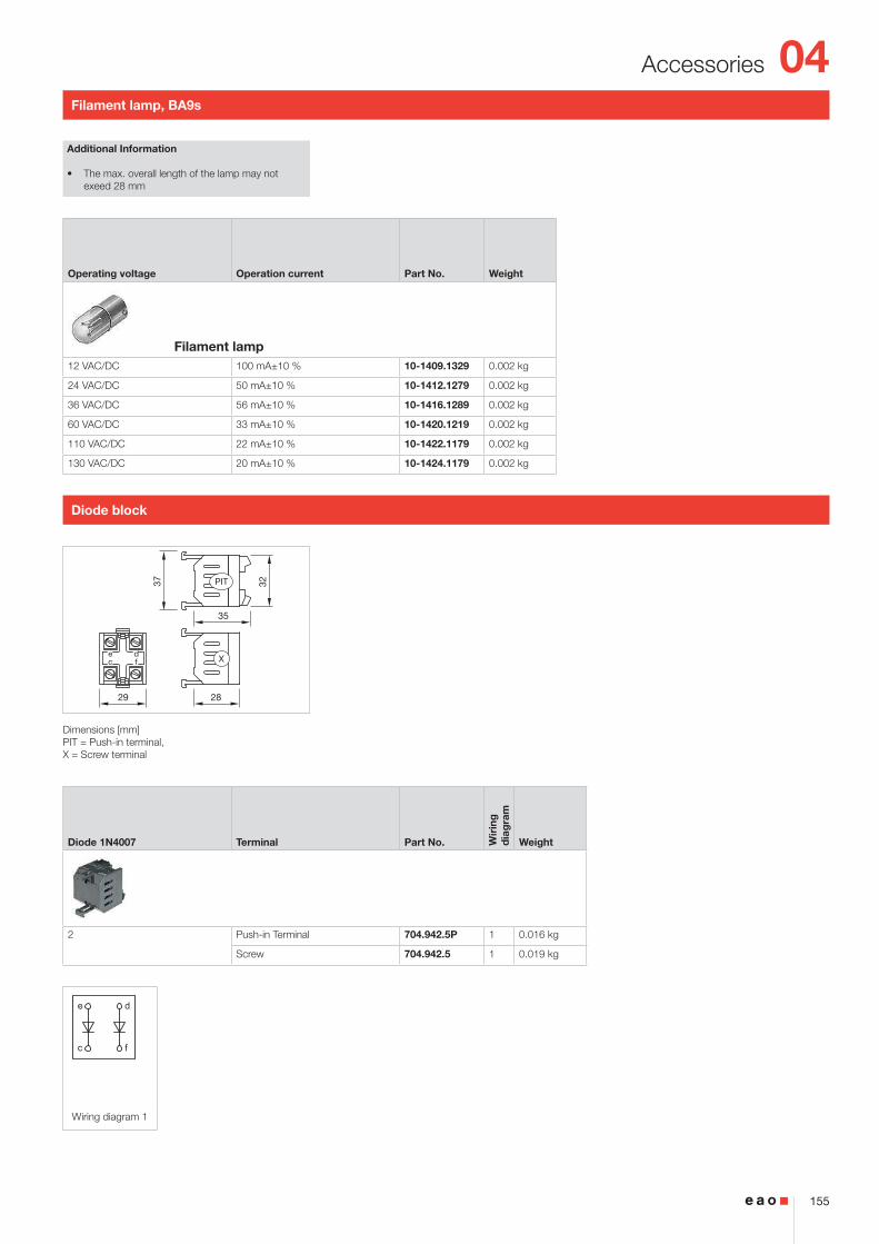
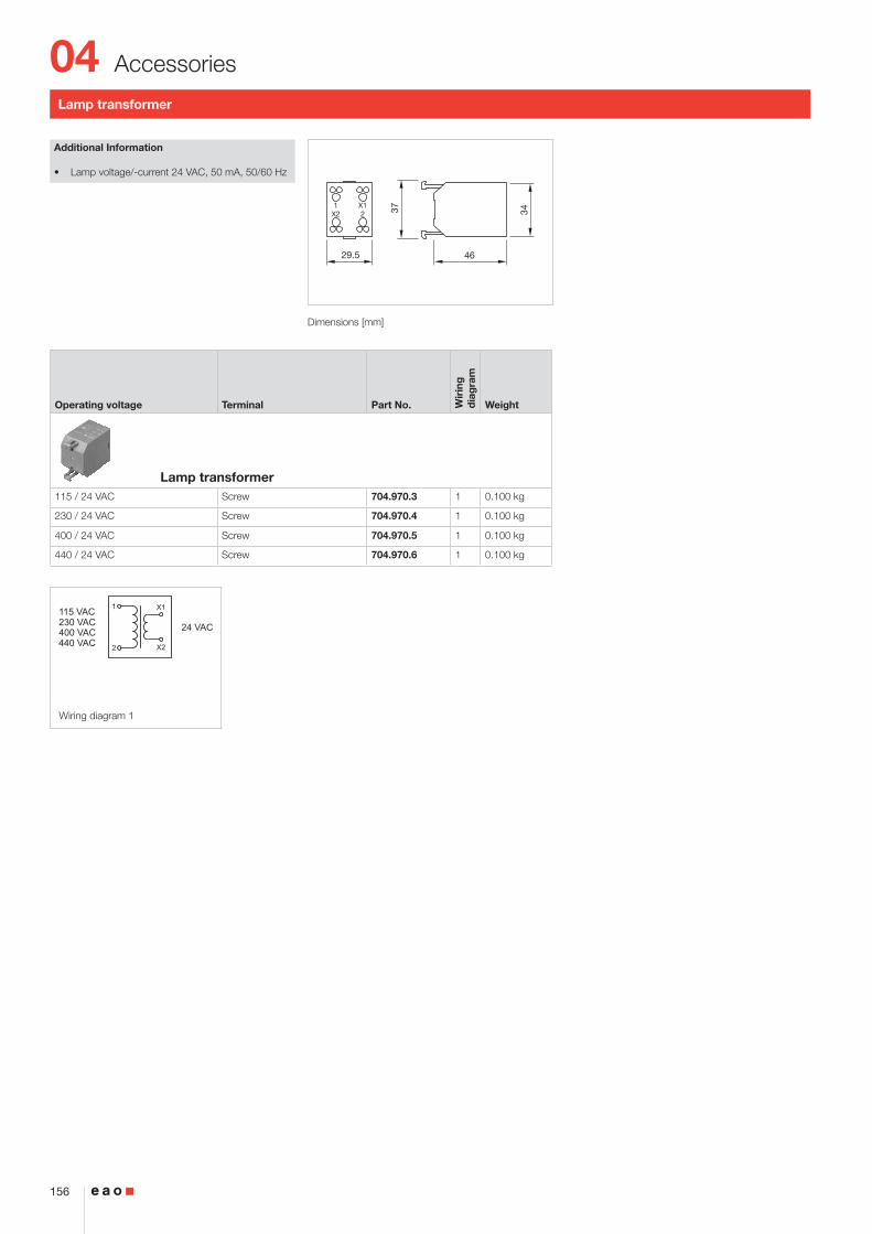
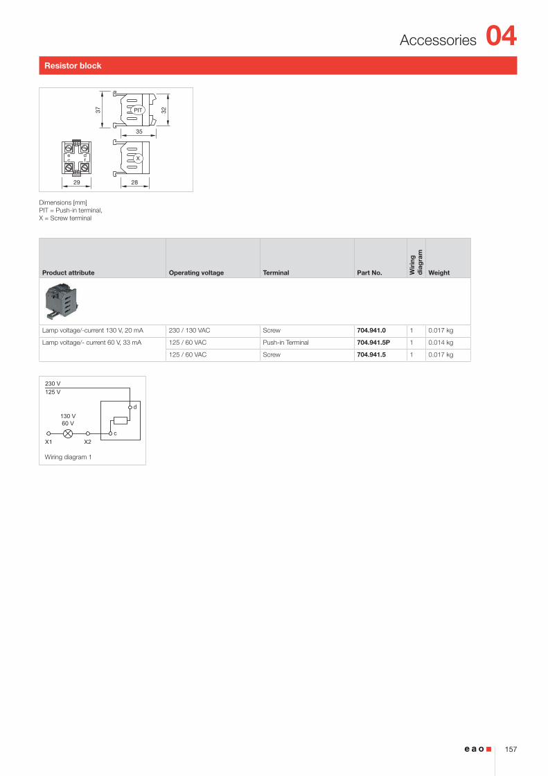
Transcript
HMI ComponentsEdition 03/2018
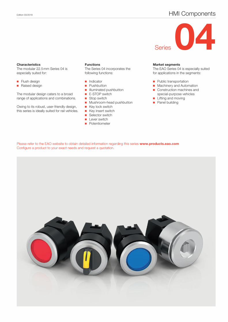
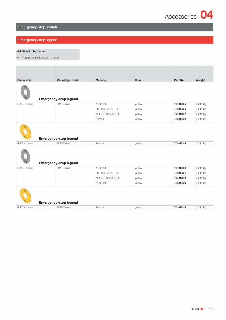
CharacteristicsThe modular 22.5 mm Series 04 is especially suited for:
■■ Flush design■■ Raised design
The modular design caters to a broad range of applications and combinations. Owing to its robust, user-friendly design, this series is ideally suited for rail vehicles.
FunctionsThe Series 04 incorporates the following functions:
Market segmentsThe EAO Series 04 is especially suited for applications in the segments:
■■ Public transportation■■ Machinery and Automation ■■ Construction machines and
special-purpose vehicles■■ Lifting and moving■■ Panel building
Series 04
Please refer to the EAO website to obtain detailed information regarding this series www.products.eao.comConfigure a product to your exact needs and request a quotation.
3
Content
Flush design
Indicator 4
Flasher 8
Buzzer 12
Pushbutton 13
Illuminated pushbutton 17
Stop switch 21
Mushroom-head pushbutton 22
Keylock switch 23
Selector switch 27
Selector rotary switch 46
Keylock rotary switch 50
Key insert switch 51
Lever switch 54
Potentiometer 55
Raised design
Indicator 56
Flasher 66
Buzzer 74
Pushbutton 75
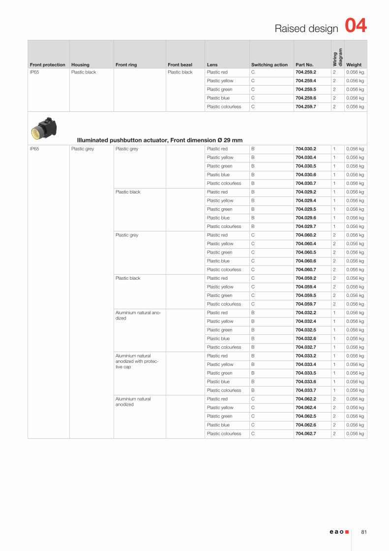
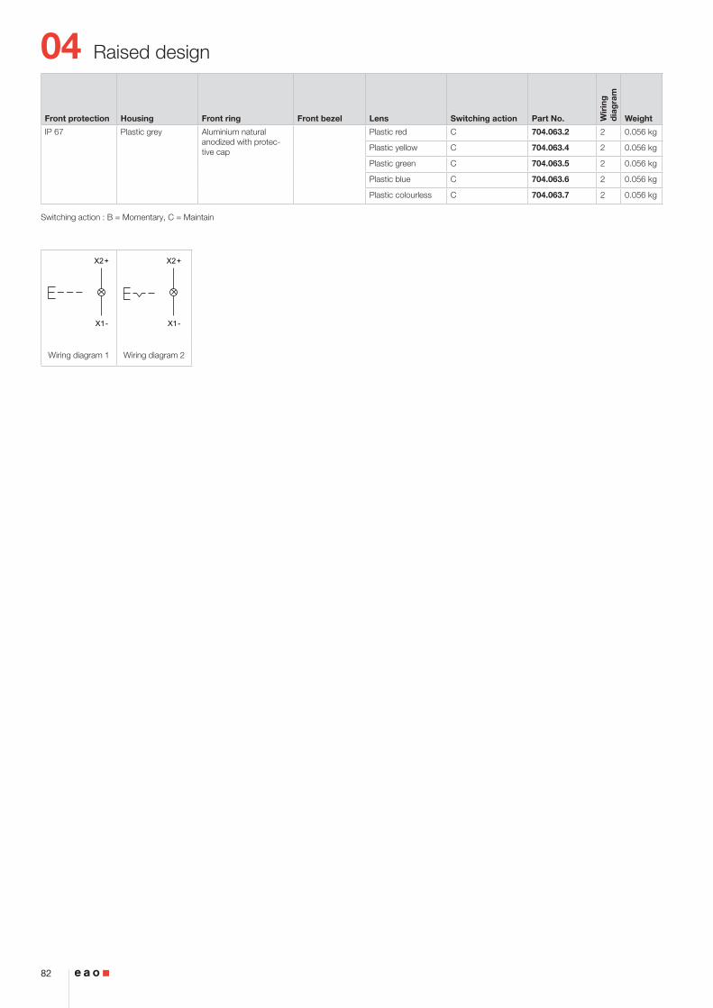
Illuminated pushbutton 80
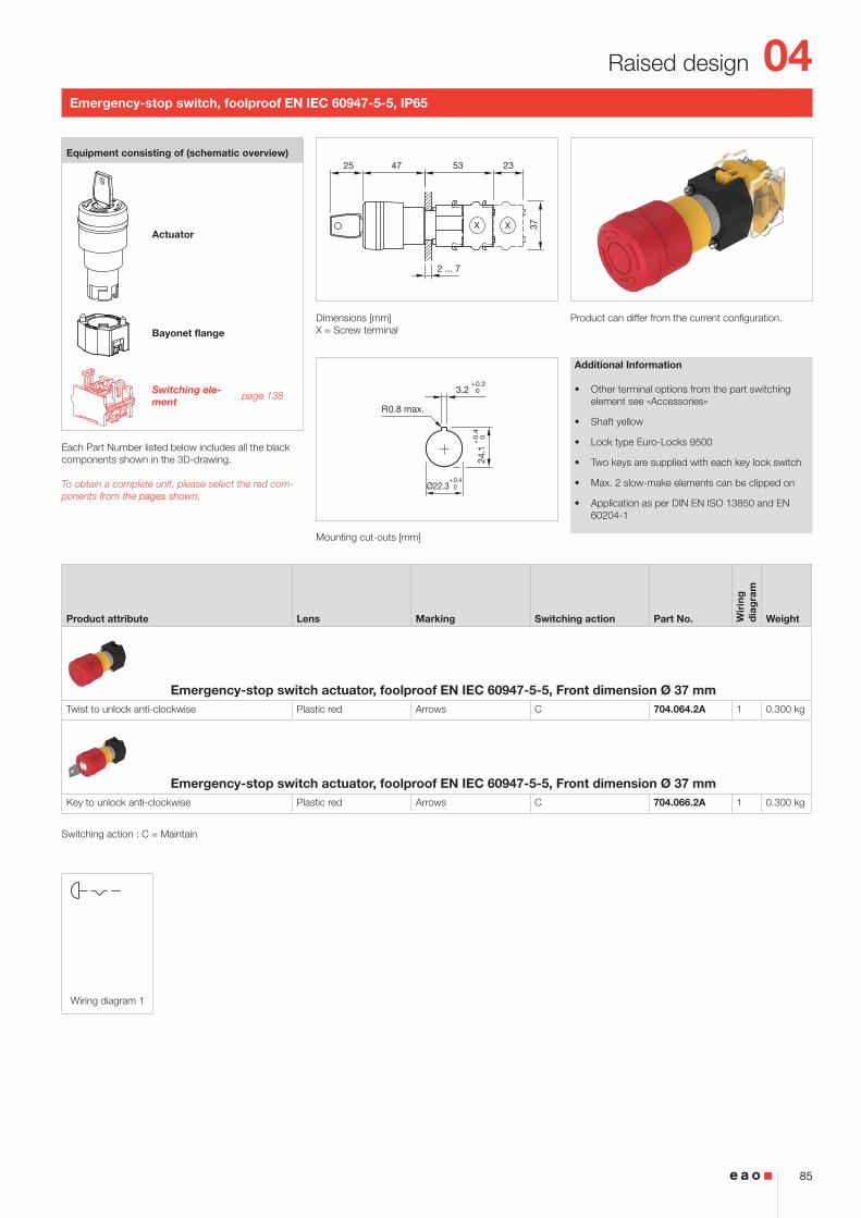
Emergency-stop switch 85
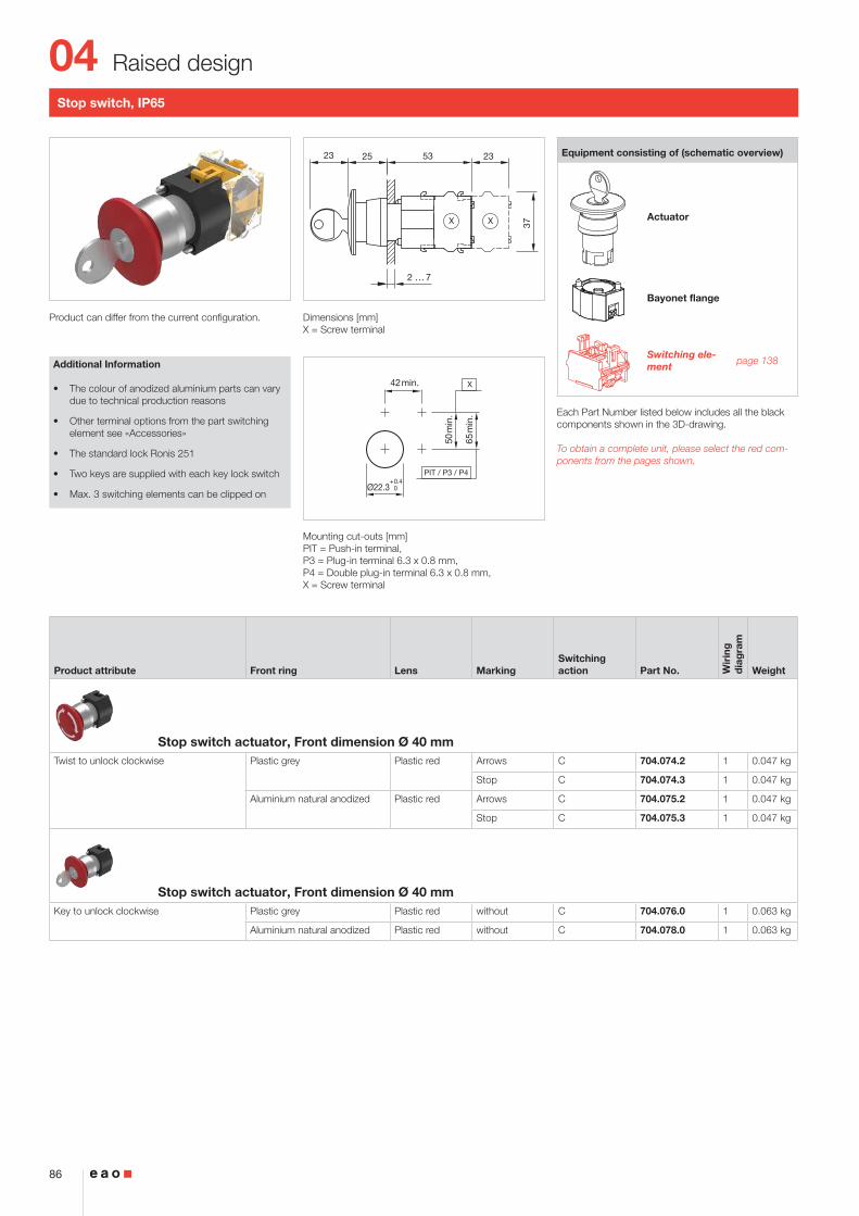
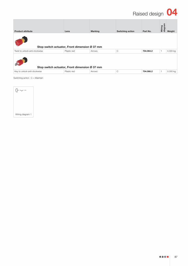
Stop switch 86
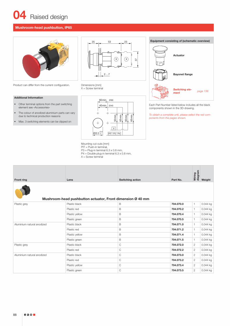
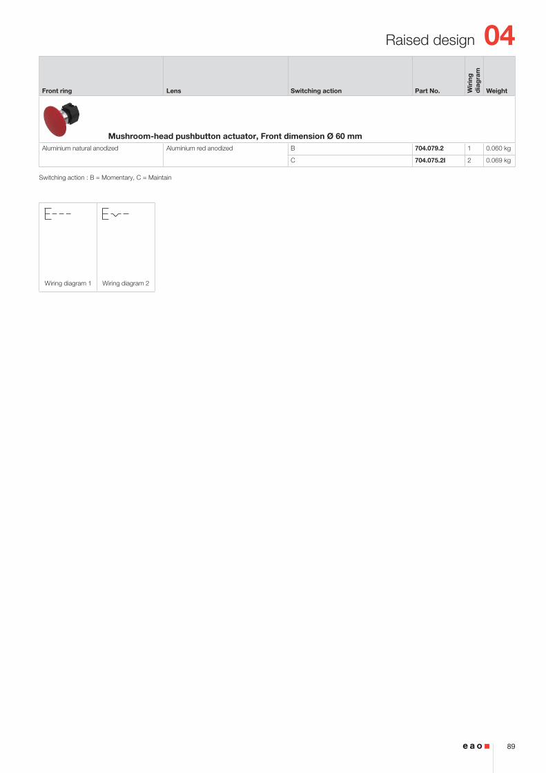
Mushroom-head pushbutton 88
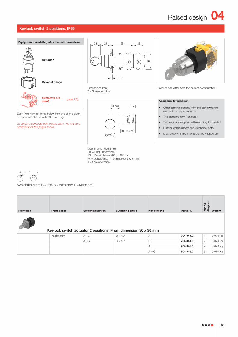
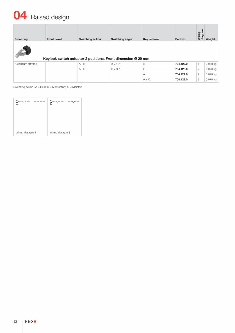
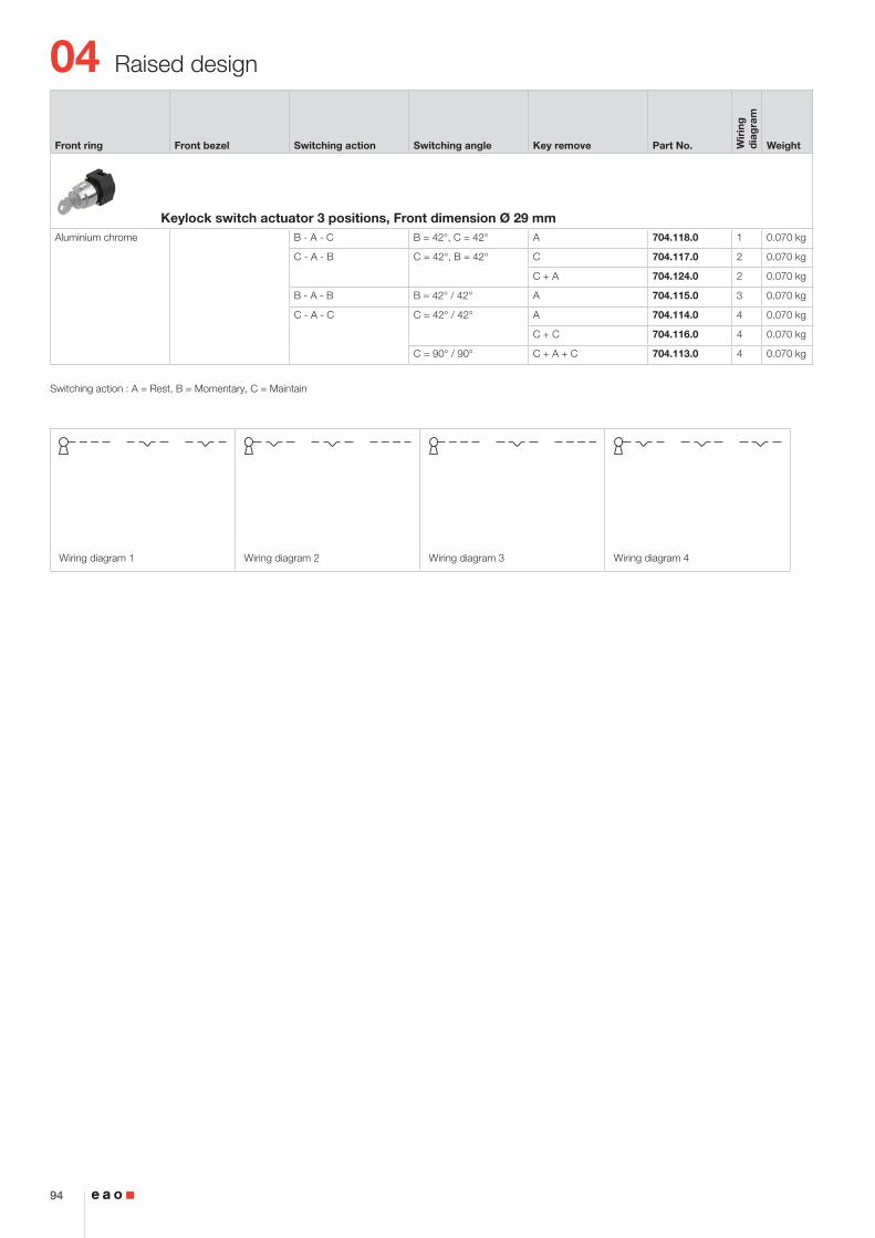
Keylock switch 91
Selector switch 95
Selector rotary switch 114
Potentiometer 118
Accessories 119
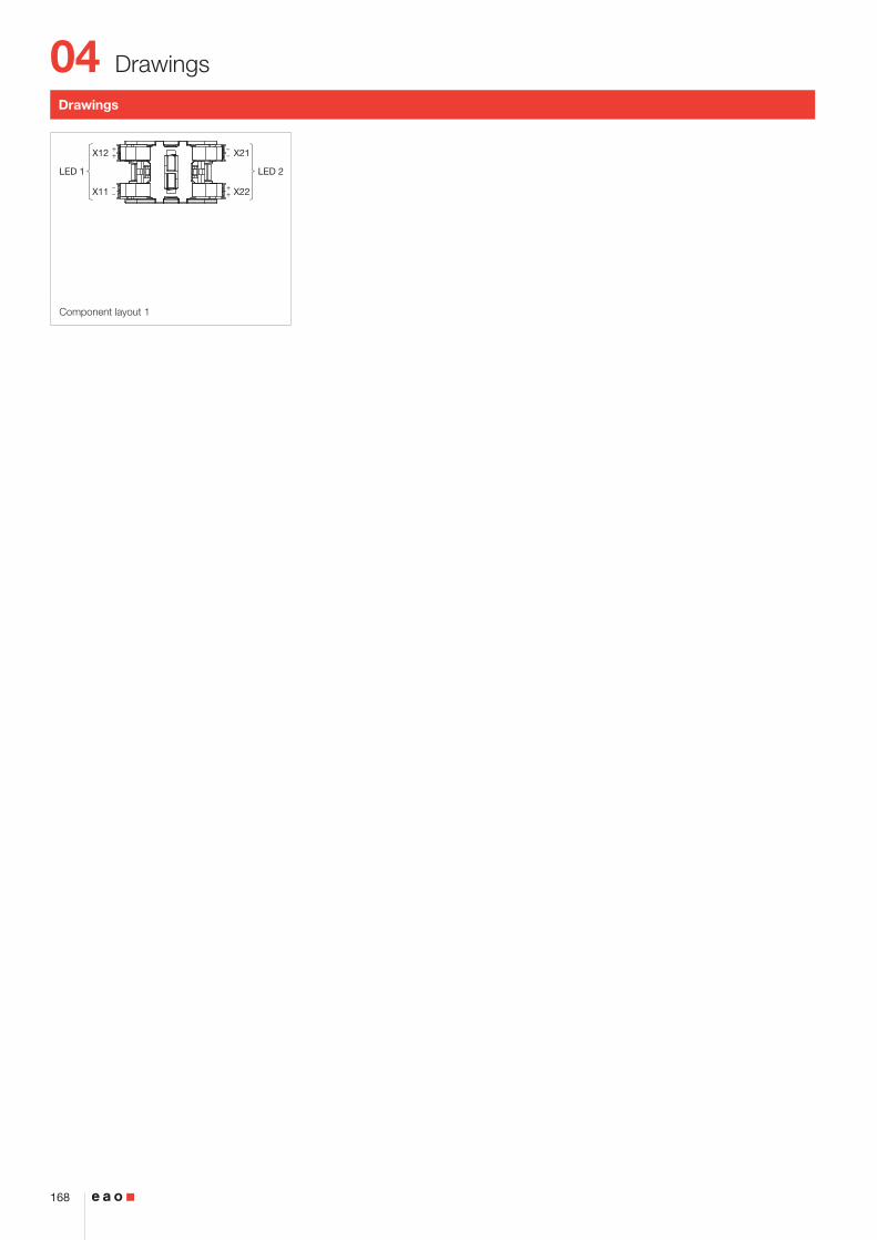
Drawings 168
Technical data 169
Marking 179
Application guidelines 184
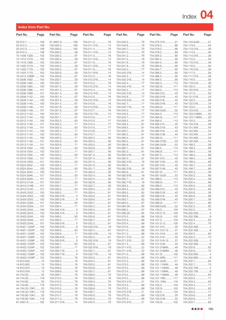
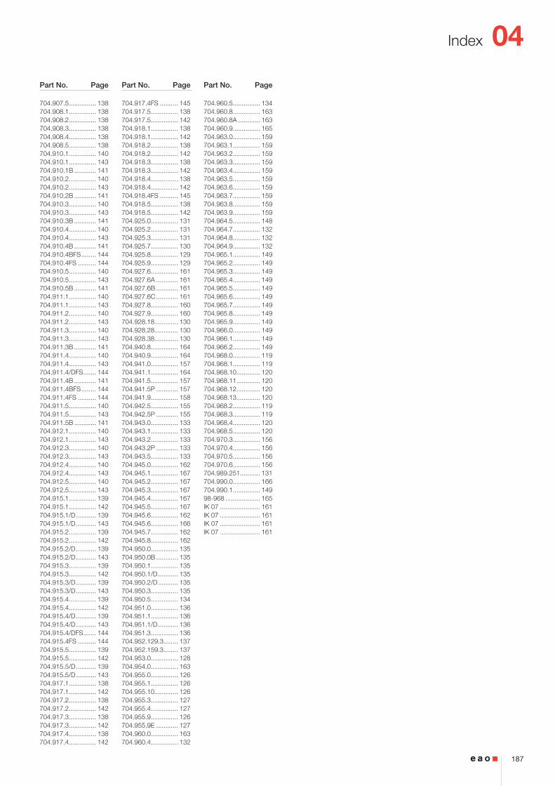
Index 185
Overview
04
4
Flush design
2 ... 6
40
2
3
55
54
(Ø35)
(35x35)
(Ø35)
(35x35)
50 m
in.
35 min.
Ø30.5+0.5 030
+0.5 0
35 min.
30+
0.5
0
R1.2 max.
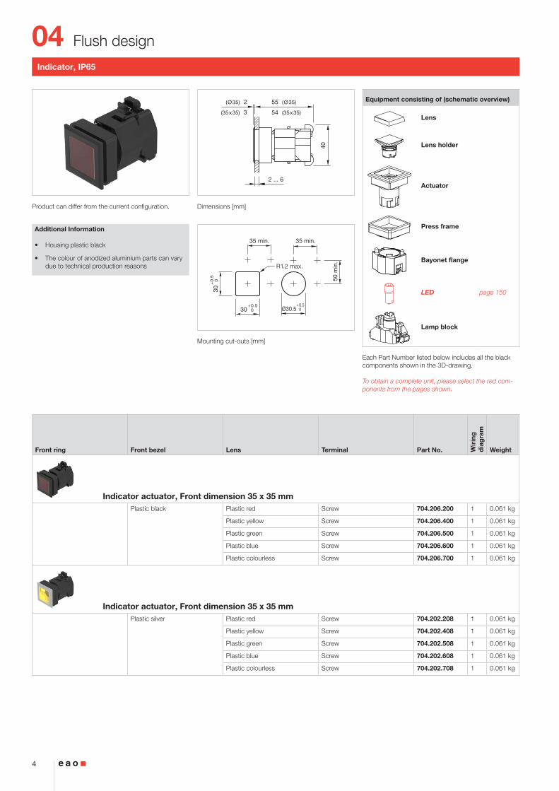
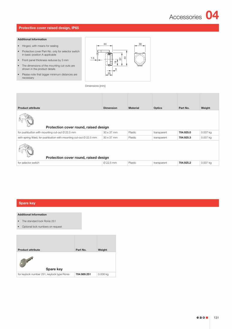
Indicator, IP65
Product can differ from the current configuration. Dimensions [mm]
Mounting cut-outs [mm]
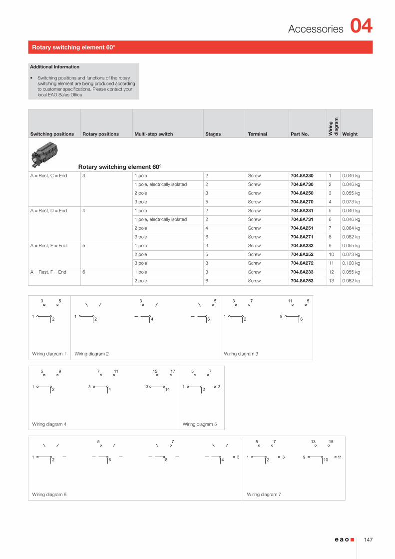
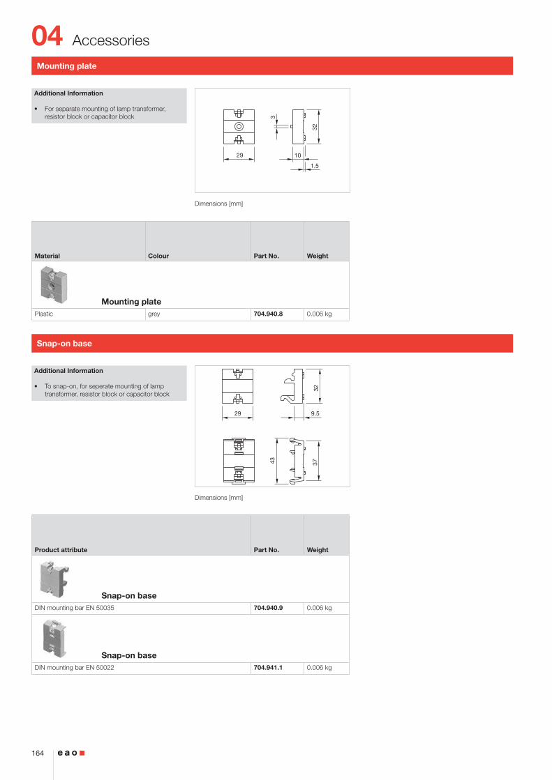
Additional Information
• Housing plastic black
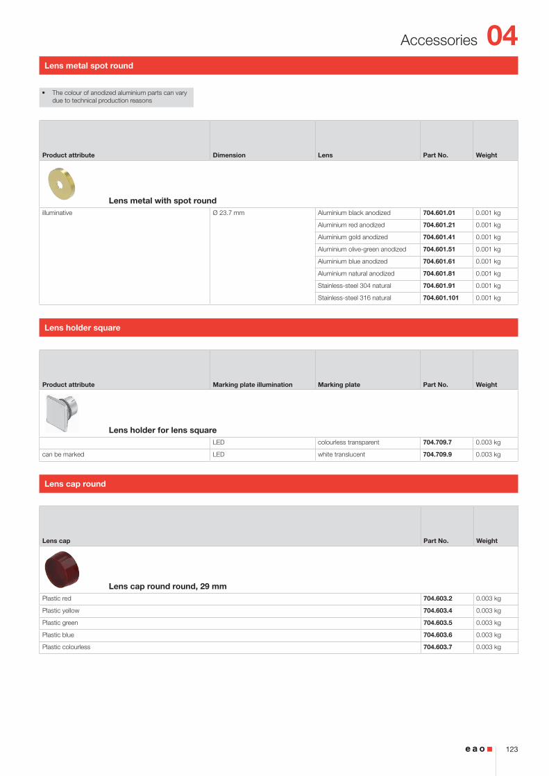
• The colour of anodized aluminium parts can vary due to technical production reasons
Equipment consisting of (schematic overview)
Lens
Lens holder
Actuator
Press frame
Bayonet flange
LED page 150
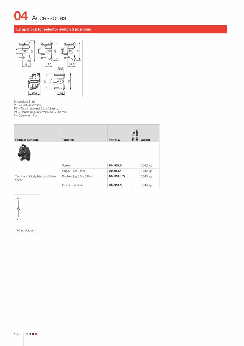
Lamp block
Each Part Number listed below includes all the black components shown in the 3D-drawing.
To obtain a complete unit, please select the red com-ponents from the pages shown.
Front ring Front bezel Lens Terminal Part No. Wir
ing
d
iag
ram
Weight
Indicator actuator, Front dimension 35 x 35 mmPlastic black Plastic red Screw 704.206.200 1 0.061 kg
Plastic yellow Screw 704.206.400 1 0.061 kg
Plastic green Screw 704.206.500 1 0.061 kg
Plastic blue Screw 704.206.600 1 0.061 kg
Plastic colourless Screw 704.206.700 1 0.061 kg
Indicator actuator, Front dimension 35 x 35 mmPlastic silver Plastic red Screw 704.202.208 1 0.061 kg
Plastic yellow Screw 704.202.408 1 0.061 kg
Plastic green Screw 704.202.508 1 0.061 kg
Plastic blue Screw 704.202.608 1 0.061 kg
Plastic colourless Screw 704.202.708 1 0.061 kg
04
5
Flush design
x2+
x1-
Wiring diagram 1
Front ring Front bezel Lens Terminal Part No. Wir
ing
d
iag
ram
Weight
Indicator actuator, Front dimension Ø 35 mmAluminium natural anodized Plastic red Screw 704.006.218 1 0.061 kg
Plastic yellow Screw 704.006.418 1 0.061 kg
Plastic green Screw 704.006.518 1 0.061 kg
Plastic blue Screw 704.006.618 1 0.061 kg
Plastic colourless Screw 704.006.718 1 0.061 kg
04
6
Flush design
2 ... 6
3 46.5 17.5
40X
50 m
in.
65 m
in.
PIT / P3 / P4
30+0.5 0
35 min.
30+
0.5
0
X
R1.2 max.
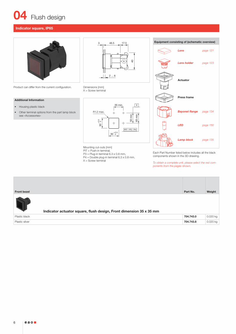
Indicator square, IP65
Product can differ from the current configuration. Dimensions [mm]X = Screw terminal
Mounting cut-outs [mm]PIT = Push-in terminal, P3 = Plug-in terminal 6.3 x 0.8 mm, P4 = Double plug-in terminal 6.3 x 0.8 mm, X = Screw terminal
Additional Information
• Housing plastic black
• Other terminal options from the part lamp block see «Accessories»
Equipment consisting of (schematic overview)
Lens page 121
Lens holder page 123
Actuator
Press frame
Bayonet flange page 134
LED page 150
Lamp block page 135
Each Part Number listed below includes all the black components shown in the 3D-drawing.
To obtain a complete unit, please select the red com-ponents from the pages shown.
Front bezel Part No. Weight
Indicator actuator square, flush design, Front dimension 35 x 35 mmPlastic black 704.743.0 0.020 kg
Plastic silver 704.743.8 0.020 kg
04
7
Flush design
2 ... 6
2 47.5 17.5
40X
50 m
in.
65 m
in.
PIT / P3 / P4
35 min.
Ø30.5+0.5 0
X
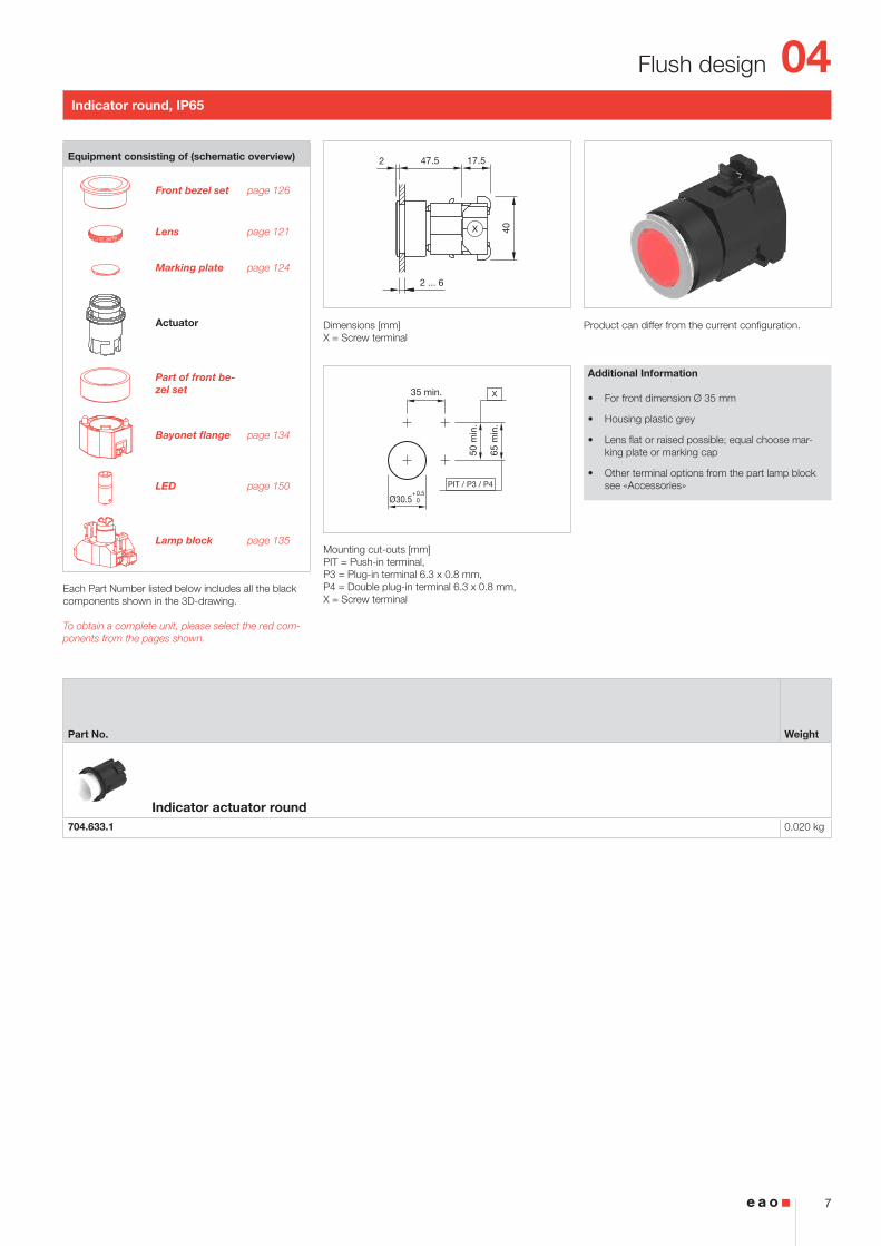
Indicator round, IP65
Product can differ from the current configuration. Dimensions [mm]X = Screw terminal
Mounting cut-outs [mm]PIT = Push-in terminal, P3 = Plug-in terminal 6.3 x 0.8 mm, P4 = Double plug-in terminal 6.3 x 0.8 mm, X = Screw terminal
Additional Information
• For front dimension Ø 35 mm
• Housing plastic grey
• Lens flat or raised possible; equal choose mar-king plate or marking cap
• Other terminal options from the part lamp block see «Accessories»
Equipment consisting of (schematic overview)
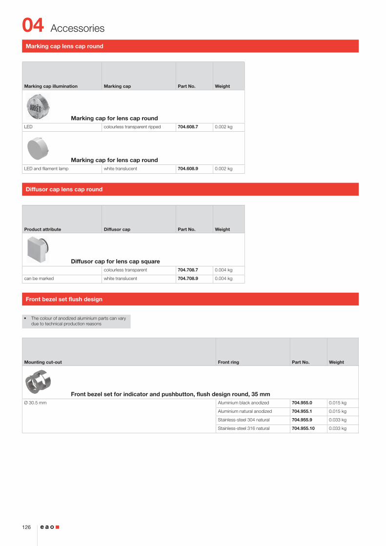
Front bezel set page 126
Lens page 121
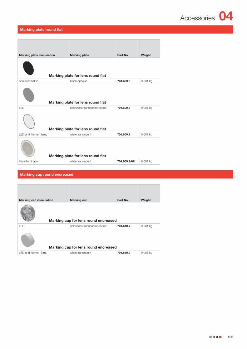
Marking plate page 124
Actuator
Part of front be-zel set
Bayonet flange page 134
LED page 150
Lamp block page 135
Each Part Number listed below includes all the black components shown in the 3D-drawing.
To obtain a complete unit, please select the red com-ponents from the pages shown.
Part No. Weight
Indicator actuator round704.633.1 0.020 kg
04
8
Flush design
2 ... 6
28
40
2
3
54.5
53.5
(Ø35)
(35x35)
(Ø35)
(35x35)
X
50 m
in.
65 m
in.
35 min.
Ø30.5+0.5 030
+0.5 0
35 min.
30+
0.5
0
X
PIT
R1.2 max.
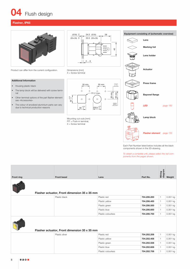
Flasher, IP65
Product can differ from the current configuration. Dimensions [mm]X = Screw terminal
Mounting cut-outs [mm]PIT = Push-in terminal, X = Screw terminal
Additional Information
• Housing plastic black
• The lamp block will be delivered with screw termi-nal
• Other terminal options of the part flasher element see «Accessories»
• The colour of anodized aluminium parts can vary due to technical production reasons
Equipment consisting of (schematic overview)
Lens
Marking foil
Lens holder
Actuator
Press frame
Bayonet flange
LED page 150
Lamp block
Flasher element page 133
Each Part Number listed below includes all the black components shown in the 3D-drawing.
To obtain a complete unit, please select the red com-ponents from the pages shown.
Front ring Front bezel Lens Part No. Wir
ing
d
iag
ram
Weight
Flasher actuator, Front dimension 35 x 35 mmPlastic black Plastic red 704.206.200 1 0.061 kg
Plastic yellow 704.206.400 1 0.061 kg
Plastic green 704.206.500 1 0.061 kg
Plastic blue 704.206.600 1 0.061 kg
Plastic colourless 704.206.700 1 0.061 kg
Flasher actuator, Front dimension 35 x 35 mmPlastic silver Plastic red 704.202.208 1 0.061 kg
Plastic yellow 704.202.408 1 0.061 kg
Plastic green 704.202.508 1 0.061 kg
Plastic blue 704.202.608 1 0.061 kg
Plastic colourless 704.202.708 1 0.061 kg
04
9
Flush design
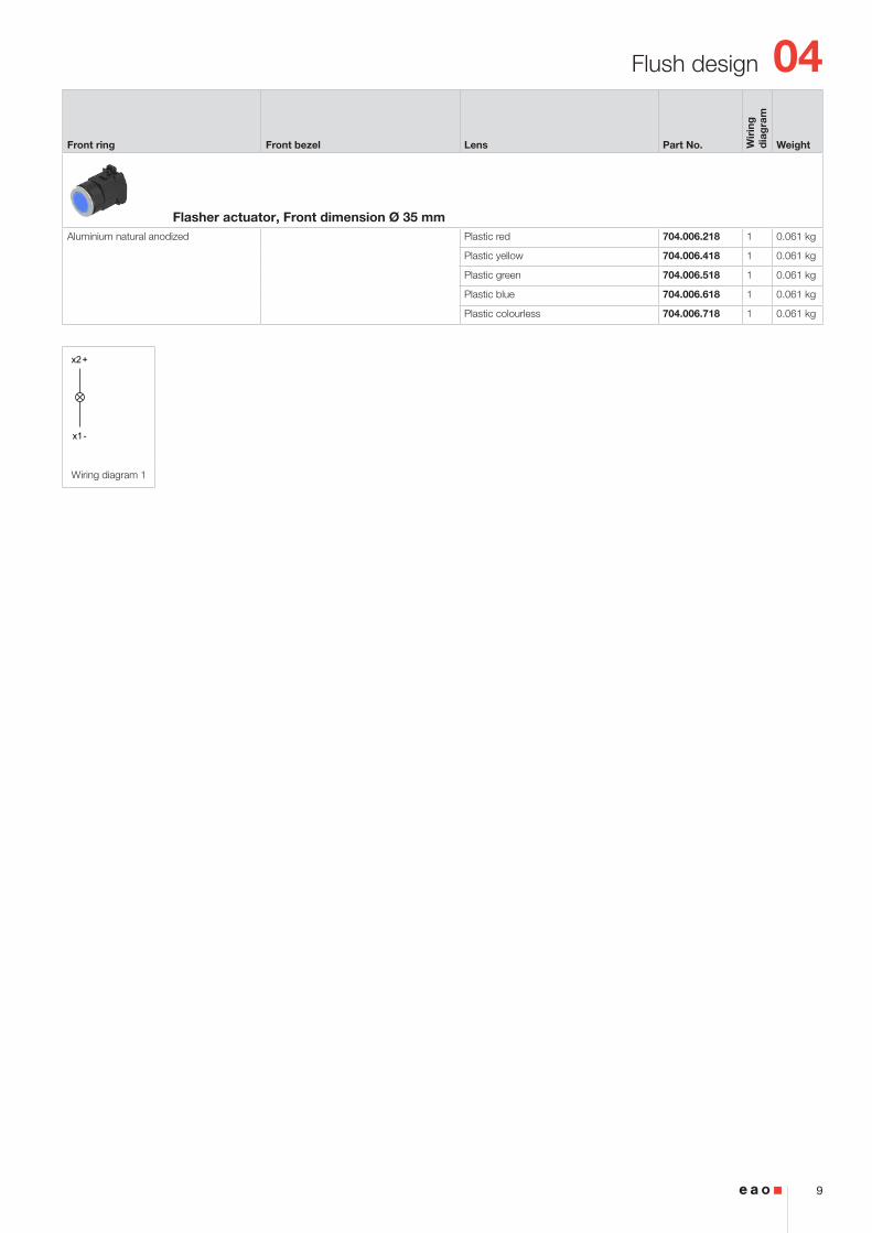
x2+
x1-
Wiring diagram 1
Front ring Front bezel Lens Part No. Wir
ing
d
iag
ram
Weight
Flasher actuator, Front dimension Ø 35 mmAluminium natural anodized Plastic red 704.006.218 1 0.061 kg
Plastic yellow 704.006.418 1 0.061 kg
Plastic green 704.006.518 1 0.061 kg
Plastic blue 704.006.618 1 0.061 kg
Plastic colourless 704.006.718 1 0.061 kg
04
10
Flush design
2 ... 6
2815.5
40
3 39
X
50 m
in.
65 m
in.
30+0.5 0
35 min.
30+
0.5
0
X
PIT
R1.2 max.
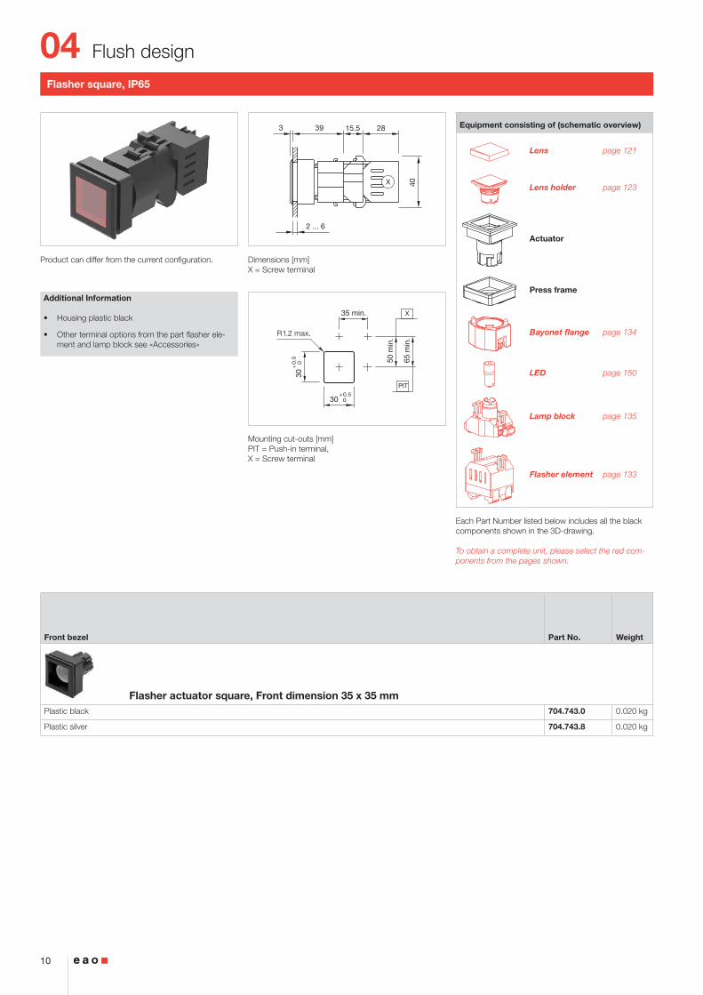
Flasher square, IP65
Product can differ from the current configuration. Dimensions [mm]X = Screw terminal
Mounting cut-outs [mm]PIT = Push-in terminal, X = Screw terminal
Additional Information
• Housing plastic black
• Other terminal options from the part flasher ele-ment and lamp block see «Accessories»
Equipment consisting of (schematic overview)
Lens page 121
Lens holder page 123
Actuator
Press frame
Bayonet flange page 134
LED page 150
Lamp block page 135
Flasher element page 133
Each Part Number listed below includes all the black components shown in the 3D-drawing.
To obtain a complete unit, please select the red com-ponents from the pages shown.
Front bezel Part No. Weight
Flasher actuator square, Front dimension 35 x 35 mmPlastic black 704.743.0 0.020 kg
Plastic silver 704.743.8 0.020 kg
04
11
Flush design
2 ... 6
2815.5
40
2 40
X
50 m
in.
65 m
in.
35 min.
Ø30.5+0.5 0
X
PIT
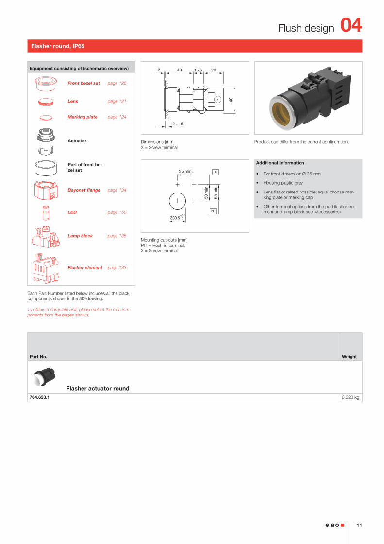
Flasher round, IP65
Product can differ from the current configuration. Dimensions [mm]X = Screw terminal
Mounting cut-outs [mm]PIT = Push-in terminal, X = Screw terminal
Additional Information
• For front dimension Ø 35 mm
• Housing plastic grey
• Lens flat or raised possible; equal choose mar-king plate or marking cap
• Other terminal options from the part flasher ele-ment and lamp block see «Accessories»
Equipment consisting of (schematic overview)
Front bezel set page 126
Lens page 121
Marking plate page 124
Actuator
Part of front be-zel set
Bayonet flange page 134
LED page 150
Lamp block page 135
Flasher element page 133
Each Part Number listed below includes all the black components shown in the 3D-drawing.
To obtain a complete unit, please select the red com-ponents from the pages shown.
Part No. Weight
Flasher actuator round704.633.1 0.020 kg
04
12
Flush design
2 ... 6
2 46.5
Ø35
x2-
x1+
Wiring diagram 1
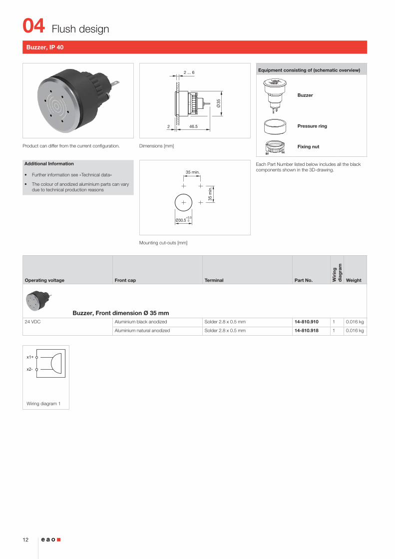
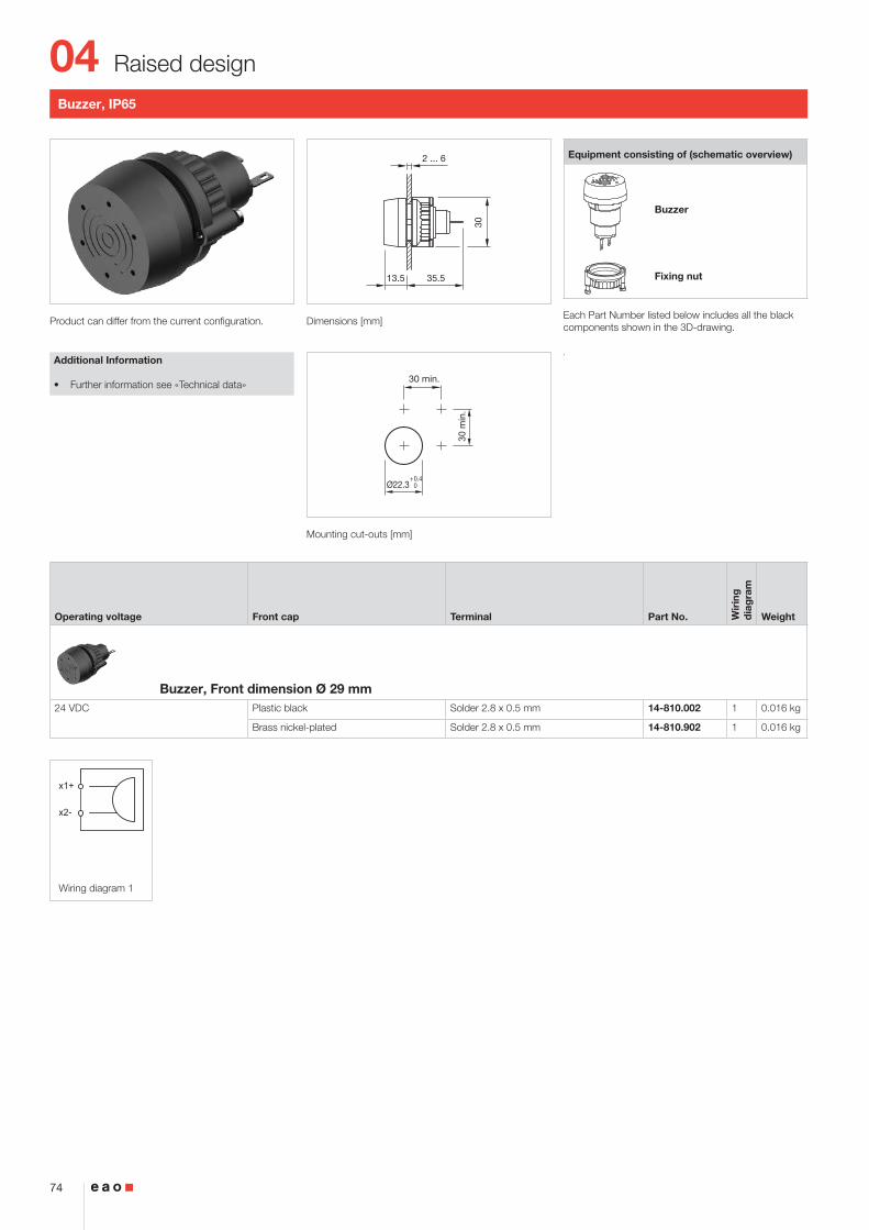
Buzzer, IP 40
Product can differ from the current configuration. Dimensions [mm]
Mounting cut-outs [mm]
Additional Information
• Further information see «Technical data»
• The colour of anodized aluminium parts can vary due to technical production reasons
Equipment consisting of (schematic overview)
Buzzer
Pressure ring
Fixing nut
Each Part Number listed below includes all the black components shown in the 3D-drawing.
Operating voltage Front cap Terminal Part No. Wir
ing
d
iag
ram
Weight
Buzzer, Front dimension Ø 35 mm24 VDC Aluminium black anodized Solder 2.8 x 0.5 mm 14-810.910 1 0.016 kg
Aluminium natural anodized Solder 2.8 x 0.5 mm 14-810.918 1 0.016 kg
04
13
Flush design
2 ... 6
23
37
2
3
64
63
(Ø35)
(35x35)
(Ø35)
(35x35)
X X
50 m
in.
65 m
in.
PIT / P3 / P4
35 min.
Ø30.5+0.5 030
+0.5 0
35 min.
30+
0.5
0
X
R1.2 max.
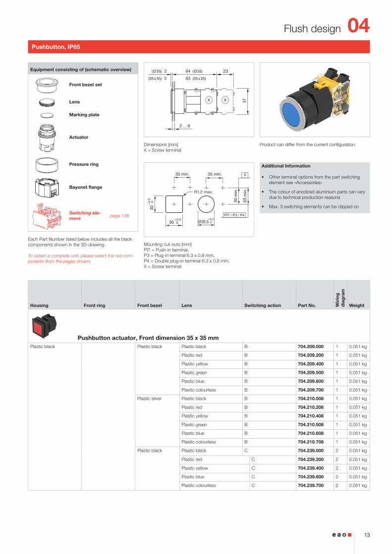
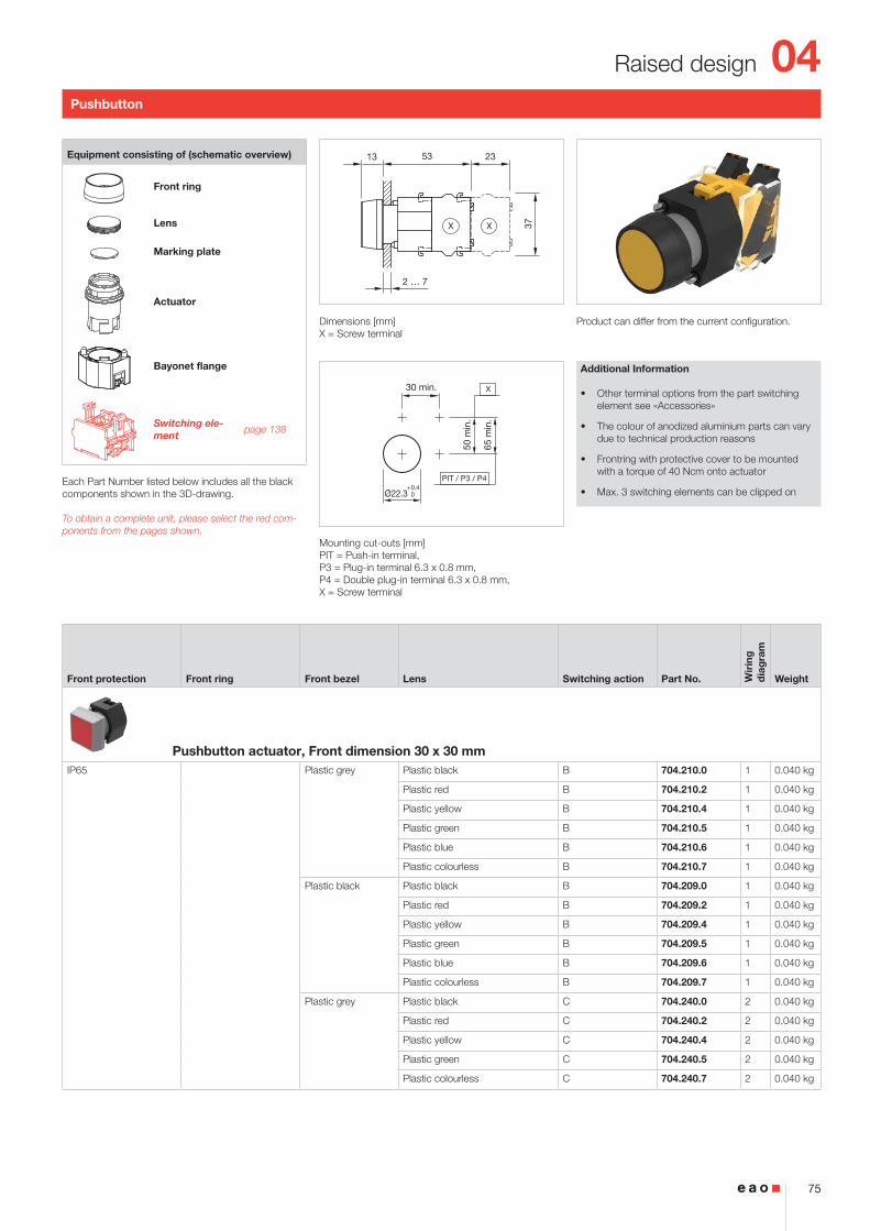
Pushbutton, IP65
Product can differ from the current configuration. Dimensions [mm]X = Screw terminal
Mounting cut-outs [mm]PIT = Push-in terminal, P3 = Plug-in terminal 6.3 x 0.8 mm, P4 = Double plug-in terminal 6.3 x 0.8 mm, X = Screw terminal
Additional Information
• Other terminal options from the part switching element see «Accessories»
• The colour of anodized aluminium parts can vary due to technical production reasons
• Max. 3 switching elements can be clipped on
Equipment consisting of (schematic overview)
Front bezel set
Lens
Marking plate
Actuator
Pressure ring
Bayonet flange
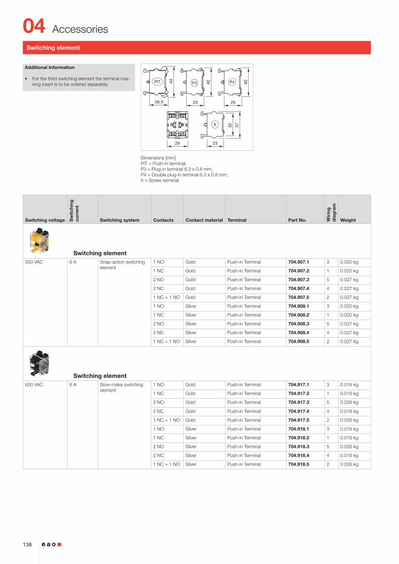
Switching ele-ment page 138
Each Part Number listed below includes all the black components shown in the 3D-drawing.
To obtain a complete unit, please select the red com-ponents from the pages shown.
Housing Front ring Front bezel Lens Switching action Part No. Wir
ing
d
iag
ram
Weight
Pushbutton actuator, Front dimension 35 x 35 mmPlastic black Plastic black Plastic black B 704.209.000 1 0.051 kg
Plastic red B 704.209.200 1 0.051 kg
Plastic yellow B 704.209.400 1 0.051 kg
Plastic green B 704.209.500 1 0.051 kg
Plastic blue B 704.209.600 1 0.051 kg
Plastic colourless B 704.209.700 1 0.051 kg
Plastic silver Plastic black B 704.210.008 1 0.051 kg
Plastic red B 704.210.208 1 0.051 kg
Plastic yellow B 704.210.408 1 0.051 kg
Plastic green B 704.210.508 1 0.051 kg
Plastic blue B 704.210.608 1 0.051 kg
Plastic colourless B 704.210.708 1 0.051 kg
Plastic black Plastic black C 704.239.000 2 0.051 kg
Plastic red C 704.239.200 2 0.051 kg
Plastic yellow C 704.239.400 2 0.051 kg
Plastic blue C 704.239.600 2 0.051 kg
Plastic colourless C 704.239.700 2 0.051 kg
04
14
Flush design
Wiring diagram 1 Wiring diagram 2
Housing Front ring Front bezel Lens Switching action Part No. Wir
ing
d
iag
ram
Weight
Plastic black Plastic silver Plastic red C 704.240.208 2 0.051 kg
Plastic yellow C 704.240.408 2 0.051 kg
Plastic green C 704.240.508 2 0.051 kg
Plastic colourless C 704.240.708 2 0.051 kg
Pushbutton actuator, Front dimension Ø 35 mmPlastic grey Aluminium natural
anodizedAluminium black anodized B 704.011.018 1 0.051 kg
Aluminium red anodized B 704.011.218 1 0.051 kg
Aluminium gold anodized B 704.011.418 1 0.051 kg
Aluminium olive-green anodized B 704.011.518 1 0.051 kg
Aluminium blue anodized B 704.011.618 1 0.051 kg
Aluminium natural anodized B 704.011.818 1 0.051 kg
Plastic black B 704.012.018 1 0.051 kg
Plastic red B 704.012.218 1 0.051 kg
Plastic yellow B 704.012.418 1 0.051 kg
Plastic green B 704.012.518 1 0.051 kg
Plastic blue B 704.012.618 1 0.051 kg
Plastic colourless B 704.012.718 1 0.051 kg
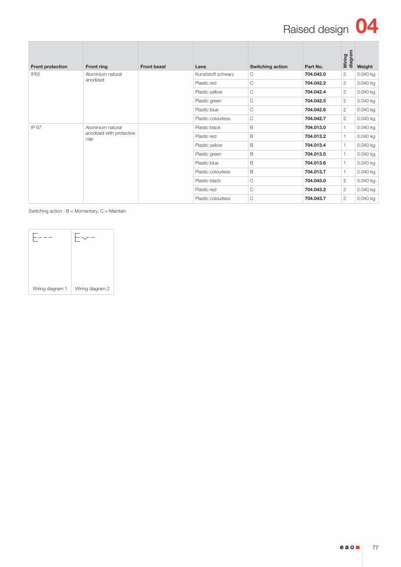
Plastic black C 704.042.018 2 0.051 kg
Plastic red C 704.042.218 2 0.051 kg
Plastic yellow C 704.042.418 2 0.051 kg
Plastic green C 704.042.518 2 0.051 kg
Plastic blue C 704.042.618 2 0.051 kg
Plastic colourless C 704.042.718 2 0.051 kg
Switching action : B = Momentary, C = Maintain
04
15
Flush design
2 ... 6
23
37
2
3
64
63
(Ø35)
(35x35)
(Ø35)
(35x35)
X X
50 m
in.
65 m
in.
PIT / P3 / P4
35 min.
Ø30.5+0.5 030
+0.5 0
35 min.
30+
0.5
0
X
R1.2 max.
Wiring diagram 1 Wiring diagram 2
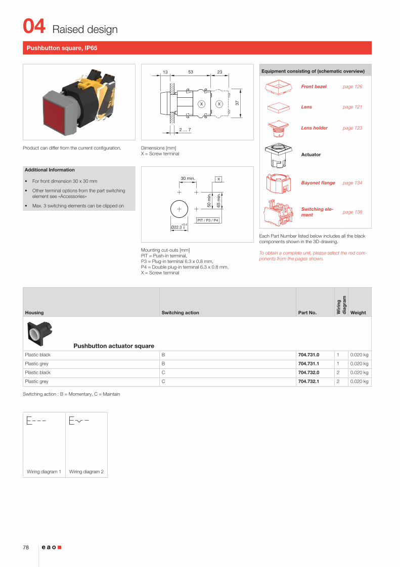
Pushbutton square, IP65
Product can differ from the current configuration. Dimensions [mm]X = Screw terminal
Mounting cut-outs [mm]PIT = Push-in terminal, P3 = Plug-in terminal 6.3 x 0.8 mm, P4 = Double plug-in terminal 6.3 x 0.8 mm, X = Screw terminal
Additional Information
• Housing plastic black
• Other terminal options from the part switching element see «Accessories»
• Max. 3 switching elements can be clipped on
Equipment consisting of (schematic overview)
Lens page 121
Lens holder page 123
Actuator
Press frame
Bayonet flange page 134
Switching ele-ment page 138
Each Part Number listed below includes all the black components shown in the 3D-drawing.
To obtain a complete unit, please select the red com-ponents from the pages shown.
Front bezel Switching action Part No. Wir
ing
d
iag
ram
Weight
Pushbutton actuator square, Front dimension 35 x 35 mmPlastic black B 704.741.0 1 0.020 kg
Plastic silver B 704.741.8 1 0.020 kg
Plastic black C 704.742.0 2 0.020 kg
Plastic silver C 704.742.8 2 0.020 kg
Switching action : B = Momentary, C = Maintain
04
16
Flush design
2 ... 6
23
37
2
3
64
63
(Ø35)
(35x35)
(Ø35)
(35x35)
X X
50 m
in.
65 m
in.
PIT / P3 / P4
35 min.
Ø30.5+0.5 030
+0.5 0
35 min.
30+
0.5
0
X
R1.2 max.
Wiring diagram 1 Wiring diagram 2
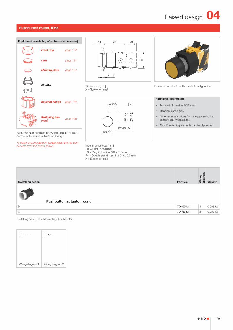
Pushbutton round, IP65
Product can differ from the current configuration. Dimensions [mm]X = Screw terminal
Mounting cut-outs [mm]PIT = Push-in terminal, P3 = Plug-in terminal 6.3 x 0.8 mm, P4 = Double plug-in terminal 6.3 x 0.8 mm, X = Screw terminal
Additional Information
• For front dimension Ø 35 mm
• Metal lens to be ordered with marking plates
• Housing plastic grey
• Other terminal options from the part switching element see «Accessories»
• Max. 3 switching elements can be clipped on
Equipment consisting of (schematic overview)
Front bezel set page 126
Lens page 121
Marking plate page 124
Actuator
Part of front be-zel set
Bayonet flange page 134
Switching ele-ment page 138
Each Part Number listed below includes all the black components shown in the 3D-drawing.
To obtain a complete unit, please select the red com-ponents from the pages shown.
Switching action Part No. Wir
ing
d
iag
ram
Weight
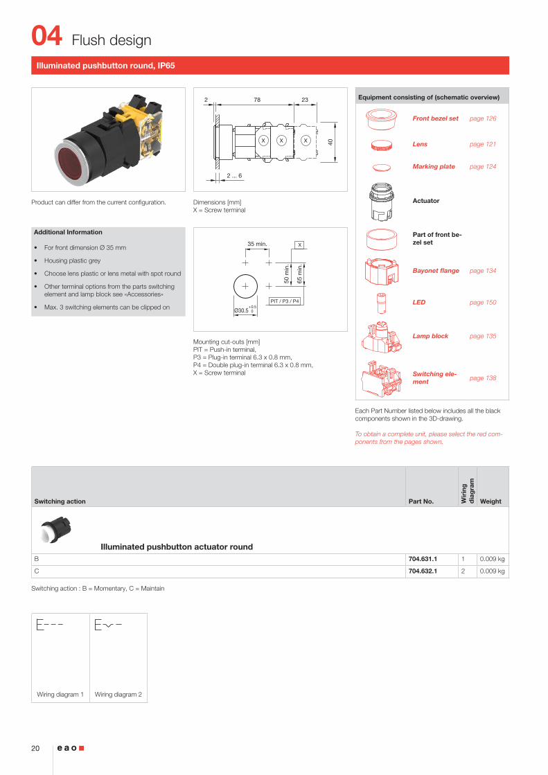
Pushbutton actuator roundB 704.631.1 1 0.009 kg
C 704.632.1 2 0.009 kg
Switching action : B = Momentary, C = Maintain
04
17
Flush design
2 ... 6
23
40
2
3
78
77
(Ø35)
(35x35)
(Ø35)
(35x35)
X X
50 m
in.
65 m
in.
PIT / P3 / P4
35 min.
Ø30.5+0.5 030
+0.5 0
35 min.
30+
0.5
0
X
R1.2 max.
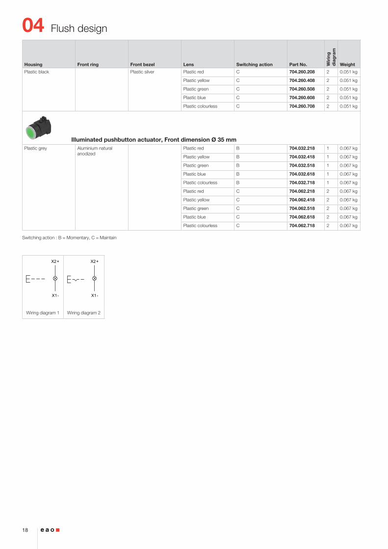
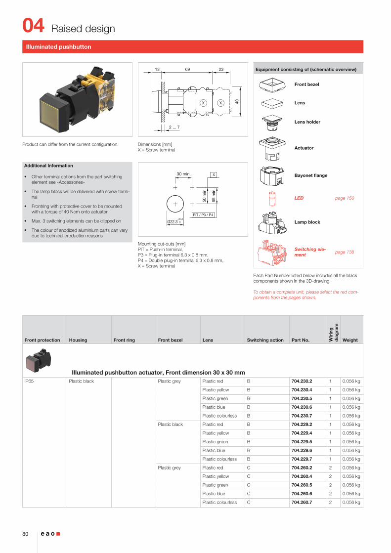
Illuminated pushbutton, IP65
Product can differ from the current configuration. Dimensions [mm]X = Screw terminal
Mounting cut-outs [mm]PIT = Push-in terminal, P3 = Plug-in terminal 6.3 x 0.8 mm, P4 = Double plug-in terminal 6.3 x 0.8 mm, X = Screw terminal
Additional Information
• The lamp block will be delivered with screw termi-nal
• Other terminal options from the part switching element see «Accessories»
• The colour of anodized aluminium parts can vary due to technical production reasons
• Max. 3 switching elements can be clipped on
Equipment consisting of (schematic overview)
Front bezel set
Lens
Marking plate
Actuator
Pressure ring
Bayonet flange
LED page 150
Lamp block
Switching ele-ment page 138
Each Part Number listed below includes all the black components shown in the 3D-drawing.
To obtain a complete unit, please select the red com-ponents from the pages shown.
Housing Front ring Front bezel Lens Switching action Part No. Wir
ing
d
iag
ram
Weight
Illuminated pushbutton actuator, Front dimension 35 x 35 mmPlastic black Plastic black Plastic red B 704.229.200 1 0.051 kg
Plastic yellow B 704.229.400 1 0.051 kg
Plastic green B 704.229.500 1 0.051 kg
Plastic blue B 704.229.600 1 0.051 kg
Plastic colourless B 704.229.700 1 0.051 kg
Plastic silver Plastic red B 704.230.208 1 0.051 kg
Plastic yellow B 704.230.408 1 0.051 kg
Plastic green B 704.230.508 1 0.051 kg
Plastic blue B 704.230.608 1 0.051 kg
Plastic colourless B 704.230.708 1 0.051 kg
Plastic black Plastic red C 704.259.200 2 0.051 kg
Plastic yellow C 704.259.400 2 0.051 kg
Plastic green C 704.259.500 2 0.051 kg
Plastic blue C 704.259.600 2 0.051 kg
Plastic colourless C 704.259.700 2 0.051 kg
04
18
Flush design
X2+
X1-
X2+
X1-
Wiring diagram 1 Wiring diagram 2
Housing Front ring Front bezel Lens Switching action Part No. Wir
ing
d
iag
ram
Weight
Plastic black Plastic silver Plastic red C 704.260.208 2 0.051 kg
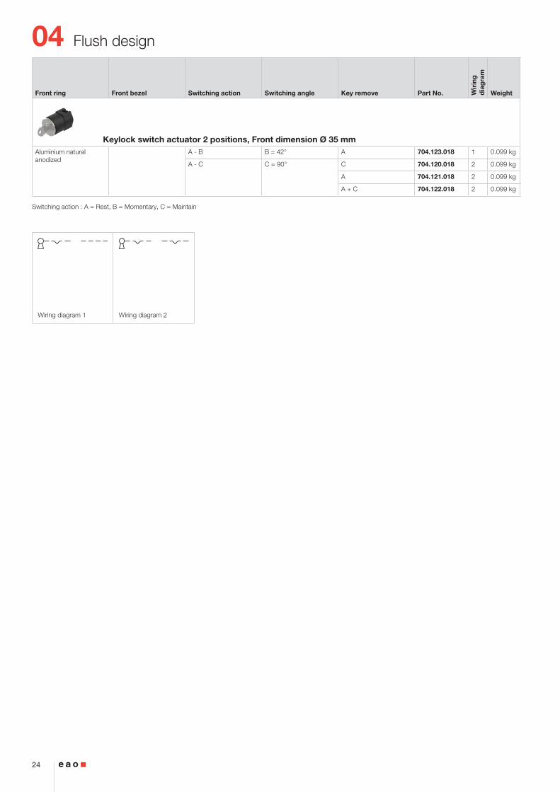
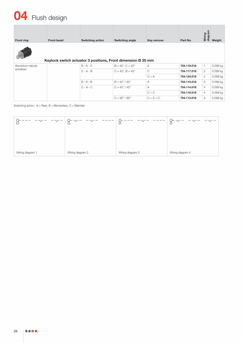
B - A - C B = 42°, C = 42° A 704.118.018 1 0.099 kg
C - A - B C = 42°, B = 42° C 704.117.018 2 0.099 kg
C + A 704.124.018 2 0.099 kg
B - A - B B = 42° / 42° A 704.115.018 3 0.099 kg
C - A - C C = 42° / 42° A 704.114.018 4 0.099 kg
C + C 704.116.018 4 0.099 kg
C = 90° / 90° C + A + C 704.113.018 4 0.099 kg
Switching action : A = Rest, B = Momentary, C = Maintain
04
27
Flush design
2 ... 6
15
16
23
37
79
78
(Ø35)
(35x35)
(Ø35)
(35x35)
23.6
X X
50 m
in.
65 m
in.
PIT / P3 / P4
35 min.
Ø30.5+0.5 030
+0.5 0
35 min.
30+
0.5
0
X
R1.2 max.
AB
A
C
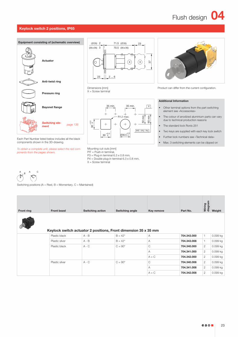
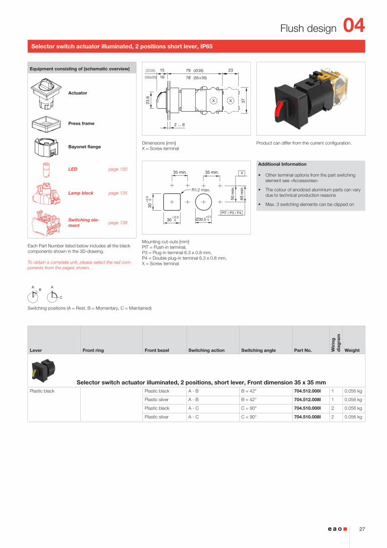
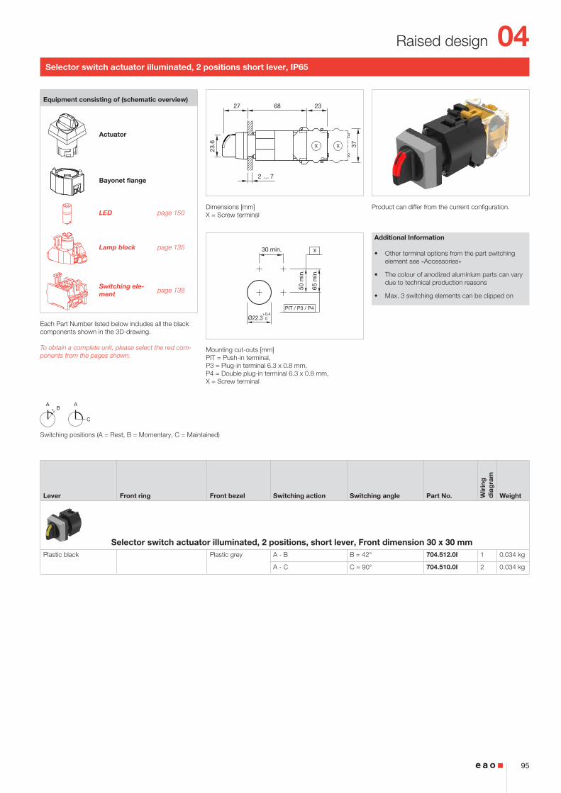
Selector switch actuator illuminated, 2 positions short lever, IP65
Product can differ from the current configuration. Dimensions [mm]X = Screw terminal
Mounting cut-outs [mm]PIT = Push-in terminal, P3 = Plug-in terminal 6.3 x 0.8 mm, P4 = Double plug-in terminal 6.3 x 0.8 mm, X = Screw terminal
Additional Information
• Other terminal options from the part switching element see «Accessories»
• The colour of anodized aluminium parts can vary due to technical production reasons
• Max. 3 switching elements can be clipped on
Equipment consisting of (schematic overview)
Actuator
Press frame
Bayonet flange
LED page 150
Lamp block page 135
Switching ele-ment page 138
Each Part Number listed below includes all the black components shown in the 3D-drawing.
To obtain a complete unit, please select the red com-ponents from the pages shown.
Switching positions (A = Rest, B = Momentary, C = Maintained)
Lever Front ring Front bezel Switching action Switching angle Part No. Wir
ing
d
iag
ram
Weight
Selector switch actuator illuminated, 2 positions, short lever, Front dimension 35 x 35 mmPlastic black Plastic black A - B B = 42° 704.512.000I 1 0.056 kg
Plastic silver A - B B = 42° 704.512.008I 1 0.056 kg
Plastic black A - C C = 90° 704.510.000I 2 0.056 kg
Plastic silver A - C C = 90° 704.510.008I 2 0.056 kg
04
28
Flush design
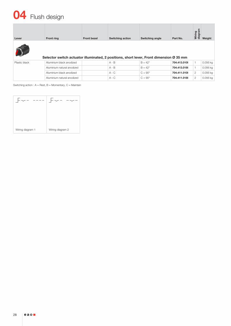
Wiring diagram 1 Wiring diagram 2
Lever Front ring Front bezel Switching action Switching angle Part No. Wir
ing
d
iag
ram
Weight
Selector switch actuator illuminated, 2 positions, short lever, Front dimension Ø 35 mmPlastic black Aluminium black anodized A - B B = 42° 704.413.010I 1 0.056 kg
Aluminium natural anodized A - B B = 42° 704.413.018I 1 0.056 kg
Aluminium black anodized A - C C = 90° 704.411.010I 2 0.056 kg
Aluminium natural anodized A - C C = 90° 704.411.018I 2 0.056 kg
Switching action : A = Rest, B = Momentary, C = Maintain
04
29
Flush design
2 ... 6
15
16
2323
37
40
39
(Ø35)
(35x35)
(Ø35)
(35x35)
X X
50 m
in.
65 m
in.
PIT / P3 / P4
35 min.
Ø30.5+0.5 030
+0.5 0
35 min.
30+
0.5
0
X
R1.2 max.
AB
A C
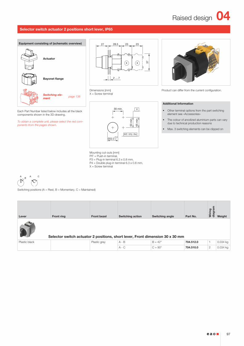
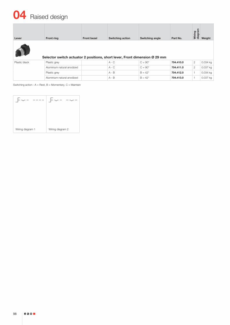
Selector switch actuator 2 positions short lever, IP65
Product can differ from the current configuration. Dimensions [mm]X = Screw terminal
Mounting cut-outs [mm]PIT = Push-in terminal, P3 = Plug-in terminal 6.3 x 0.8 mm, P4 = Double plug-in terminal 6.3 x 0.8 mm, X = Screw terminal
Additional Information
• Other terminal options from the part switching element see «Accessories»
• The colour of anodized aluminium parts can vary due to technical production reasons
• Max. 3 switching elements can be clipped on
Equipment consisting of (schematic overview)
Actuator
Press frame
Bayonet flange
Switching ele-ment page 138
Each Part Number listed below includes all the black components shown in the 3D-drawing.
To obtain a complete unit, please select the red com-ponents from the pages shown.
Switching positions (A = Rest, B = Momentary, C = Maintained)
Lever Front ring Front bezel Switching action Switching angle Part No. Wir
ing
d
iag
ram
Weight
Selector switch actuator 2 positions, short lever, Front dimension 35 x 35 mmPlastic black Plastic black A - B B = 42° 704.512.000 1 0.056 kg
Plastic silver A - B B = 42° 704.512.008 1 0.056 kg
Plastic black A - C C = 90° 704.510.000 2 0.056 kg
Plastic silver A - C C = 90° 704.510.008 2 0.056 kg
04
30
Flush design
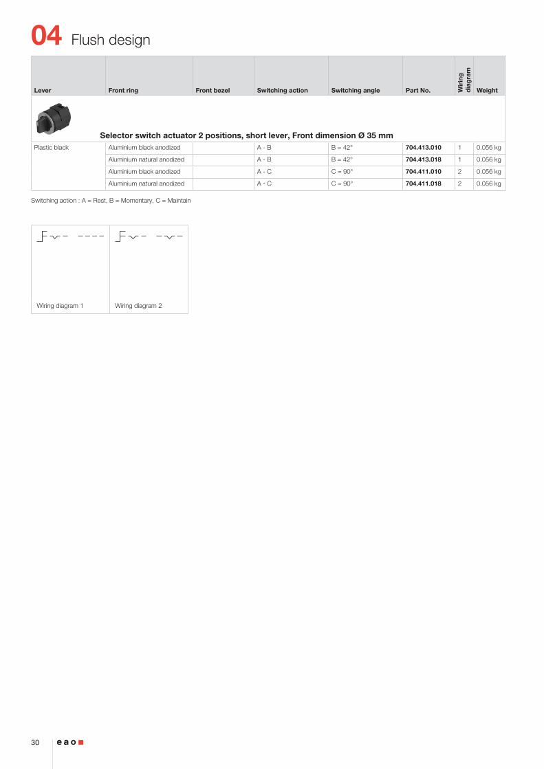
Wiring diagram 1 Wiring diagram 2
Lever Front ring Front bezel Switching action Switching angle Part No. Wir
ing
d
iag
ram
Weight
Selector switch actuator 2 positions, short lever, Front dimension Ø 35 mmPlastic black Aluminium black anodized A - B B = 42° 704.413.010 1 0.056 kg
Aluminium natural anodized A - B B = 42° 704.413.018 1 0.056 kg
Aluminium black anodized A - C C = 90° 704.411.010 2 0.056 kg
Aluminium natural anodized A - C C = 90° 704.411.018 2 0.056 kg
Switching action : A = Rest, B = Momentary, C = Maintain
04
31
Flush design
50 m
in.
65 m
in.
PIT / P3 / P4
35 min.
Ø30.5+0.5 030
+0.5 0
35 min.
30+
0.5
0
X
R1.2 max.
Wiring diagram 1
A
C
2 ... 6
15
16
2323
37
40
39
(Ø35)
(35x35)
(Ø35)
(35x35)
X X
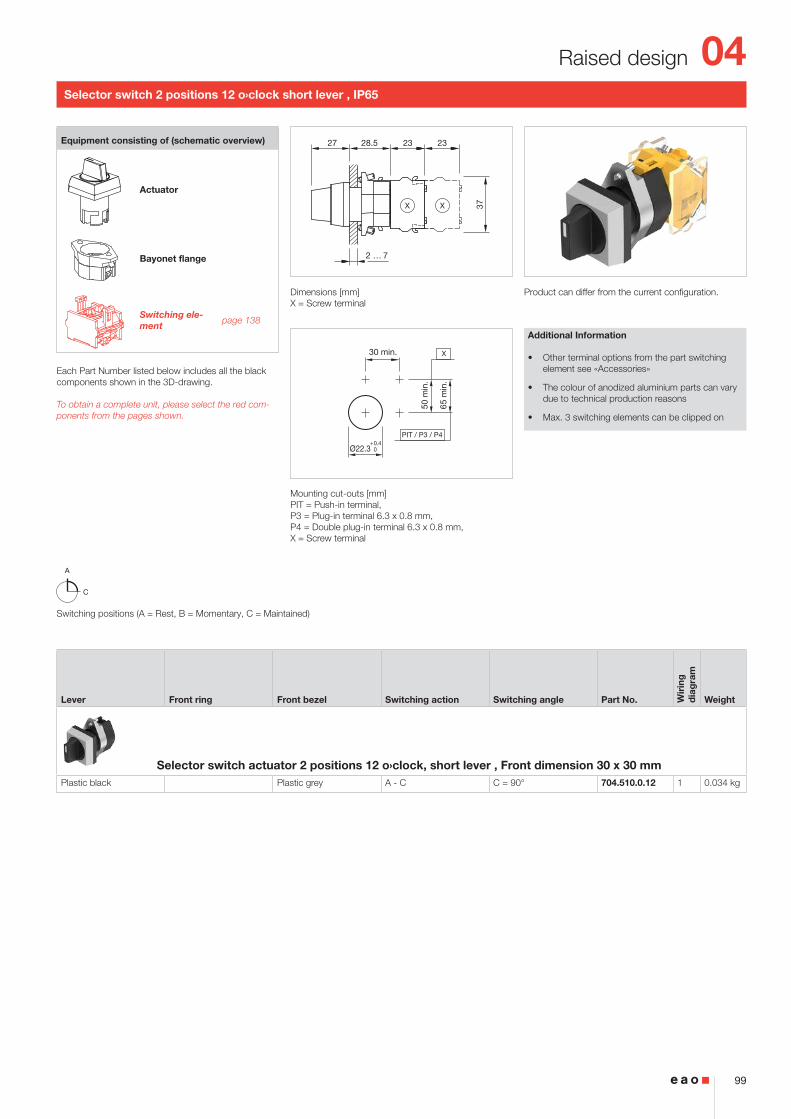
Selector switch 2 positions 12 o›clock short lever , IP65
Product can differ from the current configuration. Dimensions [mm]X = Screw terminal
Mounting cut-outs [mm]PIT = Push-in terminal, P3 = Plug-in terminal 6.3 x 0.8 mm, P4 = Double plug-in terminal 6.3 x 0.8 mm, X = Screw terminal
Additional Information
• Other terminal options from the part switching element see «Accessories»
• The colour of anodized aluminium parts can vary due to technical production reasons
• Max. 3 switching elements can be clipped on
Equipment consisting of (schematic overview)
Actuator
Press frame
Bayonet flange
Switching ele-ment page 138
Each Part Number listed below includes all the black components shown in the 3D-drawing.
To obtain a complete unit, please select the red com-ponents from the pages shown.
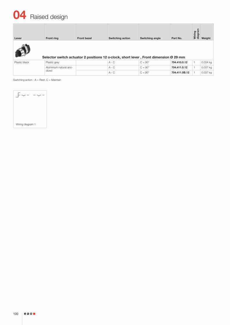
Switching positions (A = Rest, B = Momentary, C = Maintained)
Lever Front ring Front bezel Switching action Switching angle Part No. Wir
ing
d
iag
ram
Weight
Selector switch actuator 2 positions 12 o`clock, short lever , Front dimension 35 x 35 mmPlastic black Plastic black A - C C = 90° 704.510.000.12 1 0.056 kg
Plastic silver A - C C = 90° 704.510.008.12 1 0.056 kg
Selector switch actuator 2 positions 12 o`clock, short lever , Front dimension Ø 35 mmPlastic black Aluminium black anodized A - C C = 90° 704.411.010.12 1 0.056 kg
Aluminium natural anodized A - C C = 90° 704.411.018.12 1 0.056 kg
Switching action : A = Rest, C = Maintain
04
32
Flush design
2 ... 6
15
16
23
37
79
78
(Ø35)
(35x35)
(Ø35)
(35x35)
31.5 X X
50 m
in.
65 m
in.
PIT / P3 / P4
42 min.
Ø30.5+0.5 030
+0.5 0
42 min.
30+
0.5
0
X
R1.2 max.
AB
A
C
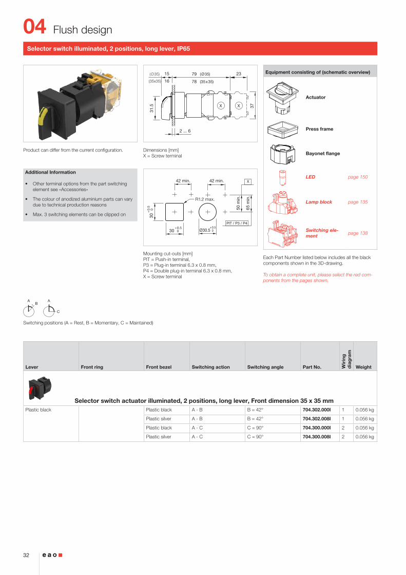
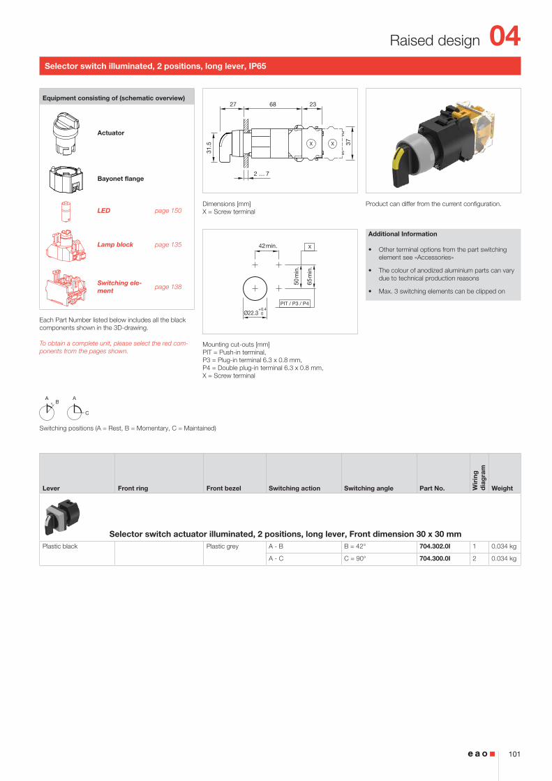
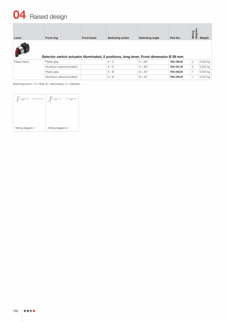
Selector switch illuminated, 2 positions, long lever, IP65
Product can differ from the current configuration. Dimensions [mm]X = Screw terminal
Mounting cut-outs [mm]PIT = Push-in terminal, P3 = Plug-in terminal 6.3 x 0.8 mm, P4 = Double plug-in terminal 6.3 x 0.8 mm, X = Screw terminal
Additional Information
• Other terminal options from the part switching element see «Accessories»
• The colour of anodized aluminium parts can vary due to technical production reasons
• Max. 3 switching elements can be clipped on
Equipment consisting of (schematic overview)
Actuator
Press frame
Bayonet flange
LED page 150
Lamp block page 135
Switching ele-ment page 138
Each Part Number listed below includes all the black components shown in the 3D-drawing.
To obtain a complete unit, please select the red com-ponents from the pages shown.
Switching positions (A = Rest, B = Momentary, C = Maintained)
Lever Front ring Front bezel Switching action Switching angle Part No. Wir
ing
d
iag
ram
Weight
Selector switch actuator illuminated, 2 positions, long lever, Front dimension 35 x 35 mmPlastic black Plastic black A - B B = 42° 704.302.000I 1 0.056 kg
Plastic silver A - B B = 42° 704.302.008I 1 0.056 kg
Plastic black A - C C = 90° 704.300.000I 2 0.056 kg
Plastic silver A - C C = 90° 704.300.008I 2 0.056 kg
04
33
Flush design
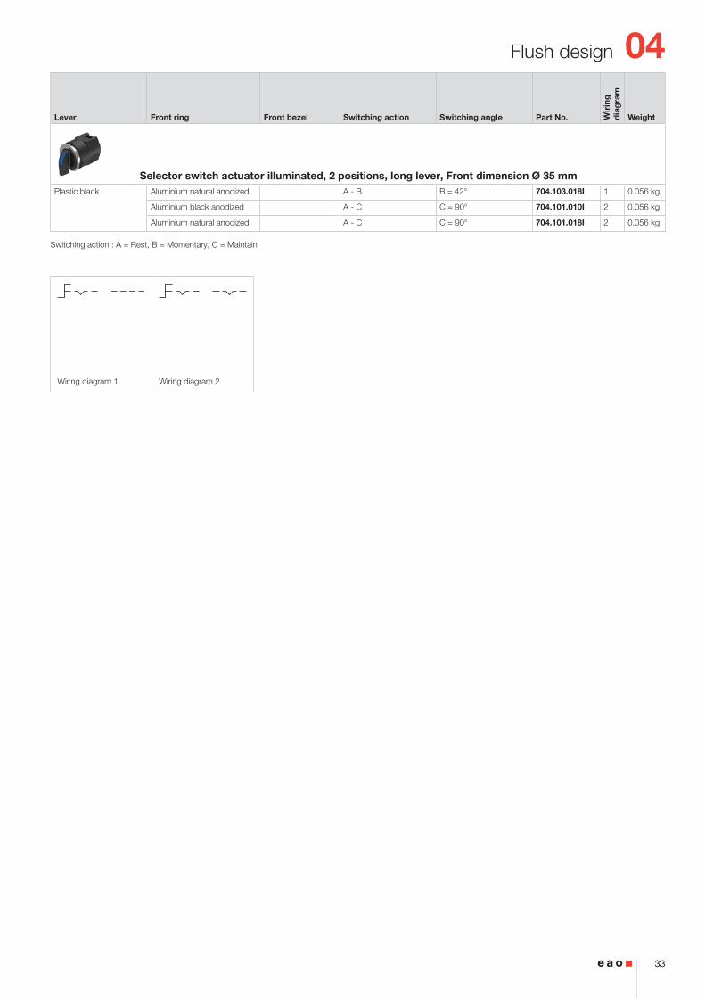
Wiring diagram 1 Wiring diagram 2
Switching action : A = Rest, B = Momentary, C = Maintain
Lever Front ring Front bezel Switching action Switching angle Part No. Wir
ing
d
iag
ram
Weight
Selector switch actuator illuminated, 2 positions, long lever, Front dimension Ø 35 mmPlastic black Aluminium natural anodized A - B B = 42° 704.103.018I 1 0.056 kg
Aluminium black anodized A - C C = 90° 704.101.010I 2 0.056 kg
Aluminium natural anodized A - C C = 90° 704.101.018I 2 0.056 kg
04
34
Flush design
2 ... 6
15
16
2323
37
25
40
39
(Ø35)
(35x35)
(Ø35)
(35x35)
X X
50 m
in.
65 m
in.
PIT / P3 / P4
42 min.
Ø30.5+0.5 030
+0.5 0
42 min.
30+
0.5
0
X
R1.2 max.
AB
A C
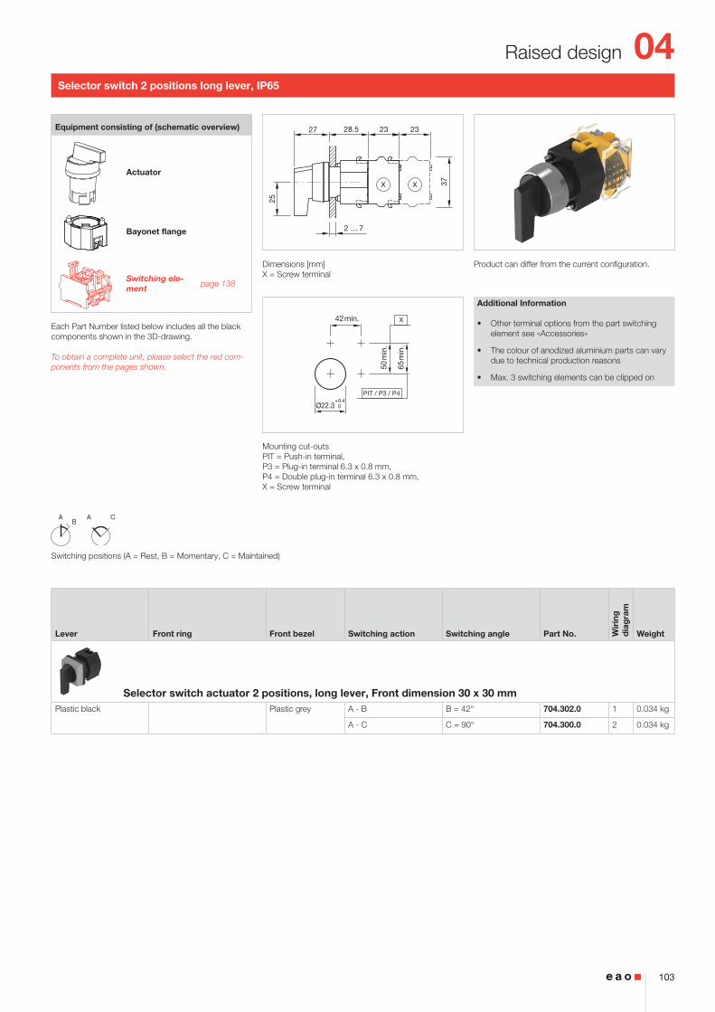
Selector switch 2 positions long lever, IP65
Product can differ from the current configuration. Dimensions [mm]X = Screw terminal
Mounting cut-outs [mm]PIT = Push-in terminal, P3 = Plug-in terminal 6.3 x 0.8 mm, P4 = Double plug-in terminal 6.3 x 0.8 mm, X = Screw terminal
Additional Information
• Other terminal options from the part switching element see «Accessories»
• The colour of anodized aluminium parts can vary due to technical production reasons
• Max. 3 switching elements can be clipped on
Equipment consisting of (schematic overview)
Actuator
Press frame
Bayonet flange
Switching ele-ment page 138
Each Part Number listed below includes all the black components shown in the 3D-drawing.
To obtain a complete unit, please select the red com-ponents from the pages shown.
Switching positions (A = Rest, B = Momentary, C = Maintained)
Lever Front ring Front bezel Switching action Switching angle Part No. Wir
ing
d
iag
ram
Weight
Selector switch actuator 2 positions, long lever, Front dimension 35 x 35 mmPlastic black Plastic black A - B B = 42° 704.302.000 1 0.056 kg
Plastic silver A - B B = 42° 704.302.008 1 0.056 kg
Plastic black A - C C = 90° 704.300.000 2 0.056 kg
Plastic silver A - C C = 90° 704.300.008 2 0.056 kg
04
35
Flush design
Wiring diagram 1 Wiring diagram 2
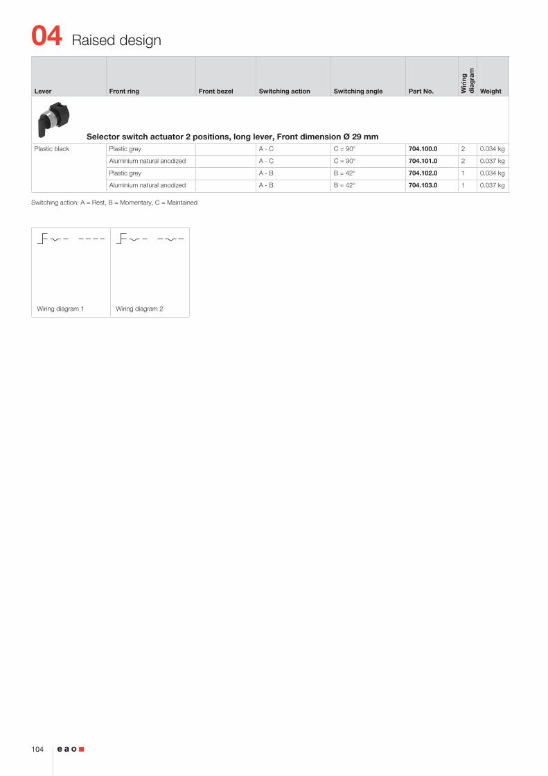
Lever Front ring Front bezel Switching action Switching angle Part No. Wir
ing
d
iag
ram
Weight
Selector switch actuator 2 positions, long lever, Front dimension Ø 35 mmPlastic black Aluminium natural anodized A - B B = 42° 704.103.018 1 0.056 kg
Aluminium black anodized A - C C = 90° 704.101.010 2 0.056 kg
Aluminium natural anodized A - C C = 90° 704.101.018 2 0.056 kg
Switching action : A = Rest, B = Momentary, C = Maintain
04
36
Flush design
50 m
in.
65 m
in.
PIT / P3 / P4
42 min.
Ø30.5+0.5 030
+0.5 0
42 min.
30+
0.5
0
X
R1.2 max.
A
C
2 ... 6
15
16
2323
37
25
40
39
(Ø35)
(35x35)
(Ø35)
(35x35)
X X
Selector switch 2 positions 12 o›clock long lever, IP65
Product can differ from the current configuration. Dimensions [mm]X = Screw terminal
Mounting cut-outs [mm]PIT = Push-in terminal, P3 = Plug-in terminal 6.3 x 0.8 mm, P4 = Double plug-in terminal 6.3 x 0.8 mm, X = Screw terminal
Additional Information
• Other terminal options from the part switching element see «Accessories»
• The colour of anodized aluminium parts can vary due to technical production reasons
• Max. 3 switching elements can be clipped on
Equipment consisting of (schematic overview)
Actuator
Press frame
Bayonet flange
Switching ele-ment page 138
Each Part Number listed below includes all the black components shown in the 3D-drawing.
To obtain a complete unit, please select the red com-ponents from the pages shown.
Switching positions (A = Rest, B = Momentary, C = Maintained)
Lever Front ring Front bezel Switching action Switching angle Part No. Wir
ing
d
iag
ram
Weight
Selector switch actuator 2 positions 12 o›clock, long lever, Front dimension 35 x 35 mmPlastic black Plastic black A - C C = 90° 704.300.000.12 1 0.056 kg
Plastic silver A - C C = 90° 704.300.008.12 1 0.056 kg
04
37
Flush design
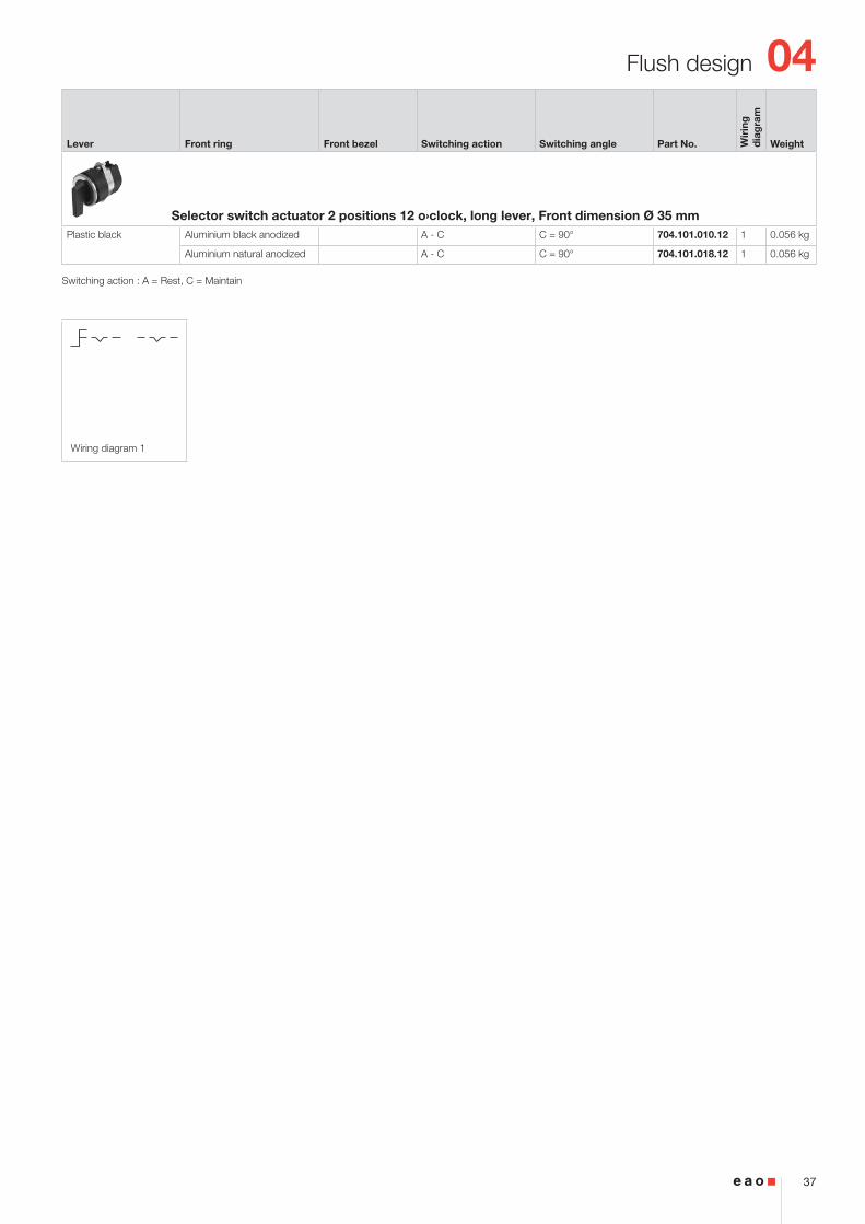
Wiring diagram 1
Switching action : A = Rest, C = Maintain
Lever Front ring Front bezel Switching action Switching angle Part No. Wir
ing
d
iag
ram
Weight
Selector switch actuator 2 positions 12 o›clock, long lever, Front dimension Ø 35 mmPlastic black Aluminium black anodized A - C C = 90° 704.101.010.12 1 0.056 kg
Aluminium natural anodized A - C C = 90° 704.101.018.12 1 0.056 kg
04
38
Flush design
2 ... 6
15
16
23
37
79
78
(Ø35)
(35x35)
(Ø35)
(35x35)
23.6
X X
50 m
in.
65 m
in.
PIT / P3 / P4
35 min.
Ø30.5+0.5 030
+0.5 0
35 min.
30+
0.5
0
X
R1.2 max.
ACB
ABC
ABB
ACC
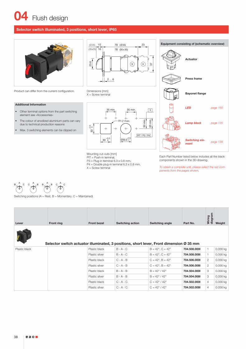
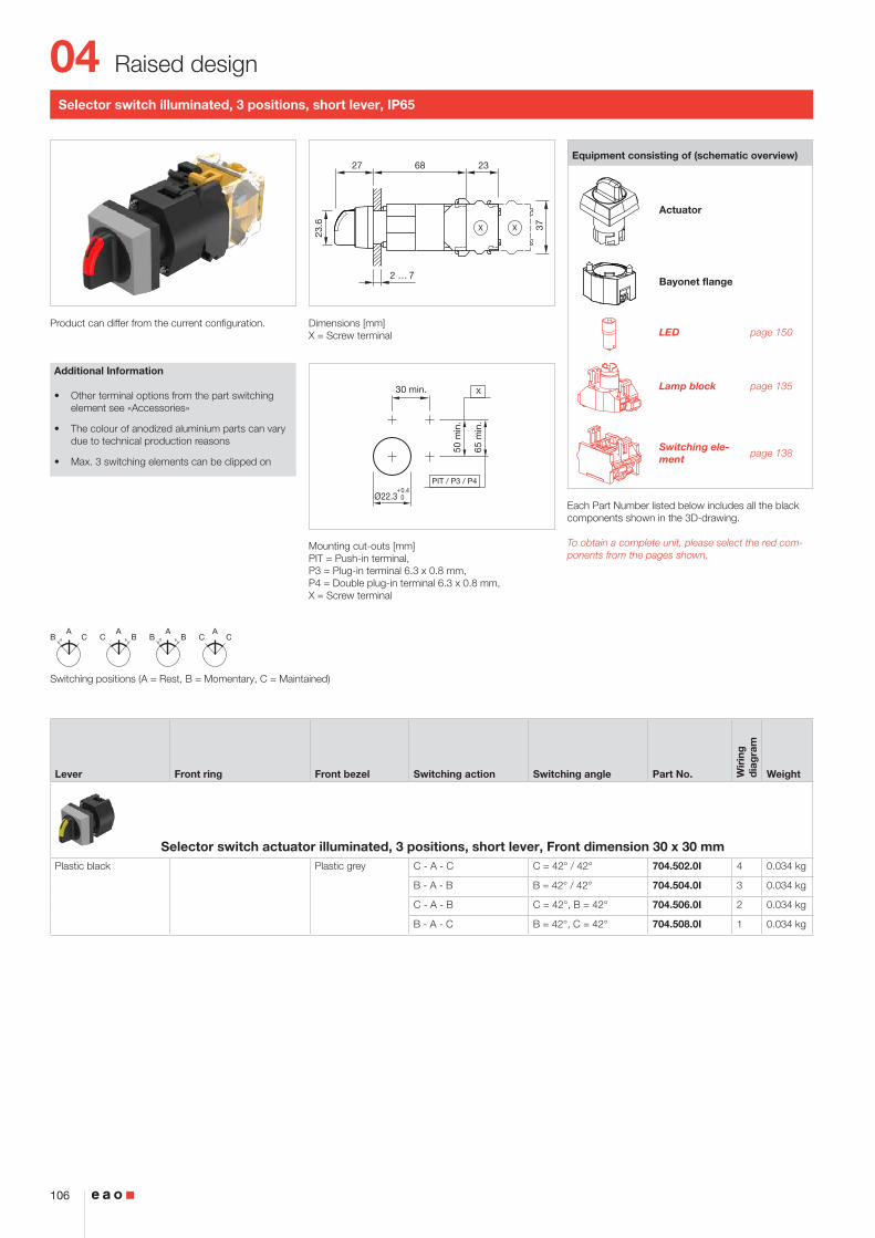
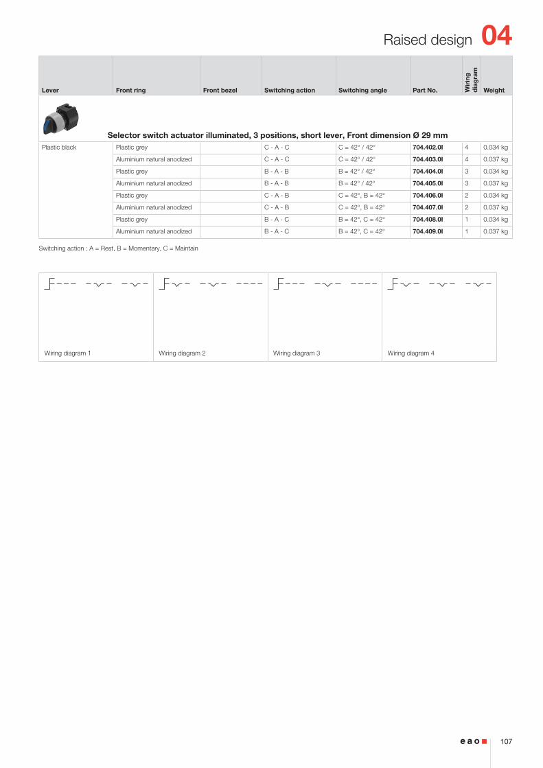
Selector switch illuminated, 3 positions, short lever, IP65
Product can differ from the current configuration. Dimensions [mm]X = Screw terminal
Mounting cut-outs [mm]PIT = Push-in terminal, P3 = Plug-in terminal 6.3 x 0.8 mm, P4 = Double plug-in terminal 6.3 x 0.8 mm, X = Screw terminal
Additional Information
• Other terminal options from the part switching element see «Accessories»
• The colour of anodized aluminium parts can vary due to technical production reasons
• Max. 3 switching elements can be clipped on
Equipment consisting of (schematic overview)
Actuator
Press frame
Bayonet flange
LED page 150
Lamp block page 135
Switching ele-ment page 138
Each Part Number listed below includes all the black components shown in the 3D-drawing.
To obtain a complete unit, please select the red com-ponents from the pages shown.
Switching positions (A = Rest, B = Momentary, C = Maintained)
Lever Front ring Front bezel Switching action Switching angle Part No. Wir
ing
d
iag
ram
Weight
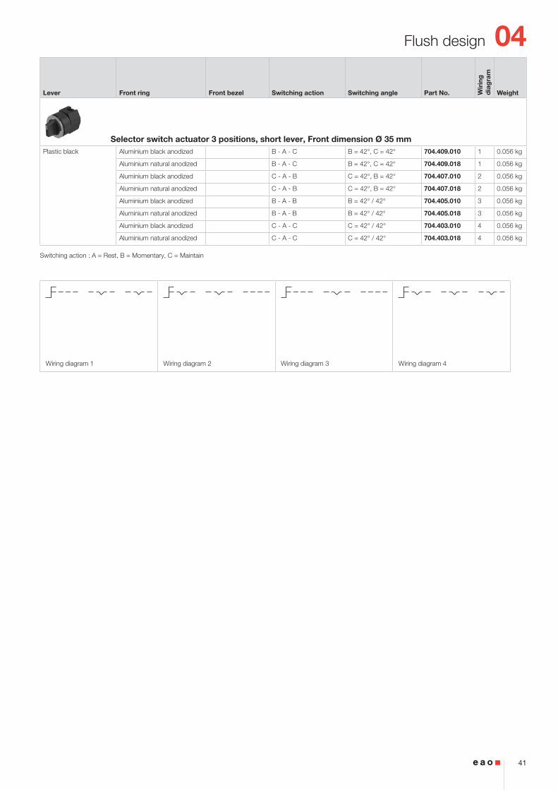
Selector switch actuator illuminated, 3 positions, short lever, Front dimension Ø 35 mmPlastic black Plastic black B - A - C B = 42°, C = 42° 704.508.000I 1 0.056 kg
Plastic silver B - A - C B = 42°, C = 42° 704.508.008I 1 0.056 kg
Plastic black C - A - B C = 42°, B = 42° 704.506.000I 2 0.056 kg
Plastic silver C - A - B C = 42°, B = 42° 704.506.008I 2 0.056 kg
Plastic black B - A - B B = 42° / 42° 704.504.000I 3 0.056 kg
Plastic silver B - A - B B = 42° / 42° 704.504.008I 3 0.056 kg
Plastic black C - A - C C = 42° / 42° 704.502.000I 4 0.056 kg
Plastic silver C - A - C C = 42° / 42° 704.502.008I 4 0.056 kg
Lever Front ring Front bezel Switching action Switching angle Part No. Wir
ing
d
iag
ram
Weight
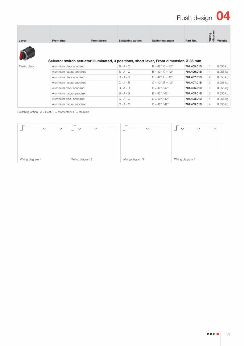
Selector switch actuator illuminated, 3 positions, short lever, Front dimension Ø 35 mmPlastic black Aluminium black anodized B - A - C B = 42°, C = 42° 704.409.010I 1 0.056 kg
Aluminium natural anodized B - A - C B = 42°, C = 42° 704.409.018I 1 0.056 kg
Aluminium black anodized C - A - B C = 42°, B = 42° 704.407.010I 2 0.056 kg
Aluminium natural anodized C - A - B C = 42°, B = 42° 704.407.018I 2 0.056 kg
Aluminium black anodized B - A - B B = 42° / 42° 704.405.010I 3 0.056 kg
Aluminium natural anodized B - A - B B = 42° / 42° 704.405.018I 3 0.056 kg
Aluminium black anodized C - A - C C = 42° / 42° 704.403.010I 4 0.056 kg
Aluminium natural anodized C - A - C C = 42° / 42° 704.403.018I 4 0.056 kg
Switching action : A = Rest, B = Momentary, C = Maintain
04
40
Flush design
2 ... 6
15
16
2323
37
40
39
(Ø35)
(35x35)
(Ø35)
(35x35)
X X
50 m
in.
65 m
in.
PIT / P3 / P4
35 min.
Ø30.5+0.5 030
+0.5 0
35 min.
30+
0.5
0
X
R1.2 max.
ACB
ABC
ABB
ACC
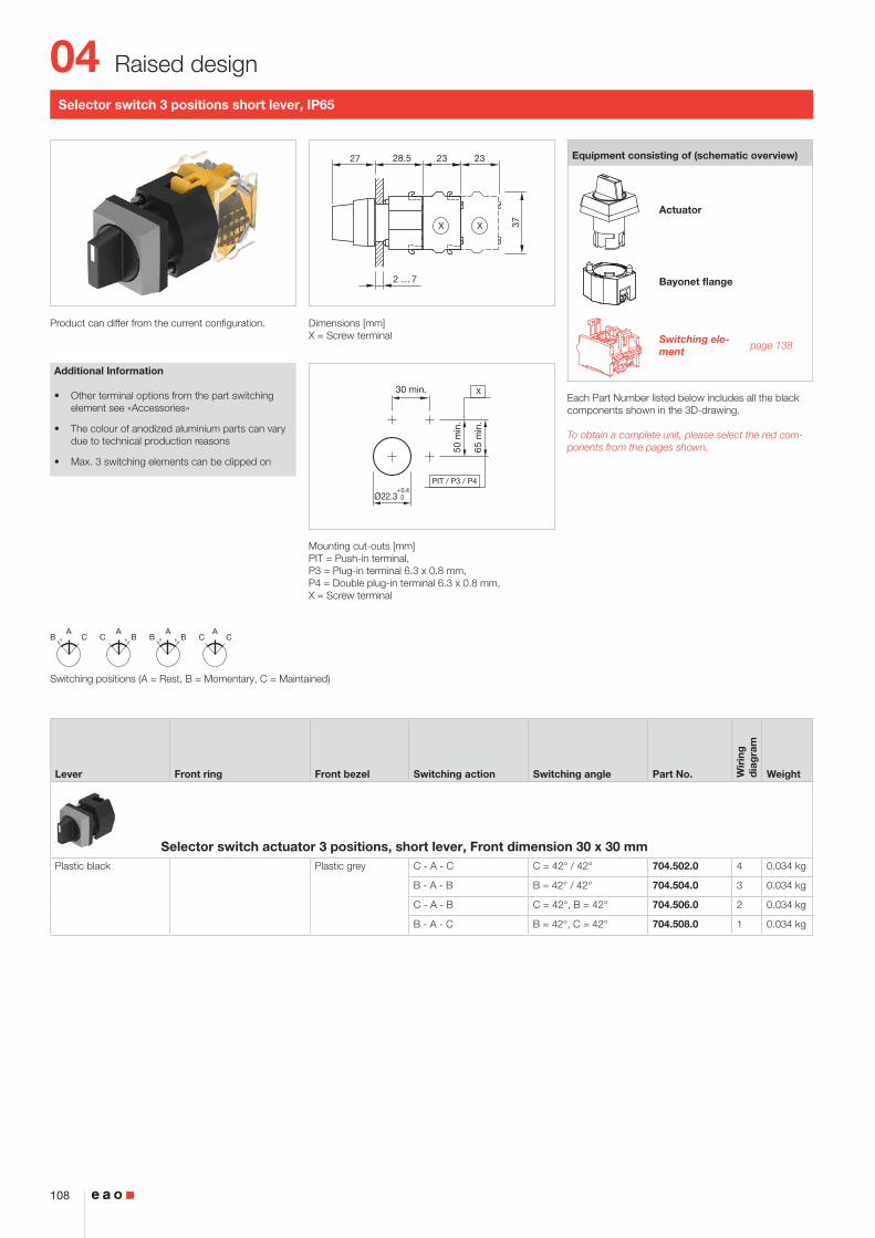
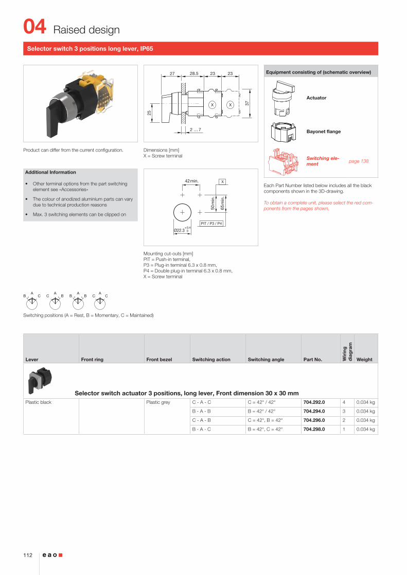
Selector switch 3 positions short lever, IP65
Product can differ from the current configuration. Dimensions [mm]X = Screw terminal
Mounting cut-outs [mm]PIT = Push-in terminal, P3 = Plug-in terminal 6.3 x 0.8 mm, P4 = Double plug-in terminal 6.3 x 0.8 mm, X = Screw terminal
Additional Information
• Other terminal options from the part switching element see «Accessories»
• The colour of anodized aluminium parts can vary due to technical production reasons
• Max. 3 switching elements can be clipped on
Equipment consisting of (schematic overview)
Actuator
Press frame
Bayonet flange
Switching ele-ment page 138
Each Part Number listed below includes all the black components shown in the 3D-drawing.
To obtain a complete unit, please select the red com-ponents from the pages shown.
Switching positions (A = Rest, B = Momentary, C = Maintained)
Lever Front ring Front bezel Switching action Switching angle Part No. Wir
ing
d
iag
ram
Weight
Selector switch actuator 3 positions, short lever, Front dimension 35 x 35 mmPlastic black Plastic black B - A - C B = 42°, C = 42° 704.508.000 1 0.056 kg
Plastic silver B - A - C B = 42°, C = 42° 704.508.008 1 0.056 kg
Plastic black C - A - B C = 42°, B = 42° 704.506.000 2 0.056 kg
Plastic silver C - A - B C = 42°, B = 42° 704.506.008 2 0.056 kg
Plastic black B - A - B B = 42° / 42° 704.504.000 3 0.056 kg
Plastic silver B - A - B B = 42° / 42° 704.504.008 3 0.056 kg
Plastic black C - A - C C = 42° / 42° 704.502.000 4 0.056 kg
Plastic silver C - A - C C = 42° / 42° 704.502.008 4 0.056 kg
Lever Front ring Front bezel Switching action Switching angle Part No. Wir
ing
d
iag
ram
Weight
Selector switch actuator 3 positions, short lever, Front dimension Ø 35 mmPlastic black Aluminium black anodized B - A - C B = 42°, C = 42° 704.409.010 1 0.056 kg
Aluminium natural anodized B - A - C B = 42°, C = 42° 704.409.018 1 0.056 kg
Aluminium black anodized C - A - B C = 42°, B = 42° 704.407.010 2 0.056 kg
Aluminium natural anodized C - A - B C = 42°, B = 42° 704.407.018 2 0.056 kg
Aluminium black anodized B - A - B B = 42° / 42° 704.405.010 3 0.056 kg
Aluminium natural anodized B - A - B B = 42° / 42° 704.405.018 3 0.056 kg
Aluminium black anodized C - A - C C = 42° / 42° 704.403.010 4 0.056 kg
Aluminium natural anodized C - A - C C = 42° / 42° 704.403.018 4 0.056 kg
Switching action : A = Rest, B = Momentary, C = Maintain
04
42
Flush design
50 m
in.
65 m
in.
PIT / P3 / P4
42 min.
Ø30.5+0.5 030
+0.5 0
42 min.
30+
0.5
0
X
R1.2 max.
ACB
ABC
ABB
ACC
2 ... 6
15
16
23
37
79
78
(Ø35)
(35x35)
(Ø35)
(35x35)
31.5 X X
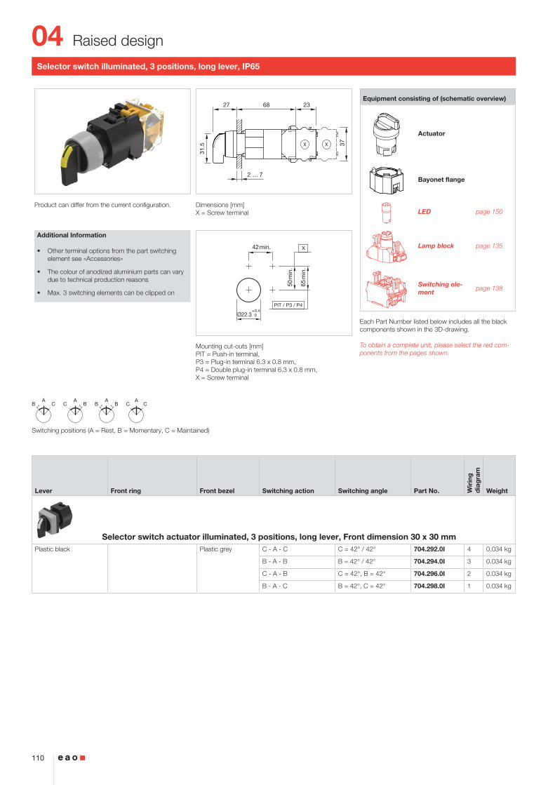
Selector switch illuminated, 3 positions, long lever, IP65
Product can differ from the current configuration. Dimensions [mm]X = Screw terminal
Mounting cut-outs [mm]PIT = Push-in terminal, P3 = Plug-in terminal 6.3 x 0.8 mm, P4 = Double plug-in terminal 6.3 x 0.8 mm, X = Screw terminal
Additional Information
• Other terminal options from the part switching element see «Accessories»
• The colour of anodized aluminium parts can vary due to technical production reasons
• Max. 3 switching elements can be clipped on
Equipment consisting of (schematic overview)
Actuator
Press frame
Bayonet flange
LED page 150
Lamp block page 135
Switching ele-ment page 138
Each Part Number listed below includes all the black components shown in the 3D-drawing.
To obtain a complete unit, please select the red com-ponents from the pages shown.
Switching positions (A = Rest, B = Momentary, C = Maintained)
Lever Front ring Front bezel Switching action Switching angle Part No. Wir
ing
d
iag
ram
Weight
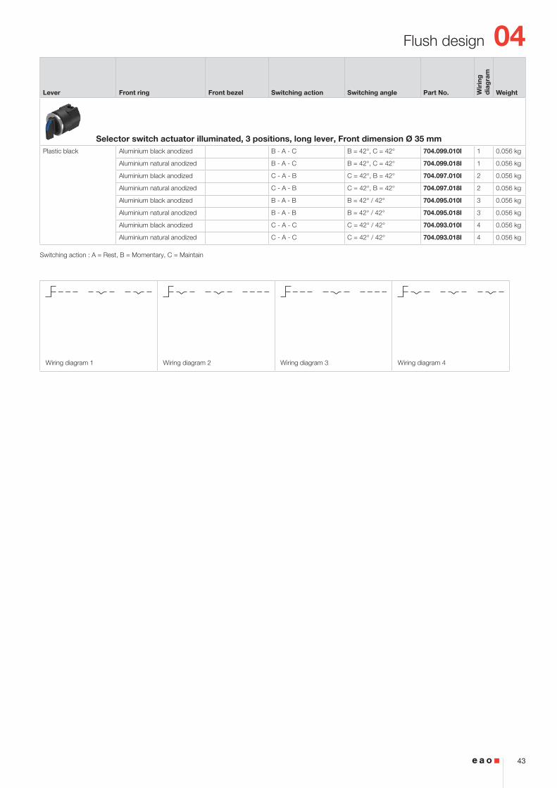
Selector switch actuator illuminated, 3 positions, long lever, Front dimension 35 x 35 mmPlastic black Plastic black B - A - C B = 42°, C = 42° 704.298.000I 1 0.056 kg
Plastic silver B - A - C B = 42°, C = 42° 704.298.008I 1 0.056 kg
Plastic black C - A - B C = 42°, B = 42° 704.296.000I 2 0.056 kg
Plastic silver C - A - B C = 42°, B = 42° 704.296.008I 2 0.056 kg
Plastic black B - A - B B = 42° / 42° 704.294.000I 3 0.056 kg
Plastic silver B - A - B B = 42° / 42° 704.294.008I 3 0.056 kg
Plastic black C - A - C C = 42° / 42° 704.292.000I 4 0.056 kg
Plastic silver C - A - C C = 42° / 42° 704.292.008I 4 0.056 kg
Switching action : A = Rest, B = Momentary, C = Maintain
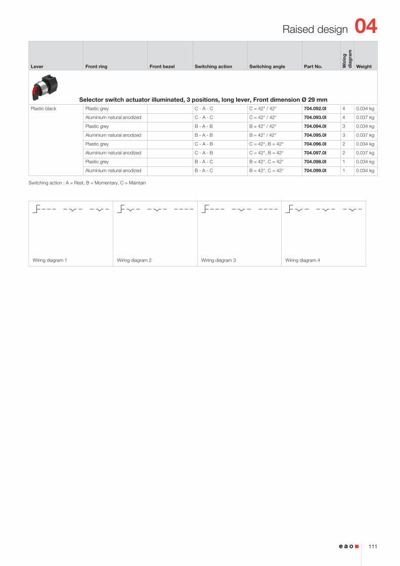
Lever Front ring Front bezel Switching action Switching angle Part No. Wir
ing
d
iag
ram
Weight
Selector switch actuator illuminated, 3 positions, long lever, Front dimension Ø 35 mmPlastic black Aluminium black anodized B - A - C B = 42°, C = 42° 704.099.010I 1 0.056 kg
Aluminium natural anodized B - A - C B = 42°, C = 42° 704.099.018I 1 0.056 kg
Aluminium black anodized C - A - B C = 42°, B = 42° 704.097.010I 2 0.056 kg
Aluminium natural anodized C - A - B C = 42°, B = 42° 704.097.018I 2 0.056 kg
Aluminium black anodized B - A - B B = 42° / 42° 704.095.010I 3 0.056 kg
Aluminium natural anodized B - A - B B = 42° / 42° 704.095.018I 3 0.056 kg
Aluminium black anodized C - A - C C = 42° / 42° 704.093.010I 4 0.056 kg
Aluminium natural anodized C - A - C C = 42° / 42° 704.093.018I 4 0.056 kg
04
44
Flush design
2 ... 6
15
16
2323
37
25
40
39
(Ø35)
(35x35)
(Ø35)
(35x35)
X X
50 m
in.
65 m
in.
PIT / P3 / P4
42 min.
Ø30.5+0.5 030
+0.5 0
42 min.
30+
0.5
0
X
R1.2 max.
ACB
ABC
ABB
ACC
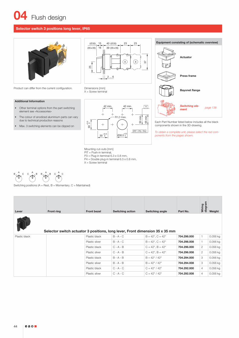
Selector switch 3 positions long lever, IP65
Product can differ from the current configuration. Dimensions [mm]X = Screw terminal
Mounting cut-outs [mm]PIT = Push-in terminal, P3 = Plug-in terminal 6.3 x 0.8 mm, P4 = Double plug-in terminal 6.3 x 0.8 mm, X = Screw terminal
Additional Information
• Other terminal options from the part switching element see «Accessories»
• The colour of anodized aluminium parts can vary due to technical production reasons
• Max. 3 switching elements can be clipped on
Equipment consisting of (schematic overview)
Actuator
Press frame
Bayonet flange
Switching ele-ment page 138
Each Part Number listed below includes all the black components shown in the 3D-drawing.
To obtain a complete unit, please select the red com-ponents from the pages shown.
Switching positions (A = Rest, B = Momentary, C = Maintained)
Lever Front ring Front bezel Switching action Switching angle Part No. Wir
ing
d
iag
ram
Weight
Selector switch actuator 3 positions, long lever, Front dimension 35 x 35 mmPlastic black Plastic black B - A - C B = 42°, C = 42° 704.298.000 1 0.056 kg
Plastic silver B - A - C B = 42°, C = 42° 704.298.008 1 0.056 kg
Plastic black C - A - B C = 42°, B = 42° 704.296.000 2 0.056 kg
Plastic silver C - A - B C = 42°, B = 42° 704.296.008 2 0.056 kg
Plastic black B - A - B B = 42° / 42° 704.294.000 3 0.056 kg
Plastic silver B - A - B B = 42° / 42° 704.294.008 3 0.056 kg
Plastic black C - A - C C = 42° / 42° 704.292.000 4 0.056 kg
Plastic silver C - A - C C = 42° / 42° 704.292.008 4 0.056 kg
Lever Front ring Front bezel Switching action Switching angle Part No. Wir
ing
d
iag
ram
Weight
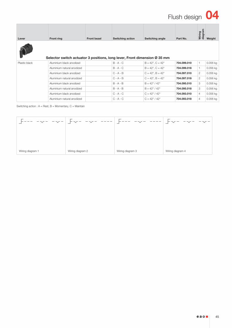
Selector switch actuator 3 positions, long lever, Front dimension Ø 35 mmPlastic black Aluminium black anodized B - A - C B = 42°, C = 42° 704.099.010 1 0.056 kg
Aluminium natural anodized B - A - C B = 42°, C = 42° 704.099.018 1 0.056 kg
Aluminium black anodized C - A - B C = 42°, B = 42° 704.097.010 2 0.056 kg
Aluminium natural anodized C - A - B C = 42°, B = 42° 704.097.018 2 0.056 kg
Aluminium black anodized B - A - B B = 42° / 42° 704.095.010 3 0.056 kg
Aluminium natural anodized B - A - B B = 42° / 42° 704.095.018 3 0.056 kg
Aluminium black anodized C - A - C C = 42° / 42° 704.093.010 4 0.056 kg
Aluminium natural anodized C - A - C C = 42° / 42° 704.093.018 4 0.056 kg
Switching action : A = Rest, B = Momentary, C = Maintain
04
46
Flush design
L15
12
44
2 ... 6
50 m
in.
52 min.
Ø30.5+0.5 0
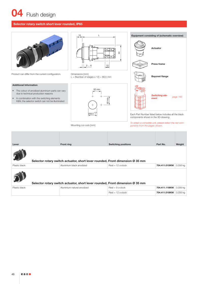
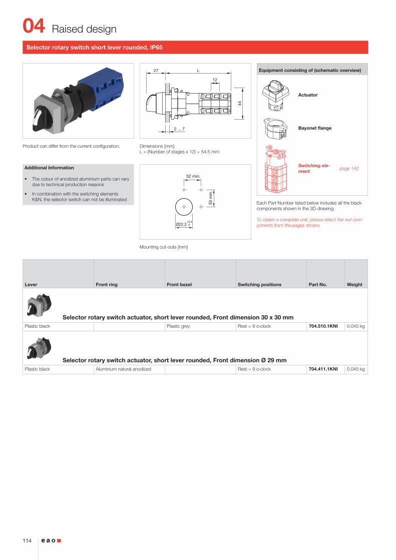
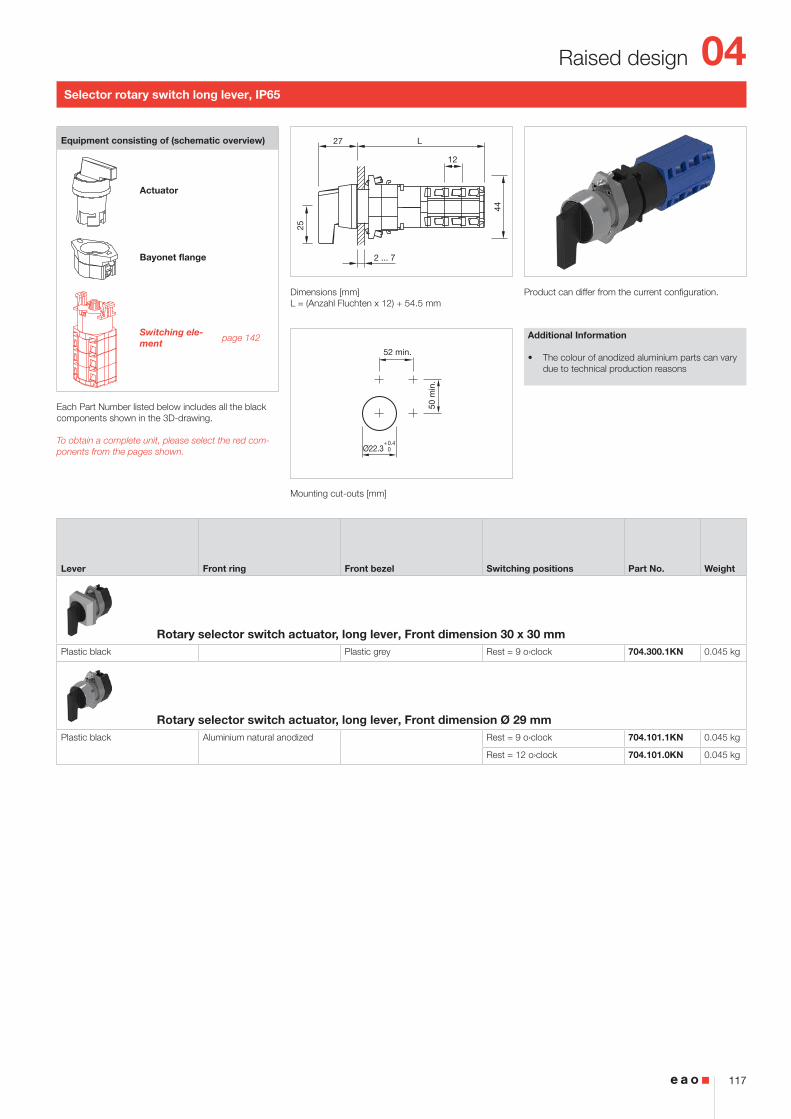
Selector rotary switch short lever rounded, IP65
Product can differ from the current configuration. Dimensions [mm]L = (Number of stages x 12) + 66.5 mm
Mounting cut-outs [mm]
Equipment consisting of (schematic overview)
Actuator
Press frame
Bayonet flange
Switching ele-ment page 143
Each Part Number listed below includes all the black components shown in the 3D-drawing.
To obtain a complete unit, please select the red com-ponents from the pages shown.
Lever Front ring Switching positions Part No. Weight
Selector rotary switch actuator, short lever rounded, Front dimension Ø 35 mmPlastic black Aluminium black anodized Rest = 12 o›clock 704.411.010KNI 0.056 kg
Selector rotary switch actuator, short lever rounded, Front dimension Ø 35 mmPlastic black Aluminium natural anodized Rest = 9 o›clock 704.411.118KNI 0.056 kg
Rest = 12 o›clock 704.411.018KNI 0.056 kg
Additional Information
• The colour of anodized aluminium parts can vary due to technical production reasons
• In combination with the switching elements K&N, the selector switch can not be illuminated
04
47
Flush design
L15
L-1
(Ø35)
(35x35)
(Ø35)
(35x35) 16
12
44
2 ... 6
50 m
in.
52 min.
Ø30.5+0.5 030
+0.5 0
52 min.
30+
0.5
0
R1.2 max.
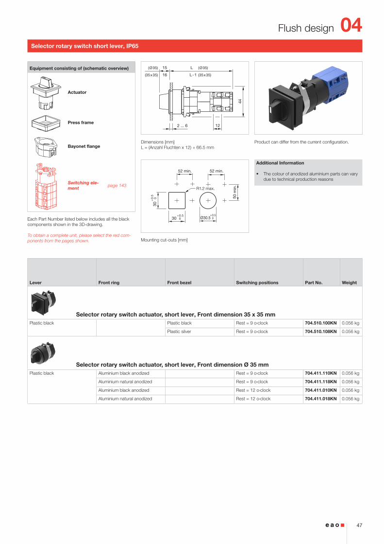
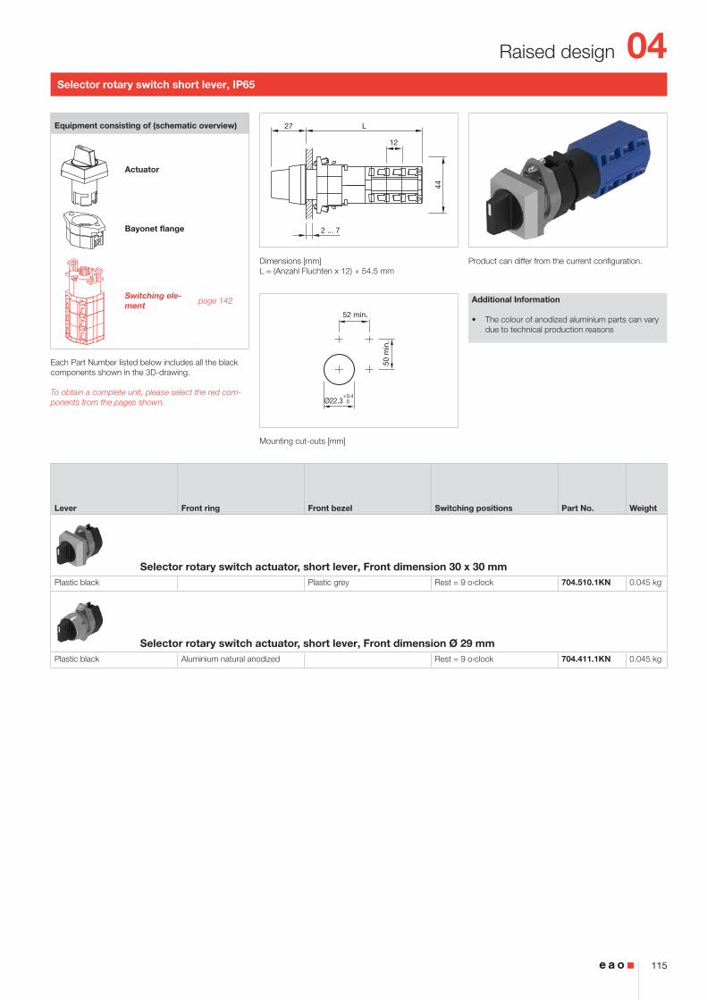
Selector rotary switch short lever, IP65
Product can differ from the current configuration. Dimensions [mm]L = (Anzahl Fluchten x 12) + 66.5 mm
Mounting cut-outs [mm]
Additional Information
• The colour of anodized aluminium parts can vary due to technical production reasons
Equipment consisting of (schematic overview)
Actuator
Press frame
Bayonet flange
Switching ele-ment page 143
Each Part Number listed below includes all the black components shown in the 3D-drawing.
To obtain a complete unit, please select the red com-ponents from the pages shown.
Lever Front ring Front bezel Switching positions Part No. Weight
Selector rotary switch actuator, short lever, Front dimension 35 x 35 mmPlastic black Plastic black Rest = 9 o›clock 704.510.100KN 0.056 kg
Plastic silver Rest = 9 o›clock 704.510.108KN 0.056 kg
Selector rotary switch actuator, short lever, Front dimension Ø 35 mmPlastic black Aluminium black anodized Rest = 9 o›clock 704.411.110KN 0.056 kg
Aluminium natural anodized Rest = 9 o›clock 704.411.118KN 0.056 kg
Aluminium black anodized Rest = 12 o›clock 704.411.010KN 0.056 kg
Aluminium natural anodized Rest = 12 o›clock 704.411.018KN 0.056 kg
04
48
Flush design
L15
12
44
2 ... 6
31.5
50 m
in.
52 min.
Ø30.5+0.5 0
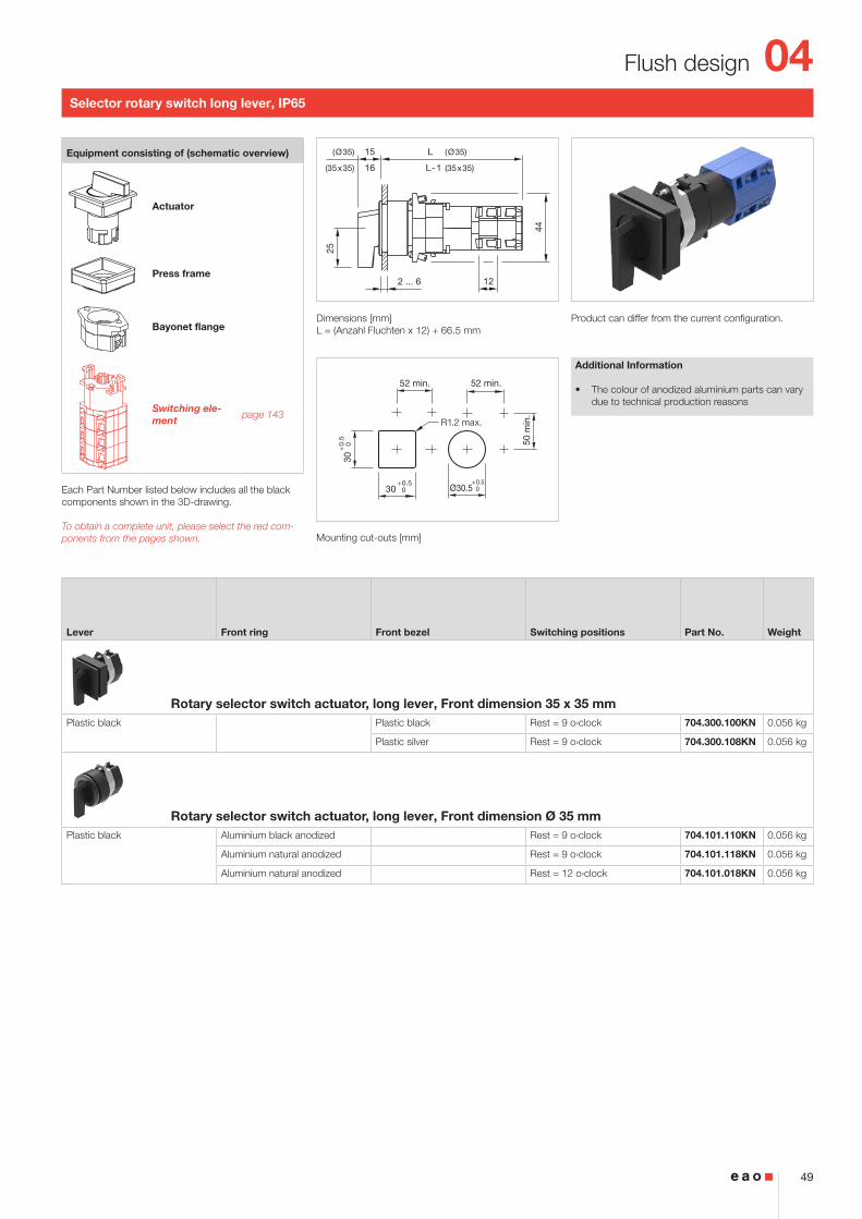
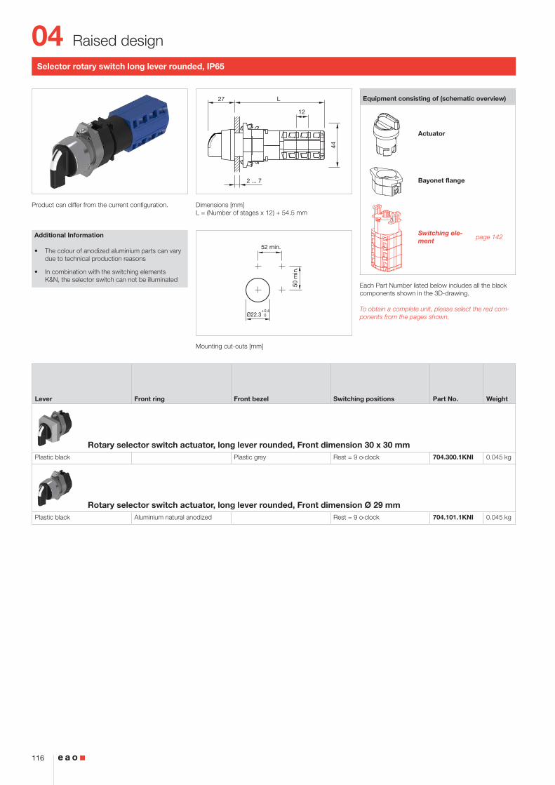
Selector rotary switch long lever rounded, IP65
Product can differ from the current configuration. Dimensions [mm]L = (Number of stages x 12) + 66.5 mm
Mounting cut-outs [mm]
Equipment consisting of (schematic overview)
Actuator
Press frame
Bayonet flange
Switching ele-ment page 143
Each Part Number listed below includes all the black components shown in the 3D-drawing.
To obtain a complete unit, please select the red com-ponents from the pages shown.
Lever Front ring Switching positions Part No. Weight
Rotary selector switch actuator, long lever rounded, Front dimension Ø 35 mmPlastic black Aluminium black anodized Rest = 9 o›clock 704.101.110KNI 0.056 kg
Rotary selector switch actuator, long lever rounded, Front dimension Ø 35 mmPlastic black Aluminium natural anodized Rest = 9 o›clock 704.101.118KNI 0.056 kg
Rest = 12 o›clock 704.101.018KNI 0.056 kg
Additional Information
• The colour of anodized aluminium parts can vary due to technical production reasons
• In combination with the switching elements K&N, the selector switch can not be illuminated
04
49
Flush design
25
L15
L-1
(Ø35)
(35x35)
(Ø35)
(35x35) 16
12
44
2 ... 6
50 m
in.
52 min.
Ø30.5+0.5 030
+0.5 0
52 min.
30+
0.5
0
R1.2 max.
Selector rotary switch long lever, IP65
Product can differ from the current configuration. Dimensions [mm]L = (Anzahl Fluchten x 12) + 66.5 mm
Mounting cut-outs [mm]
Additional Information
• The colour of anodized aluminium parts can vary due to technical production reasons
Equipment consisting of (schematic overview)
Actuator
Press frame
Bayonet flange
Switching ele-ment page 143
Each Part Number listed below includes all the black components shown in the 3D-drawing.
To obtain a complete unit, please select the red com-ponents from the pages shown.
Lever Front ring Front bezel Switching positions Part No. Weight
Rotary selector switch actuator, long lever, Front dimension 35 x 35 mmPlastic black Plastic black Rest = 9 o›clock 704.300.100KN 0.056 kg
Plastic silver Rest = 9 o›clock 704.300.108KN 0.056 kg
Rotary selector switch actuator, long lever, Front dimension Ø 35 mmPlastic black Aluminium black anodized Rest = 9 o›clock 704.101.110KN 0.056 kg
Aluminium natural anodized Rest = 9 o›clock 704.101.118KN 0.056 kg
Aluminium natural anodized Rest = 12 o›clock 704.101.018KN 0.056 kg
04
50
Flush design
L222.5
44
2 ... 4
12
A
C
50 m
in.
52 min.
Ø30.5+0.5 0
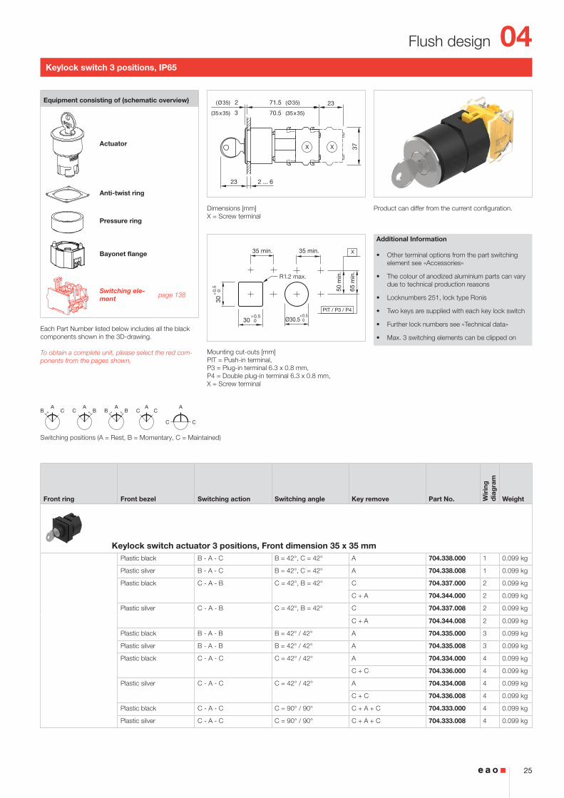
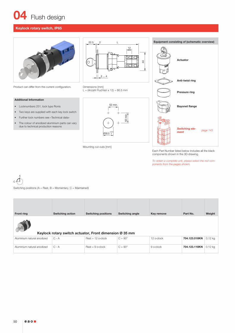
Keylock rotary switch, IP65
Product can differ from the current configuration. Dimensions [mm]L = (Anzahl Fluchten x 12) + 66.5 mm
Mounting cut-outs [mm]
Additional Information
• Locknumbers 251, lock type Ronis
• Two keys are supplied with each key lock switch
• Further lock numbers see «Technical data»
• The colour of anodized aluminium parts can vary due to technical production reasons
Equipment consisting of (schematic overview)
Actuator
Anti-twist ring
Pressure ring
Bayonet flange
Switching ele-ment page 143
Each Part Number listed below includes all the black components shown in the 3D-drawing.
To obtain a complete unit, please select the red com-ponents from the pages shown.
Switching positions (A = Rest, B = Momentary, C = Maintained)
Front ring Switching action Switching positions Switching angle Key remove Part No. Weight
Keylock rotary switch actuator, Front dimension Ø 35 mmAluminium natural anodized C - A Rest = 12 o›clock C = 90° 12 o›clock 704.123.018KN 0.12 kg
Aluminium natural anodized C - A Rest = 9 o›clock C = 90° 9 o›clock 704.123.118KN 0.12 kg
04
51
Flush design
2 ... 5
2 68
37X
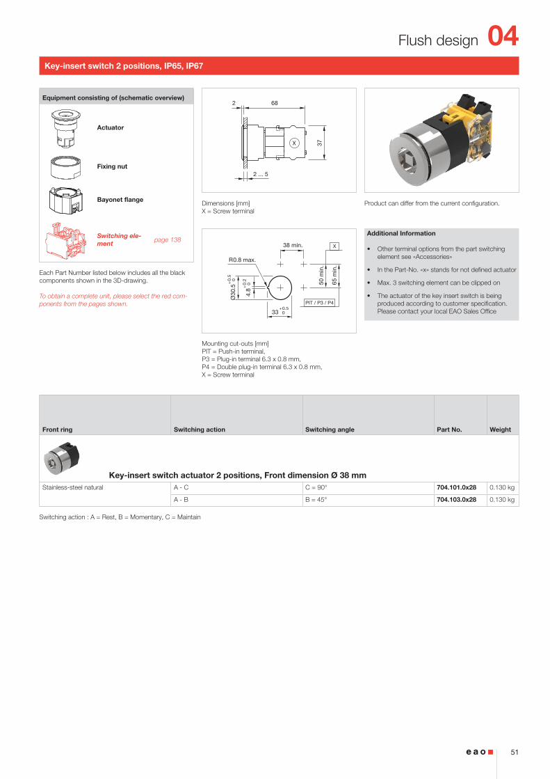
Key-insert switch 2 positions, IP65, IP67
Product can differ from the current configuration. Dimensions [mm]X = Screw terminal
Mounting cut-outs [mm]PIT = Push-in terminal, P3 = Plug-in terminal 6.3 x 0.8 mm, P4 = Double plug-in terminal 6.3 x 0.8 mm, X = Screw terminal
Additional Information
• Other terminal options from the part switching element see «Accessories»
• In the Part-No. «x» stands for not defined actuator
• Max. 3 switching element can be clipped on
• The actuator of the key insert switch is being produced according to customer specification. Please contact your local EAO Sales Office
Equipment consisting of (schematic overview)
Actuator
Fixing nut
Bayonet flange
Switching ele-ment page 138
Each Part Number listed below includes all the black components shown in the 3D-drawing.
To obtain a complete unit, please select the red com-ponents from the pages shown.
Front ring Switching action Switching angle Part No. Weight
Key-insert switch actuator 2 positions, Front dimension Ø 38 mmStainless-steel natural A - C C = 90° 704.101.0x28 0.130 kg
A - B B = 45° 704.103.0x28 0.130 kg
Switching action : A = Rest, B = Momentary, C = Maintain
04
52
Flush design
2 ... 5
2 68
37X
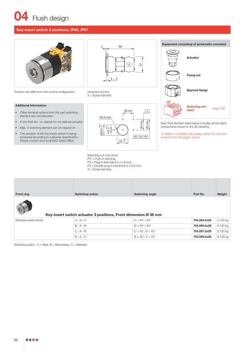
Key-insert switch 3 positions, IP65, IP67
Product can differ from the current configuration. Dimensions [mm]X = Screw terminal
Mounting cut-outs [mm]PIT = Push-in terminal, P3 = Plug-in terminal 6.3 x 0.8 mm, P4 = Double plug-in terminal 6.3 x 0.8 mm, X = Screw terminal
Additional Information
• Other terminal options from the part switching element see «Accessories»
• In the Part-No. «x» stands for not defined actuator
• Max. 3 switching element can be clipped on
• The actuator of the key insert switch is being produced according to customer specification. Please contact your local EAO Sales Office
Equipment consisting of (schematic overview)
Actuator
Fixing nut
Bayonet flange
Switching ele-ment page 138
Each Part Number listed below includes all the black components shown in the 3D-drawing.
To obtain a complete unit, please select the red com-ponents from the pages shown.
Front ring Switching action Switching angle Part No. Weight
Key-insert switch actuator 3 positions, Front dimension Ø 38 mmStainless-steel natural C - A - C C = 45° / 45° 704.093.0x28 0.130 kg
B - A - B B = 45° / 45° 704.095.0x28 0.130 kg
C - A - B C = 45°, B = 45° 704.097.0x28 0.130 kg
B - A - C B = 45°, C = 45° 704.099.0x28 0.130 kg
Switching action : A = Rest, B = Momentary, C = Maintain
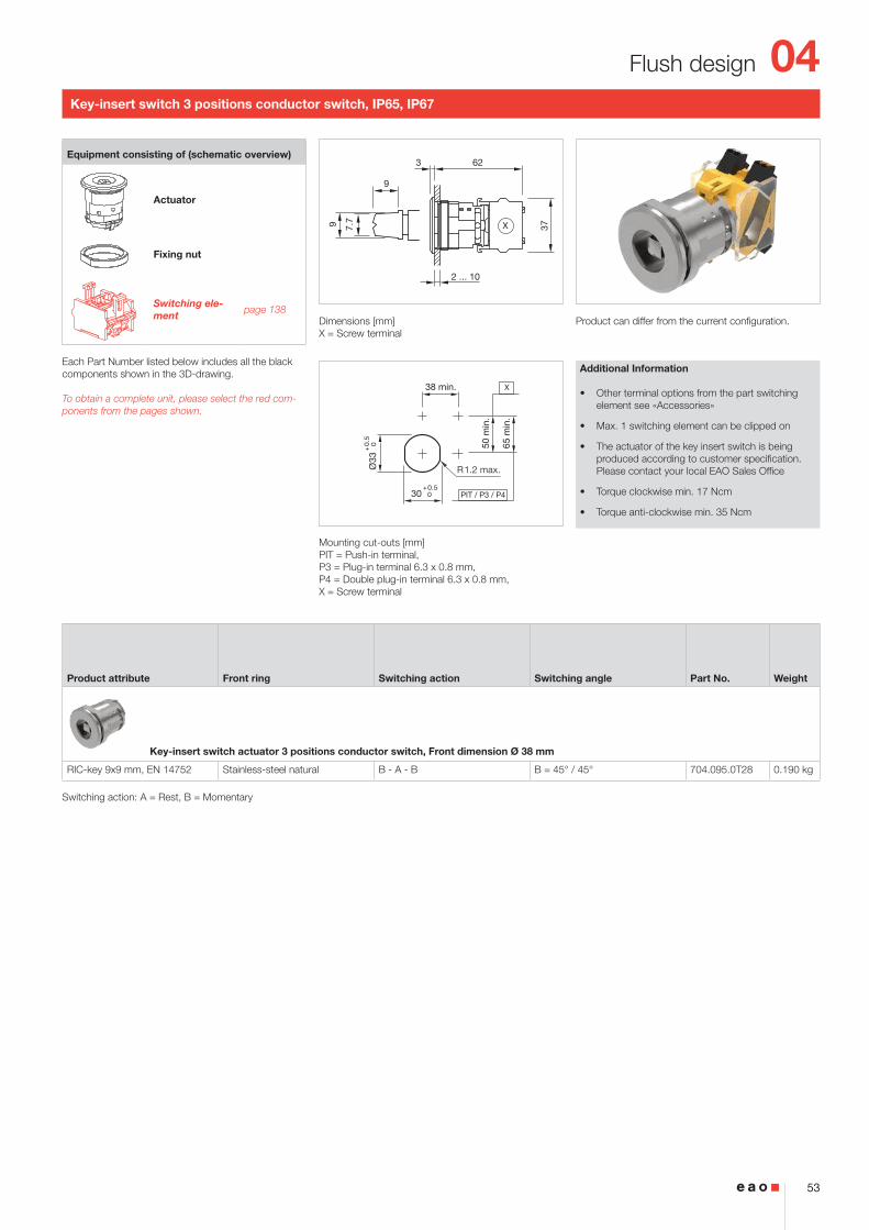
Product can differ from the current configuration. Dimensions [mm]X = Screw terminal
Mounting cut-outs [mm]PIT = Push-in terminal, P3 = Plug-in terminal 6.3 x 0.8 mm, P4 = Double plug-in terminal 6.3 x 0.8 mm, X = Screw terminal
Additional Information
• Other terminal options from the part switching element see «Accessories»
• Max. 1 switching element can be clipped on
• The actuator of the key insert switch is being produced according to customer specification. Please contact your local EAO Sales Office
• Torque clockwise min. 17 Ncm
• Torque anti-clockwise min. 35 Ncm
Equipment consisting of (schematic overview)
Actuator
Fixing nut
Switching ele-ment page 138
Each Part Number listed below includes all the black components shown in the 3D-drawing.
To obtain a complete unit, please select the red com-ponents from the pages shown.
Product attribute Front ring Switching action Switching angle Part No. Weight
Key-insert switch actuator 3 positions conductor switch, Front dimension Ø 38 mm
RIC-key 9x9 mm, EN 14752 Stainless-steel natural B - A - B B = 45° / 45° 704.095.0T28 0.190 kg
Switching action: A = Rest, B = Momentary
04
54
Flush design
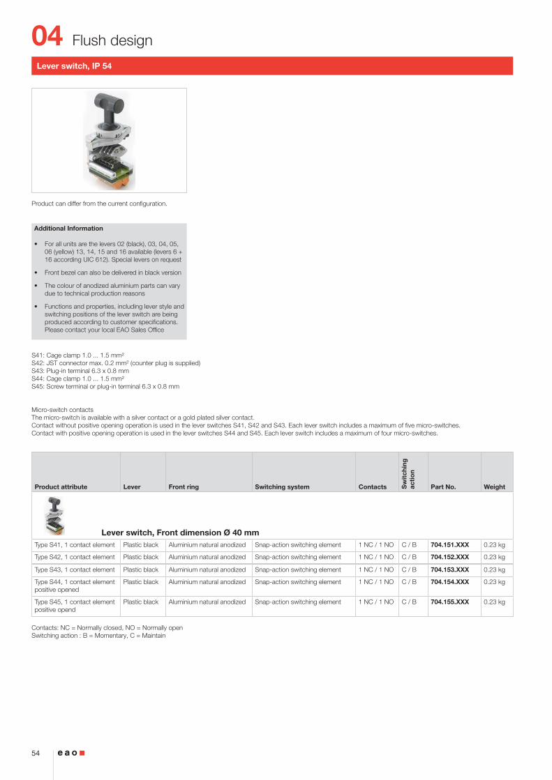
Lever switch, IP 54
Product can differ from the current configuration.
Additional Information
• For all units are the levers 02 (black), 03, 04, 05, 06 (yellow) 13, 14, 15 and 16 available (levers 6 + 16 according UIC 612). Special levers on request
• Front bezel can also be delivered in black version
• The colour of anodized aluminium parts can vary due to technical production reasons
• Functions and properties, including lever style and switching positions of the lever switch are being produced according to customer specifications. Please contact your local EAO Sales Office
S41: Cage clamp 1.0 ... 1.5 mm²S42: JST connector max. 0.2 mm² (counter plug is supplied)S43: Plug-in terminal 6.3 x 0.8 mmS44: Cage clamp 1.0 ... 1.5 mm²S45: Screw terminal or plug-in terminal 6.3 x 0.8 mm
Micro-switch contactsThe micro-switch is available with a silver contact or a gold plated silver contact.Contact without positive opening operation is used in the lever switches S41, S42 and S43. Each lever switch includes a maximum of five micro-switches.Contact with positive opening operation is used in the lever switches S44 and S45. Each lever switch includes a maximum of four micro-switches.
Product attribute Lever Front ring Switching system Contacts Sw
itch
ing
ac
tio
n
Part No. Weight
Lever switch, Front dimension Ø 40 mmType S41, 1 contact element Plastic black Aluminium natural anodized Snap-action switching element 1 NC / 1 NO C / B 704.151.XXX 0.23 kg
Type S42, 1 contact element Plastic black Aluminium natural anodized Snap-action switching element 1 NC / 1 NO C / B 704.152.XXX 0.23 kg
Type S43, 1 contact element Plastic black Aluminium natural anodized Snap-action switching element 1 NC / 1 NO C / B 704.153.XXX 0.23 kg
Type S44, 1 contact element positive opened
Plastic black Aluminium natural anodized Snap-action switching element 1 NC / 1 NO C / B 704.154.XXX 0.23 kg
Type S45, 1 contact element positive opend
Plastic black Aluminium natural anodized Snap-action switching element 1 NC / 1 NO C / B 704.155.XXX 0.23 kg
Contacts: NC = Normally closed, NO = Normally openSwitching action : B = Momentary, C = Maintain
04
55
Flush design
2.5
4 max.
21.5 39
Wiring diagram 1
Potentiometer, IP 65
Product can differ from the current configuration. Dimensions [mm]
Mounting cut-outs [mm]
Additional Information
• For front dimensions 36 x 36 mm, Ø 36 mm
• Resistor 10 kOhm / linear, series E3
• Power 0.4 W
• Slewing range 300°
Equipment consisting of (schematic overview)
Knob
Actuator
Front bezel set page 127
Fixing nut
Potentiometer
Each Part Number listed below includes all the black components shown in the 3D-drawing.
To obtain a complete unit, please select the red com-ponents from the page s shown.
Product attribute Front ring Terminal Part No. Wir
ing
d
iag
ram
Weight
Potentiometerwith potentiometer Plastic matt chrome Solder 44-745.20-10K1 1 0.030 kg
Plastic matt grey Solder 44-745.60-10K1 1 0.030 kg
without potentiometer, specification for potentiometer: Shaft = length 32 mm, shaft end = Form A, Ø = 6 mm
Plastic matt chrome 44-744.20 0.016 kg
Plastic matt grey 44-744.60 0.016 kg
04
56
Raised design
13 52
2 ... 7
X2+
X1-
x2+
x1-
Wiring diagram 1 Wiring diagram 2
Indicator full-face illumination compact, IP65
Product can differ from the current configuration. Dimensions [mm]
Mounting cut-outs [mm]
Additional Information
• Housing plastic grey
Equipment consisting of (schematic overview)
Lens cap
Marking cap
LED page 150
Actuator
Fixing nut
Each Part Number listed below includes all the black components shown in the 3D-drawing.
To obtain a complete unit, please select the red com-ponents from the pages shown.
Product attribute Marking cap Lens cap Terminal Part No. Wir
ing
d
iag
ram
Weight
Indicator full-face illumination compact, Front dimension Ø 29 mmFilament lamp 130 V, max. 2.6 W with integrated series resistor 230/130 V
white translucent Plastic red translucent Screw 704.022.2 1 0.025 kg
Plastic yellow translucent Screw 704.022.4 1 0.025 kg
Plastic green translucent Screw 704.022.5 1 0.025 kg
Plastic blue translucent Screw 704.022.6 1 0.025 kg
Plastic colourless translucent Screw 704.022.7 1 0.025 kg
Filament lamp max. 2.6 W or LED white translucent Plastic red translucent Screw 704.020.2 2 0.020 kg
Plastic yellow translucent Screw 704.020.4 2 0.020 kg
Plastic green translucent Screw 704.020.5 2 0.020 kg
Plastic blue translucent Screw 704.020.6 2 0.020 kg
Plastic colourless translucent Screw 704.020.7 2 0.020 kg
colourless transparent ripped Plastic red transparent Screw 704.021.2 2 0.020 kg
Plastic yellow transparent Screw 704.021.4 2 0.020 kg
Plastic green transparent Screw 704.021.5 2 0.020 kg
Plastic blue transparent Screw 704.021.6 2 0.020 kg
Plastic colourless transparent Screw 704.021.7 2 0.020 kg
04
57
Raised design
13 52
2 ... 7
X2+
X1-
x2+
x1-
Wiring diagram 1 Wiring diagram 2
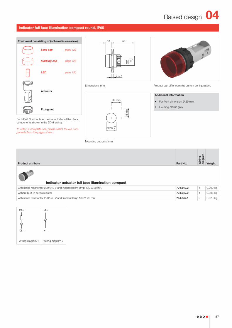
Indicator full face illumination compact round, IP65
Product can differ from the current configuration. Dimensions [mm]
Mounting cut-outs [mm]
Additional Information
• For front dimension Ø 29 mm
• Housing plastic grey
Equipment consisting of (schematic overview)
Lens cap page 123
Marking cap page 126
LED page 150
Actuator
Fixing nut
Each Part Number listed below includes all the black components shown in the 3D-drawing.
To obtain a complete unit, please select the red com-ponents from the pages shown.
Product attribute Part No. Wir
ing
d
iag
ram
Weight
Indicator actuator full face illumination compactwith series resistor for 220/240 V and incandescent lamp 130 V, 20 mA 704.642.2 1 0.009 kg
without built-in series resistor 704.642.0 1 0.006 kg
with series resistor for 220/240 V and filament lamp 130 V, 20 mA 704.642.1 2 0.020 kg
04
58
Raised design
13 46
2 … 7
40
50 m
in.
30 min.
Ø22.3+0.4 0
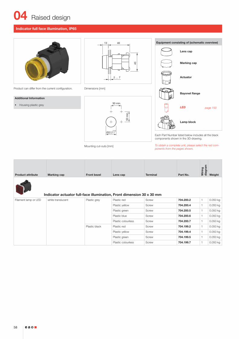
Indicator full face illumination, IP65
Product can differ from the current configuration. Dimensions [mm]
Mounting cut-outs [mm]
Additional Information
• Housing plastic grey
Equipment consisting of (schematic overview)
Lens cap
Marking cap
Actuator
Bayonet flange
LED page 150
Lamp block
Each Part Number listed below includes all the black components shown in the 3D-drawing.
To obtain a complete unit, please select the red com-ponents from the pages shown.
Product attribute Marking cap Front bezel Lens cap Terminal Part No. Wir
ing
d
iag
ram
Weight
Indicator actuator full-face illumination, Front dimension 30 x 30 mmFilament lamp or LED white translucent Plastic grey Plastic red Screw 704.200.2 1 0.050 kg
Plastic yellow Screw 704.200.4 1 0.050 kg
Plastic green Screw 704.200.5 1 0.050 kg
Plastic blue Screw 704.200.6 1 0.050 kg
Plastic colourless Screw 704.200.7 1 0.050 kg
Plastic black Plastic red Screw 704.199.2 1 0.050 kg
Plastic yellow Screw 704.199.4 1 0.050 kg
Plastic green Screw 704.199.5 1 0.050 kg
Plastic colourless Screw 704.199.7 1 0.050 kg
04
59
Raised design
x2+
x1-
Wiring diagram 1
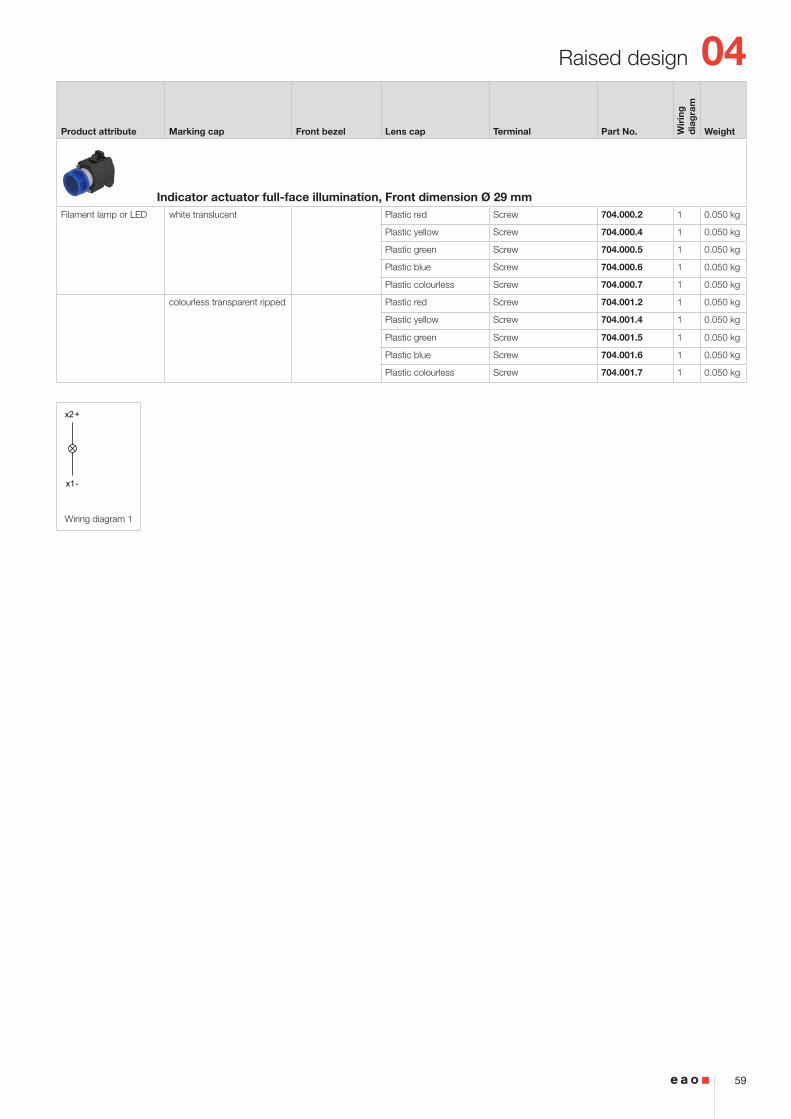
Product attribute Marking cap Front bezel Lens cap Terminal Part No. Wir
ing
d
iag
ram
Weight
Indicator actuator full-face illumination, Front dimension Ø 29 mmFilament lamp or LED white translucent Plastic red Screw 704.000.2 1 0.050 kg
Plastic yellow Screw 704.000.4 1 0.050 kg
Plastic green Screw 704.000.5 1 0.050 kg
Plastic blue Screw 704.000.6 1 0.050 kg
Plastic colourless Screw 704.000.7 1 0.050 kg
colourless transparent ripped Plastic red Screw 704.001.2 1 0.050 kg
Plastic yellow Screw 704.001.4 1 0.050 kg
Plastic green Screw 704.001.5 1 0.050 kg
Plastic blue Screw 704.001.6 1 0.050 kg
Plastic colourless Screw 704.001.7 1 0.050 kg
04
60
Raised design
13 28.5 17.5
2 … 7
40
X
30 min.
50 m
in.
65 m
in.
PIT / P3 / P4
X
Ø22.3+0.4 0
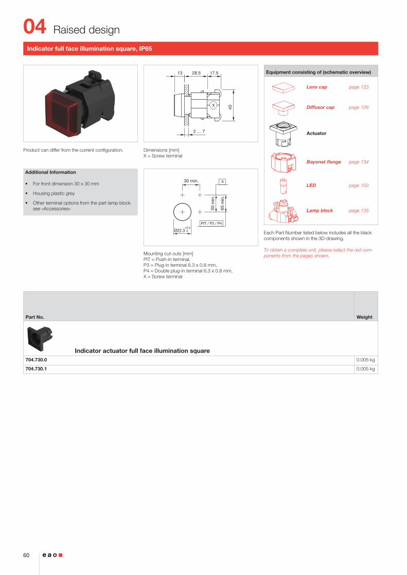
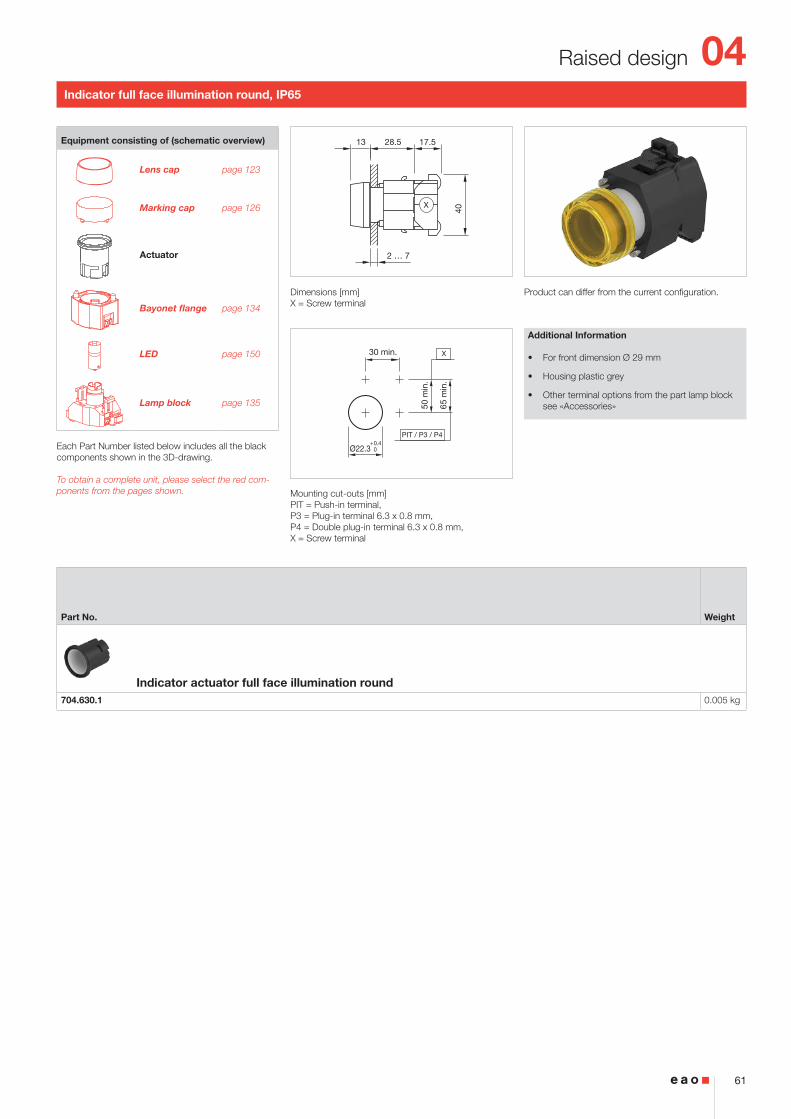
Indicator full face illumination square, IP65
Product can differ from the current configuration. Dimensions [mm]X = Screw terminal
Mounting cut-outs [mm]PIT = Push-in terminal, P3 = Plug-in terminal 6.3 x 0.8 mm, P4 = Double plug-in terminal 6.3 x 0.8 mm, X = Screw terminal
Additional Information
• For front dimension 30 x 30 mm
• Housing plastic grey
• Other terminal options from the part lamp block see «Accessories»
Equipment consisting of (schematic overview)
Lens cap page 123
Diffusor cap page 126
Actuator
Bayonet flange page 134
LED page 150
Lamp block page 135
Each Part Number listed below includes all the black components shown in the 3D-drawing.
To obtain a complete unit, please select the red com-ponents from the pages shown.
Part No. Weight
Indicator actuator full face illumination square704.730.0 0.005 kg
704.730.1 0.005 kg
04
61
Raised design
13 28.5 17.5
2 … 7
40
X
30 min.
50 m
in.
65 m
in.
PIT / P3 / P4
X
Ø22.3+0.4 0
Indicator full face illumination round, IP65
Product can differ from the current configuration. Dimensions [mm]X = Screw terminal
Mounting cut-outs [mm]PIT = Push-in terminal, P3 = Plug-in terminal 6.3 x 0.8 mm, P4 = Double plug-in terminal 6.3 x 0.8 mm, X = Screw terminal
Additional Information
• For front dimension Ø 29 mm
• Housing plastic grey
• Other terminal options from the part lamp block see «Accessories»
Equipment consisting of (schematic overview)
Lens cap page 123
Marking cap page 126
Actuator
Bayonet flange page 134
LED page 150
Lamp block page 135
Each Part Number listed below includes all the black components shown in the 3D-drawing.
To obtain a complete unit, please select the red com-ponents from the pages shown.
Part No. Weight
Indicator actuator full face illumination round704.630.1 0.005 kg
04
62
Raised design
13 46
2 … 7
40
50 m
in.
30 min.
Ø22.3+0.4 0
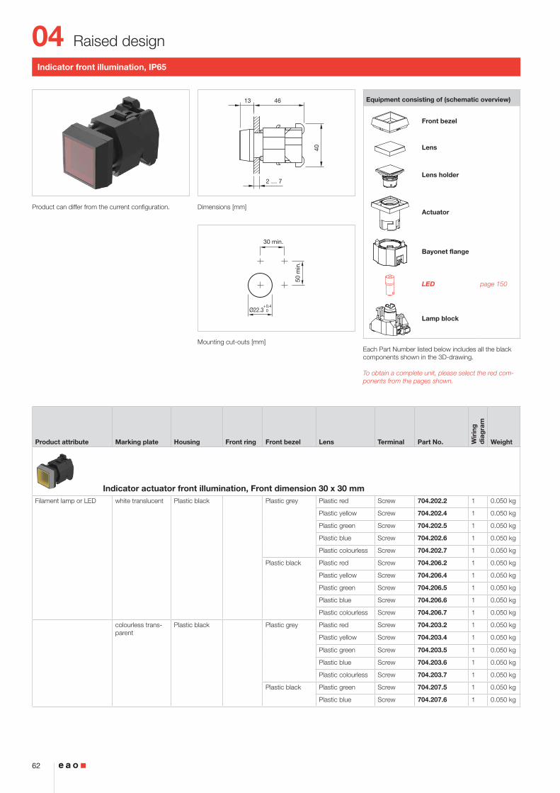
Indicator front illumination, IP65
Product can differ from the current configuration. Dimensions [mm]
Mounting cut-outs [mm]
Equipment consisting of (schematic overview)
Front bezel
Lens
Lens holder
Actuator
Bayonet flange
LED page 150
Lamp block
Each Part Number listed below includes all the black components shown in the 3D-drawing.
To obtain a complete unit, please select the red com-ponents from the pages shown.
Product attribute Marking plate Housing Front ring Front bezel Lens Terminal Part No. Wir
ing
d
iag
ram
Weight
Indicator actuator front illumination, Front dimension 30 x 30 mmFilament lamp or LED white translucent Plastic black Plastic grey Plastic red Screw 704.202.2 1 0.050 kg
Plastic yellow Screw 704.202.4 1 0.050 kg
Plastic green Screw 704.202.5 1 0.050 kg
Plastic blue Screw 704.202.6 1 0.050 kg
Plastic colourless Screw 704.202.7 1 0.050 kg
Plastic black Plastic red Screw 704.206.2 1 0.050 kg
Plastic yellow Screw 704.206.4 1 0.050 kg
Plastic green Screw 704.206.5 1 0.050 kg
Plastic blue Screw 704.206.6 1 0.050 kg
Plastic colourless Screw 704.206.7 1 0.050 kg
colourless trans-parent
Plastic black Plastic grey Plastic red Screw 704.203.2 1 0.050 kg
Plastic yellow Screw 704.203.4 1 0.050 kg
Plastic green Screw 704.203.5 1 0.050 kg
Plastic blue Screw 704.203.6 1 0.050 kg
Plastic colourless Screw 704.203.7 1 0.050 kg
Plastic black Plastic green Screw 704.207.5 1 0.050 kg
Plastic blue Screw 704.207.6 1 0.050 kg
04
63
Raised design
x2+
x1-
Wiring diagram 1
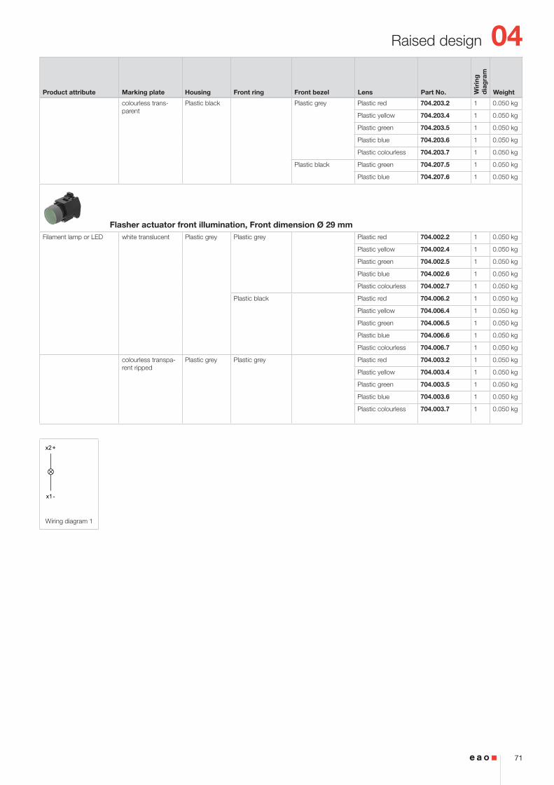
Product attribute Marking plate Housing Front ring Front bezel Lens Terminal Part No. Wir
ing
d
iag
ram
Weight
Indicator actuator front illumination, Front dimension Ø 29 mmFilament lamp or LED white translucent Plastic grey Plastic grey Plastic red Screw 704.002.2 1 0.050 kg
Plastic yellow Screw 704.002.4 1 0.050 kg
Plastic green Screw 704.002.5 1 0.050 kg
Plastic blue Screw 704.002.6 1 0.050 kg
Plastic colourless Screw 704.002.7 1 0.050 kg
Plastic black
Plastic red Screw 704.006.2 1 0.050 kg
Plastic yellow Screw 704.006.4 1 0.050 kg
Plastic green Screw 704.006.5 1 0.050 kg
Plastic blue Screw 704.006.6 1 0.050 kg
Plastic colourless Screw 704.006.7 1 0.050 kg
colourless trans-parent ripped
Plastic grey Plastic grey Plastic red Screw 704.003.2 1 0.050 kg
Plastic yellow Screw 704.003.4 1 0.050 kg
Plastic green Screw 704.003.5 1 0.050 kg
Plastic blue Screw 704.003.6 1 0.050 kg
Plastic colourless Screw 704.003.7 1 0.050 kg
04
64
Raised design
13 28.5 17.5
2 … 7
40
X
30 min.
50 m
in.
65 m
in.
PIT / P3 / P4
X
Ø22.3+0.4 0
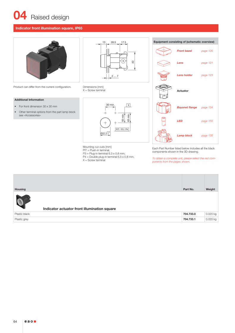
Indicator front illumination square, IP65
Product can differ from the current configuration. Dimensions [mm]X = Screw terminal
Mounting cut-outs [mm]PIT = Push-in terminal, P3 = Plug-in terminal 6.3 x 0.8 mm, P4 = Double plug-in terminal 6.3 x 0.8 mm, X = Screw terminal
Additional Information
• For front dimension 30 x 30 mm
• Other terminal options from the part lamp block see «Accessories»
Equipment consisting of (schematic overview)
Front bezel page 126
Lens page 121
Lens holder page 123
Actuator
Bayonet flange page 134
LED page 150
Lamp block page 135
Each Part Number listed below includes all the black components shown in the 3D-drawing.
To obtain a complete unit, please select the red com-ponents from the pages shown.
Housing Part No. Weight
Indicator actuator front illumination squarePlastic black 704.733.0 0.020 kg
Plastic grey 704.733.1 0.020 kg
04
65
Raised design
13 28.5 17.5
2 … 7
40
X
30 min.
50 m
in.
65 m
in.
PIT / P3 / P4
X
Ø22.3+0.4 0
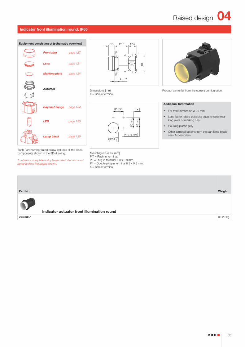
Indicator front illumination round, IP65
Product can differ from the current configuration. Dimensions [mm]X = Screw terminal
Mounting cut-outs [mm]PIT = Push-in terminal, P3 = Plug-in terminal 6.3 x 0.8 mm, P4 = Double plug-in terminal 6.3 x 0.8 mm, X = Screw terminal
Additional Information
• For front dimension Ø 29 mm
• Lens flat or raised possible; equal choose mar-king plate or marking cap
• Housing plastic grey
• Other terminal options from the part lamp block see «Accessories»
Equipment consisting of (schematic overview)
Front ring page 127
Lens page 121
Marking plate page 124
Actuator
Bayonet flange page 134
LED page 150
Lamp block page 135
Each Part Number listed below includes all the black components shown in the 3D-drawing.
To obtain a complete unit, please select the red com-ponents from the pages shown.
Part No. Weight
Indicator actuator front illumination round704.633.1 0.020 kg
04
66
Raised design
13
40
43.5 28
2 … 7
X
30 min.
Ø22.3+0.4 0
50 m
in.
65 m
in.
PIT
X
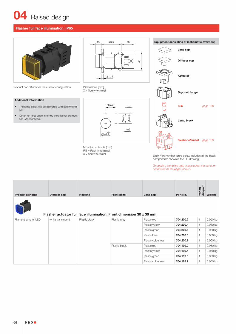
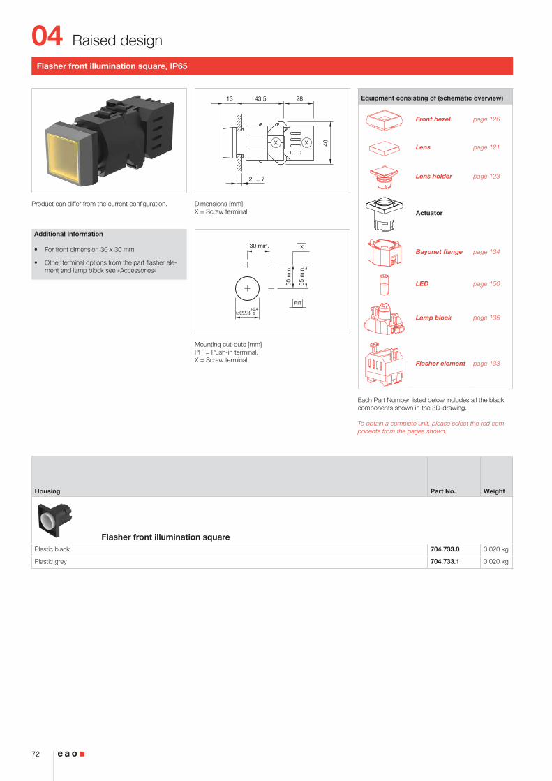
Flasher full face illumination, IP65
Product can differ from the current configuration. Dimensions [mm]X = Screw terminal
Mounting cut-outs [mm]PIT = Push-in terminal, X = Screw terminal
Additional Information
• The lamp block will be delivered with screw termi-nal
• Other terminal options of the part flasher element see «Accessories»
Equipment consisting of (schematic overview)
Lens cap
Diffusor cap
Actuator
Bayonet flange
LED page 150
Lamp block
Flasher element page 133
Each Part Number listed below includes all the black components shown in the 3D-drawing.
To obtain a complete unit, please select the red com-ponents from the pages shown.
Product attribute Diffusor cap Housing Front bezel Lens cap Part No. Wir
ing
d
iag
ram
Weight
Flasher actuator full face illumination, Front dimension 30 x 30 mmFilament lamp or LED white translucent Plastic black Plastic grey Plastic red 704.200.2 1 0.050 kg
Plastic yellow 704.200.4 1 0.050 kg
Plastic green 704.200.5 1 0.050 kg
Plastic blue 704.200.6 1 0.050 kg
Plastic colourless 704.200.7 1 0.050 kg
Plastic black Plastic red 704.199.2 1 0.050 kg
Plastic yellow 704.199.4 1 0.050 kg
Plastic green 704.199.5 1 0.050 kg
Plastic colourless 704.199.7 1 0.050 kg
04
67
Raised design
x2+
x1-
Wiring diagram 1
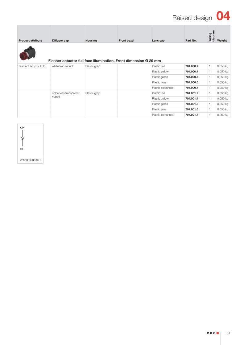
Product attribute Diffusor cap Housing Front bezel Lens cap Part No. Wir
ing
d
iag
ram
Weight
Flasher actuator full face illumination, Front dimension Ø 29 mmFilament lamp or LED white translucent Plastic grey Plastic red 704.000.2 1 0.050 kg
Plastic yellow 704.000.4 1 0.050 kg
Plastic green 704.000.5 1 0.050 kg
Plastic blue 704.000.6 1 0.050 kg
Plastic colourless 704.000.7 1 0.050 kg
colourless transparent ripped
Plastic grey Plastic red 704.001.2 1 0.050 kg
Plastic yellow 704.001.4 1 0.050 kg
Plastic green 704.001.5 1 0.050 kg
Plastic blue 704.001.6 1 0.050 kg
Plastic colourless 704.001.7 1 0.050 kg
04
68
Raised design
13
40
43.5 28
2 … 7
XX
30 min.
Ø22.3+0.4 0
50 m
in.
65 m
in.
PIT
X
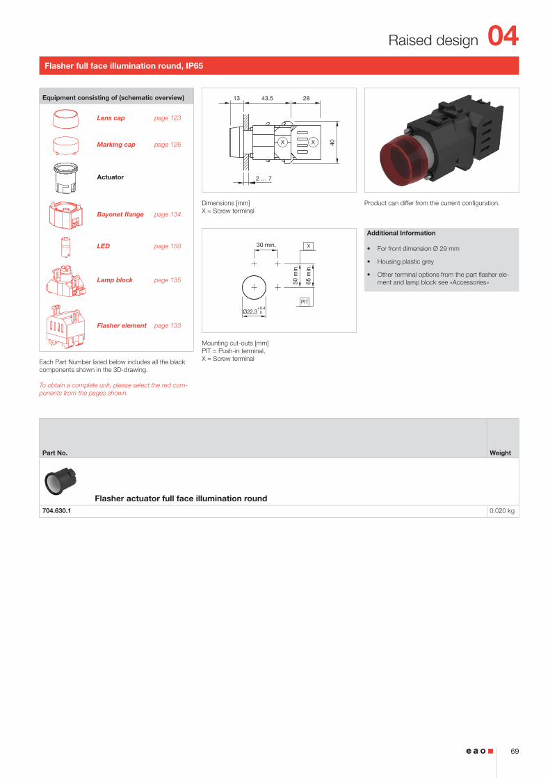
Flasher full face illumination square, IP65
Product can differ from the current configuration. Dimensions [mm]X = Screw terminal
Mounting cut-outs [mm]PIT = Push-in terminal, X = Screw terminal
Additional Information
• For front dimension 30 x 30 mm
• Other terminal options from the part flasher ele-ment and lamp block see «Accessories»
Equipment consisting of (schematic overview)
Lens cap page 123
Diffusor cap page 126
Actuator
Bayonet flange page 134
LED page 150
Lamp block page 135
Flasher element page 133
Each Part Number listed below includes all the black components shown in the 3D-drawing.
To obtain a complete unit, please select the red com-ponents from the pages shown.
Housing Part No. Weight
Flasher actuator full face illumination squarePlastic black 704.730.0 0.050 kg
Plastic grey 704.730.1 0.050 kg
04
69
Raised design
13
40
43.5 28
2 … 7
XX
30 min.
Ø22.3+0.4 0
50 m
in.
65 m
in.
PIT
X
Flasher full face illumination round, IP65
Product can differ from the current configuration. Dimensions [mm]X = Screw terminal
Mounting cut-outs [mm]PIT = Push-in terminal, X = Screw terminal
Additional Information
• For front dimension Ø 29 mm
• Housing plastic grey
• Other terminal options from the part flasher ele-ment and lamp block see «Accessories»
Equipment consisting of (schematic overview)
Lens cap page 123
Marking cap page 126
Actuator
Bayonet flange page 134
LED page 150
Lamp block page 135
Flasher element page 133
Each Part Number listed below includes all the black components shown in the 3D-drawing.
To obtain a complete unit, please select the red com-ponents from the pages shown.
Part No. Weight
Flasher actuator full face illumination round704.630.1 0.020 kg
04
70
Raised design
13
40
43.5 28
2 … 7
X
30 min.
Ø22.3+0.4 0
50 m
in.
65 m
in.
PIT
X
Flasher front illumination, IP65
Product can differ from the current configuration. Dimensions [mm]X = Screw terminal
Mounting cut-outs [mm]PIT = Push-in terminal, X = Screw terminal
Additional Information
• The lamp block will be dtelivered with screw ter-minal
• Other terminal options of the part flasher element see «Accessories»
Equipment consisting of (schematic overview)
Front ring
Lens
Marking plate
Actuator
Bayonet flange
LED page 150
Lamp block
Flasher element page 133
Each Part Number listed below includes all the black components shown in the 3D-drawing.
To obtain a complete unit, please select the red com-ponents from the pages shown.
Product attribute Marking plate Housing Front ring Front bezel Lens Part No. Wir
ing
d
iag
ram
Weight
Flasher actuator front illumination, Front dimension 30 x 30 mmFilament lamp or LED white translucent Plastic black Plastic grey Plastic red 704.202.2 1 0.050 kg
Plastic yellow 704.202.4 1 0.050 kg
Plastic green 704.202.5 1 0.050 kg
Plastic blue 704.202.6 1 0.050 kg
Plastic colourless 704.202.7 1 0.050 kg
Plastic black Plastic red 704.206.2 1 0.050 kg
Plastic yellow 704.206.4 1 0.050 kg
Plastic green 704.206.5 1 0.050 kg
Plastic blue 704.206.6 1 0.050 kg
Plastic colourless 704.206.7 1 0.050 kg
04
71
Raised design
x2+
x1-
Wiring diagram 1
Product attribute Marking plate Housing Front ring Front bezel Lens Part No. Wir
ing
d
iag
ram
Weight
colourless trans-parent
Plastic black Plastic grey Plastic red 704.203.2 1 0.050 kg
Plastic yellow 704.203.4 1 0.050 kg
Plastic green 704.203.5 1 0.050 kg
Plastic blue 704.203.6 1 0.050 kg
Plastic colourless 704.203.7 1 0.050 kg
Plastic black Plastic green 704.207.5 1 0.050 kg
Plastic blue 704.207.6 1 0.050 kg
Flasher actuator front illumination, Front dimension Ø 29 mmFilament lamp or LED white translucent Plastic grey Plastic grey Plastic red 704.002.2 1 0.050 kg
Plastic yellow 704.002.4 1 0.050 kg
Plastic green 704.002.5 1 0.050 kg
Plastic blue 704.002.6 1 0.050 kg
Plastic colourless 704.002.7 1 0.050 kg
Plastic black Plastic red 704.006.2 1 0.050 kg
Plastic yellow 704.006.4 1 0.050 kg
Plastic green 704.006.5 1 0.050 kg
Plastic blue 704.006.6 1 0.050 kg
Plastic colourless 704.006.7 1 0.050 kg
colourless transpa-rent ripped
Plastic grey Plastic grey Plastic red 704.003.2 1 0.050 kg
Plastic yellow 704.003.4 1 0.050 kg
Plastic green 704.003.5 1 0.050 kg
Plastic blue 704.003.6 1 0.050 kg
Plastic colourless 704.003.7 1 0.050 kg
04
72
Raised design
13
40
43.5 28
2 … 7
XX
30 min.
Ø22.3+0.4 0
50 m
in.
65 m
in.
PIT
X
Flasher front illumination square, IP65
Product can differ from the current configuration. Dimensions [mm]X = Screw terminal
Mounting cut-outs [mm]PIT = Push-in terminal, X = Screw terminal
Additional Information
• For front dimension 30 x 30 mm
• Other terminal options from the part flasher ele-ment and lamp block see «Accessories»
Equipment consisting of (schematic overview)
Front bezel page 126
Lens page 121
Lens holder page 123
Actuator
Bayonet flange page 134
LED page 150
Lamp block page 135
Flasher element page 133
Each Part Number listed below includes all the black components shown in the 3D-drawing.
To obtain a complete unit, please select the red com-ponents from the pages shown.
Housing Part No. Weight
Flasher front illumination squarePlastic black 704.733.0 0.020 kg
Plastic grey 704.733.1 0.020 kg
04
73
Raised design
13
40
43.5 28
2 … 7
XX
30 min.
Ø22.3+0.4 0
50 m
in.
65 m
in.
PIT
X
Flasher front illumination round, IP65
Product can differ from the current configuration. Dimensions [mm]X = Screw terminal
Mounting cut-outs [mm]PIT = Push-in terminal, X = Screw terminal
Additional Information
• For front dimension Ø 29 mm
• Lens flat or raised possible; equal choose mar-king plate or marking cap
• Housing plastic grey
• Other terminal options from the part flasher ele-ment and lamp block see «Accessories»
Equipment consisting of (schematic overview)
Front ring page 130
Lens page 123
Marking plate page 127
Actuator
Bayonet flange page 136
LED page 151
Lamp block page 137
Flasher element page 135
Each Part Number listed below includes all the black components shown in the 3D-drawing.
To obtain a complete unit, please select the red com-ponents from the pages shown.
Part No. Weight
Flasher actuator front illumination round704.633.1 0.020 kg
04
74
Raised design
2 ... 6
13.5 35.5
30
30 m
in.
30 min.
Ø22.3+0.4 0
x2-
x1+
Wiring diagram 1
Buzzer, IP65
Product can differ from the current configuration. Dimensions [mm]
Mounting cut-outs [mm]
Additional Information
• Further information see «Technical data»
Equipment consisting of (schematic overview)
Buzzer
Fixing nut
Each Part Number listed below includes all the black components shown in the 3D-drawing.
.
Operating voltage Front cap Terminal Part No. Wir
ing
d
iag
ram
Weight
Buzzer, Front dimension Ø 29 mm24 VDC Plastic black Solder 2.8 x 0.5 mm 14-810.002 1 0.016 kg
Brass nickel-plated Solder 2.8 x 0.5 mm 14-810.902 1 0.016 kg
04
75
Raised design
13 53 23
37
2 … 7
X X
30 min.
50 m
in.
65 m
in.
PIT / P3 / P4
X
Ø22.3+0.4 0
Pushbutton
Product can differ from the current configuration. Dimensions [mm]X = Screw terminal
Mounting cut-outs [mm]PIT = Push-in terminal, P3 = Plug-in terminal 6.3 x 0.8 mm, P4 = Double plug-in terminal 6.3 x 0.8 mm, X = Screw terminal
Additional Information
• Other terminal options from the part switching element see «Accessories»
• The colour of anodized aluminium parts can vary due to technical production reasons
• Frontring with protective cover to be mounted with a torque of 40 Ncm onto actuator
• Max. 3 switching elements can be clipped on
Equipment consisting of (schematic overview)
Front ring
Lens
Marking plate
Actuator
Bayonet flange
Switching ele-ment page 138
Each Part Number listed below includes all the black components shown in the 3D-drawing.
To obtain a complete unit, please select the red com-ponents from the pages shown.
Front protection Front ring Front bezel Lens Switching action Part No. Wir
ing
d
iag
ram
Weight
Pushbutton actuator, Front dimension 30 x 30 mmIP65 Plastic grey Plastic black B 704.210.0 1 0.040 kg
Plastic red B 704.210.2 1 0.040 kg
Plastic yellow B 704.210.4 1 0.040 kg
Plastic green B 704.210.5 1 0.040 kg
Plastic blue B 704.210.6 1 0.040 kg
Plastic colourless B 704.210.7 1 0.040 kg
Plastic black Plastic black B 704.209.0 1 0.040 kg
Plastic red B 704.209.2 1 0.040 kg
Plastic yellow B 704.209.4 1 0.040 kg
Plastic green B 704.209.5 1 0.040 kg
Plastic blue B 704.209.6 1 0.040 kg
Plastic colourless B 704.209.7 1 0.040 kg
Plastic grey Plastic black C 704.240.0 2 0.040 kg
Plastic red C 704.240.2 2 0.040 kg
Plastic yellow C 704.240.4 2 0.040 kg
Plastic green C 704.240.5 2 0.040 kg
Plastic colourless C 704.240.7 2 0.040 kg
04
76
Raised design
Front protection Front ring Front bezel Lens Switching action Part No. Wir
ing
d
iag
ram
Weight
IP65 Plastic black Plastic black C 704.239.0 2 0.040 kg
Plastic red C 704.239.2 2 0.040 kg
Plastic green C 704.239.5 2 0.040 kg
Plastic colourless C 704.239.7 2 0.040 kg
Pushbutton actuator, Front dimension Ø 29 mmIP65 Plastic grey Plastic black B 704.010.0 1 0.040 kg
Plastic red B 704.010.2 1 0.040 kg
Plastic yellow B 704.010.4 1 0.040 kg
Plastic green B 704.010.5 1 0.040 kg
Plastic blue B 704.010.6 1 0.040 kg
Plastic colourless B 704.010.7 1 0.040 kg
Plastic black Plastic black B 704.009.0 1 0.040 kg
Plastic red B 704.009.2 1 0.040 kg
Plastic yellow B 704.009.4 1 0.040 kg
Plastic green B 704.009.5 1 0.040 kg
Plastic blue B 704.009.6 1 0.040 kg
Plastic colourless B 704.009.7 1 0.040 kg
Plastic grey Plastic black C 704.040.0 2 0.040 kg
Plastic red C 704.040.2 2 0.040 kg
Plastic yellow C 704.040.4 2 0.040 kg
Plastic green C 704.040.5 2 0.040 kg
Plastic blue C 704.040.6 2 0.040 kg
Plastic colourless C 704.040.7 2 0.040 kg
Plastic black Plastic black C 704.039.0 2 0.040 kg
Plastic red C 704.039.2 2 0.040 kg
Plastic yellow C 704.039.4 2 0.040 kg
Plastic green C 704.039.5 2 0.040 kg
Plastic blue C 704.039.6 2 0.040 kg
Plastic colourless C 704.039.7 2 0.040 kg
Aluminium natural ano-dized
Aluminium black anodized B 704.011.0 1 0.040 kg
Aluminium red anodized B 704.011.2 1 0.040 kg
Aluminium gold anodized B 704.011.4 1 0.040 kg
Aluminium olive-green anodized B 704.011.5 1 0.040 kg
Aluminium blue anodized B 704.011.6 1 0.040 kg
Aluminium natural anodized B 704.011.8 1 0.040 kg
Plastic black B 704.012.0 1 0.040 kg
Plastic red B 704.012.2 1 0.040 kg
Plastic yellow B 704.012.4 1 0.040 kg
Plastic green B 704.012.5 1 0.040 kg
Plastic blue B 704.012.6 1 0.040 kg
Plastic colourless B 704.012.7 1 0.040 kg
Aluminium black anodized C 704.041.0 2 0.040 kg
Aluminium red anodized C 704.041.2 2 0.040 kg
Aluminium olive-green anodized C 704.041.5 2 0.040 kg
Aluminium blue anodized C 704.041.6 2 0.040 kg
Aluminium natural anodized C 704.041.8 2 0.040 kg
04
77
Raised design
Wiring diagram 1 Wiring diagram 2
Front protection Front ring Front bezel Lens Switching action Part No. Wir
ing
d
iag
ram
Weight
IP65 Aluminium natural anodized
Kunststoff schwarz C 704.042.0 2 0.040 kg
Plastic red C 704.042.2 2 0.040 kg
Plastic yellow C 704.042.4 2 0.040 kg
Plastic green C 704.042.5 2 0.040 kg
Plastic blue C 704.042.6 2 0.040 kg
Plastic colourless C 704.042.7 2 0.040 kg
IP 67 Aluminium natural anodized with protective cap
Plastic black B 704.013.0 1 0.040 kg
Plastic red B 704.013.2 1 0.040 kg
Plastic yellow B 704.013.4 1 0.040 kg
Plastic green B 704.013.5 1 0.040 kg
Plastic blue B 704.013.6 1 0.040 kg
Plastic colourless B 704.013.7 1 0.040 kg
Plastic black C 704.043.0 2 0.040 kg
Plastic red C 704.043.2 2 0.040 kg
Plastic colourless C 704.043.7 2 0.040 kg
Switching action : B = Momentary, C = Maintain
04
78
Raised design
13 53 23
37
2 … 7
X X
30 min.
50 m
in.
65 m
in.
PIT / P3 / P4
X
Ø22.3+0.4 0
Wiring diagram 1 Wiring diagram 2
Pushbutton square, IP65
Product can differ from the current configuration. Dimensions [mm]X = Screw terminal
Mounting cut-outs [mm]PIT = Push-in terminal, P3 = Plug-in terminal 6.3 x 0.8 mm, P4 = Double plug-in terminal 6.3 x 0.8 mm, X = Screw terminal
Additional Information
• For front dimension 30 x 30 mm
• Other terminal options from the part switching element see «Accessories»
• Max. 3 switching elements can be clipped on
Equipment consisting of (schematic overview)
Front bezel page 126
Lens page 121
Lens holder page 123
Actuator
Bayonet flange page 134
Switching ele-ment page 138
Each Part Number listed below includes all the black components shown in the 3D-drawing.
To obtain a complete unit, please select the red com-ponents from the pages shown.
Housing Switching action Part No. Wir
ing
d
iag
ram
Weight
Pushbutton actuator squarePlastic black B 704.731.0 1 0.020 kg
Plastic grey B 704.731.1 1 0.020 kg
Plastic black C 704.732.0 2 0.020 kg
Plastic grey C 704.732.1 2 0.020 kg
Switching action : B = Momentary, C = Maintain
04
79
Raised design
13 53 23
37
2 … 7
X X
30 min.
50 m
in.
65 m
in.
PIT / P3 / P4
X
Ø22.3+0.4 0
Wiring diagram 1 Wiring diagram 2
Pushbutton round, IP65
Product can differ from the current configuration. Dimensions [mm]X = Screw terminal
Mounting cut-outs [mm]PIT = Push-in terminal, P3 = Plug-in terminal 6.3 x 0.8 mm, P4 = Double plug-in terminal 6.3 x 0.8 mm, X = Screw terminal
Additional Information
• For front dimension Ø 29 mm
• Housing plastic grey
• Other terminal options from the part switching element see «Accessories»
• Max. 3 switching elements can be clipped on
Equipment consisting of (schematic overview)
Front ring page 127
Lens page 121
Marking plate page 124
Actuator
Bayonet flange page 134
Switching ele-ment page 138
Each Part Number listed below includes all the black components shown in the 3D-drawing.
To obtain a complete unit, please select the red com-ponents from the pages shown.
Switching action Part No. Wir
ing
d
iag
ram
Weight
Pushbutton actuator roundB 704.631.1 1 0.009 kg
C 704.632.1 2 0.009 kg
Switching action : B = Momentary, C = Maintain
04
80
Raised design
13 69
2 ... 7
23
40X X
30 min.
50 m
in.
65 m
in.
PIT / P3 / P4
X
Ø22.3+0.4 0
Illuminated pushbutton
Product can differ from the current configuration. Dimensions [mm]X = Screw terminal
Mounting cut-outs [mm]PIT = Push-in terminal, P3 = Plug-in terminal 6.3 x 0.8 mm, P4 = Double plug-in terminal 6.3 x 0.8 mm, X = Screw terminal
Additional Information
• Other terminal options from the part switching element see «Accessories»
• The lamp block will be delivered with screw termi-nal
• Frontring with protective cover to be mounted with a torque of 40 Ncm onto actuator
• Max. 3 switching elements can be clipped on
• The colour of anodized aluminium parts can vary due to technical production reasons
Equipment consisting of (schematic overview)
Front bezel
Lens
Lens holder
Actuator
Bayonet flange
LED page 150
Lamp block
Switching ele-ment page 138
Each Part Number listed below includes all the black components shown in the 3D-drawing.
To obtain a complete unit, please select the red com-ponents from the pages shown.
Front protection Housing Front ring Front bezel Lens Switching action Part No. Wir
ing
d
iag
ram
Weight
Illuminated pushbutton actuator, Front dimension 30 x 30 mmIP65 Plastic black Plastic grey Plastic red B 704.230.2 1 0.056 kg
Plastic yellow B 704.230.4 1 0.056 kg
Plastic green B 704.230.5 1 0.056 kg
Plastic blue B 704.230.6 1 0.056 kg
Plastic colourless B 704.230.7 1 0.056 kg
Plastic black Plastic red B 704.229.2 1 0.056 kg
Plastic yellow B 704.229.4 1 0.056 kg
Plastic green B 704.229.5 1 0.056 kg
Plastic blue B 704.229.6 1 0.056 kg
Plastic colourless B 704.229.7 1 0.056 kg
Plastic grey Plastic red C 704.260.2 2 0.056 kg
Plastic yellow C 704.260.4 2 0.056 kg
Plastic green C 704.260.5 2 0.056 kg
Plastic blue C 704.260.6 2 0.056 kg
Plastic colourless C 704.260.7 2 0.056 kg
04
81
Raised design
Front protection Housing Front ring Front bezel Lens Switching action Part No. Wir
ing
d
iag
ram
Weight
IP65 Plastic black Plastic black Plastic red C 704.259.2 2 0.056 kg
Plastic yellow C 704.259.4 2 0.056 kg
Plastic green C 704.259.5 2 0.056 kg
Plastic blue C 704.259.6 2 0.056 kg
Plastic colourless C 704.259.7 2 0.056 kg
Illuminated pushbutton actuator, Front dimension Ø 29 mmIP65 Plastic grey Plastic grey Plastic red B 704.030.2 1 0.056 kg
Plastic yellow B 704.030.4 1 0.056 kg
Plastic green B 704.030.5 1 0.056 kg
Plastic blue B 704.030.6 1 0.056 kg
Plastic colourless B 704.030.7 1 0.056 kg
Plastic black Plastic red B 704.029.2 1 0.056 kg
Plastic yellow B 704.029.4 1 0.056 kg
Plastic green B 704.029.5 1 0.056 kg
Plastic blue B 704.029.6 1 0.056 kg
Plastic colourless B 704.029.7 1 0.056 kg
Plastic grey Plastic red C 704.060.2 2 0.056 kg
Plastic yellow C 704.060.4 2 0.056 kg
Plastic green C 704.060.5 2 0.056 kg
Plastic blue C 704.060.6 2 0.056 kg
Plastic colourless C 704.060.7 2 0.056 kg
Plastic black Plastic red C 704.059.2 2 0.056 kg
Plastic yellow C 704.059.4 2 0.056 kg
Plastic green C 704.059.5 2 0.056 kg
Plastic colourless C 704.059.7 2 0.056 kg
Aluminium natural ano-dized
Plastic red B 704.032.2 1 0.056 kg
Plastic yellow B 704.032.4 1 0.056 kg
Plastic green B 704.032.5 1 0.056 kg
Plastic blue B 704.032.6 1 0.056 kg
Plastic colourless B 704.032.7 1 0.056 kg
Aluminium natural anodized with protec-tive cap
Plastic red B 704.033.2 1 0.056 kg
Plastic yellow B 704.033.4 1 0.056 kg
Plastic green B 704.033.5 1 0.056 kg
Plastic blue B 704.033.6 1 0.056 kg
Plastic colourless B 704.033.7 1 0.056 kg
Aluminium natural anodized
Plastic red C 704.062.2 2 0.056 kg
Plastic yellow C 704.062.4 2 0.056 kg
Plastic green C 704.062.5 2 0.056 kg
Plastic blue C 704.062.6 2 0.056 kg
Plastic colourless C 704.062.7 2 0.056 kg
04
82
Raised design
X2+
X1-
X2+
X1-
Wiring diagram 1 Wiring diagram 2
Front protection Housing Front ring Front bezel Lens Switching action Part No. Wir
ing
d
iag
ram
Weight
IP 67 Plastic grey Aluminium natural anodized with protec-tive cap
Plastic red C 704.063.2 2 0.056 kg
Plastic yellow C 704.063.4 2 0.056 kg
Plastic green C 704.063.5 2 0.056 kg
Plastic blue C 704.063.6 2 0.056 kg
Plastic colourless C 704.063.7 2 0.056 kg
Switching action : B = Momentary, C = Maintain
04
83
Raised design
13 69
2 ... 7
23
40X X
30 min.
50 m
in.
65 m
in.
PIT / P3 / P4
X
Ø22.3+0.4 0
Wiring diagram 1 Wiring diagram 2
Illuminated pushbutton square, IP65
Product can differ from the current configuration. Dimensions [mm]X = Screw terminal
Mounting cut-outs [mm]PIT = Push-in terminal, P3 = Plug-in terminal 6.3 x 0.8 mm, P4 = Double plug-in terminal 6.3 x 0.8 mm, X = Screw terminal
Additional Information
• For front dimension 30 x 30 mm
• Other terminal options from the parts switching element and lamp block see «Accessories»
• Max. 3 switching elements can be clipped on
Equipment consisting of (schematic overview)
Front bezel page 126
Lens page 121
Lens holder page 123
Actuator
Bayonet flange page 134
LED page 150
Lamp block page 135
Switching ele-ment page 138
Each Part Number listed below includes all the black components shown in the 3D-drawing.
To obtain a complete unit, please select the red com-ponents from the pages shown.
Housing Switching action Part No. Wir
ing
d
iag
ram
Weight
Illuminated pushbutton actuator squarePlastic black B 704.731.0 1 0.020 kg
Plastic grey B 704.731.1 1 0.020 kg
C 704.732.1 2 0.020 kg
Plastic black C 704.732.0 2 0.020 kg
Switching action : B = Momentary, C = Maintain
04
84
Raised design
13 69
2 ... 7
23
40X X
30 min.
50 m
in.
65 m
in.
PIT / P3 / P4
X
Ø22.3+0.4 0
Wiring diagram 1 Wiring diagram 2
Illuminated pushbutton round, IP65
Product can differ from the current configuration. Dimensions [mm]X = Screw terminal
Mounting cut-outs [mm]PIT = Push-in terminal, P3 = Plug-in terminal 6.3 x 0.8 mm, P4 = Double plug-in terminal 6.3 x 0.8 mm, X = Screw terminal
Additional Information
• For front dimension Ø 29 mm
• Lens flat or raised possible; equal choose mar-king plate or marking cap
• Lens metal with spot possible
• Housing plastic grey
• Other terminal options from the parts switching element and lamp block see «Accessories»
• Max. 3 switching elements can be clipped on
Equipment consisting of (schematic overview)
Front ring page 127
Lens page 121
Marking plate page 124
Actuator
Bayonet flange page 134
LED page 150
Lamp block page 135
Switching ele-ment page 138
Each Part Number listed below includes all the black components shown in the 3D-drawing.
To obtain a complete unit, please select the red com-ponents from the pages shown.
Switching action Part No. Wir
ing
d
iag
ram
Weight
Illuminated pushbutton actuator roundB 704.631.1 1 0.009 kg
C 704.632.1 2 0.009 kg
Switching action : B = Momentary, C = Maintain
04
85
Raised design
25 47 53
2 ... 7
37
23
X X
Wiring diagram 1
Emergency-stop switch, foolproof EN IEC 60947-5-5, IP65
Product can differ from the current configuration. Dimensions [mm]X = Screw terminal
Mounting cut-outs [mm]
Additional Information
• Other terminal options from the part switching element see «Accessories»
• Shaft yellow
• Lock type Euro-Locks 9500
• Two keys are supplied with each key lock switch
• Max. 2 slow-make elements can be clipped on
• Application as per DIN EN ISO 13850 and EN 60204-1
Equipment consisting of (schematic overview)
Actuator
Bayonet flange
Switching ele-ment page 138
Each Part Number listed below includes all the black components shown in the 3D-drawing.
To obtain a complete unit, please select the red com-ponents from the pages shown.
Product attribute Lens Marking Switching action Part No. Wir
ing
d
iag
ram
Weight
Emergency-stop switch actuator, foolproof EN IEC 60947-5-5, Front dimension Ø 37 mmTwist to unlock anti-clockwise Plastic red Arrows C 704.064.2A 1 0.300 kg
Emergency-stop switch actuator, foolproof EN IEC 60947-5-5, Front dimension Ø 37 mmKey to unlock anti-clockwise Plastic red Arrows C 704.066.2A 1 0.300 kg
Switching action : C = Maintain
04
86
Raised design
23 25 53
2 … 7
23
37X X
Stop switch, IP65
Product can differ from the current configuration. Dimensions [mm]X = Screw terminal
Mounting cut-outs [mm]PIT = Push-in terminal, P3 = Plug-in terminal 6.3 x 0.8 mm, P4 = Double plug-in terminal 6.3 x 0.8 mm, X = Screw terminal
Additional Information
• The colour of anodized aluminium parts can vary due to technical production reasons
• Other terminal options from the part switching element see «Accessories»
• The standard lock Ronis 251
• Two keys are supplied with each key lock switch
• Max. 3 switching elements can be clipped on
Equipment consisting of (schematic overview)
Actuator
Bayonet flange
Switching ele-ment page 138
Each Part Number listed below includes all the black components shown in the 3D-drawing.
To obtain a complete unit, please select the red com-ponents from the pages shown.
Product attribute Front ring Lens MarkingSwitching action Part No. W
irin
g
dia
gra
m
Weight
Stop switch actuator, Front dimension Ø 40 mmTwist to unlock clockwise Plastic grey Plastic red Arrows C 704.074.2 1 0.047 kg
Stop C 704.074.3 1 0.047 kg
Aluminium natural anodized Plastic red Arrows C 704.075.2 1 0.047 kg
Stop C 704.075.3 1 0.047 kg
Stop switch actuator, Front dimension Ø 40 mmKey to unlock clockwise Plastic grey Plastic red without C 704.076.0 1 0.063 kg
Aluminium natural anodized Plastic red without C 704.078.0 1 0.063 kg
04
87
Raised design
Wiring diagram 1
Switching action : C = Maintain
Product attribute Lens Marking Switching action Part No. Wir
ing
d
iag
ram
Weight
Stop switch actuator, Front dimension Ø 37 mmTwist to unlock anti-clockwise Plastic red Arrows C 704.064.2 1 0.300 kg
Stop switch actuator, Front dimension Ø 37 mmKey to unlock anti-clockwise Plastic red Arrows C 704.066.2 1 0.300 kg
04
88
Raised design
25 53
2…7
23
37X X
50m
in.
60m
in.
65m
in.
65m
in.
PIT / P3 / P4
40min.
60min.
Ø40
Ø60
Ø22.3+0.4 0
X
Mushroom-head pushbutton, IP65
Product can differ from the current configuration. Dimensions [mm]X = Screw terminal
Mounting cut-outs [mm]PIT = Push-in terminal, P3 = Plug-in terminal 6.3 x 0.8 mm, P4 = Double plug-in terminal 6.3 x 0.8 mm, X = Screw terminal
Additional Information
• Other terminal options from the part switching element see «Accessories»
• The colour of anodized aluminium parts can vary due to technical production reasons
• Max. 3 switching elements can be clipped on
Equipment consisting of (schematic overview)
Actuator
Bayonet flange
Switching ele-ment page 138
Each Part Number listed below includes all the black components shown in the 3D-drawing.
To obtain a complete unit, please select the red com-ponents from the pages shown.
Front ring Lens Switching action Part No. Wir
ing
d
iag
ram
Weight
Mushroom-head pushbutton actuator, Front dimension Ø 40 mmPlastic grey Plastic black B 704.070.0 1 0.044 kg
Plastic red B 704.070.2 1 0.044 kg
Plastic yellow B 704.070.4 1 0.044 kg
Plastic green B 704.070.5 1 0.044 kg
Aluminium natural anodized Plastic black B 704.071.0 1 0.044 kg
Plastic red B 704.071.2 1 0.044 kg
Plastic yellow B 704.071.4 1 0.044 kg
Plastic green B 704.071.5 1 0.044 kg
Plastic grey Plastic black C 704.072.0 2 0.044 kg
Plastic red C 704.072.2 2 0.044 kg
Aluminium natural anodized Plastic black C 704.073.0 2 0.044 kg
Plastic red C 704.073.2 2 0.044 kg
Plastic yellow C 704.073.4 2 0.044 kg
Plastic green C 704.073.5 2 0.044 kg
04
89
Raised design
Wiring diagram 1 Wiring diagram 2
Front ring Lens Switching action Part No. Wir
ing
d
iag
ram
Weight
Mushroom-head pushbutton actuator, Front dimension Ø 60 mmAluminium natural anodized Aluminium red anodized B 704.079.2 1 0.060 kg
C 704.075.2I 2 0.069 kg
Switching action : B = Momentary, C = Maintain
04
90
Raised design
25 69
2 … 7
23
37X X
X2+
X1-
X2+
X1-
Wiring diagram 1 Wiring diagram 2
Illuminated mushroom head pushbutton, IP65
Product can differ from the current configuration. Dimensions [mm]X = Screw terminal
Mounting cut-outs [mm]PIT = Push-in terminal, P3 = Plug-in terminal 6.3 x 0.8 mm, P4 = Double plug-in terminal 6.3 x 0.8 mm, X = Screw terminal
Additional Information
• The lamp block will be delivered with screw termi-nal
• Other terminal options from the part switching element see «Accessories»
• Max. 3 switching elements can be clipped on
Equipment consisting of (schematic overview)
Actuator
Bayonet flange
LED page 150
Lamp block
Switching ele-ment page 138
Each Part Number listed below includes all the black components shown in the 3D-drawing.
To obtain a complete unit, please select the red com-ponents from the pages shown.
Front ring Lens Switching action Part No. Wir
ing
d
iag
ram
Weight
Mushroom-head pushbutton actuator illuminated, Front dimension Ø 40 mmPlastic grey Plastic red B 704.084.2 1 0.044 kg
Plastic yellow B 704.084.4 1 0.044 kg
Plastic green B 704.084.5 1 0.044 kg
Plastic blue B 704.084.6 1 0.044 kg
Plastic colourless B 704.084.7 1 0.044 kg
Plastic red C 704.086.2 2 0.044 kg
Plastic yellow C 704.086.4 2 0.044 kg
Plastic green C 704.086.5 2 0.044 kg
Switching action : B = Momentary, C = Maintain
04
91
Raised design
23 21 53 23
2 … 7
37X X
30 min.
50 m
in.
65 m
in.
PIT / P3 / P4
X
Ø22.3+0.4 0
AB
A C
Keylock switch 2 positions, IP65
Product can differ from the current configuration. Dimensions [mm]X = Screw terminal
Mounting cut-outs [mm]PIT = Push-in terminal, P3 = Plug-in terminal 6.3 x 0.8 mm, P4 = Double plug-in terminal 6.3 x 0.8 mm, X = Screw terminal
Additional Information
• Other terminal options from the part switching element see «Accessories»
• The standard lock Ronis 251
• Two keys are supplied with each key lock switch
• Further lock numbers see «Technical data»
• Max. 3 switching elements can be clipped on
Equipment consisting of (schematic overview)
Actuator
Bayonet flange
Switching ele-ment page 138
Each Part Number listed below includes all the black components shown in the 3D-drawing.
To obtain a complete unit, please select the red com-ponents from the pages shown.
Switching positions (A = Rest, B = Momentary, C = Maintained)
Front ring Front bezel Switching action Switching angle Key remove Part No. Wir
ing
d
iag
ram
Weight
Keylock switch actuator 2 positions, Front dimension 30 x 30 mmPlastic grey A - B B = 42° A 704.343.0 1 0.070 kg
A - C C = 90° C 704.340.0 2 0.070 kg
A 704.341.0 2 0.070 kg
A + C 704.342.0 2 0.070 kg
04
92
Raised design
Wiring diagram 1 Wiring diagram 2
Switching action : A = Rest, B = Momentary, C = Maintain
Front ring Front bezel Switching action Switching angle Key remove Part No. Wir
ing
d
iag
ram
Weight
Keylock switch actuator 2 positions, Front dimension Ø 29 mmAluminium chrome A - B B = 42° A 704.123.0 1 0.070 kg
A - C C = 90° C 704.120.0 2 0.070 kg
A 704.121.0 2 0.070 kg
A + C 704.122.0 2 0.070 kg
04
93
Raised design
23 21 53 23
2 … 7
37X X
30 min.
50 m
in.
65 m
in.
PIT / P3 / P4
X
Ø22.3+0.4 0
ACB
ABC
ABB
ACC
A
CC
Keylock switch 3 positions, IP65
Product can differ from the current configuration. Dimensions [mm]X = Screw terminal
Mounting cut-outs [mm]PIT = Push-in terminal, P3 = Plug-in terminal 6.3 x 0.8 mm, P4 = Double plug-in terminal 6.3 x 0.8 mm, X = Screw terminal
Additional Information
• Other terminal options from the part switching element see «Accessories»
• The standard lock Ronis 251
• Two keys are supplied with each key lock switch
• Further lock numbers see «Technical data»
• Max. 3 switching elements can be clipped on
Equipment consisting of (schematic overview)
Actuator
Bayonet flange
Switching ele-ment page 138
Each Part Number listed below includes all the black components shown in the 3D-drawing.
To obtain a complete unit, please select the red com-ponents from the pages shown.
Switching positions (A = Rest, B = Momentary, C = Maintained)
Front ring Front bezel Switching action Switching angle Key remove Part No. Wir
ing
d
iag
ram
Weight
Keylock switch actuator 3 positions, Front dimension 30 x 30 mmPlastic grey C - A - B C = 42°, B = 42° C 704.337.0 2 0.070 kg
Switching action : A = Rest, B = Momentary, C = Maintain
Front ring Front bezel Switching action Switching angle Key remove Part No. Wir
ing
d
iag
ram
Weight
Keylock switch actuator 3 positions, Front dimension Ø 29 mmAluminium chrome B - A - C B = 42°, C = 42° A 704.118.0 1 0.070 kg
C - A - B C = 42°, B = 42° C 704.117.0 2 0.070 kg
C + A 704.124.0 2 0.070 kg
B - A - B B = 42° / 42° A 704.115.0 3 0.070 kg
C - A - C C = 42° / 42° A 704.114.0 4 0.070 kg
C + C 704.116.0 4 0.070 kg
C = 90° / 90° C + A + C 704.113.0 4 0.070 kg
04
95
Raised design
27 68 23
2 … 7
37
23.6 X X
30 min.
50 m
in.
65 m
in.
PIT / P3 / P4
X
Ø22.3+0.4 0
AB
A
C
Selector switch actuator illuminated, 2 positions short lever, IP65
Product can differ from the current configuration. Dimensions [mm]X = Screw terminal
Mounting cut-outs [mm]PIT = Push-in terminal, P3 = Plug-in terminal 6.3 x 0.8 mm, P4 = Double plug-in terminal 6.3 x 0.8 mm, X = Screw terminal
Additional Information
• Other terminal options from the part switching element see «Accessories»
• The colour of anodized aluminium parts can vary due to technical production reasons
• Max. 3 switching elements can be clipped on
Equipment consisting of (schematic overview)
Actuator
Bayonet flange
LED page 150
Lamp block page 135
Switching ele-ment page 138
Each Part Number listed below includes all the black components shown in the 3D-drawing.
To obtain a complete unit, please select the red com-ponents from the pages shown.
Switching positions (A = Rest, B = Momentary, C = Maintained)
Lever Front ring Front bezel Switching action Switching angle Part No. Wir
ing
d
iag
ram
Weight
Selector switch actuator illuminated, 2 positions, short lever, Front dimension 30 x 30 mmPlastic black Plastic grey A - B B = 42° 704.512.0I 1 0.034 kg
A - C C = 90° 704.510.0I 2 0.034 kg
04
96
Raised design
Wiring diagram 1 Wiring diagram 2
Lever Front ring Front bezel Switching action Switching angle Part No. Wir
ing
d
iag
ram
Weight
Selector switch actuator illuminated, 2 positions, short lever, Front dimension Ø 29 mmPlastic black Plastic grey A - C C = 90° 704.410.0I 2 0.034 kg
Aluminium natural anodized A - C C = 90° 704.411.0I 2 0.037 kg
Plastic grey A - B B = 42° 704.412.0I 1 0.034 kg
Aluminium natural anodized A - B B = 42° 704.413.0I 1 0.037 kg
Switching action : A = Rest, B = Momentary, C = Maintain
04
97
Raised design
27
2 … 7
37
28.5 2323
X X
30 min.
50 m
in.
65 m
in.
PIT / P3 / P4
X
Ø22.3+0.4 0
AB
A C
Selector switch actuator 2 positions short lever, IP65
Product can differ from the current configuration. Dimensions [mm]X = Screw terminal
Mounting cut-outs [mm]PIT = Push-in terminal, P3 = Plug-in terminal 6.3 x 0.8 mm, P4 = Double plug-in terminal 6.3 x 0.8 mm, X = Screw terminal
Additional Information
• Other terminal options from the part switching element see «Accessories»
• The colour of anodized aluminium parts can vary due to technical production reasons
• Max. 3 switching elements can be clipped on
Equipment consisting of (schematic overview)
Actuator
Bayonet flange
Switching ele-ment page 138
Each Part Number listed below includes all the black components shown in the 3D-drawing.
To obtain a complete unit, please select the red com-ponents from the pages shown.
Switching positions (A = Rest, B = Momentary, C = Maintained)
Lever Front ring Front bezel Switching action Switching angle Part No. Wir
ing
d
iag
ram
Weight
Selector switch actuator 2 positions, short lever, Front dimension 30 x 30 mmPlastic black Plastic grey A - B B = 42° 704.512.0 1 0.034 kg
A - C C = 90° 704.510.0 2 0.034 kg
04
98
Raised design
Wiring diagram 1 Wiring diagram 2
Lever Front ring Front bezel Switching action Switching angle Part No. Wir
ing
d
iag
ram
Weight
Selector switch actuator 2 positions, short lever, Front dimension Ø 29 mmPlastic black Plastic grey A - C C = 90° 704.410.0 2 0.034 kg
Aluminium natural anodized A - C C = 90° 704.411.0 2 0.037 kg
Plastic grey A - B B = 42° 704.412.0 1 0.034 kg
Aluminium natural anodized A - B B = 42° 704.413.0 1 0.037 kg
Switching action : A = Rest, B = Momentary, C = Maintain
04
99
Raised design
30 min.
50 m
in.
65 m
in.
PIT / P3 / P4
X
Ø22.3+0.4 0
A
C
27 28.5 2323
2 … 7
37X X
Selector switch 2 positions 12 o›clock short lever , IP65
Product can differ from the current configuration. Dimensions [mm]X = Screw terminal
Mounting cut-outs [mm]PIT = Push-in terminal, P3 = Plug-in terminal 6.3 x 0.8 mm, P4 = Double plug-in terminal 6.3 x 0.8 mm, X = Screw terminal
Additional Information
• Other terminal options from the part switching element see «Accessories»
• The colour of anodized aluminium parts can vary due to technical production reasons
• Max. 3 switching elements can be clipped on
Equipment consisting of (schematic overview)
Actuator
Bayonet flange
Switching ele-ment page 138
Each Part Number listed below includes all the black components shown in the 3D-drawing.
To obtain a complete unit, please select the red com-ponents from the pages shown.
Switching positions (A = Rest, B = Momentary, C = Maintained)
Lever Front ring Front bezel Switching action Switching angle Part No. Wir
ing
d
iag
ram
Weight
Selector switch actuator 2 positions 12 o›clock, short lever , Front dimension 30 x 30 mmPlastic black Plastic grey A - C C = 90° 704.510.0.12 1 0.034 kg
04
100
Raised design
Wiring diagram 1
Lever Front ring Front bezel Switching action Switching angle Part No. Wir
ing
d
iag
ram
Weight
Selector switch actuator 2 positions 12 o›clock, short lever , Front dimension Ø 29 mmPlastic black Plastic grey A - C C = 90° 704.410.0.12 1 0.034 kg
Aluminium natural ano-dized
A - C C = 90° 704.411.0.12 1 0.037 kg
A - C C = 90° 704.411.0B.12 1 0.037 kg
Switching action : A = Rest, C = Maintain
04
101
Raised design
27 68 23
2 … 7
37
31.5 X X
AB
A
C
Selector switch illuminated, 2 positions, long lever, IP65
Product can differ from the current configuration. Dimensions [mm]X = Screw terminal
Mounting cut-outs [mm]PIT = Push-in terminal, P3 = Plug-in terminal 6.3 x 0.8 mm, P4 = Double plug-in terminal 6.3 x 0.8 mm, X = Screw terminal
Additional Information
• Other terminal options from the part switching element see «Accessories»
• The colour of anodized aluminium parts can vary due to technical production reasons
• Max. 3 switching elements can be clipped on
Equipment consisting of (schematic overview)
Actuator
Bayonet flange
LED page 150
Lamp block page 135
Switching ele-ment page 138
Each Part Number listed below includes all the black components shown in the 3D-drawing.
To obtain a complete unit, please select the red com-ponents from the pages shown.
Switching positions (A = Rest, B = Momentary, C = Maintained)
Lever Front ring Front bezel Switching action Switching angle Part No. Wir
ing
d
iag
ram
Weight
Selector switch actuator illuminated, 2 positions, long lever, Front dimension 30 x 30 mmPlastic black Plastic grey A - B B = 42° 704.302.0I 1 0.034 kg
A - C C = 90° 704.300.0I 2 0.034 kg
04
102
Raised design
Wiring diagram 1 Wiring diagram 2
Switching action : A = Rest, B = Momentary, C = Maintain
Lever Front ring Front bezel Switching action Switching angle Part No. Wir
ing
d
iag
ram
Weight
Selector switch actuator illuminated, 2 positions, long lever, Front dimension Ø 29 mmPlastic black Plastic grey A - C C = 90° 704.100.0I 2 0.034 kg
Aluminium natural anodized A - C C = 90° 704.101.0I 2 0.037 kg
Plastic grey A - B B = 42° 704.102.0I 1 0.034 kg
Aluminium natural anodized A - B B = 42° 704.103.0I 1 0.037 kg
04
103
Raised design
27
2 … 7
37
28.5 2323
25
X X
AB
A C
Selector switch 2 positions long lever, IP65
Product can differ from the current configuration. Dimensions [mm]X = Screw terminal
Mounting cut-outsPIT = Push-in terminal, P3 = Plug-in terminal 6.3 x 0.8 mm, P4 = Double plug-in terminal 6.3 x 0.8 mm, X = Screw terminal
Additional Information
• Other terminal options from the part switching element see «Accessories»
• The colour of anodized aluminium parts can vary due to technical production reasons
• Max. 3 switching elements can be clipped on
Equipment consisting of (schematic overview)
Actuator
Bayonet flange
Switching ele-ment page 138
Each Part Number listed below includes all the black components shown in the 3D-drawing.
To obtain a complete unit, please select the red com-ponents from the pages shown.
Switching positions (A = Rest, B = Momentary, C = Maintained)
Lever Front ring Front bezel Switching action Switching angle Part No. Wir
ing
d
iag
ram
Weight
Selector switch actuator 2 positions, long lever, Front dimension 30 x 30 mmPlastic black Plastic grey A - B B = 42° 704.302.0 1 0.034 kg
A - C C = 90° 704.300.0 2 0.034 kg
04
104
Raised design
Wiring diagram 1 Wiring diagram 2
Switching action: A = Rest, B = Momentary, C = Maintained
Lever Front ring Front bezel Switching action Switching angle Part No. Wir
ing
d
iag
ram
Weight
Selector switch actuator 2 positions, long lever, Front dimension Ø 29 mmPlastic black Plastic grey A - C C = 90° 704.100.0 2 0.034 kg
Aluminium natural anodized A - C C = 90° 704.101.0 2 0.037 kg
Plastic grey A - B B = 42° 704.102.0 1 0.034 kg
Aluminium natural anodized A - B B = 42° 704.103.0 1 0.037 kg
04
105
Raised design
A
C
27 28.5 2323
2 … 7
37
25
X X
Wiring diagram 1
Selector switch 2 positions 12 o›clock long lever, IP65
Product can differ from the current configuration. Dimensions [mm]X = Screw terminal
Mounting cut-outs [mm]PIT = Push-in terminal, P3 = Plug-in terminal 6.3 x 0.8 mm, P4 = Double plug-in terminal 6.3 x 0.8 mm, X = Screw terminal
Additional Information
• Other terminal options from the part switching element see «Accessories»
• The colour of anodized aluminium parts can vary due to technical production reasons
• Max. 3 switching elements can be clipped on
Equipment consisting of (schematic overview)
Actuator
Bayonet flange
Switching ele-ment page 138
Each Part Number listed below includes all the black components shown in the 3D-drawing.
To obtain a complete unit, please select the red com-ponents from the pages shown.
Switching positions (A = Rest, B = Momentary, C = Maintained)
Lever Front ring Front bezel Switching action Switching angle Part No. Wir
ing
d
iag
ram
Weight
Selector switch actuator 2 positions 12 o›clock, long lever, Front dimension 30 x 30 mmPlastic black Plastic grey A - C C = 90° 704.300.0.12 1 0.034 kg
Selector switch actuator 2 positions 12 o›clock, long lever, Front dimension Ø 29 mmPlastic black Plastic grey A - C C = 90° 704.100.0.12 1 0.034 kg
Aluminium natural anodized A - C C = 90° 704.101.0.12 1 0.037 kg
Switching action : A = Rest, C = Maintain
04
106
Raised design
27 68 23
2 … 7
37
23.6 X X
30 min.
50 m
in.
65 m
in.
PIT / P3 / P4
X
Ø22.3+0.4 0
ACB
ABC
ABB
ACC
Selector switch illuminated, 3 positions, short lever, IP65
Product can differ from the current configuration. Dimensions [mm]X = Screw terminal
Mounting cut-outs [mm]PIT = Push-in terminal, P3 = Plug-in terminal 6.3 x 0.8 mm, P4 = Double plug-in terminal 6.3 x 0.8 mm, X = Screw terminal
Additional Information
• Other terminal options from the part switching element see «Accessories»
• The colour of anodized aluminium parts can vary due to technical production reasons
• Max. 3 switching elements can be clipped on
Equipment consisting of (schematic overview)
Actuator
Bayonet flange
LED page 150
Lamp block page 135
Switching ele-ment page 138
Each Part Number listed below includes all the black components shown in the 3D-drawing.
To obtain a complete unit, please select the red com-ponents from the pages shown.
Switching positions (A = Rest, B = Momentary, C = Maintained)
Lever Front ring Front bezel Switching action Switching angle Part No. Wir
ing
d
iag
ram
Weight
Selector switch actuator illuminated, 3 positions, short lever, Front dimension 30 x 30 mmPlastic black Plastic grey C - A - C C = 42° / 42° 704.502.0I 4 0.034 kg
Switching action : A = Rest, B = Momentary, C = Maintain
Lever Front ring Front bezel Switching action Switching angle Part No. Wir
ing
d
iag
ram
Weight
Selector switch actuator illuminated, 3 positions, short lever, Front dimension Ø 29 mmPlastic black Plastic grey C - A - C C = 42° / 42° 704.402.0I 4 0.034 kg
Aluminium natural anodized C - A - C C = 42° / 42° 704.403.0I 4 0.037 kg
Plastic grey B - A - B B = 42° / 42° 704.404.0I 3 0.034 kg
Aluminium natural anodized B - A - B B = 42° / 42° 704.405.0I 3 0.037 kg
Plastic grey C - A - B C = 42°, B = 42° 704.406.0I 2 0.034 kg
Aluminium natural anodized C - A - B C = 42°, B = 42° 704.407.0I 2 0.037 kg
Plastic grey B - A - C B = 42°, C = 42° 704.408.0I 1 0.034 kg
Aluminium natural anodized B - A - C B = 42°, C = 42° 704.409.0I 1 0.037 kg
04
108
Raised design
27
2 … 7
37
28.5 2323
X X
30 min.
50 m
in.
65 m
in.
PIT / P3 / P4
X
Ø22.3+0.4 0
ACB
ABC
ABB
ACC
Selector switch 3 positions short lever, IP65
Product can differ from the current configuration. Dimensions [mm]X = Screw terminal
Mounting cut-outs [mm]PIT = Push-in terminal, P3 = Plug-in terminal 6.3 x 0.8 mm, P4 = Double plug-in terminal 6.3 x 0.8 mm, X = Screw terminal
Additional Information
• Other terminal options from the part switching element see «Accessories»
• The colour of anodized aluminium parts can vary due to technical production reasons
• Max. 3 switching elements can be clipped on
Equipment consisting of (schematic overview)
Actuator
Bayonet flange
Switching ele-ment page 138
Each Part Number listed below includes all the black components shown in the 3D-drawing.
To obtain a complete unit, please select the red com-ponents from the pages shown.
Switching positions (A = Rest, B = Momentary, C = Maintained)
Lever Front ring Front bezel Switching action Switching angle Part No. Wir
ing
d
iag
ram
Weight
Selector switch actuator 3 positions, short lever, Front dimension 30 x 30 mmPlastic black Plastic grey C - A - C C = 42° / 42° 704.502.0 4 0.034 kg
Switching action : A = Rest, B = Momentary, C = Maintain
Lever Front ring Front bezel Switching action Switching angle Part No. Wir
ing
d
iag
ram
Weight
Selector switch actuator 3 positions, short lever, Front dimension Ø 29 mmPlastic black Plastic grey C - A - C C = 42° / 42° 704.402.0 4 0.034 kg
Aluminium natural anodized C - A - C C = 42° / 42° 704.403.0 4 0.037 kg
Plastic grey B - A - B B = 42° / 42° 704.404.0 3 0.034 kg
Aluminium natural anodized B - A - B B = 42° / 42° 704.405.0 3 0.037 kg
Plastic grey C - A - B C = 42°, B = 42° 704.406.0 2 0.034 kg
Aluminium natural anodized C - A - B C = 42°, B = 42° 704.407.0 2 0.037 kg
Plastic grey B - A - C B = 42°, C = 42° 704.408.0 1 0.034 kg
Aluminium natural anodized B - A - C B = 42°, C = 42° 704.409.0 1 0.037 kg
04
110
Raised design
27 68 23
2 … 7
37
31.5 X X
ACB
ABC
ABB
ACC
Selector switch illuminated, 3 positions, long lever, IP65
Product can differ from the current configuration. Dimensions [mm]X = Screw terminal
Mounting cut-outs [mm]PIT = Push-in terminal, P3 = Plug-in terminal 6.3 x 0.8 mm, P4 = Double plug-in terminal 6.3 x 0.8 mm, X = Screw terminal
Additional Information
• Other terminal options from the part switching element see «Accessories»
• The colour of anodized aluminium parts can vary due to technical production reasons
• Max. 3 switching elements can be clipped on
Equipment consisting of (schematic overview)
Actuator
Bayonet flange
LED page 150
Lamp block page 135
Switching ele-ment page 138
Each Part Number listed below includes all the black components shown in the 3D-drawing.
To obtain a complete unit, please select the red com-ponents from the pages shown.
Switching positions (A = Rest, B = Momentary, C = Maintained)
Lever Front ring Front bezel Switching action Switching angle Part No. Wir
ing
d
iag
ram
Weight
Selector switch actuator illuminated, 3 positions, long lever, Front dimension 30 x 30 mmPlastic black Plastic grey C - A - C C = 42° / 42° 704.292.0I 4 0.034 kg
Switching action : A = Rest, B = Momentary, C = Maintain
Lever Front ring Front bezel Switching action Switching angle Part No. Wir
ing
d
iag
ram
Weight
Selector switch actuator illuminated, 3 positions, long lever, Front dimension Ø 29 mmPlastic black Plastic grey C - A - C C = 42° / 42° 704.092.0I 4 0.034 kg
Aluminium natural anodized C - A - C C = 42° / 42° 704.093.0I 4 0.037 kg
Plastic grey B - A - B B = 42° / 42° 704.094.0I 3 0.034 kg
Aluminium natural anodized B - A - B B = 42° / 42° 704.095.0I 3 0.037 kg
Plastic grey C - A - B C = 42°, B = 42° 704.096.0I 2 0.034 kg
Aluminium natural anodized C - A - B C = 42°, B = 42° 704.097.0I 2 0.037 kg
Plastic grey B - A - C B = 42°, C = 42° 704.098.0I 1 0.034 kg
Aluminium natural anodized B - A - C B = 42°, C = 42° 704.099.0I 1 0.034 kg
04
112
Raised design
27
2 … 7
37
28.5 2323
25
X X
ACB
ABC
ABB
ACC
Selector switch 3 positions long lever, IP65
Product can differ from the current configuration. Dimensions [mm]X = Screw terminal
Mounting cut-outs [mm]PIT = Push-in terminal, P3 = Plug-in terminal 6.3 x 0.8 mm, P4 = Double plug-in terminal 6.3 x 0.8 mm, X = Screw terminal
Additional Information
• Other terminal options from the part switching element see «Accessories»
• The colour of anodized aluminium parts can vary due to technical production reasons
• Max. 3 switching elements can be clipped on
Equipment consisting of (schematic overview)
Actuator
Bayonet flange
Switching ele-ment page 138
Each Part Number listed below includes all the black components shown in the 3D-drawing.
To obtain a complete unit, please select the red com-ponents from the pages shown.
Switching positions (A = Rest, B = Momentary, C = Maintained)
Lever Front ring Front bezel Switching action Switching angle Part No. Wir
ing
d
iag
ram
Weight
Selector switch actuator 3 positions, long lever, Front dimension 30 x 30 mmPlastic black Plastic grey C - A - C C = 42° / 42° 704.292.0 4 0.034 kg
Switching action : A = Rest, B = Momentary, C = Maintain
Lever Front ring Front bezel Switching action Switching angle Part No. Wir
ing
d
iag
ram
Weight
Selector switch actuator 3 positions, long lever, Front dimension Ø 29 mmPlastic black Plastic grey C - A - C C = 42° / 42° 704.092.0 4 0.034 kg
Aluminium natural anodized C - A - C C = 42° / 42° 704.093.0 4 0.037 kg
Plastic grey B - A - B B = 42° / 42° 704.094.0 3 0.034 kg
Aluminium natural anodized B - A - B B = 42° / 42° 704.095.0 3 0.037 kg
Plastic grey C - A - B C = 42°, B = 42° 704.096.0 2 0.034 kg
Aluminium natural anodized C - A - B C = 42°, B = 42° 704.097.0 2 0.037 kg
Plastic grey B - A - C B = 42°, C = 42° 704.098.0 1 0.034 kg
Aluminium natural anodized B - A - C B = 42°, C = 42° 704.099.0 1 0.037 kg
04
114
Raised design
27
44
L
2 ... 7
12
Selector rotary switch short lever rounded, IP65
Product can differ from the current configuration. Dimensions [mm]L = (Number of stages x 12) + 54.5 mm
Mounting cut-outs [mm]
Equipment consisting of (schematic overview)
Actuator
Bayonet flange
Switching ele-ment page 142
Each Part Number listed below includes all the black components shown in the 3D-drawing.
To obtain a complete unit, please select the red com-ponents from the pages shown.
Lever Front ring Front bezel Switching positions Part No. Weight
Selector rotary switch actuator, short lever rounded, Front dimension 30 x 30 mmPlastic black Plastic grey Rest = 9 o›clock 704.510.1KNI 0.045 kg
Selector rotary switch actuator, short lever rounded, Front dimension Ø 29 mmPlastic black Aluminium natural anodized Rest = 9 o›clock 704.411.1KNI 0.045 kg
Additional Information
• The colour of anodized aluminium parts can vary due to technical production reasons
• In combination with the switching elements K&N, the selector switch can not be illuminated
04
115
Raised design
27
44
L
2 ... 7
12
Selector rotary switch short lever, IP65
Product can differ from the current configuration. Dimensions [mm]L = (Anzahl Fluchten x 12) + 54.5 mm
Mounting cut-outs [mm]
Additional Information
• The colour of anodized aluminium parts can vary due to technical production reasons
Equipment consisting of (schematic overview)
Actuator
Bayonet flange
Switching ele-ment page 142
Each Part Number listed below includes all the black components shown in the 3D-drawing.
To obtain a complete unit, please select the red com-ponents from the pages shown.
Lever Front ring Front bezel Switching positions Part No. Weight
Selector rotary switch actuator, short lever, Front dimension 30 x 30 mmPlastic black Plastic grey Rest = 9 o›clock 704.510.1KN 0.045 kg
Selector rotary switch actuator, short lever, Front dimension Ø 29 mmPlastic black Aluminium natural anodized Rest = 9 o›clock 704.411.1KN 0.045 kg
04
116
Raised design
27
44
L
2 ... 7
12
Selector rotary switch long lever rounded, IP65
Product can differ from the current configuration. Dimensions [mm]L = (Number of stages x 12) + 54.5 mm
Mounting cut-outs [mm]
Additional Information
• The colour of anodized aluminium parts can vary due to technical production reasons
• In combination with the switching elements K&N, the selector switch can not be illuminated
Equipment consisting of (schematic overview)
Actuator
Bayonet flange
Switching ele-ment page 142
Each Part Number listed below includes all the black components shown in the 3D-drawing.
To obtain a complete unit, please select the red com-ponents from the pages shown.
Lever Front ring Front bezel Switching positions Part No. Weight
Rotary selector switch actuator, long lever rounded, Front dimension 30 x 30 mmPlastic black Plastic grey Rest = 9 o›clock 704.300.1KNI 0.045 kg
Rotary selector switch actuator, long lever rounded, Front dimension Ø 29 mmPlastic black Aluminium natural anodized Rest = 9 o›clock 704.101.1KNI 0.045 kg
04
117
Raised design
25
27
44
L
2 ... 7
12
Selector rotary switch long lever, IP65
Product can differ from the current configuration. Dimensions [mm]L = (Anzahl Fluchten x 12) + 54.5 mm
Mounting cut-outs [mm]
Additional Information
• The colour of anodized aluminium parts can vary due to technical production reasons
Equipment consisting of (schematic overview)
Actuator
Bayonet flange
Switching ele-ment page 142
Each Part Number listed below includes all the black components shown in the 3D-drawing.
To obtain a complete unit, please select the red com-ponents from the pages shown.
Lever Front ring Front bezel Switching positions Part No. Weight
Rotary selector switch actuator, long lever, Front dimension 30 x 30 mmPlastic black Plastic grey Rest = 9 o›clock 704.300.1KN 0.045 kg
Rotary selector switch actuator, long lever, Front dimension Ø 29 mmPlastic black Aluminium natural anodized Rest = 9 o›clock 704.101.1KN 0.045 kg
Rest = 12 o›clock 704.101.0KN 0.045 kg
04
118
Raised design
24 36
6 max.
5
Wiring diagram 1
Potentiometer, IP 65
Product can differ from the current configuration. Dimensions [mm]
Mounting cut-outs [mm]
Additional Information
• Resistor 10 kOhm / linear, series E3
• Power 0.4 W
• Slewing range 300°
Each Part Number listed below includes all the black components shown in the 3D-drawing.
Product attribute Front ring Terminal Part No. Wir
ing
d
iag
ram
Weight
Potentiometer, Front dimension Ø 28 mmwith potentiometer Plastic matt chrome Solder 44-745.20-10K1 1 0.03 kg
Plastic matt grey Solder 44-745.60-10K1 1 0.03 kg
without potentiometer, specification for potentiometer: Shaft = length 32 mm, shaft end = Form A, Ø = 6 mm
Plastic matt chrome Solder 44-744.20 0.016 kg
Plastic matt grey Solder 44-744.60 0.016 kg
Equipment consisting of (schematic overview)
Knob
Actuator
Fixing nut
Potentiometer
04
119
Accessories
14.5
14.5
50
23.5 0.75
0.7523.5
4Ø
22.6
57.5
4
3540
Ø30
.6
30
35
Additional Information
• The colour of anodized aluminium parts can vary due to technical production reasons
Front
Legend frame
Dimensions [mm]
Product attribute Dimension Material Colour Mounting type Part No. Weight
Legend framefor raised design 30 x 50 x 0.75 mm Aluminium black anodized adhesive 704.968.2 0.001 kg
for flush design 35 x 57.5 x 0.75 mm Aluminium black anodized adhesive 704.968.3 0.001 kg
Legend plate
Dimension Material Colour Mounting type Part No. Weight
Legend plate for legend frame14.5 x 23.5 mm Aluminium natural anodized adhesive 704.968.0 0.001 kg
black anodized adhesive 704.968.1 0.001 kg
Additional Information
• The colour of anodized aluminium parts can vary due to technical production reasons
04
120
Accessories
Additional Information
• For devices square with flush design
• The colour of anodized aluminium parts can vary due to technical production reasons
Additional Information
• The colour of anodized aluminium parts can vary due to technical production reasons
Legend plate flush design
Dimension Material Colour Mounting type Part No. Weight
Legend plate for flush design18 x 35 mm Aluminium natural anodized adhesive 704.968.4 0.001 kg
black anodized adhesive 704.968.5 0.001 kg
Legend plate rotary switch
Product attribute Dimension Material Colour Mounting type Part No. Weight
Legend plate for rotary selector switchfor raised design Ø 29 mm 48 x 48 mm Aluminium black anodized adhesive 704.968.10 0.003 kg
for flush design Ø 35 mm 48 x 48 mm Aluminium black anodized adhesive 704.968.11 0.003 kg
Legend plate for rotary selector switchfor raised design Ø 29 mm 48 x 60 mm Aluminium black anodized adhesive 704.968.12 0.004 kg
for flush design Ø 35 mm 48 x 60 mm Aluminium black anodized adhesive 704.968.13 0.004 kg
04
121
Accessories
• Druckhauben sind für quadratische Geräte in er-habener und flacher Bauform verwendbar
• Lenses are usable for square devices in raised design and flush design
Lens plastic square
Product attribute Dimension Lens Part No. Weight
Lens plastic squarenon-illuminative 24.4 x 24.4 mm black opaque 704.702.0 0.001 kg
illuminative 24.4 x 24.4 mm red transparent 704.702.2 0.001 kg
yellow transparent 704.702.4 0.001 kg
green transparent 704.702.5 0.001 kg
blue transparent 704.702.6 0.001 kg
colourless transparent 704.702.7 0.001 kg
non-illuminative 24.4 x 24.4 mm white opaque 704.702.9 0.001 kg
Lens plastic round flat
Product attribute Dimension Lens Symbol Part No. Weight
Lens plastic round flatnon-illuminative Ø 23.7 mm black opaque 704.602.0 0.001 kg
illuminative Ø 23.7 mm red transparent 704.602.2 0.001 kg
yellow transparent 704.602.4 0.001 kg
green transparent 704.602.5 0.001 kg
blue transparent 704.602.6 0.001 kg
colourless transparent 704.602.7 0.001 kg
Lens plastic round flatilluminative Ø 23.7 mm colourless transparent Ring 704.602.7A01 0.001 kg
04
122
Accessories
• The colour of anodized aluminium parts can vary due to technical production reasons
Lens plastic round encreased
Product attribute Dimension Lens Part No. Weight
Lens plastic round encreasedilluminative Ø 23.7 mm red transparent 704.611.2 0.002 kg
yellow transparent 704.611.4 0.002 kg
green transparent 704.611.5 0.002 kg
colourless transparent 704.611.7 0.002 kg
Lens metal round
Product attribute Dimension Lens Part No. Weight
Lens metal roundnon-illuminative Ø 23.7 mm Aluminium black anodized 704.601.0 0.001 kg
Aluminium red anodized 704.601.2 0.001 kg
Aluminium gold anodized 704.601.4 0.001 kg
Aluminium olive-green anodized 704.601.5 0.001 kg
Aluminium blue anodized 704.601.6 0.001 kg
Aluminium natural anodized 704.601.8 0.001 kg
Stainless-steel natural 304 704.601.9 0.001 kg
Stainless-steel natural 316 704.601.10 0.001 kg
04
123
Accessories
• The colour of anodized aluminium parts can vary due to technical production reasons
Lens metal spot round
Product attribute Dimension Lens Part No. Weight
Lens metal with spot roundilluminative Ø 23.7 mm Aluminium black anodized 704.601.01 0.001 kg
Aluminium red anodized 704.601.21 0.001 kg
Aluminium gold anodized 704.601.41 0.001 kg
Aluminium olive-green anodized 704.601.51 0.001 kg
Aluminium blue anodized 704.601.61 0.001 kg
Aluminium natural anodized 704.601.81 0.001 kg
Stainless-steel 304 natural 704.601.91 0.001 kg
Stainless-steel 316 natural 704.601.101 0.001 kg
Lens holder square
Product attribute Marking plate illumination Marking plate Part No. Weight
Lens holder for lens squareLED colourless transparent 704.709.7 0.003 kg
can be marked LED white translucent 704.709.9 0.003 kg
Lens cap round
Lens cap Part No. Weight
Lens cap round round, 29 mmPlastic red 704.603.2 0.003 kg
Plastic yellow 704.603.4 0.003 kg
Plastic green 704.603.5 0.003 kg
Plastic blue 704.603.6 0.003 kg
Plastic colourless 704.603.7 0.003 kg
04
124
Accessories
Lens cap Part No. Weight
Lens cap square square, 30 x 30 mmPlastic red 704.703.2 0.003 kg
Plastic yellow 704.703.4 0.003 kg
Plastic green 704.703.5 0.003 kg
Plastic blue 704.703.6 0.003 kg
Plastic colourless 704.703.7 0.003 kg
Marking foil square
Product attribute Material Colour Optics Part No. Weight
Marking foil for lens cap square, front illuminationcan be hot stamped Plastic colourless transparent 704.707.7 0.001 kg
Marking foil for lens cap square, full face illuminationcan be hot stamped Plastic colourless transparent 704.706.7 0.001 kg
Lens cap square
04
125
Accessories
Marking plate round flat
Marking plate illumination Marking plate Part No. Weight
Marking plate for lens round flatnon-illuminative black opaque 704.609.0 0.001 kg
Marking plate for lens round flatLED colourless transparent ripped 704.609.7 0.001 kg
Marking plate for lens round flatLED and filament lamp white translucent 704.609.9 0.001 kg
Marking plate for lens round flatHalo illumination white translucent 704.609.9A01 0.001 kg
Marking cap round encreased
Marking cap illumination Marking cap Part No. Weight
Marking cap for lens round encreasedLED colourless transparent ripped 704.610.7 0.001 kg
Marking cap for lens round encreasedLED and filament lamp white translucent 704.610.9 0.001 kg
04
126
Accessories
• The colour of anodized aluminium parts can vary due to technical production reasons
Marking cap lens cap round
Marking cap illumination Marking cap Part No. Weight
Marking cap for lens cap roundLED colourless transparent ripped 704.608.7 0.002 kg
Marking cap for lens cap roundLED and filament lamp white translucent 704.608.9 0.002 kg
Diffusor cap lens cap round
Product attribute Diffusor cap Part No. Weight
Diffusor cap for lens cap squarecolourless transparent 704.708.7 0.004 kg
can be marked white translucent 704.708.9 0.004 kg
Front bezel set flush design
Mounting cut-out Front ring Part No. Weight
Front bezel set for indicator and pushbutton, flush design round, 35 mmØ 30.5 mm Aluminium black anodized 704.955.0 0.015 kg
Aluminium natural anodized 704.955.1 0.015 kg
Stainless-steel 304 natural 704.955.9 0.033 kg
Stainless-steel 316 natural 704.955.10 0.033 kg
04
127
Accessories
Front bezel square
Fro
nt b
e-ze
l
Part No. Weight
Front bezel square square, 30 x 30 mmPlastic black 704.701.0 0.002 kg
Plastic chrome 704.701.4 0.002 kg
Plastic grey 704.701.6 0.002 kg
Front bezel set protective mem. , IP 67
Product attribute Dimension Front ring Part No. Weight
Front bezel set with protective membrane, flush designwith transparent silicone membrane Ø 35 mm Aluminium natural anodized 704.955.3 0.015 kg
Aluminium black anodized 704.955.4 0.015 kg
with transparent silicone membrane, resistant to sea water Ø 35 mm Stainless-steel 316 natural 704.955.9E 0.033 kg
Additional Information
• The colour of anodized aluminium parts can vary due to technical production reasons
• For pushbutton and illuminated pushbutton for IP 67 front protection
• Front ring to be mounted with a torque of 40 Ncm onto actuator
04
128
Accessories
• The colour of anodized aluminium parts can vary due to technical production reasons
Additional Information
• For indicator, pushbutton and illuminated push-button for protection IP 68
Front ring
Product attribute Front ring Part No. Weight
Front ring round, 29 mmPlastic black 704.600.0 0.003 kg
Plastic grey 704.600.6 0.003 kg
Aluminium natural anodized 704.600.1 0.005 kg
Aluminium black anodized 704.600.1A 0.005 kg
Stainless-steel natural 704.600.9 0.006 kg
Front ring round, 29 mm16 mm high Plastic grey 704.600.7 0.003 kg
Front protective cap, IP 68
Product attribute Material Colour Optics Part No. Weight
Front protective caponly together with lenses Part No. 704.602.X, 704.601.X and front rings Part No. 704.600.X
Silicone colourless transparent 704.953.0 0.002 kg
04
129
Accessories
54 38.5
1.8
13
19
42 45
Product attribute Material Colour Part No. Weight
Front protective ringwith transparent silicone membrane (extent resistant to sea water), temperature resistance -40 °C ... +85 °C
Brass chrome 704.600.2 0.005 kg
Aluminium natural anodized 704.600.3 0.005 kg
with transparent Pebax membrane, temperature resistance -40 °C ... +85 °C Aluminium natural anodized 704.600.5/A 0.005 kg
Protective cover sq. flush des., IP 67
Additional Information
• Hinged
• Front panel thickness reduces by 2 mm
• Please note that bigger minimum distances are necessary
Dimensions [mm]
Product attribute Dimension Material Optics Part No. Weight
Protective cover square, flush designwith means for sealing, for pushbutton with mounting cut-out 30 x 30 mm 38.5 x 45 mm Plastic transparent 704.925.8 0.007 kg
Protective cover square, flush designwith means for sealing, for selector switch with mounting cut-out 30 x 30 mm 38.5 x 45 mm Plastic transparent 704.925.9 0.007 kg
Front protective ring, IP 67
Additional Information
• For pushbutton and illuminated pushbutton with front illumination (IP 67)
• Front protective ring to be mounted with a torque of 40 Ncm onto actuator
• The colour of anodized aluminium parts can vary due to technical production reasons
04
130
Accessories
58
19
54 50
38
52
9
38
44 50
3744.5
22.5
24.5
24.5
44.5
9.5
Protective cover rd. flush des., IP65
Dimensions [mm]
Product attribute Dimension Material Colour Optics Part No. Weight
Protective cover round, flush designwith means for sealing, for pushbutton with mounting cut-out Ø 30.5 mm
37 x 44.5 mm Plastic colourless transparent 704.925.7 0.006 kg
Protective cover round, flush designnot with means for sealing, with spring fitted, with win-dow, for pushbutton with mounting cut-out Ø 30.5 mm
38 x 50 mm Aluminium natural anodized 704.928.18 0.019 kg
Protective cover round, flush designwith means for sealing, for pushbutton and selector switch with mounting cut-out Ø 30.5 mm, short lever
38 x 50 mm Aluminium natural anodized 704.928.28 0.019 kg
Protective cover round, flush designwith means for sealing, for pushbutton and selector switch with mounting cut-out Ø 30.5 mm, short lever
38 x 50 mm Aluminium natural anodized 704.928.38 0.019 kg
Additional Information
• Hinged
• Front panel thickness reduces by 2 mm
• The dimensions of the mounting cut-outs are shown in the product details
• Please note that bigger minimum distances are necessary
• The colour of anodized aluminium parts can vary due to technical production reasons
04
131
Accessories
44
20
3
1.5
18
37 44
30
Protective cover raised design, IP65
Dimensions [mm]
Product attribute Dimension Material Optics Part No. Weight
Protection cover round, raised designfor pushbutton with mounting cut-out Ø 22.5 mm 30 x 37 mm Plastic transparent 704.925.0 0.007 kg
with spring fitted, for pushbutton with mounting cut-out Ø 22.5 mm 30 x 37 mm Plastic transparent 704.925.3 0.007 kg
Protection cover round, raised designfor selector switch Ø 22.5 mm Plastic transparent 704.925.2 0.007 kg
Spare key
Product attribute Part No. Weight
Spare keyfor keylock number 251, keylock type Ronis 704.989.251 0.006 kg
Additional Information
• Hinged, with means for sealing
• Protective cover Part-No. only for selector switch in basic position A applicable
• Front panel thickness reduces by 3 mm
• The dimensions of the mounting cut-outs are shown in the product details
• Please note that bigger minimum distances are necessary
Additional Information
• The standard lock Ronis 251
• Optional lock numbers on request
04
132
Accessories
2.5 ... 6
4.8 20
Ø30
Ø28
Ø36
.2
Ø35
.6
2.6 14
2 … 6
30 x
30
Ø27
.52 … 6
2.5 12
2 ... 6
3 15
35 x
35
Blind plug, IP65
Dimensions [mm]
Dimension Mounting cut-out Material Colour Part No. Weight
Blind plugØ 28 mm Ø 22.5 mm Plastic black 704.960.4 0.004 kg
Blind plug30 x 30 mm Ø 22.5 mm Plastic black 704.964.7 0.009 kg
Blind plugØ 36 mm Ø 30.5 mm Plastic black 704.964.8 0.007 kg
Blind plug35 x 35 mm 30 x 30 mm Plastic black 704.964.9 0.009 kg
Additional Information
• The dimensions of the mounting cut-outs are shown in the product details
• Please note that bigger minimum distances are necessary
04
133
Accessories
29 28
35
3237
ec f
d
PIT
X
e dc f
X2+AC/DC
X1-
Wiring diagram 1
Rear side
Flasher element
Dimensions [mm]PIT = Push-in terminal, X = Screw terminal
Product attribute Operating voltage Terminal Part No. Wir
ing
d
iag
ram
Weight
Lamp voltage/-current 130 V, 20 mA 230 VAC ±6 % Screw 704.943.0 1 0.024 kg
Screw 704.943.1 1 0.024 kg
Lamp voltage/-current 130 V, 3 mA 130 VDC ±10 % Push-in Terminal 704.943.2P 1 0.021 kg
Screw 704.943.2 1 0.024 kg
Lamp voltage/-current 24 V, 10 ... 85 mA 24 VDC ±15 % Screw 704.943.5 1 0.024 kg
Additional Information
• Further information see «Technical data»
04
134
Accessories
20 29.5
32
20
44
27.6
Bayonet flange
Dimensions [mm]
Material Part No. Weight
Bayonet flange (standard)Plastic 704.950.5 0.015 kg
Bayonet flangeMetal 704.960.5 0.025 kg
04
135
Accessories
27.5
50
37
1915.3
17.5
40
18.5 18.5
44 44PIT
X
P3 P4
x2+
x1-
Wiring diagram 1
Lamp block for selector switch 2 positions
Dimensions [mm]PIT = Push-in terminal, P3 = Plug-in terminal 6.3 x 0.8 mm, P4 = Double plug-in terminal 6.3 x 0.8 mm, X = Screw terminal
Product attribute Terminal Part No. Wir
ing
d
iag
ram
Weight
Screw 704.950.0 1 0.012 kg
Plug 6.3 x 0.8 mm 704.950.1 1 0.012 kg
Terminals nickel plated and blank Cu/Sn Double plug 6.3 x 0.8 mm 704.950.1/D 1 0.013 kg
Push-in Terminal 704.950.3 1 0.014 kg
Terminals nickel plated Cu/Sn Double plug 6.3 x 0.8 mm 704.950.2/D 1 0.013 kg
for ring cable shoe Screw 704.950.0B 1 0.013 kg
04
136
Accessories
27.5
50
37
1915.3
17.5
40
18.5 18.5
44 44PIT
X
P3 P4
x2+
x1-
Wiring diagram 1
Lamp block for selector switch 3 positions
Dimensions [mm]PIT = Push-in terminal, P3 = Plug-in terminal 6.3 x 0.8 mm, P4 = Double plug-in terminal 6.3 x 0.8 mm, X = Screw terminal
Product attribute Terminal Part No. Wir
ing
d
iag
ram
Weight
Screw 704.951.0 1 0.012 kg
Plug 6.3 x 0.8 mm 704.951.1 1 0.012 kg
Terminals nickel plated and blank Cu/Sn
Double plug 6.3 x 0.8 mm 704.951.1/D 1 0.013 kg
Push-in Terminal 704.951.3 1 0.014 kg
04
137
Accessories
29
51.2
22.7
15.3
PIT
X12(+)
X11(–)
X21(–)
X22(+)
Wiring diagram 1
Dual lamp block
Dimensions [mm]PIT = Push-in terminal
LED colour Operating voltage Operation current Terminal Part No. Co
mp
o-
nent
layo
ut
Wir
ing
d
iag
ram
Weight
Lamp blockwhite/white 24 VDC –30%/+25% 8 mA Push-in terminal 704.952.129.3 1 1 0.019 kg
110 VDC –30%/+25% 8 mA Push-in terminal 704.952.159.3 1 1 0.019 kg
The component layouts you will find from page 168
04
138
Accessories
32 37
23
44
26.5 25 25
29
40 40PIT
X
P3 P4
Switching element
Dimensions [mm]PIT = Push-in terminal, P3 = Plug-in terminal 6.3 x 0.8 mm, P4 = Double plug-in terminal 6.3 x 0.8 mm, X = Screw terminal
Switching voltage Sw
itch
ing
cu
rren
t
Switching system Contacts Contact material Terminal Part No. Wir
ing
d
iag
ram
Weight
Switching element500 VAC 6 A Snap-action switching
element1 NO Gold Push-in Terminal 704.907.1 3 0.020 kg
1 NC Gold Push-in Terminal 704.907.2 1 0.020 kg
2 NO Gold Push-in Terminal 704.907.3 5 0.027 kg
2 NC Gold Push-in Terminal 704.907.4 4 0.027 kg
1 NC + 1 NO Gold Push-in Terminal 704.907.5 2 0.027 kg
1 NO Silver Push-in Terminal 704.908.1 3 0.020 kg
1 NC Silver Push-in Terminal 704.908.2 1 0.020 kg
2 NO Silver Push-in Terminal 704.908.3 5 0.027 kg
2 NC Silver Push-in Terminal 704.908.4 4 0.027 kg
1 NC + 1 NO Silver Push-in Terminal 704.908.5 2 0.027 kg
Switching element500 VAC 6 A Slow-make switching
element1 NO Gold Push-in Terminal 704.917.1 3 0.019 kg
1 NC Gold Push-in Terminal 704.917.2 1 0.019 kg
2 NO Gold Push-in Terminal 704.917.3 5 0.026 kg
2 NC Gold Push-in Terminal 704.917.4 4 0.019 kg
1 NC + 1 NO Gold Push-in Terminal 704.917.5 2 0.026 kg
1 NO Silver Push-in Terminal 704.918.1 3 0.019 kg
1 NC Silver Push-in Terminal 704.918.2 1 0.019 kg
2 NO Silver Push-in Terminal 704.918.3 5 0.026 kg
2 NC Silver Push-in Terminal 704.918.4 4 0.019 kg
1 NC + 1 NO Silver Push-in Terminal 704.918.5 2 0.026 kg
Additional Information
• For the third switching element the terminal mar-king insert is to be ordered separately
04
139
Accessories
Switching voltage Sw
itch
ing
cu
rren
t
Switching system Contacts Contact material Terminal Part No. Wir
ing
d
iag
ram
Weight
Switching element500 VAC 6 A Snap-action switching
element1 NO Silver Plug 6.3 x 0.8 mm 704.905.1 3 0.021 kg
1 NC Silver Plug 6.3 x 0.8 mm 704.905.2 1 0.021 kg
2 NO Silver Plug 6.3 x 0.8 mm 704.905.3 5 0.028 kg
2 NC Silver Plug 6.3 x 0.8 mm 704.905.4 4 0.028 kg
1 NC + 1 NO Silver Plug 6.3 x 0.8 mm 704.905.5 2 0.028 kg
Switching element500 VAC 6 A Slow-make switching
element1 NO Silver Plug 6.3 x 0.8 mm 704.915.1 3 0.021 kg
1 NC Silver Plug 6.3 x 0.8 mm 704.915.2 1 0.021 kg
2 NO Silver Plug 6.3 x 0.8 mm 704.915.3 5 0.028 kg
2 NC Silver Plug 6.3 x 0.8 mm 704.915.4 4 0.028 kg
1 NC + 1 NO Silver Plug 6.3 x 0.8 mm 704.915.5 2 0.028 kg
Switching element500 VAC 6 A Snap-action switching
element1 NO Gold Double plug 6.3 x 0.8 mm 704.901.1/D 3 0.026 kg
1 NC Gold Double plug 6.3 x 0.8 mm 704.901.2/D 1 0.026 kg
2 NO Gold Double plug 6.3 x 0.8 mm 704.901.3/D 5 0.033 kg
2 NC Gold Double plug 6.3 x 0.8 mm 704.901.4/D 4 0.033 kg
1 NC + 1 NO Gold Double plug 6.3 x 0.8 mm 704.901.5/D 2 0.033 kg
1 NO Silver Double plug 6.3 x 0.8 mm 704.905.1/D 3 0.026 kg
1 NC Silver Double plug 6.3 x 0.8 mm 704.905.2/D 1 0.026 kg
2 NO Silver Double plug 6.3 x 0.8 mm 704.905.3/D 5 0.033 kg
2 NC Silver Double plug 6.3 x 0.8 mm 704.905.4/D 4 0.033 kg
1 NC + 1 NO Silver Double plug 6.3 x 0.8 mm 704.905.5/D 2 0.033 kg
Switching element500 VAC 6 A Slow-make switching
element1 NO Silver Double plug 6.3 x 0.8 mm 704.915.1/D 3 0.025 kg
1 NC Silver Double plug 6.3 x 0.8 mm 704.915.2/D 1 0.025 kg
2 NO Silver Double plug 6.3 x 0.8 mm 704.915.3/D 5 0.032 kg
2 NC Silver Double plug 6.3 x 0.8 mm 704.915.4/D 4 0.032 kg
1 NC + 1 NO Silver Double plug 6.3 x 0.8 mm 704.915.5/D 2 0.032 kg
Switching element failsafe500 VAC 10 A Slow-make switching element 1 NC + 1 FS Gold Push-in Terminal 704.917.4FS 1 0.027 kg
Silver Push-in Terminal 704.918.4FS 1 0.027 kg
Contacts: NC = Normally closed, FS = Failsafe
Rotary switching element 30°
Product attribute Switching positions Rotary positions Multi-step switch Stages Terminal Part No. Wir
ing
d
iag
ram
Weight
Rotary switching element 30°A = Rest, I = End 9 1 pole 5 Screw 704.8A236 2 0.073 kg
A = Rest, K = End 20 1 pole 5 Screw 704.8A237 3 0.073 kg
A = Rest, L = End 11 1 pole 6 Screw 704.8A238 4 0.082 kg
A = Rest, M = End 12 1 pole 6 Screw 704.8A239 1 0.082 kg
without stop A = Rest 12 1 pole 6 Screw 704.8A639 1 0.082 kg
Additional Information
• Switching positions and functions of the rotary switching element are being produced according to customer specifications. Please contact your local EAO Sales Office
Switching positions Rotary positions Multi-step switch Stages Terminal Part No. Wir
ing
d
iag
ram
Weight
Rotary switching element 45°A = Rest, G = End 7 1 pole 4 Screw 704.8A234 1 0.064 kg
2 pole 7 Screw 704.8A254 2 0.091 kg
A = Rest, H = End 8 1 pole 4 Screw 704.8A235 3 0.064 kg
2 pole 8 Screw 704.8A255 4 0.100 kg
Additional Information
• Switching positions and functions of the rotary switching element are being produced according to customer specifications. Please contact your local EAO Sales Office
Switching positions Rotary positions Multi-step switch Stages Terminal Part No. Wir
ing
d
iag
ram
Weight
Rotary switching element 60°A = Rest, C = End 3 1 pole 2 Screw 704.8A230 1 0.046 kg
1 pole, electrically isolated 2 Screw 704.8A730 2 0.046 kg
2 pole 3 Screw 704.8A250 3 0.055 kg
3 pole 5 Screw 704.8A270 4 0.073 kg
A = Rest, D = End 4 1 pole 2 Screw 704.8A231 5 0.046 kg
1 pole, electrically isolated 2 Screw 704.8A731 6 0.046 kg
2 pole 4 Screw 704.8A251 7 0.064 kg
3 pole 6 Screw 704.8A271 8 0.082 kg
A = Rest, E = End 5 1 pole 3 Screw 704.8A232 9 0.055 kg
2 pole 5 Screw 704.8A252 10 0.073 kg
3 pole 8 Screw 704.8A272 11 0.100 kg
A = Rest, F = End 6 1 pole 3 Screw 704.8A233 12 0.055 kg
2 pole 6 Screw 704.8A253 13 0.082 kg
Additional Information
• Switching positions and functions of the rotary switching element are being produced according to customer specifications. Please contact your local EAO Sales Office
• Do not insert by Emergency-stopp switches and by stop switches
• Available in unit of 10 pieces
Terminal marking
Product attribute Marking Part No. Weight
Terminal marking2 NO for 1st or 2nd switching element 13/23 33/43 704.965.1 0.001 kg
24/14 44/34 704.965.2 0.001 kg
2 NO for 3rd switching element 53/63 73/83 704.965.3 0.001 kg
64/54 84/74 704.965.4 0.001 kg
2 NC for 1st or 2nd switching element 11/21 31/41 704.965.5 0.001 kg
22/12 42/32 704.965.6 0.001 kg
2 NC for 3rd switching element 51/61 71/81 704.965.7 0.001 kg
62/52 82/72 704.965.8 0.001 kg
1 NC + 1 NO for 1st or 2nd switching element 13/21 33/41 704.965.9 0.001 kg
22/14 42/34 704.966.0 0.001 kg
1 NC + 1 NO for 3rd switching element 53/61 73/81 704.966.1 0.001 kg
62/54 82/74 704.966.2 0.001 kg
Contacts: NC = Normally closed, NO = Normally open
Contact bridge
Part No. Weight
Contact bridge704.990.1 0.001 kg
04
150
Accessories
Ø10
max
.
25 max. (standard)
29 max. (super bright)
Illumination
LED, BA9s
Dimensions [mm]
LED colour Operating voltage Operation current Lumi. intensity Dom. wavelength Part No. Weight
Single-LEDSingle-LED red 6 VDC +10 % 17 mA ±15 % 400 mcd 630 nm 10-2506.1082 0.002 kg
12 VAC/DC +10 % 16 mA ±15 % 390 mcd 630 nm 10-2509.1142 0.002 kg
24 VAC/DC +10 % 15 mA ±15 % 350 mcd 630 nm 10-2512.1142 0.002 kg
28 VAC/DC +10 % 13 mA ±15 % 300 mcd 630 nm 10-2513.1142 0.002 kg
48 VAC/DC +10 % 8 mA ±15 % 200 mcd 630 nm 10-2519.1052 0.002 kg
130 VDC +10 % 3 mA ±15 % 120 mcd 630 nm 10-2524.3042 0.002 kg
130 VAC +10 % 5 mA ±15 % 180 mcd 630 nm 10-2H24.2052 0.002 kg
230 VAC +10 % 3 mA ±15 % 120 mcd 630 nm 10-2H25.2042 0.002 kg
Single-LED yellow 6 VDC +10 % 17 mA ±15 % 340 mcd 587 nm 10-2506.1084 0.002 kg
12 VAC/DC +10 % 16 mA ±15 % 340 mcd 587 nm 10-2509.1144 0.002 kg
24 VAC/DC +10 % 15 mA ±15 % 300 mcd 587 nm 10-2512.1144 0.002 kg
28 VAC/DC +10 % 13 mA ±15 % 270 mcd 587 nm 10-2513.1144 0.002 kg
48 VAC/DC +10 % 8 mA ±15 % 180 mcd 587 nm 10-2519.1054 0.002 kg
130 VDC +10 % 3 mA ±15 % 110 mcd 587 nm 10-2524.3044 0.002 kg
130 VAC +10 % 5 mA ±15 % 160 mcd 587 nm 10-2H24.2054 0.002 kg
230 VAC +10 % 3 mA ±15 % 110 mcd 587 nm 10-2H25.2044 0.002 kg
Single-LED green 6 VDC +10 % 7 mA ±15 % 1050 mcd 525 nm 10-2506.1085 0.002 kg
12 VAC/DC +10 % 7 mA ±15 % 1050 mcd 525 nm 10-2509.1145 0.002 kg
24 VAC/DC +10 % 7 mA ±15 % 1050 mcd 525 nm 10-2512.1145 0.002 kg
28 VAC/DC +10 % 7 mA ±15 % 1050 mcd 525 nm 10-2513.1145 0.002 kg
48 VAC/DC +10 % 4 mA ±15 % 600 mcd 525 nm 10-2519.1055 0.002 kg
130 VDC +10 % 2 mA ±15 % 300 mcd 525 nm 10-2524.3045 0.002 kg
130 VAC +10 % 3 mA ±15 % 450 mcd 525 nm 10-2H24.2055 0.002 kg
230 VAC +10 % 2 mA ±15 % 300 mcd 525 nm 10-2H25.2045 0.002 kg
Additional Information
• The specified 6 VDC, 24 VDC Bi-colour; 130 VAC, 130 DC und 230 VAC versions are built with a protection diode
• The specified 12, 24, 28, 48 VAC/DC versions are built with a bridge rectifier
• The specified 130 VAC types are developed to run on a supply voltage of 130 VAC only. An ope-ration at a higher supply voltage using commer-cial lampholders with integrated resistors, is not approved
• If the 24VDC Bi-colour lamp is driven with normal polarity (plus on middle contact of the lamp) the first mentioned colour will light up, with inverted polarity the second colour will ligth up
• Luminous intensity data of the LEDs on direct voltage
• Electrical and optical data are measured at 25 °C
• Luminosity and wave length variations caused by LED manufacturing processes may cause slight differences regarding the illumination
04
151
Accessories
LED colour Operating voltage Operation current Lumi. intensity Dom. wavelength Part No. Weight
Single-LED blue 6 VDC +10 % 17 mA ±15 % 780 mcd 470 nm 10-2506.1086 0.002 kg
12 VAC/DC +10 % 16 mA ±15 % 720 mcd 470 nm 10-2509.1146 0.002 kg
24 VAC/DC +10 % 15 mA ±15 % 680 mcd 470 nm 10-2512.1146 0.002 kg
28 VAC/DC +10 % 13 mA ±15 % 590 mcd 470 nm 10-2513.1146 0.002 kg
48 VAC/DC +10 % 8 mA ±15 % 400 mcd 470 nm 10-2519.1056 0.002 kg
130 VDC +10 % 3 mA ±15 % 200 mcd 470 nm 10-2524.3046 0.002 kg
130 VAC +10 % 5 mA ±15 % 230 mcd 470 nm 10-2H24.2056 0.002 kg
230 VAC +10 % 3 mA ±15 % 200 mcd 470 nm 10-2H25.2046 0.002 kg
Single-LED white 6 VDC +10 % 5 mA ±15 % 750 mcd x0.31/y0.32 nm 10-2506.1089 0.002 kg
12 VAC/DC +10 % 8 mA ±15 % 1200 mcd x0.31/y0.32 nm 10-2509.1149 0.002 kg
24 VAC/DC +10 % 7 mA ±15 % 1050 mcd x0.31/y0.32 nm 10-2512.1149 0.002 kg
28 VAC/DC +10 % 5 mA ±15 % 750 mcd x0.31/y0.32 nm 10-2513.1149 0.002 kg
48 VAC/DC +10 % 5 mA ±15 % 750 mcd x0.31/y0.32 nm 10-2519.1059 0.002 kg
130 VDC +10 % 1.5 mA ±15 % 225 mcd x0.31/y0.32 nm 10-2524.3049 0.002 kg
130 VAC +10 % 2 mA ±15 % 300 mcd x0.31/y0.32 nm 10-2H24.2059 0.002 kg
230 VAC +10 % 1.5 mA ±15 % 225 mcd x0.31/y0.32 nm 10-2H25.2049 0.002 kg
Single-LED super brightSingle-LED red 28 VAC/DC +10 % 14 mA ±15 % 7700 mcd 630 nm 10-2413.1132R 0.002 kg
Single-LED green 28 VAC/DC +10 % 13 mA ±15 % 12400 mcd 525 nm 10-2413.1125R 0.002 kg
Single-LED yellow 28 VAC/DC +10 % 14 mA ±15 % 4200 mcd 589 nm 10-2413.1134R 0.002 kg
Single-LED with integrated Zener diodeSingle-LED red 24–30 VAC/DC +10 % 13–19 mA ±15 % 300–440 mcd 630 nm 10-2H13.3162Q 0.002 kg
Single-LED green 24–30 VAC/DC +10 % 12–18 mA ±15 % 1800–2700 mcd 525 nm 10-2H13.3165Q 0.002 kg
Single-LED yellow 24–30 VAC/DC +10 % 13–19 mA ±15 % 270–380 mcd 587 nm 10-2H13.3164Q 0.002 kg
Single-LED blue 24–30 VAC/DC +10 % 12–18 mA ±15 % 560–800 mcd 470 nm 10-2H13.3166Q 0.002 kg
Single-LED white diffuse 24–30 VAC/DC +10 % 7–11 mA ±15 % 600–900 mcd x0.31/y0.32 10-2H13.3169Q 0.002 kg
Bi-colour LEDBi-colour LED red/green 24 VDC +10 % 15 mA ±15 % 1200/900 mcd 625/525 nm 10-2H12.314A 0.002 kg
Bi-colour LED red/yellow 24 VDC +10 % 15 mA ±15 % 1200/550 mcd 625/589 nm 10-2H12.314B 0.002 kg
Bi-colour LED yellow/green 24 VDC +10 % 15 mA ±15 % 900/550 mcd 525/589 nm 10-2H12.314C 0.002 kg
04
152
Accessories
Ø10
max
.
25 max.
LED BA9s, EN 50155, Fail Safe
Product can differ from the current configuration. Dimensions [mm]
LED colour Operating voltage Operation current Lumi. intensity Dom. wavelength Part No. Wir
ing
d
iag
ram
Weight
Multi-LED Fail SafeMulti-LED rot 72 VAC/DC –30%/+25 % 2.2 mA –30%/+25 % 4 x 190 mcd 625 nm 10-4H21.1032P 1 0.002 kg
110 VAC/DC –30%/+25 % 2 mA –30 % /+25% 4 x 170 mcd 625 nm 10-4H22.1032P 1 0.002 kg
Multi-LED yellow 72 VAC/DC –30%/+25 % 2.2 mA –30%/+25 % 4 x 190 mcd 589 nm 10-4H21.1034P 1 0.002 kg
110 VAC/DC –30%/+25 % 2 mA –30%/+25 % 4 x 170 mcd 589 nm 10-4H22.1034P 1 0.002 kg
Multi-LED green 72 VAC/DC –30%/+25 % 2.2 mA –30%/+25 % 4 x 120 mcd 525 nm 10-4H21.1035P 1 0.002 kg
110 VAC/DC –30%/+25 % 2 mA –30%/+25 % 4 x 170 mcd 525 nm 10-4H22.1035P 1 0.002 kg
Multi-LED blue 72 VAC/DC –30%/+25 % 2.2 mA –30%/+25 % 4 x 30 mcd 465 nm 10-4H21.1036P 1 0.002 kg
110 VAC/DC –30%/+25 % 2 mA –30%/+25 % 4 x 25 mcd 465 nm 10-4H22.1036P 1 0.002 kg
Multi-LED white 72 VAC/DC –30%/+25 % 2.2 mA –30%/+25 % 4 x 160 mcd 10-4H21.1039P 1 0.002 kg
110 VAC/DC –30%/+25 % 2 mA –30%/+25 % 4 x 145 mcd 10-4H22.1039P 1 0.002 kg
Additional Information
• A suitable LED remover Part No. 700.006.0 (Se-ries 44 Part No. 44-935)
• Luminous intensity data of the LEDs on direct voltage
• Electrical and optical data are measured at 25 °C
• The specified 72 and 110 VAC/VDC versions are built with a protection diode
• Specified 72 and 110 VAC/VDC versions are built with a bridge rectifier
• In case one LED fails, the other pair of still functio-ning LED›s is working. The light output then is half in order to indicate the malfunction and shows this way the need for replacement
• Luminosity and wave length variations caused by LED manufacturing processes may cause slight differences regarding the illumination
04
153
Accessories
Bridge rectifier
Wiring diagram 1
04
154
Accessories
Ø10
max
.
25 max.
R1 R2
D3 D4
Z-Diode
LED
D1 D2
Schaltschema 1
LED BA9s, EN 50155
Product can differ from the current configuration. Dimensions [mm]
LED colour Operating voltage Operation current Lumi. intensity Dom. wavelength Part No. Wir
ing
d
iag
ram
Weight
Multi-LEDMulti-LED white 24 VAC/DC –30%/+25 % 7.5 mA –30%/+25 % 700 mcd 625 nm 10-2412.1089P 1 0.002 kg
Additional Information
• A suitable LED remover Part No. 700.006.0 (Se-ries 44 Part No. 44-935)
• Luminous intensity data of the LEDs on direct voltage
• Electrical and optical data are measured at 25 °C
• The specified 24 VAC/VDC versions are built with a protection diode
• Specified 24 VAC/VDC versions are built with a bridge rectifier
• The new, white BA9s LED operates within a ran-ge of 16VDC to 34VDC. It conforms to the norms EN 50155 and IEEE 1476.
• Luminosity and wave length variations caused by LED manufacturing processes may cause slight differences regarding the illumination
04
155
Accessories
29 28
35
3237
ec f
d
PIT
X
Wiring diagram 1
Filament lamp, BA9s
Operating voltage Operation current Part No. Weight
Filament lamp12 VAC/DC 100 mA±10 % 10-1409.1329 0.002 kg
24 VAC/DC 50 mA±10 % 10-1412.1279 0.002 kg
36 VAC/DC 56 mA±10 % 10-1416.1289 0.002 kg
60 VAC/DC 33 mA±10 % 10-1420.1219 0.002 kg
110 VAC/DC 22 mA±10 % 10-1422.1179 0.002 kg
130 VAC/DC 20 mA±10 % 10-1424.1179 0.002 kg
Additional Information
• The max. overall length of the lamp may not exeed 28 mm
Diode block
Dimensions [mm]PIT = Push-in terminal, X = Screw terminal
Diode 1N4007 Terminal Part No. Wir
ing
d
iag
ram
Weight
2 Push-in Terminal 704.942.5P 1 0.016 kg
Screw 704.942.5 1 0.019 kg
04
156
Accessories
29.5 46
34371X2
X12
Wiring diagram 1
Additional Information
• Lamp voltage/-current 24 VAC, 50 mA, 50/60 Hz
Lamp transformer
Dimensions [mm]
Operating voltage Terminal Part No. Wir
ing
d
iag
ram
Weight
Lamp transformer115 / 24 VAC Screw 704.970.3 1 0.100 kg
230 / 24 VAC Screw 704.970.4 1 0.100 kg
400 / 24 VAC Screw 704.970.5 1 0.100 kg
440 / 24 VAC Screw 704.970.6 1 0.100 kg
04
157
Accessories
29 28
35
3237
ec f
d
PIT
X
Wiring diagram 1
Resistor block
Dimensions [mm]PIT = Push-in terminal, X = Screw terminal
Product attribute Operating voltage Terminal Part No. Wir
ing
d
iag
ram
Weight
Lamp voltage/-current 130 V, 20 mA 230 / 130 VAC Screw 704.941.0 1 0.017 kg
Lamp voltage/- current 60 V, 33 mA 125 / 60 VAC Push-in Terminal 704.941.5P 1 0.014 kg
125 / 60 VAC Screw 704.941.5 1 0.017 kg
04
158
Accessories
29 28
35
3237
ec f
d
PIT
X
Wiring diagram 1
Additional Information
• For fitting with series resistors
Resistor-diode block
Zusätzliche Informationen
• Lamp voltage/-current 130 V, 20 mA
Dimensions [mm]PIT = Push-in terminal, X = Screw terminal
Operating voltage Terminal Part No. Wir
ing
d
iag
ram
Weight
230 / 130 VAC Screw 704.941.9 1 0.017 kg
Terminal plate empty
Product attribute Dimension Part No. Weight
Terminal plate empty5 spaces 62.5 x 60 x 15 mm 02-912.1 0.025 kg
10 spaces 125 x 60 x 15 mm 02-912.2 0.045 kg
15 spaces 187.6 x 60 x 15 mm 02-912.3 0.090 kg
20 spaces 250 x 60 x 15 mm 02-912.4 0.095 kg
04
159
Accessories
Emergency-stop switch
Emergency-stop legend
Additional Information
• Front panel thickness 3 mm max.
Dimension Mounting cut-out Marking Colour Part No. Weight
Emergency-stop legendØ 59 x 1 mm Ø 22.5 mm NOT AUS yellow 704.963.5 0.011 kg
EMERGENCY STOP yellow 704.963.6 0.011 kg
ARRET D›URGENCE yellow 704.963.7 0.011 kg
Symbol yellow 704.963.8 0.011 kg
Emergency-stop legendØ 59 x 1 mm Ø 22.5 mm Symbol yellow 704.963.9 0.011 kg
Emergency-stop legendØ 90 x 1 mm Ø 22.5 mm NOT AUS yellow 704.963.0 0.011 kg
EMERGENCY STOP yellow 704.963.1 0.011 kg
ARRET D›URGENCE yellow 704.963.2 0.011 kg
NOT HALT yellow 704.963.3 0.011 kg
Emergency-stop legendØ 90 x 1 mm Ø 22.5 mm Symbol yellow 704.963.4 0.011 kg
04
160
Accessories
Ø5020
50
3
50
3
Ø22
.3+
0.4
0
Ø22
.3+
0.4
0
Ø8330
E-stop protective shroud, IP65
Dimensions [mm]
Dimension Material Colour Standard Part No. Weight
E-stop protective shroudØ 50 mm Plastic yellow 704.927.8 0.052 kg
E-stop protective shroudØ 83 mm Plastic yellow SEMI S2-93/12.4.c 704.927.9 0.067 kg
Additional Information
• Use only for Part No. 704.064.2 und 704.066.2
• The protection shroud is not suitable for a proper use of emergency-stop. It can obstruct a sponta-neous operation of the emergency-stop
04
161
Accessories
Ø22.5
2
20 1.8
Ø65
Ø37
±0.1
Additional Information
• Front panel thickness 1 .... 2.5 mm other actua-tors
• Front panel thickness 1 .... 5 mm Emergency-stop switch
• With anti-twist device
• When using a protective shroud the e-stop or stop switch has to be turned by 180° to be mounted. See dimensional drawing
• Do not use solvents when cleaning
E-stop protective shroud, IP 67
Dimensions mm]
Dimension Marking Colour Protection degree Part No. Weight
E-stop protective shroudØ 65 mm yellow IK 07 704.927.6 0.017 kg
NOT-AUS yellow IK 07 704.927.6A 0.017 kg
EMERGENCY-STOP yellow IK 07 704.927.6B 0.017 kg
EMERGENCY-STOP / NOT-AUS yellow IK 07 704.927.6C 0.017 kg
04
162
Accessories
H
B
L
2.5
Emergency-stop enclosure
Dimensions [mm]
Product attribute Dimension Part No. Weight
Emergency-stop enclosurewith mounting cut-out 1 x Ø 22.5 mm, with anti-twist device L 94 x B 94 x H 81 mm 704.945.0 0.195 kg
Emergency-stop enclosurewith mounting cut-out 1 x Ø 22.5 mm, with anti-twist device L 65 x B 65 x H 81 mm 704.945.7 0.127 kg
Emergency-stop enclosurewith mounting cut-out 1 x Ø 22.5 mm, with anti-twist device L 94 x B 65 x H 81 mm 704.945.8 0.157 kg
Cable gland, IP 68
Product attribute Thread Material Colour Part No. Weight
Cable glandClamping range Ø 4 ... 10 mm, thread length 8 mm M16 x 1.5 Plastic grey 61-9481.6 0.007 kg
Clamping range Ø 6 ... 12 mm, thread length 9 mm M20 x 1.5 Plastic grey 704.945.6 0.011 kg
Additional Information
• Bottom grey similar RAL 7035; cover lead-sealab-le, yellow similar RAL 1004
• Openings for cable gland M16 or M20
• To be used with one switching element Series 04
Additional Information
• With traction relief
• With fixing nut
04
163
Accessories
2.8
2
Ø35
Ø30
.4
Ø22
.6
Mounting
Anti-twist ring
Part No. Weight
Anti-twist ring, flush design704.954.0 0.002 kg
Reducing ring
Dimensions [mm]
Product attribute Material Colour Part No. Weight
Reducing ringAluminium black anodized 704.960.0 0.004 kg
natural anodized 704.960.8 0.004 kg
Reducing ring with opening for anti rotation pinwith slot for anti-twist device Aluminium natural anodized 704.960.8A 0.004 kg
Additional Information
• Devices Ø 22.5 mm in mounting cut-out Ø 30.5 mm
• With the metal bayonet flange you can use one reduction ring. If you have a plastic bayonet flan-ge you need to install two reduction rings
• The colour of anodized aluminium parts can vary due to technical production reasons
04
164
Accessories
29 10
1.5
32
3
29
3743
32
9.5
Mounting plate
Dimensions [mm]
Material Colour Part No. Weight
Mounting platePlastic grey 704.940.8 0.006 kg
Snap-on base
Dimensions [mm]
Product attribute Part No. Weight
Snap-on baseDIN mounting bar EN 50035 704.940.9 0.006 kg
Snap-on baseDIN mounting bar EN 50022 704.941.1 0.006 kg
Additional Information
• For separate mounting of lamp transformer, resistor block or capacitor block
Additional Information
• To snap-on, for seperate mounting of lamp transformer, resistor block or capacitor block
04
165
Accessories
Reinforcement ring
Dimension Mounting cut-out Material Colour Part No. Weight
Reinforcement ring44 x 29 x 3 mm Ø 22.5 mm Steel sheet galvanized, yellow passivated 704.960.9 0.014 kg
Lens plug
Part No. Weight
Lens plug for round lens, flush design700.006.0 0.003 kg
Lens remover
Part No. Weight
Lens remover98-968 0.004 kg
Additional Information
• For thin front panel and plastic case
Additional Information
• With lamp remover function (BA9s)
• For mounting and dismantling of the round lens, flush design
Additional Information
• For dismantling of the square lens, flush design
04
166
Accessories
Mounting tool indicator
Product attribute Part No. Weight
Mounting tool for indicator700.005.0 0.020 kg
Mounting tool key insert switch
Product attribute Part No. Weight
Mounting tool for key insert switch704.990.0 0.020 kg
Cable gland, IP 68
Product attribute Thread Material Colour Part No. Weight
Cable glandClamping range Ø 4 ... 10 mm, thread length 8 mm M16 x 1.5 Plastic grey 61-9481.6 0.007 kg
Clamping range Ø 6 ... 12 mm, thread length 9 mm M20 x 1.5 Plastic grey 704.945.6 0.011 kg
Additional Information
• For Indicators full-face illumination, compact
• for tightening or loosening of the fixing nut
Additional Information
• for tightening or loosening of the fixing nut
Additional Information
• With traction relief
• With fixing nut
04
167
Accessories
B
LH
2.5
Enclosure, IP 66
Dimensions [mm]
Product attribute Dimension Material Colour Part No. Weight
Enclosurewith mounting cut-out 1 x Ø 22.5 mm, with anti-twist device L 94 x B 94 x H 81 mm Plastic grey, similar RAL 7035 704.945.1 0.211 kg
Enclosurewith mounting cut-out 2 x Ø 22.5 mm, with anti-twist device L 130 x B 94 x H 81 mm Plastic grey, similar RAL 7035 704.945.2 0.251 kg
Enclosurewith mounting cut-out 3 x Ø 22.5 mm, with anti-twist device L 180 x B 94 x H 81 mm Plastic grey, similar RAL 7035 704.945.3 0.313 kg
Enclosurewith mounting cut-out 4 x Ø 22.5 mm, with anti-twist device L 180 x B 182 x H 110 mm Plastic grey, similar RAL 7035 704.945.4 0.572 kg
Enclosurewith mounting cut-out 6 x Ø 22.5 mm, with anti-twist device L 180 x B 182 x H 110 mm Plastic grey, similar RAL 7035 704.945.5 0.568 kg
Additional Information
• Cover lead-sealable
• Openings for cable gland M16 or M20
04
168
Drawings
X12
X11
X21
X22
LED 1 LED 2
++
––
––
++
Component layout 1
Drawings
04
169
Technical data
Slow-make switching element
Switching systemThe double-break, slow-make switching element is equipped with one or two independent contact systems, acting as normally open or normally closed contact. The normally closed contact has forced opening.Slow-make contacts with forced action are ideal for high switchratings.Up to three switching elements can be snapped to each actuator.For the emergency-stop pushbutton use the slow-make switching element (max. 3).
Material
Material of contactHardsilver, gold-silver, silver-palladium (for aggressive atmospheres)
Switch housingPolycarbonate (PC)
Mechanical characteristics
TerminalsScrew terminalsPlug-in terminals 6.3 x 0.8 mmmax. wire cross-section 2 x 2.5 mm²max. wire cross-section of stranded cable 2 x 1.5 mm²For switches with plug-in terminals it is necessary to provideinsulation sleeves and to maintain a spacing of 65 mm betweenrows (mounting cut-outs)
Tightening torqueScrews at the mounting flange max. 0.25 – 0.30 NmScrews at switching element max. 0.50 Nm
Actuating force1 Normally closed 2 N1 Normally open 3.1 N
Actuating travel5.8 mm ± 0.2 mm
Rebound time≤ 1 ms
Mechanical lifetime(with 1 switching element)Pushbutton maintained action 1.5 million Cycles of operationPushbutton momentary action 3 million Cycles of operationSelector switch maintained action 1.25 million Cycles of operationSelector switch momentary action 2.5 million Cycles of operationEmergency-stop switch 50 000 Cycles of operationKeylock switch maintained action 25 000 Cycles of operationKeylock switch momentary action 50 000 Cycles of operation
Electrical characteristics
StandardsThe switches comply with the “Standards for low-voltage switching devices” EN IEC 60947-5-1
Rated Insulation Voltage Ui
500 VAC/600 VDC, as per EN IEC 60947-5-1
Contact resistanceNew state ≤ 50 mΩ as per DIN IEC 60512-2-4
Isolation resistance≥ 10 MΩ between open contacts at 500 VDC, as per DIN IEC 60512-3-1
Electrical life6050 cycles of operations
Conventional free air thermal current Ith
As per EN IEC 60947-5-16 A for plug-in terminals10 A for screw terminalsthe maximum current in continuous operation and at ambient temperature must not exceed the quoted maximum values.
Switch ratingAt switch rating AC for gold-silver, silver-palladium and hardsilver contacts, service category AC-15, as per EN IEC 60947-5-1 (cosφ 0.3)
Voltage 230 VAC 400 VAC 500 VACCurrent 7 A 5 A 4 A
At switch rating DC for gold-silver and hardsilver contacts, service category DC-13, as per EN IEC 60947-5-1
Voltage 24 VDC 60 VDC 110 VDC 250 VDCCurrent 10 A 5 A 2.5 A 0.6 A
Recommended minimum operational dataGold-silver contacts:Voltage 24 VDC 110 VDCCurrent 5 mA 2 mA
Hardsilver contacts:Voltage 24 VDC 110 VDCCurrent 50 mA 10 mA
Protection classIndicators and switches, fit for mounting into devices with protec-tion class II
04
170
Technical data
Snap-action switching element
Switching system
The double-break, snap-action switching element is equipped with one or two independent contact systems, acting as normally open or normally closed contact. The snap-action switching element is fitted with self-cleaning contacts.Up to three switching elements can be snapped to each actuator.Snap-action switching elements are not permissible for emergency-stop pushbuttons!
Material
Material of contactHardsilver, gold-silver, silver-palladium (for aggressive atmospheres)
Switch housingPolycarbonate (PC)
Mechanical characteristics
TerminalsScrew terminalsPlug-in terminals 6.3 x 0.8 mmmax. wire cross-section 2 x 2.5 mm²max. wire cross-section of stranded cable 2 x 1.5 mm²For switches with plug-in terminals it is necessary to provide insulation sleeves and to maintain a spacing of 65 mm between rows (mounting cut-outs)
Tightening torqueScrews at the mounting flange max. 0.25 – 0.30 NmScrews at switching element max. 0.50 Nm
Actuating force1 Normally closed 1.9 N1 Normally open 2 N
Actuating travel5.8 mm ± 0.2 mm
Rebound time≤ 3 ms
Mechanical lifetime(with 1 switching element)Pushbutton maintained action 1.5 million Cycles of operationPushbutton momentary action 3 million Cycles of operationSelector switch maintained action 1.25 million Cycles of operationSelector switch momentary action 2.5 million Cycles of operationKeylock switch maintained action 25 000 Cycles of operationKeylock switch momentary action 50 000 Cycles of operation
Electrical characteristics
StandardsThe switches comply with the “Standards for low-voltage switching devices” EN IEC 60947-5-1
Rated Insulation Voltage Ui
500 VAC/600 VDC, as per EN IEC 60947-5-1
Contact resistanceNew state ≤ 50 mΩ as per DIN IEC 60512-2-4
Isolation resistance≥ 10 MΩ between open contacts at 500 VDC, as per DIN IEC 60512-3-1
Electrical life50 000 cycles of operations
Environmental conditions
Storage temperature-40 °C … +85 °C
Operating temperature-40 °C … +55 °C(other temperatures on request)
Protection degreeIP 00
Shock resistance(single impacts, semi-sinusoidal)300 m/s² puls width 11 ms, as per EN IEC 60068-2-27
Vibration resistance(sinusoidal)100 m/s² at 10 Hz … 500 Hz, amplitude 0.75 mm, as per EN IEC 60068-2-6
As per EN IEC 60947-5-16 A for plug-in terminals10 A for screw terminalsthe maximum current in continuous operation and at ambient temperature must not exceed the quoted maximum values.
Switch ratingAt switch rating AC for gold-silver, silver-palladium and hardsilver contacts, service category AC-15, as per EN IEC 60947-5-1 (cosφ 0.3)
Voltage 230 VAC 400 VAC 500 VACCurrent 6 A 4 A 2.5 A
At switch rating DC for gold-silver and hardsilver contacts, service category DC-13, as per EN IEC 60947-5-1
Voltage 24 VDC 60 VDC 110 VDCCurrent 10 A 3 A 1 A
Recommended minimum operational dataGold-silver contacts:Voltage 5 VDC 24 VDC 110 VDCCurrent 15 mA 5 mA 2 mA
Hardsilver contacts:Voltage 24 VDC 110 VDCCurrent 50 mA 10 mA
Protection classIndicators and switches, fit for mounting into devices with protec-tion class II
Environmental conditions
Storage temperature-40 °C … +85 °C
Operating temperature-40 °C … +55 °C(other temperatures on request)
Protection degreeIP 00
Shock resistance(single impacts, semi-sinusoidal)300 m/s² puls width 11 ms, as per EN IEC 60068-2-27
Vibration resistance(sinusoidal)100 m/s² at 10 Hz … 500 Hz, amplitude 0.75 mm, as per EN IEC 60068-2-6
The double-break, slow-make switching element is equipped with one or two independent contact systems, acting as normally open or normally closed contact. The normally closed contact has forced opening.Slow-make contacts with forced action are ideal for high switchratings.Up to three switching elements can be snapped to each actuator.For the emergency-stop pushbutton use the slow-make switching element (max. 3).
Material
Material of contactHardsilver and gold-silver
Switch housingPolycarbonate (PC)
Mechanical characteristics
TerminalsPIT push-in terminalSkinning 8 mmWire cross-section:Wire 0.2 to 1.0 mm²Stranded wire 0.2 to 1.0 mm² without core and sleeveStranded wire 0.2 to 0.75 mm² with core and sleeve
Tightening torqueScrews at the mounting flange max. 25 Ncm
Actuating force1 Normally closed 2 N1 Normally open 3.1 N
Actuating travel5.8 mm ± 0.2 mm
Rebound time≤ 1 ms
04
172
Technical data
Mechanical lifetime(with 1 switching element)Pushbutton maintained action 1.5 million Cycles of operationPushbutton momentary action 3 million Cycles of operationSelector switch maintained action 1.25 million Cycles of operationSelector switch momentary action 2.5 million Cycles of operationEmergency-stop switch 50 000 Cycles of operationKeylock switch maintained action 25 000 Cycles of operationKeylock switch momentary action 50 000 Cycles of operation
Electrical characteristics
StandardsThe switches comply with EN IEC 60947-1/EN IEC 60947-5-1
Rated Insulation Voltage Ui
500 VAC/600 VDC, as per EN IEC 60947-5-1
Contact resistanceNew state ≤ 50 mΩ as per DIN IEC 60512-2-4
Isolation resistance≥ 10 MΩ between open contacts at 500 VDC, as per DIN IEC 60512-3-1
Electrical life6050 cycles of operations
Conventional free air thermal current Ith
6 A, as per EN IEC 60947-5-1the maximum current in continuous operation and at ambient temperature must not exceed the quoted maximum values.
Switch ratingAt switch rating AC for gold-silver and hardsilver contacts, service category AC-15, as per EN IEC 60947-5-1 (cosφ 0.3)
Voltage 250 VACCurrent 6 A
At switch rating DC for gold-silver and hardsilver contacts, service category DC-13, as per EN IEC 60947-5-1
Voltage 24 VDC 110 VDCCurrent 6 A 1.0 A
Recommended minimum operational dataGold-silver contacts:Voltage 24 VDCCurrent 5 mA
Hardsilver contacts:Voltage 24 VDCCurrent 50 mA
Protection classIndicators and switches, fit for mounting into devices with protec-tion class II
Environmental conditions
Storage temperature-40 °C … +85 °C
Operating temperature-40 °C … +55 °C(other temperatures on request)
Protection degreeIP 20
Shock resistance(single impacts, semi-sinusoidal)300 m/s² puls width 11 ms, as per EN IEC 60068-2-27
The double-break, snap-action switching element is equipped with one or two independent contact systems, acting as normally open or normally closed contact. The snap-action switching element is fitted with self-cleaning contacts.Up to three switching elements can be snapped to each actuator.Snap-action switching elements are not permissible for emergen-cystop pushbuttons!
Material
Material of contactHardsilver and gold-silver
Switch housingPolycarbonate (PC)
04
173
Technical data
Mechanical characteristics
TerminalsPIT push-in terminalSkinning 8 mmWire cross-section:Wire 0.2 to 1.0 mm²Stranded wire 0.2 to 1.0 mm² without core and sleeveStranded wire 0.2 to 0.75 mm² with core and sleeve
Tightening torqueScrews at the mounting flange max. 25 Ncm
Actuating force1 Normally closed 1.9 N1 Normally open 2 N
Actuating travel5.8 mm ± 0.2 mm
Rebound time≤ 3 ms
Mechanical lifetime(with 1 switching element)Pushbutton maintained action 1.5 million Cycles of operationPushbutton momentary action 3 million Cycles of operationSelector switch maintained action 1.25 million Cycles of operationSelector switch momentary action 2.5 million Cycles of operationKeylock switch maintained action 25 000 Cycles of operationKeylock switch momentary action 50 000 Cycles of operation
Electrical characteristics
StandardsThe switches comply with EN IEC 60947-1/EN IEC 60947-5-1
Rated Insulation Voltage Ui
500 VAC/600 VDC, as per EN IEC 60947-5-1
Contact resistanceNew state ≤ 50 mΩ as per DIN IEC 60512-2-4
Isolation resistance≥ 10 MΩ between open contacts at 500 VDC, as per DIN IEC 60512-3-1
Electrical life50 000 cycles of operations
Conventional free air thermal current Ith
6 A, as per EN IEC 60947-5-1the maximum current in continuous operation and at ambient temperature must not exceed the quoted maximum values.
Switch ratingAt switch rating AC for gold-silver and hardsilver contacts, service category AC-15, as per EN IEC 60947-5-1 (cosφ 0.3)
Voltage 250 VACCurrent 6 A
At switch rating DC for gold-silver and hardsilver contacts, service category DC-13, as per EN IEC 60947-5-1
Voltage 24 VDC 110 VDCCurrent 6 A 1.0 A
Recommended minimum operational dataGold-silver contacts:Voltage 24 VDCCurrent 5 mA
Hardsilver contacts:Voltage 24 VDCCurrent 50 mA
Protection classIndicators and switches, fit for mounting into devices with protec-tion class II
Environmental conditions
Storage temperature-40 °C … +85 °C
Operating temperature-40 °C … +55 °C(other temperatures on request)
Protection degreeIP 20
Shock resistance(single impacts, semi-sinusoidal)300 m/s² puls width 11 ms, as per EN IEC 60068-2-27
Vibration resistance(sinusoidal)100 m/s² at 10 Hz … 500 Hz, as per EN IEC 60068-2-6 and EN 61373 Increased broad band noise, class 1B
TerminalsScrew terminalsPlug-in terminals 6.3 x 0.8 mmmax. wire cross-section 2 x 2.5 mm²max. wire cross-section of stranded cable 2 x 1.5 mm²For switches with plug-in terminals it is necessary to provide insulation sleeves and to maintain a spacing of 65 mm between rows (mounting cut-outs)
Tightening torqueScrews at lamp block max. 0.5 Nm
Electrical characteristics
StandardsThe switches comply with EN IEC 60947-1/EN IEC 60947-5-1
IlluminationVoltage 250 V max.Power 2.6 W max.BA9s standard adaptable.
Material
HousingPolycarbonate (PC)
Mechanical characteristics
TerminalsPIT push-in terminalSkinning 8 mmWire cross-section:Wire 0.2 to 1.0 mm²Stranded wire 0.2 to 1.0 mm² without core and sleeveStranded wire 0.2 to 0.75 mm² with core and sleeve
Electrical characteristics
StandardsThe switches comply with EN IEC 60947-1/EN IEC 60947-5-1
IlluminationVoltage 250 V max.Power 2.6 W max.BA9s standard adaptable.
Environmental conditions
Storage temperature-40 °C … +85 °C
Operating temperature-40 °C … +55 °C(other temperatures on request)
Protection degreeIP 00
Shock resistance(single impacts, semi-sinusoidal)300 m/s² puls width 11 ms, as per EN IEC 60068-2-27
Vibration resistance(sinusoidal)100 m/s² at 10 Hz … 500 Hz, as per EN IEC 60068-2-6 and EN 61373 Increased broad band noise, class 1B
Environmental conditions
Storage temperature-40 °C … +85 °C
Operating temperature-40 °C … +55 °C(other temperatures on request)
Protection degreeIP 20
Shock resistance(single impacts, semi-sinusoidal)300 m/s² puls width 11 ms, as per EN IEC 60068-2-27
Vibration resistance(sinusoidal)100 m/s² at 10 Hz … 500 Hz, as per EN IEC 60068-2-6 and EN 61373 Increased broad band noise, class 1B
04
175
Technical data
Dual lamp block
Material
HousingPlastic
Mechanical characteristics
Terminals– PIT push-in-terminal– Strip length L = 8 mm
Wire cross sectionMax. wire cross section 0.2 to 1.0 mm²Max. wire cross section of stranded cable 0.2 bto 0.75 mm² with bootlace ferrules
Mechanical lifetime(with 1 switching element)Pushbutton ≤ 3 million Cycles of operationSelector switch ≤2.5 million Cycles of operationStop switch ≤ 50 000 Cycles of operationFool proofed E-stop ≥ 50 000 Cycles of operationKeylock switch ≤ 50 000 Cycles of operationKey insert switches ≤ 250 000 Cycles of operation
Keylock switchThe standard lock number is 251, the last digit of the device Part No. = 0 (example: 704.335.0).Additional lock numbers are available:252 last digit = 1; 253 last digit = 2; 254 last digit = 3255 last digit = 4, 256 last digit = 5; 257 last digit = 6258 last digit = 7; 259 last digit = 8; 260 last digit = 9
Electrical characteristics
StandardsThe switches comply with the “Rules for low-voltage switching devices” EN IEC 60947-5-1
Environmental conditions
Storage temperature-40 °C … +85 °C
Operating temperature-40 °C … +55 °C(other temperatures on request)
Protection degreeAs per EN IEC 60529frontside IP65 (IP65 and IP67 Key insert switch)
Rotary selector switching element
Mechanical characteristics
TerminalsScrew terminalsTerminal lead material copper wires onlymax. permissible wire gage:Single-core or stranded wire 2 x 1.5 mm² (2 x AWG 14)flexible wire 2 x 1.5 mm² (2 x AWG 16)
Tightening torquefor fixing nut max. 0.25 Nm
Number of stages1 to 8 positions max.
Number of contacts1 to 16 max. normally open contacts(contact positioning according circuit drawing)
Switching angleBasic position of switching position “A” is 9 o’clock
Momentary action with release 24°(provide at the beginning or at the end)
Standard type of Kraus & NaimerCG4 Hard Silver contacts with 1 μm Gold layerCG4-1 Hard Silver contacts with 35 μm Gold layerElectrical characteristics
Minimum Voltage20 V
Rated Impulse Withstand Voltage Uimp
4 kV
Short Circuit ProtectionMax. fuse size (gL-characteristic) 10 ARated short-time withstand current (1s-current) 90 A
Electrical characteristics for AC
StandardsThe devices comply with: EN IEC 60947-3, VDE 0660 part 107
Rated Operational Voltage Ue
440 V
Rated Insulation Voltage Ui
440 V
Rated Thermal Current Iu / Ith
10 A
04
177
Technical data
Rated Operational Current Ie
AC-15 Switching of control devices, contactors, valves etc.
110 V – 120 V 2.5 A220 V – 240 V 2.5 A380 V – 440 V 1.5 A
No load operation10 A
AC-21A Switching of resistive loads, including moderate overloadsFor switchin of power > 1 kW10 A
AC-22A Switching of combined resistive or low inductive loads including moderate overloads220 V – 240 V 10 A
Rated Utilization CategoryAC-2 Slip ring motor starting, reversing and plugging, star-delta starting 3 phase, 3 pole
220 V – 240 V 2.5 kW380 V – 440 V 4.5 kW
AC-3 Direct-on-line starting, star-delta starting
3 phase, 3 pole 220 V – 240 V 2.50 kW 380 V – 440 V 2.20 kW1 phase, 2 pole 110 V – 120 V 0.30 kW 220 V – 240 V 0.55 kW 380 V – 440 V 0.75 kW
AC-Direct-on-line starting, reversing, plugging and inching
3 phase, 3 pole 220 V – 240 V 0.37 kW 380 V – 440 V 0.55 kW1 phase, 2 pole 110 V – 120 V 0.15 kW 220 V – 240 V 0.25 kW 380 V – 440 V 0.50 kW
AC-23A Frequent switching of motors or other high inductive loads
3 phase, 3 pole 220 V – 240 V 1.80 kW 380 V – 440 V 3.00 kW1 phase, 2 pole 110 V – 120 V 0.37 kW 220 V – 240 V 0.75 kW 380 V – 440 V 1.10 kW
Overvoltage categoryIII, valid for lines with grounded common neutral termination
Degree of pollution3, valid for lines with grounded common neutral termination
Electrical characteristics for AC (UL/Canada)
Rated operational voltage300 V
Rated Insulation Voltage Ui
300 V
Rated Thermal Current10 A
Ampere RatingResisitve or low inductive loads, for switching of power > 1 kW, 10 A
RatingsStandard motor load, DOL Rating (similar AC-3)
3 phase, 3 pole 110 V – 120 V 0.75 HP 220 V – 240 V 1.00 HP1 phase, 2 pole 110 V – 120 V 0.33 HP 220 V – 240 V 0.75 HP 277 V – 277 V 0.75 HP
Pilot Duty, Heavy300 VAC
Electrical characteristics for DC
Switch Rating DCResistive loads T ≤ 1 ms
Number of series contact(s) Switch 1 2 3 4 5 6 8 Capacity 24 V 48 V 70 V 95 V 120 V 145 V 190 V 10.0 A 48 V 95 V 140 V 190 V 240 V 290 V 350 V 6.0 A 60 V 120 V 180 V 240 V 300 V 360 V 450 V 2.5 A 110 V 220 V 330 V 440 V 550 V 660 V 0.7 A 220 V 440 V 660 V 0.3 A 440 V 660 V 0.2 A
Inductive loads T = 50 ms
Number of series contact(s) Switch 1 2 3 4 5 6 8 Capacity 24 V 48 V 70 V 95 V 120 V 145 V 190 V 6.0 A 30 V 60 V 90 V 120 V 150 V 180 V 240 V 3.0 A 48 V 95 V 140 V 190 V 240 V 290 V 350 V 1.0 A 60 V 120 V 180 V 240 V 300 V 360 V 450 V 0.7 A 110 V 220 V 330 V 440 V 550 V 660 V 0.3 A
Environment conditions
Operating temperatureAmbient Temperatures of Stagesopen at 100 % Iu / Ith 55 °C during 24 h with peaks up to 60 °Cenclosed at 100 % Ithe 35 °C during 24 h with peaks up to 40 °C
04
178
Technical data
Flasher
Material
HousingPolycarbonat (PC), nach UL 94 V0
Mechanical characteristics
TerminalsScrew terminal
Electrical characteristics
Flasher frequency1.5 Hz
Relative duty factorca. 50 %
Environment conditions
Operating temperature0° … +50 °C
Protection degreeRear side IP30
EAO reserves the right to alter specifications without further notice.
04
179
Marking
General notes
1. EngravingIn addition to the most commonly used world languages, in DIN1451-3 close spacing, other typefaces are available as Scandinavian, Slavic, Greek, Russian and Polish. The engraved marking caps and plates are filled with black or white colour. Standard height of letters is 3 mm. If the height is not specified, we will supply 3 mm engraved letters.
2. Hot stampingStandard legends and ISO symbols are hot stamped. For larger series it is worth considering markings by means of hot stamping. We will pleased to advise you.
3. Film insertsInstead of using engraving the square lenses can be fitted with film inserts, as an alternative. Film thickness is 0.25 mm. Max. film size: for Indicator 24.5 x 24.5 mm, for illuminated Pushbutton 21.5 x 21.5 mm.
Engraving marking cap for Indicator round, full face illumination
Engraving marking cap for Indicator and illuminated Pushbutton round, front illumination
All dimensions in mm
Height of letters Number of lines Number of letters per line (target value) Line spacing
h b1 b2 b3 d
3 3 11 10 9 4.6
4 2 8 7 – 6.6
8 1 4 – – –
23
d
h
d h
h
b3 b1 b2 b1
The gap between two words results in each case a letter less.
All dimensions in mm
Height of letters Number of lines Number of letters per line (target value) Line spacing
h b1 b2 b3 d
3 3 9 9 7 4.6
4 2 7 6 – 6.6
8 1 3 – – –
20
d
d
h
h
h
b3 b1 b1b2
The gap between two words results in each case a letter less.
04
180
Marking
Engraving diffusor cap for Indicator square, full face illumination
Engraving lens holder for Indicator and Illuminate Pushbutton square, front illumination
All dimensions in mm
Height of letters h Number of linesNumber of capital letters
per line(target value)Number of small letters per line (target value)
2.5 6 13 14
3.0 5 11 12
4.0 4 8 8 – 9
5.0 3 6 – 7 7
6.0 2 5 – 6 6
8.0 1 4 4 – 5
24.2
24.2
h
The gap between two words results in each case a letter less.
All dimensions in mm
Height of letters h Number of linesNumber of capital letters
per line(target value)Number of small letters per line (target value)
2.5 5 9 9 – 10
3.0 4 7 – 8 8
4.0 3 5 – 6 6
5.0 2 4 – 5 4 – 5
6.0 2 3 – 4 4
8.0 1 2 – 3 3
h21.2
21.2
The gap between two words results in each case a letter less.
Important: Consider lens holder mounting orientation before specifying engraving charachters!
04
181
Marking
Engraving legend plates
All dimensions in mm
Dimension Devices mounting style Height of letters h Number of linesNumber of letters
per line (target value) Image
30 x 50 round, raised 3 2 12 B1
4 1 7 B1
8 1 4 B1
35 x 57.5 round, flush 3 2 12 B2
4 1 7 B2
8 1 4 B2
18 x 35 square, flush 3 3 16 B3
4 2 10 B3
50
h
30
57.5
35 35
Ø25 18
Ø30
.5
B2B1 B3
The gap between two words results in each case a letter less.
Height of letters 6 mm
Standard texts for marking plates and marking caps for Indicator and Illuminated Pushbutton
I Part No. 704.609.912001 II Part No. 704.609.912002 III Part No. 704.609.912003 O Part No. 704.609.912004
EIN Part No. 704.609.912005 AUS Part No. 704.609.912006 AUF Part No. 704.609.912007 AB Part No. 704.609.912008
START Part No. 704.609.912009 STOP Part No. 704.609.912010 HAND Part No. 704.609.912011 AUTO Part No. 704.609.912012
ZU Part No. 704.609.912013 ON Part No. 704.609.912014 OFF Part No. 704.609.912015 ARRET Part No. 704.609.912016
MARCHE Part No. 704.609.912017 RESET Part No. 704.609.912018
04
182
Marking
Symbols for marking plates and marking caps for Indicator and Illuminated Pushbutton
All marking plates with the printed article-numbers are available for flat lenses, marking cap only on request.
Part No. 704.609.910001 Direction of linear rectilinear motion (also for )
Part No. 704.609.910002Linear motion in 2 direc-tions (also for )
Part No. 704.609.910004 Limited linear motion (also for )
Part No. 704.609.910007Direction of continuous rotation (right)
Part No. 704.609.9100071Direction of continuous rotation (left)
Part No. 704.609.910008Rotation in 2 directions
Part No. 704.609.910009Direction of interrupted rotation (right)
Part No. 704.609.910010Limited rotation (right)
Part No. 704.609.9100101Limited rotation (left)
Part No. 704.609.910013Direction of spindle rotation
Part No. 704.609.910026Rapid traverse
Part No. 704.609.910028Increase of value (speed, for instance)
Part No. 704.609.910029Decrease of value (speed, for instance)
Part No. 704.609.910041Electric motor
Part No. 704.609.910048 Pump (general symbol)
Part No. 704.609.9100631Lock or tighten
Part No. 704.609.9100632Lock or tighten
Part No. 704.609.9100641Unlock, unclamp
Part No. 704.609.9100642Unlock, unclamp
Part No. 704.609.910065Brake on
Part No. 704.609.910066Brake off
Part No. 704.609.910067Automatic (or semi-automatic) cycle
Part No. 704.609.910068Hand control
Part No. 704.609.910069Start, on
Part No. 704.609.910070Stop, off
Part No. 704.609.910071Start and stop with same button
Part No. 704.609.910072In action as long as button is operated
Part No. 704.609.910074 Engaging (mechanical start)
Part No. 704.609.910075Disengaging (mechanical stop)
Part No. 704.609.910092Danger (high voltage)! ! Part No. 704.609.910093
Caution!Part No. 704.609.910101Coolant fluid
Part No. 704.609.910102Machine lighting
Part No. 704.609.910108Blast
04
183
Marking
Terminal Markings
We supply the switch elements with terminal marking labels inserted, the figures always being visible for the first element (immediately following the actuator). Therefore, when two switch elements are used, these inserts have to be turned for the second element.Then the numbers appear as described under III.
If more than two switch elements are used, this should be noted on your order, in order that we may insert and deliver the marking labels accordingly.
I. Consecutive numbering of switch systems (2 per switch element)
First switch element Second switch element
When more than 2 switch elements are used, the numbering is sequenced accordingly (5, 6 etc.).
Labels for normally closed and normally closed / normally open contacts should be inserted accordingly.
II. Marking of normally closed contact, normally open contact and their combinations
III. Example of the correct insertion of the labels for 2 switch elements with normally open contacts
First switch element Second switch element
1 2
1 2
1 1
2 2
3 3
4 4
1 3
2 4
3 4
3 4
13 23
2414
33 43
4434
04
184
Application guidelines
Suppressor circuits
The free-wheeling diode should be chosen so that the reverse breakdown voltage is greater than the voltage driving the induc-tive load. The DC blocking voltage (VR) of the free-wheeling diode can be found in the datasheet of a diode. The forward current should be equal or greater than the maximum current flowing through the load.
To get an efficient protection, the free-wheeling diode must be connected as close as possible to the inductive load!
When switching inductive loads such as relays, DC motors, and DC solenoids, it is always important to absorb surges (e. g. with a diode) to protect the contacts. When these inductive loads are switched off, a counter emf can severely damage switch contacts and greatly shorten lifetime.
Fig. 1 shows an inductive load with a free-wheeling diode con-nected in parallel. This free-wheeling diode provides a path for the inductor current to flow when the current is interrupted by the switch. Without this free-wheeling diode, the voltage across the coil will be limited only by dielectric breakdown voltages of the circuit or parasitic elements of the coil. This voltage can be kilo-volts in amplitude even when nominal circuit voltages are low (e. g. 12 VDC) see Fig. 2.