220 CES TRANSACTIONS ON ELECTRICAL MACHINES AND SYSTEMS, VOL. 2, NO. 2, JUNE 2018 Abstract— During recent years, the axial-flus PMSM with contra-rotating rotors has become a hot topic in academic research due to its high efficiency and simple structure. However, its back-EMF may be distorted under the condition of different angular positions. This paper investigates characteristics of the novel motor used for contra-propeller driving. Considering the torque ripple and current oscillation under unbalanced load condition, this paper analyzes the distorted back-EMF of the machine when its two rotors get different angular positions during rotating. The analysis results are validated by transient-magnetic 3-D FEA method, which the 3-D FEA software is used to model this motor and transient simulations are carried out to obtain its magnetic characteristic and main performances. A main focus is put on the back-EMF characteristic with different angular positions between the two rotors. Furthermore, the characteristic of torque production under unbalanced load is investigated. Finally, a prototype motor is fabricated to validate the analyses of this paper. Index Terms— 3-D finite element analysis (FEM), back electromagnetic force (back-EMF), contra-rotating rotors, permanent magnet machines. I. INTRODUCTION ONTRA-ROTATING propellers (CRP) comprise two propellers settled coaxially and operated in an opposite direction. When used for ship propulsion, the CRP can recover energy from the circumferential flow of its main propeller. It has been demonstrated that the efficiency of the system can be raised up 15% [1] when a CRP is installed. Moreover, the CRP Manuscript was submitted for review on 21, January, 2018. This work was supported in part by the National Key R&D Program of China (No.2017YFB1300900) and the Natural Science Foundation of China under Grant 51577052, 51707062. Yichang Zhong is with the College of Electrical and Information Engineering, Hunan University, Changsha 410082, China and also with the College of Electrical and Information Engineering, Hunan Institute of Engineering, Xiangtan 411104,China (e-mail: [email protected] ). Shoudao Huang is with the College of Electrical and Information Engineering, Hunan University, Changsha 410082, China (e-mail: [email protected]). Derong Luo and Wu Xuan are with the College of Electrical and Information Engineering, Hunan University, Changsha 410082, China (e-mail: [email protected]; [email protected] ). Digital Object Identifier 10.30941/CESTEMS.2018.00027 allows canceling of rotational torque produced by a single propeller, thus can also be applied to torpedoes, among other under water vehicles, to prevent spinning and keep stability. A novel axial-flux permanent magnet synchronous machine (PMSM) with contra-rotating rotors is proposed in [1]-[2], which is designed exclusively for direct driving of a CRP. Also, a radial-flux PMSM with contra-rotating rotors is presented in [3]-[7], which is the same as the former in principle. The most salient feature of such a machine is the only one set of three phase windings and a single inverter. However, it is exactly this feature that poses a challenge for control of it due to its different characteristics from conventional PMSM. With regard to the control of a PMSM with contra-rotating rotors, few literatures can be found to the present. In the research of these novel motors [8]-[13], Zhao et al. discussed the significant performance of higher torque (power) density and efficiency via sample quasi-2D or 3-D FEM(finite element analysis) method. Unfortunately, there are no discussion and analysis of the effect of the two rotor positions on the back EMF and torque production. Given the great advantages in term of cost, weight and efficiency of this type of machine, cheng et al. [14] designed a small-scale axial-flux prototype machine and implemented its control using a dynamic master-slave control strategy. It was found that the torque ripple and current oscillation would rise during the tests under unbalanced load condition, and it was also found that the main reason accounted for the problem was that the back-EMF (back electromagnetic force) superimposed by the two rotors was distorted not only in amplitude but also in phase angle, due to misalign of the two rotors under unbalanced load in [14]. Hence, this paper presents an investigation into the characteristics of the back-EMF and torque production of the axial-flux PMSM with contra-rotating rotors under unbalanced load. Related research can only be found in [15]-[16], which investigated a radial-flux PMSM with contra-rotating rotors and analyzed the mutual effects of the two rotors through the common stator based on 2-D FEA (finite element analysis). The results suggested that the peak value of the back-EMF in the stator winding is related to the relative position of the two rotors. As the limited test equipment, the total back-EMF superimposed by the two rotors, between which a certain Characteristics of an Axial-flux Permanent Magnet Synchronous Machine with Contra-rotating Rotors under Unbalanced Load Condition from 3-D Finite Element Analysis Yichang Zhong, Shoudao Huang, Senior Member, IEEE, Derong Luo, Xuan Wu C
Transcript
220 CES TRANSACTIONS ON ELECTRICAL MACHINES AND SYSTEMS, VOL. 2, NO. 2, JUNE 2018
Abstract— During recent years, the axial-flus PMSM with
contra-rotating rotors has become a hot topic in academic research due to its high efficiency and simple structure. However, its back-EMF may be distorted under the condition of different angular positions. This paper investigates characteristics of the novel motor used for contra-propeller driving. Considering the torque ripple and current oscillation under unbalanced load condition, this paper analyzes the distorted back-EMF of the machine when its two rotors get different angular positions during rotating. The analysis results are validated by transient-magnetic 3-D FEA method, which the 3-D FEA software is used to model this motor and transient simulations are carried out to obtain its magnetic characteristic and main performances. A main focus is put on the back-EMF characteristic with different angular positions between the two rotors. Furthermore, the characteristic of torque production under unbalanced load is investigated. Finally, a prototype motor is fabricated to validate the analyses of this paper.
Index Terms— 3-D finite element analysis (FEM), back electromagnetic force (back-EMF), contra-rotating rotors, permanent magnet machines.
I. INTRODUCTION ONTRA-ROTATING propellers (CRP) comprise two propellers settled coaxially and operated in an opposite
direction. When used for ship propulsion, the CRP can recover energy from the circumferential flow of its main propeller. It has been demonstrated that the efficiency of the system can be raised up 15% [1] when a CRP is installed. Moreover, the CRP
Manuscript was submitted for review on 21, January, 2018. This work was supported in part by the National Key R&D Program of
China (No.2017YFB1300900) and the Natural Science Foundation of China under Grant 51577052, 51707062.
Yichang Zhong is with the College of Electrical and Information Engineering, Hunan University, Changsha 410082, China and also with the College of Electrical and Information Engineering, Hunan Institute of Engineering, Xiangtan 411104,China (e-mail: [email protected] ).
Shoudao Huang is with the College of Electrical and Information Engineering, Hunan University, Changsha 410082, China (e-mail: [email protected]).
Derong Luo and Wu Xuan are with the College of Electrical and Information Engineering, Hunan University, Changsha 410082, China (e-mail: [email protected]; [email protected] ).
Digital Object Identifier 10.30941/CESTEMS.2018.00027
allows canceling of rotational torque produced by a single propeller, thus can also be applied to torpedoes, among other under water vehicles, to prevent spinning and keep stability. A novel axial-flux permanent magnet synchronous machine (PMSM) with contra-rotating rotors is proposed in [1]-[2], which is designed exclusively for direct driving of a CRP. Also, a radial-flux PMSM with contra-rotating rotors is presented in [3]-[7], which is the same as the former in principle. The most salient feature of such a machine is the only one set of three phase windings and a single inverter. However, it is exactly this feature that poses a challenge for control of it due to its different characteristics from conventional PMSM. With regard to the control of a PMSM with contra-rotating rotors, few literatures can be found to the present. In the research of these novel motors [8]-[13], Zhao et al. discussed the significant performance of higher torque (power) density and efficiency via sample quasi-2D or 3-D FEM(finite element analysis) method. Unfortunately, there are no discussion and analysis of the effect of the two rotor positions on the back EMF and torque production. Given the great advantages in term of cost, weight and efficiency of this type of machine, cheng et al. [14] designed a small-scale axial-flux prototype machine and implemented its control using a dynamic master-slave control strategy. It was found that the torque ripple and current oscillation would rise during the tests under unbalanced load condition, and it was also found that the main reason accounted for the problem was that the back-EMF (back electromagnetic force) superimposed by the two rotors was distorted not only in amplitude but also in phase angle, due to misalign of the two rotors under unbalanced load in [14]. Hence, this paper presents an investigation into the characteristics of the back-EMF and torque production of the axial-flux PMSM with contra-rotating rotors under unbalanced load. Related research can only be found in [15]-[16], which investigated a radial-flux PMSM with contra-rotating rotors and analyzed the mutual effects of the two rotors through the common stator based on 2-D FEA (finite element analysis). The results suggested that the peak value of the back-EMF in the stator winding is related to the relative position of the two rotors.
As the limited test equipment, the total back-EMF superimposed by the two rotors, between which a certain
Characteristics of an Axial-flux Permanent Magnet Synchronous Machine with
Contra-rotating Rotors under Unbalanced Load Condition from 3-D Finite Element Analysis
ZHONG et al. : CHARACTERISTICS OF AN AXIAL-FLUX PERMANENT MAGNET SYNCHRONOUS MACHINE WITH 221 CONTRA-ROTATING ROTORS UNDER UNBALANCED LOAD CONDITION FROM 3-D FINITE ELEMENT ANALYSIS
position difference is kept during rotating, can’t be obtained as expected. Since the 3-D FEA method is an effective tool to simulate the characteristics of a machine precisely and thoroughly, the analysis of this paper is based on it.
In this paper, section II will analyze how the distorted back-EMF affects three phase currents of an axial-flux PMSM with contra-rotating rotors under unbalanced load condition. Section III will present a 3-D FEA model and a transient magnetic analysis will be carried out to simulate the unbalanced load operation. In this section, the characteristic of back-EMF in the stator winding and torque production of the two rotors will be obtained. Section IV will draw a conclusion of this paper.
II. MACHINE AND ANALYSIS
A. Machine Principle The machine investigated in this paper is characterized by
that two permanent magnet (PM) rotors shares a common single stator, which employs a special toroidal winding and allows an anti-rotational electromagnetic field to be formed at the both sides of it. A 1/16 3-D model of the machine and a winding diagram of one pole are represented in Fig. 1(a) and (b). As can be seen, the winding is wounded toroidally on the stator core in such manner that a pair of rotating field in opposite direction can be formed at dual annular air gaps of the stator when a symmetric current is commanded in the stator winding. The detailed description regarding the machine’s principle can refer to [1]. When the three-phase symmetrical currents are supplied to the toroidal stator windings, the opposite rotating magnetic fields can be generated at the both sides of the stator. The two rotating fields separately interact with respective rotor flux to develop the opposite electromagnetic torques which drive the both rotors rotate. In order to keep two rotors synchronous, a master-slave motor control method is adopted to control the motor[14]. That is to say, the rotor with large load should be selected as the main rotor, and the other rotor with lighter load should rotate and follow the main rotor to ensure the synchronization of the two rotors. Two machine prototypes have been fabricated, as shown in Fig. 1(c) and (d). One can see that two rotor axes in Fig. 1(c) protrude from the same side of the machine in a concentric way, whereas the rotor axes protrude from corresponding side of each rotor in Fig. 1(d). The prototype in Fig. 1 (c) is similar to the machine presented in [1], which is designed here to simulate a real CRP system. The prototype in Fig. 1(d) has the same characteristic with in Fig. 1(c). It is built because that its structure is convenient for load testing.
B. Analysis for back-EMF Distortion Under the unbalanced load torque, the two rotors get
different angular position, which leads to a different phase angle of the back-EMF produced by each rotor. The back-EMF in the stator winding is a superposition of back-EMF produced by the two rotors, as the studied machine can be treated as two conventional PMSM connected in series[14]-[15]. Assuming that a waveform of the back-EMF produced by one rotor is
sinusoidal, the total back-EMF can be expressed as
PM of rotor1
toroidal winding
stator iron
PM of rotor2
iron of rotor2
iron of rotor1
A Y Z C B X
toroidal winding
end winding
① ② ③
(a) (b)
rotor axes rotor axes
(c) (d)
Fig. 1 Machine model and prototype machine.(a) 1/16 3-D model of the machine. (b) winding diagram of one pole. (c) prototype machine1. (d) prototype machine2.
1 2 1 1 2 2cos( ) cos( )tot rot rot e ee e e k t k tω ϕ ω ϕ= + = + + + (1)
where tote is the total back-EMF in the stator winding; 1tote and
2tote are the back-EMF produced by the rotor1 and rotor2, respectively; Likewise, 1ek and 2ek are the back-EMF constants, and 1ϕ and 2ϕ are the phase angles; ω is angular speed of the rotors, which is regarded the same for the two rotors in steady state. Given that the phase angle of 2tote leads that of 1tote by 90 , then the correlation among tote , 1tote , and
2tote is represented in Fig. 2. It can be seen that, with different rotor angular positions, i.e., different phase angles, the total back-EMF e’tot is not in accordance with the total back-EMF
tote obtained with equal angular positions. The differences are both in phase angle and in amplitude. The total back-EMF can then be expressed as
cos( )tot ee k tω ϕ= + (2)
where the back-EMF constant ek and phase angle vary with the difference of angular position between the two rotors.
In [14], an Id=0 vector control strategy is adopted. Assuming that the material of the stator core is linear, in dq-axes reference frame (d-axes is aligned with rotor flux), the model of the machine with contra-rotating rotors takes same forms as the conventional Permanent Magnet Synchronous Machine (PMSM). The voltage equations in dq-axis reference frame can be given by
222 CES TRANSACTIONS ON ELECTRICAL MACHINES AND SYSTEMS, VOL. 2, NO. 2, JUNE 2018
eba
ck-E
MF
etot2 etot1
−90 −45 0 45 90 135 180 225 270 315 360ωt/(deg)
etot(with same rotor angular positions)
etot(with different rotor angular positions)
′
0
θ
Fig. 2. Comparison of sinusoidal back-EMF with different angular positions of the two rotors.
1 22 2 ( )dd s d q
diu R i L Li
dtω ω= + − + (3)
1 2 1 22 2 ( ) ( )qq s q d e
diu R i L Li k
dtω ω ω ω= + + + + + (4)
where du and qu are the dq-axis voltages, di and qi are the dq-axis currents, respectively. The subscript 1 or 2 indicates whether the quantify corresponds to dq1 reference frame (for the rotor 1 ) or dq2 reference frame ( for the rotor 2 ). where ek is the PM flux linkage, 1ω and 2ω are the rotating angle speeds of the two rotors. sR is the stator winding resistance, and Lis the stator inductance. It can be seen from (3) that the d-axis component of the back-EMF, which contributes to the du , is zero and the back-EMF constant is changeless. Obviously, the variation in back-EMF discussed above had not been taken into consideration in (3). By considering the variation in back-EMF, the voltage equations above are replaced by
1 2
1 2
1 2
1 2
2 2 ( )
( ) cos(90 )
2 2 ( )
( ) cos( )
dd s d q
e
qq s q d
e
diu R i L Li
dtk
diu R i L Li
dtk
ω ω
ω ω δ
ω ω
ω ω δ
= + − +
+ + − = + + + + +
(5)
where δ is an angle by which one back-EMF leads the other. Equation (5) reveals that the back-EMF has contributed to both the du and qu because of the variation. Therefore, variation in
the back-EMF would lead to the incomplete decoupling of the three-phase currents, thereby distorting the current and affecting the torque performance. It is a key reason for the detriment of control.
III. 3-D FEA VALIDATION A load test bench for the machine investigated in this paper
had been built during the control experiments in [14], which is shown in Fig. 3. The test bench employs two generators settled at two sides of the machine to simulate the loads. Each
generator is standalone and the load torque is exerted via manipulating consoles of the generators manually. Obviously, it is impossible to drive the two rotors of the prototype machine synchronously via the generators, to obtain the total back-EMF. Fortunately, the transient-magnetic 3-D FEA method provides a good solution to this problem.
Load generator1
Prototype machine
Load generator2
Fig. 3. Load test bench for the prototype machine.
A 3-D FEA model of the axial-flux PMSM with the same specification of the prototype machine is established. The parameters of the prototype machine are listed in Table 1. To the author’s knowledge, it is the first experience to analyze a PMSM with contra-rotors using a 3-D FEA method. The key problem here is that there are two motional parts with opposite direction during the transient-magnetic analysis. Hence, it is important to consider a competent electromagnetic FEM software package to perform such an analysis. Considering the periodicity and symmetry, only a 1/16 part of the machine needs to be modeled and analyzed. To achieve a good precision, 600000 or more 2nd order elements may be needed.
TABLE Ⅰ
CHARACTERISTICS OF THE AXIAL-FLUX PMSM WITH CONTRA-ROTATING ROTORS
Parameter Quantity
specified speed (r/min) 500 nominal frequency (Hz) 80
nominal torque (Nm) 21 peak of Back-EMF (V) 100
number of poles 16 air gap flux density (T) 0.5 inner diameter of stator core (mm) 156 outer diameter of stator core (mm) 240 thickness of stator core (mm) 12 thickness of permanent magnet (mm) 8 turns-in-series per-phase 480 number of coils 48
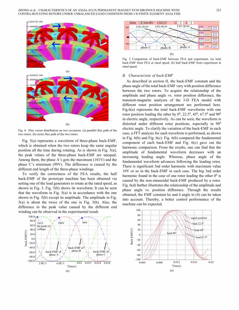
A. Comparison of 3-D FEA and Experiment To obtain the characteristics of the total back-EMF in the
stator winding, the FEA model is first set to a generator, in which the speeds of the two rotors are fixed at the rated value and no current flow in the winding due to an infinite series resistor in each phase. Fig. 4(a) and (b) represent the flux vector distribution of a quarter of the machine model on two occasions during the transient-magnetic analysis. Therein, Fig. 4(a) represents an occasion when the flux path of the two rotors is in parallel through the common stator core. On the contrary, in Fig. 4(b), the flux path on the stator core is in series.
ZHONG et al. : CHARACTERISTICS OF AN AXIAL-FLUX PERMANENT MAGNET SYNCHRONOUS MACHINE WITH 223 CONTRA-ROTATING ROTORS UNDER UNBALANCED LOAD CONDITION FROM 3-D FINITE ELEMENT ANALYSIS
1.606875E+000
1.400000E+000
1.200000E+000
8.000000E-001
1.000000E+000
6.000000E-001
4.000000E-001
2.000000E-001
5.707411E-003 (a)
1.604485E+000
1.400000E+000
1.200000E+000
8.000000E-001
1.000000E+000
6.000000E-001
4.000000E-001
2.000000E-001
3.988538E-002 (b)
Fig. 4. Flux vector distribution on two occasions. (a) parallel flux path of the two rotors. (b) series flux path of the two rotors
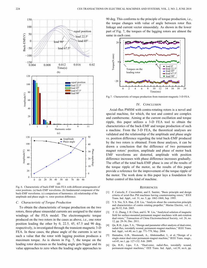
Fig. 5(a) represents a waveform of three-phase back-EMF, which is obtained when the two rotors keep the same angular position all the time during rotating. As is shown in Fig. 5(a), the peak values of the three-phase back-EMF are unequal. Among them, the phase A’s gets the maximum (101V) and the phase C’s minimum (99V). The difference is caused by the different end length of the three-phase windings.
To verify the correctness of the FEA results, the half back-EMF of the prototype machine has been obtained via setting one of the load generators to rotate at the rated speed, as shown in Fig. 3. Fig. 5(b) shows its waveform. It can be seen that the waveform in Fig. 5(a) is in accordance with the one shown in Fig. 5(b) except its amplitude. The amplitude in Fig. 5(a) is about the twice of the one in Fig. 5(b). Also, the difference in the peak value caused by the different end winding can be observed in the experimental result.
back
-EM
F(V
)
−100.0−80.0−60.0−40.0−20.0
0.020.040.060.080.0
100.0
101Vthe peak of voltage
100V 99V
back-EMF of phase A
back-EMF of phase B back-EMF of
phase C
2.0E-3 6.0E-3 0.01 0.012 0.014 0.016Time(s)
(a)
time 2 ms/div CH123 U I╳ ╳11
phase C phase B phase A−100
100 CH3:49.85 CH2:48.56 CH1:50.60 CH1
CH2
CH3
CH4
(v)37.333
36.645
36.645
0.004
50.60-50.30
49.85
48.56
-0.013
-48.56
-49.60
0.016
(b)
Fig. 5 Comparison of back-EMF between FEA and experiment. (a) total back-EMF from FEA at rated speed. (b) half back-EMF from experiment at rated speed.
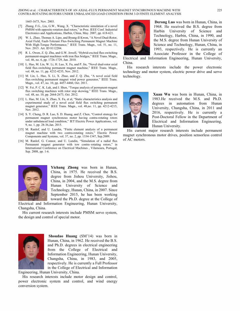
B. Characteristic of back-EMF As described in section II, the back-EMF constant and the
phase angle of the total back-EMF vary with position difference between the two rotors. To acquire the relationship of the amplitude and phase angle vs. rotor position difference, the transient-magnetic analyses of the 3-D FEA model with different rotor position arrangement are performed here. Fig.6(a) represents the total back-EMF waveforms with one rotor position leading the other by 00, 22.50, 450, 67.50 and 900 in electric angle, respectively. As can be seen, the waveform is distorted under different rotor positions, especially in 900 electric angle. To clarify the variation of the back-EMF in each case, a FFT analysis for each waveform is performed, as shown in Fig. 6(b) and Fig. 6(c). Fig. 6(b) compared the fundamental component of each back-EMF and Fig. 6(c) gave out the harmonic comparison. From the results, one can find that the amplitude of fundamental waveform decreases with an increasing leading angle. Whereas, phase angle of the fundamental waveform advances following the leading rotor. There is significant 3nd order harmonic with maximum value 10V or so in the back-EMF in each case. The big 3nd order harmonic found in the case of one rotor leading the other 00 is caused by the non-sinusoidal back-EMF produced by a rotor. Fig. 6(d) further illustrates the relationship of the amplitude and phase angle vs. position difference. Through the results obtained, the EMF constant ke and δ angle in (4) can be taken into account. Thereby, a better control performance of the machine can be expected.
Bac
k-EM
F(V
)
−100−80
−60
−40
−20
0
20
4060
80
100
0.004Time(s)
0.008 0.012 0.016 0.02
lead 90°
lead 22.5°
lead 45°
lead 67.5°
equal position
(a)
224 CES TRANSACTIONS ON ELECTRICAL MACHINES AND SYSTEMS, VOL. 2, NO. 2, JUNE 2018
Bac
k-EM
F(V
)
−150
−100
−50
0
50
100
150
0.004Time(s)
0.008 0.012 0.016 0.02
lead 90°
lead 22.5°lead 45°
lead 67.5°
equal position
(b)
Am
plitu
de(V
)
0
20
40
60
80
100
lead 90°
lead 22.5°lead 45°lead 67.5°
equal position
120
1Harmonic order
3 5 7 9 11
(c)
Am
plitu
de(V
)
0
20
40
60
80
100
120
Phase angle(deg)
0
10
20
30
40
50AmplitudePhase angle
0 10 20 30 40 50 60 70 80 90 (d)
Fig. 6. Characteristic of back-EMF from FEA with different arrangements of rotor positions. (a) back-EMF waveforms. (b) fundamental component of the back-EMF waveforms. (c) comparison of harmonics. (d) relationship of the amplitude and phase angle vs. rotor position difference.
C. Characteristic of Torque Production To obtain the characteristic of torque production on the two
rotors, three-phase sinusoidal currents are assigned to the stator windings of the FEA model. The electromagnetic torque produced on the two rotors in the cases as above, i.e., one rotor position leading the other by 0, 22.5, 45, 67.5 and 90 deg, respectively, is investigated through the transient-magnetic 3-D FEA. In these cases, the phase angle of the currents is set to such a value that the rotor with lagging position produces a maximum torque. As is shown in Fig. 7, the torque on the leading rotor decreases as the leading angle gets bigger and its value approaches to zero when the leading angle approaches to
90 deg. This conforms to the principle of torque production, i.e., the torque changes with value of angle between rotor flux linkage and current vector sinusoidaly. As shown in the lower part of Fig. 7, the torques of the lagging rotors are almost the same in each case.
−20
0
20
Torq
ue(N
.mm
)
0Time(ms)
4 8 12 16 20
Torques on the leading rotor
lead 90°
lead 22.5°lead 45°lead 67.5°
lead 0°
2 6 10 14 18
Fig.7. Characteristic of torque production from transient-magnetic 3-D FEA.
IV. CONCLUSION Axial-flux PMSM with contra-rotating rotors is a novel and
special machine, for which, the test and control are complex and cumbersome. Aiming at the current oscillation and torque ripple, this paper utilizes a 3-D FEA tool to obtain the characteristics of the back-EMF and torque production of such a machine. From the 3-D FEA, the theoretical analyses are validated and the relationship of the amplitude and phase angle vs. position difference regarding the total back-EMF produced by the two rotors is obtained. From those analyses, it can be drawn a conclusion that the difference of two permanent magnet rotors’ position, amplitude and phase of motor back EMF waveforms are distorted, amplitude with position difference increases with phase difference increases gradually. The offset of the total back-EMF phase is one of the results of the torque ripple of the motor, so the results of this paper provide a reference for the improvement of the torque ripple of the motor. The work done in this paper lays a foundation for better control of this kind of machine.
REFERENCES [1] F. Caricchi, F. Crescimbini, and E. Santini, “Basic principle and design
criteria of axial-flux PM machines having counterrotating rotors,” IEEE Trans. Ind. Appl., vol. 31, no. 5, pp. 1062-1068, Sep. 1995.
[2] Y.S. Nie, X.S. Han, Z.H. Liu, “Analysis about the construction principle and characteristics of contra rotating propeller,” Marine Electric, vol. 2, pp.50-52, Feb. 2005.
[3] F. G. Zhang, J. H. Chen, and G. W. Liu, “Analytical solution of magnetic field for surface-mounted permanent magnet machines with anti-rotation dual rotors,” Transaction of China Electromechnical Society, vol. 26, no. 12, pp. 28-36, Dec. 2011.
[4] Qu, R.H., Lipo, T.A., “Design and parameter effect analysis of dual-rotor, radial-flux, toroidally wound, permanent-magnet machines,” IEEE Trans. Ind. Appl., vol.40, no.3, pp. 771-779, May. 2004.
[5] Hamadou, G.B., Masmoudi, A., Abdennadher, I., et al.,“Design of a single-stator dual-rotor permanent-magnet machine,” IEEE Trans. magn., vol.45, no.1, pp. 127-132. Feb. 2009.
ZHONG et al. : CHARACTERISTICS OF AN AXIAL-FLUX PERMANENT MAGNET SYNCHRONOUS MACHINE WITH 225 CONTRA-ROTATING ROTORS UNDER UNBALANCED LOAD CONDITION FROM 3-D FINITE ELEMENT ANALYSIS
1665-1673, Nov. 2003. [7] Zhang, F.G., Liu, G.W., Wang, X. “Characteristic simulation of a novel
PMSM with opposite-rotation dual rotors,” in Proc. IEEE Conf. Industrial Electronics and Applications, Harbin, China, May. 2007, pp. 618-621.
[8] W. L. Zhao, Thomas A. Lipo, and Byung-II Kwon, “A Novel Dual-Rotor, Axial Field, Fault-Tolerant Flux-Switching Permanent Magnet Machine With High-Torque Performance,” IEEE Trans. Magn., vol. 51, no. 11, Nov. 2015. Art. ID 8112204.
[9] R. L. Owen, Z. Q. Zhu, and G.W. Jewell, “Hybrid-excited flux-switching permanent-magnet machines with iron flux bridges,” IEEE Trans. Magn., vol. 46, no. 6, pp. 1726-1729, Jun. 2010.
[10] L. Hao, M. Lin, W. Li, H. Luo, X. Fu, and P. Jin, “Novel dual-rotor axial field flux-switching permanent magnet machine,” IEEE Trans. Magn., vol. 48, no. 11, pp. 4232-4235, Nov. 2012.
[11] M. Lin, L. Hao, X. Li, X. Zhao, and Z. Q. Zhu, “A novel axial field flux-switching permanent magnet wind power generator,” IEEE Trans. Magn., vol. 47, no. 10, pp. 4457-4460, Oct. 2011.
[12] W. Fei, P. C. K. Luk, and J. Shen, “Torque analysis of permanent-magnet flux switching machines with rotor step skewing,” IEEE Trans. Magn., vol. 48, no. 10, pp. 2664-2673, Oct. 2012.
[13] L. Hao, M. Lin, X. Zhao, X. Fu, et al, “Static characteristics analysis and experimental study of a novel axial field flux switching permanent magnet generator,” IEEE Trans. Magn., vol. 48,no. 11, pp. 4212-4215, Nov. 2012.
[14] S. Y. Cheng, D. R. Luo, S. D. Huang, and Z. Chen, “Control strategy for permanent magnet synchronous motor having contra-rotating rotors under unbalanced load condition,” IET Electric Power Applications, vol. 9, no. 1, pp. 28-36,Jan. 2015.
[15] M. Ranlof, and U. Lundin, “Finite element analysis of a permanent magnet machine with two contra-rotating rotors,” Electric Power Components and Systems, vol. 37, no. 2, pp. 1334-1347, Sep.2009.
[16] M. Ranlof, G. Connor, and U. Lundin, “Simulation of a radial flux Permanent magnet generator with tow contra–rotating rotors,” in International Conference on Electrical Machines , Vilamoura, Portugal, Sep. 2008, pp. 1-6.
Yichang Zhong was born in Hunan, China, in 1975. He received the B.S. degree from Jishou University, Jishou, China, in 2004, and the M.S. degree from Hunan University of Science and Technology, Hunan, China, in 2007. Since September 2015, he has been working toward the Ph.D. degree at the College of
Electrical and Information Engineering, Hunan University, Changsha, China.
His current research interests include PMSM servo system, the design and control of special motor.
Shoudao Huang (SM’14) was born in Hunan, China, in 1962. He received the B.S. and Ph.D. degrees in electrical engineering from the College of Electrical and Information Engineering, Hunan University, Changsha, China, in 1983, and 2005, respectively. He is currently a Full Professor in the College of Electrical and Information
Engineering, Hunan University, China. His research interests include motor design and control,
power electronic system and control, and wind energy conversion system.
Derong Luo was born in Hunan, China, in 1968. He received the B.S. degree from Harbin University of Science and Technology, Harbin, China, in 1990, and the M.S. degree from Hunan University of Science and Technology, Hunan, China, in 1993, respectively. He is currently an Associate Professor in the College of
Electrical and Information Engineering, Hunan University, China.
His research interests include the power electronic technology and motor system, electric power drive and servo technology.
Xuan Wu was born in Hunan, China, in 1983.He received the M.S. and Ph.D. degrees in automation from Hunan University, Changsha, China, in 2011 and 2016, respectively. He is currently a Post-Doctoral Fellow in the Department of Electrical and Information Engineering, Hunan University.
His current major research interests include permanent magnet synchronous motor drives, position sensorless control of AC motors.


![Design of Axial-Flux Motor for Traction Applicationradial-flux motors, the axial-flux ones can be modulated which leads to the increase of their torque generation capabilities [1,2,4].](https://static.documents.pub/doc/80x56/5e7ecdb1efdfb0767a23aa9b/design-of-axial-flux-motor-for-traction-application-radial-flux-motors-the-axial-flux.jpg)


