Proceedings of GT2006 ASME Turbo Expo 2006: Power for Land, Sea and Air
May 8-11, 2006, Barcelona, Spain
GT2006-91217
Characteristics of Combustion Processes in a Stagnation Point Reverse Flow Combustor
M. K. Bobba, P. Gopalakrishnan, J. M. Seitzman, B. T. Zinn
School of Aerospace Engineering Georgia Institute of Technology
Atlanta, GA ABSTRACT
The performance of dry, low NOx gas turbines, which employ lean premixed (or partially premixed) combustors, is often limited by static and dynamic combustor stability, power density limitations and expensive premixing hardware. To overcome these issues, a novel design, referred to as the Stagnation Point Reverse Flow (SPRF) combustor, has recently been developed. Various optical diagnostic techniques are employed here to elucidate the combustion processes in this novel combustor. These include simultaneous planar laser-induced fluorescence (PLIF) imaging of OH radicals and chemiluminescence imaging, and separate experiments with particle image velocimetry and elastic laser sheet scattering from liquid particles seeded into the fuel. The SPRF combustor achieves internal exhaust gas recirculation and efficient mixing, which eliminates local peaks in temperature. This results in low NOx emissions, limited by flame zone (prompt) production, for both premixed and non-premixed modes of operation. The flame is anchored in a region of reduced velocity and high turbulent intensities, which promotes mixing of hot products into the reactants, thus enabling stable operation of the combustor even at very lean equivalence ratios. Also, the flame structure and flow characteristics were found to remain invariant at high loadings, i.e., mass flow rates. Combustion in the non-premixed mode of operation is found to be similar to the premixed case, with the OH PLIF measurements indicating that nonpremixed flame burns at an equivalence ratio that is close to the overall combustor equivalence ratio. Similarities in emission levels between premixed and non-premixed modes are thus attributable to efficient fuel-air mixing in the nonpremixed mode, and entrainment of hot products into the reactant stream before burning occurs.
INTRODUCTION
The drive towards reduced pollutant emissions has prompted the gas turbine industry to develop cleaner, more environmentally friendly power and propulsion systems, while
simultaneously maintaining (or improving) efficiency, operability and performance. Lean premixed combustion, preheating and exhaust gas recirculation are among the common approaches used to achieve this goal. Alternate concepts to reduce peak temperatures include staged combustion and catalytic combustion.
Preheating of combustion air or reactants has been employed in many types of practical combustion systems.1 It has long been recognized that significant savings in fuel can occur with energy recovery from furnace exhaust gases, for example through the use of recuperators and regenerators. Raising the combustion air temperature with heat extracted from furnace exhaust gases provides many benefits, such as enhanced efficiency and flame stability, and reduced pollutant emission. Gupta2 reported that flames with highly preheated combustion air were much more stable and homogeneous (both temporally and spatially) as compared to room-temperature combustion air and hence could operate at much leaner equivalence ratios Under these conditions, combustion is no longer confined to a thin reaction front, instead a distributed combustion zone spread over a large volume is realized. This results in a uniform thermal field and lower peak temperatures, which generates less NOx.
Lean premixed or partially premixed combustion also generally results in lower peak temperatures compared to nonpremixed combustion; thus it is a common approach for lowering emissions. In both premixed and partially premixed combustors, however, combustor stability is compromised as the mixture is made leaner, because the weaker combustion process is more vulnerable to small perturbations in combustor operating conditions Thus combustor blowout (static stability) and combustion instabilities (dynamic stability) typically become an operability issue for lean, premixed combustors.3
The principle of exhaust gas recirculation is based on lowering the oxygen concentration before combustion with inert gas that is provided by the engine itself. Arai4 showed that the ignition delay of fuel is elongated by low oxygen concentration. The low oxygen concentration also reduces the reaction rates and allows for combustion to be spread over a
larger region. Thus exhaust gas recirculation can also suppress peak flame temperatures and lower pollutant emissions.
In the past, combustors that incorporate reactant preheating and flue gas recirculation have been developed for use in land-based gas turbines. Wunning et al.5,6 identified a set of operating conditions at which no visually distinct flame was observed. This “flameless oxidation” process was found to produce low NOx levels (of the order of 2-29ppm @ 15% O2). Similar combustion characteristics were demonstrated with high temperature air. Fujimori et al.7 demonstrated that dilution of fuel-air mixtures for high-speed lifted jet flames also helped to lower reaction rates and hence reduce emission levels. It was shown that lifted flames result in broadened reaction zones thereby producing a more uniform temperature profile. However, much of this earlier work has been directed towards developing large volume industrial burners.
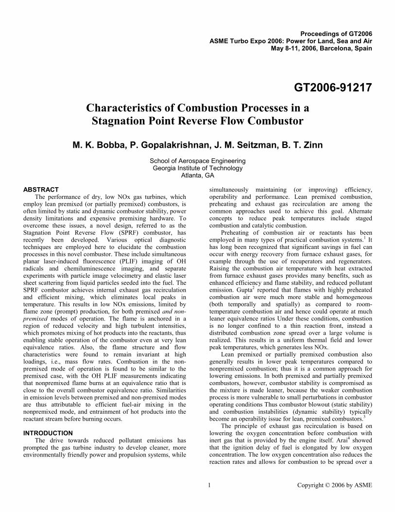
A compact, low emissions combustor design that incorporates some aspects of these approaches has recently been demonstrated.8 An important attribute of this design, designated the Stagnation Point Reverse Flow (SPRF) combustor, is the ability of the combustor to burn gaseous or liquid fuels in premixed or non-premixed modes of combustion while maintaining low emissions.8 In its simplest configuration (Figure 1), the combustor consists of a tube with one end open and the other closed. Unlike most combustors, the reactants and products enter and leave this combustor at the same (open) end. In the basic design, the reactants are injected along the combustor center line and move towards the closed end. The SPRF combustor design has demonstrated ultra lean operation with good stability while producing minimal NOx with corresponding CO emissions under 10 ppm.8 Stable operation of the combustor at lean equivalence ratios may also be leveraged to burn alternate fuels with lower flame speeds (or heating values) without a major penalty on emissions.
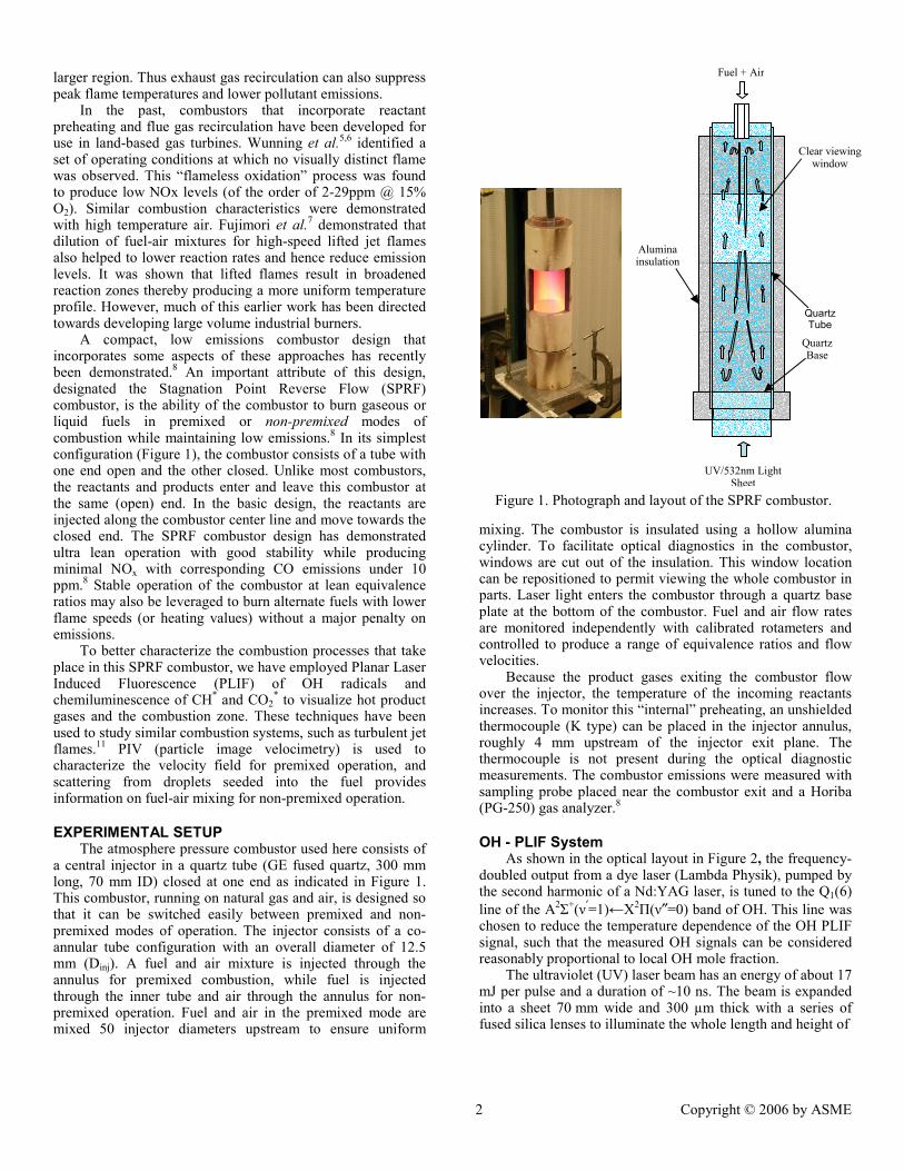
To better characterize the combustion processes that take place in this SPRF combustor, we have employed Planar Laser Induced Fluorescence (PLIF) of OH radicals and chemiluminescence of CH* and CO2
* to visualize hot product gases and the combustion zone. These techniques have been used to study similar combustion systems, such as turbulent jet flames.11 PIV (particle image velocimetry) is used to characterize the velocity field for premixed operation, and scattering from droplets seeded into the fuel provides information on fuel-air mixing for non-premixed operation.
EXPERIMENTAL SETUP The atmosphere pressure combustor used here consists of
a central injector in a quartz tube (GE fused quartz, 300 mm long, 70 mm ID) closed at one end as indicated in Figure 1. This combustor, running on natural gas and air, is designed so that it can be switched easily between premixed and non-premixed modes of operation. The injector consists of a co-annular tube configuration with an overall diameter of 12.5 mm (Dinj). A fuel and air mixture is injected through the annulus for premixed combustion, while fuel is injected through the inner tube and air through the annulus for non-premixed operation. Fuel and air in the premixed mode are mixed 50 injector diameters upstream to ensure uniform
mixing. The combustor is insulated using a hollow alumina cylinder. To facilitate optical diagnostics in the combustor, windows are cut out of the insulation. This window location can be repositioned to permit viewing the whole combustor in parts. Laser light enters the combustor through a quartz base plate at the bottom of the combustor. Fuel and air flow rates are monitored independently with calibrated rotameters and controlled to produce a range of equivalence ratios and flow velocities.
Because the product gases exiting the combustor flow over the injector, the temperature of the incoming reactants increases. To monitor this “internal” preheating, an unshielded thermocouple (K type) can be placed in the injector annulus, roughly 4 mm upstream of the injector exit plane. The thermocouple is not present during the optical diagnostic measurements. The combustor emissions were measured with sampling probe placed near the combustor exit and a Horiba (PG-250) gas analyzer.8
OH - PLIF System As shown in the optical layout in Figure 2, the frequency-
doubled output from a dye laser (Lambda Physik), pumped by the second harmonic of a Nd:YAG laser, is tuned to the Q1(6) line of the A2Σ+(ν′=1)←X2Π(ν″=0) band of OH. This line was chosen to reduce the temperature dependence of the OH PLIF signal, such that the measured OH signals can be considered reasonably proportional to local OH mole fraction.
The ultraviolet (UV) laser beam has an energy of about 17 mJ per pulse and a duration of ~10 ns. The beam is expanded into a sheet 70 mm wide and 300 µm thick with a series of fused silica lenses to illuminate the whole length and height of
Figure 1. Photograph and layout of the SPRF combustor.
the combustor. The emitted fluorescence light is detected at right angles to the sheet using a 25 mm intensified camera (PI- MAX, 1024×256 pixels) equipped with a UV-Nikkor lens system (105 mm, f/4.5). The detected fluorescence is limited to wavelengths of 300-370 nm with WG305 and UG11 Schott glass filters placed in front of the camera lens. The spatial resolution obtained with this configuration is 300 µm.
CH*/CO2* Chemiluminescence
The chemiluminescence signal emitted from the flame zone is also collected at right angles to the sheet with a second intensified camera (18 mm intensifier, 384×576 pixels) equipped with a narrow band interference filter centered at 430 nm, which passes emission from both CH* and CO2
*. The chemiluminescence camera is synchronized such that the exposure starts after the fluorescence signal decays, and the exposure time is 250 µs. Since the fluorescence lifetime is short (<10 ns), the PLIF and chemiluminescence images record essentially simultaneous features of the flame. The camera’s field of view is set to match the width of the PLIF image region, which covers the whole width of the combustor. This gives a spatial resolution of ~250 µm for the chemiluminescence images. PIV and Scattering Studies
Particle image velocimetry (PIV) is a non-intrusive technique that can be used to obtain instantaneous whole field velocity measurements.9 PIV is a direct measure of the velocity of a fluid since it depends directly on the displacement of a tracer particle during a known time. Here, the combustion air is seeded with 1-2 µm aluminum oxide particles, which are illuminated with a laser light sheet produced from the second harmonic output (532 nm) of a dual-head, pulsed Nd:YAG laser. Each laser head is capable of providing 150 mJ/pulse at 10 Hz. The beam is converted into a
thin sheet with three cylindrical lenses and enters from the bottom of the combustor. The illuminated particles in the combustor are imaged using a 12-bit interline CCD camera (MicroMAX, 1300×1030 pixels) equipped with a 50 mm camera lens (Nikkor, f/1.8). Separately, mixing of unburned, cold fuel with air and hot products are studied by seeding the fuel with ~5 µm diameter olive oil droplets and collecting the scattered laser light with the same optical system used for PIV. The oil droplets were generated using a standard aerosol generator.10
RESULTS AND DISCUSSION NOx Emissions
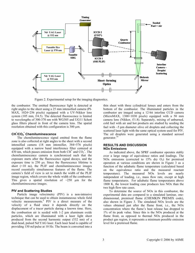
As indicated above, the SPRF combustor operates stably over a large range of equivalence ratios and loadings. The NOx emissions (corrected to 15% dry O2) for premixed operation at various conditions are shown in Figure 3 as a function of the adiabatic flame temperature (calculated based on the equivalence ratio and the measured reactant temperature). The measured NOx levels are nearly independent of loading, i.e., mass flow rate, except at high flame temperatures. For adiabatic flame temperatures above 1800 K, the lowest loading case produces less NOx than the two high flow rate cases.
To determine the source of NOx in this combustor, the experimental data are compared to a simulated laminar, one-dimensional, premixed flame (CHEMKIN PREMIX code), also shown in Figure 3. The simulated NOx levels are the values obtained just after the flame front, i.e., the NOx concentration where the flame’s heat release has dropped to 1% of its peak value. Since this is the NOx produced at the flame front, as opposed to thermal NOx produced in the product gas region, it represents a minimum possible emission level for a premixed flame.
Figure 2. Experimental setup for the imaging diagnostics.
reasonably match the calculated values below ~1800K (the experimental uncertainty is ±0.5-1 ppm). Thus we conclude that NOx emissions from the SPRF combustor at lower temperatures are limited by flame zone (prompt) NOx production, which explains the lack of loading dependence at low temperatures. At higher equivalence ratios and flame temperatures, where one would expect the thermal (Zeldovich) mechanism to become important in the post flame region, NOx emissions should also depend on the temperature-time history of the products. The similarity in the NOx emissions for the two high loading cases suggests either: 1) a trade-off between reduced residence time and higher product temperatures at higher loadings (where heat losses become a relatively smaller fraction of the heating rate), or 2) a small change in effective residence time due to changes in internal recirculation of products within the combustor. The lower NOx production for the low flowrate case above 1800 K, and the closer agreement with the prompt NOx calculations, can be explained by heat losses. For the lower loading, heat losses to the combustor walls become a larger fraction of the heat release, thereby reducing the post-flame temperatures and the thermal NOx production.
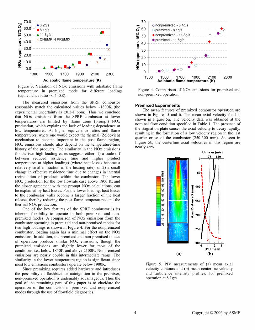
One of the key features of the SPRF combustor is its inherent flexibility to operate in both premixed and non-premixed modes. A comparison of NOx emissions from the combustor operating in premixed and non-premixed modes for two high loadings is shown in Figure 4. For the nonpremixed combustor, loading again has a minimal effect on the NOx emissions. In addition, the premixed and non-premixed modes of operation produce similar NOx emissions, though the premixed emissions are slightly lower for most of the conditions i.e., below 1850K and above 2100K. Nonpremixed emissions are nearly double in this intermediate range. The similarity in the lower temperature region is significant since most low emissions combustors operate below 1900K.
Since premixing requires added hardware and introduces the possibility of flashback or autoignition in the premixer, non-premixed operation is undeniably advantageous. Thus the goal of the remaining part of this paper is to elucidate the operation of the combustor in premixed and nonpremixed modes through the use of flowfield diagnostics.
Premixed Experiments
The mean features of premixed combustor operation are shown in Figures 5 and 6. The mean axial velocity field is shown in Figure 5a. The velocity data was obtained at the nominal flow condition specified in Table 1. The presence of the stagnation plate causes the axial velocity to decay rapidly, resulting in the formation of a low velocity region in the last quarter or so of the combustor (250-300 mm). As seen in Figure 5b, the centerline axial velocities in this region are nearly zero.
m/s
(a) (b)
m/s
m/s
(a) (b)
0.0
10.0
20.0
30.0
40.0
50.0
60.0
70.0
1300 1500 1700 1900 2100 2300Adiabatic flame temperature (K)
NO
x (p
pm, c
orr.
15%
O2) 3.2g/s
8.1g/s11.8g/sCHEMKIN PREMIX
0
10
20
30
40
50
60
70
1300 1500 1700 1900 2100 2300Adiabatic flame temperature (K)
Figure 5. PIV measurements of (a) mean axial velocity contours and (b) mean centerline velocity and turbulence intensity profiles, for premixed operation at 8.1g/s.
Figure 4. Comparison of NOx emissions for premixed and non-premixed operation.
Figure 3. Variation of NOx emissions with adiabatic flame temperature in premixed mode for different loadings (equivalence ratio ~0.5–0.8).
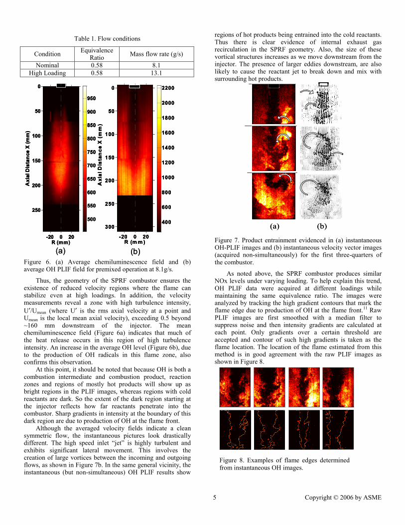
Figure 6. (a) Average chemiluminescence field and (b) average OH PLIF field for premixed operation at 8.1g/s.
Thus, the geometry of the SPRF combustor ensures the existence of reduced velocity regions where the flame can stabilize even at high loadings. In addition, the velocity measurements reveal a zone with high turbulence intensity, U′/Umean (where U′ is the rms axial velocity at a point and Umean is the local mean axial velocity), exceeding 0.5 beyond ~160 mm downstream of the injector. The mean chemiluminescence field (Figure 6a) indicates that much of the heat release occurs in this region of high turbulence intensity. An increase in the average OH level (Figure 6b), due to the production of OH radicals in this flame zone, also confirms this observation.
At this point, it should be noted that because OH is both a combustion intermediate and combustion product, reaction zones and regions of mostly hot products will show up as bright regions in the PLIF images, whereas regions with cold reactants are dark. So the extent of the dark region starting at the injector reflects how far reactants penetrate into the combustor. Sharp gradients in intensity at the boundary of this dark region are due to production of OH at the flame front.
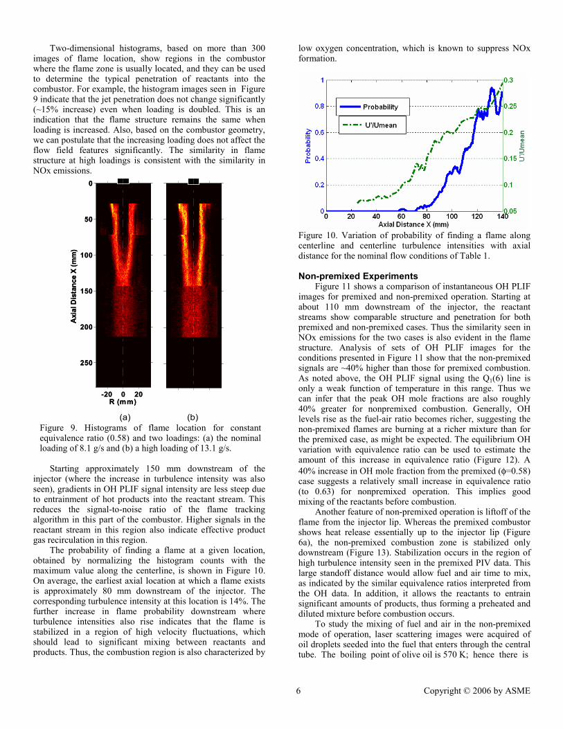
Although the averaged velocity fields indicate a clean symmetric flow, the instantaneous pictures look drastically different. The high speed inlet “jet” is highly turbulent and exhibits significant lateral movement. This involves the creation of large vortices between the incoming and outgoing flows, as shown in Figure 7b. In the same general vicinity, the instantaneous (but non-simultaneous) OH PLIF results show
regions of hot products being entrained into the cold reactants. Thus there is clear evidence of internal exhaust gas recirculation in the SPRF geometry. Also, the size of these vortical structures increases as we move downstream from the injector. The presence of larger eddies downstream, are also likely to cause the reactant jet to break down and mix with surrounding hot products.
(a) (b)(a) (b) Figure 7. Product entrainment evidenced in (a) instantaneous OH-PLIF images and (b) instantaneous velocity vector images (acquired non-simultaneously) for the first three-quarters of the combustor.
As noted above, the SPRF combustor produces similar NOx levels under varying loading. To help explain this trend, OH PLIF data were acquired at different loadings while maintaining the same equivalence ratio. The images were analyzed by tracking the high gradient contours that mark the flame edge due to production of OH at the flame front.11 Raw PLIF images are first smoothed with a median filter to suppress noise and then intensity gradients are calculated at each point. Only gradients over a certain threshold are accepted and contour of such high gradients is taken as the flame location. The location of the flame estimated from this method is in good agreement with the raw PLIF images as shown in Figure 8.
R (m m )
Axi
al D
ista
nce
X (
mm
)
-20 0 20
0
50
100
150
200
250
300400
600
800
1000
1200
1400
1600
1800
2000
2200
R (mm)
Axi
al D
ista
nce
X (m
m)
-20 0 20
0
50
100
150
200
250
500
550
600
650
700
750
800
850
900
950
R (m m )
Axi
al D
ista
nce
X (
mm
)
-20 0 20
0
50
100
150
200
250
300400
600
800
1000
1200
1400
1600
1800
2000
2200
R (mm)
Axi
al D
ista
nce
X (m
m)
-20 0 20
0
50
100
150
200
250
500
550
600
650
700
750
800
850
900
950
(a) (b)R (m m )
Axi
al D
ista
nce
X (
mm
)
-20 0 20
0
50
100
150
200
250
300400
600
800
1000
1200
1400
1600
1800
2000
2200
R (mm)
Axi
al D
ista
nce
X (m
m)
-20 0 20
0
50
100
150
200
250
500
550
600
650
700
750
800
850
900
950
R (m m )
Axi
al D
ista
nce
X (
mm
)
-20 0 20
0
50
100
150
200
250
300400
600
800
1000
1200
1400
1600
1800
2000
2200
R (mm)
Axi
al D
ista
nce
X (m
m)
-20 0 20
0
50
100
150
200
250
500
550
600
650
700
750
800
850
900
950
(a) (b)
Figure 8. Examples of flame edges determined from instantaneous OH images.
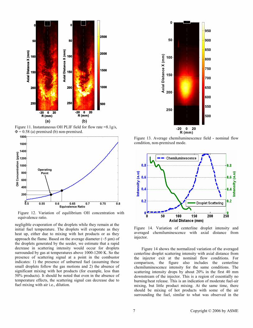
Two-dimensional histograms, based on more than 300 images of flame location, show regions in the combustor where the flame zone is usually located, and they can be used to determine the typical penetration of reactants into the combustor. For example, the histogram images seen in Figure 9 indicate that the jet penetration does not change significantly (~15% increase) even when loading is doubled. This is an indication that the flame structure remains the same when loading is increased. Also, based on the combustor geometry, we can postulate that the increasing loading does not affect the flow field features significantly. The similarity in flame structure at high loadings is consistent with the similarity in NOx emissions.
R (mm)
Axi
al D
ista
nce
X (m
m)
-20 0 20
0
50
100
150
200
250
R (mm)
Axi
al D
ista
nce
X (m
m)
-20 0 20
0
50
100
150
200
250
(b)(a) Figure 9. Histograms of flame location for constant equivalence ratio (0.58) and two loadings: (a) the nominal loading of 8.1 g/s and (b) a high loading of 13.1 g/s.
Starting approximately 150 mm downstream of the
injector (where the increase in turbulence intensity was also seen), gradients in OH PLIF signal intensity are less steep due to entrainment of hot products into the reactant stream. This reduces the signal-to-noise ratio of the flame tracking algorithm in this part of the combustor. Higher signals in the reactant stream in this region also indicate effective product gas recirculation in this region.
The probability of finding a flame at a given location, obtained by normalizing the histogram counts with the maximum value along the centerline, is shown in Figure 10. On average, the earliest axial location at which a flame exists is approximately 80 mm downstream of the injector. The corresponding turbulence intensity at this location is 14%. The further increase in flame probability downstream where turbulence intensities also rise indicates that the flame is stabilized in a region of high velocity fluctuations, which should lead to significant mixing between reactants and products. Thus, the combustion region is also characterized by
low oxygen concentration, which is known to suppress NOx formation.
Figure 10. Variation of probability of finding a flame along centerline and centerline turbulence intensities with axial distance for the nominal flow conditions of Table 1. Non-premixed Experiments
Figure 11 shows a comparison of instantaneous OH PLIF images for premixed and non-premixed operation. Starting at about 110 mm downstream of the injector, the reactant streams show comparable structure and penetration for both premixed and non-premixed cases. Thus the similarity seen in NOx emissions for the two cases is also evident in the flame structure. Analysis of sets of OH PLIF images for the conditions presented in Figure 11 show that the non-premixed signals are ~40% higher than those for premixed combustion. As noted above, the OH PLIF signal using the Q1(6) line is only a weak function of temperature in this range. Thus we can infer that the peak OH mole fractions are also roughly 40% greater for nonpremixed combustion. Generally, OH levels rise as the fuel-air ratio becomes richer, suggesting the non-premixed flames are burning at a richer mixture than for the premixed case, as might be expected. The equilibrium OH variation with equivalence ratio can be used to estimate the amount of this increase in equivalence ratio (Figure 12). A 40% increase in OH mole fraction from the premixed (φ=0.58) case suggests a relatively small increase in equivalence ratio (to 0.63) for nonpremixed operation. This implies good mixing of the reactants before combustion.
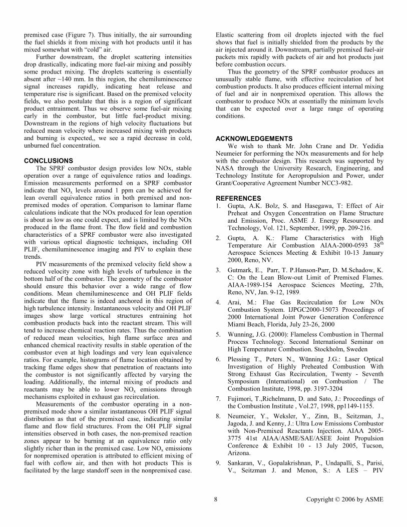
Another feature of non-premixed operation is liftoff of the flame from the injector lip. Whereas the premixed combustor shows heat release essentially up to the injector lip (Figure 6a), the non-premixed combustion zone is stabilized only downstream (Figure 13). Stabilization occurs in the region of high turbulence intensity seen in the premixed PIV data. This large standoff distance would allow fuel and air time to mix, as indicated by the similar equivalence ratios interpreted from the OH data. In addition, it allows the reactants to entrain significant amounts of products, thus forming a preheated and diluted mixture before combustion occurs.
To study the mixing of fuel and air in the non-premixed mode of operation, laser scattering images were acquired of oil droplets seeded into the fuel that enters through the central tube. The boiling point of olive oil is 570 K; hence there is
(a) (b) Figure 11. Instantaneous OH PLIF field for flow rate =8.1g/s, Φ = 0.58 (a) premixed (b) non-premixed.
0.5 0.55 0.6 0.65 0.7 0.75 0.80
200
400
600
800
1000
1200
1400
1600
1800
OH
Con
cent
ratio
n (p
pm)
Equivalence Ratio
OperatingPoint
negligible evaporation of the droplets while they remain at the initial fuel temperature. The droplets will evaporate as they heat up, either due to mixing with hot products or as they approach the flame. Based on the average diameter (~5 µm) of the droplets generated by the seeder, we estimate that a rapid decrease in scattering intensity would occur for droplets surrounded by gas at temperatures above 1000-1200 K. So the presence of scattering signal at a point in the combustor indicates: 1) the presence of unburned fuel (assuming these small droplets follow the gas motions and 2) the absence of significant mixing with hot products (for example, less than 50% products). It should be noted that even in the absence of temperature effects, the scattering signal can decrease due to fuel mixing with air i.e., dilution.
R (mm)
Axi
al D
ista
nce
X (m
m)
-20 0 20
0
50
100
150
200
250500
550
600
650
700
750
800
850
900
950
Figure 13. Average chemiluminescence field - nominal flow condition, non-premixed mode.
Figure 14. Variation of centerline droplet intensity and averaged chemiluminescence with axial distance from injector.
Figure 14 shows the normalized variation of the averaged
centerline droplet scattering intensity with axial distance from the injector exit at the nominal flow conditions. For comparison, the figure also includes the centerline chemiluminescence intensity for the same conditions. The scattering intensity drops by about 20% in the first 40 mm downstream of the injector. This is a region of essentially no burning/heat release. This is an indication of moderate fuel-air mixing, but little product mixing. At the same time, there should be mixing of hot products with some of the air surrounding the fuel, similar to what was observed in the
Figure 12. Variation of equilibrium OH concentration with equivalence ratio.
premixed case (Figure 7). Thus initially, the air surrounding the fuel shields it from mixing with hot products until it has mixed somewhat with “cold” air.
Further downstream, the droplet scattering intensities drop drastically, indicating more fuel-air mixing and possibly some product mixing. The droplets scattering is essentially absent after ~140 mm. In this region, the chemiluminescence signal increases rapidly, indicating heat release and temperature rise is significant. Based on the premixed velocity fields, we also postulate that this is a region of significant product entrainment. Thus we observe some fuel-air mixing early in the combustor, but little fuel-product mixing. Downstream in the regions of high velocity fluctuations but reduced mean velocity where increased mixing with products and burning is expected,, we see a rapid decrease in cold, unburned fuel concentration.
CONCLUSIONS The SPRF combustor design provides low NOx, stable
operation over a range of equivalence ratios and loadings. Emission measurements performed on a SPRF combustor indicate that NOx levels around 1 ppm can be achieved for lean overall equivalence ratios in both premixed and non-premixed modes of operation. Comparison to laminar flame calculations indicate that the NOx produced for lean operation is about as low as one could expect, and is limited by the NOx produced in the flame front. The flow field and combustion characteristics of a SPRF combustor were also investigated with various optical diagnostic techniques, including OH PLIF, chemiluminescence imaging and PIV to explain these trends.
PIV measurements of the premixed velocity field show a reduced velocity zone with high levels of turbulence in the bottom half of the combustor. The geometry of the combustor should ensure this behavior over a wide range of flow conditions. Mean chemiluminescence and OH PLIF fields indicate that the flame is indeed anchored in this region of high turbulence intensity. Instantaneous velocity and OH PLIF images show large vortical structures entraining hot combustion products back into the reactant stream. This will tend to increase chemical reaction rates. Thus the combination of reduced mean velocities, high flame surface area and enhanced chemical reactivity results in stable operation of the combustor even at high loadings and very lean equivalence ratios. For example, histograms of flame location obtained by tracking flame edges show that penetration of reactants into the combustor is not significantly affected by varying the loading. Additionally, the internal mixing of products and reactants may be able to lower NOx emissions through mechanisms exploited in exhaust gas recirculation.
Measurements of the combustor operating in a non-premixed mode show a similar instantaneous OH PLIF signal distribution as that of the premixed case, indicating similar flame and flow field structures. From the OH PLIF signal intensities observed in both cases, the non-premixed reaction zones appear to be burning at an equivalence ratio only slightly richer than in the premixed case. Low NOx emissions for nonpremixed operation is attributed to efficient mixing of fuel with coflow air, and then with hot products This is facilitated by the large standoff seen in the nonpremixed case.
Elastic scattering from oil droplets injected with the fuel shows that fuel is initially shielded from the products by the air injected around it. Downstream, partially premixed fuel-air packets mix rapidly with packets of air and hot products just before combustion occurs.
Thus the geometry of the SPRF combustor produces an unusually stable flame, with effective recirculation of hot combustion products. It also produces efficient internal mixing of fuel and air in nonpremixed operation. This allows the combustor to produce NOx at essentially the minimum levels that can be expected over a large range of operating conditions.
ACKNOWLEDGEMENTS We wish to thank Mr. John Crane and Dr. Yedidia
Neumeier for performing the NOx measurements and for help with the combustor design. This research was supported by NASA through the University Research, Engineering, and Technology Institute for Aeropropulsion and Power, under Grant/Cooperative Agreement Number NCC3-982.
REFERENCES 1. Gupta, A.K. Bolz, S. and Hasegawa, T: Effect of Air
Preheat and Oxygen Concentration on Flame Structure and Emission, Proc. ASME J. Energy Resources and Technology, Vol. 121, September, 1999, pp. 209-216.
2. Gupta, A. K.: Flame Characteristics with High Temperature Air Combustion AIAA-2000-0593 38th Aerospace Sciences Meeting & Exhibit 10-13 January 2000, Reno, NV.
3. Gutmark, E., Parr, T. P.Hanson-Parr, D. M.Schadow, K. C: On the Lean Blow-out Limit of Premixed Flames. AIAA-1989-154 Aerospace Sciences Meeting, 27th, Reno, NV, Jan. 9-12, 1989.
4. Arai, M.: Flue Gas Recirculation for Low NOx Combustion System. IJPGC2000-15073 Proceedings of 2000 International Joint Power Generation Conference Miami Beach, Florida, July 23-26, 2000
5. Wunning, J.G. (2000): Flameless Combustion in Thermal Process Technology. Second International Seminar on High Temperature Combustion. Stockholm, Sweden
6. Plessing T., Peters N., Wünning J.G.: Laser Optical Investigation of Highly Preheated Combustion With Strong Exhaust Gas Recirculation, Twenty - Seventh Symposium (International) on Combustion / The Combustion Institute, 1998, pp. 3197-3204
7. Fujimori, T.,Richelmann, D. and Sato, J.: Proceedings of the Combustion Institute , Vol.27, 1998, pp1149-1155.
8. Neumeier, Y., Weksler, Y., Zinn, B., Seitzman, J., Jagoda, J. and Kenny, J.: Ultra Low Emissions Combustor with Non-Premixed Reactants Injection. AIAA 2005-3775 41st AIAA/ASME/SAE/ASEE Joint Propulsion Conference & Exhibit 10 - 13 July 2005, Tucson, Arizona.
9. Sankaran, V., Gopalakrishnan, P., Undapalli, S., Parisi, V., Seitzman J. and Menon, S.: A LES – PIV
Investigation of a Stagnation Point Reverse Flow Combustor. AIAA2005-3969 41st AIAA/ASME/SAE/ASEE Joint Propulsion Conference & Exhibit 10 - 13 July 2005, Tucson, Arizona.
10. Melling, A.: Tracer Particles and Seeding for Particle Image Velocimetry. 1997 Meas. Sci. Technol. 8 1406-1416.
11. Griebel, P., Bombach, R., Inauen, A., Schären, R., Schenker, S. and Siewert, P.: Flame Characteristics and Turbulent Flame Speeds of Turbulent, High-Pressure, Lean Premixed Methane/Air Flames. GT2005-68565 Proceedings of GT2005 ASME Turbo Expo 2005: Power for Land, Sea, and Air June 6-9, 2005, Reno-Tahoe, Nevada, USA
12. Griebel, P., Schären, R., Siewert, P., Bombach, R., Inauen, A. and Kreutner, W.: Flow Field and Structure of Turbulent High-Pressure Premixed Methane/Air Flames. GT2003-38398 Proceedings of ASME Turbo Expo 2003 Power for Land, Sea, and Air June 16-19, 2003, Atlanta, Georgia, USA
13. Muniz, L., Martınez, R. E. and Mungal, M. G.:1997 Application of PIV to Turbulent Reacting Flows Developments in Laser Techniques and Fluid Mechanics (Berlin: Springer) pp 411–424
14. Chapman, K., Keller, R. and Keshavarz, A.: Modeling and Parametric Studies of NOx Production in Natural Gas Fired Turbines with Lean Premixed Combustors. Proceedings of GMC GMRC Gas Machinery Conference October 6-8 2004, Albuquerque NM
15. Rizk, N. K. and Chin, J. S. : Modeling of NOx Formation in Diffusion Flame Combustors. AIAA 2002-3713 38th AIAA/ASME/SAE/ASEE Joint Propulsion Conference & Exhibit 7-10 July 2002, Indianapolis, Indiana