139
Characterization and Estimation of the Stiffness (or Impedance) of a Robot by Giorgio Grioli

Characterization and Estimation of the Stiffness (or Impedance) of a Robot
by Giorgio Grioli

Part 0
a recap on Soft Robots and their actuation
by Giorgio Grioli
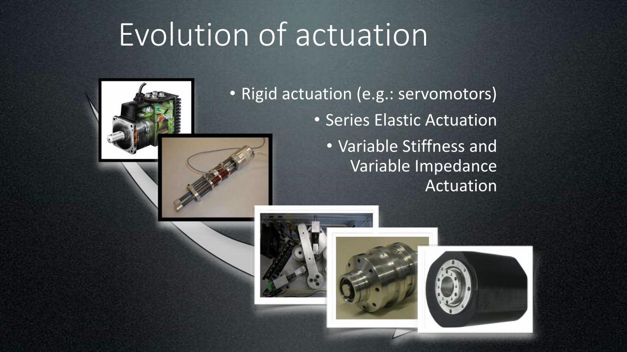
Evolution of actuation
• Rigid actuation (e.g.: servomotors)
• Series Elastic Actuation
• Variable Stiffness and Variable Impedance
Actuation
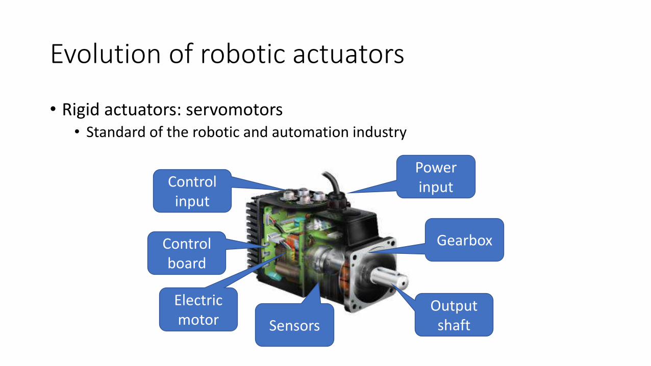
Evolution of robotic actuators
• Rigid actuators: servomotors• Standard of the robotic and automation industry
Electric motor
Gearbox
Output shaft
Power inputControl
input
Control board
Sensors
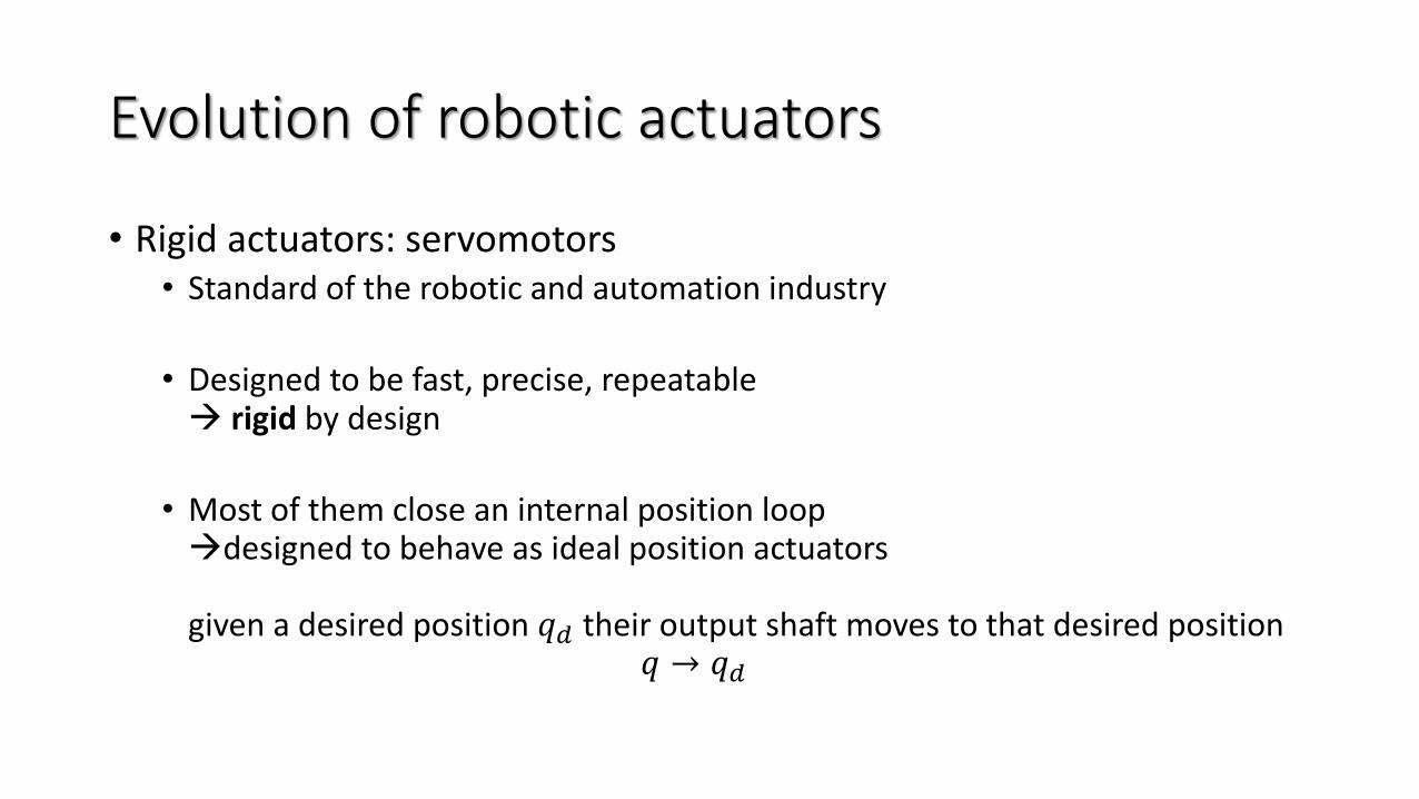
Evolution of robotic actuators
• Rigid actuators: servomotors• Standard of the robotic and automation industry
• Designed to be fast, precise, repeatable → rigid by design
• Most of them close an internal position loop→designed to behave as ideal position actuators
given a desired position 𝑞𝑑 their output shaft moves to that desired position𝑞 → 𝑞𝑑
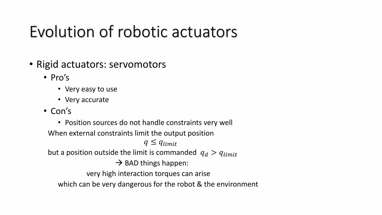
Evolution of robotic actuators
• Rigid actuators: servomotors• Pro’s
• Very easy to use
• Very accurate
• Con’s• Position sources do not handle constraints very well
When external constraints limit the output position𝑞 ≤ 𝑞𝑙𝑖𝑚𝑖𝑡
but a position outside the limit is commanded 𝑞𝑑 > 𝑞𝑙𝑖𝑚𝑖𝑡
→ BAD things happen:
very high interaction torques can arise
which can be very dangerous for the robot & the environment
Evolution of robotic actuators
• Rigid actuators: servomotors
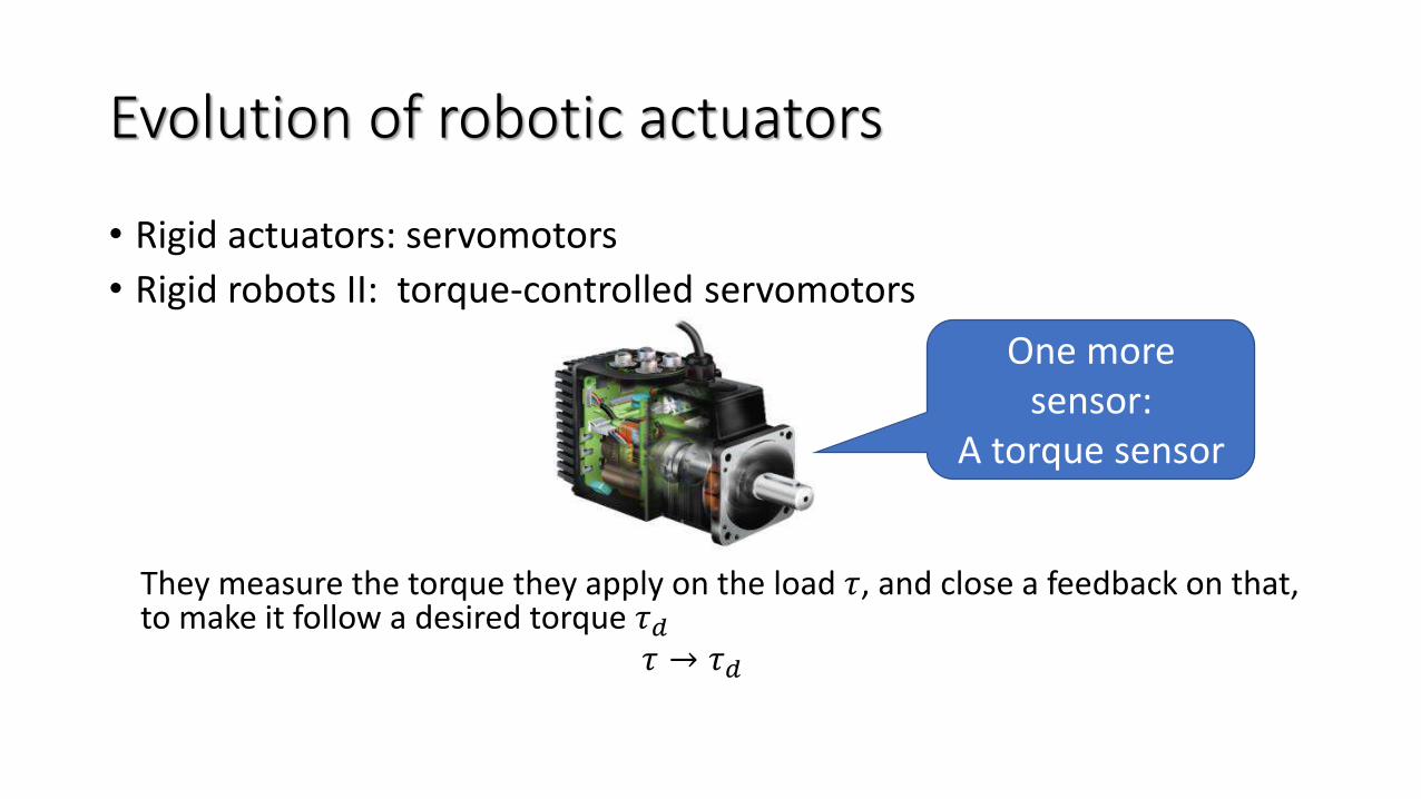
• Rigid robots II: torque-controlled servomotors
They measure the torque they apply on the load 𝜏, and close a feedback on that, to make it follow a desired torque 𝜏𝑑
𝜏 → 𝜏𝑑
One more sensor:
A torque sensor
Evolution of robotic actuators
• Rigid actuators: servomotors
• Rigid robots II (or Soft robots 0?): torque-controlled servomotors• Pros’s
• Can be used to implement more advanced control strategies
e.g.: impedance control
• Nicer behavior on slow interaction tasks
• Con’s• The system is still rigid
→ fast interaction are still problematic
How fast is “fast” is determined by the controller speed
Evolution of robotic actuators
• Rigid actuators
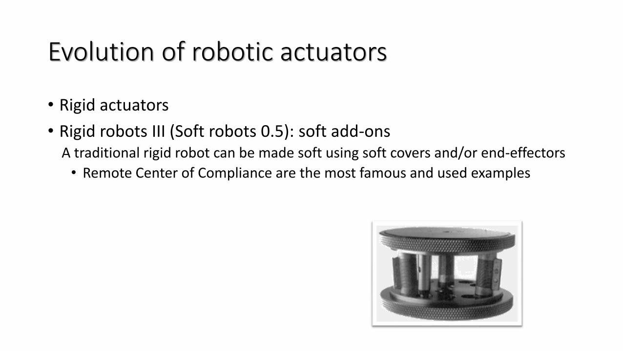
• Rigid robots III (Soft robots 0.5): soft add-onsA traditional rigid robot can be made soft using soft covers and/or end-effectors
• Remote Center of Compliance are the most famous and used examples
History and evolution
• Rigid actuators
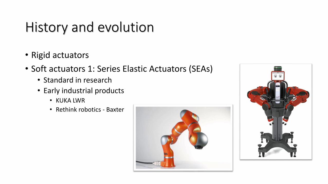
• Soft actuators 1: Series Elastic Actuators (SEAs)• Standard in research
• Early industrial products• KUKA LWR
• Rethink robotics - Baxter
History and evolution
• Rigid actuators
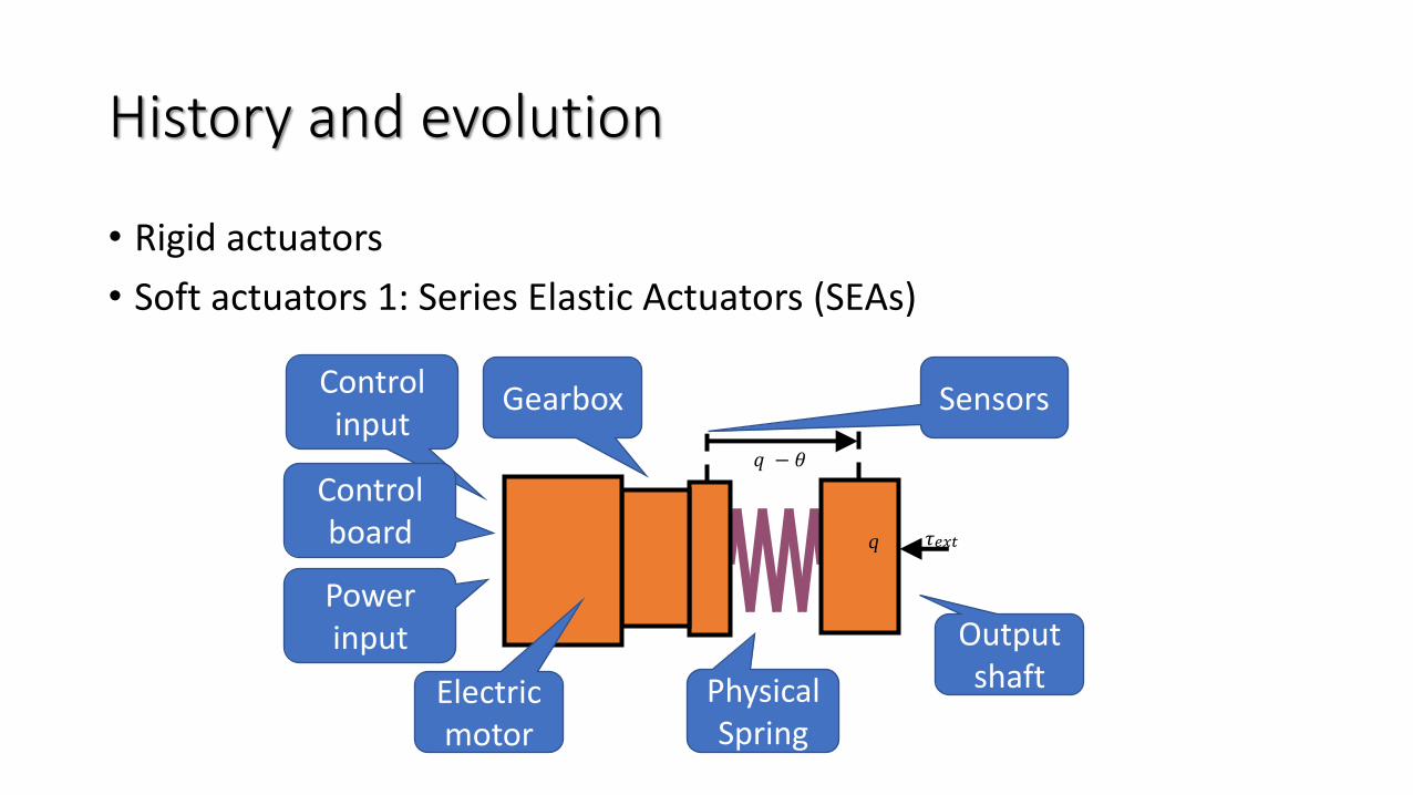
• Soft actuators 1: Series Elastic Actuators (SEAs)
𝑞 − 𝜃
q 𝜏𝑒𝑥𝑡
Electric motor
Gearbox
Output shaft
Sensors
PhysicalSpring
Power input
Control input
Control board

History and evolution
• Rigid actuators
• Soft actuators 1: Series Elastic Actuators (SEAs)• A physical spring with elastic constant 𝑘 is put in series with the motor to the
external load
• The position of the motor 𝜃 and the position of the output shaft 𝑞 are no longer the same
• A feedback loop can be closed on the motor position 𝜃 to let the torque on the link 𝜏𝑒𝑥𝑡 follow a desired torque 𝜏𝑑
• The physical spring in series with the motor yields that even when something happens at speeds that are faster than the controller (e.g. impacts), the system still behaves as the spring.
History and evolution
• Rigid actuators
• Soft actuators 1: Series Elastic Actuators (SEAs)• Pro’s
• At low frequencies the system can be torque controlled
• At high frequencies the system behavior is elastic
• Con’s • The spring (along with the link inertia) yields a natural oscillating frequency of the system
• This limits, in practice, the bandwidth of the torque which can be transmitted from the motor side to the link side
• Ultimately limits the performance of the control
History and evolution
• Rigid actuators
• Soft actuators 1: Series Elastic Actuators (SEAs)
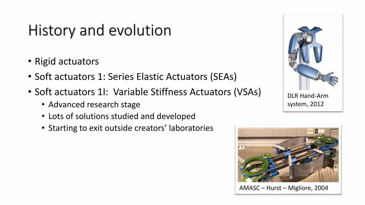
• Soft actuators 1I: Variable Stiffness Actuators (VSAs)• Advanced research stage
• Lots of solutions studied and developed
• Starting to exit outside creators’ laboratories
AMASC – Hurst – Migliore, 2004
DLR Hand-Arm system, 2012
History and evolution
• Rigid actuators
• Soft actuators 1: Series Elastic Actuators (SEAs)
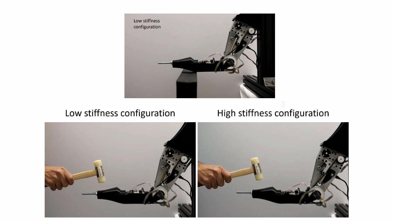
• Soft actuators 1I: Variable Stiffness Actuators (VSAs)• Since the stiffness 𝑘 of the SEA limits its maximum bandwidth
• Since my bandwidth requirements are not the same every time• E.g.: soft in case of hits, or while pushing against a surface, rigid while doing fast
accelerations/decelerations or when precision is needed
→ The perfect solution would be to be able to change the stiffness
History and evolution
• Rigid actuators
• Soft actuators 1: Series Elastic Actuators (SEAs)
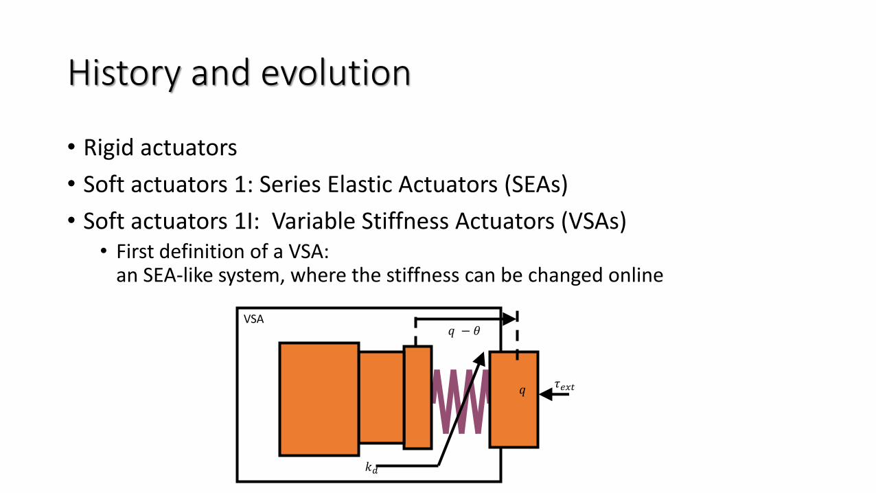
• Soft actuators 1I: Variable Stiffness Actuators (VSAs)• First definition of a VSA:
an SEA-like system, where the stiffness can be changed online
VSA
𝑞 𝜏𝑒𝑥𝑡
𝑞 − 𝜃
𝑘𝑑
History and evolution
• Rigid actuators
• Soft actuators 1: Series Elastic Actuators (SEAs)
• Soft actuators 1I: Variable Stiffness Actuators (VSAs)
We will be talking about VSA later.…but since we are looking at the landscape,
let’s keep sightseeing for a little while…
History and evolution
• Rigid actuators
• Soft actuators 1: Series Elastic Actuators (SEAs)
• Soft actuators 1I: Variable Stiffness Actuators (VSAs)
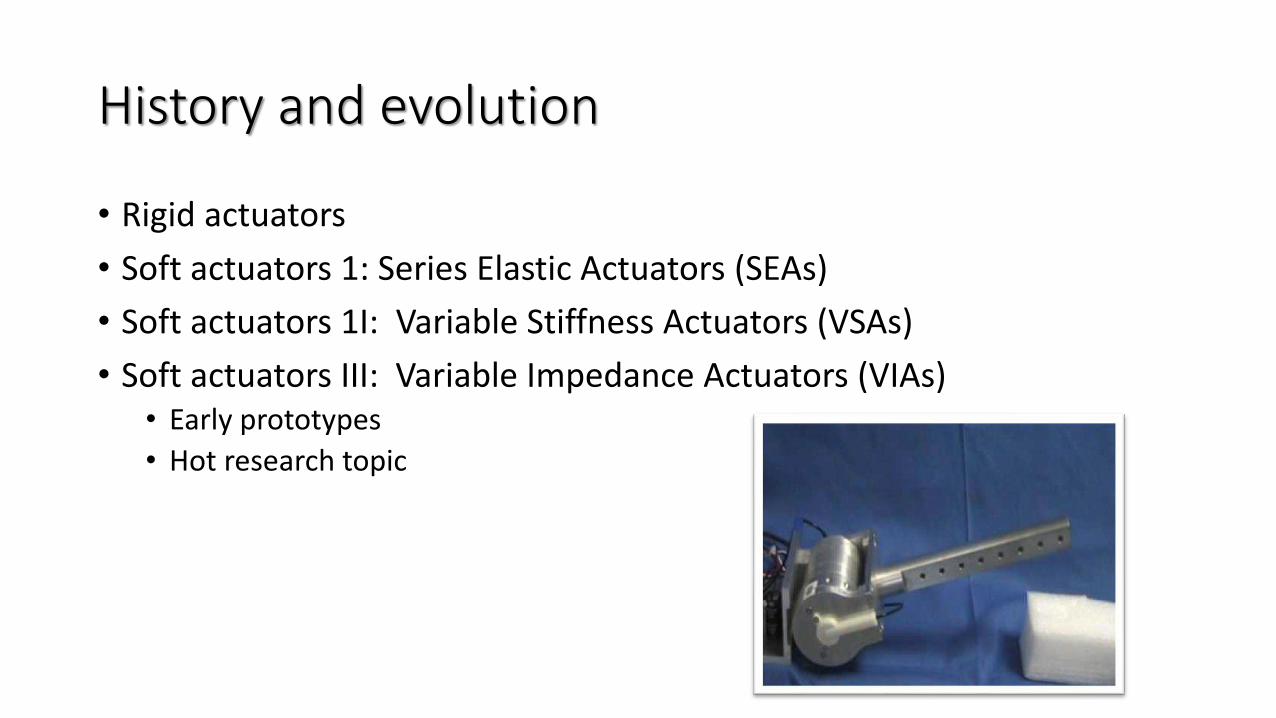
• Soft actuators III: Variable Impedance Actuators (VIAs)• Early prototypes
• Hot research topic
History and evolution
• Rigid actuators
• Soft actuators 1: Series Elastic Actuators (SEAs)
• Soft actuators 1I: Variable Stiffness Actuators (VSAs)
• Soft actuators III: Variable Impedance Actuators (VIAs)• Stiffness is not the only physical element which ca be put in series with a
motor• Damping is the very next thing that comes in someone's mind→ variable damping actuators
• Variable Inertia could be another possibilityRelated work can be found in the field of energy harvesting: KERS and high efficiency flywheels
• Also non-linear SEA are classically included in this category
• Multiple parallel SEA or SPEA
History and evolution
• Rigid actuators
• Soft actuators 1: Series Elastic Actuators (SEAs)
• Soft actuators 1I: Variable Stiffness Actuators (VSAs)
• Soft actuators III: Variable Impedance Actuators (VIAs)
• Soft structure:• Another hot topic
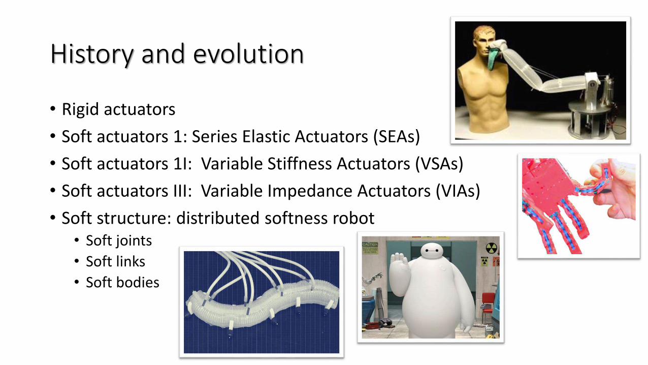
History and evolution
• Rigid actuators
• Soft actuators 1: Series Elastic Actuators (SEAs)
• Soft actuators 1I: Variable Stiffness Actuators (VSAs)
• Soft actuators III: Variable Impedance Actuators (VIAs)
• Soft structure: distributed softness robot• Soft joints
• Soft links
• Soft bodies
History and evolution
• Rigid actuators
• Soft actuators 1: Series Elastic Actuators (SEAs)
• Soft actuators 1I: Variable Stiffness Actuators (VSAs)
• Soft actuators III: Variable Impedance Actuators (VIAs)
• Soft structure: distributed softness robot

A focus on VSAsModels of VSAs
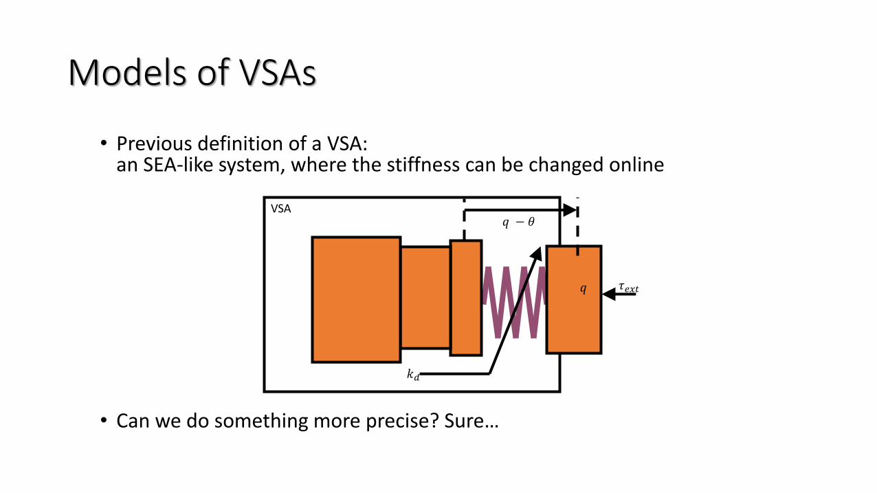
Models of VSAs
• Previous definition of a VSA:an SEA-like system, where the stiffness can be changed online
• Can we do something more precise? Sure…
VSA
𝑞 𝜏𝑒𝑥𝑡
𝑞 − 𝜃
𝑘𝑑
25
Züri
ch, O
cto
ber
04
-05
, 20
16
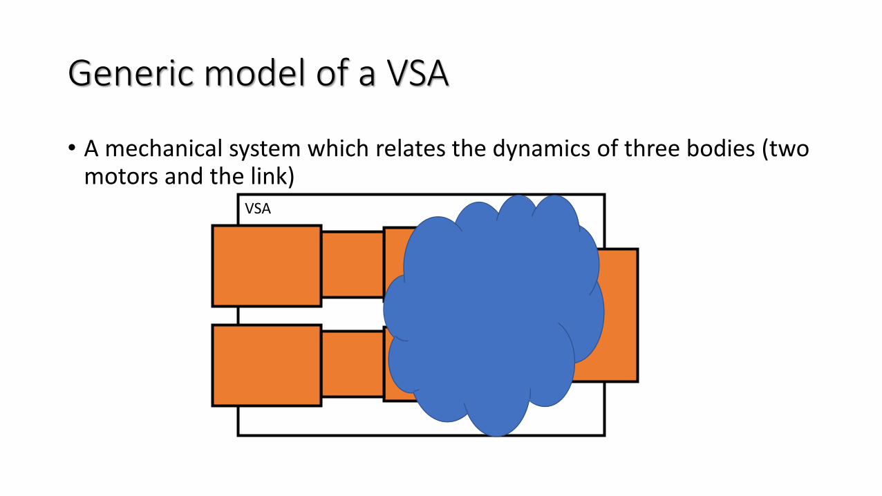
Generic model of a VSA
• A mechanical system which relates the dynamics of three bodies (two motors and the link)
VSA
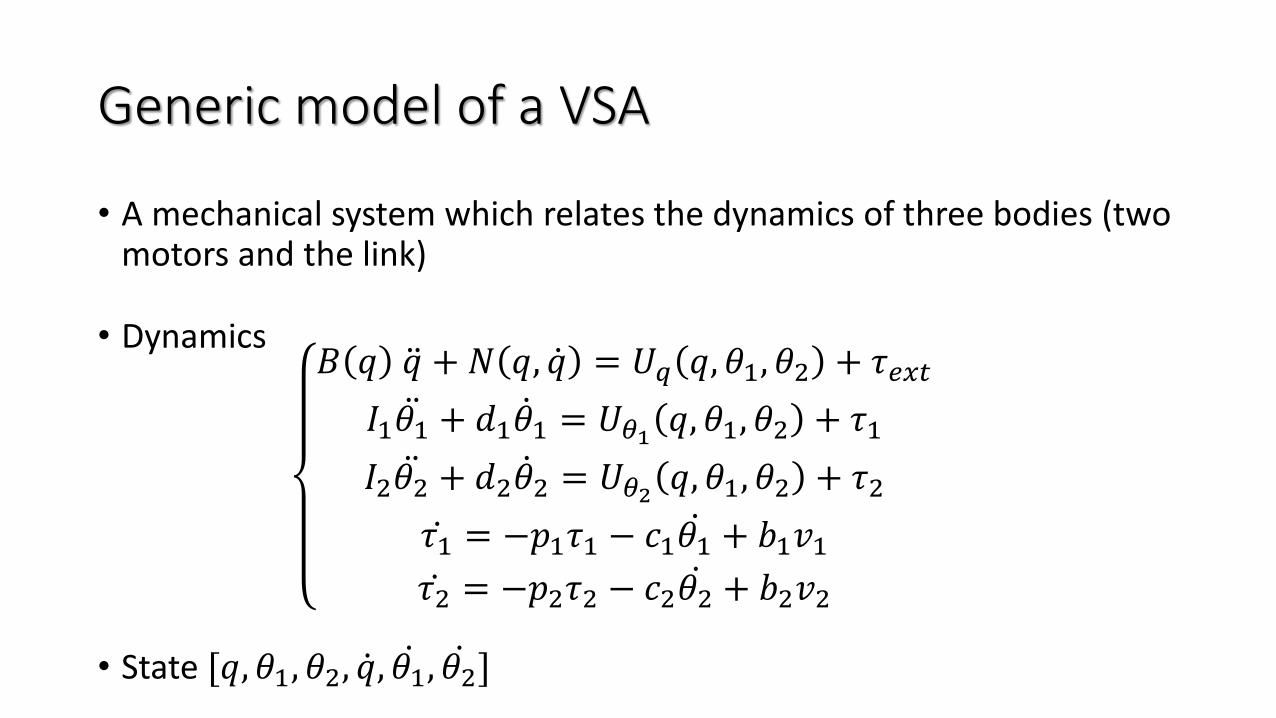
Generic model of a VSA
• A mechanical system which relates the dynamics of three bodies (two motors and the link)
• Dynamics𝐵 𝑞 ሷ𝑞 + 𝑁 𝑞, ሶ𝑞 = 𝑈𝑞 𝑞, 𝜃1, 𝜃2 + 𝜏𝑒𝑥𝑡
𝐼1 ሷ𝜃1 + 𝑑1 ሶ𝜃1 = 𝑈𝜃1 𝑞, 𝜃1, 𝜃2 + 𝜏1
𝐼2 ሷ𝜃2 + 𝑑2 ሶ𝜃2 = 𝑈𝜃2 𝑞, 𝜃1, 𝜃2 + 𝜏2
ሶ𝜏1 = −𝑝1𝜏1 − 𝑐1 ሶ𝜃1 + 𝑏1𝑣1ሶ𝜏2 = −𝑝2𝜏2 − 𝑐2 ሶ𝜃2 + 𝑏2𝑣2
• State [𝑞, 𝜃1, 𝜃2, ሶ𝑞, ሶ𝜃1, ሶ𝜃2]
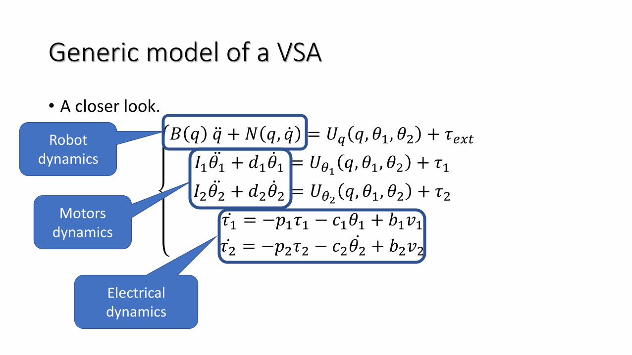
• A closer look.
𝐵 𝑞 ሷ𝑞 + 𝑁 𝑞, ሶ𝑞 = 𝑈𝑞 𝑞, 𝜃1, 𝜃2 + 𝜏𝑒𝑥𝑡
𝐼1 ሷ𝜃1 + 𝑑1 ሶ𝜃1 = 𝑈𝜃1 𝑞, 𝜃1, 𝜃2 + 𝜏1
𝐼2 ሷ𝜃2 + 𝑑2 ሶ𝜃2 = 𝑈𝜃2 𝑞, 𝜃1, 𝜃2 + 𝜏2
ሶ𝜏1 = −𝑝1𝜏1 − 𝑐1 ሶ𝜃1 + 𝑏1𝑣1ሶ𝜏2 = −𝑝2𝜏2 − 𝑐2 ሶ𝜃2 + 𝑏2𝑣2
Generic model of a VSA
Robot dynamics
Motors dynamics
Electricaldynamics
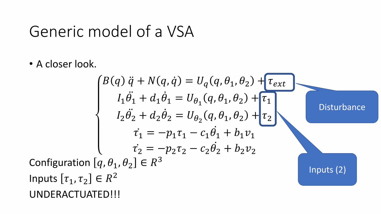
• A closer look.
𝐵 𝑞 ሷ𝑞 + 𝑁 𝑞, ሶ𝑞 = 𝑈𝑞 𝑞, 𝜃1, 𝜃2 + 𝜏𝑒𝑥𝑡
𝐼1 ሷ𝜃1 + 𝑑1 ሶ𝜃1 = 𝑈𝜃1 𝑞, 𝜃1, 𝜃2 + 𝜏1
𝐼2 ሷ𝜃2 + 𝑑2 ሶ𝜃2 = 𝑈𝜃2 𝑞, 𝜃1, 𝜃2 + 𝜏2
ሶ𝜏1 = −𝑝1𝜏1 − 𝑐1 ሶ𝜃1 + 𝑏1𝑣1ሶ𝜏2 = −𝑝2𝜏2 − 𝑐2 ሶ𝜃2 + 𝑏2𝑣2
Configuration 𝑞, 𝜃1, 𝜃2 ∈ 𝑅3
Inputs 𝜏1, 𝜏2 ∈ 𝑅2
UNDERACTUATED!!!
Generic model of a VSA
Inputs (2)
Disturbance

• A closer look.
𝐵 𝑞 ሷ𝑞 + 𝑁 𝑞, ሶ𝑞 = 𝑈𝑞 𝑞, 𝜃1, 𝜃2 + 𝜏𝑒𝑥𝑡
𝐼1 ሷ𝜃1 + 𝑑1 ሶ𝜃1 = 𝑈𝜃1 𝑞, 𝜃1, 𝜃2 + 𝜏1
𝐼2 ሷ𝜃2 + 𝑑2 ሶ𝜃2 = 𝑈𝜃2 𝑞, 𝜃1, 𝜃2 + 𝜏2
ሶ𝜏1 = −𝑝1𝜏1 − 𝑐1 ሶ𝜃1 + 𝑏1𝑣1ሶ𝜏2 = −𝑝2𝜏2 − 𝑐2 ሶ𝜃2 + 𝑏2𝑣2
Configuration 𝑞, 𝜃1, 𝜃2 ∈ 𝑅3
Inputs 𝜏1, 𝜏2 ∈ 𝑅2
UNDERACTUATED!!!
Generic model of a VSA
Inputs (2)
Disturbance
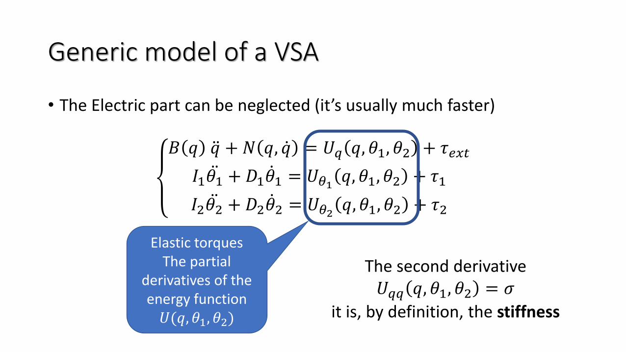
• The Electric part can be neglected (it’s usually much faster)
𝐵 𝑞 ሷ𝑞 + 𝑁 𝑞, ሶ𝑞 = 𝑈𝑞 𝑞, 𝜃1, 𝜃2 + 𝜏𝑒𝑥𝑡
𝐼1 ሷ𝜃1 + 𝐷1 ሶ𝜃1 = 𝑈𝜃1 𝑞, 𝜃1, 𝜃2 + 𝜏1
𝐼2 ሷ𝜃2 + 𝐷2 ሶ𝜃2 = 𝑈𝜃2 𝑞, 𝜃1, 𝜃2 + 𝜏2
Generic model of a VSA
Elastic torquesThe partial
derivatives of the energy function 𝑈(𝑞, 𝜃1, 𝜃2)
The second derivative𝑈𝑞𝑞 𝑞, 𝜃1, 𝜃2 = 𝜎
it is, by definition, the stiffness

Categories of VSAsSpecial models of VSAs
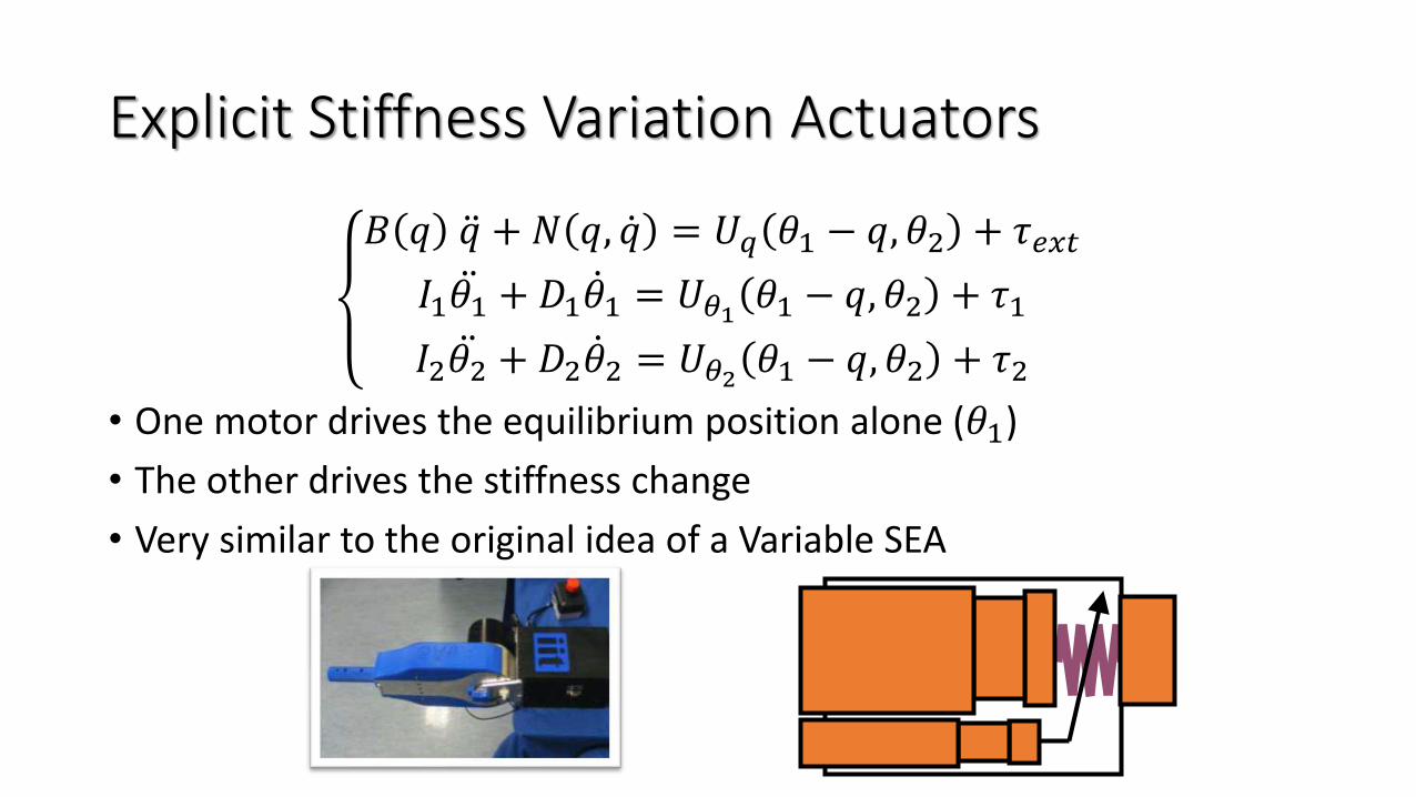
Explicit Stiffness Variation Actuators
𝐵 𝑞 ሷ𝑞 + 𝑁 𝑞, ሶ𝑞 = 𝑈𝑞 𝜃1 − 𝑞, 𝜃2 + 𝜏𝑒𝑥𝑡
𝐼1 ሷ𝜃1 + 𝐷1 ሶ𝜃1 = 𝑈𝜃1 𝜃1 − 𝑞, 𝜃2 + 𝜏1
𝐼2 ሷ𝜃2 + 𝐷2 ሶ𝜃2 = 𝑈𝜃2 𝜃1 − 𝑞, 𝜃2 + 𝜏2
• One motor drives the equilibrium position alone (𝜃1)
• The other drives the stiffness change
• Very similar to the original idea of a Variable SEA
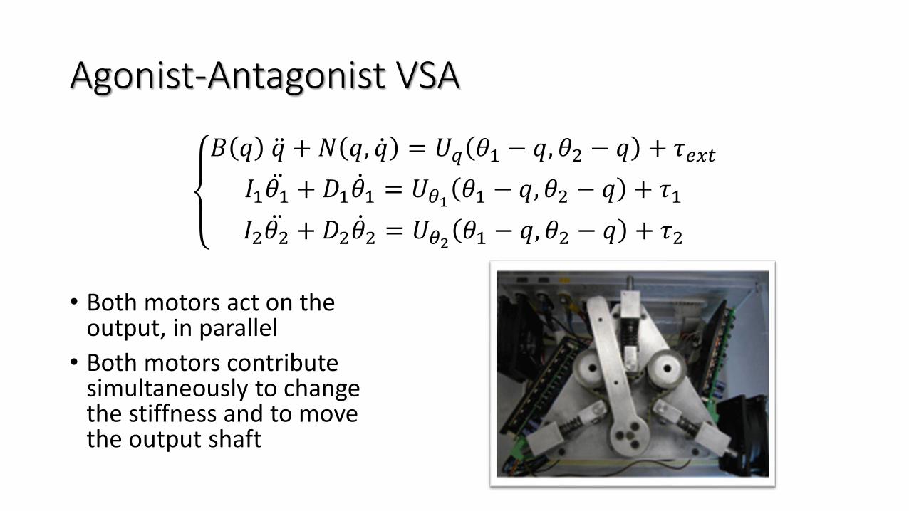
Agonist-Antagonist VSA
𝐵 𝑞 ሷ𝑞 + 𝑁 𝑞, ሶ𝑞 = 𝑈𝑞 𝜃1 − 𝑞, 𝜃2 − 𝑞 + 𝜏𝑒𝑥𝑡
𝐼1 ሷ𝜃1 + 𝐷1 ሶ𝜃1 = 𝑈𝜃1 𝜃1 − 𝑞, 𝜃2 − 𝑞 + 𝜏1
𝐼2 ሷ𝜃2 + 𝐷2 ሶ𝜃2 = 𝑈𝜃2 𝜃1 − 𝑞, 𝜃2 − 𝑞 + 𝜏2
• Both motors act on the output, in parallel
• Both motors contributesimultaneously to changethe stiffness and to movethe output shaft
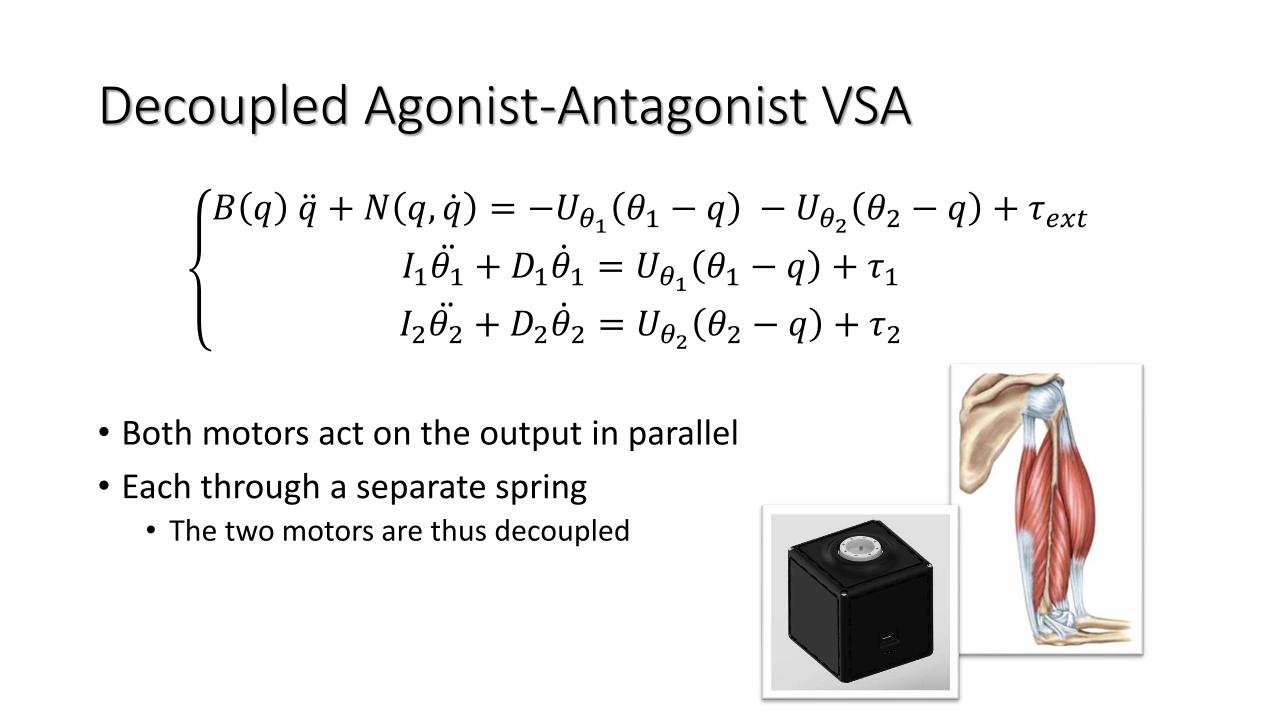
Decoupled Agonist-Antagonist VSA
𝐵 𝑞 ሷ𝑞 + 𝑁 𝑞, ሶ𝑞 = −𝑈𝜃1 𝜃1 − 𝑞 − 𝑈𝜃2 𝜃2 − 𝑞 + 𝜏𝑒𝑥𝑡
𝐼1 ሷ𝜃1 + 𝐷1 ሶ𝜃1 = 𝑈𝜃1 𝜃1 − 𝑞 + 𝜏1
𝐼2 ሷ𝜃2 + 𝐷2 ሶ𝜃2 = 𝑈𝜃2 𝜃2 − 𝑞 + 𝜏2
• Both motors act on the output in parallel
• Each through a separate spring• The two motors are thus decoupled
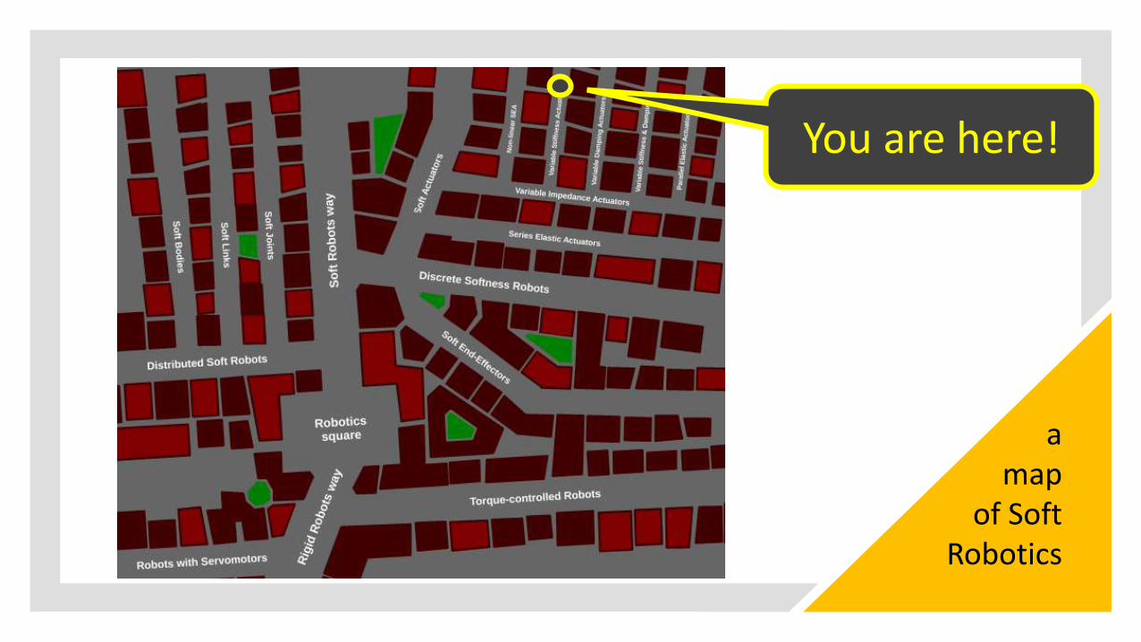
You are here!
a map
of Soft Robotics
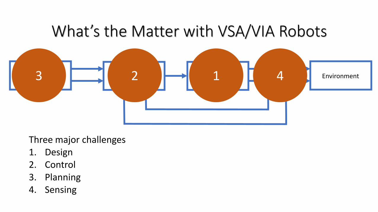
What’s the Matter with VSA/VIA Robots
Three major challenges1. Design2. Control3. Planning4. Sensing
VSA / VIA RobotControl System EnvironmentPlanner 2 13 4
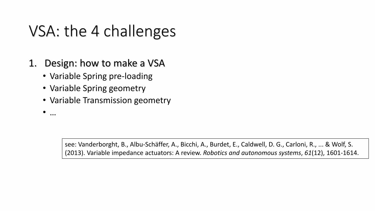
VSA: the 4 challenges
1. Design: how to make a VSA• Variable Spring pre-loading
• Variable Spring geometry
• Variable Transmission geometry
• …
see: Vanderborght, B., Albu-Schäffer, A., Bicchi, A., Burdet, E., Caldwell, D. G., Carloni, R., ... & Wolf, S. (2013). Variable impedance actuators: A review. Robotics and autonomous systems, 61(12), 1601-1614.
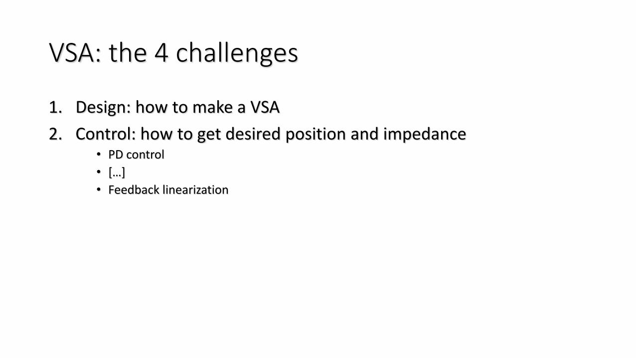
VSA: the 4 challenges
1. Design: how to make a VSA
2. Control: how to get desired position and impedance• PD control
• […]
• Feedback linearization
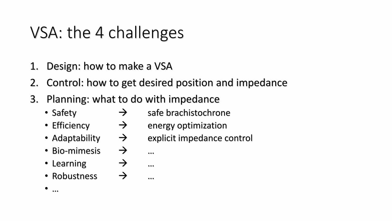
VSA: the 4 challenges
1. Design: how to make a VSA
2. Control: how to get desired position and impedance
3. Planning: what to do with impedance• Safety → safe brachistochrone
• Efficiency → energy optimization
• Adaptability → explicit impedance control
• Bio-mimesis → …
• Learning → …
• Robustness → …
• …
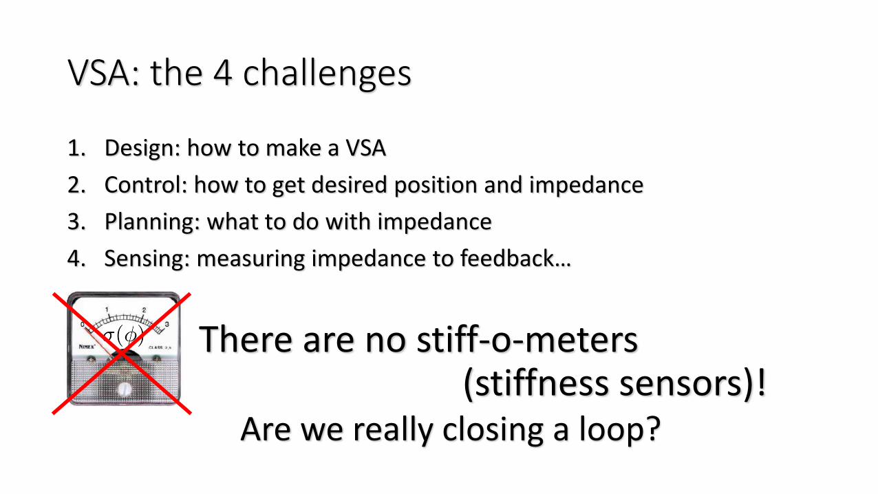
VSA: the 4 challenges
1. Design: how to make a VSA
2. Control: how to get desired position and impedance
3. Planning: what to do with impedance
4. Sensing: measuring impedance to feedback…
There are no stiff-o-meters (stiffness sensors)!
Are we really closing a loop?

Part 1
Characterization of the Stiffness (or Impedance) of a Robot
by Giorgio Grioli
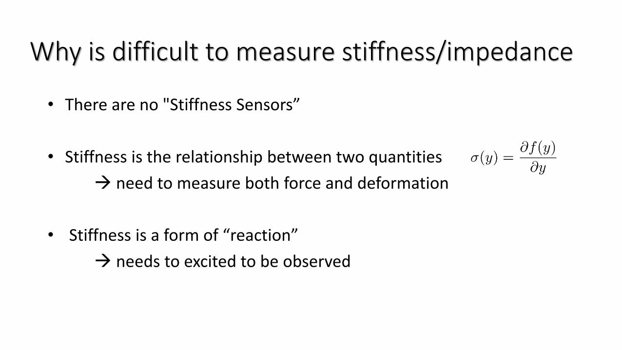
Why is difficult to measure stiffness/impedance
• There are no "Stiffness Sensors”
• Stiffness is the relationship between two quantities
→ need to measure both force and deformation
• Stiffness is a form of “reaction”
→ needs to excited to be observed
Impedance Measurement
• Not only feedback needs to measure impedance…
• Measurements are one of the basis of scientific approach
• State of Art• In Mechanical Engineering
• In Biomechanics
• In Robotics, etc.
“Misura ciò che e misurabile e rendi misurabile ciò che non lo è”
(Measure what is measurable and make measurable what is not so.)
Galileo de’ Galilei
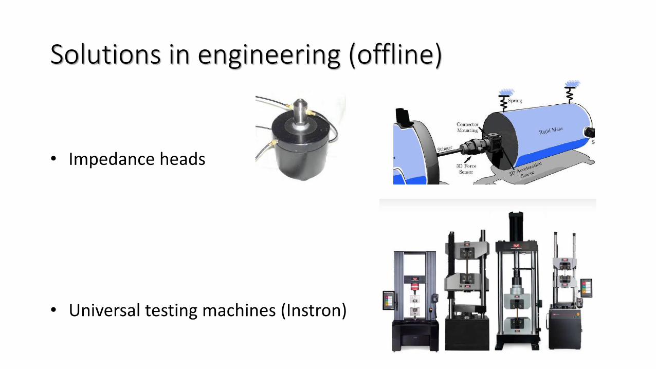
Solutions in engineering (offline)
• Impedance heads
• Universal testing machines (Instron)
Solutions in motor sciences
It is not an easy problem
Why is difficult to measure stiffness/impedancein humans
• Reflexes change completely the game
• Not all the variables are easy to access
- we measure what happens “outside” more easily than what happens “inside”
- examples of variables that are difficult to access are, e.g.:- rest length of muscles under some level of activation
- force on single muscles and tendons
- muscle activation (EMG is related but not the same)
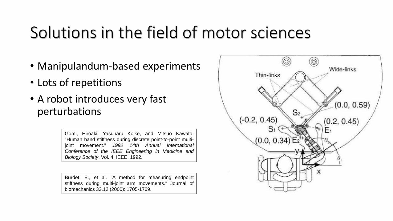
Solutions in the field of motor sciences
• Manipulandum-based experiments
• Lots of repetitions
• A robot introduces very fast perturbations
Burdet, E., et al. "A method for measuring endpoint
stiffness during multi-joint arm movements." Journal of
biomechanics 33.12 (2000): 1705-1709.
Gomi, Hiroaki, Yasuharu Koike, and Mitsuo Kawato.
"Human hand stiffness during discrete point-to-point multi-
joint movement." 1992 14th Annual International
Conference of the IEEE Engineering in Medicine and
Biology Society. Vol. 4. IEEE, 1992.
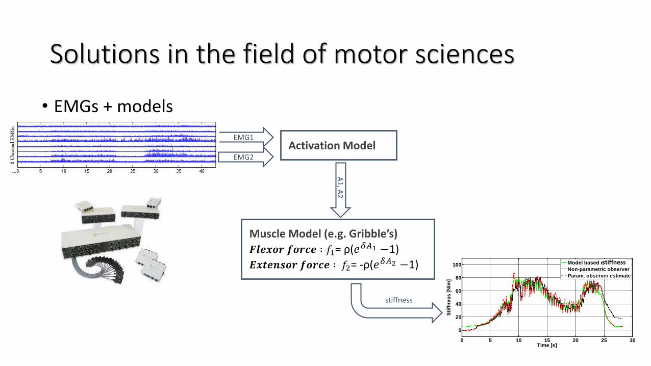
Solutions in the field of motor sciences
• EMGs + models
Muscle Model (e.g. Gribble’s)
𝑭𝒍𝒆𝒙𝒐𝒓 𝒇𝒐𝒓𝒄𝒆 ∶ 𝑓1= ρ(𝑒𝛿𝐴1 −1)
𝑬𝒙𝒕𝒆𝒏𝒔𝒐𝒓 𝒇𝒐𝒓𝒄𝒆 ∶ 𝑓2= -ρ(𝑒𝛿𝐴2 −1)
EMG1
0 5 10 15 20 25 30
0
20
40
60
80
100
Time [s]
Sti
ffn
es
s [
N/m
]
Model based estimate
Non-parametric observer
Param. observer estimate
stiffness
stiffness
Activation Model
A1
, A2
EMG2
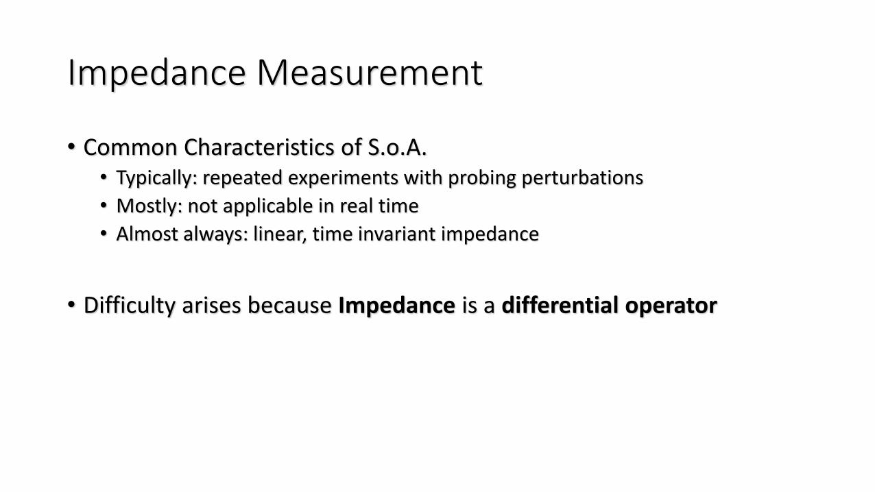
Impedance Measurement
• Common Characteristics of S.o.A.• Typically: repeated experiments with probing perturbations
• Mostly: not applicable in real time
• Almost always: linear, time invariant impedance
• Difficulty arises because Impedance is a differential operator
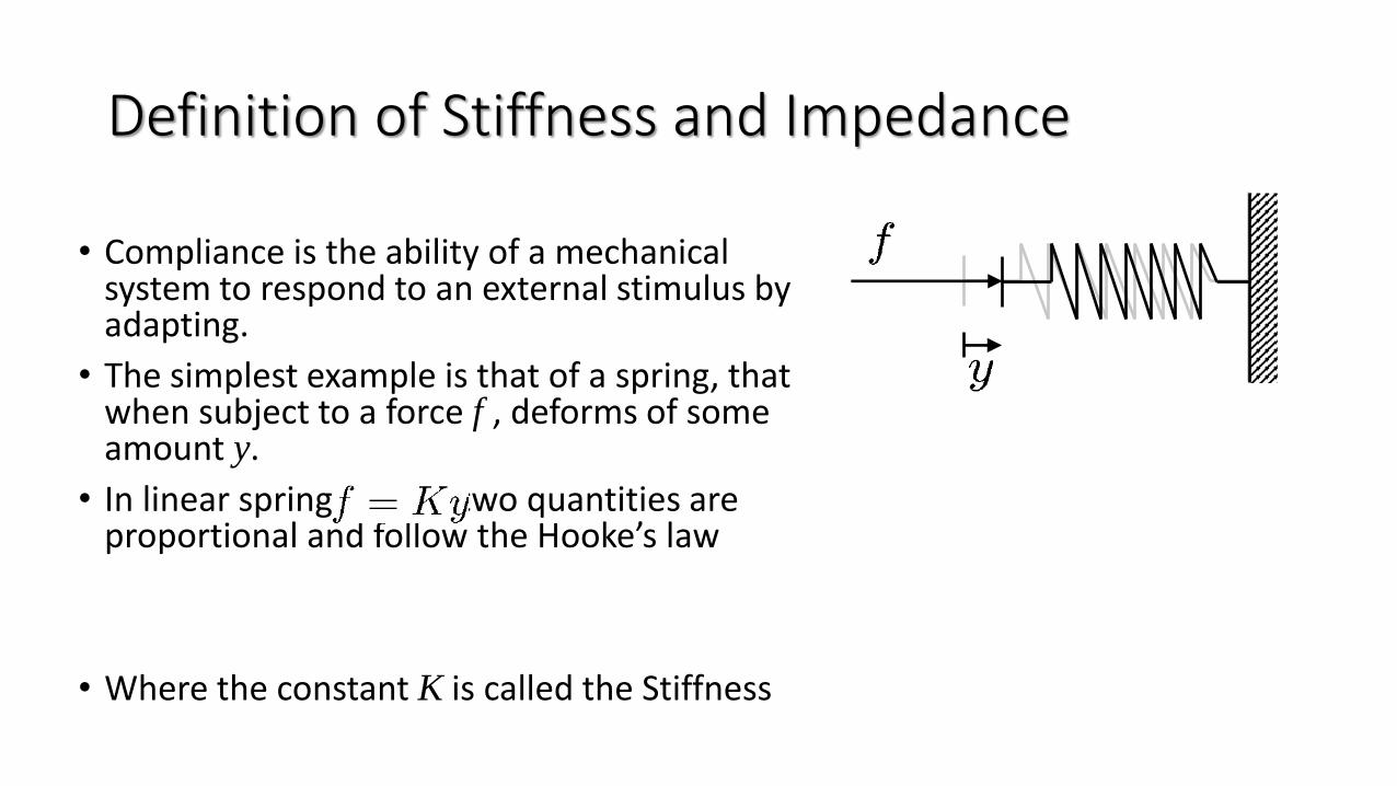
Definition of Stiffness and Impedance
• Compliance is the ability of a mechanical system to respond to an external stimulus by adapting.
• The simplest example is that of a spring, that when subject to a force f , deforms of some amount y.
• In linear springs, these two quantities are proportional and follow the Hooke’s law
• Where the constant K is called the Stiffness
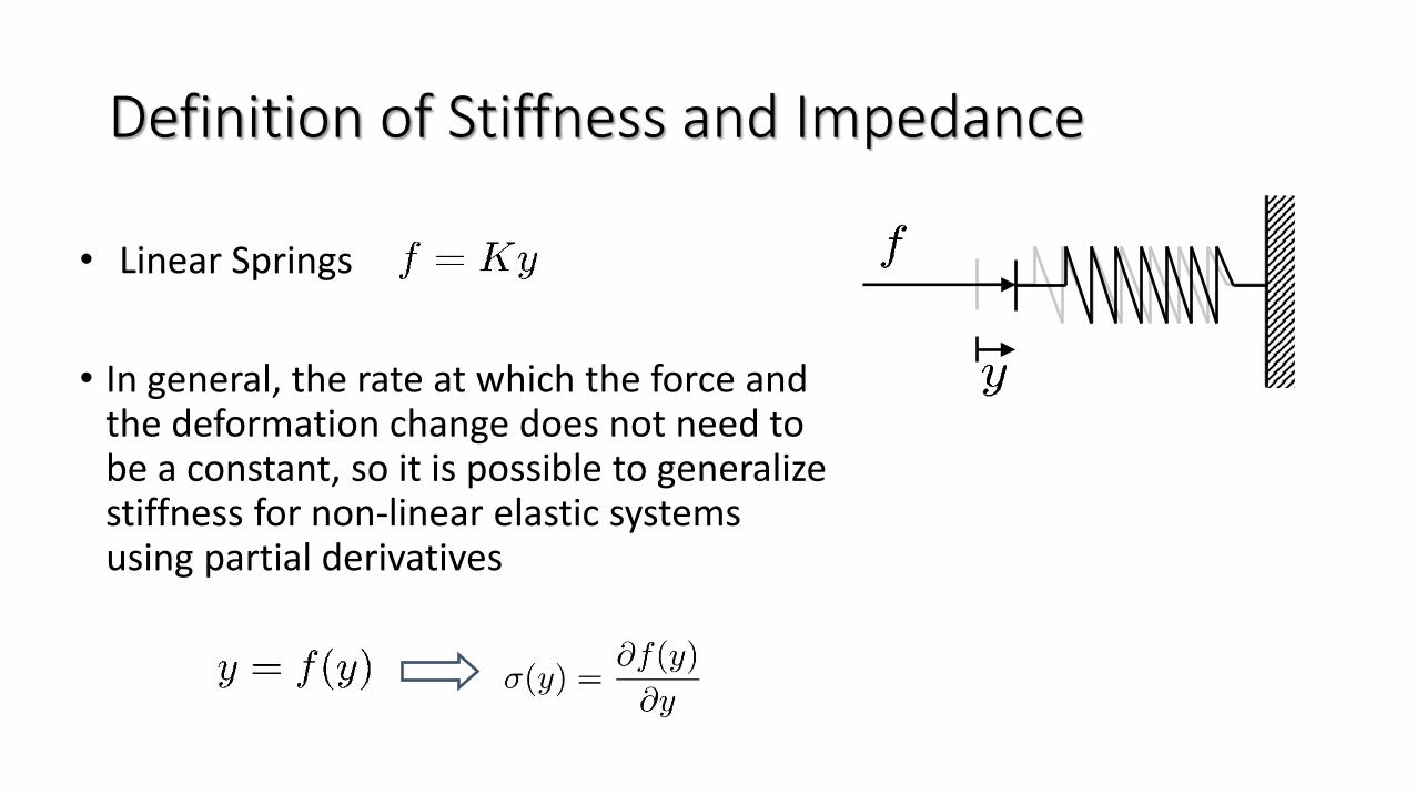
Definition of Stiffness and Impedance
• Linear Springs
• In general, the rate at which the force and the deformation change does not need to be a constant, so it is possible to generalize stiffness for non-linear elastic systems using partial derivatives
Definition of Stiffness and Impedance
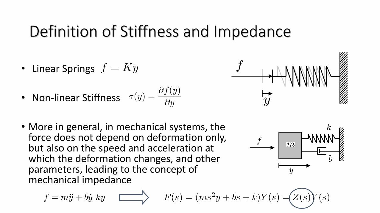
• Linear Springs
• Non-linear Stiffness
• More in general, in mechanical systems, the force does not depend on deformation only, but also on the speed and acceleration at which the deformation changes, and other parameters, leading to the concept of mechanical impedance
Definition of Stiffness and Impedance
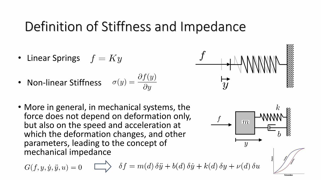
• Linear Springs
• Non-linear Stiffness
• More in general, in mechanical systems, the force does not depend on deformation only, but also on the speed and acceleration at which the deformation changes, and other parameters, leading to the concept of mechanical impedance
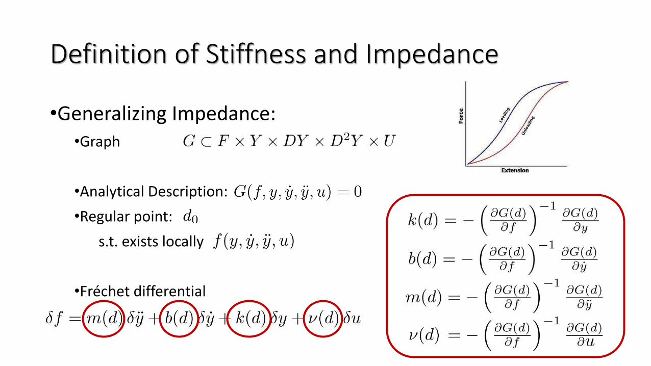
•Generalizing Impedance:•Graph
•Analytical Description:
•Regular point:
s.t. exists locally
•Fréchet differential
Definition of Stiffness and Impedance
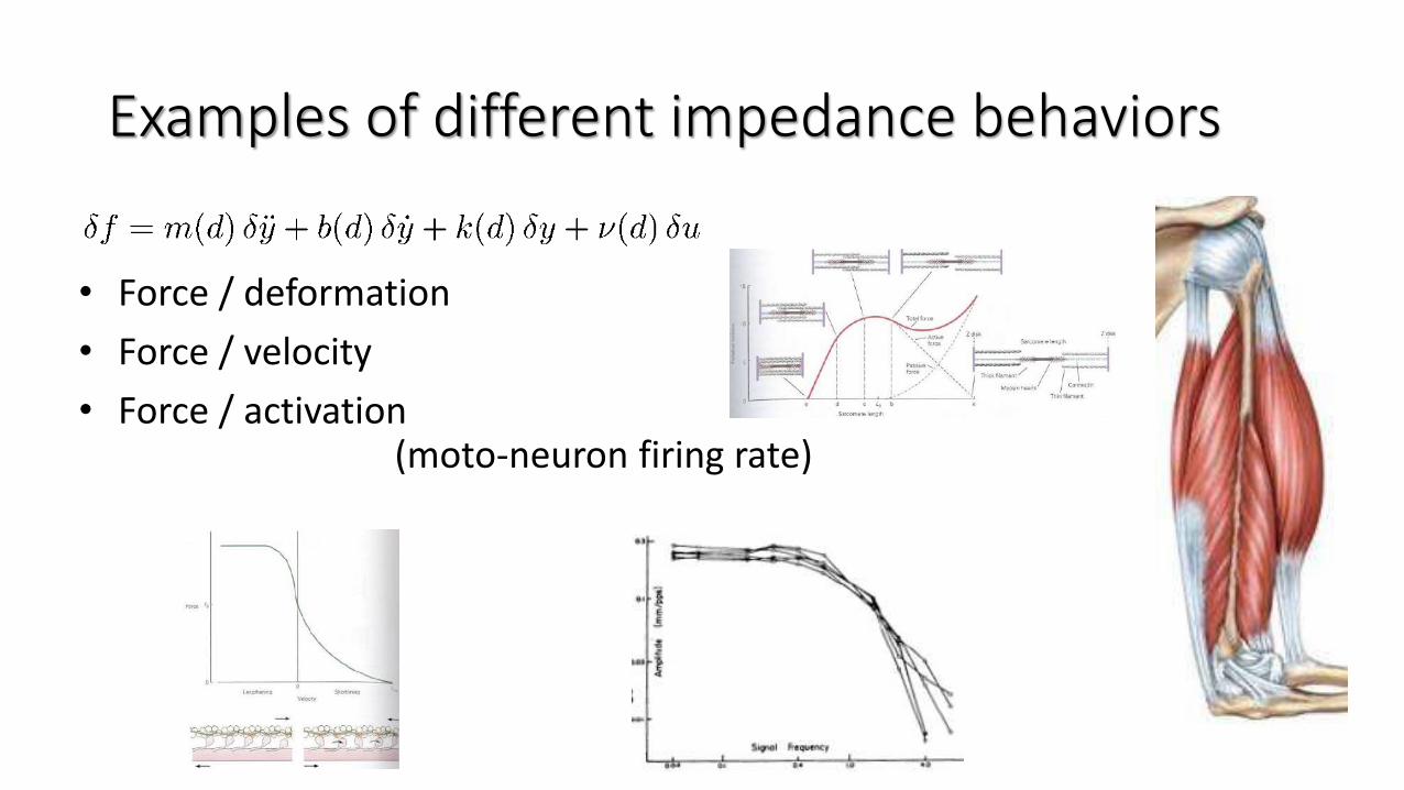
Examples of different impedance behaviors
• Force / deformation
• Force / velocity
• Force / activation(moto-neuron firing rate)
How to characterize a VSA?
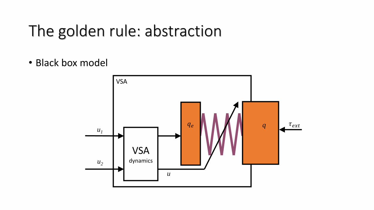
The golden rule: abstraction
• Black box model
VSA
VSAdynamics
u
q 𝜏𝑒𝑥𝑡u1
u2
𝑞𝑒
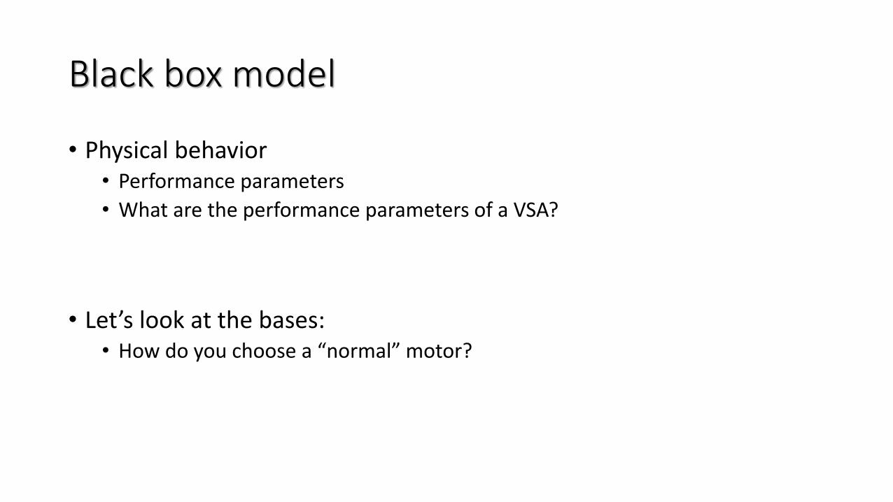
Black box model
• Physical behavior• Performance parameters
• What are the performance parameters of a VSA?
• Let’s look at the bases:• How do you choose a “normal” motor?
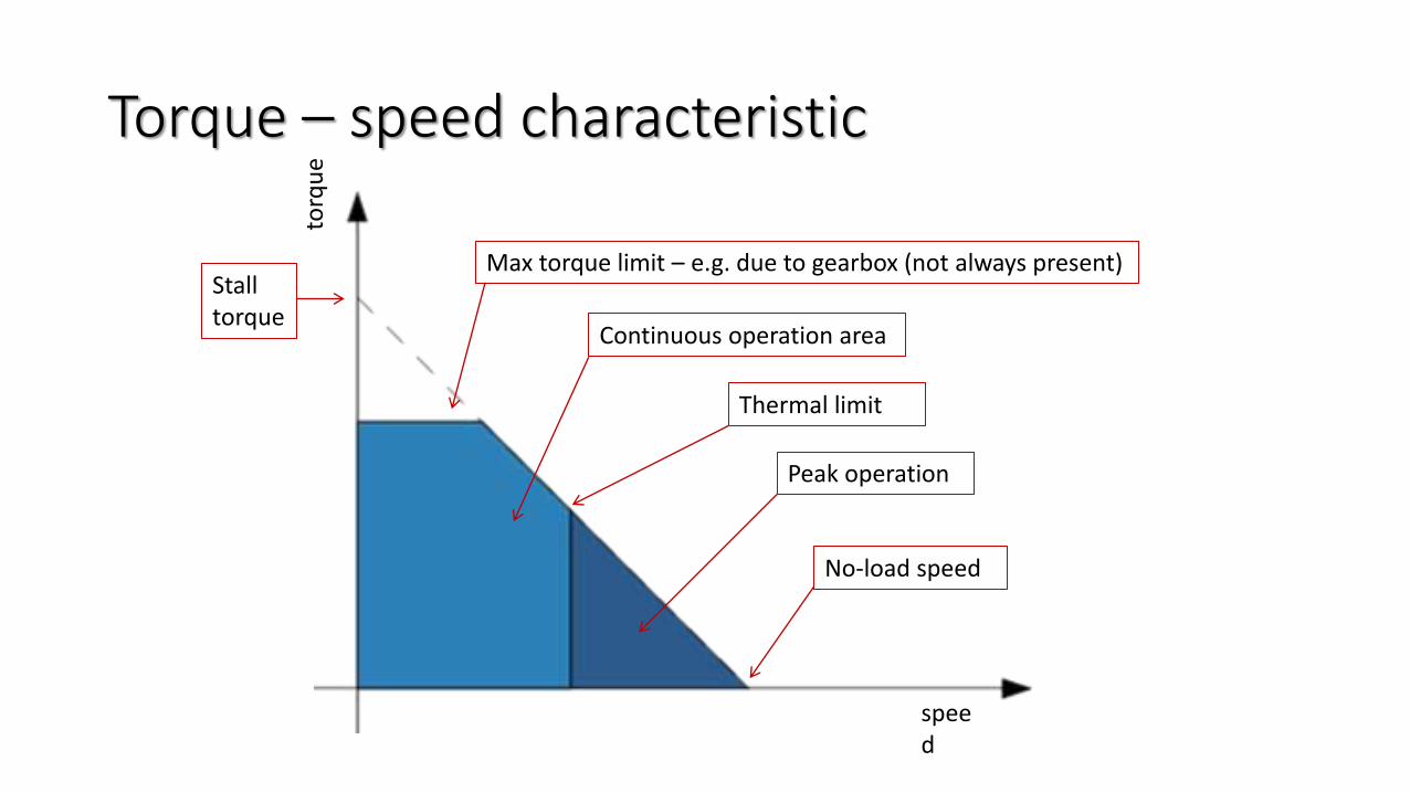
Torque – speed characteristic
speed
torq
ue
Peak operation
Max torque limit – e.g. due to gearbox (not always present)Stalltorque
No-load speed
Continuous operation area
Thermal limit
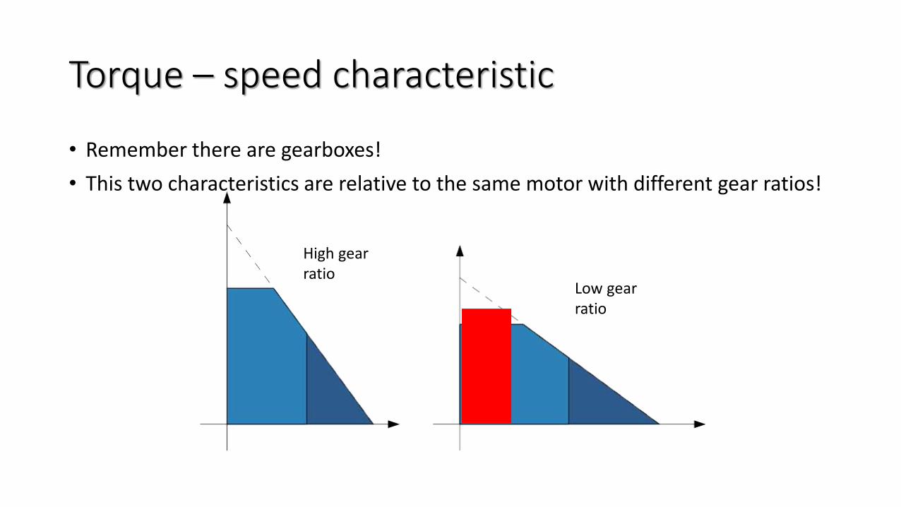
Torque – speed characteristic
• Remember there are gearboxes!
• This two characteristics are relative to the same motor with different gear ratios!
Low gear ratio
High gear ratio

Back to VSAsWhat are the main parameters of a VSA?
Main parameters of a VSA
• A VSA is primarily a motor, so we still have• Torque
• Speed
• The core characteristic of a VSA is the variable stiffness• Stiffness range
Main parameters of a VSA
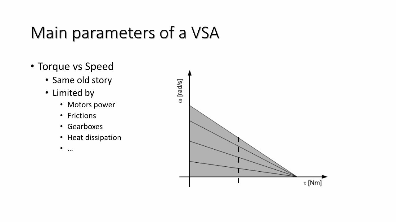
• Torque vs Speed• Same old story
• Limited by• Motors power
• Frictions
• Gearboxes
• Heat dissipation
• …
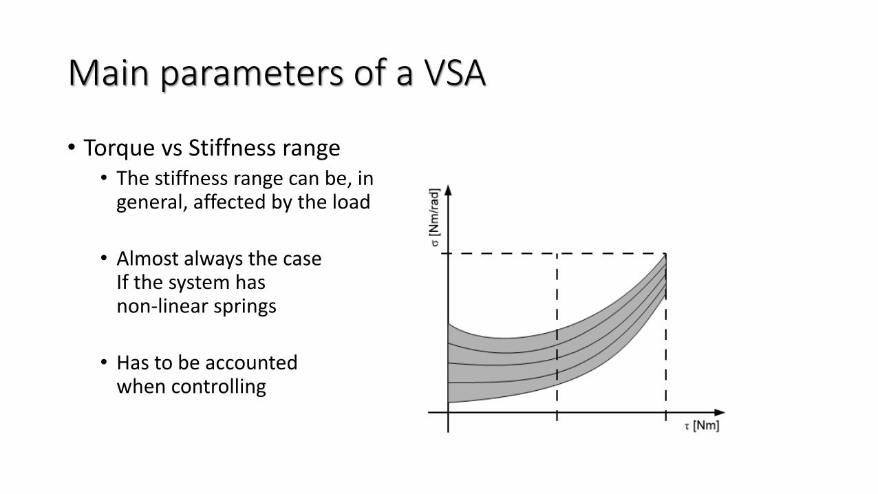
Main parameters of a VSA
• Torque vs Stiffness range• The stiffness range can be, in
general, affected by the load
• Almost always the case If the system hasnon-linear springs
• Has to be accounted when controlling
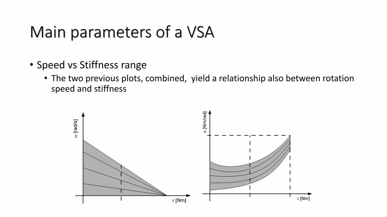
Main parameters of a VSA
• Speed vs Stiffness range• The two previous plots, combined, yield a relationship also between rotation
speed and stiffness

Main parameters of a VSA
• 3d working volume • Torque
• Speed
• Stiffness range
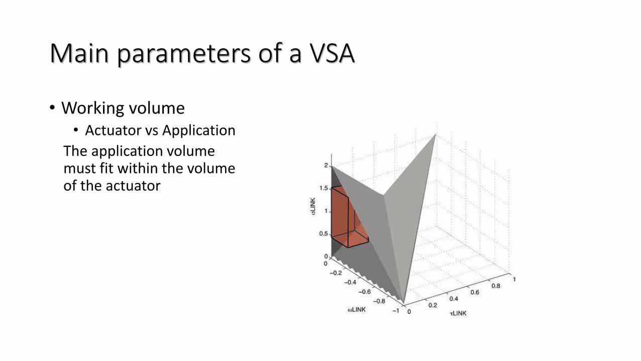
Main parameters of a VSA
• Working volume• Actuator vs Application
The application volumemust fit within the volumeof the actuator
Main parameters of a VSA
• Stiffness has a speed too• The real figure should be 4D
• Difficult to visualize and to work with• What we really care about is the time to change stiffness
• Given the previous points, this time could, in general, be different when there is a load applied and when there is not, thus the parameters to read are:
• Nominal stiffness variation time with no load• Nominal stiffness variation time with nominal load
• Important for rapid tasks• e.g.: bang-bang optimal control
(see lesson of Manolo Garabini Monday)
Main parameters of a VSA
• Elasticity means deflection• Variable stiffness → variable deflection• Maximum deflection with minimum stiffness• Maximum deflection with maximum stiffness
• Elasticity means storable energy• Maximum energy storable in the springs
• Important for • Shock absorption • Exploiting natural oscillations
Other aspects of a VSA
• Active rotation angle• Not all actuators can rotate continuously
• Limits can derive from• Sensors
• Type of transmission
• Shape of system
• Since the main application is robot joints this is usually not a problem
• For some application a limited rotation angle could be problematic
• In general, you should check that the range of the active rotation angle is enough do perform your intended task
Other aspects of a VSA
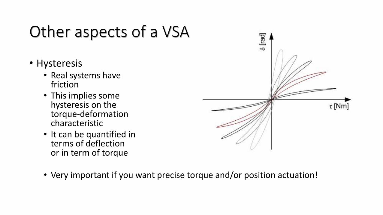
• Hysteresis• Real systems have
friction• This implies some
hysteresis on thetorque-deformation characteristic
• It can be quantified in terms of deflectionor in term of torque
• Very important if you want precise torque and/or position actuation!
Other aspects of a VSA
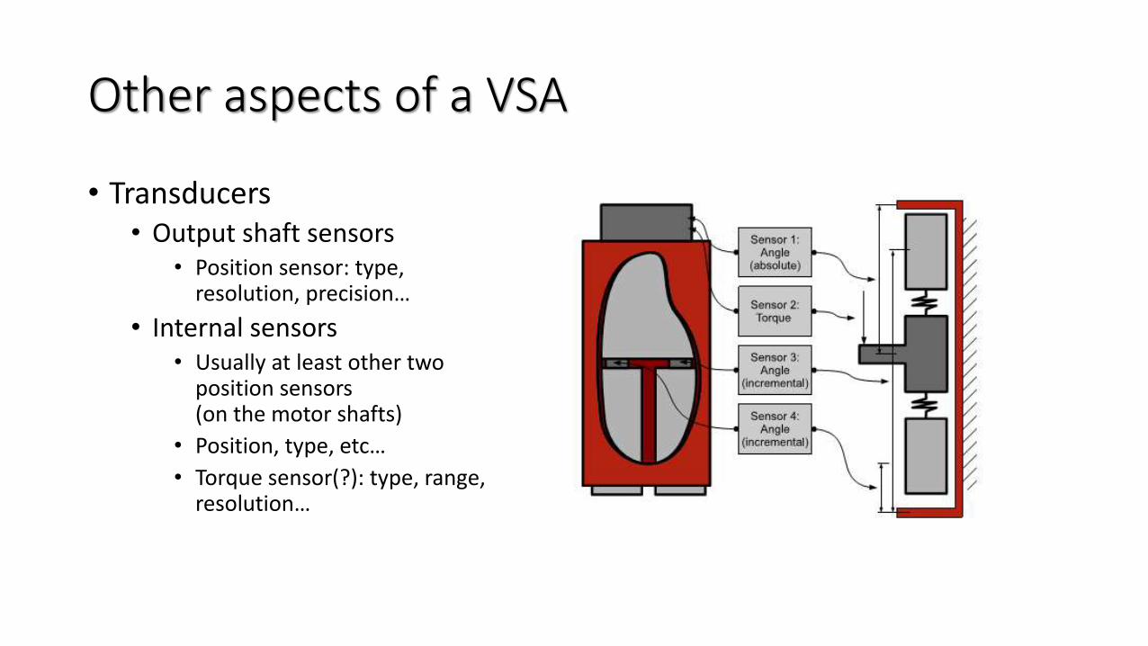
• Transducers• Output shaft sensors
• Position sensor: type,resolution, precision…
• Internal sensors• Usually at least other two
position sensors (on the motor shafts)
• Position, type, etc…
• Torque sensor(?): type, range, resolution…
Other aspects of a VSA
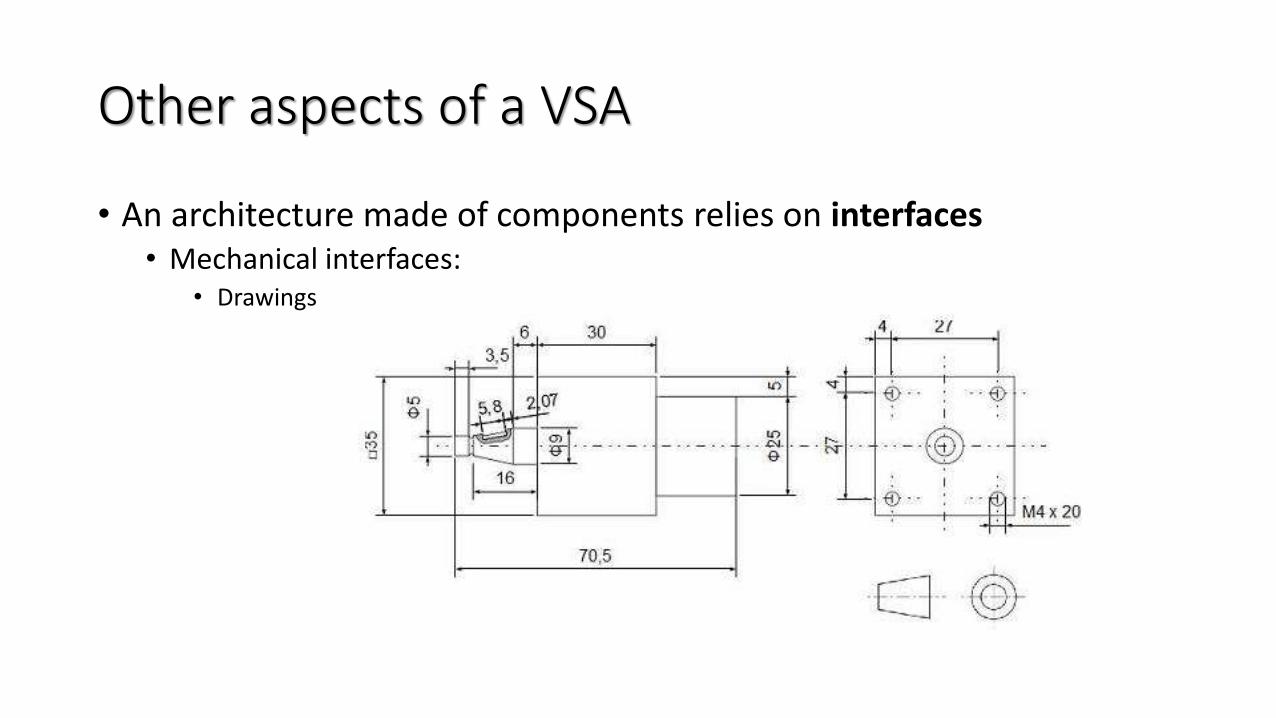
• An architecture made of components relies on interfaces• Mechanical interfaces:
• Drawings
Other aspects of a VSA
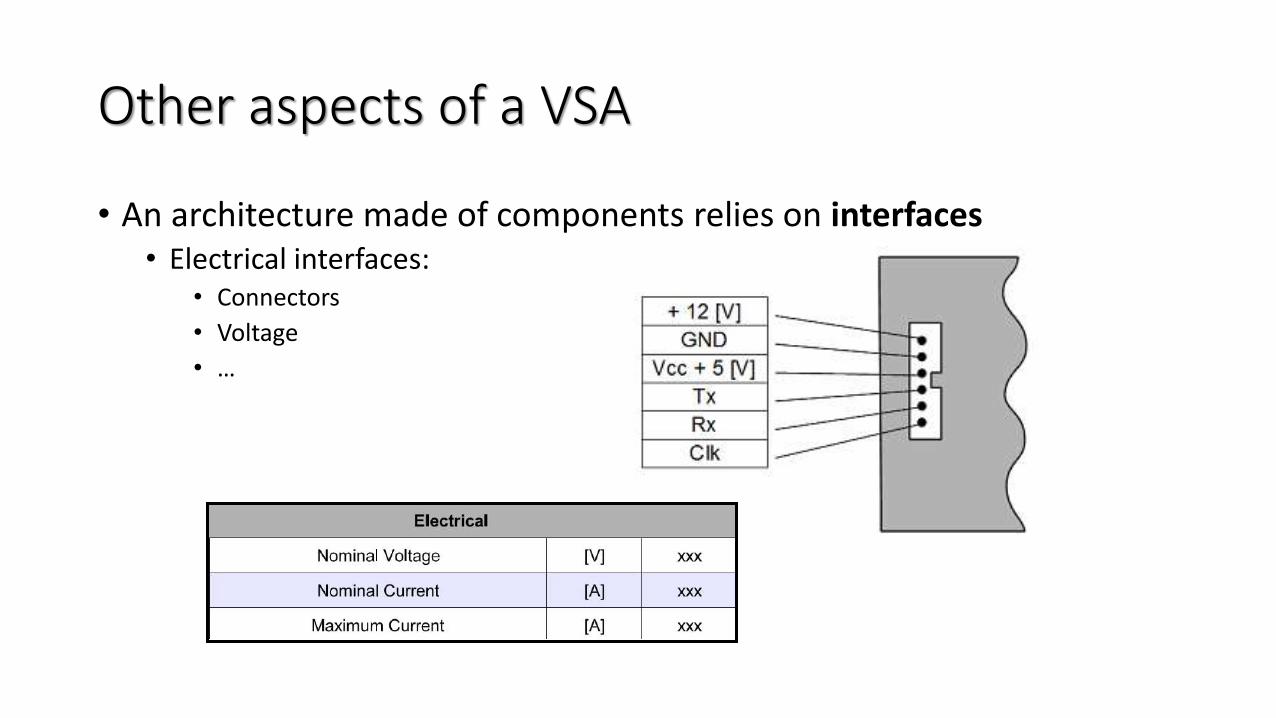
• An architecture made of components relies on interfaces• Electrical interfaces:
• Connectors
• Voltage
• …
Other aspects of a VSA
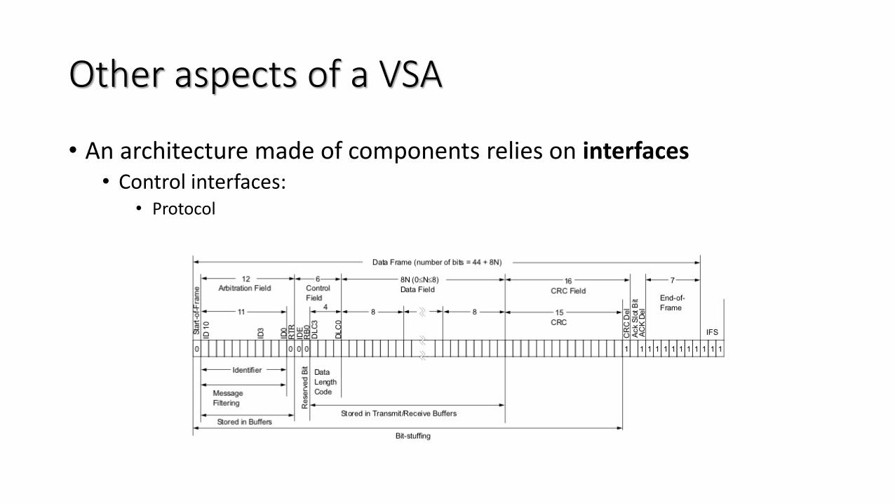
• An architecture made of components relies on interfaces• Control interfaces:
• Protocol

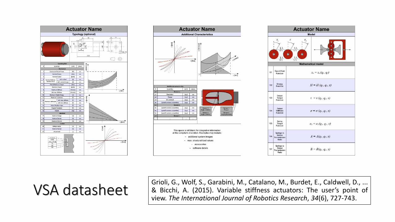
VSA datasheetGrioli, G., Wolf, S., Garabini, M., Catalano, M., Burdet, E., Caldwell, D., ...& Bicchi, A. (2015). Variable stiffness actuators: The user’s point ofview. The International Journal of Robotics Research, 34(6), 727-743.
Part 1.5
Identification of the Stiffnessof a Robot
by Giorgio Grioli
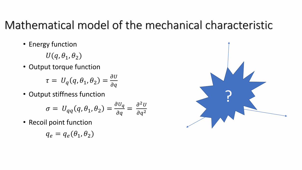
Mathematical model of the mechanical characteristic
• Energy function
𝑈(𝑞, 𝜃1, 𝜃2)
• Output torque function
𝜏 = 𝑈𝑞 𝑞, 𝜃1, 𝜃2 =𝜕𝑈
𝜕𝑞
• Output stiffness function
𝜎 = 𝑈𝑞𝑞 𝑞, 𝜃1, 𝜃2 =𝜕𝑈𝑞
𝜕𝑞=
𝜕2𝑈
𝜕𝑞2
• Recoil point function
𝑞𝑒 = 𝑞𝑒(𝜃1, 𝜃2)
?
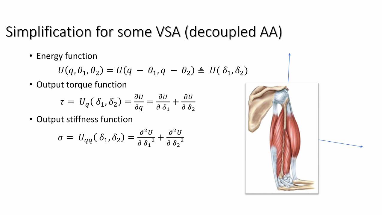
Simplification for some VSA (decoupled AA)
• Energy function
𝑈 𝑞, 𝜃1, 𝜃2 = 𝑈 𝑞 − 𝜃1, 𝑞 − 𝜃2 ≜ 𝑈( 𝛿1, 𝛿2)
• Output torque function
𝜏 = 𝑈𝑞 𝛿1, 𝛿2 =𝜕𝑈
𝜕𝑞=
𝜕𝑈
𝜕 𝛿1+
𝜕𝑈
𝜕 𝛿2
• Output stiffness function
𝜎 = 𝑈𝑞𝑞 𝛿1, 𝛿2 =𝜕2𝑈
𝜕 𝛿12 +
𝜕2𝑈
𝜕 𝛿22
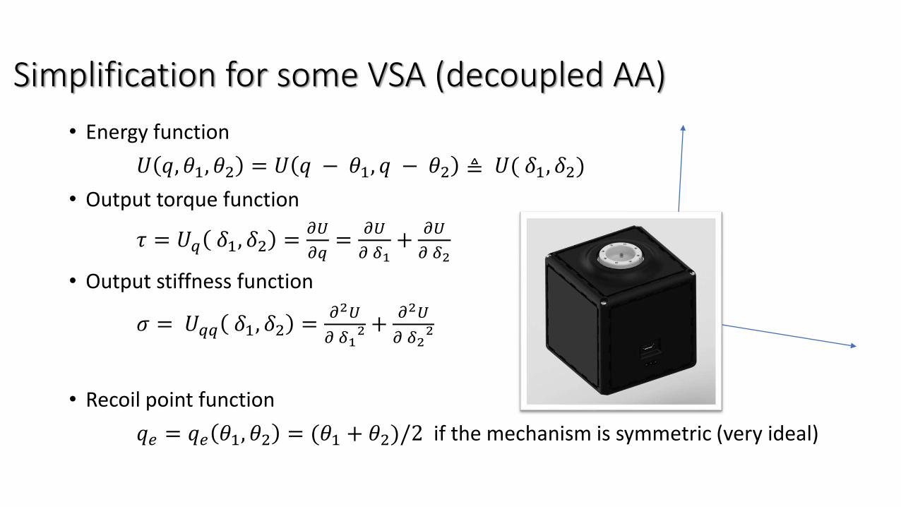
Simplification for some VSA (decoupled AA)
• Energy function
𝑈 𝑞, 𝜃1, 𝜃2 = 𝑈 𝑞 − 𝜃1, 𝑞 − 𝜃2 ≜ 𝑈( 𝛿1, 𝛿2)
• Output torque function
𝜏 = 𝑈𝑞 𝛿1, 𝛿2 =𝜕𝑈
𝜕𝑞=
𝜕𝑈
𝜕 𝛿1+
𝜕𝑈
𝜕 𝛿2
• Output stiffness function
𝜎 = 𝑈𝑞𝑞 𝛿1, 𝛿2 =𝜕2𝑈
𝜕 𝛿12 +
𝜕2𝑈
𝜕 𝛿22
• Recoil point function
𝑞𝑒 = 𝑞𝑒 𝜃1, 𝜃2 = (𝜃1 + 𝜃2)/2 if the mechanism is symmetric (very ideal)
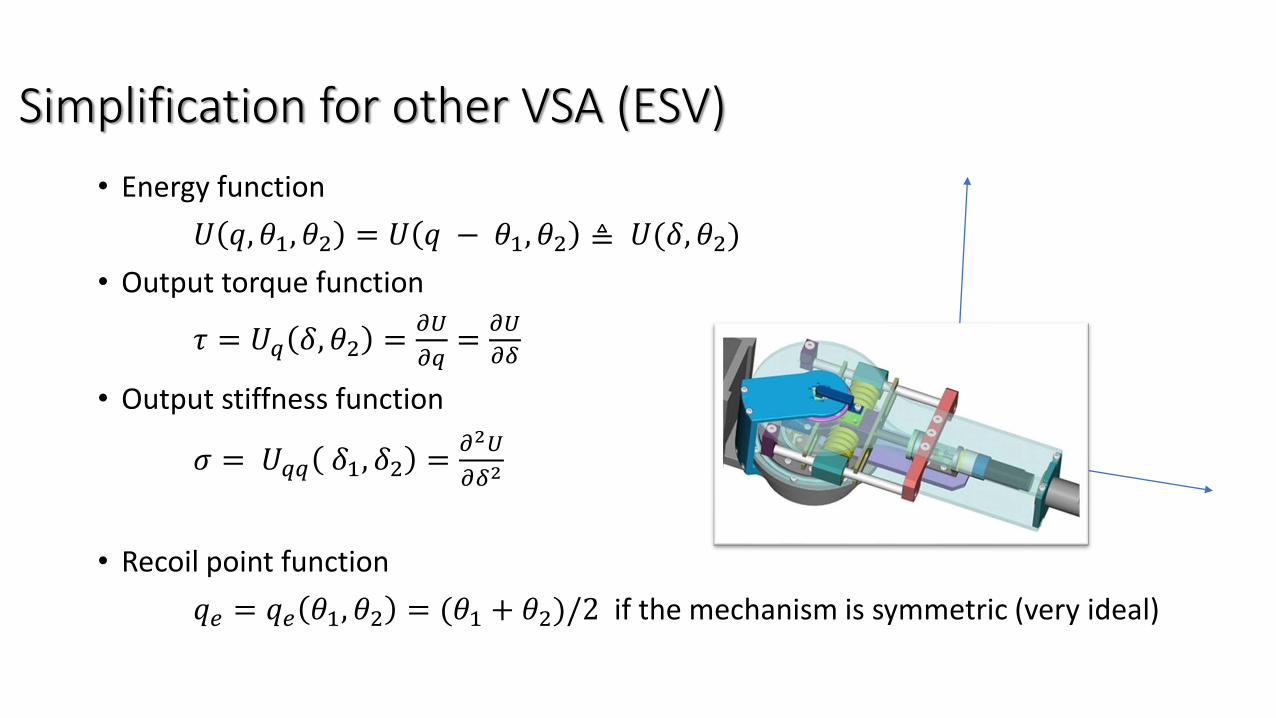
Simplification for other VSA (ESV)
• Energy function
𝑈 𝑞, 𝜃1, 𝜃2 = 𝑈 𝑞 − 𝜃1, 𝜃2 ≜ 𝑈(𝛿, 𝜃2)
• Output torque function
𝜏 = 𝑈𝑞 𝛿, 𝜃2 =𝜕𝑈
𝜕𝑞=
𝜕𝑈
𝜕𝛿
• Output stiffness function
𝜎 = 𝑈𝑞𝑞 𝛿1, 𝛿2 =𝜕2𝑈
𝜕𝛿2
• Recoil point function
𝑞𝑒 = 𝑞𝑒 𝜃1, 𝜃2 = (𝜃1 + 𝜃2)/2 if the mechanism is symmetric (very ideal)
VSA datasheetGrioli, G., Wolf, S., Garabini, M., Catalano, M., Burdet, E., Caldwell, D., ...& Bicchi, A. (2015). Variable stiffness actuators: The user’s point ofview. The International Journal of Robotics Research, 34(6), 727-743.
Where do parameters come from?
Experimental characterization of a VSA
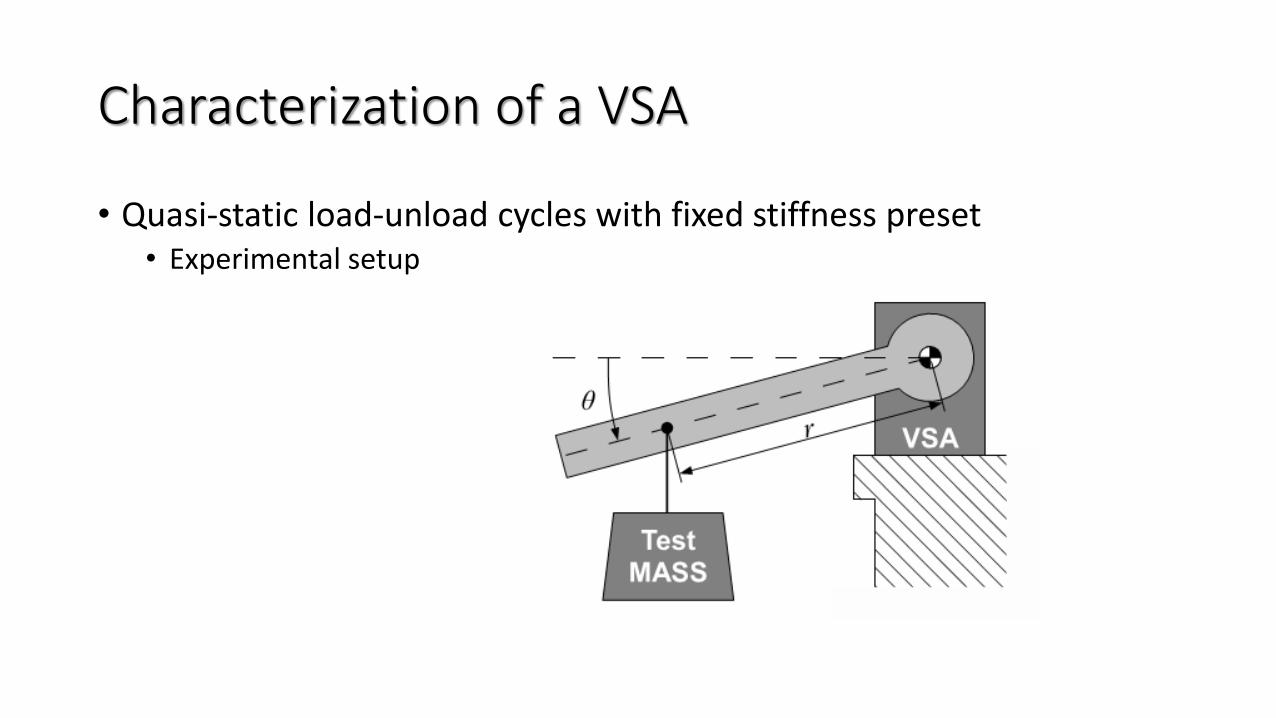
Characterization of a VSA
• Quasi-static load-unload cycles with fixed stiffness preset• Experimental setup
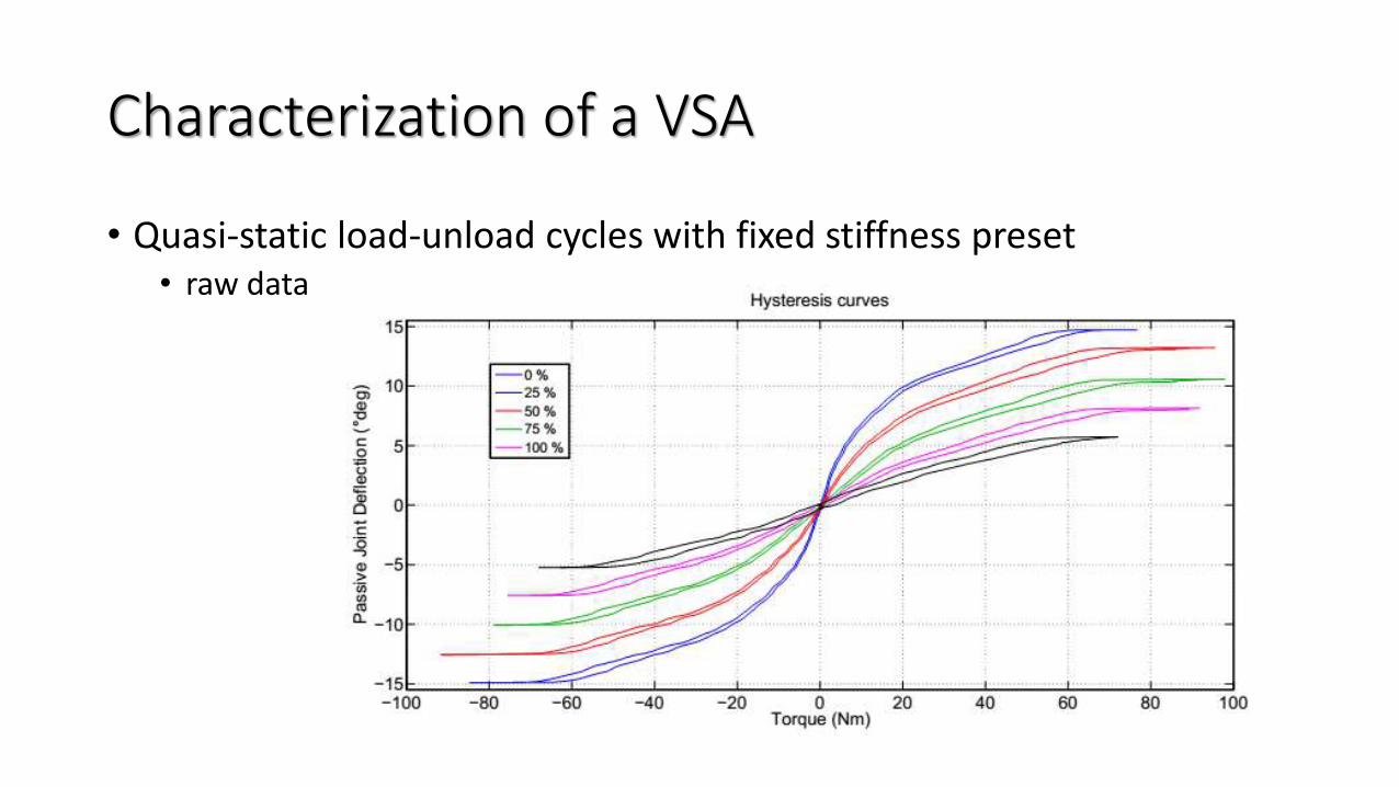
Characterization of a VSA
• Quasi-static load-unload cycles with fixed stiffness preset• raw data
Characterization of a VSA
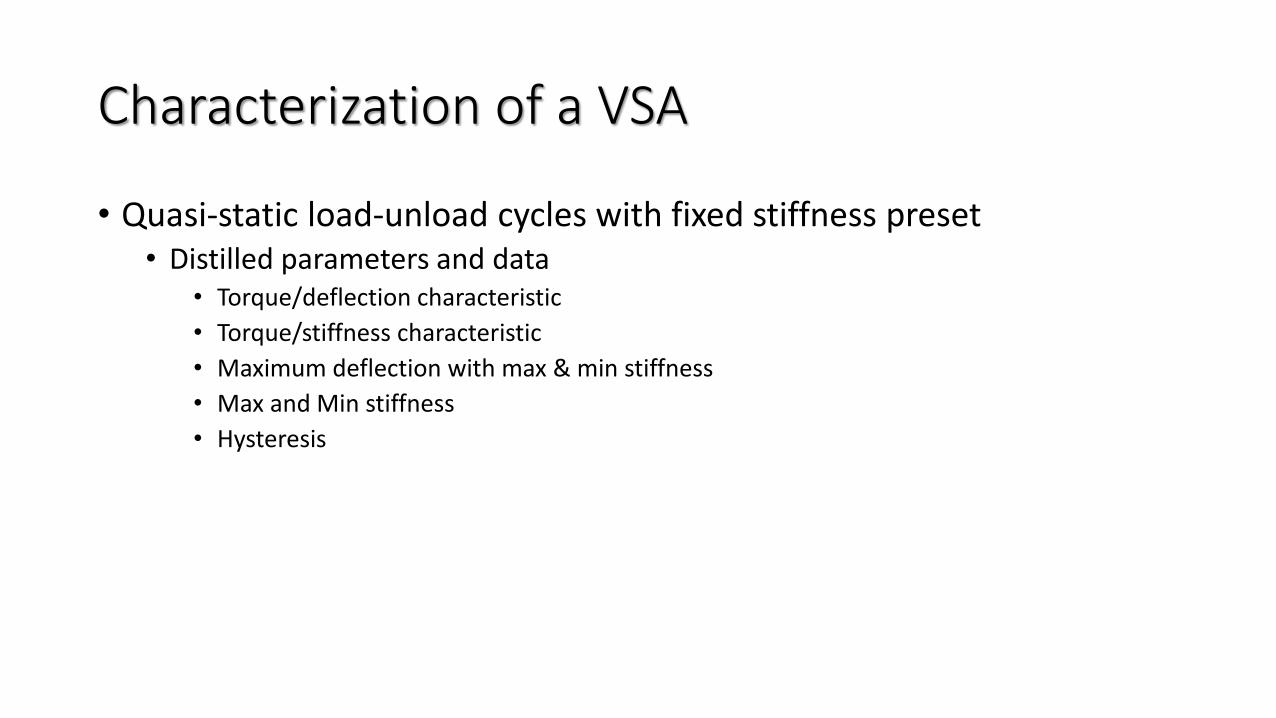
• Quasi-static load-unload cycles with fixed stiffness preset• Distilled parameters and data
• Torque/deflection characteristic
• Torque/stiffness characteristic
• Maximum deflection with max & min stiffness
• Max and Min stiffness
• Hysteresis
Characterization of a VSA
• Step command(s)• Experimental setup
• Actuator in horizontal, with no added load• Step in output position
• Step in stiffness reference
• Actuator with nominal load (e.g. with same setup as before)• Step in stiffness reference
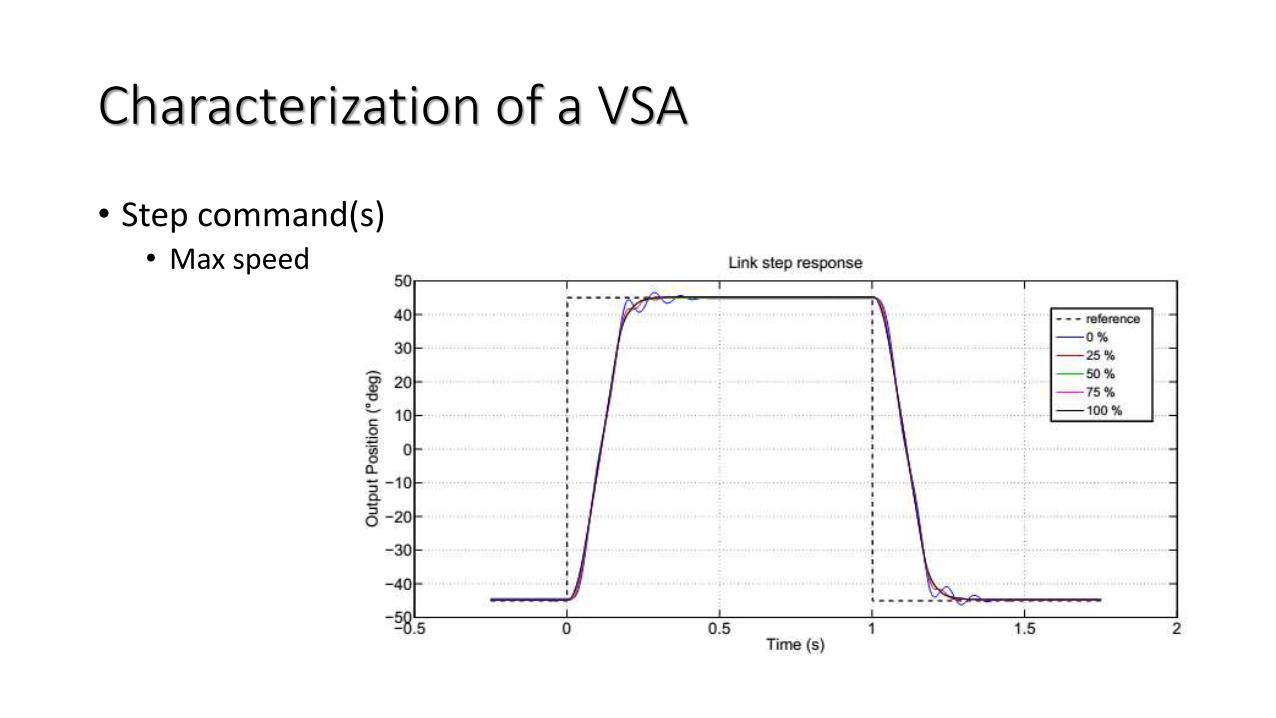
Characterization of a VSA
• Step command(s)• Max speed
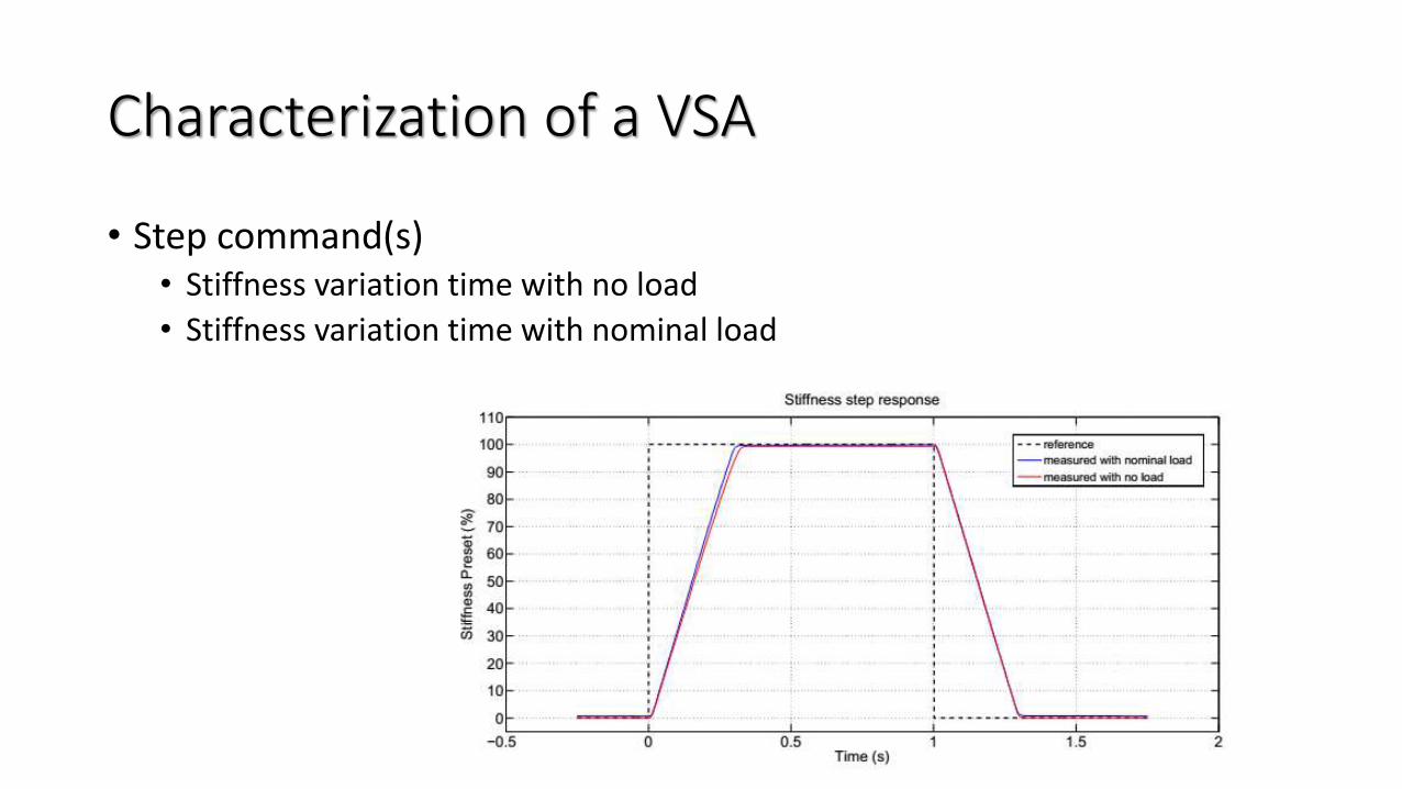
Characterization of a VSA
• Step command(s)• Stiffness variation time with no load
• Stiffness variation time with nominal load
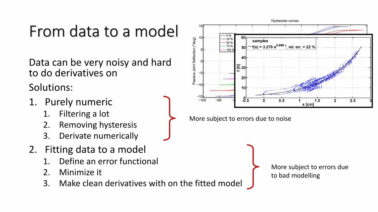
From data to a model
Data can be very noisy and hard to do derivatives on
Solutions:
1. Purely numeric1. Filtering a lot2. Removing hysteresis3. Derivate numerically
2. Fitting data to a model1. Define an error functional2. Minimize it3. Make clean derivatives with on the fitted model
More subject to errors due to noise
More subject to errors due to bad modelling
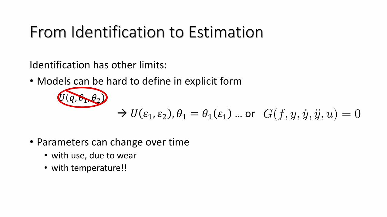
From Identification to Estimation
Identification has other limits:
• Models can be hard to define in explicit form
𝑈 𝑞, 𝜃1, 𝜃2
→ 𝑈 1, 2 , 𝜃1 = 𝜃1 1 … or
• Parameters can change over time• with use, due to wear
• with temperature!!
Part II
Estimation of the Stiffness (or Impedance)of a Robot
by Giorgio Grioli
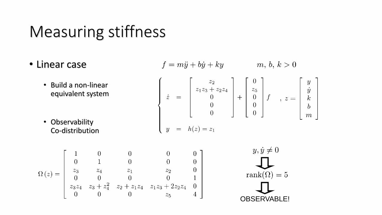
OBSERVABLE!
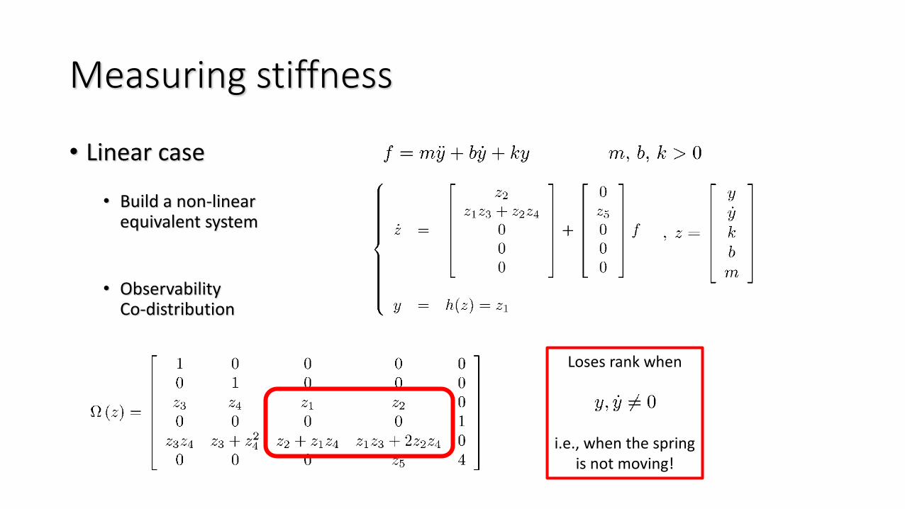
Measuring stiffness
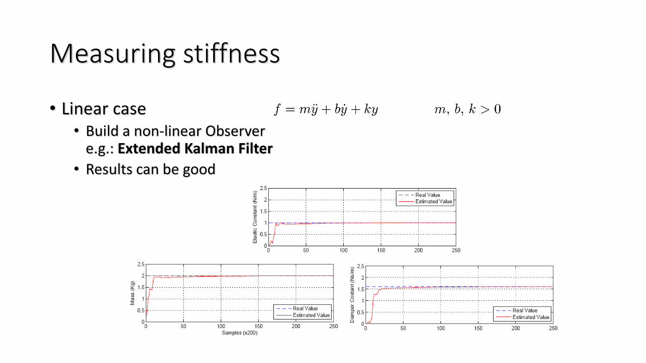
• Linear case
• Build a non-linearequivalent system
• ObservabilityCo-distribution
Measuring stiffness
• Linear case• Build a non-linear Observer
e.g.: Extended Kalman Filter
• Results can be good
Measuring stiffness
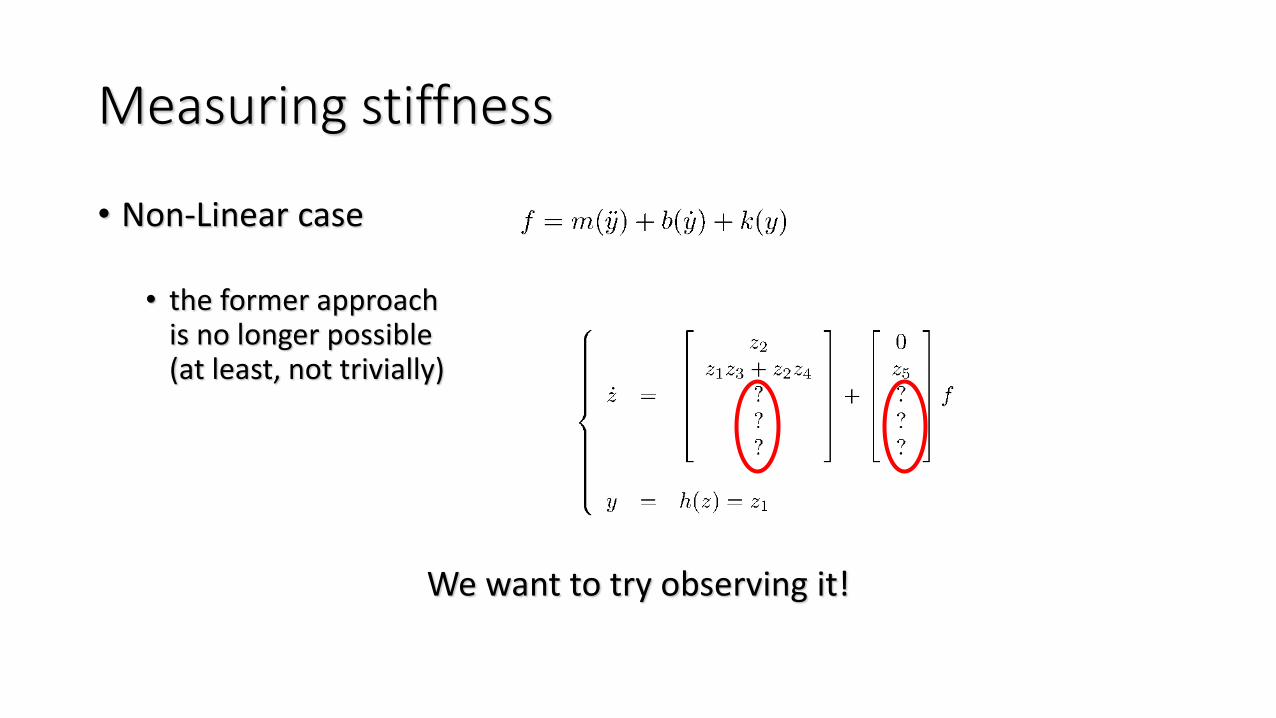
• Non-Linear case
• the former approachis no longer possible(at least, not trivially)
We want to try observing it!
Observation of Stiffness: possible approaches
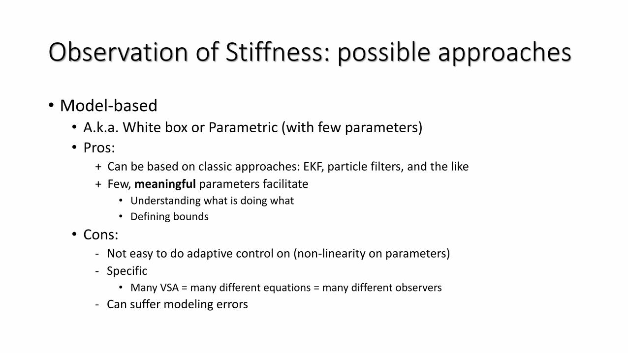
• Model-based• A.k.a. White box or Parametric (with few parameters)
• Pros:+ Can be based on classic approaches: EKF, particle filters, and the like
+ Few, meaningful parameters facilitate• Understanding what is doing what
• Defining bounds
• Cons:- Not easy to do adaptive control on (non-linearity on parameters)
- Specific• Many VSA = many different equations = many different observers
- Can suffer modeling errors
Observation of Stiffness: possible approaches
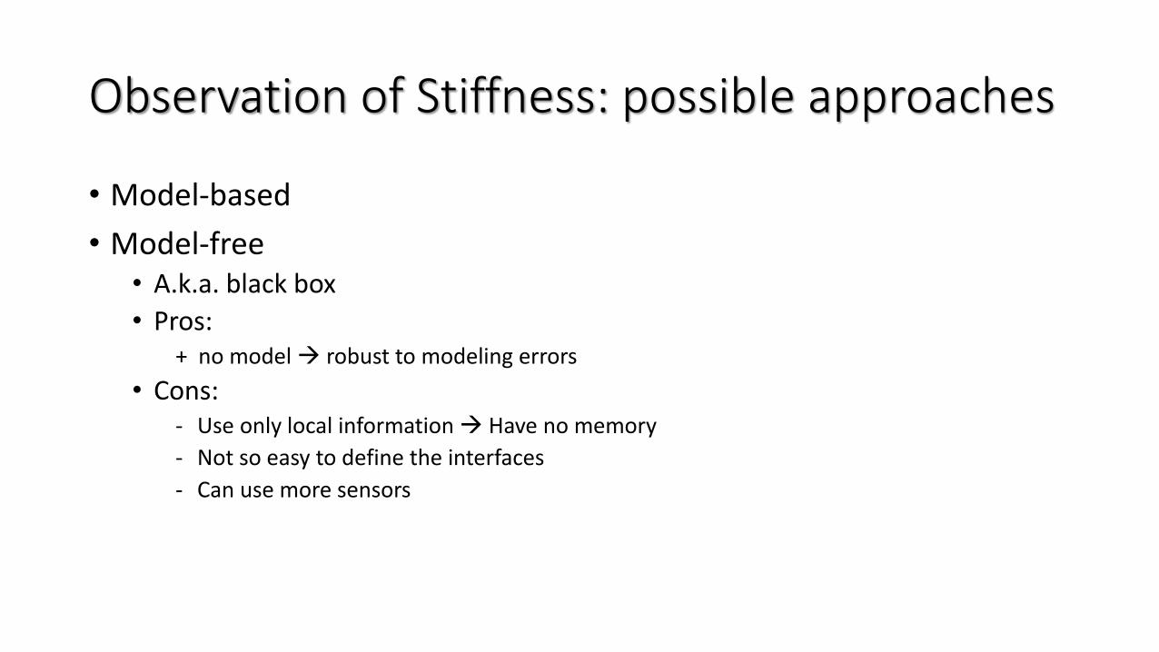
• Model-based
• Model-free• A.k.a. black box
• Pros:+ no model → robust to modeling errors
• Cons:- Use only local information → Have no memory
- Not so easy to define the interfaces
- Can use more sensors
Observation of Stiffness: possible approaches
• Model-based
• Model-free
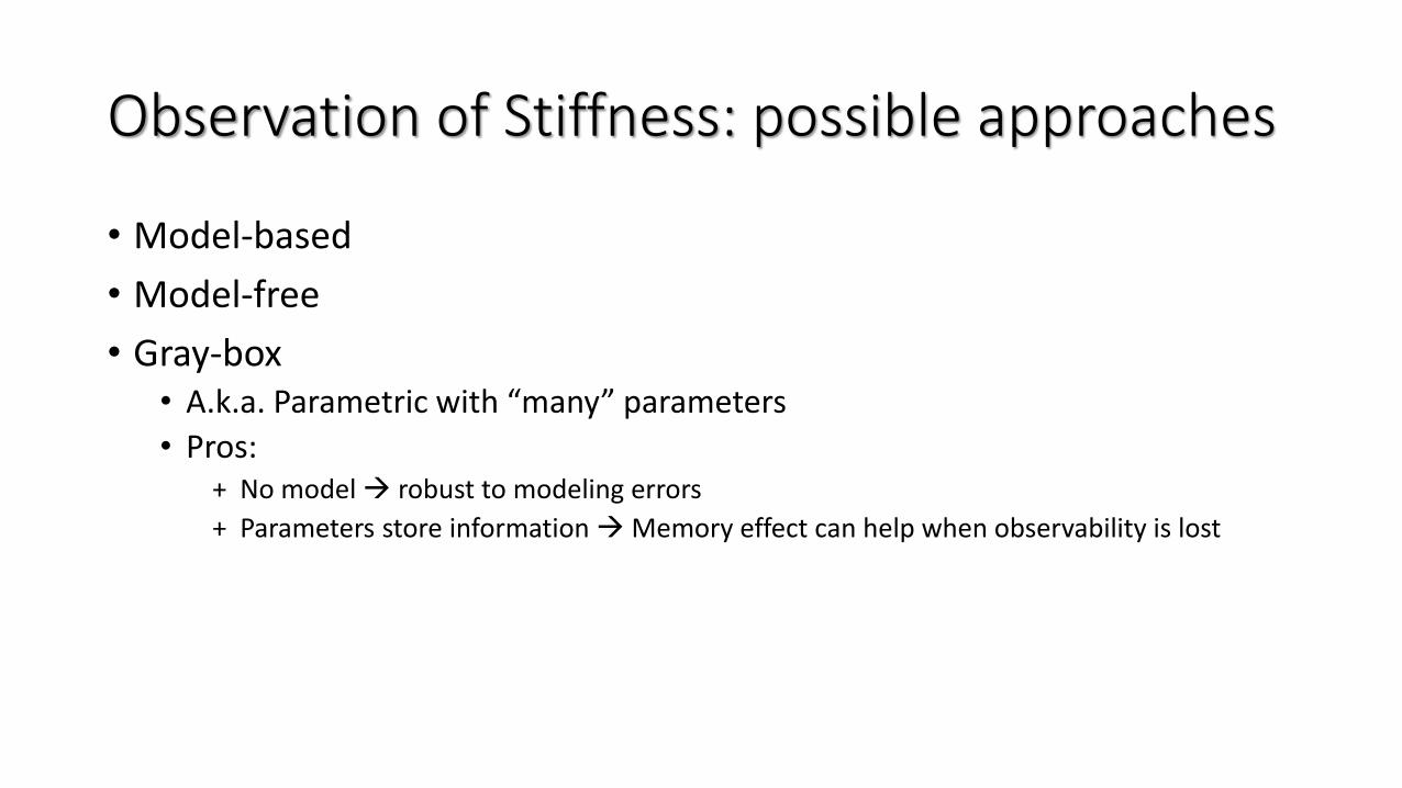
• Gray-box• A.k.a. Parametric with “many” parameters
• Pros:+ No model → robust to modeling errors
+ Parameters store information →Memory effect can help when observability is lost
OBSERVABLE!
Measuring stiffness
• Linear case
• Build a non-linearequivalent system
• ObservabilityCo-distribution
Loses rank when
i.e., when the spring is not moving!
Observation of Stiffness: possible approaches
• Model-based
• Model-free
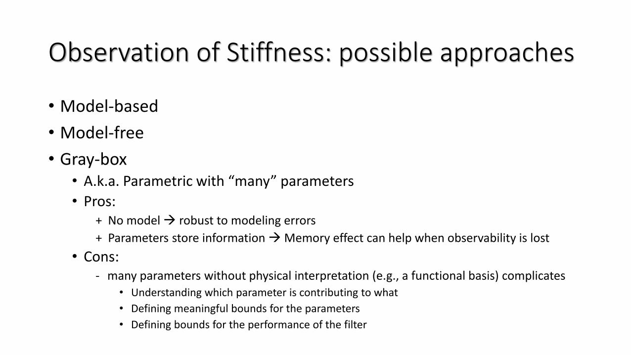
• Gray-box• A.k.a. Parametric with “many” parameters
• Pros:+ No model → robust to modeling errors
+ Parameters store information →Memory effect can help when observability is lost
• Cons:- many parameters without physical interpretation (e.g., a functional basis) complicates
• Understanding which parameter is contributing to what
• Defining meaningful bounds for the parameters
• Defining bounds for the performance of the filter
Observation of Stiffness: possible approaches
• Model-based
• Model-free
• Gray-box
Model-base and Gray-box go together
Vs
Model-free
Example of a model-basedapproach
Stiffness Estimation and Nonlinear Control of Robots with Variable
Stiffness Actuation
18th IFAC World CongressAugust 28 - September 2, 2011, Milano, Italy
Fabrizio FlaccoAlessandro De Luca
Dipartimento di Informatica e Sistemistica A. Ruberti
{deluca,fflacco}@dis.uniroma1.itwww.dis.uniroma1/~labrob
Courtesy of
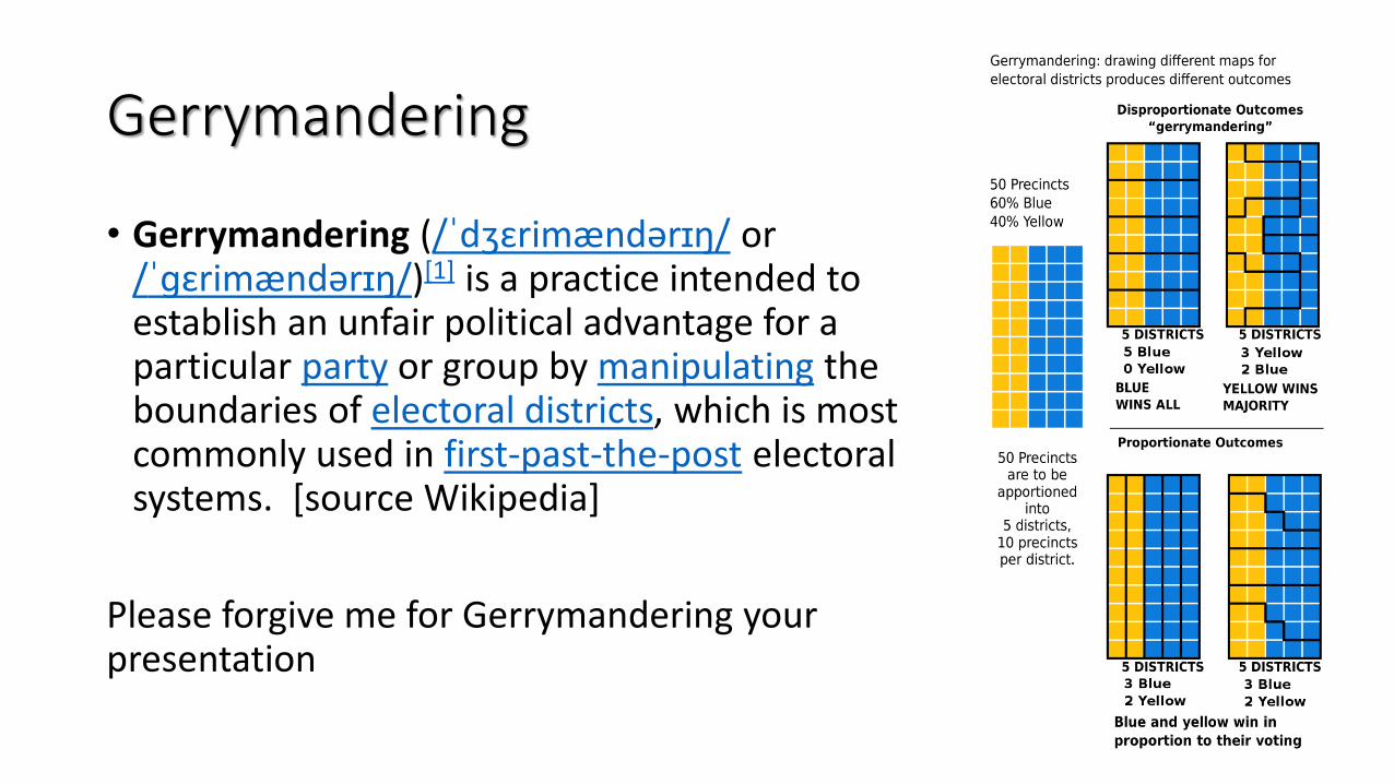
Gerrymandering
• Gerrymandering (/ˈdʒɛrimændərɪŋ/ or /ˈɡɛrimændərɪŋ/)[1] is a practice intended to establish an unfair political advantage for a particular party or group by manipulating the boundaries of electoral districts, which is most commonly used in first-past-the-post electoral systems. [source Wikipedia]
Please forgive me for Gerrymandering your presentation
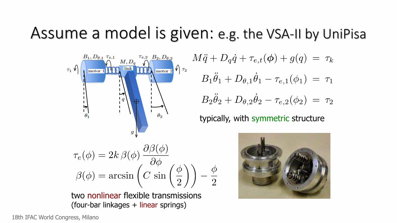
Assume a model is given: e.g. the VSA-II by UniPisa
typically, with symmetric structure
two nonlinear flexible transmissions (four-bar linkages + linear springs)
18th IFAC World Congress, Milano
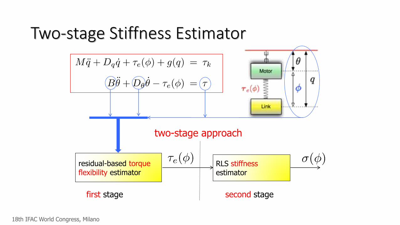
Two-stage Stiffness Estimator
two-stage approach
residual-based torqueflexibility estimator
first stage
RLS stiffnessestimator
second stage
18th IFAC World Congress, Milano
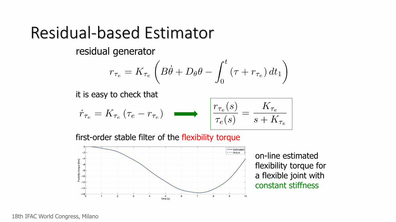
Residual-based Estimatorresidual generator
it is easy to check that
first-order stable filter of the flexibility torque
on-line estimatedflexibility torque fora flexible joint with constant stiffness
18th IFAC World Congress, Milano
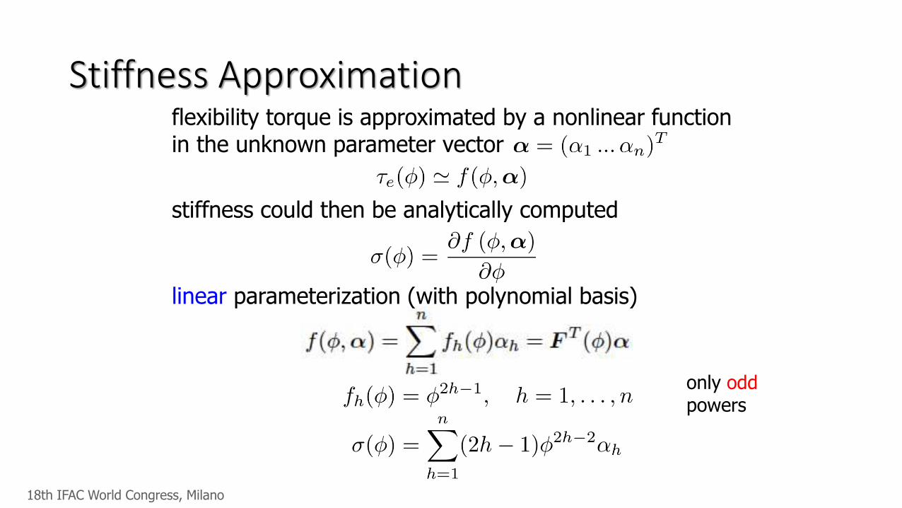
Stiffness Approximationflexibility torque is approximated by a nonlinear function in the unknown parameter vector
stiffness could then be analytically computed
linear parameterization (with polynomial basis)
only oddpowers
18th IFAC World Congress, Milano
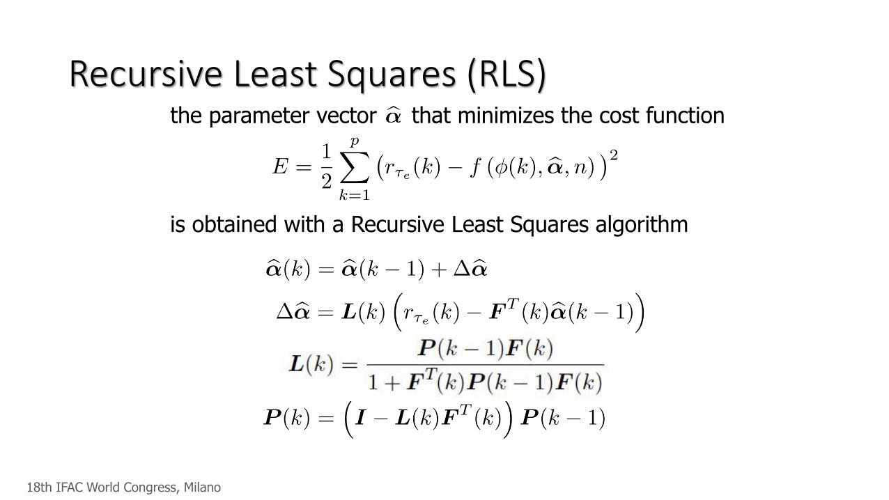
Recursive Least Squares (RLS)the parameter vector that minimizes the cost function
is obtained with a Recursive Least Squares algorithm
18th IFAC World Congress, Milano
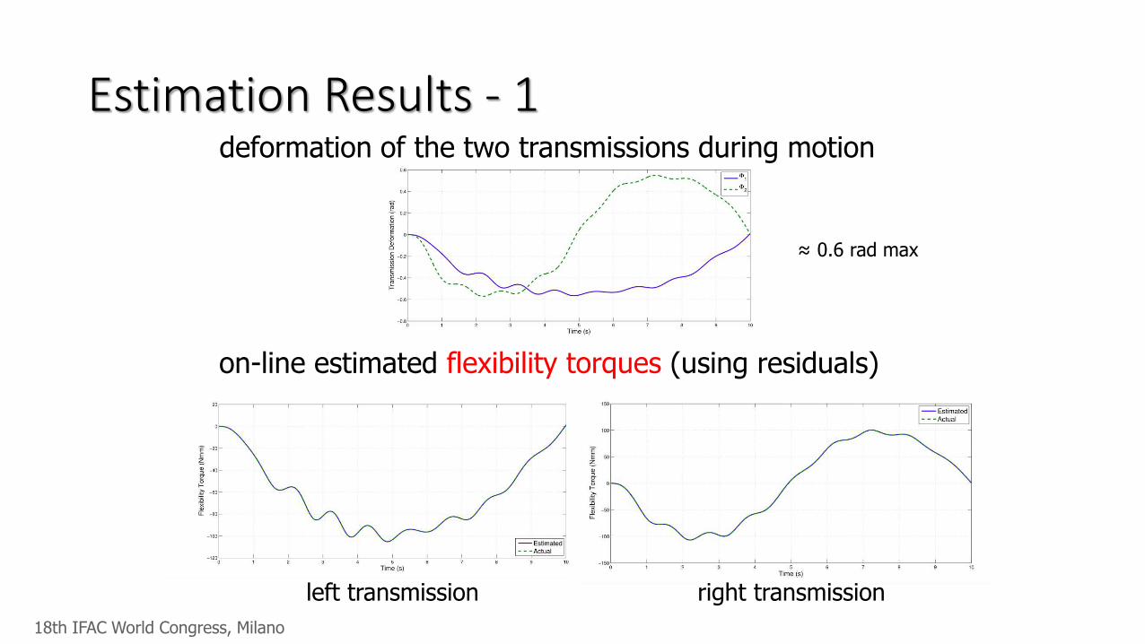
Estimation Results - 1deformation of the two transmissions during motion
on-line estimated flexibility torques (using residuals)
left transmission right transmission
≈ 0.6 rad max
18th IFAC World Congress, Milano
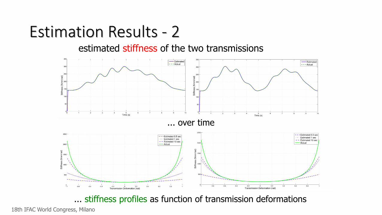
Estimation Results - 2estimated stiffness of the two transmissions
... over time
... stiffness profiles as function of transmission deformations18th IFAC World Congress, Milano
Examples of model-freeapproaches
“A Non-Invasive, Real-Time
Method for Measuring Variable
Stiffness”
G. Grioli, A. Bicchi
Robotic Science and Systems 2010,
Zaragoza, Spain.
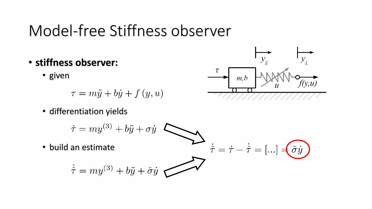
Model-free Stiffness observer
• stiffness observer:• given
• differentiation yields
• build an estimate
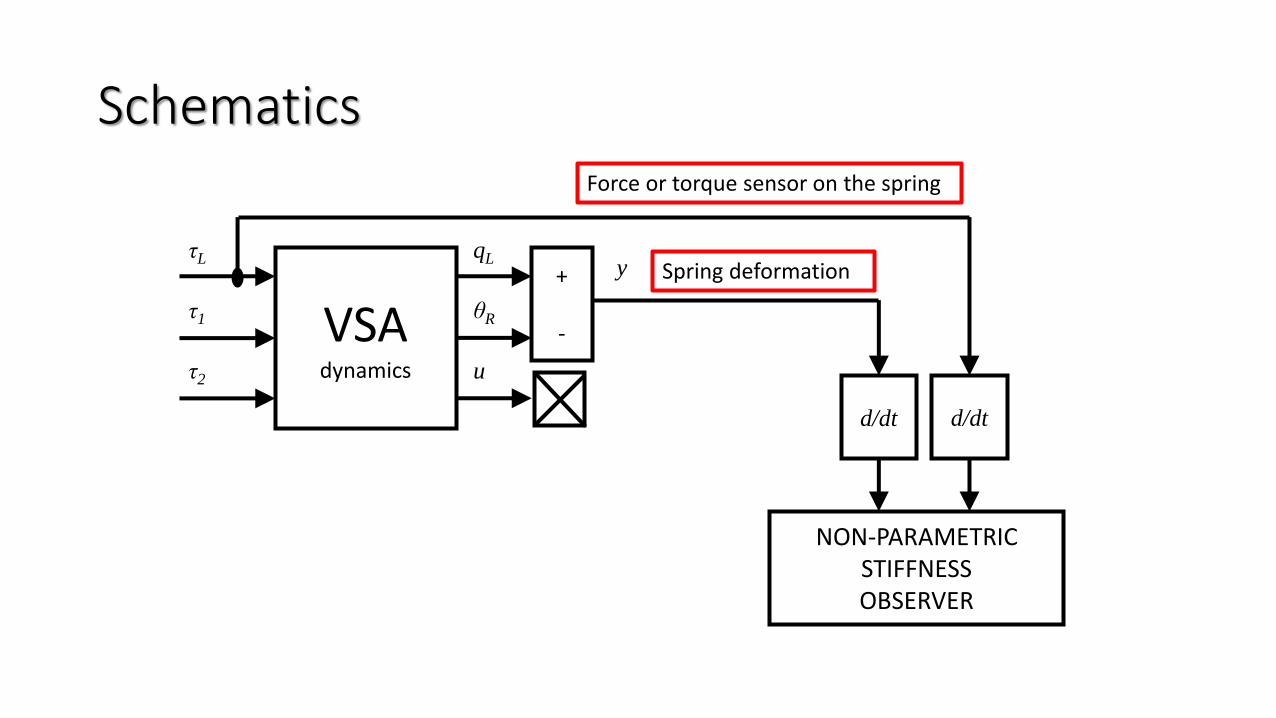
Schematics
VSAdynamics
qL
θR
u
τL
τ1
τ2
y+
-
d/dtd/dt
NON-PARAMETRICSTIFFNESSOBSERVER
Force or torque sensor on the spring
Spring deformation
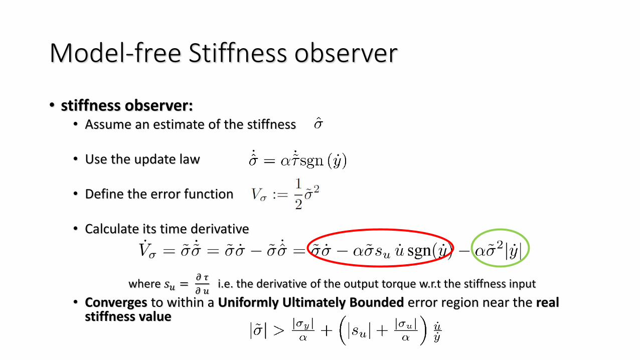
Model-free Stiffness observer
• stiffness observer:• Assume an estimate of the stiffness
• Use the update law
• Define the error function
• Calculate its time derivative
where 𝑠𝑢 =𝜕 𝜏
𝜕 𝑢i.e. the derivative of the output torque w.r.t the stiffness input
• Converges to within a Uniformly Ultimately Bounded error region near the real stiffness value
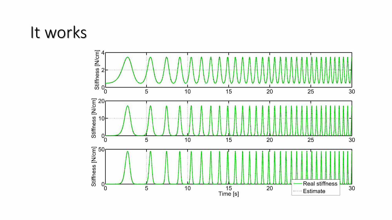
It works
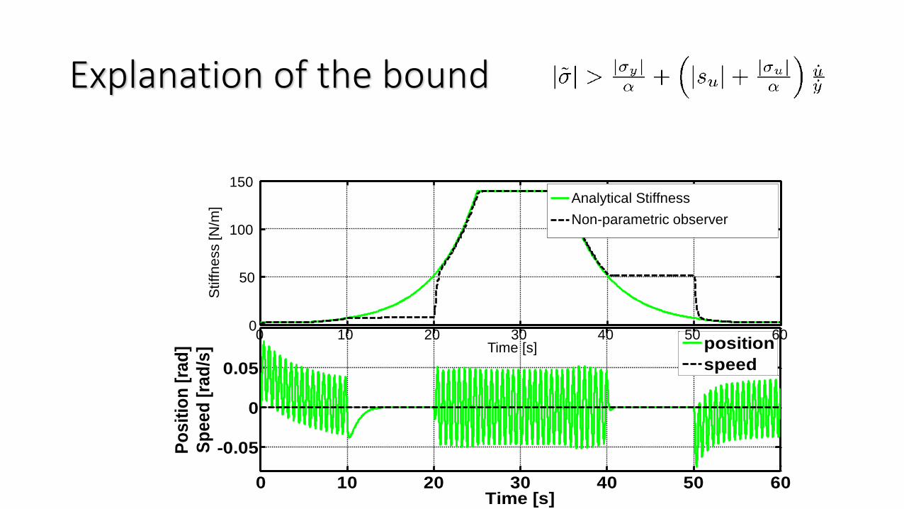
Explanation of the bound
0 10 20 30 40 50 60
-0.05
0
0.05
Time [s]
Po
sit
ion
[ra
d]
Sp
ee
d [
rad
/s]
position
speed
0 10 20 30 40 50 600
50
100
150
Time [s]
Stiffn
ess [N
/m]
Analytical Stiffness
Non-parametric observer
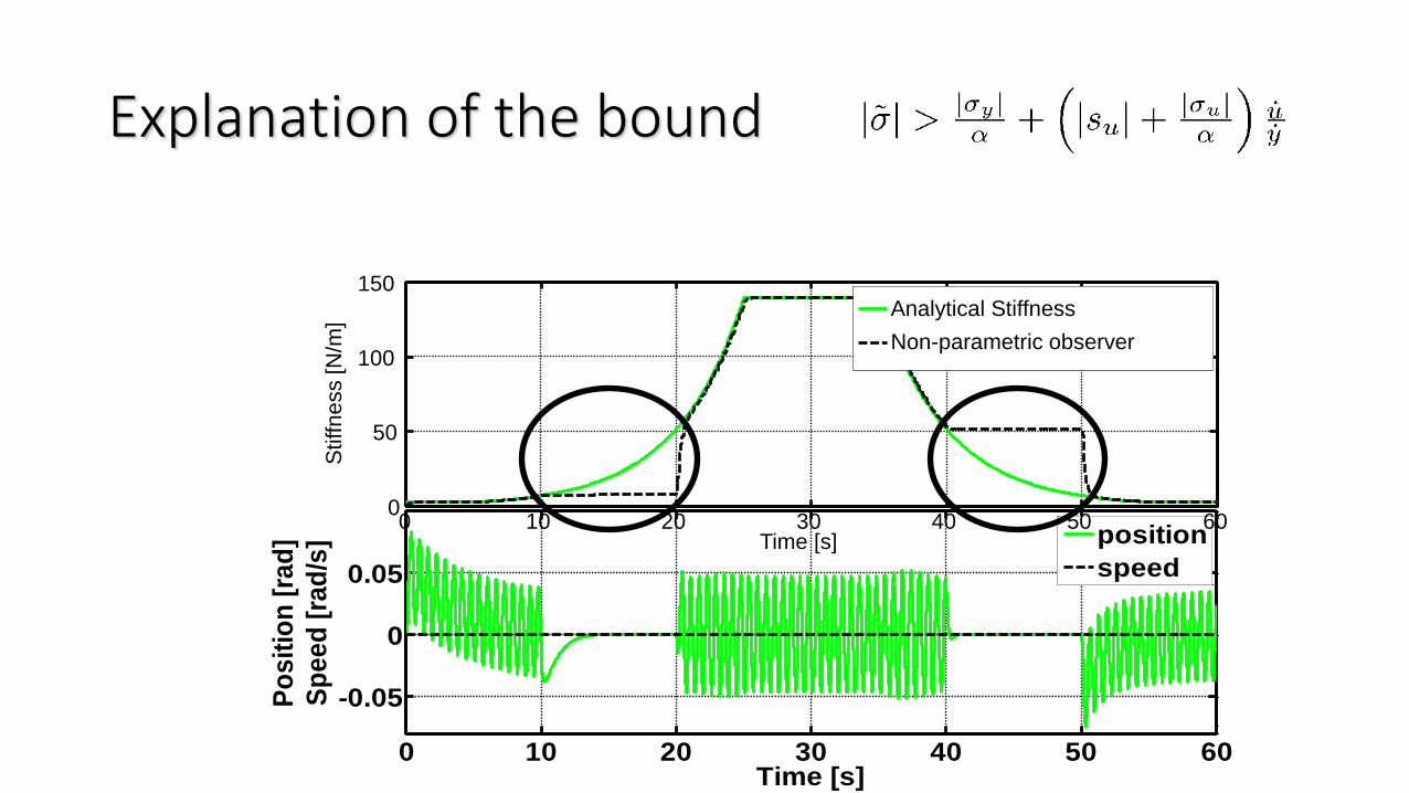
Explanation of the bound
0 10 20 30 40 50 60
-0.05
0
0.05
Time [s]
Po
sit
ion
[ra
d]
Sp
ee
d [
rad
/s]
position
speed
0 10 20 30 40 50 600
50
100
150
Time [s]
Stiffn
ess [N
/m]
Analytical Stiffness
Non-parametric observer
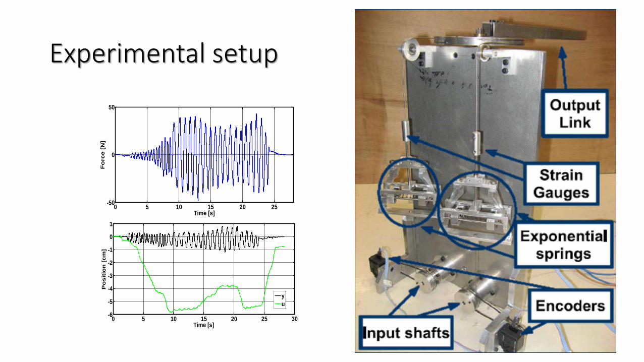
Experimental setup
0 5 10 15 20 25 30-6
-5
-4
-3
-2
-1
0
1
Time [s]
Po
sit
ion
[c
m]
y
u
0 5 10 15 20 25-50
0
50
Time [s]
Fo
rce
[N
]
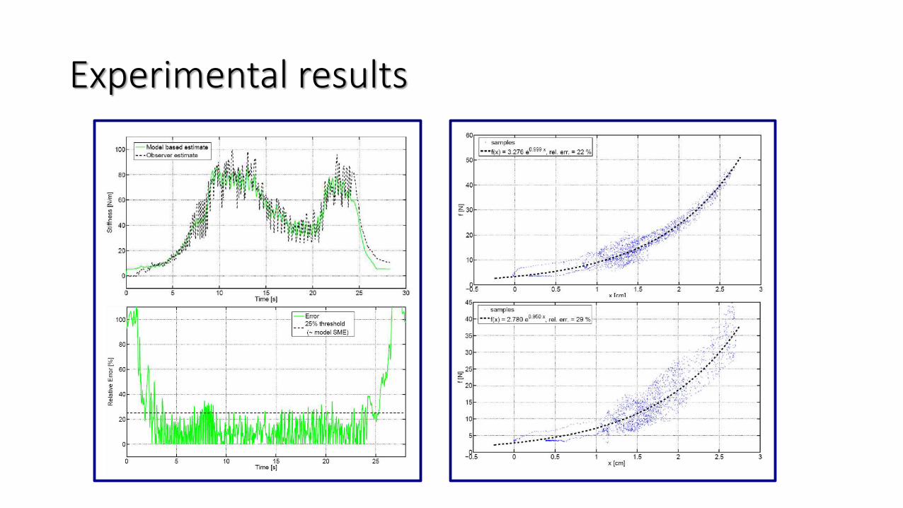
Experimental results
“A Non-Invasive, Real-Time Method for Measuring Variable Stiffness” G. Grioli, A.
Bicchi Robotic Science and Systems 2010, Zaragoza, Spain.
• Still needed force or torque sensors
Residual-based Stiffness Estimationin Robots with
Flexible Transmissions
2011 IEEE International Conference onRobotics and AutomationMay 9-13, 2011 Shanghai, China
ICRA 2011, May 9-13, Shanghai, China
Fabrizio FlaccoAlessandro De LucaDipartimento di Informatica e Sistemistica
Courtesy of
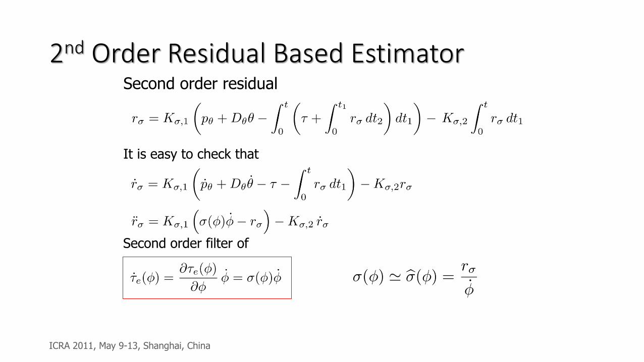
2nd Order Residual Based EstimatorSecond order residual
It is easy to check that
Second order filter of
ICRA 2011, May 9-13, Shanghai, China
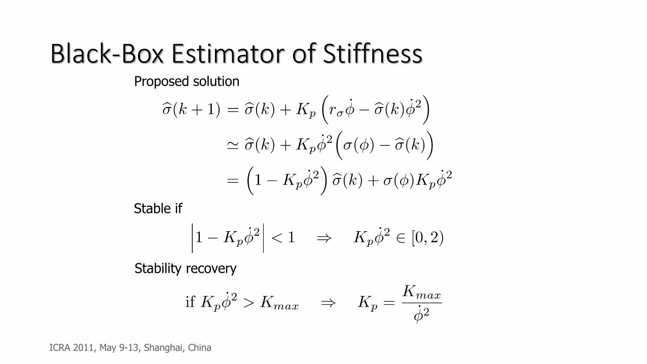
Black-Box Estimator of StiffnessProposed solution
Stable if
Stability recovery
ICRA 2011, May 9-13, Shanghai, China
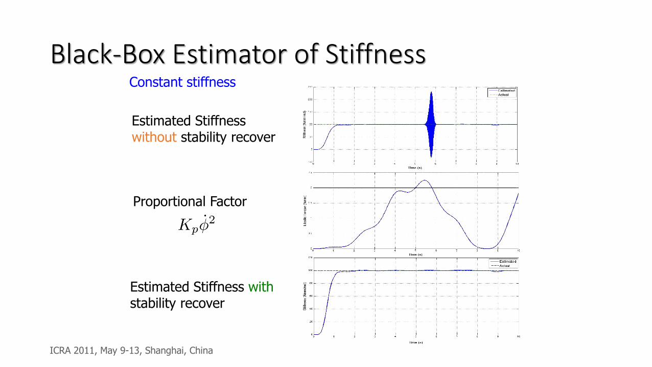
Black-Box Estimator of StiffnessConstant stiffness
Estimated Stiffness without stability recover
Estimated Stiffness withstability recover
Proportional Factor
ICRA 2011, May 9-13, Shanghai, China
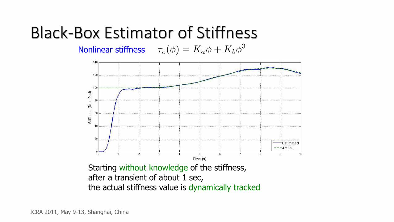
Black-Box Estimator of StiffnessNonlinear stiffness
Starting without knowledge of the stiffness, after a transient of about 1 sec, the actual stiffness value is dynamically tracked
ICRA 2011, May 9-13, Shanghai, China
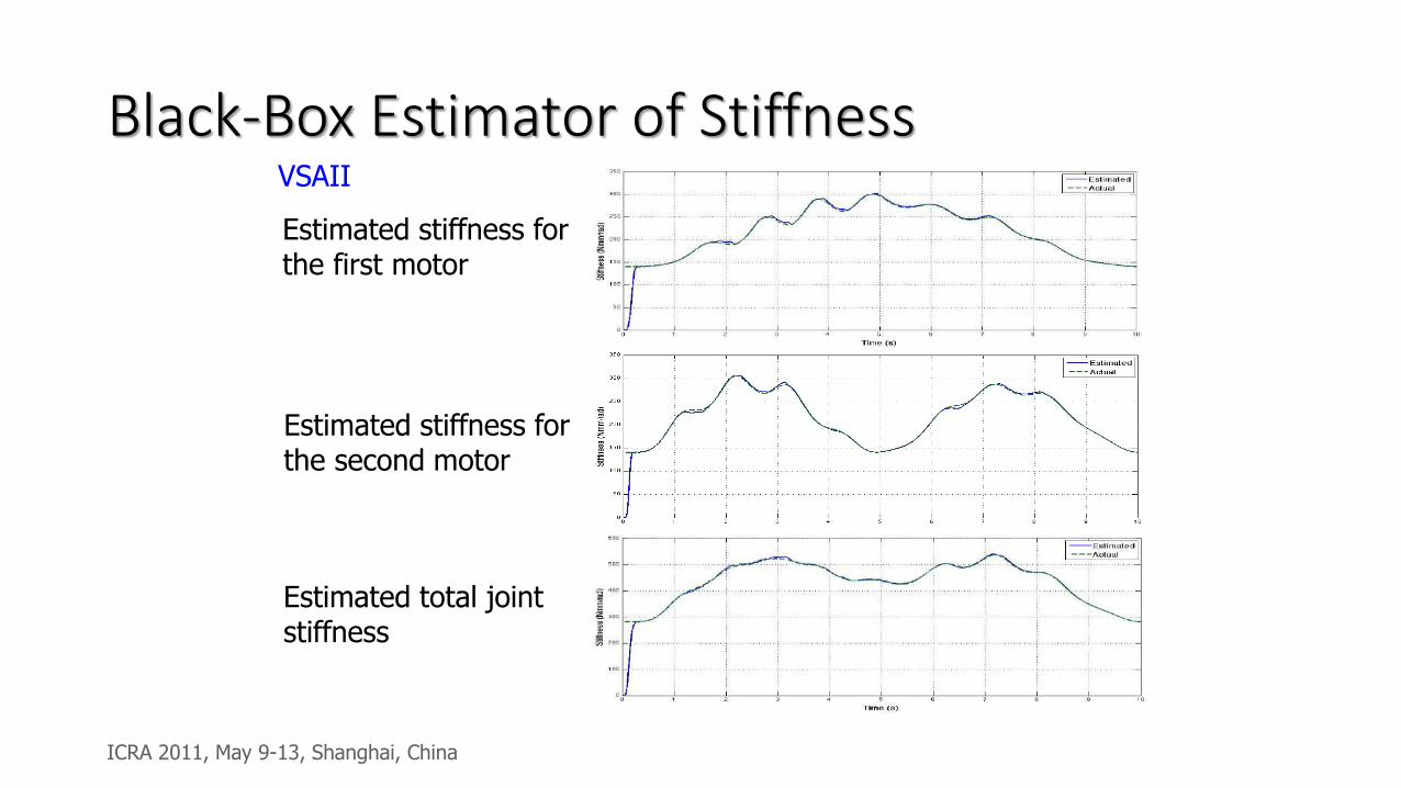
Black-Box Estimator of StiffnessVSAII
Estimated stiffness for the first motor
Estimated stiffness for the second motor
Estimated total joint stiffness
ICRA 2011, May 9-13, Shanghai, China

Other works
T. Ménard1,
G. Grioli2,3 and A. Bicchi2,3
1GREYC, University of Caen, Caen, France
2Advanced Robotics Dept., Istituto Italiano di Tecnologia, Genova, Italy
3Centro Interdipartimentale di Ricerca ``E. Piaggio'', University of Pisa, Italy
A real-time robust observer for an Agonistic-Antagonist Variable
Stiffness Actuator
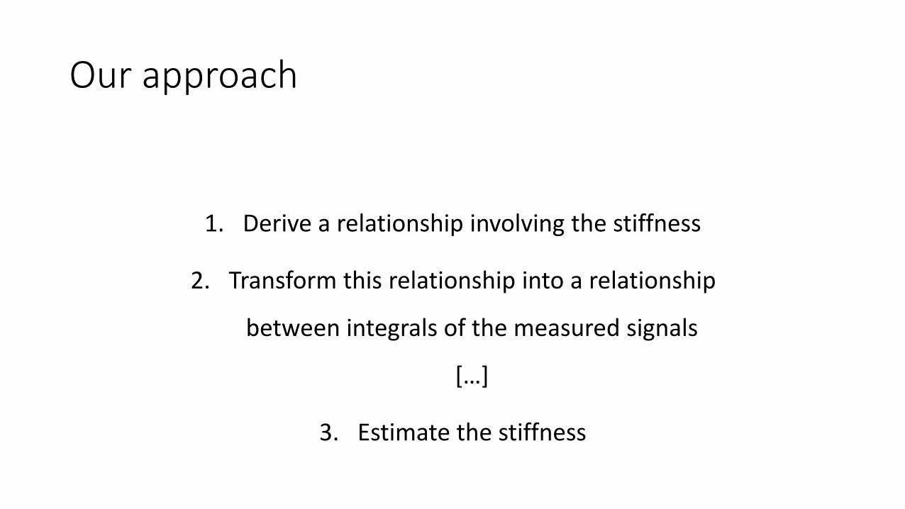
Our approach
1. Derive a relationship involving the stiffness
2. Transform this relationship into a relationship
between integrals of the measured signals
[…]
3. Estimate the stiffness
An Input Observer-Based Stiffness Estimation
Approach for Flexible Robot Joints
Adriano Fagiolini, Maja Trumić, Kosta Jovanović
ICRA 2020
School of Electrical Engineering - ETF
Courtesy of
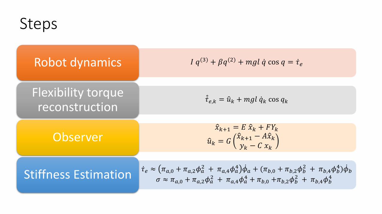
Steps
𝐼 𝑞(3) + 𝛽𝑞(2) +𝑚𝑔𝑙 ሶ𝑞 cos 𝑞 = ሶ𝜏𝑒Robot dynamics
መሶ𝜏𝑒,𝑘 = ො𝑢𝑘 +𝑚𝑔𝑙 ሶ𝑞𝑘 cos 𝑞𝑘Flexibility torque reconstruction
ො𝑥𝑘+1 = 𝐸 ො𝑥𝑘 + 𝐹𝑌𝑘
ො𝑢𝑘 = 𝐺ො𝑥𝑘+1 − 𝐴ො𝑥𝑘𝑦𝑘 − 𝐶 𝑥𝑘
Observer
ሶ𝜏𝑒 ≈ 𝜋𝑎,0 + 𝜋𝑎,2𝜙𝑎2 + 𝜋𝑎,4𝜙𝑎
4 ሶ𝜙𝑎 + (𝜋𝑏,0 + 𝜋𝑏,2𝜙𝑏2 + 𝜋𝑏,4𝜙𝑏
4) ሶ𝜙𝑏
𝜎 ≈ 𝜋𝑎,0 + 𝜋𝑎,2𝜙𝑎2 + 𝜋𝑎,4𝜙𝑎
4 + 𝜋𝑏,0 +𝜋𝑏,2𝜙𝑏2 + 𝜋𝑏,4𝜙𝑏
4Stiffness Estimation
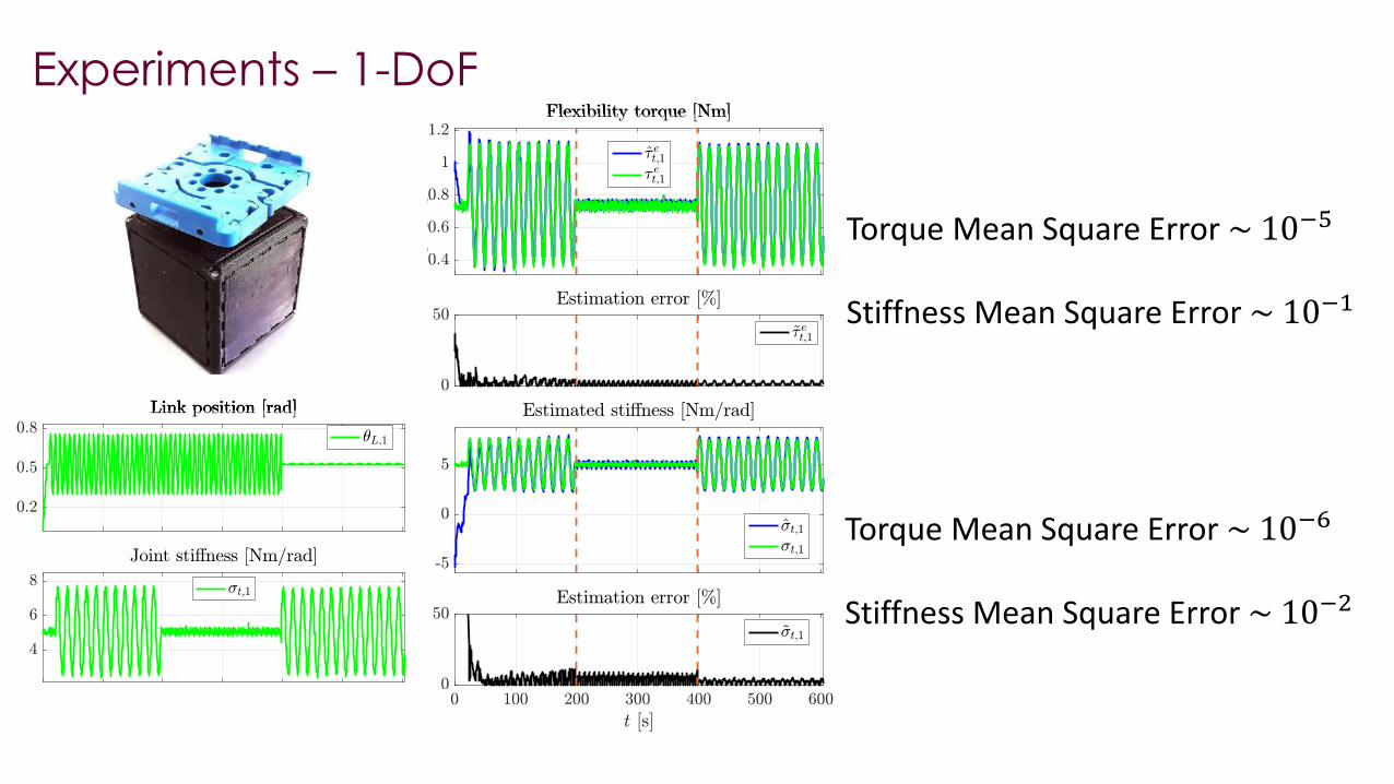
Experiments – 1-DoF
Torque Mean Square Error ~ 10−5
Stiffness Mean Square Error ~ 10−1
Torque Mean Square Error ~ 10−6
Stiffness Mean Square Error ~ 10−2
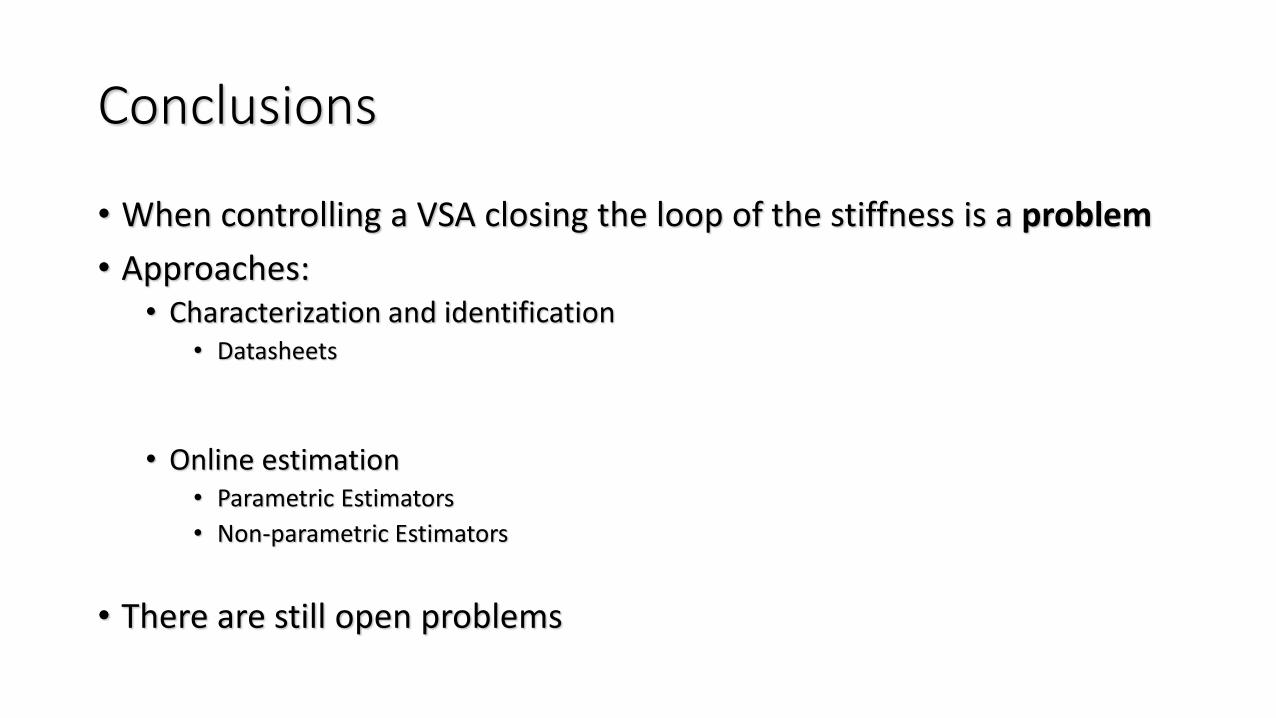
Conclusions
• When controlling a VSA closing the loop of the stiffness is a problem
• Approaches:• Characterization and identification
• Datasheets
• Online estimation• Parametric Estimators
• Non-parametric Estimators
• There are still open problems
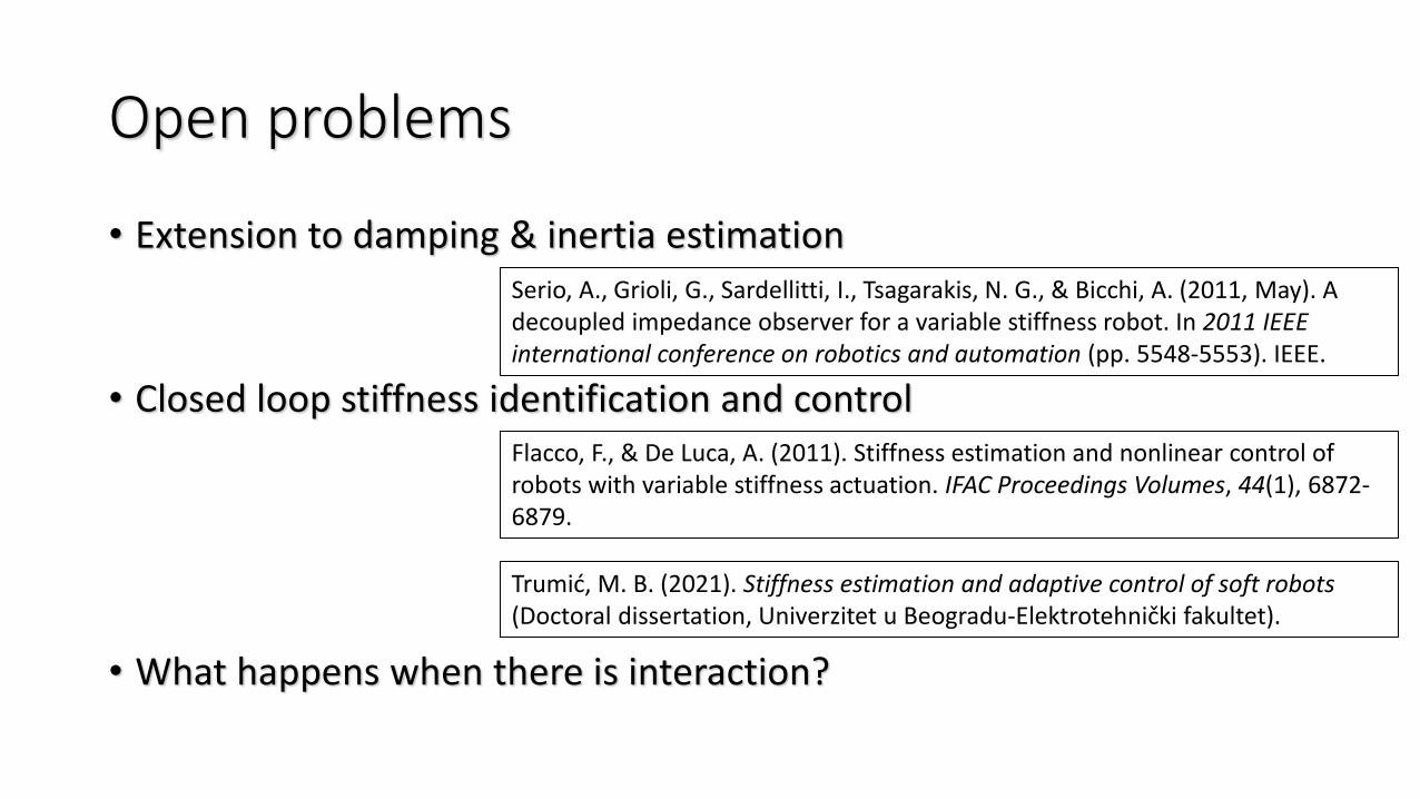
Open problems
• Extension to damping & inertia estimation
• Closed loop stiffness identification and control
• What happens when there is interaction?
Serio, A., Grioli, G., Sardellitti, I., Tsagarakis, N. G., & Bicchi, A. (2011, May). A decoupled impedance observer for a variable stiffness robot. In 2011 IEEE international conference on robotics and automation (pp. 5548-5553). IEEE.
Trumić, M. B. (2021). Stiffness estimation and adaptive control of soft robots(Doctoral dissertation, Univerzitet u Beogradu-Elektrotehnički fakultet).
Flacco, F., & De Luca, A. (2011). Stiffness estimation and nonlinear control of robots with variable stiffness actuation. IFAC Proceedings Volumes, 44(1), 6872-6879.
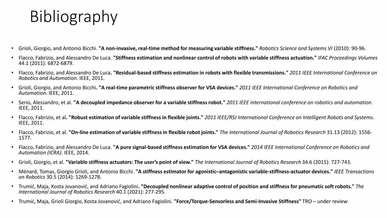
Bibliography
• Grioli, Giorgio, and Antonio Bicchi. "A non-invasive, real-time method for measuring variable stiffness." Robotics Science and Systems VI (2010): 90-96.
• Flacco, Fabrizio, and Alessandro De Luca. "Stiffness estimation and nonlinear control of robots with variable stiffness actuation." IFAC Proceedings Volumes44.1 (2011): 6872-6879.
• Flacco, Fabrizio, and Alessandro De Luca. "Residual-based stiffness estimation in robots with flexible transmissions." 2011 IEEE International Conference on Robotics and Automation. IEEE, 2011.
• Grioli, Giorgio, and Antonio Bicchi. "A real-time parametric stiffness observer for VSA devices." 2011 IEEE International Conference on Robotics and Automation. IEEE, 2011.
• Serio, Alessandro, et al. "A decoupled impedance observer for a variable stiffness robot." 2011 IEEE international conference on robotics and automation. IEEE, 2011.
• Flacco, Fabrizio, et al. "Robust estimation of variable stiffness in flexible joints." 2011 IEEE/RSJ International Conference on Intelligent Robots and Systems. IEEE, 2011.
• Flacco, Fabrizio, et al. "On-line estimation of variable stiffness in flexible robot joints." The International Journal of Robotics Research 31.13 (2012): 1556-1577.
• Flacco, Fabrizio, and Alessandro De Luca. "A pure signal-based stiffness estimation for VSA devices." 2014 IEEE International Conference on Robotics and Automation (ICRA). IEEE, 2014.
• Grioli, Giorgio, et al. "Variable stiffness actuators: The user’s point of view." The International Journal of Robotics Research 34.6 (2015): 727-743.
• Ménard, Tomas, Giorgio Grioli, and Antonio Bicchi. "A stiffness estimator for agonistic–antagonistic variable-stiffness-actuator devices." IEEE Transactionson Robotics 30.5 (2014): 1269-1278.
• Trumić, Maja, Kosta Jovanović, and Adriano Fagiolini. "Decoupled nonlinear adaptive control of position and stiffness for pneumatic soft robots." The International Journal of Robotics Research 40.1 (2021): 277-295.
• Trumić, Maja, Grioli Giorgio, Kosta Jovanović, and Adriano Fagiolini. "Force/Torque-Sensorless and Semi-Invasive Stiffness" TRO – under review

Thank You!
Characterization and Estimation of the Stiffness (or Impedance) of a Robot
by Giorgio Grioli


