Characterization of neonatal aortic cannula jet flow regimes for improved cardiopulmonary bypass Prahlad G. Menon a , Nikola Teslovich a , Chia-Yuan Chen a , Akif Undar b , Kerem Pekkan a,c,n a Department of Biomedical Engineering, Carnegie Mellon University, Pittsburgh, PA 15219, United States b Penn State Milton S. Hershey Medical Center, Hershey, PA 17033, United States c Department of Mechanical Engineering, Koc - University, Istanbul, Turkiye article info Article history: Accepted 23 October 2012 Keywords: Neonatal cardiopulmonary bypass Pediatric aortic cannula Computational fluid dynamics Particle image velocimetry Hemolysis blood damage abstract During pediatric and neonatal cardiopulmonary bypass (CPB), tiny aortic outflow cannulae (2–3 mm inner diameter), with micro-scale blood-wetting features transport relatively large blood volumes (0.3 to 1.0 L/min) resulting in high blood flow velocities (2 to 5 m/s). These severe flow conditions are likely to complement platelet activation, release pro-inflammatory cytokines, and further result in vascular and blood damage. Hemodynamically efficient aortic outflow cannulae are required to provide high blood volume flow rates at low exit force. In addition, optimal aortic insertion strategies are necessary in order to alleviate hemolytic risk, post-surgical neurological complications and developmental defects, by improving cerebral perfusion in the young patient. The methodology and results presented in this study serve as a baseline for design of superior aortic outflow cannulae. In this study, direct numerical simulation (DNS) computational fluid dynamics (CFD) was employed to delineate baseline hemodynamic performance of jet wakes emanating from microCT scanned state-of-the-art pediatric cannula tips in a cuboidal test rig operating at physiologically relevant laminar and turbulent Reynolds numbers (Re: 650–2150 , steady inflow). Qualitative and quantitative validation of CFD simulated device-specific jet wakes was established using time-resolved flow visualization and particle image velocimetry (PIV). For the standard end-hole cannula tip design, blood damage indices were further numerically assessed in a subject-specific cross-clamped neonatal aorta model for different cannula insertion configurations. Based on these results, a novel diffuser type cannula tip is proposed for improved jet flow-control, decreased blood damage and exit force and increased permissible flow rates. This study also suggests that surgically relevant cannula orientation parameters such as outflow angle and insertion depth may be important for improved hemodynamic performance. The jet flow design paradigm demonstrated in this study represents a philosophical shift towards cannula flow control enabling favorable pressure-drop versus outflow rate characteristics. & 2012 Elsevier Ltd. All rights reserved. 1. Introduction In the US, approximately 1 in 100 children are born with a clinically significant congenital heart defect (CHD), representing 30,000 children each year in the United States and 1300,000 children worldwide. The palliative repair of these defects requires complex biventricular and univentricular surgical operations in newborns often smaller than 2 kg. A major component of these surgeries is the cardiopulmonary bypass (CPB) procedure which can potentially lead to neurological complications and develop- mental defects in young patients due to poor cerebral perfusion. Blood damage resulting from high blood flow velocities in the cannulated aorta is hypothesized to be another major problem and severe flow conditions may result in platelet activation as well as vascular injury. In comparison with adult aortic cannulae where the design focus is on reducing outflow velocities in order to prevent dislodging of atherosclerotic plaque on cannulated vessel (White et al., 2009), the primary design goal of pediatric and neonatal cannulae is different and more challenging. As an anecdotal example regarding outflow velocities, at 1 L/min, an 8FR ( 2 mm inner diameter) pediatric cannula is likely to experience between 3 – 4 m/s peak inflow velocity (subject to variability in inner diameters), whereas the 24FR adult size cannula would have a jet velocity that is 3 times lower for the same Reynolds numbers (Re). Present literature has indicated biomechanical risks of aortic cannulation in adults (Kaufmann et al., 2009a, 2009b; Tokuda et al., 2008) but there are no studies to our knowledge that focus neonatal CPB cannulation. Our recent investigations have indicated the high hemolytic risk of standard aortic cannulae used in the setting of pediatric CPB pro- cedures compared to adult cannulae and post intervention recovery Contents lists available at SciVerse ScienceDirect journal homepage: www.elsevier.com/locate/jbiomech www.JBiomech.com Journal of Biomechanics 0021-9290/$ - see front matter & 2012 Elsevier Ltd. All rights reserved. http://dx.doi.org/10.1016/j.jbiomech.2012.10.029 n Correspondence to: Department of Biomedical Engineering, Carnegie Mellon University, 700 Technology Drive, Pittsburgh, PA 15219, United States. Tel.: þ1 412 259 3031; fax: þ1 404 268 9807. E-mail addresses: [email protected], [email protected] (K. Pekkan). Journal of Biomechanics 46 (2013) 362–372
Transcript
Journal of Biomechanics 46 (2013) 362–372
Contents lists available at SciVerse ScienceDirect
Prahlad G. Menon a, Nikola Teslovich a, Chia-Yuan Chen a, Akif Undar b, Kerem Pekkan a,c,n
a Department of Biomedical Engineering, Carnegie Mellon University, Pittsburgh, PA 15219, United Statesb Penn State Milton S. Hershey Medical Center, Hershey, PA 17033, United Statesc Department of Mechanical Engineering, Koc- University, Istanbul, Turkiye
a r t i c l e i n f o
Article history:
Accepted 23 October 2012During pediatric and neonatal cardiopulmonary bypass (CPB), tiny aortic outflow cannulae (2–3 mm inner
diameter), with micro-scale blood-wetting features transport relatively large blood volumes (0.3 to 1.0 L/min)
resulting in high blood flow velocities (2 to 5 m/s). These severe flow conditions are likely to complement
platelet activation, release pro-inflammatory cytokines, and further result in vascular and blood damage.
Hemodynamically efficient aortic outflow cannulae are required to provide high blood volume flow rates at
low exit force. In addition, optimal aortic insertion strategies are necessary in order to alleviate hemolytic risk,
post-surgical neurological complications and developmental defects, by improving cerebral perfusion in the
young patient. The methodology and results presented in this study serve as a baseline for design of superior
aortic outflow cannulae. In this study, direct numerical simulation (DNS) computational fluid dynamics
(CFD) was employed to delineate baseline hemodynamic performance of jet wakes emanating from microCT
scanned state-of-the-art pediatric cannula tips in a cuboidal test rig operating at physiologically relevant
laminar and turbulent Reynolds numbers (Re: 650–2150 , steady inflow). Qualitative and quantitative
validation of CFD simulated device-specific jet wakes was established using time-resolved flow visualization
and particle image velocimetry (PIV). For the standard end-hole cannula tip design, blood damage indices
were further numerically assessed in a subject-specific cross-clamped neonatal aorta model for different
cannula insertion configurations. Based on these results, a novel diffuser type cannula tip is proposed for
improved jet flow-control, decreased blood damage and exit force and increased permissible flow rates. This
study also suggests that surgically relevant cannula orientation parameters such as outflow angle and
insertion depth may be important for improved hemodynamic performance. The jet flow design paradigm
demonstrated in this study represents a philosophical shift towards cannula flow control enabling favorable
pressure-drop versus outflow rate characteristics.
& 2012 Elsevier Ltd. All rights reserved.
1. Introduction
In the US, approximately 1 in 100 children are born with aclinically significant congenital heart defect (CHD), representing30,000 children each year in the United States and 1300,000children worldwide. The palliative repair of these defects requirescomplex biventricular and univentricular surgical operations innewborns often smaller than 2 kg. A major component of thesesurgeries is the cardiopulmonary bypass (CPB) procedure whichcan potentially lead to neurological complications and develop-mental defects in young patients due to poor cerebral perfusion.Blood damage resulting from high blood flow velocities in thecannulated aorta is hypothesized to be another major problem
and severe flow conditions may result in platelet activation aswell as vascular injury.
In comparison with adult aortic cannulae where the design focusis on reducing outflow velocities in order to prevent dislodging ofatherosclerotic plaque on cannulated vessel (White et al., 2009), theprimary design goal of pediatric and neonatal cannulae is differentand more challenging. As an anecdotal example regarding outflowvelocities, at 1 L/min, an 8FR (�2 mm inner diameter) pediatriccannula is likely to experience between 3 – 4 m/s peak inflowvelocity (subject to variability in inner diameters), whereas the24FR adult size cannula would have a jet velocity that is 3 timeslower for the same Reynolds numbers (Re). Present literature hasindicated biomechanical risks of aortic cannulation in adults(Kaufmann et al., 2009a, 2009b; Tokuda et al., 2008) but there areno studies to our knowledge that focus neonatal CPB cannulation. Ourrecent investigations have indicated the high hemolytic risk ofstandard aortic cannulae used in the setting of pediatric CPB pro-cedures compared to adult cannulae and post intervention recovery
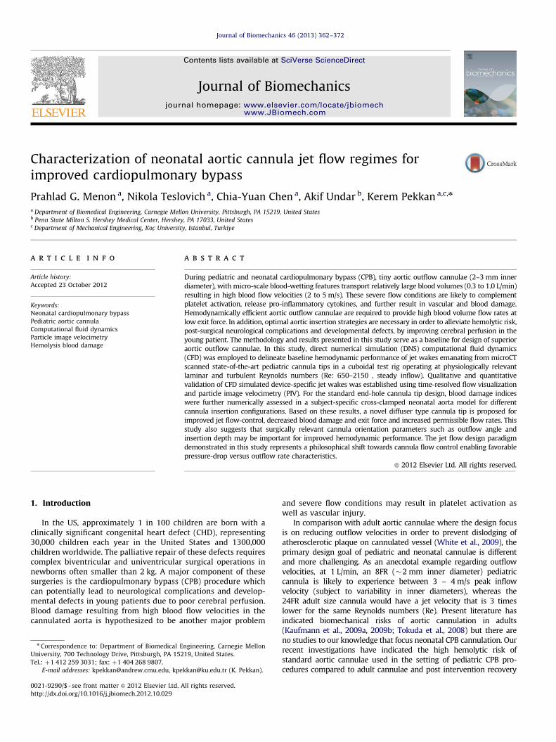
Fig. 1. Annotated illustration of major flow regimes of cannula hemodynamics, in
a cross-clamped aortic arch. Each flow region requires a dedicated investigation.
BCA: brachiocephalic artery; LCCA: left common carotid artery; LSCA: left
subclavian artery; DAo: descending aorta.
P.G. Menon et al. / Journal of Biomechanics 46 (2013) 362–372 363
has been reported to remain suboptimal (McElhinney et al., 2010;Pekkan et al., 2008; Wang et al., 2009). Therefore, there is a definitiveneed for engineering small yet hemodynamically efficient aorticoutflow cannulae for neotatal and pediatric CPB procedures whichcan provide high blood volume flow rates but with low exit force andoutflow velocity while minimizing recognized risks related to infec-tion, bleeding, hemolysis and thromboembolism while improvingcerebral perfusion during mechanical circulatory support.
The major flow regimes of interest during CPB are labeled inFig. 1, for an illustrated cross-clamped aortic arch sketch. The
main focus of this project is to study hemodynamics in the jet wake of
current state-of-the-art aortic cannula, and to document baseline
blood damage indices, with specific attention to improving cannula
tip design. Jet-wake analysis is first performed in a confinedcuboidal test rig for common cannula tips. Influence of cannula-tion in three-dimensional (3D) aortic arch geometry is furtherassessed using a patient-specific model. A novel diffuser-tippedcannula design is investigated as a potential improvement tostandard end-hole and oblique cut tip designs from the stand-point of decreased blood damage and increased permissibleflow rates.
Currently, the hydrodynamic behavior of neonatal cannulae areevaluated by basic pressure loss versus flow rate characteristicswhich are obtained from in-vitro experiments (De Wachter et al.,2002; Qiu et al., 2011) or with the M-number (Montoya et al., 1991).The latter is further applicable only to characterizing pressure–flowrelationships of cannulae having regular internal diameters, for agiven length. Therefore, a majority of cannula studies have focusedon their design from the standpoint of blood flow rate and pressuredrop across the cannula. This methodology neither furnishes infor-mation about the local fluid dynamics nor establishes the nature ofthe flow field in specific clinical conditions.
Device-specific cannula flow studies have been conducted toassess local hemodynamics using computational fluid dynamics(CFD) simulation inside rigid vessels (Grigioni et al., 2002).However such studies are limited to the regions that are closerto the cannula and unduly simplify the problem using planes ofsymmetry. Therefore, a truly 3D CFD numerical assessment of thefluid dynamics created by different outflow cannula tip designscan provide key information that both: (a) support the design ofsuperior aortic cannulae; and (b) establish optimal clinical useparameters such as insertion depth and outflow angle, limitingrisks of biomechanical origin. In the present study, high-resolution
3D CFD characterization of pediatric and neonatal cannula jetstreams are conducted for the first time in the literature fordevice-specific evaluation of jet wake hemodynamic effects. Theknow-how reported in this study is essential to engineer cannulatips that can control jet wake fluid dynamics in the future.
2. Methods
Device specific jet flow CFD simulations were performed for microCT scanned
8FR cannulae: RMI FEM II -008-ATI (RMI), a standard end-hole cannula tip, and
DLP Medtronic 77008 (DLP), an oblique cut end-hole cannula tip in a confined
cuboidal test-rig (see Fig. 2 for sample microCT reconstructions). The extended set
of cannula tips that are investigated in this study also included a novel 151 diffuser
cannula tip design (151 half cone-angle) which was compared with current
ments and particle image velocimetry (PIV) were conducted in an experimental
in-vitro flow loop in order to experimentally validate CFD results. Jet-axial
pressure-drop versus flow rate characteristics were measured experimentally in
order to complement our numerical studies. Finally, since, the significance of
intra-operative outflow cannula positioning (Osorio et al., 2011) in mitigating
clinical stroke-risk (1–3% risk) cannot be discounted (Andropoulos et al., 2010),
the utility of the CFD technique is extended to derive surgically relevant blood
damage indices from in-silico cannula insertion configurations. The focus of the
in-silico cannulation simulations presented in this study is to establish the
consequence cannula orientation on the sub-lethal hemolysis. The methods
summarized above are presented with more detail in the following sections:
2.1. Micro CT geometry reconstruction and model preparation
3D cannula reconstructions were obtained starting with scans from a SkyScan
1172 (Kontich, Belgium) X-ray computed tomography (micro-CT) system, with
image resolution of 13.49 micrometers. Cannulae were scanned from the outflow
tip and included 5 cm of the cannula body. On average, 273 projections were
obtained from each scan, which were reconstructed using in-house filtered back-
projection MATLAB (The Mathworks Inc, Natick, MA) codes in order to recover
slice data along the longitudinal axis of the cannula. Reconstructed 2D slice data
were further processed in ScanIP (Simpleware, Exeter, UK) for slice-wise segmen-
tation of the cannula geometry, using a thresholding algorithm. Smooth 3D inner
and outer triangulated surface reconstructions of the scanned cannulae were
created by first applying a Gaussian smoothing filter to each segmented slice
image and subsequently introducing the resulting surfaces into Geomagic Studio
10 (Durham, NC) for minor surface repairs and smoothing before finally convert-
ing into a NURBS surface for exporting as an IGS model. The IGS model was finally
imported into Pro/Engineer where the model cannula was attached externally to
the center of the square face of a cuboidal computational domain with dimensions
of breadth equal to 10 cannula diameters (inlet to the domain). This procedure is
illustrated in Fig. 2.
The choice of a cuboidal domain for jet flow confinement was designed for
easy PIV access and also to be compatible with previous experimental and 2D
numerical studies by Ouwa et al. (1986a, 1986b) on symmetric, asymmetric and
wall jets in a rectangular domain. The computational domain length was
considered as 100 inlet diameters based on numerical considerations for stability of
the transient CFD pressure field solution, as well as suitability for accommodating the
full length of developed jet streams at a flow rate of 0.3 L/min (Re �650 for blood)
through the 8FR circular orifices.
Cannulae were attached externally to the cuboidal computational domain or
inserted into it as per requirements to accommodate angular cut cannula tips. This
same methodology was followed to insert a three-dimensional parametrically oriented
end-hole 8FR cannula into a patient specific neonatal aorta model (Pekkan et al., 2008).
The parameters chosen for cannula insertion included cannula insertion angle,
insertion depth and outflow Re, in order to entertain a full gamut of clinically relevant
CPB related scenarios. 3D surgeon sketches describing pediatric CPB cannulation were
used as a reference in order to orient the cannula and aortic arch with respect to each
other in a typical standard CPB outflow configuration, directing flow along the
transverse arch towards the descending aorta. A second more arbitrary orientation
of aortic cannulation—directing flow toward the walls of the transverse arch, was also
prepared in order to study the effect of cannula orientation on hemolysis.
2.2. Computational model and solver
The CFD flow domains were discretized into unstructured Cartesian immersed
boundary grids (Fig. 2). Direct numerical simulation was performed to solve
the Navier–Stokes equations using a second-order accurate, finite difference
method; in-house cardiovascular flow solver has been used extensively for
image-based hemodynamic modeling and incorporates a validated multi-grid
artificial compressibility numerical solver (Le et al., 2010; Payli et al., 2007;
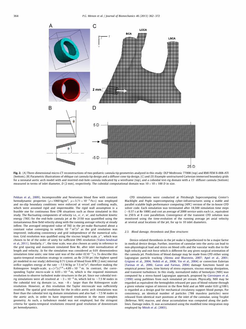
Fig. 2. (A) Three-dimensional micro-CT reconstructions of two pediatric cannula tip geometries analyzed in this study: DLP Medtronic 77008 (top) and RMI FEM II-008-ATI
(bottom). (B) Parametric illustrations of oblique cut cannula tip design and a diffuser cone tip design. (C) and (D) Example unstructured Cartesian immersed boundary grids
for a neonatal aortic arch model with and inserted end-hole cannula indicated by a wireframe (top), and a cuboidal test-rig domain with a 151 diffuser cannula (bottom)
measured in terms of inlet diameter, D (2 mm), respectively. The cuboidal computational domain was 10�10�100 D in size.
P.G. Menon et al. / Journal of Biomechanics 46 (2013) 362–372364
Pekkan et al., 2009). Incompressible and Newtonian blood flow with constant
hemodynamic properties (r¼1060 kg/m3, m¼3.71�10�3 Pa s) was employed
and no-slip boundary conditions were enforced at vessel and confining walls,
which were assumed rigid and impermeable. The rigid wall assumption is a
feasible one for continuous flow CPB situations such as those simulated in this
study. The fluctuating components of velocity i.e., u0 , v0 , w0 , and turbulent kinetic
energy (TKE) for the end-hole cannula jet at Re 2150 was quantified using the
instantaneous flow field velocity along with the running average velocity at steady
inflow. The averaged integrated value of TKE in the jet-wake fluctuated about a
constant value converging to within 10�2 m2/s2 as the grid resolution was
improved; indicating consistency and grid independence of the numerical solu-
tion. Grid resolution was qualified using the viscous length scale, yþ , which was
chosen to be of the order of unity for sufficient DNS resolution (Valen-Sendstad
et al., 2011). Similarly, tþ , the time scale, was also chosen as unity in reference to
the grid spacing and maximum simulated flow Re, after inlet normalization of
length and velocity. Dt for the simulation was considered as 0.01 dimensionless
simulation time units; one time unit was of the order O(10�5) s. To describe this
spatio-temporal resolution strategy in context, an Re 2150 jet (the highest speed
jet modeled in our study) delivering 0.71 L/min of blood from 8FR (2 mm) internal
orifice supplies energy at the rate �7.5 W/kg or 7.5 m2/s2; therefore making the
Kolmogorov length-scale, Z¼(n3/e)1/4¼4.89�10�5 m. In contrast, the corre-
sponding Taylor micro-scale is 4.03�10�4 m, which is the required minimum
resolution to observe turbulent wake structures in the jet. Since our cuboidal test-
rig simulations were all resolved at �3�10�4 m, which led to �7.5 M nodes in
the cuboidal test rig domain i.e., was �8� larger than the Kolmogorov scale
resolution. However, at this resolution the Taylor microscale was sufficiently
resolved. The spatial grid resolution for the in-silico aortic arch simulations was
finer than the cuboidal test rig domain simulations and also had �7.5 M nodes in
the aortic arch, in order to have improved resolution in the more complex
geometry. As such, a turbulence model was not employed, but the stringent
criteria for spatio-temporal resolutions ensured good resolution of downstream
jet hemodynamics.
CFD simulations were conducted at Pittsburgh Supercomputing Center’s
Blacklight and Pople supercomputing cyber-infrastructures using a stable and
parallel scalable high-performance computing (HPC) version of the in-house CFD
solver code. Each simulation was terminated after 18,500 simulation time steps
(�0.37 s at Re 1000) and cost an average of 2000 service units each i.e., equivalent
to 250 h at 8 core parallelism. Convergence of the transient CFD solution was
monitored using the time-evolution of the running average jet axial velocity
at several axial locations of the jet, for up to 10 inlet diameters.
2.3. Blood damage, thrombosis and flow structures
Device-related thrombosis in the jet wake is hypothesized to be a major factor
in medical device design. Further, insertion of cannulae into the aorta can lead to
non-physiological load and stress on blood cells and the vascular walls due to the
high velocity and exit force which is different for any given surgical orientation of
the cannula jet. Predictions of blood damage may be made from CFD either using
Lagrangian particle tracking (Alemu and Bluestein, 2007; Apel et al., 2001;
Grigioni et al., 2004; Nobili et al., 2008; Yin et al., 2004) or convection Eulerian
(Farinas et al., 2006; Garon and Farinas, 2004) damage functions based on
empirical power laws, time history of stress exposure, viscous energy dissipation,
and transient turbulence. In this study, normalized index of hemolysis (NIH) was
computed by a stress-based Lagrangian approach, proposed by Giersiepen et al.
(1990) using pathlines from each simulated jet stream. Physically, NIH may be
regarded as equivalent the hemoglobin released per pass of blood volume through
a given volume region of interest in the flow field and an NIH under 0.01 g/100 L
is regarded as a design goal for mechanical circulatory support blood pumps. For
consistency, an identical number of particles (788 massless particles) were
released from identical start positions at the inlet of the cannulae, using Tecplot
(Bellevue, WA) macros, and shear accumulation was computed along the path-
lines. Damage index. D, was accumulated using the modified time integration step
employed by Mitoh et al. (2003).
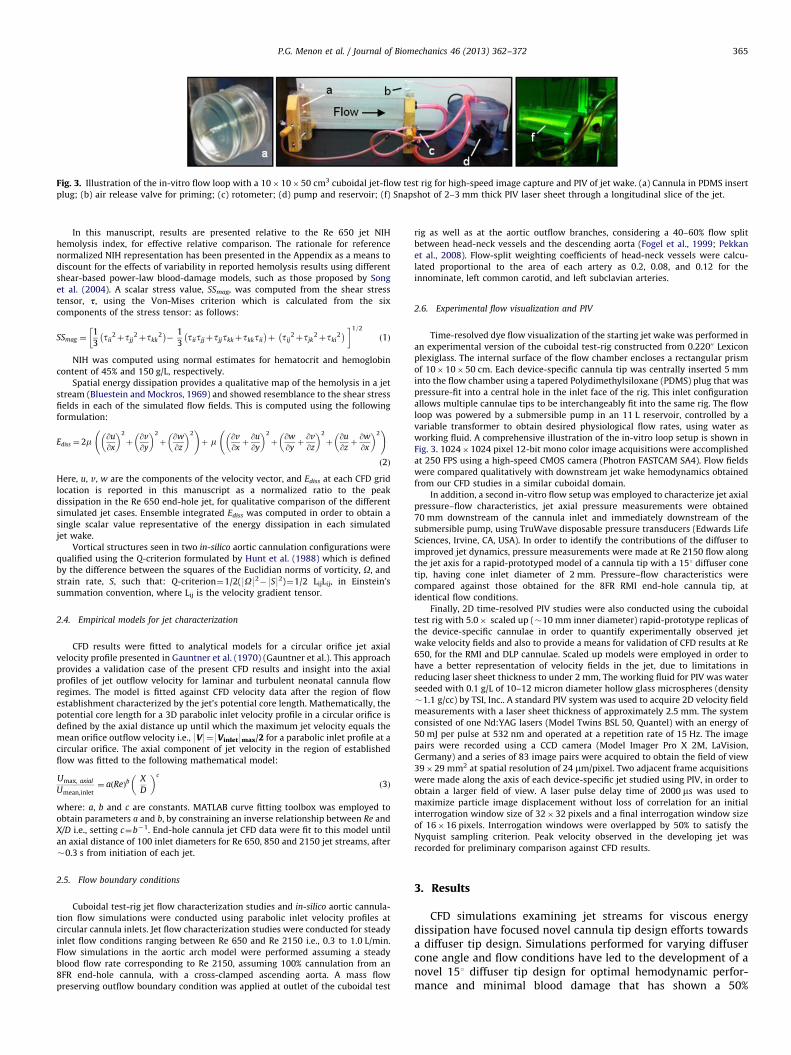
Fig. 3. Illustration of the in-vitro flow loop with a 10�10�50 cm3 cuboidal jet-flow test rig for high-speed image capture and PIV of jet wake. (a) Cannula in PDMS insert
plug; (b) air release valve for priming; (c) rotometer; (d) pump and reservoir; (f) Snapshot of 2–3 mm thick PIV laser sheet through a longitudinal slice of the jet.
P.G. Menon et al. / Journal of Biomechanics 46 (2013) 362–372 365
In this manuscript, results are presented relative to the Re 650 jet NIH
hemolysis index, for effective relative comparison. The rationale for reference
normalized NIH representation has been presented in the Appendix as a means to
discount for the effects of variability in reported hemolysis results using different
shear-based power-law blood-damage models, such as those proposed by Song
et al. (2004). A scalar stress value, SSmag, was computed from the shear stress
tensor, s, using the Von-Mises criterion which is calculated from the six
components of the stress tensor: as follows:
SSmag ¼1
3tii
2þtjj2þtkk
2� �
�1
3tiitjjþtjjtkkþtkktii
� �þ tij
2þtjk2þtki
2� �� �1=2
ð1Þ
NIH was computed using normal estimates for hematocrit and hemoglobin
content of 45% and 150 g/L, respectively.
Spatial energy dissipation provides a qualitative map of the hemolysis in a jet
stream (Bluestein and Mockros, 1969) and showed resemblance to the shear stress
fields in each of the simulated flow fields. This is computed using the following
formulation:
Ediss ¼ 2m @u
@x
� �2
þ@v
@y
� �2
þ@w
@z
� �2 !
þ m @v
@xþ@u
@y
� �2
þ@w
@yþ@v
@z
� �2
þ@u
@zþ@w
@x
� �2 !
ð2Þ
Here, u, v, w are the components of the velocity vector, and Ediss at each CFD grid
location is reported in this manuscript as a normalized ratio to the peak
dissipation in the Re 650 end-hole jet, for qualitative comparison of the different
simulated jet cases. Ensemble integrated Ediss was computed in order to obtain a
single scalar value representative of the energy dissipation in each simulated
jet wake.
Vortical structures seen in two in-silico aortic cannulation configurations were
qualified using the Q-criterion formulated by Hunt et al. (1988) which is defined
by the difference between the squares of the Euclidian norms of vorticity, O, and
strain rate, S, such that: Q-criterion¼1/2(9O92�9S92)¼1/2 LijLij, in Einstein’s
summation convention, where Lij is the velocity gradient tensor.
2.4. Empirical models for jet characterization
CFD results were fitted to analytical models for a circular orifice jet axial
velocity profile presented in Gauntner et al. (1970) (Gauntner et al.). This approach
provides a validation case of the present CFD results and insight into the axial
profiles of jet outflow velocity for laminar and turbulent neonatal cannula flow
regimes. The model is fitted against CFD velocity data after the region of flow
establishment characterized by the jet’s potential core length. Mathematically, the
potential core length for a 3D parabolic inlet velocity profile in a circular orifice is
defined by the axial distance up until which the maximum jet velocity equals the
mean orifice outflow velocity i.e., 9V9¼9Vinlet9max/2 for a parabolic inlet profile at a
circular orifice. The axial component of jet velocity in the region of established
flow was fitted to the following mathematical model:
Umax, axial
Umean,inlet¼ aðReÞb
X
D
� �c
ð3Þ
where: a, b and c are constants. MATLAB curve fitting toolbox was employed to
obtain parameters a and b, by constraining an inverse relationship between Re and
X/D i.e., setting c¼b�1. End-hole cannula jet CFD data were fit to this model until
an axial distance of 100 inlet diameters for Re 650, 850 and 2150 jet streams, after
�0.3 s from initiation of each jet.
2.5. Flow boundary conditions
Cuboidal test-rig jet flow characterization studies and in-silico aortic cannula-
tion flow simulations were conducted using parabolic inlet velocity profiles at
circular cannula inlets. Jet flow characterization studies were conducted for steady
inlet flow conditions ranging between Re 650 and Re 2150 i.e., 0.3 to 1.0 L/min.
Flow simulations in the aortic arch model were performed assuming a steady
blood flow rate corresponding to Re 2150, assuming 100% cannulation from an
8FR end-hole cannula, with a cross-clamped ascending aorta. A mass flow
preserving outflow boundary condition was applied at outlet of the cuboidal test
rig as well as at the aortic outflow branches, considering a 40–60% flow split
between head-neck vessels and the descending aorta (Fogel et al., 1999; Pekkan
et al., 2008). Flow-split weighting coefficients of head-neck vessels were calcu-
lated proportional to the area of each artery as 0.2, 0.08, and 0.12 for the
innominate, left common carotid, and left subclavian arteries.
2.6. Experimental flow visualization and PIV
Time-resolved dye flow visualization of the starting jet wake was performed in
an experimental version of the cuboidal test-rig constructed from 0.22000 Lexicon
plexiglass. The internal surface of the flow chamber encloses a rectangular prism
of 10�10�50 cm. Each device-specific cannula tip was centrally inserted 5 mm
into the flow chamber using a tapered Polydimethylsiloxane (PDMS) plug that was
pressure-fit into a central hole in the inlet face of the rig. This inlet configuration
allows multiple cannulae tips to be interchangeably fit into the same rig. The flow
loop was powered by a submersible pump in an 11 L reservoir, controlled by a
variable transformer to obtain desired physiological flow rates, using water as
working fluid. A comprehensive illustration of the in-vitro loop setup is shown in
Fig. 3. 1024�1024 pixel 12-bit mono color image acquisitions were accomplished
at 250 FPS using a high-speed CMOS camera (Photron FASTCAM SA4). Flow fields
were compared qualitatively with downstream jet wake hemodynamics obtained
from our CFD studies in a similar cuboidal domain.
In addition, a second in-vitro flow setup was employed to characterize jet axial
pressure–flow characteristics, jet axial pressure measurements were obtained
70 mm downstream of the cannula inlet and immediately downstream of the
submersible pump, using TruWave disposable pressure transducers (Edwards Life
Sciences, Irvine, CA, USA). In order to identify the contributions of the diffuser to
improved jet dynamics, pressure measurements were made at Re 2150 flow along
the jet axis for a rapid-prototyped model of a cannula tip with a 151 diffuser cone
tip, having cone inlet diameter of 2 mm. Pressure–flow characteristics were
compared against those obtained for the 8FR RMI end-hole cannula tip, at
identical flow conditions.
Finally, 2D time-resolved PIV studies were also conducted using the cuboidal
test rig with 5.0� scaled up (�10 mm inner diameter) rapid-prototype replicas of
the device-specific cannulae in order to quantify experimentally observed jet
wake velocity fields and also to provide a means for validation of CFD results at Re
650, for the RMI and DLP cannulae. Scaled up models were employed in order to
have a better representation of velocity fields in the jet, due to limitations in
reducing laser sheet thickness to under 2 mm, The working fluid for PIV was water
seeded with 0.1 g/L of 10–12 micron diameter hollow glass microspheres (density
�1.1 g/cc) by TSI, Inc.. A standard PIV system was used to acquire 2D velocity field
measurements with a laser sheet thickness of approximately 2.5 mm. The system
consisted of one Nd:YAG lasers (Model Twins BSL 50, Quantel) with an energy of
50 mJ per pulse at 532 nm and operated at a repetition rate of 15 Hz. The image
pairs were recorded using a CCD camera (Model Imager Pro X 2M, LaVision,
Germany) and a series of 83 image pairs were acquired to obtain the field of view
39�29 mm2 at spatial resolution of 24 mm/pixel. Two adjacent frame acquisitions
were made along the axis of each device-specific jet studied using PIV, in order to
obtain a larger field of view. A laser pulse delay time of 2000 ms was used to
maximize particle image displacement without loss of correlation for an initial
interrogation window size of 32�32 pixels and a final interrogation window size
of 16�16 pixels. Interrogation windows were overlapped by 50% to satisfy the
Nyquist sampling criterion. Peak velocity observed in the developing jet was
recorded for preliminary comparison against CFD results.
3. Results
CFD simulations examining jet streams for viscous energydissipation have focused novel cannula tip design efforts towardsa diffuser tip design. Simulations performed for varying diffusercone angle and flow conditions have led to the development of anovel 151 diffuser tip design for optimal hemodynamic perfor-mance and minimal blood damage that has shown a 50%
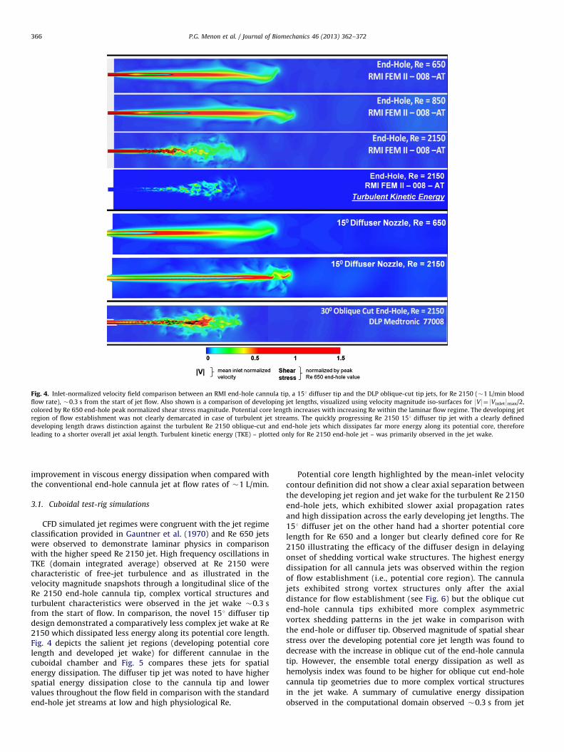
Fig. 4. Inlet-normalized velocity field comparison between an RMI end-hole cannula tip, a 151 diffuser tip and the DLP oblique-cut tip jets, for Re 2150 (�1 L/min blood
flow rate), �0.3 s from the start of jet flow. Also shown is a comparison of developing jet lengths, visualized using velocity magnitude iso-surfaces for 9V9¼9Vinlet9max/2,
colored by Re 650 end-hole peak normalized shear stress magnitude. Potential core length increases with increasing Re within the laminar flow regime. The developing jet
region of flow establishment was not clearly demarcated in case of turbulent jet streams. The quickly progressing Re 2150 151 diffuser tip jet with a clearly defined
developing length draws distinction against the turbulent Re 2150 oblique-cut and end-hole jets which dissipates far more energy along its potential core, therefore
leading to a shorter overall jet axial length. Turbulent kinetic energy (TKE) – plotted only for Re 2150 end-hole jet – was primarily observed in the jet wake.
P.G. Menon et al. / Journal of Biomechanics 46 (2013) 362–372366
improvement in viscous energy dissipation when compared withthe conventional end-hole cannula jet at flow rates of �1 L/min.
3.1. Cuboidal test-rig simulations
CFD simulated jet regimes were congruent with the jet regimeclassification provided in Gauntner et al. (1970) and Re 650 jetswere observed to demonstrate laminar physics in comparisonwith the higher speed Re 2150 jet. High frequency oscillations inTKE (domain integrated average) observed at Re 2150 werecharacteristic of free-jet turbulence and as illustrated in thevelocity magnitude snapshots through a longitudinal slice of theRe 2150 end-hole cannula tip, complex vortical structures andturbulent characteristics were observed in the jet wake �0.3 sfrom the start of flow. In comparison, the novel 151 diffuser tipdesign demonstrated a comparatively less complex jet wake at Re2150 which dissipated less energy along its potential core length.Fig. 4 depicts the salient jet regions (developing potential corelength and developed jet wake) for different cannulae in thecuboidal chamber and Fig. 5 compares these jets for spatialenergy dissipation. The diffuser tip jet was noted to have higherspatial energy dissipation close to the cannula tip and lowervalues throughout the flow field in comparison with the standardend-hole jet streams at low and high physiological Re.
Potential core length highlighted by the mean-inlet velocity
contour definition did not show a clear axial separation between
the developing jet region and jet wake for the turbulent Re 2150
end-hole jets, which exhibited slower axial propagation rates
and high dissipation across the early developing jet lengths. The
151 diffuser jet on the other hand had a shorter potential core
length for Re 650 and a longer but clearly defined core for Re
2150 illustrating the efficacy of the diffuser design in delaying
onset of shedding vortical wake structures. The highest energy
dissipation for all cannula jets was observed within the region
of flow establishment (i.e., potential core region). The cannula
jets exhibited strong vortex structures only after the axial
distance for flow establishment (see Fig. 6) but the oblique cut
end-hole cannula tips exhibited more complex asymmetric
vortex shedding patterns in the jet wake in comparison with
the end-hole or diffuser tip. Observed magnitude of spatial shear
stress over the developing potential core jet length was found to
decrease with the increase in oblique cut of the end-hole cannula
tip. However, the ensemble total energy dissipation as well as
hemolysis index was found to be higher for oblique cut end-hole
cannula tip geometries due to more complex vortical structures
in the jet wake. A summary of cumulative energy dissipation
observed in the computational domain observed �0.3 s from jet
Fig. 5. Spatial energy dissipation (normalized by peak Re 650 energy dissipation) visualized in longitudinal slices though jet axis, acquired �0.3 s from initiation of jet
flow. Maximum energy dissipation was apparent in the developing jet region i.e., within the potential core length.
Fig. 6. Vortical structures are visualized using vortex cores computed in Tecplot for Re 2150 cannula jet streams 0.03 s from jet initiation for: (a) end-hole RMI cannula;
(b) oblique cut end-hole DLP cannula. Each is compared with instantaneous snapshots from dye flow visualizations (below). There is visual concordance between the jet
wake regions from CFD and experiment with regard to the axial location of dominant vortical structures downstream of the developing potential core length. Vortical
structures are apparent within a shorter axial distance of the jet inlet for the DLP than the RMI tip. Potential core length is visualized using 9V9¼9Vinlet9max/2, iso-surfaces
colored by shear stress, normalized by peak Re 650 shear stress magnitude. Each device-specific cannula tip’s internal surfaces revealed oval rather than perfectly circular
internal surfaces.
P.G. Menon et al. / Journal of Biomechanics 46 (2013) 362–372 367
flow initiation is summarized in Table 1, normalized with referenceto the Re 650 end-hole jet.
Table 2 presents a summary of NIH for end-hole and 151diffuser jets, at Re 650, 850 and 2150. Linear correlation wasobserved between the integrated Ediss values (Table 1) for each jetstream and the corresponding hemolysis indices (Table 2) com-puted for corresponding jets simulated in the cuboidal test-rig.The diffuser was found to outperform the end-hole jet withregards to both Ediss and NIH. An analysis of smoothed probabilitydistributions (not shown) constructed for the shear damage, D,accumulated for different streamlines indicated that that Re 2150end-hole jet damage accumulation was distributed over a widerrange of higher D values than the slower Re 650 jet, supportingthe correlation between sub-lethal hemolysis and Reynolds num-ber, reported in Table 2.
3.2. Experimental flow visualization and jet characterization
Time-resolved dye flow visualizations were qualitativelyfound to resemble CFD simulated jet behavior (see Fig. 6). Dyeflow visualizations represent both convection and diffusion trans-port of dye in the flow field and therefore provide only qualitativeevidence of jet axial propagation i.e., axial distance of jet wakeand local jet diameter; whereas, in contrast, PIV and CFD deter-mine velocity fields that are instantaneous representations of theflow physics. PIV provided quantitative validation of numericalresults in the developing jet region (near inlet). The CFD derivedpeak velocity in the developing Re 650 jet region (equivalent to5.0–6.5 cm/s for water) as well as the range for slower movingcomplex shedding vortex structures (o2 cm/s for water) at theshear layer of the jet were found to match well with observations
P.G. Menon et al. / Journal of Biomechanics 46 (2013) 362–372368
from PIV (Fig. 7). PIV also complemented the CFD observationsfrom the vortex-core plots in Fig. 6 that indicate vortical struc-tures are apparent within a shorter axial distance of the jet for theDLP oblique cut tip in comparison with the RMI end-hole tip.
Experimental pressure–flow analysis revealed that the staticpressures drop 70 mm axially downstream from diffuser cone jetinlet was distinctly reduced for the same cannulation flow rate incomparison with the identically sized RMI end-hole cannula tip.Lower pressure gradients for the same flow rate are concordantwith a weaker outflow jet i.e., lower exit force and outflow velocity,
Table 1Summary of cumulative energy dissipation calculated for the instantaneous flow
fields noted for different jet streams at �0.3 s from start of jet flow, reported as
a normalized ratio to the Re 650 end-hole result. Corresponding potential
core length information is reported as a multiple of cannula inlet diameter, D.
n the case of Re 2150 jets, a clear potential core defined by the axial extent of
the 9V9¼9Vmean9inlet/2 isocontour is not observed.
Tip design Re Integrated netenergy dissipation, e
Potential core length(in inlet diameters, D)
End-hole (RMI) 650 1 20
850 1.23 25
2150 2.32 –n
151 diffuser 650 0.44 15
2150 1.31 40
151 oblique cut 650 7.00 25
301 oblique cut (DLP) 650 10.17 30
2150 15.80 –n
n Potential core length not distinctly demarcated using the isocontour definition.
Table 2Summary of hemolysis index computations for end-hole and 151 degree diffuser
jets, reported as a normalized ratio Re 650 end-hole result.
Re End-hole 151 diffuser
650 1.00 0.31
850 1.62 0.83
2150 4.10 3.45
Fig. 7. Left: representative zoomed in particle injection instantaneous snapshots at Re 6
unsymmetrical oblique cut DLP cannula jet, close to the inlet for 4 inlet diameters. Beau
at low Re. Right: PIV flow fields for water jets through the RMI and DLP cannula tips,
supporting that the diffuser tip is more ideal than the end-hole tipwith regard to producing a potentially less-damaging outflow jet ina cannulated aorta. Fig. 8 shows the pressure drop versus flow raterelationship for an end-hole and a diffuser tip jet, along the jet axis,in terms of equivalent flow-rates of blood after dynamical scaling.This plot indicates that the standard end-hole jet required asignificantly higher driving pressure from the pump in order topropel axially forward, in comparison with the diffuser conecannula tip, at the same flow rates. Therefore, the diffuser not onlyprovides desirable jet flow characteristics by virtue of its potentialcore length, velocity field and blood damage (discussed in previousCFD analysis sections) but simultaneously has desirable pressure–flow characteristics which could potentially reduce the requirementof pumping pressures during CPB procedures. This characteristic ofthe diffuser tip requires further investigation in a more realisticexperimental extra-corporeal circulation setting because apart from
50, for a 5.0� scaled up end-hole RMI laminar jet (top) and a more disturbed and
tiful periodically shedding vortices are seen in the end-hole cannula jet shear layer,
presented at Re 650.
Fig. 8. Experimental characterization of pressure drop versus flow rate relation-
ship for the jet along the jet axis, comparing a standard RMI 8FR end-hole cannula
against 151 diffuser cone outflow tip.
NIH = 0.00029 g / 100 L NIH = 0.0024 g / 100 L
Low hemolysis configuration
High hemolysis configuration
Fig. 9. Comparison between vortical structures created by an Re 2150 end-hole cannula jet stream in an in-silico cannulation setting, for two different insertion
orientations, using iso-surfaces of Q-criterion 40,overlaid on a slice through the center of the jet stream colored by the max-normalized resultant velocity field. Pathlines
in flow field are shown colored by normalized shear stress magnitude. Velocity fields seen in cross sectional slice view-planes through a neonatal aorta model cannulated
with an 8FR end-hole cannula are shown (bottom) for comparison with the jet wakes in the cuboidal chamber. Important regions of the cannula jet have been labeled.
Effects of vascular geometry and in-vivo cannula orientation cannot be discounted.
Table 3Empirical model fit data for jet streams. Here, a, b, c are constants (c¼b�1) and D is
the inlet diameter of the cannula.
Umax, axial
Umean,inlet¼ aðReÞb X
D
� �c; c¼b�1
Re a b c
650 (end-hole) 0.83 0.94 �0.94
850 (end-hole) 0.84 0.76 �0.76
2150 (end-hole) 2.18 0.81 �0.81
650 (151 diffuser) 0.63 0.84 �0.84
P.G. Menon et al. / Journal of Biomechanics 46 (2013) 362–372 369
the cannula tip design, the inner diameters of the cannula tip,cannulation angle relative to the aortic arch, as well as subject-specific aortic arch geometry will have significant roles to play indetermining the pumping pressures.
Fig. 9 describes vortical structures seen in two in-silico aorticcannulation configurations qualified using the Q-criterion. Iso-surfaces of Q-criterion 40 i.e., where the Euclidean norm of thevorticity tensor dominates that of the rate of strain, were utilizedin order to visualize coherent vortex structures in the jet wake.The arbitrarily oriented cannulation case resulted in being a highhemoylsis configuration and complex vortex structures wereapparent at the location of jet impingement upon the walls ofthe transverse aortic arch, which is undesirable due to closeproximity to the head and neck vessels. In contrast, the
orientation prepared based upon the surgeon sketches resultedin a low hemolysis configuration where only a single coherentpredominant vortex-core was observed around the irrotational jetcore prior to jet impingement proximal to the descending aorta.
P.G. Menon et al. / Journal of Biomechanics 46 (2013) 362–372370
These observations suggest the existence of optimal character-istics (outflow angle and insertion depth) for improved hemody-namic performance during surgery.
3.4. Empirical models for jet characteristics
In-silico cannula jet evaluations in the cuboidal test rig may bereduced to tractable empirical relationships for instantaneousaxial jet velocity in the developed jet wake region, which maypotentially be regarded as a simple rule of thumb for optimal jetstream based cannula tip choice in the operating room. The goalof empirical model fitting is also to allow case-specific CFD resultsto be generalized for a variety of fluid media, Reynolds numbersor cannula sizes, based on the theory of dynamic similarity.Table 3 indicates the parameters for empirical model fits for theaxial component of velocity (normalized by mean inlet velocity)in the established jet region for three Re cases of the end-hole aswell as the 151 diffuser tipped cannula. The fits indicate that theinverse relationship set by the proposed empirical model betweenRe and the axial distance from the orifice match the CFD datawell. The turbulent Re 2150 end-hole jet was found to showaugmented unsteady behavior after the potential core length thanthe Re 650 and Re 850 jets. However, despite these differences,the mean axial velocity after the region of establishment wasfound to fit well with the empirical model.
The length of the region of establishment (i.e., potential core)is an indication of resistance-to-outflow characteristic for a givencannula tip design. Visual inspection of energy dissipation alongthe axial length of the jet from Fig. 5 indicates that the highestenergy dissipation occurred upstream of the potential core axiallength. This is corroborated by the results in Table 1 whichhighlight a direct relationship between potential core lengthand energy dissipation for a given cannula tip. For the same flowRe, a shorter potential core is an indicator of less resistance tooutflow and lesser energy dissipation in the developing jet region.The oblique-cut cannula tips were observed to demonstratehigher net energy dissipation ratings than end-hole whereas theirpotential core lengths were comparable to the end-hole jets,indicating that the increased energy dissipation in these jetswas a consequence of shear–layer interactions in the jet wake.Increasingly angular oblique-cut tips were observed to havegreater net energy dissipation and longer potential cores, for thesame Re (Table 1).
In the case of axisymmetric jets, the characteristic velocity canbe taken as the local centerline velocity of the jet, i.e., U(x), whichhas an inverse relationship with axial length, x i.e., proportionalitywith 1/x (Dimotakis, 2000). An inverse relationship was observedbetween centerline velocity and axial distance based on robustempirical curve fits to our CFD results (Table 3), which conformsto expectations in the developed jet region. Since the local lengthscale for the round jet is typically taken as the local jet diameter,L(x), which is proportionate to jet axial distance, the local Re ofthe jet is proportionate to U(x)� L(x), the local Re of the jet is aconstant along the jet-axial direction. This provides a basis fornumerical choices for grid resolution in jet flow studies basedupon Re, since a single Re can be used as a metric to determinethe length and time scales required to resolve the flow completelyin the entire domain.
4. Discussion
Submerged jets are characterized by four distinct states as afunction of the Re number: (a) dissipated-laminar; (b) laminar;(c) semi-turbulent; and (d) turbulent. Dissipated laminar jets areunstable because the inlet jet momentum is quickly dissipated to
the surrounding fluid typically less than six diameters beyond theinlet (McNaughton and Sinclair, 1966), which was not seen for theminimum flow Re 650 jets. Jet penetration depth increases withlarger values of Re but in downstream jet regions the azimuthalvelocity component (VY) oscillates with exponentially increasingamplitude over time due to Kelvin–Helmholtz instability beforefully dissipating. These instabilities were observed in the Re 650and Re 850 cannula jets. Numerical simulations for circular jetshave shown that at the critical Re number of 225 different typesof flow instabilities are exhibited (Danalia et al., 1997). Ouwaet al. (1986a, 1986b) reported from experiments using Dopplervelocimetry and dye injections for streamlines in 2D rectangularchannels that symmetric confined jets begin to show asymmetricflow patterns after a Re of 30. Since the range of Re seen inneonatal and pediatric CPB scenarios and those studied in our jetflow simulations are between �20 and 100 times this range, thesimulated asymmetric flow patterns soon after the inlet arejustified. These patterns were also observed in out flow visualiza-tion experiments. Experiments on scalar-mixing behavior in non-reacting round jets have indicated that a qualitative transition tofull turbulence and turbulent-mixing behavior for Re only in thevicinity of 10,000 (Dimotakis, 2000). Therefore, the highest speed(Re 2150) jet flows that we simulate in this study may still beregarded as transitional rather than fully-developed turbulence.
In free single jet flows, the primary sources of vorticity are thedissipating transient jet wake and the shear layers along the jetboundary layer surrounding the irrotational jet core. Confined jetflows in physiological settings demonstrate additional complexitydue to wall influence. Therefore, although pressure across thecannula tip (gauged using line-pressure in the heart-lungmachine) is the common means of determining the operatingpoint and choice of cannula based on flow rate which is usuallychosen in order to maintain the cardiac index of the patient tobetween 2 and 2.5, this study suggests that in order to choose acannula based on desirable jet flow hemodynamics, the potentialcore length, resistance to outflow, and NIH for a cannula jet at achosen operating flow rate are major parameters. In an 8FRneonatal cannula jet, the main source of hemolysis is the sub-lethal damage of the red blood cells due to leaking of hemoglobinrather than damage due to rupturing at extremely shear ratesabove 42,000 s�1 (Leverett et al., 1972). In-vitro hemolysis testswill be required to be carried out in future studies in order tovalidate NIH estimates from CFD data in this study.
The diffuser cannula tip demonstrated in this study has beenshown to remain laminar at high Re flow, reduce outflow velocity,improve hemolysis performance and improve pressure–flowcharacteristics of the cannula jet. Despite the advantages of thediffuser design, issues of increased local energy dissipation andthe Coanda effect documented in the aortic cannula designliterature (Joubert-Hubner et al., 1999; Magilligan et al., 1972)which is the property of a jet stream to adhere to the boundarywall, both become pronounced at high diffuser angles. This in-turn may limit its desirable effects of the diffuser design.
Future studies will be required to examine the effect of flowpulsatility on hemolysis and energy dissipation in the jet wake.Aortic arch CFD models may be improved using more realisticrepresentation of the downstream aortic vasculature incorporat-ing impedance based analog models (Dur et al., 2011; Vignon-Clementel I et al., 2006) that can be tuned accurately to simulateflow oscillations. CFD analyses of jet wakes through optimalcannula positioning studies performed using a two-way couplingapproach between a parametric model geometry and real-timeCFD data can provide inverse optimization criteria for derivingoptimal intra-operative cannula insertion and orientation guidanceduring time-critical CPB operations. This can potentially guide furthercannula tip design improvements, internal flow control features
P.G. Menon et al. / Journal of Biomechanics 46 (2013) 362–372 371
and patient-specific cannula insertion configurations for optimalperfusion and decreased risk of thrombo-embolism during extra-corporeal circulation.
5. Conclusion
CFD was employed to delineate baseline hemodynamic per-formance of jet wakes emanating from pediatric/neonatal cannulatips used in current clinical practice as well as some noveldesigns, using DNS CFD in a cuboidal test rig. A diffuser cannulatip has been shown to posses passive jet flow control, hemody-namic performance and reduce exit force. Several diffuser coneangles require to be analyzed to arrive at an optimal diffuser inlet.This study also suggests that optimal outflow angle and insertiondepth of aortic cannulation may lead to upto a 10-fold improvedNIH performance during surgery. Innovative introducers speciallydesigned for tiny pediatric aortas will be required for efficient,adequate and safe connection of diffuser tipped aortic cannulae tothe intracorporeal circulation. The jet flow design paradigmdemonstrated in this study represents a philosophical shift forcannula design practice which simultaneously accounts for engi-neering favorable pressure-drop versus flow-rate characteristics.
Conflict of interest statement
This statement is to declare that we, the authors of themanuscript, do not possess any financial relationships that mightbias our work. We hereby declare that no conflict of interestexists in our work.
Acknowledgements
The study was supported through the Dowd-ICES fellowshipaward (2011–2012). We acknowledge Prof. Fotis Sotiropoulos provid-ing the baseline cardiovascular CFD solver employed in this work. Weare grateful to Dr. Dennis Trumble for facilitating the high-resolutiondevice-specific microCT scans of the cannula tips analyzed in thisstudy, and to Prof. James Antaki for building rapid-prototype models.Finally, this computationally intensive study would not have beenpossible without the support of the NSF XSEDE/Teragrid supercom-puting resources at the Pittsburgh Supercomputing Center (allocationnumber: CCR080013).
Appendix A. Supplementary information
Supplementary data associated with this article can be foundin the online version at http://dx.doi.org/10.1016/j.jbiomech.2012.10.029.
References
Alemu, Y., Bluestein, D., 2007. Flow-induced platelet activation and damageaccumulation in a mechanical heart valve: numerical studies. Artificial Organs31, 677–688.
Andropoulos, D.B., Brady, K.M., Easley, R.B., Fraser Jr., C.D., 2010. Neuroprotectionin pediatric cardiac surgery: what is on the horizon? Progress in PediatricCardiology 29, 113–122.
Apel, J., Paul, R., Klaus, S., Siess, T., Reul, H., 2001. Assessment of hemolysis relatedquantities in a microaxial blood pump by computational fluid dynamics.Artificial Organs 25, 341–347.
Bluestein, M., Mockros, L.F., 1969. Hemolytic effects of energy dissipation inflowing blood. Medical and Biological Engineering 7, 1–16.
Danalia, I., Dusek, J., Anselmet, F., 1997. Coherent structures in a round, spatiallyevolving, unforced, homogeneous jet at low Reynolds numbers. Physics ofFluids 9, 3323–3342.
De Wachter, D., De Somer, F., Verdonck, P., 2002. Hemodynamic comparison oftwo different pediatric aortic cannulas. International Journal of ArtificialOrgans 25, 867–874.
Dimotakis, P.E., 2000. The mixing transition in turbulence. Journal of FluidMechanics 409, 69–98.
Dur, O., Coskun, S., Coskun, K., Frakes, D., Kara, L., Pekkan, K., 2011. Computer-aided patient-specific coronary artery graft design improvements using CFDcoupled shape optimizer. Cardiovascular Engineering and Technology 2,35–47.
Farinas, M.I., Garon, A., Lacasse, D., N’Dri, D., 2006. Asymptotically consistentnumerical approximation of hemolysis. Journal of Biomechanical Engineering128, 688–696.
Fogel, M.A., Weinberg, P.M., Rychik, J., Hubbard, A., Jacobs, M., Spray, T.L.,Haselgrove, J., 1999. Caval contribution to flow in the branch pulmonaryarteries of Fontan patients with a novel application of magnetic resonancepresaturation pulse. Circulation 99, 1215–1221.
Garon, A., Farinas, M.I., 2004. Fast three-dimensional numerical hemolysisapproximation. Artificial Organs 28, 1016–1025.
Gauntner, J.W., B, L.J.N., Hrycak, P., 1970. Survey of Literature on Flow Character-istics of a Single Turbulent Jet Impinging on a Flat Plate, NASA TN D-5652.Lewis Research Center, National Aeronautics and Space Administation, Cleve-land, OH.
Giersiepen, M., Wurzinger, L.J., Opitz, R., Reul, H., 1990. Estimation of shear stress-related blood damage in heart valve prostheses—in vitro comparison of 25aortic valves. International Journal of Artificial Organs 13, 300–306.
Grigioni, M., Daniele, C., Morbiducci, U., D’Avenio, G., Di Benedetto, G., Barbaro, V.,2004. The power-law mathematical model for blood damage prediction:analytical developments and physical inconsistencies. Artificial Organs 28,467–475.
Grigioni, M., Daniele, C., Morbiducci, U., D’Avenio, G., Di Benedetto, G., Del Gaudio,C., Barbaro, V., 2002. Computational model of the fluid dynamics of a cannulainserted in a vessel: incidence of the presence of side holes in blood flow.Journal of Biomechanics 35, 1599–1612.
Hunt, J.C.R., Way, A., Moin, P., 1988. Eddies, Stream, and Convergence Zones inTurbulent Flows.
Joubert-Hubner, E., Gerdes, A., Klapproth, P., Esders, K., Prosch, J., Henke, P., Pfister,G., Sievers, H.H., 1999. An in-vitro evaluation of aortic arch vessel perfusioncharacteristics comparing single versus multiple stream aortic cannulae.European Journal Cardio-Thoracic Surgery 15, 359–364.
Kaufmann, T.A., Hormes, M., Laumen, M., Timms, D.L., Linde, T., Schmitz-Rode, T.,Moritz, A., Dzemali, O., Steinseifer, U., 2009a. The impact of aortic/subclavianoutflow cannulation for cardiopulmonary bypass and cardiac support: acomputational fluid dynamics study. Artificial Organs 33, 727–732.
Kaufmann, T.A., Hormes, M., Laumen, M., Timms, D.L., Schmitz-Rode, T., Moritz, A.,Dzemali, O., Steinseifer, U., 2009b. Flow distribution during cardiopulmonarybypass in dependency on the outflow cannula positioning. Artificial Organs 33,988–992.
Le, T.B., Borazjani, I., Sotiropoulos, F., 2010. Pulsatile flow effects on the hemody-namics of intracranial aneurysms. Journal of Biomechanical Engineering 132,111009.
McElhinney, D.B., Tworetzky, W., Lock, J.E., 2010. Current status of fetal cardiacintervention. Circulation 121, 1256–1263.
McNaughton, K., Sinclair, G., 1966. Submerged jets in short cylindrical flowvessels. Journal of Fluid Mechanics 25, 367–375.
Mitoh, A., Yano, T., Sekine, K., Mitamura, Y., Okamoto, E., Kim, D.W., Yozu, R.,Kawada, S., 2003. Computational fluid dynamics analysis of an intra-cardiacaxial flow pump. Artificial Organs 27, 34–40.
Montoya, J.P., Merz, S.I., Bartlett, R.H., 1991. A standardized system for describingflow/pressure relationships in vascular access devices. ASAIO Transactions 37,4–8.
Nobili, M., Sheriff, J., Morbiducci, U., Redaelli, A., Bluestein, D., 2008. Plateletactivation due to hemodynamic shear stresses: damage accumulation modeland comparison to in vitro measurements. ASAIO Journal 54, 64–72.
Osorio, A.F., Osorio, R., Ceballos, A., Tran, R., Clark, W., Divo, E.A., Argueta-Morales,I.R., Kassab, A.J., Decampli, W.M., 2011. Computational fluid dynamics analysisof surgical adjustment of left ventricular assist device implantation tominimise stroke risk. Computer Methods in Biomechanics and BiomedicalEngineering 21, 21.
Ouwa, Y., Watanabe, M., Matsuoka, Y., 1986a. Behavior of a confined plane jet in arectangular channel at low Reynolds number I. General flow characteristics.Japanese Journal of Applied Physics 25, 754–761.
Ouwa, Y., Watanabe, M., Matsuoka, Y., 1986b. Behavior of a plane jet at lowReynolds Number confined in a rectangular channel II. Two solutions bynumerical analysis. Japanese Journal of Applied Physics 25, 1736–1740.
Payli, R., Pekkan, K., Zelicourt, D., Frakes, D., Sotiropoulos, F., Yoganathan, A., 2007.High performance clinical computing on the TeraGrid: patient-specifichemodynamic analysis and surgical planning, TeraGrid 2007 ConferenceMadison, WI.
P.G. Menon et al. / Journal of Biomechanics 46 (2013) 362–372372
Pekkan, K., Dur, O., Sundareswaran, K., Kanter, K., Fogel, M., Yoganathan, A., Undar,A., 2008. Neonatal aortic arch hemodynamics and perfusion during cardio-pulmonary bypass. Journal of Biomechanical Engineering 130, 061012.
Pekkan, K., Dur, O., Zelicourt, D., Payli, R., Sotiropoulos, F., Kowalski, W., Chen, C.,Patrick, M., Kara, L., Keller, B., 2009. Embryonic Intra-Cardiac Flow Fields at 3Idealized Ventricular Morphologies. APS, Milwaukee, USA.
Qiu, F., Clark, J.B., Kunselman, A.R., Undar, A., Myers, J.L., 2011. Hemodynamicevaluation of arterial and venous cannulae performance in a simulatedneonatal extracorporeal life support circuit. Perfusion 26, 276–283.
Song, X., Wood, H.G., Olsen, D., 2004. Computational fluid dynamics (CFD) study ofthe 4th generation prototype of a continuous flow ventricular assist device(VAD). Journal of Biomechanical Engineering 126, 180–187.
Tokuda, Y., Song, M.H., Ueda, Y., Usui, A., Akita, T., Yoneyama, S., Maruyama, S.,2008. Three-dimensional numerical simulation of blood flow in the aortic archduring cardiopulmonary bypass. European Journal Cardio-Thoracic Surgery 33,164–167.
Valen-Sendstad, K., Mardal, K.A., Mortensen, M., Reif, B.A., Langtangen, H.P., 2011.Direct numerical simulation of transitional flow in a patient-specific intracra-nial aneurysm. Journal of Biomechanics 44, 2826–2832.
Vignon-Clementel, I, Figueroa, A, Jansen, K.C.T., 2006. Outflow boundary condi-tions for three-dimensional finite element modeling of blood flow andpressure in arteries. Computer Methods in Applied Mechanics and Engineering195, 3776–3796.
Wang, Y., Dur, O., Patrick, M.J., Tinney, J.P., Tobita, K., Keller, B.B., Pekkan, K., 2009.Aortic arch morphogenesis and flow modeling in the chick embryo. Annalsof Biomedical Engineering 37, 1069–1081.
White, J.K., Jagannath, A., Titus, J., Yoneyama, R., Madsen, J., Agnihotri, A.K., 2009.Funnel-tipped aortic cannula for reduction of atheroemboli. Annals of ThoracicSurgery 88, 551–557.
Yin, W., Alemu, Y., Affeld, K., Jesty, J., Bluestein, D., 2004. Flow-induced plateletactivation in bileaflet and monoleaflet mechanical heart valves. Annals ofBiomedical Engineering 32, 1058–1066.