Laser tweezers, which utilize the gradient force gen-erated by a highly focused laser beam, are a powerfultool for the remote manipulation of biological cells andother small objects.1 Recently, optical trapping of me-tallic Mie ~particle diameter f .. l! and Rayleigh ~f.. l! particles ~gold, silver, bronze, and iron! has beendemonstrated.2–6 It has been shown that a metallicRayleigh particle can be trapped in three dimensionswith a TEM00 mode laser beam,4,6 whereas a metallicMie particle can be trapped only in two dimensionswith a TEM00 mode or a TEM01* mode laser beam.3,5
Employing a trapped metallic particle as a near-fieldscatterer might make nondisturbing high-resolutionimaging of biological samples possible.6,7
For these applications of laser tweezers, a charac-terization of trapping force is of importance. Twomethods for the evaluation of trapping force, based onelectromagnetic wave theory8 and ray optics,9–11 havebeen developed. The predictions from these two mod-els are in agreement with the experimental measure-ments for trapped dielectric Rayleigh and Mieparticles.10,12–16 In the case of trapping with metal-lic particles, trapping force has been evaluated with
The authors are with the Optoelectronic Imaging Group, Schoolof Communications and Informatics, Victoria University of Tech-nology, P. O. Box 14428 MCMC, Victoria 8001, Australia. M. Gu’se-mail address is [email protected].
Received 13 July 1998; revised manuscript received 28 Septem-ber 1998.
160 APPLIED OPTICS y Vol. 38, No. 1 y 1 January 1999
these two models. When the ray-optics model isused to evaluate trapping force on metallic Mie par-ticles,17 multiple reflection by the inner surface of ametallic particle is included in the expression fortrapping force. This treatment is not necessarily truefor a metallic Mie particle because the skin depth ofmetallic material is usually only several or tens ofnanometers.18 However, there has been no detailedcharacterization of trapping force on metallic particles.
There are a few problems in characterizing trap-ping force on metallic particles. One of them is heat-ing due to the absorption by a metallic particle. Asa result, radiometric force produced by heat flowing19
may affect the trapping performance of a metallicparticle. Another possible problem is the mismatchof refractive indices between the solution in whichmetallic particles are suspended and the solution’simmersion material. Spherical aberration can becaused by the refractive-index mismatch, and thusthe trapping power in the focal region of an objectiveis effectively reduced.15,20 Our aim is to characterizethe trapping force on metallic Mie particles with aconsideration of the heating effect and the sphericalaberration.
This paper is organized as follows: In Section 2 anexpression for trapping force on a metallic Mie par-ticle is derived on the basis of the ray-optics modelbut without including multiple reflection. Threetypes of metallic Mie particles ~gold, nickel, and sil-er!, which represent three typical absorption prop-rties of metallic material, are chosen to evaluaterapping force in the transverse and the axial direc-ions for different values of the numerical apertureNA! of a trapping objective. Details of measure-
wlitsast
w
ml
ments of the maximum transverse trapping force onthe metallic Mie particles ~gold, nickel, and silver! aredescribed in Section 3. To compare the theoreticaland the experimental results, we discuss the effect ofspherical aberration and heating in Section 4. Ac-cordingly, the magnitude of radiometric force onthree types of metallic particles is estimated. Fi-nally, in Section 5 we present our conclusions.
2. Calculation of Trapping Force on Metallic MieParticles
When light impinges on the surface of a metallic Mieparticle, most of the incident light is reflected backowing to the high reflectance at the metallic surface,whereas the rest of the light penetrates into the par-ticle. The energy density of the transmitted lightfalls to 1ye of the original value after the light travelsthrough a skin depth that is usually of several or tensof nanometers.18 The momentum change of the in-cident light, or the optical force experienced by ametallic Mie particle, is determined mainly by thereflection at the surface of the particle. Thus theoptical force, caused by the multiple reflection on theinner surface of the particle, can be neglected for ametallic Mie particle. As a result, the expressionsfor the scattering force Fs and the gradient force Fgcaused by a single ray incident on a spherical metallicMie particle can be expressed as
Fs 5npc
~1 1 R cos 2u!,
Fg 5npR
csin 2u, (1)
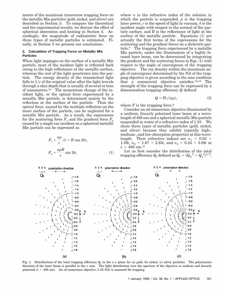
Fig. 1. Distributions of the total trapping efficiency Qt in the xdirection of the laser beam is parallel to the x axis. The light dpolarized ~l 5 488 nm!. An oil-immersion objective ~1.25 NA! is
where n is the refractive index of the solution inhich the particle is suspended, p is the trapping
aser power, c is the speed of light in vacuum, u is thencident angle with respect to the normal of the par-icle surface, and R is the reflectance of light at theurface of the metallic particle. Equations ~1! arectually the first terms of the expressions for thecattering and the gradient forces on a dielectric par-icle.9 The trapping force experienced by a metallic
Mie particle, under the illumination of a highly fo-cused laser beam, can be determined by integratingthe gradient and the scattering forces in Eqs. ~1! withrespect to the angle of convergence of the trappingobjective. The ray density within the maximum an-gle of convergence determined by the NA of the trap-ping objective is given according to the sine conditionthat a commercial objective satisfies.16,18 Thestrength of the trapping force can be expressed by adimensionless trapping efficiency Q defined
Q 5 Fcy~np!, (2)
here F is the trapping force.9Consider an oil-immersion objective illuminated by
a uniform, linearly polarized laser beam at a wave-length of 488 nm and a spherical metallic Mie particlesuspended in water of a refractive index of 1.33. Wechose three types of metallic particles ~gold, nickel,and silver! because they exhibit typically high-,
edium-, and low-absorption properties at this wave-ength. Their refractive indices are n1 5 0.82 1
Let us first consider the distribution of the totaltrapping efficiency Qt defined as Qt 5 ~Qtr
2 1 Qa2!1y2,
ane for ~a! gold, ~b! nickel, ~c! silver particles. The polarizationution over the aperture of the objective is uniform and linearly
med for trapping.
–z plistribassu
1 January 1999 y Vol. 38, No. 1 y APPLIED OPTICS 161
ttasfp
eloils
1
where Qtr and Qa are the trapping efficiencies alonghe transverse and the axial directions and areermed the transverse trapping efficiency and thexial trapping efficiency, respectively. Figure 1hows the distribution of the total trapping efficiencyor gold, nickel, and silver particles at different trap-ing positions ~x, z! in the x–z plane. The transverse
and the axial trapping positions originating from thecenter of the particle are x and z. The polarizationdirection of the incident light is assumed to be alongthe x axis. The distribution of the total trappingefficiency on the right plane is omitted owing to itssymmetry with respect to x 5 0. Here the particleradius is normalized to 1. Each individual arroworiginates from the trapping position of the laserbeam and points in the direction of the total trappingforce. The trapping laser beam is in the direction ofthe z axis. The length of the arrow is proportional tothe strength of Qt.
It is clearly seen that the axial trapping efficiencyis always a positive value, thus showing that theaxial trapping force always pushes a metallic Mieparticle downward. On the other hand, when thefocal position of a laser beam is shifted downward andaway from the center of the particle, the transversetrapping efficiency changes from a positive value ~re-pulsive force! to a negative value ~attractive force!.This property means that transverse trapping is pos-sible, which is consistent with the experimental ob-servation that a metallic Mie particle can be trappedonly in two dimensions near the bottom of the parti-cle.3,5
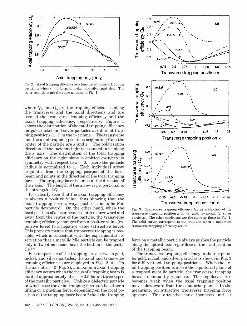
For comparison of the trapping force between gold,nickel, and silver particles, the axial and transversetrapping efficiencies are displayed in Figs. 2–4. Onthe axis at x 5 0 ~Fig. 2!, a maximum axial trappingfficiency occurs when the focus of a trapping beam isocated approximately at z 5 20.5 for all three typesf the metallic particles. Unlike a dielectric particlen which case the axial trapping force can be either aifting or a pushing force, depending on the focal po-ition of the trapping laser beam,9 the axial trapping
Fig. 2. Axial trapping efficiency as a function of the axial trappingposition z when x 5 0 for gold, nickel, and silver particles. Theother conditions are the same as those in Fig. 1.
62 APPLIED OPTICS y Vol. 38, No. 1 y 1 January 1999
force on a metallic particle always pushes the particlealong the optical axis regardless of the focal positionof the trapping beam.
The transverse trapping efficiency in the x–z planefor gold, nickel, and silver particles is shown in Fig. 3for different axial trapping positions. When the ax-ial trapping position is above the equatorial plane ofa trapped metallic particle, the transverse trappingforce is dominantly repulsive. This repulsive forcebecomes weak when the axial trapping positionmoves downward from the equatorial plane. In themeantime, an attractive transverse trapping forceappears. This attractive force increases until it
Fig. 3. Transverse trapping efficiency Qtr as a function of thetransverse trapping position x for ~a! gold, ~b! nickel, ~c! silverparticles. The other conditions are the same as those in Fig. 1.The solid curves correspond to the situation when a maximumtransverse trapping efficiency occurs.
t
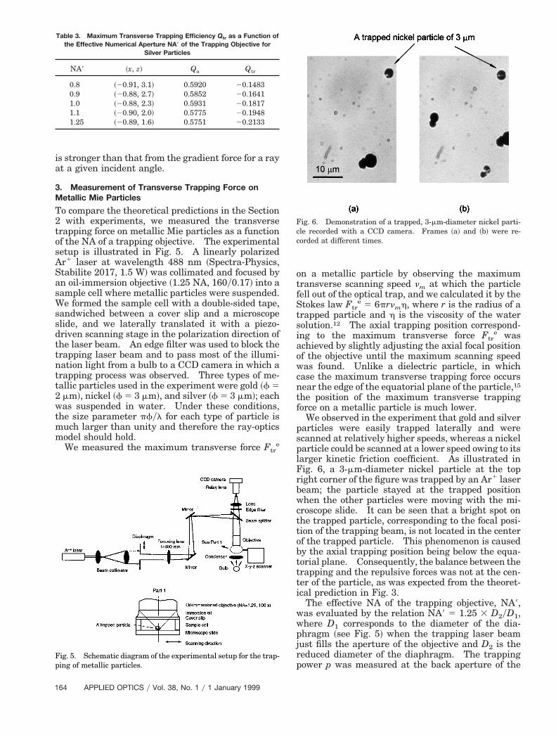
Table 1. Maximum Transverse Trapping Efficiency Q as a Function of
reaches a maximum, which is represented by thesolid curve in Fig. 3. For an example, the maximumtransverse trapping efficiency occurs at z 5 1.1, z 51.5, and z 5 1.6 for gold, nickel, and silver particles,respectively. Therefore Fig. 3 suggests that, whenthe axial trapping position is sufficiently low, a me-tallic particle can be trapped at an on-axis position,whereas it can be trapped at an off-axis position if thetrapping position is slightly below the equatorialplane. This conclusion agrees with the ray-opticsmodel5 and the experimental observation.5 Notethat transverse force on a dielectric particle is alwaysattractive.9
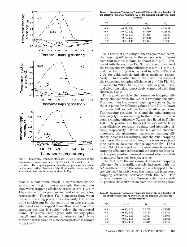
Fig. 4. Transverse trapping efficiency Qtr as a function of thetransverse trapping position y for ~a! gold, ~b! nickel, ~c! silverparticles. The trapping position is in the y–z plane perpendicularto the polarization direction of the illumination beam, and theother conditions are the same as those in Fig. 1.
As a result of our using a linearly polarized beam,the trapping efficiency in the y–z plane is differentfrom that in the x–z plane, as shown in Fig. 4. Com-pared with the result in Fig. 3, the maximum value ofthe transverse trapping efficiency at z 5 1.1, z 5 1.5,and z 5 1.6 in Fig. 4 is reduced by 28%, 3.3%, and2.1% for gold, nickel, and silver particles, respec-tively. On the other hand, the maximum value ofthe transverse trapping efficiency at z 5 0 in Fig. 4 isincreased by 201%, 40.7%, and 10.5% for gold, nickel,and silver particles, respectively, compared with thatshown in Fig. 3.
For a given particle, the transverse trapping effi-ciency changes with the NA of a trapping objective.The maximum transverse trapping efficiency Qtr inhe x–z plane for different values of the NA is shown
in Tables 1–3 for gold, nickel, and silver particles.The trapping positions ~x, z! and the axial trappingefficiency Qtr corresponding to the maximum trans-verse trapping efficiency Qtr are also listed in Tables1–3. The positive and the negative signs of the trap-ping efficiency represent pushing and attractive ef-fects, respectively. When the NA of the objectiveincreases, the maximum transverse trapping effi-ciency increases accordingly, and the axial trappingposition shifts upward although the transverse trap-ping position does not change appreciably. For agiven NA of the objective, the maximum transversetrapping efficiency reduces and the corresponding ax-ial trapping position moves downward when a metal-lic material becomes less absorptive.
The fact that the maximum transverse trappingefficiency for a metallic particle increases with theNA is different from the situation of a trapped dielec-tric particle,9 in which case the maximum transversetrapping efficiency decreases with the NA. Thephysical reason for this difference is that for a metal-lic particle the contribution from the scattering force
tr
the Effective Numerical Aperture NA* of the Trapping Objective for GoldParticles
1 January 1999 y Vol. 38, No. 1 y APPLIED OPTICS 163
w
Table 3. Maximum Transverse Trapping Efficiency Q as a Function of
1
is stronger than that from the gradient force for a rayat a given incident angle.
3. Measurement of Transverse Trapping Force onMetallic Mie Particles
To compare the theoretical predictions in the Section2 with experiments, we measured the transversetrapping force on metallic Mie particles as a functionof the NA of a trapping objective. The experimentalsetup is illustrated in Fig. 5. A linearly polarizedAr1 laser at wavelength 488 nm ~Spectra-Physics,Stabilite 2017, 1.5 W! was collimated and focused byan oil-immersion objective ~1.25 NA, 160y0.17! into asample cell where metallic particles were suspended.We formed the sample cell with a double-sided tape,sandwiched between a cover slip and a microscopeslide, and we laterally translated it with a piezo-driven scanning stage in the polarization direction ofthe laser beam. An edge filter was used to block thetrapping laser beam and to pass most of the illumi-nation light from a bulb to a CCD camera in which atrapping process was observed. Three types of me-tallic particles used in the experiment were gold ~f 52 mm!, nickel ~f 5 3 mm!, and silver ~f 5 3 mm!; eachwas suspended in water. Under these conditions,the size parameter pfyl for each type of particle ismuch larger than unity and therefore the ray-opticsmodel should hold.
We measured the maximum transverse force Ftre
Fig. 5. Schematic diagram of the experimental setup for the trap-ping of metallic particles.
tr
the Effective Numerical Aperture NA* of the Trapping Objective forSilver Particles
64 APPLIED OPTICS y Vol. 38, No. 1 y 1 January 1999
on a metallic particle by observing the maximumtransverse scanning speed nm at which the particlefell out of the optical trap, and we calculated it by theStokes law Ftr
e 5 6prnmh, where r is the radius of atrapped particle and h is the viscosity of the watersolution.12 The axial trapping position correspond-ing to the maximum transverse force Ftr
e wasachieved by slightly adjusting the axial focal positionof the objective until the maximum scanning speedwas found. Unlike a dielectric particle, in whichcase the maximum transverse trapping force occursnear the edge of the equatorial plane of the particle,15
the position of the maximum transverse trappingforce on a metallic particle is much lower.
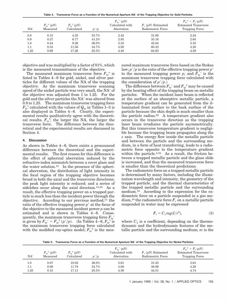
We observed in the experiment that gold and silverparticles were easily trapped laterally and werescanned at relatively higher speeds, whereas a nickelparticle could be scanned at a lower speed owing to itslarger kinetic friction coefficient. As illustrated inFig. 6, a 3-mm-diameter nickel particle at the topright corner of the figure was trapped by an Ar1 laserbeam; the particle stayed at the trapped positionwhen the other particles were moving with the mi-croscope slide. It can be seen that a bright spot onthe trapped particle, corresponding to the focal posi-tion of the trapping beam, is not located in the centerof the trapped particle. This phenomenon is causedby the axial trapping position being below the equa-torial plane. Consequently, the balance between thetrapping and the repulsive forces was not at the cen-ter of the particle, as was expected from the theoret-ical prediction in Fig. 3.
The effective NA of the trapping objective, NA9,as evaluated by the relation NA9 5 1.25 3 D2yD1,
where D1 corresponds to the diameter of the dia-phragm ~see Fig. 5! when the trapping laser beamjust fills the aperture of the objective and D2 is thereduced diameter of the diaphragm. The trappingpower p was measured at the back aperture of the
Fig. 6. Demonstration of a trapped, 3-mm-diameter nickel parti-cle recorded with a CCD camera. Frames ~a! and ~b! were re-corded at different times.
ltostg0F
ctbts
rteq
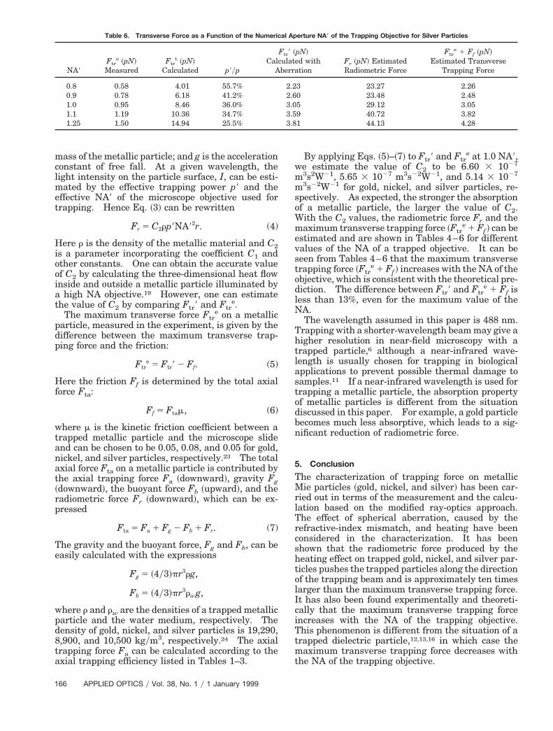
Table 4. Transverse Force as a Function of the Numerical Aperture NA* of the Trapping Objective for Gold Particles
al Ap
objective and was multiplied by a factor of 81%, whichis the measured transmittance of the objective.
The measured maximum transverse force Ftre is
isted in Tables 4–6 for gold, nickel, and silver par-icles for different values of the NA of the trappingbjective. As the maximum transverse scanningpeed of the nickel particle was very small, the NA9 ofhe objective was adjusted from 1 to 1.25. For theold and the silver particles the NA9 was altered from.8 to 1.25. The maximum transverse trapping forcetr
t calculated with the values of Qtr in Tables 1–3 isalso displayed in Tables 4–6. Clearly, the experi-mental results qualitatively agree with the theoreti-cal results, Ftr
t; the larger the NA, the larger thetransverse force. The difference between the theo-retical and the experimental results are discussed inSection 4.
4. Discussion
As shown in Tables 4–6, there exists a pronounceddifference between the theoretical and the experi-mental results. The first reason for this difference isthe effect of spherical aberration induced by therefractive-index mismatch between a cover glass andthe water solution.15 In the presence of the spheri-al aberration, the distribution of light intensity inhe focal region of the trapping objective becomesroad in both the axial and the transverse directions;he peak light intensity is reduced; and a series ofidelobes occur along the axial direction.15,20 As a
result, the effective trapping power on a trapped par-ticle is much less than the incident power through theobjective. According to our previous method,15 theatio of the effective trapping power p9 at the focus ofhe objective to the measured incident power p can bestimated and is shown in Tables 4–6. Conse-uently, the maximum transverse trapping force Ftr9
is given by Ftr9 5 Ftrt ~p9yp!. ~In Tables 4–6, Ftr
t isthe maximum transverse trapping force calculatedwith the modified ray-optics model; Ftr
sured maximum transverse force based on the Stokeslaw; p9yp is the ratio of the effective trapping power p9to the measured trapping power p; and Ftr9 is themaximum transverse trapping force calculated withthe consideration of p9yp.!
The difference between Ftr9 and Ftre may be caused
by the heating effect of the trapping beam on metallicparticles. When the incident laser beam is reflectedat the surface of an absorptive metallic particle, atemperature gradient can be generated from the il-luminated front surface to the back surface of theparticle because the skin depth is much smaller thanthe particle radius.22 A temperature gradient alsooccurs in the transverse direction as the trappinglaser beam irradiates the particle asymmetrically.But this transverse temperature gradient is negligi-ble because the trapping beam propagates along thez axis. The energy flow inside the metallic particleand between the particle and the surrounding me-dium, in a form of heat transferring, leads to a radio-metric force opposite to the temperature gradientwithin the particle.4,22 As a result, the friction be-tween a trapped metallic particle and the glass slideis increased, and thus the measured transverse forceis smaller than the theoretical predictions.
The radiometric force on a trapped metallic particleis determined by many factors, including the illumi-nation wavelength and intensity, the geometry of thetrapped particle, and the thermal characteristics ofthe trapped metallic particle and the surroundingmedium.19 According to the expression for the ra-diometric force on a particle suspended in a gas me-dium,19 the radiometric force Fr on a metallic particlesuspended in water may be expressed
Fr 5 C1 mg~Iyr2!, (3)
where C1 is a coefficient, depending on the thermo-dynamic and the hydrodynamic features of the me-tallic particle and the surrounding medium; m is the
erture NA* of the Trapping Objective for Nickel Particles
pN!ed withtion
Fr ~pN! EstimatedRadiometric Force
Ftre 1 Ff ~pN!
Estimated TransverseTrapping Force
1 31.23 3.618 38.89 4.286 44.51 4.74
Ftr9 ~ulatberra
2.42.83.34.04.4
Ftr9 ~ulatberra
3.64.04.3
1 January 1999 y Vol. 38, No. 1 y APPLIED OPTICS 165
met
oo
H
t
p
T
pd8
a
lN
Tht
Table 6. Transverse Force as a Function of the Numerical Aperture NA* of the Trapping Objective for Silver Particles
1
mass of the metallic particle; and g is the accelerationconstant of free fall. At a given wavelength, thelight intensity on the particle surface, I, can be esti-
ated by the effective trapping power p9 and theffective NA9 of the microscope objective used forrapping. Hence Eq. ~3! can be rewritten
Fr 5 C2rp9NA92r. (4)
Here r is the density of the metallic material and C2is a parameter incorporating the coefficient C1 andther constants. One can obtain the accurate valuef C2 by calculating the three-dimensional heat flow
inside and outside a metallic particle illuminated bya high NA objective.19 However, one can estimatethe value of C2 by comparing Ftr9 and Ftr
e.The maximum transverse force Ftr
e on a metallicparticle, measured in the experiment, is given by thedifference between the maximum transverse trap-ping force and the friction:
Ftre 5 Ftr9 2 Ff. (5)
ere the friction Ff is determined by the total axialforce Fta:
Ff 5 Ftam, (6)
where m is the kinetic friction coefficient between atrapped metallic particle and the microscope slideand can be chosen to be 0.05, 0.08, and 0.05 for gold,nickel, and silver particles, respectively.23 The totalaxial force Fta on a metallic particle is contributed byhe axial trapping force Fa ~downward!, gravity Fg
~downward!, the buoyant force Fb ~upward!, and theradiometric force Fr ~downward!, which can be ex-
ressed
Fta 5 Fa 1 Fg 2 Fb 1 Fr. (7)
he gravity and the buoyant force, Fg and Fb, can beeasily calculated with the expressions
Fg 5 ~4y3!pr3rg,
Fb 5 ~4y3!pr3rw g,
where r and rw are the densities of a trapped metallicarticle and the water medium, respectively. Theensity of gold, nickel, and silver particles is 19,290,,900, and 10,500 kgym3, respectively.24 The axial
trapping force Fa can be calculated according to thexial trapping efficiency listed in Tables 1–3.
66 APPLIED OPTICS y Vol. 38, No. 1 y 1 January 1999
By applying Eqs. ~5!–~7! to Ftr9 and Ftre at 1.0 NA9,
we estimate the value of C2 to be 6.60 3 1027
m3s2W21, 5.65 3 1027 m3s22W21, and 5.14 3 1027
m3s22W21 for gold, nickel, and silver particles, re-spectively. As expected, the stronger the absorptionof a metallic particle, the larger the value of C2.With the C2 values, the radiometric force Fr and themaximum transverse trapping force ~Ftr
e 1 Ff ! can beestimated and are shown in Tables 4–6 for differentvalues of the NA of a trapped objective. It can beseen from Tables 4–6 that the maximum transversetrapping force ~Ftr
e 1 Ff ! increases with the NA of theobjective, which is consistent with the theoretical pre-diction. The difference between Ftr9 and Ftr
e 1 Ff isess than 13%, even for the maximum value of theA.The wavelength assumed in this paper is 488 nm.
rapping with a shorter-wavelength beam may give aigher resolution in near-field microscopy with arapped particle,6 although a near-infrared wave-
length is usually chosen for trapping in biologicalapplications to prevent possible thermal damage tosamples.11 If a near-infrared wavelength is used fortrapping a metallic particle, the absorption propertyof metallic particles is different from the situationdiscussed in this paper. For example, a gold particlebecomes much less absorptive, which leads to a sig-nificant reduction of radiometric force.
5. Conclusion
The characterization of trapping force on metallicMie particles ~gold, nickel, and silver! has been car-ried out in terms of the measurement and the calcu-lation based on the modified ray-optics approach.The effect of spherical aberration, caused by therefractive-index mismatch, and heating have beenconsidered in the characterization. It has beenshown that the radiometric force produced by theheating effect on trapped gold, nickel, and silver par-ticles pushes the trapped particles along the directionof the trapping beam and is approximately ten timeslarger than the maximum transverse trapping force.It has also been found experimentally and theoreti-cally that the maximum transverse trapping forceincreases with the NA of the trapping objective.This phenomenon is different from the situation of atrapped dielectric particle,12,13,16 in which case themaximum transverse trapping force decreases withthe NA of the trapping objective.
analytical development and numerical computations of the
The authors acknowledge the support from theAustralian Research Council. P. C. Ke is supportedby an Australian Postgraduate Award. Correspon-dence should be addressed to M. Gu.
References1. S. Sato and H. Inaba, “Optical trapping and manipulation of
microscopic particles and biological cells by laser beams,” Opt.Quantum Electron. 28, 1–16 ~1996!.
2. K. Sasaki, M. Koshioka, H. Misawa, N. Kitamura, and H.Masuhara, “Optical trapping of a metal particle and a waterdroplet by a scanning laser beam,” Appl. Phys. Lett. 60, 807–809 ~1991!.
3. S. Sato, Y. Harada, and Y. Waseda, “Optical trapping of mi-croscopic metal particles,” Opt. Lett. 19, 1807–1809 ~1994!.
4. K. Svoboda and S. M. Block, “Optical trapping of metallicRayleigh particles,” Opt. Lett. 19, 930–932 ~1994!.
5. H. Furukawa and I. Yamaguchi, “Optical trapping of metallicparticles by a fixed Gaussian beam,” Opt. Lett. 23, 216–218~1998!.
6. T. Sugiura, T. Okada, Y. Inouye, O. Nakamura, and S. Kawata,“Gold-bead scanning near-field optical microscope with laser-force position control,” Opt. Lett. 22, 1663–1665 ~1997!.
7. S. Kawata, Y. Inouye, and T. Sugiura, “Near-field scanningoptical microscope with a laser trapped probe,” Jpn. J. Appl.Phys. 33, L1725–L1727 ~1994!.
8. J. P. Barton, D. R. Alexander, and S. A. Schaub, “Theoreticaldetermination of net radiation force and torque for a sphericalparticle illumination by a focused laser beam,” J. Appl. Phys.66, 4594–4601 ~1989!.
9. A. Ashkin, “Forces of a single-beam gradient laser trap on adielectric sphere in the ray optics regime,” J. Biophys. 61,569–582 ~1991!.
10. R. Gussgard, T. Lindmo, and I. Brevik, “Calculation of thetrapping force in a strongly focused laser beam,” J. Opt. Soc.Am. B 9, 1922–1930 ~1992!.
11. R. C. Gauthier and S. Wallace, “Optical levitation of spheres:
force equations,” J. Opt. Soc. Am. B 12, 1680–1686 ~1995!.12. W. H. Wright, G. J. Sonek, and M. W. Berns, “Parametric
study of the forces on microspheres held by optical tweezers,”Appl. Opt. 33, 1735–1748 ~1994!.
13. W. H. Wright and G. J. Sonek, “Radiation trapping forces onmicrospheres with optical tweezers,” Appl. Phys. Lett. 63, 715–717 ~1993!.
14. H. Felgner, O. Muller, and M. Schilwa, “Calibration of lightforces in optical tweezers,” Appl. Opt. 34, 977–982 ~1995!.
15. P. C. Ke and M. Gu, “Characterisation of trapping force in thepresence of spherical aberration,” J. Mod. Opt. ~in press!.
16. M. Gu, P. C. Ke, and X. S. Gan, “Trapping force by a highnumerical-aperture microscope objective obeying the sine con-dition,” Rev. Sci. Instrum. 68, 3666–3668 ~1997!.
17. S. Sato, “Calculation of optical trapping forces for micrometer-sized particles with complex refractive index,” in QuantumElectronics and Laser Science Conference, Vol. 16 of 1995 OSATechnical Digest Series ~Optical Society of America, Washing-ton, D.C., 1995!, pp. 197.
18. M. Born and E. Wolf, Principles of Optics, 6th ed. ~Pergamon,New York, 1980!, Chap. 13, pp. 612–615.
19. M. Lewittes, S. Arnold, and G. Oster, “Radiometric levitationof micron sized spheres,” Appl. Phys. Lett. 40, 455–457 ~1982!.
20. P. Torok, P. Varga, Z. Laczik, and G. R. Booker, “Electromag-netic diffraction of light focused through a planar interfacebetween materials of mismatched refractive indices: an inte-gral representation,” J. Opt. Soc. Am. A 12, 325–332 ~1995!.
21. D. R. Lide, CRC Handbook of Chemistry and Physics, 77th ed.~CRC Press, Boca Raton, Fla., 1996–1997!, Sec. 12, pp. 130–143.
22. R. M. Wood, Laser Damage in Optical Materials ~GEC Re-search, Hirst Research Centre, UK, 1986!, Chap. 1, pp. 24–25.
23. R. M. Besancon, The Encyclopedia of Physics, 2nd ed. ~VanNostrand Reinhold, New York, 1974!, pp. 376.
24. K. Raznjevic, Handbook of Thermodynamic Tables and Charts~Hemisphere, Washington, D.C., 1976!, pp. 3.
1 January 1999 y Vol. 38, No. 1 y APPLIED OPTICS 167