A. PROVIDE EACH SUB-CONTRACTOR WITH A COMPLETE SET OF ELECTRONIC CONTRACT DOCUMENTS FOR THEIR USE ANDREFERENCE AND VERIFY THEIR RECEIPT UPON REQUEST.
B. FILL AND PATCH EXPOSED HOLES OR CRACKS IN FLOOR OR WALL SURFACES AND FINISH LEVEL, SMOOTH AND FLUSH WITHADJACENT SURFACES.
C. COORDINATE AND VERIFY CLEARANCES REQUIRED OF PRODUCTS AND EQUIPMENT FOR DELIVERY, INSTALLATION USE ANDOPERATION.
D. MAINTAIN DIMENSIONS INDICATED AS "HOLD" ACCURATELY AS NOTED.E. BRACE PARTITIONS, CEILINGS, SOFFITS, PLATFORMS, SUSPENDED CONSTRUCTION AND SIMILAR ELEMENTS TO STRUCTURAL
ELEMENTS - EVEN IF NOT INDICATED. DO NOT BRACE TO THE ROOF DECK, PLUMBING OR SPRINKLER PIPES, DUCTWORK, ELECTRICAL CONDUITS OR SIMILAR ELEMENTS.
F. INSTALL FRAMING AND FURRING TO AVOID CONFLICTS OR INTERFERENCES WITH CONCEALED OR RECESSED PLUMBING,MECHANICAL, ELECTRICAL OR CONTROL COMPONENTS.
G. ALIGN TOP OF NEW CONCRETE WITH EXISTING AS APPLICABLE.H. REFER TO FINISH / MATERIAL / COLOR SCHEDULE FOR EXPOSED FINISHES OF BUILDING MATERIALS, WALLS, FLOORS, CEILING,
DOORS, TRIM, CASEWORK, COUNTERTOPS AND SIMILAR CONSTRUCTION ELEMENTS.I. PROVIDE CONCEALED 2x6 MIN WOOD BLOCKING WITHIN DRYWALL CONSTRUCTION FOR SECURE ANCHORAGE OF CASEWORK
CABINETS, WALL-MOUNTED SHELVES, GRAB-BARS, DOOR STOPS, WOOD FRAMES AND SIMILAR ELEMENTS. J. PROVIDE PRESERVATIVE-TREATED WOOD BLOCKING WHEN IN CONTACT WITH MASONRY OR CONCRETE OR WHEN ASSOCIATED
WITH ROOFING OR FLASHING WORK.K. PROVIDE MINIMUM 3/4-INCH THICK FIRE-RETARDANT TREATED PLYWOOD AT ELECTRICAL OR PHONE/DATA PANELS.L. PROVIDE JOINT SEALS TO MAINTAIN A PERMANENT, AIR-TIGHT, VERMIN AND WATERPROOF BUILDING ENCLOSURE THROUGHOUT
THE PROJECT. PROVIDE FIRE-SEALANTS AT FIRE-RATED PARTITIONS, AND ACOUSTICAL SEALANTS AT SOUND-RATED PARTITIONS,AS APPLICABLE.
M. PROVIDE DOOR HARDWARE AT EACH SWINGING DOOR TO INCLUDE 3 HINGES, LEVER LOCKSET, 3 FRAME SILENCERS AND A WALLSTOP MINIMUM, UNO.
N. LOCATE FLOOR FINISH CHANGES AND TRANSITIONS UNDER CENTER OF DOORS, UNO.O. PAINT FINISH ALL EXPOSED SURFACES THROUGHOUT THE BUILDING UNLESS PRE-FINISHED OR INTEGRALLY FINISHED OR WHERE
A NATURAL FINISH IS INDICATED.P. PAINT FINISH ELECTRICAL & CONTROL PANELS WHEN NOT LOCATED WITHIN ELECTRICAL OR MECHANICAL ROOMS, COLOR PER
ARCHITECT.
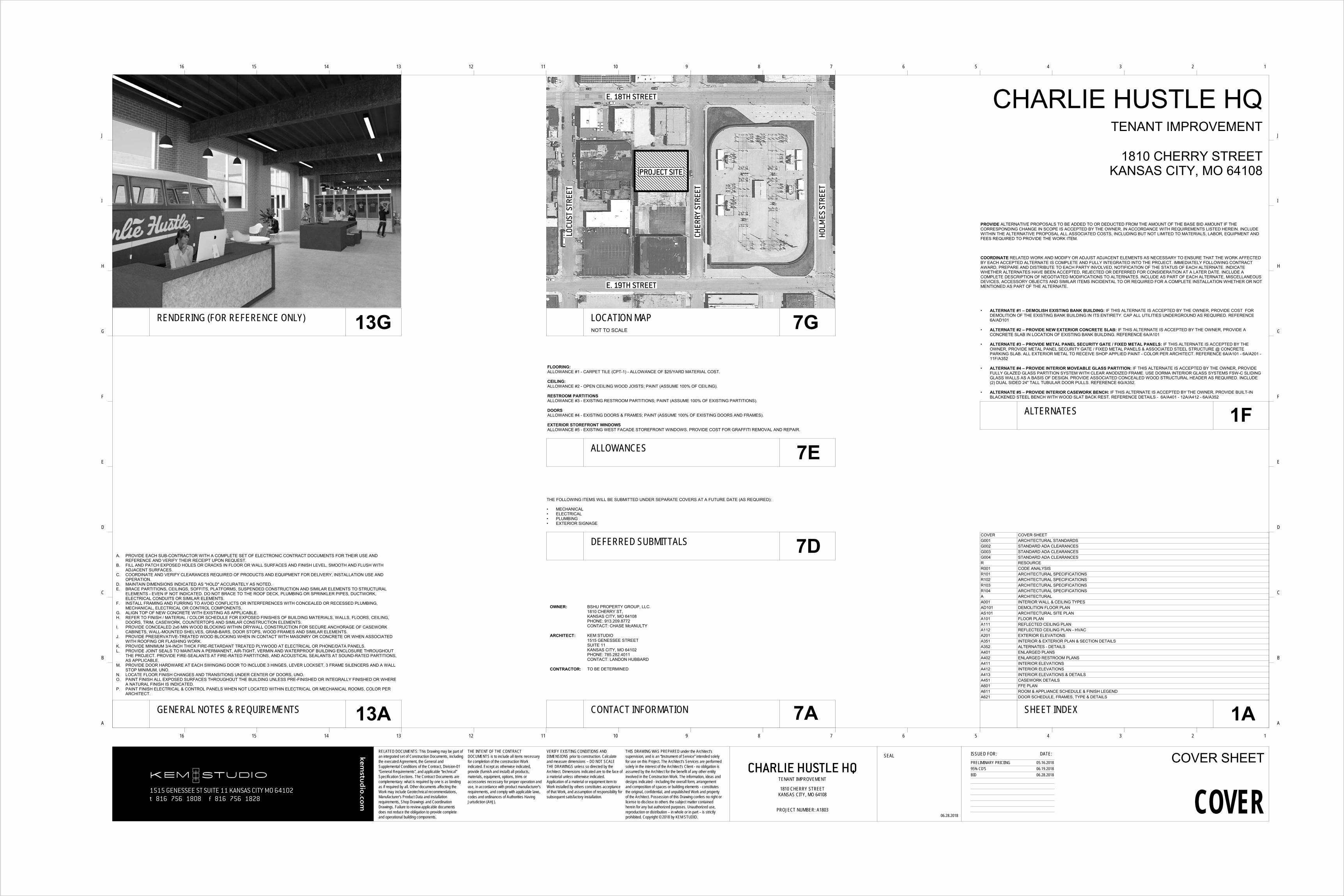
OWNER: BSHU PROPERTY GROUP, LLC.1810 CHERRY ST,KANSAS CITY, MO 64108PHONE: 913.209.8772CONTACT: CHASE McANULTY
ARCHITECT: KEM STUDIO1515 GENESSEE STREETSUITE 11KANSAS CITY, MO 64102PHONE: 785.282.4011CONTACT: LANDON HUBBARD
CONTRACTOR: TO BE DETERMINED
THE FOLLOWING ITEMS WILL BE SUBMITTED UNDER SEPARATE COVERS AT A FUTURE DATE (AS REQUIRED):
PROVIDE ALTERNATIVE PROPOSALS TO BE ADDED TO OR DEDUCTED FROM THE AMOUNT OF THE BASE BID AMOUNT IF THE CORRESPONDING CHANGE IN SCOPE IS ACCEPTED BY THE OWNER, IN ACCORDANCE WITH REQUIREMENTS LISTED HEREIN. INCLUDE WITHIN THE ALTERNATIVE PROPOSAL ALL ASSOCIATED COSTS, INCLUDING BUT NOT LIMITED TO MATERIALS, LABOR, EQUIPMENT AND FEES REQUIRED TO PROVIDE THE WORK ITEM.
COORDINATE RELATED WORK AND MODIFY OR ADJUST ADJACENT ELEMENTS AS NECESSARY TO ENSURE THAT THE WORK AFFECTED BY EACH ACCEPTED ALTERNATE IS COMPLETE AND FULLY INTEGRATED INTO THE PROJECT. IMMEDIATELY FOLLOWING CONTRACT AWARD, PREPARE AND DISTRIBUTE TO EACH PARTY INVOLVED, NOTIFICATION OF THE STATUS OF EACH ALTERNATE. INDICATE WHETHER ALTERNATES HAVE BEEN ACCEPTED, REJECTED OR DEFERRED FOR CONSIDERATION AT A LATER DATE. INCLUDE A COMPLETE DESCRIPTION OF NEGOTIATED MODIFICATIONS TO ALTERNATES. INCLUDE AS PART OF EACH ALTERNATE, MISCELLANEOUS DEVICES, ACCESSORY OBJECTS AND SIMILAR ITEMS INCIDENTAL TO OR REQUIRED FOR A COMPLETE INSTALLATION WHETHER OR NOT MENTIONED AS PART OF THE ALTERNATE.
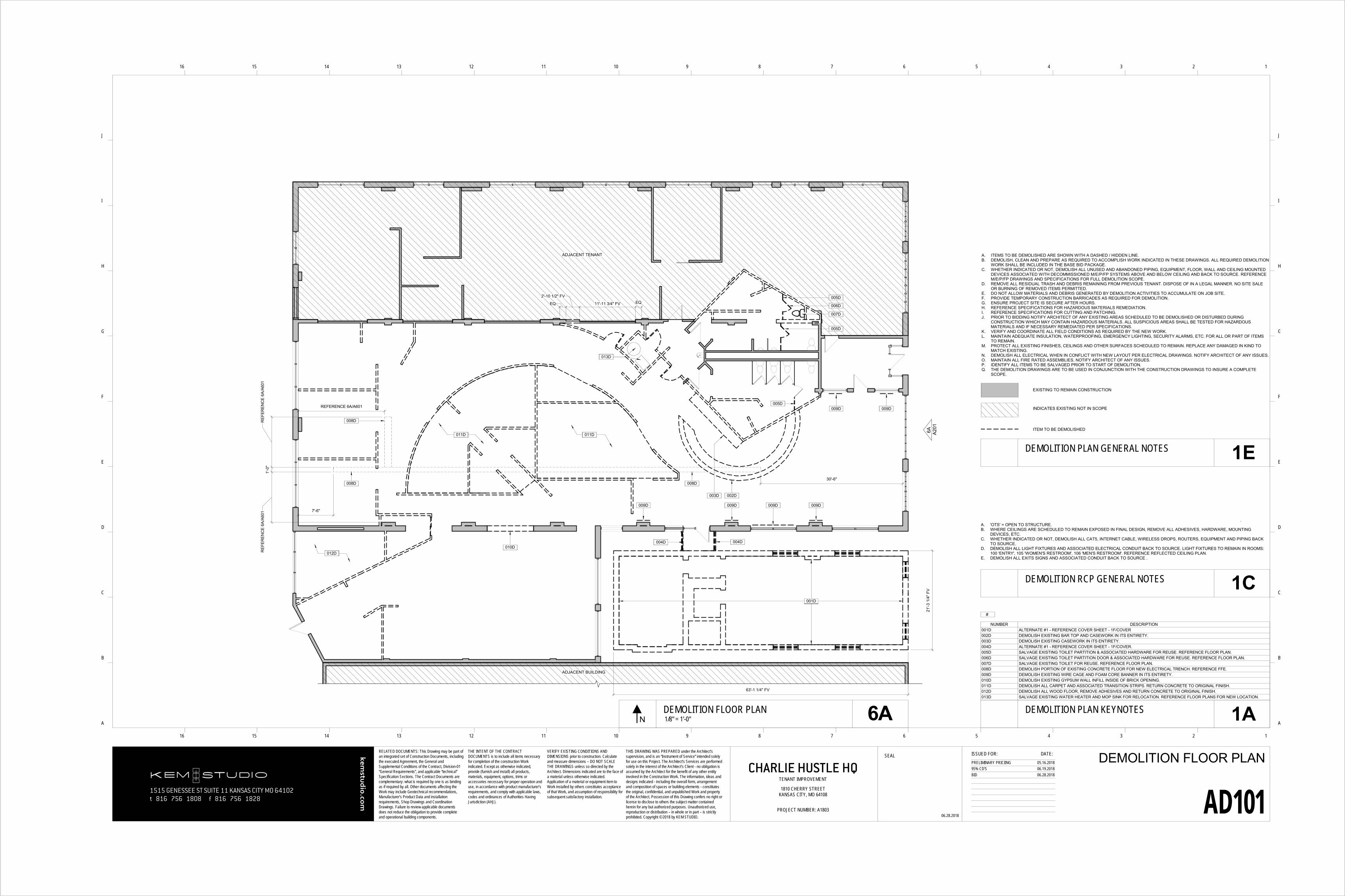
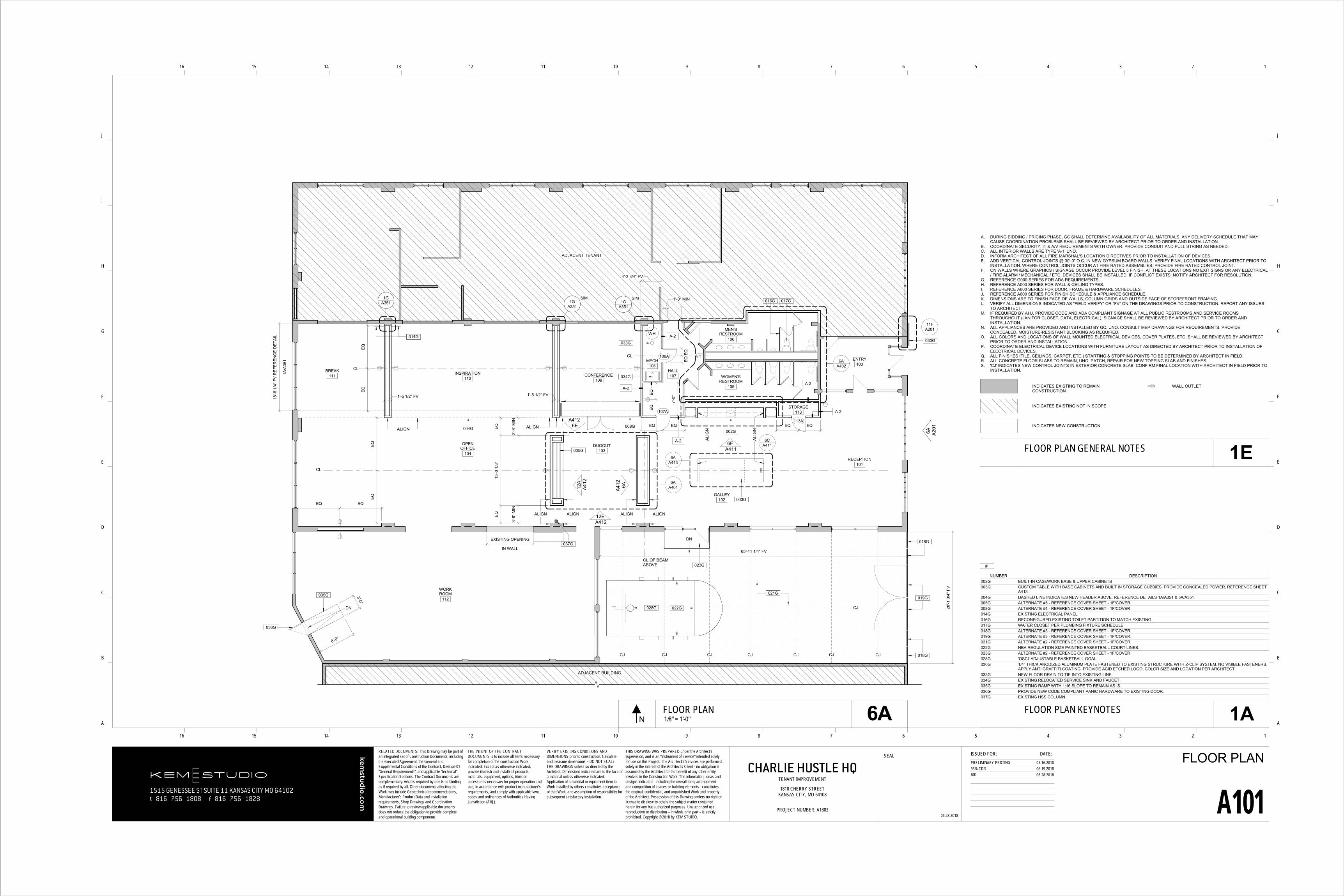
• ALTERNATE #1 – DEMOLISH EXISTING BANK BUILDING: IF THIS ALTERNATE IS ACCEPTED BY THE OWNER, PROVIDE COST FORDEMOLITION OF THE EXISTING BANK BUILDING IN ITS ENTIRETY. CAP ALL UTILITIES UNDERGROUND AS REQUIRED. REFERENCE 6A/AD101
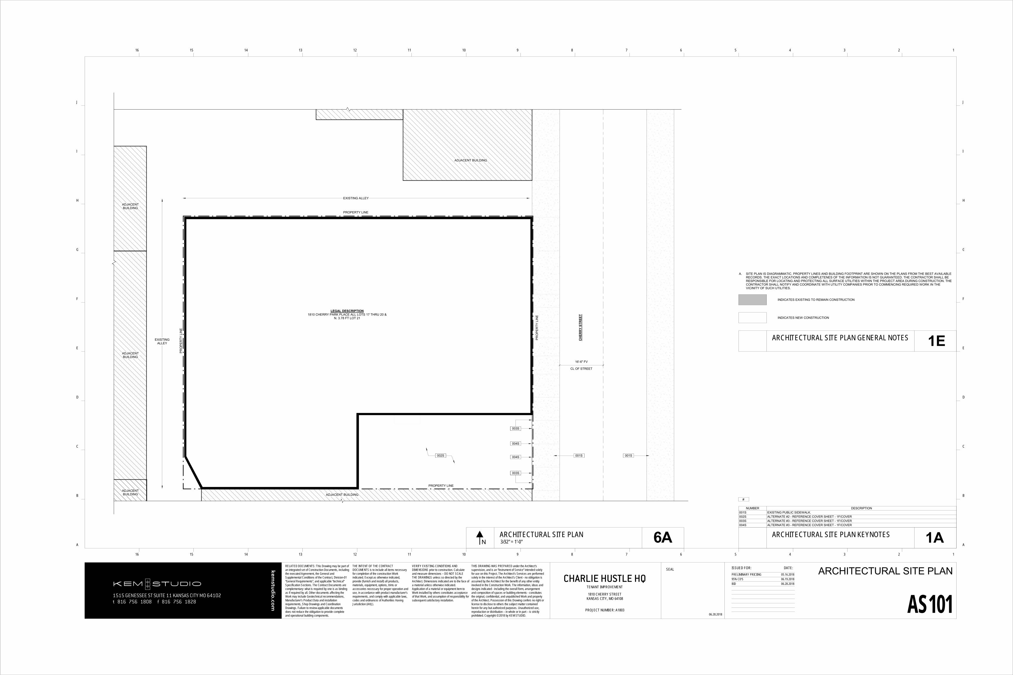
• ALTERNATE #2 – PROVIDE NEW EXTERIOR CONCRETE SLAB: IF THIS ALTERNATE IS ACCEPTED BY THE OWNER, PROVIDE ACONCRETE SLAB IN LOCATION OF EXISTING BANK BUILDING. REFERENCE 6A/A101
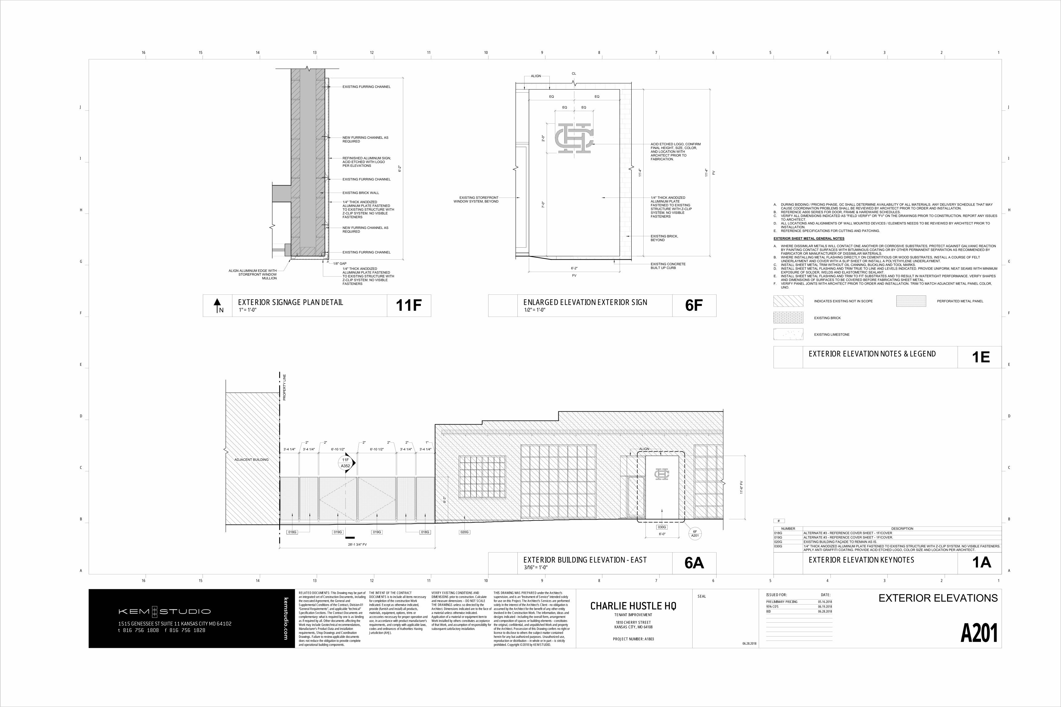
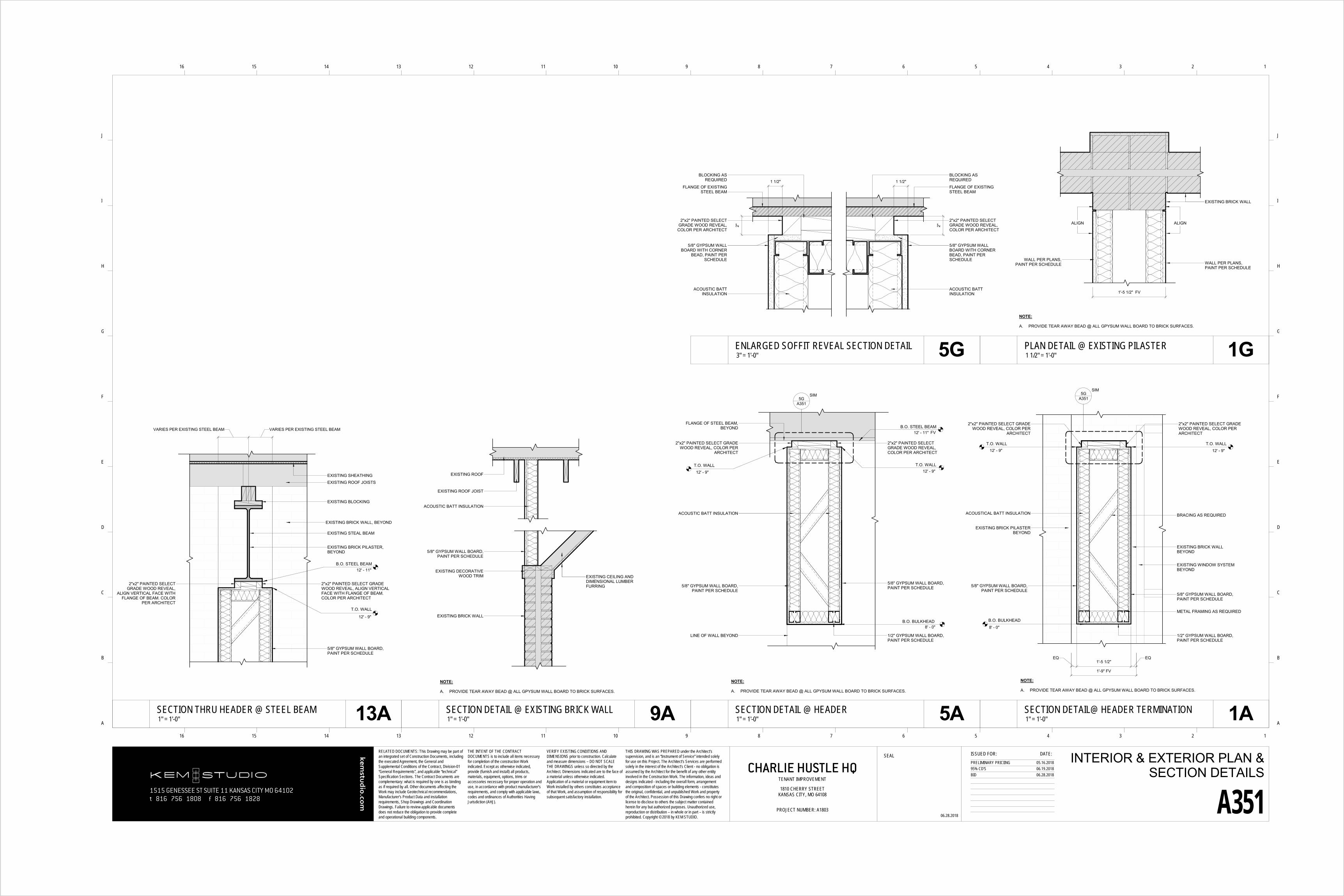
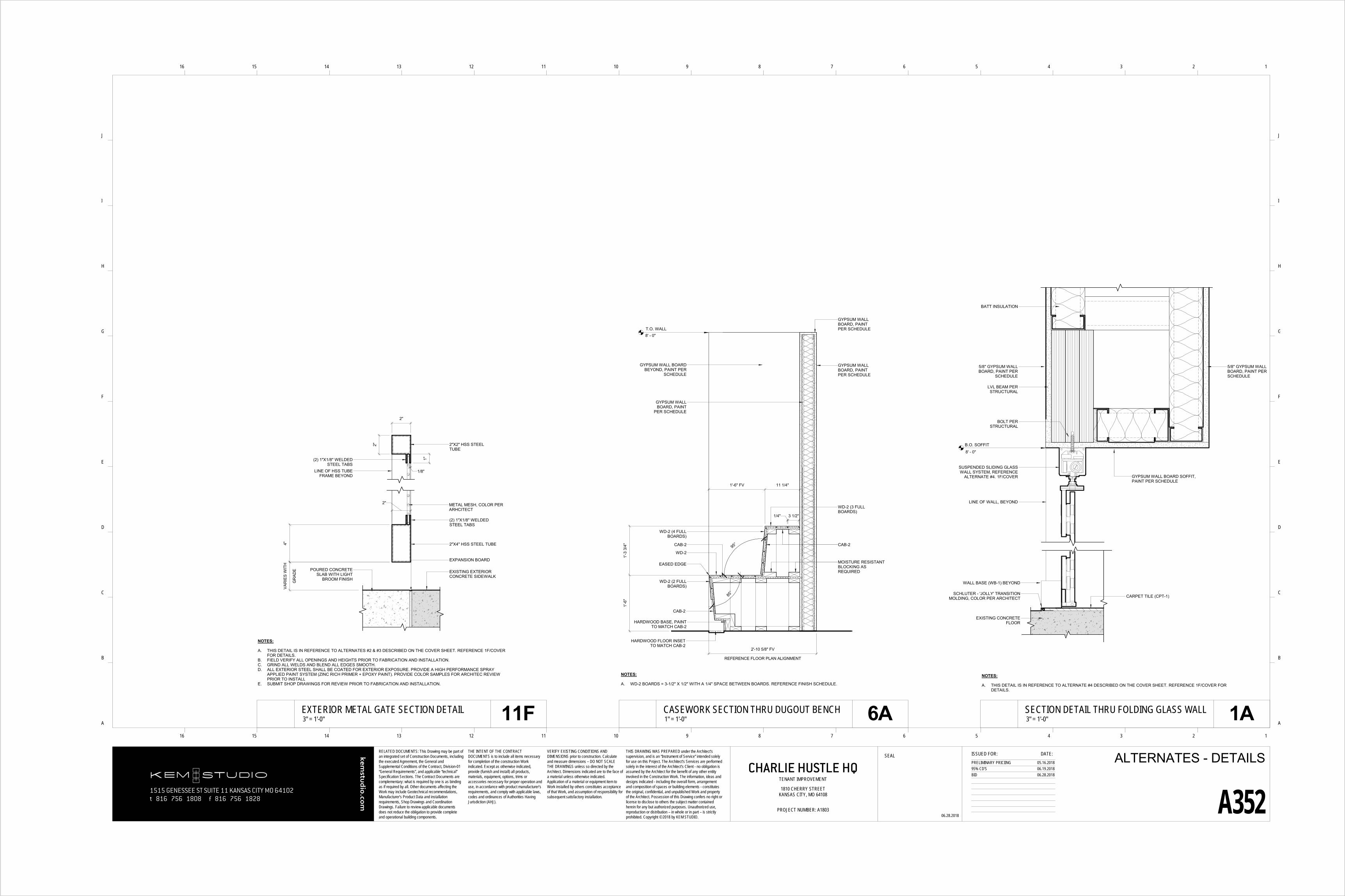
• ALTERNATE #3 – PROVIDE METAL PANEL SECURITY GATE / FIXED METAL PANELS: IF THIS ALTERNATE IS ACCEPTED BY THEOWNER, PROVIDE METAL PANEL SECURITY GATE / FIXED METAL PANELS & ASSOCIATED STEEL STRUCTURE @ CONCRETEPARKING SLAB. ALL EXTERIOR METAL TO RECEIVE SHOP APPLIED PAINT - COLOR PER ARCHITECT. REFERENCE 6A/A101 - 6A/A201 -11F/A352
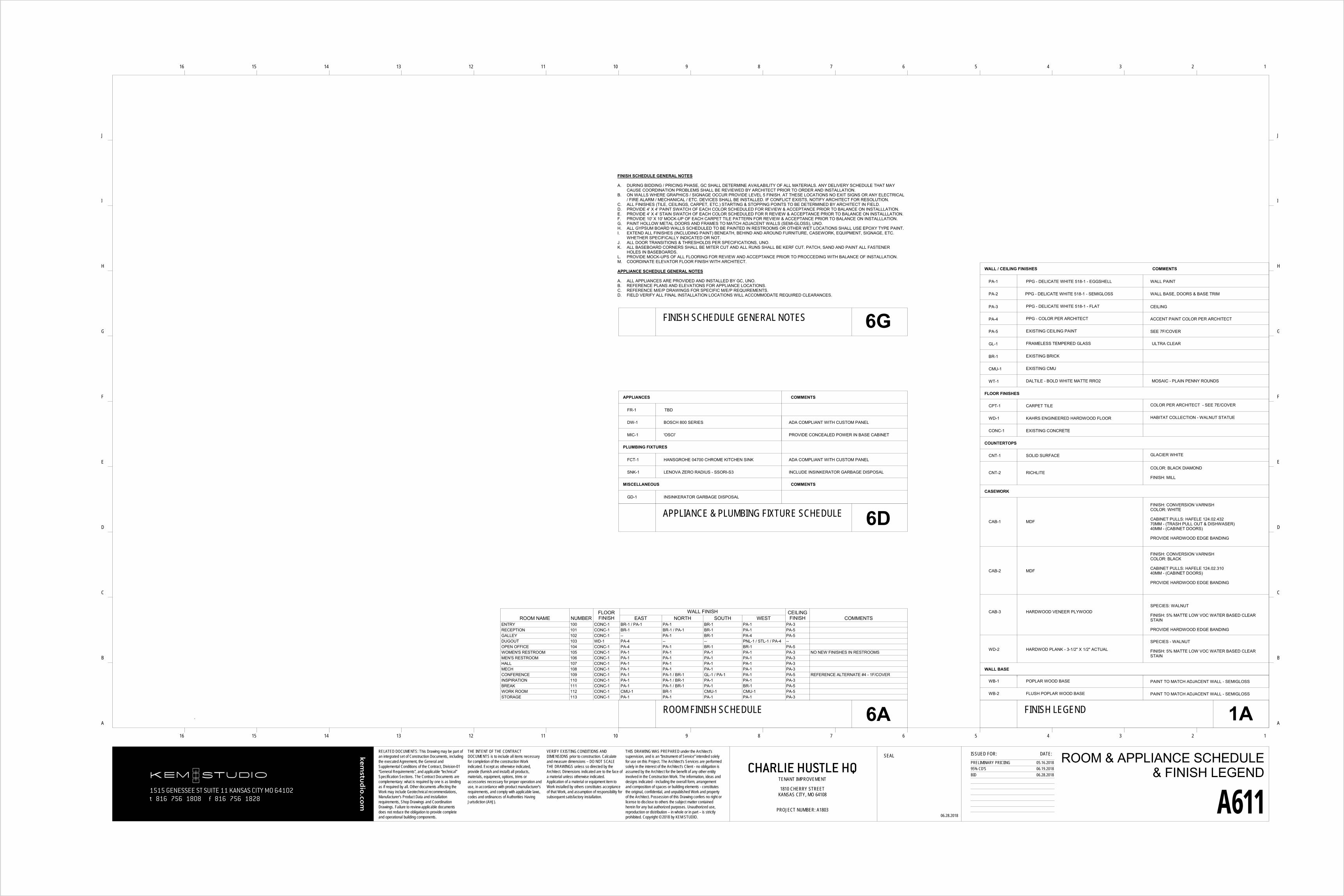
• ALTERNATE #4 – PROVIDE INTERIOR MOVEABLE GLASS PARTITION: IF THIS ALTERNATE IS ACCEPTED BY THE OWNER, PROVIDEFULLY GLAZED GLASS PARTITION SYSTEM WITH CLEAR ANODIZED FRAME. USE DORMA INTERIOR GLASS SYSTEMS FSW-C SLIDINGGLASS WALLS AS A BASIS OF DESIGN. PROVIDE ASSOCIATED CONCEALED WOOD STRUCTURAL HEADER AS REQUIRED. INCLUDE(2) DUAL SIDED 24" TALL TUBULAR DOOR PULLS. REFERENCE 6G/A352.
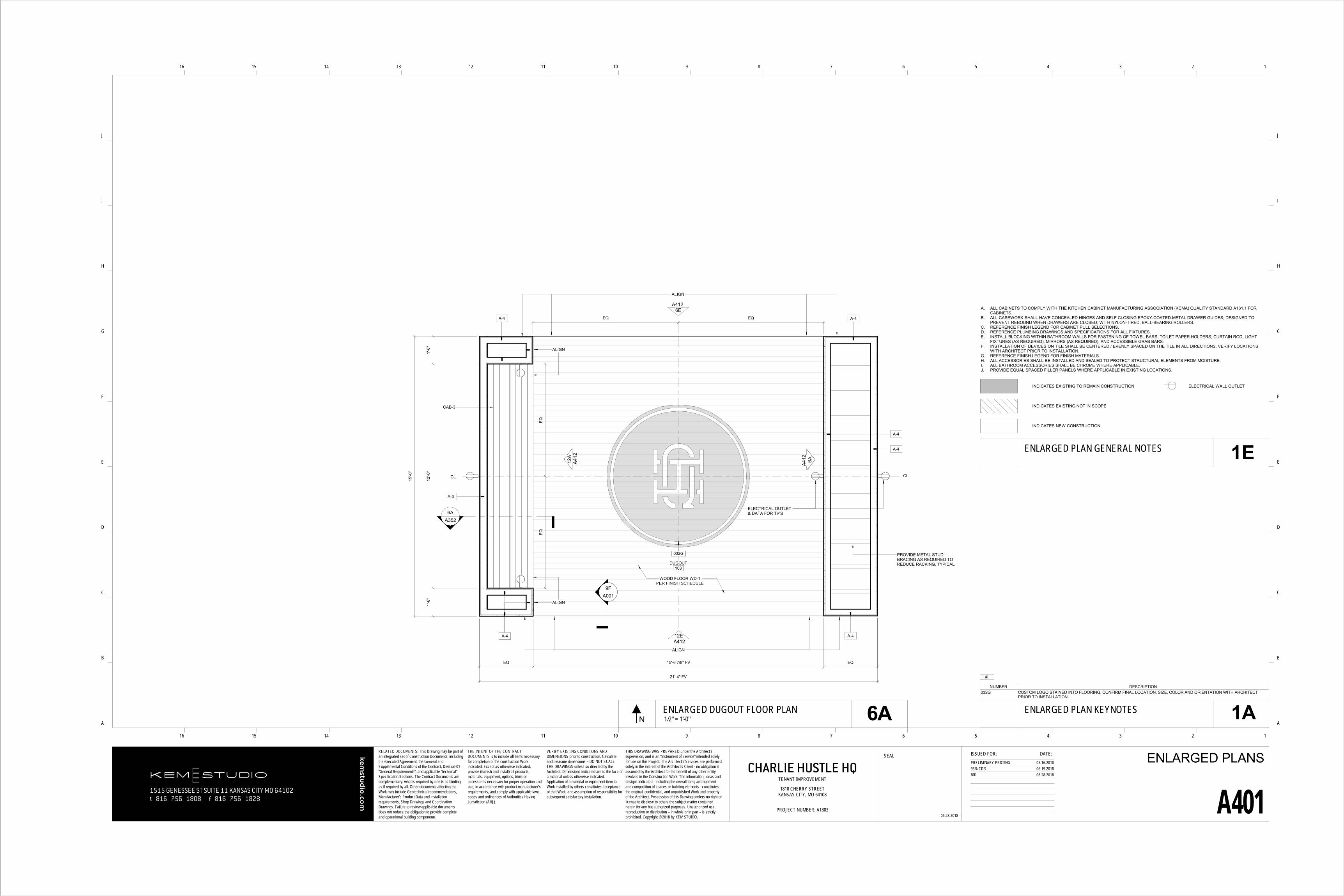
• ALTERNATE #5 – PROVIDE INTERIOR CASEWORK BENCH: IF THIS ALTERNATE IS ACCEPTED BY THE OWNER, PROVIDE BUILT-INBLACKENED STEEL BENCH WITH WOOD SLAT BACK REST. REFERENCE DETAILS - 6A/A401 - 12A/A412 - 6A/A352
.
FLOORING:ALLOWANCE #1 - CARPET TILE (CPT-1) - ALLOWANCE OF $25/YARD MATERIAL COST.
CEILING:ALLOWANCE #2 - OPEN CEILING WOOD JOISTS; PAINT (ASSUME 100% OF CEILING).
DOORSALLOWANCE #4 - EXISTING DOORS & FRAMES; PAINT (ASSUME 100% OF EXISTING DOORS AND FRAMES).
EXTERIOR STOREFRONT WINDOWSALLOWANCE #5 - EXISTING WEST FACADE STOREFRONT WINDOWS. PROVIDE COST FOR GRAFFITI REMOVAL AND REPAIR.
1515 GENESSEE ST SUITE 11 KANSAS CITY MO 64102t 816 756 1808 f 816 756 1828
kemstu
dio.co
m
RELATED DOCUMENTS: This Drawing may be part of an integrated set of Construction Documents, including the executed Agreement, the General and Supplemental Conditions of the Contract, Division-01 “General Requirements”, and applicable “technical” Specification Sections. The Contract Documents are complementary: what is required by one is as binding as if required by all. Other documents affecting the Work may include Geotechnical recommendations, Manufacturer’s Product Data and installation requirements, Shop Drawings and Coordination Drawings. Failure to review applicable documents does not reduce the obligation to provide complete and operational building components.
SEAL ISSUED FOR: DATE:
16 15 14 13 12 11 10 9 8 7 6 5 4 3 2 1
16 15 14 13 12 11 10 9 8 7 6 5 4 3 2 1
A
B
C
D
E
F
G
H
I
J
A
B
C
D
E
F
G
H
I
J
THE INTENT OF THE CONTRACT DOCUMENTS is to include all items necessary for completion of the construction Work indicated. Except as otherwise indicated, provide (furnish and install) all products, materials, equipment, options, trims or accessories necessary for proper operation and use, in accordance with product manufacturer’s requirements, and comply with applicable laws, codes and ordinances of Authorities Having Jurisdiction (AHJ).
VERIFY EXISTING CONDITIONS AND DIMENSIONS prior to construction. Calculate and measure dimensions – DO NOT SCALE THE DRAWINGS unless so directed by the Architect. Dimensions indicated are to the face of a material unless otherwise indicated. Application of a material or equipment item to Work installed by others constitutes acceptance of that Work, and assumption of responsibility for subsequent satisfactory installation.
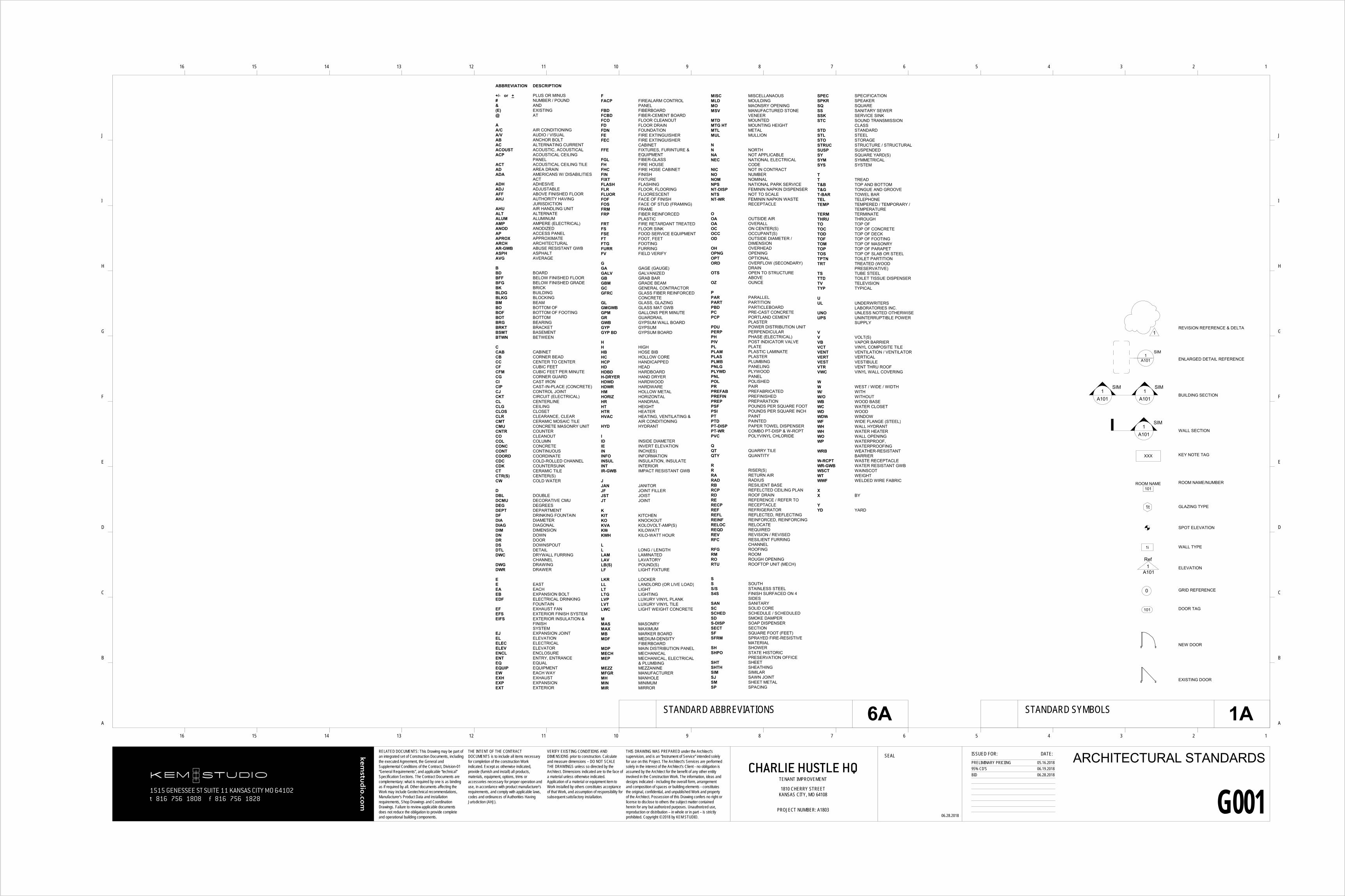
EJ EXPANSION JOINTEL ELEVATIONELEC ELECTRICALELEV ELEVATORENCL ENCLOSUREENT ENTRY, ENTRANCEEQ EQUALEQUIP EQUIPMENTEW EACH WAYEXH EXHAUSTEXP EXPANSIONEXT EXTERIOR
FFACP FIREALARM CONTROL
PANELFBD FIBERBOARDFCBD FIBER-CEMENT BOARDFCO FLOOR CLEANOUTFD FLOOR DRAINFDN FOUNDATIONFE FIRE EXTINGUISHERFEC FIRE EXTINGUISHER
CABINETFFE FIXTURES, FURINTURE &
EQUIPMENTFGL FIBER-GLASSFH FIRE HOUSEFHC FIRE HOSE CABINETFIN FINISHFIXT FIXTUREFLASH FLASHINGFLR FLOOR, FLOORINGFLUOR FLUORESCENTFOF FACE OF FINISHFOS FACE OF STUD (FRAMING)FRM FRAMEFRP FIBER REINFORCED
PLASTICFRT FIRE RETARDANT TREATEDFS FLOOR SINKFSE FOOD SERVICE EQUIPMENTFT FOOT, FEETFTG FOOTINGFURR FURRINGFV FIELD VERIFY
TT TREADT&B TOP AND BOTTOMT&G TONGUE AND GROOVET-BAR TOWEL BARTEL TELEPHONETEMP TEMPERED / TEMPORARY /
TEMPERATURETERM TERMINATETHRU THROUGHTO TOP OFTOC TOP OF CONCRETETOD TOP OF DECKTOF TOP OF FOOTINGTOM TOP OF MASONRYTOP TOP OF PARAPETTOS TOP OF SLAB OR STEELTPTN TOILET PARTITIONTRT TREATED (WOOD
1515 GENESSEE ST SUITE 11 KANSAS CITY MO 64102t 816 756 1808 f 816 756 1828
kemstu
dio.co
m
RELATED DOCUMENTS: This Drawing may be part of an integrated set of Construction Documents, including the executed Agreement, the General and Supplemental Conditions of the Contract, Division-01 “General Requirements”, and applicable “technical” Specification Sections. The Contract Documents are complementary: what is required by one is as binding as if required by all. Other documents affecting the Work may include Geotechnical recommendations, Manufacturer’s Product Data and installation requirements, Shop Drawings and Coordination Drawings. Failure to review applicable documents does not reduce the obligation to provide complete and operational building components.
SEAL ISSUED FOR: DATE:
16 15 14 13 12 11 10 9 8 7 6 5 4 3 2 1
16 15 14 13 12 11 10 9 8 7 6 5 4 3 2 1
A
B
C
D
E
F
G
H
I
J
A
B
C
D
E
F
G
H
I
J
THE INTENT OF THE CONTRACT DOCUMENTS is to include all items necessary for completion of the construction Work indicated. Except as otherwise indicated, provide (furnish and install) all products, materials, equipment, options, trims or accessories necessary for proper operation and use, in accordance with product manufacturer’s requirements, and comply with applicable laws, codes and ordinances of Authorities Having Jurisdiction (AHJ).
VERIFY EXISTING CONDITIONS AND DIMENSIONS prior to construction. Calculate and measure dimensions – DO NOT SCALE THE DRAWINGS unless so directed by the Architect. Dimensions indicated are to the face of a material unless otherwise indicated. Application of a material or equipment item to Work installed by others constitutes acceptance of that Work, and assumption of responsibility for subsequent satisfactory installation.
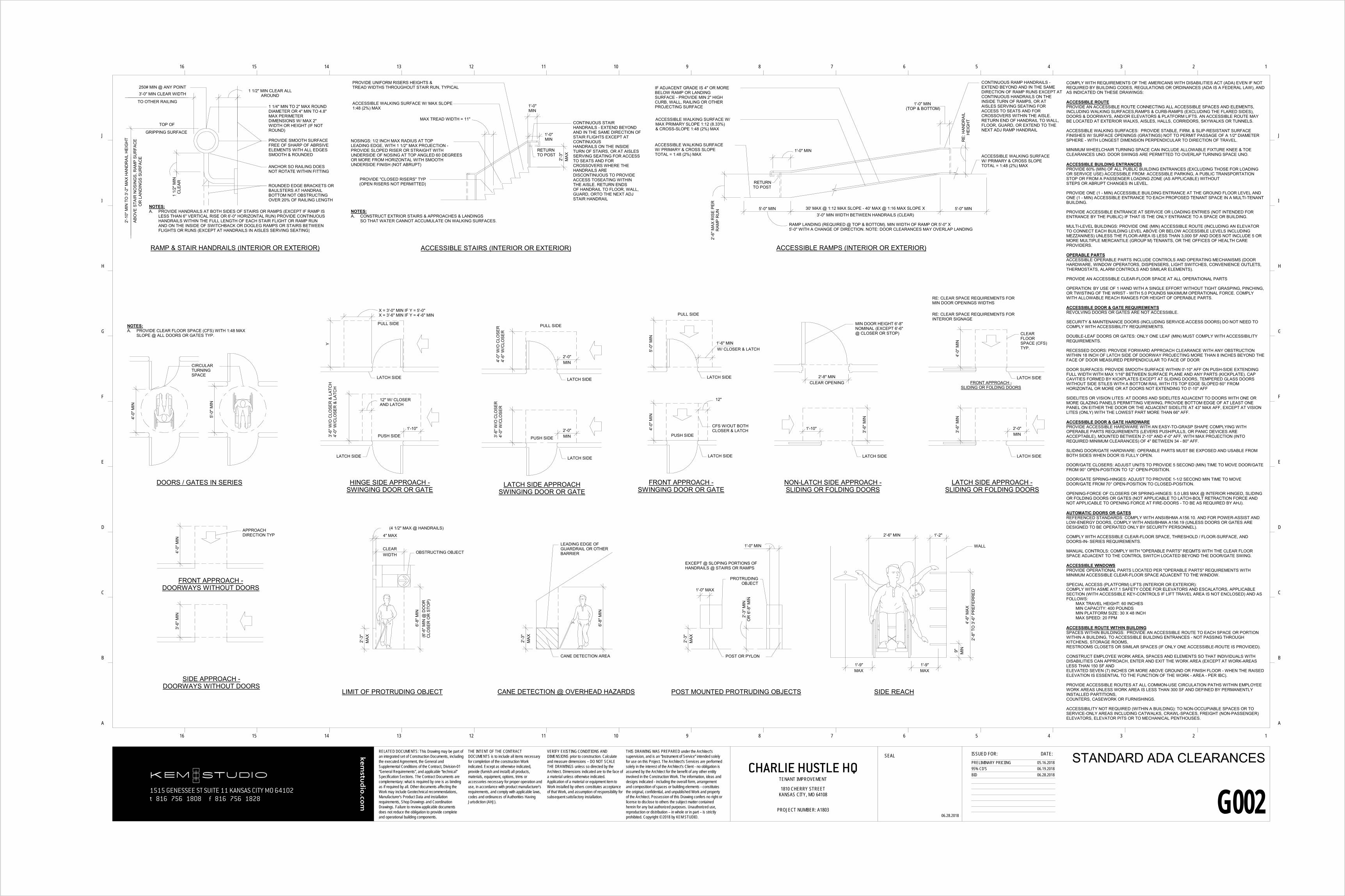
PROVIDE SMOOTH SURFACEFREE OF SHARP OF ABRSIVEELEMENTS WITH ALL EDGESSMOOTH & ROUNDED
ANCHOR SO RAILING DOESNOT ROTATE WITHIN FITTING
ROUNDED EDGE BRACKETS ORBAULSTERS AT HANDRAILBOTTOM NOT OBSTRUCTINGOVER 20% OF RAILING LENGTH
NOTES:A. PROVIDE HANDRAILS AT BOTH SIDES OF STAIRS OR RAMPS (EXCEPT IF RAMP IS
LESS THAN 6" VERTICAL RISE OR 6'-0" HORIZONTAL RUN) PROVIDE CONTINUOUSHANDRAILS WITHIN THE FULL LENGTH OF EACH STAIR FLIGHT OR RAMP RUNAND ON THE INSIDE OF SWITCHBACK OR DOGLEG RAMPS OR STAIRS BETWEENFLIGHTS OR RUNS (EXCEPT AT HANDRAILS IN AISLES SERVING SEATING)
RAMP & STAIR HANDRAILS (INTERIOR OR EXTERIOR)
GRIPPING SURFACE
TOP OF
TO OTHER RAILING
3'-0" MIN CLEAR WIDTH
1 1/4" MIN TO 2" MAX ROUNDDIAMETER OR 4" MIN TO 4.8"MAX PERIMETERDIMENSIONS W/ MAX 2"WIDTH OR HEIGHT (IF NOTROUND)
OR
LAN
DIN
GS
SUR
FAC
E
2'-1
0" M
IN T
O 3
'-2" M
AX H
AND
RAI
L H
EIG
HT
ABO
VE S
TAIR
NO
SIN
GS,
RAM
P SU
RFA
CE
1 1/2" MIN CLEAR ALLAROUND
RE:
HAN
DR
AIL
HEI
GH
T
5'-0" MIN30' MAX @ 1:12 MAX SLOPE - 40' MAX @ 1:16 MAX SLOPE X3'-0" MIN WIDTH BETWEEN HANDRAILS (CLEAR)
5'-0" MIN
1'-0" MIN(TOP & BOTTOM)
RETURNTO POST
CONTINUOUS RAMP HANDRAILS -EXTEND BEYOND AND IN THE SAMEDIRECTION OF RAMP RUNS EXCEPT ATCONTINUOUS HANDRAILS ON THEINSIDE TURN OF RAMPS, OR ATAISLES SERVING SEATING FORACCESS TO SEATS AND FORCROSSOVERS WITHIN THE AISLE.RETURN END OF HANDRAIL TO WALL,FLOOR, GUARD, OR EXTEND TO THENEXT ADJ RAMP HANDRAIL
IF ADJACENT GRADE IS 4" OR MOREBELOW RAMP OR LANDINGSURFACE - PROVIDE MIN 2" HIGHCURB, WALL, RAILING OR OTHERPROJECTING SURFACE
PROVIDE "CLOSED RISERS" TYP(OPEN RISERS NOT PERMITTED)
NOSINGS: 1/2 INCH MAX RADIUS AT TOP LEADING EDGE, WITH 1 1/2" MAX PROJECTION -PROVIDE SLOPED RISER OR STRAIGHT WITH UNDERSIDE OF NOSING AT TOP ANGLED 60 DEGREES OR MORE FROM HORIZONTAL WITH SMOOTH UNDERSIDE FINISH (NOT ABRUPT)
MAX TREAD WIDTH = 11"
ACCESSIBLE WALKING SURFACE W/ MAX SLOPE 1:48 (2%) MAX
PROVIDE UNIFORM RISERS HEIGHTS & TREAD WIDTHS THROUGHOUT STAIR RUN, TYPICAL
SO THAT WATER CANNOT ACCUMULATE ON WALKING SURFACES.
CONTINUOUS STAIR HANDRAILS - EXTEND BEYOND AND IN THE SAME DIRECTION OF STAIR FLIGHTS EXCEPT AT CONTINUOUSHANDRAILS ON THE INSIDE TURN OF STAIRS, OR AT AISLES SERVING SEATING FOR ACCESS TO SEATS AND FOR CROSSOVERS WHERE THE HANDRAILS ARE DISCONTINUOUS TO PROVIDE ACCESS TOSEATING WITHIN THE AISLE. RETURN ENDSOF HANDRAIL TO FLOOR, WALL, GUARD, ORTO THE NEXT ADJ STAIR HANDRAIL
ACCESSIBLE STAIRS (INTERIOR OR EXTERIOR)
5'-0
" MIN
4'-0
" MIN
CIRCULARTURNING SPACE
DOORS / GATES IN SERIES
NOTES:A. PROVIDE CLEAR FLOOR SPACE (CFS) WITH 1:48 MAX
SLOPE @ ALL DOORS OR GATES TYP.
1'-10"
Y3'
-6" W
/O C
LOSE
R &
LAT
CH
4'-0
" W/C
LOSE
R &
LAT
CH
LATCH SIDE
HINGE SIDE APPROACH -SWINGING DOOR OR GATE
PUSH SIDE
PULL SIDE
X = 3'-0" MIN IF Y = 5'-0"X = 3'-6" MIN IF Y = 4'-6" MIN
12" W/ CLOSERAND LATCH
LATCH SIDE
2'-0"MIN
2'-0"MIN
LATCH SIDE
3'-6
" W/O
CLO
SER
4'-0
" W/C
LOSE
R4'
-0" W
/O C
LOSE
R4'
-6" W
/CLO
SER
PUSH SIDE
PULL SIDE
LATCH SIDE APPROACHSWINGING DOOR OR GATE
LATCH SIDE
4'-0
" MIN
1'-6" MIN
5'-0
" MIN
LATCH SIDE
PUSH SIDE
FRONT APPROACH -SWINGING DOOR OR GATE
W/ CLOSER & LATCH
PULL SIDE
CFS W/OUT BOTHCLOSER & LATCH
LATCH SIDE
12"
2'-8" MINCLEAR OPENING
1'-10"
3'-6
" MIN
MIN DOOR HEIGHT 6'-8"NOMINAL (EXCEPT 6'-6"@ CLOSER OR STOP)
LATCH SIDE
NON-LATCH SIDE APPROACH -SLIDING OR FOLDING DOORS
3'-6
" MIN
2'-0"MIN
4'-0
" MIN
LATCH SIDE
LATCH SIDE
LATCH SIDE APPROACH -SLIDING OR FOLDING DOORS
FRONT APPROACH -SLIDING OR FOLDING DOORS
CLEARFLOORSPACE (CFS)TYP.
RE: CLEAR SPACE REQUIREMENTS FOR INTERIOR SIGNAGE
RE: CLEAR SPACE REQUIREMENTS FOR MIN DOOR OPENINGS WIDTHS
3'-6
" MIN
4'-0
" MIN
APPROACHDIRECTION TYP
SIDE APPROACH -DOORWAYS WITHOUT DOORS
FRONT APPROACH -DOORWAYS WITHOUT DOORS
COMPLY WITH REQUIREMENTS OF THE AMERICANS WITH DISABILITIES ACT (ADA) EVEN IF NOT REQUIRED BY BUILDING CODES, REGULATIONS OR ORDINANCES (ADA IS A FEDERAL LAW), AND AS INDICATED ON THESE DRAWINGS:
ACCESSIBLE ROUTEPROVIDE AN ACCESSIBLE ROUTE CONNECTING ALL ACCESSIBLE SPACES AND ELEMENTS, INCLUDING WALKING SURFACES,RAMPS & CURB-RAMPS (EXCLUDING THE FLARED SIDES), DOORS & DOORWAYS, AND/OR ELEVATORS & PLATFORM LIFTS. AN ACCESSIBLE ROUTE MAY BE LOCATED AT EXTERIOR WALKS, AISLES, HALLS, CORRIDORS, SKYWALKS OR TUNNELS.
ACCESSIBLE WALKING SURFACES: PROVIDE STABLE, FIRM, & SLIP-RESISTANT SURFACE FINISHES W/ SURFACE OPENINGS (GRATINGS) NOT TO PERMIT PASSAGE OF A 1/2" DIAMETER SPHERE - WITH LONGEST DIMENSION PERPENDICULAR TO DIRECTION OF TRAVEL.
MINIMUM WHEELCHAIR TURNING SPACE CAN INCLUDE ALLOWABLE FIXTURE KNEE & TOE CLEARANCES UNO. DOOR SWINGS ARE PERMITTED TO OVERLAP TURNING SPACE UNO.
ACCESSIBLE BUILDING ENTRANCESPROVIDE 60% (MIN) OF ALL PUBLIC BUILDING ENTRANCES (EXCLUDING THOSE FOR LOADING OR SERVICE USE) ACCESSIBLE FROM: ACCESSIBLE PARKING, A PUBLIC TRANSPORTATION STOP OR FROM A PASSENGER LOADING ZONE (AS APPLICABLE) WITHOUTSTEPS OR ABRUPT CHANGES IN LEVEL.
PROVIDE ONE (1 - MIN) ACCESSIBLE BUILDING ENTRANCE AT THE GROUND FLOOR LEVEL AND ONE (1 - MIN) ACCESSIBLE ENTRANCE TO EACH PROPOSED TENANT SPACE IN A MULTI-TENANT BUILDING.
PROVIDE ACCESSIBLE ENTRANCE AT SERVICE OR LOADING ENTRIES (NOT INTENDED FOR ENTRANCE BY THE PUBLIC) IF THAT IS THE ONLY ENTRANCE TO A SPACE OR BUILDING.
MULTI-LEVEL BUILDINGS: PROVIDE ONE (MIN) ACCESSIBLE ROUTE (INCLUDING AN ELEVATOR TO CONNECT EACH BUILDING LEVEL ABOVE OR BELOW ACCESSIBLE LEVELS INCLUDING MEZZANINES) UNLESS THE FLOOR-AREA IS LESS THAN 3,000 SF AND DOES NOT INCLUDE 5 OR MORE MULTIPLE MERCANTILE (GROUP M) TENANTS, OR THE OFFICES OF HEALTH CARE PROVIDERS.
OPERABLE PARTSACCESSIBLE OPERABLE PARTS INCLUDE CONTROLS AND OPERATING MECHANISMS (DOOR HARDWARE, WINDOW OPERATORS, DISPENSERS, LIGHT SWITCHES, CONVENIENCE OUTLETS, THERMOSTATS, ALARM CONTROLS AND SIMILAR ELEMENTS).
PROVIDE AN ACCESSIBLE CLEAR-FLOOR SPACE AT ALL OPERATIONAL PARTS
OPERATION: BY USE OF 1 HAND WITH A SINGLE EFFORT WITHOUT TIGHT GRASPING, PINCHING, OR TWISTING OF THE WRIST - WITH 5.0 POUNDS MAXIMUM OPERATIONAL FORCE. COMPLY WITH ALLOWABLE REACH RANGES FOR HEIGHT OF OPERABLE PARTS.
ACCESSIBLE DOOR & GATE REQUIREMENTSREVOLVING DOORS OR GATES ARE NOT ACCESSIBLE.
SECURITY & MAINTENANCE DOORS (INCLUDING SERVICE-ACCESS DOORS) DO NOT NEED TO COMPLY WITH ACCESSIBILITY REQUIREMENTS.
DOUBLE-LEAF DOORS OR GATES: ONLY ONE LEAF (MIN) MUST COMPLY WITH ACCESSIBILITY REQUIREMENTS.
RECESSED DOORS: PROVIDE FORWARD APPROACH CLEARANCE WITH ANY OBSTRUCTION WITHIN 18 INCH OF LATCH SIDE OF DOORWAY PROJECTING MORE THAN 8 INCHES BEYOND THE FACE OF DOOR MEASURED PERPENDICULAR TO FACE OF DOOR
DOOR SURFACES: PROVIDE SMOOTH SURFACE WITHIN 0'-10" AFF ON PUSH-SIDE EXTENDING FULL WIDTH WITH MAX 1/16" BETWEEN SURFACE PLANE AND ANY PARTS (KICKPLATE). CAP CAVITIES FORMED BY KICKPLATES EXCEPT AT SLIDING DOORS, TEMPERED GLASS DOORS WITHOUT SIDE STILES WITH A BOTTOM RAIL WITH ITS TOP EDGE SLOPED 60° FROM HORIZONTAL OR MORE OR AT DOORS NOT EXTENDING TO 0'-10" AFF
SIDELITES OR VISION LITES: AT DOORS AND SIDELITES ADJACENT TO DOORS WITH ONE OR MORE GLAZING PANELS PERMITTING VIEWING, PROVIDE BOTTOM EDGE OF AT LEAST ONE PANEL ON EITHER THE DOOR OR THE ADJACENT SIDELITE AT 43" MAX AFF, EXCEPT AT VISION LITES (ONLY) WITH THE LOWEST PART MORE THAN 66" AFF.
ACCESSIBLE DOOR & GATE HARDWAREPROVIDE ACCESSIBLE HARDWARE WITH AN EASY-TO-GRASP SHAPE COMPLYING WITH OPERABLE PARTS REQUIREMENTS (LEVERS PUSH/PULLS, OR PANIC DEVICES ARE ACCEPTABLE), MOUNTED BETWEEN 2'-10" AND 4'-0" AFF, WITH MAX PROJECTION (INTOREQUIRED MINIMUM CLEARANCES) OF 4" BETWEEN 34 - 80" AFF.
SLIDING DOOR/GATE HARDWARE: OPERABLE PARTS MUST BE EXPOSED AND USABLE FROM BOTH SIDES WHEN DOOR IS FULLY OPEN.
DOOR/GATE CLOSERS: ADJUST UNITS TO PROVIDE 5 SECOND (MIN) TIME TO MOVE DOOR/GATE FROM 90° OPEN-POSITION TO 12° OPEN-POSITION.
DOOR/GATE SPRING-HINGES: ADJUST TO PROVIDE 1-1/2 SECOND MIN TIME TO MOVE DOOR/GATE FROM 70° OPEN-POSITION TO CLOSED-POSITION.
OPENING-FORCE OF CLOSERS OR SPRING-HINGES: 5.0 LBS MAX @ INTERIOR HINGED, SLIDING OR FOLDING DOORS OR GATES (NOT APPLICABLE TO LATCH-BOLT RETRACTION FORCE AND NOT APPLICABLE TO OPENING FORCE AT FIRE-DOORS - TO BE AS REQUIRED BY AHJ).
AUTOMATIC DOORS OR GATESREFERENCED STANDARDS: COMPLY WITH ANSI/BHMA A156.10. AND FOR POWER-ASSIST AND LOW-ENERGY DOORS, COMPLY WITH ANSI/BHMA A156.19 (UNLESS DOORS OR GATES ARE DESIGNED TO BE OPERATED ONLY BY SECURITY PERSONNEL).
COMPLY WITH ACCESSIBLE CLEAR-FLOOR SPACE, THRESHOLD / FLOOR-SURFACE, AND DOORS-IN- SERIES REQUIREMENTS.
MANUAL CONTROLS: COMPLY WITH "OPERABLE PARTS" REQMTS WITH THE CLEAR FLOOR SPACE ADJACENT TO THE CONTROL SWITCH LOCATED BEYOND THE DOOR/GATE SWING.
ACCESSIBLE WINDOWSPROVIDE OPERATIONAL PARTS LOCATED PER "OPERABLE PARTS" REQUIREMENTS WITH MINIMUM ACCESSIBLE CLEAR-FLOOR SPACE ADJACENT TO THE WINDOW.
SPECIAL ACCESS (PLATFORM) LIFTS (INTERIOR OR EXTERIOR):COMPLY WITH ASME A17.1 SAFETY CODE FOR ELEVATORS AND ESCALATORS, APPLICABLE SECTION (WITH ACCESSIBLE KEY-CONTROLS IF LIFT TRAVEL AREA IS NOT ENCLOSED) AND AS FOLLOWS:
MAX TRAVEL HEIGHT: 60 INCHESMIN CAPACITY: 400 POUNDSMIN PLATFORM SIZE: 30 X 48 INCHMAX SPEED: 20 FPM
ACCESSIBLE ROUTE WITHIN BUILDINGSPACES WITHIN BUILDINGS: PROVIDE AN ACCESSIBLE ROUTE TO EACH SPACE OR PORTION WITHIN A BUILDING, TO ACCESSIBLE BUILDING ENTRANCES - NOT PASSING THROUGH KITCHENS, STORAGE ROOMS,RESTROOMS CLOSETS OR SIMILAR SPACES (IF ONLY ONE ACCESSIBLE-ROUTE IS PROVIDED).
CONSTRUCT EMPLOYEE WORK AREA, SPACES AND ELEMENTS SO THAT INDIVIDUALS WITH DISABILITIES CAN APPROACH, ENTER AND EXIT THE WORK AREA (EXCEPT AT WORK-AREAS LESS THAN 150 SF ANDELEVATED SEVEN (7) INCHES OR MORE ABOVE GROUND OR FINISH FLOOR - WHEN THE RAISED ELEVATION IS ESSENTIAL TO THE FUNCTION OF THE WORK - AREA - PER IBC).
PROVIDE ACCESSIBLE ROUTES AT ALL COMMON-USE CIRCULATION PATHS WITHIN EMPLOYEE WORK AREAS UNLESS WORK AREA IS LESS THAN 300 SF AND DEFINED BY PERMANENTLY INSTALLED PARTITIONS,COUNTERS, CASEWORK OR FURNISHINGS.
ACCESSIBILITY NOT REQUIRED (WITHIN A BUILDING): TO NON-OCCUPIABLE SPACES OR TO SERVICE-ONLY AREAS INCLUDING CATWALKS, CRAWL-SPACES, FREIGHT (NON-PASSENGER) ELEVATORS, ELEVATOR PITS OR TO MECHANICAL PENTHOUSES.
CLEARWIDTH
6'-8
" MIN
4" MAX
2'-3
"M
AX (6'-6
" MIN
@ D
OO
RC
LOSE
R O
R S
TOP)
(4 1/2" MAX @ HANDRAILS)
OBSTRUCTING OBJECT
LIMIT OF PROTRUDING OBJECT
2'-3
"M
AX
6'-8
" MIN
LEADING EDGE OFGUARDRAIL OR OTHERBARRIER
CANE DETECTION @ OVERHEAD HAZARDS
CANE DETECTION AREA
1'-0" MAX
2'-3
" MIN
OR
6'-8
" MIN
1'-0" MIN
2'-3
"M
AX
PROTRUDINGOBJECT
EXCEPT @ SLOPING PORTIONS OF HANDRAILS @ STAIRS OR RAMPS
POST OR PYLON
POST MOUNTED PROTRUDING OBJECTS
4'-6
" MAX
2'-8
" TO
3'-6
" PR
EFER
RED
1'-9"MAX
2'-6" MIN
9" MIN
1'-9"MAX
1'-2"
WALL
SIDE REACH
1515 GENESSEE ST SUITE 11 KANSAS CITY MO 64102t 816 756 1808 f 816 756 1828
kemstu
dio.co
m
RELATED DOCUMENTS: This Drawing may be part of an integrated set of Construction Documents, including the executed Agreement, the General and Supplemental Conditions of the Contract, Division-01 “General Requirements”, and applicable “technical” Specification Sections. The Contract Documents are complementary: what is required by one is as binding as if required by all. Other documents affecting the Work may include Geotechnical recommendations, Manufacturer’s Product Data and installation requirements, Shop Drawings and Coordination Drawings. Failure to review applicable documents does not reduce the obligation to provide complete and operational building components.
SEAL ISSUED FOR: DATE:
16 15 14 13 12 11 10 9 8 7 6 5 4 3 2 1
16 15 14 13 12 11 10 9 8 7 6 5 4 3 2 1
A
B
C
D
E
F
G
H
I
J
A
B
C
D
E
F
G
H
I
J
THE INTENT OF THE CONTRACT DOCUMENTS is to include all items necessary for completion of the construction Work indicated. Except as otherwise indicated, provide (furnish and install) all products, materials, equipment, options, trims or accessories necessary for proper operation and use, in accordance with product manufacturer’s requirements, and comply with applicable laws, codes and ordinances of Authorities Having Jurisdiction (AHJ).
VERIFY EXISTING CONDITIONS AND DIMENSIONS prior to construction. Calculate and measure dimensions – DO NOT SCALE THE DRAWINGS unless so directed by the Architect. Dimensions indicated are to the face of a material unless otherwise indicated. Application of a material or equipment item to Work installed by others constitutes acceptance of that Work, and assumption of responsibility for subsequent satisfactory installation.
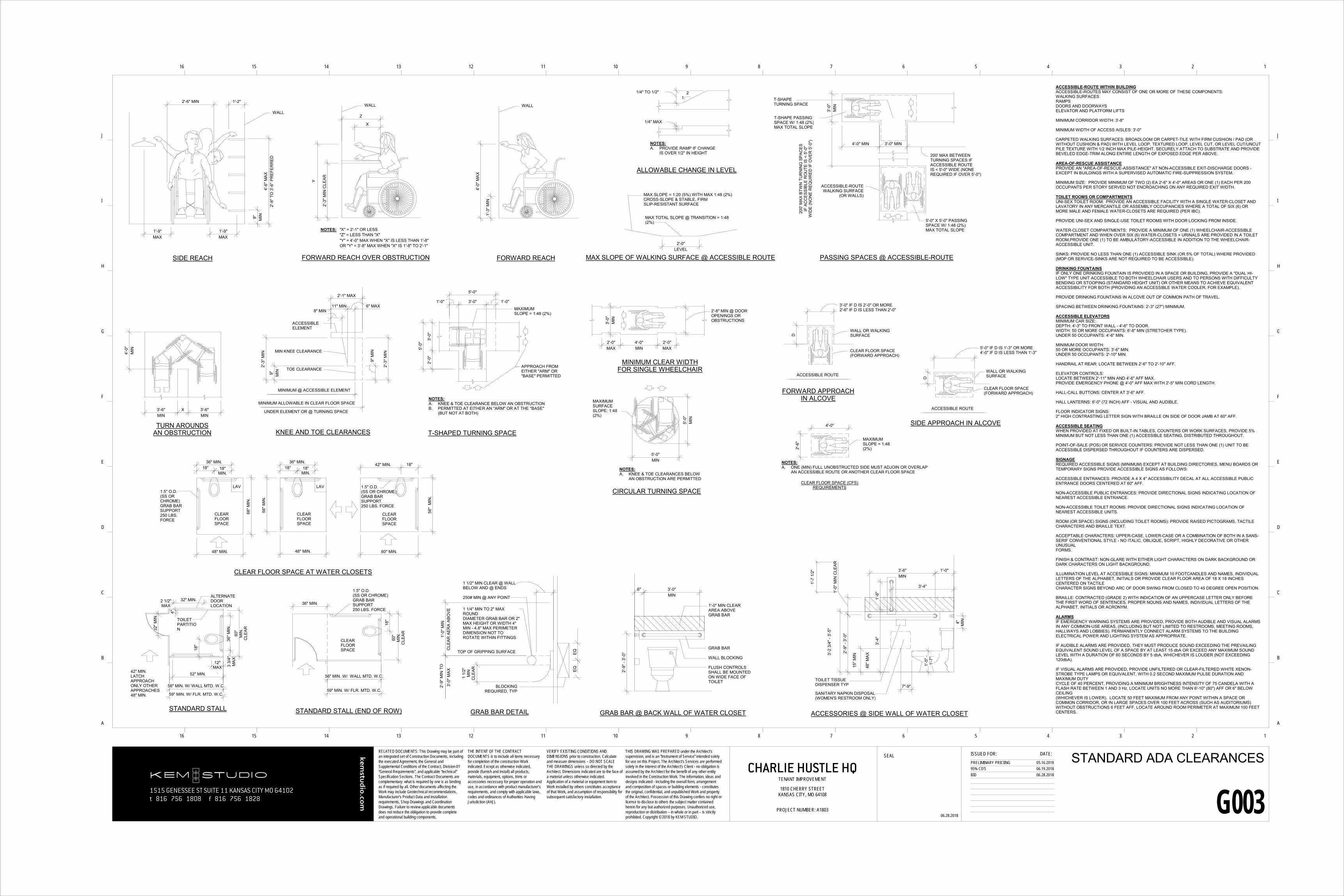
ACCESSIBLE-ROUTE WITHIN BUILDINGACCESSIBLE-ROUTES MAY CONSIST OF ONE OR MORE OF THESE COMPONENTS:WALKING SURFACESRAMPSDOORS AND DOORWAYSELEVATOR AND PLATFORM LIFTS
MINIMUM CORRIDOR WIDTH: 3'-8"
MINIMUM WIDTH OF ACCESS AISLES: 3'-0"
CARPETED WALKING SURFACES: BROADLOOM OR CARPET-TILE WITH FIRM CUSHION / PAD (OR WITHOUT CUSHION & PAD) WITH LEVEL LOOP, TEXTURED LOOP, LEVEL CUT, OR LEVEL CUT/UNCUT PILE TEXTURE WITH 1/2 INCH MAX PILE-HEIGHT. SECURELY ATTACH TO SUBSTRATE AND PROVIDE BEVELED EDGE-TRIM ALONG ENTIRE LENGTH OF EXPOSED EDGE PER ABOVE.
AREA-OF-RESCUE ASSISTANCEPROVIDE AN "AREA-OF-RESCUE-ASSISTANCE" AT NON-ACCESSIBLE EXIT-DISCHARGE DOORS -EXCEPT IN BUILDINGS WITH A SUPERVISED AUTOMATIC FIRE-SUPPRESSION SYSTEM.
MINIMUM SIZE: PROVIDE MINIMUM OF TWO (2) EA 2'-6" X 4'-0" AREAS OR ONE (1) EACH PER 200 OCCUPANTS PER STORY SERVED NOT ENCROACHING ON ANY REQUIRED EXIT WIDTH.
TOILET ROOMS OR COMPARTMENTSUNI-SEX TOILET ROOM: PROVIDE AN ACCESSIBLE FACILITY WITH A SINGLE WATER-CLOSET AND LAVATORY IN ANY MERCANTILE OR ASSEMBLY OCCUPANCIES WHERE A TOTAL OF SIX (6) OR MORE MALE AND FEMALE WATER-CLOSETS ARE REQUIRED (PER IBC).
PROVIDE UNI-SEX AND SINGLE-USE TOILET ROOMS WITH DOOR LOCKING FROM INSIDE.
WATER-CLOSET COMPARTMENTS: PROVIDE A MINIMUM OF ONE (1) WHEELCHAIR-ACCESSIBLE COMPARTMENT AND WHEN OVER SIX (6) WATER-CLOSETS + URINALS ARE PROVIDED IN A TOILET ROOM,PROVIDE ONE (1) TO BE AMBULATORY-ACCESSIBLE IN ADDITION TO THE WHEELCHAIR-ACCESSIBLE UNIT.
SINKS: PROVIDE NO LESS THAN ONE (1) ACCESSIBLE SINK (OR 5% OF TOTAL) WHERE PROVIDED (MOP OR SERVICE-SINKS ARE NOT REQUIRED TO BE ACCESSIBLE).
DRINKING FOUNTAINSIF ONLY ONE DRINKING FOUNTAIN IS PROVIDED IN A SPACE OR BUILDING, PROVIDE A "DUAL HI-LOW" TYPE UNIT ACCESSIBLE TO BOTH WHEELCHAIR USERS AND TO PERSONS WITH DIFFICULTY BENDING OR STOOPING (STANDARD HEIGHT UNIT) OR OTHER MEANS TO ACHIEVE EQUIVALENT ACCESSIBILITY FOR BOTH (PROVIDING AN ACCESSIBLE WATER COOLER, FOR EXAMPLE).
PROVIDE DRINKING FOUNTAINS IN ALCOVE OUT OF COMMON PATH OF TRAVEL.
SPACING BETWEEN DRINKING FOUNTAINS: 2'-3" (27") MINIMUM.
ACCESSIBLE ELEVATORSMINIMUM CAR SIZE: DEPTH: 4'-3" TO FRONT WALL - 4'-6" TO DOOR.WIDTH: 50 OR MORE OCCUPANTS: 6'-8" MIN (STRETCHER TYPE).UNDER 50 OCCUPANTS: 4'-6" MIN.
MINIMUM DOOR WIDTH:50 OR MORE OCCUPANTS: 3'-6" MIN.UNDER 50 OCCUPANTS: 2'-10" MIN.
HANDRAIL AT REAR: LOCATE BETWEEN 2'-6" TO 2'-10" AFF.
ELEVATOR CONTROLS:LOCATE BETWEEN 2'-11" MIN AND 4'-6" AFF MAX.PROVIDE EMERGENCY PHONE @ 4'-0" AFF MAX WITH 2'-5" MIN CORD LENGTH.
HALL-CALL BUTTONS: CENTER AT 3'-6" AFF.
HALL LANTERNS: 6'-0" (72 INCH) AFF - VISUAL AND AUDIBLE.
FLOOR INDICATOR SIGNS: 2" HIGH CONTRASTING LETTER SIGN WITH BRAILLE ON SIDE OF DOOR JAMB AT 60" AFF.
ACCESSIBLE SEATINGWHEN PROVIDED AT FIXED OR BUILT-IN TABLES, COUNTERS OR WORK SURFACES, PROVIDE 5% MINIMUM BUT NOT LESS THAN ONE (1) ACCESSIBLE SEATING, DISTRIBUTED THROUGHOUT.
POINT-OF-SALE (POS) OR SERVICE COUNTERS: PROVIDE NOT LESS THAN ONE (1) UNIT TO BE ACCESSIBLE DISPERSED THROUGHOUT IF COUNTERS ARE DISPERSED.
SIGNAGEREQUIRED ACCESSIBLE SIGNS (MINIMUM) EXCEPT AT BUILDING DIRECTORIES, MENU BOARDS OR TEMPORARY SIGNS PROVIDE ACCESSIBLE SIGNS AS FOLLOWS:
ACCESSIBLE ENTRANCES: PROVIDE A 4 X 4" ACCESSIBILITY DECAL AT ALL ACCESSIBLE PUBLIC ENTRANCE DOORS CENTERED AT 60" AFF.
NON-ACCESSIBLE PUBLIC ENTRANCES: PROVIDE DIRECTIONAL SIGNS INDICATING LOCATION OF NEAREST ACCESSIBLE ENTRANCE.
NON-ACCESSIBLE TOILET ROOMS: PROVIDE DIRECTIONAL SIGNS INDICATING LOCATION OF NEAREST ACCESSIBLE UNITS.
ROOM (OR SPACE) SIGNS (INCLUDING TOILET ROOMS): PROVIDE RAISED PICTOGRAMS, TACTILE CHARACTERS AND BRAILLE TEXT.
ACCEPTABLE CHARACTERS: UPPER-CASE, LOWER-CASE OR A COMBINATION OF BOTH IN A SANS-SERIF CONVENTIONAL STYLE - NO ITALIC, OBLIQUE, SCRIPT, HIGHLY DECORATIVE OR OTHER UNUSUALFORMS.
FINISH & CONTRAST: NON-GLARE WITH EITHER LIGHT CHARACTERS ON DARK BACKGROUND OR DARK CHARACTERS ON LIGHT BACKGROUND.
ILLUMINATION LEVEL AT ACCESSIBLE SIGNS: MINIMUM 10 FOOTCANDLES AND NAMES, INDIVIDUAL LETTERS OF THE ALPHABET, INITIALS OR PROVIDE CLEAR FLOOR AREA OF 18 X 18 INCHES CENTERED ON TACTILECHARACTER SIGNS BEYOND ARC OF DOOR SWING FROM CLOSED TO 45 DEGREE OPEN POSITION.
BRAILLE: CONTRACTED (GRADE 2) WITH INDICATION OF AN UPPERCASE LETTER ONLY BEFORE THE FIRST WORD OF SENTENCES, PROPER NOUNS AND NAMES, INDIVIDUAL LETTERS OF THE ALPHABET, INITIALS OR ACRONYM.
ALARMSIF EMERGENCY WARNING SYSTEMS ARE PROVIDED, PROVIDE BOTH AUDIBLE AND VISUAL ALARMS IN ANY COMMON-USE AREAS, (INCLUDING BUT NOT LIMITED TO RESTROOMS, MEETING ROOMS, HALLWAYS AND LOBBIES). PERMANENTLY CONNECT ALARM SYSTEMS TO THE BUILDING ELECTRICAL POWER AND LIGHTING SYSTEM AS APPROPRIATE.
IF AUDIBLE ALARMS ARE PROVIDED, THEY MUST PRODUCE SOUND EXCEEDING THE PREVAILING EQUIVALENT SOUND LEVEL OF A SPACE BY AT LEAST 15 dbA OR EXCEED ANY MAXIMUM SOUND LEVEL WITH A DURATION OF 60 SECONDS BY 5 dbA, WHICHEVER IS LOUDER (NOT EXCEEDING 120dbA).
IF VISUAL ALARMS ARE PROVIDED, PROVIDE UNFILTERED OR CLEAR-FILTERED WHITE XENON-STROBE TYPE LAMPS OR EQUIVALENT, WITH 0.2 SECOND MAXIMUM PULSE DURATION AND MAXIMUM DUTYCYCLE OF 40 PERCENT, PROVIDING A MINIMUM BRIGHTNESS INTENSITY OF 75 CANDELA WITH A FLASH RATE BETWEEN 1 AND 3 Hz. LOCATE UNITS NO MORE THAN 6'-10" (80") AFF OR 6" BELOW CEILING(WHICHEVER IS LOWER). LOCATE 50 FEET MAXIMUM FROM ANY POINT WITHIN A SPACE OR COMMON CORRIDOR, OR IN LARGE SPACES OVER 100 FEET ACROSS (SUCH AS AUDITORIUMS) WITHOUT OBSTRUCTIONS 6 FEET AFF, LOCATE AROUND ROOM PERIMETER AT MAXIMUM 100 FEET CENTERS.
4'-6
" MAX
2'-8
" TO
3'-6
" PR
EFER
RED
1'-9"MAX
2'-6" MIN
9" MIN
1'-9"MAX
1'-2"
WALL
SIDE REACH
2'-3
" MIN
CLE
AR
Z
Y
X
WALL
NOTES:"Z" = LESS THAN "X""X" = 2'-1" OR LESS
"Y" = 4'-0" MAX WHEN "X" IS LESS THAN 1'-8"OR "Y" = 3'-8" MAX WHEN "X" IS 1'-8" TO 2'-1"
FORWARD REACH OVER OBSTRUCTION
1'-3
" MIN
4'-0
" MAX
WALL
FORWARD REACH
1/4" TO 1/2"
1/4" MAX
ALLOWABLE CHANGE IN LEVEL
NOTES:A. PROVIDE RAMP IF CHANGE
IS OVER 1/2" IN HEIGHT
21
2'-0"LEVEL
MAX TOTAL SLOPE @ TRANSITION = 1:48(2%)
MAX SLOPE = 1:20 (5%) WITH MAX 1:48 (2%)CROSS-SLOPE & STABLE, FIRMSLIP-RESISTANT SURFACE
MAX SLOPE OF WALKING SURFACE @ ACCESSIBLE ROUTE
3'-0" MIN4'-0" MIN
3'-0
"M
IN
T-SHAPETURNING SPACE
T-SHAPE PASSINGSPACE W/ 1:48 (2%)MAX TOTAL SLOPE
200'
MAX
BTW
N T
UR
NIN
G S
PAC
ESIF
AC
CES
SIBL
E R
OU
TE IS
< 5
'-0"
WID
E (N
ON
E R
EQU
IRED
IF O
VER
5'-0
")
200' MAX BETWEENTURNING SPACES IF ACCESSIBLE ROUTE IS < 5'-0" WIDE (NONEREQUIRED IF OVER 5'-0")
ACCESSIBLE-ROUTEWALKING SURFACE
(OR WALLS)
5'-0" X 5'-0" PASSINGSPACE W/ 1:48 (2%)MAX TOTAL SLOPE
PASSING SPACES @ ACCESSIBLE-ROUTE
4'-0
"M
IN
3'-6"MIN
X 3'-6"MIN
TURN AROUNDSAN OBSTRUCTION
2'-3
" MIN
6" MAX
9" MIN
8" MIN
2'-1" MAX
2'-3
" MIN
9" M
IN
11" MIN
UNDER ELEMENT OR @ TURNING SPACE
MINIMUM ALLOWABLE IN CLEAR FLOOR SPACE
MINIMUM @ ACCESSIBLE ELEMENT
ACCESSIBLEELEMENT
MIN KNEE CLEARANCE
TOE CLEARANCE
KNEE AND TOE CLEARANCES2'
-0"
5'-0"
3'-0
"
5'-0
"
1'-0"3'-0"1'-0"
APPROACH FROMEITHER "ARM" OR"BASE" PERMITTED
MAXIMUMSLOPE = 1:48 (2%)
NOTES:A. KNEE & TOE CLEARANCE BELOW AN OBSTRUCTIONB. PERMITTED AT EITHER AN "ARM" OR AT THE "BASE"
(BUT NOT AT BOTH)
T-SHAPED TURNING SPACE
5'-0"MIN
5'-0
"M
IN
NOTES:A. KNEE & TOE CLEARANCES BELOW
AN OBSTRUCTION ARE PERMITTED
CIRCULAR TURNING SPACE
MAXIMUMSURFACESLOPE: 1:48(2%)
2'-0"MAX
4'-0"MIN
2'-0"MAX
3'-0
"M
IN
2'-8" MIN @ DOOROPENINGS OROBSTRUCTIONS
MINIMUM CLEAR WIDTHFOR SINGLE WHEELCHAIR
D
ACCESSIBLE ROUTE
WALL OR WALKINGSURFACE
CLEAR FLOOR SPACE(FORWARD APPROACH)
3'-0" IF D IS 2'-0" OR MORE2'-6" IF D IS LESS THAN 2'-0"
FORWARD APPROACH IN ALCOVE
D
ACCESSIBLE ROUTE
WALL OR WALKINGSURFACE
CLEAR FLOOR SPACE(FORWARD APPROACH)
5'-0" IF D IS 1'-3" OR MORE4'-0" IF D IS LESS THAN 1'-3"
SIDE APPROACH IN ALCOVE
2'-6
"
4'-0"
NOTES:A. ONE (MIN) FULL UNOBSTRUCTED SIDE MUST ADJOIN OR OVERLAP
AN ACCESSIBLE ROUTE OR ANOTHER CLEAR FLOOR SPACE
CLEAR FLOOR SPACE (CFS)REQUIREMENTS
MAXIMUMSLOPE = 1:48(2%)
1'-0
" MIN
CLE
AR A
ERA
ABO
VE
EQEQ
2'-9
" -3'
-0"
1 1/
2"
MIN
CLE
AR
6" 3'-0"MIN
60"
MIN
.C
LEAR32
" MIN
.
12"MAX
.52" MIN.
56" MIN. W/ WALL MTD. W.C.
59" MIN. W/ FLR. MTD. W.C.
18"
4"
18"
60"
MIN
.C
LEAR
56" MIN. W/ WALL MTD. W.C.
59" MIN. W/ FLR. MTD. W.C.
36" MIN.
48" MIN.
56" M
IN.
66" M
IN.
48" MIN.
36" MIN.18"
MIN.18"
56"
MIN
.
60" MIN.
42" MIN. 18"36" MIN.18"
MIN.18"
3 3/
4"M
AX36
" MIN
.
2 1/2"MAX
32" MIN.
3'-2
3/4
" -3'
-5"
2'-9
" -3'
-0"
7"-9"
1'-5
" -1'
-7"
15" M
IN
48" M
AX
3'-6"MIN
1'-0
" MIN
CLE
AR
1'-0"
4" MIN
3'-4"
1'-6
"3'
-4"
3'-0
" MAX
2'-9
" MIN
TO
TOP OF GRIPPING SURFACE
1 1/2" MIN CLEAR @ WALLBELOW AND @ ENDS
WALL BLOCKING
GRAB BAR @ BACK WALL OF WATER CLOSETGRAB BAR DETAIL
BLOCKINGREQUIRED, TYP
FLUSH CONTROLSSHALL BE MOUNTED ON WIDE FACE OF TOILET
1 1/4" MIN TO 2" MAX ROUNDDIAMETER GRAB BAR OR 2" MAX HEIGHT OR WIDTH 4" MIN - 4.8" MAX PERIMETER DIMENSION NOT TO ROTATE WITHIN FITTINGS
250# MIN @ ANY POINT
1'-0" MIN CLEAR AREA ABOVE GRAB BAR
GRAB BAR
STANDARD STALL
ALTERNATEDOOR LOCATION
42" MIN. LATCHAPPROACH ONLY OTHER APPROACHES48" MIN.
STANDARD STALL (END OF ROW)
CLEARFLOORSPACE
CLEAR FLOOR SPACE AT WATER CLOSETS
CLEARFLOORSPACE
LAV
CLEARFLOORSPACE
CLEARFLOORSPACE
LAV
1.5" O.D.(SS OR CHROME)GRAB BAR SUPPORT250 LBS. FORCE
1.5" O.D.(SS OR CHROME)GRAB BAR SUPPORT250 LBS. FORCE
TOILETPARTITION
1.5" O.D.(SS ORCHROME)GRAB BARSUPPORT250 LBS. FORCE
ACCESSORIES @ SIDE WALL OF WATER CLOSET
TOILET TISSUEDISPENSER TYP
SANITARY NAPKIN DISPOSAL(WOMEN'S RESTROOM ONLY)
1'-7
1/2
"
1515 GENESSEE ST SUITE 11 KANSAS CITY MO 64102t 816 756 1808 f 816 756 1828
kemstu
dio.co
m
RELATED DOCUMENTS: This Drawing may be part of an integrated set of Construction Documents, including the executed Agreement, the General and Supplemental Conditions of the Contract, Division-01 “General Requirements”, and applicable “technical” Specification Sections. The Contract Documents are complementary: what is required by one is as binding as if required by all. Other documents affecting the Work may include Geotechnical recommendations, Manufacturer’s Product Data and installation requirements, Shop Drawings and Coordination Drawings. Failure to review applicable documents does not reduce the obligation to provide complete and operational building components.
SEAL ISSUED FOR: DATE:
16 15 14 13 12 11 10 9 8 7 6 5 4 3 2 1
16 15 14 13 12 11 10 9 8 7 6 5 4 3 2 1
A
B
C
D
E
F
G
H
I
J
A
B
C
D
E
F
G
H
I
J
THE INTENT OF THE CONTRACT DOCUMENTS is to include all items necessary for completion of the construction Work indicated. Except as otherwise indicated, provide (furnish and install) all products, materials, equipment, options, trims or accessories necessary for proper operation and use, in accordance with product manufacturer’s requirements, and comply with applicable laws, codes and ordinances of Authorities Having Jurisdiction (AHJ).
VERIFY EXISTING CONDITIONS AND DIMENSIONS prior to construction. Calculate and measure dimensions – DO NOT SCALE THE DRAWINGS unless so directed by the Architect. Dimensions indicated are to the face of a material unless otherwise indicated. Application of a material or equipment item to Work installed by others constitutes acceptance of that Work, and assumption of responsibility for subsequent satisfactory installation.
GENERAL ACCESSIBLE PLUMBING NOTES:A. WATER CLOSER CONTROLS SHALL BE OPERABLE WITH ONE HAND, AND SHALL NOT REQUIRE
TIGHT GRASPING, PINCHING, OR TWISTING OF THE WRIST.B. CONTROLS FOR FLUSHING OF WATER CLOSETS AND URINALS SHALL BE MOUNTED ON THE WIDEC. SIDE OF THE TOILET AREAS, NO MORE THAN 42" AFF.D. THE FORCE REQUIRED TO ACTIVATE CONTROLS SHALL BE NO GREATER THAN 5 POUNDS.E. IF SELF-CLOSING VALVES ARE USED, THEY SHALL REMAIN OPEN FOR AT LEAST 10 SECONDS.F. FAUCET CONTROLS AND OPERATING MECHANISMS SHALL NOT BE OF THE TYPE REQUIRING
TIGHT.G. INSULATE ALL PLUMBING LINES AND DRAINS AT LAVATORIES.
NOTES:A. GRASPING, PINCHING, OR TWISTING OF THE WRIST
(OPERABLE WITH ONE HAND SUCH AS LEVER-OPERATED)AND AN OPERATING FORCE NOT EXCEEDING 5 POUNDS OF FORCE.
1'-7"MAX
9" MIN
5'-0
"
1'-5"
1'-5
"M
IN
4'-0" MIN CLEAR X 2'-6" WIDITH
3'-4
" MAX
TO R
EFLE
CTI
NG
SU
RFA
CE
2'-1
0" M
AX T
O R
IM
2'-3
" MIN
9" MIN
8"
6" MAX
EQEQ
2'-6" MIN CLEARFLOOR SPACE
6" MAX
4'-0
" MIN
CLE
AR F
LOO
R S
PAC
E
NOT TO EXCEEDFOUNTAIN DEPTH
4'-0"CLEAR FLOOR SPACE2'-6"
MIN
4'-0
"M
IN
3'-2
" MIN
TO
3'-7
" MAX
STAN
DIN
G
2'-9
" MAX
TO
BU
BBLE
R
2'-3
" MIN
8"
4'-0
"M
IN
2'-6"MIN
2'-0"MAX
2'-6
" MIN
C
LEAR
FLO
OR
SP
ACE
8" M
IN
CENTERED IN THE CLEAR
FLOOR SPACE
5'-0
" TYP
.
4'-0
" MIN
-5'
-0" M
AXR
UN
TO
BO
TTO
M O
F TE
XT
1'-5
"M
AX
2'-6" MIN CLEARFLOOR SPACE
3'-8
" MAX
TO
OPE
RAB
LE P
ART
2'-6" CLEAR
EQEQ
1'-2
"M
IN
2'-6
" TO
CL
4'-0
" MAX
TO
HIG
HES
TO
PER
ABLE
PAR
T
WH
ERE
CEI
LIN
G H
EIG
HT
> 30
'-0"
4" -
1'-0
"R
EQU
IRED
4'-6
"M
AX
5'-0
" TO
CL
NO
N-A
CC
ESSI
BLE
4'-0
" TO
CL
MAX
6'-8
" -8'
-0" R
EQU
IRED
TO B
OTT
OM
OF
APPL
IAN
CE
30'-0
"M
AX
3'-7
" M
IN T
O C
L AC
CES
SIBL
E
1'-6
" TO
CL
MIN
1'-7
" TO
DIS
PEN
SER
2'-8
"
2'-9
"
3'-4
" MAX
TO
H
IGH
EST
OPE
RAB
LE P
ART
3'-2
" MIN
TO
OPE
NIN
G4'
-0" M
AX
3'-2
" MIN
4'-0
" MAX
3'-2
" MIN
TO
OPE
NIN
G4'
-0" M
AX
36" M
AX. T
O S
POU
T
27" M
IN. C
LEAR
1'-2"
4'-0
" MIN
CLE
AR F
LOO
R S
PAC
E
PUSH BUTTON, LEVER,AUTOMATIC OR SIMILARCONTROLS WITHIN 6" OF FRONT
TO T
OP
OF
FOLD
-O
UT
TABL
E SU
RFA
CE
2'-1
1" M
AX T
YP T
OR
EFLE
CTI
NG
SU
RFA
CE
3'-4
" AFF
MAX
ABO
VELA
VATO
RY,
SIN
K O
R
CO
UN
TER
ACCESSIBLESTANDARD
CONTROLS: LEVER ACTION, AUTOMATIC, PUSH BUTTON (OR SIMILAR)
INSULATE HOT WATER SUPPLY & DRAIN LINES OR PROTECT W/ REMOVEABLE FRONT PANEL
INTERNATIONAL SYMBOL OF ACCESSIBILITY (ENTER SIDE @ PAIR OF DOORS)
LATCH SIDE
SHADED AREADENOTES KNEE & TOE SPACEREQUIRED
WALL MOUNTED MIRROR
WALL CABINETS IF APPLICABLE
EQUIPMENTPERMITTED INSHADED AREA
TEXT
LATCH SIDE OF DOOR
GRADE 2BRAILLE PLATE
ADA DOOR SIGN W/ RAISEDPICTORIALGRAMSYMBOL
ADA DOOR SIGN WITH RAISED PICTORIALGRAM SYMBOL AND GRADE 2 BRAILLE PLATE
NON-ACCESSIBLEURINAL
ACCESSIBLE URINAL
URINAL SCREEN(OPTIONAL)
1'-6"X1'-6" CLEAR FLOOR SPACE
SWITCHES, TELEPHONE,THERMOSTATS, DOORBELLS, DOOR KNOCKERS, KEY PADS, FIRE ALARM PULL, TYPICAL
LOCATION OF CEILING / WALL MOUNTED
APPLIANCES
FIRE EXTINGUISHER DOOR VIEWERS
AUDIBLE ANDLIGHT ALARMS
TOILET PAPERDISPENSER
RECESSEDTOLIET SEAT
COVER DISPENSER
SWITCHES
RECEPTICALES, PHONE JACKS, & SIMULAR ITEMS, ETC.
PAPER TOWELDISPENSER/DISPOSAL
SANITARY NAPKINDISPENSER
BABY CHANGINGSTATION
ACCESSIBLE MIRROR
TO COIN SLOTSOPERATINGPARTS OR OTHERCEILING
SEAT COVERDISPENSER
SOAP DISPENSERHAND DRYERSANITARY NAPKIN
DISPOSAL UNIT
CENTERLINE OF FIXTURE
C OF FIXTUREL
DRINKING FOUNTAIN - CLEAR FLOOR SPACEBUILT-IN FOUNTAIN OR COOLERFREE-STANDING FOUNTAIN OR COOLERDRINKING FOUNTAIN - SIDE VIEWDRINKING FOUNTAIN - FRONT VIEWPLAN VIEWSIDE VIEW
EXTERIOR DOOR @ ACCESSIBLE ENTRANCE RESTROOM ACCESSIBLE SIGNAGEURINAL - CLEAR FLOOR SPACE PLAN VIEWURINAL - FRONT VIEW
CENTERLINE
1515 GENESSEE ST SUITE 11 KANSAS CITY MO 64102t 816 756 1808 f 816 756 1828
kemstu
dio.co
m
RELATED DOCUMENTS: This Drawing may be part of an integrated set of Construction Documents, including the executed Agreement, the General and Supplemental Conditions of the Contract, Division-01 “General Requirements”, and applicable “technical” Specification Sections. The Contract Documents are complementary: what is required by one is as binding as if required by all. Other documents affecting the Work may include Geotechnical recommendations, Manufacturer’s Product Data and installation requirements, Shop Drawings and Coordination Drawings. Failure to review applicable documents does not reduce the obligation to provide complete and operational building components.
SEAL ISSUED FOR: DATE:
16 15 14 13 12 11 10 9 8 7 6 5 4 3 2 1
16 15 14 13 12 11 10 9 8 7 6 5 4 3 2 1
A
B
C
D
E
F
G
H
I
J
A
B
C
D
E
F
G
H
I
J
THE INTENT OF THE CONTRACT DOCUMENTS is to include all items necessary for completion of the construction Work indicated. Except as otherwise indicated, provide (furnish and install) all products, materials, equipment, options, trims or accessories necessary for proper operation and use, in accordance with product manufacturer’s requirements, and comply with applicable laws, codes and ordinances of Authorities Having Jurisdiction (AHJ).
VERIFY EXISTING CONDITIONS AND DIMENSIONS prior to construction. Calculate and measure dimensions – DO NOT SCALE THE DRAWINGS unless so directed by the Architect. Dimensions indicated are to the face of a material unless otherwise indicated. Application of a material or equipment item to Work installed by others constitutes acceptance of that Work, and assumption of responsibility for subsequent satisfactory installation.
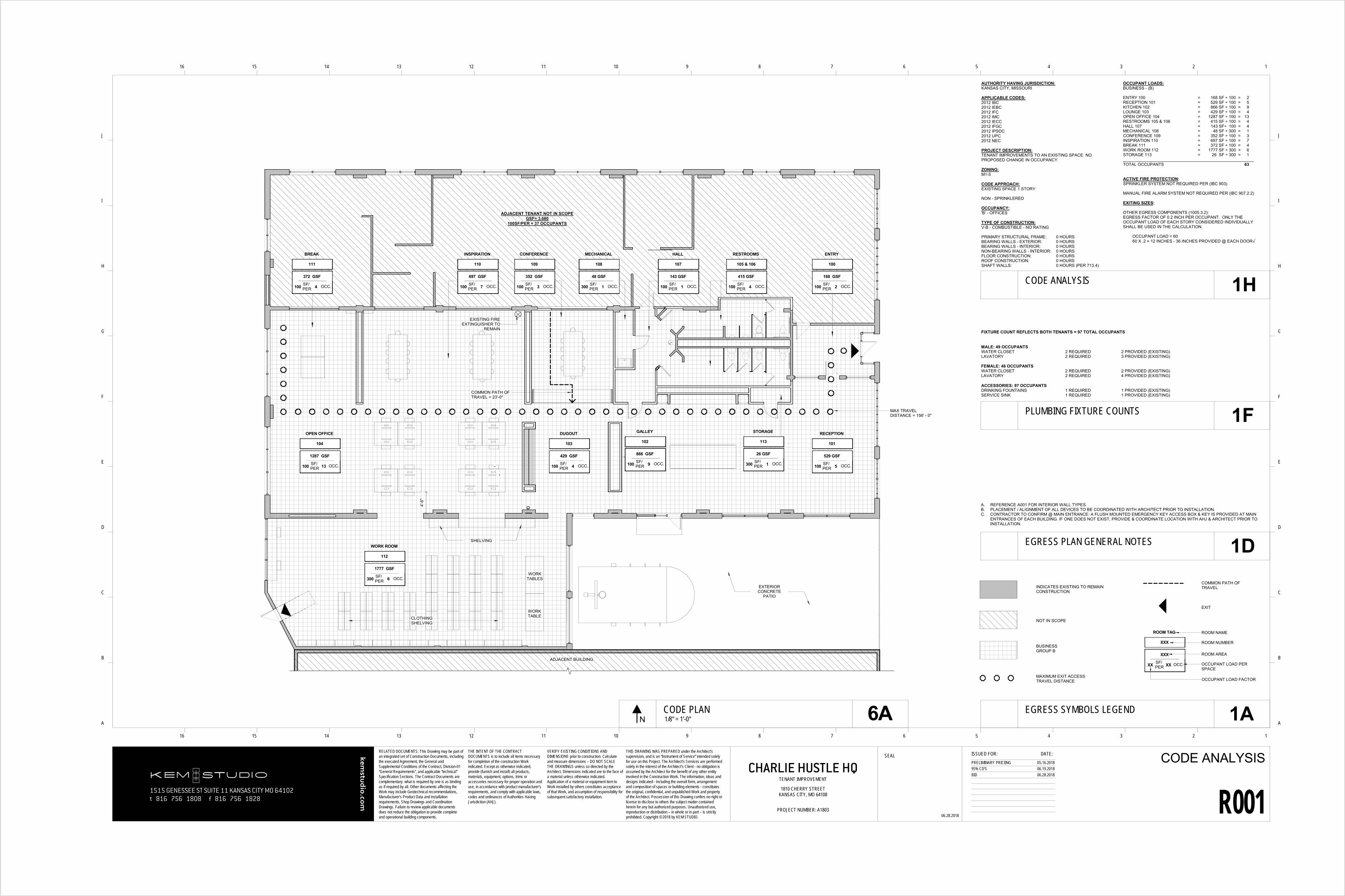
ENTRY 100 = 168 SF ÷ 100 = 2RECEPTION 101 = 529 SF ÷ 100 = 5KITCHEN 102 = 866 SF ÷ 100 = 9LOUNGE 103 = 429 SF ÷ 100 = 4OPEN OFFICE 104 = 1287 SF ÷ 100 = 13RESTROOMS 105 & 106 = 415 SF ÷ 100 = 4HALL 107 = 143 SF÷ 100 = 4MECHANICAL 108 = 48 SF ÷ 300 = 1CONFERENCE 109 = 352 SF ÷ 100 = 3INSPIRATION 110 = 697 SF ÷ 100 = 7BREAK 111 = 372 SF ÷ 100 = 4WORK ROOM 112 = 1777 SF ÷ 300 = 6STORAGE 113 = 26 SF ÷ 300 = 1
TOTAL OCCUPANTS 63
ACTIVE FIRE PROTECTION:SPRINKLER SYSTEM NOT REQUIRED PER (IBC 903)
MANUAL FIRE ALARM SYSTEM NOT REQUIRED PER (IBC 907.2.2)
EXITING SIZES:
OTHER EGRESS COMPONENTS (1005.3.2):EGRESS FACTOR OF 0.2 INCH PER OCCUPANT. ONLY THE OCCUPANT LOAD OF EACH STORY CONSIDERED INDIVIDUALLY SHALL BE USED IN THE CALCULATION.
OCCUPANT LOAD = 6060 X .2 = 12 INCHES - 36 INCHES PROVIDED @ EACH DOOR√
FIXTURE COUNT REFLECTS BOTH TENANTS = 97 TOTAL OCCUPANTS
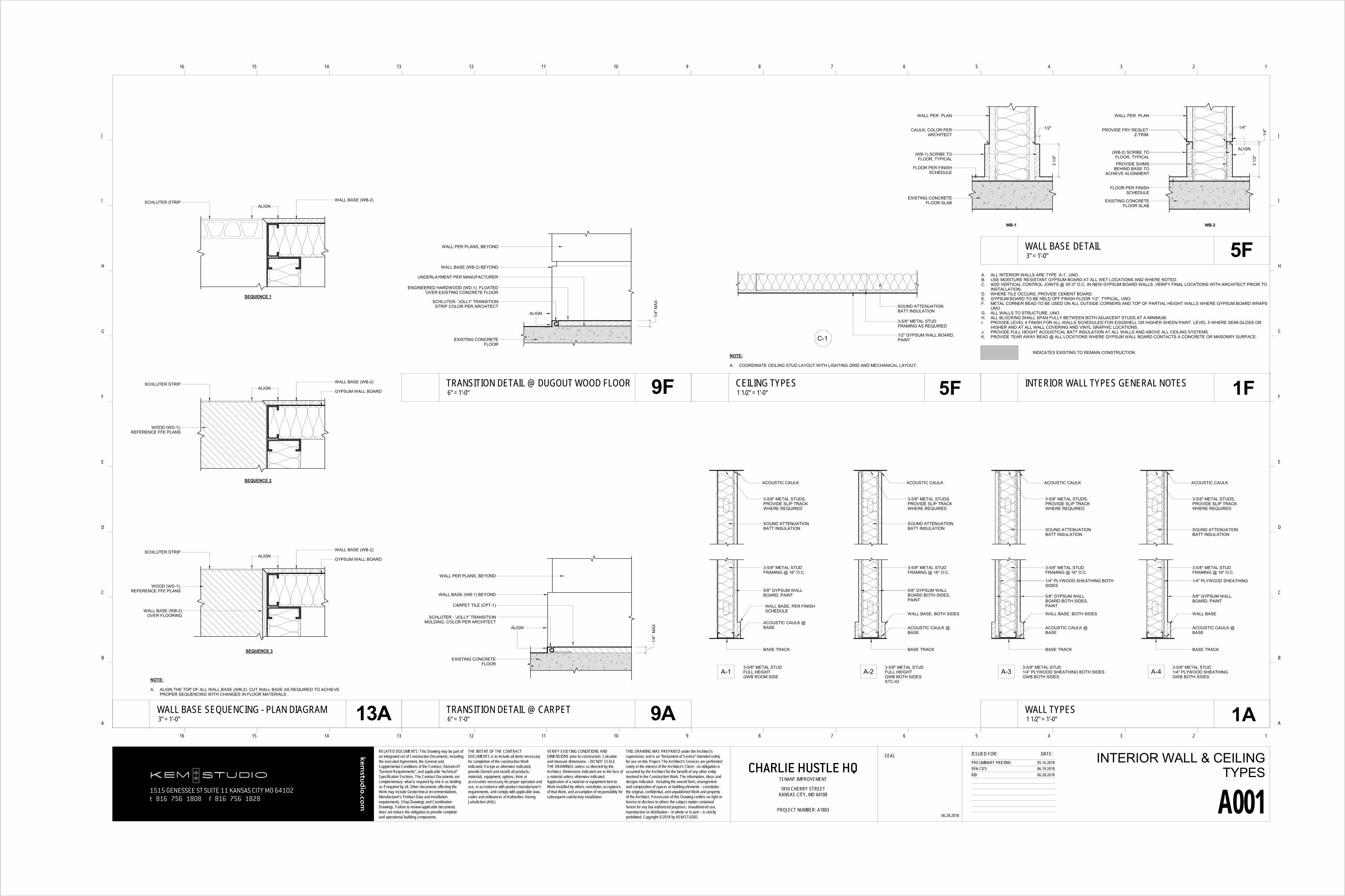
A. REFERENCE A001 FOR INTERIOR WALL TYPES.B. PLACEMENT / ALIGNMENT OF ALL DEVICES TO BE COORDINATED WITH ARCHITECT PRIOR TO INSTALLATION.C. CONTRACTOR TO CONFIRM @ MAIN ENTRANCE: A FLUSH MOUNTED EMERGENCY KEY ACCESS BOX & KEY IS PROVIDED AT MAIN
ENTRANCES OF EACH BUILDING. IF ONE DOES NOT EXIST, PROVIDE & COORDINATE LOCATION WITH AHJ & ARCHITECT PRIOR TOINSTALLATION.
NOT IN SCOPE
MAXIMUM EXIT ACCESS TRAVEL DISTANCE
OCC.SF/PER
ROOM TAG
XXX
XXX
XX XX
ROOM NAME
ROOM NUMBER
ROOM AREA
OCCUPANT LOAD PER SPACE
OCCUPANT LOAD FACTOR
EXIT
BUSINESSGROUP B
INDICATES EXISTING TO REMAIN CONSTRUCTION
COMMON PATH OF TRAVEL
1515 GENESSEE ST SUITE 11 KANSAS CITY MO 64102t 816 756 1808 f 816 756 1828
kemstu
dio.co
m
RELATED DOCUMENTS: This Drawing may be part of an integrated set of Construction Documents, including the executed Agreement, the General and Supplemental Conditions of the Contract, Division-01 “General Requirements”, and applicable “technical” Specification Sections. The Contract Documents are complementary: what is required by one is as binding as if required by all. Other documents affecting the Work may include Geotechnical recommendations, Manufacturer’s Product Data and installation requirements, Shop Drawings and Coordination Drawings. Failure to review applicable documents does not reduce the obligation to provide complete and operational building components.
SEAL ISSUED FOR: DATE:
16 15 14 13 12 11 10 9 8 7 6 5 4 3 2 1
16 15 14 13 12 11 10 9 8 7 6 5 4 3 2 1
A
B
C
D
E
F
G
H
I
J
A
B
C
D
E
F
G
H
I
J
THE INTENT OF THE CONTRACT DOCUMENTS is to include all items necessary for completion of the construction Work indicated. Except as otherwise indicated, provide (furnish and install) all products, materials, equipment, options, trims or accessories necessary for proper operation and use, in accordance with product manufacturer’s requirements, and comply with applicable laws, codes and ordinances of Authorities Having Jurisdiction (AHJ).
VERIFY EXISTING CONDITIONS AND DIMENSIONS prior to construction. Calculate and measure dimensions – DO NOT SCALE THE DRAWINGS unless so directed by the Architect. Dimensions indicated are to the face of a material unless otherwise indicated. Application of a material or equipment item to Work installed by others constitutes acceptance of that Work, and assumption of responsibility for subsequent satisfactory installation.
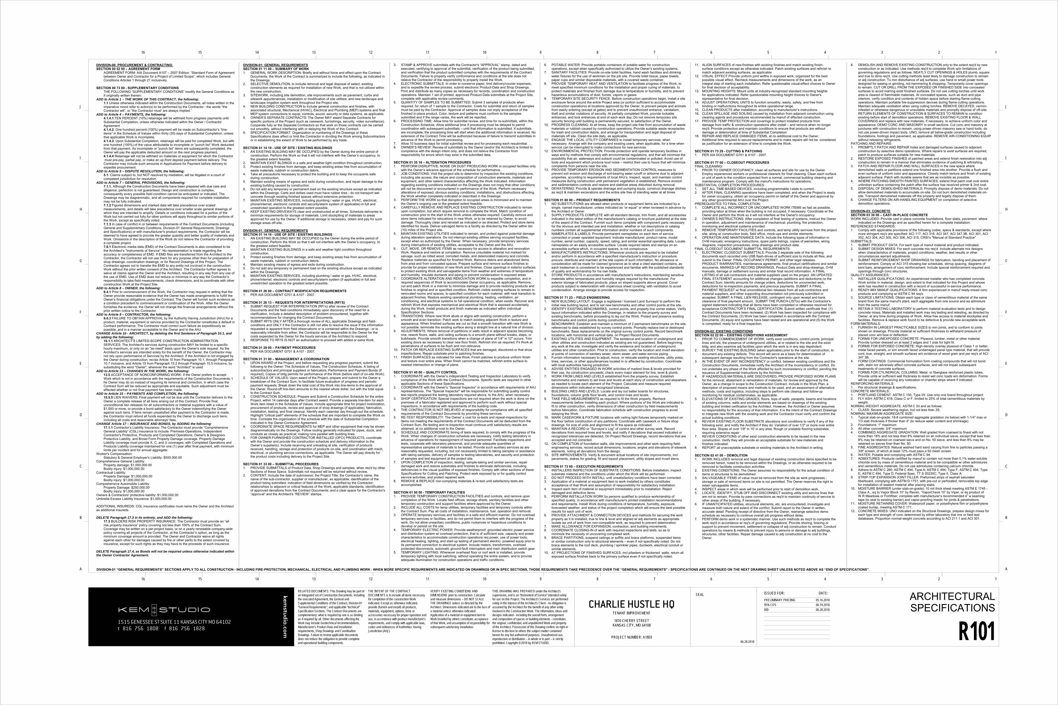
DIVISION-01 “GENERAL REQUIREMENTS” SECTIONS APPLY TO ALL CONSTRUCTION - INCLUDING FIRE-PROTECTION, MECHANICAL, ELECTRICAL AND PLUMBING WORK - WHEN MORE SPECIFIC REQUIREMENTS ARE INDICATED ON DRAWINGS OR IN SPEC SECTIONS, THOSE REQUIREMENTS TAKE PRECEDENCE OVER THE “GENERAL REQUIREMENTS” - SPECIFICATIONS ARE CONTINUED ON THE NEXT DRAWING SHEET UNLESS NOTED ABOVE AS “END OF SPECIFICATIONS”.
DIVISION-00: PROCUREMENT & CONTRACTING:SECTION 00 52 00 – AGREEMENT FORM
AGREEMENT FORM: AIA Document A107 – 2007 Edition: “Standard Form of Agreement between Owner and Contractor for a Project of Limited Scope”, which includes General Conditions Articles 1 through 21 inclusively.
SECTION 00 73 00 - SUPPLEMENTARY CONDITIONSTHE FOLLOWING “SUPPLEMENTARY CONDITIONS” modify the General Conditions as if originally written therein:
ADD to Article 1 – THE WORK OF THIS CONTRACT, the following:1.1 Unless otherwise indicated within the Construction Documents, all notes written in the imperative mood refer to action(s) to be performed by the Contractor - the words “the Contractor will”, or “the Contractor must' are always implied.”
ADD to Article 4 – PAYMENTS, the following:4.1.4.1:TEN PERCENT (10%) retainage will be withheld from progress payments until Substantial Completion, unless otherwise indicated within the Owner / Contractor Agreement. 4.1.4.2: One hundred percent (100%) payment will be made on Subcontractor’s “line-items” in the Schedule of Values within thirty (30) days of Substantial Completion, unless that applicable Work is incomplete. 4.1.4.3: Upon Substantial Completion, retainage will be paid for completed Work, but with one hundred (100%) of the value attributable to incomplete or “punch list” Work deducted from that payment. As incomplete or “punch list” items are subsequently completed, the Owner will pay the applicable deducted amount on the next progress payment.4.1.4.4 Retainage will not be withheld on materials or equipment for which the Contractormust pre-pay, partial pay, or make an up-front deposit payment before delivery. TheContractor may include such amounts in Applications for Payment before delivery to expedite procurement.
ADD to Article 5 – DISPUTE RESOLUTION, the following: 5.1: Claims subject to, but NOT resolved by mediation, will be litigated in a court of competent jurisdiction for resolution.
ADD to Article 7 – GENERAL PROVISIONS, the following:7.1.1. Although the Construction Documents have been prepared with due care and diligence, perfection is not guaranteed. Design and construction is complex, consequently every possible field condition cannot be anticipated or indicated. The Drawings may be diagrammatic, and all components required for complete installation may not be fully indicated. 7.1.2 Figured dimensions and marked data will take precedence over scaled measurements, and details will take precedence over smaller scale general drawings of which they are intended to amplify. Details or conditions indicated for a portion of the Work but not carried out fully for other portions will apply throughout to similar portions of the Work, except as specifically noted. 7.1.3 In case of conflict in or between requirements of the Contract Documents (including General and Supplementary Conditions, Division-01 General Requirements, Drawings and Specifications) or with manufacturer's product requirements, the Contractor will be deemed to have agreed to provide the greater quantity and better quality of materials and Work. Omissions in the description of the Work do not relieve the Contractor of providing a complete project.7.6.1 Electronic media data (EMD) of the Contract Documents is also considered to be the Architect’s “Instruments of Service”. No representation is made regarding the accuracy or completeness of EMD. If EMD files are transferred from the Architect to the Contractor, the Contractor will not use them for any purpose other than for preparation of shop drawings, coordination drawings, or for Record Drawings of this Project. The Contractor agrees not to transfer the EMD to any entity not involved in the construction Work without the prior written consent of the Architect. The Contractor further agrees to waive all claims against the Owner and the Architect, resulting in any way from any use of the use of EMD. Use of EMD does not reduce or minimize in any way the Contractor’s responsibility to take field measurements, check dimensions, and to coordinate with other construction Work at the Project Site.
ADD to Article 8 – OWNER, the following:8.4.1 Prior to commencement of the Work, the Contractor may request in writing that the Owner provide reasonable evidence that the Owner has made arrangements to fulfill the Owner’s financial obligations under the Contract. The Owner will furnish such evidence as a condition precedent to commencement or continuation of the Work. After the Owner furnishes the evidence, the Owner will not change the financial arrangements without the prior written notice to the Contractor.
ADD to Article 9 – CONTRACTOR, the following:9.6.3 FAILURE TO OBTAIN APPROVAL by the Authority Having Jurisdiction (AHJ) for a product, material, equipment or service provided by the Contractor constitutes a default in Contract performance. The Contractor must correct such failure as expeditiously as possible, and in a manner acceptable to the Owner and to the AHJ.
CHANGE Article 10 - ARCHITECT, by deleting the first Sentence of Paragraph 10.1, and by adding the following:
10.1.1 ARCHITECT'S LIMITED-SCOPE CONSTRUCTION ADMINISTRATION SERVICES: The Architect's services during construction MAY be limited to a specific hourly maximum, or only on an "as-need" basis upon the Owner's sole request. As the Architect’s services are intended solely for the benefit of the Owner, the Contractor may not rely upon performance of Services by the Architect. If the Architect is not engaged by the Owner during construction, revise Article 10 from Paragraph 10.1, through Paragraph 10.7 inclusive, and Article 15 from Paragraph 15.2 through Paragraph 15.5 inclusive, by substituting the word "Owner", wherever the word "Architect" is used.
ADD to Article 13 – CHANGES IN THE WORK, the following:13.5 ACCEPTANCE OF NONCONFORMING WORK: If the Owner prefers to accept Work which is not in accordance with the requirements of the Construction Documents, the Owner may do so instead of requiring its removal and correction, in which case the Contract Sum will be reduced as appropriate and equitable. Such adjustment must be effected whether or not final payment has been made.
ADD to Article 15 – PAYMENTS AND COMPLETION, the following:15.5.5 LIEN WAIVERS: Final payment will not be due until the Contractor delivers to the Owner a complete release of all liens arising out of this Contract. Provide final, unconditional lien releases for all subcontractors or material suppliers with a value of $1,000 or more, or provide a bond satisfactory to the Owner indemnifying the Owner against such liens. If liens remain unsatisfied after payment to the Contractor is made, the Contractor must refund all funds expended by the Owner to discharge such liens, including all costs and reasonable attorneys' fees.
CHANGE Article 17 – INSURANCE AND BONDS, by ADDING the following:17.1.1 Contractor’s Liability Insurance: The Contractor must provide “Comprehensive General Liability” (CGL) insurance to include: Premises-Operations, Independent Contractor's Protective, Products and Completed Operations, Owner's & Designers Protective Liability, and Broad Form Property Damage coverage. Property Damage Liability coverage must provide X, C, and U coverages, with Completed Operations and Products Liability coverage maintained for one (1) year after final payment, with minimum limits per incident and for annual aggregate:
Worker's Compensation: Statutory & General Employer's Liability: $500,000.00
Comprehensive General Liability: Property damage: $1,000,000.00Bodily injury: $1,000,000.00
ADDITIONAL INSUREDS: CGL insurance certificates must name the Owner and the Architect as additional insureds.
DELETE Paragraph 17.3 in its entirety, and ADD the following:17.3 BUILDERS RISK PROPERTY INSURANCE: The Contractor must provide an “all risk property insurance” policy covering not less than 100% of the Contract Sum. Coverage may be written on a per-project basis, or on a yearly renewable company-wide policy covering all projects of the Contractor, at the Contractor’s option, as long as the minimum coverage amount is provided. The Owner and Contractor waive all rights against each other for damages caused by fire or other perils to the extent covered by insurance, except for such rights as they may have to the proceeds of such insurance.
DELETE Paragraph 17.4, as Bonds will not be required unless otherwise indicated within the Owner Contractor Agreement.
DIVISION-01: GENERAL REQUIREMENTSSECTION 01 11 00 – SUMMARY OF WORK1. GENERAL WORK DESCRIPTION: Briefly and without force and effect upon the Contract
Documents, the Work of the Contract is summarized to include the following, as indicated inthe Drawings:
2. SELECTIVE DEMOLITION, to include removal and legal disposal of select, existingconstruction elements as required for installation of new Work, and that is not utilized withinthe new construction;
3. SITEWORK, including site demolition, site improvements such as pavement, curbs andsitework appurtenances, installation or modification of site utilities; and new landscape andlandscape irrigation system work throughout the Project site;
4. NEW BUILDING CONSTRUCTION to include general construction and finishes, withassociated structural, Mechanical (HVAC), Electrical and Plumbing (MEP) systems and finalMEP system connections to equip, controls, sound, security or data systems, as applicable.
5. OWNER’S SEPARATE CONTRACTS: The Owner MAY award Separate Contracts forspecific portions of the Project (such as casework, furnishings, security, video surveillance). Cooperate fully w/ the Separate Contractors so that work on those contracts can be carriedout smoothly, without interfering with or delaying the Work of this Contract.
6. SPECIFICATION FORMAT: Organization or numbering of the Drawings or theseSpecifications does affect or limit the Contractor in dividing the Work among Subcontractorsor in establishing the extent of Work to be performed by any trade.
SECTION 01 14 19 - USE OF SITE / EXISTING BUILDINGS1. AN EXISTING BUILDING MAY BE OCCUPIED by the Owner during the entire period of
construction. Perform the Work so that it will not interfere with the Owner’s occupancy, tothe greatest extent feasible.
2. MAINTAIN EXIST BLDINGS in a safe and weather tight condition throughout construction.3. Protect existing finishes from damage, and keep existing areas free from accumulation of
waste materials, rubbish or construction debris.4. Take all precautions necessary to protect the building and to keep the occupants safe
during construction.5. Maintain existing means of egress and exits during construction, and repair damage to the
existing building caused by construction.6. Do not add any temporary or permanent load on the existing structure except as indicated
within the Drawings. Carts and dollies used must have rubber tires - do not transport wetconcrete through existing finished spaces without extensive protection.
7. MAINTAIN EXISTING SERVICES, including plumbing / water or gas, HVAC, electrical,phone/internet, electronic controls and security/alarm system (if applicable) in full andunrestricted operation to the greatest extent possible.
8. KEEP EXISTING DRIVEWAYS clear and unobstructed at all times. Schedule deliveries tominimize requirements for storage of materials. Limit stockpiling of materials to areasapproved for use by the Owner. If additional storage is necessary, obtain and pay for suchstorage areas off-site.
DIVISION-01: GENERAL REQUIREMENTSSECTION 01 14 19 - USE OF SITE / EXISTING BUILDINGS1. AN EXISTING BUILDING MAY BE OCCUPIED by the Owner during the entire period of
construction. Perform the Work so that it will not interfere with the Owner’s occupancy, tothe greatest extent feasible.
2. MAINTAIN EXISTING BUILDINGS in a safe and weather tight condition throughoutconstruction.
3. Protect existing finishes from damage, and keep existing areas free from accumulation ofwaste materials, rubbish or construction debris.
4. Maintain existing means of egress and exits during construction.5. Do not add any temporary or permanent load on the existing structure except as indicated
within the Drawings. 6. MAINTAIN EXISTING SERVICES, including plumbing / water or gas, HVAC, electrical,
phone/internet, electronic controls and security/alarm system (if applicable) in full and unrestricted operation to the greatest extent possible.
SECTION 01 26 13 – REQUESTS FOR INTERPRETATIONS (RFI’S)1. SUBMIT REQUEST FOR INTERPRETATION (RFI’s) after review of the Contract
Documents and the field conditions immediately upon discovery of the need for aclarification. Include a detailed description of problem encountered, together withrecommendations for changing the Contract Documents.
2. SUBMIT RFI'S ONLY AFTER a thorough review of ALL applicable Drawings and field-conditions and ONLY if the Contractor is still not able to resolve the issue If the informationrequested is apparent from field observations or is contained within the Drawings - or isreasonably inferable from either, the Contractor will be responsible to the Owner for thecosts expended by the Owner for the hourly services of the Architect to respond.
3. RESPONSE TO RFI'S IS NOT an authorization to proceed with added or extra Work.
SECTION 01 31 00 – MANAGEMENT & COORDINATION1. UPON AWARD of the Project, and before requesting any progress payment, submit the
following to the Owner: The Schedule of Values, The Construction Schedule, A listing ofsubcontractors and principal suppliers or fabricators, Performance and Payment Bonds (ifrequired), Copies of bldg permits for performance of the Work (before start of on-site Work).
2. SCHEDULE OF VALUES: Upon award of the Project, prepare and submit to the Owner abreakdown of the Contract Sum, to facilitate future evaluation of progress and periodicpayment requests. Break down the total cost of the Work into line-items to the approval ofthe Owner. Round-off line-item amounts to the nearest whole dollar, but with the total equalto the Contract Sum.
3. CONSTRUCTION SCHEDULE: Prepare and Submit a Construction Schedule for the entireProject, within 14 calendar days after Contract award. Provide a separate line-item for eachWork item listed in the Schedule of Values. Include appropriate time for project mobilization, procurement of products, review and approval of shop drawings (if applicable), fabrication,installation, testing, and final cleanup. Identify each calendar day through-out the schedule.Highlight "critical path" elements of the schedule that are important to complete the Work on time. Correlate the organization of the schedule with the date of Substantial Completionindicated in the Owner-Contractor Agreement.
4. COORDINATE SPACE REQUIREMENTS for MEP and other equipment that may be showndiagrammatically on the Drawings. Follow routing generally indicated for pipes, ducts, andconduits as closely as practical; making runs parallel with building lines.
5. FOR OWNER-FURNISHED CONTRACTOR INSTALLED (OFCI) PRODUCTS, coordinatewith the Owner and provide the construction schedule and delivery information to theOwner’s supplier(s). Include receiving and unloading at site, verification of products received, handling, storage and protection of products on-site, and coordination with mech, electrical, or plumbing service connections, as applicable. The Owner will pay directly for the product costs including delivery to the Project Site.
SECTION 01 33 00 – SUBMITTAL PROCEDURES1. PROVIDE SUBMITTALS of Product Data, Shop Drawings and samples, when req'd by other
Sections of these Specs. Submittals not required will be returned without review.2. CONTENT: Include the date of submission; the Project Title; the Contractor's name, the
name of the sub-contractor, supplier or manufacturer, as applicable; identification of theproduct being submitted; indication of field dimensions as verified by the Contractor;relationships to adjacent or critical features of the Work; applicable standards; identificationof approved deviations from the Contract Documents; and a clear space for the Contractor's“approval” and the Architect's “REVIEW” stamps.
3. STAMP & APPROVE submittals with the Contractor's “APPROVAL” stamp, dated andexecuted, certifying to approval of the submittal, verification of the product being submitted,and verification that the product submitted complies with the requirements of the ContractDocuments. Failure to properly verify conformance and conditions at the site does notrelieve the Contractor of the responsibility to properly install the Work.
4. ELECTRONIC SUBMITTALS: In order to conserve paper, limit delivery/courier expenses,and to expedite the review process, submit electronic Product-Data and Shop Drawings.Print and distribute as many copies as necessary for records, coordination and constructionoperations. Maintain 1 set of printed, approved Product-Data submittals at the Project Site,complete with applicable review comments.
5. QUANTITY OF SAMPLES TO BE SUBMITTED: Submit 3 samples of products whenrequired, for return of 1 sample to the Contractor. Costs for submittal and return of samplesmust be paid by the Contractor. Approval of samples does not imply acceptance of thefinished in-place product. Color, texture and patterns must conform to the samplessubmitted and if the range varies, the work will be rejected.
6. PROCESSING TIME: Allow time for submittal review, and time for re-submittals, within theConstruction Schedule. Allow additional time if processing must be delayed to permitcoordination with subsequent submittals – until that information is submitted. If submittalsare incomplete, the processing time will start when the additional information is received. No extension of the Contract Time will be authorized because of failure to transmit submittals in advance of the Work to permit processing.
7. Allow 10 business days for initial submittal review and for processing each resubmittal.8. OWNER’S REVIEW: Review of submittals by the Owner (and/or the Architect) is limited to
compliance with the design intent only, and does not relieve the Contractor fromresponsibility for errors which may exist in the submitted data.
SECTION 01 35 16 – ALTERATION PROCEDURES1. PERFORM DISRUPTIVE, NOISE OR DUST PRODUCING WORK in occupied facilities only
with the Owner’s advance approval of the schedule for performance.2. JOB CONDITIONS: Visit the project site to determine by inspection the existing conditions,
including site access, the nature and composition of construction elements, materials and equipment, and other salient characteristics affecting the Work indicated. Information regarding existing conditions indicated on the Drawings does not imply that other conditions will not be discovered or encountered in performance of the Work. Perform necessary alterations of exposed, obvious existing conditions, installations, and obstructions affecting the Work whether completely indicated or described in the Drawings.
3. PERFORM THE WORK so that disruption to occupied areas is minimized and to maintain the Owner’s ongoing use to the greatest extent feasible.
4. CAREFULLY REMOVE AND REPLACE EXISTING CONSTRUCTION indicated to remainupon completion, but which require removal to complete the Work. Match condition ofconstruction prior to the start of the Work unless otherwise required. Carefully remove andstore items indicated for relocations in new Work, or to be retained by Owner, to avoiddamage. Thoroughly clean and reinstall as indicated or as directed. Protect and store itemsidentified for reuse. Deliver salvaged items to a facility as directed by the Owner within ten(10) miles of the Project site.
5. MAINTAIN EXISTING UTILITIES indicated to remain, and protect against potential damageduring alteration operations. Do not interrupt existing utilities serving occupied facilities,except when so authorized by the Owner. When necessary, provide temporary servicesduring interruptions of existing utilities, acceptable to the Owner and the AHJ.
6. CUT, MOVE, OR REMOVE ITEMS as necessary for access to alteration and renovationWork. Replace and restore at completion. Remove unsuitable material not marked forsalvage, such as rotted wood, corroded metals, and deteriorated masonry and concrete.Replace materials as specified for finished Work. Remove debris and abandoned itemsfrom area and from concealed spaces. Prepare surface and remove surface finishes to provide for proper installation of new Work and finishes. Close openings in exterior surfaces to protect existing Work and salvageable items from weather and extremes of temperature and humidity. Insulate ductwork and piping to prevent condensation in exposed areas.
7. COORDINATE ALTERATION AND RENOVATION WORK to expedite completion, and in required sequences of Work to accommodate Owner occupancy, as applicable. Remove, cut and patch Work in a manner to minimize damage and to provide restoring products and finishes to original and or specified condition. Refinish visible existing surfaces to remain in renovated rooms and spaces, to specified condition for each material, with neat transition to adjacent finishes. Restore existing operational plumbing, heating, ventilation, air conditioning, and electrical systems to full operational condition, when exists. Recover and refinish Work that exposes mechanical and electrical Work that is exposed accidentally during the Work. Install products and finish materials as indicated within individual Specification Sections.
8. TRANSITIONS: Where new Work abuts or aligns with existing construction, perform asmooth and even transition. Patch work to match existing adjacent Work in texture andappearance. When finished surfaces are cut so that a smooth transition with new Work isnot possible, terminate the existing surface along a straight line at a natural line of division.
9. ADJUSTMENTS: Where removal of partitions or walls result in adjacent spaces becomingone, rework floors, walls, and ceiling surfaces to a smooth plane without breaks, steps, orbulkheads. Provide smooth transitions when a change of plane of 1/4" in 12" occurs. Trimexisting doors as necessary to clear new floor finish. Refinish trim as required. Fit Work atpenetrations of surfaces to be flush and non-obtrusive.
10. PATCH OR REPLACE EXISTING SURFACES that are damaged, discolored or that showimperfections. Repair substrate prior to patching finishes.
11. FINISH SURFACES as indicated for new Work. Finish patches to produce uniform finishand texture over entire area. When finish cannot be matched, refinish entire surface tonearest intersection or change of plane.
SECTION 01 45 00 – QUALITY CONTROL1. COORDINATE with the Owner’s independent Testing and Inspection Laboratory to verify
compliance of the Work with the Contract Documents. Specific tests are required in otherapplicable Sections of these Specifications.
2. COORDINATE with the Owner’s “Special Inspector” in accordance with requirements of AHJrepresentatives. The "Special Inspector" will be responsible for submitting quality controltest reports prepared the testing laboratory required above, to the AHJ, when necessary.
3. SHOP CERTIFICATION: Special inspections are not required when the work is done on thepremises of a fabricator registered and approved to perform such work without specialinspections, in accordance with requirements of the building code.
4. THE CONTRACTOR IS NOT RELIEVED of responsibility for compliance with all specifiedrequirements of the Contract Documents by providing these services.
5. RE-TEST RESPONSIBILITY: The Owner’ s cost for re-tests and repeat-inspections foritems not meeting the requirements of the Contract Documents will be deducted from theContract Sum. Re-testing and re-inspection must continue until satisfactory results areobtained, at no additional cost to the Owner.
6. SCHEDULE AND COORDINATE timing of tests required, to comply with the progress of the Work. When changes of construction schedule are necessary, notify testing laboratory inadvance of operations for reassignment of required personnel. Facilitate inspections andtests, cooperate with laboratory personnel, and provide adequate quantities ofrepresentative samples of materials to be tested. Provide such auxiliary services as arereasonably requested, including, but not necessarily limited to taking samples or assistancewith taking samples, delivery of samples to testing laboratories, and security and protectionof samples and test equipment at the project site.
7. UPON COMPLETION of inspection, testing, sample-taking and similar services, repairdamaged work and restore substrates and finishes to eliminate deficiencies, includingdeficiencies in the visual qualities of exposed finishes. Comply with other sections of theseSpecifications for Cutting and Patching. Protect work exposed by or for quality controlservice activities, and protect repaired work.
SECTION 01 50 00 - TEMPORARY FACILITIES1. PROVIDE TEMPORARY CONSTRUCTION FACILITIES and controls, and remove upon
completion of the Work. Locate field offices, storage sheds, sanitary facilities and othertemporary construction and support facilities where approved by the Owner.
2. INCLUDE ALL COSTS for temp utilities, temporary facilities and temporary controls withinthe Contract Sum. Pay all costs of installation, maintenance, fuel, operation and removal.
3. OPERATE temporary services and facilities in a safe and efficient manner. Do not overloadtemporary services or facilities, and do not permit them to interfere with the progress of thework. Do not allow unsanitary conditions, public nuisances or hazardous conditions todevelop or persist on the site.
4. TEMPORARY ELECTRIC POWER: Provide weatherproof, grounded electric power serviceand distribution system w/ overload protection, that is of sufficient size, capacity and powercharacteristics to accommodate construction operations req power, use of power tools,electrical heating, lighting, and start-up testing of permanent electric- powered equip prior toits permanent connection to electrical system. Include meters, transformers, overloadprotected disconnects, automatic ground-fault interrupters and main distribution switch gear.
5. TEMPORARY LIGHTING: Whenever overhead floor or roof work is installed, providetemporary lighting with local switching, without operating the entire system, and to provideadequate illumination for construction operations and traffic conditions.
6. POTABLE WATER: Provide portable containers of potable water for constructionoperations, except when specifically authorized to utilize the Owner’s existing systems.
7. SANITARY FACILITIES: Provide on-site toilet facilities, hand wash facilities and drinkingwater fixtures for the use of workmen on the job site. Provide toilet tissue, paper towels,paper cups and similar disposable materials, with a covered waste container.
8. PROVIDE TEMPORARY HEAT AND VENTILATION to facilitate progress of the Work, tomeet specified minimum conditions for the installation and proper curing of materials, toprotect materials and finishes from damage due to temperature or humidity, and to preventhazardous accumulations of dust, fumes, vapors or gases.
9. TEMPORARY SITE SECURITY FENCE: Before construction operations begin, install a siteenclosure fence around the entire Project area (or portion sufficient to accommodateconstruction operations) at locations approved by the Owner, to prevent people and animalsfrom easily entering (except at gates) and to prevent unauthorized entrance, vandalism,theft and similar violations of security. At partially completed Work, provide lockableentrances, and lock entrances at end of each work day. Do not remove temporary sitesecurity fencing until building is permanently secured, to satisfaction of the Owner.
10. PROGRESS CLEANING: At all times, keep the project site free from accumulation of wastematerials or rubbish caused by construction operations. Provide suitable waste receptaclesfor trash and construction debris, and arrange for transportation and legal disposal ofmaterials off site. Clean the site daily, as applicable.
11. ENGAGE THE LOCAL UTILITY COMPANIES to install temporary services, whennecessary. Arrange with the company and existing users, when applicable, for a time whenservice can be interrupted to make connections for new services.
12. ENVIRONMENTAL PROTECTION: Provide protection and operate temporary facilities inways and by methods that comply with environmental regulations, and that will minimize thepossibility that air, waterways and subsoil could be contaminated or polluted. Avoid use oftools and equipment which produce loud noise – restrict their use to hours that will minimizecomplaints from persons near the site.
13. PROVIDE TEMPORARY EROSION AND SEDIMENTATION CONTROL measures toprevent soil erosion and discharge of soil-bearing water runoff or airborne dust to adjacentproperties, according to requirements of local AHJ’s. Inspect, repair, and maintain controlmeasures during construction until permanent vegetation is established. Remove erosionand sedimentation controls and restore and stabilize areas disturbed during removal.
14. DEWATERING: Provide & operate drainage and pumping equip, construct drainage ditchesas req'd & maintain excavations and the entire site free of standing water at all times.
SECTION 01 60 00 – PRODUCT REQUIREMENTS1. NO SUBSTITUTIONS are allowed when products or equipment items are indicated by a
single, named manufacturer, unless indicated as “or equal” or when reviewed in advance bythe Architect or Owner.
2. SUPPLY PRODUCTS COMPLETE with all standard devices, trim finish, and all accessoriesindicated in the latest edition of the manufacturer's catalog or brochure published at the date of the award of the Contract. Furnish such items complete with component parts necessaryfor the obvious and intended use and installation, whether or not descriptions or catalognumbers contain all supplemental information and/or numbers of such components.
3. NAMEPLATES & LABELS: Provide permanent nameplates on each item of serviceconnected or power operated equipment. Indicate manufacturer, product name, modelnumber, serial number, capacity, speed, rating, and similar essential operating data. Locatenameplates on an easily accessible surface. Locate required labels and stamps on anaccessible surface which, in occupied spaces, is not conspicuous.
4. MANUFACTURER'S INSTRUCTIONS: Whenever products are required to be installedand/or perform in accordance with a specified manufacturer's instruction or procedure,procure, distribute and maintain at the site copies of such information. No allowance orconsideration will be made for claimed ignorance as to what a cited standard contains, aseach tradesman is considered to be experienced and familiar with the published standardsof quality and workmanship for his own trade.
5. STORE PRODUCTS in accordance with manufacturer's instructions, maintaining sensitivematerials within temperatures and humidity ranges required by the manufacturer. Forexterior storage of fabricated products, place on sloped supports above ground. Coverproducts subject to deterioration with impervious sheet covering; with ventilation to avoidcondensation. Arrange storage to provide access for inspection.
SECTION 01 71 23 – FIELD ENGINEERING1. NEW BUILDING LAYOUT: Engage a registered / licensed Land Surveyor to perform the
initial new building layout, and to set new benchmarks and other control points at the site.2. IDENTIFY EXISTING BENCHMARKS, control points, and property line corner stakes. Verify
layout information indicated within the Drawings, in relation to the property survey and existing benchmarks, before proceeding to lay out the Work. Protect and preserve existing benchmarks and control points during construction.
3. BENCHMARKS: Establish and maintain a minimum of 2 permanent benchmarks on the site, referenced to data established by survey control points. Promptly replace lost or destroyed benchmarks. Base replacements on the original survey control points. Record benchmark locations, with horizontal and vertical data, on Project Record Documents.
4. EXISTING UTILITIES AND EQUIPMENT: The existence and location of underground and other utilities and construction indicated as existing are not guaranteed. Before beginning any work at the site, investigate and verify the existence and location of underground utilities and other construction. Prior to construction, verify the location and invert elevation at points of connection of sanitary sewer, storm sewer, and water-service piping.
5. Furnish information necessary to adjust, move, or relocate existing structures, utility poles,lines, services, or other appurtenances located in or affected by construction. Coordinatewith local authorities having jurisdiction.
6. ADVISE ENTITIES ENGAGED IN WORK activities of marked lines & levels provided fortheir use. As construction proceeds, check every major element for line, level & plumb.
7. WORK FROM LINES AND LEVELS established from the property survey. Establishbenchmarks and markers to set lines and levels at each story of construction and elsewhere as needed to locate each element of the Project. Calculate and measure requireddimensions within indicated or recognized tolerances.
8. BUILDING LINES AND LEVELS: Locate and lay out batter boards for structures,foundations, column grids floor levels, and control lines and levels.
9. TAKE FIELD MEASUREMENTS as required to fit the Work properly. Recheckmeasurements before installing each product. Where portions of the Work are indicated tofit to other construction, verify dimensions of other construction by field measurementsbefore fabrication. Coordinate fabrication schedule with construction progress to avoiddelaying the Work.
10. MARK CASEWORK & FIXTURE locations with ceiling light fixtures temporarily marked onthe floor before construction of any partitions. Coordinate with casework or fixture shopdrawings for size of units and alignment to fit the space as indicated.
11. MAINTAIN A RECORD or “Surveyor’s Log” of control and other survey work. Recorddeviations from required lines and levels, and notify if deviations that exceed indicated orrecognized tolerances are detected. On Project Record Drawings, record deviations that areaccepted and not corrected.
12. ON COMPLETION of foundation walls, site improvements and other work requiring field-engineering services, record actual dimensions, locations, angles and elevations of siteworkelements, noting all deviations from the design.
13. SITE IMPROVEMENTS: Verify & document actual locations of site improvements, inclpavements, stakes for grading, fill and topsoil placement, utility slopes and invert elevs.
SECTION 01 73 00 – EXECUTION REQUIREMENTS1. INSTALLERS INSPECTION OF SUBSTRATE CONDITIONS: Before installation, inspect
substrate material and the conditions under which the Work will be performed.2. DO NOT PROCEED WITH INSTALL until unsatisfactory conditions have been corrected.3. Application of a material or equipment item to work installed by others constitutes
acceptance of that Work and assumption of responsibility for satisfactory installation.4. Inspect each item of material or equipment immediately prior to installation. Reject
damaged and defective items.5. PERFORM INSTALLATION WORK by persons qualified to produce workmanship of
specified quality, in accordance with manufacturer's printed installation recommendationsand requirements. Install Work during conditions of temperature, humidity, exposure,forecasted weather, and status of the project completion which will ensure the best possibleresults for each unit of work.
6. PROVIDE ATTACHMENT & CONNECTION DEVICES and methods for securing the workproperly as it is installed, true to line & level and aligned w/ adj elements as appropriate.Isolate ea unit of work from non-compatible work, as required to prevent deterioration.
7. MAKE ALLOWANCE FOR EXPANSION, contraction, and building movements.8. COORDINATE CLOSING-IN of work with required inspections and tests, so as to
minimize the necessity of uncovering completed work.9. BRACE PARTITIONS, suspend ceilings or soffits and brace platforms, suspended items
or similar construction only to structural elements – even if not specifically noted. Do notbrace elements to the roof deck, plumbing / sprinkler pipes, ductwork, electrical conduit orsimilar elements.
10. AT PROJECTIONS OF FINISHED SURFACES, incl pilasters or thickened walls, return allexposed surface finishes back to the primary surface even if not specifically noted.
11. ALIGN SURFACES of new finishes with existing finishes and match existing finish-surface conditions except as otherwise indicated. Patch existing surfaces and refinish tomatch adjacent existing surfaces, as applicable.
12. VISUAL EFFECT Provide uniform joint widths in exposed work, organized for the bestpossible visual effect. Recheck measurements and dimensions of the work, as an integral step of starting each installation. Refer questionable visual-effect choices to Owner for final decision of acceptability.
13. MOUNTING HEIGHTS: Mount units at industry-recognized standard mounting heightsfor applications indicated. Refer questionable mounting height choices to Owner'srepresentative for final decision.
14. ADJUST OPERATIONAL UNITS to function smoothly, easily, safely, and free frombinding or malfunctions throughout its entire operational range.
15. CLEAN PRODUCTS after installation, according to manufacturer’s instructions.16. CLEAN SPILLAGE AND SOILING caused by installation from adjacent construction using
cleaning agents and procedures recommended by manuf of affected constuction.17. PROVIDE TEMP PROTECTION and coverings to protect installed products from
damage from traffic & construction operations after install – and remove when no longerreq'd. Provide protection and maintain conditions to ensure that products are withoutdamage or deterioration at time of Substantial Completion
18. REPAIR AND REPLACE DAMAGED ITEMS, at no additional cost to the Owner.Additional time required to secure replacements and to make repairs will not be consideredas justification for an extension of time to complete the Work.
SECTION 01 77 00 – CLOSEOUT PROCEDURESFINAL CLEANING: 1. PRIOR TO OWNER OCCUPANCY, clean all surfaces and site for use by the Owner.
Employ experienced workers or professional cleaners for final cleaning. Clean each surfaceor unit of work to the condition expected from a normal, commercial building cleaning andmaintenance program. Comply with the manuf's instructions for operations.
SUBSTANTIAL COMPLETION PROCEDURES:1. SET ALL TIME-BASED DEVICES, including programmable t-stats to current.2. AFTER FINAL CLEANING operations have been completed, and when the Project is ready
for owner occupancy, obtain an occupancy permit on behalf of the Owner and approval by any other governmental AHJ over the Project.
PREREQUISITES TO FINAL COMPLETION: 1. COMPLETE ALL INCORRECT OR UNCOMPLETED WORK ITEMS as fast as possible,
providing labor at times when the building is not occupied, if necessary. Coordinate w/ theOwner and perform the Work so it will not interfere w/ the Owner's occupancy.
2. OWNER’S INSTRUCTIONS: After completion of final testing of systems, instruct the Ownerin operation, adjustment and maintenance of mechanical, plumbing, fire protection, monitoring and electrical systems provided.
3. REMOVE TEMPORARY FACILITIES and controls, and temp utility services from the project site, along w/ construction tools, field office, mock-ups and similar elements.
4. OPERATION AND MAINTENANCE DATA: Include the following types of information inO+M manuals: emergency instructions, spare parts listings, copies of warranties, wiringdiagrams, inspection procedures, shop drawings and product data.
FINAL CLOSEOUT DOCUMENT SUBMITTAL REQUIREMENTS: 1. ELECTRONIC CLOSEOUT SUBMITTALS: Provide 2 separate sets of the following
documents each recorded onto USB flash-drives of sufficient size to include all files, andsubmit to the Owner: FINAL OCCUPANCY PERMIT, and other legal releases.PRODUCT WARRANTIES, maintenance agreements, final product certifications and similar documents. MARKED-UP RECORD DRAWINGS, Product Data and shop-drawings, O+Mmanuals, damage or settlement survey and similar final record information. A FINALLISTING of all sub-contractors and material suppliers used on the project. AN UPDATEDFINAL STATEMENT accounting for additional changes (additions and deductions) to theContract Sum. Identify amounts for change orders, deductions for uncorrected work,deductions for re-inspection payments, and previous payments. SUBMIT A FINALPAYMENT REQUEST w/ final unconditional lien releases from all sub-contractors andmaterial suppliers, and other supporting documentation not previously submitted oraccepted. SUBMIT A FINAL LIEN RELEASE, contingent only upon receipt and bankclearance of final payment amount. SUBMIT THE PUNCH-LIST(s) with the Contractor'ssigned statement indicating that all items have been completed or otherwise resolved foracceptance.CONTRACTOR’S FINAL CERTIFICATION: Submit written certificate that: (1)Contract Documents have been reviewed, (2) Work has been inspected for compliance withthe Contract Documents, (3) Work has been completed in accordance with the ContractDocuments, (4) equip and systems have been tested and are operational and (5) the Workis completed, ready for a final inspection.
DIVISION-02: EXISTING CONDITIONSSECTION 02 22 00 – EXISTING CONDITIONS ASSESSMENT1. PRIOR TO COMMENCEMENT OF WORK, verify exist conditions, control points, principal
lines and els, the presence of underground utilities, at or related to the site and the existbldg, and also examine adj facilities upon which the work is in any way dependent.
2. SURVEY THE EXISTING BUILDING (when applicable) prior to the start of construction, todocument any existing defects. This record will serve as a basis for determination ofsubsequent damage resulting from the Contractor's operations at the site.
3. IN THE EVENT OF ANY INCONSISTENCY or conflict, between existing conditions and theConstruction Documents, immediate notify the Architect of the inconsistency or conflict. Do not undertake any phase of the Work affected by such inconsistency or conflict, pending the issuance of Supplemental Instructions by the Architect.
4. IF HAZARDOUS MATERIALS ARE DISCOVERED, PROVIDE PROPOSED WORK PLANSfor the removal, abatement or remediation of materials, for review and approval by theOwner, as a change in scope to the Construction Contract. Include in the Work Plan, adescription of proposed means and methods to be used, and an assessment of alternativemethods, costs and logistics, including steps to perform site cleanup and follow-upmonitoring for residual contaminates, as applicable.
5. ELEVATIONS OF EXISTING GRADES, floors, tops of walls, parapets, beams and locationsof existing columns, walls and similar elements are based on drawings of the existingbuilding and limited verification by the Architect. However, the Architect or Owner assumesno responsibility for the accuracy of that information. It is the intent of the Contract Drawings to integrate new Work with the existing work and the Contractor must verify and confirm theactual building conditions.
6. REVIEW EXISTING FLOOR SUBSTRATE elevations and conditions to verify if any of thefollowing exist, and notify the Architect if they do: Variation of over 1/2" or more over entirefloor area. Slopes of over 1/8" in 10' in any area. Rough or unstable flooring substratesrequiring extensive repair
7. REVIEW CONDITIONS of other exist construction elements to be reused in the new construction. Verify they will provide an acceptable substrate for new materials andfinishes indicated.
8. REPORT all unacceptable substrate or existing materials to the Architect in writing.
SECTION 02 41 00 – DEMOLITION1. WORK INCLUDES removal and legal disposal of existing construction items specified to be
removed herein, noted to be removed within the Drawings, or as otherwise required to beremoved to facilitate construction activities.
2. EXISTING CONDITIONS: The Owner assumes no responsibility for the actual condition ofitems or structures to be demolished.
3. SALVAGEABLE ITEMS of value must be removed from the site as work progresses -storage or sale of removed items on site is not permitted. The Owner reserves the right toretain salvageable items.
4. INSPECT areas in which work will be performed prior to start of demolition work.5. LOCATE, IDENTIFY, STUB OFF AND DISCONNECT existing utility and service lines that
are not to remain. Provide by pass connections as req'd to maintain continuity of service toother areas of the building, if necessary.
6. IF UNANTICIPATED utilities, structural elements, etc. are encountered, investigate andmeasure both nature and extent of the conflict. Submit report to the Owner in written,accurate detail. Pending receipt of directive from the Owner, rearrange selective demoschedule as necessary to continue overall job progress without delay.
7. PERFORM demo work in a systematic manner. Use such methods as req'd to complete thework req'd in accordance w/ req's of governing regulations. Provide shoring, bracing orsupport to prevent movement, settlement or collapse of adj construction to remain. Conductoperations by means & methods to prevent injury to persons or damage to adj buildings,structures, other facilities. Repair damage caused to adj construction at no cost to theOwner.
8. DEMOLISH AND REMOVE EXISTING CONSTRUCTION only to the extent req'd by new construction or as indicated. Use methods req'd to complete Work w/in limitations ofgoverning regulations and as follows: NEATLY CUT OPENINGS & HOLES plumb, squareand true to dims req'd. Use cutting methods least likely to damage construction to remainor adj construction. To min disturbance of adj surfaces, use hand or small power toolsdesigned for sawing or grinding, not hammering & chopping. Temporarily cover openingsto remain. CUT OR DRILL FROM THE EXPOSED OR FINISHED SIDE into concealedsurfaces to avoid marring exist finished surfaces. Do not use cutting torches until workarea is cleared of flammable materials. At concealed spaces, such as duct and pipeinteriors, verify condition and contents of hidden space before starting flame-cuttingoperations. Maintain portable fire-suppression devices during flame-cutting operations.Maintain adequate ventilation when using cutting torches. REMOVE DECAYED, vermin-infested or otherwise dangerous or unsuitable materials and promptly dispose of off-site.RETURN ELEMENTS OF CONSTRUCTION & SURFACES TO REMAIN to conditionexisting before start of demolition operations. REMOVE EXISTING FLOOR & WALLCOVERINGS and replace with new materials, if necessary, to achieve uniform color andappearance. DEMO CONC AND MASONRY in small sections. Cut conc and masonry atjunctures with construction to remain, using power-driven masonry saw or hand tools; donot use power-driven impact tools. UNO, remove all below-grade construction includingfoundations, footings and pavement, as applicable. REMOVE AIR-CONDITIONING EQUIPwithout releasing refrigerants.
PATCHING AND REPAIRS:1. PROMPTLY PATCH AND REPAIR holes and damaged surfaces caused to adjacent
construction by selective demo operations. Where repairs to exist surfaces are required,patch to produce surfaces suitable for new materials.
2. RESTORE EXPOSED FINISHES of patched areas and extend finish restoration into adjconstruction to remain in a manner that eliminates evidence of patching & refinishing.
3. PATCH AND REPAIR FLOOR AND WALL SURFACES in the new space wheredemolished walls or partitions extend one finished area into another. Provide a flush andeven surface of uniform color and appearance. Closely match texture and finish of existing adjacent surface. Patch with durable seams that are as invisible as possible.
4. WHERE PATCHING SMOOTH PAINTED SURFACES, extend final paint coat over entireunbroken surface containing the patch after the surface has received primer & 2nd coat.
5. DISPOSAL OF DEMOLISHED MATERIALS: Promptly dispose of demo materials. Do notallow demolished materials to accumulate on-site. Do not burn demolished materials on-site. Transport demolished materials off the property and legally dispose of them.
6. CHANGE FILTERS ON AIR-HANDLING EQUIPMENT on completion of selectivedemolition operations.
DIVISION-03: CONCRETESECTION 03 30 00 – CAST-IN-PLACE CONCRETEWORK INCLUDED: Provide cast in place concrete foundations, floor slabs, pavement where
indicated on the Drawings and as specified herein for a complete installation. REFERENCED STANDARDS:1. Comply with applicable provisions of the following codes, specs & standards, except where
more stringent req's are specified: ACI 117, ACI 318, ACI 347, ACI 347.3B, ACI 301, ACI302, ACI 304, ACI 305, ACI 306, ACI 315, CRSI’s "Manual of Standard Practice"
SUBMITTALS:1. SUBMIT PRODUCT DATA: For each type of manuf material and product indicated.2. SUBMIT DESIGN MIXES: For each concrete mix req'd. Include alternate mix designs
when characteristics of materials, project conditions, weather, test results or othercircumstances warrant adjustments.
3. SUBMIT REINFORCEMENT SHOP DRAWINGS for fabrication, bending and placement ofreinforcement. Comply w/ ACI 315 showing bar schedules, stirrup spacing, diagrams ofbent bars, arrangement of conc reinforcement. Include special reinforcement required andopenings through conc structures.
QUALITY ASSURANCES:1. INSTALLER QUALIFICATIONS: An experienced installer who has completed concrete
Work similar in material, design, and extent to that indicated for this Project and whosework has resulted in construction with a record of successful in-service performance.
2. READY-MIX MANUF QUALIFICATIONS: A firm experienced in manuf ready-mixed concproducts and complying w/ ASTM C 94 req's.
3. SOURCE LIMITATIONS: Obtain each type or class of cementitious material of the samebrand from the same manuf's plant, each aggregate from one source and ea admixturefrom the same manuf.
4. RETAIN A TESTING LABORATORY to perform material evaluation tests and to designconcrete mixes. Materials and installed work may req testing and retesting, as directed byOwner, at any time during progress of Work. Allow free access to material stockpiles andfacilities. Remove & replace work found to be defective & provide new acceptable work.
FORM MATERIALS:1. FURNISH IN LARGEST PRACTICABLE SIZES to min joints, and to conform to joints
shown on drawings. Provide material w/ sufficient thickness to withstand pressure ofplaced conc w/o bow or deflection.
2. FORMS FOR UNEXPOSED CONCRETE: Plywood, lumber, metal or other material.Provide lumber dressed on at least 2 edges and 1 side for tight fit.
3. FORMS FOR EXPOSED CONCRETE: High-density overlay plywood of Class 1 or better,metal faced panels, or sim smooth faced undamaged panel type material, that will providecont, true, straight, and smooth surfaces w/o evidence of wood grain and per req's of ACI347.3B.
4. FORM COATINGS: Commercial formulation form coating compounds that will not bondwith, stain nor adversely affect concrete surfaces, and will not impair subsequenttreatments of concrete surfaces.
5. FORMS FOR CYLINDRICAL COLUMNS: Metal, or fiberglass reinforced plastic tubes.Provide units w/ sufficient wall thickness to resist wet conc loads w/o deformation. Formswill be capable of receiving any rustication or chamfer strips where if indicated .
REINFORCING MATERIALS: 1. Per structural drawings & specifications.CONCRETE MATERIALS:1. PORTLAND CEMENT: ASTM C 150, Type I/II. Use only one brand throughout project2. FLY ASH: ASTM C 618, Class C or F, limited to 25% of total cementitious materials by
weight.NORMAL-WEIGHT AGGREGATE: ASTM C 33 and as follows:1. CLASS: Severe weathering region, but not less than 3S.NOMINAL MAXIMUM AGGREGATE SIZE:1. Typical slab-on-grade: 18-8 combined aggregate gradation (re below) with 1-1/4" max or
1/3 slab thickness if thicker than 4" (to reduce water content and shrinkage)2. Foundations: 1" maximum3. All other concrete: 3/4" maximum4. COMBINED AGGREGATE GRADATION: Well graded from coarsest to finest with not
more than 18% and not less than 8% retained on an individual sieve, except that less than8% may be retained on coarsest sieve and on No. 50 sieve, and less than 8% may beretained on sieves finer than No. 50.
5. FINE AGGREGATES: Natural washed hard sand varying from fine to particles passing a3/8" screen, of which at least 12% must pass a 50 mesh screen.
6. WATER: Potable and complying with ASTM C 94.7. ADMIXTURES: Products certified by manuf to contain not more than 0.1% water-soluble
chloride ions by mass of cementitious material and to be compatible w/ other admixturesand cementitious materials. Do not use admixtures containing calcium chloride.
8. Adhere to ASTM C 260; ASTM C 494, Type A; ASTM C 494, Type F; ASTM C 494, TypeE; ASTM C 494, Type D; Federal Spec. TT S 00230C, Type II, Class A.
9. STRIP-TOP EXPANSION JOINT FILLER: Preformed strips of asphalt saturatedfiberboard, complying with ASTM D-1751, with pre-cut or perforated, removable top edgefor installation of sealant material after placing slabs.
10. MOISTURE BARRIER (under slab-on-grade): 10 mil thick sheet meeting ASTM E 1745 -Class A., eq to Vapor Block 10” by Raven, “VaporCheck 10” by Viper, or eq product ofW.R Meadows or Fortifiber, complete with manufacturer’s recommended 4” w seamingtape (to seal to existing barrier) and vapor-proofing mastic for joints & penetrations.
11. MOISTURE RETAINING COVER: Waterproof paper, or polyethylene film or polyethylenecoated burlap, meeting ASTM C 171.
12. CONCRETE MIXES: UNO indicated on the Structural Drawings, prepare design mixes foreach type and strength of conc determined by either laboratory trial mix or field testdatabases. Proportion normal-weight concrete according to ACI 211.1 and ACI 301.
1515 GENESSEE ST SUITE 11 KANSAS CITY MO 64102t 816 756 1808 f 816 756 1828
kemstu
dio.co
m
RELATED DOCUMENTS: This Drawing may be part of an integrated set of Construction Documents, including the executed Agreement, the General and Supplemental Conditions of the Contract, Division-01 “General Requirements”, and applicable “technical” Specification Sections. The Contract Documents are complementary: what is required by one is as binding as if required by all. Other documents affecting the Work may include Geotechnical recommendations, Manufacturer’s Product Data and installation requirements, Shop Drawings and Coordination Drawings. Failure to review applicable documents does not reduce the obligation to provide complete and operational building components.
SEAL ISSUED FOR: DATE:
16 15 14 13 12 11 10 9 8 7 6 5 4 3 2 1
16 15 14 13 12 11 10 9 8 7 6 5 4 3 2 1
A
B
C
D
E
F
G
H
I
J
A
B
C
D
E
F
G
H
I
J
THE INTENT OF THE CONTRACT DOCUMENTS is to include all items necessary for completion of the construction Work indicated. Except as otherwise indicated, provide (furnish and install) all products, materials, equipment, options, trims or accessories necessary for proper operation and use, in accordance with product manufacturer’s requirements, and comply with applicable laws, codes and ordinances of Authorities Having Jurisdiction (AHJ).
VERIFY EXISTING CONDITIONS AND DIMENSIONS prior to construction. Calculate and measure dimensions – DO NOT SCALE THE DRAWINGS unless so directed by the Architect. Dimensions indicated are to the face of a material unless otherwise indicated. Application of a material or equipment item to Work installed by others constitutes acceptance of that Work, and assumption of responsibility for subsequent satisfactory installation.
13. Use a qualified independent testing agency for preparing and reporting proposed mixdesigns for the laboratory trial mix basis.SLAB-ON-GRADE: 4,000 PSI min compressive strength at 28 days (design strength –mix design is actually higher), with min 520 pounds/cubic yard of cementitious materialscontent with fly-ash, max water/cement ratio = 0.44, and 4" +/- 1" natural slump or 8" maxslump for concrete with high-range water-reducing admixture added to 2- to 4" naturalslump concrete. The intent of this mix design is to minimize overall water content withinthe slab, by maximizing aggregate and cementious materials.EXTERIOR PAVEMENT: 4,000 PSI compressive strength (28 Days), max water/cementratio = 0.50 and 4" +/- 1" natural slump or 8" max slump for concrete w/ high-rangewater-reducing admixture added to 2- to 4" natural slump concrete and with 6% airentrainment.CONCRETE EXPOSED TO DEICERS: Limit cementitious materials other than Portlandcement by percentage of weight according to ACI 301 reqs.AIR CONTENT: Provide air-entraining admixture at manuf prescribed rate to result inconc at point of placement having an air content as follows w/in a tolerance of + 1 or -1.5%, to provide 6% air content for 1" nominal max aggregate size. Do not air entrainconcrete on trowel-finished interior floors and suspended slabs. Do not allow entrappedair content to exceed 3%.LIMIT WATER-SOLUBLE, CHLORIDE-ION CONTENT in hardened concrete to 0.15percent by weight of cement.
15. MIX ADJUSTMENTS may be made by the Contractor, at no additional cost to theOwner. Laboratory test data for revised mix design and strength results must besubmitted to and accepted by the Owner before using in the Work. At Contractor's option,withhold up to 2 1/2 gals of water per cubic yard of concrete. Add withheld waterimmediately prior to discharge but only after five minutes of mixing time has elapsed.
16. AGGREGATE PROPORTIONING: The volume of fine aggregate must not be less than35% of the total volume of fine and coarse aggregates when measured in loose dryvolumes before being combined.
17. ADMIXTURES: use according to manufacturer's written instructions. Chlorides in anyform or concentration must not be added to any concrete.USE WATER-REDUCING ADMIXTURE or high-range water-reducing admixture(superplasticizer) in conc, as req'd, for placement and workability.USE WATER-REDUCING AND RETARDING ADMIXTURE when required by hightemperatures, low humidity, or other adverse placement conditions.USE WATER-REDUCING ADMIXTURE in pumped concrete, concrete for heavy-useindustrial slabs and parking structure slabs, concrete required to be watertight, and concwith a water-cementitious materials ratio below 0.50.
18. SLUMP LIMITS: Design mixes to result in conc slump at point of placement as follows:RAMPS, SLABS, AND SLOPING SURFACES: Not more than 3". REINFORCEDFOUNDATION SYSTEMS: Not < 1" and not more than 4". CONCRETE CONTAININGPLASTICIZER: Not more than 8" after addition of plasticizer to verified 2" to 3" slumpconcrete. MASONRY GROUT: 8 to 10". OTHER CONCRETE: Not more than 4".
19. FABRICATE STEEL REINF according to CRSI's "Manual of Standard Practice."20. CONCRETE MIXING
READY-MIXED CONCRETE: Measure, batch, mix & deliver concrete according to ASTMC 94 and ASTM C 1116, and furnish batch ticket info.
WHEN AIR TEMPERATURE is between 85 and 90 deg F, reduce mixing and delivery time from 1-1/2 hrs to 75 mins; when air temp is above 90 deg F, reduce mixing and delivery time to 60 mins.
FORM CONSTRUCTION:1. DESIGN, ERECT, SUPPORT, BRACE AND MAINTAIN formwork so it will safely support
vertical and lateral loads that might be applied, until such loads can be supported by theconc structure. Design formwork to be readily removable without impact, shock ordamage to cast in place concrete surfaces and adjacent materials.
2. CONSTRUCT FORMS to sizes, shapes, lines and dims shown and to obtain accuratealignment, location, grades, level and plumb work in the finished Work. Provide foropenings, offsets, sinkages, keyways, recesses, moldings, rustications, reglets,chamfers, blocking, screeds, bulkheads, anchorages and inserts and other featuresrequired in work. Use selected materials to obtain required finishes. Solidly butt joints and provide back up at joints to prevent leakage of cement paste.
3. At exposed conc, install forms in an orderly & symmetrical manner with a min of seams.Locate seams and ties as indicated on the Dwgs, or if not indicated, arrange seams andties to be visually symmetrical w / in formwork panels, to the acceptance of the Architect.
4. Comply with req's of ACI 347.3B regarding characteristics of exposed conc surfaces, andper the schedule of conc finishes req'd.
5. FABRICATE FORMS FOR EASY REMOVAL without hammering or prying againstsurfaces. Provide crush plates or wrecking plates where stripping may damage castconcrete surfaces. Kerf wood inserts for forming keyways, knockout panels recesses, etc. to prevent swelling and for easy removal.
6. PROVIDE wedges, jacks or camber strips to facilitate vert adjustments. Carefully inspectformwork during and after conc placement operations to determine abnormal deflection or signs of failure; make necessary adjustments to produce Work of req'd dims.
7. PROVISIONS FOR OTHER TRADES: Provide openings in concrete formwork toaccommodate work of other trades. Determine size and location of openings, recessesand chases from trades providing such items. Accurately place and securely supportitems built into forms.
8. INSTALLATION OF EMBEDDED ITEMS: Set and build into work anchorage devices,rustication strips, chamfers, and other embedded items such as sleeves, mechanicalsuspension devices, conduit, electrical boxes, switches.
9. CLEANING AND TIGHTENING: Thoroughly clean forms and adj surfaces to receiveconcrete. Remove chips, wood, sawdust, dirt, etc. debris just before conc is placed. Retighten forms immediately after conc placement as req'd to eliminate mortar leaks, and to maintain proper alignment.
PLACING REINFORCEMENT: 1. Per structural drawings & specifications.JOINTS:1. CJS: Locate and install cjs as indicated or, if not indicated, locate so as not to impair
strength and appearance of the structure, as acceptable to the Architect.2. PROVIDE KEYWAYS at least 1-1/2" deep or UNO, where indicated in the drawings.3. PLACE CJS perp to main reinforce. Continue reinforce across cjs.4. ISOLATION JOINTS IN SLAB ON GRADE: Construct at points of contact between slabs
and vert surfaces, such as col pedestals, foundation walls, grade beams, etc. Provideremovable-top type exp jt material for install of sealant, where exposed to view in work.
5. CONTRACTION (CONTROL) JTS IN SLAB ON GRADE: Construct to form panels todivide slab into controlled areas of conc pour as indicated on the Dwgs. Use premoldedplastic cj former, inserted into fresh concrete until top surface of strip is flush with slabsurface. Remove pull top stiffener, and finish conc flat over joint.
6. SAWN CONTRACTION JOINTS may be provided in lieu of premolded units, as soon aspossible after slab finishing as may be safely done w/o dislodging aggregate. Saw cut not less than 1/4 the slab thickness.
INSTALLATION OF EMBEDDED ITEMS:1. SET AND BUILD INTO WORK anchorage devices and other embedded items req'd for
other work attached to, or supported by, cast in place conc. Use setting dwgs, diagrams,instructions and directions provided by suppliers of items to be attached.
2. EDGE FORMS AND SCREED STRIPS FOR SLABS: Set edge forms or bulkheads andintermediate screed strips for slabs to obtain req'd elevations and contours in finishedslab surface. Provide and secure units sufficiently strong to support types of screed stripsby use of strike off templates or accepted compacting type screeds.
PREPARATION OF FORM SURFACES:1. CLEAN re-used forms of conc matrix residue, repair and patch as req'd to return forms to
acceptable surface condition. Rust stained steel formwork is not acceptable.2. COAT CONTACT SURFACES w/ form coating compound before reinforce is placed. Do
not allow excess form coating to accumulate in forms or to come into contact with in place conc against which fresh conc will be placed.
CONCRETE PLACEMENT: 1. INSPECT and complete formwork install, reinforce steel and items to be embedded or
cast in place. Notify other crafts to permit install of their work; cooperate w/ other trades in setting such work. Moisten wood forms immediately before placing conc where formcoatings are not used.
2. COORD install of jt materials and moisture barriers w/ placement of forms & reinf steel.3. COMPLY with ACI 304 and as herein specified.4. DO NOT USE CONC which becomes nonplastic, unworkable, does not meet the req'd
quality control limits, or which has been contaminated by foreign materials. Removerejected conc from the site and dispose of it in a location approved by local authorities.
5. CONC CONVEYING: Handle conc from the point of delivery and transfer to conc conveyingequip, and to the location of final deposit, as rapidly and practicable as Specified in ASTM C 94. Use chutes or tremies for placing conc where a drop of more than 3' is required. Pumpsmay be used only if they can pump the mix designed. Do not add fine aggregate or water tothe mix to satisfy needs of a pumping device.
6. DEPOSIT CONC cont or in layers of such thickness that no conc will be placed on concwhich has hardened sufficiently to cause the formation of seams or planes of weakness. If a section cannot be placed cont, provide cjs as herein specified. Deposit conc as nearly aspracticable in its final location to avoid segregation. Place in forms in horiz layers notdeeper than 24", and to avoid inclined cjs.
7. CONSOLIDATE PLACED CONC by mech vibrating equip supplemented by hand spading,rodding/tamping, in accordance w/ ACI recommended practices. Install & withdraw vibratorsvert at uniformly spaced locations not farther than visible effectiveness of machine.
8. PLACE VIBRATORS to rapidly penetrate placed layer and at least 6" into preceding layer.Do not insert vibrators into lower layers of conc that have begun to set. At ea insertation,limit duration to time necessary to consolidate & complete embedment of reinforce &embedded items w/o causing segregation of mix. Do not use vibrators to transport concinside forms. Do not vibrate forms or reinforce. Do not subject conc to any procedure whichwill cause segregation. Maintain reinf in proper position during placement and consolidation.
HOT-WEATHER CONCRETE PLACING: 1. COMPLY with ACI 305 and as req'd herein. When air temp is between 85-90 deg. F, reduce
mixing and delivery time from 90 to 75 mins, when air temp is above 90 deg. F, reducemixing and delivery time to 60 mins.
2. USE CHILLED WATER OR ICE to maintain conc temp at time of placement below 90 deg,provided the water eq of the ice is included in the total allowable amount of water.
3. COVER REINFORCING STEEL w/ water soaked burlap if the stl becomes too hot. Stl tempmust not exceed the ambient air temp. Wet forms thoroughly prior to placement of conc.Fog spray forms, reinforcing steel and subgrade just before conc is placed.
4. USE WATER REDUCING RETARDING ADMIXTURE when req'd by high temps, low humidity or other adverse placing conditions.
FINISHING FORMED CONCRETE SURFACES:1. ROUGH-FORMED FINISH (provide only at surfaces not exposed to view): As-cast conc
texture imparted by form-facing material w/ tie holes and defects repaired and patched andper ACI 347.3B’s CSC1 surface category. Remove fins & other projections that exceed 1/4".
2. SMOOTH-FORM FINISH (at concealed surfaces to be covered w/ a coating materialincluding damproofing, waterproofing, paint or other coatings, at exposed foundation wallsof less than 1' exposure, and at exposed conc w/ limited visibility - such as w/in un-finishedbasement spaces): As-cast conc texture imparted by form-facing material, per ACI 347.3B’sCSC2. Repair and patch tie holes and defective areas. Remove fins and other projectionsexceeding 1/8" in height.
3. TYPICAL EXPOSED-CONC FINISH (typical conc finish UNO, and at conc surfaces toreceive a sandblasted, rubbed, cork-floated or grout-cleaned finish as described below):Visually important exposed conc per ACI 347.3B’s CSC3.
4. RELATED OR ADJACENT UNFORMED SURFACES: At tops of walls, horizontal offsets,and similar unformed surfaces adjacent to formed surfaces, strike off smooth and finish with a texture matching adjacent formed surfaces. Continue final surface treatment of formedsurfaces uniformly across adjacent unformed surfaces, UNO.
FINISHING FLOORS AND SLABS: 1. COMPLY WITH ACI 302.1R. Do not wet concrete surfaces.2. SCRATCH FINISH (apply to floor or slab surfaces that are to receive concrete floor topping
or mortar setting beds): After placing, plane surface so that depressions between high spotsdo not exceed 1/4" in 10'. Slope surfaces uniformly to drains where required. After leveling,roughen surface before final set, with stiff brushes, brooms or rakes.
3. FLOAT FINISH: Apply float finish to floor or slab surfaces that are to receive trowel finish,and to surfaces which are to be covered with membrane waterproofing or roofing. Do notwork surfaces after screeding, consolidating, and leveling slabs, until ready for floating.Begin floating when surface water has disappeared or when the conc has stiffenedsufficiently to permit operation of a power driven floats. Consolidate surface with powerdriven floats, or by hand floating if area is small or inaccessible to power units. Check andlevel the surface plane to a tolerance not exceeding 1/4" in 10', in two different angles. Cutdown high spots and fill low spots. Uniformly slope surfaces to drains. Immediately afterleveling, refloat surface to a smooth, uniform, granular texture.
4. TROWEL FINISH: Apply trowel finish to int and ext conc floor or slab surfaces that are to be exposed to view (including exterior patio) and to slab surfaces that are to be covered w/resilient flooring, carpet, ceramic or quarry tile, or other thin film finish coating system. Afterfloating, begin first trowel finish operation using a power driven trowel. Begin final trowelingwhen surface produces a ringing sound as trowel is moved over the surface. Consolidateconc surface by final hand troweling operation, free from trowel marks, uniform in textureand appearance. Grind smooth surface defects which would telegraph through applied floorcovering system. Finish to achieve flatness and levelness using the F-number system for“floor flatness” (FF), and “floor levelness (FL) per ACI 117 and as follows, UNO.
5. Non-critical mechanical / electrical room floors, parking structure slabs: Class 2: FF=20 /FL=15 (overall and local)
6. Carpeted areas: Class 2: FF=25 / FL=20 (overall and local)7. For areas with thin-set Flooring: Class 3: FF=35 / FL=25 (overall and local)8. For ground / polished finished floors: FF-50 / FL359. TROWEL / FINE BROOM FINISH: Where ceramic or quarry tile is to be installed with thin
set mortar, apply trowel finish and immediately scarify surface slightly by fine brooming.10. NON SLIP BROOM FINISH: Apply non slip broom finish to exterior concrete surfaces at
doors, exterior steps and ramps, and where otherwise indicated on the drawings.Immediately after trowel finishing, slightly roughen concrete surface by brooming with fiberbristle broom perpendicular to main traffic route. Coordinate required final finish with Ownerbefore application.
11. CONCRETE CURING AND PROTECTION: Protect freshly placed conc from prematuredrying caused by wind, excessive cold and hot temp, and maintain for a period of timenecessary for hydration of cement and proper hardening.
12. INITIATE CURING as soon as the surface water has disappeared after finishing inaccordance with ACI 301. Avoid rapid drying at end of final curing period. Comply with ACI306.1 with recommendations in ACI 305R.
13. FORMED SURFACES: Cure formed conc surfaces, including underside of beams,supported slabs, and other similar surfaces. If forms remain during curing period, moisturecure after loosening forms. If removing forms before end of curing period, continue curingby moisture curing.
14. UNFORMED SURFACES: Begin curing immediately after finishing concrete. Cure unformed surfaces, including floors and slabs, conc floor toppings, and other surfaces.
15. ANTI SPALLING TREATMENT: Apply over conc cured by cont moist curing methods. Apply to surfaces no sooner than 28 days after placement, to clean, dry conc free of oil, dirt andother foreign material. Apply in 2 sprayed applications, with first application at rate of 40 SYper gallon; second application at 60 SY per gal. Allow complete drying between apps.
SCHEDULE OF CURING METHODS: 1. INTERIOR FLOORS: Moisture cure or moisture cover cureMISCELLANEOUS CONCRETE ITEMS:1. FILL IN holes and openings left in conc structures for passage of work by other trades is in
place. Mix, place and cure conc as herein specified, to blend with in place construction.2. CURBS: Provide monolithic finish to curbs by stripping forms while concrete is still green,
and steel troweling surfaces to a hard, dense finish with corners, intersections andterminations slightly rounded.
3. SET ANCHOR BOLTS furnished by others at correct elevations, complying with templatesprovided by manufacturer or supplier furnishing such items.
CONCRETE SURFACE REPAIRS: 1. PATCH AND REPAIR defective areas of conc w/ cement mortar immediately after removal
of forms. Cut out honeycomb, rock pockets, voids over 1/4" in any dim, and holes left by tierods and bolts, down to solid concrete but in no case to a depth of less than 1". Make edgesof cuts perpendicular to the concrete surface. Thoroughly clean, dampen w/ water and brush coat the area to be patched with bonding agent. Place patching mortar after bondingcompound has dried.
2. FOR EXPOSED TO VIEW SURFACES, blend white portland cement and standard portlandcement so that when dry, patching mortar will match surrounding color.
FIELD QUALITY CONTROL:1. SAMPLING & TESTING for quality control during placement of conc must include the
following: SLUMP: ASTM C 143. AIR CONTENT: ASTM C 231. CONCRETETEMPERATURE: Test hourly when air temperature is 40 degrees F. and below, and when80 degrees F. and above and each time a set of compressive test specimens made.COMPRESSIVE TEST SPECIMEN: ASTM C 3l. COMPRESSIVE STRENGTH TESTS:ASTM C 39.
2. REPORT TEST RESULTS in writing to Owner, Special Inspector and Contractor w/in 24hours after tests are made. Reports of compressive strength tests must contain the projectID name and number, date of conc placement, name of conc testing service, conc type andclass, location of conc batch in structure, mix proportions and materials, the compressivebreaking strength and type of break for both 7 and 28 day tests.
3. ADDITIONAL TESTS must be made when test results indicate req'd strengths have notbeen attained. Tests may be done by cored cylinders complying with ASTM C 42, or byother methods as directed. The GC must pay for such tests conducted, and any otheradditional testing as may be req'd, when unacceptable conc is verified.
DIVISION 05 - METALSSECTION 05 50 00 - METAL FABRICATIONS1. PROVIDE miscellaneous metal fabrications and anchors where shown on the Drawings and
as specified herein.2. FERROUS STEEL MATERIALS: Provide steel plate, shapes and bars meeting ASTM A36,
steel pipe meeting ASTM A53 - grade A schedule 40 where indicated and steel tube atinterior railings (typically) meeting ASTM A500. For materials exposed to view, providematerials that are free from surface blemished, pitting, rolled trade names, and roughness.
FASTENERS must be zinc-coated for exterior use or when built into exterior walls as follows:1. Bolts and Nuts: Regular hexagon head type, ASTM A-307, Grade A.2. Lag Bolts: Square Heat type, FS FF-B-561.3. Machine Screws: Cadmium plated steel, FS FF-S-92.4. Plain Washers: Round Carbon Steel FS FF-W-92.5. Toggle Bolts: Tumble wing type, FS FF-B-588, Type, class and style as required.6. Lock Washers: Helical spring type carbon Steel, FS FF--W-84.7. Drilled-In Expansion Anchors: Expansion anchors complying with FS FF-S-325, Group VIII
(anchors, expansion, nondrilling), Type I (internally threaded tubular expansion anchor); and machine bolts complying with FS FF-B-575, Grade 5.
EXPANSION ANCHORS: Anchor bolt and sleeve assembly of material indicated below w/capability to sustain, w/o failure, a load equal to 6 times the load imposed when installed in unit masonry and eq to 4 times the load imposed when installed in concrete, as determined by testing per ASTM E 488, conducted by a qualified independent testing agency.
1. TYPICAL: Carbon-steel components zinc-plated to comply with ASTM B 633, Class Fe/Zn 5.2. AT LOCATIONS EXPOSED TO WEATHER: Alloy Group 1 or 2 ss bolts complying w/ ASTM
F 593 and nuts complying with ASTM F 594 at locations exposed to weather.3. ROUGH HARDWARE: Furnish bent or otherwise custom fabricated bolts, plates, anchors,
hangers, dowels and other miscellaneous steel and iron shapes as required for framing,supporting or anchoring.
FINISHES:1. COMPLY WITH NAAMM's "Metal Finishes Manual for Architectural and Metal Products" for
recommendations for applying & designating finishes. Finish metal fabs after assembly.2. SHOP PRIMING PREPARATION: Prepare uncoated ferrous-metal surfaces to comply with
minimum requirements indicated below for SSPC surface-preparation specifications andenvironmental exposure conditions of installed metal fabrications: Exteriors (SSPC Zone1B): SSPC-SP 6/NACE No. 3, "Commercial Blast Cleaning.", Interiors (SSPC Zone 1A):SSPC-SP 3, "Power Tool Cleaning."
3. APPLY SHOP PRIMER to uncoated surfaces of metal fabrications, except those withgalvanized finishes and those to be embedded in concrete, sprayed-on fireproofing, ormasonry, UNO. Comply with SSPC-PA 1, "Paint Application Specification No. 1," for shoppainting. Stripe paint corners, crevices, bolts, welds and sharp edges.
4. HOT-DIP GALVANIZED FINISH (typical at all exterior ferrous steel): Apply zinc coating bythe hot-dip process to comply with ASTM A 123, for steel and iron products, or ASTM A 153.
5. Galvanize all steel located in exterior walls.6. Galvanize all exterior steel assemblies, including associated attachments and brackets.7. Fill vent holes and grind smooth after galvanizing.EXECUTION:1. FASTENING TO IN-PLACE CONSTRUCTION: Provide anchorage devices and fasteners
where necessary for securing metal fabrications to in-place construction. Include threadedfasteners for concrete and masonry inserts, toggle bolts, through-bolts, lag bolts, woodscrews and other connectors.
2. CUTTING, FITTING, AND PLACEMENT: Perform cutting, drilling, and fitting required forinstalling metal fabrications. Set metal fabrications accurately in location, alignment, andelevation; with edges and surfaces level, plumb, true, and free of rack; and measured fromestablished lines and levels. Provide temporary bracing or anchors in formwork for itemsthat are to be built into concrete, masonry, or similar construction.
3. FIT EXPOSED CONNECTIONS accurately together to form hairline joints. Weldconnections that are not to be left as exposed joints but cannot be shop welded because ofshipping size limitations. Do not weld, cut, or abrade surfaces of exterior units that havebeen hot-dip galvanized after fabrication and are for bolted or screwed field connections.
FIELD WELDING: Comply with the following requirements:1. Use materials and methods that minimize distortion and develop strength and corrosion
resistance of base metals.2. Obtain fusion without undercut or overlap.3. Remove welding flux immediately.4. At exposed connections, finish exposed welds and surfaces smooth and blended so no
roughness shows after finishing and contour of welded surface matches adjacent surface.
DIVISION-06: WOOD PLASTICS & COMPOSITESSECTION 06 10 00 - ROUGH CARPENTRY1. PROVIDE wood framing, nailers, blocking, backing and plywood which is generally not
exposed to view, as req'd for completion of the Work, where noted on the Dwgs and asspecified herein.
2. LUMBER: Comply w/ PS 20 of "American Softwood Lumber Standard" and w/ applicablegrading rules of inspection agencies certified by the ALSC board of Review. Providedressed lumber, S4S typically, seasoned w/ 19% moisture content for sizes 2" or less.
3. BLOCKING LUMBER for support or attachment of other construction, including rooftopequip bases & support curbs, blocking, cants, nailers, furring and grounds, providedimension lumber of Construction, Stud, or No. 2 grade with 19% max moisture content andof any of the following species: Mixed southern pine; SPIB. Hem-fir or Hem-fir (north);NLGA, WCLIB, or WWPA. Spruce-pine-fir (south) or Spruce-pine-fir; NELMA, NLGA,WCLIB, or WWPA. Eastern softwoods; NELMA. Northern species; NLGA. Western woods;WCLIB or WWPA.
4. ELECTRICAL EQUIPMENT BACKING PANELS: DOC PS 1, Exposure 1, C-D Plugged, fire-retardant treated, in thickness indicated or, if not indicated, not less than 3/4" thick.
WOOD-PRESERVATIVE-TREATED MATERIALS:1. PRESERVATIVE TREATMENT BY PRESSURE PROCESS: AWPA C2 (lumber) and
AWPA C9 (plywood), except lumber not in contact w/the ground and is continuouslyprotected from liquid water may be treated according to AWPA C31 w/ inorganic boron. Usepreservative chemicals acceptable to AHJ and containing no arsenic or chromium and oneof the following: Ammoniacal, or amine, copper quat. Copper bis. Ammoniacal coppercitrate. Copper azole, Type A. Oxine copper in a light petroleum solvent.
2. FOR EXPOSED ITEMS PRESERVATIVE ITEMS that are noted to receive a stained ornatural finish, use chemical formulations that do not req incising, contain colorants, bleedthrough or otherwise adversely affect finishes.
3. KILN-DRY MATERIAL AFTER TREATMENT to a max moisture content of 19% for lumber &15% for plywood. Do not use material that is warped or does not comply w/ req's foruntreated material. Mark ea treated item w/ the treatment quality mark of an inspectionagency approved by the American Lumber Standards Committee Board of Review.
4. TREAT ITEMS INDICATED on Drawings, and the following: Wood cants, nailers, curbs,equipment support bases, blocking, stripping,etc. in connection with roofing, flashing, vaporbarriers, and waterproofing. Wood sills, sleepers, blocking, furring, stripping, and similarconcealed members in contact with masonry or concrete.
5. FASTENERS: of size and type indicated that comply w/ following req's of material &manuf. Where rough carpentry is exposed to weather, in ground contact or in area of highrelative humidity, provide fasteners w/ hot-dip zinc coating complying with ASTM A 153/A153M.• Nails, Brads, and Staples: ASTM F 1667.• Power-Driven Fasteners: CABO NER-272.• Wood Screws: ASME B18.6.1.• Screws for Fastening to Cold-Formed Metal Framing: ASTM C 954, except w/ wafer
heads and reamer wings, length per screw manuf for material being fastened.• Lag Bolts: ASME B18.2.1. (ASME B18.2.3.8M).• Bolts: Steel bolts complying with ASTM A 307, Grade A (ASTM F 568M); with ASTM A
563 (ASTM A 563M) hex nuts and, where indicated, flat washers.6. EXP ANCHORS: Anchor bolt & sleeve assembly of material indicated below w/ capability to
sustain, w/o failure, a load eq to 6xs the load imposed when installed in unit masonryassemblies and eq to 4xs the load imposed when installed in conc as determined by ASTME 488 conducted by a qualified independent agency.
7. Material: Carbon-steel components, zinc plated per ASTM B 633, Class Fe/Zn 5.8. PROVIDE METAL FRAMING ANCHORS made from metal indicated, of struct capacity,
type, and size indicated and as follows: Provide products acceptable to AHJ and for whichmodel code research/evaluation reports exist that show compliance of metal framinganchors, for application indicated, with building code in effect for Project. AllowableDesign Loads: Provide products w/ allowable design loads, as published by manuf thatmeet or exceed those indicated. Manuf's published values must be determined fromempirical data or by rational engineering analysis and demonstrated by comprehensivetesting performed by a qualified independent testing agency. Galv Steel Sheet: Hot-dip,zinc-coated steel sheet complying with ASTM A 653, G60 coating designation. MANUF:The CDs are based on the use of products manuf by “Simpson Strong Tie Co.” Othermanufs are not acceptable, UNO.
9. SILL SEALER (provide continuously at bottom wall plate abutting concrete): Closed-cellneoprene foam, 1/4" thick, in width to match bottom plate width.
EXECUTION:1. SET ROUGH CARPENTRY to req'd levels and lines, w/ members plumb, true to line, cut,
and fitted. Fit rough carpentry to other construction; scribe and cope as needed for accuratefit. Locate furring, nailers, blocking, etc. to comply w/ req's for attaching other construction.
2. DO NOT USE MATERIALS w/ defects that impair quality of rough carpentry or pieces thatare too small to use with min number of joints or optimum joint arrangement.
3. APPLY FIELD TREATMENT complying with AWPA M4 to cut surfaces of preservative-treated lumber and plywood.
4. SECURELY ATTACH ROUGH CARPENTRY WORK to substrate by anchoring andfastening indicated, complying w/ Table 2304.9.1, "Fastening Schedule," in ICC's IBC.
5. USE COMMON WIRE NAILS, UNO. Select fasteners of size that will not fully penetratemembers where opp side will be exposed to view or will receive finish materials. Make tightconnections. Install fasteners w/o splitting wood - predrill as req'd.WOOD SLEEPER, BLOCKING, AND NAILER INSTALLATION:
6. INSTALL WHERE INDICATED and where req'd for attaching other work. Form to shapesindicated and cut as required for true line and level of attached work.
7. ATTACH ITEMS TO SUBSTRATES to support applied loading. Recess bolts & nuts flushwith surfaces, unless otherwise indicated. Build anchor bolts into masonry during install ofmasonry work. Where possible, secure anchor bolts to formwork before conc placement.
8. PROVIDE PERMANENT GROUNDS of dressed, pressure-preservative-treated, key-beveled lumber not less than 1-1/2" wide and of thickness required to bring face of groundto exact thickness of finish material. Remove temporary grounds when no longer required.
SECTION 06 40 00 – ARCHITECTURAL WOODWORK 1. WORK INCLUDED: Provide Arch woodwork req quality, expert craftsmanship and joinery
skills, where indicated on the Dwgs, as specified herein as necessary for complete install.2. PRIMING & FINISHING: Note all woodwork must be sealed on all surfaces before install -
incl the back-or mounting side, the joining edges, and at all field-cut ends, withoutexception. Refer to Div-09 “Painting” for materials & application of shop and/or field appliedfinishes.
3. QUALITY STANDARD: UNO, comply with “Custom Grade” standards of applicableprovisions of the Architectural Woodwork Institute (AWI)'s "Architectural Woodwork QualityStandards" for construction, finishes and other requirements.
4. DO NOT DELIVER INT WOODWORK until building is enclosed, wet work is complete andHVAC system is operating and maintaining temp and relative humidity at occupancy levelsduring the remainder of the construction period. If woodwork must be stored in other thaninstall areas, store only in areas where environmental conditions comply w/ req's herein.
5. MISCELLANEOUS WOOD MATERIALS: Provide units that comply with req's of thereferenced AWI quality standard for each type of woodwork/quality grade indicated and withreq's of the following referenced product standards: Typical Hardboard: AHA A135.4.Medium-Density Fiberboard: ANSI A208.2, Grade MD. Particleboard: ANSI A208.1, GradeM-2. Softwood Plywood: DOC PS 1, Medium Density Overlay. Interior Hardwood PlywoodAnd Face Veneers: HPVA HP-1.
6. WOOD SPECIES & FINISH FOR NATURAL (STAINED) FINISHES: Refer to Dwgs –smooth surfaced finish typ on all sides UNO to be “rough” or “textured” on exposed facesurface.
7. WOOD MATERIAL FOR INTERIOR HIGH-GLOSS OPAQUE FINISH: Water-proof MDFequal to “Medex” by SierraPine Composite Solutions.
8. WOOD GRADING: Natural characteristics are acceptable, but face knots and knot holes,chipped edge knots, short end splits, planer burns, etc. are not acceptable.
INSTALLATION MATERIALS:1. Exterior Nails or screws: Type 304 stainless steel.2. At metal framing supports, provide self-drilling screws metal-framing manuf.3. Anchors: Select material, type, size and finish req'd for each substrate for secure
anchorage, penetrating a min of 1-1/4" into wood substrate materials. Provide toothed-steelor lead expansion sleeves for drilled-in-place anchors.
4. Power nailing systems are permitted using fasteners with eq or greater performancecharacteristics of typical nails.
FABRICATION, GENERAL: Provide and maintain units w/ 7 to 12% moisture content typically. Comply w/ AWI Section 300, Custom grade, UNO, or other AWI req's as applicable:
1. Fabricate woodwork to dimensions, profiles, and details indicated.2. Backout or groove backs of flat trim members and kerf backs of other wide, flat members,
except at ends exposed in finished work.3. At transparent finished frames or jambs wider than available lumber, use veneered
construction - do not glue units for required width.4. Typically, ease edges to min 1/16" except as otherwise indicated.5. Complete fab, including assembly, finishing & hardware application, to max extent possible,
before shipment to Project site. Disassemble components only as necessary for shipmentand install.
6. Where necessary for fitting at site, provide allowance for scribing, trimming, and fitting.7. HARDWOOD SHELVES: 3/4" thick hardwood veneered plywood (both sides), with an
exposed, 1-1/2" high hardwood edge trim on the exposed face.SHOP PRIMING:1. WOODWORK FOR TRANSPARENT FINISH: Shop seal woodwork for transparent finish w/
stain (if req'd), other req'd pretreatments, and first coat of finish as specified.2. PREPARATIONS FOR FINISHING: Comply with referenced quality standard for sanding,
filling countersunk fasteners, sealing concealed surfaces, and similar preparations forfinishing architectural woodwork, as applicable to each unit of work.
3. BACKPRIMING: Apply one coat of sealer or primer, compatible with finish coats, to allconcealed surfaces of interior or exterior woodwork before installation.
EXECUTION:1. INSTALL WOODWORK TRUE AND STRAIGHT with no distortions. Shim as required with
concealed shims. Install level and plumb to a tolerance of 1/8" in 96". Scribe and cutwoodwork to fit adjoining work, and refinish cut surfaces or repair damaged finish at cuts.
2. INSTALL STANDING AND RUNNING TRIM with minimum number of joints possible, usingfull- length pieces to the greatest extent possible. Cut into the exposed face of the trim-board material. Do not route-out over 5/16" of trim material. Locate all joints over a solid framing member, and double-nail each side of joint. Stagger joints in adjacent and related members. Cope at returns, miter at corners, and use scarf joints for end to end joints, to provide tight fitting joints with full surface contact throughout length of joint.
3. ANCHOR WOODWORK TO ANCHORS OR BLOCKING built in or directly attached tosubstrates. Do not use staples, or T-nails. Secure to grounds, stripping and blocking withcountersunk, concealed fasteners and blind nailing. Use fine finishing nails for exposednailing, countersunk and filled flush with woodwork. Double nail all trim at 16" max on-center, with an additional nail on boards over 12" nominal thickness. Do not nail into a cutedge of trim material. Anchor between 1/2 min to 2" max from the edge - penetrating 1-1/4"min into wood substrate, or not less than 3 screw-threads through metal framing. Anchortrim from one end to the other – do not nail towards the ends from the center.
4. COMPLETE FINISHING WORK specified in this Section to the extent not completed atshop or before installation of woodwork.
5. At both interior and exterior applications, verify that all edges and backs of members aresealed, and if not, field-apply sealer before installation.
6. Field-apply sealer to all field-cut wood surfaces before installation, so that all edges of wood members will be protected from moisture infiltration and damage.
7. Where exposed, fill nail & screw holes w/ filler that will finish in color sim to adj woodwork.8.
quality craftsmanship and joinery, where indicated in the Drawings and as specified herein. 2. QUALITY ASSURANCE: UNO, provide Architectural Woodwork in compliance with The
Architectural Woodwork Institute's "Quality Standards" Section 400 – Custom Grade.3. SUBMIT PRODUCT DATA for each type of product indicated. Include data for fire-
retardant treatment from chemical treatment manuf and certification by treating plant thattreated materials comply with req's.
4. SUBMIT SHOP DRAWINGS showing location of each item, dimensioned plans andelevations, large-scale details, attachment devices, and other components. Show locations and sizes of furring, blocking, and hanging strips, including concealed blocking and reinforcement specified in other Sections. Show locations and sizes of holes and cutouts installed in architectural woodwork.
5. ENVIRONMENTAL LIMITATIONS: Do not deliver or install woodwork until building isenclosed, wet work is complete, and HVAC system is operating and maintainingtemperature and relative humidity at occupancy levels during the remainder of theconstruction period.
6. PROVIDE MATERIALS THAT COMPLY with requirements of the AWI quality standard foreach type of woodwork and quality grade specified, unless otherwise indicated.
7. TYPICAL SUBSTRATE MATERIAL: 3/4" thick min medium-density fiberboard materialcomplying with ANSI A208.1 Grade M-2 with no added urea formaldehyde.
8. WATERPROOF MDF: For countertop substrate and at door, drawer end and otherexposed components of opaque painted cabinets, provide water-proof formaldehyde-freemedium density fiberboard (MDF) as follows: APPROVED MANUFACTURER: “Medex” bySierraPine Composite Solutions.
9. THERMOSET DECORATIVE OVERLAY PANELS (typical finish of cabinet interiors):Particleboard complying with ANSI A208.1, Grade M-2, or medium-density fiberboardcomplying with ANSI A208.2, Grade MD, with surface of thermally fused, melamine-impregnated decorative paper complying with LMA SAT-1. Provide material with no addedurea formaldehyde (NAUF).
10. Provide material / color as indicated on the Drawings. If not indicated, provide color asselected by Architect from Manufacturer’s full range of available color options.
11. HIGH-PRESSURE DECORATIVE LAMINATE: NEMA LD 3, grades as indicated, or if notindicated, as req'd by woodwork quality standard. Provide manuf and color/series(including solid-color core materials) and surface finish as indicated on the Drawings.
12. AUTOMOTIVE LIKE WOODWORK FINISH: Opaque conversion varnish finish. Refer tothe Dwgs. Apply only to “Medex” waterproof particleboard substrate: APPROVEDMANUFACTURER : AcromaPro (AP) – a division of Sherwin-Williams.
13. HARDWOOD VENEER PLYWOOD: Min 3/4" thick hardwood veneer plywood, withminimum 1/4" matching hardwood edging typically – in species and cut matching typicalhardwood species / cut indicated above, UNO.
14. WOOD SPECIES FOR OPAQUE FINISH: Poplar, or other eq closed-grain hardwood15. MISCELLANEOUS WOOD MATERIALS: Hardboard: AHA A135.4. Medium-Density
INSTALLATION MATERIALS:1. FURRING, BLOCKING, SHIMS, AND HANGING STRIPS: Softwood or hardwood lumber,
kiln-dried to less than 15 percent moisture content.2. ANCHORS: Select material, type, size, and finish req'd for each substrate for secure
anchorage. Provide nonferrous-metal or hot-dip galvanized anchors and inserts on insideface of exterior walls and elsewhere as req'd for corrosion resistance. Provide toothed-steel or lead expansion sleeves for drilled-in-place anchors.
3. CABINET HARDWARE AND ACCESSORIES: Per BHMA A156.9 for items indicated byBHMA reference numbers, or as indicated in the Drawings: Frameless Concealed Hinges(European Type): BHMA A156.9, B01602, 170 degrees (minimum) of opening, self-closing.
4. Back-Mounted Pulls: Provide typical cabinet pull units and in finish as indicated on theDrawings or as selected by Architect. Adjustable Shelf Standards and Clip-type supports:BHMA A156.9, B04071; with shelf rests, B04081. Adjustable Shelf Standards andbrackets: BHMA A156.9, B04102; with shelf brackets, B04112. Shelf Rests for drilledholes: BHMA A156.9, B04013. Soft-closing Drawer Slides: Side-mounted, full-extension –soft-closing unit, zinc-plated steel drawer slides with steel ball bearings, BHMA A156.9,B05091 and rated for the following loads: Box Drawer Slides: 100 lbf. File Drawer Slides:200 lbf.
5. TYPICAL FABRICATION OF WOOD CABINETS FOR TRANSPARENT FINISH: Complywith AWI Section 400, Custom Grade, and as follows: AWI Type of Cabinet Construction:Frameless Style, Flush overlay or as otherwise indicated. Grain Matching: Run & matchgrain vertically for drawer fronts, doors and fixed panels or as otherwise indicated.Matching of Veneer Leaves: Book match. Vert Matching of Veneer Leaves: End match.
6. TYPICAL FABRICATION OF WOOD CABINETS FOR OPAQUE FINISH: Comply with AWI Section 400, Custom Grade requirements for wood cabinets, and as follows: AWI Type ofCabinet Construction: Framless (face frame) w/ Flush overlay, UNO. WOOD PANELS fordoors, drawers, cabinet sides and other exposed surfaces: Waterproof MDF.
7. AWI Type of Cabinet Construction: Framless with Flush overlay8. Laminate Cladding for Exposed Surfaces: High-pressure decorative laminate complying
with the following: Horizontal Surfaces Other Than Tops: HGL. Postformed Surfaces: HGP. Vertical Surfaces: VGS.
9. Edges: Self-edged with PVC tape, 0.018" min thickness, matching laminate in color,pattern and finish.
10. Materials for Semi-exposed Surfaces: Provide surface materials indicated: Surfaces Other Than Drawer Bodies: Thermoset decorative overlay. Drawer Sides and Backs: Thermosetdecorative overlay. Drawer Bottoms: Hardwood plywood – or decorative pre-finishedpanels.
11. SOLID-SURFACING-MATERIAL COUNTERTOPS & FABRICATIONS: Comply with AWISection 400 – Custom Grade requirements, using min 1/2" thick material.
12. RECYCLED PAPER COMPOSITE COUNTERTOP: Flat sheet of minimum 1/2 inchthickness of 100 percent recycled paper with
13. petroleum-free phenolic resins with a UL Class A fire-rating and food-safe certification from NSF. Fabricate with exposed edges laminated to required countertop thickness as indicated on the Drawings, or minimum 1-1/2” thick solid material at countertop
14. edges if not indicated. Cracked, chipped, broken, stained, or defective material will not beacceptable. Minimize color differences across joints. Provide matching joint adhesiveapproved for use by manufacturer. Fabrication must be in strict compliance with
15. Manufacturer's instructions. Check color match before proceeding with fabrication.Route and shape exposed edges for a homogeneous integral surfaced appearance. Allsurfaces must be of uniform gloss, with edges eased and polished smooth Provide thefollowing:
16. BASIS-OF-DESIGN: “RICHLITE” (P: 360-538-1480 – www.richlite.com) in Series / Color as indicated on the Drawings, or as selected by Architect from “Solid Color” or “DesignerSeries” panels of
FABRICATION, GENERAL:1. WOOD MOISTURE CONTENT: Comply w/ req's of referenced quality standard for wood
moisture content in relation to ambient relative humidity during fabrication & in installareas.
2. FABRICATE WOODWORK to dims, profiles and details indicated. Ease edges to 1/16"radius at corners of cabinets and edges of solid-wood members and rails.
3. COMPLETE FABRICATION, including assembly, and hardware application, to max extentpossible, before shipment to Project site. Disassemble components only as necessary forshipment and install. Where necessary for fitting at site, provide ample allowance forscribing, trimming and fitting.
4. SHOP CUT OPENINGS, to max extent possible, to receive hardware, appliances, plumbfixtures, electrical work, etc. Locate openings accurately using templates or roughing-indiagrams to produce accurately sized and shaped openings. Sand edges of cutouts toremove splinters and burrs. Seal edges of openings in countertops w/ a coat of varnish.
5. SHOP FABRICATE casework to dims, profiles and details indicated on Shop Dwgs. Where necessary for fitting at site, provide ample allowance for scribing, trimming and fitting.Complete fabrication, finishing, hardware application and other Work before shipment toproject site to max extent possible.
6. SHOP ASSEMBLY OF CASEWORK: Completely assemble casework in shop prior toshipment to project site. Mark individual items in sequence w/ removable materials tofacilitate field assembly. Shop fit glass in casework, remove and package to protect frombreakage, clearly marked to facilitate field install.
7. COUNTERTOP CUTOUTS: To the greatest extent possible, make countertop cutouts inthe factory, w/ all exposed edges completely sealed against potential water between finishsurface & substrate, and substrate & web frame, as applicable.
INSTALLATION OF CASEWORK: 1. EXECUTION: Per 01 73 00, manufacturer's written instructions, referenced standards and
in compliance with any requirements of AHJ.2. INSTALL the Work plumb, level, true and straight w/ no distortions. Shim as req'd using
concealed shims. Install to a tolerance of 1/8" in 8'-0" for plumb and level, and with 1/16"max offset in flush adj surfaces and 1/8" max offsets in revealed adj surfaces.
SECTION 06 61 16 – SOLID SURFACE FABRICATIONS1. PROVIDE custom-fabricated fabrications of solid-surfacing requiring quality
craftsmanship and joinery, where indicated in the Drawings and as specified herein.2. SUBMIT SHOP DWGS and product data. Include materials, component profiles,
QUALITY ASSURANCE:1. SINGLE-SOURCE SUPPLIER: Supply the Work of this Section by one manufacturer and
supplier. Product color must match for all items, except as otherwise indicated in theDwgs.
ALLOWABLE TOLERANCES: 1. Variation in component size: +/- 1/8" in 8'.2. Maximum height of abrupt irregularities: 1/32".3. Location of openings: +/- 1/8" from indicated location.PROJECT CONDITIONS:1. Environmental Limitations: Do not deliver or install engineered stone materials until
building is enclosed, wet work is complete, and HVAC system is operating andmaintaining temperature and relative humidity at occupancy levels during the remainderof the construction period.
2. Maintain ambient temp between 50 - 95 degrees F for 48 hrs before, during and for min 7days after install.
3. Locate concealed framing, blocking, and reinforcements that support engineered stonework by field measurements before being enclosed and indicate measurements on ShopDwgs.
SPECIAL WARRANTY for Solid Surfacing Material: 1. Provide 10 year Warranty against defects in materials and workmanship.PRODUCTS:1. SOLID-SURFACING MATERIAL: Homogeneous solid sheets of filled plastic resin
complying with material and performance requirements in ANSI Z124.3, for Type 5 orType 6, without a pre-coated finish.
INSTALLATION MATERIALS:1. ANCHORS: Select material, type, size, and finish req'd for ea substrate for secure
anchorage. Provide nonferrous-metal or hot-dip galvanized anchors and inserts on insideface of exterior walls and elsewhere as req'd for corrosion resistance. Provide toothed-steel or lead expansion sleeves for drilled-in-place anchors.
2. ADHESIVE AND SEALANT: as recommended by engineered stone manufacturer.3. SINK / BOWL MOUNTING HARDWARE: Manufacturer’s approved bowl clips, brass
inserts and fasteners for attachment of undermount sinks/bowls.EXECUTION: Per 01 73 00, manufacturer's written instructions, referenced standards and in
compliance with any requirements of AHJ.1. Tolerance: Install flat and true to within 1/16" over a 10' length.2. Clearances: Allow a min of 1/16" to a max of 1/8" clearance between surface and each
wall. 3. Secure joints between adjacent pieces with manufacturer’s recommended adhesive with
joint widths no greater than 1/8" in finished work.4. SOLID SURFACING TRIM INSTALL: Install with no more than 1/8" in 96" sag, bow or
other variation from a straight line. Secure trim to walls with blind anchorages oradhesive, as applicable.
SECTION 07 21 00 - THERMAL INSULATION1. WORK INCLUDED: Provide insulation, as shown on the drawings, as specified herein,
and as needed to meet the requirements of the construction shown in the ContractDocuments. Applications of insulation specified in this section include the following:blanket-type building insulation and rigid-type building insulation at wall furring.
2. Do not expose to sunlight, except to extent necessary for install and concealment.3. Protect against ignition at all times.4. Complete install and concealment of plastic materials ASAP area of construction.5. PROVIDE PREFORMED UNITS, sized to fit applications indicated; selected from manuf
standard thicknesses, widths, and lengths, as appropriate for conditions of use.6. UN-FACED BATT or BLANKET INSULATION: Provide unfaced batts or blankets
consisting of fiberglass, or rock-wool meeting ASTM C 665, Type I (blankets withoutmembrane facing) with maximum flame-spread and smoke-developed indexes of 25 and50, respectively; passing ASTM E 136 for combustion characteristics.
7. LOOSE-FILL INSULATION: Cellulosic-Fiber Loose-Fill Insulation meeting ASTM C 739,chemically treated for flame-resistance, processing and handling characteristics, inthickness indicated on the Drawings.
AUXILIARY INSULATING MATERIALS:1. VAPOR-RETARDER TAPE: Pressure-sensitive tape of type recommended by vapor-
retarder manufacturer for sealing joints and penetrations in vapor retarder.2. ADHESIVE FOR BONDING INSULATION: Product w/ demonstrated capability to bond
insulation securely to substrates indicated without damaging insulation and substrates.3. MISCELLANEOUS INSULATION ANCHORS: Provide adhesively attached, spindle-type
anchors (angle-shaped when required), insulation-retaining washers and insulationstandoffs with suitable anchor adhesive with demonstrated capability to bond insulationanchors securely to substrates indicated where insulation is required in areas wheremetal framing or other insulation retention system is not indicated.
EXECUTION: Per 01 73 00, manufacturer's written instructions, referenced standards and in compliance with any requirements of AHJ.
1. WATER-PIPING COORDINATION: If water piping is located on inside of insulatedexterior walls, coordinate location of piping to ensure that it is placed on warm side ofinsulation and insulation encapsulates piping.
2. APPLY SINGLE LAYER OF INSULATION to produce thickness indicated, unless multiple layers are otherwise shown or required to make up total thickness.
3. INSTALL MINERAL-FIBER BLANKETS IN CAVITIES formed by framing membersaccording to the following req's: Use blanket widths and lengths that fill the cavitiesformed by framing members. Place blankets in cavities formed by framing members toproduce a friction fit between edges of insulation and adjoining framing members. Formetal-framed wall cavities where cavity heights exceed 96", support unfaced blanketsmech and support faced blankets by taping stapling flanges to flanges of metal studs.
SECTION 07 92 00 - JOINT SEALANTS1. PROVIDE sealants complying with requirements included herein, in order to establish
and maintain airtight, vermin proof and waterproof continuous seals on a permanentbasis. Failures of installed sealants to comply with this requirement will recognized asfailures of materials and workmanship.
2. SEALANT COLORS: Match adj material color typ as reviewed & accepted by theArchitect.
3. The quantity of sealant colors is limited only by the number and color of adjacentmaterials indicated in the Drawings.
4. Provide custom colors to match adjacent materials at no additional cost if manuf’s“standard” colors do not match adj materials, in the professional opinion of the Architect
5. Provide multiple-colors of sealant as required by field-conditions when adjacent materialsand their colors change throughout the height or width of a sealant joint.
PRODUCTS:1. ELASTOMERIC SEALANTS: Comply with ASTM C 920 and other reqs indicated for each
liquid-applied chemically curing sealant specified, including those referencing ASTM C920 classifications for type, grade, class and uses related to exposure and jointsubstrates.
2. SEALANT APPLICATIONS / MATERIAL TYPES SCHEDULE:• EXTERIOR VERTICAL BLDG JOINTS, exterior wall penetrations, joints between
different exterior finish materials, and control joints w/in stone, masonry or otherexterior finishes, as applicable): Exterior silicone sealant per ASTM C 920 Type S,grade NS, class 100/50, Use NT and use related to joint substrates of M, G, A and,as applicable to joint substrates indicated, O.
• DOOR THRESHOLDS: Butyl-rubber sealant per ASTM C 1085.• TYPICAL INTERIOR JOINTS (including joints within and abutting drywall): Latex
joint sealant per ASTM C 834, Type P, Grade NF.• TILE JOINTS (and joints to adjacent finishes, plumbing fixtures to walls, and other
“non-food related” but “wet” locations including showers): Sanitary silicone sealantper ASTM C 920 Type S and Grade NS, Class 25, white colored (UNO) mildew-resistant, acid-curing silicone sealant.
• “FOOD-RELATED” JOINTS (in kitchens and between kitchen countertops andwalls): NSF Approved Silicone Sealant without mildew resistance, meeting ASTM C920 Type S and Grade NS Class 25, white colored (UNO) acid-curing.
3. PROVIDE SEALANT BACKINGS of material and type that are nonstaining; arecompatible w/ joint substrates, sealants, primers and other joint fillers; and are approvedfor applications indicated by sealant manuf based on field experience and laboratorytesting.
4. PRIMER: Material recommended by joint-sealant manufacturer where required foradhesion of sealant to joint substrates indicated, as determined from preconstructionjoint-sealant-substrate tests and field tests.
1515 GENESSEE ST SUITE 11 KANSAS CITY MO 64102t 816 756 1808 f 816 756 1828
kemstu
dio.co
m
RELATED DOCUMENTS: This Drawing may be part of an integrated set of Construction Documents, including the executed Agreement, the General and Supplemental Conditions of the Contract, Division-01 “General Requirements”, and applicable “technical” Specification Sections. The Contract Documents are complementary: what is required by one is as binding as if required by all. Other documents affecting the Work may include Geotechnical recommendations, Manufacturer’s Product Data and installation requirements, Shop Drawings and Coordination Drawings. Failure to review applicable documents does not reduce the obligation to provide complete and operational building components.
SEAL ISSUED FOR: DATE:
16 15 14 13 12 11 10 9 8 7 6 5 4 3 2 1
16 15 14 13 12 11 10 9 8 7 6 5 4 3 2 1
A
B
C
D
E
F
G
H
I
J
A
B
C
D
E
F
G
H
I
J
THE INTENT OF THE CONTRACT DOCUMENTS is to include all items necessary for completion of the construction Work indicated. Except as otherwise indicated, provide (furnish and install) all products, materials, equipment, options, trims or accessories necessary for proper operation and use, in accordance with product manufacturer’s requirements, and comply with applicable laws, codes and ordinances of Authorities Having Jurisdiction (AHJ).
VERIFY EXISTING CONDITIONS AND DIMENSIONS prior to construction. Calculate and measure dimensions – DO NOT SCALE THE DRAWINGS unless so directed by the Architect. Dimensions indicated are to the face of a material unless otherwise indicated. Application of a material or equipment item to Work installed by others constitutes acceptance of that Work, and assumption of responsibility for subsequent satisfactory installation.
5. CLEANERS FOR NONPOROUS SURFACES: Chemical cleaners acceptable to manufs ofsealants and sealant backing materials, free of oily residues or other substances capable ofstaining or harming joint substrates and adj nonporous surfaces in any way, and formulatedto promote optimum adhesion of sealants to joint substrates.
6. MASKING TAPE: Nonstaining, nonabsorbent material compatible with joint sealants andsurfaces adjacent to joints.
7. WEEPS: Absorbent, UV-resistant synthetic fiber rope, 3/8" minimum diameter, in lengthrequired to produce an initial 2" exposure on the exterior face extending through sealantbacking into the internal drainage plane.
EXECUTION: Per 01 73 00, manufacturer's written instructions, referenced standards and in compliance with any requirements of AHJ.
DIVISION-08: OPENINGSSECTION 08 11 00 – METAL DOORS & FRAMES1. PROVIDE metal door frames and hollow metal drs, where noted and specified herein.
Comply w/ applicable requirements of the Steel Door Institute "RecommendedSpecifications: Standard Steel Doors and Frames."
2. SUBMIT PRODUCT DATA for each type of door and frame specified, include details ofconstruction, materials, dims, hardware preparation, core, label compliance, sound ratings,profiles and finishes.
3. SUBMIT DR SCHEDULE indicating drs and frames with the same reference numbers fordetails and openings as those on Contract Drawings. Indicate coord of glazing frames andstops w/ glass and glazing req's.
4. STORE DRS AND FRAMES at building site under cover. Place units on min 4" high woodblocking. Avoid using nonvented plastic or canvas shelters that could create a humiditychamber. If cardboard wrappers on drs become wet, remove cartons immediately.
Provide min 1/4" spaces between stacked drs to promote air circ.5. Hot-Rolled Steel Sheets and Strip: Commercial-quality carbon steel, pickled and oiled,
complying with ASTM A 569.6. Cold-Rolled Steel Sheets: Carbon steel complying with ASTM A 366, commercial quality, or
ASTM A 620, drawing quality, special killed.7. Galvanized Steel Sheets: Zinc-coated carbon steel complying with ASTM A 526,
commercial quality, or ASTM A 642 drawing quality, hot-dip galvanized according to ASTMA 525, with A 60 or G 60 coating designation, mill phosphatized.
8. Supports and Anchors: Fab from not less than 0.0478" thick steel sheet; 0.0516" thick galvsteel where used w/ galvanized steel frames.Inserts, Bolts, and Fasteners: manuf'sstandard units. Where items are to be built into exterior walls, hot-dip galvanize complyingw/ ASTM A 153, Class C or D as applicable.
9. STEEL DOORS: Provide 1-3/4" thick doors of materials and ANSI/SDI 100 grades andmodels specified below, or as indicated on Dwgs.
10. INTERIOR DOORS: Provide drs complying w/ ANSI 250.8 for level and model and ANSIA250.4 for physical-endurance level: Level 2 and Physical Performance Level B (HeavyDuty), Faces: 0.042" steel faces both sides, Type: Model 2.
11. EXTERIOR DOORS: Provide drs complying w/ req's indicated below by referencing ANSIA250.8 for level and model and ANSI A250.4 for physical-endurance level: Level 3 and Physical Performance Level A (Extra Heavy Duty), Faces: 0.053" steel faces both sides, Type: Model 2, galv.
12. HARDWARE REINFORCEMENT: Fab reinforce plates from same material as door facesheets to comply w/ the following min sizes: At Hinges: Min 0.123" thick by 1-1/2" w x 6"longer than hinge, secured by not less than 6 spot welds. At Pivots: Min 0.167" thick by1-1/2" wide by 6" longer than hinge, secured by not less than 6 spot welds. At Lock Face,Flush Bolts, Closers and Concealed Holders: Min 0.067" thick. Other Surface-MountedHardware: Min 0.067" thick.
13. STEEL FRAMES: Per ANSI A250.8 and w/ details indicated for type and profile. Concealfastenings, UNO. Fab w/ mitered corners and cont welded construction, and as follows:
14. FRAME HARDWARE REINFORCEMENT: Fabricate reinforcement plates from samematerial as frames to comply w/ the following min sizes:Hinges: Min 0.123" thick by 1-1/2" w x by 6" longer than hinge, secured by not less than 6 spot welds. Pivots: Min 0.167" thick by1-1/2" wide by 6" longer than hinge, secured by not less than 6 spot welds. Lock Face, Flush Bolts, Closers and Concealed Holders: Min 0.067" thick. All Other Surface-MountedHardware: Min 0.067" thick. Supports and Anchors: Fabricated from electrolytic zinc-coatedor metallic-coated steel sheet.
15. Masonry Type: Adjustable strap-and-stirrup or T-shaped anchors to suit frame size, not lessthan 0.042" thick, w/ corrugated or perforated straps not less than 2" wide by 10" long; orwire anchors not less than 0.177" thick.
16. Stud-Wall Type: Designed to engage stud, welded to back of frames; not < 0.042".17. SILENCERS: Except on weatherstripped frames, drill stops to receive 3 silencers on strike
jambs of single-dr frames & 2 silencers on heads of double-dr frames.18. FABRICATE STEEL DR AND FRAME UNITS to be rigid, neat in appearance and free from
defects, warp or buckle. Shop prime all hollow metal drs and frames.19. CLEARANCES: Not more than 1/8" at jambs and heads, except not more than 1/4" between
non-fire-rated pairs of doors. Not more than 3/4" at bottom.20. FABRICATE EXPOSED FACES of doors and panels, including stiles and rails of nonflush
units, from only cold-rolled steel sheet.21. TOLERANCES: Comply with SDI 117.22. FABRICATE CONCEALED STIFFENERS, reinforcement, edge channels, louvers and
moldings from either cold- or hot-rolled steel sheet.23. EXPOSED FASTENERS: UNO, provide countersunk flat heads for exposed screws & bolts.24. THERMAL-RATED (INSULATING) ASSEMBLIES: At exterior locations, provide doors
fabricated as thermal-insulating assemblies complying with testing per ASTM C 236 orASTM C 976 on fully operable door assemblies. UNO, provide thermal-rated assemblieswith U-value rating of 0.41 Btu/sq. ft. x h x deg F or better.
25. HARDWARE PREPARATION: Prep drs and frames to receive mortised and concealedhardware according to final dr hardware schedule and templates provided by hardwaresupplier. Comply w/ applicable req's of SDI 107 and ANSI A115 Series specifications for drand frame preparation for hardware. Reinforce drs and frames to receive surface-appliedhardware. Drilling and tapping for surface-applied hardware may be done at Project site.
26. LOCATE HARDWARE as indicated on dwgs or, if not indicated, according to the Door andHardware Institute's recommmendations.
27. PREFIT DOORS at factory with clearance of 1/8" at vertical edges and at top, 1/8" in 2"bevel at lock edge, bottom clearance: 3/8" without threshold, 3/4" with threshold.
28. SURFACE PREPARATION: Solvent-clean surfaces to comply with SSPC-SP 1 to removedirt, oil, grease, and other contaminants that could impair paint bond. Remove mill scaleand rust from uncoated steel to comply with SSPC-SP 5.
29. PRETREATMENT: Immediately after surface preparation, apply a conversion coating oftype suited to organic coating applied over it.
30. AT GALVANIZED STEEL SHEET FINISHES, apply zinc-dust, zinc-oxide primer paintcomplying with performance req's of FS TT-P-641, Type II for field painting.
31. FACTORY PRIMING FOR FIELD-PAINTED FINISH: Apply shop primer that complies withANSI A224.1 acceptance criteria, is compatible with finish paint systems indicated and hascapability to provide a sound foundation for field-applied topcoats. Apply primer immediately after surface preparation and pretreatment.
32. PLACING FRAMES: Comply with provisions of SDI 105, UNO.33. DR INSTALL: Fit hollow-metal drs accurately in frames specified in ANSI/SDI 100.34. PRIME COAT TOUCHUP: Immediately after erection, sand smooth any rusted or damaged
areas of prime coat and apply touchup of compatible air-drying primer.
SECTION 08 14 00 – WOOD DOORS1. PROVIDE wood doors where noted on the dwgs, as specified herein and in compliance with
applicable requirements of AWI "Architectural Woodwork Quality Standards".SUBMITTALS:1. SUBMIT PRODUCT DATA including manuf's technical data for each type of door, including
details of core and edge construction, trim for openings and louvers, indicating compliancewith these specs.
2. SHOP DRAWINGS indicating location and size of each door, elevation of each kind of door,details of construction, location and extent of hardware blocking, fire ratings, reqs for factory finishing and other pertinent data.
3. SUBMIT FACTORY FINISH SAMPLES applied to actual door face materials, approx 8 by10", for ea material and finish. For ea wood species & transparent finish, provide set ofthree samples showing typ range of color and grain to be expected in the finished Work.
4. FIRE-RATED WOOD DOORS: Provide fire-rated wood doors at int doors opening to agarage and where otherwise indicated on the Dwgs. Units must be identical in materials andconstruction to units tested in door and frame assemblies per ASTM E 152 and which arelabeled and listed by UL, Warnock Hersey or other testing and inspection agencyacceptable to AHJ representatives - min 1-Hour Fire rated.
5. MANUFACTURER'S WARRANTY: Submit written agreement on door manuf's standardform signed by manuf, Installer and Contractor, agreeing to repair or replace defective doorsthat have warped more than 1/4" in a 42-by-84" section or that show telegraphing of coreconstruction in face veneers exceeding 0.01" in a 3" span, or do not conform to tolerancelimitations of referenced quality standards. Warranty must be in effect during the followingperiod of time after date of Substantial Completion: Solid Core Interior Doors: Life of install.
PRODUCTS:1. MANUFACTURERS: Obtain doors from a single manuf. Provide products of acceptable
manufs which have been in satisfactory use in sim service for 3 years. Use experiencedinstallers. Acceptable manufs include: Algoma Hardwoods, Eggers Industries, Graham, V-TIndustries, Marshfield Door Systems, Simpson.
2. SOLID-CORE FLUSH PAINTED WOOD DOORS: AWI Custom Grade construction w/ facesof paint-grade birch or other close-grained hardwood both sides. Provide solid, particleboard cores complying with ANSI A208.1, Grade LD-2, factory primed.
3. FACTORY MACHINE DOORS & FRAMES FOR HARDWARE that is not surface applied.Locate hardware to comply w/ DHI-WDHS-3. Pre-drill pilot holes and comply w/ finalhardware schedules, door frame shop dwgs, DHI A115-W series standards and hardwaretemplates. Coord measurements of hardware mortises in metal frames to verify dims andalignment before proceeding with factory machining.
EXECUTION: Per 01 73 00, manufacturer's written instructions, referenced standards and in compliance with any requirements of AHJ.
SECTION 08 71 00 – DOOR HARDWARE 1. WORK INCLUDED: Provide door hardware throughout the Work as indicated in the
Drawings, as specified herein and as required for a complete installation.2. FASTENERS: Provide necessary screws, bolts and other fasteners of suitable size and type
to anchor hardware in position for long life under hard use. Provide concealed fasteners forhardware units which are exposed when door is closed.
3. PROVIDE CONCEALED FASTENERS for hardware units are exposed when dr is closedexcept to the extent no standard units of type spec are available with concealed fasteners.Do not use thru-bolts for install where bolt head or nut on opp face is exposed in other workunless their use is the only means of reinforcing the work adequately to fasten the hardwaresecurely. Where thru-bolts are used as a means of reinforcing the work, provide sleeves foreach thru-bolt or use sex screw fasteners.
4. HINGES: Except for hinges to be installed entirely (both leaves) into wood doors andframes, provide only template-produced units with Phillips flat-head screws: For metal drs &frames, install machine screws into drilled & tapped holes. Finish screw heads to matchsurface of hinges or pivots. Hinge Pins: Non-removable (NRP) typically with flat button tipsand matching plug, finished to match leaves. # of Hinges: Provide number of hingesindicated (not less than 3) per door leaf and as follows: Over 84" height: ADD one (1) hingeper ea 30" of added height. Over 36" wide: ADD one (1) hinge (up to 48” width).
LOCKS, LATCHES AND BOLTS: 1. STRIKES: Manuf's standard wrought box strike for each latch or lock bolt, with curved lip
extended to protect frame, finished to match hardware set2. Provide extra long strike lips for locks on frames with applied wood casing trim.3. Provide recess type top strikes for bolts locking into head frames4. Provide dust-proof strikes for foot bolts, except when threshold construction provides
nonrecessed strike for bolt.5. MINIMUM BOLT THROW: Provide 5/8" min throw of latch on pairs of doors. Provide 1/2"
min throw of latch for other bored and preassembled types of locks and 3/4" min throw oflatch for mortise locks. Provide 1" min throw for all dead bolts.
6. FLUSH BOLT MATERIAL: Min of 1/2" dia rods of brass, bronze, or ss w/ min12" long rod for drs up to 84" in ht. Provide longer rods as necessary for drs exceeding 84" in ht.
7. PUSH/PULLS, DOOR TRIM AND FLATGOOD UNITS: Provide manuf's standard exposedfasteners for dr trim units consisting of machine screws or self-tapping screws, thru-boltedfor matched pairs but not for single units. Fabricate edge trim of ss to fit dr thickness instandard lengths or to match height of protection plates.
8. DOOR SEAL & THRESHOLDS: Provide cont weatherstripping on exterior drs typ.Provide noncorrosive fasteners at exterior. Provide only those units where resilient orflexible seal strip is easily replaceable and readily available from stocks maintained bymanuf.
9. Weatherstripping at Jambs and Heads: Provide bumper-type resilient insert and metalretainer strips, mortised or semi-mortised.
10. Weatherstripping at Door Bottoms: Provide threshold consisting of contact-type resilientinsert and metal housing.
11. DOOR STOPS: If a wall stop is indicated but is not possible or feasible to install, providean “Ives” # 438 floor stop or equal.
12. FRAME SILENCERS: Provide frame-mounted resilient bumpers at all dr frames whereweatherstripping or other dr seals are not provided: 3 ea at single drs, 2 ea dr pairs
13. INSTALL hardware items at heights as recommended by the Door and Hardware Institute,except as specifically req'd to comply with local codes. Install hardware in compliancewith the manuf's instructions and recommendations. Set units level, plumb and true.Consult with owner as to keying instructions.
14. MINIMUM DOOR HARDWARE (typical per door leaf, UNO): 3 each Butt Hinges. Lockset(entry Function, to be verified with Owner before ordering). Wall Stop (floor stop whenwall stop is not feasible). 3 each frame silencers.
15. HARDWARE SCHEDULE: Refer to Dwgs. Specific hardware units and manufs indicatedtake precedence over general descriptions and acceptable manufs indicated.
SECTION 08 80 00 - GLAZING1. WORK INCLUDED: Provide glass and glazing as shown on the drawings, as specified
herein, and as needed to meet the requirements of the construction.2. WATERTIGHT AND AIRTIGHT INSTALLATION of each glass product is required, UNO. Ea
install must withstand normal temp changes, wind loading, impact loading, w/o failureincluding loss or breakage of glass, failure of sealants or gaskets to remain watertight andairtight, deterioration of glazing materials and other defects in the work.
REFERENCED STANDARDS:1. GLAZING STANDARD: Comply w/ published recommendations of glass product manufs
and organizations below, UNO. Refer to these publications for glazing terms not otherwisedefined in this Section or in referenced standards.
2. GANA Publications: GANA'S "Glazing Manual" and "Laminated Glass Design Guide."3. SAFETY GLAZING STANDARDS: Where safety glass is req'd by code or the AHJ, provide
type of products indicated which comply w/ ANSI Z97.1 and testing req's of 16 CFR Part1201 for category II materials.
4. WARRANTY ON HERMETIC SEALS: Provide insulating glass manuf's written warranty,agreeing to, w/in specified warranty period, furnish FOB project site, replacement units forinsulating units which have defective hermetic seals (excluding glass breakage); defined toinclude intrusion of moisture or dirt, internal condensation at temp above -20 deg F,deterioration of internal glass coating & other visual evidence of seal failure or performancefailure, provide manuf's instructions for handling, install, protection and maintenance havebeen adhered to during warranty period. WARRANTY PERIOD: 10 years after seal dateperm imprinted on unit, but < than 9 years after date of Substantial Completion.
PRODUCTS:1. MANUFACTURERS / SOURCE LIMITATIONS: For ea glass type and glazing accessory,
obtain from a single manufr. Approved manuf of glass include: AGC, Cardinal, Guardian,Vitro and Viracon.
PERFORMANCE REQUIREMENTS:1. GLASS DESIGN REQUIREMENTS: Glass thicknesses indicated are min and are for
detailing only. Confirm glass thicknesses by analyzing Project loads and in-serviceconditions. Provide glass lites for various size openings in nominal 1/4" thickness min, butnot less than thicknesses and in strengths (annealed or heat treated) req'd to meet orexceed the following criteria. Select min glass thicknesses to comply w/ ASTM E 1300,according to the following req's: Specified Design Wind Load for Exterior Glass: Determinedesign wind loads applicable to Project from basic wind speed indicated on the Dwgs inmiles/hr at 33' above grade, according to ASCE 7: Section 6.4.2 based on mean roof htsabove grade – with a min uniform pressure loading of 25 PSF inward and 25 psf outward.Probability of Breakage for Vert Glazing: 8 lites per 1000 for lites set vert or no more than 15 deg off vert and under wind action. Load Duration: 60 sec or less.
2. THERMAL MOVEMENTS: Provide glazing that allows for thermal movements resulting fromthe following max change in ambient and surface temps acting on glass framing membersand glazing components. Base engineering calculation on surface temps of materials due to both solar heat gain and nighttime-sky heat loss. Temp Change: 120 deg F, ambient; 180deg F, material surfaces.
3. FLOAT/PLATE GLASS: Type I, Quality q3, clear unless otherwise indicated,4. SAFETY GLASS: Provide “Category II” materials complying w/ testing req's in 16 CFR 1201
and ANSI Z97.1. Subject to compliance with req's, permanently mark safety glass withcertification label of Safety Glazing Certification Council or another certification agencyacceptable to AHJ.
5. TEMPERED GLASS: Provide prime glass of color and type indicated, edge-seamed(ground) and heat treated by horizontal (roller hearth) process to strengthen glass inbending to not less than 4.5 times annealed strength. Temper glass horizontally - visibletong marks or other distortions are not acceptable. Provide safety glass permanentlymarked with certification label of Safety Glazing Certification Council or another certificationagency acceptable to authorities having jurisdiction.
6. GLASS FOR “ALL-GLASS” INTERIOR STOREFRONT: Provide fully tempered, ultraclear(low-iron) glass meeting ASTM C 1048, Kind FT, Condition A, Type I, Class 1, Quality-Q3,with visible light transmission of not less than 91 percent, tested for surface and edgecompression per ASTM C 1048 and for impact strength per 16 CFR 1201 for Category IImaterials, and as follows: Prepare glazing panels for required fittings and hardware beforetempering, when applicable. Polish all edges that will be exposed in the finished work to abright flat polish surface.
7. MINIMUM GLASS THICKNESS (per clear, unsupported span from inside top and bottomframing edges): Up to 5': 1/4" min. Up to 8': 3/8" min. Up to 10' max: 1/2" min. DOORPANELS: comply w/ above - 1/2 " thick min.
8. TYPICAL INSULATED GLASS (IG) UNITS: 2 sheets of glass and a 1/2" air-filled space witha desicant-filled tubular alum spacer bar frame. Provide dual edge seals bonded to bothsheets of glass and spacer bar of polysulfide, silicone or hot-melt butyl elastomeric sealant(fabricators option) the hermetic seal. Provide high-performance, clear (non tinted) insulated glass units with the following min performance characteristics UNO Dwgs: Visible LightTransmittance: 70%, Exterior Reflectance: 11%, Interior Reflectance: 12%, Winter U-Value(air filled): 0.29, Solar Heat Gain Coefficient 0.39, Light to Solar Gain: 1.79.
Grade NS, Class 25, Use NT; specially compounded and tested to show a min of 20 yearsresistance to deterioration in normal glazing applications. Provide at exterior glazing.Products include: Dow Corning 790, GE Silicones Silpruf, Pecora Corporation 895, Tremco.
11. GLAZING TAPE: Preformed, butyl-based elastomeric tape with solids content of 100%,complying with ASTM C 1281 and AAMA 800.
12. MISCELLANEOUS GLAZING MATERIALS: Provide cleaners, primers and sealers, settingblocks, spacers and edge blocks of size and shape complying w/ referenced glazing standards, and with req's of glass manufacturer for application indicated.
13. FABRICATE GLASS AND OTHER GLAZING PRODUCTS in sizes req'd to glaze openingsindicated for Project, w/ edge and face clearances, edge and surface conditions, and bitecomplying w/ written instructions of product manuf and referenced glazing standard, tocomply with system performance req's.
14. EXAMINE FRAMING, glazing channels and stops, w/ Installer present, for compliance w/manuf and install tolerances, for presence and functioning of weep systems, for min req'dface and edge clearances and for effective sealing between joints of glass-framingmembers. Proceed w/ install only after unsatisfactory conditions have been corrected.
15. WATERTIGHT AND AIRTIGHT INSTALL of each glass product is req'd, UNO. Each installmust withstand normal temp changes, wind loading, impact loading, w/o failure includingloss or breakage of glass, failure of sealants or gaskets to remain watertight and airtight,deterioration of glazing materials and other defects in the work.
16. COMPLY with FGMA "Glazing Manual" and manuf’s instructions and recommendations.Install manuf's recommended spacers, blocks, primers, sealers, gaskets and accessories.
17. PROVIDE FULLY TEMPERED “SAFETY” GLASS indicated on the Dwgs, in all door unitsand w/in 60" horiz of a door in any position (open or closed), and when a glass lite is w/in18" from the finished floor – even if not specifically indicated on the Dwgs.
18. CLEAN GLAZING CHANNEL and other framing members to receive glass, immediatelybefore glazing. Remove coatings which are not firmly bonded substrate. Remove lacquerfrom metal surfaces where elastomeric sealants are used.
19. INSTALL INSULATING GLASS UNITS to comply w/ recommendations by Sealed InsulatingGlass Manufacturers Association, except UNO.
DIVISION-09: FINISHESSECTION 09 21 16 - GYPSUM BOARD ASSEMBLIES1. PROVIDE screw-type gyp drywall finish indicated on the dwgs, as specified herein, and as
needed to meet the req's of the construction shown in the Contract Documents.2. HAT-SHAPED FURRING CHANNELS: 7/8" min deep ASTM C-645 rigid units of 20 gage
min of commercial steel sheet w/ manuf's standard corrosion-resistant zinc coating. Providestud manuf's standard clips, shoes, ties, reinforcements, fasteners, etc. as needed for acomplete stud system.
3. RESILIENT FURRING CHANNELS: 1/2" deep, steel sheet members designed to reducesound transmission, in asymmetrical config face attached to single flange by a slotted leg.
4. ACOUSTICAL INSULATION: ASTM C 665, Type I (blankets w/o membrane facing)produced by combining thermosetting resins with mineral fibers manuf from glass, slagwool, or rock wool. Provide 3-1/2" thick units, UNO.
5. TYPICAL GYPSUM BOARD: ASTM C 1396 compliant “Type X” with tapered long edges, inmaximum length available which will minimize end joints.
6. THICKNESS: 5/8" typical at walls and ceilings, UNO.7. WATER-RESISTANT GYP BOARD (WR-GWB - provide in rooms w/ showers, saunas, etc.:
ASTM C 1658 compliant glass-mat surfaced inorganic gyp board panels w/ a water-resistant fiberglass reinforced gyp core and tested as mold resistant per ASTM D 3273 w/score of 10 per ASTM D 3274. B-O-D: “DensArmor Plus Fireguard Interior Panel” by GP,“Gold Bond eXP Interior Extreme Gypsum Panel” by National Gypsum, “Sheetrock Glass-Mat Mold Tough Firecode X” panels by USG or eq. Anchors: Type S-12 bugle head self-tapping, rust-resistant fine-thread panel anchors. Joint Treatment: 2" wide 10x10 fiberglassmesh tape, embedded w/ setting-type waterproof joint compound.
8. TILE-BACKER GYP BOARD (Provide behind all wall tile & up 12" min at tile floor base):ASTM C 1178 compliant glass mat surfaced water resist gyp board panels w/ a water-resistfiberglass reinforced gyp core and w/ an integral moisture-resist barrier to stop moisturepassing through tile joints: B-O-D: “DenShield Tile Backer” by GP or “Gold Bond eXP TileBacker” by National Gypsum, “Durock Glass-Mat Tile Backerboard” by USG. Anchors: TypeS-12 bugle head self-tapping, rust-resistant fine-thread panel anchors. Tile-Backer JointTreatment: Use only ASTM C 1047 plastic trims, set w/ 2" wide 10x10 fiberglass mesh tapeembedded w/ setting-type waterproof joint compound. At joints between surfaces, providesilicone joint sealer eq to “Dow Corning 795”.
9. TRIM ACCESSORIES: Provide manuf's standard trim accessories of types indicated fordrywall work, formed of galvanized steel UNO, w/ either knurled and perforated or expanded flanges for nailing and beaded for concealment of flanges in joint compound. Provide corner beads, L-type edge trim-beads, U-type edge trim-beads, special L-kerf-type edge trim-beads. Stapling of trim accessories will not be permitted.
10. EXTRUDED EDGE TRIM: Whenever a “reveal” profile” is indicated on the Drawings,provide trim members of extruded aluminum ally 6063 T5 and as follows: Finish Color: clearanodized except as otherwise indicated on the Drawings. Manufacturer: Fry RegletCorporation. “F-TRIM” REVEAL: 1/2" wide reveal - # DRMF-50-50, UNO. “L-TRIM” EDGEMOLDING: Series # DRML, in exposed flange width as indicated on Dwgs with 1/2" return:DRML-50, UNO.
11. JOINT COMPOUND: ASTM C 475; Provide single, multi-purpose grade, ready-mixed vinyl-type, with perforated type paper joint tape.
12. TYP GYP BOARD FASTENERS: Gyp Board Screws: ASTM C 1002 (Nails not accepted).13. MISCELLANEOUS MATERIALS: Provide auxiliary materials for gypsum drywall work of the
type and grade recommended by the manufacturer gypsum boards.EXECUTION:1. INSTALL insulation where indicated, prior to gyp board app unless readily installed after
board has been placed. Locate exposed end-butt joints as far from center of walls andceilings as possible and stagger not less than 1'-0" in alt courses of board. Install clg boardsin the direction and manner which will min the number of end-butt joints and which will avoidend joints in the central area of each clg. Stagger end joints at least 1'-0".
2. INSTALL WALL / PARTITION BOARDS vert to avoid end-butt joints wherever possible. Atstairwells and sim high walls, install boards horiz w/ end joints staggered over studs.
3. INSTALL EXPOSED GYPSUM BOARD w/ face side out. Do not install imperfect, damagedor damp boards. Butt boards together for a light contact at edges and ends with not more than 1/16" open space between boards. Do not force into place.
4. LOCATE either edge or end joints over supports, except in horiz apps or where intermediate supports or gyp board black-blocking is provided behind end joints. Position boards so bothtapered edge joints abut and mill-cut or field-cut end joints abut. Do not place tapered edgesagainst cut edges or ends. Stagger vert joints over different studs on opp sides of partitions.
5. ATTACH gyp board to framing and blocking as req'd for additional support at openings andcutouts. Form cjs and exp joints w/ space between edges of boards, prepared to receivetrim accessories. Cover both faces of steel stud partition framing w/ gyp board in concealedspaces except in chase walls which are properly braced internally.
6. ISOLATE perimeter of non-load-bearing drywall partitions at structural abutments. Provide1/4-1/2" space and trim edge with J-type semi-finishing edge trim. Seal joints with acousticalsealant. Do not fasten drywall directly to stud system runner tracks.
7. AT ACOUSTICAL ASSEMBLIES, seal construction at perim, behind control joints and atopenings and penetrations w/ a cont bead of acoustical sealant. Install acoustical sealant atboth faces of partitions at perim and through penetrations. Close off sound-flanking pathsaround or thru gyp board assemblies, by sealing partitions above clgs.
8. SPACE FASTENERS in gyp boards in accordance w/ referenced standards and manuf'srecommendations. Fasten gypsum board supports with screws.
9. DIRECT-BONDING TO SUBSTRATE: Where necessary to install gyp board adhereddirectly to a substrate (other than studs, joints, furring members or base layer of gypsumboard), comply w/ gyp board manufs recommendations, and temporarily brace or fastengypsum board until fastening adhesive has set.
10. INSTALLATION OF DRYWALL TRIM ACCESSORIES: Where feasible, use the samefasteners to anchor trim accessory flanges as required to fasten gypsum board to thesupports. Install metal corner beads at external corners of drywall work.
11. INSTALL METAL EDGE TRIM whenever edge of gypsum board would otherwise beexposed or semi-exposed. Provide type with face flange to receive joint compound. InstallL-type trim where work is tightly abutted to other work, and install special kerf-type whereother work is kerfed to receive long leg of L- type trim. Install U-type where edge isexposed, revealed, gasketed, or sealant-filled (including expansion joints).
12. INSTALLATION OF DRYWALL FINISHING: Apply treatment at gyp board joints (bothdirections), flanges of trim accessories, penetrations, fasteners heads, surface defects and elsewhere as req'd to prepare work for decoration. Prefill open joints and rounded or beveled edges, using type of compound recommended by manuf. Apply joint tape at joints between gyp boards, except where a trim accessory is indicated. Apply joint compound in
3 coats (not including prefill of openings in base), and sand between last 2 coats and after last coat. At water-resistant gyp board base for ceramic tile, tape and finish joints with 2 coats
water-resistant joint material.13. PARTIAL FINISHING: Omit 3rd coat (if specified) and sanding on concealed drywall work
which is indicated for drywall finishing or which req's finishing to achieve fire resistancerating, sound rating or to act as air or smoke barrier. Refer to sections on painting, coatingand wall-coverings in Div-9 for decorative finishes to be applied to drywall work.
14. FINISH GYP BOARD to levels indicated below, according to ASTM C 840, for locationsindicated: LEVEL 5 FINISH (Typ exposed finish required throughout): Embed tape in jointcompound and apply first, fill (second), and finish (third) coats of joint compound overjoints, angles, fastener heads and accessories; and apply 2 ea thin, uniform skim coats ofjoint compound over entire surface. For skim coats, use joint compound specified forthird coat or a product specially formulated for this purpose and acceptable to gyp boardmanuf. Touch up and sand between coats and after last coat as needed to produce asurface free of visual defects, tool marks and ridges and ready for decoration.
SECTION 09 30 00 – TILING 1. PROVIDE TILE WORK where indicated on the Drawings, as specified herein, and as
needed to meet the req's of the construction shown in the Contract Documents.SUBMITTALS:1. SUBMIT PRODUCT DATA including manuf's technical info and install instructions for
materials req'd. Include certs and other data to show compliance w/ these specs.2. SUBMIT SAMPLES FOR SELECTION of each type of tile and grout indicated. Include
Samples of accessories involving color selection.3. SEQUENCE OF FLOOR TILE INSTALL: Where integral tile-cove base is indicated, install
tile work after install of gyp board, base cabinets or other base substrate as applicable.PRODUCTS:1. TILE MATERIALS & GROUT COLORS: Refer to the Dwgs for tile materials& grout colors.2. TILE TRIM UNITS: Provide units matching characteristics of adjoining flat tile and
coordinated with sizes and coursing of adjoining flat tile where applicable. Provide manuf'sstandard shapes, including but not limited to coved base units, wainscot caps, externalcorner units and other trim units as applicable.
fabric laminated to both sides and manuf specifically for adhering to latex-Portland cementmortar at interior locations; 72" wide by 0.025" nominal thickness. B-O-D: “Wall Seal” asmanuf by The Noble Company.
SETTING MATERIALS:1. ACCEPTABLE MANUFS FOR TILE SETTING MATERIALS: Subject to compliance w/
req's, provide tile-setting products as manuf by one of the following: Custom BuildingProducts, LATICRETE International Inc., MAPEI Corporation.
2. THIN-SET MORTAR: ANSI A118.4 latex modified, Portland cement mortar consisting ofprepackaged dry-mortar mix combined with acrylic resin liquid-latex additive. For wallapplications, provide nonsagging mortar complies with Paragraph F-4.6.1 in addition to the other req's in ANSI A118.4: B-O-D: “Porcelain Tile Fortified Thin-Set Mortar”, “VersaBondFlex Fortified Thin-Set Mortar”, or “VersaBond-LFT (as applicable), by Custom BuildingProducts or equal.
3. TILE GROUT SEALER: “Auqa-Mix Sealer's Choice 15 Gold” penetrating sealer.EXECUTION: Per 01 73 00, manufacturer's written instructions, referenced standards and in
compliance with any requirements of AHJ.1. COMPLY w/ the Tile Council of North America’s “Handbook for Ceramic, Glass, and Stone
Tile Installation” as applicable to types of setting and grouting materials used.2. EXTEND tile work into recesses and under or behind equip and fixtures, to form a
complete covering w/o interruptions, except as otherwise shown. Terminate work neatly atobstructions, edges and corners without disrupting pattern or joint alignments.
3. INSTALL MEMBRANES throughout tile install area, per req's of membrane manuf. Atwaterproofing membrane, overlap sheet membrane a min of 2" shingle fashion in thedirection of water drainage. At sheet membranes, install with full coverage of bondingmortar to substrate and fully embed sheet membrane into bonding material with a roller.Allow to cure and verify by testing that waterproofing membrane is watertight beforeinstalling tile or setting materials over it.
4. JOINTING PATTERN: UNO, lay tile in grid pattern. Align joints when adj tiles on floor,base, walls and trim are same size. Layout tile work and center tile fields in both directionsin ea space or on each wall area. Adjust to min tile cutting. Provide uniform joint widths,UNO.
5. APPLICATION OF GROUT SEALER: Provide tile and grout seal coating in full strength inaccordance with manuf’s recommendations. Avoid overlapping, over-spraying, puddlingand immediately wipe off all adj materials of overspray. Maintain sealed areas dry for notless than 12 hrs after application.
13. INSTALLATION SCHEDULE: (per TCNA’s installation methods):• TYPICAL INTERIOR WALL TILE & TILE BASE (at limited-wet areas, including
toilets): TCNA Method # W248.
SECTION 09 64 00 – WOOD FLOORING1. PROVIDE wood flooring where noted on the drawings and as specified herein.2. REFERENCED STANDARDS: Comply with the following: NWFA – National Wood Flooring
Association: Official Flooring Grading Rules, Finishing Hardwood Flooring – finishing /refinishing Manual, Wood Flooring Institute
3. SUBMIT PRODUCT DATA to include manuf's detailed technical install instructions foreach type of wood flooring. Include instructions for handling, storage, install, finishing,protection and maintenance.
4. SUBMIT SAMPLES FOR INITIAL SELECTION of flooring materials, as selected by theArchitect from the full range of available options.
QUALITY ASSURANCES:1. INSTALLER QUALIFICATIONS: Specialized wood flooring firm w/ not less than 3 years
successful experience in install of flooring types specified.2. SOURCE LIMITATIONS: Obtain each species, grade and cut of wood from one source
with resources to provide materials and products of consistent quality in appearance andphysical properties.
3. GRADING RULES: Comply with NWFA's "Official Flooring Grading Rules" for species,grade and cut. Provide flooring that carries NWFA grade stamp on each bundle or piece.
4. INSTALL MOCKUP to verify selections made under sample submittals and to demonstrate aesthetic effects and set quality standards for materials and execution. Approved mockupsmay become part of the completed Work at time of Substantial Completion.
JOB CONDITIONS:1. CONDITIONING: Do not proceed w/ install of wood flooring until spaces have been
enclosed and are at approx humidity condition planned for occupancy. Condition wood for5 days prior to start of install by placing in spaces to receive flooring and maintainingambient temp between 65 deg. F and 70 deg. F before, during, and after install. Openpackages of wood flooring which are sealed (if any) to permit natural adjustment ofmoisture content.
PRODUCTS:1. WOOD FLOORING: Refer to Dwgs for wood material species, cut, pattern and finish2. FLOORING ADHESIVE: Mastic recommended by flooring and adhesive manufacturers for
application indicated.3. CONCRETE SLAB PRIMER: Nonstaining type as recommended by flooring manuf.4. TROWELABLE UNDERLAYMENTS AND PATCHING COMPOUNDS: Latex modified,
Portland cement based formulation provided or approved by tile manuf for apps indicated.5. WOOD FLOORING TRIM: Provide in same species, grade, cut and finish as wood flooring,
for reducer strips, nosings, saddles, thresholds and other wood accessories as indicated inthe Drawings or as required to finish trim the wood flooring installation.
6. REDUCER STRIP: 2" w tapered on 1 side and in thickness req'd to match adj woodflooring.
7. SLEEPER ADHESIVE: Mastic recommended by flooring and adhesive manufacturers forapplication indicated.
1.
ACCESSORY MATERIALS:1. VAPOR RETARDER: ASTM D 4397, polyethylene sheet not less than 10.0 mils thick.2. FELT UNDERLAYMENT: ASTM D 226, Type I, No. 15, asphalt-saturated felt.3. WOOD FLOORING ADHESIVE: Mastic recommended by flooring and adhesive
manufacturers for application indicated.4. FASTENERS: As recommended by manufacturer, but not less than that recommended in
NOFMA's "Installing Hardwood Flooring."5. CORK EXPANSION STRIP: Composition cork strip complying with FS HH-C-576, Type I-
B, Class 2.6. WOOD FLOORING FIN SYS: Water-based low VOC urethane finish system of
compatible components recommended by the finish manuf for the app indicated, in colorreq'd to match sample or as selected by Architect from full range of available coloroptions and as follows: Wood Filler: Formulated to fill and repair seams, defects, andopen-grain hardwood floors; compatible w/ finish system components and recommendedby filler and finish manufs for use indicated. If req'd to match approved samples, providepigmented filler. Stain: MPI # 90, Semi-transparent stain for interior wood, penetratingand nonfading type, in color to match Architect’s sample or as selected by Architect frommanuf’s full range, compatible w/ topcoat finish system. Floor Sealer: water-basedpenetrating type, compatible with finish system. First Finish Coat: MPI # 56 – InteriorPolyurethane Varnish, oil modified, gloss finish. Second & Third Finish Coats: MPI # 57 –Interior Polyurethane varnish, oil modified, satin finish. Sand between ea successivefinish coat.
EXECUTION: Per 01 73 00, manufacturer's written instructions, referenced standards and in compliance with any requirements of AHJ.
1. CONCRETE SLAB CONDITIONS: Verify that conc substrate is dry according to test methods recommended by flooring manuf or, if none, by test methods in NWFA's "Installing Hardwood flooring." Verify that slabs are free of curing compounds, sealers, hardeners and other materials that may interfere with adhesive bond.
2. AT NEW CONCRETE SLABS (< 6 months after installation), apply flooring only after application of a vapor-mitigation floor treatment per other Division-09 Section.
3. COMPLY with recommendations in NWFA's "Installing Hardwood flooring," as applicableto flooring type.
4. SUBSTRATE PREPARATION: Where wood flooring is installed directly over concrete,grind high spots and fill low spots to provide a maximum 1/8" deviation in any directionwhen checked with a 10' straight edge.
INSTALLATION OF WOOD FLOORING:1. PATTERN: Lay wood flooring in pattern per architect.2. INSTALL UNDERLAYMENT if necessary to flatten surfaces and to coordinate with
adjacent floor finishes.3. EXPANSION SPACE: Provide expansion space at walls and other obstructions and
terminations of flooring system of not less than 1/2", UNO. Fill exposed expansion spacewith flush cork expansion strip.
4. INSTALL SLEEPERS consisting of dressed, pressure-preservative-treated lumber notless than 3-1/2" wide, and of thickness required to bring face of finished wood flooring to exact position required. Install at 1' centers and at perimeter of all flooring system, adhesively and mechanically anchored securely to concrete substrate.
5. VAPOR RETARDER: Where strip or plank flooring is nailed to sleepers over concrete,install flooring system over a layer of polyethylene sheet with edges overlapped oversleepers and turned up not less than 4" behind baseboards. Lap all vapor barrier joints amin of 6" and tape seal.
6. SOLID-WOOD STRIP AND PLANK FLOORING: Blind nail or staple flooring to substrateaccording to NOFMA's written recommendations. For flooring of face width more than 3,install countersunk screws at each end of each piece in addition to blind nailing. Coverscrew heads with wood plugs glued flush with flooring.
7. ACCESSORIES: Nail wall base trim directly to walls and nail shoe molding or other trim to baseboard - do not nail to flooring.
SANDING AND FINISHING:1. MACHINE-SAND FLOORING to remove offsets, ridges, cups, and sanding-machine
marks that would be noticeable after finishing.2. VACUUM AND TACK with a clean cloth immediately before applying finish.3. APPLY FILLER according to manufacturer's written instructions. Fill open-grained
hardwood. Fill and repair seams and defects.4. APPLY STAIN to match accepted sample if required.5. APPLY FLOOR SEALER according to finish manuf's written instructions.6. APPLY FLOOR FINISH according to finish manuf's instructions. Apply in number of coats
recommended by finish manuf for application indicated, but not < 3. For water-basedfinishes, use finishing methods recommended by finish manuf to minimize grain raise.
SECTION 09 68 00 – CARPETING1. WORK INCLUDED: Provide carpeting, and all accessory materials, where indicated in
the Dwgs, as req'd herein and as necessary for a complete and proper install. The Workincludes leveling & patching of concrete floors, procurement and installation of carpeting,providing carpet cushion and adhesive and providing associated carpet accessories.
2. REFERENCED STANDARD: "Carpet Specifiers' Handbook" by The Carpet and RugInstitute; complete w/ recommendations which can be reasonably applied to types ofcarpeting work req'd.
SUBMITTALS:1. SUBMIT MANUFACTURER'S DATA to include manuf's specs and install instructions for
each type of carpeting material carpet and related items specified. Include methods ofinstallation for each type of substrate. Submit written data on physical characteristics,durability, resistance to fading and flame resistance characteristics.
2. SUBMIT MANUFACTURER'S CERTIFICATION that carpet meets or exceeds specifiedcriteria for carpet testing requirements.
3. SUBMIT SHOP DRAWINGS showing carpet layout and seaming diagrams, clearlyindicating carpet direction, and types of edge strips. Indicate columns, doorways,enclosing walls/ partitions, built-in cabinets, and locations where cut-outs are required incarpet. Show install details at any special conditions.
4. SUBMIT SAMPLES per Division-01 requirements in minimum 18 x 18" panels of eachtype of carpet, in each specified pattern, color & construction.
5. SUBMIT MAINTENANCE INSTRUCTIONS including methods & frequency recommended for maintaining optimum condition under anticipated traffic & use conditions. Includeprecautions against materials & methods which may be detrimental to finishes &performance. Maintenance instructions are to be incorporated into the O&M Manual.
PRODUCTS:1. CARPET MATERIAL: Refer to Drawings for manufacturers, product/series, and colors.2. CUSHION FOR STRETCHED INSTALLATION: Except as otherwise indicated on the
Drawings, provide 110 ounce per SY, 23 PCF density rubber cushion as follows: Basis-of-Design: “Full-House” Lifestyle Series” by Sponge Cushion Inc.
3. CUSHION FOR DOUBLE-STICK INSTALLATION: UNO, provide 62 ounce per SY, 33PCF density rubber cushion intended for double-stick glue-down installation, with anti-microbial treatment: B-O-D: “TredMOR 1562” by Sponge Cushion Inc or equal.
CARPET ACCESSORIES:1. RESILIENT CARPET EDGE: Extruded or molded heavy duty rubber carpet edge guard
with min 2" wide anchorage flange; in colors as indicated on the Drawings, or as selectedby Architect from manufacturer's full color range.
2. LEVELING COMPOUND: Latex type as recommended by carpet manuf compatible withadhesive and curing/sealing compound on concrete.
3. INSTALLATION ADHESIVE: Water-resistant, non-staining as recommended by carpetmanufacturer, which complies with flammability requirements for installed carpet.
4. DOUBLE-STICK CARPET CUSHION ADHESIVE: Use adhesive with VOC content lessthan 50 g/L (per 40 CFR 59, Subpart D - EPA Method 24), except as otherwise requiredby pad or carpet manufacturer: “SS-5” ("Safe-Set"), by Chicago Adhesive Products, Co.“Parabond” Dubl-Stik DS-902, by Para-Chem, Inc. “ECO 220”; by Mapei Corp.
5. SEAMING CEMENT: Hot-melt seaming adhesive or similar product recommended bycarpet manuf, for taping seams and butting cut edges at backing to form secure seamsand prevent pile loss at seams.
6. MISCELLANEOUS MATERIALS: As recommended by manuf of carpet, cushions andother carpeting products; selected by Installer to meet project circumstances and req's.
EXECUTION: Per 01 73 00, manufacturer's written instructions, referenced standards and in compliance with any requirements of AHJ.
SECTION 09 91 00 – PAINTING1. WORK INCLUDES surface prep and painting or finishing of surfaces exposed to view,
throughout the Project and in accordance with req's herein. Except where a natural finish ora material is specifically noted as a surface not to be painted, paint or finish all exposedsurfaces whether or not painting is designated in the Drawings. Where items or surfaces are not specifically mentioned, paint the same as similar adjacent materials or areas.
2. PAINTING NOT REQUIRED: UNO, painting is not req'd on plastic laminate, prefinishedsheet metal, plumbing fixtures, elect equip (excluding exposed distribution cabinet(s) orelect devices. Painting is not req'd on surfaces such as walls or ceilings in concealed orinaccessible areas. Metal surfaces of anodized alum, stainless steel, chromium plate andsimilar finished materials will not req finish painting, UNO. Do not paint over code-req'dlabels or equip ID labels.
3. PROVIDE PRIMERS and undercoat paints produced by the same manuf as the finish coats. Use only thinners approved by paint manuf and use only w/in recommended limits.
4. PREPARE surfaces and apply coatings in strict accordance w/ the coating manuf's recommendations.
5. DELIVER MATERIALS to job site in original, new and unopened packages and containersbearing manuf's name and label. Store materials not in actual use in tightly coveredcontainers. Maintain containers used in storage of paint in a clean condition, free of foreignmaterials and residue. Keep storage area neat and orderly. Remove rags and water daily.Take all precautions to ensure that workmen and Work areas are adequately protected fromfire and health hazards resulting from handling, mixing and application of paints.
6. JOB CONDITIONS: Apply paints only when temp of surfaces to be painted and surroundingair temp are w/in recommended range permitted by the paint manuf's printed instructions.Do not apply paint when relative humidity exceeds 85% or to damp surfaces.
PRODUCTS:1. MATERIAL QUALITY: Provide best quality grade of various types of coatings as regularly
manufactured by acceptable paint materials manufacturers. Materials not displayingmanufacturers identification as a standard, best-grade product will not be acceptable.
2. REFER to Paint Materials Schedule at end of this Specification. Provide materials in colorsand finishes as indicated on the Drawings.
EXECUTION:1. SURFACE PREPARATION: Clean surfaces of dirt, rust, scale, grease, moisture or other
conditions otherwise detrimental to formation of a durable paint film. Perform prep andcleaning procedures in accordance with paint manuf's printed instructions for each particular substrate condition.
2. REMOVE hardware, accessories, plates, lighting fixtures and similar items in place and notto be finish-painted, or provide surface-applied protection prior to surface preparation andpainting operations. Remove, if necessary, for complete painting of items and adjacentsurfaces. Following completion of painting of each space or area, reinstall removed items.
3. CLEAN WOOD SURFACES of dirt, oil, and other foreign substances with scrapers, mineralspirits and sandpaper, as req'd. Sand surfaces exposed to view smooth and dust off.Scrape and clean small, dry, seasoned knots and apply a thin coat of white shellac or otherrecommended knot sealer before application of primer. After priming, fill holes andimperfections in finish surfaces with putty or plastic wood filler. Sand smooth when dried.
4. PRIME, STAIN OR SEAL WOOD to be painted immediately upon delivery. Prime edges,ends, faces, undersides, and backsides of wood, including cabinets, counters, cases, andpaneling. When transparent finish is required, backprime with spar varnish. Backprimepaneling on interior partitions where masonry, plaster, or other wet wall construction occurson backside. Seal tops, bottoms, and cutouts of unprimed wood doors with a heavy coat ofvarnish or sealer immediately upon delivery or after installation, if unit is cut in the field.
5. CLEAN NONGALVANIZED FERROUS-METAL SURFACES that have not been shopcoated; remove oil, grease, dirt, loose mill scale, and other foreign substances. Use solventor mechanical cleaning methods that comply with recommendations of the Steel StructuresPainting Council.
6. TOUCH UP SHOP-APPLIED PRIME COATS that have been damaged. Wire-brush, cleanw/ solvents per manuf, and touch up w/ the same primer as the shop coat.
7. MATERIALS PREPARATION: Carefully mix and prepare paint materials in accordance withmanufacturer's directions. Maintain containers used in mixing and application of paint in aclean condition, free of foreign materials and residue. Stir material before application toproduce a mixture of uniform density; stir as required during application. Do not stir surfacefilm into material. Remove film and, if necessary, strain material before using. Use onlythinners approved by the paint manufacturer, and only within recommended limits.
8. APPLICATION: Apply paint in accordance with manufacturer's directions. Use applicatorsand techniques best suited for substrate and type of material being applied. Use applicatorsand techniques best suited for substrate and type of material being applied. Do not paintover dirt, rust, scale, grease, moisture, scuffed surfaces or conditions detrimental toformation of a durable paint film.
SCHEDULING: Apply first-coat material to surfaces that have been cleaned, pretreated or otherwise prepared for painting as soon as practicable after preparation and before subsequent surface deterioration. Allow sufficient time between successive coatings to permit proper drying. Do not recoat until paint has dried to where it feels firm, does not deform or feel sticky under moderate thumb pressure, and application of another coat of paint does not cause lifting or loss of adhesion of the undercoat.
1. APPLY PAINT to completely cover previously painted surfaces, to provide an opaque,smooth surface of uniform finish, color, appearance and coverage. Cloudiness, spotting,holidays, lap marks, brush marks, runs, sags, ropiness or other surface imperfections willnot be acceptable.
2. THE NUMBER OF COATS and film thickness req'd is the same regardless of theapplication method. Do not apply succeeding coats until the previous coat has cured asrecommended by the manuf. Sand between applications where sanding is required toproduce an even smooth surface in accordance with the manufacturer's directions.
3. APPLY ADDITIONAL PAINT coats when undercoats, stains or other conditions show through final coat of paint, until paint film is of uniform finish, color and appearance. Givespecial attention to insure that surfaces, including edges, corners, crevices, and exposedfasteners receive a dry film thickness equivalent to that of flat surfaces.
4. PAINT INTERIOR SURFACES of ducts, where visible through registers or grilles with a flat,nonspecular black paint. Paint back sides of access panels and removable or hingedcovers to match exposed surfaces.
5. MIN COATING THICKNESS: Apply materials ot less than the manuf's recommendation.Provide a total dry film thickness of the entire system as recommended by the manuf.
6. PRIME COATS: Before application of finish coats, apply a prime coat of material asrecommended by the manuf to material that is req'd to be painted or finished and has notbeen prime coated by others. Recoat primed and sealed surfaces where evidence ofsuction spots or unsealed areas in first coat appears, to assure a finish coat with no burnthrough or other defects due to insufficient sealing.
7. PIGMENTED (OPAQUE) FINISHES: Completely cover surfaces as necessary to provide asmooth, opaque surface of uniform finish, color, appearance, and coverage. Cloudiness,spotting, holidays, laps, brush marks, runs, sags, ropiness, etc. will not be acceptable.
8. APPLY TRANSPARENT STAINS in accordance w/ the stain and substrate manuf'srecommendations to ensure proper penetration of the stain, and to produce an an even,consistent, color that enhances the natural characteristics of the substrate material. Applyw/ spray and brush applicators using means and techniques best suited for the substrateand the type of stain being applied. Provide a consistent application of stain w/o colorirregularities, brush marks, or other surface irregularities not inherent w/ the substratematerial. Stain edges and ends of boards, and brush out excess stain that collects insurface textures or joints, as applicable. Do not apply stain on surfaces that are notsufficiently dry, or that are in direct sunlight.
9. TRANSPARENT (CLEAR) FINISHES: Use multiple coats to produce a glass-smoothsurface film of even luster. Lightly sand the surface between each successive coat. Providea finish free of laps, runs, cloudiness, color irregularity, brush marks, orange peel, nail holes or other surface imperfections. Typ, provide satin finish for final coats, UNO.
1515 GENESSEE ST SUITE 11 KANSAS CITY MO 64102t 816 756 1808 f 816 756 1828
kemstu
dio.co
m
RELATED DOCUMENTS: This Drawing may be part of an integrated set of Construction Documents, including the executed Agreement, the General and Supplemental Conditions of the Contract, Division-01 “General Requirements”, and applicable “technical” Specification Sections. The Contract Documents are complementary: what is required by one is as binding as if required by all. Other documents affecting the Work may include Geotechnical recommendations, Manufacturer’s Product Data and installation requirements, Shop Drawings and Coordination Drawings. Failure to review applicable documents does not reduce the obligation to provide complete and operational building components.
SEAL ISSUED FOR: DATE:
16 15 14 13 12 11 10 9 8 7 6 5 4 3 2 1
16 15 14 13 12 11 10 9 8 7 6 5 4 3 2 1
A
B
C
D
E
F
G
H
I
J
A
B
C
D
E
F
G
H
I
J
THE INTENT OF THE CONTRACT DOCUMENTS is to include all items necessary for completion of the construction Work indicated. Except as otherwise indicated, provide (furnish and install) all products, materials, equipment, options, trims or accessories necessary for proper operation and use, in accordance with product manufacturer’s requirements, and comply with applicable laws, codes and ordinances of Authorities Having Jurisdiction (AHJ).
VERIFY EXISTING CONDITIONS AND DIMENSIONS prior to construction. Calculate and measure dimensions – DO NOT SCALE THE DRAWINGS unless so directed by the Architect. Dimensions indicated are to the face of a material unless otherwise indicated. Application of a material or equipment item to Work installed by others constitutes acceptance of that Work, and assumption of responsibility for subsequent satisfactory installation.
PAINT MATERIALS SCHEDULE:(RE: for MPI’s “Approved Product List” – except as indicated below)1. EXTERIOR FERROUS METAL: SEMI-GLOSS ALKYD
• Primer: MPI # 23 - Primer, Metal, Surface Tolerant(w/ SSPC SP1 with SP 2 or SP3 preparation
• Note: Primer not required to be applied in field on pre-primed items• Two (2) Finish Coats: MPI # 94 - Alkyd, Exterior, Semi-Gloss (MPI Gloss Level 5), or• MPI # 81 - Alkyd, Quick Dry, Semi-Gloss
4. INTERIOR METAL: SEMI-GLOSS ALKYD ENAMEL (Class A: 5-5-0)• First Coat: MPI # 107 - Primer, Rust-Inhibitive, Water Based• Note: Primer not required to be applied in field on pre-primed items• Two (2) Finish Coats: MPI # 54 X-Green - Latex, Interior, Semi-Gloss• Brush apply finish coats unless otherwise indicated
SECTION 09 93 13 – EXTERIOR STAINS AND TRANSPARENT FINISHES1. SECTION INCLUDES: Exterior coating with transparent and semi-transparent finishes.SUBMITTALS:1. Submit under provisions of Section 01 33 00, Submittal Procedures.2. Product Data: Manuf's data sheets on each paint and coating product should include:
Product characteristics, Surface preparation instructions and recommendations, Primerreq's and finish specification, Storage and handling req's and recommendations, Application methods, Cleanup information, Selection Samples: Submit a complete set of color chipsthat represent the full range of manufacture's color samples available.
3. Coating Maintenance Manual: upon conclusion of the project, the Contractor or paintmanufacture/supplier shall furnish a coating maintenance manual, such as Sherwin-Williams “Custodian Project Color and Product Information” report or equal. Manual shallinclude an Area Summary with finish schedule, Area Detail designating where each product/ color / finish was used, product data pages, care and cleaning instructions, touch-upprocedures and color samples of each color and finish used.
MOCK-UP:1. Include a mock-up if the project size and / or quality warrant taking such a precaution.2. Finish surfaces for verification of products, colors, & sheens.3. Provide samples that designate prime & finish coats.4. Do not proceed with remaining work until the Architect approves the mock-up samples.DELIVERY, STORAGE, AND HANDLING:1. Delivery: Deliver manufacturer's unopened containers to the work site. Packaging shall bear
the manufacture’s name, label, and the following list of information: Product name, andtype, Application & use instructions, Surface preparation
2. VOC content, Environmental handling, Batch date, Color number, Storage: Store anddispose of solvent-based materials and materials used w/ solvent-based materials, inaccordance w/ reqs of AHJ. Store materials in an area that is within the acceptabletemperature range, per manufacturer’s instructions. Protect from freezing. Handling:Maintain a clean, dry storage area, to prevent contamination or damage to the coatings.
PRODUCTS:1. Acceptable Manufacturers: Sikkens ProLuxe2. Substitutions: Requests for substitutions will be considered in accordance with provisions of
Section 01 60 00 Product Requirements.MATERIALS: 1. UNO, provide factory-mixed coatings. When required, mix coatings to correct consistency in
accordance with manuf's instructions before application. Do not reduce, thin or dilutecoatings or add materials to coatings unless such procedure is specifically described inmanufacturer's product instructions.
2. For opaque finishes, tint each coat including primer coat and intermediate coats, one-halfshade lighter than succeeding coat, with final finish coat as base color.
3. Primers: Where the manufacturer offers options on primers for a particular substrate, useprimer categorized as "best" by the manufacturer.
4. The execution of back-priming of woodwork is usually specified in the woodwork section,although the materials may be specified here.
ACCESSORIES:1. Provide all primers, sealers, cleaning agents, cleaning cloths, sanding materials, and clean-
up materials required, per manufacturer’s specifications.EXECUTION: Per 01 73 00, manufacturer's written instructions, referenced standards and in
compliance with any requirements of AHJ.
DIVISION-11: EQUIPMENTSECTION 11 31 00 – APPLIANCES1. PROVIDE (OR INSTALL) appliances where indicated on the dwgs, as specified herein.2. UNO, procure, arrange for delivery, receive at the site, unload, protect, set-in-place and
coordinate final connections, and adjustments.3. RELATED WORK: Plumbing, electrical and ventilation work req'd in connection w/
appliances is specified in other Sections of these Specifications.4. SUBMIT PRODUCT DATA for each appliance item specified, including construction details
relative to materials, dims, gages, profiles, mounting method, specified options and finishes.5. COORD: Coord appliance & equip locations, install and sequencing w/ other work to avoid
interference w/ & ensure proper install, operation, adjustment, cleaning & servicing of units.6. PRODUCTS: Refer to Drawings for Schedule of appliances, and for responsibilities of
procurement, or installation only, as applicable.7. FASTENERS: Screws, bolts and other devices of same material as accessory unit.EXECUTION: Per 01 73 00, manufacturer's written instructions, referenced standards and in
compliance with any requirements of AHJ.
DIVISION 22 - PLUMBING SECTION 22 00 00 – PLUMBING SYSTEM1. PROVIDE materials, equip, appliances, and labor required for a complete and functioning
plumbing system, as required by the construction Work indicated on the Drawings.2. DESIGN / BUILD: Provide design services by competent, trained technicians to determine
applicable requirements of the Plumbing System, and to prepare Shop Drawings showingthe pipe types, sizes, routing and components to be installed. Provide Shop Drawings of the Plumbing System for review before the on-site coordination meeting with the Architectand/or Owner.
3. PLUMBING SYSTEM WORK includes the following: PROVIDE all piping, fittings,accessories, offsets, and materials necessary to facilitate the Plumbing system'sfunctioning. Abnormal noise in the plumbing system will not be acceptable. PROVIDEEXCAVATION AND BACKFILLING associated with installation of underground plumbingWork. PROVIDE FINAL CONNECTIONS to equipment with a plumbing system connection -whether the equipment is furnished through this Contract or directly by the Owner. SECUREALL PERMITS, hook-up charges, and licenses required for performance of the PlumbingSystem Work. Certificates of inspection, where required, must be obtained by the Contractor and forwarded to the Architect and/or Owner. PROVIDE CUTTING & PATCHING of walls,floors, ceilings and other installed Work required for install of the Plumbing System Work.
SUBMITTALS:1. SUBMIT PRODUCT DATA for each type of material or equipment item required. Include
rough in dimensions, details showing mounting methods, relationships to surroundingconstruction, materials and trim, as applicable. Provide plumbing products and materialswith trims that will properly fit the types of ceiling, wall, or floor finishes actually installed.
PRODUCTS:1. PROVIDE PLUMBING PRODUCTS AND MATERIALS with trims that will properly fit the
types of ceiling, wall, or floor finishes actually installed. Model numbers indicated, if any, are not necessarily intended to designate the required trim.
2. ABOVE GRADE WATER PIPING (COLD AND HOT): Type "L" hard temper copper tube with wrought copper fittings and soldered connections made up with 95/5 solder.
3. BELOW GRADE WATER PIPING: Type “K” soft temper coper tubing with flared copperalloy fittings and connections for 2" diameter and smaller pipe.
4. PEX WATER PIPING SYSTEM: When permitted by the AHJ, a PEX tube and fitting systemis acceptable above grade in lieu of copper tubing, as follows: Distribution System: perASTM F 877, SDR 9 tubing. FITTINGS: ASTM F 1807, metal-insert or poly insert type withcopper or stainless-steel crimp rings and matching PEX tube dimensions. MANIFOLD:Multiple-outlet, copper assembly complying with ASTM F 877; with outlets for crimp ringfittings. JOINTS for PEX Piping: Join according to ASTM F 1807.
5. SOIL, WASTE AND VENT PIPING: Standard-weight cast-iron soil pipe with “no-hub” fittings, or Schedule 40 PVC pipe and fittings, UNO indicated or required by the AHJ.
6. NATURAL GAS PIPING: Standard weight black steel with malleable iron screwed fittings.7. ROOF DRAIN PIPING: Schedule 40 PVC, except at roof drains exterior to building or in
areas where freezing may occur, provide galvanized steel pipe with galvanized cast ironscrewed fittings. Storm drain piping below slab and exterior to building: Schedule 40 PVC.
8. WATER HAMMER ARRESTORS: Provide triple O-ring sealed and lubricated acetal pistontype “Size A” arrestor w/in 20' of the end of each domestic hot and cold water piping branch.
9. VALVES: Manufacturer’s best quality 125 PSI working pressure units, GATE VALVES:Class 125, size 2-1/2" and smaller must be “Crane” #1701 or “Nibco” T113, non-rising stem,screwed brass body and parts, with wedge disc. Gate valves 3" and larger must be “Crane”#465-1/2 or “Nibco” 617-0, O.S. & Y., iron body flanged wedge gate w/ brass seats & stem.• BALL VALVES: two piece bronze body, with screwed ends, chrome plated bronze ball
with conventional port, 400 psi, blow-out proof stem.• GLOBE VALVES: Class 125, screwed brass body and brass disc.• CHECK VALVES: Screwed bronze body with bronze disk, of “swing disk” type for
horizontal pipe runs, and “vertical lift” type units for vertical pipe runs.10. GAS COCKS: screwed iron body with brass trim and flat head.11. DRAIN VALVES AND HOSE BIBS: Rough brass body w/ satin nickel plated face, 1/2"
screwed inlet, 3/4" threaded hose outlet, w/ screw-on vacuum breaker, wheel handle andcomposition disc. Provide 12" deep “non-freeze” unit w/ integral vacuum breaker and withaccessible stop valve inside of building at exterior locations.
12. PLUMBING FIXTURES: Provide fixtures as scheduled, or as otherwise proposed as asubstitution request. China fixtures must be of of the best grade vitreous ware, without pitholes or blemishes, and outlines must be generally true. Non-conforming fixtures may berejected, and must be replaced.
FIXTURE TRIMS: Exposed trim and piping must be chrome-plated unless otherwise indicated, and supply piping must be valved at each fixture.
1. FIXTURE P-TRAPS: Chrome plated brass body, with cleanout, 17 gauge seamless tubularwall bend, with cast brass slip nut, and shallow steel flange
2. SUPPLIES for lavatories, sinks and water closets must be chrome plated brass angle typeunits with quarter-turn handle, 3/8" IPS inlet, shallow steel flange, 3/8” chrome plated copper riser flange, with final connection as required
3. LAVATORY DRAINS: Grid type chrome plated 17 gauge brass open grid with 1-1/4” X 6”long seamless brass tailpiece and brass locknut with heavy rubber basin washer and fiberfriction washer
4. SINK DRAINS: Basket type with chrome plated forged brass basket strainer and strainerbody w/ 1-1/2 x 4" long seamless brass tailpiece and cast brass lock and coupling nuts.
5. WATER HEATER RELIEF VALVE: test lever type, with automatic reset, combination tempand pressure relief, approved and stamped by the American Gas Association.
6. ACCESS DOORS: Provide in drywall ceilings, soffits, and walls for access to systemcomponents requiring periodic adjustment or maintenance that are installed as a part of theWork of this Section.
7. COLD WATER PIPING AND CONDENSATE DRAIN PIPING: 1/2" thick one-piecefiberglass w/ fire-resistant jacket and self-sealing lap to provide a cont vapor barrier.
8. HOT WATER & INTERIOR ROOF DRAIN PIPING: 1" thick one-piece fiberglass w/ fire-resistant jacket and self-sealing lap to provide a continuous vapor barrier.
9. EQUIPMENT INSULATION: Provide at water heaters, storage tanks and hot water pumpsthat are not factory insulated.
EXECUTION:1. ON-SITE COORDINATION: Review routing, final locations and types of all plumb fixtures,
equip and devices to be provided w/ the Architect and Owner at the Site.2. EXAMINE AREAS AND SUBSTRATES, with Installer present, for compliance with
requirements and other conditions affecting performance of the Work of this Section.Proceed with installation only after unsatisfactory conditions have been corrected.
3. INSTALL PIPING parallel to bld lines, supported & anchored as req'd to facilitate expansionand contraction. Conceal piping except in unfinished spaces. Install as req'd to meet allconstruction conditions and to allow for install of other Work such as ducts and electconduit. At connections between ferrous piping and nonferrous piping, provide an isolatingdielectric union. All hangers must be compatible with piping material to prevent corrosion.
4. Care must be taken to install as few underground copper piping joints as possible.5. No joints may be installed under or within 5' of the foundation wall or building slab.6. Provide adequate cover over water piping installed below grade to prevent freezing.7. Uniformly pitch all drainage piping, at 1/4" per foot unless otherwise indicated.8. Extend drainage vent system through the roof with appropriate flashing.9. INSTALL WALL OR FLOOR CLEANOUTS of the same size as the pipes they serve, at the
end of each horizontal waste line, and at the base of all vertical waste and drain pipes. Provide related accessories and trims as necessary to conceal cleanouts.
10. INSTALL VALVES on the hot and cold water lines at the water heater connections, and atother places as indicated or req'd by the instal to allow ease of future maintenance.
11. INSTALL PLUMBING FIXTURES set firm and true, connected to required piping services,thoroughly cleaned, and left ready for use and left clean.
12. INSULATE hot and cold water supply line piping throughout the building. Insulation must becontinuous along the pipe surface, except where piping is exposed at fixtures.
13. INSTALL WATER HEATER PRESSURE RELIEVE VALVE directly on the heater tank, or inthe hot water outlet, no more than 3" from the tank. Set temp to relieve at 210 degrees Fand at 125 PSI. Pipe the relief valve discharge to terminate not more than 6" above a floordrain or standpipe.
14. STERILIZE WATER PIPING SYSTEM (cold, hot, and hot water return, when applicable) w/a solution containing no less than 50 PPM available chlorine. Solution must remain in thesystem a min of 24 hrs, w/ each valve being operated several times during the period. Aftercompletion, flush system w/ city water until chlorine residual is lowered to incoming citywater level.
DIVISION 23 – HEATING, VENTILATING & AIR-CONDITIONINGSECTION 23 00 00 – HVAC SYSTEM1. HVAC WORK: Provide materials, equipment, appliances, and labor required for a complete
and functioning HVAC System, as required by the conditions of the existing building (whenapplicable) and per the new construction Work indicated on the Architectural and StructuralDrawings (if included).
2. DESIGN / BUILD: Provide design services by competent, trained technicians to determineapplicable heating and cooling loads, and to prepare Shop Drawings of the complete HVACsystem to be installed. Provide Shop Drawings of the HVAC system for review before theon-site coordination meeting with the Architect and/or Owner.
3. Design HVAC systems to comply with the Energy Code required by local or state AHJ’s, orper requirements of the 2012 International Energy Code (IECC) - whichever requirementsare greater or more energy-efficient.
4. HVAC SYSTEM WORK includes the following: PROVIDE all ductwork, devices,connections, accessories, offsets, and materials necessary to facilitate the HVAC system tofunction properly with respect to efficiency, capacity, noise levels, and other industrystandard characteristics. Abnormal noise caused by equipment or ducts, air devices, andsqueaks in rotating components will not be acceptable. PROVIDE FINAL CONNECTIONSto equipment with an HVAC system connection - whether the equipment is furnishedthrough this Contract or directly by the Owner. SECURE ALL PERMITS, hook-up charges,and licenses required for performance of the HVAC System Work. Certificates ofinspection, where required, must be obtained by the Contractor and forwarded to theArchitect and/or Owner. PROVIDE CUTTING & PATCHING of walls, floors, ceilings andother installed Work required for installation of the HVAC System Work.
5. ON-SITE COORDINATION: Review routing, final locations & types of all supply andreturn-air ductwork, diffusers & equip to be provided w/ the Architect & Owner at the Site.
6. SELECT AIR-DIFFUSER DEVICES to limit room noise to no greater than NC-30, except provide NC-25 rated devices in Dining Rooms and Bedrooms. Provide all devices w/ a soft plastic gasket to make an airtight seal against the mounting surface.
DIVISION 26 - ELECTRICALSECTION 26 00 00 – ELECTRICAL SYSTEM1. ELECTRICAL SYSTEM WORK: Provide materials, equipment, appliances, and labor
required for a complete and functioning electrical system, as required by the conditions ofthe existing building (when applicable) and per the new construction Work indicated on theArchitectural and Structural Drawings (if included).
2. DESIGN / BUILD: Provide design services by competent, trained technicians to determineto prepare Shop Drawings of the complete Electrical System to be installed. Provide ShopDrawings of the Electrical System for review before the on-site coordination meeting withthe Architect and/or Owner.
3. Comply with most recent edition of NFPA 70A: “National Electric Code (NEC) for One-andTwo-Family Dwellings.
4. ON-SITE COORD: Review routing, rough-in locations and types of new panels, cabinets,lighting fixtures, fixture transformers, switch locations and power outlet boxes to be installedwith the Architect and Owner at the Project Site before install begins.
5. ELECTRICAL SYSTEM WORK includes the following: SECURE ALL PERMITS, hook-upcharges, and licenses req'd for performance of the Elect System Work. Certificates ofinspection, where required, must be obtained by the Contractor and forwarded to theArchitect and/or Owner. PROVIDE EXCAVATION AND BACKFILLING associated withinstallation of underground electrical Work. PROVIDE FINAL CONNECTIONS to equip w/an elect system connection - whether the equip is furnished through this Contract or directly by Owner. PROVIDE CUTTING & PATCHING of walls, floors, ceilings and other installedWork required for installation of the Electrical System Work.
6. UTILITY SERVICES: Provide termination, metering provisions and other req's forconnection by the elect and telephone / data service utility companies, in compliance withtheir install req's. Provide conduit and accessories req'd for service connections that are not furnished by the applicable utility. Notify the utility companies w/in two weeks after notice toproceed, of all req'd info necessary for new service to be supplied without delay. Pay allutility company hook-up charges for service initiation.
7. COORDINATE ELECTRICAL SYSTEM WORK w/ other trades so the various componentsof the systems will be installed at the proper time, will fit the available space, and will allow proper service access to those items req maintenance. Any components which are installedwithout regard to the above must be relocated at no additional cost to the Owner.
8. MECH & PLUMB EQUIP COORD: Coord w/ the mech and plumb sub-contractors to verifyactual wire sizing amps for all mech equip. Verify wire sizing amps from the equipnameplate - elect install must be based on actual req'd amperages - w/o additional costs.
9. ROUGH-IN WORK: Coordinate with other trades, without delay, all roughing-in with generalconstruction. Except for light fixtures and as specifically indicated, elect system equip andcomponents must be concealed.
10. SUBMIT PRODUCT DATA for each type of material or equipment item required. Includerough in dimensions, details showing mounting methods, relationships to surroundingconstruction, materials and trim, as applicable.
DIVISION 31 – EARTHWORKSECTION 31 20 00 – EARTHWORK (APPLIES IF ALTERNATE #2 IS ACCEPTED)1. WORK INCLUDED: Excavate, backfill, and compact the site to the elevations shown on the
Dwgs, as specified herein, and as needed to meet the req's of the construction shown in the Contract Documents. Earthwork includes but is not limited to the following: DEMOLISH AND REMOVE from the site all earthwork materials not utilized in the new construction• ENGINEERED-FILLS including remediated existing soil materials below new
construction elements. PROVIDE ADDITIONAL SOIL MATERIALS for topsoil at lawnand planter areas, if necessary. ROUGH and FINISH GRADING of the site to providepositive slope away from the buildings and to attain indicated finished grades.
2. MECH / ELECT EARTHWORK: Excavation and backfill req'd in conjunction w/ underground mech & elect utilities, and buried mech and elect components must comply w/ specifiedreq's of this Section, but is not included as a part of the Work of this Section.
QUALITY ASSURANCES:1. A TESTING LAB may be retained to: (1) classify proposed on-site and borrow soils to verify
soil materials comply w/ specified reqs for quality control testing, (2) approve earthworkmaterials, and (3) to provide continuous observation during placement of all fill materials.
2. COMPACTION DENSITY: Any reference to compaction or density is hereby defined as thedensity obtained in accordance with ASTM Specification D-698, UNO.
JOB CONDITIONS:1. EXISTING UTILITIES: Locate existing underground utilities in areas of work. If utilities are to
remain in place, provide adequate means of support and protection during earthworkoperations. Should uncharted, or incorrectly charted, piping or other utilities be encounteredduring excavation, consult utility owner immediately for directions. Cooperate w/ Owner andutility companies in keeping respective services and facilities in operation. Repair damagedutilities to satisfaction of utility owner.
2. DEMOLISH AND COMPLETELY REMOVE site exist underground utilities indicated to beremoved. Coord w/ utility companies to shutoff services if lines are active.
3. IF BLASTING IS USED FOR ROCK REMOVAL, engage an entity experienced w/demonstrable successful prior rock-blasting operations sim to the Work of this Project. Limit peak velocities at the property lines to less than 2" per second, unless local ordinances reqmore stringent limitations. Prior to blasting, perform a pre-blast survey of adj structures; andprovide vibration monitoring during all blasting operations. Blast with smaller amounts ofexplosives over a number of delays to reduce potential blasting damage.
PRODUCTS:1. PROVIDE SATISFACTORY BORROW SOIL MATERIALS from off-site when sufficient
approved soil materials are not available at the exist site. All fill and backfill materials aresubject to the approval of the Testing Laboratory.
2. SATISFACTORY FILL MATERIALS are soil or soil-rock mixture free from clay, debris,waste, vegetable and other deleterious matter, complying with ASTM D 2487 SoilClassification Groups CL, ML, CL-ML, SP, GP AND GW, with 100% passing a 3" sieve, nomore than 60% passing a 200 sieve and “Fine fraction” (passing the 40 sieve)characteristics of: liquid limit: < 45 and plasticity index: < 25.
3. UNSATISFACTORY SOIL MATERIALS contain clay, rock or gravel larger than 3” in anydim, debris, waste or frozen materials, vegetable and other deleterious matter, and arefurther defined as those complying with ASTM D 2487 Soil Classification Groups GC, SC,ML, MH, CH, OL, OH and PT.
4. STRUCTURAL BACKFILL, GRAVEL SURFACING, or SUBBASE MATERIAL (under floorslabs): Naturally or artificially graded mixture of natural or crushed gravel, crushed stone, crushed slag, and natural or crushed sand, with not more than 5% passing a No. 200 sieve. (tunnel rock and crushed concrete will not be permitted).
5. DRAINAGE FILL: washed, evenly graded mixture of crushed stone or crushed or uncrushed gravel, with 100% passing a 1-1/2" sieve, not more than 5% passing a No. 4 sieve and nomore than 1% passing a No. 200 sieve (tunnel rock & crushed conc not be permitted).
6. FILTERING MATERIAL: Evenly graded mixture of natural or crushed gravel or crushedstone & natural sand, with 100% passing a 1-1/2" sieve & 0 to 5% passing a No. 50 sieve.
7. IMPERVIOUS FILL: Clayey gravel & sand mixture capable of compacting to a dense state.8. STRIP TOPSOIL and stockpile it for re-use on site. Provide additional topsoil if quantity is
insufficient, from local sources having similar soil characteristics as that at the project site.9. TRENCH BACKFILL AT PAVEMENT: Under and within 5' of paved areas, provide a
uniformly graded mixture of natural or crushed gravel, crushed stone, or crushed slag, with100% passing a No. 4 sieve and not more than 5% passing a No. 200 sieve (tunnel rockand crushed concrete will not be permitted).
10. PIPE BEDDING: Provide a uniformly graded mixture of natural or crushed gravel, crushedstone, or crushed slag, 1/4" to 3/4" size, meeting ASTM C-33 for soundness and ASTMC-67 for Gradation. Blocking for grade not permitted.
11. TERMITE TREATMENT: commercial chemical or combination of chemical toxicantsintended as a soil poisoning to control subterranean termites, approved for use bygovernmental authorities, in max strength allowed.
12. HERBICIDE TREATMENT: Commercial chemical compound for weed control, registeredby the EPA, in granular, liquid, or wettable powder form.
13. LIME - CHEMICAL STABILIZATION ADDITIVE: "Code L" type Lime (locally availablecalcium oxide by-product also known as lime kiln dust). Add water to allow for properhydration of the lime.
14. FLY-ASH - CHEMICAL STABILIZATION ADDITIVE: ASTM C 618 Class-C fly ash –between 12 to 16% on a dry-weight basis, per approval of Testing Lab
DEWATERING:1. PROTECT SUBGRADES AND FOUNDATION SOILS from softening and damage by rain or
water accumulation.2. PROVIDE DRAINAGE DITCHES and/or pumping equip necessary to remove promptly and
dispose of all water entering the excavations. Dewater by means which will ensure dry excavations and the preservation of final lines and grades of bottoms of excavations.
3. REMOVE SOFTENED SUB-GRADE: Where soil has been softened or eroded by floodingor placement during unfavorable weather, remove all damaged areas and recompact at noadditional cost to the Owner.
4. ENGINEERED-FILL: Backfill over-excavations and fill other areas with one of the followingfill systems:
LOW-PLASTIC APPROVED, IMPORTED SOIL MATERIALS:1. CRUSHED LIMESTONE consisting of 1" minus material, drained to daylight or to a sump
pump.
2. LEAN-CONCRETE FILL (if used, widening of the footing excavation is not required), orCHEMICALLY STABILIZED EXISTING SOIL material, stabilized by the addition of lime ata rate of 7% or approx 8 lbs of lime per cubic foot of soil. Use pulverizing and tilling equipsuch as “gators” for mixing the lime into the soil.
3. COMPACT approved soil material in multiple lifts and mech compact to not less than 95%of its max dry density, to the approval of the Owner’s Soils Engineer.
4. FOOTINGS ON BEDROCK: If bedrock is encountered w/in a footing excavations, extendthe foundation down through the natural soil so all footings bear on sim approved bedrockmaterial, to the approval of the Owner’s Soil Engineer. At the Contractor’s option, excavate rock not less than 1' below the footing bearing elevation and backfill w/ engineered-fill, sothe foundations will bear on materials of sim subgrade characteristics. EARTHWORKUNDER BUILDING FOOTINGS: Insecticide treatment for termites over approved existing,undisturbed soil materialsEARTHWORK UNDER BUILDING SLAB-ON-GRADE:
1. Insecticide treatment for termites over 4" thick drainage fill course – compacted to at least98% of its maximum dry density, over Approved Engineered-fill in multiple layers, overApproved existing soil material, with the top 6" scarified and uniformly moistureconditioned and compacted to not less than 95% of maximum dry density.
EARTHWORK UNDER FLEXIBLE ASPHALT PAVEMENT:1. Herbicide treatment over Crushed stone base: 6" thick at parking areas or 8" thick at drive
lanes, over Approved existing soil materials or compacted fill materials until requiredsubgrade is obtained, with the top 6" of approved existing materials scarified and uniformly moisture conditioned and compacted to not less than 95% of maximum dry density
EARTHWORK UNDER LIGHT-DUTY RIGID CONC PAVEMENT (including walks):1. Herbicide treatment over approved exist soil materials or compacted fill materials until
req'd subgrade is obtained, w/ the top 6" scarified and uniformly moisture conditioned andcompacted to not less than 95% of max dry density.
EXCAVATION:1. EXCAVATION IS UNCLASSIFIED, and includes excavation of subgrade elevations
indicated, regardless of the character of materials and obstructions encountered.2. CLASSIFIED EXCAVATION:3. EXCAVATE to subgrade elevations. Material to be excavated will be classified as earth
and rock. Do not excavate rock until it has been classified and verified. The Contract Sumwill be adjusted for rock excavation according to Unit Prices included in the ContractDocuments. Changes in the Contract time may be authorized for rock excavation.
4. ROCK EXCAVATION INCLUDES removal and disposal of rock. Remove rock to lines andsubgrade elevations indicated to permit installation of permanent construction withoutexceeding the following dimensions: 4" outside of concrete forms other than at footings.12" outside of concrete forms at footings outside of minimum required dimensions of concretecast against grade. Outside dimensions of concrete walls indicated to be cast against rockwithout forms or exterior waterproofing treatments. 6" beneath bottom of concrete slabs ongrade. 6" beneath pipe in trenches, and the greater of 24" wider than pipe or 42" wide. 12"below footings.
5. EXCAVATE ROCK BELOW FOOTINGS and over-excavate at soft soils to a min 1' below the footing bottom, to allow for more consistent bearing conditions. Do not excavate rockuntil it has been classified & cross sectioned by the Owner’s Testing & Inspection agency.
6. UNAUTHORIZED EXCAVATION consists of removal of materials beyond requiredsubgrade elevations or dimensions w/o specific direction. Unauthorized excavation, as wellas remedial work, must be at the Contractor's expense.
7. STABILITY OF EXCAVATIONS: Slope sides of excavations to comply w/ local codes andordinances, OSHA and req's of the Testing Laboratory. Step and bank all slopesexceeding 5 horiz to 1 vert, w/ benches spaced so the height of the cut at the up-slope end of the bench is less than 5'. Shore and brace where sloping is not possible because ofspace restrictions or stability of the material excavated. Maintain sides and slopes ofexcavations in a safe condition until completion of backfilling.
EXCAVATION FOR STRUCTURES:1. CONFORM TO ELEVATIONS AND DIMENSIONS SHOWN w/in a tolerance of plus or
minus 0.10'. Extend excavation to permit placing and removal of concrete formwork, installof services, other construction and for inspection.
2. PROTECT EXCAVATION BOTTOMS AGAINST FREEZING when atmospherictemperature is less than 35 degrees F.
3. EXCAVATE FOR FOOTING & FOUNDATIONS only after general site excavation fillingand grading are complete. Take care not to disturb B.O. excavation. Excavate by hand tofinal grade just before conc reinforce is placed. Trim bottoms to req'd lines and grades toleave solid base to receive other work.
4. EXCAVATION FOR WALKS AND PAVEMENTS: Excavate surfaces under walks andpavements to indicated cross sections, elevations and grades.
EXCAVATION FOR UTILITY TRENCHES:1. EXCAVATE TRENCHES to uniform widths to provide a working clearance of 12" on each
side of pipe or conduit. Excavate trench walls vertically from trench bottom to 12" higherthan top of pipe or conduit, UNO.
2. TRENCH BOTTOMS: Excavate and shape trench bottoms to provide uniform bearing andsupport of pipes and conduit. Shape subgrade to provide continuous support for bells,joints, and barrels of pipes and for joints, fittings, and bodies of conduits. Remove stonesand sharp objects.
3. FOR PIPES OR CONDUIT LESS THAN 6" in nominal dia and for flat-bottomed, multiple-duct conduit units, hand-excavate trench bottoms and support pipe and conduit on anundisturbed subgrade.
4. FOR PIPES AND CONDUIT 6 INCHES OR LARGER in nominal dia, shape B.O. trench tosupport bottom 90 degs of pipe circumference. Fill depressions w/ tamped sand backfill.Where encountering rock or another unyielding bearing surface, carry trench excavation 6" below invert elevation to receive bedding course.
APPROVAL OF SUBGRADE:1. NOTIFY TESTING LAB when excavations have reached req'd subgrade.2. UNFORESEEN ADDITIONAL EXCAVATION: If Testing Lab determines that unforeseen
unsatisfactory soil is present, continue excavation and replace w/ compacted backfill or fillmaterial as directed. Unforeseen additional excavation and replacement material will bepaid for in accordance w/ the Construction Contract’s provisions for changes in Work.
3. RECONSTRUCT SUBGRADES damaged by freezing temps, frost, rain, accumulatedwater or construction activities, as directed by the Architect, at no added cost to the Owner.
UNAUTHORIZED EXCAVATION:1. FILL UNAUTHORIZED EXCAVATION UNDER FOUNDATIONS or wall footings by
extending indicated bottom elevation of conc foundation or footing to excavation bottom,w/o altering required top elevation. Lean concrete fill may be used to bring elevations toproper position when acceptable to the Architect.
2. FILL UNAUTHORIZED EXCAVATIONS UNDER OTHER CONSTRUCTION as directed byArch. Where widths of utility trenches are exceeded, provide stronger pipe or specialinstallation procedures, as req'd by the Architect.
STORAGE OF SOIL MATERIALS:1. STOCKPILE EXCAVATED MATERIALS acceptable for backfill and fill soil materials,
including acceptable borrow materials. Stockpile soil materials without intermixing. Place,grade and shape stockpiles to drain surface water. Cover to prevent wind-blown dust.
2. STOCKPILE SOIL MATERIALS away from edge of excavations. Do not store within dripline of remaining trees.
BACKFILL:1. BACKFILL EXCAVATIONS PROMPTLY, but not before completing:2. ACCEPTANCE OF CONSTRUCTION BELOW FINISH GRADE including, where
applicable, dampproofing, waterproofing, and perimeter insulation.3. SURVEYING LOCATIONS of underground utilities for record documents.4. TESTING, INSPECTING, AND APPROVAL of underground utilities.5. REMOVAL OF CONCRETE FORMWORK.6. REMOVAL OF TRASH and debris from excavation.7. REMOVAL OF TEMPORARY SHORING and bracing, and sheeting.INSTALLING PERMANENT or temp horizontal bracing on horizontally supported walls.1. PLACE MATERIALS evenly adj to structures, piping or conduit to required elevations.
Take care to prevent wedging action of backfill against structures or displacement ofpiping or conduit by carrying material uniformly around the structure, piping or conduit toapproximately same elevation in each lift.
2. TERMITE AND HERBICIDE TREATMENT: Install termite treatment in subsoil below building pad and 5’ outside exterior perimeter of pad. Install herbicide treatment below allpavements. Comply with manf’s strict written instructions for install procedures.
3. PLACE AND COMPACT BEDDING COURSE on rock and other unyielding bearingsurfaces and to fill unauthorized excavations. Shape bedding course to provide contsupport for bells, joints and barrels of pipes and for joints, fittings and bodies of conduits.
4. CONCRETE BACKFILL TRENCHES that carry below or pass under footings and areexcavated within 18" of footings. Place conc to level of bottom of footings.
5. PROVIDE 4" THICK CONCRETE BASE SLAB support for piping or conduit less than 30"below surface of roadways, streets, parking areas, or driveways (vehicular areas). Afterinstall and testing, completely encase piping or conduit in a min of 4" of concrete beforebackfilling or placing roadway subbase.
6. PLACE AND COMPACT INITIAL BACKFILL of satisfactory soil material or subbasematerial, free of particles larger than 1", to a height of 12" over utility pipe or conduit.
7. CAREFULLY COMPACT material under pipe haunches and bring backfill even up onboth sides and along the full length of utility piping or conduit to avoid damage ordisplacement of utility system. Coord backfilling w/ utilities testing. Fill voids w/ approvedbackfill materials as shoring & bracing & sheeting is removed. Place and compact finalbackfill of satisfactory soil material to final subgrade. Install warning tape directly aboveutilities, 12" below finished grade, except 6" below subgrade under pavements and slabs.
FILL:1. PREPARATION: Remove vegetation, topsoil, debris, wet, and unsatisfactory soil
materials, obstructions and deleterious materials from ground surface prior to placing fills. Plow strip or break up sloped surfaces steeper than 1 vert to 4 horiz so fill material willbond w/ exist surface.
2. WHEN SUBGRADE or exist ground surface to receive fill has a density less than thatreq'd for the fill, break up ground surface to depth req'd, pulverize, moisture-condition oraerate soil and recompact to req'd density.
3. PLACE FILL MATERIAL IN LAYERS to req'd els for ea location as indicated above.MOISTURE CONTROL:1. UNIFORMLY MOISTEN OR AERATE subgrade and ea subsequent fill or backfill layer
before compaction to within 2% of optimum moisture content, preventing free water fromappearing on the surface during or subsequent to compaction operations.
2. DO NOT PLACE BACKFILL or fill material on surfaces that are muddy, frozen, or containfrost or ice.
3. REMOVE AND REPLACE, OR SCARIFY and air-dry all satisfactory soil material that istoo wet to compact to spec density. Stockpile or spread and dry remove wet satisfactorysoil material. Maintain moisture content until floor slab, pavement, or next layer of fill isconstructed. If drying has occurred, scarify, re-moisten and recompact subgrade to 9" min depth or remove affected material.
etc. able to compact fill to specified density while material is at specified moisturecontent.
2. COMPACTION MUST BE CONTINUOUS over area and equipment must make sufficienttrips to insure that required density has been obtained.
3. PLACE BACKFILL AND FILL MATERIALS in layers no more than 8" in loose depth formaterial compacted by heavy compaction equip and not more than 4" in loose depth formaterial compacted by hand-operated tampers.
4. PLACE BACKFILL AND FILL MATERIALS EVENLY on all sides of structures to requiredelevations. Place backfill and fill uniformly along the full length of ea structure.
5. PLACE AND COMPACT SOIL MATERIAL in layers to req'd subgrade elevations, and toprovide min density spec above in accordance with ASTM D 1557, for ea area, to theapproval of the Owner’s testing agency.
6. PROOF-ROLL SUBGRADES at floor slab and pavements w/ a loaded tandem axle dumptruck or a scraper when excavation has reached req'd sub-grade elevations.
GRADING:1. UNIFORMLY GRADE AREAS to a smooth surface, free from irregular surface changes.
Comply w/ compaction req's and grade to cross sections, lines and elevations indicated.2. PROVIDE A SMOOTH TRANSITION between existing adjacent grades and new grades.3. CUT OUT SOFT SPOTS, fill low spots and trim high spots to conform to req'd surface
tolerances.4. SLOPE GRADES to direct water away from buildings and to prevent ponding. Finish
subgrades to req'd elevations w/in the following tolerances: Lawn or Unpaved Areas: Plus or minus 1/2"; Walks: Plus or minus 1/2"; Pavements: Plus or minus 1/2"; Grading InsideBuilding Lines: Finish subgrade to a tolerance of 1/2" when tested w/ a 10' straightedge.
SUBBASE AND BASE COURSES:1. UNDER PAVEMENTS AND WALKS, place subbase course material on prepared
subgrades. Place base course material over subbases to pavements.2. COMPACT SUBBASE AND BASE COURSES at optimum moisture content to required
grades, lines, cross sections and thickness to not less than 95 percent of ASTM D 4254relative density.
3. SHAPE SUBBASE AND BASE to required crown elevations and cross-slope grades.4. WHEN THICKNESS OF COMPACTED SUBBASE OR BASE COURSE IS 6 INCHES OR
LESS, place materials in a single layer.5. WHEN THICKNESS OF COMPACTED SUBBASE OR BASE COURSE EXCEEDS 6
INCHES, place materials in equal layers, with no layer more than 6 inches thick or lessthan 3 inches thick when compacted.
6. PAVEMENT SHOULDERS: Place shoulders along edges of subbase and base course toprevent lateral movement. Construct shoulders at least 12" wide of acceptable soilmaterials and compact simultaneously with each subbase and base layer.
DRAINAGE FILL:1. UNDER SLABS-ON-GRADE, place drainage fill course on prepared subgrade.2. COMPACT DRAINAGE FILL to required cross sections and thickness. When compacted
thickness of drainage fill is 6" or less, place materials in a single layer. When compactedthickness of drainage fill exceeds 6" thick place materials in equal layers, with no layermore than 6" thick nor less than 3" thick when compacted.
3. APPLY SOIL TREATMENTS in strict compliance with manufacturer's recommendeddosages and application instructions. Apply to compacted, dry subbase.
FIELD QUALITY CONTROL:1. TESTING AGENCY SERVICES: Allow testing agency to inspect and test each subgrade
and each fill or backfill layer. Do not proceed until test results for previously completedwork verify compliance with requirements.
2. PERFORM FIELD IN-PLACE DENSITY TESTS according to ASTM D 1556, ASTM D2167, or ASTM D 2937 as applicable. Field in-place density tests may also be performedby the nuclear method according to ASTM D 2922, provided that calibration curves areperiodically checked and adjusted to correlate to tests performed using ASTM D 1556.With each density calibration check, check the calibration curves furnished with themoisture gages according to ASTM D 3017.
3. FOOTING SUBGRADE: At footing subgrades, perform at least one test of each soilstratum to verify design bearing capacities. Subsequent verification and approval of other footing subgrades may be based on a visual comparison of each subgrade with relatedtested strata when acceptable to the Testing Laboratory.
4. PAVED AND BUILDING SLAB AREAS: At subgrade and at each compacted fill andbackfill layer, perform at least one field in-place density test for every 2000 SF or less ofpaved area or building slab, but in no case fewer than 3 tests.
5. FOUNDATION WALL BACKFILL: In each compacted backfill layer, perform at least onefield in-place density test for each 100' or less of wall length, but no fewer than two testsalong a wall face.
6. TRENCH BACKFILL: In each compacted initial and final backfill layer, perform at leastone field in-place density test for each 150' or less of trench, but no fewer than 2 tests.
7. SCARIFY AND MOISTEN OR AERATE, OR REMOVE AND REPLACE SOIL to the depth required, recompact and retest until required density is obtained, if testing agency reportsthat subgrades, fills or backfills are below specified density.
PROTECTION:1. PROTECT NEWLY GRADED AREAS from traffic, freezing and erosion.2. REPAIR AND RE-ESTABLISH GRADES to specified tolerances where completed or
partially completed surfaces become eroded, rutted, settled or lose compaction due tosubsequent construction operations or weather conditions. Scarify or remove and replace material to depth directed by the Architect; reshape and recompact at optimum moisturecontent to the required density.
3. WHERE SETTLING OCCURS during the Project correction period, remove finishedsurfacing, backfill with additional approved material, compact, and reconstruct surfacing.
4. RESTORE APPEARANCE, QUALITY, AND CONDITION of finished surfacing to matchadjacent work, and eliminate evidence of restoration to the greatest extent possible.
5. DISPOSE OF SURPLUS SOIL AND WASTE MATERIALS including unsatisfactory soil,trash and debris, and legally dispose of it off the Owner's property.
END OF SPECIFICATIONS
EXISTING CONCRETE FLOOR SLAB
FLOOR PER FINISH SCHEDULE
(WB-1) SCRIBE TO FLOOR, TYPICAL
WALL PER PLAN
1/2"
3 1/
2"
WB-1
CAULK, COLOR PER ARCHITECT
EXISTING CONCRETE FLOOR SLAB
FLOOR PER FINISH SCHEDULE
(WB-2) SCRIBE TO FLOOR, TYPICAL
WALL PER PLAN
3 1/
2"
1/4"
WB-2
1/4"
PROVIDE SHIMS BEHIND BASE TO
ACHIEVE ALIGNMENT
PROVIDE FRY REGLET Z-TRIM
ALIGN
A-2A-1
3-5/8" METAL STUDS,PROVIDE SLIP TRACKWHERE REQUIRED
SOUND ATTENUATION BATT INSULATION
3-5/8" METAL STUDFRAMING @ 16" O.C.
5/8" GYPSUM WALL BOARD, PAINT
3-5/8" METAL STUDS,PROVIDE SLIP TRACKWHERE REQUIRED
SOUND ATTENUATION BATT INSULATION
3-5/8" METAL STUDFRAMING @ 16" O.C.
5/8" GYPSUM WALL BOARD BOTH SIDES, PAINT
ACOUSTIC CAULK @ BASE
ACOUSTIC CAULK
ACOUSTIC CAULK @ BASE
ACOUSTIC CAULK
3-5/8" METAL STUDFULL HEIGHTGWB BOTH SIDESSTC-42
3-5/8" METAL STUDFULL HEIGHTGWB ROOM SIDE
WALL BASE, BOTH SIDES
WALL BASE, PER FINISH SCHEDULE
BASE TRACK BASE TRACK
A-3
3-5/8" METAL STUDS,PROVIDE SLIP TRACKWHERE REQUIRED
SOUND ATTENUATION BATT INSULATION
3-5/8" METAL STUDFRAMING @ 16" O.C.
5/8" GYPSUM WALL BOARD BOTH SIDES, PAINT
ACOUSTIC CAULK @ BASE
ACOUSTIC CAULK
3-5/8" METAL STUD1/4" PLYWOOD SHEATHING BOTH SIDESGWB BOTH SIDES
WALL BASE, BOTH SIDES
BASE TRACK
1/4" PLYWOOD SHEATHING BOTH SIDES
A-4
3-5/8" METAL STUDS,PROVIDE SLIP TRACKWHERE REQUIRED
SOUND ATTENUATION BATT INSULATION
3-5/8" METAL STUDFRAMING @ 16" O.C.
5/8" GYPSUM WALL BOARD, PAINT
ACOUSTIC CAULK @ BASE
ACOUSTIC CAULK
3-5/8" METAL STUD1/4" PLYWOOD SHEATHINGGWB BOTH SIDES
WALL BASE
BASE TRACK
1/4" PLYWOOD SHEATHING
3-5/8" METAL STUDFRAMING AS REQUIRED
1/2" GYPSUM WALL BOARD, PAINTC-1
SOUND ATTENUATION BATT INSULATION
NOTE:
A. COORDINATE CEILING STUD LAYOUT WITH LIGHTING GRID AND MECHANICAL LAYOUT.
INDICATES EXISTING TO REMAIN CONSTRUCTION
A. ALL INTERIOR WALLS ARE TYPE ‘A-1’, UNO.B. USE MOISTURE RESISTANT GYPSUM BOARD AT ALL WET LOCATIONS AND WHERE NOTED.C. ADD VERTICAL CONTROL JOINTS @ 30'-0" O.C. IN NEW GYPSUM BOARD WALLS. VERIFY FINAL LOCATIONS WITH ARCHITECT PRIOR TO
INSTALLATION. D. WHERE TILE OCCURS, PROVIDE CEMENT BOARD.E. GYPSUM BOARD TO BE HELD OFF FINISH FLOOR 1/2", TYPICAL, UNO.F. METAL CORNER BEAD TO BE USED ON ALL OUTSIDE CORNERS AND TOP OF PARTIAL HEIGHT WALLS WHERE GYPSUM BOARD WRAPS
UNO.G. ALL WALLS TO STRUCTURE, UNO.H. ALL BLOCKING SHALL SPAN FULLY BETWEEN BOTH ADJACENT STUDS AT A MINIMUM.I. PROVIDE LEVEL 4 FINISH FOR ALL WALLS SCHEDULED FOR EGGSHELL OR HIGHER SHEEN PAINT. LEVEL 5 WHERE SEMI-GLOSS OR
HIGHER AND AT ALL WALL COVERING AND VINYL GRAPHIC LOCATIONS.J. PROVIDE FULL HEIGHT ACOUSTICAL BATT INSULATION AT ALL WALLS AND ABOVE ALL CEILING SYSTEMS.K. PROVIDE TEAR AWAY BEAD @ ALL LOCATIONS WHERE GYPSUM WALL BOARD CONTACTS A CONCRETE OR MASONRY SURFACE.
ENGINEERED HARDWOOD (WD-1) FLOATED OVER EXISTING CONCRETE FLOOR
WALL BASE (WB-2) BEYOND
WALL PER PLANS, BEYOND
EXISTING CONCRETE FLOOR
SCHLUTER- 'JOLLY' TRANSITION STRIP COLOR PER ARCHITECT
ALIGN 1/4"
MAX
UNDERLAYMENT PER MANUFACTURER
CARPET TILE (CPT-1)
WALL BASE (WB-1) BEYOND
WALL PER PLANS, BEYOND
EXISTING CONCRETE FLOOR
SCHLUTER - 'JOLLY' TRANSITION MOLDING, COLOR PER ARCHITECT
ALIGN
1/4"
MAX
SCHLUTER STRIP WALL BASE (WB-2)ALIGN
SCHLUTER STRIP
GYPSUM WALL BOARD
WALL BASE (WB-2)ALIGN
SCHLUTER STRIP
GYPSUM WALL BOARD
WALL BASE (WB-2)ALIGN
WOOD (WD-1), REFERENCE FFE PLANS
WALL BASE (WB-2) OVER FLOORING
WOOD (WD-1), REFERENCE FFE PLANS
NOTE:
A. ALIGN THE TOP OF ALL WALL BASE (WB-2). CUT WALL BASE AS REQUIRED TO ACHIEVEPROPER SEQUENCING WITH CHANGES IN FLOOR MATERIALS .
SEQUENCE 1
SEQUENCE 2
SEQUENCE 3
1515 GENESSEE ST SUITE 11 KANSAS CITY MO 64102t 816 756 1808 f 816 756 1828
kemstu
dio.co
m
RELATED DOCUMENTS: This Drawing may be part of an integrated set of Construction Documents, including the executed Agreement, the General and Supplemental Conditions of the Contract, Division-01 “General Requirements”, and applicable “technical” Specification Sections. The Contract Documents are complementary: what is required by one is as binding as if required by all. Other documents affecting the Work may include Geotechnical recommendations, Manufacturer’s Product Data and installation requirements, Shop Drawings and Coordination Drawings. Failure to review applicable documents does not reduce the obligation to provide complete and operational building components.
SEAL ISSUED FOR: DATE:
16 15 14 13 12 11 10 9 8 7 6 5 4 3 2 1
16 15 14 13 12 11 10 9 8 7 6 5 4 3 2 1
A
B
C
D
E
F
G
H
I
J
A
B
C
D
E
F
G
H
I
J
THE INTENT OF THE CONTRACT DOCUMENTS is to include all items necessary for completion of the construction Work indicated. Except as otherwise indicated, provide (furnish and install) all products, materials, equipment, options, trims or accessories necessary for proper operation and use, in accordance with product manufacturer’s requirements, and comply with applicable laws, codes and ordinances of Authorities Having Jurisdiction (AHJ).
VERIFY EXISTING CONDITIONS AND DIMENSIONS prior to construction. Calculate and measure dimensions – DO NOT SCALE THE DRAWINGS unless so directed by the Architect. Dimensions indicated are to the face of a material unless otherwise indicated. Application of a material or equipment item to Work installed by others constitutes acceptance of that Work, and assumption of responsibility for subsequent satisfactory installation.
A. ITEMS TO BE DEMOLISHED ARE SHOWN WITH A DASHED / HIDDEN LINE.B. DEMOLISH, CLEAN AND PREPARE AS REQUIRED TO ACCOMPLISH WORK INDICATED IN THESE DRAWINGS. ALL REQUIRED DEMOLITION
WORK SHALL BE INCLUDED IN THE BASE BID PACKAGE.C. WHETHER INDICATED OR NOT, DEMOLISH ALL UNUSED AND ABANDONED PIPING, EQUIPMENT, FLOOR, WALL AND CEILING MOUNTED
DEVICES ASSOCIATED WITH DECOMMISSIONED M/E/P/FP SYSTEMS ABOVE AND BELOW CEILING AND BACK TO SOURCE. REFERENCEM/E/P/FP DRAWINGS AND SPECIFICATIONS FOR FULL DEMOLITION SCOPE.
D. REMOVE ALL RESIDUAL TRASH AND DEBRIS REMAINING FROM PREVIOUS TENANT. DISPOSE OF IN A LEGAL MANNER. NO SITE SALEOR BURNING OF REMOVED ITEMS PERMITTED.
E. DO NOT ALLOW MATERIALS AND DEBRIS GENERATED BY DEMOLITION ACTIVITIES TO ACCUMULATE ON JOB SITE.F. PROVIDE TEMPORARY CONSTRUCTION BARRICADES AS REQUIRED FOR DEMOLITION.G. ENSURE PROJECT SITE IS SECURE AFTER HOURS.H. REFERENCE SPECIFICATIONS FOR HAZARDOUS MATERIALS REMEDIATION.I. REFERENCE SPECIFICATIONS FOR CUTTING AND PATCHING.J. PRIOR TO BIDDING NOTIFY ARCHITECT OF ANY EXISTING AREAS SCHEDULED TO BE DEMOLISHED OR DISTURBED DURING
CONSTRUCTION WHICH MAY CONTAIN HAZARDOUS MATERIALS. ALL SUSPICIOUS AREAS SHALL BE TESTED FOR HAZARDOUSMATERIALS AND IF NECESSARY REMEDIATED PER SPECIFICATIONS.
K. VERIFY AND COORDINATE ALL FIELD CONDITIONS AS REQUIRED BY THE NEW WORK.L. MAINTAIN ADEQUATE INSULATION, WATERPROOFING, EMERGENCY LIGHTING, SECURITY ALARMS, ETC. FOR ALL OR PART OF ITEMS
TO REMAIN.M. PROTECT ALL EXISTING FINISHES, CEILINGS AND OTHER SURFACES SCHEDULED TO REMAIN. REPLACE ANY DAMAGED IN KIND TO
MATCH EXISTING.N. DEMOLISH ALL ELECTRICAL WHEN IN CONFLICT WITH NEW LAYOUT PER ELECTRICAL DRAWINGS. NOTIFY ARCHITECT OF ANY ISSUES.O. MAINTAIN ALL FIRE RATED ASSEMBLIES. NOTIFY ARCHITECT OF ANY ISSUES.P. IDENTIFY ALL ITEMS TO BE SALVAGED PRIOR TO START OF DEMOLITION.Q. THE DEMOLITION DRAWINGS ARE TO BE USED IN CONJUNCTION WITH THE CONSTRUCTION DRAWINGS TO INSURE A COMPLETE
SCOPE.
INDICATES EXISTING NOT IN SCOPE
EXISTING TO REMAIN CONSTRUCTION
ITEM TO BE DEMOLISHED
.
001D001D001D001D
002D003D
004D004D
63'-1 1/4" FV
21'-3
1/4
" FV
005D
006D
005D
007D
008D
008D
--A2
016A
009D 009D
009D009D009D
010D
009D
EQ
2'-10 1/2" FV
11'-11 3/4" FV EQ
005D
30'-6"
011D011D011D011D
008D
7'-6"
013D013D
ADJACENT BUILDING
ADJACENT TENANT
012D012DREF
EREN
CE
6A/A
601
1'-0
"R
EFER
ENC
E 6A
/A60
1
REFERENCE 6A/A601
A. 'OTS' = OPEN TO STRUCTURE.B. WHERE CEILINGS ARE SCHEDULED TO REMAIN EXPOSED IN FINAL DESIGN, REMOVE ALL ADHESIVES, HARDWARE, MOUNTING
DEVICES, ETC.C. WHETHER INDICATED OR NOT, DEMOLISH ALL CAT5, INTERNET CABLE, WIRELESS DROPS, ROUTERS, EQUIPMENT AND PIPING BACK
TO SOURCE. D. DEMOLISH ALL LIGHT FIXTURES AND ASSOCIATED ELECTRICAL CONDUIT BACK TO SOURCE. LIGHT FIXTURES TO REMAIN IN ROOMS:
100 'ENTRY', 105 'WOMEN'S RESTROOM', 106 'MEN'S RESTROOM'. REFERENCE REFLECTED CEILING PLAN.E. DEMOLISH ALL EXITS SIGNS AND ASSOCIATED CONDUIT BACK TO SOURCE .
1515 GENESSEE ST SUITE 11 KANSAS CITY MO 64102t 816 756 1808 f 816 756 1828
kemstu
dio.co
m
RELATED DOCUMENTS: This Drawing may be part of an integrated set of Construction Documents, including the executed Agreement, the General and Supplemental Conditions of the Contract, Division-01 “General Requirements”, and applicable “technical” Specification Sections. The Contract Documents are complementary: what is required by one is as binding as if required by all. Other documents affecting the Work may include Geotechnical recommendations, Manufacturer’s Product Data and installation requirements, Shop Drawings and Coordination Drawings. Failure to review applicable documents does not reduce the obligation to provide complete and operational building components.
SEAL ISSUED FOR: DATE:
16 15 14 13 12 11 10 9 8 7 6 5 4 3 2 1
16 15 14 13 12 11 10 9 8 7 6 5 4 3 2 1
A
B
C
D
E
F
G
H
I
J
A
B
C
D
E
F
G
H
I
J
THE INTENT OF THE CONTRACT DOCUMENTS is to include all items necessary for completion of the construction Work indicated. Except as otherwise indicated, provide (furnish and install) all products, materials, equipment, options, trims or accessories necessary for proper operation and use, in accordance with product manufacturer’s requirements, and comply with applicable laws, codes and ordinances of Authorities Having Jurisdiction (AHJ).
VERIFY EXISTING CONDITIONS AND DIMENSIONS prior to construction. Calculate and measure dimensions – DO NOT SCALE THE DRAWINGS unless so directed by the Architect. Dimensions indicated are to the face of a material unless otherwise indicated. Application of a material or equipment item to Work installed by others constitutes acceptance of that Work, and assumption of responsibility for subsequent satisfactory installation.
NUMBER DESCRIPTION001D ALTERNATE #1 - REFERENCE COVER SHEET - 1F/COVER002D DEMOLISH EXISTING BAR TOP AND CASEWORK IN ITS ENTIRETY.003D DEMOLISH EXISTING CASEWORK IN ITS ENTIRETY.004D ALTERNATE #1 - REFERENCE COVER SHEET - 1F/COVER.005D SALVAGE EXISTING TOILET PARTITION & ASSOCIATED HARDWARE FOR REUSE. REFERENCE FLOOR PLAN.006D SALVAGE EXISTING TOILET PARTITION DOOR & ASSOCIATED HARDWARE FOR REUSE. REFERENCE FLOOR PLAN.007D SALVAGE EXISTING TOILET FOR REUSE. REFERENCE FLOOR PLAN.008D DEMOLISH PORTION OF EXISTING CONCRETE FLOOR FOR NEW ELECTRICAL TRENCH. REFERENCE FFE.009D DEMOLISH EXISTING WIRE CAGE AND FOAM CORE BANNER IN ITS ENTIRETY.010D DEMOLISH EXISTING GYPSUM WALL INFILL INSIDE OF BRICK OPENING.011D DEMOLISH ALL CARPET AND ASSOCIATED TRANSITION STRIPS. RETURN CONCRETE TO ORIGINAL FINISH.012D DEMOLISH ALL WOOD FLOOR, REMOVE ADHESIVES AND RETURN CONCRETE TO ORIGINAL FINISH.013D SALVAGE EXISTING WATER HEATER AND MOP SINK FOR RELOCATION. REFERENCE FLOOR PLANS FOR NEW LOCATION.
N 1/8" = 1'-0"DEMOLITION FLOOR PLAN 6A
DEMOLITION RCP GENERAL NOTES 1C
.
A. SITE PLAN IS DIAGRAMMATIC. PROPERTY LINES AND BUILDING FOOTPRINT ARE SHOWN ON THE PLANS FROM THE BEST AVAILABLERECORDS. THE EXACT LOCATIONS AND COMPLETENES OF THE INFORMATION IS NOT GUARANTEED. THE CONTRACTOR SHALL BERESPONSIBLE FOR LOCATING AND PROTECTING ALL SURFACE UTILITIES WITHIN THE PROJECT AREA DURING CONSTRUCTION. THECONTRACTOR SHALL NOTIFY AND COORDINATE WITH UTILITY COMPANIES PRIOR TO COMMENCING REQUIRED WORK IN THEVICINITY OF SUCH UTILITIES.
INDICATES EXISTING TO REMAIN CONSTRUCTION
INDICATES NEW CONSTRUCTION
LEGAL DESCRIPTION1810 CHERRY PARK PLACE ALL LOTS 17 THRU 20 &
N. 3.78 FT LOT 21
ADJACENT BUILDING
ADJACENT BUILDING
CH
ERR
Y ST
REE
T
CL OF STREET
16'-6" FV
EXISTING ALLEY
EXISTING ALLEY
ADJACENT BUILDING
ADJACENT BUILDING
ADJACENT BUILDING
001S 001S002S002S
003S003S
003S003S
004S
004S
PROPERTY LINE
PRO
PER
TY L
INE
PROPERTY LINE
PRO
PER
TY L
INE
1515 GENESSEE ST SUITE 11 KANSAS CITY MO 64102t 816 756 1808 f 816 756 1828
kemstu
dio.co
m
RELATED DOCUMENTS: This Drawing may be part of an integrated set of Construction Documents, including the executed Agreement, the General and Supplemental Conditions of the Contract, Division-01 “General Requirements”, and applicable “technical” Specification Sections. The Contract Documents are complementary: what is required by one is as binding as if required by all. Other documents affecting the Work may include Geotechnical recommendations, Manufacturer’s Product Data and installation requirements, Shop Drawings and Coordination Drawings. Failure to review applicable documents does not reduce the obligation to provide complete and operational building components.
SEAL ISSUED FOR: DATE:
16 15 14 13 12 11 10 9 8 7 6 5 4 3 2 1
16 15 14 13 12 11 10 9 8 7 6 5 4 3 2 1
A
B
C
D
E
F
G
H
I
J
A
B
C
D
E
F
G
H
I
J
THE INTENT OF THE CONTRACT DOCUMENTS is to include all items necessary for completion of the construction Work indicated. Except as otherwise indicated, provide (furnish and install) all products, materials, equipment, options, trims or accessories necessary for proper operation and use, in accordance with product manufacturer’s requirements, and comply with applicable laws, codes and ordinances of Authorities Having Jurisdiction (AHJ).
VERIFY EXISTING CONDITIONS AND DIMENSIONS prior to construction. Calculate and measure dimensions – DO NOT SCALE THE DRAWINGS unless so directed by the Architect. Dimensions indicated are to the face of a material unless otherwise indicated. Application of a material or equipment item to Work installed by others constitutes acceptance of that Work, and assumption of responsibility for subsequent satisfactory installation.
A. DURING BIDDING / PRICING PHASE, GC SHALL DETERMINE AVAILABILITY OF ALL MATERIALS. ANY DELIVERY SCHEDULE THAT MAYCAUSE COORDINATION PROBLEMS SHALL BE REVIEWED BY ARCHITECT PRIOR TO ORDER AND INSTALLATION.
B. COORDINATE SECURITY, IT & A/V REQUIREMENTS WITH OWNER. PROVIDE CONDUIT AND PULL STRING AS NEEDED.C. ALL INTERIOR WALLS ARE TYPE 'A-1' UNO.D. INFORM ARCHITECT OF ALL FIRE MARSHAL'S LOCATION DIRECTIVES PRIOR TO INSTALLATION OF DEVICES.E. ADD VERTICAL CONTROL JOINTS @ 30'-0" O.C. IN NEW GYPSUM BOARD WALLS. VERIFY FINAL LOCATIONS WITH ARCHITECT PRIOR TO
INSTALLATION. WHERE CONTROL JOINTS OCCUR AT FIRE RATED ASSEMBLIES, PROVIDE FIRE RATED CONTROL JOINT.F. ON WALLS WHERE GRAPHICS / SIGNAGE OCCUR PROVIDE LEVEL 5 FINISH. AT THESE LOCATIONS NO EXIT SIGNS OR ANY ELECTRICAL
/ FIRE ALARM / MECHANICAL / ETC. DEVICES SHALL BE INSTALLED. IF CONFLICT EXISTS, NOTIFY ARCHITECT FOR RESOLUTION.G. REFERENCE G000 SERIES FOR ADA REQUIREMENTS.H. REFERENCE A000 SERIES FOR WALL & CEILING TYPES.I. REFERENCE A600 SERIES FOR DOOR, FRAME & HARDWARE SCHEDULES.J. REFERENCE A600 SERIES FOR FINISH SCHEDULE & APPLIANCE SCHEDULE.K. DIMENSIONS ARE TO FINISH FACE OF WALLS, COLUMN GRIDS AND OUTSIDE FACE OF STOREFRONT FRAMING.L. VERIFY ALL DIMENSIONS INDICATED AS "FIELD VERIFY" OR "FV" ON THE DRAWINGS PRIOR TO CONSTRUCTION. REPORT ANY ISSUES
TO ARCHITECT.M. IF REQUIRED BY AHJ, PROVIDE CODE AND ADA COMPLIANT SIGNAGE AT ALL PUBLIC RESTROOMS AND SERVICE ROOMS
THROUGHOUT (JANITOR CLOSET, DATA, ELECTRICAL). SIGNAGE SHALL BE REVIEWED BY ARCHITECT PRIOR TO ORDER ANDINSTALLATION.
N. ALL APPLIANCES ARE PROVIDED AND INSTALLED BY GC, UNO. CONSULT MEP DRAWINGS FOR REQUIREMENTS. PROVIDECONCEALED, MOISTURE-RESISTANT BLOCKING AS REQUIRED.
O. ALL COLORS AND LOCATIONS OF WALL MOUNTED ELECTRICAL DEVICES, COVER PLATES, ETC. SHALL BE REVIEWED BY ARCHITECTPRIOR TO ORDER AND INSTALLATION.
P. COORDINATE ELECTRICAL DEVICE LOCATIONS WITH FURNITURE LAYOUT AS DIRECTED BY ARCHITECT PRIOR TO INSTALLATION OFELECTRICAL DEVICES.
Q. ALL FINISHES (TILE, CEILINGS, CARPET, ETC.) STARTING & STOPPING POINTS TO BE DETERMINED BY ARCHITECT IN FIELD.R. ALL CONCRETE FLOOR SLABS TO REMAIN, UNO. PATCH, REPAIR FOR NEW TOPPING SLAB AND FINISHES.S. 'CJ' INDICATES NEW CONTROL JOINTS IN EXTERIOR CONCRETE SLAB. CONFIRM FINAL LOCATION WITH ARCHITECT IN FIELD PRIOR TO
INSTALLATION.
INDICATES EXISTING NOT IN SCOPE
INDICATES NEW CONSTRUCTION
WALL OUTLET
.
A4116F
A412 6AA412
12A
A4136A
ENTRY100
RECEPTION101
GALLEY102
HALL107 WOMEN'S
RESTROOM105
MEN'SRESTROOM
106
MECH108
CONFERENCE109
DUGOUT103
OPENOFFICE
104
INSPIRATION110
BREAK111
WORKROOM
112
005G
008G002G
003G
107A
A41212E
A4126E
017G016G
ADJACENT BUILDING
--A2
016A
28'-1
3/4
" FV
021G
65'-11 1/4" FV
021G
023G
DN 018G018G
019G019G
018G018GCJ CJ CJ CJCJCJCJ
CJ
108A
ALIG
N
ALIG
N
4'-3 3/4" FV
A3511G
A3511G
SIM
A3511G
SIM
WH
STORAGE113
113A
A-2
A-2
A-2
A-2A-2
A-2A-2
A4016A
8'-0"
ALIGNEQ EQEQ EQ
EQEQ
004G
CL
EQ15
'-0 1
/8"
EQ
CL OF BEAM ABOVE
3'-8
" MIN
3'-8
" MIN
1'-5 1/2" FV 1'-5 1/2" FV
CL EQEQ
7'-0
"
1'-0" MIN
EQ EQ
EQEQ
CL
EQEQ
1A/A
351
18'-8
1/4
" FV
REF
EREN
CE
DET
AIL
ALIGNALIGNALIGNALIGN
ADJACENT TENANT
ALIGN
028G 022G022G022G
033G
034G
035G
DN
036G
IN WALL
EXISTING OPENING
3'-0"
A4116C
A4026A
030G
A20111F
037G
014G014G
1515 GENESSEE ST SUITE 11 KANSAS CITY MO 64102t 816 756 1808 f 816 756 1828
kemstu
dio.co
m
RELATED DOCUMENTS: This Drawing may be part of an integrated set of Construction Documents, including the executed Agreement, the General and Supplemental Conditions of the Contract, Division-01 “General Requirements”, and applicable “technical” Specification Sections. The Contract Documents are complementary: what is required by one is as binding as if required by all. Other documents affecting the Work may include Geotechnical recommendations, Manufacturer’s Product Data and installation requirements, Shop Drawings and Coordination Drawings. Failure to review applicable documents does not reduce the obligation to provide complete and operational building components.
SEAL ISSUED FOR: DATE:
16 15 14 13 12 11 10 9 8 7 6 5 4 3 2 1
16 15 14 13 12 11 10 9 8 7 6 5 4 3 2 1
A
B
C
D
E
F
G
H
I
J
A
B
C
D
E
F
G
H
I
J
THE INTENT OF THE CONTRACT DOCUMENTS is to include all items necessary for completion of the construction Work indicated. Except as otherwise indicated, provide (furnish and install) all products, materials, equipment, options, trims or accessories necessary for proper operation and use, in accordance with product manufacturer’s requirements, and comply with applicable laws, codes and ordinances of Authorities Having Jurisdiction (AHJ).
VERIFY EXISTING CONDITIONS AND DIMENSIONS prior to construction. Calculate and measure dimensions – DO NOT SCALE THE DRAWINGS unless so directed by the Architect. Dimensions indicated are to the face of a material unless otherwise indicated. Application of a material or equipment item to Work installed by others constitutes acceptance of that Work, and assumption of responsibility for subsequent satisfactory installation.
NUMBER DESCRIPTION002G BUILT-IN CASEWORK BASE & UPPER CABINETS003G CUSTOM TABLE WITH BASE CABINETS AND BUILT IN STORAGE CUBBIES. PROVIDE CONCEALED POWER, REFERENCE SHEET
APPLY ANTI GRAFFITI COATING. PROVIDE ACID ETCHED LOGO, COLOR SIZE AND LOCATION PER ARCHITECT.033G NEW FLOOR DRAIN TO TIE INTO EXISTING LINE.034G EXISTING RELOCATED SERVICE SINK AND FAUCET.035G EXISTING RAMP WITH 1:16 SLOPE TO REMAIN AS IS.036G PROVIDE NEW CODE COMPLIANT PANIC HARDWARE TO EXISTING DOOR.037G EXISTING HSS COLUMN.
INDICATES EXISTING TO REMAIN CONSTRUCTION
A. DURING BIDDING / PRICING PHASE, GC SHALL DETERMINE AVAILABILITY OF ALL MATERIALS. ANY DELIVERY SCHEDULE THAT MAYCAUSE COORDINATION PROBLEMS SHALL BE REVIEWED BY ARCHITECT PRIOR TO ORDER AND INSTALLATION.
B. COORDINATE SECURITY, IT & A/V REQUIREMENTS WITH OWNER. PROVIDE CONDUIT AND PULL STRING AS NEEDED.C. INFORM ARCHITECT OF ALL FIRE MARSHAL'S LOCATION DIRECTIVES PRIOR TO INSTALLATION OF DEVICES.D. ADD HORIZONTAL CONTROL JOINTS @ 30'-0" O.C. IN NEW GYPSUM BOARD CEILINGS. VERIFY FINAL LOCATIONS WITH ARCHITECT
PRIOR TO INSTALLATION. WHERE CONTROL JOINTS OCCUR AT FIRE RATED ASSEMBLIES, PROVIDE FIRE RATED CONTROL JOINT.E. REFERENCE A000 SERIES FOR FLOOR, WALL, AND CEILING TYPES.F. REFERENCE A600 SERIES FOR FINISH SCHEDULE.G. VERIFY ALL DIMENSIONS INDICATED AS "FIELD VERIFY" OR "FV" ON THE DRAWINGS PRIOR TO CONSTRUCTION. REPORT ANY ISSUES
TO ARCHITECT.H. 'OTS' = OPEN TO STRUCTURE.I. ALL WIRING AND CABLING TO BE IN HARD CONDUIT IN AREAS EXPOSED TO STRUCTURE. MC CABLING NOT ACCEPTABLE. ALL
EXPOSED CONDUIT AND JUNCTION BOXES LOCATED IN CEILING PLANE TO BE PAINTED TO MATCH EXISTING CEILING. PROVIDE COLOR SAMPLE FOR ARCHITECT REVIEW.
J. PROVIDE ACOUSTICAL BATT INSULATION ABOVE ALL CONFERENCE ROOMS AND OFFICES (WHERE OCCURS) HARD LID CEILINGS.K. ALL GYPSUM BOARD SOFFITS SHALL BE PAINTED PER SCHEDULE.L. ACCESS SHALL BE PROVIDED FOR INSTALLATION AND MAINTENANCE OF ABOVE CEILING ELEMENTS. LOCATIONS AND TYPES OF
ACCESS PANELS SHALL BE COORDINATED WITH OTHER TRADES AND REVIEWED BY THE ARCHITECT PRIOR TO ORDER AND INSTALLATION.
M. SUBMIT A FULLY COORDINATED AND DIMENSIONED REFLECTED CEILING PLAN INDICATING THE PLACEMENT OF ALL LIGHT FIXTURES,FIRE LIFE SAFETY ELEMENTS, ETC. WHETHER INDICATED OR NOT FOR ARCHITECT'S REVIEW. PROVIDE SHOP DRAWING SHOWING SPECIFIC, DIMENSIONED LOCATIONS OF EACH ITEM.
N. ALL LIGHT FIXTURE DIMENSIONS ARE TO THE CENTER LINE, UNO. CIRCUITRY SHOWN FOR REFERENCE ONLY.O. REMOVE ALL MANUFACTURER'S TAGS FROM FIXTURES. DO NOT REMOVE UL LABELS.P. PROVIDE EXIT SIGNS PER ELECTRICAL AND AHJ. ALIGNMENT TO BE VERIFIED WITH ARCHITECT PRIOR TO INSTALLATION.Q. CONTACT ARCHITECT IF THERE IS A DISCREPANCY BETWEEN ELECTRICAL LIGHTING PLAN AND ARCHITECTURAL REFLECTED CEILING
PLAN.R. ALL LOCATIONS, ALIGNMENTS & COLORS OF CEILING & WALL MOUNTED ELECTRICAL DEVICES, COVER PLATES ETC. SHALL BE
REVIEWED BY ARCHITECT PRIOR TO ORDER AND INSTALLATION. ALL LIGHTS SHALL BE ACCESSIBLE FOR MAINTENANCE. NOTIFY ARCHITECT OF ANY ISSUES PRIOR TO ORDER AND INSTALLATION.
S. ALL PENDANT FIXTURE MOUNTING HEIGHTS SHALL BE DETERMINED ON SITE BY THE ARCHITECT. FIXTURE MUST BE WORKING MOCK-UP TO DETERMINE FINAL MOUNTING HEIGHT.
T. REFER TO ELECTRICAL FOR ALL FIXTURE AND LAMPING SPECIFICATIONS.U. ALL PIPING, DUCTING, CONDUIT, ETC. RUNS / LOCATIONS IN EXPOSED CEILINGS SHALL BE COORDINATED WITH THE ARCHITECT
PRIOR TO INSTALLATION. ALL NEW & EXISTING PIPES, CONDUITS, DUCTWORK TO BE PAINTED. PAINT COLOR PER ARCHITECT.V. MOUNTING HEIGHT OF ALL EXPOSED DUCTWORK SHALL BE CONFIRMED WITH ARCHITECT IN FIELD PRIOR TO INSTALLATION.W. CEILING ELEVATIONS GIVEN REPRESENT APPROXIMATIONS BASED ON EXISTING FINISHED FLOOR. ACTUAL CEILING ELEVATION MAY
DIFFER FROM LISTED. CONTACT ARCHITECT TO SET FINAL ELEVATIONS.X. ONLY NEW SWITCHING AND ELECTRICAL OUTLETS SHOWN IN ARCHITECTURAL RCP. NOTIFY ARCHITECT OF ANY CONFLICTS PRIOR
TO INSTALLATION / RELOCATION OF ELECTRICAL DEVICES. COORDINATE MOUNTING HEIGHTS WITH ARCHITECT PRIOR TO INSTALLATION.
Y. DESIGN / BUILD M/E/P/FP CONTRACTOR TO COORDINATE ALL DIFFUSER, GRILLE, EXHAUST, LIGHTING, DEVICE, ETC. LOCATIONS WITHARCHITECT PRIOR TO ORDER & INSTALLATION.
Z. DESIGN / BUILD ELECTRICAL CONTRACTOR TO REVIEW LIGHTING LAYOUT TO DETERMINE ANY UNDER AND OVER LIT AREAS. THESEAREAS, IF ANY, TO BE RECONCILED WITH ARCHITECT PRIOR TO ORDER & INSTALLATION OF ASSOCIATED MATERIALS & FIXTURES.
INDICATES EXISTING NOT IN SCOPE
INDICATES NEW CONSTRUCTION
GYPSUM BOARD CEILING013G013G013G013G013G013G
ENTRY100
RECEPTION101
GALLEY102
HALL107
WOMEN'SRESTROOM
105
MEN'SRESTROOM
106
MECH108
CONFERENCE109
DUGOUT103
OPENOFFICE
104
INSPIRATION110
BREAK111
8' - 0" 8' - 0" 8' - 0" 8' - 0"
EQ EQEQ EQ
6'-0
"6'
-0"
6'-0
"6'
-0"
EQ EQ
6'-0
"6'
-0"
C
C
C
C
C
C
C
C
CEQ EQ EQ EQ EQ EQ
B B B B B
DEQ EQEQ EQEQ EQ
C
C C
C C
C
B
B
B
D
C
C
D
D
WORKROOM
112
EQEQ
EQEQ
C
C
CC
C
CC
C
C
EQ EQ EQ EQ EQ EQEQ EQ
'OTS'
'OTS' 'OTS'
'OTS'
E
E
E
'OTS'
'OTS'
ADJACENT BUILDING
D C-1
F
F
F
F
F
F
F
F
F
F
F
F
F
F
F
F
F
F
F
F
F
F
F
F
F
1AA351
EQ EQ
EQEQ
5AA351
6'-0
"6'
-0"
6'-0
"6'
-0"
EQEQ
A
A
EQ EQ
2'-0
"1'
-0"
A
T
T013G 013G 013G
9' - 0"
9' - 0"
9' - 0"
EQEQ
EQEQ
CL CL CL CL
EQ EQ EQ EQ EQ EQ
EQEQ
D
F F F F
EQEQ
EQEQ
EQ
EQEQ
EQEQ
2'-6
"
2'-6
"
C
C C
C C
C2'-6
"2'
-6"
2'-6
"2'
-6"
2'-6
"
2'-6
"
'OTS' 'OTS'
EQEQ
EQ EQ
EXISTING SLOPED CEILING
STORAGE113
EXISTING SLOPED CEILING
ADJACENT TENANT
030G
13AA351 CC
C-1
C-1
9' - 0"
9' - 0"
13AA351
SIMY Y Y Y Y
YYY
Y
EQ EQ
CUSTOM TABLE, BELOW
EQEQ
3
3
D
WALL MOUNTED EXIT SIGN(RELOCATE EXISTING PER RCP)
NOTE:
1. THIS LEGEND IS FOR GRAPHIC PURPOSES ONLY. REFERENCE ELECTRICAL DRAWINGS FOR LIGHT FIXTURE TYPEDESIGNATIONS & DESCRIPTIONS.
2. ALL FIXTURES TO HAVE 3,500K COLOR TEMPERATURE. NOTIFY OF ARCHITECT OF ANY FIXTURES THAT DO NOTCOMPLY PRIOR TO ORDERING.
6" RECESSED CAN - INTEGRATED LED -MANUFACTURER: JUNO
CEILING MOUNTED EXIT SIGN
A
ELECTRICAL SWITCH
AX2 SUSPENDED LINEAR LED FIXTURE -MANUFACTURER: H.E. WILLIAMS
UNFOLD PENDANT LIGHT - DARK GRAY FINISH MANUFACTURER: MUUTO
B
C
E 6" RECESSED CAN - REMODEL LED -MANUFACTURER: JUNO
F BULB PENDANT - SOCO PENDANT LIGHT - MODERN SOCKETMANUFACTURER: TECH LIGHTING
T WALL MOUNTED THERMOSTAT
ELECTRICAL DIMMER SWITCHD
EXISTING CAN LIGHTY
ELECTRICAL 3 WAY SWITCH3
.
1515 GENESSEE ST SUITE 11 KANSAS CITY MO 64102t 816 756 1808 f 816 756 1828
kemstu
dio.co
m
RELATED DOCUMENTS: This Drawing may be part of an integrated set of Construction Documents, including the executed Agreement, the General and Supplemental Conditions of the Contract, Division-01 “General Requirements”, and applicable “technical” Specification Sections. The Contract Documents are complementary: what is required by one is as binding as if required by all. Other documents affecting the Work may include Geotechnical recommendations, Manufacturer’s Product Data and installation requirements, Shop Drawings and Coordination Drawings. Failure to review applicable documents does not reduce the obligation to provide complete and operational building components.
SEAL ISSUED FOR: DATE:
16 15 14 13 12 11 10 9 8 7 6 5 4 3 2 1
16 15 14 13 12 11 10 9 8 7 6 5 4 3 2 1
A
B
C
D
E
F
G
H
I
J
A
B
C
D
E
F
G
H
I
J
THE INTENT OF THE CONTRACT DOCUMENTS is to include all items necessary for completion of the construction Work indicated. Except as otherwise indicated, provide (furnish and install) all products, materials, equipment, options, trims or accessories necessary for proper operation and use, in accordance with product manufacturer’s requirements, and comply with applicable laws, codes and ordinances of Authorities Having Jurisdiction (AHJ).
VERIFY EXISTING CONDITIONS AND DIMENSIONS prior to construction. Calculate and measure dimensions – DO NOT SCALE THE DRAWINGS unless so directed by the Architect. Dimensions indicated are to the face of a material unless otherwise indicated. Application of a material or equipment item to Work installed by others constitutes acceptance of that Work, and assumption of responsibility for subsequent satisfactory installation.
NUMBER DESCRIPTION013G EXISTING STEEL BEAM.030G 1/4" THICK ANODIZED ALUMINUM PLATE FASTENED TO EXISTING STRUCTURE WITH Z-CLIP SYSTEM. NO VISIBLE FASTENERS.
APPLY ANTI GRAFFITI COATING. PROVIDE ACID ETCHED LOGO, COLOR SIZE AND LOCATION PER ARCHITECT.
N 1/8" = 1'-0"REFLECTED CEILING PLAN 6A
FIXTURE LEGEND 1I
REFLECTED CEILING PLAN KEYNOTES
ENTRY100
RECEPTION101
GALLEY102
HALL107
WOMEN'SRESTROOM
105
MEN'SRESTROOM
106
MECH108
CONFERENCE109
OPENOFFICE
104
INSPIRATION110
BREAK111
EQ EQEQ EQEQ EQ
WORKROOM
112
'OTS' 'OTS'
'OTS'
'OTS'
'OTS'
ADJACENT BUILDING
'OTS' 'OTS'
STORAGE113
ADJACENT TENANT
EQEQ
013G 013G 013G013G013G013G
013G013G 013G
EQ EQEQ EQEQ EQEQ EQ
050G 050G050G
049G
050G 050G 050G
049G
048G
049G
049G
CL CLCLCL
051G
051G
048GCL OF DOOR
BELOW
CL OF DOOR
BELOW
EQ EQ
EQEQ
.
INDICATES EXISTING TO REMAIN CONSTRUCTION
A. DURING BIDDING / PRICING PHASE, GC SHALL DETERMINE AVAILABILITY OF ALL MATERIALS. ANY DELIVERY SCHEDULE THAT MAYCAUSE COORDINATION PROBLEMS SHALL BE REVIEWED BY ARCHITECT PRIOR TO ORDER AND INSTALLATION.
B. REFERENCE A000 SERIES FOR FLOOR, WALL, AND CEILING TYPES.C. REFERENCE A600 SERIES FOR FINISH SCHEDULE.D. VERIFY ALL DIMENSIONS INDICATED AS "FIELD VERIFY" OR "FV" ON THE DRAWINGS PRIOR TO CONSTRUCTION. REPORT ANY ISSUES
TO ARCHITECT.E. 'OTS' = OPEN TO STRUCTURE.F. ALL GYPSUM BOARD SOFFITS SHALL BE PAINTED PER SCHEDULE.G. ACCESS SHALL BE PROVIDED FOR INSTALLATION AND MAINTENANCE OF ABOVE CEILING ELEMENTS. LOCATIONS AND TYPES OF
ACCESS PANELS SHALL BE COORDINATED WITH OTHER TRADES AND REVIEWED BY THE ARCHITECT PRIOR TO ORDER ANDINSTALLATION.
H. SUBMIT A FULLY COORDINATED AND DIMENSIONED REFLECTED CEILING PLAN INDICATING THE PLACEMENT OF ALL LIGHT FIXTURES,FIRE LIFE SAFETY ELEMENTS, ETC. WHETHER INDICATED OR NOT FOR ARCHITECT'S REVIEW. PROVIDE SHOP DRAWING SHOWING SPECIFIC, DIMENSIONED LOCATIONS OF EACH ITEM.
I. PROVIDE EXIT SIGNS PER ELECTRICAL AND AHJ. ALIGNMENT TO BE VERIFIED WITH ARCHITECT PRIOR TO INSTALLATION.J. CONTACT ARCHITECT IF THERE IS A DISCREPANCY BETWEEN HVAC PLAN AND ARCHITECTURAL REFLECTED CEILING PLAN.K. ALL PIPING, DUCTING, CONDUIT, ETC. RUNS / LOCATIONS IN EXPOSED CEILINGS SHALL BE COORDINATED WITH THE ARCHITECT
PRIOR TO INSTALLATION. ALL NEW & EXISTING PIPES, CONDUITS, DUCTWORK TO BE PAINTED. PAINT COLOR PER ARCHITECT.L. MOUNTING HEIGHT OF ALL EXPOSED DUCTWORK SHALL BE CONFIRMED WITH ARCHITECT IN FIELD PRIOR TO INSTALLATION.M. DESIGN / BUILD M/E/P/FP CONTRACTOR TO COORDINATE ALL DIFFUSER, GRILLE, EXHAUST, LIGHTING, DEVICE, ETC. LOCATIONS WITH
ARCHITECT PRIOR TO ORDER & INSTALLATION.N. DESIGN / BUILD ELECTRICAL CONTRACTOR TO REVIEW HVAC LAYOUT TO DETERMINE ANY UNDER AND OVER SUPPLIED AREAS.
THESE AREAS, IF ANY, TO BE RECONCILED WITH ARCHITECT PRIOR TO ORDER & INSTALLATION OF ASSOCIATED MATERIALS & FIXTURES.
O. PROVIDE EXPOSED SQUARE DUCT IN AREAS OPEN TO STRUCTURE, PAINT COLOR PER ARCHITECT. PROVIDE DIFFUSERS IN ENCLOSED CEILINGS.
INDICATES EXISTING NOT IN SCOPE
INDICATES NEW CONSTRUCTION
GYPSUM BOARD CEILING
NOTE:1. THIS LEGEND IS FOR GRAPHIC PURPOSES ONLY. REFERENCE MECHANICAL DRAWINGS FOR TYPE DESIGNATIONS &
DESCRIPTIONS.
INDICATES SQUARE DUCT
INDICATES LOCATION OF SUPPLY GRILLE
INDICATES PATH OF SUPPLY
INDICATES EXISTING THROUGH CEILING SUPPLY
CEILING SUPPLY GRILLE
1515 GENESSEE ST SUITE 11 KANSAS CITY MO 64102t 816 756 1808 f 816 756 1828
kemstu
dio.co
m
RELATED DOCUMENTS: This Drawing may be part of an integrated set of Construction Documents, including the executed Agreement, the General and Supplemental Conditions of the Contract, Division-01 “General Requirements”, and applicable “technical” Specification Sections. The Contract Documents are complementary: what is required by one is as binding as if required by all. Other documents affecting the Work may include Geotechnical recommendations, Manufacturer’s Product Data and installation requirements, Shop Drawings and Coordination Drawings. Failure to review applicable documents does not reduce the obligation to provide complete and operational building components.
SEAL ISSUED FOR: DATE:
16 15 14 13 12 11 10 9 8 7 6 5 4 3 2 1
16 15 14 13 12 11 10 9 8 7 6 5 4 3 2 1
A
B
C
D
E
F
G
H
I
J
A
B
C
D
E
F
G
H
I
J
THE INTENT OF THE CONTRACT DOCUMENTS is to include all items necessary for completion of the construction Work indicated. Except as otherwise indicated, provide (furnish and install) all products, materials, equipment, options, trims or accessories necessary for proper operation and use, in accordance with product manufacturer’s requirements, and comply with applicable laws, codes and ordinances of Authorities Having Jurisdiction (AHJ).
VERIFY EXISTING CONDITIONS AND DIMENSIONS prior to construction. Calculate and measure dimensions – DO NOT SCALE THE DRAWINGS unless so directed by the Architect. Dimensions indicated are to the face of a material unless otherwise indicated. Application of a material or equipment item to Work installed by others constitutes acceptance of that Work, and assumption of responsibility for subsequent satisfactory installation.
N 1/8" = 1'-0"REFLECTED CEILING PLAN - HVAC LAYOUT 6A REFLECTED CEILING PLAN - HVAC - KEYNOTES
RCP GENERAL - HVAC - NOTES & LEGEND
1A
1C
NUMBER DESCRIPTION013G EXISTING STEEL BEAM.048G GYPSUM WALL BOARD BULKHEAD. CONCEAL HVAC DUCTWORK WITHIN BULKHEAD. PAINT PER SCHEDULE.049G EXISTING TROUGH CEILING MECHANICAL SUPPLY DUCT.050G SQUARE MECHANICAL DUCT HUNG BELOW EXISTING STEEL BEAMS. NO BENDS ALLOWED UNDER STEEL BEAMS. PAINT ALL
EXPOSED DUCT, COLOR PER ARCHITECT.051G EXISTING SUPPLY DUCT TO REMAIN.
#
FIXTURE LEGEND - HVAC 1G
.
A. DURING BIDDING / PRICING PHASE, GC SHALL DETERMINE AVAILABILITY OF ALL MATERIALS. ANY DELIVERY SCHEDULE THAT MAYCAUSE COORDINATION PROBLEMS SHALL BE REVIEWED BY ARCHITECT PRIOR TO ORDER AND INSTALLATION.
B. REFERENCE A600 SERIES FOR DOOR, FRAME & HARDWARE SCHEDULES.C. VERIFY ALL DIMENSIONS INDICATED AS "FIELD VERIFY" OR "FV" ON THE DRAWINGS PRIOR TO CONSTRUCTION. REPORT ANY ISSUES
TO ARCHITECT.D. ALL LOCATIONS AND ALIGNMENTS OF WALL MOUNTED DEVICES / ELEMENTS NEEDS TO BE REVIEWED BY ARCHITECT PRIOR TO
INSTALLATION.E. REFERENCE SPECIFICATIONS FOR CUTTING AND PATCHING.
EXTERIOR SHEET METAL GENERAL NOTES
A. WHERE DISSIMILAR METALS WILL CONTACT ONE ANOTHER OR CORROSIVE SUBSTRATES, PROTECT AGAINST GALVANIC REACTIONBY PAINTING CONTACT SURFACES WITH BITUMINOUS COATING OR BY OTHER PERMANENT SEPARATION AS RECOMMENDED BYFABRICATOR OR MANUFACTURER OF DISSIMILAR MATERIALS.
B. WHERE INSTALLING METAL FLASHING DIRECTLY ON CEMENTITIOUS OR WOOD SUBSTRATES, INSTALL A COURSE OF FELTUNDERLAYMENT AND COVER WITH A SLIP SHEET OR INSTALL A POLYETHYLENE UNDERLAYMENT.
C. INSTALL SHEET METAL TRIM WITHOUT OIL CANNING, BUCKLING AND TOOL MARKS.D. INSTALL SHEET METAL FLASHING AND TRIM TRUE TO LINE AND LEVELS INDICATED. PROVIDE UNIFORM, NEAT SEAMS WITH MINIMUM
EXPOSURE OF SOLDER, WELDS AND ELASTOMETRIC SEALANT.E. INSTALL SHEET METAL FLASHING AND TRIM TO FIT SUBSTRATES AND TO RESULT IN WATERTIGHT PERFORMANCE. VERIFY SHAPES
AND DIMENSIONS OF SURFACES TO BE COVERED BEFORE FABRICATING SHEET METAL.F. VERIFY PANEL JOINTS WITH ARCHITECT PRIOR TO ORDER AND INSTALLATION. TRIM TO MATCH ADJACENT METAL PANEL COLOR,
UNO.
INDICATES EXISTING NOT IN SCOPE
EXISTING BRICK
EXISTING LIMESTONE
PERFORATED METAL PANEL
ADJACENT BUILDING
018G018G 019G 019G 018G018G 020G
28'-1 3/4" FV
8'-3
"
030G
ALIGN
11'-6
" FV
6'-0"
11FA352
3'-4 1/4"
2"
3'-4 1/4"
2"
6'-10 1/2"
2"
6'-10 1/2"
2"
3'-4 1/4"
2"
3'-4 1/4"
1"
PRO
PER
TY L
INE
A2016F
FV
6'-2"
FV11'-4
"
ACID ETCHED LOGO, CONFIRM FINAL HEIGHT, SIZE, COLOR, AND LOCATION WITH ARCHITECT PRIOR TO FABRICATION.
1/4" THICK ANODIZED ALUMINUM PLATE FASTENED TO EXISTING STRUCTURE WITH Z-CLIP SYSTEM. NO VISIBLE FASTENERS
EXISTING BRICK, BEYOND
EXISTING CONCRETE BUILT UP CURB
2'-0
"7'
-0"
11'-4
"
ALIGN
EXISTING STOREFRONT WINDOW SYSTEM, BEYOND
EQ EQ
EQ EQ
CL
EXISTING BRICK WALL
EXISTING FURRING CHANNEL
REFINISHED ALUMINUM SIGN; ACID ETCHED WITH LOGO PER ELEVATIONS
EXISTING FURRING CHANNEL
EXISTING FURRING CHANNEL
1/4" THICK ANODIZED ALUMINUM PLATE FASTENED TO EXISTING STRUCTURE WITH Z-CLIP SYSTEM. NO VISIBLEFASTENERS
6'-2
"
NEW FURRING CHANNEL AS REQUIRED
NEW FURRING CHANNEL AS REQUIRED
1/4" THICK ANODIZED ALUMINUM PLATE FASTENED TO EXISTING STRUCTURE WITH Z-CLIP SYSTEM. NO VISIBLEFASTENERS
1/8" GAP
ALIGN ALUMINUM EDGE WITH STOREFRONT WINDOW
MULLION
1515 GENESSEE ST SUITE 11 KANSAS CITY MO 64102t 816 756 1808 f 816 756 1828
kemstu
dio.co
m
RELATED DOCUMENTS: This Drawing may be part of an integrated set of Construction Documents, including the executed Agreement, the General and Supplemental Conditions of the Contract, Division-01 “General Requirements”, and applicable “technical” Specification Sections. The Contract Documents are complementary: what is required by one is as binding as if required by all. Other documents affecting the Work may include Geotechnical recommendations, Manufacturer’s Product Data and installation requirements, Shop Drawings and Coordination Drawings. Failure to review applicable documents does not reduce the obligation to provide complete and operational building components.
SEAL ISSUED FOR: DATE:
16 15 14 13 12 11 10 9 8 7 6 5 4 3 2 1
16 15 14 13 12 11 10 9 8 7 6 5 4 3 2 1
A
B
C
D
E
F
G
H
I
J
A
B
C
D
E
F
G
H
I
J
THE INTENT OF THE CONTRACT DOCUMENTS is to include all items necessary for completion of the construction Work indicated. Except as otherwise indicated, provide (furnish and install) all products, materials, equipment, options, trims or accessories necessary for proper operation and use, in accordance with product manufacturer’s requirements, and comply with applicable laws, codes and ordinances of Authorities Having Jurisdiction (AHJ).
VERIFY EXISTING CONDITIONS AND DIMENSIONS prior to construction. Calculate and measure dimensions – DO NOT SCALE THE DRAWINGS unless so directed by the Architect. Dimensions indicated are to the face of a material unless otherwise indicated. Application of a material or equipment item to Work installed by others constitutes acceptance of that Work, and assumption of responsibility for subsequent satisfactory installation.
A. PROVIDE TEAR AWAY BEAD @ ALL GPYSUM WALL BOARD TO BRICK SURFACES.
12' - 9"T.O. WALL
8' - 0"
B.O. BULKHEAD
A3515G
SIM
ACOUSTICAL BATT INSULATION
2"x2" PAINTED SELECT GRADE WOOD REVEAL, COLOR PER ARCHITECT
12' - 9"T.O. WALL2"x2" PAINTED SELECT GRADE
WOOD REVEAL, COLOR PER ARCHITECT
5/8" GYPSUM WALL BOARD, PAINT PER SCHEDULE
FLANGE OF STEEL BEAM, BEYOND
1/2" GYPSUM WALL BOARD, PAINT PER SCHEDULE
5/8" GYPSUM WALL BOARD, PAINT PER SCHEDULE
LINE OF WALL BEYOND
NOTE:
A. PROVIDE TEAR AWAY BEAD @ ALL GPYSUM WALL BOARD TO BRICK SURFACES.
12' - 11" FVB.O. STEEL BEAM
T.O. WALL
8' - 0"B.O. BULKHEAD
12' - 9"
A3515G
SIM
ACOUSTIC BATT INSULATION
2"x2" PAINTED SELECT GRADE WOOD REVEAL, COLOR PER ARCHITECT
12' - 9"T.O. WALL
ALIGN ALIGN
WALL PER PLANS, PAINT PER SCHEDULE
EXISTING BRICK WALL
WALL PER PLANS, PAINT PER SCHEDULE
NOTE:
A. PROVIDE TEAR AWAY BEAD @ ALL GPYSUM WALL BOARD TO BRICK SURFACES.
1'-5 1/2" FV
2"x2" PAINTED SELECT GRADE WOOD REVEAL, COLOR PER ARCHITECT
FLANGE OF EXISTING STEEL BEAM
5/8" GYPSUM WALL BOARD WITH CORNER BEAD, PAINT PER SCHEDULE
BLOCKING AS REQUIRED
2"
1 1/2"
2"x2" PAINTED SELECT GRADE WOOD REVEAL,
COLOR PER ARCHITECT
FLANGE OF EXISTING STEEL BEAM
5/8" GYPSUM WALL BOARD WITH CORNER
BEAD, PAINT PER SCHEDULE
BLOCKING AS REQUIRED
2"
1 1/2"
ACOUSTIC BATT INSULATION
ACOUSTIC BATT INSULATION
EXISTING BRICK WALL
5/8" GYPSUM WALL BOARD, PAINT PER SCHEDULE
EXISTING ROOF JOIST
EXISTING ROOF
EXISTING CEILING AND DIMENSIONAL LUMBER FURRING
EXISTING DECORATIVE WOOD TRIM
NOTE:
A. PROVIDE TEAR AWAY BEAD @ ALL GPYSUM WALL BOARD TO BRICK SURFACES.
ACOUSTIC BATT INSULATION
12' - 9"
B.O. STEEL BEAM
T.O. WALL
EXISTING STEAL BEAM
EXISTING BLOCKING
EXISTING ROOF JOISTSEXISTING SHEATHING
5/8" GYPSUM WALL BOARD, PAINT PER SCHEDULE
2"x2" PAINTED SELECT GRADE WOOD REVEAL,
ALIGN VERTICAL FACE WITH FLANGE OF BEAM. COLOR
PER ARCHITECT
EXISTING BRICK PILASTER, BEYOND
EXISTING BRICK WALL, BEYOND
12' - 11"
2"x2" PAINTED SELECT GRADE WOOD REVEAL, ALIGN VERTICAL FACE WITH FLANGE OF BEAM. COLOR PER ARCHITECT
VARIES PER EXISTING STEEL BEAMVARIES PER EXISTING STEEL BEAM
1515 GENESSEE ST SUITE 11 KANSAS CITY MO 64102t 816 756 1808 f 816 756 1828
kemstu
dio.co
m
RELATED DOCUMENTS: This Drawing may be part of an integrated set of Construction Documents, including the executed Agreement, the General and Supplemental Conditions of the Contract, Division-01 “General Requirements”, and applicable “technical” Specification Sections. The Contract Documents are complementary: what is required by one is as binding as if required by all. Other documents affecting the Work may include Geotechnical recommendations, Manufacturer’s Product Data and installation requirements, Shop Drawings and Coordination Drawings. Failure to review applicable documents does not reduce the obligation to provide complete and operational building components.
SEAL ISSUED FOR: DATE:
16 15 14 13 12 11 10 9 8 7 6 5 4 3 2 1
16 15 14 13 12 11 10 9 8 7 6 5 4 3 2 1
A
B
C
D
E
F
G
H
I
J
A
B
C
D
E
F
G
H
I
J
THE INTENT OF THE CONTRACT DOCUMENTS is to include all items necessary for completion of the construction Work indicated. Except as otherwise indicated, provide (furnish and install) all products, materials, equipment, options, trims or accessories necessary for proper operation and use, in accordance with product manufacturer’s requirements, and comply with applicable laws, codes and ordinances of Authorities Having Jurisdiction (AHJ).
VERIFY EXISTING CONDITIONS AND DIMENSIONS prior to construction. Calculate and measure dimensions – DO NOT SCALE THE DRAWINGS unless so directed by the Architect. Dimensions indicated are to the face of a material unless otherwise indicated. Application of a material or equipment item to Work installed by others constitutes acceptance of that Work, and assumption of responsibility for subsequent satisfactory installation.
A. THIS DETAIL IS IN REFERENCE TO ALTERNATE #4 DESCRIBED ON THE COVER SHEET. REFERENCE 1F/COVER FORDETAILS.
LVL BEAM PER STRUCTURAL
5/8" GYPSUM WALL BOARD, PAINT PER
SCHEDULE
SUSPENDED SLIDING GLASS WALL SYSTEM, REFERENCE
ALTERNATE #4. 1F/COVER GYPSUM WALL BOARD SOFFIT, PAINT PER SCHEDULE
5/8" GYPSUM WALL BOARD, PAINT PER SCHEDULE
BATT INSULATION
BOLT PER STRUCTURAL
LINE OF WALL, BEYOND
8' - 0"
B.O. SOFFIT
CARPET TILE (CPT-1)
WALL BASE (WB-1) BEYOND
EXISTING CONCRETE FLOOR
SCHLUTER - 'JOLLY' TRANSITION MOLDING, COLOR PER ARCHITECT
GR
ADE
VAR
IES
WIT
H
2"X4" HSS STEEL TUBE
METAL MESH, COLOR PER ARHCITECT
2"X2" HSS STEEL TUBE
(2) 1"X1/8" WELDED STEEL TABS
EXISTING EXTERIOR CONCRETE SIDEWALK
POURED CONCRETE SLAB WITH LIGHT
BROOM FINISH
EXPANSION BOARD
2"
2"
4"
2"
LINE OF HSS TUBE FRAME BEYOND
1"
1/8"
(2) 1"X1/8" WELDEDSTEEL TABS
NOTES:
A. THIS DETAIL IS IN REFERENCE TO ALTERNATES #2 & #3 DESCRIBED ON THE COVER SHEET. REFERENCE 1F/COVERFOR DETAILS.
B. FIELD VERIFY ALL OPENINGS AND HEIGHTS PRIOR TO FABRICATION AND INSTALLATION.C. GRIND ALL WELDS AND BLEND ALL EDGES SMOOTH.D. ALL EXTERIOR STEEL SHALL BE COATED FOR EXTERIOR EXPOSURE. PROVIDE A HIGH PERFORMANCE SPRAY
APPLIED PAINT SYSTEM (ZINC RICH PRIMER + EPOXY PAINT). PROVIDE COLOR SAMPLES FOR ARCHITEC REVIEWPRIOR TO INSTALL
E. SUBMIT SHOP DRAWINGS FOR REVIEW PRIOR TO FABRICATION AND INSTALLATION.
MOISTURE RESISTANT BLOCKING AS REQUIRED
GYPSUM WALL BOARD, PAINT PER SCHEDULE
WD-2 (4 FULL BOARDS)
CAB-2
HARDWOOD BASE, PAINT TO MATCH CAB-2
1'-6" FV 11 1/4"
GYPSUM WALL BOARD, PAINT PER SCHEDULE
WD-2 (3 FULL BOARDS)
GYPSUM WALL BOARD, PAINT
PER SCHEDULE
GYPSUM WALL BOARD BEYOND, PAINT PER
SCHEDULE
EASED EDGE
8' - 0"T.O. WALL
95°
85°
REFERENCE FLOOR PLAN ALIGNMENT
2'-10 5/8" FV
1'-6
"1'
-3 3
/4" CAB-2
WD-2
WD-2 (2 FULL BOARDS)
1/4" 3 1/2"
NOTES:
A. WD-2 BOARDS = 3-1/2" X 1/2" WITH A 1/4" SPACE BETWEEN BOARDS. REFERENCE FINISH SCHEDULE.
CAB-2
HARDWOOD FLOOR INSET TO MATCH CAB-2
1515 GENESSEE ST SUITE 11 KANSAS CITY MO 64102t 816 756 1808 f 816 756 1828
kemstu
dio.co
m
RELATED DOCUMENTS: This Drawing may be part of an integrated set of Construction Documents, including the executed Agreement, the General and Supplemental Conditions of the Contract, Division-01 “General Requirements”, and applicable “technical” Specification Sections. The Contract Documents are complementary: what is required by one is as binding as if required by all. Other documents affecting the Work may include Geotechnical recommendations, Manufacturer’s Product Data and installation requirements, Shop Drawings and Coordination Drawings. Failure to review applicable documents does not reduce the obligation to provide complete and operational building components.
SEAL ISSUED FOR: DATE:
16 15 14 13 12 11 10 9 8 7 6 5 4 3 2 1
16 15 14 13 12 11 10 9 8 7 6 5 4 3 2 1
A
B
C
D
E
F
G
H
I
J
A
B
C
D
E
F
G
H
I
J
THE INTENT OF THE CONTRACT DOCUMENTS is to include all items necessary for completion of the construction Work indicated. Except as otherwise indicated, provide (furnish and install) all products, materials, equipment, options, trims or accessories necessary for proper operation and use, in accordance with product manufacturer’s requirements, and comply with applicable laws, codes and ordinances of Authorities Having Jurisdiction (AHJ).
VERIFY EXISTING CONDITIONS AND DIMENSIONS prior to construction. Calculate and measure dimensions – DO NOT SCALE THE DRAWINGS unless so directed by the Architect. Dimensions indicated are to the face of a material unless otherwise indicated. Application of a material or equipment item to Work installed by others constitutes acceptance of that Work, and assumption of responsibility for subsequent satisfactory installation.
A. ALL CABINETS TO COMPLY WITH THE KITCHEN CABINET MANUFACTURING ASSOCIATION (KCMA) QUALITY STANDARD A161.1 FORCABINETS.
B. ALL CASEWORK SHALL HAVE CONCEALED HINGES AND SELF CLOSING EPOXY-COATED-METAL DRAWER GUIDES; DESIGNED TOPREVENT REBOUND WHEN DRAWERS ARE CLOSED; WITH NYLON-TIRED, BALL-BEARING ROLLERS.
C. REFERENCE FINISH LEGEND FOR CABINET PULL SELECTIONS.D. REFERENCE PLUMBING DRAWINGS AND SPECIFICATIONS FOR ALL FIXTURES.E. INSTALL BLOCKING WITHIN BATHROOM WALLS FOR FASTENING OF TOWEL BARS, TOILET PAPER HOLDERS, CURTAIN ROD, LIGHT
FIXTURES (AS REQUIRED), MIRRORS (AS REQUIRED), AND ACCESSIBLE GRAB BARS.F. INSTALLATION OF DEVICES ON TILE SHALL BE CENTERED / EVENLY SPACED ON THE TILE IN ALL DIRECTIONS. VERIFY LOCATIONS
WITH ARCHITECT PRIOR TO INSTALLATION.G. REFERENCE FINISH LEGEND FOR FINISH MATERIALS.H. ALL ACCESSORIES SHALL BE INSTALLED AND SEALED TO PROTECT STRUCTURAL ELEMENTS FROM MOISTURE.I. ALL BATHROOM ACCESSORIES SHALL BE CHROME WHERE APPLICABLE.J. PROVIDE EQUAL SPACED FILLER PANELS WHERE APPLICABLE IN EXISTING LOCATIONS.
INDICATES EXISTING NOT IN SCOPE
INDICATES NEW CONSTRUCTION
ELECTRICAL WALL OUTLET
6AA352
A412
12A
A412 6A
ELECTRICAL OUTLET & DATA FOR TV'S
WOOD FLOOR WD-1 PER FINISH SCHEDULE
CAB-3
DUGOUT103
9FA001
1'-6
"12
'-0"
1'-6
"
EQ 15'-6 7/8" FV EQ
A-3
032G
EQ EQ
EQEQ
21'-4" FV
15'-0
"
ALIGN
ALIGN
CL
ALIGN
ALIGN
A-4
A-4
A-4A-4
A-4A-4A-4A-4
A-4A-4
CL
PROVIDE METAL STUD BRACING AS REQUIRED TO REDUCE RACKING, TYPICAL
A4126E
A41212E
1515 GENESSEE ST SUITE 11 KANSAS CITY MO 64102t 816 756 1808 f 816 756 1828
kemstu
dio.co
m
RELATED DOCUMENTS: This Drawing may be part of an integrated set of Construction Documents, including the executed Agreement, the General and Supplemental Conditions of the Contract, Division-01 “General Requirements”, and applicable “technical” Specification Sections. The Contract Documents are complementary: what is required by one is as binding as if required by all. Other documents affecting the Work may include Geotechnical recommendations, Manufacturer’s Product Data and installation requirements, Shop Drawings and Coordination Drawings. Failure to review applicable documents does not reduce the obligation to provide complete and operational building components.
SEAL ISSUED FOR: DATE:
16 15 14 13 12 11 10 9 8 7 6 5 4 3 2 1
16 15 14 13 12 11 10 9 8 7 6 5 4 3 2 1
A
B
C
D
E
F
G
H
I
J
A
B
C
D
E
F
G
H
I
J
THE INTENT OF THE CONTRACT DOCUMENTS is to include all items necessary for completion of the construction Work indicated. Except as otherwise indicated, provide (furnish and install) all products, materials, equipment, options, trims or accessories necessary for proper operation and use, in accordance with product manufacturer’s requirements, and comply with applicable laws, codes and ordinances of Authorities Having Jurisdiction (AHJ).
VERIFY EXISTING CONDITIONS AND DIMENSIONS prior to construction. Calculate and measure dimensions – DO NOT SCALE THE DRAWINGS unless so directed by the Architect. Dimensions indicated are to the face of a material unless otherwise indicated. Application of a material or equipment item to Work installed by others constitutes acceptance of that Work, and assumption of responsibility for subsequent satisfactory installation.
NUMBER DESCRIPTION032G CUSTOM LOGO STAINED INTO FLOORING, CONFIRM FINAL LOCATION, SIZE, COLOR AND ORIENTATION WITH ARCHITECT
PRIOR TO INSTALLATION.
1EENLARGED PLAN GENERAL NOTES
N 1/2" = 1'-0"ENLARGED DUGOUT FLOOR PLAN 6A
5'-2"
3'-4
3/4
"
5'-2"
2'-1
"
2'-11"
1'-6"
MEN'SRESTROOM
106
HALL107
WOMEN'SRESTROOM
105
A-2
A-2
A-2
016G 017G
039G
040G 040G 040G
040G 040G040G
041G
041G
041G041G041G
042G042G
3'-1
"
3'-3
3/8
"
EXIS
TIN
G
5'-6
" FV
EXIS
TIN
G
5'-1
1 1/
4" F
V
043G043G043G
046G
043G
016G
043G
A-2
A-2
044G
ALIGN
ALIGN
045G
045G
047G
047G
ALIGN
ALIGN
INDICATES EXISTING TO REMAIN CONSTRUCTION
A. REFERENCE PLUMBING DRAWINGS AND SPECIFICATIONS FOR ALL FIXTURES.B. FIELD VERIFY ALL PLUMBING ROUGH IN LOCATIONS FOR POTENTIAL EXISTING STRUCTURAL CONFLICTS. NOTIFY ARCHITECT OF ANY
CONFLICTS PRIOR TO INSTALLATION.C. INSTALL BLOCKING WITHIN BATHROOM WALLS FOR FASTENING OF TOWEL BARS, TOILET PAPER HOLDERS, CURTAIN ROD, LIGHT
FIXTURES (AS REQUIRED), MIRRORS (AS REQUIRED), AND ACCESSIBLE GRAB BARS.D. INSTALLATION OF DEVICES ON TILE SHALL BE CENTERED / EVENLY SPACED ON THE TILE IN ALL DIRECTIONS. VERIFY LOCATIONS
WITH ARCHITECT PRIOR TO INSTALLATION.E. REFERENCE FINISH LEGEND FOR FINISH MATERIALS.F. ALL ACCESSORIES SHALL BE INSTALLED AND SEALED TO PROTECT STRUCTURAL ELEMENTS FROM MOISTURE.G. ALL BATHROOM ACCESSORIES SHALL BE CHROME WHERE APPLICABLE.H. ALL BATHROOM ACCESSORIES SHALL BE BOBRICK OR APPROVED EQUAL.I. REFERENCE G000 SERIES DRAWINGS FOR STANDARD ADA MOUNTING HEIGHTS.J. PAINT ALL NEW & EXISTING RESTROOM PARTITION WALLS AND DOORS, COLOR PER ARCHITECT.
INDICATES EXISTING NOT IN SCOPE
INDICATES NEW CONSTRUCTION
.
1515 GENESSEE ST SUITE 11 KANSAS CITY MO 64102t 816 756 1808 f 816 756 1828
kemstu
dio.co
m
RELATED DOCUMENTS: This Drawing may be part of an integrated set of Construction Documents, including the executed Agreement, the General and Supplemental Conditions of the Contract, Division-01 “General Requirements”, and applicable “technical” Specification Sections. The Contract Documents are complementary: what is required by one is as binding as if required by all. Other documents affecting the Work may include Geotechnical recommendations, Manufacturer’s Product Data and installation requirements, Shop Drawings and Coordination Drawings. Failure to review applicable documents does not reduce the obligation to provide complete and operational building components.
SEAL ISSUED FOR: DATE:
16 15 14 13 12 11 10 9 8 7 6 5 4 3 2 1
16 15 14 13 12 11 10 9 8 7 6 5 4 3 2 1
A
B
C
D
E
F
G
H
I
J
A
B
C
D
E
F
G
H
I
J
THE INTENT OF THE CONTRACT DOCUMENTS is to include all items necessary for completion of the construction Work indicated. Except as otherwise indicated, provide (furnish and install) all products, materials, equipment, options, trims or accessories necessary for proper operation and use, in accordance with product manufacturer’s requirements, and comply with applicable laws, codes and ordinances of Authorities Having Jurisdiction (AHJ).
VERIFY EXISTING CONDITIONS AND DIMENSIONS prior to construction. Calculate and measure dimensions – DO NOT SCALE THE DRAWINGS unless so directed by the Architect. Dimensions indicated are to the face of a material unless otherwise indicated. Application of a material or equipment item to Work installed by others constitutes acceptance of that Work, and assumption of responsibility for subsequent satisfactory installation.
NUMBER DESCRIPTION016G RECONFIGURED EXISTING TOILET PARTITION TO MATCH EXISTING.017G WATER CLOSET PER PLUMBING FIXTURE SCHEDULE039G EXISTING DRINKING FOUNTAIN.040G EXISTING LAVATORIES AND COUNTERTOP.041G EXISTING WATER CLOSET.042G EXISTING URINAL.043G LEXISTING TOILET PARTITION.044G TOILET PAPER DISPENSER.045G FUR OUT PORTION OF 'A-2' WALL TYPE TO ACHIEVE ALIGNMENT.046G MODIFIED EXISTING TOILET PARTITION. RELOCATE EXISTING DOOR AS REQUIRED.047G EXISTING PAPER TOWEL DISPENSER.
#
INDICATES EXISTING TO REMAIN CONSTRUCTION
A. ALL CABINETS TO COMPLY WITH THE KITCHEN CABINET MANUFACTURING ASSOCIATION (KCMA) QUALITY STANDARD A161.1 FORCABINETS.
B. ALL CASEWORK SHALL HAVE CONCEALED HINGES AND SELF CLOSING EPOXY-COATED-METAL DRAWER GUIDES; DESIGNED TOPREVENT REBOUND WHEN DRAWERS ARE CLOSED; WITH NYLON-TIRED, BALL-BEARING ROLLERS.
C. REFERENCE FINISH LEGEND FOR CABINET PULL SELECTIONS.D. REFERENCE PLUMBING DRAWINGS AND SPECIFICATIONS FOR ALL FIXTURES.E. FIELD VERIFY ALL PLUMBING ROUGH IN LOCATIONS FOR POTENTIAL EXISTING STRUCTURAL CONFLICTS. NOTIFY ARCHITECT OF ANY
CONFLICTS PRIOR TO INSTALLATION.F. REFERENCE FINISH LEGEND FOR FINISH MATERIALS.G. ALL ACCESSORIES SHALL BE INSTALLED AND SEALED TO PROTECT STRUCTURAL ELEMENTS FROM MOISTURE.H. REFERENCE G000 SERIES FOR STANDARD ADA MOUNTING HEIGHTS.I. SCRIBE STRIPS NOT TO HAVE MORE THAN A 1/8" VARIANCE FROM TOP TO BOTTOM.J. SCRIBE WALL BASE TO FLOOR AS REQUIRED.K. SCRIBE ALL MILLWORK TO FLOOR.L. MOUNTING HEIGHTS FOR PENDANT FIXTURES TO BE COORDINATED WITH ARCHITECT ON SITE.M. ACOUSTICALLY INSULATE WALLS (AND SOFFITS WHERE APPLICABLE) SURROUNDING MECHANICAL UNITS.N. ALL EXPOSED EDGES OF CABINETS, FILLER PANELS, COUNTERTOPS AND END PANELS TO BE FINISHED.O. REFERENCE A600 SERIES FOR APPLIANCE SCHEDULE.P. MITER ALL COUNTERTOP SURFACES AT WATERFALL CONDITIONS.
INDICATES EXISTING NOT IN SCOPE
INDICATES NEW CONSTRUCTION
.
PA-1
17'-6" FV EQ 3'-4" EQ 2'-4"
4 7/8"
14'-2"
4 7/8"
2'-4" EQ 3'-4" EQ
CNT-1
WB-1
ALIGN
ALIGN ALIGN
WB-1WB-1WB-1 008G CAB-1
013G013G
FIXED PANEL
CAB-1
3'-2
"2'
-0"
2'-1
0"
DW-1TRASH PULL OUT
FR-1FR-1
WT-1
ELECTRICAL OUTLETFCT-1
SNK-1
9AA451
5AA451
WB-1
013G
ALIGN
5AA351
SIM
031G031G031G013G
PA-4BEYOND
9AA351
EXISTING BRICK WALL, BEYOND
EXISTING WINDOW, BEYOND
EXISTING DOOR, BEYOND
EXISTING WINDOW, BEYOND
12' - 11"B.O. STEEL BEAM
FV
12' - 9"T.O. WALL
1'-5 1/2" FV
8' - 0"B.O. SOFFIT
8' - 0"B.O. BULKHEAD
OPEN
1AA352
EQEQEQ EQ
EQEQ
052G052G 052G 052G
13AA451
MIC-1
ELECTIRCAL OUTLET UNDER COUNTER
EQ EQ
EQ EQCL OF BEAM
EQ EQ
EQ EQ
13AA451
SIM
9AA451
5AA451
DW
SNK-1
FCT-1
2'-4"
4 7/8" 1" SCRIBE
14'-0"
1" SCRIBE 4 7/8"
2'-4"
2'-0" 2'-0" 2'-0" 2'-0" 2'-0" 2'-0" 2'-0"
FR-1FR-1 CNT-1
13AA451
MIC-1
6" 6"
1515 GENESSEE ST SUITE 11 KANSAS CITY MO 64102t 816 756 1808 f 816 756 1828
kemstu
dio.co
m
RELATED DOCUMENTS: This Drawing may be part of an integrated set of Construction Documents, including the executed Agreement, the General and Supplemental Conditions of the Contract, Division-01 “General Requirements”, and applicable “technical” Specification Sections. The Contract Documents are complementary: what is required by one is as binding as if required by all. Other documents affecting the Work may include Geotechnical recommendations, Manufacturer’s Product Data and installation requirements, Shop Drawings and Coordination Drawings. Failure to review applicable documents does not reduce the obligation to provide complete and operational building components.
SEAL ISSUED FOR: DATE:
16 15 14 13 12 11 10 9 8 7 6 5 4 3 2 1
16 15 14 13 12 11 10 9 8 7 6 5 4 3 2 1
A
B
C
D
E
F
G
H
I
J
A
B
C
D
E
F
G
H
I
J
THE INTENT OF THE CONTRACT DOCUMENTS is to include all items necessary for completion of the construction Work indicated. Except as otherwise indicated, provide (furnish and install) all products, materials, equipment, options, trims or accessories necessary for proper operation and use, in accordance with product manufacturer’s requirements, and comply with applicable laws, codes and ordinances of Authorities Having Jurisdiction (AHJ).
VERIFY EXISTING CONDITIONS AND DIMENSIONS prior to construction. Calculate and measure dimensions – DO NOT SCALE THE DRAWINGS unless so directed by the Architect. Dimensions indicated are to the face of a material unless otherwise indicated. Application of a material or equipment item to Work installed by others constitutes acceptance of that Work, and assumption of responsibility for subsequent satisfactory installation.
NUMBER DESCRIPTION008G ALTERNATE #4 - REFERENCE COVER SHEET - 1F/COVER013G EXISTING STEEL BEAM.031G ARCHITECTURAL REVEAL, RE: DETAILS052G TITUS SUPPLY GRILLE.
1C
INTERIOR ELEVATION KEYNOTES
3/8" = 1'-0"INTERIOR GALLEY ELEVATION 6F
N 3/8" = 1'-0"ENLARGED GALLEY PLAN PLAN 6C
INDICATES EXISTING TO REMAIN CONSTRUCTION
A. ALL CABINETS TO COMPLY WITH THE KITCHEN CABINET MANUFACTURING ASSOCIATION (KCMA) QUALITY STANDARD A161.1 FORCABINETS.
B. ALL CASEWORK SHALL HAVE CONCEALED HINGES AND SELF CLOSING EPOXY-COATED-METAL DRAWER GUIDES; DESIGNED TOPREVENT REBOUND WHEN DRAWERS ARE CLOSED; WITH NYLON-TIRED, BALL-BEARING ROLLERS.
C. REFERENCE FINISH LEGEND FOR CABINET PULL SELECTIONS.D. REFERENCE PLUMBING DRAWINGS AND SPECIFICATIONS FOR ALL FIXTURES.E. FIELD VERIFY ALL PLUMBING ROUGH IN LOCATIONS FOR POTENTIAL EXISTING STRUCTURAL CONFLICTS. NOTIFY ARCHITECT OF ANY
CONFLICTS PRIOR TO INSTALLATION.F. REFERENCE FINISH LEGEND FOR FINISH MATERIALS.G. ALL ACCESSORIES SHALL BE INSTALLED AND SEALED TO PROTECT STRUCTURAL ELEMENTS FROM MOISTURE.H. REFERENCE G000 SERIES FOR STANDARD ADA MOUNTING HEIGHTS.I. SCRIBE STRIPS NOT TO HAVE MORE THAN A 1/8" VARIANCE FROM TOP TO BOTTOM.J. SCRIBE WALL BASE TO FLOOR AS REQUIRED.K. SCRIBE ALL MILLWORK TO FLOOR.L. MOUNTING HEIGHTS FOR PENDANT FIXTURES TO BE COORDINATED WITH ARCHITECT ON SITE.M. ACOUSTICALLY INSULATE WALLS (AND SOFFITS WHERE APPLICABLE) SURROUNDING MECHANICAL UNITS.N. ALL EXPOSED EDGES OF CABINETS, FILLER PANELS, COUNTERTOPS AND END PANELS TO BE FINISHED.O. REFERENCE A600 SERIES FOR APPLIANCE SCHEDULE.P. MITER ALL COUNTERTOP SURFACES AT WATERFALL CONDITIONS.
INDICATES EXISTING NOT IN SCOPE
INDICATES NEW CONSTRUCTION
.
6AA352
PENDANT FIXTURES, PER ELECTRICAL; TYPICAL
DET
ERM
INED
BY
ARC
HIT
ECT
ON
SIT
E
1'-6" 12'-0 1/8" 1'-6"
15'-0 1/8"
PA-4
PA-4 BEYOND
WD-2
PA-4
WB-2WB-2
8' - 0"
T.O. WALL
WD-2
WD-2
CAB-2
CAB-2 TOE KICK
PA-4
013G 013G
DET
ERM
INED
BY
ARC
HIT
ECT
ON
SIT
E
PENDANT FIXTURES, PER ELECTRICAL; TYPICAL
8' - 0"T.O. WALL
8' - 0"T.O. WALL
WB-2
PA-4
WB-2
OPEN TO BEYOND
EXISTING RAFTERS AND DECKING
PA-4PA-4
013G 013G
DET
ERM
INED
BY
ARC
HIT
ECT
ON
SIT
E
PENDANT FIXTURES, PER ELECTRICAL; TYPICAL
WB-2WB-2
8' - 0"T.O. WALL
8' - 0"T.O. WALL
EXISTING RAFTERS AND DECKING
OPEN TO BEYOND
DET
ERM
INED
BY
ARC
HIT
ECT
ON
SIT
E
PA-4
PENDANT FIXTURES, PER ELECTRICAL; TYPICAL
15'-0"
EQ EQ
ELECTRICAL OUTLET & DATA
1" 1"WB-2
DASHED LINE INDICATES LOCATION FOR FUTURE MEDIA WALL (4 52"
TELEVISIONS SHOWN FOR REFERENCE); CENTER ON WALL
PROVIDE POWER AND DATA FOR MEDIA WALL
1'-0
"
4'-0
"
1" 1"
8' - 0"T.O. WALL
1515 GENESSEE ST SUITE 11 KANSAS CITY MO 64102t 816 756 1808 f 816 756 1828
kemstu
dio.co
m
RELATED DOCUMENTS: This Drawing may be part of an integrated set of Construction Documents, including the executed Agreement, the General and Supplemental Conditions of the Contract, Division-01 “General Requirements”, and applicable “technical” Specification Sections. The Contract Documents are complementary: what is required by one is as binding as if required by all. Other documents affecting the Work may include Geotechnical recommendations, Manufacturer’s Product Data and installation requirements, Shop Drawings and Coordination Drawings. Failure to review applicable documents does not reduce the obligation to provide complete and operational building components.
SEAL ISSUED FOR: DATE:
16 15 14 13 12 11 10 9 8 7 6 5 4 3 2 1
16 15 14 13 12 11 10 9 8 7 6 5 4 3 2 1
A
B
C
D
E
F
G
H
I
J
A
B
C
D
E
F
G
H
I
J
THE INTENT OF THE CONTRACT DOCUMENTS is to include all items necessary for completion of the construction Work indicated. Except as otherwise indicated, provide (furnish and install) all products, materials, equipment, options, trims or accessories necessary for proper operation and use, in accordance with product manufacturer’s requirements, and comply with applicable laws, codes and ordinances of Authorities Having Jurisdiction (AHJ).
VERIFY EXISTING CONDITIONS AND DIMENSIONS prior to construction. Calculate and measure dimensions – DO NOT SCALE THE DRAWINGS unless so directed by the Architect. Dimensions indicated are to the face of a material unless otherwise indicated. Application of a material or equipment item to Work installed by others constitutes acceptance of that Work, and assumption of responsibility for subsequent satisfactory installation.
INTERIOR ELEVATION KEYNOTESINTERIOR DISPLAY WALL - EAST ELEVATION 12A
3/8" = 1'-0"INTERIOR MEDIA WALL - NORTH ELEVATION 6E 3/8" = 1'-0"
INTERIOR MEDIA WALL - SOUTH ELEVATION 12E
#
3/8" = 1'-0"INTERIOR MEDIA WALL - WEST ELEVATION 6A
A413 6D
A41311A
CNT-2
ELECTRICAL OUTLET MOUNTED TO VERTICAL FACE OF CAB-3; BELOW. CONFIRM FINAL HEIGHT WITH ARCHITECT. PROVIDE HARD CONDUIT AND J-BOX CONEALED IN CABINET.
ELECTRICAL OUTLET MOUNTED TO VERTICAL FACE OF CAB-3; BELOW. CONFIRM FINAL HEIGHT WITH ARCHITECT. PROVIDE HARD CONDUIT AND J-BOX CONEALED IN CABINET.
HOLE IN CNT-2 FOR KEGERATOR DRAFT TOWER, CONFIRM FINAL LOCATION WITH ARCHITECT PRIOR TO INSTALL
A413
6DSI
M
A4131G
A4131G
EQ EQEQEQ
PROVIDE BLACK FLUSH MOUNT POP UP POWER AND
DATA PORT IN CNT-2
CNT-2
CNT-2 WATERFALL
3'-6
"CAB-2
CNT-2; WATERFALL
CNT-2
CNT-2; WATERFALL
CAB-3; BEYOND3'-6
"
14'-2"
11GA413
6GA413
CAB-3
CAB-2
13'-11 1/2" 2 1/2"
TOE KICK TO MATCH CAB-2 FINISH
3'-0
"6"
EQEQEQEQ
CAB-2
CNT-2; WATERFALL
CNT-2
CNT-2; WATERFALL
CAB-3, BEYOND3'-6
"
13'-11 1/2"
2 1/2" 14'-2"
11GA413
6GA413
CAB-3TOE KICK TO MATCH CAB-2 FINISH. TOE KICK ATTACHED TO CAB-2 DOOR FOR KEGERATOR ACCESS
CAB-26"3'
-0"
EQ EQ EQ EQ
INDICATES EXISTING TO REMAIN CONSTRUCTION
A. ALL CABINETS TO COMPLY WITH THE KITCHEN CABINET MANUFACTURING ASSOCIATION (KCMA) QUALITY STANDARD A161.1 FORCABINETS.
B. ALL CASEWORK SHALL HAVE CONCEALED HINGES AND SELF CLOSING EPOXY-COATED-METAL DRAWER GUIDES; DESIGNED TOPREVENT REBOUND WHEN DRAWERS ARE CLOSED; WITH NYLON-TIRED, BALL-BEARING ROLLERS.
C. REFERENCE FINISH LEGEND FOR CABINET PULL SELECTIONS.D. REFERENCE PLUMBING DRAWINGS AND SPECIFICATIONS FOR ALL FIXTURES.E. FIELD VERIFY ALL PLUMBING ROUGH IN LOCATIONS FOR POTENTIAL EXISTING STRUCTURAL CONFLICTS. NOTIFY ARCHITECT OF ANY
CONFLICTS PRIOR TO INSTALLATION.F. REFERENCE FINISH LEGEND FOR FINISH MATERIALS.G. ALL ACCESSORIES SHALL BE INSTALLED AND SEALED TO PROTECT STRUCTURAL ELEMENTS FROM MOISTURE.H. REFERENCE G000 SERIES FOR STANDARD ADA MOUNTING HEIGHTS.I. SCRIBE STRIPS NOT TO HAVE MORE THAN A 1/8" VARIANCE FROM TOP TO BOTTOM.J. SCRIBE WALL BASE TO FLOOR AS REQUIRED.K. SCRIBE ALL MILLWORK TO FLOOR.L. MOUNTING HEIGHTS FOR PENDANT FIXTURES TO BE COORDINATED WITH ARCHITECT ON SITE.M. ACOUSTICALLY INSULATE WALLS (AND SOFFITS WHERE APPLICABLE) SURROUNDING MECHANICAL UNITS.N. ALL EXPOSED EDGES OF CABINETS, FILLER PANELS, COUNTERTOPS AND END PANELS TO BE FINISHED.O. REFERENCE A600 SERIES FOR APPLIANCE SCHEDULE.P. MITER ALL COUNTERTOP SURFACES AT WATERFALL CONDITIONS.
INDICATES EXISTING NOT IN SCOPE
INDICATES NEW CONSTRUCTION
CAB-2
CAB-2
CNT-2
MOISTURE-RESISTANT BLOCKING AS REQUIRED
3'-6
"
2'-0"
TOE KICK TO MATCH CAB-2 FINISH. TOE KICK ATTACHED TO CAB-2 DOOR FOR FUTURE KEGERATOR ACCESS
TOE KICK TO MATCH CAB-2
FINISH
5'-0"
2 3/
4"
3/4"
3'-0
" CAB-3; BEYOND
CAB-3
MOISTURE RESISTANT BLOCKING AS REQUIRED
CNT-2
CAB-2
CAB-3; BEYOND
CAB-3
CAB-2
3'-6
"
1'-4" 2'-4" 1'-4"
16" COUNTERTOP BRACKET
16" COUNTERTOP BRACKET
CNT-2
1/4" REVEAL PAINT, PT-4 1/4" REVEAL PAINT, PT-4
5'-0"
1'-4"
MOISTURE RESISTANT BRACING AS RQUIRED
HOLE IN CNT-2 FOR FUTURE KEGERATOR DRAFT TOWER, CONFIRM FINAL LOCATION WITH ARCHITECT PRIOR TO INSTALL
CNT-2
2X4 BLOCKING AS REQUIRED
CNT-2
CNT-2
MOISTURE RESISTANT BLOCKING AS
REQUIRED
CAB-3
CAB-3
CAB-3
CAB-3
ALIGN
ALIGN ALIGN
CAB-2
CAB-2
ALIGN
ALIGN
ALIGN
1515 GENESSEE ST SUITE 11 KANSAS CITY MO 64102t 816 756 1808 f 816 756 1828
kemstu
dio.co
m
RELATED DOCUMENTS: This Drawing may be part of an integrated set of Construction Documents, including the executed Agreement, the General and Supplemental Conditions of the Contract, Division-01 “General Requirements”, and applicable “technical” Specification Sections. The Contract Documents are complementary: what is required by one is as binding as if required by all. Other documents affecting the Work may include Geotechnical recommendations, Manufacturer’s Product Data and installation requirements, Shop Drawings and Coordination Drawings. Failure to review applicable documents does not reduce the obligation to provide complete and operational building components.
SEAL ISSUED FOR: DATE:
16 15 14 13 12 11 10 9 8 7 6 5 4 3 2 1
16 15 14 13 12 11 10 9 8 7 6 5 4 3 2 1
A
B
C
D
E
F
G
H
I
J
A
B
C
D
E
F
G
H
I
J
THE INTENT OF THE CONTRACT DOCUMENTS is to include all items necessary for completion of the construction Work indicated. Except as otherwise indicated, provide (furnish and install) all products, materials, equipment, options, trims or accessories necessary for proper operation and use, in accordance with product manufacturer’s requirements, and comply with applicable laws, codes and ordinances of Authorities Having Jurisdiction (AHJ).
VERIFY EXISTING CONDITIONS AND DIMENSIONS prior to construction. Calculate and measure dimensions – DO NOT SCALE THE DRAWINGS unless so directed by the Architect. Dimensions indicated are to the face of a material unless otherwise indicated. Application of a material or equipment item to Work installed by others constitutes acceptance of that Work, and assumption of responsibility for subsequent satisfactory installation.
N-S SECTION THRU CUSTOM TABLE 02 6G N 3/4" = 1'-0"CUSTOM TABLE PLAN DETAIL 1G
INDICATES EXISTING TO REMAIN CONSTRUCTION
A. ALL CABINETS TO COMPLY WITH THE KITCHEN CABINET MANUFACTURING ASSOCIATION (KCMA) QUALITY STANDARD A161.1 FORCABINETS.
B. ALL CASEWORK SHALL HAVE CONCEALED HINGES AND SELF CLOSING EPOXY-COATED-METAL DRAWER GUIDES; DESIGNED TOPREVENT REBOUND WHEN DRAWERS ARE CLOSED; WITH NYLON-TIRED, BALL-BEARING ROLLERS.
C. REFERENCE SPECIFICATIONS FOR CABINET PULL SELECTIONS.D. REFERENCE PLUMBING DRAWINGS AND SPECIFICATIONS FOR ALL FIXTURES.E. FIELD VERIFY ALL PLUMBING ROUGH IN LOCATIONS FOR POTENTIAL EXISTING STRUCTURAL CONFLICTS. NOTIFY ARCHITECT OF ANY
CONFLICTS PRIOR TO INSTALLATION.F. REFERENCE FINISH LEGEND FOR FINISH MATERIALS.G. SCRIBE ALL MILLWORK TO FLOOR.H. SCRIBE STRIPS NOT TO HAVE MORE THAN A 1/8" VARIANCE FROM TOP TO BOTTOM.I. ALL EXPOSED EDGES OF CABINETS, FILLER PANELS, COUNTERTOPS AND END PANELS TO BE FINISHED.
INDICATES EXISTING NOT IN SCOPE
INDICATES NEW CONSTRUCTION
CAB-1
CNT-1, SCRIBE TO BACK WALL
GYPSUM WALL BOARD SOFFIT, PAINT PER SCHEDULE
TOE KICK TO MATCH CABINET FINISH
GYPSUM WALL BOARD, PAINT PER SCHEDULE
BRACING AS REQUIRED
3'-2
"2'
-0"
2'-1
0"
8'-0
"
CAB-1
(1) ADJUSTABLE SHELF
WT-1
LINE OF GYPSUM WALL BOARD, BEYOND
3 1/
2"
(1) FIXED SHELF
EQEQ
8' - 0"B.O. SOFFIT
A3515G
SIM
B.O. STEEL BEAM
T.O. WALL12' - 9"
12' - 11"
1'-0"
2'-1"
1/4"MAX OVERHANG
MOISTURE RESISTANT BLOCKING AS REQUIRED
A4511E
SIM
WALL PER PLANS
2 1/2"
3'-2
"2'
-0"
2'-1
0"
8'-0
"
CAB-1, FIXED PANEL
CNT-1, SCRIBE TO BACK WALL
FCT-1
SINK-1
GD-1
GYPSUM BOARD SOFFIT, PAINT PER SCHEDULE
WT-1
TOE KICK TO MATCH CABINET FINISH
3 1/
2"
GYPSUM WALL BOARD, PAINT PER SCHEDULE
BRACING AS REQUIRED
LINE OF GYPSUM WALL BOARD, BEYOND
1'-0"
8' - 0"B.O. SOFFIT
12' - 9"
12' - 11"B.O. STEEL BEAM
T.O. WALL
A3515G
SIM
ACOUSTIC BATT INSULATION
WALL PER PLANS
MOISTURE RESISTANT BLOCKING AS REQUIRED
2'-1"
1/4" MAX OVERHANG
A4511E
2 1/2"
EQEQ
(1) FIXED SHELF
1"
3/4"
CAB-1 DOOR PANEL
GYPSUM WALL BOARD SOFFIT, PAINT PER SCHEDULECAB-1 SCRIBE
ACOUSTIC BATT INSULATION
BLOCKING AS REQUIRED
PER
MAN
UFA
CTU
RER
PER
APP
LIAN
CE
SPEC
IFIC
ATIO
N
PER APPLIANCE SPECIFICATION
ALIGN
GYPSUM WALL BOARD, PAINT PER SCHEDULE
GYPSUM WALL BOARD, PAINT PER SCHEDULE
BRACING AS REQUIRED
8' - 0"B.O. SOFFIT
B.O. STEEL BEAM
T.O. WALL12' - 9"
12' - 11"
WALL PER PLANS
GYPSUM WALL BOARD SHELF, PAINT PER SCHEDULE
REF-1
CAB -1 SELF, SCRIBE TO BACK AND SIDE
WALLS 3/4"
1/4"
REV
EAL
A3515G
SIM
1515 GENESSEE ST SUITE 11 KANSAS CITY MO 64102t 816 756 1808 f 816 756 1828
kemstu
dio.co
m
RELATED DOCUMENTS: This Drawing may be part of an integrated set of Construction Documents, including the executed Agreement, the General and Supplemental Conditions of the Contract, Division-01 “General Requirements”, and applicable “technical” Specification Sections. The Contract Documents are complementary: what is required by one is as binding as if required by all. Other documents affecting the Work may include Geotechnical recommendations, Manufacturer’s Product Data and installation requirements, Shop Drawings and Coordination Drawings. Failure to review applicable documents does not reduce the obligation to provide complete and operational building components.
SEAL ISSUED FOR: DATE:
16 15 14 13 12 11 10 9 8 7 6 5 4 3 2 1
16 15 14 13 12 11 10 9 8 7 6 5 4 3 2 1
A
B
C
D
E
F
G
H
I
J
A
B
C
D
E
F
G
H
I
J
THE INTENT OF THE CONTRACT DOCUMENTS is to include all items necessary for completion of the construction Work indicated. Except as otherwise indicated, provide (furnish and install) all products, materials, equipment, options, trims or accessories necessary for proper operation and use, in accordance with product manufacturer’s requirements, and comply with applicable laws, codes and ordinances of Authorities Having Jurisdiction (AHJ).
VERIFY EXISTING CONDITIONS AND DIMENSIONS prior to construction. Calculate and measure dimensions – DO NOT SCALE THE DRAWINGS unless so directed by the Architect. Dimensions indicated are to the face of a material unless otherwise indicated. Application of a material or equipment item to Work installed by others constitutes acceptance of that Work, and assumption of responsibility for subsequent satisfactory installation.
A. DURING BIDDING / PRICING PHASE, GC SHALL DETERMINE AVAILABILITY OF ALL MATERIALS. ANY DELIVERY SCHEDULE THAT MAYCAUSE COORDINATION PROBLEMS SHALL BE REVIEWED BY ARCHITECT PRIOR TO ORDER AND INSTALLATION.
B. COORDINATE SECURITY, IT & A/V REQUIREMENTS WITH OWNER. PROVIDE CONDUIT AND PULL STRING AS NEEDED.C. INFORM ARCHITECT OF ALL FIRE MARSHAL'S LOCATION DIRECTIVES PRIOR TO INSTALLATION OF DEVICES.D. ON WALLS WHERE GRAPHICS / SIGNAGE OCCUR PROVIDE LEVEL 5 FINISH. AT THESE LOCATIONS NO EXIT SIGNS OR ANY ELECTRICAL
/ MECHANICAL / ETC. DEVICES SHALL BE INSTALLED. IF CONFLICT EXISTS, NOTIFY ARCHITECT FOR RESOLUTION.E. VERIFY ALL DIMENSIONS INDICATED AS "FIELD VERIFY" OR "FV" ON THE DRAWINGS PRIOR TO CONSTRUCTION. REPORT ANY ISSUES
TO ARCHITECT.F. IF REQUIRED BY AHJ, PROVIDE CODE AND ADA COMPLIANT SIGNAGE AT ALL PUBLIC RESTROOMS AND SERVICE ROOMS
THROUGHOUT (JANITOR CLOSET, DATA, ELECTRICAL). SIGNAGE SHALL BE REVIEWED BY ARCHITECT PRIOR TO ORDER ANDINSTALLATION.
G. ALL COLORS AND LOCATIONS OF WALL MOUNTED ELECTRICAL DEVICES, COVER PLATES, ETC. SHALL BE REVIEWED BY ARCHITECTPRIOR TO ORDER AND INSTALLATION.
H. PROVIDE FIRE EXTINGUISHERS AND CABINETS AS INDICATED ON DRAWINGS. FINAL LOCATIONS SHALL BE COORDINATED WITH AHJ.INFORM ARCHITECT OF ALL FIRE MARSHAL'S LOCATION DIRECTIVES PRIOR TO INSTALLATION OF DEVICES.
I. ALL APPLIANCES ARE PROVIDED AND INSTALLED BY GC, UNO.J. COORDINATE ELECTRICAL DEVICE LOCATIONS WITH FURNITURE LAYOUT AS DIRECTED BY ARCHITECT PRIOR TO INSTALLATION OF
ELECTRICAL DEVICES.K. ALL LOCATIONS AND ALIGNMENTS OF CEILING, FLOOR AND WALL MOUNTED DEVICES / ELEMENTS NEEDS TO BE REVIEWED BY
ARCHITECT PRIOR TO INSTALLATION.L. PROVIDE NON-COMBUSTIBLE MATERIALS IN RETURN PLENUMS (WALLS AND SOFFIT).M. ALL FINISHES (TILE, CEILINGS, CARPET, ETC.) STARTING & STOPPING POINTS TO BE DETERMINED BY ARCHITECT IN FIELD.N. PROVIDE 4' X 4' PAINT SWATCH OF EACH COLOR SCHEDULED FOR REVIEW & ACCEPTANCE PRIOR TO BALANCE ON INSTALLLATION.O. PROVIDE 4' X 4' STAIN SWATCH OF EACH COLOR SCHEDULED FOR R REVIEW & ACCEPTANCE PRIOR TO BALANCE ON INSTALLLATION.P. PROVIDE 10' X 10' MOCK-UP OF EACH CARPET TILE & WOOD PATTERN FOR REVIEW & ACCEPTANCE PRIOR TO BALANCE ON
INSTALLLATION.Q. PAINT HOLLOW METAL DOORS AND FRAMES TO MATCH ADJACENT WALLS (SEMI-GLOSS), UNO.R. ALL GYPSUM BOARD WALLS SCHEDULED TO BE PAINTED IN RESTROOMS OR OTHER WET LOCATIONS SHALL USE EPOXY TYPE PAINT.S. AT TILE LOCATIONS PROVIDE 1/8" GROUT LINES MAXIMUM, UNO. PROVIDE MOCK-UP FOR REVIEW PRIOR TO INSTALLATION.T. EXTEND ALL FINISHES (INCLUDING PAINT) BENEATH, BEHIND AND AROUND FURNITURE, CASEWORK, EQUIPMENT, SIGNAGE, ETC.
WHETHER SPECIFICALLY INDICATED OR NOT.U. PROVIDE CEMENT BOARD IN LIEU OF GYPSUM BOARD WHERE WALL TILE IS SPECIFIED, UNO.V. PROVIDE MOCK-UPS OF ALL FLOORING FOR REVIEW AND ACCEPTANCE PRIOR TO PROCEEDING WITH BALANCE OF INSTALLATION.W. ALL DOOR TRANSITIONS & THRESHOLDS PER SPECIFICATIONS, UNO.X. ALL BASEBOARD CORNERS SHALL BE MITER CUT AND ALL RUNS SHALL BE KERF CUT. PATCH, SAND AND PAINT ALL FASTENER
HOLES IN BASEBOARDS, FINISH PER SCHEDULE.Y. COORDINATE DELIVERY, STORAGE AND INSTALLATION OF FFE ITEMS.Z. COORDINATE ALL CORE DRILL / FLOOR BOX LOCATIONS WITH FURNITURE LAYOUT AND ELECTRICAL. ARCHITECT SHALL REVIEW ALL
LOCATIONS PRIOR TO DRILLING AND INSTALLATION.AA. REFERENCE FINISH SCHEDULE FOR ALL FLOOR, CEILING & WALL FINISHES.BB. ALL MATERIAL TRANSITIONS TO BE COORDINATED WITH THE SPECIFICATIONS. LOCATIONS AND ALIGNMENTS TO BE DETERMINED BY
ARCHITECT PRIOR TO INSTALLATION.CC. PROVIDE SCHLUTER EDGE TRIM AT PERIMETER OF ALL CARPET (CPT-1) & WOOD FLOORING (WD-1), REFERENCE A001.
INDICATES EXISTING TO REMAIN CONSTRUCTION
INDICATES EXISTING NOT IN SCOPE
INDICATES NEW CONSTRUCTION
EXISTING CONCRETE FLOOR
RECESSED FLOOR BOX (POWER & DATA)
CARPET TILE (CPT-1)
WOOD FLOOR (WD-1) WALLS TO RECEIVE LEVEL 5 FINISH
.
ENTRY100
GALLEY102
HALL107
WOMEN'SRESTROOM
105
MEN'SRESTROOM
106
MECH108CONFERENCE
109
DUGOUT103
OPENOFFICE
104
INSPIRATION110
BREAK111
WORKROOM
112
107A
010G
010G010G
014G014G
EQ EQ
ADJACENT BUILDING
--A2
016A
029G
DN
ALIGN
ALIGN
REFERENCE FLOOR PLAN FOR EXTERIOR
FINISHES022G022G022G022G028G
RECEPTION101
010G
113A
STORAGE113
108A
HW
EQ1'
-0"
EQADJACENT TENANT
033G
034G
EQ EQ EQ EQ
ALIGN ALIGN
DN
035G
3'-0"
8'-0"
1'-5 1/2"
037G
038G
A4016A
A4116C
A4026A
A3511G
SIM
A3511G
SIM
A3511G
SIM
9AA001
ALIG
N
ALIG
N
CUSTOM TABLE SHOWN FOR REFERENCE
1515 GENESSEE ST SUITE 11 KANSAS CITY MO 64102t 816 756 1808 f 816 756 1828
kemstu
dio.co
m
RELATED DOCUMENTS: This Drawing may be part of an integrated set of Construction Documents, including the executed Agreement, the General and Supplemental Conditions of the Contract, Division-01 “General Requirements”, and applicable “technical” Specification Sections. The Contract Documents are complementary: what is required by one is as binding as if required by all. Other documents affecting the Work may include Geotechnical recommendations, Manufacturer’s Product Data and installation requirements, Shop Drawings and Coordination Drawings. Failure to review applicable documents does not reduce the obligation to provide complete and operational building components.
SEAL ISSUED FOR: DATE:
16 15 14 13 12 11 10 9 8 7 6 5 4 3 2 1
16 15 14 13 12 11 10 9 8 7 6 5 4 3 2 1
A
B
C
D
E
F
G
H
I
J
A
B
C
D
E
F
G
H
I
J
THE INTENT OF THE CONTRACT DOCUMENTS is to include all items necessary for completion of the construction Work indicated. Except as otherwise indicated, provide (furnish and install) all products, materials, equipment, options, trims or accessories necessary for proper operation and use, in accordance with product manufacturer’s requirements, and comply with applicable laws, codes and ordinances of Authorities Having Jurisdiction (AHJ).
VERIFY EXISTING CONDITIONS AND DIMENSIONS prior to construction. Calculate and measure dimensions – DO NOT SCALE THE DRAWINGS unless so directed by the Architect. Dimensions indicated are to the face of a material unless otherwise indicated. Application of a material or equipment item to Work installed by others constitutes acceptance of that Work, and assumption of responsibility for subsequent satisfactory installation.
NUMBER DESCRIPTION010G INFILL ELECTRICAL TRENCH WITH CONCRETE TO MATCH EXISTING IN KIND.014G EXISTING ELECTRICAL PANEL022G NBA REGULATION SIZE PAINTED BASKETBALL COURT LINES.028G 'OSCI' ADJUSTABLE BASKETBALL GOAL.029G 'OSCI' EXISTING MERCHANDISE STORAGE RACKS. CONFIRM FINAL QUANTITY WITH OWNER.033G NEW FLOOR DRAIN TO TIE INTO EXISTING LINE.034G EXISTING RELOCATED SERVICE SINK AND FAUCET.035G EXISTING RAMP WITH 1:16 SLOPE TO REMAIN AS IS.037G EXISTING HSS COLUMN.038G EXISTING WALL MOUNTED FIRE EXTINGUISHER TO REMAIN AS IS.
1EFFE PLAN GENERAL NOTES
FFE PLAN KEYNOTESN 1/8" = 1'-0"
FFE FLOOR PLAN 6A
FINISH SCHEDULE GENERAL NOTES
A. DURING BIDDING / PRICING PHASE, GC SHALL DETERMINE AVAILABILITY OF ALL MATERIALS. ANY DELIVERY SCHEDULE THAT MAYCAUSE COORDINATION PROBLEMS SHALL BE REVIEWED BY ARCHITECT PRIOR TO ORDER AND INSTALLATION.
B. ON WALLS WHERE GRAPHICS / SIGNAGE OCCUR PROVIDE LEVEL 5 FINISH. AT THESE LOCATIONS NO EXIT SIGNS OR ANY ELECTRICAL/ FIRE ALARM / MECHANICAL / ETC. DEVICES SHALL BE INSTALLED. IF CONFLICT EXISTS, NOTIFY ARCHITECT FOR RESOLUTION.
C. ALL FINISHES (TILE, CEILINGS, CARPET, ETC.) STARTING & STOPPING POINTS TO BE DETERMINED BY ARCHITECT IN FIELD.D. PROVIDE 4' X 4' PAINT SWATCH OF EACH COLOR SCHEDULED FOR REVIEW & ACCEPTANCE PRIOR TO BALANCE ON INSTALLLATION.E. PROVIDE 4' X 4' STAIN SWATCH OF EACH COLOR SCHEDULED FOR R REVIEW & ACCEPTANCE PRIOR TO BALANCE ON INSTALLLATION.F. PROVIDE 10' X 10' MOCK-UP OF EACH CARPET TILE PATTERN FOR REVIEW & ACCEPTANCE PRIOR TO BALANCE ON INSTALLLATION.G. PAINT HOLLOW METAL DOORS AND FRAMES TO MATCH ADJACENT WALLS (SEMI-GLOSS), UNO.H. ALL GYPSUM BOARD WALLS SCHEDULED TO BE PAINTED IN RESTROOMS OR OTHER WET LOCATIONS SHALL USE EPOXY TYPE PAINT.I. EXTEND ALL FINISHES (INCLUDING PAINT) BENEATH, BEHIND AND AROUND FURNITURE, CASEWORK, EQUIPMENT, SIGNAGE, ETC.
WHETHER SPECIFICALLY INDICATED OR NOT.J. ALL DOOR TRANSITIONS & THRESHOLDS PER SPECIFICATIONS, UNO.K. ALL BASEBOARD CORNERS SHALL BE MITER CUT AND ALL RUNS SHALL BE KERF CUT. PATCH, SAND AND PAINT ALL FASTENER
HOLES IN BASEBOARDS.L. PROVIDE MOCK-UPS OF ALL FLOORING FOR REVIEW AND ACCEPTANCE PRIOR TO PROCCEDING WITH BALANCE OF INSTALLATION.M. COORDINATE ELEVATOR FLOOR FINISH WITH ARCHITECT.
APPLIANCE SCHEDULE GENERAL NOTES
A. ALL APPLIANCES ARE PROVIDED AND INSTALLED BY GC, UNO.B. REFERENCE PLANS AND ELEVATIONS FOR APPLIANCE LOCATIONS.C. REFERENCE M/E/P DRAWINGS FOR SPECIFIC M/E/P REQUIREMENTS.D. FIELD VERIFY ALL FINAL INSTALLATION LOCATIONS WILL ACCOMMODATE REQUIRED CLEARANCES.
FLUSH POPLAR WOOD BASE PAINT TO MATCH ADJACENT WALL - SEMIGLOSS WB-2
HARDWOD PLANK - 3-1/2" X 1/2" ACTUAL
SPECIES - WALNUT
FINISH: 5% MATTE LOW VOC WATER BASED CLEAR STAIN
WD-2
SPECIES: WALNUT
FINISH: 5% MATTE LOW VOC WATER BASED CLEAR STAIN
PROVIDE HARDWOOD EDGE BANDING
APPLIANCES
FR-1
DW-1
TBD
COMMENTS
ADA COMPLIANT WITH CUSTOM PANELBOSCH 800 SERIES
PLUMBING FIXTURES
ADA COMPLIANT WITH CUSTOM PANELHANSGROHE 04700 CHROME KITCHEN SINKFCT-1
SNK-1 INCLUDE INSINKERATOR GARBAGE DISPOSALLENOVA ZERO RADIUS - SSORI-S3
MISCELLANEOUS COMMENTS
GD-1 INSINKERATOR GARBAGE DISPOSAL
MIC-1 'OSCI' PROVIDE CONCEALED POWER IN BASE CABINET
1515 GENESSEE ST SUITE 11 KANSAS CITY MO 64102t 816 756 1808 f 816 756 1828
kemstu
dio.co
m
RELATED DOCUMENTS: This Drawing may be part of an integrated set of Construction Documents, including the executed Agreement, the General and Supplemental Conditions of the Contract, Division-01 “General Requirements”, and applicable “technical” Specification Sections. The Contract Documents are complementary: what is required by one is as binding as if required by all. Other documents affecting the Work may include Geotechnical recommendations, Manufacturer’s Product Data and installation requirements, Shop Drawings and Coordination Drawings. Failure to review applicable documents does not reduce the obligation to provide complete and operational building components.
SEAL ISSUED FOR: DATE:
16 15 14 13 12 11 10 9 8 7 6 5 4 3 2 1
16 15 14 13 12 11 10 9 8 7 6 5 4 3 2 1
A
B
C
D
E
F
G
H
I
J
A
B
C
D
E
F
G
H
I
J
THE INTENT OF THE CONTRACT DOCUMENTS is to include all items necessary for completion of the construction Work indicated. Except as otherwise indicated, provide (furnish and install) all products, materials, equipment, options, trims or accessories necessary for proper operation and use, in accordance with product manufacturer’s requirements, and comply with applicable laws, codes and ordinances of Authorities Having Jurisdiction (AHJ).
VERIFY EXISTING CONDITIONS AND DIMENSIONS prior to construction. Calculate and measure dimensions – DO NOT SCALE THE DRAWINGS unless so directed by the Architect. Dimensions indicated are to the face of a material unless otherwise indicated. Application of a material or equipment item to Work installed by others constitutes acceptance of that Work, and assumption of responsibility for subsequent satisfactory installation.
A. DURING BIDDING / PRICING PHASE, GC SHALL DETERMINE AVAILABILITY OF ALL MATERIALS. ANY DELIVERY SCHEDULE THAT MAYCAUSE COORDINATION PROBLEMS SHALL BE REVIEWED BY ARCHITECT PRIOR TO ORDER AND INSTALLATION.
B. THE HARDWARE SCHEDULE REPRESENTS THE DESIGN INTENT. THEY ARE A GUIDELINE ONLY AND SHOULD NOT BE CONSIDERED ADETAILED HARDWARE SCHEDULE. DISCREPANCIES, CONFLICTING HARDWARE AND MISSING ITEMS SHOULD BE BROUGHT TO THEATTENTION OF THE ARCHITECT WITH CORRECTIONS MADE PRIOR TO THE BIDDING PROCESS AND INSTALLATION. OMITTED ITEMSNOT INCLUDED IN A HARDWARE SET SHOULD BE SCHEDULED WITH THE APPROPRIATE ADDITIONAL HARDWARE REQUIRED FORPROPER APPLICATION AND FUNCTIONALITY.
C. PRIOR TO BIDDING ALL HARDWARE COLORS / FINISHES SHALL BE COORDINATED WITH ARCHITECT.D. ALL HARDWARE MUST BE ADA AND IBC CODE COMPLIANT.E. ALL DOOR HARDWARE MUST BE REVIEWED WITH OWNER AND ARCHITECT PRIOR TO ORDER AND INSTALLATION.F. ACCOUNT FOR REQUIRED HARDWARE QUANTITIES FOR PAIRS OF DOORS WHERE APPLICABLE.G. PANIC HARDWARE: REQUIRED ON DOORS SERVING ASSEMBLY OCCUPANCIES WITH 50 OR MORE OCCUPANTS PER SECTION
1008.1.10. REQUIRED ON ALL LOWER LEVEL EXIT DOORS. REQUIRED IN ELECTRICAL ROOMS (DOORS SWINGING OUT) WITHEQUIPMENT RATED 800 AMPERES OR MORE AND OVER 6' WIDE THAT CONTAIN OVERCURRENT DEVICES, SWITCHING DEVICES ORCONTROL DEVICES PER 1008.1.10.
H. DOOR SHALL SWING IN THE DIRECTION OF EGRESS IF SERVING 50 OR MORE OR IF > 800 AMPS PER 1008.1.10.I. PROVIDE FLOOR / WALL MOUNTED DOOR STOPS AS REQUIRED. COLOR TO MATCH DOOR HARDWARE COLOR. NOTIFY ARCHITECT OF
TYPE & LOCATIONS BEING PROPOSED PRIOR TO ORDER & INSTALLATION.J. ALL KEYING SHALL BE COORDINATED WITH OWNER.K. REFERENCE FLOOR PLANS FOR DOOR SWING OPERATION.
.
SCHEDULE
PER
SC
HED
ULE
FRAME TYPE 1 2" HOLLOW METAL FRAME, PAINT
SINGLE DOOR
DOOR TYPE A SOLID CORE, PAINT
WOOD
SCHEDULE
/6G A621
/6G A621
PER
SC
HED
ULE
NOTES:
A. SEAM WELDED, SINGLE RABBET, HOLLOW METAL FRAME; FACTORY PRIMED AND PREPPED FOR PAINTB. DOOR PER SCHEDULE
TYPICAL JAMB TYPICAL HEAD
1"1"
2" 2"
2"
2"
WALL PER PLAN
DOOR PER PLAN
WALL PER PLAN
DOOR PER PLAN
WALL PER PLAN
HARDWARE SETS
SET 1.0 (DOORS 107A, 108A, 113A)
4 HINGE (HEAVY WEIGHT) - T4A3786 4-1/2" X 4X1/2" US26D MK 087100
1 PASSAGE SET 28 DLU15 TOMD US26D SA 087100
1 CONCEALED CLOSER 2031 BUMPER US26D LC 087100
1 GASKETING S88D PE
1515 GENESSEE ST SUITE 11 KANSAS CITY MO 64102t 816 756 1808 f 816 756 1828
kemstu
dio.co
m
RELATED DOCUMENTS: This Drawing may be part of an integrated set of Construction Documents, including the executed Agreement, the General and Supplemental Conditions of the Contract, Division-01 “General Requirements”, and applicable “technical” Specification Sections. The Contract Documents are complementary: what is required by one is as binding as if required by all. Other documents affecting the Work may include Geotechnical recommendations, Manufacturer’s Product Data and installation requirements, Shop Drawings and Coordination Drawings. Failure to review applicable documents does not reduce the obligation to provide complete and operational building components.
SEAL ISSUED FOR: DATE:
16 15 14 13 12 11 10 9 8 7 6 5 4 3 2 1
16 15 14 13 12 11 10 9 8 7 6 5 4 3 2 1
A
B
C
D
E
F
G
H
I
J
A
B
C
D
E
F
G
H
I
J
THE INTENT OF THE CONTRACT DOCUMENTS is to include all items necessary for completion of the construction Work indicated. Except as otherwise indicated, provide (furnish and install) all products, materials, equipment, options, trims or accessories necessary for proper operation and use, in accordance with product manufacturer’s requirements, and comply with applicable laws, codes and ordinances of Authorities Having Jurisdiction (AHJ).
VERIFY EXISTING CONDITIONS AND DIMENSIONS prior to construction. Calculate and measure dimensions – DO NOT SCALE THE DRAWINGS unless so directed by the Architect. Dimensions indicated are to the face of a material unless otherwise indicated. Application of a material or equipment item to Work installed by others constitutes acceptance of that Work, and assumption of responsibility for subsequent satisfactory installation.