Page 1
8/3/2019 Chasis CN200A DAEWOO
http://slidepdf.com/reader/full/chasis-cn200a-daewoo 1/35
Service ManualColor Television
CHASSIS : CN-200I/A
NTSC-M SYSTEM
MODEL: DTQ-26S1FC/FS/FSP(CN-200I)
DTQ-29S1FCN/FSN/FSP(CN-200I)
DTQ-26S1HC/HS/HSP(CN-200A)
DTQ-29S1HC/HS/HSP(CN-200A)
Page 2
8/3/2019 Chasis CN200A DAEWOO
http://slidepdf.com/reader/full/chasis-cn200a-daewoo 2/35
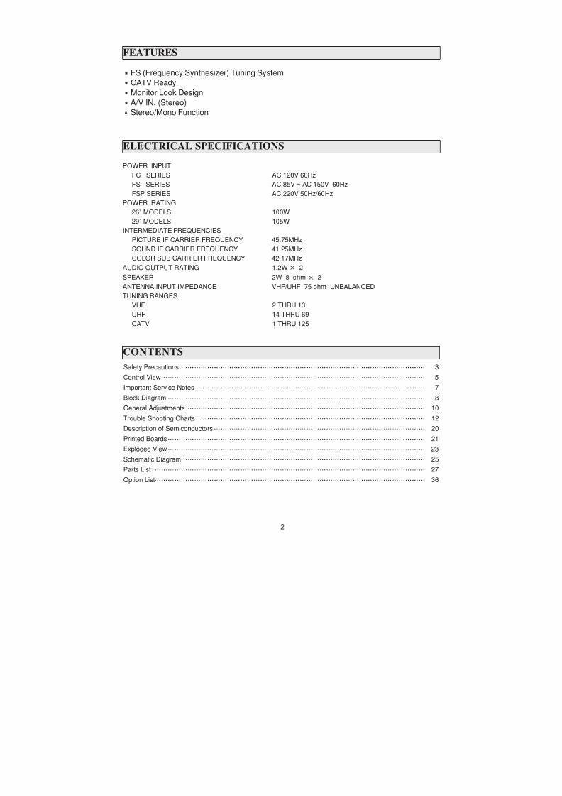
FS (Frequency Synthesizer) Tuning System
CATV Ready
Monitor Look Design
A/V IN. (Stereo)
Stereo/Mono Function
POWER INPUT
FC SERIES AC 120V 60Hz
FS SERIES AC 85V ~ AC 150V 60Hz
FSP SERIES AC 220V 50Hz/60Hz
POWER RATING
26” MODELS 100W
29” MODELS 105W
INTERMEDIATE FREQUENCIES
PICTURE IF CARRIER FREQUENCY 45.75MHz
SOUND IF CARRIER FREQUENCY 41.25MHz
COLOR SUB CARRIER FREQUENCY 42.17MHz
ELECTRICAL SPECIFICATIONS
FEATURES
Page 3
8/3/2019 Chasis CN200A DAEWOO
http://slidepdf.com/reader/full/chasis-cn200a-daewoo 3/35
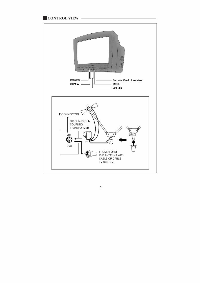
CONTROL VIEW
Page 4
8/3/2019 Chasis CN200A DAEWOO
http://slidepdf.com/reader/full/chasis-cn200a-daewoo 4/35
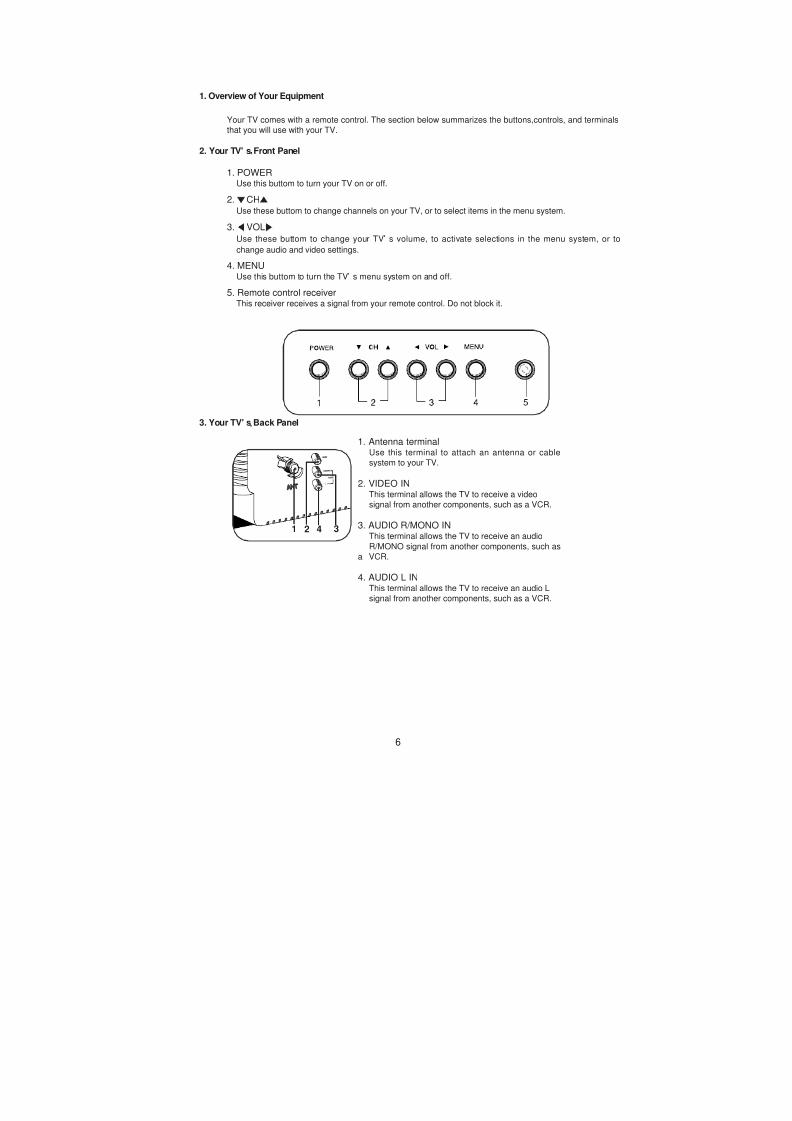
1. Overview of Your Equipment
Your TV comes with a remote control. The section below summarizes the buttons,controls, and terminals
that you will use with your TV.
2. Your TV' s Front Panel
1. POWERUse this buttom to turn your TV on or off.
2. CHUse these buttom to change channels on your TV, or to select items in the menu system.
3. VOL
Use these buttom to change your TV s volume, to activate selections in the menu system, or to
change audio and video settings.
4. MENUUse this buttom to turn the TV s menu system on and off.
5. Remote control receiverThis receiver receives a signal from your remote control. Do not block it.
Page 5
8/3/2019 Chasis CN200A DAEWOO
http://slidepdf.com/reader/full/chasis-cn200a-daewoo 5/35
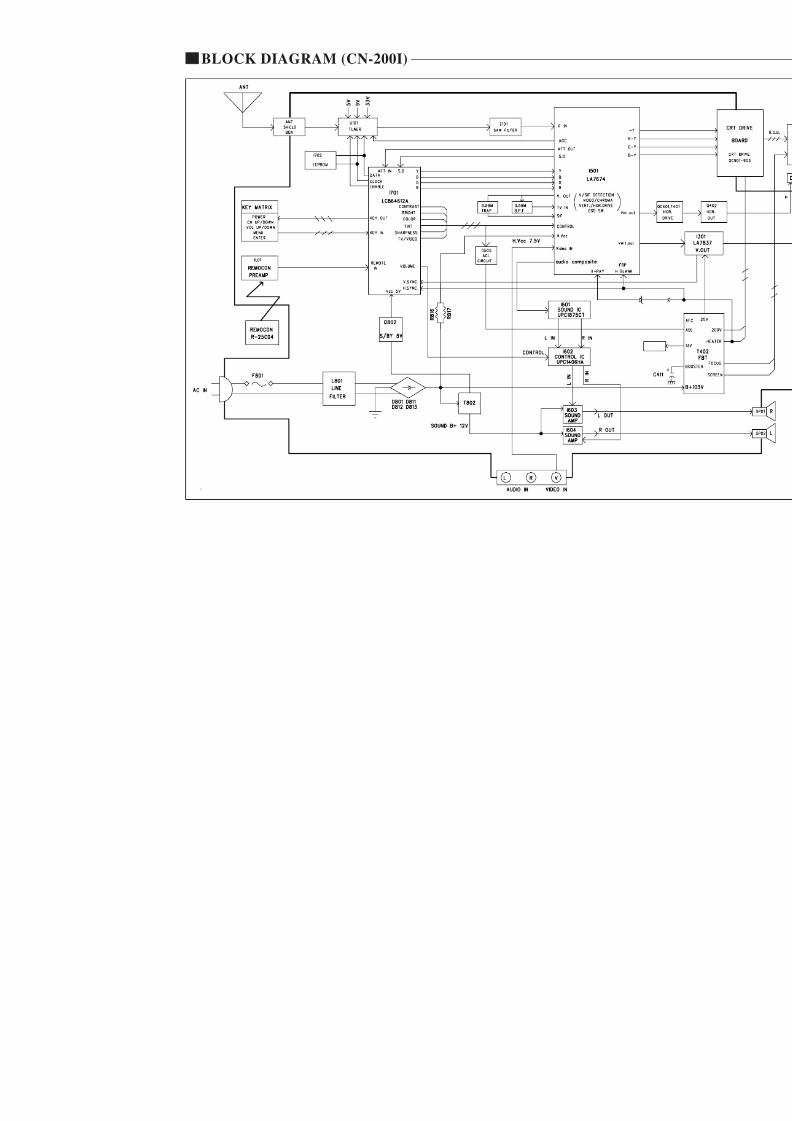
BLOCK DIAGRAM (CN-200I)
Page 6
8/3/2019 Chasis CN200A DAEWOO
http://slidepdf.com/reader/full/chasis-cn200a-daewoo 6/35
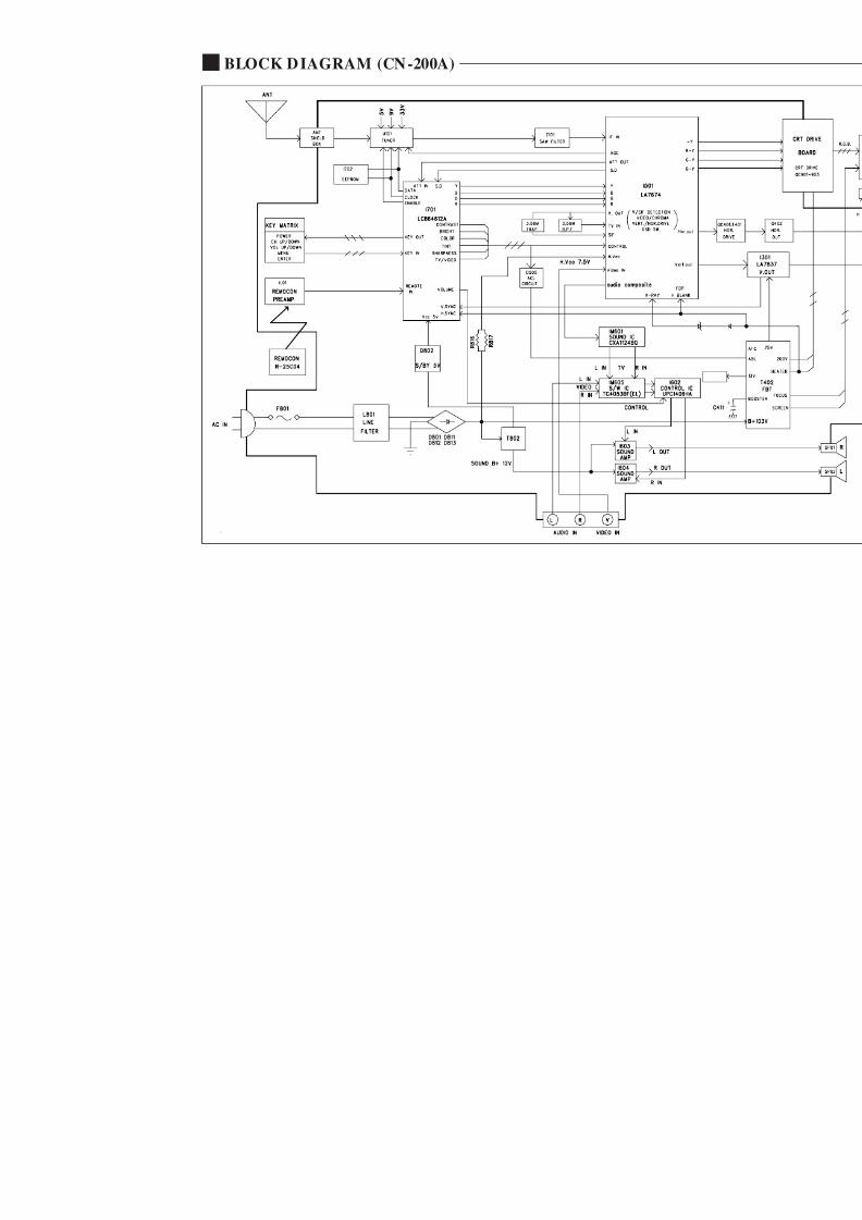
BLOCK DIAGRAM (CN-200A)
Page 7
8/3/2019 Chasis CN200A DAEWOO
http://slidepdf.com/reader/full/chasis-cn200a-daewoo 7/35
GENERAL ADJUSTMENTS
1. GENERALIn the majority of cases, all color televisions will need only
slight touch-up adjustment upon installation. Check the basic
characteristics such as height, focus and sub- basic
characteristics such as height, focus and sub- bright. Observe
the picture for good black and white details without
objectionable color shading.
2. VERTICAL HEIGHT ADJUSTMENT
1) Tune in an active channel.
2) Adjust brightness and contrast controls for a good picture.
3) Adjust vertical height control (R305) for approximately onehalf inch over scan at top and bottom of picture screen.
4) Vertical centering adjustment R310Horizontal centering adjustment R516.
3. FOCUS ADJUSTMENT
1) Tune in an active channel.
2) Adjust brightness, sharpness and contrast controls for a
good picture.3) Adjust focus control (part of T402) for sharp scanning lines
and/or sharp picture.
4. RF AGC ADJUSTMENT
1) Tune in an active channel.
2) Using the attenuator, apply the signal of 60dBm to the
antenna input terminal.
clockwise.)4) Rotate the RED, GREEN and BLUE BIAS controls (R917,
R918, R919) counterclock wise from the maximum, set
them to the position where notches in the knobs become
parallel to the surface of P.C. Board.
5) Set the GREEN and BLUE DRIVE controls (R920, R921)to the mid position.
6) Turn the service switch SW901 (Service Position) on theCRT board.
7) Rotate the SCREEN control (on T402) gradually
clockwise until the second horizontl line following the first
line appears slightly on the screen. Then turn fully
counterclockwise the two BIAS controls corresponding to
the colors of the first and the second horizontal lines to
eliminated the lines.
8) Set the SCREEN control to the position where the third
horizontal line lights slightly on the screen.
9) Adjust the two BIAS control set to the minimum in item 7)
above to obtain the slightly lighted horizontal line in the
same levels of three (red, green, blue) colors. (The line
should be white if the BIAS controls are adjusted
properly.)
10) Turn the service switch SW901 again (Normal position on
the CRT board.)
11) Press PICTURE-SEL, P-UP and set the brightness and
contrast controls to the maximum.
Page 8
8/3/2019 Chasis CN200A DAEWOO
http://slidepdf.com/reader/full/chasis-cn200a-daewoo 8/35
10. PICTURE IF/AFT ADJUSTMENTS
NOTE : THIS RECEIVER IS TRANSISTORIZED AND SPECIAL CARE MUST BE TAKEN WHEN SERVICING. READ
THE FOLLOWING (NOTES BEFORE ATTEMPTING ALIGNMENT)
Alignment requires an exacting procedure and should be undertaken only when necessary.
Isolation transformer must be used to prevent shock hazard.
The test equipment specified or its equivalent is required to perform the alignment properly. Use of equipment which
does not meet these requirements may result in improper alignment.
Accurate equipment is essential to obtain proper alignment of this receiver.
Use of excessive signal from a sweep generator can cause overloading of receiver circuit Overloading should be
avoided to obtain a true response curve. Insertion of markers from the marker generator should not cause distortion of
the response curve.
The AC Power line voltage should be kept 120 volts while alignment is being performed.
Do not attempt to disconnect any components while the receiver is in operation.
Make sure the power cord is disconnected before replacing any parts in the receiver.
TEST EQUIPMENT
Digital voltmeter National Model VP-2600A or equivalent
Oscilloscope Tektronix Model 2215A or equivalent.
Direct/Low-capacity probe Tektronix Model P6120 or equivalent
(Accessory of oscilloscope)
Color-Bar/Dot/Crosshatch generator Tektronix Model 146 or equivalent.
PIF sweep marker generator Nihon Tsushinki Model 4723 or equivalent
Power supply Academy Model 150A or equivalent
Isolation transformer Voltage adjustable type having capacity of
at least 150 watts
BLOCK DIAGRAM
Page 9
8/3/2019 Chasis CN200A DAEWOO
http://slidepdf.com/reader/full/chasis-cn200a-daewoo 9/35
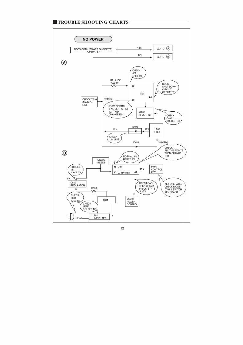
TROUBLE SHOOTING CHARTS
A
A
B
GO TOYESDOES QC701(POWER ON/OFF TR)
OPERATE?
NO
NO POWER
GO TO
2WATT
R816 15K
CHECK
DOESSHUT DOWN
CIRCUITOPERATE?
#30(7.5V DC)
30
26
24
Q402
IF #26 NORMAL& NO OUTPUT AT#23 THENCHANGE I501
CHECK TP10(MAIN B+LINE)
103VDC
I501
Page 10
8/3/2019 Chasis CN200A DAEWOO
http://slidepdf.com/reader/full/chasis-cn200a-daewoo 10/35
21
42
39
31
11 14
C
D
H
H
GO TOOK
CHECK THE WAVE FORM OFI501 #44 (2Vp-p)
NG
FSFC
NO PICTURE
GO TO
I501LA 7674
COMPOSITEVIDEO INPUT
C
C506
Y-OUT
DRIVE
H. BLANKING
CHECK210VKINE
QC501VIDEO
QC201
CONTRAST
BRIGHTCHECKCONTROL(NORMAL)VOLTAGES#39 5 0V T402
Page 11
8/3/2019 Chasis CN200A DAEWOO
http://slidepdf.com/reader/full/chasis-cn200a-daewoo 11/35
#19
#18
#17
#1
#2 9V(B+)
#12
#13
E
F
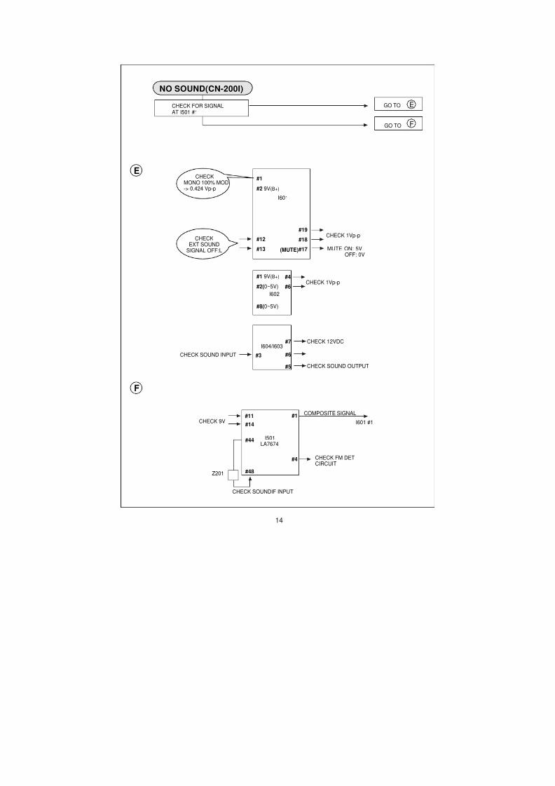
GO TOCHECK FOR SIGNALAT I501 #1
NO SOUND(CN-200I)
GO TO
E
I601
CHECKMONO 100% MOD-> 0.424 Vp-p
CHECKEXT SOUND
SIGNAL OFF:L
CHECK 1Vp-p
MUTE ON: 5VOFF: 0V
(MUTE)
Page 12
8/3/2019 Chasis CN200A DAEWOO
http://slidepdf.com/reader/full/chasis-cn200a-daewoo 12/35
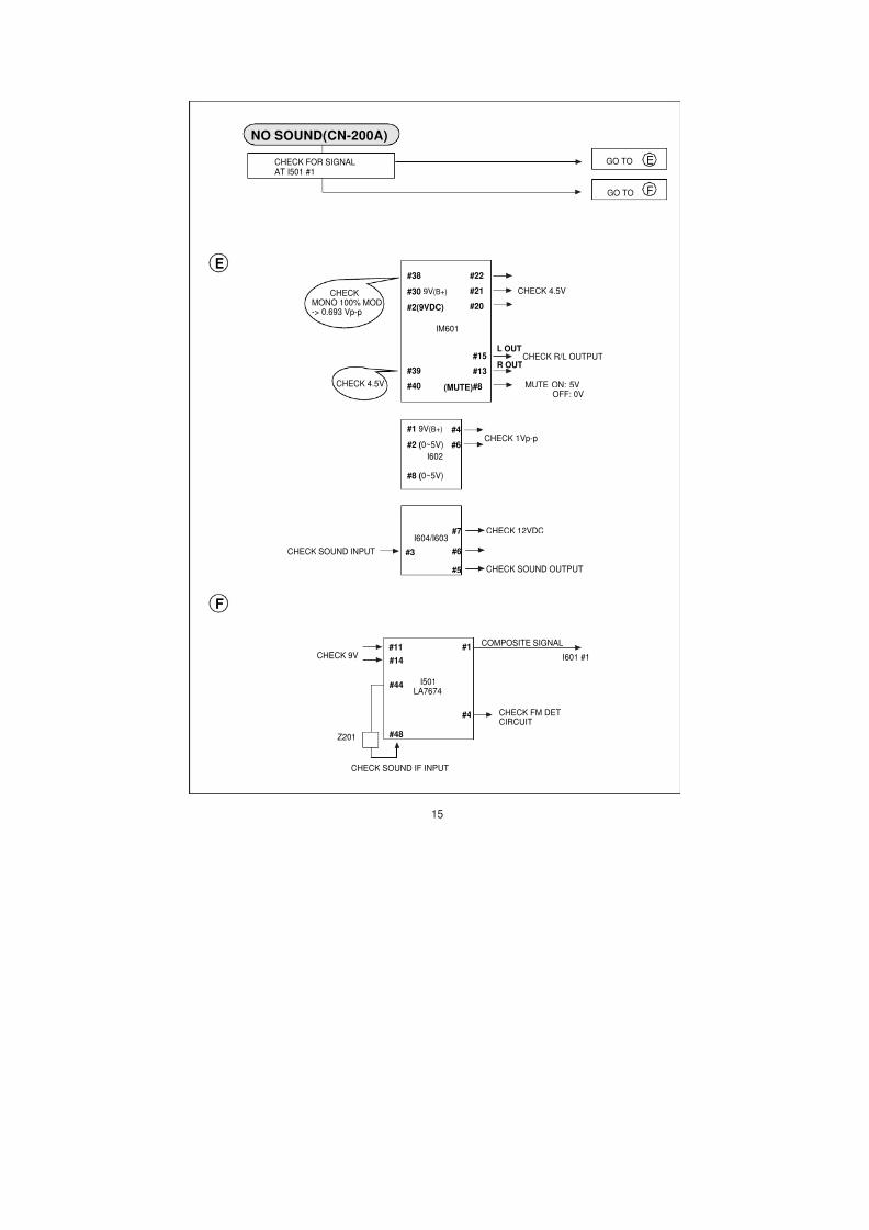
NO SOUND(CN-200A)
#15
#13
#8
#38
#30 9V(B+)
#2(9VDC)
#39
#40
E
F
GO TOCHECK FOR SIGNALAT I501 #1
GO TO
E
IM601
CHECKMONO 100% MOD-> 0.693 Vp-p
CHECK 4.5V
CHECK R/L OUTPUT
MUTE ON: 5VOFF: 0V
(MUTE)
#22
#21
#20
L OUT
R OUT
CHECK 4.5V
Page 13
8/3/2019 Chasis CN200A DAEWOO
http://slidepdf.com/reader/full/chasis-cn200a-daewoo 13/35
8, 9
10
2 3 4
8
9
46
45
GGO TOGOODCHECK INPUT SIGNALCONDITIONS
BAD
CH DON'T STOP
G
LOSS OF SIGNAL ORWEAK SIGNAL
IF OUTPUT
CHECKAFT WINDOWVTG.1.6V ~ 3.4V
ADJUSTRF AGCR113
U101
TUNER
I501LA7674
AFT
PIF
Page 14
8/3/2019 Chasis CN200A DAEWOO
http://slidepdf.com/reader/full/chasis-cn200a-daewoo 14/35
TINT
COLOR
X502
C506COMPOSITEVIDEO
APC FILTER
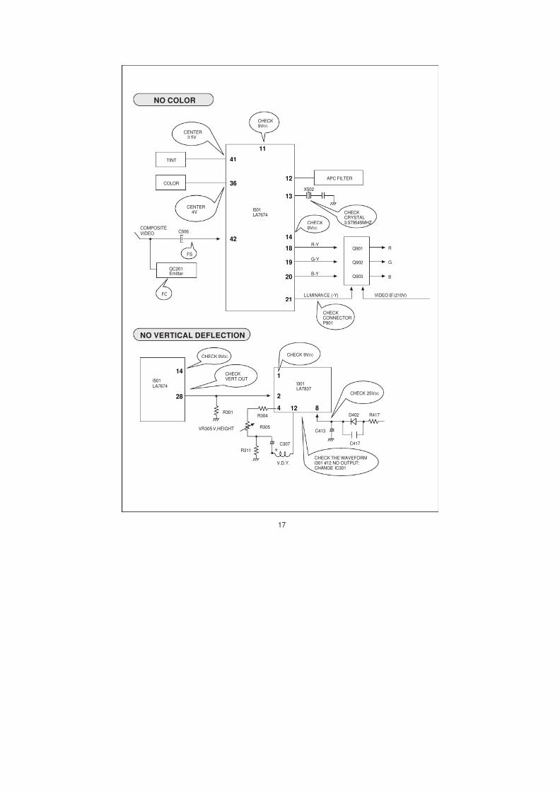
NO COLOR
CENTER
3.5V
CHECK9VDC
CENTER4V
R-Y
G-Y
CHECK9VDC
CHECKCRYSTAL3.579545MHZ
I501LA7674
Q901 R
GQ902
41
36
42
12
13
14
18
19
11
FS
Page 15
8/3/2019 Chasis CN200A DAEWOO
http://slidepdf.com/reader/full/chasis-cn200a-daewoo 15/35
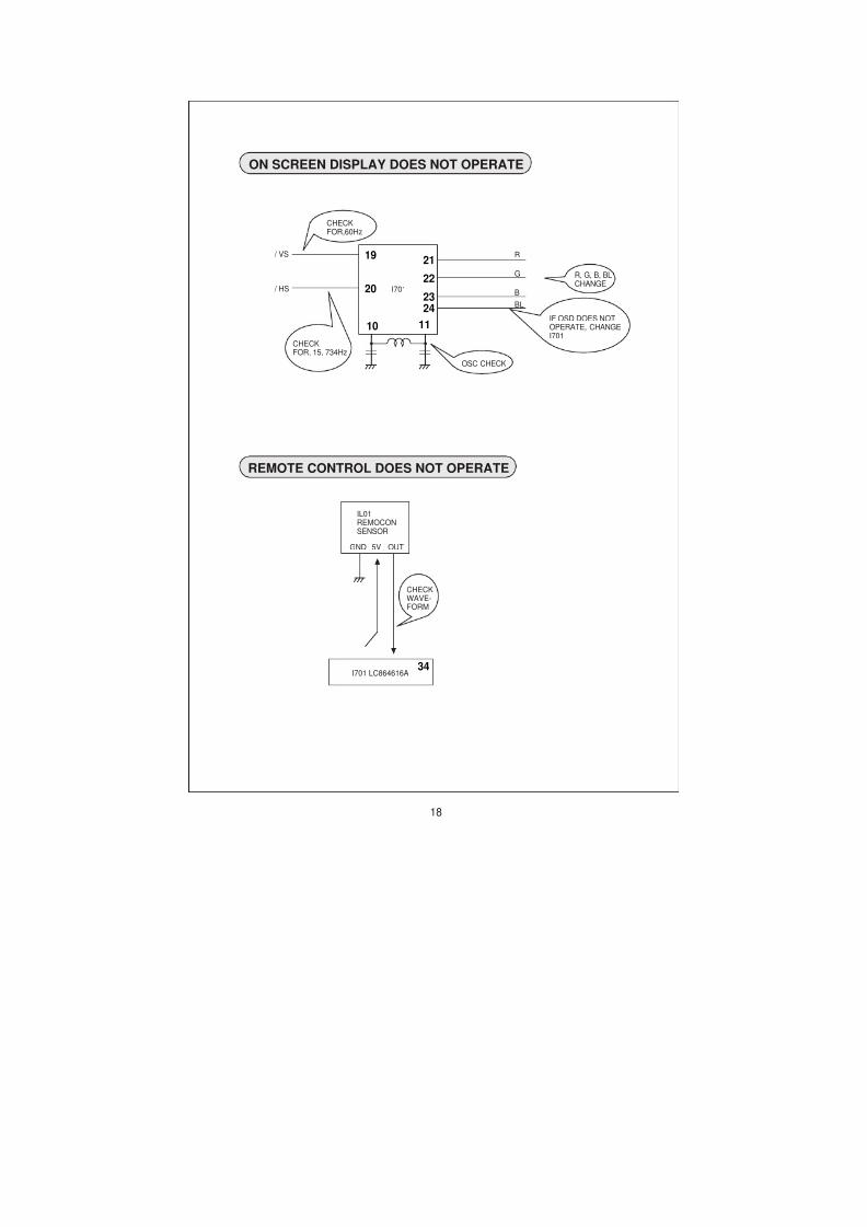
ON SCREEN DISPLAY DOES NOT OPERATE
I701
CHECKFOR,60Hz
OSC CHECK
R, G, B, BLCHANGE
R
G
B
BL
IF OSD DOES NOTOPERATE, CHANGEI701
CHECKFOR, 15, 734Hz
/ VS
/ HS
2119
20
10
22
2324
11
Page 16
8/3/2019 Chasis CN200A DAEWOO
http://slidepdf.com/reader/full/chasis-cn200a-daewoo 16/35
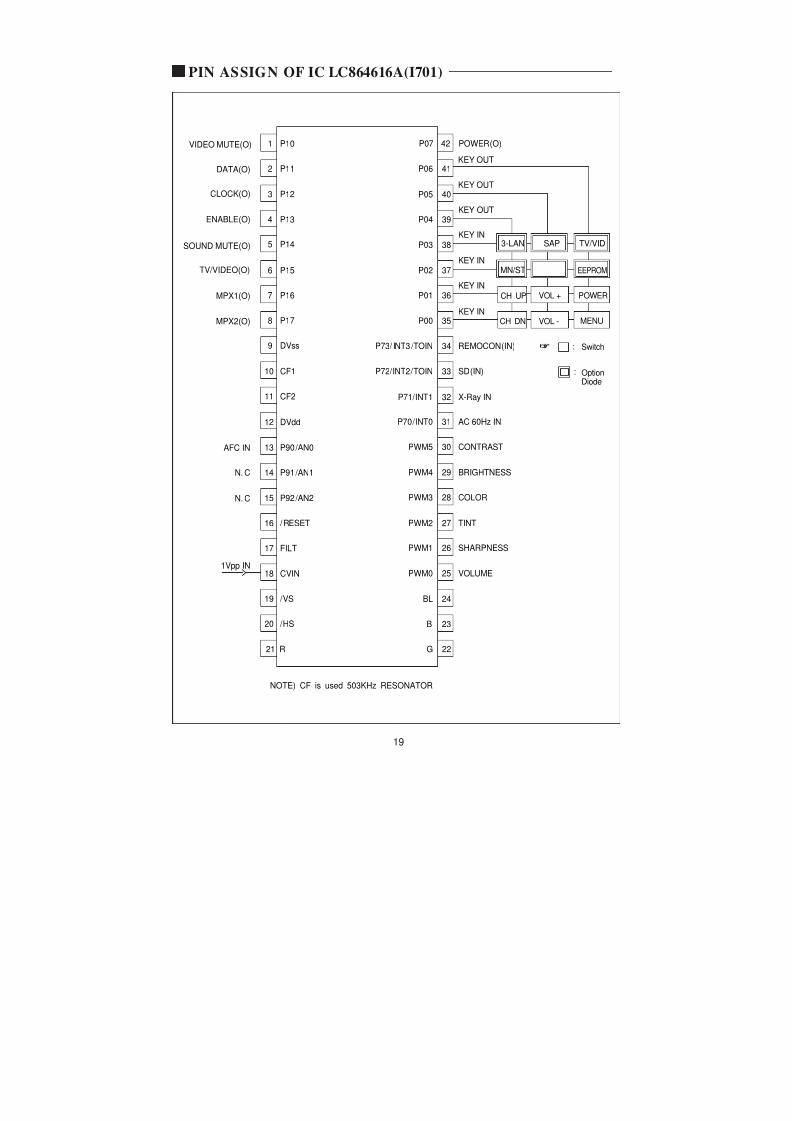
PIN ASSIGN OF IC LC864616A(I701)
VIDEO MUTE(O)
DATA(O)
CLOCK(O)
ENABLE(O)
SOUND MUTE(O)
TV/VIDEO(O)
MPX1(O)
MPX2(O)
1 P10
2 P11
3 P12
4 P13
5 P14
6 P15
7 P16
8 P17
9 DVss
10 CF1
P07 42 POWER(O)
33P72/INT2/TOIN SD(IN)
34P73/ INT3 /TOIN REMOCON(IN)
35P00
36P01
37P02
38P03
39P04
40P05
41P06
KEY IN
KEY IN
KEY IN
KEY IN
KEY OUT
3-LAN
MN/ST
CH UP VOL + POWER
MENUVOL -CH DN
EEPROM
SAP TV/VID
KEY OUT
KEY OUT
: Switch
O i
Page 17
8/3/2019 Chasis CN200A DAEWOO
http://slidepdf.com/reader/full/chasis-cn200a-daewoo 17/35
TROUBLE SHOOTING CHARTS
A
A
B
GO TOYESDOES QC701(POWER ON/OFF TR)
OPERATE?
NO
NO POWER
GO TO
2WATT
R816 15K
CHECK
DOESSHUT DOWNCIRCUITOPERATE?
#30(7.5V DC)
30
26
24
Q402
IF #26 NORMAL& NO OUTPUT AT#23 THENCHANGE I501
CHECK TP10(MAIN B+LINE)
103VDC
I501
Page 18
8/3/2019 Chasis CN200A DAEWOO
http://slidepdf.com/reader/full/chasis-cn200a-daewoo 18/35
21
42
39
31
11 14
C
D
H
H
GO TOOK
CHECK THE WAVE FORM OFI501 #44 (2Vp-p)
NG
FSFC
NO PICTURE
GO TO
I501LA 7674
COMPOSITEVIDEO INPUT
C
C506
Y-OUT
DRIVE
H. BLANKING
CHECK210VKINE
QC501VIDEO
QC201
CONTRAST
BRIGHTCHECKCONTROL(NORMAL)VOLTAGES#39 5 0V T402
Page 19
8/3/2019 Chasis CN200A DAEWOO
http://slidepdf.com/reader/full/chasis-cn200a-daewoo 19/35
#19
#18
#17
#1
#2 9V(B+)
#12
#13
E
F
GO TOCHECK FOR SIGNALAT I501 #1
NO SOUND(CN-200I)
GO TO
E
I601
CHECKMONO 100% MOD-> 0.424 Vp-p
CHECKEXT SOUND
SIGNAL OFF:L
CHECK 1Vp-p
MUTE ON: 5VOFF: 0V
(MUTE)
Page 20
8/3/2019 Chasis CN200A DAEWOO
http://slidepdf.com/reader/full/chasis-cn200a-daewoo 20/35
NO SOUND(CN-200A)
#15
#13
#8
#38
#30 9V(B+)
#2(9VDC)
#39
#40
E
F
GO TOCHECK FOR SIGNALAT I501 #1
GO TO
E
IM601
CHECKMONO 100% MOD-> 0.693 Vp-p
CHECK 4.5V
CHECK R/L OUTPUT
MUTE ON: 5VOFF: 0V
(MUTE)
#22
#21
#20
L OUT
R OUT
CHECK 4.5V
Page 21
8/3/2019 Chasis CN200A DAEWOO
http://slidepdf.com/reader/full/chasis-cn200a-daewoo 21/35
8, 9
10
2 3 4
8
9
46
45
GGO TOGOODCHECK INPUT SIGNALCONDITIONS
BAD
CH DON'T STOP
G
LOSS OF SIGNAL ORWEAK SIGNAL
IF OUTPUT
CHECKAFT WINDOWVTG.1.6V ~ 3.4V
ADJUSTRF AGCR113
U101TUNER
I501LA7674
AFT
PIF
Page 22
8/3/2019 Chasis CN200A DAEWOO
http://slidepdf.com/reader/full/chasis-cn200a-daewoo 22/35
TINT
COLOR
X502
C506COMPOSITEVIDEO
APC FILTER
NO COLOR
CENTER3.5V
CHECK9VDC
CENTER4V
R-Y
G-Y
CHECK9VDC
CHECKCRYSTAL3.579545MHZ
I501LA7674
Q901 R
GQ902
41
36
42
12
13
14
18
19
11
FS
Page 23
8/3/2019 Chasis CN200A DAEWOO
http://slidepdf.com/reader/full/chasis-cn200a-daewoo 23/35
ON SCREEN DISPLAY DOES NOT OPERATE
I701
CHECKFOR,60Hz
OSC CHECK
R, G, B, BLCHANGE
R
G
B
BL
IF OSD DOES NOT
OPERATE, CHANGEI701
CHECKFOR, 15, 734Hz
/ VS
/ HS
2119
20
10
22
2324
11
Page 24
8/3/2019 Chasis CN200A DAEWOO
http://slidepdf.com/reader/full/chasis-cn200a-daewoo 24/35
PIN ASSIGN OF IC LC864616A(I701)
VIDEO MUTE(O)
DATA(O)
CLOCK(O)
ENABLE(O)
SOUND MUTE(O)
TV/VIDEO(O)
MPX1(O)
MPX2(O)
1 P10
2 P11
3 P12
4 P13
5 P14
6 P15
7 P16
8 P17
9 DVss
10 CF1
P07 42 POWER(O)
33P72/INT2/TOIN SD(IN)
34P73/ INT3 /TOIN REMOCON(IN)
35P00
36P01
37P02
38P03
39P04
40P05
41P06
KEY IN
KEY IN
KEY IN
KEY IN
KEY OUT
3-LAN
MN/ST
CH UP VOL + POWER
MENUVOL -CH DN
EEPROM
SAP TV/VID
KEY OUT
KEY OUT
: Switch
O i
Page 25
8/3/2019 Chasis CN200A DAEWOO
http://slidepdf.com/reader/full/chasis-cn200a-daewoo 25/35
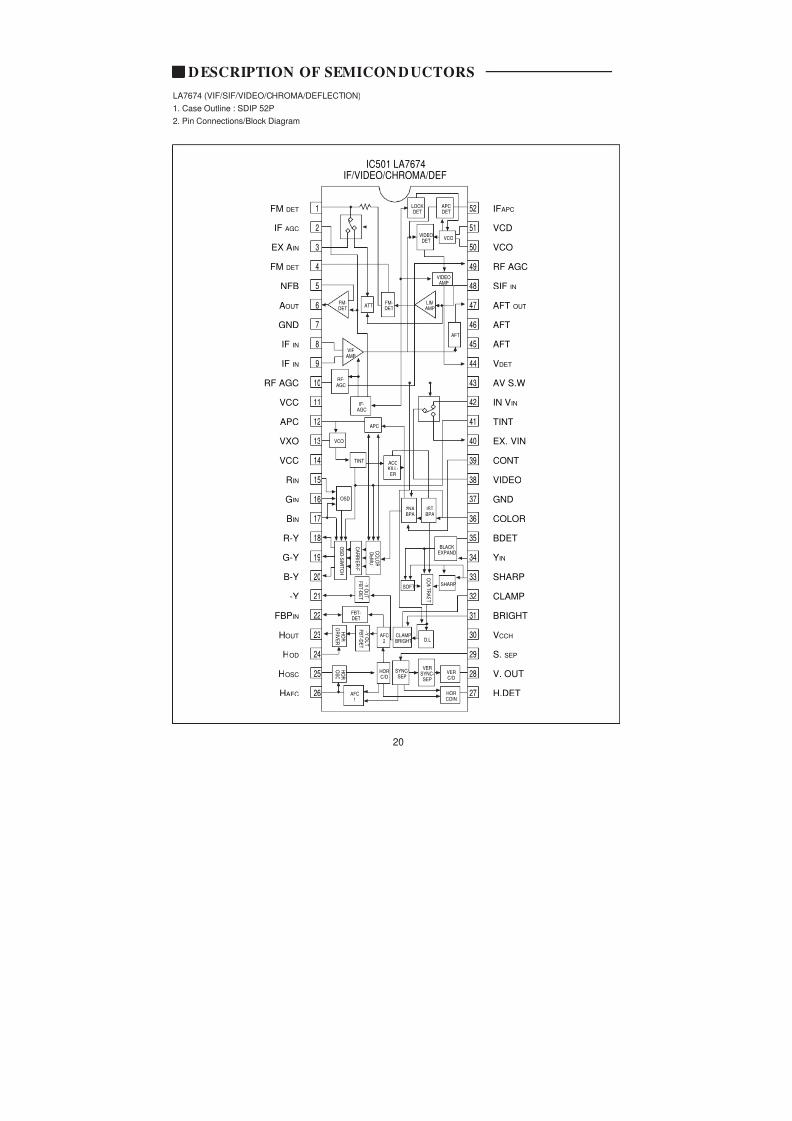
DESCRIPTION OF SEMICONDUCTORS
1
2
3
4
5
6
7
8
9
FM DET
IF AGC
EX AIN
FM DET
NFB
AOUT
GND
IF IN
IF IN
IFAPC
VCD
VCO
RF AGC
SIF IN
AFT OUT
AFT
AFT
VDET
52
51
50
49
48
47
46
45
44
LOCKDET
VIDEOAMP
FM-DET
AFT
FM-DET
VIFAMP
LIMAMP
VIDEODET
APCDET
VCO
ATT
IC501 LA7674IF/VIDEO/CHROMA/DEF
LA7674 (VIF/SIF/VIDEO/CHROMA/DEFLECTION)
1. Case Outline : SDIP 52P
2. Pin Connections/Block Diagram
DTQ-26S1FC/FS/FSP/HC/HS/HSPEXPLODED VIEW
Page 26
8/3/2019 Chasis CN200A DAEWOO
http://slidepdf.com/reader/full/chasis-cn200a-daewoo 26/35
EXPLODED VIEW
DTQ-29S1FCN/FSN/FSP/HC/HS/HSPEXPLODED VIEW
Page 27
8/3/2019 Chasis CN200A DAEWOO
http://slidepdf.com/reader/full/chasis-cn200a-daewoo 27/35
24
EXPLODED VIEW
Page 28
8/3/2019 Chasis CN200A DAEWOO
http://slidepdf.com/reader/full/chasis-cn200a-daewoo 28/35
Page 29
8/3/2019 Chasis CN200A DAEWOO
http://slidepdf.com/reader/full/chasis-cn200a-daewoo 29/35
Page 30
8/3/2019 Chasis CN200A DAEWOO
http://slidepdf.com/reader/full/chasis-cn200a-daewoo 30/35
Page 31
8/3/2019 Chasis CN200A DAEWOO
http://slidepdf.com/reader/full/chasis-cn200a-daewoo 31/35
Page 32
8/3/2019 Chasis CN200A DAEWOO
http://slidepdf.com/reader/full/chasis-cn200a-daewoo 32/35
Page 33
8/3/2019 Chasis CN200A DAEWOO
http://slidepdf.com/reader/full/chasis-cn200a-daewoo 33/35
Page 34
8/3/2019 Chasis CN200A DAEWOO
http://slidepdf.com/reader/full/chasis-cn200a-daewoo 34/35
Page 35
8/3/2019 Chasis CN200A DAEWOO
http://slidepdf.com/reader/full/chasis-cn200a-daewoo 35/35