36
1 Chatter reduction through active vibration damping Abhijit Ganguli Department of Civil Engineering, IIT Delhi

1
Chatter reduction through active vibration damping
Abhijit Ganguli
Department of Civil Engineering, IIT Delhi
2
Motivation of the work:
• To demonstrate active damping as a chatter control strategy
Organization of the presentation • Introduction • Regenerative chatter in turning
• Regenerative chatter in milling
• Active control of chatter
• Experimental investigations
Realization of Demonstrator for chatter in turning
Realization of Demonstrator for chatter in milling
Application of active damping
• Conclusion

3
Applications of machining- • Aircraft & Automobile industries • All kinds basic metallic components & parts • High precision tiny equipments
Introduction
Typical machining operations
Workpiece
Tool
Turning
Milling

4
Chatter Marks Problem affecting machining:
Machine tool chatter instability
Broken tools
Effects of chatter
• Low precision and low surface quality • Damage to tool or workpiece system • Low efficiency • Rising costs
Requirement for the machined end product
• High quality of surface finish

5
Organization of the presentation
• Introduction
• Regenerative chatter in turning
• Regenerative chatter in milling
• Active control of chatter
• Experimental investigations
Realization of demonstrator for chatter in turning
Realization of Demonstrator for chatter in milling
Application of active damping
• Conclusion

6
The regeneration process
T = 60/N = Period of one revolution
Dynamic Chip Thickness
Oscillation during previous pass Oscillation during
current pass
Cutting Force Cutting Constant
Axial width of cut
Chip Thickness
Kcut

7
Feedback Loop Model for chatter in turning (Merrit 1965)
Stable
Marginally Stable
Unstable
Machine vibration
Dynamic chip thickness
Cutting stiffness
Cutting force
Machine tool transfer function
Time delay
+
+
+ _ y(s) Kcut G(s)
Feed
Structural Dynamics
Cutting Process
Displacement Forces

8
Solve characteristic equation
1 + (1 - e-sT ) Kcut G(s) = 0
Pade Approximation
Methods of stability analysis • Time domain simulations • Root Locus Method
Outline of Root Locus Method • Choose spindle speed i.e., T • Solve characteristic equation with increasing Kcut • Identify the value of Kcut for which at least a couple of conjugate roots lie on the imaginary axis
9
Spindle speed
Kcu
t / k
Unstable
Stable
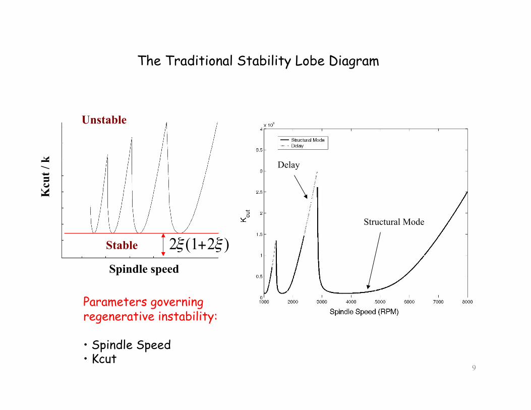
The Traditional Stability Lobe Diagram
Parameters governing regenerative instability:
• Spindle Speed • Kcut
Delay
Structural Mode

10
Organization of the presentation
• Introduction
• Regenerative chatter in turning
• Regenerative chatter in milling
• Active control of chatter
• Experimental investigations
Realization of demonstrator for chatter in turning
Realization of Demonstrator for chatter in milling
Application of active damping
• Conclusion

11
Δx = x – x(t – T); Δy = y – y(t – T) T = tooth passing period = (Period
of rotation/number of teeth)
Regenerative chatter in milling
Periodic Regenerative Forces
Regenerative Displacements
Cutting forces
Axial width of cut
Cutting Constant
Periodic feed
forces
Governing equation: Linear DDE with periodic coefficients

12
Complexities of milling chatter • Existence of tooth passing frequency harmonics (Nm/60) • Multiple mechanisms of chatter
• Stability limits dependent on the kind of milling operation, direction of feed etc.

13
Flip Bifurcation
Hopf Bifurcation
Characteristics of chatter frequencies in milling • Harmonics of tooth passing frequency
• Hopf Bifurcation : Basic chatter frequency close to structural modal frequency
• Flip Bifucation : Chatter frequencies located at odd multiples of one half of tooth passing frequency

14
Observation • Hopf Bifurcation in low stability regions • Flip Bifurcation in certain parts of high stability regions
Downmilling
Downmilling
Upmilling
Stability lobes in milling

15
Organization of the presentation
• Introduction
• Regenerative chatter in turning
• Regenerative chatter in milling
• Active control of chatter
• Experimental investigations
Realization of demonstrator for chatter in turning
Realization of Demonstrator for chatter in milling
Application of active damping
• Conclusion

16
Active control of chatter
• Online control of spindle speed • Application of damping
Spindle speed
Kcu
t / k
Unstable
Stable
High stability Region (control spindle speed)
Augment damping
H(s)

17
Active Damping
Colocated actuator/sensor
Alternating poles & zeros
Actuator
sens
or Control laws with
guaranteed stability
Source – Vibration Control of Active Structures- An Introduction André Preumont

18
How does active damping work?
Enhanced modal damping

19
Demonstration of enhanced damping effect
Stability enhancement more pronounced
Damping Coefficient Feedback
gain
Chatter Frequency

20
Effect of Active Damping of both directions (Numerical Simulation)
• Enhancement of stability more pronounced in low stability regions

21
Organization of the presentation
• Introduction
• Regenerative chatter in turning
• Regenerative chatter in milling
• Active control of chatter
• Experimental investigations
Realization of demonstrator for chatter in turning
Realization of Demonstrator for chatter in milling
Application of active damping
• Conclusion

22
Motivation • To investigate active damping as a chatter control strategy
Difficulties in real machining • Perform numerous cutting tests • Chatter needs to be actually triggered • Life of the machine endangered • Repeatibility of results
Intermediate Platform
A laboratory demonstrator
Technological advances • Chatter model well developed • Advances in signal processing technologies
Potentials • Realistic simulation of regenerative chatter • Repeatability • Platform for active damping

23
Conceptual model of a mechatronic simulator (Hardware in the Loop concept)
Basic parameters governing regenerative instability: Tooth passing period (Spindle speed) • Kcut • Angle of entry & angle of exit (Type of milling)
User defined
Experimental stability Analysis • Choose cutting conditions • Increase Kcut step wise • Monitor displacements • Store Kcut value at instability
Structural Dynamics
Cutting Process
Displacement Forces

24
The Chatter Demonstrator for 1 DOF turning
Structural Dynamics
Software Layer
Hardware Layer
Cutting process

25
Comparison between Experimental & Numerical Simulations
Stability Lobe Diagram
Chatter Frequency Diagram

26
Organization of the presentation
• Introduction
• Regenerative chatter in turning
• Regenerative chatter in milling
• Active control of chatter
• Experimental investigations
Realization of demonstrator for chatter in turning
Realization of Demonstrator for chatter in milling
Application of active damping
• Conclusion
27
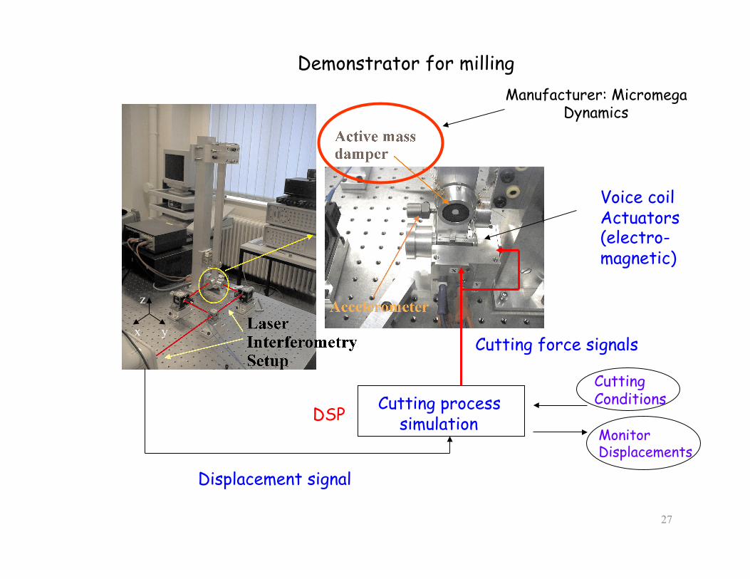
Demonstrator for milling
Cutting process simulation
Voice coil Actuators (electro- magnetic)
Displacement signal
DSP
Cutting force signals
Cutting Conditions
Monitor Displacements
x y
z
Manufacturer: Micromega Dynamics

28
Experimental and numerical stability lobe diagrams
Upmilling
Downmilling

29
Organization of the presentation
• Introduction
• Regenerative chatter in turning
• Regenerative chatter in milling
• Active control of chatter
• Experimental investigations
Realization of demonstrator for chatter in turning
Realization of Demonstrator for chatter in milling
Application of active damping
• Conclusion

30
Application of active damping (Direct acceleration feedback)

31
Effect of active damping (Experimental)
Bending X 2.1 % 6.7 % 8.2 %
Bending Y 2.7 % 4.5 % 5.8 %
Uncontrolled Damped 1 Damped 2

32
Source: Soraluce & Micromega Dynamics
Application of active damping on an industrial setup
33
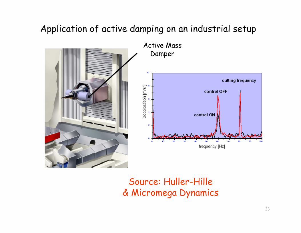
Application of active damping on an industrial setup
Source: Huller-Hille & Micromega Dynamics
Active Mass Damper

34
Conclusions
• Phenomenon of regenerative chatter investigated
• Laboratory mechatronic setups realized
• Demonstrators simulate regenerative chatter realistically
• Active damping as chatter reduction strategy demonstrated

35
Acknowledgements
• Prof. André Preumont
• Drs. M . Horodinca, I. Romanescu, A. Deraemaeker
• All members of the ASL team
• The SMARTOOL Consortium
• The European commission
• Micromega Dynamics

36
Thank you


