105
Land Star 7 User Guide il CHC® LandStar 7 User Guide Revision 1.0 September 2016

Land Star 7 User Guide
Safety Information
il
CHC® LandStar 7 User Guide
Revision 1.0September 2016

Land Star 7 User Guide
2
CopyrightCopyright 2015-2016 CHC |Shanghai HuaCe NavigationTechnology Ltd. All rights reserved.The CHC are trademark ofShanghai Huace NavigationTechnology Limited. All othertrademarks are the property of theirrespective owners.
TrademarksAll product and brand namesmentioned in this publication aretrademarks of their respectiveholders.
Safety WarningsThe Global Positioning System(GPS) is operated by the U.S.Government, which is solelyresponsible for the accuracy andmaintenance of the GPS network.Accuracy can also be affectedby poor satellite geometry andobstructions, like buildings andheavy canopy.
FCC interference statementThis equipment has been designed
to comply with the limitsfor a class B digitaldevice, pursuant to part15 of the FCC Rules in
the Portable Mode. These limits aredesigned to provide reasonableprotection against harmful
interference in a residentialinstallation.
Operation is subject to the followingtwo conditions: (1) this device maynot cause harmful interference and(2) this device must accept anyinterference thatmay cause undesired operation.
LandStar 7 Quick Start Guide –Revision 1.0 September 2016

Land Star 7 User Guide
Table of contents
1 LandStar 7 Overview............................................................................ 11.1 Software Description.....................................................................11.2 Unique Characteristics.................................................................. 11.3 Software Interface......................................................................... 31.4 Software Installation......................................................................7
2 Project......................................................................................................72.1 Projects.......................................................................................... 7
2.1.1 New.....................................................................................72.1.2 Delete................................................................................122.1.3 Open................................................................................. 122.1.4 Upload and Download......................................................13
2.2 CRS..............................................................................................142.3 Import.......................................................................................... 192.4 Export.......................................................................................... 202.5 Reports.........................................................................................212.6 Base Map..................................................................................... 222.7 Points........................................................................................... 23
2.7.1 Add................................................................................... 232.7.2 Query................................................................................ 242.7.3 Delete................................................................................242.7.4 Details...............................................................................252.7.5 Recycle............................................................................. 262.7.6 Coordinate Type............................................................... 262.7.7 Multiple Operation........................................................... 27
2.8 Lines............................................................................................ 272.8.1 Add................................................................................... 272.8.2 Delete................................................................................28

Land Star 7 User Guide
4
2.8.3 Detail................................................................................ 292.8.4 Request............................................................................. 30
2.9 Features........................................................................................312.10 Cloud......................................................................................... 312.11 CodeList.....................................................................................322.12 PRJ Codes..................................................................................38
3 Config.................................................................................................... 393.1 Connect........................................................................................393.2 Work Mode.................................................................................. 40
3.2.1 External Radio Base......................................................... 413.2.2 Internal UHF Base............................................................413.2.3 Internal UHF Rover..........................................................433.2.4 Internal GSM Rover (Receiver Network)........................443.2.5 DCI (PDA Network).........................................................473.2.6 Static Settings................................................................... 49
3.3 NMEAOutput............................................................................. 513.4 Device Info.................................................................................. 523.5 Interface....................................................................................... 543.6 About........................................................................................... 54
4 Survey................................................................................................... 554.1 Map..............................................................................................55
4.1.1 Option............................................................................. 554.1.2 Symbols..........................................................................60
4.2 PT Survey.................................................................................... 624.3 PT Stakeout..................................................................................644.4 Line Stakeout...............................................................................654.5 Surface Stakeout..........................................................................694.6 Road.............................................................................................70
4.6.1 The introduction of Road interface.................................. 70

Land Star 7 User Guide
4.6.2 Road..................................................................................724.6.3 Road Stakeout...................................................................77
4.7 PPK..............................................................................................814.8 Site Calibration............................................................................844.9 Base Shift.....................................................................................85
5 Tools.......................................................................................................865.1 Inverse Calculation......................................................................865.2 Areas............................................................................................ 875.3 Angle Converter.......................................................................... 875.4 Parameters Calculate................................................................... 885.5 Calculator.................................................................................... 905.6 Ruler............................................................................................ 915.7 Ionosphere Prediction..................................................................915.8 Point to Line Distance................................................................. 925.9 Eccentric Distance.......................................................................935.10 Deflection Angle........................................................................935.11 Rotation......................................................................................945.12 Intersection Point.......................................................................955.13 Bisection Angle......................................................................... 965.14 Divide Line................................................................................97


Land Star 7 User Guide
1
1 LandStar 7 Overview
1.1 Software DescriptionThanks for your interest in LandStar 7 – the most convenient software for
positioning. It is the latest measuring software based on Android platform and
developed by CHC Technology Co., Ltd.
If you are new to LandStar 7, you will be impressed by its convenient work
mode switching, graphic measurement interface, simple operation, friendly
user guide, extensive data import/export formats and multiple types of
measurement and stakeout methods.
LandStar 7 supports X91/X900 with the firmware version of v8.33 and above,
and CHC smart receiver i80 with the firmware version of v1.3.42 and above, as
well as GNSS receiver in your Android smartphone and handheld controller.
You will enjoy high precision surveying with various types of measurement, as
well as abundant import/export data formats.
1.2 Unique CharacteristicsPowerful graphical surveying: Support both online OSM (Open Street Map)
map and offline map (DXF and SHP file) as the base map while surveying.
Selected points in a DXF or SHP file can be automatically added to the point’
s manager for staking out.
Automatic drawings: Multiple line and polygon features can be measured
simultaneously, with measuring results are mapped automatically in the field
and the perimeters and areas are stored into the features manager.
Extensive data import and export formats: Support CSV, DAT, TXT, DXF,SHP and NCN as the import format, CSV, DAT, TXT, KML, DXF, SHP, RAW,
HTML as the export format. Contents of CSV, DAT, TXT can be customized by
users.
Multiple localization methods: Support 3 parameters, 7 parameters, 4

Land Star 7 User Guide
2
parameters, Geoid and Grid shift file (GGF)[ BIN, GRD, GSF, GRI and ASC
geoid and grid shift file formats will available soon.], RTCM transformation
message(1021-1027).
Correction repeater function: Support repeating correction data from RTK
network to other rovers via the internal radio modem.
Convenient work mode management: Support presetting of common work
modes of base and rover, selecting or switching work modes by one button
push. You will not need additional steps to configure your work mode while
surveying.
Various types of measurement: Support points, lines, polygons and PPK
measurement. The methods of point measurement include topographic point,
control point, quick point, continuous point, offset point and compensation
point.
Multiple types of stakeout: Support point stakeout, line stakeout, surface
stakeout and road stakeout.
Various GNSS data resources: Support CHC legacy ARM and i80 GNSS
receivers, Android smartphone and handheld controller internal GPS, and
many types of peripheral instruments such as generic NMEA0183 receivers.
Three connection types: Support three different connection types, Bluetooth,WIFI and demonstration modes.WIFI mode features fast connection speed,
stable performance and longer distance. Demonstration module allows user to
input the coordinates and simulate it as the current position.
Smart e-manual: Support embedded e-manual. You can check the help
documentation in the top right corner of the interface and get guide of each
function being used.
RAW file recording: Support RAW files. You can review the operation
procedures, configuration parameters and measurement results, as well as
transfer RAW files into third party surveying software.
Customizable layer display: Support separate display of points name, code
and height, custom of color, size and type of points, lines and polygons,
Land Star 7 User Guide
3
configuration of single or multiple points with height.
Navigation stakeout: Support real-time display of direction, distance and
elevation difference between your position and the point to stakeout.
Measurement geofencing: Support series of points as the measurement
geofencing. It will remind you once your position goes out of the boundary to
ensure user’s work being limited in a predetermined area.
Site calibration Quality Control : Support automatic reminders when the
error of site calibration results is too large, preventing wrong corrections to be
applied.
Powerful COGO tools: Support calculation of perimeters, areas,
transformation parameters, etc. It also has a build-in RPN calculator so that
you can do common calculations conveniently in the field.
Real-time global TEC map: Support a built-in global TEC map with updating
every 10 minutes to help you to choose the best working time in high
ionospheric activity regions.
1.3 Software InterfaceLandStar 7 main interface is divided into four parts: Project, Survey, Configand Tools.Startup Interface: Install at the first time and run the software can directly intothe main interface and go to the next slide in turn.

Land Star 7 User Guide
4
Status Bar
: This icon will show receiver battery.
: This icon will lead you to device Information interface.
: This icon will read skyplot information and satellites list. Arepresents the total number of received satellites; N represents
the number of effective solver satellites.
: This icon will lead you to view position and precision of single
status.
: This icon will lead you to view position and precision of float
status.
: This icon will lead you to view position and precision of fixed
status.
Precision : H means horizontal accuracy, V means elevation accuracy;
RMS means the relative error.
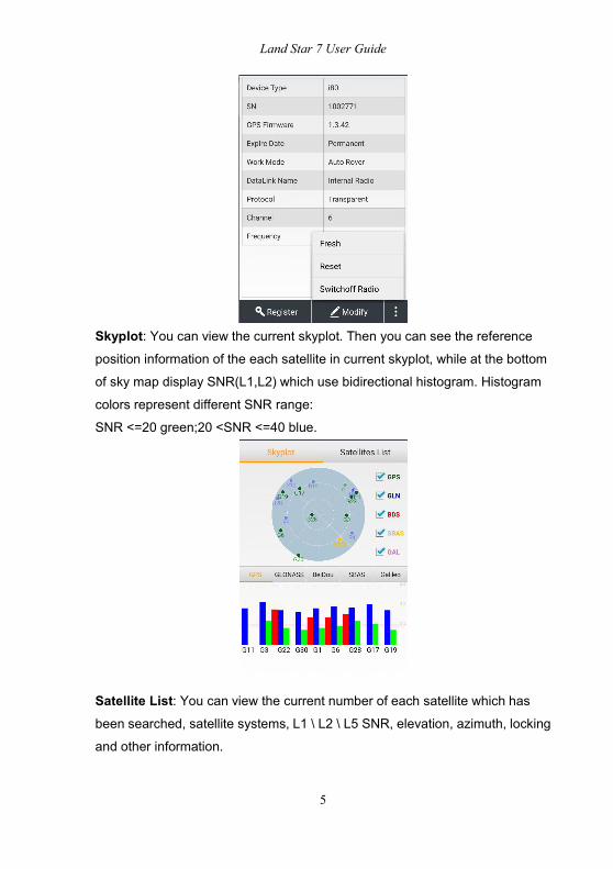
Device Information: You can view the details of the current device as shown
below.
Land Star 7 User Guide
5
Skyplot: You can view the current skyplot. Then you can see the reference
position information of the each satellite in current skyplot, while at the bottom
of sky map display SNR(L1,L2) which use bidirectional histogram. Histogram
colors represent different SNR range:
SNR <=20 green;20 <SNR <=40 blue.
Satellite List: You can view the current number of each satellite which has
been searched, satellite systems, L1 \ L2 \ L5 SNR, elevation, azimuth, locking
and other information.

Land Star 7 User Guide
6
Position: You can view GPS time, solver status (single point, floating or fixed),
the differential delay and the current position in WGS84. You can also change
coordinate system in the drop down list (including Local N/E/H, Local
Lat/Lon/H, Local X/Y/Z, WGS84 Lat/Lon/H, WGS84 X/Y/Z).
Precision: You can view horizontal precision, vertical precision and RMS.
DOPs: You can view current status of the search space satellites precision
factors, including PDOP, HDOP, VDOP, TDOP and GDOP.

Land Star 7 User Guide
7
1.4 Software InstallationCopy the software (LandStar 7.apk) and help (LandstarHelp.apk) onto Android
devices, touch screen to start the installation program. After install successfully,
it will generate LandStar 7 procedures and LandStar 7.Help icon on the
desktop, open the LS7 software and click the help icon at the top-right corner
to view the help file.
2 Project
2.1 Projects
2.1.1 NewWhile creating a new project, clicking Yes if it prompts “Set the Current ProjectXXX Code list as Default Code list Template or not”. Then, you will cover the
code list of default template with current code when closing a project.
Note: The prompt "Close Current Project and Create a New One" will pop up if
you had projects in the list before. Clicking Confirm means you are allowed to
another new project.

Land Star 7 User Guide
8
Project Name: Input the project name.Author: Input the name of the operator.Date: The default time is the local time.Time zone: It refers to the time zone different from local time and the GPS
time which can be selected in the time zone drop-down list from -12 to +14.
Project Template: Select the project template, then it will show you a list of
historical projects. You can select one and click OK to complete the project
template. It's used for applying the transformation parameters for different sites.
For example, there is task A which has finished site calibration, while another
task B needs the transformation parameters the same as task A. When you
input a new project name in Projects, you can select task A in the project
template.
Note: Transformation parameter isn't applied if the new project you’re creating
without project template. Project template can also apply all parameters of the
existed project.
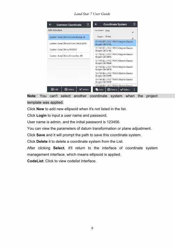
Coordinate System: You are able to add a new coordinate system after
clicking Add. Select coordinate system, then the interface of coordinatesystem management will pop up.
Land Star 7 User Guide
9
Note: You can't select another coordinate system when the project
template was applied.
Click New to add new ellipsoid when it's not listed in the list.
Click Login to input a user name and password.
User name is admin, and the initial password is 123456.
You can view the parameters of datum transformation or plane adjustment.
Click Save and it will prompt the path to save this coordinate system.Click Delete it to delete a coordinate system from the List.
After clicking Select, it'll return to the interface of coordinate system
management interface, which means ellipsoid is applied.
CodeList: Click to view codelist interface.
Land Star 7 User Guide
10
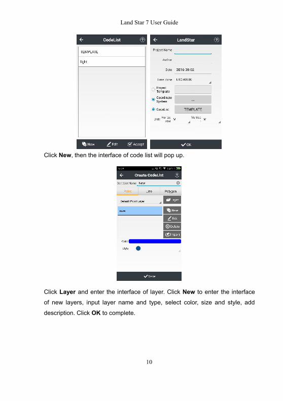
Click New, then the interface of code list will pop up.
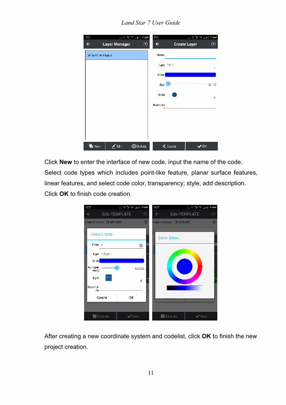
Click Layer and enter the interface of layer. Click New to enter the interface
of new layers, input layer name and type, select color, size and style, add
description. Click OK to complete.
Land Star 7 User Guide
11
Click New to enter the interface of new code, input the name of the code.
Select code types which includes point-like feature, planar surface features,
linear features, and select code color, transparency; style, add description.
Click OK to finish code creation.
After creating a new coordinate system and codelist, click OK to finish the new
project creation.
Land Star 7 User Guide
12
Click Edit to edit current new code.
Click Accept and it will return to previous interface which means code isapplied.
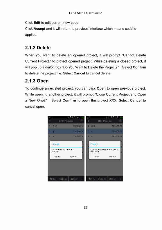
2.1.2 DeleteWhen you want to delete an opened project, it will prompt "Cannot Delete
Current Project." to protect opened project. While deleting a closed project, it
will pop up a dialog box "Do You Want to Delete the Project?" Select Confirmto delete the project file. Select Cancel to cancel delete.
2.1.3 OpenTo continue an existed project, you can click Open to open previous project.
While opening another project, it will prompt "Close Current Project and Open
a New One?" Select Confirm to open the project XXX. Select Cancel tocancel open.
Land Star 7 User Guide
13
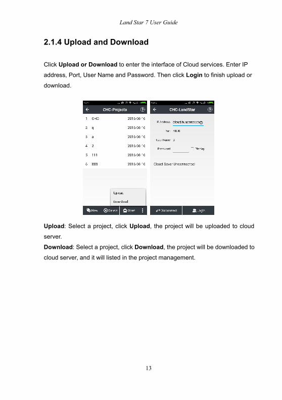
2.1.4 Upload and Download
Click Upload or Download to enter the interface of Cloud services. Enter IP
address, Port, User Name and Password. Then click Login to finish upload or
download.
Upload: Select a project, click Upload, the project will be uploaded to cloud
server.
Download: Select a project, click Download, the project will be downloaded tocloud server, and it will listed in the project management.
Land Star 7 User Guide
14
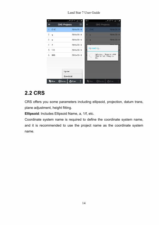
2.2 CRSCRS offers you some parameters including ellipsoid, projection, datum trans,
plane adjustment, height fitting.
Ellipsoid: Includes Ellipsoid Name, a, 1/f, etc.Coordinate system name is required to define the coordinate system name,
and it is recommended to use the project name as the coordinate system
name.
Land Star 7 User Guide
15
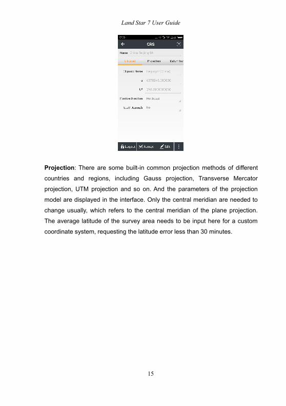
Projection: There are some built-in common projection methods of different
countries and regions, including Gauss projection, Transverse Mercator
projection, UTM projection and so on. And the parameters of the projection
model are displayed in the interface. Only the central meridian are needed to
change usually, which refers to the central meridian of the plane projection.
The average latitude of the survey area needs to be input here for a custom
coordinate system, requesting the latitude error less than 30 minutes.

Land Star 7 User Guide
16
Datum Trans: Represents the mathematical model for transformation betweentwo coordinate systems. Datum transformation model includes none parameter,
three parameters, seven parameters models. You can input the local seven
parameters directly if they have, no needing the site calibration any more.
7 parameters: Requires having three known points at least, and the points can
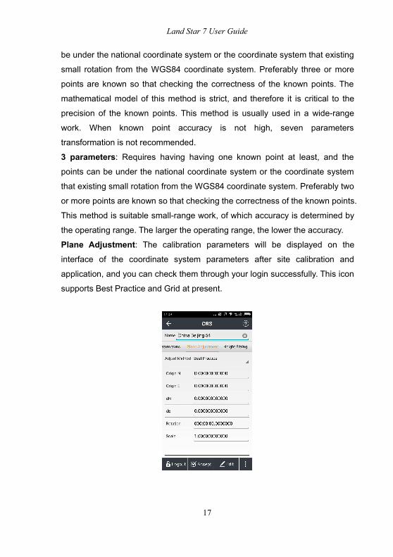
Land Star 7 User Guide
17
be under the national coordinate system or the coordinate system that existing
small rotation from the WGS84 coordinate system. Preferably three or more
points are known so that checking the correctness of the known points. The
mathematical model of this method is strict, and therefore it is critical to the
precision of the known points. This method is usually used in a wide-range
work. When known point accuracy is not high, seven parameters
transformation is not recommended.
3 parameters: Requires having having one known point at least, and the
points can be under the national coordinate system or the coordinate system
that existing small rotation from the WGS84 coordinate system. Preferably two
or more points are known so that checking the correctness of the known points.
This method is suitable small-range work, of which accuracy is determined by
the operating range. The larger the operating range, the lower the accuracy.
Plane Adjustment: The calibration parameters will be displayed on the
interface of the coordinate system parameters after site calibration and
application, and you can check them through your login successfully. This icon
supports Best Practice and Grid at present.
Land Star 7 User Guide
18
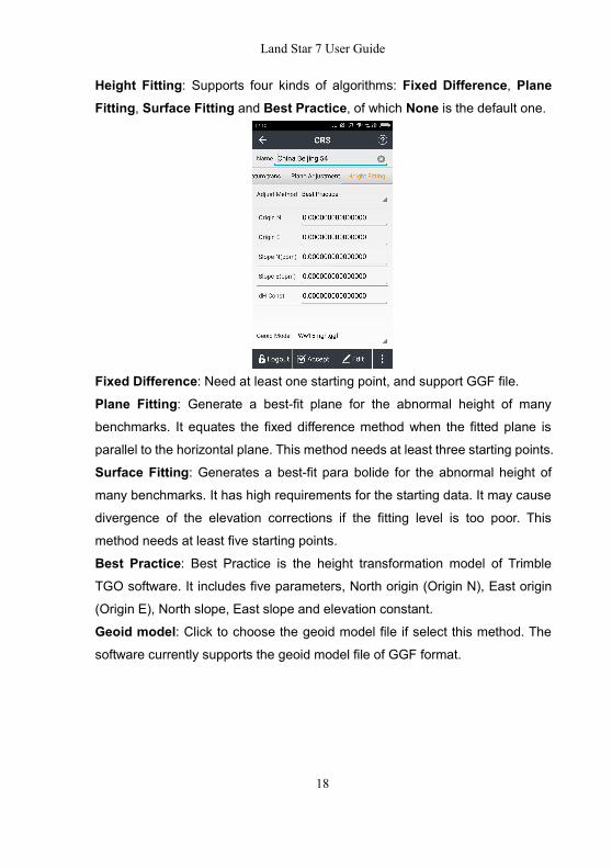
Height Fitting: Supports four kinds of algorithms: Fixed Difference, PlaneFitting, Surface Fitting and Best Practice, of which None is the default one.
Fixed Difference: Need at least one starting point, and support GGF file.
Plane Fitting: Generate a best-fit plane for the abnormal height of many
benchmarks. It equates the fixed difference method when the fitted plane is
parallel to the horizontal plane. This method needs at least three starting points.
Surface Fitting: Generates a best-fit para bolide for the abnormal height of
many benchmarks. It has high requirements for the starting data. It may cause
divergence of the elevation corrections if the fitting level is too poor. This
method needs at least five starting points.
Best Practice: Best Practice is the height transformation model of Trimble
TGO software. It includes five parameters, North origin (Origin N), East origin
(Origin E), North slope, East slope and elevation constant.
Geoid model: Click to choose the geoid model file if select this method. The
software currently supports the geoid model file of GGF format.

Land Star 7 User Guide
19
2.3 Import
It is no doubt that inputting a large amount of known points to data controller is
always wasting time and easy to make mistakes. Click Import in maininterface, and the software will import the known data according to the
requirement format in device or SD card.
File Name: Input the file name.
Coordinate System: Plane or Lat/Lon.
File Type: TXT file or CSV file. There are several available formats in common
use and users can also set the format in custom.
Customize: You can also customize the import contents while choosing theCSV, DAT and TXT format.
Path: Select the path of import file. Click the folder and it will display a blueselect prompt. Then, click Import.
Land Star 7 User Guide
20
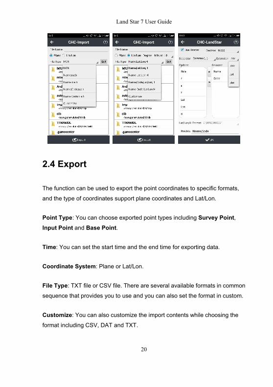
2.4 Export
The function can be used to export the point coordinates to specific formats,
and the type of coordinates support plane coordinates and Lat/Lon.
Point Type: You can choose exported point types including Survey Point,Input Point and Base Point.
Time: You can set the start time and the end time for exporting data.
Coordinate System: Plane or Lat/Lon.
File Type: TXT file or CSV file. There are several available formats in common
sequence that provides you to use and you can also set the format in custom.
Customize: You can also customize the import contents while choosing theformat including CSV, DAT and TXT.
Land Star 7 User Guide
21
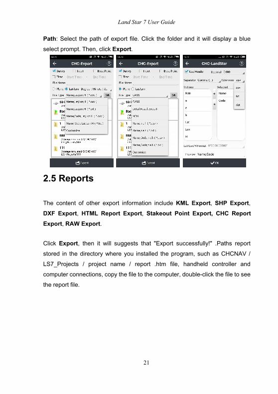
Path: Select the path of export file. Click the folder and it will display a blue
select prompt. Then, click Export.
2.5 Reports
The content of other export information include KML Export, SHP Export,DXF Export, HTML Report Export, Stakeout Point Export, CHC ReportExport, RAW Export.
Click Export, then it will suggests that "Export successfully!" .Paths report
stored in the directory where you installed the program, such as CHCNAV /
LS7_Projects / project name / report .htm file, handheld controller and
computer connections, copy the file to the computer, double-click the file to see
the report file.

Land Star 7 User Guide
22
2.6 Base MapBase map mainly import the required map to software. Now it supports two
formats namely DXF and SHP. After importing, the points or lines that are in
the base map can be displayed, selected or stakeout.
To modify the layer display, click Survey-Map-Settings-Display.

Land Star 7 User Guide
23
2.7 Points
Points can view the input point, the measuring point and the coordinate of the
point to be staked.
2.7.1 AddClick Add to create a point. Creating a point needs some attributes as follows:
name, code, coordinate systems (Including: local NEH, local BLH, local XYZ,
WGS84 BLH, WGS84 XYZ coordinates), role (Including Normal Point and
Control Point). Then, input the point coordinate that you create, and make sure
the code item must be non-mandatory.
Note: If the point that you make have reel number, the prompt “Projection
Error” will appear after adding point. We can add reel number in “False East'
from CRS-Projection.
Set the above values, click OK and the coordinates point will be built.
Land Star 7 User Guide
24
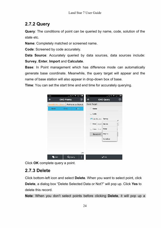
2.7.2 QueryQuery: The conditions of point can be queried by name, code, solution of the
state etc.
Name: Completely matched or screened name.Code: Screened by code accurately.Data Source: Accurately queried by data sources, data sources include:
Survey, Enter, Import and Calculate.Base: In Point management which has difference mode can automatically
generate base coordinate. Meanwhile, the query target will appear and the
name of base station will also appear in drop-down box of base.
Time: You can set the start time and end time for accurately querying.
Click OK complete query a point.
2.7.3 DeleteClick bottom-left icon and select Delete. When you want to select point, click
Delete, a dialog box “Delete Selected Data or Not?” will pop up. Click Yes todelete this record.
Note: When you don’t select points before clicking Delete, it will pop up a
Land Star 7 User Guide
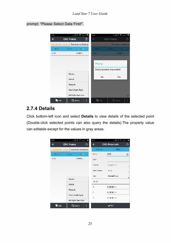
25
prompt: “Please Select Data First!”.
2.7.4 DetailsClick bottom-left icon and select Details to view details of the selected point
(Double-click selected points can also query the details).The property value
can editable except for the values in gray areas.

Land Star 7 User Guide
26
2.7.5 RecycleRecycle is used to restore deleted records, and if deleted records do not exist,
it will prompt "No Record".
Detail: Query details of deleted point coordinate.Restore Point: Recover coordinates information of deleted points.Query: Query information of deleted points but cannot query the undelete
points.
Coordinate Type: Set coordinates types of recycle points.
Coordinates Library: Click to view coordinates library.
Multiply Operation: Multiply clear the selected point in the recycle bin.
2.7.6 Coordinate TypeYou can set coordinates types of points.

Land Star 7 User Guide
27
2.7.7 Multiple OperationClick it, then, you can delete points from point management not only one item
but also multi-items.
2.8 Lines
2.8.1 AddClick Add to create a line, enter the following new line interface to create a line:

Land Star 7 User Guide
28
Linetype (Including: Line, Circle, Arc), Method (Including Two Points, One
Point + Azimuth + Distance), Name, Start Point, End Point, Start Distance.
After setting the above values, click OK, a line can be built.
2.8.2 Delete
When selecting line, click Delete , and then it will pop up a dialog box "DeleteSelected Data or Not?", Select Yes, remove this record, select No, do notdelete this record.

Land Star 7 User Guide
29
When the line is not selected, click on the Delete button will pop up a prompt“Please Select Data First!”.
2.8.3 Detail
Select Line, click Detail to view detailed information about the selected line
(double-click the selected points can also check the details at that line).In
addition, the gray area indicates the property value of the remaining property
values are editable.

Land Star 7 User Guide
30
2.8.4 Request
Click Request to view line query conditions. Line query conditions can be
queried by line, name, origin, destination, and other fields.
Name: exactly match the query line.

Land Star 7 User Guide
31
Start point: The starting point of the line can be an exact match queries.End Point: Through the end of the line can be an exact match queries.Length: Fully match the query by the length of the line (Enter the start and endvalues).
2.9 FeaturesClick Features, then it will display the line or region features which collected incurrent project. Double click Map Display, the collected features will display inMap Display and it can also inquire or delete by Map Display.
2.10 CloudCloud is the login interface of Cloud, and you can upload or download tasks,
coordinate system, work mode etc. You can ask local dealer or salesman for
obtaining an account and password to use Cloud. CHC will help customers to
build own cloud server (Customer need to provide server and network) if
necessary. For more information, please contact local dealer or salesman.

Land Star 7 User Guide
32
2.11 CodeListThe main function of CodeList is to manage codes under the different work
conditions. For example, the codes of water management and road survey
require different code; if we save these codes in one list, it is not easy to select
when we do the field jobs. So it is better to create the different code lists to
save the different codes, and you can select the corresponding code list basing
on the particular work condition. Create a new group of CodeList, and then
click TEMPLATE to enter CodeList.
Click New to create a new group of CodeList (For example: CITY). It contains
three elements: Point, Line and Polygon.

Land Star 7 User Guide
33
Click Layer, later click New to create new layers.
Point:Name: TREE.Type: Point.Color: Green.Size: 2.Style: Select from the list.
Remark: Input the description.Click OK.

Land Star 7 User Guide
34
Back to CITY group, click New to create new features.
So there are two codes on TREE layer, as shown below:
AspT represents Aspen Tree.
CamT represents Camphor Tree.
Land Star 7 User Guide
35
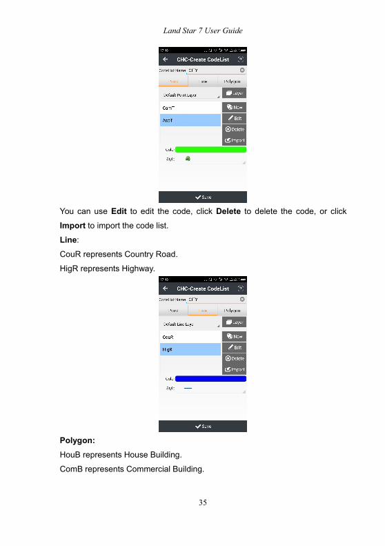
You can use Edit to edit the code, click Delete to delete the code, or click
Import to import the code list.Line:CouR represents Country Road.
HigR represents Highway.
Polygon:HouB represents House Building.
ComB represents Commercial Building.

Land Star 7 User Guide
36
BusB represents Business Building.
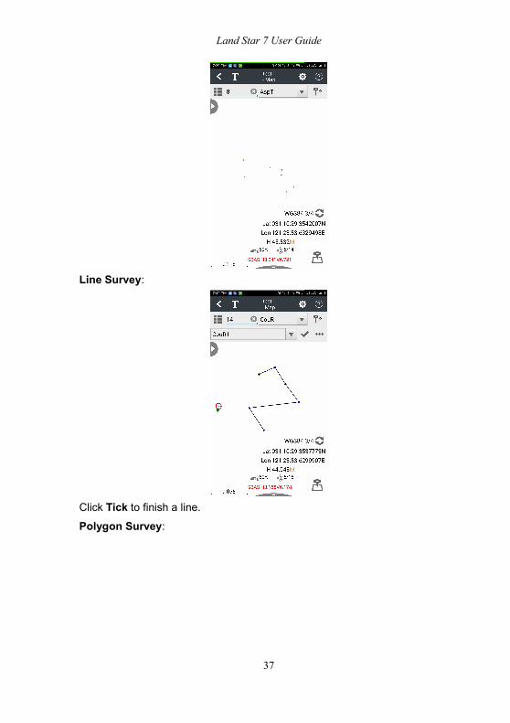
Application of CodeList:After the creation of CodeList and connection of receiver, you now open Map.
Click Code to select the features: point, line or polygon.
Point survey:
Land Star 7 User Guide
37
Line Survey:
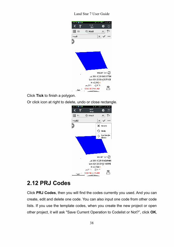
Click Tick to finish a line.Polygon Survey:
Land Star 7 User Guide
38
Click Tick to finish a polygon.Or click icon at right to delete, undo or close rectangle.
2.12 PRJ CodesClick PRJ Codes, then you will find the codes currently you used. And you cancreate, edit and delete one code. You can also input one code from other code
lists. If you use the template codes, when you create the new project or open
other project, it will ask "Save Current Operation to Codelist or Not?”, click OK,
Land Star 7 User Guide
39
the operation to the codes will be saved. The functions of new codes can refer
to the CodeList, the functions are only available to the codes in the current task;
but if you want to save the functions for the next time, please choose Cancel
and the functions will be saved in the Template codelist.
3 Config
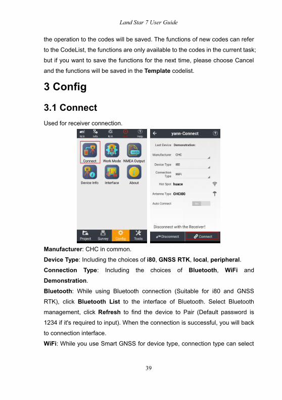
3.1 ConnectUsed for receiver connection.
Manufacturer: CHC in common.
Device Type: Including the choices of i80, GNSS RTK, local, peripheral.Connection Type: Including the choices of Bluetooth, WiFi and
Demonstration.Bluetooth: While using Bluetooth connection (Suitable for i80 and GNSS
RTK), click Bluetooth List to the interface of Bluetooth. Select Bluetooth
management, click Refresh to find the device to Pair (Default password is
1234 if it's required to input). When the connection is successful, you will back
to connection interface.
WiFi: While you use Smart GNSS for device type, connection type can select

Land Star 7 User Guide
40
WIFI. Click Connection List of Hot Spots, then it will show you WLAN
interface. Click Refresh to find the SN of current receiver, input password
(Default password is 12345678), then click Connect. When the connection is
successful, you will back to connection interface.
Demonstration: Enter Demo mode, and then you can use or test all the
functions of this software. Meanwhile, the function can simulate position by
inputting coordinate.
Antenna Type: Click Antenna Type list, select antenna type. You can handlespecific item by clicking Detail, Add, Edit, or Delete.
Auto Connect: Switch on, then, it will connect previous device when you openthe software.
Connect: It will display the SN, connection type of current device or prompt
“Connection Failed”.
Disconnect: Break the current receiver connection.
3.2 Work ModeMain screen of work mode displays the configuration of the current equipment,
including the receiver setting and device operating modes. In most cases, we

Land Star 7 User Guide
41
use the common and specific operation mode to meet the daily trial.
3.2.1 External Radio BaseClick New to create a work mode.
RTK: Switch on.Work Mode: Select Manual Base.Date Link: Select External Radio.Correction Format: Select RTCM3.2.Baudrate: Select 9600.Elevation Mask: 10.
Click Save, then the prompt “Please Set a Name for The New Mode” will pop
up. Enter your Name, and click OK. The prompt “Create Mode Successfully”
will pop up. Click OK, now, the work mode is available in the list. Please selectthe work mode then click Accept.
3.2.2 Internal UHF BaseClick New to create a work mode.
RTK: Switch on.Work Mode: Select Manual Base.
Land Star 7 User Guide
42
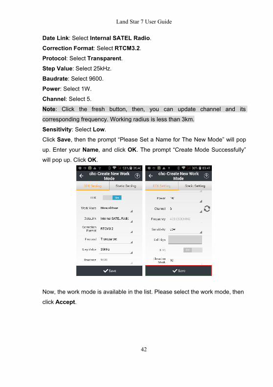
Date Link: Select Internal SATEL Radio.Correction Format: Select RTCM3.2.Protocol: Select Transparent.Step Value: Select 25kHz.Baudrate: Select 9600.Power: Select 1W.
Channel: Select 5.Note: Click the fresh button, then, you can update channel and its
corresponding frequency. Working radius is less than 3km.
Sensitivity: Select Low.Click Save, then the prompt “Please Set a Name for The New Mode” will pop
up. Enter your Name, and click OK. The prompt “Create Mode Successfully”
will pop up. Click OK.
Now, the work mode is available in the list. Please select the work mode, then
click Accept.
Land Star 7 User Guide
43
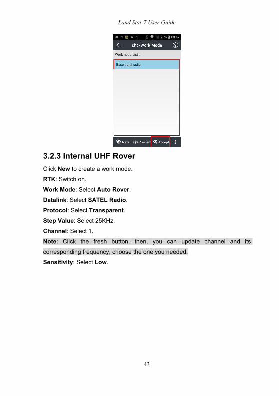
3.2.3 Internal UHF RoverClick New to create a work mode.
RTK: Switch on.Work Mode: Select Auto Rover.Datalink: Select SATEL Radio.Protocol: Select Transparent.Step Value: Select 25KHz.Channel: Select 1.Note: Click the fresh button, then, you can update channel and its
corresponding frequency, choose the one you needed.
Sensitivity: Select Low.
Land Star 7 User Guide
44
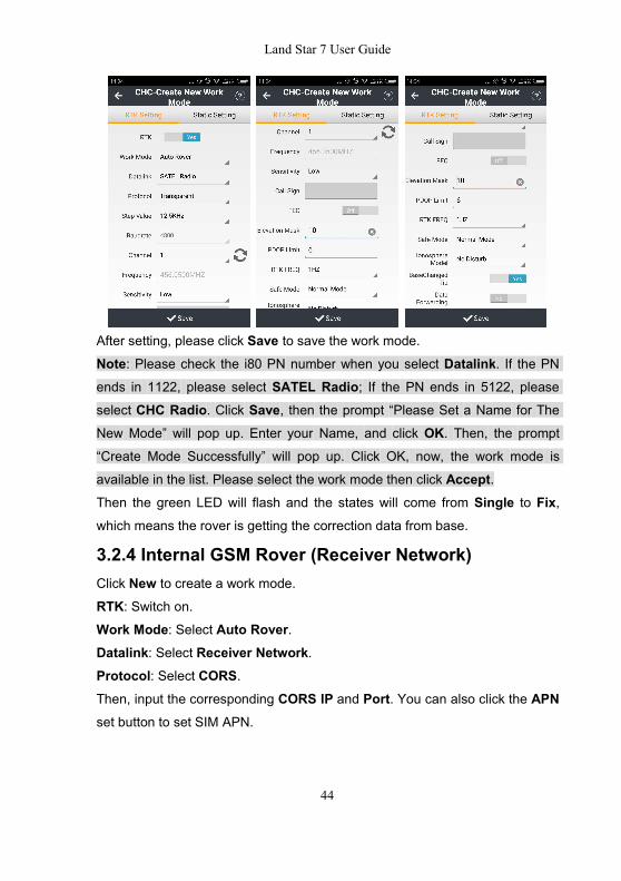
After setting, please click Save to save the work mode.Note: Please check the i80 PN number when you select Datalink. If the PN
ends in 1122, please select SATEL Radio; If the PN ends in 5122, please
select CHC Radio. Click Save, then the prompt “Please Set a Name for The
New Mode” will pop up. Enter your Name, and click OK. Then, the prompt
“Create Mode Successfully” will pop up. Click OK, now, the work mode is
available in the list. Please select the work mode then click Accept.Then the green LED will flash and the states will come from Single to Fix,which means the rover is getting the correction data from base.
3.2.4 Internal GSM Rover (Receiver Network)Click New to create a work mode.
RTK: Switch on.Work Mode: Select Auto Rover.Datalink: Select Receiver Network.Protocol: Select CORS.Then, input the corresponding CORS IP and Port. You can also click the APNset button to set SIM APN.
Land Star 7 User Guide
45
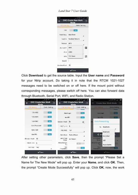
Click Download to get the source table. Input the User name and Passwordfor your Ntrip account. Do taking it in note that the RTCM 1021-1027
messages need to be switched on or off here. If the mount point without
corresponding messages, please switch off here. You can also forward data
through Bluetooth, Serial Port, WIFI, and Radio Station.
After setting other parameters, click Save, then the prompt “Please Set a
Name for The New Mode” will pop up. Enter your Name, and click OK. Then,the prompt “Create Mode Successfully” will pop up. Click OK, now, the work
Land Star 7 User Guide
46
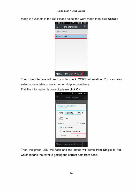
mode is available in the list. Please select the work mode then click Accept.
Then, the interface will lead you to check CORS information. You can also
select source table or switch other Ntrip account here.
If all the information is correct, please click OK.
Then the green LED will flash and the states will come from Single to Fix,which means the rover is getting the correct data from base.

Land Star 7 User Guide
47
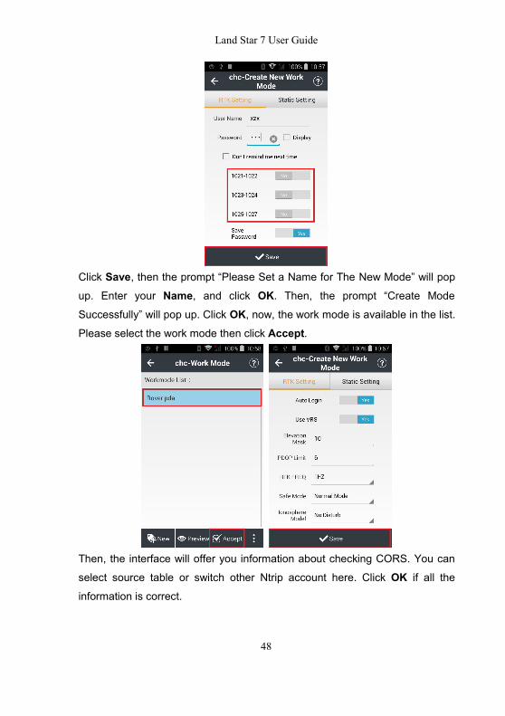
3.2.5 DCI (PDA Network)Click New to create a work mode.
RTK: Switch on Yes.Work Mode: Select Auto Rover.Datalink: Select Receiver Network.Protocol: Select CORS.Then, input the corresponding CORS IP and Port. You can also click
Download to get the source table.
Input the User Name and Password for your Ntrip account. Do taking it in notethat the RTCM 1021-1027 messages need to be switched on or off here. If the
mount point without corresponding messages, please switch off it here.
Land Star 7 User Guide
48
Click Save, then the prompt “Please Set a Name for The New Mode” will pop
up. Enter your Name, and click OK. Then, the prompt “Create Mode
Successfully” will pop up. Click OK, now, the work mode is available in the list.Please select the work mode then click Accept.
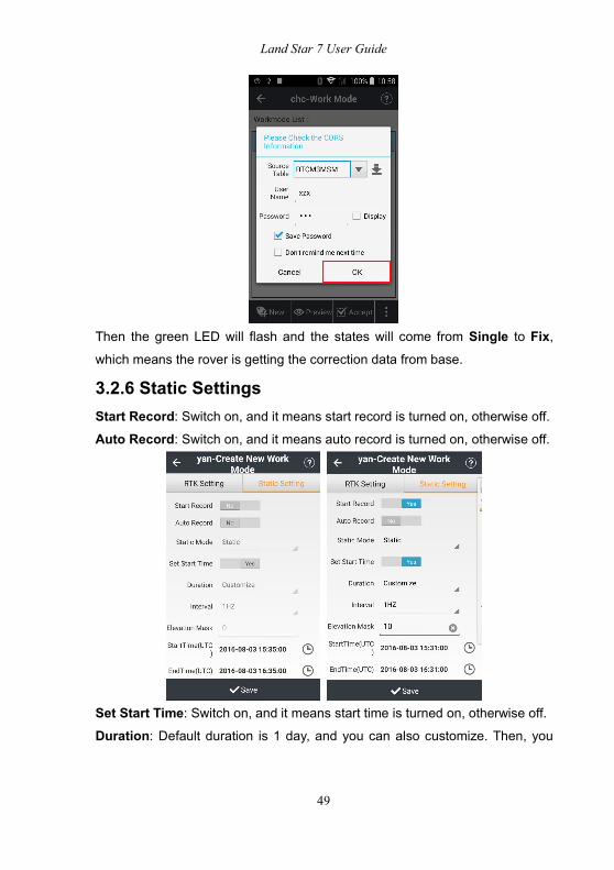
Then, the interface will offer you information about checking CORS. You can
select source table or switch other Ntrip account here. Click OK if all the
information is correct.
Land Star 7 User Guide
49
Then the green LED will flash and the states will come from Single to Fix,which means the rover is getting the correction data from base.
3.2.6 Static SettingsStart Record: Switch on, and it means start record is turned on, otherwise off.Auto Record: Switch on, and it means auto record is turned on, otherwise off.
Set Start Time: Switch on, and it means start time is turned on, otherwise off.Duration: Default duration is 1 day, and you can also customize. Then, you

Land Star 7 User Guide
50
should set start time and end time at the bottom of the interface, otherwise you
cannot start static recording.
Interval: Including choices of 1HZ, 2S, 5S, 10S, 15S, and 30S.Elevation Mask: The angle is set for shielding obstruction. The satellites lowerthan this angle will not be tracked, the default is 10.
After setting these parameters, click Save, then the prompt “Please Set a
Name for The New Mode” will pop up. Enter your Name, and click OK. Then,the prompt “Create Mode Successfully” will pop up. Click OK, now, the work
mode is available in the list. Please select the work mode then click Accept.The software will prompt "Accept This Mode?" click Yes, then, the software
prompts "Accept the Mode Successfully!" click OK, and then we finish
completing static mode setting.
Now, you have already been static recording. However, when RTK and static
recording exist at the same time again, RTK status will become a priority,
including whether automatically record, recording period, mask angle, the
sample interval. Click Info or Config - Device Info to view the current work
mode.

Land Star 7 User Guide
51
3.3 NMEA Output
This function is set for making output the NMEA for other external equipments.
GNSS RTK can use Bluetooth, Port to connect receiver. Smart RTK can use
the Bluetooth, port or WiFi to connect receiver. When the config is modified, it
needs to click Set, and it is proposed to refresh to confirm no matter the setting
is done successfully or not.
If you have done the set of the output mode by Bluetooth, Serial Port or WiFi,
you can copy the config and paste it to other output mode when you want to
use the same config to another output mod, and it will avoid a repeated config.

Land Star 7 User Guide
52
Please ensure Baud rate is 9600 when GPGGA Serial output set is 1HZ based
on connecting CHC Receivers.
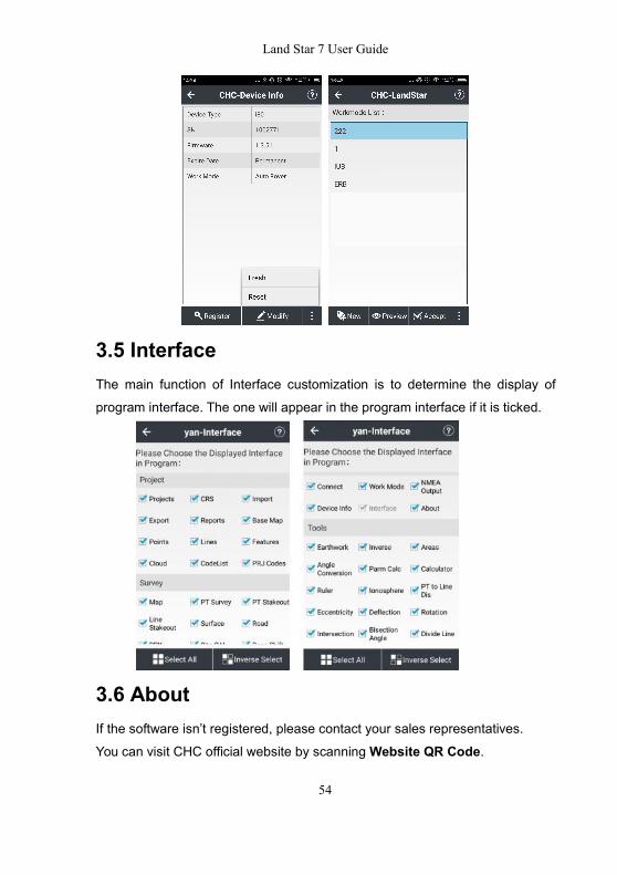
3.4 Device InfoAfter connecting between handheld and receiver, Landstar 7 will read out the
receiver information, such as device type, serial number, expire date, work
mode, data link and so on.

Land Star 7 User Guide
53
RegistrationClick Register, it will display the input box to type in the register code. Please
contact with your local dealer or CHC technical to get the code.
Note: There is no need to enter the - of the register code.ModifyClick Modify, it will display the list of the Work Mode to modify the receiver
working mode.
FreshClick Fresh, it will get the device information again.ResetClick Reset, it will reset the receiver main board. Then, it will restart the
receiver and star search.
Land Star 7 User Guide
54
3.5 InterfaceThe main function of Interface customization is to determine the display of
program interface. The one will appear in the program interface if it is ticked.
3.6 AboutIf the software isn’t registered, please contact your sales representatives.
You can visit CHC official website by scanningWebsite QR Code.
Land Star 7 User Guide
55
You can follow CHC official facebook by scanning Facebook QR Code.
4 Survey
4.1 MapMain functions:1. You can see the graph with basemap, and all the basemaps can be
displayed.
2. During measurement, the point, line and surface will be displayed in different
color or style (colors of points, lines and surfaces follow generally the colors
chosen when you create the new codes.
3. During measurement, you can select the codes for the points, lines and
surfaces (on point survey interface, only the codes of points are available).
4. During the features surveying (points, lines and surfaces), if the job of
feature surveying is not finished one time, and you continue with other features,
the previous job of feature surveying will stop temporarily. You can do the
surveying of several features at the same time. It allows to check the the task
not achieved as well as the task you are doing.
4.1.1 OptionSURVEY: You can view survey information in this interface.

Land Star 7 User Guide
56
Survey Method: Support topographic point, control point, quick point,
continuous point, eccentric point and compensate point.
Observation Time: Default observation time of topographic point is 5s, controlpoint is 10s, eccentric point is 1s, compensate point is 5s, etc.
Horizontal Precision &Vertical Precision: Modify as you wish. Such as:
default horizontal precision of topographic point is 0.0300m, its vertical
precision is 0.0500m; default horizontal precision of quick point is 0.1000m, its
vertical precision is 0.2000m.
Offset Tolerance: Modify as you wish. Default is 0.10m.Tilt Tolerance: Modify as you wish. Default is 0.020m, and its range is
between 0.001m and 1m.
Name Step: Modify as you wish. Default is 1.Track File: Input a name for the track.Save Track: Tick to save track.Auto Survey: Default is not checked. Tick if you need to do the auto survey,
and then the current point survey will stop; if you choose Continue, the surveywill continue.
Tilt Warning: Make the receiver be tilted when surveying, and you can decideto Abandon or Stop when it says “The tilt is excessive”.

Land Star 7 User Guide
57
EBubble: You will see the ebubble on the interface when doing the point
staking, if the ebubble is ticked. It will be ticked generally when using the
instrument with the function of auto survey.
Offset Warning: Make the receiver offset when surveying and you can decideto Abandon or Stop when it says “The offset is excessive”.
Fixed Solution: If the fixed solution ticked, then you can measure only when
the solution is fixed; please uncheck the fixed solution, if you want to measure
even when the solution is single or floating.
AutoCenter: Your position will automatically display on screen center within 5swhile mapping.
Log Avg.Obs: Log average observation data when observation times >1, the
storage path is “CHCNAV / LS7_Projects / project name”.
Display Avg.Stats: Display the stats of average observation data when
observation times >1.
DISPLAY: Set to modify what to display on the main interface.
Name/Code/Height: If one item is selected to be displayed, you will see it on

Land Star 7 User Guide
58
the interface display area. For example, if selecting Name, you will see the
point name on the display area after measurement.
Display - Point Type: Tick to choose point type to display in the interface. Forexample, when we have measured a lot of topography points, control points
and quick points, we can tick Topography if we want to see only the
topography points. Then in the interface, what we can see are the topography
points, no control points or quick points.
Display - Layer: Display the layers with created new codes, including the
layers of points, base map, lines and surfaces.
Advance: Configure what else to display by advance selection. You can filtratethrough single point or multiple points or height.
EBUBBLE: View information of receivers with the function of automatic
measurement or with tilt sensor.
Land Star 7 User Guide
59
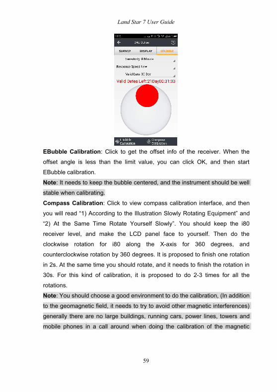
EBubble Calibration: Click to get the offset info of the receiver. When the
offset angle is less than the limit value, you can click OK, and then start
EBubble calibration.
Note: It needs to keep the bubble centered, and the instrument should be wellstable when calibrating.
Compass Calibration: Click to view compass calibration interface, and then
you will read “1) According to the Illustration Slowly Rotating Equipment” and
“2) At the Same Time Rotate Yourself Slowly”. You should keep the i80
receiver level, and make the LCD panel face to yourself. Then do the
clockwise rotation for i80 along the X-axis for 360 degrees, and
counterclockwise rotation by 360 degrees. It is proposed to finish one rotation
in 2s. At the same time you should rotate, and it needs to finish the rotation in
30s. For this kind of calibration, it is proposed to do 2-3 times for all the
rotations.
Note: You should choose a good environment to do the calibration, (In additionto the geomagnetic field, it needs to try to avoid other magnetic interferences)
generally there are no large buildings, running cars, power lines, towers and
mobile phones in a call around when doing the calibration of the magnetic

Land Star 7 User Guide
60
sensor. If you can’t avoid the condition mentioned, please stay away from the
above items when doing the calibration of magnetic sensor.
4.1.2 Symbols
Symbols: You will view symbols in drop-down menu on the left of interface.
Locate to: You can locate to point and set measuring scale as you wish.

Land Star 7 User Guide
61
Survey Boundary: Click to view survey boundary interface, you can select
several points to build boundary. Settings of survey boundary are for planning
out one job area.
Up: Move the boundary point up.Down: Move the boundary point down.Ok: Confirm boundary list.
Select: Select existent points.New: Manually enter the points that are in the measurement area.
Land Star 7 User Guide
62
Edit: Edit selected point in boundary list.Delete: Delete selected point.Clean: Clean all points.Use Boundary: Tick to use survey boundary. When receiver is out of the
boundary, there will be some red words "Over Survey Boundary!" showed on
map interface.
Voice Prompt: Tick to open voice prompt. There will prompt an alarm sound
once receiver is out of the boundary.
Note: Survey boundary can be used for the survey, stake, road stake and
power stake, etc.
4.2 PT Survey
Antenna: Consist of Vertical H and Slant H.
Vertical H: The height from ground point to the bottom of receiver. When using
range pole, the vertical height is the pole height.
Slant H: The height from the ground point to static measurement tick mark
(X91+ is the blue rubber ring, i80 is the receiver bottom) of receiver, usually
this height is needed when setting up the receiver on a tripod.
Method: Consist of Topographic PT, Control PT, Quick PT, Continuous PT,Eccentric PT and Compensate PT.
Continuous PT: Continuously survey points automatically according to a
preset fixed time period or space distance.
Eccentric PT: When you cannot reach the target point, this function is helpful.
Input the azimuth angle between the target point and the current position (You
can measure the current point and any point on the direction of the target point,

Land Star 7 User Guide
63
and get the angle by calculation function on Tools menu), horizontal distance,vertical distance (If the target point is higher than the current point, input a
positive value; if lower, input a negative value).
Compensate PT: When the range pole/level is tilted, the survey result will be
automatically compensated to normal level condition. The survey result is of
the location of the range pole bottom (This function is only available with those
RTK receiver with tilt survey function, compass and Ebubble calibration should
be done before available).
Note: Before surveying, you should set options. Go to Options, set the
Horizontal Precision to be higher than the value of H, Vertical Precision to
be higher than the value of V. If the current solution is non-fixed (say float or
DGPS or 3D/single point), but you want to go ahead with the point collection
procedure, please un-tick Fixed Solution. If the rover receiver keeps static,
but it reminds movement of the rover receiver (If you find the coordinate is
changing a lot while the rover receiver keeps static), this could be caused by
site calibration/localization error.
Land Star 7 User Guide
64
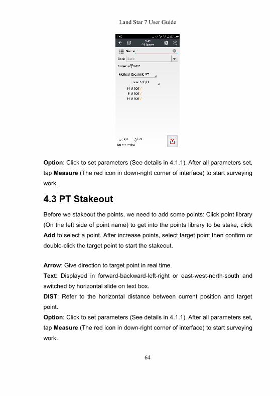
Option: Click to set parameters (See details in 4.1.1). After all parameters set,tap Measure (The red icon in down-right corner of interface) to start surveyingwork.
4.3 PT StakeoutBefore we stakeout the points, we need to add some points: Click point library
(On the left side of point name) to get into the points library to be stake, click
Add to select a point. After increase points, select target point then confirm or
double-click the target point to start the stakeout.
Arrow: Give direction to target point in real time.Text: Displayed in forward-backward-left-right or east-west-north-south and
switched by horizontal slide on text box.
DIST: Refer to the horizontal distance between current position and target
point.
Option: Click to set parameters (See details in 4.1.1). After all parameters set,tap Measure (The red icon in down-right corner of interface) to start surveyingwork.

Land Star 7 User Guide
65
Points: Click to select survey points (See details in 2.10).
Note: After setting the proper parameters, the software will calculate the
difference between stakeout point and target point. If the difference is under
the limit, the software will go to the next point. If not, we need to stake this point
again.
4.4 Line StakeoutAdd Line: Configure options in this interface. Including linetype, method, name,start point, end point and start distance. After options set, the new created line
will be shown at left side of the Point Name in the Lines.Linetype: Include Line, Circle and Arc.Method: Include Two Points and One Point + Azimuth + Distance.Name: Input line name as you wish.Start/End Point: Select start/end point from Points.Start Distance: Input start distance of line.Circle Center: Input point as circle center.Note: When it comes the stakeout of straight line, the default setup is "stake to
line" (This time the mileage interface will display "stake to line", lead us to go to
a point on the nearest line from the current point. If you want to go back to use
other features of stakeout line, you can erase the mileage that you already
input.
Arrow: Find the target following the arrow's direction.Text Indication: There are four indication modes (all shows the distance from
the target point), switch the mode, slide left-right in the text box. Like all
sides, elevation; all directions, elevation, vertical & horizaontal-biased, mileage,
elevation; the distance to starting point, elevation; to the end point, elevation.
Stakeout: Directly input the mileage between "+" "-" signs in the mileage box(ifthe mileage interval is fix, modify the "stake spacing", and then go to the Line
Land Star 7 User Guide
66
Stakeout's main screen, click "+" "-" to switch sake).
Partial Cross-Staked Point: For example, at the 50 meters mileage point, 5
meters to the right: Click "staking to the line" (after you entering the mileage,
display "Stakeout to stake"), offset: 5, angle: 90 °, Mileage: 50.
Stakeout Offset Point: For example, at the 60 meters mileage point, 30
degrees to the left, 6 meters. Click "Staking to the line" (After you entering the
mileage, display "Stakeout to stake"), offset: 6, angle: 330 °, Mileage: 60.
Slope Ratio: The segment without elevation, use it for the slope with elevationsubsection. Divide the line into segments of equal length, to save the time of
manually calculating the mileage time of each segment. Click "+" "-" to
automatically switch segment point.
Stake Spacing: After the set-up, click "+" "-" automatically to switch the
mileage.
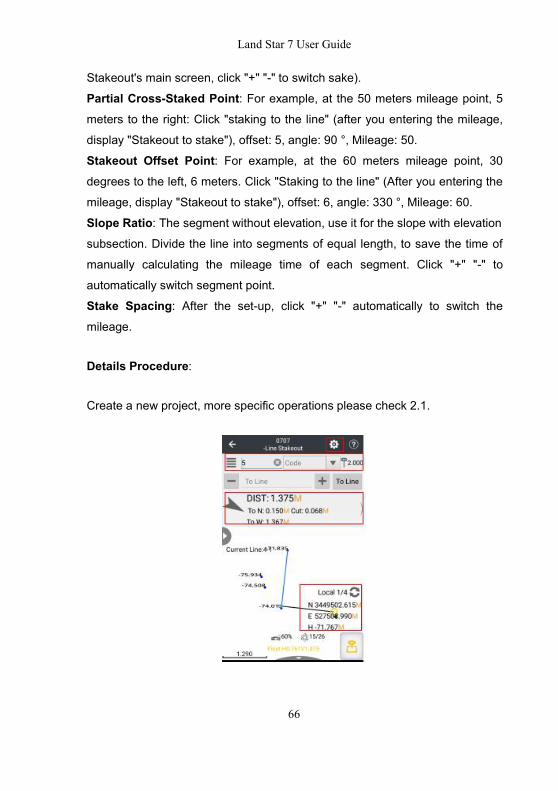
Details Procedure:
Create a new project, more specific operations please check 2.1.
Land Star 7 User Guide
67
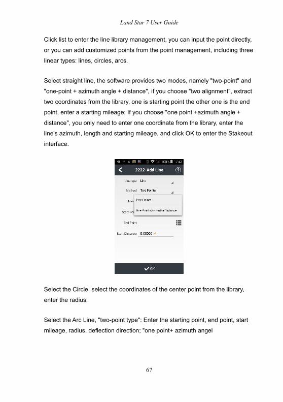
Click list to enter the line library management, you can input the point directly,
or you can add customized points from the point management, including three
linear types: lines, circles, arcs.
Select straight line, the software provides two modes, namely "two-point" and
"one-point + azimuth angle + distance", if you choose "two alignment", extract
two coordinates from the library, one is starting point the other one is the end
point, enter a starting mileage; If you choose "one point +azimuth angle +
distance", you only need to enter one coordinate from the library, enter the
line's azimuth, length and starting mileage, and click OK to enter the Stakeout
interface.
Select the Circle, select the coordinates of the center point from the library,
enter the radius;
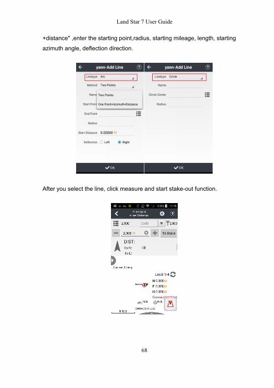
Select the Arc Line, "two-point type": Enter the starting point, end point, start
mileage, radius, deflection direction; "one point+ azimuth angel
Land Star 7 User Guide
68
+distance" ,enter the starting point,radius, starting mileage, length, starting
azimuth angle, deflection direction.
After you select the line, click measure and start stake-out function.

Land Star 7 User Guide
69
4.5 Surface StakeoutExport Surface File: Click New and Select to choose measure points from
coordinate library.
Note: There are two types of files can choose which are HCT and ROD. Click
Ok to give a new name or confirm the created name as below. After uploading
points from Coordinate Library, The interface will show the areas which consist
by known points and you can see Design height and whether this area need
fill , how many cube need to fill or can be shown in the middle of interface.
Beside, you can click icon on left to set stakeout information (the light point is
we add Cut Tolerance and Fill Tolerance) .

Land Star 7 User Guide
70
4.6 Road
4.6.1 The introduction of Road interface
The text introductions of road stakeout divide into three ways:
1. All around and elevation difference.

Land Star 7 User Guide
71
2. Horizontal and vertical offset and elevation difference.
3. Distance in real time and elevation difference (Calculated by the receiver's
location automatically). Three introduction ways can be achieved by sliding
text prompt box.
4. The interface of road stakeout contains three parts which are view area, the
navigation text area and button, the current measuring area will display the
road, measuring point and current point. There are also some operations of
displaying north direction, dynamic scales and buttons for operating view-map.
List: Click to new or open roads, points and export data.
Name: Click to set the point name and it can be set by clicking the mileage or
setting as your wish.
Code: Input directly or select the code in the code list.
Land Star 7 User Guide
72
Blue point: The position of road mileage.+: Add mileage.-: Decrease mileage.Arrow: Display the current position in real-time and the target can be found inthe site.
East/South/West/North: Show the target in east (E), south(S), west (W), north
(N) (only display two distance messages).
Front/Back/Left/Right: Heading direction is the positive direction (only displaytwo distance messages).
Fill: Indicates current position lower than the design position of the distance
and need to fill.
Dig: Represent current position higher than the position of design distance andit need to dig.
Left: Roads along the direction of the left side.Right: Roads along the direction of the right side.Nearest: To check the nearest stake from current position.
Section: Click the button to use the cross section mode.Measure: After setting the antenna, it will start to measure.
4.6.2 Road
New: Input road name and store path, click New Road, and then choose roadtype, click Finish.

Land Star 7 User Guide
73
Note: Please input parameters up to down in order.
Stations Equation: Click New to input before and after mileage, click OK to
confirm.
Horizontal Alignment:

Land Star 7 User Guide
74
C/L
Append: Choose type, and input coordinates,etc.
Line: Input azimuth and length.
Arc: Input radius and length, and choose direction.
Transition: Input start radius, end radius and length.
Next: Click until all curve parameters inputted, click Finish, and then Apply.
Append: Input roads parameters.
Insert: Insert roads parameters.
Edit: Modify selected roads parameters.
Delete: Delete selected roads parameters

Land Star 7 User Guide
75
PI
Append: Input start coordinate and stake, click next to input curve type andparameters. You can choose curve type at the pull-down list, and input
required parameters.
Arc: Input coordinates and radius.
Spiral|Spiral: Input coordinates, in and out transition length.
Spiral|Arc|Spiral: Input coordinates, radius, in and out transition length.
Points: Input coordinates and mileage.
Next: Click until all curve parameters inputted, click Finish, and then Apply.
Land Star 7 User Guide
76
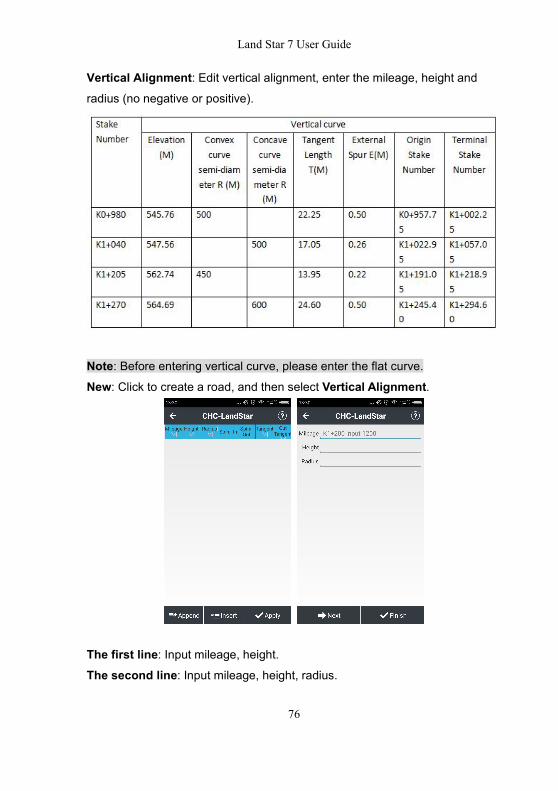
Vertical Alignment: Edit vertical alignment, enter the mileage, height andradius (no negative or positive).
Note: Before entering vertical curve, please enter the flat curve.New: Click to create a road, and then select Vertical Alignment.
The first line: Input mileage, height.The second line: Input mileage, height, radius.
Land Star 7 User Guide
77
……
The last line: Input mileage, height.Apply: Click the icon in down-right corner of interface to complete input.
Standard Section: Click New, select section name, standard width, standard
slope, click OK to complete, and then click Save.
Super Elevation: Click New, input distance, slope, vary type, click OK, andthen click Save.
Widening: Click New, input distance, width, vary type, click OK, and then clickSave.
Slope: Click New, input slope name, slope type, start mileage, end mileage,
click Confirm and Continue to input next slope, and then click Save.
Points: Click to entry points list (Details please refer to 2.7).
Export Data: Click to input file name, select export type and export path.
4.6.3 Road StakeoutOpen Road: Click Survey, Road to enter road stakeout interface. Then open
a road file to stakeout.

Land Star 7 User Guide
78
Setting: Click to set parameters.
Miles as Name: Check this box, the center stake name will used the mileage.Stakeout Tolerance: Set stakeout tolerance and if tolerance is over the limit,
the software will remind that the tolerance is not satisfied.
Stake Interval: The current mileage will increase by the stakeout distance.Stakes: Enter the mileage in main interface and do the stakeout following
prompts. Select left or right then input offset and stake out according to
prompts, as shown settings.

Land Star 7 User Guide
79
Section: When measuring cross section, be sure to measure corresponding
center stake, or cannot export the section data. After check the cross section, it
will into the cross section measurement mode and a red line will display.
Cross: Distance from the current to cross section.
Along: Distance from projection of current position to cross section. - Indicatescurrent position is at road.
Fill: Elevation difference between the current position and designed elevation.When collecting cross section, the cross is nearly 0 means the current position;
cross is not 0 means the distance from the current position to center stake.
Cross is negative means the current position is on the left side of road. Cross
is positive means the current position is on the right side.
Culvert: Select culvert, input culvert distance and angle, then begin survey.Angle: Input the angle between culvert direction and highway midline.

Land Star 7 User Guide
80
Slope: Display current slope will appear in the main interface.
Data Check: Use receiver to check any position on roads whether it remains
deviation.
Land Star 7 User Guide
81
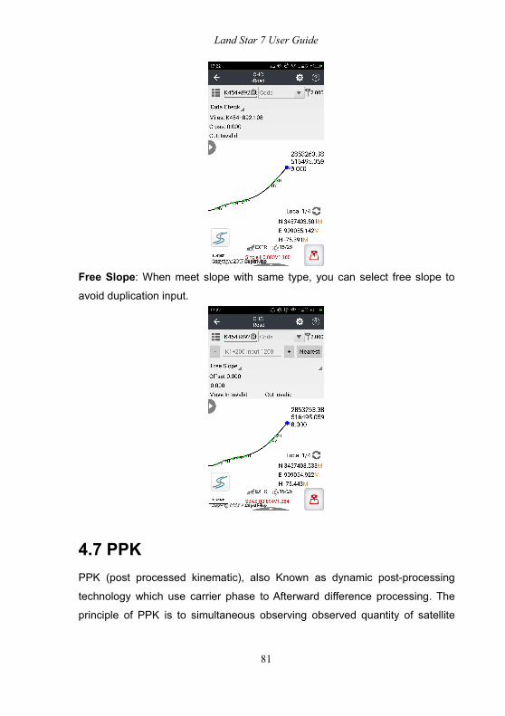
Free Slope: When meet slope with same type, you can select free slope to
avoid duplication input.
4.7 PPKPPK (post processed kinematic), also Known as dynamic post-processing
technology which use carrier phase to Afterward difference processing. The
principle of PPK is to simultaneous observing observed quantity of satellite

Land Star 7 User Guide
82
carrier phase for one receiver as base station and at least one receiver as
rover station. After that use Land Star 7 PPK function to linear combination and
generate virtual carrier phase observed values, and then determine the relative
position of receivers and obtain the rover station coordinates in the local
coordinate system from coordinate conversion.
Connect receivers (as base or rover station) and set Static ModeConnect: Click to set receivers as base station or rover station.Work Mode: Set static mode from Static Setting.Note: Start Record button must be Yes, the suggestive value of interval and
Elevation Mask should be 1HZ and 13 degree receptively, default duration is 1Day. If you choose Customize,you must set start time and end time as you
wish, and end time must be latter than start time. You can only record static
data after start time and before end time.
Accept: Click to Accept work mode.
Land Star 7 User Guide
83
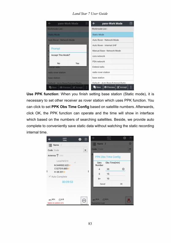
Use PPK function: When you finish setting base station (Static mode), it is
necessary to set other receiver as rover station which uses PPK function. You
can click to set PPK Obs Time Config based on satellite numbers. Afterwards,
click OK, the PPK function can operate and the time will show in interface
which based on the numbers of searching satellites. Beside, we provide auto
complete to conveniently save static data without watching the static recording
internal time.
Land Star 7 User Guide
84
4.8 Site Calibration
When the correction parameters of application points prompt abnormal ratio for
flat correction' or 'residual value is too large, we suggest check the control
point that participate point correction input wrong or not, whether match control
point or not. If you confirm there is no error, please continue operations.
Point correction is to calculate the mathematical conversion relationship
between WGS-84 and local plane rectangular coordinate system.
Assuming there are some known points K1, K2, K3, K4, and find the field
position of known points. After that measure corresponding points 1,2,3,4 in
the case of the base station does not move.
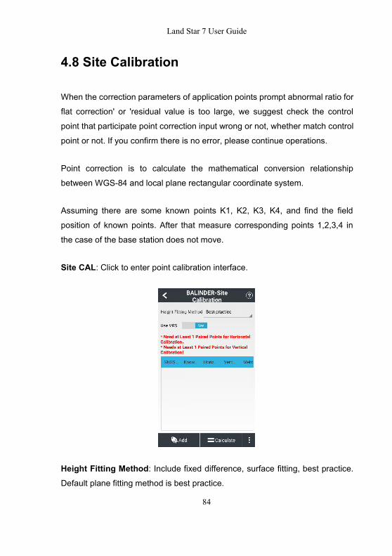
Site CAL: Click to enter point calibration interface.
Height Fitting Method: Include fixed difference, surface fitting, best practice.
Default plane fitting method is best practice.

Land Star 7 User Guide
85
Add: Click to select correspond GNSS points and Known points. Select
Horizontal + Vertical Calibration. The best choice is to choose 3 couples of
points based on actual situation.
Calculate: Click to calculate. The software will prompt “plane correction
success, height fitting success”. After that click Application, the prompt is
“Whether replace the current project engineering parameters or not”, select
Yes will make current calculated correction parameters apply in the coordinatesystem which can effect into the whole project. Users can log for viewing plane
correction and elevation fitting parameters, otherwise parameters are not
display.
4.9 Base ShiftWhen moving or setting up the base again in Auto Base mode, Base Shift isrequired to ensure all the current points are belong to the same coordinate
system as before.

Land Star 7 User Guide
86
Base Shift: Click to enter base shift interface. In base shift Interface, click theicon beside GNSS Point to select a current point surveyed at a control point,
click the icon beside Known Point to select the corresponding control point.
The calculation results will show automatically. Then click OK. The softwareprompts “Apply Shift Parameters or not?” click Yes, then the software prompts“Shift base and Related Survey Points, Whether Open Point Library or Not?”.
Click Yes, the point library is opened and the plane coordinates are changedbecause shift parameters have been applied to all the points surveyed on this
base.
5 Tools
5.1 Inverse CalculationClick list at right side and select starting point A and ending point B from points,
click OK to calculate. The results will be shown in the table. The results contain:
azimuth, elevating angle, horizontal distance, tile distance, north offset, east
offset, height difference and gradient. Click OK can obtain results of inverse
calculation.

Land Star 7 User Guide
87
5.2 AreasThis function is to calculate the area, perimeter of figure, the coordinates that
participates resolve are chosen from point management by library chosen. The
unit of perimeter is metric and the unit of area supports square meters.
OK: Calculate the perimeter and area of the figure which is composed of pointsin sequence.
Delete: Delete point.Select: Add points to the list.Up/Down: Make selected points move up or down.
5.3 Angle ConverterAngle converter can convert degrees, minutes, seconds and radians among
these 3 types of converter.
Enter a value in degrees, minutes and seconds edit box, click on the OK button
to calculate the value of the corresponding degrees and radians.
Similarly, it can convert radians to degrees and degrees, minutes and seconds,
or converts degrees to radians and the value of every minute.

Land Star 7 User Guide
88
5.4 Parameters Calculate
Calculation Type: Include 7 Parameters and 3 Parameters.
7 Parameters: The application scope of 7 parameters is relatively large,
generally larger than 50 km. You need to know at least three pairs of known
point values in local coordinate system and their corresponding WGS-84
coordinates. Only when we get the seven parameters transmitting from WGS
coordinate system to local coordinate system, can we start the parameters
calculation.
Select Point Pair: Click Add to add point pairs and input pairs of GNSS point
and known points to calculate 7 parameters. Add WGS-84 coordinates at
GNSS Point and add plane coordinates at Known Point.

Land Star 7 User Guide
89
Note: Select three corresponding point pairs and add to the interface of
parameters calculation.
Calculate: Click to calculate. The results will be popped up automatically. Thenclick OK to apply 7 parameters to the current project.
Datum trans: Back to the main menu, click CRS to view Datum trans interface
and 7 parameters can be viewed. Default datum transformation is 7
parameters. Click Login, input name is admin and password is 123456, and
then parameters will be unlocked.

Land Star 7 User Guide
90
3 parameters: At least one known point pair is requested which is usually usedin small scales. The accuracy is up to the operating range, decreasing with the
increase of operating distance.
5.5 CalculatorUse for simple mathematical calculations.
MC: Clear historical.DRG: Transform input number type (Degree or rad).

Land Star 7 User Guide
91
C: Clear current record.Sin/Cos/Tan: Calculate sin/cos/tan value. You should click DRG to transform
input number type into degree (DEG), sin 30(DRG) = 0.5.
: Back.
log/ln: log10=1.√: 8√3=2.
⌃: 8⌃2=64.
n!: n!3=6.
5.6 RulerThis function will provide you a ruler to do some simple measurement.
You can use real ruler to adjust the length of ruler by moving the circle, then
click confirm icon.
5.7 Ionosphere PredictionDisplay ionospheric conditions at present and update every 10 minutes.

Land Star 7 User Guide
92
Solar storms occurs once every 11-year, along with the period of sun pot
activity. The frequency and intensity of ionospheric storm is related to sun pot.
When the solar wind swept the Earth, it will change the electromagnetic field,
causing geomagnetic storms and ionospheric storm, affect communications,
especially short-wave communications, for example GNSS.
5.8 Point to Line DistanceSelect points A, B, C from point management and click OK to calculate. The
result is displayed in a pop-up box, as follows: click Clean to clear current data.

Land Star 7 User Guide
93
5.9 Eccentric DistanceOrigin (A): Select form Points.Horizontal distance (AP '): Input the horizontal distance.Perpendicular (PP '): Input the vertical distance.Azimuth Angle: Input the azimuth angle.Eccentric Distance: Click OK to display a calculation result screen, enter the
point name, and click OK to save the calculated point.
5.10 Deflection AngleDeflection Angle: Click Deflection to calculate deflection angle. Select Point A,
B, C, and click OK, the angle will be displayed in pop-up interface.

Land Star 7 User Guide
94
5.11 Rotation
Rotation: Point P is on the line AB which rotates a certain angle. After
selecting AB points, the system will calculate the distance between A point and
B point as default and this distance as initial value for AP. the value of AP can
be negative which means the P point is in the extension line of selected line.
A/B: Select the coordinate of A,B from Library Option.
AP: Initial distance.
Rotation Angle: Click OK will show calculate result.
Calculation Result: Input name and code, and then click OK to save this
calculated point.

Land Star 7 User Guide
95
5.12 Intersection PointKnown Points: Select points from point management, and click OK to
calculate the intersection P of line AB and line CD.
Points + 2 Sides: Select points A and B from point management. Enter the
length of line AP and line B. Click OK to calculate. Input a name, and click OK

Land Star 7 User Guide
96
to save.
Points + 2 Angles: Calculate intersection P with known points A and B and the
inner angle of PAB. Click OK to calculate. Input a name, and click OK to save.
5.13 Bisection AngleBisection Angle: Given line BA and BC comes to an angle ABC, P is one point
on the angle bisection line, according to the coordinates of Points A, B, C, and

Land Star 7 User Guide
97
the plane distance from Point P to Point B, we can have the coordinate of Point
P. If the distance value is negative, it mean Point P is on the oppositely
extension line of the angle bisection line. Click OK, the results will show out,
input the point name, and click OK to save the calculated point.
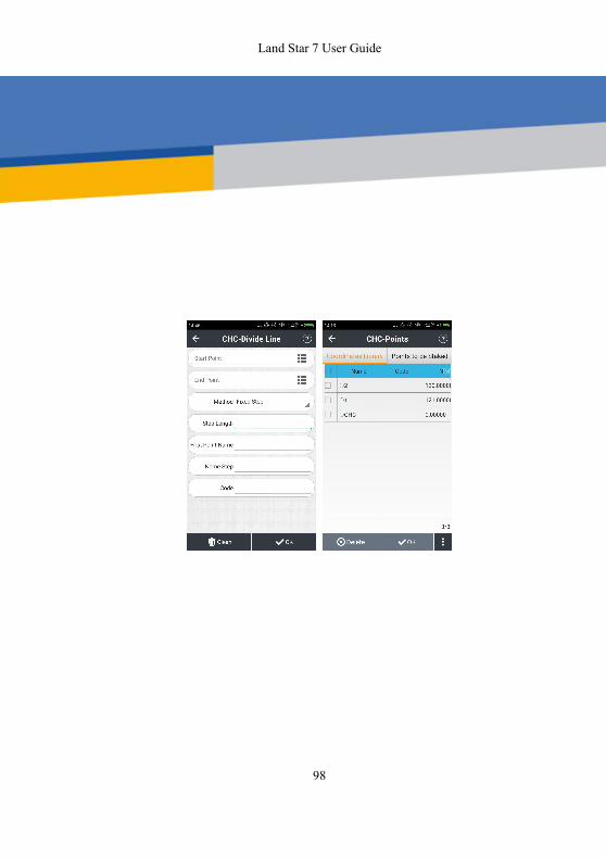
5.14 Divide LineDivide Line: Select start point and end point from Points, select Method,Input step and first point name, then click OK; it will remind you a successful
division. Click Points of Project to review points.
Land Star 7 User Guide
98

Land Star 7 User Guide
99
Shanghai Huace Navigation Technology Co., Ltd
Building C, NO. 599 Gaojing Road,Qingpu District, 201702 Shanghai, China
Tel: +86 21 542 60 273Tel: +86 21 649 50 963
Email:[email protected]| [email protected]:www.chcnav.com


