September 2012 www.che.com PAGE 34 New Valve Technology Vacuum Systems Plant Security Cooling Water THIN-FILM DRYING PAGE 40 Reciprocating Compressors Focus on Flowmeters Facts at Your Fingertips: Gas Sparging
Transcript
September 2012
www.che.com
PAGE 34
New Valve Technology
Vacuum Systems
Plant Security
Cooling Water
THIN-FILM DRYING
PAGE 40
Reciprocating Compressors
Focus onFlowmeters
Facts at Your Fingertips:Gas Sparging
November 14 - 15, 2012ERNEST N. MORIAL CONVENTION CENTER
NEW ORLEANS, LA
3rd Annual
P R E S E N T E D B Y:
Chemical. Petrochemical. Refining.
Access and Learn About the CPI Building Boom Being Driven by Unconventional Natural-Gas Supplies
» A “First Look” at the Technologies Driving the Future: See, demo and compare leading-edge solutions from 150+ exhibits.
» Learn objectively about the latest technological breakthroughs for the CPI, In the Chementator Lightning Round, Chemical Engineering editors will interview various technology providers and ask them the questions you really want to know: What makes this different from existing technologies, how does it work, what are the advantages, and so on.
» Unparalleled Networking Opportunities: Connect with thousands of attendees across all exhibit floors – Numerous events, one trade show: ChemInnovations, Shale EnviroSafe, CLEAN GULF, and Industrial Fire, Safety & Security.
» Talk one-on-one with CPI leaders and technical experts about the latest and issues technologies – and get a glimpse of the future from the people that are shaping it.
» Four Conference Tracks including Fundamentals, Emerging Issues, Process Design & Optimization, and Controls & Automation. www.cpievent.com
KEYNOTE PRESENTATIONS
The Evolving Shale Landscape, Wednesday, November 14Two industry experts address the environmental and regulatory issues, as well as the economic impacts of unconventional oil and gas drilling one week following the Presidential election.
Moderator: Rebekkah Marshall, Editor-in-Chief, Chemical Engineering
Plant Manager Roundtable, Thursday, November 15Moderator: Rebekkah Marshall, Editor-in-Chief, Chemical Engineering
PANELISTS:
Jim Armstrong, Operations Manager, Rhodia, Inc. - Baton Rouge
Paresh Bhakta*, Site Director, Clear Lake Plant, Celanese Ltd.
Jim Hull, Vice President - Manufacturing, Georgia Gulf Chemicals and Vinyls, LLC
* Denotes Invited Panelists
Shale Gas: A Game Changer Impacts for American Chemistry, Manufacturing & U.S. Economy
The Shale Gas Prize and Its Politics: The Risks and Rewards for our Environment
Martha Gilchrist Moore, Sr. Director for Policy Analysis & Economics, American Chemistry Council
John Hanger, Special Counsel, Eckert Seamans
SPEAKERS:
SPECIAL DISCOUNT FOR CHEMICAL ENGINEERING SUBSCRIBERS:REGISTER TODAY at www.cpievent.com
with VIP code CHEMENG9 to qualify for Advanced Discounts on the conference!
W E ’ R E E N H A N C I N G T H E
O F S T R E N G T H .
Enhance the strength of your next industrial
job. Visit corzancpvc.com or call a piping
systems consultant at 1.855.735.1431.
Corzan® Industrial Systems get their strength
from our science. That’s because The Lubrizol
Corporation’s superior CPVC compounds create
every Corzan pipe and fi tting. With the power of
mechanical strength and corrosion resistance,
Corzan pipe and fi ttings exceed the demands of
industrial and commercial applications. Plus, every
All marks are property of The Lubrizol Corporation, a Berkshire Hathaway Company.
GC 121100
Circle 20 on p. 72 or go to adlinks.che.com/40271-20
51 Engineering Practice Reciprocating Compressors: Startup and Capacity Control Methods Procedures and guidelines that will help operators minimize energy consumption and maintenance requirements of compressor systems
59 Environmental Manager Vacuum Systems: Recommendations for Safe Operation Follow this guidance to ensure that steam-ejector systems, mechanical vacuum pumps and integrated vacuum systems are designed, operated and maintained to ensure process safety
EQUIPMENT & SERVICES
29 Focus on Flowmeters A flowmeter designed for biogas; A wide choice of power solutions for this flowmeter; Minimize pressure drop with this mass-flow device; This flowmeter has a direct-mount configuration; and more
32I-1 New Products (International edition) A retractable assembly for sterile
pH measurements; This new pastillation machine requires less maintenance; Leaks are minimized in this AODD pump; A hygienic actuator that requires less space; Aseptic globe valves for pure steam applications; and more
COMMENTARY
5 Editor’s Page Opinions on ChE education Comments stemming from a recent CE story on education underscore a modern industry challenge: a higher percentage of less experienced engineers
68 The Fraction- ation Column Try
harder to stay awake A caution-ary tale from the FRI technical director on falling asleep during meetings
DEPARTMENTS
Letters . . . . . . . . . . . 6
Bookshelf . . . . . . . 8–9
Who’s Who . . . . . . . 74
Reader Service . . . . 72
Economic Indicators . . . . . 75–76
ADVERTISERS
Product Showcase . . 69
Classified Advertising . . . . 70–71
Advertiser Index . . . 73
COMING IN OCTOBER
Look for: Feature Reports on Batch to Continuous Process-ing; and Acid Handling; an Environmental Manager article on Safety Considerations for Vacuum Systems; a Solids Processing ar-ticle on Blending, Seg-regation and Testing; a Focus on Gas Detec-tion; News articles on Ethylene Feedstocks; and Steam Handling; and more
Cover: David Whitcher
CHEMICAL ENGINEERING WWW.CHE.COM SEPTEMBER 2012 3
SEPTEMBER 2012 VOLUME 119, NO. 9IN THIS ISSUE
COVER STORY
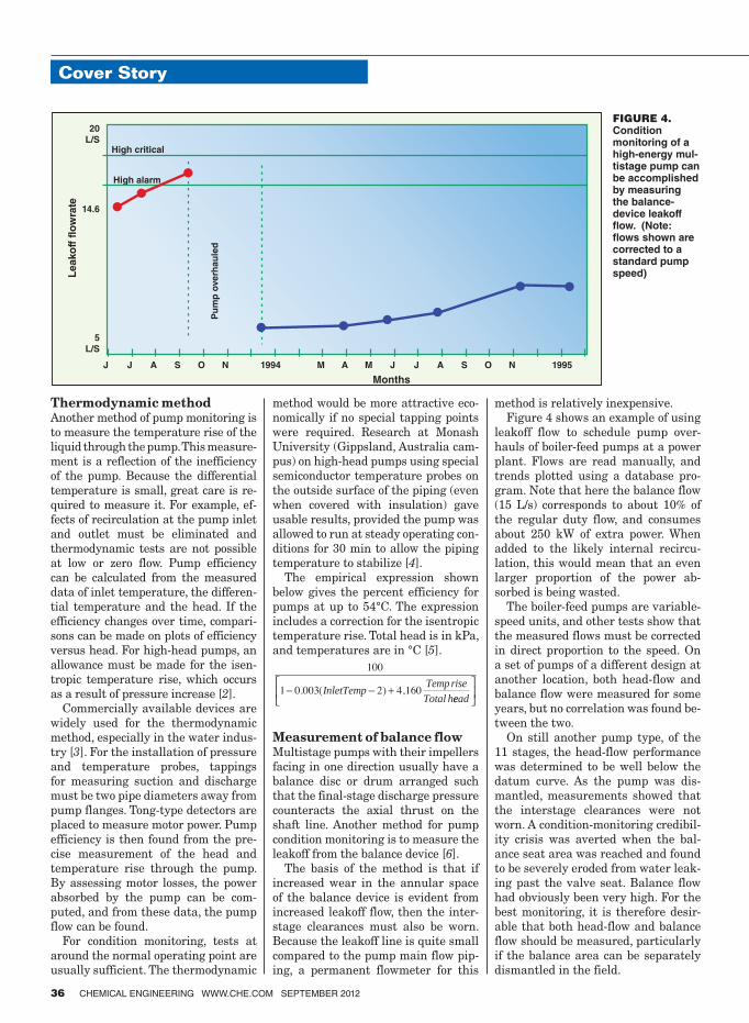
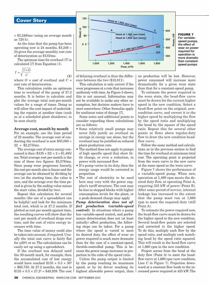
34 Cover Story Condition Monitoring Methods for Pumps Applying condition monitoring tests to pumps can save costs by optimizing overhaul scheduling
NEWS
11 Chementator A commercial move toward algae farming for CO2 recovery; This osmium-based catalyst is rendered nontoxic by polymer incarceration; Strain-hardening test method speeds HDPE pipe testing; A high-temperature Fischer-Tropsch process demonstrated in China; and more
17 Newsbriefs EPA evaluates alternatives to a toxic flame-retardant chemical; Report on bio-based chemicals from algae and other sources; CSB deploys team to Chevron accident; and more
18 Newsfront Chemical Plant Security: Gating More Than the Perimeter Cyber security and physical security are now considered to be interdependent
24 Newsfront An Open-and-Shut Case Improvements in valve technology allow processors to improve performance while reducing leaks
ENGINEERING
33 Facts at Your Fingertips Gas Sparging This one-page reference guide discusses major considerations in setting up and operating a gas-sparging system
40 Feature Report Thin-Film Drying Offers Deep Benefits This continuous drying technology is especially safe and flexible, and offers many benefits, including low operating costs, low space requirements and high specific evaporation capacity
46 Engineering Practice Cooling-Water Outlet Temperature This article discusses the evaluation process — and tradeoffs — that must be considered to optimize recirculating cooling-water systems
ROBERT PACIOREKSenior Vice President, Chief Information Officer
SYLVIA SIERRASenior Vice President, Corporate Audience Development
MICHAEL KRAUSVice President, Production and Manufacturing
STEVE BARBERVice President, Financial Planning and Internal Audit
GERALD STASKOVice President/Corporate Controller
4 Choke Cherry Road, Second FloorRockville, MD 20850 • www.accessintel.com
Re: Education needs a reality check...
I would like to pass on a few comments on Jason Ma-
kansi’s letter titled “Education needs a reality check”,
which appeared in the August 2012 edition (p. 6).
I too, like Jason, began my now 36-year career not
knowing which way to turn a valve but being fully trained
in transport phenomena. Did my university fail me? No.
My university’s ChE program (B.S.Ch.E. 1976, University
of Akron) provided a very essential engineering skill-set:
discipline and problem solving. Sure, I would like to see
new hires have more practical knowledge, but the engi-
neering field is so broad that I think it is difficult for any
university to meet the need of every industry.
In my field, power generation, we utilize engineers who
excel at transport phenomena and finite element analysis
(FEA), as well as engineers who excel in skills developed
through the sweat of their brow, such as welding, machin-
ing or equipment repair. The common trait I observe is
that successful engineers have the “knack”, a curiosity
about how things work and how they can be improved.
This is a teachable skill. I know. I was able to teach it to
my son, a young electrical engineer. It constantly amazes
me how his mind never stops working, investigating and
inventing. This is the skill engineering programs need to
focus on. James S. Bloss, P.E., Sr. Principal Engineer
The Babcock and Wilcox Co., Barberton, Ohio
...internships should fi ll the gap
I read with great interest Mr. Makansi’s letter in the Au-
gust 2012 Chemical Engineering periodical. It struck a
chord with me when I recalled that as a newly graduated
engineer from a respected university, I didn’t even know
what a pipe flange was. However, I was fortunate enough
to be hired by a world-class air-pollution control equip-
ment manufacturer. There, I quickly learned and became
an “expert” as I was sent out to start up newly installed
systems. I’m not saying this is ideal, but it is reality. Many
students cannot complete an engineering curriculum in
four years. Adding any practical training courses would
exacerbate that goal.
The solution may lie in summer intern jobs where
students can gain practical insight into how their edu-
cation can be applied, and learn about necessary topics
not covered in the classroom, like how to turn a valve.
In addition, it provides a company an opportunity to try
out a potential employee and target those students that
fit their organization at graduation. I believe that an
engineering degree doesn’t provide everything a gradu-
ate needs to know to function in our industry, but it is
an indicator to an employer that the individual has the
capacity to learn. If we work together with educators and
provide opportunities to supplement the academic cur-
riculum with real-life experiences in summer positions,
we can all win.
Roger E. Blanton, P.E., Business Development Manager John Zink Co., LLC, Tulsa, Okla.
Letters
6 CHEMICAL ENGINEERING WWW.CHE.COM SEPTEMBER 2012
Over 50 years of experience
The Larox® solid liquid separation equipment
is now available from Outotec.
www.outotec.com
Circle 24 on p. 72 or go to adlinks.che.com/40271-24
Ross mixers and blenders
are engineered to run
trouble-free for decades. But
if you ever need a replacement
part, chances are we have it
right here, ready to ship in
48 hours or less.
We keep a multi-million dollar
inventory of parts in stock
— from planetary gears to
rotors, stators, seals and
O-rings for your High Shear
Mixer. So, when you need
help to keep your production
on track, you can count on us.
Learn more about the value
built into every Ross mixer and
blender. Visit www.mixers.com.
Or call 1-800-243-ROSS.
Jon Kerr
Parts Manager
Ross Employee Owner
Jon Kerr
Parts Manager
Ross Employee Owner
Scan to learn more.Free Tag Reader: http://gettag.mobi
“Need a new gear for your 1967 HDM Double
Planetary Mixer? No problem.”
Circle 28 on p. 72 or go to adlinks.che.com/40271-28
8 CHEMICAL ENGINEERING WWW.CHE.COM SEPTEMBER 2012
Bookshelf
Chemical Thermodynamics for Process Simulation. By Jürgen Gmehling, Bärbel Kolbe, Michael Kleiber and Jürgen Rarey. Wiley & Sons Inc., 111 River Street, Hoboken, NJ 07030. Web: wiley.com. 2012. 760 pages. $135.00.
Reviewed by David Hill,
Chemstations Inc., Houston
The authors of this text are leaders in chemical en-
gineering thermodynamics. Based on their status, I
recommended this book in a blog entry before even
seeing a review copy — and I’m glad I did. The book is
aimed at both students and professionals who work with
process simulators. It assumes a prior understanding of
thermodynamics, and is a more advanced text that focuses
on how complex thermodynamic situations affect the use
and application of process simulation.
Many aspects of applied thermodynamics are not ex-
plored in undergraduate courses. Users of process simu-
lation are often left to learn this material on their own.
Gmehling’s book assembles many of these topics in one
text, and supplies examples and sample problems. It is
more approachable and extensive than the out-of-print
thermodynamics text by Stanley Walas (Phase Equilibria
for Chemical Engineering, 1985).
In the book, mathematics — some quite complex — is
interspersed with clear explanations of what the math-
ematics indicates. This is helpful because many practi-
tioners may require a refresher for the mathematics, and
many students will not be aware of practical applications
that the mathematics can explain.
Effective explanations are provided for why there are
different models for physical properties and vapor-liquid
equilibria (VLE). Background on some of the models and
equations is also discussed, as are the strengths and
weaknesses of the methods. The explanations of why we
have different types of models (activity methods and equa-
tions of state) for VLE are very helpful.
Many topics that routinely confuse users of process sim-
ulators are discussed and explained. There is an excellent
explanation on the often confusing concept of reference
state of enthalpy. Modeling options for “special” systems,
such as polymer, acetic-acid-water, or formaldehyde-water,
are discussed. Both the theoretical basis and practical
implications of azeotropes are also well explained, and
the book includes one of the best available explanations of
residue curve maps. The explanation on how simulators
calculate heat of reaction is also very helpful.
TechTeam can HelpKeep Your Hot Oil System Running!
NEED TECHNICAL SUPPORT
www.MultiTherm.com
NON-TOXIC
NON-HAZARDOUS
Heat Transfer Fluid
for your Hot Oil System?
�Heat Transfer Fluids �Design
�Filter Systems �Training
�Cleaning �Start-Up
�Trouble Shooting �Operations
Call Today!
1-800-225-7440
Circle 22 on p. 72 or go to adlinks.che.com/40271-22
CHEMICAL ENGINEERING WWW.CHE.COM SEPTEMBER 2012 9
Although English is not the first language for the au-
thors, the text is generally easy to read, despite an occa-
sional clumsy phrase. The text’s authors are involved with
DDBST products (Dortmund Data Bank, the Dechema
database), and contributed heavily to the development of
the PSRK (Predictive Soave-Redlich-Kwong) and Volume-
Translated Peng-Robinson (VTPR) models. I felt the book
promoted these methods and tools too heavily. That being
said, I am a strong proponent of the PSRK VLE model
and would agree that these tools and methods are power-
ful. Sample Mathcad files are available, but it would have
been helpful to see the examples in Matlab also.
This text explains many of the concepts that my com-
pany’s technical support group regularly explains to users
of our process simulator, and we recommend this book to
our customers.
Guide to the Business of Chemistry. By the American
Chemistry Council, 700 Second St. NE, Washington, D.C.
ゲ;ノWゲをHヴWくIラマ ┘┘┘くHヴWくIラマ ΓΑΓ ΑΑヶどヵヲヲヰ US Βヰヰ ΑΑヶどヵヲヲヰ
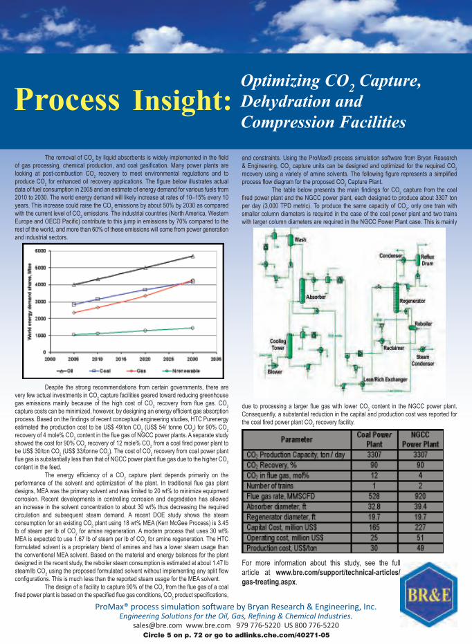
Insight: The removal of CO
2 by liquid absorbents is widely implemented in the ield
of gas processing, chemical production, and coal gasiication. Many power plants are looking at post-combustion CO
2 recovery to meet environmental regulations and to
produce CO2 for enhanced oil recovery applications. The igure below illustrates actual
data of fuel consumption in 2005 and an estimate of energy demand for various fuels from 2010 to 2030. The world energy demand will likely increase at rates of 10–15% every 10 years. This increase could raise the CO
2 emissions by about 50% by 2030 as compared
with the current level of CO2 emissions. The industrial countries (North America, Western
Europe and OECD Paciic) contribute to this jump in emissions by 70% compared to the rest of the world, and more than 60% of these emissions will come from power generation and industrial sectors.
Despite the strong recommendations from certain governments, there are very few actual investments in CO
gas emissions mainly because of the high cost of CO2 recovery from lue gas. CO
2
capture costs can be minimized, however, by designing an energy eficient gas absorption process. Based on the indings of recent conceptual engineering studies, HTC Purenergy estimated the production cost to be US$ 49/ton CO
2 (US$ 54/ tonne CO
2) for 90% CO
2
recovery of 4 mole% CO2 content in the lue gas of NGCC power plants. A separate study
showed the cost for 90% CO2 recovery of 12 mole% CO
2 from a coal ired power plant to
be US$ 30/ton CO2 (US$ 33/tonne CO
2). The cost of CO
2 recovery from coal power plant
lue gas is substantially less than that of NGCC power plant lue gas due to the higher CO2
content in the feed. The energy eficiency of a CO
2 capture plant depends primarily on the
performance of the solvent and optimization of the plant. In traditional lue gas plant designs, MEA was the primary solvent and was limited to 20 wt% to minimize equipment corrosion. Recent developments in controlling corrosion and degradation has allowed an increase in the solvent concentration to about 30 wt% thus decreasing the required circulation and subsequent steam demand. A recent DOE study shows the steam consumption for an existing CO
2 plant using 18 wt% MEA (Kerr McGee Process) is 3.45
lb of steam per lb of CO2 for amine regeneration. A modern process that uses 30 wt%
MEA is expected to use 1.67 lb of steam per lb of CO2 for amine regeneration. The HTC
formulated solvent is a proprietary blend of amines and has a lower steam usage than the conventional MEA solvent. Based on the material and energy balances for the plant designed in the recent study, the reboiler steam consumption is estimated at about 1.47 lb steam/lb CO
2 using the proposed formulated solvent without implementing any split low
conigurations. This is much less than the reported steam usage for the MEA solvent. The design of a facility to capture 90% of the CO
2 from the lue gas of a coal
ired power plant is based on the speciied lue gas conditions, CO2 product speciications,
and constraints. Using the ProMax® process simulation software from Bryan Research & Engineering, CO
2 capture units can be designed and optimized for the required CO
2
recovery using a variety of amine solvents. The following igure represents a simpliied process low diagram for the proposed CO
2 Capture Plant.
The table below presents the main indings for CO2 capture from the coal
ired power plant and the NGCC power plant, each designed to produce about 3307 ton per day (3,000 TPD metric). To produce the same capacity of CO
2, only one train with
smaller column diameters is required in the case of the coal power plant and two trains with larger column diameters are required in the NGCC Power Plant case. This is mainly
due to processing a larger lue gas with lower CO2 content in the NGCC power plant.
Consequently, a substantial reduction in the capital and production cost was reported for the coal ired power plant CO
2 recovery facility.
For more information about this study, see the full article at www.bre.com/support/technical-articles/
gas-treating.aspx.
Optimizing CO2 Capture,
Dehydration and
Compression Facilities
Circle 5 on p. 72 or go to adlinks.che.com/40271-05
Advanced Algal Technologies (Sydney, Aus-
tralia; www.advancedalgal.com) has signed
a $100-million deal with Fuzhou Xiangli En-
terprise Management Consulting (Fuzhou,
China) — an LED-lighting manufacturer
— for a license to build 500 algal-farming-
conveyor modular units per year. These units
will be used to reduce carbon dioxide emis-
sions in manufacturing plants in China.
Traditionally, algae have been grown ei-
ther in open ponds, or in bioreactors (see,
for example, Chem. Eng, September 2008,
pp. 22–25). Both entail serious limitations:
open ponds are subject to external condi-
tions such as weather, pollutants and wild-
life; bioreactors may require expensive sun
tracking equipment and involve problems in
harvesting the algae. Meanwhile, bioreac-
tors still rely on contact of the gas bubbles
in the water to dissolve the CO2.
In the patented system, developed by Ad-
vanced Algal Technologies, the algae are
grown on a fabric inside an insulated build-
ing, within a precisely controlled environ-
ment. The algae can grow to a density of 100
g/m2 per day. The algae are in constant con-
tact with the correct levels of CO2 in the at-
mosphere of the growing structure, and the
use of a wet mat technology provides a high
molecular transfer rate of CO2 in solution.
The company said the system allows
maximum algae yield. For example, a
3,000-m2 warehouse fitted with the system
can produce more than 200 ton/d of algae
or more than 50,000 L of algal oil and 150
tons of high-protein animal feedstock.
Such a facility would consume more than
130,000 ton/yr of CO2.
A commercial move toward algae farming for CO2 recovery
Synfuels China Technology Co. (Beijing;
www.synfuelschina.com.cn) says it has
developed a high-temperature slurry Fis-
cher-Tropsch (F-T) process (flowsheet) that
produces mainly clean diesel, naphtha and
liquefied petroleum gas (LPG) products,
with unique features including: high pro-
ductivity of proprietary catalyst; efficient
recovery of reaction heat by producing
2.5–3.0-MPa(g) steam, which can be used to
generate electricity; a uniform temperature
distribution in the slurry bed; and easy in-
tegration with different synthesis-gas- (syn-
gas) production technologies.
To design the F-T catalyst, the company
first used quantum chemistry to calculate the
molecular energy levels of different crystal
faces, and then achieved the desired catalyst
structure by strictly controlling the prepa-
ration conditions. This approach resulted in
high productivity of the catalyst.
The company’s technology has been suc-
cessfully applied in the Yitai 160,000-ton/
yr, and the Luan 160,000-ton/yr demonstra-
tion coal-to-liquids (CTL) plants, located at
Ordos City in the Inner Mongolia Autono-
mous Region.
Features of the Yitai plant include: a uni-
form temperature distribution across the
5.3-m slurry-bed reactor; the ability to eas-
ily separate the catalyst from the wax, and
replace it online to ensure the continuous
and stable operation of the plant; and the
utilization of the F-T heat of reaction by pro-
ducing 3-MPa byproduct steam, which can
be used to generate electricity for the power
supply of the CTL plant itself.
The Luan plant’s features include: nitro-
gen from the air-separation unit and hy-
drogen from the pressure-swing-adsorption
(PSA) unit are used for the synthesis of am-
monia, which is used to produce urea with
the high-purity CO2 from the purification
and F-T synthesis units; the fuel gas from
the PSA unit is used for integrated gasifi-
cation combined cycle, improving the total
heat efficiency of the plant.
Based on its experience with the demon-
stration plants, Synfuels China is now work-
ing on a few large-scale CTL projects.
Note: For more information, circle the 3-digit number on p. 72, or use the website designation.
Edited by Gerald Ondrey September 2012
Artificial photosynthesisScientists at Panasonic Corp.(Osaka, Japan; www.panasonic.com) have developed an arti� cial photosynthesis system that utilizes sunlight to con-vert CO2 to organic materials (mainly formic acid) at what is said to be the highest efficiency yet achieved (0.2%). The ef-� ciency level is comparable to that of plants. The keys to the Panasonic system are a nitride semiconductor, which is used as a photo-electrode for the reduction of CO2, and a metal catalyst to accelerate the reac-tion and increase selectivity. The research was presented at the International Conference on the Conversion and Storage of Solar Energy in July. The com-pany hopes to use the develop-ment in a system to capture and converte waste CO2 from incinerators, power plants and other industrial processes.
Ion exchangeThe RecoPur system from Eco-Tec Inc. (Pickering, Ont.; www.eco-tec.com) improves the per-formance of the ion exchange process for treating produced water at oil drilling locations. The system features an ion-exchange resin with � ner particles than conventional resins, and resin beds that are
CHEMICAL ENGINEERING WWW.CHE.COM SEPTEMBER 2012 11
Boiler
Steam
Sulfer
CO shift
Tail gas
convention
PSAFuel
gas
Low temp
oil absorp
CO2
removal
H2
H2
Sulfer
recovery
O2
CO2
ASU
Coal
gasification
Coal-water
slurry prep.
Coal
Water
Purification
F-T reaction
water treatment Generator Electricty
LPG
naphtha
diesel
F-T
synthesis
Tail gas
Product
upgrading
LPG
Steam
Crude
syngas CO+H2
(Continues on p. 12)
A high-temperature F-T process demonstrated in China
Masaru Nakamichi, leader of the Blanket
Technology Group, Naka Fusion Insti-
tute, Japan Atomic Energy Agency (JAEA,
Ibaraki, Japan; www.naka.jaea.go.jp) has
developed a new fabrication technology that
enables the mass-production of beryllium
intermetallic compounds (beryllides), which
are advanced, efficient neutron multipliers
that could be used for nuclear fusion reac-
tors. JEAE is said to be the first to fabricate
beryllides with 1-mm dia., and it expects the
newly developed technology to be a big step
toward establishing fuel-production tech-
nology for the nuclear-fusion demonstration
(DEMO) reactor.
At temperatures higher than 600°C, JAEA
has found that the beryllide Be12Ti expands
by only 3% compared to 50% expansion by Be
itself. Also, hydrogen generation from the re-
action of steam at high temperatures — a po-
tential hazard in fusion reactors — is 1,000
times higher with Be compared to Be12Ti.
JAEA has optimized the fabrication
method at the DEMO Design and R&D Co-
ordination Center of International Fusion
Energy Reactor Center (IFERC; Aomori;
www.naka.jaea.go.jp), where it has produced
ductile and easy-worked beryllides rod,
using beryllides raw powders with surfaces
cleaned by a plasma sintering method. In the
past, such materials prepared by alternative
methods have been too fragile and unwork-
able to make powders. By using the beryl-
lides rod as the electrode in a “rotating elec-
trode” process, researchers have fabricated
the world’s first beryllides fine particles with
1-mm dia. This achievement will contribute
to the fuel production test at the Interna-
tional Thermonuclear Experimental Reactor
(ITER; naka-www.jaea.go.jp), and also to-
ward establishing a fuel-production technol-
ogy for the nuclear fusion DEMO reactor.
The scientists also believe that this tech-
nology could be applied for the fabrication
of aluminum-based alloys that are light-
weight, and heat and wear resistant, for use
as mechanical parts in high-performance
automobile engines.
CHEMENTATOR
A step toward the production of fuel for nuclear fusion
shorter, allowing higher lowrates in a more compact footprint. Re-coPur is designed to efficiently remove calcium and magnesium from produced water at oil drill-ing sites so that the high-salinity water can be used as feed water for once-through steam genera-tors (OTSG) in steam-assisted gravity drainage (SAGD), and other enhanced oil-recovery techniques. The RecoPur system consists of a strong-acid- and weak-acid-cation resin bed that can reduce total hardness from thousands of ppm to less than 0.1 ppm. The ion-exchange sys-tem also signiicantly reduces the use of salt for regeneration of the resin.
Sans organomercuryThe Dow Chemical Company (Dow; Midland, Mich.; www.dow.com) has voluntarily completed a program to replace mercury-based catalysts used in a product portfolio acquired from another company. The results
(Continues on p. 14)
(Continued from p. 11)
Circle 23 on p. 72 or go to adlinks.che.com/40271-23
Sterile ice fog improves control of freeze-drying
Linde Gases (Murray Hill, N.J.; www.linde-gases.com) has
developed a novel cryogenic technology that promotes
uniformity in the formation of ice crystals during freeze-
drying (lyophilization) processes for proteins, vaccines and
other injectable pharmaceutical products.
Lyophilization involves freezing a solution of the prod-
uct, then reducing the surrounding pressure to allow
the water to sublimate. Because of the high purity of the
water and clean production environments used in phar-
maceutical products,
there is a lack of
nucleation points for
water to begin freez-
ing, explains Pre-
rona Chakravarty,
Manager of Linde’s
project, known as
VeriSeq Nucleation.
The solutions be-
come supercooled,
which makes con-
trolling the forma-
tion of ice crystals
difficult, she adds.
This lack of control
lengthens operating
cycles and reduces
product yields.
The Linde tech-
nology uses a propri-
etary mixing tech-
nique to blend liquid
nitrogen with ultra-
pure water to create
a mist of fine, sterile
ice crystals. The “ice fog” rapidly spreads throughout the
lyophilizing chamber and causes all vials to freeze at the
same time and at the desired temperature. Controlling
the temperature at which a vial freezes — the ice nucle-
ation temperature — produces the preferred ice structure
within the product, which reduces processing time and
minimizes product damage.
This can be seen in the top image, which shows the mag-
nified pore structure of a freeze-dried product subjected to
VeriSeq Nucleation. The pores are larger and more regu-
lar, which leads to improved drying properties. The image
on the bottom shows the pore structure of a freeze-dried
product without any nucleation control.
Linde’s VeriSeq Nucleation technology can be retrofit-
ted onto existing dryers, as well as incorporated into new
installations, Chakravarty says, and initial customer feed-
back from early demonstrations of the technology, which
was unveiled last June at the Achema 2012 tradeshow,
has been positive.
A01
120
EN
Partner with
the Best
With over 50 independent subsidiar-ies and more than 220 engineering and sales offi ces spread across the world, SAMSON ensures the safety and environmental compatibility of your plants on any continent.
To offer the full range of high-quality control equipment used in industrial processes, SAMSON has brought together highly specialized compa-nies to form the SAMSON GROUP.
SAMSON AG · MESS- UND REGELTECHNIK Weismüllerstraße 360314 Frankfurt am Main · GermanyPhone: +49 69 4009-0 · Fax: +49 69 4009-1507 E-mail: [email protected] · www.samson.deSAMSON GROUP · www.samsongroup.net
Cir
cle
29
on
p. 7
2 o
r g
o t
o a
dlin
ks.c
he
.co
m/4
02
71
-29
A new hydraulically driven, positive-dis-
placement-pump system can lower the
energy requirements for pumping water
by 10% in large seawater reverse osmosis
(SWRO) desalination plants, where electric-
ity typically represents the largest cost.
Recently launched by GE Water & Power
(www.ge-energy.com) at the 2012 Interna-
tional Water Week in Singapore, the IPER
(integrated pump and energy recovery) sys-
tem is designed for plants with greater than
1,000-m3/d capacity, where crank-driven
positive displacement pumps are not practi-
cal because the crankshaft lengths become
prohibitively large. Improvements to the con-
ventional centrifugal pumps used for higher
capacity SWRO plants have been able to de-
liver only incremental energy savings.
In the IPER system (diagram), the crank-
shaft is eliminated, and the piston is instead
moved by a unique hydraulic-drive system
that powers three double-acting pistons at
much slower cycle speeds than traditional
positive displacement pumps. The system
consists of a hydraulic-pump-drive unit, a
water-displacement cylinder, and a sophis-
ticated control unit.
GE Water & Power has installed the sys-
tem in a GE owned-and-operated facility
in the Caribbean, and is in discussions re-
garding future installations. The company
is also developing larger IPER units, says
Erik Hanson, systems product management
leader for water and process technologies at
GE Power & Water, including one with a ca-
pacity of 2,500 m3/d, anticipated for August
2013 and a 10,000-m3/d unit in the third
quarter of 2014.
CHEMENTATOR
14 CHEMICAL ENGINEERING WWW.CHE.COM SEPTEMBER 2012
CALFLO AF delivers longer fluid life and better equipment protection. And more savings to you.We put CALFLO AF and leading competitors to the test in a challenging Severe Oxidative Stability Test and the results are clear. CALFLO AF
provides better oxidative stability for longer fluid life and enhanced equipment protection. That means more savings in operations
and maintenance costs. And less worry. Test CALFLO AF, or another product in our line of CALFLO heat transfer fluids, in your operation.
And see the results for yourself.
Visit www.calflo.com for the clear facts.
One tough test. One clear winner. CALFLOTM AF.
Petro-Canada is a Suncor Energy businessTMTrademark of Suncor Energy Inc. Used under licence.
A specialty heat transfer � uid competitorNo flow, remains completely stuck in tube.
A world leader in industrial lubricantsFlows, but severe build-up of deposits remains in tube.
CALFLO AFFlows easily, stays cleaner longer.
Results from Severe Oxidative
Stability Test.
Circle 25 on p. 72 or go to adlinks.che.com/40271-25
Supply
FSH
CDH FSH = Feed supply header
FPH = Feed pressure header
CPH = Concentrate pressure header
CDH = Concentrate discharge header
ROFPH
Feed Product water
ConcentrateDischarge
Patent pending
Hydraulic drive
A
B
This new pump system improves efficiency for desalination operations
of the 18-mo program enabled Dow Formulated Systems to remove all organo-mercury catalysts from its polyurethane (PU) elastomer products prior to the E.U.’s formal recom-mendation to phase out these catalysts, and � ve years before such compliance is mandated. Dow launched its complete suite of re-engineered PU elastomer products earlier this year. This launch required eight different catalyst packages to replace just one that used a mercury-containing catalyst. The new Hy-
(Continues on p. 16)
(Continued from p. 12)
CHEMENTATOR
Strain-hardening test method speeds HDPE pipe testing
A test method developed by SABIC (Saudi Basic Industries
Corp.; Riyadh, Saudi Arabia; www.sabic.com) scientists
drastically reduces the time needed to evaluate slow-crack
growth resistance in high-density polyethylene (HDPE)
that is used in pressure pipes. The strain-hardening test
method allows HDPE producers to speed product develop-
ment and improve quality control by offering an alternative
to traditional approaches for collecting data on the long-
term slow-crack growth performance of pressure pipes.
Traditional methods, such as the full-notch creep test
(FNCT) involve subjecting material samples to constant
stress, and crack-inducing liquid and measuring the time
to failure, a process that can go on for months. The strain-
hardening test consists of a tensile test carried out at
80°C in a few hours. When a polymer sample is highly
stretched, it exhibits strain-hardening, a phenomenon
that SABIC scientists have correlated with slow-crack
growth in HDPE, so that the slope of the stress/strain
curve at very high elongation rate — the so-called strain-
hardening modulus — can be used to predict its resistance
to slow-crack growth.
“The beauty of the method is that it can be carried out
with non-specialized equipment right in the plant, rather
than having to send samples out for testing at special insti-
tutes,” says Ralph Handstanger, SABIC technical market-
ing engineer.
“So far the fundamental connections between strain-
hardening and crack propagation have been worked out
for the assessment and ranking of HDPE raw materials,”
Handstanger says. There is potential for the application of
this approach to pipes and other areas, however.
No matter in what markets you operate: serv&care
maximizes the reliability of your plant with competent
service solutions. Fast, reliable and backed up by the
Circle 14 on p. 72 or go to adlinks.che.com/40271-14
This silicone coating keeps electrical insulators safe
Wacker Chemie AG (Munich, Germany; www.wacker.
com) has commercialized a solvent-free coating for
electrical insulators. Powersil 570 Plus is said to be the
world’s first insulator coating based on a patented silicone-
in-water emulsion technology. Its viscosity displays a strong
dependence on its shear rate, which makes it possible for
spray applications. The one-component emulsion is applied
by spraying and then it cures to form a water-repellent sili-
cone coating. It adheres to ceramic and glass substrates,
and passes the 1,000-h salt-fog test per IEC 62217.
Porcelain and glass are commonly used to insulate over-
head powerlines, but in coastal and industrial areas, salt de-
posits and dirt can impair the insulating properties, which
can lead to electrical discharges or so-called pollution flash-
overs. To avoid such scenarios, insulators must be cleaned
regularly. Silicone coatings maintain the electrical insulating
properties, and their hydrophobicity prevents the formation
of “wet pollution layers.” Thus, the typical flashover scenario
— wet film layer with an increased leakage current, dry band
arcing, bridging or individual insulator sheds and finally the
electrical flashover — is impossible, says Wacker.
CHEMENTATOR
Professor Shu Kobayashi and his research
group at The School of Science, University
of Tokyo (Japan; www.chem.s.u-tokyo.ac.jp/
users/synorg/index_E.html) have developed
an osmium-based catalyst for performing
asymmetric syntheses of drug precursors.
While showing the same catalytic perfor-
mance of its predecessor — a microencap-
sulated osmium oxide in a polymer — the
new catalyst system is not dissolved by sol-
vents, which makes it possible to recover the
catalyst for reuse. The new, so-called poly-
mer-incarcerated osmium (PIOS) system is
nontoxic, nonvolatile and stable for months
in air.
The catalyst is made by mixing OsO4 in
a styrene-based polymer solution for 72 h.
Hexane is then added, which causes the
OsO4 to become microencapsulated by the
polymer. After removing the solvent, the
solids are heated to 110°C, which crosslinks
the polymer into a matrix in which the OsO4
is bound.
The catalyst enables a one-step reaction
process instead of the three or four steps
required by conventional catalyst technolo-
gies. For example, the chemists demon-
strated that the PIOS system catalyzes the
asymmetric dihydroxylation of alkenes into
the corresponding diols with high yields
and high enantioselectivities. They also pre-
pared 1-mol quantities of a key intermediate
for camptothecin (an anticancer drug) with
97% yield with the catalyst. They also con-
firmed that osmium was not detected to be
absorbed in the organs of PIOS-dosed mice
in acute toxicity tests.
The researchers are expecting that their
achievement on immobilization and stabili-
zation of a toxic system could be applied to
other catalyst systems that show high activ-
ity but also suffer due to high toxicity.
This osmium-based catalyst is rendered nontoxic by polymer incarceration
Novozymes A/S (Copenhagen, Denmark;
www.novozymes.com) has developed a
strain of metabolically engineered Asper-
gillus oryzae fungus that is capable of pro-
ducing the four-carbon, dicarboxylic acid
compound malic acid. The chemical building
block malic acid is used as a flavor enhancer
in the food industry, and can be converted
into 1,4-butanediol (BDO), which serves as
a precursor to many other chemical deriva-
tives used in resins and polymers. Developed
in partnership with Archer Daniels Midland
Co. (ADM; Decatur, Ill.; www.adm.com), the
robust fungus strain generates high yields of
malic acid and has the potential to achieve
production economics similar to petroleum-
derived malic acid, says Novozymes vice
president Rasmus von Gottberg. Novozymes
is looking to out-license the fungus strain
and associated technology to partners who
would commercialize the bio-based malic
acid and its derivatives.
A move toward bio-based malic acid . . .
perplast and Diprane products ensure that users can already be conident to have non-mer-cury catalysts that comply with future REACH requirements, says the company.
Phenol recoveryLast month, Rhein Chemie Rheinau GmbH (Mannheim, Germany; rheinchemie.com) was awarded irst prize in this year’s Responsible Care com-petition — held by the Baden-Wuerttemberg branch of the German Chemical Industry Assn. (VCI; Frankfurt am Main, Germany; www.vci.de) — for a process to recover phenol from mixed wastewater streams generated in the manufacture of a plastics additive. The process removes phenol and recycles it back to the produc-tion process, thereby reducing the amount of phenol to be dis-posed of by around 150 metric tons per year.
Phosphorus recoveryResearchers from the Fraun-hofer Institute for Interfacial Engineering and Biotechnol-ogy (IGB; Stuttgart, Germany; www.igb.fraunhofer.de) are developing a patented process for the recovery of struvite (magnesium-ammonium phos-phate) from sewage sludge. The electrochemical process precipitates struvite (from a solution containing nitrogen and phosphorus) as crystals that can be directly used as a fertilizer, without the need for further processing.
The process is now being tested in a mobile pilot plant, which features a 2-m tall electro-lytic cell with a sacriicial magne-sium anode and a metallic cath-ode. Water is split into OH– at the cathode, and oxidation takes place at the anode to form Mg+2 ions, which migrate through the water and react with PO4
–3 and NH4
+ to form struvite.So far, the required power
for the process has never ex-ceeded 70 W-h/m3 for all types of wastewater tested, and the researchers have demonstrated that the phosphorous concen-tration is reduced by 99.7% to less than 2 mg/L, which is lower than the maximum allowable concentration permitted by the German Waste Water Ordi-nance (AbwV). ❏
(Continued from p. 14)
16 CHEMICAL ENGINEERING WWW.CHE.COM SEPTEMBER 2012
Meanwhile, BASF SE (Ludwigshafen,
Germany; www.basf.com), Cargill (Min-
neapolis, Minn.; www.cargill.com) and No-
vozymes signed a joint R&D agreement to
develop an industrial biotechnology-based
production process for acrylic acid. Since
2008, Novozymes and Cargill have collabo-
rated to develop microorganisms that con-
vert renewable feedstock into 3-hydroxy-
propionic acid (3-HP), which is a possible
precursor to acrylic acid. BASF has now
joined forces to develop a process to convert
3-HP into acrylic acid. BASF plans to first
use the bio-based acrylic acid to manufac-
ture superabsorbent polymers, which are
used in diapers and other hygiene products.
Also last month, Invista (Wichita, Kan.;
www.invista.com) and LanzaTech (Roselle,
Ill.; www.lanzatech.com) signed a joint devel-
opment agreement focused on bio-based buta-
diene. According to the agreement, Invista
and LanzaTech will collaborate on projects
to develop one- and two-step technologies to
convert carbon monoxide into butadiene.
Initial commercialization is expected in
2016. The collaboration will initially focus
on the production of butadiene in a two-
step process from LanzaTech — CO-derived
2,3-butanediol (2,3 BDO). A direct single-
step process will also be developed to pro-
duce butadiene directly through a process of
gas fermentation. ■
. . . and acrylic acid . . .
. . . and butadiene
CHEMICAL ENGINEERING WWW.CHE.COM SEPTEMBER 2012 17
NewsbriefsNewsbriefs
CHEMICAL PRODUCTION SEES DECLINE
Overall production of chemicals in the U.S. fell by 0.1% to 86.6% of its 2007 level during July, but the overall decline
masked gains in specialty and bulk chemicals, according to data from the U.S. Federal Reserve Board that was analyzed in the August 17 Weekly Chemistry and Economic Report from the American Chemistry Council (ACC; Washington, D.C.; www.americanchemistry.com). U.S. specialty chemical production was up 0.4% in July, said the report, while basic chemical produc-tion gained 0.2%. Production fell in agricultural chemicals and consumer products.
The bio-based materials
and chemicals industry
needs to tap newer, non-
food sources of biomass
and cellulosic material and
raise volumes of feedstock
before it can emerge as
an economically viable
alternative to petroleum-
based products, accord-
ing to a Lux Research
(Boston, Mass.; www.
luxresearchinc.com) report.
Currently, the high cost
of capital and operations
limit bio-based materials
and chemicals to a few fa-
cilities located where corn
and sugarcane are plenti-
ful and inexpensive.
“Bio-based materials and
chemicals manufacturers
need syngas [synthesis
gas] and sugar to fuel their
growth. Gasification and
enzymatic hydrolysis are
key technologies for secur-
ing vast amounts,” says
Mark Bunger, research
director and lead author
of the report, “Pruning the
Cost of Bio-Based Materi-
als and Chemicals.”
Lux Research analysts
studied cost drivers in gas-
ification, enzymatic hydro-
lysis of cellulose and algae
cultivation to find opportu-
nities where new technolo-
gies can turn them to profit.
Among their findings:
• Algaeremainsacost-intensive loser. In Lux
Research’s model, algae
cultivation yields a 48%
loss, calling into ques-
tion its long-term pros-
pects. The problem lies
in the high capital costs
for growing algae at in-
dustrial scale
• Syngasfermentationhas great new product
potential. The many
products of syngas
fermentation proven
at laboratory scale, or
larger, include ethanol,
butanol, acetic acid,
butyric acid, 2,3-butane-
diol and methane. Lead-
ing startups in this do-
main include ZeaChem,
which is collaborating
with Procter & Gamble,
and LanzaTech
• Thereishopeforcellu-
losic biomass, but costs
need to fall further.
Enzymatic hydrolysis
is being commercialized
at new facilities like
GraalBio’s plant in Bra-
zil, using the latest en-
zymes from Novozymes
andDSM.However,many parts of the pro-
cess need to improve,
including harvesting
and collecting biomass,
which adds $15/ton, or
$0.21/gal, in costs
Cheaper chemicals from algae, farms & forest may be possible, report says
Progress on a waste-to-fuels process reported at ACS meeting
A process for converting
municipal waste, algae,
cornstalks and similar ma-
terial to gasoline, diesel and
jet fuel shows promise in
larger plants, the develop-
ers reported at the National
Meeting & Exposition of the
AmericanChemicalSociety(ACS;Washington,D.C.;
www.acs.org), which took
place in Philadelphia from
August 19–23.
The technology, termed in-
tegrated hydropyrolysis and
hydroconversion (IH2), was
developed by the Gas Tech-
nology Institute (GTI; Des
Plaines, Ill.; www.gastech-
nology.org). GTI scientist
Martin Linck anticipates
multiple demonstration-
scale facilities in operation
by 2014.
IH2 technology involves
the use of internally gener-
ated hydrogen and a series of
proprietary catalysts, which
jump-start chemical reac-
tions that otherwise would
happen slowly or not at all.
Linck said it differs from
other biofuel technologies in
that it produces a finished,
ready-to-use liquid hydro-
carbon fuel, rather than
crude intermediate sub-
stances or substances that
contain oxygen, which must
be processed further.
CSB deploys to fire and explosion at Chevron refinery
A seven-member inves-
tigative team from
theU.S.ChemicalSafetyBoard(CSB;www.csb.gov)was deployed to the scene
of an explosion and fire
that occurred August 6 at
the Chevron Refinery in
Richmond, Calif. The team
isheadedbyDonaldHolm-
strom,directoroftheCSB’sWesternRegionalOfficein Denver. Board member
Mark Griffon accompa-
nied the team. According
to company officials, the
explosion and fire involved
the release of vapor that
found an ignition source.
Four workers sustained
minor injures.
CSBchairmanRafaelMoure-Erasosaid,“CSBinvestigations examine a
wide range of safety issues
such as effective process
safety management and
mechanical integrity.”
EPA identifies substitutes for toxic flame-retardant chemical
In an effort to identify
possible substitutes for
a toxic flame-retardant
chemical, known as de-
cabromodiphenyl ether
(decaBDE),theU.S.En-
vironmental Protection
Agency(EPA;Washington,D.C.; www.epa.gov) has
released a draft report on
alternatives. This assess-
ment, developed under
EPA’s Design for the En-
vironment (DfE) program,
profiles the environmental
and human health haz-
ards on 30 alternatives to
decaBDE, which will be
phased out of production
by December 2013.
DecaBDE is a common
flame retardant used in
electronics, vehicles and
building materials that can
bio-accumulate in humans
and animals. The techni-
cal assessment can help
manufacturers identify
alternatives to decaBDE.
This draft report is the lat-
est in a series of actions the
agency is taking to address
flame retardants made
with bromine.
18 CHEMICAL ENGINEERING WWW.CHE.COM SEPTEMBER 2012
Newsfront
It was clear at the recent Chemical
Sector Security Summit (Baltimore,
Md., July 31-Aug. 1) that aware-
ness of and activity in security for
the chemical process industries (CPI)
are growing. The annual summit, now
in its sixth year, was held at its larg-
est venue ever and brought together
about 650 participants from industry,
academia and the government to net-
work with other security professionals,
share best practices and learn more
about chemical security regulations.
One of the strong messages from
this summit, as well as from addi-
tional sources, is that more atten-
tion than ever before is being given
to cybersecurity of industrial control
systems. In fact, in her introductory
comments at the summit Suzanne
Spaulding, deputy undersecretary for
the National Programs and Protection
Directorate (NPPD) for the U.S. Dept.
of Homeland Security (DHS; Washing-
ton, D.C.; www.dhs.gov) emphasized
an increased awareness of the interde-
pendence between cyber and physical
security and said that the “chemical
sector has been a leader to bring to-
gether those two disciplines.”
Meanwhile, in his keynote address
at the summit, undersecretary for the
NPPD, Rand Beers, spoke of a new
appreciation of owners and operators
across all sectors, including the chemi-
cal sector, for the need for cybersecu-
rity. He said that in the larger picture,
security requires teamwork — across
the government, private sector and
the public.
That type of teamwork was evident
in the mix of participants at the sum-
mit. Evidence is also seen in a number
of working groups that are collabora-
tive efforts to reduce the risks to in-
dustrial control systems. A good ex-
ample of this is the Industrial Control
Systems Joint Working Group (IC-
SJWG; www.us-cert.gov/control_sys-
tems/icsjwg/).
CFATS
The CPI are considered part of the criti-
cal infrastructure in the U.S., and as
such are regulated by the DHS under the
Chemical Facility Anti-Terrorism Stan-
dards (CFATS; for details on CFATS see
Chemical Plant Security, Chem. Eng.,
pp. 21–23, September 2009).
While CFATS continues to be a
driver for much of the heightened ac-
tivity in security, the program itself
has recently been confronted by seri-
ous challenges. Last year at this time,
with strong support in both the House
and the Senate, CFATS was poised to
be reauthorized by Congress for mul-
tiple years (as opposed to the annual
reauthorization it had been receiving).
However, an internal assessment of
the CFATS program in the last months
of 2011 brought to light some serious
concerns about the management and
implementation of the program. A
multi-year reauthorization now seems
to be unlikely in the foreseeable fu-
Newsfront
While fences and locks have been
helping to secure the CPI
for some time, the vulnerability
of industrial control systems
has only recently been
demonstrated in ways that
make everyone take notice.
Cyber and physical security
are now considered interdependent
CHEMICAL PLANT SECURITY:
GATING MORE THAN THE
PERIMETER
FIGURE 1. TrakLok integrated the physical security of a lock with a sophisticated system that monitors the security of cargo and instanta-neously reports security breaches via cellular and satellite networks
Traklok
DUPRÉ LOGISTICS, LLC / 201 Energy Parkway Suite 500 / Lafayette, LA 70508For more information, call 855-686-5478 or email [email protected]
Circle 11 on p. 72 or go to adlinks.che.com/40271-11
20 CHEMICAL ENGINEERING WWW.CHE.COM SEPTEMBER 2012
Newsfront
ture. While authorization inspections
have resumed as of July 2012, the pro-
gram is currently facing the possibil-
ity of drastic funding cuts.
During a “Congressional Perspec-
tives” panel at the Security Sum-
mit, Monica Sanders, council for the
House Committee on Homeland Se-
curity, shed some light on the CFATS
situation. She explained that with a
new program like CFATS, you want
to have one-year authorizations until
the program is “mature”, at which
time it is extended for multiple years.
“Congress thought that CFATS was
at that point, but the late 2011 memo
was a game changer”, she said, and
heavy Congressional oversight is
still needed on the CFATS program.
The panel members, which also in-
cluded Chris Schepis, senior profes-
sional staff member for the House
Committee on Homeland Security;
and Jerry Couri, senior professional
staff member for the House Commit-
tee on Energy and Commerce, seemed
to agree that they expected CFATS
would face a budget cut. The panel
also commented, however, that Con-
gress wants to see CFATS succeed
as the kind of program envisioned in
2006 when it was first authorized.
While CFATS has been a driver for
much of the heightened activity in se-
curity over the past few years, the goal
of securing the CPI is not dependent
on the standard. As Lawrence Sloan,
president and CEO of the Society of
Chemical Manufacturers & Affiliates
(SOCMA; Washington, D.C.; www.
socma.com) said in his opening re-
marks at the summit “… the reason we
meet here is not merely because of the
presence of a regulation, but because
of a need for mutual collaboration ...
industry’s commitment to securing its
most hazardous chemical products is
stronger than ever, as evidenced by
the overwhelming presence of so many
attendees here today from the private
sector. Others who are here who may
not fall under CFATS or the Coast
Guard’s MTSA [Maritime Transpor-
tation Security Act] program are also
here to learn because, whether you are
regulated or not, securing your assets
and the communities in which you op-
erate makes good business sense.”
Physical security “Perimeter security is the first line of
defense,” says Ryan Loughin, director
of Petrochemical & Energy Solutions
at Tyco Integrated Security (TycoIS;
Boca Raton, Fla.; www.tycois.com),
“and Tyco Integrated Security offers
many solutions including advanced
fiber-based technology, thermal imag-
ing/infrared, analytics software and
remote video products that help sat-
isfy the CFATS Risk-Based Perfor-
mance Standards”.
Indeed, most of CFATS addresses
the critical need to physically secure
chemical plants, with one of the major
goals being to prevent theft and diver-
sion. Diversion is a form of misappro-
Innovations for a better world.
Buhler Aeroglide, 100 Aeroglide Drive, Cary NC 27511 USA, Tel +1 919 851 2000, Fax +1 919 851 6029
In addition to making leak-free, high performance valves, industry experts say ac-tuation is growing considerably. “I believe the increase in actuation is related to labor savings in that by automating the systems, users are able to see, from a re-
mote monitoring station, what’s going on with the valves — whether they’re engaged, on or off, having issues and so on,” says Dave Stewart, director of marketing with Hayward Flow Control (Clemmons, N.C.). “In a vast refinery or chemical plant that is not automated, this involves a lot of time spent getting to valves in remote areas, but by automating them you save a lot of time. Actuators serve as a way to monitor the status of the valves in a facility and, as more plants and refineries are being updated, actuation is being added.”
GF Piping System’s Dave Vollaire agrees: “Automation is on the rise and we see people moving away from manual systems and using positioners and more feedback devices that reveal the actual position of valves in a system.” ❑
AN OPEN AND SHUT CASE FIGURE 1. Clampseal bellows seal
valves allow for zero emissions in applica-tions where packed valves may not reliably
contain light gases or hazardous � uids
Conval
CHEMICAL ENGINEERING WWW.CHE.COM SEPTEMBER 2012 25
perature limitations of plastics and
rubbers are more restrictive, so the
new and improved graphite packings
work better, last longer and resist pit-
ting, making them more suitable for
critical applications with tempera-
tures over 500°F.
However, to provide even more leak-
proof capability, Conval developed the
Clampseal Packing System (Figure 1),
which puts compression on the pack-
ing in an effort to maximize packing
life in the demanding high-pressure
and high-temperature applications.
The uniform, single-piece gland
allows the graphite packing to be
loaded uniformly with a one-piece
gland, which eliminates the potential
for stem damage from gland cock-
ing, while the integral gland wrench
provides immediate gland/packing
adjustment capability. “This feature
makes it easier to adjust the packing
and gives more uniform compression
of the packing, which helps reduce
leaks,” says Hendrick.
The Clampseal technology can
be found on many of the company’s
valves, including the new zero-emis-
sions bellows seal valves, which are
suitable for applications where packed
valves may not reliably contain light
gases or hazardous system fluids, due
to leakage in the stem/packing seal or
stuffing box, wall/packing seal area.
Also to prevent leaks of hazardous
liquids, many facilities are double
containing their valve and piping sys-
tems, says Vollaire. “This means they
run the main carrier line of chemical,
and around that line there is a second
pipe,” Vollaire says. “In our case, we
put an outer valve, like a dummy valve
that throttles and closes the valve in-
side that is carrying the chemical.
This type of double containment is
especially helpful for lines that carry
chemicals overhead, but have the po-
tential to leak, because the secondary
pipe contains the chemical leak from
falling down.”
GF’s Double-See (Figure 2) is used
as a pressure-rated, double contain-
ment system and offers versatile
installation options, assembled and
tested fittings and a pipe cut-length
guidance system that provides a sim-
plified approach to installation. The
valve-in-valve design allows full-con-
tainment-pressure ratings. ❏
Circle 10 on p. 72 or go to adlinks.che.com/40271-10
FIGURE 2. The Double-See vinyl piping system provides a pressure-rated dou-ble-containment system for transporting hazardous liquids
GF Piping Systems
26 CHEMICAL ENGINEERING WWW.CHE.COM SEPTEMBER 2012
Equipment News Roundup
MORE VALVE
PRODUCTS
Wafer check valves for critical water applicationsThese 10- and 12-in. PVC wafer check
valves (photo) are installed on the dis-
charge side of pumps to prevent back-
flow flooding that could damage pump
systems. The body, disc and stopper as-
sembly are machined from solid PVC
plate stock, which conforms to ASTM
D1784 Cell Classification 12454A.
This material offers chemical resis-
tance. The valve is easily installed by
slip fitting the valve between two mat-
ing flanges. The valve body automati-
cally centers on the mating flanges,
once the stud pack is installed. A di-
rectional flow arrow on the valve body
indicates the upstream and down-
stream sides of the valve. The lack
of bolt pattern allows one valve style
to accommodate many mating flange
dimensions. — Asahi/America, Inc.,
Malden, Mass.
www.asahi-america.com
An inline check valve for backflow preventionThe CheckMate’s (photo) custom-en-
gineered, all-rubber, uni-body design
eliminates backflow, while the elasto-
mer-fabric reinforced-design reduces
maintenance. The valve offers low
head loss and can open to a near-full
pipe diameter to maximize the flow
capacity of the outfall. The valves are
available in 4–72-in. sizes. — Tideflex
Technologies, a Division of Red Valve
Co., Inc., Carnegie, Pa.
www.tideflex.com
Hand valves and manifolds for instrumentation applicationsHand valves and two-, three- and five-
valve manifolds in carbon steel (photo,
p. 27) provide a solution for natural gas
Circle 9 on p. 72 or go to adlinks.che.com/40271-09
Asahi/America
Red Valve
transmission line’s, and other chemi-
cal process industries’ instrumentation
applications that don’t require the ex-
treme performance of stainless steel.
The products are pressure rated up
to 6,000 psig (414 bar) to provide sys-
tem flexibility when selecting process
valves. Designed to work with a vari-
ety of fittings, the valves and manifolds
feature an external adjustable gland
that allows for full adjustment of the
stem packing without removal of the
valve from the system. Handles are
color-coded to quickly and easily iden-
tify valve functions. — Parker Hannifin
Corp., Huntsville, Ala.
www.parker.com
Glass-filled PP makes this valve more durableThe platinum GF-PP (glass-filled
polypropylene) TB Series ball valves
(photo) feature a full port design with
true-union threaded or flanged end
connections and reversible seats. The
valves have a maximum pressure rat-
ing of 250 or 150 psi with threaded or
flanged ends, and a maximum service
temperature of 240°F. The platinum
GF-PP material provides high impact
resistance and is suitable for more
robust chemical services, abrasive ap-
plications and water distribution. Fea-
tures include an adjustable seat re-
tainer, double O-ring stems and easy
actuation. Options in-
clude handle lockouts,
2-in. square operating
nut, stem extensions,
pneumatic or electric actu-
ation, manual limit switches
and spring return handle. —
Hayward Flow Control, a Division of
Hayward Industries, Clemmons, N.C.
www.haywardflowcontrol.com
Improve safety and reliability with this ball valveThe KTM Unibody EB700 Series ball
valve is designed and certified to meet
the standards and service require-
ments of the petrochemical, chemical
and oil-and-gas industries through
improved pipeline integrity, perfor-
mance and safety characteristics. The
one-piece, cast body minimizes poten-
tial leak paths, making it safer and
more environmentally friendly than
split body designs. With dual body-
insert seals and shaft seals, this valve
Circle 17 on p. 72 or go to adlinks.che.com/40271-17
Parker Hannifin
Hayward Flow Control
provides sealing integrity, says
the manufacturer. The valves
feature a PTFE/PFA co-poly-
mer “E” seat. The valves in
sizes above DN25 (NPS 1) also
provide an additional safety
feature incorporating cavity self-re-
lieving seats to relieve potential ball
cavity over-pressure when the valve
is in the closed position. — Tyco Flow
Control, Princeton, N.J.
www.tycoflowcontrol.com
This dust-duty valve createsa quality air sealThe Dust Duty Valve (DDV; photo)
comes with a robust cast housing de-
signed for greater capacity and is suit-
able for dust collection. It will service
applications where a quality air seal
is necessary in light-duty, non-abra-
sive applications under baghouse,
cyclone and dust collections with a
maximum pressure differential of 60
in. wc.. The maximum temperature is
300°F. The valve is available in cast-
iron or stainless-steel construction
with square or round flanges in sizes
6–14 in. — W.M. Meyer & Sons, Inc.,
Libertyville, Ill.
www.wmwmeyer.com
Spring-return actuators for infrequently operated valvesThe ManPower range of products
(photo) reduces installation time and
expense since no electrical-, hydrau-
lic- or pneumatic-power supply is re-
quired. Suitable for a range of ball,
butterfly and plug valves, the scotch-
yoke actuators are equipped with a
compact, self-contained, manually
operated hydraulic-power pack. A hy-
draulic hand pump on the power pack
is used to operate the actuator and
compress the failsafe spring, hold-
ing the valve in the desired open or
closed position until a failsafe signal
is received, at which point the spring
will immediately drive the valve to the
safe position. Failsafe operation can be
triggered by electrical signals, high-
or low-pressure pilots or fire sensors,
enabling the successful fulfillment
of many ESD (emergency shutdown)
and pressure-related protection du-
ties in the oil, gas, petrochemical and
pipeline industries. — Rotork Fluid
Systems, U.K.
www.rotork.com ■Joy LePree
28 CHEMICAL ENGINEERING WWW.CHE.COM SEPTEMBER 2012
Equipment News
Circle 19 on p. 72 or go to adlinks.che.com/40271-19
Since 1929, the italian Excellence in the worldPompetravaini Group, the “Heart” of the plant
New name but old traditionat the top of technology:
Our commitment is always to stay ahead
Combivac® System
SB Compressor
SB Compressor skidfor flare gas recovery
Circle 27 on p. 72 or go to adlinks.che.com/40271-27
Department Editor: Scott Jenkins
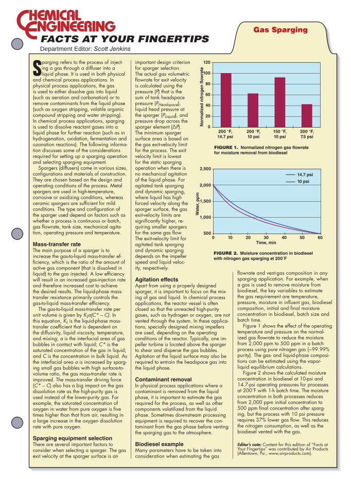
Sparging refers to the process of inject-ing a gas through a diffuser into a liquid phase. It is used in both physical
and chemical process applications. In physical process applications, the gas is used to either dissolve gas into liquid (such as aeration and carbonation) or to remove contaminants from the liquid phase (such as oxygen stripping, volatile organic compound stripping and water stripping). In chemical process applications, sparging is used to dissolve reactant gases into a liquid phase for further reaction (such as in hydrogenation, oxidation, fermentation and ozonation reactions). The following informa-tion discusses some of the considerations required for setting up a sparging operation and selecting sparging equipment.
Spargers (diffusers) come in various sizes, configurations and materials of construction. They are chosen based on the design and operating conditions of the process. Metal spargers are used in high-temperature, corrosive or oxidizing conditions, whereas ceramic spargers are sufficient for mild conditions. The type and configuration of the sparger used depend on factors such as whether a process is continuous or batch, gas flowrate, tank size, mechanical agita-tion, operating pressure and temperature.
Mass-transfer rateThe main purpose of a sparger is to increase the gas-to-liquid mass-transfer ef-ficiency, which is the ratio of the amount of active gas component (that is dissolved in liquid) to the gas injected. A low efficiency will result in an increased gas-injection rate and therefore increased cost to achieve the desired results. The liquid-phase mass-transfer resistance primarily controls the gas-to-liquid mass-transfer efficiency.
The gas-to-liquid mass-transfer rate per unit volume is given by KLa(C* – C). In this equation, KL is the liquid-phase mass-transfer coefficient that is dependent on the diffusivity, liquid viscosity, temperature, and mixing; a is the interfacial area of gas bubbles in contact with liquid; C* is the saturated concentration of the gas in liquid; and C is the concentration in bulk liquid. As the interfacial area a is increased by sparg-ing small gas bubbles with high surface-to-volume ratio, the gas mass-transfer rate is improved. The mass-transfer driving force (C* – C) also has a big impact on the gas dissolution rate as the high-purity gas is used instead of the lower-purity gas. For example, the saturated concentration of oxygen in water from pure oxygen is five times higher than that from air, resulting in a large increase in the oxygen dissolution rate with pure oxygen.
Sparging equipment selectionThere are several important factors to consider when selecting a sparger. The gas exit velocity at the sparger surface is an
important design criterion for sparger selection. The actual gas volumetric flowrate for exit velocity is calculated using the pressure (P) that is the sum of tank headspace pressure (PHeadspace), liquid head pressure at the sparger (PLiquid), and pressure drop across the sparger element (∆P). The minimum sparger surface area is based on the gas exit-velocity limit for the process. The exit velocity limit is lowest for the static sparging operation when there is no mechanical agitation of the liquid phase. For agitated tank sparging and dynamic sparging, where liquid has high forced velocity along the sparger surface, the gas exit-velocity limits are significantly higher, re-quiring smaller spargers for the same gas flow. The exit-velocity limit for agitated tank sparging and dynamic sparging depends on the impeller speed and liquid veloc-ity, respectively.
Agitation effectsApart from using a properly designed sparger, it is important to focus on the mix-ing of gas and liquid. In chemical process applications, the reactor vessel is often closed so that the unreacted high-purity gases, such as hydrogen or oxygen, are not vented through the system. In these applica-tions, specially designed mixing impellers are used, depending on the operating conditions of the reactor. Typically, one im-peller turbine is located above the sparger to shear and disperse the gas bubbles. Agitation at the liquid surface may also be required to entrain the headspace gas into the liquid phase.
Contaminant removalIn physical process applications where a contaminant is removed from the liquid phase, it is important to estimate the gas required for the process, as well as other components volatilized from the liquid phase. Sometimes downstream processing equipment is required to recover the con-taminant from the gas phase before venting the sparging gas to the atmosphere.
Biodiesel exampleMany parameters have to be taken into consideration when estimating the gas
flowrate and vent-gas composition in any sparging application. For example, when a gas is used to remove moisture from biodiesel, the key variables to estimate the gas requirement are temperature, pressure, moisture in influent gas, biodiesel composition, initial and final moisture concentration in biodiesel, batch size and batch time.
Figure 1 shows the effect of the operating temperature and pressure on the normal-ized gas flowrate to reduce the moisture from 2,000 ppm to 500 ppm in a batch process using pure nitrogen gas (~99.99% purity). The gas- and liquid-phase composi-tions can be estimated using the vapor-liquid equilibrium calculations.
Figure 2 shows the calculated moisture concentration in biodiesel at 10-psi and 14.7-psi operating pressures for processes at 200˚F with 1-h batch time. The moisture concentration in both processes reduces from 2,000 ppm initial concentration to 500 ppm final concentration after sparg-ing, but the process with 10 psi pressure requires 37% lower gas flow. This reduces the nitrogen consumption, as well as the biodiesel vented with the gas.
Editor’s note: Content for this edition of “Facts at Your Fingertips” was contributed by Air Products (Allentown, Pa.; www.airproducts.com).
Gas Sparging
No
rma
lize
d n
itro
ge
n f
low
rate
120
100
80
60
40
20
0200 °F,
14.7 psi
200 °F,
10 psi
200 °F,
7.5 psi
150 °F,
10 psi
Wa
ter,
pp
m
2,500
2,000
1,500
1,000
500
14.7 psi
10 psi
0 10 20 30Time, min
40 50 60
FIGURE 1. Normalized nitrogen gas lowrate
for moisture removal from biodiesel
FIGURE 2. Moisture concentration in biodiesel
with nitrogen gas sparging at 200˚F
Pumps are among the most com-
monly used machines in the
chemical process industries
(CPI). Condition monitoring
tests and predictive maintenance can
help pump operators determine when
to overhaul pumps in a way that mini-
mizes costs. Despite pumps’ ubiquity
and large energy demands, however,
relatively little information is avail-
able on how to apply predictive main-
tenance approaches and condition
monitoring to process pumps.
Pump overhauls may occur on a fixed
time schedule or as a result of a specific
breakdown, but neither case necessar-
ily represents the most cost-effective
policy. In cases where deterioration in
the performance of a centrifugal pump
causes a drop in plant production,
pump overhaul is readily justified, be-
cause the cost of performing the over-
haul is usually small compared to the
losses from reduced production. How-
ever, when pump performance deterio-
rates due to wear and the only effect is
increased power consumption (with no
discernable effect on production), the
question of when to perform an over-
haul becomes important.
The right time to overhaul that
minimizes cost can be calculated
from predictive maintenance test re-
sults. The use of condition monitoring
methods ensures that pump over-
hauls aimed at restoring performance
are executed when they are actu-
ally necessary. This article describes
several condition-monitoring tests
for pumps, and discusses how to use
these predictive-maintenance meth-
ods to estimate the increased power
consumption that results from pump
wear (Figures 1 and 2).
Experience in the field or with an
original equipment manufacturer
(OEM) may help pump operators de-
termine when to undertake overhauls,
but others may not have an idea of
how to determine the optimal time,
because many pump textbooks, even
excellent and widely used ones, have
failed to cover the application of con-
dition monitoring to pumps in detail,
and information in this area has been
lacking until recently [1, 2].
It is hoped that the tools presented
in this article will help asset managers
and engineers improve management
of pump assets to provide capacity for
production, as well as improve energy
efficiency and minimize greenhouse-
gas emissions. Although the article
focuses on pumps, the optimization
approach described here can also be ap-
plied to other plant equipment where
deterioration results in efficiency loss,
and where energy consumption can be
measured or estimated.
Choosing monitoring methodsThe extent and specific effects of in-
ternal wear in centrifugal pumps vary
according to the characteristics of the
liquid being pumped, as well as the
type of pump and its operating duty.
Some pumps last for years, while oth-
ers last for only months.
Pump monitoring methods (where
justified) should be chosen that can
detect each of the pump degradation
modes that are either experienced or
expected. Common pump-monitoring
methods include the following:
•Vibration monitoring and analy-
sis: probably the most widely ap-
plied method of condition monitor-
ing for rotating machines in general,
and suited to detect such faults as
unbalance, misalignment, looseness
•Sampling and analysis of lubri-
cants for deterioration and wear
debris: relevant for bearings and
Feature Report
34 CHEMICAL ENGINEERING WWW.CHE.COM SEPTEMBER 2012
Cover Story
Ray BeebeMCM Consultants Pty Ltd. andMonash University
Applying condition monitoring tests
to pumps can save costs
by optimizing overhaul scheduling
Condition Monitoring Methods for Pumps
FIGURE 2. The degree of pump wear is expressed as the percent reduction in total head
FIGURE 1. Pump wear, such as that shown on this pump impeller, can lead to reduced pump performance
lubrication system faults
•Electrical plant tests: relevant for
motor condition
•Visual inspection and non-de-
structive testing: particularly rel-
evant for pump casing wear
•Performance monitoring and
analysis: relevant for pump inter-
nal conditions
For critical machinery, the use of more
than one method of condition monitor-
ing in combination may be justified.
This article demonstrates the use of
performance analysis and includes
some examples of condition monitor-
ing in practice.
An understanding of basic pump
performance characteristics is as-
sumed, as is how to measure test data
in a repeatable manner. For condition
monitoring, repeatability is more im-
portant than absolute accuracy.
Head-flow method shows wear
The most useful condition-monitoring
method is head-flow measurement,
because in addition to pump deterio-
ration, it also detects any changes in
system resistance. This method can
be used for all pumps where flow (or
some repeatable indicator of flow) can
be measured.
Figure 3 shows the trend in degrada-
tion of two pumps over multiple years.
The degree of wear is expressed as the
percent reduction in total head due to
wear, compared with the pump’s new
condition, at duty-point flow. This is
usually derived from head-flow tests
near the duty point, but can also be
obtained using the shut-off head test,
where this test is allowable.
Regular interrogation of the plant
historian can be used if a plant has a
DCS (distributed control system). Fig-
ure 3 (bottom) shows data for a mul-
tistage boiler-feed pump (specifically,
a constant-speed, four-stage pump;
5,853 rpm; 5,744 kW; 171 kg/s at 20.4
MPa). Data points are extracted every
six months from a run of 10 days at a
steady load.
Performance information such as
that shown in Figure 3 can reveal the
extent to which a pump has deterio-
rated, and pumps can be prioritized for
overhaul on the basis of their relative
wear. The question becomes whether
an overhaul of the worst-performing
pump is justified economically. (The
article will revisit this question and
provide a method for helping to make
the decision later.)
Throttling the pump over its full
flow range to obtain data points is
not necessary for monitoring. Several
points near the normal operating duty
point are sufficient to reveal the ef-
fects of wear, usually shown by a shift
in the head-flow curve towards the
zero-flow axis by an amount equal to
the internal leakage flow.
A series of test readings at steady
conditions, at about 15-s intervals, is
sufficient. Average values are plot-
ted. Speed must also be measured for
variable-speed pumps, and the head-
flow data must be corrected to a stan-
dard speed using the affinity laws for
pump performance.
Field tests sometimes yield results
that are slightly different from the
manufacturer’s works tests because
site conditions for flow and pressure
measurement (as required by the var-
ious standards for pump testing) are
rarely available. It is important to re-
member that for monitoring, relative
changes are more important than ab-
solute accuracy.
For condition monitoring, non-
intrusive ultrasonic flowmeters are
acceptable in many cases. A perma-
nent flowmeter installed as part of a
pump’s minimum flow protection or
for process measurement can be used,
as long as the flowmeter’s long-term
condition is considered to be constant.
Or, it can be inspected regularly.
Shut-off head method
The shut-off head method can be used
for predictive maintenance of pumps.
While measuring the head at zero
flow is a relatively simple test, it is
only possible where it can be tolerated
by the pump. This is not the case for
high-energy pumps, and for pumps of
high specific speed where the power
at shutoff is greater than that at the
duty point. Pumps have exploded from
a buildup of pressure when left run-
ning at zero flow.
To perform the shut-off head test,
read the suction and discharge pres-
sures (when steady) with the dis-
charge valve closed fully for no longer
than 30 s or so. To convert the pres-
sure readings into head values, the
liquid temperature is also needed to
determine the density.
Wear on the outer diameters of
pump vanes will show readily, be-
cause the head-flow curve of a worn
pump shifts toward the zero-flow axis.
To show wear of the sealing ring, the
pump head-flow curve needs to be rel-
atively steep. (Note that if the pump
has a rising head-flow curve, internal
leakage will initially give rise to an in-
crease in shut-off head).
CHEMICAL ENGINEERING WWW.CHE.COM SEPTEMBER 2012 35
Days in service
Re
du
cti
on
in
he
ad
, %
Re
du
cti
on
in
he
ad
at
no
rma
l fl
ow
, %
0
18
16
14
12
10
8
6
4
2
12
10
8
6
4
2
0
0
500
Time since overhaul, years
4 6 8 10 1220
1,000 1,500
FIGURE 3. The degradation of pump perfor-mance can be shown by the per-cent decrease in total head at nor-mal-duty low, and can be determined by head-low test-ing (Top graph, 230 kW; Bottom graph, 5,744 kW)
Cover Story
36 CHEMICAL ENGINEERING WWW.CHE.COM SEPTEMBER 2012
Thermodynamic methodAnother method of pump monitoring is
to measure the temperature rise of the
liquid through the pump. This measure-
ment is a reflection of the inefficiency
of the pump. Because the differential
temperature is small, great care is re-
quired to measure it. For example, ef-
fects of recirculation at the pump inlet
and outlet must be eliminated and
thermodynamic tests are not possible
at low or zero flow. Pump efficiency
can be calculated from the measured
data of inlet temperature, the differen-
tial temperature and the head. If the
efficiency changes over time, compari-
sons can be made on plots of efficiency
versus head. For high-head pumps, an
allowance must be made for the isen-
tropic temperature rise, which occurs
as a result of pressure increase [2].
Commercially available devices are
widely used for the thermodynamic
method, especially in the water indus-
try [3]. For the installation of pressure
and temperature probes, tappings
for measuring suction and discharge
must be two pipe diameters away from
pump flanges. Tong-type detectors are
placed to measure motor power. Pump
efficiency is then found from the pre-
cise measurement of the head and
temperature rise through the pump.
By assessing motor losses, the power
absorbed by the pump can be com-
puted, and from these data, the pump
flow can be found.
For condition monitoring, tests at
around the normal operating point are
usually sufficient. The thermodynamic
method would be more attractive eco-
nomically if no special tapping points
were required. Research at Monash
University (Gippsland, Australia cam-
pus) on high-head pumps using special
semiconductor temperature probes on
the outside surface of the piping (even
when covered with insulation) gave
usable results, provided the pump was
allowed to run at steady operating con-
ditions for 30 min to allow the piping
temperature to stabilize [4].
The empirical expression shown
below gives the percent efficiency for
pumps at up to 54°C. The expression
includes a correction for the isentropic
temperature rise. Total head is in kPa,
and temperatures are in °C [5].
100
1 0 003 2 4 160− − +. ( ) ,InletTempTemp rise
Total heead
Measurement of balance flowMultistage pumps with their impellers
facing in one direction usually have a
balance disc or drum arranged such
that the final-stage discharge pressure
counteracts the axial thrust on the
shaft line. Another method for pump
condition monitoring is to measure the
leakoff from the balance device [6].
The basis of the method is that if
increased wear in the annular space
of the balance device is evident from
increased leakoff flow, then the inter-
stage clearances must also be worn.
Because the leakoff line is quite small
compared to the pump main flow pip-
ing, a permanent flowmeter for this
method is relatively inexpensive.
Figure 4 shows an example of using
leakoff flow to schedule pump over-
hauls of boiler-feed pumps at a power
plant. Flows are read manually, and
trends plotted using a database pro-
gram. Note that here the balance flow
(15 L/s) corresponds to about 10% of
the regular duty flow, and consumes
about 250 kW of extra power. When
added to the likely internal recircu-
lation, this would mean that an even
larger proportion of the power ab-
sorbed is being wasted.
The boiler-feed pumps are variable-
speed units, and other tests show that
the measured flows must be corrected
in direct proportion to the speed. On
a set of pumps of a different design at
another location, both head-flow and
balance flow were measured for some
years, but no correlation was found be-
tween the two.
On still another pump type, of the
11 stages, the head-flow performance
was determined to be well below the
datum curve. As the pump was dis-
mantled, measurements showed that
the interstage clearances were not
worn. A condition-monitoring credibil-
ity crisis was averted when the bal-
ance seat area was reached and found
to be severely eroded from water leak-
ing past the valve seat. Balance flow
had obviously been very high. For the
best monitoring, it is therefore desir-
able that both head-flow and balance
flow should be measured, particularly
if the balance area can be separately
dismantled in the field.
20
L/S
5
L/S
14.6
J J A S O N 1994 1995M A M J J A S O N
High critical
High alarm
Pu
mp
overh
au
led
Months
Leako
ff f
low
rate
FIGURE 4. Condition monitoring of a high-energy mul-tistage pump can be accomplished by measuring the balance-device leakoff low. (Note: lows shown are corrected to a standard pump speed)
CHEMICAL ENGINEERING WWW.CHE.COM SEPTEMBER 2012 37
Calculating time to overhaulThe most economically cost-effective
time to restore lost pump performance
by overhaul varies with the circum-
stances. If the deterioration of pump
performance is constant over time,
then operators can conduct a cashflow
analysis to ensure that investing in
the pump overhaul will yield the re-
quired rate of return. This analysis is
the same process as that used in de-
ciding on any significant investment
in plant improvement. If the dete-
rioration rate is increasing with time,
then the optimum time for overhaul
occurs when the accumulated cost of
the increased electricity consumption
equals the cost of the overhaul itself.
The method for calculating the opti-
mal time to overhaul can be applied to
a number of pump-operating scenarios,
which are described as follows:
Pump deterioration results in a
reduction in plant production:
Whenever the cost of the overhaul is
small or insignificant compared to the
cost of lost plant production, prompt
overhaul is usually justified at any
convenient “window.”
Pumps that run intermittently to
meet a demand: In a pumping in-
stallation such as topping-up a water
supply tank or pumping liquid out of
a tank or vessel, deterioration will re-
sult in the pump taking more time to
do its duty. Therefore, the extra ser-
vice time required of the pump results
in increased power consumption, and
that can be compared to the cost of
conducting the overhaul.
Pump deterioration does not affect
plant production: In some cases,
where a pump is operated at constant
speed with throttle-valve control, a
deterioration in pump performance
may not affect plant performance, at
least initially. The internal wear does
not cause any loss in production from
the plant, because the control valve
can open more fully to maintain pump
output. Eventually, as wear progresses
over time, pump output may not be
sufficient to avoid a loss of production.
Or the extra power consumed will ex-
ceed the motor rating.
Figure 5 shows the head-power-
flow site-test characteristics of such a
pump. Its output is controlled using a
throttle control valve. The duty flow is
800 m³/h, and the duty point in the new
condition is represented in Line A. The
power absorbed by the pump is read off
the power-flow curve (2,150 kW; Line
B). The power-flow curve should ideally
be found onsite, but information from
the works tests may have to suffice.
After some service, the data points
marked on the diagram as “Test points
— worn pump” indicate that internal
wear has occurred. When worn to this
extent, the operating point moves to
Point C (the system resistance curve
moves lower when the throttle valve
is opened further).
The increased power required in the
worn condition can be estimated by
extending from the head-flow curve at
constant head from the operating point
to Point D, and then dropping straight
down to the point where the the power-
flow curve intersects for the new con-
dition at constant flow: Point E. Next,
follow the arrowed line in Figure 5. It
is assumed that the original curve still
represents the flow through the impel-
lers. Less flow is leaving the pump to
the system due to internal wear. (If the
pump was motor-driven, it may be pos-
sible to measure the actual power by a
test at extra expense).
In the example, the power required
for this duty in the worn condition is
shown in Figure 5 by the projection
from the duty flow of 800 m3/h to the
test curve to find 640 m of head, then
by moving across to the “site test —
new pump” curve, and down to the
power curve, to find 2,300 kW.
The extra electricity consumption
is therefore 2,300 – 2,150 = 150 kW,
which is then divided by motor ef-
ficiency (90%, in this case), to obtain
167 kW of extra consumption.
If the sealing clearances are known
(either by previous experience of corre-
lation with measured performance, or
if the pump is opened up already), op-
erators can estimate the extra power
consumed that will likely be saved as
a result of an overhaul [1, 8].
Finding the optimum time for over-
haul from head-flow data. For this
example (Figure 6), the test points
were obtained following 24 months of
service (the pump was known to be in
new condition at the start). An over-
haul would cost $50,000, with electric-
ity costs of $0.10/kWh and with the
pump in service for 27% of the time,
on average. The increased power con-
sumption is estimated at 167 kW (with
motor efficiency included in the total).
The test discussed here shows that
the rate of increasing cost per month
has reached 167 × 0.10 × 0.27 × 720
D
E
A
Test points – worn pump
2,300
900
800
700
600
3,000
He
ad
, m
Po
we
r, k
W 2,000 2,150
0 200 400
Flow, m3/h
600 800 1,000
C
B
Site test – new pump
Co
st
pe
r m
on
th, $
Time, months
Cost of overhaul/month
Total cost/month
Cost/month of energy usage
Optimum time to overhaul
FIGURE 5. Head-low-power char-acteristics of a new pump differ from the data points for a worn pump. Point C to D shows internal leakage low
FIGURE 6. The point that optimizes the time to pump overhaul can be shown graphically
Cover Story
38 CHEMICAL ENGINEERING WWW.CHE.COM SEPTEMBER 2012
= $3,246/mo (using an average month
as 720 h).
As the time that the pump has been
operating now is 24 months, $3,246 ÷
24 gives the average monthly cost rate
of deterioration as $135/mo.
The optimum time for overhaul (T) is
calculated [7] from Equation (1).
TO
C= ×2
(1)
where O = cost of overhaul and C =
cost rate of deterioration.
This calculation yields an optimum
time to overhaul of the pump of 27.2
months. It is better to calculate and
plot the average total cost-per-month
values for a range of times. Doing so
will allow the cost impact of undertak-
ing the repairs at another time (such
as at a scheduled plant shutdown), to
be seen clearly.
Average cost, month by monthFor an example, use the time period
of 22 months. The average cost of con-
ducting the overhaul is now $50,000 ÷
22 = $2,273/mo.
The average cost of extra energy con-
sumed is then ($135 × 22) ÷ 2 = $1,485/
mo. Total average cost per month is the
sum of these two figures: $3,578/mo.
Since pump wear progresses linearly,
the cost per month also is linear and the
average can be obtained by dividing by
two (at the starting time, the value is
zero, and the average over the time pe-
riod is given by the ending value minus
the start value, divided by two).
Repeat this calculation for several
months (the use of a spreadsheet can
be helpful) and look for the minimum
total cost, which is at 27.2 months. If
plotted as cost per month against time,
the resulting curves will show that the
cost per month of overhaul drops over
time, and the cost of extra energy in-
creases with time.
The time value of money could also
be taken into account, if required. Usu-
ally the total cost curve is fairly flat
for ±20% or so. The calculations can be
easily set up using a spreadsheet.
If the overhaul was delayed until
the 30-month mark, for example, then
the accumulated cost of lost energy
would have reached $135 × 0.5 × 30²
= $60,750. At 27.2 months, the cost is
$135 × 0.5 × 27.2² = $49,939. The cost
of delaying overhaul is thus the differ-
ence between the two ($10,811).
This calculation is only correct if the
wear progresses at a rate that increases
uniformly with time. As Figure 3 shows,
this is not unusual. Information may
not be available to make any other as-
sumption, but decision makers have to
start somewhere. Other formulas apply
for nonlinear rates of change [7].
Some notes and additional points to
consider regarding these calculations
are as follows:
•Some relatively small pumps maynever fully justify an overhaul on
savings in energy use alone, but the
overhaul may be justified on reduced
plant-production rate
•Themethoddoesnotapplytopumpsof high specific speed that show lit-
tle change, or even a reduction, in
power with increased flow
•Ifapumpvariesinitsduty,thentheenergy usage would be corrected in
proportion
•The cost of electricity to be usedhere may vary with the power sup-
plier’s tariff structure. The cost may
be less in stepped blocks with higher
consumption levels for the plant, or
a peak-demand charge may apply
Pump deterioration does not af-
fect production (variable-speed
control): In situations where a pump
has variable-speed control, and perfor-
mance deterioration does not (at least
initially) affect production, the follow-
ing steps can be taken. For a pump
where the speed is varied to meet
its desired duty, the effect of wear on
power required is much more dramatic
than for the case of a constant-speed,
throttle-controlled pump. This is be-
cause the power usage increases in pro-
portion to the cube of the speed ratio.
Unless the pump output is limited
by the pump reaching its maximum
speed, or by its driver reaching its
highest allowable power output, then
no production will be lost. However,
power consumed will increase more
dramatically for a given wear state
than that for a constant-speed pump.
To estimate the power required in
the worn state, the head-flow curve
must be drawn for the current higher
speed in the new condition. Select a
head-flow point on the original, new-
condition curve, and correct it to the
higher speed by multiplying the flow
by the speed ratio and multiplying
the head by the square of the speed
ratio. Repeat this for several other
points at flows above regular-duty
flow to draw the new condition head-
flow curve.
Follow the same method and calcula-
tions as in the previous section to find
the time for overhaul at minimum total
cost. The operating point is projected
from the worn curve to the new curve
at the same speed as the worn curve.
Figure 7 shows the performance of
a variable-speed pump. When new,
operation at 1,490 rpm meets the de-
sired duty flow, at operating Point A,
requiring 325 kW of power (Point B).
After some period of service, internal
leakage has increased to the extent
that the pump must run at 1,660
rpm to meet the required duty (still
Point A).
To estimate the power required now,
the head-flow curve must be drawn for
the higher speed in the new condition.
Several head-flow points are selected
and corrected to the higher speed.
To do this, multiply each flow by the
speed ratio, and multiply each match-
ing head by the speed ratio squared.
This will result in the head-flow curve
at 1,660 rpm in the new condition.
Project across from the head at the
duty flow (Point A) to meet the head-
flow curve at 1,660 rpm (new condition;
Line C in Figure 7). Projection down-
ward at a constant flow leads to the in-
creased power required at 425 kW. The
120
100
80
6 0
1,400
Flow, m3/h
1,600 1,800
300
325
425
Po
we
r, k
W
He
ad
, m
B
CA
Head at 1,660 rpm (worn)
Head at 1,490 rpm (new)
400
500
600
1,2001,000
Head at 1,660 rpm (new)
Power at 1,490 rpm (new)
FIGURE 7 For variable-speed pumps, the effect of wear on power required for operation is more dramatic than constant-speed pumps
CHEMICAL ENGINEERING WWW.CHE.COM SEPTEMBER 2012 39
extra power is 31% more. (This pump
is driven by a steam turbine, so power
consumption cannot be measured).
The same calculations as those pre-
sented in the previous section are fol-
lowed to find the time to an overhaul
that minimizes total cost.
Using shut-off head test resultsThe shut-off head test information
can also be used to estimate the power
used in the worn state, and to perform
the optimization calculations as ex-
plained in the above section.
Head-power-flow characteristics
in the “new” state are needed as be-
fore, and the operating point must be
known. Note the power required at the
operating point, as before.
Make an overlay trace of the head-
flow curve in the new condition. Place
it over the “new” curve and move to
the left horizontally until the curve
cuts the head axis at the value of the
shut-off head obtained on the test.
The trace is now in the position of
the “worn” head-flow curve, which is
being experienced. Exactly the same
process as that explained above can
be followed. ■
Edited by Scott Jenkins
AuthorRay Beebe (Phone: +61-408-178-261; Email: [email protected]) works part-time since retiring after a 20-year tenure as a senior university engineering lecturer at Mo-nash University (Gippsland campus, Victoria, Australia) and an engineering consul-tant with 28 years of experi-ence in the power generation industry. His commitment
to sharing knowledge and experience has led to writing and presenting at many conferences and conducting training courses in condition moni-toring around the world. His second book gained the George Julius Medal of Engineers Australia for the best publication in mechanical engineer-ing in 2004. His third book, on condition moni-toring of steam turbines will be published later this year. He is an active volunteer in rotary and scouting. Beebe received a diploma of mechanical engineering from the Caulfield Institute of Tech-nology, and an M.S. in engineering science from Monash University.
References 1. American National Standards Institute.
American National Standard for Centrifugal and Vertical Pumps for Condition Monitor-ing. ANSI/HI 9.6.5-2000.
2. Beebe, R.S. “Predictive maintenance of pumps using condition monitoring.” Elsevier, London. 2004.
3. Robertson, M. and others. Continuous Pump Performance Monitoring and Scheduling. IMechE Symposium — Energy Savings in Pumps and Pumping, London, 2007.
4. Beebe, R.S. Thermometric testing of high-energy pumps using pipe surface measure-ments. Paper presented at the 3rd ACSIM (Asia-Pacific Conference on Systems Integ
rity and Maintenance), September 25–27, 2002, Cairns, Australia.
5. Whillier, A. Site testing of high-lift pumps in the South African mining industry. IMechE paper C155/72, Conference on Site testing of Pumps. London, pp. 209–217.
6. Karassik, I.J. and others (Eds.). “Pump Handbook” McGraw-Hill, New York, 2001.
7. Haynes, C.J., and Fitzgerald, M.A. Schedul-ing Power Plant Maintenance Using Perfor-mance Data, ASME Paper 86-JPGC-Pwr-63, 1986.
8. Stepanoff, A.J. “Centrifugal And Axial Flow Pumps.” John Wiley & Sons. Hoboken, N.J. 1957, and Figure 1-77A of the PDF figures found at www.pumps.org.
The Chemical Engineering bookstore offers a
variety of industry topics you will come to rely on.
The safe and validated bacterial culture for the anaerobic degradationof chlorinated ethanes and ethenes in soil and groundwater. Degradation of 100 000 μg 1,2-DCA/L in 10 days in the ield!
Contact agitated dryers are
used for drying wet powders,
slurries, filter cakes, and ap-
plications where off-gases
during the drying cycle must be con-
tained. If the applications are also
heat-sensitive, such as specialty
chemicals, polymers, food products
and pharmaceuticals, contact dry-
ing must take place at low heating
temperatures, at residence times in
tune with the tolerance of the prod-
uct, and occasionally in conjunction
with a heated sweep gas (stripping
medium). These operating conditions
plus the ever-present wall fouling
by the product, considerably reduce
the effectiveness of commonly used
agitated dryers (for instance, paddle
dryers and disc dryers) to the extent
that they become inefficient.
Therefore, there is a strong demand
by the chemical process industries
(CPI) for a high-performance, continu-
ous agitated dryer. Thin-film drying
technology (TFDT) meets these chal-
lenges. Instead of a heated sweep gas,
thin-film dryers (TFDs) operate at
a reduced pressure (0.01 bar or even
lower). Retention time, which is nor-
mally measured in hours for paddle
and disc dryers, is measured in min-
utes or even in seconds, and the foul-
ing problem — a common deficiency
of conventional agitated dryers — is
eliminated or controlled.
TFDT is characterized by a low con-
sumption of utilities and consequently
of operating costs (1.15 kg saturated
steam per 1 kg of evaporated water),
compact construction (and hence low
space requirements) and high specific
evaporation capacity. These major fea-
tures make TFDT economical. It offers
operational flexibility, feedstock adju-
stability and simple handling. Mean-
while, low product holdup and product
containment has earned TFDT the rec-
ognition of safe processing technology.
The thin-film principle is widely
used for evaporation of temperature-
sensitive specialty chemicals, poly-
mers, food products and pharmaceu-
ticals, plus a growing list of other
materials (for more, see box entitled
Typical applications). Applying this
principle to the drying of solids in-
volves only a modification of the well
known thin-film evaporation principle
to now handle salt solutions, polymer
solutions, slurries, semi-solids, press
cakes and wet powders from the CPI.
Whether a vertical or a horizontal
thin-film dryer (TFD) type is appro-
priate depends on a variety of pa-
rameters, which are explained below.
Applications for both TFD types are
provided as illustrative examples.
Feature Report
40 CHEMICAL ENGINEERING WWW.CHE.COM SEPTEMBER 2012
Feature Report
Georgios RaouzeosBuss-SMS-Canzler GmbH
This continuous drying
technology is especially
safe and flexible, and
offers many benefits,
including low operating
costs, low space
requirements and high
specific-evaporation
capacity
Thin-Film Drying Offers Deep Benefits
TABLE 1: CLASSIFICATION, MODE AND RANGE OF OPERATION
Classification Mode of operation
Range of operation
Continuous Batch Heating temperature, °C
Operating pressure, bars
Resi-dence time, min
Vertical ✓ ✗ 0 ~ 700 0.01 – 30 0.15 – 2
Horizontal ✓ ✗ 0 ~ 700 0.01 – 30 0.15 – 30
TABLE 2: SELECTION CRITERIA ACCORDING TO THE CONSISTENCY OF THE FEEDSTOCK
Type of dryer Vertical Horizontal
Consistency of feedstock Suitability
Solution, suspension ✓ ✱
Slurry ✓ ✱
Thixotropic paste (pumpable) ✱ ✓
Pasty (hardly pumpable) ✗ ✗
Filter cake ✗ ✓
Crumbly to free flowing ✗ ✓
Granular (mm range) ✗ ✱
Very coarse (cm range) ✗ ✗
Fibrous ✗ ✱
✓ = Suitable; ✱ = Conditional; ✗ = Not suitable
CHEMICAL ENGINEERING WWW.CHE.COM SEPTEMBER 2012 41
TYPICAL APPLICATIONS
Generally, thin-film dryers are used for drying crystalline type powders or filter cakes, which tend to agglomerate or adhere to heating surfaces during drying. More specifically, applica-
tions for thin-film dryers exist in such areas where the material to be dried is temperature-sensitive or where an auxiliary sweep gas is not satisfactory. A very small sample of applications is shown in the table below, classified according to the type of dryer.
SHORT LIST OF EXAMPLE APPLICATIONS
Type of dryer
Application v-TFD h-TFD
Glycerine separation and recovery ✓
Saline effluents and residues ✓
Sodium lauryl sulphate in isopropanol ✓
Pigments water wet ✓
Thin-film dryers are recommended for applications where low heat-ing temperatures and reduced pressures plus high performance are needed. These include pharmaceuticals and polymers.
Drying intermediate pharmaceuticals Drying intermediate pharmaceutical products is a quality-determin-ing process step. In many occasions the production process of such products follows a batch mode. In the reaction stage of the process it is rather common to use solvents, occasionally also water, as the carrier phase. After crystallization of the intermediate product and mechanical separation of the liquid carrier phase from the solid intermediate, pharmaceutical drying is applied.
Batch drying is typical for the pharmaceutical industry. It is often justified with arguments such as, better control of the temperature and better identification of the batches; the latter being imposed by good manufacturing practice (GMP) directive. The batch drying process is characterized by the following steps: • Charge the wet filter or centrifuge cake into the dyer • Evacuate the process chamber of the dryer to the desired op-
erating pressure; if possible heat up the dryer at the operating temperature simultaneously
• Dry the charge to its final volatiles content • Cool the dryer • Discharge the final dry material from the dryer • Clean the dryer from the residual material • Condition the dryer for the next charge Beside the fact that batch drying demands long residence time (the actual process time), the total time required for the completion of one charge can be as long as 24 hours or even longer. Generally, the drawbacks of batch drying are: 1. Long residence time 2. High energy demand (heating and cooling cycles for each batch
cycle) 3. Large drying equipment or a series of small equipment operat-
ing in parallel 4. High manpower demand (intensive handling) 5. Intermediate storage of batches is necessary A viable alternative for these applications is a horizontal thin-film dryer that is customized for pharmaceutical applications (h-PTFD), which offers the following advantages: • High heat-transfer coefficient leading to high specific drying
rates, even at low heating temperatures• Extremely short product residence time in the process chamber of
the dryer (< 5 min) under mild conditions These features also translate into small economic units.
Comparing the product capacity resulting from a conventional batch paddle dryer with the one achieved in an h-PTFD, one can immediately appreciate and acknowledge the fundamental differ-ences (see Figures 1 and 2).
Compared to the paddle dryer, an h-PTFD has an extremely short product residence time and a high heat-transfer coefficient. The product residence times of a typical application that was processed in both dryers is shown in Figure 2.
Shortening the product residence time up to a factor of 500 has the following effects: • Reduction of side reactions • Reduction of color changes
Furthermore, with rapid and non-destructive drying h-PTFDs open up new possibilities for all-in-one processing. This can be accomplished, for instance, through the provision of rotating spray nozzles positioned along the axis of the rotor (Figure 3). Through such nozzles additional substances can be sprayed on the thin-film. Since this thin-film is extremely turbulent, a perfect mixing of the substances takes place. Therefore, an h-PTFD can allow simultane-ous mixing and reaction processes in one single processor.
Meanwhile, the maximization of the process control flexibility is achieved through splitting the heating jacket into different heating zones. Last but not least, additional feed nozzles can be placed at different places along the axis of the dryer (Figure 4). ❏
calm film
zone
bow wave
zone
Shear
zone
FIGURE 1. Product hold-up in a batch paddle dryer (left) is much larger than that achieved in an h-PTFD
FIGURE 2. In this test, product was tested in both an h-PTFD and a batch paddle dryer. The differ-ence was almost a factor of 500
✓ ✗
✓ ✗
FIGURE 3. Since h-PTFDs offer perfect mixing, new possibilities for all-in-one pro-cessing, such as mixing and react-ing open up with the positioning of rotating spray nozzles positioned along the axis of the rotor
FIGURE 4. By splitting the heating jacket into different heat-ing zones and placing multiple feed nozzles along the axis of the dryer, an h-PTFD can maximize process control � exibility
Feature Report
42 CHEMICAL ENGINEERING WWW.CHE.COM SEPTEMBER 2012
Background Drying is a thermal-separation unit
operation whereby, through heating,
volatile substances are removed from
a single non-volatile material or a
mixture of several of them. The final
product is relatively or completely
free of volatiles. Its consistency can
be that of a powder, a granular solid,
a paste or even a concentrate of high
viscosity. In the majority of industrial
applications, the volatile substance is
an organic solvent or water and occa-
sionally a mixture of both.
Concisely, dryers are classified ac-
cording to how heat is transferred
to the moist material in convective
(direct contact), contact (indirect),
radiation or infrared, dielectric and
freeze dryers.
Thin-film drying technology falls
into the category of contact agitated
dryers and features the following:
• Low energy consumption • Low space requirement • High operational flexibility • Safe processing of toxic and hazard-
ous feedstocks
• Once-through process, without the need for recycling
• Ability to handle feedstocks of nearly any consistency
Thin-film dryers are characterized by
the following attributes:
• Gentle treatment of temperature-sensitive products
• High heat-transfer rate • Short residence time • High number of stirred tanks • Plug-flow • Low product hold-up • Continuous operation • High turbulence in the thin product
layer
• Environmentally friendly processing of toxic and hazardous substances
due to completely closed design
Classification and selectionTables 1 through 5 provide guidance
toward the following:
• Classification of thin-film dryers, the mode and the range of their op-
eration (Table 1)
TABLE 3: SELECTION CRITERIA ACCORDING TO THE VOLATILE COMPONENT CONTAINED
IN THE FEED STREAM
Type of dryer Vertical Horizontal
Volatile component Suitability
Water ✓ ✓
Solvent (low boiling point) ✓ ✓
Solvent (high boiling point) ✓ ✓
TABLE 4: SELECTION CRITERIA ACCORDING TO THE PRODUCT BEHAVIOR DURING DRYING
Type of dryer Vertical Horizontal
Product behavior Suitability
Crystallizes during drying ✓ ✓
Breaks up in particles ✓ ✓
Pasty phase during drying ✱ ✓
Sticky / viscous phase ✗ ✗
Crust forming on surfaces ✱ ✱
Temperature sensitive ✓ ✓
Softening at low temperature ✗ ✗
Melting at low temperature ✗ ✗
Combustible ✓ ✓
Dust explosion risk ✓ ✓
Toxic ✓ ✓
Abrasive ✱ ✱
✓ = Suitable; ✱ = Conditional; ✗ = Not suitable
TABLE 5: SELECTION CRITERIA ACCORDING TO THE DESIRED FORM OF THE FINAL PRODUCT
Type of dryer Vertical Horizontal
Desired form of final product Suitability
Powder ✓ ✓
Fine crystals ✓ ✓
Coarse crystals ✱ ✱
Granular ✗ ✗
Paste ✓ ✓
Liquid or slurry ✓ ✓
✓ = Suitable; ✱ = Conditional; ✗ = Not suitable
FIGURES 5 AND 6. Whether of vertical (above) or of hori-zontal design (below), a TFD consists of a cylindrical body with a heating jacket and a coaxial close-clearance rotor � tted in the shell. The rotor is equipped with special elements (blades) and revolves at high speed
CHEMICAL ENGINEERING WWW.CHE.COM SEPTEMBER 2012 43
•Selection according to the consis-tencyofthefeedstock(Table2)
•Selection criteria according to thevolatile components contained inthefeedstream(Table3)
•Selection criteria according to theproduct behavior during drying(Table4)
•Selection criteria according to thedesired form of the final product(Table5)
Thin-film principle Whether of vertical (Figure 5) or ofhorizontal design (Figure 6), a TFDconsists of a cylindrical body witha heating jacket and a coaxial close-clearancerotorfittedintheshell.The
rotor is equipped with special ele-ments (blades) and revolves at highspeed. The blades are designed toevenly spread the material over theentireheatedwall.Thisactionformsa thin layer (film) over the heatedwall, irrespective of the rheologi-cal consistency of the feed material,whichiscontinuallyrenewedandac-companiedby intense turbulent flowconditions.Thethicknessofthelayeris defined by the clearance betweentherotorbladesandthewall.
A highly agitated bow wave isformed in front of the rotor blades(Figure 7). The turbulence increasesas the product passes through theclearance before entering a calmingzone situated behind the blades. Astheproductconveysalongtheheatedwall, the volatile component evapo-rates continuously. The minimumclearancebetweenthebladesandthedryer’swall(bladesdonotcontacttheheated wall) prevents fouling of theheatingsurface,minimizingtheresis-tance toheat transfer, yielding rapidvaporization,promotingplugflowandgranting the possibility to preciselycontroltheproducttemperature.
Operating principle of TFDs Bothhorizontal andvertical types ofdryers can be heated electrically, in-ductivelyorwithsteam,hotwaterorthermaloil.Vertical TFDs. Typically, thedryingprocessinaverticalthin-filmdryer(v-
TFD) comprises three distinct zones:the preheating, the slurry and thepowder zone. In the preheating zonethe product reaches its boiling tem-
perature. Evaporation starts, super-saturation is reached and then solidparticlesbegin to form. In theslurryzone, the concentration of solids in-creases.Inthisphasemanyproductstendtoformagglomerates,whicharecrushedundertheactionoftheblades.Inthepowderzonethesolidparticlesstill containvolatile components, buttheyfurthervaporizeuntilthedryingprocesscompletes.
For a given v-TFD, the length ofeach one of the three zones dependson the feedrate, the initial volatilescontent and the operating conditions(predominantlypressureandheatingtemperature).Understeadyoperatingconditions,ifthefeedratetothedryerwere to increase, the length of thepreheatingandtheslurryzonewouldalso increase.The same effect wouldhappen, if at a constant feedrate theamount of contained volatiles wouldsignificantly increase. In either case,theresultisthatthepowderzonede-creases,whichinturnleadstoincom-
pleted drying (higher final volatilescontent).Nevertheless, for awell de-signed v-TFD system, fluctuations ofthepreheatingandslurryzonecanbecompensatedthroughtheadjustmentoftheoperatingconditions.
The vapors of the volatiles movethrough the dryer counter-current
calm film
zone
bow wave
zone
Turbulant
zone
FIGURE 3. In the thin ilm principle, a highly agitated bow wave is formed in front of the rotor blades. The turbu-lence increases as the product passes through the clearance before entering a calming zone situated behind the blades
VERTICAL TFD APPLICATION
The v-TFD is recommended for applications where a liq-uid feedstock under the effect of vaporization would spontaneously crystallize. Spontaneous crystallization
means that no intermediate pasty phase would take place. The case study described below demonstrates the advan-tages of the v-TFD.
In a specialty chemicals plant, product losses occurred with centrifugation method formerly used as part of purifi-cation procedure in the manufacture of dimethyl sulfoxide. The process specifications required removal of a relatively small amount of inorganic salts from the product. The so-lution was to install a v-TFD for the processing step (see figure, right).
Normally, a solvent is evaporated and passes out the top of the unit while powdered product is collected in the bottom. In the redesigned case, however, the product, dimethyl sulfox-ide, is recovered from the top of the dryer and the powder in the bottom is the material removed. In operation, the feed material enters the top as slurry. A feed-specific distribution system spreads the feed material evenly over the circumference of the thermal section. As the rotor turns and the blades wipe the shell of the unit, the drying process occurs in seconds.
The result is that the improvement over the centrifugation method has been dramatic. Product losses have been almost eliminated. Bottoms are in excess of 96% dry. Capital recovery from improved
product yield is enabling the equipment to pay for itself in a rela-tively short period of time. Maintenance has also been greatly im-proved, with at least several thousand dollars having been saved. The system operates under vacuum, which along with the short residence time minimizes overheating and helps to maintain the high quality of the dimethyl-sulfoxide solvent being recovered. ❏
Sealing
system
Feed
Heating
medium
Heating
medium
Dry product
Vacuum
N2
v-TFD
CondenserExhaust
Cooling
medium
Cooling
medium
Condensate
MPCR
MFC
MFC
Feature Report
44 CHEMICAL ENGINEERING WWW.CHE.COM SEPTEMBER 2012
to the product flow and condense in
an external condenser. As they flow
through the dryer toward the vapor
exit nozzle, any entrained fine parti-
cles re-agglomerate due to the contact
with the wet feed. The final product
from a v-TFD is usually a free flow-
ing powder. However, other final prod-
uct forms are possible, such as paste,
slurry, melt and so on. The discharge
of the final product from a v-TFD de-
pends on its consistency and on the
operating conditions. Specialized dis-
charge systems are available.
Horizontal TFDs. The horizontal
TFD (h-TFD) is usually applied for
drying pastes, such as filter or centri-
fuge cake feedstocks, slurries or crum-
bly materials. Pumps, screws or other
feed devices supply the wet material
to the dryer. The rotor is an endless
screw. It is fitted with shovel-type
blades to move the material, mixing
blades to reduce the size of the lumps,
and fixed clearance blades to maintain
an even distribution while exposing
every particle of product to the heat-
ing surface. The necessary residence
time — a parameter defined by the
product characteristics or the process
specifics or from both — is controlled
by adjusting the blades configuration
of the rotor.
Comparing performanceFroude number. The performance
of TFD can be compared with other
agitated dryers by using heat trans-
fer and the Froude number (Fr). The
Froude number is the ratio of the cen-
trifugal to the gravitational forces in-
side the unit. It is defined as follows:
Frn r
g= ∗ ∗( )2
2π
(1)
Where n = The number of revolutions
of the rotor, 1/s
r = radius of the rotor, m
g = gravitational acceleration,
m/s2
In TFD a proper Froude number is
important because it ensures that
the material covers the whole heating
surface. This is accomplished when
the centrifugal force is at least equal
to the gravitational force. Figure 8
shows the dependence between U and
Fr. The results were obtained with a
reference free-flowing, dry material.
From the figure, it becomes evi-
dent that once the Froude number is
higher than 1, the heat transfer co-
efficient stays practically constant.
Furthermore, it has been shown that
the value of the heat transfer coef-
ficient depends only on the specific
loading of the TFD. Similar measure-
ments on a paddle dryer showed that
constant heat-transfer coefficients
are not reached until the Froude
number is at least higher than 4. In
terms of energy, this means the pad-
dle dryer must turn at a higher rota-
tional speed — with a larger electric
motor, higher purchase expenditure
and permanently higher operating
cost — to reach the same heat trans-
fer coefficient as in the TFD.
Normally, heat transfer coefficients
for free-flowing, dry granular materi-
als in horizontal thin-film dryers are
one order of magnitude higher, com-
pared with conventional disc or paddle
dryers. For the drying of filter cakes,
slurries and very wet powders, TFD
is particularly efficient, since Froude
numbers greater than 1 can be used
effectively. This is because the wet
product in the dryer now behaves as
a liquid, and accordingly reacts to tur-
bulent conditions. As a result, there
is more exposure to the heating wall,
plus a greater break-up of the agglom-
erates as they are made.
U-value. The overall heat transfer co-
efficient is defined as follows:
UQ
A T=
∆ (2)
Where
U = Overall heat transfer coefficient,
W/m2K
Q = Total heat input into the unit, W
A = dryer surface area, m2
∆T = Temperature difference between
the heating medium and the boil-
ing point of the volatiles, K
Typical U-values in a TFD range from
350 to 750 W/m2K. The relatively high
U-values indicate that high heat flux
He
at
tra
ns
fer
co
eff
icie
nt,
W/m
2K
400
350
300
250
200
150
100
50
00 1 2 3 4
Specific loading kg/h*m2 86 151 280
Froude number
5 6 7 8 9
Residence time, s0 100 200 300 400
Fre
qu
en
cy
4
2
3
1
1 100 250
2 200 250
3 300 250
4 180 400
kg/h rpm
FIGURE 8. In a TFD, once the Froude number is higher than 1, the heat transfer coefficient stays practi-cally constant. Similar measurements on a paddle dryer showed that constant heat-transfer coefficients are not reached until the Froude number is at least higher than 4. In terms of energy, this means the paddle dryer must turn at a higher RPM — with a larger electric motor, higher purchase ex-penditure and perma-nently higher operat-ing cost — to reach the same heat transfer co-efficient as in the TFD
FIGURE 9. In this graph of residence time distribution (for a reference mate-rial at various operating conditions), of particular importance is Run 4, which shows the mean residence time of 60 s at a speciic load of 195 kg/h-m2. This is a particularly narrow span for a solids-handling piece of equipment
changes
41:
x-axis;
(it that be to
the
CHEMICAL ENGINEERING WWW.CHE.COM SEPTEMBER 2012 45
accompanies thin-film drying. The
heat flux can be as high as 45 kW/m2,
which is similar to a flash dryer. Due
to high U-values and high heat fluxes,
the residence time in TFD is short.
For free-flowing solids the typical dry-
ing time is 45 s to 1 min. For viscous
products, which can stick to the wall
and agglomerate, it ranges from 3 to 5
min. While rotor speed does influence
retention time to a degree, this method
is not recommended for the regulation
of the residence time. Instead, regula-
tion is done by modifying the inner ge-
ometry of the rotor without sacrificing
either heat transfer performance or
materials handling capability.
It is evident that product holdup
in TFD is low, since just enough ma-
terial is present to completely cover
the heating wall in a thin layer. The
product holdup depends on the consis-
tency of the feedstock and its behav-
ior during drying and is determined
experimentally. This amount varies,
depending on whether the feedstock is
a free-flowing or pasty material or a
filter cake.
Residence time distribution In trying to prevent product degrada-
tion, it is of no use to secure a short
mean residence time for the product
in the heated zone if at the same time
the residence time distribution is bad.
A bad distribution of residence time
means that although some of the feed
goes through in less than the mean
time, a certain portion will stay much
longer than the mean time. Even a
small portion of the total feed, which
stays long enough to become degraded,
will contaminate the whole product.
Owing to the rotor configuration of
TFD, the feed pursues a helical path
along the heated wall. Every particle
of the feed follows in a strict sequence,
thereby insuring that the treatment
time is about the same for all portions of
the feed. Figure 9 shows the residence
time distribution of a reference mate-
rial at various operating conditions. Of
particular importance is Run 4, which
shows the mean residence time of 60 s
at a specific load of 195 kg/h-m2. This is
a particularly narrow span for a solids-
handling piece of equipment.
Because of the three previously-
mentioned factors (low holdup, short
residence time and minimum back
mixing), a TFD is scaled up with a
high degree of assurance.
Particle integrity Another important advantage of the
TFD is retaining particle integrity. It
would appear that high shear forces
set up by the rotational speed and the
narrow clearance would damage the
basic structure of free-flowing solids.
However, this is negligible as demon-
strated from numerous experimental
results. It has been proven that crys-
talline or even amorphous materials
exhibit a marginal decrease of their
particle size mainly due to abrasion of
the edges rather than due to disinte-
gration. For extremely shear-sensitive
particles, such as pigments, it is rec-
ommended to investigate the particle
integrity on a case-by-case basis.
Press cakes and slurries containing
micro-size particles (1 to 5 microns)
show a strong tendency to agglomerate
and case-harden while drying. This is
a natural phenomenon that fouls the
heating surface of standard dryers.
The elements of a TFD are designed
to minimize the agglomerate build-
up and to break up any agglomerates
that have already been formed.
Concluding remarks Adapting the thin-film principle to a
rotary contact dryer offers the spe-
cialty chemicals, polymers, food and
pharmaceutical industries a new
dryer. Wet feedstocks — irrespective
of their consistency and hazardous
behavior — can now be continuously
dried under product specific pressure
and temperature at high drying rates
and without a sweep gas. ■Edited by Rebekkah Marshall
HORIZONTAL TFD APPLICATION
A complete h-TFD offers a closed, high-performance system. The figure, right, shows a h-TFD set up for the continuous vacuum drying of a pumpable press cake, which is temperature-sensitive. Briefly, the feed
is metered into the unit, and drying occurs as the material is conveyed along the dryer length. The dried product is then discharged through an air lock at timed intervals. The volatiles are condensed and pumped back to the process. Once the dryer temperature and vacuum are established by standard control methods, the remaining operating variable becomes the feedrate, which is dependent only upon the material characteristics and solvent content.
With the new drying-system, solvent worth several hundred thousand euros is being recovered on an annual basis. Short residence time of only a few minutes makes it possible to dry the heat-sensitive product at relatively high temperatures, while maintaining high quality. Since the system is com-pletely closed, with no sweeping gas required, no loss of solvent occurs and there is no airborne dust. Hence, a potential air pollution problem has been eliminated. Product hold-up in dryer is less than 10 kg. Energy requirements are low, about 1.1 kg of steam per kg of water and solvent evaporated. Operating costs have been reduced due to the efficient use of energy and labor. Some care is needed in the operation. Close tolerance between rotor blades and wall requires occasional adjustment of rotor blades. The clear-ance is important for maintaining heat transfer and high throughput. ❏
Wet feed
Feed pumpCooling zone
(optional)
Cooling medium
Drying zone
Condensate pump
Vacuum pump
Vacuum lock
Dry product
Filter
h-TFDM
AuthorGeorgios Raouzeos is man-ager of process and engineer-ing at Buss-SMS-Canzler GmbH, Branch Office Prat-teln (10 Hohenrain Str., Prat-teln, CH-4133, Switzerland: Phone: +41 61 825 66 32; Fax: +41 61 825 67 66; Email: [email protected]). He has been a profes-sional engineer since 1985, focused on the design of spe-
cialized contact-drying industrial systems and of specialized units for the thermal treatment of polymers. He holds a B.S.Ch.E. from University College London (U.K.), and a Ph.D. in chemical engineering from the National Technical Uni-versity of Athens (Greece). During his profes-sional career, his research interests focused on the development and optimization of special-ized dryers and reactors, the latter especially for the synthesis and refining of polymers.
Recirculating cooling-water sys-
tems are essential parts of
many facilities throughout the
chemical process industries
(CPI), including petroleum refineries,
petrochemical, chemical and nuclear
plants, and others. The cooling system
shown in Figure 1 is widely used as
a safe method for removing heat from
various process operations.
Typically, the process engineer uses
rules of thumb to define the cooling
water flowrate, the temperature of
the cooling-water return stream to the
tower (t2) and the inlet temperature of
the cooling water stream to the heat
exchanger (t1) [1]. These criteria can
be used to obtain quick and reliable
estimates, and to optimize both sys-
tem design and operation.
The temperature of the cooling-
water return stream to the tower has
a direct impact on the water flowrate
and the required surface area for the
heat exchange equipment. On one
hand, for a determined inlet tem-
perature of the cooling water stream
to the heat exchanger (t1), the use of
a higher temperature of the cooling-
water return stream to the tower (t2)
can help to decrease the quantity of
cooling water that is required. Con-
sequently, the ∆TLMTD value calcu-
lated by the heat exchanger design
equation [shown below as Equation
(2)] decreases and the heat-transfer
surface area thus increases (thereby
increasing a fixed cost of the system).
But this tradeoff is often worth-
while, since the cooling-water pump-
ing costs (an operational cost) also
decrease as a result of the reduced
water requirements.
Efforts to achieve an economic bal-
ance between the temperature, the
cooling water flowrate, and the re-
quired heat exchanger area indicate
that the optimal temperature of the
cooling-water return stream to the
tower (t2) occurs at the point of mini-
mum total cost for cooling water and
equipment fixed charges.
The purpose of this article is to
show that selecting a higher tempera-
ture for the return stream to the cool-
ing tower can often be justified, when
one considers the impact of higher op-
erational costs (in terms of energy and
cooling water) in comparison to the
fixed costs related to increased heat
exchanger size.
Meanwhile, since scale formation
is a common issue in cooling tower
systems, this article also discusses
how to use the Ryznar Stability
Index (RSI) to provide another eval-
uation of the selected water temper-
ature. The RSI gives a qualitative
value of the water’s tendency to form
scale. Thus, an RSI evaluation guar-
antees the correct operability of the
system with the derived optimum-
return temperature. By using the
calculated RSI value, the designer or
process engineer can decide whether
the calculated optimum return tem-
perature should be used, based on
the actual scale-forming tendencies
of the water.
The basic equationsThe procedure described below can
help users to find the optimum tem-
perature for the return stream to the
cooling tower (t2). It is based on the
method described by Peters [2]. The
energy balance in any heat exchanger
system is given by Equation (1):
Q wCp T T= ( )2 1
− (1)
Considering the heat exchanger
design equation:
Q UAF LMTDG= (2)
Where the LMTD is defined using
Equation (3):
LMTDT t T t
T t
T t
= − − −−−
( ) ( )
ln( )
1 2 2 1
1 2
2 1 (3)
Working out the value of w from Equa-
tion (1):
Feature Report
46 CHEMICAL ENGINEERING WWW.CHE.COM SEPTEMBER 2012
Engineering Practice
This article discusses the evaluation
process — and tradeoffs —
that must be considered to optimize
recirculating cooling-water systems
Cooling tower
Hot Exchanger
Air
Cold
t2
t1
T2
T1
FIGURE 1. The components of a typical recirculating-cooling-water system are shown here with the various
inlet and outlet streams labeled
Cooling Water Outlet Temperature: EVALUATING THE BEST MAXIMUM VALUE
Alejandro Anaya Durand, National University of Mexico
Ricardo Gabriel Suárez Suárez, PEMEX
Francisco Javier Pacheco Román, Mexican Petroleum Institute (IMP)
Adriana Shunashi García Cornejo, Mexican Petroleum Institute (IMP)
Luis Francisco Villalobos Vazquez de la Parra King Abdullah University of Science and Technology (KAUST)
wQ
Cp T T=
−( )2 1 (4)
the annual cost for cooling water is
QHyCw. From Equation (4), the op-
erational cost (including the costs of
the cooling water and pumping) is ex-
pressed using Equation (5):
COQH C
Cp t t
y w=−( )
2 1 (5)
The fixed costs, which depend on the
heat exchanger size, are calculated
using Equation (6):
CF AK CF A= (6)
Then, by combining the foregoing
relations, the total annual cost is ex-
pressed according to Equation (7):
CTQH C
Cp t tAK C
y w
F A=−
+( )2 1 (7)
Substituting the area (A) from Equa-
tion (2):
CTQH C
Cp t t
K C QT t
T t
UF T
y wF A
G
=−
+⋅ −
−( )
ln( )
(2 1
1 2
2 1
11 2 2 1− − −[ ]t T t) ( )
(8)
Equation (8) contains the desired
variable, which is the tempera-
ture of cooling water leaving the
heat exchanger (t2). Then, the cor-
responding optimum exit tempera-
ture can be found by differentiating
Equation (8) — which reflects the
annual sum of water costs and
fixed charges — with respect to
t2, or more simply, with respect to
the temperature difference (T1–t2),
and setting the result equal to zero
to find the minimum total annual
costs. When this is done, Equation
(9) is obtained:
XZ Y
Y
Y
YY
0
0
0
2 0
0
0
1
1
1= + −−
− +( ) ( ln )
(9)
Wherein:
YT t
T t0
1 2
2 1
= −−( )
( )
(10)
XUF C H
C K C
G W Y
A F P
0=
(11)
ZT T
T t=
−( )−( )
1 2
2 1 (12)
Calculation of the desired (T1–t2)
values is achieved using a numeric
method. But the numeric method can
be avoided by using the chart shown
in Figure 2.
An exampleThe goal of this example is to design
a counterflow cooling tower to cool
10,000 lb/h of gas, having a Cp of
0.24 Btu/lb, from 200 to 90°F, using
water that enters the cooling tower
at 85°F. To do this, we follow the steps
described below, to calculate the op-
timum temperature for the return
stream to the cooling tower (t2) for the
year 1990 and 2011.
For this example, it is assumed
that the overall heat-transfer coeffi-
cient at the optimum conditions may
be taken as 7.8 Btu/(h)(ft2)(°F). The
heat exchanger is to operate 8,400 h/
yr, and the heat exchanger has a sin-
gle shell pass and a single tube pass
(1-1). Thus, it has a geometrical factor
of 1 (Note: This measure depends on
the geometrical arrangement of the
shell and tube passes in the exchanger
and serves as a correction factor that
must be used with the log mean tem-
perature difference for a countercur-
rent heat exchanger to accommodate
the fact that the flow of two streams
is more complicated than simple coun-
tercurrent or concurrent flow. The
value of this factor can be obtained
from graphs or equations typically
reported in the literature). The rest of
the required parameters are provided
in Table 1.
Before carrying out the direct cal-
culation of the optimum temperature
for the return stream to the cooling
tower (t2) using Equation (9), some
values that are required as inputs to
this equation must be calculated. The
procedure for obtaining these values,
which are the parameters from Table
1, is briefly explained next.
CHEMICAL ENGINEERING WWW.CHE.COM SEPTEMBER 2012 47
FIGURE 2. This igure shows the solution of Equation (9) for an ordinary range of Z. With the given known data, X0 and Z are calculated using Equations (11) and (12), respectively. Then, the value of Y0 can be read from this chart, and with this value, the desired value (t2) can be obtained, using Equation (10)
TABLE 1. KEY PARAMETERS USED FOR THE EXAMPLE
Economic information Year
19901 20062 2011
Cooling water costs, $/lb 1.81x10⁻⁵ Not calculated 3.63x10⁻⁵
Cost per square foot of heat transfer surface, $/ft2
32.2 45.0 53.0
Chemical Engineering Plant Cost Index (CEPCI)3
357.6 499.6 588.9
1. The year 1990 was chosen to provide a representative range of time against which the current data could be compared.2. The year 2006 was used as a reference to obtain the 1990 and 2011 values of the cost per square foot of heat transfer surface material. The price for year 2006 is an average price for a shell-and-tube heat exchanger type based on all-stainless-steel construction and may vary depending on the manufacturer [3].3. Evaluated monthly by the staff of Chemical Engineering and printed along with historical val-ues of this and other indexes on the last page of each issue.
Engineering Practice
48 CHEMICAL ENGINEERING WWW.CHE.COM SEPTEMBER 2012
Surface water (moderately soft) Ground water (very hard)
Borehole water (hard)
River water (slightly hard)
TABLE 2. PARAMETER VALUES FOR WATER COST CALCULATION
Price of energy for industry in U.S. $/GJ41990 5.07
2011 13.19
Chemical Engineering Plant Cost Index (CEPCI)1990 357.6
2011 556.8
Cooling water cost coefficient, a(Grassroots plant with q = 10 m3/s, $/m3)
0.0000725
Cooling water cost coefficient, b(Grassroots plant), $/m3 0.003
4Calculated with a weighted average of the most common fuels used in U.S. Data obtained from the May 2011 Monthly Energy Review published by the U.S. Energy Information Administration
FIGURE 3. This plot shows the Ryznar Stability Index (RSI) data versus temperature for different types of water
CHEMICAL ENGINEERING WWW.CHE.COM SEPTEMBER 2012 49
calcium carbonate scale can be pre-
dicted from calculations involving cal-
cium hardness, total alkalinity, total
dissolved solids, pH and temperature.
The most commonly used indicators
are the Langelier Saturation Index
(LSI), the Ryznar Stability Index
(RSI), and the Puckorius (Practical,
Predictive) Scale Index (PSI) [5].
For this article, the RSI was chosen
to predict the scale tendencies. The
RSI has several advantages over the
other techniques: it always gives posi-
tive values, provides better estimates
of the severity of scaling tendencies
[6], and it is not possible for low-hard-
ness and high-hardness waters to have
the same value (which can sometimes
happen with the LSI [7]).
RSI is defined by Equation (15) [8]:
RSI pH pHs= −2 (15)
Usually, pHs is calculated by the fol-
lowing relation [8]:
pH S t D Bs = + + − −9 3. (16)
Where:
S TDS= ( ) −( )0 1 1. log (17)
tT= − +
+13 12
459 67
1 834 55. log
.
..
(18)
D TH= ( ) −log .04 (19)
B TAlkalinity= ( )log (20)
Some typical values corresponding to
different types of water for calculating
the parameters S, D and B are shown
in Table 3 [9].
For practical purposes, the RSI was
calculated considering a wide range of
temperatures and the values of the pa-
rameters shown in Table 3 for all types
of water. The results are presented as
a graph in Figure 3. This graph helps
one to easily determine the RSI, given
a particular type of water and a cool-
ing water temperature.
Using the optimum temperatures
obtained from the example for year
1990 and year 2011, and considering
river water (slightly hard), RSI can be
determined easily from Figure 3.
For year 1990 and t2 = 119°F, the
value of RSI according to the graph is
7.5. From Table 4, it is found that with
this RSI value, scale may be dissolved.
It is suggested to use the value of 7 >
RSI > 6 as a breaking point, instead of
using the published value of RSI = 6.
Now for year 2011, where the tem-
perature to evaluate for scale-forming
tendency is higher, the following exer-
cise analyzes also the effect of the type
of water on the RSI value. The results
of evaluating the RSI for all types of
water, considering t2 = 121.5°F, are
shown in Table 5.
As it can be observed, the optimum
temperature obtained for year 2011
is higher than that for year 1990. For
both years, comparing the results of
the RSI obtained for the same type of
water (river water, slightly hard), this
temperature increase gives a lower
RSI value (7.4). In this case, given the
characteristics of the water, scale also
may be dissolved, but the RSI value
tends to be in the limit of being in
chemical balance.
For the same example, and consid-
ering the case of borehole water that
is relatively hard, this increase on the
temperature of the cooling water re-
turn stream to the tower (t2) is even
more convenient, because, according
to Table 4, the RSI (6.0) shows that
the system is in chemical balance —
thus, the water is essentially neutral.
Hence, operating with a higher cool-
ing water outlet temperature is justi-
fied and should provide no additional
problems in terms of added scale.
Readers should note that the RSI
relates only to scaling — not to corro-
TABLE 3. TYPICAL WATER ANALYSIS, PPM
Parameter Lake water (VS)
Surface water (MS)
River water (SH)
River water (MH)
Borehole water (H)
Ground water(VH)
pH 6.3 6.8 7.4 7.5 7.1 7.1
Total alkalinity 2 38 90 180 250 470
Total hardness 10 53 120 230 340 559
Total dissolved solids 33 88 185 332 400 1,670VS: Very soft MS: Moderately soft SH: Slightly hard MH: Moderately hard H: Hard VH: Very hard
NOMENCLATURE
Q Exchanged heat, Btuw Flowrate of the cooling water, lb/hCp Heat capacity, Btu/(lb)(°F)U Constant overall coefficient of heat-
transfer determined at optimum condi-tions, Btu/(h) (ft2)(°F)
A Area of heat transfer, ft2FG Geometrical factor (depends on the
geometrical arrangement of the shell-and-tube passes in the exchanger), dimensionless
LMTD Log mean temperature difference driv-ing force over heat exchanger, °F
T1 Temperature of the hot process stream entering the heat exchanger, °F
T2 Temperature of the hot process stream leaving the heat exchanger, °F
t1 Temperature of cooling water entering the heat exchanger, °F
t2 Temperature of cooling water leaving the heat exchanger or temperature of the cooling water return stream to the tower, °F
CO Operational cost, $/yrHy Hours the exchanger is operated per
year, h/yrCw Cooling water cost assumed as di-
rectly proportional to amount of water supplied, $/lb
CF Annual fixed costs, $/yrKF Annual fixed charges including main-
tenance, expressed as a fraction of initial cost for completely installed equipment, dimensionless
CA Installed cost of heat exchanger per square foot of heat-transfer area, $/ft2
CT Total annual costs, $/yrCS,u Cooling water price for use in Equa-
tion (14), $/m3 CS,f Fuel price for use in equation (14), $/GJ
CEPCI Chemical Engineering Plant Cost Index, which is an inflation parameter for projects in the U.S.5
a Cooling water cost coefficient, $/m3
b Cooling water cost coefficient, $/m3
q Total water capacity, m3/sRSI Ryznar Stability Index, dimensionlesspH pH value of studied water T Water temperature, °FpHS pH value of water saturated in CaCO3S Coefficient of the equation to calculate
pHS, dimensionlesst Coefficient of the equation to calculate
pHS, dimensionlessD Coefficient of the equation to calculate
pHS, dimensionlessB Coefficient of the equation to calculate
pHS, dimensionlessTDS Total dissolved solids, mg/LTH Total hardness as Ca2+, mg/LTAlkalinity Total alkalinity, mg/L
5. Calculated with a weighted average of the most common fuels used in the U.S. data obtained from the May 2011 Monthly Energy Review published by the U.S. Energy Information Administration
Engineering Practice
50 CHEMICAL ENGINEERING WWW.CHE.COM SEPTEMBER 2012
sivity — even though these two trou-
blesome conditions are often loosely
correlated. The RSI and other indica-
tors were never intended as measures
of corrosive tendencies towards mild
steel or other metals. They describe
only the water’s corrosivity towards an
existing calcium carbonate scale [5].
From this exercise, one can see that
the optimum tower-inlet temperature
increase is justified for the rise in en-
ergy cost, but this increase may result
in higher scaling problems. To avoid
scaling, the temperature may need
to be decreased, or the scale problem
may need to be managed through the
use of additives. One should carry out
a cost-benefit analysis for the use of
anti-scale additives, to compare with
the costs of decreasing temperature.
Final thoughtsWith rising energy costs, the prospect
of increasing costs for cooling water
pumping makes it more attractive to
select a higher optimum temperature
of the cooling-water return stream to
the tower (t2). This tradeoff may mod-
ify the current rules of thumb used for
selecting the temperature.
According to the example presented
in the article, the cooling-tower return
temperature should be 121.5°F. This
is 1.25% higher than the temperature
recommended using the existing rules
of thumb, which suggested using a
temperature of 120°F [1].
However, further analysis of the op-
timum temperature found that, with
the given conditions, the water may
have a slightly scale-dissolving ten-
dency. Not only does this depend on
the water temperature, but also on
its chemical characteristics. The RSI
calculation for a wide range of critical
parameters, such as the pH and the
temperature, provides a panoramic
view of the impact for different opera-
tion conditions.
If water has a scale-formation ten-
dency at the optimum temperature,
then lowering this temperature or
adding an anti-scale additive should
be considered for the most cost-effec-
tive tower performance. ■Edited by Suzanne Shelley
AuthorsAlejandro Anaya Durand (Parque España No. 15b Col. Condesa, C.P. 06140, Mexico, D.F. Phone +52-55035898;Email: [email protected]), holds a B.S.Ch.E from the National University of Mexico (UNAM), and an M.S. degree in project engineer-ing from UNAM. He has 48 years of experience in project and process engineering. He
retired from Instituto Mexicano del Petroleo in 1998, after holding several top positions. Durand now consults to several engineering companies. He has published more than 250 papers related to engineering and education, and has served as an educator in chemical engineering at several universities throughout Mexico. Durand is a Fel-low of the AIChE, a member of Mexico’s National Academy of Engineering, and has received many awards in chemical engineering in Mexico.
Ricardo Gabriel Suárez Suárez (Industria #6 Col. Florida Axotla, C.P. 01030, México D.F.; Email: [email protected]) holds a B.S.Ch.E. from the National University of Mexico (UNAM), graduating with honors. He currently works for PEMEX Exploración y Producción (PEP) in the technology-mon-itoring project for the oil & gas industry.
Francisco Javier Pacheco Román (Av. Universidad #2014 Ed. Argentina 503 Col. Copilco, C.P. 04350, México D.F.; Email: [email protected]) holds a B.S.Ch.E. from the Na-tional University of Mexico (UNAM). He graduated with honors. He has professional experience in environmental regulations and has worked
as a consultant for the Minister of Environment and Natural Resources of Mexico (SEMARNAT). Currently he works for the Mexican Petroleum Institute (IMP) in the technology-monitoring project for the oil & gas industry.
Adriana Shunashi García Cornejo (Hidalgo No 5-A, Co-lonia Axotla, Alvaro Obregón , C.P 01030 , México, D.F., Méx-ico; Phone: +52 55 18 70 76 40; Email:[email protected]) holds a B.S.Ch.E. from the Na-tional University of Mexico (UNAM). She graduated with honors. She worked as a trainee in COMEX Mexico.
Currently she works for the Mexican Petroleum Institute (IMP) monitoring project for the oil and gas industry.
Luis Francisco Villalo-bos Vazquez de la Parra (Rincon de los Arcos 95, Col. Bosque Residencial del Sur, C.P. 16010, Xochimilco, Mexico, D.F; Phone: 52 55 29 09 52 02; Email: lu is franciscovi l la [email protected]) is studying a mas-ter’s degree at the King Ab-dullah University of Science and Technology (KAUST). He
holds a B.S.Ch.E. from the National University of Mexico (UNAM). He worked as a trainee in DuPont Mexico.
TABLE 4. CALCIUM CARBONATE SCALING TENDENCIESProperties RSI Value Interpretation
Scale may be dissolved > 8.5>7.5
Aggressive scale removalScale removal expected
RSI ≈ 6Generally in chemical balance
7.06.05.0
Essentially neutral. Mild scale for-mation or removal possible
Scale may form and precipitate
< 4.5 Scale formation anticipated
References1. Coker, A.K. and Ludwig, E.E., “Ludwig’s Ap-
plied Process Design for Chemical and Petro-chemical Plants,” Gulf Professional Publish-ing, U.S., 1995.
2. Peter, M., and Timmerhaus, K., “Plant De-sign and Economics for Chemical Engineers,” McGraw Hill, New York, 1958.
3. Ferraro, A., Process Heating For Manufac-turing Engineers Who Use Heat Processing Equipment and Supplies, in “Heat Exchanger Basics,” 2006. Retrieved November 17, 2011, from http://www.process-heating.com/Ar-ticles/Feature_Article/8a3a404a85ca9010VgnVCM100000f932a8c0
4. Ulrich, G.D., and Vasudevan, P.T., How to Es-timate Utility Costs, Chem. Eng., Vol. 133 pp. 66–69, April 2006.
6. Ryznar, J.W., A new index for determining amount of calcium carbonate scale formed by water, Journal AWWA, Vol. 36 p. 472, 1944.
7. Ryznar, J.W, An index for determining the amount of calcium carbonate scale formed by a water, Journal AWWA.
8. Moraru, M., Cameni, I., and Chiopescu, A.,“The Characterization of Cooling Waters by Using Stability Indexes,” Romanian: Pe-troleum — Gas University of Ploiesti, 2010.
9. Roberge, P.R. “Handbook of Corrosion Engi-neering,” McGraw-Hill, New York, 2000.
10. U.S. Energy Information Administration, Monthly Energy Review, May 2011.
TABLE 5. RSI VALUES FOR DIFFERENT TYPES OF WATER USING THE 2011 OPTIMUM TEMPERATURE FROM THE EXAMPLE
Lake water (VS)
Surface water(MS)
River water(SH)
River water (MH)
Borehole water(H)
Ground water(VH)
RSI 13.9 9.4 7.4 6.2 6.0 5.2VS: Very soft MS: Moderately soft SH: Slightly hard MH: Moderately Hard H: Hard VH: Very hard
Engineering Practice
CHEMICAL ENGINEERING WWW.CHE.COM SEPTEMBER 2012 51
There are two main reasons why
compressor capacity regulation
is used. The most prevalent rea-
son is to adjust the suction flow
to match the process demand. The sec-
ond reason is to save energy. As a rule,
capacity control is determined by the
compressor discharge pressure. Com-
pressor capacity-control methods are
utilized to maintain a required delivery
under variable process conditions [1].
In this article, methods for control-
ling the capacity of reciprocating com-
pressors are presented in detail. These
methods are bypass recycling, un-
loader valves, clearance pockets, step-
less valves and variable-speed drives.
The advantages and disadvantages of
each method, as well as their applica-
tions, are presented.
In addition, auxiliary devices and
packages used under transient condi-
tions (namely, during startup, shut-
down and maintenance) and during
normal operation are described. Bar-
ring devices (gear), hydro-jacking
systems, frame lubrication systems
and cylinder lube oil systems are ex-
plained. Finally, a recommended pro-
cedure for starting up and stopping a
reciprocating compressor in single and
parallel operation is presented, along
with some major points that should
be taken into consideration by plant
operators.
Capacity control methodsBypass control. As the name implies,
this control method uses an external
bypass around the compressor to recy-
cle gas from the compressor discharge
to the inlet, or to the atmosphere in
the case of an air compressor. The
take-off point for the bypass must be
downstream of a heat exchanger so
that cooled gas will be spilled back to
the suction. If there is no exchanger
in the discharge, the bypass must
branch into the suction line upstream
of an exchanger.
Alternatively, a cooler may be
placed in the bypass line. In any case,
the bypass should tie-in upstream
of a suction knockout drum so that
any condensate resulting from the
expansion cannot enter the compres-
sor. Bypass control is preferred over
other control methods because of its
smoothness, simplicity and low ini-
tial costs. It is, however, inefficient
because excess compressor capacity is
expanded across the control valve in
the recycle line. For this reason, this
method is commonly accompanied
by the use of inlet valve unloaders or
clearance pockets, which reduce com-
pressor capacity in discrete predeter-
mined steps [1–5].
In multistage compressors, a bypass
around the first stage or a partial by-
pass can be used. Because of decreas-
ing discharge pressure, the absolute
power input would be reduced in this
way, although the mass flowrate is
increased as shown in Equations (1)
and (2).
(1)
(2)
Where:
W = Compressor power
m• = Rated mass flow
Mw = Gas molecular weight
p2/p1 = Compressor ratio
K = Gas specific-heat ratio
Tin = Gas inlet temperature
PD = Compressor piston
displacement
Q = Compressor flow
C = Compressor clearance
volume
R = Ideal gas constant
It must be remembered that a reduc-
tion in the flow to the second stage
causes a drop of all inter-stage pres-
sures, and consequently it can lead to
excessively high-pressure ratios and
discharge temperatures in subsequent
stages. Moreover, this pressure shift-
ing may cause an overload in the last
stage. Thus, there should be a limita-
tion on the maximum by-passed flow
in multistage equipment. The mini-
mum capacity that can be obtained
depends on the number of compres-
sion stages.
The more stages used for a given
overall compression ratio, the wider
the achievable control range.
Inlet valve unloaders. Valve unload-
Feature ReportEngineering Practice
Ali GhanbariannaeeniNargan Engineers and ConstructorsGhazalehsadat GhazanfarihashemiSazeh Consultants
Reciprocating Compressors Startup and Capacity Control Methods
Procedures and guidelines that will help operators
minimize energy consumption and maintenance
requirements of compressor systems
Engineering Practice
52 CHEMICAL ENGINEERING WWW.CHE.COM SEPTEMBER 2012
ers are mechanisms that are held open
or bypass one or more cylinders’ inlet
valves at each end of double-acting
cylinders. This provides complete un-
loading of one or both ends of the cyl-
inder. For a single-cylinder compres-
sor stage, valve unloaders can achieve
three-step unloading that provides
nominal cylinder capacities of 100, 50
and 0%; and two-step unloading that
provides cylinder capacities of 100
and 0%. Thus, considering two cylin-
ders per compressor, the capacity can
be controlled in five stages 100, 75, 50,
25 and 0%.
Three-step (100, 50 and 0%) capacity
control is used on some general pur-
pose machines, such as air compres-
sors. This method of control requires
more cyclic actuation of the unload-
ers than five-step control. Therefore,
three-step control is more detrimental
to machine components — especially
to valves.
Standard API 618 [6] introduces
three unloader types: finger, plug and
port. The finger type unloader is not
recommended when other types are
viable. Plug type unloaders should
be installed on extra suction ports. A
minimum number of valve unloader
steps should be considered in order to
maximize compressor reliability.
Unloaders should be pneumati-
cally operated by instrument air and
equipped with positioner indication.
The unloader actuator should be sized
to operate on minimum air pressure
as well. Nitrogen purge ports should
be provided for all types. The unloader
stem packing should be provided with
a lantern ring and a nitrogen connec-
tion for the purging of leak gas. All
purge and vent connections should be
piped up to a single purge and vent
connection. All lines to and from un-
loaders are to be AISI 316 L stainless
steel [6, 7].
It should be noted that there are
some restrictions on actuator sizing at
suction pressures higher than 70 barg.
Clearance pockets. Cylinder de-
livered capacity can be reduced by
increasing the cylinder clearance
volume; this is done by a clearance
pocket. There are two types of pockets:
fixed and variable. Opening the pocket
reduces the cylinder’s inlet volumetric
flow by trapping additional gas in the
larger clearance volume at the end of
the piston stroke. Consequently, clear-
ance-pocket flow adjustment is fre-
quently applied to the head end only,
leading to a maximum of 50–60% re-
duction in the head end capacity and a
25–30% overall capacity reduction in
a double acting cylinder [8].
Valve unloaders combined with
clearance pockets can provide five-
step unloading leading to nominal cyl-
inder capacities of 100, 75, 50, 25 and
0% in a compressor with only one cyl-
inder. This means that 75% capacity
is achieved by opening the head-end
clearance pocket, 50% load makes use
of the crank-end valve unloader, 25%
load makes use of the crank-end valve
unloader and head-end clearance
pocket simultaneously and 0% load is
achieved by activating the valve un-
loaders on both ends of the cylinder.
At compression ratios below 1.7, the
pocket volume becomes very large rel-
ative to cylinder size, thus, it should
not be used in this case [2].
Clearance pockets can be arranged
for local manual operation, manual/
pneumatic operation, or automatic/
pneumatic operation. However, the au-
tomatic/pneumatic type is preferred.
Using clearance pockets is usually
restricted to services with cylinder
inlet pressures less than 70 barg.
Stepless capacity control. A step-
less capacity control system, known as
reverse flow control, can provide a ca-
pacity range of approximately 100 to
40% of rated capacity; however, more
turndown ratios have become feasible
recently. In this system, an unloading
device is fitted to each suction valve.
At partial loads, the unloading device
does not allow the inlet valve to close
when the piston is at its bottom dead
center position, but rather delays the
closing in a controlled way. Conse-
quently, an amount of gas, which can
be adjusted, is allowed to return to
the compressor inlet manifold before
the compression starts. As the piston
velocity increases in the compression
stroke, it pushes gas in reverse flow
back out the inlet valve faster and
faster. This creates a larger and larger
gas drag force on the inlet valve plate
that eventually overcomes the un-
loader force and closes the inlet valve.
Applying this type of control requires
economic justification. In general it is
not recommended because of limita-
tions in performance accuracy and fa-
tigue consequences on the valve plate
and seat [7].
Inlet throttling. This method of ca-
pacity control is not recommended
because pressures lower than normal
inlet pressures cause higher piston-
rod loads and discharge temperatures.
Consequently, the mass flow range
that can be safely achieved in this re-
gard is normally too low to suit pro-
cess needs.
Variable speed drive. Reciprocating
compressors should normally be speci-
fied for constant-speed operation in
order to avoid excitation of torsional,
acoustic and mechanical resonances.
When variable-speed drivers are used,
all equipment should be designed to
run safely throughout the operat-
ing speed range, up to and including
the trip speed [6]. Gas engine drives,
which could operate in a 75 to 100%
speed range, make use of variable
speed method for flow control. Opera-
tion below 75% is normally done by
bypass control and inlet valve unload-
ers or clearance pockets [9–12].
Startup unloading. Some means
of unloading for startup is usually
required because drivers lack suf-
ficient torque to accelerate the train
rotating parts under positive displace-
ment compression loads. Inlet valve
unloaders and external bypasses are
the two most commonly used methods
for startup unloading. The machine
should be capable of starting with op-
erating suction pressure on each stage.
An unloading system may be designed
to operate automatically on a voltage
dip for service continuity where auto-
matic reacceleration of motor driven
compressors is required.
Compressor operation modesAuto mode. In the automatic (auto)
mode of operation, the compressor
meets the demand of all the main pro-
cesses, including all cases of operation
requested by the equipment datasheet.
In some cases, operation with nitrogen
is also requested for pre-commission-
ing, cleaning purposes, testing of the
automatic functions and leak testing
of other equipment. In this mode, the
machine is controlled automatically.
CHEMICAL ENGINEERING WWW.CHE.COM SEPTEMBER 2012 53
When the compression gas is changed,
set point values are only adjusted for
the new condition with no change in
control procedure.
Maintenance mode. In this mode,
during which the compressor is at
standstill, all auxiliary drivers (such
as auxilliary oil pump, water pumps,
and bypass valves) can be manually
started by operators.
Off mode. In this mode, all drivers
are out of operation, and standby func-
tions are disabled. This mode will be
activated only when the compressor is
not running; otherwise, selecting the
“off” mode will have no effect on the
operation of the compressor.
Mode selection between auto, off
and maintenance is done within the
distributed control system (DCS). A
compressor is provided with several
local instrument boards (LIBs), with
gages for indicating pressure, tem-
perature, flowrate and level of process
gas, lubrication oil and other utilities
(such as water, air and nitrogen), dur-
ing compressor operation in all modes.
Additionally, the LIB shows whether
local motor-control stations are also
available for local starting and stop-
ping of auxiliary equipment in main-
tenance mode. Auxiliary motors also
have local motor-control stations lo-
cated within a few meters from the as-
sociated auxiliary-drive motor. Visual-
ization and control of the compressor
operation is normally done from a cen-
tral control room (CCR) station.
Compressor auxiliary systemsHydro jacking device. For large re-
ciprocating compressors and motors,
manufacturers consider adding an ad-
ditional system to the equipment in
order to lessen the breakaway torque
in the bearings in transient conditions
(startup, shutdown or maintenance).
For this purpose, one oil pump is usu-
ally added in series after the lubrica-
tion pump. A jacking oil pump assures
lasting oil film existence between
bearing and journal (shaft) surfaces at
the instant a rotation commences.
Barring device. The compressor
should be fitted with a barring device
(barring gear), which can be manual,
electrical or pneumatic. This device is
used only for maintenance, while the
compressor is stopped. For compres-
sors with a rated power equal to or
greater than 750 kW (1,000 hp), and
torque requirement equal to or greater
than 1,600 Nm (1,200 ft-lb), either the
electrical or pneumatic type should be
considered. Manual barring may be
achieved by turning the flywheel. The
barring device should be designed so
that gas forces acting on the pistons
cannot cause the compressor either to
accelerate or to rotate in the reverse
direction. With the barring device
engaged, it should not be possible to
start the compressor [6].
Manual barring devices should have
a locking feature, whereas pneumatic
and electrical devices should incorpo-
rate appropriate safety switches or
measures for interlocking with the
main driver. Moreover, a pneumatic
system should be equipped with an
air-supply inlet filter and oiler, and a
four-way control valve for operation in
forward or reverse directions.
The barring device should be de-
signed to enable barring over the
pressurized machine at suction pres-
sure. Before the barring device is en-
abled to start, the hydro jacking of
compressor and main motor have to
be started, and the minimum pres-
sure must be obtained.
The barring device operates with a
local push button (forward and reverse)
on the local panel near the motor. The
barring device motor works only while
one of the push buttons is pressed; re-
lease of the button stops the barring
device and locks the crank gear. When
maintenance is finished, the stopped
barring gear must be moved back in
the “turn wheel free” position, which is
displayed on the DCS system.
Compressor frame lubrication
system. A frame lubrication system
is pressurized through two electri-
cally driven oil pumps. One is used
for normal operation (main pump)
and the second is in standby mode
as an auxiliary pump for necessary
conditions. A crankshaft-driven main
pump is allowed per API 618, but for
large machines, each oil pump should
be individually equipped with an
electrical motor.
In auto mode, the main oil pump
has to be started before starting the
compressor main motor. Generally,
pre-lubrication time is set for approxi-
mately one minute. When pre-lubrica-
tion time has passed, the startup con-
dition “Pre-lubrication time passed” is
activated and displayed on the DCS.
When neither the low-lube-oil pres-
sure alarm nor the low low-lube-oil
pressure alarm is activated, the hydro
jacking pump and subsequently the
main motor are permitted to start.
During normal operation of the com-
pressor, the standby oil pump should
be in auto mode and start automati-
cally when a low-oil-pressure alarm is
triggered on the DCS.
If the low low-oil-pressure signal
lasts more than a specified time (usu-
ally 2 s), the compressor main motor
should be stopped immediately by a
shutdown (trip).
Since the compressor is stopped nor-
mally, post lubrication is started; this
means that the lubrication oil pump
will continue to run for a minimum of
approximately 2 min. When post lubri-
cation time has passed and the normal
stop sequence is accomplished, the oil
pump can either be stopped by the op-
erator or continues running. Note that
in maintenance mode, the frame oil
pump can be started individually.
Moreover, the operator can enable
the oil heater by pushing a button in
the DCS. If the heater is enabled, the
temperature of the frame lubrication
oil is controlled by the switch control-
ler inside the heater. Note that the
crankcase oil temperature should not
exceed 70°C (160°F).
For safety reasons, the heater is
interlocked and must be switched off
when the low “low oil level” is acti-
vated. It should be noted that during
compressor operation, the heater shall
always be stopped.
Compressor cylinder lubrication
system. The cylinder lubrication
system is pressurized by electrically
driven multiple-plunger-type oil
pumps (plunger per point) or by the
divider block method. However, using
a divider block system is not recom-
mended because of complexity and
low reliability.
The cylinder lubrication system will
be started locally if the cylinder oil-
tank level is fulfilled (above low level).
When the pre-lubrication time (ap-
proximately 2 min) has elapsed, the
compressor start condition “cylinder
Engineering Practice
54 CHEMICAL ENGINEERING WWW.CHE.COM SEPTEMBER 2012
pre lubrication time passed” is ful-
filled and displayed in the DCS, and
the over lubrication time starts. The
total time of the cylinder lubrication
pumps running without the main
motor running is cumulative via cyl-
inder lubrication time.
The compressor main motor must
be started within the over lubrication
time (approximately 5 min) to prevent
accumulation of oil in the cylinder.
If the total over-lubrication time has
elapsed and the main motor is still not
running, a compressor main-motor-
start inhibit will be activated and an
alarm “remove oil collected in cylinders
before re-start” appears on the DCS.
Resetting the “over lubrication
time” alarm will be done by slowly ro-
tating the compressor for a number of
revolutions (usually two or three) by a
barring device to distribute the accu-
mulated lube oil among the compres-
sor cylinders. At this time, the alarm
can be reset in the DCS manually.
During cylinder barring-over or
maintenance operations, the cylinder
lubrication should not be activated.
At compressor normal stop, post
lubrication time starts for approxi-
mately 2 min, and the cylinder oil
pump switches off automatically af-
terwards. By pressing the emergency
stop, the cylinder oil pump stops im-
mediately and no post lubrication is
carried out. The cylinder lubrication-
oil pumps should run while the com-
pressor main motor is running. In the
event of low flow, an alarm will be trig-
gered in the DCS and in the case of
low low-flow, compressor trip action
will be activated.
Moreover, the operator can enable
the oil heater by pushing a button in
the DCS. If the heater is enabled, the
temperature of the cylinder lubrica-
tion oil is controlled by a switch con-
troller inside the heater body. The heat
density of the heater should be limited
to 2.3 W/cm2 (15 W/in.2). A tempera-
ture switch prevents overheating. An
“over temperature” switch activates
an alarm and switches off the heater.
For safety reasons, the heater is inter-
locked and must be switched off when
the low “low-oil level” is activated.
Compressor cooling water system.
Minimum cooling water flow to the
cylinders and packings is one of the al-
lowed conditions for starting the main
motor. As long as low flow is detected
during normal running, an alarm will
be triggered in the DCS. In a closed
cooling cycle, the system is pressurized
through two electrically driven water
pumps. One pump is used for normal
operation (main pump) and the second
is in standby mode as an auxiliary for
necessary conditions. For the compres-
sor to get a permissive start, it is nec-
essary to run the main water pump in
order to deliver a minimum required
flow of cooling water. Auxiliary water
pumps can be started, as long as the
water-pressure or low-flow alarm is
activated in the DCS.
Main motor purging system. The
main-motor purge system is an inde-
pendent working system. In EEx“p”
drivers, the motor becomes explosion-
proof by pressurizing its cage. The
main drive motor should be started
only if it has been purged with air for
a period of time specified by the motor
manufacturer. (Purge time is approxi-
mately between 30 to 60 min).
Preparation before startingBefore the compressor is allowed to be
started, the following checks and con-
ditions have to be fulfilled in the field:
Check if the cooling-water supply
valves are open (for inter-stage gas-
and oil-system coolers). Moreover, the
cooling water specifications, such as
flowrate, temperature and pressure,
should be verified with design con-
ditions by local instrument devices.
Check the oil level in the tanks; it has
to be above the minimum level on the
oil sight glass.
Check if the lube oil systems are
ready for operation and the manual
valves are in the correct position.
Drain valves of all process pipes and
vessels (including pulsation dampen-
ers, inter-stage coolers and separa-
tor drums) have to be checked for the
presence of liquid. If liquid is present,
it should be drained. Otherwise, liquid
would be carried over to the cylinder
and damage the compressor when
starting the main motor.
Check if all utilities including in-
strument air, hydraulic oil (for high-
pressure valves actuation) and nitro-
gen for purging of pressure packings
are available.
The main drive motor should be
started only if it has been purged and
the pre-lubrication time of the crank
gear and cylinder have passed. This
should be considered at the time of
starting the compressor.
Check the operability of all voltage
circuits and the shut down system.
The oil pumps can be started at min-
imum ambient temperature, whereas
the compressor only when the lube oil
temperature is above the minimum
temperature recommended by the
manufacturer (about 15°C). Hence,
frame and cylinder lubrication heater
and tracing system should be on (tem-
perature start permissive of motors).
The compressor should be barred
over by a barring device (for two to
three revolutions) to ensure that liq-
uid is not present in cylinders.
Start inter-lock system. Before com-
pressor startup, several parameters
(such as level, pressure, temperature
and flowrates) are checked and com-
pared with set point values, specified
by the compressor manufacturer in the
set point list (set point lists include all
instrument devices’ set values specify-
ing alarm or trip signals). Afterwards,
compressor start permission can be
passed by the DCS and the next step
will be executed. Note that interlocks
will only prevent the start sequence
from continuing, or will interrupt the
start sequence unless all specified
conditions are fulfilled; interlocks are
not trip signals.
Depending on the manufacturer
and user concerns, an interlock sys-
tem could be varied, but interlocks
(alarm conditions) below are consid-
ered in most applications. An alarm is
a signal generated automatically from
an irregular state, which does not lead
to a compressor shutdown.
The start sequence will be aborted
if an alarm occurs. In other words,
an alarm will inhibit the start of the
machine as long as it is active. Alarms
and warnings do not stop the compres-
sor. Causes of alarms must be inves-
tigated and rectified immediately by
operators, or else they could cause the
machine to trip (shutdowns). The com-
pressor is ready to start if none of the
following alarms are active:
•Lowlube-oiltanklevel•Lowcylinderoil-tanklevel
CHEMICAL ENGINEERING WWW.CHE.COM SEPTEMBER 2012 55
A trip is an irregular state that re-quires an immediate and automaticshutdownof the compressor in ordertoavoiddamagetotheequipmentandpersonnel.NotethatpriortoshutdownanalarmwillbeindicatedintheDCSto warn the operators.The followingtrips commence thenormalstoppro-cedureatanytimeofoperation.
Thecompressor is ready tostart ifnoneofthefollowingshutdowncondi-tions are active. The start sequencewillbeabortedifatripoccurs.•Highhigh-suction-gastemperature•High high-discharge-gas tempera-ture
•High high-vibration on compressorcasing and rod drop low low-up-stream-bearingsoilpressure
•Lowlow-cylinderlube-oilflowStarting sequence of the compres-
sor in auto mode. Regarding com-pressor-packagecontrolphilosophy,itcouldbestartedfromtheDCSorLCS(localcontrolstation).Afterstartup,allfunctionswillbe carriedout throughtheDCSautomatically.Bypass valvecontrollersshouldbeactivatedbytheoperator when the compressor startsequencehasbeencompletedsuccess-fully.Forthecompressorstartingpro-
cedure to be deemed successful, thepositionofthemanualvalvesmustbeasfollows:•Gas suction isolating valves areopen
•Gas discharge isolating valves areopen
•Blow-offvalveandventvalvetosafelocation, flare, and atmosphere areclosed
•Control valves and isolation valveonseparatordrainareopen
•Shut-offvalves forpressure instru-mentsareopen
•Bypassofseparatordrainisclosed•Separator drain valves have beenputinautomode,andtheirrelevantinterlocksareactivated
Thepreconditionsforstartupsequenceareasfollows:1.All heaters, including oil heatersandthemotorspaceheater,mustbeswitchedon.
2.Purge airmust be available. If thepurge time of the main motor haselapsed,themessage“purgeend”isdisplayedintheDCS.
3.The compressor has been barredover.Todothis,firstthecompressor’soperatingmode should be changedto maintenance mode in the DCS,andtheoperatorinthefieldshouldengagethebarringdevicemanually.Then,theframeoilpumpisstartedand compressor/motor jacking oilpumpswill be started (with delay)afterwards because barring deviceoperationisonlypossibleaslongasthehydro-jacking inlet-oilpressurealarmisnotactivated.Atthistime,barringovershouldbeenabledfromthelocalpanelbypressingtwobut-tonsforoperationofbarringgearinclockwise and reverse direction. Itshould be noted that, none of pre-lubrication time, low-oil-tempera-ture,orthelube-oil-pressurealarmsshould be activated.When barringovertime(approximately5min)haselapsed, theoperator shouldde-en-gagethebarringdeviceandremoveanyoil.
4.Nolowcooling-water-flowalarm.5.No low-level alarm on interstateseparators.
6.Nolow-levelalarmonoiltanks.7.No high-temperature alarm on themainmotor.
Permission to start. At this stage,
the frame oil pump is started, andthejackingpumpsofthemainmotorandcompressorwillbestartedifpre-lube time, low oil temperature andlow-pressure alarms are not active.Additionally, the following conditionsshouldbesatisfied:•Nolow-suction-pressurealarm•Nohigh-discharge-pressurealarm•Barringdeviceinsafeposition(dis-engaged)
Next, the cylinder lubrication pumpwillbestartedifallpreconditionsarefulfilled.Thiswillalsostartthecylin-derpre-lubricationtimer.Ifthecylin-der pre-lubrication timehas elapsed,the compressor start condition “cyl-inder pre-lubrication time passed” isfulfilled andwill be displayed in theDCSandover-lubricationtimestartsafterwards. The cylinder lubricationtimershouldbeprogrammedasacu-mulativetimer.Ifitisnotreset,itwillaccumulate the total time of the cyl-inderlubricationpumprunningwhilethemainmotor isnot runningup tothe over-lubrication time limit. Dur-ingthistimerange,itallowsmultiplestartupsaslongastheyarewithintheover-lubricationtime.
If the over-lubrication time haselapsedandthemainmotorisnotrun-ning,thestart-upsequencewillbecan-celledandanalarmtoremovecollectedoilappearsinDCS.Accumulatedoilinthecylindershastoberemovedbyturn-ing the barring device before anotherstartingsequencecommencement.
Ifthemainmotorstartswhileover-lubricationtimehasnotelapsed,motorspaceheatersandlubeoilheaterswillbe stopped at the same time. More-over,forapproximately2min,thelowlow-pressure trip on the compressorsuctionwill be overridden to allowastable conditionwithout tripping themachine. After that, the overriddenfunctionwillbedeactivated.
Thejackingoilpumpwillbestopped1min after a successful start of thecompressor.Inthisposition,thecom-pressorisnowrunningatnoloadcon-dition.Inordertoobtainthedesireddischarge pressure for each stage,thebypassvalvesettingmustbeper-
Engineering Practice
56 CHEMICAL ENGINEERING WWW.CHE.COM SEPTEMBER 2012
formed manually. For this purpose, the
first stage bypass valve shall be en-
abled to control suction pressure au-
tomatically. Note that automatic con-
trol capability of all bypass valves will
have been deactivated during startup.
At this time, close the second-stage
discharge to first stage’s discharge
bypass valve gradually until the de-
sired second-stage discharge pressure
is obtained. For the last stage, the de-
sired pressure is obtained by closing
the discharge isolating valve. In this
way, the stroke position of the previ-
ous bypass valves are slowly adjusted
to control pressure between each
stage. Thus, the compressor runs in
0% capacity continuously and bypass
valve positions are set for 0% capac-
ity (or 100% turndown). It is of high
importance to close the bypass valves
slowly and gradually to stabilize the
conditions and prevent overshooting
of discharge pressure.
Note that in compressors, which
are only started by bypass method,
the starting procedure is performed
with bypass valves fully open. If an
unloader valve also exists, the bypass
valves are fully closed and unloader
devices open the inlet valves, until
compressor reaches the rated speed
at 0% capacity. Due to increasing suc-
tion-valve temperature in this condi-
tion, the compressor is usually run
between 5 to 10 min as maximum.
After that, the performance step is in-
creased by loading each cylinder cham-
ber in the sequence shown in Table 1
for a compressor with two double-act-
ing cylinders (HE = cylinder head end,
CE = crank case cylinder end).
After a period of time (adjustable
between 5 to 15 min), in each perfor-
mance step, solenoid valve activation
on unloaders will be automatically
switched over. This switching pre-
vents increasing the temperature of
the suction valve. Moreover, if pur-
chase requisition states that the com-
pressor shall run at 0% capacity for a
long time, the compressor should run
at 25% step capacity, and total flow is
recycled by bypass valve thereafter.
Due to unbalance matters, minimum
load on each stage could be changed to
50%. Note that compressor mechani-
cal stability must have priority over
energy consumption.
Bypass valvesIn this section, we investigate
the capacity control procedure of
a reciprocating compressor with
bypass valves in two stages. As a
principle rule, each stage is con-
trolled with one bypass valve,
which is independent of the other
bypass valves, but valve set-
points are adjusted together and
finalized during the compressor
commissioning period. Per API
recommendation, the maximum
predicted discharge temperature
on each stage should not exceed
150°C (300°F). This limit applies
to all specified operating and load
conditions. However, in actual
designation, this limitation is de-
creased to 135°C (275°F) by com-
pressor manufacturers.
To control discharge tempera-
ture, pressure ratio or differential
pressure is a parameter that is
considered as a controlling value.
Designers mention relevant set-
tings in the instrument set-point-
list document.
Figure 1 shows an example of a
typical capacity-control diagram.
In this figure, PCV is pressure
control valve and PT is pressure
transmitter. The main objective of
the capacity control is to maintain
constant suction pressure (PT1).
The capacity of the compressor is
controlled by bypass over the first
stage (PCV1) and bypass over
the second stage (PCV2). If compres-
sor suction pressure PT1 is decreased,
the first stage bypass valve (PCV1)
could be opened continuously up to a
percent of stroke (between 50 to 60%)
until suction pressure (PT2) is above
the setpoint of the minimum suction
pressure in the second stage.
If suction pressure (PT1) still falls,
controller will open the second to first
stage bypass valve PCV2. This bypass
valve will open continuously to 100%.
Now the first stage bypass (PCV1) will
be able to control the main suction pres-
sure (PT1) with PCV2 in parallel. Thus,
the desired pressure is obtained by high-
pressure gas, which is recycled through
first- and second-stage bypass valves.
When both valves are fully open,
the compressor will operate in full re-
cycle mode, until suction pressure is
increasing again. When suction pres-
sure is increasing, the bypasses will
close in reverse.
Rapid valve movement causes rapid
load change on the compressor. To pre-
vent this from happening, the bypass
characteristic is linear and the stroke
travel rate is approximately 2 min;
however, this rate can be adjusted
during compressor commissioning.
Please note that, in case of higher
capacity requirements, increasing the
suction pressure (PT1) could increase
the compressor capacity.
Bypass and unloading valvesIn most process applications, compres-
sor capacity control is established by
a suction pressure controller acting
on the bypass valve and step capacity
control (0, 25, 50, 75 and 100%). The
TABLE 1. LOADING SEQUENCE FOR A COMPRESSOR WITH TWO
DOUBLE-ACTING CYLINDERS
For 0% load (X = Loaded; 0 = not loaded)
Cylinder A Cylinder B
Time (min) HE CE CE HE
Maximum (5-10 min)
0 0 0 0
For 25% load (X = Loaded):
Cylinder A Cylinder B
HE CE CE HE
0 X 0 0 0
5 0 X 0 0
10 0 0 X 0
15 0 0 0 X
20 Return to 0 Min.
For 50% load (X = Loaded):
Cylinder A Cylinder B
Time (min) HE CE CE HE
0 X 0 X 0
5 0 X 0 X
10 Return to 0 Min.
For 75% load (X = Loaded):
Cylinder A Cylinder B
Time (min) HE CE CE HE
0 X X X 0
5 0 X X X
10 X X 0 X
15 X 0 X X
20 Return to 0 Min.
For 0% load (X = Loaded):
Cylinder A Cylinder B
HE CE CE HE
No Limitation
X X X X
CHEMICAL ENGINEERING WWW.CHE.COM SEPTEMBER 2012 57
choice of the step depends on the set-
points of the bypass valves.
Up-stepping is one-step increasing
in capacity, for example, 25 to 50% and
down-stepping is one step decreasing,
for instance, 75 to 50%.
The suction pressure controller
reaches a balance in opening or clos-
ing the bypass valve depending on
actually adjusted step load (0–25–50–
75–100%) and actual flow through the
compressor. If the actual bypass flow
is smaller than 30% and higher than
5%, no up- or down-stepping action is
required in the step capacity control.
This means that suction pressure is
only controlled by the stage bypass
valve in this case.
If bypass flow is lower than 1% or
for a time duration (approximately
3 min) lower than 5%, bypass flow is
very small, and therefore, the suction
pressure controller is not able to main-
tain suction pressure with fully closed
bypass. The step capacity control has
to make the up-step, increasing the
compressor performance over 25% by
adjusting the next higher step.
Increasing compressor performance
will cause a momentary suction pres-
sure drop. Hence, time delay (1 min)
is considered to prevent activation
of low or low low-suction-pressure
alarms or trips. After a certain time,
suction pressure will reach stability
again and restore the suction pres-
sure to its normal value.
If bypass flow is higher than 35%
or for a time duration (approximately
3 min) higher than 30%, bypass flow
is very high and the compressor is
wasting energy. To avoid unnecessary
bypass flow, the step capacity control
should perform down-stepping, de-
creasing the compressor performance
by 25%. Decreasing compressor per-
formance will cause a pressure peak
in suction. Consequently, a time delay
(approximately 1 min) should be con-
sidered to prevent activation of high
or high high-suction-pressure alarms
or trips. After passing a certain time
PT1
PCV1
Cooler 1
Stage 1
PT2
PCV2
Cooler 2
Stage 2
FIGURE 1. Shown here is a typical setup for capacity control in a two-stage re-ciprocating compressor using bypass valves (PCV = pressure control valve; PT = pressure transmitter)
TABLE 2. CONDITIONS FOR UP- AND DOWN-STEPPING PARALLEL COMPRESSORS
Up-stepping:
Compressor load B (Slave)
Compressor load A (Master)
25% 50% 75% 100%
25% Upstep A Upstep B Upstep B Upstep B
50% Upstep A Upstep A Upstep B Upstep B
75% Upstep A Upstep A Upstep A Upstep B
100% Upstep A Upstep A Upstep A No Action
Down-stepping:
Compress or load B (Slave)
Compressor load A (Master)
25% 50% 75% 100%
25% No Action Downstep A Downstep A Downstep A
50% Downstep B Downstep B Downstep A Downstep A
75% Downstep B Downstep B Downstep B Downstep A
100% Downstep B Downstep B Downstep B Downstep A
for example:
Sludge dryingGlycol recovery
Used oil recoveryLubricant recycling
Environmental Applications
Waste to m Waste Waste Waste Waste Waste Waste Waste Waste Waste Waste Waste Waste Waste Waste Waste Waste Waste Waste Waste Waste Waste Waste Waste Waste Waste Waste Waste Waste Waste Waste to money to money to money to money to money to money to money to money to m to m to m to m to m to m to m to m to m to m to m to m to m to m to m to m to m to m to m to m
Processing Partners:
www.gigkarasek.atwww.incontech.com
system solutions for evaporation and biopharma
Circle 15 on p. 72 or go to adlinks.che.com/40271-15
Engineering Practice
58 CHEMICAL ENGINEERING WWW.CHE.COM SEPTEMBER 2012
duration, the suction pressure will
reach stability again and restore the
suction pressure to its normal value.
The lowest automatic down-step
will be to 25%. The 0% performance
step is only used in compressor start-
up and shutdown sequences.
Compressor parallel working. Gen-
erally, 10% increasing flowrate is per-
formed by increasing suction pressure,
but in many applications, two compres-
sors are needed to send out enough
flowrate downstream of the system.
For this purpose, one of the compressor
controllers will be master and the other
the slave. The master takes the control
decisions about suction pressure con-
trol and up- and down-stepping of the
capacity. A slave compressor always
follows the master decisions.
To start two compressors, when the
master machine is stable at 100% ca-
pacity, the slave machine should be
started in 0% load. Then, during several
steps, performance of both are equaled
as much as possible. In this regard, in
each stage, 25% of master compressor
capacity (one step) will be decreased
and 25% capacity of slave machine will
be increased subsequently. Meanwhile,
enough time delay (approximately
1 min) between each step should be
considered so that flow stability is ob-
tained at suction of compressors.
The conditions for up- and down-
step criteria are the same as for single
compressor operation and are shown
in Table 2.
If the operator decides to take out
one of the two running compres-
sors, the selected compressor will be
stopped with the following automatic
steps with a time delay (approxi-
mately 1 min):
The load of the selected compres-
sor will be decreased by 25%. At the
same moment, the load of the com-
pressor that is intended to remain in
operation will be increased by 25%.
This method will be repeated until the
selected compressor is completely un-
loaded (at 0% capacity).
Stopping the compressorGenerally, three compressor-stop
methods are considered regarding the
permitted overhaul time of compres-
sion units and the safety level of the
machine for plant protection.
Normal compressor stop. A normal
shutdown is manually initiated by
the operator from the DCS or LCS, if
the compressor needs to be stopped
for reasons such as overhauling the
machine or unit maintenance. The
following actions will be taken auto-
matically afterwards:
•Allbypassvalveswillbeopenedbyaslow ramp up to fully open position.
Note that ramp shall be set slowly
enough to avoid over pressurization
of lower stages downstream of the
bypass valves
•Thehydrojackingpumpofthemainmotor and the compressor will be
started
•Themainmotorwillbestopped,andall control valves will be de-ener-
gized and return to their fail posi-
tion, especially bypass valves, which
will be closed
•The isolating suction valve will beforced closed, and the frame lube-
oil pump and cylinder-oil pump will
continue to run after post-lubrica-
tion time
•Oil tank heaters and the motorspace heater will be enabled
•Atlast,thedischargeisolatingvalvewill be closed and the compressor
will be manually depressurized by
relief valves (vent valves) installed
in each stage
Automatic stop based on trip. The
automatic shutdown of the compressor
is used to avoid damage of equipment
and to ensure personnel safety. This
stop sequence is exactly the same as
a normal stop, except that the bypass
valves are not opened at the first step.
Emergency stop. In case of danger,
manual actuation of the emergency
push buttons, located around the ma-
chine or on the emergency shut down
(ESD) panel, shall switch off all the
electrical consumers (main motor, oil
pumps, heaters, solenoid valves on by-
pass valves and so on). This stop se-
quence is similar to automatic trip stop
except that no post lubrication is needed
by frame and cylinder oil pumps.
Final remarksMost reciprocating compressors are
specified for constant speed operation
to avoid excitation of torsional criti-
cal speeds. For all constant speed ap-
plications, it is recommended that an
automatic bypass control be provided.
For more flexibility of the system, an
unloader valve or pocket may be fur-
nished to decrease power loss during
turndown capacity. Moreover, if the
stepless method is employed, it should
be supplemented with a bypass con-
trol arrangement. ■Edited by Gerald Ondrey
References1. Bloch, Heinz and Soares, Claire, “Process
AuthorsAli Ghanbariannaeeni is a rotating equipment engineer at Nargan Engineers and ConstructorsCo.(TehranCO15 98 98 3116, Iran; Phone: +98-21-88-908-104-8; Fax +98-21-88-91-0173; Email: [email protected] and [email protected]). He is specialized in reciprocating, centrifugal and screw compressors, gas
and steam turbines, process pumps, engines and electric machines. He obtained a B.S.M.E. degree from Iran University of Science and Technology (Tehran, Iran).
Ghazalehsadat Ghazan-farihashemi is a rotating equipment engineer at Sazeh Consultants Co. (Tehran CO1587657413, Iran; Phone: +98-21-88-532-156-7; Fax +98-21-88-731-503; Email: [email protected] and [email protected]). She is specialized in reciprocating and centrifugal compressors, process pumps,
engines and electric machines. She obtained B.S.ME. and M.S.M.E. degrees from Sharif Uni-versity of Technology (Tehran, Iran).
This article is the first in a two-
part series, in which the types
of process vacuum equipment
(steam ejector systems and
mechanical vacuum pumps) are dis-
cussed.1 Emphasis is given on how
they are constructed and operate, and
how to design associated parts of the
systems (such as foundations, suction
piping, discharge piping, and so on), to
ensure safe operation.
Many unit operations — including
distillation, evaporation, drying, crys-
tallization, filtration, and others — are
often conducted under vacuum condi-
tions. To achieve the desired vacuum,
the following three process- vacuum
systems can be used:
•Steamejectorsystems•Mechanicalvacuumpumps•Integrated vacuum systems (which
combine steam ejectors and me-
chanical vacuum pumps)
Available capacities and operating
ranges for vacuum pumps and vacuum
pumping systems that are most often
used in process operations throughout
thechemicalprocessindustries(CPI)are listed in the Table on p. 60 [1].
This article reviews the hazards as-
sociated with steam ejector systems
and mechanical vacuum pumps, and
recommends design and operating
practices that can be taken to prevent
or mitigate these dangers.
Steam ejector systemsSteam ejector systems are gener-ally categorized into one of four basic
types: single-stage, multi-stage non-
condensing, multi-stage condensing,
and multi-stage with both condensing
and non-condensing stages.
For many years, steam ejector sys-
tems dominated process applications
thanks to their simplicity, low pur-
chase cost, good reliability and their
ability to be designed for very large ca-
pacities (in excess of 1,000,000 acfm)
and be operated at very low pressures
in the micron range (for instance, six-
stage units are routinely designed for
suction pressures in the range of 3–10
microns). They also are available in a
variety of materials of construction.
Steamejectorsystemsareidealforwet-vacuum and highly corrosive ap-
plications. As a result, they are still
being used instead of mechanical
vacuum pumps in applications that
require a reliable vacuum system that
can tolerate corrosive chemicals, liq-
uid slugs and solids carryover.
Safety considerations. In gen-
eral, there are very few safety prob-
lems associated with the operation
of steam ejector vacuum systems.
However, one safety issue associated
with their design is the potential for
back-streaming of steam into the pro-
cess equipment.
For instance, steam ejectors nor-
mally use a “steam bleed” to control
the suction pressure. If the process
contains a water-reactive chemical
(such as acetic anhydride), a steam
bleed is not acceptable. If the ejectorshould “backfire,” this will push steam
back into the process and could result
in a possibly violent reaction, which
could overpressure the system.
To avoid this problem, a nitrogen
bleed can be used to control the suc-
tion pressure. If the jet should backfire, nitrogen will prevent the steam
from reaching the process. However,
using nitrogen to control an existing
multi-stage ejector may not be techni-
callyfeasible.Ifnitrogenistobeusedto control a multi-stage jet, the user
must indicate this when writing the
performance and equipment specifica-
tions for the steam ejector.
Using nitrogen to control the suc-
tion pressure of the first stage — that
which is closest to the process — will
affect the design of subsequent stages,
and using nitrogen to control suction
pressure can significantly affect the
design of the inter-condensers. If theback flow of steam or water into the
process equipment from the ejector
system can cause a serious safety or
quality problem, then a liquid separa-
tor (a so-called “knockout pot”) may be
installed between the ejector system
and the process equipment.
Another possible safety problem
may result from the loss of the inter-
condenser cooling medium (usually
water), which could lead to overpres-
sure of the system.
Solids Processing
Stanley S. GrosselProcess Safety & Design Consultant
CHEMICAL ENGINEERING WWW.CHE.COM SEPTEMBER 2012 59
Environmental Manager
Suction
Cooling water
supply
Cooling water
return
To seal potTo seal pot
Steam supply
Condensate
Condensate
PI
TI
X
YZ
T
T
YZ
in
terc
on
de
ns
er
TI
Aft
erc
on
de
ns
er
PI
Gate valve
Four-way valve
Piccolo connectionSteam trap
Pressure indicator
Temperature indicator
PI
TI
T
FIGURE 1. Shown here is a schematic of a three-stage steam ejector system with inter-condensers (Reprinted with permission from Ref. 1)
1. Editor’s note: This is the first half of a two-part article. Part 2 is scheduled to appear in the October 2012 issue.
VacuumSystems: Recommendations ForSafeOperation
Follow this guidance to ensure that steam ejector
systems, mechanical vacuum pumps and integrated
vacuum systems are designed, operated and
maintained to ensure process safety
60 CHEMICAL ENGINEERING WWW.CHE.COM SEPTEMBER 2012
Environmental Manager
In instances where suction gases,
or materials entrained in the suction
gases, might freeze inside the ejector,
ejectors with external heating jackets
can be specified.
Instrumentation. It is good engi-
neering practice to provide adequate
instrumentation to monitor and con-
trol the operation of the steam ejector
system. The following instrumenta-
tion items are recommended for moni-
toring and controlling the vacuum
system, and to support troubleshoot-
ing efforts:
•Control system for controlling thesteam bleed to maintain the desired
vacuum level
•Pressure gage on themain steam-supply line
•Steam pressure gage on each ejector
•Suctionpressuregageontheinlettoeach ejector
•Vacuum gage to monitor absolutepressure at the process vessel
•A flowmeter to monitor the waterflow to each inter-condenser
•Temperaturegagesontheinletandoutlet water lines to and from each
TABLE 1. CAPACITY AND OPERATING RANGE FOR VACUUM PUMPS AND VACUUM PUMPING SYSTEMS COMMONLY USED IN PROCESS
APPLICATIONS
Type Blind or base pres-sure
Lower limit for process appli-cations
Single unit capacity range, ft3/min
Single ejectors
One stage 50 torr 75 torr 10–1,000,000
Two stages 4 torr 10 torr
Three stages 800 micron* 1.5 torr
Four stages 100 micron 250 micron
Five stages 10 micron 50 micron
Six stages 1 micron 3 micron
Liquid-ring pumps
60°F water-sealed:
One stage 50 torr 75 torr 3–18,000
Two stages 20 torr 40 torr
Oil-sealed 4 torr 10 torr
Air ejector first stage 2 torr 10 torr
Rotary-piston pumps
One stage 5 micron 100 micron 3–800
Two stages 0.001 micron 10 micron
Rotary-vane pumps
Operated as a dry compres-sor
20 torr 50 torr 20–6,000
Oil-sealed, rough-vacuum pump
0.5 torr 20 torr 50–800
Oil-sealed, high-vacuum pump:
One stage 5 micron 100 micron 3–150
Two stages 0.001 micron 10 micron
Rotary-lobe blowers:
One stage 100 torr** 300 torr 30–30,000
Two stages 10 torr** 60 torr
Integrated pumping systems
Ejector-liquid ring pump 1 micron 3 micron 100–100,000
Rotary-blower, liquid-ring pump
1.0 torr 5 torr 100–10,000
Rotary-blower, rotary-piston pump
0.1 micron 0.10 torr*** 100–30,000
Rotary-blower, rotary-vane pump
20 micron 200 micron****
100–30,000
* 1.0 micron = 0.001 torr**Based on intercooled design that uses gas admitted to a trapped dis-charge pocket to cool the blower***Based on using a two-stage, rotary-piston pump as the backing pump****Based on a two-stage, rough-vacuum, rotary-vane design that exhibits a base pressure of approximately 0.5 torr
Source:Ref.1
CHEMICAL ENGINEERING WWW.CHE.COM SEPTEMBER 2012 61
selection of an appropriate oil for the
application is critical for good pump
maintenance.
This dependency on the oil for inter-
nal lubrication is a limiting factor in
the use of these types of pumps in the
CPI. The integrity of the oil must be
maintained to avoid internal damage
that could cause contaminant buildup.
Particulates in the oil must be filtered
out ahead of the vacuum pump, and
water or solvent vapors must either be
removed ahead of the pump by using
pre-condensers, or prevented from
condensing within the pump by the
use of gas ballasting (air stripping) or
oil distillation.
For oil-sealed, rotary-vane vacuum
pumps, a variety of oils are available,
each with very different properties.
The sealing oil used in such pumps
that are destined for chemical service
has several additional requirements.
For instance, it must:
•Be inert to chemical attack byacids, bases, halogens and halogen-
Both oil-sealed, rotary-vane and pis-ton vacuum pumps need periodic oil
changes. The chief purpose of chang-
ing of the oil is to remove particles that
either originate from aging of the oil
or particles that are generated by the
process (such as dust, decomposition
products, and other contaminants).
When either an oil-sealed rotary-
vane or rotary-piston vacuum pump
is improperly installed a hazardous
condition can result. The following
installation practices will minimize
potential problems with these types of
oil-sealed vacuum pumps [1]:
Foundations. The foundation design
will depend on the type and size of the
oil-sealed pump. If the pump is inher-
ently balanced, it can be mounted on
any floor that is able to support the
weight of the pump. However, pumps
that are partially balanced, should
be installed with vibration mounts
or matting between the base and the
floor. If the pump is not balanced, the
base should be securely fastened to a
concrete foundation with anchor bolts
and grouting. The pump manufacturer
should be consulted when designing
the pump foundation. It is always good
engineeringpracticetoinstallflexible,bellows-type connectors in the suction
and discharge piping; these can help
to isolate the rest of the system from
pump vibration.
Suction piping. Certain precautions
mustbetakenwheninstallingthesuc-tion piping for an oil-sealed vacuum
pump.Caremustbetakentopreventany backstreaming of pump oil intothe process vessel and to prevent pro-
cess liquids and solids from reaching
thepump.Backstreamingofoilises-pecially significant with larger pumps.
Baffles and traps are frequently in-
stalled in the suction line to prevent
this from happening.
Coldtraps,knockoutpots,wetscrub-
bers, and bag filters are some of the
devices used to protect the pump from
liquids and particulates in the suc-
tion stream. The degree of protection
necessary will depend on the process
application. If the upstream knock-
out pot is not continuously drained, a
high-level sensor should be installed
to automatically stop the pump or
close an isolation valve to prevent any
overflow from theknockout pot fromreaching the pump.
Oil-sealed vacuum pumps must be
protected from flooding if the oil flow
does not automatically stop when the
pump is shut down. To prevent flood-
ing, a valve can be installed in the
suction line to admit air or nitrogen
tobreakthevacuumwhenthepumpstops. This prevents the siphoning of
oil from the reservoir when the oil is
not being discharged from the pump
by the normal pumping action. A zero-
speed switch or solenoid valve is used
to actuate the air or nitrogen bleed
and close the isolation valve. Closing
the isolation valve allows the process
to remain under vacuum and allows
thevacuuminthepumptobebrokenmorequickly.
Flooding may be avoided with some
oil-sealed pumps by sealing the dis-
charge line using a barometric leg
or a discharge check valve. This al-lows the system to pull a vacuum on
the oil reservoir so that oil siphoning
stops.A check valve or knockout potmust be installed in the suction line to
prevent reverse flow from carrying oil
intotheprocessvessel.Aknockoutpotis recommended for critical applica-
tions where carryover of oil into the
process vessel might result in a fire
orexplosion.Discharge piping. Condensable vapors
that pass through an oil-sealed pump
tend to condense in the discharge line.
The discharge piping should slope
away from the pump, and a drip-leg
or knockout pot should be installedin the discharge line to prevent the
backflowofcondensateintothepump.Backpressure on the pump should be minimized.
Serious mechanical damage can re-
sult if the pump is operated against
a closed discharge valve. Discharge
valves are therefore not recommended
unless the pump must discharge into
a common exhaust header. If a dis-chargevalveisrequired,aninterlock
Cam
Automaticdecanting arrangement
Piston
Oil levelview port
DischargeSeparatorbaffle withscreen
Discharge valve
Inlet
SlidepinVanes
Stator
Rotor
Inlet
Seal0.0001-in.clearance
Outlet
FIGURE 2. Shown here is a schematic of the internals of a rotary-vane vacuum pump (left) and a rotary-piston vacuum pump (right) (Reprinted with permission from Ref. 1)
62 CHEMICAL ENGINEERING WWW.CHE.COM SEPTEMBER 2012
Environmental Manager
(that ensures that the exhaust valve is
open before the pump can be started)
is recommended; in fact, this is a con-
dition of the warranty for some vac-
uum-pump manufacturers.
A fine mist of oil drops is emitted
with the exhaust gases that are dis-
charged from an oil-sealed pump. Ex-
haust filters are normally installed
to eliminate this oil mist. The most
popular design has removable filter
elements and can be mounted any-
where in the discharge line. Units are
available that can remove up to 99.9%
of the exhausted oil mist. Oil mist fil-
ters should not be allowed to become
blocked, as hazardous over-pressures
could occur. A differential pressure
sensor and alarm can be installed on
oil mist filters to monitor their opera-
tion and detect potential blockages.
If the oil mist is contaminated with
organic compounds from the process
gas, especially if they are toxic, then
an activated carbon filter should be in-
stalled after the oil mist filter. The ac-
tivated carbon filter will remove these
contaminants by adsorption.
Pump cooling. Oil-sealed pumps must
be cooled to remove the absorbed heat
of compression. Both water- and air-
cooled models are available. Air-cooled
models should be installed in an area
that will allow an ample flow of fresh
air to reach the pump. The jackets on
water-cooled pumps usually contain
small clearances that can plug with
solids. A strainer or filter should be
installed in the cooling water supply
line to remove any solids. A regulating
valve should be installed in the cool-
ing-water supply line to control the
pump operating temperature. A high-
temperature “cutout” switch is some-
times installed to protect the vacuum
pump from overheating.
Movement of oil and flammable
vapor droplets from oil-sealed vacuum
pumps has been known to generate a
static charge, which could lead to a fire
or explosion [3]. To avoid or minimize
this potential hazard, it is critical to
inert the exhaust stream with nitro-
gen to eliminate oxygen or reduce it to
below the limiting oxygen concentra-
tion (LOC).
Also, in many cases, it is prudent to
use nitrogen to dilute the gas stream
upstream of the pump inlet to move it
out of the flammable range. It is criti-
cal that the nitrogen supply source be
free of oxygen. There have been a few
instances where the nitrogen supply
was compromised, allowing in air that
can lead to an explosion [3]. For pyro-
phoric gases, such as silane, special
care must be taken to prevent air or
oxygen from entering the system.
Liquid-ring vacuum pumpsLiquid-ring vacuum pumps are widely
CHEMICAL ENGINEERING WWW.CHE.COM SEPTEMBER 2012 63
• Experiences little increase in the temperature of the discharged gas
• Experiences no damage from liquid or small particles in the process gas
• Enables simple maintenance and rebuilding
• Uses a relatively slow rotational speed (1,800 rpm or less), which maximizes operational life
• Can use any type of liquid for the sealant fluid in situations where co-mingling of the sealant with the process vapor is permissible
• Has no lubricating liquid in the pro-cess equipment to be contaminated
• Can accommodate both condensable and non-condensable gases while operating as both a vacuum pump and condenser
Disadvantages:
• Mixing of the condensed gas/vapor with the sealing liquid, which re-quires external equipment to sepa-rate them
• The risk of cavitation requires a portion of the process load to be noncondensable under operating conditions
• High power consumption requires large motors to form and maintain the liquid ring
• Achievable vacuum is limited by the vapor pressure of the sealant liquid at the operating temperature
• The power consumption of a liquid-ring pump is normally higher than that of other types of mechanical vacuum pumps
The proper installation of a liquid-ring vacuum pump is critical to its opera-tion and maintenance. The following recommendations should be followed to ensure proper installation [1, 4]:
Foundations and pump checking.
Since liquid-ring pumps do not usu-ally create vibration problems, special foundations are not required. Pumps that are about 50 hp or above are best placed on a concrete pad. Smaller units may be mounted on existing floors and skids. On pumps of all sizes, the base should be leveled and the coupling alignment should be checked during installation. On belt-driven models, the sheaves should be aligned and the proper v-belt tensions set according to the manufacturer’s instructions. After the motor has been wired, the pump rotation must be checked to ensure that the polarity is not reversed. Do not test the polarity without liquid in the pump.
Suction piping. A check valve or a valve that closes automatically when the motor is shut down should be in-stalled in the suction line to prevent dumping of the liquid from the pump back into the upstream process ves-sel in the event of pump failure. This check valve will also serve to prevent any backflow of air into the upstream process vessel.
Where protection against back-streaming air is critical due to process requirements, the vent and drain on
the separator should be barometrically sealed. This can be accomplished by discharging to a seal pot or by install-ing a vertical run in the suction line to serve as a barometric leg between the pump and the process vessel. If the suction line is used as a barometric leg, the vacuum pump discharge must be sealed beneath the liquid level in the separator.
A vacuum relief device should be installed in the suction line on pumps that are not automatically controlled. Otherwise, the pump may cavitate dur-ing operation at low suction pressures or when it is dead-headed by mistake. The vacuum relief valve should be con-nected to a supply of inert gas (usually nitrogen) if admitting air to the sys-tem is unacceptable.
If inlet spray nozzles are used to condense incoming vapors, the nozzles should be located in the suction piping as close as possible to the pump. An enlarged pipe section or a small vessel may be needed to provide contacting space between the spray liquid and in-coming vapors.
Discharge piping. The pump and discharge piping must be installed to minimize backpressure on the pump.
In this sector liquid moves outward, draws gas from inlet portsinto rotor chambers
1
In this sector compressed gasescapes at discharge ports
Rotatingliquidcompressant
Discharge ports
Inletport
Inletport
Liquid
Inlet connections
Body
Rotor
Discharge connections
3
In this sector liquid moves inward, compresses gas in rotor chambers
2
FIGURE 3. This � gure shows a cross-sectional view (above) and general view of assembly (right) of a liquid-ring vacuum pump (Reprinted with permission from Ref. 1)
64 CHEMICAL ENGINEERING WWW.CHE.COM SEPTEMBER 2012
Environmental Manager
Both the compressed gases and the
sealing liquid are discharged through
the pump discharge connection, and
the discharge piping must be sized
for two-phase flow. Piping of the same
diameter as the discharge connection
will usually be adequate, but a larger
line may be required if the distance
to the vapor-liquid separator is more
than a few feet. The discharge pip-
ing should never rise more than 2–3
ft above the pump before the gas and
liquid are separated. The discharge
piping should be designed so that it is
free to drain after a shutdown.
Pump draining. The pump casing
should be drained to the shaft level
before a liquid-ring pump is started.
Starting the pump when it is com-
pletely filled with liquid will overload
the motor and place undue mechanical
stresses on the shaft and rotor. Shaft
failure is not uncommon on large liq-
uid-ring pumps operated in this way.
A solenoid valve installed in the seal-
ant supply line to the pump is the best
way to stop the flow of sealant when the
pump is shut down. It will not be neces-
sary to drain any residual liquid from
the casing. If sealant is recirculated
from the vapor-liquid separator, the
sealant will automatically drain to the
shaft level if the separator is designed
with an overflow nozzle at the pump
shaft level. The sealant may be manu-
ally drained to the shaft level through
a hole drilled in the pump casing or by
a drain in the sealant supply line.
If the pump is located outdoors or
in unheated buildings, it should be
completely drained for freeze protec-
tion during prolonged shutdowns.
Similarly, the pump must never be re-
started dry; it must be partially filled
with sealant liquid. This may neces-
sitate a bypass around the solenoid
valve in the sealant supply line.
Sealant piping. There are three pos-
sible arrangements for sealant flow
to liquid ring pumps: Once-through
(no recovery), closed loop (recirculated
sealant) and partial recirculation sys-
tem (partial recovery).
Once-through arrangement. A once-
through installation does not neces-
sarily imply that none of the sealant
is recovered; rather, the term simply
refers to the absence of any return
piping from the vapor-liquid separa-
tor drain to the pump-sealant supply
connection. This is a common arrange-
ment where conservation or con-
tamination of the seal liquid is not a
concern.
The line supplying sealant to the
pump should contain a shut-off valve
followed by a strainer with a blow-
down valve to remove particulates. An
automatic solenoid valve may be in-
stalled in the supply line, interlocked
with the pump motor’s operation, to
prevent flow of sealant to the pump
in case the motor stops running, (in
this case, if the motor stops, the valve
closes to prevent the pump casing
from filling with liquid).
If a solenoid valve is used, a bypass
should be installed to allow some seal-
ant to be introduced before starting
(when the pump has been completely
drained). The sealant flow can be reg-
ulated manually or automatically.
The manual method regulates the
flow by a globe valve (upstream of
an orifice), which uses pressure drop
across the orifice to set the desired
pressure to the pump. The orifice is
usually chosen so that the proper flow
to the pump is set by maintaining a
pressure drop of 5 to 10 psi across the
orifice. Automatic control is achieved
by using a flow controller to maintain
a constant pressure drop if the sealant
supply pressure tends to fluctuate.
Closed loop (total recirculated seal-
ant) arrangement. In this arrange-
ment the system is designed to oper-
ate as a closed loop with no addition
of fresh sealant. Only the vapors that
condense in the pump need to be re-
moved from the system. In actual
practice, however, some fresh sealant
is often continually added to control
the concentration of low boilers or
other contaminants in the sealant or
to make up for evaporative losses from
the system.
A heat exchanger is installed in this
system to remove the heat of compres-
sion and condensation from the seal-
ant before it is reintroduced into the
pump. The heat exchanger is normally
water cooled, but any suitable cool-
ant can be used. Often, the system is
provided with a sealant recirculation
pump. This allows more flexibility in
the design and operation of the vac-
uum system. The sealant cooler can be
designed for a higher pressure drop,
which results in better heat transfer
and reduced fouling. A recirculation
pump must operate at suction pres-
sures that are too high to “siphon”
an adequate flow of sealant from the
separator and in operations involving
frequent or prolonged evacuation. A
recirculation pump is often used for
FIGURE 4. This is a cutaway view of a rotary-claw type dry vacuum pump, showing all components of the pump
Edwards Vacuum
CHEMICAL ENGINEERING WWW.CHE.COM SEPTEMBER 2012 65
systems in which several vacuum
pumps share a common separator.
The fresh sealant makeup line is in-
stalled in much the same way as for
a once-through installation. In addi-
tion, a check valve should be installed
in the makeup line to prevent reverse
flow if makeup supply pressure is lost
while the vacuum pump is operating.
The recirculation line should con-
tain a strainer and one or more tem-
perature gages. The strainer removes
solids that would otherwise accumu-
late in the sealant. Temperature gages
should be installed on both sides of
sealant coolers to monitor heat ex-
changer performance.
Partial recirculation (partial recov-
ery) arrangement. A partial recircu-
lation system has no sealant cooler.
Fresh solvent makeup is used as the
heat sink. A portion of the total seal-
ant flow is supplied as cold makeup
and the rest is recirculated from the
separator. The fresh and recirculated
streams mix and come to some inter-
mediate temperature before entering
the vacuum pump. The desired tem-
perature is controlled by varying the
ratio between the two streams until a
satisfactory temperature is reached. A
partial recirculation arrangement can
reduce fresh sealant requirements
by 50% or more compared with once-
through systems, depending on the
temperature of the fresh stream.
The recommendations about piping
design and filters given in the section
on closed-loop arrangements apply
here as well.
Potential hazards and options to
prevent or mitigate them. Listed
below are some potential hazards of
liquid-ring vacuum pumps and mea-
sures that can be used to prevent or
mitigate them [5]:
•The escape of flammable or toxicvapors from failed mechanical seals
can create external hazardous con-
ditions. Liquid-ring vacuum pumps
handling non-hazardous vapors
usually are provided with single me-
chanical seals. If these pumps han-
dle flammable or toxic vapors, then
double mechanical seals should be
installed with seal-welded connec-
tions to eliminate leak paths
•Improper installation, mounting,and alignment of pumps: This can
cause damaging vibration, which
can lead to potential seal or other
mechanical failures and leakage to
the environment of internal fluids
(sealant, gas or both)
•Improper installation of pipingcan result in external loads on the
casing leading to pump failure, or
again, leakage of internal fluids to
the atmosphere
•Liquid-ring pumps use seal liq-
uids that are in direct contact with
the process gases, and if the gases
pumped are flammable or toxic, the
discharged gases and sealants will
potentially also be hazardous
•Sincesealliquidsareindirectcon-
tact with the process gases, liquid
ring pumps act as mixers in a sense,
and any potential reactions between
the seal liquid and the process gas
must be considered
•Gases and seal liquids are dis-charged together and proper separa-
tion must be done if the gases are to
go to subsequent processes. If gases
or vapors condense or dissolve in the
seal liquid, consideration must be
given to selecting the proper materi-
als of construction for the discharge
system to resist attack by any of
the gases present in the process gas
stream to the pump, or introduced
and/or formed in the seal liquid
•Seal liquids, if recirculated, willbecome saturated to equilibrium
states with the process gases being
pumped. As a result, the overflows
from a liquid-ring pump system
must be treated as a hazardous liq-
uid if the gases are flammable or
toxic.Since, inmanycasesthesealliquid is reused in the system, the
concentrations of contaminants can
increase with time
•Since compression in a liquid-ringvacuum pump is essentially isother-
mal, this means that any vapors or
gases exiting will be saturated with
the seal liquid and that any poten-
tially hazardous vapors or gases
may condense and be discharged as
liquids to the discharge system
•Proper materials of constructionmust be selected if liquid-ring
pumps use seal liquids that are cor-
rosive (such as sulfuric acid) or if the
process gases contain corrosive com-
ponents
•Liquid-ringvacuumpumpsarenotgenerally built for high pressures
and use non-live sealed gasket sys-
tems for the most part. This means
that if pressure can rise in hazard-
ous systems quickly, the liquid ring
system is often the lowest pressure
component, and must be protected
from the rise or particular design
variations made, to ensure that they
are resistant to maximum pressures
that may occur
Dry vacuum pumps
Dry vacuum pumps have been used
since the 1980s, originally in the semi-
conductor industry, then in the phar-
maceutical industry, and now in other
chemical process applications. They
have several advantages, as follows:
•No contamination of the processcaused by backstreaming of sealing
liquids or lubricating oils
•Nocontaminationofevacuatedgaswith sealing liquid or lubricant
•Due to lackof condensation (whichis assured because the pump runs
hot), the pump can be fabricated of
standard, inexpensive cast iron
•They have a rugged rotor designwhich is constructed of sturdy cast
iron, or ductile iron, without any
flimsy rotating components
•Noncontact design: Timing gearsare oil lubricated in a sealed-off end
chamber to synchronize the rotors
for proper phasing and noncontact-
ing operation
•High operational speed: Operationat high speeds reduces the ratio of
gas slip to displacement, increases
net pumping capacity and reduces
ultimate pressure. To accomplish
this, the rotors are well balanced
•Theycanbedesignedwithmultiplestaging
•Thepump candischarge to the at-mosphere
•They canbeused forhandling cor-rosive gases
•Theycanbeusedforhandlingflam-
mable gases as the pumps are de-
signed for containment of an inter-
nal explosion for this service
However,theyalsohavethefollowingdrawbacks:
•They cannot handle particulates,nor slugs of liquid
•Theymayrequireasilencer
Environmental Manager
66 CHEMICAL ENGINEERING WWW.CHE.COM SEPTEMBER 2012
Environmental Manager
• They may discharge gases at high temperatures, in some cases as high as 350–400°C. Newer designs allow running at lower temperatures and have precise temperature control
• Some models are difficult to repair or rebuild
• They may require a gas purge for cooling or to protect the bearings and seals from the process gas
• Due to the high operating tempera-ture, some process materials such as monomers, may have a tendency to polymerize
An excellent overview of dry vacuum pumps is presented by Ryans and Bays [6]. Two types of vacuum pumps that are used in high and ultra-high vacuum applications are the turbo-molecular pump and diffusion pump. However, they are not discussed in this article. ■
Edited by Suzanne Shelley
References1. Ryans, J.L., and Roper, D.L., “Process Vacuum
System Design and Operation,” McGraw-Hill Book Co., New York, N.Y.1986.
3. Private communication (email) of July 8, 2011 from Mark Nichols of Edwards Limited.
4. Aglitz, A., and others, Installing liquid ring vacuum pumps, Chem. Eng., November 1996.
5. Private communication (email) of August 11, 2011 from John Campbell of SIHI Pumps Americas.
6. Ryans, J., and Bays, J., Run clean with dry vacuum pumps, Chem. Eng. Prog., pp. 32–41, October 2001.
7. Edwards Ltd., “Safety Manual-Vacuum Pump and Vacuum Systems,” 2008.
8. NFPA 69, “Standard on Explosion Preven-tion Systems,” National Fire Protection As-sociation, Quincy, Mass., 2008.
AuthorStanley S. Grossel is president of Process Safety and Design, Inc. (4 Marble Court, Unit 9, Clifton, N.J. 07013-2212; Phone: 973-779-3668; Email: [email protected]). He provides consulting ser-vices related to process safety and loss prevention, storage and handling of bulk solids and powders, air pollution control, and process design of batch plants. Prior to his 1993 retirement, Grossel spent 25 years in the Engineering Dept. of Hoffman-La-Roche, in a variety of roles. He was honored as the only Senior Engineering Fellow ever to be desig-nated by Hoffman-LaRoche. Grossel is a fellow of AIChE, and holds AIChE’s Norton Walton/Russell Miller Award for outstanding contributions to loss prevention. He has lectured and been published widely, and has authored major standards and guidelines. Grossel is also a contributor on process safety to the 7th Ed. of “Perry's Chemical Engi-neers’ Handbook.” He holds a B.S.Ch.E. from City College of New York and an M.S.Ch.E. from Drexel Inst. of Technology, and has completed courses to-ward a doctoral degree.
AcknowledgementsThe author wishes to thank J.L. Ryans of Eastman Chemical Co. (Kingsport, Tenn.) for his review of the draft of this article and for his helpful com-ments and recommendations. I also acknowledge the assistance of the fol-
lowing people who provided technical information that was used in writing this article: Peter N. Lodal (Eastman Chemical Co.), John Campbell (SIHI Pumps Americas), Mark Nichols (Ed-wards Ltd.), and Eric Johnson (Gra-ham Manufacturing Co.).
CHEMICAL ENGINEERING WWW.CHE.COM JUNE 2012 66
Visit CE Lit Online
at che.com
Literature ReviewFeaturing Brochures and Catalogs of Products and Services for the CPI
SEPTEMBER 2012
CHE.COM
EquipNet provides asset management ser-vices to world-class chemical companies
Circle XX on p. 60 or go to adlinks.che.com/40270-XX
Mike Resetarits is the technical director at Fractionation Research, Inc. (FRI; Stillwater, Okla.; www.fri.org), a distilla-tion research consortium. Each month, Mike shares his � rst-hand experience with CE readers
❯❯Receive full access today by visiting
www.omeda.com/cbm/facts
to ALL of Chemical Engineering’s Facts at Your Fingertips articles in one convenient location.
RECEIVE FULL ACCESS
EACH INFORMATION PACKED PDF article includes graphs, charts, tables,
equations and columns on the full
chemical engineering processes you deal
with on a daily basis. This is the tool you
will come to rely on, referring back to the
information again and again with just the
click of a mouse.
Facts at Your Fingertips Topics Include:
Conservation Economics: Carbon
Pricing Impacts
Distillation Tray Design
Burner Operating Characteristics
Measurement Guide for Replacement Seals
Steam Tracer Lines and Traps
Positive Displacement Pumps
Low-Pressure Measurement for
Control Valves
Creating Installed Gain Graphs
Aboveground and Underground Storage Tanks
Chemical Resistance of Thermoplastics
Heat Transfer: System Design II
Adsorption
Flowmeter Selection
Specialty Metals
Plus much, much more…17872
Receive full access today by visitinghttp://store.che.com/product/facts
Circle 204 on p. 72 or go toadlinks.ce.com/40271-204
CHEMICAL ENGINEERING WWW.CHE.COM SEPTEMBER 2012 69
Circle 243 on p. 72 or go to adlinks.che.com/40271-243
CRYSTALLIZATION & PRECIPITATION
Dr. Wayne J. Genck Genck International 3 Somonauk Court, Park Forest, IL. 60466Tel (708) 748-7200 Fax (708) [email protected] – http://www.genckintl.com
The Market-Leading Engineering Suite for Modeling, Evaluation,
Scheduling, and Debottlenecking of Multi-Product Facilities
SuperPro® SchedulePro®
Use SuperPro Designer to model, evaluate, and
optimize batch and continuous processesMigrate to SchedulePro to model, schedule,
and debottleneck multi-product facilities
Easy production tracking, conflict
resolution and rescheduling
Tracking demand for resources
(e.g., labor, materials, utilities, etc.)
Managing inventories for input,
intermediate, and output materials
SuperPro Designer is a comprehensive process simulator that facilitates modeling, cost analysis, debottlenecking, cycle
time reduction, and environmental impact assessment of integrated biochemical, bio-fuel, fine chemical, pharmaceutical
(bulk & fine), food, consumer product, mineral processing, water purification, wastewater treatment, and related processes.Its development was initiated at the Massachusetts Institute of Technology (MIT). SuperPro is already in use at more than
500 companies and 900 universities around the globe (including 18 of the top 20 pharmaceutical companies and 9 of the top
10 biopharmaceutical companies).
SchedulePro is a versatile production planning, scheduling, and resource management tool. It generates feasibleproduction schedules for multi-product facilities that do not violate constraints related to the limited availability of equipment,
labor, utilities, and inventories of materials. It can be used in conjunction with SuperPro (by importing its recipes) or
independently (by creating recipes directly in SchedulePro). Any industry that manufactures multiple products by sharing
production lines and resources can benefit from the use of SchedulePro. Engineering companies use it as a modeling tool to
74 ChemiCal engineering www.Che.Com September 2012
People
John Nathan becomes director of operations for Magnetic Products (Highland, Mich.).
Intellitect Water (Hants, U.K.) makes two appointments: Mark Duckworth becomes engineering manager in product development; Jo Cooper becomes product and market specialist.
CleanTech Biofuels (St. Louis, Mo.) names James E. Russell, an indepen-dent consultant who spent 35 years with Science Applications Interna-
tional Corp. (SAIC), to its board of directors.
May Shana’a becomes group vice president, technology and growth strategy, for Ashland Specialty Ingredients (Wilmington, Del.).
Manfred Baumann, currently the managing director of Gerrescheimer Medical Plastic Systems (Wack-ersdorf, Germany), assumes interna-tional leadership of the company’s new sales and engineering center, technical competence center, mold-
making, finance & controlling, IT, human resources, marketing and legal. Oliver Burgel joins the company to become chief production officer.
OPX Biotechnologies (Boulder, Colo.) appoints Earl Douglas as vice president and general counsel.
Christian Matzen becomes head of sales for packaging systems for Beumer Maschinenfabrik GmbH & Co. KG (Beckum, Germany). ■ Suzanne Shelley
Nathan MatzenDuckworthCooper
SePtember WHO’S WHO
Shana'a
SUBSCRIBE SUBSCRIBE SUBSCRIBE SUBSCRIBE SUBSCRIBE SUBSCRIBE SUBSCRIBE SUBSCRIBE SUBSCRIBE SUBSCRIBE SUBSCRIBE SUBSCRIBE SUBSCRIBE SUBSCRIBE SUBSCRIBE SUBSCRIBE SUBSCRIBE SUBSCRIBE SUBSCRIBE SUBSCRIBE SUBSCRIBE SUBSCRIBE SUBSCRIBE SUBSCRIBE SUBSCRIBE SUBSCRIBE SUBSCRIBE SUBSCRIBE SUBSCRIBE SUBSCRIBE SUBSCRIBE SUBSCRIBE SUBSCRIBE SUBSCRIBE SUBSCRIBE SUBSCRIBE SUBSCRIBE SUBSCRIBE SUBSCRIBE SUBSCRIBE SUBSCRIBE SUBSCRIBE SUBSCRIBE SUBSCRIBE SUBSCRIBE S U B S C R I B E T O
Written for engineers, by engineersMore and more, business in the Chemical Process Industries (CPI) is notlocal, it’s global. To keep up with this rapidly evolving marketplace, youneed a magazine that covers it all, not just one country or region, not justone vertical market, but the whole CPI.
With editorial offices in Europe, Asia, and North America, CHEMICAL
ENGINEERING is well-positioned to keep abreast of all the latest innovationsin the equipment, technology, materials, and services used by processplants worldwide. No other publication even comes close.
Focus on Gas DetectionNew Engineering MaterialsClosed Liquid Dispensing Finding the Right Gloves
To Fit the ApplicationFacts at Your Fingertips: Vacuum PumpsFlowmeter News
PAGE 34
August 2008www.che.com
8Sterilization
Reverse OsmosisHeat Transfer Fluids
Hydrocarbon Properties
PAGE 34
Focus on FiltrationFacts at Your Fingertips: ValvesPreventing Caking
Lessons-Learned Systems
21_CHE_090112_WW.indd 74 8/24/12 5:51:21 PM
Economic Indicators
September 2012; VOL. 119; NO. 9Chemical Engineering copyright @ 2012 (ISSN 0009-2460) is published monthly, with an additional issue in October, by Access Intelligence, LLC, 4 Choke Cherry Road, 2nd Floor, Rockville, MD, 20850. Chemical Engineering Executive, Editorial, Advertising and Publication Offices: 88 Pine Street, 5th Floor, New York, NY 10005; Phone: 212-621-4674, Fax: 212-621-4694. Subscription rates: $149.97 U.S. and U.S. possessions, $166.97 Canada, and $269 International. $20.00 Back issue & Single copy sales. Periodicals postage paid at Rockville, MD and additional mailing offices. Postmaster: Send address changes to Chemical Engineering, Fulfillment Manager, P.O. Box 3588, Northbrook, IL 60065-3588. Phone: 847-564-9290, Fax: 847-564-9453, email: [email protected]. Change of address, two to eight week notice requested. For information regarding article reprints, please contact Wright’s Media, 1-877-652-5295, [email protected]. Contents may not be reproduced in any form without written permission. Canada Post 40612608. Return undeliverable Canadian Addresses to: PitneyBowes, P.O. BOX 25542, LONDON, ON N6C 6B2
FOR ADDITIONAL NEWS AS IT DEVELOPS, PLEASE VISIT WWW.CHE.COM
PLANT WATCH
Air Products to build world’s largest
energy-from-waste facility in the U.K.
August 7, 2012 — Air Products (Lehigh Valley, Pa.; www.airproducts.com) plans to build and operate a renewable energy plant in the U.K. using advanced-gasification ener-gy-from-waste (EfW) technology. The Tees Valley plant, located at the New Energy and Technology Business Park, near Billingham, Teesside, is said to be the first of its kind in the U.K., and the largest of its kind anywhere in the world with an approximate capacity of 50 MW. Air Products has secured the neces-sary environmental and planning approvals, and the renewable energy facility is sched-uled to enter commercial operation in 2014.
Cobalt and Rhodia to build biobutanol
demonstration plant in Brazil
August 1, 2012 — Cobalt Technologies (Co-balt; Mountain View, Calif.; www.cobalttech.com) and Rhodia, a member of the Solvay Group (Brussels, Belgium; www.solvay.com), will begin joint development and operation of a biobutanol demonstration facility in Brazil. This is a step toward the construction of commercial-scale biorefineries using Cobalt’s technology to convert Brazilian ba-gasse and other local non-food feedstock into bio-n-butanol. Operational testing at the demonstration plant is expected to be completed by mid-2013.
BASF and Sinopec to explore building a
world-scale isononanol plant in Maoming
July 31, 2012 — BASF SE (Ludwigshafen, Germany; www.basf.com) and China Petro-leum & Chemical Corp. (Sinopec; www. sinopec.com) have signed a memo-randum of understanding (MoU) to jointly explore the possibility of building an isononanol (INA) plant in Maoming Hi-tech Industrial Development Zone, Maoming, China. The final scope of the investment will be determined following the outcome of the joint feasibility study, which is expected by the end of 2012. Under the terms of the MoU, the two parties will evaluate the viability of jointly owning and operating a world-scale facility for the production of INA under a 50-50 joint venture (JV) agreement.
Novasep invests €3 million to boost its
HPAPI manufacturing capabilities
July 19, 2012 — Novasep (Pompey, France; www.novasep.com) has announced a €3-million ($3.7 million) investment to
expand its highly potent, active-pharma-ceutical ingredients (HPAPI) manufacturing capabilities at its facility in Le Mans, France. In the new facility, Novasep will be able to perform cryogenic chemistry at –60°C in Hastelloy reactors, large-scale HPLC chro-matography and drying in confined areas to manufacture antibody-drug conjugates (ADC) toxins at commercial scale. The plant expansion is expected to be fully opera-tional by the beginning of 2013.
Uhde Inventa-Fischer to construct a
polyamide 6 plant in China
July 18, 2012 — Uhde Inventa-Fischer (Berlin, Germany and Domat/Ems, Switzerland; www.uhde-inventa-fischer.com) and Changle Highsun Synthetic Fiber Technol-ogy Co. have signed a contract for the supply of a polymerization plant to produce high-performance polyamide 6 for textile applications. The multi-line plant will have an overall production capacity of 180,000 metric tons per year (m.t./yr) and will be located in Binhai Industrial Zone, Changle City, Fujian Province, China. Operation of the plant will be based on Uhde Inventa-Fischer’s High-Performance Polyamide 6 technology (HPPA).
Teijin to expand dimethyl
terephthalate supply capability
July 17, 2012 — Teijin Ltd. (Tokyo; www.teijin.co.jp) says it will expand its supply capa-bility for dimethyl terephthalate (DMT), a petrochemical used as a raw material in producing polyethylene terephthalate (PET) and for other specialty chemical applications. The company’s existing DMT production facility at the Matsuyama Fac-tory in Ehime Prefecture, Japan, will add a new line that processes DMT into high-purity briquettes. Capital expenditure for the ex-pansion will be approximately one billion yen. Construction will begin in October, with operations scheduled to begin in April 2013. The expansion will enable Teijin to double its annual supply capability for DMT from the current 50,000 tons to 100,000 tons.
Linde to construct two air-separation
units for Tata Steel
July 16, 2012 — The Linde Group (Munich, Germany; www.linde.com) will be investing €80 million ($98.8 million) to construct two air-separation units (ASUs) at the Kalingana-gar industrial complex in Odisha, India, for Tata Steel Ltd. The two companies recently signed an agreement to this effect. The air
separation units are part of a long-term, on-site-gases supply contract for a new integrat-ed steelworks that Tata is currently building in Kalinganagar. Each of the two new ASUs will be capable of producing 1,200 m.t./d of air gases. Once they go onstream in 2014, the units will supply gaseous oxygen, nitrogen and argon. Tata’s new blast-furnace-based steel plant is also set to go onstream in 2014. It will initially produce 3 million m.t./yr. The company aims to increase capacity in the medium term to 12 million m.t./yr.
MERGERS AND ACQUISITIONS
Teijin to establish polyester chemical
recycling JV in China
August 8, 2012 — Teijin Ltd. plans to estab-lish Zhejiang Jiaren New Materials Co., Ltd., a JV with Jinggong Holding Group (Shaoxing, Zhejiang Province, China; www.jgsteelgroup.com). Through the JV, Teijin will chemically recycle polyester, as well as manufacture and sell the resulting fibers. The JV — to which Teijin will contribute 49% and Jinggong Holding Group will con-tribute 51% — will invest around ¥6 billion (about $76 million) in the construction of facilities for DMT production, polymerization and fiber spinning. The construction will be-gin this November, with operations sched-uled to begin by the end of March, 2014.
AkzoNobel signs agreement to sell its
shares in ICI Pakistan
July 30, 2012 — AkzoNobel (Amsterdam, the Netherlands; www.akzonobel.com) has reached an agreement to sell its 75.81% shareholding in ICI Pakistan Ltd. to the Yunus Brothers Group for $152.5 million (€124.4 mil-lion). The price is subject to adjustments.The transaction is expected to be completed toward the end of this year, once regulatory approvals have been obtained and the purchaser has completed a legally required tender offer for at least 50 % of the shares in ICI Pakistan held by the other shareholders.
Fluor forms joint venture with
Brazil’s Construcap
July 23, 2012 — Fluor Corp. (Irving, Tex.; www.fluor.com) has formed a new JV with CFPS Engenharia e Projetos, S.A. (Construcap; Sao Paulo, Brazil; www.construcap.com.br), to pursue engineering, procurement and construction management (EPCM) proj-ects in Brazil. Financial terms of the JV were not disclosed. ■
Dorothy Lozowski
BUSINESS NEWS
FOR MORE ECONOMIC INDICATORS, SEE NEXT PAGE CHEMICAL ENGINEERING WWW.CHE.COM SEPTEMBER 2012 75
Economic Indicators
CURRENT BUSINESS INDICATORS LATEST PREVIOUS YEAR AGO
J F M A M J J A S O N D J F M A M J J A S O N D J F M A M J J A S O N D
70
80
90
100
110
120
CPI OUTPUT INDEX (2007 = 100) CPI OUTPUT VALUE ($ BILLIONS) CPI OPERATING RATE (%)
400
450
500
550
600
650
J F M A M J J A S O N D
DOWNLOAD THE CEPCI TWO WEEKS SOONER AT WWW.CHE.COM/PCI
CURRENT TRENDS
2010 2011 2012
CHEMICAL ENGINEERING PLANT COST INDEX (CEPCI)
(1957-59 = 100) June '12Prelim.
May '12Final
June '11Final
CE Index 585.5 593.8 588.9
Equipment 713.9 726.2 718.0
Heat exchangers & tanks 661.4 683.6 678.0
Process machinery 666.5 680.1 664.5
Pipe, valves & fittings 917.7 926.7 904.8
Process instruments 425.1 428.9 440.9
Pumps & compressors 927.0 928.1 904.7
Electrical equipment 513.7 515.2 510.8
Structural supports & misc 759.9 763.8 760.7
Construction labor 322.5 322.9 325.6
Buildings 527.2 527.7 519.1
Engineering & supervision 327.9 328.3 332.6
Current Business Indicators provided by IHS Global Insight, Inc., Lexington, Mass.
Capital equipment prices, as reflected in the CE Plant Cost Index (CEPCI; top), dropped 0.6% from May to June (the
most recent data). Meanwhile, the Current Business Indicators from IHS Global Insight (middle), including the operating rate, changed very little from June to July.
Meanwhile, according to the American Chemistry Council’s (ACC; Washington, D.C.; www.americanchemistry.com) latest weekly economic report at CE press time, the Organization for Economic Cooperation and Development (OECD) composite leading indicator (CLI) for June and other data “continue to point to an easing of economic activity” in most major OECD econo-
mies and slowdowns in most major non-OECD economies.” The June CLIs for China and India continued to point to a slow-
down, and that for Russia suggests that it, too, may be headed toward a slowdown, the ACC report said. Brazil, on the other hand, appeared to be set for a moderate pickup in economic activity. The OECD CLI is designed to provide early signals of turning points between expansions and slowdowns in economic activity. The reading for the OECD countries plus Brazil, China, India, Indonesia, Russian Federation and South Africa showed a 0.1% decline in June, the ACC report said. It was the third con-secutive monthly decline. ■
Annual
Index:
2004 = 444.2
2005 = 468.2
2006 = 499.6
2007 = 525.4
2008 = 575.4
2009 = 521.9
2010 = 550.8
2011 = 585.7
76 CHEMICAL ENGINEERING WWW.CHE.COM SEPTEMBER 2012
ChemInnovations and Chemical Engineering Magazine are excited to present eLearning On Demand. This new feature allows you the convenience of watching online courses anytime, anywhere, and at your own pace. 2 hour courses start at $49. Receiving educational training has never been easier!
Visit www.cpievent.com/elearning and use promo code TRIAL to view a free trial of ChemInnovations’ 2011 Keynote Presentation “U.S. Oil, Natural Gas, and Natural Gas Liquids (NGL) Outlook and its Impact on the Chemical Industry by 2020.”
Learn valuable information relevant to your daily work
without having to leave your desk!
Visit the BRAND NEW eLearning On Demand site and enjoy the luxury of receiving training without leaving the office!
www.cpievent.com/elearning
OUR INDUSTRY EXPERTS COVER DOZENS OF TOPICS INCLUDING:
» Global Energy Outlook » Regulatory Issues » Process, Design and Operations » EH & S » Equipment Maintenance » Equipment Reliability » Instrumentation » Controls » Automation » And more…
YOU CAN DO THAT
Eliminate uncertainty, reduce your risk with DeltaV SIS.
Emerson’s smart safety instrumented system provides an integrated, intuitive set of engineering
tools and software that enables your team to handle configuration, alarms and device health
monitoring–while maintaining the systems separation required by IEC 61511 and 61508
standards. The DeltaV SIS system reduces your training and lifecycle costs by eliminating complex data-mapping and
multiple databases while helping to ensure that you’re meeting safety compliance. Learn more about safety processes
and best practices by downloading the Safety Lifecycle Workbook at: www.DeltaVSIS.com/workbook
Our safety experts talk safety. Our operators talk control. But when itcomes to keeping our people and plant safe,we all need to speak the same language.
DeltaV SIS YCDT_8125x11_Layout 1 8/13/2012 7:49 AM Page 1