Dakota State University Beadle Scholar Masters eses & Doctoral Dissertations Spring 4-7-2015 Check Exception Automation (CEA) System Aashima Arora Dakota State University Follow this and additional works at: hps://scholar.dsu.edu/theses Part of the Databases and Information Systems Commons is esis is brought to you for free and open access by Beadle Scholar. It has been accepted for inclusion in Masters eses & Doctoral Dissertations by an authorized administrator of Beadle Scholar. For more information, please contact [email protected]. Recommended Citation Arora, Aashima, "Check Exception Automation (CEA) System" (2015). Masters eses & Doctoral Dissertations. 324. hps://scholar.dsu.edu/theses/324
Transcript
Dakota State UniversityBeadle Scholar
Masters Theses & Doctoral Dissertations
Spring 4-7-2015
Check Exception Automation (CEA) SystemAashima AroraDakota State University
Follow this and additional works at: https://scholar.dsu.edu/theses
Part of the Databases and Information Systems Commons
This Thesis is brought to you for free and open access by Beadle Scholar. It has been accepted for inclusion in Masters Theses & Doctoral Dissertationsby an authorized administrator of Beadle Scholar. For more information, please contact [email protected].
A graduate project submitted to Dakota State University in partial fulfillment of the requirements
for the degree of
Master of Science
In
Information Systems
By
Aashima Arora
Project Committee:
Dr. Ronghua Shan
Dr. William Figg
Dr. Stephan Krebsbach
ii
PROJECT APPROVAL FORM
We certify that we have read this project and that, in our opinion, it is satisfactory in scope and
quality as a project for the degree of Master of Science in Information Systems.
Student Name: Aashima Arora
Master’s Project Title: Check Exception Automation (CEA) System
Faculty supervisor: Date:
Committee member: Date:
Committee member: Date:
iii
ACKNOWLEDGMENT
I express my sincere appreciation to Dr. Omar El-Gayar and Dr. William Figg who
provided me the proper guidance and knowledge to understand the project management and project
life cycle which helped me in understanding the overall picture of the information system from
business point of view as well as from development point of view. It is my pleasure to say that Dr.
Omar encouraged me and helped to implement the project models in real time. And Dr. William
Figg provided me the knowledge how to manage the project timelines, team communications and
relations.
I wish to express my sincere appreciation to Dr. Ronghua Shan and Dr. Stephan Krebsbach
who put their valuable experienced time and knowledge to make me understand and implement
the highly complex transactional database management system. Dr. Shan taught me and nourishes
my skills to create and manage enterprise database management system using Oracle and Dr.
Krebsbach took my knowledge to another level by providing me complex transactional database
management skills.
I express my gratitude to Dr. Chris Olson, Dr. Richard Christoph, Dr. Ahmad Al-Omari
and Dr. Jun Liu for their support and extreme depth of knowledge by which I could implement the
necessary building blocks for my project. I am very thankful to Dr. Richard Christoph who
provided me the depth knowledge of web application front end development.
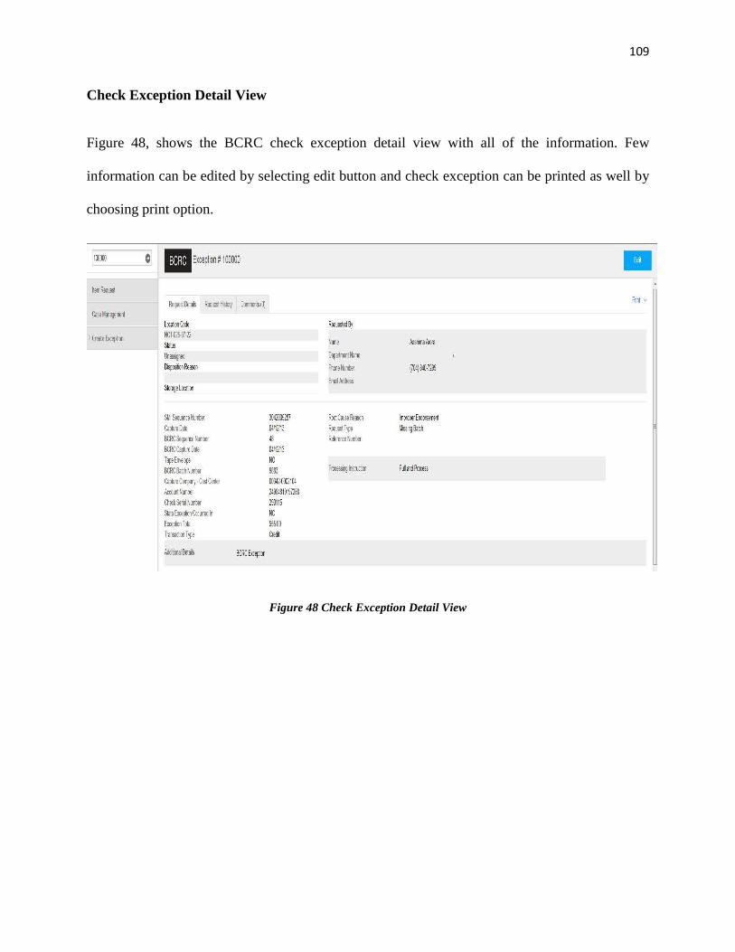
I am very thankful to my project manager Kay E. Falli, my technical lead Scott W. Ayres
and my whole team who gave me this opportunity to work on and supported me to complete my
graduation project successfully.
I express my respect to my parents and my family who supported me mentally, financially
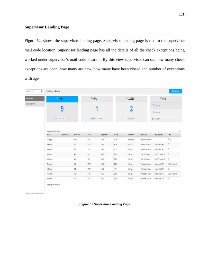
and emotionally to complete my graduation and achieve my goals.
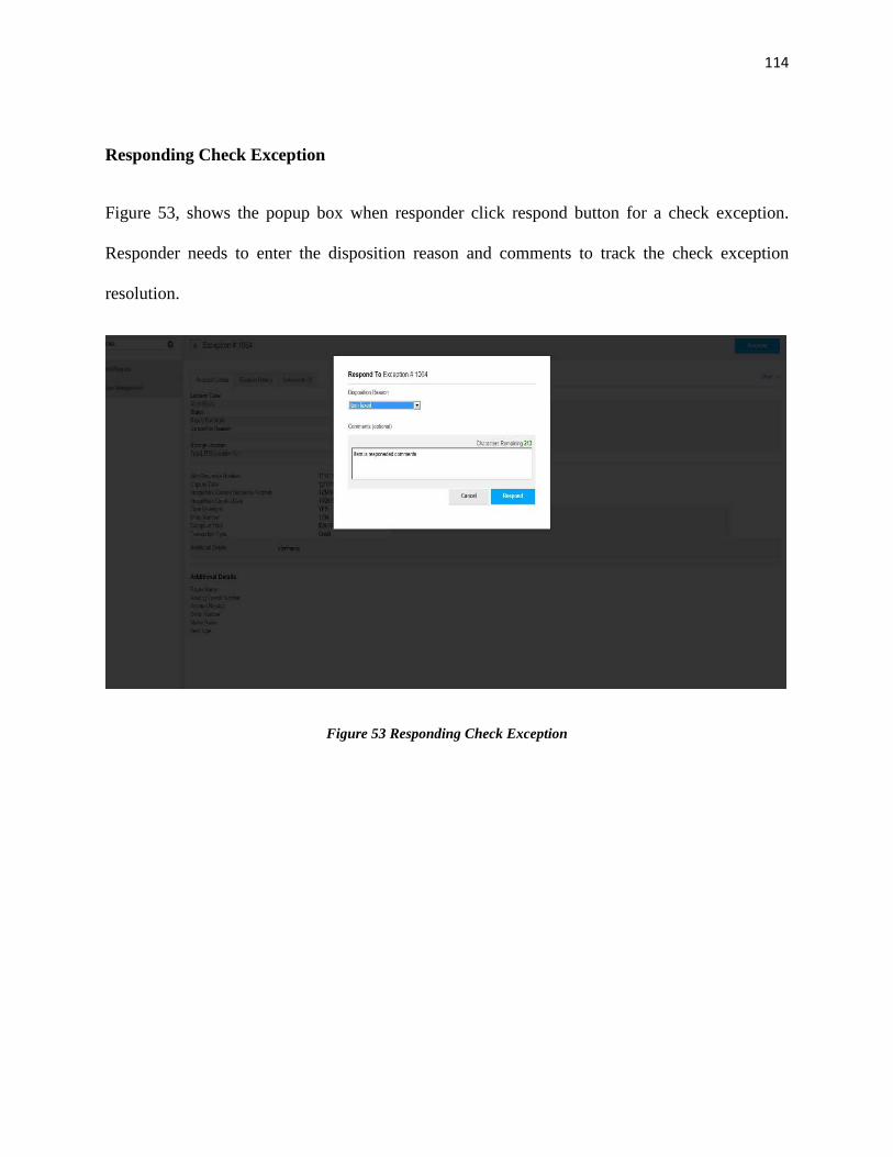
I express my worship to Almighty GOD for providing me such a good path and grace to
build my carrier.
Aashima Arora
iv
ABSTRACT
Check Exception Automation (CEA) System is a web application which provides the facility to
create and resolve the check exception that occurs after the check is successfully deposited to the
American Bank. Checks can be deposited via different channels such as ATM, Cash Vault (which
is a kind of check dropping box) and via mobile. There are a number of exceptions that may occur
after depositing the check such as missing signature, wrong amount, altered check, duplicate check
and missing amount. The older check exception resolution process was manual process. The goal
of this project is to automate the check resolution process with no or very little human involvement.
This project is implemented using all the advanced technologies such as Java 1.7, Spring 3.1,
Spring Security, Apache CXF web services and JQuery. This documentation describes the project
plan which explains the requirements with timelines and the methodology used for project life
cycle. It also briefly explains about the meeting plans and team building activities during the
project development. Furthermore, it explains the problems existed in older system and the benefits
expected from the new system. Moreover, this document also covers the basic technical as well as
architectural aspects of the project. The project is implemented on agile methodology which is
different than traditional waterfall model. This document also explains the interaction strategy and
interaction flow among the development teams and business partners.
v
DECLARATION
I hereby certify that this project constitutes my own product, that where the language of
others is set forth, quotation marks so indicate, and that appropriate credit is given where I have
used the language, ideas, expressions or writings of another.
I declare that the project describes original work that has not previously been presented for
the award of any other degree of any institution.
Signed,
Aashima Arora
Aashima Arora
vi
TABLE OF CONTENTS
PROJECT APPROVAL FORM ..................................................................................................... ii Acknowledgment ........................................................................................................................... iii ABSTRACT ................................................................................................................................... iv
Declaration ...................................................................................................................................... v
TABLE OF CONTENTS ............................................................................................................... vi INTRODUCTION .......................................................................................................................... 1
Older System ........................................................................................................................... 1
Background of the Problem .................................................................................................... 1
High check resolution time ................................................................................................. 2
The American Bank did not have the online system to create or resolve the check exceptions. The
whole process was manual process, in which when a commercial/ consumer customer deposits the
check via any channel such as ATM, mobile, cash vault or at cashier’s office and later bank finds
any problem such as missing signature, altered check, duplicate check or missing check amount
then all the checks with the exceptions are mailed to the associated banking center (BC) site and a
check resolver analyst manually analyzes the checks and resolves the check, after that all the
checks are put into the bags and then all the bags are mailed to the bank long term paper storage
location (BLTPS) site where all these bags are kept into the trays and checks are stored for next
45 days. Within 45 days, if any query occurs on any check then a check analyst at bank’s long
term paper storage location (BLTPS) site searches for the tray, and then within the tray searches
for the bag and then goes through each and every check in that bag and reads the check information
to match the right check and finally tries to resolve the check. If necessary, analyst can mail the
check back to the originating banking center for resolution. After 45 days, all the checks are
discarded and all the empty bags are kept for the record.
Background of the Problem
The older system was fully manual to resolve the check exception. It was totally inefficient and
very expensive process. To even resolve a single check at any banking center location, the
complete process has to follow. The following are the major problems exists in older system.
2
High check resolution time
In older system check resolution time was quite high. The minimum time to resolve the check was
3 days. And resolution of after inquiry can take extra 2 days to 6 days. Check is a very crucial part
of the business and for a customer if it get delays it can have direct impact on the customer.
Suppose a customer has deposited his pay check and he urgently needs money to pay his bill or
debt and it got exception, if check resolution takes 3 days to 6 days it can go very bad with that
customer though there might not be customer’s fault at all.
Customer dissatisfaction
High resolution time in financial matters is certainly can cause the customer dissatisfaction. Every
bank customer expects that he get the money in his account as soon as possible. If the customer
cannot get the money on time, it can cause worry or sometimes it can cause serious problem in his
life because customer might be dependent on the check money. The America Bank had high
probability to lose customers because of the older system.
Expensive
Older system was quite expensive for the bank. Even if there was only one check with error at any
ATM, it had to go through the whole process of resolution. First it had to be carried to the banking
center (BC) site then to the bank longer term paper storage (BLTPS). Postal services charged the
same amount because charges were based on bags and even if there was only one check it had to
go into the bag. The American bank was paying around $50 million per year to the postal services.
And check storage cost for next 45 days was approximately $20 million per year. So the older
system was costing around at least $70 million per year only for checks resolutions.
3
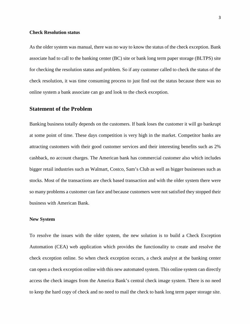
Check Resolution status
As the older system was manual, there was no way to know the status of the check exception. Bank
associate had to call to the banking center (BC) site or bank long term paper storage (BLTPS) site
for checking the resolution status and problem. So if any customer called to check the status of the
check resolution, it was time consuming process to just find out the status because there was no
online system a bank associate can go and look to the check exception.
Statement of the Problem
Banking business totally depends on the customers. If bank loses the customer it will go bankrupt
at some point of time. These days competition is very high in the market. Competitor banks are
attracting customers with their good customer services and their interesting benefits such as 2%
cashback, no account charges. The American bank has commercial customer also which includes
bigger retail industries such as Walmart, Costco, Sam’s Club as well as bigger businesses such as
stocks. Most of the transactions are check based transaction and with the older system there were
so many problems a customer can face and because customers were not satisfied they stopped their
business with American Bank.
New System
To resolve the issues with the older system, the new solution is to build a Check Exception
Automation (CEA) web application which provides the functionality to create and resolve the
check exception online. So when check exception occurs, a check analyst at the banking center
can open a check exception online with this new automated system. This online system can directly
access the check images from the America Bank’s central check image system. There is no need
to keep the hard copy of check and no need to mail the check to bank long term paper storage site.
4
Any analyst can directly access the web application and can get the status as well as whole worked
history on any check exception. He can adjust the customer account with the disputed or error
amount directly with the help of CEA application online and after the check is resolved, a
notification is automatically generated to the customer.
Objective of the Project
The objective of the project is to replace the manual check resolution process with the online Check
Exception Automation System. This automated system provides the online capability to the
process and thus helps in providing high values to the banking business as well as to the customer
by resolving the checks quicker and reducing the overhead cost. The new automated system
provides the following benefits:
Faster check resolution
Online check resolution process reduces the check resolution time from average 4 days to 1 day
which is a big improvement.
Cutting the overhead cost
This project fully eliminates the need of mailing the checks by providing the analyst with the online
check image system as an analyst has access to the check image online which saves bank
approximately $70 million per year.
Customer satisfaction
Customer satisfaction is the success key of any business. This automated system provides faster
check resolution. Also, customers can come to know the status of check resolution process very
5
quickly because an analyst can check the status online in seconds and give the status details to the
customers.
Project Name
Business name of the project : Check Exception Automation (CEA) System
Development name of the project : Exception Management
Organization Profile
The American Bank is one of the top notch US bank and is world’s leading wealth management
company having history of more than 200 years for providing sales and services to clients in more
than 40 countries in the world. The American bank serves individual consumer, financial
institutions, government, small, middle market and large businesses. It also provides other risk
management, asset management products and financial services. Company has approximately 49
million small businesses and consumer relationships. The American Bank has 16,200 ATMs and
5100 retail banking offices around the world. American Bank provides excellent online easy to
use services, have approximately 15 million mobile users and 30 million active online users.
Business Need
The main goal for the initiation of the project is to eliminate the check resolution manual process
completely and provide the easy to use online capabilities to create and resolve the checks with
very less amount of time and to cut down the overhead mailing and storage costs.
6
Scope of the Project
Check Exception Automation System is completely new web application. Following is the broader
scope of the project:
Creating the check exception online
Resolving the check exception online
Access to the check images from Check Image system
Adjusting the customer directly from CEA system by debiting or crediting the money
Notifying the customer automatically after check resolution
Access to the check exception creation and resolution work history
Assigning the right status to the check exception
Pulling the customer and customer’s account information and attach them with the
exception.
Posting the customer’s adjustment amount to America Bank financial system.
Feasibility Study
Feasibility study focuses on providing answers to the essential questions such as given project idea
is worth to implement, should we proceed with the proposed idea etc. Assessing the feasibility of
Check Exception Automation (CEA) System is very crucial step for American Bank Business
partners as they have to determine the chances of success of the project. Operational, Economic
and Technical feasibility analysis is used to determine this new project’s feasibility.
7
Technical Feasibility
Check Exception Automation (CEA) System is new system and will be using the existing bank
web services to pull the data and will determine the required action. All web services are in place
and bank has been using them for past many years. Proposed project will be using the latest well
known technologies and bank already have the expertise in the technologies that are going to be
used in this project. The process of setting up the technical environment, servers and getting the
technical tools are already in place so technical project does not seem to have any sort of risk.
Economic Feasibility
This project is internal bank application and will be accessible by bank employees only and there
might not be the need of expensive production servers or security setup. Almost all web services
are in place, so there will not be any added cost of building them and last but not least, bank already
has the necessary skills to build the project. So economically project is ranked a low cost project.
Also, by this project bank is going to save $70 million per year thus project is very strong
economically.
Operational Feasibility
The American Bank has very skilled employees who resolved the check exceptions on day to day
basis and they are much trained employees. This new project will have very high concentration on
user experience and user does not need to go for intense training because system will be using very
minimal amount of user inputs and will have the availability of everything within three clicks. So
at most, 3 days training by any of project team member such as technical analyst can trained the
bank employees, so operationally also, this new project is feasible.
8
Project Milestone List
The below chart list the major milestones for Check Exception Automation (CEA) System. With
these major milestones, there is highly likely chances project will have minor milestones during
the development of the project. If in any case, project milestone is not hitting on time then project
manager should be notified immediately so that right decision can be made on time and by knowing
the cause, this kind of situation can be prevented in future. These milestones should be discussed
with the team so that team is aware of deadlines and can plan their work accordingly.
Table 1 Project Milestones
Milestone Description Target Date
Project Start Project Start Date Aug 18, 2014
Project Charter Approval Project Charter Approved by Project Sponsor Aug 28, 2014
Project Initiation Complete Project Initiation Phase Complete Aug 30, 2014
Requirement Document
Approval
Requirement document approved by business Sep 30, 2014
Development Plan Approval Development plan approval by business Oct 15, 2014
Test Plan Approval Test plan approved by business Oct 20, 2014
Maintenance Plan Approval Maintenance plan approved by business Oct 27, 2014
Acceptance Criteria Approval Acceptance criteria approval by business Oct 30, 2014
Architecture Design
Complete and Approval
Hardware and software architecture design
completion and approval by bank architectures
Nov 12, 2014
Product Design Complete and
Approval
Product design completion and approval Nov 30, 2014
9
Test Plan Complete and
Approval
Test plan completion and approval by Testing
Manager
Dec 10, 2014
Requirement Grooming with
Development Team
Discussing the business requirements with the
team
Dec 30, 2014
Development Phase 1 Start Development Phase 1 Start Date Jan 1, 2015
Development Phase 1 End Development Phase 1 Completed Apr 30, 2015
Regression Testing Start QA Regression Testing Start May 5, 2015
Regression Testing End QA Regression Testing End May 12, 2015
Code Push To UAT Pushing the Code to UAT environment May 13, 2015
UAT Testing Start User experience testing start May 15, 2015
UAT Testing End User experience testing end May 27, 2015
Pre-Production Deployment Deployment of application to pre-production May 30, 2015
Pre-Production UAT Testing
Start
UAT testing in pre-production environment
start
Jun 2, 2015
Pre-Production UAT Testing
Complete
UAT testing in pre-production environment
complete
Jun 12, 2015
Release 1.0 Deployment of application to production June 14, 2015
Project Phase 1 Complete Project first major release complete June 16, 2015
10
CHAPTER 2
SYSTEM ANALYSIS
Technical Description of the Project
Check Exception Automation (CEA) System is a web application which can be accessed by
internal American Bank employees only. Bank employee at the post of check analyst can access
the system via browser and can create a check exception online. While creating the check
exception, the check analyst is able to pull the customer’s information online from the bank’s
central database as well as the rejected check images from check image system. Check analyst can
resolve the check exception by debiting or crediting the money from their bank accounts with the
help of CEA system and then can post the transaction to the bank Financial Deposit System (FDS).
While resolving the check exception, customer is notified automatically about the transaction on
their accounts. After resolving the check exception, analyst can close the exception and update the
status of the exception as “resolved”.
Business Requirements
Priority
Each functionality is given a priority based on its criticality as well as business requirements.
Critical: Functionality must go live as soon as possible or business requirements having core
functionality.
Essential: Business requirements which serves a part of the critical functionality.
Nice to Have: Business requirements such as view changes, user experience
11
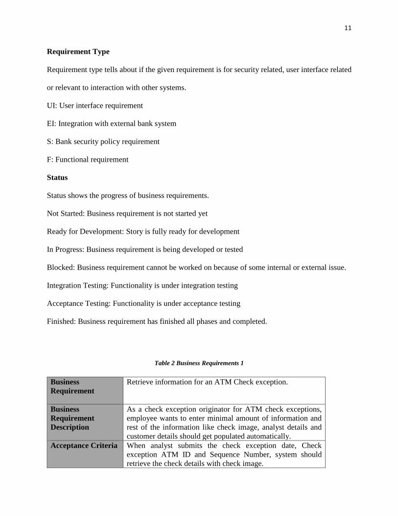
Requirement Type
Requirement type tells about if the given requirement is for security related, user interface related
or relevant to interaction with other systems.
UI: User interface requirement
EI: Integration with external bank system
S: Bank security policy requirement
F: Functional requirement
Status
Status shows the progress of business requirements.
Not Started: Business requirement is not started yet
Ready for Development: Story is fully ready for development
In Progress: Business requirement is being developed or tested
Blocked: Business requirement cannot be worked on because of some internal or external issue.
Integration Testing: Functionality is under integration testing
Acceptance Testing: Functionality is under acceptance testing
Finished: Business requirement has finished all phases and completed.
Table 2 Business Requirements 1
Business Requirement
Retrieve information for an ATM Check exception.
Business Requirement Description
As a check exception originator for ATM check exceptions, employee wants to enter minimal amount of information and rest of the information like check image, analyst details and customer details should get populated automatically.
Acceptance Criteria
When analyst submits the check exception date, Check exception ATM ID and Sequence Number, system should retrieve the check details with check image.
12
Originator should be able to successfully submit the check exception request. If there is any error, error should be displayed on the check exception form and check exception request should be rejected.
Validation
Check Exception Date: Mandatory with format mm/dd/yy. ATM ID: Mandatory and must be in database ATM table. Check Sequence Number: Mandatory and must be 11 digit.
Priority
Critical
Type
F
Status
Table 3 Business Requirements 2
Business Requirement
Retrieve information for a Bank Center (BC) Check exception.
Business Requirement Description
As a check exception originator for BC check exceptions, employee wants to enter minimal amount of information and rest of the information such as check image, analyst details etc. should get populated automatically.
Acceptance Criteria
When analyst submits the check exception date and source Sequence Number, system should retrieve the check details with check image. Originator should be able to successfully submit the check exception request. If there is any error, error should be displayed on the check exception form and check exception request should be rejected.
Validation
Check Exception Date: Mandatory with format mm/dd/yy. Source Sequence Number: Mandatory and must be 11 digit.
Priority
Critical
Type
F
Status
13
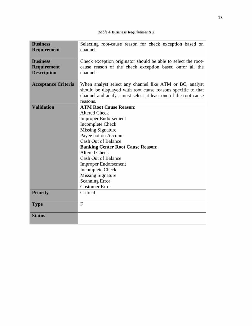
Table 4 Business Requirements 3
Business Requirement
Selecting root-cause reason for check exception based on channel.
Business Requirement Description
Check exception originator should be able to select the root-cause reason of the check exception based onfor all the channels.
Acceptance Criteria
When analyst select any channel like ATM or BC, analyst should be displayed with root cause reasons specific to that channel and analyst must select at least one of the root cause reasons.
Validation
ATM Root Cause Reason: Altered Check Improper Endorsement Incomplete Check Missing Signature Payee not on Account Cash Out of Balance Banking Center Root Cause Reason: Altered Check Cash Out of Balance Improper Endorsement Incomplete Check Missing Signature Scanning Error Customer Error
Priority
Critical
Type
F
Status
14
Table 5 Business Requirements 4
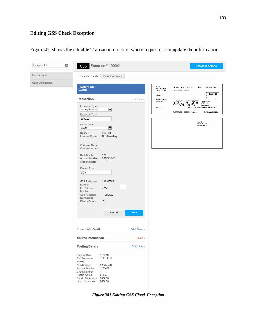
Business Requirement
Populating the check exception originator information at the time of check exception creation.
Business Requirement Description
When check exception originator creates a check exception his/ her details should be retrieved from bank’s employee central system and should populate in the check exception automatically. The following details should get populated: First Name Last Name Phone Number Fax Number Mail Code Department Name Street Address
Acceptance Criteria
When check exception originator selects the create check exception, his details should get populated automatically and the details should be editable.
Validation
First Name, Last Name: Maximum 255 characters, Not Null Phone/Fax Number: Maximum 15 digit, Format: 999-999-9999
Priority
Critical
Type
F
Status
Table 6 Business Requirements 5
Business Requirement
Populating the check information for ATM/ Banking Center check exception
Business Requirement Description
Check details should be retrieved using web services and should be pre populated into the check exception form by providing only two inputs to that form- check capture date and check sequence number.
Acceptance Criteria
When as a check exception originator, I enter check capture date and check sequence number, inputs are added and check exception form gets populated.
Validation
If external web services call fails, originator should be represented by appropriate message.
15
Priority
Critical
Type
F
Status
Table 7 Business Requirements 6
Business Requirement
Assign check exception to the correct storage location
Business Requirement Description
As originator, I want the check exception to be routed to the correct storage location so that request can be resolved.
Acceptance Criteria
ATM ID determines the storage location and the location is tied to the check exception.
Validation
ATM ID must be in ATM table otherwise location must be Unassigned.
Priority
Critical
Type
F
Status
Table 8 Business Requirements 7
Business Requirement
Check exception responder view the check exception for resolution
Business Requirement Description
As check exception responder, I want to view the check exception assigned to my storage location so that I can resolve them.
Acceptance Criteria
All check exception routed to check exception responder storage location should be on the responder landing page and all the exceptions should be sorted by date. Responder can view the individual check exception.
Validation
Check exception responder landing page should have check exceptions routed to his/ her storage location.
16
Priority
Critical
Type
F
Status
Table 9 Business Requirements 8
Business Requirement
Check Exception system can print the check exception
Business Requirement Description
As a check exception responder I should be able to print the check exception assigned to my storage location
Acceptance Criteria
I know I am done if I can print the check exception, check image and this activity should be logged.
Validation
Check exception responder can print the check exception assigned to his/ her storage location
Priority
Critical
Type
F
Status
Table 10 Business Requirements 9
Business Requirement
Check exception responder responds to the check exception
Business Requirement Description
Check exception responder should be able to select the pre populated response reasons and should be able to add comments to respond to the check exception
Acceptance Criteria
Check responder can respond only one time Responder can select only one response reason Response Reasons: Request processed Request faxed Request not located Request not stored at this location
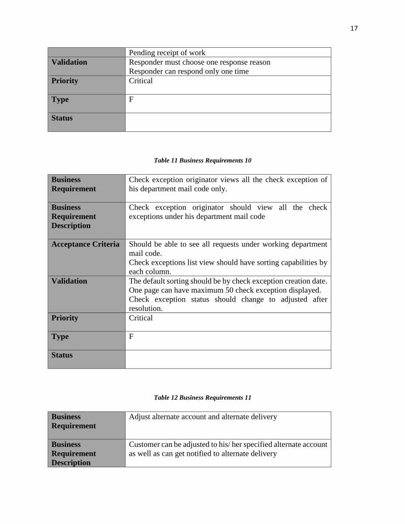
17
Pending receipt of work Validation
Responder must choose one response reason Responder can respond only one time
Priority
Critical
Type
F
Status
Table 11 Business Requirements 10
Business Requirement
Check exception originator views all the check exception of his department mail code only.
Business Requirement Description
Check exception originator should view all the check exceptions under his department mail code
Acceptance Criteria
Should be able to see all requests under working department mail code. Check exceptions list view should have sorting capabilities by each column.
Validation
The default sorting should be by check exception creation date. One page can have maximum 50 check exception displayed. Check exception status should change to adjusted after resolution.
Priority
Critical
Type
F
Status
Table 12 Business Requirements 11
Business Requirement
Adjust alternate account and alternate delivery
Business Requirement Description
Customer can be adjusted to his/ her specified alternate account as well as can get notified to alternate delivery
18
Acceptance Criteria
If customer has specified alternate account for financial adjustment then alternate account should get adjusted. If customer has specified alternate delivery then customer should be notified using alternate delivery such as email/ fax/ mail. If customer has specified no delivery then customer should not get notified but notification should be saved in database.
Validation
Alternate account must be a valid alternate account. Alternate delivery must be a valid alternate delivery method.
Priority
Critical
Type
F
Status
Quality Management Plan
Introduction
Check Exception Automation (CEA) System project’s quality management plan is to manage the
quality of the project from project planning to delivery and document the strategy and information
which is essential for better manage and quality policies enforcement of the project. This document
is created during the planning phase and it needs collaboration of project manager, sponsors and
project team. Quality management plans states and documents the approach the CEA system team
has been using throughout the project lifecycle from planning to product delivery. Quality
management plan helps to manage the resources, cost and helps to reduce the waste, increase the
project implementation time and it is the key component to build less error prone system which
can be maintained and enhance easily. On high level, quality management plan for CEA system
controls the quality for both process and product.
19
Process Quality
Process quality standards, requirements and tools are determined by CEA web application quality
manager and project manager. There are restrictions to choose the tools to manage the process
quality. Only American Bank licensed tools can be used. If there is critical need to use the tool
which American Bank does not have the license than project manager needs to raise a request,
need to describe the need for the tool and should wait until bank approves the request. Project can
have its project specific process but they have to follow the bank standards, regulations and must
get approved by the bank IT director. In order to measure process metrics, the iterative process is
used throughout the project life cycle. It is the responsibility of quality manager to monitor the
project process and to improve the process if there are problems in current processes.
Product Quality
The product quality requirements, standards and tools are determined by project manager with the
co-operation of project technical leads and engineers. Product must follow the bank privacy policy,
security and encoding standards to protect the user’s private data. Product can have its own product
specific quality standards unless those standards do not breach the bank’s product quality
standards. Product specific standards must be reviewed by bank’s IT quality department.
Quality management plan documents the following things to manage the project quality:
Project’s quality policies
Quality procedures
Quality criteria for the CEA web application
Team roles, responsibilities and authorities
20
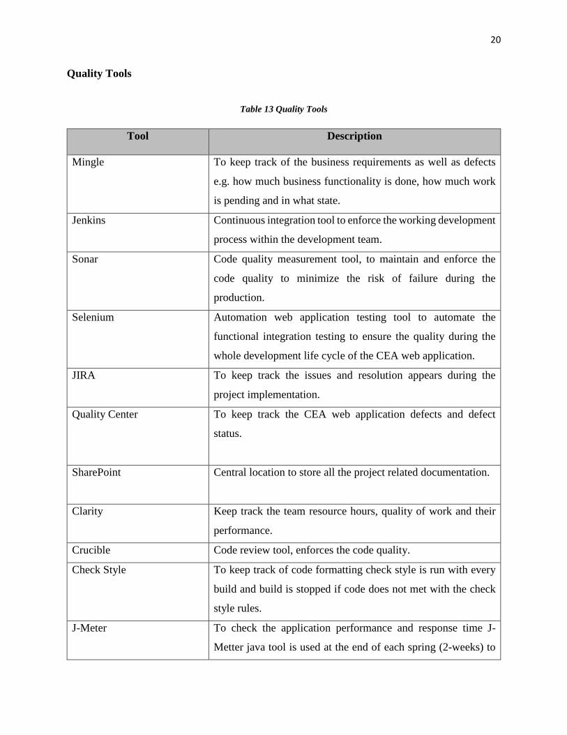
Quality Tools
Table 13 Quality Tools
Tool Description
Mingle To keep track of the business requirements as well as defects
e.g. how much business functionality is done, how much work
is pending and in what state.
Jenkins Continuous integration tool to enforce the working development
process within the development team.
Sonar Code quality measurement tool, to maintain and enforce the
code quality to minimize the risk of failure during the
production.
Selenium Automation web application testing tool to automate the
functional integration testing to ensure the quality during the
whole development life cycle of the CEA web application.
JIRA To keep track the issues and resolution appears during the
project implementation.
Quality Center To keep track the CEA web application defects and defect
status.
SharePoint Central location to store all the project related documentation.
Clarity Keep track the team resource hours, quality of work and their
performance.
Crucible Code review tool, enforces the code quality.
Check Style To keep track of code formatting check style is run with every
build and build is stopped if code does not met with the check
style rules.
J-Meter To check the application performance and response time J-
Metter java tool is used at the end of each spring (2-weeks) to
21
check the application performance. If application performance
does not meet the criteria code must be refactored to improve
the performance.
Jenkins Dashboard
Figure 1 Jenkins Dashboard
22
Sonar Dashboard
Figure 2 Sonar Dashboard
Quality Planning
Quality planning documents the quality metrics, measures standards for project processes, product
functionality, project deliverables, documentation, testing and how to satisfy these quality
standards. Quality planning identifies the acceptance criteria for product performance, product
quality and project deliverables.
23
Quality Standards
Business requirements quality standards
Business requirements should not contain technical details and any solution
recommendations. Requirement should be easy to understand and should be in plain text.
Business analysts should expose the business requirements to the development team before
proceeding to implementation, so that if there are any questions and concerns those can be
identified and addressed early in the development phase.
Business requirements must be prioritize, so that critical functionality can be built early.
By this way, if project is running behind the schedule that can be handled easily without
worrying too much as application has the critical functional behavior.
Development standards
Unit testing code coverage is mandatory and minimum code coverage level should be 80%.
Project should have the user interface integration testing for all user screens to make sure
any new functionality does not break the existing functionality.
Any new functionality must pass the code review, to identify any kind of bad code which
can make application enhancement and maintenance difficult in future.
Development code must not have any team member’s signature on it and all the code is the
property of bank.
Continuous integration build server should be active all the time, and should send auto
generated emails to project team if build breaks.
User experience (UX) reviews should be part of any functionality completion to make CEA
web application user friendly and easy to access.
24
Testing standards
For regression testing there should be a different server where testers can keep testing the
existing and new functionalities without worrying about the current functionality which is
in progress in development environment.
Regression test must pass before pushing the code for user acceptance testing.
For user acceptance testing there should be different server so that user acceptance testers
keep testing existing and new functionalities without any dependencies.
Performance standards
CEA web application must pass the bank performance standards e.g. web application
server response time should not be more than 8 seconds.
Application should pass the performance load with average number of users who currently
are accessing the web application.
Quality Assurance
For Quality assurance of CEA web application, quality management of bank focuses on the
performance, security, memory leak, privacy, application functional behavior, development and
deployment process. Quality team processes quality check point every two weeks by gathering the
statistics from the project teams and also collects the possible solutions from the project teams and
chooses the best solution to improve the process. Product (CEA web Application) quality check
point happens every month by bank quality team, security & privacy team and performance team.
It the responsibility of performance team to make sure CEA web application is working well with
existing user load and provides the response within the time bound. Security & privacy team is
responsible to verify that CEA web application is following the bank standardized encryption
25
mechanism to encrypt sensitive data and fully met the bank privacy standards. Technical leads are
responsible to do day to day code review and to detect the problems in the code at very early phase.
Code review must pass before the code is pushed to integration server.
Quality Control
Quality control of CEA web application primarily focuses on application performance, code
quality and application security.
• Performance team does hard check point every month with heavy test user load and
measures the application’s performance and memory leakage. If performance team finds
any performance issue than functionality pushes back to the technical leads to fix the issue.
Application is not be pushed to next level until all performance issues get resolved.
• Unit testing code coverage must always be higher than the minimum threshold which is
80%. If code coverage gets down build breaks and it is the priority to fix the unit test code
coverage. Test report code coverage is generated with every build and Sonar provides the
statistics for code coverage to analyze.
• Integration tests and user acceptance tests must pass when any new functionality is added
to the system. Integration and user acceptance testing happens iteratively with any new
functionality in the system. Integration test engineers are responsible for integration
automation. If integration tests fail, integration test engineers define the failure, priority
level and raise the defect in quality center. Code does not migrate for user acceptance
testing without passing the integration testing.
• Sonar analysis should run after every successful Jenkins’s build. If sonar analysis fails
build also fails. There should always be zero major violation, zero critical violation and
26
zero cyclic dependencies. If any one of these sonar violation occurs, build fails and email
is sent to the development team automatically. If there is any minor violation, build passes
but it is the responsibility of the technical lead to ask the responsible person to fix those
violations too.
• Business requirement cannot be changed at the time of development. Change in business
requirements are tracked by Mingle.
Communication Management Plan
Introduction
Check Exception Automation project communication plan is to manage the communications
among the on-shore team, off-shore team, business partners, quality team, security team,
performance team, other external services team, development leads and managers.
Communications among all the teams and within the team members is one of the key of project’s
success. If team members and teams have better communication, it directly affects their
performance and increase the product quality, as well as decrease the production time line. Poor
communications can produce the conflictions among the team members, and they might not work
as whole team which will have very negative impact on project progress.
Scrum Meeting
Check Exception System have couple of on shore as well as off shore teams. Each team has their
own stream of work. Each team have their own scrum meeting each day in which they discuss
with the following things:
What you did yesterday?
27
What you will do today?
Is there any impediments?
By this way each team member gets very clear idea of the tasks progress and they get the chance
to discuss if they have any road blocks or impediments.
Retrospective Meeting
Each team have their own retrospective meetings every two weeks. In this meeting each team
member gets a chance to present and discuss his/her concerns to the business partners so that issues
can be addressed. Each team member has the chance to discuss the following things:
What worked well?
What did not worked well?
What we can do to improve?
All team members can present their thoughts to above questions and team decides how to improve
the process and eliminate the impediments.
Scrum of Scrum Meeting
Scrum of scrum meeting provides the chance to communicate across the team. Technical leads
from each team attends the scrum of scrum and discusses about the cross team communications
and supports. After the meeting, team leads discusses the annotated items with team members.
28
CEA All Hands Meeting
All hands meeting can be planned any time any day and can be set up just half an hour before. All
team members require to join all hands. Usually project manager plans the all hands meeting to
communicate about the critical things, team changes, and process changes.
Team Lunch
Every other week each team has team lunch and they get to gather at lunch. These lunch meetings
helps to build the team relations and provides good coordination and team works as family.
Release Meeting
Release meeting are held after every release and business partners communicates to the
development team about the product and user experience.
Acceptance Plan
Purpose
The acceptance plan document has the following purpose
• The acceptance plan document, documents the strategy for acceptance testing for CEA
system and verifies that CEA web application meets all the business requirements as
specified in the contract.
• To ensure that all the requirements for acceptance testing for CEA web application system
are appropriately planned, reviewed and assessed within the overall project plan.
29
• And to demonstrate the testing processes to all stakeholders to make sure that all testing
processes is being controlled and managed appropriately.
Scope
The scope of CEA Web Application system acceptance plan is to:
• Test all the views and verify the views with the user experience approved business artifact.
• Test the response time of each http request and verify that response time should not be
greater than eight seconds.
• Test all the user screens on different mobile devices to verify that behavior of application
is meeting the expectations.
• Test the functional behavior for each business requirement and verify that it meets the
acceptance criteria mentioned in the business requirements.
Output
Acceptance plan should have the following outputs after completion of acceptance testing:
Defects which are related to the user view for example, position of a button or formatting on UI
comes under category “Nice to have”.
Defects which are stopping user to complete his/ her work efficiently, but not blocking the user to
complete the work comes under category “Essential”.
Defects where functionality does not meet the acceptance criteria and the functional behavior is
blocking the user to complete the work comes under category “Critical”.
30
Testing
General Testing Approach
The general approach for Acceptance Testing for CEA Web Application is as follows:
• All tests should pass before pushing the application to next upper environment.
• Test cases and test scripts should be ready before functionality is ready to test.
• Test scripts should consider the business requirements as source of truth and thus should
be written based on business requirements without any external assumption.
Acceptance Testing Approach
Acceptance testing is the responsibility of the acceptance test manager. The general approach for
acceptance testing for CEA Web Application system is as follows:
• Acceptance testing is a continuous testing. New business stories is pushed to UAT server
every two weeks. These stories’ test scripts is executed independently without integration
testing.
• Every two weeks after the new stories acceptance testing and integration testing scripts are
executed to test the integration of new functionality with existing functionality.
• Test data is provided for user acceptance testing before pushing the new functionality so
that test scripts can be created beforehand.
• Acceptance testers can reach to internal development team directly in case of any test data
related problems or to verify any functionality or defects.
• Acceptance tester can reach to web services team via team technical analyst to set the web
services’ test data or to get the web services’ related test data.
31
• Defects are logged in the quality center and only acceptance testers can close the defects,
after retesting and verifying the defect.
• Acceptance testing are allowed to do the manual testing also, in the cases where it is harder
to catch all the testing scenarios from automated acceptance testing scripts.
• All views should passed through the acceptance testing and must match with the user’s
experience design artifact.
• While retesting the defect, if acceptance tester finds any defect which is not fixed then that
defect should be logged again in quality center, and it should be discussed personally with
the development team to find the cause of failure.
• Two weeks before the release, acceptance testing environment is ceased and no new
functionality is pushed.
• Release acceptance testing is undertaken against the Acceptance Test Plan which is
prepared by CEA web application’s acceptance test manager.
• Acceptance is performed on user acceptance testing (UAT) environment
• At the time of code freeze, only defect’s fixes can be pushed and need technical lead’s
approval.
• At the time of release maximum 3 cycles are possible, so all defect’s fixes should be pushed
within first 2 cycles of testing.
Development Unit Testing
Development unit testing is responsibility of the project manager and technical lead. The general
approach for development unit testing for CEA Web Application is as follows:
32
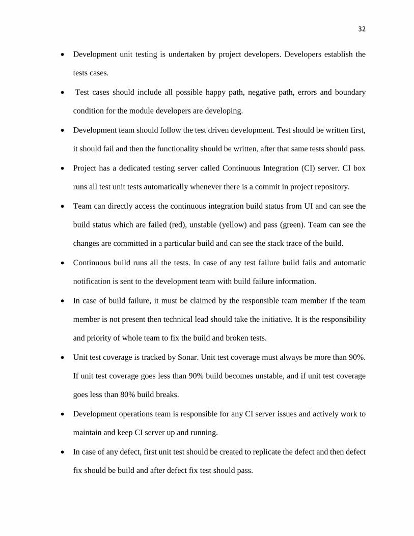
• Development unit testing is undertaken by project developers. Developers establish the
tests cases.
• Test cases should include all possible happy path, negative path, errors and boundary
condition for the module developers are developing.
• Development team should follow the test driven development. Test should be written first,
it should fail and then the functionality should be written, after that same tests should pass.
• Project has a dedicated testing server called Continuous Integration (CI) server. CI box
runs all test unit tests automatically whenever there is a commit in project repository.
• Team can directly access the continuous integration build status from UI and can see the
build status which are failed (red), unstable (yellow) and pass (green). Team can see the
changes are committed in a particular build and can see the stack trace of the build.
• Continuous build runs all the tests. In case of any test failure build fails and automatic
notification is sent to the development team with build failure information.
• In case of build failure, it must be claimed by the responsible team member if the team
member is not present then technical lead should take the initiative. It is the responsibility
and priority of whole team to fix the build and broken tests.
• Unit test coverage is tracked by Sonar. Unit test coverage must always be more than 90%.
If unit test coverage goes less than 90% build becomes unstable, and if unit test coverage
goes less than 80% build breaks.
• Development operations team is responsible for any CI server issues and actively work to
maintain and keep CI server up and running.
• In case of any defect, first unit test should be created to replicate the defect and then defect
fix should be build and after defect fix test should pass.
33
Functional Testing
Functional testing is responsibility of the project manager and functional test manager. Functional
testing is project functionality centered, and tests the end to end functional behavior. The general
approach for functional testing for CEA Web Application is as follows:
• Functional unit testing is undertaken by functional test engineers. Functional test engineers
establish the functional tests cases.
• Functional test cases include all possible happy path, negative path, errors and boundary
conditions for the module developers are developing.
• Selenium automation tool is used for functional testing.
• Project has a dedicated functional testing server called Dev2 server. Dev2 server runs all
functional tests twice a day.
• Functional testing defects are logged and tracked into Mingle, new business functionality
must pass the functional testing for completeness. Only functional engineer can close the
defect after retesting and verifying the defects.
• Development operation team is responsible to migrate the new code, database changes,
files, tables and reference data to Dev2 server.
• Functional testing is a continuous testing throughout the development.
• Development operations team is responsible for any Dev2 server issues and actively works
to maintain and keep Dev2 server up and running.
• Functional test completion is recorded and documented, and documentation is retained in
project share point repository.
34
System Testing
System testing is responsibility of the project manager and a delegated system test manager.
System testing is whole system centered, which does the integration testing as a whole system
scope. The general approach for system testing for CEA Web Application is as follows:
• System testing is undertaken by system test engineers. System test engineers establish the
system integration test scripts.
• Primary purpose of system testing is to ensure that the system works as expected as a
whole.
• System test plan and scripts is prepared by system test engineers, and is executed by system
the test engineers.
• Project has a dedicated system testing server called SIT server. System test engineers
perform system testing on SIT, they have the SIT database access also so that they can
directly insert data for testing purpose.
• System testing defects are logged and tracked into Quality Center, only system test
engineer can close the defects after retesting and verifying the defects at SIT server.
• Development operation team is responsible to migrate the code, database changes, files,
tables and reference data to SIT server.
• System testing is performed against live data. It is the responsibility of business and
technical analyst to provide the live test data to system test engineers.
• System testing is continuous testing throughout the development.
• System operations team is responsible for any SIT server issues and actively works to
maintain the keep SIT server up.
35
• System test completion is recorded, documented and documentation is retained in project
share point repository.
• System testing includes high data volume testing with a high number of records and
transactions to test the system behavior at high volume of data.
Acceptance Plan Responsibilities
This sections describes the roles and responsibilities of stakeholders and other project team
members required for the acceptance plan process.
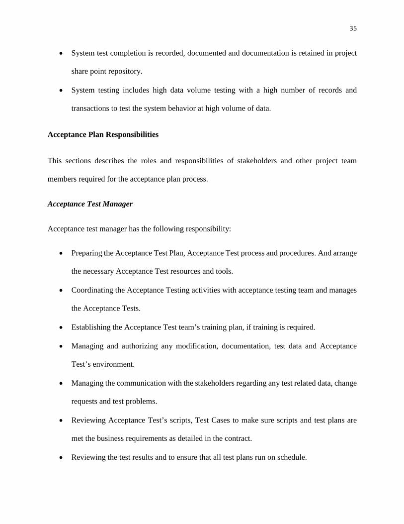
Acceptance Test Manager
Acceptance test manager has the following responsibility:
• Preparing the Acceptance Test Plan, Acceptance Test process and procedures. And arrange
the necessary Acceptance Test resources and tools.
• Coordinating the Acceptance Testing activities with acceptance testing team and manages
the Acceptance Tests.
• Establishing the Acceptance Test team’s training plan, if training is required.
• Managing and authorizing any modification, documentation, test data and Acceptance
Test’s environment.
• Managing the communication with the stakeholders regarding any test related data, change
requests and test problems.
• Reviewing Acceptance Test’s scripts, Test Cases to make sure scripts and test plans are
met the business requirements as detailed in the contract.
• Reviewing the test results and to ensure that all test plans run on schedule.
36
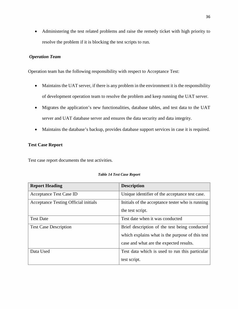
• Administering the test related problems and raise the remedy ticket with high priority to
resolve the problem if it is blocking the test scripts to run.
Operation Team
Operation team has the following responsibility with respect to Acceptance Test:
• Maintains the UAT server, if there is any problem in the environment it is the responsibility
of development operation team to resolve the problem and keep running the UAT server.
• Migrates the application’s new functionalities, database tables, and test data to the UAT
server and UAT database server and ensures the data security and data integrity.
• Maintains the database’s backup, provides database support services in case it is required.
Test Case Report
Test case report documents the test activities.
Table 14 Test Case Report
Report Heading Description
Acceptance Test Case ID Unique identifier of the acceptance test case.
Acceptance Testing Official initials Initials of the acceptance tester who is running
the test script.
Test Date Test date when it was conducted
Test Case Description Brief description of the test being conducted
which explains what is the purpose of this test
case and what are the expected results.
Data Used Test data which is used to run this particular
test script.
37
Expected Result States what is the expected result for this test
case.
Actual Result Actual result which came up after executing
the test case.
Test Result Code Accept/ Not Tested/ Fail/ Partial Failure/ Can
Not be Tested/ Test Data Unavailable.
Test Review Number Test review number which is issued by Test
Manager to review the test.
38
CHAPTER 3
SYSTEM DESIGN
Project Methodology
Agile Methodology
Check Exception Automation system is a web application which is used by American Bank’s
employees to resolve the check exceptions. This work on CEA web application is totally new, and
methodology like waterfall is not best fit for this web application, because user experience is one
of the critical aspect of web application as well as there are highly likely chances of changing the
requirements as project progresses. CEA web application is built based on good user experience
and is capable to adapt with changing requirements. To achieve this goal, agile methodology is
best fit for CEA web application. Development teams can deliver the product within 3 months,
and bank employees can start using the product, and by their experience product can be enhanced
at very early stage which produces a better quality and user friendly product.
Figure 3 Agile Methodology Workflow
39
Figure 4 Agile Methodology Workflow
40
Figure 5 Agile Development
41
Advantages of Agile Software Engineering Process
Test Driven Development
Agile uses the test driven development which means test should be created before the actual code.
All the positive, negative and exception tests should be created before the actual functionality and
then actual functionality should be implemented, and tests should pass after that. This helps to
prevent any kind of bug in the code. If any developer changes anything in one piece of code and it
breaks some other functionality, then at that moment executing tests helps developer to know what
is being broken.
Better Communication
In Agile methodology, all team members usually sits very closely. Scrum master, business analyst,
technical analyst, developers, user experience and testers all sits together. So if any team member
has any question they can just ask by calling the other team members. Agile increases the
communication among the team and nobody has to wait for the response because all team members
are easily accessible.
Better Project Progress Tracking
In Agile, each team has scrum meeting every day, in which each team member discusses things he
or she is working on, which provides very keen track of each task and project overall progress. If
there is any impediments that can be resolved very early.
Pair Programming
Agile has terminology called pair programming. If there is any difficult task or any new team
member joins the team then team can pair program, which helps to resolve a complex piece of
42
problem very quickly and a new team member can learn about the project very easily and quickly
duration. This helps new team members to contribute in the project development from very first
week of their joining.
Quick Releases
Agile methodology produces the full piece of functionality, which provides the value to end user
very quickly and product can be release to production very quickly, as quickly as three months and
further releases can be set every month. It provides immense benefit to the end user to put their
thoughts about the product as well as business partners which help to improve the application as
well as fix the bugs and missing requirements.
Architectural Technology
MVC Architectural Technology
Model View Controller (MVC) design pattern is best suits for CEA web application. MVC design
patterns decouples the model, view and controller. Developers can work in parallel without waiting
for functionality to be completed. MCV design pattern divides the functionality and can be divided
into the expertise level groups. Spring MVC framework provides the dispatcher servlet which
handles all the web requests and handles the request to appropriate controller by finding the
mapping from handler mapper. After finishing the work controller hands out the model and view
object to the dispatcher servlet and dispatcher servlet renders the specified view with populated
model into that.
43
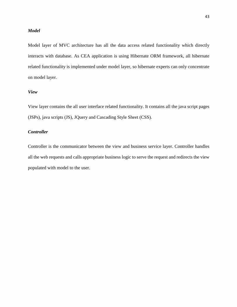
Model
Model layer of MVC architecture has all the data access related functionality which directly
interacts with database. As CEA application is using Hibernate ORM framework, all hibernate
related functionality is implemented under model layer, so hibernate experts can only concentrate
on model layer.
View
View layer contains the all user interface related functionality. It contains all the java script pages
(JSPs), java scripts (JS), JQuery and Cascading Style Sheet (CSS).
Controller
Controller is the communicator between the view and business service layer. Controller handles
all the web requests and calls appropriate business logic to serve the request and redirects the view
populated with model to the user.
44
Figure 6 MVC Architecture
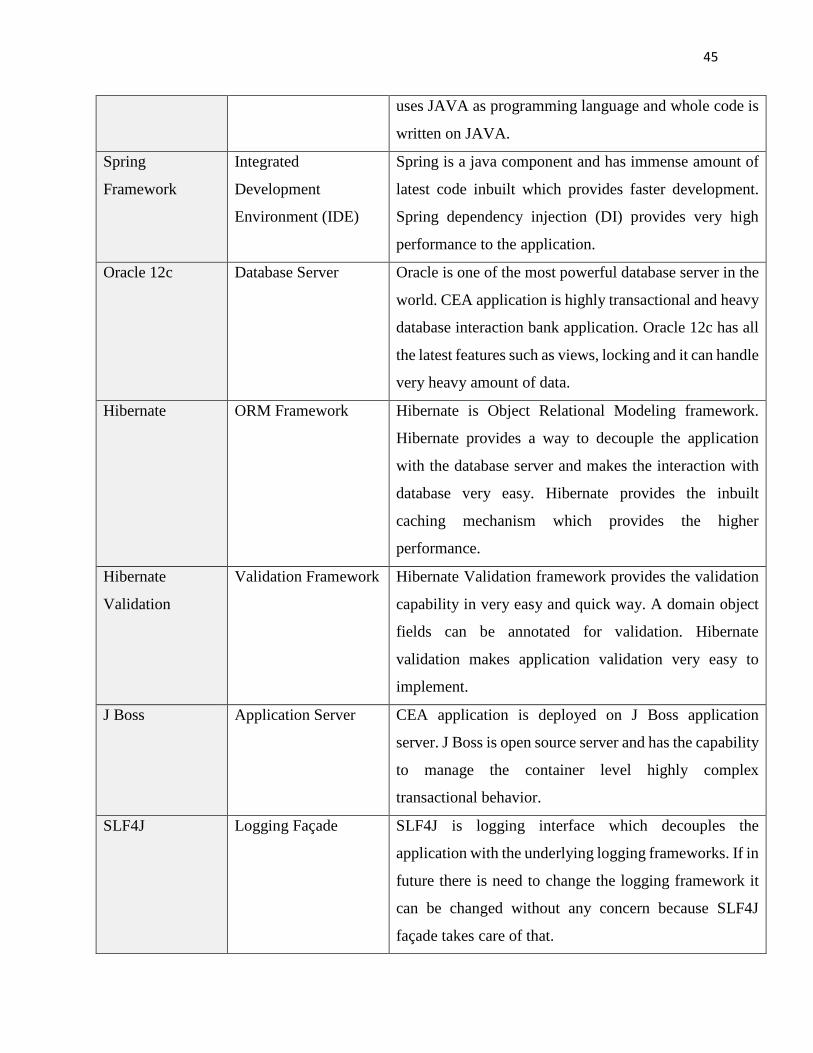
Project Implementation Technologies
Check Exception Automation system is a web application which is built from scratch using all the
latest technologies, which made the development faster and high quality product. The following
are the technologies used to build CEA system.
Table 15 Project Implementation Technologies
Technology
Name
Technology Category Technology Description
JAVA 1.7 Backend Programming
Language
JAVA is most widely used back end programming
language and it is open source which increase its usability
as well as quick bug tracking and fixing. CEA system
45
uses JAVA as programming language and whole code is
written on JAVA.
Spring
Framework
Integrated
Development
Environment (IDE)
Spring is a java component and has immense amount of
latest code inbuilt which provides faster development.
Spring dependency injection (DI) provides very high
performance to the application.
Oracle 12c Database Server Oracle is one of the most powerful database server in the
world. CEA application is highly transactional and heavy
database interaction bank application. Oracle 12c has all
the latest features such as views, locking and it can handle
very heavy amount of data.
Hibernate ORM Framework Hibernate is Object Relational Modeling framework.
Hibernate provides a way to decouple the application
with the database server and makes the interaction with
database very easy. Hibernate provides the inbuilt
caching mechanism which provides the higher
performance.
Hibernate
Validation
Validation Framework Hibernate Validation framework provides the validation
capability in very easy and quick way. A domain object
fields can be annotated for validation. Hibernate
validation makes application validation very easy to
implement.
J Boss Application Server CEA application is deployed on J Boss application
server. J Boss is open source server and has the capability
to manage the container level highly complex
transactional behavior.
SLF4J Logging Façade SLF4J is logging interface which decouples the
application with the underlying logging frameworks. If in
future there is need to change the logging framework it
can be changed without any concern because SLF4J
façade takes care of that.
46
LOG4J Logging Framework
Implementation
LOG4J is one of the most widely used logging
framework today provides the functionality to log the
application errors, warning and useful information.
Spring Security Web Application
Security Framework
Spring Security is one of the most populate web
application security framework which can be integrated
with the application very quickly and provides
application resources from unauthorized access.
CXF Soap Web
Services
Integration with Other
Bank System
CXF Soap based web services provides very flexible way
to communicate with other systems using XML message.
CXF requires very minimal amount of work to integrate
with the application. Application can send the request and
can receive the responses CXF automatically handles this
communication.
Spring Restful
Web Services
Integration with CEA
System with Other
Bank Systems
Spring restful is used to create the restful web services
which handles smaller requests and other system can
access the web services just using the URL.
JAXP XML parser JAXP is one the java technology to parse the XML
response, it creates the DOM of XML elements and
provides the way to read the values within the elements.
JAXB XML Binding JAXB is java technology which binds the XML response
automatically with domain object behind the scene. It just
needs very little effort to annotate the fields or methods
with the expected XML element tag, JAXB automatically
Un-Marshal or Marshal the XML.
JSON UI Communication Java Script Object Notation is a very simple way to send
the response object back to the UI. And spring Jaxson
library is capable to read the JSON response.
J Unit Testing Framework J Unit is one of the most popular java testing framework,
which provides the capabilities to test a piece of code and
helps to build a bug free application.
47
Easy Mock Mock Testing
Framework
Easy Mock is a testing framework which provides a way
to mock the dependencies, which helps to concentrate on
a single piece of testing without worrying about outside
dependencies.
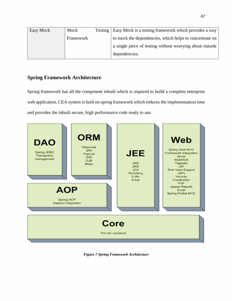
Spring Framework Architecture
Spring framework has all the component inbuilt which is required to build a complete enterprise
web application. CEA system is built on spring framework which reduces the implementation time
and provides the inbuilt secure, high performance code ready to use.
Figure 7 Spring Framework Architecture
48
Spring Transaction
CEA system has very high transactional behavior as it is a bank application, transaction is very crucial and critical aspect of the CEA application. Spring provides very easy way to make any functional behavior transactional just annotating the method with transactional annotation.
What does spring transaction provides
Opening the DB connection
Closing the DB connection
Opening the transaction
Closing transaction
Rolling back or committing the transaction
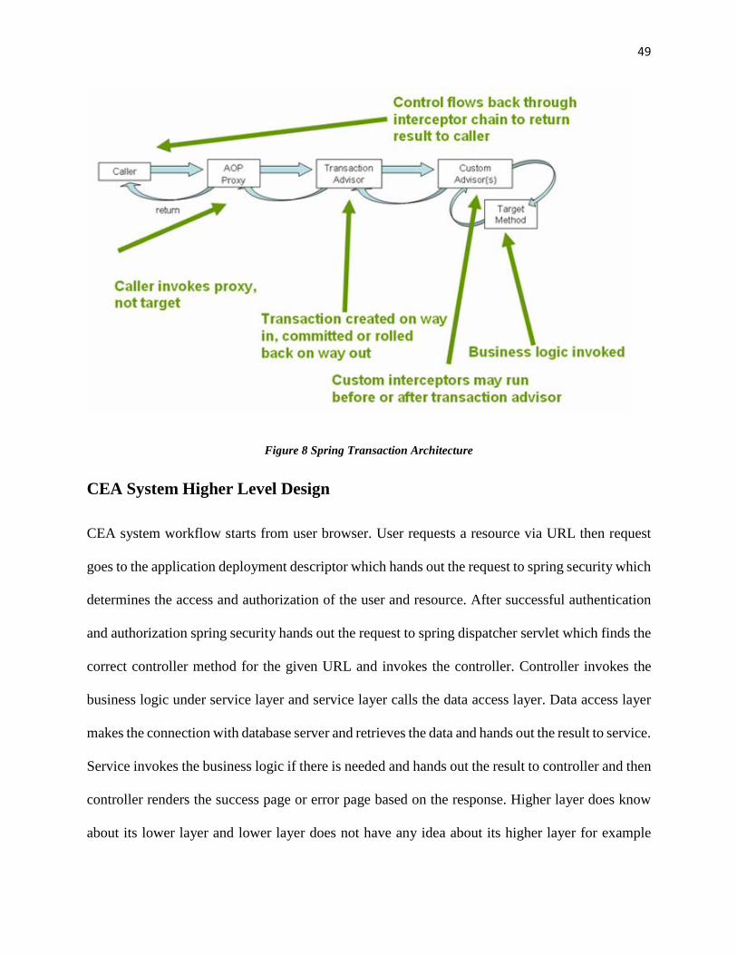
Spring transaction workflow
When @Transaction annotation applies on a method implementation (@Transaction annotation
never applies on interface method) then spring creates a proxy for that class and any call to that
method goes via proxy. So when call is already in the class via passing the proxy means call have
access to the method.
49
Figure 8 Spring Transaction Architecture
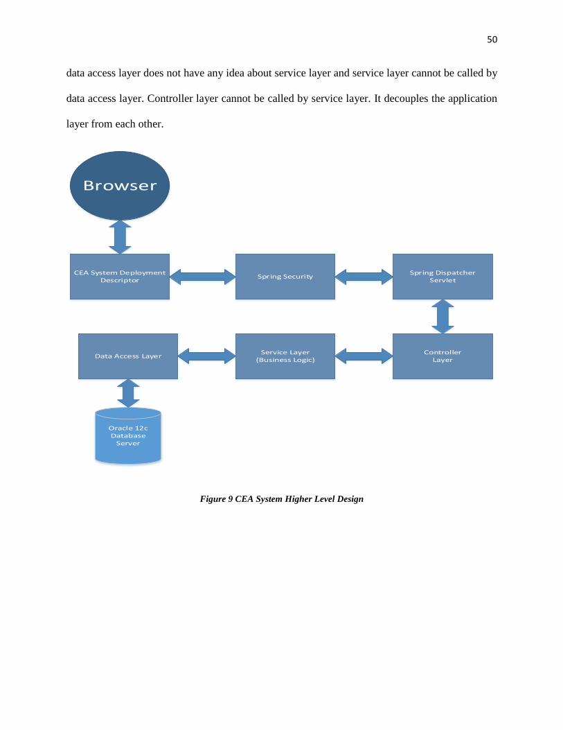
CEA System Higher Level Design
CEA system workflow starts from user browser. User requests a resource via URL then request
goes to the application deployment descriptor which hands out the request to spring security which
determines the access and authorization of the user and resource. After successful authentication
and authorization spring security hands out the request to spring dispatcher servlet which finds the
correct controller method for the given URL and invokes the controller. Controller invokes the
business logic under service layer and service layer calls the data access layer. Data access layer
makes the connection with database server and retrieves the data and hands out the result to service.
Service invokes the business logic if there is needed and hands out the result to controller and then
controller renders the success page or error page based on the response. Higher layer does know
about its lower layer and lower layer does not have any idea about its higher layer for example
50
data access layer does not have any idea about service layer and service layer cannot be called by
data access layer. Controller layer cannot be called by service layer. It decouples the application
layer from each other.
Browser
Spring SecurityCEA System Deployment Descriptor
Spring Dispatcher Servlet
ControllerLayer
Service Layer(Business Logic)Data Access Layer
Oracle 12cDatabase
Server
Figure 9 CEA System Higher Level Design
51
Use Cases Description
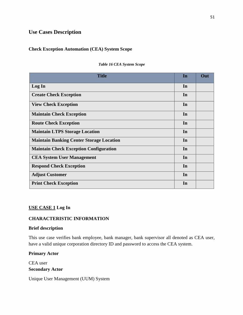
Check Exception Automation (CEA) System Scope
Table 16 CEA System Scope
Title In Out
Log In In
Create Check Exception In
View Check Exception In
Maintain Check Exception In
Route Check Exception In
Maintain LTPS Storage Location In
Maintain Banking Center Storage Location In
Maintain Check Exception Configuration In
CEA System User Management In
Respond Check Exception In
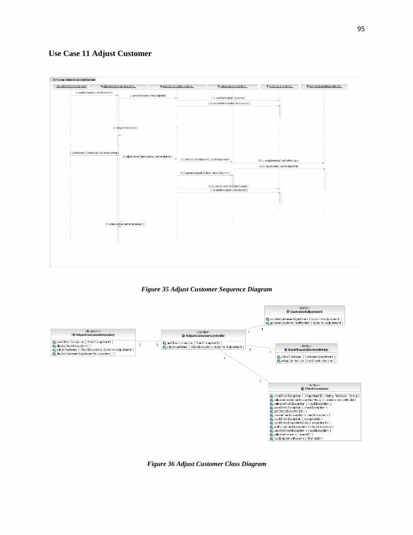
Adjust Customer In
Print Check Exception In
USE CASE 1 Log In
CHARACTERISTIC INFORMATION
Brief description
This use case verifies bank employee, bank manager, bank supervisor all denoted as CEA user, have a valid unique corporation directory ID and password to access the CEA system.
Primary Actor
CEA user Secondary Actor
Unique User Management (UUM) System
52
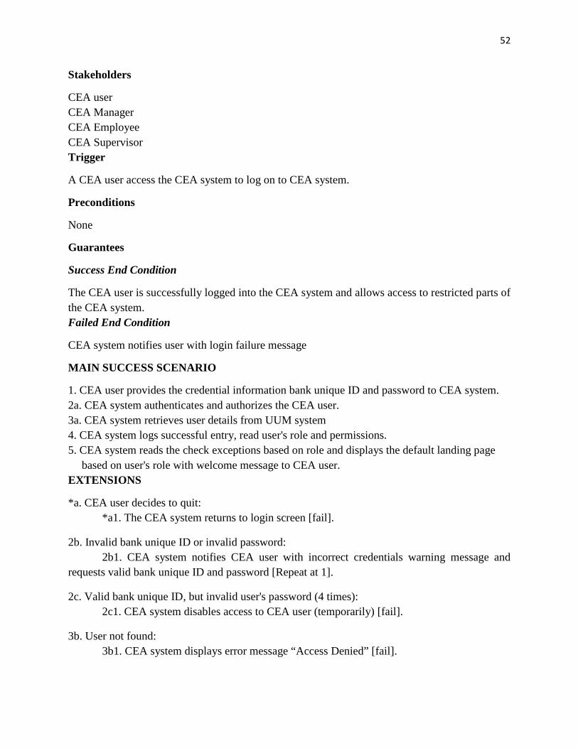
Stakeholders
CEA user CEA Manager CEA Employee CEA Supervisor Trigger
A CEA user access the CEA system to log on to CEA system.
Preconditions
None
Guarantees
Success End Condition
The CEA user is successfully logged into the CEA system and allows access to restricted parts of the CEA system. Failed End Condition
CEA system notifies user with login failure message
MAIN SUCCESS SCENARIO
1. CEA user provides the credential information bank unique ID and password to CEA system. 2a. CEA system authenticates and authorizes the CEA user. 3a. CEA system retrieves user details from UUM system 4. CEA system logs successful entry, read user's role and permissions. 5. CEA system reads the check exceptions based on role and displays the default landing page
based on user's role with welcome message to CEA user. EXTENSIONS
*a. CEA user decides to quit: *a1. The CEA system returns to login screen [fail].
2b. Invalid bank unique ID or invalid password: 2b1. CEA system notifies CEA user with incorrect credentials warning message and requests valid bank unique ID and password [Repeat at 1].
2c. Valid bank unique ID, but invalid user's password (4 times): 2c1. CEA system disables access to CEA user (temporarily) [fail].
3b. User not found: 3b1. CEA system displays error message “Access Denied” [fail].
53
3c. UUM not available: 3c1. CEA system displays warning message with error event id [step 4]. Business Rules
Number Business Rules Description
1 Bank Unique ID must be alphanumeric and must be exactly of 7 digits. 2 Password must be alphanumeric and between 6 to 12 characters. 3 ID and password must not contain any special characters. 4 CEA system user must have one of the role associated:
Exception Originator, System Manager, Exception Supervisor, Exception Responder, Exception Analyst
5 User can have maximum 4 login attempts in case of valid user ID.
USE CASE 2 Create Check Exception
CHARACTERISTIC INFORMATION
Brief description
This use case allows the Exception Originator to create the ATM/Cash Vault/Banking Center check exception.
Primary Actor
Exception Originator
Secondary Actor
Check Info Central System
Stakeholders
Exception Originator
Customer
Trigger
Exception Originator receives the rejected check.
Preconditions
CEA Exception Originator is logged on
Guarantees
Success End Condition
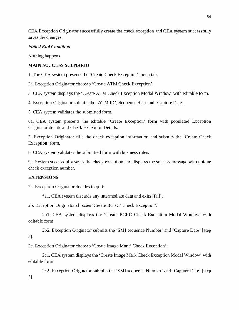
54
CEA Exception Originator successfully create the check exception and CEA system successfully saves the changes.
Failed End Condition
Nothing happens
MAIN SUCCESS SCENARIO
1. The CEA system presents the ‘Create Check Exception’ menu tab.
2c1. CEA system displays the ‘Create Image Mark Check Exception Modal Window’ with editable form.
2c2. Exception Originator submits the ‘SMI sequence Number’ and ‘Capture Date’ [step 5].
55
6b. Invalid data:
6b1. CEA system displays the validation error with error message.
6b2. Exception Originator submits the corrected information [repeat at 5].
6c. ATM ID/ SMI sequence does not found:
6c1. CEA system displays the error message ‘Check information does not found’.
6c2. Exception Originator provides the other check information [repeat at 5].
6d. External system failure:
6d1. CEA system displays the network down error message with error event id
6d2. Exception Originator submits the form again [repeat at 5].
9b. Invalid information:
9b1. CEA system presents invalid error fields with error messages to Exception Originator.
9b2. Exception Originator submits the corrected information [repeat at 8].
Business Rules
Number Business Rules Description
1 Only CEA Exception Originator can create the check exception.
2 There must be ATM ID, SMI Sequence Number existed into the external system to proceed to the ‘Create Exception’ form from ‘Create Exception’ modal.
3 ATM ID must be alphanumeric and must be 12 digits.
4 SMI sequence number must be alphanumeric and must be of 11 digits.
5 Capture date must be in format MM/DD/YY
6 Capture date must not be the future date.
7 Allowed Root Cause Reasons are:
Altered Check
Cash Out of Balance
Check Appeared Blank
Customer Error
Improper Endorsement
56
Missing Signature
Money Gram
8 Exception total is mandatory and must be more than $0.01.
9 Newly created check exception status must be ‘Ready For Work’.
USE CASE 3 View check exception
CHARACTERISTIC INFORMATION
Brief description
This use case allows the Exception Originator, Exception Responder, System Manager, Exception Supervisor and Exception Analyst all denoted as CEA user to view the check exception.
Primary Actor
CEA User
Stakeholders
Exception Originator
Exception Responder
Exception Supervisor
Exception Analyst
System Manager
Trigger
CEA user clicks on Check Exception/ search for check exception.
Preconditions
CEA user is logged on
Guarantees
Success End Condition
CEA user successfully view the check exception details with exception history and comments.
Failed End Condition
Nothing happens
57
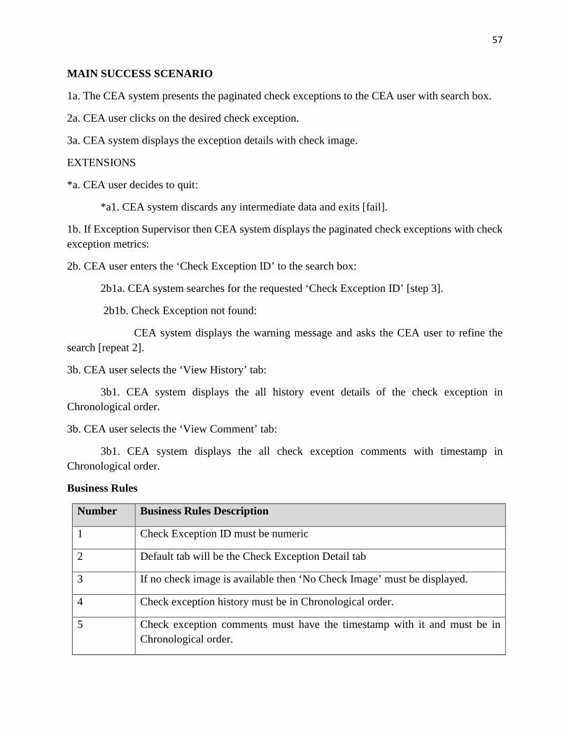
MAIN SUCCESS SCENARIO
1a. The CEA system presents the paginated check exceptions to the CEA user with search box.
2a. CEA user clicks on the desired check exception.
3a. CEA system displays the exception details with check image.
EXTENSIONS
*a. CEA user decides to quit:
*a1. CEA system discards any intermediate data and exits [fail].
1b. If Exception Supervisor then CEA system displays the paginated check exceptions with check exception metrics:
2b. CEA user enters the ‘Check Exception ID’ to the search box:
2b1a. CEA system searches for the requested ‘Check Exception ID’ [step 3].
2b1b. Check Exception not found:
CEA system displays the warning message and asks the CEA user to refine the search [repeat 2].
3b. CEA user selects the ‘View History’ tab:
3b1. CEA system displays the all history event details of the check exception in Chronological order.
3b. CEA user selects the ‘View Comment’ tab:
3b1. CEA system displays the all check exception comments with timestamp in Chronological order.
Business Rules
Number Business Rules Description
1 Check Exception ID must be numeric
2 Default tab will be the Check Exception Detail tab
3 If no check image is available then ‘No Check Image’ must be displayed.
4 Check exception history must be in Chronological order.
5 Check exception comments must have the timestamp with it and must be in Chronological order.
58
6 Only Exception Supervisor can view the ‘Check Exception Metrics’.
USE CASE 4 Maintain check exception
CHARACTERISTIC INFORMATION
Brief description
This use case allows the Exception Originator to edit, close and resubmit the check exception.
Primary Actor
Exception Originator
Stakeholders
Exception Originator
Customer
Trigger
CEA Exception Originator clicks on check exception detail.
Preconditions
CEA Exception Originator is logged on
Guarantees
Success End Condition
CEA Exception Originator successfully edit/ close/ resubmit the check exception.
Failed End Condition
Nothing happens
MAIN SUCCESS SCENARIO
1. CEA Exception Originator view the check exception details.
2. System displays the conditionally edit/ resubmit and close options.
3a. CEA Exception Originator chooses ‘Edit’ option.
4. CEA system presents the check exception editable form.
5. CEA Exception Originator submits the filled from.
59
6. CEA system validates the submitted form with business rules.
7a. CEA system successfully saves the updated check exception, update the check exception history and presents the success message.
EXTENSIONS
*a. CEA Exception Originator decides to quit:
*a1. CEA system discards any intermediate data and exits [fail].
3b. CEA Exception Originator clicks on ‘Resubmit’ option:
3b1. [step 4]
3c. CEA Exception Originator clicks on ‘Close’ option:
3c1. CEA system change the status to close and presents the user with success message.
Business Rules
Number Business Rules Description
1 Only the Check Exception Originator can edit/ resubmit and close the check exception who actually created the check exception.
2 Only Check Exception with ‘Responded’ status can be resubmitted.
3 Only Check Exception with ‘Responded’ status and ‘Item Sent’ disposition reason can be closed.
4 All Check Exception changes must be saved in Check Exception history.
USE CASE 5 Route check exception
CHARACTERISTIC INFORMATION
Brief description
This use case allows the check exception to route to a particular storage location so that check exception Responders can further work on check exception to resolve it.
Primary Actor
Check Exception Originator
Stakeholders
60
Check Exception Originator
Check Exception Responder
Check Exception Supervisor
Check Exception Manager
Trigger
CEA Exception Originator submits the ATM ID/ BCRC/ Image Mark SMI Sequence number and Capture Date on Create Check Exception Modal.
Preconditions
CEA Exception Originator is logged on
Guarantees
Success End Condition
Check exception gets routed to a specific location.
Failed End Condition
Nothing happens.
MAIN SUCCESS SCENARIO
1a. CEA Exception Originator submits the create ATM check exception modal.
2. CEA system validates the submitted data.
3a. CEA system do storage location lookup based on ATM ID.
4. CEA system assigns the storage location to check exception and presents the ‘Create Check Exception’ form with populated storage location.
EXTENSIONS
*a. CEA Exception Originator decides to quit:
*a1. CEA system discards any intermediate data and exits [fail].
1b. CEA Exception Originator submits the create BCRC/ Image mark check exception modal:
1b1. CEA system validates the submitted data.
1b2. CEA system do storage location look based on SMI Sequence number [step 4].
3b. Invalid data:
3b1. CEA system presents the error fields with error message [repeat 1].
61
3c. ATM ID does not exist:
3c1. CEA system presents the error message ‘ATM ID not found’ and asks to provide the valid ATM ID
[Repeat 1].
3b. No storage location found:
3b1. CEA system assigns the ‘Invalid Storage Location’ to check exception [step 5].
Business Rules
Number Business Rules Description
1 To route AMT check exception ATM ID must present in Check Exception Automation database.
2 To route BCRC/ Image mark check exception SMI Sequence number must exist in central check exception system
3 ATM ID must be alphanumeric and must be 12 digits.
4 SMI sequence number must be alphanumeric and must be of 11 digits.
USE CASE 6 Maintain LTPS Storage Location
CHARACTERISTIC INFORMATION
Brief description
This use case allows the CEA Manager to edit, delete and add the LTPS storage location.
Primary Actor
Exception Manager
Stakeholders
CEA Manager
CEA Responder
CEA Supervisor
Trigger
CEA Exception Manager chooses LTPS storage location ‘Configuration’.
62
Preconditions
CEA Exception Manager is logged on
Guarantees
Success End Condition
CEA Manager successfully performs CRUD (Create/ delete/ edit) operations on LTPS storage location.
Failed End Condition
Nothing happens
MAIN SUCCESS SCENARIO
1a. CEA Manager chooses ‘Add New LTPS’ location.
2. System presents the editable ‘Add LTPS’ location form to CEA Manager
3. CEA Manager submits the filled form to the CEA system.
4. CEA system validates the submitted data from business rules.
5a. CEA system successfully saves the new LTPS location to the system and presents the CEA Manager Success message.
EXTENSIONS
*a. CEA Manager decides to quit:
*a1. CEA system discards any intermediate data and exits [fail].
1b. CEA Manager chooses ‘Edit LTPS’ location:
1b1. CEA system presents the LTPS storage location editable form with data to the CEA Manager [step 3].
1c. CEA Manager chooses ‘Delete LTPS’ location:
3c1. CEA system asks CEA Manager to confirm the delete operation.
3c2a. CEA Manager confirms delete operation:
CEA system validates the delete operation with business rules.
CEA system deletes the LTPS storage location and presents the CEA Manager Success message.
CEA system denies the delete operation and presents the CEA Manager Failure message [failure].
63
3c2b. CEA system cancel the delete operation:
CEA system discards any changes [failure].
5b. Invalid data:
5b1. CEA system presents the invalid field with error message.
5b2. CEA Manager corrects the error fields and submits the form [repeat 4].
5c. Duplicate LTPS storage location:
5c1. CEA system presents the error message ‘Duplicate entry’ to the CEA Manager [failure].
Business Rules
Number Business Rules Description
1 Duplicate LTPS storage location can be added.
2 LTPS storage location company, cost center, mail code are mandatory.
3 Company can contain only numeric values and must have 5 digits.
4 Cost center can contain only numeric values and must be 7 digits.
5 At least one channel is mandatory.
USE CASE 7 Maintain Banking center Storage Location
CHARACTERISTIC INFORMATION
Brief description
This use case allows the CEA Manager to edit, delete and add the Banking Center storage location.
Primary Actor
Exception Manager
Stakeholders
CEA Manager
CEA Responder
CEA Supervisor
64
Trigger
CEA Exception Manager chooses Banking Center storage location ‘Configuration’.
Preconditions
CEA Exception Manager is logged on
Guarantees
Success End Condition
CEA Manager successfully performs CRUD (Create/ delete/ edit) operations on Banking Center storage location.
Failed End Condition
Nothing happens
MAIN SUCCESS SCENARIO
1a. CEA Manager chooses ‘Add New Banking Center’ storage location.
2. System presents the editable ‘Add Banking Center’ location form to CEA Manager
3. CEA Manager submits the filled form to the CEA system.
4. CEA system validates the submitted data from business rules.
5a. CEA system successfully saves the new Banking Center location to the system and presents the CEA Manager Success message.
EXTENSIONS
*a. CEA Manager decides to quit:
*a1. CEA system discards any intermediate data and exits [fail].
1b. CEA Manager chooses ‘Edit Banking Center’ location:
1b1. CEA system presents the Banking Center storage location editable form with data to the CEA Manager [step 3].
1c. CEA Manager chooses ‘Delete Banking Center’ location:
3c1. CEA system asks CEA Manager to confirm the delete operation.
3c2a. CEA Manager confirms delete operation:
CEA system validates the delete operation with business rules.
65
CEA system deletes the Banking Center storage location and presents the CEA Manager Success message.
CEA system denies the delete operation and presents the CEA Manager Failure message [failure].
3c2b. CEA system cancel the delete operation:
CEA system discards any changes [failure].
5b. Invalid data:
5b1. CEA system presents the invalid field with error message.
5b2. CEA Manager corrects the error fields and submits the form [repeat 4].
5c. Duplicate Banking Center storage location:
5c1. CEA system presents the error message ‘Duplicate entry’ to the CEA Manager [failure].
Business Rules
Number Business Rules Description
1 Duplicate Banking Center storage location can be added.
2 Banking Center storage location company, cost center, mail code and banking center name are mandatory.
3 Company can contain only numeric values and must have 5 digits.
4 Cost center can contain only numeric values and must be 7 digits.
5 Banking center can be associated with banking center or one of the LTPS storage location.
USE CASE 8 Maintain check exception configuration
CHARACTERISTIC INFORMATION
Brief description
This use case allows the CEA Manager to edit, delete and add the Business Address, Root Cause Reason, Request Type and Originator Edit Reasons.
Primary Actor
66
Exception Manager
Stakeholders
CEA Manager
CEA Responder
CEA Supervisor
CEA Originator
Trigger
CEA Exception Manager chooses maintain check exception ‘Configuration’.
Preconditions
CEA Exception Manager is logged on
Guarantees
Success End Condition
CEA Manager successfully performs CRUD (Create/ delete/ edit) operations on check exception configuration.
Failed End Condition
Nothing happens
MAIN SUCCESS SCENARIO
1a. CEA Manager chooses maintain one of the options Business Address/ Root Cause Reason/ Request Type/ Originator Edit Reason’ configuration.
2a. CEA Manager chooses ‘Add configuration’.
3. CEA system presents the editable form to the CEA Manager.
4. CEA Manager submits the filled form to the CEA system.
5. CEA system validates the submitted data with the business rules.
6a. CEA system successfully saves the new configuration to the system and presents the CEA Manager Success message.
EXTENSIONS
*a. CEA Manager decides to quit:
*a1. CEA system discards any intermediate data and exits [fail].
67
2b. CEA Manager chooses ‘Edit Configuration’:
1b1. CEA system presents the configuration editable form with data to the CEA Manager [step 4].
2c. CEA Manager chooses ‘Delete Configuration’:
3c1. CEA system asks CEA Manager to confirm the delete operation.
3c2a. CEA Manager confirms delete operation:
CEA system validates the delete operation with business rules.
CEA system deletes the configuration and presents the CEA Manager Success message.
CEA system denies the delete operation and presents the CEA Manager Failure message [failure].
3c2b. CEA system cancel the delete operation:
CEA system discards any changes [failure].
5b. Invalid data:
5b1. CEA system presents the invalid field with error message.
5b2. CEA Manager corrects the error fields and submits the form [repeat 5].
5c. Duplicate Configuration:
5c1. CEA system presents the error message ‘Duplicate entry’ to the CEA Manager [failure].
Business Rules
Number Business Rules Description
1 Duplicate Configuration can be added.
2 Root Cause Reason must contain only alphabets, not special characters are allowed, and maximum allowed length is 255 characters.
3 Request Type must contain only alphabets, not special characters are allowed, and maximum allowed length is 255 characters.
4 Business Address name must contain only alphabets, not special characters are allowed, and maximum allowed length is 255 characters, Address line 1, City, State and Postal Code are mandatory fields.
68
USE CASE 9 CEA System User management
CHARACTERISTIC INFORMATION
Brief description
This use case allows the CEA Manager to edit, delete, add and upload CEA system user.
Primary Actor
Exception Manager
Stakeholders
CEA Manager
Trigger
CEA Exception Manager chooses maintain CEA system ‘User Management’.
Preconditions
CEA Exception Manager is logged on
Guarantees
Success End Condition
CEA Manager successfully performs CRUD (Create/ delete/ edit/ upload) operations on CEA system user.
Failed End Condition
Nothing happens
MAIN SUCCESS SCENARIO
1. CEA Manager chooses ‘User Management’ from CEA system.
2. CEA system presents the CEA user maintenance options.
3a. CEA Manager chooses ‘Add User’ from CEA system.
4. CEA system presents the ‘Add User’ editable form to CEA Manager.
5. CEA Manager submits the filled ‘Add User’ form to the CEA system.
6. CEA system validates the submitted data with CEA system business rules.
7a. CEA system saves the new user to the CEA system database and presents the success message to the CEA Manager.
69
EXTENSIONS
*a. CEA Manager decides to quit:
*a1. CEA system discards any intermediate data and exits [fail].
3b. CEA Manager chooses ‘Edit User:
3b1. CEA Manager Search for the user by unique bank ID.
3b2a. User Found:
CEA system presents the user details with editable form to the CEA Manager.
CEA Manager submits the modified form to the CEA system [step 6].
3b2b. User Not Found:
CEA system presents warning message and asks CEA Manager to refine the search [repeat at 3b1].
3c. CEA Manager chooses ‘Delete User:
3c1. CEA Manager Search for the user by unique bank ID.
3c2a. User Found:
CEA system presents the user details to the CEA Manager and asks CEA Manager to confirm the delete operation.
CEA Manager confirms delete operation:
CEA system validates the delete operation with business rules.
CEA system deletes the user and presents the CEA Manager Success message.
CEA system denies the delete operation and presents the CEA Manager Failure message [failure].
CEA system cancel the delete operation:
CEA system discards any changes [failure].
3c2b. User Not Found:
CEA system presents warning message and asks CEA Manager to refine the search [repeat at 3b1].
3d. CEA Manager chooses ‘Upload User:
3d1. CEA System asks for CSV format file to upload the users.
70
3d2. CEA Manager provide the CSV file to the CEA system.
3d3. CEA system validates the file format.
3d4a. CEA system uploads the file to the CEA system database.
3d4b. Invalid File:
CEA system presents the error message to the CEA Manager and asks to provide the valid file.
7b. Invalid data:
5b1. CEA system presents the invalid field with error message.
5b2. CEA Manager corrects the error fields and submits the form [repeat 5].
7c. Duplicate User:
7c1. CEA system presents the error message ‘Duplicate entry’ to the CEA Manager [failure].
Business Rules
Number Business Rules Description
1 Bank Unique ID is mandatory and must be alphanumeric and must be exactly of 7 digits.
2 Role is mandatory for editing/ adding/ uploading user.
3 Duplicate user cannot be added.
4 Upload file must be CSV format file.
USE CASE 9 Respond check exception
CHARACTERISTIC INFORMATION
Brief description
This use case allows the CEA Responder to respond to the check exception for check exception resolution.
Primary Actor
CEA Responder
71
Stakeholders
CEA Responder
Trigger
CEA responder chooses ‘Respond’ check exception.
Preconditions
CEA Responder is logged on
Guarantees
Success End Condition
CEA Responder successfully responds to the check exception.
Failed End Condition
Nothing happens
MAIN SUCCESS SCENARIO
1. CEA Responder chooses ‘View Exception Details.
2. CEA system validates the check exception and presents the check exception details with conditional ‘Respond’ option.
3. CEA Responder chooses ‘Respond’ check exception.
4. CEA system presents the ‘Respond Modal’ to the CEA Responder.
5. CEA Responder submits the ‘Respond’ check exception form to the CEA system.
6. CEA system validates the submitted data with business rules.
7a. CEA system changes the check exception status to ‘Responded’ or ‘Closed’, saves into the CEA database and presents the success message to the CEA Responder.
EXTENSIONS
*a. CEA Responder decides to quit:
*a1. CEA system discards any intermediate data and exits [fail].
7b. Invalid data:
5b1. CEA system presents the invalid field with error message to CEA Responder.
5b2. CEA Responder corrects the error fields and submits the form [repeat 6].
72
Business Rules
Number Business Rules Description
1 Only check exception with status ‘Ready For Work’ or ‘In Process’ can be responded.
2 Responder can respond to only those check exception having storage location mail code prefix same as responder mail code prefix e.g. SD1-067-1234 and SD1-987-4567 have same prefix SD1.
3 Disposition reason is mandatory and must be chosen from available disposition reasons list
4 Respond comments are optional, maximum allowed length of comment are 255 and no special characters are allowed in comment.
5 Item can be responded only one time.
USE CASE 10 Adjust customer
CHARACTERISTIC INFORMATION
Brief description
This use case allows the CEA Analyst to adjust the customer to debit or credit the disputed amount to the customer bank account, and send the customer automatic notification.
Primary Actor
CEA Analyst
Stakeholders
CEA Analyst
Customer
Trigger
CEA Analyst chooses ‘Adjust Customer’ from check exception details.
Preconditions
CEA Analyst is logged on
Guarantees
73
Success End Condition
CEA Analyst successfully adjust the customer and generate the customer notification letter.
Failed End Condition
Nothing happens
MAIN SUCCESS SCENARIO
1. CEA Analyst chooses ‘View Exception Details.
2. CEA system communicates with the external Bank Account systems and receives the customer as well as customer account details.
3a. CEA system displays the check exception, customer and account details with ‘Adjust Customer’ option to the CEA Analyst.
4. CEA Analyst chooses the ‘Adjust Customer’ from CEA system.
5. CEA system presents the customer adjust details modal popup and asks to confirm the customer adjustment.
6a. CEA Analyst confirms the customer adjustment.
7. CEA system communicates with the external bank system to post the customer adjustment.
8a. CEA system generates the customer notification and saves to the CEA system.
9. CEA system changes the check exception status from Non-Monetary to Monetary, check exception status from ‘Ready for Work’ to ‘In Process’ and presents to the CEA Analyst.
EXTENSIONS
*a. CEA Analyst decides to quit:
*a1. CEA system discards any intermediate data and exits [fail].
3b. Remote System Exception:
3b1. CEA system presents the check exception details with warning message having unique error event id.
3b2. CEA system does not display the ‘Adjust Customer’ option [failure].
6b. Cancel the Adjustment:
CEA system hides the ‘Adjust Customer’ modal on check exception details.
8b. Remote System Exception:
CEA system displays the error message to the CEA Analyst [failure].
74
Business Rules
Number Business Rules Description
1 After successful customer adjustment financial status must change from ‘Non-Monetary’ to ‘Monetary’.
2 After successful customer adjustment check exception status must change to ‘In Process’
3 Debit check exception amount must be credited to the customer and Credit check exception amount must be debited to the customer.
4 Credited Adjustment must have the Transaction Code 001.
Debited adjustment must have the Transaction Code 002.
5 Customer and account details must be present on check exception details before making adjustment, if customer and account details are not present customer adjustment should fail and no customer notification must be generated.
USE CASE 11 Print check exception
CHARACTERISTIC INFORMATION
Brief description
This use case allows the CEA Originator/ CEA Responder/ CEA Supervisor/ CEA Manager all denoted as CEA user to print the check exception.
Primary Actor
CEA user
Stakeholders
CEA user
Trigger
CEA user chooses ‘Print Check Exception’.
Preconditions
CEA user is logged on
75
Guarantees
Success End Condition
CEA user successfully prints the check exception.
Failed End Condition
Nothing happens
MAIN SUCCESS SCENARIO
1a. CEA user selects multiple check exceptions.
2. CEA system enables the ‘Print Selection’ button.
3. CEA user selects the ‘Print Selection’ button from CEA system.
4. CEA system opens the operating system print widow.
5a. CEA user selects ‘Print’ from print window.
6a. CEA system prints the check exceptions.
EXTENSIONS
*a. CEA user decides to quit:
*a1. CEA system discards any intermediate data and exits [fail].
1b. CEA user select check exception details:
1b1. CEA system presents the check exception details with ‘Print Check Exception’ button.
1b2. CEA user selects ‘Print Check Exception’ from CEA system [step 4].
5b. CEA user chooses ‘Cancel’:
CEA system discards any changes and close the print window [failure].
6b. Printer Unavailable:
CEA system displays printer unavailable warning message [failure].
Business Rules
Number Business Rules Description
1 Print selection button should be enabled after at least one selection.