Porous block copolymer separation membranesfor 21st century sanitation and hygiene
Leiming Guo, *a Yong Wang *b and Martin Steinhart *a
Removing hazardous particulate and macromolecular contaminants as well as viruses with sizes from a
few nm up to the 100 nm-range from water and air is crucial for ensuring sufficient sanitation and
hygiene for a growing world population. To this end, high-performance separation membranes are
needed that combine high permeance, high selectivity and sufficient mechanical stability under
operating conditions. However, design features of separation membranes enhancing permeance reduce
selectivity and vice versa. Membrane configurations combining high permeance and high selectivity
suffer in turn from a lack of mechanical robustness. These problems may be tackled by using block
copolymers (BCPs) as a material platform for the design of separation membranes. BCPs are macro-
molecules that consist of two or more chemically distinct block segments, which undergo microphase
separation yielding a wealth of ordered nanoscopic domain structures. Various methods allow the
transformation of these nanoscopic domain structures into customized nanopore systems with pore
sizes in the sub-100 nm range and with narrow pore size distributions. This tutorial review summarizes
design strategies for nanoporous state-of-the-art BCP separation membranes, their preparation, their
device integration and their use for water purification.
Key learning points(1) Comprehensive overview of the state-of-the-art regarding BCP-based separation membranes.(2) Strategies for the structural and morphological design of BCP membranes.(3) Correlation between the morphology of BCP-based membranes and separation benchmark parameters such as selectivity and permeance.(4) Device integration and use cases of BCP-based membranes.
1. Introduction
The supply of clean water has emerged as a major challenge formankind. The shortage of clean water is further exacerbated bycontinuous population growth and by anthropogenic climatechange. It is of significant importance to pay close attention tothe hygiene of water since the quality of water available tohumans is highly correlated to human health. The problemscaused by the lack of clean water may be mitigated by theengineering of water redistribution and storage, sea waterdesalination and wastewater treatment.1 Especially wastewatertreatment is a demanding task since water pollution may
comprise not only dissolved small molecules such as deter-gents, active pharmaceutical ingredients and nutrients but alsopathogens and particulate pollutants such as microplastics.Sophisticated separation techniques including, for example,distillation, crystallization of pollutants, extraction, adsorptionseparation and membrane separation are employed to removepotentially hazardous pollutants.2 Compared to other waterpurification methods, membrane separation is environmen-tally friendly, energy-saving and associated with a small ecolo-gic footprint.3 Separation membranes rejecting pollutants andsolutes larger than 100 nm are called microfiltration mem-branes, separation membranes rejecting pollutants and soluteslarger than 2 nm are called ultrafiltration membranes andseparation membranes rejecting pollutants and solutes smallerthan 2 nm are called nanofiltration membranes.4 For efficientoperation, separation membranes should be characterized byhigh permeance as well as by high selectivity. Unfortunately,structural and morphological features of separation membranesthat result in high permeance often reduce selectivity and vice versa.
a Institut fur Chemie neuer Materialien and CellNanOs, Universitat Osnabruck,
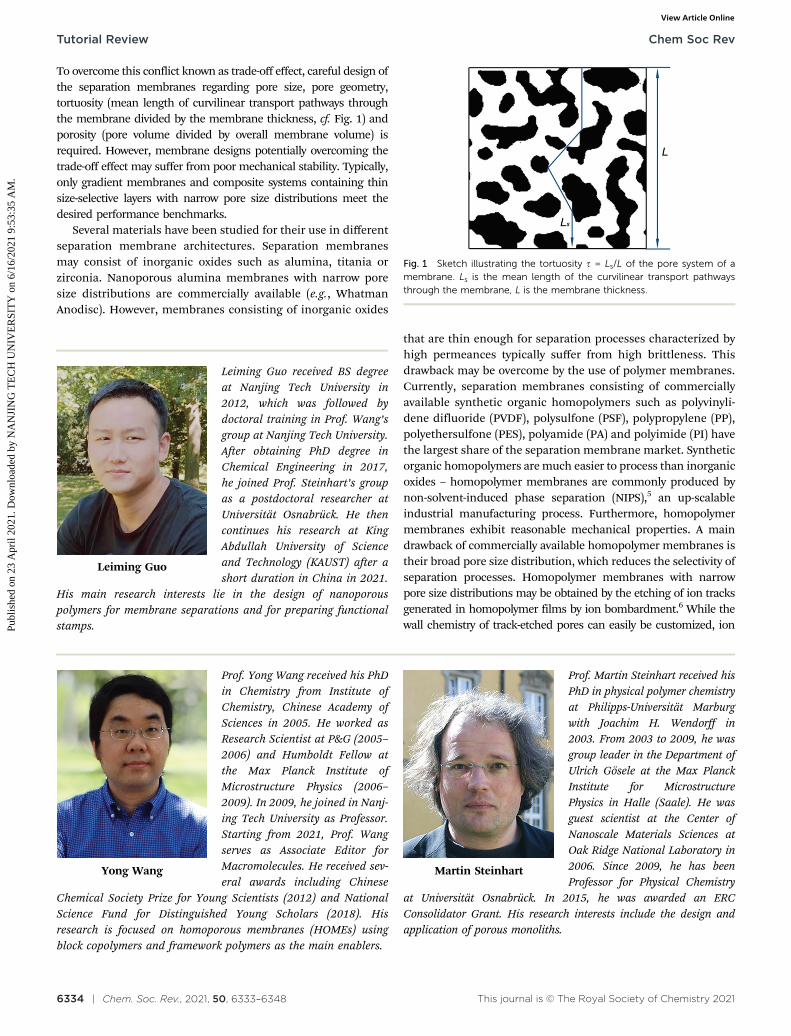
To overcome this conflict known as trade-off effect, careful design ofthe separation membranes regarding pore size, pore geometry,tortuosity (mean length of curvilinear transport pathways throughthe membrane divided by the membrane thickness, cf. Fig. 1) andporosity (pore volume divided by overall membrane volume) isrequired. However, membrane designs potentially overcoming thetrade-off effect may suffer from poor mechanical stability. Typically,only gradient membranes and composite systems containing thinsize-selective layers with narrow pore size distributions meet thedesired performance benchmarks.
Several materials have been studied for their use in differentseparation membrane architectures. Separation membranesmay consist of inorganic oxides such as alumina, titania orzirconia. Nanoporous alumina membranes with narrow poresize distributions are commercially available (e.g., WhatmanAnodisc). However, membranes consisting of inorganic oxides
that are thin enough for separation processes characterized byhigh permeances typically suffer from high brittleness. Thisdrawback may be overcome by the use of polymer membranes.Currently, separation membranes consisting of commerciallyavailable synthetic organic homopolymers such as polyvinyli-dene difluoride (PVDF), polysulfone (PSF), polypropylene (PP),polyethersulfone (PES), polyamide (PA) and polyimide (PI) havethe largest share of the separation membrane market. Syntheticorganic homopolymers are much easier to process than inorganicoxides – homopolymer membranes are commonly produced bynon-solvent-induced phase separation (NIPS),5 an up-scalableindustrial manufacturing process. Furthermore, homopolymermembranes exhibit reasonable mechanical properties. A maindrawback of commercially available homopolymer membranes istheir broad pore size distribution, which reduces the selectivity ofseparation processes. Homopolymer membranes with narrowpore size distributions may be obtained by the etching of ion tracksgenerated in homopolymer films by ion bombardment.6 While thewall chemistry of track-etched pores can easily be customized, ion
Fig. 1 Sketch illustrating the tortuosity t = Ls/L of the pore system of amembrane. Ls is the mean length of the curvilinear transport pathwaysthrough the membrane, L is the membrane thickness.
Yong Wang
Prof. Yong Wang received his PhDin Chemistry from Institute ofChemistry, Chinese Academy ofSciences in 2005. He worked asResearch Scientist at P&G (2005–2006) and Humboldt Fellow atthe Max Planck Institute ofMicrostructure Physics (2006–2009). In 2009, he joined in Nanj-ing Tech University as Professor.Starting from 2021, Prof. Wangserves as Associate Editor forMacromolecules. He received sev-eral awards including Chinese
Chemical Society Prize for Young Scientists (2012) and NationalScience Fund for Distinguished Young Scholars (2018). Hisresearch is focused on homoporous membranes (HOMEs) usingblock copolymers and framework polymers as the main enablers.
Martin Steinhart
Prof. Martin Steinhart received hisPhD in physical polymer chemistryat Philipps-Universitat Marburgwith Joachim H. Wendorff in2003. From 2003 to 2009, he wasgroup leader in the Department ofUlrich Gosele at the Max PlanckInstitute for MicrostructurePhysics in Halle (Saale). He wasguest scientist at the Center ofNanoscale Materials Sciences atOak Ridge National Laboratory in2006. Since 2009, he has beenProfessor for Physical Chemistry
at Universitat Osnabruck. In 2015, he was awarded an ERCConsolidator Grant. His research interests include the design andapplication of porous monoliths.
Leiming Guo
Leiming Guo received BS degreeat Nanjing Tech University in2012, which was followed bydoctoral training in Prof. Wang’sgroup at Nanjing Tech University.After obtaining PhD degree inChemical Engineering in 2017,he joined Prof. Steinhart’s groupas a postdoctoral researcher atUniversitat Osnabruck. He thencontinues his research at KingAbdullah University of Scienceand Technology (KAUST) after ashort duration in China in 2021.
His main research interests lie in the design of nanoporouspolymers for membrane separations and for preparing functionalstamps.
bombardment can be carried out only in specialized large researchfacilities, and ion-track membranes typically have a thicknessexceeding several mm. However, for separation applicationsthinner membranes are required.7–9 Track-etched membranescan, in principle, be prepared with high porosities but containthen high proportions of intersecting pores – resulting ininsufficient mechanical strength of the membrane scaffold. Asa result, commercial track-etched membranes typically haveporosities lower than 3% and correspondingly low permeances.
To overcome the aforementioned problems, membrane materialswith reasonable mechanical properties are needed that allow therealization of pore systems characterized by narrow pore sizedistributions, regular pore shapes and high porosities. Potentialmembrane materials including membrane proteins like aquaporins,peptides, carbon nanotubes, graphene oxides and polymerizablesurfactants have been considered for the design of next-generationseparation membranes for water treatment.10 In specific applicationscenarios, membranes made from these materials remove contami-nants from aqueous solutions with sufficient selectivity while theystill exhibit high water permeances. However, only limited adapta-tions of the textural properties of these membranes are possible soas to meet the requirements of given use cases. Some of thesematerials, such as graphene oxides, are unstable in water. Sufficientstability of the corresponding membranes can only be achieved byadditional measures such as grafting steps,11 which inevitablychange the lamellar spacings (pore sizes) of graphene oxide andimpede its use for separation purposes.
The preparation of separation membranes from blockcopolymers (BCPs) enables flexible tailoring of pore sizes, poreshapes, tortuosities, porosities and the surface chemistry of thepore walls. Moreover, thin size-selective BCP layers with adequatemechanical stabilities can easily be integrated into gradient andcomposite membrane designs. Therefore, the looming shortageof clean water may be alleviated by the availability of advancedwater treatment systems based on BCP membranes. BCPmembranes may be employed as a component especially of smallmobile water purification devices that can be operated whereneeded. BCP membranes might also be used as filters inventilation and air conditioning systems. Several reviews havecovered specific aspects of BCP membranes.12–16 A recent reviewby Hampu et al. comprehensively addresses the state of the artregarding block copolymer ultrafiltration membranes.17 In thistutorial review, we aim at the explicit introduction of basic termsand concepts relevant to the design and use of BCP ultrafiltrationand nanofiltration membranes. In Section 2, key parameters toassess the performance of BCP separation membranes as well asthe intertwined and often conflicting relation between selectivityand permeance are discussed. Section 3 introduces the peculiarfeatures of BCPs as a material platform for ultrafiltrationmembranes. The state of the art regarding the design of BCPultrafiltration membranes will be addressed, focussing ontextural and morphological features of the pore systems of BCPmembranes as well as on the preparation of BCP membranes bygeneration of pores in BCP films and monoliths. In Section 4,strategies for the design of complex ultrafiltration membraneconfigurations overcoming the trade-off between permeance and
selectivity are discussed. Section 5 deals with the integration ofBCP ultrafiltration membranes into device configurations forwater purification and corresponding use cases of BCP ultra-filtration membranes. Possible designs for BCP nanofiltrationmembranes and corresponding application examples arereviewed in Section 6. We conclude this tutorial review with asummary and with perspectives for the further developmentand future applications of BCP separation membranes.
2. Separation performance: keyparameters
In the following, it will be discussed how the performance ofseparation membranes is quantified. Selectivity and permeanceare introduced as key benchmark parameters, and the trade-offassociated with their concurrent optimization is discussed.
2.1 Selectivity
The selectivity is a measure of the efficiency, with which solutes– such as contaminants – are removed from a gaseous or liquidfluid to be purified. Commonly, the selectivity is representedby the rejection R and the molecular-weight-cut-off (MWCO).R is the fraction of a solute that does not pass a separationmembrane:
R ¼ 1� C2
C1
� �� 100% (1)
C1 is the solute concentration in the fluid prior to filtering(referred to ‘‘feed’’), and C2 the solute concentration in thepurified fluid after filtering (referred to ‘‘permeate’’). The MWCOis defined in such a way that a membrane rejects at least 90% of asolute with a molecular weight M equal or larger than the MWCO.MWCO values are determined by using aqueous test solutionscontaining polymers such as polyethylene oxide (PEO)18 or dextran19
with various well-defined molecular weights. The effective porediameters d can then be estimated by empirically correlating themolecular weight M of the largest polymer solute that passes atested separation membrane and its hydrodynamic radius r, whichis the radius of a hard sphere that diffuses like the solute.
2.2 Permeance
The permeance Pw (L h�1 m�2 bar�1) is the fluid volume V (L) thatpasses a separation membrane per time t (h), per membrane areaA (m2) and per pressure drop Dp (bar):
Pw ¼V
AtDp(2)
On the other hand, the velocity n (m s�1) of the flowing fluidequals the fluid volume V passing the separation membraneper membrane area A and per time t. Therefore, we obtain:
n ¼ V
At¼ PwDp (3)
Assuming that a separation membrane contains straightcylindrical pores oriented parallel to the flow direction of thefluid and assuming that the flow through the membrane pores
is laminar, the effective pore diameter d of the membranes canbe obtained from n using Hagen–Poiseuille’s law:20
n ¼ et2
Dpd2
32mL
� �(4)
Here, m is the dynamic viscosity of the fluid (bar s�1), and L themembrane thickness (m). The surface porosity e of a separationmembrane is the fraction of the surface area that is occupied bypore openings. As mentioned above, the tortuosity t is the ratioof the mean length of the curvilinear transport pathwaysthrough the membrane (Ls) and L. If the BCP membranescontain straight cylindrical pores, the tortuosity t equals 1.For all other pore morphologies, t is larger than 1 because eventhe shortest curvilinear connection between the membranesurfaces is then longer than L (Fig. 1). Consequently, theeffective pore diameter d of a membrane can be estimatedeither from the MWCO values or from n – in addition to othertexture characterization methods such as porosimetry. Especiallywhen swollen hydrophilic test polymer molecules adsorb onmembrane pore walls in the course of membrane separation tests,effective pore diameters d estimated from separation selectivitiesand n may be smaller than the textural pore diameters of drymembranes measured by porosimetry. The pore geometry gener-ally impacts the permeance of a membrane.21 Thus, non-cylindrical cross sections of the membrane pores result in mod-ified water flow. For example, cylindrical domains in BCP filmsoriented parallel to the film plane were converted into slit-shapedpores at the positions of the cylindrical domains.9 The slit-shapedpores had widths of around 10 nm, but lengths of several mm up totens of mm. For the description of water flow through the slit-shaped pores a modified Hagen–Poiseuille’s law was proposed,9,21
where h denotes the width of the slit-shaped pores:
n ¼ et2
Dph2
3mL
� �(5)
2.3 Membrane design: major challenges
Although considerable progress has been made in the designand performance optimization of BCP membranes, severalproblems need to be addressed to push forward the use ofBCP separation membranes in real-life applications. As alreadymentioned, the design of separation membranes generallyinvolves a trade-off between separation selectivity, permeanceand mechanical stability of the membranes that impedesperformance breakthroughs.22 High permeances are desiredbecause high permeances result in higher water throughput.Thus, more water can be purified per time and membrane area.On the other hand, for obvious reasons also high separationselectivities are required. Pore length and membrane thicknessinfluence the selectivity only to some extent if the membranepores are large enough for the occurrence of convective fluidtransport.23 In the case of ultra- and nanofiltration throughmembrane pores with diameters well below 100 nm, exclusivelythe ratio between solute diameter and pore diameter shoulddetermine selectivity. Then, the selectivity can be optimized bycarefully adjusting the diameter of the membrane pores and by
the realization of narrow pore size distributions. However, anycombination of geometric and morphological parameters,such as membrane thickness, pore diameter and porosity, isassociated with drawbacks. Thicker separation membraneswith smaller pore diameters will exhibit high separation selectivitiesbut poor permeances. Increasing the pore diameter will result inbetter permeance but poorer selectivity. The membrane thickness ispositively related to the transport resistance encountered by a fluidpassing the membrane – the thinner a membrane is, the higher isits permeance. Therefore, thin membranes with small pores mayshow good permeances as well as good separation selectivities.Unfortunately, thin membranes typically lack sufficient mechanicalrobustness for routine operations. Reducing porosity while keepingpore diameter and membrane thickness constant improvesmechanical stability but reduces in turn permeance – possiblybelow acceptable levels. As discussed below, only complexcomposite and gradient membrane configurations exhibit com-binations of properties sufficient for real-life use cases. Inaddition, organic and biological fouling often occurs duringthe use of separation membranes. Membrane fouling related tothe chemical and physical surface properties of the pore wallsreduces permeance.10 Contaminants with sizes comparableto the sizes of the membrane pores may get stuck in themembranes pores. The resulting pore clogging reduces thepermeance. These problems may be tackled by sophisticatedlydesigned BCP-based separation membrane configurations, as,for example, comprehensively discussed by Hampu et al.17
3. BCP ultrafiltration membranes – amodular assembly system3.1 BCPs as a material platform for ultrafiltration membranes
BCPs are macromolecules consisting of two or more chemicallydifferent block segments with distinct physicochemical properties.Typically, the different block segments of a BCP are immiscibleand tend to segregate. However, since the block segments areconnected by covalent bonds, macroscopic phase separation isimpossible. Instead, microphase separation takes place andtypically results in the formation of an ordered nanoscopicdomain structure. The domains contain one specific blocksegment species; the covalent bonds between the different blocksegments enrich, therefore, at the domain interfaces. Themorphology of the nanoscopic BCP domain structures isdetermined by parameters like the volume fractions occupiedby the different BCP block segment species and their degree ofcompatibility. Symmetric diblock copolymers, in which the twocomponents occupy half of the volume, form lamellar equili-brium morphologies. In asymmetric diblock copolymers, theequilibrium morphologies change from gyroid to cylindrical tospherical as the volume fraction of the minority componentdecreases.24 Defects in the nanoscopic BCP domain structuresmay be healed by methods such as solvent annealing, thermalannealing and application of magnetic or electric fields.15 Theperiods of the nanoscopic domain structures formed by BCPmicrophase separation typically amount to a few 10 nm. For a
given nanoscopic domain structure type, the periods of theBCP domains may be tuned by the degree of polymerizationof the BCP block segments (while their volume fractions arekept constant).
The chemical synthesis of tailored BCPs is well establishedand comprises synthetic strategies such as anionic polymerization,atom transfer radical polymerization and reversible addition–fragmentation chain transfer radical polymerization.25 Hence, amodular assembly system of BCP architectures is accessible bystate-of-the-art polymer chemistry. The chemical composition andthe length of the BCP block segments as well as the sequence, inwhich they are incorporated into BCPs, can be customized.Customizing the chemical structure of BCPs in turn allows tailoringtheir morphology and period as well as chemical contrast andthermodynamic compatibility of their block segments. Besidesdiblock copolymers (AB) as the simplest BCP architecture, triblockcopolymers (ABA, ABC), quarterpolymers (e.g., ABAB or ABCD) aswell as star-, comb- and cyclic BCPs can be synthesized. Hence, awealth of different BCP architectures is available,25 which haveattracted tremendous interest in nanoscience – in particular forthe preparation of nanoporous films, membranes and monoliths.
3.2 Textural design of BCP membranes
The pore systems of BCP membranes are typically derived fromthe nanoscopic BCP domain structures resulting from microphaseseparation in the BCP films and monoliths used as startingmaterials for the preparation of the BCP membranes. As discussedbelow, important textural features of BCP membranes, such aspore sizes, pore shapes and membrane porosities, are cruciallyinfluenced by the nature of the nanoscopic BCP domain structuresthat template pore formation at least to some extent.
3.2.1 Pore size. The possibility to customize pore sizes inmembranes is an efficient lever for the tailoring of permeanceand selectivity. BCP membrane pores derived from nanoscopicBCP domain structures typically have pore diameters corres-ponding to or being slightly larger than the domain sizes of theparent nanoscopic BCP domain structures. Therefore, the poresof BCP membranes typically have sizes from several nm up toseveral tens of nm, but well below 100 nm. Considering thepore size range of BCP membranes, BCPs are a promisingmaterial platform for the design and synthesis of ultrafiltrationmembranes and, to some extent, of nanofiltration membranes.The MWCO is an appropriate benchmark parameter for BCPmembranes because the molecular dimensions of syntheticand biological polymers typically match their pore sizes.
The derivation of the pores in BCP membranes from regularnanoscopic BCP domain structures typically results in narrowpore size distributions. Pore size and pore size distribution ofBCP membranes can be tuned and tailored much more efficientlythan pore size and pore size distribution of homopolymermembranes, because classical pore formation techniques forthe preparation of homopolymer membranes based on spinodaldecomposition26 are difficult to control. Narrow pore size dis-tributions are a striking advantage of BCP membranes over mostseparation membranes consisting of other materials, becausenarrow pore size distributions boost selectivity. More specifically,
narrow pore size distributions are the prerequisite for a sharpstepwise increase of the rejection rates for macromolecules iftheir molecular weights become equal or larger than the MWCOvalue. In contrast, separation membranes with broad pore sizedistributions will be characterized by a diffuse molecular weightrange, in which the rejection rates for macromolecules graduallyincrease with the molecular weight, rather than by well-definedMWCO values.
3.2.2 Pore shape. Pore shapes crucially influence theseparation performance of any kind of separation membrane. If aBCP membrane has an interpenetrating-bicontinuous morphologyconsisting of a continuous pore network and a likewise continuousscaffold, the length of the transport paths through the membraneexceeds the membrane thickness. Consequently, t will be largerthan 1, and the larger t is, the longer are the transport paths. BCPseparation membranes with spongy tortuous pore systems mayshow excellent selectivity but poor permeance, because pore wallsintersecting straight transport paths are obstacles to fluid flow.Another drawback of spongy tortuous pore systems is theirsusceptibility to membrane fouling. Membrane fouling involvesadsorption of larger macromolecular solutes or of particulatepollutants at the pore walls. As a result, the pore cross section isreduced, or the pores are even clogged. To optimize permeance,transport paths through BCP membranes should be as short aspossible. It is straightforward that the length of the shortestpossible transport path through a membrane corresponds tothe membrane thickness L. Such short transport paths can berealized if the membranes are penetrated by straight poreshaving their pore axes oriented perpendicularly to the membraneplane – corresponding to a tortuosity of 1. Such membranes arereferred to ‘‘homoporous membranes’’.13
3.2.3 Porosity. The porosity is the volume fraction of aporous material that is occupied by the pores. High porositiesresult in high permeances but thinner pore walls. The latterfeature may compromise the mechanical stability of a membraneso that it cannot withstand the impact that is exerted on it duringuse. Lowering the porosity increases the mechanical stability of amembrane but reduces permeance. The surface porosity e, whichis the area fraction of the pore openings at the surface of a porousmaterial, may differ from the bulk porosity inside a membrane. Alow surface porosity reduces the permeance of a membrane. In thecase of homoporous BCP membranes containing arrays of straightcylindrical pores with constant diameter along their length, whichare oriented normal to the membrane plane, bulk porosity andsurface porosity have the same value – typically up to 15%.20,27 Theporosities of BCP membranes with slit-shaped pores may beas high as 34%.9 Spongy interpenetrating-bicontinuous BCPmembranes containing continuous pore networks may possessbulk porosities of up to 60%.13
3.3 Generation of pores
A plethora of methods for the generation of pores in BCP filmsand monoliths has been established. The over-arching designcriterium for pore systems in BCP separation membranes isthat the opposite membrane surfaces need to be connected bythe pore systems. Moreover, the surface porosities need to be
sufficiently large so that the pore systems can be accessed fromthe environment. Hence, pore systems of BCP separationmembranes should provide transport pathways connecting thecompartments separated by the BCP separation membranes.Most pore generation routes yield nanosized pores in BCPmembranes, which are suitable for ultrafiltration. In Section 3.3we will summarize basic pore formation strategies that allow thetransformation of solid BCP films and monoliths into porousBCP films and monoliths. Pore formation processes coupled withthe generation of complex membrane configurations to tacklethe trade-off between permeance and selectivity, such as poreformation in the course of self-assembly combined with non-solvent induced phase separation (SNIPS),28 are discussed in thefollowing Section 4.
3.3.1 Selective degradation of block segments. To generatepores in asymmetric microphase-separated BCPs, in which theblock segments of a majority component form a continuousmatrix, the minority domains may be degraded. The majoritydomains are conserved as walls of the pores formed in place ofthe minority domains (Fig. 2).12 For example, degradation ofcylindrical minority domains yields holey films of the remainingmajority component containing cylindrical pores. Several degrada-tion methods including hydrolysis, UV irradiation, ozonolysis andtreatment with acids such as hydrogen fluoride (HF), hydroiodicacid (HI) and trifluoroacetic acid (TFA) were employed to generatenanoporous BCPs. Selective degradation of one of the blocksegment species of a BCP by acidic or basic hydrolysis can beaccomplished if at least another block segment species is inertunder the applied conditions. Frequently, polyesters such aspoly(lactide) (PLA) are employed as hydrolysable block segmentsof, for example, polystyrene-block-polylactide (PS-b-PLA).29 Porouspolymer membranes are also accessible by hydrolysing thepoly(propylene carbonate) (PPC) block segments of poly(propylenecarbonate)-block-poly(4-vinylcatechol acetonide) (PPC-b-PVCA) inalkaline solution.7 The poly(methyl methacrylate) (PMMA) blocksegments of polystyrene-block-poly(methyl methacrylate) (PS-b-PMMA) selectively decompose by exposure to UV radiation;
the short oligomeric PMMA chains thus formed can then beextracted with selective solvents such as acetic acid. Notably, theUV irradiation induces cross-linking of the PS chains in theremaining PS scaffold. The crosslinks between different PSchains improve the mechanical strength of the nanoporousPS membranes obtained in this way.30 A drawback of poreformation by selective degradation of a BCP block segmentis the mechanical weakening of the remaining membranescaffold. The partial destruction of the BCP molecules oftenresults in deteriorated mechanical properties of BCP separationmembranes obtained in this way.
3.3.2 Selective extraction of dissolvable species from minoritydomains. As an alternative to their decomposition, the BCP blocksegments forming the minority domains can be loaded with adissolvable species. The dissolvable species needs to be selectivelycompatible with the minority block segments so that it segregatesinto the minority domains during microphase separation. Thedissolvable species is then extracted from the BCP minoritydomains with a selective solvent, against which the majoritydomains are inert. As a result, the nanoscopic domain structureof the BCP is arrested by the rigid majority component, whilepores having walls consisting of the minority block segmentsform in place of the former hybrid domains containing theminority block segments and the dissolvable species. The dis-solvable species may be a short homopolymer having the samechemical repeat unit than the BCP’s minority block segmentsso that homopolymer and BCP minority block segments aremiscible. In an early example, the PMMA minority domains in afilm consisting of asymmetric PS-b-PMMA were blended withPMMA homopolymer. The film was formed on a modifiedsubstrate with balanced substrate–PS and substrate–PMMA inter-facial interactions. Thus, hexagonal cylindrical domains containingthe PMMA block segments and the PMMA homopolymer orientednormal to the film plane formed. Treatment with acetic acidremoved the PMMA homopolymer so that the PMMA cylinderswere converted into cylindrical pores with walls consisting ofPMMA block segments (Fig. 3).31
Alternatively, the block segments forming the minority domainscan be loaded with small molecules. The miscibility of a polymerand a low-molecular-mass compound is typically better than themiscibility of two polymeric species, because in the former case asignificant amount combinatorial entropy of mixing is generated,whereas in the latter case the generated combinatorial entropy ofmixing is negligible. Commonly, small molecules are chosen thatundergo specific noncovalent interactions with the BCP minorityblock segments, such as halogen bonding or hydrogen bonding.While these noncovalent interactions help direct the small mole-cules into the minority domains of the BCP, the small moleculescan nevertheless be extracted by treatment with suitable polarsolvents. As a result, again pores form that mimic the shapeof the minority domains and that have pore walls consisting ofthe minority block segments. A typical BCP used in this contextis asymmetric poly(styrene)-b-poly(4-vinylpyridine) (PS-b-P4VP)with PS as majority component forming a continuous matrixsurrounding minority domains consisting of P4VP. Each P4VPrepeat unit contains a pyridyl group with an N atom that can act
Fig. 2 On top, a thin film of a cylinder-forming BCP, in which the minoritydomains (purple) form cylinders oriented normal to the film plane pene-trating the entire film, is shown. At the bottom, the remaining scaffold ofthe majority component (green) after selective degradation of the minoritydomains is shown. (Reproduced from ref. 12 with permission from theAmerican Chemical Society, Copyright 2010.)
as Lewis base. Small molecules with suitable functional groupssuch as hydroxyl groups or carboxyl groups may form hydrogenbonds with the N atom of P4VP.32
A general limitation associated with pore formation byextraction of dissolvable species from BCP minority domainsis that only a limited amount of the dissolvable species can beincorporated into the minority domains. If the amount of thedissolvable species is too high, the volume fraction of the minoritydomains may increase to such an extent that the type of thenanoscopic domain structure changes, e.g., from cylindrical togyroidal. If the content of the dissolvable component is furtherincreased, macroscopic phase separation into a BCP-rich phase anda phase, in which the dissolvable species is enriched, may occur.
3.3.3 Selective swelling-induced pore generation. Selectiveswelling-induced pore formation13,33 is a simple process involvingthe treatment of a BCP film or a BCP monolith with a solventselective to the minority domains. In the case of thin BCPfilms with a thickness comparable to the BCP period typicallyonly surface reconstruction or formation of shallow concaveindentations occurs.34 For the production of BCP separationmembranes predominantly swelling-induced pore formation in– often unsupported – BCP monoliths with thicknesses of a fewtimes the BCP period is relevant.13,33 Starting point is thedeposition of a BCP solution (Fig. 4a) on a substrate yieldingsolid microphase-separated BCP films or monoliths (Fig. 4b).Exposure to a selective solvent for the minority block segmentsleads to selective migration of the solvent molecules into the
minority domains. In analogy to osmosis, more and more solventmolecules are drawn into the minority domains that consequentlyswell (Fig. 4c). The minority block segments maximize contact withthe solvent molecules by adapting stretched conformations. Themajority component of the BCP also swells but to a much lowerextent than the strongly swollen minority domains. The osmoticpressure emerging from the swollen minority domains triggersplastic deformation of the majority domains so as to accommodatethe increasing volume of the minority domains. Any transientmorphology can be conserved by quenching selective swelling-induced pore formation. For this purpose, the selective solvent issimply removed. Once the selective solvent evaporates, thestretched block segments of the BCP minority component undergoentropic relaxation into coiled conformations, while the majoritycomponent constitutes a rigid scaffold that fixates the recon-structed transient morphology. As a result, pores with wallsconsisting of the collapsed minority block segments form inplace of the previously swollen minority domains (Fig. 4d). Swelling-induced pore formation can be applied to a wide range of BCPsconsisting of block segments, for which selective solvents exist. Inparticular PS-b-PxVP (x = 2, 4) has been used frequently to preparenanoporous membranes by selective swelling-induced poreformation,9,33,35 because PS and PxVP are highly incompatible sothat highly selective solvents for both components exist.
Mild swelling strengths achievable with suitable solvents byappropriately adjusting swelling temperatures and durationsyield pores faithfully mimicking the arrangement and thegeometry of the minority domains prior to swelling. In thisselective swelling-induced pore formation regime, the nano-scopic BCP domain structures template the formation of regularpore systems with narrow pore size distributions. The formedpore systems thus retain the initial ordering of the nanoporousdomain structures. To some extent, pore sizes and membraneporosities can be tuned without deterioration of the regular porearrangement and without significant broadening of the poresize distribution.9,35 The conservation of the ordering of thenanoscopic BCP domain structures combined with the textural
Fig. 3 Composite membranes with size-selective nanoporous PS-b-PMMA layers prepared by extraction of PMMA homopolymer from cylind-rical hybrid domains consisting of PMMA block segments and PMMAhomopolymer. (a) A PS-b-PMMA/PMMA homopolymer film with cylind-rical hybrid domains consisting of PMMA block segments and PMMAhomopolymer oriented normal to the film plane is formed on a surface-modified silicon wafer. (b) The PS-b-PMMA/PMMA homopolymer film isdetached and the PMMA homopolymer is extracted with acetic acid.(c) The obtained nanoporous PS-b-PMMA film with a pore diameter of15 nm is transferred onto a macroporous supporting layer. (d) Theobtained composite membrane rejects HRV14 viruses (colored green)while bovine serum albumin (BSA) (colored yellow) can pass. (Reproducedfrom ref. 31 with permission from Wiley-VCH, Copyright 2006.)
Fig. 4 Preparation of nanoporous PS-b-P2VP membranes with bicontin-uous morphology by selective swelling-induced pore formation (green,glassy matrix of the BCP; red, swellable component of the BCP). (a) BCPsolution. (b) Unswollen BCP. (c) Partially swollen BCP after morphologyreconstruction. (d) Nanoporous BCP membrane after collapse of theswollen domains caused by solvent evaporation. (Reproduced from ref. 33with permission from Wiley-VCH, Copyright 2010.)
design flexibility of selective swelling-induced pore formation isadvantageous for the fabrication of BCP membranes withexcellent selectivity and adjustable permeances. For example,selective swelling-induced pore generation of PS-b-P2VP filmscontaining P2VP cylinders oriented parallel to the film surfaceyielded PS-b-P2VP membranes with highly regular, intercon-nected slit-shaped pores (Fig. 5).9
At later stages of swelling-induced pore formation, the volume ofinitially spherical or cylindrical minority domains increases to suchan extent that they are converted to interconnected continuousnetworks. Quenching selective swelling-induced pore formation atthis stage yields spongy-continuous pore networks (Fig. 6). Hence,selective swelling-induced pore formation is a viable access tomechanically stable BCP membranes with bicontinuous morphologycharacterized by high surface and bulk porosities up to 60%.13 Sincethe starting point is a microphase-separated BCP characterized by aregular nanoscopic domain structure, the pore sizes lie well below100 nm. The natural endpoint of selective swelling-induced poreformation would be the complete dissolution of the BCP film ormonolith into micelles or inverse micelles corresponding to theequilibrium structure the BCP forms in the applied solvent.
4. Tackling the ‘‘trade-off’’ effect4.1 General considerations
The optimization of the performance of separation membranes– including BCP-based ultrafiltration membranes – needs to
address the competition between selectivity and permeance(‘‘trade-off’’ effect). Thin homoporous BCP membranes withnarrow pore size distributions may solve this problem. Suchhomoporous membranes may be derived from BCP films ormonoliths containing arrays of cylindrical minority domainsoriented normal or parallel to the film/monolith plane. Forinstance, 42 nm thick BCP membranes with slit-shaped poresexhibited a 10–100 times higher permeance than commercialmembranes with comparable selectivity.9 However, only fewexamples of thin unsupported BCP membranes with sufficientmechanical stability are known, such as porous polysulfone-b-poly(ethylene glycol) (PSF-b-PEG) membranes, in which the PSFdomains exhibit excellent mechanical, thermal, and chemicalstability.36 Most thin BCP membranes lack the mechanicalrobustness required for use in real-life applications. The solutionto this problem is the combination of thin homoporous BCPmembranes exhibiting both high selectivity and high permeancewith a supporting layer for mechanical stabilization. Two designoptions exist: (1) monolithic BCP gradient membranes (Fig. 7a)and (2) composite membranes (Fig. 7b). BCP gradient mem-branes are monolithic in that they consist of a single continuousBCP scaffold. However, by suitable preparation methods, a thinsize-selective BCP skin layer with small pores can be generated ontop of a macroporous BCP sublayer (Fig. 7a). The second option iscomposite membranes consisting of a thin size-selective porousBCP layer adhesively bonded to a macroporous supporting layerof a different material (Fig. 7b). The sublayer of monolithic BCPgradient membranes and the supporting layer of compositemembranes mechanically support the thin size-selective BCPlayers. However, their own pores are so large – typically severalmicrons to several tens of microns – that they only slightlyincrease flow resistance and reduce permeance.
4.2 Monolithic BCP gradient membranes by self-assemblycombined with non-solvent induced phase separation (SNIPS)
Gradient membranes prepared by the SNIPS process28,37 con-sist of a thin size-selective BCP layer containing nanoporesmonolithically joined to a sublayer of the same BCP with muchlarger pores. The size-selective layer with a thickness typicallyranging from 200 to 300 nm contains cylindrical through-pores withdiameters of a few 10 nm oriented normal to the layer plane.28
Fig. 5 Scanning electron microscopy image of the surface of a PS-b-P2VP film with slit-shaped pores formed by selective swelling of cylindricalP2VP domains oriented parallel to the film plane with ethanol. (Repro-duced from ref. 9 with permission from Royal Society of Chemistry,Copyright 2014.)
Fig. 6 Top view (a) and cross-sectional view (b) of a spongy PS-b-P2VPmembrane obtained by selective swelling-induced pore formation. (Reproducedfrom ref. 33 with permission from Wiley-VCH, Copyright 2010.)
Fig. 7 Schematic illustration of the basic configurations of (a) monolithicBCP gradient membranes containing a thin size-selective layer on top of amacroporous sublayer and (b) composite membranes consisting of a thinsize-selective BCP layer bonded on a macroporous supporting layer of adifferent material. BCPs are coloured blue, supporting layers of othermaterials are coloured orange.
The sublayer with a typical thickness of hundreds of mm containsa spongy pore system with low flow resistance (Fig. 8a and b). TheSNIPS process involves simultaneous self-assembly and non-solvent induced phase separation of BCPs, which can be achievedin a technically simple way by casting a BCP film onto a substratefollowed by immersion into a nonsolvent for all BCP components(Fig. 8c). A BCP frequently used to prepare SNIPS membranes isPS-b-P4VP. Tetrahydrofuran (THF) is then employed as a selectivesolvent for PS and dimethyl formamide (DMF) as a selectivesolvent for P4VP.28 After casting a solution of PS-b-P4VP in a THF–DMF mixture onto a substrate, predominantly THF evaporatessince THF is more volatile than DMF. THF thus depletes withintens of seconds at the solution–air interface, whereas the DMFconcentration increases (Fig. 8d). The DMF selectively migratesinto the P4VP-rich regions, which consequently swell, whereas thePS-rich regions shrink. These effects induce the alignment ofcylindrical domains of the P4VP-rich phase normal to the filmplane within a skin layer at the air surface of the PS-b-P4VP film(Fig. 8e). Subsequently, the PS-b-P4VP film is immersed into
water (Fig. 8c), which is a nonsolvent for PS and P4VP. As aresult, the swollen P4VP block segments in the skin layercollapse, and the P4VP cylinders normal to the film surfaceare converted into cylindrical pores with P4VP-lined pore walls.Away from the surface, a PS-b-P4VP-rich phase and a water-richphase form by macroscopic phase separation. The PS-b-P4VP-rich phase vitrifies and forms the scaffold of the sublayer. Afterthe removal of the water, the volume initially occupied by thewater-rich phase forms macropores (Fig. 8f).
The SNIPS process allows varying several process parametersincluding the choice of the BCP species and the solvents,solvent mixing ratios, as well as evaporation and immersiondurations. Hence, the morphological features of SNIPS membranesas well as the chemistry of their pore walls can be customized. Thepore diameters in the size-selective skin layer are strongly influencedby the overall molecular weights of the BCP used as well as by thevolume ratios of the pore-forming block.38 Larger pores are obtainedif the volume fraction of the pore-forming block is increasedor if, for a given volume fraction of the pore-forming block,
Fig. 8 SNIPS membranes. (a and b) SEM images of (a) the top surface and (b) the cross-section of a SNIPS membrane derived from poly(4-(2-hydroxyethyl-thio)-2-methyl butene-stat-4-(2-hydroxyethylthio)-3-methylbutene-random-isoprene)-block-polystyrene-block-poly(4-vinylpyridine)(P(HTMB-r-I)-b-PS-b-P4VP). (c) Summary of SNIPS. A BCP film is cast on a substrate where solvent evaporation results in BCP self-assembly at thesurface. Then, the BCP film is immersed in a non-solvent for pore formation. (d–f) Mechanistic details of the SNIPS process using PS-b-P4VP (blue: P4VP;orange: PS) dissolved in a THF–DMF mixture (green arrows: evaporation of THF; red arrows: evaporation of DMF) as example. (d) After film formation,mainly THF evaporates from the film surface, resulting in the formation of a skin layer. (e) In the skin layer self-assembly results in the formation ofcylindrical domains of the P4VP-rich phase oriented normal to the film surface within seconds. (f) Immersion of the film into the nonsolvent water leadsto non-solvent-induced phase separation and the formation of the porous sublayer; simultaneously, the P4VP-lined cylinders grow in length and areconverted into pores. (Panels (a–c) were reproduced from ref. 37 with permission from Wiley-VCH, Copyright 2020; panels (d–f) were reproduced fromref. 28 with permission from Springer Nature, Copyright 2007.)
the overall molecular weight of the BCP is increased. The porewalls of SNIPS membranes are lined with the pore-forming block.The surface chemistry of the pore walls and the pore diameters ofthe thin size-selective skin layer can be further tuned by chemicalmodifications of the internal surfaces of as-prepared SNIPSmembranes.37 The permeances of SNIPS membranes amountingto up to 3200 L m�2 h�1 bar�1 are nearly two orders of magnitudehigher than those of commercial membranes with comparableselectivity39 and were ascribed to the gradient design of the SNIPSmembranes as well as to the hydrophilicity of the pore walls.
4.3 Monolithic gradient membranes by selectiveswelling-induced pore generation
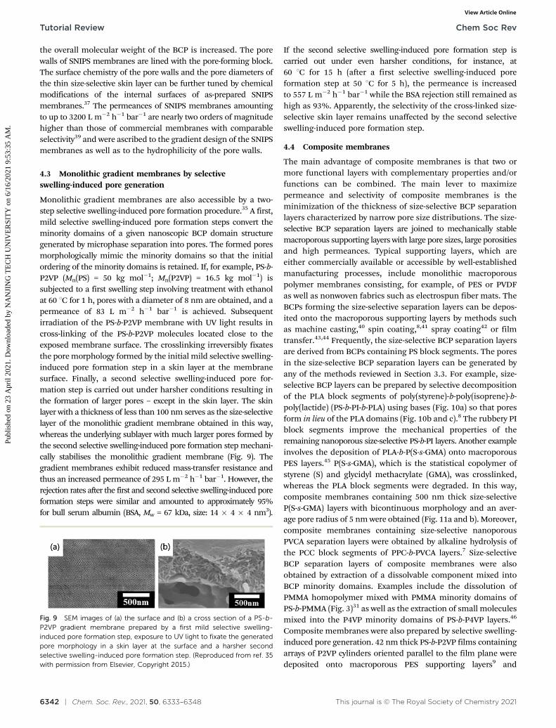
Monolithic gradient membranes are also accessible by a two-step selective swelling-induced pore formation procedure.35 A first,mild selective swelling-induced pore formation steps convert theminority domains of a given nanoscopic BCP domain structuregenerated by microphase separation into pores. The formed poresmorphologically mimic the minority domains so that the initialordering of the minority domains is retained. If, for example, PS-b-P2VP (Mn(PS) = 50 kg mol�1; Mn(P2VP) = 16.5 kg mol�1) issubjected to a first swelling step involving treatment with ethanolat 60 1C for 1 h, pores with a diameter of 8 nm are obtained, and apermeance of 83 L m�2 h�1 bar�1 is achieved. Subsequentirradiation of the PS-b-P2VP membrane with UV light results incross-linking of the PS-b-P2VP molecules located close to theexposed membrane surface. The crosslinking irreversibly fixatesthe pore morphology formed by the initial mild selective swelling-induced pore formation step in a skin layer at the membranesurface. Finally, a second selective swelling-induced pore for-mation step is carried out under harsher conditions resulting inthe formation of larger pores – except in the skin layer. The skinlayer with a thickness of less than 100 nm serves as the size-selectivelayer of the monolithic gradient membrane obtained in this way,whereas the underlying sublayer with much larger pores formed bythe second selective swelling-induced pore formation step mechani-cally stabilises the monolithic gradient membrane (Fig. 9). Thegradient membranes exhibit reduced mass-transfer resistance andthus an increased permeance of 295 L m�2 h�1 bar�1. However, therejection rates after the first and second selective swelling-induced poreformation steps were similar and amounted to approximately 95%for bull serum albumin (BSA, Mw = 67 kDa, size: 14 � 4 � 4 nm3).
If the second selective swelling-induced pore formation step iscarried out under even harsher conditions, for instance, at60 1C for 15 h (after a first selective swelling-induced poreformation step at 50 1C for 5 h), the permeance is increasedto 557 L m�2 h�1 bar�1 while the BSA rejection still remained ashigh as 93%. Apparently, the selectivity of the cross-linked size-selective skin layer remains unaffected by the second selectiveswelling-induced pore formation step.
4.4 Composite membranes
The main advantage of composite membranes is that two ormore functional layers with complementary properties and/orfunctions can be combined. The main lever to maximizepermeance and selectivity of composite membranes is theminimization of the thickness of size-selective BCP separationlayers characterized by narrow pore size distributions. The size-selective BCP separation layers are joined to mechanically stablemacroporous supporting layers with large pore sizes, large porositiesand high permeances. Typical supporting layers, which areeither commercially available or accessible by well-establishedmanufacturing processes, include monolithic macroporouspolymer membranes consisting, for example, of PES or PVDFas well as nonwoven fabrics such as electrospun fiber mats. TheBCPs forming the size-selective separation layers can be depos-ited onto the macroporous supporting layers by methods suchas machine casting,40 spin coating,8,41 spray coating42 or filmtransfer.43,44 Frequently, the size-selective BCP separation layersare derived from BCPs containing PS block segments. The poresin the size-selective BCP separation layers can be generated byany of the methods reviewed in Section 3.3. For example, size-selective BCP layers can be prepared by selective decompositionof the PLA block segments of poly(styrene)-b-poly(isoprene)-b-poly(lactide) (PS-b-PI-b-PLA) using bases (Fig. 10a) so that poresform in lieu of the PLA domains (Fig. 10b and c).8 The rubbery PIblock segments improve the mechanical properties of theremaining nanoporous size-selective PS-b-PI layers. Another exampleinvolves the deposition of PLA-b-P(S-s-GMA) onto macroporousPES layers.45 P(S-s-GMA), which is the statistical copolymer ofstyrene (S) and glycidyl methacrylate (GMA), was crosslinked,whereas the PLA block segments were degraded. In this way,composite membranes containing 500 nm thick size-selectiveP(S-s-GMA) layers with bicontinuous morphology and an aver-age pore radius of 5 nm were obtained (Fig. 11a and b). Moreover,composite membranes containing size-selective nanoporousPVCA separation layers were obtained by alkaline hydrolysis ofthe PCC block segments of PPC-b-PVCA layers.7 Size-selectiveBCP separation layers of composite membranes were alsoobtained by extraction of a dissolvable component mixed intoBCP minority domains. Examples include the dissolution ofPMMA homopolymer mixed with PMMA minority domains ofPS-b-PMMA (Fig. 3)31 as well as the extraction of small moleculesmixed into the P4VP minority domains of PS-b-P4VP layers.46
Composite membranes were also prepared by selective swelling-induced pore generation. 42 nm thick PS-b-P2VP films containingarrays of P2VP cylinders oriented parallel to the film plane weredeposited onto macroporous PES supporting layers9 and
Fig. 9 SEM images of (a) the surface and (b) a cross section of a PS-b-P2VP gradient membrane prepared by a first mild selective swelling-induced pore formation step, exposure to UV light to fixate the generatedpore morphology in a skin layer at the surface and a harsher secondselective swelling-induced pore formation step. (Reproduced from ref. 35with permission from Elsevier, Copyright 2015.)
subsequently treated with ethanol at 50 1C for different durationsto convert the P2VP cylinders into nanopores. Another exampleinvolves the transfer of 260 nm thick PS-b-P2VP films formed onwater surfaces onto macroporous PVDF supporting layers fol-lowed by selective swelling-induced pore formation.43
Although selectivity and permeance of composite membranesdepend by and large on the nature of the size-selective BCPmembrane layers, the underlying macroporous supporting layersmay also affect the permeance.8 The pore sizes of the
macroporous supporting layers should be as large as possibleso that the flow resistance is as weak as possible. Therefore, thedifference between the pore sizes of the size-selective BCPseparation layer and the macroporous supporting layer shouldbe as large as possible. However, if the pore size of the macro-porous supporting layer is too large so that too large portions ofthe size-selective BCP separation are unsupported, the size-selective BCP separation layer may partially collapse (Fig. 10c).Moreover, a certain portion of the pore openings of the size-selective BCP separation layers may impinge on the pore walls ofthe macroporous supporting layer. A significant number of suchdead-end pores may result in reduced permeance.8 To circumventthis problem, macroporous supporting layers with ultrahigh sur-face porosities having pore walls formed by sharp scaffolds areused. Finally, sufficient adhesion between the size-selective BCPseparation layers and the macroporous supporting layers isrequired to avoid delamination. Thus, besides the carefuldesign of the size-selective BCP separation layers, the support-ing layers must be carefully chosen also.
5. Applications of BCP ultrafiltrationmembranes
A large body of literature deals with the use of BCP separationmembranes for ultrafiltration. In the following, some representativeexamples are discussed.
The ultrafiltration performance of gradient membranesprepared by the SNIPS process was investigated intensively.For example, SNIPS membranes consisting of polystyrene-block-poly(2-hydroxyethyl methacrylate-stat-2-(succinyloxy)ethyl meth-acrylate) (PS-b-P(HEMA-s-SEMA)) contain pores lined with highlyhydrophilic P(HEMA-s-SEMA) block segments characterized byabundant –OH and –COOH groups.47 Aqueous solutions swellthe P(HEMA-s-SEMA) block segments so that the pore diameter ismarkedly reduced. As a result, BSA permeates monolithic PS-b-P(HEMA-s-SEMA) gradient membranes, whereas haemoglobin(size: 7 � 5.5 � 5.5 nm3) is rejected. In another example, poly-(2-(dimethylamino)ethyl methacrylate) (PDMAEMA) chains weregrafted on graphene oxide sheets, which were in turn mixedwith PS-b-P4VP. The PDMAEMA modification hydrophilized thegraphene oxide sheets and prevented their agglomeration. Mixturesof PS-b-P4VP and of up to 1.5 wt% PDMAEMA-modified grapheneoxide were used to prepare PS-b-P4VP/graphene oxide hybrid gra-dient membranes (Fig. 12a and b) with 200 nm thick size-selectivelayers containing straight aligned pores normal to the surface withan average diameter of 25 nm. The PS-b-P4VP/graphene oxidehybrid gradient membranes showed 1.6 times higher permeanceand enhanced anti-fouling properties as compared to the corres-ponding pure PS-b-P4VP SNIPS membranes, while BSA couldefficiently be separated from globulin-g (IgG, Mw = 150 kDa)(Fig. 12c).48 Deposition of polydopamine/cysteine onto SNIPSmembranes consisting of PS-b-P4VP improved the membranehydrophilicity and antifouling performance as well.49
Ultrafiltration using BCP-based composite membranes wasintensively studied also. For example, [P(S-s-GMA)]/PES composite
Fig. 10 Composite membrane with a nanoporous size-selective poly-(styrene)-b-poly(isoprene) (PS-b-PI) layer on a macroporous PES supportprepared by casting a PS-b-PI-b-PLA (PLA = poly(lactide)) film onto thePES support followed by the removal of the PLA block segments.(a) Schematic representation of the preparation and the structure.(b) SEM cross-sectional micrograph of a PS-b-PI/PES composite membrane.(c) Overlay of the SEM surface micrographs of the nanoporous PS-b-PI layerand the PES supporting material. (Reproduced from ref. 8 with permissionfrom the American Chemical Society, Copyright 2013).
Fig. 11 Composite membranes consisting of a size-selective nanoporouspoly[styrene-stat-(glycidyl methacrylate)] [P(S-s-GMA)] layer on a macro-porous PES supporting layer. (a and b) SEM micrographs of (a) a bare PESsupporting layer and (b) a nanoporous size-selective [P(S-ran-GMA)] layerdeposited on a PES supporting layer. (c) UV-vis absorbance spectra ofTRITC-dextran (M = 150 kg mol�1, r = 7 nm). The solid curve is thespectrum of the feed solution containing 0.5 mg mL�1 TRITC-dextranand the dashed curve the spectrum of the permeate. The rejection ratecalculated by comparing the absorbance of feed solution and permeate at521 nm amounted to 98%. The insets show photographs of (1) the feedsolution and (2) the permeate. (Reproduced from ref. 45 with permissionfrom the American Chemical Society, Copyright 2017).
membranes with 500 nm thick size-selective [P(S-s-GMA)] layers(Fig. 11a and b) had a water permeance of 7 L m�2 h�1 bar�1,which is much lower than that of the bare PES supporting layer(3700 L m�2 h�1 bar�1). However, the rejection of fluorescentTRITC-dextran (0.5 mg mL�1, M = 150 kg mol�1, hydrodynamicradius (r) = 7 nm) was determined to be 98% by UV-vis absorbancespectroscopy (Fig. 11c). Decreasing the thickness of the size-selective BCP layer to 150 nm resulted in an increased permeanceof 196 L m�2 h�1 bar�1, while the rejection of TRITC-dextrandropped to 96% as a signature of the trade-off effect.45 Otherexamples are composite membranes containing size-selectivePVCA separation layers obtained with PPC-b-PVCA as startingmaterial. The pore walls of the size-selective PVCA separationlayers were hydrophilized by ZrO2 coatings generated by abiomineralization process (Fig. 13a).7 For this purpose, thecatechol acetonide side groups of the PVCA chains were convertedto catechol side groups, which in turn chelated Zr4+ suppliedas acidic zirconium sulfate solution. Thus-obtained compositemembranes containing 200 nm thick size-selective PVCA–ZrO2
separation layers with a pore diameter of 12 nm had a permeanceas high as 114 � 4 L m�2 h�1 bar�1 (Fig. 13b). The permeance ofZrO2-functionalized membranes was about 5 times higher thanthat of composite membranes with untreated size-selective PVCAlayers. The retention capability of composite membranes contain-ing size-selective PVCA–ZrO2 separation layers was demonstratedby completely removing Au nanoparticles with a diameter of20 nm from aqueous dispersions (Fig. 13c), and their antifoulingproperties were demonstrated by protein adsorption experiments. The permeance of composite membranes consisting of 260 nm
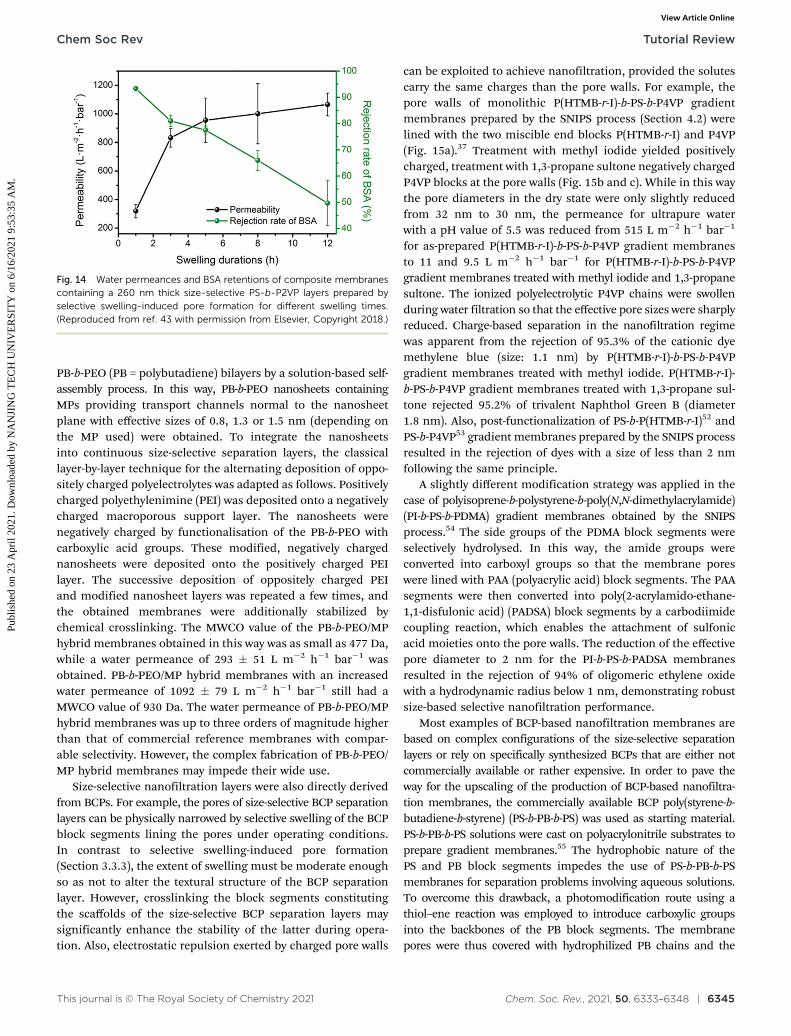
thick size-selective PS-b-P2VP separation layers prepared byselective-swelling-induced pore generation in ethanol at 55 1C for1 h and of macroporous PVDF supporting layers amounted to319 L m�2 h�1 bar�1 (Fig. 14).43 Extending the ethanol treatmentto 3 h resulted in an increased permeance of 832 L m�2 h�1 bar�1
attributed to the formation of larger pores. The rejection of BSA inturn declined from 93% to 81%. Further extension of the exposureto ethanol to 12 h resulted in a significantly enhanced permeanceof 1080 L m�2 h�1 bar�1, while the rejection of BSA fell to 50%.The performance of composite membranes can be optimized bymodifications of size-selective BCP layers prepared by selectiveswelling-induced pore formation. For example, the hydrophilicityof nanoporous PS-b-PDMAEMA membranes obtained by selectiveswelling-induced pore formation was increased by functionaliza-tion of the pore walls with zwitterions, resulting in several timeshigher permeances.50
6. BCP membranes for nanofiltration
The periods of the nanoscopic BCP domain structures, whichtemplate the pore formation in the course of the preparation ofBCP membranes, typically amount to a few 10 nm. Therefore,the direct preparation of nanofiltration membranes with effec-tive pore diameters of 2 nm or smaller using BCPs as startingmaterials is challenging. Instead of applying one of the classicalmechanisms for pore formation in BCPs reviewed in Section 3.3,Tu et al.51 introduced b-barrel membrane proteins (MPs) into
Fig. 12 Separation performance of PS-b-P4VP/graphene oxide hybridgradient membranes. (a and b) SEM images of (a) the surface and (b) across section of a PS-b-P4VP/graphene oxide hybrid gradient membrane.(c) Schematic diagram displaying the size-based separation of the proteinsBSA and IgG by PS-b-P4VP/graphene oxide hybrid gradient membranes.The details on the right display graphene oxide sheets, onto whichDMAEMA was grafted by free-radical polymerization after initial silaniza-tion and which were mixed into the PS-b-P4VP. (Reproduced from ref. 47with permission from the American Chemical Society, Copyright 2019).
Fig. 13 Composite membranes containing nanoporous size-selectivePVCA layers derived from PPC-b-PVCA, which were hydrophilized byfunctionalization with ZrO2. (a) Schematic diagram displaying the bio-mineralization process applied to functionalize the size-selective PVCAseparation layer with ZrO2, which involves chelation of Zr4+ in acidiczirconium sulfate solution by catechol groups obtained from the catecholacetonide side groups of the PVCA chains. (b) Water flux through non-mineralized (black) and ZrO2-modified (orange) composite membranes.(c) UV-vis spectra of an aqueous dispersion containing 20 nm goldnanoparticles (feed, upper photograph) and the filtrate after permeationthrough a ZrO2-mineralized composite membrane (lower photograph).(Reproduced from ref. 7 with permission from the American ChemicalSociety, Copyright 2018).
PB-b-PEO (PB = polybutadiene) bilayers by a solution-based self-assembly process. In this way, PB-b-PEO nanosheets containingMPs providing transport channels normal to the nanosheetplane with effective sizes of 0.8, 1.3 or 1.5 nm (depending onthe MP used) were obtained. To integrate the nanosheetsinto continuous size-selective separation layers, the classicallayer-by-layer technique for the alternating deposition of oppo-sitely charged polyelectrolytes was adapted as follows. Positivelycharged polyethylenimine (PEI) was deposited onto a negativelycharged macroporous support layer. The nanosheets werenegatively charged by functionalisation of the PB-b-PEO withcarboxylic acid groups. These modified, negatively chargednanosheets were deposited onto the positively charged PEIlayer. The successive deposition of oppositely charged PEIand modified nanosheet layers was repeated a few times, andthe obtained membranes were additionally stabilized bychemical crosslinking. The MWCO value of the PB-b-PEO/MPhybrid membranes obtained in this way was as small as 477 Da,while a water permeance of 293 � 51 L m�2 h�1 bar�1 wasobtained. PB-b-PEO/MP hybrid membranes with an increasedwater permeance of 1092 � 79 L m�2 h�1 bar�1 still had aMWCO value of 930 Da. The water permeance of PB-b-PEO/MPhybrid membranes was up to three orders of magnitude higherthan that of commercial reference membranes with compar-able selectivity. However, the complex fabrication of PB-b-PEO/MP hybrid membranes may impede their wide use.
Size-selective nanofiltration layers were also directly derivedfrom BCPs. For example, the pores of size-selective BCP separationlayers can be physically narrowed by selective swelling of the BCPblock segments lining the pores under operating conditions.In contrast to selective swelling-induced pore formation(Section 3.3.3), the extent of swelling must be moderate enoughso as not to alter the textural structure of the BCP separationlayer. However, crosslinking the block segments constitutingthe scaffolds of the size-selective BCP separation layers maysignificantly enhance the stability of the latter during opera-tion. Also, electrostatic repulsion exerted by charged pore walls
can be exploited to achieve nanofiltration, provided the solutescarry the same charges than the pore walls. For example, thepore walls of monolithic P(HTMB-r-I)-b-PS-b-P4VP gradientmembranes prepared by the SNIPS process (Section 4.2) werelined with the two miscible end blocks P(HTMB-r-I) and P4VP(Fig. 15a).37 Treatment with methyl iodide yielded positivelycharged, treatment with 1,3-propane sultone negatively chargedP4VP blocks at the pore walls (Fig. 15b and c). While in this waythe pore diameters in the dry state were only slightly reducedfrom 32 nm to 30 nm, the permeance for ultrapure waterwith a pH value of 5.5 was reduced from 515 L m�2 h�1 bar�1
for as-prepared P(HTMB-r-I)-b-PS-b-P4VP gradient membranesto 11 and 9.5 L m�2 h�1 bar�1 for P(HTMB-r-I)-b-PS-b-P4VPgradient membranes treated with methyl iodide and 1,3-propanesultone. The ionized polyelectrolytic P4VP chains were swollenduring water filtration so that the effective pore sizes were sharplyreduced. Charge-based separation in the nanofiltration regimewas apparent from the rejection of 95.3% of the cationic dyemethylene blue (size: 1.1 nm) by P(HTMB-r-I)-b-PS-b-P4VPgradient membranes treated with methyl iodide. P(HTMB-r-I)-b-PS-b-P4VP gradient membranes treated with 1,3-propane sul-tone rejected 95.2% of trivalent Naphthol Green B (diameter1.8 nm). Also, post-functionalization of PS-b-P(HTMB-r-I)52 andPS-b-P4VP53 gradient membranes prepared by the SNIPS processresulted in the rejection of dyes with a size of less than 2 nmfollowing the same principle.
A slightly different modification strategy was applied in thecase of polyisoprene-b-polystyrene-b-poly(N,N-dimethylacrylamide)(PI-b-PS-b-PDMA) gradient membranes obtained by the SNIPSprocess.54 The side groups of the PDMA block segments wereselectively hydrolysed. In this way, the amide groups wereconverted into carboxyl groups so that the membrane poreswere lined with PAA (polyacrylic acid) block segments. The PAAsegments were then converted into poly(2-acrylamido-ethane-1,1-disfulonic acid) (PADSA) block segments by a carbodiimidecoupling reaction, which enables the attachment of sulfonicacid moieties onto the pore walls. The reduction of the effectivepore diameter to 2 nm for the PI-b-PS-b-PADSA membranesresulted in the rejection of 94% of oligomeric ethylene oxidewith a hydrodynamic radius below 1 nm, demonstrating robustsize-based selective nanofiltration performance.
Most examples of BCP-based nanofiltration membranes arebased on complex configurations of the size-selective separationlayers or rely on specifically synthesized BCPs that are either notcommercially available or rather expensive. In order to pave theway for the upscaling of the production of BCP-based nanofiltra-tion membranes, the commercially available BCP poly(styrene-b-butadiene-b-styrene) (PS-b-PB-b-PS) was used as starting material.PS-b-PB-b-PS solutions were cast on polyacrylonitrile substrates toprepare gradient membranes.55 The hydrophobic nature of thePS and PB block segments impedes the use of PS-b-PB-b-PSmembranes for separation problems involving aqueous solutions.To overcome this drawback, a photomodification route using athiol–ene reaction was employed to introduce carboxylic groupsinto the backbones of the PB block segments. The membranepores were thus covered with hydrophilized PB chains and the
Fig. 14 Water permeances and BSA retentions of composite membranescontaining a 260 nm thick size-selective PS-b-P2VP layers prepared byselective swelling-induced pore formation for different swelling times.(Reproduced from ref. 43 with permission from Elsevier, Copyright 2018.)
modified size-selective PS-b-PB-b-PS separation layers enabledefficient water purification. Although the membranes had aneffective pore size of 4.4 nm based on the estimation of PEOrejections, the rejection rates of methyl orange (molecular mass is327 g mol�1) and brilliant blue (molecular mass is 826 g mol�1)amounted to up to 74% and 100%, respectively. The nanofiltrationcapability of the modified PS-b-PB-b-PS membranes relies onelectrostatic repulsion rather than on size-based separation asboth the carboxyl groups of the modified PB block segmentsand the two selected model dyes are negatively charged.
7. Conclusions and perspectives
Removing hazardous nanoparticulate contaminants, biologicalor synthetic macromolecules and viruses from fluids such aswater and air is a technical challenge, the importance of whichcannot be underestimated. Corresponding purification processesare crucial for the sufficient supply of clean water for a growingworld population, but also for the containment of diseasesspreading by transmission of viruses. Separation membranesfor water and air purification should be characterized by highseparation selectivity and high permeance. However, the designof separation membranes typically involves a trade-off betweenpermeance and selectivity. Structural features favouring highpermeance such as large pore sizes reduce selectivity. Small poresizes ensure high selectivity but reduce permeance. The use ofBCPs as a material platform for the manufacturing of separationmembranes may reconcile high permeance with high selectivitybecause BCPs combine the high manufacturing flexibility ofpolymers with the possibility to generate tailored pore systems.The pore systems in BCP separation membranes are derived fromthe ordered nanoscopic domain structures the BCPs form bymicrophase separation. Conversion of the ordered nanoscopicBCP domain structures into pores may accomplished by selectivedegradation of block segments forming the BCP minoritydomains, by extraction of dissolvable species from BCP minoritydomains or by swelling-induced pore formation. Membraneconfigurations combining high permeance and high selectivitycontain thin size-selective BCP separation layers with a thicknessnot exceeding a few 100 nm, with pores having a tailoreddiameter in the sub-100 nm range and with a sharp pore sizedistribution. Free-standing and unsupported thin size-selectiveBCP separation layers with sufficiently high porosity aremechanically not robust enough under operating conditions.Therefore, thin size-selective BCP separation layers are typicallyintegrated into monolithic gradient membrane configurationsor into composite membrane architectures. In both cases,macroporous layers with high permeance mechanically supportthe thin size-selective BCP separation layers. The advantages ofBCP membranes are summarized in Table 1.
BCP-based monolithic gradient membranes and compositemembranes with thin size-selective BCP separation layers showpromising separation performances in the ultrafiltration regime,while their applicability in the nanofiltration regime is limited.However, so far, the investigation of BCP-based separation
Fig. 15 P(HTMB-r-I)-b-PS-b-P4VP gradient membranes prepared by theSNIPS process featuring positively charged or negatively charged porewalls. (a) Schematic illustration of the formation mechanism. Treatmentwith methyl iodide yielded pore walls containing positively chargedP4VP block segments, treatment with 1,3-propane sultone pore wallscontaining negatively charged P4VP block segments. (b and c) Schematicrepresentations, chemical structures and SEM images of the top surfacesas well as the cross-sections (b) of P(HTMB-r-I)-b-PS-b-P4VP gradientmembranes treated with methyl iodide and (c) of P(HTMB-r-I)-b-PS-b-P4VP gradient membranes treated with 1,3-propane sultone. (Reproducedfrom ref. 37 with permission from Wiley-VCH, Copyright 2020.)
membranes has predominantly been limited to well-designedtest scenarios using selected test solutes in laboratory environ-ments. In contrast, real-life application scenarios have rarely beenstudied. One example involves the use of PSF-b-PEG ultrafiltra-tion membranes for hemodialysis,56 suggesting that BCP-basedmembrane systems may by applied in high-added-value fieldssuch as health care. Until now, the manufacturing costs of BCP-based separation membranes are relatively high because BCPs asstarting materials are relatively expensive. The production ofaffordable BCP-based separation membranes is still a challenge.Moreover, most of the BCPs currently used for the preparation ofseparation membranes contain PS block segments that form themembrane scaffold. Hence, the glass transition temperature ofPS (B100 1C for bulk PS) limits the temperature range withinwhich PS-containing BCP separation membranes can be used. Ifpurification processes are carried out at elevated temperatures,BCP-based separation membranes may lack the required thermalstability. BCPs containing PSF block segments with a glasstransition temperature of nearly 190 1C as scaffold-formingcomponent may mitigate this drawback. PSF-b-PEG as startingmaterial for membrane production may yield affordable andmechanically robust BCP membranes.36 However, further effortsare required to narrow the pore size distribution of PSF-b-PEGseparation membranes to improve their separation selectivity.36
Finally, it should be noted that most BCP-based separationmembrane configurations are produced in the form of flat sheets.It would be rewarding to integrate BCP separation layers intoother geometries such as hollow-fibre membranes that may allowoptimization of throughput and better device integration.15
Conflicts of interest
There are no conflicts to declare.
Acknowledgements
L. G. and M. S. acknowledge support by the European ResearchCouncil (ERC-CoG-2014, Project 646742 INCANA). Y. W. thanksfinancial support by National Science Fund for DistinguishedYoung Scholars (21825803).
Notes and references
1 M. Elimelech and W. A. Phillip, Science, 2011, 333, 712–717.2 M. I. F. Mota, P. C. Rodrigues Pinto, J. M. Loureiro and
A. E. Rodrigues, Sep. Purif. Rev., 2016, 45, 227–259.
3 P. S. Goh and A. F. Ismail, Graphene-based membranes formass transport applications, The Royal Society of Chemistry,UK, 2019.
4 W. J. Koros, Y. H. Ma and T. Shimidzu, Pure Appl. Chem.,1996, 68, 1479–1489.
5 D. M. Wang and J. Y. Lai, Curr. Opin. Chem. Eng., 2013, 2,229–237.
6 T. J. Ma, J. M. Janot and S. Balme, Small Methods, 2020, 4,2000366–2000401.
8 S. E. Querelle, E. A. Jackson, E. L. Cussler and M. A.Hillmyer, ACS Appl. Mater. Interfaces, 2013, 5, 5044–5050.
9 L. Guo and Y. Wang, Chem. Commun., 2014, 50, 12022–12025.10 J. R. Werber, C. O. Osuji and M. Elimelech, Nat. Rev. Mater.,
2016, 1, 16018–16032.11 M. Zhang, Y. Mao, G. Liu, G. Liu, Y. Fan and W. Jin, Angew.
Chem., Int. Ed., 2020, 59, 1689–1695.12 E. A. Jackson and M. A. Hillmyer, ACS Nano, 2010, 4,
3548–3553.13 Y. Wang, Acc. Chem. Res., 2016, 49, 1401–1408.14 S. P. Nunes, Macromolecules, 2016, 49, 2905–2916.15 M. Radjabian and V. Abetz, Prog. Polym. Sci., 2020, 102,
101219–101256.16 J. Zhou and Y. Wang, Macromolecules, 2020, 53, 5–17.17 N. Hampu, J. R. Werber, W. Y. Chan, E. C. Feinberg and
M. A. Hillmyer, ACS Nano, 2020, 14, 16446–16471.18 S. Singh, K. C. Khulbe, T. Matsuura and P. Ramamurthy,
J. Membr. Sci., 1998, 142, 111–127.19 D. Venturoli and B. Rippe, Am. J. Physiol.: Renal, Fluid
Electrolyte Physiol., 2005, 288, F605–F613.20 E. A. Jackson, Y. Lee and M. A. Hillmyer, Macromolecules,
2013, 46, 1484–1491.21 D. M. Kanani, W. H. Fissell, S. Roy, A. Dubnisheva, A. Fleischman
and A. L. Zydney, J. Membr. Sci., 2010, 349, 405–410.22 H. B. Park, J. Kamcev, L. M. Robeson, M. Elimelech and
B. D. Freeman, Science, 2017, 356, eaab0530.23 W. M. Deen, AIChE J., 1987, 33, 1409–1425.24 F. S. Bates and G. H. Fredrickson, Phys. Today, 1999, 52,
32–38.25 V. Abetz, N. Hadjichristidis, H. Iatrou, M. Pitsikalis and
P. F. W. Simon, Block Copolymers, Springer, Berlin/Heidel-berg, Germany, 2005.
26 P. van de Witte, P. J. Dijkstra, J. W. A. van den Berg andJ. Feijen, J. Membr. Sci., 1996, 117, 1–31.
27 W. Sun, Z. Wang, X. Yao, L. Guo, X. Chen and Y. Wang,J. Membr. Sci., 2014, 466, 229–237.
Table 1 Advantages of BCP membranes for water purification
Advantage High selectivity High permeance Good hydrophilicityand antifouling
28 K.-V. Peinemann, V. Abetz and P. F. W. Simon, Nat. Mater.,2007, 6, 992–996.
29 A. S. Zalusky, R. Olayo-Valles, J. H. Wolf and M. A. Hillmyer,J. Am. Chem. Soc., 2002, 124, 12761–12773.
30 T. Thurn-Albrecht, R. Steiner, J. DeRouchey, C. M. Stafford,E. Huang, M. Bal, M. Tuominen, C. J. Hawker and T. Russell,Adv. Mater., 2000, 12, 787–791.
31 S. Y. Yang, I. Ryu, H. Y. Kim, J. K. Kim, S. K. Jang andT. P. Russell, Adv. Mater., 2006, 18, 709–712.
32 A. Sidorenko, I. Tokarev, S. Minko and M. Stamm, J. Am.Chem. Soc., 2003, 125, 12211–12216.
33 Y. Wang, C. He, W. Xing, F. Li, L. Tong, Z. Chen, X. Liao andM. Steinhart, Adv. Mater., 2010, 22, 2068–2072.
34 Y. Boontongkong and R. E. Cohen, Macromolecules, 2002,35, 3647–3652.
35 Z. Wang, L. Guo and Y. Wang, J. Membr. Sci., 2015, 476,449–456.
36 Z. Wang, R. Liu, H. Yang and Y. Wang, Chem. Commun.,2017, 53, 9105–9108.
37 Z. Zhang, M. M. Rahman, C. Abetz, A.-L. Hohme, E. Sperlingand V. Abetz, Adv. Mater., 2020, 32, 1907014–1907023.
38 V. Abetz, Macromol. Rapid Commun., 2015, 36, 10–22.39 X. Qiu, H. Yu, M. Karunakaran, N. Pradeep, S. P. Nunes and
K.-V. Peinemann, ACS Nano, 2013, 7, 768–776.40 X. Shi, Z. Wang and Y. Wang, J. Membr. Sci., 2017, 533,
201–209.41 H. Yang, Z. Wang, Q. Lan and Y. Wang, J. Membr. Sci., 2017,
542, 226–232.42 D. Ma, J. Zhou, Z. Wang and Y. Wang, J. Membr. Sci., 2020,
598, 117656–117662.43 N. Yan, Z. Wang and Y. Wang, J. Membr. Sci., 2018, 568,
40–46.
44 X. Shi, Z. Xu, C. Huang, Y. Wang and Z. Cui, Macromolecules,2018, 51, 2283–2292.
45 T. Vidil, N. Hampu and M. A. Hillmyer, ACS Cent. Sci., 2017,3, 1114–1120.
46 B. P. Tripathi, N. C. Dubey, S. Choudhury, F. Simon andM. Stamm, J. Mater. Chem. B, 2013, 1, 3397–3409.
47 R. Shevate, M. Kumar, H. Cheng, P.-Y. Hong, A. R. Behzad,D. Anjum and K.-V. Peinemann, ACS Appl. Mater. Interfaces,2019, 11, 8507–8516.
48 J. Wang, M. M. Rahman, C. Abetz and V. Abetz, J. Membr.Sci., 2020, 604, 118074–118082.
49 R. Shevate, M. Kumar, M. Karunakaran, M. N. Hedhili andK.-V. Peinemann, J. Membr. Sci., 2017, 529, 185–194.
50 C. Zhang, C. Yin, Y. Wang, J. Zhou and Y. Wang, J. Membr.Sci., 2020, 599, 117833–117840.
51 Y.-M. Tu, W. Song, T. Ren, Y.-X. Shen, R. Chowdhury,P. Rajapaksha, T. E. Culp, L. Samineni, C. Lang, A. Thokkadam,D. Carson, Y. Dai, A. Mukthar, M. Zhang, A. Parshin, J. N. Sloand,S. H. Medina, M. Grzelakowski, D. Bhattacharya, W. A. Phillip,E. D. Gomez, R. J. Hickey, Y. Wei and M. Kumar, Nat. Mater., 2020,19, 347–354.
52 Z. Zhang, M. M. Rahman, C. Abetz and V. Abetz, J. Mater.Chem. A, 2020, 8, 9554–9566.
53 Z. Zhang, M. M. Rahman, C. Abetz, B. Bajer, J. Wang andV. Abetz, Macromol. Rapid Commun., 2019, 40, 1800729–1800735.
54 Y. Zhang, R. A. Mulvenna, S. Qu, B. W. Boudouris andW. A. Phillip, ACS Macro Lett., 2017, 6, 726–732.
55 B. Sutisna, G. Polymeropoulos, V. Musteata, R. Sougrat, D.-M. Smilgies, K.-V. Peinemann, N. Hadjichristidis andS. P. Nunes, Small, 2018, 14, 1701885–1701895.
56 D. Zhong, Z. Wang, J. Zhou and Y. Wang, J. Membr. Sci.,2021, 618, 118690–118698.