CC-STEADY STATE CC- DYNAMICS CC-THERM CC-BATCH CC-SAFETY NET CC-FLASH Functionality 9 9 9 9 9 9 Design New Processes 9 9 9 9 9 9 Model Existing Processes 9 9 9 9 9 9 Optimize/Debottleneck Existing Processes 9 9 9 9 9 9 HAZOP Analysis 9 9 9 DIERS Analysis 9 9 9 9 9 9 Environmental Analysis 9 9 9 9 9 9 Process Expansion modelling 9 9 Economic Feasibility studies 9 9 Control System Design/Testing 9 9 Advanced Process Control 9 9 Plant Data Reconciliation 9 9 Operator Training Systems (OTS) 9 Build CHEMCAD simulations which interact with any 3rd party HMI/SCADA/OTS interface as a rigorous, first principles-based simulated plant 9 Train on generic models or build CHEMCAD simulations that mimic your actual processes 9 9 Real Time Optimization (RTO) 9 9 Use CHEMCAD's internal optimizer or any proprietary/third party optimizer to improve plant performance based on results of CHEMCAD simulations 9 9 Open or closed loop operation 9 9 Process/Plant Performance Monitoring (PPM) 9 9 Monitor specific unit performance (heat exchanger fouling, distillation column efficiency, etc) 9 9 Display performance directly to operation staff on any HMI/SCADA display 9 9 Inferential / Soft sensor 9 9 Open or closed loop operation: use any PLC/DCS control loop interact directly with CHEMCAD variables 9 9 9 9 9 9 Day to Day Engineering Calculations 9 9 9 9 9 9 Physical/Thermophysical property calculations 9 9 9 9 9 What ifs/Process Sensitivity/Process Scenarios 9 9 9 9 9 Model Single Unit Operations or Groups of Unit Operations 9 9 9 9 9 Equipment Design/Rating 9 9 9 9 9 Process Development 9 9 9 9 9 Lab Scale 9 9 9 9 9 Pilot Scale 9 9 9 9 9 Full Scale 9 9 9 9 9 Scale Up between the above CHEMCAD Version 6.2.2
Transcript
CC-STEADY STATE
CC-DYNAMICS CC-THERM CC-BATCH
CC-SAFETY NET CC-FLASH
FunctionalityDesign New ProcessesModel Existing ProcessesOptimize/Debottleneck Existing ProcessesHAZOP Analysis
DIERS AnalysisEnvironmental AnalysisProcess Expansion modellingEconomic Feasibility studiesControl System Design/TestingAdvanced Process Control
Plant Data ReconciliationOperator Training Systems (OTS)
Build CHEMCAD simulations which interact with any 3rd party HMI/SCADA/OTS interface as a rigorous, first principles-based simulated plantTrain on generic models or build CHEMCAD simulations that mimic your actual processes
Real Time Optimization (RTO)Use CHEMCAD's internal optimizer or any proprietary/third party optimizer to improve plant performance based on results of CHEMCAD simulationsOpen or closed loop operation
Process/Plant Performance Monitoring (PPM)Monitor specific unit performance (heat exchanger fouling, distillation column efficiency, etc)Display performance directly to operation staff on any HMI/SCADA displayInferential / Soft sensorOpen or closed loop operation: use any PLC/DCS control loop interact directly with CHEMCAD variables
Day to Day Engineering CalculationsPhysical/Thermophysical property calculationsWhat ifs/Process Sensitivity/Process ScenariosModel Single Unit Operations or Groups of Unit Operations
Equipment Design/RatingProcess Development
Lab ScalePilot ScaleFull ScaleScale Up between the above
CHEMCAD Version 6.2.2
CC-STEADY STATE
CC-DYNAMICS CC-THERM CC-BATCH
CC-SAFETY NET CC-FLASH
Utility System Design/TestingUnit Operations
DistillationShortcut and rigorousMultiple column arrangementsFlexible specificationsSimultaneous Correction and Rigorous Inside Out algorithmsSupport for more than 500 theoretical stagesThree phase distillationScrubbing and strippingMass transfer based distillation for packed and tray-ed columns
Automatically calculates the component diffusivitiesRigorous calculation of the mass transfer coefficient
User editable database of packing data from packing manufacturersCalculation of ambient heat lossColumn Autoconvergence
Automatic estimation to assist column convergence optionOptimization for infeasible design specifications optionColumn Diagnosis Report for unconverged columns
Pumparounds to move liquid flow to higher stages in a distillation columnWater Quench option to accelate calculation for Hydrocarbon-Water systemTotal, Partial, Total with Decant and Partial with Decant condersersSide strippers to draw liquid from one column stage and return vapor to a column stage aboveSide Heat Exchangers option at any column locationTray by tray tabular and plotted outputReactive Distillation
Reactions may be equilibrium or kinetic equation basedReactions solved simultaneously with VLEFlexible rate form, including user addedPurity and temperature specificationsUp to 300 reactionsVapor and/or liquid reactions are permitted
Batch DistillationGeneral Features:
Graphical plotting of time dependent results
Online, real-time display of results during calculation
CC-STEADY STATE
CC-DYNAMICS CC-THERM CC-BATCH
CC-SAFETY NET CC-FLASH
Calculation interrupt
Full integration into the CHEMCAD Suite and flowsheets
Column Features:Any number of operating steps
Up to 500 theoretical stages
Reservoir feeds
Side product accumulators
Stage heaters and coolers
Stage and condenser hold-ups (stage holdup profiles)
Simultaneous Correction and Rigorous Inside Out algorithms
Rigorous column sizing for trayed and packed columns available at the end of each operating step
Operating Step Options:Startup from total reflux or from fixed liquid on all stages
Specifications may include a variety of options for the distillate, boil-up, reflux, condenser, and heat duties
Dump accumulators at any time
Add material at any time
Stop criterion may be based on the accumulator, distillate, residual charge, or time
User-defined pressure profile (linear or non-linear)
Alternate stop criteria permitted
Dynamic DistillationColumn Features:
Can begin the simulation as a startup or from a steady-state condition
Holdups can be:
ignored
constant or variable
liquid and/or vapor
specified in mass, molar or volumetric units
specified for the condenser, reboiler, or any stages
specified on each stage
Pressure can be fixed or calculated
Simulation can be performed using rigorous mass transfer analysis or using the equilibrium stage approach
Packed columns can be calculated using rigorous mass transfer analysis or assuming equilibrium stages
Multiple liquid phases
Discrete event scheduler
Pressure drop calculations included
Reactive distillation allowed
CC-STEADY STATE
CC-DYNAMICS CC-THERM CC-BATCH
CC-SAFETY NET CC-FLASH
Calculation of ambient heat loss
Start-up Features:Dry or Wet tray startups
Fixed or variable pressure
May specify startup duration time and reboiler duty
Open or closed loop control simulation
Condenser Features:Holdup can be:
Constant or variable
Specified in mass, mole or volume units
Set by a control valve
Reflux can be:
Specified in mass, mole or volume units
Set by a control valve
Distillate can be:
Specified in mass, mole, or volume units
Set by a control valve
Condenser U*A can be set; cooling fluid flow rates can be fixed or controlled
Reboiler Features:Holdup can be variable or constant
Bottoms liquid product rate can be:
Specified in mass, mole, or volume units
Set by a control valve
Reboiler U*A can be set; heating fluid flow rates can be fixed or controlled
Reboiler vessel options:
Orientation
Head type
Diameter and length
Initial liquid level
Simulation Without Controllers:Condenser/Reboiler specification options:
CC-STEADY STATE
CC-DYNAMICS CC-THERM CC-BATCH
CC-SAFETY NET CC-FLASH
Reflux/Reboil ratio or rate
Heat duty
Temperature
Flow rate
Component flow rate
Purity
Recovery
Component recovery
Component ratios
Side product specification options:
Liquid or vapor flows
Liquid or vapor draw ratios
Complete stage information
Graphical and tabular time history for:
Condenser and reboiler
Any stage
ReactorsCan be specified adibatic, isothermal, and heat duty thermal modeStoichiometric
User can specify stoichiometric coefficients for up to 105 componentsUser can specify heat of reaction reference state (Ideal gas state or Liquid state)
EquilibriumUnit calculates the Overall IG Heat of Reaction and the Overall Liquid Heat of ReactionUp to 300 simultaneous reactionsUser can specify reaction engineering unitsReversibility or no-reversibility convergence optionsUser can specify heat of reaction temperature referenceReactor Model
General equilibrium reactor
Water-gas shift
Methanation
Calculation ModeParallel or inseries reaction conversions
Aproach temperature gradient
Aproach fraction
Kx or Ka liquid equilibrium models
CC-STEADY STATE
CC-DYNAMICS CC-THERM CC-BATCH
CC-SAFETY NET CC-FLASH
Gibbs free energy minimizationUnit calculates heat of reaction and lambdaAir/Oxygen calculation for combustion processesModel solid conbustionInert specificationAllows vapor/mix or liquid only reaction phases
Kinetic (PFR or CSTR)Allows liquid holdup calculations for dynamics simulationUnit calculates Utility Temperature, Overall IG heat of reaction, and Overall Liquid Heat of ReactionUser can specify reaction engineering unitsUser can specify heat of reaction temperature referenceUnlimited simultaneous reactionsFlexible rate form, including user addedReactor Model
Allows for Liquid, vapor or mixed phases reaction
User can specify PFR temperature profile
User can specify PFR utility
Option to specify actual reaction volume
Calculation modesSpecify volume to calculate conversion
Specify conversion to calculate volume
Specify utility flow (co-corrunt or countercurrent for a PFR)
Reactor Calculations:Reactor Temperature
Reactor Pressure
Wall Temperature
Heat Rate
Reaction Heat Rate
Liquid Level
Overall Heat
Overall Heat of Reaction
Option to include compression and expansion effectUser can specify rate equation unitsGeneral Features
Graphical plotting of time dependent results
Graphical plotting of time calculated results
CC-STEADY STATE
CC-DYNAMICS CC-THERM CC-BATCH
CC-SAFETY NET CC-FLASH
Display of results during calculation
Thermal ModesSpecify time vs. temperature profile
Specify jackets/coils
Specify time/heat duty profile
Specify vapor rate and pressure to calculate duty
Chemical DesignUnlimited number of species
Unlimited number of simultaneous reactions
Choice of Arrhenius, Langmuir-Hinshelwood, or user added rate equation forms
Regression of kinetic process data
Reactor DesignMultiple Coils and jackets
Service or process side heat exchangers and electric heaters
Heat transfer rate calculation; includes calculation of process and service side film coefficients
Vapor and liquid draws permitted
Batch, semi-batch or continuous operation
User specifed reactor holdup
Vessel pressurization calculated
Auxiliary EquipmentOther unit operations may be used with the batch reactor to flexibly model the process
Control SystemUser specified PID loops
Multiple ramp or step changes in setpoint
Control of reactor or jacket temperature differential
Level controllers
Pressure controllers
Cascade control
Heat-cool-chill system with safety interlocks
Split range controllers
Kinetic Data RegressionCan regress any combination of concentration, temperature volume and/or heat of reaction (Qr) data
Can fit multiple experiments in a single regression analysis
Can calculate the frequency factor, activation energy, component reaction order, Langmuir absorption parameters
Offers a variety of numerical methods to ensure that the regression is fast, accurate and can handle stiff systems
Accepts data from a wide range of calorimeters including the Mettler RC1 for which special features are provided
CC-STEADY STATE
CC-DYNAMICS CC-THERM CC-BATCH
CC-SAFETY NET CC-FLASH
Graphical and tabular comparison of experimental and predicted results makes it easy for the user to evaluate the validity of the model
Diers Analysis FacilityOutput
Graphical and tabular time history reports for:
Compositions
Pressure
Temperature
Heat of reaction
Utility flow rates
Liquid volume
Reaction mass physical properties
Rates of formation
Yields
Conversions
Calculator / ParserUser customizable unit operationAllows use of C parser file to perform heat and mass balance for unit operationUser customizable input / output dialogFlowsheet unit operations can interact with the unit operation results
Component separatorBlack-box separatorSplits input stream into 2 output streams (Top annd bottom)Different compositions and thermal conditionsUser specified
TemperatureBuble Point Temperature
Dew Point Temperature
Degrees Subcooled
Degrees Superheat
Pressure OutPressure Drop
Split BasisSplit Fractions
Mass Flow Rates
Solids Split (Electrolytes Only)
CC-STEADY STATE
CC-DYNAMICS CC-THERM CC-BATCH
CC-SAFETY NET CC-FLASH
Split DestinationSpecifications refer to top product
Specifications refer to bottom product
Compressor / Expander (Turbine)Simulates isentropic or polytropic compression/expansionMode of Operation
Specify Outlet Pressure and EfficiencySpecify Actual Work and EfficiencySpecify Pout/Pin and EfficiencySpecify Pressure Out and Actual WorkSpecify Pressure Out, Actual Work, and EfficiencySpecify Permance Curves
Calculation OptionFixed Flowrate, Calculate Pressure OutPressure Out from Downstream UnitOp, Calculate Flowrate
UnitSpecify Head in Length UnitSpecify Pressure Change
Muliple Performance CurvesNumber of Speed LinesActual RPM
Controller (Goal Seeker)Numerical controller similar to solver routineModes
Feed-ForwardSet Stream or UnitOp Variable
Equal to Stream or UnitOp Variable
Add Stream or Equipment Variable
Subtract Stream or Equipment Variable
Multiply Stream or Equipment Variable
Divide Stream or Equipment Variable
Log (a)
Exp (a)
Power (a^b)
Select Hi
Select Low
Discretize
Inverval in Minutes
Lag1
Specify Gain
Specify Lag Time
Lead-Lag
Specify Gain
CC-STEADY STATE
CC-DYNAMICS CC-THERM CC-BATCH
CC-SAFETY NET CC-FLASH
Specify Lag Time
Specify Lead Time
Dead Time
Feed-BackwardAdjust Stream or UnitOp Variable
Until Stream or UnitOp Variable
Add Stream or Equipment Variable
Subtract Stream or Equipment Variable
Multiply Stream or Equipment Variable
Divide Stream or Equipment Variable
Log (a)
Exp (a)
Power (a^b)
Select Hi
Select Low
Discretize
Inverval in Minutes
Lag1
Specify Gain
Specify Lag Time
Lead-Lag
Specify Gain
Specify Lag Time
Specify Lead Time
Dead Time
Equals
Stream Variable
Equipment Variable
Constant
Set to scale
Control ValveCalculates flow rate through valve based on output signal from controllerEspecially useful for dynamic simulation with PID controllerIn Steady State, can calculate flow as function of position, or position as function of flowHandles compressible and incompressible flowHandles critical and sub-critical flow
CC-STEADY STATE
CC-DYNAMICS CC-THERM CC-BATCH
CC-SAFETY NET CC-FLASH
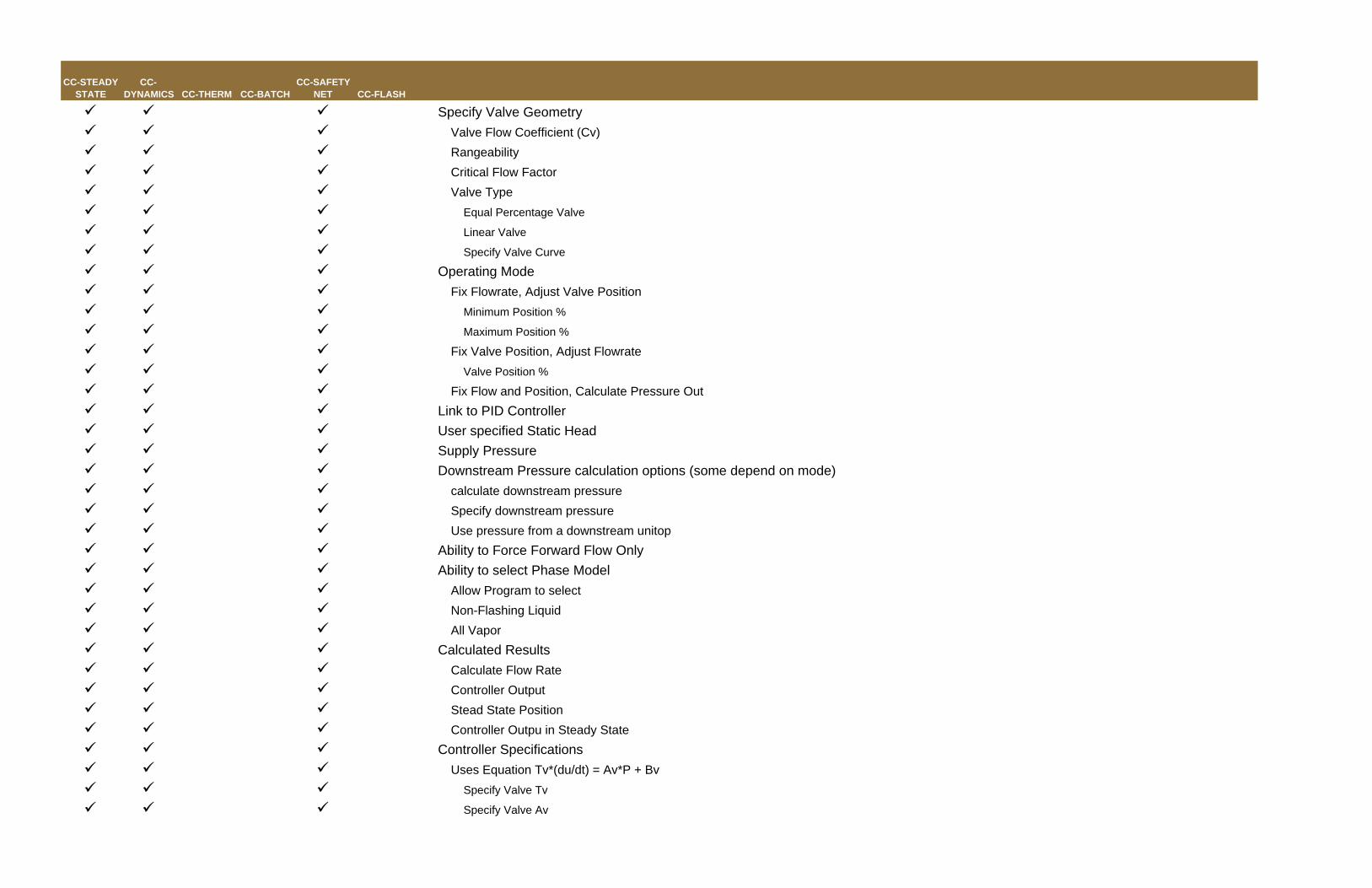
Specify Valve GeometryValve Flow Coefficient (Cv)RangeabilityCritical Flow FactorValve Type
Equal Percentage Valve
Linear Valve
Specify Valve Curve
Operating ModeFix Flowrate, Adjust Valve Position
Minimum Position %
Maximum Position %
Fix Valve Position, Adjust FlowrateValve Position %
Fix Flow and Position, Calculate Pressure OutLink to PID ControllerUser specified Static HeadSupply PressureDownstream Pressure calculation options (some depend on mode)
calculate downstream pressureSpecify downstream pressureUse pressure from a downstream unitop
Ability to Force Forward Flow OnlyAbility to select Phase Model
Allow Program to selectNon-Flashing LiquidAll Vapor
Calculated ResultsCalculate Flow RateController OutputStead State PositionController Outpu in Steady State
NormalPower FailureManually CloseManually OpenManually Set Valve Position
Optional Mass Flow Rate Transfer (send calculated flow rate to another unit operation)Specify Equipment IDSelect Variable
DividerSplits one stream into many streamsOutlet streams have same composition and intensive propertiesSplit flows based on
Flow ratioMolar flow rateBack-calculated feed rateMass flow rateFlow units defined below (user-specified )
Excel UnitUser customizable unit operation using a Microsoft Excel spreadsheet as a unit operationAllows use of Excel VBA for additional customization with access to CHEMCAD function librariesUser customizable input / output dialogFlowsheet unit operations can interact with the unit operation results
Fired heaterCalculates fuel usage required to heat process stream to specified temperatureHeating value of fuel gas can be input by user (default 900 BTU/scf)If calc. heat duty to heat stream > rated heat duty of heater, output T of stream is reduced accordinglyOption for phase separation (multiple outlets)Specify temperature outOptional inputs
Use inlet T and P; calculate V/F and HeatSpecify V/F and P; calculate T and Heat
CC-STEADY STATE
CC-DYNAMICS CC-THERM CC-BATCH
CC-SAFETY NET CC-FLASH
Specify T and P; calculate V/F and HeatSpecify T and H; calculate V/F and PSpecify V/F and T; calculate P and HeatSpecify P and H; calculate V/F and TSpecify P; isentropic flashSpecify T; isentropic flashSpecify P; water dew point T (H 2O/HC)Specify T; water dew point P (H 2O/HC)
Cost EstimationsSpecify
Type
Horizontal Pressure Vessel
Vertical Pressure Vessel
Storage Tank
Diameter
Length
Vessel Thickness
Head Thickness
Straight Flange
Head Type
Ellipsoidal
Hemispherical
Bumped (F and D)
Flat
Vessel Material
Carbon Steel
Stainless steel 304
Stainless steel 316
Carpenter 20CB-3
Nickel 200
Monel 400
Inconel 600
Incoloy 825
Titanium
Metal Density
Storage tank material
CC-STEADY STATE
CC-DYNAMICS CC-THERM CC-BATCH
CC-SAFETY NET CC-FLASH
Carbon Steel
Stainless steel 316
Stainless steel 304
Stainless steel 347
Heat exchangerSimple Heat Exchanger
Modeled by Q=U*A*LMTDCan specify pressure dropDesign mode - specify 1 of the following
Two Sided Heat ExchnagerDesign CaseRating CaseUtilityCalculation Mode
CHEMCAD simulation
Backcalc mode (for Autocalc)
Utility Option
Off
Calculate Flow of stream 1
Calculate Flow of stream 2
Specifications
Temperature of hot stream out
Temperature of cold stream out
Vapor fraction of hot stream out
Vapor fraction of cold stream out
Subcooling hot stream out
Subcooling cold stream out
Superheat hot stream out
Superheat cold stream out
Heat duty
minimum change in temperature
hot outlet - cold inlet
hot inlet - cold outlet
difference between both streams out
difference between in & out streams
Heat transfer coefficient (U)
Area (per shell)
CC-STEADY STATE
CC-DYNAMICS CC-THERM CC-BATCH
CC-SAFETY NET CC-FLASH
pressure drop
Type
Counter current
Evaporator
Cocurrent
Specifications
P1 out
P2 out
Number of zones
Shells in series
No of SS passes
No of TS passes
include holdup in dynamic calculation
1st side holdup
2nd side holdup
Utility operating T (evaporator)
Calculated Results
heat duty
LMTD (end points)
LMTD corr Factor
U
Area (per shell)
Tube fouling
Shell fouling
Pinch flag
Wt. LMTD
Area (zone analysis)
Str1 Pout
Str2 Pout
Shell & Tube simulation
Shell & Tube fouling factor rating
Plate Exchanger fouling factor rating
Double Pipe Simulation
Double Pipe Fouling Factor Rating
LNG Heat exchanger (multi stream exchanger)Used to simulate exchange of heat between multiple hot & cold streams
CC-STEADY STATE
CC-DYNAMICS CC-THERM CC-BATCH
CC-SAFETY NET CC-FLASH
SpecificationsPressure dropTemperature of outlet streamsVapor fraction of outlet streamsheat DutySuperheat of outlet streamsSubcool of outlet streamsTemperature difference of inlet stream and outlet stream
CalculatedDutyOverall Heat Duty
LoopUsed to execute a given sequence of UnitOps run until a convergence tolerance is reachedPossible to run large simulation with easy convergenceCan run small subset of flowsheet at tighter convergence toleranceConvergence tolerances
Link another flowsheet as a unit operation for nesting large or commonly used simulationsUse for Sub-Flowsheet functionalityUser can map streams from current flowsheet to streams from the embedded flowsheet (up to 13 inlets and 13 outlets)Can run all UnitOps or a specific group of UnitOps in the embedded flowsheetUnlimited nesting of simulations
MixerMix up to 13 streams and up to 2 outletsPerforms adiabatic flash calculation at outlet pressure of mixerIf more than one output stream is entered, the mixer serves as phase separator
NodeAllows simultaneous flow and pressure calculations throughout the flowsheet for hydraulic calculationsUnit modes:
CC-STEADY STATE
CC-DYNAMICS CC-THERM CC-BATCH
CC-SAFETY NET CC-FLASH
Variable PressureFixed Pressure
For variable pressure, maximum and minimum pressure may be setElevation may be set for static head calculationsUp to five inlets and five outlets can be usedStream modes:
Fixed Mole RateFixed Mass RateFixed Volume RateFlow set by Unit OpFree inlet/outlet streamUse current stream rate
Phase GeneratorDoes a series of flash calculations in a range of user-specified operating conditions Results show temperature, pressure, total mass balance, energy balance, compressibility factors of the vapor and liquid productsSpecify flash mode, lower/upper bounds of flash parameters, and number of desired flash pointsUser Specified
Vapor Fraction and Pressure, calculate Temperature and HeatTemperature and Pressure, calculate Vapor Fraction and HeatTemperature, adiabatic flashVapor Fraction and Temperature, calculate Pressure and HeatPressure, adiabatic flashPressure, isentropic flashTemperature, isentropic flashPressure, water dew point temperature (H 2O/HC)Temperature, water dew point pressure (H 2O/HC)
Pipe simulatorFluid Flow Methods
Darcy-Weisbach Equation - for single phase flow either compressible or incompressibleBaker Method - For two-phase flow; determines if the flow is dispersed, bubble, slug, stratified, plug, annular, or wave flow and applies appropriate equationBeggs and Brill Method - For two-phase flow; identifies flow as segregated, intermittent, distributed, or transition flow to select correct equation parametersIsothermal flow equation - For long distance transmition linesHazen-Williams equation - For water sprinkler fire protection systemsFritzsche equation - Pressure-drop formula for steam systemsCritical flow - Critical flow of compressible fluids is always detected and reported; at the user's option, it will limit flowSlurry (solid +liquid) - Considers the effect of suspend solid components on pressure drop
CC-STEADY STATE
CC-DYNAMICS CC-THERM CC-BATCH
CC-SAFETY NET CC-FLASH
User-added pipe models - User-specified pressure drop fluid flow method, which can be written in Visual C language Sizing options
Rating - User specifies pipe size; the program calculates outlet pressure based on pipe size, flow rate, and inlet pressureDesign: Single phase flow - Pipe size calculation for either liquid or gasesDesign based on Dp/100ft - Single-phase flow designs based on pressure drop per 100 ftDesign, Two-phase vertical flow - For the calculation of the optimum pipe diameter when flow is two-phase and verticalGiven size and Pout, backcalc. Pin - The program back calculates inlet pressure (meant for Auto Calc mode only)Given size, Pin and Pout, calc flowrate - User specifies pipe size and inlet/outlet pressure, and the program calculates flow rateDesign based on velocity - Diameter is calculated based on user-specified velocity
User-specified pipe elevation optionJain or Churchill friction factor modelsUser-specified number of segments - for multiple segement pipelinesUser-specified roughness factor or pipe materialInclude holdup in dynamic simulation optionGas expansion consideration optionValves - A library of valves is providedFittings and elbows - A library of fittings and elbows is providedUser-specified fiitings/valves - Flow resistance may be entered as L/D, Kr, Ks, or 3K (Darby) methodCommercial pipe schedules built into the programHeat Transfer consideration
Thermal modes:Adiabatic
Isothermal
Heat Transfer to ambient
User-specified ambient conditions and pipe wall conditionsUser-specified number of insulation layers
PID ControllerPID (proportional - integral - derivative) action can be specifiedController set points can be purity, temperature, pressure, level, flow, or any other flowsheet variableController limits may be set:
With or without upper or lower limitsRelative to the set pointAt a specified value
Cascade and split range controllers can be usedSensor functions can be specifiedController action can be specified as direct or indirect
CC-STEADY STATE
CC-DYNAMICS CC-THERM CC-BATCH
CC-SAFETY NET CC-FLASH
Measured object can be stream or unit operationsController Limit options - Limits put dead band into controller response
RAMP ControllerChange various operating parameters with respect to timeIn Dynamics, can be used to simulate operator functions (such as opening valve at time = t)Manipulate stream or UnitOp variables
Input Time and valueInput Time and use random disturbance (set min and max)Use Sine wave
Input Offset c
Input Period
Input Baseline
Input Amplitude
PumpUnit calculates power and headOn/Off Operating mode Calculation mode
Performance curve optionsAllows for a fixed flow rate to calculate outlet pressureAllows use of outlet pressure from downstream UnitOp to calculate flow rate
Special OptionNPSHa calculations
Cost EstimationRecorder
Records stream information as a function of the number of recycle iterationsCan be used in dynamic simulations to record information as a function of timeCan be used to diagnose recycle loop convergence problemsRecords inlet stream information to a file each time calculation is passed through it; writes the inlet stream to the outlet stream
Stream referenceTransfer process stream information to other streamInternal distillation streams can be transferred to simulate heat integrated processOutput stream is exact as input stream
CC-STEADY STATE
CC-DYNAMICS CC-THERM CC-BATCH
CC-SAFETY NET CC-FLASH
ModeReference from stream to stream
Transfer all stream properties
Transfer component and total flowrates only
Transfer stream enthalpy only
Reference from column to external streamStage number
Phase option
Pass Heat Exchanger duty to column inlet (HX) streamPass Pumparound draw to external streamPass stream to batch column/reactor pot chargeScaleFixed flow rate
User Added ModuleUser-customizable unit operation using a .DLL file created by the user for ultimate customizationAllows use of C++ with access to CHEMCAD function librariesUser customizable input / output dialogFlowsheet unit operations can interact with the unit operation resultsFaster calculation times compared with Excel unit operations
ValvePerforms adiabatic flash at output pressure on input streamSpecify either
outlet pressurepressure dropdew point temperaturebubble point temperature
Serves as phase separator if more than one output stream specifiedCan be set to closed
VesselUsed as a comination of flash drum with dividerAllows the vapor and liquid phases to be separatedAllows the liquid to be split among several outletsCan have two liquid phasesMode
Use inlet T and P; calculate V/F and HeatSpecify V/F and P; calculate T and Heat
CC-STEADY STATE
CC-DYNAMICS CC-THERM CC-BATCH
CC-SAFETY NET CC-FLASH
Specify T and P; calculate V/F and HeatSpecify T and H; calculate V/F and PSpecify V/F and T; calculate P and HeatSpecify P and H; calculate V/F and TSpecify P; isentropic flashSpecify T; isentropic flashSpecify P; water dew point T (H 2O/HC)Specify T; water dew point P (H 2O/HC)
Split based onFlow ratioMolar flow rateBack-calculate feed rateMass flow rateFlow units defined
Solids handling:Baghouse filter
Simulate and rate operations of standard filter dust collectorCalculation of efficiency, pressure drop, flow through the dust bed, time of residency, number of cells and gas velocityUser-specified Performance Table: Particle size vs. efficiency table
Centrifugal filterCalculation of height, input flow rate, cake radius ration, and cake radius ratioCost estimation option
Crusher/GrinderWork, size reduction and solid mass flow calculation by three different type of crushers:
Jaw and primary-gyratory crushers
Reduction-gyratory and cone crushers
Roller crushers
User-specified D80 (square-mesh aperture that passes 80% of the material) and crusher PSD functionCost estimation optionOutlet particle size distribution calcualtion
CrystallizerSimulates crystallization for liquid-solid or vapor-liquid-solid phases and melting processes by cooling or heatingCalculation of Temperature, Heat Duty and VaporizationUser specified crystallization stoichiometry and solubility table
CycloneModule for the design or rating of gas-liquid cyclone separator
CC-STEADY STATE
CC-DYNAMICS CC-THERM CC-BATCH
CC-SAFETY NET CC-FLASH
Calculation of cyclone dimension, pressure drop and overall efficiencyTwo cyclone methods options available: Koch and Linch and Rosen, Rammler, Intelmann method
DryerSimulates the material and energy balance associated with general drying processVapor flow and final vapor pressure calculation
Electrostatic precipitatorModule for the design or rating of electrostatic precipitator to collect small dust particles from gas streamsFor rating mode user specifies area and program calculates efficiencyFor design mode user specifies overall efficiency and program calculates area of the precipitatorUser-specified charging field, collecting field, and pressure drop
HydrocycloneSimulating or designing a hydrocyclone to separate solids in a liquid stream by either of two methods: Dahlstrom or BradleyRating pressure drop and calculating efficiency of the equipmentDesign cyclone dimensions
ScreenSimulates screening processes by either a separation formula or an efficiency tableEfficiency calculationCost estimation option
SedimentatorSeparates solids from liquid slurryUser-specified height, diameter, liquid radius ratio, and speed; CHEMCAD calculates moisture fraction and overall efficiency
Vacuum filterCan simulate or design either a vacuum or a constant-pressure filterThree types of filter: rotary drum, general constant pressure, or simple material balancePressure drop, filter area, and input flow rate calculationUser-specified cake characteristics: specific resistance, compressibility, moisture fraction, and solid loss fractionUser-specified optional cake properties: particle size, sphericity, cake porosity, and shape constantCost estimation option
Venturi scrubberPrecipitates particulates, fogs, and condensable vapors from gas streams, and will partition the particulates between the liquid and vapor outlet streams Treats the liquid-vapor contact as an equilibrium systemFor rating efficiency is calculatedFor designing flow rate of the liquid stream is calculated
WasherMass and energy balance for washing wet solids with solventUser specification for mixing efficiency, solid loss fraction, and liquid-solid ratio
CC-STEADY STATE
CC-DYNAMICS CC-THERM CC-BATCH
CC-SAFETY NET CC-FLASH
Adiabatic, Isothermal, and Heat Duty -Temperature mode optionsCustom
Microsoft Excel spreadsheet unit.DLL generated from C++Visual Basic internal VBA
ThermodynamicsGeneral
Vapor phase associationDifferent K-Value models and/or enthalpy models for different units or traysDifferent BIPs for different units or traysVapor-Liquid and Vapor-Liquid-Liquid equilibriumPhysical properties estimation of undefined components: group contribution methods available for pure and mixture properties estimationComposite heat curve pinch analysisDistillation curve assay analysisPhysical properties databank for pure components (DIPPR)BIP database for activity coefficient equationsElectrolytes databaseVapor phase association databaseInterface to corporate and/or third party databasesVapor Fugacity or Poynting Correction for pressure of the vapor phase when using activity coefficient modelsSRK and Peng Robinson Alpha function and Boston Mathias extrapolation optionWater-Hydrocarbon solubility which accounts for the miscibility or immiscibility of water in the systemHenry components option to select components that are to be modeled by Henry's Gas Law K-ValueWilson model salt option which accounts for the effect of dissolved salts on the vapor-Liquid Equilibrium of solventsUser-customizable Binary Interaction ParametersBinary Interaction Parameters Regression Component properties regression: Antoine vapor pressure, Library vapor pressure, Heat of vaporization, Liquid densityLiquid and Vapor viscosity, Liquid and Vapor thermal conductivity, Liquid surface tension, Polynomial and Library Ideal gas heat capacityFill in missing BIPs using regression of UNIFAC with one click
Empirical ESSO (Maxwell-Bonnell)Ideal Vapor Pressure (Ideal Solution)Henry's Gas Law
Activity Coefficient MethodsUNIQUAC (UNIQUAC with the new group and surface parameters)UNIFAC/UNIQUAC (UNIQUAC with the old group and surface parameters)UNIFAC VLEUNIFAC LLEUPLM (UNIFAC for Polymers)WilsonT. K. WilsonHRNM Modified WilsonVan LaarNon-Random Two Liquid (NRTL)MargulesGMAC (Chien-Null)Scatchard-Hildebrand (Regular Solution)Wilson Salt Modified UNIFAC (Dortmund)
Special SystemsAmines (VLE and LLE) (AMINE)Sour Water (SOUR)Tri-Ethylene-Glycol/Water Dehydration (TEG Dehydration)Flory-Huggins Method for PolymersMaurer model for Formaldehyde - Methanol - Water systems
User Supplied K-Values Polynomial K-valuesTabular K-values (USRK)Partial Pressures of Aqueous Mixtures (PPAQ) (Tabular Data)
CC-STEADY STATE
CC-DYNAMICS CC-THERM CC-BATCH
CC-SAFETY NET CC-FLASH
User SubroutineUser Specified Activity Coefficients (ACTX)User Visual C VLE compile program (ADDK)
Special Option SettingsVapor Phase AssociationHydrocarbon/Water SolubilityVapor Fugacity/Poynting CorrectionSalt Effect (Dissolved Salts)Ethane/Ethylene, Propane/Propylene special BIPsAlpha function optionsSolid-Liquid Equilibrium
Predict solid-liquid equilibrium from melting point and heat of fusion
Allows study of solid-liquid, and vapor-solid-liquid systems
Model predicts based on assumption of a single solid state
CAPE-OPEN Imported Transport PropertiesPhysical Property Database
ComponentsOver 1500 pure components from DIPPRUser custimizable components
Group Contribution Estimation
UNIFAC
Joback
Methyl Esters
CC-STEADY STATE
CC-DYNAMICS CC-THERM CC-BATCH
CC-SAFETY NET CC-FLASH
Biodiesel
Edit ComponentsProperty Regression
Antoine Vapor PressureLibrary Vapor PressureHeat of VaporizationLiquid DensityLiquid Heat CapacityLiquid ViscosityLiquid Thermal ConductivityLiquid Surface TensionPolynomial Ideal Gas Heat CapacityVapor ViscosityVapor Thermal ConductivityLibrary Idal Gas Heat Capacity (DIPPR Equation)
PropertiesSynonymFormulaMolecular WeightCritical TemperatureCritical PressureCritical VolumeAcentric FactorSpecific Gravity at 60 °FNormal Boiling PointMelting PointIdeal Gas Heat of FormationIdeal Gas Gibbs of FormationSolubility ParameterDipole MomentMean Average Boiling PointMolecular DiameterHeat of VaporizationAPI Net Heating ValueAPI Gross Heating ValueLiquid Volume Constant
Equations for user componentsLiquid DensitySolid DensityVapor PressureHeat of VaporizationIdeal Gas Heat CapacityLiquid Heat CapacitySolid Heat CapacityVapor ViscosityLiquid ViscosityVapor Thermal ConductivityLiquid Thermal ConductivitySurface Tension
ElectrolytesMethods
PitzermNRTL 1986 and 1982 electrolyte activity methods for strong and weak electrolytes including temperature dependent interaction parameters
Binary and ternary interaction parameter databaseReaction equilibrium database including many common industrial systems; calculated from Gibbs free energy when data is absentExpert system assistance for setting up electrolyte chemistryTrue species convertion optionElectrolyte User database optionOption to consider electrolyte precipitate formation
CC-STEADY STATE
CC-DYNAMICS CC-THERM CC-BATCH
CC-SAFETY NET CC-FLASH
Engineering UnitsEngineering units converter
Easily convertTemperature
Temperature difference
Pressure
Pressure difference
Moles/Mass
Energy
Liquid Volume
Liquid Volume Flow Rate
Liquid Density
Vapor Volume Flow Rate
Crude Flow Rate
Specific Heat
Specified Enthalpy
Heat Transfer Coefficient
Thermal Conductivity
Heat Flux Density
Entropy
Viscosity
Surface Tension
Length
Velocity
Area
Time
Solubility Parameter
Dipole Moment
Fouling Factor
Pressure Difference per length
Cake Resistance
Density * velocity2
Engineering units screenSet flowsheet units
Time
Mass/Mole
CC-STEADY STATE
CC-DYNAMICS CC-THERM CC-BATCH
CC-SAFETY NET CC-FLASH
Temperature
Pressure
Enthalpy
Work
Liquid Volume
Liquid Volume Rate
Crude Flow Rate
Vapor Volume
Vapor Volume Rate
Liquid Density / Concentration
Vapor Density
Thickness
Diameter
Length
Velocity
Area
Heat Capacity
Specific Heat
Heat Transfer Coefficient
Thermal Conductivity
Viscosity
Surface Tension
Solubility Parameter
Dipole Moment
Cake Resistance
Packing DP
Currency
Enter Currency factor
Set Stream Flow Units
StdL ft3/h
StdL ft3/d
StdL ft3/min
StdL gph
StdL gpd
StdL gpm
StdL BPSH
CC-STEADY STATE
CC-DYNAMICS CC-THERM CC-BATCH
CC-SAFETY NET CC-FLASH
StdL BPSD
StdL BPSM
StdL m3/h
StdL m3/day
StdL m3/min
StdL L/h
StdL L/day
StdL L/min
StdL cc/sec
StdV scfh
StdV MMscfd
StdV scfm
StdV m3/h
StdV m3/day
StdV m3/min
StdV L/h
StdV L/day
StdV L/min
StdV cc/sec
Set Component Flow
Mole Fractions
Mass Fractions
Liquid Volume Fractions
Set Atmospheric Pressure Reference
Set Vapor reference temperature
Engineering units for reportsMoleMassStd liquid volumeSTD vapor volumemole fractionsmass fractionsstd. liquid volume fractionsstd. vapor volume fractionsMole %Mass %
Engineering Units Displayed in UnitOpsFlowsheeting
Flowsheet ConvergenceSteady State
Sequential Modular convergenceSpeed up methods (Wegstein, Dominant Eigenvalue)Simultaneous Modular convergenceFlexible flowsheet tolerances for
Flow
Temperature
Pressure
Vapor Fraction
Enthalpy
Optimization algorithm - Maximize or minimize objective function given certain independent variables and constraintsDefine objective function as a flowsheet variable to be minimized or maximized
Define up to 120 unconstrained, bounded, or fixed independent flowsheet variables
Define up to 120 unconstrained, bounded, or fixed independent flowsheet contraints
Methods
Generalized Reduced Gradient (GRG)
Successive Quadratic Programming (SQP)
Simultaneous Modular SQP
Forward or Central difference derivatives
Flowsheet or user specific calculation sequence
Sensitivity and Parametric analysis with reportingAdjust one or two flowsheet variables (Beginning / End / # of steps)
Record up to 12 variables for reporting and analysis
Text or Chart reports
Data Maps to ExcelAllow connection of a Microsoft Excel Spreadsheet to a CHEMCAD simulation
CC-STEADY STATE
CC-DYNAMICS CC-THERM CC-BATCH
CC-SAFETY NET CC-FLASH
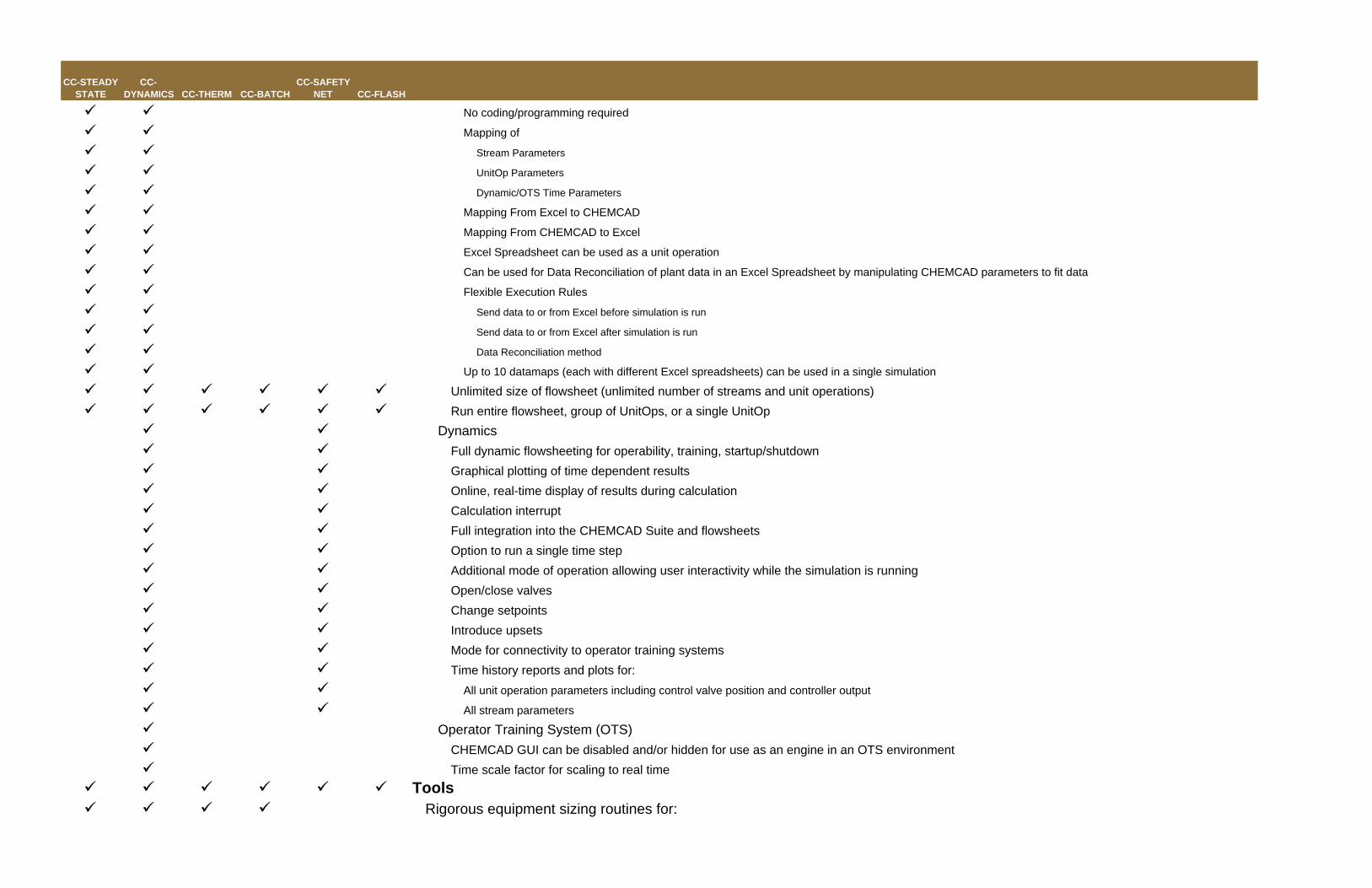
No coding/programming required
Mapping of
Stream Parameters
UnitOp Parameters
Dynamic/OTS Time Parameters
Mapping From Excel to CHEMCAD
Mapping From CHEMCAD to Excel
Excel Spreadsheet can be used as a unit operation
Can be used for Data Reconciliation of plant data in an Excel Spreadsheet by manipulating CHEMCAD parameters to fit data
Flexible Execution Rules
Send data to or from Excel before simulation is run
Send data to or from Excel after simulation is run
Data Reconciliation method
Up to 10 datamaps (each with different Excel spreadsheets) can be used in a single simulation
Unlimited size of flowsheet (unlimited number of streams and unit operations)Run entire flowsheet, group of UnitOps, or a single UnitOp
DynamicsFull dynamic flowsheeting for operability, training, startup/shutdownGraphical plotting of time dependent resultsOnline, real-time display of results during calculationCalculation interruptFull integration into the CHEMCAD Suite and flowsheetsOption to run a single time stepAdditional mode of operation allowing user interactivity while the simulation is runningOpen/close valvesChange setpointsIntroduce upsetsMode for connectivity to operator training systemsTime history reports and plots for:
All unit operation parameters including control valve position and controller output
All stream parameters
Operator Training System (OTS) CHEMCAD GUI can be disabled and/or hidden for use as an engine in an OTS environmentTime scale factor for scaling to real time
ToolsRigorous equipment sizing routines for:
CC-STEADY STATE
CC-DYNAMICS CC-THERM CC-BATCH
CC-SAFETY NET CC-FLASH
Heat ExchangersGeneral Features
Full integration into the CHEMCAD Suite and flowsheets
Output
Complete tabular and graphical reporting features including TEMA and/or API datasheets
A detailed tabulated analysis report
A detailed report of overall exchanger values
A zone-by-zone report of the heat curve, fluid properties, heat transfer and pressure drop calculations
Stream information inlet/outlet with H, T, P, and component flow rates
Optimization data
Shell and tubeDesign mode - geometry calculated from user constaints and desired performance
Rating mode - performance calculated from geometry
Fouling Rating mode - fouling calculated from geometry and performance
Simulation mode - geometry used to calculate performance in a CHEMCAD simulation
Design codes
TEMA R
TEMA B
TEMA C
ASME
DIN A.D. Merkblatter
British Standard 5500
Non-standard
All TEMA Front head, shell, and rear head standards
Tubeside process types:
Sensible flow (vapor or liquid)
Forced evaporation
Falling film evaporation
Vertical thermosyphon
Vertical once through thermosyphon
Horizontal condensation
Vertical condensation
Knock-back condensation
Shellside process types:
Sensible flow (vapor or liquid)
Forced evaporation
CC-STEADY STATE
CC-DYNAMICS CC-THERM CC-BATCH
CC-SAFETY NET CC-FLASH
Horizontal thermosyphon
Horizontal once through thermosyphon
Horizontal condensation
Vertical condensation
Pool boiling
Exchangers may have evaporation on one side with condensation on the other with any combination of subcooling and superheating
Fouling factor may be user specified
Shell or tube side heat transfer calculation can be overridden
A full stream analysis is performed on the shellside
Zone-by-zone analysis is performed (2-31 zones, user defined)
2-31 zones, user defined
Conditions and properties automatically generated at all zones and can be user modified
Complete materials library for tubes, pipes, shells, bonnet, and tubesheets
Counter- or co- current exchangers
Dry- or wet- wall condensing
5 stream exchangers (evaporators with separate outlet streams for vapor and liquid) calculated
Shellside
Shells in series or parallel
Shell as pipe or plate
Sealing strips permitted
Diameter or maximum diameter may be specified
Tubeside
Tubes may be bare or fin
Fintube databank and optional user specified fintube data
Turbulators may be used on the inside of the tube
User may specify tube OD, gauge, pattern, and pitch
Tubesheet thickness calculated to determine effective area
U-bend radius and/or efficiency may be specified
Tube length or maximum tube length may be specified
Nozzles
User specified Nozzle Diameters
User specified Nozzle Orientation
Long neck nozzle option
Baffles
Baffles may be single segmental, double segmental, triple segmental, full circle, no-tubes-in-window, or rod
Specify or have the program optimize the baffle spacing, cut, and direction
CC-STEADY STATE
CC-DYNAMICS CC-THERM CC-BATCH
CC-SAFETY NET CC-FLASH
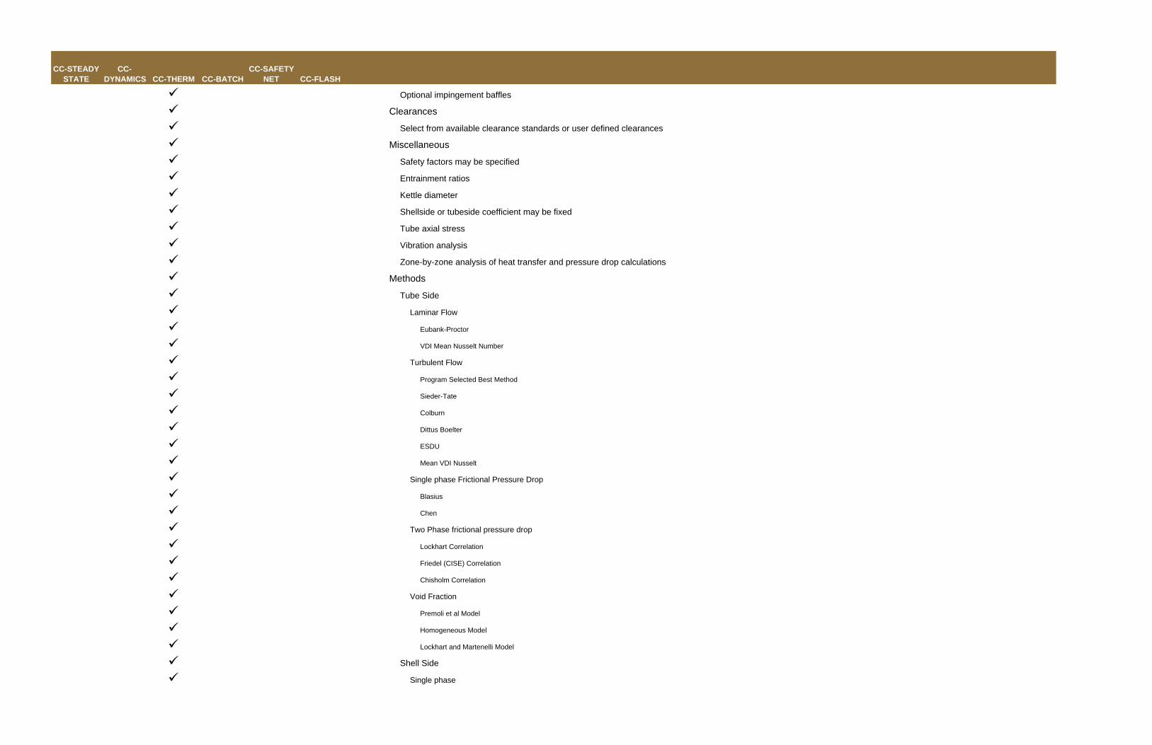
Optional impingement baffles
Clearances
Select from available clearance standards or user defined clearances
Miscellaneous
Safety factors may be specified
Entrainment ratios
Kettle diameter
Shellside or tubeside coefficient may be fixed
Tube axial stress
Vibration analysis
Zone-by-zone analysis of heat transfer and pressure drop calculations
Methods
Tube Side
Laminar Flow
Eubank-Proctor
VDI Mean Nusselt Number
Turbulent Flow
Program Selected Best Method
Sieder-Tate
Colburn
Dittus Boelter
ESDU
Mean VDI Nusselt
Single phase Frictional Pressure Drop
Blasius
Chen
Two Phase frictional pressure drop
Lockhart Correlation
Friedel (CISE) Correlation
Chisholm Correlation
Void Fraction
Premoli et al Model
Homogeneous Model
Lockhart and Martenelli Model
Shell Side
Single phase
CC-STEADY STATE
CC-DYNAMICS CC-THERM CC-BATCH
CC-SAFETY NET CC-FLASH
Stream Analysis
Bell Delaware
Kern
No vapor shear condensation, Horizontal
Kern
Nusselt
Eissenberg
Vapor shear condensations, Horizontal
Nusselt
McNaught
Taborek
Vertical Condensation
Chemstations
VDI Film
Falling film evaporation
Hewitt et al
VDI
Subcooling flow pattern
Liquid stratified
Liquid filled
Kettle flow
Plug
Perfect mixing
Silver Bell Ghaly for multicomponent condensation option
Parallel flow model if shell diameter is smaller than baffle spacing option
User override of LMTD correction factor
Stream Analysis
Baffle by baffle calculation on the shellside accounts for effects of clearances and shellside configurations on heat transfer and pressure drop
This analysis can be extended to include:
Finned tubes
Turbulators
Sealing strips
Impingement plates
Sparger pipes
Many other construction variables
Detailed Zone Analysis
CC-STEADY STATE
CC-DYNAMICS CC-THERM CC-BATCH
CC-SAFETY NET CC-FLASH
At each zone, the conditions, properties, flow regime, and applicable heat transfer mechanism are calculated
Pressure drop and film coefficients calculated using the appropriate formula
Double PipeDesign mode - geometry calculated from user constaints and desired performance
Rating mode - performance calculated from geometry
Fouling Rating mode - fouling calculated from geometry and performance
Simulation mode - geometry used to calculate performance in a CHEMCAD simulation
Calculation of U-tube or straight tube double pipe exchangers (sensible to sensible heat transfer only)
Allows multitube arrangements
Shellside
Shells in series or parallel
Diameter or maximum diameter may be specified
Tubeside
Tubes may be bare or fin
Fintube databank and optional user specified fintube data
User may specify tube OD, gauge, pattern, and pitch
Tube length or maximum tube length may be specified
Nozzles
User specified Nozzle Diameters
Complete materials library for tubes
Methods
Tube Side
Laminar Flow
Eubank-Proctor
VDI Mean Nusselt Number
Turbulent Flow
Program Selected Best Method
Sieder-Tate
Colburn
Dittus Boelter
ESDU
Mean VDI Nusselt
Single phase Frictional Pressure Drop
Blasius
Chen
Shell Side
CC-STEADY STATE
CC-DYNAMICS CC-THERM CC-BATCH
CC-SAFETY NET CC-FLASH
Laminar Flow
Program Selected Best Method
Turbulent Flow
Program Selected Best Method
Sieder-Tate
Colburn
Dittus Boelter
ESDU
Mean VDI Nusselt
Single phase Frictional Pressure Drop
Blasius
Chen
Plate and FrameDesign mode - geometry calculated from user constaints and desired performance
Rating mode - performance calculated from geometry
Fouling Rating mode - fouling calculated from geometry and performance
General
Specify Number of plates per unit
Pass arrangement
Cold side single pass / hot side multiple passes
Hot side single pass / cold side multiple passes
Both sides equal passes (user specify number of passes)
Complete materials library for plates
Sensible to sensible heat transfer
Film coefficients may be calculated or specified
Plate
Corrugation
Chevron
Intermating
User specified
Specify height, weight, thickness, spacing, thermal conductivity, chevron angle, and effective area
Nozzles
User specified Nozzle Diameters
User specified number of nozzles
Methods
Heat Transfer
CC-STEADY STATE
CC-DYNAMICS CC-THERM CC-BATCH
CC-SAFETY NET CC-FLASH
HEDH, Kumar 1989 (Heat Exchanger Design Handbook)
User Specified Parameters
Frictional Pressure Drop
HEDH, Kumar 1989
User Specified Parameters
Air CooledDesign mode - geometry calculated from user constaints and desired performance
Rating mode - performance calculated from geometry
Fouling Rating mode - fouling calculated from geometry and performance
Tubeside process types:
Sensible flow (vapor or liquid)
Horizontal condensation
Vertical Condensation
Reflux Condensation
Fouling factor may be user specified
Shell or tube side heat transfer calculation can be overridden
Design codes
ASME
DIN A.D. Merkblatter
British Standard 5500
Tubeside
Tubes may be bare or fin
Fintube databank and optional user specified fintube data
Turbulators may be used on the inside of the tube
User may specify tube OD, gauge, pattern, and pitch
Tubesheet thickness calculated to determine effective area
U-bend radius and/or efficiency may be specified
Tube length or maximum tube length may be specified
Tubes may be Welded or seamless
Fin attachments may be extruded, welded, grooved, or galvanized
Bundle
Number of tubes per row
Total number of rows
Number of rows per pass
Number of passes per bundle
Number of rows per bay
CC-STEADY STATE
CC-DYNAMICS CC-THERM CC-BATCH
CC-SAFETY NET CC-FLASH
Slope of header
Bay connections can be in parallel and/or series
Bundle connections can be in parallel and/or series
Nozzles
User specified Nozzle Diameters
Miscellaneous
Headers can be Plug, Coverplate, Bonnet, Split, U-tube, or Pipe(dished)
Header gaskets can be Spiral Wound, corrugated asbestos filled, corrugated, flat asbestos filled, grooved, solid, or metallic o-ring
Flanges can be slip on, weld neck, lap joint, ring type joint, or long weld neck
User specified
Header Design Temperature
Header Design pressure
Flange rating (ANSI, API, DIN)
Complete materials library for tubes, plug, header gasket, fan blade, fan hub, and fins
Dry wall and wet wall condensing can be accommodated
Fan data from the following manufacturers are provided:
Checo
Moore
Environment Element Corporation
Aerovent
Hudson
Fan drive data from the following manufacturers are provided:
GE
Westinghouse
Reliance
Methods
Tube Side
Heat Transfer
Single Phase Laminar Flow
Eubank-Proctor
Single Phase Turbulent Flow
Program Selected Best Method (Sieder-Tate, Dittus-Boelter, or ESDU)
Data RegressionPure component physical property regressionMulticomponent VLE/LLE regression from user data, UNIFAC, or infinite dilution dataRegression of electrolyte dataReaction rate regression from Temperature, Heat, and Concentration data
Data ReconciliationFlexible data file formatGRG, SQP, and Simultaneous Modular SQP methodsInterface to Excel through CHEMCAD's Excel DataMap functionsSimultaneous:Steady state (gross error) detectionData reconciliationParameter estimationUser defined model parameters can be estimatedUser defined model constraints
Vapor Venting/DepressurizingEPA WAR Algorithm for environmental and health impact studiesHydrate/Solid CO2 predictionTotal Organic Content/Chemical Oxygen Demand calculation
ReportingText Reports
Available inInternal text report viewerMicrosoft WordpadMicrosoft WordMicrosoft Excel
Stream Compositions / Properties (Single / Multiple Streams or Groups)
CC-STEADY STATE
CC-DYNAMICS CC-THERM CC-BATCH
CC-SAFETY NET CC-FLASH
Particle Size DistributionPseudo-component CurvesUnitOps (Single / Multiple Unit Operations or Groups)Specification SheetsDistillation
Collumn ProfileTray CompositionTray PropertiesTower Mass TransferDynamic Column HistoryColumn Diagnosis
Flowsheet TopologyFlowsheet Thermodynamic SettingsUser Component DataMass and Energy BalanceBatch ResultsDynamic Column / Stream / Unitop ReportsFull Consolidated Report of simulation
ChartsTPXYBinodalResidue Curve MapsBinodal with Residue Curve Map overlayBinary Liquid-Liquid EquilibriumSolid-Liquid EquilibriumStream PropertiesPhase EnvelopesComposite CurvesPseudo-component CurvesUnit Op Charts
User Specified File chartSymbol Builder for custom graphic representations
GUIExplorer Tree
Tree Display of simulation data including:Components used in the simulationThermodynamic settingsUnit OperationsStreamsSensitivity AnalysesData MapsSaved ChartsUnitOp and Stream GroupsFlowsheet LayersUnitOp and Stream Templates
Color and icon indications of warnings / errors / convergenceTree display of CHEMCAD VBA modulesRecently used file list
Unit Operations PaletteStandard UnitOps with multiple iconsUnitOp groups for UnitOps familiesCustomizable icons for standard UnitOpsCustomizable icons for user-added UnitOpsCustom groups for commonly used UnitOpsSearch bar and search results Group for finding UnitOps
Messaging WindowWarning and Error DisplayCalculation Progress and Run Trace informationUser Notes area for annotating flowsheet
Flowsheeting Window
CC-STEADY STATE
CC-DYNAMICS CC-THERM CC-BATCH
CC-SAFETY NET CC-FLASH
Scalable flowsheet area for small or large flowsheetsLayers for customizing graphics and annotationsHide/show UnitOp and stream IDsColor-coded UnitOp IDs for warnings/errorsPFD
Stream DataboxesUnit Operation DataboxesT & P BoxesText BoxesExcel Spreadsheet Range Display on FlowsheetImport of Graphics/LogosExport to Clipboard as MetafileExport PFD to .DXF (AutoCAD)
UnitOp copy / paste with all specificationsCopy Streams from other simulations (one time or permanent link)Create UnitOp or Stream groups for quick access to subsets of the flowsheetCreate UnitOp or Stream templates for commonly used specifications across multiple simulations
Help SystemFull technical reference material for all calculations and unit operationsTutorials and User Guide for navigating the interface (printed User Guide available)CHEMCAD Coach system for step by step instructions for common simulation work
Email simulations directly from CHEMCAD (using your email client)Zoom to find UnitOp or Streams on large flowsheets using ID numbersAutosave system saves data at regular (user specified) intervals and includes automatic file recovery at startup
ExtensibilityVBA/VSTA
Licensed, embedded Visual Basic for Applications (VBA) and Visual Studio Toolkit for Applications (VSTA) included in CHEMCADCreate custom code for
Unit operationsMixing rulesThermodynamic propertiesReaction kineticsAny user-defined calculation desired
Most CHEMCAD functionality exposed in a documented library of function callsOLE/COM/DCOM
3rd party applications can connect to CHEMCAD to read/write variables and run simulations
CC-STEADY STATE
CC-DYNAMICS CC-THERM CC-BATCH
CC-SAFETY NET CC-FLASH
CHEMCAD can act as client or server in a generic COM environmentAllows CHEMCAD to be an engine inside of a 3rd party applicationMost CHEMCAD functionality exposed in a documented library of function calls
CAPE OPENImport 3rd party thermodynamics/physical property packages into a CHEMCAD simulationUses CAPE-OPEN standard v1.0
OPCA CHEMCAD Simulation can be an OPC Data ServerAll stream and UnitOp data published for both steady state and dynamic simulationsAll time data published for dynamic simulationsSteady state run function available to OPC ClientsDynamic run function available to OPC ClientsRun single time step (dynamics) function available to OPC ClientsOPC Foundation Compliance and Interoperability tested for Data Access (DA) v2.05
XMLExport all simulation data to a tree-d format XML file (pending)Export to Bentley AXSYS via XML
License DurationHours per yearMonthly1, 3, 5, and 10 year licenses
Program ModulesCC-STEADY STATE (standalone) for steady state calculationsCC-DYNAMICS (add-on or standalone) for dynamic calculationsCC-THERM (add-on or standalone) for rigorous heat exchanger calculationCC-BATCH (add-on or standalone) for batch distillationCC-SAFETY NET (add-on or standalone) for pipe network and safety relief calculationsCC-FLASH (standalone) for physical property and phase equilibrium calculations
TECHNOTRADE: Suite No. 1, 1st Floor, Al-Haram Plaza, Plot No. 6, Block S, PIA Housing Society, Main BoulevardLahore-PakistanTel: 92-42-3583-2403Fax: 92-42-3583-2467E-Mail: [email protected] Web Site: http://www.technotrade.com.pk