41
Chemical Engineering at Orbital ATK Shelby Healy, Justin Pancoast Peer Review: Scott Mildenhall March 22, 2016 University of Utah Chemical Engineering Seminar
Chemical Engineering at Orbital ATK
Shelby Healy, Justin Pancoast
Peer Review: Scott Mildenhall
March 22, 2016
University of Utah Chemical Engineering Seminar
Overview
• Goal: Give a snapshot of what a chemical engineer might expect to do in
the aerospace industry through the experiences of two different
engineers at Orbital ATK
• Company description
• Product description
• Shelby’s experiences
• Justin’s experiences
1
About Orbital ATK
• $4.5 billion global aerospace and defense systems company
• Industry leader in government, defense and commercial markets
• Employs ~12,500 people, including ~4,300 engineers and scientists
• Major locations in 8 states (Virginia, Maryland, West Virginia, Minnesota, Missouri, Utah, Arizona and California), plus smaller locations and employees based in another 12 states
• Corporate headquarters in Dulles, Virginia
• This is a very exciting time for Orbital ATK. This is a unique strategic convergence of two companies that have worked together for more than 25 years
• Orbital ATK is financially strong and highly competitive in the aerospace and defense sector based on the company’s focus on the innovation, reliability, and affordability of its products
• Go to www.orbitalatk.com for more information
2
Company Overview
3
Special
Operations
Forces
Ground Combat
Vehicles
Naval
Platforms
Satellite
and Strategic
Launch
Soldier
Systems
Rotary-Wing
Military Aircraft
Fixed-Wing
Military Aircraft
Commercial
Aerospace
Satellites Human Space
Launch
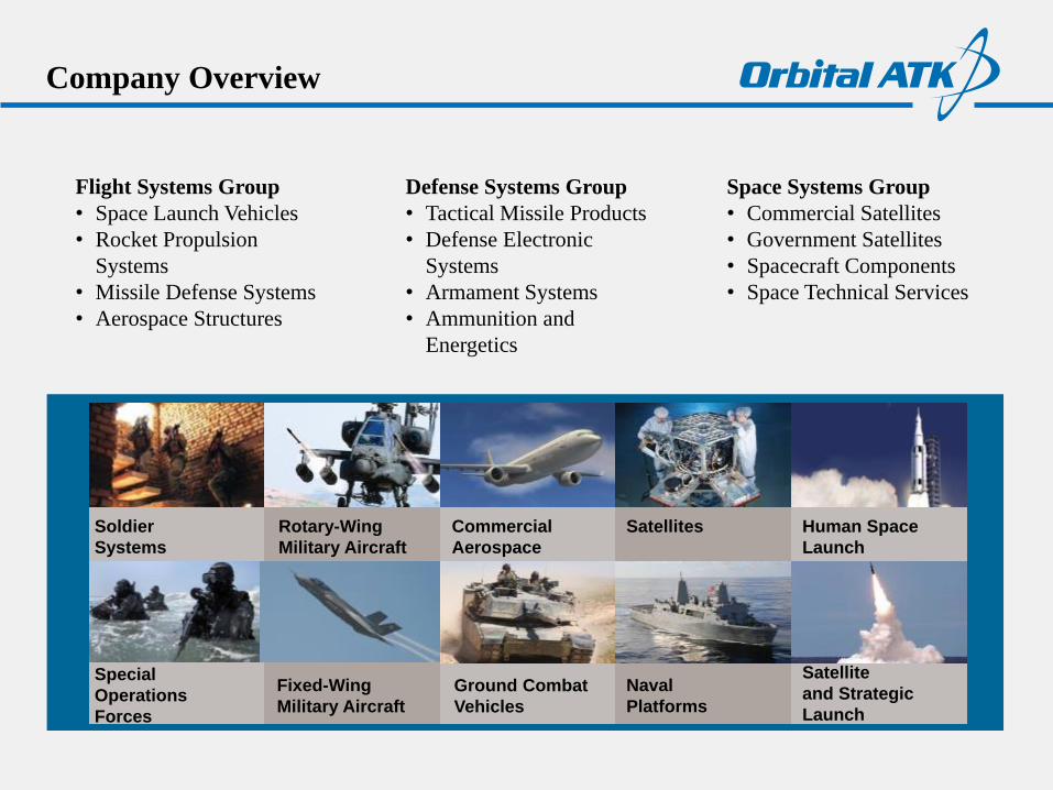
Flight Systems Group
• Space Launch Vehicles
• Rocket Propulsion
Systems
• Missile Defense Systems
• Aerospace Structures
Space Systems Group
• Commercial Satellites
• Government Satellites
• Spacecraft Components
• Space Technical Services
Defense Systems Group
• Tactical Missile Products
• Defense Electronic
Systems
• Armament Systems
• Ammunition and
Energetics
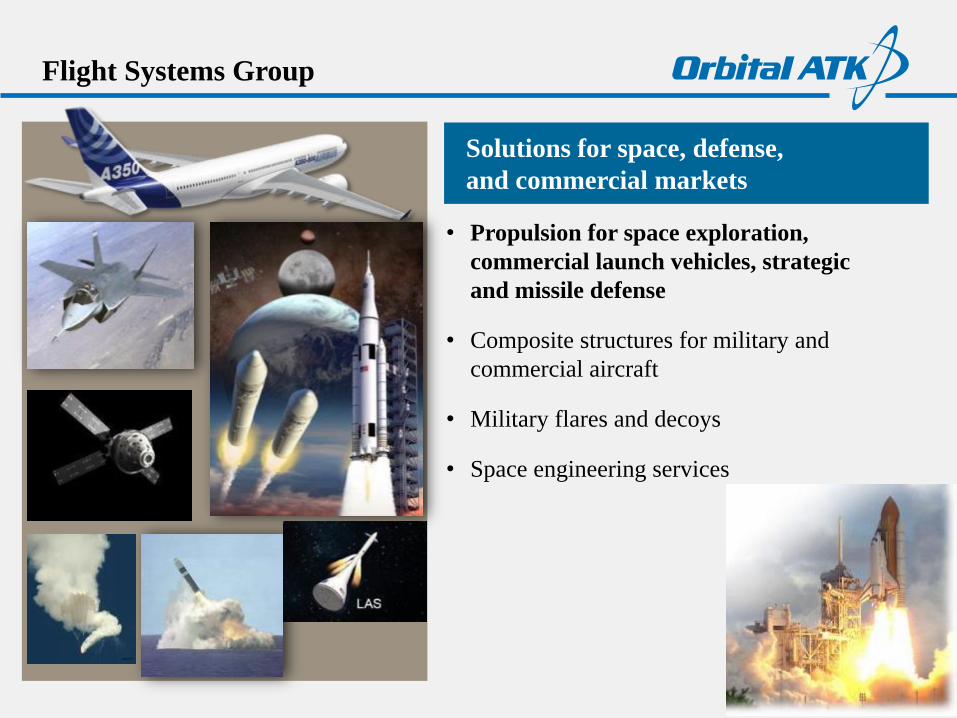
Flight Systems Group
Solutions for space, defense,
and commercial markets
• Propulsion for space exploration,
commercial launch vehicles, strategic
and missile defense
• Composite structures for military and
commercial aircraft
• Military flares and decoys
• Space engineering services
4
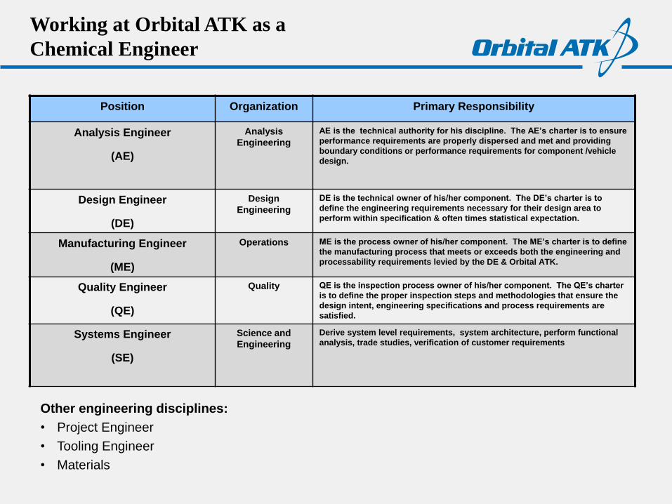
Working at Orbital ATK as a
Chemical Engineer
Other engineering disciplines:
• Project Engineer
• Tooling Engineer
• Materials
Position Organization Primary Responsibility
Analysis Engineer
(AE)
Analysis
Engineering
AE is the technical authority for his discipline. The AE’s charter is to ensure
performance requirements are properly dispersed and met and providing
boundary conditions or performance requirements for component /vehicle
design.
Design Engineer
(DE)
Design
Engineering
DE is the technical owner of his/her component. The DE’s charter is to
define the engineering requirements necessary for their design area to
perform within specification & often times statistical expectation.
Manufacturing Engineer
(ME)
Operations ME is the process owner of his/her component. The ME’s charter is to define
the manufacturing process that meets or exceeds both the engineering and
processability requirements levied by the DE & Orbital ATK.
Quality Engineer
(QE)
Quality QE is the inspection process owner of his/her component. The QE’s charter
is to define the proper inspection steps and methodologies that ensure the
design intent, engineering specifications and process requirements are
satisfied.
Systems Engineer
(SE)
Science and
Engineering
Derive system level requirements, system architecture, perform functional
analysis, trade studies, verification of customer requirements
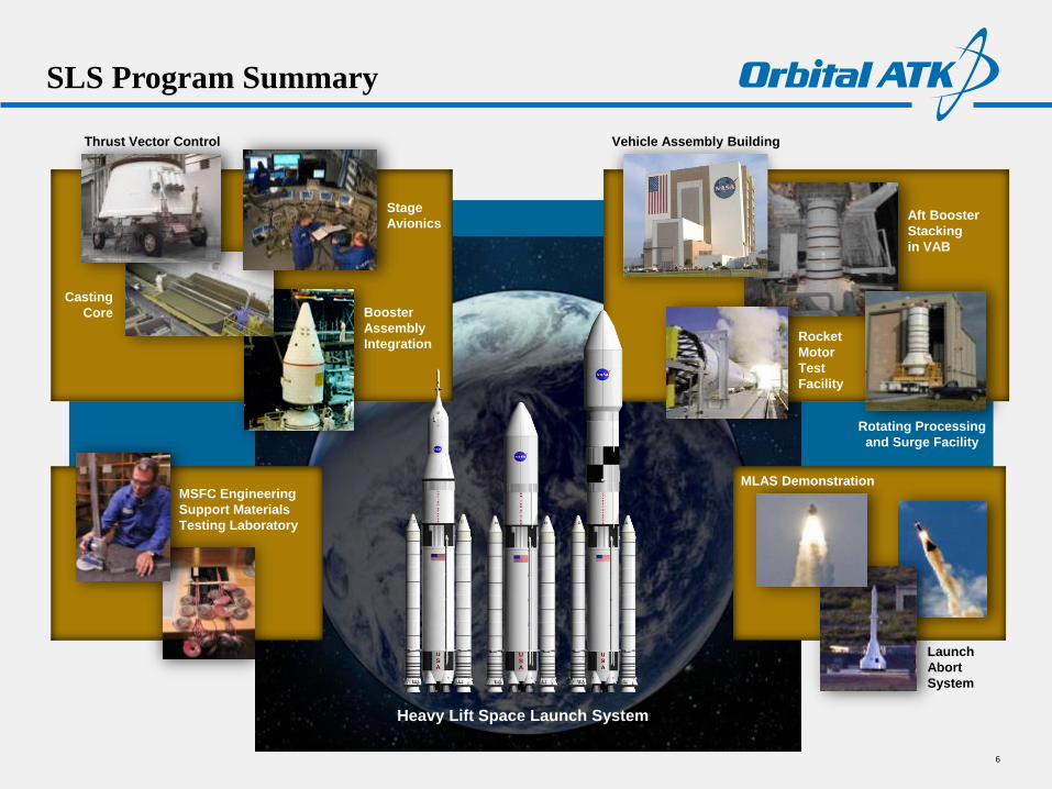
SLS Program Summary
Launch
Abort
System
Heavy Lift Space Launch System
MSFC Engineering
Support Materials
Testing Laboratory
CCiCap-020v11
1st Stage Transit by
Rail
RPSF: 1st
Stage Aft Assyoff critical path
VAB: Assembly and Testing
2nd Stage Transit by
Ship
1st Stage Stacking12 days
2nd Stage Stacking
5 days
Integrated Testing
IST #1: 4 daysIST #2: 3 days
Space VehicleMate3 days
Vehicle Closeouts
3 days
LC39: Pad Activities and
Launch5 days
(5 day refurb)
Liberty Ground Ops Process Flow: 40 Days
O&C: Crew/Service
Module Assembly
off critical path
MLP/Crawler
LCC
Astrotech: MLAS ProcessingIntegration, Fuel load
Off critical path
Recovery & RefurbReturn to O&C
Mission Ops
MLAS Demonstration
Vehicle Assembly Building
Rotating Processing
and Surge Facility
Rocket
Motor
Test
Facility
Aft Booster
Stacking
in VAB
Booster
Assembly
Integration
Stage
Avionics
Thrust Vector Control
Casting
Core
6
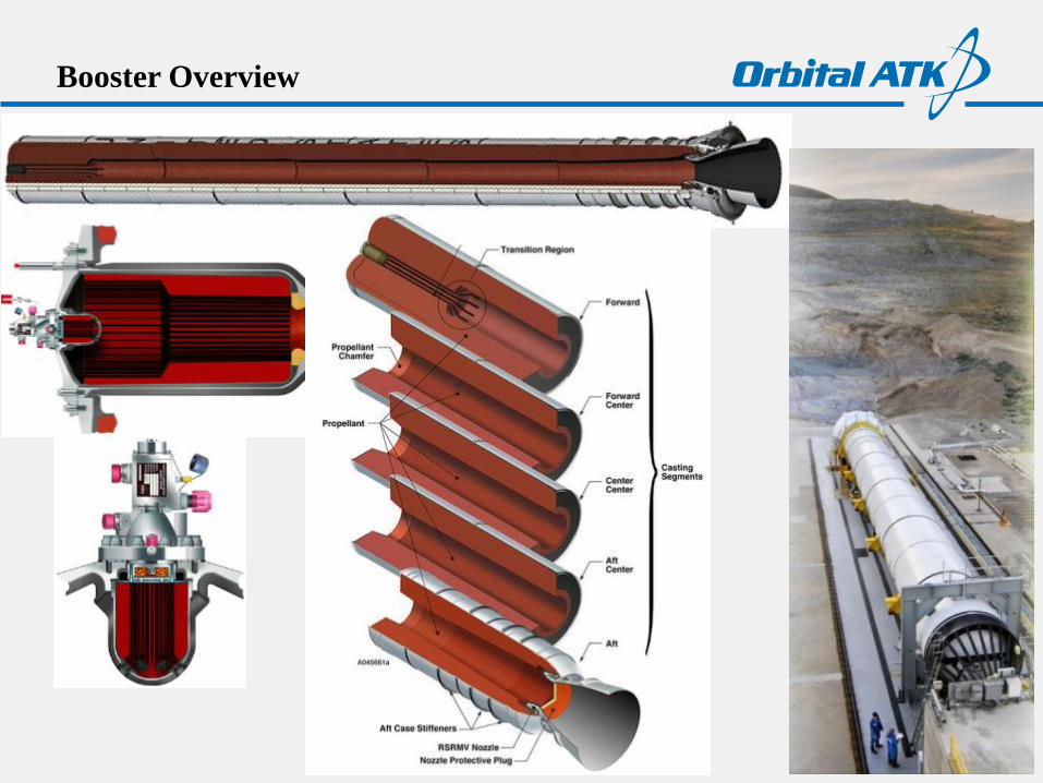
Booster Overview
Liner provides bonding between
propellant and internal insulation
Liner/insulation bond is primarily a
physical bond (insulation has a
textured-surface to enhance bonding)
Liner/propellant bond is primarily a
chemical bond
Liner, like insulation and propellant,
is a viscoelastic material: mechanical
response changes based on the rate
and time period of applied load
Propellant
Liner
Insulation
Steel Case
Liner
Castable
InhibitorPropellant Surface
Burn Inhibitor (aft
face of forward and
center segments)
LinerPropellant-to-insulation
Bond System (full
length of interior of each
segment and igniter)
9
• Hand line application of SLS forward segment requires one medium size liner mix
• Applied with segment in horizontal position
• Sling line application of SLS segments requires two large liner mixes
• Applied with segment in vertical position
Liner Mixing & Application
10
Sling Lining Disc
Slinger disc turns at >10,000 RPM
Sling liner disc does not pivot requiring hand lining
Segment cured at elevated temperature for about two days
Liner Application Methods
Hand-line Application
Igniter boot, dome region, and first factory joint on forward segments are hand applied with a medium sized liner mix (thixotrope increased to prevent liner slump/sag)
Applied with segment in horizontal position
The liner is applied to insulated segment with a weight requirement
Inspected for “full coverage”
• Thickness not measured: weight requirement with
known surface area
• Prior to liner cure, an operator is lowered into segment
(personned basket) to verify full coverage
• Liner voids are reworked if found
• After liner pre-cure, operators and inspectors are
lowered into the segment to verify full coverage
• Any liner voids found are repaired with liner saved from
the liner used for sling application
• Repair liner will cure during segment pre-heat prior to
propellant cast
Liner Post-Cure Inspection - OLD
Liner Inspection
The segment must be cast with propellant within about three weeks after liner
cure to ensure adequate liner cure potential remaining
During this time witness panels are tested to verify tensile strength of the
liner/insulation system
Liner Post-Cure Inspection – NEW
Flash Thermography
Inspection – Liner Witness to Offgassing
Pinhole, exposed insulation
Micro-CT
14
• Witness panels are processed side-by-side with the segments
• Segment witness panels include tensile buttons and peel strips that test the critical bond interfaces
Liner Witness Panels
Liner-Propellant Bondline
Liner-Insulation Bondline
Witness Panels – Screed vs Sling
• Motor experiences sling line application while witness panels experience
screed application
Witness Panels – Screed vs Sling
• Effort to sling line panels showed that it is more difficult to test uneven
surface texture of sling line application
Witness Panel Testing - Instron
Witness Panel Failure Mode Shift
1x
20X
50X

Test Specimens –AFT, Tensile Buttons
Test Specimens – Peels, FLS
Flapped Lap Shear Configuration
Test Specimens – Dogbones, Slump
Variety of Projects: BKNO3 Pelletization
https://upload.wikimedia.org/wikipedia/commons/5/5a/Tablet_press_animation.gif
Variety of Projects: Booster Separation Motors
Variety of Projects: BSM Post-Fire Assessment
Post-fire Assessment
BSM Nominal Liner Condition
− Loose char covering the ID of the case
− More erosion in the propellant valleys than the fins
− Slivers of propellant at the fin centers after post-flight
◦ No remaining propellant after static test
− Heat affected igniter liner swells and becomes brittle
BSM Liner Evaluation
− Erosion patterns are visually inspected
− Thickness of remaining virgin material is measured
− Bondlines are examined
Nonconformance
ERL-510 , 7297 LOT# 0207 CAN #20 0F 44, HATR SMEAR 60 DEG. ZNSE PLATE WITH COVER SLIP, LWI L07080137.001.SPA
ERL-510, LOT#126, 60 DEG. ATR SMEAR W/ COVERSLIP, RUN 1, S0402-28-A1.SPC
0.00
0.05
0.10
0.15
0.20
0.25
0.30
0.35
0.40
0.45
0.50
0.55
Abs
orb
anc
e
1000 1500 2000 2500 3000 3500
Wavenumbers (cm-1)
• Contamination
• Crayons
• Conveyor belt - vendor
• Grease - cranes
• Bugs - spider legs
• Out-of-place process
materials
• Liner Cure Issues
• Under cured
• Over cured
• Wrong temperature
• Processing parameter violations
• Humidity
• Flow rate
• Mix speed, weights,
temperature
• Shelf life issues
• Test results violations
• Raw materials
• Liner specimens
Digital Image Correlation and Structured Light
3D Scanning
Digital image correlation is a generic term that describes a noncontact optical method of tracking changes to an object’s surface through successive digital images in 2D or 3D space
Object changes at the image pixel level are correlated to strain and displacement using basic measurement inputs and pixel recognition tracking software
The ARAMIS system measures changes to an object during a deformation event and provides a means for dynamic measurement and analysis
Essentially uses pixels as strain gages and creates a strain field
Surface is often speckle coated to provide pixel contrast
Structured Light can measure changes to an object before and after a deformation event and provides a means for static measurement and analysis
Measurement scans create a 3D geometry of the object which can also be compared to a nominal CAD model for as-designed to as-built deviation analysis
Results for both methods are often compared to FE model predictions for model validation and optimization
ATOS Structured Light Scanner
ARAMIS System
Basics of ARAMIS Dynamic Deformation
Measurement
27
facet size
facet step
fovx 465.9 [mm] 18.343 [in]
computation size
total points with 12M cameras
strain sensitivity [%]
strain sensitivity [ue]
equivalent gage length 4.55 [mm] 0.179 [in]
in plane displacement sensitivity 3.11 [um] 0.000 [in]
out of plane displacement sensitivity 15.53 [um] 0.001 [in]
Point Spacing 1.14 [mm] 0.045 [in]
Dot Size 0.57 [mm] 0.022 [in]
Presets
Expected Results
125829
30
10
5
0.011
111
ARAMIS equipment is highly mobile and can be tailored to lab and in-field measurements
ARAMIS software allocates coordinates to the image pixels
The first image represents the undeformed state to which all images are compared for deformation calculations
The measurement object is speckle coated to provide the grayscale distribution contrast necessary to track pixel movement
The pixel grouping size and overlap are used to define and optimize the mesh density (facet field)
Facet size = dimension in pixels (virtual gauge areas)
Facet step = distance in pixels of adjacent facets
Computation size = # of adjacent facets in strain calculation
Strain is calculated at each node in the mesh based on the measured displacement of the adjacent pixel groupings
Typical Sensitivity of 12M System
Facet Field Overlay on Speckle Surface
ARAMIS Application: PLI FEA Model and
Material Validation
Solid rocket motor propellant and internal insulation have a time and temperature
dependent nonlinear material response
Numerical models incorporate master curves to predict stresses in actual hardware but
these models require validation
ARAMIS testing provided quantification of model accuracy and allowed for tuning to
identify sources of error or bias
Model was validated with stress/relaxation loading (thermal stresses during motor
storage); however, bi-rate loading (a motor ignition event) did not match
These results emphasized that a linear elastic material model may not be sufficient,
which resulted in work to develop a more refined hyper-viscoelastic material model
28
Relaxation Strain Comparison

ARAMIS Application: SLS Booster
FSTA-1 &-2 Forward Skirt Structural Testing
SLS ultimate assent loads are approximately 40% higher than
historical shuttle loads; however, NASA wants to use the
heritage space shuttle forward skirt hardware instead of
designing a new structure
The booster transfers load to the core vehicle through the
forward skirt thrust post
Analysis indicated that the shuttle forward skirt would not
meet structural safety factor requirements so testing was
commissioned to identify actual capability
ARAMIS testing was able to provide data when strain gages
failed, identify localized high strain near joint welds, and
strain at the failure initiation point on the thrust post
29
hotspot
0 s
High strain spot at crack initiation
point
Strain Gage Comparisons
The traditional strain gages failed mid-test
ARAMIS strain
did not fail
High strain spot
near weld
intersectionForward
Skirt
(top of
booster)Flight
Load
Simulation
Beam
ARAMIS System
Thrust
Post
Weld
(not
shown)
ARAMIS Application: Full-scale NRA Composite Booster
Case Burst Testing
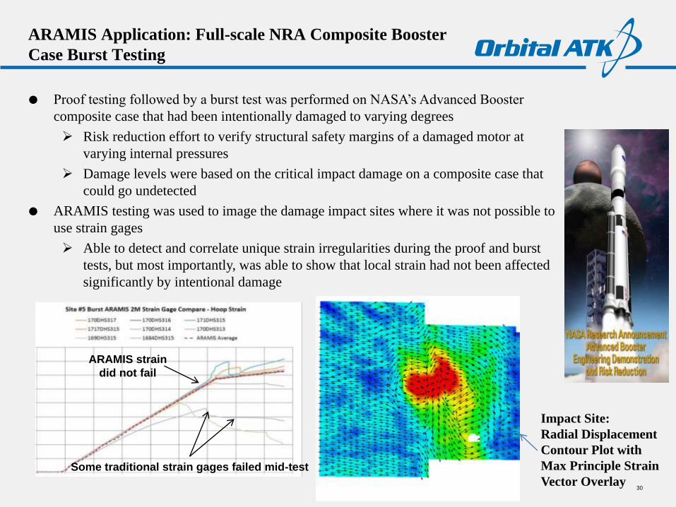
Proof testing followed by a burst test was performed on NASA’s Advanced Booster
composite case that had been intentionally damaged to varying degrees
Risk reduction effort to verify structural safety margins of a damaged motor at
varying internal pressures
Damage levels were based on the critical impact damage on a composite case that
could go undetected
ARAMIS testing was used to image the damage impact sites where it was not possible to
use strain gages
Able to detect and correlate unique strain irregularities during the proof and burst
tests, but most importantly, was able to show that local strain had not been affected
significantly by intentional damage
30
Some traditional strain gages failed mid-test
ARAMIS strain
did not fail
Impact Site:
Radial Displacement
Contour Plot with
Max Principle Strain
Vector Overlay
Basics of Structured Light (TRITOP/ATOS) Static
Deformation Measurement
31
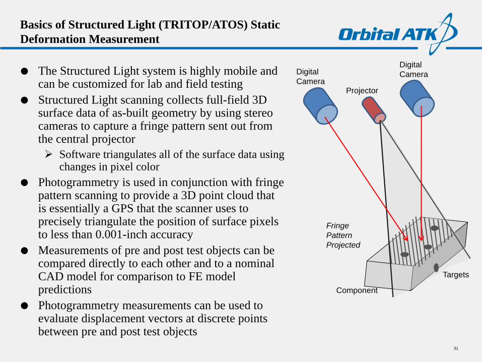
The Structured Light system is highly mobile and can be customized for lab and field testing
Structured Light scanning collects full-field 3D surface data of as-built geometry by using stereo cameras to capture a fringe pattern sent out from the central projector
Software triangulates all of the surface data using changes in pixel color
Photogrammetry is used in conjunction with fringe pattern scanning to provide a 3D point cloud that is essentially a GPS that the scanner uses to precisely triangulate the position of surface pixels to less than 0.001-inch accuracy
Measurements of pre and post test objects can be compared directly to each other and to a nominal CAD model for comparison to FE model predictions
Photogrammetry measurements can be used to evaluate displacement vectors at discrete points between pre and post test objects
Digital
Camera
Digital
Camera
Projector
Component
Targets
Fringe
Pattern
Projected
Structured Light Application: SLS Booster EM-1 & -2
Case Structures Hardware Measurements
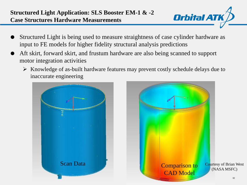
Structured Light is being used to measure straightness of case cylinder hardware as
input to FE models for higher fidelity structural analysis predictions
Aft skirt, forward skirt, and frustum hardware are also being scanned to support
motor integration activities
Knowledge of as-built hardware features may prevent costly schedule delays due to
inaccurate engineering
32
Courtesy of Brian West
(NASA MSFC)Comparison to
CAD Model
Scan Data
Structured Light Application: QM-1 Nozzle Erosion
Measurement
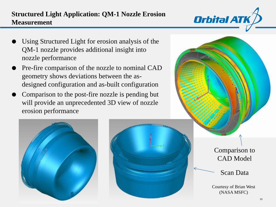
Using Structured Light for erosion analysis of the
QM-1 nozzle provides additional insight into
nozzle performance
Pre-fire comparison of the nozzle to nominal CAD
geometry shows deviations between the as-
designed configuration and as-built configuration
Comparison to the post-fire nozzle is pending but
will provide an unprecedented 3D view of nozzle
erosion performance
33
Comparison to
CAD Model
Scan Data
Courtesy of Brian West
(NASA MSFC)
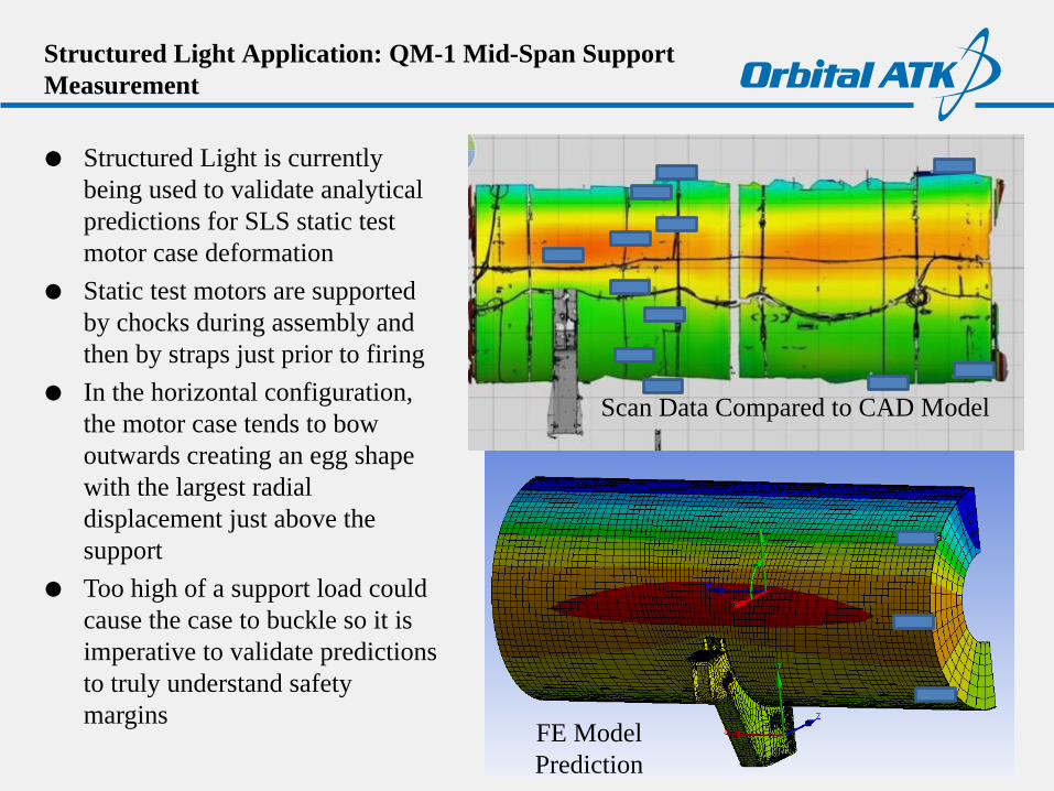
Structured Light Application: QM-1 Mid-Span Support
Measurement
Structured Light is currently
being used to validate analytical
predictions for SLS static test
motor case deformation
Static test motors are supported
by chocks during assembly and
then by straps just prior to firing
In the horizontal configuration,
the motor case tends to bow
outwards creating an egg shape
with the largest radial
displacement just above the
support
Too high of a support load could
cause the case to buckle so it is
imperative to validate predictions
to truly understand safety
margins
34
FE Model
Prediction
Scan Data Compared to CAD Model
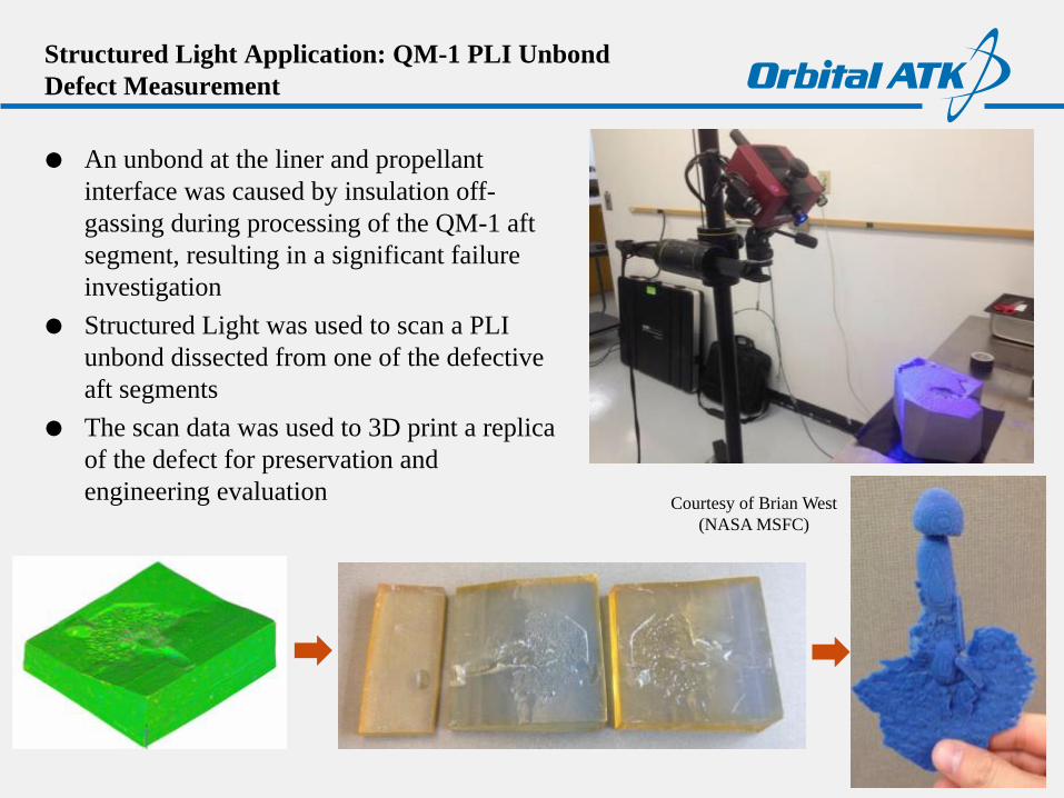
Structured Light Application: QM-1 PLI Unbond
Defect Measurement
An unbond at the liner and propellant
interface was caused by insulation off-
gassing during processing of the QM-1 aft
segment, resulting in a significant failure
investigation
Structured Light was used to scan a PLI
unbond dissected from one of the defective
aft segments
The scan data was used to 3D print a replica
of the defect for preservation and
engineering evaluation
35
Courtesy of Brian West
(NASA MSFC)
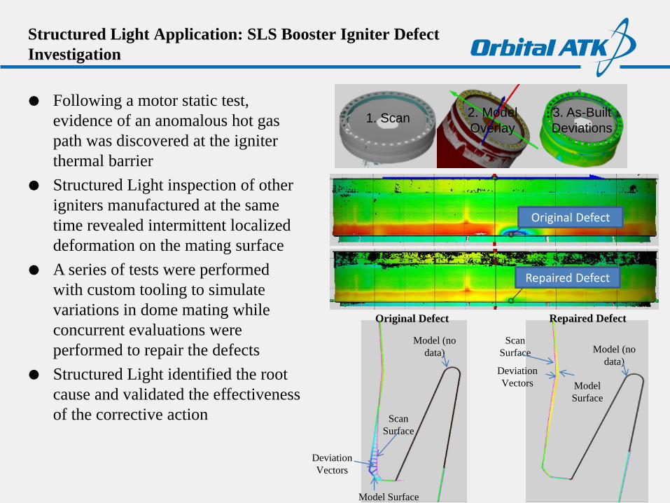
Structured Light Application: SLS Booster Igniter Defect
Investigation
Following a motor static test,
evidence of an anomalous hot gas
path was discovered at the igniter
thermal barrier
Structured Light inspection of other
igniters manufactured at the same
time revealed intermittent localized
deformation on the mating surface
A series of tests were performed
with custom tooling to simulate
variations in dome mating while
concurrent evaluations were
performed to repair the defects
Structured Light identified the root
cause and validated the effectiveness
of the corrective action
36
1. Scan 2. Model
Overlay
3. As-Built
Deviations
Original Defect
Repaired Defect
Original Defect Repaired Defect
Model (no
data)
Model Surface
Deviation
Vectors
Scan
Surface
Model (no
data)
Scan
Surface
Model
Surface
Deviation
Vectors
Conclusions
ARAMIS is a mobile full-field 3D dynamic deformation measurement and analysis
system
Provides information far beyond typical strain gages and is not limited to strain
measurement in a discrete location
Technology is scalable so it can be applied from a microscopic to macroscopic level
Most valuable for validation and optimization of FE model predictions to better define
structural margins of safety
Structured Light is a mobile full-field 3D scanning system capable of static
deformation measurement and analysis and as-designed to as-built deviation analysis
Method is more rapid and less data-intensive than laser scanning or traditional CMM
methods and has greater analysis software capabilities
Most valuable design verification, inspection, and reverse engineering but also quite
useful for FE model validation and optimization
37
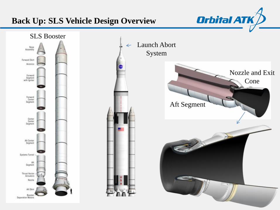
Back Up: SLS Vehicle Design Overview
38
Launch Abort
System
Aft Segment
Nozzle and Exit
Cone
SLS Booster
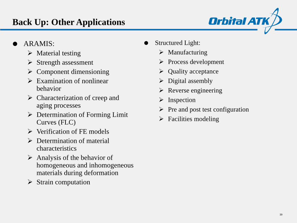
Back Up: Other Applications
ARAMIS:
Material testing
Strength assessment
Component dimensioning
Examination of nonlinear behavior
Characterization of creep and aging processes
Determination of Forming Limit Curves (FLC)
Verification of FE models
Determination of material characteristics
Analysis of the behavior of homogeneous and inhomogeneous materials during deformation
Strain computation
39
Structured Light:
Manufacturing
Process development
Quality acceptance
Digital assembly
Reverse engineering
Inspection
Pre and post test configuration
Facilities modeling
Questions?
40


![upk w atk plenum box - Teknocalor...4 Fig. 3, ATK-B Fig. 5, ATK-LS Fig. 4, ATK-S DIMENSIONSANDWEIGHT ATK,SANDLS ATK Dim. BFxHF D A Weight[kg] 125 200x100 124 180 2,8 160 300x100 159](https://static.documents.pub/doc/80x56/60d1222cb73d421fbe7fe348/upk-w-atk-plenum-box-teknocalor-4-fig-3-atk-b-fig-5-atk-ls-fig-4-atk-s.jpg)


