Evaluation of the Thermal Runaway Decomposition of Cumene Hydroperoxide by Adiabatic Calorimetry
Olga Reyes Valdesa*, Valeria Casson Morenob,c, Sam Mannana and Luc Véchotc aMary Kay O’Connor Process Safety Center, Artie McFerrin Department of Chemical Engineering, Texas A&M University, College Station, Texas 77843-3122, USA bAlma Mater Studiorum - Università di Bologna, Dipartimento di Ingegneria Chimica, Mineraria e delle Tecnologie Ambientali, Bologna, Italy cMary Kay O’Connor Process Safety Center at Qatar, Texas A&M Engineering Building, Education City, 23874 Doha, Qatar [email protected]
Many industrial accidents in the recent past showed that the thermal decomposition of Cumene Hydroperoxide (CHP) can lead to runaway reactions and subsequent fires and explosions. Still this organic peroxide is extensively used in the petrochemical industry. This paper is aimed at a better understanding of the possible consequences of CHP decomposition by analyzing its thermal behavior when dissolved in a high boiling point solvent using two different adiabatic calorimeters. The experimental data obtained allowed us to assess the general trends on the main runaway parameters and to characterized the thermal decomposition of the mixture with respect to the peroxide concentration, as well as the influence of the thermal inertia of the equipment. The gas generation rate for each of experiment was calculated and then corrected to adiabatic conditions. The data generated can assist as a guidance for designing processes where CHP is involved, along with their safeguards.
1. Introduction
Cumene Hydroperoxide is widely used as an initiator, a cross linking agent, a hardener and a drying accelerator in the petrochemical industry. However, the use of this peroxide presents an intrinsic hazard due to its high instability nature (class IV)(National Fire Protection Association, 2012) and its thermal decomposition reaction, which is usually highly exothermic and can lead to a runaway reaction and subsequent explosions. The hazards associated with the processing, transportation and storage of CHP are clearly reflected in the numerous incidents that have occurred in the Asian processing industry in the last two decades: Taiwan 2008, Taiwan 2003, Japan (1999) and Taiwan (1988) (Hsu, Su, Huang, & Duh, 2012). From a pressure relief stand point, CHP has been classified as an hybrid system: vapor and gasses are formed during the runaway (Véchot, Minko, Bigot, Kazmierczak, & Vicot, 2011). As for other peroxides systems, depending on the nature of the solvent (mainly the boiling point) the system’s behavior during a runaway may differ. The higher the boiling point of the solvent the more likely the system will approach an "untempered" behavior (the action of a pressure relief system will have no effect on the reaction kinetics). Currently there is very few experimental data available on the behavior of hybrid systems, particularly for untempered hybrid systems, most of the studies present in the literature are focused on the description of the kinetic of decomposition (Marco et al. 2000, Iizuka & Surianarayanan 2003, Levin et al. 2006) or on the assessment of the thermal hazards and runaway prevention by screening techniques (V Casson & Maschio, 2011; Valeria Casson, Battaglia, & Maschio, 2012; Valeria Casson, Salzano, & Maschio, 2013; Maschio, Lister, & Casson, 2010). Moreover, the evaluation of the fundamental parameters characterizing a runaway by laboratory scale experiments, which is a critical step in the vent sizing process, is still quite uncertain even when different methodologies for the experiments and further calculations are available in literature (Fisher et al. 1992). For these reasons, the experimental study being conducted in this research, aimed at: (1) Collect experimental data to characterize the behavior of the runaway decomposition of CHP when diluted in a high boiling point solvent; (2) identify the main parameters of the runaway decomposition of such untempered hybrid system; (3)
DOI: 10.3303/CET1543169
Please cite this article as: Reyes Valdes O.J., Casson Moreno V., Mannan S., Vechot L., 2015, Evaluation of the thermal runaway decomposition of cumene hydroperoxide by adiabatic calorimetry, Chemical Engineering Transactions, 43, 1009-1014 DOI: 10.3303/CET1543169
1009
address the importance of following a rigorous methodology while collecting and analysing experimental data. To achieve these objectives, a series of adiabatic experiments at two small-scale calorimeters were performed.
2. Materials and methods
In order to acquire fundamental understanding of the behaviour of an untempered hybrid system, it was decided to study the runaway of CHP in solution in 2,2,4-trimethyl-1,3-pentanediol diisobutyrate. Experiments were run at 72.5 %w/w ± 2.5 %w/w fill level of the sample cells and concentrations of 16 %w/w, 24 %w/w and 32 %w/w of CHP (from a 80 %w/w CHP solution in cumene). Chemicals were purchased from sigma Aldrich. The runaway experiments were run under pseudo adiabatic conditions using Phi-TEC I and Phi-TEC II calorimeters using closed test cells (HEL group, 2013). In the equipment, the heat losses are minimized by maintaining the temperature surrounding the cell as close as possible to the temperature of the sample. The experiments were performed in heat-wait-search mode, in which the sample is gradually heated (Heat) to specific temperature steps then the temperature is kept constant for a short period of time (Wait) while searching for an exotherm (Search). When an exotherm is detected the equipment shifts to an adiabatic mode and tracks the runaway reaction until completion. The main differences between the apparatus used during the experiments are the volume of the sample cell and the phi factor (φ) of the equipment defined as follows:
(1)
Where, m is the mass and Cp the heat capacity. The significance of φ lies in the fact that at large industrial reactors behave with a φ ~ 1 (Kersten, Boers, Stork, & Visser, 2005). It is therefore of paramount importance that the φ factor at experimental conditions approaches unity to obtain a set of data on the severity of a runaway reaction representative of large scale reactors. Phi-TEC I cells are 8 ml stainless steel bomb of that can withstand high pressure (up to 200 bar) due to the high wall thickness of the cells themselves. However they also present a significantly high thermal mass (φ ~ 1.8). Phi-TEC II cells are thin walled 110 ml agitated stainless steel cells with a relatively low thermal mass (φ ~ 1.1). These cells stand a relatively low pressure (3 bar), They are placed inside a high pressure vessel so that the pressure developed during the runaway reaction inside the cell can be compensated by the fast injection of nitrogen into the vessel such preventing the bursting of the cell.
3. Experimental Procedure and conditions
For both, Phi-TEC I and Phi-TEC II calorimeters, the different solutions were first quickly heated to 70 °C. After a 40 min calibration at that temperature, the equipment were programmed to start operating in the Heat-wait search, with heating steps of 2 °C/min. After the completion of the runaway reaction, the experiments were stopped and the equipment was left to cool down to ambient conditions, where the final temperature and pressure were recorded, as well as the mass of the final products in the cell. The measured initial and final conditions of each of the test performed during this work are shown in Table 1. The final mass of the 32 %w/w run in Phi-TEC II could not be recorded, as the test cell burst during the runaway and the reactant mass was lost to the containment vessel.
Table 1: Experimental conditions of each of the test.
The experimental data obtained from the Phi-TEC I gave a preliminary estimation on the decomposition behaviour. The following data were recorded: detected onset temperature (Ton), maximum temperature (Tmax) and pressure (Pmax) generated and maximum temperature and pressure rise rates (dT/dtmax, dP/dtmax).These experiments were used as screening tests to successfully and safely perform experiments in the Phi-TEC II
φ=1+× ×
1010
calorimeter. A more accurate calorimetric study was subsequently performed with the Phi-TEC II such providing a more realistic assessment of the runaway characteristics at industrial scale (due to its low φ).
4. Experimental Results and discussion
In order to estimate the formation of non-condensable gases, the specific gas production (moles of gas/kg of initial solution) was calculated based on the assumption that the ideal gas law holds:
∆n = n − n = ×× − ×× (2)
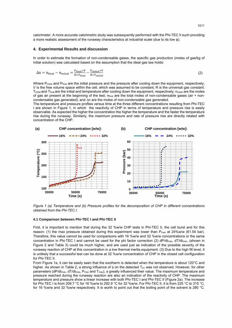
Where Pinitial and Pfinal are the initial pressure and the pressure after cooling down the equipment, respectively; V is the free volume space within the cell, which was assumed to be constant; R is the universal gas constant; Tinitial and Tfinal are the initial and temperature after cooling down the equipment, respectively; ninitial are the moles of gas air present at the beginning of the test; nfinal are the total moles of non-condensable gases (air + non-condensable gas generated); and Δn are the moles of non-condensable gas generated. The temperature and pressure profiles versus time at the three different concentrations resulting from Phi-TEC I are shown in Figure 1, in which the reactivity of CHP in terms of temperature and pressure rise is easily observable. As expected the higher the concentration the higher the temperature and the faster the temperature rise during the runaway. Similarly, the maximum pressure and rate of pressure rise are directly related with concentration of the CHP.
Figure 1 (a) Temperature and (b) Pressure profiles for the decomposition of CHP in different concentrations obtained from the Phi-TEC I.
4.1 Comparison between Phi-TEC I and Phi-TEC II
First, it is important to mention that during the 32 %w/w CHP tests in Phi-TEC II, the cell burst and for this reason: (1) the max pressure obtained during this experiment was lower than Pmax at 24%w/w (61.54 bar). Therefore, this value cannot be used for comparisons with 16 %w/w and 32 %w/w concentrations or the same concentration in Phi-TEC I and cannot be used for the phi factor correction (2) dP/dtmax, dT/dtmax, (shown in Figure 2 and Table 3) could be much higher, and are used just as indication of the possible severity of the runaway reaction of CHP at this concentration in a low thermal inertia equipment. (3) Due to the high fill level, it is unlikely that a successful test can be done at 32 %w/w concentration of CHP in the closed cell configuration for Phi-TEC II. From Figure 1a, it can be easily seen that the exotherm is detected when the temperature is about 120°C and higher. As shown in Table 2, a strong influence of φ on the detected Ton was not observed. However, for other parameters (dP/dtmax, dT/dtmax, Pmax and Tmax), φ greatly influenced their value. The maximum temperature and pressure reached during the runaway reaction are also an indication of the reactivity of CHP. The maximum temperature and pressure show a linear increase with both Phi-TEC I and Phi-TEC II (Figure 2a). The increase for Phi-TEC I is from 209.7 °C for 16 %w/w to 292.9 °C for 32 %w/w. For Phi-TEC II, it is from 225 °C to 315 °C, for 16 %w/w and 32 %w/w respectively. It is worth to point out that the boiling point of the solvent is 280 °C.
100
150
200
250
300
35000 55000 75000
Tem
per
atu
re (
°C)
Time (s)
16% 24% 32%
0
10
20
30
40
50
60
35000 55000 75000
Pre
ssu
re (
bar
)
Time (s)
16% 24% 32%
1011
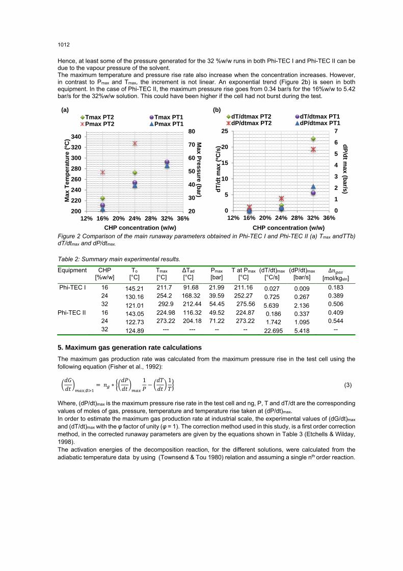
Hence, at least some of the pressure generated for the 32 %w/w runs in both Phi-TEC I and Phi-TEC II can be due to the vapour pressure of the solvent. The maximum temperature and pressure rise rate also increase when the concentration increases. However, in contrast to Pmax and Tmax, the increment is not linear. An exponential trend (Figure 2b) is seen in both equipment. In the case of Phi-TEC II, the maximum pressure rise goes from 0.34 bar/s for the 16%w/w to 5.42 bar/s for the 32%w/w solution. This could have been higher if the cell had not burst during the test.
(a) (b)
Figure 2 Comparison of the main runaway parameters obtained in Phi-TEC I and Phi-TEC II (a) Tmax andTTb) dT/dtmax and dP/dtmax.
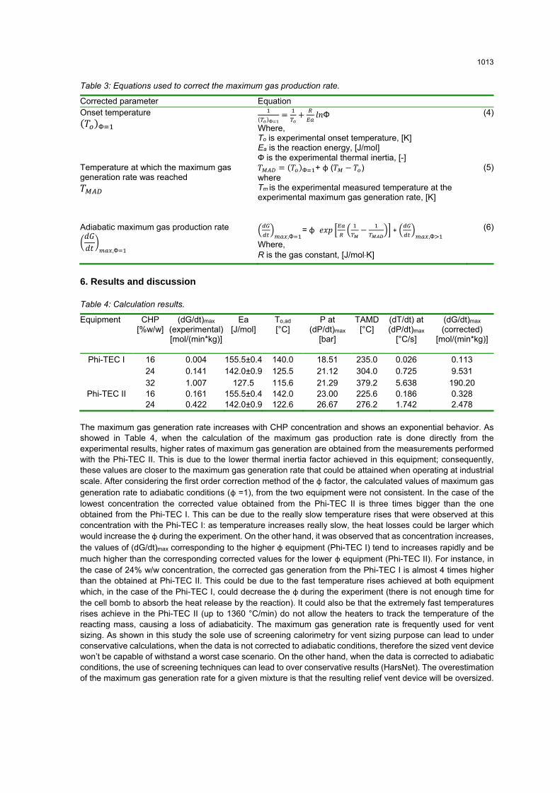
The maximum gas production rate was calculated from the maximum pressure rise in the test cell using the following equation (Fisher et al., 1992):
,∅ = ∗ 1 − 1 (3)
Where, (dP/dt)max is the maximum pressure rise rate in the test cell and ng, P, T and dT/dt are the corresponding values of moles of gas, pressure, temperature and temperature rise taken at (dP/dt)max. In order to estimate the maximum gas production rate at industrial scale, the experimental values of (dG/dt)max and (dT/dt)max with the φ factor of unity (φ = 1). The correction method used in this study, is a first order correction method, in the corrected runaway parameters are given by the equations shown in Table 3 (Etchells & Wilday, 1998). The activation energies of the decomposition reaction, for the different solutions, were calculated from the adiabatic temperature data by using (Townsend & Tou 1980) relation and assuming a single nth order reaction.
The maximum gas generation rate increases with CHP concentration and shows an exponential behavior. As showed in Table 4, when the calculation of the maximum gas production rate is done directly from the experimental results, higher rates of maximum gas generation are obtained from the measurements performed with the Phi-TEC II. This is due to the lower thermal inertia factor achieved in this equipment; consequently, these values are closer to the maximum gas generation rate that could be attained when operating at industrial scale. After considering the first order correction method of the φ factor, the calculated values of maximum gas generation rate to adiabatic conditions (φ =1), from the two equipment were not consistent. In the case of the lowest concentration the corrected value obtained from the Phi-TEC II is three times bigger than the one obtained from the Phi-TEC I. This can be due to the really slow temperature rises that were observed at this concentration with the Phi-TEC I: as temperature increases really slow, the heat losses could be larger which would increase the φ during the experiment. On the other hand, it was observed that as concentration increases, the values of (dG/dt)max corresponding to the higher φ equipment (Phi-TEC I) tend to increases rapidly and be much higher than the corresponding corrected values for the lower φ equipment (Phi-TEC II). For instance, in the case of 24% w/w concentration, the corrected gas generation from the Phi-TEC I is almost 4 times higher than the obtained at Phi-TEC II. This could be due to the fast temperature rises achieved at both equipment which, in the case of the Phi-TEC I, could decrease the φ during the experiment (there is not enough time for the cell bomb to absorb the heat release by the reaction). It could also be that the extremely fast temperatures rises achieve in the Phi-TEC II (up to 1360 °C/min) do not allow the heaters to track the temperature of the reacting mass, causing a loss of adiabaticity. The maximum gas generation rate is frequently used for vent sizing. As shown in this study the sole use of screening calorimetry for vent sizing purpose can lead to under conservative calculations, when the data is not corrected to adiabatic conditions, therefore the sized vent device won’t be capable of withstand a worst case scenario. On the other hand, when the data is corrected to adiabatic conditions, the use of screening techniques can lead to over conservative results (HarsNet). The overestimation of the maximum gas generation rate for a given mixture is that the resulting relief vent device will be oversized.
1013
Conclusions
The runaway decomposition of cumene hydroperoxide at 16 %w/w, 24 %w/w and 32 %w/w concentrations in 2,2,4-trimethyl-1,3-pentanediol diisobutyrate, was studied using pseudo adiabatic (Phi-TEC I) and adiabatic (Phi-TEC II) tests in close cell configuration. The main runaway parameters of the thermal decomposition of CHP were measured. As expected, the data obtained and analyzed during this study showed that the severity of the runaway of CHP increases when increasing the concentration of the peroxide. This increase shows a linear trend for the Pmax, and Tmax, and an exponential trend for the maximum temperature, pressure and gas generation rates. The comparison of the data obtained from both calorimeters highlights the importance of performing experiments in a low phi factor calorimeter in order to have representative and confinable data, before the vent sizing, design and scale up of the reaction. In order to take into account the gas dissolved in the liquid phase, for more accurate calculations, further tests will be performed by varying the fill ratio of the sample within the cell. Acknowledgements
Part of the work presented in this paper was funded under the Undergraduate Research Experience Program of the Qatar National Research Fund (UREP 13 - 167 - 2 - 056). The authors thank the Qatar Foundation for their support. References
Casson, V., Battaglia, E., & Maschio, G. (2012). Hydrogen Peroxide Decomposition Analysis by Screening Calorimetry Technique. Chemical Engineering Transactions, 26, 27–32, doi: 10.3303/CET1226005
Casson, V., & Maschio, G. (2011). Screening Analysis for Hazard Assessment of Peroxides Decomposition. Industrial & Engineering Chemistry Research, (51), 7526–7535. doi:10.1021/ie201690n
Casson, V., Salzano, E., & Maschio, G. (2013). Sensitivity Analysis for the Thermal Stability Criteria of Hydrogen Peroxide. Chemical Engineering Transactions, 32(1), 541–546. doi:10.3303/CET1332091
Etchells, J., & Wilday, J. (1998). Workbook for Chemical Reactor Relief System Sizing. HSE,Health & Safety Executive.
Fisher, H. G., Forrest, H. S., Grossel, S. S., Huff, J. E., Muller, A. R., Noronha, J. A., … Tilley, B. J. (1992). Emergency Relief System Design Using DIERS Technology: The Design Institute for Emergency Relief Systems (DIERS) Project Manual. Design Institute for Physical Property Data/AIChE.
HarsNet, 2002. HarsBook, Frankfurt: Dechema. Hsu, J.-M., Su, M.-S., Huang, C.-Y., & Duh, Y.-S. (2012). Calorimetric studies and lessons on fires and
explosions of a chemical plant producing CHP and DCPO. Journal of Hazardous Materials, 217-218, 19–28. doi:10.1016/j.jhazmat.2011.12.064
Iizuka, Y., & Surianarayanan, M. (2003). Comprehensive Kinetic Model for Adiabatic Decomposition of Di-tert-butyl Peroxide Using BatchCAD. Industrial & Engineering Chemistry Research, 42(13), 2987–2995. doi:10.1021/ie020687r
Kersten, R. J. a., Boers, M. N., Stork, M. M., & Visser, C. (2005). Results of a Round-Robin with di-tertiary-butyl peroxide in Various Adiabatic Equipment for Assessment of Runaway Reaction Hazards. Journal of Loss Prevention in the Process Industries, 18(3), 145–151. doi:10.1016/j.jlp.2005.03.003
Levin, M. E., Gonzales, N. O., Zimmerman, L. W., & Yang, J. (2006). Kinetics of acid-catalyzed cleavage of cumene hydroperoxide. Journal of Hazardous Materials, 130(1-2), 88–106. doi:10.1016/j.jhazmat.2005.07.068
Marco, E., Cuartielles, S., Pena, J., & Santamaria, J. (2000). Simulation of the decomposition of di-cumyl peroxide in an ARSST unit. Thermochimica Acta, 362, 49–58.
Maschio, G., Lister, D. G. D., & Casson, V. (2010). Use of Screening Analysis Calorimetry in the Study of Peroxides Decomposition. Chemical Engineering Transactions, 19(19), 347–352. doi:10.3303/CET1019057
National Fire Protection Association. (2012). NFPA 704: Standard System for the Identification of the Hazards of Materials for Emergency Response (2012th ed.).
Véchot, L., Minko, W., Bigot, J.-P., Kazmierczak, M., & Vicot, P. (2011). Vent sizing: analysis of the blowdown of a hybrid non tempered system. Journal of Hazardous Materials, 191(1-3), 8–18. doi:10.1016/j.jhazmat.2011.03.100