................................................................................................... Chemical guidelines for water/steam cycle of fossil fired units ................................................................................................... Thermal Generation Study Committee ................................................................................................... April 1997 Ref : 02004Ren9766
Thermal Generation Study Committee......................................................................................................
April 1997Ref : 02004Ren9766
The “Union of the Electricity Industry – EURELECTRIC” has been formed through a merger of the two associations
and
The Union of the Electricity Industry - EURELECTRIC , formed as a result of a merger inDecember 1999 of the twin Electricity Industry Associations, UNIPEDE1 and EURELECTRIC2, is thesole sector association representing the common interests of the European Electricity Industry and itsworldwide affiliates and associates.
Its mission is to contribute to the development and competitiveness of the Electricity Industry and topromote the role of electricity in the advancement of society.
As a centre of strategic expertise, the Union of the Electricity Industry - EURELECTRIC willidentify and represent the common interests of its members and assist them in formulating commonsolutions to be implemented and in coordinating and carrying out the necessary actions. To that end itwill also act in liaison with other international associations and organisations, respecting the specificmissions and responsibilities of these organisations.
The Union of the Electricity Industry - EURELECTRIC is also the association of the ElectricityIndustry within the European Union representing it in public affairs, in particular in relation to theinstitutions of the EU and other international organisations, in order to promote the interests of itsmembers at a political level and to create awareness of its policies.
The reports published by EURELECTRIC are the result of the work of its structure of expertise: theyrepresent one of the most direct methods of circulating knowledge and information throughout thesector, on subjects of common interest.
They are intended for wide circulation both within the electricity supply industry and outside it.
Ä Please do not hesitate to ask for the latest available printed EURELECTRIC publicationscatalogue (with summaries of EURELECTRIC reports) from:
Union of the Electricity Industry – EURELECTRICDocumentation66 Boulevard de l'ImpératriceBE-1000 BrusselsBELGIUM
1. INTRODUCTION ........................................................................................................11.1 Overview .......................................................................................................................... 11.2 Review of Current Practice of UNIPEDE Members........................................................... 11.3 Scope of the Guidelines..................................................................................................... 2
2. BASICS OF DEPOSITION AND CORROSION PROTECTION .................................32.1 Objectives and Principles ................................................................................................. 32.2 Feed-water system ............................................................................................................ 32.3 Boiler ............................................................................................................................... 42.4 Turbine, superheater and reheater.................................................................................... 5
3. RECOMMENDED CONCEPT OF CHEMICAL CONTROL .......................................54. RECOMMENDED CONTROL PARAMETERS ..........................................................6
4.1 Feed-water and steam....................................................................................................... 64.2 Boiler water...................................................................................................................... 74.3 Condensate....................................................................................................................... 8
TABLE I. Definitions and characteristic of Action Levels..................................................... 10TABLE II. Key parameters for control of water/steam cycle .................................................. 11TABLE III. Overview of Action Levels .................................................................................... 11
The chemical control of water/steam cycles in member countries of UNIPEDE is based on experience publishedin world literature, own operational experiences and guidelines issued by different national and internationalbodies. The Therchim Committee has made an inquiry into the general practice for chemical control ofwater/steam cycles of fossil-fired power units in UNIPEDE members. The inquiry was addressed to membercountries being represented in the committee. The answers were evaluated and on the basis of this evaluation itwas decided to formulate UNIPEDE Chemical guidelines for water/steam cycles of fossil units. A group ofexperts from several countries has been constituted to develop generic guidelines.
The guidelines are based on the data assembled from the inquiry. As the practice in single countries is adaptedto the local conditions (type of the installation, operation mode etc.), it was necessary to make the guidelinesapplicable to the broadest possible range of units used by utilities in UNIPEDE countries. Furthermore, theguidelines have in view the present and the near future developments of the design, operation and control ofpower plants. In particular, two directions have been considered during development of the guidelines. Theintroduction of units operating at higher and higher pressure and temperature and introduction of combinedcycle units operating at several pressure stages, where the low pressure stage is operating at unusually lowpressure. Thus, the pressure range is extended in both directions.
Chemical control of water steam cycle based on the concept of action levels was originally been introduced bynuclear power utilities. The concept was introduced for the first time for fossil fired plants by EPRI. Severalcountries around the world, among them some of the UNIPEDE members, adopted the concept because of itsdetailed guidance of operators during chemical disturbances of the cycle. However, the definitions of actionlevels have to be adjusted when transforming the concept from the application on nuclear power plants to theapplication on fossil plants. The safety considerations on nuclear plants demand very rigid application of theaction level concept, while on fossil plants it is more or less a question of an economic assessment. The lengthof time a fossil fired plant should be allowed to operate at a certain action level is a question of cost-benefitevaluation.
The concept of action levels is introduced in the UNIPEDE Guidelines, but some important adjustments aremade to the concept used by nuclear utilities, as well as to the concept introduced by EPRI for fossil firedplants.
Three action levels and a target for normal operation are defined. Definitions of action levels are slightlydifferent from the EPRI definitions. A characterisation of each action level is given with an indication of therisk connected to operation at these conditions. Furthermore, guidance is given for actions whenever an actionlevel is reached during operation.
The same action levels are recommended for start-up procedure. In this case the unit is in action level 3 regionbefore start-up. Guidance is given for procedure steps during start-up according to a successive purification ofthe cycle and adjustment of parameters.
The UNIPEDE guidelines distinguish between 2 types of chemical parameters - key parameters and diagnosticparameters. Key parameters are basically purity parameters which should be continuously monitored, ifpossible, whereas diagnostic parameters are measured according to operational needs. The most importantdifference between parameters is reflected at action level 3, where key parameters call for a forced shut-down ofthe unit. The diagnostic parameters call for less radical actions such as load reduction.
Almost all the parameters are specified in diagrams, where the interdependency of parameters is defined. Insome cases it is the interdependency of two chemical parameters (such as pH and oxygen concentration in feed-water), in others it is dependency of a chemical parameter on full load operating pressure (such as acidconductivity). In these cases, other parameters, such as heat flux, would be more correct to use, thoughextremely inconvenient. There is a certain functionality between the correct parameters and pressure, thus themost convenient parameter is chosen.
For a successfull implementation of the guidelines, a close cooperation between station chemist and operators,as well as support from the management, is essential.
ii ii
GLOSSARY
Acid conductivity Conductivity measured after exchange of cations to H+ passing an acid regenerated cation exchanger. Thus, alkalinity is neutralised and all salts are converted to acids.
AVT All Volatile Treatment. Conditioning concept, where ammonia is used with orwithout addition of hydrazine as oxygen scavenger.
CPP Condensate polishing plant.
CWT Combined Water Treatment (in this document called Oxygenated Treatment, OT). Conditioning concept, where ammonia and oxygen are added. Very high purity of water is required for succesful application of this concept.
EPRI Electric Power Research Institute, USA.
Equivalent Lifetime Operation time at reference conditions causing the same wear or damage as real operation time at actual conditions.
OT Oxygenated Treatment (also called CWT). Conditioning concept, where ammonia and oxygen are added. Very high purity of water is required for succesfulapplication of this concept.
Quality Index Index expressing rate of lifetime consumption relative to lifetime consumption at reference conditions
Strong Mineral Acids Sum of chlorides and sulphates expressed as mg chlorides / kg water.
Therchim UNIPEDE committee of chemical experts.
VGB Technische Vereinigung der Grosskesselbetrieber, German founded international organisation of boiler owners.
11
1. INTRODUCTION
1.1 Overview
The integrity of water/steam circuits of thermo-electric power plants is critically dependent onchemistry issues to ensure the avoidance of excessive corrosion damage and deposition. The consequences ofinappropriate chemistries can be severe irreversible plant damage requiring extensive repairs and remedialactions. Accordingly there has been widespread development, generally on a country by country and in somecases on a company by company basis, of guidelines for the chemistry of fossil fired plants. Discussion of thissubject on a seminar (at the Israel meeting of THERCHIM, Group of Experts meeting in 1995) showed aconvergence of national guidelines comparing to the earlier inquiry [1] in 1970. Because of differences innational standards at that time, joint UNIPEDE guidelines could not be prepared. The current agreementbetween countries motivated formation of a Working Group for the preparation of the UNIPEDE guidelines forthe chemical control of steam water circuits. This includes the establishment of guidance for the optimisation ofplant integrity and availability when operating for periods outside the normal specification range.
The approach adopted has been to encompass all of the national and company reference guidelines for thechemical control of large generating plant available from the utilities represented in UNIPEDE. Theseguidelines have been developed and defined taking account of both operational experience and therecommendations of the plant suppliers.
The concept of action levels for important chemical control parameters has been adopted, and a procedure forfurther development of the use of these in terms of plant lifetime assessment is suggested. In some of thenational and company guidelines action levels are already identified for some parameters for the out ofspecification operation of the water, steam circuit. These set out, in broad terms, the time limits for operationout of specification. In general the action level approach is not supported by the plant suppliers who tend tospecify normal operating parameters only. In Europe the VGB recommendations[2], which apply to industrialplants in addition to power systems carry international authority.
The concept of action levels has also been adopted by the Electrical Power Research Institute (EPRI) in theUSA[3]; these are probably the most widely adopted guidelines world wide.
The UNIPEDE guidelines will only address fossil fuelled power plants. The action level approach adoptedcovers chemical control parameters from normal acceptable operation, through minor perturbations, to moreserious deviations and ultimately plant shut down. Control parameters are chosen as those which are directlyinfluenceable by operator intervention.
1.2 Review of Current Practice of UNIPEDE Members
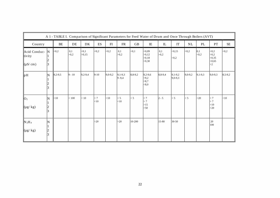
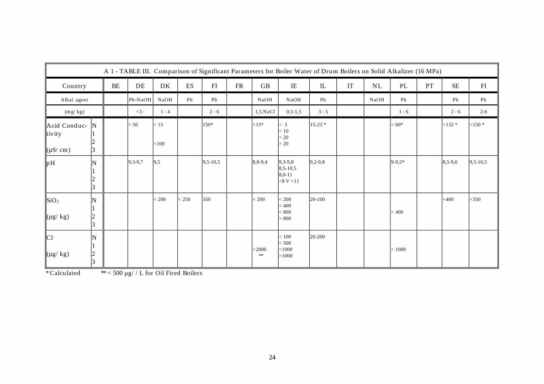
Guidelines from several countries/utilities have been collected together and compared. Only the mostsignificant chemical parameters for feed-water, boiler water, and steam have been considered, and although afew UNIPEDE members already use the action level approach, the normal operating values in individualguidelines have been found to be quite similar (see Appendix 1). It has therefore proved feasible to proposeaction levels which are broadly applicable across UNIPEDE members.
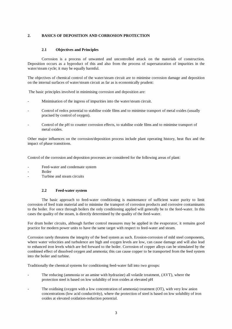
Data from the inquiry relate to high pressure plants, including both once through and drum type boilers. Thefollowing operational regimes are covered:
- All volatile treatment, AVT, - reducing regimes in which pH is controlled with ammonia and anoxygen scavenger (usually hydrazine) may be added.
- Combined water treatment, CWT, or oxygenated treatment, OT, - ammonia under slightly oxidising conditions usually achieved by oxygen dosing with very restrictive limits on acid conductivity.(In these guidelines the acronym OT will be used.)
22
- Non-volatile alkali - sodium hydroxide or sodium phosphate boiler water treatment applied underreducing conditions. (This regime is limited to drum boiler circuits only and ammonia is still used to adjust pH in feed-water and steam).
All the plants operate with high purity water and steam conditions and almost all national and companyguidelines define the target parameter values to be aimed for (either below or within which to operate) and themaximum values (or the maximum range) not to be exceeded.
The individual guidelines are based largely on the experience gained in the last twenty years as a result of manyearlier plant failures resulting from inadequate control of water and steam purity.
1.3 Scope of the Guidelines
These guidelines are intended for the operation of fossil fired generating plants. They do not cover lowrated industrial equipment, that operate with softened water. They include multi-pressure combined cycleplants, where each stage is considered as an individual boiler with respect to limits, but the control strategyhave to take account the interdependency of stages.
Existing guidance, reflecting good practice, takes into account avoidance of corrosion and deposition withinpower plant components. In specifying action levels an attempt is made to relate deviation from good practiceto possible plant damage.
In implementing the guidelines, it must be borne in mind that :
- Plant chemistry provides the manager with information for decision making. Commitment of management, to make economic and safety decisions based on risk assessment, backed by high quality technical guidance, is essential.
- Action levels must be credible to those running the plant, and making operational decisions, not just those with specialist chemistry knowledge.
- Operators are normally opposed to shutting-down plant as a consequence of loss of chemical control.
- Sufficient information must be available on which to base a request for intervention.
The guidelines recommend conditions for both continuous operation and for plant start-up. A target range andthree levels of action are defined in simple terms below, and in more detail in table 1.
Target range, no action required; this range covers the practicable values which plant managers willnormally achieve without excessive cost.
Action level 1, minor disturbance requiring investigation, diagnosis and optimization.
Action level 2, serious disturbance in chemical control requiring diagnosis and action to eliminate the cause.
Action level 3, very serious disturbance requiring substantial operator intervention, such as load reduction, or plant shut-down.
The limits are the same for start-up and continuous operation. For start-up however, the action levels should beused for optimising the start-up procedure.
33
2. BASICS OF DEPOSITION AND CORROSION PROTECTION
2.1 Objectives and Principles
Corrosion is a process of unwanted and uncontrolled attack on the materials of construction.Deposition occurs as a byproduct of this and also from the process of supersaturation of impurities in thewater/steam cycle; it may be equally harmful.
The objectives of chemical control of the water/steam circuit are to minimise corrosion damage and depositionon the internal surfaces of water/steam circuit as far as is economically prudent:
The basic principles involved in minimising corrosion and deposition are:
- Minimisation of the ingress of impurities into the water/steam circuit.
- Control of redox potential to stabilise oxide films and to minimise transport of metal oxides (usually pracised by control of oxygen).
- Control of the pH to counter corrosion effects, to stabilise oxide films and to minimise transport of metal oxides.
Other major influences on the corrosion/deposition process include plant operating history, heat flux and theimpact of phase transitions.
Control of the corrosion and deposition processes are considered for the following areas of plant:
- Feed-water and condensate system- Boiler- Turbine and steam circuits
2.2 Feed-water system
The basic approach to feed-water conditioning is maintenance of sufficient water purity to limitcorrosion of feed train material and to minimise the transport of corrosion products and corrosive contaminantsto the boiler. For once through boilers the only conditioning applied will generally be to the feed-water. In thiscases the quality of the steam, is directly determined by the quality of the feed-water.
For drum boiler circuits, although further control measures may be applied in the evaporator, it remains goodpractice for modern power units to have the same target with respect to feed-water and steam.
Corrosion rarely threatens the integrity of the feed system as such. Erosion-corrosion of mild steel components,where water velocities and turbulence are high and oxygen levels are low, can cause damage and will also leadto enhanced iron levels which are fed forward to the boiler. Corrosion of copper alloys can be stimulated by thecombined effect of dissolved oxygen and ammonia; this can cause copper to be transported from the feed systeminto the bolier and turbine.
Traditionally the chemical systems for conditioning feed-water fall into two groups:
- The reducing (ammonia or an amine with hydrazine) all volatile treatment, (AVT), where theprotection steel is based on low solubility of iron oxides at elevated pH
- The oxidising (oxygen with a low concentration of ammonia) treatment (OT), with very low anion concentrations (low acid conductivity), where the protection of steel is based on low solubility of iron oxides at elevated oxidation-reduction potential.
44
Although individual national and company guidelines generally specify limited concentration ranges, overallexperience indicates that these two protection mechanisms act simultaneously and there are no distinguishedborder lines between these types of conditioning. On the contrary, there is seen to be a continuum of suitableoperation conditions in a broad range with high pH and low oxygen concentration at one end, and low pH andhigh oxygen concentration at the other. Achievable purity of feed-water determines the degree of freedomavailable to operators within this range (high oxygen concentrations are incompatible with chloride andsulphate contamination).
Choice of the optimal chemical conditions within this broad range will be influenced by the boiler type,operational conditions, design and materials of construction. The presence of the following materials isparticularly important:
- Carbon steels are particularly compatible with mildly oxidising conditions in the absence of contamination anions (chloride, sulphate, etc.)
- Copper and copper alloys may suffer oxide transport problems in oxidising regimes in some plants andare vulnerable to attack by high levels of ammonia.
- Other materials, such as titanium, high chromium steel and chromium nickel steel are relatively indifferent to the conditioning regime.
2.3 Boiler
Two general classes of boilers are in use:
- Once through boilers in which water is evaporated to a high steam content. These are not tolerant of nonvolatile dosing chemicals and generally operate without further dosing downward the feedwaterchemical dosing.
- Drum boilers in which steam separation takes place in an unheated vessel. Boiling occurs in tubes through which water from the drum is recirculated, preventing dryout at the boiling surfaces. Such boilers may be tolerant of addition of low levels of non-volatile alkalis to prevent any risk of acidic corrosion.
The major objectives of boiler water treatment are to minimise deposition and corrosion of the boiler and toensure that steam is of the appropriate quality. During initial operation or post chemical cleaning, the boilersteel reacts with the water and steam to produce a protective film of iron oxides. The rate of reaction decreaseswith time as the thickness of the protective oxide film increases.
Boiler integrity can be prejudiced by a number of corrosion mechanisms or by overheating due to excessivethickness of oxide layers.
Nonvolatile impurities can concentrate in boilers and can increase the risk of corrosion. A number of factorsinfluence this. The build up of porous oxides by deposition onto heat transfer surfaces is particularlydetrimental. Other important factors include details of design, construction and operating regime.
The optimum boiler water condition is mildly alkaline. Deviation either to acidic or to highly alkalineconditions carries a risk of damage.
- Acid forming species (particularly chlorides, but also sulphates and organic anions) if present and
able to concentrate at boiler tube surfaces can result in very rapid rates of general corrosion. This typeof corrosion is often accompanied by hydrogen damage in mild steels which can lead to large suddentube failures. Acids can be generated from neutral salts particularly under oxidising conditions, and soit is particularly important to minimise ingress of chlorides and sulphates when using oxidisingtreatments and during oxygen transients at start-up for reducing treatments.
55
- If strong alkalis concentrate at surfaces, corrosion at unacceptable rates can also occur. Hydrogen damage is not normally caused by this type of attack, but some alloys are vulnerable to stress corrosioncracking and grooving in very high pH environments.
The required benign boiler water which is mildly alkaline at operating temperatures and pressures is achievedusing either an AVT or solid alkali treatment. The choice of regime may be limited by heat flux considerations,since this has a strong effect on concentration of involatile materials at boiling surfaces. Furthermore allsubstances that are added to control boiler water corrosion will inevitably impact upon steam quality.
Ideally the aim is to have a zero concentration of impurities, but this is impractical and realistic targets for bothacceptable operation and limited out of specification operation are needed.
2.4 Turbine, superheater and reheater
No direct conditioning of steam is normally applied, and hence the chemical quality of steam derivesfrom the measures applied to control feed and boiler water. Thus, one of the objectives of feed-water and boilerwater conditioning is to avoid deposition and corrosion in the steam pipework and turbine.
Steam purity must be high and actual quality is determined by:
- The concentration and solubility of salts in steam. The solubility is a function of pressure, temperature and of other chemical components
- Carry over of droplets of boiler water
- Injection of contaminated feed-water into steam for attemporation.
Both acidic and alkaline contaminants are important :
Sodium hydroxide, hydrogen sulphates and chlorides at certain concentrations present a stress corrosioncracking risk to steels, particularly with austenitic structures.
Salts deposited in steam pipework on-load can result in the development of concentrated solutions off-loadfollowing condensation of residual steam. This effect is particularly significant for reheaters and some types offeedheaters.
Decomposition products of organic impurities (organic and carbonate anions) may be implicated in turbinedamage.
The early condensation zone of the turbine is particularly sensitive to low volatility contaminants. Theseimpurities can concentrate on surfaces and in the very first droplets of condensate to form an aggressiveenvironment.
Silica is the most soluble of the common boiler water contaminants in high pressure steam and can becomesupersaturated during expansion in the turbine. This results in deposition on the blades causing loss of turbineefficiency, and in severe cases, loss of output.
3. RECOMMENDED CONCEPT OF CHEMICAL CONTROL
The chemical control is based on specifications of target and 3 action levels for out of targetconcentrations of chemical species. The most significant parameters are defined as key parameters andstringent control of them is required. If possible continuous monitoring must be applied.
Other chemical measurements will frequently provide valuable diagnostic data. Laboratory support is requiredfor periodical extended analysis and check of monitors.
66
The action levels are defined which allow the operator to use the same set of limits for continuous operationand for start-up. The detailed definitions of action levels are specified separately for these situations in table 1.Action levels are time related and the combination of concentration and time are set to minimise damage tofeed water systems, boiler and turbine components from corrosion and deposition processes.
The limits for action levels are defined as a function of pressure. This is a simplified approach; there are otherparameters which affect the "true" limits (e.g. heat flux). Nevertheless, pressure has been chosen as the mostconvenient parameter for operators. Boilers with extraordinary high heat flux (some designs of oil fired boilers)may require more stringent limits particularly in regard of boiler water quality.
- Operation in action level 1 regularly requires extended analysis for diagnostic and optimisationpurpose.
- Operation in action level 2 requires qualified interpretation of laboratory and monitor data to enablethe operators to take appropriate corrective steps.
- Operation in action level 3 with respect to the key parameters requires immediate action to shut-down the unit. In cases when less critical parameters (i.e. results of diagnostic measurements) exceed action level 3, load reduction will generally be required until the fault is rectified.
It is the aim of the guidelines to avoid the shut-down requirement as long as there is any realistic chance toeliminate the source of trouble. This should be managed by such actions as load reduction to reduce heat flux(i.e. reducing the risk of damage whilst remedial actions are being undertaken) before action level 3 limits areexceeded. Load reductions may also be essential when feed-water contamination is encountered in order toallow the flow of this water to attemporator sprays to be terminated without risk of overheating.
When a drum boiler on AVT dosing is exposed to high levels of impurities, it can be temporarily conditionedwith solid alkali (giving it higher tolerance of impurities) and thus delaying or avoiding action level 3.
Some designs of once-through boilers, with water filled level holding vessel having drain facilities, approachthe conditions of drum boiler (though without moisture separators) during low load operation.
The key parameters for action level 3 decisions are set out in table II.
4. RECOMMENDED CONTROL PARAMETERS
Chemical parameters are specified for the following sampling points:
- Condensate at the condensate pump discharge- Feed-water at the economizer inlet- Boiler water (preferably at a downcomer sampling point)- Steam (saturated and/or superheated)
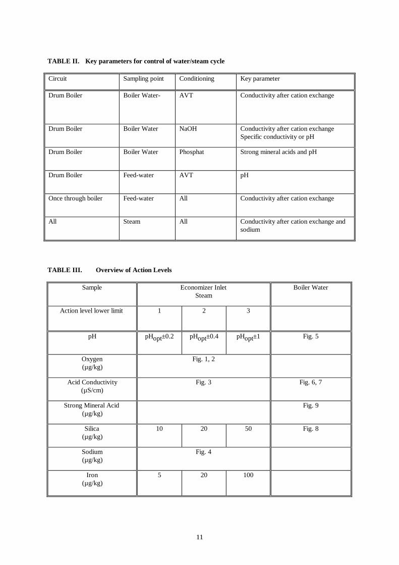
Table III summarises the specifications of chemical control parameters. Most of these are detailed in thediagrams in chapter 7, with parameters characterising the purity of the system expressed as function ofoperating pressure.
4.1 Feed-water and steam
Purity specifications for feed-water at the economizer inlet and for steam are the same, as nodistinction is drawn between units with drums and those with once-through boilers. Operation with condenserleakage on a drum boiler unit without a condensate polishing plant (CPP) is considered as operation atparticular action level.
The specification of pH and oxygen concentration in feed-water is given as a broad range for information infigure 1 and 2 (for systems with and without copper alloys). This specification does not suggest randomoperation within this range, but identifies the limit at which action level 3 becomes applicable.
77
To find a suitable target operational feed-water pH and oxygen range for a particular unit it is necessary tooptimize conditions for this unit according to its design, materials of construction, operation mode and achie-vable purity of the water/steam cycle. Particularly when copper alloys are used in the water/steam circuit, theoptimisation must take into account the enhancement of copper oxide solubility in the presence of higher levelsof oxygen and ammonia. Having determined the optimum operational pH, the target operating range is definedas within ± 0.2 of this value, action level 1 is defined as within ± 0.4 and action level 2 is defined as within ±1. Limits for oxygen are station specific and are thus individually estimated. Generally the purer feed-water is,the more relaxed specifications on oxygen can be accepted.
Boiler water pH of drum boilers operating on AVT treatment is determined by the pH of feed-water. A carefulcontrol of low limits in feed-water pH is therefore essential (specified in table III).
Control of pH of feed-water (and hence of steam) may be based on direct conductivity measurements as aconvenient reliable alternative for many plants.
Figure 3 specifies the action levels for acid conductivity of steam and feed-water.
Figure 4 shows action level limits for sodium in steam. For once through boilers this limits apply tosuperheated steam as well as to feed-water. For drum boilers this applies to saturated steam.
4.2 Boiler water
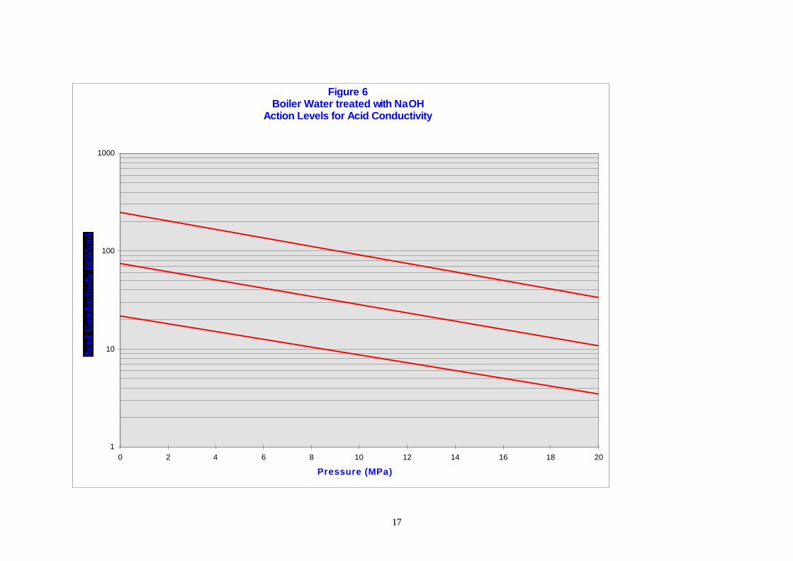
For boiler water, the action levels for units with drum boilers vary depending upon whether theapplied treatment is AVT or non-volatile alkali. Because of the enhanced ability of sodium hydroxide andphosphate dosed systems to maintain alkaline conditions at the boiler tube surface, greater concentrations ofimpurities than under AVT conditioning are tolerable in the bulk water and this is reflected in a higheracceptable acid conductivity.
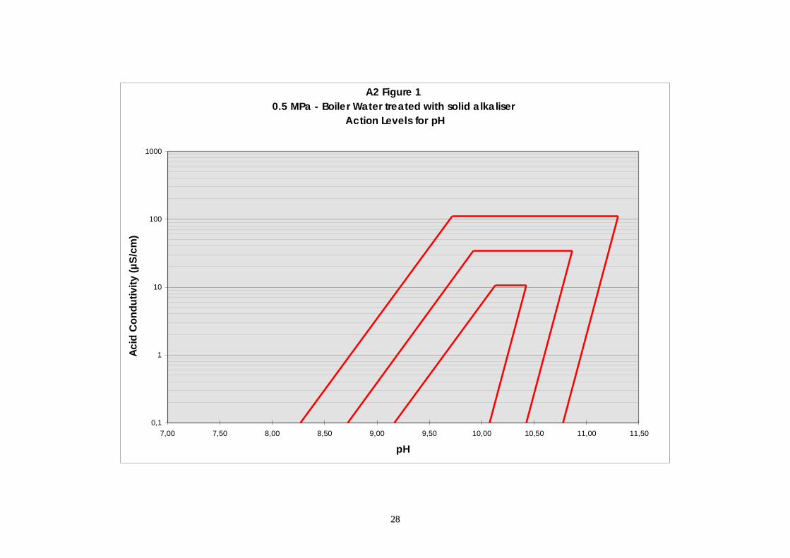
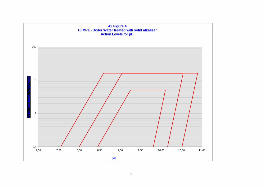
Action levels and target ranges for boiler water pH are given in figure 5 . The figure expresses the dependenceof the high and low pH limits on the pressure of the boiler and on the acid conductivity of boiler water. Theoptimal pH of boiler water increases with increase of acid conductivity, but falls with increasing pressure. Theratio of acid conductivity to boiler pressure can be used to derive specific pH limits for any individual boiler.Some examples of this procedure are shown in Appendix 2.
The broad range of normal operation is for general guidance only. The normal range of operation for a givenunit is dependent upon the chosen chemical conditioning regime and on factors specific to that unit.
Boiler water pH for AVT dosed plant is determined by feed-water treatment. The control of feed-water pH isthus essential not only for condensate and feed-water circuit, but also for the boiler. Because of the highvolatility of ammonia, the pH of boiler water is considerably lower than the pH of feed-water. Particularly atlow pressure a very high ammonia concentration is necessary to reach sufficient high pH in boiler water.Therefore, AVT treatment of boilers below 8MPa, particularly those with copper alloy components in thecondenser and/or feedwater circuit, is not recommended.
The control of boiler water pH in units conditioned with sodium hydroxide is usually based on the measurementof conductivity and acid conductivity. These two parameters give the operator a safe and reliable method tocontrolling boiler water purity by blow down and pH by either dosing additional NaOH or blowing down theexcess.
Boiler water pH in units alkalized with a phosphate is controlled by direct measurement of pH and phosphate.On units where phosphate hide-out occurs, a measurement of sodium is also necessary to assure adequatecontroll.
Guideline concentrations for the most important impurities in boiler water are given in figures 6, 7 and 8. Theanionic impurities are controlled via acid conductivity measurements of boiler water, when AVT or sodiumhydroxide is used for pH control. When phosphate treatment is chosen for pH control, this measurement wouldbe disturbed by phosphate contribution to the acid conductivity. Limits for concentration of strong mineral
88
acids (fig. 9) are then used to ensure purity of boiler water. The practical definition of strong mineral acidconcentration is the sum of chloride and sulphate concentrations.
4.3 Condensate
Because condenser leakage is the major source of impurities in circuits, monitoring of the condensateis particularly important as an early indicator of the need for action. As station circuits vary, consideration foreach plant on an individual basis is necessary to ensure that contaminated condensate is not fed to vulnerablecomponents (such as attemporator sprays, etc.).
Units with once through boiler are always equipped with a condensate polishing plant (CPP) to take care of thisproblem. The CPP should be designed, maintained and operated on a standard which is able to cope withcondenser leakages.
Drum boiler units often do not have a CPP and in case of condenser leakage precautions must be taken to avoiddamage.
The specific action level responses (action level determined by feed-water specifications) appropriate tocontamination of condensate are as follows:
Action level 1 - reduce flow to attemporators sufficiently to maintain sodium in steam within target. This mayimply either feeding attemporators from an uncontaminated alternative source, or minor load reduction in orderto avoid overheating.
Action level 2 - terminate flow to attemporators. Adjust load and provide alternative uncontaminated watersource as appropriate. Prepare to increase boiler blow-down or condensate polisher regeneration frequency(where fitted). Plan to address condenser leakage at first convenient opportunity.
Action level 3 - reduce load and address condenser leakage as soon as practicable.
5. FUTURE DEVELOPMENTS
The action level concept is seen as positive progress towards the development of optimal controlroutines. Operation outside the target region will cause damage and its impact will depend on both the size andthe duration of the excursion. EPRI has addressed this relationship, giving time limits for operation at eachaction level during one year. This is a rather rigid approach, and does not take into consideration the actualoperating conditions and lifetime prognosis for the installation. A system of chemistry evaluation on the basisof economic/scientific evaluation of all possibilities for damage is not possible. A somewhat more pragmaticsystem based on quality indices is suggested in Appendix 3 of these guidelines. This system is based on asimple mathematical presentation of general long time operational experience. However, it must be consideredas a rough preliminary guide and may benefit from future development.
6. REFERENCES
[1] Report on the chemical standards of the water-steam cycle in Power Stations as in use by the member-Countries of the UNIPEDE. KEMA, Arnhem, november 1970. Made for UNIPEDE SUB-COMMITTEE for the study of electric Power Station Chemistry.
[2] VGB-R 450 L - Richtlinien für Kesselspeisewasser, Kesselwasser und Dampf von Dampferzeugernüber 68 bar zulässigem Betriebsdruck, 1988
[3] Interim Consensus Guidelines on Fossil Plant Cycle Chemistry, EPRI CS-4629, June 1986
99
7. TABLES
1100
TABLE I. Definitions and characteristic of Action Levels
Actionlevel
Characterisation Risk Action during operation(specific actions on condensate in chapter 4.3)
Action during start-up
Target Normal stable operation,where everything isunder control
The maintenance of chemical control through themonitoring of key parameters should be continued.
Target should be reached within 24 hours. If not,improvements in system control are required.
1 Periodic or minordisturbances in chemicalcontrol.
Long term damage andreduction in remaininglife of power cyclecomponents.
Monitoring of the circuit chemistry should beextended to diagnostic components to identify thesource of the problem. Strategic considerationsshould be made to avoid similar occurrences in thefuture.
Action level 1 for key parameters should be achieved in 2to 8 hours for warm and cold starts respectively.
2 Serious loss of chemicalcontrol.
Serious damage tocomponents due todeposition andcorrosion. Significantreduction in thecomponent life
Immediate action should be taken to find andeliminate the cause within hours and/or actionsshould be taken to minimise the damage (e.g.decrease load).
Fire the boiler. Check the steam quality. At least actionlevel 2 for all parameters should be reached beforeturbine is brought into service.
3 Chemistry out ofcontrol.
Component failure. The unit should be shut down within 1 hour usingthe normal shut down procedure if one of the keyparameters deteriorate to action level 3. If one of thediagnostic parameters deteriorates to this actionlevel, reduce load to prevent immediate damage andto gain time to restore chemical control.
Purge the boiler until all the key parameters are belowaction level 3.
1111
TABLE II. Key parameters for control of water/steam cycle
Circuit Sampling point Conditioning Key parameter
Drum Boiler Boiler Water- AVT Conductivity after cation exchange
Drum Boiler Boiler Water NaOH Conductivity after cation exchangeSpecific conductivity or pH
Drum Boiler Boiler Water Phosphat Strong mineral acids and pH
Drum Boiler Feed-water AVT pH
Once through boiler Feed-water All Conductivity after cation exchange
All Steam All Conductivity after cation exchange andsodium
A2 Figure 416 MPa - Boiler Water treated with solid alkaliser
Action Levels for pH
0,1
1
10
100
7,00 7,50 8,00 8,50 9,00 9,50 10,00 10,50 11,00
pH
3322
Appendix 3
Assessment of water/steam chemistry by quality indices
The quality index I for any control parameter p is in general terms defined as a ratio of lifetime consumption(TP) of a component effected by the control parameter at the actual operating value and the lifetimeconsumption (TL1p) of this component operating at the reference conditions, which means at the limit betweentarget and action level 1 (L 1p).
Ip = dTP / dTL1p
The index expresses the relative rate of lifetime consumption and will then be 1 at the operation at the limit forAction level 1, which is considered as conditions with reference lifetime consumption:
At P = L1p Ip = I0 = dTL1p/dTL1p = 1
The lifetime consumption at actual conditions T p of a particular component during any operation period t isthen calculated from the formula:
T I dtP P
t
= ∫ *0
Operating at action level 1 (P > L L1p and P < LL2p) the index will have value above 1 and operating below theaction level 1 limit (target area), the index will have value less then 1. Thus the lifetime consumption will befaster or slower comparing to the operation at reference conditions.
It is extremely difficult to establish a scientifically or statistically based model for the lifetime consumptiondeviations from reference conditions. A pragmatic way was chosen , based on the following concept:- The lifetime consumption should be evaluated separately for each main component of water/steam
circuit using parameters significant for the componen t in question.- The rate of lifetime consumption (Index I) is an exponential function of the relevent parameter- The exponential function is normalized for action level limits defining:
at P = L1p I = 1at P = L2p I = 10at P = L3p I = 100at P = 3*L3p I = 1000
The justification of these values is based on some experience from units operating with good chemical practiceand also from units where less attention is paid to chemistry, however, the data basis is limited.
The index is mathematically related to action levels by the following equations:
I P
P LL L=
−−10
1
2 1 for L1 < P ≤ L2
I P
P LL L=
−−
+10
2
3 21
for L2 < P < L3
3333
I P
P LL=
− +10
3
322
* for P > L3
where IP is the index for parameter pP is the monitored value of parameter pL1 is the threshold for action level 1L2 is the threshold for action level 2L3 is the threshold for action level 3
The index can be used for relative evaluation of the chemical performance with respect to the lifetimeconsumption of components for which the parameter p is the key parameter. It has to be emphasized, that it isan evaluation relative to reference conditions and if more than one key parameter is relevant for the componentin question, a combination of indices described on page 33 should be used.
As examples of key parameters for some components are:1. Acid conductivity of feed-water for the evaporator of once through boiler with respect to the operation time
between acid cleanings.2. Acid conductivity and pH of boiler water for the evaporator of a drum boiler on caustic treatment with
respect to the operation time between acid cleanings.3. Acid conductivity of boiler water and pH of feed-water for the evaporator of a drum boiler on AVT with
respect to the operation time between acid cleanings.4. Acid conductivity of steam for the turbine blades.5. Conductivity of the effluent from condensate polishing plant (CPP) as a key parameter for performance of
CPP. In this case there is no direct connection to lifetime of any particular component.
Some examples are illustrated in more details .
For a typical cold start-up a good practice is to reach L1 (coming from L3) for acid conductivity in feed-waterwithin 24 hours. The calculation shows, that the mean value of the index I is about 30. This indicates, that thechemical load on the evaporator during this day of start-up is similar to the load of 30 (720 h) days of operationat L1. For a unit, which is not performing very well, the purification period during the start-up can easily take 2days, which makes the life consumption for the whole period 2*30=60 days (1440 h).
Similarly it can be calculated, that a hot start-up of a good unit taking 16 hours will be equivalent to roughly200 h lifetime consumption, while unattended unit will use 400 h equivalent operation at reference condition.
These values are used in examples below.
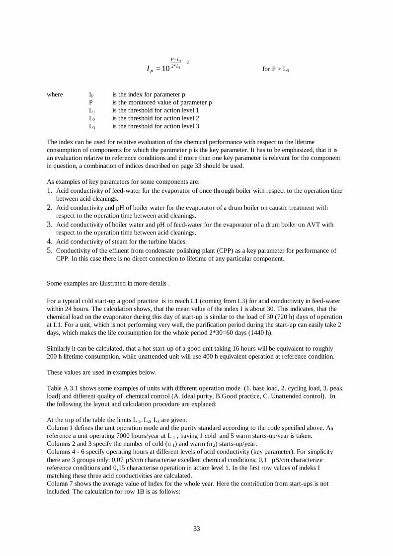
Table A 3.1 shows some examples of units with different operation mode (1. base load, 2. cycling load, 3. peakload) and different quality of chemical control (A. Ideal purity, B.Good practice, C. Unattended control). Inthe following the layout and calculation procedure are explaned:
At the top of the table the limits L 1, L2, L3 are given.Column 1 defines the unit operation mode and the purity standard according to the code specified above. Asreference a unit operating 7000 hours/year at L 1 , having 1 cold and 5 warm starts-up/year is taken.Columns 2 and 3 specify the number of cold (n 1) and warm (n 2) starts-up/year.Columns 4 - 6 specify operating hours at different levels of acid conductivity (key parameter). For simplicitythere are 3 groups only: 0,07 µS/cm characterise excellent chemical conditions; 0,1 µS/cm characterizereference conditions and 0,15 characterise operation in action level 1. In the first row values of indeks Imatching these three acid conductivities are calculated.Column 7 shows the average value of Index for the whole year. Here the contribution from start-ups is notincluded. The calculation for row 1B is as follows:
3344
II t
ti i
i
= = ++ =∑
∑* , * *
,0 501 3000 1 4000
3000 40000 786
Column 8 show the calculated equivalent lifetime consumption T c including contributions from start-ups. Thecalculation for row 1B is as follows:
The registered lifetime consumption is of course 7000 h, but chemically the evaporator has received more loaddue to start-ups, but decreased load because of the excellent purity in part of the operation time. In calculationof examples with purity standard C, a higher life time consumption is used for start-ups (1440, 400).
Columns 9 and 10 show a prognosis for acid cleanings if the same operating conditions would be maintainedall the time. This calculation is based on experience with units operating close to the conditions of the referenceunit. These units used to be acid cleaned after 100 000 operating hours.
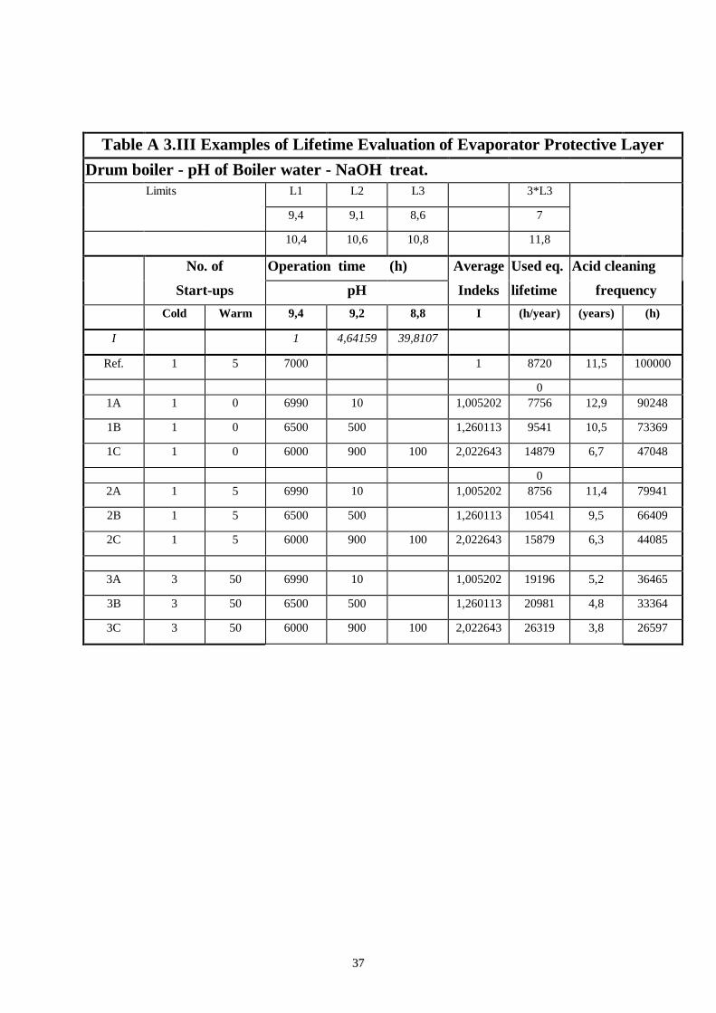
Tables A 3.II - A 3.V show similar exercises for drum boilers on NaOH and AVT respectively. Two keyparameters are used for separate calculation in each case, and in the table A 3.VI a combined evaluation ofindices calculated from these two key parameters is shown. As the best combination of indices was found to betheir sum -1. Mathematically:
I12 = I1 + I2 - 1
More generaly:
I I ii ii
i
11
1= − +=∑
On the basis of these combined indices the expected acid cleaning frequency is calculated.
It must be emphasised that the method is designed for evaluation of operational lifetime consumption. Theimpact of the off-load damage on lifetime must be evaluated separately. It may be possible to use the sameconcept, but a careful consideration should then be given to reference condition, key parameters and actionlevels.
3355
Table A 3.I Examples of Lifetime Evaluation of Evaporator Protective LayerOnce Trough boiler - Acid conductivity of Feedwater
L1 L2 L3 3*L3
0,1 0,2 0,5 1,5
No. of Operation time (h) Average Used eq. Acid cleaning
Start-ups at acid conductivity (µS/cm) Index lifetime frequencyCold Warm 0,07 0,1 0,15 I (h/year) (years) (h)
I 0,501187 1 3,1622777
Ref. 1 5 7000 1 8720 11,5 100000
1A 1 0 7000 0,50 4228 23,7 165551
1B 1 0 3000 4000 0,79 6224 16,1 112476
1C 1 0 1000 3000 4000 2,02 17590 5,7 45480
2A 1 5 4000 1000 0,60 4725 21,2 105826
2B 1 5 2000 3000 0,80 5722 17,5 87376
2C 1 5 2000 3000 2,30 14927 6,7 33497
3A 3 50 1000 2000 0,83 14661 6,8 20462
3B 3 50 2000 1000 1,72 17322 5,8 17319
3C 3 50 3000 3,16 33807 3,0 8874
3366
Table A 3.II Examples of Lifetime Evaluation of Evaporator Protective LayerDrum boiler - Acid conductivity of Boiler water - NaOH treated
Limits L1 L2 L3 3*L3
µS/cm 5 15,8 50 150
No. of Operation time (h) Average Used eq. Acid cleaning
Starts-up at acid conductivity (µS/cm) Index lifetime frequencyCold Warm 3 5 10 I (h/year) (years) (h)
I 0,65285 1 2,90378
Ref. 1 5 7000 1 8720 11,5 100000
1A 1 0 7000 0,65 5290 18,9 132326
1B 1 0 3000 4000 0,85 6679 15,0 104813
1C 1 0 1000 3000 4000 1,91 16708 6,0 47881
2A 1 5 4000 1000 0,72 5331 18,8 93784
2B 1 5 2000 3000 0,86 6026 16,6 82978
2C 1 5 2000 3000 2,14 14151 7,1 35332
3A 3 50 1000 2000 0,88 14813 6,8 20253
3B 3 50 2000 1000 1,63 17064 5,9 17581
3C 3 50 3000 2,90 33031 3,0 9082
3377
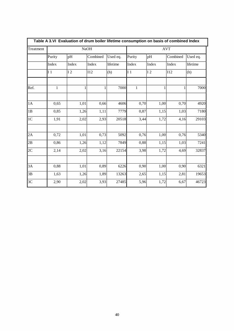
Table A 3.III Examples of Lifetime Evaluation of Evaporator Protective LayerDrum boiler - pH of Boiler water - NaOH treat.
Limits L1 L2 L3 3*L3
9,4 9,1 8,6 7
10,4 10,6 10,8 11,8
No. of Operation time (h) Average Used eq. Acid cleaning