Wake County PSC Skylight & PSC & L Bldg. Fall Protection ADDENDUM NO. 2 Raleigh, North Carolina Page 1 April 8, 2021 HUFFMAN ARCHITECTS, PA 632 PERSHING ROAD RALEIGH, NORTH CAROLINA 27608 PHONE (919) 740-5669 TO: ALL PRIME BIDDERS OF RECORD This Addendum forms a part of the Contract Documents and modifies the original Project Manual and Construction Documents dated March 15, 2021. Acknowledge receipt of this Addendum in the space provided on the Bid Form. Failure to do so may subject the Bidder to disqualification. This addendum consists of three (3) pages, fourteen (14) 8 ½” x 11” attachments, and one (1) 24x36 attachment. All documents are distributed digitally. SPECIFICATIONS: Item No. Description 1. Add the following specification Section “08 3950 BULLET RESISTANT ALUMINUM DOOR AND STOREFRONT FRAME SYSTEM.” 2. Add the following specification section “11 0140 ROOFTOP FALL PROTECTION ANCHORAGE SYSTEMS. 3. Section 01 3100 – PROJECT MANAGEMENT AND COORDINATION – Make the following revisions. a. Change 1.6.D To read “Progress Meetings: Conduct progress meetings at two-week intervals. Coordinate dates of meetings with preparation of payment requests.” 4. Section 01 3300 – SUBMITTAL PROCEDURES – Make the following revisions. a. Change 1.4.B.A.1 To read “Shop drawing and product data submittals shall be transmitted to Architect in electronic (PDF) format.” b. Delete section 1.4.B.B.3. 5. Section 07 4243 – COMPOSITE WALL PANELS – Make the following revisions. a. Delete section 2.2 WEATHER BARRIER. 6. Section 07 8100 – APPLIED FIREPROOFING – Make the following revisions. a. Change 3.4.A To read “Special Inspections: A third party special inspector shall be hired by the Owner to perform the following special inspections:” 7. Section 08 4115 – ALUMINUM-FRAMED ENTRANCES AND STOREFRONTS – Make the following revisions: a. 1.2 SUMMARY A.1 change to read “Interior manual-swing entrance doors.” b. 1.2 SUMMARY B add line 3. “Section 08 3950 Bullet Resistant Aluminum Door and Storefront Frame System.: c. Remove paragraph 2.1 MANUFACTURERES A. Drawings: Item No. Description 1. Drawing Sheet S001 – Make the following revisions: a. Replace the entire sheet with the attached sheet S001 Revision 1 Special Inspections Revision dated 4/8/2021. b. Add the attached “Statement of Special Inspections.”
Transcript
Wake County PSC Skylight & PSC & L Bldg. Fall Protection ADDENDUM NO. 2 Raleigh, North Carolina Page 1 April 8, 2021 HUFFMAN ARCHITECTS, PA 632 PERSHING ROAD RALEIGH, NORTH CAROLINA 27608 PHONE (919) 740-5669 TO: ALL PRIME BIDDERS OF RECORD This Addendum forms a part of the Contract Documents and modifies the original Project Manual and Construction Documents dated March 15, 2021. Acknowledge receipt of this Addendum in the space provided on the Bid Form. Failure to do so may subject the Bidder to disqualification. This addendum consists of three (3) pages, fourteen (14) 8 ½” x 11” attachments, and one (1) 24x36 attachment. All documents are distributed digitally. SPECIFICATIONS: Item No. Description 1. Add the following specification Section “08 3950 BULLET RESISTANT ALUMINUM DOOR AND
STOREFRONT FRAME SYSTEM.”
2. Add the following specification section “11 0140 ROOFTOP FALL PROTECTION ANCHORAGE SYSTEMS. 3. Section 01 3100 – PROJECT MANAGEMENT AND COORDINATION – Make the following revisions.
a. Change 1.6.D To read “Progress Meetings: Conduct progress meetings at two-week intervals. Coordinate dates of meetings with preparation of payment requests.”
4. Section 01 3300 – SUBMITTAL PROCEDURES – Make the following revisions.
a. Change 1.4.B.A.1 To read “Shop drawing and product data submittals shall be transmitted to Architect in electronic (PDF) format.”
b. Delete section 1.4.B.B.3.
5. Section 07 4243 – COMPOSITE WALL PANELS – Make the following revisions. a. Delete section 2.2 WEATHER BARRIER.
6. Section 07 8100 – APPLIED FIREPROOFING – Make the following revisions.
a. Change 3.4.A To read “Special Inspections: A third party special inspector shall be hired by the Owner to perform the following special inspections:”
7. Section 08 4115 – ALUMINUM-FRAMED ENTRANCES AND STOREFRONTS – Make the following
revisions: a. 1.2 SUMMARY A.1 change to read “Interior manual-swing entrance doors.”
b. 1.2 SUMMARY B add line 3. “Section 08 3950 Bullet Resistant Aluminum Door and Storefront Frame
System.:
c. Remove paragraph 2.1 MANUFACTURERES A. Drawings: Item No. Description 1. Drawing Sheet S001 – Make the following revisions:
a. Replace the entire sheet with the attached sheet S001 Revision 1 Special Inspections Revision dated 4/8/2021.
b. Add the attached “Statement of Special Inspections.”
Wake County PSC Skylight & PSC & L Bldg. Fall Protection ADDENDUM NO. 2 Raleigh, North Carolina Page 2 April 8, 2021 CLARIFICATIONS: Item No. Description 1. OBE standard Reliance is the Basis-of-Design, but the specs also call for an OITC of 33 minimum & Bullet-
resistant glazing in both the system & in the doors. OBE does not have Bullet-resistant doors or curtain wall to offer. Do the doors and frames need to be Bullet-resistant or just the glazing? Also, the Bullet-resistant glazing is 1-1/4” thick. We cannot accommodate this thickness in our doors (1” Max). The thickness will not be a problem in the curtain wall. Also, none of our systems meet an OITC of 33 minimum. Response: The basis-of-design shall be Oldcastle Reliance HTC. It is understood that Oldcastle does not have bullet resistant doors or curtain wall frames. ¼” steel plate shall be added to the curtain wall frames, per the drawings, to provide bullet-resistance. The basis-of-design for the exterior bullet resistant doors shall be the Aluminum Bullet Resistant Door ABRD Series, as manufactured by C.R. Laurence, Co., Inc (see attached specification section 08 3950). The minimum OTIC of 33 shall not be required.
2. “The spec doesn’t say that the Curtainwall framing has to be bullet resistant, but the doors and glazing must
be. I was hoping you could clarify if the framing has to be bullet resistant or not. Our security glazing vendor is seeing if they can do that glass in a thinner size so that we would be able to fit it into a standard curtainwall frame. If the framing doesn’t have to be bullet resistance it opens up our options quite a bit and will be much less expensive. If the entire assembly - framing, glazing, and doors must have steel inserts to be bullet resistance it narrows the vendors quite a bit and inflates the price.” Response: See response to CLARIFICATIONS Item No. 1 Above. The curtainwall framing must be able to accept 1” insulated glass and bullet resistant glass, an air space, and ¼” glass for a total thickness of 1 ¾ inches.
3. We were reviewing the RFQ package for the Wake County Fall Protection scope on Planhub. We didn't see any specifications for the fall protection equipment, however the plans did defer to a particular player in the market. We can offer the full package - anchors, lifelines, guardrail, davits, testing, etc. However, I believe a substitution request may be required. Can you confirm Tractel may be able to provide equipment? Response: See attached specification section 11 0140 ROOFTOP FALL PROTECTION ANCHORAGE SYSTEMS”.
4. Section 01 3100; 1.6.D requires weekly progress meetings. Please confirm weekly meetings are required. Response: Weekly progress meetings are not required. Progress meetings will be scheduled every two weeks.
5. Does the permit fee allowance cover lane and sidewalk closures that may be required to perform the work? Response: No, the permit fee allowance, Allowance No. 1, only covers the actual cost of the building permit fee. The cost of all inspection fees, lane, and sidewalk closures, etc. are not covered by the allowance and are the responsibility of the general contractor.
6. Section 01 3300 requires the use of Submittal Exchange for shop drawing transmission. Is this required? Response: No, Submittal Exchange is not required.
7. Spec section 07 2726 is requiring a fluid applied air barrier however spec section 07 4243 (2.2.A) mentions the installation of house wrap style air barrier. Please clarify. Response: Provide the fluid applied air barrier per specification section 07 2726.
Wake County PSC Skylight & PSC & L Bldg. Fall Protection ADDENDUM NO. 2 Raleigh, North Carolina Page 3 April 8, 2021
8. Please confirm that the contractor is responsible for special inspection of fire proofing (per section 07 8100; 3.4.A).
Response: A special inspector shall be hired by Wake County. The General Contractor is not responsible to hire a special inspector. See attached revised Sheet S001 and the Statement of Special Inspections.
END OF ADDENDUM NUMBER TWO
04/08/2021
Wake County PSC Skylight & PSC & L Bldg Fall Protection Huffman Architects, PA
BULLET RESISTANT ALUMINUM DOOR AND STOREFRONT FRAME SYSTEM 08 3950 - 1
SECTION 08 3950 BULLET RESISTANT ALUMINUM DOOR AND STOREFRONT FRAME SYSTEM
PART 1 - GENERAL
1.1 RELATED DOCUMENTS
A. Drawings and general provisions of the Contract, including General and Supplementary Conditions and Division 01 Specification Sections, apply to this Section.
1.2 SUMMARY
A. Section Includes:
1. Exterior bullet resistant aluminum door manual-swing entrance doors.
A. ADA/ABA Accessibility Guidelines: U.S. Architectural & Transportation Barriers Compliance Board's "Americans with Disability Act (ADA) and Architectural Barriers Act (ABA) Accessibility Guidelines for Buildings and Facilities."
1.4 PERFORMANCE REQUIREMENTS
1.5 ACTION SUBMITTALS
A. Product Data: For each type of product indicated. Include construction details, material descriptions, dimensions of individual components and profiles, and finishes for aluminum-framed systems. 1. Certification: Provide printed data in sufficient detail to indicate compliance with the
contract.
B. Shop Drawings: For swinging doors. Include plans, elevations, sections, details, and attachments to other work.
1. For entrance doors, include hardware schedule and indicate operating hardware types, functions, quantities, and locations.
C. Samples for Verification: For each type of exposed finish required, in manufacturer's standard sizes.
D. Other Action Submittals:
Wake County PSC Skylight & PSC & L Bldg Fall Protection Huffman Architects, PA
BULLET RESISTANT ALUMINUM DOOR AND STOREFRONT FRAME SYSTEM 08 3950 - 2
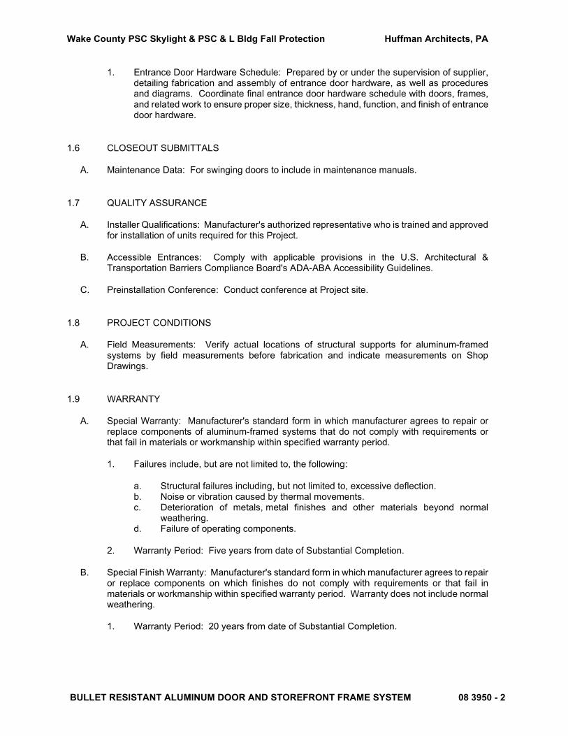
1. Entrance Door Hardware Schedule: Prepared by or under the supervision of supplier, detailing fabrication and assembly of entrance door hardware, as well as procedures and diagrams. Coordinate final entrance door hardware schedule with doors, frames, and related work to ensure proper size, thickness, hand, function, and finish of entrance door hardware.
1.6 CLOSEOUT SUBMITTALS
A. Maintenance Data: For swinging doors to include in maintenance manuals.
1.7 QUALITY ASSURANCE
A. Installer Qualifications: Manufacturer's authorized representative who is trained and approved for installation of units required for this Project.
B. Accessible Entrances: Comply with applicable provisions in the U.S. Architectural & Transportation Barriers Compliance Board's ADA-ABA Accessibility Guidelines.
C. Preinstallation Conference: Conduct conference at Project site.
1.8 PROJECT CONDITIONS
A. Field Measurements: Verify actual locations of structural supports for aluminum-framed systems by field measurements before fabrication and indicate measurements on Shop Drawings.
1.9 WARRANTY
A. Special Warranty: Manufacturer's standard form in which manufacturer agrees to repair or replace components of aluminum-framed systems that do not comply with requirements or that fail in materials or workmanship within specified warranty period.
1. Failures include, but are not limited to, the following:
a. Structural failures including, but not limited to, excessive deflection. b. Noise or vibration caused by thermal movements. c. Deterioration of metals, metal finishes and other materials beyond normal
weathering. d. Failure of operating components.
2. Warranty Period: Five years from date of Substantial Completion.
B. Special Finish Warranty: Manufacturer's standard form in which manufacturer agrees to repair or replace components on which finishes do not comply with requirements or that fail in materials or workmanship within specified warranty period. Warranty does not include normal weathering.
1. Warranty Period: 20 years from date of Substantial Completion.
Wake County PSC Skylight & PSC & L Bldg Fall Protection Huffman Architects, PA
BULLET RESISTANT ALUMINUM DOOR AND STOREFRONT FRAME SYSTEM 08 3950 - 3
PART 2 - PRODUCTS
2.1 MANUFACTURERS
A. Manufacturers: The basis-of-design shall be based on Aluminum Bullet Resistant Door and Storefront Frame ABRD Series, as manufactured by C.R. Laurence Co. Inc.
2.2 MATERIALS
A. Aluminum: Extrusions shall be 6063-T5 alloy and temper (ASTM B221 alloy T5 temper). Fasteners, where exposed, shall be aluminum, stainless steel or zinc plated steel in accordance with ASTM A 164. Perimeter anchors shall be aluminum or steel, providing the steel is properly isolated from the aluminum. Framing must utilize testing recognized under the standards established by u.l. 752 for bullet resistant components.
B. Finish: Aluminum extrusions shall be given a caustic etch followed by an anodic oxide treatment to obtain Fluoropolymer paint coating conforming with the requirements of AAMA 2605. Color shall be a custom color to match the curtain wall finish.
C. Glazing: The glazing must be in accordance with U.L. 752 testing standards (Level 3) and as specified in Section 08 800 Glazing.
2.3 ENTRANCE DOOR SYSTEMS
A. Entrance Doors: Manufacturer's standard glazed entrance doors for manual-swing operation.
1. Door Construction: 2-3/16 inches overall thickness,
2. Door Design: As indicated.
a. Accessible Doors: Smooth surfaced for width of door in area within 10 inches (255 mm) above floor or ground plane.
3. Glazing Stops and Gaskets: Manufacturer’s standard.
a. Provide nonremovable glazing stops on outside of door.
B. Entrance Door Hardware: As specified in Section 08 7110 "Door Hardware."
C. Bullet Resistance: Install bullet resistant Level 3 fiberglass per manufacturer’s requirements.
2.4 FABRICATION
A. Form or extrude aluminum shapes before finishing.
B. Weld in concealed locations to greatest extent possible to minimize distortion or discoloration of finish. Remove weld spatter and welding oxides from exposed surfaces by descaling or grinding.
C. Entrance Doors: Reinforce doors as required for installing entrance door hardware.
Wake County PSC Skylight & PSC & L Bldg Fall Protection Huffman Architects, PA
BULLET RESISTANT ALUMINUM DOOR AND STOREFRONT FRAME SYSTEM 08 3950 - 4
1. At exterior doors, provide weather sweeps applied to door bottoms.
D. Entrance Door Hardware Installation: Factory install entrance door hardware to the greatest extent possible. Cut, drill, and tap for factory-installed entrance door hardware before applying finishes.
E. After fabrication, clearly mark components to identify their locations in Project according to Shop Drawings.
2.5 ALUMINUM FINISHES
A. High-Performance Organic Finish: 3-coat fluoropolymer finish complying with AAMA 2605 and containing not less than 70 percent PVDF resin by weight in both color coat and clear topcoat. Prepare, pretreat, and apply coating to exposed metal surfaces to comply with coating and resin manufacturers' written instructions.
1. Color and Gloss: Provide a custom finish to match the finish of the existing curtain wall system.
PART 3 - EXECUTION
3.1 EXAMINATION
A. Examine areas and conditions, with Installer present, for compliance with requirements for installation tolerances and other conditions affecting performance of the Work.
B. Proceed with installation only after unsatisfactory conditions have been corrected.
3.2 INSTALLATION
A. General:
1. Comply with manufacturer's written instructions. 2. Do not install damaged components. 3. Fit joints to produce hairline joints free of burrs and distortion. 4. Rigidly secure nonmovement joints. 5. Install anchors with separators and isolators to prevent metal corrosion and electrolytic
deterioration. 6. Seal joints watertight unless otherwise indicated.
B. Install components plumb and true in alignment with established lines and grades, and without warp or rack.
C. Install glazing as specified in Section 08 8000 "Glazing."
D. Entrance Doors: Install doors to produce smooth operation and tight fit at contact points.
1. Exterior Doors: Install to produce weathertight enclosure and tight fit at weather stripping.
Wake County PSC Skylight & PSC & L Bldg Fall Protection Huffman Architects, PA
BULLET RESISTANT ALUMINUM DOOR AND STOREFRONT FRAME SYSTEM 08 3950 - 5
2. Field-Installed Entrance Door Hardware: Install surface-mounted entrance door hardware according to entrance door hardware manufacturers' written instructions using concealed fasteners to greatest extent possible.
3.3 ADJUSTING
A. Adjust operating entrance door hardware to function smoothly as recommended by manufacturer.
1. For entrance doors accessible to people with disabilities, adjust closers to provide a 3-second closer sweep period for doors to move from a 70-degree open position to 3 inches (75 mm) from the latch, measured to the leading door edge.
END OF SECTION 09 3950
Wake County PSC Skylight & PSC & L Bldg Fall Protection Huffman Architects, PA
ROOFTOP FALL PROTECTION ANCHORAGE SYSTEMS 11 0140-1
SECTION 11 0140 - ROOFTOP FALL PROTECTION ANCHORAGE SYSTEMS
PART 1 - GENERAL
1.1 SECTION INCLUDES
A. Personal Fall Arrest Anchorage Systems:
1. System design and certification. 2. Fall protection roof anchors. 3. Horizontal lifelines. 4. Training.
1.2 RELATED SECTIONS
A. Section 05 1200 “Structural Steel Framing.”
1.3 REFERENCES
A Occupational Safety and Health Administration (OSHA):
5. OSHA 1910, Subpart D - Walking and Working Surfaces. 6. OSHA 1910.66, Appendix C - Personal Fall Arrest Systems. 7. OSHA Procedures and Precautions for Employees Using Decent Control
Equipment.
B. American National Standards Institute: ANSI Z 359 - Fall Protection Code.
C. American Institute of Steel Construction (AISC): Load and Resistance Factor Design.
B. American Welding Society: AWS D1.1 - Structural Welding Code.
1.4 SUBMITTALS
A Submit under provisions of Section 01 3300 “Submittal Procedures.”
B. Product Data: Manufacturer's data sheets and detail drawings for each product to be used, including:
1. Preparation instructions and recommendations. 2. Storage and handling requirements and recommendations. 3. Product literature, material specifications. 4. Installation details and methods. 5. Dimensions of product components. 6. Finishes of anchor components.
C. Shop Drawings
1. Shall be to scale and clearly show dimensioned layout of system components. 2. Include details for each specified product to indicate materials, dimensions,
accessories, rated load, and ultimate load. Details shall clearly indicate attachment to building structure and welds shall be indicated by AWS welding symbols, distinguishing between shop and field welds, and show size, length and type of each weld.
Wake County PSC Skylight & PSC & L Bldg Fall Protection Huffman Architects, PA
ROOFTOP FALL PROTECTION ANCHORAGE SYSTEMS 11 0140-2
3. Include notes to indicate proper use of system. 4. Shall bear the seal of the supervising registered professional engineer.
Professional engineer shall be licensed in the state of North Carolina.
D. Close-out Submittals:
1. Provide a Fall Protection Anchorage System Log Book to include:
a. Requirements for inspection and re-certification. b. Statement by supervising qualified fall protection engineer that system was
designed and installed in accordance with ANSI Z359.6 and is certified for use. It is the requirement of the General Contractor to hire a fall protection engineer to provide this statement and certification.
c. As-built Drawings to indicate as-installed anchorage locations, details, and user notes.
1) The As-Built drawings shall provide a fall protection device labeling and numbering system such that each fall protection device is specifically identified. Each anchor shall be assigned a unique number which shall include the building number, flooring, and anchor. The contractor shall coordinate the labeling and numbering system with the architect and Owner.
d. Manufacturer's 1 year standard warranty document commencing on date of Substantial Completion. Manufacturer's warranty is in addition to any warranties as required by project contract documents.
1.5 QUALITY ASSURANCE
A Manufacturer Qualifications:
1. Specializes in the design, fabrication, and installation of fall protection anchorage systems with a minimum of five years of documented experience.
2. Manufacturer shall carry specific liability insurance (products and completed operations) in an amount not less than $5,000,000 to protect against product failure.
3. Manufacturer shall provide samples of product for inspection or outside agency testing at the request of the owner. Manufacturer shall be compensated for additional product.
B. Installer Qualifications:
1. Installation contractor shall be trained or qualified by the manufacturer. 2. The fall protection installer shall maintain appropriate insurance as applicable for
the installation of fall protection systems. 3. Welding methods shall comply with AWS D1.1 and welding personnel shall be
certified in accordance with AWS requirements.
1.6 DELIVERY, STORAGE, AND HANDLING
A Deliver, store and handle materials and products in strict compliance with manufacturer's instructions and recommendations and industry standards.
B. Inspect products prior to installation and replace damage products.
C. Store products indoors in manufacturer's or fabricator's original containers and packaging, with labels clearly identifying product name and manufacturer. Protect from damage.
Wake County PSC Skylight & PSC & L Bldg Fall Protection Huffman Architects, PA
ROOFTOP FALL PROTECTION ANCHORAGE SYSTEMS 11 0140-3
1.7 SEQUENCING AND COORDINATION
A Coordinate installation of products that connect to the work of other trades. Furnish setting drawings and directions for installing products that are to be embedded in concrete or masonry. Deliver such items to the project site in time for installation.
B. Contractor shall be immediately made aware of any site conditions that may interfere with proper installation and intended use of anchorage system.
1.8 PROJECT CONDITIONS
A Maintain environmental conditions (temperature, humidity, and ventilation) within limits recommended by manufacturer for optimum results. Do not install systems under environmental conditions outside manufacturer's recommended limits.
PART 2 - PRODUCTS
2.1 MANUFACTURERS
A Basis of Design: Fall protection systems are based on products manufactured by Peak Fall Protection, Inc. Subject to compliance with requirements, provide the named products or comparable products by one of the following:
1. Fall Protection Systems. 2. Miller Fall Protection, by Honeywell International, Inc.
3. Tractel LTD.,
2.2 DESIGN REQUIREMENTS
A. System Design Requirements:
1. System shall comply with current OSHA, ANSI and applicable state regulatory requirements.
2. System shall be designed by a qualified fall protection engineer with experience in the design of horizontal lifeline systems.
3. Provide rooftop edge access to designated roof areas where parapet height does not meet OSHA/ANSI requirements for fall prevention. Refer to the Drawings for extent of fall protection system.
B. Fall Protection Anchorage Design Requirements:
1. Fall Protection Roof Anchors: Capable of sustaining a minimum ultimate load of 5000 lbs (2268 kg) in any direction the load may be applied without fracture or failure.
2. Fall Protection Roof Anchors: Capable of sustaining a minimum proof load of 2500 lbs (1134 kg) in any direction the load may be applied without damage or permanent deformation.
C. Horizontal Lifeline Design Requirements:
1. The horizontal lifeline shall be designed for a minimum of two users, each using an energy absorbing lanyard which limits the force applied to the horizontal lifeline to 900 lbs (or as designated by the Qualified Fall Protection Engineer, not to exceed 1,800 lbs).
2. Termination anchors, intermediate anchors, and cable components shall maintain
Wake County PSC Skylight & PSC & L Bldg Fall Protection Huffman Architects, PA
ROOFTOP FALL PROTECTION ANCHORAGE SYSTEMS 11 0140-4
a minimum safety factor of 2:1 as required by OSHA, specifically 1926.502(d)(8). 3 Permanently installed horizontal lifelines shall be designed for fall arrest in
accordance with ANSI Z359.6 section 6.2.2.2. 4. Horizontal lifeline required clearance shall be less than or equal to the available
clearance for the system. Clearance safety margin shall comply with ANSI Z359.6.
2.3 MATERIALS
A. Steel: Minimum strengths.
1. Structural Steel W-Shapes: ÅSTM A 572, Grade 50, Fy= 50 ksi. 2. HSS (Tube): ÅSTM A 500, Grade B, Fy = 46 ksi. 3. Angles, Channels, and Plates: ASTM A 36, Fy = 36 ksi. 4. Stainless Steel Shapes: ASTM A 276, Type 304. 5. Stainless Steel Wire Rope: ÅSTM A 492, Type 316, 5/16 inch (8 mm) minimum diameter.
B. Aluminum: 6061-T6 alloy.
C. Fasteners: Provide stainless steel Type 304 for exterior fasteners exposed to weather. Diameter of bolt sizes per designer/engineer.
D. Non Stainless Steel Materials: Hot dipped galvanized.
2.4 MANUFACTURED UNITS
A. Fall Protection Roof Anchors:
1. U-Bars: Minimum 0.75 inch (19 mm) diameter type 304 stainless steel with 1.5 inch (39 mm) eye opening.
2. Anchor Posts: Hot dipped galvanized HSS with minimum height as designated by General Contractor to provide not less than 8 inches (203 mm) above finished roof or as necessary to allow proper flashing per roof manufacturer requirements.
3. Baseplates: Minimum 5/8 inch (8 mm) or as designed by manufacturer. Hot dipped galvanized.
4. Fasteners: As designed and provided by manufacturer for proper attachment to substrate. Exposed fasteners are to be Type 304 SS.
B. Horizontal Lifelines:
1. Horizontal Lifeline system shall be composed of galvanized steel fall protection anchors and stainless steel wire rope. Extent of system is as noted on contract Drawings.
2. Wire rope shall be minimum 5/16 inch (8 mm) diameter. Wire rope and wire rope termination components shall be stainless steel.
3. Shall allow user to bypass intermediate anchors without detachment or reattachment to the system.
4. Provide two stainless steel cable runner devices capable of attachment and removal at any point along the system.
C. Personal User Equipment
1. OSHA/ANSI Z359 Compliant Full Body Harnesses. QTY = 2 Units.
2.5 FABRlCATlON
Wake County PSC Skylight & PSC & L Bldg Fall Protection Huffman Architects, PA
ROOFTOP FALL PROTECTION ANCHORAGE SYSTEMS 11 0140-5
A. Product manufacturing shall be constructed without defects in appearance or defects damaging to the performance of the product.
B. Anchors shall be checked for any material (including but not limited to welding material build-ups) and are free of sharp edges or abrasions that can cause damage to workers ropes.
C. Painting: Rooftop anchors shall be primed and painted to match the metal roofing color.
PART 3 - EXECUTION
3.1 EXAMINATION AND PREPARATION
A Inspect and prepare substrates for compliance with anchorage requirements using the methods recommended by the manufacturer for achieving best result for the substrates under project conditions.
B. Do not proceed with installation until substrates have been prepared using the methods recommended by the manufacturer and deviations from manufacturer's recommended tolerances and conditions that will be detrimental to the anchorage system are corrected. Commencement of installation constitutes acceptance of conditions.
C. If preparation is the responsibility of another installer, notify Architect in writing of deviations from manufacturer's recommended installation tolerances and conditions.
3.2 INSTALLATION
A Install products in accordance to manufacturer's instructions and approved shop drawings.
B. Coordinate installation with Contractor to ensure an approved water-tight roofing and flashing method will be used.
C. Clean mounting surfaces to insure direct and even bearing of base plates.
E. Torque fasteners to manufacturer's required rating.
F. All fasteners threads shall be deformed by mechanical, chemical or welding methods to prevent accidental removal or vandalism.
G. All welders shall be certified to applicable American Welding Society (AWS) standards.
H. After installation, clean and paint as necessary any field welds with cold galvanizing compound to prevent corrosion.
3.3 FIELD QUALITY CONTROL
A Anchors utilizing adhesive studs shall be tested using a load cell test apparatus in accordance with manufacturer's written instructions.
B. Equipment shall be tested and inspected on site in accordance with manufacturer's recommendations and under the supervision of a professional engineer. Testing should be conducted in accordance with applicable OSHA/ANSI standards. Testing data shall be recorded and submitted with system log book. Testing data shall be sent to the Engineer of Record.
3.4 PROTECTION
Wake County PSC Skylight & PSC & L Bldg Fall Protection Huffman Architects, PA
ROOFTOP FALL PROTECTION ANCHORAGE SYSTEMS 11 0140-6
A Protect installed products until completion of project.
B. Touch-up, repair or replace damaged products before Substantial Completion.
3.5 ADJUSTMENT
A Verify that products have been installed in accordance with manufacturer's instructions. Adjust as necessary to ensure compliance.
B. Correct component deficiencies to assure compliance prior to substantial completion.
3.6 TRAINING
A Provide on-site instruction by manufacturer's certified technician for owner's designated operators in proper use of personal fall arrest anchorage system. Provide training session and one bound copy of training materials.
END OF SECTION 11 0140
Revised on 01/05/18
Statement of Special Inspections
Project: Location: Owner’s Representative: Owner’s Address: Architect of Record: Structural Engineer of Record: This Statement of Special Inspections is submitted as a condition for permit issuance in accordance with the Special Inspection requirements (Chapter 17) of the North Carolina State Building Code. The Statement includes a Schedule of Special Inspections applicable to this project as well as the required qualifications for the Special Inspector and Agents of the Special Inspector to perform on this project. The Special Inspector shall keep records of all inspections, furnish inspection reports, and identify discrepancies as required by Section 1704.1.3 of the North Carolina State Building Code. A final report of Special Inspections, documenting the completion of all required Special Inspections and confirming the correction of any discrepancies, will be submitted prior to issuance of a Certificate of Use and Occupancy. The Special Inspections program does not relieve the Contractor of his or her responsibilities. Job Site safety and means and methods of construction are solely the responsibility of the Contractor.
Schedule of Special Inspections The following sheets comprise the required schedule of special inspections for this project. The construction divisions which require special inspections for this project are as follows:
Soils Site Retaining Walls Special Foundations Cast-in-Place Concrete Structural Load Bearing Precast Concrete Wall Panels and Veneers Post Tensioned Concrete Sprayed Fire-Resistant Materials Structural Masonry – Level 1
Exterior Insulation & Finish System (EIFS) Wood Shear Walls Smoke Control Structural Steel: Connections, welds, bolts, & anchors Quality Assurance for Seismic Resistance Mastic & Intumescent Fire-Resistant Coating Quality Assurance for Wind Requirements Modular Construction Alternate Methods
Cold-Formed Steel Framed “X” Bracing/Seismic Resisting Systems Seismic Design Category: Basic Wind Speed: Wind Exposure Category: Statement of Special Inspections Prepared by (Structural Engineer of Record): ________________________________________________________________ Signature Date Owner’s Authorization Accepted for the Building Official by: _____________________________________________ _____________________________________________ Signature Date Signature Date
WC PSC Skylight Replacement & PSC & L Bldg Fall Protection330 S Salisbury St., Raleigh, NC 27601
Wake County / Eric Sowers
330 S Salisbury St., Raleigh, NC 27601
Eric Sowers, Huffman Architects
Chuck Lysaght, Lysaght & Associates
x
x
B90
B
04/08/2021
1 of 2
Schedule of Special Inspection Services Structural Steel
Item Qualifications Scope
1. Fabricator Certification/Quality Control Procedures
SI
SER / SI
• Ensure fabricator meets the requirements of NCSBC 1704.2.2
• Collect certificate of compliance from fabricator at completion of fabrication
2. Welding SI • Continuous inspection of complete and partial joint penetration welds, multipass fillet welds, plug and slot welds, and single-pass fillet welds > 5/16” in accordance with NCSBC Table 1704.3
• Periodic inspection of single-pass fillet welds ≤ 5/16”
• Collect certificate of compliance for weld filler material
• Identify use of approved filler material and in accordance with AWS D1.1
3. Metal Deck SI
SER / SI
• Collect material data sheets for decking and connectors or fasteners
• Periodic inspection of welds and / or mechanical fasteners
4. Structural Details SER / SI • Periodic inspection of steel framing and joint details
5. Bolting SI
SI SER / SI
• Collect material data sheets for bolts, nuts, and washers
• Collect certificate of compliance from bolt supplier
• Periodic inspection of snug-tight, pretensioned, and slip critical joints in accordance with NCSBC Table 1704.3
• Continuous inspection of pretensioned and slip-critical joints using turn-of-nut without matchmarking or calibrated wrench methods of installation
6. Material Certification
SI • Collect certified mill test reports
2 of 2
Schedule of Special Inspection Services Sprayed On Fire Resistant Materials
Item Qualification Scope
1. Preparation SI / ITL • Periodically inspect preparation of substrate prior to installation in accordance with approved fire resistance design and approved manufacturer’s written instructions
2. Application SI / ITL • Periodically inspect that substrate has minimum
ambient temperature before and after application as specified by the fire resistance design and approved manufacturer’s written instructions
• Test thickness of sprayed on material per the instruction of Section 1704.12.4, the fire resistance design, and the approved manufacturer’s written instructions
• Periodically test Density of sprayed on material per fire resistance design and approved manufacturer’s written instructions
• Periodically test bond Strength to ensure a value greater than 150 pounds per square foot.
GENERAL STRUCTURAL NOTES
GENERAL
THESE DRAWINGS, AS INSTRUMENTS OF PROFESSIONAL SERVICE, ARE THE PROPERTY
OF LYSAGHT & ASSOCIATES, P.A., FOR USE SOLELY WITH THIS PROJECT AND
SHALL NOT BE REPRODUCED FOR OTHER PURPOSES.
THE PROFESSIONAL ENGINEER WHOSE SEAL APPEARS ON THESE DRAWINGS IS THE
PROJECT STRUCTURAL ENGINEER-OF-RECORD (SER) WHO BEARS LEGAL
RESPONSIBILITY FOR THE PERFORMANCE OF THE STRUCTURAL FRAMING RELATING TO
PUBLIC HEALTH, SAFETY, AND WELFARE. NO OTHER PARTY, WHETHER OR NOT A
PROFESSIONAL ENGINEER, MAY COMPLETE, CORRECT, REVISE, DELETE, OR ADD TO
THESE CONSTRUCTION DOCUMENTS OR PERFORM INSPECTIONS OF THE WORK WITHOUT
THE WRITTEN PERMISSION OF THE SER.
USE STRUCTURAL DRAWINGS IN CONJUNCTION WITH JOB SPECIFICATIONS, AND
OTHER DRAWINGS.
SECTIONS AND DETAILS SHOWN SHALL BE CONSIDERED TYPICAL FOR ALL SIMILAR
CONDITIONS.
ALL NON-STRUCTURAL ELEMENTS INDICATED ON THE STRUCTURAL DRAWINGS HAVE
BEEN SHOWN IN GENERAL RELATIONSHIP TO THE STRUCTURAL ELEMENTS. THEY
SHALL NOT BE ASSUMED TO BE ACCURATE AND REFERENCE MUST BE MADE TO THE
APPROPRIATE CONSULTANT(S) PLANS AND SPECIFICATIONS.
CONTRACTOR SHALL VERIFY ALL CONDITIONS IN THE FIELD AND TAKE ALL
NECESSARY FIELD MEASUREMENTS.
CONTRACTOR SHALL TAKE SUCH ACTION AS NECESSARY TO PREVENT MOVEMENT OF OR
DAMAGE TO THE ADJACENT STRUCTURE DURING CONSTRUCTION.
THE STRUCTURE SHOWN ON THESE DRAWINGS IS STRUCTURALLY SOUND ONLY IN ITS
COMPLETED FORM. THE CONTRACTOR SHALL PROVIDE ALL NECESSARY BRACING TO
STABILIZE THE BUILDING DURING CONSTRUCTION.
WHENEVER EXISTING CONSTRUCTION IS RENOVATED, THERE IS LIKELY SOME
COSMETIC DEFECTS DUE TO THE AGE OF THE BUILDING THAT WILL NOT BE
CORRECTED DURING THE RENOVATION. THESE DEFECTS INCLUDE SAGGING FLOORS,
MINOR CRACKS IN MASONRY WALLS, CRACKS IN SHEETROCK OR PLASTER THAT IS
LEFT IN PLACE, ETC. THIS IS TO BE EXPECTED BY THE OWNER, UNLESS NOTED
OTHERWISE ON THE DRAWINGS.
METAL DECK
DESIGN, FABRICATION AND ERECTION OF METAL DECK SHALL CONFORM TO THE
STEEL DECK INSTITUTE "DESIGN MANUAL FOR COMPOSITE DECKS, FORM DECKS AND
ROOF DECKS".
METAL ROOF DECK SHALL BE 22 GAGE, TYPE "B" BY NEW MILLENNIUM, WIDE RIB
STEEL WITH 1 1/2" NOMINAL CORRUGATION DEPTH (1.5B22), OR APPROVED EQUAL.
THE MINIMUM YIELD STRESS SHALL BE 33 KSI.
METAL ROOF DECK SHALL BE INSTALLED IN 2 SPAN CONDITION, MINIMUM.
FASTEN METAL ROOF DECK TO SUPPORTING STEEL WITH #12 SCREWS IN A 36/4
PATTERN WITH (2) #10 TEK SCREW SIDELAP FASTENER AT EQUAL SPACING WITHIN
DECK SPANS.
SUSPENDED CEILINGS, LIGHT FIXTURES, DUCTS, AND OTHER UTILITIES OR
FINISHES SHALL NOT BE SUPPORTED BY THE METAL DECK.
ALL ROOF DECK SHALL RECEIVE A SHOP-COAT OF HIGH QUALITY RUST INHIBITIVE
PRIMER, IN ACCORDANCE WITH THE MANUFACTURER'S RECOMMENDATIONS. ALL
FLOOR DECK SHALL BE GALVANIZED IN CONFORMANCE WITH ASTM A653-94, G60
MINIMUM.
SUBMIT ERECTION DRAWINGS TO THE STRUCTURAL ENGINEER FOR REVIEW PRIOR TO
FABRICATION.
POST-INSTALLED ANCHORS
EXCEPT WHERE INDICATED ON THE DRAWINGS, POST-INSTALLED ANCHORS SHALL
CONSIST OF THE FOLLOWING ANCHOR TYPES AS PROVIDED BY HILTI, INC., OR
APPROVED EQUAL. THE GENERAL CONTRACTOR SHALL CONTACT HILTI AT
(800)-879-8000 FOR PRODUCT RELATED QUESTIONS.
A. ANCHORAGE TO CONCRETE - USE "KH-EZ" UNLESS NOTED OTHERWISE ON
PLANS, OR REQUIRED BY HILTI PER APPLICATION.
1. ADHESIVE ANCHORS FOR CRACKED AND UNCRACKED CONCRETE USE:
a. HILTI "HIT-RE 500 V3" EPOXY ADHESIVE ANCHORING SYSTEM
PER ICC ESR-2322 FOR SLOW CURE APPLICATIONS.
b. STEEL ANCHOR ELEMENT SHALL BE HILTI "HIS-N" INTERNALLY
THREADED INSERTS (USED WITH "RE 500-SD" AND "HY 200"
ONLY), HILTI "HAS-E" CONTINUOUSLY THREADED ROD, OR
CONTINUOUSLY DEFORMED STEEL REBAR.
2. MEDIUM DUTY MECHANICAL ANCHORS FOR CRACKED AND UNCRACKED
CONCRETE USE:
a. HILTI "KWIK HUS EZ" SCREW ANCHORS PER ICC ESR-3027
ANCHOR CAPACITY USED IN DESIGN SHALL BE BASED ON THE TECHNICAL DATA
PUBLISHED BY HILTI (OR SUCH OTHER METHOD AS APPROVED BY THE STRUCTURAL
ENGINEER OF RECORD). SUBSTITUTION REQUESTS FOR ALTERNATIVE PRODUCTS
MUST BE APPROVED IN WRITING BY THE STRUCTURAL ENGINEER OF RECORD PRIOR
TO USE. CONTRACTOR SHALL PROVIDE CALCULATIONS DEMONSTRATING THAT THE
SUBSTITUTED PRODUCT IS CAPABLE OF ACHIEVING THE PERFORMANCE VALUES OF
THE SPECIFIED PRODUCT. SUBSTITUTIONS WILL BE EVALUATED BY THEIR HAVING
AN ICC ESR SHOWING COMPLIANCE WITH THE RELEVANT BUILDING CODE FOR
SEISMIC USES, LOAD RESISTANCE, INSTALLATION CATEGORY, AND AVAILABILITY
OF COMPREHENSIVE CREEP, IN-SERVICE TEMPERATURE AND INSTALLATION
TEMPERATURE.
INSTALL ANCHORS PER THE MANUFACTURER INSTRUCTIONS, AS INCLUDED IN THE
ANCHOR PACKAGE.
ANCHOR CAPACITY IS DEPENDENT UPON SPACING BETWEEN ADJACENT ANCHORS AND
PROXIMITY OF ANCHORS TO EDGE OF CONCRETE. INSTALL ANCHORS IN ACCORDANCE
WITH SPACING AND EDGE CLEARANCES INDICATED ON THE DRAWINGS.
EXISTING REINFORCING BARS IN THE CONCRETE STRUCTURE MAY CONFLICT WITH
SPECIFIC ANCHOR LOCATIONS. UNLESS NOTED ON THE DRAWINGS THAT THE BARS
CAN BE CUT, THE CONTRACTOR SHALL REVIEW THE EXISTING STRUCTURAL DRAWINGS
AND SHALL UNDERTAKE TO LOCATE THE POSITION OF THE REINFORCING BARS AT
THE LOCATIONS OF THE CONCRETE ANCHORS. G.C. SHALL CONTACT S.E.R. WITH
CONFLICTS IN THE FIELD, PRIOR TO CONSTRUCTION.
SCOPE OF STRUCTURAL ENGINEERING SERVICES
LYSAGHT & ASSOCIATES, P.A. HAS PERFORMED THE STRUCTURAL DESIGN AND
PREPARED THE STRUCTURAL WORKING DRAWINGS FOR THIS PROJECT.
"CONSTRUCTION REVIEW" SERVICES ARE ALSO A PART OF OUR CONTRACT. THE
CONTRACTOR MUST NOTIFY THE STRUCTURAL ENGINEER AT THE FOLLOWING STAGES
OF CONSTRUCTION FOR A FIELD REVIEW OF THE WORK:
1. AFTER PLACEMENT OF COLUMN ANCHORAGE.
2. AFTER ERECTION OF THE STRUCTURAL STEEL.
3. AFTER COMPLETION OF THE STRUCTURAL SYSTEM, BEFORE INTERIOR
FINISHES ARE INSTALLED.
4. AT ANY STAGE OF CONSTRUCTION WHEN DESIGN OR CONSTRUCTION PROBLEMS
ARE ENCOUNTERED.
A "CONSTRUCTION REVIEW REPORT" WILL BE SENT TO THE CONTRACTOR FOLLOWING
EACH FIELD TRIP.
THE STRUCTURAL ENGINEER IS RESPONSIBLE FOR THE DESIGN OF THE PRIMARY
STRUCTURAL SYSTEM, EXCEPT FOR THE COMPONENTS NOTED ABOVE.
RESPONSIBILITY FOR ANY SECONDARY STRUCTURAL AND NON-STRUCTURAL SYSTEMS
NOT SHOWN ON THE STRUCTURAL PLANS RESTS WITH SOMEONE OTHER THAN THE
STRUCTURAL ENGINEER.
THE STRUCTURAL ENGINEER IS NOT RESPONSIBLE FOR, AND WILL NOT HAVE
CONTROL OF, CONSTRUCTION MEANS, METHODS, TECHNIQUES, SEQUENCES OR
PROCEDURES, OR FOR SAFETY PRECAUTIONS AND PROGRAMS IN CONNECTION WITH
THE CONSTRUCTION WORK; NOR WILL HE BE RESPONSIBLE FOR THE CONTRACTOR'S
FAILURE TO CARRY OUT THE CONSTRUCTION WORK IN ACCORDANCE WITH THE
CONTRACT DOCUMENTS.
FIELD MEASUREMENTS AND THE VERIFICATION OF FIELD DIMENSIONS ARE NOT
PART OF THE STRUCTURAL ENGINEER'S RESPONSIBILITY. THE CONTRACTOR MUST
CHECK ALL (ASSUMED) EXISTING CONDITIONS SHOWN ON THESE DRAWINGS FOR
ACCURACY AND NOTIFY THE STRUCTURAL ENGINEER OF ANY DISCREPANCIES.
CODE
NORTH CAROLINA STATE BUILDING CODE - 2018 EDITION
BUILDING OCCUPANCY CATEGORY II
DESIGN LOADS
ROOF DEAD LOAD 15 PSF
ROOF LIVE LOAD 20 PSF
SNOW LOAD DATA :
GROUND SNOW LOAD 15 PSF
SNOW EXPOSURE FACTOR 1.0
SNOW LOAD IMPORTANCE FACTOR 1.0
THERMAL FACTOR 1.0
FLAT ROOF SNOW LOAD 15 PSF
ROOF SLOPE FACTOR 1.0
PITCHED ROOF SNOW LOAD 15 PSF
WIND LOAD DATA :
ULTIMATE DESIGN WIND SPEED, Vult 115 MPH
NOMINAL WIND SPEED, Vasd 89 MPH
WIND IMPORTANCE FACTOR 1.0
WIND EXPOSURE B
INTERNAL PRESSURE COEFFICIENTS +0.18, -0.18
ULTIMATE WIND BASE SHEAR (x-x DIRECTION) 7.3 KIPS
ULTIMATE WIND BASE SHEAR (y-y DIRECTION) 17.0 KIPS
WIND PRESSURE FOR COMPONENTS / CLADDING PER ASCE 7-10
SEISMIC LOAD DATA :
SEISMIC IMPORTANCE FACTOR I 1.00
MAPPED SPECTRAL RESPONSE ACCELERATION, Ss 0.154
MAPPED SPECTRAL RESPONSE ACCELERATION, S1 0.077
SITE CLASS D
SPECTRAL RESPONSE COEFFICIENT, SDS 0.164
SPECTRAL RESPONSE COEFFICIENT, SD1 0.123
SEISMIC DESIGN CATEGORY B
BASIC STRUCTURAL SYSTEM STEEL SYSTEM NOT
SPECIFICALLY DETAIL FOR
SEISMIC RESISTANCE
RESPONSE MODIFICATION COEFFICIENT, R 3.00
SYSTEM OVERSTRENGTH FACTOR, Omega 3.00
DEFLECTION AMPLIFICATION FACTOR, Cd 3.00
SEISMIC RESPONSE COEFFICIENT, Cs 0.055
ANALYSIS PROCEDURE Equivalent Lateral Force
SEISMIC BASE SHEAR 3.5 KIPS
LATERAL DESIGN CONTROL WIND
BUILDING CODE REQUIREMENTS FOR EXISTING BUILDINGS
THE 2015 NORTH CAROLINA EXISTING BUILDING CODE CLARIFIES ALL
REQUIREMENTS FOR "EXISTING BUILDINGS AND STRUCTURES." THESE
REQUIREMENTS INCLUDE, BUT ARE NOT LIMITED TO, ADDITIONS, ALTERATIONS,
AND REPAIRS OF EXISTING STRUCTURES.
THESE CODE PROVISIONS HAVE BEEN INTERPRETED AS FOLLOWS:
1. THE EXISTING BUILDING IS EXEMPT FROM A WIND OR SEISMIC ANALYSIS
BECAUSE THE MAIN WIND (AND SEISMIC) FORCE RESISTING SYSTEM WILL NOT BE
ALTERED DURING THIS RENOVATION.
2. ALL EXISTING GRAVITY ELEMENTS THAT ARE AFFECTED BY THE RENOVATION
MUST BE CHECKED FOR DESIGN LOADS SHOWN ABOVE, AND REINFORCED AS
NECESSARY.
3. ALL DEFECTIVE STRUCTURAL ELEMENTS MUST BE REPAIRED OR REPLACED.
THE SCOPE OF STRUCTURAL DESIGN IS ONLY AS NOTED IN THE DRAWINGS. IT IS
THE RESPONSIBILITY OF THE GENERAL CONTRACTOR TO NOTIFY THE S.E.R. IF ANY
DEFECTIVE, DETERIORATED, OR DAMAGED MEMBERS ARE FOUND, THAT ARE NOT
SPECIFICALLY NOTED ON THE DRAWINGS.
ASSUMPTIONS
FOR PURPOSES OF THESE NOTES, ASSUMPTION SHALL BE DEFINED AS "TO BELIEVE,
THINK, OR SUPPOSE A CONDITION TO BE TRUE." AN ASSUMPTION CAN NOT BE
CONFIRMED BY THE STRUCTURAL ENGINEER BECAUSE IT IS BEYOND HIS SCOPE OF
SERVICES AND/OR EXPERTISE. IF THE CLIENT REQUIRES CONFIRMATION OF AN
ASSUMPTION, THEN ANOTHER EXPERT SHALL DO THE NECESSARY CALCULATIONS AND
TESTING.
THE FOLLOWING ASSUMPTIONS HAVE BEEN MADE REGARDING THE STRENGTHS OF THE
VARIOUS EXISTING STRUCTURAL COMPONENTS:
A. ALLOWABLE SOIL BEARING PRESSURE 3,000 PSF
B. EXISTING CONCRETE, f'c 4,000 PSI
C. EXISTING REBAR, fy 60,000 PSI
D. STRUCTURAL STEEL, fy 33,000 PSI
STRUCTURAL STEEL
FABRICATE AND ERECT ALL STRUCTURAL STEEL IN ACCORDANCE WITH THE AMERICAN
INSTITUTE OF STEEL CONSTRUCTION "SPECIFICATION FOR STRUCTURAL STEEL
BUILDINGS (ANSI/AISC 360-14)".
STRUCTURAL STEEL SHALL RECEIVE ONE SHOP COAT OF RUST-INHIBITIVE PAINT.
STEEL COLUMNS BELOW GRADE THAT ARE NOT ENCASED IN CONCRETE SHALL BE
FIELD PAINTED WITH A WATERPROOF MASTIC COMPOUND TO PREVENT CORROSION.
THE STEEL USED SHALL HAVE THE FOLLOWING MINIMUM YIELD STRESS: