47
1 1

11

China Steel Building (Group Headquarters)
The quality policy of China Steel Corporation
China Steel Corporation, based-on customer orientation, will incessantly innovate, research & develop to provide excellent and eco-friendly products, and consequently fulfi ll our responsibility to society.

4 55555555555555555555
China Steel Accelerated Cool ing System
1 1.Brief Introduction
2 2.Product and Service Features
3 3.Introduction of New Products
5 4.Certifi cation
7 5.Manufacturing Process and Major Equipments
11 6.Application Examples
13 7.Specifi cation
13 7.1 Chemical Composition and Mechanical properties
34 7.2 Tolerances
40 8.Available Size
41 9.Marking
42 10.Precautions for Use
44 11.Conversion Tables
45 12.Ordering Information 45
4444
444
44
A NAME FOR QUALITY, TECHNOLOGY AND SERVICE
PRODUCT MANUAL
1
Plant Greening
1
BRIEF IN
TRODUCTIO
N
China Steel Corporation (CSC), located at
Kaohsiung, Taiwan was founded in December
1971. With annual capacity (in terms of crude steel)
around 10 million tonnes, CSC produces a range
of products that includes plates, bars, wire rods,
hot and cold rolled coils, electrogalvanized coils,
electrical steel coils, hot-dip galvanized coils, and Ti/
Ni-base alloy. The domestic market takes roughly
65% of CSC's production and the exports take the
remaining 35%. CSC is the largest steel company
in Taiwan, enjoying more than 50% of the domestic
market. Major export destinations are Mainland
China, Japan and Southeast Asia.
CSC is very active in innovation, and has strong
capability to put the innovations into practice. The
company' s vision is:〝We aspire to be a trustworthy
steel company of global distinction that pursues
growth, environmental protection, energy saving and
value-innovation〞. CSC actively puts into practice
its corporate values of 〝teamwork, entrepreneurial
approach, down-to-earthiness and pursuit of
innovation〞, as well as its operations beliefs of 〝
promotion of social well-being, result orientation,
implementation of teamwork, and emphasis on
employees' self-realization.〞 CSC keeps deepening
the roots for its core business in steel, and devoted
to integrate the related downstream industries
to foster healthy development and international
competitiveness of Taiwan's steel related industry.

2
customers' appreciation and trust and help them
be successful, and the aim of that is to promote
customers' technology and upgrade the steel industry.
In order to enhance the customer services, CSC
adopts multi-step and multi-level service pattern which
is characterized by emphasizing on (1) the pre-sale
services for helping customers to choose suitable
materials and improve their production processes; (2)
handling complains and claims from customers with
proper and rapid manner, and conducting customers
the corresponding improvements to the root-causes;
(3) providing customers with the developed high-grade
materials to meet the upgrade policy for domestic
industries.
The stable and reliable quality of CSC's steel
products have gained the acceptance of domestic
industries widely, and CSC has also been selected
as the first priority provider to purchase their needed
steel materials owing to CSC's quick and efficient
technical services. CSC will continue to improve
customer services and the technical technologies both
for customers and CSC itself to promote steel-use
industries' international competitiveness.
2
China Steel Corporation (CSC) is an integrated
steel producer that has produced steel plates
since the commencement of its plate mill. Through
developments and improvements over the years,
CSC's comprehensive steel plate grades have
fulfi lled industrial requirements demanded by general
structure and building applications such as earthquake
resistance, weather resistance, corrosion resistance,
fire resistance, bridge and welding, as well as other
uses like construction of ships, pressure vessels, line
pipes, HIC resistance, laser-cutting, etc.
Much emphasis has placed on product safety
standards. As surrounding conditions change, the
quality and reliability of the steel become increasingly
important. If quality fails, accidents and severe
consequences may result. Therefore, besides selecting
the proper type of steel plate, it is also crucial for a steel
producer to adopt proper design, process equipment,
production conditions and quality control demanded by
customer's requirements and specifi cations in order to
ensure quality and stability.
CSC's steel plates have been approved by certifi cations
such as ABS, BV, CR, CCS, DNV, GL, KR, LR, NK, ISO
9001, ISO/TS 16949, JIS MARK. They also conform to
the regulations of QC080000, RoHS and REACH. The
approvals and qualifications are testament to CSC's
commitment to reliable and superior products, thus
providing its clients a peace of mind.
The vision of CSC's customer services is to gain
PRODUCT AN
D SER
VICE FEATU
RES

33
ASTM A841 Gr.B Class2
This grade is a new specifi cation of thermal-mechanical control process (TMCP) steel plates for pressure
vessels possessing high yield strength, high charpy V-notch impact absorption energy at low temperature
and low carbon content to obtain excellent weldability that are the best used in pressure vessel at low
temperature environment (note: heat-treatment temperature during or after fabrications shall not exceed
650℃ )
JIS G3101 SS400 -Steel Plates for Laser Cutting
This grade of steel plate has special surface quality to prevent problems from laser cutting such as
nozzle blocking or miss-focusing, and providing good cutting quality
CSC LYS100
This grade of steel plate has excellent seismic resistance due to properties of extremely low yield
strength and yield ratio that are the best used in steel structural parts of buildings for absorbing elastic
potential energy released by earthquake and protect main structure
CSC PZ30H
This grade of chromium and molybdenum steel plate has excellent formability to attain high dimensional
& shape accuracy after forming, also possesses excellent wear-resistance, toughness, heat- resistance
to prevent abrasion or fracture that are best used in mold
CNS 13812 SN490YB/YC
The yield/tensile strength ratio of this grade of steel plate has been designed below 80% (YS: 325~445
MPa) to absorb maximum elastic potential energy released by earthquake that enables uniform plastic
deformation within thickness range of 40.01~ 80.00mm and prevents buildings & constructions from
collapsing.
INTR
ODUCTIO
N O
F NEW
PRODUCTS

44
CSC PZ590TThis grade of high strength structural steel plate belongs to the specification of HI-TEN590C group, and
possesses very low C, S, P etc elements to obtain excellent weldability and toughness that are the best used in
heavy machinery such as forks of power lift truck and dipper buckets of hydraulic shovel.
CSC PH490TB This grade of structural steel plate possesses characteristics of fire-resistance through effects of alloying
elements, and provides feature of yield strength at 600°C (873K) being 2/3 or more of the specifi ed minimum
yield strength at room temperature that are the best used in fire-resistant structure of high-rise buildings,
factories and laboratories.
CSC SM570M (Building Structure with)This grade of structural steel plate has higher strength than the general structures of building. Its strengths can
be classifi ed into 4 classes (A, B, C and C HW). In addition to excellent weldability, toughness and ultra-high
strength, the class of C HW is applicable to high heat input welding that are the best used in structure of high-
rise buildings such as Taipei 101 and Taipei Gemini towers.
ASTM A516 HIC (The pressure vessel of Hydrogen Induced Crack resistant)
This grade of steel plate has ultra-low C. P. S. elements, the design of proper alloy and the addition of special
process, as well as provides resistance to hydrogen induced cracking (HIC) and controlling crack length ratio
(CLR) below 15% that are the best used in those environments with high H2S.
ABS EH47(Hull plate)This grade of high-strength steel plate for shipbuilding has low sulfur and low phosphorus composition design
and control of rolling mill reductions and accelerated cooling process, high cleanliness, high strength, high
toughness, good welding characteristics that are applicable to the hatch coaming hull structure. In 2012, fi ve
certifi cates for these products were approved by the Classifi cation Societies and then CSC provided CSBC
with these products for building the large container ships.

55
CER
TIFICATIO
N
ISO 9001 Certifi cate
ISO/TS 16949 Certifi cate
IECQ Certifi cate
ISISISOOO 9090900000001010101 CCCCererertitititififififi cacacattetete

66
JIS MARK Certifi cate HULL Certifi cate

7 87 8
MAN
UFAC
TURING PR
OCESS AN
D M
AJOR EQ
UIPM
ENTS

9 109 10
Plates are fi nally air cooled as they are transferred across a cooling bed. In special cases, stacking of plates to reduce the cooling rate is employed.
Ultrasonic Testing is a form of quality assurance used for ensuring the strength and quality of rolled steel plate.
Paint printing can be done on the surface of steel plate according to the requirements of customers and standards.
As well as cutting discrete plates to their ordered sizes. The shear-line also extracts test samples which are used to certify the plate properties.
The plates be treated by roller normalizing furnace, which can normalize, temper, anneal and stress-relief.
Slabs are heated a temperature in a typical range from 1150 to 1270 ℃ . Reheating reduces the deformation strength of slabs sufficiently to allow it to be rolled, and ensure that all alloy elements are in solid solution.
The rolling process for a plate thus has to achieve the correct dimensions. The device(HAGC,WRB,AWC) is used to obtain excellent dimensional accuracy and uniformity.
The addition of an edger and its integrated width control automation package gives more accurate control of the product width and signifi cantly reduces width variations.
ACC equipments can be used to realize TMCP process and improve the properties of steel plates. Thermo-mechanical control process(TMCP) is a micro-structural control technique combining controlled rolling and cooling.
Leveller is a stress relief process carried out through low and controlled elongation in a multi-roller machine, the plate surface undergoing a series of reverse bends.
HAGC (Hydraulic Automatic Gauge Control ):
Automatic gauge control(AGC)is a closed loop control function designed to regulate thickness at the exit of the rolling mill stand to increase the thickness accuracy. To make sure that the fl at products rolled in the mill are of required uniform thickness within the required tolerance.
AWC (Automatic Width Control):
Automatic width control (AWC) can be applied at each edger to provide in-bar width control to increase the width accuracy by adjusting the roll gap. The addition of an edger and its integrated width control automation package gives more accurate control of the product width and signifi cantly reduces width variations.
WRB (Work Roll Bending System):
The crowned roller will only compensate for one set of condition, specifically the material, temperature, and amount of deformation. Work roll bending involves using hydraulic cylinders at the ends of the rolls to counteract roll defl ection. To make sure the fl atness coming into the mill will be preserved at the exit of the mill.
CSAC (China Steel Accelerated Cooling):
Thermo-mechanical control process (TMCP) is a micro-structural control technique combining controlled rolling and cooling. TMCP is used to obtain excellent properties for steel plants, such as high strength, excellent toughness, and excellent weld-ability.
width gauge
MAN
UFAC
TURING PR
OCESS AN
D M
AJOR EQ
UIPM
ENTS
Reheating Furnace 4 High Rolling Mill Vertical Edger Accelerated
Cooling Hot Leveller
Cooling Bed Ultrasonic Testing Hot Painting Shearing device Normalizing furnace

11111
6.1 Building Structure
China Steel Building was constructed by building structure steel SN490B and SN490C.
Taipei 101 Building was constructed by using steel SM570M for welded structures.
6.3 Hull Construction
6.2 Welded Structure
National Stadium of Kaoshiung is constructed by CSC's building structure steel SN490A and high strength structural steel A572 Gr.50.
CSC auditorium was constructed by atmospheric corrosion resistant structural steel A588.
Hatch coaming top of the 8000 TEU cargo ship of Evergreen Marine Corporation (Taiwan) was constructed by CSC's EH47 hull plates.
APPLICATIO
N EXAM
PLES

1212
6.4 Bridge Structure
6.5 Pressure Vessel
6.6 Specialty Usage
Xinfa bridge, which was donated and constructed by CSC Group, was built by atmospheric corrosion structural steel for bridge A709 Gr.50W.
Tank truck was made of pressure vessel steel.
One of CSC plant site chimneys was made from corrosion resistant steel SCR-TEN.

13113
SPECIFIC
ATION
The contents of this catalog are for reference only. Custom
ers are urged to consult the specifi cations published by the corresponding associations. Inform
ations of the available CSC
steel grades, as shown herein m
ay be updated w
ithout notice to comply w
ith actual production situations.
Grade
Thick-ness(t)mm
Chemical Compositions % Tension Test
C Mn P S
Yield Point or Yield Strength N/mm2
TensileStrength N/mm2
Elongation
Thickness(t) mmThickness(t) mm
TestPiece %t≦
16
16< t≦40
40< t≦100
t>100
SS330 6≦ t≦ 50
─ ─0.050max.
0.050max.
205min.
195min.
175min.
165min.
330~430
6≦ t≦ 16 No.1A 21
min.
16< t≦50 No.1A 26
min.
40< t No.4 28min.
SS400 6≦ t≦ 150
245min.
235min.
215min.
205min.
400~510
6≦ t≦16 No.1A 17
min.
16< t≦50 No.1A 21
min.
40< t No.4 23min.
SS490 6≦ t≦ 50
285min.
275min.
255min.
245min.
490~610
6≦ t≦ 16 No.1A 15
min.
16< t≦ 50 No.1A 19
min.
40< t No.4 21min.
SS540 6≦ t≦ 40
0.30max.
1.60max.
0.040max.
0.040max.
400min.
390min. ─ ─
540min.
6≦ t≦ 16 No.1A 13
min.
16< t≦ 40 No.1A 17
min.
Remark:1. Alloy elements other than those shown in the above table may be added necessary.2. For the elongation of No.4 test piece for steel plates over 90mm in thickness, it shall be subtracted 1% from the values of
elongation per each increase of 25.0mm or its fraction in thickness. However, the limit to be subtracted shall be 3%.
7.1 Chemical Compositions and Mechanical Properties
7.1.1 Steel Plates for General Structural Usage
7.1.1.1 JIS G3101-10 Rolled Steels for General Structure

1414Remarks:1. Alloy elements other than those shown in the above table may be added necessary.
2. Impact test is applicable to thickness over 12.0mm of steel.
7.1.1.2 JIS G3106-08 Rolled Steels for Welded Structure
Grade
Thick-ness(t)mm
Chemical Compositions % Tension Test Impact Test
C Si Mn P S
Yield Point or Yield Strength N/mm²
TensileStrengthN/mm²
Elongation
TestTemp℃
CharpyAbsorbedEnergyAverage
J
Thickness (t) mmThickness(t) mm
TestPiece
%mint≦
16
16< t≦40
40< t≦75
75< t≦100
100< t≦160
SM400A
t≦50
0.23max.
─
2.5×Cmin.
0.035max.
0.035max.
245min.
235min.
215min.
215min.
205min. 400~
510
6≦ t≦ 16
16< t≦ 50
40< t
No.1A
No.1A
No.4
18
22
24
─ ─50< t≦90
0.25max.
SM400B
t≦50
0.20max. 0.35
max.0.60~1.40
027min.50< t
≦900.22max.
SM400C
t≦90
0.18max.
0.35max.
1.40max.
─ 047min.
SM490A
t≦50
0.20max. 0.55
max.1.65max.
0.035max.
0.035max.
325min.
315min.
295min.
295min.
285min. 490~
610
6≦ t≦ 16
16< t≦ 50
40< t
No.1A
No.1A
No.4
17
21
23
─ ─50< t≦90
0.22max.
SM490B
t≦50
0.18max. 0.55
max.1.65max.
027min.50< t
≦900.20max.
SM490C
t≦100
0.18max.
0.55max.
1.65max.
─ 047min.
SM490YA
t≦90
0.20max.
0.55max.
1.65max.
0.035max.
0.035max.
365min.
355min.
335min.
325min.
─490~610
6≦ t≦ 16
16< t≦ 50
40< t
No.1A
No.1A
No.4
15
19
21
─ ─
SM490YB
027min.
SM520B
t≦90
0.20max.
0.55max.
1.65max.
0.035max.
0.035min.
365min.
355min.
335min.
325min.
─520~640
6≦ t≦ 16
16< t≦ 50
40< t
No.1A
No.1A
No.4
15
19
21
027min.
SM520C
047min.
SM570
t≦90
0.18max.
0.55max.
1.70max.
0.035max.
0.035max.
460min.
450min.
430min.
420min.
─570~720
6≦ t≦ 16
16< t
20< t
No.5
No.5
No.4
19
26
20
-547min.
Parallel to rolling directionTest piece

15
Thickness(t) mm
Chemical Compositions % Tension Test
C Si Mn P SYield Point
ksi(N/mm²)
Tensile Strengthksi
(N/mm²)
Elongation
Test Piece in.(mm) %
t≦ 19.05 0.25max. 0.40
max.
─
0.040max.
0.050max.
36(250)min.
58~80(400~550)
GL=8(200)GL=2(50)
20min.23min.
19.05< t≦ 38.10 0.25max. 0.80~
1.2038.10< t≦ 63.50 0.26
max.
0.15~0.4063.50< t≦ 101.60 0.27
max. 0.85~1.20
101.60< t 0.29max.
Grade
Chemical Compositions % Tension Test
C
Thickness(t)mm
Mn P SYield Point
ksi(N/mm²)
Tensile Strength
ksi(N/mm²)
Elongation
t≦38.10 t> 38.10 Test Piecein.(mm) %
Grade C 0.24max. 0.40
max.0.15~0.40
0.90max.
0.030max.
0.030max.
30(205)min.
55~75(380~515)
GL=8(200)GL=2(50)
22min.25min.
Grade D 0.27max.
33(230)min.
60~80(415~550)
GL=8(200)GL=2(50)
20min.23min.
Remarks:1. When copper steel is specifi ed, minimum Cu shall be 0.20%.2. For each reduction of 0.01% below the specifi ed carbon maximum, an increase of 0.06% manganese above the specifi ed maximum will be
permitted up to the maximum of 1.35%.3. For plates wider than 24 in.(600mm), the elongation requirement is reduced two percentage points.4. For nominal thickness under 5/16 in.(8mm), the deduction from the specifi ed percentage of elongation in 8 in.(200mm) shall be made
for decreases of the nominal thickness below 5/16 in.(8mm). See elongation requirement adjustments under the Tension Tests Section of Specifi cation A6 for deduction values.
Remarks:1. When copper steel is specifi ed, minimum Cu shall be 0.20%.2. For plates wider than 24 in.(600mm), the elongation requirement is reduced two percentage points.3. For nominal thickness under 5/16 in.(8mm), the deduction from the specifi ed percentage of elongation in 8 in.(200mm) shall be made for
decreases of the nominal thickness below 5/16 in.(8mm). See elongation requirement adjustments under the Tension Tests section of Specifi cation A6 for deduction values.
4. Applicable thickness range of this specifi cation is from 6.00 to 50.80mm.
7.1.1.3 ASTM A36-12 Carbon Structural Steel
7.1.1.4 ASTM A283-13 Low and Intermediate Tensile Strength Carbon Steel Plates
16
SP
EC
IFICATIO
N
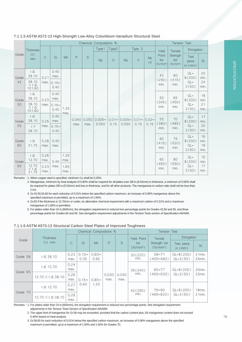
GradeThickness
(t)mm
Chemical Compositions % Tension Test
C Si Mn P S
Type1 Type2 Type 3 Yield Pointksi
(N/mm²)
Tensile Strength
ksi(N/mm²)
Elongation
Nb V Nb V Nb+V
Test piece
in.(mm)%
Grade 42
t≦38.10 0.21
max.
0.40max.
1.35max.
0.040max.
0.050max.
0.005~ 0.050
0.01~ 0.15
0.005~ 0.050
0.01~ 0.15
0.02~ 0.15
42(290)min.
60(415)min.
GL=8(200)GL=
2(50)
20min.24min.
38.10< t≦101.60
0.15~0.40
Grade 50
t≦38.10 0.23
max.
0.40max. 50
(345)min.
65(450)min.
GL=8(200)GL=
2(50)
18min.21min.
38.10< t≦101.60
0.15~0.40
Grade 55
t≦38.10 0.25
max.
0.40max. 55
(380)min.
70(485)min.
GL=8(200)GL=
2(50)
17min.20min.
t>38.10
0.15~0.40
Grade 60
t≦31.75
0.26max.
0.40max.
60(415)min.
75(520)min.
GL=8(200)GL=
2(50)
16min.18min.
Grade 65
t≦12.70
0.26max. 0.40
max.
1.35max. 65
(450)min.
80(550)min.
GL=8(200) GL=
2(50)
15min.17min.
12.70< t≦31.75
0.23max.
1.65max.
Remarks:1. When copper steel is specifi ed, minimum Cu shall be 0.20%.2. Manganese, minimum by heat analysis of 0.80% shall be required for all plates over 3/8 in.(9.53mm) in thickness, a minimum of 0.50% shall be required for plates 3/8 in.(9.53mm) and less in thickness, and for all other products. The manganese to carbon ratio shall not be less than
2 to1. 3. Gr.42,50,55,60 for each reduction of 0.01% below the specifi ed carbon maximum, an increase of 0.06% manganese above the specifi ed maximum is permitted, up to a maximum of 1.60%.4. Gr.65 if the thickness is 12.70mm or under, an alternative chemical requirement with a maximum carbon of 0.21% and a maximum manganese of 1.65% is permitted.5. For plates wider than 24 in.(600mm), the elongation requirement is reduced two percentage points for Grades 42,50 and 55, and three percentage points for Grades 60 and 65. See elongation requirement adjustments in the Tension Tests section of Specifi cation A6/A6M.
Grade Thickness(t) mm
Chemical Compositions % Tension Test
C Si Mn P SYield Point
ksi(N/mm²)
Tensile Strength ksi(N/mm²)
Elongation
Test piecein.(mm) %
Grade 58 t≦ 38.10 0.23max.
0.10~0.35
0.60~0.90
0.030max.
0.030max.
32(220)min.
58~71(400~490)
GL=8(200)GL=2(50)
21min.24min.
Grade 65t≦ 12.70 0.24
max.
0.15~0.40
0.85~1.20
35(240)min.
65~77(450~530)
GL=8(200)GL=2(50)
20min.23min.
12.70< t≦ 38.10 0.26max.
Grade 70t≦ 12.70 0.27
max. 42(290)min.
70~90(485~620)
GL=8(200)GL=2(50)
18min.21min.
12.70< t≦ 38.10 0.28max.
Remarks:1. For plates wider than 24 in.(600mm), the elongation requirement is reduced two percentage points. See elongation requirement adjustments in the Tension Tests Section of Specifi cation A6/A6M.
2. The upper limit of manganese for Gr.58 may be exceeded, provided that the carbon content plus 1/6 manganese content does not exceed 0.40% based on heat analysis.
3. Gr.58,65 for each reduction of 0.01% below the specifi ed carbon maximum, an increase of 0.06% manganese above the specifi ed maximum is permitted, up to a maximum of 1.50% and 1.60% for Grades 70.
7.1.1.6 ASTM A573-13 Structural Carbon Steel Plates of Improved Toughness
7.1.1.5 ASTM A572-13 High-Strength Low-Alloy Columbium-Vanadium Structural Steel

17
Grade
Thick-ness(t)mm
Chemical Compositions % Tension Test
C Si Mn P S
Type1
Type 2 Type 3 Yield
Pointor
Yield Strength
ksi(N/mm²)
Tensile Strength
ksi(N/mm²)
Elongation
Nb V Nb V Nb+VTest piece
in.(mm)
%min
Grade36
t≦19.05
0.25max.
0.40max.
─
0.040max.
0.050max.
─ ─ ─ ─ ─36
(250)min.
58~80(400~550)
GL=8(200) 20
19.05< t≦38.10 0.80~
1.2038.10< t≦63.50
0.26max.
0.15~0.40
GL=2(50) 23
63.50< t≦101.60
0.27max.
0.85~1.20
Grade50
t≦38.10
0.23max.
0.40max.
1.35max.
0.005~
0.050
0.01~
0.15
0.005~
0.050
0.01~
0.15
0.02~
0.15
50(345)min.
65(450)min.
GL=8(200) 18
38.10< t≦101.60
0.15~0.40
GL=2(50) 21
Grade50WType A
t≦101.60
0.19max.
0.30~0.65
0.80~1.25
Ni Cr Cu V ─ 50(345)min.
70(485)min.
GL=8(200) 18
0.40max.
0.40~0.65
0.25~0.40
0.02~0.10 ─
GL=2(50) 21
Remarks:1. When copper is specifi ed, minimum Cu shall be 0.20%.2. For each reduction of 0.01% below the specifi ed carbon maximum, an increase of 0.06% manganese. 3. Manganese of Gr.50, minimum by heat analysis of 0.80% shall be required for all plates over 3/8 in.(9.53mm) in thickness, a minimum of
0.50% shall be required for plates 3/8 in.(9.53mm) and less in thickness, and for all other products. The manganese to carbon ratio shall not be less than 2 to1.For eachreduction of 0.01% below the specifi ed carbon maximum, an increase of 0.06% manganese above the specifi ed maximum is permitted, up to a maximum of 1.60%.
4. For Gr.50W Type A, the silicon content in excess of 0.40% by heat analysis must be negotiated. 5. For each reduction of 0.01% below the specifi ed maximum for carbon, an increase of 0.06% above the specifi ed maximum for manganese
is permitted, up to a maximum of 1.50%.6. For plates wider than 24 in.(600mm), the elongation requirement is reduced two percentage points. See elongation requirement adjustments
in the Tension Tests section of Specifi cation A6/A6M.
註:Pcm(%)= C+ Si/30+ Mn/20+ Cu/20+ Ni/60+ Cr/20+ Mo/15+ V/10+ 5B。
7.1.1.7 ASTM A709-13 Structural Steel for Bridges
GradeThick-ness(t)mm
Composition % Mechanical Properties
C Si Mn P S N Pcm YSN/mm²
TSN/mm²
Elongation Impact Test
No.5
No.5
No.4
Temp℃
AVGJoule
Testpiece
Thickness(t)mm
13≦ t≦16
16< t≦20
20<t≦80
SBHS500
15≦ t≦80
0.11max.
0.55max.
2.00max.
0.020max.
0.006max.
0.006max.
0.20max.
500min.
570
~
720
19min.
26min.
20min. -5 100
min.
Trans. to
rollingdirection
7.1.1.8 JIS G3140-08 SBHS500 Higher Yield Strength Steel Plates for Bridges

18
SP
EC
IFICATIO
N
Grade
Thick-
ness
(t)m
m
Com
position %
Mechanical Properties
CSi
Mn
PS
Ceq
Tension Test
Impact Test
Yield point or
Proof Stress
N/m
m²
Tensile
Strength
N/m
m²
Yield Ratio %
Elongation (%
)Through-
thickness
characteristics
Test
Temp
℃
Charpy
Absorbed
Energy
Average
J
Test
piece
No.1A
No.1A
No.4
Average
%Individual
%
Thickness(t)
mm
Thickness(t)
mm
Thickness(t)
mm
t<12
12≦
t<
1616≦
t≦
4040<
t≦
100
t<12
12≦
t<
1616≦
t≦
4040<
t≦
100
t≦16
16<
t≦
5040<
t≦
100
SN40
0A6.00
≦t≦
100
0.24
max.─
─0.05
0max.0.05
0max.
─23
5min.
235
min.
235
min.
215
min.
400~
510
─
──
─17 min.
21 min.
23 min.
──
──
─
SN40
0B
6.00
≦t≦
50.00
0.20
max.
0.35
max.0.60
~1.50
0.03
0max.0.01
5max.
0.36
max.
235
min.
235~
355
235~
355
215~
335
80 max.
80 max.
80 max.
18 min.
22 min.
24 min.
027 min.
No.4
inrolling
direction
50.01
≦t≦
100
0.22
max.
SN40
0C
16.00
≦t≦
50.00
0.20
max.
0.02
0max.0.00
8max.
──
─25 min.
15 min.
50.01
≦t≦
100
0.22
max.
SN49
0B
6.00
≦t≦
40.00
0.18
max.
0.55
max.
1.65
max.
0.03
0max.0.01
5max.
0.44
max.
325
min.
325~
445
325~
445
295~
415
490~
610
80 max.
17 min.
21 min.
23 min.
──
40.01
≦t≦
50.00
0.46
max.
50.01
≦t≦
100
0.20
max.
SN49
0C
16.00
≦t≦
40.00
0.18
max.
0.02
0max.0.00
8max.
0.44
max.
──
─25 min.
15 min.
40.00
<t≦
50.00
0.46
max.
50.01
≦t≦
100
0.20
max.
Rem
arks:
1.Al
loy
elem
ents
oth
er th
an th
ose
show
n in
the
abov
e ta
ble
may
be
adde
d ne
cess
ary.
2.Im
pact
test
is a
pplic
able
to th
ickne
ss o
ver 1
2.0m
m o
f ste
el.
3.C
eq=
C+M
n/6+
Si/2
4+N
i/40+
Cr/5
+Mo/
4+V/
14。
4.U
ltras
onic
Test
:(1
)SN
400B
and
SN
490B
is o
ver 1
3.00
mm
in th
ickne
ss, w
hich
may
be
test
ed in
acc
orda
nce
with
JIS
G09
01 C
L.Y
If ag
reem
ent b
etw
een
the
purc
hase
r and
the
man
ufac
ture
r.(2
)SN
400C
and
SN
490C
is 1
6.00
mm
or o
ver,
whi
ch s
hall b
e te
sted
in a
ccor
danc
e w
ith J
IS G
0901
CL.
Y
7.1.
1.9
JIS
G31
36-1
2 R
olle
d S
teel
s fo
r Bui
ldin
g S
truct
ure

19
Remarks:1. When the content of soluble aluminum is not less than 0.015%, the minimum required silicon content does not apply.2. For Grade A, rimmed steel sections may be accepted up to and including 12.5 mm (0.5 in.).3. A maximum carbon content of 0.23% is acceptable for Grade A sections.4. For Gr.B steel of cold fl anging quality or when fully killed, the lower limit of manganese may be reduced to 0.60%.5. Gr.D hull steel which is normalized, thermo-mechanical control processed or control rolled is to be marked AB/DN.6. The contents of nickel, chromium, molybdenum and copper are to be determined and reported. When the amount does not exceed 0.02%,
these elements may be reported as≦ 0.02%.7. For Grade A sections, the upper limit of tensile strength may be 550 N/mm2 (56 kgf/ mm2,80 ksi).8. Applicable thickness range of this specifi cation is from 6.00 to 50.80mm.
7.1.2 Shipbuilding Steel Plates
7.1.2.1 ABS(2014)Ordinary-Strength Hull Structural Steel
Grade
Chemical Composition % Tension Test Impact Test
C Si Mn P S C+Mn/6YieldPoint N/mm²
Tensile Strength N/mm²
ElongationTestTemp℃
EnergyAverage J
Test piecemm
%Parallel to
rolling direction
Transverse to rolling direction
Grade A
0.21max.
0.50max.
2.5×Cmin.
0.035max.
0.035max.
0.40max.
235min.
400~520
GL=5.65√A
22min.
─ ─ ─
Grade B 0.35max.
0.80min. 0
27min.
20min.Grade D
0.10~0.35
0.60min. -20
Grade E 0.18max.
0.70min. -40

20
SP
EC
IFICATIO
N
Remarks:1. AH steel 12.5mm(0.50 in.) and under in thickness may have a minimum manganese content of 0.70%.2. When the content of soluble aluminum is not less than 0.015%, the minimum required silicon content does not apply.3. Applicable thickness range of this specifi cation is from 6.00 to 50.80mm for AH32~EH36, for higher strength grade EH40 is
40.00~75.00mm,and for extra strength grade EH47 is 50.00~65.00mm.
Grade
Chemical Composition % Mechanical Properties
C Si Mn P S Cu Cr Ni Mo Nb V Ti Al
Tension Test Impact Test
YieldPointN/mm²
TensileStrengthN/mm²
ElongationTestTemp℃
EnergyAverage J
Thickness(t) mm
Test piecemm
%Parallelto
rollingdirection
Transverse to rolling direction
AH32
0.18max.
0.10
∼
0.50
0.90
∼
1.60
0.035max.
0.035max.
0.35max.
0.20max.
0.40max.
0.08max.
0.02
∼
0.05
0.05
∼
0.10
0.020max.
0.020min.
315min.
440
∼
590
GL=5.65√A
22min.
0 t≦50.031min.
50.0< t≦70.038min.
70.0< t≦75.046min.
t≦50.022min.
50.0< t≦70.026min.
70.0< t≦75.031min.
DH32 -20
EH32 -40
AH36
355min.
490
∼
620
GL=5.65√A
21min.
0t≦50.034min.
50.0< t≦70.041min.
70.0< t≦75.050min.
t≦50.024min.
50.0< t≦70.027min.
70.0< t≦75.034min.
DH36 -20
EH36 -40
EH40
390min.
510
∼
650
20min. -40
t≦50.039min.
50.0< t≦70.046min.
70.0< t≦75.055min.
t≦50.026min.
50.0< t≦70.031min.
70.0< t≦75.037min.
EH47
0.10max.
0.10
∼
0.55
1.60max.
0.030max.
0.030max.
0.35max.
0.20max.
1.50max.
0.08max.
0.05max.
0.10max.
0.007
∼
0.020
0.020min.
460min.
570
∼
720
17min. -40
50.0≦ t≦65.064min.
50.0≦ t≦65.043min.
7.1.2.2 ABS(2014)Higher-Strength Hull Structural Steel

21
Grade
Thick-ness(t)mm
Chemical Composition %Mechanical Properties
Tension Test Bend Test
C Si Mn P S MoYield point
N/mm²
TensileStrengthN/mm²
Elongation%, min
TestPiece
BendAngle
Thickness(t) mm
InsideRadius
TestPiece
SB410
t≦25.0
0.24max.
0.15~0.40
0.90max.
0.020max.
0.020max.
─
225min.
410~550
21 No.1A
1800
t≦ 2525< t≦ 5050< t≦ 100
0.50t0.75t1.00t
25.0< t≦50.0
0.27max.
25 No.10
50.0< t≦100
0.29max.
SB450
t≦25.0
0.28max.
245min.
450~590
19 No.1A
t≦ 2525< t≦ 100
0.75t1.00t
25.0< t≦50.0
0.31max.
23 No.10
50.0< t≦100
0.33max.
SB480
t≦25.0
0.31max.
1.20max.
265min.
480~620
17 No.1A
t≦ 2525< t≦ 5050< t≦ 100
1.00t1.00t1.25t
25.0< t≦50.0
0.33max.
21 No.10
50.0< t≦100
0.35max.
SB450M
t≦25.0
0.18max.
0.90max.
0.45~0.60
255min.
450~590
19 No.1A
t≦ 2525< t≦ 100
0.50t0.75t25.0
< t≦50.0
0.21max. 23 No.
10
SB480M
t≦25.0
0.20max.
275min.
480~620
17 No.1A
t≦ 2525< t≦ 100
0.75t1.00t25.0
< t≦50.0
0.23max. 21 No.
10
Remarks:1. For SB450 of over 25mm in thickness, the content of C may be designated to be within 0.30%, and that of Mn may be within 1.00%.2. For tension test pieces, No.1A test piece shall be used for the steel plates of 50mm or under in thickness and No.10 test piece for that over
50mm. However, for the steel plates over 40mm in thickness, No.10 test piece may be used.3. The elongation of No.1A test piece cut off from the steel plate under 8mm in thickness shall be the values in the above table reduced by
1% for every decrease of 1mm of thickness or its fraction.4. The elongation of No.10 test piece cut off from the steel plate over 90mm in thickness shall be the values in the above table reduced by
0.5% for every increase of 12.5mm of thickness or its fraction. However, the reduction shall be limited to 3%.5. When the elongation of No.1A test piece cut off from SB450M and SB480M steel plates of over 6 mm to and excluding 20 mm in thickness
is more than the value specifi ed in the above table subtracted by 3, the test piece shall be accepted despite the above specifi cation provided that the value of elongation in the gage length of 50 mm including the broken part is 25% or over.
7.1.3 Steel Plates for boilers and Pressure Vessels
7.1.3.1 JIS G3103-12 Carbon Steel and Molybdenum Alloy Steel Plate for Boilers and Other Pressure Vessels
Transverse to rolling direction

22
SP
EC
IFICATIO
N
Remark:1.When the thickness less than 5/16 in.(8mm), See Specifi cation A20/A20M for elongation adjustment.2. Applicable thickness range of this specifi cation is from 6.00 to 50.80mm.
Remarks:1. Alloy elements other than those shown in the above table may be added if necessary. 2. Ceq(%)= C+Mn/6+Si/24+Ni/40+Cr/5+Mo/4+V/14.3. Impact test is applicable to thickness over 12.0mm of steel.4.Applicable thickness range of this specifi cation is from 6.00 to 50.80mm
7.1.3.2 ASTM A285-12 Pressure Vessel Plates, Carbon Steel, Low- and Intermediate-Tensile Strength
7.1.3.3 JIS G3115-10 Steel Plates for Pressure Vessels for Intermediate Temperature Service
Grade
Chemical Composition %Mechanical Properties
Tension Test
C Mn P S Yield Strengthksi(N/mm²)
Tensile Strengthksi(N/mm²)
Elongation
Test piece in.(mm) %
Grade A 0.17max.
0.90max.
0.025max.
0.025max.
24(165)min. 45~65(310~450) GL=8(200)GL=2(50)
27min.30min.
Grade B 0.22max. 27(185)min. 50~70(345~485) GL=8(200)
GL=2(50)25min.28min.
Grade C 0.28max. 30(205)min. 55~75(380~515) GL=8(200)
GL=2(50)23min.27min.
Grade
Chemical Composition % Mechanical Properties
C Si Mn P S Ceq
Tension TestBend Test
Impact Test
Yield point orproof stress
N/mm²TensileStrengthN/mm²
Elongation
Test Temp.℃
CharpyAbsorbedEnergy J
Testpiece
Thick-ness(t) mm
Testpiece
%min
BendAngle
Thick-ness(t) mm
InsideRadius
Testpiece
Thick-ness
(t) mm
AVG IDVt≦50
50< t≦100
SPV235
t≦100
0.18max.
0.35max.
1.40max.
0.030max.
0.030max. ─
235min.
215min.
400~510
t≦ 16t> 16t> 40
No.1A No.1ANo.4
172124
1800
t≦ 50t> 50
1.0t1.5t
0
47min.
27min.
t>100
0.20max.
SPV315
0.18max.
0.55max.
1.60max.
315min.
295min.
490~610
t≦ 16t> 16t> 40
No.1ANo.1ANo.4
162023
─ 1.5tSPV355
0.20max.
355min.
335min.
520~640
t≦ 16t> 16t> 40
No.1ANo.1ANo.4
141821
SPV410
0.18max.
0.75max.
410min.
390min.
550~670
t≦ 16t> 16t> 40
No.1ANo.1ANo.4
121618
-10
No.1 transverse to rolling direction
V-notch, parallel to rolling direction

23
Grade Thickness(t) mm
Chemical Composition % Tension Test
C Si Mn P S
Yield strengthksi
(N/mm²)
Tensile strengthksi
(N/mm²)
Elongation
Test piecein.(mm) %
Grade 60
t≦ 25.40 0.24max.
0.15~0.40
0.90max.
0.025max.
0.025max.
32(220)min.
60~80(415~550)
GL=8(200)GL=2(50)
21min.25min.25.40< t≦ 50.80 0.27
max.
50.80< t≦ 101.60 0.29max.
Grade65
t≦ 25.40 0.28max.
35(240)min.
65~85(450~585)
GL=8(200)GL=2(50)
19min.23min.25.40< t≦ 50.80 0.31
max.
50.80< t≦ 101.60 0.33max.
Grade70
t≦ 25.40 0.31max.
1.20max.
38(260)min.
70~90(485~620)
GL=8(200)GL=2(50)
17min.21min.25.40< t≦ 50.80 0.33
max.
50.80< t≦ 101.60 0.35max.
Remark:1. When the thickness less than 5/16 in(8mm), See Specifi cation A20/A20M for elongation adjustment.2. For each reduction of 0.01% below the specifi ed carbon maximum, an increase of 0.06% manganese above the specifi ed maximum is
permitted, up to a maximum of 1.50%.
7.1.3.4 ASTM A515-10 Pressure Vessel Plates, Carbon Steel, for Intermediate - and High-Temperature Service
24
SP
EC
IFICATIO
N
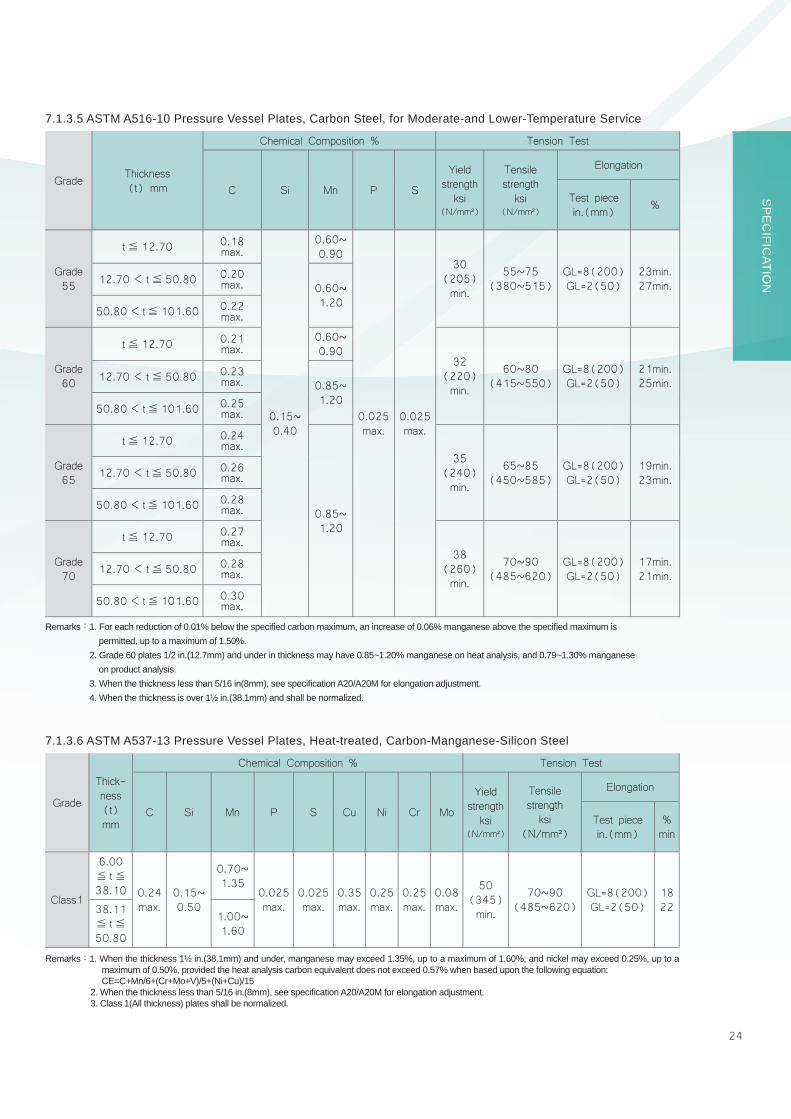
Grade Thickness(t) mm
Chemical Composition % Tension Test
C Si Mn P S
Yield strengthksi
(N/mm²)
Tensile strengthksi
(N/mm²)
Elongation
Test piecein.(mm) %
Grade55
t≦ 12.70 0.18 max.
0.15~0.40
0.60~0.90
0.025max.
0.025max.
30(205)min.
55~75(380~515)
GL=8(200)GL=2(50)
23min.27min.12.70< t≦ 50.80 0.20
max. 0.60~1.20
50.80< t≦101.60 0.22 max.
Grade60
t≦ 12.70 0.21 max.
0.60~0.90
32(220)min.
60~80(415~550)
GL=8(200)GL=2(50)
21min.25min.12.70< t≦ 50.80 0.23
max. 0.85~1.20
50.80< t≦101.60 0.25 max.
Grade65
t≦ 12.70 0.24 max.
0.85~1.20
35(240)min.
65~85(450~585)
GL=8(200)GL=2(50)
19min.23min.12.70< t≦ 50.80 0.26
max.
50.80< t≦101.60 0.28 max.
Grade70
t≦ 12.70 0.27 max.
38(260)min.
70~90(485~620)
GL=8(200)GL=2(50)
17min.21min.12.70< t≦ 50.80 0.28
max.
50.80< t≦101.60 0.30 max.
Grade
Thick-ness(t)mm
Chemical Composition % Tension Test
C Si Mn P S Cu Ni Cr Mo
Yield strengthksi
(N/mm²)
Tensile strengthksi
(N/mm²)
Elongation
Test piecein.(mm)
%min
Class1
6.00≦ t≦38.10 0.24
max.0.15~0.50
0.70~1.35
0.025max.
0.025max.
0.35max.
0.25max.
0.25max.
0.08max.
50(345)min.
70~90(485~620)
GL=8(200)GL=2(50)
182238.11
≦ t≦50.80
1.00~1.60
Remarks:1. For each reduction of 0.01% below the specifi ed carbon maximum, an increase of 0.06% manganese above the specifi ed maximum is permitted, up to a maximum of 1.50%.
2. Grade 60 plates 1/2 in.(12.7mm) and under in thickness may have 0.85~1.20% manganese on heat analysis, and 0.79~1.30% manganese on product analysis.
3. When the thickness less than 5/16 in(8mm), see specifi cation A20/A20M for elongation adjustment.4. When the thickness is over 1½ in.(38.1mm) and shall be normalized.
7.1.3.5 ASTM A516-10 Pressure Vessel Plates, Carbon Steel, for Moderate-and Lower-Temperature Service
7.1.3.6 ASTM A537-13 Pressure Vessel Plates, Heat-treated, Carbon-Manganese-Silicon Steel
Remarks:1. When the thickness 1½ in.(38.1mm) and under, manganese may exceed 1.35%, up to a maximum of 1.60%, and nickel may exceed 0.25%, up to a maximum of 0.50%, provided the heat analysis carbon equivalent does not exceed 0.57% when based upon the following equation:CE=C+Mn/6+(Cr+Mo+V)/5+(Ni+Cu)/15
2. When the thickness less than 5/16 in.(8mm), see specifi cation A20/A20M for elongation adjustment.3. Class 1(All thickness) plates shall be normalized.

25
Chemical Composition %(1)
Grade Thickness(mm) C Si Mn P S
0.15~0.35 0.030max. 0.035max.
S10C t≧ 7.90 0.08~0.13 0.30~0.60
S12C t≧ 7.90 0.10~0.15 0.30~0.60
S15C t≧ 7.90 0.13~0.18 0.30~0.60
S17C t≧ 7.90 0.15~0.20 0.30~0.60
S20C t≧ 7.90 0.18~0.23 0.30~0.60
S22C t≧ 7.90 0.20~0.25 0.30~0.60
S25C t≧ 7.90 0.22~0.28 0.30~0.60
S28C t≧ 7.90 0.25~0.31 0.60~0.90
S30C t≧ 7.90 0.27~0.33 0.60~0.90
S33C t≧ 7.90 0.30~0.36 0.60~0.90
S35C t≧ 7.90 0.32~0.38 0.60~0.90
S38C t≧ 7.90 0.35~0.41 0.60~0.90
S40C t≧ 7.90 0.37~0.43 0.60~0.90
S43C t≧ 7.90 0.40~0.46 0.60~0.90
S45C t≧ 7.90 0.42~0.48 0.60~0.90
S48C t≧ 7.90 0.45~0.51 0.60~0.90
S50C t≧ 7.90 0.47~0.53 0.60~0.90
S53C t≧ 7.90 0.50~0.56 0.60~0.90
S55C t≧ 7.90 0.52~0.58 0.60~0.90
S58C* t≧ 7.90 0.55~0.61 0.60~0.90
Chemical Composition %
Grade Thickness(mm) C Si Mn P S
PC1050(4) t> 125 0.47~0.53 0.15~0.35 0.60~0.90 0.030max. 0.035max.
7.1.4.2 CSC PC Machine Structural Usage (over-thickness)
7.1.4 Steel Plates for Machine Structural Usage (ex: Abrasion Resisting)
7.1.4.1 JIS G4051- 09 Steel Plates for Machine Strctural Usage
26
SP
EC
IFICATIO
N
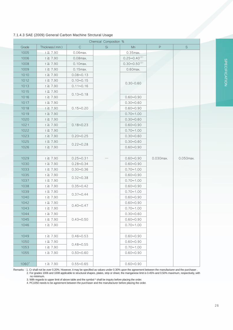
Chemical Composition %
Grade Thickness(mm) C Si Mn P S
1005 t≧ 7.90 0.06max.
─
0.35max.
0.030max. 0.050max.
1006 t≧ 7.90 0.08max. 0.25~0.40(2)
1008 t≧ 7.90 0.10max. 0.30~0.50(2)
1009 t≧ 7.90 0.15max. 0.60max.
1010 t≧ 7.90 0.08~0.13
0.30-0.601012 t≧ 7.90 0.10~0.15
1013 t≧ 7.90 0.11~0.16
1015 t≧ 7.900.13~0.18
1016 t≧ 7.90 0.60~0.90
1017 t≧ 7.90
0.15~0.20
0.30~0.60
1018 t≧ 7.90 0.60~0.90
1019 t≧ 7.90 0.70~1.00
1020 t≧ 7.90
0.18~0.23
0.30~0.60
1021 t≧ 7.90 0.60~0.90
1022 t≧ 7.90 0.70~1.00
1023 t≧ 7.90 0.20~0.25 0.30~0.60
1025 t≧ 7.900.22~0.28
0.30~0.60
1026 t≧ 7.90 0.60~0.90
1029 t≧ 7.90 0.25~0.31 0.60~0.90
1030 t≧ 7.90 0.28~0.34 0.60~0.90
1033 t≧ 7.90 0.30~0.36 0.70~1.00
1035 t≧ 7.900.32~0.38
0.60~0.90
1037 t≧ 7.90 0.70~1.00
1038 t≧ 7.90 0.35~0.42 0.60~0.90
1039 t≧ 7.900.37~0.44
0.70~1.00
1040 t≧ 7.90 0.60~0.90
1042 t≧ 7.900.40~0.47
0.60~0.90
1043 t≧ 7.90 0.70~1.00
1044 t≧ 7.90
0.43~0.50
0.30~0.60
1045 t≧ 7.90 0.60~0.90
1046 t≧ 7.90 0.70~1.00
1049 t≧ 7.90 0.46~0.53 0.60~0.90
1050 t≧ 7.900.48~0.55
0.60~0.90
1053 t≧ 7.90 0.70~1.00
1055 t≧ 7.90 0.50~0.60 0.60~0.90
1060* t≧ 7.90 0.55~0.65 0.60~0.90
7.1.4.3 SAE (2009) General Carbon Machine Strctural Usage
Remarks:1. Cr shall not be over 0.20%. However, it may be specifi ed as values under 0.30% upon the agreement between the manufacturer and the purchaser .2. For grades 1006 and 1008 applicable to structural shapes, plates, strip or sheet, the manganese limit is 0.45% and 0.50% maximum, respectively, with
no minimum.3. With regards to upper limit of above table and the symbol * shall be inquiry before placing the order.4. PC1050 needs to be agreement between the purchaser and the manufacturer before placing the order.

27
7.1.5 Atmospheric Corrosion Resistant Steel Plates
7.1.5.1 CSC-specification plate for Sulfur Dew-Point Corrosion-Resistance
Grade
Thick-ness(t)mm
Chemical Composition % Mechanical PropertiesTension Test Bend Test
C Si Mn P S Cu Ni Cr TiYield PointN/mm²
Tensile StrengthN/mm²
Elongation%
Testpiece
BendAngle
InsideRadius
Testpiece
SCRTEN2
6.00≦ t≦20.00
0.14max.
0.15
~
0.55
0.90max.
0.025max.
0.035max.
0.20
~
0.50
0.50max.
0.50
~
1.00
0.15max.
325min.
440min.
18min.
No.1A
1800 1.5t No.1
SCRTEN3
0.035max.
0.035max.
0.25
~
0.50─
0.80
~
1.30
Sb
22min.
No.5
0.15max.
7.1.5.2 CSC-specification plate for Galvanizing Pot
GradeThickness(t)
mm
Chemical Composition %
C Si Mn P S
GP16.00≦ t≦50.80
0.07max.
0.02max.
0.35max.
0.020max.
0.020max.
GP20.15
~
0.25
0.03max.
0.90max.
0.012max.
7.1.4.4 Alloy Machine Strctural Usage (Abrasion Resisting)
Chemical Composition %
Grade Thickness(mm) C Si Mn P S
1330 t≧ 7.90 0.28∼ 0.33
0.15~0.35
1.60∼ 1.80
0.030max. 0.040max.1335 t≧ 7.90 0.33∼ 0.38
1.60∼ 1.901340 t≧ 7.90 0.38∼ 0.43
1345 t≧ 6.00 0.43∼ 0.48

28
SP
EC
IFICATIO
N
Remarks: 1. The letter symbol ‘W’ denotes that the plates are usually used in the delivered condition or chemically treated against rusting, while ‘P’ denotes that they are usually used after coated.2 .The elements effective for the atmospheric corrosion resistance, such as Mo, Nb, Ti, V and Zr may be added to any grade of plates,
provided that the total content of these elements does not exceed 0.15%.3. Pertaining to the charpy absorbed energy, the value higher than those shown in the above table may be agreed upon by the parties
concerned.4. Impact test is applied only to the plates exceeding 12.00mm in thickness.5. The symbol * means that shall be inquiry before placing the order.6.Applicable thickness range of this specifi cation is from 6.00 to 50.00mm
7.1.5.3 JIS G3114-08 Hot-Rolled Atmospheric Corrosion Resisting Steels for Welded Structure
Grade
Chemical Composition %
Mechanical PropertiesTension Test Impact Test
Yield Point or Proof StressN/mm²
Tensile StrengthN/mm²
ElongationCharpyAbsorbedEnergyAverage
JC Si Mn P S Cu Cr Ni
Thickness (t) mm Thick-
ness(t) mm
Testpiece
%min.t≦
16
16<
t≦40
40<
t≦75
SMA400A.B.C.
W
0.18max.
0.15
~
0.65 1.25max.
0.035max.
0.035max.
0.30
~
0.50
0.45~
0.75
0.05
~0.30 245
min.235min.
215min.
400
~
540
t≦ 16t> 16t> 40
No.1ANo.1ANo.4
172123
A ─ ─
B 027min.
P0.55max.
0.20
~
0.35
0.30
~
0.55─ C 0
47min.
SMA490A.B.C.
W0.15
~
0.65
1.40max.
0.30
~
0.50
0.45
~
0.75
0.05
~
0.30 365min.
355min.
335min.
490~
610
t≦ 16t> 16t> 40
No.1ANo.1ANo.4
151921
A ─ ─
B 027min.
P0.55max.
0.20
~
0.35
0.30
~
0.55─ C 0
47min.
*SMA570
W0.15
~
0.65
0.30
~
0.50
0.45
~
0.75
0.05
~
0.30 460min.
450min.
430min.
570
~
720
t≦ 16t> 16t> 20
No.5No.5No.4
192620
─ -547min.
P0.55max.
0.20
~
0.35
0.30
~
0.55─
Symbol
Test temp ℃
Test pieceV-Notch in rolling direction
29
Grade
Chemical Composition % Tension Test
C Si Mn P S Cu Ni Cr Mo V Nb
Yield pointksi
(N/mm²)
Tensile strengthksi
(N/mm²)
Elongation
Test piece
in.(mm)
%min
GradeA
0.19max.
0.30
~
0.65
0.80
~
1.25
0.040max.
0.050max.
0.25
~
0.40
0.40max.
0.40
~
0.65─
0.02
~
0.10─
50(345)min.
70(485)min.
GL=8(200)
GL=2(50)
18
21
GradeB
0.20max.
0.15
~
0.50
0.75
~
1.35
0.20
~
0.40
0.50max.
0.40
~
0.70
0.01
~
0.10
GradeK
0.17max.
0.25
~
0.50
0.50
~
1.20
0.30
~
0.50
0.40max.
0.40
~
0.70
0.10max. ─
0.005
~
0.050
Remarks:1. For each reduction of 0.01% below the specifi ed maximum for carbon, an increase of 0.06% above the specifi ed maximum for manganese is permitted, up to a maximum of 1.50%.
2. Gr.K for plates under 1/2 in.(12.70mm) in thickness, the minimum columbium is waived.3. For plates wider than 24 in.(600mm), the elongation requirement is reduced two percentage points.4. When the thickness less than 5/16 in(8mm), See Specifi cation A6/A6M for elongation adjustment.5.Applicable thickness range of this specifi cation is from 6.00 to 50.80mm
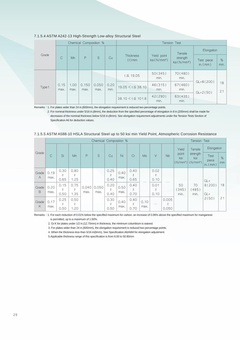
7.1.5.5 ASTM A588-10 HSLA Structural Steel up to 50 ksi min Yield Point, Atmospheric Corrosion Resistance
Grade
Chemical Composition % Tension Test
C Mn P S Cu Thickness(t)mm
Yield pointksi(N/mm²)
Tensile strength
ksi(N/mm²)
Elongation
Test piecein.(mm)
%min.
Type1 0.15max.
1.00max.
0.150max.
0.050max.
0.20min.
t≦ 19.05 50(345)min.
70(480)min.
GL=8(200)
GL=2(50)
18
2119.05< t≦38.10 46(315)
min.67(460)
min.
38.10< t≦101.6 42(290)min.
63(435)min.
Remarks:1. For plates wider than 24 in.(600mm), the elongation requirement is reduced two percentage points.2. For nominal thickness under 5/16 in.(8mm), the deduction from the specifi ed percentage of elongation in 8 in.(200mm) shall be made for
decreases of the nominal thickness below 5/16 in.(8mm). See elongation requirement adjustments under the Tension Tests Section of Specifi cation A6 for deduction values.
7.1.5.4 ASTM A242-13 High-Strength Low-alloy Structural Steel

30
SP
EC
IFICATIO
N
Level Grade Thicknesst(mm)
Chemical Composition % Tension Test
C Mn P S Si Nb V Ti Ni+V+Ti
(7)
CEiiw(8)
CEpcm
Yield Strength
ksi(N/mm²)
Tensile Strength
ksi(N/mm²)
PSL1
A 6.00≦ t≦50.80
0.22max.
0.90max.
0.030max.
0.030max. ─ ─ ─ ─
─
─ ─
30.5(210)min.
48.6(335) min.
B(5) 6.00≦ t≦50.80
0.26max.
1.20max.
0.15max.
35.5(245) min.
60.2(415) min.
X42 6.00≦ t≦27.00
1.30max.
42.1(290) min.
60.2(415) min.
X46 ─
1.40max.
46.4(320) min.
63.1(435)min.
X52 7.93≦ t≦27.00
52.2(360) min.
66.7(460)min.
X56 ─56.6(390)
min.71.1(490)
min.
X60 9.00≦ t≦19.50
(6)
60.2(415) min.
75.4(520) min.
X65 10.00≦ t≦26.00
1.45max.
65.3(450)min.
77.6(535) min.
X70 15.00≦ t≦30.00
1.65max.
70.3(485) min.
82.7(570) min.
PSL2
BM 15.00≦ t≦50.80
0.22max.
1.20max.
0.025max.
0.015max.
0.45max.
0.050max.
0.050max.
0.040max. ─
0.43max.
0.25max.
35.5~65.3(245~450)
60.2~110.2(415~760)
X42M 15.00≦ t≦27.00 1.30
max.
42.1~71.8(290~495)
60.2~110.2(415~760)
X46M ─46.4~76.1(320~525)
63.1~110.2(435~760)
X52M 15.00≦ t≦27.00 1.40
max.
─ ─ ─
0.15max.
52.2~76.9(360~530)
66.7~110.2(460~760)
X56M ─56.6~79.0(390~545)
71.1~110.2(490~760)
X60M 15.00≦ t≦19.50
0.12max.
1.60max.
(6)
60.2~81.9(415~565)
75.4~110.2(520~760)
X65M 15.00≦ t≦26.00
65.3~87.0(450~600)
77.6~110.2(535~760)
X70M 15.00≦ t≦30.00
1.70max.
70.3~92.1(485~635)
82.7~110.2(570~760)
Remarks:1. Gr.A through Gr.X70 for each reduction of 0.01% below the specifi ed maximum carbon content, an increase of 0.05% above the specifi ed maximum manganese content is permissible, but:‧X42~X52:Maximum manganese content is applicable to 1.50%.‧X56~X65:Maximum manganese content is applicable to 1.65%.‧X70:Maximum manganese content is applicable to 2.00%.
2. Niobium, vanadium, or combinations thereof may be used at the discretion of the manufacturer.3. The sum of the niobium, vanadium, and titanium contents shall not exceed 0.15%.4 .Gr.60 through Gr.X70 are permissible to add other chemical compositions by agreement between purchaser and manufacturer.5. Elongation values are according to Specifi cation of API 5L-2007 (ISO 3183).6. The sum of niobium and vanadium contents shall not exceed 0.06% except for agreement between purchaser and manufacturer.7. Carbon Equivalent CEiiw(%)= C+Mn/6+ (Cr+Mo+ V)/5+ (Ni+ Cu)/15.8. Carbon Equivalent CEpcm(%)= C+ Si/30+Mn/20+ Cu/20+ Ni/60+ Cr/20+Mn/15+ V/10+ 5B.
7.1.6 Steel Plates for API 5L-2007 (ISO 3183) Line Pipe Usage

31
7.1.7 Chemical Composition and Mechanical Property for New Products
7.1.7.1 ASTM A841-13 Gr. B Class 2 (For Welded Pressure Vessels use)
7.1.7.2 JIS G3101 SS400 (Plates for Laser cutting ues)
7.1.7.3 CSC LYS100 (Low Yield Strength Steel plate for Building Construction use)
7.1.7.4 CSC PZ30H Plates for Die of pressing
7.1.7.5 JIS G4053 SCM440 Nickel Chromium Steels for Machine Structural Use
Thickness(t) mm
Chemical Composition % Tension Test Impact Test
C Si Mn P S Tot-Al
YieldStrength
ksi(N/mm²)
Tensile Strength
ksi(N/mm²)
Elongation Test Temp℃ /
Test direction
CharpyAbsorbedEnergy Average
J
Testpiece
in.(mm)%
15.00≦ t≦38.10
0.15max.
0.15~
0.50
0.70~
1.35 0.030max.
0.025max.
0.020min.
60(415)min.
80~100(550~690)
GL=2(50)
22min.
- 40/
in rolling direction
20min.
38.10< t≦63.50
1.00~
1.60
Thickness (t) mm
Chemical Composition %
C Si Mn P S Ni Cr Mo
15≦ t≦ 85 0.35max. ─ 0.80min. ─ ─ ─ 1.70max. 0.45max.
Thickness (t) mm
Chemical Composition %
C Si Mn P S Cu Ni Cr Mo
12≦ t≦ 125 0.38~0.43
0.15~0.35
0.60~0.90
0.030max.
0.030max.
0.30max.
0.25max.
0.90~1.20
0.15~0.30
Thickness (t) mm
Tension Test
Yield Strength N/mm²
Tensile Strength N/mm²
Elongation
Test Piece %
6.00≦ t< 20.0070~120 200~300
JIS No.550min.
20.00≦ t≦ 50.80 JIS No.4
Remarks: 1. When the thickness 1½ in.(38.1mm) and under, Manganese may exceed 1.35% on heat analysis, up to a maximum of 1.60%, provided that the carbon equivalent on heat analysis does not exceed 0.47%, or the value specifi ed in Supplementary Requirement S77 When that requirement is invoked, when based on the following formula: CE=C+Mn/6+(Cr+Mo+V)/5+(Ni+Cu)/15
2. By agreement, the steel may be produced with titanium, in which case the minimum aluminum content shall not apply. When this option is exercised, the titanium content, by heat analysis,shall be 0.006% to 0.02%.
3. For each reduction of 0.01 percentage point below the specifi ed maximum for carbon, an increase of 0.06 percentage points above the specifi ed maximum for manganese is permitted, up to a maximum of 1.85%.
Remarks:1. There is no mechanical properties requirements for die for pressing of plates.2. This is applicable afterwards quenching and tempering process.
Remarks:1. There is no mechanical properties requirements for die for pressing of plates.2. This is applicable afterwards quenching and tempering process.
Thickness(t) mm
Chemical Composition %Tension Test
Yield Point or Yield Strength N/mm² Tensile
StrengthN/mm²
Elongation
C Mn P S SiThickness (t) mm
Thickness(t) mm
TestPiece
%min.12.0≦
t≦ 16.016.0<t≦ 25.0
12.00≦ t≦25.00 0.25max.
1.35max.
0.030max.
0.030max.
0.50max.
245min.
235min.
400~510
12≦ t≦ 16No.1A
17
16< t≦ 25 21

32
SP
EC
IFICATIO
N
7.1.7.6.1 CNS 13812-12 SN490YB (Rolled steels for building structure)
7.1.7.6.2 CNS 13812-12 SN490YC (Rolled steels for building structure)
7.1.7.7 CSC PZ590T (The most excellent strength plate for structural use)
7.1.7.8 CSC PH490TB (Fire resistant steel plates)
Thickness(t) mm
Chemical Composition % Mechanical Propertites
C Si Mn P S CeqYield
StrengthN/mm²
TensileStrengthN/mm²
Yield Ratio%
Elongation Impact Test
Testpiece % Temp/Test
DirectionAVGJoule
6≦ t≦ 16
0.18max.
0.55max.
1.60max.
0.030max.
0.015max.
0.44max.
325~445
490~610
80max.
No.1A17min.
0℃ /Parallel to rollingdirection
27min.
16< t≦ 40 21min.
40< t≦ 50 0.46max. No.4 23min.
50< t≦ 80
Thickness(t) mm
Chemical Composition % Mechanical Propertites
C Si Mn P S CeqYield
StrengthN/mm²
TensileStrengthN/mm²
Yield Ratio%
Elongation ZRa% Impact Test
Testpiece %
AVG/IDVmin
Temp/Test
Direction
AVGJoule
t=16
0.18max.
0.55max.
1.60max.
0.020max.
0.008max.
0.44max.
325~445
490~610
80max.
No.1A
17min.
25/15
0℃ /Parallel to
rollingdirection
27min.
16< t≦ 40 21min.
40< t≦ 50 0.46max. No.4 23
min.50< t≦ 80
Thickness(t) mm
Chemical Composition % Mechanical Propertites
C Si Mn P S Ceq YSN/mm²
TSN/mm²
YieldRatio%
Elongation %(No.1A) Impact Test
thickness(t)mmTemp℃
AVG Joule
Testpiece12<
t≦ 1616<t≦ 30
12< t≦ 30 0.18max.
0.55max.
1.60max.
0.030max.
0.015max.
0.44max.
325~445
490~610
80max.
17min.
21min. 0 27
min.
Parallel to
rollingdirection
Thickness(t) mm
Chemical Composition % Mechanical Propertites
C Si Mn P S Ceq YSN/mm²
TSN/mm²
Elongation % ZRa% Impact Test
No.5 No.4 thickness(t)mm
Temp℃
AVG Joule
Testpiece
thickness(t)mm 20< t≦ 80
15≦ t≦ 20
20< t≦ 80 AVG IDV
15≦ t≦ 400.09max.
0.55max.
1.80max.
0.020max.
0.008max.
0.44max. 440
min.
590~
740
20min.
20min.
25min.
15min. -5 47
min.
Parallelto
rollingdirection
40< t≦ 80 0.47max.
Remarks:Carbon Equivalent Ceq(%)= C+Mn/6+Si/24+Ni/40+Cr/5+Mo/4+V/14. (This is applicable for non-TMCP supply of condition only)
Remarks:1. Carbon Equivalent Ceq(%)= C+Mn/6+Si/24+Ni/40+Cr/5+Mo/4+V/14.2. Impact test is applied only to the plates exceeding 12 mm in thickness.3. It needs not to be performed in ZRa% test if below 20mm in thickness except for agreement between purchaser and manufacturer.
Remarks:The product properties could be maintained by 2/3 yield strength of room temperature in 600℃ .
33
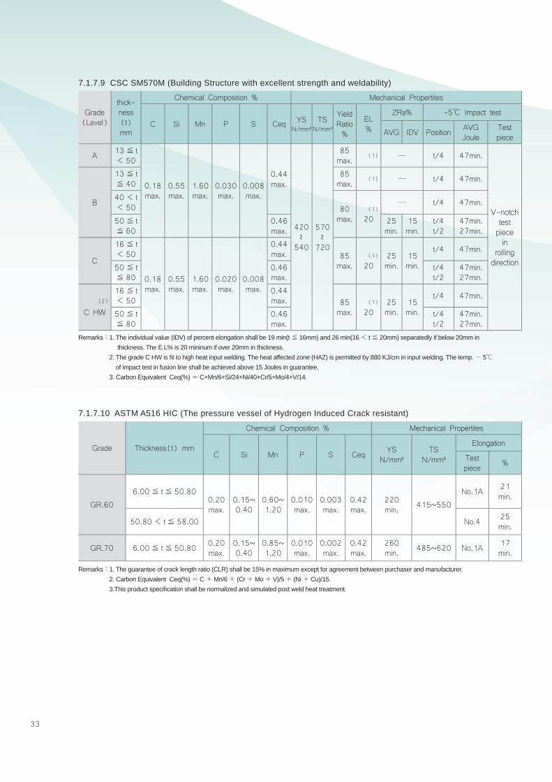
7.1.7.9 CSC SM570M (Building Structure with excellent strength and weldability)
7.1.7.10 ASTM A516 HIC (The pressure vessel of Hydrogen Induced Crack resistant)
Grade(Level)
thick-ness(t)mm
Chemical Composition % Mechanical Propertites
C Si Mn P S Ceq YSN/mm²
TSN/mm²
YieldRatio%
EL%
ZRa% -5℃ Impact test
AVG IDV Position AVG Joule
Testpiece
A 13≦ t< 50
0.18max.
0.55max.
1.60max.
0.030max.
0.008max.
0.44max.
420~540
570~
720
85max.
(1) ─ t/4 47min.
V-notchtest piecein
rolling direction
B
13≦ t≦ 40
85max.
(1) ─ t/4 47min.
40< t< 50 80
max.(1)
20
─ t/4 47min.
50≦ t≦ 60
0.46max.
25min.
15min.
t/4t/2
47min.27min.
C
16≦ t< 50
0.18max.
0.55max.
1.60max.
0.020max.
0.008max.
0.44max. 85
max.(1)
2025min.
15min.
t/4 47min.
50≦ t≦ 80
0.46max.
t/4t/2
47min.27min.
(2)
C HW
16≦ t< 50
0.44max. 85
max.(1)
2025min.
15min.
t/4 47min.
50≦ t≦ 80
0.46max.
t/4t/2
47min.27min.
Remarks:1. The individual value (IDV) of percent elongation shall be 19 min(t≦ 16mm) and 26 min(16< t≦ 20mm) separatedly if below 20mm in thickness. The E.L% is 20 mininum if over 20mm in thickness.
2. The grade C HW is fi t to high heat input welding. The heat affected zone (HAZ) is permitted by 880 KJ/cm in input welding. The temp.- 5℃ of impact test in fusion line shall be achieved above 15 Joules in guarantee.
3. Carbon Equivalent Ceq(%)= C+Mn/6+Si/24+Ni/40+Cr/5+Mo/4+V/14.
Remarks:1. The guarantee of crack length ratio (CLR) shall be 15% in maximum except for agreement between purchaser and manufacturer. 2. Carbon Equivalent Ceq(%)= C+Mn/6+ (Cr+Mo+ V)/5+ (Ni+ Cu)/15.3.This product specifi cation shall be normalized and simulated post weld heat treatment.
Grade Thickness(t) mm
Chemical Composition % Mechanical Propertites
C Si Mn P S Ceq YSN/mm²
TSN/mm²
Elongation
Test piece %
GR.60
6.00≦ t≦ 50.800.20max.
0.15~0.40
0.60~1.20
0.010max.
0.003max.
0.42max.
220min. 415~550
No.1A 21min.
50.80< t≦ 58.00 No.4 25min.
GR.70 6.00≦ t≦ 50.80 0.20max.
0.15~0.40
0.85~1.20
0.010max.
0.002max.
0.42max.
260min. 485~620 No.1A 17
min.

34
SP
EC
IFICATIO
N
Remarks:1. When required, the tolerance in the above table may be one-sided either minus or plus side, provided that the total range of the tolerance in this case shall be equal to the total range of the tolerance given in the above table.
2. The positions where the thickness is to be measured shall be as follows:● For as-rolled steel plates with edge untrimmed, any point inward from the line of width predetermined to be cut.● For cut-edged steel plates, any point 15mm and over inward from the edge.
3. The above table does not apply to the pressure vessel plates.
Remarks:1. The minus side of thickness tolerance shall be -0.30mm.2. The positions where the thickness is to be measured shall be as follows:● For as-rolled steel plates with edge untrimmed, any point inward from the line of width predetermined to be cut.●For cut-edged steel plates, any point 15mm and over inward from the edge.
Remark:The minus side tolerance on thickness shall be -0.25mm.
7.2 Tolerances
7.2.1 JIS G3193 Thickness Tolerances of Steel Plates
7.2.2 JIS G3136(SN) Thickness Tolerances of Steel Plates
7.2.3 JIS G3103(SB),JIS G3115(SPV) Thickness Tolerances of Steel Plates
unit:mm
unit:mm
unit:mm
800≦ w< 1600 1600≦w<2000 2000≦w<2500 2500≦w<3150 3150≦w<4000
6.00≦ t< 6.30 ±0.50 ±0.60 ±0.60 ±0.75 ±0.75
6.30≦ t< 10.0 ±0.55 ±0.65 ±0.65 ±0.80 ±0.80
10.0≦ t< 16.0 ±0.55 ±0.65 ±0.65 ±0.80 ±0.80
16.0≦ t< 25.0 ±0.65 ±0.75 ±0.75 ±0.95 ±0.95
25.0≦ t< 40.0 ±0.70 ±0.80 ±0.80 ±1.00 ±1.00
40.0≦ t< 63.0 ±0.80 ±0.95 ±0.95 ±1.10 ±1.10
63.0≦ t< 100 ±0.90 ±1.10 ±1.10 ±1.30 ±1.30
100≦ t≦ 125 ±1.30 ±1.50 ±1.50 ±1.70 ±1.70
Thickness (t)
Width (w)
800≦ w< 1600 1600≦w<2000 2000≦w<2500 2500≦w<3150 3150≦w<4000
6.00≦ t< 6.30 + 0.70 + 0.90 + 0.90 + 1.20 + 1.20
6.30≦ t< 10.0 + 0.80 + 1.00 + 1.00 + 1.30 + 1.30
10.0≦ t< 16.0 + 0.80 + 1.00 + 1.00 + 1.30 + 1.30
16.0≦ t< 25.0 + 1.00 + 1.20 + 1.20 + 1.60 + 1.60
25.0≦ t< 40.0 + 1.10 + 1.30 + 1.30 + 1.70 + 1.70
40.0≦ t< 63.0 + 1.30 + 1.60 + 1.60 + 1.90 + 1.90
63.0≦ t< 100 + 1.50 + 1.90 + 1.90 + 2.30 + 2.30
100 + 2.30 + 2.70 + 2.70 + 3.10 + 3.10
Thickness (t)
Width (w)
800≦ w< 1600 1600≦w<2000 2000≦w<2500 2500≦w<3150 3150≦w<4000
6.00≦ t< 6.30 + 0.75 + 0.95 + 0.95 + 1.25 + 1.25
6.30≦ t< 10.0 + 0.85 + 1.05 + 1.05 + 1.35 + 1.35
10.0≦ t< 16.0 + 0.85 + 1.05 + 1.05 + 1.35 + 1.35
16.0≦ t< 25.0 + 1.05 + 1.25 + 1.25 + 1.65 + 1.65
25.0≦ t< 40.0 + 1.15 + 1.35 + 1.35 + 1.75 + 1.75
40.0≦ t< 63.0 + 1.35 + 1.65 + 1.65 + 1.95 + 1.95
63.0≦ t< 100 + 1.55 + 1.95 + 1.95 + 2.35 + 2.35
Thickness (t)
Width (w)

35
Remarks:1. The minus side tolerance on thickness shall be -0.25mm.2. Thickness shall be measured at 9.53 to 19.05mm from the longitudinal edge.3. For thickness measured at any location other than that specifi ed in note 2, the permissible maximum over tolerance shall be increased by 75%.
7.2.4 ASTM A6,ASME SA6 Thickness Tolerances of Steel Plates
7.2.5 ABS Thickness Tolerances of Steel Plates
7.2.6 JIS G3193 Width Tolerances of Steel Plates
7.2.7 JIS G3193 Length Tolerances of Steel Plates
unit:mm
unit:mm
unit:mm
unit:mm
800≦ w<1219
1219≦ w<1524
1524≦ w<1829
1829≦ w<2134
2134≦ w<2438
2438≦ w<2743
2743≦ w<3048
3048≦ w<3353
3353≦ w<3658
3658≦ w<4267
6.00≦ t< 6.35 0.76 0.76 0.76 0.76 0.76 0.76 0.76 0.76 1.02 -
6.35≦ t< 7.94 0.76 0.76 0.76 0.76 0.76 0.76 0.76 1.02 1.02 -
7.94≦ t< 9.53 0.76 0.76 0.76 0.76 0.76 0.76 0.76 1.02 1.02 1.27
9.53≦ t< 11.11 0.76 0.76 0.76 0.76 0.76 0.76 1.02 1.02 1.27 1.52
11.11≦ t< 12.70 0.76 0.76 0.76 0.76 0.76 0.76 1.02 1.02 1.27 1.52
12.70≦ t< 15.88 0.76 0.76 0.76 0.76 0.76 0.76 1.02 1.02 1.27 1.52
15.88≦ t< 19.05 0.76 0.76 0.76 0.76 0.76 1.02 1.02 1.02 1.27 1.52
19.05≦ t< 25.40 0.76 0.76 0.76 0.76 1.02 1.02 1.27 1.27 1.52 1.78
25.40≦ t< 50.80 1.52 1.52 1.52 1.52 1.52 1.78 2.03 2.54 2.54 2.79
50.80≦ t< 76.20 2.29 2.29 2.29 2.54 2.54 2.79 3.05 3.30 3.56 3.81
76.20≦ t< 101.60 2.79 2.79 2.79 2.79 2.79 3.30 3.56 3.56 3.56 3.81
101.60≦ t< 125.0 3.81 3.81 3.81 3.81 3.81 3.81 3.81 3.81 3.81 5.08
Norminal Thickness(t) Thickness Tolerance
6.00≦ t≦ 75.00 According to ISO 7452 Class C rules
Width(w) Thickness(t)
Tolerance
Mill Edge Cut Edge(By Ordinary Cutting)
Lower Upper Lower Upper
800≦ w< 10006.00≦ t< 20.0
0 Notspecified 0
10
20.0≦ t 15
1000≦ w< 12506.00≦ t< 20.0
1520.0≦ t
1250≦ w< 16006.00≦ t< 20.0
20.0≦ t
1600≦ w6.00≦ t< 20.0
1.2%20.0≦ t
Length(L)
Tolerance
Cut Edge(By Ordinary Cutting)
Lower Upper
3048≦ L< 4000 0 20
4000≦ L< 6000 0 30
6000≦ L< 8000 0 40
8000≦ L< 10000 0 50
10000≦ L< 15000 0 75
15000≦ L≦ 18000 0 100
Thickness (t)
Width (w)

36
SP
EC
IFICATIO
N
Remark:The lower limit tolerance on specifi ed length and width is -6mm.
7.2.8 ASTM Length & Width Tolerances of Sheared Plates
7.2.9 ASTM Width & Length Tolerances of Steel Plates(When Gas Cutting is Specified or Required)
unit:mm
unit:mm
Specified Dimensions Upper Limit of Tolerance on Length & Width for Thickness (t)
Length(L) Width(w)t≦ 9.53 9.53< t≦ 15.87 15.88≦ t≦ 25.39 25.40≦ t≦ 50.80
Width Length Width Length Width Length Width Length
L< 3048
w< 15241524≦ w< 21332133≦ w< 2743
2743≦ w
9111316
13161922
11131619
16172225
13161922
19222528
16192528
25252832
3048≦ L<6096
w< 15241524≦ w<21332133≦ w<2743
2743≦ w
9131416
19192225
13161719
22222428
16192022
25252832
19222528
28323535
6096≦ L<9144
w< 15241524≦ w< 21332133≦ w< 2743
2743≦ w
9131417
25252528
13161722
28282832
16192225
32323535
19222532
38383844
9144≦ L<12192
w< 15241524≦ w< 21332133≦ w< 2743
2743≦ w
11131419
28323235
13161922
32353538
16192225
35383841
19222532
41414747
12192≦ L<15240
w< 15241524≦ w< 21332133≦ w< 2743
2743≦ w
11131619
32353538
13161922
38383841
16192225
41414144
19222532
47474747
15240≦ L<18288
w< 15241524≦ w< 21332133≦ w< 2743
2743≦ w
13161622
44444444
16191925
47474751
19222228
47474757
22252832
57575763
18288≦ L
w< 15241524≦ w< 21332133≦ w< 2743
2743≦ w
14191925
51515151
19222228
54545460
22252532
57575763
25283235
70707076
Specified Thickness (t) Tolerance on Width and length(Applies to Carbon Steel)
Tolerance on Width and length(Applies to Alloy Steel)
t< 50.8 + 130
+ 190
50.8≦ t< 101.6 + 160
+ 250
101.6≦ t≦ 125 + 190
+ 280

37
7.2.10 JIS G3193 Maximum Flatness Tolerances of Steel Plates unit:mm
Measured Length 2000 4000
800≦ w<1250
1250≦ w<1600
1600≦ w<2000
2000≦ w800≦ w<2000
2000≦ w<3000
3000≦ w
6.00≦ t< 8.00 13 13 13 21 22 28 -
8.00≦ t< 15.00 12 12 12 16 12 16 24
15.00≦ t< 25.00 12 12 12 16 12 16 22
25.00≦ t< 40.00 9 9 9 13 9 13 19
40.00≦ t< 80.00 8 8 8 11 8 11 16
80.00≦ t< 150 8 8 8 10 8 10 15
150≦ t< 250 10 10 10 15 10 15 20
250≦ t≦ 350 20 20 20 20 20 20 20
Thickness (t)
Width(w)
Remarks:1.The above table applies to 4m in length at any place of steel plate, and for steel plate less than 4m in length,to the full length.2. For the steel plate whose minimum tensile strength is specifi ed to be 570N/mm2 and over, or whose minimum yield strength 430N/mm2
and over, the maximum value of fl atness specifi ed in the above table shall be altered to one and half times the given values, unless otherwise specifi ed.
3. This table shall not be applied to the as-rolled steel plate with untrimmed edge.4. Measurement of fl atness, as a rule, shall be made on a fl at surface plate.
7.2.11 ASTM Maximum Flatness Tolerances of Steel Plates(Applies to Carbon Steel Only) unit:mm
Specified Thickness(t)
Permitted Variations From a Flat Surface for Specified Width (w)
w<914
914≦ w<1219
1219≦ w<1524
1524≦ w<1829
1829≦ w<2134
2134≦ w<2438
2438≦ w<2743
2743≦ w<3048
3048≦ w<3658
3658≦ w<4267
4267≦ w
t< 6.35 14 19 24 32 35 38 41 44 47 - -
6.35≦ t< 9.53 13 16 19 24 28 32 35 38 41 - -
9.53≦ t< 12.70 13 14 16 16 19 22 25 28 32 47 54
12.70≦ t< 19.05 11 13 14 16 16 19 25 25 28 38 50
19.05≦ t< 25.40 11 13 14 16 16 16 19 22 25 35 44
25.40≦ t< 50.80 9 13 13 14 14 16 16 16 17 28 38
50.80≦ t< 101.60 8 9 11 13 13 13 13 14 16 22 28
101.60≦ t< 125.00 9 11 13 13 14 14 16 19 22 22 25
Remarks:1. The above table applies to fl atness variations for length and width.2. The fl atness variations across the width shall not exceed the tabular amount for the specifi ed width.3. The permissible variations in fl atness along the length shall not exceed the tabular amount for the specifi ed width in plates up to 3.6m in
length, or in any 3.6m of longer plates.4. When the longer dimension is under 914mm the permissible variation shall not exceed 6mm. When the longer dimension ranges from
914mm to 1829mm incl. the permissible variation shall not exceed 75% of the tabular amount for the specifi ed width, but in no case less than 6mm.
5. These variations apply to plates which have a specifi ed min. tensile strength not more than 60ksi(414N/mm2). The limits in the table are increased 50% for plates specifi ed to a higher min. tensile strength.

38
SP
EC
IFICATIO
N
7.2.12 ASTM Maximum Flatness Tolerances of High-Strength Low-Alloy and Alloy Steel Plates unit:mm
SpecifiedThickness(t)
Flatness Tolerances for Specified Widths(w)
w<914
914≦ w<1219
1219≦ w<1524
1524≦ w<1829
1829≦ w<2134
2134≦ w<2438
2438≦ w<2743
2743≦ w<3048
3048≦ w<3658
3658≦ w<4267
4267≦ w
t< 6.35 20 28 35 47 51 57 60 66 70 - -
6.35≦ t< 9.53 19 24 28 35 44 47 51 57 60 - -
9.53≦ t< 12.70 19 22 24 24 28 33 38 41 47 70 79
12.70≦ t< 19.05 16 19 20 22 25 28 32 35 41 57 76
19.05≦ t< 25.40 16 19 22 22 24 25 28 33 38 51 66
25.40≦ t< 50.80 14 16 19 20 22 24 25 25 25 41 57
50.80≦ t< 101.60 13 14 17 19 19 19 19 22 25 32 41
101.60≦ t≦ 125.00 14 17 19 19 22 22 24 28 32 32 38
Remarks:1. The above table applies to fl atness variations for length and width.2. The fl atness variations across the width shall not exceed the tabular amount for the specifi ed width.3. The permissible variations in fl atness along the length shall not exceed the tabular amount for the specifi ed width in plates up to 3.6m in
length, or in any 3.6m of longer plates.4. When the longer dimension is under 914mm the variation shall not exceed 9.5mm. When the longer dimension ranges from 914mm to
1829mm incl. the variation shall not exceed 75% of the tabular amount for the specifi ed width.
7.2.13 JIS,ASTM Lateral Warpage Tolerance of Steel Plates unit:mm
JIS ASTM
2500≦ L<4000
4000≦ L<6300
6300≦ L<10000
10000≦ L Not Specified
630≦ w< 1000 6max. 10max. 16max.16 max.
for10000 oflength at any place
W≧ 1000 5max. 8max. 12max.12 max.
for10000 of length at any place
Not Specified 2×Length(m)max.
Length(L)
Width(w)
Remark:The above table applies to shear-cut and fl ame-cut plates.

39
7.2.14 ASTM Permissible Variation in Waviness Tolerances for Plates unit:mm
Tolerancesfrom 7.2.11 or 7.2.12
Waviness Tolerances (Number of Waves/per 3600mm)
1 2 3 4 5 6 7
8 8 6 5 3 3 2 2
9 9 8 5 5 3 2 2
11 11 8 6 5 3 3 2
13 13 9 8 5 5 3 2
14 14 11 8 6 5 3 2
16 16 13 9 6 5 3 2
17 17 13 9 8 5 5 2
19 19 14 11 8 6 5 2
21 21 16 11 8 6 5 2
22 22 17 13 9 6 5 2
24 24 17 13 9 8 6 5
25 25 19 14 11 8 6 5
29 29 22 16 13 9 8 6
32 32 24 17 13 9 8 6
35 35 27 19 14 11 8 6
38 38 29 22 16 13 9 6
41 41 32 24 17 13 9 8
44 44 33 25 19 14 11 8
48 48 37 27 21 14 11 8
51 51 38 29 22 16 13 9
54 54 41 30 22 17 13 9
57 57 43 32 24 17 14 9
60 60 46 33 25 19 14 11
63 63 48 37 27 21 14 11
67 67 51 38 29 21 16 11
70 70 52 40 29 22 16 13
73 73 56 41 30 24 17 13
76 76 57 43 32 24 17 14
79 79 60 44 33 25 19 14
Remark: The waviness tolerance is a function of the fl atness tolerance as obtained from 7.2.11 or 7.2.12.

4040
AVAILABLE SIZE
1524
~
1599
1600
~
1700
1701
~
1800
1801
~
1900
1901
~
2050
2051
~
2200
2201
~
2400
2401
~
2600
2601
~
2800
2801
~
3000
3001
~
3200
3201
~
3400
3401
~
3600
3601
~
38006.00~6.99 Negotiation 6.00~6.99
7.00~7.99 7.00~7.99
8.00~8.99 8.00~8.99
9.00~9.99 9.00~9.99
10.00~11.99 10.00~11.99
12.00~13.99 12.00~13.99
14.00~15.99 14.00~15.99
16.00~17.99 16.00~17.99
18.00~19.99 18.00~19.99
20.00~21.99 20.00~21.99
22.00~23.99 17.7 22.00~23.99
24.00~25.99 18.2 17.2 16.3 24.00~25.99
26.00~27.99 18.1 16.9 16.0 15.1 26.00~27.99
28.00~29.99 18.0 16.9 15.8 14.9 14.1 28.00~29.99
30.00~31.99 18.1 16.9 15.8 14.8 14.0 13.2 30.00~31.99
32.00~33.99 18.4 17.0 15.9 14.9 13.9 13.1 12.4 32.00~33.99
34.00~35.99 17.3 16.1 15.0 14.0 13.1 12.4 11.7 34.00~35.99
36.00~37.99 17.9 16.4 15.2 14.2 13.3 12.4 11.7 11.1 36.00~37.99
38.00~39.99 16.8 15.6 14.4 13.5 12.6 11.8 11.1 10.5 38.00~39.99
40.00~41.99 18.3 17.7 16.0 14.8 13.7 12.8 12.0 11.2 10.6 10.0 40.00~41.99
42.00~43.99 18.1 18.4 17.4 18.1 16.9 15.2 14.1 13.1 12.2 11.4 10.7 10.1 9.5 42.00~43.99
44.00~45.99 18.4 17.3 17.6 17.6 17.3 16.1 14.6 13.5 12.5 11.7 10.9 10.2 9.6 9.1 44.00~45.99
46.00~47.99 17.7 16.6 16.9 16.9 16.6 15.4 13.9 13.0 12.0 11.2 10.5 9.8 9.2 8.7 46.00~47.99
48.00~50.80 16.9 15.9 16.2 16.2 15.9 14.8 13.4 12.4 11.5 10.7 10.0 9.4 8.8 8.4 48.00~50.80
50.81~51.99 16.3 15.3 15.6 15.6 15.3 14.2 12.9 11.9 11.0 10.3 9.6 9.0 8.5 8.0 50.81~51.99
52.00~53.99 15.7 14.7 15.0 15.0 14.7 13.7 12.4 11.5 10.6 9.9 9.3 8.7 8.2 7.7 52.00~53.99
54.00~55.99 15.1 14.2 14.4 13.4 14.2 13.2 11.9 11.1 10.3 9.6 8.9 8.3 7.9 7.4 54.00~55.99
56.00~57.99 14.6 13.7 13.9 12.9 13.7 12.7 11.5 10.7 9.9 9.2 8.6 8.1 7.6 7.2 56.00~57.99
58.00~59.99 14.1 13.2 13.5 12.5 13.2 12.3 11.1 10.3 9.6 8.9 8.3 7.8 7.3 6.9 58.00~59.99
60.00~61.99 13.6 12.8 13.0 12.1 12.8 11.9 10.7 10.0 9.2 8.6 8.1 7.5 7.1 6.7 60.00~61.99
62.00~63.99 13.2 12.4 12.6 11.7 12.4 11.5 10.4 9.7 8.9 8.3 7.8 7.3 6.9 6.5 62.00~63.99
64.00~65.99 12.7 12.0 12.2 11.3 12.0 11.2 10.1 9.4 8.7 8.1 7.6 7.1 6.6 6.3 64.00~65.99
66.00~67.99 12.3 11.6 11.8 11.0 11.6 10.8 9.8 9.1 8.4 7.8 7.3 6.8 6.4 6.1 66.00~67.99
68.00~69.99 12.0 11.3 11.5 10.7 11.3 10.5 9.5 8.8 8.2 7.6 7.1 6.6 6.3 5.9 68.00~69.99
70.00~71.99 11.6 10.9 11.2 10.4 10.9 10.2 9.2 8.6 7.9 7.4 6.9 6.4 6.1 5.7 70.00~71.99
72.00~73.99 11.3 10.6 10.9 10.1 10.6 9.9 9.0 8.3 7.7 7.2 6.7 6.3 5.9 5.6 72.00~73.99
74.00~75.99 11.0 10.4 10.6 9.8 10.4 9.7 8.7 8.1 7.5 7.0 6.5 6.1 5.7 5.4 74.00~75.99
76.00~77.99 10.7 10.1 10.3 9.6 10.1 9.4 8.5 7.9 7.3 6.8 6.4 5.9 5.6 5.3 76.00~77.99
78.00~79.99 10.4 9.8 10.0 9.3 9.8 9.2 8.3 7.7 7.1 6.6 6.2 5.8 5.4 5.1 78.00~79.99
80.00~81.99 10.2 9.6 9.8 9.1 9.6 8.9 8.1 7.5 6.9 6.5 6.0 5.6 5.3 5.0 80.00~81.99
82.00~83.99 9.9 9.3 9.5 8.9 9.4 8.7 7.9 7.3 6.8 6.3 5.9 5.5 5.2 4.9 82.00~83.99
84.00~85.00 9.8 9.2 9.4 8.8 9.2 8.6 7.8 7.2 6.7 6.2 5.8 5.4 5.1 4.8 84.00~85.00
85.01~90.00 9.3 8.7 8.9 8.3 8.7 8.1 7.3 6.8 6.3 5.9 5.5 5.1 4.8 4.6 85.01~90.00
90.01~95.00 8.8 8.2 8.4 7.8 8.2 7.7 6.9 6.4 6.0 5.5 5.2 4.8 4.6 90.01~95.00
95.01~100.00 8.3 7.8 8.0 7.4 7.8 7.3 6.6 6.1 5.6 5.3 4.9 4.6 95.01~100.00
100.01~105.00 7.9 7.4 7.6 7.0 7.4 6.9 6.3 5.8 5.4 5.0 4.7 100.01~105.00
105.01~110.00 7.5 7.1 7.2 6.7 7.1 6.6 6.0 5.5 5.1 4.8 105.01~110.00
110.01~115.00 7.2 6.8 6.9 6.4 6.8 6.3 5.7 5.3 4.9 110.01~115.00
115.01~120.00 6.9 6.5 6.6 6.1 6.5 6.0 5.5 5.1 4.7 115.01~120.00
120.01~125.00 6.6 6.2 6.3 5.9 6.2 5.8 5.2 4.8 4.5 120.01~125.001524
~
1599
1600
~
1700
1701
~
1800
1801
~
1900
1901
~
2050
2051
~
2200
2201
~
2400
2401
~
2600
2601
~
2800
2801
~
3000
3001
~
3200
3201
~
3400
3401
~
3600
3601
~
3800
(Unit:Thickness/Width:mm, Length:m)
Maximum length for this area: 18.5m
Thickness
LengthWidth
Thickness
LengthWidth
Thickness
LengthWidth
Thickness
LengthWidth

41
Instruction Position
Stencilfor
painting
1 Pattern and Mark
2 CSC Name
3 Date
4 Customer Name
5 Spec./Grade
6 Dimensions
7 Order No/Plate No.
Die Stamp
8 Trade Mark
9 Heat No./Slab ID
10 Grade
MAR
KING
(1) Plate for general use
(2) Plate for pressure vesselInstruction Position
Stencilfor
painting(TwoSites)
1 Customer Name
2 Spec./Grade
3 Dimensions
4 Heat No./Slab ID
Low Stress Die
Stamp
5 Trade Mark
6 Heat No./Slab ID
7 Grade
3A136-302-3SS400
YUNG KUANG HUAASTM A285 GR.C10.00x2438x9144mmQT3105A001 94778A
Rolling Direction
Stencil for Painting
Die Stamp
Low Stress Die Stamp
Stencil for Painting
Low Stress Die Stamp
Above 30.5cm
Rolling Direction
Above 30.5cm
Above 30.5cm
Above 30
.5cm
Above 30
.5cm
Above 30
.5cm
IT883-201-1A285 GRC
IT883-201-1A285 GRC

42
10.1 Orientation Feature
Plate products are produced from slabs through rolling process. In general, the properties of plate on rolling
direction (longitudinal) are better than those on transverse direction. In addition, the applications, which stress is
applied on thickness direction and the effect of middle thickness position of plate due to the center segregation
of slabs, shall be considered. The properties on thickness direction shall be also asked to announce and verify
if necessary.
10.2 Post-Processes and Quality Requirements
The ways of processing for plate products are mostly often seen in cutting, bending and welding, among which
welding is specially the most major way of processing since almost all applications of steel plates need to have
the post-process for welding. The use of steel plates, in addition to the requirements for specifi cation tolerance
and surface quality, the inner quality for satisfying various uses needs to have the corresponding quality
properties, such as strength, toughness, corrosion resistance, weldability etc. Therefore, it should plan carefully
in the early stage of material design according to the end-uses and consider the subsequent corresponding
processes to avoid unexpected failures.
10.3 The Infl uences of Cutting
Since shear-cutting produces some unfavorable features such as micro cracks, burrs and hardened layer on
the cutting surface, it is easy to result in the end-surface cracks that are detrimental to following processes. The
effective methods to prevent the occurring of end-surface cracks are removing of burrs, making of rounded
corners or heat annealing.
Flame-cutting will harden the cutting surface by the quenching effect which is positively correlative to the
carbon equivalent. Mild heating to the cutting region before and after fl ame-cutting is helpful to the subsequent
processes.
10.4 Weldability
Welding area includes fusion zone (i.e. the weld metal) and heat affected zone (HAZ). The fusion zone
forms casting texture while the HAZ turns to a hardened area after welding. Due to quenching effect, HAZ is
characterized by its low elongation and could be a crack source during welding or using. Hence, the material
properties and welding conditions have to be confi rmed so that the highest hardness in heat affected zone can
be possibly reduced. Since the highest hardness is generally a direct proportion with the carbon content, the
hardened area alloy additions (as carbon equivalent) can be considered and adjusted from the early stage of
material design in order to improve the weldability and reduce the detrimental effects of HAZ.
PREC
AUTIO
NS FO
R U
SE

43
The carbon equivalent can be estimated by following equation:
Ceq(%) = C + Mn/6 + (Cr+Mo+V)/5 + (Ni+Cu)/15Steel grades that contains Ni, Cr, Mo, Cu, V and Nb in the composition need to be treated carefully during welding
because the material is easy to form a HAZ with very hard textures and result in such problems as low elongation and low-
temperature cracks.
Low-temperature crack happens after a period of time from the welding, including underbead crack, root crack and toe
crack, etc. The causes of low-temperature crack include the elongation of HAZ, the diffusion of hydrogen in weld metal, and
the restraint and hardenability of material.
PCM, the low-temperature crack sensitivity, is a quantitative index to monitor the correlation between chemical
composition and low-temperature crack occurrence, which can be calculated as below:
PCM(%)= C+ Si/30+ Mn/20+ Cu/20+ Ni/60+ Cr/20+ Mo/15+ V/10+ 5BThe lower PCM value, the lower risk of crack of materials is. It may reduce preheating temperature when doing the welding.
PCM is a very important property to the steel maker developing high strength steels, and it have to be properly handled for
the production of steels with excellent weldability and crack resistance.
10.5 Bendability
The bending radius applied on a steel plate shall not be smaller than the minimum value given by specifi cation. The degree
of minimum bending radius depends on the thickness and materials of steel plates. The smaller minimum bending radius,
the better bendability of steel plates is. As for the infl uences of thickness of steel plates, the thicker, the more diffi cult
processing is, and the larger minimum bending radius becomes, too.
Because the effect of rolling steel plates with longitudinal direction for bending work is better than that with the transverse
direction, when the bending direction is toward parallel direction of rolling, the materials can bear more strains. In reverse,
it is easy to crack if the bending direction is vertical direction of rolling. These factors should be regarded at sampling and
planning stage for preventing bending work from cracks. Furthermore, burrs of cutting surface are supposed to be in the
inner radius of bending since they are crack inducers under tension stress.
10.6 Ultrasonic Test
(1) Since CSC uses continuous casting slabs to roll steel plates, the maximum thickness of slabs is 270 mm. The
maximum thickness of plate would be extended as possible to meet requirments of customers. And for the rolling ratio
and safty considerations, customers should consider doing the UT examination.
(2) Adoptable ultrasonic test standards are listed as follows:
(a) ASTM A435 and A578: The ultrasonic tests that focus on inner layer type defect detection. Test and acceptance
criteria of A578 are divided into 3 levels of A, B and C. Level A is the same with A435 that single defective spot shall
not be larger than 3 inch or the circle area of the diameter of 1/2 thickness. Level B is altered from level A that nearby
small defects will be involved into the calculation of defect size. Level C is the strictest that the acceptable single
maximum defect size shall not be larger than 1 inch.
(b) JIS G0801 and G0901: G0801 is designed for pressure vessels and is divided into 3 types of SG、AC、AL and
class X、Y. G0901 is designed for building structures and is divided into 2 types of X and Y. Both standards focus on
the detection of inner layers and defect spots that the criteria of G0801 are stricter than that of G0901.

4444
CONVER
SION TABLES
Length
ft inch mm m
1 12 304.8 0.3048
0.08333 1 25.4 0.0254
0.003281 0.03937 1 0.001
Stress
ksi(=1000psi) psi kgf/mm2 N/mm2(=MPa)
1 1000 0.70307 6.89476
0.001 1 7.0307×10⁻⁴ 6.89476×10⁻³
1.42233 1422.33 1 9.80665
0.145038 145.038 0.101972 1
AbsorbedEnergy
ft-lbf kgf-m N-m(= joule)
1 0.138255 1.35582
7.23301 1 9.80665
0.737562 0.101972 1
Mass 1kg = 2.20462 lb
Force 1kgf = 9.80665 N

45445
ORDER
ING IN
FORMATIO
N
Required Ordering Data Example
1 Specification ASTM/ASME/JIS
2 Designation Grade and Year of Issue A36/SA36/SS400
3 Order Size(Thickness × Width × Length) 6.00~125mm×1524mm×3048mm
4 Order Piece 7 pieces
5 Chemical Composition Specification/Cust. Spec./Mill Range
6 Application General Purpose
7 Edge Status Mill Edge or Cut Edge
8 Delivery Condition As-Rolled/Normalized/Control Rolled
9 Special Requirements(If required)
Ultrasonic Test (A435/A578/G0801/G0901)
Impact Test (Temp./Direction/Absorption Energy)
Simulated Post Welding Heat Treatment(Hold Temp./Time/Heating or Cooling Rate)
1.The contents of this catalog are for reference only. Customers are urged to consult the specifications published by the corresponding Associations.
2.Information on the available steel grades, size, marking and packing as shown herein may be updated without notice to comply with actual production situations.
3.We invite you to contact our Head Offi ce should you have any questions concerning steel specifi cations or ordering requirements.
Phone number are listed below for your convenience. Numbers of our international Offi ces are shown on the back cover.
1.Sales servicesCHINA STEEL GLOBAL TRADING CORPORATION Address:10F, NO.88, Cheng gong 2nd Rd, Qian zhen, Kaohsiung 80661 TAIWAN
Tel:886-7-3322168 Fax:886-7-3356411 E-mail:[email protected]
CSGT JAPAN CO., LTD. Address:2F, Osaka U2 Bldg., 4-7 Uchihonmachi 2-Chome, Chuoku, Osaka 540-0026, Japan
Tel:002-81-6-69100850 Fax:002-81-6-69100851 E-mail:[email protected]
CSGT HONG KONG LIMITED Address:ROOM 1407,14/F, WORLD WIDE HOUSE, 19 DES VOEUX ROAD, CENTRAL, HONG KONG
Tel:852-25231488 Fax:852-25234748 E-mail:[email protected]
CSGT (SHANGHAI) CO.,LTD.Address:21F, NO.1468 NAN JING WEST RD., SHANGHAI 200040
Tel:86-21-62896898 Fax:86-21-62896678 E-mail:[email protected]
CSGT (SINGAPORE) PTE, LTD.Address:#14-01, MAS BUILDING, 10 SHENTON WAY SINGAPORE 079117
Tel:65-62238777~8 Fax:65-62256054 E-mail:[email protected]
2.Metallurgical DepartmentTechnical Service Section-Metallurgy:886-7-8021335
Metallurgical Specification and Testing Section:886-7-8021111 Ext. 3261


