1 School of Chemical Engineering and Technology, Chemical Engineering Research Center, Collaborative Innovation Center of Chemical Science and Engineering (Tianjin),State Key Laboratory of Chemical Engineering, Tianjin University, Tianjin 300072, China2 Department of Chemical Engineering, Norwegian University of Science and Technology (NTNU), Trondheim, 7491, Norway
☆ Supported by the National Basic Research Prog2012CB720500), the National Supporting Researc2013BAA03B01), the National Natural Science FoundaChina Scholarship Council (201506250011) and theFoundation (2017M620587).⁎ Corresponding authors to: X. Qian, College of Inform
Beijing University of Chemical Technology, North Third RBeijing 100029, China.X.G.Yuan, Chemical Engineering Research Center, TiaCampus, Yaguan Road 135, Jinnan District, Tianjin 300350
Keywords:Distillation columnsAutomatic process controlComputer-aided control system designPetlyuk columns
1. Introduction
Distillation is one of the most important and widely applied unitoperations for separation in the chemical and petrochemical industries[1–9]. However, the energy efficiency of distillation operation can beimproved. The Petlyuk column, usually implemented as a dividingwall column (DWC) to save also capital costs, provides a promisingalternative for energy saving [10,11]. Compared with traditional distil-lation columns, 30% of energy saving can be expected from the DWC[12]. The configuration of a DWC is shown in Fig. 1, and it is thermody-namically equivalent to the Petlyuk configuration shown in Fig. 2. TheDWC shown in Fig. 1 can be used for ternary distillation, and the compo-nents A, B, and C, which are arranged in the order of their volatilities,are recovered respectively in the top distillate D, the side withdraw S,and the bottom B. As shown in Fig. 2, the main feature of the Petlyuk
ram of China (973 Program:h Program of China (Granttion of China (21176178), theChina Postdoctoral Science
ation Science and Technology,ing Road 15, Chaoyang District,
configuration, or DWC, is to have a prefractionator with a thermal cou-pling between the prefractionator and the main section by the inter-column streams Dp, Lp, Vp, and Bp. In terms of process control, the majordifference between DWC and normal distillation column is that morefreedoms are involved in the DWC due to the inclusion of the thermalcoupling streams, which are reflected by the liquid and vapor splits asshown in Fig. 1. Such a complexity in control is also a main barrier forthe industrial application of DWCs.
Because of the extra degrees of freedoms, more control loopsare generally needed, and the difficulties in the control of DWC comemainly from the interactions among different control loops. Researcheshave been extensively reported in the literature on the controllabilityand operability of various distillation configurations, e.g. Petlyuk column[13–21], Kaibel column [22–25], reactive distillation (RD) [26–29],reactive dividing wall columns (RDWC) [30–32], extractive dividingwall columns (EDWC) [33–35], and azeotropic dividing wall columns(ADWC) [36,37]. The objective of this paper is to investigate multi-loopproportional–integral–differential (PID) control schemes of DWC forseparating ethanol, n-propanol and n-butanol at atmospheric pressure.
In previous research, both temperature and composition controllershave beenused. However, few studies have compared temperature con-trol and temperature–composition control for three-product Petlyukcolumn. In the present paper, four typical control structures areproposed, and analyzed and compared by numerical simulation. Thecontrol structures include a pure temperature control structure (CS1),as well as control structures containing both the temperature andthe composition controls (CS2, CS3, and CS4). CS2 adds a composition
Fig. 1. The three-product dividing wall column (Petlyuk column).
Fig. 2. Petlyuk configuration with prefractionator (P) and the main section (M)(thermodynamically equivalent to Fig. 1).
Table 1Nominal data for the DWC
Variables Prefractionator Main section
Total number of theoretical stages 15 53Feed stages (from top) 8 20/35Product stage (from top) 1/15 28Operating pressure/MPa 0.1144 0.1013Tray pressure drop/Pa 689 689Top mole flow rate (D)/kmol·h−1 0.577 0.335Side product flow rate (S)/kmol·h−1 – 0.330Liquid split ratio (RL)① – 0.469Vapor split ratio (RV)① – 0.601Reflux flow rate (L)/kmol·h−1 1.19 2.654Condenser duty (Qc)/kW – 32.33Reboiler duty (Qr)/kW – 30.86Composition of A in distillate② 0.259 0.99Composition of B in side product – 0.99Composition of C in bottom product 0.255 0.99Composition of B in distillate 0.739 0.01Composition of B in bottom product 0.739 0.01Composition of C in side product – 0.004Composition of A in side product – 0.006
① The vapor split ratio (RV) is defined as the fraction of vapor that is send to theprefractionator, i.e., RV = Vp/V (where V is the vapor flow below the vapor split and Vp isthe vapor flow into the prefractionator). The liquid split ratio (RL) is defined as the fractionof liquid that is send to the prefractionator, i.e., RL = Lp/L (where L is the liquid flow aboveof the liquid split and Lp is the liquid reflux flow into the prefractionator).
② Compositions are mole fractions.
Fig. 3. Vmin diagram for sharp separation of equimolar A-B-C feed.
1622 S. Jia et al. / Chinese Journal of Chemical Engineering 26 (2018) 1621–1630
controller (CCDB) on top of CS1. CS3 adds two more temperature–composition cascade controllers and a high selector. CS4 adds anotherhigh selector. The performances of the control structures are tested interms of the impurity composition time profiles with+20% step distur-bances in either feed flow rate or feed compositions.
2. Design of Three Product Petlyuk Configuration
The atmospheric separation of ethanol (A), n-propanol (B) andn-butanol (C) is used for the investigation. The feed of 1 kmol·h−1 isequimolar saturated liquid. The relative volatilities for A, B and C are4.46, 2.16 and 1, respectively, with respect to heavy component C. Thethree product purity specifications are all 99mol%. Rigorous simulationsare performed using Aspen Plus, and the nominal data of the Petlyukcolumn are shown in Table 1.
In Fig. 3, the Vmin diagram [4] shows the minimum vapor flows(with infinite number of stages) in various sections required for sharpseparation of an equimolar A-B-C feed. The y-axis shows the normalizedminimumboilup (V/F) and the x-axis shows the net productwithdrawal(D/F) in a conventional two-product column. The peak PAB gives theminimum vapor flow (V/F) required for separating A and B. Similarly,point PAC denotes the minimum vapor required to separate A and C.The Vmin diagram suggests that the BC-separation in the bottom of
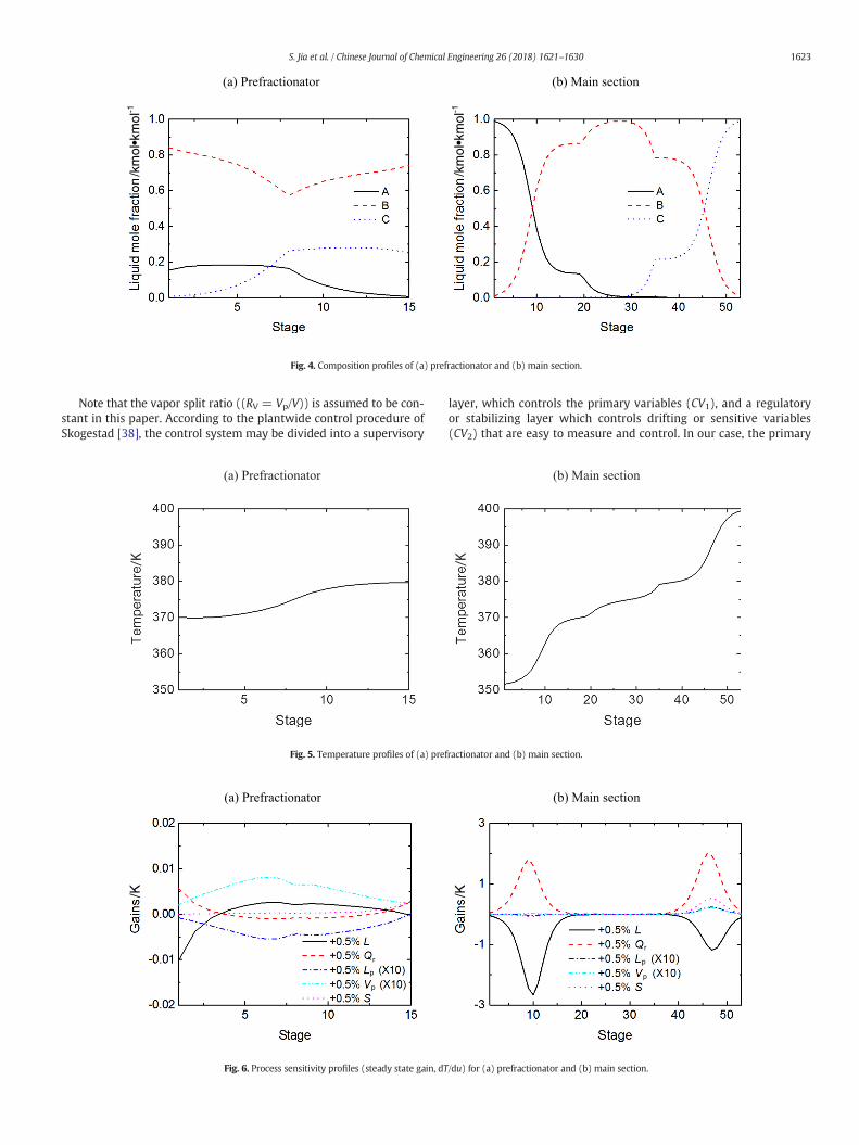
the main section is the more difficult separation compared with theAB-separation. The composition profiles of the prefractionator and themain section are shown in Fig. 4.
3. Control Structures
All the control behaviors are analyzed by dynamic simulationsemploying Aspen Plus Dynamics™. PI controllers are used in all loops,except P controllers for levels. We assume that the column pressure iscontrolled by the condenser duty, the condenser level is controlled bythe top distillate flow rate, and the sump level is controlled by the bot-tom product flow rate. With these three stabilizing control loops, thereare five remaining degrees of freedom, which from a control point ofview correspond to the following manipulated variables (u):
1. Reflux flow rate (L)2. Reboiler duty (Qr)3. Liquid flow from the main section to the prefractionator (Lp)4. Vapor flow from the main section to the prefractionator (Vp)5. Side product flow rate (S)
/km
ol•k
mol
-1
/km
ol•k
mol
-1
Fig. 4. Composition profiles of (a) prefractionator and (b) main section.
1623S. Jia et al. / Chinese Journal of Chemical Engineering 26 (2018) 1621–1630
Note that the vapor split ratio ((RV = Vp/V)) is assumed to be con-stant in this paper. According to the plantwide control procedure ofSkogestad [38], the control system may be divided into a supervisory
/K
Fig. 5. Temperature profiles of (a) pref
/K
r
p
p
Fig. 6. Process sensitivity profiles (steady state gain, dT
layer, which controls the primary variables (CV1), and a regulatoryor stabilizing layer which controls drifting or sensitive variables(CV2) that are easy to measure and control. In our case, the primary
/K
ractionator and (b) main section.
/K
r
p
p
/du) for (a) prefractionator and (b) main section.
Table 2Controller tuning parameters of CS1
Controlloop
Controlledvariable
Manipulatedvariable
Controllergain
Controller integraltime/min
τC/min
TC1 TP6 Lp 5.1 5.3 2TC2 TM9 L 1.1 7.9 2TC3 TM47 S 5.7 12.9 2
1624 S. Jia et al. / Chinese Journal of Chemical Engineering 26 (2018) 1621–1630
(economic) controlled variables (CV1) are assumed to be the threeproduct compositions. In addition, the two prefractionator “products”may be controlled in order to avoid breakthrough of C in the top (Dp)and breakthrough of A in the bottom (Bp). For distillation, the secondarycontrolled variables (CV2) are usually temperatures.
The temperature profiles of the prefractionator and themain sectionare shown in Fig. 5. For stabilizing control, the first issue is to decidewhich temperatures to control. In general, we need one stabilizingtemperature or composition loop for each split [39]. The prefractionatorperforms one split (A/C), and needs one stabilizing temperaturecontroller. The main section performs two splits (A/B and B/C) andneeds two stabilizing temperature controllers.
The temperatures used for stabilizing control should be sensitiveto input changes [39]. In order to find the steady-state sensitivities(gains, dT/du) for the tray temperatures (T), small increases (+0.5%)have been made in each of the five independent variables (u). Thechanges were made one at a time with the other flows constant. Theresults are shown graphically in Fig. 6 for the prefractionator (left)and main section (right). The gains for Lp and Vp were relatively smalland have been multiplied by a factor 10. In the prefractionator weneed to close one stabilizing loop and the most sensitive tray of theprefractionator is the 6th tray (TP,6, above the feed). In themain sectionwe need to close two loops and from Fig. 6 we see that there are twoclear peaks, corresponding to the 9th tray (TM,9, above the liquid split)and the 47th tray (TM,47, below the vapor split).
3.1. Control structure 1 (CS1)
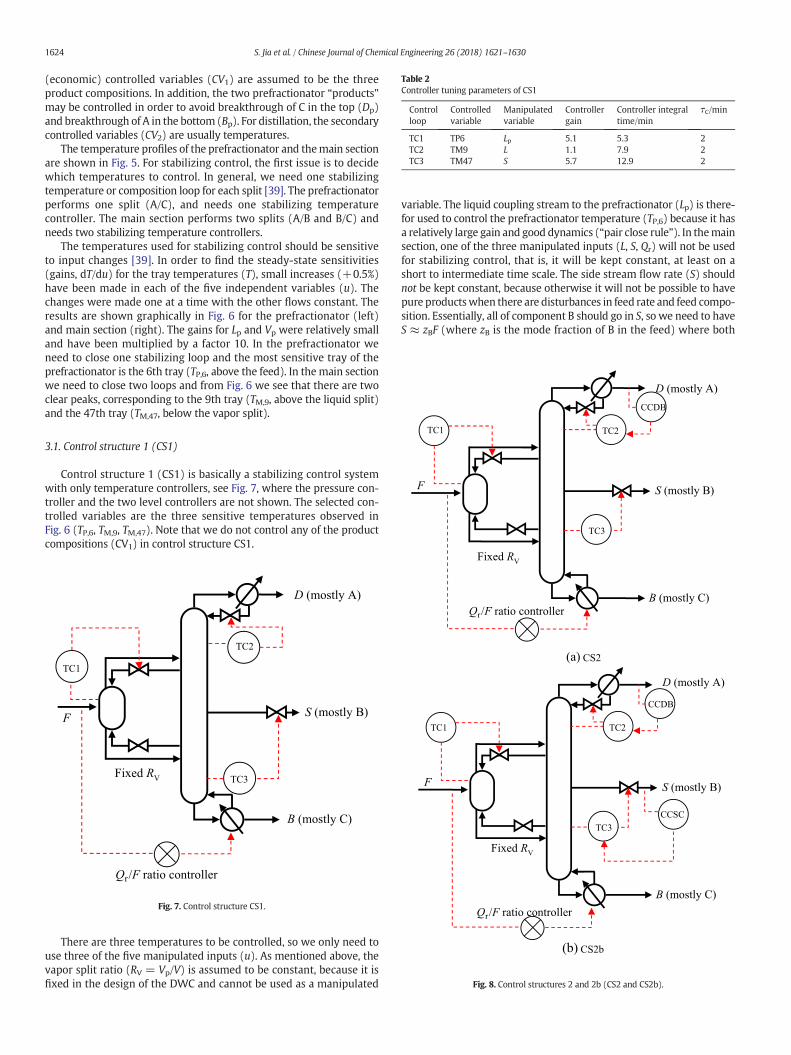
Control structure 1 (CS1) is basically a stabilizing control systemwith only temperature controllers, see Fig. 7, where the pressure con-troller and the two level controllers are not shown. The selected con-trolled variables are the three sensitive temperatures observed inFig. 6 (TP,6, TM,9, TM,47). Note that we do not control any of the productcompositions (CV1) in control structure CS1.
Fig. 7. Control structure CS1.
Fig. 8. Control structures 2 and 2b (CS2 and CS2b).
There are three temperatures to be controlled, so we only need touse three of the five manipulated inputs (u). As mentioned above, thevapor split ratio (RV = Vp/V) is assumed to be constant, because it isfixed in the design of the DWC and cannot be used as a manipulated
variable. The liquid coupling stream to the prefractionator (Lp) is there-for used to control the prefractionator temperature (TP,6) because it hasa relatively large gain and good dynamics (“pair close rule”). In themainsection, one of the three manipulated inputs (L, S, Qr) will not be usedfor stabilizing control, that is, it will be kept constant, at least on ashort to intermediate time scale. The side stream flow rate (S) shouldnot be kept constant, because otherwise it will not be possible to havepure productswhen there are disturbances in feed rate and feed compo-sition. Essentially, all of component B should go in S, so we need to haveS ≈ zBF (where zB is the mode fraction of B in the feed) where both
Table 4Controller tuning parameters of CS3 (on top of CS1 controllers)
Controlloop
Controlledvariable
Setpoint Manipulatedvariable
Controllergain
Controllerintegraltime/min
τC/min
CCP1 xDp,C 0.0026 Set pointof TC1
0.003 0.977 35
CCP2 xBp,A 0.0058 Qr/F highselector
0.050 1.64 55
CCDB xD,B 0.01 Set pointof TC2
0.007 2.48 30
CCSC xS,C 0.0042 Set pointof TC3
0.030 4.19 10
CCSA xS,A 0.0058 Qr/F highselector
0.042 3.19 50
CCBB xB,B 0.01 Qr/F highselector
0.031 1.58 45
Table 3Controller tuning parameters of CS2 and CS2b (on top of CS1 controllers)
Controlloop
Controlledvariable
Manipulatedvariable
Controllergain
Controller integraltime/min
τC/min
CCDB xD,B Set point of TC2 0.013 15.2 30CCSC xS,C Set point of TC3 0.047 2.19 50
1625S. Jia et al. / Chinese Journal of Chemical Engineering 26 (2018) 1621–1630
zB and F are unknown disturbances. Thus, S needs to vary and should beused for temperature control. From Fig. 6, we see that S mainly affectsTM,47, and this is also a good pairing dynamically according to the “pairclose rule”. What remains now is TM,9, which from Fig. 6 is effectedsomewhat more at steady state by the reflux (L) than by the boilup(Qr). Furthermore, the “pair close rule” favors using reflux for control-ling TM,9.
In summary, the liquid flow to the prefractionator (Lp) is used tocontrol the 6th tray temperature in the prefractionator (TC1), whilethe reflux flow rate (L) and the side product flow rate (S) are used tocontrol the temperatures of the 9th tray (TC2) and the 47th tray (TC3)of the main section, respectively. The ratio of the reboiler duty to thefeed flow rate (Q r/F) is assumed constant in CS1, which can be realizedusing ratio control. The gains and integral times for the three tempera-ture controllers are obtained based on SIMC tuning rules [38]. SIMCmeans “Simple control” or “Skogestad IMC”. The controller settingsalong with the selected tuning constants (τC = 2 min in all loops) areshown in Table 2. The control structure performs very well as wesee later.
3.2. Control structure 2 (CS2)
Control structures 2 and 2b (CS2 and CS2b), shown in Fig. 8, are in-troduced to reduce the steady state deviation of the product composi-tion. In control structure CS2, the top composition loop is closed bymanipulating the setpoint for TM,9 for controller TC2. Actually, wetried to add more composition controllers (CCSC and CCBB), but thiswas not successful. In control structures 2b (CS2b), we attempt toreduce the steady state deviation of the side product composition byadding the controller CCSC which controls the mole fraction of heavycomponent (C) in the side stream. However, simulations show that
Fig. 9. Control stru
this was not successful. The system performs nicely when only onecomposition controller (CCDB) is used, see CS2. Controller tuning pa-rameters are shown in Table 3.
3.3. Control structure 3 (CS3)
Control structure 3 (CS3) is shown in Fig. 9. In CS3, six compositioncontrollers are added on top of CS1. The controlled variables of com-position controllers CCP1, CCDB and CCSC are the impurity composi-tion C in the top overhead vapor stream of the prefractionator, theimpurity composition B in the distillate of the main section and theimpurity composition C in the side stream of the main section. Themanipulated variables of CCP1, CCDB and CCSC are set points of TC1,TC2 and TC3, respectively. The controlled variables of compositioncontrollers CCP2, CCSA and CCBB are the impurity composition A inthe bottom liquid stream of the prefractionator (BpA), the light impu-rity composition A in the side product (SA) and the impurity compo-sition B in the bottom stream (BB) of the main section, respectively.A high selector is used to choose the highest controller (CCP2, CCSAand CCBB) output value to manipulate the ratio of reboiler duty andfeed flow rate (Qr/F). The SIMC tuning rules was used and the control-ler tuning parameters of CS3 is shown in Table 4.
cture 3 (CS3).
Fig. 10. Control structure 4 (CS4).
1626 S. Jia et al. / Chinese Journal of Chemical Engineering 26 (2018) 1621–1630
3.4. Control structure 4 (CS4)
Control structure 4 (CS4), as shown in Fig. 10, is an extension ofCS3, where a high selector is used to select the higher value of outputsof controllers CCP2 and CCBB, while another high selector is added toselect the higher value of outputs of controllers CCSA and CCDB. CS4 isintroduced to reduce the interactions between different control loopsin CS3.
The values for the gains and integral times for each control loops areobtained based on SIMC tuning rules [38]. Controller tuning parametersof CS4 are shown in Table 5.
Table 5Controller tuning parameters of CS4 (on top of CS1 controllers)
Controlloop
Controlledvariable
Setpoint Manipulatedvariable
Controllergain
Controllerintegraltime/min
τC/min
CCP1 xDp,C 0.0026 Set pointof TC1
0.003 0.977 35
CCP2 xBp,A 0.0058 Qr/F highselector
0.050 1.64 55
CCDB xD,B 0.01 Set point ofTC2 selector
0.007 2.48 30
CCSC xS,C 0.0042 Set pointof TC3
0.030 4.19 10
CCSA xS,A 0.0058 Set point ofTC2 selector
0.007 1.57 50
CCBB xB,B 0.01 Qr/F highselector
0.031 1.64 45
4. Results and Discussion
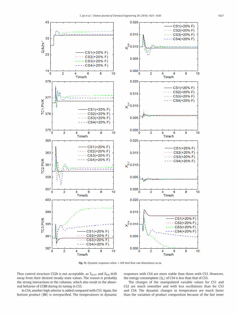
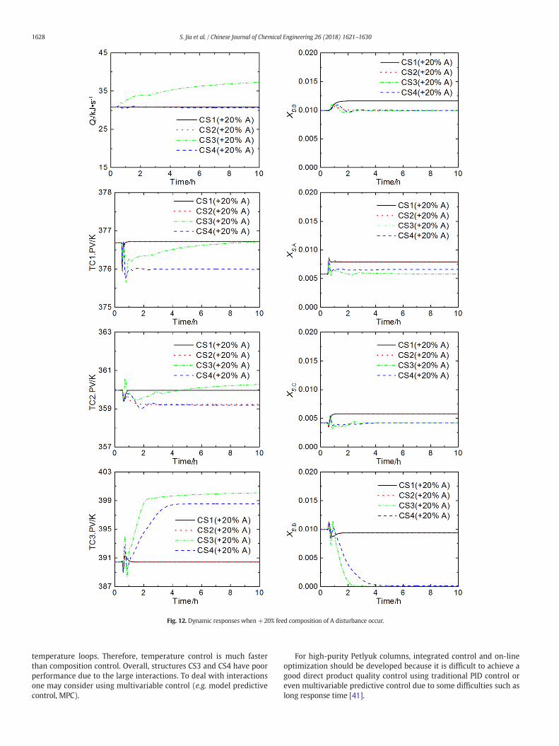
The dynamic responses of the impurity compositions and the con-trolled temperatures for the proposed control structures to a +20%feed flow rate disturbance and+20% feed composition of A disturbanceare shown in Figs. 11 and 12, respectively. A +20% feed compositionincrease of A is that A is increased from 0.333 to 0.4 while the othertwo (B and C) are both equal to 0.3. DA, SB, and BCmean the light com-ponentA in distillate, the intermediate component B in side product and
the heavy component C in bottom product, respectively. DB, SC, BB, andSA mean B in distillate, C in side product, B in bottom product, and A inside product, respectively. Some composition control structures cannothave stable dynamic performances using the Aspen Plus Dynamicsbuild-in Tyreus–Luyben method [40]. Therefore, SIMC tuning rules areused in this paper.
The dynamic responses of CS1with only temperature controllers arevery smooth. Although the impurity compositions have some steadystate deviations, the deviations are small. In addition, the settling timeis very short.
The dynamic responses with CS2 are smooth and very similar toCS1, and because of the added composition controller the impurity(component B) in the top product returns to its setpoint in this case.Also, all other impurity compositions are lower or at least the sameas CS1.
The bottom composition shows some steady-state deviation withCS1 and CS2 for feed rate changes (e.g., see bottom right of Fig. 11),and the side stream composition shows deviations for feed compositionchanges (Fig. 12). CS3 has a selector where the maximum controlleroutput value for the light impurity in the side product stream (SA),the impurity in the bottom product stream (BB) and the impurity inthe bottom of the prefractionator (BpA) are controlled by manipulatingthe reboiler duty. However, an abnormal behavior of CCBB was ob-served during its tuning.When the reboiler duty increases, the impuritycomposition in the bottom product (BB) increases instead of decreasingas would be expected. These may be due to the strong interactions be-tween the intermediate and bottom products. When the reboiler dutyincreases, the less volatile component in the side product stream (SC)increases. As the controller CCSC has been added, the side stream flowrate decreases. Because of mass balance, the bottom stream flow rateincreases. The product in the bottom product stream (BC) decreasesand the impurity in the bottom product stream (BB) increases. Thus,as a high selector is used in CS3, the bottomproduct (BB) is overpurified(Fig. 12).
In CS2b, in order to reduce the steady state deviation of the sideproduct composition, controller CCSC is added to control the mole frac-tion of heavy component (C) in the side stream. However, simulations(Fig. 13) show that this was not successful as the bottom impurityincreases beyond 2% when feed composition of A disturbance occurs.
1627S. Jia et al. / Chinese Journal of Chemical Engineering 26 (2018) 1621–1630
Thus control structure CS2b is not acceptable, as TM,47 and XB,B driftaway from their desired steady-state values. The reason is probablythe strong interactions in the columns, which also result in the abnor-mal behavior of CCBB during its tuning in CS3.
In CS4, another high selector is added comparedwith CS3. Again, thebottom product (BB) is overpurified. The temperatures in dynamic
responses with CS4 are more stable than those with CS3. However,the energy consumption (Qr) of CS4 is less than that of CS3.
The changes of the manipulated variable values for CS1 andCS2 are much smoother and with less oscillations than for CS3and CS4. The dynamic changes in temperature are much fasterthan the variation of product composition because of the fast inner
Fig. 12. Dynamic responses when +20% feed composition of A disturbance occur.
1628 S. Jia et al. / Chinese Journal of Chemical Engineering 26 (2018) 1621–1630
temperature loops. Therefore, temperature control is much fasterthan composition control. Overall, structures CS3 and CS4 have poorperformance due to the large interactions. To deal with interactionsone may consider using multivariable control (e.g. model predictivecontrol, MPC).
For high-purity Petlyuk columns, integrated control and on-lineoptimization should be developed because it is difficult to achieve agood direct product quality control using traditional PID control oreven multivariable predictive control due to some difficulties such aslong response time [41].
Fig. 13. CS2 vs CS2b: Dynamic responses when +20% feed composition of A disturbance occur.
1629S. Jia et al. / Chinese Journal of Chemical Engineering 26 (2018) 1621–1630
5. Conclusions
Four control structures based on the PI control loopswere simulatedand compared. Control structure CS1 with three temperature controlloops was shown to work well. Control structure CS2 with theaddition of a distillate composition controller (CCDB) cascaded on top
of temperature control also works well. Control structure CS3 adds sev-eral composition loops and a selector to the reboiler duty and CS4has anadditional selector. Dynamic simulations for various disturbancesshowed that all control structures are able to maintain the desiredsteady states. Structures CS2, CS3 and CS4 all drive the impurity (B) inthe top product to its setpoint, and the impurities in the side withdraw
1630 S. Jia et al. / Chinese Journal of Chemical Engineering 26 (2018) 1621–1630
product were also lower than or equal to those in CS1. However, CS3and CS4 can give overpurified bottom product (BB), and the responsetime is longer than for CS1 and CS2. The results of the simulationsshow that even though the control structure with only temperaturecontrol (CS1) gives some steady-state deviations in the product compo-sitions, the deviations is fairly small, and its dynamic performance is su-perior compared to CS3 and CS4. This suggests that temperature controlshould be basically used in the development of more advanced controlstructures for Petlyuk or DWC configurations.
References
[1] Z. Fidkowski, L. Krolikowski, Thermally coupled system of distillation columns:Optimization procedure, AIChE J. 32 (1986) 537–546.
[2] Z. Fidkowski, L. Królikowski, Minimum energy requirements of thermally coupleddistillation systems, AIChE J. 33 (1987) 643–653.
[3] I.J. Halvorsen, S. Skogestad, Minimum energy consumption in multicomponentdistillation. 1. V min diagram for a two-product column, Ind. Eng. Chem. Res. 42(2003) 596–604.
[4] I.J. Halvorsen, S. Skogestad, Minimum energy consumption in multicomponentdistillation. 2. Three-product Petlyuk arrangements, Ind. Eng. Chem. Res. 42 (2003)605–615.
[5] I.J. Halvorsen, S. Skogestad, Minimum energy consumption in multicomponentdistillation. 3. More than three products and generalized Petlyuk arrangements,Ind. Eng. Chem. Res. 42 (2003) 616–629.
[6] A.A. Kiss, Distillation technology-still young and full of breakthrough opportunities,J. Chem. Technol. Biotechnol. 89 (2014) 479–498.
[7] Z. Olujic, M. Joedecke, A. Shilkin, G. Schuch, B. Kaibel, Equipment improvementtrends in distillation, Chem. Eng. Process. 48 (2009) 1089–1104.
[8] D. Staak, T. Gruetzner, B. Schwegler, D. Roederer, Dividing wall column for industrialmulti purpose use, Chem. Eng. Process. 75 (2014) 48–57.
[9] N. Asprion, G. Kaibel, Dividing wall columns: Fundamentals and recent advances,Chem. Eng. Process. 49 (2010) 139–146.
[10] I. Dejanovic, L. Matijasevic, Z. Olujic, Dividing wall column — A breakthroughtowards sustainable distilling, Chem. Eng. Process. 49 (2010) 559–580.
[11] O. Yildirim, A.A. Kiss, E.Y. Kenig, Dividing wall columns in chemical process industry:A review on current activities, Sep. Purif. Technol. 80 (2011) 403–417.
[12] N. Sharma, K. Singh, Neural network and support vector machine predictive controlof tert-amyl methyl ether reactive distillation column, Syst. Sci. Control Eng. 2 (2014)512–526.
[13] M.I.A. Mutalib, R. Smith, Operation and control of dividing wall distillation columns— Part 1: Degrees of freedom and dynamic simulation, Chem. Eng. Res. Des. 76(1998) 308–318.
[14] I.J. Halvorsen, S. Skogestad, Optimal operation of Petlyuk distillation: Steady-statebehavior, J. Process Control 9 (1999) 407–424.
[15] M. Serra, M. Perrier, A. Espuna, L. Puigjaner, Study of the divided wall columncontrollability: Influence of design and operation, Comput. Chem. Eng. 24 (2000)901–907.
[16] S. Luan, K. Huang, N. Wu, Operation of dividing-wall columns. 1. A simplifiedtemperature difference control scheme, Ind. Eng. Chem. Res. 52 (2013) 2642–2660.
[17] N. Wu, K. Huang, S. Luan, Operation of dividing-wall distillation columns. 2. Adouble temperature difference control scheme, Ind. Eng. Chem. Res. 52 (2013)5365–5383.
[18] Y. Yuan, K. Huang, Operation of dividing-wall distillation columns. 3. A simplifieddouble temperature difference control scheme, Ind. Eng. Chem. Res. 53 (2014)15969–15979.
[19] Y. Yuan, K. Huang, H. Chen, L. Zhang, S. Wang, Configuring effectively double tem-perature difference control schemes for distillation columns, Ind. Eng. Chem. Res.56 (2017) 9143–9155.
[20] Y. Yuan, K. Huang, H. Chen, L. Zhang, S. Wang, Asymmetrical temperature control ofa BTX dividing-wall distillation column, Chem. Eng. Res. Des. 123 (2017) 84–98.
[21] Y. Yuan, K. Huang, L. Zhang, H. Chen, S. Wang, Y. Jiao, Elevating the flexibility andoperability of dividing-wall distillation columns via feed thermal condition adjust-ment, Chin. J. Chem. Eng. 25 (2017) 947–954.
[22] D. Dwivedi, J.P. Strandberg, I.J. Halvorsen, H.A. Preisig, S. Skogestad, Active vaporsplit control for dividing-wall columns, Ind. Eng. Chem. Res. 51 (2012) 15176–15183.
[23] D. Dwivedi, J.P. Strandberg, I.J. Halvorsen, S. Skogestad, Steady state and dynamicoperation of four-product dividing-wall (Kaibel) columns: Experimental verifica-tion, Ind. Eng. Chem. Res. 51 (2012) 15696–15709.
[24] D. Dwivedi, I.J. Halvorsen, S. Skogestad, Control structure selection for three-productPetlyuk (dividing-wall) column, Chem. Eng. Process. 64 (2013) 57–67.
[25] D. Dwivedi, I.J. Halvorsen, S. Skogestad, Control structure selection for four-productPetlyuk column, Chem. Eng. Process. 67 (2013) 49–59.
[26] H. Chen, K. Huang,W. Liu, L. Zhang, S.Wang, S.-J. Wang, Enhancingmass and energyintegration by external recycle in reactive distillation columns, AIChE J. 59 (2013)2015–2032.
[27] H. Chen, K. Huang, L. Zhang, S. Wang, Reactive distillation columns with a top-bottom external recycle, Ind. Eng. Chem. Res. 51 (2012) 14473–14488.
[28] H. Chen, L. Zhang, K. Huang, Y. Yuan, X. Zong, S. Wang, L. Liu, Reactive distillationcolumns with two reactive sections: Feed splitting plus external recycle, Chem.Eng. Process. 108 (2016) 189–196.
[29] Y. Yuan, L. Zhang, H. Chen, S. Wang, K. Huang, H. Shao, Interpreting the dynamiceffect of internal heat integration on reactive distillation columns, Chin. J. Chem.Eng. 25 (2017) 89–102.
[30] X. Qian, S. Jia, Y. Luo, X. Yuan, K.-T. Yu, Selective hydrogenation and separation of C3stream by thermally coupled reactive distillation, Chem. Eng. Res. Des. 99 (2015)176–184.
[31] X. Qian, S. Jia, S. Skogestad, X. Yuan, Y. Luo, Model predictive control of reactivedividing wall column for the selective hydrogenation and separation of a C3 streamin an ethylene plant, Ind. Eng. Chem. Res. 55 (2016) 9738–9748.
[32] A.A. Kiss, J.J. Pragt, C.J.G. van Strien, Reactive dividing-wall column show to get morewith less resources? Chem. Eng. Commun. 196 (2009) 1366–1374.
[33] M. Xia, B. Yu, Q. Wang, H. Jiao, C. Xu, Design and control of extractive dividing-wallcolumn for separating methylal–methanol mixture, Ind. Eng. Chem. Res. 51 (2012)16016–16033.
[34] M. Xia, Y. Xin, J. Luo, W. Li, L. Shi, Y. Min, C. Xu, Temperature control for extractivedividing-wall column with an adjustable vapor split: Methylal/methanol azeotropeseparation, Ind. Eng. Chem. Res. 52 (2013) 17996–18013.
[35] C. Bravo-Bravo, J.G. Segovia-Hernandez, C. Gutierrez-Antonio, A.L. Duran, A. Bonilla-Petriciolet, A. Briones-Ramirez, Extractive dividing wall column: Design and optimi-zation, Ind. Eng. Chem. Res. 49 (2010) 3672–3688.
[36] L. Shi, K. Huang, S.-J. Wang, J. Yu, Y. Yuan, H. Chen, D.S.H.Wong, Application of vaporrecompression to heterogeneous azeotropic dividing-wall distillation columns, Ind.Eng. Chem. Res. 54 (2015) 11592–11609.
[38] S. Skogestad, Simple analytic rules for model reduction and PID controller tuning,J. Process Control 13 (2003) 291–309.
[39] S. Skogestad, The dos and don'ts of distillation column control, Chem. Eng. Res. Des.85 (2007) 13–23.
[40] W.L. Luyben, Distillation Design and Control Using Aspen Simulation, John Wiley &Sons, New York, 2013.
[41] W. Lv, Y. Zhu, D. Huang, Y. Jiang, Y. Jin, A new strategy of integrated control and on-line optimization on high-purity distillation process, Chin. J. Chem. Eng. 18 (2010)66–79.


![v l^ ] ] v P - NTNUfolk.ntnu.no/skoge/septek/lectures/septek-sis3... · 2017-10-09 · ] } v 6wdjh prgho 7ud\ froxpq](https://static.documents.pub/doc/80x56/5e84f5429a6b1b4bba398739/v-l-v-p-2017-10-09-v-6wdjh-prgho-7ud-froxpq.jpg)


