8
Choosing a PCD Configuration for Your Cycle White Paper

Choosing a PCD Configuration for Your Cycle
White Paper

Choosing a PCD Configuration for Your CycleWhen configuring a process challenge device (PCD), you must first develop your cycle using biological indicators (BIs) embedded
in your load’s most difficult-to-sterilize location(s). This can be done using an internal process challenge device (IPCD).
02 \\ Choosing a PCD Configuration for your Cycle
The most common method,
overkill, is conducted by first
running fractional cycles,
in which some of the BIs
survive and some of the BIs
are killed.
You will use the data from
the fractional cycle to
calculate the Spore Log
Reduction (SLR) achieved
at that exposure time.
1 2 3 4 5
The Overkill Method
Then the cycle is extended
little by little to obtain total
kill of all the embedded
BIs. Total kill of all BIs is
obtained at approximately
an 8 SLR of a BI with a
106 spore population.
This exposure time, where
all of the BIs were killed,
would then become the
time of the half-cycle.
Once the half-cycle
demonstrates complete
kill of all the embedded
BIs three times, the half-
cycle exposure time can
be doubled to obtain the
overkill cycle.
6 does not equal 8
ISO 11135-1 states that complete kill must be obtained in the half-cycle. Those who are not familiar with BIs may think that complete kill is obtained within 6 SLRs. The logic being that the “overkill method” is centered around achieving 12 SLRs, which is equivalent to a Sterility Assurance Level (SAL) of 10-6; therefore, half of 12 is 6. So it is automatically assumed that in 6 SLRs (the half-cycle) all spores are killed, but this is NOT true.
Complete kill occurs at 8 SLRs*
Theoretically, for a BI with a 1 x 10⁶ spore population (at 6 SLRs of the population), there would be one surviving spore per BI. However, there is not going to be exactly one spore per BI—some are going to contain one while others may contain zero, two or three spores. Statistically, this works out to 63% of the BIs being positive.
At the log of the population + 1 (or 7 SLRs), statistically 10% of the exposed BIs would be positive.
At the log of the population + 2 (or 8 SLRs), statistically 1% of the exposed BIs would be positive. This would be the exposure time where complete kill would consistently appear. Unless there are 100 BIs in the same cycle, the likelihood of observing that one positive would be small.
If the target is to have complete kill at the half-cycle, you should expose the units until the time point at which 8 SLR is achieved.
Exposing the BIs to this time period (8 SLR) is approximate because you do not know at which time point prior to the cycle time the BIs were actually killed.
For this reason we suggest you run a cycle in which there is fractional kill and then slowly increase the cycle until complete kill is achieved. However, total kill at 8 SLR is sufficient if the legwork in developing a cycle has been completed for which the internal or imbedded BI (IPCD) is killed in the half-cycle.
Calculating the D-value
Once the cycle development work has been completed, the D-value can be calculated. D-value is the time it will take to reduce the BI population by one log. Take the exposure time at the half-cycle and divide by 8, because 8 SLR is where total kill of a BI with a 106 spore population has occurred.
One may purposely target 6 SLR when conducting initial studies and the performance of the imbedded PCD or external PCD is unknown. In this case, the fraction-negative results, where some units are positive and some negative, can be accurately calculated using the exact SLRs achieved with the MPN method where MPN = ln(n/r).*
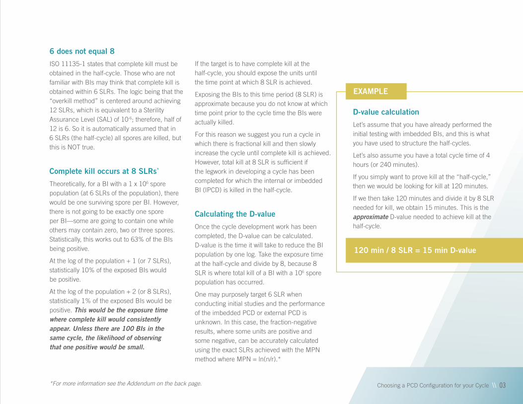
D-value calculation
Let’s assume that you have already performed the initial testing with imbedded BIs, and this is what you have used to structure the half-cycles.
Let’s also assume you have a total cycle time of 4 hours (or 240 minutes).
If you simply want to prove kill at the “half-cycle,” then we would be looking for kill at 120 minutes.
If we then take 120 minutes and divide it by 8 SLR needed for kill, we obtain 15 minutes. This is the approximate D-value needed to achieve kill at the half-cycle.
120 min / 8 SLR = 15 min D-value
Choosing a PCD Configuration for your Cycle \\ 03*For more information see the Addendum on the back page.
EXAMPLE

Nominal D-values on Mesa PCD products
The Mesa PCDs have a nominal D-value listed, because this is the D-value of the PCD in our Biological Indicator Evaluator Resistometer (BIER) vessel. A BIER vessel uses the parameters of 600 mg/L EtO, 54°C and 60% relative humidity (RH) with the PCD being the only object in the chamber. A commercial sterilizer may use different parameters and will be loaded, so the PCD will likely perform differently than in a BIER vessel. A PCD resistance can be calculated using the BIER vessel data and EtO parameters; however, the data is only good for that exact EtO cycle in a small BIER vessel. In the field, medical device companies use many different EtO cycles, and the EtO cycles are much different than those in a BIER vessel. The large EtO sterilizers do not perform exactly the same as the BIER vessel. Sterilizer temperature and, especially, product temperature can vary. Vacuum removal times, %RH, EtO charging times and post-vacuum rates can affect the results, leaving an exact comparison between the PCD in a BIER vessel and a PCD in a large industrial EtO sterilizer somewhat variable.
04 \\ Choosing a PCD Configuration for your Cycle
See mesalabs.com for the nominal D-values on all our products.
How to choose a PCD
Using the D-value (15 minutes) from the above example, select three PCDs with differing D-values as follows:
» One PCD as close as possible to that D-value
» One slightly below that D-value
» One slightly greater than that D-value
For this example, try PCD 5.13 (13 min.), 6.5 (17 min.) and 7.5 (14 min.). PCD 6.5 and 7.5 contain a spore strip that would need to be aseptically cultured into growth media after the cycle. PCD 5.13 contains a self-contained BI (SCBI) that does not require aseptic culturing into growth media.
EXAMPLE

Additional things to keep in mind
ISO 11135 states that, at the half-cycle, all IPCDs must be killed, but some positive external PCDs (EPCDs) are allowed. The reason for this is that if all IPCDs and all EPCDs are killed in the half-cycle, the user doesn’t know which was killed first nor if the EPCD is more resistant. If all the IPCDs are killed in the half-cycle and there are some positive EPCDs, the EPCD has demonstrated more resistance. The full-cycle needs to be capable of total kill for both the IPCDs and EPCDs.
The IPCD and EPCD do not have to use the same BI. For example, the IPCD may consist of a microstrip placed into the device, and the EPCD may contain a self-contained BI, such as EZTest. It’s important that the EPCD configuration provides a greater challenge than the IPCD.
Some EtO sterilizers will include a pre-humidification phase, which is sometimes performed in a separate chamber. The maximum allowable time should be established and adhered to—from the end of the pre-humidification to the start of the cycle. In this case, you should establish that relative humidity is a critical parameter of an EtO cycle, and, if the pre-humidification is reduced due to a long time elapsing between end of pre-humidification and beginning of the cycle, the materials may rob some of the RH from the cycle, thus reducing the lethality. Keep the following three points in mind:
Load configuration must be consistent
Any change in load configuration can cause different conditions in different locations within the chamber, which may result in unexpected positive results. One suggestion is to build a load configuration that is a mirror image of itself (where the front and back are the same). This way, if the load is inadvertently placed into the chamber backwards, it will not effect the conditions in the chamber.
IPCDs and EPCDs must be handled consistently at all stages
For validation fractional cycles, validation half-cycles, validation full-cycles and routine cycles, the most critical time of consistent handling is after the cycle. The BIs should be removed from the IPCD and EPCD pouch in the same amount of time every time, such as immediately when they are removed from the sterilizer or just before the BIs are cultured/incubated. The design of the IPCD and EPCD pouch makes it difficult for the EtO to enter and reach the BI, making it difficult for the EtO to leave the IPCD and EPCD pouch. Consequently, there is potential for residual EtO to remain in the IPCD and EPCD pouch, which would provide additional lethality to the BI. For example, if the BI isn’t usually removed from the PCD pouch until right before it is cultured/incubated, but one time the BI is removed from the PCD pouch immediately after it was removed from the sterilizer, there is the potential for a variance from previous results.
Choosing a PCD Configuration for your Cycle \\ 05
PCDs/BIs should be inspected before use, especially if it is a self-contained BI
If a media ampoule of a self-contained BI is broken, and the filter paper under the cap is wet, the EtO will not penetrate the wet paper and will not reach the spore strip. Low-fill volume in the media ampoule, condensate inside the plastic body, filter paper under the cap appearing wet or discolored and the spore strip appearing wet or discolored are indications of a damaged media ampoule or PCD/BI. The PCD pouch should also be inspected for intact seals.
If a load is wrapped in plastic, you should place the EPCD on the outside of the plastic. The plastic will create a barrier. Even if the validation was performed with the EPCDs under one layer of plastic, there is a chance that a technician may use one layer of plastic but another technician will use two or three layers of plastic, creating more of a barrier than before.
06 \\ Choosing a PCD Configuration for your Cycle
In conclusion…consistency is mandatory.

Ready to get started?We can guide you through the process to ensure your new PCDs are properly
integrated into your sterilization protocols. Our technical support team is available in the U.S. and in France to help you select an appropriate PCD.
To expedite the process, please let us know:
» The parameters of your cycle (EtO concentration, RH, temperature and exposure time)
» If you have a validated cycle for your internal BIs» The exposure time of your half-cycle or full-cycle
For more information:visit: biologicalindicators.mesalabs.com/pcd-products
email: [email protected]
call: +1.406.585.9535 ext. 10042
Choosing a PCD Configuration for your Cycle \\ 07
Download our PCD selection guide here: mesalabs.com/selectPCD

Spore Log Reduction (SLR) Total kill of all BIs will appear approximately within an 8 log reduction, which is approximately at the theoretical kill time.
(log 1.0 x 10⁶ – 2) x 2.0 minutes 8.0 minutes 99.999999% of the BIs will be positive 4 SLR (This is the calculated survival time listed on the COA.)
(log 1.0 x 10⁶ – 1) x 2.0 minutes 10.0 minutes 99.9% of the BIs will be positive 5 SLR
(log 1.0 x 10⁶ – 0) x 2.0 minutes 12.0 minutes 63% of the BIs will be positive 6 SLR
(log 1.0 x 10⁶ + 1) x 2.0 minutes 14.0 minutes 10% of the BIs will be positive 7 SLR
(log 1.0 x 10⁶ + 2) x 2.0 minutes 16.0 minutes 1% of the BIs will be positive
8 SLR (This is the theoretical kill time, which is close to the
empirical kill time or where we first see total kill of all BIs in
our BIER vessel or F0 kill time.)
(log 1.0 x 10⁶ + 3) x 2.0 minutes 18.0 minutes 0.1% of the BIs will be positive 9 SLR
(log 1.0 x 10⁶ + 4) x 2.0 minutes 20.0 minutes 0.01% of the BIs will be positive 10 SLR (This is the calculated kill time listed on the COA.)
(log 1.0 x 10⁶ + 5) x 2.0 minutes 22.0 minutes 0.001% of the BIs will be positive 11 SLR
(log 1.0 x 10⁶ + 6) x 2.0 minutes 24.0 minutes 0.0001% of the BIs will be positive 12 SLR (this is the sterility assurance level or SAL or 10-6)
Most Probable Number (MPN)The percent of positive BIs above comes from the
MPN equation. MPN = ln(n/r), where “n” is the
number of exposed BIs and “r” is the number of
negative BIs.
For example, the BI above with a population of
1.0 x 10⁶ and a 6 SLR has a 63% survival rate.
To determine a percentage, we set “n” equal to
100 and solve for “r”. The 63% number is for when
the MPN = 1.0 = 100 (i.e. if our BI population was
exactly 1.0 x 10⁶ and we applied exactly 6.0 SLRs
to that BI).
Thus:
1.0 = ln (100/r)
r = 100/inv ln 1.0
r = 100/2.718
r = 36.79
Therefore, out of 100 exposed replicate BIs,
we’d predict that approximately 37 BIs would be
negative and 63 BIs would be positive or a 63%
chance for survival.
If replicate BIs are used at each location, you can
calculate the SLR achieved at each location when
you have fractional results. For example, at one
location you placed 10 BIs with a population =
2.3 x 10⁶ and 5 BIs were negative and 5 BIs
were positive.
MPN = ln(10/5)
MPN = ln(2)
MPN = 0.693
Next, we use this information to calculate the SLR
at this test location with the following equation:
SLR = Log10 N0 – Log10 MPN
Where SLR equals spore log reduction, and
N0 equals the initial spore population of the
non-exposed BI as listed on the COA.
SLR = Log10 2.3 x 10⁶ – Log10 0.693
SLR = 6.362 – (-0.159)
SLR = 6.521
This would mean that, at this test location, you
have achieved a 6.521 SLR.
To calculate the SLR using the MPN equation, you
need to use statistical equivalents or multiple BIs
(at least 3 BIs) in one location. You cannot calculate
an SLR at a specific location by using the results of
BIs at different locations. Ideally, to develop a cycle,
you would use multiple BIs at multiple locations,
since different conditions, such as differing
concentration, temperature or RH, can exist
inside the sterilizer chamber.
ADDENDUM
Choosing a PCD Configuration for your Cycle


