32
Choosing the Right Sensor for Measuring High Pressure
| Date post: | 14-Jul-2015 |
| Category: |
Technology |
| Upload: | design-world |
| View: | 188 times |
| Download: | 0 times |

Choosing the Right Sensor for Measuring High
Pressure

This webinar will be available afterwards at
designworldonline.com & email
Q&A at the end of the presentation
Hashtag for this webinar: #DWwebinar
Before We Start

Moderator
Randy Frank Design World
Presenters
Ian Abbott TERPS, GE Energy
Karmjit Sidhu American Sensor Technologies
Marek Wlodarczyk Optrand
Wendell McCulley InterMEMS

Choosing the right sensor
for measuring high
pressure Karmjit S. Sidhu
American Sensor Technologies Inc
Www.astsensor.com

Design considerations for high pressure sensors
• Hermetic seal against media
• Rugged and durable
• Wide media compatibility
• Wide operating temperature range
• High cyclic life
• High proof and burst pressure ratings
• Long term stability
• Low non repeatable errors - hysteresis and no repeatability
• High degree of compensation

Typical high pressure applications
• Hydraulics - 500PSI to 15000PSI
• Oil & Gas - 500PSI to 20000PSI
• Diesel injection - up to 45000PSI
• Compressed Hydrogen - 2500PSI to 15000PSI
• High pressure oxygen - up to 6000PSI
• Water jet cutting - up to 72000PSI
• Gas chromatography - 500PSI to 20000PSI
• CNG systems - up to 4000PSI
• Fire suppression systems - 500PSI to 3000PSI
• Refrigeration - 500PSI to 1000PSI
• Filtration

Krystal Bond Technology for high pressure
• One piece design - no welds, no O-rings, no fluid filling
• High temperature inorganic bonding of silicon to metals
• Wetted materials - 17-4PH and 316L stainless steels, Inconel 718, Hastelloy C276, Titanium CP4
• Low operating strain
• Thick membrane
• High output of 40mV/V
• No p-n junctions - stable over wide temperature
• Very low EMI interference

Cross section of Krystal Bond Sensor

Silicon sensing elements glass bonded to
stainless steel diaphragm


Fiber-Optic
Pressure Sensors
for
Environments
18
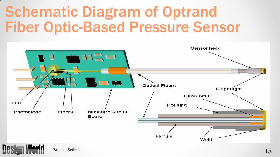
Schematic Diagram of Optrand Fiber Optic-Based Pressure Sensor

19
Pressure Range: 0-150, 0-250, 0-350, 0-3000 bar
Burst Pressure: > 4 range
Tip temp.: -40oC to 380oC (480oC)
Conditioner temp.: -40oC to 125oC (140oC)
Accuracy: 1-2% FSO
Frequency range
Dynamic Sensor: 0.1(1) Hz to 20 (60) kHz
Static-Dynamic: 0 Hz to 20 kHz
Service life: 0.5B -5B pressure cycles,
10k- 30k hours
High-Pressure High-Temperature
Pressure Sensor Key Specifications

20
Pressure Sensors Targeting Internal
Combustion Engines • Dynamic sensors for use in (1) engine R&D and (2)
production gasoline, diesel, natural gas, jet fuel engines used in passenger car, light- and heavy-duty truck, off-highway, marine, gen-set, ship, locomotive, or light aircraft applications
• Two versions offered: o Signal conditioner connected to sensor head by ruggedized
~few meter-long fiber optic cable; targeting engine R&D and large engines
o Signal conditioner located on top of sensor head; targeting automotive OE applications

21
Sensors Targeting Harsh Environment
Industrial and Turbine Applications • 480oC-rated static-dynamic sensor for turbines • 420oC-rated static pressure sensors for Plastic Melts with
flush mounted diaphragms as small as 1mm in diameter with M4x0.6 thread
• 380oC-rated all fiber optic static-dynamic pressure sensor with fiber optic cable up to hundreds meters-long for monitoring of industrial circuit breakers and transformers
• 280oC-rated all fiber optic static-dynamic pressure AND temperature sensor in one package with fiber optic cable up to ~1 Km for oil-gas exploration, geothermal well & volcano monitoring

22
Current Sensor Packages
M12x1.25
M4x0.6
M3x0.5
F1.8mm
M8x1 M4x0.6

Wendell McCulley President

•At first glance High Pressure Sensor packaging seems to be more forgiving than Low Pressure.
•Die attach can be done with “Harder” materials with less effect on TCOffset.
•Overpressure however is a Big Issue.
•Do you choose to use less traditional packaging methods (e.g. NASA SSME)
High Pressure Presents some very Special Considerations
•Topside Applied Pressure with RTV Die attach.
•Oil Filled with Stainless Steel Isolation Diaphragm
•May require a Ceramic or other material as an Interposer
•Common Mode Pressure Considerations
Traditional packaging

Extremely hard to accurately Model the Performance of Corrugated Diaphragms since they are inherently Non-linear, and in the Large Deflection Regime
Provides Media Isolation, Must be strong enough to withstand High Hydrostatic pressure, but must be flexible enough to take up Oil expansion over Temperature

•Do you choose to use less traditional packaging methods (e.g. NASA SSME)
•Hard Eutectic Die Attach
•Metal or Nitride V-Ring Seals
•Must withstand cryogenic temperatures -425⁰F to 250⁰F
•Use of Materials with closely matched Temperature Coefficient of Expansion
•Electron Beam Welded
Creative High Pressure packaging
•Use of Integrated Strain Gauge to measure flexure of the overall Chip
•Correction of Pressure Sensor Measurand for Chip flexure.
•On Chip Thin film Laser Trimmable Resistors.
Creative Electronics, Compensation and Calibration

•Silicon is a mode 1 Fracture Material
•Silicon and glass are Pulled from the central region of the chip
•Looks similar to the hole a BB makes in glass
•Diameter is directly related to the Radius of transition from Tension to Compression and can be controlled by judicious design.
•Design Choices depend on many considerations
•Slab Vs. Diaphragm Design
•Aspect Ratio
Backside Pressure Failure Mode

•Both have the same Die Size and Thickness
•Both have the Same Diaphragm Edge Length to Thickness Aspect Ratio
•Both have Approximately the same Pressure Sensitivity.
Two Different Design Realizations for a 1000 PSI Pressure Sensor
(A Case Study)
•In the case of the Larger Diaphragm it is Completely off the Diaphragm.
•In the case of the Smaller Diaphragm it is just on the Diaphragm near the Edge.
The ideal location “Sweet Spot” for the Piezoresistors is Very Different

•The Larger Diaphragm is also thicker, and therefore must be more Robust, Right?
•By choosing the smaller Diaphragm we can make the overall Die Size much smaller, Right?
Why do we Care?
•For Backside Applied Pressure, the Large Diaphragm will Fail at much lower Pressures.
•The Smaller Diaphragm needs to be part of a Large Die to support higher Burst Pressure.
In the World of High Pressure Things are often Counter-Intuitive.

•Often Counter-Intuitive
•Highly Interdisciplinary requiring a Deep Knowledge of:
•Materials
•Fracture Mechanics
•Piezoresistivity
•Packaging
•Media Compatibility
•Still a bit of a Black Art
High Pressure Sensor Design
•Specific knowledge of High Pressure Sensor Design & Manufacturing
•Has the Tools necessary to develop high performance devices.
•Non-linear Large Deflection Finite Element Analysis (FEA)
•Process Modeling (SUPREM)
•Wafer Processing
•Packaging
•Excels in Design for Manufacturability
InterMEMS Inc. Capability
Summary

Questions?
Design World Randy Frank [email protected] Optrand
Marek Wlodarczyk [email protected]
American Sensor Technologies Karmjit S. Sidhu [email protected]
TERPS, GE Energy Ian Abbott [email protected]
InterMEMS Wendell E. McCulley [email protected]

Thank You
This webinar will be available at designworldonline.com & email
Tweet with hashtag #DWwebinar
Connect with
Twitter: @DesignWorld
Facebook: facebook.com/engineeringexchange
LinkedIn: Design World Group
YouTube: youtube.com/designworldvideo
Discuss this on EngineeringExchange.com


![[500DISTRO] Measuring for SaaS Monetization: Choosing Metrics, Running Experiments & Deciding When To Charge](https://static.documents.pub/doc/80x56/53f8b19e8d7f72b82e8b478e/500distro-measuring-for-saas-monetization-choosing-metrics-running-experiments-deciding-when-to-charge.jpg)


