97
Operator Manual ™ Chronos A Multifunctional Response and Stimulus Device PST-101600
Operator Manual
™
ChronosA Multifunctional Response and Stimulus DevicePST-101600

Chronos Operator ManualPST-101614Rev 1
CopyrightCopyright 2015 Psychology Software Tools, Inc. All rights reserved.
The information in this document is subject to change without notice. Except as permitted under the United States Copyright Act of 1976, no part of this publication may be reproduced, or distributed in any form or by any means, or stored in a database or retrieval system, without prior written permission of Psychology Software Tools, Inc.
Psychology Software Tools, Inc.311 23rd Street Extension, Suite 200Sharpsburg, PA 15215-2821Phone: 412-449-0078Fax: 412-449-0079E-mail: [email protected]: www.pstnet.com
For questions or comments regarding this manual or installation assistance:Please e-mail us at [email protected] or visit us at https://support.pstnet.com.
TrademarkPsychology Software Tools, Inc., the Psychology Software Tools, Inc. logo, the Chronos Response System (Chronos System), and Chronos System images are trademarks or registered trademarks of Psychology Software Tools, Inc. Microsoft, Notepad, and Windows are either registered trademarks or trademarks of Microsoft Corporation in the United States and/or other countries. YouTube is a trademark of Google Inc.
This manual describes the installation procedure for the Chronos System. Please review the manual prior to unpacking and installing the system. The Chronos System is designed to collect responses from participants via any computer system equipped with a Windows 7 or later operating system. Chronos also operates as an auditory stimulus presentation device. Proper performance of this system is affirmed only while the system is used in accordance to the enclosed instructions and safety guidelines.
NOTICE: TRANSPORT AND STORE THIS PRODUCT UNDER THE FOLLOWING ENVIRONMENTAL CONDITIONS ONLY, FOR A PERIOD NOT EXCEEDING 4 WEEKS: AMBIENT TEMPERATURE OF -40°C to +60°C RELATIVE HUMIDITY OF 10% TO 100% (Non-Condensing) ATMOSPHERIC PRESSURE OF 765 hPa TO 1011 hPa
The Chronos System (PST-101600) is for research and educational purposes only.

Table of ContentsChapter 1: Safety ................................................................................................7
1.1 Symbol Definition .......................................................................................71.2 Warnings ....................................................................................................71.3 Cautions .....................................................................................................8
Chapter 2: Getting Started .................................................................................92.1 Unpacking Your System .............................................................................92.2 System Requirements ..............................................................................12
Chapter 3: Introduction to the Chronos System ............................................133.1 Product Overview .....................................................................................133.2 The Chronos Device – Front View ...........................................................143.3 The Chronos Device – Back View ...........................................................15
Chapter 4: Software Installation ......................................................................164.1 Full Software Installation ...........................................................................174.2 Run-Time Only Installation ........................................................................214.3 Software and Firmware Updates ..............................................................254.4 Chronos Power up Sequence ...................................................................254.5 Chronos Startup Sequence ......................................................................264.6 Chronos Features Explorer Experiment ...................................................27
Chapter 5: Exploring Chronos .........................................................................285.1 Introduction ...............................................................................................285.2 Tutorial 1: Adding a Chronos Device to an E-Prime experiment ...............295.3 Introduction to Chronos Features ..............................................................41
Chapter 6: Chronos Features In Depth .......................................................... 446.1 Communicating with Chronos ...................................................................446.2 Pseudo Buttons ........................................................................................456.3 Factors that affect how signals are sampled/responses are processed ....476.4 Fuzzy Values and Precision ......................................................................486.5 Chronos Task Events ................................................................................49
6.5.1 Introduction .......................................................................................496.5.2 Key Concepts ...................................................................................496.5.3 LED Task Events ...............................................................................516.5.4 Analog In Task Events ......................................................................536.5.5 Audio In Task Events ........................................................................556.5.6 Analog Out Task Events ....................................................................576.5.7 Digital Out Task Events .....................................................................606.5.8 Pulse Generator Task Events ............................................................62
Chapter 7: Samples ...........................................................................................637.1 General Information ...................................................................................637.2 LED Sample ..............................................................................................64
7
Chronos Operator Manual - PST-101614 - Rev 1
7.3 Audio In Samples ......................................................................................727.4 Audio Out Samples ...................................................................................78
Chapter 8: Additional Topics ...........................................................................858.1 Using Emulation ........................................................................................858.2 Converting your SRBox Experiment to Chronos .......................................87
8.2.1 Manually change all SRBox references into Chronos references ......888.2.2 Switch SRBox keyboard emulation to Chronos keyboard emulation .898.2.3 Emulate Chronos responses into the SRBox ....................................90
8.3 Auxiliary I/O Breakout Cable .....................................................................918.4 I/O Expander Pin Assignments .................................................................91
8.4.1 I/O Expander 40-pin Header Pin Assignments ..................................928.4.2 External Button Input Timing Requirements......................................94
8.5 Analog Output ...........................................................................................948.6 Photo Sensor ............................................................................................95
Chapter 9: Contact Information .......................................................................97
7
Chronos Operator Manual - PST-101614 - Rev 1
Chapter 1: Safety
1.1 Symbol Definition
The following symbol will be used throughout this manual as a means to alert you to potential safety hazards on the accompanying equipment.
This chapter is designed to alert you to any safety precautions associated with the Chronos System. Read all WARNINGS and CAUTIONS before use of the Chronos System. Psychology Software Tools, Inc. is not liable for any damage or injury resulting from misuse of this equipment.
1.2 Warnings
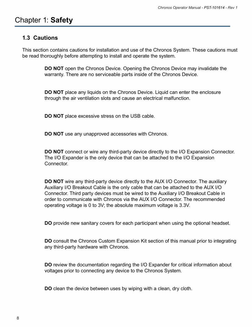
The following Warning sticker appears on the Chronos Device:
WARNING: Service to be performed by qualified service personnel only. Opening the device by non-qualified personnel will invalidate the warranty.
WARNING: DO NOT expose this unit to rain or moisture to prevent fire and shock.
9
Chronos Operator Manual - PST-101614 - Rev 1
8
Chronos Operator Manual - PST-101614 - Rev 1
Chapter 1: Safety
DO NOT open the Chronos Device. Opening the Chronos Device may invalidate the warranty. There are no serviceable parts inside of the Chronos Device.
DO NOT place any liquids on the Chronos Device. Liquid can enter the enclosure through the air ventilation slots and cause an electrical malfunction.
DO NOT place excessive stress on the USB cable.
DO NOT use any unapproved accessories with Chronos.
DO NOT connect or wire any third-party device directly to the I/O Expansion Connector. The I/O Expander is the only device that can be attached to the I/O Expansion Connector.
DO NOT wire any third-party device directly to the AUX I/O Connector. The auxiliary Auxiliary I/O Breakout Cable is the only cable that can be attached to the AUX I/O Connector. Third party devices must be wired to the Auxiliary I/O Breakout Cable in order to communicate with Chronos via the AUX I/O Connector. The recommended operating voltage is 0 to 3V; the absolute maximum voltage is 3.3V.
DO provide new sanitary covers for each participant when using the optional headset.
DO consult the Chronos Custom Expansion Kit section of this manual prior to integrating any third-party hardware with Chronos.
DO review the documentation regarding the I/O Expander for critical information about voltages prior to connecting any device to the Chronos System.
DO clean the device between uses by wiping with a clean, dry cloth.
1.3 Cautions
This section contains cautions for installation and use of the Chronos System. These cautions must be read thoroughly before attempting to install and operate the system.
9
Chronos Operator Manual - PST-101614 - Rev 1
8
Chronos Operator Manual - PST-101614 - Rev 1
Chapter 2: Getting Started
2.1 Unpacking Your System
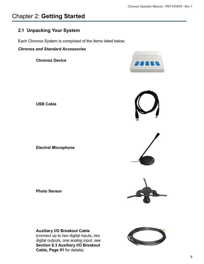
Each Chronos System is comprised of the items listed below.
Chronos Device
USB Cable
Electret Microphone
Photo Sensor
Chronos and Standard Accessories
Auxiliary I/O Breakout Cable(connect up to two digital inputs, two digital outputs, one analog input, see Section 8.3 Auxiliary I/O Breakout Cable, Page 91 for details)
11
Chronos Operator Manual - PST-101614 - Rev 1
10
Chronos Operator Manual - PST-101614 - Rev 1
Chapter 2: Getting Started
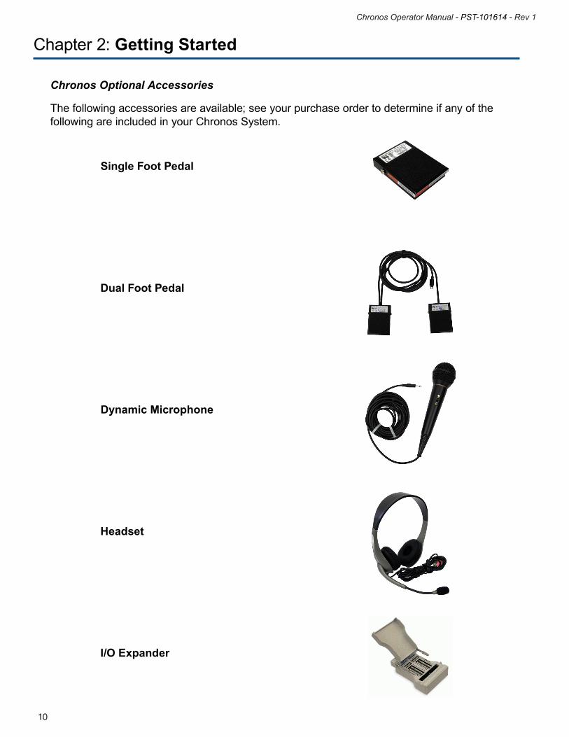
Chronos Optional Accessories
The following accessories are available; see your purchase order to determine if any of the following are included in your Chronos System.
Single Foot Pedal
Dual Foot Pedal
Dynamic Microphone
Headset
I/O Expander
11
Chronos Operator Manual - PST-101614 - Rev 1
10
Chronos Operator Manual - PST-101614 - Rev 1
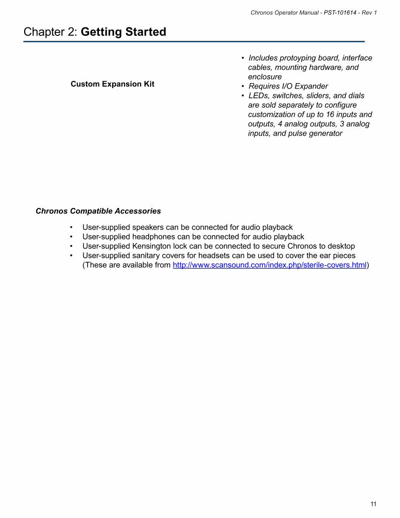
• Includes protoyping board, interface cables, mounting hardware, and enclosure • Requires I/O Expander • LEDs, switches, sliders, and dials are sold separately to configure customization of up to 16 inputs and outputs, 4 analog outputs, 3 analog inputs, and pulse generator
Chapter 2: Getting Started
Custom Expansion Kit
Chronos Compatible Accessories
• User-suppliedspeakerscanbeconnectedforaudioplayback • User-suppliedheadphonescanbeconnectedforaudioplayback • User-suppliedKensingtonlockcanbeconnectedtosecureChronostodesktop • User-suppliedsanitarycoversforheadsetscanbeusedtocovertheearpieces (These are available from http://www.scansound.com/index.php/sterile-covers.html)
13
Chronos Operator Manual - PST-101614 - Rev 1
12
Chronos Operator Manual - PST-101614 - Rev 1
2.2 System Requirements
Chronos is compatible with PCs running one of the following operating systems:•Windows8/8.1(64-bit)•Windows7SP1(32and64-bit)
The minimum Chronos machine configuration is:•PentiumcompatibleDual-CoreorMulti-CoreProcessor2GHz•2GBRAM•USB2.0or3.0Portorpoweredhubport
Chronos is compatible with E-Prime 2.0 SP1 Standard or Professional Editions. However, using Chronos with the Standard Edition restricts the following functionality:• NoaccesstousingmultipleChronosdeviceswithinanexperiment(nomulti-boxfunctionality)• Noaccesstotheapproximately30ChronosTaskEventsthatsupportanalogin,analogout, digital in, digital out, LED, and pulse generator functionality without the need to write E-Basic Script.
Chapter 2: Getting Started
13
Chronos Operator Manual - PST-101614 - Rev 1
12
Chronos Operator Manual - PST-101614 - Rev 1
Chapter 3: Introduction to the Chronos System
3.1 Product Overview
Chronos allows the accurate collection and verification of tactile, auditory, visual, analog, and digital responses. Chronos also provides a precise source of audio timing, generic analog output timing, and digital outputs – including pulse generation. Chronos features millisecond accuracy and consistent sound output latencies across machines. Chronos includes 16 digital inputs and 16 digital outputs, eliminating the need for a parallel port. All responses collected are synchronized to the E-Prime time domain. The Chronos hardware components are introduced in this section.
15
Chronos Operator Manual - PST-101614 - Rev 1
14
Chronos Operator Manual - PST-101614 - Rev 1
Chapter 3: Introduction to the Chronos System
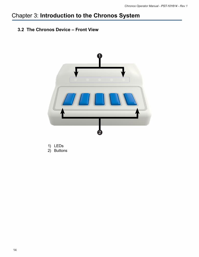
3.2 The Chronos Device – Front View
1) LEDs 2) Buttons
1
2
15
Chronos Operator Manual - PST-101614 - Rev 1
14
Chronos Operator Manual - PST-101614 - Rev 1
Chapter 3: Introduction to the Chronos System
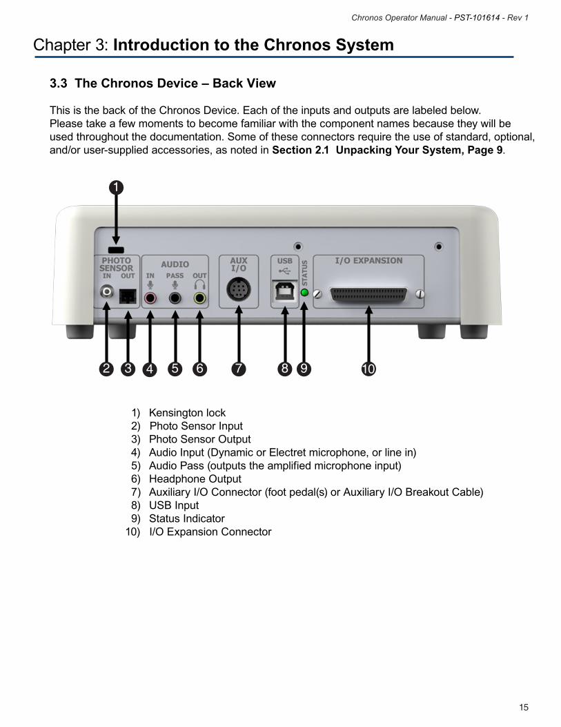
3.3 The Chronos Device – Back View
This is the back of the Chronos Device. Each of the inputs and outputs are labeled below. Please take a few moments to become familiar with the component names because they will be used throughout the documentation. Some of these connectors require the use of standard, optional, and/or user-supplied accessories, as noted in Section 2.1 Unpacking Your System, Page 9.
1) Kensington lock 2) Photo Sensor Input 3) Photo Sensor Output 4) Audio Input (Dynamic or Electret microphone, or line in) 5) Audio Pass (outputs the amplified microphone input) 6) Headphone Output 7) Auxiliary I/O Connector (foot pedal(s) or Auxiliary I/O Breakout Cable) 8) USB Input 9) Status Indicator10) I/O Expansion Connector
2
3
4
7
8
9
10
5
6
1
17
Chronos Operator Manual - PST-101614 - Rev 1
16
Chronos Operator Manual - PST-101614 - Rev 1
The Chronos System software consists of the Chronos Device Driver and the Chronos E-Prime device. These elements are installed as part of the Chronos System software installation and are described briefly here.
Chronos Device DriverThe Chronos Device accurately timestamps any responses made with it. The Chronos Device Driver communicates between Chronos, E-Prime, and the operating system; it forwards response information to the stimulus presentation computer. The Chronos Device Driver is also used to play audio files with minimal sound onset latency, collect and record vocal responses, as well as send and receive digital and analog signals.
Chronos E-Prime deviceChronos is supported in E-Prime as an InputDevice, which provides optimized functioning and integration with E-Prime. As with any other InputDevice, Chronos is added to the experiment and configured via the Devices tab. The Chronos Device Properties provide a rich interface to access numerous default configuration settings, including audio sensitivity, LED state at experiment startup, debounce values for each of the digital inputs and responses, and sampling rates for the analog input channels. The Chronos Device Properties are detailed in Chronos Device Properties, Page 44.
Chapter 4: Software Installation
17
Chronos Operator Manual - PST-101614 - Rev 1
16
Chronos Operator Manual - PST-101614 - Rev 1
Chapter 4: Software Installation
4.1 Full Software InstallationYou must have administrative rights to install this software on the computer. If you do not have administrative rights, you will be unable to install the Chronos System. If you are unsure of your administrative privileges, contact your System Administrator. We recommend manually uninstalling any older versions of the Chronos System software before installing any updates.
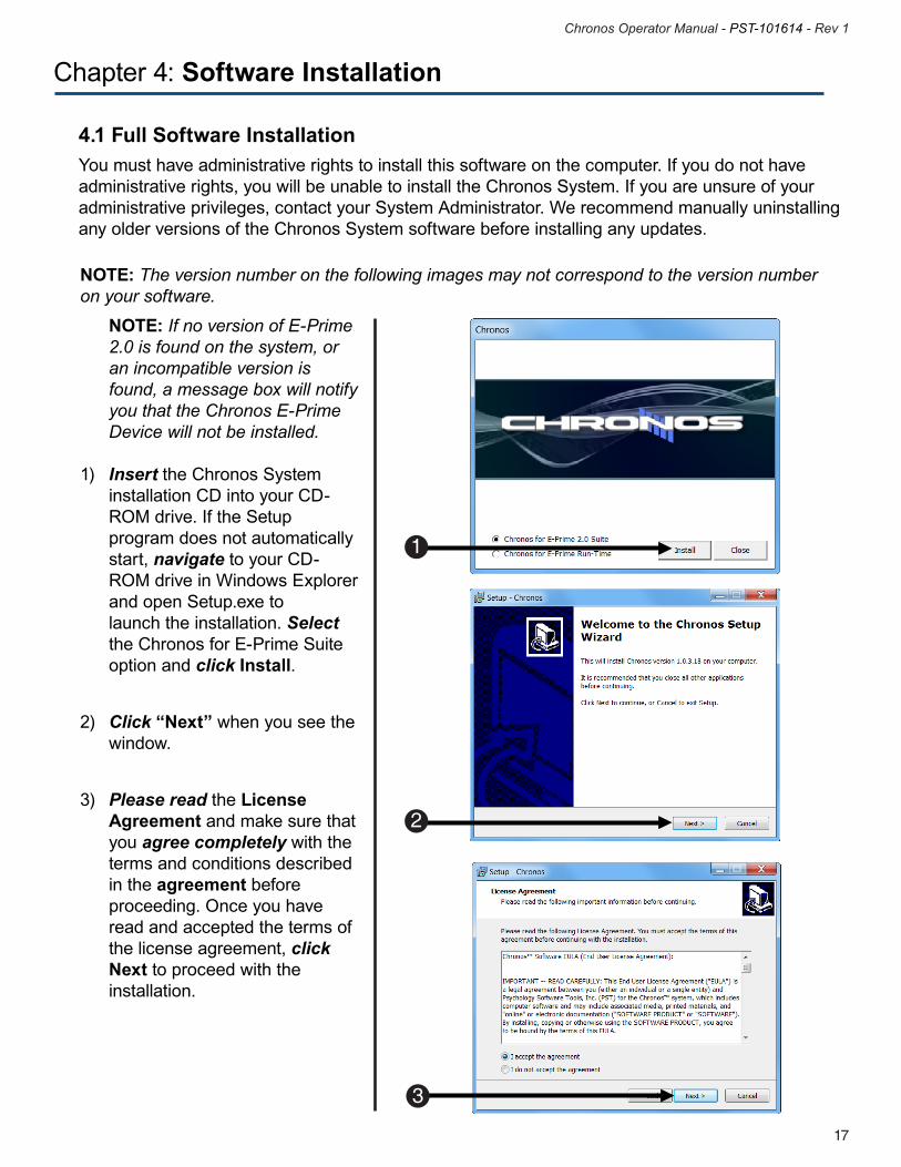
NOTE: The version number on the following images may not correspond to the version numberon your software.
1
3
NOTE: If no version of E-Prime 2.0 is found on the system, or an incompatible version is found, a message box will notify you that the Chronos E-Prime Device will not be installed. 1) Insert the Chronos System installation CD into your CD- ROM drive. If the Setup program does not automatically start, navigate to your CD- ROM drive in Windows Explorer and open Setup.exe to launch the installation. Select the Chronos for E-Prime Suite option and click Install.
2) Click “Next” when you see the window.
3) Please read the License Agreement and make sure that you agree completely with the terms and conditions described in the agreement before proceeding. Once you have read and accepted the terms of the license agreement, click Next to proceed with the installation.
2
19
Chronos Operator Manual - PST-101614 - Rev 1
18
Chronos Operator Manual - PST-101614 - Rev 1
Chapter 4: Software Installation
5
4
4
6
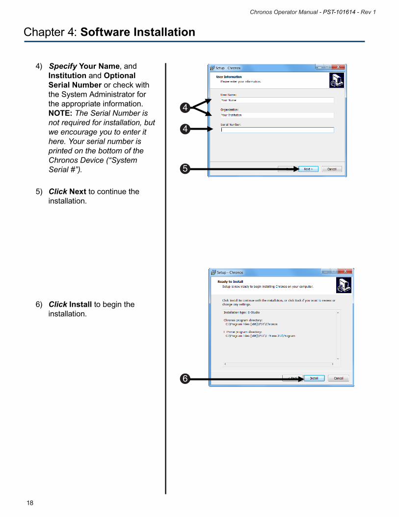
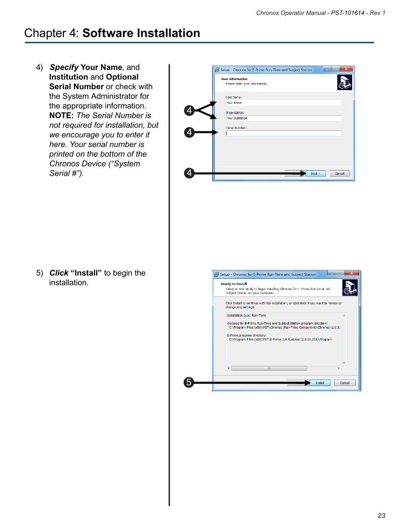
4) Specify Your Name, and Institution and Optional Serial Number or check with the System Administrator for the appropriate information. NOTE: The Serial Number is not required for installation, but we encourage you to enter it here. Your serial number is printed on the bottom of the Chronos Device (“System Serial #”).
5) Click Next to continue the installation.
6) Click Install to begin the installation.
19
Chronos Operator Manual - PST-101614 - Rev 1
18
Chronos Operator Manual - PST-101614 - Rev 1
Chapter 4: Software Installation
8
7
9
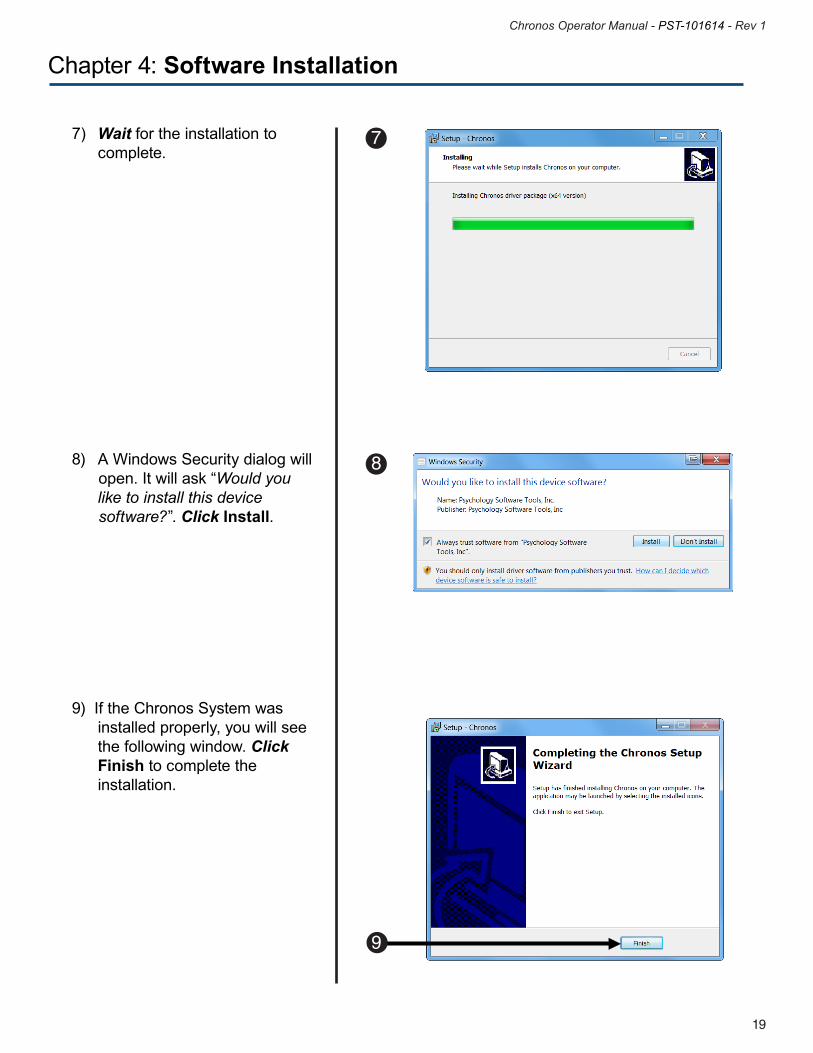
7) Wait for the installation to complete.
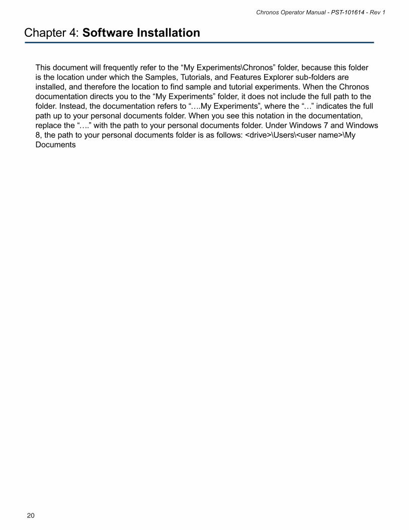
8) A Windows Security dialog will open. It will ask “Would you like to install this device software?”. Click Install.
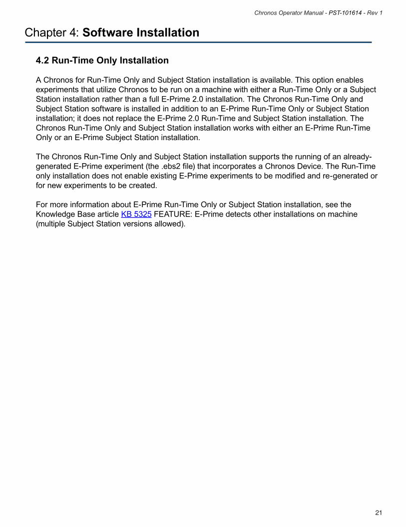
9) If the Chronos System was installed properly, you will see the following window. Click Finish to complete the installation.
21
Chronos Operator Manual - PST-101614 - Rev 1
20
Chronos Operator Manual - PST-101614 - Rev 1
Chapter 4: Software Installation
This document will frequently refer to the “My Experiments\Chronos” folder, because this folder is the location under which the Samples, Tutorials, and Features Explorer sub-folders are installed, and therefore the location to find sample and tutorial experiments. When the Chronos documentation directs you to the “My Experiments” folder, it does not include the full path to the folder. Instead, the documentation refers to “….My Experiments”, where the “…” indicates the full path up to your personal documents folder. When you see this notation in the documentation, replace the “….” with the path to your personal documents folder. Under Windows 7 and Windows 8, the path to your personal documents folder is as follows: <drive>\Users\<user name>\My Documents
21
Chronos Operator Manual - PST-101614 - Rev 1
20
Chronos Operator Manual - PST-101614 - Rev 1
4.2 Run-Time Only Installation
A Chronos for Run-Time Only and Subject Station installation is available. This option enables experiments that utilize Chronos to be run on a machine with either a Run-Time Only or a Subject Station installation rather than a full E-Prime 2.0 installation. The Chronos Run-Time Only and Subject Station software is installed in addition to an E-Prime Run-Time Only or Subject Station installation; it does not replace the E-Prime 2.0 Run-Time and Subject Station installation. The Chronos Run-Time Only and Subject Station installation works with either an E-Prime Run-Time Only or an E-Prime Subject Station installation. The Chronos Run-Time Only and Subject Station installation supports the running of an already-generated E-Prime experiment (the .ebs2 file) that incorporates a Chronos Device. The Run-Time only installation does not enable existing E-Prime experiments to be modified and re-generated or for new experiments to be created. For more information about E-Prime Run-Time Only or Subject Station installation, see the Knowledge Base article KB 5325 FEATURE: E-Prime detects other installations on machine (multiple Subject Station versions allowed).
Chapter 4: Software Installation
23
Chronos Operator Manual - PST-101614 - Rev 1
22
Chronos Operator Manual - PST-101614 - Rev 1
Chapter 4: Software Installation
You must have administrative rights to install this software on the computer. If you do not have administrative rights, you will be unable to install the Chronos System. If you are unsure of your administrative privileges, contact your System Administrator. We recommend manually uninstalling any older versions of the Chronos System software before installing any updates.
NOTE: The version number on the following images may not correspond to the version numberon your software.
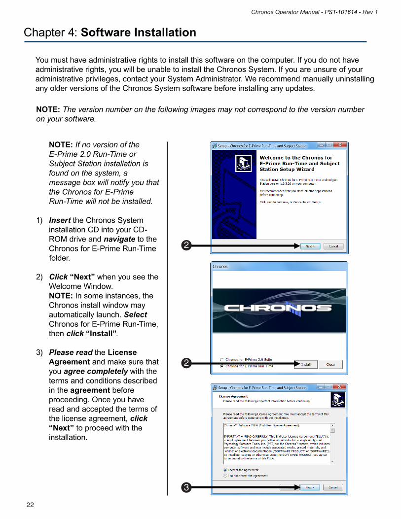
NOTE: If no version of the E-Prime 2.0 Run-Time or Subject Station installation is found on the system, a message box will notify you that the Chronos for E-Prime Run-Time will not be installed. 1) Insert the Chronos System installation CD into your CD- ROM drive and navigate to the Chronos for E-Prime Run-Time folder.
2) Click “Next” when you see the Welcome Window. NOTE: In some instances, the Chronos install window may automatically launch. Select Chronos for E-Prime Run-Time, then click “Install”.
3) Please read the License Agreement and make sure that you agree completely with the terms and conditions described in the agreement before proceeding. Once you have read and accepted the terms of the license agreement, click “Next” to proceed with the installation.
2
3
2
23
Chronos Operator Manual - PST-101614 - Rev 1
22
Chronos Operator Manual - PST-101614 - Rev 1
Chapter 4: Software Installation
4
4
4
4) Specify Your Name, and Institution and Optional Serial Number or check with the System Administrator for the appropriate information. NOTE: The Serial Number is not required for installation, but we encourage you to enter it here. Your serial number is printed on the bottom of the Chronos Device (“System Serial #”).
5) Click “Install” to begin the installation.
NOTE: The version number on the following images may not correspond to the version numberon your software.
5
25
Chronos Operator Manual - PST-101614 - Rev 1
24
Chronos Operator Manual - PST-101614 - Rev 1
Chapter 4: Software Installation
6
7
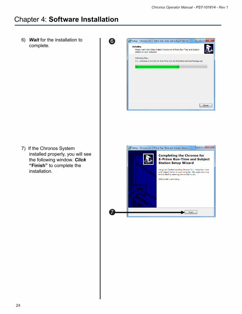
6) Wait for the installation to complete.
7) If the Chronos System installed properly, you will see the following window. Click “Finish” to complete the installation.
25
Chronos Operator Manual - PST-101614 - Rev 1
24
Chronos Operator Manual - PST-101614 - Rev 1
Chapter 4: Software Installation
4.3 Software and Firmware Updates
Refer to the PST Product Service and Support web site (http://support.pstnet.com) for the latest information about updates to the Chronos Software and Firmware.
4.4 Chronos Power up Sequence
When the Chronos Device is inserted into a USB 2.0 or 3.0 port connected to a PC, the system performs a Powerup sequence. The five LEDs will blink on and off three times; when on, the LEDs will be blue. This Powerup sequence occurs whenever a Chronos Device is inserted into a supported USB port and confirms that the Chronos is ready to communicate with the device driver, if installed and configured.
27
Chronos Operator Manual - PST-101614 - Rev 1
26
Chronos Operator Manual - PST-101614 - Rev 1
Chapter 4: Software Installation
4.5 Chronos Startup Sequence
When Chronos is connected to a PC and an experiment that uses Chronos begins to run, the system may perform a Chronos Startup sequence. The five LEDs will blink on and off three times; when on, the LEDs will be white. This Startup Sequence confirms that the E-Prime experiment can send and receive information from Chronos. The Chronos Startup Sequence is only performed when all of the following are true:•TheChronossoftwarehasbeeninstalledasdescribedinSection 4.1 Full Software Installation, Page 17 of this manual•TheChronosDeviceisinsertedintoaUSBportconnectedtoaPC•AChronosDevicehasbeenaddedtoanE-Primeexperiment•TheStartupsequenceisenabledontheChronosDeviceProperties
The Startup Sequence is not enabled by default. See Section Step 4: Review Chronos Device Default tab, Page 36 for information on enabling the Startup Sequence.
27
Chronos Operator Manual - PST-101614 - Rev 1
26
Chronos Operator Manual - PST-101614 - Rev 1
Chapter 4: Software Installation
4.6 Chronos Features Explorer Experiment
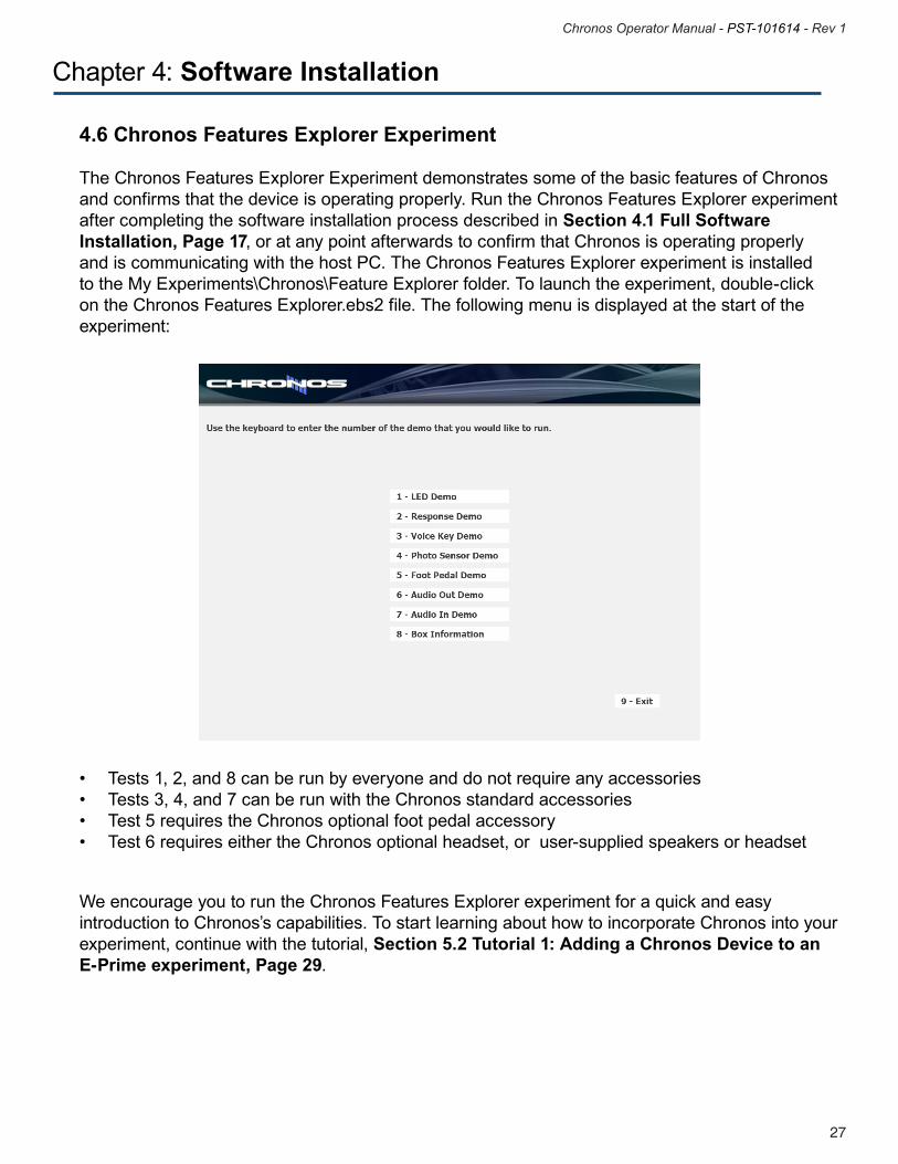
The Chronos Features Explorer Experiment demonstrates some of the basic features of Chronos and confirms that the device is operating properly. Run the Chronos Features Explorer experiment after completing the software installation process described in Section 4.1 Full Software Installation, Page 17, or at any point afterwards to confirm that Chronos is operating properly and is communicating with the host PC. The Chronos Features Explorer experiment is installed to the My Experiments\Chronos\Feature Explorer folder. To launch the experiment, double-click on the Chronos Features Explorer.ebs2 file. The following menu is displayed at the start of the experiment:
• Tests1,2,and8canberunbyeveryoneanddonotrequireanyaccessories• Tests3,4,and7canberunwiththeChronosstandardaccessories• Test5requirestheChronosoptionalfootpedalaccessory• Test6requireseithertheChronosoptionalheadset,oruser-suppliedspeakersorheadset
We encourage you to run the Chronos Features Explorer experiment for a quick and easy introduction to Chronos’s capabilities. To start learning about how to incorporate Chronos into your experiment, continue with the tutorial, Section 5.2 Tutorial 1: Adding a Chronos Device to an E-Prime experiment, Page 29.

29
Chronos Operator Manual - PST-101614 - Rev 1
28
Chronos Operator Manual - PST-101614 - Rev 1
Chapter 5: Exploring Chronos
5.1 Introduction
This chapter outlines the basic features in Chronos. Section 5.2 Tutorial 1: Adding a Chronos Device to an E-Prime experiment, Page 29 presents Chronos Tutorial 1, which uses Chronos to present auditory stimulus files and collect participant responses. Section 5.3 Introduction to Chronos Features, Page 41 introduces the Chronos Device Properties, which allows the numerous Chronos properties to be initialized easily.
29
Chronos Operator Manual - PST-101614 - Rev 1
28
Chronos Operator Manual - PST-101614 - Rev 1
Chapter 5: Exploring Chronos
5.2 Tutorial 1: Adding a Chronos Device to an E-Prime experiment
Summary: The following tutorial begins with an overview of a multi-modal E-Prime 2.0 experiment that presents audio files via the host computer’s sound card and collects participant responses from the keyboard. The tutorial continues by teaching you how to use Chronos instead of the computer’s sound card to present the audio file, as well as use Chronos instead of the keyboard to collect participant responses. Before you begin the tutorial, it is important that you understand what the multi-modal task does. In the initial version, a single digit between 1 and 5 is presented on the screen while at the same time an audio recording of the same digit is played. The participant’s task is to press the key that corresponds to the digit that was presented in both modalities. This tutorial is set up to work with one Chronos Device. This tutorial assumes that you have both the full Chronos system software installed, as described in Section 4.1 Full Software Installation, Page 17 along with E-Prime 2.0 SP1 or later. This tutorial also assumes basic familiarity with the E-Studio application. For users who are new to E-Prime, we strongly recommend that you review the E-Prime Getting Started Guide, particularly Chapter 2: E-Studio. Finally, this tutorial requires either that speakers or headphones be connected to the Audio Output connector.
Goal: This tutorial illustrates how to add a Chronos Device to an existing experiment and utilize it to both play audio files and collect button responses. This tutorial also illustrates how to use the Echo Client feature to provide feedback about the accuracy of the button response via the LEDs.
31
Chronos Operator Manual - PST-101614 - Rev 1
30
Chronos Operator Manual - PST-101614 - Rev 1
Step 1: Load PreChronosSimpleRT.es2
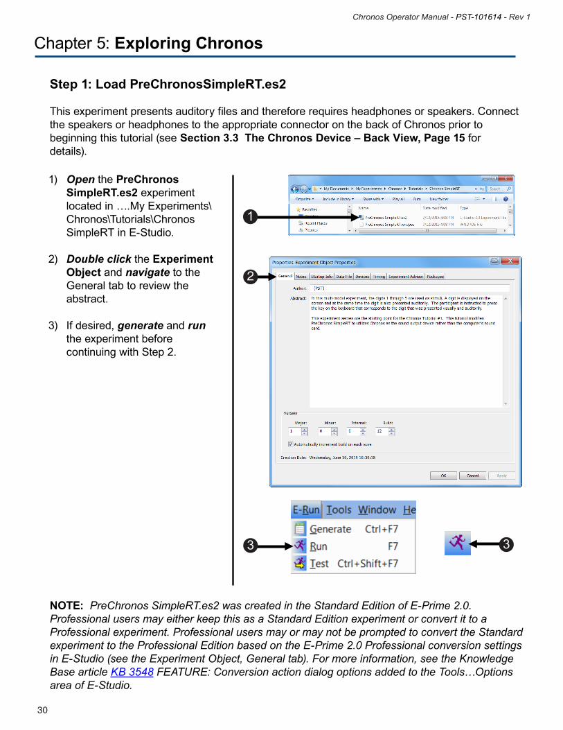
This experiment presents auditory files and therefore requires headphones or speakers. Connect the speakers or headphones to the appropriate connector on the back of Chronos prior to beginning this tutorial (see Section 3.3 The Chronos Device – Back View, Page 15 for details).
1) Open the PreChronos SimpleRT.es2 experiment located in ….My Experiments\ Chronos\Tutorials\Chronos SimpleRT in E-Studio. 2) Double click the Experiment Object and navigate to the General tab to review the abstract.
3) If desired, generate and run the experiment before continuing with Step 2.
Chapter 5: Exploring Chronos
NOTE: PreChronos SimpleRT.es2 was created in the Standard Edition of E-Prime 2.0. Professional users may either keep this as a Standard Edition experiment or convert it to a Professional experiment. Professional users may or may not be prompted to convert the Standard experiment to the Professional Edition based on the E-Prime 2.0 Professional conversion settings in E-Studio (see the Experiment Object, General tab). For more information, see the Knowledge Base article KB 3548 FEATURE: Conversion action dialog options added to the Tools…Options area of E-Studio.
1
2
3
3
31
Chronos Operator Manual - PST-101614 - Rev 1
30
Chronos Operator Manual - PST-101614 - Rev 1
Chapter 5: Exploring Chronos
Step 2: Review existing experiment structure
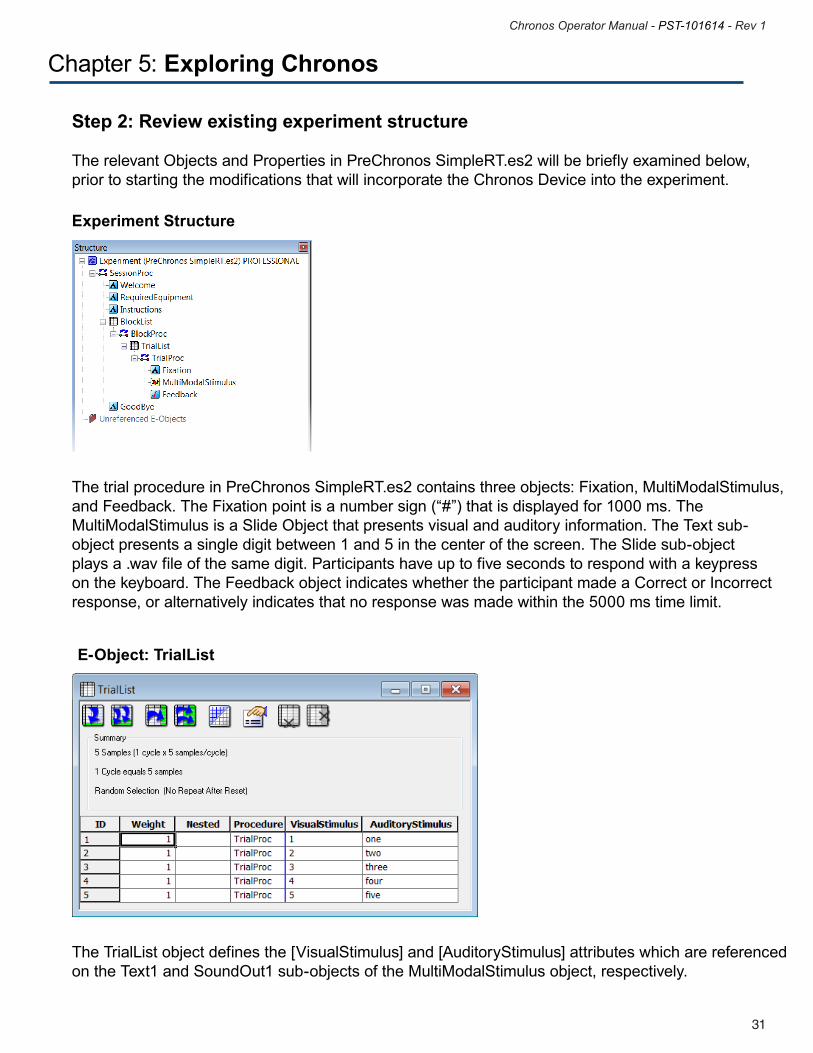
The relevant Objects and Properties in PreChronos SimpleRT.es2 will be briefly examined below, prior to starting the modifications that will incorporate the Chronos Device into the experiment.
Experiment Structure
The trial procedure in PreChronos SimpleRT.es2 contains three objects: Fixation, MultiModalStimulus, and Feedback. The Fixation point is a number sign (“#”) that is displayed for 1000 ms. The MultiModalStimulus is a Slide Object that presents visual and auditory information. The Text sub-object presents a single digit between 1 and 5 in the center of the screen. The Slide sub-object plays a .wav file of the same digit. Participants have up to five seconds to respond with a keypress on the keyboard. The Feedback object indicates whether the participant made a Correct or Incorrect response, or alternatively indicates that no response was made within the 5000 ms time limit.
The TrialList object defines the [VisualStimulus] and [AuditoryStimulus] attributes which are referenced on the Text1 and SoundOut1 sub-objects of the MultiModalStimulus object, respectively.
E-Object: TrialList
33
Chronos Operator Manual - PST-101614 - Rev 1
32
Chronos Operator Manual - PST-101614 - Rev 1
Chapter 5: Exploring Chronos
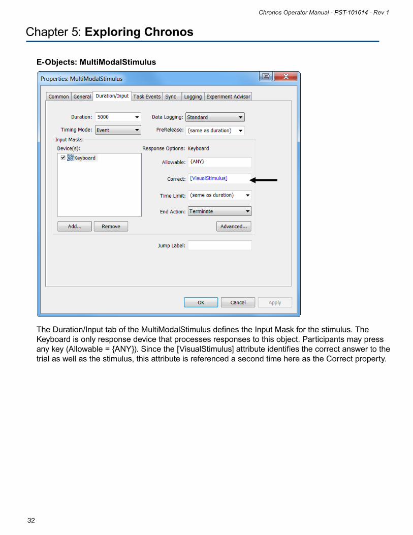
The Duration/Input tab of the MultiModalStimulus defines the Input Mask for the stimulus. The Keyboard is only response device that processes responses to this object. Participants may press any key (Allowable = {ANY}). Since the [VisualStimulus] attribute identifies the correct answer to the trial as well as the stimulus, this attribute is referenced a second time here as the Correct property.
E-Objects: MultiModalStimulus
33
Chronos Operator Manual - PST-101614 - Rev 1
32
Chronos Operator Manual - PST-101614 - Rev 1
Chapter 5: Exploring Chronos
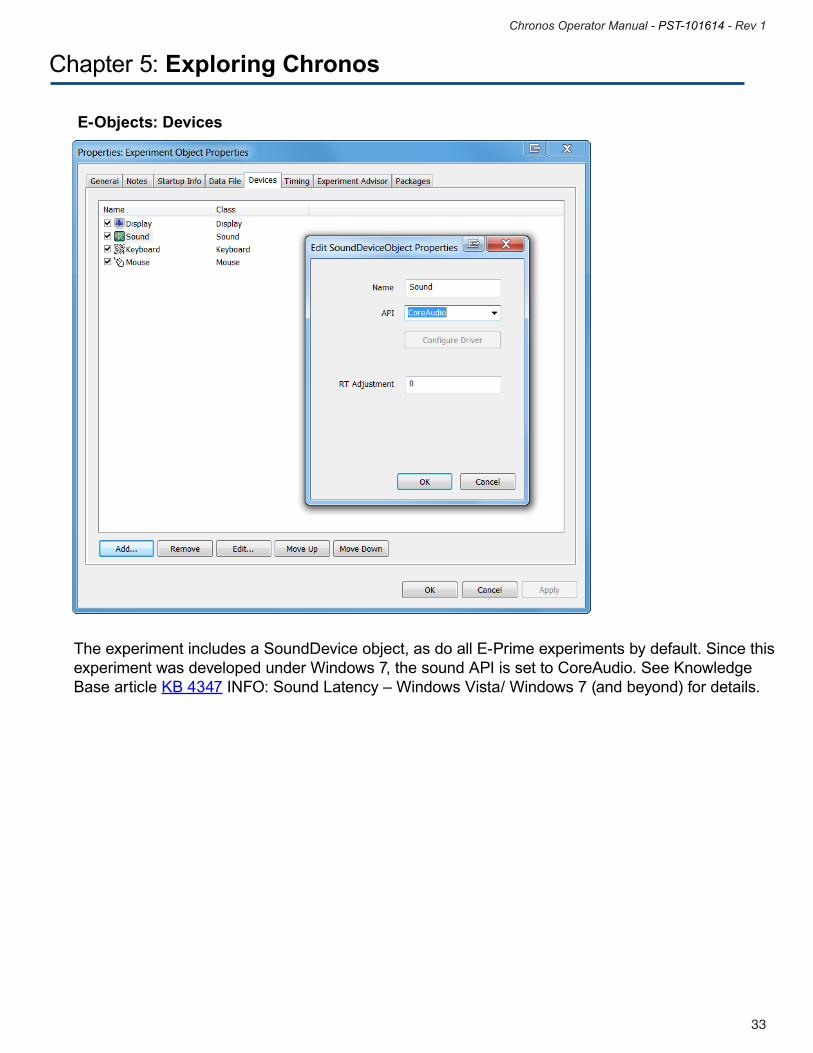
The experiment includes a SoundDevice object, as do all E-Prime experiments by default. Since this experiment was developed under Windows 7, the sound API is set to CoreAudio. See Knowledge Base article KB 4347 INFO: Sound Latency – Windows Vista/ Windows 7 (and beyond) for details.
E-Objects: Devices
35
Chronos Operator Manual - PST-101614 - Rev 1
34
Chronos Operator Manual - PST-101614 - Rev 1
Chapter 5: Exploring Chronos
Step 3: Add Chronos Device
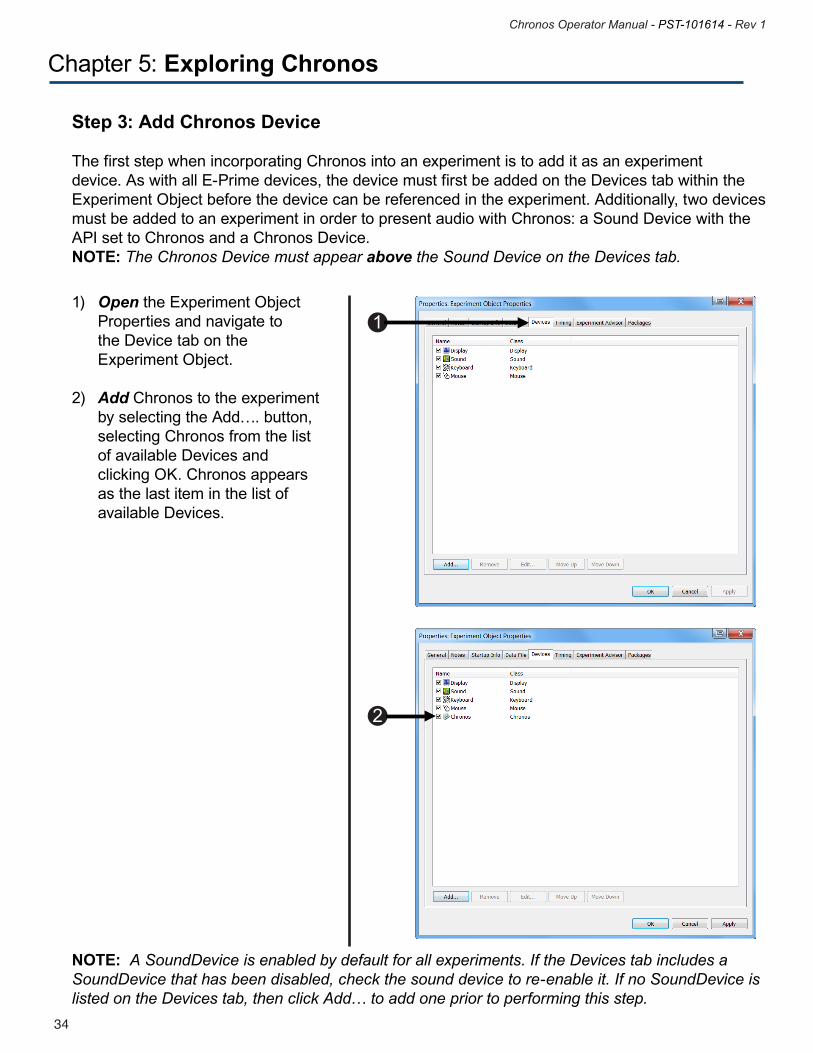
The first step when incorporating Chronos into an experiment is to add it as an experiment device. As with all E-Prime devices, the device must first be added on the Devices tab within the Experiment Object before the device can be referenced in the experiment. Additionally, two devices must be added to an experiment in order to present audio with Chronos: a Sound Device with the API set to Chronos and a Chronos Device. NOTE: The Chronos Device must appear above the Sound Device on the Devices tab.
1) Open the Experiment Object Properties and navigate to the Device tab on the Experiment Object.
2) Add Chronos to the experiment by selecting the Add…. button, selecting Chronos from the list of available Devices and clicking OK. Chronos appears as the last item in the list of available Devices.
NOTE: A SoundDevice is enabled by default for all experiments. If the Devices tab includes a SoundDevice that has been disabled, check the sound device to re-enable it. If no SoundDevice is listed on the Devices tab, then click Add… to add one prior to performing this step.
1
2
35
Chronos Operator Manual - PST-101614 - Rev 1
34
Chronos Operator Manual - PST-101614 - Rev 1
Chapter 5: Exploring Chronos
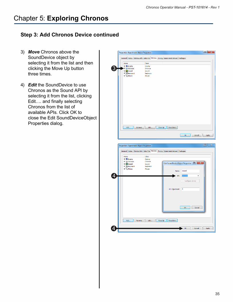
3) Move Chronos above the SoundDevice object by selecting it from the list and then clicking the Move Up button three times.
4) Edit the SoundDevice to use Chronos as the Sound API by selecting it from the list, clicking Edit…. and finally selecting Chronos from the list of available APIs. Click OK to close the Edit SoundDeviceObject Properties dialog.
Step 3: Add Chronos Device continued
3
4
4
37
Chronos Operator Manual - PST-101614 - Rev 1
36
Chronos Operator Manual - PST-101614 - Rev 1
Chapter 5: Exploring Chronos
Step 4: Review Chronos Device Default tab
As we will explore in Chapter 6, Chronos has a large number of properties that can be configured by editing the Chronos Device Properties. For the purpose this experiment, all of the Chronos Device Properties default values are appropriate, so we do not need to examine them in detail now. However, there are a few properties that should be reviewed briefly on the General tab.
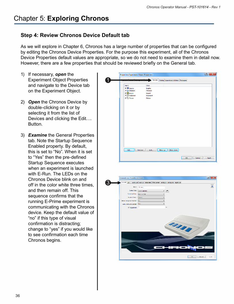
1) If necessary, open the Experiment Object Properties and navigate to the Device tab on the Experiment Object. 2) Open the Chronos Device by double-clicking on it or by selecting it from the list of Devices and clicking the Edit…. Button.
3) Examine the General Properties tab. Note the Startup Sequence Enabled property. By default, this is set to “No”. When it is set to “Yes” then the pre-defined Startup Sequence executes when an experiment is launched with E-Run. The LEDs on the Chronos Device blink on and off in the color white three times, and then remain off. This sequence confirms that the running E-Prime experiment is communicating with the Chronos device. Keep the default value of “no” if this type of visual confirmation is distracting; change to “yes” if you would like to see confirmation each time Chronos begins.
1
3
37
Chronos Operator Manual - PST-101614 - Rev 1
36
Chronos Operator Manual - PST-101614 - Rev 1
Chapter 5: Exploring Chronos
Step 4: Review Chronos Device Default Tab continued
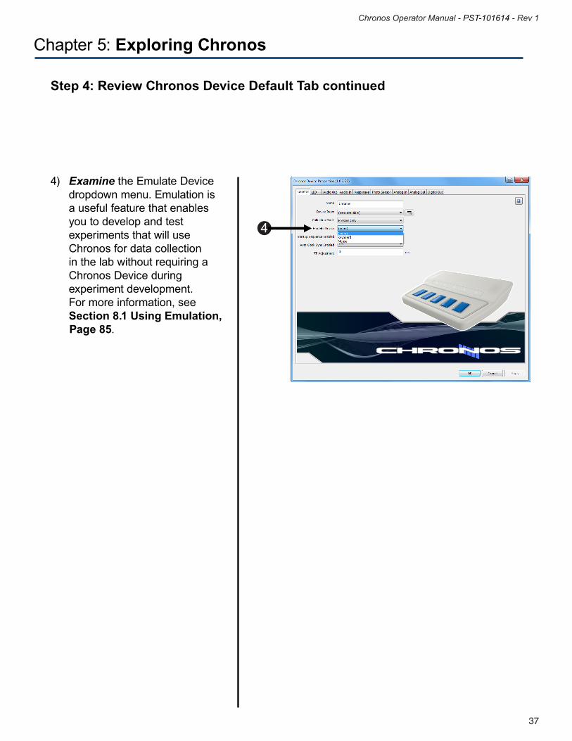
4) Examine the Emulate Device dropdown menu. Emulation is a useful feature that enables you to develop and test experiments that will use Chronos for data collection in the lab without requiring a Chronos Device during experiment development. For more information, see Section 8.1 Using Emulation, Page 85.
4
39
Chronos Operator Manual - PST-101614 - Rev 1
38
Chronos Operator Manual - PST-101614 - Rev 1
Chapter 5: Exploring Chronos
Step 5: Modify Stimulus Object
Now that Chronos has been added as a Device, a Chronos Input Mask needs to be added to the response collection object in order to accept responses from Chronos. By default, Chronos accepts presses only. This can be changed to accept releases as well, or both presses and releases, by modifying the Chronos Device Properties, but button presses is only appropriate for this tutorial experiment.
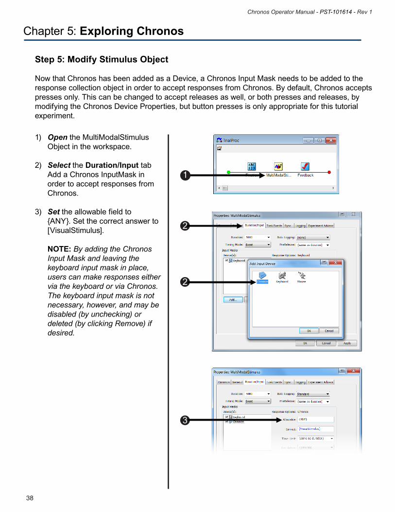
1) Open the MultiModalStimulus Object in the workspace.
2) Select the Duration/Input tab Add a Chronos InputMask in order to accept responses from Chronos. 3) Set the allowable field to {ANY}. Set the correct answer to [VisualStimulus].
NOTE: By adding the Chronos Input Mask and leaving the keyboard input mask in place, users can make responses either via the keyboard or via Chronos. The keyboard input mask is not necessary, however, and may be disabled (by unchecking) or deleted (by clicking Remove) if desired.
1
2
2
3
39
Chronos Operator Manual - PST-101614 - Rev 1
38
Chronos Operator Manual - PST-101614 - Rev 1
Chapter 5: Exploring Chronos
Step 6: Add Feedback to show which button was pressed by using the Chronos Echo Client
Chronos provides three methods to manipulate the LEDs: Echo Client, user-written E-Basic script with Chronos commands, and Task Events. This tutorial introduces the Chronos Echo Client. Note that the use of Task Events requires the E-Prime Professional Edition (for more information about E-Prime Standard and Professional Editions, see the Knowledge Base article KB 5607 INFO: FAQ about E-Prime Versions and Editions. For this tutorial, a very simple Echo Client is used: the LED above the button that was pressed is illuminated in white. See the LED Samples or LED Samples Pro experiments for examples of a more complex implementation of Echo Client, along with examples of E-Basic Chronos commands and LED Task Events. As described in Step 2 of this tutorial, the experiment procedure includes a Feedback object that provides response accuracy (correct, incorrect, omission) and response time (for correct response only) feedback. In addition to the information provided by the Feedback object, we will add a Chronos Echo Client to illuminate the LED that maps to button that was pressed on the trial.
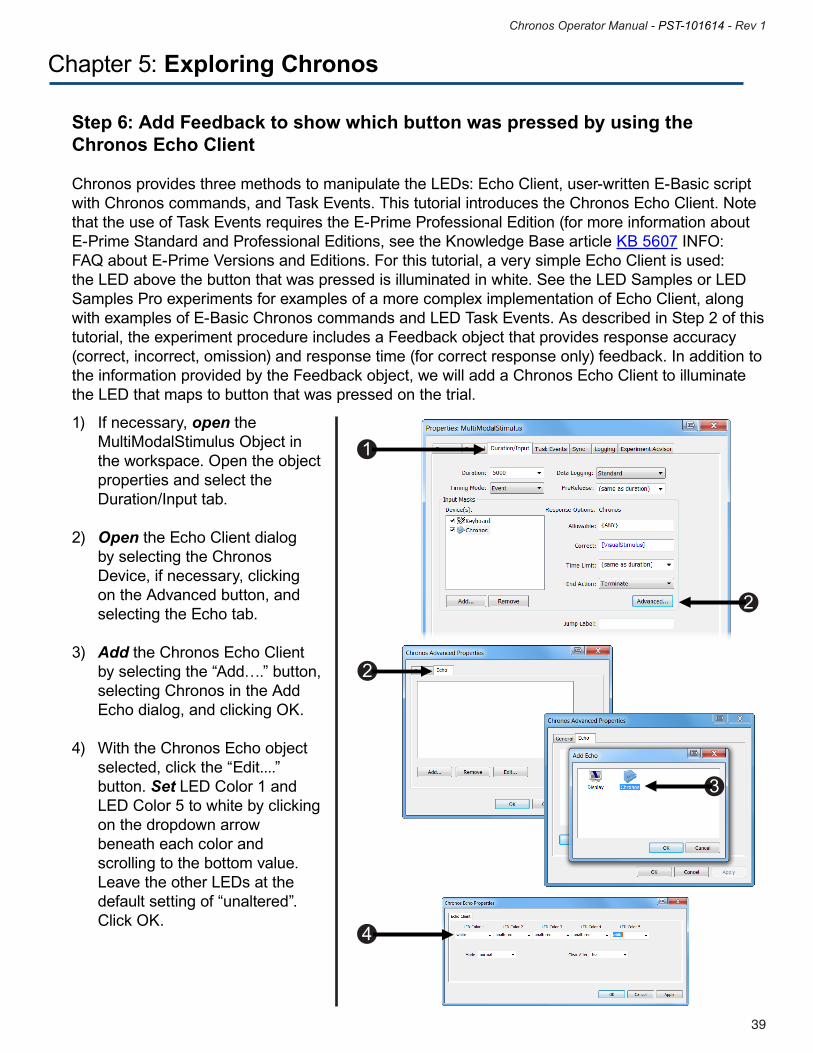
1) If necessary, open the MultiModalStimulus Object in the workspace. Open the object properties and select the Duration/Input tab.
2) Open the Echo Client dialog by selecting the Chronos Device, if necessary, clicking on the Advanced button, and selecting the Echo tab.
3) Add the Chronos Echo Client by selecting the “Add….” button, selecting Chronos in the Add Echo dialog, and clicking OK.
4) With the Chronos Echo object selected, click the “Edit....” button. Set LED Color 1 and LED Color 5 to white by clicking on the dropdown arrow beneath each color and scrolling to the bottom value. Leave the other LEDs at the default setting of “unaltered”. Click OK.
1
2
2
3
4
41
Chronos Operator Manual - PST-101614 - Rev 1
40
Chronos Operator Manual - PST-101614 - Rev 1
Chapter 5: Exploring Chronos
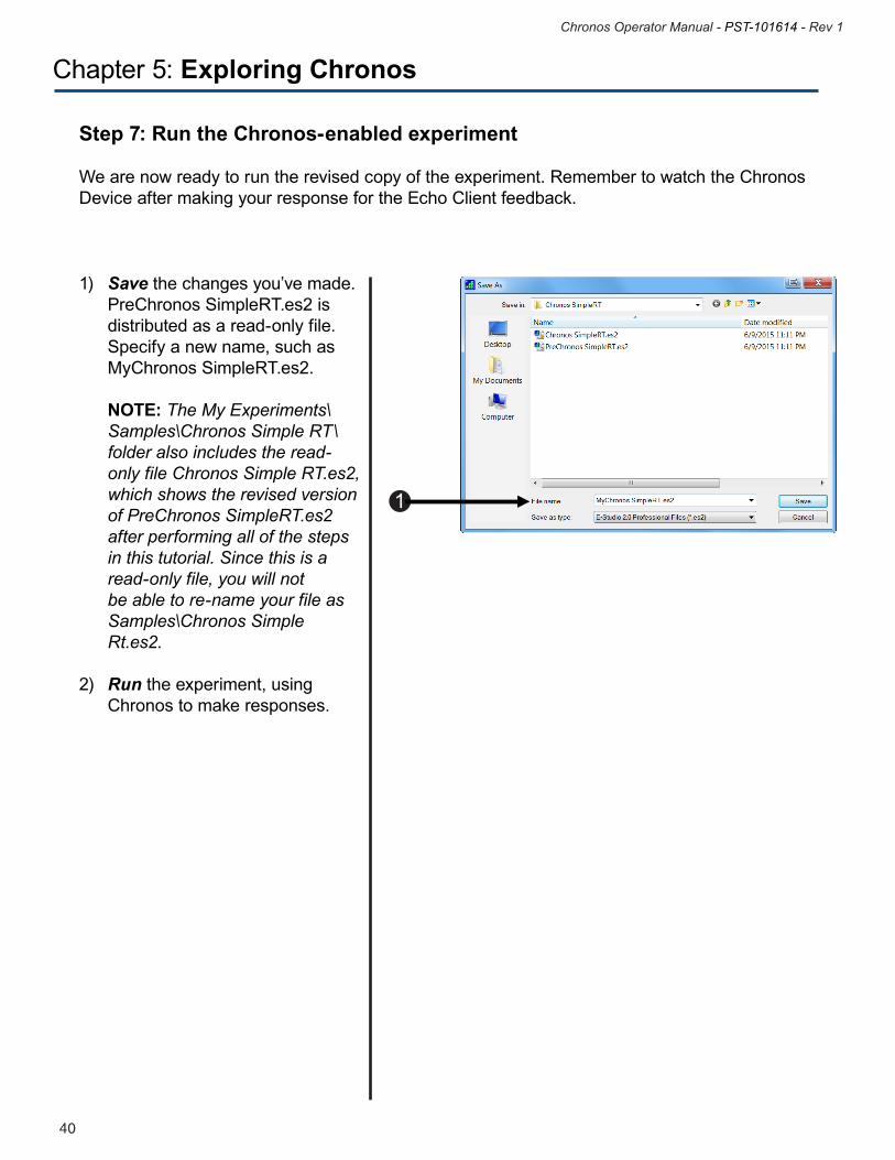
Step 7: Run the Chronos-enabled experiment
We are now ready to run the revised copy of the experiment. Remember to watch the Chronos Device after making your response for the Echo Client feedback.
1) Save the changes you’ve made. PreChronos SimpleRT.es2 is distributed as a read-only file. Specify a new name, such as MyChronos SimpleRT.es2.
NOTE: The My Experiments\ Samples\Chronos Simple RT\ folder also includes the read- only file Chronos Simple RT.es2, which shows the revised version of PreChronos SimpleRT.es2 after performing all of the steps in this tutorial. Since this is a read-only file, you will not be able to re-name your file as Samples\Chronos Simple Rt.es2. 2) Run the experiment, using Chronos to make responses.
1
41
Chronos Operator Manual - PST-101614 - Rev 1
40
Chronos Operator Manual - PST-101614 - Rev 1
Chapter 5: Exploring Chronos
5.3 Introduction to Chronos Features
As the Features Explorer experiment that was introduced in Section 4.6 Chronos Features Explorer Experiment, Page 27 shows, Chronos provides multiple options for stimulus presentation in several modalities as well as numerous input and output capabilities. These features are introduced briefly here for those users who may only be familiar with a subset of the functionality supported by Chronos. These features are examined in detail in the next chapter.
Chronos – General FeaturesAs with other E-Prime response input devices, the Chronos buttons support the collection of presses and releases as well as n-key rollover designs, in which participants can press and hold down multiple buttons, and Chronos will provide the time stamps for each button press. Lastly, Chronos supports the emulation of other input devices including the keyboard. As described in Section 8.1 Using Emulation, Page 85, the emulation feature makes the path between experiment development, testing, and data collection in the lab smoother. With emulation, experiment development can occur in an office environment without Chronos, data collection can occur in the lab with Chronos, no edits or experiment re-generation are needed to the experiment specification file (.es2) when moving between experiment development and data collection, and data collection with Chronos still provides the same precise timing supported by Chronos.
LEDsChronos provides five LEDs that can be controlled individually. LEDs can be used as response mapping verification, stimuli, or to provide accuracy feedback. The LEDs can be set to colors using HTML/CSS color names or RGB color values: more than 4,000 colors can be specified per LED. Chronos E-Basic script commands enable sophisticated programming of the LEDs. Furthermore, the Chronos Device Properties LED settings for experiment startup and completion, the Echo Client, and Task Events enable the LEDs to be set without user-written script.
Audio OutChronos Audio Output functionality supports the presentation of auditory stimuli with accurate and precise sound output latencies. Two Audio Output modes are provided: Mix Mode 1 offers consistently low latencies of 1 ms for single distinct files across different machine hardware. Mix Mode 2, used when presenting overlapping sounds, offers a small but fixed latency across machines based upon the sound buffer size (defaults to 6 ms but configurable from 4 to 10 ms). Chronos also provides configurable onset and offset thresholds per Audio Output channel. The thresholds, used in conjunction with pseudo buttons, enable sound latencies to be checked.
43
Chronos Operator Manual - PST-101614 - Rev 1
42
Chronos Operator Manual - PST-101614 - Rev 1
Chapter 5: Exploring Chronos
Audio InChronos supports both the collection of vocal response times and the recording of vocal responses with a single microphone. The Audio Input capabilities include a wide range of configurable options. Recording can begin either immediately when the response collection object begins to execute, or when the participant begins to speak. The pre-onset and post-offset intervals used in conjunction with onset and offset thresholds enable silence-to-sound and sound-to-silence transitions to be detected and recorded. The configurable pre-amp gain supports calibration of the microphone by individual participants. Macro support enables customization of the recorded data file name. The recorded vocal responses are stored on the E-Prime computer as individual .wav files. The recordings are also accessible from within E-DataAid.
Response Input: Buttons, Voice Key, and Pseudo Buttons Chronos supports the collection of the following responses: • Fivebuttons–collectpresses,releases,andn-keyrollover • Voicekey–collectresponseswithCondenser-ordynamic-microphone • Singleordualfootpedal(optionalaccessories) • 16digitalinputs(accesstoall16requirestheoptionalI/OExpanderaccessory;twodigital inputs are accessible with the standard Auxiliary I/O Breakout Cable) • PseudoButtonsgenerateabutton-likeresponsetonon-buttoninputs,providingprecisetime stamps for analog and digital I/O • Programmabledebounceintervalsforallresponsesenablesstabledetectionofstate transitions
Photo SensorThe Chronos Photo Sensor enables stimulus onset latency to be determined on a variety of display devices, including LCDs, CRTs, and display projectors. Further, the Photo Sensor’s calibration feature enables it to adjust to differences in brightness within and between the different types of display devices.
Analog InChronos supports three Analog Inputs with configurable onset and offset thresholds. These three inputs, along with the Photo Sensor, can be combined into an aggregate channel. The Analog Inputs can be scaled and have their onset and offset thresholds configured. Analog Inputs can be streamed to a recorded file. Macro definitions enables customization of the recorded data.
Analog OutChronos supports four digital to analog output channels. The Chronos Device Properties, introduced briefly in Step 4: Review Chronos Device Default tab, Page 36, enable the type of waveform (sine, sawtooth (up or down), square, triangle) as well as the frequency, amplitude, and offset to be configured. The Chronos Analog Out E-Basic Commands enable custom waveforms to be generated.
Digital OutChronos provides access to 16 digital inputs and outputs, which eliminates the need for parallel port communications. The digital I/O states can be individually configured at the start or end of the experiment. Chronos also supports a pulse generator, which generates square wave at a configurable frequency.
43
Chronos Operator Manual - PST-101614 - Rev 1
42
Chronos Operator Manual - PST-101614 - Rev 1
Chapter 5: Exploring Chronos
Chronos – Accessories (sold separately)
I/O ExpanderThe I/O Expander is customized for the I/O Expansion Connector on the Chronos Back Panel. The expander is required to gain access to the full capability of external analog and digital I/O. The expander features a Push-in Terminal Block for each of the I/O connections (16 digital inputs, 16 digital outputs, two analog inputs, four analog outputs, one pulse generator, power and ground). The I/O Expander also features a 40-pin IDC Header for carrying all digital I/O on a single ribbon cable. Lastly, it comes with a pivoting removable wiring cover for protection.
Custom Expansion KitThe Chronos Custom Expansion Kit includes a prototyping board, interface cables, mounting hardware, and enclosure. The Custom Expansion Kit requires the I/O Expander. LEDs, switches, sliders, and dials may also be purchased and used with the Custom Expansion Kit to construct your own layout of response devices.
45
Chronos Operator Manual - PST-101614 - Rev 1
44
Chronos Operator Manual - PST-101614 - Rev 1
6.1 Communicating with Chronos
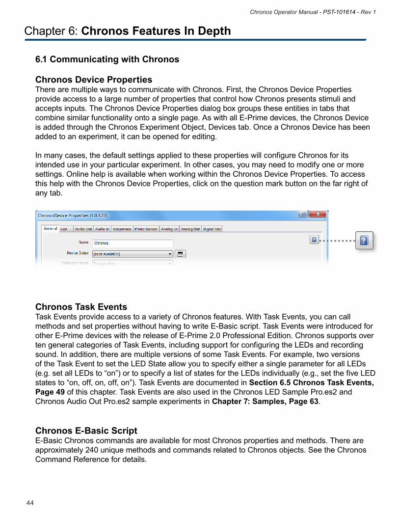
Chronos Device Properties There are multiple ways to communicate with Chronos. First, the Chronos Device Properties provide access to a large number of properties that control how Chronos presents stimuli and accepts inputs. The Chronos Device Properties dialog box groups these entities in tabs that combine similar functionality onto a single page. As with all E-Prime devices, the Chronos Device is added through the Chronos Experiment Object, Devices tab. Once a Chronos Device has been added to an experiment, it can be opened for editing.
In many cases, the default settings applied to these properties will configure Chronos for its intended use in your particular experiment. In other cases, you may need to modify one or more settings. Online help is available when working within the Chronos Device Properties. To access this help with the Chronos Device Properties, click on the question mark button on the far right of any tab.
Chronos Task Events Task Events provide access to a variety of Chronos features. With Task Events, you can call methods and set properties without having to write E-Basic script. Task Events were introduced for other E-Prime devices with the release of E-Prime 2.0 Professional Edition. Chronos supports over ten general categories of Task Events, including support for configuring the LEDs and recording sound. In addition, there are multiple versions of some Task Events. For example, two versions of the Task Event to set the LED State allow you to specify either a single parameter for all LEDs (e.g. set all LEDs to “on”) or to specify a list of states for the LEDs individually (e.g., set the five LED states to “on, off, on, off, on”). Task Events are documented in Section 6.5 Chronos Task Events, Page 49 of this chapter. Task Events are also used in the Chronos LED Sample Pro.es2 and Chronos Audio Out Pro.es2 sample experiments in Chapter 7: Samples, Page 63.
Chronos E-Basic ScriptE-Basic Chronos commands are available for most Chronos properties and methods. There are approximately 240 unique methods and commands related to Chronos objects. See the Chronos Command Reference for details.
Chapter 6: Chronos Features In Depth
45
Chronos Operator Manual - PST-101614 - Rev 1
44
Chronos Operator Manual - PST-101614 - Rev 1
Chapter 6: Chronos Features In Depth
6.2 Pseudo Buttons
Chronos includes pseudo buttons. Although pseudo buttons are supported in other E-Prime devices, such as the voice key on the SRBox, there are more pseudo buttons for Chronos (seven) than for any other E-Prime device. By definition, a pseudo button is a digital input triggered from one of a number of potential inputs that triggers a button response. For example, consider the voice key, used to collect a vocal latency from Chronos. When a vocal response is made, the pseudo button 6 is triggered. This button behaves like the five physical buttons on Chronos in terms of how E-Prime processes the response. For example, button 6 can be specified as an allowable answer for an InputMask, and it can be retrieved in the Device History. Response times can be obtained from the pseudo buttons. Lastly, pseudo buttons can be configured to support both button “presses” and “releases”.
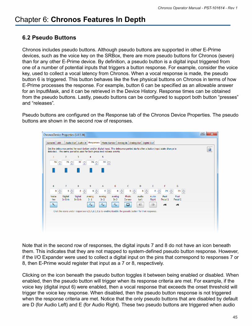
Pseudo buttons are configured on the Response tab of the Chronos Device Properties. The pseudo buttons are shown in the second row of responses.
Note that in the second row of responses, the digital inputs 7 and 8 do not have an icon beneath them. This indicates that they are not mapped to system-defined pseudo button response. However, if the I/O Expander were used to collect a digital input on the pins that correspond to responses 7 or 8, then E-Prime would register that input as a 7 or 8, respectively. Clicking on the icon beneath the pseudo button toggles it between being enabled or disabled. When enabled, then the pseudo button will trigger when its response criteria are met. For example, if the voice key (digital input 6) were enabled, then a vocal response that exceeds the onset threshold will trigger the voice key response. When disabled, then the pseudo button response is not triggered when the response criteria are met. Notice that the only pseudo buttons that are disabled by default are D (for Audio Left) and E (for Audio Right). These two pseudo buttons are triggered when audio
47
Chronos Operator Manual - PST-101614 - Rev 1
46
Chronos Operator Manual - PST-101614 - Rev 1
Chapter 6: Chronos Features In Depth
data is recognized by Chronos on either the left or the right channel. If Chronos is playing audio, then one or both of these pseudo buttons may trigger, depending on the panning, volume, and threshold settings for Audio Input. Therefore, in the interest of avoiding a stimulus presentation device terminating early, as would happen if Chronos is used to accept button responses, Allowable were set to {ANY} (as is often done for the sake of convenience), and Chronos were also being used to present audio stimuli, the Audio Left and Audio Right pseudo buttons are disabled by default.
However, the Audio Left and Audio Right pseudo buttons are required in order to check your sound onset latency, or the time between the point at which E-Prime instructs Chronos to play the audio file and the time that the audio file becomes detectable. This technique is used in the Sample Audio Out Mode 1 and Sample Audio Out Mode 2 experiments.
47
Chronos Operator Manual - PST-101614 - Rev 1
46
Chronos Operator Manual - PST-101614 - Rev 1
Chapter 6: Chronos Features In Depth
6.3 Factors that affect how signals are sampled/responses are processed
Several parameters influence whether a response is recognized, a digital input triggers, or an analog response is sampled. When sampling inputs, all of the following factors need to be considered:
Debounce – Debounce refers to the time period after a button press or button release transition during which a state change is not considered. Debounce should be long enough to cover the worst-case bounce of the switch, but short enough to allow the best-case rapid-fire input. If a state transition occurs during the debounce period, then it will not be recognized by Chronos. By default, debounce is assigned to 20 ms for the responses that are mapped to physical switches (the five Chronos buttons (responses 1 through 5) and the two foot pedals (responses F and G)), and 0 for all other inputs. The debounce settings are configurable on the Responses tab of the Chronos Device Properties; see the screen grab in Section 6.2 Pseudo Buttons, Page 45 for details.
Chronos timestamps button presses on the leading edge of the state transition. This means that whenever a button is pressed, the response is immediately timestamped before entering debounce. Any subsequent state transitions are ignored for the duration of the debounce period. Similarly, a button release is timestamped immediately before entering debounce.
Gain – Audio Output, Audio Input and the Photo Sensor input have a Gain setting. The gain is applied to the raw signal, and then the modified value is considered for further processing. For example, if an Audio Input signal with the Pre Amp Gain applied exceeds the OnsetThreshold, then Chronos will flag this signal as an input. Thresholds •OnsetThresholdsdefinethelevelatwhichaninputsignalmustexceedinorderfortheinputto be recognized.•OffsetThresholdsdefinethelevelatwhichaninputsignalmustdropbelowinorderfortheinput signal to be considered to be complete or a release response is registered, see Section 6.4 Fuzzy Values and Precision, Page 48.•TheAnalogInChannel1isprotectedagainstexcessivevoltageinput.Asaresult,itsmaximum input value is approximately 90%. NOTE: Analog Input Channels 2 and 3 are NOT protected against excessive voltage; DO NOT send greater than 3.3V to these inputs.
49
Chronos Operator Manual - PST-101614 - Rev 1
48
Chronos Operator Manual - PST-101614 - Rev 1
Chapter 6: Chronos Features In Depth
6.4 Fuzzy Values and Precision
Sometimes a user-specified value in the GUI appears to be changed from the value that was entered. This can be seen with respect to user-specified frequencies, sampling rates, and threshold values and can be referred to as a “fuzzy” value. The background behind these transformations is explained below. Note, that time stamps and time durations are accurate to the millisecond on Chronos.
Frequencies and Sampling Rates will snap to an integer microsecond value. For example, a user-specified frequency value of 475 Hz will snap to 475.059 microseconds. The Chronos Device Properties always reflects these snapped values.
Thresholds are precise to approximately 0.4%. Thresholds are entered on the Chronos Device Properties as decimal percentage values, but they are processed by Chronos as 8-bit integers. Therefore, for example, if the Audio Out Pseudo Button Onset Threshold is set to be 50%, Chronos ultimately sets this to 49.8%. Since the maximum value that can be represented with 8 bits is 255, 50% represents 127.5 which is a number that Chronos cannot represent. Since a 0.4%, precision is of no consequence, the Chronos Device Properties always reflects the value entered by the user. However, calling the Chronos E-Basic Get command for a frequency or sampling rate will yield the fuzzy value. Time-based properties – When specifying values for time-based properties, including Debounce, PreOnset Interval, and PostOffset Interval, Chronos is precise to the (whole) microsecond level. Because of this, either value set in the Chronos Device Properties or with Chronos E-Basic command will always be set to the whole microsecond level.
49
Chronos Operator Manual - PST-101614 - Rev 1
48
Chronos Operator Manual - PST-101614 - Rev 1
6.5 Chronos Task Events
6.5.1 IntroductionTask Events are an E-Prime feature that initiates a user-defined task in response to the execution of any one of a variety of often time-critical, system-defined events. For example, a user may want a sound to be played via Chronos (the Task) when the object that presents the visual stimulus begins its execution (the Event). One benefit of Task Events is that they provide precise access to numerous events that relate to either an object’s life cycle (such as when the object begins or ends execution) or object’s status (such as when a correct response is recognized by a response-collection object) without requiring E-Basic script. Task Events were introduced with the release of E-Prime 2.0 Professional Edition. Task Events are an E-Prime Professional-only feature. For more information on Task Events in general, see any one of the following resources:
• Section3.1TaskEventsoftheE-Prime 2.0 New Features/Reference Guide• KnowledgeBasearticleKB 4803 INFO: Feature – Task Events• TheTaskEventYouTube video
Chronos supports multiple Chronos-specific tasks, such as setting the color on an LED or recording a vocal response. These tasks can be mapped to a Chronos event, such as when a Chronos button press occurs, or to a non-Chronos event, such as when a display object begins its execution. An overview of Chronos Task Events is provided in this section. Complete details are in the Chronos Command Reference.
6.5.2 Key ConceptsUsers that are not familiar with E-PrimeTask Event support are urged to examine the above resources prior to continuing with this section. The most important concepts are reviewed below.
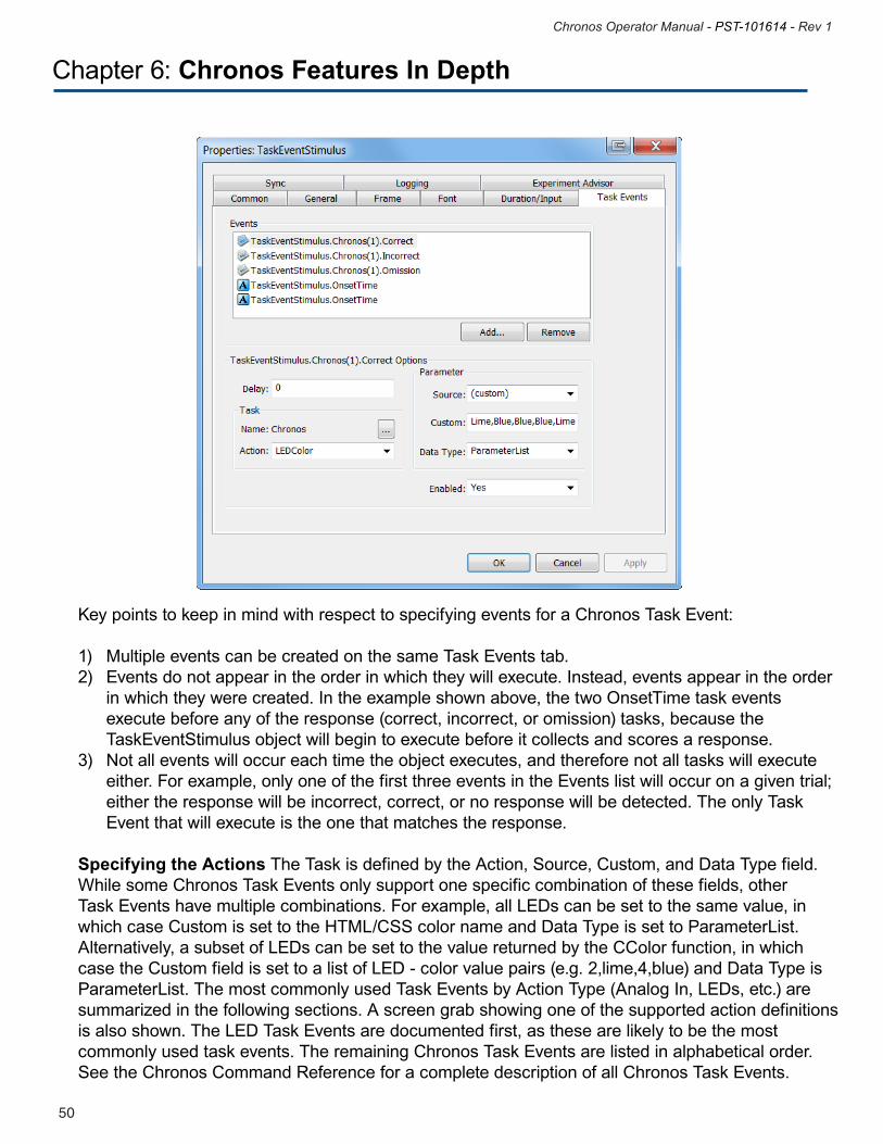
Creating Task Events Task Events are created on the Task Events tab of any RteRunnableInput object, such as Text Display, Slide Display, Sound Out, and Sound In. Specifying the Event(s) The first step in creating Task Events is to identify the event to which some Task should be performed. A Task Events tab is shown as an example on the next page; this is from the Chronos LED Sample Pro.es2 experiment specification. There are five Task Events defined on this object. The first three events relate to the response accuracy; these entries define what happens when a response is made to the TaskStimulusObject (correct, incorrect, or omission). The last two task events define what happens when the TaskEventStimulus onset time is reached.
There is a one-to-one mapping between the event and the task: once the Event is added to the Event list at the top of the dialog box, the Task that is to be associated with that Event is defined in the bottom portion of the dialog. Since two of the Events in the Events list are identical (OnsetTime for the object), then two different tasks will be performed in response to the same event. In this particular case, one Task Event sets the LED states, and the other Task Event sets the LED colors.
Chapter 6: Chronos Features In Depth
51
Chronos Operator Manual - PST-101614 - Rev 1
50
Chronos Operator Manual - PST-101614 - Rev 1
Chapter 6: Chronos Features In Depth
Key points to keep in mind with respect to specifying events for a Chronos Task Event:
1) Multiple events can be created on the same Task Events tab.2) Events do not appear in the order in which they will execute. Instead, events appear in the order in which they were created. In the example shown above, the two OnsetTime task events execute before any of the response (correct, incorrect, or omission) tasks, because the TaskEventStimulus object will begin to execute before it collects and scores a response. 3) Not all events will occur each time the object executes, and therefore not all tasks will execute either. For example, only one of the first three events in the Events list will occur on a given trial; either the response will be incorrect, correct, or no response will be detected. The only Task Event that will execute is the one that matches the response. Specifying the Actions The Task is defined by the Action, Source, Custom, and Data Type field. While some Chronos Task Events only support one specific combination of these fields, other Task Events have multiple combinations. For example, all LEDs can be set to the same value, in which case Custom is set to the HTML/CSS color name and Data Type is set to ParameterList. Alternatively, a subset of LEDs can be set to the value returned by the CColor function, in which case the Custom field is set to a list of LED - color value pairs (e.g. 2,lime,4,blue) and Data Type is ParameterList. The most commonly used Task Events by Action Type (Analog In, LEDs, etc.) are summarized in the following sections. A screen grab showing one of the supported action definitions is also shown. The LED Task Events are documented first, as these are likely to be the most commonly used task events. The remaining Chronos Task Events are listed in alphabetical order. See the Chronos Command Reference for a complete description of all Chronos Task Events.
51
Chronos Operator Manual - PST-101614 - Rev 1
50
Chronos Operator Manual - PST-101614 - Rev 1
Chapter 6: Chronos Features In Depth
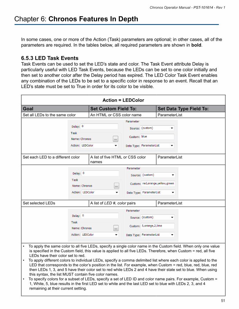
6.5.3 LED Task EventsTask Events can be used to set the LED’s state and color. The Task Event attribute Delay is particularly useful with LED Task Events, because the LEDs can be set to one color initially and then set to another color after the Delay period has expired. The LED Color Task Event enables any combination of the LEDs to be set to a specific color in response to an event. Recall that an LED’s state must be set to True in order for its color to be visible.
Action = LEDColor
Goal Set Custom Field To: Set Data Type Field To:Set all LEDs to the same color An HTML or CSS color name ParameterList
Set each LED to a different color A list of five HTML or CSS color names
ParameterList
Set selected LEDs A list of LED #, color pairs ParameterList
•ToapplythesamecolortoallfiveLEDs,specifyasinglecolornameintheCustomfield.Whenonlyonevalue is specified in the Custom field, this value is applied to all five LEDs. Therefore, when Custom = red, all five LEDs have their color set to red.•ToapplydifferentcolorstoindividualLEDs,specifyacommadelimitedlistwhereeachcolorisappliedtothe LED that corresponds to the color’s position in the list. For example, when Custom = red, blue, red, blue, red then LEDs 1, 3, and 5 have their color set to red while LEDs 2 and 4 have their state set to blue. When using this syntax, the list MUST contain five color names.•TospecifycolorsforasubsetofLEDs,specifyasetofLEDIDandcolornamepairs.Forexample,Custom= 1, White, 5, blue results in the first LED set to white and the last LED set to blue with LEDs 2, 3, and 4 remaining at their current setting.
In some cases, one or more of the Action (Task) parameters are optional; in other cases, all of the parameters are required. In the tables below, all required parameters are shown in bold.
53
Chronos Operator Manual - PST-101614 - Rev 1
52
Chronos Operator Manual - PST-101614 - Rev 1
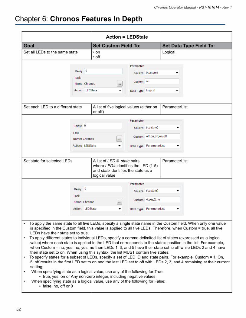
Action = LEDState
Goal Set Custom Field To: Set Data Type Field To:Set all LEDs to the same state •on
•offLogical
Set each LED to a different state A list of five logical values (either on or off)
ParameterList
Set state for selected LEDs A list of LED #, state pairswhere LED# identifies the LED (1-5) and state identifies the state as a logical value
ParameterList
•ToapplythesamestatetoallfiveLEDs,specifyasinglestatenameintheCustomfield.Whenonlyonevalue is specified in the Custom field, this value is applied to all five LEDs. Therefore, when Custom = true, all five LEDs have their state set to true.•ToapplydifferentstatestoindividualLEDs,specifyacommadelimitedlistofstates(expressedasalogical value) where each state is applied to the LED that corresponds to the state’s position in the list. For example, when Custom = no, yes, no, yes, no then LEDs 1, 3, and 5 have their state set to off while LEDs 2 and 4 have their state set to on. When using this syntax, the list MUST contain five states.•TospecifystatesforasubsetofLEDs,specifyasetofLEDIDandstatepairs.Forexample,Custom=1,On, 5, off results in the first LED set to on and the last LED set to off with LEDs 2, 3, and 4 remaining at their current setting.• Whenspecifyingstateasalogicalvalue,useanyofthefollowingforTrue:▪true,yes,onorAnynon-zerointeger,includingnegativevalues• Whenspecifyingstateasalogicalvalue,useanyofthefollowingforFalse:▪false,no,offor0
Chapter 6: Chronos Features In Depth
53
Chronos Operator Manual - PST-101614 - Rev 1
52
Chronos Operator Manual - PST-101614 - Rev 1
Chapter 6: Chronos Features In Depth
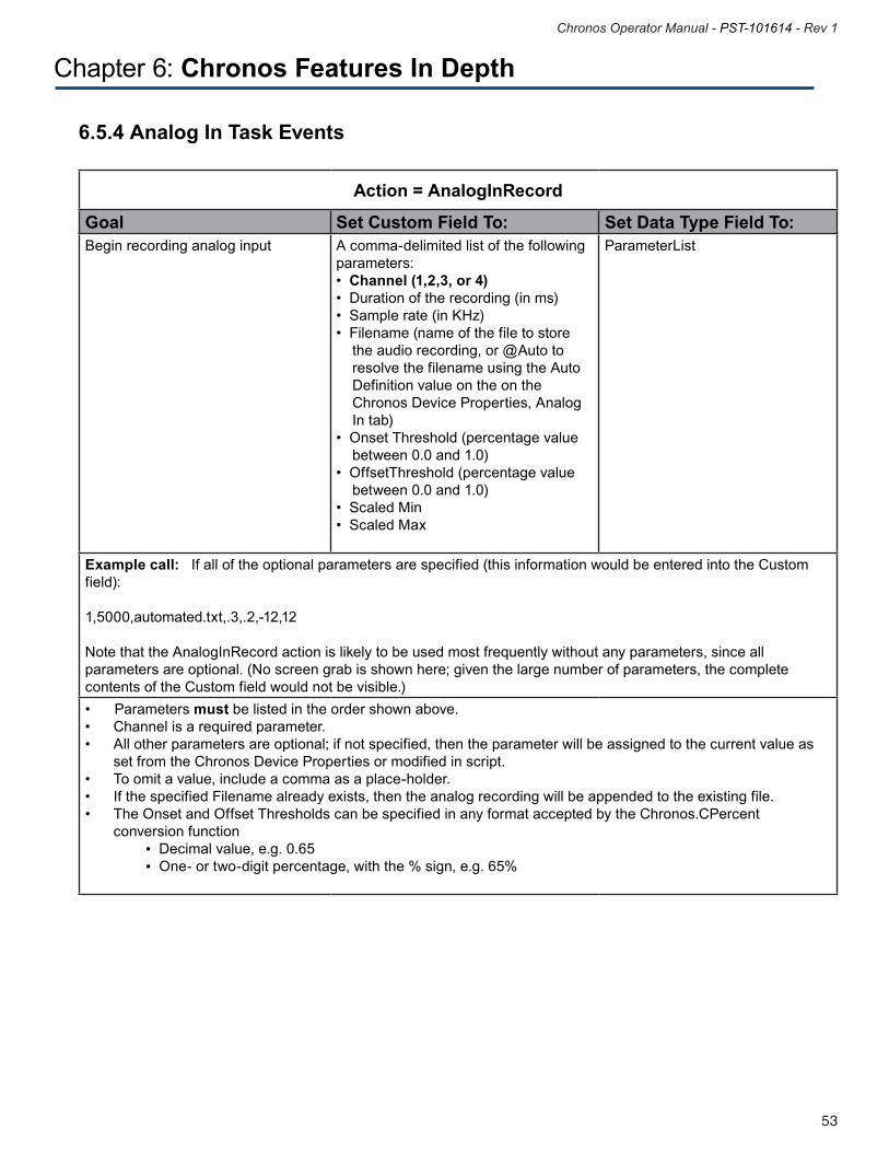
6.5.4 Analog In Task Events
Action = AnalogInRecord
Goal Set Custom Field To: Set Data Type Field To:Begin recording analog input A comma-delimited list of the following
parameters: •Channel (1,2,3, or 4)•Durationoftherecording(inms)•Samplerate(inKHz)•Filename(nameofthefiletostore the audio recording, or @Auto to resolve the filename using the Auto Definition value on the on the Chronos Device Properties, Analog In tab)•OnsetThreshold(percentagevalue between 0.0 and 1.0) •OffsetThreshold(percentagevalue between 0.0 and 1.0) •ScaledMin•ScaledMax
ParameterList
Example call: If all of the optional parameters are specified (this information would be entered into the Custom field):
1,5000,automated.txt,.3,.2,-12,12
Note that the AnalogInRecord action is likely to be used most frequently without any parameters, since all parameters are optional. (No screen grab is shown here; given the large number of parameters, the complete contents of the Custom field would not be visible.) •Parametersmust be listed in the order shown above. • Channelisarequiredparameter.• Allotherparametersareoptional;ifnotspecified,thentheparameterwillbeassignedtothecurrentvalueas set from the Chronos Device Properties or modified in script. • Toomitavalue,includeacommaasaplace-holder.• IfthespecifiedFilenamealreadyexists,thentheanalogrecordingwillbeappendedtotheexistingfile.• TheOnsetandOffsetThresholdscanbespecifiedinanyformatacceptedbytheChronos.CPercent conversion function▪Decimalvalue,e.g.0.65▪One-ortwo-digitpercentage,withthe%sign,e.g.65%
55
Chronos Operator Manual - PST-101614 - Rev 1
54
Chronos Operator Manual - PST-101614 - Rev 1
Chapter 6: Chronos Features In Depth
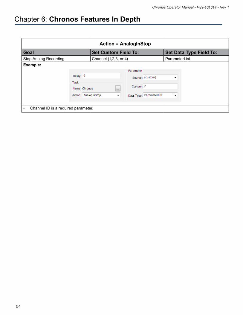
Action = AnalogInStop
Goal Set Custom Field To: Set Data Type Field To:Stop Analog Recording Channel (1,2,3, or 4) ParameterListExample:
•ChannelIDisarequiredparameter.
55
Chronos Operator Manual - PST-101614 - Rev 1
54
Chronos Operator Manual - PST-101614 - Rev 1
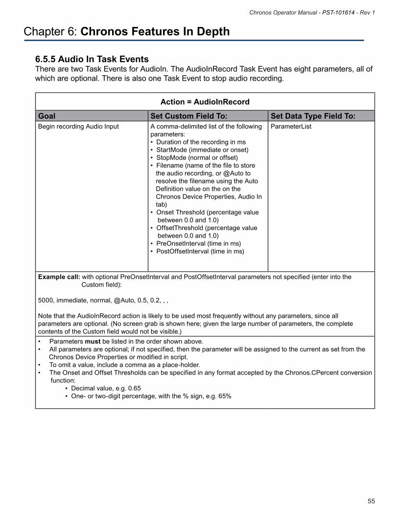
6.5.5 Audio In Task EventsThere are two Task Events for AudioIn. The AudioInRecord Task Event has eight parameters, all of which are optional. There is also one Task Event to stop audio recording.
Chapter 6: Chronos Features In Depth
Action = AudioInRecord
Goal Set Custom Field To: Set Data Type Field To:Begin recording Audio Input A comma-delimited list of the following
parameters: •Durationoftherecordinginms•StartMode(immediateoronset)•StopMode(normaloroffset)•Filename(nameofthefiletostore the audio recording, or @Auto to resolve the filename using the Auto Definition value on the on the Chronos Device Properties, Audio In tab)•OnsetThreshold(percentagevalue between 0.0 and 1.0) •OffsetThreshold(percentagevalue between 0.0 and 1.0) •PreOnsetInterval(timeinms)•PostOffsetInterval(timeinms)
ParameterList
Example call: with optional PreOnsetInterval and PostOffsetInterval parameters not specified (enter into the Custom field):
5000, immediate, normal, @Auto, 0.5, 0.2, , ,
Note that the AudioInRecord action is likely to be used most frequently without any parameters, since all parameters are optional. (No screen grab is shown here; given the large number of parameters, the complete contents of the Custom field would not be visible.) •Parametersmust be listed in the order shown above.•Allparametersareoptional;ifnotspecified,thentheparameterwillbeassignedtothecurrentassetfromthe Chronos Device Properties or modified in script.•Toomitavalue,includeacommaasaplace-holder.•TheOnsetandOffsetThresholdscanbespecifiedinanyformatacceptedbytheChronos.CPercentconversion function:▪Decimalvalue,e.g.0.65▪One-ortwo-digitpercentage,withthe%sign,e.g.65%
57
Chronos Operator Manual - PST-101614 - Rev 1
56
Chronos Operator Manual - PST-101614 - Rev 1
Chapter 6: Chronos Features In Depth
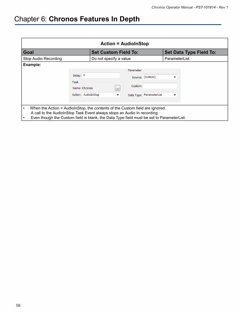
Action = AudioInStop
Goal Set Custom Field To: Set Data Type Field To:Stop Audio Recording Do not specify a value ParameterListExample:
•WhentheAction=AudioInStop,thecontentsoftheCustomfieldareignored. A call to the AudioInStop Task Event always stops an Audio In recording.• EventhoughtheCustomfieldisblank,theDataTypefieldmustbesettoParameterList.
57
Chronos Operator Manual - PST-101614 - Rev 1
56
Chronos Operator Manual - PST-101614 - Rev 1
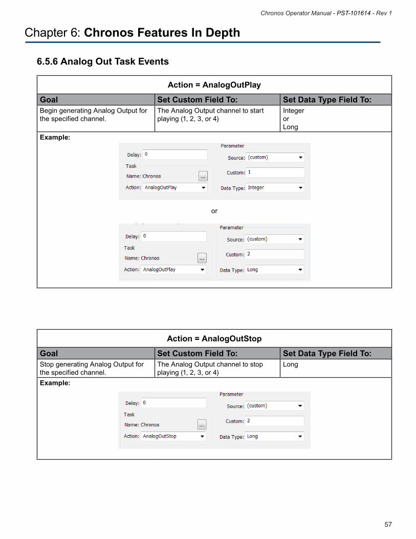
6.5.6 Analog Out Task Events
Chapter 6: Chronos Features In Depth
Action = AnalogOutPlay
Goal Set Custom Field To: Set Data Type Field To:Begin generating Analog Output for the specified channel.
The Analog Output channel to start playing (1, 2, 3, or 4)
Integer or Long
Example:
or
Action = AnalogOutStop
Goal Set Custom Field To: Set Data Type Field To:Stop generating Analog Output for the specified channel.
The Analog Output channel to stop playing (1, 2, 3, or 4)
Long
Example:
59
Chronos Operator Manual - PST-101614 - Rev 1
58
Chronos Operator Manual - PST-101614 - Rev 1
Chapter 6: Chronos Features In Depth
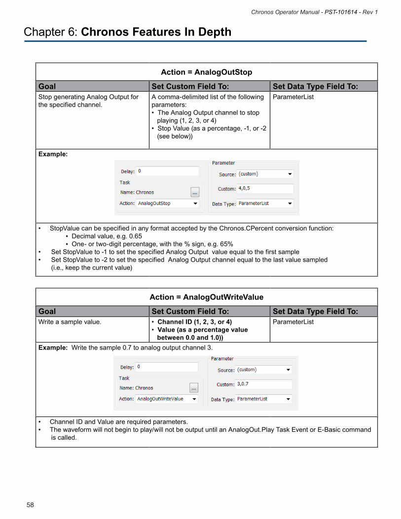
Action = AnalogOutStop
Goal Set Custom Field To: Set Data Type Field To:Stop generating Analog Output for the specified channel.
A comma-delimited list of the following parameters: •TheAnalogOutputchanneltostop playing (1, 2, 3, or 4)•StopValue(asapercentage,-1,or-2 (see below))
ParameterList
Example:
•StopValuecanbespecifiedinanyformatacceptedbytheChronos.CPercentconversionfunction:▪Decimalvalue,e.g.0.65▪One-ortwo-digitpercentage,withthe%sign,e.g.65%• SetStopValueto-1tosetthespecifiedAnalogOutputvalueequaltothefirstsample• SetStopValueto-2tosetthespecifiedAnalogOutputchannelequaltothelastvaluesampled (i.e., keep the current value)
Action = AnalogOutWriteValue
Goal Set Custom Field To: Set Data Type Field To:Write a sample value. •Channel ID (1, 2, 3, or 4)
•Value (as a percentage value between 0.0 and 1.0))
ParameterList
Example: Write the sample 0.7 to analog output channel 3.
•ChannelIDandValuearerequiredparameters.•Thewaveformwillnotbegintoplay/willnotbeoutputuntilanAnalogOut.PlayTaskEventorE-Basiccommand is called.
59
Chronos Operator Manual - PST-101614 - Rev 1
58
Chronos Operator Manual - PST-101614 - Rev 1
Chapter 6: Chronos Features In Depth
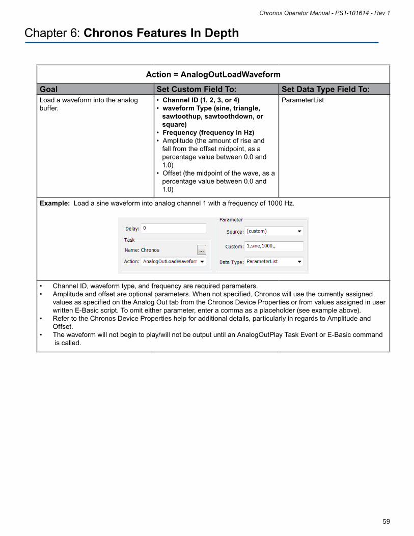
Action = AnalogOutLoadWaveform
Goal Set Custom Field To: Set Data Type Field To:Load a waveform into the analog buffer.
•Channel ID (1, 2, 3, or 4)•waveform Type (sine, triangle, sawtoothup, sawtoothdown, or square)•Frequency (frequency in Hz)•Amplitude(theamountofriseand fall from the offset midpoint, as a percentage value between 0.0 and 1.0)•Offset(themidpointofthewave,asa percentage value between 0.0 and 1.0)
ParameterList
Example: Load a sine waveform into analog channel 1 with a frequency of 1000 Hz.
• ChannelID,waveformtype,andfrequencyarerequiredparameters.• Amplitudeandoffsetareoptionalparameters.Whennotspecified,Chronoswillusethecurrentlyassigned values as specified on the Analog Out tab from the Chronos Device Properties or from values assigned in user written E-Basic script. To omit either parameter, enter a comma as a placeholder (see example above). • RefertotheChronosDevicePropertieshelpforadditionaldetails,particularlyinregardstoAmplitudeand Offset. • Thewaveformwillnotbegintoplay/willnotbeoutputuntilanAnalogOutPlayTaskEventorE-Basiccommand is called.
61
Chronos Operator Manual - PST-101614 - Rev 1
60
Chronos Operator Manual - PST-101614 - Rev 1
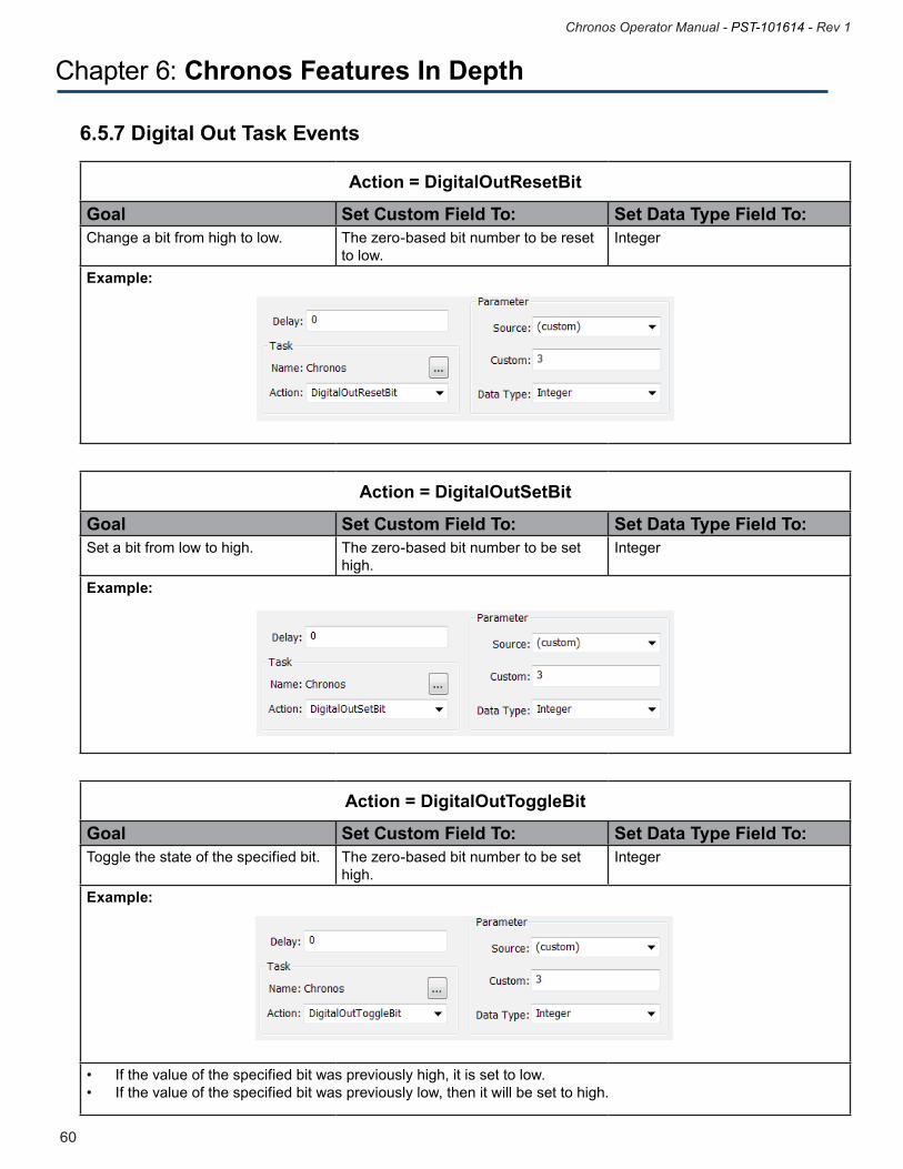
6.5.7 Digital Out Task Events
Action = DigitalOutResetBit
Goal Set Custom Field To: Set Data Type Field To:Change a bit from high to low. The zero-based bit number to be reset
to low. Integer
Example:
Action = DigitalOutSetBit
Goal Set Custom Field To: Set Data Type Field To:Set a bit from low to high. The zero-based bit number to be set
high. Integer
Example:
Action = DigitalOutToggleBit
Goal Set Custom Field To: Set Data Type Field To:Toggle the state of the specified bit. The zero-based bit number to be set
high. Integer
Example:
• Ifthevalueofthespecifiedbitwaspreviouslyhigh,itissettolow.• Ifthevalueofthespecifiedbitwaspreviouslylow,thenitwillbesettohigh.
Chapter 6: Chronos Features In Depth
61
Chronos Operator Manual - PST-101614 - Rev 1
60
Chronos Operator Manual - PST-101614 - Rev 1
Chapter 6: Chronos Features In Depth
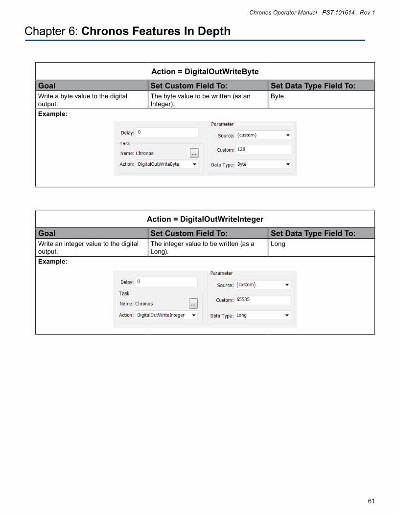
Action = DigitalOutWriteByte
Goal Set Custom Field To: Set Data Type Field To:Write a byte value to the digital output.
The byte value to be written (as an Integer).
Byte
Example:
Action = DigitalOutWriteInteger
Goal Set Custom Field To: Set Data Type Field To:Write an integer value to the digital output.
The integer value to be written (as a Long).
Long
Example:
63
Chronos Operator Manual - PST-101614 - Rev 1
62
Chronos Operator Manual - PST-101614 - Rev 1
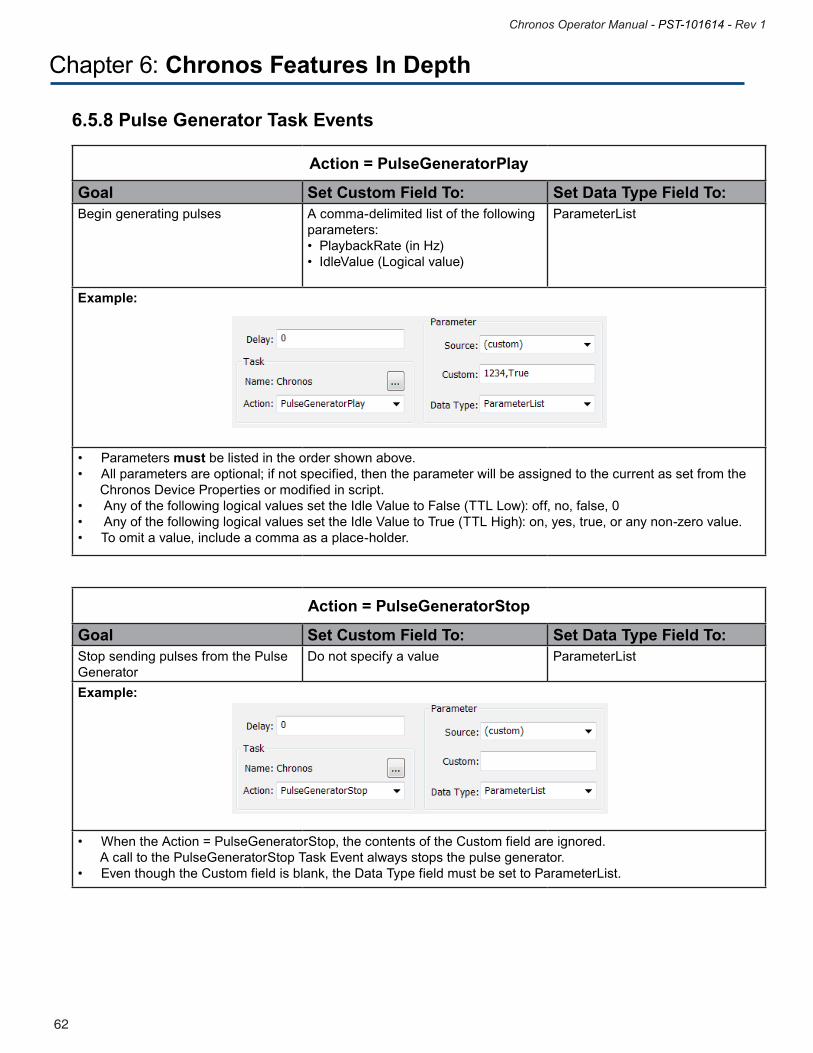
6.5.8 Pulse Generator Task Events
Action = PulseGeneratorPlay
Goal Set Custom Field To: Set Data Type Field To:Begin generating pulses A comma-delimited list of the following
parameters: •PlaybackRate(inHz)•IdleValue(Logicalvalue)
ParameterList
Example:
•Parametersmust be listed in the order shown above.•Allparametersareoptional;ifnotspecified,thentheparameterwillbeassignedtothecurrentassetfromthe Chronos Device Properties or modified in script.• AnyofthefollowinglogicalvaluessettheIdleValuetoFalse(TTLLow):off,no,false,0• AnyofthefollowinglogicalvaluessettheIdleValuetoTrue(TTLHigh):on,yes,true,oranynon-zerovalue.•Toomitavalue,includeacommaasaplace-holder.
Action = PulseGeneratorStop
Goal Set Custom Field To: Set Data Type Field To:Stop sending pulses from the Pulse Generator
Do not specify a value ParameterList
Example:
•WhentheAction=PulseGeneratorStop,thecontentsoftheCustomfieldareignored. A call to the PulseGeneratorStop Task Event always stops the pulse generator. •EventhoughtheCustomfieldisblank,theDataTypefieldmustbesettoParameterList.
Chapter 6: Chronos Features In Depth
63
Chronos Operator Manual - PST-101614 - Rev 1
62
Chronos Operator Manual - PST-101614 - Rev 1
7.1 General Information
The full Chronos installation (see Section 4.1 Full Software Installation, Page 17) provides sample experiments from which you can learn about Chronos features. The sample experiments, which are described in this chapter, are designed to illustrate how to use specific Chronos features. Although they are not complete experiments, they are designed to be generated and run through to first understand what they do, and then loaded into E-Studio and reviewed to understand how they are implemented. Additional samples will be developed and made available from the PST Product Service and Support web site.
Except where noted, the samples and tutorials are distributed in the E-Prime 2.0 Standard format. For E-Prime Professional Edition users, we recommend that you convert your experiments to E-Prime 2.0 Professional Edition rather than maintaining them as Standard Edition experiments. There may be some differences between the screen illustrations from the samples as shown in this chapter and the information you see on the screen; this is because the screen captures were made after loading each sample into E-Prime Professional. For more information about the Standard and Professional Editions of E-Prime, see Knowledge Base article KB 5607 INFO: FAQ about E-Prime Versions and Editions. In other cases, both a Standard and Professional version of a sample is distributed. Both editions of the experiment share the same name, but the suffix “Pro” is appended to the end of the experiment name to distinguish the Professional Edition experiment from the Standard Edition experiment. Developing a Professional Edition of a sample experiment is done when there is a Professional-only feature, most commonly Task Events, that provide an alternative way to support the demonstrated functionality. For example, the Chronos Audio In Sample.es2 file illustrates how to record audio by using the E-Basic script commands; this can be done in both Standard and Professional Editions. The Chronos Audio In Sample Pro.es2 contains the same objects and functionality that is shown in the Standard Edition. In addition, it illustrates how to record audio via Task Events. Since Task Events are a Professional-only feature, they require a Professional Edition experiment.
Chapter 7: Samples
65
Chronos Operator Manual - PST-101614 - Rev 1
64
Chronos Operator Manual - PST-101614 - Rev 1
7.2 LED Sample
As mentioned in Section 5.2 Tutorial 1: Adding a Chronos Device to an E-Prime experiment, Page 29, the Chronos LEDs can be manipulated in three different ways: via an Echo Client, Chronos E-Basic commands, or Chronos Task Events. The first two methods are supported in both the E-Prime Standard Edition and the E-Prime Professional Edition. However, the Task Event method is supported in E-Prime Professional Edition only. The LED Samples.es2 experiment is a Standard Edition experiment that demonstrates the first two methods. The LED Sample Pro .es2 experiment is a Professional Edition experiment that demonstrates all three methods. Both experiments are installed to ….My Experiments\Chronos\Samples\ChronosLED folder.
Chapter 7: Samples
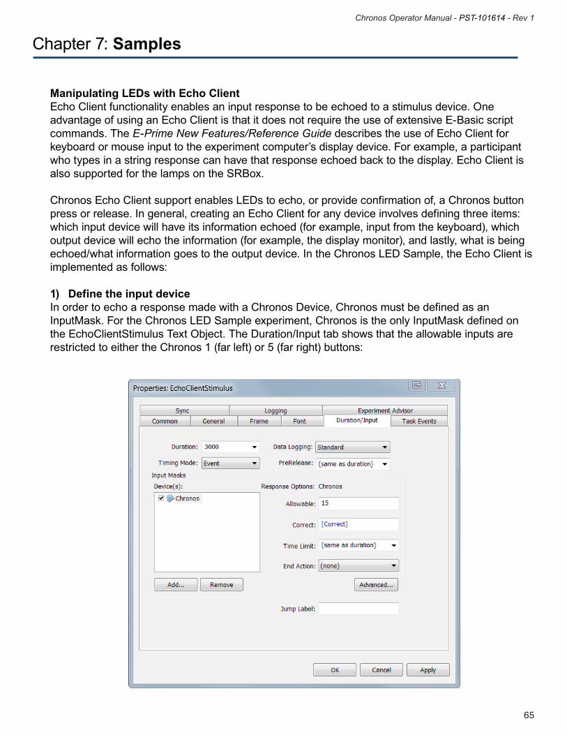
65
Chronos Operator Manual - PST-101614 - Rev 1
64
Chronos Operator Manual - PST-101614 - Rev 1
Chapter 7: Samples
Manipulating LEDs with Echo Client Echo Client functionality enables an input response to be echoed to a stimulus device. One advantage of using an Echo Client is that it does not require the use of extensive E-Basic script commands. The E-Prime New Features/Reference Guide describes the use of Echo Client for keyboard or mouse input to the experiment computer’s display device. For example, a participant who types in a string response can have that response echoed back to the display. Echo Client is also supported for the lamps on the SRBox.
Chronos Echo Client support enables LEDs to echo, or provide confirmation of, a Chronos button press or release. In general, creating an Echo Client for any device involves defining three items: which input device will have its information echoed (for example, input from the keyboard), which output device will echo the information (for example, the display monitor), and lastly, what is being echoed/what information goes to the output device. In the Chronos LED Sample, the Echo Client is implemented as follows:
1) Define the input device In order to echo a response made with a Chronos Device, Chronos must be defined as an InputMask. For the Chronos LED Sample experiment, Chronos is the only InputMask defined on the EchoClientStimulus Text Object. The Duration/Input tab shows that the allowable inputs are restricted to either the Chronos 1 (far left) or 5 (far right) buttons:
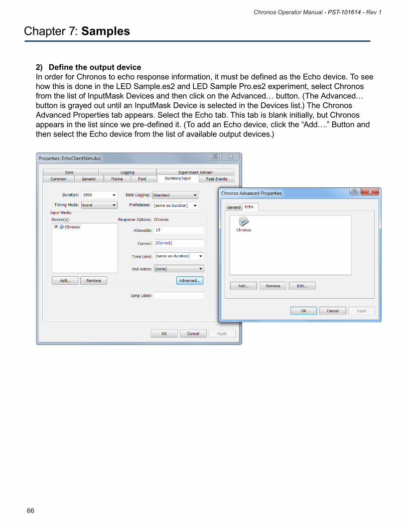
67
Chronos Operator Manual - PST-101614 - Rev 1
66
Chronos Operator Manual - PST-101614 - Rev 1
2) Define the output device In order for Chronos to echo response information, it must be defined as the Echo device. To see how this is done in the LED Sample.es2 and LED Sample Pro.es2 experiment, select Chronos from the list of InputMask Devices and then click on the Advanced… button. (The Advanced…button is grayed out until an InputMask Device is selected in the Devices list.) The Chronos Advanced Properties tab appears. Select the Echo tab. This tab is blank initially, but Chronos appears in the list since we pre-defined it. (To add an Echo device, click the “Add….” Button and then select the Echo device from the list of available output devices.)
Chapter 7: Samples
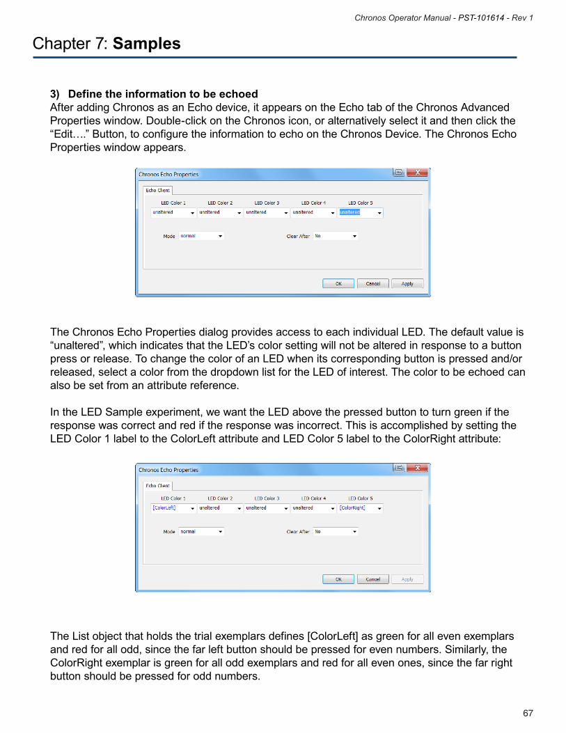
67
Chronos Operator Manual - PST-101614 - Rev 1
66
Chronos Operator Manual - PST-101614 - Rev 1
Chapter 7: Samples
The Chronos Echo Properties dialog provides access to each individual LED. The default value is “unaltered”, which indicates that the LED’s color setting will not be altered in response to a button press or release. To change the color of an LED when its corresponding button is pressed and/or released, select a color from the dropdown list for the LED of interest. The color to be echoed can also be set from an attribute reference.
In the LED Sample experiment, we want the LED above the pressed button to turn green if the response was correct and red if the response was incorrect. This is accomplished by setting the LED Color 1 label to the ColorLeft attribute and LED Color 5 label to the ColorRight attribute:
3) Define the information to be echoedAfter adding Chronos as an Echo device, it appears on the Echo tab of the Chronos Advanced Properties window. Double-click on the Chronos icon, or alternatively select it and then click the “Edit….” Button, to configure the information to echo on the Chronos Device. The Chronos Echo Properties window appears.
The List object that holds the trial exemplars defines [ColorLeft] as green for all even exemplars and red for all odd, since the far left button should be pressed for even numbers. Similarly, the ColorRight exemplar is green for all odd exemplars and red for all even ones, since the far right button should be pressed for odd numbers.
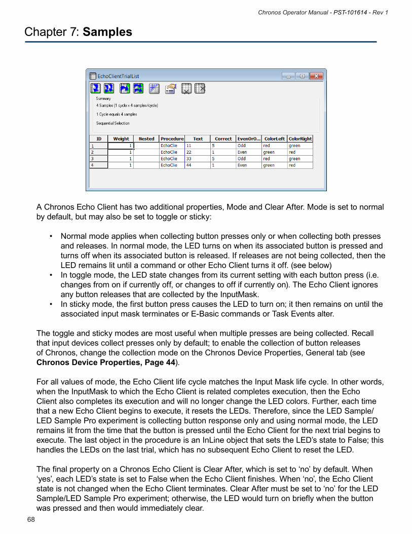
69
Chronos Operator Manual - PST-101614 - Rev 1
68
Chronos Operator Manual - PST-101614 - Rev 1
A Chronos Echo Client has two additional properties, Mode and Clear After. Mode is set to normal by default, but may also be set to toggle or sticky:
• Normalmodeapplieswhencollectingbuttonpressesonlyorwhencollectingbothpresses and releases. In normal mode, the LED turns on when its associated button is pressed and turns off when its associated button is released. If releases are not being collected, then the LED remains lit until a command or other Echo Client turns it off. (see below) • Intogglemode,theLEDstatechangesfromitscurrentsettingwitheachbuttonpress(i.e. changes from on if currently off, or changes to off if currently on). The Echo Client ignores any button releases that are collected by the InputMask. • Instickymode,thefirstbuttonpresscausestheLEDtoturnon;itthenremainsonuntilthe associated input mask terminates or E-Basic commands or Task Events alter.
The toggle and sticky modes are most useful when multiple presses are being collected. Recall that input devices collect presses only by default; to enable the collection of button releases of Chronos, change the collection mode on the Chronos Device Properties, General tab (see Chronos Device Properties, Page 44). For all values of mode, the Echo Client life cycle matches the Input Mask life cycle. In other words, when the InputMask to which the Echo Client is related completes execution, then the Echo Client also completes its execution and will no longer change the LED colors. Further, each time that a new Echo Client begins to execute, it resets the LEDs. Therefore, since the LED Sample/LED Sample Pro experiment is collecting button response only and using normal mode, the LED remains lit from the time that the button is pressed until the Echo Client for the next trial begins to execute. The last object in the procedure is an InLine object that sets the LED’s state to False; this handles the LEDs on the last trial, which has no subsequent Echo Client to reset the LED.
The final property on a Chronos Echo Client is Clear After, which is set to ‘no’ by default. When ‘yes’, each LED’s state is set to False when the Echo Client finishes. When ‘no’, the Echo Client state is not changed when the Echo Client terminates. Clear After must be set to ‘no’ for the LED Sample/LED Sample Pro experiment; otherwise, the LED would turn on briefly when the button was pressed and then would immediately clear.
Chapter 7: Samples
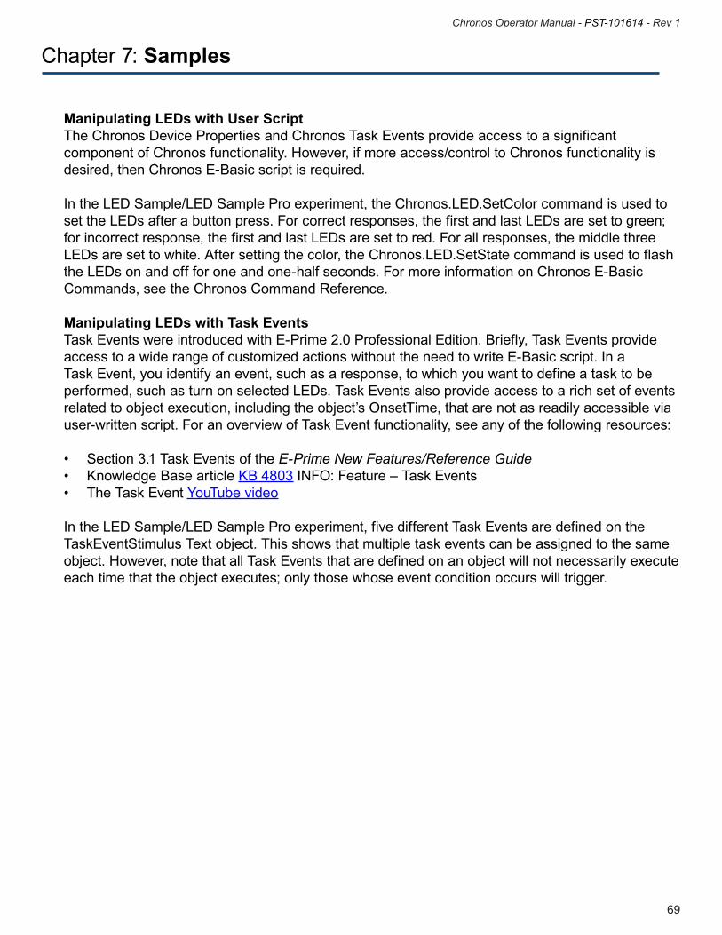
69
Chronos Operator Manual - PST-101614 - Rev 1
68
Chronos Operator Manual - PST-101614 - Rev 1
Chapter 7: Samples
Manipulating LEDs with User Script The Chronos Device Properties and Chronos Task Events provide access to a significant component of Chronos functionality. However, if more access/control to Chronos functionality is desired, then Chronos E-Basic script is required.
In the LED Sample/LED Sample Pro experiment, the Chronos.LED.SetColor command is used to set the LEDs after a button press. For correct responses, the first and last LEDs are set to green; for incorrect response, the first and last LEDs are set to red. For all responses, the middle three LEDs are set to white. After setting the color, the Chronos.LED.SetState command is used to flash the LEDs on and off for one and one-half seconds. For more information on Chronos E-Basic Commands, see the Chronos Command Reference.
Manipulating LEDs with Task Events Task Events were introduced with E-Prime 2.0 Professional Edition. Briefly, Task Events provide access to a wide range of customized actions without the need to write E-Basic script. In a Task Event, you identify an event, such as a response, to which you want to define a task to be performed, such as turn on selected LEDs. Task Events also provide access to a rich set of events related to object execution, including the object’s OnsetTime, that are not as readily accessible via user-written script. For an overview of Task Event functionality, see any of the following resources:
• Section3.1TaskEventsoftheE-Prime New Features/Reference Guide• KnowledgeBasearticleKB 4803 INFO: Feature – Task Events• TheTaskEventYouTube video
In the LED Sample/LED Sample Pro experiment, five different Task Events are defined on the TaskEventStimulus Text object. This shows that multiple task events can be assigned to the same object. However, note that all Task Events that are defined on an object will not necessarily execute each time that the object executes; only those whose event condition occurs will trigger.
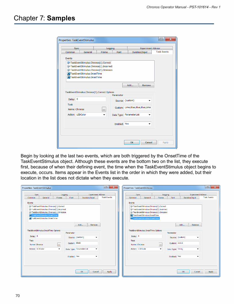
71
Chronos Operator Manual - PST-101614 - Rev 1
70
Chronos Operator Manual - PST-101614 - Rev 1
Begin by looking at the last two events, which are both triggered by the OnsetTime of the TaskEventStimulus object. Although these events are the bottom two on the list, they execute first, because of when their defining event, the time when the TaskEventStimulus object begins to execute, occurs. Items appear in the Events list in the order in which they were added, but their location in the list does not dictate when they execute.
Chapter 7: Samples
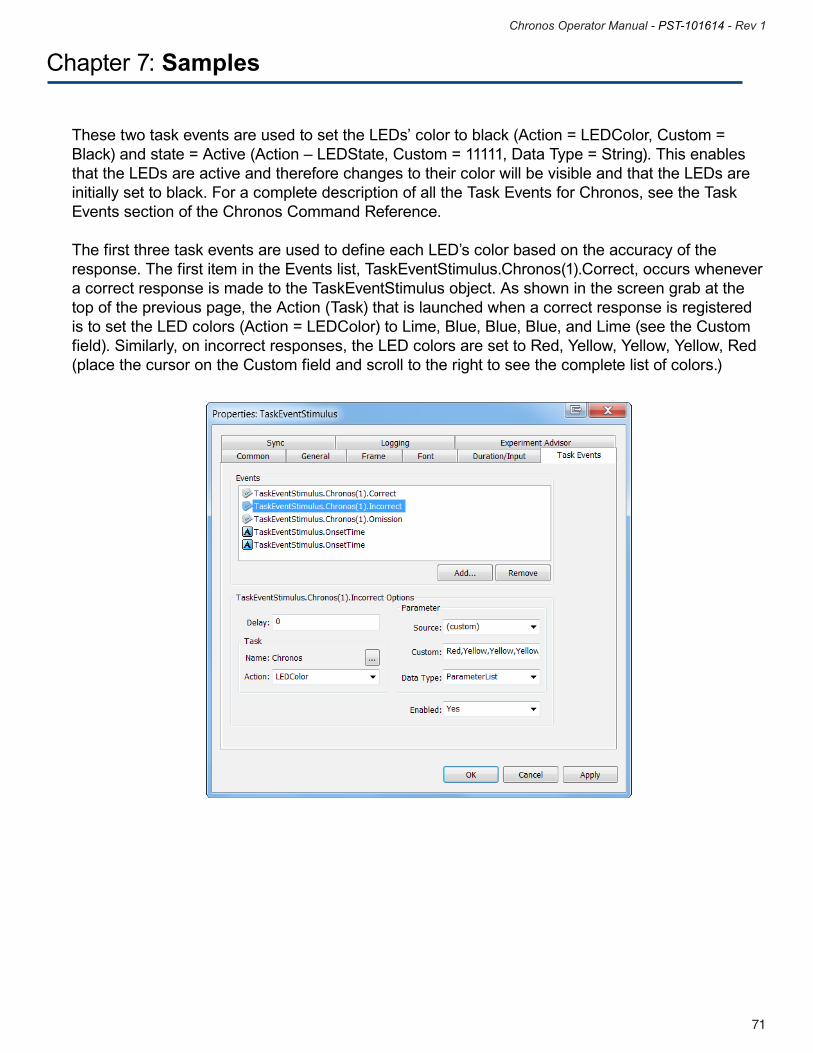
71
Chronos Operator Manual - PST-101614 - Rev 1
70
Chronos Operator Manual - PST-101614 - Rev 1
Chapter 7: Samples
These two task events are used to set the LEDs’ color to black (Action = LEDColor, Custom = Black) and state = Active (Action – LEDState, Custom = 11111, Data Type = String). This enables that the LEDs are active and therefore changes to their color will be visible and that the LEDs are initially set to black. For a complete description of all the Task Events for Chronos, see the Task Events section of the Chronos Command Reference.
The first three task events are used to define each LED’s color based on the accuracy of the response. The first item in the Events list, TaskEventStimulus.Chronos(1).Correct, occurs whenever a correct response is made to the TaskEventStimulus object. As shown in the screen grab at the top of the previous page, the Action (Task) that is launched when a correct response is registered is to set the LED colors (Action = LEDColor) to Lime, Blue, Blue, Blue, and Lime (see the Custom field). Similarly, on incorrect responses, the LED colors are set to Red, Yellow, Yellow, Yellow, Red (place the cursor on the Custom field and scroll to the right to see the complete list of colors.)
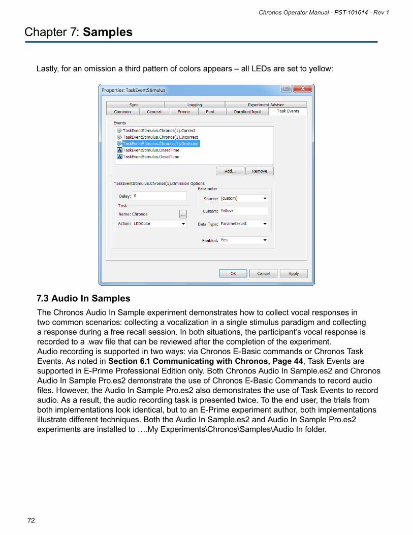
73
Chronos Operator Manual - PST-101614 - Rev 1
72
Chronos Operator Manual - PST-101614 - Rev 1
Lastly, for an omission a third pattern of colors appears – all LEDs are set to yellow:
The Chronos Audio In Sample experiment demonstrates how to collect vocal responses in two common scenarios: collecting a vocalization in a single stimulus paradigm and collecting a response during a free recall session. In both situations, the participant’s vocal response is recorded to a .wav file that can be reviewed after the completion of the experiment. Audio recording is supported in two ways: via Chronos E-Basic commands or Chronos Task Events. As noted in Section 6.1 Communicating with Chronos, Page 44, Task Events are supported in E-Prime Professional Edition only. Both Chronos Audio In Sample.es2 and Chronos Audio In Sample Pro.es2 demonstrate the use of Chronos E-Basic Commands to record audio files. However, the Audio In Sample Pro.es2 also demonstrates the use of Task Events to record audio. As a result, the audio recording task is presented twice. To the end user, the trials from both implementations look identical, but to an E-Prime experiment author, both implementations illustrate different techniques. Both the Audio In Sample.es2 and Audio In Sample Pro.es2 experiments are installed to ….My Experiments\Chronos\Samples\Audio In folder.
7.3 Audio In Samples
Chapter 7: Samples
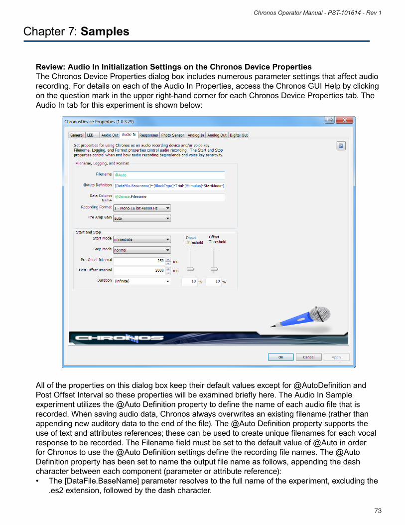
73
Chronos Operator Manual - PST-101614 - Rev 1
72
Chronos Operator Manual - PST-101614 - Rev 1
Chapter 7: Samples
Review: Audio In Initialization Settings on the Chronos Device Properties The Chronos Device Properties dialog box includes numerous parameter settings that affect audio recording. For details on each of the Audio In Properties, access the Chronos GUI Help by clicking on the question mark in the upper right-hand corner for each Chronos Device Properties tab. The Audio In tab for this experiment is shown below:
All of the properties on this dialog box keep their default values except for @AutoDefinition and Post Offset Interval so these properties will be examined briefly here. The Audio In Sample experiment utilizes the @Auto Definition property to define the name of each audio file that is recorded. When saving audio data, Chronos always overwrites an existing filename (rather than appending new auditory data to the end of the file). The @Auto Definition property supports the use of text and attributes references; these can be used to create unique filenames for each vocal response to be recorded. The Filename field must be set to the default value of @Auto in order for Chronos to use the @Auto Definition settings define the recording file names. The @Auto Definition property has been set to name the output file name as follows, appending the dash character between each component (parameter or attribute reference): • The[DataFile.BaseName]parameterresolvestothefullnameoftheexperiment,excludingthe .es2 extension, followed by the dash character.
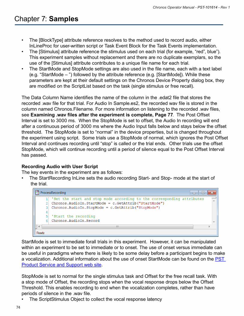
75
Chronos Operator Manual - PST-101614 - Rev 1
74
Chronos Operator Manual - PST-101614 - Rev 1
• The[BlockType]attributereferenceresolvestothemethodusedtorecordaudio,either InLineProc for user-written script or Task Event Block for the Task Events implementation. • The[Stimulus]attributereferencethestimulususedoneachtrial(forexample,“red”,blue”). This experiment samples without replacement and there are no duplicate exemplars, so the use of the [Stimulus] attribute contributes to a unique file name for each trial. • TheStartModeandStopModesettingsarealsousedinthefilename,eachwithatextlabel (e.g. “StartMode – ”) followed by the attribute reference (e.g. [StartMode]). While these parameters are kept at their default settings on the Chronos Device Property dialog box, they are modified on the ScriptList based on the task (single stimulus or free recall).
The Data Column Name identifies the name of the column in the .edat2 file that stores the recorded .wav file for that trial. For Audio In Sample.es2, the recorded wav file is stored in the column named Chronos.Filename. For more information on listening to the recorded .wav files, see Examining .wav files after the experiment is complete, Page 77. The Post Offset Interval is set to 3000 ms. When the StopMode is set to offset, the Audio In recording will end after a continuous period of 3000 ms where the Audio Input falls below and stays below the offset threshold. The StopMode is set to “normal” in the device properties, but is changed throughout the experiment using script. Some trials use a StopMode of normal, which ignores the Post Offset Interval and continues recording until “stop” is called or the trial ends. Other trials use the offset StopMode, which will continue recording until a period of silence equal to the Post Offset Interval has passed.
Recording Audio with User Script The key events in the experiment are as follows:• TheStartRecordingInLinesetstheaudiorecordingStart-andStop-modeatthestartof the trial.
StartMode is set to immediate forall trials in this experiment. However, it can be manipulated within an experiment to be set to immediate or to onset. The use of onset versus immediate can be useful in paradigms where there is likely to be some delay before a participant begins to make a vocalization. Additional information about the use of onset StartMode can be found on the PST Product Service and Support web site.
StopMode is set to normal for the single stimulus task and Offset for the free recall task. With a stop mode of Offset, the recording stops when the vocal response drops below the Offset Threshold. This enables recording to end when the vocalization completes, rather than have periods of silence in the .wav file.• TheScriptStimulusObjecttocollectthevocalresponselatency
Chapter 7: Samples
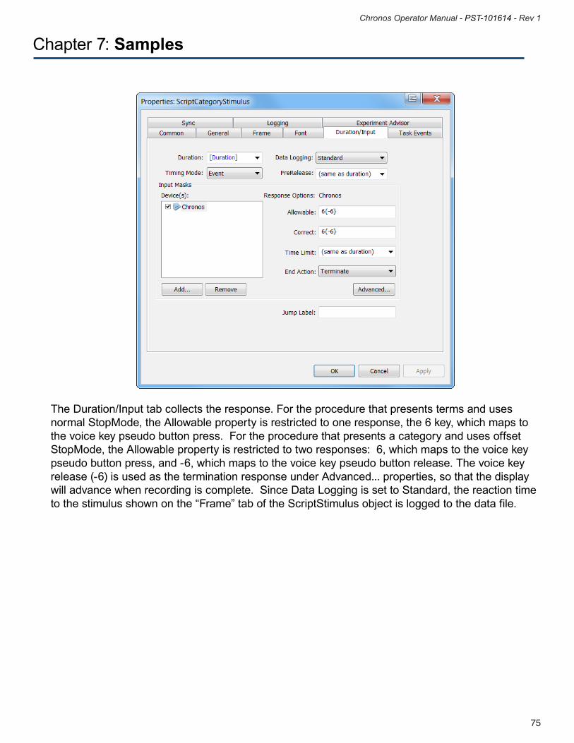
75
Chronos Operator Manual - PST-101614 - Rev 1
74
Chronos Operator Manual - PST-101614 - Rev 1
Chapter 7: Samples
The Duration/Input tab collects the response. For the procedure that presents terms and uses normal StopMode, the Allowable property is restricted to one response, the 6 key, which maps to the voice key pseudo button press. For the procedure that presents a category and uses offset StopMode, the Allowable property is restricted to two responses: 6, which maps to the voice key pseudo button press, and -6, which maps to the voice key pseudo button release. The voice key release (-6) is used as the termination response under Advanced... properties, so that the display will advance when recording is complete. Since Data Logging is set to Standard, the reaction time to the stimulus shown on the “Frame” tab of the ScriptStimulus object is logged to the data file.

77
Chronos Operator Manual - PST-101614 - Rev 1
76
Chronos Operator Manual - PST-101614 - Rev 1
Recording Audio with Task Events (Professional Edition Users only)
The recording (Action = AudioInRecord) begins when the object begins to execute (Event = TaskEventStimulus.OnsetTime). The Source field is set to “(custom)”. The Custom field is blank and the Data Type is set to ParameterList. The recording parameters, initialized on the Audio In tab of the Chronos Device Properties and examined at the start of this tutorial, apply to the recording, unless they are subsequently changed in user script.
Chapter 7: Samples
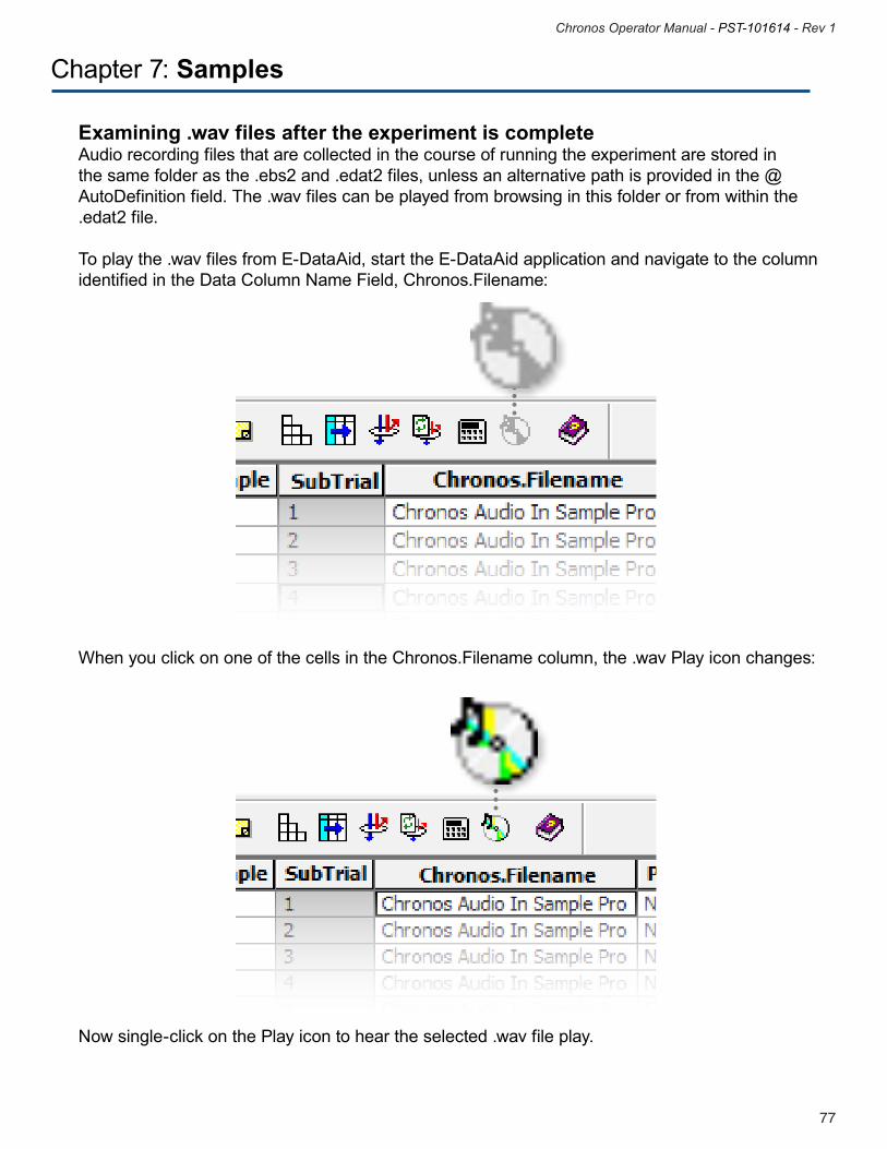
77
Chronos Operator Manual - PST-101614 - Rev 1
76
Chronos Operator Manual - PST-101614 - Rev 1
Chapter 7: Samples Examining .wav files after the experiment is complete Audio recording files that are collected in the course of running the experiment are stored in the same folder as the .ebs2 and .edat2 files, unless an alternative path is provided in the @AutoDefinition field. The .wav files can be played from browsing in this folder or from within the .edat2 file.
To play the .wav files from E-DataAid, start the E-DataAid application and navigate to the column identified in the Data Column Name Field, Chronos.Filename:
When you click on one of the cells in the Chronos.Filename column, the .wav Play icon changes:
Now single-click on the Play icon to hear the selected .wav file play.
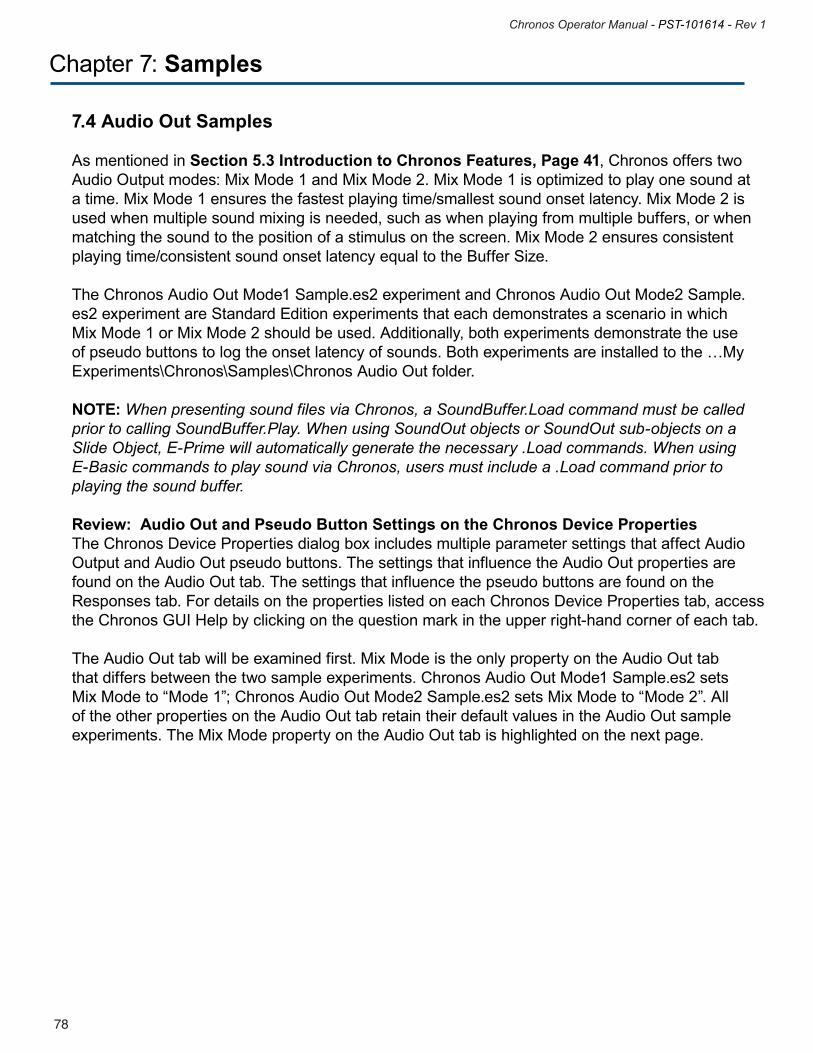
79
Chronos Operator Manual - PST-101614 - Rev 1
78
Chronos Operator Manual - PST-101614 - Rev 1
Chapter 7: Samples
7.4 Audio Out Samples
As mentioned in Section 5.3 Introduction to Chronos Features, Page 41, Chronos offers two Audio Output modes: Mix Mode 1 and Mix Mode 2. Mix Mode 1 is optimized to play one sound at a time. Mix Mode 1 ensures the fastest playing time/smallest sound onset latency. Mix Mode 2 is used when multiple sound mixing is needed, such as when playing from multiple buffers, or when matching the sound to the position of a stimulus on the screen. Mix Mode 2 ensures consistent playing time/consistent sound onset latency equal to the Buffer Size. The Chronos Audio Out Mode1 Sample.es2 experiment and Chronos Audio Out Mode2 Sample.es2 experiment are Standard Edition experiments that each demonstrates a scenario in which Mix Mode 1 or Mix Mode 2 should be used. Additionally, both experiments demonstrate the use of pseudo buttons to log the onset latency of sounds. Both experiments are installed to the …My Experiments\Chronos\Samples\Chronos Audio Out folder.
NOTE: When presenting sound files via Chronos, a SoundBuffer.Load command must be called prior to calling SoundBuffer.Play. When using SoundOut objects or SoundOut sub-objects on a Slide Object, E-Prime will automatically generate the necessary .Load commands. When using E-Basic commands to play sound via Chronos, users must include a .Load command prior to playing the sound buffer. Review: Audio Out and Pseudo Button Settings on the Chronos Device PropertiesThe Chronos Device Properties dialog box includes multiple parameter settings that affect Audio Output and Audio Out pseudo buttons. The settings that influence the Audio Out properties are found on the Audio Out tab. The settings that influence the pseudo buttons are found on the Responses tab. For details on the properties listed on each Chronos Device Properties tab, access the Chronos GUI Help by clicking on the question mark in the upper right-hand corner of each tab. The Audio Out tab will be examined first. Mix Mode is the only property on the Audio Out tab that differs between the two sample experiments. Chronos Audio Out Mode1 Sample.es2 sets Mix Mode to “Mode 1”; Chronos Audio Out Mode2 Sample.es2 sets Mix Mode to “Mode 2”. All of the other properties on the Audio Out tab retain their default values in the Audio Out sample experiments. The Mix Mode property on the Audio Out tab is highlighted on the next page.
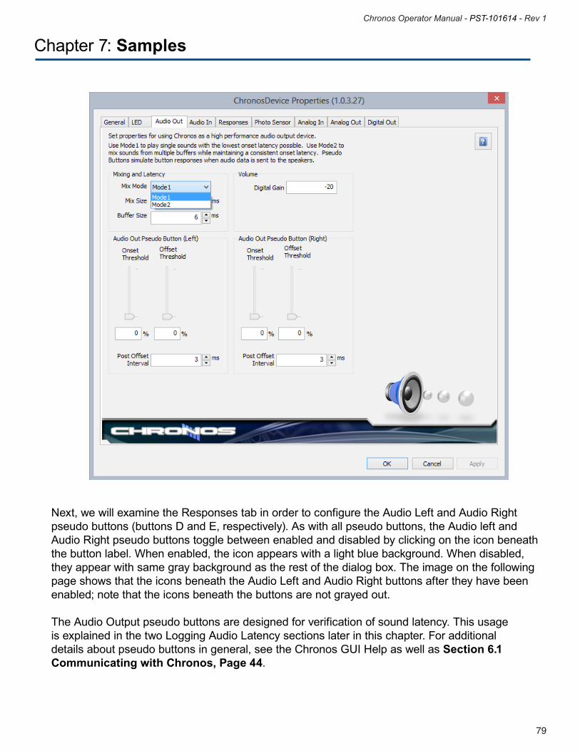
79
Chronos Operator Manual - PST-101614 - Rev 1
78
Chronos Operator Manual - PST-101614 - Rev 1
Chapter 7: Samples
Next, we will examine the Responses tab in order to configure the Audio Left and Audio Right pseudo buttons (buttons D and E, respectively). As with all pseudo buttons, the Audio left and Audio Right pseudo buttons toggle between enabled and disabled by clicking on the icon beneath the button label. When enabled, the icon appears with a light blue background. When disabled, they appear with same gray background as the rest of the dialog box. The image on the following page shows that the icons beneath the Audio Left and Audio Right buttons after they have been enabled; note that the icons beneath the buttons are not grayed out.
The Audio Output pseudo buttons are designed for verification of sound latency. This usage is explained in the two Logging Audio Latency sections later in this chapter. For additional details about pseudo buttons in general, see the Chronos GUI Help as well as Section 6.1 Communicating with Chronos, Page 44.
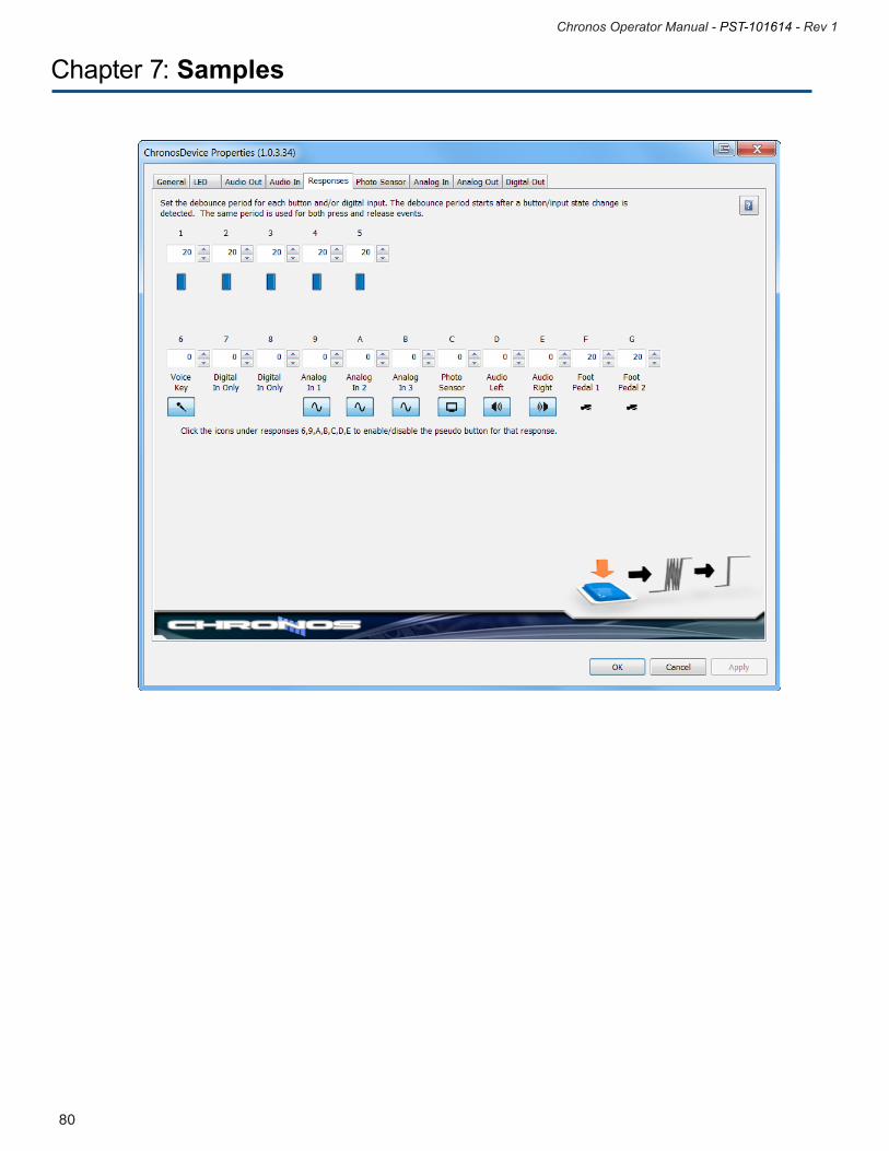
81
Chronos Operator Manual - PST-101614 - Rev 1
80
Chronos Operator Manual - PST-101614 - Rev 1
Chapter 7: Samples
81
Chronos Operator Manual - PST-101614 - Rev 1
80
Chronos Operator Manual - PST-101614 - Rev 1
Chapter 7: Samples
Chronos Audio Out Mode1 Sample.es2Chronos Audio Out Mode1 Sample.es2 is a reaction time experiment that presents an auditory stimulus. Each trial begins with a fixation, followed by an auditory stimulus and a request for input from the participant to indicate whether he or she heard the auditory stimulus. The LogAudioLatency InLine object is used to record the latency of the audio stimulus. Finally, a feedback object presents reaction time and audio latency feedback information. The experiment consists of one block of four trials. In each block, the pan setting for the stimulus sound is changed; this has the effect of playing the sound through either the right audio channel or the left audio channel, depending on the pan value. At the trial level, the volume of the stimulus sound is changed on each of the four trials. On two of the trials, the sound is played at a level that would be audible to most individuals under typical conditions. On the other two trials, the sound is played a level that would not typically be audible. The E-Prime New Features/Reference Guide provides additional details about attenuating volume in an experiment.
Details about implementing a reaction time experiment with audio stimuli can be found in the E-Prime 2.0 Getting Started Guide, Advanced Tutorial 2. Details about panning can be found in the E-Prime New Features/Reference Guide. The aspect of the design of this experiment that is unique to Chronos is the use of pseudo buttons, which we examine next.
Logging Audio Latency Using Pseudo Buttons – One SoundAs mentioned previously, the Audio Left and Audio Right pseudo buttons have been changed from their default state of disabled to enabled for both Audio Out sample experiments. These buttons are designed for logging the sound latency, or the delay between when the command to present the sound executes and when the sound is actually played. Historically, when using the computer’s sound card to present audio stimuli, sound latency is large (sometimes in the hundreds of ms) and inconsistent across sound card manufacturers and operating systems. Large and variable sound latencies are not an issue with Chronos. When Mix Mode is 1, Chronos provides the fastest sound latency possible, typically 0-1 ms. With Chronos, you can determine the sound latency by logging the pseudo buttons as well as configure the log the sound latency to confirm The LogAudioLatency InLine object is then used to calculate and record the latency of the pseudo button responses (i.e., the sound onset latency).
Do not confuse the pseudo buttons D and E with the voice key input, which maps to pseudo button 6. The voice key is registering a vocal response. Typically, the voice key is collected through a microphone connected to the Chronos Audio In connector. The voice key could also collect a sound latency if a connector was placed between the Audio Out and Audio In connectors; when a sound is placed through the Audio Out, it would be sent immediately to the voice key and therefore trigger a response.
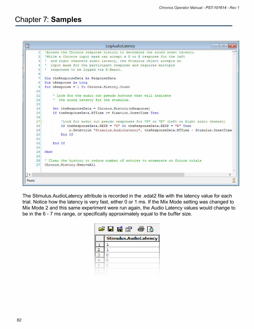
83
Chronos Operator Manual - PST-101614 - Rev 1
82
Chronos Operator Manual - PST-101614 - Rev 1
Chapter 7: Samples
The Stimulus.AudioLatency attribute is recorded in the .edat2 file with the latency value for each trial. Notice how the latency is very fast, either 0 or 1 ms. If the Mix Mode setting was changed to Mix Mode 2 and this same experiment were run again, the Audio Latency values would change to be in the 6 - 7 ms range, or specifically approximately equal to the buffer size.
83
Chronos Operator Manual - PST-101614 - Rev 1
82
Chronos Operator Manual - PST-101614 - Rev 1
Chapter 7: Samples
Chronos Audio Out Mode2 Sample.es2The structure and design of Chronos Audio Out Mode2 Sample.es2 is very similar to Chronos Audio Out Mode1 Sample.es2, with the following exceptions:
• MixMode:Asmentionedpreviously,theMixModeforChronosAudioOutMode1Sample.es2 is set to Mode1 in Chronos Device Properties; in Chronos Audio Out Mode2 Sample.es2, it is set to Mode2.• Distractorsound:IntheMode1Sample,asinglestimulussoundisplayedoneachtrial.Inthe Mode2 Sample, a distractor sound begins on the Fixation slide and continues while the stimulus sound is played. Chronos Audio Out Mode2.es2 consists of four blocks of four trials. In each block, the pan setting for both the stimulus sound and the distractor sound is changed so that one is set at the minimum pan value, and one is set at the maximum pan value. This has the effect of playing the stimulus sound through one audio channel and the distractor sound through the other audio channel. The audio latency of the stimulus sound can then be logged independently using the Audio Left and Audio Right pseudo buttons. At the trial level, the volume of the stimulus sound is changed on each of the four trials. On two of the trials, the sound is played at a level that would be audible to most individuals under typical conditions. On the other two trials, the sound is played a level that would not typically be audible. Note that the volume of the distractor sound is kept the same across trials.
Logging Audio Latency Using Pseudo Buttons – Two SoundsAs mentioned previously, the Audio Left and Audio Right pseudo buttons are enabled in Chronos Device Properties for both experiments. The LogAudioLatency InLine object is then used to calculate and record the latency of the pseudo button responses (i.e., the sound onset latency). Since the distractor sound is played to one audio channel and the stimulus sound is played to the other channel, the latency of each can be recorded individually by looking for a “D” pseudo button response for the left channel or an “E” pseudo button response for the right channel.
Notice that even on those trials where the volume level is low, the pseudo buttons still register a response. Since the onset threshold for the pseudo buttons was not changed from the default setting of 0%, ANY sound that plays will trigger a pseudo button response.
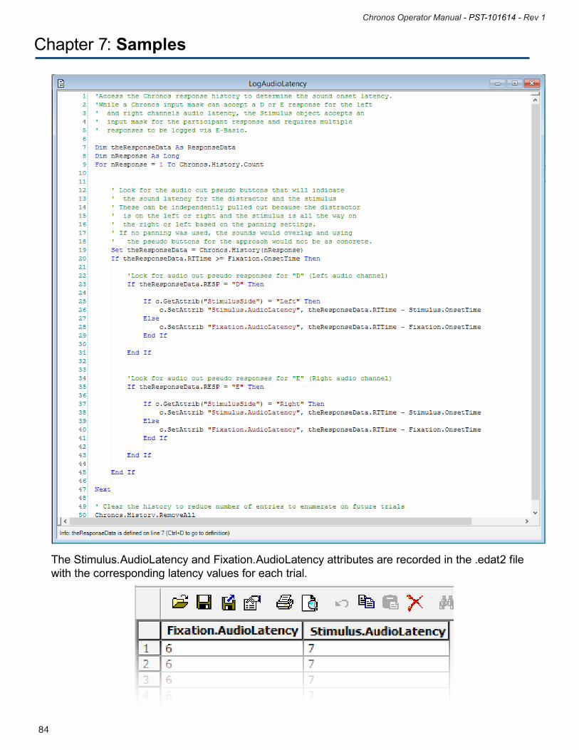
85
Chronos Operator Manual - PST-101614 - Rev 1
84
Chronos Operator Manual - PST-101614 - Rev 1
The Stimulus.AudioLatency and Fixation.AudioLatency attributes are recorded in the .edat2 file with the corresponding latency values for each trial.
Chapter 7: Samples
85
Chronos Operator Manual - PST-101614 - Rev 1
84
Chronos Operator Manual - PST-101614 - Rev 1
Chapter 8: Additional Topics
8.1 Using Emulation
Chronos, just like all other E-Prime input devices, supports emulation into other input devices. With emulation, responses that are made with the input device appear as if they came from the emulated device. For example, when Chronos emulates the keyboard, a button press from Chronos appears to E-Prime as if it came from the keyboard. We recommend using emulation in the following scenarios:• whenyouwanttochangeanexistingexperimentthatiscollectingresponsesfromthekeyboard or mouse to collect response from Chronos instead • whenyouaredevelopinganewexperimentthatiscollectingresponsefromChronos
Emulation is recommended for several reasons. Most importantly, it provides the flexibility to develop and test an experiment on a computer that does not have a Chronos Device attached but will ultimately collect participant responses from Chronos. During experiment development, responses can be made with the emulated device (which will mostly likely be a keyboard, but could also be another device such as a mouse). During data collection, responses can be made with Chronos; further, no edits need to be made to the experiment specification file when moving between the development and data collection computers. The timing advantages offered by Chronos are available even when emulating. The time stamp for a Chronos button press retains its precision and accuracy whether or not that button press is emulated to a keyboard response. Second, since emulation enables you to run an experiment with either the input or emulated device, it simplifies the process of sharing experiments with colleagues. If you emulate Chronos into the keyboard, then anyone can run your compiled .ebs2 experiment as long as they run on a computer with a keyboard; a Chronos Device is not required. Third, whenever you choose not to use the emulation feature, you must add a device-specific input mask to every input object, such as we did in Tutorial 1, Step 5: Modify Stimulus Object, Page 38.
Emulation only affects responses. For example, when emulating into the keyboard, Chronos responses appear as though they came from the keyboard input mask and all Chronos-specific features remain functional. For example, Chronos can still be used to present auditory stimuli when emulating the keyboard.
Emulating Chronos into another device is not possible if any non-button Chronos features are used, including controlling LEDs by any method (Echo Client, Task Events, user script), presenting sound, or performing analog or digital input or output. To use emulation, navigate to the Devices tab on the Experiment Object Properties window, select the Chronos Device and either double-click or click on the “Edit….” Button. The Chronos Device Properties dialog appears, and the General tab is selected.
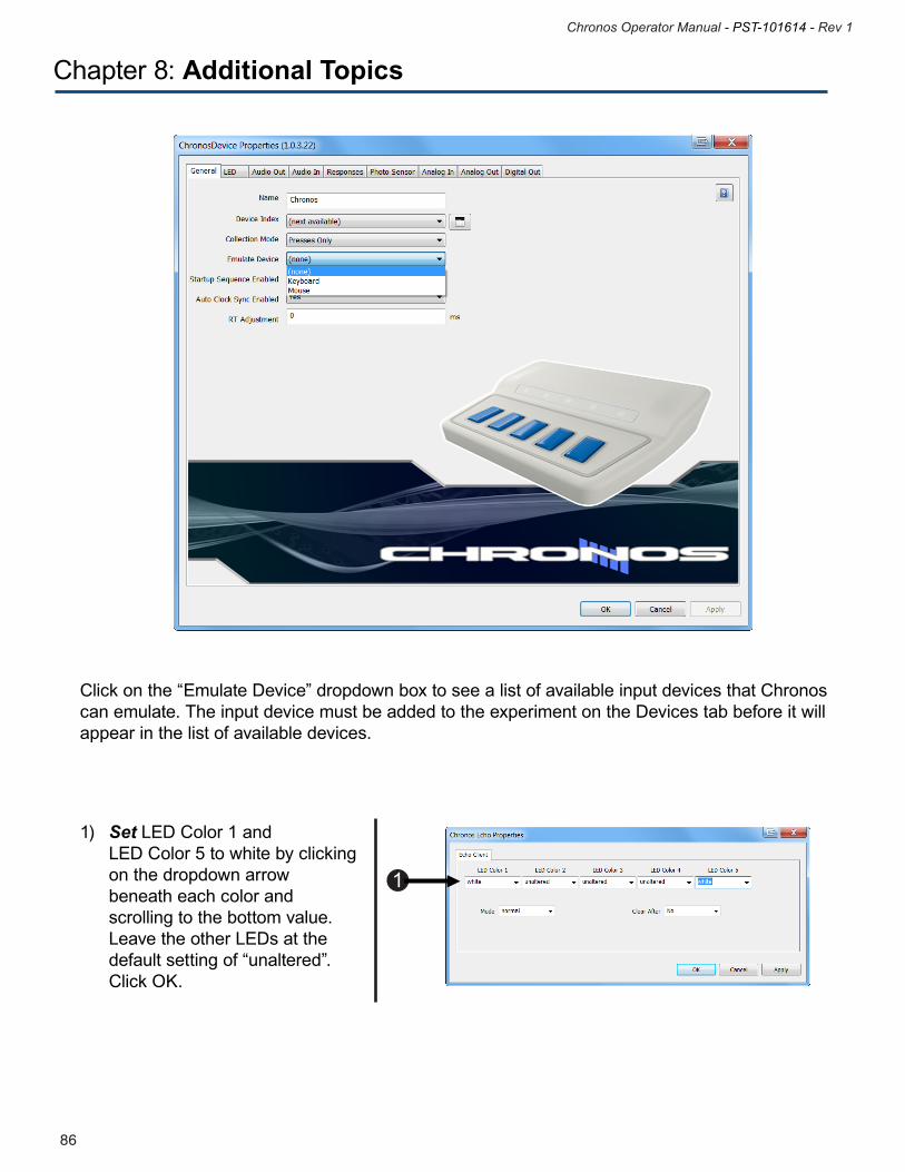
87
Chronos Operator Manual - PST-101614 - Rev 1
86
Chronos Operator Manual - PST-101614 - Rev 1
Chapter 8: Additional Topics
Click on the “Emulate Device” dropdown box to see a list of available input devices that Chronos can emulate. The input device must be added to the experiment on the Devices tab before it will appear in the list of available devices.
1) Set LED Color 1 and LED Color 5 to white by clicking on the dropdown arrow beneath each color and scrolling to the bottom value. Leave the other LEDs at the default setting of “unaltered”. Click OK.
1
87
Chronos Operator Manual - PST-101614 - Rev 1
86
Chronos Operator Manual - PST-101614 - Rev 1
Chapter 8: Additional Topics
8.2 Converting your SRBox Experiment to Chronos
There are multiple options available to update an experiment that is implemented to accept input from a PST Serial Response Box (SRBox) to accept input from Chronos instead. The best option to utilize depends on how the SRBox is implemented. For any of the options described below, Chronos must first be added as an input device, as described in Tutorial 1, Section Step 3: Add Chronos Device, Page 34. Once Chronos has been added as a device, select one of the following options as appropriate. Any of these options involve modifying input masks in E-Studio. To review basic information related to input masks, see the E-Prime User’s Manual, Chapter 3.
89
Chronos Operator Manual - PST-101614 - Rev 1
88
Chronos Operator Manual - PST-101614 - Rev 1
Chapter 8: Additional Topics
8.2.1 Manually change all SRBox references into Chronos referencesTo switch completely the response input device from SRBox to Chronos, you can manually replace all references to SRBox with all references to Chronos. This involves the following:
1) Uncheck or remove the SRBox device from the list of available devices in the experiment. NOTE: DO NOT delete the SRBox from the list of Devices. Doing so will result in all SRBox input masks being removed from the experiment as well, which removes any indication of which objects need to be edited in Step 2.
2) For any object that is currently accepting SRBox responses: a) add Chronos as an InputDevice b) either uncheck or remove the existing SRBox input device
3) For any user-written script that manipulates the SRBox Lamps, replace with updated script or Task Events to manipulate the Chronos LEDs.
4) For any Echo Client that echoes information either from or to the SRBox, update to echo information from or to Chronos.
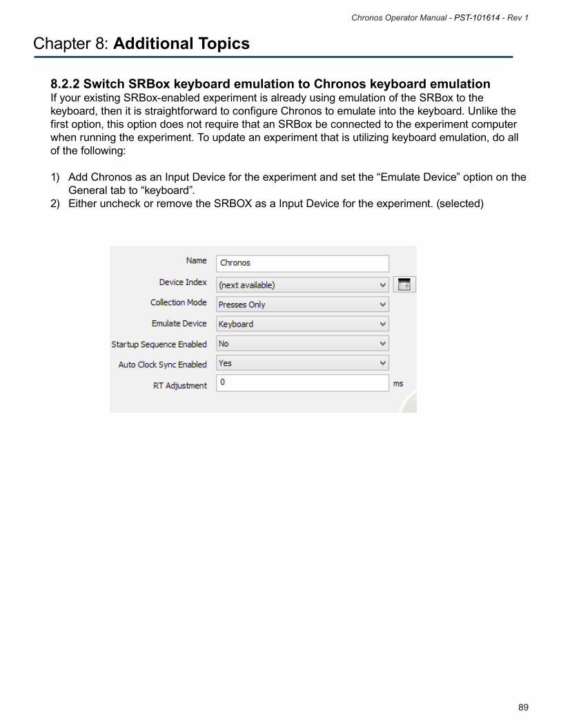
89
Chronos Operator Manual - PST-101614 - Rev 1
88
Chronos Operator Manual - PST-101614 - Rev 1
Chapter 8: Additional Topics
8.2.2 Switch SRBox keyboard emulation to Chronos keyboard emulationIf your existing SRBox-enabled experiment is already using emulation of the SRBox to the keyboard, then it is straightforward to configure Chronos to emulate into the keyboard. Unlike the first option, this option does not require that an SRBox be connected to the experiment computer when running the experiment. To update an experiment that is utilizing keyboard emulation, do all of the following:
1) Add Chronos as an Input Device for the experiment and set the “Emulate Device” option on the General tab to “keyboard”.2) Either uncheck or remove the SRBOX as a Input Device for the experiment. (selected)
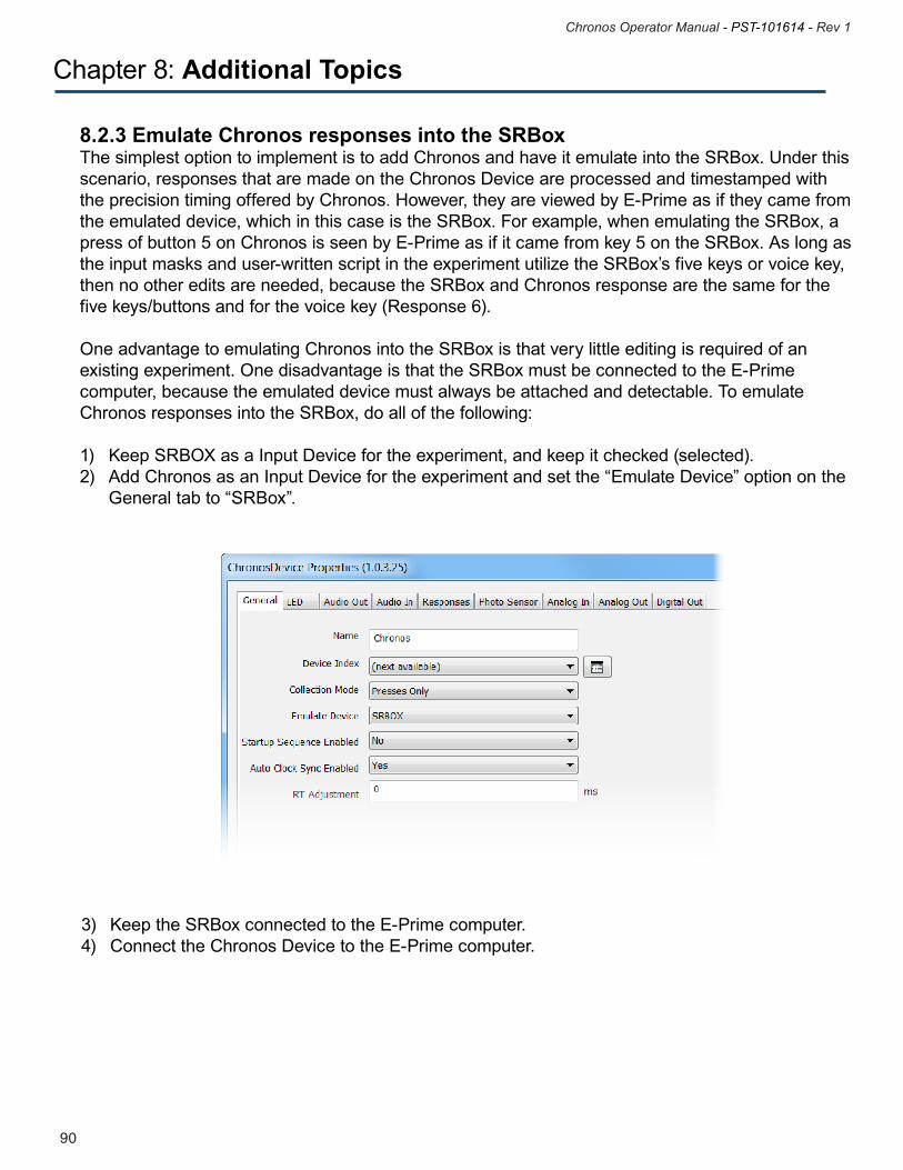
91
Chronos Operator Manual - PST-101614 - Rev 1
90
Chronos Operator Manual - PST-101614 - Rev 1
Chapter 8: Additional Topics
8.2.3 Emulate Chronos responses into the SRBoxThe simplest option to implement is to add Chronos and have it emulate into the SRBox. Under this scenario, responses that are made on the Chronos Device are processed and timestamped with the precision timing offered by Chronos. However, they are viewed by E-Prime as if they came from the emulated device, which in this case is the SRBox. For example, when emulating the SRBox, a press of button 5 on Chronos is seen by E-Prime as if it came from key 5 on the SRBox. As long as the input masks and user-written script in the experiment utilize the SRBox’s five keys or voice key, then no other edits are needed, because the SRBox and Chronos response are the same for the five keys/buttons and for the voice key (Response 6).
One advantage to emulating Chronos into the SRBox is that very little editing is required of an existing experiment. One disadvantage is that the SRBox must be connected to the E-Prime computer, because the emulated device must always be attached and detectable. To emulate Chronos responses into the SRBox, do all of the following:
1) Keep SRBOX as a Input Device for the experiment, and keep it checked (selected).2) Add Chronos as an Input Device for the experiment and set the “Emulate Device” option on the General tab to “SRBox”.
3) Keep the SRBox connected to the E-Prime computer.4) Connect the Chronos Device to the E-Prime computer.
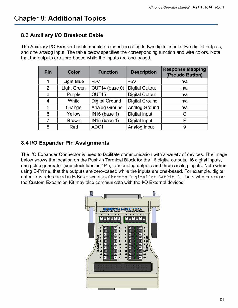
91
Chronos Operator Manual - PST-101614 - Rev 1
90
Chronos Operator Manual - PST-101614 - Rev 1
Chapter 8: Additional Topics
8.3 Auxiliary I/O Breakout Cable
The Auxiliary I/O Breakout cable enables connection of up to two digital inputs, two digital outputs, and one analog input. The table below specifies the corresponding function and wire colors. Note that the outputs are zero-based while the inputs are one-based.
Pin Color Function Description Response Mapping (Pseudo Button)
1 Light Blue +5V +5V n/a2 Light Green OUT14 (base 0) Digital Output n/a3 Purple OUT15 Digital Output n/a4 White Digital Ground Digital Ground n/a5 Orange Analog Ground Analog Ground n/a6 Yellow IN16 (base 1) Digital Input G7 Brown IN15 (base 1) Digital Input F8 Red ADC1 Analog Input 9
8.4 I/O Expander Pin Assignments
The I/O Expander Connector is used to facilitate communication with a variety of devices. The image below shows the location on the Push-in Terminal Block for the 16 digital outputs, 16 digital inputs, one pulse generator (see block labeled “P”), four analog outputs and three analog inputs. Note when using E-Prime, that the outputs are zero-based while the inputs are one-based. For example, digital output 7 is referenced in E-Basic script as Chronos.DigitalOut.SetBit 6. Users who purchase the Custom Expansion Kit may also communicate with the I/O External devices.
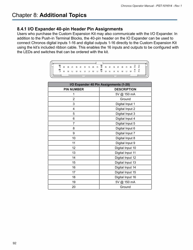
93
Chronos Operator Manual - PST-101614 - Rev 1
92
Chronos Operator Manual - PST-101614 - Rev 1
Chapter 8: Additional Topics
8.4.1 I/O Expander 40-pin Header Pin AssignmentsUsers who purchase the Custom Expansion Kit may also communicate with the I/O Expander. In addition to the Push-in Terminal Blocks, the 40-pin header on the IO Expander can be used to connect Chronos digital inputs 1-16 and digital outputs 1-16 directly to the Custom Expansion Kit using the kit’s included ribbon cable. This enables the 16 inputs and outputs to be configured with the LEDs and switches that can be ordered with the kit.
I/O Expander 40 Pin Assignments (1-20)PIN NUMBER DESCRIPTION
1 5V @ 150 mA2 Ground3 Digital Input 14 Digital Input 25 Digital Input 36 Digital Input 47 Digital Input 58 Digital Input 69 Digital Input 710 Digital Input 811 Digital Input 912 Digital Input 1013 Digital Input 1114 Digital Input 1215 Digital Input 1316 Digital Input 1417 Digital Input 1518 Digital Input 1619 5V @ 150 mA20 Ground
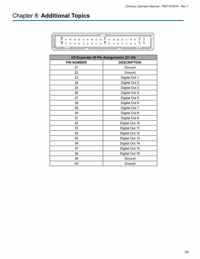
93
Chronos Operator Manual - PST-101614 - Rev 1
92
Chronos Operator Manual - PST-101614 - Rev 1
Chapter 8: Additional Topics
I/O Expander 40 Pin Assignments (21-40)PIN NUMBER DESCRIPTION
21 Ground22 Ground23 Digital Out 124 Digital Out 225 Digital Out 326 Digital Out 427 Digital Out 528 Digital Out 629 Digital Out 7 30 Digital Out 831 Digital Out 932 Digital Out 10 33 Digital Out 1134 Digital Out 1235 Digital Out 1336 Digital Out 1437 Digital Out 1538 Digital Out 1639 Ground 40 Ground
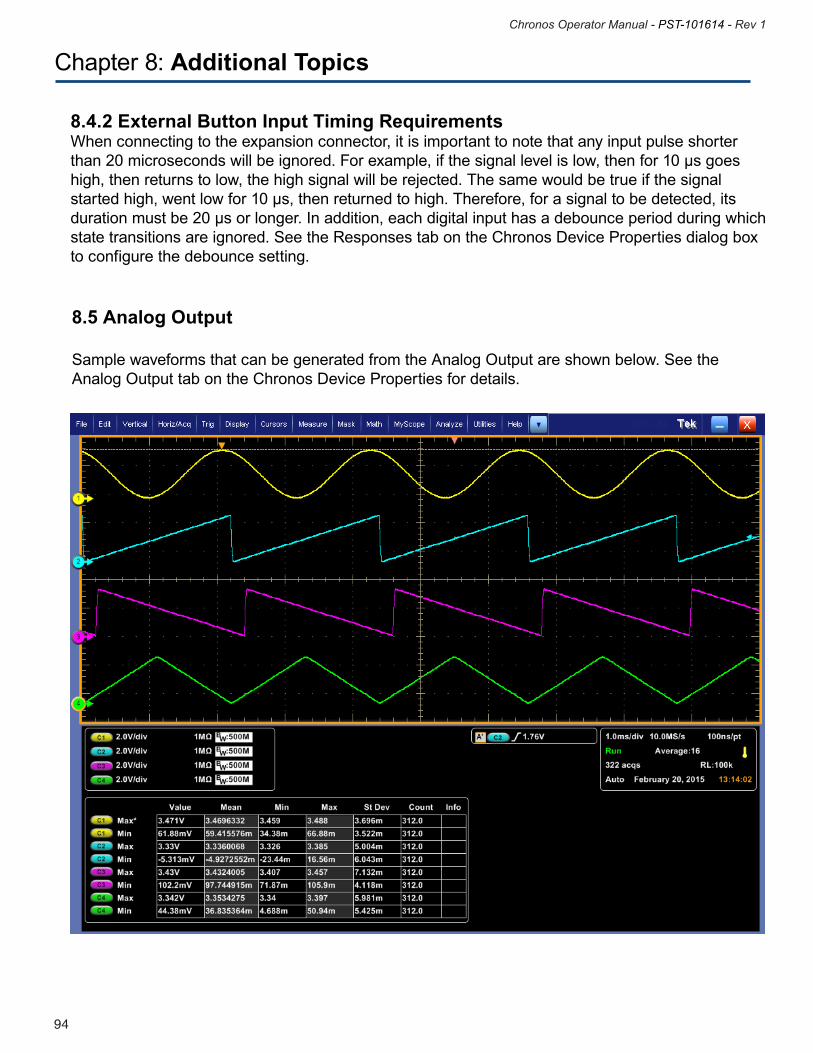
95
Chronos Operator Manual - PST-101614 - Rev 1
94
Chronos Operator Manual - PST-101614 - Rev 1
Chapter 8: Additional Topics
8.5 Analog Output
Sample waveforms that can be generated from the Analog Output are shown below. See the Analog Output tab on the Chronos Device Properties for details.
8.4.2 External Button Input Timing RequirementsWhen connecting to the expansion connector, it is important to note that any input pulse shorter than20microsecondswillbeignored.Forexample,ifthesignallevelislow,thenfor10μsgoeshigh, then returns to low, the high signal will be rejected. The same would be true if the signal startedhigh,wentlowfor10μs,thenreturnedtohigh.Therefore,forasignaltobedetected,itsdurationmustbe20μsorlonger.Inaddition,eachdigitalinputhasadebounceperiodduringwhichstate transitions are ignored. See the Responses tab on the Chronos Device Properties dialog box to configure the debounce setting.
95
Chronos Operator Manual - PST-101614 - Rev 1
94
Chronos Operator Manual - PST-101614 - Rev 1
Chapter 8: Additional Topics
8.6 Photo Sensor
Use of the Photo Sensor is demonstrated in the Chronos Feature Explorer. If you have not run the Feature Explorer already, please do so now. See Section 4.6 Chronos Features Explorer Experiment, Page 27 for details. The Photo Sensor is designed to work with a variety of display devices, including CRTs, LCDs, and Projection Screens. Data from the Photo Sensor can be accessed in two ways. First, the Photo Sensor maps to pseudo button C. Therefore, response data from the Photo Sensor can be collected in the same manner as all other pseudo buttons, via an Input Mask. See Section 6.2 Pseudo Buttons, Page 45 for general information about pseudo buttons. For the Photo Sensor, the response time associated with pseudo button C relates to the time when the sensor detected a change on the display device; this can be used to determine the display latency, or the time between when E-Prime sent information to be displayed to the display device and the time when the information first became visible. This time reflects several components, including the location of the information on the screen (i.e., information near the top of the display becomes visible before information near the bottom of the display), and the refresh rate of the monitor. For LCD displays, this time also reflects the rise time of the LCD, or the time it takes a pixel to change from black to the specified display color.
The second way to access Photo Sensor input is as an Analog Input. The Photo Sensor is mapped to Analog Input Channel 4. Therefore, E-Basic Analog In script commands and Task Events can be used to retrieve Photo Sensor data. See the Analog In and the Photo Sensor tabs in the Chronos Device Properties to configure the Photo Sensor.
Whenever working with the Photo Sensor, always perform Auto Calibration prior to using the Photo Sensor on your particular display device. Auto Calibration will adjust the gain level on the signal received by the Photo Sensor and will attempt to account for differences in brightness between monitors. To perform Auto Calibration, select the “Calculate Gain....” button on the Photo Sensor and follow the prompts.
97
Chronos Operator Manual - PST-101614 - Rev 1
96
Chronos Operator Manual - PST-101614 - Rev 1
Chapter 8: Additional Topics
To use the Photo Sensor to determine display latency, do the following:1) Connect your Photo Sensor to the display device, with the sensor component facing the monitor. When working with a CRT or LCD display, use the cord to secure the sensor. When working with a projector, you may have an assistant hold the Photo Sensor up to the projection screen; do not use an adhesive or any other method that may permanently damage the projection screen.
2) Navigate to the Photo Sensor tab on the Chronos Device Properties
3) Select the “Calculate Gain…” button to have Chronos detect the appropriate gain level; note that this may be different from the default value and therefore may update the value shown in the Gain field.
4) Create an experiment with the following trial sequence: a) First object: Black Box i. Display a black box on the portion of the screen ii. Synchronize the onset of the black box display with the refresh iii. Display the box for a multiple of the refresh rate iv. Ensure that the Photo Sensor is over the black box area.
b) Second object: White Box i. Change the color the box from black to white. ii. Create a Chronos InputMask on the second display, accepting ‘C’ as a valid input (pseudo button for the Photo Sensor) iii. Log the reaction time for pseudo button C; this provides the time when the object was placed on the screen.
Lastly, as demonstrated in the Chronos Feature Explorer experiment, the Photo Sensor can provide information about refresh rates. E-Basic script is generally required in order to calculate the refresh rate from the Photo Sensor data. See the PST Product Service and Support web site for further details.
97
Chronos Operator Manual - PST-101614 - Rev 1
96
Chronos Operator Manual - PST-101614 - Rev 1
Chapter 9: Contact Information
For additional information or support
Contact us atPsychology Software Tools, Inc
311 23rd Street Extension, Suite 200Sharpsburg, PA 15215-2821
Phone: 412-449-0078Fax: 412-449-0079www.pstnet.com
For Product Service and Support:Please visit us at https://support.pstnet.com


