Erisoft 9/S94:002 Rev D Uppgjord - Prepared Datum - Date Rev Dokumentnr - Document no Tfn - Phone Dokumentnamn - Document name Godkänd - Approved Tillhör/referens - File/reference Sida - Page 1(15) Interpreting the Information Element “C/I” This document in the first place addresses users of the GSM versions of TEMS Investigation, TEMS Light, and TEMS Optimization. Technical Report EPL/T/T P.Eriksson, A.Hedlund +46 910 731000 2000-04-11 A EPL/T/TN-00:022 D; EPL/T/TNC Nils Lindberg
Transcript
Eri
soft
9/S
94:0
02 R
ev D
Sida - Page
1(15)
Interpreting the Information Element “C/I”
This document in the first place addresses users of the GSM versions of TEMS Investigation, TEMS Light, and TEMS Optimization.
Datum - Date Rev Dokumentnr -
Dokumentnamn - Document name
Technical Report
Uppgjord - Prepared Tf
Godkänd - Approved
EPL/T/T P.Eriksson, A.Hedlund +
n - Phone
46 910 731000
2000-04-11 T
A E
Document no
illhör/referens - File/reference
PL/T/TN-00:022
EPL/T/TNC Nils Lindberg
D;
Eri
soft
10/
S94
:002
Rev
D
Uppgjord - Prepared Datum - Date Rev Dokumentnr - Document noTfn - Phone
Dokumentnamn - Document name Sida - Page
2(15)Technical Report
EPL/T/T P.Eriksson, A.Hedlund +46 910 731000 2000-04-11 A EPL/T/TN-00:022
hat
to ons
and
of
use ved
/I l
1 Introduction
“Why is my C/I so bad?”During your first drive test with the new TEMS Investigation release, you notice that the C/I reading drops sharply in one particular area. You know that this indicates a high level of interference on the carrier frequency, but what is the reason for this?
This document describes the most common causes of poor C/I values, and how these phenomena can be detected with the TEMS products. Also, it hints at how each of the underlying problems can be remedied.
See chapters 2-9.
What is “interference”?We must define what we mean by “interference” within the TEMSframework. Sometimes the meaning of the word is restricted, in tit refers exclusively to other signals from radio communication devices, and is distinguished from “noise”. Other terms are usedidentify various categories of disturbances, such as “long” reflecticausing problems with time dispersion, adjacent channel disturbances, etc.
We use the word “interference” here as an umbrella term for anyunwanted signals, that is, any signals other than the carrier itself,the information element “C/I” is a generalized measure of the interference level (in particular, it does not refer exclusively to co-channel interference).
C/I vs. speech qualityC/I is not a measure of speech quality. For assessing the speechquality perceived by a human listener, the TEMS products offer another measure, the Speech Quality Index (SQI). Although it iscourse generally true that severe interference problems tend to degrade speech quality, and although low C/I values typically caSQI drops, the C/I does not give a reliable estimate of the perceispeech quality. For instance, in a cell with five carriers using frequency hopping, one of the carriers can suffer from very low Cwithout the speech quality being degraded, thanks to the channecoding and interleaving employed in GSM.
Eri
soft
10/
S94
:002
Rev
D
Uppgjord - Prepared Datum - Date Rev Dokumentnr - Document noTfn - Phone
Dokumentnamn - Document name Sida - Page
3(15)Technical Report
EPL/T/T P.Eriksson, A.Hedlund +46 910 731000 2000-04-11 A EPL/T/TN-00:022
or
2 Co-channel interference
By co-channel interference is meant interference from other network cells using the same transmission frequency. In most environments (in fact almost anywhere except in very sparsely populated rural areas), co-channel interference is the factor that limits network capacity (the maximum number of simultaneous users). Mostly, in such cases, it is by far the most important source of interference.
In GSM, there are two main channel types: broadcast channels with continuous output power, and traffic channels whose output power is dependent on the traffic load in the cell. During cell planning, different reuse patterns are often used for the two kinds of channel, but unless the broadcast channels are put in a separate band, they may still interfere with each other.
When the interference stems from a broadcast channel, measuring the C/I is fairly straightforward thanks to the constant output power. However, if the interferer is a traffic channel, the C/I will vary according to the load on the interfering cell. This means that if, for example, you perform a drive test at night, when the amount of traffic is likely to be low, the interference situation can be totally different than during busy hour. Even functions such as downlink DTX and downlink power control can affect the interference situation.
Using TEMSAs stated above, co-channel interference is by far the most common cause of low C/I, and one of the tasks to be handled by future TEMS products is to identify the source of the interfering signal (the actual cell where it originates). Until such a tool is available, however, you will have to study the cell plan to identify possible interfering cells.
CountermeasuresSome steps typically taken to reduce co-channel interference are:
• Improvement of cell planning
• Shrinking the interfering cell, e.g. by lowering its output power tilting the antennas of its base station
• Activating downlink DTX on the traffic channels
• Activating downlink power control on traffic channels.
Eri
soft
10/
S94
:002
Rev
D
Uppgjord - Prepared Datum - Date Rev Dokumentnr - Document noTfn - Phone
Dokumentnamn - Document name Sida - Page
4(15)Technical Report
EPL/T/T P.Eriksson, A.Hedlund +46 910 731000 2000-04-11 A EPL/T/TN-00:022
’s arriers
kHz.
ls ow
of
3 Adjacent channel interference (C/A)
A GSM mobile station is designed to demodulate a signal with a 3 dB bandwidth of approximately 170 kHz. This means that a bandpass filter is applied to the RF channel, removing signal power outside the pass band. However, this filter is not perfect: it cannot remove the unwanted signal components completely. This means that signal power can leak from adjacent carriers into the passband. Such disturbances are called adjacent channel interference.
Adjacent channel interference always originates from other carriers than the one the mobile is transmitting on. The GSM 05.05 specification requires that the signal transmitted from the mobileown base station be attenuated by at least 30 dB on the nearest c(at +/–200 kHz) and by at least 60 dB on carriers located at +/–400
The mobile station, in turn, is required to cope with fairly high leveof adjacent interference. It shall keep the bit error rate (BER) bel10-4 for each of the following C/A levels (GSM 05.05):
• dB at +/–200 kHz
• dB at +/–400 kHz
• dB at +/–600 kHz.
Using TEMSC/A can be presented directly in TEMS (if enabled on the mobile station property page). C/A can also be calculated by inspecting the channel bar chart in the Frequency Scanner window; see the example below. There is therefore no need to inspect C/I in order to detect C/A problems. However, if some C/A’s drop low enough, this will course show as a deterioration in the C/I as well.
C A⁄ 9–≥
C A⁄ 41–≥
C A⁄ 49–≥
Eri
soft
10/
S94
:002
Rev
D
Uppgjord - Prepared Datum - Date Rev Dokumentnr - Document noTfn - Phone
Dokumentnamn - Document name Sida - Page
5(15)Technical Report
EPL/T/T P.Eriksson, A.Hedlund +46 910 731000 2000-04-11 A EPL/T/TN-00:022
n ce, gh
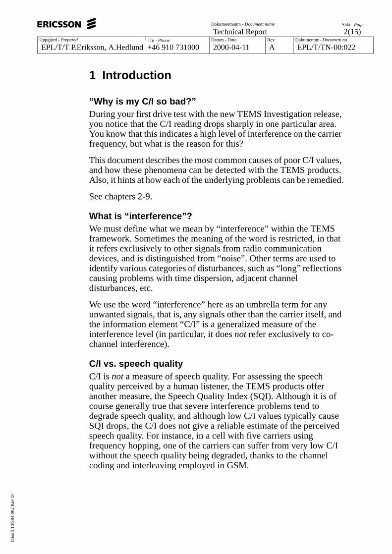
Figure 1. Detecting a C/A problem in TEMS Investigation.
In figure 1, showing the Frequency Scanner window in TEMS Investigation, the mobile is receiving on the channel with ARFCN 18 (highlighted). The adjacent channel with ARFCN 19 has a signal strength of –63 dBm, while the signal strength on the mobile’s owchannel is a mere –82 dBm. With this very high level of interferenthe mobile will not be able to filter out the desired signal well enouto meet the bit error rate requirements.
CountermeasuresThe measures taken to combat excessive adjacent channel interference are the same as those directed against co-channel interference (see page 3).
Eri
soft
10/
S94
:002
Rev
D
Uppgjord - Prepared Datum - Date Rev Dokumentnr - Document noTfn - Phone
Dokumentnamn - Document name Sida - Page
6(15)Technical Report
EPL/T/T P.Eriksson, A.Hedlund +46 910 731000 2000-04-11 A EPL/T/TN-00:022
y
on-
rom
by on
ould
bar
4 Blocking
Co-channel interference and adjacent channel interference both arise in the operator’s own network. However, an interfering signal maalso originate from other sources that are beyond his control – typically from a different operator.
If a mobile station comes very close to the antenna system of a ndesignated base station which is transmitting on some frequencyfairly close to the mobile’s, it may happen that the transmissions fthe base station completely overwhelm the mobile receiver. The typical situation where this is possible is when the base station antenna is positioned at ground level, and a mobile user passes the sidewalk.
As is the case with adjacent channel interference, the problem wnot exist if both transmitter and receiver filters had ideal characteristics. Unfortunately, this is not so.
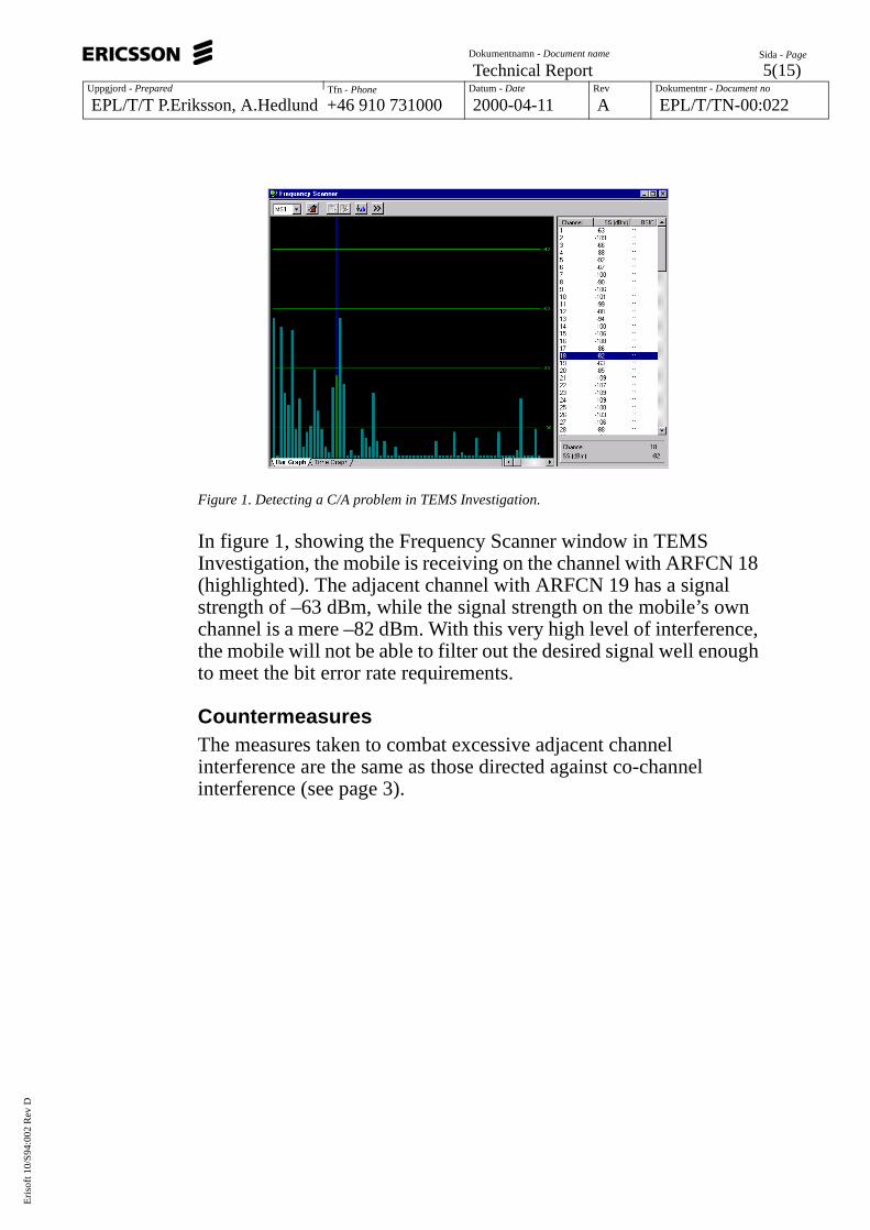
Using TEMSBlocking is conveniently detected using the Frequency Scanner chart.
Figure 2. A typical RF spectrum with a carrier causing receiver blocking.
Eri
soft
10/
S94
:002
Rev
D
Uppgjord - Prepared Datum - Date Rev Dokumentnr - Document noTfn - Phone
Dokumentnamn - Document name Sida - Page
7(15)Technical Report
EPL/T/T P.Eriksson, A.Hedlund +46 910 731000 2000-04-11 A EPL/T/TN-00:022
ven
ion
t all e
In figure 2, a very strong interferer is found at ARFCN 19. The signal strength reading is –31 dBm, but in this case the signal is actually estronger, since the scanner has reached the high end of its measurement range. This interferer will drown ordinary transmisson all channels at a distance of up to +/–15 ARFCNs.
Blocking might appear to be an extreme phenomenon, but it is nothat uncommon for instance in certain urban environments whercarriers of different operators interfere heavily with each other.
Eri
soft
10/
S94
:002
Rev
D
Uppgjord - Prepared Datum - Date Rev Dokumentnr - Document noTfn - Phone
Dokumentnamn - Document name Sida - Page
8(15)Technical Report
EPL/T/T P.Eriksson, A.Hedlund +46 910 731000 2000-04-11 A EPL/T/TN-00:022
d rated ls so
e-ise)
e to
o the th of ted in e
t the e t
tely
5 Noise (C/N)
As was said in chapter 2, the factor most commonly limiting network capacity is the level of co-channel interference. In sufficiently sparsely populated areas, however, this ceases to apply. Here, capacity is instead limited simply by the range of the transmitters (compare walkie-talkies). In other words, the limit is set not by the amount of interference from other nearby callers, but by assorted random disturbances that are always present – i.e. what is usually terme“noise”. This concept encompasses both the thermal noise genewithin the circuits of the mobile station, and external backgroundnoise from a plethora of sources, including other man-made signafaint that they merely add up to a quasi-random disturbance.
In environments where the interference can be described as noislike, the interference level is usually termed the C/N (carrier-to-noratio or SNR (signal-to-noise ratio) instead of C/I. The noise is typically a broadband signal with stochastic variation, comparablan AWGN (average white Gaussian noise) signal.
The level of the noise floor in a GSM mobile is determined by twparameters. The first is the thermal noise, which is dependent onnature of the GSM RF channel (the temperature and the bandwidthe signal). The second parameter is the amount of noise generathe mobile station’s hardware. The noise floor is obtained from thformula
. (1)
The part corresponds to the thermal noise and is approximately –122 dBm (k = Boltzmann’s constant, T = absolute temperature, and B = the 3 dB bandwidth of the RF channel).
The term represents the hardware noise. In order to meeBER requirement in the GSM 05.05 specification at the referencsensitivity level (–104 dBm, C/N 9 dB), the value of musnot exceed
. (2)
This means that the noise floor in a GSM mobile lies at approxima–113 dBm (i.e. –122 dBm + 9 dB according to eq. (1) above). However, in practice, a certain margin is required because of
Nreceiver 10 log kTB( ) NFreceiver+=
10 log kTB( )
NFreceiver
NFreceiver
NFreceiver max 104– 9– 122–( )– 9 dB= =
Eri
soft
10/
S94
:002
Rev
D
Uppgjord - Prepared Datum - Date Rev Dokumentnr - Document noTfn - Phone
Dokumentnamn - Document name Sida - Page
9(15)Technical Report
EPL/T/T P.Eriksson, A.Hedlund +46 910 731000 2000-04-11 A EPL/T/TN-00:022
.
low
ving the
nge
ied hat that If es
s to
temperature variation, aging of the RF components in the receiver, etc. This means that in actuality the noise floor will be 2-3 dB lower than –113 dBm (the exact value being manufacturer dependent)
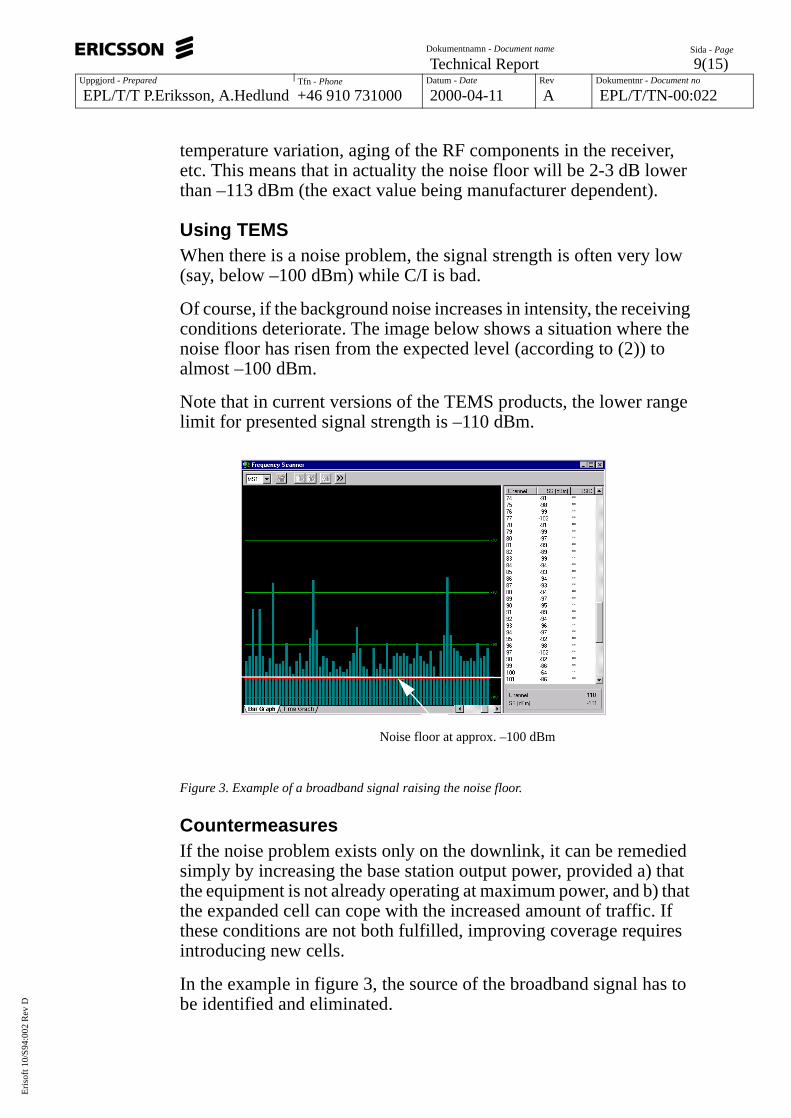
Using TEMSWhen there is a noise problem, the signal strength is often very (say, below –100 dBm) while C/I is bad.
Of course, if the background noise increases in intensity, the receiconditions deteriorate. The image below shows a situation wherenoise floor has risen from the expected level (according to (2)) toalmost –100 dBm.
Note that in current versions of the TEMS products, the lower ralimit for presented signal strength is –110 dBm.
Figure 3. Example of a broadband signal raising the noise floor.
CountermeasuresIf the noise problem exists only on the downlink, it can be remedsimply by increasing the base station output power, provided a) tthe equipment is not already operating at maximum power, and b)the expanded cell can cope with the increased amount of traffic. these conditions are not both fulfilled, improving coverage requirintroducing new cells.
In the example in figure 3, the source of the broadband signal habe identified and eliminated.
Noise floor at approx. –100 dBm
Eri
soft
10/
S94
:002
Rev
D
Uppgjord - Prepared Datum - Date Rev Dokumentnr - Document noTfn - Phone
Dokumentnamn - Document name Sida - Page
10(15)Technical Report
EPL/T/T P.Eriksson, A.Hedlund +46 910 731000 2000-04-11 A EPL/T/TN-00:022
6 Intermodulation products
Intermodulation (IM) products are unwanted disturbances that may arise when several signals with different frequencies are mixed. This mixing can occur in nonlinear components in both transmitters and receivers, and also in various metal objects encountered in the air interface (wire fences, railings, etc.). In the latter case, signals from different cellular systems may be mixed, and they might interfere with one another even if they belong to different frequency bands.
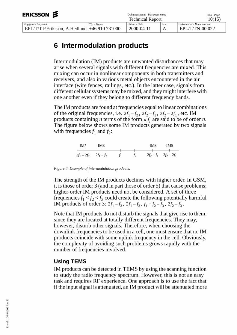
The IM products are found at frequencies equal to linear combinations of the original frequencies, i.e. , , , etc. IM products containing n terms of the form are said to be of order n. The figure below shows some IM products generated by two signals with frequencies f1 and f2:
Figure 4. Example of intermodulation products.
The strength of the IM products declines with higher order. In GSM, it is those of order 3 (and in part those of order 5) that cause problems; higher-order IM products need not be considered. A set of three frequencies f1 < f2 < f3 could create the following potentially harmful IM products of order 3: , , , .
Note that IM products do not disturb the signals that give rise to them, since they are located at totally different frequencies. They may, however, disturb other signals. Therefore, when choosing the downlink frequencies to be used in a cell, one must ensure that no IM products coincide with some uplink frequency in the cell. Obviously, the complexity of avoiding such problems grows rapidly with the number of frequencies involved.
Using TEMSIM products can be detected in TEMS by using the scanning function to study the radio frequency spectrum. However, this is not an easy task and requires RF experience. One approach is to use the fact that if the input signal is attenuated, an IM product will be attenuated more
2f1 f2– 2f2 f1– 3f2 2f1–aifi
f1 f2 2f2 – f12f1 – f2
IM5
3f2 – 2f13f1 – 2f2
IM3 IM3 IM5
2f1 f2– 2f1 f3– f1 f2 f3–+ 2f2 f3–
Eri
soft
10/
S94
:002
Rev
D
Uppgjord - Prepared Datum - Date Rev Dokumentnr - Document noTfn - Phone
Dokumentnamn - Document name Sida - Page
11(15)Technical Report
EPL/T/T P.Eriksson, A.Hedlund +46 910 731000 2000-04-11 A EPL/T/TN-00:022
than the corresponding carriers. For example, if the carriers generating IM3 products are attenuated 10 dB, the corresponding IM3 product will be attenuated 30 dB.
CountermeasuresFrequency planning: One simply has to make sure that unfortunate combinations of frequencies are not used.
Eri
soft
10/
S94
:002
Rev
D
Uppgjord - Prepared Datum - Date Rev Dokumentnr - Document noTfn - Phone
Dokumentnamn - Document name Sida - Page
12(15)Technical Report
EPL/T/T P.Eriksson, A.Hedlund +46 910 731000 2000-04-11 A EPL/T/TN-00:022
7 Time dispersion (C/R)
If the transmitted radio wave is reflected by large objects in the service area, the mobile station will receive multiple copies of the wave at slightly different times. The bit stream from the direct wave may arrive a number of bit times earlier than the identical reflected bits (intersymbol interference). This phenomenon is known as time dispersion.
Time dispersion complicates the task of the receiver. However, if the reflections are not too much delayed, it is possible, simply put, to separate the different copies of the signal from each other and improve the reconstruction of the transmitted signal by utilizing the information content in all the copies. In other words, the receiver can profit by the time dispersion phenomenon. It should be noted that, at least in urban areas, receiving the direct (line-of-sight) wave is actually fairly unusual, so that the receiver is dependent on picking up reflections.
The GSM specification requires that the system should be able to handle a time dispersion of up to 15 µs, corresponding to a path difference of 4.5 km. This means that it shall be possible to handle a set of signal copies arriving within a 15 µs window (including or not including the direct wave) as independent sources of information for the reconstruction of the original. For this to be possible, reflections delayed longer than 15 µs must be sufficiently weak. A GSM receiver must, according to the 05.05 specification, be able to handle a level of interference where the total power of all reflections delayed more than 15 µs is at least 9 dB weaker than the power of the signals within the 15 µs window. In other words, assuming no other interference, the C/R ratio must be at least 9 dB.
Typical causes of severe and thus problematic time dispersion are
• large buildings with reflecting surfaces (metal, glass)
• mountain ranges
• lakes with steeps or densely built-up shores
Eri
soft
10/
S94
:002
Rev
D
Uppgjord - Prepared Datum - Date Rev Dokumentnr - Document noTfn - Phone
Dokumentnamn - Document name Sida - Page
13(15)Technical Report
EPL/T/T P.Eriksson, A.Hedlund +46 910 731000 2000-04-11 A EPL/T/TN-00:022
Figure 5. Time dispersion.
Using TEMSToday, there is no way of measuring time dispersion in the TEMS products. This is one of the tasks that are under investigation for the future product portfolio.
CountermeasuresCell planning.
Antenna direction.
d2
d1
d3
d2 + d3 - d1 > 4.5 km => C/R risk!
Eri
soft
10/
S94
:002
Rev
D
Uppgjord - Prepared Datum - Date Rev Dokumentnr - Document noTfn - Phone
Dokumentnamn - Document name Sida - Page
14(15)Technical Report
EPL/T/T P.Eriksson, A.Hedlund +46 910 731000 2000-04-11 A EPL/T/TN-00:022
the its t
iate in
much ser
ce it
8 Receiver saturation
If the signal strength from the serving cell becomes very high (say, > –30 dBm), it can be seen that the C/I goes down. This is due tofact that the A/D converter in the mobile has reached the limit of dynamic range; it is said to be saturated. (It can also be remarked thathe mobile cannot measure higher signal strengths than approx. –30 dBm.)
As might be expected, receiver saturation is frequent in the immedvicinity of base stations with a high output power (typically found rural areas). The risk of encountering this problem in urban environments is smaller, since base stations in such places use alower power and are designed to allow mobiles to come much clowithout upsetting their operation.
CountermeasuresThere is in fact not much that can be done about this problem, sinis an unavoidable consequence of cellular system design.
Eri
soft
10/
S94
:002
Rev
D
Uppgjord - Prepared Datum - Date Rev Dokumentnr - Document noTfn - Phone
Dokumentnamn - Document name Sida - Page
15(15)Technical Report
EPL/T/T P.Eriksson, A.Hedlund +46 910 731000 2000-04-11 A EPL/T/TN-00:022
d of
e
ting the ng iddle this t
r r
o
9 Amplitude Modulation of LNA Operating Point
The GSM 05.05 specification states requirements on what is called “AM suppression”. These are necessary to neutralize a special kindisturbance which is caused by an intermittent interfering signal.
In a GSM receiver, there is an amplifier called the LNA (low noisamplifier), which is located after the antenna and the first RF bandpass filter. The LNA is designed to work at an optimal operapoint, which is adjusted continuously. There is, however, a limit tospeed at which the operating point can be adjusted. If a very strointerferer (even on an adjacent carrier) suddenly appears in the mof a burst from the serving cell, the control of the operating pointcannot keep up, so that the operating point temporarily becomessuboptimal (it is said to be amplitude modulated). Interference of kind usually originates from a different base station whose outpupower is subject to abrupt changes.
Unless it is kept in check, this sort of non-ideal amplifier behaviomay have the effect of degrading performance in terms of bit errorate. However, the requirements in GSM 05.05 are such that thecontrol of the operating point in GSM receivers is good enough teliminate this problem in practice.