26
Specification Controlling Service Point Level Smart Devices in a Distribution Network using IEC CIM
| Date post: | 02-Jun-2018 |
| Category: |
Documents |
| Upload: | tepen387139 |
| View: | 218 times |
| Download: | 0 times |
8/10/2019 CIM Iterface Specification V1.0
http://slidepdf.com/reader/full/cim-iterface-specification-v10 1/26
Specification
Controlling Service Point Level Smart Devices in a DistributionNetwork using IEC CIM
8/10/2019 CIM Iterface Specification V1.0
http://slidepdf.com/reader/full/cim-iterface-specification-v10 2/26
P a g e 1 | 25
DATE AUTHOR COMPANY CHANGES12.8.2014 Risto-Matti Keski-Keturi ABB Initial version
8/10/2019 CIM Iterface Specification V1.0
http://slidepdf.com/reader/full/cim-iterface-specification-v10 3/26
P a g e 2 | 25
Contents1. About this document 3
1.1. Background 3 1.2. References 3
2. Description of the system 4
2.1. Coverage 4
2.2. Technology 5
2.3. Security 5
3. CIM Data Types 7
3.1. Names in CIM 9
3.2. Controls and events 11 3.3. Values used for specific fields 13
3.3.1. EndDevice 13
3.3.2. EndDeviceControl 13
3.4. Standard types supported 14
3.5. Event details 15
3.6. Identifiers 16
3.7. Methods in the interface 18
4. Use cases and examples 19
4.1. Querying devices in an apartment 19
4.2. On/Off control of a fuse group 20
4.3. Subscribing to measurements and receiving updates 22
4.4. Querying stored readings 23
4.5. Receiving events 24
4.6. General reply 25
8/10/2019 CIM Iterface Specification V1.0
http://slidepdf.com/reader/full/cim-iterface-specification-v10 4/26
P a g e 3 | 25
1. ABOUT THIS DOCUMENT
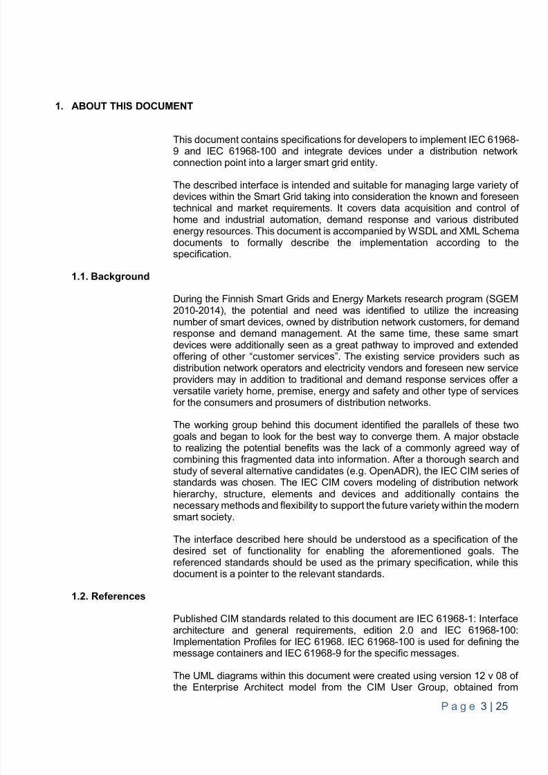
This document contains specifications for developers to implement IEC 61968-9 and IEC 61968-100 and integrate devices under a distribution networkconnection point into a larger smart grid entity.
The described interface is intended and suitable for managing large variety ofdevices within the Smart Grid taking into consideration the known and foreseentechnical and market requirements. It covers data acquisition and control ofhome and industrial automation, demand response and various distributedenergy resources. This document is accompanied by WSDL and XML Schemadocuments to formally describe the implementation according to thespecification.
1.1. Background
During the Finnish Smart Grids and Energy Markets research program (SGEM2010-2014), the potential and need was identified to utilize the increasingnumber of smart devices, owned by distribution network customers, for demandresponse and demand management. At the same time, these same smartdevices were additionally seen as a great pathway to improved and extendedoffering of other “customer services”. The existing service providers such asdistribution network operators and electricity vendors and foreseen new serviceproviders may in addition to traditional and demand response services offer aversatile variety home, premise, energy and safety and other type of services
for the consumers and prosumers of distribution networks.
The working group behind this document identified the parallels of these twogoals and began to look for the best way to converge them. A major obstacleto realizing the potential benefits was the lack of a commonly agreed way ofcombining this fragmented data into information. After a thorough search andstudy of several alternative candidates (e.g. OpenADR), the IEC CIM series ofstandards was chosen. The IEC CIM covers modeling of distribution networkhierarchy, structure, elements and devices and additionally contains thenecessary methods and flexibility to support the future variety within the modernsmart society.
The interface described here should be understood as a specification of thedesired set of functionality for enabling the aforementioned goals. Thereferenced standards should be used as the primary specification, while thisdocument is a pointer to the relevant standards.
1.2. References
Published CIM standards related to this document are IEC 61968-1: Interfacearchitecture and general requirements, edition 2.0 and IEC 61968-100:Implementation Profiles for IEC 61968. IEC 61968-100 is used for defining themessage containers and IEC 61968-9 for the specific messages.
The UML diagrams within this document were created using version 12 v 08 ofthe Enterprise Architect model from the CIM User Group, obtained from
8/10/2019 CIM Iterface Specification V1.0
http://slidepdf.com/reader/full/cim-iterface-specification-v10 5/26
P a g e 4 | 25
http://cimug.ucaiug.org . A draft version of this document was released internallywithin the working group in spring 2014 before the pilot case implementation. .
2. DESCRIPTION OF THE SYSTEM
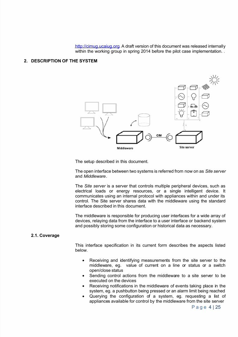
The setup described in this document.
The open interface between two systems is referred from now on as Site server
and Middleware .
The Site server is a server that controls multiple peripheral devices, such aselectrical loads or energy resources, or a single intelligent device. Itcommunicates using an internal protocol with appliances within and under itscontrol. The Site server shares data with the middleware using the standardinterface described in this document.
The middleware is responsible for producing user interfaces for a wide array ofdevices, relaying data from the interface to a user interface or backend systemand possibly storing some configuration or historical data as necessary.
2.1. Coverage
This interface specification in its current form describes the aspects listedbelow.
Receiving and identifying measurements from the site server to themiddleware, eg. value of current on a line or status or a switchopen/close status
Sending control actions from the middleware to a site server to beexecuted on the devices
Receiving notifications in the middleware of events taking place in thesystem, eg. a pushbutton being pressed or an alarm limit being reached
Querying the configuration of a system, eg. requesting a list ofappliances available for control by the middleware from the site server
8/10/2019 CIM Iterface Specification V1.0
http://slidepdf.com/reader/full/cim-iterface-specification-v10 6/26
P a g e 5 | 25
Functionality proposed but left out from this interface at this initial stage include:
Describing control groups, eg a list list of control actions identified by asingle control type. Instead, such groups should be defined only withinthe middleware and not propagated to the site server. In case afunctionality is to be mapped to a physical button or similar, the event ofpressing the button should be exported to the interface and anymapping to control actions should be maintained only in the middleware.
2.2. Technology
The interface described here will be implemented using XML and described asan XML schema. The outlying transmission technology will be SOAP overHTTP(S).
2.3. Security
The transmission link will use the HTTPS protocol for transmission. The securitypresumption is that the site server will have one communication partner that itcan reliably identify and will have full trust in. This can be achieved by setting asingle certificate as trusted and allowing all communication from a counterpartythat can produce this predefined certificate.
Implementations may alternatively contain methods of defining multiple certifi-cates and an access control list for parts of the system behind one server, eg.devices 1,2,3 can be controlled from a counterparty identified by certificate A
and devices 3 and 4 can be controlled by a counterparty identified by certificateB. This may be useful for example when an apartment building is controlled viaone shared server.
8/10/2019 CIM Iterface Specification V1.0
http://slidepdf.com/reader/full/cim-iterface-specification-v10 7/26
P a g e 6 | 25
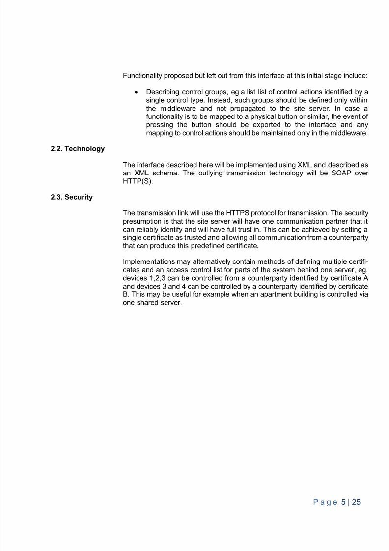
Figure 1 The security model
In this model, managing user credentials (e.g. password changes, additionalidentification methods etc.) does not have to be done on the site server, whichis meant to be usable with minimum maintenance load. On this server, only theallowable service providers are configured.
In an installation where the devices under a single server are owned by multiple
independent parties (e.g. in an apartment building), the procedure for a deviceowner to enable the interface would thus be
1. Make contract with a service provider
2. Deliver details of the certificate of the provider to the organizationresponsible for the site server
a. Organization responsible for site server will add mapping fromkey of the organization to the device in question in the certificatelist of the site server
3. Service provider will look up publicly available communication details ofthe site server
8/10/2019 CIM Iterface Specification V1.0
http://slidepdf.com/reader/full/cim-iterface-specification-v10 8/26
P a g e 7 | 25
3. CIM DATA TYPES
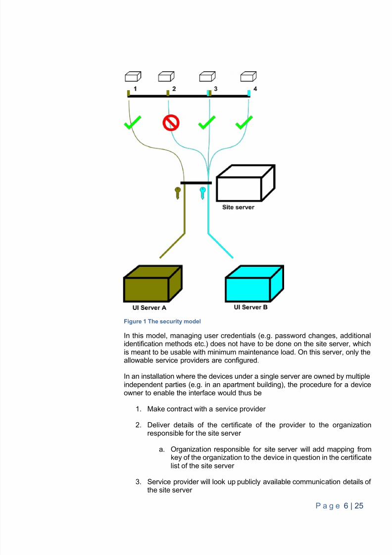
The basic concept of this interface is that there are multiple EndDevices in ahierarchy representing controllable loads. An EndDevice may be a real device,such as a car charge port, or a virtual device such as a controllable object in asite network.
This allows measurements, controls and descriptions to be allocated to theexact device they relate to. The devices available can be queried from theserver, with all the necessary metadata attached that will allow identification ofa specific controllable object.
Figure 2 Representing KNX feeders in an apartment as individual EndDevices
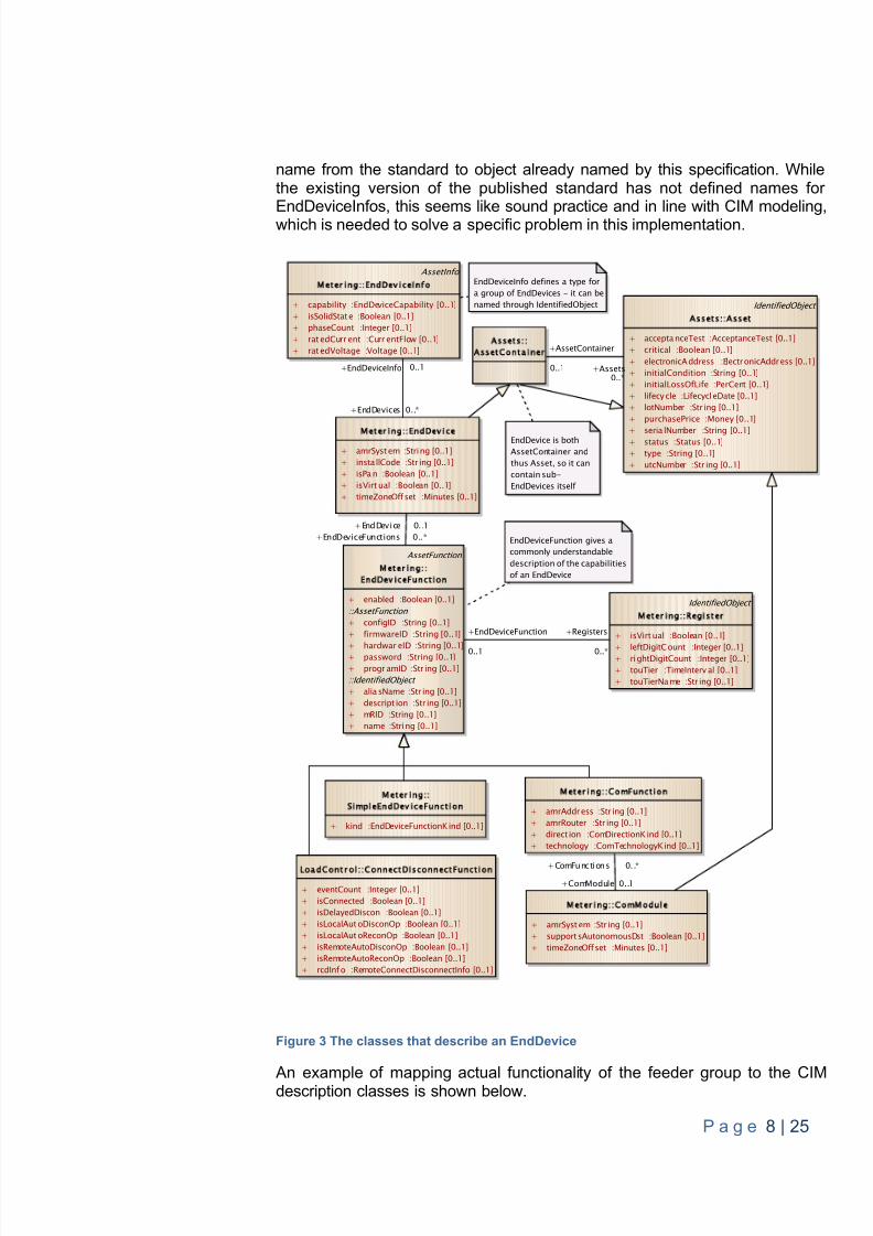
Figure 3 shows the classes that describe an EndDevice. While these includemany ways to describe the functionality of an EndDevice, ultimately sufficientis if both sides of the interface understand a combination of Name andNameType. The final version of IEC 61968-9 is expected to define names ofcommon types of at least EndDeviceEvents and EndDeviceControls, so in thisinterface the IdentifiedObject.name field is left empty to allow adding a primary
8/10/2019 CIM Iterface Specification V1.0
http://slidepdf.com/reader/full/cim-iterface-specification-v10 9/26
P a g e 8 | 25
name from the standard to object already named by this specification. Whilethe existing version of the published standard has not defined names forEndDeviceInfos, this seems like sound practice and in line with CIM modeling,which is needed to solve a specific problem in this implementation.
Figure 3 The classes that describe an EndDevice
An example of mapping actual functionality of the feeder group to the CIMdescription classes is shown below.
M e t e r i n g E n d D e v i c e
+ amrSyst em :String [0..1]+ insta llCode :Str ing [0..1]+ isPa n :Boolean [0..1]+ isVirt ual :Boolean [0..1]+ timeZoneOffset :Minutes [0..1]
AssetFunction
M e t e r i n gE n d D e v i c e F u n c t i o n
+ enabled :Boolean [0..1]::AssetFunction + configID :String [0..1]+ firmwareID :String [0..1]
+ hardwar eID :String [0..1]+ password :String [0..1]+ progr amID :Str ing [0..1]::IdentifiedObject + alia sName :Str ing [0..1]+ descript ion :Str ing [0..1]+ mRID :String [0..1]+ name :String [0..1]
M e t e r i n gS i m p l e E n d D e v i c e F u n c t i o n
+ kind :EndDeviceFunctionKind [0..1]
M e t e r i n g C o m F u n c t i o n
+ amrAddress :Str ing [0..1]+ amrRouter :Str ing [0..1]+ direct ion :ComDirectionK ind [0..1]+ technology :ComTechnologyKind [0..1]
M e t e r i n g C o m M o d u l e
+ amrSyst em :Str ing [0..1]+ support sAutonomousDst :Boolean [0..1]+ timeZoneOffset :Minutes [0..1]
IdentifiedObject
M e t e r i n g R e g i s t e r
+ isVirt ual :Boolean [0..1]
+ leftDigitCount :Integer [0..1]+ rightDigitCount :Integer [0..1]+ touTier :TimeInterv al [0..1]+ touTierNa me :Str ing [0..1]
L o a d C o n t r o l C o n n e c t Di s c o n n ec t F u n c t i o n
+ eventCount :Integer [0..1]+ isConnected :Boolean [0..1]+ isDelayedDiscon :Boolean [0..1]+ isLocalAut oDisconOp :Boolean [0..1]+ isLocalAut oReconOp :Boolean [0..1]+ isRemoteAutoDisconOp :Boolean [0..1]+ isRemoteAutoReconOp :Boolean [0..1]+ rcdInf o :RemoteConnectDisconnectInfo [0..1]
s s e t ss s e t C o n t a i n e r
IdentifiedObject
s s e t s s s e t
+ accepta nceTest :AcceptanceTest [0..1]+ critical :Boolean [0..1]+ electronicAddress :ElectronicAddress [0..1]+ initialCondition :String [0..1]+ initialLossOfLife :PerCent [0..1]+ lifecy cle :LifecycleDate [0..1]+ lotNumber :Str ing [0..1]+ purchasePrice :Money [0..1]
+ seria lNumber :String [0..1]+ status :Status [0..1]+ type :String [0..1]+ utcNumber :Str ing [0..1]
EndDevice is bothAssetContainer andthus Asset, so it cancontain sub-EndDevices itself
AssetInfo
M e t e r i n g E n d D e v i c e I n f o
+ capability :EndDeviceCapability [0..1]+ isSolidStat e :Boolean [0..1]+ phaseCount :Integer [0..1]+ rat edCurr ent :Curr entFlow [0..1]+ rat edVoltage :Voltage [0..1]
EndDeviceInfo defines a type fora group of EndDevices - it can benamed through IdentifiedObject
EndDeviceFunction gives acommonly understandabledescription of the capabilitiesof an EndDevice
+EndDevice 0. .1+EndDeviceFunctions 0..*
+ComModule 0..1
+ComFunctions 0. .*
+Registers
0..*
+EndDeviceFunction
0..1
+Assets0..*
+AssetContainer
0..1
+EndDevices 0..*
+EndDeviceInfo 0..1
8/10/2019 CIM Iterface Specification V1.0
http://slidepdf.com/reader/full/cim-iterface-specification-v10 10/26
P a g e 9 | 25
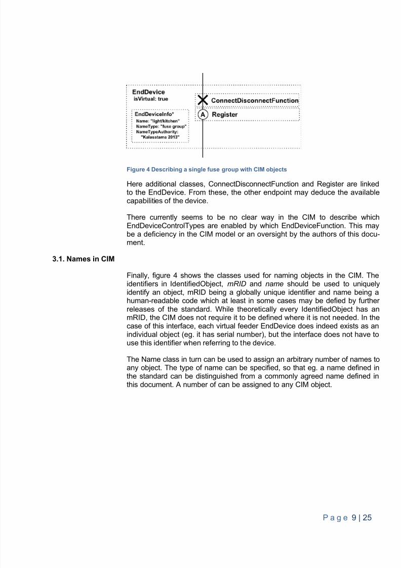
Figure 4 Describing a single fuse group with CIM objects
Here additional classes, ConnectDisconnectFunction and Register are linkedto the EndDevice. From these, the other endpoint may deduce the availablecapabilities of the device.
There currently seems to be no clear way in the CIM to describe whichEndDeviceControlTypes are enabled by which EndDeviceFunction. This maybe a deficiency in the CIM model or an oversight by the authors of this docu-ment.
3.1. Names in CIM
Finally, figure 4 shows the classes used for naming objects in the CIM. Theidentifiers in IdentifiedObject, mRID and name should be used to uniquelyidentify an object, mRID being a globally unique identifier and name being ahuman-readable code which at least in some cases may be defied by furtherreleases of the standard. While theoretically every IdentifiedObject has anmRID, the CIM does not require it to be defined where it is not needed. In thecase of this interface, each virtual feeder EndDevice does indeed exists as anindividual object (eg. it has serial number), but the interface does not have touse this identifier when referring to the device.
The Name class in turn can be used to assign an arbitrary number of names toany object. The type of name can be specified, so that eg. a name defined inthe standard can be distinguished from a commonly agreed name defined inthis document. A number of can be assigned to any CIM object.
8/10/2019 CIM Iterface Specification V1.0
http://slidepdf.com/reader/full/cim-iterface-specification-v10 11/26
P a g e 10 | 25
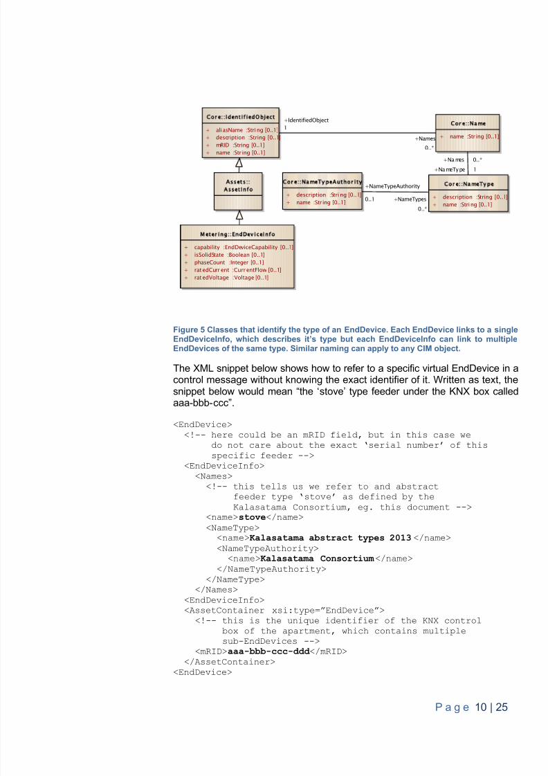
Figure 5 Classes that identify the type of an EndDevice. Each EndDevice links to a singleEndDeviceInfo, which describes it’s type but each EndDeviceInfo can link to multipleEndDevices of the same type. Similar naming can apply to any CIM object.
The XML snippet below shows how to refer to a specific virtual EndDevice in acontrol message without knowing the exact identifier of it. Written as text, thesnippet below would mean “the ‘ stov e’ type feeder under the KNX box called
aaa-bbb- ccc”. <EndDevice>
<!-- here could be an mRID field, but in this case wedo not care about the exact ‘serial number’ of this specific feeder -->
<EndDeviceInfo><Names>
<!-- this tells us we refer to and abstractfeeder type ‘ stov e’ as defined by theKalasatama Consortium, eg. this document -->
<name> stove </name><NameType>
<name> Kalasatama abstract types 2013 </name><NameTypeAuthority><name> Kalasatama Consortium </name>
</NameTypeAuthority></NameType>
</Names><EndDeviceInfo><AssetContainer xsi:type=”EndDevice”>
<!-- this is the unique identifier of the KNX controlbox of the apartment, which contains multiplesub-EndDevices -->
<mRID> aaa-bbb-ccc-ddd </mRID></AssetContainer>
<EndDevice>
Meter ing EndDeviceInfo
+ capability :EndDeviceCapability [0..1]+ isSolidState :Boolean [0..1]+ phaseCount :Integer [0..1]
+ rat edCurr ent :Curr entFlow [0..1]+ rat edVoltage :Voltage [0..1]
sse ts
sset Info
Core Ident i f iedObject
+ aliasName :Stri ng [0..1]+ description :String [0..1]+ mRID :String [0..1]+ name :Str ing [0..1]
Core Name
+ name :Str ing [0..1]
Core NameType
+ description :String [0..1]+ name :Stri ng [0..1]
Core NameType uthor i ty
+ description :Stri ng [0..1]+ name :Str ing [0..1]
+Names
0..*
+IdentifiedObject1
+Na mes 0..*
+Na meTy pe 1
+NameTypes
0..*
+NameTypeAuthority
0..1
8/10/2019 CIM Iterface Specification V1.0
http://slidepdf.com/reader/full/cim-iterface-specification-v10 12/26
P a g e 11 | 25
3.2. Controls and events
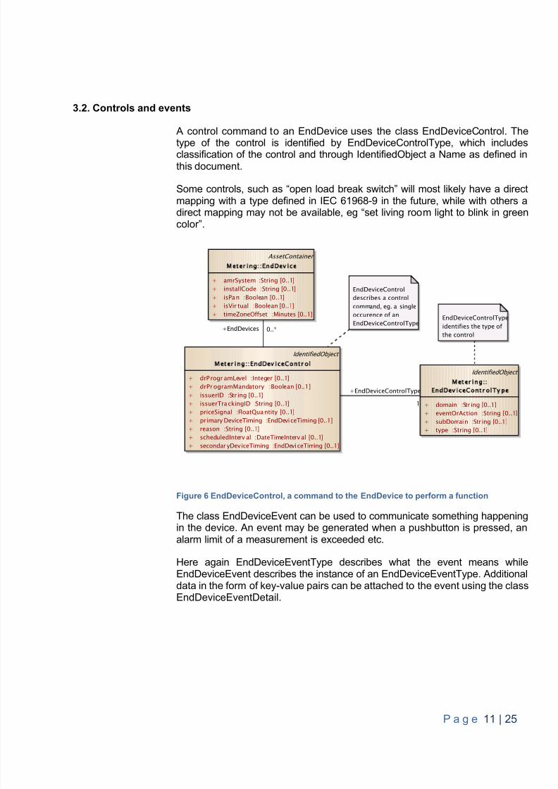
A control command to an EndDevice uses the class EndDeviceControl. Thetype of the control is identified by EndDeviceControlType, which includesclassification of the control and through IdentifiedObject a Name as defined inthis document.
Some controls, such as “open load break switch” will most likely have a directmapping with a type defined in IEC 61968-9 in the future, while with others adirect mapping may not be available, eg “set living roo m light to blink in greencolor”.
Figure 6 EndDeviceControl, a command to the EndDevice to perform a function
The class EndDeviceEvent can be used to communicate something happeningin the device. An event may be generated when a pushbutton is pressed, analarm limit of a measurement is exceeded etc.
Here again EndDeviceEventType describes what the event means whileEndDeviceEvent describes the instance of an EndDeviceEventType. Additionaldata in the form of key-value pairs can be attached to the event using the classEndDeviceEventDetail.
IdentifiedObject
Metering EndDevice ontrol
+ drP rogr amLevel :Integer [0..1]+ drPr ogramMandatory :Boolean [0..1]+ issuerID :Str ing [0..1]+ issuerTra ckingID :String [0..1]
+ priceSignal :FloatQuantity [0..1]+ pr imary DeviceTiming :EndDeviceTiming [0..1]+ reason :String [0..1]+ scheduledInterv al :DateTimeInterv al [0..1]+ secondar yDeviceTiming :EndDeviceTiming [0..1]
IdentifiedObject
Meter ingEndDevice ontrolType
+ domain :Str ing [0..1]
+ eventOrAction :String [0..1]+ subDomain :Str ing [0..1]+ type :String [0..1]
AssetContainer
Metering EndDevice
+ amrSystem :String [0..1]+ installCode :String [0..1]+ isPan :Boolean [0..1]+ isVir tual :Boolean [0..1]+ timeZoneOffset :Minutes [0..1] EndDeviceControlType
identifies the type ofthe control
EndDeviceControldescribes a controlcommand, eg. a singleoccurence of anEndDeviceControlType
+EndDeviceControlType
1
+EndDevices 0..*
8/10/2019 CIM Iterface Specification V1.0
http://slidepdf.com/reader/full/cim-iterface-specification-v10 13/26
P a g e 12 | 25
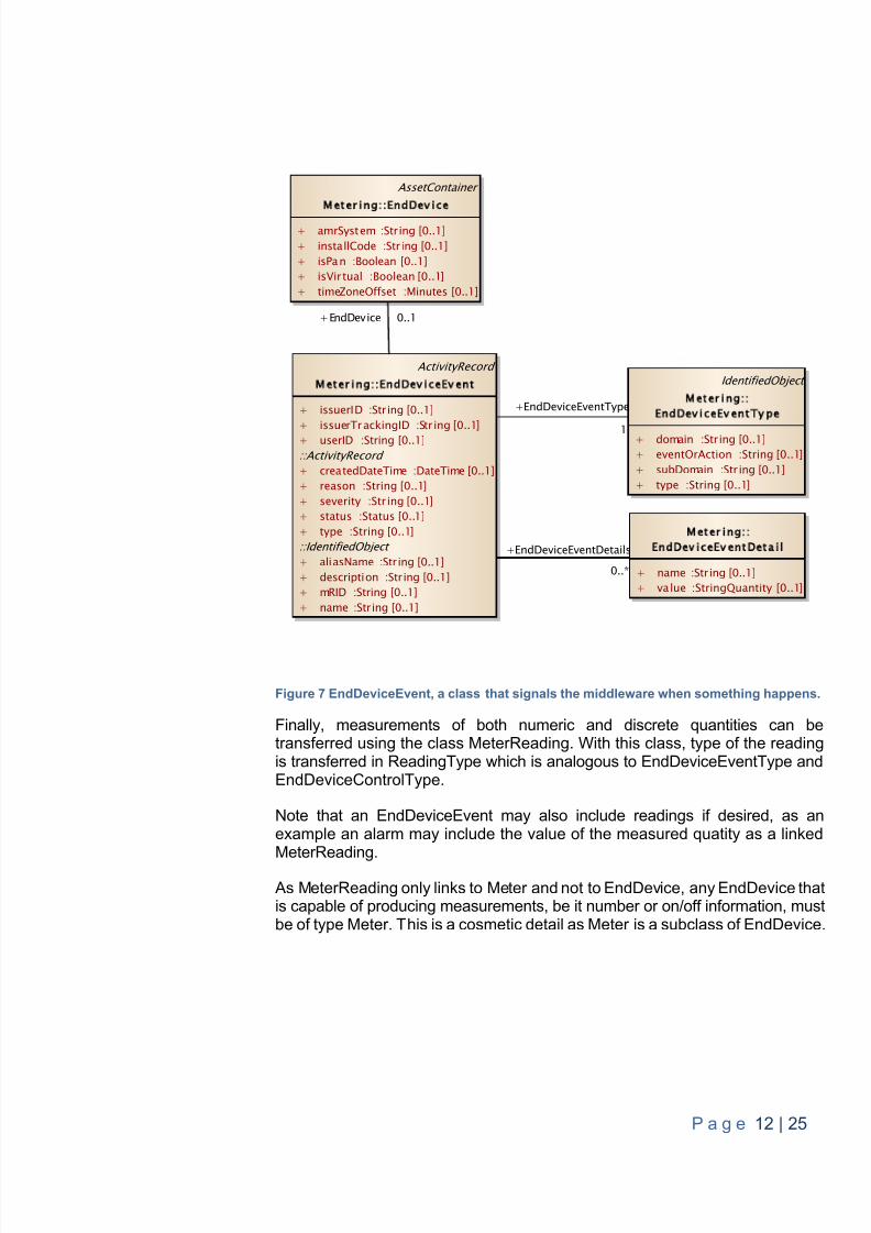
Figure 7 EndDeviceEvent, a class that signals the middleware when something happens.
Finally, measurements of both numeric and discrete quantities can betransferred using the class MeterReading. With this class, type of the readingis transferred in ReadingType which is analogous to EndDeviceEventType andEndDeviceControlType.
Note that an EndDeviceEvent may also include readings if desired, as anexample an alarm may include the value of the measured quatity as a linked
MeterReading. As MeterReading only links to Meter and not to EndDevice, any EndDevice thatis capable of producing measurements, be it number or on/off information, mustbe of type Meter. This is a cosmetic detail as Meter is a subclass of EndDevice.
AssetContainer
M e t e r i n g E n d e v i c e
+ amrSystem :String [0..1]+ installCode :String [0..1]+ isPan :Boolean [0..1]+ isVir tual :Boolean [0..1]+ timeZoneOffset :Minutes [0..1]
ActivityRecord
M e t e r i n g E n d e v i c e E v e n t
+ issuerID :String [0..1]
+ issuerTrackingID :Str ing [0..1]+ userID :String [0..1]::ActivityRecord + createdDateTime :DateTime [0..1]+ reason :String [0..1]+ severity :Str ing [0..1]+ status :Status [0..1]+ type :String [0..1]::IdentifiedObject + aliasName :String [0..1]+ description :String [0..1]+ mRID :String [0..1]+ name :String [0..1]
IdentifiedObject
M e t e r i n gE n d e v i c e E v e n t Ty p e
+ domain :String [0..1]+ eventOrAction :String [0..1]+ subDomain :Str ing [0..1]+ type :String [0..1]
M e t e r i n gE n d e v i c e E v e n t e t a i l
+ name :String [0..1]+ value :StringQuantity [0..1]
+EndDevice 0..1
+EndDeviceEventType
1
+EndDeviceEventDetails
0..*
8/10/2019 CIM Iterface Specification V1.0
http://slidepdf.com/reader/full/cim-iterface-specification-v10 14/26
P a g e 13 | 25
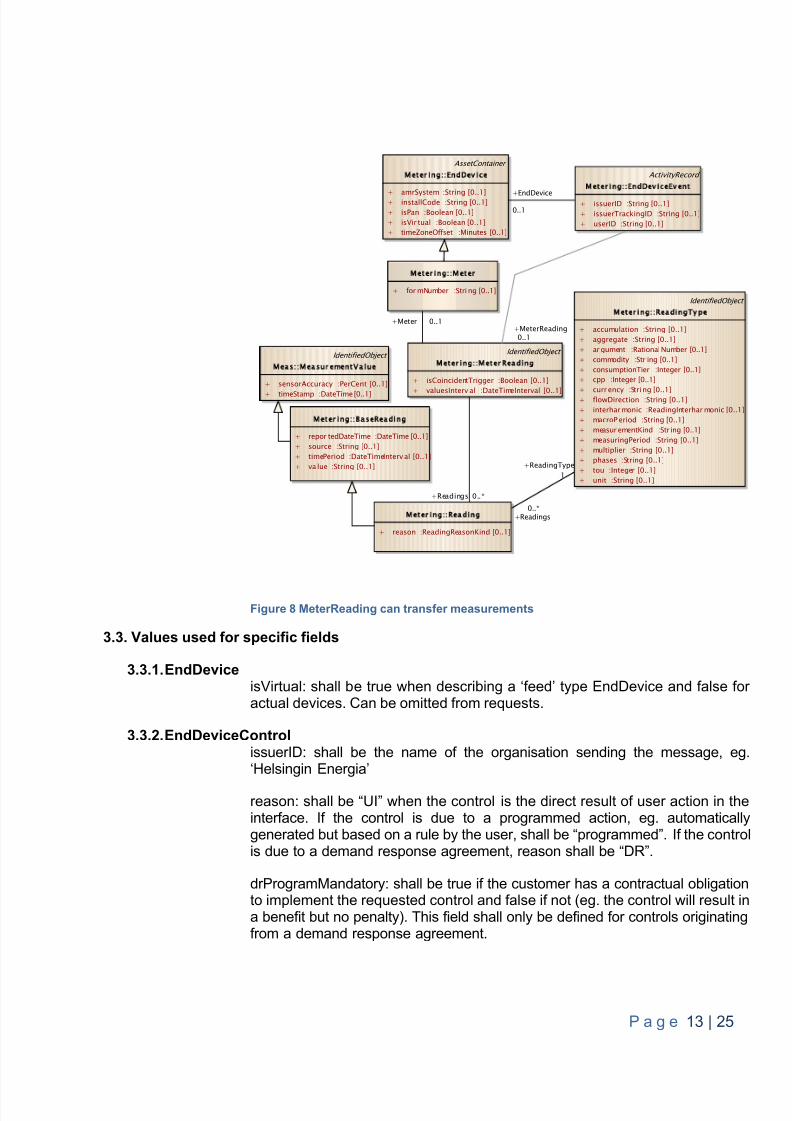
Figure 8 MeterReading can transfer measurements
3.3. Values used for specific fields
3.3.1. EndDeviceisVirtual: shall b e true when describing a ‘feed’ type EndDevice and false foractual devices. Can be omitted from requests.
3.3.2. EndDeviceControlissuerID: shall be the name of the organisation sending the message, eg.‘Helsingin Energia’
reason: shall be “UI” when the control is the direct result of user action in theinterface. If the control is due to a programmed action, eg. automaticallygenerated but based on a rule by the user, shall be “programmed”. If the controlis due to a demand response agreement, reason shall be “DR”.
drProgramMandatory: shall be true if the customer has a contractual obligationto implement the requested control and false if not (eg. the control will result ina benefit but no penalty). This field shall only be defined for controls originatingfrom a demand response agreement.
M e t e r i n g a s e R e a d i n g
+ repor tedDateTime :DateTime [0..1]+ source :String [0..1]+ timePeriod :DateTimeInterv al [0..1]+ va lue :String [0..1]
ActivityRecord
M e t e r i n g E n d D e v i c e E v e n t
+ issuerID :String [0..1]+ issuerTrackingID :String [0..1]+ userID :String [0..1]
M e t e r i n g R e a d i n g
+ reason :ReadingReasonKind [0..1]
AssetContainer
M e t e r i n g E n d D e v i c e
+ amrSystem :String [0..1]+ installCode :String [0..1]+ isPan :Boolean [0..1]+ isVir tual :Boolean [0..1]+ timeZoneOffset :Minutes [0..1]
IdentifiedObject
M e t e r i n g R e a d i n g Ty p e
+ accumulation :String [0..1]+ aggregate :String [0..1]+ ar gument :RationalNumber [0..1]+ commodity :Str ing [0..1]+ consumptionTier :Integer [0..1]+ cpp :Integer [0..1]
+ curr ency :Stri ng [0..1]+ flowDirection :String [0..1]+ interhar monic :ReadingInterhar monic [0..1]+ macroP eriod :String [0..1]+ measur ementKind :Str ing [0..1]+ measuringPeriod :String [0..1]+ multiplier :String [0..1]+ phases :String [0..1]+ tou :Integer [0..1]+ unit :String [0..1]
IdentifiedObject
M e t e r i n g M e t e r R e a d i n g
+ isCoincidentTrigger :Boolean [0..1]
+ valuesInterv al :DateTimeInterval [0..1]
M e t e r i n g M e t e r
+ for mNumber :Stri ng [0..1]
IdentifiedObject
M e a s M e a s u r e m e n t Va l u e
+ sensorAccuracy :PerCent [0..1]+ timeStamp :DateTime [0..1]
+EndDevice
0..1
+Readings0..*
+ReadingType1
+Readings 0..*
+MeterReading0..1
+Meter 0..1
8/10/2019 CIM Iterface Specification V1.0
http://slidepdf.com/reader/full/cim-iterface-specification-v10 15/26
P a g e 14 | 25
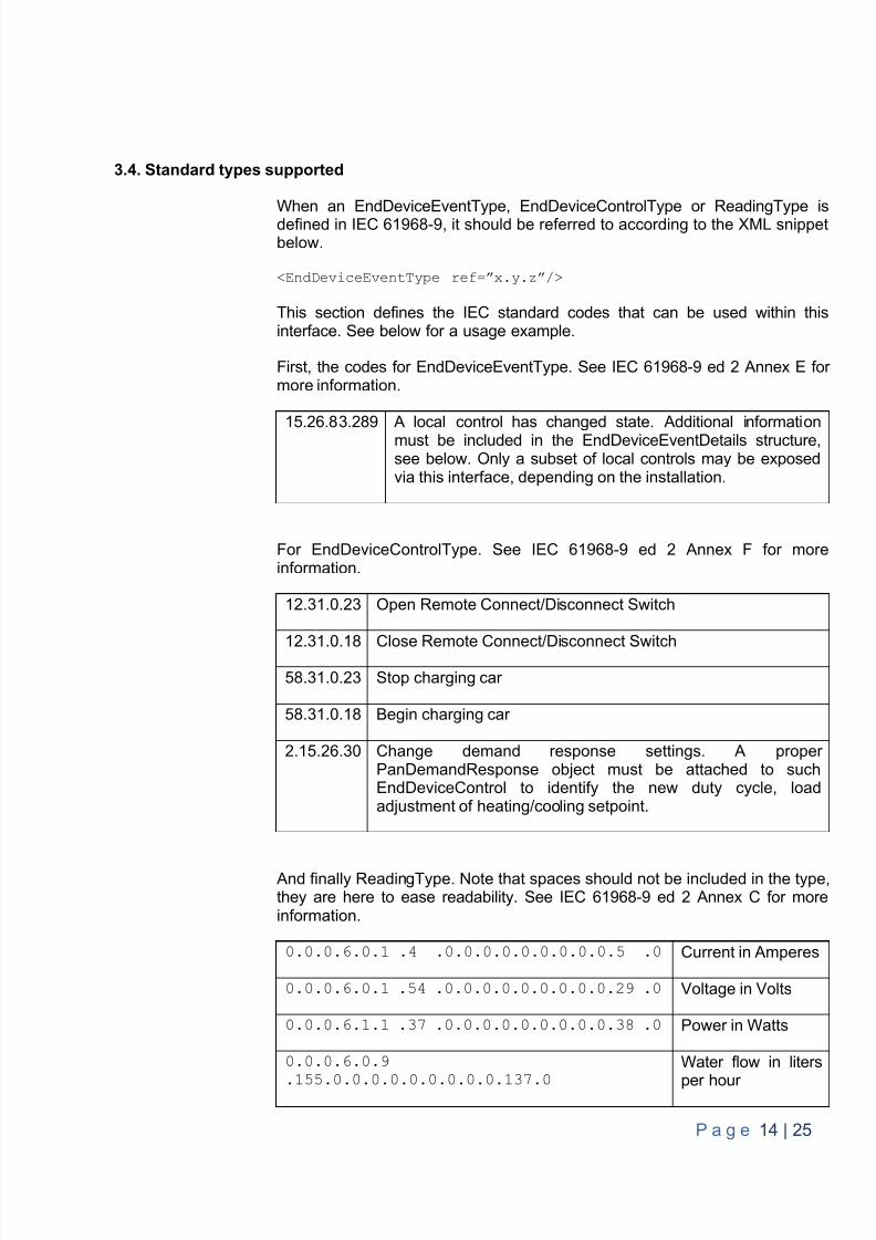
3.4. Standard types supported
When an EndDeviceEventType, EndDeviceControlType or ReadingType isdefined in IEC 61968-9, it should be referred to according to the XML snippetbelow.
<EndDeviceEventType ref=”x.y.z”/>
This section defines the IEC standard codes that can be used within thisinterface. See below for a usage example.
First, the codes for EndDeviceEventType. See IEC 61968-9 ed 2 Annex E formore information.
15.26.83.289 A local control has changed state. Additional informationmust be included in the EndDeviceEventDetails structure,see below. Only a subset of local controls may be exposedvia this interface, depending on the installation.
For EndDeviceControlType. See IEC 61968-9 ed 2 Annex F for moreinformation.
12.31.0.23 Open Remote Connect/Disconnect Switch
12.31.0.18 Close Remote Connect/Disconnect Switch58.31.0.23 Stop charging car
58.31.0.18 Begin charging car
2.15.26.30 Change demand response settings. A properPanDemandResponse object must be attached to suchEndDeviceControl to identify the new duty cycle, loadadjustment of heating/cooling setpoint.
And finally ReadingType. Note that spaces should not be included in the type,they are here to ease readability. See IEC 61968-9 ed 2 Annex C for moreinformation.
0.0.0.6.0.1 .4 .0.0.0.0.0.0.0.0.0.5 .0 Current in Amperes
0.0.0.6.0.1 .54 .0.0.0.0.0.0.0.0.0.29 .0 Voltage in Volts
0.0.0.6.1.1 .37 .0.0.0.0.0.0.0.0.0.38 .0 Power in Watts
0.0.0.6.0.9
.155.0.0.0.0.0.0.0.0.0.137.0
Water flow in liters
per hour
8/10/2019 CIM Iterface Specification V1.0
http://slidepdf.com/reader/full/cim-iterface-specification-v10 16/26
P a g e 15 | 25
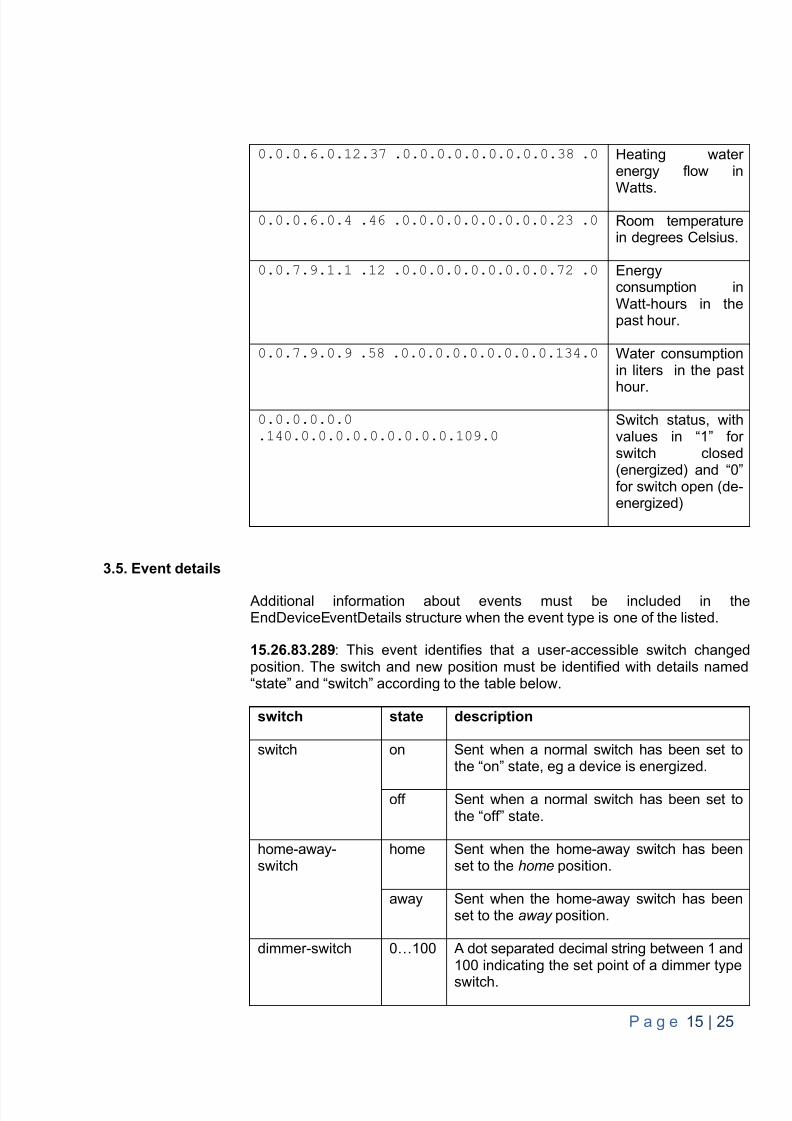
0.0.0.6.0.12.37 .0.0.0.0.0.0.0.0.0.38 .0 Heating waterenergy flow in
Watts.0.0.0.6.0.4 .46 .0.0.0.0.0.0.0.0.0.23 .0 Room temperature
in degrees Celsius.
0.0.7.9.1.1 .12 .0.0.0.0.0.0.0.0.0.72 .0 Energyconsumption inWatt-hours in thepast hour.
0.0.7.9.0.9 .58 .0.0.0.0.0.0.0.0.0.134.0 Water consumptionin liters in the past
hour.
0.0.0.0.0.0.140.0.0.0.0.0.0.0.0.0.109.0
Switch status, withvalues in “1” forswitch closed(energized) and “0”for switch open (de-energized)
3.5. Event details
Additional information about events must be included in theEndDeviceEventDetails structure when the event type is one of the listed.
15.26.83.289 : This event identifies that a user-accessible switch changedposition. The switch and new position must be identified with details named“state” and “switch” according to the table below.
switch state description
switch on Sent when a normal switch has been set tothe “on” state, eg a device is energized.
off Sent when a normal switch has been set tothe “off” state.
home-away-switch
home Sent when the home-away switch has beenset to the home position.
away Sent when the home-away switch has beenset to the away position.
dimmer-switch 0…100 A dot separated decimal string between 1 and100 indicating the set point of a dimmer typeswitch.
8/10/2019 CIM Iterface Specification V1.0
http://slidepdf.com/reader/full/cim-iterface-specification-v10 17/26
P a g e 16 | 25
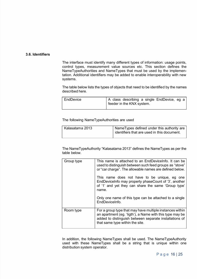
3.6. Identifiers
The interface must identify many different types of information: usage points,control types, measurement value sources etc. This section defines theNameTypeAuthorities and NameTypes that must be used by the implemen-tation. Additional identifiers may be added to enable interoperability with newsystems.
The table below lists the types of objects that need to be identified by the namesdescribed here.
EndDevice A class describing a single EndDevice, eg afeeder in the KNX system.
The following NameTypeAuthorities are used
Kalasatama 2013 NameTypes defined under this authority areidentifiers that are used in this document.
The NameTypeAuthority “Kalasatama 2013” defines the NameTypes as per thetable below.
Group type This name is attached to an EndDeviceInfo. It can beused to distinguish between such feed groups as “stove”or “car charge” . The allowable names are defined below.
This name does not have to be unique, eg oneEndDeviceInfo may property phaseCount of ‘3’, anotherof ‘1’ and yet they can share the same ‘Group type’name.
Only one name of this type can be attached to a singleEndDeviceInfo.
Room type For a group type that may have multiple instances withinan apartment (eg. ‘ligth’), a Name with this type may beadded to distinguish between separate installations ofthat same type within the site.
In addition, the following NameTypes shall be used. The NameTypeAuthority
used with these NameTypes shall be a string that is unique within onedistribution system operator.
8/10/2019 CIM Iterface Specification V1.0
http://slidepdf.com/reader/full/cim-iterface-specification-v10 18/26
P a g e 17 | 25
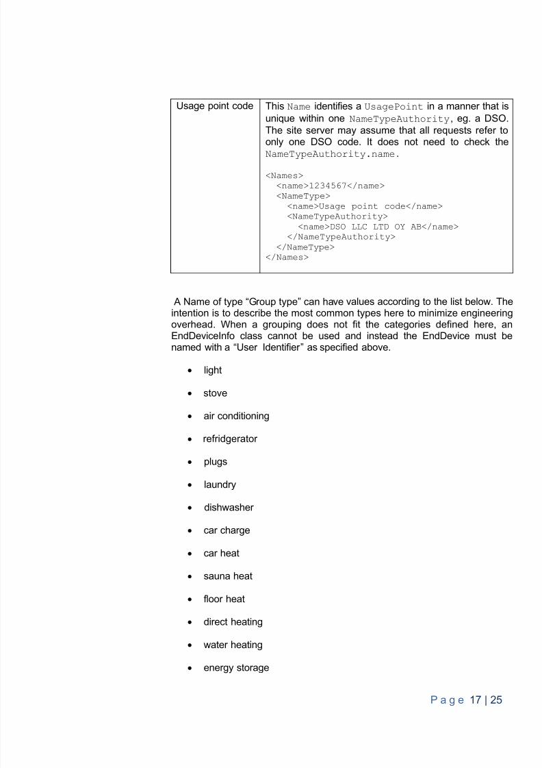
Usage point code This Name identifies a UsagePoint in a manner that isunique within one NameTypeAuthority , eg. a DSO.
The site server may assume that all requests refer toonly one DSO code. It does not need to check theNameTypeAuthority.name .
<Names><name>1234567</name><NameType>
<name>Usage point code</name><NameTypeAuthority>
<name>DSO LLC LTD OY AB</name></NameTypeAuthority>
</NameType></Names>
A Name of type “Group type” can have values according to the list below. Theintention is to describe the most common types here to minimize engineeringoverhead. When a grouping does not fit the categories defined here, anEndDeviceInfo class cannot be used and instead the EndDevice must benamed with a “User Identifier” as specified above.
light
stove
air conditioning
refridgerator
plugs
laundry
dishwasher
car charge
car heat
sauna heat
floor heat
direct heating
water heating
energy storage
8/10/2019 CIM Iterface Specification V1.0
http://slidepdf.com/reader/full/cim-iterface-specification-v10 19/26
P a g e 18 | 25
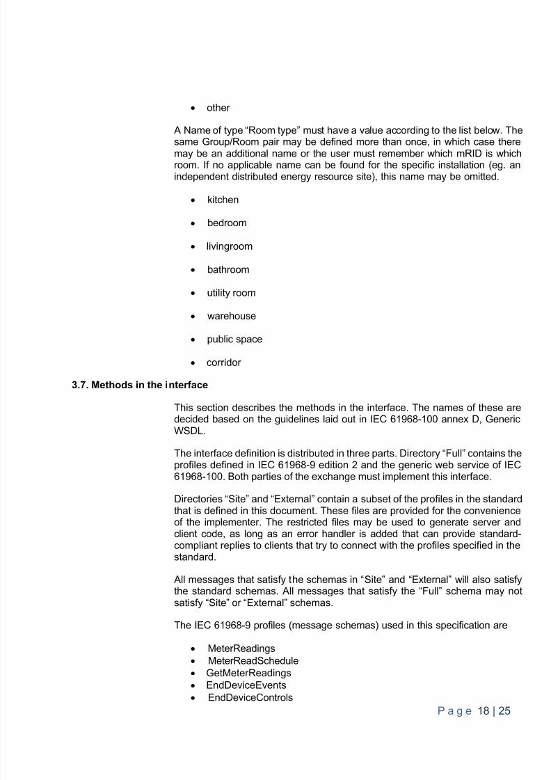
other
A Name of type “Room type” must have a value according to the list below. Thesame Group/Room pair may be defined more than once, in which case theremay be an additional name or the user must remember which mRID is whichroom. If no applicable name can be found for the specific installation (eg. anindependent distributed energy resource site), this name may be omitted.
kitchen
bedroom
livingroom
bathroom
utility room
warehouse
public space
corridor
3.7. Methods in the interface
This section describes the methods in the interface. The names of these aredecided based on the guidelines laid out in IEC 61968-100 annex D, GenericWSDL.
The inter face definition is distributed in three parts. Directory “Full” contains theprofiles defined in IEC 61968-9 edition 2 and the generic web service of IEC61968-100. Both parties of the exchange must implement this interface.
Directories “ Site ” and “External” contain a subset of the profiles in the standardthat is defined in this document. These files are provided for the convenienceof the implementer. The restricted files may be used to generate server andclient code, as long as an error handler is added that can provide standard-compliant replies to clients that try to connect with the profiles specified in thestandard.
All messages that satisfy the schemas in “ Site ” and “External” will also satisfythe standard schemas. All messages that satisfy the “Full” schema may notsatisfy “ Site ” or “External” schemas.
The IEC 61968-9 profiles (message schemas) used in this specification are
MeterReadings MeterReadSchedule GetMeterReadings EndDeviceEvents EndDeviceControls
8/10/2019 CIM Iterface Specification V1.0
http://slidepdf.com/reader/full/cim-iterface-specification-v10 20/26
P a g e 19 | 25
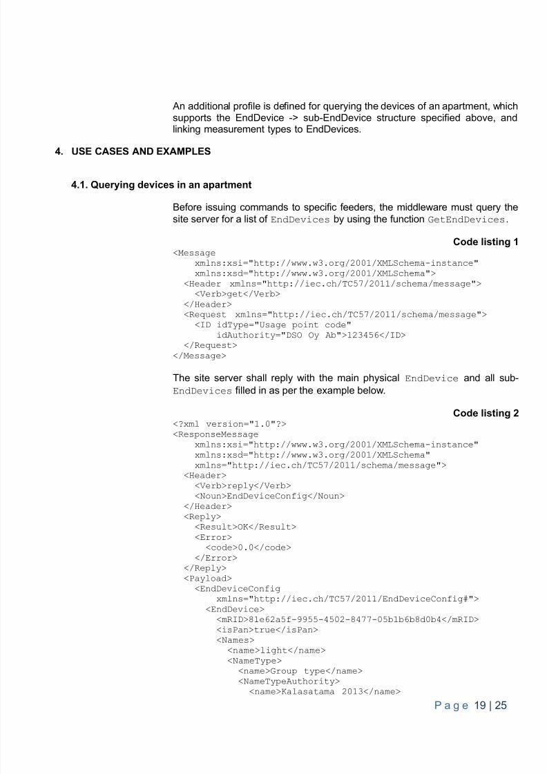
An additional profile is defined for querying the devices of an apartment, whichsupports the EndDevice -> sub-EndDevice structure specified above, andlinking measurement types to EndDevices.
4. USE CASES AND EXAMPLES
4.1. Querying devices in an apartment
Before issuing commands to specific feeders, the middleware must query thesite server for a list of EndDevices by using the function GetEndDevices .
Code listing 1<Message
xmlns:xsi="http://www.w3.org/2001/XMLSchema-instance"xmlns:xsd="http://www.w3.org/2001/XMLSchema">
<Header xmlns="http://iec.ch/TC57/2011/schema/message"><Verb>get</Verb>
</Header><Request xmlns="http://iec.ch/TC57/2011/schema/message">
<ID idType="Usage point code"idAuthority="DSO Oy Ab">123456</ID>
</Request></Message>
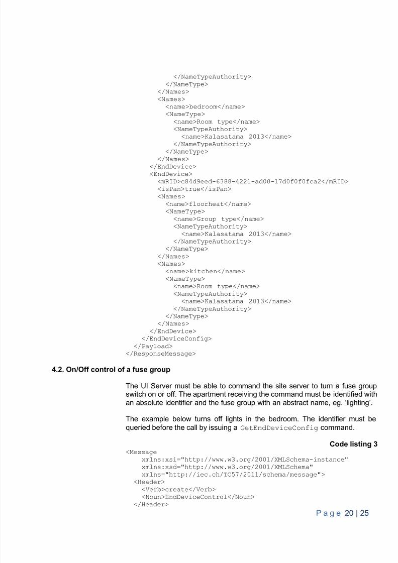
The site server shall reply with the main physical EndDevice and all sub-EndDevices filled in as per the example below.
Code listing 2<?xml version="1.0"?><ResponseMessage
xmlns:xsi="http://www.w3.org/2001/XMLSchema-instance"xmlns:xsd="http://www.w3.org/2001/XMLSchema"xmlns="http://iec.ch/TC57/2011/schema/message">
<Header><Verb>reply</Verb><Noun>EndDeviceConfig</Noun>
</Header><Reply>
<Result>OK</Result>
<Error><code>0.0</code></Error>
</Reply><Payload>
<EndDeviceConfigxmlns="http://iec.ch/TC57/2011/EndDeviceConfig#">
<EndDevice><mRID>81e62a5f-9955-4502-8477-05b1b6b8d0b4</mRID><isPan>true</isPan><Names>
<name>light</name><NameType>
<name>Group type</name><NameTypeAuthority><name>Kalasatama 2013</name>
8/10/2019 CIM Iterface Specification V1.0
http://slidepdf.com/reader/full/cim-iterface-specification-v10 21/26
P a g e 20 | 25
</NameTypeAuthority></NameType>
</Names><Names>
<name>bedroom</name><NameType>
<name>Room type</name><NameTypeAuthority>
<name>Kalasatama 2013</name></NameTypeAuthority>
</NameType></Names>
</EndDevice><EndDevice>
<mRID>c84d9eed-6388-4221-ad00-17d0f0f0fca2</mRID><isPan>true</isPan>
<Names><name>floorheat</name><NameType>
<name>Group type</name><NameTypeAuthority>
<name>Kalasatama 2013</name></NameTypeAuthority>
</NameType></Names><Names>
<name>kitchen</name><NameType>
<name>Room type</name>
<NameTypeAuthority><name>Kalasatama 2013</name>
</NameTypeAuthority></NameType>
</Names></EndDevice>
</EndDeviceConfig></Payload>
</ResponseMessage>
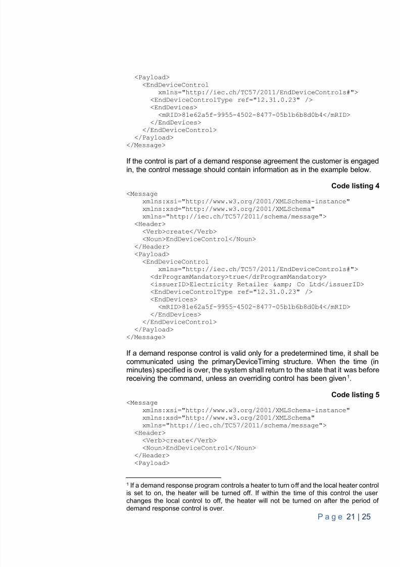
4.2. On/Off control of a fuse group
The UI Server must be able to command the site server to turn a fuse groupswitch on or off. The apartment receiving the command must be identified withan absolute identifier and the fuse group with an abstract name, eg. ‘lighting’.
The example below turns off lights in the bedroom. The identifier must bequeried before the call by issuing a GetEndDeviceConfig command.
Code listing 3<Message
xmlns:xsi="http://www.w3.org/2001/XMLSchema-instance"xmlns:xsd="http://www.w3.org/2001/XMLSchema"xmlns="http://iec.ch/TC57/2011/schema/message">
<Header>
<Verb>create</Verb><Noun>EndDeviceControl</Noun></Header>
8/10/2019 CIM Iterface Specification V1.0
http://slidepdf.com/reader/full/cim-iterface-specification-v10 22/26
P a g e 21 | 25
<Payload><EndDeviceControl
xmlns="http://iec.ch/TC57/2011/EndDeviceControls#"><EndDeviceControlType ref="12.31.0.23" /><EndDevices>
<mRID>81e62a5f-9955-4502-8477-05b1b6b8d0b4</mRID></EndDevices>
</EndDeviceControl></Payload>
</Message>
If the control is part of a demand response agreement the customer is engagedin, the control message should contain information as in the example below.
Code listing 4<Message
xmlns:xsi="http://www.w3.org/2001/XMLSchema-instance"xmlns:xsd="http://www.w3.org/2001/XMLSchema"xmlns="http://iec.ch/TC57/2011/schema/message">
<Header><Verb>create</Verb><Noun>EndDeviceControl</Noun>
</Header><Payload>
<EndDeviceControlxmlns="http://iec.ch/TC57/2011/EndDeviceControls#">
<drProgramMandatory>true</drProgramMandatory><issuerID>Electricity Retailer & Co Ltd</issuerID><EndDeviceControlType ref="12.31.0.23" /><EndDevices>
<mRID>81e62a5f-9955-4502-8477-05b1b6b8d0b4</mRID></EndDevices>
</EndDeviceControl></Payload>
</Message>
If a demand response control is valid only for a predetermined time, it shall becommunicated using the primaryDeviceTiming structure. When the time (inminutes) specified is over, the system shall return to the state that it was beforereceiving the command, unless an overriding control has been given 1.
Code listing 5<Messagexmlns:xsi="http://www.w3.org/2001/XMLSchema-instance"xmlns:xsd="http://www.w3.org/2001/XMLSchema"xmlns="http://iec.ch/TC57/2011/schema/message">
<Header><Verb>create</Verb><Noun>EndDeviceControl</Noun>
</Header><Payload>
1 If a demand response program controls a heater to turn off and the local heater control
is set to on, the heater will be turned off. If within the time of this control the userchanges the local control to off, the heater will not be turned on after the period ofdemand response control is over.
8/10/2019 CIM Iterface Specification V1.0
http://slidepdf.com/reader/full/cim-iterface-specification-v10 23/26
P a g e 22 | 25
<EndDeviceControlxmlns="http://iec.ch/TC57/2011/EndDeviceControls#">
<drProgramMandatory>true</drProgramMandatory><issuerID>Electricity Retailer & Co Ltd</issuerID><EndDeviceControlType ref="12.31.0.23" /><EndDevices>
<mRID>81e62a5f-9955-4502-8477-05b1b6b8d0b4</mRID></EndDevices><primaryDeviceTiming>
<duration>120</duration><durationIndefinite>false</durationIndefinite><interval />
</primaryDeviceTiming></EndDeviceControl>
</Payload></Message>
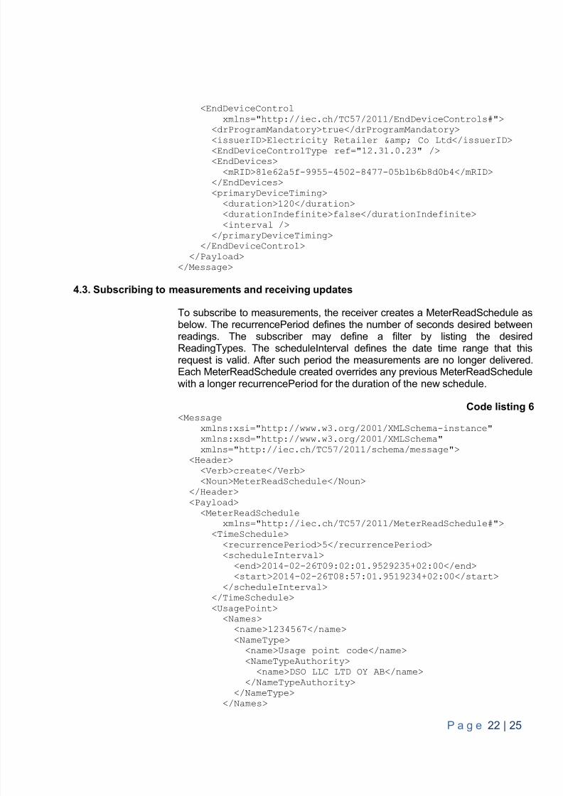
4.3. Subscribing to measurements and receiving updates
To subscribe to measurements, the receiver creates a MeterReadSchedule asbelow. The recurrencePeriod defines the number of seconds desired betweenreadings. The subscriber may define a filter by listing the desiredReadingTypes. The scheduleInterval defines the date time range that thisrequest is valid. After such period the measurements are no longer delivered.Each MeterReadSchedule created overrides any previous MeterReadSchedulewith a longer recurrencePeriod for the duration of the new schedule.
Code listing 6<Message
xmlns:xsi="http://www.w3.org/2001/XMLSchema-instance"xmlns:xsd="http://www.w3.org/2001/XMLSchema"xmlns="http://iec.ch/TC57/2011/schema/message">
<Header><Verb>create</Verb><Noun>MeterReadSchedule</Noun>
</Header><Payload>
<MeterReadSchedulexmlns="http://iec.ch/TC57/2011/MeterReadSchedule#">
<TimeSchedule><recurrencePeriod>5</recurrencePeriod>
<scheduleInterval><end>2014-02-26T09:02:01.9529235+02:00</end><start>2014-02-26T08:57:01.9519234+02:00</start>
</scheduleInterval></TimeSchedule><UsagePoint>
<Names><name>1234567</name><NameType>
<name>Usage point code</name><NameTypeAuthority>
<name>DSO LLC LTD OY AB</name></NameTypeAuthority>
</NameType></Names>

8/10/2019 CIM Iterface Specification V1.0
http://slidepdf.com/reader/full/cim-iterface-specification-v10 24/26
P a g e 23 | 25
</UsagePoint></MeterReadSchedule>
</Payload></Message>
The measurement message sent by the site server is shown below.
Code listing 7<?xml version="1.0" encoding="utf-8" ?><Message xmlns="http://iec.ch/TC57/2011/schema/message"
xmlns="http://iec.ch/TC57/2011/MeterReadings#"><Header>
<Verb>created</Verb><Noun>MeterReadings</Noun>
</Header><Payload>
<MeterReadings><MeterReading
xmlns="http://iec.ch/TC57/2011/MeterReadings#"><Meter>
<mRID>81e62a5f-9955-4502-8477-05b1b6b8d0b4</mRID></Meter><Readings>
<reason>inquiry</reason><timeStamp>2014-04-14T18:10:21Z</timeStamp><value>231.3</value>
<!--current in Volts --><ReadingType
ref="0.0.0.6.0.1.54.0.0.0.0.0.0.0.0.0.29.0"/></Readings>
</MeterReading></MeterReadings>
</Payload></Message>
4.4. Querying stored readings
Depending on the storage capacity at the site, the site server may allowquerying past measurements. If multiple readings are available, the time serieswill be transmitted as one MeterReadings element with multiple Readingelements.
<?xml version="1.0" encoding="utf-8" ?><Message xmlns="http://iec.ch/TC57/2011/schema/message"
xmlns="http://iec.ch/TC57/2011/MeterReadings#"><Header>
<Verb>create</Verb><Noun>GetMeterReadings</Noun>
</Header><Payload>
<GetMeterReadings><Meter>
<mRID>81e62a5f-9955-4502-8477-05b1b6b8d0b4</mRID></Meter>
<!--current in Volts --><ReadingTyperef="0.0.0.6.0.1.54.0.0.0.0.0.0.0.0.0.29.0"/>
8/10/2019 CIM Iterface Specification V1.0
http://slidepdf.com/reader/full/cim-iterface-specification-v10 25/26
8/10/2019 CIM Iterface Specification V1.0
http://slidepdf.com/reader/full/cim-iterface-specification-v10 26/26
P g 25 | 25
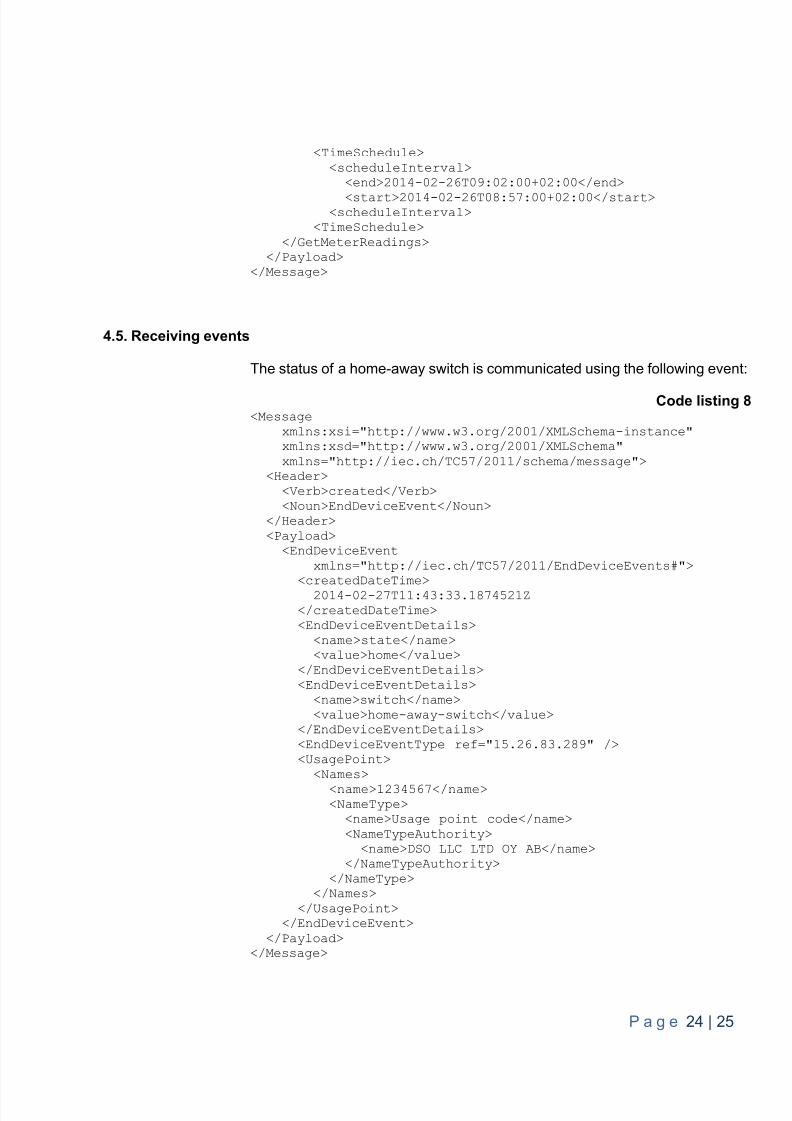
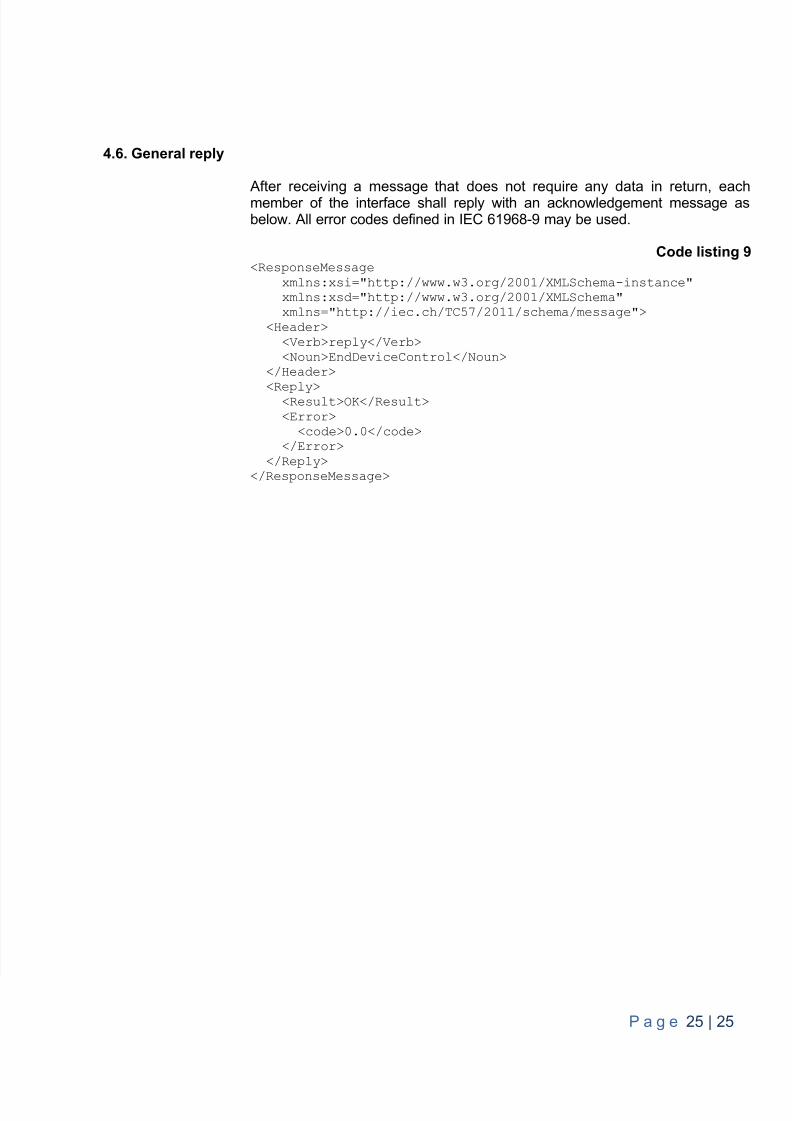
4.6. General reply
After receiving a message that does not require any data in return, eachmember of the interface shall reply with an acknowledgement message asbelow. All error codes defined in IEC 61968-9 may be used.
Code listing 9<ResponseMessage
xmlns:xsi="http://www.w3.org/2001/XMLSchema-instance"xmlns:xsd="http://www.w3.org/2001/XMLSchema"xmlns="http://iec.ch/TC57/2011/schema/message">
<Header><Verb>reply</Verb><Noun>EndDeviceControl</Noun>
</Header>
<Reply><Result>OK</Result><Error>
<code>0.0</code></Error>
</Reply></ResponseMessage>


