78
CIMAC Congress Bergen 2010
CIMAC CongressBergen 2010

SMALLER FUEL INTAKE, LESS EMISSIONS.
Wärtsilä now offers the marine industry total solutions that cover
everything from design to lifecycle service. This makes our solutions
uniquely efficient and environmentally sound. Read more about
what we can do for you, wherever you are: wartsila.com.
WÄ
RTS
ILÄ
® is
a r
egis
tere
d t
rad
emar
k.
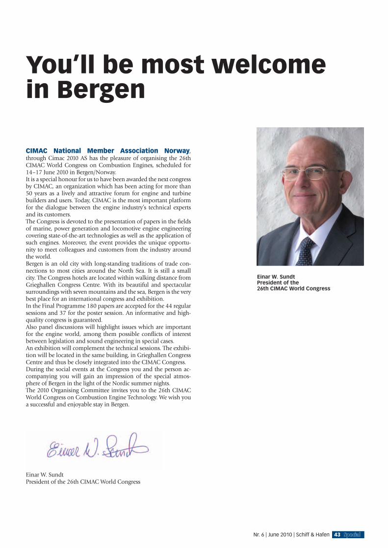
Einar W. SundtPresident of the26th CIMAC World Congress
You’ll be most welcomein Bergen
CIMAC National Member Association Norway, through Cimac 2010 AS has the pleasure of organising the 26th CIMAC World Congress on Combustion Engines, scheduled for 14–17 June 2010 in Bergen/Norway.It is a special honour for us to have been awarded the next congress by CIMAC, an organization which has been acting for more than 50 years as a lively and attractive forum for engine and turbine builders and users. Today, CIMAC is the most important platform for the dialogue between the engine industry’s technical experts and its customers.The Congress is devoted to the presentation of papers in the fi elds of marine, power generation and locomotive engine engineering covering state-of-the-art technologies as well as the application of such engines. Moreover, the event provides the unique opportu-nity to meet colleagues and customers from the industry around the world.Bergen is an old city with long-standing traditions of trade con-nections to most cities around the North Sea. It is still a small city. The Congress hotels are located within walking distance from Grieghallen Congress Centre. With its beautiful and spectacular surroundings with seven mountains and the sea, Bergen is the very best place for an international congress and exhibition.In the Final Programme 180 papers are accepted for the 44 regular sessions and 37 for the poster session. An informative and high-quality congress is guaranteed.Also panel discussions will highlight issues which are important for the engine world, among them possible confl icts of interest between legislation and sound engineering in special cases.An exhibition will complement the technical sessions. The exhibi-tion will be located in the same building, in Grieghallen Congress Centre and thus be closely integrated into the CIMAC Congress.During the social events at the Congress you and the person ac-companying you will gain an impression of the special atmos-phere of Bergen in the light of the Nordic summer nights.The 2010 Organising Committee invites you to the 26th CIMAC World Congress on Combustion Engine Technology. We wish you a successful and enjoyable stay in Bergen.
Einar W. SundtPresident of the 26th CIMAC World Congress
43Nr. 6 | June 2010 | Schiff & Hafen
13:30 June 14th Room Peer Gynt Salen(1–1) Product Development – Diesel Engines – High Speed Engines
MTU solutions for meeting future exhaust emissions regulationsU. Dohle, Tognum AG, Germany
The development activities of all major diesel engine manufac-turers are focused on the exhaust emission regulations that will come into force in the future. IMO Stage 3 will limit NOx emissions to 2 g/kWh for marine en-gines with high nominal speed. For locomotives, the EU Stage IIIB limits NOx + HC emissions to 4.0 g/kWh (from 2012). Particulate emissions must be within 0.025 g/kWh. The US EPA specifi es for prime power gensets a NOx limit of 0.67 g/kWh for installations with 900 kW and above (as of 2011). The particulate limit is 0.10 g/kWh. A large number of other regulatory requirements of other legisla-tures could be listed. MTU Friedrichshafen sells its products world-wide for a broad range of applications and therefore has to take account of the extremely heterogeneous parametersprevailing. Op-timum technical concepts for minimizing lifecycle costs have been developed for every application. Depending on the emission limits applicable, recooling conditions, fuel-economy requirements and fuel qualities, different combinations of technologies can be used: fuel injection, turbocharging, valve timing, exhaust gas recircula-tion and exhaust aftertreatment. This paper presents the technical oncepts together with selected application examples.
Development strategies for high speed marine diesel enginesF. Koch, T. Seidl, O. Schnitzer, G. Oehler, A. Loettgen, S. Loeser, MAN Diesel & Turbo SE, Germany
Main targets for modern marine engines are effi ciency, durability, engine size, fuel fl exibility and a suitable design for the world wide production by international licensees. Signifi cantly reduced emissions have and will set further challenges for the engine development, considering the variation of fuel quality around the world. 2010 MAN has merged the High Speed Engine activities of MAN Diesel and MAN Nutzfahrzeuge into the new Business Unit ”High-Speed Engines”, using the synergies between both areas: e.g. developments based on a truck engine or test strategies and cost optimized production adapted for a marine engine with a higher cylinder numbers. Product development processes have to comply with a complexity of requirements. Precise product ender specifi cations based on understanding of market demands, utilization of superior materials, tools and technologies, optimal product supply chain, management of relations with suppliers, environmental and economical aspects, and short time to market. To meet all these requirements a special simultaneous development process was applied and modern tools for 3D design and data processing for R&D and production are necessary. The extensive depth of simulation in the development process allows the transfer of knowledge form one particular engine to various types. This is strongly supported by a closed 3-D-data-structure for the complete high speed engine program. To incorporate the in-house core competences for turbo charging, injection and engine control is highly advantageous for the engine development process. The high grade of integration leads to a cost effective, compact and robust design. The outstanding simultaneous engineering process
of production and engine development experts create marine engines with highest performance data.
The design and development of the General Electric L/V250 diesel engineK. Bailey General Electric, USA, C. Atz, J Dowell, GE Transportation, USA, P. Raina, GE Transportation, India, K. Lierz, FEV Inc., USA, E. Reichert, FEV Motorentechnik, Germany
General Electric has developed a new medium-speed diesel engine for marine and stationary applications. The engine family designation is “250”, and it is available in 6- and 8-cylinder in-line, or 12- and 16-cylinder vee confi gurations. The L/V250 engines were designed with the features desired by the marine marketplace, including engine-mounted auxiliaries, full power take-off from either end, provision for sea water pump and auxiliary power take off. The new engine is based on the highly successful Evolution locomotive engine that went into series production in 2005. In order to leverage production capacity and product reliability, many components of the Evolution engine are carried over to the 250-family. This component commonality allows a reduced inventory of parts and tools at the factory and at customer’s facilities. The results are lower manufacturing costs, low operating costs, high reliability, and a greater assurance for parts availability in emergency situations. This paper will describe some of the features of the new L/V250 engine models, and provide information on the design and development efforts. Brief descriptions of the fi rst applications of the engine in the fi eld are also provided.
The design and development of a new advanced heavy duty high speed diesel engineE. Karimi, N. Hadley, Technomot, UK
This paper describes the technical features and methodologies used to design a brand new family of heavy duty diesel and dual fuel gas engines, from 6 cylinder inline to 12 cylinder Vee confi guration, up to 1800 rpm. The use of electronically controlled high pressure common rail, high effi ciency turbochargers, cross-fl ow cylinder heads with separate ports and other engine design strategies to achieve best in class fuel consumption are discussed. The development of the engine performance model describes the interaction between Design and Analysis Groups in the creation of a simulation model and component design geometry which achieves the optimum balance in performance and manufacturability. This communication between engineers is the key factor in understanding the whole engine performance process and pushing the boundaries of existing knowledge to achieve improvements in engine performance over previous engine designs. The design guidelines agreed with the client, for this engine, for factors including reliability, cost, weight, size, recyclability and performance, are described. The impact of these guidelines on components like the crankcase and ladderframe are outlined with particular design solutions for low cost manufacture with nominated suppliers, assembly sequence optimised to suit the manufacturing facilities, high durability and matching to the target market servicing strategy. The project methodologies used to design this engine are explained - particularly the use of concurrent engineering to capture the companys sum total of engine operating knowledge and feed it into the design process at an early stage to ensure right-fi rst-time design in the shortest possible project duration. The impact of methodologies like concurrent engineering on the project, and the continuous design
Schiff & Hafen | June 2010 | Nr. 6
CIMAC CONGRESS | BERGEN 2010
44

Monday, 14 June
������������� ����������������������������������������������� �� ���������������������������
������ ������ ������������������������������ ����������������������!���"���������������
�����#$%����&'())%�*+����������,����������-
.��������������������������������� ��
���������� ���������������� ������ �������� ������������� ���������������������������� �����������
����������������������� �� �������������������

process improvements are also outlined. The result of this work is the development of a complete family of heavy duty, high speed engines with bestin- class fuel consumption and a good specifi c power output, demonstrating Technomots ability to introduce new products working closely with its engine manufacturing clients.
13:30 June 14th Room Scene GH (8–1) Integrated Systems & Electronic Control – Engines, Turbines & Applications – Sensors & Actuators
Electronics for the safety-critical application and control of combustion enginesD. Eikemeier, T. Dauenhauer, MAN Diesel & Turbo SE, Germany
In the recent years the reliability of modern diesel and gas engines depend more and more on reliable and robust electronics. The common rail injection is an example to meet current and future regulations and standards for emissions. The following article gives an insight to the new family of engine control electronics of MAN Diesel SE (SaCoSone - Safety and Control System on engine) and necessary considerations, implementation of processes and advanced testing of these engine controllers. In the beginning of the project, a very detailed FMEA of the complete system and each electronic control module was carried out. This identifi ed for instance the need for redundancies in several places to always remain in a safe and working condition of the engine in the case of a failure. Regarding development processes, a detailed but still fl exible development process was not only implemented for the software development, but for hardware development, too. This included an automatic versioning management in combination with a detailed and software supported change management process. Of course also the sub-suppliers and development partners have to be integrated into these processes. The control products are being extensively tested. This included of course all necessary tests according to standards like IEC or IACS: vibration, temperature, EMC. Furthermore MAN Diesel SE has also carried out a more in-depth analysis of the different electronics parts both theoretically and practically. The testing is done in the laboratory with HALT / HASS (Highly Accelerated Life Testing / Highly Accelerated Stress Screening) chambers. Faults are induced by a combination of 3D-vibration together with fast changing temperature cycles. The following article gives a glance into the new SaCoSone control system, together with experiences in implementing new development processes. Certain test results are explained in more detail with examples of critical electronic components, which can be replaced by different parts or discrete circuits to result in a higher reliability.
Reducing fuel consumption on the fi eld by continuously measuring fuel quality on electronically fuel injected enginesP. Flot, A. Meslati, Controle Mesure Regulation, France, T. Delorme, Ecole Centrale Marseille, France
In order to save crude oil worldwide resources and to reduce the amount of GHG - green house gas - emissions resulting from combustion inside engines, builders have to research new ideas for further fuel consumption reduction, and cleaner exhaust gas. That trend is not new but just more challenging and progress is
becoming seldom as modern engine performances are coming closer to the Carnot effi ciency. Although increasing use of electronics on engine could support greater amount of conditions and parameters in adjusting the engine actuators for optimised combustion, like pressure and temperature of air, coolant, lub-oil, and fuel, still fuel quality is not considered, so that commercial engines are usually fi ne tuned for average quality of fuels as found on the market. As a result, engine performances on the fi eld can be affected when locally purchased fuel quality is far away from the average quality considered by the engine builder. At the same time, engine builders and authorities are asking for more stringent fuel specifi cations, when oil companies, on the opposite, would like to enlarge fuel specifi cations to help marketing and eliminating lower grades of fuels. A smart fuel sensor has been developed and its capability proven. This fuel sensor uses the patented HydroCarbon Profi ler technology, which measures the molecular structure of the fuel. This information is continuously transmitted to the Engine Control Unit allowing real time optimization of injection, combustion and post treatment for all possible fuel, including bio-fuels. This fuel quality sensor is based on a smart combination of a Near Infrared low cost hardware and powerful data treatment software. That technology is in use since end of the years 90’s at inlet, and outlet of crude oil refi neries in order to continuously adjust and control the chemical processes of the factory. But the sensors are huge and expensive: 500 kg to 1000 kg, costing nearly 1 M Euro! Although using the same principle, the new sensor has been drastically reduced in size and cost from the refi nery experience, so that the sensor can be mounted on the engine, not being bigger than a bottle of fruit juice! Then it went through various marine approval type tests to prove its robustness in engine ambient conditions, far away from those quiet ones met inside refi nery measurement room. The paper will describe the sensor hardware and software technologies and the expected engine combustion performance improvement resulting from that new parameter input. This sensor can be used as well to protect the engine against accidentally bad quality of fuel.
Exhaust gas recirculation electric actuation technologyA. Pintauro, Woodward Governor, USA
Exhaust gas recirculation (EGR) is an effective method to reduce nitrogen oxide (NOx) emissions. There are many advantages to using electric actuation technology for both metering EGR fl ow and for waste gate control but this has been a challenge for the heavy industrial engine market without using active cooling because of the exhaust gas temperatures as high as 750°C. The paper gives a general overview of an integrated package comprising of a valve, rotary electric actuator, linkage, support bracket, and actuation technology that solves this issue. The system characteristics, technical data, models, as well as fi eld life test data are included. The modulating actuator relies on only passive cooling due to its high ambient temperature rating as well as having a unique linkage/bracket that is designed for minimal heat transfer while allowing for relative motion due to thermal expansion. This EGR electric actuation system allows for precise metering control while simplifying the fi nal installation as no customer supplied linkage is required and the valve to actuator position is pre-set at the factory. In addition, the actuator system has been designed to be mounted directly on engine and has the ability to withstand the associated vibration and thermal loads through the use of a vibration isolation for the integral electronics. The demonstrated vibration isolation profi les are detailed in the paper’s results.
Schiff & Hafen | June 2010 | Nr. 6
CIMAC CONGRESS | BERGEN 2010
4646

Tuesday, 15 June Wednesday, 16 June Thursday, 17 June
Monday 14 June
Malfunction diagnosis at marine diesel engines based on indicator cock pressure data – model based sensor reconstruction of in-cylinder pressure trace using indicator cock pressure information & fundamental investigations on malfunction diagnosis at marine diesel engines based on reconstructed in-cylinder pressure informationP. Obrecht, P. Voegelin, ETH Zurich, Aerothermo-chemistry and Combustion Systems Laboratory, Switzerland, C. Onder, E. Oezatay, ETH Zurich, Institute for Dynamic Systems and Control, Switzerland, P. Fuchs, W. Fuchs, Peter Fuchs Technology Group AG, Switzerland
Large heavy-duty diesel engines usually give access to the cylinder via a so-called indicator cock (IC). Due to the construction of the IC, the pressure signal is distorted and cannot be directly interpreted. Simplifi ed models are not precise enough for the pressure correction. Thus, a model which is parameterized with measurements is applied. Using frequency domain methods, the transfer function of the IC is determined when the engine is at the manufacturer and precise incylinder measurements are possible. Using the transfer function, the dynamics of the IC is inverted and the measured pressure is corrected and reliable information on the cylinder pressure can be used for subsequent calculations. Comparisons with various models are shown and the advantages of the presented method are demonstrated. Measurements of a large diesel engine are given and the methods are applied. The presented knowledge works as ICCA (Indicator Cock Correction Algorithm) in The Doctor DM 8-32 engine analysis tool of Fuchs Technology Group builds a basis for the second part of the paper. Fundamental investigations on malfunction diagnosis at marine diesel engines based on reconstructed in-cylinder pressure information. To fulfi l the needs of marine diesel engine customers, an engine diagnosis tool was developed which provides precise information on the actual state of the engine on the basis of cylinder pressure measurements via indicator cock. The investigation was worked out in the context of a master thesis at ETH Zurich and started with a one dimensional engine simulation model, where the indicator cock’s geometry was replicated regarding simulation of the distorted pressure at the end of the indicator path. In a next step models of common engine malfunctions were developed with the simulation software. The reconstructed in-cylinder pressure provides a basis for running the
engine at the maximal designed cylinder pressure and a further thermo dynamical analysis enables malfunction diagnosis. The presented algorithms are implemented in an engine analysis system called The Doctor DM 8-32 (Fuchs Technology Group) and show a practical application of the method developed in the fi rst part of the paper. The engine diagnosis tool is represented as a light-weight computer, which can be taken on-board, comprises data gathering as well as post-processing and pressure trace interpretation.
13:30 June 14th Room Troldtog (6–1) Product Development, Component & Maintenance Technology – Gas Engines – New Engines
Development of the Rolls-Royce C26:33 marine gas engine seriesT. Humerfelt, E. Johannessen, E. Vaktskjold, L.- A. Skarbö, Rolls-Royce Marine AS, Engines - Bergen, Norway
The Rolls-Royce C26:33 marine gas engine is a new natural gas powered engine launched in 2010, based on the C25:33 marine diesel engine. The C26:33 marine gas engine has been identifi ed as an engine with interesting market potential for ship propulsion as a variable speed – variable load engine, with low emissions, compared to liquid fuelled engines, being the key selling point. The C26:33 marine gas engine will in this paper be described with design philosophy and qualities as follows:
• Maximising profi tability through optimising swept volume of the engine, i.e. recommending an increase of bore from current Ø250 mm to Ø260 mm. The increase leads to an increased cylinder volume from 16,2 litres to 17,5 litres and will be an ample resource to either increased power without increase in break mean effective pressure, or to use as a margin for reduced emissions or indeed for improved response.
• The decision to develop the C25:33 platform for gaseous fuels, implied the use of experience and technology from the K-and BV-type gas engine platforms.
• Improved responsiveness of the engine in order to get propulsion engine certifi cation as well as focussing on reduced hydrocarbon emission through exploring optimisation of our current mechanical gas control & admission concept
• The C26:33 marine gas engine is designed to meet both redundancy and response requirements for marine generating sets and single engine propulsion applications.
Nr. 6 | June 2010 | Schiff & Hafen 47

• The C26:33 marine gas engine is designed to be able to run as a propulsion engine at variable speed when connected to a controllable pitch propeller. When the propeller thrust requirement is low, the propeller speed may then be reduced, effectively reducing zero pitch loss.
Newly developed Mitsubishi MACH II-SI and CM-MACH gas engines, enhancing and expan-ding utilization for energy and specialty gasesM. Ishida, S. Namekawa, Y. Takahashi, H. Suzuki, A. Yuuki, K. Iwanaga, Mitsubishi Heavy Industries, Ltd., Japan
Mitsubishi Heavy Industries, Ltd. (MHI) has developed and added the new MACHII-SI and CM (Central Mixing)-MACH models to its lineup of MACH gas series engines. The MACH-30G gas engine, formerly the MP (Micro Pilot Ignition)-type model, has delivered more than 150 units since 2001. The experience and know-how accumulated from their on-going operations have been fed back into the development process to ensure even higher reliability and performance. The MACHII-SI, whose ignition concept has been modifi ed to a spark ignition (SI) system, was developed in order to meet the demand for a simple gas engine that does not require liquid pilot fuel and an engine with improved energy utilization effi ciency. Further, the concept of CM-MACH (MP-type) was developed to expand the utilization of low calorie gases and other specialty gases as operational fuel. This paper describes the technology of effi ciency enhancement and the features of these new engines, including test results performed at the factory and at actual sites. Working in collaboration with the New Energy and
Industrial Technology Development Organization (NEDO) and the Japan Gas Association (JGA), MHI has completed advanced development of technology to improve the effi ciency of gas engine. These improvements are focused on the optimization and control of combustion. Using these technologies, the MACHII-SI has optimized its exhaust temperature and consequently reached a total effi ciency of 66% - combined with generation effi ciency and steam effi ciency, the world’s highest for this class of engine. These same enhancement technologies have also been applied to the former MACH-30G model raising its power generation effi ciency up to 46%. Moreover, the MACHII-SI start-up time has been reduced to less than six minutes from activation to 100% loading, meeting the requirements for peak application. Intricate details combining optimum control and the diagnosis techniques for combustion greatly contribute to this performance achievement. We have been conducting rigorous verifi cation tests for start-up, performance, reliability, and overall system operation under the most severe conditions at our in-house test plant since October 2008. With the CM-MACH, low calorie gas has been achieved by means of gas supply features in both the intake port at each cylinder and the suction port before the turbocharger. This feature offers an additional safety advantage in that it keeps an appropriate concentration of air-fuel mixture in the intake system to prevent auto ignition. The fi rst engine was delivered and began operation in October of 2009. MHI believes that through our expanded lineup of MACH gas engines, we are able to meet an unprecedented diversity of customer needs.
Development of large gas engine with high effi ciency (MD36G)T. Oka, M. Kondo, Mitsui Engineering and Shipbuilding Co. Ltd., Japan, T. Aiko, Daihatsu Diesel MFG. Co., Ltd., Japan
Mitsui Engineering & Shipbuilding Co., Ltd. (MES) has developed a large size lean-burn gas engine MD36G with high effi ciency whose generating power output range is 2.8 - 8.1MW jointly with Daihatsu Diesel MFG. Co., Ltd. (Daihatsu) and opened business in April 2008. The base engine of MD36G is the medium-speed diesel engine Daihatsu DK-36 that has a large number of records and experiences in both land and marine engines. The engine has been developed as a series of a 1MW class as engine MD20G which had already been developed and commercialized by MES, in line with a trend of market demand for bigger generator engines. Basic concept of MD20G has been followed, and experiences and know-how obtained from operation results of MD20G have been incorporated into development. Technologies such as the Miller cycle and combustion control in addition to the direct-injection micro pilot ignition which is the most signifi cant feature of the MD-G series, are applied to the MD36G. It is possible to cope with various usages fl exibly, because the electronic control units that have abnormal combustion detection and air-fuel ratio control for stable combustion are developed by MES. The demonstration plant with this developed engine is working well as a power generation facility in Tamano works of MES, and it was confi rmed through its operation we achieved the world top class high generating effi ciency among gas engines with same output range at the mean effective pressure 2MPa. Regarding NOx emission, 300ppm (O
2=0%) NOx in the normal model and
below 200ppm(O2=0%) NOx in the low NOx model of that cycle
parameters have been changed, has been confi rmed. As a result of this development, our lineup of gas engines whose generating power output range is 0.88
~.1MW has been
completed.
AVL EPOSTM – DAS OFFENE MOTORBETRIEBSANALYSE SYSTEM
Schiff & Hafen | June 2010 | Nr. 6
CIMAC CONGRESS | BERGEN 2010
48
Monday, 14 June
Tuesday, 15 June Wednesday, 16 June Thursday, 17 June
Newly developed Kawasaki green gas engine – top performance GEH. Sakurai, T. Sugimoto, Y. Sakai, T. Tokuoka, Y. Nonaka, M. Honjou, T. Horie, Kawasaki Heavy Industries, Ltd., Japan
Kawasaki Heavy Industries, Ltd (KHI) started the development of a high performance gas engine in 2004 for the purpose of meeting new market requirements. After various tests on the single cylinder engine in order to optimize the performance parameters, KHI completed the full-scaled fi rst engine of Green Gas Engine (GGE) at KHI Kobe works in May 2007. KHI achieved the world’s highest electrical effi ciency of 48.5%, and the lowest NOx emissions level below 200ppm at 0% O
2 simultaneously. Electrical effi ciency was
improved by more than two percents. In addition NOx emissions level was reduced to half compared with the existing level. The power range of 5.0 to 7.8MW is covered by 12,14,16 and 18 cylinder engines. The above mentioned fi rst engine has the largest electric power among the above. The electric spark ignition system is applied and no liquid fuel is required. The fuel gas is supplied to the main combustion chamber and pre-combustion chamber individually by electronically controlled gas injection system where the gas injection timing, and air/fuel ratio is optimized. The cylinder pressure is measured for all cylinder, thereby misfi ring is controlled for individual cylinder in order to achieve the optimum condition for each cylinder. After the test at KHI Kobe works, the fi rst power plant was constructed at Joetsu City, Niigata prefecturein Japan and commissioned in December 2007. GGE completed 4000 hours test in December 2008 and comprehensive inspection was carried out in January 2009. KHI confi rmed its high performance and reliability. In addition, KHI carried out special tests such as quick loading up test, test with various as composition, etc. to meet customer’s various demands. KHI is now constructing KG-12 in Kobe works, where activities of further new technology improvement in performance are carried out.
Development of high effi cient gas engine H35/40GD. Y. Jung, J. S. Kim, J. T. Kim, E. S. Kim, Hyundai Heavy Industries Co., Ltd., Korea, A. Skipton-Carter, Ricardo UK Ltd., UK
In order to implement strict emission legislations in accordance with growing concern with exhaust emissions from internal combustion engines, natural gas is a promising alternative fuel for power generation plants and marine propulsions. Hyundai Heavy Industries Co., Ltd. (HHI) has been developing a new HiMSEN gas engine H35/40G, 350mm bore size and 400mm stroke length, in response to this market trend. Its design principle is based on the wellproven technology of lean burn combustion by Pre chamber Spark Ignition system (PCSI) and Pre Chamber Micro Pilot system (PCMP). Both are possible to immediately install on in-line type and V type engines. The aim of this work is to develop a new gas engine that has high effi ciency and high power combined with optimization towards environmental and economical aspects The development target of H35/40G is high thermal effi ciency of 47.2%, high power output of 480kW per cylinder, break mean effective pressure of 20.8 bar at 720 rpm, and low emission; 50ppm at 13% oxygen. These are achieved applying state-of-the-art technology such as PCSI and PCMP for effective lean burn combustion. In addition, the combustion performance is improved by the investigation on air inlet port geometry with optimized swirl. To avoid an increase in thermal load on the engine, the charge-air pressure is raised by developing the turbo charging system supported by the Miller cycle. H35/40G is based on the
reliable H32/40 diesel engine and is increased in its bore size to boost the power. Furthermore, the specially developed Engine Control System is designed to control the combustion process in each cylinder, and NOx, knocking, power, and air fuel ratio. In hence, the engine attains high effi ciency and high output complying with the lowest emission. This paper describes the design and development details of this new gas engine with the test results of the prototype engine of H35/40G. Also, the main idea concepts are proven by features and diagrams from examinations and calculations. Furthermore, a unique gas admission system and intelligent control system to achieve development target are demonstrated by HHI’s future-oriented view.
13:30 June 14th Room Klokkeklang (4–1) Diesel Engines – Tribology
Suction air humidity infl uence on piston running reliability in low-speed two-stroke diesel enginesF. Micali, M. Weber, M. Stark, K. Raess, Wärtsilä Switzerland Ltd., Switzerland, M. Potenza, University of Salento, Italy
The number of scuffi ng incidents between piston rings and cylinder liner surface of lowspeed two-stroke diesel engines recorded in climatically humid areas suggests that high ambient humidity affects the reliability of piston running in this type of engine. This paper aims at identifying the correlation between the properties of engine suction air and damages found on cylinder liners and piston rings. The authors present their campaign to study the interaction between suction air humidity, sulphuric acid generated by combustion of sulphur-containing fuels and engine characteristics, leading to the socalled sudden severe wear (SSW), which stands for unpredictable damages of piston rings and liner surface, making it – in most cases – necessary to exchange the affected parts immediately. Tests performed on large-bore two-stroke diesel engines installed on cargo vessels during regular port-to-port operation were focused on investigating effects like liquid water carry-over by scavenging air originating from the scavenging air cooler heading to the cylinder liner inlet ports and dropletevaporation phenomena in the scavenging air receiver. Further engine tests made on a 60 cm bore research engine of Wärtsilä Switzerland as well as rig tests using a Cameron Plint Test machine of Shell Global Solutions GmbH (Germany) aimed at fi nding combinations between cylinder lube oil, water and sulphuric acid, which would lead to scuffi ng between the sliding surfaces and as a consequence to SSW on a real engine. Finally, a correlation between ambient conditions and lube oil degradation is presented caused by an emulsifi cation of the lube oil on the liner surface with water, which leads to a novel scheme for diffusion of sulphuric acid in the lube oil fi lm on the cylinder liner, strongly infl uencing the acid neutralization effect of the alkaline additives in the lube oil.
Lubrication challenges for distillate fuel operated two-stroke enginesM. Boons, R. Brand, Chevron Oronite Technology b.v., The Netherlands
The marine world is changing faster than ever before. Marine diesel engines in ships sailing on the oceans generally burn Heavy Fuel Oil (HFO) and the average sulfur content of this fuel is a little less than 3 wt%. In light of the global movement to reduce emissions, the International Maritime Organization (IMO) has defi ned a
Nr. 6 | June 2010 | Schiff & Hafen 49
scheme with fuel sulfur limits that ultimately will lead to a maximum of 0.5 wt% sulfur globally and 0.1 wt% in some locations unless scrubbers are used to remove SOx from the exhaust gases. It remains to be seen if the refi ning industry will produce enough low sulfur fuel and it is also uncertain how widespread the use of exhaust gas cleaning will be. Reductions in other ship emissions will certainly add to an already complicated situation. Assuredly, there will be drastic changes in the future for a large number of diesel engines in the marine and power station industry. These changes will also no doubt impact the lubricant requirements for these engines. This paper describes how the change from HFO to low sulfur distillate fuel can lead to fi eld issues for two-stroke diesel engines. A laboratory engine test was developed that reproduces these fi eld issues and furthermore indicates an increased sensitivity to lubricant feed rate when operating on distillate fuel. It is likely that currently available lubricants are not optimal for this new situation and that new oils will need to be formulated on the basis of performance in laboratory and fi eld engines.
Investigation of tribological damage mechanisms of various slide bearing materials used in medium speed and low speed diesel engines on the microscopic and macroscopic scaleM. Offenbecher, W. Gärtner, G. Gumpoldsberger, R. Aufischer, Miba Gleitlager GmbH, Austria, F. Gruen, I. Godor, Montanuniversitaet Leoben, Austria
In this paper we will give an overview on the damage mechanisms of the modern slide bearing materials used in diesel engines. Bimetal bearing concepts on bronze and multilayer concepts with Pb- and Sn-based respectively polymer-based overlays will be compared in detail. The damage mechanisms on the macroscopic scale, measured on a bearing test rig, and on the microscopic scale, measured on a tribometer, will be compared.
Experimental investigation of lubrication regimes on piston ring – cylinder liner contacts for large two-stroke enginesA. Voelund, C. Felter, MAN Diesel & Turbo SE, Denmark
Friction in the piston ring package (piston, piston rings and cylinder liner) is one of the largest contributors to the overall mechanical power loss of two stroke marine diesel engines. This can be seen both from service experiments and through simulation studies. From these studies it can be concluded that the friction force in the piston rings has its maximum contribution around the two dead centres – top dead centre (TDC) and bottom dead centre (BDC). It can be shown through simulation and from service experience that the tendency of asperity contact between piston ring and cylinder liner is pronounced around TDC and BDC of the stroke. From a tribological point of view, it is the tribological mechanisms around TDC and BDC, which are the main area of interest in an experimental investigation. Since this is a diffi cult investigation to conduct on operating engines a small scale experimental setup was developed. The intent of this work is to study the tribology of the piston rings at a lab scale test rig. A reciprocating test rig was developed in collaboration with The Technical University of Denmark to study the performance of piston rings of two stroke marine diesel engines. The basic principle behind the test rig is similar to an operating engine where a piston ring segment is moving in a reciprocating
motion subjected to a certain normal load. Segments of the piston ring and the cylinder liner material for the test rig were taken from the operating engines and were machined for the dimensions of the test rig. Friction force, oil fi lm thickness and temperature distribution of the piston ring is studied as a function of crank shaft position, rotational speed, and loading of the piston ring. Furthermore electrical resistance measurements are conducted in order to investigate the transition from full separation (hydrodynamic conditions) to partial separation (boundary lubrication). Finally simulations are carried out on a selected set of experiments in order to compare the measured values with theoretical results.
15:30 June 14th Room Peer Gynt Salen (1–2) Product Development – Diesel Engines – Medium Speed Engines I
GE PowerHaul diesel engine developmentP. Flynn, R. J. Mischler, GE Transportation, USA
GE Transportation has developed a new family of diesel engines to meet the challenge of high power, low weight and new emissions requirements in lightweight locomotives. The fi rst member of the family is a 16 cylinder engine that runs at 1500 rpm and produces 2750 kW. Future models include a 12 cylinder engine rated at 2060 kW and adaption of the engine for marine and power generation. The PowerHaul engines were derived from the successful Series 6 Jenbacher gas engines. The strength of the gas engine was retained, and state of the art fuel injection, turbocharging and combustion systems were applied. A high pressure common rail system gave the fl exibility to optimize the NOx-fuel consumption tradeoff, while minimizing PM. The engine uses high pressure ratio, single stage turbochargers to supply air to support the moderate Miller Cycle combustion system. A moderate Miller Cycle inlet valve closing was employed to retain simple matched turbochargers and a conventional valve train while maintaining good acceleration and low power performance. The combustion processes were modeled and calibrated on a single cylinder research engine to evaluate several combinations of piston crown, valve timing, boost level and fuel injection nozzle geometry. This allowed a single set of multicylinder hardware to be built and directly meet the targets for power, emissions and fuel consumption. The 16 cylinder engine has been certifi ed to EU IIIa emissions levels. The base structure of the engine was modifi ed to couple closely to a locomotive alternator and to drive the lubricant and cooling pumps necessary for the locomotive cooling system. The engine is elastically mounted in the locomotive to reduce vibration transfer, but resist the shock loads experienced in locomotive applications. The engine as a whole and its major parts were validated for locomotive service by extensive component and engine endurance tests. The engine was qualifi ed with 10% overspeed and 20% overload levels. A special load cycling test was performed to qualify the engine for highly cyclic locomotive service. The fi rst application of the 16 cylinder PowerHaul engine will be in the PH37ACmi locomotive for the Freightliner rail system in the UK. It represents a new standard for power, emissions, haulage, and fuel consumption in lightweight locomotive markets.
Development of Niigata new medium-speed diesel engine “28AHX”K. Imai, H. Nagasawa, H. Yamamoto, S. Kato, K. Sonobe, Niigata Power Systems Co. ,Ltd., Japan
Niigata Power Systems Co., Ltd. (NPS) has developed a new medium speed diesel engine ”28AHX” which covers an output
Schiff & Hafen | June 2010 | Nr. 6
CIMAC CONGRESS | BERGEN 2010
50
Monday, 14 June
Tuesday, 15 June Wednesday, 16 June Thursday, 17 June
range of 2070-3330kW by inline 6-9 cylinder engines. In recent years, as container ships have become bigger in size, the higher output of tug boat is demanded in the world. Also the demand of supply vessels of PSV (Platform Supply Vessel) and AHTS (Anchor Handling Tug Supply) vessels are increased. To accommodate to this market demand, this new engine has been developed for the main engine driving azimuth type propulsion system ”Z-peller” mainly. 28AHX has a 280mm bore and a 390mm stroke, and its maximum output is 370kW/cyl. at 800min-1, and 345kW/cyl. at 750min-1 respectively. The engine can comply with the exhaust emission regulations in the next stage such as IMO NOx Tier II, and it is considered the performance of low load operation and transient response as a main propulsion engine. To achieve these performance targets for the environment without increase of the specifi c fuel consumption, the following technical expedients are applied.
- Optimization of combustion: piston design and injection system etc.
- Miller cycle and optimization of intake and exhaust valve timings
- Adoption of variable intake valve timing mechanism - Improvement of a turbocharging system: air bypass and waste
gate In addition, for the purpose of the decrease of engine and auxiliary equipment space in the engine room, and of easy maintenance, the following construction is designed.
- ”Cylinder unit”: assembling of cylinder parts - ”Front end unit”: integrated unit of auxiliary machinery on
engine front sideThis paper reports the design feature and engine structure of 28AHX, and also the performance and mechanical results of the prototype engine. The engine performance are well accepted, especially the quick load increase operation characteristic is very good. The fuel consumption is improved compare to existing medium size engine of Niigata, even 28AHX keeps Tier II NOx emission.
Development of the new Caterpillar VM32C LE low emission engineU. Hopmann, Caterpillar Motoren GmbH und Co. KG, Germany
Caterpillar Motoren’s Vee engine VM32 was originally introduced in 1997 as a 12 and 16 cylinder version. This engine proved its reliability and high customer value over years. With the introduction of the “C” version in 2003, which was based on the original engine layout, this engine was IMO Tier I compliant and continued to be successful in the marine and stationary power market. In order to meet the upcoming IMO Tier II emission regulation (effective date will be January 2011) a more complex update was required. This paper describes the development of the new low emission (LE) version VM 32 C LE from concept to fi nal design. Through concept studies and concept design, the overall engine layout has been conceived. The major outcome of this phase was an increase in stroke from 420 mm to 460 mm. This means, that the mean piston speed went up to 11,5 m/s. This is a signifi cant increase and a fairly high value for a medium speed engine where the typical mean piston speed is between 9,5 and 10,5 m/s. In order to substantiate the concept thorough FE analysis of the main components has been carried and will be presented in this paper. Dynamic simulations as well as torsional vibration analysis (TVA) of the rotating components confi rmed the chosen engine layout. Components without design changes have been analysed to ensure reliable operation under the new load conditions. The increase in piston speed required an investigation of the fl uid dynamics in air and exhaust system. Results of the CFD analysis to improve
breathing and gas exchange will be shown as well. Apart from component development, the general engine layout, engine design and new engine features will be shown. For further confi rmation, additional pretests related to high mean piston speed have been carried out and will be presented.
MTU’s new series 8000 gas-protected engineM. Eckstein, E. Osterloff, C. Hecker, MTU Friedrichshafen GmbH, Germany
The series 8000 is the biggest and most powerful engine family of MTU, rated up to 9100 kW. It is mainly intended for main propulsion of fast military and commercial vessels. Recently, MTU added a new member to this engine family, the “gas protected engine”. Such engines have to be able to operate safely even in an environment that could be contaminated with explosive gases. This engine has been designed for the propulsion system of the new and the world’s most powerful emergency tugboat, the “Nordsee”. The “Nordsee” is currently under construction and will be operating from the beginning of 2011 in the North Sea. Equipped with two series 8000 engines it will have 200 to bollard pull capability and a maximum speed of more than 19,5 knots. Furthermore, the gas protected version of the series 8000 engines will make it able to operate in hazardous and explosive environments. MTU was awarded the contract for this boat from the “German Coast Guard Working Group” (Arbeitsgemeinschaft Kuestenschutz) after a Europe-wide invitation to tender from the German Federal Ministry for Transport, Building and Urban Affairs, because MTU is the only engine manufacturer in the world that has a long-term experience with this special technology. In the last decades, several similar boats have been equipped with smaller gas-protected MTU engines of series 396 and series 4000. Giving a series 8000 engine, these special capabilities allow shipbuilders to provide faster and more powerful emergency tug boats and therefore increase the safety on sea. In mid 2009, MTU completed this development project successfully and received the fi nal certifi cate from Germanischer Lloyd for this engine. This presentation highlights the challenges of this special application as well as the technical solutions applied. The unique capabilities of the series 8000 engine in this application are given. The safety concept of the engine and the electronic engine control system is also shown.
15:30 June 14th Room Scene GH (3–10) Environment, Fuel & Combustion – Diesel Engines – Overview Emissions
Legislative update: International requirements on next generation nonroad – marine & stationary engines (diesel & gas) & their fuelsP. Scherm, P. Zepf, Euromot, Germany
Exhaust emission legislation and the demand to comply to a variety of emissions regulations all over the world is a major driver of engine development. The need for globally aligned legislation is one of the essentials for being successful in the worldwide markets. For Euromot representing more than 40 CI and SI engine manufacturers in Europe and abroad it has always been one of its highest priorities to facilitate harmonisation of global legislation and to ensure that effi cient and environmentally friendly engines are available on the global markets. An overview will be given on the current revision processes of major global emissions legislation such as the technical review of the EU Directive on nonroad mobile machinery engines
Nr. 6 | June 2010 | Schiff & Hafen 51

and amendments including rail applications and inland waterway vessels; the revision of the UNECE Gothenburg Protocol as well as the EU Directives on industrial emissions or national emission ceilings for stationary engines; the recent developments of IMO, EU or national legislation for seagoing vessels; and fi nally on the existing legislation and future environmental requirements on fossil or renewable transportation (nonroad and marine) fuels.
Large high speed diesels, quo vadis? Superior system integration, the answer to the challenge of the 2012 – 2020 emission limitsA. Ludu, K. H. Foelzer, AVL List GmbH, Austria, T. Bouche, AVL List GmbH, Switzerland, M. Engelmayer, LEC - Large Engines Competence Center, Austria, B. Pemp, Institute for Internal Combustion Engines and Thermodynamics Graz University of Technology, Austria, G. Lustgarten, AVL Consultant, Switzerland
The present paper treats the question of the development direction of Large High Speed Diesel Engines (with nominal speeds of 1200-2000rpm) and Multi-Application Medium Speed Engines (with nominal speeds up to 1150 rpm). The common characteristic of this engine class is their capability to serve a wide range of applications at sea but also for terrestrial application (power generation, locomotives, industrial and construction). Due to their large application footprint, they have to meet by the mid of the current decade extremely strict emission limits, mainly NOx and PM, 80-85% lower. Application
diversity and market presence result in different emission compliance solutions. The present paper addresses the question of technology deployment taking into account the variety of application. This is superimposed with the possible scenarios for further power density increased. In a fi rst step, the engines under consideration are characterized by their market relevance and operational specifi cs. This classifi cation is then superimposed with the regulatory emission 2012 – 2020 for the respective applications and market segments. The next step reports about the AVL approach, implemented with the help of advanced technology tools. The test carrier is a fl exible single cylinder engine system. In a fi rst step, a number of technology building blocks and their respective benefi ts for emission reduction are reviewed, such as fuel injection, EGR, Miller valve timing. These in turn, drive the need for higher air boost- and cylinder pressure. The objective is to move the NOx / PM trade-off curve of state of art engines towards a more favorable emission performance. Achieving the most demanding regulatory limits, NOx levels below 2g/kWh and PM below 0.025-0.04g/kW requires the involvement of suitable aftertreatment technology. The optimum combination of combustion and aftertreatment elevates the task to the level of superior system integration. To answer the daring question “Large High Speed and Multi Application Medium Speed Engine, where are you heading to?” one needs to take a differentiated approach: In other words, the integral system of engine, turbocharging, aftertreatment must be matched for specifi c applications. To underline the approach, the roadmaps for two relevant applications, marine and power generation are outlined. Close alignment between thermodynamic layout and the aftertreatment solutions such as CR and DPF is needed. Even more so, the selected solution impacts the engine architecture and its mechanical robustness. Two stage turbocharging and engine structures capable to take up cylinder pressures up to 250 bar and beyond are necessary in the future. Implicitly, a similar approach can be adopted for other applications such as for marine, industrial or construction.
Future emission demands for ship and locomotive engines –challenges, concepts and synergies from HD-applicationsA. Wiartalla, L. Ruhkamp, T. Koerfer, FEV Motorentechnik GmbH, Germany, D. Tomazic, M. Tatur, E. Koehler, FEV Inc., USA
Future world-wide exhaust emission legislation for ship and locomotive engines requires a drastic reduction of the relevant exhaust gas constituents and here especially nitrogen oxide emissions. A signifi cant reduction of the tailpipe emissions while maintaining low fuel consumption is currently also the main development focus with regard to heavy-duty engines (US2010; JP ´09/NLT; EU-VI emission legislation) as well as industrial engines (Tier 4 emission legislation). Based on the experiences obtained from these developments it can be concluded, that the stringent emission levels cannot only be achieved by one technology step (internal engine measures/installation of exhaust aftertreatment purifi cation systems), but that an integral, economically attractive package must be developed consisting of low engine-out emission level plus adequate, high-effi cient exhaust aftertreatment. With regard to nitrogen oxide emission reduction mainly the SCR (Selective Catalytic Reduction) technology is currently followed up by these applications. Even if the specifi c demands and boundary conditions differ signifi cantly between ship and locomotive applications on the one hand and heavy-duty onroad as well as smaller industrial engine applications on the other hand, the experiences already obtained especially with regard to on-road applications can be used in order to develop future ship and locomotive low-emission concepts. In the fi rst section of this paper
ONTOP is the European leader in lightweight, prefab exhaust systems for the shipbuilding industry. Manufacturer of the unique METALOTERM® products. With more than 45 years of experience in exhaust systems.
We are considered the best and most innovative company in the field.
Total Solutions in Flue Systems
www.metaloterm-marine.com
Schiff & Hafen | June 2010 | Nr. 6
CIMAC CONGRESS | BERGEN 2010
52

Monday, 14 June
Tuesday, 15 June Wednesday, 16 June Thursday, 17 June
the emission legislation as well as the typical operating boundary conditions for ship and locomotive applications will be compared to heavy-duty and small industrial engine applications. Furthermore state-of-the art technologies and actual development trends for heavy-duty and small industrial engine applications will be pointed out including base engine concepts (EGR, boosting, injection system,...), aftertreatment technologies (diesel oxidation catalyst, SCR, active/passive diesel particulate fi lter, particulate oxidation catalysts,...) as well as sensor and control concepts. Based on this suitable technology concepts for ship and locomotive applications will be pointed out, which take the specifi c boundary conditions for such applications (e.g. legislative demands, fuel quality and specifi c operating profi le) into account. The future integration of base engine and aftertreatment measures will signifi cantly increase the challenges and effort with regard to system layout as well as calibration. Especially with regard to large ship and locomotive engines the number of hardware variants which can be tested in advance to the fi nal application will be extremely limited. Within this context high-effi cient development tools (such as detailed 1D-simulation of the aftertreatment system, detailed characterisation of catalysts on a synthetic gas test bench, assessment of control and sensor concepts based on simulation) as well as high-effi cient calibration procedures (such as DoE based calibration or offl ine calibration of the SCR system) which have been developed for on-road applications, can be used in order to guarantee a reliable system layout and calibration while maintaining short development and engine testing times.
Large engine injection systems for future emission legislationsC. Kendlbacher, P. Müller, M. Bernhaupt, G. Rehbichler, Robert Bosch AG, Austria
Emissions are one of the driving factors in today’s engine development, fuel injection systems as well as exhaust aftertreatment technologies are being developed for large diesel engines. Due to the long life of large diesel engines many of them are upfi tted throughout their lives to modern fuel systems to be competitive in the market. Large diesel engines are used in many different industrial applications where they have to comply with various emission regulations (i.e. TIER, EU, IMO) over the next years. Engine internal as well as external modifi cations (exhaust aftertreatment) are re-quired to meet upcoming emission standards – on the fuel injection side common rail is the best approach to fi nd solutions to this challenge. All of the future fuel injection systems will be based on common rail technology. This is the most complex but also the most fl exible fuel injection technology on the market. Individual boundary conditions, engine design constraints and cost drive the type of common rail system which is being applied on a particular engine type and size. Bosch provides all kinds of fuel systems to its customers for small automotive engines to large diesel engines, using many different types of fuels.
15:30 June 14th Room Troldtog (6–2) Product Development, Component & Maintenance Technology – Gas Engines – New Components
Port inlet gas admission valves for large gas enginesR. Boom, Woodward, Netherlands
The paper is about the latest development in port inlet gas admission valves for large gas engines. The Solenoid Operated
Gas Admission Valves (SOGAV) has been in the market since the early 1990’s and has gone through a development program to enhance the design to meet the future large gas engine requirements. The development is driven by a demand for higher mass fl ow rates and reduction of life cycle cost. The new developed generation of SOGAV has a new design to allow higher differential pressure and therefore allows a higher mass fl ow with the same valve size. The design of the new generation SOGAV has been changed to allow on engine maintenance and re-conditioning. This reduces engine downtime and increases availability. The paper will describe design, development and validation testing on the new valve. Also the market trends driving new technologies will be presented. The design of the new valve is based on the existing valve and operational fi eld experiences at numerous different engine types, running at different fuel gases and at different environmental conditions. The paper will give a background on the operational experiences and product improvements. The power demand from gas engines is increasing more and more. This drives a trend towards gas engines with a larger cylinder output and thus requiring a higher mass fl ow rate of the gas admission valves. Miller valve timing is reducing the amount of time for gas admission and also the requirement for lower caloric fuel gases drive the demand for higher mass fl ow rates. Maintenance and overhaul of gas admission valves have been a labor intensive activity. Complete valves have to be taken of the engine, with complete disassembling of the electrical connections. Critical stack up tolerances made it diffi cult to re-condition existing valves after several thousand of hours of operation. The design has been changed to accommodate on engine replacement of critical parts. The paper will describe the design of a valve that both can deal with higher differential pressures and also can be maintained much more user friendly at lower operational cost.
A new technology electronic ignition which eliminates the limitations of traditional ignition systemsJ. Lepley, Altronic Inc., USA, K. Brooks, D. Bell, Altronic, LLC, USA
Electronic ignition systems remain the standard for internal combustion engines today, in spite of the best efforts of researchers worldwide to fi nd alternatives. The allocation of so much R&D effort to fi nd a replacment for the electronic ignition system is in part driven by a number of limitations in the current electronic ignition systems which have been seen as diffi cult, if not impossible to overcome. A new approach to electronic ignition will be described and its ability to overcome the various ignition limitations of the past described and demonstrated. The intention of this presentation is to show that in terms of electronic ignition systems ’The best is yet to come’.
Development of pre-chamber spark plug for gas engineK. Yamanaka, Denso Corporation, Japan, S. Nishioka, Denso Europe B.V., Netherlands, Y. Shiraga, S. Nakai, Osaka Gas Co., Ltd., Japan
Recently, CHP (Combined heat and power) systems are receiving attention because of effect they have on reducing CO
2 emissions.
This is especially seen in the increasing number of gas engines used that full into the 5kW (residential use) – 10MW (industrial use) range. Many large gas engines (2MW or above) have prechambers already installed in the combustion chamber. The
Nr. 6 | June 2010 | Schiff & Hafen 53

fl ame ignition discharged from the prechamber can achieve a high thermal effi ciency by creating rapid and stable combustion in a super lean gas mixture area. However, many medium gas engines (2MW or smaller) have open combustion chambers, and the fl ame kernel is formed by the single spark plug discharge. Therefore the lean gas mixture area is restricted to only the spark plug discharge, and improving thermal effi ciency is generally harder than in pre-chamber engines. Therefore, we designed a spark plug with its own pre-chamber (hereinafter PC plug), to achieve improved fl ame ignition for open-chamber engines similar that of the pre-chamber engine. The goal of this research is to improve thermal effi ciency by expanding the lean misfi re limit of the open-chamber engine by only changing the spark plug and the engine calibration without needing to change the entire ignition system. If this is accomplished, running cost can be reduced without increasing the initial costs. However, the combustion characteristics depend on the specifi cations of the PC plug and the fl ame ignition mechanism has not been clarifi ed. Hence the purpose of this study is to improve the thermal effi ciency of the engine up to the target value after clarifying the specifi cation of the PC plug which up to this point has not yet been specifi ed.
• For this purpose, the combustion mechanism of the PC plug was verifi ed using a visible engine and CFD analysis. Based on these test results, prototypes of the PC plugs were made and then combustion period, COV, and thermal effi ciency were compared using a supercharged single cylinder engine.
• Based on the results, it has been concluded that internal volume, diameter of orifi ce and sparking position greatly contribute to the combustion characteristics of the engine. The PC plug with the optimum combination of the above mentioned there factors achieved a thermal effi ciency value 1% higher than a conventional plug under 1.9Mpa of Pmi. In addition, it enhances lean limit value ramda from 1.8 to 1.85.
• Enlarging the internal volume can allow the proper amount of fuel to fl ow into the prechamber. Reducing diameter of orifi ce increases the power of the fl ame jet. An optimized spark position was able to eliminate the infl uence of the residual gas forecasted by CFD, which ultimatly resulted in high ignitability.
• The above results show that the PC plug can be designed to reach the targeted thermal effi ciency level in an open-chamber engine. However, because combustion characters differ, the next target is to achieve a wider coverage of engines with minimum changes to the PC plug.
The gas engine of the future – Innovative combustion and high compression ratios for highest effi cienciesJ. Klausner, C. Trapp, H. Schaumberger, M. Haidn, J. Lang, GE Jenbacher GmbH, Austria
Gas engines are expected to play an increasingly important role within a trend towards decentralized energy supply worldwide. Today’s gas engines have already reached a high level of effi ciency thanks to lean burn combustion strategy and Miller/Atkinson valve timing in combination with steadily increasing compression ratios. However, the pressing need to further increase engine effi ciency, with the target to maximize the energy harvest from various types of gas, requires further progress. This paper describes a new high-pressure turbo charging approach with advanced Miller/Atkinson timing. By increasing the turbo charger effi ciency and pressure ratio, the Miller/Atkinson cycle’s potential is more fully exploited than was hitherto possible. The paper describes the modular changes in charging, valve timing, gas exchange, ignition and combustion of the development engines.
15:30 June 14th Room Klokkeklang (4–2) Diesel Engines – Tribology II
Cylinder lubrication – understanding oil stress in the low speed two-stroke diesel engineJ. Hammett, J. L. Garcia, Shell Global Solutions GmbH, Germany, F. Micali, M. F. Weber, Wärtsilä Switzerland Ltd., Switzerland, A. De Risi, University of Salento, Italy
The concept of oil stress in a low speed two-stroke diesel engine has yet to be tackled in the same way or depth as it has been in the four-stroke engine. The present work illustrates a predictive model for cylinder oil stress in low speed two-stroke diesel engines based on the results from several enginetest campaigns. The experimental investigation has been carried out on Wärtsilä large bore marine diesel engines equipped with several lubrication oil systems and on the Bolnes 3(1) DNL 170/600 research engine from Shell Global Solutions (Deutschland) GmbH. Acquired experimental data regarded both cylinder oil sampling techniques, chemical and physical laboratory analysis of the oil samples and optical technique to quantify the amount of oil blown off though the inlet ports from the piston ring pack. Relevant differences in used cylinder lube oil properties between samples gathered with different techniques have been found. The paper will describe these fi ndings and will propose an innovative way of looking at oil stress analysis in two-stroke engines.
The piston-running behaviour monitoring of large bore low-speed marine diesel engine at sea by measurement of piston ring oil fi lm thickness and iron content in cylinder drain oilY. Saito, T. Yamada, IHI Corporation, Japan, K. Moriyama, Diesel United, Ltd., Japan
In low speed two stroke diesel engines, the scuffi ng problem of the cylinder liners and the piston rings is one of the most important subjects in order to secure reliability due to the high cylinder pressure and the low quality fuels in these days. On the other hand, the reduction of cylinder oil feeding rate is required because of the reduction of ship operation cost. Therefore, achieving coexisting of the high reliability and low cylinder oil feeding rate are the very important subject for engine builders. The study for revealing the factors which affects to the lubricating conditions of piston rings and cylinder liners are effective to develop the new highly reliable and low operation cost engine. This paper describes the long term continuous measurement results of the oil fi lm thickness, the contact electric resistance between the piston rings and the cylinder liner, the iron content in cylinder drain oil, and the pressure between piston rings. The oil fi lm thickness and the contact electric resistance are measured with newly developed sensors, and they are measured with same sensor by switching the electric circuit. The low speed two-stroke diesel engine for the 280,000 t VLCC was selected for this measurement. The special 28 sensors which are made inhouse are installed into the drilled holes at the cylinder wall, and the circumference direction and stroke direction oil fi lm thickness distribution are measured. Automatic continuous measurement enabled to collect huge data under various engine operating condition during two years. The factors which affect to the long term oil fi lm thickness variation trend after maiden voyage, the factors which affect to the short term variation in oil fi lm thickness, contact condition between piston
Schiff & Hafen | June 2010 | Nr. 6
CIMAC CONGRESS | BERGEN 2010
54
X-life – so heißt die Premium-
Qualität von INA und FAG,
die Ihnen neue Erfolgsper-
spektiven eröffnet.
Profitieren Sie von der ver-
einten Kompetenz zweier
Marken mit weltweitem
Renommee – in allen
Anwendungsbereichen des
Fahrzeug-, Maschinen- und
Gerätebaus.
INA und FAG addieren ihre
Stärken zu einer neuen
Qualitäts-Dimension:
X-life – die Partner-Power.
Mehr Infos unter
Telefon: 0180 5003872
E-Mail: [email protected]
Internet: x-life.fag.com
908
00
1
jetzt mit mehr als doppelt so langer Lebensdauer. Für mehr Wirtschaftlichkeit und Betriebssicherheit.
Axial-Pendelrollenlager E1 nehmen sehr hohe Axiallasten auf und lassen relativ hohe Drehzahlen zu. Beides unter härtesten Umgebungsbedingungen. Zum Beispiel in Getrieben, Kalandern, Schiffsantrieben und Rudermaschinen, Hebezeugen, Bau- maschinen und Walzwerken. Nutzen Sie bei Neukonstruktionen die Vorteile des Downsizings.
Eine X-life-Lösung von FAG.
Top-PerformerUnser
W I L L K O M M E N I N D E R D O P P E L T E N W E L T K L A S S E V O N I N A & F A G

rings and cylinder liner, and the iron content in cylinder drain oil are clarifi ed by the data analysis. According to the factors, the actual method to improve the sliding condition of piston rings and cylinder liners are studied. As a result, the reason why the wearing speed of the coating of the 2nd and 4th piston ring is different, the infl uence that differential pressure at the piston rings and its variation exerts on the sliding condition, and other useful mechanism have been clarifi ed.
Intelligent monitoring of journal bearingsA. Valkonen, J. Juhanko, P. Kuosmanen, Helsinki University of Technology, Finland, J. Martikainen, Mikkeli University of Applied Science, Finland
Journal bearing are used in demanding applications in mechanical engineering like in internal combustion engines and heavy rolls in paper and steel industry. The main guidelines in design of journal bearing are to avoid wearing of sliding surfaces and to keep power loss caused by friction reasonable. Therefore, the sliding bearings are typically designed to operate at hydrodynamic lubrication conditions. During the hydrodynamic lubrication, the pressure formed on the lubrication fi lm by sliding separates the bearing and the shaft and, thereby, keeps the wear and friction at low levels. In research and industry there is a great demand to fi nd a sensor which measures the real pressure of the lubrication fi lm and which could be used under demanding conditions, for example in bearings of an operating internal combustion engine. This measuring information could be used in online monitoring. In addition, measurements of the thickness and pressure of the lubrication fi lm could be used to verify the results of bearing simulation. The main aims presented in this paper were to introduce methods for measuring of the thickness and pressure of the lubrication fi lm, and to demonstrate the feasibility of optical pressure sensors for measuring the oil fi lm pressure. The vision in developing more sophisticated machine elements like intelligent journal bearings is to be able to indicate the key parameters continuously. This is required also in intelligent condition monitoring. The results proved that thin fi lm pressure sensors could measure quite accurately the real fi lm pressure. Measurement is easy to carry out in test bench and possible also in demanding environment like combustion engines. Anyway, the method is still new and manufacturing of sensors requires special technology, which is expensive in low quantities. Sensors are also damaged if thin insulator fi lm is worn out. Next steps are to prepare a full scale sliding bearing and make the tests in dynamic bearing test rig. Optical sensor operated well in test conditions with high bearing loads, speeds and operating temperature. The relative errors in the measurement of the oil fi lm pressure was about ±5%. Signifi cant differences between the measured and simulated oil fi lm pressure distributions were found. Typically, the measured area of high pressure in the lubricating oil fi lm was wider than the simulated one. The results can be used in the development and validation of mathematical methods in hydrodynamic journal bearing research.
The Universal concept: the lubrication solution to 2020 and beyondD. Lancon, V. Doyen, Total Raffinage Marketing, France
Current IMO regulations have led ships to burn bunker fuel of varying sulphur contents. Future emissions regulations are likely to mandate the use of more extreme fuels with strongly varying
composition and combustion quality. The drive to design engines with more power per cylinder, the advent of the electronically controlled engine and the push to minimize cylinder lubricant feed rates, all add pressure that is further increasing the performance constraint on the lubricant. An in-depth understanding of the neutralization mechanism and the interactions between two-stroke slow speed engine operation and the lubricant behaviour (1,2,3) led Total Lubmarine two years ago to introduce Talusia Universal. The formulation of this lubricant avoids the necessity for the ship operator to switch cylinder lubricant when changing from high to low sulphur fuel (4). The knowledge built with the Universal concept is now being extended to fi t the upcoming emission regulations planned for the period 2015 to 2020 and beyond. Base Number levels will decrease, yet antiwear, thermal stability, resistance to deposit formation and detergency need to be maintained to ensure good engine operation and long term reliability. This paper details several novel technical aspects related to our understanding of the degradation mechanism from new cylinder lubricant to drain oil. Deposits found in drain oil, are representative also of these found in the piston ring packs, and are of great interest in their understanding. They provide information on the transformation of cylinder lubricant during its passage down the liner wall and its degradation into drain oil. An in-depth identifi cation of the chemical nature and size distribution of particles, down to a nanoscale, is applied. Thanks to these result, a laboratory procedure has been developed to mimic the formation of these deposits. One further step is to determine the hardness of these deposits, which can differ from one formulation to another one. The paper then reviews how the lubricant formulation can interact with the degradation mechanism to maintain a safety margin from the top to the bottom of the cylinder liner. It fi nally proposes the Universal concept as a sustainable lubricating solution from now to 2020 and beyond. This concept allows the lowering of BN whilst maintaining effi cient neutralization and avoiding excessive wear. 1 “From fresh cylinder lubricant to drain oil – an evaluation of its performance profi le” by D. Lancon, J.- M. Bourmaud and E. Matray, ISME Conference Tokyo 2005 2 “Advanced applied research unravelling the fundamentals of 2-stroke engine cylinder lubrication – an innovative on-line measurement method based on the use of radioactive tracers –” by V. Doyen, R. Drijfholt and T. Delvigne, CIMAC Conference Vienna 2007 3 “Engine operating and mapping – the next step in drain oil analysis” by D. Lancon, accepted for publication at ISME Conference Busan 2009 4 “Talusia Universal: the perfect fi t” by J.-P. Roman, Marine Propulsion Conference London 2009
8:30 June 15th Room Peer Gynt Salen(1–3) Product Development – Diesel Engines – Medium Speed Engines II
Continuous development of Hyundai HiMSEN engine familyJ. K. Park, K. H. Ahn, J. T. Kim, E. S. Kim, Hyundai Heavy Industries. Co., Ltd., Republic of Korea
Since the fi rst announcement of HiMSEN H21/32 in 2001, Hyundai Heavy Industries (HHI) has been continuously developing new diesel engine models of H25/33, H17/28, H32/40, H32/40V and gas engine models of H17/24G, H35/40G, H35/40GV and compact diesel engine models of H17/28E, H21/32E as a part of HiMSEN family. All above engines have been developed with
Schiff & Hafen | June 2010 | Nr. 6
CIMAC CONGRESS | BERGEN 2010
56

Tuesday, 15 June
Wednesday, 16 June Thursday, 17 JuneMonday, 14 June
HiMSEN engine concept of a PRATICAL engine by Hi-Touch and Hi-Tech and some new diesel, gas, and dual fuel engine models are under the development with more improved HiMSEN concept for various application. Current HiMSEN diesel engine can cover the output range from 575kW of 5H17/28 to 10,000 kW of 20H32/40V and application of HiMSEN engine is marine genset, marine propulsion, and land based power plant. For marine application HiMSEN diesel engines have been continuously developed to meet the IMO NOx Tier II regulation which will come into force from January 2011 based on vessel keel laying date. And output power per cylinder of some HiMSEN engine models will be increased with adoption of IMO Tier II design. HiMSEN gas engine models have 520kW of 5H17/24G to 9600 kW of 20H35/40GV output range for land power plant. The electronic (digital) fuel injection control (injection timing and amount) system for HiMSEN engine family was developed and a Hyundai own designed intelligent engine control system (HiMSEN Engine Control System: HiMECS) is under development. For the stricter future environmental requirement like IMO NOx Tier III regulation, some local restriction, HHI already has several economic and eco-friendly technologies, i.e. HHI’s unique SCR (Selective Catalytic Reduction) system and ChAM (Charge Air Moisturizer) system. In addition EGR (Exhaust Gas Recirculation) system is under the development for HiMSEN diesel engine. This paper describes the continuously developed HiMSEN engine family and HHI’s emission abatement technologies to meet the rapidly changing market demands and circumstances.
Latest developments in Wärtsilä’s medium-speed engine portfolioK. Heim, Wärtsilä Corporation, Switzerland, M. Troberg, Wärtsilä Corporation, Italy, R. Ollus, M. Vaarasto, Wärtsilä Corporation, Finland
Customer needs in operational economy and lifecycle cost, as well as the extending regulations in emissions and safety, are setting the goals and boundaries for engine development today. To meet those goals and boundaries, the development of Wärtsilä four-stroke engine portfolio has been focusing for the past few years on the introduction of new engines and the development of new technologies and existing products. In the lower output range, the Auxpac 26 and an upgrade of the Wärtsilä 26 have been introduced, sharing the same basic engine design. The 26cm bore Auxpac engine supplements the successful Auxpac family of standardised generating sets with easy installation, commissioning and operation. For higher powers, the Vee-form confi guration of the 46F engine is now in the pilot release phase. Confi gurations with 12 and 16 cylinders have been designed for marine applications with attached turbochargers while a 20-cylinder version has been designed for power plants with separately mounted turbochargers. This paper also describes the latest updates in Wärtsilä’s gas engines, their technical features and main advantages. Their outputs range from less than 4 MW to more than 17 MW with low emissions, high effi ciency, reliability and proven technology. The 34DF is the latest, replacing the ageing 32DF. Offering fuel fl exibility, high effi ciency and low emissions it is ideal for marine applications as well as for land-based applications where fuel fl exibility is needed. Using the same well-proven technology as its predecessor, the new engine upgrades the DF engine to the same basis as the 34SG engine. The larger 50 cm bore, dual-/tri-fuel engine applies the same well-proven technology that is used in the smaller gas engines. It was the fi rst gas engine to enter the LNG carrier market competing with and offering advantages over gas turbines. It is also suitable for power plant applications. The main drivers for engine development are the further, more stringent
emissions requirements for marine engines: IMO Tier II which will be in force in 2011 and Tier III in 2016. Tier II foresees a 20% reduction in NOx emissions as well as limitations for fuel sulphur content. Tier III will be a major step as the NOx emissions are to be reduced by 80% from today’s levels. The sulphur cap will go as low as 0.1% which means the variety of fuels used will be even further broadened. Various new technologies and designs have been developed to fulfi l present and coming emissions limits set by legislation. Development of existing common rail fuel injection systems and their introduction to new engine types are the main part of these technology packages. Variable Inlet valve Closing (VIC) is an important part of the IMO Tier II package on many of the engines. The next generation of engines will need a further developed control system to allow optimum tuning for the various load points. For IMO Tier III, exhaust aftertreatment will have a major role. However other advanced technologies, such as waste heat recovery and two-stage turbocharging will also impact future engine development.
Introduction of the Caterpillar common rail on M32 engine family – operational experienceS. Haas, Caterpillar Motoren GmbH und Co. KG, Germany
To fulfi l the upcoming emission legislations the development of completely new combustion process supporting technologies is necessary. One of those technologies is a fully fl exible injection system with regard to injection timing and injection pressure to be able to adjust best engine performance to the respective load point and emission level. To achieve this target Caterpillar selected the solution of a relatively simple single fl uid common rail system comprising an electronically controlled fast injector enabling multi injections. As our today’s engines are able to reach IMO II emission levels combining a standard engine with FCT technology Caterpillar sees a clear need for common rail in future to support additional emission reductive measures. In the year 2004 Caterpillar Motoren GmbH & Co. KG in Kiel started to develop a HFO-suitable common rail injection system for their entire engine family. This system is called Caterpillar Common Rail (CCR). The fi rst engine type to be started with was the M32C. M25C and M43 are the fi rst followers. The CR system for the M32C engine type bases of L´Orange concept what was adapted according to Caterpillar’s safety, reliability and performance standards. In March 2008 a type approval on a 8 M32 C CR was conducted successfully and three month later the fi rst 9-cylinder engine was retrofi tted in the fi eld. Meanwhile more than 4500 running hours were collected successfully. The following article will give some insights of operational experience and lessons learned so far.
The 32 bore engine program from MAN Diesel-SE - the fl exible adaption in terms of concept and layout in the propulsion and stationary market for diesel- and gas operationsW. Bauder, C. Vogel, G. Heider, C. Poensgen, MAN Diesel & Turbo SE, Germany
The main target of the engine development is to fulfi l the emission legislation together with higher specifi c power output and at the same time lower fuel consumption and emissions. Therefore on basis of the well-established V32/40 engine, which is introduced in the market since 1994 with a high number of units, the engine concept for the series of the 32-bore was comprehensively revised. Furthermore a 20-V version has been integrated in the engine
57Nr. 6 | June 2010 | Schiff & Hafen
program. As a result the new 32/44 CR engine can be used among other purposes as ship main engine, offshore-genset and also in the power station range. With a per-cylinder output of 560 kW and an ignition pressure of 230 bar the engine has an unique selling position characteristic within the medium speed large diesel engines of the 32-bore class. Special attention on the combustion process development in the course of compliance with the emission regulations is directed toward the reduction of greenhouse gases, like CO
2. Temperature points during the
combustion above 90% are responsible for the formation of NOx. Therefore MAN Diesel develops different technologies to prevent the forming of NOx in the combustion chamber and at the same time to reduce the fuel consumption respectively to improve the effi ciency of the engines. As a further emission-reducing measure the modular engine concept, beside the proven technologies, as the CR-injection and MAN own engine control SaCoSone, is now equipped with a variable valve system. By means of the so-called Millertiming this system contributes to the internal-engine NOx reduction. Thereby the engine can be fl exibly adapted to the respective engine operating conditions both for today´s and future emission requirements in the best way. The paper shows the modifi cations of the fuel combustion process developed for this engine which has the potential to optimize NOx – SFOC soot trade off without engine-external measures. Furthermore the engine architecture of the cam shaft concept was intensively adjusted. The construction layout between L- and V-engine was extended regarding the respective applications. In accordance to MAN Diesel philosophy technical innovations are used by the customer only, if already tested in house or in the fi eld test successfully. The current results of the engine operating values as well as the validation of important technology innovations, like Common Rail and VVT system, are represented in this paper. As a consistent further step on basis of the series of the V32/44CR the concept for a pure gas engine was developed. Objective with the development of the gas engine the existing engine concept had to be modifi ed so the requirements for a pure gas-engine operation for a power plant under utilization of all possible degrees of constructive freedom could be realized. The paper gives an outlook on future gas engine concepts and the substantial modifi cations for gas engine architecture.
8:30 June 15th Room Scene GH(3–3) Environment, Fuel & Combustion – Diesel Engines – PM / Smoke
PM emission from ships – how to measure and reduce PM during voyageK. Maeda, M. Tuda, M. Hori, National Fisheries University, Japan, K. Takasaki, Kyushu University, Japan, G. Kon, National Institute for Sea Training, Japan
The issue of particulate matter measurement and reduction techniques has been widely discussed in the automotive sector and the developed measures are applicable to small size, high speed engines. Engines in the marine sector, however, show signifi cant differences compared to automotive engines not only regarding its size but also in regard to total power output and fuels applied. Marine diesel engines cover a wide operating range (low speed, medium speed and high speed engines) which may have different effects in PM generation. Further the application of multiple fuel types, such as marine diesel oil (MDO) and heavy fuel oil (HFO), which properties and characteristics differ greatly from standard gasoline or diesel used in small size engines, are
believed to have signifi cant infl uence in PM emission. PM emission measurements according to the ISO method are applicable to exhaust fromfuel combustion with a fuel sulfur content of less than 0.8%. Most of the fuel used in ship engines, however, is represented by HFO with a sulfur content of more than 0.8%. Therefore a new method of measuring the PM emission from engines using high sulfur fuels should be developed and investigated, using dilution tunnel measurements. Experiments:
(1) A new PM measurements system has been developed by means of dilution tunnel measurements, which is valid for the application of fuels with sulfur content of above 0.8%. The system is applicable for low speed engines as well as for medium speed engines. Moreover, the apparatus is portable to allow direct onboard measurements.
(2) The measurements system has been applied to the test ship “Seiun Maru” (116 m in length and 5890 GT in weight) equipped with a Mitsui MAN B&W 6L50MC engine with a power output of 7722 kW running at 148 rpm. PM measurements from two types of fuels (MDO and HFO) have been conducted and compared at 25%, 50% and 75% load conditions. Further the ratio of PM components, namely dry soot, soluble organic fraction (SOF) and sulfate, is examined by PM components analysis in order to examine the origin of the PM components.
(3) A Diesel Particulate Filter (DPF) has been developed and investigated in order to reduce PM emission from ships. The DPF is mounted in the exhaust transfer line, fi ltering the PM components of the exhaust gas. Results:
(1) The portable PM measurement system by means of dilution tunnel measurements assures an accuracy of +/- 2% for onboard measurements of all load cases and the application of MDO and HFO.
(2) The comparison of the PM emission of MDO and HFO combustion at 25%, 50% and 75% has confi rmed an emission level of 0.51-0.57g/kWh for MDO and 1.08-1.54g/kWh for HFO.
(3) The percentage of dry soot in the PM is small for fuel with high sulfur content due to the proportionality between sulfur content and sulfate percentage in the PM. It has been confi rmed that PM emission from low speed engines is mainly composed of SOF and sulfate.
(4) The DPF is successfully applied to fi lter dry soot, however unable in SOF and sulfate fi ltering from the exhaust gas. Therefore the following measures to reduce SOF and sulfate are proposed: The authors believe that SOF in the PM mainly results from the lubrication oil and could be reduced by applying new cylinder lubrication systems. Sulfate in the PM is directly related to the sulfur content of the fuel and could be reduced by applying low sulfur fuels.
Chemical and physical characterization of exhaust particulate matter from a marine medium speed diesel engineJ. Ristimaki, G. Hellén, Wärtsilä Finland Oy, Finland, M. Lappi, VTT, Finland
During the last decades, the increased awareness of adverse health effects of polluted environment has resulted in a number of legislative measures to decrease the pollution levels from different emission sources. As airborne pollution is not limited by national borderlines, international co-operation is required. Example of one such international cooperation is the forthcoming IMO regulations that will limit the fuel sulphur content at sea. The decrease in fuel sulphur content will have an effect on especially SOx and particle emissions. The decrease in the fuel sulphur content will evidently decrease the ISO8178 defi ned particulate mass emitted by shipping
Schiff & Hafen | June 2010 | Nr. 6
CIMAC CONGRESS | BERGEN 2010
58
Tuesday, 15 June
Monday, 14 June
as large fraction of the particulate matter emission, during residual fuel operation, is sulphate and associated water – which are directly derived from the fuel sulphur. However, particulate emission consists of many different constituents and the composition of particulate matter is signifi cantly changed when switching to low sulphur distillate fuel. In this paper, the chemical composition and physical properties of particulate matter is studied as a function of fuel quality (one distillate and two residual fuels) and engine loads (high, medium, low loads). Particulate emission was fractioned to elemental and organic carbon, sulphates and associated water and ash. Chemical fractioning revealed that the emission of all components did not decrease when switching from heavy to distillate fuel. One such component was elemental carbon. Taking into account the recent scientifi c studies [1] suggesting that the decrease in sulphate concentration of particulate emissions may actually increase the lifetime of particulates in the atmosphere and contribution of elemental carbon to global warming [2], the net benefi t from a fuel sulphur restriction, in terms of improved air quality and global warming, may be different as previously anticipated. When operating on typical marine fuels the particulate measurement result of ISO8178 is dramatically affected by the dilution factor. Results showing this infl uence will be presented, concluding that ISO8178 particulate measurement method seems to have signifi cant drawbacks for regulative purposes as the measured particulate result will vary a lot with the dilution ratio chosen. The investigation was performed by Wärtsilä in cooperation with VTT Technical Research Centre of Finland and was partly fi nanced by Tekes – the Finnish Funding Agency for Technology and Innovation.
Particle number emission from high speed diesel engine with state-of-the-art exhaust gas after treatment systemS. Okada, Y. Kawabata, T. Saeki, Y. Takahata, M. Okubo, Yanmar Co., Ltd., Japan, J. Senda, Doshisha University, Japan
For the sustainable development with the human activity, more and more stringent emission regulations are mandated not only to the automotive engines but also to the marine and industrial engines which are so-called off-road engines. Engines themselves are making innovative progress with the clean combustion techniques, such as homogeneous charge combustion (HCCI), low temperature combustion and so on. As for the NOx emission, IMO MARPOL ANNEX VI came into effect in May 2005. However, a more stringent NOx emission level is needed to be achieved for IMO Tier II emission regulation in 2011 which requires approximately 20% less NOx emission level from IMO emission regulation. Further more NOx emission regulation IMO Tier III would be applied in 2016, which claims approximately 80% less NOx emission against IMO NOx emission level. For attaining dramatic NOx emission reduction, exhaust gas recirculation (EGR) or NOx after treatment systems would employ as on-road engines. As for the particulate matter emission, stringent emission regulations are mandated especially for passenger cars, trucks, and some sorts of off-road engines. Currently, particulate matter emissions are mainly evaluated with the fi lter weighing method based on the mass collected on fi lters obtained by sampling in the diluted exhaust. From the view point of human health, so-called nano-particle is thought to be nuisance because it could reach deeper lung tissue. New emission regulation for PM number density will be introduced for passenger car since Euro 5b (2011). Such new regulation for heavy duty engine is under review in PMP (Particle Measurement Program). These stringent emission regulations, which might require diesel particulate fi lter, make
www.gea-heatexchangers.geagroup.com
GEA Heat Exchangers
Heat Transfer is our Passion
The largest assortment of heat exchangers
Great innovation capability through
close collaboration among GEA companies
Production plants around the world
Maximum proximity to our customers
and to the market
GEA Heat Exchangers – the greatest extent and depth of
product ranges for customized heat exchangers in the world.
Heat exchangers of almost any kind and model type: finned-tube
heat exchangers, single-tube heat exchangers, air-cooled conden-
sers, plate heat exchangers, HVAC systems, and all types of
shell-and-tube heat exchangers. For all feasible marine and
offshore applications, GEA Heat Exchangers – the heat-exchanger
segment of the GEA Group – offers optimal solutions as your
one-stop supplier, and in addition provides you with powerful
support in all areas of heat exchange.
GEA Heat Exchangers
GEA Maschinenkühltechnikwww.gea-gmt.com
GEA Bloksmawww.gea-bloksma.com
GEA PHE Systemswww.gea-phe.com
Please visit us at
June 14-17, 2010 - B
erge
n

exhaust gas containing less particles in particle number. If particulate matter emission from on-road engine were reduced dramatically and particulate matter emission from marine and off-road engine were majority, it is quite important to know its emission trend. However, it is diffi cult to measure and evaluate particle number density in the exhaust gas, because it deeply depends on the measurement conditions. Thus, many researches have been done and then one guideline for the measurement was proposed by PMP. A series of experiments were conducted on a high speed research diesel engine with diesel particulate fi lter and a De-NOx catalyst system (Urea-SCR). Micro dilution tunnel was used for PM measurement with conventional fi lter method. Particle number counting system (PMP recommended system) was used to make stable particle number measurements possible. The instruments yields data of particle number for a particle size range from 23 to 3000 nanometers. Gaseous emission analysis and soxhlet extraction analysis were employed to examine the exhaust emission. The data presented covers whole operating conditions including the operating modes of E3 and D2. Even at the same engine operating condition, particle number emission was changed with changing dilution air temperature. However, stable results were obtained with PMP recommended measurement condition. Changes in particle number emission according to the variation in engine operating conditions can be seen with E3 and D2 mode. This illustrates that the physical characteristics of PM is dependent on the engine operating conditions. Slight increase in particle number was observed with urea rich operation. However, dramatic reduction in particle number can be seen at tail pipe end measurement point. These results could give us a prospect of the future marine and stationary diesel engine from the view of particle number emission.
Swirl combustion system for low smoke and particle emissionsR. Turunen, VTT, Finland, C. Wik, A.-H. Selvaraj, Wärtsilä, Finland
In large diesel engines, mixing of fuel and air in the combustion chamber is usually generated by turbulence caused by the fuel jet. At low loads, with conventional fuel injection systems, the injection pressure is, however, low resulting in weak turbulence and large droplet sizes. This is considered a main reason for high smoke and particle emissions at low load in large diesel engines. A concept with increased horizontal swirl in the combustion chamber of a medium-speed diesel engine by modifi cation of the intake air channel shape has been developed for solving problems mentioned above. Subsequently, proper modifi cations in combustion chamber shape and fuel injection spray pattern, for avoiding fuel jet – cylinder liner wall contact, has been performed utilising a CFD tool to optimise whole engine performance. A so called squish effect has been achieved with the new deep-bowl piston top intensifying the horizontal swirl and, at the same time, generating a vertical swirl motion. This effect is stronger, the smaller the clearance between the piston top and the cylinder head at top dead centre is. This means that in order to utilise it the most, a short valve overlap period has to be applied a well. Engine test result comparisons between a standard medium-speed diesel and a swirl combustion system will be presented in the paper together with aspects to consider when designing an optimised swirl combustion system. CFD results from the combustion chamber optimisation process will also be reported. This paper gives a picture regarding limitations in engine internal means for pressing down particle and smoke emissions at heavy fuel oil operation. This project has been a part of the Tekes – National Technology Agency of Finland, fi nanced LOSPAC project.
8:30 June 15th Room Troldtog(6–4) Product Development, Component & Maintenance Technology – Gas Engines – Operating Experience
Operational experience of the 51/60 DF from MAN Diesel SEN. Boeckhoff, G. Heider, P. Hagl, MAN Diesel & Turbo SE, Germany
The 51/60DF engine is a new development of the MAN Diesel SE. The design of the engine had to consider the market requirements for marine and stationary applications. Driven by those market requirements the focus of the development was pointed on the effi ciency, emissions and fuel fl exibility and a wide range of application possibilities. The fi rst prototype engine started its test run in 2006. During the one and a half years of testing period the engine components and engine parameters were optimized to fulfi ll the costumers demands. In addition, new technologies like a turbocharger with variable turbine area were introduced and tested. The fi nal design was introduced to the serial production engines. The fi rst inline engines for a 174,000m3 LNG carrier passed successfully the factory acceptance test in December 2008 followed by 18 V 51/60DF engines for a stationary power plant in 2009. In addition, an existing 48/60 engine which ran more than 80,000 operating hours with HFO was converted to the 51/60 DF technology. This power plant in Portugal allows MAN Diesel SE to get fi eld experience and to validate the 51/60DF technology. The paper will give an overview about the achieved results of the prototype engine operating on liquid fuels and gaseous fuels. The test carried out showed a very good engine performance while switching from liquid fuel to gas operation. Even using HFO as fuel, the MAN engine control was optimized, so that a direct change over without using an intermediate fuel for cleaning the combustion room is possible. After more then one year of operation the fi eld test engine is now showing an outstanding availability of 97%.
Wärtsilä dual fuel (DF) engines for offshore applications and mechanical driveK. Portin, Wärtsilä Finland Oy, Finland
Fuel fl exibility has been and will be to a higher extent utilised in offshore applications and in the shipping industry. In order to meet this demand, Wärtsilä has been developing engines that are capable of using both gas and liquid fuel as fuel since 1987. In 1996 Wärtsilä started to develop a lean burn dual fuel engine (DF). Today Wärtsilä has a product range for the DF engines ranging from 800kW to 17,550kW. The dual fuel engine has the ability of combining the benefi ts from operation on both diesel and gas. In diesel mode, the engine is able to operate with a high effi ciency and at the same time meet the demands regarding NOx emissions and variation in load. In addition to this, the engine can be operated on both marine diesel oil as well as heavy fuel oil. In gas mode the engine has an even higher effi ciency and the NOx emissions are already at such a level that it will meet the coming demands for the marine industry. In order to meet the demands from the market, Wärtsilä is continuously developing the dual fuel engines regarding ability to operate in gas mode at the highest performance when the gas quality is changing. The dual fuel engine must be able to work with the highest performance though the fuel quality is changing. The paper will show how the engine can adapt to the fuel and thus be operated with a high performance. The demand for mechanical drive for the dual fuel engines is also growing in order to have an easy installation combined with a wide operation range regardless of the fuel. The
Schiff & Hafen | June 2010 | Nr. 6
CIMAC CONGRESS | BERGEN 2010
60

Tuesday, 15 June
Wednesday, 16 June Thursday, 17 JuneMonday, 14 June
mechanical drive for Wärtsilä 34DF and Wärtsilä 50DF is being developed and the paper will show features that are crucial for a dual fuel engine operating on a variable speed with a high demand on loading capabilities. Test results from operation on variable speed as well as load acceptance performance will be shown.
Experiences on 1 to 6 MW class highly adaptable micro-pilot gas engines in one hundred fi elds and over fi fty thousand running hoursS. Nakayama, S. Goto, T. Hashimoto, S. Takahashi, Niigata Power Systems Co., Ltd., Japan
Niigata has a success story about original micro-pilot gas engines that are high-density gas engines with BMEP of 1.96MPa. Niigata 22AG series have been applied as the key hardware in cogeneration systems in Japan since 2002. The total delivered number is over 100 units, and generating power is over 200MW. The 22AG series consist on in-line type 6, 8, V-type 12, 16, 18 cylinders, which cover from 1MW to 3MW. Most of all engines have been in operation approximately 8000 hours at BMEP 1.96 MPa continuously in a year. The fi rst delivered three 8L22AG engines have since been operated continuously every day, which the running hour per year corresponds to 8000 hours. There were no serious problems until now, July 2009. The total operation time is 55,000 hours and minimum engine stop maintenance interval is 4,000 hours as scheduled. The engineering fi ndings that the performance of various fi eld applications and their operation history, durability of engine parts are described in this paper. Field results for one-year experience of our 6 MW class 28AG type gas engines, which were delivered in 2008, are also described. In Japan, specifi c operation and special adjustment for individual cogeneration system is required according to the unique power supply circumstances. Niigata cogeneration system based on AG series gas engine has been progressing to have robustness in order to meet these individual requirements. Some specifi c examples are introduced here. In some region, commercial electric power failure occurs by thunder sometimes and it is a big risk for customers production. When service electricity happens to stop suddenly, normally engine-generating system is stopped
according to the reason of grid system. AG cogeneration system can survive for such case with still keeping power generating. This robust operation can provide the safety plant running, for example for chemical plant being desired to keep the reaction temperature constant. Figure 1 shows the time chart of the sudden load decrease from full load to 55% load. Some factories in Japan are located in the area like mountainous region where fuel gas pipeline networks do not spread enough and in such case LNG satellite supply fuel is used. Property of fuel gas evaporated from LNG is not always constant so the heating value varies with time. The property variation causes knocking phenomena. Highly reliable knocking control system with fast response is essential. Many gas engine generation systems do not only use the power generated by own gas engine systems but some quantity of commercial electricity. One of the customers needs is to keep the amount of commercial electricity consumption constant to low level. In some plant, the frequency of engine start/stop has to increase to cope with the power demand. The frequent start/stop is not good for the engine parts. Niigata patent; spark start micro-pilot system is clear function to secure frequent start/stop operation and quick power generation.
Exploration of optimum design parameters for Miller-Cycle lean-burn gas enginesD. Montgomery, S. Fiveland, S. Vijayaraghavan, H. Sivadas, M. Willi, Caterpillar Inc., USA
Gas engines for stationary applications are rapidly expanding in popularity. In order to continue this trend, widespread attention is being paid to extend operating modes to enable higher effi ciency whilst maintaining detonation margins. A strong enabler of high effi ciency in lean burn gas engines is Miller cycle. The limits of Miller cycle operation are often imposed by production hardware limitations and valve-train dynamics. A study was undertaken to explore the fundamental limitations of Miller cycle operation. This paper explores the boundaries of Miller cycle performance augmentation in gas engines. Fundamentally, Miller cycle is used to transfer work from the compression stroke of the piston to the turbocharger. This transfer reduces pumping losses during the compression stroke and takes advantage of exhaust enthalpy that is otherwise wasted. As more compression work is transferred, the potential for higher
61Nr. 6 | June 2010 | Schiff & Hafen

engine effi ciency increases. Unfortunately, the exhaust stroke pumping losses increase with increasing Miller effect. Thus, an optimum exists where the exhaust pumping losses start to outweigh the gains extracted by decreasing the work done during the compression stroke. Using a proprietary Gas Engine Cycle Simulation code, the limitations of production engines were removed to explore the future feasibility of aggressive Miller cycle in lean burn natural gas engines. An optimum balance was found after manipulating turbocharger confi gurations, compression ratio and valve events.
8:30 June 15th Room Klokkeklang(9–1) Turbochargers & Turbomachinery – New Products
New turbochargers for more powerful engines running under stricter emissions regimesP. Neuenschwander, M. Thiele, M. Seiler, ABB Turbo Systems Ltd., Switzerland
The latest and coming rounds of emissions legislation for reciprocating engines in marine, stationary and mobile applications require much cleaner exhaust gas emissions. At the same time, demand for higher engine power density and reduced life cycle costs is steadily increasing, with the latter and the volatile price of fuel translating into the underlying requirement that improvements be achieved at unchanged or reduced specifi c fuel consumption. The possible technical solutions for meeting the targets described depend on the fi eld of application of the engines. These differ widely and, with its role as a central infl uence on the combustion process, decisively affect the demands made on - and by - the turbocharging system. The simultaneous achievement of emissions compliance, targeted power density and lowest specifi c fuel consumption are decisively affected by charge air pressure and particularly with low speed engines exhaust gas receiver pressure as a function of engine load and engine speed. Based on these values, the turbocharger air pressure ratio and effi ciency can be derived. Other parameters, like the specifi c volume fl ow of the compressor, variable elements of the turbocharging system and the design of the turbocharger itself, are mainly related to economics, service-friendliness and reliability as well as to the physical restrictions imposed by fl ows and materials. In a fi rst step, this paper discusses the principal thermodynamic requirements of turbocharger design for diesel and gas engines with enhanced emissions, higher power density and optimised fuel consumption and how they have evolved for the three major engine types i.e. low, medium and high speed. In a second step, using the evolution of ABB’s A100 turbocharger generation as an example, the practical realisation of turbocharging systems for the fulfi lment of these requirements is described, including the product objectives reliability and service friendliness. The paper emphasises the new technical features against the background of future engine requirements but also justifi es the retention of well-proven principles from predecessor generations. Finally, the paper concludes with a summary of fi eld experience to date is given.
TCA33 – the new MAN Diesel turbocharger for high-speed enginesK. Bartholomae, E. Boelt, D. Balthasar, MAN Diesel & Turbo SE, Germany
In summer 2008 the decision was made to develop a new turbocharger for MAN Diesel’s new high-speed engine 28/33D. This turbocharger should be tailor-made to the particular needs of
this engine type. The development process should profi t from all advantages resulting from the fact that MAN Diesel engines and turbochargers are all developed under one roof so that the turbocharger is integrated to a great extent into the engine architecture. As MAN Diesel’s latest turbocharger the TCA33- 42 extends the TCA axial turbocharger series towards smaller power outputs. Being the smallest TCA turbocharger this turbocharger type combines the advantages of the well-established TCA and TCR turbocharger series. As forerunner for a new TCA 4- stroke generation the design includes all features necessary for fulfi lling the IMO Tier II regulations. The turbocharger TCA33-42 is characterized by a high power to weight ratio and high compactness. The requirement specifi cation also contained highest pressure ratios up to six in the peak as well as a low mass moment of inertia, high fl exibility for Tier I and Tier II applications to cover all cylinder numbers from 12V to 20V28/33D. Different rotors are installed in the same outlines for the different cylinder numbers in order to keep the mounting variants on the engine and hence the development effort for the engine customer at a minimum. As many modern diesel engines, the 28/33D is also designed for Miller timing, resulting in the demand of a high pressure ratio for the turbocharger. MAN Diesel has consequently developed special compressor wheels that also generate the best possible fl ow rate at a high pressure ratio. In comparison with previous turbochargers, the increased pressure ratio results in an increased air temperature and as a consequence to an increase of the compressor wheel component temperature. If, however, the use of aluminium as compressor wheel material instead of titanium should be continued, then the service life of the compressor wheel will be considerably shortened due to the accelerated material aging. An effi cient compressor wheel cooling counteracts this drawback. MAN Diesel developed a water cooling that utilizes the water from the engine circuit and has hence no infl uence on the thermodynamic parameters of the turbocharging unit. Two turbochargers TCA33-42 were mounted on an engine 20V28/33D and successfully tested already one year after starting the development. At the same time MAN Diesel carried out fundamental investigations and approval tests at the combustion chamber in Augsburg. The results of these fi rst operational experiences as well as the new design features of the new turbocharger are presented.
Development of high-pressure ratio type turbochargerR. Murano, K. Nakano, Y. Hirata, IHI, Japan
The raising of the environmental awareness in global scale over the past few years has lead to the discussion of the prevention of air pollution by exhaust gas from ship engines at International Maritime Organization (IMO). The discussion has been held at IMO for many years. And as a result, MARPOL Appendix VI was established, and the 1st stage emission regulation became effective in May 2005. The regulation value is agreed to be adjusted in every fi ve years, so the 2nd stage regulation will become effective in Jan 2011. In the 2nd stage regulation, NOx has to be reduced approximately 20% more, compared to the 1st stage regulation. It is possible to achieve this desired value by applying mirror cycle timing, which is available by changing the intake air valve timing in the engine. And for turbochargers, higher pressure ratio will be demanded to take in necessary amount of suction air at shorter time. In addition to these technical demands related to environment, users also strongly require longer maintenance interval, easier handling, and reduction of life cycle cost, against turbochargers. Under these circumstances, IHI has developed the new radial type high-pressure ratio turbocharger based on a conventional type for 500kW class marine diesel engine. The main development items are the compressor
Schiff & Hafen | June 2010 | Nr. 6
CIMAC CONGRESS | BERGEN 2010
62
Tuesday, 15 June
Wednesday, 16 June Thursday, 17 JuneMonday, 14 June
wheel, the compressor housing with recirculation device, cooling system of the compressor back surface, and simplifi cation of maintenance. IHI improved pressure ratio from 3.8 to up to 5.0 at the engine operation point, by optimizing the compressor wheel, the diffuser, and also the compressor housing with recirculation device, by using CFD and so on. When rising compressor pressure ratio, the compressor wheel is heated up by the compressed air, and this gives negative effect on life duration of the compressor wheel. IHI solved this problem by developing a system to spray lubricant oil on the back plate by way of cooling the back plate and reducing the radiation heat transferred to the compressor wheel. A turbocharger for marine diesel engines requires easy maintenance by the users. This is because that a turbocharger is usually maintained several times by the users themselves while on the ship. To answer this request, IHI revised the design of the housings to make it simpler, and also applied ’seal bush’ type rotor. A ’seal bush’ type rotor separates the turbine side sealing part as a ’seal bush’ from the rotor, and is easily available to replace the sealing part for maintenance. These efforts have made IHI turbochargers more convenient than the conventional. IHI’s high-pressure ratio type turbocharger which has succeeded in various developments, has already been adopted as a standard model by some engine builders, and is expected to show its high-performance in the global market. IHI is continuously developing series of this turbocharger for 300kW – 400kW smaller marine diesel engines.
High performance of small turbochargersJ. Klima, M. Vacek, O. Tomek, PBS Turbo s.r.o., Czech Republic
The papers summarize the latest results for the development of turbochargers suitable for the latest generation of engines. The engines have to observe primary emission limits such as IMO Tier II, TALUFT, which will come into force soon. To meet these limits, most engine-makers have settled on the design concept of
- shortened compression in cylinder (Miller, Atkinson timing) - high power density (increased BMEP, to keep relative power
price at an acceptable level) Both items specify a clear requirement for the charging group - high pressure ratio, which means a ratio higher than 5:0. The challenge was solved in larger turbochargers, but there are not so many high pressure turbochargers within the range of compressor mass fl ow 0.5 – 1.2 kg/s. To keep the engine scavenging, an effi ciency of about 60% is necessary for the turbocharger. This target can be reached by using the well-proven fl ow parts of the TCR family of turbochargers. PBS Turbo responded by reinforcing the capacity for simulation and by TCR turbochargers series extension to lower compressor mass fl ow. It was not just downscaling, it was necessary to respect some specifi cs and modify the design to meet the needs of our customers. A summary of the requirements and subsequent development steps forms the main content of this paper. We would like to focus primarily on the description of rotor dynamics optimization, increasing the compressor circumferential speed and the safety directly related to it. Items which are important to users of the turbocharger, such as matching, durability and maintenance will also be mentioned. From this point of view, the concept of maintaining the durability of the aluminum compressor wheel is very important. The short and long test results will be presented so as to be able to confront the prediction from the simulations and actual behaviour of the rotor and casings. The fi rst experience in the fi eld will also be mentioned. The next part of the results will focus on the thermodynamics parameters. We would like to present not only the results of the fi nal design but some of the intermediate steps to show the effect of compressor and turbine specifi cation changes and effect of the different geometry of some fl ow parts. In
the conclusion, the most important results will be summarized to be able to show the technical level of the turbochargers which we plan for the coming decade.
10:30 June 15th Room Peer Gynt Salen(1–4) Product Development – Diesel Engines – High & Medium Speed Engines
Development of the Series 4000 Ironmen workboat engineN. Veser, R. Speetzen, C. Glowacki, MTU Friedrichshafen GmbH, Germany
MTU Friedrichshafen GmbH has developed a specialized diesel engine for workboats. This new engine is a Series 4000 engine and draws on MTU’s experience dating back to 1996 in the use of heavy-duty diesel engines in the construction, industrial, rail, and marine sectors. The engine is specially adapted to workboat requirements. Therefore, the key technologies focus on benefits in terms of engine performance, fuel consumption, time between overhauls, and the valid worldwide marine emissions limits such as EPA Tier II and EU Stage IIIA. Optimum engine design and charge air concepts were determined by means of thermodynamic and fluid dynamic analysis, as well as from information obtained in a thorough market survey. These were the basis for the final engine design and the cylinder versions: 8V, 12V and 16V. The common rail fuel injection system and combustion components were optimized in single-cylinder engine studies. These components and thermodynamic concepts were then qualified on test engines for each cylinder version. Special attention was also
paid to the suitability of fuel qualities available worldwide. Another key technology, the electronic engine control system, as well as the engine operating software were also updated specifically for workboat requirements. The development process from market survey to serially produced engine and detailed information on the key technologies and engine concepts form a major part of this article about the development of Series 4000 Ironmen workboat engines.
Impact of market demands and future emission legislations on medium speed engine designE. Reichert, H. Pleimling, FEV, Germany
Future market demands as well as reduced NOx, HC, CO2 and
particulate emissions without drawbacks in fuel consumption/CO2–
emissions, engine reliability and cost, will face ”Medium Speed Engine”-design with new challenges regarding mechanical and thermal loading. Depending on the engine size and the application (e.g. marine propulsion, gen-set or railroad) combined with the use of different fuels (e.g. distillate; heavy fuel oil, gas, alternative fuels) different measures like fl exibility in the injection system combined with increased injection pressure, variable valve-actuation-system, higher boost system performance as well as possible exhaust after treatment systems will have to be considered. Especially the possible need for exhaust after treatments systems will have an impact on the engine package and engine room layout. After a short introduction of the emission legislations for the different applications, detailed measures to cope with this legislation and there impact on engine design will be described. The infl uence of variable valve timing, anticipated two-stage turbo-charging and higher peak cylinder pressure requirements on the design of major engine components like crankshaft, bearings, cylinder head, cylinder liner and crankcase will be discussed. Furthermore the possible need for upgraded materials and/or surface treatments will be presented. A further part of the publication will focus on the impact on engine design caused by future market demands like ”plug-in-solutions” with as much as possible on-engine accessories, power density (kW/m3), life cycle cost ($/kW) and reliability. More cost effective solutions for the base engine component and subsystem design have to compensate the cost for additional emission related components like exhaust after treatment systems. An other measure to keep the life cycle cost ($/kW) on an acceptable level will be to use two-stage turbo charging for emissions compliance but also for power growth capability to ensure higher power density. On-condition-maintenance ensured by intensive engine component and subsystem monitoring will also have to be considered during engine design. In order to ensure high engine reliability from market introduction on, intensive use of CAE tools combined with an intelligent engine testing strategy will be a key point for future engine development. The presentation will end with a short outline of a vision for the future design of ”Medium Speed Engine”.
Emissions reduction opportunities on MaK enginesK. Wirth, Caterpillar Motoren GmbH und Co. KG, Germany
The upcoming emission legislation IMO Tier II and IMO Tier III require a further step in technology for inside the engine technologies. These will be of major interest for customers as Emission Control Areas (ECAs), state or port authorities may drive towards implementation of emissions reduction solutions from a fi nancial perspective. The pay back time for the customer after
You don´t need an expert to interpret datafrom our EPM-XP Electronic Indicator
www.imes.de
Please visit
our booth
at CIMAC
Schiff & Hafen | June 2010 | Nr. 6
CIMAC CONGRESS | BERGEN 2010
64

Tuesday, 15 June
Wednesday, 16 June Thursday, 17 JuneMonday, 14 June
implementation can be extremely short. Caterpillar Motoren GmbH & Co. KG has developed or is on the way to develop those solutions. One of the tasks was and still is to develop these solutions to be retrofi ttable. In former presentations Caterpillar had announced that the pure IMO Tier II technology including higher compression ratio, fl ex cam technology (FCT), updated valve and injection lopes and turbo specifi cation can be retrofi tted on MaK C-engines. This was proven by a fi eld test which was successfully carried out on a vessel called “Fure West” in October 2007 which is in operation since then meeting IMO Tier II legislation. Similar development was done to the Caterpillar Common Rail System (CCR). MaK C-engines after production date 2005 are prepared such that the conventional injection system and controls can be dismantled and replaced by a set of components for common rail. There is also one fi eld test engine in successful operation since May 2008. Caterpillar Motoren is now on the way to develop a dual fuel solution for the M43 in the fi rst step. It is planned here as well to have a design and technology to retrofi t and take conventional components off and replace them by dual fuel equipment. In all these cases it is self explanatory that these solutions will be Marine Society approved. Todays MaK engines offer the opportunity to react on future emissions legislation of all kinds and are therefore a viable, environmental positive and future orientated solution for customers in the marine and electric power business.
The next generation of MTU series 4000 rail engines to comply with EUIIIB emission legislationI. Wintruff, O. Bücheler, S. Huchler, MTU Friedrichshafen, Germany
From 2012 on, diesel engines for locomotives will have to fulfi l the tightened emission regulations of EU non-road guideline 97/68/EG Stage IIIb. Compared to Stage IIIA, the prescriptive limits for nitrogen oxides have been reduced by 39%, the limits for particulate emissions even by 88%. The new MTU Series 4000 R44 complies with the emission limits of Stage IIIb. Initially, a 12 and 16V engine will be available from 2012, later to be followed by 8 and 20V versions. The new Series 4000 will cover a power range from 1,000kW to 3,000kW for the application in diesel-electric or diesel-hydraulic main-line locomotives and shunters. The MTU Series 4000 has been used for more than ten years as main drive (oder traction) for diesel locomotives operating worldwide. Right from the start, MTU Series 4000 engines have distinguished themselves by their excellent values regarding economic effi ciency, reliability and power-to-weight ratio. The new Series 4000 R44 is a logical further development of the current Series 4000 R43 which entered the market in 2009. It is developed with the aim of retaining as much tried and tested technology of the predecessor series as possible. Customer interfaces and main dimensions of the engine are adapted only slightly and in close cooperation with the customers. All new technologies have undergone an intensive testing and qualifi cation program for several years. Until the start of standard series production in 2012, several thousand hours of prototype engine operation on the test stand and in the fi eld will be completed. The EUIIIb NOx limit (NOx+HC < 4 g/kWh) is complied with exclusively by means of engine-internal technologies (without SCR catalyst) while a diesel particle fi lter makes it possible to stay below the particle limit (PM < 0.025 g/kWh). In addition to the cooled exhaust gas recirculation and an optimized valve timing (Miller cycle), the newest generation of the LEAD R common rail injection system (made by L’Orange) and the MTU two-stage turbocharger system are the outstanding features of the new engine design. Based on these advanced engine-internal technologies, it was possible to realize low particle raw emissions and an engine confi guration that is compatible with higher back-
pressures (coming from a loaded particle fi lter). The diesel particle fi lter design implemented on this basis, together with the regeneration strategy developed, fulfi l the exacting requirements of operators for compactness, operational safety, ease of maintenance and effi ciency. In spite of the massive reduction of exhaust gas emissions, the excellent fuel consumption of the predecessor R43 has been retained. With the new engine design, MTU will continue to set the standard for diesel engines installed in main-line locomotives and shunters.
Design and development of the new GE Tier 3 locomotive diesel engineN. Blythe, General Electric, USA, W. D. Glenn, GE Transportation, USA
In response to the 1998 promulgation of locomotive emissions regulations (effective in 2000) by the United States Environmental Protection Agency (EPA), GE embarked on the development of the GEVO engine. This new engine platform was developed to addres future emissions requirements of the US EPA and other regulatory agencies as well as address customer requirements for high reliability and low operating cost. With over 2000 Tier II Evolution Series Locomotives delivered since being launched in 2005, the GEVO engine has proven to be a very reliable and effi cient product. Designed to meet Tier II emissions, the performance of this highly successful engine has recently been extended to meet US EPA Tier III Locomotive Emission requirements. Through a combination of improved injection strategies, reduced lube oil consumption and improved air handling, a 50% reduction in particulate matter has been demonstrated, while holding NOx emissions constant and without a negative affect on fuel economy. The PM reduction was achieved through a combination of lube oil consumption reduction and injection control strategies. The oil consumption reduction was accomplished through the employment of a more aggressive piston ring pack and liner surface fi nish optimization. To quantify the impact of various power assembly design features and down select to the fi nal power assembly confi guration, an instantaneous lube oil consumption measurement system was employed. This system yielded signifi cant insight into the oil transport mechanisms associated with different operating conditions (i.e., low load, transient and high load). Further reductions in particulate emissions were achieved by implementing a new high pressure, common rail fuel injection system that enabled greater fl exibility in the scheduling of fuel injection and control of injection pressure. Specifi c fuel consumptions penalties were offset through a combination of turbocharger effi ciency improvements, the adoption of early intake valve closure and optimization of injection strategies. The fi nal confi guration was validated through extensive test bed and fi eld endurance testing. This paper will discuss the development process and design features of GE’s next generation diesel locomotive engine.
10:30 June 15th Room Scene GH(3–4) Environment, Fuel & Combustion – Diesel Engines – NOx
Emission control technology by Niigata, the clean marine diesel engine for low speed, medium speed and high speedT. Tagai, T. Mimura, S. Goto, Niigata Power Systems Co., Ltd., Japan
In order to meet stringent emission standards for marine diesel engines, Niigata continues the development of low emission
65Nr. 6 | June 2010 | Schiff & Hafen
combustion technology and apply the right means to commercial engines according to the emission standard requirement. Our portfolios of marine diesel engine are widely provided. The low, medium and high speed engines which engine speeds from 290 to 1950min-1 are manufactured and delivered for various types of ship applications by Niigata. The low emission combustion technologies to comply with IMO NOx emission standard are required for these various products independently of engine speed. The low NOx emission technology consists of the miller cycle and the optimization of fuel injection are considered for every speed of diesel engines, and are also confi rmed the feasibility of the reduction of NOx emission to meet IMO NOx Tier II. It is confi rmed that there are the possible ways of further NOx reduction as optimizing earlier Miller timing, higher boost pressure and fuel injection timing. This emission control technology and engineering fi ndings are applied for new designed 28AHX diesel engine. This newly developed marine diesel engine, 28AHX, can be complied with IMO NOx Tier II by engine itself and also keep the good level of fuel consumption from low load to high load. The cylinder size is 280mm, the output power per cylinder is 370kW. However, the described 28AHX paper will be presented at another session on this CIMAC Congress. When the selective catalytic reduction (SCR) systems will be employed as NOx reduction method to meet IMO NOx Tier III, the SCR device should be small and compact design to appropriate with the short in height and narrow engine room for medium speed engine. Since the size of SCR device depends on reduction ratio of NOx emission, it is necessary to focus on the improvement of emission reduction of diesel engine as the small size of the SCR device. Furthermore, the engine test with extreme Miller timing and boost pressure is carried out to aim for remarkable NOx emission reduction well over the IMO NOx Tier II requirement. Through these investigations, new challenges on engine design like higher exhaust temperature are confi rmed. In this paper, the obtained results are shown as the effect of the optimized injection and Miller cycle on NOx emission, respectively. Moreover the promising emission control technologies for further emission regulation are described.
SCR system for NOx reduction of medium speed marine diesel engineY. Niki, K. Hirata, T. Kishi, T. Inaba, M. Takagi, T. Fukuda, T. Nagai, E. Muraoka, National Maritime Research Institute, Japan
A marine diesel engine is available to low-quality heavy oil, and also has the advantage of high effi ciency. However, NOx emission of the marine diesel engine is grater than the other internal combustion engines on the ground, such as to use automotives and electric power plants. The NOx emission causes acid rain and photochemical smog, and it is infl uence directly to human health, such as lack of oxygen or respiratory disease. Especially, to keep environment protection in a harbour area, we must reduce the NOx emission urgently. We have started to study on a SCR (Selective Catalytic Reduction) system for a four-stroke medium speed marine diesel engine since 2007. The SCR is a reducing technology of nitrogen oxide, NOx. A general SCR system consists of a catalyst made of titanium vanadium and an injection nozzle to jet mist of urea water as a reducing agent. When the temperature of the exhaust gas is kept enough high, the urea is converted to ammonia, and NOx in the exhaust gas is converted to nitrogen and water by the catalysis. Also as the reducing agent, ammonia gas or ammonia water is able to use for the catalysis. In order to apply the SCR system to the marine application, it is necessary to estimate a basic performance of the SCR and to develop a control system of the reducing agent. In this paper, we show test results of
several experimental studies in our project. One of our experimental studies, to estimate the basic performance of the SCR, we have carried out several catalyst only tests without a diesel engine. The test results are effective to design and develop a marine SCR system. As the next step, we have constructed an experimental SCR system in our laboratory. The system has a marine diesel engine, and we have examined the NOx reduction rate at each load and the effects of a kind of the reducing agent, which are ammonia gas and urea water. As the results, it is confi rmed that the SCR system has suitable NOx reduction performance at each load. It is also clarifi ed that there is no deference by the kind of reducing agent in enough high temperature of the exhaust gas. On the other hand, we have investigated control methods with the experimental SCR system. In the control system, the reducing agent is controlled by a calculated exhaust gas fl ow rate and a measured NOx concentration. It is confi rmed that the control system has suitable performance in our early tests. Based on the above test results, we have designed and developed a SCR system for a marine Diesel generator on a ship. The SCR system is installed to the ship and examined on board at sea. In the actual ship, there is not enough wide space for the SCR. Therefore the distance between the injection nozzle and the catalyst of the SCR system must be short, though it is needed a long distance for the conversion to ammonia from urea generally. We developed a special injection nozzle for the system and achieved suitable NOx reduction performance. In conclusion, we got a lot of benefi cial results to apply a SCR system to a middle-speed marine diesel engine. In the next step, in order to develop a practical SCR system, it is necessary to develop a simple and low-cost control system and to estimate a durability performance of catalyst. Also, in order to apply the SCR system to large two-stroke diesel engine, we need to examine the SCR system performance in detail, because the engine has too low temperature of exhaust gas.
Development of a NOx fast sampling system for marine diesel enginesM. Ioannou, K. Xepapa, T. Stelios, N. Kyrtatos, NTUA, Greece
Cylinder specifi c NOx measurements for large marine engines can provide important information for the combustion system that can be used by the engine design and development engineers. In addition, signifi cant cost savings can result from reduced test bed running times which are usually required to characterise the combustion system. Furthermore, detailed NOx measured data can be used for the development and calibration of combustion system simulation models. Emission measurement equipment that allow cylinder specifi c measurements are currently only available to automotive industry applications. Due to the size of marine diesel engines, and more specifi cally the exhaust system, this equipment needs to be suitably modifi ed in order to be used in large engines. The work reported here describes the further design and development of a NOx fast sampling system applicable to marine diesel engines towards a more reliable and robust system. The most important considerations when sampling exhaust gases from a marine engine is the strong possibility of probe’s blockage due to excessive soot deposition and the mechanical reliability, without compromising the performance of the measuring system. All these factors were considered during the design phase and the developed sampling system satisfi es all requirements successfully. The main design parameters of the sampling system were fi rst evaluated though theoretical analysis, followed by fl ow bench investigations, and the fi nal evaluation of the design was done on the test bed by performing NOx
Schiff & Hafen | June 2010 | Nr. 6
CIMAC CONGRESS | BERGEN 2010
66

Tuesday, 15 June
Wednesday, 16 June Thursday, 17 JuneMonday, 14 June
measurements on a marine diesel research engine. The emission measurements were supported by detailed measurements of the engine performance parameters. The fi nal probe design is a customised sampling system for a fast response chemiluminescence detector that can measure NOx in the exhaust gases downstream the exhaust valve of a specifi c cylinder of a marine diesel engine. The extremely fast response time of the system enables the characterization of NOx during an engine cycle with a one degree crank-angle resolution.
Development of sulfur-tolerant SCR type De-NOx system for marine applicationsY.-M. Lee, S.-K. An, DSME, Korea, K.-H. Kang, IAE, Korea, Ø. Toft, BW Fleet Management AS, Norway
Nitrogen oxides (NOx) are mainly generated by combustion of fossil fuels used for marine vessels. Nowadays, a consensus has been reached internationally to limit emission of air-polluting compounds. And the NOx emission level requirements of marine diesel engine are getting more stringent these days. Especially to meet the Tier III requirement of IMO MPEC 58, external fl ue gas treatment system may be necessary as the requirements cannot be met by NOx reduction system in diesel engine boundary. One of the possible solutions of the NOx reduction could be the Selective Catalytic Reduction (SCR) type De-NOx system. However, it is well known that the SCR performance is greatly affected by the fl ue gas temperature and the existence of sulfur contents and that the temperature of exhaust gas from the marine diesel engine is relatively low and sulfur components are detrimental to the catalyst. In marine diesel oil, some amount of sulfur is contained in most of the cases. The typical contents of the sulfur in marine fuel oil could be 1.0 4
~.5% range. It is believed that the allowable
sulfur level contained in fuel oil will be gradually reduced. Nevertheless, the complete removal of the sulfur in fuel oil is impractical due to high desulfurization cost in the process of fuel oil production. With the reason, the De-NOx system which can be operated in the existence of some range of sulfur, typically 1% in fuel oil, might be practically implemented in the marine diesel engine in the near future. Daewoo Shipbuilding and Marine Engineering Co., Ltd. (DSME) and BW Group are developing
“Sulfurtolerant SCR type De-NOx system for Marine Applications”. We have evaluated the durability and optimum conditions for NOx reduction performance using selected commercial catalysts and have developed SCR catalyst suitable for low temperature and existence of SOx contents with a manufacturer specialized in the SCR catalyst. The infl uences of the SOx contents and dust for the developed SCR have been compared by extensive experiments. For the verifi cation of the developed SCR, bench scale test facility has been utilized. With the facility, various performance comparisons of SOx and dust have been achieved. The test has been carried with the collaboration of Institute of Advanced Engineering (IAE). In addition to the bench scale test, we have been selected optimum combination of catalyst and SCR operational variables with the aid of computational fl uid dynamics (CFD). Through the studies, we expect sulfur-tolerant SCR element and practical De- NOx system for marine applications would be developed. Based on the results obtained from the test and CFD analysis, detailed engineering design and actual onboard tests will be carried out for targeted vessel. We expect the developed De-NOx system would contribute to the emission reduction in the marine industry.
10:30 June 15th Room Troldtog(6–3) Product Development, Component & Maintenance Technology – Gas Engines – Technology, Fuels & Emissions
Methane slip reduction in Wärtsilä lean burn gas enginesA. Järvi, Wärtsilä, Finland
Global warming set reduction needs for all greenhouse gases. Lean burn gas engines are having superior effi ciency and thanks to low-carbon fuel, CO
2 emissions are low compared to diesel
engines and gas turbines. Though the main emissions (CO2 and
NOx) are generally low in lean burn gas engines, incomplete combustion leads to unburned hydrocarbon (HC) emissions, called methane slip. While methane is a 25 times more harmful greenhouse gas than CO
2, the author’s company has a program to
67Nr. 6 | June 2010 | Schiff & Hafen

minimize HC emissions of lean burn gas engines. The program consists of engine testing both in laboratory and in fi eld with both primary and secondary reduction methods. There are several primary methods in engine tuning, control and operation, which reduce HC emissions from lean burn gas engines. Among primary HC reduction methods are air fuel ratio, compression ratio, skip fi ring, EGR and optimization of gas admission. Utilising fully all mentioned methods is challenging, because gas engine combustion is a compromise of several parameters, targets and especially limits. To take into account the engine as a whole, there are reasons why primary HC emission reduction methods can not eliminate methane completely from exhaust gas. Therefore also higher reduction rates can be reached at low loads due to fewer limits. The reduction mechanisms and contribution of different methods to HC emissions are presented in this paper together with most common limiting factors in engine. Load dependency of HC reduction is a consequence of different engine limits. Therefore primary reduction methods fi t better to marine applications, where engine load is typically on the range 0. . . 90%. Power plant engines operate practically on load range 90-100% and therefore a rather small primary methane slip reduction can be achieved due to combination of several limits. After treatment methods are needed to reach even lower methane emissions. These include methane oxidisation in a catalyst or in sandbed. Challenge with methane oxidization is the high temperature required for the chemical reaction to start. While exhaust gas temperature after engine is remarkably lower, special arrangements are needed. This paper also describes the working principle of both after treatment methods together with reduction rates and examples of test arrangements.
Qualifying the effect of different gas mixtures on NOx emissionsM. Birner, G. Wachtmeister, Technical University of Munich, Germany
Strict emissions regulations force engineers to successively optimize combustion motor parts, its combustion processes and operating range. Especially gas engines are operated with a wide range of different gas mixtures dependant on the place of installation. To comply with the strict legislation of emissions –in particular NOx emissions– the effect of different kinds of gas mixtures has to be identifi ed. A short summary of the possible kinds of gas mixtures will introduce in the topic. Next the appearance of the gaseous fuels will be illustrated. At the chair of internal combustion engines (LVK) of the Technische Universitaet Muenchen a one cylinder diesel engine was retrofi tted in a former research project to run as a spark ignited, charged gas engine. The test rig enables to mix six different kinds of gases and provides all the necessary measurement equipment for the combustion products. This study will concentrate on the effect of the gas mixtures on NOx emissions. First, out of the possible gaseous fuels the four most important ones are selected. Then the sensitive motor parameters for NOx emissions are defi ned and methodically varied. In the fi rst part of the paper the measurement results will be discussed in detail. In addition to the test rig measurements the thermodynamic combustion analysis will remain as one of the essential tools during every step of the motor design. Thus the second part of the paper will focus on the effect of gas mixtures on the pressure curve analysis together with the calculation of NOx emissions. Therefore two different kinds of calculation models are tested. To summarize, this paper will discuss the effect of different gas mixtures on NOx emissions. The conducted measurements and calculations provide an insight into special features of a gas engine.
Additionally it will give a short prospect of the capability to quantitatively calculate NOx emissions.
Knock in dual fuel engines: A comparison between different techniques for detection and controlF. Millo, G. Lavarino, Politecnico di Torino, Italy, A. Cafari, Wärtsilä, Italy
In dual fuel engines operating on gas mode knock represents one of the major constraints on performance and effi ciency, because it limits the maximum value of the engine compression ratio and of the boost pressure. The detection of abnormal combustion onset and the evaluation of knock intensity is therefore a crucial issue in engine development. In this work two different categories of knockdetection methods, based both on frequency domain manipulations of the cylinder pressure signal and on cylinder head vibration analysis, were extensively compared through an experimental investigation carried out on a Wärtsilä W50DF engine. After a detailed literary review, the following three knock indicators were chosen to be examined through the experimental analysis:
• maximum peak to peak value of the band-pass fi ltered pressure or vibration signal;
• mean square value of the band-pass fi ltered pressure or vibration signal;
• integral of the absolute value of the fi rst derivative of band-pass fi ltered pressure or vibration signal.
Different criteria for the identifi cation of knocking cycles were evaluated, based on the comparison of the individual cycle knock indicator level with a constant threshold or on a statistical approach. While constant threshold approach was shown to be suitable for in cylinder pressure methods at constant engine load and speed (as for genset applications), the use of a statistical approach appeared to be mandatory for a fi xed propeller pitch engine applications. Moreover the statistical approach turned out to be more reliable and robust in case of use of vibration based methods and therefore more suitable for the implementation on mass-produced engines.Finally, by means of a proper choice of fi ltering frequencies and of the accelerometer position, the infl uence of the engine transfer function on the vibration signal was remarkably reduced, thus allowing an easier and more reliable detection of knocking cycles, as well as a ranking of knocking cycles on the base of their intensity, thus paving the way to future fi ner engine control strategies development.
Development of high-effi ciency gas engine through observation and simulation of knocking phenomenaH. Tajima, D. Tsuru, Kyushu University, Japan, M. Kunimitsu, K. Sugiura, Mitsui Engineering and Shipbuilding Co., Ltd., Japan
Large-sized gas engines are appreciated as environmentally clean power sources thanks to their sulphur-free natural gas fuel and to their much lower NOx emission under lean combustion conditions of high air excess factor. Adding to which, their higher heat-to-power ratio seems advantageous to cogeneration systems in power generation facilities in suburban areas. Their effi ciency, however, pales in comparison with that of their marine counterpart, that is, medium-speed four-stroke diesel engines. As reasonably anticipated, fl ame propagation in homogeneous premixture of natural gas and air cannot be decoupled from knocking limitation
Schiff & Hafen | June 2010 | Nr. 6
CIMAC CONGRESS | BERGEN 2010
68
Tuesday, 15 June
Wednesday, 16 June Thursday, 17 JuneMonday, 14 June
being the same with high-speed SI engines. This drawback becomes more evident in Japan because of the higher butane content in Japanese manufactured gas, which can reach to as high as 3%. The autoignition mechanism in these large-sized gas engines should be clarifi ed in order to inhibit knocking development and to achieve higher thermal effi ciency. Unfortunately, knocking observation is awfully diffi cult especially in large engines since the high and impactive in-cylinder pressure limits the size of glass windows and thus restricts the viewing fi eld into the end-gas region. In this study, a RCEM (Rapid compression and expansion machine) was introduced to realize both the in-cylinder conditions compatible with actual gas engines and the full transversal access into the combustion chamber by utilizing a reservoir tank of compressed and preheated air. This RCEM was fi rstly motored with its intake valve closed. After it reached to its rating speed, the intake valve was activated only once synchronously with its piston motion to simulate the intake stroke of a real engine. The pre-compression and preheating of the intake air allowed lower geometric compression ratio, which enabled its clearance volume to be a square block of an opposed pair of transparent windows. The dimensions of the windows are 200mm in width and 50mm in height, whereas the compression pressure and maximum combustion pressure exceeded 10 MPa and 20 MPa respectively. Visualization results revealed the autoignition phenomena in large-sized gas engine for the fi rst time. Tiny cores of autoignition were clearly captured to scatter around the whole combustion chamber over a certain range of intake temperatures. The boundaries dividing heavy knocking, mild autoignition like HCCI combustion, and premixed fl ame propagation initiated by pilot diesel fl ame were examined in detail through changing the experimental conditions precisely. KIVA 3V code coupled with CHEMKIN II package was also applied to examine the effect of Butane content in manufactured gas since Butane has the smallest octane index in the manufactured gas components and it is one of the smallest hydrocarbons that show the negative temperature gradient, which effect on ignition delay is diffi cult to simulate the effect on ignition delay. The simulations were carried out for both the RCFM and Mitsui 6MD20G engine. The results showed that 3D CFD with detailed chemical kinetics successfully reproduce the onset of knocking in the actual gas engine and it could be useful to predict the effect of some engine parameters like EGR rate to avoid knocking or abnormal combustion.
10:30 June 15th Room Klokkeklang(9–2) Turbochargers & Turbomachinery – Advanced Turbocharging Systems
IMO III emission regulation: Impact on the turbocharging systemE. Codan, S. Bernasconi, H. Born, ABB Turbo Systems Ltd., Switzerland
In combination with advanced turbocharging, a number of internal engine measures have been considered for fulfi lling the IMO Tier II, the second stage of the IMO’s regulations on exhaust emissions from marine engines. Coming into force at the beginning of 2011, IMO Tier II requires a reduction in emissions of oxides of nitrogen (NOx) of 20% compared to IMO Tier I. In order to fulfi l the requirement of the IMO Tier III stage coming into force in 2016, a major decrease in specifi c NOx emissions (about -80% compared to the IMO Tier I values) needs to be achieved in designated Emission Control Areas (ECAs). Emissions of oxides of sulphur (SOx) and particulate matter (PM) are to be controlled by limiting the sulphur content of the fuel used. An alternative
- For 2-stroke & 4-stroke engines- Valve seat grinding/machining- Valve spindle grinding- Cylinder liner honing- Sealing surfaces grinding/machining- Portable lathes for various purposes- Special machines for workshops
THE OPTIMUM SOLUTION
CHRIS-MARINE® HEAD OFFICE AND SUBSIDIARIES: SWEDEN Chris-Marine AB• +46 - 40 671 2600•[email protected]
DENMARK IOP Marine A/S•+45 - 4498 3833•[email protected] Chris-Marine (S) Pte. Ltd.• +65 - 6268 8611•[email protected]
GREECE CM Hellas Ltd.• +30 - 210 482 6060•[email protected] CHINA Chris-Marine Rep Offi ce Shanghai•+86 - 21 6575 9331•[email protected] Chris-Marine Rep Offi ce St. Petersburg• +7 - 911 908 5482•[email protected]
INDIA Chris-Marine Rep Offi ce India• +91 - 712 224 2719•[email protected]

measure is the use of SOx abatement equipment such as sea water scrubbers, fresh water scrubbers or a dry exhaust gas cleaning system. For IMO Tier III either external measures (aftertreatment technologies) or a combination of internal engine technologies are required. This paper provides an overview of IMO Tier III solutions with regard to NOx reduction measures and their impact on the engine turbocharger system, taking into account both, single stage and 2-stage turbocharging. From a range of possible solutions, two NOx reduction technologies with high potential, SCR and EGR, have been selected for study in greater detail. Selective Catalytic Reduction (SCR) is a proven technology that basically allows any engine to fulfi l IMO Tier III. Nevertheless some confi gurations require SCR to be installed before the turbine (two-stroke engines, two-stage turbocharging), which affects transient operation. The impact on the system and an evaluation of several countermeasures are detailed based on transient simulations. Exhaust Gas Recirculation (EGR) is an established NOx-reduction technology in the automotive sector but is not yet state-of-the art for large engines. An evaluation of several strategies with regard to NOx reduction, fuel consumption, and other relevant parameters demonstrate the potential and the advantages of recirculating exhaust gases. A further challenge for the turbocharging system is the necessity to provide the variability needed to allows an engine to fulfi l the low emission limits within the ECA’s while running with the highest fuel economy elsewhere.
Utilisation of cylinder air injection as a low load and load acceptance improver on a medium-speed diesel engineC. Wik, S. Hostman, Wärtsilä Finland Oy, Finland
Development of engine concepts for lower NOx emissions e.g. by means of Miller valve timing (early inlet valve closure) makes loading capability worse, especially at low loads. Continuous increase of cylinder output makes the situation even worse; larger absolute load steps, as kW or bar BMEP, and larger turbochargers mean longer rotor acceleration and slower pressure increase. Furthermore, Miller timings demand higher charge air pressure, i.e. the pressure ratio capacity of the turbocharger must be greater. This causes the optimum effi ciency of turbocharger to move towards higher pressure and decreased effi ciency at low load which results in poor load response at low load. Future engine concepts will probably also include a shorter valve overlap (scavenge period), which also deteriorates low load performance. Poor load response is directly linked to high smoke and particle emissions. All this sums up in the fact that low load operation of state-of-art medium speed diesel engines is known to result in fairly high smoke emissions and thermal loads. This is a problem in transient operation and especially for auxiliary engines that need to be fast reacting generating sets. There are different means available to compensate for the transient problems, of which, air injection in different ways before the combustion starts is one. Air could be injected directly on the turbocharger compressor; so called air jet assist or into the air receiver. Both these methods, however, always give a certain time delay in load response situation, and the air receiver injection may also force the turbocharger to stall. There is one additional method that has potential in bringing large benefi ts compared to the available methods mentioned above and this is injection of pressurized air directly into the cylinders. In this paper, focus will be put on air injection into the air receiver or into the cylinders. Preliminary transient and stationary tests aimed for proving the potential on a medium speed diesel engine have been performed utilising the existing starting air valves. These tests resulted in considerable reduction of smoke opacity during engine
start-up as well as ability to run 2-step load application fulfi lling classifi cation criteria. Final outcome of the tests will be presented in the paper. Design of a production system for an auxiliary engine, with its challenges, will be presented together with rig test results for system optimisation, verifi cation, and validation. Ultimate engine test results, proving the concept, will fi nally be reported upon availability. This project has been a part of the Tekes, National Technology Agency of Finland, fi nanced LOSPAC project and performed in cooperation with VTT Technical Research Centre of Finland, Yrkeshoegskolan Novia, and CITEC Engineering.
Design and fi rst application of a two-stage turbocharging system for a medium-speed diesel engineT. Raikio, B. Hallbäck, A. Hjort, Wärtsilä Finland Oy, Finland
It is obvious that strong reductions in nitrogen oxides (NOx) and carbon dioxide (CO
2) are required for combustion engines in the
near future. One effi cient means to achieve both targets is to apply Miller valve timing. However advanced Miller timing requires strongly increased charge air pressure. The best concept for achieving this is two-stage turbocharging, which gives more or less unlimited boost pressure with a high effi ciency level. Earlier two-stage turbocharging feasibility tests on Wärtsilä 20 engine, reported in CIMAC 2007, confi rmed the performance expectations put on advanced Miller timing and 2-stage turbocharging. Used hardware was however suitable for test purposes only, not for serial production. Parts of the turbocharging unit were located ”off-the- engine”, which cannot be regarded as the optimum production solution, merely a mediocre compromise. After the test on Wärtsilä 20 attention was directed to create a production standard design for a larger size Wärtsilä engine. Design targets:
• All turbocharging modules/components preferably located on the engine
• Maintain excellent engine dynamic properties • Maintain compact engine dimensions simultaneously main-
taining a good serviceability• Include necessary controls (air/exhaust gas/cooling water) in
the above mentioned dimensions• Necessary valve timing controls included in the design
Achieving the design targets is challenging especially considering the fact that two-stage turbocharging in practise doubles the amount of turbocharging system components. Design work was supported with extensive optimisation using detailed FE-calculations, taking into consideration especially the strongly increased internal pressure. Flow channels were optimised by means of latest CFD tools. To ensure proper and easy manufacturing the design, especially castings, was reviewed and fi nalised in co-operation with suppliers. This paper presents the design project aiming at the optimum 2-stage turbocharging system for a medium-speed diesel engine. Additionally operation and performance experiences are summarised. Testing experiences are covering assembly and operational feedback of the 2-stage turbocharging system specifi c components.
Two-stage turbocharging – fl exibility for engine optimisationE. Codan, C. Mathey, A. Rettig, ABB Turbo Systems Ltd., Switzerland
With demand for greater economy, lower emissions and higher output continuing to infl uence engine development, a wider range of fl exibility is required in modern engine designs. Two-stage turbocharging can make a signifi cant contribution towards
Schiff & Hafen | June 2010 | Nr. 6
CIMAC CONGRESS | BERGEN 2010
70
Tuesday, 15 June
Wednesday, 16 June Thursday, 17 JuneMonday, 14 June
satisfying these requirements. Parallel with its participation in different research and development projects, such as HERCULES and HERCULES-B, ABB Turbo Systems Ltd in recent years has developed turbochargers specifi cally for two-stage turbocharging. Several studies have been carried out in connection with these activities which show the potential of two-stage turbocharging on diesel and gas engines, not only in terms of actual performance, but also in respect of the improved fl exibility it offers modern engine design. This paper shows and discusses some of the possibilities offered by two-stage turbocharging regarding engine output increase, emissions reduction and, last but not least, fuel consumption improvements. A large number of engine cycle simulations, some of them verifi ed by engine tests, have been performed for diesel engines in different applications as well as for gas engines of either spark-ignition or dual-fuel design. Different control modes, e.g. variable valve timing or the use of an exhaust waste gate, and emission reduction methods such as exhaust gas recirculation or selective catalytic reduction, have also been taken into account. The results of these investigations served equally well as boundary conditions for the development of the specifi c two-stage turbochargers and their major components. Also presented is the design of a newly developed two-stage turbocharging system that is currently undergoing an extensive validation and qualifi cation program in ABB’s turbocharger test centre. ABB has invested considerably in new turbocharger test rigs for two-stage turbocharging in recent years, and as a result turbocharger performance tests can be performed under realistic conditions. The design of these turbochargers with overall pressure ratios of 8 and above differs considerably from that of conventional turbochargers, especially with respect to the highpressure stage. First prototypes have already been tested on several engines. The fi rst engines with these two-stage turbocharging systems are scheduled for fi eld operation in 2010.
13:30 June 15th Room Peer Gynt Salen(1–5) Product Development – Diesel Engines – Low Speed Engines
Cutting edge technologies of UE engine for higher effi ciency and environmentH. Sakabe, N. Hosokawa, Mitsubishi Heavy Industries, Ltd., Japan
This paper describes the latest technologies of the UE engine. The UE engine program is continuously updated to meet customer demands. For this purpose, the number of types of the latest engine series, the LSE, has increased. In this paper, new LSE engines have been reported, and especially the UEC40LSE/35LSE, which have just begun development, are focused on. Also their design features with several new technologies are described. In addition, “environment” is the key word in the marine industry these days. The UE engine is an environmentally friendly engine, and some technical progress in this fi eld is introduced, such as technologies for reduction of fuel oil consumption and NOx. The design concepts of the latest UE engine series, the LSE, are excellent reliability, economy, easy maintenance and environmentally friendly, with higher engine power for faster and larger ships. The fi rst LSE engine, the UEC52LSE, was released in 1998. Since then, fi ve engine types of bore sizes from 45 to 68 cm have been added to the LSE program. Now, the UEC40LSE/35LSE engines have been introduced into the portfolio. The UEC40LSE/35LSE have been jointly developed in cooperation with Wärtsilä Switzerland to accommodate various small- and medium-sized ships such as handy bulk carriers, product tankers, and reefer vessels, which are
Driveline and Chassis Technology

less than 30,000 dwt. At the same time, replacement from middle-speed four-stroke engines is also targeted. Low load operation systems and waste heat recovery systems are being developed due to high crude oil prices, owner’s requirements of operation cost reduction, CO
2 reduction. In order to continuously operate an
engine at low load, a special fuel valve atomizer, increase of the auxiliary blower capacity and modifi cation of the turbocharger specifi cation are applied. In addition, the one-turbocharger-cut method is another candidate for solving this problem. Several ships with low load systems are already in service. Furthermore, a waste heat recovery system to increase total plant effi ciency will be introduced. Because the environmental issue is the most important for marine diesel engines, new technology to comply with Tier I, Tier II and treatment for existing ships has been in development for the UE engine. The appropriate engine tuning will be applied for all UE engines for Tier II. To meet Tier III regulation, application of SCR technology is supposed to be the most practical; however, other solutions, such as a water injection system, remain under consideration.
The Wärtsilä low-speed engine programme for today’s and future requirementsK. Heim, Wärtsilä Industrial Operations, Switzerland, P. Frigge, Wärtsilä Switzerland Ltd, Switzerland
The Wärtsilä low-speed marine engine programme is being developed to meet a diverse mix of requirements. Shipowners require highly reliable engines that are economical to run. Shipbuilders need engines that provide an ideal match to ships’ propulsion requirements while having an economical fi rst cost. Yet the same engine must also meet regulatory demands for low exhaust emissions of nitrogen oxides (NOx), sulphur oxides (SOx), etc. Soon carbon dioxide (CO
2) emissions will be in the
focus, to meet the challenge of global warming. The paper reviews the latest developments in the low-speed engine programme to satisfy all these requirements. Among the larger engines we have introduced the RT-fl ex82C and RT-fl ex82T engines which take advantage of the platform concept, sharing components to give economies of scale in manufacture, storage and logistics. RT-fl ex82C and RT-fl ex82T engines were subjected to thorough testing in 2008 and 2009. Test results and the fi rst service experience are presented in the paper. The programme is also being extended to lower powers with the RT-fl ex35 which is introduced in the paper. The paper describes the new features of this new engine type, such as a simplifi ed common-rail concept to suit its small size. In addition to the new engines being added to the programme, certain existing engine types are being upgraded by increasing their BMEP (brake mean effective pressure) up to 21 bar. The increased cylinder powers are allowing greater fl exibility in the matching of engines to ship propulsion requirements. Flexibility is a key attribute of the electronically controlled RT-fl ex common-rail engines. The common-rail system is already bringing benefi ts in areas such as fuel consumption, emissions control, engine setting, waste heat recovery potential and vibration control. The paper shows how the electronically controlled common-rail system has clear advantages in emissions control, particularly with respect to the latest IMO Tier II regulations for NOx emissions. The RT-fl ex engines will meet the Tier II regulations with a smaller fuel consumption penalty than other engines. Work is also progressing on meeting the next IMO Tier III NOx limits, possibly without recourse to catalytic reactors. Investigations for compliance with IMO Tiers II and III, as well as other research tasks, are being carried out on the new RTX-4 research engine. The paper reports on these tests and special features of this engine.
Product development of MAN B&W two-stroke diesel enginesS. Kindt, MAN Diesel & Turbo SE, Denmark
Ever since 1982, when the fi rst MC engine was introduced, the engines have gone through a long and stable development so as to be able to always fulfi l the requirements from the market. Not only with regard to increased power and lower fuel consumption and emissions, but also with regard to optimised design, taking cost, production, reliability as well as service and maintenance into consideration. More than 17,000 MC engines have been ordered since 1982. The MC-C and ME/ME-C versions were introduced in 1996 and 2003, respectively, and they have superseded the MC version as more modern versions of the very reliable MC engine design. This paper will deal with the latest developments of the MC engine; namely the ME-B8/9 engines and the 80 and 90 bore ME-C9 engines, for which service experience is now already available for K80MEC9, S40ME-B9 and S35ME-B9. These two engine designs have been optimised, utilizing the experience from earlier designs, as well as introducing brand new construction principles, for instance, the new horizontal main bearing assembly, the integrated scavenge air receiver, the integrated auxiliary blower and single-wall piping for the hydraulic oil supply. The engines have been uprated compared with previous designs. They are designed for the optimum propeller speed so as to increase propeller effi ciency and, thereby, reduce fuel costs for the ship speed chosen. With more than 100 engines on order, the ME-B design has proved its worth, showing a great benefi t for small-bore two-stroke engines with electronically operated fuel injection and camshaft-operated exhaust valve. From the above, it can be seen that the latest engine designs are only offered as electronically controlled versions, which from an overall cost point of view is the most economical solution when bearing in mind the Tier II regulations. However, if needed, the ME-C9 engines can also be designed as MC-C9/MCS9.
The new Wärtsilä 820 mm-bore engine series – advanced design and fi rst running experienceM. Spahni, H. Brunner, R. de Jong, Wärtsilä Switzerland Ltd., Switzerland
The Wärtsilä family of 820 mm-bore marine low-speed engines arose from a need to provide more modern engines in this size range to provide ship owners and ship builders with the benefi ts of recent developments in operating economy, reliability with long times between overhauls, manufacturing, electronically controlled common-rail systems and engine installation, as well as increased unit powers. The paper presents the four 820 mm-bore lowspeed marine engine types introduced for a wide range of applications. With a piston stroke of 2646 mm, the ‘C’ versions suit Panamax container ships, with powers between 21,720 and 54,240 kW, while the ‘T’ versions of 3375 mm stroke are ideally suited for very large tankers and ore carriers with powers of 21,720 to 40,680 kW. The ‘T’ version also perfectly suits for container vessel applications if a low shaft speed is required. The paper mainly focuses on the RT-fl ex82C and RT-fl ex82T engines which incorporate the latest electronically controlled common-rail systems. Electronically controlled Wärtsilä RT-fl ex common-rail engines are proving to be very popular. They have added benefi ts for ship owners and operators, including smokeless operation at all engine speeds, low stable running speeds, low fuel consumption, and consistent engine settings for reduced maintenance. Different tunings allow perfect adaptation of an engine to its operating conditions. The RTA versions with mechanically controlled fuel injection pumps
Schiff & Hafen | June 2010 | Nr. 6
CIMAC CONGRESS | BERGEN 2010
72
Tuesday, 15 June
Wednesday, 16 June Thursday, 17 JuneMonday, 14 June
and exhaust valve drives are available for those owners preferring the traditional concept. The possibility of meeting the requirements of two distinctly different market segments with engines of the same cylinder bore and the same power of 4520kW/cylinder opened the way for the use of the platform concept with two different strokes to suit different ship applications but sharing components to give economies of scale in manufacture, storage and logistics. An extended layout fi eld was introduced to offer widened fl exibility to select the most effi cient propeller speed for lowest daily fuel consumption, and the most economic propulsion equipment (propeller, shafting, etc.), together with the appropriate propeller diameter. The engines are already proving to be highly successful in the market, with orders amounting to 138 engines with an aggregate power of 5GW (6.8 million bhp). The engines are being installed in vessels constructed in South Korea, China and Germany. The fi rst examples of the RTA82C and RT-fl ex82C types were subjected in 2008 to a comprehensive testing programme. The engine performance was optimised, the calculated stresses and temperatures of all major components were verifi ed, and for future applications the tuning for IMO Tier II emission regulations was also defi ned. A type approval test was successfully passed in September 2008. The fi rst RT-fl ex82T was shoptested successfully in spring 2009, and a type approval test was passed in September 2009. In total, more than thirty 82C and 82T engines have completed their shop test. By January 2010, seventeen RTA82C, RT-fl ex82C and RT-fl ex82T engines were in service with up to 7000 running hours. The general running behaviour of the engines is very satisfactory. Piston-running, exhaust valve and main bearing behaviour are without any complaints. Only some minor modifi cations have been successfully introduced on the camshaft alignment of the RTA versions and the fi xation of the high pressure pipes of the RT-fl ex versions.
13:30 June 15th Room Scene GH(3–5) Environment, Fuel & Combustion – Diesel Engines – Injection & Engine Technologies
Some experimental experience gained with a medium-speed diesel research engineM. Imperato, T. Sarjovaara, M. Larmi, Helsinki University of Technology, Finland, I. Kallio, C. Wik, Wärtsilä Finland Oy, Finland
The objective of this paper is to show some experimental results gained from a medium-speed research engine. The study is in fact carried out with a single-cylinder common rail diesel engine (EVE), which is used only for research purposes. Its main feature is that the gas exchange valve timing is completely adjustable with an electro-hydraulic system that uses the engine lubrication oil at 250 bars to open the gas exchange valves. In addition the engine does not have a turbocharger, but a separate air compressor supply system that permits to change freely the intake charge air conditions; after the engine, a butterfl y valve tunes the exhaust back pressure. The fuel system is a common rail type: rail pressure, start of injection and injection duration are fully adjustable. The studies are carried out exploiting all the possibilities of the EVE engine: different loads, rail pressures, starts of injection and boundary conditions are modifi ed. Nevertheless the hydraulic system of the gas exchange valves is changed to test and evaluate the performance with different timings. Two studies are described in this paper. The fi rst is an application of the Miller technique, advancing the closure of the intake valve. The purpose of this work is a massive reduction of the NOx emission with no penalties in fuel consumption. The setup of the loads with Miller cycle is found with the help of a simulation
model. The results show that high NOx reduction is achievable with the used strategy at every run load but the greatest decrease occurs at partial load. The major drawback is the increase of soot formation in the runs with very advanced intake valve closing. The second study is the infl uence of the injection parameters on the engine performance. Different rail pressures and starts of injection are tested combined with both high and low engine loads. The same setup with the highest rail pressure is used for all the run loads. The results show that there is a clear dependency between the injection parameters and the engine performance. An optimization may be possible but the overall view of all the main engine outcomes has to be taken into account.
Predictive simulation and experimental validation of phenomenological combustion and pollutant models for medium-speed common rail diesel engines at varying inlet conditionsP. Kyrtatos, P. Obrecht, K. Boulouchos, ETH Zürich, Switzerland, K. Hoyer, Paul Scherrer Institut, Switzerland
As internal combustion engines are becoming ever more complex, there is increasing need for engine parameter optimization through simulation, to avoid numerous timely and costly test-bed measurements. When performing simulations for engine performance and emission optimization, the capability of the combustion model used to accurately predict NOx emission formation as well as heat release rates at varying engine conditions becomes increasingly important. Considering the trade-off between computational cost and accuracy of predictions of diesel engine combustion and pollutant models, phenomenological models have a clear advantage compared to their CFD and simple mathematical approximation alternatives. The detailed phenomenological model used in this study is able to capture changes in fuel injection system and charge-air thermal and chemical properties for direct injection diesel motors, while being computationally effi cient. This paper aims to show the ability of these models to predict diesel combustion and emission formation during signifi cantly varying inlet charge and injection conditions, in common rail medium-speed diesel engines. Initially the phenomenological models are calibrated using measurement data from a production common rail medium-speed Wärtsilä 6L20CR diesel engine, employing a state-of-the-art turbocharging system. The model calibration includes data from experiments where injection timing and pressure as well as engine load were varied, to determine their infl uence on combustion and NOx emissions. The models are then used to predict the heat release rate and NOx formation when the inlet valve timing is changed to earlier Miller timing and the charge air pressure is raised using two-stage turbocharging. Additionally, the models are embedded in a 1-D simulation model of the engine to predict the resulting engine performance. The simulation results are compared with experimental results obtained from the test engine with matching hardware changes, giving an indication of the models’ ability to capture the most important combustion and emission formation characteristics. Results from the study show very good performance of the combustion and emission models, when used to perform operating map-wide simulations with varying fuel injection conditions. When the models are used to predict heat release rate in the two-stage turbocharged engine with Miller timing, the combustion rate is predicted well, with small discrepancies in ignition delay calculation. The emission model correctly forecasts the reduction in NOx emissions as a result of the advanced Miller valve timing, but underestimates the true level of NOx produced. Overall, the
73Nr. 6 | June 2010 | Schiff & Hafen
combustion and emission models show good performance, and their short calculation time allows them to be used for multi-variable engine optimization within the calibration ranges. With improvements in the ignition delay and NOx calculation, the models can additionally be used for preliminary engine concept design studies and turbocharger matching through simulation.
Emission reduction potential of 3000 bar common rail injection and development trendsS. Pflaum, J. Wloka, G. Wachtmeister, Technical University of Munich, Germany
Due to the introduction of new emission limits, engine developers are forced to optimize both, combustion process and peripheral equipment of diesel engines. For this purpose peripherical systems like the cooling system, the exhaust-gas-recirculationsystem (EGR) and the injection system play a major role. Beside cooling- and EGR-system highly affecting the generation of nitrogen oxide (NOx) emissions, the soot production is primarily infl uenced by the injection system. To investigate and develop new combustion processes the Chair of Internal Combustion Engines (LVK) at the Technische Universitaet Muenchen (TUM) developed a novel single-cylinder-research-engine, equipped with a special EGR system and a 3000 bar common rail system. This common rail system based on a standard 1800 bar system had to be adapted and redeveloped for the extremely high injection pressures. The LVK-Research-Engine itself was build for combustion pressures up to 300 bar, which is high above series. The fi rst engine tests with the new 3000 bar injection system showed a great correlation between the injection pressure and the emission. As the extremely high injection pressures in combination with standard injector nozzles (designed for 1800 bar) did not yet produce satisfying emission results, the LVK started to adapt and design new nozzles for this high injection pressures. The development process of the new highpressure-nozzles is based on Computional Fluid Dynamic (CFD) calculations, which show the diesel fl ow in the injector nozzle holes. After adapting the calculations to the new high-pressure range, the infl uence of the different geometry parameters,
like nozzle-hole number, diameter, conicity and degree of hydro erosive (HE)-rounding of the nozzle holes was studied. With consideration of the needs of a low-emission combustion process, the new, adapted nozzles for high pressures were designed by CFD and manufactured by drilling and HE-rounding. The high-pressure-nozzles were mounted in the LVK-Research-Engine for further investigations. The emission behaviour of the new nozzles was tested and validated in the research engine. With the new high-pressure-nozzles remarkable good emission-results could be achieved. The 3000 bar common rail system with the new CFD-optimized nozzles showes big potential to comply with EURO VIin a distinctive area of the engine map. Beside the described development process the paper will discuss engine development trends concerning also costs, lifetime and potentials, like reduction of emission and fuel consumption by applying new, adapted high-pressure-injection-systems (up to 3000 bar and above). In addition some future visions will be presented.
NOx emission reduction by use of N2 diluted charge airO. Melhus, I. J. Garasen, B. Haukebo, K. K. Langnes, Ecoxy AS, Norway, D. J. Stookey, Compact Membrane Systems, Inc., USA, J. E. Hustad, Norwegian University of Science and Technology (NTNU)
In the years from 2004 to 2009 Ecoxy has tested three different ways to dilute the charge air for NOx reducing purposes. EGR is a well-known measure to reduce NOx from diesel engines and has been extensively used for automotive diesel engines for a number of years. For marine diesel engines, which run on totally different types of fuel, EGR may have draw-backs leading to a reluctant attitude among engine makers and users to this technology. The market for NOx reducing solutions for marine diesel engines in Norway was opened by the business sectors NOx fund established in May 2008. The cooperation between the pollution authorities and the industries established by this fund has been a big success for technology development and introduction of NOx reducing
technologies in to the shipping market. The relation between O
2 content in the charge
air and NOx emission from the engine is well known. A signifi cant reduction of NOx emission will be obtained by using air separating membranes to reducing the O
2
content of the charge air. The O2 lean charge
air thus produced is always clean without particulate matter and has ambient temperature. The paper will describe the three different solutions Ecoxy has tested. All systems use Nitrogen Enriched Air (NEA) producing membranes, but operate quite differently:
1. NEA membrane system moderately pressurized by the Turbo Charger (TC) of the engine (<3 bar g) producing charge air with 80% N
2 – installed behind the Charge
Air Cooler. 2. NEA system pressurized by a separate
compressor (approx. 10 bar g) producing 95% pure N
2 for diluting the air at the air
inlet in front of the TC of the engine producing an air mix with 80% N
2 for the
engine. 3. Vacuum-driven NEA system directly
Liner Wall Temperature Monitoring SystemProtect your valuable engine!
LIWAT
+ Never again undetected cylinder liner scuffing problems+ Allows you to respond quickly and reliably to operational problems+ Compact and easy to self install+ Independent or fully integrated in the alarm monitoring system+ No additional PC required+ Reasonably priced
MARIDISGmbHMaritime Diagnostic & Service
Friedrich-Barnewitz-Str. 4c18119 RostockPhone: +49 381 77 89 388 0Telefax: +49 381 77 89 388 9
www.maridis.de [email protected]
Schiff & Hafen | June 2010 | Nr. 6
CIMAC CONGRESS | BERGEN 2010
74

Tuesday, 15 June
Wednesday, 16 June Thursday, 17 JuneMonday, 14 June
producing air with 80% N2 in front of the engine air intake.
The fi rst system was installed as a pilot application on a medium speed Bergen Diesel BRM9 engine on board the car ferry MF “Tresfjord” in cooperation with Compact Membrane Systems (CMS) and the ferry company Fjord1 in 2004-2005. The second system was tested on a high speed Mercedes Benz OM444 engine in a test bench at Mantena, Trondheim in cooperation with ETech, Parker and Pon Power in 2007. The third system was tested on a high speed Caterpillar 3508 engine on a test bench at Karmsund Videregaende Skole, Haugesund in cooperation with CMS and Pon Power in 2008-2009. The fi rst test was funded by Innovasjon Norge, the Norwegian Maritime Directorate and the Norwegian Public Roads Administration – Ferries Management Section. The two last tests was part of a project funded by the Research Council of Norway. All three tests were in addition funded by StatoilHydro. All three tests gave reduction of NOx emissions as predicted. The paper will discuss results, pros and cons with the three concepts. In particular issues related to modifi cations, operation and economy included fuel economy will be highlighted. As a main idea, application of all the three different solutions has been for retrofi tting in existing engines. A discussion on how the solutions can be applied to new engines will also be given in the closure of the paper.
13:30 June 15th Room Troldtog(6–5) Product Development, Component & Maintenance Technology – Gas Engines – Non-Traditional Gases & Tribology
Thermodynamic optimisation of three gas engine families for higher effi ciencyR. Boewing, D. Plohberger, MWM GmbH, Germany
The MWM GmbH located in Mannheim, Germany develops and produces three gas engine families for power generation. The engine models TCG 2016, TCG 2020 and TCG 2032 can be operated with natural gas or special gases like sew age gas, biogas, landfi ll gas, mine gas as well as various industrial gases. There are versions for 50 Hz and 60 Hz applications available covering a power range from 400 kWel to 4300 kWel. In 2009, an improved engine generation with substantially increased effi ciency has been introduced. The effi ciency increase of the models TCG 2016, TCG 2020 and TCG 2032 ranges between about 2 % and about 4 %. At the same time, the engine power output has been increased by about 3% and even by about 10% in case of the TCG 2032. The present paper presents the extensive engine development work which made these improvements possible. Various development tools have been used to improve engine performance. Engine testing has been carried out on the newly erected engine test bench fi eld which has been put into operation in 2008/2009. In order to test under most realistic conditions, complete gen-sets are now operated on state-of-the-art test benches. Cylinder pressure indication, as well as intake and exhaust port indication has been used throughout the complete development programme. Furthermore, cylinder head testing has been done on the new MWM fl ow bench to assist intake and exhaust port development. The testing work has been supported by combustion process simulation, 1D gas exchange simulation and 3D combustion CFD. In each case it has been assured that the calculated results were validated by experimental data. In order to increase effi ciency and power of the gas engines, the focus of thermodynamic optimisation work was put mainly on mixture preparation, gas exchange, charge motion, ignition and combustion. In a common integrated approach, various engine parts have been investigated and optimised for all gas engine models equally. The adaptation of new turbochargers has also been part of the optimisation, especially concerning the TCG 2032 engine which
experienced the highest step in power increase. In addition to the engine optimisation at net power, part-load operation has been improved as well. The thermodynamic improvements allowed the introduction of a new gas engine generation that is characterised by high effi ciencies and low pollutant emissions. The paper shows that this could be achieved by forceful conventional engine optimisation with the complexity and the production costs of the engines remaining almost constant.
Development of new gas engine oils for superior corrosion and deposit control in severe gas applicationsS. Rea, Infineum USA, L.P., USA
This paper covers the development of a corrosion bench test to predict yellow metal corrosion for gas engine oils operating in landfi ll or biogas digester service. The new corrosion bench test is run at 100°C with a mixture of corrosive accelerants added to the test oil representative of “sour gas” service. This new test was used as a screening tool in a designed experiment that varied the types and amounts of detergent, dispersant, anti-oxidant, and corrosion inhibitor. The experiment identifi ed a leading engine oil candidate with an additive composition that is predicted to give both good corrosion resistance and deposit control. Field testing of the new additive technology is progressing in both landfi ll and biogas applications.
Next generation gas engine lubricationK. Tellier, ExxonMobil Research and Engineering, USA, G. Delafargue, ExxonMobil Lubricants and Specialties, France, K. Harrington, ExxonMobil Lubricants and Petroleum Specialities Company, USA
Engine designs, operating conditions, customers needs and environmental factors continue to place high demands on lubricants for natural gas engines. Projections for future energy supply and demand indicate that oil, coal and natural gas will continue to be the predominant energy sources through 2030. As energy prices rise through market cycles, owners and operators of natural gas engines will seek ways to reduce their energy costs. This will be especially true in power generation markets where fuel costs directly affect the profi tability. This paper will focus on next generation natural gas engine oil product development utilizing leading edge synthetic technology that provides extended oil life, excellent piston deposit control and increased engine effi ciency and reduced emission benefi ts. The comprehensive bench test program which evaluated oxidation stability, high temperature thermal stability and frictional characteristics of promising candidates will be discussed. The paper will also provide highlights of the extensive engine durability test program which evaluated the oil life, piston cleanliness and wear performance in shop and fi eld applications.
Controlling NOx emissions of large gas engines based on in-cylinder pressure measurementJ. Eggers, S. Sofke, M. Greve, AVAT Automation GmbH, Germany
In a market largely governed by economic effi ciency, engine control systems signifi cantly determine the performance of large gas
75Nr. 6 | June 2010 | Schiff & Hafen
engines. At this, the use of pressure indication makes an especially valuable contribution to long-term engine monitoring and closed-loop control of the combustion process of each cylinder per working cycle. It allows reliable knock and misfi re detection and individual cylinder balancing of various kinds of combustion parameters such as mean indicated power, peak pressure and Center- or Duration-of-Combustion. Therefore, real-time signal processing solutions are used to ensure very precise controlling strategies to operate the engine at its limit. The operators benefi t results in increased engine durability and performance as well as safe engine operation for increased power. However, it should be emphasized that the capabilities of pressure indication are far from being fully exploited for series engine applications, yet. To establish pressure indication outside test rigs, we presented closed-loop engine control based on incylinder pressure courses at the 6th Dessau Gas Engine Conference in 2009, whereby the proposed method can be applied to any gas engine immediately. Meanwhile, our in-cylinder pressure measurement device and engine control unit has been extended to tackle another important aim besides engine uprating in terms of power and effi ciency. In this paper, we propose a general NOx control intended for in-cylinder pressure measurement. It can be used as additional feature, when in-cylinder pressure acquisition is already available to avoid any further specifi c NOx control sensors or as replacement probably outperforming existing NOx control solutions. At this, we focused on the design approach of NOx control and outlined fundamental advantages of our method in more detail. Founded on theoretical aspects of NOx formation proposed by Zel’dovich, we initially establish a common understanding in the most relevant aspects that deal with the essential infl uence of temperature referring the NOx formation rate. In simulations, this theoretical NOx model was employed to analyze secondary infl uence parameters on NOx formation, whereby two empirical NOx control approaches were derived. Further, this proposed NOx control approaches were evaluated on acquired in-cylinder pressure courses from a single-cylinder research engine covering a wide range of representative operating points. Meaningful results in accuracy and robustness of the investigated NOx estimation strategy confi rm our assumption that it is benefi cial to use these methods for advanced emission control in series applications. When the fundamental engine control is completely performed within the in-cylinder pressure domain, it overcomes typical shortcomings of existing emission control principles which are applied under limited assumptions about the internal combustion and require periodic engine and fuel specifi c calibration. With respect to a trade-off between low NOx emission levels and high engine effi ciency, an increased precision of NOx control allows for smaller safety margins and leads to more effi cient engine operation.
13:30 June 15th Room Klokkeklang(9–3) Turbochargers & Turbomachinery – Advanced Turbocharging Systems II
Fuel economy by load profi le optimized charging systems from MANH. Schmuttermair, A. Fernandez, M. Witt, MAN Diesel & Turbo SE, Germany
Due to exploding oil prices especially in 2008, ship owners and operators are looking for ways of reducing fuel consumption, which is taking the biggest portion in the operating costs, with highest priority. In view of the current global fi nancial crisis, the requirement of fuel economy has become increasingly a centre of attention related to all involved technical aspects. With regard to
ship propulsion, MAN is covering the variety of solutions in the most comprehensive way from one source. Depending on the case, whether newbuilding or retrofi t, this can include the basic engine selection or just ship operation considerations like the immediately available “slow steaming” by reducing vessel speed. In any case, the contribution of the propulsion system effi ciency is required to gain maximum benefi ts. In this respect the charging system is regarded as a key factor, and the layout must be tailor-made acc. to the application and average mission. Based on the intended time-based load profi le – if the focus is set on full load or part load operation – two main categories can be established and even a combination with full fl exibility is possible. MAN Diesel can offer the most effective solutions, which include not only the desired fuel consumption reduction but also attractive considerations of the return on the invested money. In this paper, the favoured solutions with regard to the charging system from MAN Diesel are discussed in detail. The MAN solution for high load operational profi les is the full waste heat recovery system consisting of both power turbine and steam turbine made by MAN, in combination with the high effi cient turbocharger series TCA. A step forward in engine fuel effi ciency can be expected, unreachable to this extent by other measures. The preferred solution for low load profi les is “VTA” variable turbine area technology of MAN Diesel. Further options – of course also available from MAN Diesel - in order to increase the cylinder pressure level at low load and therewith improve combustion are known, like sequential turbocharging (e.g. cut-out of one turbocharger out of min. two at part load), waste gate installation (closed at part load) or simply optimization of the turbochargers characteristics for low load. For all these methods a feasibility study is made in order to assess the economic importance. By VTA’s fl exibility, all inherent disadvantages can be avoided and the benefi ts optimized up to the limits of the available margins. Of course, the intermediate load range can be covered by both preferred options and a case by case study is essential in order to fi nd the respective best solution. To carry it to extremes, even a combination of VTA on the turbochargers as well as on a power turbine at the same time would provide fl exibility and fuel economy in all aspects – even if the load profi le is fl exible.
Development of a large-scale turbocharger generator unitS. Tochio, R. Ide, T. Ito, T. Iwasaki, R. Suenaga, H. Shimaya, Nishishiba Electric Co., Ltd., Japan, M. Kondo, M. Kunimitsu, Mitsui Engineering and Shipbuilding Co., Ltd., Japan
Mitsui Engineering & Shipbuilding Co., Ltd. and Nishishiba Electric Co., Ltd. have developed a Turbocharger Generator Unit (TGU) which can produce the electric power from the exhaust gas energy of large marine diesel engines. The continuous increase of turbocharger effi ciency has made the large marine diesel engines possible to recover the additional power through Turbo Compound System (TCS) from the surplus exhaust energy. TGU consists of a high-speed generator which is assembled to a turbocharger compressor end and an electric power control system, while a conventional power turbine system requires a reduction gear and an exhaust gas bypass line as well as a power turbine. The maximum continuous power of the developed high-speed generator is 1,300kW at 10,500min-1 that corresponds to the rated speed of the world largest turbocharger Mitsui-MAN TCA88 with high effi ciency. In order to obtain the fundamental design data prior to designing a full-scale high-speed generator, a halfsized model was designed, manufactured and tested driven by an electric motor in combination with such electric power control system as an inverter, a transformer, a harmonic fi lter and a system controller which were newly
Schiff & Hafen | June 2010 | Nr. 6
CIMAC CONGRESS | BERGEN 2010
76
Tuesday, 15 June
Wednesday, 16 June Thursday, 17 JuneMonday, 14 June
developed for a full-scale model. The full-scale high-speed generator was designed and manufactured based on the evaluation of the manufacturing and test results of the half-sized model. On the other hand, the connection between a full-scale high-speed generator and a turbocharger was carefully designed through the FEM analysis and the rotor vibration analysis. The full-scale high-speed generator was assembled to the TCA88 turbocharger for Mitsui-MAN 11K98MC-C(62,810kW × 104min-1), on which three sets of turbocharger are installed, after a mechanical running test driven by an electric motor and the assembly was subjected to a turbocharger burner rig test together with the above mentioned electric power control system. The generator (system) output of 1,015kW (960kW) was achieved at 10,500min-1 with the generator (system) effi ciency of 94.0% (88.9%), resulting in the reduction of apparent turbocharger effi ciency by 3.8 points. The system output corresponds to 4.6% of the intended diesel engine shaft output, which yields 2.3 points increase in thermal effi ciency. It is expected through the detailed evaluation of the measured data that more output can be achieved when the turbocharger is designed for the hot cycle engines suitable for waste heat recovery. It was also confi rmed that the electric power control system works satisfactorily and the rotor runs without any harmful vibration through the whole running speed.
Development of a new turbocharger technology for energy effi cient and low emission diesel power plantT. Teshima, M. Kimura, K. Shiraishi, Y. Ono, Mitsubishi Heavy Industries, Ltd., Japan
All of the marine diesel engines are requiring the increasing demand for energy effi cient and low emission. Following three issues have become major concern for diesel engines.
1. Increase of charging air pressure for lower NOx emission for TierII engines
2. Exhaust gas waste heat recovery for lower CO2 emission
3. Flexibility of the engine for part load optimization for lower CO
2 emission
To comply with engine requirement to supply very high scavenging air pressure, MHI successfully developed new series of MET-MB turbochargers. In consideration to maximize exhaust gas energy recovery, MHI has developed a hybrid turbocharger system (HB TC System) for marine diesel engines because it has the advantage of a higher heat recovery effi ciency coming from the latest power electronic system. This is a turbocharger coupled directly with a high speed generator/motor. This system was originally developed for stationary gas engines to keep the charging air pressure constant in all season. The technology above could be changed for a Waste Heat Recovery system (WHR system) of marine diesel engines. This paper introduces design features and estimated calculation results of the fi rst hybrid turbocharger MET83MAG which is newly developed by MHI. As the other new technology of achieving lower fuel oil consumption at the low-load of marine diesel engine, MHI jointly proposed with shipyards and engine manufacturers an on/off sequential turbo-charging system responding to engine load, featuring two different sized turbochargers which are located in a parallel arrangement used with a single diesel engine. This new sequential turbo-charging system (STC System) can contribute for both engine optimizing points at low load and high load. MHI obtained good results at shop test. Further advantage of the system above is that it can make remarkable increase of heat recovery at part load. Usually, the WHR system is functional at engine load more than 50% engine load in case of conventional turbo-charging system. In case that the WHR system applied together with this new turbo-charging system, the WHR system is possible to be
functional at lower load range than a conventional system, for example 40% engine load due to increased scavenging pressure. Authors are also proposing this system for energy effi cient and low emission diesel power plants to next generation.
Multi-model adaptive wastegate control of a large medium-speed engineF. Oestman, T. Kaas, Wärtsilä Finland Oy, Finland
The emission legislation for large medium-speed engines has become increasingly stricter in recent years. One of the more common ways of meeting these restrictions is to treat the exhaust gases with various external devices, such as catalysts and scrubbers. However, to ensure admissible air pollution levels throughout the life-time of the engine system, the long-term performance of the different engine control-loops needs also to be guaranteed. The dynamics of marine and power plant engines are usually dependent on many different factors, such as the operating point of the engine and external conditions. Aging, wear and clogging of mechanical components affects, furthermore, the dynamic behaviour of the engine. As a consequence, the optimal set of controller parameters varies over time and deteriorates the performance of the closed-loop control system. To consider the dynamic variations due to nonlinearities and changing conditions, gain scheduling control schemes are usually used, where the controller parameters are a function of a measured quantity, e.g. the engine load. To eliminate the need of additional measurements, adaptive control schemes could be considered. A typical problem with adaptive control methods is the drifting of the identifi ed parameters during states of insuffi cient excitation. Multi-model adaptive control scheme has been proposed as an approach which is more robust to excitation problems. The contribution of this paper is the development of a multi-model adaptive control method for waste-gate control of an internal combustion engine. Instead of using additional measurements, the dynamic changes in the process due to varying operating conditions are identifi ed using process identifi cation which are then used for adjusting the controller behaviour. The adaptive control scheme is evaluated on a 2.7MW Wärtsilä 6L34SG natural gas engine, where the dynamics variations due to the wastegate and turbocharger are successfully identifi ed and used for determining the correct response of the controller.
15:30 June 15th Room Peer Gynt Salen(12) Users’ Aspects – Land-based Applications (Power Generation, CHP, Oil & Gas, Rail)
Exhaust emissions from A 2,850kW EMD SD60M locomotive equipped with a diesel oxidation catalystS. Fritz, D. Osborne, J. C. Hedrick, Southwest Research Institute, USA, M. Iden, Union Pacific Railroad Company, USA, J. Galassie, Miratech Corporation, USA
This paper evaluates the effectiveness and durability of a third generation experimental diesel oxidation catalyst (DOC) system on the emissions of a 2,850kW EMD SD60M US EPA Tier 0 locomotive. The locomotive was originally manufactured in 1989, and the diesel engine was last overhauled and brought into EPA Tier 0 compliance in 2005. The DOC system was positioned in the pre-turbine exhaust fl ow. Locomotive Federal Test Procedure (FTP) testing was performed on the Union Pacifi c Railroad locomotive, before and after
77Nr. 6 | June 2010 | Schiff & Hafen

installation of the oxidation catalyst. The locomotive was then put into revenue service in California, and worked back to SwRI after completing six months and 14 months of service for additional emissions testing and DOC inspection. Two previous generations of this DOC technology were installed on this same locomotive, starting in May 2006. Initial test results showed that the V-CAT produced a 46% reduction in brake specifi c particulate matter (PM) over the locomotive line-haul duty-cycle, and 32% reduction over the switcher duty-cycle. Hydrocarbons (HC) and Carbon Monoxide (CO) were reduced by 57 and 78%, respectively, over the US EPA line-haul cycle, and 55 and 69% over the switcher cycle. Initial testing of the V-CAT also demonstrated minimal fuel penalty, with back-to-back testing of the locomotive with and without the V-CAT showing that brake specifi c fuel consumption (BSFC) increased over the line-haul cycle by 0.5% and essentially no change over the switch cycle. Smoke opacity increased due to reduced engine breathing at Notch 6, but was well below Tier 0+ smoke limits. Testing at six and 14 months showed no signifi cant degradation in emissions performance or engine performance. V-CAT inspections at six and 14 months revealed that there were no major durability issues. There were also no aftertreatment maintenance performed during the 14 month demonstration. Based on the results of this test program, a DOC may be a viable tool for meeting Tier 0+ PM standards for various EMD locomotive models. Additional fi eld operation of any “retrofi t” DOC on EMD locomotives would likely be necessary to further validate the long-term reliability, as these locomotive engines are typically expected to operate for seven to ten years between overhauls.
Wind Diesel Hybrid Systems - engines supporting wind powerC. Dommermuth, J. Dorner, MAN Diesel & Turbo SE, Germany
The environmental impacts of electricity production are attracting increasing attention. Environmental friendly and low CO
2
electricity production methods are supported by worldwide policymakers as part of a strategy to stop climate change and ongoing pollution. This paper deals with an interesting opportunity especially for Internal Combustion engines (IC engines) to combine the multi-fuel high-effi cient power generation with IC engines and the environmental-friendly power generation with CO
2 neutral wind power in hybrid wind diesel solutions. No other
energy generating solution has a stronger growth rate over the past 15 years than wind power - and no other prime mover technology has so much fl exibility, high availability and reliability in electricity generating than an IC engine. In modern electricity grids, e.g. the European UCTE with a high share of fl uctuating power installations like wind farms, a Transmission System Operator (TSO) takes care of transmitting electrical power from generation plants to regional or local electricity distribution operators.
VOC energy recovery by gas turbine cogenerationY. Yoshimura, S. Uji, IHI Corporation, Japan
Volatile organic compounds (VOCs) are discharged during plant operation at manufacturing facilities for paints, chemicals, or plastic/resin, and can cause photochemical smog and pollution due to suspended particulate matter (SPM). In some cases severaltypes of VOC, such as toluene and xylene, are necessary in the painting process, and there is much concern regarding disposal of VOCs after use. The waste gas containing large amounts of used VOCs must be treated by taking certain measures. In general,
treatment of VOCs can be classifi ed into two types: (1) recycling by activated carbon adsorption and (2) exothermic oxidation by combustion to render the compound harmless. Although exothermic oxidation (combustion) is occasionally used, regenerative thermal oxidation and catalytic oxidation have recently become the most popular methods in large-scale processing. Suffi cient reduction of VOC emissions can be achieved using any of these methods, but there are some concerns about energy effi ciency. In an attempt to resolve these issues, we have developed a new VOC abatement system in which the chemical energy of VOC is recovered as a partial fuel for gas turbine cogeneration. The use of this system may result in a reduction in carbon dioxide (CO
2) emissions and also a signifi cant reduction in the operating
cost of the entire VOC abatement system. In this paper, we explain the new VOC abatement system, which combines a steam-injected gas turbine with an adsorption apparatus using activated carbon.
Application of an experimental EGR system to a 1,715kw EMD 12-645e3 locomotive engineJ. Hedrick, S. Fritz, Southwest Research Institute, USA, S. Ted, Advanced Global Engineering, Inc., USA
This paper investigates the exhaust emissions and fuel consumption benefi ts of using exhaust gas recirculation (EGR), separate circuit aftercooler, and retarded injection timing on a 1,715kW Electro-Motive Diesel (EMD), two-cycle, 12-645E3 diesel engine, which is very popular in marine and locomotive applications in North America. The use of EGR, 4 degree static injection timing retard, and minimizing manifold temperature provided a US-EPA line-haul duty cycle brake specifi c Nitrogen Oxides (NOx) emission reduction of 46% while demonstrating no increase in cycle brake specifi c fuel consumption (BSFC) when compared to the baseline test. The brake specifi c particulate matter emissions increased by only 7.5% over baseline levels. The same engine confi guration offered a 50.6% reduction in NOx over the US-EPA switcher cycle and a simultaneous 2.8% improvement in fuel consumption. The switcher cycle weighted PM increased by only 12.7.
15:30 June 15th Room Scene GH(3–6) Environment, Fuel & Combustion – Diesel Engines – Emission Reduction
Sailing towards IMO Tier III – Exhaust after-treatment versus engine-internal technologies for medium speed diesel enginesG. Tinschmann, D. Thum, S. Schlueter, P. Pelemis, G. Stiesch, MAN Diesel & Turbo SE, Germany
Large engines capable of burning heavy fuel oil (HFO) offer unrivalled effi ciency in operation, long maintenance intervals and thus hold a dominant market share of over 95% as propulsion engines in merchant shipping. Taking into account of the tonnages transported ships are the most economical and lowest emissions means of transport. However, the proportion of shipping related emissions of oxides of nitrogen (NOx) und oxides of sulphur (SOx) is increasing constantly, especially on shipping routes with a high traffi c concentration and in ports. Issued by the International Maritime Organization (IMO), with MARPOL 73/78 Annex VI the fi rst internationally valid piece of legislation for the limitation of gaseous harmful emissions from marine diesel engines came into force in 2005, retroactively to 1st January 2000 and is by now titled
Schiff & Hafen | June 2010 | Nr. 6
CIMAC CONGRESS | BERGEN 2010
78
Tuesday, 15 June
Wednesday, 16 June Thursday, 17 JuneMonday, 14 June
IMO Tier I in relation to its NOx limits. Scheduled for 2011, IMO Tier II targets for a 15 - 22% reduction in the NOx limits to be complemented in 2016 by IMO Tier III which calls for the application of a reduction in NOx emissions of 80% compared with today’s standard in certain waters yet to be defi ned – so called Emission Control Areas or “ECA’s”. For the reduction of sulphur oxide (SOx) emissions from marine engines IMO has nominated SOx- Emissions Control Areas (SECAs). In these zones, only fuels with a maximum sulphur content of today 1.5% may be used or the ship operators are required to employ an equally effective exhaust aftertreatment. Since the sulphur content of the fuel has an enormous infl uence on the particulate emissions of an engine, with the introduction of Annex VI the maximum sulphur content of marine fuels will be further limited not just for the ECA’s but worldwide. To fulfi l the limits set by the IMO MAN Diesel is focussing on technologies which are best to meet the requirements. On the one hand engines have to fulfi l IMO Tier II limits on the free ocean and it is allowed to burn heavy fuel oils with up to 3.5% sulphur until 2020. On the other hand NOx emissions must be 80% below IMO Tier I inside the ECA’s and low sulphur fuel has to be used or equivalent techniques for reducing the SOx-Emissions have to be applied. This paper describes investigations carried out at MAN Diesel SE and deals with the following questions and tasks:
• What is the preferred technology for IMO Tier III having the lowest capital and operational expenditures in mind?
• Is exhaust gas aftertreatment with an SCR catalyst the preferred solution to reach the NOx-limits or are there alternatives like Miller-Cycle, exhaust gas recirculation and wet methods? Are these options technically feasible and competitive?
• Is a fl exible engine necessary, switching from Tier II to Tier III operation when entering ECA’s?
• What’s the benefi t of an exhaust gas scrubber and which are the major challenges if we use HFO also in ECA’s?
• What is the preferred solution for a small genset engine and which is the favourite for large propulsion engines? After giving a short overview of technical solutions including test results, the paper summarizes the challenges and concludes with the evaluation of several Tier III technologies..
Exhaust emission control of Mitsubishi UE diesel engineA. Miyanagi, K. Watanabe, J. Yanagi, Mitsubishi Heavy Industries, Ltd., Japan
This paper shows our approach and perspective to exhaust emission control of Mitsubishi UE low speed two-stroke diesel engine for marine propulsion. Regulations for the emission from marine diesel engines are tightened still further. IMO Tier II regulation requires nitrogen oxides to be reduced approx. 15% by 2011 and Tier III requires them to be reduced 80% by 2016. Sulfur oxides are required the phased reduction of sulfur content in fuel. Carbon dioxide is also the matter being discussed for the future regulation. UE engine adapts to IMO Tier II with engine parameter optimization such as Miller cycle, fuel injection rate, optimization of fuel spray and swirl fl ow in combustion chamber in order to prevent large increase of carbon oxide. For IMO Tier III regulation, aftertreatment of emission is under consideration. Combination of exhaust gas re-circulation and water injection could be possible to reduce nitrogen oxides. However, this combination possibly brings some carbon dioxide increase and reliability degradation caused by sulfuric acid. For sulfur oxides, reduction of sulfur content in fuel might be well received and suitable for after treatment and EGR system because of low sulfuric oxides. In future, demand for carbon dioxide reduction will probably be strengthened. Several measures are under investigation such as waste heat recovery system, hybrid
turbocharger and so on. It is assumed that this approach would be signifi cant in conjunction with shipping mode optimization.
Two-stroke engine emission reduction technology: state-of-the-artM. F. Pedersen, A. Andreasen, S. Mayer, MAN Diesel & Turbo SE , Denmark
Future emission regulation requires drastic reductions of harmful regulated pollutants from large diesel engines. For marine diesel engines, especially the recently adopted amendments to MARPOL Annex VI, contains signifi cantly tightened regulations in terms of emission control for both existing and new engines. Engine-out emissions can be controlled either by primary or secondary methods. Primary methods focus on the process on emission formation and involve e.g. adjustment of the engine injection equipment, injection and exhaust valve timing, as well as technologies such e.g. Water-In-Fuel emulsion (WIF) and exhaust gas recirculation (EGR). Secondary methods focus on exhaust gas after-treatment and involve for instance NOx reduction using selective catalytic reduction (SCR) and scrubber technology for washing out sulfur species as well as particulate matter. This paper will focus on primary methods. The regulation, as well as an increasing demand from various owners, operators, ports and other concerned task holders, has led to MAN Diesel using part of its R&D resources in developing retrofi t measures for existing engines. The retrofi ts are aimed at reducing NOx, but will also be benefi cial for other emission and operation aspects. Recent results on this work will be presented in the paper. Water in fuel emulsion (WIF) is an existing wellproven technology for large two-stroke engines, especially for land based stationary diesel power plants. Recently WIF has been further investigated on the 4T50ME-X test engine in Copenhagen. Both the NOx reduction potential as well as the effect on other emissions is investigated. In this paper water contents up to 90 % vol. added water have been achieved and a NOx reduction approaching 60% has been obtained. While the emission of unburned hydrocarbons (HC) increase somewhat it is shown that WIF is very effective in reducing the emission of CO. Results from investigations on exhaust gas recirculation (EGR) will be presented. The results will include an overview of the potential for NOx reduction and the infl uence on other emissions such as CO and HC. High EGR ratios exceeding 40% have been achieved and it has been shown that EGR has the potential to fulfi l the IMO Tier III legislation. While the emissions of HC decrease slightly the CO emissions increase. As a result from the extensive testing of the EGR technology on the 4T50ME-X test engine, it has been decided to test the technology onboard a ship. EGR and WIF technologies can be combined for even further NOx reduction. Results from combinatorial tests are presented in the paper. Extremely low emission of NOx down to 0.2 g/kWh has been demonstrated while achieving low emission levels of both HC and CO.
Theoretical and experimental study on measures to minimize the NOx -SFC trade-offK. Sugiura, K. Shimada, Mitsui Engineering and Shipbuilding Co., Ltd., Japan, K. Takasaki, K. Okazaki, Kyushu University, Japan
MES (Mitsui Engineering and Shipbuilding Co., Ltd.) and Kyushu University have been theoretically and experimentally investigating effects of some measures to clear the IMO NOx regulations for marine diesel engines, MARPOL Tier II starting from 2011 and Tier III from 2016. Formation of NOx, a product from thermal dissociation of combustion air, is strongly infl uenced by the
79Nr. 6 | June 2010 | Schiff & Hafen
maximum combustion temperature (fl ame temperature). For example, lowering the fl ame temperature of 200K (for example, from 2400K to 2200K) realizes a NOx reduction to one tenth. On the other hand the higher the fl ame temperature, the better combustion results and the higher the maximum temperature in the thermodynamic cycle, the higher the thermal effi ciency. For that reason, NOx and specifi c fuel consumption (SFC, directly linked to CO
2 emission) are in a ’trade-off’ relation. The authors
introduce some unique ’trade-off minimum’ measures, with which NOx can be reduced keeping the sacrifi ce of SFC to a minimum. Effects of the following measures have been verifi ed with visualization of spray combustion using a specially designed visual test engine and a constant volume combustion chamber (CVCC) simulating the combustion chamber of a marine diesel engine:
1. Water utilization, the measures to cool the combustion fl ame and restrain NOx formation using water
1-1. FWE, fuel water emulsion 1-2. DWI, direct water injection (DWI is defi ned as the method
of water injection into the cylinder from other injection holes than the fuel injection holes.) Applying the water technologies, following results have been de-rived: For FWE, 30% NOx reduction by adding 30% water (100% fuel + 30% water) without any increase of SFC has been confi rmed from running tests using a medium-speed engine. Improvement of spray combustion applying FWE that compensates the bad effect of water has been clearly visualized by the visual test engine. Fur-ther MES has achieved a long-time record of FWE application to a Mitsui MAN B&W two-stroke engine for electric power generation in Guam Island. Regarding DWI, a clear drop in fl ame temperature has been found in the visual data. A 75% NOx reduction with less than 3% increase of SFC has been achieved at low load (25% load) as best record using a two-stroke test engine (400 mm bore).
2. Miller cycle technique, a method to lower the maximum combustion temperature by lowering the temperature at the beginning of combustion (at the compression end). As a fundamental research work, the Miller cycle effect has been examined using the CVCC (constant volume combustion cham-ber). And 20% NOx reduction has been confi rmed by lowering the air temperature at combustion start by 50K. This result will encou-rage the engine designers to apply the Miller cycle technique.
3. Application of EFI (Electronically controlled fuel injection system) to achieve a “trade-off minimum” Drastic improvement of spray combustion by combining smaller in-jection holes and higher injection pressure (raised to 150 MPa) has been visualized. Utilizing the visual data and CFD spray combustion simulation, the “trade-off minimum” measures are being investi-gated. As an example, “rate-shaping”, controlling of fuel injection pressure at the beginning of injection applying EFI is introduced. A drop in fl ame temperature that leads to NOx reduction, with smaller deterioration of combustion by rate-shaping has been confi rmed, compared to the normal way like injection timing retard, by analyzi-ng the high-speed photos taken from the visual test engine.
15:30 June 15th Room Troldtog(2–5) Fundamental Engineering – Gas Engines
Formation of formaldehyde in lean burn gas enginesM. Bauer, G. Wachtmeister, Technical University of Munich, Germany
In recent times stationary gas engines, especially those fuelled with poor gases, have shown amounts of formaldehyde emissions exceeding the given limits. In order to achieve compliance with the
emission regulations for newly developed engines as well as for old sites, research was conducted at the Lehrstuhl fuer Verbrennungskraftmaschinen (LVK, Chair of Internal Combustion Engines) of the Technische Universitaet Muenchen to discover the factors infl uencing the formation of formaldehyde as gas-engine emission component. The fundamental effects of charge-air pressure, excess air ratio and ignition timings on the emissions of formaldehyde were investigated in basic experiments. A combination of high charge pressure, low excess air ratio and late ignition timings led to a decrease of the emissions of formaldehyde. On the other hand low charge pressures and lean airfuel- mixtures caused signifi cantly higher emissions of formaldehyde, partly rising with decreasing spark advance. Following the basic experiments, the infl uence of engine and operating parameters on the emissions of formaldehyde were investigated. Within these experiments the operating parameters fuel gas composition and mixture humidity and the engine parameters swirl intensity, compression ratio, shape of the combustion chamber and top land crevice’s volume were varied. The emissions of nitrogen oxides were held constant within these investigations. The characteristics of the formaldehyde emissions over ignition timing were qualitatively the same for all variations. Emitting most formaldehyde at advanced ignition, late ignition timings implicate a decrease of formaldehyde emissions and sinking engine effi ciency. The more carbon dioxide the fuel gas mixture contains, the lower are the formaldehyde emissions. A slight reduction of the formaldehyde emissions could also be achieved by reducing the compression ratio by one unit, whereas increasing it by two units caused the formaldehyde emissions to rise signifi cantly at the same time. Strikingly increased formaldehyde emissions have also been measured in tests with a piston with increased volume of the top land crevice. Compared with this swirl intensity, mixture humidity and shape of the combustion chamber did not infl uence the amount of formaldehyde emissions signifi cantly, but caused the characteristics of formaldehyde emissions over ignition timing to shift. A correlation could be found between the rate of heat release and the shifts in the formaldehyde emissions’ characteristics. The temperatures of fresh mixture and coolant as well as the exhaust gas pressure were varied within short tests. When nitrogen oxide emissions were held constant, no notable infl uence on the formaldehyde emissions could be found. A short test, in which the exhaust valve clearance was reduced to zero, led to a signifi cant rising of formaldehyde emissions. Within this research project there could be found no factor capable of reducing formaldehyde emissions without negative effects on further important parameters, for example nitrogen oxides, effi ciency and exhaust gas temperatures, except a reduced volume of the top land crevice. However, a reduction of the top land crevice’s volume is structurally limited.
Optimization of combustion and knocking behaviour in open chamber gas engines based on optical analysis and 3D-CFD simulationP. Christiner, G. Kogler, A. Wimmer, LEC - Large Engines Competence Center, Austria, T. Jauk, Graz University of Technology, Austria
In addition to the criteria of highest possible performance, greatest effi ciency and lowest emissions, one critical development goal in the optimization of large gas engines is to apply engine concepts versatilely to a very diverse range of gases. In particular, the goal of reaching a high BMEP level with different gas qualities necessitates taking measures to shift the knocking limit. In this context, the
80 Schiff & Hafen | June 2010 | Nr. 6
CIMAC CONGRESS | BERGEN 2010

Tuesday, 15 June
Wednesday, 16 June Thursday, 17 JuneMonday, 14 June
optimization of piston geometry plays a decisive role in open chamber combustion concepts. To solve the complex problem, an integrated methodology consisting of calculation with the 3D-CFD code AVL-FIRE and experimental investigations on a single-cylinder research engine (SCRE) was chosen. To review the pre-calculations of the effects of changes in geometry on knocking behavior, a verifi cation of the simulation results for selected variants was initially conducted using a VisioKnock system from AVL, which also permits the detection of knocking in piston bowls. Based on the adapted simulation tools, optimization measures were derived, extracts of which will be presented in the article.
Knock occurrence prediction by means of chemical kinetics in heavy duty dual-fuel engineG. Javadirad, M. Gorji, Nushirvani University of Technology, Iran, A. Al-Sened, Technomot Ltd., United Kingdom, M. Keshavarz, H. Safari, Iran Heavy Diesel
The onset of knock is a major issue of running dual fuel engines at high loads with different gaseous fuels and ambient conditions. Two types of knock can limit the power output from dual fuel engines: diesel knock and gas (spark) knock. It is acknowledged that the ratio of diesel fuel mass to gaseous fuel mass is an important index in determining which type of knock is predominant. This paper describes the development of a two-zone predictive model for the onset of knock in a dual fuel engine. A 9-step short mechanism with 11 chemical species is used to determine the chemical reactivity of the endgas zone. The contribution of pilot diesel fuel combustion is taken into account by a heat release model. The results were fi rst validated against some published results of engine analysis and performance prediction. Secondly, a known dual-fuel development engine was simulated and, fi nally, an engine in service, which had been converted from diesel to dual-fuel, was simulated. Good agreement with existing performance data was demonstrated in all these cases.
Stoichiometric operation of natural gas engines for very low emissions applicationsJ. Hiltner, M. Flory, Hiltner Combustion Systems, USA
The utilization of natural gas engines for power generation and other stationary applications has grown dramatically in the last two decades, due largely to the favorable emissions characteristics, and more recently, to the favorable power density and thermal effi ciency of lean burn spark ignited engines relative to their various market competitors. With minimal required after-treatment and relatively low-cost controls, open-chamber and pre-chamber lean burn engines are capable of effi ciency and BMEP levels comparable to similar displacement diesel engines, with an order of magnitude reduction in NOx and particulate emissions. This rapid development is now threatened in many markets by proposed emissions regulations that are below the currently achievable engine out NOx capabilities of lean burn engines. While SCR aftertreatment offers a clear technical solution for larger installations where very low NOx levels are required, these systems represent a signifi cant increase in system cost and complexity and are not economically feasible for smaller installations, particularly those operating in remote areas. This combination of factors is driving many traditional natural gas engine markets, particularly
in North America, away from lean burn combustion and back to stoichiometric combustion systems where 3-way catalysts can be utilized to reduce overall emissions of NOx, CO, NMHC and to some extent other trace pollutants. Engines operating under stoichiometric conditions generally offer lower performance and suffer from signifi cant durability issues due to high in-cylinder and exhaust gas temperatures. This paper explores the roots of the performance penalty paid for a shift to stoichiometric combustion. Engine test results from a heavy duty natural gas engine are used to illustrate the impact of heat release rate, charge thermodynamics, in-cylinder heat transfer, knock limits, engine breathing and exhaust gas temperature limits on engine performance under stoichiometric conditions. The individual effects of each of these parameters is quantifi ed through one-dimensional modeling of the test engine. The impact of cooled, low pressure EGR is also discussed in terms of its performance potential relative to stoichiometric and lean combustion systems. The loss of engine power density, increase in brake specifi c engine cost, and the increase in greenhouse gas emissions of stoichiometric engines are then quantifi ed relative to their NOx reduction potential with respect to high performance lean burn engines. This paper seeks to quantify the performance and market penalties associated with a shift to stoichiometric engine operation, as well as describing the roots of these penalties.
15:30 June 15th Room Klokkeklang(9–4) Turbochargers & Turbomachinery – Aspects of Turbomachinery
Turbocharger performance stability under HFO conditionsV. Haueisen, T. Behr, W. Gizzi, ABB Turbo Systems Ltd., Switzerland
To meet the performance and emission requirements of modern diesel and gas engines turbochargers must be built using the same highly advanced aero- and thermodynamic design principles applicable to related turbomachinery such as gas turbines and aero-engines. Unlike these applications, however, turbochargers are not always operated with “clean” media. Under harsh conditions turbochargers can ingest oil and dust laden air on the compressor side as well as severely contaminated exhaust gases on the turbine side. Since peak aerodynamic performance is required and the geometries of the compressor and turbine stages are designed with this aim, it is evident that any contamination in the fl ow duct or on blade profi les will infl uence aerodynamics and may lead to performance deterioration. Possible consequences for the engine of a drop in turbocharger performance are higher exhaust gas and valve-seat temperatures, while for the turbocharger there is the possibility of increased rotor speed. Each of these consequences can even lead to an undesirable reduction in engine load rating. Additionally, fouling on the turbine side of the turbocharger can cause the blade wear rate exceed acceptable limits. As a result mechanical cleaning, shorter exchange intervals or premature reconditioning may be necessary, with all their economic impacts. Several cleaning procedures are available to counteract the build-up of fouling on turbocharger components and thus keep performance more or less stable. However, under certain boundary conditions, and especially on some four-stroke HFO burning engines, these measures often have only limited effect. As a result, an uncontrolled downward drift in performance is possible over a turbocharger’s operating period. Besides the drop in performance in such circumstances, there is also the disadvantage that today’s cleaning methods are not always well
81Nr. 6 | June 2010 | Schiff & Hafen

suited to the avoidance of turbine component wear. The present paper outlines available cleaning methods and their integration into the turbocharger design and development process in order to narrow the gap between the performance potential of turbocharger technology and the performance effectively available over standard service intervals. Current methods are described and their effi ciency documented, based on fi eld-experience. Further, the paper provides an insight into how wear due to contamination can be signifi cantly reduced and how this can have a substantial economic impact. Finally, parts of the development process are described, showing how procedures can be derived by adopting a systematic approach and how they lead to performance stability in turbochargers operating on HFO.
3D-fl uid-structure interaction for an axial turbocharger turbine blade to improve the vibrational safeguard processA. Bornhorn, S. Mayr, T. Winter, MAN Diesel & Turbo SE, Germany
The vibrational safeguarding of a turbine rotor blade design is still a great challenge for today’s high performance turbochargers, in particular thereby affected, that the turbocharger has to operate in a very wide rotor speed range without any critical vibrational excitation. According to the state of the art the vibrational safeguarding is an integrated process of numerical simulation and experimental verifi cation. Finite Element calculations establish the basis for experimental determination of dynamic blade load by strain gauge measurement or non intrusive measurement techniques e.g. tip timing. The measured blade loads again are a necessary input for a subsequent numerical calculation of the blades fatigue safety. As this approach is dependent on the availability of prototype hardware results can be obtained in a very late stage of the development process. In order to get decisive references about the excitability of a turbine rotor blade during the development process, a plurality of existing vibrational measurements in their critical modes were recomputed with an unsteady CFD code. The results of the CFD analysis are pointing to aerodynamic effects, which are causative for an excitation. Beside the evaluation and visualisation of the aerodynamic unsteady effects, the time depending pressure distribution on the rotor blade surfaces is the most important result of the CFD computation, as this distribution is impressed as a time depending load on a FE model. Considering, that the damping coeffi cient is not fi nally determined, the FE analysis shows tendencies, which are comparable with the measurements. Therefore it will be possible in the future to obtain valuable indications about the vibration behavior of a turbine rotor blade at a very early state of the development process.
ST27: A new generation of radial turbine turbochargers for highest pressure ratiosR. Drozdowski, K. Buchmann, Kompressorenbau Bannewitz GmbH, Germany
The biggest challenge to future developments of medium-size and large diesel engines in marine applications, especially engines using heavy fuel, will be to comply with the tougher environmental regulations of IMO Tier II. A supercharging system offers optimum support for these developments by providing a higher boost pressure and better effi ciencies. Since its introduction, KBB’s HPR turbocharger range has been well accepted on the market. KBB will continue to face up to this challenge with the new ST27 range of radial turbine type turbochargers. Based on the successful HPR
range, the new ST27 turbochargers reach pressure ratios of up to 5.5 with a high overall effi ciency. In order to meet the new demands of engine applications, the ST27 range has been extended by two additional sizes over the HPR range and will be used for gas, diesel and heavy fuel oil engines with a power output from 300 to 4800kW. However, the outline dimensions for the ST3–ST6 are equal to those of the HPR3000 – HPR6000. The ST2 is planned for smaller and the ST7 for higher volume fl ow rates. The ST27 has already been launched onto the market. The full range will be available by the end of 2010. This paper describes the development of the main ST27 turbocharger features such as bearing and compressor design including temperature measurements in the rotating impeller in preparation for adopting a new air-cooling system. An extensive qualifi cation test program was successfully performed on both the turbocharger test stand and engine test benches. The paper focuses in detail on the development process for the radial turbine wheel. High rotational speeds and high temperatures, but especially blade vibration, make the turbine wheel one of the most critical parts in the turbocharger. In contrast, less time is available for developments. Effi cient and fast design and evaluation tools help reduce prototyping and experimental work to a minimum. Knowledge of the occurring peak vibratory stress is essential during the design process. In this regard, a method is presented to estimate the vibratory stress of radial turbine blades by a simple excitation model. The effects of mistuning induced by geometric differences in the blades result in a further uncertainty during the design process. The modeling and analysis of the effects of geometric-based blade mistuning and thus the relevant effect on peak vibratory stress are described in this paper along with the corresponding results of blade vibration measurements.
Development of Niigata-NGT3B gas turbine for large standby generator setH. Kojima, S. Tarui, T. Kuribayashi, K. Takahashi, M. Koyama, Niigata Power Systems Co., Ltd., Japan
Niigata Power Systems Co., has developed the new gas turbine NGT3B which is installed in a large standby generator set. This gas turbine engine meets a large capacity of important facilities in Japanese metropolitan areas. It is installed in the CNT-3000EA generator set which generates 3000kVA. Furthermore, it is scaled up to 6000kVA by using a twin NGT3B gas turbine. Although the generator set is large, it can be quickly started within 40 seconds defi ned by the fi re defense law in Japan. An additional specifi cation of rapid restarting within 40 seconds after an engine stop increases reliability for a standby generator set. The other features are lightness, a digital control, a remote monitoring system and a low leakage lubricating system. The gas turbine engine is composed of a single shaft, two-stage centrifugal compressor, three-stage axial turbine, a single-can combustor, and a dual-fuel injector. One characteristic is turning-less for rotor cooling after the engine stops. Characteristic positions of rotor bearings realize it. The rated output power is increased from 2207kW to 2648kW by the improvement of NGT3A base model. A thermal effi ciency achieves 24.7%. On the other hand, the maximum power is 2800kW, so some margin is given to the rated output power. Durability against the heat cycle by the fast start is tested by repeated engine starts and stops. And rapid restarting tests within 40 seconds are done on the assumption that power grids are returned during the engine stops. Long no load continuous running tests improve reliabilities of early standby to blackout. Over load tests confi rm the durability of hot parts. There is no problem for durability of the engine. Any remarkable decrease in performance can be detected in the
82 Schiff & Hafen | June 2010 | Nr. 6
CIMAC CONGRESS | BERGEN 2010
Tuesday, 15 June
Wednesday, 16 June Thursday, 17 JuneMonday, 14 June
durability tests. This paper describes the design features of major engine component and a generator set for NGT3B. An engine performance and durability tests results are also shown.
June 15th Exhibition areaPoster Session
Session 1
The design of a new generation medium-speed research engineO. Kaario, M. Imperato, A. Tilli, K. Lehto, O. Ranta, E. Antila, A. Elonheimo, T. Sarjovaara, M. Nuutinen, M. Larmi, Aalto University School of Science and Technology, Finland, T. Roennskog, S. Pisilae, Componenta Pistons Oy, Finland, J. Tiainen, I Kallio, H. Rinta-Torala, Wärtsilä Finland Oy, Finland
Session 2
Improving the combustion process in lean-burn natural gas compressor enginesR. Evans, R. Brown, A. Mezo, The University of British Columbia, Canada
Combustion system design study to maximize thermal efficiency in open chamber stationary natural gas engines
B. Suhre, J. Adair, D. Chiera, L. Tozzi, E. Sotiropoulou, Woodward , USAD. Montgomery, P. Jensen, B. Hanks, A. Kim, Caterpillar, USA
Session 3
Effects of Miller timing on the performance and exhaust emissions of a non-road diesel engine
S. Niemi, University of Vaasa and Turku University of Applied Sciences, Finland, P. Nousiainen, P. Lassila, V. Tikkanen, K. Ekman, Turku University of Applied Sciences, Finland
Emissions – the way ahead
P. Tremuli, A. S. Carter, Ricardo UK Ltd., UK
Improvements to transient response times and decreased smoke production in medium speed marine propulsion diesel engines
T. Yamada, Y. Okano, K. Hanamoto, S. Shimomura, Daihatsu Diesel MFG.Co., Ltd., Japan
Liquids to Value
Werner-Habig-Straße 1 · 59302 Oelde
Tel. +49 2522 77-0 · Fax +49 2522 77-1778
[email protected] · www.westfalia-separator.com
GEA Westfalia Separator GmbH
GEA Mechanical Equipment
Bleib sauber, Chief!Bilgewasser < 5 ppmVerschärfte Grenzwerte zuverlässig einhalten: Mit den neuen Westfalia Separator® BilgeMaster® cleandesign-Systemen sind Sie schon heute für die Zukunft gerüstet.
Diese speziellen Entwicklungen arbeiten mit selbstreini-genden Separatoren, die bei Kapazitäten von 750 bis 4.000 l pro Stunde für einen Restölgehalt von weniger als 15 ppm sorgen. In besonders sensiblen Ökosystemen lässt sich der Wert mit einer adaptiven Pumpendrehzahl-regelung sogar auf < 5 ppm senken.
Damit werden aktuelle und zukünftige IMO Richtlinien sowie nationale Umweltauflagen sicher erfüllt. Und das ganz ohne Einsatz von Chemikalien.
Ihr direkter Weg zum 24 / 7- Service: www.westfalia-separator.com / de / service
WSS
T-4-
10-0
23

NO formation model of a diesel engine based on quantum chemistry
S. Zhou, T. Xu, Y. Zhu, Harbin Engineering University, P.R. of China
Optimization of combustion system to comply with IMO Tier 2 regulation on medium speed diesel engines
K. -D. Kim, W. -H. Yoon, S. -H. Ghal, H. -I. Kim, Hyundai Heavy Industries Co., Ltd., Korea, C.-S. Bae, Korea Advanced Institute of Science and Technology, Korea
Session 6
Wärtsilä gas engines – the green power alternative
H. Sillanpaeae, U. Astrand, Wärtsilä Finland Oy, Finland
Integrated cylinder pressure measurement for gas engine control
S. Neumann, M. Bienwald, Imes GmbH, Germany
Session 12
Acid and base in engine oil and the correct determination of oil change intervals
F. W. Girshick, Infineum USA, L.P., USA
8:30 June 16th Room Peer Gynt Salen(11–1) Users’ Aspects – Marine Applications – Service Experiences
Service experience of MAN B&W two-stroke diesel enginesS. B. Jakobsen, MAN Diesel & Turbo SE, Denmark
A very large number of MC & ME engines are entering service these years. The latest development of the most successful marine engine series ever is the ME-B series of which more than hundred engines are on order or delivered. The ME-B series are targeting the small bore end (35-40-46-50 and 60) of the MAN B&W two stroke engine range. Electronically controlled low speed diesels have been part of our engine programme for several years, actually since 2001. Today more than 500 electronically controlled engines are in service and with IMO Tier II emission rules coming into force for vessels with keel-laying after 1st January 2011 increased focus on the electronically engine versions are expected. Also because of this development the optimized ME-B engine range is very important and has already grabbed a lot of attention among ship owners. This paper will deal with the latest service experience obtained until now with ME/ME-C engines in service. Also early service experience for the 6S40ME-B will be dealt with. The difference between the ME-C concept and the ME-B concept will be described from a service point of view. Advantages of recent
ME-software updates focussing on onboard trouble shooting will be described and related to service experience. Furthermore update on service experience on the MC/MC-C engine series will be given focusing on the engine structure. Common for both the ME/ME-C and the MC/MCC engine series is the well documented possibility to do Condition Based Overhaul (CBO) with average Time Between Overhauls (TBOs) of 32,000 hours and above. For tanker this opens up the possibility to do only major overhauls at dockings with fi ve years interval. Many ship-owners do now have the experience of CBO. Also the development in relation to the cylinder condition with focus on cylinder oil consumption will be touched upon. Due to the present economic crisis (June 2009) a lot of focus have lately been devoted to optimisation of low load operation. In early 2009 MAN Diesel issued a Service Letter dealing with the possibility of operating continuously down to 10% load. Service tests with various scavenging air pressure increasing measures at low load have also been carried out. Here tests with turbocharger cut-out and Variable Turbine Area (VTA) turbochargers are the most important ones. Result of these tests will also be dealt with.
Field experience with the MWH ReliaValve with sentry rotator: a 2-stroke exhaust valve with demonstrated time between overhauls (TBO) of over fi ve yearsH. Fellmann, Märkisches Werk GmbH, Germany
Optimizing exhaust valve service intervals has never been more critical than today. Weak global economic conditions mean that many two-stroke engines are operating under low load only, as shipping companies try to reduce fuel consumption and related costs. At the so called ‘ecospeed’, the exhaust valve spindle operates under increased thermal load while under extremely harsh environmental conditions. The resulting frequent overhauls make exhaust valves cost intensive components of the engine. Hence, there is an obvious need in the market for a two-stroke exhaust valve which can achieve much extended service intervals even under very adverse operating conditions. Today, the majority of two-stroke exhaust valves have exhaust valve spindles with vane wheels. Exhaust gas fl ow actuates the vane wheel and rotates the valve during opening, resulting in a symmetrical distribution of isotherms in the exhaust valve spindle. The disadvantages of this approach include weak or absent polishing effects of the seat during closing, and risk of valve spindle sticking. As a result, most engines require overhaul of the exhaust valves after 6000 to 8000 running hours. In 2002, at the request of customers, MWH began development of a novel two-stroke valve rotator, with a goal of extending the TBO to a minimum of 18,000 hrs, equal to three years. Continued development lead to the fi rst MWH ReliaValve with Sentry Rotator being brought into service in 2003, and receiving a patent in 2004. The detailed development steps and results of more than three years endurance test were reported at the 2007 CIMAC conference in Vienna. Now, after over six years running time, the fi rst ReliaValves have been proven to reach a maintenance-free period of more than fi ve years. As of the last inspection, carried out in 2009 without overhaul of the valve spindle, seat ring or Sentry Rotator, the MWH ReliaValve had reached nearly 32,000 running hours. The ReliaValve was installed again and is expected to reach its 40,000th running hour in 2010. Currently, eight two-stroke engines are completely fi tted with MWH ReliaValves, while fi rm orders for fi tting another seven engines with ReliaValves are in place. Additionally, more than a dozen test installations are in operation and MWH has begun the classifi cation society’s acceptance procedure. This paper describes the latest service experience and provides fi eld description and
84 Schiff & Hafen | June 2010 | Nr. 6
CIMAC CONGRESS | BERGEN 2010

Tuesday, 15 June
Wednesday, 16 June
Thursday, 17 JuneMonday, 14 June
analysis of wear effects for different exhaust valves including detailed discussion of tribology, thermal evaluations, engine load and stresses.
Some reliability trends and operating issues related to exhaust gas turbochargers and diesel engine crankshaft & running gear in the marine industry – a classifi cation society viewK. Banisoleiman, J. Stainsby, Lloyd´s Register EMEA, UK
Lloyd’s Register, (LR), is a leading international classifi cation society with objectives of enhancing its clients’ quality, safety, environmental and business performance. In support of these objectives LR maintains technical rules and regulations for classifi cation of ships and installed machinery, including engines and turbochargers. LR’s rules for diesel engines and turbochargers stem from the International Association of Classifi cation Societies’ (IACS) Unifi ed Requirements. This paper provides the perspective of a classifi cation society on marine exhaust gas turbochargers and marine diesel engine crankshaft and running gear. The following are addressed:
• The most common recurring in-service defects and their incidence statistics over the past decade for exhaust gas turbochargers, crankshaft and running gear on the main propulsion two-stroke, four-stroke and auxiliary diesel engines.
• Failure investigation case-studies related to turbochargers and marine diesel engine crankshafts and running gear are presented as examples of the above. Finally, overall conclusions are drawn based on the information presented affecting exhaust gas turbochargers, engine crankshafts and running gear.
Operating experience with MaK M43K. Vollrath, Caterpillar Motoren GmbH und Co. KG, Germany
Example: Condition at 30,000 h overhaul At the scheduled 30,000 hour overhaul of the main engine of a container feeder running on HFO 380, various components were dismantled and inspected. The components inspected included cylinder heads, inlet and exhaust valves, main and big end bearings, cylinder liners and landing surfaces, pistons, cams and rollers. Except for the cylinder liners, the named components are part of the manufacturer’s recommendations for a 30,000 hour overhaul.The cylinder heads were found in excellent overall condition, showing the expected light soiling in the combustion chamber. All hydraulic nuts, exhaust gas fl anges/clamps and plug-in connections for cooling water could be dismantled without diffi culty. All seals were in excellent condition. All measurements on the valve guides were found within tolerances. Inlet and exhaust valves were found in very good condition with slight to moderate soiling of the stems. The seat surfaces were fully intact and only a minimal material loss due to high temp. corrosion could be observed on the bottom of the exhaust valve plate. On the pistons, the combustion bowl was very clean with a clearly visible, cleanly limited injection pattern, but no measurable burn-off. The piston ring group was very clean overall and no measurable wear of the chromium layer was found. The wear of ring grooves during last 15,000 hours was measured at < 0.01mm/1,000 operating hours. Together with the piston skirts where no irregularities were found as well, the piston crowns were reinstalled in as-is condition. On the complete surface of the liner the honing ridges were still
present, no other wear marks such as coke abrasion etc. found. In the upper area wear rates < 0.01mm/1,000 operating hours were measured. On one cylinder, the landing surface of the liner to the crankcase was inspected and no traces of relative movement between landing surface of cylinder liner and crankcase were found. All big end and main bearings were found with very good condition of the running surfaces with scarcely visible, even running pattern. No cavitation marks were found, no wear marks on the back of the bearings. The valve cams and rollers show the known wear patterns, but no ridges are perceptible. The running pattern is stable compared to earlier inspections. One complete rocking lever (lower valve drive) was dismantled and taken apart in the workshop. The check of roller, bush and pin revealed no irregularities. All inspected components safely reached the manufacturer’s expected lifetimes. Valves and bearings were exchanged because a safe operation until the next scheduled overhaul could not be guaranteed. All other inspected components could be refi tted after cleaning.
8:30 June 16th Room Scene GH(2–1) Fundamental Engineering – Piston Engines
HERCULES-B: The continuation of a major R&D effort towards the next generation marine diesel enginesN. Kyrtatos, NTUA, Greece, L. Hellberg, Wärtsilä Corp., Finland, C. Poensgen, MAN Diesel & Turbo SE, Germany
HERCULES-Beta is the second phase of the HERCULES programme, which was conceived in 2002 as a long-term strategic R&D plan. The project was initiated by Europe’s two major engine manufacturers, Wärtsilä Corporation and MAN Diesel and is jointly coordinated by ULEME EEIG. HERCULES-Beta began on September 2008 with a budget of EUR 25 million and it is planned to run for 36 months. The project consortium has 32 participants, including engine-component suppliers, equipment manufacturers, universities, research institutions and shipping companies from ten European countries. HERCULES-Beta comprises 56 subprojects and is funded by the European Commission’s Framework Program 7 for R&D (FP7, Theme Transport). The project’s principal aim is to reduce marine diesel engine fuel consumption by 10% and to improve the effi ciency of marine diesel propulsion systems to more than 60%, signifi cantly reducing CO
2 emissions as a result.
A further aim of the project is to target ultra-low exhaust emissions by eliminating 70% of NOx and 50% of particulates from marine engines by 2020. The fi rst phase of the HERCULES project concentrated on the development of tools (e.g., simulation software, measurement techniques, etc.) and the general investigation of potential avenues for reducing emissions and fuel consumption. Initially, the project established and operated prototypes. The results stemming from this indicate a great potential for signifi cantly reducing fuel consumption and emissions and reaching the project’s ambitious targets. HERCULES-Beta directly builds on the fi ndings of the fi rst phase of the HERCULES project. The tools previously established are employed to more closely investigate, understand and ultimately optimise the engines. Both analytical investigations as well as prototypes will be refi ned, based on fi rst-phase results, with the intention of achieving the ultra-low emission and fuel consumption targets. Finally, by carrying out fi eldtests on the prototypes developed in the fi rst phase, information on the important effect of real-life boundary conditions will be gathered and analysed. The paper presents the complex structure of the project, as well as some initial results.
85Nr. 6 | June 2010 | Schiff & Hafen

Optical and numerical investigation of the combustion process in a single cylinder medium speed diesel engineU. Waldenmaier, J. Metzger, P. Porten, G. Stiesch, MAN Diesel & Turbo SE, Germany, T. Heidenreich, U. Wagner, Institute for Reciprocating Engines (IFKM), University of Karlsruhe, Germany
Strict emission regulations and the need of higher effi ciency of future diesel engines require an optimized combustion process. For getting a better understanding of the combustion process optical investigations represent a powerful tool and they are already widely used within the development process of passenger car and truck engines. For medium speed diesel engines however, optical investigations are still not common due to costs of optical test engines and technical practicability. Within the IP-Hercules Β project MAN Diesel SE in cooperation with the “Institut fuer Kolbenmaschinen” (IfKM) at the Technical University of Karlsruhe realized optical in-situ investigations of the combustion process on an MAN Diesel SE 32/44 CR single cylinder medium speed diesel engine. For the optical investigations a special optical cylinder head was developed with several optical accesses for an endoscope and also laser illumination. Endoscopic investigations were chosen because an emphasis was placed on minimum modifi cations to the combustion chamber. The defl ection of spray and combustion due to the optical instrumentation had to be minimized in order to obtain results fully representative of the standard engine as well. The fi rst optical investigations aimed on soot luminescence. For that purpose special injectors were designed for separating a single fl ame plume and spray cone respectively. Pressure and temperature conditions at start of injection were adjusted by modifi ed charge air conditions. Different marine fuels were used for the tests. The images of the combustion process were recorded with an endoscope and a high speed camera. For comparing optical images and CFD combustion simulation results, selected engine operating points were simulated with a modifi ed version of the CFD code KIVA3V-Release2 containing additional sub-models developed both at the Engine Research Center of the University of Wisconsin - Madison (ERC) and at MAN Diesel. The purpose of the comparison was to validate the CFD models with in-situ measurements inside the combustion chamber. First results show that endoscopic in-situ investigations of the combustion process can give feasible data for validating CFD combustion simulation models. The used CFD-models are capable of predicting standard measurement data of medium speed diesel engines like cylinder pressure, heat release rate or NOx emissions without adjustment of model parameters. The comparisons of spatially resolved data show that the used CFD models are capable of predicting important trends, but that they are not yet accurate enough for getting exact agreement with the optical images. Nevertheless, the observed deviations between spatially resolved details represent valuable information about how to further optimize the CFD models with a focus on medium speed diesel engines.
Fuel injection strategies for heavy fuel medium speed engines to comply with future emission limitsR. Rabe, M. Epp, H. Harndorf, E. Hassel, C. Fink, University of Rostock, Germany
To fulfi l prospective emission regulations, IMO Tier III engines must be able to adjust themselves to operating conditions and to fuel quality currently applied. This requires the implementation of
an optimal combustion control strategy to distinguish between HFO and distillate fuel operation. The research objective at the University of Rostock is to fi nd fuel injection strategies for effi cient and emission-minimised combustion of maritime fuels. The conventional fuel injection system of the heavyfuel capable single-cylinder research engine has been replaced with a CR injection system, a freely programmable research engine control unit and fi tted with optical accesses. With this HFO-capable, needle controlled CR injection system which allows up to fi ve independent injection events per working cycle, the medium-speed single-cylinder research engine offers ideal conditions for research. Results from other analysis facilities at the University of Rostock, i.e. the CR injection rate analyser, the high-pressure / high-temperature chamber, the optical and laser-optical research tools and the DOE-Method are validated with the single cylinder HFO- research engine. Thereby, a detailed understanding of the relationships between different CR injection strategies, fuel quality, combustion and emission formation processes is gained. This serves as a valuable foundation for future engine control strategies and engine internal emission reduction. As a result, engine-type independent basics for the functions to be integrated in engine control units are created, allowing injection adapted to the pertaining emission limits and the operation conditions of the individual fuels and fuel qualities. The test engine and the optical and laser-optical analysis tools used are presented in the paper. Furthermore, Injection Rate Analyzer studies such as the injection rate dependency on fuel viscosity and the viscosity-infl uence on fuel spray penetration depth found in the high-pressure/high-temperature chamber are shown. Their effects on the engine’s emission process depending on the fuel and its conditioning are discussed. Further research projects will be presented.
Experimental and computational considerations of fuel spray mixingH. J. Hillamo, V. Vuorinen, T. Sarjovaara, O. Kaario, M. Larmi, Aalto University School of Science and Technology, Finland
Fuel sprays play major role in primary emission reduction of diesel engines. In this study fuel sprays have been studied in pressurized measurement chamber. Experimental fuel spray imaging results were analyzed by image processing techniques to analyze mixing and the internal structure of the sprays. The interesting features of sprays include shear layer vortices, interaction of droplets with the vortices and subsequently mixing. To support these views we offer possible explanations to mixing using Large-Eddy Simulation (LES) of a spray jet. The LES results support the experimental picture on spray formation mechanisms. In specifi c, LES reveals that droplet size is an important parameter and closely related to mixing. Turbulent diffusion of droplets is also demonstrated in the LES simulations. Measurements were performed using both laser sheet imaging and back-light imaging. The inner structures of fuel spray and turbulent mixing were of interest. Ambient conditions were non-evaporative. The tests of the common rail diesel engine injector have been done at pressurized injection test rig. In diesel sprays the inner structures of spray can have high effect on mixing and those structures are monitored. Turbulence levels in fuel sprays have high importance to mixing of fuel and air. Used procedure reveals inner structures of spray, and the growth of structure sizes of droplet clusters (more concentrated areas of spray). In the near nozzle area the occasional change in concentration of droplets is most likely dominated by nozzle effects, but after the spreading of spray and complete atomization, the more concentrated areas of spray are formed due to fl ow effects. Certain estimations of droplet size distribution can be linked to experimental data.
86 Schiff & Hafen | June 2010 | Nr. 6
CIMAC CONGRESS | BERGEN 2010
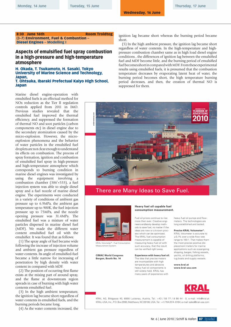
Tuesday, 15 June
Wednesday, 16 June
Thursday, 17 JuneMonday, 14 June
8:30 June 16th Room Troldtog(3–7) Environment, Fuel & Combustion – Diesel Engines – Modelling I
Aspects of emulsifi ed fuel spray combustion in a high-pressure and high-temperature atmosphereH. Okada, T. Tsukamoto, H. Sasaki, Tokyo University of Marine Science and Technology, Japan, T. Ohtsuka, Ibaraki Prefectual Kaiyo High School, Japan
Marine diesel engine-operation with emulsifi ed fuels is an effectual method for NOx reduction as the Tier II regulation controls applied from 2011 in IMO. Previous studies revealed that the emulsifi ed fuel improved the thermal effi ciency, and suppressed the formation of thermal NO and soot particles (carbon components etc) in diesel engine due to the secondary atomization caused by the micro-explosion. However, the micro-explosion phenomena and the behavior of water particles in the emulsifi ed fuel droplets are not clear enough to understand its effects on combustion. The process of spray formation, ignition and combustion of emulsifi ed fuel spray in high-pressure and high-temperature atmosphere which corresponds to burning condition in marine diesel engines was investigated by using the equipment involving a combustion chamber (386’×533), a fuel injection system was able to single diesel spray and a fuel nozzle of marine diesel engine. The experiments were conducted in a variety of conditions of ambient gas pressure up to 6.9MPa, the ambient gas temperature up to 900K, the fuel injection pressure up to 75MPa, and the nozzle opening pressure was 31.4MPa. The emulsifi ed fuel was a mixture of water particles dispersed in marine diesel fuel (MDF). We made the different water content emulsifi ed fuel oil with the emulsifi er. It was found that as follows:
(1) The spray angle of fuel became wide following the increase of injection volume and ambient gas pressure regardless of water contents. Its angle of emulsifi ed-fuel became a little narrow for increasing of penetration by high density with water content in compared with MDF.
(2) The position of occurring fi rst fl ame exists at the mixing part of around spray, and the fl ame at downstream region spreads in case of burning with high water contents emulsifi ed fuel.
(3) In the high ambient temperature, the ignition lag became short regardless of water contents in emulsifi ed fuels, and the burning periods became long.
(4) As the water contents increased, the
ignition lag became short whereas the burning period became short.
(5) In the high ambient pressure, the ignition lag became short regardless of water contents. In the high-temperature and high-pressure combustion chamber same as in high load diesel engine conditions , the differences of ignition lag between the emulsifi ed fuel and MDF become little, and the burning period of emulsifi ed fuel becomes short in compared with MDF. From these experimental results using emulsifi ed fuels, it is presumed that the combustion temperature decreases by evaporating latent heat of water, the burning period becomes short, the high temperature burning period decreases, and then, the creation of thermal NO is suppressed for them.
Fuel oil prices continue to rise more then ever. Creative engi-neers endlessly develop meth-ods to save fuel, no matter if the ideas are new or a known proc-ess which can be optimized. The KRAL fuel consumption measurement is capable of measuring heavy fuel oil with such accuracy, that the result can be verifi ed right away.
Experience with heavy fuel oil.The idea that precise meters are incompatible with high temperatures and abrasive heavy fuel oil components is still widely held. KRAL has many years of experience with
CIMAC World CongressBergen, Booth No. 14
heavy fuel oil pumps and fl ow-meters. The technologies are long established and tested.
Precise KRAL Volumeter®.KRAL Volumeter is accurate to ± 0,1% over a wide fl ow rate range to 100:1. That makes them the most precise positive dis-placement meters for marine applications such as oceangoingshipping, barges, fi shing vessels, yachts, oil drilling platforms, tug boats and supply vessels.
www.kral.atwww.kral-usa.com
Heavy fuel oil capable fuel consumption measurement.
KRAL Volumeter® - Fuel Consumption Measurement System.
KRAL AG, Bildgasse 40, 6890 Lustenau, Austria, Tel.: +43 / 55 77 / 8 66 44 - 0, e-mail: [email protected] -USA, Inc., P.O. Box 2990, Matthews, NC 28106, USA, Tel.: +1 / 704 / 814 - 6164, e-mail: [email protected]
There are Many Ideas to Save Fuel.
AWARDED IN THE
YEARBOOK OFADVERTISING
87Nr. 6 | June 2010 | Schiff & Hafen

Assessing the performance of spray and combustion simulation tools against reference data obtained in a spray combustion chamber representative of large two-stroke diesel engine combustion systemsR. Schulz, K. Herrmann, G. Weisser, B.v. Rotz, S. Hensel, F. Seling, Wärtsilä Switzerland Ltd, Switzerland, Y. M. Wright, M. Bolla, K. Boulouchos, Swiss Fede–ral Institute of Technology (ETH) Zürich, Switzerland
The optimization of the combustion systems of large marine diesel engines still relies largely on extensive testing; however, it is more and more supported by computational fl uid dynamics (CFD) simulations – in spite of limitations regarding the applicability of the available spray, evaporation, combustion and emissions formation models to those systems. As combustion is particularly sensitive to the fuel vapour distribution, the accurate simulation of spray and evaporation processes is seen as a prerequisite for reliable combustion and emissions formation results. In order to enable the validation of such simulations at conditions relevant to large two-stroke engines, a novel experimental setup was realized, consisting of an optically accessible, disk-shaped constant volume chamber of 500 mm diameter with peripheral injection into a swirling fl ow. In this setup, thermo- and fl uid dynamic conditions similar to those applying at start of injection of an engine are obtained by feeding pressurized and heated air or nitrogen to the spray combustion chamber (SCC) via inclined intake ports. The SCC has been used extensively for visualizing spray phenomena by means of shadow imaging techniques, thereby covering a large range of operating conditions, including non-reactive and reactive cases, as well as a variety of confi gurations, specifi cally with respect to the injector nozzle. In the present paper, those data are used for the validation of different CFD sub-models for spray and evaporation, based on initial conditions at start of injection, which have been derived on the basis of comprehensive simulations of the fi lling of the chamber, verifi ed separately through fl ow measurements. Additionally, since each spray is also affected by the conditions upstream the orifi ce, the fl ow inside the injector is simulated in order to identify its effect on the injection boundary conditions, thereby taking into account the geometry of the nozzle tip actually used in the SCC tests, which is determined by means of computer tomography. This investigation hence focuses on the key aspects of spray and evaporation simulation, including different fuel modelling approaches and injector geometry effects. It allows identifying the most suitable models and model combinations, thereby establishing a basis for the simulation of combustion and emissions formation, and thus represents a major step towards the application of CFD for actual combustion system optimization.
Modelling of the oxidation of fuel sulphur in low speed two-stroke diesel enginesA. Andreasen, S. Mayer, MAN Diesel & Turbo SE, Denmark
In large marine two stroke diesel engines during combustion of sulfur containing fuel, the sulfur is oxidised to SO
2, mainly,
although substantial amounts of SO3 and H
2SO
4 will form as well.
These latter species may cause corrosional wear of the cylinder liner if not neutralised by lube oil additives. Potential attacks is due to either condensation of sulfuric acid on the cylinder liner lube oil fi lm or direct dissolution of oxidised sulfur species in the lube oil fi lm in which reaction with dissolved water may be the source of acidic species. In order to evaluate and predict corrosional
wear of the liner material, it is pivotal to have realistic estimates of the distribution/concentration of oxidised sulfur species as well as a reliable model of formation, transport and destruction of acidic species in the oil fi lm. This paper addresses the former part by invoking a detailed reaction mechanism in order to simulate the oxidation of fuel bound sulfur and predicting the concentration of SO
2 as well as the conversion fraction into SO
3 and H
2SO
4. The
reaction mechanism is coupled to a realistic model of the combustion process in which the air entrainment into the combustion zone is accounted for. The results of the simulation are evaluated with respect to previously applied models as well as existing data on the conversion fraction of SO
2 to SO
3 and H
2SO
4.
The conversion fraction is found to be in a range of 2.6-6.7 %.
A study on the spray combustion characteristics of bio diesel fuelA. Azetsu, K.-O. Hagio, M. Aoki, Tokai University, Japan
Bio-derived fuel, such as vegetable oil and so forth, is a renewable energy and obtained a considerable amount of interests as a promising alternative fuel for IC engines. Concerning the alternative fuel for diesel engine, fatty acid methyl ester, FAME, is now in the stage of practical usage. The production of FAME is examined from many vegetable oils such as palm oil, rapeseed oil, coconuts oil, etc., and there are many studies concerning the applicability of FAMEs as an alternative fuels for diesel engines. However majority of those studies are engine tests to examine the effect on engine performance and emission characteristics, and the study concerning the fundamental characteristics of spray combustion, i.e., ignition delay, fl ame temperature and soot production characteristics are still needed. From these backgrounds, the objective of our study is to understand the fundamental spray combustion characteristics of FAME mixed with diesel oil, called Bio Diesel Fuel hereafter. To examine the phenomena in detail, diesel spray fl ame formed in the constant volume high pressure vessel was visualized and the fl ame temperature and the soot concentration were analyzed by two color method of luminous fl ame. The ambient high-pressure and high-temperature conditions inside the constant volume vessel were achieved by the combustion of hydrogen in an enriched oxygen and air mixture. The composition of the mixture was such that the oxygen concentration after hydrogen combustion was approximately 21% by volume. Following hydrogen combustion, fuel was injected into the vessel at the time when the ambient pressure reached the expected value, and the spray combustion was then examined. The fuel injection system used in the present study is an electronically controlled accumulator type fuel injection system developed by the authors. The ambient pressure and temperature were set to 3MPa and 930K, and the injection pressure was set to 100MPa, a typical ambient and injection conditions of modern diesel engine. Spray combustion was photographed using the ICCD camera and the two-color method was used to evaluate 2-D temperature and soot distributions in fl ame. In this two-color pyrometry system, a doubling prism with two different band-pass fi lters was placed in front of an ICCD camera to obtain the two spray images simultaneously. The FAMEs examined in this study are Palm Methyl Ester, PME, Rapeseed Methyl Ester, RME and Coconuts Methyl Ester, CME, and compared with the combustion characteristics of diesel oil. From the systematic experiments, it is explored that the characteristics of ignition delay is well explained by the Cetane number of bio diesel fuels and that of PME is the shortest. The fl ame temperature of bio diesel fuel is lower than that of diesel oil by 50 to 100 K, which can be explained by the C/H ratio of each fuels and the fl ame temperature of CME is the lowest. Furthermore soot production decreased drastically by using the bio diesel fuel in
88 Schiff & Hafen | June 2010 | Nr. 6
CIMAC CONGRESS | BERGEN 2010

Tuesday, 15 June
Wednesday, 16 June
Thursday, 17 JuneMonday, 14 June
the order of the mass fraction of oxygen in the molecule. The soot production of CME is extremely lower than that of diesel oil, therefore CME should be an promising candidate for the fuel of clean diesel engines.
8:30 June 16th Room Klokkeklang(8–4) Integrated Systems & Electronic Control – Engines, Turbines & Applications – Electronic Control Systems
From remote monitoring to life-cycle asset management – The development of a new service conceptJ. Pensar, Wärtsilä Corporation, Finland, R. Windischhofer, Abo Akademi University, Finland
During the last decades, information and communication technology has enabled a rapid development of information based services for various technical installations. At the same time, the demands of investors, owners, and authorities to improve the performance of their investments have increased, which puts new expectations and requirements on service solutions for industry. In this paper we explain the change of remote condition monitoring services from a technical expert service to a service solution which focuses on improving the overall commercial and technical performance of an industrial asset. Critical review of the evolution and current state of remote condition monitoring services gives that the expectations seldom have been realized in form of true practical achievements, and in case of success, the results have been rather limited. Typically, the solutions derive more from a technical opportunity than from a thorough understanding of the user needs. This has resulted in solutions that have been too technical, too fragmented or too limited to really utilize the possibilities to add a considerable value from a total life-cycle view. To defi ne a service concept with a real and substantial value for the life-time management of engineering assets, the service requirements have to be studied from a different point of view. We describe a framework and a concept for potential services, where substantial focus has been put on investigating the real user needs. In the study, aspects like a wide scope of services, modularity, a reduced number of applications and interfaces, synergies between technical and commercial services, information integration, operational effi ciency, risk management, as well as the means of communication within and between organizations have been considered. This concept has further on been implemented in a real-life pilot implementation, in which it has been further refi ned to match to the user needs. The paper also extends the discussion towards lacking standardization in the fi eld, the need of combining different knowledge areas, new requirements on supplier and user collaboration, and it elaborates on the possible merits and drawbacks international standards could offer in order to reach a more widespread development of real value adding services.
Permanent diagnosis and optimization of large-bore marine engine operation with expert based AVL EPOSTMH. Mohr, R. Teichmann, N. Mayrhofer, AVL List GmbH, Austria, C. Pfister, AVL AUTOKUT Engineering Kft., Hungary, R. Johansen, Kongsberg Maritime AS, Norway
The shipping companies are facing strong demands to reduce operational costs, fuel consumption and emissions. Beside the
current economical situation new emission legislations are going to affect this business in a short term. This leads to the need for a continuous holistic ship operation optimization with special focus onto the engine room. AVL EPOSTM enables a permanent online monitoring and diagnosis of the propulsion and auxiliary engines - two-strokes and four-strokes - onboard a vessel. The outcome allows the operators a persistent engine operation optimization. This system develops its maximum performance as one heartpiece of Kongsbergs vessel performance optimizer, integrated in the respective marine automation system. The fi rst version of AVL EPOSTM was introduced together with Kongsberg Maritime into the market in June 2009. The system has been developed by utilizing AVLs typical core competencies and products from the large engine division, the instrumentation and test system division and the advanced simulation technology division in combination with extensive internal and external practical experience. AVL EPOSTM is based on well-proven in-house software tools. A big part contains the algorithms of the expert system. The software is engineered with an open platform concept allowing the integration of all kind of measurement systems for e. g. shaft torque, bearing clearance and temperature. The current version allows the online diagnosis of the fuel injection and the combustion, latter in combination with AVL cylinder pressure sensors suitable for long-term online operation with HFO, biofuel or gas. Several of these sensors are in operation on various kinds of engine types in different installations with operating times of up to 14.000 hours. Since 2008 two pilot installations are in operation in the fi eld: one on the car carrier ’H¨oegh Detroit’ with a HFO-fueled slow-speed main engine and one in the stationary power plant Stendal with mainly gas-riven dual-fuel medium-speed engines. Both installations showed a very reliable behaviour delivering very accurate results and diagnoses. The cylinder pressure sensors showed no operation related failure up to now. Since mid of 2009 a test installation on the container vessel ’Maersk Drury’ is in operation fulfi lling the ship owners expectations clearly. Currently several extensions of AVL EPOSTM are under development, e.g. automatic TDC correction, thermodynamical turbocharger monitoring, prediction of component behaviour and NOx modelling. As fi nal goal it is foreseen to extend AVL EPOSTM to all relevant zones and auxiliary systems for capturing the engine operation in its entireness.
Applying close loop control, ‘Auto-tuning’, to MAN Diesel two-stroke enginesT. Moeller, MAN Diesel & Turbo SE, Denmark
This paper will introduce the development and technical description of closed loop engine control, ”Auto-tuning”, and furthermore demonstrate the service experiences and conclusions gained from applying the concept to MAN Diesel two-stroke ME as well as MC engine types. The continued focus on reducing fuel oil consumption, emissions and overall operational costs has, combined with availability of new reliable technologies, allowed for development of new systems to more effectively obtain results in these areas. One of the means is the MAN Diesel ”Auto-tuning” concept, that by clever innovation addresses all of the areas, without adding considerable system complexity and installation costs - as otherwise is typically the case of other concepts. The later years progresses in sensor technology have made high accurate & reliable sensors with long life time available for two-stroke applications. The MAN Diesel ”PMI online” system for continuous cylinder pressure measuring, utilises sensors provided by either ABB or Kistler. With the MAN Diesel ”Auto-tuning” concept, our ”PMI online” system is integrated into the engine control system (electronically controlled engines) for continuous close-loop tuning of the engine. This paper will discuss and present the
89Nr. 6 | June 2010 | Schiff & Hafen

challenges identifi ed as well as the full scale fi eld test results observed in respect to which of the traditional key parameters (Pmax, Pcomp, PI) that from a cost benefi t approach is target for being auto-tuned. Not only actual engine type and layout infl uences this targeting, also safety issues, transparency of the tuning process towards the operator, remote tuning opportunities and strategy for handling the non-linearity of the process to be adjusted is among the aspects to be taken into account. The paper primarily focuses upon applying ”Auto-tuning” to electronically controlled engines. However, the additional challenges to overcome by introducing ”Auto-tuning” also for conventional engines with camshaft operated fuel plunger and exhaust valves is outlined. For these engines, the existing VIT (Variable Injection Timing) is replaced by a continuous close loop control of the VIT actuation, integrated with the Auto-tuning system. The MAN Diesel developed concept for ”Auto-tuning” is capable of optimising operation of the engine to well within the recommended maximum deviation and operation limits, thereby allowing for an optimisation with considerable benefi ts to be gained even for engines already being operated ”well” from an traditional point of view. The optimisation is achieved even though the ”Auto-tuning” system in fact utilises the same handles as otherwise used by the operator for manual adjustment, at the same time dramatically limiting the required operator efforts to keep the engine always optimal tuned. By ensuring optimised engine tuning, we have actively lowered operational costs, and generally improved system effi ciency. Thereby, a positive effect has been achieved on the total fuel consumption as well as the overall environmental impact on the surroundings. This paper will reveal the newly developed techniques & means reaching this important target.
The UNIC embedded controls – fi rst years of fi eld experienceJ. Pensar, Wärtsilä Corporation, Finland, J. Akerman, F. Oestman, P. Juppo, Johan Grankull, Wärtsilä Finland Oy, Finland
In 2002, Wärtsilä took a decision to develop a new embedded control system for harsh environments as a strategic move to ensure the performance and reliability of future products. The requirements on the system were set very high – unsurpassed reliability, high fault tolerance, extreme scalability and fl exibility as well as a cost effi cient design were some of the objectives. The outcome of the design eventually became known as UNIC – Unifi ed Controls – and was fi rst introduced on engines in the fi eld in 2005. The development of the more complex features was, however, at that time still ongoing, and the fi nal and most advanced applications went into commercial operation in 2008. The design introduced novel ideas related to sensor design, cabling, electronics, fault tolerance and redundancy that enabled a both reliable and cost effi cient design. The system also introduced new possibilities for advanced engine control, with several patented inventions related to e.g. engine speed/load control as well as fuel injection, pushing the envelope for what can be considered state-of-the-art in engine controls. It should, however, be remembered that only the real-world experience will show the actual reliability of the system. Today this system has been delivered with thousands of engines and has acquired more than fi ve million cumulative operation hours in the fi eld. This gives us now the opportunity to review how well the design ideas and assumptions have turned out in practise and how well the system has withstood the test of the realworld. This paper guides us through the project, focusing not only on the aspects and assumptions that turned out to be successful, but also on the problems, failures and rework that occurred during the introduction process. Based on this experience, some important
lessons can be learned for future work. In addition, this paper also refl ects on the future development of controls, looking towards the future on both embedded controls and its relation to the Big Picture, i.e. effi cient system integration and total solutions.
10:30 June 16th Room Peer Gynt Salen(11–2) Users’ Aspects – Marine Applications – Monitoring
Shipboard engine performance assessment by comparing actual measured data to nominal values produced by detailed engine simulationsN. Kyrtatos, E. Tzanos, NTUA, Greece, J. Coustas, D. Vastarouhas, E. Rizos, Danaos Shipping Co. Ltd., Greece
During the lifetime of a ship’s engine, the original shop trials and sea trials are often the only available reference conditions, which can be used for engine performance analysis, during ship operation. In the case of container vessels, the engine actual operating point may be far away from any reference conditions. In addition, charterers may request different operating regimes for the ship. In such cases, the shipping company needs to predict, with confi dence, details about the operation and performance of the engine and its auxiliaries, in conditions where there is no measured or reference data. Extrapolation, using corrected fi gures from shop/sea trials, often results in errors. This paper presents a novel method and procedure for obtaining performance fi gures for a specifi c shipboard engine, at any possible operating point, at different operating regimes. These reference fi gures are produced by using detailed simulation models for engine performance prediction. Up to now, such detailed models are mainly used by manufacturers for engine design. The nominal performance fi gures produced by detailed simulation models can also be used as reference, to compare with any shipboard measured actual performance data, for engine performance evaluation. The paper describes the above procedure used by Danaos Shipping Co. on two different main engines of large containerships, typical of its fl eet. The implementation initially involved collection of geometric and operational data for each engine. Then the generic engine simulation software Mother (Motor Thermodynamics) was tuned and pegged using the shop test data and initially validated using the sea trials data for each specifi c engine. The results of simulation allowed prediction of all engine parameters within 3% of actual measured values at sea trials. A task force within the Danaos Technical Department was specially trained in using the simulation software. Further sets of simulations at operating conditions away from sea/shop trials, allowed the prediction of all engine parameters and comparison to measured data and thus provided a good baseline for engine performance evaluation and condition assessment.
One way to condition-based survey for marine diesel enginesJ. Rebel, Germanischer Lloyd, Germany
Particularly in times of economic crisis, availability and hence reliability is very important for cargo vessels. This is the main reason why an increasing number of shipping companies invest in condition monitoring technology and move towards conditionbased maintenance. Classifi cation societies are involved in this subject in order to support non-open-up surveys by offering respective survey arrangements. Since 2005, Germanischer Lloyd
90 Schiff & Hafen | June 2010 | Nr. 6
CIMAC CONGRESS | BERGEN 2010

Tuesday, 15 June
Wednesday, 16 June
Thursday, 17 JuneMonday, 14 June
has been engaged in pilot projects for condition monitoring (CM) systems covering the crank-train of two-stroke crosshead diesel engines and other items of diesel equipment. The main engine of the test vessels C/V “Norasia Alya” and C/V “Hamburg Express” are equipped with bearing wear condition monitoring. In joint industry projects, the shipping company, the engine licenser, the manufacturers of the CM systems and the GL as the responsible classifi cation society have been working closely together in order to gain fi eld experience with these tools and to develop an effi cient way to condition-based survey procedures. The paper continues the presentation of selected results of the ongoing fi eld tests regarding the verifi cation of the condition monitoring method and the defi nition of requirements for the condition-based maintenance procedures. In case of the crank-train bearing monitoring, the condition-based survey procedure is fully developed and will be presented for both vessels.
Development of a remote non intrusive diagnosis system for two stroke diesel enginesF. J. Jimenez-Espadafor, J. A. Becerra Villanueva, M. Torres Garcia, T. Sanchez Lencero, Seville University, Spain, F. Fernandez-Vacas, M. Bueno del Amo, Endesa Generacion, Spain
Maintenance cost and unexpected failures can be drastically reduced in low speed diesel engines using vibro-acoustic analysis.
This methodology has presented as a reliable method for detection of manufacturing faults, running damages and other abnormalities in engine and its components. Continuous trending keeping deviations of monitorized parameter allows also reduction of fuel consumption, optimize exhaust emissions, and increase components life time and increase safety. This paper describes the method of vibration monitoring for fault diagnosis based on time-windowing and frequency analysis. The effectiveness is demonstrated based on the results of two year operation on a large two stroke power plant diesel engine, located in Mahon, Spain.
Evaluation method of engine and propulsion shaft alignment for large vesselI. Sugimoto, T. Nakao, Hitachi Zosen Diesel and Engineering Co., Ltd., Japan
Propulsion shaft alignment of large vessel is sensitive to draft change from light draft to full load draft. Each initial bearing offset of the shaft alignment changes by the fl uctuation of draft level. Especially, it presents vessels such as VLCC and large bulk carrier. The reasons include a propulsion shaft diameter stiffer and an engine main bearing center distance shorter. Those correspond to engine development trend of higher power and more compact size. The initial bearing offset change affects each bearing performance. In some cases, the change causes sever trouble to an engine and propulsion shaft. It is necessary to estimate an engine crankshaft and propulsion shaft alignment against a draft change for both engine development trend and improving reliability of bearings
BRUNVOLL – the single
source supplier of thrustersystems
Refined and proven concepts
teamed up with supreme
technical solutions ensureslow life cycle costs
BRUNVOLL – manufacturer of
• Tunnel Thrusters
• Azimuth Thrusters
• Low-Noise Thrusters
• Thruster Control Systems
A successful story...Thruster Systems from BRUNVOLL
Brunvoll’s operation is dedicated tothrusters, and we supply and servicecomplete thruster packages
We take fullresponsibilityfor your thrusterneeds, includingdrive system packages
For more information,
www.brunvoll.no
BRUNVOLLStrandgata 4-6,N-6415 Molde
Tlf. +47 71219600
e-mail: [email protected]
91Nr. 6 | June 2010 | Schiff & Hafen
and shafts. Our past study was mainly focused on engine bearings in service condition. Before in service, it is indispensable for users to estimate reliability both of engine and propulsion shaft alignment against a vessel deformation and engine thermal expansion. So, an evaluation method of both engine and propulsion shaft alignment has developed for large vessel such as VLCC and bulk carrier. Input parameters are a vessel deformation information and an engine thermal expansion data. The vessel deformation is able to be given by a vessel deformation result by a FEM analysis, a directly measurement result of shaft alignment of a similar vessel or an inverse calculation result of shaft alignment of a similar vessel by using our developed software. In this tudy, an inverse calculation result is used. The evaluation values are conventional shaft alignment calculation values and engine crankshaft values. The conventional shaft alignment values include bearing load, propulsion shaft angle at stern tube bearing, shaft bending moment and shaft bending stress. The engine crankshaft values are crankshaft defl ection and bearing load. Calculation parameters are intermediate shaft bearing height, engine bearing height and engine inclination, which are decided by a vessel deformation and an engine thermal expansion. The calculation procedures are as follows.
(1) A certain shaft alignment for initial condition is set.(2) Shaft alignment after considered a vessel deformation for a
vessel draft condition and an engine thermal expansion is calculated.
(3) Output values are calculated.(4) Each output value is estimated whether to meet or not with
permissible values.(5) Permissible vessel deformation and draft level is solved.
By calculating the shaft alignment including the whole range of designed draft level, allowable shaft alignment area is able to be solved. The validity of this method is confi rmed that the already serviced vessel data are enough for reliability within the allowable area. It is also confi rmed that the vessel deformation and engine thermal expansion infl uence mainly engine aft side bearing. A stern tube bearing performance is determined by initial installation and is not infl uenced by a vessel deformation and engine thermal expansion. Finally, it is clarifi ed that a conventional design is essential for the stern tube bearing, and it is necessary for engine bearing to consider a vessel deformation. At a vessel under construction, this method is able to indicate the allowable value of intermediate shaft bearing height, engine bearing height and engine inclination. And for in-service vessel, by using the inverse shaft alignment calculation, safety margin of shaft alignment against vessel deformation is able to be indicated.
10:30 June 16th Room Scene GH(2–2) Fundamental Engineering – Piston Engines – Mechanics
Comparison of crankshaft calculation methods with reference to classifi cation societies’ requirementsM. Savolainen, H. Tienhaara, Wärtsilä Oy, Finland, T. Resch, AVL List GmbH, Austria, B. Smiljanic, AVL AST d.o.o, Croatia
Crankshaft strength analysis methods have signifi cantly developed since last ten years. Modern numerical methods combine fl exible multi-body dynamic simulation, Finite Element method and multiaxial fatigue criteria to predict local stresses under realistic boundary conditions very accurately. In parallel traditional, analytical methods and rules as Unifi ed Requirement M53 are still used and have their place in large engine development due to their
stability and reliability. Therefore they are also used by classifi cation societies. Nevertheless, durability results between different methods can vary signifi cantly due to their different approaches, representation of structures and loads, but also material data consideration and infl uence factors. Modern numerical methods also have the disadvantage that they can be considerably dependent on the tools involved and even the user, due to high number of required input and their deviation, as well as the complexity of the usage in general. Due to the necessity for high reliability, especially for large engine crankshafts, on one hand, but new demands in sense of effi ciency and costs on the other hand, which can hardly be covered by traditional approaches, it is important to enhance the current rules to go closer to the limits and reach the new targets, but avoid loosing the stability of these methods. Therefore the relation between the methods and their results is of interest to be able to connect them or further develop the traditional ones. Within the current project different methods for crankshaft fi llet strength are analyzed and compared. The present work is done within the CIMAC Working Group 4 and discusses a sequence of different approaches, starting from original UR M53 up to most complex approach using MBS, FEM-structures and multi-axial fatigue method. Each step is based on the previous one and differences in results are outlined to detect the specifi c infl uences of each approach. Focus is set on the local stresses and safety factors in pin and journal fi llets of the specifi c crankshaft. The target crankshaft is a modern 20-cylinder 4-stroke ship engine crankshaft from Wärtsilä. The examined operating condition is 600rpm with full load. Specifi c infl uences are investigated separately. Most important are stress concentration factors from analytical defi nition, via FEM based ones, up to direct evaluation of stresses, which avoids the usage of such factors, the load defi nition and the resultant local stresses. Loads are derived from analytically calculated bending moments in combination with torsional torque from separate torsional vibration analysis up to full 3-dimensional and transient coupled bending and torsional ones. Effects of phasing between loads and stress components as well as mean stress infl uence are worked out. Additional infl uences from material defi nition, infl uence factors and the usage of different fatigue methods are compared.
Fatigue design and optimization of diesel engine cylinder headsT. Gocmez, Institute for Combustion Engines VKA RWTH Aachen University, Germany, S. Lauer, FEV Motorentechnik GmbH, Germany
Cylinder head high cycle fatigue (HCF) and thermomechanical fatigue (TMF) behavior has become more critical under today’s stringent demands, where modern engines are increasingly designed much closer to their mechanical limits. Often, the problem of critical loading of cylinder heads is solved by a material variation and/or by a design change - depending on the most critical fatigue mechanism. This leads to additional design iterations and accordingly costs. Therefore, an optimized design done in early phases of engine development lowers the cost. This paper aims to give an insight on optimization possibilities (production process, material selection, design features) and a focus on integrated cylinder head design optimization for cost effective engine development. An integrated simulation approach covering the development needs in terms of turnaround times, accuracy and reliability during the different phases of cylinder head engineering process is presented. A through understanding of fatigue mechanisms via design of experiments is provided along with primary material and design feature selection criteria, mathematical formulation of the design optimization problem and cylinder head
92 Schiff & Hafen | June 2010 | Nr. 6
CIMAC CONGRESS | BERGEN 2010

Tuesday, 15 June
Wednesday, 16 June
Thursday, 17 JuneMonday, 14 June
optimization roadmap. Showing that TMF is a global problem and HCF is a local one, pre- and post-optimization measures for the former and latter are proposed, respectively. Emphasis is given to increased quality in entire development process by “do it right the fi rst time” philosophy, where analysis of mass distribution on cylinder heads and 1D heat transfer through the combustion chamber walls taking into account the coolant side boiling effects are integrated to the frontloading. A new solution for the TMF problem of heavy duty cylinder heads, by the introduction of a groove between bore diameter and sealing diameter on cylinder head fl ame deck, is presented as well. The result is maximization of effectiveness of calculation methods on the end product. The integrated usage of benchmark, empirical, analytical and fi nite element methods, which are explained throughout the paper, delivers an optimized dimensioning process of valve bridge width and thickness at concept phase and removal of local structural weaknesses on cylinder head coolant jacket side at detailed design phase. The application of proposed methods is provided on an example high end diesel engine cylinder head with 100kW/L specifi c power and 250 bar peak fi ring pressure. The initial dimensioning of the valve bridge proved to be safe in terms of TMF and 40-50% improvement in safety factors of local HCF critical regions are achieved within fi ve iterations of an automatic overnight calculation, proving the effectiveness and effi ciency of the proposed methodology. Keywords: cylinder head, high cycle fatigue, thermomechanical fatigue, TMF groove, structure optimization
Fracture mechanics approach to contact problems in medium speed diesel enginesC. Loennqvist, A. Maentylae, Wärtsilä Finland Oy, Finland
A medium speed diesel engine contains many components that are intended to transmit high static and/or dynamic loads. To be able to transmit these loads, the components are joined to the engine block, or to sub-assemblies, with heavy-duty screws or interference fi ts. A high pre-tightening force or interference level is applied in order to obtain proper functioning of these joints. Due to complicated geometry, concentration of pre-tightening force around the screw-hole, difference in compliance of the joined parts, machining errors and waviness, it is sometimes diffi cult to
obtain an evenly distributed contact pressure. This, in connection with superposed cyclic external loading, may cause interfacial sliding to localize at regions where contact shear tractions reach a certain limit value: friction factor times contact pressure. This process is often referred to as fretting and may cause irreversible damage in the form of wear and/or fatigue crack nucleation at stick-slip boundaries. It is particularly perilous as it often is allowed to progress undetected until fi nal failure. Many factors, such as the material combination, microstructure, variation of friction coeffi cient, number of cycles and infl uence of steep stress gradients, make fretting especially challenging to approach from a calculation point of view. In 2004 Wärtsilä therefore initiated a multi-collaborative research project with the ambitious aim to develop calculation methods and design rules that take fretting into consideration. The third and currently on-going continuation project is greatly focusing on the complete type of contacts, the category to which most of the contacts in medium speed diesel engines belong. The mating surfaces of engine block and liner, engine block and main bearing cap, counterweight and crankshaft are a few examples. In practice, analysis has to be conducted with the help of numerical methods like the fi nite element method (FEM) which allows contact-related displacement and traction fi elds of complex geometries to be solved. Sharp corners that constitute typical regions for crack nucleation, nevertheless, introduce singularities that require the use of an extremel dense mesh and an elastic-plastic material model. In this aspect, fracture mechanics and the application of generalized stress intensity factors developed by researchers at the University of Oxford offer a promising approach. This approach has an analogy with familiar linear elastic fracture mechanics, hence it assumes that the critica traction fi eld scales with a proportionality constant. The attractiveness of the method is, among other things, found in the much lighter FE model its implementation requires. Tests with sharp cornered pads were therefore conducted at the University of Oxford with the aim to obtain a test setup that resembles a fl at-on-fl at contact of actual engine components. The results show that the knock-down factor with sharp-edged corners, as in comparison with plain fatigue, may be as high as 3.8. The test outcome correlates well with the analysis results obtained from implementation of a fi ne FE model and elastic-plastic material model. Moreover, the correlation by application of critical stress intensity is also in good agreement.
The very new exhaust gas cleaning system.There is no longer an excuse!
www.couple-systems.comPM, SOx and NOx reduction according to IMO regulations (Marpol Annex VI)
Tel.: 040 526 000 900 / Fax: 040 526 000 939 / mail: [email protected]
93Nr. 6 | June 2010 | Schiff & Hafen

The infl uence of hull defl ection and propeller loading on load distribution in engine bearingsB. J. Vartdal, Det Norske Veritas AS, Norway
Out of damage cases reported to DNV, one of the most common machinery related damages experienced for direct coupled diesel engines are those to main engine bearings and in particular to the aft most engine bearings which are infl uenced by the alignment of the propeller shaft. The effect of the shaft alignment on the main engine bearings are to be accounted for by the shaft alignment calculation. However, historically the shaft alignment calculations have considered the only varying parameter affecting the load distribution of the main engine bearings to be due to structural changes of the main engine as caused by thermal variations. Other known parameters such as hull defl ections and propeller forces are known to affect the main engine bearing loads, but these parameters have been omitted mainly due to the complexity associated with determining such parameters. Since 2001, DNV have carried out a research project in order to quantify the infl uence of hull defl ections and propeller loads on shaft alignment and load distribution in propeller shaft and main engine bearings for direct coupled drive trains. The project included full scale measurements as well as comprehensive fi nite element and CFD analysis designed to quantify and assess the effect of such parameter variations. The measurements and analyses have been carried out for a number of vessels. Several vessels within the same vessel type have been studied as well as different vessel types. The vessel types studied are VLCC’s, container vessels and LNG’s. The part of the study presented here focuses on main engine bearings and the potential for variation of load distribution in the main engine bearings caused by feasible parameter variations experienced during vessel operation. Such parameters include hydrostatically induced hull defl ections, hull defl ections caused by tank fi lling, hull defl ections caused by hydrodynamics, propeller thrust, lateral propeller forces and thermal effects. The results of the study clearly indicate the relative importance of each of the infl uencing parameters and that the need to include the infl uence of the parameters studied depends on the shafting and the vessel type.
10:30 June 16th Room Troldtog(3–9) Environment, Fuel & Combustion –Diesel Engines – Downstream Components
Theoretical and practical results of engine and exhaust gas performance optimisationH. Jungbluth, A. Tippl, Innospec Ltd., Germany, D. Daniels, Innospec Fuel Specialties, USA, I. Crutchley, Innospec Limited, UK, S. Bludszuweit, H. Stueckrad, MET Motoren- und Energietechnik GmbH, Germany
The economic crisis, the global target on emission reduction as well as cost speed effi ciency has led to slow steaming, which causes a higher deposit formation in the combustion process and negatively infl uences the exhaust gas equipment. The negative impact of deposit formation on internal combustion equipment effi ciency, operations, and subsequent cost is well documented in literature. This paper will not only describe this phenomenon; it will provide a theoretical calculation about the impact of the deposit formation on the turbocharger effi ciency as well as practical methods to reduce and avoid these deposits. The formation of deposits in internal combustion engines and its infl uence on fuel economy was studied by developing a foresighted calculation and
by practical tests onboard ships. The presented investigation of the deposit formation is, in part, described as initiating with an induction phase. This phase is immediately followed by continual deposit growth until it reaches an equilibrium phase of growth and decay. Deposit growth is infl uenced by numerous factors. These factors include but are not limited to time, combustion environment, composition of the materials that form the deposits, and physical conditions at the location of formation. Engine effi ciency can only be restored by removal of existing deposits, or more preferably by avoiding the induction phase itself. Avoiding the induction phase is best accomplished by precluding the initial formation of a liquid surface layer of deposit precursor material. The simulation as well as the fi eld trials will show that keeping the exhaust gas system clean will avoid effi ciency losses of the turbocharger system and improve environmental sustainability. A more complete combustion achieved by chemical fuel treatments will reduce deposit formation signifi cantly. By example, only a clean turbocharger will avoid effi ciency losses, which result into a fuel benefi t of approximately 2 % or more depending on the equipment. These concepts will be proven by new innovative theoretical calculations and substantial fi eld evidence. There are several known cleaning procedures for the turbocharger equipment. However, the optimum, most cost effective and most convenient method of protecting the equipment is to avoid fouling.
Exhaust gas heat recovery on large engines – potential, opportunities, limitationsI. Vlaskos, P. Feulner, A. Alizadeh, I. Kraljevic, Ricardo Deutschland, Germany
Improving effi ciency is a major development trend in all applications of energy conversion. This applies to large engines especially, since the ecological benefi t of reduced greenhouse gas emissions is going hand in hand with the economic advantage of reduced fuel cost. In recent years conversion of exhaust gas heat to useful work has become a focus of development efforts in many branches of combustion engine work. This paper looks at the potential, which can be realised by staged processes, the opportunities for utilisation on large engines and some pertinent limitations. To this end a hypothetical large engine is conceived and some options for exhaust heat recovery systems are calculated for application on this engine. Analysis is limited to operation at full load and rated speed since the positive impact of any improvement of effi ciency is greatest there and furthermore many large engines in energetic installations (power stations) are routinely operating at these conditions. Since steam and ORC systems are currently en vogue and widely covered in a great number of publications this paper will concentrate on gas cycles.
Next generation of fl exible and reliable SCR-systemsC. Gerhart, H.-P. Krimmer, Alzchem Trostberg GmbH, Germany, B. Schulz, NIGU Chemie GmbH, Germany, O. Kroecher, Paul Scherrer Institute, Switzerland, D. Peitz, Paul Scherrer Institute, Germany, Th. Sattelmayer, P. Toshev, Lehrstuhl fuer Thermo-dynamik, Technical University of Munich, Germany, G. Wachtmeister, A. Heubuch, Lehrstuhl fuer Ver-brennungskraftmaschinen, Technical University of Munich, Germany
Driven by upcoming tighter emission regulations for internal combustion engines selective catalytic reduction (SCR) technology
94 Schiff & Hafen | June 2010 | Nr. 6
CIMAC CONGRESS | BERGEN 2010

Tuesday, 15 June
Wednesday, 16 June
Thursday, 17 JuneMonday, 14 June
had become state of the art. With SCR lowest NOx levels could be reached. SCR had been adapted to mobile onroad applications from heavy duty [1] down to smaller engines in passengers cars. Now fi rst installations also for larger, nonroad or stationary engines have been realized. The integration of SCR with AdBlue R as standardized aqueous urea solution is already in operation in a variety of onroad applications [2]. Still there are reliability and operation problems to overcome concerning solid residues, mixing into the exhaust gas fl ow and effi cient decomposition upstream or directly on the SCR-catalyst. Also for nonroad engines in many cases standard AdBlue R as ammonia precursor does not fulfi l requirements in the various applications. Of interest would be a better ammonia release potential per litre, less water in the liquid solution and in some cases an improved stability concerning freezing at the lower end and less decomposition and consequently less vapour pressure at the higher end of the ambient temperature conditions. The direct use of ammonia gas from pressure vessels has already been banned in mobile onroad applications due to critical safety issues while handling and in the supply chain. Throughout the search of a safe, liquid ammonia precursor, guanidinium salts came into the focus of further investigations [3]. These high-N containing and non-toxic substances could become a new class of molecules as ammonia precursor in a variety of formulations depending on the application. Especially guanidinium formate has a extremely high solubility of more than 6 kg in 1 litre water (equal to > 0,52 kg NH
3/l compared to 0,2 kg NH
3/l of AdBlue
R ). Guanidinium formate could be used in formulations with urea and water depending on the application: without urea as highly concentrated solution with an elevated freezing point but high stability up to 100°C or as an eutectic mixture with urea (e.g. 41% guanidinium formate, 16% urea) resulting in a freezing point below -30°C. Investigations on the hydrolysis have shown that this guanidinium salt can be completely decomposed to ammonia on a titania hydrolysis catalyst above 200°C. Due to the low water content of the liquid solution about 50% less energy is required for complete heating, evaporation and decomposition to ammonia compared to AdBlue R . The main difference compared to aqueous urea is the slightly elevated optimum temperature for complete decomposition. A complete, reliable and independently working system of such a next generation SCR should include a small and compact ammonia generator containing a hydrolysis catalyst operating under well defi ned conditions. A simple bypass reactor unit for the decomposition of the liquid precursor to ammonia gas could have advantages e.g. in availability of ammonia and be more independent of the exhaust or engine conditions. The complete decomposition to ammonia would occur under controlled conditions. Specifi cations and investigations on such a type of ammonia generator will be presented.
Attenuation of low-frequency exhaust noise from combustion enginesS. Frederiksen, C. Ammitzbo, Silentor A/S, Denmark, B. B. Jessen, Delta, Denmark
There is an increased awareness about disturbance caused by low-frequency exhaust noise from all types of combustion engines. Especially large, 2-stroke engines are characterized by a low ignition frequency which increases the risk of prominent noise at this frequency and at higher harmonics. When the frequency of a sound wave is low, there will be less attenuation at transmission through walls, windows, etc. In addition, low frequencies are associated with relatively long wavelengths that may coincide with distances between walls, whereby strong, standing waves can be set up. This increased awareness includes, not only audible sound of
low frequency, but also infra-sound (below around 20 Hz), which cannot be heard, but felt, to a degree which varies from one individual to another. Although the matter from a medical point of view is still somewhat obscure, there is scientifi c evidence that some people are sensitive to infra-sound to a degree that can documented objectively. Accordingly, some noise regulations today stipulate maximum allowable noise level within a wide frequency spectrum, including values at infra-sound frequencies. Therefore, the acoustic engineer cannot ignore the issue of infra-sound, apart from disturbance caused by noise within the audible spectrum. Conventional silencers can indeed yield satisfactory attenuation at all relevant frequencies, but stringent demands regarding low-frequency performance tend to call for ample accommodation space and for an allowance to design for rather big pressure drops. This is in confl ict with the fact that available space is often narrow, for instance on board ships. Also, a high backpressure can retract from engine performance and can cause unwanted increase of thermal loading of combustion chambers. The paper presents a novel silencer concept that combines three per se well-known silencer principles in an optimal way. The fi rst of these principles is the reactive sound-refl ection principle; a silencer according to this principle in acoustic theory is sometimes referred to as a low-pass fi lter, since it attenuates noise of frequencies higher than a lower cut-off frequency. The second principle is the sound-absorptive principle which provides mainly high frequency attenuation. The third principle is the Helmholtz resonator principle in which sound confi ned to a certain frequency band is being absorbed. Each principle has its pros and cons: The reactive silencer can provide noise reduction within a wide frequency spectrum, but there is a pressure-drop penalty. A resonator, on the other hand, can be designed for an insignifi cant pressure drop, but its bandwidth is rather narrow. Additional problems with a resonator are, that its resonance frequency is sensitive to temperatur variations, and that the frequency at which maximum attenuation is needed will change with rotational speed of the engine, making exact tuning diffi cult. The various principles can be combined in such a way that the attenuation spectrum of a reactive stage is supplemented at the lower end by a resonator. Automatic tuning of the resonator can be performed by a robust feed-forward control loop which can compensate for frequency shifts caused by changed rotational speed of the engine. The paper presents the theoretical basis for the new silencer concept, supported by empirical verifi cation, as well as an evaluation of its fi tness from a practical application point of view, as related to an ongoing fi eld project.
10:30 June 16th Room Klokkeklang(5–1) Component & Maintenance Technology – Piston Engines – Components
Recent development in analysis and design of principal bearings of large two stroke diesel enginesP. Rønnedal, H. W. Christensen, MAN Diesel & Turbo SE, Denmark
The two stroke crosshead low speed diesel engine has been a preferred prime mover in the merchant marine for mostly a century. Although its basic working principle has not been changed, the demand for still higher power, produced at the lowest possible fuel consumption, from a machine occupying a minimum of space, has constantly increased the demands to its three principal bearings, main bearing, crank pin bearing, and crosshead bearing. This paper deals with design techniques for bearings as applied in modern large two stroke diesel engines. Simulation methodology as well as
95Nr. 6 | June 2010 | Schiff & Hafen

design verifi cation techniques by measurements are described. Most important, the actual design features, as developed using the illustrated techniques, are shown. Calculation results from in house simulation software including advanced combinations of loadgeneration and Elasto Hydro Dynamic (EHD) analysis are demonstrated, in particular for a newly developed main bearing assembly, and for the Blended- Edge (BE) main bearing applied in MAN B&W two stroke diesel engines. Also simulation results for the wide pad crosshead bearing, which has been introduced in the ME-B engine series, are given. Major design particulars, bearing application range, and service experience are illustrated in each case. The actual geometry of a bearing journal, even when produced within strict tolerances of cylindricity, may strongly infl uence the distribution of hydraulic pressure in the oil fi lm. A method of in situ measuring the shape of a main bearing journal in detail is presented, and the infl uence of typical imperfections discussed. Measurements of the oil fi lm thickness of the main bearings during full operation, made on the 4T50MX test engine in Copenhagen, are shown in correlation with the equivalent simulation results, and illustrating the development on the main bearing components. In parallel with the mechanical/geometrical development, also the issue of material properties are addressed. Traditionally Babbitt has been the preferred bearing material for a number of reasons. However stronger Tin-Alu bearings have also been used for decades. MAN B&W diesel engines use both type of materials, and recent developments aim at merging best properties for both type of materials in one. MAN has worked on this development for well over four years now, and the fi rst service trials are presented.
Trends in engine design and their impact on engine bearing design and performanceC. Forstner, Miba Gleitlager GmbH, Austria
Latest engine designs are committed to ultimate performance and low cost of ownership which in turn means high power density and fuel effi ciency combined with engine downsizing and extended service intervals. The consequences are weight-optimized and hence more fl exible engine components as well as cost reduction at the expense of material and surface quality. At the same time engine speed, Brake Mean Effective Pressures and Exhaust Gas Recirculation rates are increasing to match the performance and emission targets. All of the above mentioned measures are directly affecting the load and operating conditions of conrod small end bushings, connecting rod big end and main bearings. In order to cope with this challenge new bearing design and material solutions have been developed. This paper will focus on late-breaking topics like recommended surface quality of crankshafts, fretting damages at conrod big end bearings and the infl uence of crankshaft torsional vibration optimization on main bearing loads. Finally specifi c bearing design changes and adaptations of existing bearing types in order to achieve the required bearing performance and operational safety will be presented.
Variable valve timing – a necessity for future large diesel and gas enginesC. Mathey, ABB Turbo Systems Ltd., Switzerland
Variable Valve Timing (VVT) systems have been used in the automotive industry for a number of years and very different techniques, including phase-shifting, variable valve lift and exhaust valve reopening, can all be found on the market. Beside its positive impact on emissions and fuel consumption, the main marketing focus is still on driveability or, in PR language, the “joy to drive”. While these systems could be described as standard automotive equipment today,
it has been rare in the past for Variable Valve Timing to be applied to large diesel and gas engines. However, the coming emissions regulations as well as further development work aimed at higher brake mean effective pressures of turbocharged large engines, especially those equipped with Miller-timing, will require more fl exibility on the air management side. This paper shows and discusses some of the possibilities offered by Variable Valve Timing in respect of engine performance data, including transient behaviour, emissions and the turbocharging requirements. Also presented is the design of a newly developed variable valve train system that is currently undergoing an extensive validation and qualifi cation program. The lay-out of this VVT has a considerable degree of fl exibility, allowing it to be used on diesel and gas engines of different sizes and for different purposes and giving it the customising capability required by all large engine manufacturers. Even retrofi tting on existing engines has been taken into account. The VVT system is designed in such a way that no external power supply is required for the operation and the control can be integrated in the engine management unit. Several design features of this hydraulic mechanical VVT are based on proven automotive design elements. First test results are presented in this paper. To develop and manufacture this new VVT system ABB Turbo Systems Ltd joined forces with a large German OEM supplier; it is planned for prototypes for testing on customers’ engines to be made available by the end of 2010.
Revised fatigue assessment of welded two-stroke engine structuresD. Bachmann, S. Soennichsen, Wärtsilä Corporation, Switzerland
In this paper the strategy of Wärtsilä 2- stroke for improvement of the reliability of the welded engine structure is presented. The strategy is based on three aspects such as production friendly and mechanically optimized design, welding quality control and instruction as well as the improvement and research on the fatigue limits of welded structures. The latter is investigated in this paper in detail. Therefore a fatigue test series has been performed with weld seam variation regarding weld root quality (lack of penetration) and post weld heat treatment. The paper closes by analyzing the consequences of the fi ndings in these tests with regard to existing and future 2-stroke engine structures.
Topology optimization of main medium-speed diesel engine partsP. Böhm, D. Pinkernell, MAN Diesel & Turbo SE, Germany
Due to the ongoing progress in computing power of computer hardware on the one hand and computational effi ciency of simulation programs on the other hand, optimization by simulation gains importance in the development process of medium-speed diesel engines. This paper presents two studies of main diesel engine parts where topology and shape optimization methods have been successfully integrated into the design process at an early design phase. The fi rst example describes a lightweight crankcase design of a V-engine for a whole set of cylinder numbers from 12V to 20V, the second one refers to an optimization of a crankshaft with main focus on web and counterweight design. It is demonstrated that topology optimization is an appropriate tool for lightweight design and that a weight reduction of more than twenty percent can be achieved. The method leads to new design recommendations expanding the well-known fi eld of experience. In both examples, the goal of weight reduction is accompanied by a comprehensive set of requirements and constraints which have
96 Schiff & Hafen | June 2010 | Nr. 6
CIMAC CONGRESS | BERGEN 2010
Tuesday, 15 June
Wednesday, 16 June
Thursday, 17 JuneMonday, 14 June
to be ensured by the optimization procedure automatically. As the distribution of applied material in a given design space infl uences the dynamics of the system, requirements for dynamic stiffness and eigenmodes have to be incorporated into the optimization process. Geometrical properties like symmetries have to be guaranteed as well as specifi cations from manufacturing. The given examples illustrate that for main engine parts it is possible to build up a topology optimization processes including a large number of quality criteria concerning geometry, stiffness and dynamic behaviour. For example, modal frequency criteria are combined with constraints for bending and torsion. It is shown that it is feasible to defi ne an appropriate set of load cases from a large number of applied timedependent forces and moments and to balance contributions from static and dynamic forces. When necessary, the presented overall optimization process ensures requirements with respect to strength by an additional shape optimization step, as in both examples it is not possible to incorporate constraints with respect to strength directly into the topology optimization procedure. Aspects from transferring design recommendations from topology optimization into a CAD based design are addressed as well as particular needs for handling models with a very large number of degrees of freedom..
13:30 June 16th Room Peer Gynt Salen(11–3) Users’ Aspects – Marine Applications – Fuels
Experience with measuring cylinder oil consumption rateC. Schneider, KRAL AG, Austria
This paper presents practical experience with cylinder oil consumption measurement systems. After an analysis of tank level measurements, used as reference, fi ndings regarding the fl ow scheme in cylinder oil supply lines will be discussed. This comprises two types of common electronically controlled injector systems. Measurements did reveal a surprisingly high fl ow dynamic in the low pressure feed lines which require further corrective actions to ensure precise results. The paper includes measurement results as well as a discussion of the options to further reduce cylinder oil consumption. The latter are based on the availability of real time consumption measurement results which can be used for the calibration of electronically controlled injector systems.
Combustion quality of marine residual fuel – trend, control, effect on engineA. Takeda, N. Iijima, S. Umemoto, H. Miyano, Nippon Yuka Kogyo, Japan, H. Nakatani, K. Adachi, H. Nomura, K. Adachi, NYK Line, Japan, H. Tajima, Kyushu University, Japan
The effectuation of the IMO/MARPOL 73/78 Annex VI and the requirement for reducing the sulfur content in accordance with future regulations have strongly infl uenced the qualities of marine residual fuels. For example, since light cycle oil (LCO) and clarifi ed light cycle oil (CLO), which are obtained in the fl uid catalytic cracking (FCC) process, contain a low level of sulfur and low viscosity, they are suitable for use as raw material for low sulfur fuels such as cutter stocks. However, a major portion of these types of oil generally contain aromatic compounds, and in the case they are blended in large quantities to marine residual fuel, its ignition and combustion quality deteriorate. As a result, lowered combustibility causes problems such as poor combustion in large
two-stroke diesel engines (main propulsion engines), which can potentially result in major failures such as damage to the piston rings and the cylinder liner. However, there is no limit value or criterion regarding ignition and/or combustion quality of marine residual fuel at the current moment. Therefore, fuel oil suppliers do not need to pay attention about ignition and/or combustion in the petroleum refi nery process with which marine residual fuel MFO is made. Energy Institute (EI) had standardized the test method (IP541) of ignition and combustion characteristics for residual fuel by using constant volume combustion chamber such as Fuel Combustion Analyzer (FCA) in 2006. However, a practical evaluation method and the criterions for the ignition and combustion quality are currently under consideration in CIMAC and ISO, and are therefore not yet established. And, there are few reports on the ignition and combustion quality of a large number of marine residual fuels by IP541. Since combustion problems are increasing in recent years, the consumer takes the necessary measures to minimize engine problems caused by poor combustion quality. In this paper, we will report the results of investigation and research for ignition and combustion quality, and the experiences obtained from operations of engine.
The users views of having to use low-sulphur fuels combined with slow-steamingK. Wilson, Keith Wilson and Associates, England
The present world wide economic situation has meant that almost all ship operators have to employ slow steaming with their ships. Long hours, or days, with engine operation at loads of 30 per cent, or even less, bring problems with those engines and these are not easy to solve, including ensuring that the exhaust gas meets with local requirements, where necessary. At the same time, the increasing number of sea areas (SECA’s) which demand the use of low sulphur content fuels or, very low sulphur exhaust gas emissions, from all ships, present more problems for the engine operator – the User. The paper sets out to show the depth of these problems and in particular the effects on engine operation, and how the Users are dealing with them. Since the use of low sulphur content fuel oils is now mandatory in different areas, the USER has to invest in extra equipment to deal with such fuel oils at the same time as extra investment in sometimes complex adaptations of the engines, have to be made. In addition, there now seems to be a problem of how much low sulphur content fuel can be supplied in some ports, particularly where large ships are concerned. Furthermore, new regulations have been brought forward rapidly, where exhaust gas emissions are concerned, in waters off the state of California, USA. These go well beyond the present requirements laid down by the IMO to which all Users have taken considerable steps, in conjunction with the engine designers, to meet the present IMO tier requirements and the next IMO tier. The latest requirements as laid down for Californian waters, mean that each User has to invest in further equipment on board when it will only be used for a relatively short time in each voyage. The need for unilateral exhaust gas emissions across the world is paramount to the Users but there are now several authorities who demand their own exhaust gas emission levels. Apart from the larger main engines on board many of the Users’ ships, the change over from heavy marine fuel to a much lighter grade of fuel oil can cause problems with auxiliary engines designed to use only one fuel oil type. For those Users operating machinery in tankers, the problem is further aggravated by having to deal with the exhaust gas emissions from the boilers where much use is made of heavy fuel oil for considerable periods since fresh water generation onboard is essential. Dealing with sulphur in the exhaust gas, on board has yet to be fully exploited.
97Nr. 6 | June 2010 | Schiff & Hafen

Florian VisserAdvertising DirectorTel.: +49 – (0)40 / 237 14 –117Fax: +49 – (0)40 / 237 14 –236 E-Mail: [email protected]
If you are interested in placing your advertisement in one or more issues of SMM Daily News, please contact your local representative or our office directly:
Concept & facts you should know:SMM Daily News will be published every fair day for distribution daily to visitors and exhibitors at the SMM. At breakfast time, SMM Daily News will provide the latest news from the maritime industry to the international trade fair visitors in English.
SMM Daily News Advertisement
Full colour rates+VAT
Bookable days are:Tuesday, September 7th 2010
Wednesday, September 8th 2010
Thursday, September 9th 2010
Friday, September 10th 2010
The 24th Shipbuilding, Machinery & Marine Technology International (SMM) trade fair will be staged at Hamburg Exhibition Centre from September 7th-10th 2010. Leading ship building companies and maritime equipment suppliers will present many innovations at this SMM. As usual, DVV Media will produce the daily trade fair newspaper SMM Daily News from Tuesday to Friday!
Here are the rates for your advertisement:
183 x 63 mm1/4-page
€ 1,240
183 x 251 mm1/1-page
€ 4,490
183 x 83 mm1/3-page
€ 1,650
183 x 125 mm1/2-page
€ 2,390
183 x 30 mm1/8-page
€ 690
�
�
First Class bulk carriers: a new perspective
�
A SAILOR 500 FleetBroadband terminal plus a crew communication solution and mobile internet bundle
Visit the Inmarsat stand, hall B6, stand 111 and complete a competition entry form.Terms and conditions apply.
The mobile satellite companyTM
WIN0 FleetBroadband terminal A SAILOR 500 FleetB
plus a crew communication solution and pllus a crew communicmmobile internet bundleet bundle
tand 111 and complete aVissit the Inmarsat stand, hall B6, stacoompetition entry form.Termms and conditions apply.
The mobile satellite companyTM
WWIN
�
�
�
�
�
� �
You
I n a s s o c i a t i o n w i t h
YOUR logo

Tuesday, 15 June
Wednesday, 16 June
Thursday, 17 JuneMonday, 14 June
Environment-friendly operation using LPG on the MAN B&W dual fuel ME-GI engineR. S. Laursen, MAN Diesel & Turbo SE, Denmark, V. W. Rudh, Hamworthy Gas Systems AS, Norway
With the new gas code, the use of LPG, i.e. propane and butane, as fuel for propulsion of ships has now come one-step closer, and MAN Diesel is ready with an engine design for this specifi c use. LPG has been used as a fuel in the car industry for many years, and now, with the dual fuel ME-GI engine, it is also possible to use LPG on ships in general. The discussion and interest in lowering CO
2, NOx,
SOx and particulate emissions have increased operators’ and ship owners’ interest in investigating future fuel alternatives. Using LPG as fuel on the two-stroke ME-GI offers the same emission benefi t as with LNG, where emissions can be reduced signifi cantly compared with MDO. Therefore, there are very good environmental reasons for using this fuel in coastal areas and on inland waterways. The GI system can also be applied on the small bore ME-B engines, which suit into smaller tankers, bulk carriers, container vessels and RoRo ships. Because of the general need to reduce CO
2 emissions, it is
already seen in some regions, especially in the Mediterranean, that a lot of traffi c is being moved from the highways to the seaways. This trend is expected to continue because sea transportation has proved to be less CO
2 polluting than both trucks and trains. This
CO2 benefi t can be further improved by using gas as the fuel. Many
ship owners have realised that in the next fi ve to six years there will most likely be an overcapacity in the LNG carrier fl eet and in the LNG production. Obviously, this generates an interest in using LNG and LPG as a fuel on ships in general, since the gas fuel for a period is expected to be cheaper than other types of fuels, and the difference will be even bigger when comparing with other types of low-sulphur fuels. LNG is considered the fuel of the future, and very few doubt this prediction. But establishing the LNG bunkering facilities, comprising small-size LNG terminals and a network of LNG supply ships, is costly and time consuming and, furthermore, it is also a subject to safety concerns and public debate in some countries. Only a few countries have an LNG network in place for general use of gas as a marine fuel, one example being Norway, but unless an unrealistic high price for the LNG can be obtained, the use of LNG is not just around the corner for ship operation. However, in due time it will be. To establish a supply network for use of LPG as a fuel is far easier because LPG terminals are less costly and not such a big safety concern, simply because LPG has been around for a long time. Older LPG carriers can be brought into use where they could function as bunkering stations. All the old LPG carriers have an onboard reliquefaction plant installed, which is less expensive to run, when compared to reliquefaction systems for LNG. Furthermore, ship to ship loading of LPG is not considered complicated, and would be a possible scenario when LPG is bunkered from an LPG carrier. Some MAN Diesel gensets are already running on LPG as the fuel on LPG carriers. Taking it now one step further, this paper describes the technology behind the ME-GI dual fuel MAN B&W two-stroke engines, using LPG as fuel, and its associated fuel supply systems. The engine requires a gas supply pressure of 550 bar and a temperature of 35°C. At this temperature and pressure, the LPG is liquid and different fuel supply solutions are available for generating this pressure for the liquid. Hence, the ME-GI for LPG will use liquid gas for injection, contrary to the ME-GI for LNG, where the methane is injected in gaseous form. All the way from tank to engine the LPG remain in liquid phase and non-cryogenic pumps can be used to generate the pressure. These pumps are standard equipment in the LPG industry, where quite a big number of suppliers are available. Safety is a concern when LPG is being used, since in gaseous form, contrary to methane, both propane and butane are heavier than air and will
drop in case of leakage. This safety needs to be analysed and our safety considerations and precautions will be described in detail.
Evaluation of using natural gas as a fuel for LNG carriers “Application of marine gas turbines“A. Radwan, M. Morsy, University of Alexandria, Egypt, M. Fahmy, Arab Academy for Science and Technology, Egypt
Liquid natural gas (LNG) shipping industry has increased dramatically since 1959. The cargo capacity has jumped from 150,000m3 to 250,000m3 meanwhile; the transport distance reached 7000 Nmile. Numerous LNG carriers demonstrate a good experience with using their boil off gas (BOG) as a fuel for propulsion machinery, mainly steam turbines. Lately, about 40% of the new orders shifted to slow speed diesel engines with reliquefaction plant (SSDRL) and dual fuel diesel electric propulsion (DFDE). So far, marine gas turbines are not applied yet in LNG carriers. This paper discusses the applicability of using natural gas as a fuel with marine gas turbine electric propulsion (DFGE), utilizing natural boil off gas (NBOG) and forced boil off gas (FBOG) as well as investigating its economical and environmental benefi cial over other propulsion options. The benchmark ship chosen for this study has a capacity of 150,000m3 powered by conventional steam propulsion. For this purpose a spreadsheet model were developed to determine the LNG carrier operating cost for different propulsion options. This is in addition to a sensitivity analysis to study the effect of varying range, (HFO) and natural gas (NG) prices on ship operating cost. It was found that, using (NG) as a fuel with the proposed marine gas turbine cycle at current HFO and NG prices provides the highest cost saving for a distance less than 4000 Nmile. With the expected changes in fuel prices, the proposed cycle achieves cost saving of 3% per round trip and this saving is directly proportional with increasing of fuel prices compared to other options.
13:30 June 16th Room Scene GH(2–3) Fundamental Engineering – Piston Engines – Combustion Two Strokes
In-situ optical combustion diagnostics on a large two-stroke marine diesel engineH. H. Poulsen, J. Hult, S. Mayer, MAN Diesel & Turbo SE, Denmark
Large two-stroke Diesel engines offer several challenges to successful implementation of the type of optical and laser based measurement techniques which have been applied with so much success in smaller automotive engines during the last decade. In this paper we will present the fi rst steps taken towards implementing optical diagnostics in a full sized and fully operational two-stroke diesel engine for marine application. Optical ports, fi tted with sapphire windows, have been developed, which allow normal uninterrupted engine operation over several hours. Considerations connected with the design of those ports, which have window diameter up to 40 mm, are introduced. Results from several measurement campaigns undertaken on this optical test engine will also be presented. The evolution and movement of burning fuel clouds are visualized at high framing rates (18 kHz) using a high-speed CMOS camera. Two types of high-speed soot luminescence imaging have been performed. By simply recording all visible light, the structure
99Nr. 6 | June 2010 | Schiff & Hafen

and dynamics of the luminous regions can be studied. From such image sequences individual fl ame ignition and propagation events can be followed in a cycle-resolved fashion. In a second set of experiments two-colour pyrometry is implemented, by splitting the emitted black body radiation into two separate optical channels. These are both captured on the same highspeed camera, whereby the temperature of the soot in the fl ame envelope can be estimated from the ratio of the two signals. The latter approach thus provides complementary information on the temperature distribution of the luminous regions during the engine cycle.
Study of exhaust gas separation (EGS) system on 2-stroke engineM. Takahashi, I. Tanaka, M. Ohtsu, Mitsui Engineering and Shipbuilding Co., Ltd., Japan
2-stroke diesel engines have been improved to the state-of-the-art heat engine, so thermal effi ciencies of those have already been achieved to the level of more than 50% since some 15 years ago, and there seems to be no room for further substantial thermal effi ciency improvement by engine itself. On the other hand, turbocharger mounted on engine is being signifi cantly improved to be more than 70% at total effi ciency, so that more and more excessive energy in exhaust gas receiver is available for other use. Accordingly, attention toward 2-stroke engine as earth friendly heat engine is focused on how to utilize the excessive energy in exhaust gas receiver, and many kinds of heat recovery equipments are under investigation and/or development. In some cases of those applications, heat recovery equipments have been already materialized. On 2-stroke engine, scavenge process in combustion chamber is performed by nearly stratifi ed fresh air through scavenge ports of cylinder liner, so exhaust gas from exhaust valve has similar profi le of gas content and temperature along time after opening of exhaust valve. If a gas separation valve is installed just after exhaust valve, it must be easy to achieve the gas separation. The exhaust gas with mainly combustion gas shall be led into high temperature receiver and the exhaust gas with almost fresh air shall be led into low temperature receiver. The high temperature receiver is connected to turbocharger, and the low temperature receiver is connected to the scavenge receiver through EGS cooler and blower. The gas separation valve will be managed by electronic control units to adjust the valve timings for better total thermal effi ciency. As a result of EGS system application, many kinds of advantages can be produced.
• Waste Heat Recovery (WHR) rate of exhaust gas energy can be drastically improved by increased gas temperature in high temperature receiver
• WHR system can be downsized by the decreased gas fl ow amount and increased temperature
• Turbocharger can be downsized by the decreased gas fl ow amount
• Conventional Selective Catalytic Reduction (SCR) can be placed after gas outlet of turbocharger instead of before turbocharger
• SCR can be downsized by the decreased gas fl ow amount and concentrated density of NOx
• Engine performance at part load can be improved by adjusted gas fl ow amount with the gas separation valve timingSome pre-tests have been carried out on our test engine to clarify the possibility of EGS implementation. Simulations of engine performance have been made after the pre-test to study EGS system from the viewpoints of WHR, SCR application, and so on. This paper begins with the explanation of EGS concept and deals with pre-tests results comparing the calculation results. Furthermore, prospective improvements of WHR and SCR installation are
discussed as the investigation results of engine performance calculation and heat dissipation simulation as a whole system.
PIV study of the effect of piston motion on the confi ned swirling fl ow in the scavenging process in 2-stroke marine diesel enginesS. Haider, K. E. Meyer, J. Schramm, Technical University of Denmark (DTU), Denmark, S. Mayer, MAN Diesel & Turbo SE, Denmark
The effect of piston motion on the incylinder swirling fl ow for a low speed, large two-stroke marine diesel engine is studied using the stereoscopic PIV technique. The measurements are conducted at 5 cross sectional planes along the cylinder length and at piston positions covering the air intake ports by 0%, 25%, 50% and 75%. The resulting swirling fl ow decays downstream the bulk fl ow direction and variation in Reynolds number has only effect in terms of magnitude. When the piston translates towards the top-dead-centre, it gradually starts closing the intake ports. The tangential velocity profi le changes from Rankine/ Burgers vortex to forced vortex and axial velocity profi le changes from wake-like to jet-like and then again to wake-like profi le..
Design of experiments analysis of the NOx-SFOC trade-off in two-stroke marine engineA. E. Tuner, A. Andreasen, S. Mayer, MAN Diesel & Turbo SE, Denmark
Conducting tests on large marine two-stroke engines is very expensive in terms of manpower, and the running costs – especially the fuel oil consumption – are signifi cant. In order to achieve high quality and steady state results, the time required per test is also a major constrain on the extent of the test plan. In order to reduce the number of tests required to map the response surface of a given number of variables, the theory of design of experiments (DOE) is applied in the present study. Further, a strategy of achieving quasi steady state in which tests are conducted fast allowing only little time for engine stabilisation upon changing parameters is utilised in order to bring down the time required per test. In the present study we present results of the mapping of the response surfaces of NOx, SFOC, and maximum cylinder pressure with respect to start of injection, exhaust valve closing, injection pressure, injection nozzle hole size, injection profi le characteristics, and turbocharger turbine area. Special emphasis is laid on the SFOC/ NOx trade-off and identifying the means to meet future NOx emissions legislation (IMO Tier II), while minimising the penalty in specifi c fuel oil consumption. Different scenarios are investigated by means of constrained optimisation mapping the results as function of usually measured performance parameters, such as scavenge pressure, compression pressure, maximum pressure, etc.
13:30 June 16th Room Troldtog(3–8) Environment, Fuel & Combustion – Diesel Engines – Modelling II
Combustion chamber design to control particulate matter emissionP. Tremuli, A. Skipton Carter, Ricardo UK Ltd., UK
This paper outlines the possibility to comply with the exhaust emissions legislation faced by medium speed engine manufacturers, considering mainly the application of primary in-cylinder
100 Schiff & Hafen | June 2010 | Nr. 6
CIMAC CONGRESS | BERGEN 2010
Tuesday, 15 June
Wednesday, 16 June
Thursday, 17 JuneMonday, 14 June
technologies. The potential for reduced particulate emissions at low NOx levels is the focus. Ricardo’s development of a combustion system for engines in the range of 170 – 230 mm bore assisted by 3D CFD analysis using Ricardo engine focused CFD code VECTIS is described. As well as reducing engine-out particulate matter (PM) emissions, the low soot combustion system should benefi t engine fi rst cost, whole life costs and engine and aftertreatment durability and reliability.
Computational study of in-cylinder NOx reduction in a large marine diesel engine using water injection strategiesC. Chryssakis, A. Frangopoulos, L. Kaiktsis, NTUA, Greece
Recently imposed regulations by the International Maritime Organization (IMO) include a 16% reduction in Nitric Oxides (NOx) emissions between 2000 and 2011 for low-speed large marine Diesel engines, and an 80% reduction by 2016 for the Emission Control Areas (ECAs). Current research efforts for reducing NOx in large marine engines consider multiple injection strategies, water addition, Exhaust Gas Recirculation (EGR) and catalytic converters. In the present work, the potential for NOx emissions reduction in a large two-stroke marine diesel engine by means of Direct Water Injection (DWI), as well as intake water addition, is studied using Computational Fluid Dynamics (CFD) simulations. The modeling platform is a modifi ed version of the CFD code KIVA-3V. For a given fuel injection profi le, the effect of water mass on NOx emissions is fi rst investigated, and compared to a reference case of zero water mass. The results indicate that Direct Water Injection is substantially more effective
than intake water addition. Next, a variation of fuel injection profi les (for both techniques), as well as of water injectors’ locations (for DWI) is performed; the effects on NOx and soot emissions, as well as on Specifi c Fuel Oil Consumption (SFOC) are quantifi ed. For the cases of unmodifi ed fuel injection, representative results indicate that a reduction in NOx of approximately 85% is achieved with DWI, and of 60% with intake water addition, for water mass levels of 50% and 200% of the injected fuel mass, respectively. Under those conditions, SFOC is increased by approximately 4.5% and 2.0%, respectively, accompanied by non-negligible increase in the emitted soot levels. By systematically varying the locations of the water injectors, as well as fuel injection timing, it has been possible to maintain the same levels of NOx emissions reduction, with milder penalties in SFOC and soot emissions. The present detailed study suggests that: (a) the 2016 NOx emission standards could be met by proper water injection strategies, (b) further improvements in emissions levels and engine performance would be feasible in terms of optimized water and fuel injection, based on rigorous optimization studies.
A combined numerical and experimental study on the infl uence of the injection system on the spray, the combustion and emissions in medium speed diesel enginesC. Fink, H. Harndorf, Rostock University, Germany, M. Frobenius, AVL Deutschland GmbH, Germany, R. Pittermann, WTZ Rosslau gGmbH, Germany
In cooperation with several partners a project funded by the German government was initiated in order to investigate the
SINOx® Emissions Controlfor Marine Applications
• SCR Catalysts & Systems
• 2/4-stroke engines & boilers
• Large tankers to small fi shing vessels
• IMO Tier III compliant
• 90% NOx reduction
• 180+ successful installations
Johnson Matthey Catalysts (Germany) GmbHStationary Emissions Control,
Bahnhofstraße 43, 96257 Redwitz, Germany
T: +49 95 74 81 879, [email protected]
www.jmsec.com
101Nr. 6 | June 2010 | Schiff & Hafen

emission reduction potential of modern common-rail injectors using different marine fuels. The experimental and numerical study focuses on engine part load and low temperature (Miller-cycle) conditions, as these conditions are mainly causing high smoke and particulate emissions. The fi rst part of the project includes the experimental and numerical analysis of injection sprays in a high pressure/high temperature research chamber at Rostock University. In order to account for nozzle internal effects, a coupled simulation method between the nozzle internal fl ow and the spray is applied. The CFD simulations have been performed using the CFD Code FIRE, which provides a modern nonlinear cavitation model combined with advanced turbulence modelling techniques to account for transient cavitation effects in the needle seat area and in the nozzle. By means of a special polymer moulding technique, real nozzle geometries were derived and considered in the simulation of the nozzle internal fl ow pattern. The obtained fl ow conditions are then used as input data for the spray simulation. Here, besides the droplet primary and secondary break-up and droplet collision models, a new advanced evaporation model considering droplet internal fl ows has been applied. The developed models have been validated against experimental data obtained in the optically accessible high pressure/high temperature research chamber at Rostock University. Different optical methods are applied in order to quantify the characteristic spray parameters penetration length, cone angle, droplet size and velocity. Good correlations of the experimental and simulation results are observed, which confi rm the applicability of the developed simulation models for the simulation of the mixture formation in the engine. In the second part of the project, the spray and mixture behaviour as well as the combustion and emission formation in a single-cylinder medium speed engine is investigated. The ECMF-3Z-combustion-model has been applied for the simulations together with an advanced NOx-model and a new developed kinetic soot model. The complex combustion and emission generation processes are investigated experimentally at the WTZ Rosslau gGmbH. A single cylinder medium speed research engine is equipped with the same common rail injector as used at Rostock University. Optical measurements of fl ame temperatures and soot concentration inside the cylinder are done for several variations. Filter smoke numbers (FSN), particulates (mass, composition, size distribution) and gaseous emissions are measured giving insight into emission generation mechanisms. As smoke emissions during low loads are mainly caused by oxygen lack, those conditions were counted for by a reduced charge air pressure of the auxiliary blowers. To investigate parameters for smoke emission reduction, the infl uence of the rail pressure, the injection timing and multiple injections on the smoke reduction was analysed. Good agreement of calculated and measured incylinder pressure traces as well as pollutant formation trends could be observed for the investigated arameter variations. The combined numerical and experimental study shows the potential of further emission reductions by the use of the fl exible common-rail system. The developed coupled simulation method can improve the understanding of the infl uence of the nozzle fl ow conditions and the spray characteristics on combustion and emission behaviour.
Predictive simulation of combustion and emissions in large diesel engines with multiple fuel injectionG. Pirker, B. Losonczi, W. Fimml, A. Wimmer, F. Chmela, LEC - Large Engines Competencce Center, Austria
Reliable simulation tools for preoptimization of the engine cycle are necessary in order to minimize the time and cost of
development of a new engine and to fulfi l future requirements for performance, effi ciency and emissions. As the number of adjustable parameters in engine control continues to grow, an ever larger number of variants must be investigated when optimizing the entire system. Zerodimensional simulation processes with simple handling and short calculation times have proven to be advantageous. The shaping of the injection rate through multiple fuel injection has likewise proven to be an effective measure for reducing particulate emissions in large diesel engines, especially when using exhaust gas recirculation. Thus the reliable pre-calculation of combustion using different injection strategies is increasing in importance. A consistent simulation methodology describing the processes in internal combustion engines has been developed at the LEC in recent years. In this article, the continuing development of a combustion model for large diesel engines is presented with a special emphasis on the detailed modeling of the injection spray. An extended spray model succeeds in describing the mixing process for operating points with multiple fuel injection, which is a requirement for the prediction of burn rate and emissions. Exact knowledge of the injection parameters is essential as the basis for the burn rate calculation with multiple fuel injection in particular. To this end, a combined measuring system for determining the rate of injection, spray velocity and the amount of fuel injected has been developed at the LEC.
13:30 June 16th Room Klokkeklang(5–2) Component & Maintenance Technology – Piston Engines – Wear & Monitoring
Contact pressure and temperature prediction in a marine piston ringD. Grunditz, H. Pedersen, H.-G. Qvist, S. Grahn, Daros Piston Rings, Sweden
A novel simulation method is proposed for predicting temperature fi eld and ring-liner contact pressure for a given top piston ring design and given engine operating conditions. The method employs AVL Excite to predict the blow-by gas fl ow rate and pressure difference over the top piston ring. Further, Ansys CFX is used for predicting the 3-dimensional gas fl ow fi eld past the top ring and the 3-dimensional temperature fi eld in the top piston ring in a set of steady-state simulations at different engine crank angles. The time-averaged, 3-dimensional temperature fi eld in the top piston ring is then predicted through a weighted average over the various crank angles. Finally the circumferential ring-liner contact pressure is predicted through the Ansys Simulation package, taking into account the computed time-averaged, 3- dimensional temperature fi eld in the top piston ring. There are different design concepts for piston rings aiming to reduce thermal load and contact pressure variation. The above model was applied to compare a traditional straight-cut piston ring design against MAN Diesels’ Controlled Pressure Release (CPR) design for the K90MC large bore, low- speed marine diesel engine. The results show that the ring with the straight-cut opening is heated on the inside near the opening due to the blow-by gas fl ow. This generates a strong thermal gradient which in turn reduces the ring-liner contact pressure near the ring opening and creates hard contact at the opening. This effect is signifi cantly reduced for the CPR design since the blowbygas fl ow is then restricted to grooves resulting in a more even temperature fi eld and a more even ringliner contact pressure. The predicted 3-dimensional temperature fi eld was validated against piston-ring mounted thermo-plug measurements made by MAN Diesel for the CPR design. The simulation results were found to compare
102 Schiff & Hafen | June 2010 | Nr. 6
CIMAC CONGRESS | BERGEN 2010

Tuesday, 15 June
Wednesday, 16 June
Thursday, 17 JuneMonday, 14 June
reasonably well with measured values. A set of hypothetical temperature fi elds were applied in Ansys Simulation in order to improve the understanding of factors affecting the ring-liner contact pressure. The results show that the most important factor is the temperature difference between the inside and the outside of the ring. The average temperature of the piston ring was found to be of minor importance to the ring-liner contact pressure.
Cylinder condition analysis in relation to large bore enginesJ. W. Fogh, C. L. Felter, MAN Diesel & Turbo SE, Denmark
The present design of piston ring packs and cylinder liners is a result of an ongoing development driven by environmental regulations, reliability issues and operating costs of our two-stroke engines. The use of low sulphur fuels, now a reality in several SECA areas, an increasing demand from shipowners to be able to operate the engines without major overhauls between dockings and the cost of lube oil are some of the elements which have led to the present piston ring pack design, maintaining the good cylinder condition for our two-stroke engines. This paper is focused on the development of the piston ring pack. The design and performance of the latest piston ring confi guration for our large bore engines will be discussed. A short description of the development of the other components relating to cylinder condition will also be given. A general description of the service experience over the years will be given. The conclusion which can be drawn from this service experience is used to motivate the introduction of Ceramic coating (Cermet) on the top and fourth ring in the standard ring pack. Different designs of the piston ring pack are correlated to service experience with a view on reliability. An analysis of the oil fi lm thickness, pressures and asperity contact has been carried out using our in-house piston ring programme showing the performance of piston ring/liner contact. The theoretical results are compared with the results from the service experience. Furthermore, tribological tests of different piston ring designs have been carried out, using a novel test rig and test procedure for evaluating piston ring/cylinder liner contact. The results from these tests are compared with service experience and simulation results from our in-house piston ring programme. The main conclusion from this work is that the introduction of Cermet coating on the top and forth piston rings is in fact supported by service experience as well as by the theoretical simulation results and the test rig results..
Development of bearing wear monitoring system using automatic calibration technique, B-WACSJ. K. Kim, U. Duk Hyung, K. Sok Ha, K. Sang Jin, Doosan Engine, Korea
In this paper, bearing wear monitoring system (BWMS) that detects abnormal wear in power train bearings of marine diesel engines is developed based on automatic calibration technique. BWMS provides continuous measurement of bearing wear status from the power train bearings consists of three bearings such as main bearing, crank-pin bearing and crosshead bearing. The primary aim of BWMS is to detect a bearing failure before it develops to an extent where heat is causing damage to other parts than the bearing shell. The working principle of BWMS is based on the fact that any change in bearing wall thickness in the loaded part of one of these bearings will result in a corresponding change of bottom dead center level of one or more of the crossheads relative to the engine structure. Doosan BWMS, B-WACS(bearing warning and control system), is
consists of signal capture unit (SCU), signal analysis unit (SAU) and date monitoring unit (DMU). The SCU is the processing unit for sensing distance data from inductive proximity sensor and fi nding BDC distance and sending data to SAU that analyzes the data from SCUs and determines the wear status. DMU shows bearing wear status in real time and other information such as wear data trend, system status, alarm status and temperature etc-. In this paper, for achieving high accuracy of SCU, the automatic calibration technique is proposed. The idea of automatic calibration technique is compensating contactless sensor value with regards to temperature and precision laser distance sensor at once. It can realize the accuracy of SCU up to ±5μm.
Development of a new evaluation method for the infl uences of catalyst fi nes on abrasive wears of marine diesel engines burning heavy fuel oilT. Yamada, H. Ukai, T. Fujii, Diesel United, Japan
Catalyst fi nes in the marine heavy fuel oil may cause abrasive wear in the engines. In order to prevent problems resulting from use of so called FCC (Fluid Catalytic Cracking) fuel, content of catalyst fi nes must be put under control during whole process from refi nery to the ship. For this purpose, as a practical solution to represent the main components Al
2O
3 and SiO
2, quantitative
analysis of Al (Aluminum) and Si (Silicon) by ICP (Inductively Coupled Plasma) method is generally adopted. The upper limit of Al + Si content in the fuel is specifi ed by engine makers and DU
systems for energy
ELWA Elektro-Wärme MünchenA. Hilpolststeiner GmbH & CO.KG
booster-modulesfuel-water-emulsionviscosity & temperature controlsteam / thermal oil / hot water heaterselectric heatersfuel pulsation dampingtechnical water systems
103Nr. 6 | June 2010 | Schiff & Hafen

(Diesel United, Ltd.) specifi es 15 ppm at engine inlet. Our fi eld experiences show correlation between wear fi gures and Al + Si content in the fuel, however, with some exceptions. There are cases of high abrasive wear even with low Al + Si content. On the contrary, there are cases of normal wear with higher Al + Si content than our specifi cation. Investigations have been conducted to make clear why exceptional cases happen and our attention was focused to catalyst fi nes particle size distribution in the fuel. Meantime, attempts to develop a new evaluation method for the infl uence of catalyst fi nes on abrasive wears have been made. The new evaluation method being developed consists of two steps. The fi rst step is to produce worn particles by sliding a couple of cast iron pieces in a test tube fi lled with sample HFO. The second step isto measure the iron content in the sample HFO by iron particle density sensor. Investigations whether the measured iron content can be used as the index to show degree of risk for abrasive wear in the engine have brought the following useful ideas to understand why exceptions happen.
- Worn particle size distribution correlates with catalyst fi nes particle size distribution in the sample HFO.
- In case large size catalyst fi nes (say 20μm) exist in the sample HFO, even if Al + Si content is low, measured worn particle size is high. This gives an idea why abrasive wear with low Al + Si fuel happens.
- In case of higher Al+ Si content than our limit (15 ppm) by ICP method but the measured worn particle is low (low wear), the size of catalyst fi nes particle distributes smaller side.
- Tests with fuels caused abrasive wear in engines in service showed higher measured worn particles than the fuel without problem. The above results show that not only the quantity but also the size of catalyst fi nes in the fuel is an important factor to evaluate the risk of abrasive wear on the sliding components of marine diesel engines. The new method we are developing is simple, and easy to evaluate risk of abrasive wear before the fuel is used. We believe the new evaluation method, together with the conventional method with Al + Si content, will help preventing abrasive wears in marine die-sel engines.
Further development and application of MWH CrystalCoat: a mineral-metal, multi-phase coating to protect highly-loaded engine components against hot-corrosionR. Stanglmaier, Märkisches Werk GmbH, Germany
A large fraction of marine and stationary engines operate on fuels that contain corrosive elements, with the result that some highly-loaded combustion chamber components, must be replaced frequently due to hot-corrosion. Most of the time, the exhaust valves for these engines must be manufacturedfrom expensive super-alloys, but even such valves suffer from hot-corrosion in highly-loaded engines. Since base materials with even higher resistance to hot corrosion are generally not available, or are extremely expensive in the cases where they are, MWH has pioneered the development of mineral-metal, multi-phase coatings for protecting highly-loaded engine components against hot-corrosion. Mineral-metal, multi-phase coatings are a unique and innovative approach to improving hot-corrosion resistance in a cost-effective manner. In general, these coatings combine the benefi cial chemical and thermal attributes of ceramic coatings with the mechanical properties and substrate adhesion
characteristics of a metal. Mineral-metal coatings are very durable and highly resistant to hot-corrosion, which makes them ideally suited to the harsh environment encountered within the combustion chambers of internal combustion engines. MWH initiated the development of its fi rst 2-phase mineral-metal coating system in 2004. Results of laboratory investigations and initial fi eld tests for this 2-phase coating were presented at the 2007 CIMAC conference in Vienna. Since then, MWH has further developed its mineral-metal coating technology and produced a 3-phase coating system with increased resistance to hot corrosion at elevated temperatures. The 3-phase coating system (MWH CrystalCoat) has been tested extensively in and outside of the laboratory and reached the industrialization stage, so that engine components coated with MWH CrystalCoat are now produced commercially. This paper describes the development of MWH CrystalCoat from initial concept, laboratory investigations, industrialization, and up through commercial application. The results of various fi eld tests, as well as the initial series products are also presented and discussed. Finally, future development opportunities and further refi nement of mineral-metal, multi-phase coatings for special applications is discussed.
June 16th Exhibition areaPoster Session
Session 2
Effect of intake channel design to cylinder charge and initial swirlA. Eero, TKK, Finland
Optimization of intake port shape in a DI diesel engine using CFD fl ow simulationJ. Kheyrollahi, DESA, Iran
Session 3
NOx formation simulation and NOx emission reduction in a marine diesel engineS. Zhou, Y. Zhu, Harbin Engineering University, P.R. of China, P. Zhou, University of Strathclyde, UK
Numerical simulation of a new dual fuel (diesel-gas) D87 engine with multi-dimensional CFD modelA. Gharehghani, M. Ghanbari, M. Mirsalim, S. A. Jazayeri, Iran Heavy Diesel Engine Mfg. (DESA), Iran
Computational study of fl ow and combustion in a large marine diesel engine operating with heavy fuel oilC. Chryssakis, K. Pantazis, L. Kaiktsis, NTUA, Greece
104 Schiff & Hafen | June 2010 | Nr. 6
CIMAC CONGRESS | BERGEN 2010
Tuesday, 15 June Wednesday, 16 June
Thursday, 17 June
Monday, 14 June
Characterising heat release in a diesel engine: A comparison between Seiliger process and Vibe modelY. Ding, D. Stapersma, H. Grimmelius, Technology University of Delft, The Netherlands, H. Knoll, Netherlands Defence Academy, The Netherlands
Application of a SCRT system at modular power plant based on ‘On Road’ technologyM. Himmen, I. Zirkwa, F. Kunz, HJS, GermanyJ. M. Lippert, HummelEnergie Systeme, Germany
Session 5
Introduction of Doosan water in oil monitoring system, O-WACSK. -T. Hong, J. -S. Park, M. -C. Park, S. -J. Kim, Doosan Engine, Korea
New Mahle innovative steel piston designs for high performance gas enginesT. Estrum, Mahle GmbH, Germany
Session 11
PID controller auto-tuning for ship power plant simulation systemF.E.I. Jingzhou, Harbin Engineering University, China
Inclusion rating of clean steels: A study on role of steel cleanliness on fatigue performance of forged steel components used in marine propulsionK.Y Sastry, J. O. Nokleby, Det Norske Veritas AS, Norway, M. Hekkanen, M. Jarl, Oerebro University, Sweden
The integration of mean value fi rst principle diesel engine models in dynamic waste heat and cooling load analysisH. Grimmelius, H. Nicolai, Delft University of Technology, The Netherlands, D. Stapersma, Netherlands Defence Academy, The Netherlands
8:30 June 17th Room Peer Gynt Salen(8–3) Integrated Systems & Electronic Control – Engines, Turbines & Applications – Operation & Field Experience
Scavenge performance monitoring system for Wärtsilä two-stroke enginesS. Nanda, Wärtsilä Switzerland, Switzerland
In the last couple of decades the power output from slow speed diesel engines has increased steadily to meet the high propulsive power demands. The major challenge in the development process has been to maintain an optimum trade off between specifi c fuel oil consumption and nitrogen oxides emission levels to meet the present IMO Tier I levels and future Tier II levels. One of the in-cylinder measures used to control nitrogen oxides emission is internal exhaust gas re-circulation which lowers the maximum cycle temperature by controlling the rate of heat release. Such advances in thermodynamics of diesel engine technology has been possible with the use of analytical tools such as Computational Fluid Dynamics and it is now essential to develop monitoring techniques that will be able to predict its performance and identify faults. The most common parameters used to monitor the thermodynamic performance of an engine are pressure and temperature at various points on the cycle. Cylinder pressure monitoring when used with a light spring version gives insight into the gas exchange process. However, this technique can fail to indicate certain faults in the thermodynamic process as it relies only on pressure measurement which is a function of temperature and has its limitations when it comes to monitoring present day diesel engines operating with lower trapped air to fuel ratio. When operating closer to stochiometric conditions, dissociation takes place which reduces the cycle temperature. The strong infl uence of dissociation results in negligible change of cycle temperature compared to appreciable changes in air to fuel ratio. Therefore, signifi cant pressure changes are not observed when operating close to stochiometric conditions. This highlighted the need to develop a monitoring technique that could predict the trapped air to fuel ratio of individual cylinders. Flame visualisation tests were made to understand the the relationship between fl ame size and air fuel ratio, and it was concluded that measurement of oxygen concentration in the gas leaving the cylinder during the blowdown and scavenging process could act as a good indicator of combustion quality and scavenge performance. The measurement of oxygen concentration in engine exhaust is widely used in the automotive industry on spark ignition gasoline engine for fuel regulation and is commonly known as the ‘Lambda sensor’. These sensor types are typically only capable of measuring oxygen concentrations in a narrow band around stochiometric conditions and are not suitable for use on compression ignition diesel engines which operate with a high excess air ratio. A cheap and reliable lambda sensor capable of measuring such a wide band of oxygen concentration from zero to ambient air was made available in the market three years ago. The sensor is active only during the period when there is a fl ow in the duct. Oxygen concentration signals are recorded in the time or crank angle domain against the exhaust valve open/close and stroke signal. The profi le of the oxygen trace and values measured at the point of infl exion or at the instant the fl ow from the cylinder stops gives an indication of the combustion quality and the scavenging process from individual cylinders. The scavenge performance monitoring system has been successful in identifying faults that was not possible with cylinder pressure monitoring.
105Nr. 6 | June 2010 | Schiff & Hafen

Goal based standards in verifi cation of ship machineryE. Brodin, J. O. Nokleby, H. B. Karlsen, Det Norske Veritas, Norway
This paper proposes to move the maritime industry towards a function based set of regulations, rules and standards. The intention is to take a holistic view at new designs in order to create a safe vessel by introducing an overall set of defi nitions and requirements to predefi ned main functions. Main functions are those functions being of vital importance for the safety of a vessel; such as propulsion, steering and power generation. By introducing a function based set of rules, newdesigns and new technology will be met by a technology neutral safety regime allowing for innovation to take place within a controlled and uniform verifi cation scheme. The use of new technology and new designs is a continuous process within the maritime industry, and establishing the overall requirements to a vessel will also contribute to a common safety level for all technologies used and thus in a better way ensure that the safety regime is not favoring one or more technologies. Det Norske Veritas is in the forefront of this change towards a function based regime and this paper will give a short look into how this may be implemented.
An integrated modelling framework for the design, operation and control of marine energy systemsG. G. Dimopoulos, N. M. P. Kakalis, Det Norske Veritas, Greece
Rapidly varying fuel costs, environmental concerns and forthcoming emissions regulations impose a pressure on ships to operate in a more effi cient, cost-effective and environmentally friendly way. The propulsion power and energy producing onboard installation– i.e. the marine energy system – is the main contributor to the overall cost-effectiveness, emissions footprint and effi ciency of the vessel. To meet those stringent and often contradicting requirements, the sophistication and, hence, complexity of modern marine energy systems increases, while operating frequently at extreme conditions and close to the design limit. The challenge of making both existing and new marine energy systems more energy effi cient and environmentally friendly imposes a need for new approaches for system confi guration, design, operation and control that are able to consider the energy production and conversion onboard ships (fuel, mechanical, electrical, thermal) in an integrated manner. At the same time, simultaneous assessment of performance, safety, and reliability of marine systems, especially under real service conditions and transient operation modes are becoming increasingly important for both ship-owners and classifi cation societies. To date, however, there is no formal methodological framework to cover the aforementioned needs in a holistic way. In this paper we present a novel approach for integrated dynamic process modelling and simulation of marine energy systems. Our methodology is based on the mathematical modelling of the dynamic thermofl uid behaviour of components including energy conversion and rotating machinery such as heat exchangers, evaporators, compressors, turbochargers, pumps, valves, pipes, etc. The component process models are generic, reconfi gurable, suitable for different types of studies and valid for a wide range of operating conditions. Then, following a hierarchical decomposition approach the lower-level component models are used to synthesise higher level subsystems and, in turn, complete energy systems. Experimental or service data are used for model verifi cation and validation. The models are implemented in state of the art process modelling tools,
where they are coupled with representations of operational scenarios/ profi les. In that manner we are able to perform a variety of model-based studies and applications like steady-state and dynamic simulation, design, optimisation and control of user-defi ned energy system confi gurations under realistic service conditions. The developed modelling framework aims at providing model-based decision support on: a) energy and emissions optimal design of onboard machinery, b) performance evaluation under real-service dynamic conditions for the whole mission envelope of the system, and c) assessment of the potential and operational capabilities of innovative designs. The main benefi t from this holistic approach is that the steady-state design characteristics, off-design operational modes and dynamic/transient behaviour can be simultaneously assessed and/or optimised in a unifi ed and consistent modelling framework. The presented approach can signifi cantly aid the design process for new systems as well as the energy management, performance prognosis, and control optimisation and reconfi guration for existing vessels. The main characteristics and benefi ts of our methodology are illustrated via the dynamic modelling of a marine combined cycle system.
Field experiences and opportunities of modern measurement techniquesT. Philipp, Geislinger GmbH, Austria
Condition monitoring plays an important role in modern drivelines with combustion engines in order to gain operational safety, to expand overhaul periods or to detect abnormal operating conditions. Torsional vibration measurement/monitoring is a well known and wide spread instrument to supervise the vibratory behaviour of a certain element (e.g. torsional vibration damper, torsional elastic coupling) or of the complete driveline. The Geislinger Monitoring System (GMS) was originally invented as a monitoring device for dampers and couplings in combustion engines. Its main goal was – and it still is today – the monitoring of the damper vibratory twist angle, mounted on the free end of the engine. The on-line comparison with reference-data gives direct feedback to the operator of the installation. It shows the current condition of the damper or coupling which allows not only a direct judgement regarding the current situation but also indicates the necessity of an overhaul. The GMS has proven its appropriateness in hundreds of installations, mainly on two-stroke marine applications. NowadAys the GMS is not only used as a monitoring device for couplings and dampers but as a monitoring and measurement tool for all kinds of vibratory aspects in drivelines: The detection of engine misfi ring based on the vibratory behaviour is signifi cantely faster than the widley used observation of the exhaust temperatures. In future applications the t.d.c.-signa of electronically controlled engines can be used to offer not only a faster but also a detailed information on which cylinder the misfi ring takes place. Theoretically even the detection of engine unbalance is possible using the same computational approach. A further enhancement on the capabilities of the GMS is the power-monitoring based on twist angle measurement. It allows the optimization of fuel consumption with minimized cost and installation effort compared to other power-meter solutions. Its effectiveness was already proven by various installations in wo-stroke and four-stroke applications. In critical installations the GMS can also be used as a long-term-measurement device with data storage. This feature allows the detection of stochastic and irregular load conditions as a part of failure investigations. A typical example are reciprocating compressor sets driven by combustion engines. These applications pass through various and sometimes unknown load conditions which makes a proper pre-calculation diffi cult. Long-term-measurements help to understand
106 Schiff & Hafen | June 2010 | Nr. 6
CIMAC CONGRESS | BERGEN 2010
Tuesday, 15 June Wednesday, 16 June
Thursday, 17 June
Monday, 14 June
the special behaviour of these installations in order to select best matching and long lasting products and solutions. This paper describes the various monitoring and measurement possibilities of the GMS and possible future applications as a powerful tool for torsional vibration related problems.
8:30 June 17th Room Scene GH(3–1) Environment, Fuel & Combustion – Diesel Engines – Fuels I
A step to reduce SOx emission from ships – improvement in combustion of high-aromatic and low-sulfur distillate fuelK. Takasaki, K. Okazaki, D. Yamanishi, Kyushu University, Japan, K. Sugiura, Mitsui Engineering and Shipbuilding Co., Ltd., Japan, S. Baba, H. Tanaka, Hitachi Zosen Corporation, Japan
New regulations of the International Maritime Organization (IMO), introducing drastic reductions in fuel sulfur content, allow 0.1% sulfur in fuels used in emission control areas (ECA), starting from 2015. Together with the worldwide situation of decreasing fuel resources the introduction of alternative fuels complying with future regulations displays an important research these days. Light Cycle Oil (LCO) also referred to as “Cracked gas oil”, a sub-product from the FCC process in refi ning, has the potential to be used as an alternative for current marine fuels. Due to the desulfurization in the FCC process, LCO reaches a low sulfur content of 0 to 0.2%. However, LCO shows a high content of aromatic hydrocarbons, mainly composed of one and/or two ring aromatics. As the number of fused benzene rings is rather low, LCO has a low and comparable viscosity to gas oil. The high aromaticity of LCO, 70-80%, results in a strong deterioration of the ignition and combustion properties of the fuel. Therefore experimental investigation showing the infl uence of LCO on the overall combustion characteristics is necessary in order to elaborate the feasibility of LCO as a low sulfur fuel. Experiments have been carried out in the following order:
1. Properties including the aromaticity of several LCO samples from Japanese oil refi neries have been investigated. Their ignition quality has also been examined using the well known constant volume analyzer FCA (Fuel Combustion Analyzer). The results confi rmed that recent LCO samples dating from the last four years show signifi cantly poorer ignition quality compared to samples taken more than ten years ago.
2. Selecting a LCO sample of average fuel quality, combustion characteristics have been investigated in detail, using a specially designed visual test engine (bore/stroke: 190/350 mm, engine speed: 400 rpm). Investigation of the fl ame images clearly confi rmed that the application of LCO leads to longer ignition delay, longer after-burning and longer spray/fl ame burnup length compared to MDO (Marine Diesel Oil) combustion.
3. Selecting another LCO sample of relatively good quality, running tests, using a full-size single-cylinder low-speed test engine (bore/stroke: 400/1350 mm, engine speed: 178 rpm), have been carried out. The application of LCO in low speed engines could not clearly indicate a difference in ignition quality compared to the use of MDO. However the deterioration in combustion quality due to LCO application could be detected by analyzing the exhaust gas data.
4. Unlike the case of low speed engines, LCO could have severe
L’Orange GmbH, P.O. Box 40 05 40, 70405 Stuttgart, Germany
Tel. +49 711/8 26 09-0, Fax +49 711/8 26 09-61, www.lorange.com
With its pioneering achievements in injection technology, L’Orange has again andagain met the most demanding challenges, setting milestones in the history oftechnology. As a leading supplier of injection systems in the off-highway segment,we contribute to our customers’ success with innovative technology and efficientprocesses. Today our injection systems are found in high-speed and medium-speed engines from all successful manufacturers worldwide. We are committed tobuilding on this trust as market leader and as a reliable partner to all our interna-tional customers offering unmatched expertise and innovation.
L’Orange – Leading infuel injection technology
PQ4/20
10
Visit us at CIMAC Congress Bergen 2010
107Nr. 6 | June 2010 | Schiff & Hafen

infl uence on medium or high-speed engines, considering not only the engine speed but also the combustion chamber size. The same LCO sample as in 3. has been tested using a high-speed turbo-charged 4-stroke marine engine (bore/stroke: 110/125 mm, engine speed: 2400 rpm). As the high aromaticity of LCO might tend to promote PM (Particulate Matter) emission in the exhaust gas, PM and SOF (Soluble Organic Fraction) emission data have been precisely measured by a dilution tunnel system.During the test, pure LCO could not be burned at low load becau-se of the severe diesel-knock caused by the long ignition delay and has therefore been blended to gas oil (for automobile use) with a varying percentage of 40 to 80%. The results indicate that LCO blending leads to drastically increased PM emission (especially SOF, unburned hydrocarbons).
5. Especially for medium and high-speed engines, the long ignition delay, long after-burning and long fl ame-length of LCO combustion could result in trouble for the piston ring and cylinder liner causing the dry-out of the lubricating oil fi lm. Using the visual test engine of 2., some measures to avoid such problems have been investigated. It has been demonstrated that a pilot injection as an application of EFI (Electronically controlled Fuel Injection system) can be used to reduce the afterburning near the cylinder liner wall. In conclusion, pure application of LCO to highspeed engines seems to be unfeasible for all tested LCO samples. At present stage, continuous running tests by a medium-speed engine with 200-300 mm bore and engine speed of 750-1200 rpm are missing. Furthermore, additional experiments of worst grade LCO combustion in low-speed engines should be carried out. Consequently the lowest grade of LCO applicable for medium-speed 4-stroke engines and for lowspeed 2-stroke engines need to be verifi ed by carrying out further studies until 2015, when IMO regulation in ECA will actually start.
Ignition and combustion properties of marine muels, potential problems and challenges. Will current and revised fuel specifi cations be able to ensure ignition and combustion characteristics will be adequately addressed?D. O. Halle, J. Stirling, A. Strom, DNV Petroleum Services, Norway, J. K. Paulsen, Canima Services AS, Norway
Increasing use of low viscous, low sulphur blending components in order to meet commercial specifi cations and requirements for marine heavy fuel, seems to have made an adverse impact on ignition and combustion properties of HFO. The paper presents recent fi ndings and research results related to ignition and combustion properties of HFO and MDO fuels. The fi ndings are based on extensive laboratory research and development as well as ship board experience from practical operations. In addition to the CCAI parameter, a standardized method for measuring actual ignition and combustion properties is now available (IP541). The project documents the limited global correlation between CCAI and actual ignition properties expressed by the Estimated Cetane Number (ECN) which is one of the parameters from IP541 combustion testing. An alternative screening method has been developed based on CCAI in combination with other easily available (low cost) analytical parameters like C, H and N. The screening method can be used to increase detection rate of potential problem fuels based on recommendations of ECN limit values from leading engine manufacturers. The method can be used to identify fuel samples that should be subject to further analysis by IP541 test method in order to verify the actual ECN values and
avoid use of potential problem fuels onboard the ships. An extensive laboratory test program of Marine Distillate Fuels (DMA, DMB, DMC) has been conducted in order to get an overview of actual ignition and combustion quality of distillate fuels on the market. The results shows large variations, and indicates that current fuel specifi cations do not seem to secure consistent levels of ignition and combustion properties of marine distillate fuels. The paper questions whether increasing demand for distillate fuels may have an adverse impact on ignition and combustion quality also for these fuels supplied to ships in the future.
Optical Combustion Analyzer (OCA) for evaluation of combustion characteristics of bunker fuel oilsE. Tomita, A. Yamaguchi, T. Takeuchi, Okayama University, Japan, Y. Yamamoto, K. Morinaka, Eiwa-Giken, Co. Ltd., Japan
Recently, two-stroke diesel engines with low-grade heavy oil have been used from the point of economical view because of high thermal effi ciency and cheapness of the fuel price. However, some marine diesel engines have been damaged due to less lubricant oil that leads to abnormal abrasion of the piston ring and the cylinder liner of the engine. There are many factors that affect scuffi ng of the piston rings and cylinder liners. Because of the complexity and diffi culties, however, no one can predict scuffi ng. On the other hand, nowadays, how to produce distillate and residual oils changes because of increase in demand of distillate oils. Therefore, the quality of the bunker fuel oil has become worse. It is said that CCAI value sometimes does not predict the ignitibility and there may be a link between scuffi ng and combustibility or after-burning of fuel. We have developed a constant-volume vessel and introduced in CIMAC 2004, ISME Tokyo 2005 and CIMAC 2007. In this paper, a constant-volume vessel was newly designed. It has only one long window and three photo-sensors at the opposite side of the window. Bunker fuel oils of many samples from 2007 till 2009, which were used in two-stroke cycle engines, were analyzed. This Optical Combustion Analyzer (OCA) system has several features: (1) visualization of transient spray fl ame; (2) excellent repeatability of experimental condition and sharp open and close movements of the injector; (3) variable conditions of ambient temperature and pressure; (4) control of the processes with a computer; (5) compact size of the experimental apparatus; (6) very short experimental time per one sample. A high-speed color camera, three photo-sensors as well as pressure history for analyzing rate of heat release were used to analyze the combustion characteristics. The viscosity of the fuel injected was set to 18 cSt. In this study, ignitibility, combustibility and afterburning were investigated. In particular, typical four samples were selected to compare the combustion characteristics. The ignitibility is one of the most important characteristics for diesel engine. Ignition delay was analyzed with photo-sensors and converted to OCA-CN (Cetane Number), which was compared to ECN value obtained with FCA. The combustibility was obtained to analyze the expansion rate of area of fl ame image just after the ignition. The after-burning was also obtained from image processing of equalizing. The criteria of distinguishing bad fuel from bunker fuel oils were discussed with analyzing ignitibility, combustibility and after-burning characteristics. In the present stage, the only way is to investigate the spray combustion itself. Further research should be needed to identify the fuel combustibility from the analysis of fuel properties in the future. The experimental conditions in this system are not the same as in engines. However, it is considered that this equipment is not a simulator but a
108 Schiff & Hafen | June 2010 | Nr. 6
CIMAC CONGRESS | BERGEN 2010
Tuesday, 15 June Wednesday, 16 June
Thursday, 17 June
Monday, 14 June
detector. Then, this new OCA is considered to be an ideal equipment for testing ignitibility, combustibility and after-burning of bunker fuel oil by analyzing optical combustion characteristics.
Investigating the ignition properties of marine fuels by the Fuel Ignition Analyser and its comparison to marine enginesP. de Hoog, K. Steernberg, Shell, The Netherlands, S. Forget, Shell, UK
The manufacturing of marine fuels is facing increasing challenges as the result of tightening environmental legislation relating to emissions from shipping. This will affect fuel quality, mostly by the increasing demand for low sulphur fuels. At the same time the increasing demand for middle distillates for transport application, leads refi neries to increased conversion, which normally impacts the volume and quality of heavy fuel oil. Properties particularly affected are stability and the ignition and combustion qualities. Poor ignition and combustion may result in unreliable engine operation. For that reason, consideration is being given to the inclusion of some form of ignition/combustion control in the international marine fuels standard, ISO 8217, namely the Shell developed Calculated Carbon Aromaticity Index (CCAI) value, which has been widely applied already as indicator of ignition quality. Another IP method to measure ignition quality, namely the Estimated Cetane Number (ECN) measured by Fuel Ignition Analyzer (FIA) is currently being considered for next versions. When new techniques are accepted for specifi cation purposes it is important that these tests measure fundamental properties and have been subjected to a robust review process, so that a sound scientifi c basis is available that demonstrates the relationship to fuel performance and mitigates the risk of product quality incidents. First results of the evaluation of the FIA ECN by Shell Global Solutions have been presented at the CIMAC 2007 congress.[1] As results were not conclusive, research in this area was continued with the purpose of further improving our knowledge of fuel oil ignition quality and better understanding the possibilities and limitations of FIA ECN. This additional work will be reviewed in this paper. The profound understanding of the infl uence of fuel composition on the ignition quality has been one of the main elements of the programme. Fit for purpose fuel is a key ingredient to have a trouble-free operation on a vessel. For that reason, the FIA ECN of a variety of refi nery residual components was compared and related to the effect on the ignition quality of the fi nal fuel oil. It was found that not all blending components can be measured directly with the FIA due to viscosity constraints of the method and that some blending components may show nonlinear blending relations. Therefore, it is not straightforward to blend to a certain ECN specifi cation and it will increase complexity and costs. The second element is the infl uence of FIA test parameters on the FIA ECN. The FIA ECN is measured at a standard temperature and pressure, which is required for comparison of fuel samples. However, engines run normally at different temperatures and pressures, therefore several fuel oil samples have been measured at the standard FIA conditions and with varying FIA test parameters in order to identify the infl uence of those parameters on the ECN. The relative ranking of the fuel oil samples is also reviewed. It was shown that the temperature can change the magnitude of the ECN differences between the fuels. This indicates that a single FIA ECN limit might not be a good indication of ignition quality for different engines that operate at changing conditions. Ultimately, the ECN should provide a result that could be used to predict reliable ignition and combustion performance in diesel engines with a high degree of confi dence. Therefore, the ECN of several
fuel oils are related to the ignition data from 2- and 4-stroke engines, namely the AVL Caterpillar 1Y540 and the Bolnes 3(1) DNL 170/600 research engines at Shell and the Wärtsilä 4RT-fl ex58TB research engine. The ranking of the ignition quality of the fuel oil samples in the three engines and the ECN will be compared in the paper. The experience that has been gained so far indicates that a single ECN limit cannot be used for specifi cation purposes. The range of engines and operating conditions is too large to describe the ignition performance with a single limit. It might be that one ECN limit will be ideal for one group of engines, but may be too low for another group of engines resulting in operating problems.
8:30 June 17th Room Troldtog(2–6) Fundamental Engineering – Piston Engines – Mechanics II
Stability of controlling operation inputs over inlet air conditions of turbocharged compression-ignition enginesG. Chen, Gannon University, USA
This paper investigates the operation stability and ultimate responses of turbo-charged compression-ignition engines as engine operation inputs are controlled over engine ambient and/or inlet air conditions. The in-cylinder combustion and output performances of an engine of this type are generally affected by its ambient, inlet and cylinder intake air conditions. The effects are extendedly analyzed and summarized. In consideration that an
���������� ���� ������� ���������������������� ���������!"��������#$���%&�'�(�)*�(����+ ,��������� ��---���������� �
���������� ������������������������
109Nr. 6 | June 2010 | Schiff & Hafen

operation input, such as fuel injection/combustion-start timing, can be adjusted to alter the engine in-cylinder combustion and outputs over the ambient or inlet air condition that may usually vary, the stability of engine operation and conditions for maintaining a stable operation, as an operation input is under adjustment, are studied and analytically predicted. The study addresses various cases in which different options for taking an engine inlet and/or intake manifold air condition to execute the control are considered. Then, the consequent effects of adjusting the operation input and engine ultimate responses over the inlet/intake conditions are investigated. The criteria for achieving a stable operation and the ultimate state of operation of the engine with the optional cases are also identifi ed.
Full cyclic simulation and fatigue design of conrod and crankshaft for medium-speed diesel engineJ. H. Lee, S. C. An, K. H. Jung, J. H. Son, J. G. Bae, Hyundai Heavy Industries Co., Ltd., Korea
Durability design of the crankshaft for marine diesel engines is not easy because a dynamic load acting on the crankshaft is combination of bending moment and torque and its magnitude and direction continuously vary in every time. It is necessary to understand a non-proportional loading of bending moment and torque as well as multi-axial fatigue theory. In a practical point of view, IACS M53 guideline is popularly used and if necessary, additionally simple FE method is applied in order to evaluation the fatigue strength more conservatively. However, a basic assumption to combine bending stress and shear stress in IACS M53 is different from a real stress history of crankshaft. The variation of inertia and pressure force in fatigue analysis of the conrod is generally taken into consideration. Since a weak point of the conrod and effective loading on fatigue damage is different relatively, the fatigue strength of the conrod should be evaluated based on not the load variation but the stress history. The local and global oil fi lm pressure distribution is very important for optimum design of conrod and is resulted from the elasto-hydrodynamic bearing analysis. In this study, the durability design and verifi cation of the crankshaft and conrod was carried out based on the full cycle simulation during one cycle that is an analysis technique to consider the time-varying forces and moments in one cycle. In case of the crankshaft, the radial force and tangential force on the crank pin were calculated and also an alternating torque predicted by the torsional vibration calculation was considered during one cycle. The whole time step was divided by 72 steps and a combined stress in every step was calculated. Fatigue safety was calculated at the crank pin fi llet, journal fi llet and oil hole and a critical damaged plane at each location was found by the FE analysis using the stress gradient method. In case of analysis for the conrod, the bearing force with more realistic oil fi lm pressure was applied to FE model. Based on the multistep analysis that the assembly procedure is taken into consideration, the effective force and stress of several weak points on fatigue damage were identifi ed and fatigue strength was evaluated.
Vibration characteristics of a V20 medium speed gas engine – simulation and measurementR. Nordrik, H. Solbakken, Rolls-Royce Marine AS, Norway
The paper describes the strategy for selection of ignition sequence for a multicylinder V20 engine. The optimum choice is a compromise between several parameters, among these are: free mass forces and moments, inner bending moments, guide force and main bearing force distribution. Torsional, axial and bending behaviour of the driveline system is important as well as the vibration response of the engine structure. Modern tools like Multi Body Simulation give valuable insight into the dynamic behaviour of an engine. To make proper use of this tool it is however necessaryto correlate the results with measurements. The MBS model is an assembly of individual FE-models coupled together with bolts, elastic elements, bearings, couplings etc. The characteristics of these couplings have large infl uence on the dynamic behaviour of the total system. In order to get good simulation results the model need to be tuned by measured values from an actual engine test. The paper discusses results from a fullscale test of a V20 engine genset and how this infl uence the MBS model setup and vibration results. It is demonstrated how the vibration level can be changed by introducing a number of different measures.
A single-phase fl ow model based on void fraction for boiling heat transfer calculation in cylinder headXincai Li, Shanghai Jiaotong University, P.R. China, Zhizhong Chen, Shanghai Marine Diesel Engine Research Institute, P.R. China
Aiming at the heat-transfer phenomenon of sub-cooled boiling in cooling water jacket of engine, a new computational model of boiling heat transfer which is based on single-phase fl ow is presen-ted and established by means of the concept of void fraction (the percentage of vapor in unit volume). The model is based on the as-sumption that vapor and liquid are homogeneously mixed in the boiling liquid. Therefore, the fl uid is considered as a single-phase fl ow in which gas and fl uid are mixed homogeneously, and it can be solved by the single-phase equation and model. With respect to the boiling portion, where the two-phase fl ow can be refl ected vividly by the distribution of void fraction, the heat fl ux during the boiling heat transfer is the sum of convection heat fl ux and the boil-off heat fl ux of void fraction. The control equation with the variable of void fraction is established by analyzing the micro-unit hexahedron of the assumed homogeneous-phase fl uid. This equation is calculated by commercial computational software with some requisite subrou-tine. And the calculated result of this single-phase boiling model is validated with the third-party experimental results. Aiming at the ap-plication of this computational model which is applied to the design of cylinder head, the selected arrange of the void fraction is presented and recommended, namely, the mean value of void fraction which
�������������
���������
���� �
����������� ������������������������������ ������������������������������ �!�"���#�����������$���� �!�"���#��������������������������������%&��'�(�)�#����������*�+&�'�)�������� �!�"����*���*����$���� �!�"����*�����,� ���-..���/�0/� ��1��0� ���2�����3����(((2�-..���/�0/� ��2�� ®
����������������� ���������!���!���������������"��#������������������$����������������%�����#�������$���������������&�#�����������'����������#�����������(�����������)��*+�������
�����������
110 Schiff & Hafen | June 2010 | Nr. 6
CIMAC CONGRESS | BERGEN 2010
Tuesday, 15 June Wednesday, 16 June
Thursday, 17 June
Monday, 14 June
is located from the wall to the height of 5 mm is between 0.40 and 0.87. As a calculation instance, the numerical simulation on boiling heat transfer process of cooling water jacket and temperature fi eld in cylinder head of the diesel engine is carried out. Compared with the data measured on engine test bench, the calculated result indicates that this method can refl ect the boiling heat transfer in water jacket rather accurately. So, this method benefi ts to improve the computati-onal precision in temperature fi eld computation of cylinder head.
8:30 June 17th Room Klokkeklang(5–4) Component & Maintenance Technology – Piston Engines – Injection
Second generation of HFO injection system for medium speed engines to fulfi l future requirementsC. Senghaas, H. Schneider, S. Reinhard, L’Orange GmbH, Germany, D. Jay, K. Ehrstroem, Wärtsilä Corp., Finland
Electrically-controlled common-rail fuel injection system can fl exibly manage to control fuel injection parameters (injection advanced angle, injection pressure, injection duration and multi-injection) within one working cycle of diesel engine, which helps to compromise the optimal point of the engine power characteristics, economic characteristics and emission performance. While, how to obtain a set of optimum fuel injection parameters suiting to all working condition and different operation environment of an engine is a big burden. Because the process of obtaining optimum fuel injection parameters, which is generally called of fuel injection system calibration, mainly depends nowadays on experiment calibration by bench testing experiments. The experiment calibration not only is consumption a lot of labour, time and money but also can not be performed for designing engine. A numerical calibration method is presented in this paper. From the method a set of optimum fuel injection parameters may be calculated by 1D simulation of whole diesel engine working process and parameters comparison of different calculation working condition. A 1D simulation model of a 4 cylinders diesel engine with turbocharger and inter cooler was set up, which was installed an electrically-controlled commonrail fuel injection system and its MAP of injection parameters was unknown. From simulation calculations of the model, the power characteristics like indicated power and torque moment, economic characteristics like indicated specifi c fuel consumption and indicated thermal effi ciency, and emission performance like NOx and soot exhaust quantities of this engine were calculated with different fuel injection parameters. The simulation results of 25 operation conditions and surveying results of bench testing experiment in the same operation conditions of this engine were compared. With the fuel injection parameters adjusted in simulation, a change pattern of performances on power, economic and emission of the engine were calculated out. When an optimum compromise performance parameter was selected out from the change pattern of performance in a calculation working condition of the engine, the optimum performance parameter is approximately identical with experiment result at the same working condition. It is indirectly proved that the optimum fuel injection parameters calculated from simulation analysis is the optimum one of meeting the engine optimizing performances requirement. Based on the simulation model of this engine, optimum fuel injection parameters were also obtained as the engine running in extreme hard environment conditions (extreme high/low temperature and high level altitude). The simulation result shows that the power,
economic and emission performances of this engine could be kept good through optimizing fuel injection parameters when the engine running in extreme high/low environment temperature condition. However, the engine performance could be partly recovered only depending on change fuel injection parameters when the engine running at high altitude area. It is perhaps needed for diesel engine running at high altitude to optimize the performance of turbocharger also. The study work explains that numerical calibration method of electrically-controlled fuel injection system by simulation analysis of working process for whole diesel engine is an alternative method relative to experiment calibration method. The optimum injection parameters could be obtained approximately, economically and conveniently through numerical calibration method. A lot of consumption in labour, time and money may be saved from experiment calibration.
Proposal on controlled spray evaporation and mixture formation by use of mutli-component mixing fuel spray modelY. Kobashi, Kanazawa Institute of Technology, Japan, M. Matsumoto, J. Senda, Doshisha University, Japan, E. Matsumura, Toyota Motor Corporation, Japan
A novel approach to control the spray evaporation, mixture formation and combustion processes, which are leading to a reduction of diesel engine emissions by using several kinds of mixed fuels with relatively low injection pressure is proposed. In the mixed fuels, additives or lower boiling point fuels, such as CO
2,
gas fuel and gasoline component, are mixed into higher boiling point fuel such as diesel gas oil, through vapor-liquid equilibrium with a formation of two-phase region in pressure-temperature diagram, where liquid and vapor phases of both components are mixed in. In this scheme, the authors intend to improve the fuel properties such as the viscosity and to control both physical process, that is the fuel vapor formation rate or spatial vapor distribution, and chemical processes, those are the mixture ignition, emission reduction of NOx and PM, and HC burn out. It is easy for mixed fuel to obtain fl ash boiling spray due to the formation of two-phase region on P-T diagram and it provides the relatively lean and homogeneous vapor mixture. In this paper, the concept of the fuel property improvement scheme with this mixing fuel application through the chemical-thermodynamics theory is introduced. Then, the practical feature and simple modeling approach for the cavitation phenomena inside the injection nozzle hole are summarized to examine the spray atomization and dispersion processes. Also, multi-component fuel spray evaporation model is developed to simulate the spatial vapor distribution of each fuel species based on multi-dimensional simulation code of KIVA. In the experiments, spatial vapor distribution of the fuels is confi rmed by applying LIF optical measurement technique. And the actual combustion performance are verifi ed using a Rapid Compression & Expansion Machine (RCEM), constant volume combustion vessel and small sized DI diesel engines.
Economical and technical aspects of Duap̀ s fuel injection parts and systemsE. Vogt, S. R. Jung, M. Poletti, Duap AG, Switzerland
Today the user of an large bore engine is confronted with two major challenges: on one hand are the increasing fuel costs which are due to the volatility of the crude oil price hard to predict, on the other hand are the step-by-step more stringent international emission levels. The fuel costs are the major part of the total
111Nr. 6 | June 2010 | Schiff & Hafen
operational costs of a large bore engine – no matter if marine use or land based. Furthermore, there are not many alternatives to IC engines for main propulsion or power generation onboard of a vessel. Luckily, the engine for itself is sturdy and reliable; some engines are well over 30 years old and still good for another one or two decades. But how to keep up with the two major challenges? As far as the fuel injection system is concerned, DUAP does have solutions. Without design changes on the fuel injection system, which would require a lot of work to renew the classifi cation tests, DUAP can provide out of the Duatop product line nozzles and pump elements for a large variety of engines. These parts are manufactured at our site in Switzerland to the highest level of quality standards and workmanship. What is the benefi t for the user? Simply spoken, saving costs. Fuel consumption can be decreased and the TBO can be extended. The following article will provide the technical background. Beside the Duatop spare parts, DUAP also provides complete common rail fuel injection systems, including the newest Electronic Engine Control Unit. Like the Duatop spare parts, they are also produced in Switzerland. Due to the wide product range of high pressures pumps, fuel rails, injectors and sensors, a large variety of engines from approx. 500kW to 12MW can be equipped. Of course this benefi ts are also for new built engines and their manufacturer available. Additionally to the fuel injection parts for MDO, MGO and HFO DUAP also provides special components for gas engines, comprising complete Micro Pilot Duarail systems as well as pre-chambers, check valves and gas injectors. Although gas engines are more niche products than mainstream, their spread will expand due to good emission levels and moderate fuel costs. The intention of this paper is to demonstrate the benefi ts Duarail and Duatop FIE parts can provide to engine OEM’s and end-users. Their technical features and new engineering results in numerical simulation like FEM or hydraulic simulation and extensive testing in DUAP’s own test facility as well as aspect regarding components for gas engines are included.
The new Heinzmann common-rail and EFI engine control system for medium-speed and high-speed enginesM.- T. Heller, A. Jaufmann, Heinzmann, Germany
In the near future the development of diesel engines for industrial, marine, gensets and rail traction application will have to cope with considerable challenges, as forthcoming emission limits, e.g. IMO & EPA Standards, will be further reduced throughout the world. To be prepared for this global tendency holistic optimisation of complete diesel systems, consisting of high-pressure injection like common-rail technology, engine and combustion processes and exhaust gas after-treatment, is necessary. Heinzmann has more than 20 years of experience in the fi eld of digital state-of-the-art electronic fuel injection (EFI) control and monitoring systems for modern large-bore engines. Building on the success of the Heinzmann Dardanos Engine Control Units, Heinzmann has added the next generation system, Odysseus, to its existing range of electronic components. Odysseus is the last word in fully-integrated fuel injection equipment (FIE); combining sophisticated injectors, high-pressure pumps, accumulators and piping. This innovative product allows Heinzmann to offer an attractive integrated solution for high-pressure marine and heavy diesel fuel injection systems to meet the demands of future emission reduction challenges. In this session Heinzmann will present their new high-performance common-rail System for medium-speed and high-speed diesel engines; for industrial power generation and marine applications. By way of interesting customer case studies, representing specifi c diesel engine projects, this technical paper will describe the achievements of using high precision components for fuel injection equipment. Functional groups such as
special control valves and high-pressure elements as well as control electronic will be discussed, including endurance bench testing and fi eld experience. The increasing challenges posed by compliance with emission thresholds and stability, throughout the application period of single components and the functional units, demands a great deal of the FIE manufacturers – especially for design, strength analysis, hydraulic simulation, new manufacturing technologies and testing. Experience with redundant technology for traction and marine application will also be demonstrated. Heinzmann quality assurance safeguards the strict requirements regarding design, material specifi cation and machining, as well as testing, approvals, auditing and certifi cations. This technical paper will illustrate results from characteristic diagrams and wear analysis of Heinzmann products.
10:30 June 17th Room Peer Gynt Salen(8–2) Integrated Systems & Electronic Control – Engines, Turbines & Applications – Fuel Injection & Valve Actuation
A study on numerical calibration of fuel injection parameters for diesel engineR. Li, L. Li, Southwest Jiaotong University, P. R. China
Electrically-controlled common-rail fuel injection system can fl exibly manage to control fuel injection parameters (injection advanced angle, injection pressure, injection duration and multi-injection) within one working cycle of diesel engine, which helps to compromise the optimal point of the engine power characteristics, economic characteristics and emission performance. While, how to obtain a set of optimum fuel injection parameters suiting to all working condition and different operation environment of an engine is a big burden. Because the process of obtaining optimum fuel injection parameters, which is generally called of fuel injection system calibration, mainly depends nowadays on experiment calibration by bench testing experiments. The experiment calibration not only is consumption a lot of labor, time and money but also can not be performed for designing engine. A numerical calibration method is presented in this paper. From the method a set of optimum fuel injection parameters may be calculated by 1D simulation of whole diesel engine working process and parameters comparison of different calculation working condition. A 1D simulation model of a 4 cylinders diesel engine with turbocharger and inter cooler was set up, which was installed an electrically-controlled common rail fuel injection system and its MAP of injection parameters was unknown. From simulation calculations of the model, the power characteristics like indicated power and torque moment, economic characteristics like indicated specifi c fuel consumption and indicated thermal effi ciency, and emission performance like NOx and soot exhaust quantities of this engine were calculated with different fuel injection parameters. The simulation results of 25 operation conditions and surveying results of bench testing experiment in the same operation conditions of this engine were compared. With the fuel injection parameters adjusted in simulation, a change pattern of performances on power, economic and emission of the engine were calculated out. When an optimum compromise performance parameter was selected out from the change pattern of performance in a calculation working condition of the engine, the optimum performance parameter is approximately identical with experiment result at the same working condition. It is indirectly proved that the optimum fuel injection parameters calculated from simulation analysis is the optimum one of meeting the engine optimizing performances requirement. Based on the simulation model of this engine, optimum fuel
112 Schiff & Hafen | June 2010 | Nr. 6
CIMAC CONGRESS | BERGEN 2010
Tuesday, 15 June Wednesday, 16 June
Thursday, 17 June
Monday, 14 June
injection parameters were also obtained as the engine running in extreme hard environment conditions (extreme high/low temperature and high level altitude). The simulation result shows that the power, economic and emission performances of this engine could be kept good through optimizing fuel injection parameters when the engine running in extreme high/low environment temperature condition. However, the engine performance could be partly recovered only depending on change fuel injection parameters when the engine running at high altitude area. It is perhaps needed for diesel engine running at high altitude to optimize the performance of turbocharger also. The study work explains that numerical calibration method of electrically-controlled fuel injection system by simulation analysis of working process for whole diesel engine is an alternative method relative to experiment calibration method. The optimum injection parameters could be obtained approximately, economically and conveniently through numerical calibration method. A lot of consumption in labor, time and money may be saved from experiment calibration.
More than 100,000 running hours fi eld test experience in HFO operation with CR injection systems on MAN medium speed diesel engines – basis for reliable and effi cient propulsion engines to reach IMO Tier II and IMO Tier III legislationG. Heider, T. Kremser, T. Gritzko, MAN Diesel & Turbo SE, Germany
In 1996 MAN Diesel SE started the development of a CR-system for medium speed engines for HFO operation up to fuel viscosity of 700 cSt. 2004 the fi rst fi eld test engine, a 7L 32/40 GenSet was put into service as a retrofi t and collected up to now more than 20,000 running hours operated on HFO on a large container vessel. Meanwhile several L32/40 CR gensets, L32/44 CR, V48/60 CR and L21/31 CR engines collected more than 100,000 running hours in HFO operation before MAN Diesel started up the serial production of the new 32/44 CR and 48/60 CR engines. All of these engines are still in service. The paper will give an overview about the fi eld experience and countermeasures which were necessary to develop a reliable product which fulfi ls the customers’ demands concerning low fuel oil consumption, invisible smoke over the whole load range, low emission levels and maintenance costs. The experience was made in a wide range of applications such as genset, cruise vessel main propulsion and ferry main propulsion running 24h/day. The fi eld test engines reached an availability of more than 90 % per year. The paper also will point out the win/win situation for the manufacturer and customer to participate in the development of the CR technology. For customers satisfaction MAN Diesel provides help for easy handling like online access per satellite connection, easy leakage detection and operator training at site or at the new built academies. The fl exibility of the CR-system is the base frame for the future development of engines which fulfi lls IMO Tier II and IMO Tier III with high effi ciency. The necessary reliability, a must, has been proven in the fi eld under real conditions.
A new fuel injection and exhaust valve actuation system for a two-stroke engine family in the 30 to 50 cm bore segmentE. Boletis, A. Kyrtatos, T. Yildirim, Y. Jia, Wärtsilä Switzerland, Switzerland
Two-stroke electronically controlled engines have been successfully introduced in the marine segment, powering a large number of
merchant vessels in the last decade. The fuel and exhaust valve actuation systems are key characteristics of this technology. From Wärtsilä side, the RT-fl ex family of engines has been designed, providing performance and operational advantages to ship owners and operators alike. The engines are equipped with an accumulator type fuel system where the injection pressure and start of injection can be individually selected at each operational point. Moreover, the timing of the exhaust valve movement is fully controlled through a dedicated actuation system providing additional operational fl exibility. It has already been demonstrated that this fl exibility provides signifi cant advantages throughout the engine operational envelope. This fl exibility will become even more signifi cant in the future as the variability of fuel types and fuel quality are increasing and the exhaust gas emission legislation becomes more severe. Based on the current fi eld experiences and the available technological advancements, new system architectures are proposed in the 30 cm to 50 cm bore segment. The systems are designed for low lifetime costs and high reliability. Stringent emission requirements can be fulfi lled, with the engines fully prepared for future IMO Tier 3 emission legislation, without modifi cations of the above mentioned systems. Additionally, it is possible to make full use of existing system components and sub- systems which have demonstrated reliability and lifetime in other marine applications, using the same type of marine fuels and at severe operational conditions. This is important due to the challenging development schedules for the systems of new engine programs. The fuel system is characterized by:
• Two injectors per cylinder, each with embedded single circuit solenoid valve
• Injection timing and quantity control embedded in the injector• An accumulator (common rail) system based on a volume
optimized, multi-element, double wall rail• A fuel supply system based on engine driven, inlet throttle
controlled, multi-element pumps validated for two-stroke applications
• System pressure which is potentially up to 50% higher than those currently applied on two-stroke engines. The exhaust valve actuation is characterized by:
• A 300 bar servo- oil actuating medium• Optimized solenoid valve actuation allowing continuous
control of exhaust valve closure.Both fuel and valve actuation systems are supported by a new electronic control system. The proposed paper presents our experiences from the development of these critical systems by providing a detailed insight on the following:
• The market requirements and their fulfi lment;• The advancement between the current RT- fl ex technology on
larger bore segments and the new system;• The major sizing, design and development challenges;• The hydraulic system analysis used for the complete, multi-
cylinder engine;• The system integration at engine level;• The overall system and component performance.
Valve train with learning control featuresM. Herranen, T. Virvalo, K. Huhtala, Tampere University of Technology, Finland, T. Glader, I. Kallio, Wärtsilä Finland Oy, Finland
The electro-hydraulic valve actuator (EHVA) system of a diesel engine has a fully controllable gas exchange valve lift and valve timing. The EHVA system can be utilized to follow existing valve lift profi les and provides possibility for utilization of modifi ed or new valve lift profi les. Fast testing of different camshaft profi les is benefi cial when
113Nr. 6 | June 2010 | Schiff & Hafen

new combustion concepts are tested or when new valve timing specifi cations needs to be studied or optimized with existing components. Comparison and testing of the different profi les with EHVA system is effi cient, since all necessary changes can be done electrically. Therefore the system should be able to follow the pregenerated valve lift curves as precise as possible. It is known, that traditional controllers are having problems to achieve reasonable good tracking due to dynamics of the hydraulic system. This can be improved by using more complex and advanced controllers, but tuning of parameters of such controller is very time consuming. One solution is to use an adaptive or a learning controller. In this study a controller with a learning feature is investigated and introduced. The modifi cation of the reference signal is based on the detected errors during the valve event, which is suitable method for a repeating work cycle. Performance of the controller is simulated and some experimental tests are presented. The EHVA system is additionally integrated with security features for stopping and starting control processes when needed. The lift profi les of the gas exchange valves can be changed or modifi ed without need of stopping the engine. If only opening and closing moment needs to be adjusted, the controller system allows this without infl uence to curve shape. The controller was found capable to keep the tracking error of the gas exchange valve lift within acceptable range and capable to respond to changes in the running conditions within adequate time.
10:30 June 17th Room Scene GH(3–2) Environment, Fuel & Combustion – Diesel Engines – Fuels II
Medium speed diesel engines operated on alternative fuels: Lessons learned and remaining questionsS. Verhelst, R. Sierens, Ghent University, Belgium, L. Vervaeke, T. Berckmoes, L. Duyck, Anglo Belgian Corporation nv, Belgium
Rudolf Diesel demonstrated his compression ignition engine at the World Fair in Paris in 1900, with the engine running on peanut oil. One year earlier, the fi rst diesel engine outside of Germany was built under license by the Carels Brothers in Ghent, Belgium. In 1912, this license was brought into the founding of the Anglo Belgian Corporation (ABC). Diesel engines have undergone tremendous progress since then, which has gone hand in hand with the development of fuel standards, both for light and heavy fuels. Currently, with increasing focus on noxious emissions, energy security and greenhouse gas emissions, there is great interest in the use of alternative fuels, mostly biofuels (biodiesel, straight vegetable oils, animal fats, . . . ). However, it is unclear what the specifi cations for these fuels should be. Ghent University has recently started research to defi ne suitable fuel specifi cations for the current and future engine technologies, in correspondence with one of the priorities set by the European Biofuels Technology Platform (BTP). Working group 3 of the BTP focuses on the R&D needs concerning the end-use of the biofuels. It states that a systematic verifi cation and profound knowledge of the impact of the fuel properties on the fueling system, engine technology, exhaust gas aftertreatment etc., is an absolute prerequisite for the formulation of fuel standards. Diesel engine manufacturer ABC, also located in Ghent, has done pioneering work in demonstrating the use of several biofuels, including biogases, with installations running on palm oil, frying oil, tallow, biodiesel, pitch, bone fat, syngas, etc., and has gathered data from long-term tests. Ghent University and ABC are cooperating in analyzing this data and correlating it with the biofuels’ chemical and physical properties. Furthermore, a constant volume combustion chamber is
being set up to study the spray and combustion characteristics of these fuels. This paper discusses the initial fi ndings when operating on different kinds of biofuels – which problems were encountered and how they were solved – using several case studies. The effects of fuel viscosity, fuel bound oxygen, phosphor content, insaturation, free fatty acids, etc., on ignition delay, deposit formation, polymerization, emissions, corrosion etc. will be discussed.
Marine distillate fuels specifi cations – today and tomorrowØ. Buhaug, Statoil ASA, Norway
When MARPOL Annex VI entered into force in 2005, it marked not only the end of a long struggle by IMO to regulate harmful emissions from international shipping, its entry into force also immediately triggered a review of the regulation with a view to tighten emissions standards established in the original Annex VI. As known to many readers, strict future IMO regulations on NOx and SOx emissions are agreed. The new regulations which will be implemented in steps from 1. July 2010 towards 2020 will have far reaching implications for marine fuels and diesel engines. In particular, a global limit of 0.5% sulphur is part if the new IMO regulation. Production of residual fuels with 0.5% sulphur is believed to be economically unattractive. This has lead to the description of the global cap of 0.5% S as ‘end of heavy fuels’ or ‘global distillates’. These future distillates are likely to be very different from present distillates, however, and the characteristics of these fuels remain unclear. This paper presents data on present day marine distillates and discusses issue relevant to the use of distillate fuels including:• Fuel lubricity• Fuel particle contamination• Fuel water and microbial contamination• Distillate safety issues• Distribution and quality control• Fuel additivesThe paper ends with a discussion on the need for research and strategies for distillate fuels towards 2020.
High cetane number paraffi nic diesel fuels and emission reduction in engine combustionA. Tilli, M. Imperato, M. Larmi, T. Sarjovaara, Aalto University School of Science and Technology, Finland, P. Aakko-Saksa, VTT Technical Research Center, Finland, M. Honkanen, Neste Renewable Fuels Oy, Finland
The objective of this study is to discuss and demonstrate the emission reduction potential of high cetane number paraffi nic diesel fuels in engine peration. The idea behind the study is to utilize the physical and chemical renewable fuel properties, that are different from those of the traditional crude oil based fuels. The ultimate goal is then to develop optimum combustion technologies for these new fuels and make a remarkable emission reduction in engine combustion. These new fuels do not suffer from storage and low temperature problems, as the Fatty Acid Methyl Ester (FAME) fuels, often called “biodiesel”, often do. The very high cetane number, the absence of Polyaromatic Hydrocarbons (PAH) and the absence of Sulphur allow far more advanced combustion strategies than have been possible with current fossil fuels. Due to these advantageous properties, these new combustion technologies allow us to reduce signifi cantly Nitrogen Oxide (NOx) emission without suffering from traditional trade-off between Particulate Matter (PM) and NOx. The paper will fi rst tell about previous studies in Helsinki University of Technology TKK and
114 Schiff & Hafen | June 2010 | Nr. 6
CIMAC CONGRESS | BERGEN 2010
Tuesday, 15 June Wednesday, 16 June
Thursday, 17 June
Monday, 14 June
emission reduction in a standard heavy duty diesel engine. Then the studies in a corresponding single-cylinder research engine “EVE” will be presented. In the single-cylinder EVE engine advanced cycles like Miller cycle and interrnal exhaust gas recirculation (EGR) have been studied. Also the possible benefi ts of blending oxygenates with the fuels have been considered. The fi rst part of the paper concentrates on high cetane number paraffi nic diesel fuels and their oxygenate blends: previous studies on their properties and effect on engine emissions. The second part describes the ongoing research in Aalto University School of Science and Technology (previously TKK, Helsinki University of Technology). In the studies, potential for emission reduction has been estimated to be 70% or more and promising preliminary results have been reached in the fi rst test runs. This study is part of “ReFuel”–project, which is an IEA collaborative task of IEA Combustion Agreement program and a collaboration framework between IEA Combustion Agreement and IEA AMF (Advance Motor Fuels) Agreement.
EMI MIN – a government funded research program to reduce emissionsU. Schlemmer-Kelling, S. Watzek, Caterpillar Motoren GmbH & Co. KG, Germany
There is an ongoing worldwide legislative trend to reduce the emissions of medium speed diesel engines [1]. For this reason, a joint research program was established in 2002. Partners of the so-called EMI MINI program were AVL Germany, L’Orange, University of Rostock, WTZ and Caterpillar Motoren. The program was funded by the German Ministry of Economics. The development target was to reduce the emission of diesel engines by 50% without using after-treatment solutions. Meanwhile, the second phase of this program (EMI MINI II) is nearly fi nished. The team worked to defi ne the strategy [2] and the fi nal solution was demonstrated on a multi-cylinder, turbocharged 6 M 32C engine in Kiel. Using the strategy, Caterpillar Motoren was able to reach the emissions target by tuning the combustion process. The fuel and air systems were modifi ed to reduce NOx and soot emission for both steady state and transient operation. The major building blocks of the concept were a common rail fuel system which was able to operate under heavy fuel conditions and a fl exible valve drive which allowed the Miller cycle to be turned on and off. A DoE tool was used to fi nd the optimal settings for the injection system at each load point. With the strategy, a 50 % NOx reduction was achieved with invisible soot emission. However, a slight loss in fuel effi ciency was also measured. A two-stage turbo charging system could be used to improve effi ciency, but this was not within the program scope and was not tested. The simulation results have shown that the target of constant fuel effi ciency can be achieved with the addition of two-stage turbo charging.
10:30 June 17th Room Troldtog(2–4) Fundamental Engineering – Piston Engines – Thermodynamics
Advanced heat transfer modelling with application to CI engine CFD simulationsM. Nuutinen, O. Kaario, M. Larmi, Aalto University School of Science and Technology, Finland
The purpose of the work is to implement and further develop an advanced wall function formalism in conjunction with a modifi ed
low Reynolds number turbulence model in Star-CD, a CFD software suitable for in-cylinder fl ow and conjugate heat transfer simulations. This advanced method has already been demonstrated to give predictions superior to standard methods when compared to measured heat transfer values and DNS data in strongly heated compressible fl ows, Nuutinen et al. [1]. Besides superior accuracy, the advanced method has a desirable feature of being free from the near wall grid resolution restrictions associated with the low and high Reynolds number turbulence models. The acquired computational tool is then used to simulate conjugate heat transfer in realistic compression ignition (CI) engines. The manufacturers of large CI engines are striving for increasing cylinder pressures which in turn results in elevated heat transfer rates and surface temperatures. As a consequence, accurate heat transfer simulation is becoming increasingly important. With the new computational tool it is possible to obtain more accurate results on heat transfer that can be utilized in engineering processes, e.g., in material choices and geometry design. In addition to improving the overall accuracy of simulations (energy balance) the more accurate temperature and heat fl ux predictions may be further utilized, e.g., to simulate thermal stresses in solid engine parts and heat transfer to the coolant.
Piston surface heat transfer during combustion in large marine diesel enginesM. V. Jensen, J. H. Walther, Technical University of Denmark, Denmark
In the design process of large marine diesel engines information on the maximum heat load on the piston surface experienced during the engine cycle is an important parameter. The peak heat load occurs during combustion when hot combustion products impinge on the piston surface. Although the maximum heat load is only present for a short time of the total engine cycle, it is a severe thermal load on the piston surface. At the same time, cooling of the piston crown is generally more complicated than cooling of the other components of the combustion chamber. This can occasionally cause problems with burning off piston surface material. In this work the peak heat load on the piston surface of large marine diesel engines during combustion was investigated. Measurements of the instantaneous surface temperature and surface heat fl ux on pistons in large marine engines are diffi cult due to expensive instrumentation and high engine running costs compared to automotive engines. Therefore the investigation in this work was carried out numerically with the use of a computational fl uid dynamics (CFD) code. At the same time, numerical work on detailed in-cylinder wall heat transfer in engines has been quite limited. The numerical investigation focused on the simulation of a hot turbulent gas jet impinging on a wall under very high pressure, thus approximating the process of the actual impingement of hot combustion gasses on the piston surface during combustion. The surface heat fl ux at the wall was calculated under different conditions in the numerical setup in order to obtain information of the actual peak heat fl ux experienced at the piston in large marine diesel engines during combustion. The variation of physical parameters infl uencing the heat transfer during combustion included a variationof pressure, temperatures, jet velocity and jet turbulence intensity. The variation in heat fl ux predictions resulting from application of different turbulence models was also investigated by performing calculations with three different models: the V2F model, a k-ε RNG model and a low-Re k-ε model. The obtained results indicate peak heat fl uxes in the order of 5−10MW/m2 on the piston surface during the combustion phase of the engine cycle.
115Nr. 6 | June 2010 | Schiff & Hafen
Combining dual stage turbocharging with extreme Miller timings to achieve NOx emissions reductions in marine diesel enginesF. Millo, M. Gianoglio, Politecnico di Torino, Italy, D. Delneri, Wärtsilä, Italy
In this work, the potential of extreme Miller cycles, combined with two stages turbocharging, was analyzed by means of 1-D simulation code for a Wärtsilä six cylinder 4-stroke medium speed diesel engine. By means of extreme Miller timings, with Early Intake Valve Closures (up to 100 crank angle degrees before BDC), followed by an in-cylinder expansion of the charge during the last portion of the intake stroke, lower temperatures at the start of injection can be obtained, and thanks to the cooler combustion process, the NOx specifi c emissions can be effi ciently reduced. However, the reduction of the effective intake stroke demands high intake manifold pressures, exceeding single stage turbocharging capabilities, and mandatory requiring dual stage turbo charging. Since turbines and compressor effi ciencies, as well as the pressure ratio between HP and LP stages are crucial factors for a successful application of the extreme Miller timings, a careful selection of the more suitable turbomachines is extremely important. The use of numerical simulation allows indeed a detailed and extensive evaluation of the effects on engine performance, fuel consumption, NOx emissions and thermal and mechanical loads on engine components of the combination of different intake valve profi les and intake valve closure timings with different boost levels. Moreover, aiming to achieve further reduction in NOx emissions, different valve overlap values were also evaluated, trying to reduce the engine scavenging effect and increase the internal EGR. By combining early intake valve closures with reduced overlaps higher exhaust gas residuals in the combustion chamber were achieved, further reducing NOx emissions. Boost pressures up to 12 bar were evaluated that combined with extreme Miller timings (up to 100 crank angle degrees before BDC) allowed up to 50 % NOx reduction compared to conventional, single stage turbocharger architecture, with only moderate BSFC worsening.
10:30 June 17th Room Klokkeklang(5–3) Component & Maintenance Technology – Piston Engines – Noise & Vibration
Noise reductions for low speed diesel engines and application of noise measurement using spherical beamforming techniqueS. Kajihara, Mitsui Engineering and Shipbuilding Co., Ltd., Japan, K. Takashima, Nittobo Acoustic Engineering Co., Ltd., Japan, J. Hoejgaard, M. Roegild, MAN Diesel & Turbo SE, Denmark
The noise level in engine rooms of general merchant ships is relatively higher than in other facilities for transportation. In the engine room, the noise from a main engine, mainly of low speed diesel types, greatly infl uences noise levels. Actually at some positions on large bore engines with big turbochargers, it is not rare for the noise level to reach close to the IMO requirement of 110 dB(A). Under such situations, various efforts have been done to reduce the noise level aiming towards the improvement of
livability and also work environment of the crew in engine room. In this paper, fi rstly, we report a noise characteristic of low speed diesel engine and also the present status of the noise level in the engine room. Secondly, we report some samples of the countermeasures for noise reduction including the application of Helmholtz resonators and absorption materials. Finally, we report on the newly introduced spherical beamforming technique with its principle and effectiveness in noise measurement. Contents:1. Present noise measurement methods and IMO noise requirements for engine room
2. Noise characteristics of low speed diesel engine Usually, noise level is measured higher at the scavenging area, that is, around the turbocharger, air cooler, scavenging pipe and its connection part. The dominating sound source are the turbochargers, especially the compression noise. It’s caused by the recurring compression shocks and emitted as air born sound through the air intake silencers on the one hand but also trough to high-pressure-side (compressor outlet) over the connected pipes (like expansion bellow, air cooler, scavenging air pipe). The frequency spectrum is dominated by the compressor wheels blade passing frequency and (in some cases) his fi rst harmonic. It corresponds with the number of main blades multiplied by the turbocharger rotor speed (and twice that frequency).
3. Countermeasures of low speed diesel engine noiseThe countermeasures are mainly applied in the turbocharger and the scavenging area. We report the present countermeasures and their effects in noise reduction such as introducing low noise turbochargers and additional insulation of diffuser pipes between the turbocharger compressor outlets and air coolers and scavenging air pipes. Further, we report new countermeasures and confi rmation test results as follows.
Example 1:Silencers of Helmholtz resonators and absorption materials
M/E Mitsui-MAN B&W 11K98MC (62,920kW x 94rpm), T/C 3 x ABB TPL85B for a 6350 TEU container vessel: The countermeasures consisted of resonance type silencers (called CoRes) designed by ABB in the expansion bellow between the turbocharger compressor outlet and diffuser pipe and inside noise absorption in the area above the air cooler elements (called CABS).
Example 2:New Silencers of Helmholtz resonators
M/E Mitsui-MAN B&W 12K98MC(68,640kW x 94rpm), T/C 3 x MAN TCA88 for an 8250 TEU container vessel: The new resonance type silencers designed by MAN Diesel were located at diffuser pipes. Test results will be reported.
5. New noise measurement by using spherical beamforming technique The noise measurement technique using spherical beamforming has been developed for identifying and visualizing the noise sources as well as analyzing their characteristics (frequencies and levels) within a very short time. This technique has been recently used for investigations of noise sources for automobiles, etc.
New low noise solutions for medium speed diesel enginesH. Tienhaara, M. Aura, S. Jussila, Wärtsilä Finland Oy, Finland, F. Degano, Wärtsilä Italia S.p.A, Italy, A. Karjalainen, Machinery Acoustics Oy, Finland
Customer requirements and excpectations of engine room noise and its characteristics are increasing importance. This is due to evolving interest in occupational health and safety issues and tightening legislations. Wärtsilä product development
116 Schiff & Hafen | June 2010 | Nr. 6
CIMAC CONGRESS | BERGEN 2010
Tuesday, 15 June Wednesday, 16 June
Thursday, 17 June
Monday, 14 June
organization, in close co-operation with their partners and contractors, has answered the challenge and expectations. Low noise solutions suitable for the existing and future engines have been designed. This paper describes diesel engine noise control measures applied to Wärtsilä 4-stroke diesel engines. In the past fi ve years, an increasing effort has been concentrated on noise and vibration related work in Wärtsilä R&D. The ultimate aim is to reduce noise radiation of medium speed 4-stroke diesel engines. This persistent hard work has resulted in knowledge of the major engine noise sources, in a deeper understanding of the structureborne noise transmission through the engine block and fi nally, in a defi nition of effective noise control measures. The measures are the heart of the newly developed noise reduction package. The package includes various enclosure and lagging solutions and cover structures. The solutions are based on add-on methods and structural component design improvements. Tonal noise from turbocharger is reduced by means of sound and heat insulation enclosures and laggings. Noise radiated from the side of the engine is effectively reduced by improved structural design of the covers. The fl ywheel end and the top part of the engine are enclosed in order to reduce the noise emitted from the subsurface. The beauty of the developed measures is that they can be adapted to any Wärtsilä 4-stroke diesel engine, existing or yet to come, large and even larger ones. Noise control measures, as a package, enables even 5 dB(A) engine noise reduction, depending slightly on engine confi guration. Furthermore, the noise control package can be combined with engine room acoustic design to achieve even greater noise reduction.
Two node torsional vibration control of the multi-cylinder two-stroke diesel engineS. J. Hwang, K.T. Yoo, STX Heavy Industries, Korea, U. K. Kim, Korea Maritime University, Korea
Marine engines have been required higher power to fi t the bigger and faster ships aiming at economical operation. To produce higher power, cylinder bore has been larger and the number of the cylinder has been increased. On the other hand, it has been continuously tried to develop components which has infl uence on engine power, as turbocharger, and to introduce a new fuel injection method etc. For this reason, the shafting system of the large scale diesel engine is getting complicated such that it is impossible to control the vibration in a simple way as before. By increasing the number of cylinders, the torsional vibration encounters another problem, 2-node torsional vibration in a crankshaft at the engine above seven cylinders [1]. As a solution of the problem caused by 2-node torsional vibration, a vibration damper [2] has been usually applied. However, in the future, the vibration damper might not be able to solve the problem by only itself because the power of the engine will be much higher than now. If the engine has a higher power than present engine, the size of the damper could be bigger to have higher damping coeffi cient [3], which affects bearings due to heavy weight and the damper’s life would be shorter by the infl uence of the big mass moment of inertia of the inertia ring. In this study, the methods of increasing the crank section [4] and changing the excitation characteristics which can be adopted as an alternative solution to cope with the future requirements have been investigated. The basic concepts of these methods are as follows; the fi rst concept is to lead to increase the modulus of section of a part of the crankshaft by increasing the diameters of one crank. With the increased section modulus, the torsional stress can be reduced. The second is to have proper excitation characteristics by changing the fi ring order. The fi ring order can infl uence on the sub-harmonic
resonance. Generally, 2-node vibration is problem with minor order. So it could be effective to change the critical order. By these concepts, the combination of the proper diameters of the crank and the fi ring order has been found. To select the crank of which section to be increased, the variation tendencies of the torsional stress and the node position by the variation of the crank section, fl ywheel and tuning wheel mass moment of inertia have been investigated. Also, since the external force, the external moment [5] and the guide force moment [6] by the change of fi ring order can induce high excitation of engine, it has been also confi rmed. In the result of the investigation, the node location becomes more distance from the crank which the diameter is increased due to the stiffness increase by the diameter change of the crank. On the other hand, the node location approaches the wheel which the mass moment of inertia is increased. Accordingly, the node movement by the stiffness increase could be controlled by changing the wheel’s mass moment of inertia, so it could make the suggested method more effectively to control the 2-node vibration. Based on the above results, these methods have been applied at eight cylinder engine shafting system and the effects have been confi rmed.
Modern ultrasonic quality evaluation of large crankshaftsA. Silvonen, P. Halla-aho, Wärtsilä Finland Oy, Finland, T. Hakkarainen, Inspecta Oy, Finland
New developments carried out by crankshaft manufacturers in order to fulfi l more strict material strength requirements set by engine builders is causing new challenges in crankshaft quality control. Higher stress amplitudes in engine operation and the fact that higher strength materials tend to have smaller allowable fl aw size against metal fatigue call for more effi cient non-destructive evaluation (NDE) of the crankshafts. Wärtsilä has together with its partners carried out a development work with the intention in implementing new hardware and detection guidelines to safeguard the high-level reliability of the crankshaft material. Introducing of ultra-clean steels already has a very high contribution in crankshaft safety, but in parallel with that new NDE methods are needed with improved accuracy and detection level. The most essential applied stresses in the shaft from the reliability point of view are highly concentrated in a relatively small material volume in the vicinity of the crank fi llets. Finite element and fracture mechanical analyses give essential information about the critical defect sizes in function of applied stresses and location, and further, information about the needed accuracy of the used NDE system. As a result of analyses carried out it is possible to guide the ultrasonic NDE in different phases. High performance, but more time consuming techniques, will be applied in critical areas, and, conventional techniques in other parts of the shaft. Based on the required accuracy, i.e. minimum detectable imperfection size, the phased array techniques has been used in the project as a highest accuracy evaluation method. This paper reports the results of the stress and strength analyses made and material tests determining the fracture-mechanical data of modern crankshaft steels, and, fi nally reports benefi ts of the phased array NDE method over to conventional non-destructive ultrasonic methods when applied in either as forged pre-machined or in fi nish-ground shafts, including visualization of detectable imperfections. Practical experience of NDE is also discussed including selection of probes; especially for diffi cult geometries, accuracy and reliability of the methods, option for automated detection, inspection data handling and relative costs.
117Nr. 6 | June 2010 | Schiff & Hafen

June 17th Exhibition areaPoster Session
Session 2
Comparison of several methods of improving the part-load performance of a medium-speed engine with a two-stage turbocharging systemJ. Bucher, BBB, Germany
Life assessment of the camshaft in a heavy duty diesel engine using fl exible multibody dynamicM. Mehrgou, Iran Heavy Diesel Engine Mfg Co. (DESA), Iran
Session 3
New application and modeling of low ignitability fuel for marine enginesD. Struckmeier, D. Tsurum, H. Tajima, Kyushu University, Japan
Characterisation of residual fuel oil combustion properties and the appropriate selection of marine fuel additives to improve combustionM. Vermeire, Chevron, Belgium, L. Audoire, W. Ang, Infineum UK Ltd., England
Syngas production from plasma stabilized diesel partial oxidationA. Nikipelov, A. Rakitin, Y. Leonov, NeqLab Research BV, Netherlands, A. Starikovskii, Drexel Plasma Institute, USA,
Non vegetable origin biofuels as a combustibility improverL. Stor, A. Prada, Petrobras SA, Brazil
Session 4
The use of tribology and wear metal analysis in two-stroke engines to optimize oil feed rates and reduce liner wearM. Winkler, Kittiwake GmbH, Germany
Online oil condition monitoring sensorsS. Lunt, Kittiwake Developments Ltd., UK
The relationship between the oil analyses results and the running surface conditions of machinery – A report of marine fi eld engineerT. Hashimoto, M. Kawabata, Y. Sasaki, Tribotex Co. Ltd., Japan
Development of a new lead-free bearing material for low speed two-stroke diesel enginesM. Yamada, W. Zhong, N. Kawakami, A. Ono, Daido Metal Co., Ltd., Japan
Slide bearing monitoring system: Recognizing friction before noticeable mechanical damage occurs; a fi eld reportH. R. Uebel, M. Theobald, Schaller Automation GmbH Co. KG, Germany
Session 5
Development of integrated vibration analysis and monitoring system for marine diesel engines and ship machineriesD. Lee, K. Joo, T. Nam, Mokpo National Maritime University, Korea, E. Kim, S. Kim, Vitech, Korea
Effects of inertia and gas torques on the crankshaft in determining vibration amplitudes for condition monitoring in preventive maintenanceJ. C. Orji, Starzs Marine, Nigeria
Sound fi eld adjustment using sound absorber in the ISO type sound insulation test facilitiesM.-S. Kim, STX Heavy Industries, Korea
118 Schiff & Hafen | June 2010 | Nr. 6
CIMAC CONGRESS | BERGEN 2010


