Cinema 3D: Large Scale Automultiscopic Display Netalee Efrat *1 Piotr Didyk 2 Mike Foshey 3 Wojciech Matusik 3 Anat Levin 1 1 Weizmann Institute 2 Saarland University, MMCI / MPI Informatik 3 MIT CSAIL Figure 1: The standard approach to the design of automultiscopic 3D displays attempts to cover the angular range of all viewer positions. However, there are usually unavoidable trade-offs between the angular range and resolution of such displays. Therefore, an application of automultiscopic technology to real-sized 3D cinema, where viewing range is usually very wide, would typically involve poor spatial/angular resolution (left), or a restricted range of screen distances. In contrast, we suggest a 3D display architecture that only presents a narrow range of angular images across the small set of viewing positions of a single seat, and replicates the same narrow angle content to all seats in the cinema, at all screen distances (right). Abstract While 3D movies are gaining popularity, viewers in a 3D cinema still need to wear cumbersome glasses in order to enjoy them. Auto- multiscopic displays provide a better alternative to the display of 3D content, as they present multiple angular images of the same scene without the need for special eyewear. However, automultiscopic displays cannot be directly implemented in a wide cinema setting due to variants of two main problems: (i) The range of angles at which the screen is observed in a large cinema is usually very wide, and there is an unavoidable tradeoff between the range of angular images supported by the display and its spatial or angular resolutions. (ii) Parallax is usually observed only when a viewer is positioned at a limited range of distances from the screen. This work proposes a new display concept, which supports automultiscopic content in a wide cinema setting. It builds on the typical structure of cinemas, such as the fixed seat positions and the fact that different rows are located on a slope at different heights. Rather than attempting to display many angular images spanning the full range of viewing angles in a wide cinema, our design only displays the narrow angular range observed within the limited width of a single seat. The same narrow range content is then replicated to all rows and seats in the cinema. To achieve this, it uses an optical construction based on two sets of parallax barriers, or lenslets, placed in front of a standard screen. This paper derives the geometry of such a display, analyzes its limitations, and demonstrates a proof-of-concept prototype. Keywords: Automultiscopic 3D displays, parallax barriers Concepts: •Hardware → Displays and imagers; * e-mail:[email protected]Permission to make digital or hard copies of all or part of this work for personal or classroom use is granted without fee provided that copies are not made or distributed for profit or commercial advantage and that copies bear 1 Introduction 3D stereoscopic movies are gaining increasing popularity. The basic technology projects on the same screen two stereo images, which are filtered at the viewer’s eyes using polarized or anaglyph glasses. The shortcomings of this technology are the inconvenience of wearing special glasses, as well as the fact that the viewer only perceives depth due to binocular parallax, and not due to motion parallax. Recently there is an increased interest in bringing automultiscopic display technology into cinemas, as it eliminates the need for spe- cial glasses. The basic construction of such displays is based on the parallax barrier principle [Ives 1903] that allows encoding and projecting multiple angular images from the same screen. However, parallax barriers have two main limitations: (i) viewers have to be at a certain distance away from the screen for optimal experience, and (ii) the display has to cover a wide field of view to accommodate all viewer positions, which leads to unavoidable tradeoffs with spatial or angular resolutions. Advanced automultiscopic displays have improved on the basic parallax barrier principle, but variants of the same tradeoffs are still present. In this work, we design an automultiscopic display that provides a 3D experience to an audience that observes a screen from a wide range of distances and angular positions, as typical in a cinema hall. We follow the observation that a viewer in a specific seat can only move his viewpoint within a tiny subset of angles limited by the seat width. this notice and the full citation on the first page. Copyrights for components of this work owned by others than ACM must be honored. Abstracting with credit is permitted. To copy otherwise, or republish, to post on servers or to redistribute to lists, requires prior specific permission and/or a fee. Request permissions from [email protected]. c 2016 ACM. SIGGRAPH ’16 Technical Paper,, July 24-28, 2016, Anaheim, CA, ISBN: 978-1-4503-4279-7/16/07 DOI: http://dx.doi.org/10.1145/2897824.2925921
Transcript
Cinema 3D: Large Scale Automultiscopic Display
Netalee Efrat∗1 Piotr Didyk2 Mike Foshey3 Wojciech Matusik3 Anat Levin1
1Weizmann Institute 2Saarland University, MMCI / MPI Informatik 3MIT CSAIL
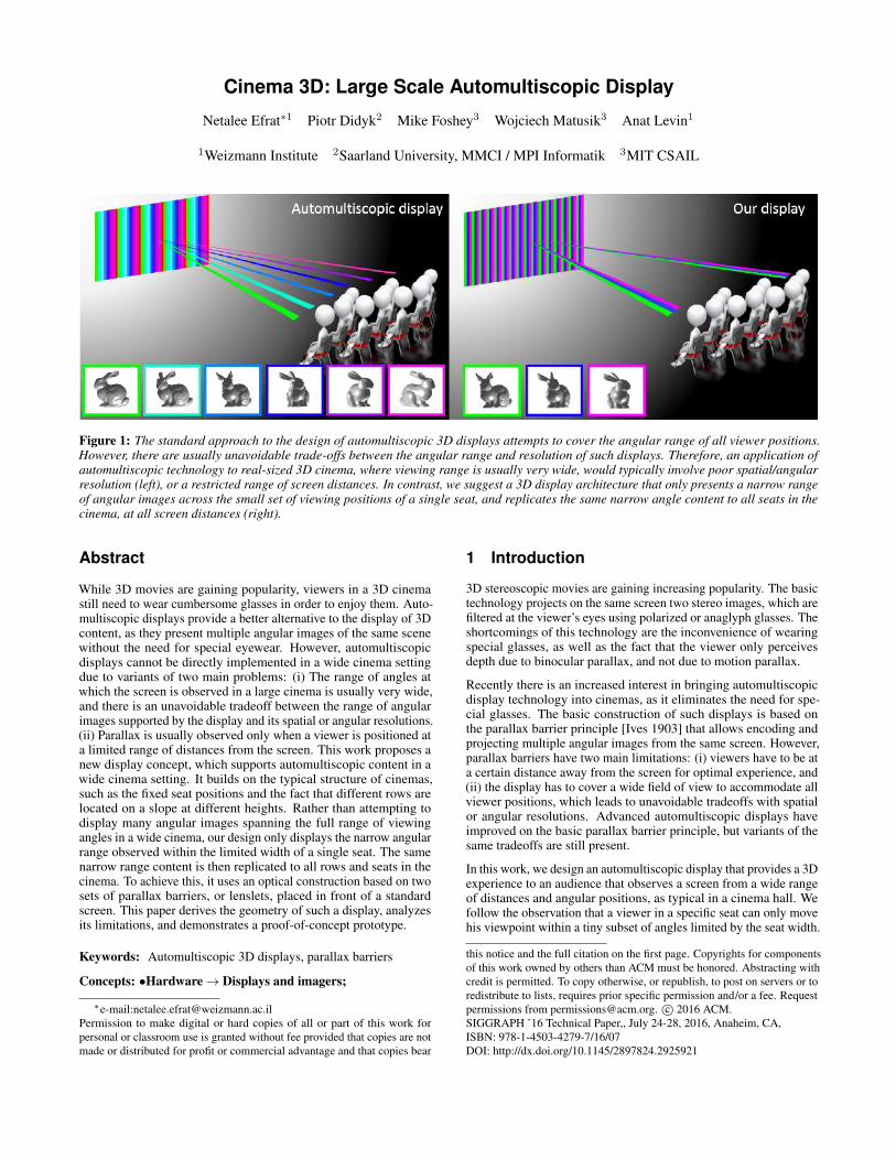
Figure 1: The standard approach to the design of automultiscopic 3D displays attempts to cover the angular range of all viewer positions.However, there are usually unavoidable trade-offs between the angular range and resolution of such displays. Therefore, an application ofautomultiscopic technology to real-sized 3D cinema, where viewing range is usually very wide, would typically involve poor spatial/angularresolution (left), or a restricted range of screen distances. In contrast, we suggest a 3D display architecture that only presents a narrow rangeof angular images across the small set of viewing positions of a single seat, and replicates the same narrow angle content to all seats in thecinema, at all screen distances (right).
Abstract
While 3D movies are gaining popularity, viewers in a 3D cinemastill need to wear cumbersome glasses in order to enjoy them. Auto-multiscopic displays provide a better alternative to the display of 3Dcontent, as they present multiple angular images of the same scenewithout the need for special eyewear. However, automultiscopicdisplays cannot be directly implemented in a wide cinema settingdue to variants of two main problems: (i) The range of angles atwhich the screen is observed in a large cinema is usually very wide,and there is an unavoidable tradeoff between the range of angularimages supported by the display and its spatial or angular resolutions.(ii) Parallax is usually observed only when a viewer is positioned ata limited range of distances from the screen. This work proposes anew display concept, which supports automultiscopic content in awide cinema setting. It builds on the typical structure of cinemas,such as the fixed seat positions and the fact that different rows arelocated on a slope at different heights. Rather than attempting todisplay many angular images spanning the full range of viewingangles in a wide cinema, our design only displays the narrow angularrange observed within the limited width of a single seat. The samenarrow range content is then replicated to all rows and seats in thecinema. To achieve this, it uses an optical construction based on twosets of parallax barriers, or lenslets, placed in front of a standardscreen. This paper derives the geometry of such a display, analyzesits limitations, and demonstrates a proof-of-concept prototype.
Keywords: Automultiscopic 3D displays, parallax barriers
Concepts: •Hardware→ Displays and imagers;
∗e-mail:[email protected] to make digital or hard copies of all or part of this work forpersonal or classroom use is granted without fee provided that copies are notmade or distributed for profit or commercial advantage and that copies bear
1 Introduction
3D stereoscopic movies are gaining increasing popularity. The basictechnology projects on the same screen two stereo images, which arefiltered at the viewer’s eyes using polarized or anaglyph glasses. Theshortcomings of this technology are the inconvenience of wearingspecial glasses, as well as the fact that the viewer only perceivesdepth due to binocular parallax, and not due to motion parallax.
Recently there is an increased interest in bringing automultiscopicdisplay technology into cinemas, as it eliminates the need for spe-cial glasses. The basic construction of such displays is based onthe parallax barrier principle [Ives 1903] that allows encoding andprojecting multiple angular images from the same screen. However,parallax barriers have two main limitations: (i) viewers have to be ata certain distance away from the screen for optimal experience, and(ii) the display has to cover a wide field of view to accommodate allviewer positions, which leads to unavoidable tradeoffs with spatialor angular resolutions. Advanced automultiscopic displays haveimproved on the basic parallax barrier principle, but variants of thesame tradeoffs are still present.
In this work, we design an automultiscopic display that provides a 3Dexperience to an audience that observes a screen from a wide rangeof distances and angular positions, as typical in a cinema hall. Wefollow the observation that a viewer in a specific seat can only movehis viewpoint within a tiny subset of angles limited by the seat width.
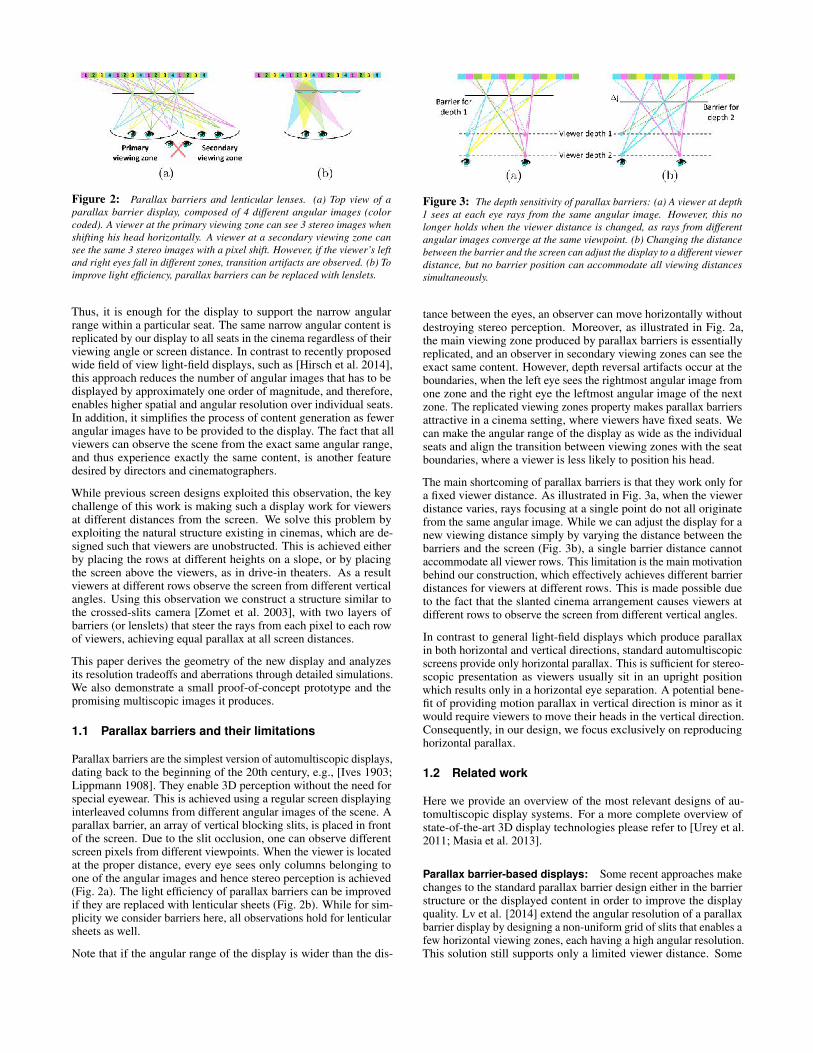
Figure 2: Parallax barriers and lenticular lenses. (a) Top view of aparallax barrier display, composed of 4 different angular images (colorcoded). A viewer at the primary viewing zone can see 3 stereo images whenshifting his head horizontally. A viewer at a secondary viewing zone cansee the same 3 stereo images with a pixel shift. However, if the viewer’s leftand right eyes fall in different zones, transition artifacts are observed. (b) Toimprove light efficiency, parallax barriers can be replaced with lenslets.
Thus, it is enough for the display to support the narrow angularrange within a particular seat. The same narrow angular content isreplicated by our display to all seats in the cinema regardless of theirviewing angle or screen distance. In contrast to recently proposedwide field of view light-field displays, such as [Hirsch et al. 2014],this approach reduces the number of angular images that has to bedisplayed by approximately one order of magnitude, and therefore,enables higher spatial and angular resolution over individual seats.In addition, it simplifies the process of content generation as fewerangular images have to be provided to the display. The fact that allviewers can observe the scene from the exact same angular range,and thus experience exactly the same content, is another featuredesired by directors and cinematographers.
While previous screen designs exploited this observation, the keychallenge of this work is making such a display work for viewersat different distances from the screen. We solve this problem byexploiting the natural structure existing in cinemas, which are de-signed such that viewers are unobstructed. This is achieved eitherby placing the rows at different heights on a slope, or by placingthe screen above the viewers, as in drive-in theaters. As a resultviewers at different rows observe the screen from different verticalangles. Using this observation we construct a structure similar tothe crossed-slits camera [Zomet et al. 2003], with two layers ofbarriers (or lenslets) that steer the rays from each pixel to each rowof viewers, achieving equal parallax at all screen distances.
This paper derives the geometry of the new display and analyzesits resolution tradeoffs and aberrations through detailed simulations.We also demonstrate a small proof-of-concept prototype and thepromising multiscopic images it produces.
1.1 Parallax barriers and their limitations
Parallax barriers are the simplest version of automultiscopic displays,dating back to the beginning of the 20th century, e.g., [Ives 1903;Lippmann 1908]. They enable 3D perception without the need forspecial eyewear. This is achieved using a regular screen displayinginterleaved columns from different angular images of the scene. Aparallax barrier, an array of vertical blocking slits, is placed in frontof the screen. Due to the slit occlusion, one can observe differentscreen pixels from different viewpoints. When the viewer is locatedat the proper distance, every eye sees only columns belonging toone of the angular images and hence stereo perception is achieved(Fig. 2a). The light efficiency of parallax barriers can be improvedif they are replaced with lenticular sheets (Fig. 2b). While for sim-plicity we consider barriers here, all observations hold for lenticularsheets as well.
Note that if the angular range of the display is wider than the dis-
Figure 3: The depth sensitivity of parallax barriers: (a) A viewer at depth1 sees at each eye rays from the same angular image. However, this nolonger holds when the viewer distance is changed, as rays from differentangular images converge at the same viewpoint. (b) Changing the distancebetween the barrier and the screen can adjust the display to a different viewerdistance, but no barrier position can accommodate all viewing distancessimultaneously.
tance between the eyes, an observer can move horizontally withoutdestroying stereo perception. Moreover, as illustrated in Fig. 2a,the main viewing zone produced by parallax barriers is essentiallyreplicated, and an observer in secondary viewing zones can see theexact same content. However, depth reversal artifacts occur at theboundaries, when the left eye sees the rightmost angular image fromone zone and the right eye the leftmost angular image of the nextzone. The replicated viewing zones property makes parallax barriersattractive in a cinema setting, where viewers have fixed seats. Wecan make the angular range of the display as wide as the individualseats and align the transition between viewing zones with the seatboundaries, where a viewer is less likely to position his head.
The main shortcoming of parallax barriers is that they work only fora fixed viewer distance. As illustrated in Fig. 3a, when the viewerdistance varies, rays focusing at a single point do not all originatefrom the same angular image. While we can adjust the display for anew viewing distance simply by varying the distance between thebarriers and the screen (Fig. 3b), a single barrier distance cannotaccommodate all viewer rows. This limitation is the main motivationbehind our construction, which effectively achieves different barrierdistances for viewers at different rows. This is made possible dueto the fact that the slanted cinema arrangement causes viewers atdifferent rows to observe the screen from different vertical angles.
In contrast to general light-field displays which produce parallaxin both horizontal and vertical directions, standard automultiscopicscreens provide only horizontal parallax. This is sufficient for stereo-scopic presentation as viewers usually sit in an upright positionwhich results only in a horizontal eye separation. A potential bene-fit of providing motion parallax in vertical direction is minor as itwould require viewers to move their heads in the vertical direction.Consequently, in our design, we focus exclusively on reproducinghorizontal parallax.
1.2 Related work
Here we provide an overview of the most relevant designs of au-tomultiscopic display systems. For a more complete overview ofstate-of-the-art 3D display technologies please refer to [Urey et al.2011; Masia et al. 2013].
Parallax barrier-based displays: Some recent approaches makechanges to the standard parallax barrier design either in the barrierstructure or the displayed content in order to improve the displayquality. Lv et al. [2014] extend the angular resolution of a parallaxbarrier display by designing a non-uniform grid of slits that enables afew horizontal viewing zones, each having a high angular resolution.This solution still supports only a limited viewer distance. Some
displays extend parallax barrier-based displays to multiple viewersusing eye tracking technology. The Random Hole Display [Yeet al. 2010; Nashel and Fuchs 2009], for example, populates parallaxbarriers with random holes, which allows viewers in known positionsanywhere in front of the display to see a different subset of thedisplay’s native pixels. Other approaches use eye tracking to improvethe degree of movement and allow for multiple viewers by usingdynamic parallax barriers [Yi et al. 2008; Peterka et al. 2008].
Du et al. [2014] manipulate the light field presented such that the tran-sitions between two viewing zones (Fig. 2a) would appear smooth,thus viewers can move continuously in space without experiencingtransitions artifacts. Although this solution extends the supportedrange of screen distances in the room, it limits the suitable content.
Multi layers and time multiplexing: Another family of ap-proaches try to extend the angular range of parallax barriers byexploiting emerging display technologies such as multilayer panels,high-speed temporal modulation, and directional backlighting [Wet-zstein et al. 2012; Wetzstein et al. 2011; Lanman et al. 2010; Ranieriet al. 2012]. They suggest that a simple parallax barrier can produceup to a rank-1 approximation of the light field, and that time multi-plexing and multiple layers can achieve a higher rank approximationthat results in improved spatial resolution, increased brightness, andmost importantly in our context, higher angular range. The aboveadvantages come at the cost of non-periodic viewing zones, so therepeatable seats property exploited in this paper cannot be used;thus, the effective horizontal viewing range is smaller than withparallax barrier-based displays. In terms of viewer distance, sincethese displays provide an approximation to the central viewing coneof the light field, a viewer who sits at the designed viewing conehas the ability to change his distance to the screen and still perceiveproper undistorted depth. This cone is extended compared to theone supported by simple parallax barriers, yet the range of distancesfrom which the content is coherent is still limited. In our design,the supported range of screen distances is extended significantly tomatch a real cinema, by exploiting the fact that seat locations arefixed and known.
Large-scale 3D systems: The ideas behind parallax barriershave been applied in designs of large displays. First large-scale au-tomultiscopic projection systems were opened in Russia and Francein the 1940s [Funk 2012]. These setups as well as their successorssuffered from limited spatial resolution, reduced brightness, and theimage quality varying as a function of the distance to the screen.More recently, Matusik and Pfister [2004] extended the ideas oflenticular sheets and proposed two multi-view screens illuminatedby multiple projectors. Each of them projects a different view whichis then reflected or refracted in an appropriate direction by an opticallayer composed of lenticular sheets, diffuser, and retro-reflector. Aconceptually similar system was proposed by Balogh [2006]. How-ever, he used as many as 96 and 128 LCD microdisplays panels tocover a wide viewing range and provide a system with high angularresolution. Takaki and Nago [2010] proposed a super multi-viewdisplay capable of producing 256 different views. Instead of multi-ple projectors, they used flat-panel displays with lenticular lenses. Afinal image was composed on a common diffuser by a set of projec-tion lenses placed between the diffuser and the flat panels. Similardesigns include [Dodgson et al. 2000] and recent efforts in providinga 180-degree view of faces and humans [Nagano et al . 2013; Joneset al. 2015]. To reduce the number of display units time-multiplexingtechniques can be applied. Bogaert et al. [2010] proposed a systemconsisting of one projector and a digital micromirror device thatacts as a light modulator that redirects the light into different view-ing zones. A new approach to multi-view projection was recentlyproposed by Hirsch et al. [2014]. Their light-field projection sys-
tem consists of a light-field compressive projector placed behind alenticular-based optical system that expands the angular range ofthe projected light field. All of the above solutions can be used forbuilding large-scale 3D screens for cinemas, but they still attempt tocover a very wide range of viewing locations, at the cost of reducedspatial or angular resolutions. This is orthogonal to our approachthat replicates a narrow range content to the entire audience.
The crossed-slits camera: Zomet et al. [2003] introduce theCrossed-Slits (X-Slits) projection, which uses a very similar con-cept for imaging rather than display. This approach uses a two-slitprojection scheme in order to capture 3D information on the scene.
2 Display construction
2.1 Problem statement
Our goal is to design an automultiscopic display that projects mul-tiscopic content to a large audience in a cinema. To achieve thiswe use two crucial properties of a cinema seating arrangement: (i)Different seating rows have different heights and as a result, viewersin different rows observe the screen from different vertical angles.(ii) The seats in each row are placed in fixed known locations.
The parameters of our setup are summarized and illustrated in Table1. We assume the cinema has m rows, i = {1, ...,m}, located on aslope, and denote the y, z displacement between successive rows as∆y,∆z . Each row has seats of width w. The display should projectk different angular images corresponding to k different viewpoints,such that a viewer shifting his head by `e = w/k will see a differentangular image. We select `e to be approximately half the averagepupillary distance. In this arrangement, a viewer sitting in a certainseat sees different images in each eye and binocular depth cues areobserved. In addition, the viewer can move his head across theseat width and see one of k different angular images, resulting inmotion-parallax based depth cues. To avoid depth reversal situations,in which the left eye sees the rightmost angular image from onezone and the right eye sees the leftmost angular image of the nextzone, the transition between angular zones should align with seatsboundaries. Since a viewer moving reasonably in his seat is lesslikely to position his head on the seat boundary, he should not besensitive to transition artifacts.
2.2 Display geometry
As discussed in Sec. 1.1, the main problem preventing standardparallax barriers from applying to a wide range of screen distancesis that the desired distance between the barriers and the screen isdifferent for each viewer rows (see Fig. 3). The main idea behind oursimple design is that at the price of some loss in vertical resolution,we encode many automultiscopic screens in one display, one foreach row. To this end, we build on the fact that, in a cinema, each rowof viewers sees the screen from a different vertical angle. Therefore,we can design a barrier arrangement such that viewers in differentrows see the screen through a barrier located at a different distanceto the screen. Although the vertical resolution is decreased in thisdesign, it is higher than for a standard pinhole approach (Sec. 4).
In its basic configuration, our display uses two sets of barriers, whichwe refer to as the vertical and horizontal barriers, as they are aimedto filter rays according to their vertical and horizontal coordinates(see sketch in Table 1). To avoid confusion, note that a barrieraimed to filter a ray according to its horizontal coordinate is actuallycomposed of vertical slits, and vice versa. A ray from the viewer tothe display first intersects the vertical barrier, which is a simple planeparallel to the screen, including ny horizontal slits, where ny is the
Table 1: Table of notations
m Number of viewer rows in the cinema.ny Number of rows displayed on the screen.nx Number of columns displayed on the
screen.i Cinema row index.j Screen row index.
(yi, zi) y, z position of the ith viewer row.(∆y,∆z) y, z displacement between two adjacent
viewer rows.
yoj
y coordinate of the jth slit on the verticalbarrier, j ∈ {1, .., n}.
(ρi,j , ζi) Point on the horizontal barrier whichshould filter correctly the x coordinateof the rays emerging from ith row view-ers toward yoj . ζi is negative in ournotations.
τ Distance between the vertical barrier andthe screen.
g Spacing between two adjacent slits on thevertical barrier.
`p Pixel size on the screen.Horizontal distance between two consec-utive angular positions of the viewer eye.
k Number of different angular images pro-jected by the screen.
w Width of a seat in the cinema.
number of rows in the displayed images. The horizontal parallaxbarrier is located behind the vertical one. This horizontal barrier isa set of slanted surfaces with nx vertical slits, whose structure isderived below.
Behind the set of two barriers, a standard screen is positioned. Wedenote the distance between the screen and the vertical barrier byτ .The screen has pixels of size `p and the k different angular imagesare interlaced on the screen, such that each column of pixels belongsto another image in a repetitive pattern. This interlaced screencontent is similar to that of a standard parallax barrier-based display,with the exception that in our screen we also lose modest resolutionin the y axis for reasons that will be explained in Sec. 2.3.1. Toaccount for that, we pre-blur the y axis of the angular image content.Throughout most of this paper we consider for simplicity an LCDscreen, or that the interlaced screen content is displayed using backprojection. In both cases we assume that the light emerging thescreen is distributed in all directions, which is a desired feature forall regular screens. In Sec. 7 we discuss equivalent configurationsusing front projection.
The main idea behind our display geometry is demonstrated in Fig. 4.Rays from a viewer at position (yi, zi) are filtered by the verticalbarrier. As a result, for each row of viewers, only rays with acertain vertical angle pass through. Since we separate the rays fromdifferent rows we can place a second horizontal barrier for eachrow, at the screen distance required by its z distance. This secondbarrier is essentially a row-dependent parallax barrier, which filtersthe rays from this row such that proper disparity is observed. InFig. 4, orange rays emerging from a row at distancez1 intersect thehorizontal parallax barrier at distanceτ − |ζ1| from the screen, andblue rays emerging from a row at distance z2 intersect the horizontalparallax barrier at a different distance τ − |ζ2| (note that ζi arenegative according to our notations). Even though the rays fromviewer 1 (orange rays) and viewer 2 (blue rays) reach the screen atdifferent vertical positions, the viewers see the same content up to asmall vertical shift without changing the perceived parallax. Belowwe derive the shape of the slanted barrier.
Figure 4: Display principle: For each viewer (yi, zi) (orange and blue),there exists ζi such that a barrier placed at that screen distance leadsto proper disparities for viewers at distance zi. Concatenating all row-dependent barrier positions ζi, i = {1, ...,m} provides the desired shapeof the slanted horizontal parallax barrier.
2.2.1 Shaping the slanted barrier
In order to derive the shape of the slanted horizontal parallax barrierconsider a viewer sitting at position (yi, zi) and looking at the screenthrough a vertical barrier slit at height yoj . To produce the correctparallax, we must place a horizontal parallax barrier at a distanceζi, which is a function of the row distance zi. Taking into accountthe y angle of rays coming from this row, we should also shift thehorizontal barrier vertically above/below the vertical slit entranceyo
j , by a distance we denote as ρi,j . That is, we denote the desiredy, z position of the barrier as (ρi,j , ζi). Claim 1 derives a formulafor (ρi,j , ζi) as a function of (yi, zi). The concatenation of all thepoints (ρi,j , ζi) for all viewer rows i = {1, ...,m} defines the shapeof the slanted barrier.
Claim 1 Let (yi, zi) denote the location of the ith viewer row, `pthe pixel size, `e the horizontal distance between two consecutiveangular positions within the seat, and τ the distance between thevertical barrier and the screen (see Table 1). The z-coordinate of
the slanted barrier ζi is a linear function of zi,
ζi =`p
`p + `e· zi +
−`eτ`p + `e
, (1)
and the y-coordinate ρi,j is a function of zi and yoj , the y-
coordinate of the jth vertical slit
ρi,j = yoj +
(c1 · zi + c2) · (c3 · zi + c4 − yoj)zi
(2)
where c1 =`p
`p+`e, c2 = −`e
`p+`e· τ , c3 =
∆y
∆z, c4 = y1 − ∆y
∆zz1.
A proof of this claim is provided in Supplementary Appendix A.
2.3 Display resolution
Next, we analyze the display’s vertical and horizontal resolutions.
2.3.1 Vertical resolution
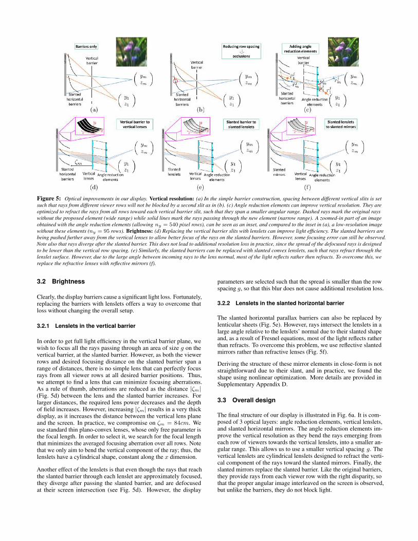
To analyze the vertical resolution of our display, we denote by g thevertical distance between two adjacent slits on the vertical barrier.Since the number of image rows we can display is equal to the screenheight divided by g, improved resolution is achieved when g is low.However, as illustrated in Fig. 5a and Fig. 5b, one needs to keepminimal spacing to prevent adjacent slanted horizontal barriers fromblocking each other. Note that it is fine for rays from different rowsto cross each other after passing through the slanted barrier, andthe only implication would be a small vertical shift of the imagesviewed from different rows. Claim 2 derives a lower bound on gas a function of the cinema structure. It shows that resolution is afunction of the difference between the angle at which the first and lastviewer rows see the top row of the display. As this angular differenceincreases, the gap between two adjacent slits in the vertical barriershould increase, and we lose more resolution. In Sec. 3.1 we suggesthow to further reduce g using additional optical elements that reducethis angular difference.
Claim 2 Denote by αi the angle of rays from the ith viewer row(yi, zi) towards the top slit yony . To prevent ray blocking the slitspacing g should satisfy
g ≥ [yo
ny − y1
z1− yo
ny − ymzm
] · −ζ1z1
z1 − ζ1(3)
or equivalently
g ≥ (α1 − αm) · −ζ1z1
z1 − ζ1(4)
A proof is provided in Supplementary Appendix B.
An important property of our construction is that all viewer rows seethe screen with the same disparity shift. That is, a viewer moving hishead by k`emm will see screen pixels shifted by k`pmm; this shiftis identical regardless of the viewer distance. The advantage is thatwe do not have to adjust the screen content for different viewer rowsand thus the vertical resolution does not depend explicitly on thenumber of rows in the cinema. However, naively adding rows to thecinema usually increases the angle difference α1 − αm in Eq. (4),which does translate to resolution loss. To overcome this problem,Sec. 3.1 suggests how to improve the display resolution despite theangle difference in the target cinema.
2.3.2 Horizontal resolution
The horizontal resolution depends solely on k, the number of angularimages projected by the screen. Assuming the native screen pixelsare of size `p, the x spacing we achieve is k`p. Note that mostexisting approaches attempt to increase the viewing range directlyby increasing the angular range supported by the display, whichnaturally increases the number of angular images k. In contrast,the angular range we need to display is rather narrow, and thus thehorizontal resolution loss we suffer in practice is relatively small.
3 Optical advances
The simplified design presented above suffers from brightness andresolution problems. To increase light efficiency, we replace thebarriers with lenslets, as discussed in Sec. 3.2. To improve thevertical resolution of the display, we add properly designed opticalelements in front of the vertical barrier, as derived below.
3.1 Improving vertical resolution
As explained in Sec. 2.3.1, the y resolution of our display is deter-mined by g, the gap between two consecutive slits in the verticalbarrier. This gap is a function of the difference between the anglesα1 and αm at which the first and last viewer rows see the top rowof the display (see Eq. (4)). In order to improve the resolution, weplace an additional optical element before the vertical barrier, towhich we refer as an angle reduction element, since it is designed toreduce the angular difference between these viewing rays.
To derive the shape of the angle reduction element associated withscreen row j, we consider the rays rji , i = {1, ...,m} from theviewer rows towards the new element, and a new, narrower set ofrays rji that connect the element to the center of the slit yoj (Fig. 5c).Each of the rays rji reaches a slightly different point on the opticalelement, denoted as pji . Given the correspondence between rji andrji , we use Snell’s law to find the normal of the optical elementat the point pji . This normal is selected such that refraction at pjitransfers the ray rji to rji . Integrating all normals provides theconcave elements in Fig. 5c.
The insets of Fig. 5a and Fig. 5c demonstrate a zoomed-in part ofan image obtained with and without the angle reduction elements,allowing ny = 540 compared to ny = 95 pixel rows in the cinemasetting of Sec. 5. Note that in theory the angle reduction elementsallow us to make the row spacing g as low as we want. However,various fabrication constraints, such as the minimal thickness of thebarrier surface itself, do place some lower bound on g. In practice,in the simulations of Sec. 5 we targeted a vertical gap of g = 5mm.
As a side effect, rays from a viewer row(yi, zi) passing through theangle reduction element of screen row j can spread to more thanone row on the vertical barrier plane. To avoid this artifact, weadd blockers between the angle reduction elements and the verticalbarrier (black segments in Fig. 5c).
The angle reduction elements are constant along the x direction sothat in the paraxial regime only the y component of rays bends. Inpractice, for viewers at the seats furthest from the center, which wewill refer to as the extreme seats, the x coordinate of the viewingangle is not sufficiently small, and the element also causes modestrefraction in the x direction. This causes some artifacts, as discussedin Sec. 3.4.
Figure 5: Optical improvements in our display. Vertical resolution: (a) In the simple barrier construction, spacing between different vertical slits is setsuch that rays from different viewer rows will not be blocked by a second slit as in (b). (c) Angle reduction elements can improve vertical resolution. They areoptimized to refract the rays from all rows toward each vertical barrier slit, such that they span a smaller angular range. Dashed rays mark the original rayswithout the proposed element (wide range) while solid lines mark the rays passing through the new element (narrow range). A zoomed-in part of an imageobtained with the angle reduction elements (allowing ny = 540 pixel rows), can be seen as an inset, and compared to the inset in (a), a low-resolution imagewithout these elements (ny = 95 rows). Brightness: (d) Replacing the vertical barrier slits with lenslets can improve light efficiency. The slanted barriers arebeing pushed further away from the vertical lenses to allow better focus of the rays on the slanted barriers. However, some focusing error can still be observed.Note also that rays diverge after the slanted barrier. This does not lead to additional resolution loss in practice, since the spread of the defocused rays is designedto be lower than the vertical row spacing. (e) Similarly, the slanted barriers can be replaced with slanted convex lenslets, such that rays refract through thelenslet surface. However, due to the large angle between incoming rays to the lens normal, most of the light reflects rather then refracts. To overcome this, wereplace the refractive lenses with reflective mirrors (f).
3.2 Brightness
Clearly, the display barriers cause a significant light loss. Fortunately,replacing the barriers with lenslets offers a way to overcome thatloss without changing the overall setup.
3.2.1 Lenslets in the vertical barrier
In order to get full light efficiency in the vertical barrier plane, wewish to focus all the rays passing through an area of size g on thevertical barrier, at the slanted barrier. However, as both the viewerrows and desired focusing distance on the slanted barrier span arange of distances, there is no simple lens that can perfectly focusrays from all viewer rows at all desired barrier positions. Thus,we attempt to find a lens that can minimize focusing aberrations.As a rule of thumb, aberrations are reduced as the distance |ζm|(Fig. 5d) between the lens and the slanted barrier increases. Forlarger distances, the required lens power decreases and the depthof field increases. However, increasing |ζm| results in a very thickdisplay, as it increases the distance between the vertical lens planeand the screen. In practice, we compromise on ζm = 84cm. Weuse standard thin plano-convex lenses, whose only free parameter isthe focal length. In order to select it, we search for the focal lengththat minimizes the averaged focusing aberration over all rows. Notethat we only aim to bend the vertical component of the ray; thus, thelenslets have a cylindrical shape, constant along the x dimension.
Another effect of the lenslets is that even though the rays that reachthe slanted barrier through each lenslet are approximately focused,they diverge after passing the slanted barrier, and are defocusedat their screen intersection (see Fig. 5d). However, the display
parameters are selected such that the spread is smaller than the rowspacing g, so that this blur does not cause additional resolution loss.
3.2.2 Lenslets in the slanted horizontal barrier
The slanted horizontal parallax barriers can also be replaced bylenticular sheets (Fig. 5e). However, rays intersect the lenslets in alarge angle relative to the lenslets’ normal due to their slanted shapeand, as a result of Fresnel equations, most of the light reflects ratherthan refracts. To overcome this problem, we use reflective slantedmirrors rather than refractive lenses (Fig. 5f).
Deriving the structure of these mirror elements in close-form is notstraightforward due to their slant, and in practice, we found theshape using nonlinear optimization. More details are provided inSupplementary Appendix D.
3.3 Overall design
The final structure of our display is illustrated in Fig. 6a. It is com-posed of 3 optical layers: angle reduction elements, vertical lenslets,and slanted horizontal mirrors. The angle reduction elements im-prove the vertical resolution as they bend the rays emerging fromeach row of viewers towards the vertical lenslets, into a smaller an-gular range. This allows us to use a smaller vertical spacing g. Thevertical lenslets are cylindrical lenslets designed to refract the verti-cal component of the rays toward the slanted mirrors. Finally, theslanted mirrors replace the slanted barrier. Like the original barriers,they provide rays from each viewer row with the right disparity, sothat the proper angular image interleaved on the screen is observed,but unlike the barriers, they do not block light.
Figure 6: (a) Our final design composed of 3 layers of optical elements:(i) angle reduction elements, (ii) vertical lenslets, and (iii) horizontal slantedmirrors. (b) Some rays from the viewer eye are blocked between the anglereduction elements and the vertical lens. (c) Despite the blockers, the anglereduction elements do not result in light loss. In the figure, green conesillustrate ray directions when no angle reduction elements are present. Theexact same cone, illustrated in orange, traverses the angle reduction elementswithout being cropped. The main effect of these elements is to focus the coneinto a narrower one, without blocking light. Note that the figure is simplifiedfor illustration – when no angle reduction elements are present, the shapeof other components in the display (slanted barriers and vertical lenses) issomewhat different.
Note that different viewer rows see the same pixel rows on thescreen, e.g. the orange and blue rays in Fig. 6a intersect the screenin overlapping areas. This does not pose a problem since the contentdisplayed on the screen is identical for all viewer rows. Fig. 6billustrates how some rays from the viewer eyes are blocked betweenthe angle reduction elements and the vertical barrier; however, therow spacing g is selected to be lower than the minimal unit peoplecan resolve from the closest cinema row, so these dark regionsare unobserved. As illustrated in Fig. 6c, we emphasize that theangle reduction elements do not result in any light loss comparedto a design without these elements. The exact same cone of raysemerging from a screen point to a viewer eye in a setup withoutthe angle reduction elements (green cones in Fig. 6c), reaches theviewer eye when the angle reduction elements are included (orangecones in Fig. 6c). The effect of the elements is only to focus theserays into a narrower cone, causing no light loss.
3.4 Aberration factors
As our final display is composed of several layers of optical elements,it also suffers from aberrations contributed by each of the layers.The main types of aberrations are summarized below.
Shift from the intended angular image: The angle reductionelements are intended to only refract the vertical component of therays. This is true for small intersection angles when the paraxial ap-proximation (sin θ ≈ θ) applies. However, when the viewing anglesare not sufficiently small, the angle reduction elements slightly bendthe x component of the rays rather than only their y component. Asa result, in large viewing angles rays intersect the slanted mirrors at
a wrong depth, leading to a horizontal shift in the intersection of therays with the screen. This means that the viewer sees nearby viewsinstead of the intended view (see Fig. 7a). A similar phenomenon iscaused by the lenslets in the vertical barrier.
As we analyze in Sec. 5, the problem can be significantly minimizedin practice by properly designing the cinema structure. The goal is toselect seat positions in the cinema such that the maximal horizontalangle at which viewers see the screen will be limited. This can beachieved by placing the seats somewhat further from the screen andusing a narrower spread of seats (eliminating some of the side seats)in the first rows.
Figure 7: Aberration factors. (a) Aberrations resulting from the anglereduction elements: The red fan of rays represents the desired path accordingto the paraxial model. However, the green fan illustrates the actual raystraveling through the system when the x component of the rays deviates fromthe paraxial regime. The green rays intersect the slanted barrier at a wrongdepth, and as a result their intersection with the screen is shifted from theposition of the intended angular image. For illustration simplicity, the figureuses slits rather than lenslets and mirrors. (b) Blur by the slanted concavemirrors: In this exaggerated illustration, rays in the middle of the display,which have a small x component, focus perfectly on the screen. However, asthe x component of the viewing angle increases, the mirrors fail to focus thelight at the right distance.
Angular blur: Another type of aberration is observed when raysreaching a viewer eye arrive from a mixture of screen pixels thatdisplay different angular images. In our setup, there are two sourcesof misfocus: (i) the vertical lenses, and (ii) the slanted concavemirrors. As illustrated in Fig. 5d, the vertical lenses can somewhatmisfocus the light on the slanted mirrors. Therefore, not all lightrays intersect the slanted mirror at the intended distance. Light raysfiltered at the wrong depth effectively achieve the disparity of adifferent viewer row and the viewer sees a mixture of nearby pixelsbelonging to different angular images. On the horizontal axis, theslanted concave mirrors misfocus the light on the screen at viewingangles whose x component is large, which also leads to a mixture ofnearby angular images (Fig. 7b). As mentioned, we can minimizeblur problems with a proper design of the seating layout.
4 Comparisons with simpler solutions
It is important to compare our design with two simpler schemes fordisplaying 3D content. The first solution is the simple lenticularsheet display discussed in Sec. 1.1.
A second, more sophisticated solution, is to use a pinhole arrayrather than two sets of slits. In this arrangement, rays from allrows are filtered by a single pinhole at a fixed distance from thescreen, so different rows view the screen with a different disparityshift. However, since different rows are located at different heights,they still view the screen at different angles. Therefore, we candisplay different content on the screen to match the row-dependentdisparity shift, as illustrated in Fig. 10. The fact that the pinhole
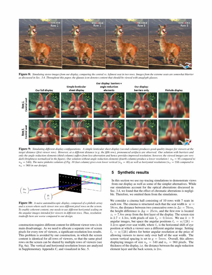
Figure 8: Simulating stereo images from our display, comparing the central vs. leftmost seat in two rows. Images from the extreme seats are somewhat blurrieras discussed in Sec. 3.4. Throughout this paper, the glasses icon denotes content that should be viewed with anaglyph glasses.
Figure 9: Simulating different display configurations. A simple lenticular sheet display (second column) produces good-quality images for viewers at thetarget distance (first viewer row). However, at a different distance (e.g. the fifth row), pronounced artifacts are observed. Our solution with barriers andonly the angle reduction elements (third column) suffers from less aberration and hence provides improved resolution; however, the viewed images are verydark (brightness normalized in the figure). Our solution without angle reduction elements (fourth column) produce a lower resolution ( ny = 95 compared tony = 540). The naive pinholes solution of Fig. 10 (last column) gives even lower vertical (ny = 40) as well as horizontal resolutions (nx = 556 compared tonx = 960 in our design).
Figure 10: A naive automultiscopic display, composed of a pinhole arrayand a screen where each viewer row sees different pixel rows on the screen.To enable coherent content, one needs to use different horizontal scaling onthe angular images intended for viewers in different rows. Thus, resolutiontradeoffs here are worse compared to our design.
construction requires different content for different viewer rows is itsmain disadvantage. As we need to allocate a separate row of screenpixels for every row of viewers, a significant resolution loss results.This problem is avoided by our construction, in which the screencontent is identical for all rows of viewers, so that the same pixelrows on the screen can be shared by multiple rows of viewers (seeFig. 6a). The vertical and horizontal resolution losses are analyzedin Supplementary Appendix C, and visualized in Sec. 5.
5 Synthetic results
In this section we use ray-tracing simulations to demonstrate viewsfrom our display as well as some of the simpler alternatives. While
our simulations account for the optical aberrations discussed inSec. 3.4, we found that the effect of chromatic aberrations is negligi-ble. Therefore, we omitted them from the simulations.
We consider a cinema hall consisting of 10 rows with 7 seats ineach row. The cinema is structured such that the seat width is w =58cm, the distance between two consecutive rows is ∆z = 70cm,the height difference is ∆y = 25cm, and the first row is locatedz1 = 7.8m away from the first layer of the display. The screen sizeis 2.7 × 4.3m, with pixels of size `p = 0.5mm. We use k = 9angular images, but space the angular positions `e = w/(2k) =3.2cm apart over seat width, where `e is the horizontal shift of eyeposition at which a viewer sees a different angular image. Setting`e = w/(2k) allows for better angular resolution at the price ofallowing viewers to move only over half of the seat width. Thescreen vertical spacing is set to g = 5mm. Overall, this allowsdisplaying images of size ny = 540 and nx = 960 pixels. Thethickness of the display, i.e. the distance between the angle reductionelement layer and the back screen, is 2m.
Figure 11: Angular images as perceived from different viewing positions.Each input angular image is coded by a different color. An aberration-freeimage should have a uniform color, but this is not fully achieved due to opticalimperfections of the system. Below each image, we show transition mapsvisualizing in white the depth reversal artifacts . The top row demonstratesthe images for the central and the extreme side seats in the first row of thecinema as seen by a viewer. There are less artifacts at the center of theviewing zone (e.g. angular position 5) relative to its boundary (e.g. angularposition 8). The bottom row depicts the sensitivity of the display to variationin the viewer height, which is negligible for ± 15cm deviations.
Toughout this section we use a small glasses icon at the cornerof figures that should be viewed with anaglyph glasses. Figure 8demonstrates simulated images for several seats in the cinema. Ad-ditional higher-resolution results are included in the supplementaryfile both in video and in JPS formats. Note that for the extreme seats,whose horizontal viewing angle is a bit large, one can see the imagesstart to get blurrier, as discussed in Sec. 3.4.
Figure 9 compares a few display configurations for seats in twodifferent rows. The first column represents our final display. Incontrast, the second column shows results for a simple lenticularsheet display designed for the first row of viewers. The imagesobtained at this row are indeed good, but at other row distances,visible artifacts appear. The third column demonstrates the output ofour display when only angle reduction elements are present, but thehorizontal and vertical lenticular elements are replaced with barriers.Since lens aberrations are avoided, the image is somewhat sharperthan the one obtained with the final display (first column). However,the barriers lead to a significant light loss (in Fig. 9, brightnesshas been normalized). The fourth column demonstrates our displaywithout any optical elements, including the angle reduction elements,demonstrating a significant loss in vertical resolution. The lastcolumn simulates the naive pinhole solution. In this case both thevertical and horizontal resolutions are even lower than those of thefourth column.
5.1 Evaluation
As mentioned in Sec. 3.4, due to aberrations, the images viewed bythe audience are effectively a mixture of some nearby angular imagesrather than only the intended one. Our goal is to evaluate the visualartifacts caused by these aberrations. We note that if in the image wesee transitions between angular image j and angular image j + 1,no significant visual artifacts are observed since overall the nearbyangular images vary continuously. On the other hand, we do need
to penalize discontinuous transitions between angular image k andangular image 1. Our proposed score counts the number of transitionedges between image regions mapped to angular image k (red inFig. 11) and regions mapped to angular image 1 (green in Fig. 11).We penalize such transitions as a function of their distance fromthe center of the image, since viewers are usually more sensitive toartifacts in the center rather than in the periphery of the screen. TheTransitions Grade (TG) measure can be written as:
TG(y, z, x, v) =
∑r∈L
wr1{r ∈ Ltransitions}∑r∈L
wr· 100%, (5)
where r denotes a ray hitting the screen, L the set of all such rays,Ltransitions screen regions where discontinuous transitions of an-gular images are present, and wr the weight of a pixel relative to thecenter of the screen. This measure is a function of a specific seat inthe cinema (y, z, x) and angular position (v); thus we calculate itfor each of the k angular positions within each seat.
To get a sense of the angular mixture obtained in practice, Fig. 11uses colors to encode different angular images and demonstrate theangular image from which each pixel originates. Below each imagewe show a map of rays falling in the transition area. In the figurecolor coding, these are the transitions between green and red pixels.The transition grade is essentially a weighted average of these maps.The bottom part of Fig. 11 shows the sensitivity of our display to theviewer’s height. We found that the perceived quality degradation isnot significant with up to±15cm height difference. Moreover, froma system design perspective, this can also be addressed by othermeans, e.g. adjustable seats.
Figures 12a,b show the transitions maps for the leftmost and centralseats in each row for all angular positions within that seat. First,it can be seen that the boundary angular positions (1 and k) havea bad quality and the artifacts are reduced in the middle of theangular viewing zone. For this reason we chose the number ofangular images k = 9 to be large enough to allow each viewersufficient space for free head motion before hitting the boundaryartifacts. A second observation is that viewers located in the centralseats (Fig. 12a) experience the best quality, but even viewers atthe extreme leftmost/rightmost seats (Fig. 12b) have a sufficientset of good-quality angular positions. Fig. 12c emphasizes thedegraded quality of the simple lenticular sheet display. Artifactsincrease as the viewer moves further from the distance at whichthe display was designed. Table 2 in Supplementary Appendix Eprovides the numerical values of the TG score, reinforcing the aboveobservations.
The cinema arrangement described in the beginning of this sectionwas selected to minimize aberrations. To demonstrate the importanceof a proper cinema design, we considered a second more naivecinema arrangement, with two main differences: (i) The distancebetween the first row and the screen is reduced from 7.8m to 5.4m,implying that the horizontal viewing angles at which the screen isobserved can be larger, leading to more aberrations as discussed inSec. 3.4. (ii) The thickness of the screen is reduced from 2m to1.5m. The implication is that we have to use vertical lenslets with ashorter focal length, resulting in more focusing aberrations. In bothcinema configurations, we designed all display elements to achievethe least possible aberrations given the cinema structure. Figure 13compares three angular images obtained at one of the seats, for bothcinema configurations. In both cases, the extreme angular imagesinvolve ghosting artifacts, but in the simpler cinema setting, there ismore ghosting in the central images of the viewing zone.
Figure 12: Transition maps of images viewed from our display, from the central seat (a) and the leftmost seat (b), in all cinema rows, relative to transitionmaps viewed from a simple lenticular sheet display, from a central seat (c). The maps are similar at the extreme seats. In the first row the viewed images are freeof artifacts (besides the extreme angular positions 1 and k); however, when a viewer changes his distance, strong transition artifacts appear.
Figure 13: Images perceived at the three leftmost angular positions of the central seat in the first row, for two different cinema configurations. In both casesthe extreme angular positions involve more ghosting than the central ones, but when the cinema arrangement is properly designed (2nd row), one can reduceghosting aberrations in the center of the viewing zone. For better visualization, the bottom row compares enlarged windows from both configurations. Thetransition map of each viewing position is presented at the top-left corner.
5.2 Fabrication sensitivities
In the next section we demonstrate a simple barriers only prototype.In addition, we use simulations to examine the complexities of ourfull design (Fig. 5f) as well as the sensitivities to some fabricationartifacts. Our simulations show that the display works as predictedeven with moderate misalignment of different components. Forgood results we expect that the tolerance should be below a pixelsize, and indeed, our simulations showed that 0.1mm misalignmentbetween the vertical lenses and the slanted mirrors, which is 20% ofthe pixel size, is acceptable and does not lead to significant qualityreduction. Other inaccuracies include manufacturing imperfectionsin the angle reduction elements and mirrors. Although not quantified,such inaccuracies would result in more aberrations, such as shiftfrom the intended angular image and angular blur .
6 Prototype fabrication
As a proof of concept, we have fabricated a small low-resolutionprototype of our display. This prototype is composed of barriers
only: the vertical barrier and the slanted horizontal parallax barrier,without lenslets or angle reduction elements. The prototype has beenfabricated from aluminium sheets, cut and bent to the desired shape.It supports a rather small 10× 20 pixel image. Since we do not useany optical elements, the resolution of our prototype is low and thespacing between pixel rows is set to 2.4cm. The overall prototypesize is 35× 28× 28cm and it is placed in front of a standard LCDmonitor that serves as the screen. Figure 16 shows the prototype andthe auditorium in which it has been captured. The first row of seats islocated 6m from the screen. The distance between two consecutiverows is ∆y = 1m, and their height difference is ∆z = 15cm. Thefirst row of viewers is located 20cm below the screen.
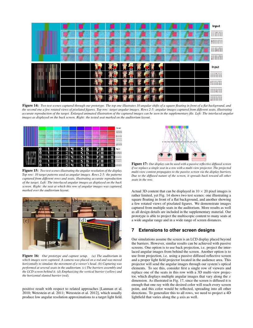
Figure 15 presents two types of test images demonstrating the goodangular resolution achieved by the prototype. In the first case, eachangular image has a different uniform color. In the second case, weuse non-overlapping numbers to better analyze the ghosting. Wecapture the display from several seats spread over multiple rowsin the auditorium. To test the effect of the x-viewing angle, wedemonstrate views from both central seats and extreme seats. Thecaptured images reproduce the target rather accurately. This is a
Figure 14: Two test scenes captured through our prototype. The top one illustrates 10 angular shifts of a square floating in front of a flat background, andthe second one a few rotated views of pixelated figures. Top row: target angular images. Rows 2-5: angular images captured from different seats, illustratingaccurate reproduction of the target. Enlarged animated illustration of the captured images can be seen in the supplementary file. Left: The interlaced angularimages as displayed on the back screen. Right: the tested seat marked on the auditorium layout.
Figure 15: Two test scenes illustrating the angular resolution of the display.Top row: 10 target patterns used as angular images. Rows 2-5: the patternscaptured from different rows and seats, illustrating accurate reproductionof the target. Left: The interlaced angular images as displayed on the backscreen. Right: the seat at which this row of angular images was captured,marked over the auditorium layout.
Figure 16: Our prototype and capture setup. (a) The auditorium inwhich images were captured. A camera was placed on a rod and was movedhorizontally to simulate the movement of a viewer’s head. (b) Capturing wasperformed at several seats in the auditorium. (c) The barriers assembly andthe LCD screen behind it. (d) Emphasizing the vertical barrier (yellow) andthe horizontal slanted barrier (red).
positive result with respect to related approaches [Lanman et al.2010; Wetzstein et al. 2011; Wetzstein et al. 2012], which usuallyproduce low angular resolution approximations to a target light field.
Figure 17: Our display can be used with a passive reflective diffused screenif we replace a single seat in a row with a multi-view projector. The projectedmulti-view content propagates to the passive screen via the display barriers.Due to the diffused nature of the screen, it spreads back toward all otherseats in the row.
Actual 3D content that can be displayed in 10× 20 pixel images israther limited, yet Fig. 14 shows two test scenes: one illustrating asquare floating in front of a flat background, and another showinga few rotated views of pixelated figures. We demonstrate imagescaptured from multiple seats in the auditorium. More results as wellas all design details are included in the supplementary material. Ourprototype is able to project the multiscopic content to many seats ata wide angular range and in a wide range of screen distances.
7 Extensions to other screen designs
Our simulations assume the screen is an LCD display placed beyondthe barriers. However, similar results can be achieved with passivescreens. One option is to use back projection, i.e. project the inter-laced angular images from behind the screen. Another option is touse front projection, i.e. using a passive diffused reflective screenand a proper light field projector located in the audience area. Thisprojector will send the angular images through our system’s opticalelements. To see this, consider first a single row of viewers andreplace one of the seats in this row with a 3D multi-view projec-tor, which displays multiple angular images that vary along the xdimension. As illustrated in Fig. 17, since the screen is diffused it isenough that one ray with the desired color will reach every screenpoint, and this color would be reflected, spreading into all otherdirections. To generalize this to all rows, we need to project a 4Dlightfield that varies along the y axis as well.
8 Discussion
We present a new design of an automultiscopic display optimizedfor 3D cinemas. We exploit existing characteristics of cinemas – thefact that seat rows are located on a slope and seat locations are fixedand known. This allows the design of a simple display supporting alarge audience sitting at a wide range of viewing angles and screendistances. We follow the observation that spanning the completerange of viewing angles in the entire hall is redundant, since noindividual viewer moves across such a wide range. Therefore, it isenough to cover the limited angular range of one seat and replicatethe same narrow-range content to all seats in the cinema. Combiningthis with accounting for audience layout allowed us to design anautomultiscopic display that provides good image quality to viewerslocated at different distances. The paper derives the basic geometryof such a display and discusses how to improve its brightness andresolution using properly designed optics. We also present a simpleprototype demonstrating the feasibility of the design.
Acknowledgements
The authors would like to thank the anonymous reviewers for theirhelpful comments and suggestions. Funding was provided by theISF and ERC.
References
BALOGH, T. 2006. The holovizio system. In Electronic Imaging2006, International Society for Optics and Photonics, 60550U–60550U.
BOGAERT, L., MEURET, Y., ROELANDT, S., AVCI, A., DE SMET,H., AND THIENPONT, H. 2010. Single projector multiviewdisplays: directional illumination compared to beam steering. InIS&T/SPIE Electronic Imaging, International Society for Opticsand Photonics, 75241R–75241R.
DODGSON, N., MOORE, J., LANG, S., MARTIN, G., ANDCANEPA, P. 2000. A time-sequential multi-projector autostereo-scopic display. Journal of the Society for Information Display 8,2, 169–176.
DU, S.-P., DIDYK, P., DURAND, F., HU, S.-M., AND MATUSIK,W. 2014. Improving visual quality of view transitions in automul-tiscopic displays. ACM Transactions on Graphics (ProceedingsSIGGRAPH Asia 2014, Shenzhen, China) 33 , 6.
FUNK, W. 2012. History of autostereoscopic cinema. Proc. SPIE8288, 82880R–82880R–25.
HIRSCH, M., WETZSTEIN, G., AND RASKAR, R. 2014. A com-pressive light field projection system. ACM Trans. Graph. 33 , 4(July), 58:1–58:12.
IVES, F., 1903. Parallax stereogram and process of making same.,Apr. 14. US Patent 725,567.
JONES, A., UNGER, J., NAGANO, K., BUSCH, J., YU, X., PENG,H.-Y., ALEXANDER, O., BOLAS, M., AND DEBEVEC, P. 2015.An automultiscopic projector array for interactive digital humans.In ACM SIGGRAPH 2015 Emerging Technologies , SIGGRAPH’15.
LANMAN, D., HIRSCH, M., KIM, Y., AND RASKAR, R. 2010.Content-adaptive parallax barriers: optimizing dual-layer 3d dis-plays using low-rank light field factorization. ACM Trans. Graph.29, 6, 163:1–163:10.
LIPPMANN, G. 1908. Epreuves reversibles donnant la sensation durelief. J. Phys. Theor. Appl. 7, 1, 821–825.
LV, G.-J., WANG, Q.-H., ZHAO, W.-X., AND WANG, J. 2014.3d display based on parallax barrier with multiview zones. Appl.Opt. 53, 7 (Mar), 1339–1342.
MASIA, B., WETZSTEIN, G., DIDYK, P., AND GUTIERREZ, D.2013. A survey on computational displays: Pushing the bound-aries of optics, computation, and perception. Computers & Graph-ics 37, 8, 1012–1038.
MATUSIK, W., AND PFISTER, H. 2004. 3d tv: a scalable system forreal-time acquisition, transmission, and autostereoscopic displayof dynamic scenes. In ACM Transactions on Graphics (TOG),vol. 23, ACM, 814–824.
NAGANO, K., JONES, A., LIU, J., BUSCH, J., YU, X., BOLAS,M., AND DEBEVEC, P. 2013. An autostereoscopic projectorarray optimized for 3d facial display. In ACM SIGGRAPH 2013Emerging Technologies, SIGGRAPH ’13.
NASHEL, A., AND FUCHS, H. 2009. Random hole display: A non-uniform barrier autostereoscopic display. In 3DTV Conference:The True Vision - Capture, Transmission and Display of 3D Video,2009, 1–4.
PETERKA, T., KOOIMA, R. L., SANDIN, D. J., JOHNSON, A.,LEIGH, J., DEFANTI, T., ET AL. 2008. Advances in the dynallaxsolid-state dynamic parallax barrier autostereoscopic visualiza-tion display system. Visualization and Computer Graphics, IEEETransactions on 14, 3, 487–499.
RANIERI, N., HEINZLE, S., SMITHWICK, Q., REETZ, D., SMOOT,L. S., MATUSIK, W., AND GROSS, M. 2012. Multi-layeredautomultiscopic displays. Computer Graphics Forum 31, 7pt2,2135–2143.
TAKAKI, Y., AND NAGO, N. 2010. Multi-projection of lenticulardisplays to construct a 256-view super multi-view display. Opticsexpress 18, 9, 8824–8835.
UREY, H., CHELLAPPAN, K. V., ERDEN, E., AND SURMAN,P. 2011. State of the art in stereoscopic and autostereoscopicdisplays. Proceedings of the IEEE 99, 4, 540–555.
WETZSTEIN, G., LANMAN, D., HEIDRICH, W., AND RASKAR, R.2011. Layered 3D: Tomographic image synthesis for attenuation-based light field and high dynamic range displays. ACM Trans.Graph. 30, 4.
WETZSTEIN, G., LANMAN, D., HIRSCH, M., AND RASKAR, R.2012. Tensor Displays: Compressive Light Field Synthesis usingMultilayer Displays with Directional Backlighting. ACM Trans.Graph. (Proc. SIGGRAPH) 31 , 4, 1–11.
YE, G., STATE, A., AND FUCHS, H. 2010. A practical multi-viewertabletop autostereoscopic display. In Mixed and Augmented Real-ity (ISMAR), 2010 9th IEEE International Symposium on , IEEE,147–156.
YI, S.-Y., CHAE, H.-B., AND LEE, S.-H. 2008. Moving parallaxbarrier design for eye-tracking autostereoscopic displays. In3DTV Conference: The True Vision-Capture, Transmission andDisplay of 3D Video, 2008, IEEE, 165–168.
ZOMET, A., FELDMAN, D., PELEG, S., AND WEINSHALL, D.2003. Mosaicing new views: The crossed-slits projection. IEEETrans. Pattern Anal. Mach. Intell. 25, 6 (June), 741–754.