Personal tools Log in / create account Views Pa ge Di sc us si on Ed it Hi st or y Search Navigati on Ma in Pa ge Al ph ab et ic al in de Circuit-breaker From Electrical Installation Guide Jump to: navigation , search Scope and content of Wiki EIG General rules of electrical installation design Connection to the MV utility distribution network Connection to the LV utility distribution network MV & LV architecture selection guide LV Distribution Protection against electric shocks Sizing and protection of conductors LV switchgear: functions & selection The basic functions of LV switchgear o Switchgear control The switchgear o Elementary switching devices o Combined Special:Search Go Search
Transcript
Personal tools
Log in / create account
Views
Pa ge
Di scussion
Ed it
Hi story
Search
Navigation
M ain Page
Al phabetical index
Ne ws room
Hi ghlig
Circuit-breakerFrom Electrical Installation Guide
Jump to: navigation, search
Scope and content of Wiki EIG
General rules of electrical installation design
Connection to the MV utility distribution network
Connection to the LV utility distribution network
MV & LV architecture selection guide
LV Distribution
Protection against electric shocks
Sizing and protection of conductors
LV switchgear: functions & selection
The basic functions of LV switchgear
o Switchgear control The switchgear
o Elementary switching devices
o Combined switchgear elements
Choice of switchgear o Switchgear selection
Circuit-breaker o Fundamental
characteristics of a circuit-breaker
o Other characteristics of a circuit-breaker
o Selection of a circuit- breaker
o Coordination between circuit-breakers
o Discrimination MV/LV in a consumer’s substation
Special:Search
Go
Search
hts He
lp
interaction
Im prove your topic
Co ntent format work
En rich existing topic
Op en a new topic
Pl ay with sandbox
Co mmunity
o Ultra-rapid circuit breaker
Protection against voltage surges in LV
Energy Efficiency in electrical distribution
Power factor correction and harmonic filtering
Power harmonics management
Characteristics of particular sources and loads
PhotoVoltaic (PV) installation
Residential electrical installations
ElectroMagnetic Compatibility (EMC)
The circuit-breaker/disconnector fulfills all of the basic switchgear functions, while, by means of accessories, numerous other possibilities exist
As shown in Figure H23 the circuit-breaker/disconnector is the only item of switchgear capable of simultaneously satisfying all the basic functions necessary in an electrical installation.Moreover, it can, by means of auxiliary units, provide a wide range of other functions, for example: indication (on-off - tripped on fault); undervoltage tripping; remote control… etc. These features make a circuit-breaker/ disconnector the basic unit of switchgear for any electrical installation.
Functions Possible conditions
Isolation
Control
Functional
Emergency switching
(With the possibility
portal
Ab out us
Co ntact us
Re cent changes
Toolbox
W hat links here
Re lated changes
Sp ecial pages
Pri ntable version
Pe rmanent
of a tripping coil for remote control)
Switching-off for mechanical maintenance
Protection Overload
Short-circuit
Insulation fault
(With differential-current relay)
Undervoltage
(With undervoltage-trip coil)
Remote control
Added or incorporated
Indication and measurement
(Generally optional with an electronic tripping device) Fig. H23: Functions performed by a circuit-breaker/disconnector
Contents
[hide]
1 Standards and description o 1.1 Standards o 1.2 Description
link
M ain contributors
Cit e this page
2 Fundamental characteristics of a circuit-breaker o 2.1 Rated operational voltage (Ue) o 2.2 Rated current (In) o 2.3 Frame-size rating o 2.4 Overload relay trip-current setting (Irth or Ir) o 2.5 Short-circuit relay trip-current setting (Im) o 2.6 Isolating feature o 2.7 Rated short-circuit breaking capacity (Icu or Icn)
3 Other characteristics of a circuit-breaker o 3.1 Rated insulation voltage (Ui) o 3.2 Rated impulse-withstand voltage (Uimp) o 3.3 Category (A or B) and rated short-time withstand
current (Icw)o 3.4 Rated making capacity (Icm) o 3.5 Rated service short-circuit breaking capacity (Ics) o 3.6 Fault-current limitation o 3.7 The advantages of current limitation
4 Selection of a circuit-breaker o 4.1 Choice of a circuit-breaker o 4.2 Choice of rated current in terms of ambient temperature o 4.3 Uncompensated thermal magnetic tripping units o 4.4 Compensated thermal-magnetic tripping units o 4.5 Electronic trip units o 4.6 Selection of an instantaneous, or short-time-delay,
tripping thresholdo 4.7 Selection of a circuit-breaker according to the short-
circuit breaking capacity requirementso 4.8 The selection of main and principal circuit-breakers o 4.9 Choice of outgoing-circuit CBs and final-circuit CBs
5 Coordination between circuit-breakers o 5.1 Cascading (or Back-up protection) o 5.2 Conditions of implementation o 5.3 Advantages of cascading o 5.4 Principles of discriminative tripping (selectivity) o 5.5 Current-level discrimination o 5.6 Time discrimination o 5.7 Energy discrimination with current limitation o 5.8 Natural total discriminitation with Compact NSX o 5.9 Logic discrimination or “Zone Sequence Interlocking –
ZSI”o 5.10 Principles o 5.11 Operation
6 Discrimination MV/LV in a consumer’s substation 7 Ultra-rapid circuit breaker
o 7.1 - Pyrotechnic interruption switching device o 7.2 - Power circuit breaker based solution o 7.3 Example of limitation offered by Masterpact UR in
decoupling bus bars in case of short circuit:
[edit] Standards and description
[edit] Standards
Industrial circuit-breakers must comply with IEC 60947-1 and 60947-2 or other equivalent standards.Domestic-type circuit-breakers must comply with IEC standard 60898, or an equivalent national standard For industrial LV installations the relevant IEC standards are, or are due to be:
60947-1: general rules 60947-2: part 2: circuit-breakers 60947-3: part 3: switches, disconnectors, switch-disconnectors and
fuse combination units 60947-4: part 4: contactors and motor starters 60947-5: part 5: control-circuit devices and switching elements 60947-6: part 6: multiple function switching devices 60947-7: part 7: ancillary equipment
For domestic and similar LV installations, the appropriate standard is IEC 60898, or an equivalent national standard.
[edit] Description
Figure H24 shows schematically the main parts of a LV circuit-breaker and its four essential functions:
The circuit-breaking components, comprising the fixed and moving contacts and the arc-dividing chamber
The latching mechanism which becomes unlatched by the tripping device on detection of abnormal current conditions
This mechanism is also linked to the operation handle of the breaker.
A trip-mechanism actuating device:
- Either: a thermal-magnetic device, in which a thermally-operated bi-metal strip detects an overload condition, while an electromagnetic striker pin operates at current levels reached in short-circuit conditions, or - An electronic relay operated from current transformers, one of which is installed on each phase
A space allocated to the several types of terminal currently used for the main power circuit conductors
Domestic circuit-breakers (see Fig. H25) complying with IEC 60898 and similar national standards perform the basic functions of:
Isolation Protection against overcurrent
Fig. H25: Domestic-type circuit-breaker providing overcurrent protection and circuit isolation features
Some models can be adapted to provide sensitive detection (30 mA) of earth-leakage current with CB tripping, by the addition of a modular block, while other models (RCBOs, complying with IEC 61009 and CBRs complying with IEC 60947-2 Annex B) have this residual current feature
Fig. H26: Domestic-type circuit-breaker as above (Fig. H25) with incorparated protection against electric shocks
Apart from the above-mentioned functions further features can be associated with the basic circuit-breaker by means of additional modules, as shown in Figure H27; notably remote control and indication (on-off-fault).
Fig. H27: “Multi 9” system of LV modular switchgear components
Moulded-case circuit-breakers complying with IEC 60947-2 are available from 100 to 630 A and provide a similar range of auxiliary functions to those described above (see Figure H28).
Fig. H28: Example of a Compact NSX industrial type of circuit-breaker capable of numerous auxiliary functions
Air circuit-breakers of large current ratings, complying with IEC 60947-2, are generally used in the main switch board and provide protector for currents from 630 A to 6300 A, typically.(see Figure H29).In addition to the protection functions, the Micrologic unit provides optimized functions such as measurement (including power quality functions), diagnosis, communication, control and monitoring.
control features in its “Micrologic” tripping unit
[edit] Fundamental characteristics of a circuit-breaker
The fundamental characteristics of a circuit-breaker are:
Its rated voltage Ue Its rated current In Its tripping-current-level adjustment ranges for overload protection
(Ir(1) or Irth(1)) and for short-circuit protection (Im)(1) Its short-circuit current breaking rating (Icu for industrial CBs; Icn
for domestic-type CBs).
(1) Current-level setting values which refer to the current-operated thermal and “instantaneous” magnetic tripping devices for over-load and short-circuit protection. [edit] Rated operational voltage (Ue)
This is the voltage at which the circuit-breaker has been designed to operate, in normal (undisturbed) conditions.Other values of voltage are also assigned to the circuit-breaker, corresponding to disturbed conditions.
[edit] Rated current (In)
This is the maximum value of current that a circuit-breaker, fitted with a specified overcurrent tripping relay, can carry indefinitely at an ambient temperature stated by the manufacturer, without exceeding the specified temperature limits of the current carrying parts.
ExampleA circuit-breaker rated at In = 125 A for an ambient temperature of 40 °C will be equipped with a suitably calibrated overcurrent tripping relay (set at 125 A). The same circuit-breaker can be used at higher values of ambient temperature however, if suitably “derated”. Thus, the circuit-breaker in an ambient temperature of 50 °C could carry only 117 A indefinitely, or again, only 109 A at 60 °C, while complying with the specified temperature limit.Derating a circuit-breaker is achieved therefore, by reducing the trip-current setting of its overload relay, and marking the CB accordingly. The use of an electronic-type of tripping unit, designed to withstand high temperatures, allows circuit-breakers (derated as described) to operate at 60 °C (or even at 70 °C) ambient.Note: In for circuit-breakers (in IEC 60947-2) is equal to Iu for switchgear generally, Iu being the rated uninterrupted current.
[edit] Frame-size rating
A circuit-breaker which can be fitted with overcurrent tripping units of different current level-setting ranges, is assigned a rating which corresponds to the highest current-level-setting tripping unit that can be fitted.ExampleA Compact NSX630N circuit-breaker can be equipped with 11 electronic trip units from 150 A to 630 A. The size of the circuit-breaker is 630A.
[edit] Overload relay trip-current setting (Irth or Ir)
Apart from small circuit-breakers which are very easily replaced, industrial circuit-breakers are equipped with removable, i.e. exchangeable, overcurrent-trip relays. Moreover, in order to adapt a circuit-breaker to the requirements of the circuit it controls, and to avoid the need to install over-sized cables, the trip relays are generally adjustable. The trip-current setting Ir or Irth (both designations are in common use) is the current above which the circuit-breaker will trip. It also represents the maximum current that the circuit-breaker can carry without tripping. That value must be greater than the maximum load current IB, but less than the maximum current permitted in the circuit Iz (see chapter G).The thermal-trip relays are generally adjustable from 0.7 to 1.0 times In, but when electronic devices are used for this duty, the adjustment range is greater; typically 0.4 to 1 times In.
Example (see Fig. H30)A NSX630N circuit-breaker equipped with a 400 A Micrologic 6.3E overcurrent trip relay, set at 0.9, will have a trip-current setting:Ir = 400 x 0.9 = 360 ANote: For circuit-breakers equipped with non-adjustable overcurrent-trip relays, Ir = In. Example: for C60N 20 A circuit-breaker, Ir = In = 20 A.
Short-circuit tripping relays (instantaneous or slightly time-delayed) are intended to trip the circuit-breaker rapidly on the occurrence of high values of fault current. Their tripping threshold Im is:
Either fixed by standards for domestic type CBs, e.g. IEC 60898, or, Indicated by the manufacturer for industrial type CBs according to
related standards, notably IEC 60947-2.
For the latter circuit-breakers there exists a wide variety of tripping devices which allow a user to adapt the protective performance of the circuit-breaker to the particular requirements of a load (see Fig. H31, Fig. H32 and Fig. H33).
Overloadprotection
Short-circuit protection
Ir = In Low setting type B 3 In ≤ Im ≤ 5 In
Standard setting type C 5 In ≤ Im ≤ 10 In
High setting circuittype D10 In ≤ Im ≤ 20 In(1)
Ir = In fixed
Low settingtype B or Z3.2 In ≤ fixed ≤ 4.8 In
Standard settingtype C7 In ≤ fixed ≤ 10 In
High settingtype D or K10 In ≤ fixed ≤ 14 In
Ir = In fixed Fixed: Im = 7 to 10 In
Adjustable:0.7 In ≤ Ir ≤ In Adjustable:
- Low setting : 2 to 5 In - Standard setting: 5 to 10 In
Long delay 0.4 In ≤ Ir ≤ In
Short-delay, adjustable 1.5 Ir ≤ Im ≤ 10 IrInstantaneous (I) fixed I = 12 to 15 In (1) 50 In in IEC 60898, which is considered to be unrealistically high by most European manufacturers (Merlin Gerin = 10 to 14 In).(2) For industrial use, IEC standards do not specify values. The above
values are given only as being those in common use.Fig. H31: Tripping-current ranges of overload and short-circuit protective devices for LV circuit-breakers
Fig. H32: Performance curve of a circuit-breaker thermal-magnetic protective scheme
A circuit-breaker is suitable for isolating a circuit if it fulfills all the conditions prescribed for a disconnector (at its rated voltage) in the relevant standard. In such a case it is referred to as a circuit-breaker-disconnector and marked on its front face with the symbol
All Multi 9, Compact NSX and Masterpact LV switchgear of Schneider Electric ranges are in this category.
[edit] Rated short-circuit breaking capacity (Icu or Icn)
The short-circuit current-breaking performance of a LV circuit-breaker is related (approximately) to the cos ϕ of the fault-current loop. Standard values for this relationship have been established in some standards The short-circuit current-breaking rating of a CB is the highest (prospective) value of current that the CB is capable of breaking without being damaged. The value of current quoted in the standards is the rms value of the AC component of the fault current, i.e. the DC transient component (which is always present in the worst possible case of short-circuit) is assumed to be zero for calculating the standardized value. This rated value (Icu) for industrial CBs and (Icn) for domestic-type CBs is normally given in kA rms.Icu (rated ultimate s.c. breaking capacity) and Ics (rated service s.c. breaking capacity) are defined in IEC 60947-2 together with a table relating Ics with Icu for different categories of utilization A (instantaneous tripping) and B (time-delayed tripping).Tests for proving the rated s.c. breaking capacities of CBs are governed by standards, and include:
Operating sequences, comprising a succession of operations, i.e. closing and opening on short-circuit
Current and voltage phase displacement. When the current is in phase with the supply voltage (cosφ for the circuit = 1), interruption of the current is easier than that at any other power factor. Breaking a current at low lagging values of cosφ is considerably more difficult to achieve; a zero power-factor circuit being (theoretically) the most onerous case.
In practice, all power-system short-circuit fault currents are (more or less) at lagging power factors, and standards are based on values commonly considered to be representative of the majority of power systems. In general, the greater the level of fault current (at a given voltage), the lower the power factor of the fault-current loop, for example, close to generators or large transformers.
Figure H34 below extracted from IEC 60947-2 relates standardized values
of cos ϕ to industrial circuit-breakers according to their rated Icu.
Following an open - time delay - close/open sequence to test the Icu capacity of a CB, further tests are made to ensure that:
- The dielectric withstand capability - The disconnection (isolation) performance and - The correct operation of the overload protection have not been impaired by the test.
Icu cosφ
6 kA < Icu ≤ 10 kA 0.5
10 kA < Icu ≤ 20 kA 0.3
20 kA < Icu ≤ 50 kA 0.25
50 kA < Icu 0.2 Fig. H34: Icu related to power factor (cosφ) of fault-current circuit (IEC 60947-2)
[edit] Other characteristics of a circuit-breaker
Familiarity with the following characteristics of LV circuit-breakers is often necessary when making a final choice. [edit] Rated insulation voltage (Ui)
This is the value of voltage to which the dielectric tests voltage (generally greater than 2 Ui) and creepage distances are referred to.The maximum value of rated operational voltage must never exceed that of the rated insulation voltage, i.e. Ue ≤ Ui.
[edit] Rated impulse-withstand voltage (Uimp)
This characteristic expresses, in kV peak (of a prescribed form and polarity) the value of voltage which the equipment is capable of withstanding without failure, under test conditions. Generally, for industrial circuit-breakers, Uimp = 8 kV and for domestic types, Uimp = 6 kV.
[edit] Category (A or B) and rated short-time withstand current (Icw)
As already briefly mentioned there are two categories of LV industrial switchgear, A and B, according to IEC 60947-2:
Those of category A, for which there is no deliberate delay in the operation of the “instantaneous” short-circuit magnetic tripping device (see Fig. H35), are generally moulded-case type circuit-breakers, and
Fig. H35: Category A circuit-breaker
Those of category B for which, in order to discriminate with other circuit-breakers on a time basis, it is possible to delay the tripping of the CB, where the fault-current level is lower than that of the short-time withstand current rating (Icw) of the CB (see Fig. H36). This is generally applied to large open-type circuit-breakers and to certain
heavy-duty moulded-case types. Icw is the maximum current that the B category CB can withstand, thermally and electrodynamically, without sustaining damage, for a period of time given by the manufacturer.
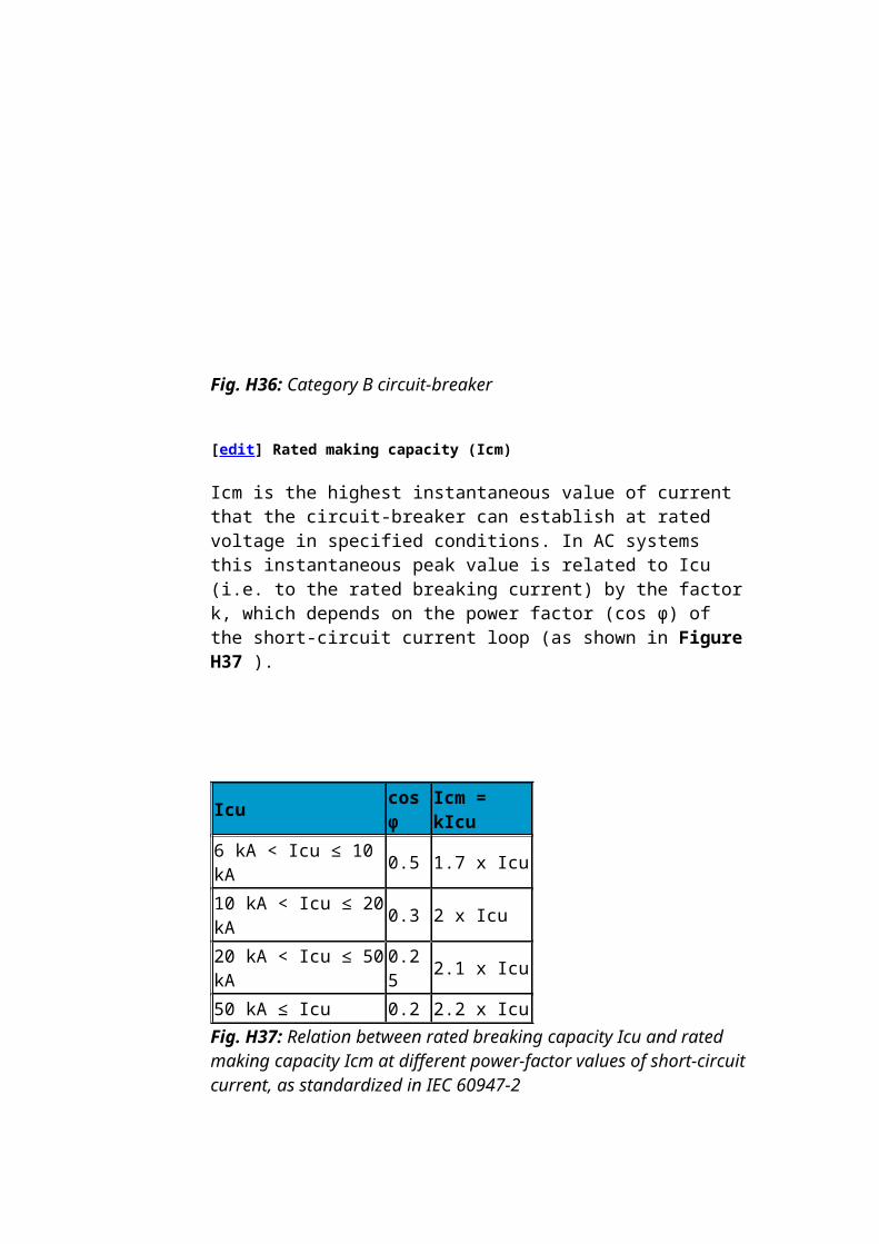
Fig. H36: Category B circuit-breaker
[edit] Rated making capacity (Icm)
Icm is the highest instantaneous value of current that the circuit-breaker can establish at rated voltage in specified conditions. In AC systems this
instantaneous peak value is related to Icu (i.e. to the rated breaking current) by the factor k, which depends on the power factor (cos ϕ) of the short-circuit current loop (as shown in Figure H37 ).
Icu cosφ Icm = kIcu
6 kA < Icu ≤ 10 kA 0.5 1.7 x Icu
10 kA < Icu ≤ 20 kA 0.3 2 x Icu
20 kA < Icu ≤ 50 kA 0.25 2.1 x Icu
50 kA ≤ Icu 0.2 2.2 x Icu Fig. H37: Relation between rated breaking capacity Icu and rated making capacity Icm at different power-factor values of short-circuit current, as standardized in IEC 60947-2
Example: A Masterpact NW08H2 circuit-breaker has a rated breaking capacity Icu of 100 kA. The peak value of its rated making capacity Icm will be 100 x 2.2 = 220 kA.
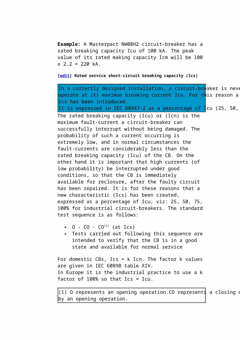
[edit] Rated service short-circuit breaking capacity (Ics)
In a correctly designed installation, a circuit-breaker is never required to operate at its maximum breaking current Icu. For this reason a new characteristic Ics has been introduced. It is expressed in IEC 60947-2 as a percentage of Icu (25, 50, 75, 100%) The rated breaking capacity (Icu) or (Icn) is the maximum fault-current a circuit-breaker can successfully interrupt without being damaged. The probability of such a current occurring is extremely low, and in normal circumstances the fault-currents are considerably less than the rated breaking capacity (Icu) of the CB. On the other hand it is important that high currents (of low probability) be interrupted under good conditions, so that the CB is immediately available for reclosure, after the faulty circuit has been repaired. It is for these reasons that a new characteristic (Ics) has been created, expressed as a percentage of Icu, viz: 25, 50, 75, 100% for industrial circuit-breakers. The standard test sequence is as follows:
O - CO - CO(1) (at Ics) Tests carried out following this sequence are intended to verify that
the CB is in a good state and available for normal service
For domestic CBs, Ics = k Icn. The factor k values are given in IEC 60898 table XIV.In Europe it is the industrial practice to use a k factor of 100% so that Ics =
Icu.
(1) O represents an opening operation.CO represents a closing operation followed by an opening operation. [edit] Fault-current limitation
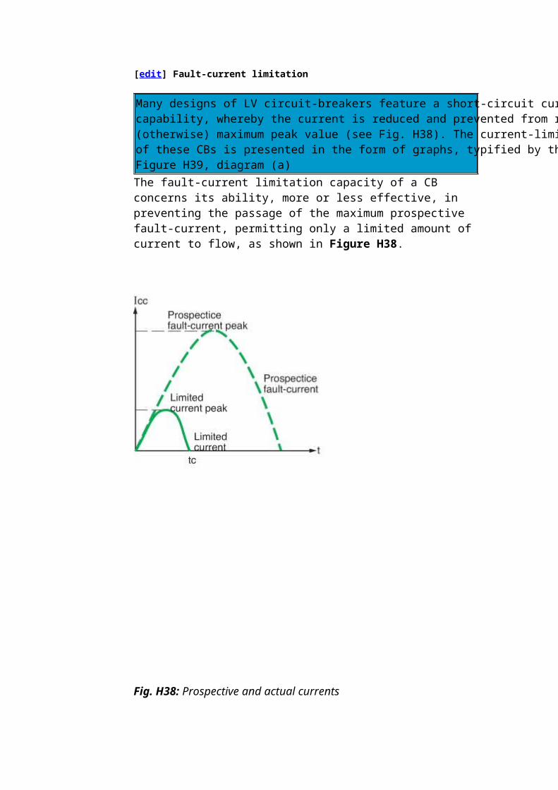
Many designs of LV circuit-breakers feature a short-circuit current limitation capability, whereby the current is reduced and prevented from reaching its (otherwise) maximum peak value (see Fig. H38). The current-limitation performance of these CBs is presented in the form of graphs, typified by that shown in Figure H39, diagram (a) The fault-current limitation capacity of a CB concerns its ability, more or less effective, in preventing the passage of the maximum prospective fault-current, permitting only a limited amount of current to flow, as shown in Figure H38.
Fig. H38: Prospective and actual currents
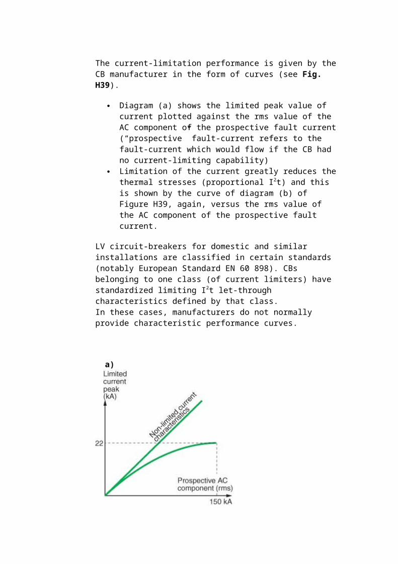
The current-limitation performance is given by the CB manufacturer in the form of curves (see Fig. H39).
Diagram (a) shows the limited peak value of current plotted against the rms value of the AC component of the prospective fault current (“prospective” fault-current refers to the fault-current which would flow if the CB had no current-limiting capability)
Limitation of the current greatly reduces the thermal stresses (proportional I2t) and this is shown by the curve of diagram (b) of Figure H39, again, versus the rms value of the AC component of the prospective fault current.
LV circuit-breakers for domestic and similar installations are classified in certain standards (notably European Standard EN 60 898). CBs belonging to one class (of current limiters) have standardized limiting I2t let-through characteristics defined by that class.In these cases, manufacturers do not normally provide characteristic performance curves.
Fig. H39: Performance curves of a typical LV current-limiting circuit-breaker
[edit] The advantages of current limitation
Current limitation reduces both thermal and electrodynamic stresses on all circuit elements through which the current passes, thereby prolonging the useful life of these elements. Furthermore, the limitation feature allows “cascading” techniques to be used (see 4.5) thereby significantly reducing design and installation costs The use of current-limiting CBs affords numerous advantages:
Better conservation of installation networks: current-limiting CBs strongly attenuate all harmful effects associated with short-circuit currents
Reduction of thermal effects: Conductors (and therefore insulation) heating is significantly reduced, so that the life of cables is correspondingly increased
Reduction of mechanical effects: forces due to electromagnetic repulsion are lower, with less risk of deformation and possible
rupture, excessive burning of contacts, etc. Reduction of electromagnetic-interference effects:
- Less influence on measuring instruments and associated circuits, telecommunication systems, etc.These circuit-breakers therefore contribute towards an improved exploitation of:
Cables and wiring Prefabricated cable-trunking systems Switchgear, thereby reducing the ageing of the installation
ExampleOn a system having a prospective shortcircuit current of 150 kA rms, a Compact L circuit-breaker limits the peak current to less than 10% of the calculated prospective peak value, and the thermal effects to less than 1% of those calculated.Cascading of the several levels of distribution in an installation, downstream of a limiting CB, will also result in important savings.The technique of cascading allows, in fact, substantial savings on switchgear (lower performance permissible downstream of the limiting CB(s)) enclosures, and design studies, of up to 20% (overall).Discriminative protection schemes and cascading are compatible, in the Compact NSX range, up to the full short-circuit breaking capacity of the switchgear.
[edit] Selection of a circuit-breaker
The choice of a range of circuit-breakers is determined by: the electrical characteristics of the installation, the environment, the loads and a need for remote control, together with the type of telecommunications system envisaged [edit] Choice of a circuit-breaker
The choice of a CB is made in terms of:
Electrical characteristics of the installation for which the CB is intended
Its eventual environment: ambient temperature, in a kiosk or switchboard enclosure, climatic conditions, etc.
Short-circuit current breaking and making requirements Operational specifications: discriminative tripping, requirements (or
not) for remote control and indication and related auxiliary contacts, auxiliary tripping coils, connection
Installation regulations; in particular: protection of persons Load characteristics, such as motors, fluorescent lighting, LV/LV
transformers
The following notes relate to the choice LV circuit-breaker for use in distribution systems.
[edit] Choice of rated current in terms of ambient temperature
The rated current of a circuit-breaker is defined for operation at a given ambient temperature, in general:
30 °C for domestic-type CBs 40 °C for industrial-type CBs
Performance of these CBs in a different ambient temperature depends mainly on the technology of their tripping units (see Fig. H40).
Fig. H40: Ambient temperature
[edit] Uncompensated thermal magnetic tripping units
Circuit-breakers with uncompensated thermal tripping units have a trip current level that depends on the surrounding temperature Circuit-breakers with uncompensated thermal tripping elements have a tripping-current level that depends on the surrounding temperature. If the
CB is installed in an enclosure, or in a hot location (boiler room, etc.), the current required to trip the CB on overload will be sensibly reduced. When the temperature in which the CB is located exceeds its reference temperature, it will therefore be “derated”. For this reason, CB manufacturers provide tables which indicate factors to apply at temperatures different to the CB reference temperature. It may be noted from typical examples of such tables (see Fig. H41) that a lower temperature than the reference value produces an up-rating of the CB. Moreover, small modular-type CBs mounted in juxtaposition, as shown typically in Figure H27, are usually mounted in a small closed metal case. In this situation, mutual heating, when passing normal load currents, generally requires them to be derated by a factor of 0.8.ExampleWhat rating (In) should be selected for a C60 N?
Protecting a circuit, the maximum load current of which is estimated to be 34 A
Installed side-by-side with other CBs in a closed distribution box In an ambient temperature of 50 °C
A C60N circuit-breaker rated at 40 A would be derated to 35.6 A in ambient air at 50 °C (see Fig. H41). To allow for mutual heating in the enclosed space, however, the 0.8 factor noted above must be employed, so that, 35.6 x 0.8 = 28.5 A, which is not suitable for the 34 A load.A 50 A circuit-breaker would therefore be selected, giving a (derated) current rating of 44 x 0.8 = 35.2 A.
[edit] Compensated thermal-magnetic tripping units
These tripping units include a bi-metal compensating strip which allows the overload trip-current setting (Ir or Irth) to be adjusted, within a specified range, irrespective of the ambient temperature.For example:
In certain countries, the TT system is standard on LV distribution systems, and domestic (and similar) installations are protected at the service position by a circuit-breaker provided by the supply authority. This CB, besides affording protection against indirect-contact hazard, will trip on overload; in this case, if the consumer exceeds the current level stated in his supply contract with the power authority. The circuit-breaker (≤ 60 A) is compensated for a temperature range of - 5 °C to + 40 °C.
LV circuit-breakers at ratings ≤ 630 A are commonly equipped with compensated tripping units for this range (- 5 °C to + 40 °C)
C60a, C60H: curve C. C60N: curves B and C (reference temperature: 30 °C)
30 °C 35 °C 40 °C 45 °C 50 °C 55 °C 60 °C
1.00 0.98 0.95 0.93 0.90 0.88 0.85
2.00 1.96 1.92 1.88 1.84 1.80 1.74
3.00 2.91 2.82 2.70 2.61 2.49 2.37
4.00 3.88 3.76 3.64 3.52 3.36 3.24
6.00 5.88 5.76 5.64 5.52 5.40 5.30
10.0 9.70 9.30 9.00 8.60 8.20 7.80
16.0 15.5 15.2 14.7 14.2 13.8 13.5
20.0 19.4 19.0 18.4 17.8 17.4 16.8
25.0 24.2 23.7 23.0 22.2 21.5 20.7
32.0 31.4 30.4 29.8 28.4 28.2 27.5
40.0 38.8 38.0 36.8 35.6 34.4 33.2
50.0 48.5 47.4 45.5 44.0 42.5 40.5
63.0 61.1 58.0 56.7 54.2 51.7 49.2
Compact NSX100-250 N/H/L equippment with TM-D or TM-G trip units
Temperature (°C)
30 35 40 45 50 55 60 65 70
17 16.6 16 15.6 15.2 14.8 14.5 14 13.8
26.3 25.6 25 24.5 24 23.5 23 22 21
33.6 32.8 32 31.3 30.5 30 29.5 29 28.5
42 41 40 39 38 37 36 35 34
52.5 51 50 49 48 47 46 45 44
66 65 63 61.5 60 58 57 55 54
84 82 80 78 76 74 72 70 68
105 103 100 97.5 95 92.5 90 87.5 85
131 128 125 122 119 116 113 109 106
168 164 160 156 152 148 144 140 136
210 205 200 195 190 185 180 175 170
263 256 250 244 238 231 225 219 213 Fig. H41: Examples of tables for the determination of derating/uprating factors to apply to CBs with uncompensated thermal tripping units, according to temperature
[edit] Electronic trip units
Electronic tripping units are highly stable in changing temperature levels An important advantage with electronic tripping units is their stable performance in changing temperature conditions. However, the switchgear
itself often imposes operational limits in elevated temperatures, so that manufacturers generally provide an operating chart relating the maximum values of permissible trip-current levels to the ambient temperature (see Fig. H42).Moreover, electronic trip units can provide information that can be used for a better management of the electrical distribution, including energy efficiency and power quality.
Masterpact NW20 version40°C 45°C 50°C 55°C 60°C
Withdrawable with horizontal plugs In (A) 2,000 2,000 2,000 1,980 1,890
Maximum adjustment Ir 1 1 1 0.99 0.95
Withdrawable with on-edge plugs In (A) 2,000 200 1,900 1,850 1,800
The installation of a LV circuit-breaker requires that its short-circuit breaking capacity (or that of the CB together with an associated device) be equal to or exceeds the calculated prospective short-circuit current at its point of installation The installation of a circuit-breaker in a LV installation must fulfil one of the two following conditions:
Either have a rated short-circuit breaking capacity Icu (or Icn) which is equal to or exceeds the prospective short-circuit current calculated for its point of installation, or
If this is not the case, be associated with another device which is located upstream, and which has the required short-circuit breaking capacity
In the second case, the characteristics of the two devices must be co-ordinated such that the energy permitted to pass through the upstream device must not exceed that which the downstream device and all associated cables, wires and other components can withstand, without being damaged in any way. This technique is profitably employed in:
Associations of fuses and circuit-breakers Associations of current-limiting circuit-breakers and standard
circuit-breakers.
The technique is known as “cascading”
[edit] The selection of main and principal circuit-breakers
The circuit-breaker at the output of the smallest transformer must have a short-circuit capacity adequate for a fault current which is higher than that through any of the other transformer LV circuit-breakers A single transformer
If the transformer is located in a consumer’s substation, certain national standards require a LV circuit-breaker in which the open contacts are clearly visible such as Compact NSX withdrawable circuit-breaker.
Example (see Fig. H44 )What type of circuit-breaker is suitable for the main circuit-breaker of an installation supplied through a 250 kVA MV/LV (400 V) 3-phase transformer in a consumer’s substation?In transformer = 360 AIsc (3-phase) = 8.9 kAA Compact NSX400N with an adjustable tripping-unit range of 160 A - 400 A and a short-circuit breaking capacity (Icu) of 50 kA would be a suitable choice for this duty.
Fig. H44: Example of a transformer in a consumer’s substation
Several transformers in parallel (see Fig. H45)
The circuit-breakers CBP outgoing from the LV distribution board must each be capable of breaking the total fault current from all transformers connected to the busbars, viz: Isc1 + Isc2 + Isc3
The circuit-breakers CBM, each controlling the output of a transformer, must be capable of dealing with a maximum short-circuit current of (for example) Isc2 + Isc3 only, for a short-circuit located on the upstream side of CBM1.
From these considerations, it will be seen that the circuit-breaker of the smallest transformer will be subjected to the highest level of fault current in these circumstances, while the circuit-breaker of the largest transformer will pass the lowest level of short-circuit current
The ratings of CBMs must be chosen according to the kVA ratings of the associated transformers
Note: The essential conditions for the successful operation of 3-phase transformers in parallel may be summarized as follows:1. the phase shift of the voltages, primary to secondary, must be the same in all units to be paralleled.2. the open-circuit voltage ratios, primary to secondary, must be the same in all units.3. the short-circuit impedance voltage (Zsc%) must be the same for all units. For example, a 750 kVA transformer with a Zsc = 6% will share the load correctly with a 1,000 kVA transformer having a Zsc of 6%, i.e. the transformers will be loaded automatically in proportion to their kVA ratings. For transformers having a ratio of kVA ratings exceeding 2, parallel operation is not recommended.
Figure H46 indicates, for the most usual arrangement (2 or 3 transformers of equal kVA ratings) the maximum short-circuit currents to which main and principal CBs (CBM and CBP respectively, in Figure H45) are subjected. It is based on the following hypotheses:
The short-circuit 3-phase power on the MV side of the transformer is 500 MVA
The transformers are standard 20/0.4 kV distribution-type units rated as listed
The cables from each transformer to its LV circuit-breaker comprise 5 metres of single core conductors
Between each incoming-circuit CBM and each outgoing-circuit CBP there is 1 metre of busbar
The switchgear is installed in a floormounted enclosed switchboard, in an ambient-air temperature of 30 °C
Moreover, this table shows selected circuit-breakers of M-G manufacture recommended for main and principal circuit-breakers in each case.
Main circuit-breakers (CBM)total discrimination with out going circuit-breakers (CBP)
Minimum S.C breaking capacity of principal CBs(Icu) kA
Rated current In of principal circuit-breaker(CPB) 250A
NW08N1/NS800N 27 NSX250H
NW08N1/NS800N 42 NSX250H
NW10N1/NS1000N 42 NSX250H
NW10N1/NS1000N 67 NSX250H
NW12N1/NS1250N 38 NSX250H
NW12N1/NS1250N 56 NSX250H
NW16N1/NS1600N 47 NSX250H
NW16N1/NS1600N 70 NSX250H
NW20N1/NS2000N 59 NSX250H
NW20N1/NS2000N 88 NSX250L
NW25N1/NS2500N 75 NSX250L
NW25N1/NS2500N 113 NSX250L
NW32N1/NS3200N 94 NSX250L
NW32N1/NS3200N 141 NSX250L Fig. H46: Maximum values of short-circuit current to be interrupted by main and principal circuit-breakers (CBM and CBP respectively), for several transformers in parallel
Example (see Fig. H47 )
Circuit-breaker selection for CBM duty:
For a 800 kVA transformer In = 1.126 A; Icu (minimum) = 38 kA (from Figure H46), the CBM indicated in the table is a Compact NS1250N (Icu =
50 kA)
Circuit-breaker selection for CBP duty:
The s.c. breaking capacity (Icu) required for these circuit-breakers is given in the Figure H46 as 56 kA.A recommended choice for the three outgoing circuits 1, 2 and 3 would be current-limiting circuit-breakers types NSX400 L, NSX250 L and NSX100 L. The Icu rating in each case = 150 kA.
Fig. H47: Transformers in parallel
These circuit-breakers provide the advantages of: - Absolute discrimination with the upstream (CBM) breakers - Exploitation of the “cascading” technique, with its associated savings for
[edit] Choice of outgoing-circuit CBs and final-circuit CBs
Short-circuit fault-current levels at any point in an installation may be obtained from tables Use of table G40From this table, the value of 3-phase short-circuit current can be determined rapidly for any point in the installation, knowing:
The value of short-circuit current at a point upstream of that intended for the CB concerned
The length, c.s.a., and the composition of the conductors between the two points
A circuit-breaker rated for a short-circuit breaking capacity exceeding the tabulated value may then be selected.
Detailed calculation of the short-circuit current levelIn order to calculate more precisely the short-circuit current, notably, when the short-circuit current-breaking capacity of a CB is slightly less than that derived from the table, it is necessary to use the method indicated in chapter G.
Two-pole circuit-breakers (for phase and neutral) with one protected pole onlyThese CBs are generally provided with an overcurrent protective device on the phase pole only, and may be used in TT, TN-S and IT schemes. In an IT scheme, however, the following conditions must be respected:
Condition (B) of table G67 for the protection of the neutral conductor against overcurrent in the case of a double fault
Short-circuit current-breaking rating: A 2-pole phase-neutral CB must, by convention, be capable of breaking on one pole (at the phase-to-phase voltage) the current of a double fault equal to 15% of the 3-phase short-circuit current at the point of its installation, if that current is ≤ 10 kA; or 25% of the 3-phase short-circuit current if it exceeds 10 kA
Protection against indirect contact: this protection is provided according to the rules for IT schemes
Insufficient short-circuit current breaking rating In low-voltage distribution systems it sometimes happens, especially in heavy-duty networks, that the Isc calculated exceeds the Icu rating of the CBs available for installation, or system changes upstream result in lower level CB ratings being exceeded
Solution 1: Check whether or not appropriate CBs upstream of the CBs affected are of the current-limiting type, allowing the principle of cascading (described in sub-clause 4.5) to be applied
Solution 2: Install a range of CBs having a higher rating. This solution is economically interesting only where one or two CBs are affected
Solution 3: Associate current-limiting fuses (gG or aM) with the CBs concerned, on the upstream side. This arrangement must, however, respect the following rules:
- The fuse rating must be appropriate - No fuse in the neutral conductor, except in certain IT installations where a double fault produces a current in the neutral which exceeds the short-circuit breaking rating of the CB. In this case, the blowing of the neutral fuse must cause the CB to trip on all phases.
[edit] Coordination between circuit-breakers
[edit] Cascading (or Back-up protection)
The technique of “cascading” uses the properties of current-limiting circuit-breakers to permit the installation of all downstream switchgear, cables and other circuit components of significantly lower performance than would otherwise be necessary, thereby simplifying and reducing the cost of an installation Definition of the cascading technique By limiting the peak value of short-circuit current passing through it, a current-limiting CB permits the use, in all circuits downstream of its location, of switchgear and circuit components having much lower short-circuit breaking capacities, and thermal and electromechanical withstand capabilities than would otherwise be necessary. Reduced physical size and lower performance requirements lead to substantial economy and to the simplification of installation work. It may be noted that, while a current-limiting circuit-breaker has the effect on downstream circuits of (apparently) increasing the source impedance during short-circuit conditions, it has no such effect in any other condition; for example, during the starting of a large motor (where a low source impedance is highly desirable). The range of Compact NSX current-limiting circuit-breakers with powerful limiting performances is particularly interesting.
[edit] Conditions of implementation
In general, laboratory tests are necessary to ensure that the conditions of implementation required by national standards are met and compatible switchgear combinations must be provided by the manufacturer Most national standards admit the cascading technique, on condition that the amount of energy “let through” by the limiting CB is less than the energy all downstream CBs and components are able to withstand without damage.In practice this can only be verified for CBs by tests performed in a laboratory. Such tests are carried out by manufacturers who provide the information in the form of tables, so that users can confidently design a cascading scheme based on the combination of recommended circuit-breaker types. As an example, Figure H48 indicates the cascading possibilities of circuit-breaker types C60, DT40N, C120 and NG125 when
installed downstream of current-limiting CBs Compact NSX 250 N, H or L for a 230/400 V or 240/415 V 3-phase installation.
kArms
Short-circuiteaking capacity of the upstream (limiter) CBs
150 NSX250L
70 NSX250H
50 NSX250N
Possible short-circuit breaking capacity of the downstream CBs (benefiting from the cascading technique)
150 NG125L
70 NG125L
36 NG125N NG125N
30 C60N/H<=32A C60N/H<=32A C60N/H<=32A
30 C60L<=25A C60L<=25A(*)Quick PRD40/20/8
C60L<=25A
25 C60H>=40AC120N/H
C60H>=40AC120N/H
C60H>=40AC120N/H
20 C60N>=40A C60N>=40A C60N>=40A (*) Quick PRD with integrated circuit-breaker as disconnector see chapter J
Fig. H48: Example of cascading possibilities on a 230/400 V or 240/415 V 3-phase installation
[edit] Advantages of cascading
The current limitation benefits all downstream circuits that are controlled by the current-limiting CB concerned.The principle is not restrictive, i.e. current-limiting CBs can be installed at any point in an installation where the downstream circuits would otherwise be inadequately rated.The result is:
Simplified short-circuit current calculations Simplification, i.e. a wider choice of downstream switchgear and
appliances The use of lighter-duty switchgear and appliances, with
consequently lower cost Economy of space requirements, since light-duty equipment have
[edit] Principles of discriminative tripping (selectivity)
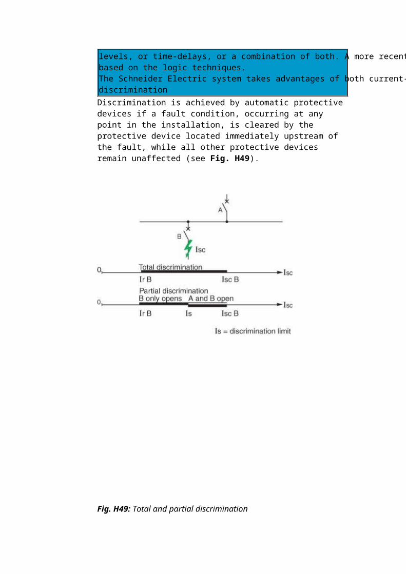
Discrimination may be total or partial, and based on the principles of current levels, or time-delays, or a combination of both. A more recent development is based on the logic techniques.The Schneider Electric system takes advantages of both current-limitation and discrimination Discrimination is achieved by automatic protective devices if a fault condition, occurring at any point in the installation, is cleared by the protective device located immediately upstream of the fault, while all other protective devices remain unaffected (see Fig. H49).
Fig. H49: Total and partial discrimination
Discrimination between circuit-breakers A and B is total if the maximum value of short-circuit-current on circuit B (Isc B) does not exceed the short-circuit trip setting of circuit-breaker A (Im A). For this condition, B only
Fig. H50: Total discrimination between CBs A and B
Discrimination is partial if the maximum possible short-circuit current on circuit B exceeds the short-circuit trip-current setting of circuit-breaker A. For this maximum condition, both A and B will trip (see Fig. H51).
Fig. H51: Partial discrimination between CBs A and B
Protection against overload : discrimination based on current levels (see Fig. H52a)This method is realized by setting successive tripping thresholds at stepped levels, from downstream relays (lower settings) towards the source (higher settings). Discrimination is total or partial, depending on particular conditions, as noted above.
As a rule of thumb, discrimination is achieved when:
IrA/IrB > 2:
Protection against low level short-circuit currents : discrimination based on stepped time delays (see Fig. H52b)This method is implemented by adjusting the time-delayed tripping units, such that downstream relays have the shortest operating times, with progressively longer delays towards the source.In the two-level arrangement shown, upstream circuit-breaker A is delayed sufficiently to ensure total discrimination with B (for example: Masterpact with electronic trip unit).
Discrimination based on a combination of the two previous methods (see Fig. H52c)A time-delay added to a current level scheme can improve the overall discrimination performance.The upstream CB has two high-speed magnetic tripping thresholds:
Im A: delayed magnetic trip or short-delay electronic trip Ii: instantaneous strip
Discrimination is total if Isc B < Ii (instantaneous).
Protection against high level short-circuit currents: discrimination based on arc-energy levelsThis technology implemented in the Compact NSX range (current limiting circuit- breaker) is extremely effective for achievement of total discrimination.Principle: When a very high level short-circuit current is detected by the two circuits- breaker A and B, their contacts open simultaneously. As a result, the current is highly limited.
The very high arc-energy at level B induces the tripping of circuit-breaker B
Then, the arc-energy is limited at level A and is not sufficient to induce the tripping of A
As a rule of thumb, the discrimination between Compact NSX is total if the size ratio between A and B is greater than 2.5.
[edit] Current-level discrimination
This technique is directly linked to the staging of the Long Time (LT) tripping curves of two serial-connected circuit-breakers.
Fig. H53: Current discrimination
The discrimination limit ls is:
Is = Isd2 if the thresholds lsd1 and lsd2 are too close or merge, Is = Isd1 if the thresholds lsd1 and lsd2 are sufficiently far apart.
As a rule, current discrimination is achieved when:
Discrimination is total if Is > Isc(D2), i.e. Isd1 > Isc(D2). This normally implies:
a relatively low level Isc(D2), a large difference between the ratings of circuit-breakers D1 and D2.
Current discrimination is normally used in final distribution. [edit] Time discrimination
Discrimination based on time-delayed tripping uses CBs referred to as “selective” (in some countries).Implementation of these CBs is relatively simple and consists in delaying the instant of tripping of the several series-connected circuit-breakers in a stepped time sequence This is the extension of current discrimination and is obtained by staging over time of the tripping curves. This technique consists of giving a time delay of t to the Short Time (ST) tripping of D1.
The thresholds (Ir1, Isd1) of D1 and (Ir2, Isd2) comply with the staging rules of current discrimination. The discrimination limit ls of the association is at least equal to li1, the instantaneous threshold of D1.
Discrimination quality
on final and/or intermediate feeders
A category circuit-breakers can be used with time-delayed tripping of the upstream circuit-breaker. This allows extension of current discrimination up to the instantaneous threshold li1 of the upstream circuit-breaker: Is = li1.If Isc(D2) is not too high - case of a final feeder - total discrimination can be obtained.
on the incomers and feeders of the MSB
At this level, as continuity of supply takes priority, the installation characteristics allow use of designed for time-delayed tripping. These circuit-breakers have a high thermal withstand (Icw ≥ 50% Icn for t = 1s): Is = Icw1.Even for high lsc(D2), time discrimination normally provides total discrimination: Icw1 > Icc(D2).Note: Use of B category circuit-breakers means that the installation must withstand high electrodynamic and thermal stresses.Consequently, these circuit-breakers have a high instantaneous threshold li that can be adjusted and disabled in order to protect the busbars if necessary.
Practical example of discrimination at several levels with Schneider Electric circuit-breakers (with electronic trip units)"Masterpact NT is totally selective with any moulded-case Compact NSX circuit breaker, i.e., the downstream circuit-breaker will trip for any short-circuit value up to its breaking capacity. Further, all Compact NSX CBs are totally selective, as long as the ration between sizes is greater than 1.6 and the ratio between ratings is greater than 2.5. The same rules apply for the total selectivity with the miniature circuit-breakers Multi9 further downstream (see Fig. H55).
Fig. H55: 4 level discrimination with Schneider Electric circuit breakers : Masterpact NT Compact NSX and Multi 9
[edit] Energy discrimination with current limitation
Cascading between 2 devices is normally achieved by using the tripping of the upstream circuit-breaker A to help the downstream circuit-breaker B to break the current. The discrimination limit Is is consequently equal to the ultimate breaking current Icu B of circuit-breaker B acting alone, as cascading requires the tripping of both devices.The energy discrimination technology implemented in Compact NSX circuit-breakers allows to improve the discrimination limit to a value higher than the ultimate breaking current Icu B of the downstream circuit-breaker. The principle is as follows:
The downstream limiting circuit-breaker B sees a very high short-
circuit current. The tripping is very fast (<1 ms) and then, the current is limited
The upstream circuit-breaker A sees a limited short-circuit current compared to its breaking capability, but this current induces a repulsion of the contacts. As a result, the arcing voltage increases the current limitation. However, the arc energy is not high enough to induce the tripping of the circuit-breaker. So, the circuit-breaker A helps the circuit-breaker B to trip, without tripping itself. The discrimination limit can be higher than Icu B and the discrimination becomes total with a reduced cost of the devices
[edit] Natural total discriminitation with Compact NSX
The major advantage of the Compact NSX range is to provide a natural total discrimination between two series-connected devices if:
The ratio of the two trip-unit current ratings is > 1.6 The ratio of rated currents of the two circuit-breakers is > 2.5
[edit] Logic discrimination or “Zone Sequence Interlocking – ZSI”
Discrimination schemes based on logic techniques are possible, using CBs equipped with electronic tripping units designed for the purpose (Compact, Masterpact) and interconnected with pilot wires This type of discrimination can be achieved with circuit-breakers equipped with specially designed electronic trip units (Compact, Masterpact): only the Short Time Protection (STP) and Ground Fault Protection (GFP) functions of the controlled devices are managed by Logic Discrimination. In particular, the Instantaneous Protection function - inherent protection function - is not concerned.Settings of controlled circuit-breakers
time delay: there are no rules, but staging (if any)of the time delays of time discrimination must be applied (ΔtD1 ≥ ΔtD2 ≥ ΔtD3),
thresholds: there are no threshold rules to be applied, but natural staging of the protection device ratings must be complied with (IcrD1 ≥ IcrD2 ≥ IcrD3).
Note: This technique ensures discrimination even with circuit-breakers of similar ratings.
[edit] Principles
Activation of the Logic Discrimination function is via transmission of information on the pilot wire:
ZSI input:
- low level (no downstream faults): the Protection function is on standby with a reduced time delay (y 0,1 s),
- high level (presence of downstream faults): the relevant Protection function moves to the time delay status set on the device.
ZSI output:
- low level: the trip unit detects no faults and sends no orders, - high level: the trip unit detects a fault and sends an order.
[edit] Operation
A pilot wire connects in cascading form the protection devices of an installation (see Fig. H56). When a fault occurs, each circuit-breaker upstream of the fault (detecting a fault) sends an order (high level output) and moves the upstream circuit-breaker to its natural time delay (high level input). The circuitbreaker placed just above the fault does not receive any orders (low level input) and thus trips almost instantaneously.
easy achievement as standard of discrimination on 3 levels or more, elimination of important stresses on the installation, relating to time-delayed tripping of the protection device, in
event of a fault directly on the upstream busbars.
All the protection devices are thus virtually instantaneous,
easy achievement of downstream discrimination with non-controlled circuit-breakers.
[edit] Discrimination MV/LV in a consumer’s substation
In general the transformer in a consumer’s substation is protected by MV fuses, suitably rated to match the transformer, in accordance with the principles laid down in IEC 60787 and IEC 60420, by following the advice of the fuse manufacturer.The basic requirement is that a MV fuse will not operate for LV faults occurring downstream of the transformer LV circuit-breaker, so that the tripping characteristic curve of the latter must be to the left of that of the MV fuse pre-arcing curve.This requirement generally fixes the maximum settings for the LV circuit-breaker protection:
Maximum short-circuit current-level setting of the magnetic tripping element
Maximum time-delay allowable for the short-circuit current tripping element
(see Fig. H57)
Fig. H57: Example
Example:
Short-circuit level at MV terminals of transformer: 250 MVA Transformer MV/LV: 1,250 kVA 20/0.4 kV MV fuses: 63 A Cabling, transformer - LV circuit-breaker: 10 metres single-core
cables LV circuit-breaker: Compact NSX 2000 set at 1,800 A (Ir)
What is the maximum short-circuit trip current setting and its maximum time delay allowable?The curves of Figure H58 show that discrimination is assured if the short-time delay tripping unit of the CB is set at:
A level ≤ 6 Ir = 10.8 kA A time-delay setting of step 1 or 2
Fig. H58: Curves of MV fuses and LV circuit-breaker
[edit] Ultra-rapid circuit breaker As installed power increases, electrical distribution has to shift from a LV design to a HV design. Indeed, a high short-circuit level can be a threat to the installation and make impossible the selection of low voltage equipments (Switchboard and bus bars, circuit breaker…)
These situations could be met in the following applications:Bus bars coupling onboard merchant vessels, off shore platform, loop networks (in industry), where the current and energy are important because of the installed power (several transformers or generators in parallel) and HV design not easy.
Some power circuit breakers with additionnal feature (based on the Thomson effect technology for instance) provide an ultrarapid opening system on very high short-circuit level. The breaking performance makes it possible to limit theshort-circuit current and prospective energy, and consequently protect the electrical installation against the electrodynamic and thermal effects of short-circuit.
Example of ultra rapid power circuit breaker: Masterpact UR
[edit] Example of limitation offered by Masterpact UR in decoupling bus bars in case of short circuit:
When a short-circuit occurs downstream in the installation (A) with no tie breaker, the short-circuit level will be the total sum of all the generated power (illustrated by curve 1).
By inserting a tie breaker - Masterpact UR - to separate the sources under fault conditions, the short circuit at (A) will consist in:a limited short circuit coming from generator G1 and G2 interrupted by the Masterpact UR (see curve 2) a non limited short circuit from generators G3 and G4 (see curve 3).
The resulting short circuit level is illustrated by curve 4.
The consequence of the strong limitation of the short circuit current and the prospective energy allows the design of a LV network instead of a MV design.This also prevents the network from being totally shutdown (black out) in case of short circuit in the main switchboard.
The following table give some example of limitation with MAsterpact UR as a tie breaker between source 1 & 2