84
r E. Circuit Digests ...4, .,1-11.... ..:14W1 .---"_,_e--------_,---4i'llylur ----em.---- t \s, The television tehniciein becomes MR. B\G when the TV set goes aad February 1954

r
E. Circuit Digests
...4,
.,1-11......:14W1
.---"_,_e--------_,---4i'llylur----em.----t
\s,
The television tehniciein
becomes MR. B\Gwhen the TV set
goes aad
February 1954

of ALL Fixed Composition Resistors by almost
*Not Claims! Not Predictions! But Plain Facts!Unbiased, authoritative, independent surveys (maderegularly since 1930) show IRC BT RESISTORS tobe the Service Technicians' choice by a continuallyincreasing margin. Today, BT RESISTORS arepreferred over the total of all other brands combined!
Ask for IRC BT's
Most Service Technicians Do !
10
INTERNATIONAL RESISTANCE COMPANY425 N. Broad Street, Philadelphia 8, Pa.
(Avon* &taut Sof -Ann, In Canada: International Resistance Co., Ltd., Toronto, Licensee

TECHNICIAN*Circuit Digests
a
TELEVISION ELECTRONIC RADIO AUDIO SERVICE
M. CLEMENTS 0. H. CALDWELLPublisher Editorial Director
SOL HELLER, Managing Editor
SIDNEY C. SILVER, Associate Editor
ANN O'ROURKE, Assistant Editor
J. L. STOUTENB'JRGH, Consulting Editor
CHARLES F. )REYER, Art Director
ELMER KETTERER, Circuit -Digest Production
GEORGE PUGLICI, Circuit Diagrams
BUSINESS DEPARTMENT
M. H. NEWTON, Business ManagerH. A. REED, Genera: Sales Manager
DIXON SCOTT, District ManagerLEE GRAVES, District Manager
CHARLES S. ROEVER, District ManagerN. McALLISTER, Asst. Business Manager
MARTHA USDIN, Production ManagerKATHLEEN CAFARO, Reader Service
WARREN S. BROWN, Circulation Manager
M. GROENING, Asst. Circulation Manager
JOHN J. BORGHI, ControllerW. W. SWIGERT, Credit Manager
480 Lexington Ave., New York 17, N. 1.
Telephone Plaza 9-7880
S. M. GASKINS, Western ManagerJOHN D. LUPTON, District Manager
201 N. Wells St., Chicago 6, III.Telephone RAndolph 6-9225
CHRIS DUNKLE & ASSOCIATESCalifornia Representative
3257 W. 6th Street, Los Angeles 5, Calif.Telephone DUnkirk 7-6149
1355 Market Street, San FranciscoTelephone Klondike 2-2311, Ext. 579
CIRCULATION
50,000-serving the industry's largest group ofservice technicians, service managers and
installation specialists.
TECHNICIAN, Feb-uary 1954, Vol. 59, No. 2.50 cents a copy. Published monthly by Caldwell -Clements, Inc., Publication Office, Emmett St..Bristol, Conn. Eoitorial, Advertising and Ex-ecutive Offices, 480 Lexington Ave., New York17, N. Y. Entered as second class matter at thePost Office at Bristol, Conn.. Nov. 4, 1953,under the act of March 3, 1879. M. Clements,President; M. H. Newton, Assistant to Presi-dent; John J. Borghl, Vice President and Sec-retary; Marguerite B. Clements, Treasurer.Subscription rates: United States and Canada,$4.00 for one year; $6.00 for two years; $8.00for three years. Pan-American and Foreigncountries: $7.00 for one year; $10.00 for twoyears; $14 for three years. Printed In U.S.A.
FEBRUARY, 1954
Problems Ahead, Outlook Good 21
"Tuning in the Picture" 22
More About Color TV Fundamentals Peter Orne & Sol Heller 24
Servicing AC -DC Radios M. G. Goldberg 27
Hi Fi Guide to Pickup Arms and Cartridges Harry Mileaf 28
What's Wrong with Carbon Tet? . Harry E. Shulman & Murray Jelling
Troubleshooting Drift in Television Receivers Philip Thier 32
Eliminating Tweet Interference Cyrus Glickstein 35
Modern Russian TV Receiver 36
Rx for Ailing CRTs 38
New Components 45
Audio and Hi-Fi Items 47
Technician's Lighter Side 48
Keep Your Eyes on Profits! 51
Manufacturer's Changes in TV Sets 58
Circuit Digest Cumulative Index 69
*CIRCUIT DIGESTS (See pages following p. 72)ADMIRAL: Chassis 20A2, 20A2Z, 20D2
GENERAL ELECTRIC: "EE" ChassisMAGNAVOX: Chassis 108A Series
RAYTHEON: Chassis 21T11WESTINGHOUSE: Chassis V-2250-1
DEPARTMENTS
31
Letters to the Editors 14 Service Ass'n. Reports 53Color Shorts 40 Calendar of Coming Events 53Shop Hints 41 "Tough Dog" 54New Products 42 Mfrs. Catalogs & Bulletins 60
New Books 63
CALDWELL-CLEMENTS, INC.Publication Office, Bristol, Conn.
Editorial/Business Offices 480 Lexington Ave., New York 17, N. Y., Tel. Plaza 9.7880Publishers also of MART and TELE-TECH & ELECTRONIC INDUSTRIES
*Reg. U. 5. Patent Office
Copyright by
Caldwell -Clements, Inc.. 1954
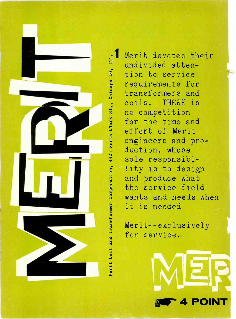
Merit devotes theirundivided atten-tion to service equirements fortransformers andcoils. THERE isn o competitionfor the time ande ffort of Merit
engineers and pro-duction, whosesole responsibi-lity is to designand produce whatthe service fieldwants and needs whenit is needed
Merit --exclusivelyfor service.
4 POINT

2 Merit actively aids in irlf
formers and yokes re-0 %%opt."service. Merit trans-
tain actual operatingcharacteristics of the wasisfoRmE
original components 4427 North Clock Street
but design improvementssimplify replacement installation.Merit installation instructionsare more complete than any othersavailable.
Merit's is the most complete re-placement catalog and the Meritreplacement guide is ahead ofservice requirements.
Merit transformers aretape marked* for quickpositive identification.
Find Merit's complete line listed inJohn Rider's Tek-File and Howard Sam'sPhotofacts and Counter Facts.
*originated by Merit.
PROGRAM air 4 POINT PROGRAM
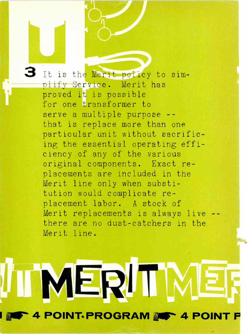
3 It is the Merit cy to sim-plify Service. erit hasproved
11is possible
for one transformer toserve a multiple purpose --that is replace more than oneparticular unit without sacrific-ing the essential operating effi-ciency of any of the variousoriginal components. Exact re-placements are included in theMerit line only when substi-tution would complicate re-placement labor. A stock ofMerit replacements is always livethere are no dust -catchers in theMerit line.
4 POINT. PROGRAM x 4 POINT Pmmumime
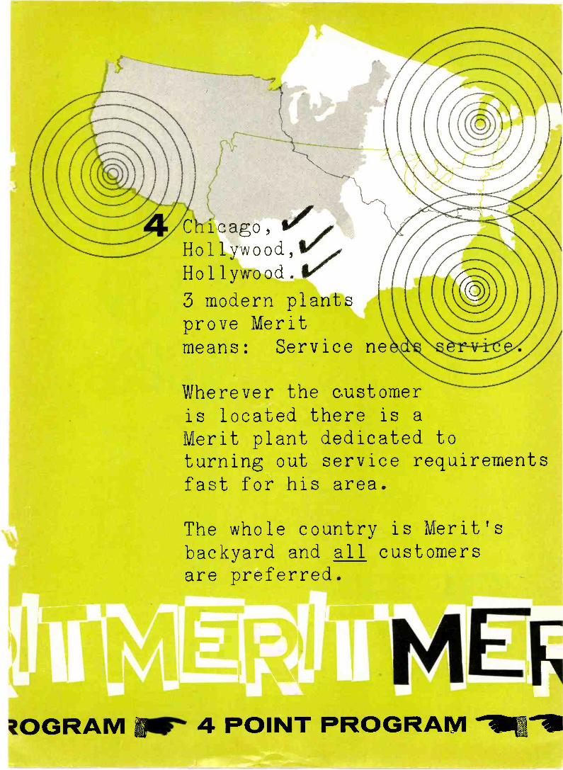
Chicago, fir,Hollywood,2Hollywood.
3 modern plantsprove Meritmeans: Service ne
Wherever the customeris located there is aVerit plant dedicated toturning out service requirementsfast for his area.
The whole country is Merit'sbackyard and all customersare preferred.
ZOGRAM 011111' 4 P01 PROGRAWI

AdmiralBOW TIE
Lowest cost ever for a quality UHF antenna. Getsexcellent reception in good signal areas on any ofthe 70 UHF channels. Each antenna furnishedwith stacking bar. Mast mounting brackets in-cluded. Mast not included.
No. AN65A-Deluxe-Shipped completelyassembled. Suggested listprice $5.95No. AN65B-Standard-Similar to above,smaller reflector screen. Shippedknocked -down. Sug. list price.. $3.95
AdmiralCORNER REFLECTOR
Recommended for troublesome locations whereghosts, reflections and interference are encountered.High gain, 14db. Front to back ratio 15 to 1.Assembled, ready to put up. Mast mountingbracket included. Mast not included.
No. ANS6A-One bracket mounting.Suggestedlist price 11.25No. AN56B-Same as above, frontmount-ing. Suggestedlist price
INDOOR UHF ANTENNAS
No. 94A10-6-Complete with lead-in.suggestedlist price.. 92.95
Admiral SuperRecommended for troublesome loca-tions. Exceptionally high gain .. . over7 db.... excellent ghost suppression.Only 12 inches wide. Weighted andfelt padded base.
Admiral TargetSmartly styled in rose -gold coloredanodized aluminum with mahoganyphenolic base. Stands only 10 incheshigh. Base is weighted and felt padded... can be placed on top of receiver... picks up all UHF channels.
11.25
No. 94A10-7 -Complete with lead-in.Suggested $495list price.
HIGH
GAIN
LOW
COSTYou'll make an extra profit on every in-stallation using these high gain UHFantennas. Ask your Admiral distributorabout the extra large discounts from thelist prices quoted here.
You'll be giving your customer extravalue, too! All these antennas are finestquality . . . made with aircraft aluminumantenna elements and vibration -proof re-flectors. "A -frame" insulators provideplenty of free air space around elements.The units have high mechanical strengthand low resistance. They are double platedfor extra resistance to weathering . . .
first zinc plated, then dipped in zincdichromate which gives them a beautifulgold finish. These antennas can be easilyfastened to existing masts and towers.Order by part number from your Admiraldistributor.
Ask your Admiral distributor for
FREE CATALOGwith complete line of AdmiralTV antennas and accessories
Admiral CorporationAccessories and Equipment Division,
Chicago 47, Illinois
6 TECHNICIAN February, 1954

Ask yourTM DISTRIBUTORhow you can get the
time and money saving new RAYTHEON BROW -CITE
Here's another sensational Raytheon first. It's adifferent kind of flashlight that sheds a newlight on Radio -TV servicing - makes it faster,easier, more profitable.
.0AEY ',2c.
Newton, M
RAYTHEON BROW-LITESare available through yourRaytheon Tube Distributor. Askhim how to get a supply for youand your men.
Here's why Service Dealers from coast to coast are hailingthe RAYTHEON BROW-LITE:
FREES BOTH HANDS - work is easier, faster
DIRECTS LIGHT AUTOMATICALLY-you see whatyou look at in a clear, bright light
USES STANDARD PARTS - 1V2 volt penlite batter-ies and 3 volt penlite bulb
ANYONE CAN USE IT - fits easily above glasses
e EASY TO CARRY - folds compactly to packet size
40 REPLACES FLASHLIGHTS - easier, safer to use
O DURABLE - made of rugged plastic
Receiving Tube Divisionhicago, Ill., Atlanta, Ga., Los Angeles, Cal.
AYTHMEON,
excellence in elecitzknics
3RECEIVING AND PICTURE TUBES RELIABLE SUBMINIATURE AND MINIATURE TUBES SEMICONDUCTOR DIODES AND TRANSISTORS NUCLEONIC TUBES MICCOVIIINE TUBES
TECHNICIAN February, 1954

1p)
the newest
//
\
addttton
.®
TR-4 ...tLe de -luxe HEAVYDUTY rot3r complete with mod-ern design meter control dial cab-inet, .sing 4 wire cable
53..95
CORNELL-DUBILIERSOUTH PLAINFIELD, NEW JERSEY

to the family of C*D*R Rotors
the ultimate in heavy duty Rotorsincorporating all the fine features
that have made the TR-2 outstandingplus these fine features:
* Handsome Meter Dial Cabinet
TR-12 ... a special combina-tion value consisting of completerotor, including thrust bearing ...handsome modern design cabinetwith meter control dial, 4 wire cable
47.95
* Uses 4 Wire Cable
TR-2 .... the Heavy -Dutyrotor, complete with "CompassControl" cabinet having illumi-nated "perfect 'pattern" dial ...
49.95
THE RADIART CORPORATIONCLEVELAND 13, OHIO
TR-11 ...the all-purpose rotorwith handsome modern designcabinet with meter control dial,uses 4 wire cable

over /00/000already installed!
model 325
CHANNEL MASTER'S fabulous
CFIAMPION*the world's most powerfulall -channel VHF antenna-OUT -PERFORMS AND OUT -SELLS THEM ALL!
Never before in the history of television has an antenna'°°° 1400111/1111
received such an overwhelming reception. Channel Master'sCHAMPION - in a few short months - has rocketed to thetop as the nation's most -wanted, best-selling, best -performingVHF antenna!
model 325-4
CHAMPIONSHIP Performance: Only the CHAMPIONhas the unique new "Tri-Pole", a triple -powered dipole syr-emin which the Low Band dipole also functions as three dipolestied together, in phase, on the High Band.
All -aluminum. Assembles faster than a 5 -element YagilThe CHAMPION is another greet contribution of theChannel Master Antenna Development Laboratories.
CHAMPIONSHIP Promotion: The CHAMPION is the artennaAmerica knows best!
Publicized in leading magazines Outstanding dealerCooperative Advertising Program! Free newspaper mats,window streamers and TV film commercials!
THE
STACKED
CHAMPION OUT -PERFORMS
Ws...
this ... or this
CHANNEL MASTER CORP.
pole eloom moat reborn dipole
I
model 325-2
11:141
IIIIN 9 i t t I, e. r. WORLD'S LARGEST MANUFACTURER OF TELEVISION ANTENNAS
I.. Eft
Ilarlsental PolarPattern
(Relative Voltage)33O Pt
PO 100
THE STACKED CHAMPIONPROVIDES:
11-13 DB High Band gain
61/2-71/2 DB Low Band gain
Model Ho. List Price325 Single Bay $20.83325-2 2 -Bay $42.36325-4 4 -Bay $88.89
Separate Stacking 14325-3 I 2 -Say Harness $ 2.08325-5 4 -Bay Ha, $ 6.17
'pot. pending

TIE SEPARATE ANTENNAS TO
ONLY ONE TRANSMISSION LINE
CHANNEL MASTER inter -action filtersOnly Channel Master
filters are
permanently sealed
in a block of
moisture -proof,
high melting -point
electrical wax,
locked in an attractive
styrene case.
Single lead No switching No signal loss No inter -action,
effective isolation.
VHF only
01/1/TENNA-TIE
modelno.
9033-A
Use withleads of any length!New, specially designedHigh and Lew Pass filtersentiely eliminate the needfor critical lead lengths! Thisnew, extremely effective cir-cuit makes the TENNA-TIEthe most effective filter ofits type now available.
- only $3.50
VHF -UHF
ULTRA -TIE
modelno.
9034
JOINS - separate VHF andUHF antennas for use witha single lead.
SEPARATES - VHF and UHFsignals at the set or con-verter where separate ter-minals are provided."Free -space" terminals.
new low price- $3.75
THE ANTENNA IN CUM TELEVISION
by Harold Harris, Vice President, Sales and Engineering
Now that color telecasting is a reality, we will seean ever-increasing flow of color sets to the consumer.Although much is being said and written on the sub-ject of color sets, many unanswered questions remainabout the role of the television receiving antenna incolor television.
Will present antennas work on color?
Will a special antenna be needed?
The results of thorough laboratory and field testsmade by engineers of the Channel Master AntennaDevelopment Laboratories show that practically allpresent TV antenna types will perform satisfactorily oncolor. Gain variations as high as 3 DB across onechannel can be tolerated. When this figure is exceededblurring or smearing of the picture may occur. Althoughthere are certain antennas on the market which dohave excessive gain variation, this is not the case ofthe vast majority of present installations.
There are also indicationsthat fringe area color recep-tion may be more critical.This may necessitate the use of fringe area antennasin areas closer to the TV station.
In the nation's most advanced television researchlaboratory, Channel Master antennas have always beendesigned for full band width and minimum variationin gain on any one channel.
For this reason, every Channel Master antenna whichyou have installed in the past, as well as the ones youinstall today, will provide reception of outstandingquality when color TV comes to your area.
VHF -UHF
TRIPLE -TIE
modelno.
9035
Ties together all three TVreception bands:
1. Low Band VHF2. High Band VHF3. All UHFHigh and Low Pass filters
enable the Triple -Tie toadapt all Hi -La VHF instal-lations to UHF - quicklyand effectively. "Free -Space"
for perfect all-weather UHF reception.
new low price- $4.86
Channel Master antennas were theantennas selected for the tests whichled to the F.C.C.'s approval of theNational Television Standards Com-mittee color system.
Copyright 1954, Channel Master Corp.
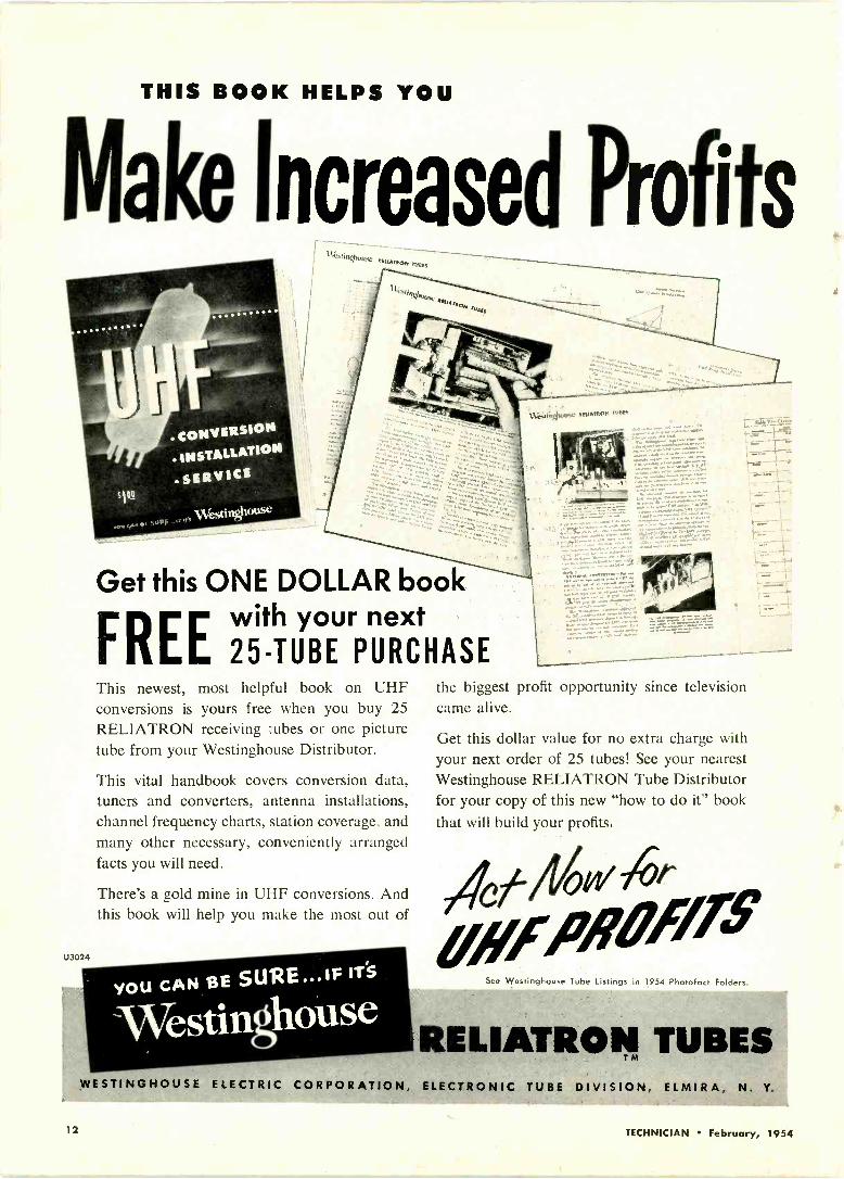
THIS BOOK HELPS YOU
Make Increased Profits
U3024
717iTev1ngt:otist:ktttene"-------
Get this ONE DOLLAR bookFREEwith your next25 -TUBE PURCHASE
This newest, most helpful book on UHFconversions is yours free when you buy 25RELIATRON receiving tubes or one picturetube from your Westinghouse Distributor.
This vital handbook covers conversion data,tuners and converters, antenna installations,channel frequency charts, station coverage, andmany other necessary, conveniently arrangedfacts you will need.
There's a gold mine in UHF conversions. Andthis book will help you make the most out of
YOU CAN 8E SURE ... IF IT'S
mor.rorerrmorr r--r.o.r
igh011se !MAMMA 'ROW,
the biggest profit opportunity since televisioncame alive.
Get this dollar value for no extra charge withyour next order of 25 tubes! See your nearestWestinghouse RELIATRON Tube Distributorfor your copy of this new "how to do it" bookthat will build your profits.
0 w
alifFil8ill.See Westinghouse Tube Listings in 1954 Photof act Folders.
RELIATRON TUBESWESTINGHOUSE ELECTRIC CORPORATION, ELECTRONIC TUBE DIVISION, ELMIRA, N. Y.
12 TECHNICIAN February, 1954

0
/ILL
PROVED from coast to coastIn every UHF area, Mallory Converters bring clear, trouble-fr2eall -channel reception to thousands and thousands of families.?lake sure your customers get this PROVED PERFORMANCE.
31:11101-y UHF Converter
ea.t.
N11>
Prove to yourself that the MaLory Convertercan be a profit -maker for yoa. Ask your Mallorydistributor for details on the Mallory 88 Converter.It's a fast -seller ... easy to install ... and perfor-mance is outstanding.
,-
P.
MALLORYR. MALLORY ft CO in,
44-
tt
CAPACITORS CONTROLS VIBRATORS SWITCHES RESISTORSRECTIFIERS POWER SUPPLIES FILTERS MERCURY BATTERIES
APPROVED PRECISION PRODUCTSP. R. MALLORY & CO. Inc., INDIANAPOLIS 6, INDIANA
'NY - 4$07.4,0 - A,

WHY IT'S BETTER BUSINESSTO REPLACE WITH
700-atea etveat'Pedero
IN APPROXIMATELY 75 percent of all cases, the originalcrystal pickup cartridge for which you are supplying thereplacement will be an ASTATIC! The record playermanufacturer's highly skilled engineers have carefullyselected each Astatic Cartridge because . . . down to thelast detail . . . its performance characteristics match therequirements of the particular player or changer. Thus,for finest results, the serviceman replacing the cartridgemust again match these requirements. AND ONLY THEPRECISION -BUILT, RECOMMENDED ASTATIC REPLACE-MENT CARTRIDGE WILL DO IT. And, despite quality re-sults, cost is almost invariably lower.
One way or another, a substitute cartridge is bound tofall down. It is not sound business to stake your reputa-tion on such substitutions. Beware particularly of claimsthat ALL cartridge replacement needs can be filled bysix or eight magic models. Actually, it takes an absoluteminimum of 24 different cartridge models to meet all oftoday's requirements. The far-sighted jobber or dealer,knowing that what is good for the record -playing publicis good for him, sees to it that the kind of cartridge origin-ally intended is used on all replacements. Usually, too,he MAKES DOUBLY SURE OF BEST RESULTS BY RELY-ING ON ASTATIC CRYSTAL CARTRIDGES.
NEW STEEL STORAGE CABINET AND DISPENSERFOR ASTATIC CRYSTAL CARTRIDGES
THERE ARE ADVANTAGES foreveryone because jobbers dispenseAstatic Crystal Cartridges from thishandsome, rugged steel cabinet. Noone - dealer, serviceman or recordplayer owner - ever gets an AstaticCartridge which has grown old frombeing accidently shunted back andforth on the shelf. This can't happento Astatic Cartridges because newstock is put in the cabinet by feed-ing into the top of each bin . . .
and the cabinet dispenses the oldestcartridge first, from the bottom ofthe bin. To make sure that every-one enjoys these advantages, thecabinets are given to Astatic Job-bers entirely free of charge, and
without a single string attached or special purchase to be made. Attractivelyfinished in light grey Hammerlin, this truly fine cabinet keeps all Astatic Cart-ridges together and permits taking accurate inventory in one glance. It isdesigned to stand solidly on the counter, on the shelf, hang on the wall, oreven stack securely when two or more are used. Included is a handy Rolla -fax cartridge replacement chart, which attaches to the top of the cabinet andworks like a miniature window blind. Note that the bottom cartridge in eachbin always protrudes, for quick, easy grasping.
EXPORT REPRESENTATIVE401 Broadway, New York, N. Y.
Cable Address: ASTATIC, New York Asmnouric CORPORATION
LETTERSTo the Editors
Author In Error, He SaysEDITORS, TECHNICIAN:
We would like to call your attentionto considerable misinformation whichappeared in the article V.H.F. AntennaInstallation Problems, in your Decemberissue.
(1) The author describes at length"oscillating lines." It is well known thattwo conditions are necessary for sus-tained oscillation-a feed -back path andenergy amplification. Since there is noamplification of energy in an antenna orits transmission line, oscillation cannotexist outside of the television set. Oneshould not confuse the "gain" of an an-tenna with amplification, or the reflec-tions in a transmission line due to mis-match with oscillation. In Channel Mas-ter's wide experience with TV antennainstallation problems, we have neverheard of "oscillating lines."
(2) In the second paragraph, the au-thor advocates the use of an open-endedstub across the antenna. The stub is cutto an effective quarter -wave length atthe channel frequency which is to beimproved. It is well known that a quar-ter -wave length open-ended stub isalmost exactly equivalent to a short-circuit. It is obvious, then, that placingthis stub across the antenna as describedwill almost completely eliminate recep-tion for the channel one is trying toimprove.
(3) In the third paragraph, the authorsuggests using an attenuating pad toeliminate "ghosts." When "ghosts" aredue to reflections in the transmissionline, due to mismatch at its ends, theuse of a pad will help. However, in thecase of "ghosts" due to multipath recep-tion, the ratio of the direct signal to thereflected signal is not changed by a pad.Therefore a pad will not help at all toreduce "ghosts" due to multipath recep-tion. Furthermore, the formula given inthis paragraph will not give the straightline distance to the reflecting obstacle;it will give the difference in total pathlengths of the direct and reflected sig-nals.
We hope this clears up the errors inyour otherwise excellent periodical.
Jur.ms GREENAntenna Laboratory
Channel Master CorporationEllenville, New York
Free Tube Checking AgainEDITORS, TECHNICIAN:
I have been an ardent reader of yourmagazine and still regard it as one ofthe top magazines in our profession. Inthe November edition, I read severalarticles on charging for tube checking.I realize that this is a pro and con af-fair, but the following is one tech-nician's view point:
One of the most imperative qualities(Continued on page 18)
14 TECHNICIAN February, 1954
Now... only *149 Vest?er Price
the popular RCA WO -SSA
featuring . . .
Voltage -MeasuringFacilities
"Plus" and "Minus" SyncHigh -Input Resistance
If Low -Input Capacitance
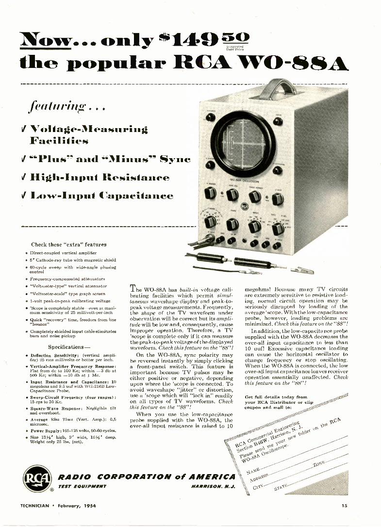
Check these "extra" features Direct -coupled vertical amplifier 5 Cathode-ray tube with magnetic shield 60 -cycle sweep with wide-angle phasing
control
Frequency -compensated attenuators "Voltmeter -type" vertical attenuator
"Voltmeter -scale" type graph screen 1 -volt peak -to -peak calibrating voltage 'Scope is completely stable-even at maxi-
mum sensitivity of 25 millivolt -per -inch
Quick "recovery" time, freedom from line"bounce"
Completely shielded input cable eliminateshum and noise pickup
Specifications - Deflection Sensitivity: (vertical ampli-
fier) 25 rms millivolts or better per inch. Vertical -Amplifier Frequency Response:
Flat from dc to 100 Kc; within -3 db at500 Kc; within -10 db at 1 Mc.
Input Resistance and Capacitance: 10megohms and 9.5 uuf with WG-216B Low -Capacitance Probe.
Sweep -Circuit Frequency (four ranges) :15 cps to 30 Kc.
Square -Wave Response: Negligible tiltand overshoot.
Average Rise Time (Vert. Amp.): 0.5microsec.
Power Supply:105-125 volts, 50-60 cycles. Size 133i' high, 9' wide, 16A deep.
Weight only 25 lbs. (net).
RAD/0
The WO -88A has built-in voltage cali-brating facilities which permit simul-taneous waveshape display and peak -to -peak voltage measurements. Frequently,the shape of the TV waveform underobservation will be correct but its ampli-tude will be low and, consequently, causeimproper operation. Therefore, a TV'scope is complete only if it can measurethe peak -to -peak voltage of the displayedwaveform. Check this feature on the "88"!
On the WO -88A, sync polarity maybe reversed instantly by simply clickinga front -panel switch. This feature isimportant because TV pulses may beeither positive or negative, dependingupon where the 'scope is connected. Toavoid waveshape "jitter" or distortion,use a 'scope which will "lock in" readilyon all types of TV waveforms. Checkthis feature on the "88"!
When you use the low -capacitanceprobe supplied with the WO -88A, theover-all input resistance is raised to 10
megohms! Because many TV circuitsare extremely sensitive to resistive load-ing, normal circuit operation may beseriously disrupted by loading of theaverage 'scope. With the low -capacitanceprobe, however, loading problems areminimized. Check this feature on the "88"!
In addition, the low -capacitance probesupplied with the WO -88A decreases theover-all input capacitance to less than10 uuf! Excessive capacitance loadingcan cause the horizontal oscillator tochange frequency or stop oscillating.When the WO -88A is connected, the lowover-all input capacitance leaves receiveroperation essentially unaffected. Checkthis feature on the "88"!
Get full details today fromyour RCA Distributor or clipcoupon and mail to:
eel\III's theSO°1 1
or:gkai
I 0.2" f6,0X v.,e.:74 koV'eIV.
'itC,VA011.1?' fie ,cole*
I0.2"
CORPORATION of AMERICATEST EQUIPMENT HARRISON. N. J.
,o0
TECHNICIAN February, 1954 15

ArthurGodfrey,famousCBS -TV star
WITH CBS-HYTRON
MIRROR -BACK SCREEN
SCREEN -MIRROR SACK
MAGNIFIEDCROSS-SECTION
GLASS FACE PLATE
No,, light
output from sc. n
Rorrforcing light
by Mirror -Bock
Mirror -Back (aluminized) screen mirrorsall the light output to the viewer. Offers:Brighter pictures. Greater contrast. Betterresolution. Reduced strain on other com-ponents. Full effective anode potential.Prevention of cross -burns. And longer life.For greater customer satisfaction . . . moreprofit, replace with original CBS-HytronMirror -Back tubes. Many types nowavailable.
WITH CBS-HYTRONBLUE -WHITE SCREEN
Ever notice how a shirt laundered withbluing appears whiter? With the CBS-Hytron Blue -White screen, whites arewhiter; blacks, blacker. Expandedgray scale gives noticeably sharper pic-tures in fringe areas. No wonder CBS-Hytron's original Blue -White screenhas become the universally preferredstandard. Your customers, too, willprefer Blue -White screens.
LOOK TO CBS-HYTRON FOR COLOR, TOO!New CBS-Colortron stresses simplicity. Offers many advantages: Simpler construction.Fool -proof assembly. Lower cost. Lighter weight. Adaptability to mass production inlarge sizes. Improved contrast. Simplified focusing . . . circuitry . . . adjustment. Re-sistance to overload. Greater stability. All stemming from unique spherical mask
and face plate. You'll appreciatethese advantages when you start
FREE CATALOGCBS-HYTRON
BUSINESS BUILDERS
Describes all CBS-Hytron Business Builders to date:Certified Quality Service tags, streamers, decals, illumi-nated and flange signs, clocks, postal cards, and ad mats.The famous CBS-Hytron service tools. Technical litera-ture. Price lists. Special offers. Get your Business BuildersCatalog, PA -37, today ... from your distributor, or direct.
servicing color TV.
NEW . . . FREE CBS-COLORTRON DATAFor a look into the future, get complete advance data onthe new, revolutionary CBS-Colortron: Construction . . .
operation . . . application . . . installation and adjustment... electrical and mechanical data. FREE ... from your
CBS-Hytron distributor . . . or direct.
WITH CBS-HYTRON
SMALL- SPOT GUN
Smaller the spot produced by electronbeam, sharper the picture. New lensfocusing system of CBS-Hytron Small -Spot Gun reduces spot size 30 per cent.Prove it. Replace with a new CBS-Hytron Small -Spot tube. See, yourself,the superior resolution. Profit more.Combine all three: CBS-Hytron Mirror -Back . . . Blue -White Screen . . . Small -Spot Gun. Get and give that better -than -new -set thrill !
CBS-HYTRON Main Office: Danvers, Mass.YTRO
Receiving Tubes Since 1921Manufacturers of A Division of Columbia Broadcasting System, Inc.
A member of the CBS family: CBS Radio CBS TelevisionColumbia Records, Inc. CBS Laboratories CBS -Columbia and CBS-Hytron
RECEIVING TRANSMITTING SPECIAL-PURPOSE TV PICTURE TUBES GERMANIUM DIODES AND TRANSISTORS
16 TECHNICIAN February, 1954

vistoet'
Mutteatt you
believe in
Antenna Claims?Every claim for all -channel antenna perform-ance should be supported by facts, and not"sales talk!' With facts to follow, you guardyour reputation for integrity. Facts are whatyou get from DAVIS ... indisputable proof ofperformance, furnished by an impartialoutside authority : Microwave EngineeringCompany, of Los Angeles, who are recognizedexperts on antenna research and testing.
Write for all the data which MicrowaveEngineering has developed on the DAVIS an-tenna. You'll see performance characteristicswhich are actually certified ... data you cancount on!
Remember, it's the picture on the TV setthat pays off in customer satisfaction. A DAVISpicture must please you-our antenna is guar-anteed to be the best all -channel unit you canbuy ... guaranteed to please or your money isrefunded by the factory.
Send the coupon for facts on the DAVISantenna. Sold through your electronic distrib-utor ... THE BACKBONE OF YOUR INDUSTRY.
DAVIS ELECTRONICS P.O. BOX 1247 BURBANK CALIFORNIAFactories in; BURBANK, CALIF., CHICAGO, ILL., SILVER SPRINGS, MD.
most
22Dg
MAIL THIS COUPON TODAY:
DAVIS ELECTRONICS, Box 1247, Burbank, Calif.
Gentlemen ...send me the following: Technical data and complete information on
the new SUPER -VISION ANTENNA1:1 Name and address of NEAREST JOBBER
COMPANY NAME
MY NAME
ADDRESS
STATE_J
TECHNICIAN February, 1954 17

SCR performer
AMONG UHF CONVERTERSAs an established service -dealer, know the relativemerits of all UHF converters. This means more thanpretty cabinets or glittering generalities or bargainprices. It's performance that counts. And Granco'ssuperlative performance-the best by test-is basedon these absolute essentials:
COAXIAL TUNING: Most efficient UHF tuning systemknown. Precision -ground metal slug sliding in and outof precision -ground glass tube for mechanical andelectrical accuracy. No troublesome noise -producing wipercontacts. Highest stability. Provably better UHF reception.
orFINE TUNING: No "on -again off -again" tuning withGranco. Fine tuning is simple and positive with high -ratiosingle tuning knob. Permits "on the button" tuning withoutneed of safecracker's touch!
PRESELECTION: Tuning circuits reject unwanted signalsand images-only the desired channel is tuned in. A "must"in areas having two or more channels, UHF or VHF. Grancopreselection means cleaner, sharper, more pleasingpictures.
ask for data
AMPLIFICATION: Low -loss tuning and associatedcircuitry, plus high -gain amplification of only thetuned -in channel, provides the finest reception in TV.
from your distributor or from us. CompareGranco UHF converters with all others. Makeyour own comparative tests. You're the judge!
GNCO PRODUCTS INC.36-17 20th Ave., Long Island City 5, N. Y.AVAILABLE AT LEADING JOBBERS
(Continued from page 14)in my estimation for a successful tech-nician, is the love of the business andalso not to be too arrogant in helpingthe average customer. I honestly be-lieve that this article regarding charg-ing for testing tubes will tend to makesome of the servicemen a little too in-dependent, in charging for everythingthey do for a customer. There arethings that come up daily in our pro-fession that have to be handled dis-creetly, such as replacing a male plugon a lamp or fixing a lady's iron. Allthese little things tend to obtain goodwill, something that would normallycost you a good sum in advertising.
I have been in business for over fif-teen years, never made a fortune, buthave always been busy and have madea good living. I believe in the old creed,when a customer asks you to do any-thing you should be honored thathe asked you, also . . . charge accord-ing to the job.
I hope that in one of your editorialsyou will try to educate the newcomersin our profession to follow this creeda little. I still think that, with a cus-tomer's respect . . . and good work-manship, a serviceman can charge alittle more and still be well ahead ofthe fellow who is arrogant and chargesfor even a washer or maybe to justdust off a chassis.
GEORGE E. FOGLEMANFogleman Radio & TV Service1721 Fort Street, S.E.Washington 20, D. C.
Likes Price EditorialEDITORS, TECHNICIAN:
Your article in the December issue,"Don't Be Afraid to Charge a GoodPrice!" was wonderful. I am conceitedenough to say that that has been myexact feeling and policy.
L. WALTON.Broadway Radio Service7 East 19th AvenueGary, Indiana
Cut -Throat CompetitionEDITORS, TECHNICIAN:
I receive TECHNICIAN magazineevery month, and look forward to everyedition, for it has given me so muchhelp.
There has opened up a wholesalehouse in Washington, Pa. They havebeen running ads in all the papers de-scribing the wholesale prices of all ourparts, and at the bottom of these adsthey state this-Wholesale to All. Itmakes me have a red face when a cus-tomer of mine prices an antenna fromme and I tell him the list price for it;then he comes right back with thenewspaper ad showing me the same an-tenna at half the cost. Some of theprices are even lower than I can buyfor wholesale. What is the solution tothis problem?
LARRY J. Srum.Stull's Radio & TVMarianna, Penna.
18 TECHNICIAN February, 1954

FLNIYt. Clair Avenue
-ittc, &mat New-
INCO®.0z;IS500
UHF ANTENNAS(All Aluminum Construction)
FINCO 504
Y COMPANY
y Company
Cleveland, Ohio
/ NEWSPAPER / MAGAZINE / TV
(doe -find out how you can participatentenna indJstry's most powerful advertising
FINCO 502
Patent No. 2,566,287Other patent applied for.
Canada Patent No. 496,735
(4 -bay unit obtains up to 50% addi-tional voltage gain over Model 502)
DOUBLE CORNER REFLECTORSAND DOUBLE COLINEARS
ACROSS THE
ENTIRE UHF BAND !Write today for authentic technical data.
THE FINNEY COMPANY, Department T-254612 St. Clair Avenue Cleveland, Ohio
Send complete information on FINCO Series '500' UHF Antennas
Ei Send complete information on advertising program
NAM
FIRM
AD
CITY STATE
TECHNICIAN February, 1954 19
Another Outstanding Service Success Story...
with SYLVANIA!From Basement Repair Shop
to prosperous Service Business...featuring Sylvania Tubes, Parts
and Promotion Programs!
img modern,efWent
repolrboot
Shov
hs
Bo111elev\s'Ionan
Radio todosi.
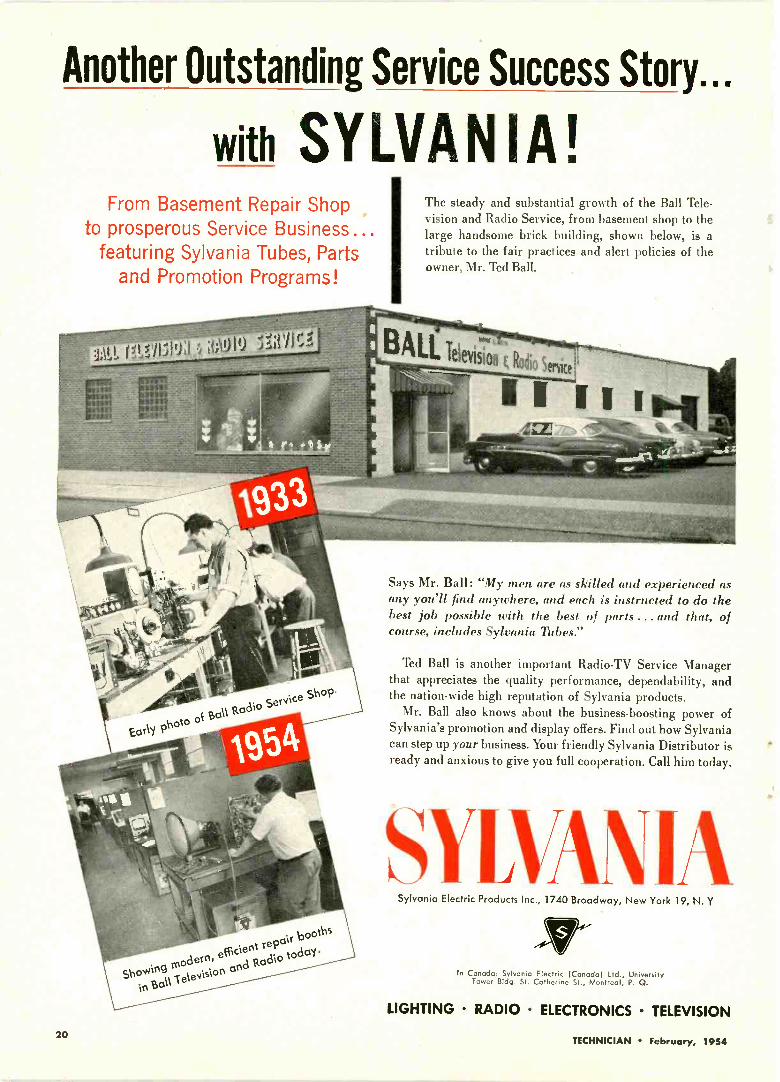
The steady and substantial growth of the Ball Tele-vision and Radio Service, from basement shop to thelarge handsome brick building, shown below, is atribute to the fair practices and alert policies of theowner, Mr. Ted Ball.
Says Mr. Ball: "My men are as skilled and experienced asany you'll find anywhere, and each is instructed to do thebest job possible with the best of parts . .. and that, ofcourse, includes Sylvania Tubes."
Ted Ball is another important Radio -TV Service Managerthat appreciates the quality performance, dependability, andthe nation-wide high reputation of Sylvania products.
Mr. Ball also knows about the business -boosting power ofSylvania's promotion and display offers. Find out how Sylvaniacan step up your business. Your friendly Sylvania Distributor isready and anxious to give you full cooperation. Call him today.
SYLVANIASylvania Electric Products Inc., 1740 Broadway, New York 19, N. Y
In Canada: Sylvania Electric (Canada) Ltd., UniversityTower Bldg. St. Catherine St, Montreal, P. Q.
LIGHTING RADIO ELECTRONICS TELEVISION
20TECHNICIAN February, 1954

TECHNICIAN& Circuit Digests
CALDWELL-CLEMENTS, INC., 480 LEXINGTON AVENUE, NEW YORK 17, N. Y.
Problems Ahead, Outlook Good
As we go into the second month of the new year, we get a clearer picture of what'sahead for the technician during the remaining months.
In taking this look ahead we can foresee a phenomenal growth for the service indus-try, as pointed out in last month's editorial. Color -TV is on the way. Hi-Fi is growingby leaps and bounds, and maintenance of a record number of B & W sets, radios,phonos and recorders spells big business in anybody's language.
Year by year servicing revenue will grow in this restless industry which is alwaysbringing out something new, exciting and different to challenge the ingenuity, skilland know-how of the technician.
Yes, '54 looks like another buy year for the men who keep the home folk happy,maintaining the equipment so many millions depend upon for daily entertainment,education and enlightenment. '54 Can be a year of greater profits and expansion forthe technician -dealer who wisely meets the challenges that lie ahead.
But there will be problems which the service department must face.
Tight Money Will Affect Service Operations
Many of such problems will come about as the result of a more or less tough marketin retail selling, which is likely to be reflected in tighter money conditions at theservice business level.
For instance, folk are hanging onto their money for dear life, and this will causemore haggling over service bills. Then, too, the gyps will intensify their efforts to in-crease their take, and more of them may be operating. Customers may be a littleslower in paying bills, and there may be a rise in the number of dead -beats.
Safe Method to Build Profits and Good -Will
All of the foregoing doesn't mean that servieL: revenue will be down. On the con-trary, 1954 bids fair to be the biggest year ,,he industry has ever had. But '54 alsolooks like a year when the service department must watch its financial step every inchof the way. It must guard against accumulating bad accounts, it must fight to sellgood, honest service at honest prices, and it must maintain prestige, profits and cus-tomer good will. Also, advertising should be kept up or initiated, in this rather slipperyperiod, to retain old business and add new trade. Never was there a time more suitedto advertising your service business.
The profit -minded technician -dealer needs to sell faith in the country to his cus-tomers these days, when all too many self-appointed dispensers of gloom are predictingfinancial chaos in the midst of the greatest prosperity the nation has ever known.
The future of the service business was never brighter, but smart owners and man-agers realize that '54 isn't a year for coasting or resting on one's laurels. It's a yearfor hard work, hard-boiled supervision and the will to meet and lick the problemswhich appear to be in the offing.
TECHNICIAN February, 1954 21

theGREATEST ERA AHEAD FOR SERVICE BUSI-
NESS, and we're not fooling! Never before in the historyof this industry has the opportunity for increasing serv-ice volume been so promising. Color TV, of course, leadsthis opportunity parade, with Hi-Fi following closely onits heels. By the end of this year, more than 100,000 (per-haps many more) color sets will be in consumers' homes,and their installation and maintenance, while posingmany a problem, will be a stimulating (and profitable)challenge to the technician.
AND THIS 100,000 OR MORE COLOR SETS is noth-ing but a trickle preceding the production deluge on theway, because in 1955 several million color receivers willin all likelihood be in use by consumers, with total TVsets in homes and public places probably reaching a fig-ure of 40,000,000!
HI-FI IS ON THE WAY, TOO, and it's moving fast to-ward the high places, presenting hundreds of opportunityangles for the service industry to capitalize on. Serviceand installation will involve components, completeinstruments, phonos, tape recorders, phono needles anda wide variety of accessories. The sale of custom -installedHi-Fi units alone may well ring up a total of $220,000,000this year.
"How many volts you figure that was, Perkins?"
ON THE BUSINESS FRONT: Repair business fell oi,"sharply after Xmas in the metropolitan New York areafor reasons no one can accurately pinpoint, though onelarge service outfit says people are hanging onto theirmoney for dear life, and are willing to tolerate poor re-ception until they've recovered from holiday expendi-tures. . . . Small-town dealers loaded with accounts re-ceivable in many sections of. country had better get outand collect their dough. Big -city service organizationscarrying only small number of charge accounts, becauseof C.O.D. policy most insist upon. . . . Dealer credit situ-ation has improved in most localities over last Summer,distributors in large cities report.
SOME TECHNICIANS IN CERTAIN UHF AREASare selling plenty of converters by simply demonstratingthe units in the home. Where good reception is obtained,such demos result in speedy sales. Converter "price -war"which broke out in Milwaukee has ended.
HIGH UHF CONVERSION FEES in some areas aredrawing grumbles from set owners and managers of newUHF stations alike. Consumer complaints to the stationsstate that some servicers ask $75 or more for adjusting oradapting a set to receive a new UHF channel. This prac-tice hurts both the technician and the station, UHF sta-tion operators claim. Some directors of new UHF stationsare cooperating with service dealers and technicians inplanning inexpensive conversion techniques, and inbringing this information to the public. Checking with theUHF station in your area re its recommendations as tothe best and cheapest technique would be a good ideabefore going ahead with conversions.
TRENDS IN THE OFFING as we go into the secondmonth of the new year: More and more customers willask YOU about Color -TV, and for the sake of good pub-lic relationship you must have intelligent answers on thetip of your tongue. . . . Plenty will ask about Hi-Fi, too,and while this subject is a bit complicated for the laymanto understand, try to explain in simple language. . . .
'54 promises to be a year of stiffer competition for theservice dollar. TECHNICIAN editors predict a slightincrease in the number of servicing outlets.
SEVERAL DEPARTMENT STORE service set-upshave been making headway in, some of the large cities,gaining business chiefly through reputation, and solici-tation of large customer lists. Trend could spread thisyear, offering the independents some very realcompetition.
MANPOWER SITUATION EASING in some heavyindustrial centers, but still very tight in New York, partsof California and in most of the South. Some suburbanNew York shops paying $100 a week to TV servicers withvery little experience.
DIPLOMACY by servicers is becoming more importantthan ever, field reports say. With the trend away fromservice contracts toward individually -billed service calls,set owners are less critical of secondary deterioration inreceiver performance. They usually wait for majorbreakdowns before hollering "Uncle." As a result, morecalls than ever involve multiple troubles. Complete over-hauls bring squawks over high bills. Repair of major de-fect alone raises complaints of incompetent work. Eitherway, the technician is left holding the bag. Getting to belike the radio dads when more than half the sets in usewere in need of repair.
22 TECHNICIAN February, 1954

PicturePIX TUBE OUTLOOK FOR '54. Almost one in every
seven TV sets in use today will require a new picturetube in 1954, according to J. Milton Lang, general man-ager of the G -E Tube Department. Market research in-dicates a need for over four million replacement picturetubes. Over 27 million sets are now in use throughout thecountry. Lang said the high replacement tube figure rep-resents a normal development, with so many sets growingolder. The four -million plus figure is the highest of anyyear to date, and is expected to top the 1953 requirementby about 50 per cent. Despite the advent of color TV, theindustry should produce about 5,200,000 additional pic-ture tubes for new black -and-white sets, Lang estimated.The need for initial equipment monochrome tubes willcome in large measure from opening up of new marketareas, and from continuing consumer demand for thelarger picture sizes and lower prices of high -qualityblack -and -white receivers. Lang believes color picturetubes should make up about two per cent of the industry'stotal CRT output in '54.
REMEMBER 'WAY BACK WHEN pre-war TV an-tennas were of the "pitchfork" type? . . . When, duringthe transmission -line shortage some of you fellows hadto use solid -conductor cable which came from abroad?. . . And those days when the predecessors of the pres-ent dollar -a -call boys charged a half a buck? . . . Canyou recall, too, the ion "spots" on many pix tubes? the"diathermy -interference" craze? The era of magnifiersand filters?
SALES RESISTANCE TO B & W TV, on part of con-sumers adopting a "wait and see" attitude on color, is infor a major assault by manufacturers. Most top set pro-ducers are announcing 21 -in. black and white sets to sellbelow $200, representing drastic price cuts in their for-mer lines. Other leaders are expected to follow. Confiden-tial sources say these new lines, streamlined in design forlow pricing, have been on paper for some time. Seemsthe industry-or at least part of it-anticipated B & Wresistance with advent of color, and is all ready to meetthe challenge.
YOU MUST HAVE SOMETHING ON THE BALL tostay in business. Motorola's Service Dep't. calls attentionto a recent government report that vividly illustrates theneed for good management and good business control.The report states that only twenty eight concerns out ofevery hundred started were going concerns after fiveyears of operation. The following shows the average trendper hundred business ventures:
Year of Operation Failures Remaining1st 32 68
2nd 18 50
3rd 12 38
4th 6 325th 4 28
These statistics deserve your serious thought. Are youtaking steps to insure that YOU will still be in businessfive years from now?
SAME OLD CHASSIS!-The doctor complained bit-terly about the $18.75 charge for repairing his TV set."My TV is certainly not as complicated as a humanbeing. I spent six years in college," he said to the tech-nician, "and two years as an interne before I practicedany medicine. But I can't get any fees like that for mywork." "In TV," replied the TV technician, "we have acouple of thousand models to deal with. Every year eachmanufacturer brings out at least one new model. We'vegot to have a big library of technical information andattend many meetings to keep up to date. But you,doctor, still work on the same model you studied inschool."-Sterling Intercom, Houston, Tex.
"Must be something wrong with this set ...all we can get is people."
WHEN A TECHNICIAN BUILDS UP A REP AS AGENIUS in his community, whether he's the owner or theservice manager, he finds himself in a tough spot as thebusiness expands because everybody and his brotherwants this particular "wizard" to PERSONALLY servicethe ailing sets. Naturally, this just can't be done whenthere's a big volume of work. Best thing to do in suchsituation is to "build up" other good technicians in theorganization, "selling" them to the customers via direct -mail, over the phone and in personal contacts.
HARD-BOILED SIGNS, such as "Not Responsible forSets Left After 30 Days," "All Work Strictly Cash," andthe like, do more harm than good, since they antagonizecustomers, and don't mean anything legally anyway.Better put up some reading, "All Work Guaranteed,""We Use Finest Parts," "Best Test Equipment," "OurTechnicians Are Highly Skilled Specialists," etc., to buildgood -will and inspire confidence in your service depart-ment.
SOME RANDOM THOUGHTS IN THE FIELD: TVantenna makers are more competitive-minded than anyother folk in the business. . . . There's been a definite de-cline in number of people bringing tubes into shops fortesting. This activity was at its height during the Depres-sion. . . . Even if they can't understand 'em, people liketo get itemized bills for service.
TECHNICIAN February, 195423

GREENISHBLUE
PUR P LIS IL/BLUE
BLUISHPURPLE
YELLOW GREEN
GREENISHYELLOW
REDDISHPURPLE
PURPLE
(A)
YELLOW
YELLOWISH----ORANGE
,ORANGE PINK
REDDISHORANGE
VARYINGSHADESOF GREY
WHITE
(G1
Fig. 1 A-The horseshoe comprises all the visible colors; the triangle includes all colors reproducible in color TV. Colors shown in this triangleare recognizable to the eye when they cover large areas. B-When medium -small areas are viewed, blues and yellows appear gray, andonly cyan and orange are clearly distinct. Two areas rather than one are shown as gray. This is so because yellow and purple-the colorsreally present in these areas-will look gray if the observer's distance from them is great enough. C-The eye cannot distinguish betweencolors and black -and -white when small objects are viewed; only intensity variations-referred to as varying shades of gray-are visible.
More About
Color TV FundamentalsHow the Eye Sees Color. What "Q," "Y" and "1" Signals Are.
Sub -carrier Modulation Explained
BY PETER ORNEAND
SOL HELLERMANAGING EDITOR, TECHNICIAN
Last month, we tried to clarifyhow room was found in the black-and -white spectrum for color sig-nals. In this month's article, we willreview the next problem sur-mounted by NTSC researchers-i.e., their determination of the mini-mum information required to obtaina satisfactory color picture. Theproblem was briefly discussed inthe Oct. '53 issue of TECHNICIAN(Serviceman's Analysis of the New
TV Color System), and will be con-sidered in greater detail in thispiece.
The less information that has tobe transmitted in addition to theluminance information (luminancerefers to the color signal componentthat corresponds to the black -and-white video signal) the less chancethere will be of interaction takingplace among the different signalssent out. In order to determine theminimum bandwidths to which colorsignals could be reduced, many in-vestigations' were made into howwell the eye sees small areas ofcolor. The result of these investiga-
tions may be summed up as follows:The eye cannot see color-i.e.,
distinguish between colors or black-and-white-when the object in-spected is very small (see Fig. 1C).The eye has "three -color" vision, onthe other hand, for large objects(Fig. 1A). "Three -color vision"means that we can, by mixing lightsof three colors in the properamount, cause the eye to see prac-tically any color. This duplication iscalled color matching.
There are many ways of obtain-ing a color match. Almost any threewidely -separated colors may beused (as we shall see later). In the
24TECHNICIAN February, 1954

color picture tube, red, green andblue lights (given off by phosphorson the screen) are employed for thispurpose.
How about cases that fall in be-tween the extremes of no color andthree -color vision-i.e., the in-stances when medium -small objectsare being viewed? What the aver-age person sees in these instancesmay be reproduced by the mixtureof two colors (see Fig. 1B). Somecolor-blind people, incidentally, seeboth large and medium-sized ob-jects in this way.
In viewing medium -small objects,most of us readily differentiate be-tween cyan (a bluish green) and or-ange. Blues and greens, however,look like cyan, and reds and yellowslook like orange. We can experiencethis effect if we try to match a sin-gle fine strand of colored thread toa correspondingly -colored spool ofthread.
It appears, therefore, that weneed three components of informa-tion to get proper coloring for largeareas; two pieces of information arerequired to get satisfactory color on"medium -small" areas; we onlyneed to know the luminance forvery small areas.
"0", "Y" and "I" Signals
The way we see small detail, inmonochrome that is, and the factthat we want a compatible system,makes it necessary that one of thecomponents be the luminance or"Y" signal. From the fact that wecan distinguish cyan and orangebest in medium -small areas, itwould be an advantage to choose asone of the other components of in-formation a signal that distinguishesbetween these colors. This signal iscalled the "I" signal.
For large areas, where the eyecan distinguish between all colors,another piece of intelligence mustbe added which is called the "Q"signal. This signal distinguishes be-tween green and purple. If the in-formation present in the "I," "Q"and "Y" signals is combined, anyvisible color can be effectively re-produced, thus permitting "three -color" viewing.
Summing up: "Y" is the lumi-nance information; it is transmittedfor the full 4 mc. "I" is the informa-tion that can tell cyan from orange,and is transmitted to 1.5 mc. "Q" isthe information that, in conjunctionwith the "I" and "Y" signals, pro-vides the three components for"three -color" vision; it is transmit-ted for only .5 mc (see Fig. 21.
Readers may wonder why the
colors in Fig. 1 are grouped in ahorse -shoe form. The theory behindthis may be summarized as follows:
Any color can be reproduced bymixing three colors together. Thethree colors used are known as theprimaries of the system. The onlyrestriction regarding the choice ofcolors is that a primary color mustnot be reproducible by any mixtureof the other two primaries.
Color Designation Systems
Visible colors can be representedin different ways. Most readers areprobably familiar with the fact thatcolors can be designated by theirwavelength. Scientists concernedwith the study of color have foundit convenient to use another methodof representing visible colors. They(arbitrarily) choose three colorsthat are supersaturated-i.e., un-mixed with white-and define anyother color by giving the amount ofeach supersaturated color necessaryto reproduce it.
The supersaturated or referencecolors are non-existent in natureand cannot be seen by the eye.They provide arbitrary standardsfor comparing colors.
One of the reference colors is sochosen that its amount affects onlythe brightness (not the hue or satu-ration) of the color to be defined.The other two colors are capable ofrepresenting any definite color(except with respect to brightness).The system is essentially the sameas the one used in color TV, inwhich two signals-"Q" and "I"-determine the color, while the thirdone-"Y"-reports on its brightness.
When the two supersaturated or
Fig. 2-Bandpass requirements for "0
reference colors are used as axes(vertical and horizontal axes, ofcourse) any color visible to the eyemay be plotted as a point on thisdiagram. The height of the point (orits distance above the X axis) indi-cates the amount of one referencecolor present; the distance of thepoint from the Y axis indicates howmuch there is of the other referencecolor.
When such a diagram is made, itis found that visible colors fall intoan area- that looks like an invertedhorse -shoe. The nearer we come tothe center of the horse -shoe, theless saturated the colors get-i.e.,the whiter they get. The area at thecenter is what most people considerwhite.
Subjective Aspects of Color
Color is subjective-that is, dif-ferent people give different namesto the same shade of color. In addi-tion, colors look different whentheir surrounding color is changed.White is a wide area (in Fig. 1) be-cause desaturated shades of anycolor (i.e., color mixed with white)will look white if looked at for sometime without comparison. This is thereason, incidentally, that the shadeof white used on a black -and -whitecrt screen turned out to be muchless important than originally ex-pected; only when a number of b &w sets are put next to each otherdoes the difference in screen white-ness become apparent.
A final note on the horse -shoepatterns of Fig. 1: There are actu-ally no sharp divisions between col-ors, such as those that seem to bepresent in these sketches. Different
"Y" and "I" signal components.
TECHNICIAN February, 1954 25

eREAD
/1/"IS
NOWz
WHAT
%%
--
NOW
1
ri
(A)(A)
li\,III
1
I
J.1
/
I/
(C)
Til
(B)
HAT
1
,..(D)
Fig.3-Mechanical analogy to phase -shift-ing of color subcarrier. Two signs, paintedon glass and mounted at right angles,represent subcarrier at 0 and 90 degrees.
people will place the dividing linesbetween colors at different points.The colors in Fig. 1A are most satu-rated (i.e., intense) on the rim ofthe horse -shoe; these intensities arelargely beyond the range of thepresent-day TV color system. Thedotted -line area in the white sec-tion will be seen as white, or whitewith a hue of the adjacent coloradded, depending on the visioncharacteristic of the viewer.
With the problem of how muchcolor information to transmit sur-mounted, the next difficulty thatarises is how to transmit two differ-ent pieces of color information, "Q"and "I," on one subcarrier. If wecould use two different subcarriers,"Q" could be modulated on one and"I" on the other. This is effectivelydone, but the two carriers are at thesame frequency. Since this maysound like double talk, let's seewhether we can clear it up.
Mechanical Analogy
Assume that two transparent sec-tions of glass are available (Fig.3A). On one of them are printedthe words READ THIS; on theother, NOW WHAT. Suppose weget our favorite glasscutter to jointhese two pieces of glass at rightangles, as shown in Fig. 3B. If welook at this combination from oneangle (Fig. 3B), we can see thewords READ THIS. If we look atit from another angle (Fig. 3C), wecan read the words NOW WHAT.If we look at the unit from the an-gle shown in Fig. 3D, however, wecan decipher neither phrase, sinceone set of words falls over theother, obscuring both groups ofwords.
An analogous situation is presentwith respect to the use of the colorsubcarrier. The "Q" signal (similarto READ THIS) is modulated onthe color subcarrier (equivalent toone glass section); the "I" signal(similar to NOW WHAT) is modu-lated onto the subcarrier after thelatter has been shifted in phase 90°
(or quadrature-shifted). The secondglass section, which makes an angleof 90° with the first one, may becompared to the phase -shifted colorsubcarrier.
If the exact phase of the carrierwhen the signal was modulated ontoit is known, the modulation can beremoved or detected (just as theglass sections can be read, if weknow the angle to read them by).This type of detection is known assynchronous detection. It requiresexact knowledge of the subcarrierphase; a subcarrier sync burst istransmitted after each regular hori-zontal sync pulse as a phase refer-ence for the receiver, to provide thisdesired phase information.
AND WAS HIS FACE RED!Technician we know was asked toinstall an outdoor antenna on theroof of a fourteen -story building inNew York. Job took almost all daybecause the superintendent insistedon lead-in being fastened to outsidewall at each floor. This necessitatedgoing into each apartment from topto second floor (and finding thesuper each time another floor wasreached.) New antenna set-up pro-vided a mediocre picture, whichowner didn't squawk about sincemost tenants on his particular sideof the building got poor receptionalso. The pay-off: A few weeks laterthe owner called the TV man andsaid that an outdoor aerial whichhe'd purchased solved his problem,bringing in an acceptable picture.
"For years I broadcast my morning setting up exercises-did fine-then they put me on TV"
DNfliq-T14.L7
26 TECHNICIAN February, 1954

Servicing AC -DC RadiosPart 3. Odd Fading Case. Locating Intermittent Filaments Quickly
BY M. G. GOLDBERG
An intermittent in any receiveris somewhat of a headache, but aperiodic fading or cut-out in anac -dc receiver is even worse, be-cause these receivers cost the cus-tomer comparatively little; servicecharges must therefore be kept low,and any job which consumes a lotof bench time means money lost.Let's consider a case in point.
The output of this 5 -tube setdropped just enough to be annoyingseveral times during a program,cutting in and out with a volumechange of 15 or 20%. After tryingall new tubes and making othertests, the trouble was finally nar-rowed down to the second i-f anddetector circuits illustrated in Fig. 1.
During the fading period, the fre-quency of the received station re -
Fig. 1-14 and second -detector circuit of5 -tube ac -dc receiver. Intermittent open -circuiting of condenser "X" resulted in fading.
mained constant (the oscillatordidn't shift); the tone was not ap-preciably affected, and there was noclick when the set cut in and out.Connecting the scope input cable topoints A, B, and C in turn showedno change in response during thefading; with the scope connectedfrom point D to chassis ground,however, the set did not cut out.The connection just cited was madeseveral times, with the same result.
The writer finally concluded thatthe small capacitor marked "X" inFig. 1 (a 50 mmfd unit) was openingand closing periodically. With thescope disconnected and the capaci-tor open, the i-f signal was notsufficiently bypassed, causing theaudio output to drop. With the scopeconnected, however, the 75 mmfdcapacitance of the latter's inputcable was more than sufficient tosubstitute for capacitor "X" in the
circuit, and no fading was thereforenoticeable.
Intermittent heaters in ac -dc re-ceivers are often troublesome. Anundue amount of time may bewasted in determining which tubein the series string is opening up.This applies especially to receiversin which the trouble occurs onlyspasmodically, and then for only afew seconds at a time. Naturally,the technician can't spend an houror two on one of these low-pricedsets, waiting around for a heater toopen. The writer has worked out asimple and speedy system for lo-cating the defective tube in suchcases, without spending more thana few minutes of bench time on thejob.
Let's refer to Fig. 2A. Here wehave a conventional 5 -tube heaterstring in which an intermitent fila-ment is present-one which won'tstay open long enough for a routinecheck, and which cuts out perhapsonly three or four times during anhour's program. Note the two acvoltmeter connections. One meter(VM-1) is attached across the twohigher voltage heaters; the otherconnects across the three lowervoltage filaments.
Place the meters where they canbe readily seen and turn the set on,then go to work on another benchjob. As long as the continuity of theheater circuit is intact, VM-1 willread approximately 85 volts; VM-2will read about 35 volts. When thecutout occurs, attracting the serv-iceman's attention, a glance at the
120VAC
Sw
IGI
120 VAC
SW.
3525-GT 501.6-GT 12007 2567 12007
Fig. 2A-Connection of 2 ac voltmeters acrosstube filaments for first fading check. B-Volt-meter connections for the second fading check.
meters will reveal that one meteris now indicating practically full linevoltage, while the other has droppedto zero.
Assume that VM-1 has gone tozero and VM-2 to full line voltage,on the first fade. This means thatthe intermittent is in one of the 12 -volt heaters. Now connect the me-ters as shown in Fig. 2B. If, on thenext fade, both meters go to zero,it will prove that the 12SA7 is thebad tube. On the other hand, if oneof the meters goes to zero, while theother reads full line voltage, thedefective tube will be the one acrosswhich full line voltage is measured.This simple arrangement checks allfive tubes in only two fades, andalmost makes child's play out ofwhat could be a time-consumingheadache.
If, on the first fade, VM-1 goes tofull line voltage (Fig. 2A) while theVM-2 reading drops to zero, con-nect one meter across each of thetwo higher voltage heaters for the2nd test.
0
TECHNICIAN February, 1954 27
Hi Fi Guide to Pickup
Tracking Problems, Phono Arm Location and Weight,
By HARRY MILEAF
This article deals with the in-stallation, service and replacementof the arm and the pickup cartridge,and also considers the part theseunits play in the overall operationof a Hi Fi system. Information use-ful in setting up an installation, orchecking and improving an installa-tion in use, will be presented.
The pickup arm and cartridge de-termine, in part, the fidelity ofrecord reproduction and longevity ofrecords; they should be periodicallychecked to insure proper operationof the Hi Fi system. Outlined below
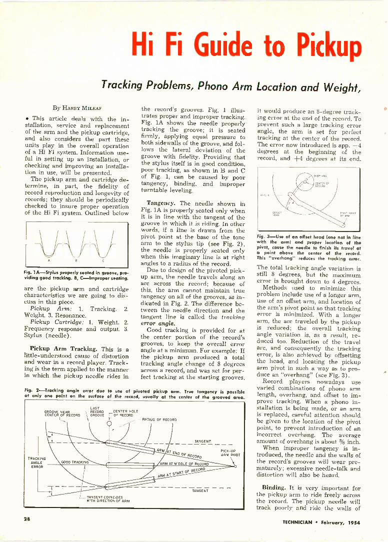
Fig. 1 A-Stylus properly seated in groove, pro-viding good tracking. B, C-Improper seating
are the pickup arm and cartridgecharacteristics we are going to dis-cuss in this piece.
Pickup Arm: 1. Tracking. 2.Weight. 3. Resonance.
Pickup Cartridge: 1. Weight. 2.Frequency response and output. 3.Stylus (needle).
Pickup Arm Tracking. This is alittle -understood cause of distortionand wear in a record player. Track-ing is the term applied to the mannerin which the pickup needle rides in
the record's grooves. Fig. 1 illus-trates proper and improper tracking.Fig. 1A shows the needle properlytracking the groove; it is seatedfirmly, applying equal pressure toboth sidewalls of the groove, and fol-lows the lateral deviation of thegroove with fidelity. Providing thatthe stylus itself is in good condition,poor tracking, as shown in B and Cof Fig. 1, can be caused by poortangency, binding, and improperturntable leveling.
Tangency. The needle shown inFig. lA is properly seated only whenit is in line with the tangent of thegroove in which it is riding. In otherwords, if a line is drawn from thepivot point at the base of the tonearm to the stylus tip (see Fig. 2),the needle is properly seated onlywhen this imaginary line is at rightangles to a radius of the record.
Due to design of the pivoted pick-up arm, the needle travels along anarc across the record; because ofthis, the arm cannot maintain truetangency on all of the grooves, as in-dicated in Fig. 2. The difference be-tween the needle direction and thetangent line is called the trackingerror angle.
Good tracking is provided for atthe center portion of the record'sgrooves, to keep the overall errorangle at a minimum. For example: Ifthe pickup arm produced a totaltracking angle change of 8 degreesacross a record, and was set for per-fect tracking at the starting grooves,
Fig. 2-Tracking angle error due to use of pivoted pickup arm. True tangency is possibleat only one point on the surface of the record, usually at the center of the grooved area.
GROOVE NEARCENTER OF RECORD
L
TRACKINGANGLEERROR
LASTRECORD _CENTER HOLE
\ GROOVE I OF RECORD
GOOD TRACKING
TANGENT COINCIDESWITH DIRECTION OF ARM
RADIUS OF' RECORD
ARM
TANGENT
AT ENDP RECORD
ARM AT MIDDLE OF RECORD
OF RECORDtaw AT sTAR1
TANGENT
PICK-UPARM PIVOT
it would produce an 8 -degree track-ing error at the end of the record. Toprevent such a large tracking errorangle, the arm is set for perfecttracking at the center of the record.The error now introduced is app. -4degrees at the beginning of therecord, and +4 degrees at its end.
TTLTIS
OFFSETHEAD
PIVOT POINTOF OW
Fig. 3-Use of an offset head (one not in linewith the arm) and proper location of thepivot, cause the needle to finish its travel ata point above the center of the record.This "overhang" reduces the tracking error.
The total tracking angle variation isstill 8 degrees, but the maximumerror is brought down to 4 degrees.
Methods used to minimize thisproblem include use of a longer arm,use of an offset arm, and location ofthe arm's pivot point so that trackingerror is minimized. With a longerarm, the arc traveled by the pickupis reduced; the overall trackingangle variation is, as a result, re-duced too. Reduction of the travelarc, and consequently the trackingerror, is also achieved by offsettingthe head, and locating the pickuparm pivot in such a way as to pro-duce an "overhang" (see Fig. 3).
Record players nowadays usevaried combinations of phono armlength, overhang, and offset to im-prove tracking. When a phono in-stallation is being made, or an armis replaced, careful attention shouldbe given to the location of the pivotpoint, to prevent introduction of anincorrect overhang. The averageamount of overhang is about 3/8 inch.
When improper tangency is in-troduced, the needle and the walls ofthe record's grooves will wear pre-maturely; excessive needle -talk anddistortion will also be heard.
Binding. It is very important forthe pickup arm to ride freely acrossthe record. The pickup needle willtrack poorly and ride the walls of
4
28TECHNICIAN February, 1954

Arms and Cartridges
Types of Pickups; Installation and Service Considerations
the grooves if it resists the lateralpressure of the grooves due to abind (see Fig. 1C). Besides intro-ducing excessive needle -talk anddistortion, this condition causes pre-mature record wear. Lubricate thepickup arm pivot shaft regularly sothat it can ride freely, and check tomake sure that no mechanical ob-structions are preventing a free side -to -side movement.
Turntable Leveling. If the turn-table is not level, the downwardpressure of the needle will not beapplied perpendicular to the planeof the turntable. Instead, the pres-sure will be applied to the sidewall
IA)
CROSS-SECTIONOF RECORD
/iii4iiaiaaiai
TURNTABLE
18)
NEED,EfriCSSIW
\\.*
Fig. 4-The needle may ride along either side -wall when the turntable has not been leveled.
of the groove in the direction of theturntable angle, as shown in Fig. 4.This condition will produce the poorseating shown in B and C of Fig. 1,and cause wear and distortion. It iswise for this reason to check that theturntable or its mounting board, andthe surface the record player willsit upon, are level. It is important tonote that the needle must be per-pendicular to the earth's surface toseat. properly. Check the pickup armor cartridge mountings, to make cer-tain they maintain the needle in thisposition.
(Such a test may often be made byplacing a pocket mirror, whosethickness approximates that of arecord, on the turntable, and allow-ing the stylus to rest on the mirror.If the needle is truly perpendicularat the point of contact, it will appearto be in line with its reflected imagefrom any angle. Any angular devia-tion present will become obvious,since such a deviation appears exag-gerated when the needle's reflectionis compared with the needle.-Ed.)
Weight. The weight of the pickuparm is a critical factor for the follow-
ing three important reasons:Vertical Compliance. Proper ver-
tical compliance requires that thepickup needle follow the verticalmodulations present in the record'sgrooves without reproducing anyunwanted signals. The biggest ver-tical modulation problem is the re-sult of "pinch effect." A considera-tion of how this effect develops willhelp to explain it.
The width of a groove in the rec-ord depends on the width of thecutting stylus making the groove.Since the cutting stylus (unlike theplayback stylus) has a flat face, thegroove it makes will be as wide asthe stylus only when the stylus iscutting in the same direction thegroove is traveling (Fig. 5A). Whenmodulation is applied to the cuttingstylus, it swings back and forth, andthe angle it makes to the direction ofgroove travel changes. The effectivewidth of the stylus thus decreases,and the width of the groove it makesis reduced (Fig. 5B).
Note in C and D of Fig. 5 thatwhen one sine wave is cut laterally,the groove develops two cycles ofwidth change. This change in width
causes the pickup needle to rise andfall as it rides the record's grooves(5E). If the pickup arm is too light,it will jump and skip grooves as thepickup needle contacts the pinchedportions of the grooves. If the pick-up arm is too heavy, the cartridgewill tend to move excessively up anddown when it rides in the pinchedportions of a groove, causing appre-ciable second harmonic distortion.
Cartridge Output vs Pickup ArmWeight. If the pickup arm is too light,there will not be enough lateral pres-sure applied to the cartridge, and theoutput level will be lower thannormal. If the arm is too heavy, toomuch pressure is applied, and con-siderable amplitude distortion willresult (since the arm has too muchinertia to follow lateral groove devi-ations faithfully).
Record Wear. If the pickup arm istoo heavy, the needle will apply toomuch pressure to the grooves' wallsand wear them prematurely. Con-versely, if the arm is too light, itwill bob up and down and also causeunnecessary wear.
As we can see, the weight of, orthe pressure adjustment on, the
Fig. 5A-When flat cutting stylus is moving in line with the direction of groove travel (asit does at points 2 and 4 in sketch C), the groove it cuts is widest. B-When the flatcutting stylus is moving at an angle to the direction of groove travel (as at points 1, 3 and5 in sketch C) Its reduced effective width causes the groove it cuts to become narrower. C-Magnified top view of disc surface, showing groove make by recorded sine wave. D-Sine waveof (C) pulled out straight, to show width variation (pinch effect). E-Cross-section of a rec-ord, showing the rise and fall of playback stylus as the width of the groove it rides in changes.
TECHNICIAN February, 1954 29

pickup arm, is an important factorwhen its replacement is necessary.The required stylus pressure de-pends on the type of cartridge beingused. Information regarding thischaracteristic is supplied by themanufacturer.
It is advisable to check the weightcarried by the pickup needle peri-odically, or when a replacement ismade, to be sure that the properpressure is being applied. Needlepressure gauges for this purpose canbe obtained for a dollar or two. Ifthe pressure being applied is not inaccordance with cartridge specifica-tions, it should be suitably adjusted.The better grade pickup arms pro-vide counter -balance springs orsliding weights that are adjustable;some provide thumbscrew or screw-driver adjustments that are easilyaccessible.
The average amount of pressurerequired for the LP cartridge is 5grams; it is between 10 and 15 gramsfor standard cartridges. Dual -speedarms with only one pickup needleshould strike a happy medium. It isalways better to have two pickupsfor this reason.
Pickup Arm Resonance. Since thepickup arm has mass, it also has,unfortunately, a physical resonantfrequency. In many of the arms onthe market, this resonant frequencyfalls within the audible range. Thelonger the arm, the lower the reso-nant frequency. The type of materialthe arm is made of also determinesits resonant frequency.
In the majority of pickup arms,the cartridge is securely attached tothe arm. Thus, any motion of thepickup needle is indirectly coupledto the arm, and physical oscillationof the arm occurs. If such arm vibra-tion is objectionable, the arm can bereplaced with one that resonates out-
side the audio range, or with an armthat provides for damping of theresonant oscillations. It is importantto note that some manufacturers usearm resonance to boost the bass re-sponse.
Cartridge Weight. The weight ofthe pickup cartridge is important be-cause of the same considerationspresented during our discussion ofpickup arm weight. It is recom-mended that the pressure of thepickup arm assembly be suitablyadjusted when the weight of the re-placement cartridge requires moreor less pressure than the original.
Cartridge Frequency Responseand Output. These are the two mostimportant factors determining thevalue of a pickup cartridge. Unfor-tunately, these characteristics areusually inversely proportional. If wechange a cartridge to obtain moregain, the frequency response rangenarrows, and vice versa.
The crystal cartridge has the high-est level of output, but also the poor-est high -frequency response. Theaverage crystal cartridge deliversabout one volt, but its treble re-sponse may only extend to a fewthousand cycles.
Some cartridges have frequencycapabilities well beyond the audiorange, but their output is measuredin millivolts. The newer ceramiccartridges can deliver between .1 to.5 v at 10 to 15 kc, which is con-siderably better than a happymedium.
Two other types of pickups some-times employed are the frequency -modulation and strain -sensitivepickups. These pickups have desir-able characteristics, but their majordisadvantage is that they requireauxiliary circuits for their operation.Where economy is a factor, they are
Fig. 6A-Compensating network for a crystal cartridge. B-Response curves for crystal cartridgebefore and after compensation. Note smaller amplitude variations in dotted -line response.
OUTPUTIN DB +5-
0-
-5-
+10-
-15 -
RESPONSE OFUNCOMPENSATED XTAL
COMPENSATED OUTPUTWITH NETWORK ADDED
50 100 200 500 I KCCYCLES CYCLES CYCLES
FREQUENCY
I
2 K IIC 5KC IOKC
I MEG.
IBI
7#
POLE PIECE
O ti-NEEDL
Pt
r
CON
ARROWS LABELED "Y.iNDICATE DIRECTION INWHICH NEEDLE MOVESLATERALLY
+-ROLE PIECE ARROWS LABELED
OIRECTiON IV wNIONNEEDLE MOVESVERTICALLY
Fig. 7-Details of magnetic pickup. Bottomview is shown in (Al, cross section in (B).
not often considered; despite theirmarked advantages.
If the response of a crystal cart-ridge is considered inadequate, aswitch can be made to a ceramic ormagnetic -type pickup. A preampli-fier is required when a magneticpickup is substituted for a crystaltype, unless the amplifier presentprovides a low impedance input foruse with a magnetic cartridge, andcan deliver enough gain to com-pensate for the magnetic cartridge'slow output. A ceramic cartridge is a
Fig. 9A-A properly shaped stylus tip. B-Aneedle point that has been worn out of shape.
high -impedance device, and can besubstituted for a crystal cartridgewithout the necessity of adding apreamplifier.
The cheapest method of improvingthe frequency response of a crystalcartridge is by way of frequencycompensation. Compensation con-trols and networks are sold for thispurpose, and are comparativelycheap. Fig. 6 shows one compensa-tion network that can be made upand used with a crystal cartridge toimprove performance. (The com-ponents incorporated in such a net-work will depend on the frequencycharacteristic of the uncompensatedcrystal. The manufacturer of thecartridge will generally provide a re-sponse curve and/or recommend acompensating network. It should benoted that there are practical limitswith respect to how much compensa-tion can be provided.-Ed.)
Other Cartridge Characteristics.Crystal cartridges are affected byvariations in temperature and hu-midity. Magnetic and ceramic types,
(Continued on page 56)
30 TECHNICIAN February, 1954

What's Wrong with Carbon Tet?An Engineer and a Chemical Consultant Present
the Case Against an Old Service Standby.
BY HARRY E. SHULMANAND MURRAY JELLING, PH. D.
Several articles have been writ-ten during the past two years on theuse of carbon tetrachloride as acleaner for controls and tuners.Having devoted a considerableamount of time to this subject, webelieve it would be enlightening tothe serviceman to explain whathappens when carbon tetrachlorideis used, and to list its disadvan-tages. Also, as improved cleanershave been developed, an explana-tion of their action and the methodsby which they should be appliedshould be valuable to the service-man.
Under no circumstances shouldcarbon tetrachloride be used onelectronic parts. Controls are usu-ally lubricated, and carbon tetra-chloride is such an excellent solventthat the lubricant is completely re-moved. The part may be in workingorder for a day or two, but the re-moval of the lubricant leads to fric-tional wear, and the trouble will ap-pear and remain thereafter.
In addition, carbon tetrachloridecauses corrosion. Even traces of thissolvent will react with moisture andproduce hydrochloric acid. Moistureis present in the air, and the coolingeffect of the carbon tetrachloride asit evaporates will cause condensa-tion on the metal surface. The ab-sence of the lubricant, and the pres-ence of the moisture and the acid,will cause corrosion of the metal,leaving a white film. 'This is prob-ably zinc oxychloride, as the metalspresent are generally zinc alloys.This film and the corrosion will ef-fect the characteristics of the con-trol, and lead to more trouble thanexisted before the part was cleaned.
Cleaners have recently been de-veloped which eliminate these diffi-culties. Essentially these are basedon several ingredients.
1. A solvent is used which is anexcellent cleaner, but is non -corro-sive in contrast to carbon tetrachlo-ride. The evaporation rate is slower,which reduces the tendency forcooling and condensation of mois-ture on the metal surface.
2. A lubricant is incorporated.
This is lett as a thin film to replacethe original lubricant, which hasbeen removed during the cleaning.It should be noted that gradual re-moval of lubrication and consequentdeterioration has been going onduring the years the control hasbeen in operation.
3. A corrosion preventative ispresent to insure the protection ofthe unit after the servicing.
4. A conductor is incorporated tocounteract any resistance intro-duced by the lubricant. This ingre-dient should not, of course, affectthe characteristics of the componentpart. One manufacturer uses a ma-terial known as "Metacote" to im-part this property to his product(Mute -Tone).
An efficient product should con-tain ingredients to perform all ofthe above functions in an expedientmanner for the serviceman. Theproduct should be supplied with adropper attachment, and the serv-iceman should be equipped with asmall brush, a cloth, a pipe cleaner,and a toothbrush, so that all types ofcontrols may be cleaned easily andproperly.
Cleaning ControlsIn applying the cleaner to con-
trols, such as volume, horizontalhold and contrast potentiometers, afew drops from a dropper are per-mitted to fall on the spaces aroundthe pot terminals; the knob is thenturned back and forth severaltimes. This procedure will usuallyclean the dirty control effectively.In most cases the control may becleaned without removing the chas-sis from the cabinet. This is doneby tilting the cabinet, and allowinga few drops to run down the con-trol shaft into the control. After afew turns of the knob, the controlis cleaned.
Cautions on Cleaning TunersGreater care must be exercised in
cleaning tuners. When cleaningwafer -type tuners, an excessiveamount of the cleaner must not bepermitted to be absorbed by thewafer material, as this may causethe tuner to drift. This caution is
especially applicable in the case ofsome RCA tuners.
The proper method is to use anartist -type paint brush or a pipecleaner, and only apply the cleanerto the contact areas of the waferswitch. This procedure is effective,and permits use of the unit for aconsiderable length of time beforeservicing is again required. Appli-cation of the cleaner by sprayingshould be avoided, as this methodcannot be restricted to the contactareas alone, and a definite drift isapt to follow such impropercleaning.
On the Standard Coil type tuner,the use of a cloth was found effec-tive. A small quantity of the cleanerwas placed on the cloth, and thecontact. areas were rubbed. After afew complete revolutions of thetuner, the contacts were cleanedand lubricated.
On the Zenith type tuner it wasfound that the use of a toothbrushwas the most efficient method ofservicing the contact areas.
Regardless of the method of ap-plication, carbon tetrachloride wasfound to be a detriment to servicingcontrols and tuners. This cleanermay eliminate the trouble for ashort time, usually a day or two,but the trouble returns and servic-ing is required again. This type ofservicing is of course unsatisfactory,as it is time-consuming and causesa loss of confidence in the service-man. Since improved cleaners arenow readily available, servicemenshould make use of them.Drum of Zenith turret tuner. Stationary contactsurfaces may be cleaned with toothbrush.
..44.1.14.4.1 44.11._4.1.° b..' -...
4 -4 4 4 .4' . t 1.1. I, I , I. 0... 1
1R,.., .....
a:4 4'4 1, rr 0 P 0. r r, s..-r... ov ,
l'A.1)4.4, ti I, 01, I. 1--1,- 6
rr4=1-FIL-71171: ;#r
TECHNICIAN February, 1954 31

BY PHILIP THIER
One of the most difficult TV serv-ice jobs, perhaps, is the correctionof frequency drift in tuners. Thesimplest cases of drift are caused byfaulty oscillator tubes. These mayhave loose elements, causing the in-ter -electrode capacitance to changeperiodically just enough to shift thetuner all over the selected channel.A quick tube replacement, followed,if necessary, by a slight realign-ment, will clear up the problem insuch a case. The more difficult cases,those which drive the serviceman todistraction or into a defense job,will be considered in this article.
Let's consider first the complaintwhich was made to the servicemanas follows:
HERE GLUE IS APPLIEDTO FASTEN'TOPPRE-SET POSITION ONSCREW SHAFT
L
INSULATED SCREWON WHICH OUTERCYLINDER RIDES
HEX HEAD PERMITSADJUSTMENT
VFIT'ETOP CYLINDERO
INNER CYLINDERREMAINS STATIONARY
Fig. 1-"Top-hat" type of tubular trimmer
"I was peacefully sipping anafter -dinner highball and watchingthe news on Channel 4. Suddenlyboth picture and sound faded out.By the time I got to the set to seewhat was wrong, the picture andsound began to come back on. Butyou better come on over quick. Itwasn't 4 that came up-it was 5.Either that set is changing channelsby itself or else I'll have to changemy brand of liquor."
Well, he didn't have to change hisbrand. There was enough drift inthe tuner to shift the reception clearover to another channel. When hemade the home call, the servicemanfound the tuner set on Channel 4;Channel 5 sound was comingthrough strong, but the (Channel 5)picture was weak and snowy.
At first inspection, the technicianreasoned that the oscillator tubewas at fault. Its replacement, how-ever, brought no improvement. Thechassis was then taken into the
Troubleshooting DriftTests and Remedies for a Tough
shop. The set, it was found, used aturret tuner with structural fea-tures peculiar to this particularmake of receiver. In electrical de-sign, however, it was similar to thegeneral run of commercial turrettuners.
Bench tests on the receiver re-vealed only front-end misalign-ment. After realigning the set, itwas kept in operation for a fewhours to see if the drift recurred. Itdid not, so the set was returned tothe customer.
The following day, the set wasback in the shop with the originalcomplaint. This time the tuner wascleaned thoroughly before being re-aligned. The set was operated onthe bench for three hours, but nodrifting occurred. A cardboard boxwas then placed around the chassis,to simulate the poor ventilationpresent when the set was in itscabinet. In a few minutes, the tunerbegan to drift all over the band.
Following Up Clue
An important clue had been dis-covered. What particular compo-nent, however, was at fault? Onelead that seemed worthy of follow-up was the fact that in each align-ment, the same two trimmer con-densers required the major adjust-ment. These were in the oscillatorand mixer circuits. A detailed testand inspection of the trimmers andall other components in the two cir-cuits resulted in the conclusion thatthere must be an easier way tomake a living. All parts tested good.The mechanical assembly of thetuner next received careful inspec-tion. The close, detailed scrutinypaid off by revealing the trouble.
All trimmers used in the tunerwere of the "top -hat" or tubulartype (see Fig. 1); after adjustment,such units are covered with glue tohold them in place. It was previouslyindicated that a rise in temperaturewas linked with the oscillator drift.Normal expansion of the condensermaterial (due to heat) could notcause so drastic a change of fre-quency. What about abnormal ex-pansion, however? To check on thisphase of the matter, the "top -hat"
position with respect to the centerbody of all the trimmer capacitorswas marked; the chassis was thenoperated inside the cardboard box.After the drift had occurred, a defi-nite change of position of the "top -hat" was observed on the two trim-mers previously referred to.
It now became apparent that the
GLUE IS PLACEDOVER SCREW ANDSPRING CLIP
Fig. 2-Tubular trimmer capacitor.
glue holding these two "top -hats" inposition was at fault. Most likelythe trimmers had been adjusted insome previous repair, and the serv-iceman had been careless in hischoice of a proper bonding agent.(It is very important that the bond-ing agent used in tuners be of suchcomposition that it will not expandor contract to any considerable de-gree with temperature changes. Thecompound must also be an excellentinsulator at high frequencies, aswell as for fairly high de potentials.)The old glue on the tuner was re-moved; after alignment, a goodquality polystyrene -base coil dopewas used to lock the trimmers inplace. The trouble was now curedto the satisfaction of all concerned.
This case history has been pre-sented in detail to illustrate justhow obscure tuner troubles can be.It also was intended to demonstratea useful method for locating thetrouble.
Tubular Capacitors
The "top -hat" trimmer used inthe tuner we have been discussingis just a special form of tubular ca-pacitor. Another kind of tubular ca-pacitor is illustrated in Fig. 2. Be-cause they can be made to cover awide capacitance range from a frac-
3 2 TECHNICIAN February, 1954

in Television TunersService Problem. Case Histories
tion of a micro-microfarad on up,tubular trimmers are being incor-porated in TV tuner design morefrequently, now that UHF is here.
In the "top -hat," the outside caseis movable and the center is usedfor mounting. The other type of tu-bular trimmer is supported by thespring clip at the top; the centerslug is movable. The usual practicewith both types is to cement themovable part at the adjustingscrew, after appropriately settingthe screw. Hence, many tuners be-sides the one previously describedmay be caused to drift by tubulartrimmers that have been "gummedup" with a poor grade of glue.
Widespread use is now beingmade of insulated terminals as tie -points or feed-throughs to facilitatewiring. In tuners, the feed-throughs(see Fig. 3) are used to bring con-nections through shield plates andcans. A one-sided terminal beused when a tie -point is needed andit is inconvenient to use a spare lug
t..---- GLASS INSULATOR
Fig. 3-A feed -through terminal.
on a tube socket, or when no suchspare lug is available.
The glass insulator on such ter-minals may break, with the termi-nal shorting to chassis, but this israre (as well as obvious). Moreoften, the glass will crack, due tothe application of excessive heat insoldering, or because of over -ener-getic tapping during a search forloose connections.
Similar in appearance to the feed -through terminal is the feed -through capacitor (see Fig. 4). Thisunit is used in TV tuners to bringthe B+ lead through the tunershield, or through shield plates be-tween stages. It serves the dualpurpose of feed -through terminaland bypass capacitor. The insulating
material employed is a ceramic whichalso serves as the dielectric materialof the capacitor.
As in the case of the feed -throughterminals, the ceramic can be dam-aged by excessive heat or mistreat-ment. Breaking the ceramic will re-sult in a short; the defect is readilyapparent to the eye. In both the ter-minal and the capacitor, the mainsource of trouble lies in cracked in-sulation.
Dust and Dirt Troubles
These cracks, which usually ex-tend from center post to the mount-ing ring or screw, as the case maybe, become filled with dust and dirtin a very short time. Now, dust in aTV receiver is composed largely ofmetallic particles. Although theseparticles are bunched togetherloosely and provide a poor or, at besta varying resistance path for dc,they will act as a series -connectedstring of capacitors to ground, caus-ing loss of r -f, oscillator or i-f sig-nal voltage.
If the terminal is carrying i-f sig-nal, the capacitance introduced bythe metallic particles may affect theplate circuit of the mixer stage orthe grid circuit of the first stage(see Figs. 4, 5). Since this stray ca-pacitance does not remain constant,its detuning effects on the mixerand i-f stages will not be constanteither, and fading or drift will be-come evident. A loss of synchroni-zation may be present as well. In-cidentally, a cracked tube socket inthe tuner can produce the same ad-verse affects on reception.
A varying resistance path insteadof a varying capacitance to groundmay be the problem encounteredwhen a feed -through capacitor iscracked and the crack becomesfilled with dirt. Since the feed -through capacitor is used to bringB+ voltage through the shield, thevarying leakage path introduced inthe case just cited will tend to causethe plate voltage of the oscillatortube to vary. This may cause unde-sired changes in oscillator fre-quency, and the receiver will, inconsequence, exhibit drift.
To locate cracks, brush the insu-
lation with carbon tetrachloride. Ifany cracks exist, they will show upas dark streaks, while the rest ofthe insulation will remain clear.
It is extremely important to re-place any resistor in the front endwhich may have become evenslightly overheated due to a shortcircuit. Any excess heat will causethe insulating material around theresistive element to crack. This, ineffect, places another resistor inparallel with the overheated one.Since this "effective resistance" isusually of a varying nature, tunerstability will be seriously affected.
A cracked resistor will also ex-hibit varying capacitance character-istics. (Carbon and composition re-sistors have an appreciable distrib-uted capacitance whose shuntingeffect varies with frequency-Ed.)The instability thus caused becomesmore pronounced as the frequencyincreases. A defective resistorkind just described is one of thethings to look for when a set driftson the higher channels (7 to 13) butnot on the lower ones.
Some servicemen may replace ashorted condenser and make notests for further damage, to get theset out of the shop quickly. Suchhaste is not good business practice.A little extra care and time spenton the repair will prevent a costlycall-back later on.
Replacement Cautions
Whenever any part replacement ismade in a tuner, the new partshould be placed electrically andmechanically exactly as the setdesigner intended. An effective
Fig. 4-Feed-through capacitor. The ceramicinsulator, when cracked, creates a low -resis-tance shunt path (indicated by dotted lines).
MOUNTING SLEEVE
CERAMIC INSULATOR
TECHNICIAN February, 1954 33

TORFIAMP
TUNER SHIELD r FEED THROUGHr TERMINAL
FEEDTHROUGHCAPACITOR
Fig. 5-Typical mixer -oscillator front-end circuit. The condenser in dotted lines illustratesthe effective shunt capacitance introduced by a cracked feed -through terminal; thedotted -line resistor illustrates the possible effect of a cracked feed -through capacitor.
method of doing this is to sketchthe exact placement of the defectivepart before removal. Lead lengthand dress must be kept the same. Astraight wire 0.04 inch in diameterand four inches long has an induct-ance of 0.1 microhenry. At standardbroadcast frequencies, this induc-tance is negligible; at 100 mc,however, it represents an imped-ance of about 65 ohms. The chokingeffect of such an impedance isobvious.
Under certain circumstances, aTV receiver will exhibit symptomsof tuner drift, yet no defect can befound in the tuner. This is espe-cially common in receivers usingselenium rectifier power supplies.These rectifiers are often sectioned,to supply different voltages to vari-ous parts of the set. A commonfault in selenium rectifiers is thatthe output voltage will vary if theoxide element is slightly defective.
Plate Voltage Changes
Should this occur in the rectifiersection supplying the tuner, thevarying oscillator plate voltage thatresults will tend to produce corres-ponding variations of local oscillatorfrequency. Other stages, of course,will also be affected, but the oscil-lator -caused symptoms will gener-ally be the most noticeable. Avacuum -tube voltmeter connectedto the tuner B+ supply line will in-dicate any voltage fluctuations,helping identify this kind of troublewhen present.
Poor power supply regulationmay cause the set to be unstable ordrift during the first fifteen minutesor half-hour after it is turned on,with receiver stabilization occurring
afterward. This source of drift, in-cidentally, is an often overlookedone. Monitoring the B+ line with avoltmeter, as in the preceding case,will help localize the trouble. Re-placing the rectifier or filter con-densers (when tests confirm thatthey are defective) will eliminatedrift caused by such componentdefects.
To avoid introducing drift into atuner when it is being serviced, ob-serve the following precautions (inaddition to others previously cited):
When making soldered connec-tions, use as little solder as possible.At high frequencies, a glob of soldermay act as a capacitor. A cold -sol-dered joint may become intermittent,and will always add resistance tothe circuit. Keep the soldering ironhot and use a high silver contentsolder (if obtainable). Any rosinflux present must always be re-moved from the connection, as it in-troduces a very low resistanceshunt path at very -high and ultra-high frequencies.
The most valuable commoditiesthe service technician has to sell arehis time and knowledge. To makebetter use of both when trouble-shooting drift, the following pointersshould be kept in mind:
1. In searching for the cause oftrouble, remember that defects inreceiver sections other than thetuner can cause drift.
2. Since even a tube replacementin the tuner may necessitate re-alignment, it is recommended thatall tuner repairs be done in theshop.
3. A very thorough mechanical in-spection of the entire tuner assem-bly should be made when trouble-shooting drift.
4. Careful and precise electricaltests of all circuits in tuner are alsorecommended.
5. Replace defective parts withexact duplicates, maintaining theoriginal physical placement and leaddress.
6. Precision alignment is advis-able. Obtain the set manufacturer'srecommended alignment procedure,if possible.
7. Before returning set to cus-tomer, keep it in operation on thebench for a few hours. This willhelp prevent costly callbacks.
"Conditions of Repair" CardOne of the novel ideas of Bonded
TV Service, Inc., of Belmont, Mass.,is a printed "conditions of repair -service" card which has been widelycopied throughout the Massachusettsarea. The card is printed on bothsides. It reads:
"Conditions of this repair service.Be certain that your set has beenadjusted to your satisfaction beforeour serviceman leaves. Recalls willnot be allowed for adjustments.
"Since many circuits and tubescombine to make up the picture andsound, we cannot assume respon-sibility for future breakdowns, evenimmediately after repair is made.
"Parts and tubes used in therepair are guaranteed for one yearand will be replaced without charge,except for service, provided BondedTV Service Co. is called to re -service set at regular charges.
"It will be assumed that therepair has been properly made,unless our main office is notified tothe contrary within two days."
Another "first" by Bonded wasthe origination of service advertis-ing on the TV page of Boston news-papers, and visual advertising overTV Station WBZ-TV once a week.
Bonded operates on a strictly cashbasis. "Credit does not work in thisbusiness," manager Widisky said.
My CompetitorMy competitor does more for me
than my friends will do.My friends are too polite to tell me
what I ought to know.My competitor makes me efficient,
diligent and attentive.He makes me work and search for
new ways to improve my service.My competitor would take my busi-
ness away from me, if he could.This keeps me constantly alert to
protect what I have.If I had no competitor, I would be
lazy, incompetent and independent.I need discipline. I like my competi-
tors. They have been so good to me.-Sales Story
34 TECHNICIAN February, 1954

Eliminating Tweet InterferencePart 2 of a Series on Lead Dress Troubles
BY CYRUS GLICRSTEIN
The most important video defectwhich can be caused by lead dressis tweet-an r -f interference pat-tern generated internally in the re-ceiver. The tweet frequency is aharmonic of the video or sound i-fcarrier. This harmonic is fed fromthe video detector back to the tuner,beats with the incoming picture orsound r -f carrier, and causes aninterference pattern to be visible onthe screen.
The tweet pattern is usually acontinuously changing one. It cangenerally be distinguished from ex-ternal interference by a simpletest. Vary the fine tuning control.If the TVI pattern seen changesfrom thin diagonal or vertical lines,to broad horizontal lines, and backto diagonal lines, as the fine tuningis slowly varied (see photos), theinterference pattern is probably due
-generated tweet.To verify this, figure out whether
any harmonic of either the soundor picture i-f is close in frequencyto either the sound or video r -fcarrier, on the channel (s) wherethe interference is present. If it is,a tweet is probably the cause of theTVI.
In most cases, the tweet is causedby pickup of the i-f harmonic in thesection of transmission line betweenthe antenna terminals and the tuner.The trouble may be due to the in-sufficient spacing of this antennalead-in from audio or video i-f
stages, particularly the video detec-tor. If moving the lead-in reducesthe tweet_ symptoms seen on thescreen, it is advisable to staple thelead-in along the top of the cabinet,as far from the video i-f section aspossible. It may be necessary tolengthen the lead-in, to obtain themaximum reduction in interference.
If the tweet is not caused bypickup in the antenna lead-in, it isadvisable to determine whether itis originating in the sound or videoi-f section. This can be done, as de-scribed previously, by simply check-ing mathematically - determiningwhether the sound or video i-f har-monic falls in the channel tuned in.Another check consists of removingthe first sound i-f tube and notingif the tweet effect disappears. If itdoes, it is originating in the soundi-f section.
Possible procedures for clearingup tweet interference originating inthe sound i-f section include thefollowing:
a) Check sound i-f and discrim-inator transformer shield cans andwiring. The cans should be tight inplace and well grounded to thechassis.
b) Lead dress in the discrimina-tor stage, especially that of discrim-inator transformer wiring, should beshort and direct.
c) All bypass capacitors in thesound i-f section should have leadsas short as possible; the capacitorsthemselves should be dressed closeto the chassis.
For clearing tweet interferenceoriginating in the video i-f section,the following is recommended:
a) Try shielding the 4th videoi-f, video detector, and video ampli-fier stages, when such shielding isabsent.
b) Wires from the video detectorcircuit should be short, dressedclose to the chassis, and away fromother wiring.
c) Determine, by bridging andresistance tests, whether bypasscondensers in the 4th picture i-fplate circuit, the r -f bias circuit,and the video i-f plate and screencircuits are in good condition.
d) An outdoor antenna should betried on receivers using built-inantennas, since the outdoor unitprovides a better signal, less sus-ceptible to interference. A built-inantenna is apt to pick up more tweetinterference than an outdoor one.
In the case of particular receivermodels, where the tweet problem ispresent in aggravated form, servicebulletins of the set manufacturershould be consulted.
TVI caused by twee varies from narrow diagonal lines (left) to broad horizontal lines (right), as fine tuning control is rotated slowly.
TECHNICIAN February, 1954 35

Modern Russian TV Receiver
Diagram and chassis photos provided by U. S. Air Forceoffer American technicians opportunity to compare
Soviet and American designs.
The late -model Russian TV set whose schematic is shown on this page is known as the "Leningrad" T-2. It isa single -channel job using 32 tubes. Set would sell for about $400 in the United States. Picture tube has an8 -in. screen which emits a green light. A. C. Omberg, Engineering Director of Bendix Radio Division, Balti-more, Md., recently demonstrated this set during the course of an interview with T. White of WBAL-TV.
Separate power supply and AM tuner chassis are used in the 1-2. Sound system present is a split -carrier; sound take -off point is at the plate ofthe converter. Circuitry seems very similar to that present in American bourgeois receivers. (Note Equivalent Tubes chart, bottom of this page.)
411WM( 1011424
.,a
.6.1.111.111. 020.2100
01:20014 sang.
r 1.31 L32
U=11.22 121
BU 000TTONSCB 25 31
RR OSC 05C %NE
PUSH -1<50049 TO JIB
PICTORIAL VIEW- TUNING ONCB ANOXL8 BANDS
203 00 00.iF12
101110.1TE I
1-C44
*FL
LAI 021121ME2
Traue "llama
EQUIVALENT TUBES
OS'SAC?6466J565N76F6121
52423LKIBGAG?65476V66567
RUSSIAN
SAC7,611460661115,6C2C61184606141544C23.116111
SAG7,61196541,511136V6,61T6C6547,647
JP -50,L55011T-50,rY-50
Goolle/01
Aft If. 21124.1200
1.11
11001
1.0111104
2.14 0111C10111
100
V1100 IP /110.114
.7 C144 110*
012:0111102100
los
C42
021
wP
f u41.00121
'I:4.n °Tamaral04070.3 0.3 0//POI acrarcacwodas
MIDICATIS 04(4040
36TECHNICIAN February, 1954

(Above) Rear view of Russian receiver's interior1. & 2. Manufacturing mark3. AM tuner Serial No.4. Hi -V Diode Access Door5. 900 Antenna Connector6. Manufacturer's mark7. TV chassis serial No.8. Interlock, Female Conn.9. Power supply serial No.10. Source voltage selections
(Above Right) Front quarter view of the te.e-vision chassis1. to 4. Manufacturing mark5. Focus coil6. Deflection coils7. Manufacturing mark
8. 15KV clear plastic cap.9. Sleeved resistor, R12110-12. Manufacturing mark13. Vert. Lin. (upper) control
(Right) Exploded view of CRT assembly1. Retaining Ring2. Manufacturing Mark3. High Voltage Contact4. Tube Type5. Manufacturing Mark6. Retaining Spring7. Hair Felt Pad8. Safety Glass9. Molded End Plate
059
R0190.1 SWITCN.ICTION ICZOLL.1 .11=Au
0.01100100..0C115100.1. 110 0050 M.,.511C YAP,
CAM.
00111 479 soma it
05
9[=/1111aC1--rael= 9_
11.39.14
LIR
-1,Vse:77 111, 1004
arwerwas
WIN
RUM
L13
13'40111
19.11/191
aea
WOO
0 Mt Bak
9110 0.101Lon.
I 11--Ffir5p1 , 005r32011.
owns09
1 4,C1r-r.
re
340 PULP.
35
041.-01.
413
121
3021_11 5 W.
TR 01 =Mir
VIOLli0914914
C00.R
511:4 ROM 0111.01110
ta1010. 10111/1LtilThel SELECTOR
1 iNN 40. S0000
TECHNICIAN February, 1954 37

Soldering Cure for CRTWhen a picture tube filament
seems open, many servicemen willreplace the crt with a new one. Awiser procedure is to first use a veryhot soldering iron on the prongs ofthe picture tube itself. A high re-sistance joint, or oxidation on thesefilament prongs, may be the causeof the crt filament not lighting. Heat-ing up the prongs will return thetube and set back to normal in sucha case.-Gelman's TV, Philadelphia,Penna.
Socket ReplacementHere is a hint which may be of
value in servicing early 1951 RCAmodels, such as 6T53 through 6T87sets. Customer's complaint: soundbut no raster. I find no glow at thecrt filament. After a slight movementof the crt socket, the tube lights andthe set works ok for a day, a week,or sometimes a month. Then an-other call. The rear of the socket isremoved, the leads are resoldered,and the pin contacts are tightened.A few days later the same troubleoccurs. I repeat the same procedure.Then I run a little Lubriplate orWalscolube in the socket contacts,hold a hot iron against the tube pinsto make sure contact here is okand reassemble the socket. A monthgoes by and the same thing hap-pens. In disgust, I replace the socket.I tell the customer if the same thinghappens it is undoubtedly the pixtube and leave. No more calls. This,of course, happened only on the firstjob of this type. Since then I havereplaced almost a dozen sockets onthe first visit, with no callbacks.Seems that, regardless of how tightthe contacts are around the heatersocket contacts, a microscopic layerof corrosion develops, and a slightrise in resistance prevents full cur -
for Ailing CRTsrent flow to the heater. One jobberhere has run out of sockets lately,pointing up the prevalence of thistrouble.-M. G. Goldberg, St. Paul,Minnesota.
Rebasing TechniqueEver have a picture tube base
came off in your hand when remov-ing the socket? There is a solutionto this problem that will probablyresult in a better connection thanthe original bond between the glassbulb and the tube base. Carefullyremove any remaining leads fromthe socket and clean them as closeto the bulb as is possible, then solderthree-inch tinned no. 18 wire leadsto the original ones. Clean all resid-ual glue from the base, and removesolder from the pins. Drill a %-in.
HOLE DRILLED IN KEYWAV
3-IN.LEADS EXTENDINGTHROUGH PINS
BASE IS FITTEDTIGHT ON BULB BEFOREWAX IS POURED IN.
----EXHAUST STEM
Technique for rebasing picture tubes by addinglead lengths and cementing with sealing wax.
hole in the flat portion of the key-way of the base, and thread thetinned leads through the proper pins,pulling the base down tight on thebulb. Then bend wires over the pins,as shown in the figure, to hold thebase in that position. Place tube onfloor, face down, and pour hot seal-ing wax in the hole drilled in thekeyway, until it completely fills theinterior of the base. Then solderpins, and clip off excess wire. Whenthe sealing wax is hard, the tubebase should be able to support theentire weight of the picture tube, thestrain now being on the exhausttube in the center of the base.-Walter C. Souders, Ambler, Penna.
More on RebasingMany technicians of my acquaint-
ance go about rebasing a picturetube with trepidation and lack ofproper technique. The tube usuallybelongs to a customer. When thebase inadvertently comes off duringhandling, the shop owner is respon-sible for an expensive component.It must be remembered that the
five leads coming out of the crtare fairly tender copper -oxidecoated leads. To feed these throughthe pins of the base, the averagetechnician first heats the prongs ofthe base and shakes off the solder.Then he tries to thread the five leadsthru the five prongs. In many casesthese wires are so short that onecan't be quite sure that they are ac-tually through the base pins. In sucha case, file these base pins down alittle, as indicated in the sketch.When the crt leads are finallythreaded through the proper basepins they will now be actually seenprotruding. You can believe me thatthis is quite reassuring. I haveshown several of my friends justhow I do it and the invariable com-ment is: "Boy, this sure is a swellway of doing it. It takes me twice aslong the other way and I am neversure that all the leads are actually inthe proper base pins and firmlysoldered. This way you can see whatyou are doing."
Here are details on the proce-dure: File down the base prongsabout %2 of an inch. That will ef-fectively remove all of the solderfrom the hollow prongs. Carefullyclean the leads with fine sandpaper.Remove all excess dried cementfrom the inside of the base. Nowcarefully thread the leads throughthe prongs of the base. They will not
only show but will actually come outof the prongs about of an inch.
BASE OFPICTURE TUBE
___FILE PRONGSDOWN ABOUT I/32
Rebasing may be facilitated by filing crtprongs down to make them 1/32 in. shorter.
Pull the base back just a trifle. Ap-ply service cement both to the baseand the glass sparingly. Allow it tostay for about two or three minutes.Then push the base up snuglyagainst the glass. Allow about halfan hour to dry. Solder leads toprongs. With a fine file, remove ex-cess solder.-B. 0. Riis, Miami,Florida.
38 TECHNICIAN February, 1954
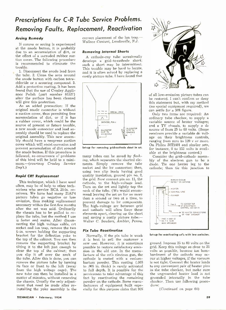
Prescriptions for C -R Tube Service Problems.
Removing Faults, Replacement, ReactivationArcing Remedy
If corona or arcing is experiencedat the anode button, it is probablydue to an accumulation of dirt, orthe effect of a corroded rubber suc-tion cover. The following procedureis recommended to eliminate thetrouble.
1. Disconnect the anode lead fromthe tube. 2. Clean the area aroundthe anode button with carbon tetra-chloride or a scouring compound. 3.Add a protective coating. It has beenfound that the use of Crosley Appli-ance Polish (part number 81527)after the surface has been cleanedwill give this protection.
As an added precaution: If theoriginal anode connector is withouta suction cover, thus permitting freeaccumulation of dirt, or if it hasa rubber cover, which could be thesource of present or future trouble,a new anode connector and lead as-sembly should be used to replace theoriginal assembly. This new assem-bly should have a neoprene suctioncover which will resist corrosion andprevent accumulation of dirt aroundthe anode button. If this procedure isfollowed, re -occurrence of problemsof this kind will be held to a mini-mum.- (courtesy Crosley ServiceDep't.)
Rapid CRT Replacement
This technique, which I have usedoften, may be of help to other tech-nicians who service RCA 21 -in. re-ceivers. We have had many 21AP4picture tubes go negative or loseemission, thus making replacementnecessary within the first few monthsafter the set was sold. Ordinarilythe chassis has to be pulled to re-place the tube, but the method I useis faster and easier. After discon-necting the high voltage cable, crtsocket and ion trap, remove the two3i -in. screws holding the supportingbracket for the deflection yoke tothe top of the cabinet. You can thenremove the supporting bracket bytilting it to the left just enough toclear the top of the cabinet; thenyou slip it off over the neck ofthe tube. After this is done, you canremove the picture tube by turningits face or front to the left (awayfrom the high voltage cage). Thenew tube can then be installed in amatter of minutes, without removingthe chassis. Usually the only adjust-ment that need be made after re-installing the yoke assembly is the
correct placement of the ion trap.-Wallace Cantoni, Landisville, N.J.
Removing Internal ShortsA cathode-ray tube occasionally
develops a grid -to -cathode short;such a short may be intermittent.This trouble may be hard to locate,and it is often solved by replacing acostly picture tube. I have found that
GRID *I, PIN 2
ACATHODE, PIN II
ALLIGATORCLIP TOH V OUTPUT
ALLIGATORCLIP TOCHASSIS
Set-up for removing grid -cathode short in crt.
many tubes can be saved by flash-ing, which separates the shorted ele-ments. Simply remove the tubesocket and the hv connector; then,using two clip leads having goodquality insulation, ground pin no. 2,the grid. Now connect pin no. 11, thecathode, to the high -voltage lead.Turn on the set and lightly tap theneck of the tube. (We would recom-mend leaving the set on for no morethan a second or two at a time, toprevent damage to hv components.The high -voltage arc between gridand cathode will often force theseelements apart, clearing up the shortand saving a costly picture tube.-Walter C. Souders, Ambler, Penna.
Pix Tube ReactivationNormally, if the pix tube is weak
it is best to sell the customer anew one. However, it is sometimespossible to restore satisfactory emis-sion in the old one. In the manu-facture of the crt's electron gun, thecathode is coated with a cesium -barium powder. This coating (.003to .005 in. thick) is rarely activatedto full depth. It is possible for theserviceman to take advantage of thisfact by reactivating the remainingpowder on the cathode. Some manu-facturers of equipment built espe-cially for this purpose claim that 90%
of all low -emission picture tubes canbe restored. I can't confirm or denythis statement but, with my method(no special equipment required), wecan settle for a 30% figure.
Only two items are required: Anordinary tube checker, to supply avariable source of heater voltages;and a TV chassis, to supply a desource of from 25 to 60 volts. (Somereceivers provide a variable dc volt-age on their brightness controls,ranging from zero to 120 v or more.On Philco 50T1401 and similar sets,for instance, 0 to 155 volts is avail-able at the brightness control.)
Consider the grid -cathode assem-bly of the electron gun to be adiode. Tie one heater leg to thecathode; then tie this junction to
BARIUM -CESIUMDEPOSIT ON CATHODE
HEATER
CONTROL GRID
CATHODE
PIN 2 TO CENTER TAP1-8. OF BRIGHTNESS
CONTROL (25-60 V)
16. TO HEATER CONNECTIONS
OF TUBE CHECKER
PINS II AND 12ON PIK TUBEBASE GROUNDED
PIN I
Set-up for reactivating crt's with low emission.
ground. Impress 25 to 60 volts on thegrid. Keep this voltage as close to 25volts as possible, because ion bom-bardment of the cathode may oc-cur at higher voltages, if the vacuumis not tight. Connect the heater leadsto any convenient pair of heater pinsin the tube checker, but make surethe ungrounded heater lead is notgrounded internally in the tubechecker. Then use following proce-dure:
(Continued on page 64)
TECHNICIAN February, 1954 39

Co LO RSHORTS
INSTALLATION procedure forcolor -TV receiver was demonstratedby RCA personnel at conferencecalled shortly after FCC announce-ment on NTSC standards. Color pixtube was not mounted on chassis, asis usual with B & W sets. The tube,packed in a separate carton, had tobe mounted in the cabinet. Unlikeconventional crt, the color tube mustbe oriented for a single correct posi-tion; the built-in mask must bealigned with the cabinet opening andthe blue gun in the neck of the tubemust be uppermost with respect tored and green guns.
THE HI -VOLTAGE regulationadjustment will have to be made(screw -driver control) with a meterwhen the receiver is installed, ascorrect hv value is important toproper beam convergence and colorregistry. A good B & W pix is thenext thing the receiver is set up for.Carried out with a linearity or dotgenerator, or special convergencechecker, this procedure preventsB & W pix from being marred bycolor ghosts.
COLOR PURITY ADJUST-MENTS are then separately madefor the individual primary colors, toinsure uniform saturation for eachacross the entire crt screen. Thenthe balancing controls for each pri-mary are manipulated, so that allthree together give a uniformly greyraster. Saturation adjustments, madenext, may depend on individualjudgment. If they are set too high,however, the excessive signal pres-ent may overdrive the crt, causingcolor distortion as well as possibletube damage.
RECEIVERS may be hinged ontop to facilitate picture tube instal-lation and access to controls. Thefront panel of one proposed com-mercial model features more than20 controls. No octopus should haveany trouble learning how to adjusthis color receiver! The fine tuningknob, an often neglected controlwith modern tuners, will becomemore important. Relatively minordeviations in receiver tuning maysuppress the 3.58 me color subcar-rier, seriously affecting color repro-duction. In switching from one chan-nel showing a color program to an-
other, the set owner may have toreadjust fine tuning regularly.Chroma and phasing controls mayalso have to be readjusted withevery switch -over to another chan-nel, to compensate for minor differ-ences in transmission. Improperphasing may result in wrong -colorreproduction (red for blue, blue forgreen, etc.).
SERVICE CONTRACTS, in-formed sources say, are expected tocost about three or four times morefor color sets than for B & W re-ceivers. First -year contracts shouldfall between $170 and $300, app.These figures, of course, representan early condition. Contract chargesshould fall in a year or two, as wasthe case with initially high B & Wcontract costs.
THE LAWRENCE COLOR TUBE,employing a single electron gun, mayget a bigger play in '54. A step-upin output of this crt was foreshad-owed with the addition of new grid -producing facilities by the ChromaticTelevision Laboratories of Califor-nia. Grids have been a principal bot-tleneck in the production of Law-rence tubes. An annual total outputof more than 25,000 grids was fore-cast for the new facilities, with pro-duction starting by the end of March.The grids will be used in the manu-facture of 21- and 24 -in. color pixtubes. The Lawrence design is saidto pave the way for these large -screen tubes. Thomas Electronics ofPassaic, New Jersey, manufacturer ofconventional B & W crts, will handlethe fabrication of the color tubesthemselves, under a recent licensingagreement.
COLOR SERVICE SCHOOLS andclinics have already been started byat least three manufacturers. West-inghouse claims the first serviceschool (December) at its plant inMetuchen, N.J. All of the Westing-house key field service personneltook part in classroom and labora-tory sessions. Subjects covered in-cluded: the study of color; com-posite color signals and their func-tion; transmitter requirements andvariables; basic receiver design; andadjustment of color receivers.
BUFFALO was chosen by Syl-vania for its first color service school
in January. Field clinics to trainSylvania dealer -servicemen are nowin the works. The first RCA colorclinics, each consisting of four daysof intensive instruction and demon-stration, were held for the benefitof receiving set licensees. New Yorkand Chicago were the sites for thefirst two such clinics in January. TheLos Angeles clinic begins on Feb-ruary 8. Similar clinics for servicegroups will be held in 65 key citiesthroughout the country, startingearly this month.
RETMA is now working on acolor -TV lecture program for tech-nicians. The program, as now pro-posed, will be offered to sponsoringorganizations as a package deal. Thepackage will include: a lecture text;an illustrated booklet, on which thelecture is based, to be distributed toaudiences at the time of the lectureas a study guide and referencetext; a series of 35 mm strip films tosupplement and illustrate the lec-tures; and a lecturer's guide pamph-let recommending procedures andtechniques for most effective use ofthe lecture material.
DR ALLEN B. DU MONT fore-sees 21 -in. color sets at $500 each,but does not believe this point willbe reached three years.He anticipates limited -quantity pro-duction of color -TV in general until1956. He believes cost factors willblock an immediate swing to color.Full integration may take 10 to 20years.
HOME STUDY COURSE INCOLOR TV for technicians alreadyversed in B & W circuitry andservice will be offered by RCA In-stitutes of New York City. Consist-ing of nine lessons, the course willcover the following subjects: Intro-duction to Color TV; Principles ofLight and Color; The Color TV Sys-tem; Receiver Principles; Color Pic-ture Tubes; Receiver Circuitry; Set-up and Adjustment Procedures;Alignment and Servicing; and Spe-cial Test Equipment. For a bulletindescribing the course, write to HomeStudy Department, RCA Institutes,350 West 4th Street, New York 14,N.Y.
COLOR ISN'T ALL-A recentComedy Hour show was telecast incolor. A follow-up of New York TVcolumnists who viewed the programon color sets produced interestingresults. When the show lagged,bored reviewers tuned out the pic-ture-in favor of B & W programsthat held greater interest.
40 TECHNICIAN February, 1954
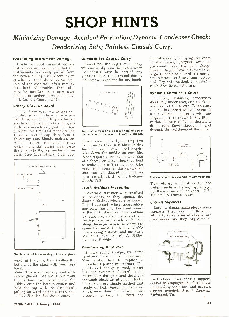
SHOP HINTSMinimizing Damage; Accident Prevention; Dynamic Condenser Check;
Deodorizing Sets; Painless Chassis Carry.
Preventing Instrument DamagePlastic or wood cases of various
test meters are so smooth that theinstruments are easily pulled fromthe bench during use. A few layersof adhesive tape placed on' the bot-tom of the case will often remedythis kind of trouble. Tape alsomay be installed in a criss-crossmanner to further prevent slipping.-H. Leeper, Canton, Ohio.
Safety Glass RemovalIf you have ever had to take out
a safety glass to clean a dirty pic-ture tube, and found to your horroryou had chipped or broken the glasswith a screw -driver, you will ap-preciate this time and money saver.I use a suction -cup dart from achild's toy gun. Simply moisten therubber (after removing screwswhich hold the glass) and pressthe cup onto the top center of theglass (see illustration). Pull out -
Simple method for removing crt safety glass.
ward, at the same time holding thebottom of the glass with your freehand.Note: This works equally well withsafety glasses that swing out fromthe bottom. On these press therubber onto the bottom center, andhold the top with the free hand,pulling outward on the suction cup.-J. L. Mancini, Winthrop, Mass.
Gimmick for Chassis CarrySometimes the edges of a heavy
TV chassis dig into the hands whenthe chassis must be carried anygreat distance. I got around this bymaking two cushions for my hands.
Grips made from an ed rubber hose help takethe pain out of carrying a heavy TV chassis.
These were made by cutting two5 -in. pieces from a rubber gardenhose. The units were sliced length-wise down the middle on one side.When slipped over the bottom edgeof a chassis on either side, they tendto make good soft grips. They takevery little room in the service kitand can be slipped off and onin a second.-H. A. Wahl, RedondoBeach, Calif.
Truck Accident PreventionSeveral of our men were involved
in accidents as they opened thedoors of their service cars or trucks.This happened when approachingmotorists ran into the truck doorsin the dark. We solved this problemby attaching narrow strips of re-flecting tape just inside each dooralong the edge. When the doors areopened at night, the tape is visibleto oncoming autoists, and accidentsare thus avoided.-H. J. Miller,Sarasota, Florida.
Deodorizing ReceiversIt may sound strange, but some
receivers have to be deodorized.This writer had to replace aburned -out power transformer. Thejob turned out quite well, exceptthat the customer objected to theburnt odor that persisted despite athorough clean-up attempt. FinallyI hit on a very simple method thatreally worked. Reasoning that evena perfume does not smell whenproperly corked, I corked the
burned areas by spraying two coatsof plastic spray (Krylon) over thediscolored areas. The smell disap-peared. Do you have a customer al-lergic to odors of burned transform-ers, resistors, and selenium rectifi-ers? Try this method, it works!-B. 0. Riis, Miami, Florida.
Dynamic Condenser CheckIn many instances, condensers
short only under load, and check okwhen out of the circuit. When sucha condition seems to be present, Iuse a voltmeter in series with thesuspect part, as shown in the illus-tration. If the capacitor is shorted, ade current flows through it andthrough the resistance of the meter.
Checking capacitor dynamically with voltmeter.
This sets up an IR drop, and themeter needle will swing up, verify-ing the existence of the short. -J. L.Mancini, Winthrop, Mass.
Chassis SupportsLarge C clamps make ideal chassis
supports. They take up little room,adjust to many sizes of chassis, areinexpensive, and they may often be
'C" CLAMPS
BOTTOM OF CHASSIS
used where other chassis supportscannot be employed. Much time canbe saved by their use, and needlessdamage avoided. foseph Amorose,Richmond, Va.
TECHNICIAN February, 1954 41
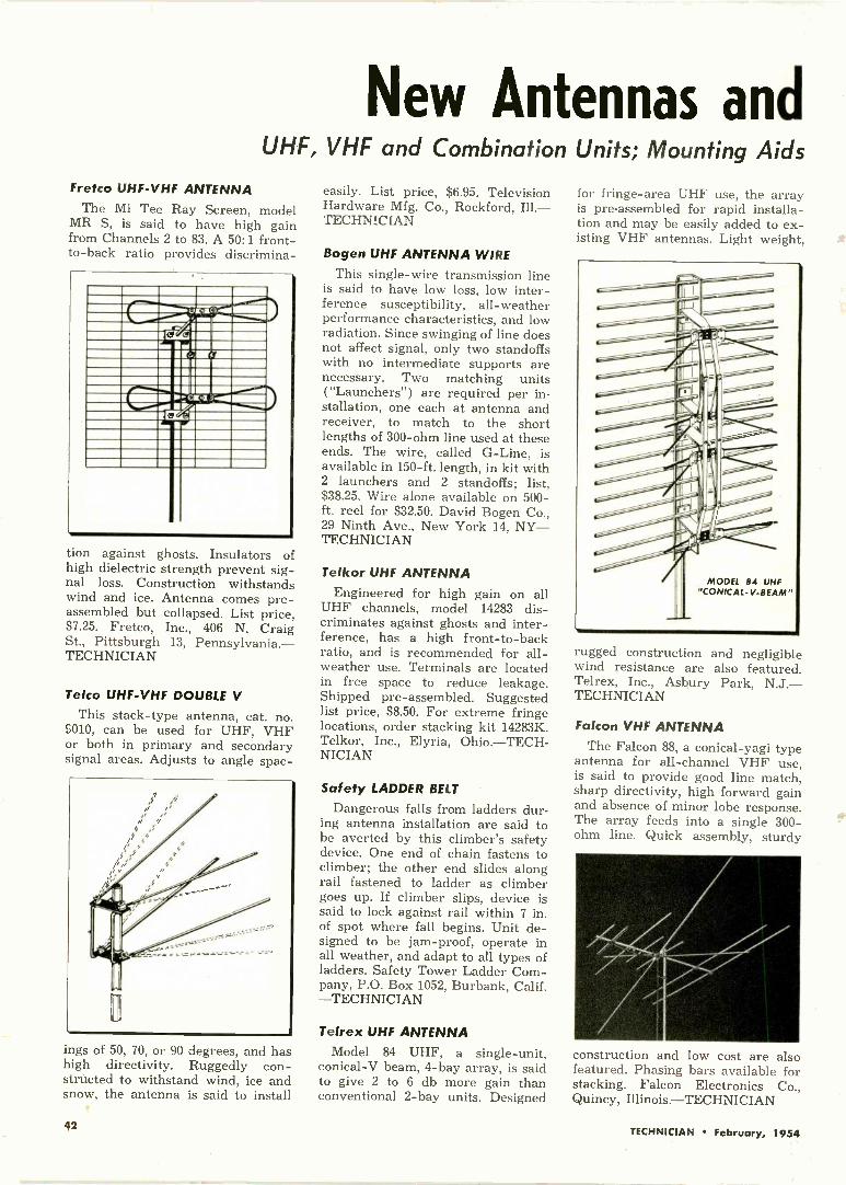
New Antennas andUHF, VHF and Combination Units; Mounting Aids
Fretco UHF -VHF ANTENNA
The Mi Tee Ray Screen, modelMR S, is said to have high gainfrom Channels 2 to 83. A 50:1 front-to -back ratio provides discrimina-
=MIMEOII ..rrmil__
1111111:4MaTio1111MMI1111111011111R"Il%iliamil 11WrAIONINIMINI
Ina IIMIZONIMIIIIMEM GE Mr 1.1111.11MIN
MI MIUMr=IM MEM MMIIIIIMI NEM. ME
11111111 IM UM. M_w MIMEO1=INIIII ra: °X'a J0111..11.11
...01111152r=11ME I= LA MMIIMINIMMEI INI1=111M111=MI 1111111111=INMINN ME NMIMIN III NM III
tion against ghosts. Insulators ofhigh dielectric strength prevent sig-nal loss. Construction withstandswind and ice. Antenna comes pre -assembled but collapsed. List price,$7.25. Fretco, Inc., 406 N. CraigSt., Pittsburgh 13, Pennsylvania.-TECHNICIAN
Telco UHF -VHF DOUBLE V
This stack -type antenna, cat. no.9010, can be used for UHF, VHFor both in primary and secondarysignal areas. Adjusts to angle spac-
ings of 50, 70, or 90 degrees, and hashigh directivity. Ruggedly con-structed to withstand wind, ice andsnow, the antenna is said to install
easily. List price, $6.95. TelevisionHardware Mfg. Co., Rockford, Ill.-TECHNICfAN
Bogen UHF ANTENNA WIREThis single -wire transmission line
is said to have low loss, low inter-ference susceptibility, all-weatherperformance characteristics, and lowradiation. Since swinging of line doesnot affect signal, only two standoffswith no intermediate supports arenecessary. Two matching units("Launchers") are required per in-stallation, one each at antenna andreceiver, to match to the shortlengths of 300 -ohm line used at theseends. The wire, called G -Line, isavailable in 150 -ft. length, in kit with2 launchers and 2 standoffs; list,$38.25. Wire alone available on 500 -ft. reel for $32.50. David Bogen Co.,29 Ninth Ave., New York 14, NY-TECHNICIAN
Telkor UHF ANTENNAEngineered for high gain on all
UHF channels, model 14283 dis-criminates against ghosts and inter-ference, has a high front -to -backratio, and is recommended for all-weather use. Terminals are locatedin free space to reduce leakage.Shipped pre -assembled. Suggestedlist price, $8.50. For extreme fringelocations, order stacking kit 14283K.Telkor, Inc., Elyria, Ohio.-TECH-NICIAN
Safety LADDER BELT
Dangerous falls from ladders dur-ing antenna installation are said tobe averted by this climber's safetydevice. One end of chain fastens toclimber; the other end slides alongrail fastened to ladder as climbergoes up. If climber slips, device issaid to lock against rail within 7 in.of spot where fall begins. Unit de-signed to be jam -proof, operate inall weather, and adapt to all types ofladders. Safety Tower Ladder Com-pany, P.O. Box 1052, Burbank, Calif.-TECHNICIAN
Telrex UHF ANTENNAModel 84 UHF, a single -unit,
conical -V beam, 4 -bay array, is saidto give 2 to 6 db more gain thanconventional 2 -bay units. Designed
for fringe -area UHF use, the arrayis pre -assembled for rapid installa-tion and may be easily added to ex-isting VHF antennas. Light weight,
rugged construction and negligiblewind resistance are also featured.Telrex, Inc., Asbury Park, N.J.-TECHNICIAN
Falcon VHF ANTENNAThe Falcon 88, a conical-yagi type
antenna for all -channel VHF use,is said to provide good line match,sharp directivity, high forward gainand absence of minor lobe response.The array feeds into a single 300 -ohm line. Quick assembly, sturdy
construction and low cost are alsofeatured. Phasing bars available forstacking. Falcon Electronics Co.,Quincy, Illinois.-TECHNICIAN
42 TECHNICIAN February, 1954

Related Productsand Hardware; Boosters, Tuners and Filters
Drake UHF TVI FILTERDesigned especially for use in
UHF reception, the UHF -300 -HPhigh-pass filter attenuates interfer-ence caused by images and spurioussignals from VHF stations, oscilla-tors of other television receiversand UHF converters, signals at in-termediate frequencies, and othersin the region below 450 mc. Listprice $3.25. R. L. Drake Co., 11Longworth Street, Dayton 2, Ohio.-TECHNICIAN
SIC TVI FILTER
High-pass filter model HP2 ismade to pass all UHF channels fromantenna to receiver with less than1 db attenuation, but to provide 45to 50 db of rejection for VHF sig-nals. Eliminates many types of TVIpeculiar to the UHF range, includ-ing interference from Channel 5 or
6 signals on double -conversion UHFsystems. Service Instruments Co.,422 S. Dearborn St., Chicago, Ill.-TECHNICIAN
Bogen UHF BOOSTER
Model UHB booster provides gainof 8 to 131/2 db across UHF band,channels 14 to 83 inclusive. Noisefigure varies from 11 to 15 db. Thetuning knob is the only control, asthe booster is turned on and off bya relay operated by the TV receiver.List price, $41. David Bogen Co., 29Ninth Avenue, New York 14, N.Y.-TECHNICIAN
TeleMatic SIGNAL EQUALIZERThe Automatic Signal Equalizer,
model AT -25, is intended for loca-tions where low -frequency VHFchannels may be strong enough tooverload the receiver, whereas highfrequency channels are not strongenough to permit constant attenu-
ation at the antenna input. Maxi-mum attenuation is provided on thelow band, minimum on the highband, without upsetting antenna -receiver impedance match. No con -
1.1.411111.
EOULIZERAUTOMATIC
SIGNALATTE A OitOM 40 4,
111601.
trols or switches need be manip-ulated. List price, $4.95. Tele-MaticIndustries, Inc., One Joralemon St.,Brooklyn, N.Y.-TECHNICIAN
HP TELESCOPIC MASTS
Zip Up telescoping mast kits areavailable in heavy-duty sets (16 -gauge) or economy sets, to makemasts in sizes of 20, 30, 40 and 50feet. Individual mast sections are10 in. long. Snug fit prevents wobble.Kits furnished with accessories in-cluding guy rings and bolts. HaydonProducts Corp., 1801 Eighth Ave.,Brooklyn 15, N.Y.-TECHNICIAN
Insuline STAND-OFFMade to accommodate all types of
standard TV transmission lines, thisstrap -type stand-off uses a low -losspolyethylene grommet and featuresan adjustable strap to mount on anypipe diameter from 3/4 in. to 11/2 in.
It is quickly tightened in place witha captive tension nut. Insuline Corp.of America, Long Island City, NewYork.-TECHNICIAN
Anchor UHF -VHF TUNER
The TV 900 tuner is a 12 -positionturret tuner for which individualchannel segments are available sep-arately. Any group of 1 to 12 chan-nels, UHF, VHF or a combinationof both, may be installed in anysequence to meet the needs of aparticular location. Original installa-tion or replacement of channelsegments is said to be rapid and torequire no special procedures ortest equipment. No extra crystals orconverter strips needed on UHF.Single conversion principle is usedon Channels 2 to 83. Anchor RadioCorp., 2215 South St. Louis Ave.,Chicago 23, Ill.-TECHNICIAN
JFD ANTENNA ACCESSORIES
The Pal stand-off, for all types ofantenna wires, avoids the use of ametal ring surrounding the lead-in.This measure prevents developmentof standing waves, which may inter-fere with TV reception in sensitiveinstallations. Lightning arrestormodel AT120, the Lightning Sentry,
includes a resistor network and tworeplaceable fuses. The network by-passes interfering static charges aswell as lightning. The replaceablefuses protect the arrestor itselfagainst damage by strong lightningcharges. List price, $4.75. JFD Mfg.Co., 6101 16th Ave., Brooklyn 4,N. Y.-TECHNICIAN
Imperial GUY WIRE
This guy wire is made of 7 strandsof 18 -gauge pure aluminum anduses a closely -knit twist for addedstrength. Wire is guaranteed againstrust, tarnish and salt -air deteriora-tion. Stretch yield is approx. 3%.Packaged in 100 -ft. continuous coils,1000 -ft. cartons and 1000 -ft. metalspools. Imperial Radar & Wire Corp.,820 E. 233rd Street, Bronx 66, N.Y.-TECHNICIAN
TECHNICIAN February, 1954 43

TV TechnicianTest Instruments and Accessories; Storage Equipment
ASD TUBE CHECKER
Model TV -20, a time -saving tubechecker, uses 20 connected socketsto facilitate testing. Developed par-ticularly for TV servicers, the check-er needs no roll chart, minimizes
set-up procedure and features port-ability. Other characteristics: auto-matic line compensation, high sensi-tivity to leakage, positive gas de-tection circuit. Net price, $124.50.American Scientific DevelopmentCo., P.O. Box 104, Fort Atkinson,Wisconsin.-TECHNICIAN
Insuline TEST LEADS
This pair of leads, intended foruse with standard test instruments,has heavy lucite handles 5 in. longand %-in. in diameter. The leadsfurnish protection against high acand dc voltages. The ends are fittedwith small chucks which takephonograph -needle test tips, usefulfor probing crowded connectionsand piercing insulation of wireswithout damage. Handles are col-ored red and black, respectively,
and carry 45 -in. lengths of flexibleleads with molded right-anglephone -tip plugs. Catalog number,304; price, $1.65. Insuline Corpora-
tion of America, 3602 35th Ave.,Long Island City, N. Y.-TECH-NICIAN
Scala DEMODULATOR PROBE
A voltage -doubling crystal de-modulator probe for use with scopeor vtvm in TV alignment and trou-bleshooting, the BZ-4 probe providesincreased utility in signal tracinglow-level i-f stages, and in cali-brating generators against crystal -oscillator harmonics. A high degreeof 60 -cycle hum rejection permitseffective tests in heater, age, and desupply lines for the presence ofspurious high -frequency voltages.Can be used to localize dead or weaki-f stages, calibrate the base line ofa scope, demodulate a video -ampli-fier sweep response curve, check theoutput of a sweep generator, and totest for sync -buzz pulses in a 4.5-mc.
sound channel. Useful to 150 mc.Priced at $10.75, complete with coax-ial lead and instruction book. ScalaRadio Co., 2814 19th St., San Fran-cisco, Calif.-TECHNICIAN
Superex CRT TEST ADAPTER
Designed for use with any maketube tester and all picture tubes,this adapter features simplicity ofoperation. One end plugs into thetube checker. The other end con-nects to the crt, which need not beremoved from cabinet. Price, $3.95.Superex Electron. Corp., 23 AthertonSt., Yonkers, N.Y.-TECHNICIAN
RCP HV PROBE
The HVMP-2 high -voltage multi-plier probe lead extends the rangeof the manufacturer's model 655peak -to -peak vtvm on dc volts. Me-ter scale readings are multiplied by100 with the probe. Complete withmultiplier resistor and terminations,the probe is of the heavy-duty typewith a safety barrier. Priced at$8.95. Radio City Products Co., Inc.,152 West 25 St., New York, N.Y.-TECHNICIAN
GI SMALL PARTS CABINETS
The line of See-Thru drawercabinets has been developed forvisible filing and storage of smallparts in service shops and homeworkshops. The spill -proof drawersare made of clear guaranteed plas-tic; welded all -steel cabinets are
%lir fit VTIP Vitt1 I tTriii litin.19La
:1,17:111,` IFT1114
used. Adjustable drawer dividersand identification labels are pro-vided. Models available with from8 to 128 drawers, with extra -size ormetal drawers, and with carryinghandles for portability. Over 750combinations can be supplied to suituser's requirements. General Indus-trial Co., 5738 N. Elston Ave., Chi-cago 30, Ill.-TECHNICIAN
Windsor TUBE CADDYAlthough this fold -out caddy, the
Carry -All, is built for portability, itprovides space for meters and othertools necessary in on -the -spot homeservicing, as well as for tubes. Thecaddy may be obtained free on a
tube purchase deal, or bought out-right ($14.95). Further details fromWindsor Electronic Tube Co., 1515Sheepshead Bay Road, Brooklyn 35,New York.-TECHNICIAN
44 TECHNICIAN February, 1954

New ComponentsParts for Initial Use and Replacement; Shop Aids
IRC POWER RESISTORS
Type PW-7 and PW-10 power re-sistors, rated at 7 and 10 watts re-spectively, are useful in many radioand TV applications. Type PW-7available from .51 to 5100 ohms,PW-10 available from 1 to 8200ohms; tolerances, 5% and 10%.Manufacturer's ratings show favor-able performance with respect to hu-midity, load life, overload and ef-fects of soldering. International Re-sistance Co., 401 N. Broad St., Phila-delphia 8, Penna.-TECHNICIAN
GE SOCKET WRENCH SET
This space -saving socket wrenchset has been developed for radio -TV service technicians. The twotools, each with four heads mountedin the shape of a cross, replace 8
individual hex -head wrenches.Made of chrome -plated hardenedsteel; sizes clearly marked. Avail-able through GE tube distributors.Tube Dept., General Electric Co.,Syracuse, N.Y.-TECHNICIAN
Daven ATTENUATORSSeries 154 fixed attenuator pads
are available in either T or balancedH networks. Units are available inlosses up to 100 db with a widerange of input or output impedances.Maximum power dissipation, 1 watt;Accuracy, ±2%. Common applica-tions: to equalize incoming signallevels, to change impedance, to com-bine 2 or more incoming lines into asingle line, or to equalize the outputsof several speakers connected to acommon source. Daven Co., 191,Central Ave., Newark, N. J.-TECH-NICIAN
Halldorson FLYBACKFlyback transformer FB412 is de-
signed as an exact replacement forPart No. C-201-21025-1 in 84 modelsand chassis of Airline, Raytheonand Truetone TV receivers. The unitfeatures a variable -gap width con-trol, tapped agc winding and a spe-cial mounting base. HalldorsonTransformer Co., 4500 RavenswoodAve., Chicago 40, Ill.-TECHNICIAN
Stancor FLYBACKSThese four flyback transformers
for Philco receivers are exact re-placements, according to the manu-facturer. A-8220 replaces Philcopart 32-8565, used in 14 models andchassis; A-8221 replaces 32-8555 in29 models and chassis; A-8222 re-places 32-8533 and 32-8534 in 38sets; and A-8223 replaces 32-8572 in15 sets. All chassis involved weremanufactured in 1952 and 1953. Thereplacement units have choke coils,resistors, and capacitors wired tothe terminal boards.
Three exact -replacement flybacktransformers cover 91 Motorolamodels using 52 chassis. Stancor partnumber A-8224 replaces Motorolaflybacks 24C711265, 24C711265 -A,and 24C721290 in 56 models. A-8225replaces 24K712193 in 15 models.A-8226 replaces 24K721301C and24K271517C in 20 models. Each unithas a horizontal centering pot, vari-able gap width control and a socketfor a 1B3 rectifier. Added to theoriginal design are a corona ring onthe tube socket and a reinforced ter-minal board to withstand the strainof inserting or removing the 1B3tube. Chicago Standard TransformerCorporation, Standard Division, Ad-dison and Elston, Chicago 18, Illi-nois.-TECHNICIAN
Jet PRECISION CONTROLSJet D-100 precision potentiome-
ters are available with rotation up to360 degrees, and in resistance rangesup to 50,000 ohms, =L-1%. Units arerated at 1 watt. Other features: lightweight, long life, high ambient tem-perature rating. Anticipated life issaid to be in excess of 1 million cy-cles of noise -free operation. Jet Elec-tronics, Inc., 93 Mass. Ave., Boston,Mass.-TECHNICIAN
Int'l SELENIUM RECTIFIERS
Special -type selenium stacks, de-signed for the anticipated power sup-ply requirements of color TV re-ceivers, are available for capacitiveloads of 600, 700 and 750 ma. Maxi-mum input voltage ratings are 130,172 and 195 volts rms. Special con-struction affords lower forward drop,lower temperature rise and longerlife. International Rectifier Corp.,El Segundo. Calif.-TECHNICIAN
EFCON CAPACITORS
Type MH plastic film capacitorsfeature special design for close toler-ance, miniature size, moisture resist-ance, high insulation resistance and
low dielectric absorption. Availablein tolerances of ±1%, ±-2%, ±5%and voltage ratings of 200, 400 and600 v dc in any value from .01 to 1mfd. Hermetically sealed in metaltubular cases. Electronic Fabricators,Inc., 682 Broadway, New York 12,N.Y.-TECHNICIAN
Sprague CAPACITORS, PC'sReplacement ceramic capacitors
and Bulplate printed circuits are be-ing furnished in clear molded poly-styrene boxes. The re -usable con-tainers reveal both contents and rat-ings of units at a glance. Snap lockson the hinged lids eliminate spilling.These compact boxes are space sav-ers for storing small parts. SpragueProducts Co., Marshall St., NorthAdams, Mass.-TECHNICIAN
No -Noise CONTACT SPRAYERNo -Noise contact and volume con-
trol cleaner is now being madeavailable in spill -proof 6 -oz. pres-sure spray cans, for service techni-cians who find this type of containermore convenient. The cleaner is alsoavailable in 2 -oz. and 8 -oz. bottles,and quart cans. Electronic ChemicalCorp., 813 Communipaw Ave., Jer-sey City 4, N.J.-TECHNICIAN
TECHNICIAN February, 1954 45
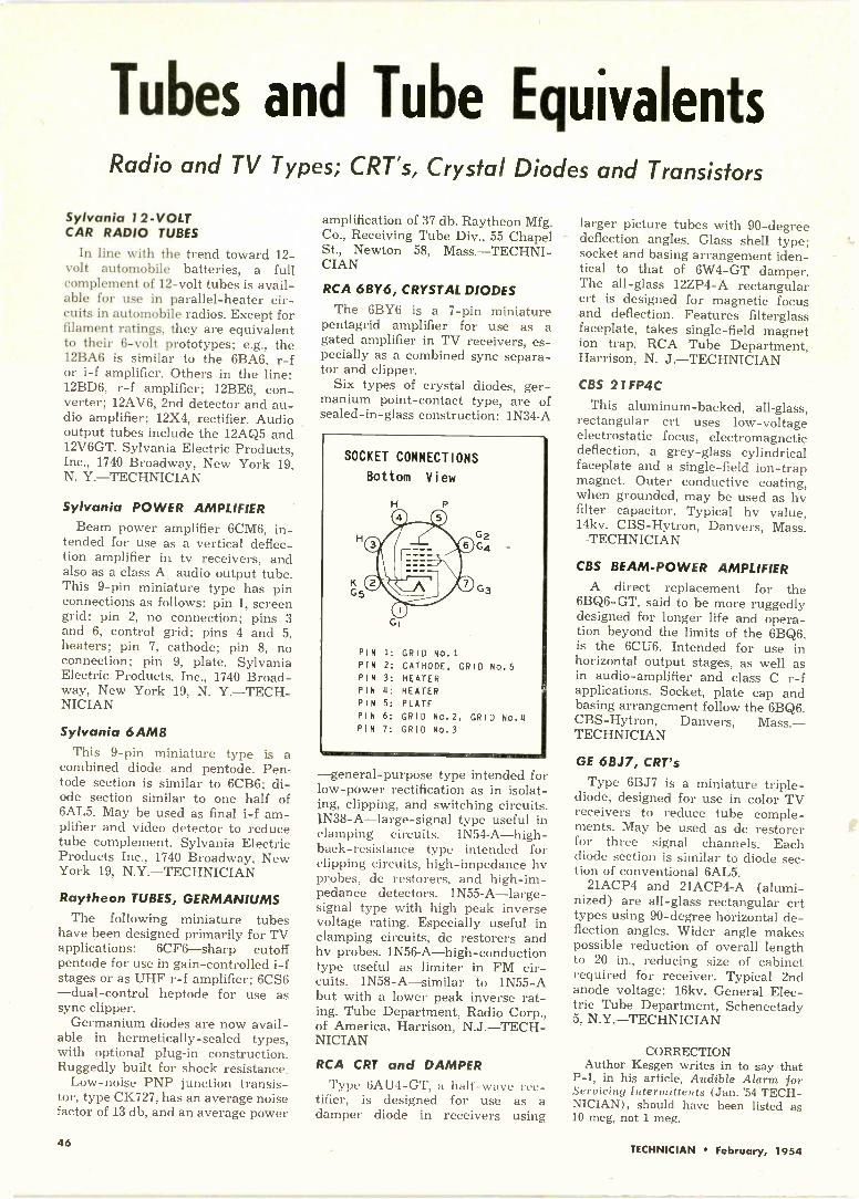
Tubes and Tube EquivalentsRadio and TV Types; CRT's, Crystal Diodes and Transistors
Sylvania 12 -VOLTCAR RADIO TUBES
In line with the trend toward 12 -volt automobile batteries, a fullcomplement of 12 -volt tubes is avail-able for use in parallel -heater cir-cuits in automobile radios. Except forfilament ratings, they are equivalentto their 6 -volt prototypes; e.g., the12BA6 is similar to the 6BA6, r -for i-f amplifier. Others in the line:12BD6, r -f amplifier; 12BE6, con-verter; 12AV6, 2nd detector and au-dio amplifier; 12X4, rectifier. Audiooutput tubes include the 12AQ5 and12V6GT. Sylvania Electric Products,Inc., 1740 Broadway, New York 19,N. Y.-TECHNICIAN
Sylvania POWER AMPLIFIERBeam power amplifier 6CM6, in-
tended for use as a vertical deflec-tion amplifier in tv receivers, andalso as a class A, audio output tube.This 9 -pin miniature type has pinconnecti6ns as follows: pin 1, screengrid; pin 2, no connection; pins 3and 6, control grid; pins 4 and 5,heaters; pin 7, cathode; pin 8, noconnection; pin 9, plate. SylvaniaElectric Products, Inc., 1740 Broad-way, New York 19, N. Y.-TECH-NICIAN
Sylvania 6AM8This 9 -pin miniature type is a
combined diode and pentode. Pen-tode section is similar to 6CB6; di-ode section similar to one half of6AL5. May be used as final i-f am-plifier and video detector to reducetube complement. Sylvania ElectricProducts Inc., 1740 Broadway, NewYork 19, N.Y.-TECHNICIAN
Raytheon TUBES, GERMANIUMSThe following miniature tubes
have been designed primarily for TVapplications: 6CF6-sharp cutoffpentode for use in gain -controlled i-fstages or as UHF r -f amplifier; 6CS6-dual -control heptode for use assync clipper.
Germanium diodes are now avail-able in hermetically -sealed types,with optional plug-in construction.Ruggedly built for shock resistance.
Low -noise PNP junction transis-tor, type CK727, has an average noisefactor of 13 db, and an average power
amplification of 37 db. Raytheon Mfg.Co., Receiving Tube Div., 55 ChapelSt., Newton 58, Mass.-TECHNI-CIAN
RCA 6BY6, CRYSTAL DIODES
The 6BY6 is a 7 -pin miniaturepentagrid amplifier for use as agated amplifier in TV receivers, es-pecially as a combined sync separa-tor and clipper.
Six types of crystal diodes, ger-manium point -contact type, are ofsealed -in -glass construction: 1N34 -A
SOCKET CONNECTIONS
Bottom View
PIN
PIN
PIN
PIN
PIN
PIN
PIN
G264
G3
1: GRID No.1
2: CATHODE, GRID No.53: HEATER4: HEATER5: PLATE6: GRID NO.2, GRID No.47: GRID NO.3
-general-purpose type intended forlow -power rectification as in isolat-ing, clipping, and switching circuits.IN38-A-large-signal type useful inclamping circuits. IN54-A-high-back-resistance type intended forclipping circuits, high -impedance hvprobes, dc restorers, and high -im-pedance detectors. 1N55-A-large-signal type with high peak inversevoltage rating. EApecially useful inclamping circuits, dc restorers andhv probes. 1N56-A-high-conductiontype useful as limiter in FM cir-cuits. 1N58-A-similar to 1N55 -Abut with a lower peak inverse rat-ing. Tube Department, Radio Corp.,of America, Harrison, N.J.-TECH-NICIAN
RCA CRT and DAMPERType 6AU4-GT, a half -wave rec-
tifier, is designed for use as adamper diode in receivers using
larger picture tubes with 90 -degreedeflection angles. Glass shell type;socket and basing arrangement iden-tical to that of 6W4-GT damper.The all -glass 12ZP4-A rectangularcrt is designed for magnetic focusand deflection. Features filterglassfaceplate, takes single -field magnetion trap. RCA Tube Department,Harrison, N. J.-TECHNICIAN
CBS 21 FP4C
This aluminum -backed, all -glass,rectangular crt uses low -voltageelectrostatic focus, electromagneticdeflection, a grey -glass cylindricalfaceplate and a single -field ion -trapmagnet. Outer conductive coating,when grounded, may be used as hvfilter capacitor. Typical hv value,14kv. CBS-Hytron, Danvers, Mass.-TECHNICIAN
CBS BEAM -POWER AMPLIFIERA direct replacement for the
6BQ6-GT, said to be more ruggedlydesigned for longer life and opera-tion beyond the limits of the 6BQ6,is the 6CU6. Intended for use inhorizontal output stages, as well asin audio -amplifier and class C r -fapplications. Socket, plate cap andbasing arrangement follow the 6BQ6.CBS-Hytron, Danvers, Mass.-TECHNICIAN
GE 6BJ7, CRT's
Type 6BJ7 is a miniature triple -diode, designed for use in color TVreceivers to reduce tube comple-ments. May be used as dc restorerfor three signal channels. Eachdiode section is similar to diode sec-tion of conventional 6AL5.
21ACP4 and 21ACP4-A (alumi-nized) are all -glass rectangular crttypes using 90 -degree horizontal de-flection angles. Wider angle makespossible reduction of overall lengthto 20 in., reducing size of cabinetrequired for receiver. Typical 2ndanode voltage: 16kv. General Elec-tric Tube Department, Schenectady5, N.Y.-TECHNICIAN
CORRECTIONAuthor Kesgen writes in to say that
P-1, in his article, Audible Alarm forServicing Interatittents (Jan. '54 TECH-NICIAN), should have been listed as10 meg, not 1 meg.
46TECHNICIAN February, 1954

Audio and Hi-Fi ItemsSpeakers, Enclosures, Amplifiers and Allied Units
W -Z TV HEARING AIDThis auxiliary speaker, specially
designed for the hard -of -hearing,permits TV viewing at normal dis-tances from the receiver withoutloss of sound. Leads from the aux-
iliary speaker clip to the leads frommain speaker. Auxiliary unit maybe hooked over shoulder of listeneror back of chair. Price, $13. Wright -Zimmerman, New Brighton, Minne-sota.-TECHNICIAN
Cabinart SPEAKER HORN KITSKits incorporating the Klipsch cor-
ner -horn enclosure design are avail-able in unfinished birch. The com-pact cabinets achieve large -enclo-sure performance on low frequenciesby using back -loading to increasepath length. Kits K-12 and K-15, for12 -in. and 15 -in. speakers, respec-tively, each provide an extra port formounting a tweeter or other auxili-ary speaker. Kits include hardware,pre-cut baffle, and instructions forassembly and finishing. G. & HWood Products Co., 75 North 11thN. Y.-TECHNICIAN
Kloss SPEAKER SYSTEM
This small -size complete speakersystem makes high-fidelity perform-ance possible at a low cost; based onthe original Baruch -Lang design.Employing four 5 -in. speakers in awedge-shaped housing little morethan a foot high and less than 20 in.wide, the system may be mountedanywhere on the floor or ceiling orin the corner between two walls.Corner -mounting is not essential forwide range and low distortion. Avail-able in output impedance of 4 or 16ohms. May be obtained direct frommanufacturer for $19.95. Kloss In-dustries, 10 Arrow Street, Cam-bridge, Mass.-TECHNICIAN
Utah HI Fl SPEAKER SYSTEMSOne single -speaker and several
multiple -speaker systems are avail-able as follows: model HF100, 12 -in.speaker and cabinet, response from30 to 10,000 CPS; model HF300, 10 -in.woofer plus tweeters in cabinet, re-sponse from 30 to 15,000 CPS; Quar-tet model, 12 -in. woofer plus tweet-ers in corner enclosure, responsefrom 30 to 15,500 CPS: Chordettemodel, 8 -in. woofer plus tweeter inbookshelf or end -table enclosure.Utah Radio Products Co., Inc.,Huntington, Ind.-TECHNICIAN
Masco TAPE RECORDERS
Models 53 and 53R (with and with-out radio) are dual speed, dual tracktape recorders featuring fast for-ward and rewind speeds and two -motor drive. Response at 7.5 in. persecond: 80 to 8500 cps, with wow andflutter less thon 0.3%; response at3.75 ips, 80 to 5000 cps. Inputs formike, radio, and phono; outputs forexternal amplifier or speaker. Tim-ing indicators, push-button operationand monitoring switch are also pro-vided. Mark Simpson Mfg. Co., 32-28 49th Street, Long Island City 3,N. Y.-TECHNICIAN
Lorenz WOOFER and TWEETER
The Lorenz woofer and tweeterare designed to be used in combina-tion for a wide -range speaker sys-tem. Also available are a high-passfilter to match the two speaker unitsand a choice of cabinets to housethe three components comprisingthe system. Kingdom Products Ltd.,23 Park Place, New York 7, N.Y.-TECHNICIAN
Craftsmen HI Fl FM TUNER
An FM tuner said to meet the high-est Hi Fi requirements, model C900features high sensitivity and stabilitywith low distortion. Some features:sensitivity of 1 microvolt for 20 dbquieting; amplified, continuouslyvariable AFC for optimum control ofstrong and weak signals; less than.05% intermodulation distortionthrough entire receiver. Three con-trols are provided: AFc, off -on -vol-ume, and tuning. Net price, $99.00.The Radio Craftsmen, Inc., 4401 N.Ravenswood, Chicago 40, Ill.-TECHNICIAN
Webcor TAPE RECORDERFollowing the success of its 3 -
speaker phonograph, Webstor-Chi-cago is producing a 3 -speaker taperecorder, model 2030, to give wide-angle dispersion of sound throughoutthe listening area. One 4 -in. and two6 -in. speakers are used to dispersesound so that high -frequency deadspots are avoided. Construction ofone-half inch wood veneers lowerscabinet resonance, thus improvingbass response. List, $143.70. Webster -Chicago, 5610 W. Bloomingdale Ave.,Chicago 39, Ill.-TECHNICIAN
Brook HI-FI AMPLIFIERA small -size single -chassis ampli-
fier and control unit, model 22Aprovides response within 1 db from20 to 20,000 cps with 10 watt outputat negligible distortion. Five inputchannels are featured for tuners,TV, recorder and phono cartridge;four output impedances from 2 to16 ohms. Controls: channel selector,record equalizer (6 positions), bass,treble, compensated loudness, andon -off power. Brook Electronics,Inc., 34 DeHart Place, Elizabeth,N.J.-TECHNICIAN
Scott HI-FI CONTROL UNIT
Model 121-A Dynaural Equalizer -Preamplifier is a self -powered re-mote control unit for broadcast orhome sound systems. Record com-pensation is provided by separate,continuously -variable bass turnoverand treble roll -off controls. Built-inDynaural Noise Suppressor dynami-cally discriminates against turntablerumble and record scratch withminimum effect on musical frequen-cies. Also featured: Variable high -frequency cut-off filters, separatebass and treble tone controls, 8 -
position input selector, and separateinput level controls. Compensatedloudness control may be switched tooperate as flat volume control. H. H.Scott, Inc., 385 Putnam Ave., Cam-bridge 39, Mass.-TECHNICIAN
TECHNICIAN February, 1954 47

Technician's
Lighter SideObscure Threat Dept.
Joe Thomas, one of our servicefriends, was telling us how he col-lected some long overdue bills.Customers to whom Joe had mailedstrings of letters, some gentle andothers stern and purposeful, hadblandly ignored the requests forimmediate payment. Several hun-dred dollars was involved, and Joewas not disposed to overlook thematter.
One day a man came around andoffered to collect the sums due, inreturn for a percentage of the take."Fine," said Joe. "You collect, andI'll pay you 20% of the total youbring in."
Within 3 days, checks adding upto $280, or about 90% of the moneyowed Joe Thomas, were received inthe mail.
Joe was curious about his collec-tor's technique.
"Tell me, whatever did you dothat made that money roll in sofast?" he asked, when he had paidthe man his $56.
"Just wrote 'em a letter," repliedthe collector.
"One letter?" asked Joe. "I wrotethem at least five letters! What didyour letter say?"
"I'll read ya one," said the collec-tor. He took a piece of paper outof his pocket and read:
Dear Mr. Best:You owe the Joe Thomas Radio
Service $15. If you don't send in a
111,0NIm*Vgame
k kik.104.404
check for this sum in 48 hours,you'll be surprised at what'll hap-pen.
Yours truly, etc.We don't recommend the tech-
nique, but it does point up the valueof a fresh approach to one's prob-lems . .
Reward of Virtue(1 80 Degrees Out of Phase)
A small-town radio shop owner-let's call him Mac-called one of histechnicians into his little office fora heart-to-heart talk the other day.
"You know, the customers likeyou very much," said Mac.
"Thank you," beamed the techni-cian.
"Practically every customeryou've visited in the month you'vebeen here has had glowing things tosay about you."
The technician's beam becamebeam -powered.
"They say you do wonderfulwork. You're courteous, competent,and thoroughly reliable."
The serviceman's smile expanded
"This must be the house...
Tr,
further. Thoughts of the raise thatseemed imminent weaved throughhis mind like 60 -cycle hum.
"In fact," concluded the boss,"you're getting so popular with thecustomers, in a few months youmight be able to start a business ofyour own, and take them all away. . . so I'm forced to fire you."
Think and Grow Poor
You probably never heard aboutthe owner of a large TV -radio shopwho was much impressed with thenumerous signs marked THINKthat he saw in the plush front officesof a factory he was visiting. Sometime later, the merchant decided toinstall similar signs in his own es-tablishment. Several days after thesigns had been posted in prominentparts of the store, a friend came into visit.
"How'd that plan of yours workout?" asked the friend. "You know,that idea of sticking up THINKsigns all over?"
"Not so good," sighed the shopowner. "The first day they were up,three people who walked in withsmall radios they wanted fixedlooked at the signs, thought a mo-ment, then walked out again. Thesecond day my chief servicemantold me that after thinking it over,he would like a partnership in thebusiness. To top it all off, my land-lord came in today, and after glanc-ing at the signs, told me it wasabout time he raised my rent."
Have you had any amusing ex-periences during the course of yourservicing work? Why not writethem down and send them in?TECHNICIAN will pay $5 for ac-ceptable anecdotes of this kind. Ad-dress Editor, Technician's LighterSide, TECHNICIAN, Caldwell -Clements, Inc., 480 Lexington Ave.,N.Y. 17, N.Y.
48TECHNICIAN February, 1954

1110111110161C6NICAl
WO
INTRODUCING the greatestadvance in Conical antennas
...it's the all -new WALSCO Imperial.Featuring a new "barrier disc"
insulator with 2 inches of airspace between the terminals
to prevent shorts. Soot deposits,dirt, moisture, salt, etc.,
cannot affect this insulator.The WALSCO Imperial will thereforemaintain lasting high gain performance
anywhere, regardless ofweather conditions. Contact
surfaces and terminals willnever rust or oxidize. Front end
hardware is stainless steel toprevent corrosion losses permanently.
Front end elements
11
are pre -assembled toholding plates
which are fastened tothe insulator with one wing nut.
Less than 2 minutes to assemble.
Guaranteed lasting high gain on ail VHF channels
tit\ 1111 r.tr 11(1j_11 In it t 11
3602 Crenshaw Blvd., Los Angeles 16, Calif.

69 me-channel 4
195 me-channel 10
Directivity patterns of theCONICAL are exceptionallyclean. The strong major lobeindicates fine directivity.
model 114-068 CONICAL
a VHF CONICALantenna built to theQuality Standards of
AM PHENoin
Now ready to join the fastest -growing and fastest -selling anten-na line in the United States is a new AMPHENOL VHF antenna.Designed to supplement the fabulous INLINE* for VHF recep-tion, the new CONICAL antenna will give true-picture recep-tion in every VHF signal area: major, fringe and long-distance.Gain and directivity have been engineered to the high AMPHENOLstandards that have set the quality goal for the entire industrycraftsmanship attention to the small but important details makethe CONICAL another example` of AMPHENOL'S fine antennawork.
AMPHENOL CONICALs are available in single, two and fourbay models. The stacked models use unique phasing harnessesfor extra gain. The CONICAL may be obtained in packagingthat contains all the necessary stacking equipment or else theindividual antenna may be purchased one or two to a carton.In addition, the single bay CONICAL is available in a completeantenna installation kit.
All elements of the CONICAL are constructed of sturdy,long-lasting seamless aluminum tubing - assuring rust -freeyears of top performance.
Reissue U. S. Potent 23,273
standard toned
Folded Boolerelerence
2
(111111111.S
High gain of the CONICAL is illustrated in the gaincharts for single, two bay and four bay models. Measuredin accordance with proposed RETMA standards, thecharts also show the desirable flatness of the gain.
AMERICAN PHENOLIC CORPORATION chicago 50, Illinois

Keep Your EYES on Profits!
Now's the Time to Make the Service Department Pay
Too many dealers are willing tooperate their businesses on the pre-mise that the service department ismerely a feeder for sales, andshouldn't be expected to show aprofit.
Here and there, because of certainunusual conditions, the premise justmentioned may be sound to the ex-tent that a few dealers find it impos-sible to rack up profits on servicework, some going in the red with stillothers managing to operate on abreak-even basis.
But it's a truly unusual case wherean owner is justified in. resigninghimself to this state of affairs beforehe has explored every avenue of pos-sible profitable operation in his serv-ice department.
TECHNICIAN'S editors have pre-pared this article with a view towardpointing out a number of reasons whyprofits get devoured in many servicedepartments. The editors are alsosuggesting some remedies to helpthose owners and managers whowant to eagle -eye their operationsin an all-out endeavor to makemoney.
Do these conditions prevail inyour service department?
Inadequate Charges: A most com-mon reason for in -the -red operation.Remedy: Review your charging for-mula. Don't be afraid to ask fairprices for your work.
Overboard Overhead: Do you haveshirkers or time -wasters on yourpayroll? Do you have too much help?How do you keep men busy duringslack periods-when the overheadcontinues to roll along? Does someonein authority assign the bench workand outside calls? Are outside callsrouted efficiently in order to savetime and cut down vehicle expense?
Remedy: Fire the hopeless drones,"re -sell" the good men, who mayhave fallen into bad habits, on thenecessity for doing a full day's work.Have someone lay out each man'sjob for the day, and plan outside callroutes carefully. Be sure to keep menbusy when things are slow. They canclean up the shop, rearrange stocketc., during these intervals.
Sketchy Estimating: Almost allshops are called on to estimate a greatmany of the repair jobs that come in.Do you have a realistic, profit -slanted method for quoting? If youuse a hit-and-miss technique you'llget plenty of headaches. If you "for-get" how much you told Mrs. Jonesthat job would be, you may wind upbehind the eight -ball. If, for instance,you bill her for more than quoted,you may lose her as a customer. Onthe other hand, "forgetting" may re-sult in a loss to you. Remedy: Makeout a simple "estimating slip" onevery job, or fill in the amount on aservice order. Spend a little extratime trying to make an accurate esti-mate. It'll pay off.
Inefficient Record -Keeping: Do youlose money through failure to includeall labor and parts on some jobs?Does the department lose moneythrough failure of employees tocharge out all tubes, components ortime on some repairs? Do your billsgo out promptly? Are collections fol-lowed up efficiently, or are accountsreceivable allowed to die of old agein the ledgers? Remedy: If some orall of the foregoing conditions existin your department, do somethingabout it! For instance, hire an ac-countant (part time) to set up a goodsystem, and insist that every man inyour employ keep an account of time,tubes and other components. (Manyshops charge parts and material'
against those employees who "draw"such supplies out of inventory.)
Sloppy Buying: This can be putinto two categories: 1. Overbuying,and 2. Underbuying. In the first in-stance, carelessness is usually toblame for buying too much stock, orgoing overboard in ordering toomany slow -moving items. In the sec-ond case, hand-to-mouth purchasingis usually alibied with the excuse thatthe person responsible for this im-portant chore of buying is too busy.Obviously, buying too heavily tiesup good money in inventory, whilebuying in inadequate supply ties uptoo many jobs and discourages tech-nicians. Remedy: Resolve to buymore carefully, making "need" listswhich should be checked againststock on shelves and in servicers'hands.
Not Enough Customers: No servicedepartment head should be satisfiedwith the amount of business it'spresently doing. The objective shouldbe to expand, to keep adding newcustomers in order to prevent lulls inwork, and to compete with what maybe an increased number of serviceset-ups coming into the field thisyear. Remedy: Advertise consist-ently, even if small space is used indirectories and in newspapers. Usedirect -mail pieces to solicit new cus-tomers, and to keep your name be-fore the old ones. The profit -mindeddealer not only renders service-hesells it, too.
Start a clean slate, in this secondmonth of the new year, and a firmresolution to show profits from yom-service and installation. Many dealersare making fine livings because theywatch every penny, and chop out thedead wood. It can be done in almostevery shop. Why not try to makemore money in your business?
TECHNICIAN February, 1954 51

HOW TO WINTo win one of these 503 prizes all you
hove to do is complete in 25 words or less"I like Pyramid capacitors becauseYou fill in this statement on a Pyramid con-test entry blank which can be obtained fromany electronic parts jobber selling Pyramidcapacitors. You have this entry blank coun-tersigned by your jobber or one of his sales-men and forward it to us attached to aPyramid Dry Electrolytic Capacitor box top-the top being the part which carries thedescription of the item. There is no limit tothe number of entries which you may makein this contest but each entry must be accom-panied by a box top. Full rules for the con-test appear on the entry blank.
It's so easy. Here is the kind of statementthat might win:
"I like Pyramid capacitors because theyalways check out perfectly and don't deteri-orate and so I know I won't have to callback at my expense."
"I like Pyramid capacitors because the lineis so complete that I can always get whatI need and don't have to worry about anoff -brand capacitor."
IN PRIZESPYRAMID
ifeet(Jy
PRIZES!$2000 -1st prize$500 - 2nd prize, $100 - 3rd prize
O
100 - $10 prizes, 400 - $5 prizes
PYRAMID FEATURES:O Only one quality-the best at no pre-
mium. All Pyramid capacitors are madeof materials commanded by rigid militaryspecifications.O All Pyramid capacitors are non -hygro-
scopic.O Highest quality insulator material used
in all production results in low leakagefactor.
O Exclusive non -contamination techniqueguarantees close tolerances and no de-
terioration. Peak performances for life.O Pyramid capacitors operate unchanged
at ambient temperature of 85- centi-grade.O Designed by service technicians across
the country for their requirements.O Individually packaged for protection.O Permanently legible, high visibility rat-
ings on each item.100% absolute electronic inspection be-fore shipment.Pyramid is in its 10th year as a leadingmanufacturer of high -quality capacitors.
PYRAMID ELECTRIC COMPANY1445 HUDSON BOULEVARD
NORTH BERGEN, N. J.
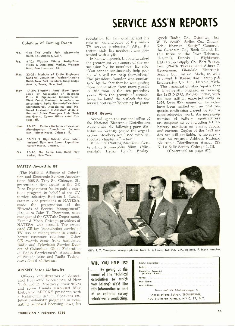
Calendar of Coming Events
Feb. 4-6: The Audio Fair, AlexandriaHotel, Los Angeles, Calif.
Feb. 8-12: Western Winter Radio -Tele-vision & Appliance Market, WesternMart, San Francisco, Calif.
Mar. 22-25: Institute of Radio EngineersNational Convention, Waldorf-AstoriaHotel, New York. Exhibits, KingsbridgeArmory, Bronx, New York.
May 17-20: Electronic Parts Show, spon-sored by Association of ElectronicParts & Equipment Manufacturers;West Coast Electronic ManufacturersAssociation; Radio -Electronic -TelevisionManufacturers Association and Na-tional Electronic Distributors Associa-tion and Sales Managers Club (East-ern Group), Conrad Hilton Hotel, Chi-cago, Ill.
June 15-17: Radio - Electronic - TelevisionManufacturers Association Conven-tion, Palmer House, Chicago, Ill.
Sept. 30 -Oct. 2: High Fidelity Show, Inter-national Sight and Sound Exposition,Palmer House, Chicago, Ill.
Oct. 13-16: The Audio Fair, Hotel NewYorker, New York.
NATESA Award to GE
The National Alliance of Televi-sion and Electronic Service Associa-tions, 5908 S. Troy St., Chicago, Ill.,presented a fifth award to the GETube Department for its public rela-tions program in behalf of the TVservice industry. Bertram L. Lewis,eastern vice-president of NATESA,made the presentation of the"Friends of Service Management"plaque to John T. Thompson, salesmanager of the GE Tube Department.Frank J. Moch, Chicago president ofNATESA, was present. The awardcited GE for "outstanding service toTV service management in creatingbetter customer relations." OtherGE awards came from AssociatedRadio and Television Service Deal-ers of Columbus, Ohio; Federationof Radio Servicemen's Associationsof Philadelphia; and Radio Techni-cians Guild of Boston.
ARTSNY Fetes Liebowitz
Officers and directors of Associ-ated Radio -TV Servicemen of NewYork, 165 E. Broadway, their wivesand some friends surprised MaxLiebowitz, ARTSNY president, witha testimonial dinner. Speakers ex-tolled Liebowitz' judgment in eval-uating proposed licensing laws, his
SERVICE ASSN REPORTS
reputation for fair dealing and hisrole as "emancipator of the radio -TV service profession." After thetestimonials, the president was pre-sented with a gift.
In his own speech, Liebowitz askedfor greater active support of the as-sociation by its members. He said,"You cannot continuously help peo-ple who will not help themselves."The president -founder was encour-aged by the fact that he was gettingmore cooperation from more peoplein 1953 than in the two precedingyears. With the growth of associa-tions, he found the outlook for theservice profession becoming brighter.
NEDA GrowsAccording to the national office of
the National Electronic DistributorsAssociation, the following parts dis-tributors recently joined the organi-zation. Members are listed with re-spective chapter affiliation:
Burton S. Phillips, Electronic Cen-ter, Inc., Minneapolis, Minn. (Min-nesota); Henry Lynch, Friday -
Lynch Radio Co., Ottumwa, Ia.;W. B. Smith, Sidles Co., Omaha,Neb.; Norman "Scotty" Cameron,the Cameron Co., Rock Island, Ill.(all three in the Iowa -NebraskaChapter); Dennis J. Hightower,H&L Radio Supply Co., Fort Worth,Tex. (North Texas); and Albert J.Kernerman, Glendale ElectronicSupply Co., Detroit, Mich., as wellas Joseph F. Keese, Radio Supply &Engineering Co., Inc., Detroit, Mich.
The organization also reports thatit is currently engaged in revisingthe 1953 NEDA Battery Index, withthe new edition expected early in1954. Over 6500 copies of the indexhave been mailed out on past re-quests, confirming a need for such across-reference work. An increasingnumber of battery manufacurersare cooperating by including NEDAbattery numbers on charts, labels,and cartons. Copies of the 1953 in-dex are still available, in the mean-time, on request. Address NationalElectronic Distributors Assoc., 228N. La Salle Street, Chicago 1, Ill.
(Continued on page 67)
GE's J. T. Thompson accepts plaque from B. L. Lewis, NATESA V.P., as pres. F. Moch watches.
WILL YOU HELP US?
. By giving us thename of the technicalassociation to which
you belong? We'd likethis information as partof an editorial survey
which we're conducting.
Service Association:
Address
Manager or RecordingSecretary's Name: .
Phone:
Your Name:
Your Address:
Please mail the filled -out coupon to
Associations Editor, TECHNICIAN,480 Lexington Avenue, N.Y.C. 17, N.Y
TECHNICIAN February, 1954

"Tough Dog" CornerDifficult Service Jobs Described by Readers
Intermittent Pix Pulling
The complaint was "picture snak-ing" and increased contrast afterthe set was on for about forty-fiveminutes. The symptoms seemed toindicate an agc defect. First, Ichecked all i-f, tuner, and agctubes. They checked ok. Next Ipulled the chassis on the floor andleft the set on for what seemed likea long time, but it played ok. I didnot care to wait too long in the cus-tomer's home with the chassis onthe floor, so I brought it to the shop.I set it up on the bench with a me-ter on the agc line. The set playedall right for two days!
I called the customer and ex-plained that the set was workingnormally in the shop, and that I hadnot found anything wrong with it.The customer requested that the setbe brought back to her home. Aboutforty-five minutes after I returnedthe set, the customer called andcomplained of the same trouble. Itold her to leave the set on, and Iwould be right over.
When I arrived, the set was pullinghorizontally, although not verybadly. "The longer it is on, theworse it gets," the set owner com-mented. I shut off the set in orderto pull the chassis out of the cabinetto check voltages. Then I put theset on the floor and turned it on. It
played fine. No pulling-just adarned good picture. It seemed im-possible that the TV cabinet shouldcause the picture to pull, yet thepicture "snaked" only when the setwas in the cabinet.
I decided to leave the set on thefloor for a while. The customer, whofortunately was a very understand-ing person, asked if I could set theTV receiver right side up for awhile, so her son could see a pro-gram he was interested in. Uponturning the set in a right -side -upposition-heretofore I had always hadit on its side so that I could checkvoltages-the set started to pull. Atfirst it was pulling just a little, butwithin an hour the set was pullingbadly and contrast had increasednoticeably.
I tipped the set sideways for justan instant, in order to clip my vtvmon the agc line. The agc voltage wasnormal! Next I placed the chassisbetween two chairs (see sketch A).This enabled me to check voltageswhile the set was in an upright po-iticn. After a considerable amount
of checking I found that the troublewas caused by a 2.4k video plateload resistor (see sketch B). Theresistor was badly charred, but onlyon one side-the side that was fac-ing the chassis. When the set was inthe normal upright position, theheat would rise up against the chas-
A-Set-up for checking the chassis in an upright position while horizontal pulling occurred.B-Schematic location of the overheating resistor in the video amplifier plate circuit. C-Cut-away chassis view, showing how resistor overheating depended upon the position of the chassis.
(A)
OVERHEATEDRESISTOR --\
2.4 K
12BH7VIDEO AMP
(B)12BH7
(VIDEO AMP)
B+
TO SYNCSECTION
HEAT RISESAGAINST CHASSIS,CANNOT ESCAPE FREELY
CHASSISCUTAWAY
(C)
DEFECTIVE2.4K RESISTOR
sis, causing the resistor to over -heatand go up in value (sketch C). Withthe increase in resistance of thevideo plate load resistor, the con-trast would increase, and some ofthe video voltage would get into thesync, causing the picture to pullhorizontally.-F. Mattioli, Madison,Wisconsin.
The Mysterious 6AG5
When I was called in to servicethis set in the owner's home, she in-formed me that she had previously
TUBE SHIELDFOR 6AG5
HOLES DRILLEDIN SHIELD FOR --VENTILATION
Holes punched in this tube shield preventedrepeated tube breakage due to excessive heat.
called several technicians in to re-pair the receiver. About a week orso after they fixed it, the set wouldgo bad again. The raster was ok,but there was no video. The ownerinformed me that a tube in the backof the set with a metal shieldaround it (6AG5, 4th video i-f) hadbeen found broken, and requiredreplacement several times. Nobody,it seems, had been able to discoverwhy the tube was breaking repeat-edly. I looked, and sure enough the6AG5 was broken again.
I took the shield off and madesmall holes in it for air ventilation(see sketch) ; then I replaced it overa new tube. My reasoning was asfollows: the ventilation would pre-vent the tube from getting too hot,expanding and finally breaking. Thediagnosis was apparently correct,since the set has been working fortwo months now without a coin-plaint.-Gelman's TV, Philadelphia,Penna.
Executive ability is deciding quicklyand getting somebody else to do thework. -J. C. Pollard
54TECHNICIAN February, 1954

WITH THE
HIGH SENSITIVITY - WIDE RANGE
5" OSCILLOSCOPEPUSH-PULL VERTICAL AND HORIZONTAL AMPLIFIERS20 into PER INCH "V" SENSITIVITY - 150 my PER INCH "H" SENSITIVITY
SERIES ES -500-A affords the ultimate in performance, visibilityand operational flexibility at moderate cost. PRECISIONengineers have incorporated every necessary feature whichthey found to be required to meet the needs of the rapidlyadvancing art of electronics, A.M., F.M., and TV.
SUMMARY OF IMPORTANT FEATURES* Push -Pull Vertical Amplifier - High Sensitivity. Wide Range, Voltage
Regulated. 20 millivolts (.02v.) per inch deflection sensitivity. 10 cyclesto 1 MC. response. 2 megohms input resistance. Approx. 22 mmf. inputcapacity.
* Compensated Vertical Input Step Attenuator-Xl, X10, X100.* Direct Peak to Peak Voltage Checks thru use of internal, semi -square
wave, regulated voltage calibrator.* Vertical Phase -Reversing Switch. Non -frequency discriminating.* Push -Pull, Extended Range. Horizontal Amplifier -150 Millivolts (.15 v.)
per inch deflection sensitivity. 10 cycles to 1 MC response at full gain.I/2 megohm, approx. 20 mmf. input.
* Linear Multi -Vibrator Sweep Circuit -10 cycles to 30 KC.* Amplitude Controlled, Four Way Synch. Selection: Internal Positive,
Internal Negative, External and Line.* "Z" Axis Modulation input facility for blanking, timing, etc.* Internal, Phasable 60 cycle Beam Blanking for elimination of alignment
retrace; clean display of synch. pulses, etc.* Sweep Phasing Control for sinusoidal line sweep usage.* Direct Horizontal and Vertical Plate Connections.* High Intensity CR Patterns through use of adequate high voltage
power supply with separate 2X2 rectifier.* The Circuit and Tube Complement: 6C4 "V" cathode follower. 6CB6
"V" amplifier. 6C4 "V" inverter. Push -Pull 616's "V" driver. 7N7 "H"amplifier and inverter. Push -Pull 6AU6's "H" driver. 7N7 Multi -vibrator, linear sweep oscillator. 5Y3 low voltage rectifier. 2X2 highpotential rectifier. VR-150 regulator. 5CP1/A CR Tube.
* Four -Way, Lab -Type Input Terminals-Take banana plugs, phone tips,bare wire or spade lugs. Matches SP -5 Probe Set cable connector.
* Light Shield and cross -ruled Mask, removable and rotatable.* Extra Heavy -Duty Construction and components.* Heavy Gauge. Etched -Anodized, No -Glare, Aluminum Panel.* Fully Licensed under Western Electric Co. patents.
SeJtee4 ES5500,4: In louvered, black -ripple, heavy gauge steelcase. Size 81/4- x 141/2" x 18". Complete with light shield, calibratingmask and comprehensive instruction manual ..NET PRICE $173.70
Series SP -5 - OSCILLOSCOPE TEST PROBE SETFOR TV SIGNAL TRACING, ALIGNMENT,
TROUBLE SHOOTING AND WAVEFORM ANALYSIS
* Specifically engineered for use with PRECISION Catnode RayOscilloscopes, Series ES -500 and ES -500A.
* Includes four of the most important test probes for generalpurpose, as well cs specialized use:
1. HIGH IMPEDANCE-LOW CAPACITY PROBE2. SIGNAL TRACING-CRYSTAL PROBE3. RESISTIVE-ISOLATING PROBE4. SHIELDED-DIRECT PROBE
* Each probe s specifically engineered for efficient applicationto the special test prcbiems requiring its use.
* Distinctively colored heads and individual IabellMg permitpositive identification of each probe.
* A single, universal, coaxial cable accommodates each probethrough a quick -change, self -shielding connector.
* A specially -designed, shielded plug provides for positive cableattachment to the ES -500 and ES -500A Verfical input posts.
* Each probe head terminates in a patented clip -on tip whichfrees bath hands of the operator.
TV AM FM TV AM FMSee the ES-&IOA Oscilloscope and theSeries SP -5 Test Probe Set at leadingRadio Parts & Equipment Eistributors.
Seleut SP -5, in custom -designed, vinyl -plastic, carryingcase, complete with four probe heads, universes coaxial cable,and detailed operating instructions. NET PRICE $23.50
PRECISION APPARATUS COMPANY, INC.92-27 HORACE HARDING BLVD. ELMHURST, L. I., N. Y.
EXPORT DIVISION: 458 BROADWAY, NEW YORK CITY U.S.A. CABLES-MORHANEXCANADIAN SALES DIVISION: ATLAS RADIO CORP. LTD., 360 KING ST. W. TORONTO 2B, ONTARIO
TECHNICIAN February, 1954 55

Hi Fi Guide to Pickup Arms & Cartridges(Continued from page 30)
on the other hand, can withstandwide variations without any ill ef-fects. This is the main reason thatmagnetic and ceramic units havelonger lives.
Another characteristic worth con-sidering is the cartridge's response tovertical modulation. Such modula-tion is the result of the cartridgetranslating the vertical movementsof the stylus into electrical signals.Vertical modulation should be keptat a minimum for high-fidelity re-production.
Some pickups, such as the vari-able -reluctance and other magnetictypes, are relatively insensitive tovertical stylus movements. Thesecartridges depend for their outputvoltages on the transfer of flux fromthe pickup cantilever (see Fig. 7) tothe pole pieces of the coils. When thecantilever moves laterally, gettingcloser to one pole piece than theother, proportional currents are in-duced in each coil, and an outputvoltage is developed. When the can-tilever moves vertically, however,the distance between the cantileverand the pole pieces does not change,and no output voltage develops.
Choosing a Cartridge. As we cansee, the various types of cartridgeshave their advantages as well astheir disadvantages. The type ofcartridge used is determined by thebudget. It does not pay, of course, tochoose a cartridge that has a widerfrequency response than the ampli-fier with which it is used.
Before a cartridge is replaced in aHi Fi system, check its character-istics to see that it will give per-
formance equal to, or better than,the original cartridge. (When achange -over is being made from onetype of pickup to another, anythingin the amplifier's input circuit that isintended for specific use with theoriginal type of cartridge may haveto be altered or removed to matchthe new unit. This applies to inputimpedance, as well as to preampli-fiers, equalizers and compensatingnetworks.-Ed.)
The Stylus. Some of the informa-tion provided on needle selection
331/3 RPMNEEDLE
78GROOVE
78 RPMNEEDLE
331/3GROOVE
Fig. 9-Improper tracking results when thestylus diameter does not have the correct sizewith respect to the record grooves it rides on.
may seem to concern the set ownermore than the serviceman; the datapresented should, however, help thetechnician answer questions he maybe asked.
The prime function of the pickupneedle (or stylus, as it is more ac-curately called) is the transfer of thelateral movement of the record'sgrooves to the pickup cartridge.Diamond -point needles are probably
II
,4111,444 A/
"It's intended to give the set owner a more intimate view of favorite performers."
3/8'
ORIGINAL OVERHANG
/2OVERHANG AFTERIMPROPER REPLACEMENTOF NEEDLE
Fig. 10-Overhang may be changed when astylus replacement is of the wrong type.
the best investment from the user'sstandpoint. Even though they costmore initially, they are good for acouple of thousand playings on fine-groove discs, whereas the saphire-tipped needle is good only for a fewhundred. Less distortion and lessrecord wear is produced by thediamond -point needle, and its life isalso longer.
Needles should be checked peri-odically to see whether wear has de-veloped. Fig. 8B shows a worn needlepoint that will not track the groovesproperly, thus introducing recordwear. A worn needle also introducesexcessive needle -talk and distortion.Magnifying lenses made for this pur-pose should be used to thoroughlyinspect the needle tip.
An unfortunate mistake to beavoided by servicemen is the inter-changing of standard and LPneedles. The LP needle has a 1 -milpoint; the standard needle has a3 -mil point. Fig. 9 illustrates the poorseating that is produced when theseneedles are interchanged. The LPneedle rests at the bottom of thestandard groove and does not followlateral motion properly. This causesan excessive amount of surface noiseand distortion. The standard needle,on the other hand, rides too high inthe LP groove and has, in conse-quence, a tendency to skip and wearthe walls of the grooves.
Another important factor in thereplacement of a pickup needle thatmay be overlooked is its shape. Ifthe wrong type of needle is used asa replacement, the pickup arm over-hang may be changed considerably(see Fig. 10).
Pickup Assembly ReplacementCautions. The various parts of thepickup arm assembly have definiterequirements. When any part re-placement is necessary, or an im-provement in operation is desired,check the overall characteristics ofthe replacement against the charac-teristics of the associated elements inthe system.
56 TECHNICIAN February, 1954

Du Mont Unveils NewDual -View TV Set
A television receiver which showstwo TV programs on one screenwhile permitting two audiences toview their choices simultaneouslywas introduced by Allen B. DuMont Laboratories, Inc. The re-ceiver is known as the "Du MontDuoscopic." The receiver can tunein any two TV programs from anystations within range. This meansa husband may view one program,while his wife watches another.
A press gathering at the pre-view demonstration, using polaroidglasses, saw a particular program atone moment and then, by merelyreversing the glasses, became ob-servers of a different telecast. Withpersonalized ear pieces and conven-ient remote control audio units, thepress group heard and saw any oftwo programs they desired. When-ever an individual wishes, he canindependently switch to anotherchannel. The remote -control soundsystem makes possible audio syn-chronization with the channelchange. Audio volume can be low-ered or raised to accommodate thelistener's preference.
New Fields for WebcorWebcor, manufacturer of phono-
graphs and magnetic recorders, to-day entered two new industrieswith the announcement of its firstradio and the first of a series ofmusical recordings on tape. Thenew Webcor radio is a five -purposeclock -radio called the "Quintet." Itfeatures a plug for attaching a taperecorder to make recordings of ra-dio shows. It will also permit plug-in of a record changer and will turnappliances on or off automatically.
Pyramid Prize ContestA contest for servicemen that of-
fers $5600 in cash prizes has beenannounced by the Pyramid ElectricCompany of North Bergen, N.J. Thecontest will begin Feb. 1 and willcontinue until the end of April.First prize will be $2,000. The sec-ond and third prizes are $500 and$100, respectively. In addition, therewill be 500 other cash awards.
The contest entails completingthe sentence, "I like Pyramid ca-pacitors because . . ." in 25 words orless. Entry blanks for the contestwill be available through jobbers,who will countersign each one sub-mitted. Duplicate awards will begranted to the lucky jobbers whoseservicemen win prizes. Each entryin the competition must be accom-panied by the top of a box from aPyramid dry electrolytic capacitor.
TELEVISION CO.JOHN
MILLER
"The Man WhoKnows"
TV ANTENNAS FOR ANY RECEPTION CONDITION
Why stock antennas from 10 manufacturers-when nomatter what the reception problem, there's a Miller an-tenna that does the job. WE OFFER THE WORLD'S LARGESTSELECTION OF TV ANTENNAS . you name it, we have it.As the West's pioneer TV antenna manufacturer, builder ofone million antennas since 1948, we guarantee you TOPQUALITY at a REALISTIC PRICE.
Compare this Value . . . this Price!A Typical Miller Value
CONICALKIT Conical Kit includes 10 element coni-cal, 6 -foot, 11/4" aluminum mast, base,
0 $975 guy ring, 30' of stranded, galvanizedsteel guy wire, 50' of 300 ohm lead-inline, mast stand-off, 3 wood stand-offinsulators, 3 screw eyes, instructionsheet. Now priced at only $9.75 list.
LIST
Write forFREE OATAI00
TELEVISION Co.
2840 NAOMI
BURBANK, CALIF.
Rockwell 9-1659
------Write for Free Catalog!-----_MILLER TELEVISION CO.2840 Naomi, Burbank, Calif.Gives Complete Information on World's Largest Se'ectionof TV Antennas. Gives our Realistic Prices. Just OffPress. Write for Your Free Copy Today!
Name
Company
Addre s
City State .
TECHNICIAN February, 195437
SERVICE MEN HAVE NO WORRIES
Tung -Sol works harder to make Tung -
Sol tubes better. That pays off in fewerservice call-backs.
TUNG-SOL®dependable
PICTURE TUBESTUNG-SOL ELECTRIC INC., Newark 4, N. J. Sales Offices: Atlanta,Chicago, Columbus, Culver City (Los Angeles), Dallas, Denver,Detroit, Newark, Seattle.
Mfrs. ChangesRecent Design Alterations
Linearity Improvement in '54 Crosley SetsSeveral of the changes that have been made in Cros-
ley's custom and deluxe line of 17 in. and 21 in. televisionreceivers to improve horizontal linearity are describedbelow (see schematic). The code letters used on chassisincorporating this change are also given. Chassis withearlier code letters do not have the change.
402 CODE E 404-1 CODE C402-1 CODE F 404-5 CODE B402-4 CODE B 405 CODE D402-5 CODE A 405-1 CODE D403 CODE E 410-1 CODE B403-1 CODE D
Although the published parts lists still apply to early produc-tion chassis, the following list gives the new parts used in thechassis incorporating this change. The symbol numbers aregiven in two columns to permit quick reference to the sche-matic in either bulletin.
SYMBOLNUMBER PRIOR TO CHANGE INCORPORATED
IN CHANGE
Bulletin BulletinNo. 459 No. 465 Part No. Description Part No. Description
C159 C161 137499-34 Capacitor, 560mmf., 10%,500 v., Mica
144675-2 Capacitor, .005mmf., 500 v.,Disc Ceramic
C162 C163 154988 Capacitor, 120mmf., 10%,3KV., Disc
157046-1 Capacitor, 100mmf., 10%.3KV., Disc
Ceramic Ceramic
R172 R182 39374-55 Resistor, 300,000ohm, 10%,34 watt
39374-57 Resistor, 470,000ohm, 10%,34 watt
Horizontal Instability in Stewart -Warner SetsIf you encounter critical horizontal hold action on any
current Stewart -Warner TV receivers, it is suggestedthat you specifically follow the procedure we are goingto outline. By so doing, you will be able to obtain hori-zontal holding action that remains within the range ofthe front panel hold control. 1. Check to see that con-denser 131 is a silver mica unit, 820 mmfd, ±5% toler-ance. This condenser is Stewart -Warner part No. 512,-547. It is already incorporated in all receivers exceptthose 9300 series sets that do not include the letter "H"in the series coding at the rear of the chassis. 2. Checkto see that condenser 130 is other than a Sangamo type
58TECHNICIAN February, 1954

in TV Setsin Television Receivers
(red body). This .01 mfd condenser should be the typesupplied under Stewart -Warner part No. 512311-donot use a substitute. The correct type is already in-corporated in all (except the 9300 series) that do notinclude the letter "R" in the series coding on the rearof the chassis. 3. If the receiver has a "horizontal range"trimmer condenser, it should be screwed closed. 4. If a6SN7GTA tube is used as the horizontal afc-blockingoscillator, replace it with a 6SN7GT. 5. Turn the re-ceiver on and allow it to operate for fifteen minutes.6. Set the horizontal hold control on the front of the re-ceiver to its counter -clockwise position. 7. Remove the6BE6 gated sync separator tube from its socket. Thiswill cause the receiver to lose both horizontal and ver-tical sync. 8. If it was necessary to replace the No. 130.01 condenser (step 2) you will probably find the re-ceiver to be pretty far off horizontal frequency. Thisshould be corrected by adjusting the bottom slug of theSynchroguide transformer until the picture "hunts"horizontally. In other words, the picture will remain in-tact and slide from side to side across the screen, butwill not break into diagonal lines. If you did not replacethe .01 condenser, the bottom slug of the Synchroguidetransformer should not be adjusted. In this case, onlythe top slug need be adjusted until the hunting condi-tion is obtained. 9. Plug the 6BE6 tube back into thesocket and set the front control of the receiver to thecenter of its range. The picture should now remain inhorizontal sync when switching channels and also re-main within the range of the horizontal hold control.
Sentinel TV Receiver ChangesTo eliminate possibility of drive lines appearing on pic-
ture, and to reduce effect on size of horizontal hold coiladjustments, make the following change (in Models 454,455, 456, 457, 464, 465, 466, 500, 511, 512, 513, 515, 520, 521,522, 523 and 525) :
Replace C-58 (a 680 mmfd fixed mica capacitor, at plateof horizontal oscillator) with a 470 mmfd fixed micacapacitor, -4-100, part no. 23E3500-40.
To increase vertical size and vertical linearity controlrange in models 532, 542, 554, 562 and 564:
If R-106 (a 270 -ohm 1 watt resistor) is connected tothe output side of the filter choke, connect it to theinput side of the filter choke instead. This can be donesimply by removing the 270 ohm 1 watt resistor from itsphysical position on the tie lug located in center ofchassis, and connecting this resistor across the C-84 inputfilter condenser sections -40 mfd (half moon) and 40 mfd(square).
Vertical Line in Emerson 27 -in. SetsA vertical white line may appear in the picture on some
27 -in. sets (chassis 120179-B, 120205-B) due to overdriveof the horizontal output tube. In the event that readjust-ment of the horizontal width coil, changing the 6BQ6horizontal output tube or changing the 6W4GT dampertube does not eliminate this overdrive bar, change thevalue of R-74 from 330k 1/2 watt to 390k 1/2 watt. Thisresistor is connected to pin no. 5 of the 6SN7 horizontaloscillator. 120179-B chassis incorporating this change arecoded Triangle C; 120205-B chassis, Triangle B.
...WHEN CUSTOMERS HAVE NOCOMPLAINTS
Tung -Sol never lets up on keepingquality up. That's why customers makefewer complaints about Tung -Sol tubes.
TUNG-SOL®dependable
RECEIVING TUBES
TUNG-SOL makes All -Glass Sealed Beam Lamps, Miniature Lamps, SignalFlashers, Picture Tubes, Radio, TV cnd Special Purpose Electron Tubesand Semiconductor Products.
TECHNICIAN February, 1954 59
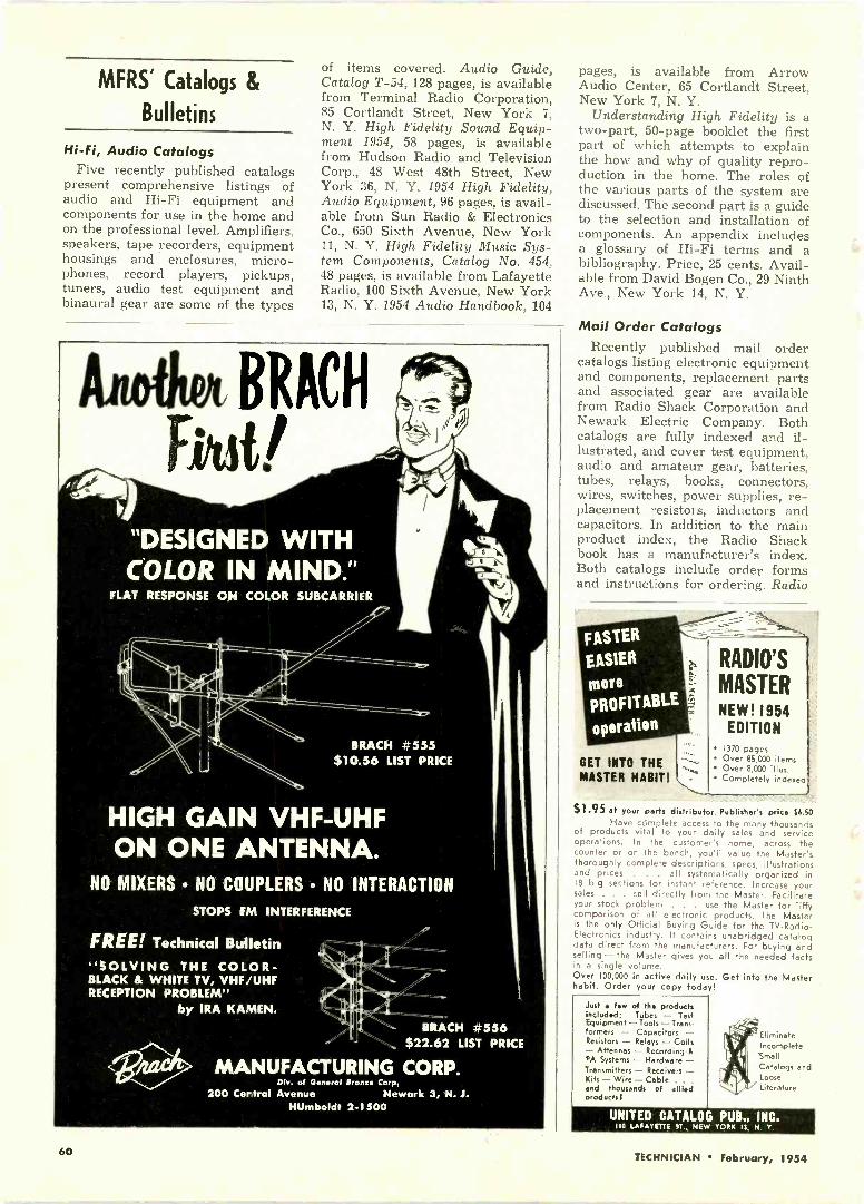
MFRS' Catalogs &
Bulletins
Hi-Fi, Audio CatalogsFive recently published catalogs
present comprehensive listings ofaudio and Hi-Fi equipment andcomponents for use in the home andon the professional level. Amplifiers,speakers, tape recorders, equipmenthousings and enclosures, micro-phones, record players, pickups,tuners, audio test equipment andbinaural gear are some of the types
of items covered. Audio Guide,Catalog T-54, 128 pages, is availablefrom Terminal Radio Corporation,85 Cortlandt Street, New York 7,N. Y. High Fidelity Sound Equip-ment 1954, 58 pages, is availablefrom Hudson Radio and TelevisionCorp., 48 West 48th Street, NewYork 36, N. Y. 1954 High Fidelity,Audio Equipment, 96 pages, is avail-able from Sun Radio & ElectronicsCo., 650 Sixth Avenue, New York11, N. Y. High Fidelity Music Sys-tem Components, Catalog No. 454,48 pages, is available from LafayetteRadio, 100 Sixth Avenue, New York13, N. Y. 1954 Audio Handbook, 104
FLAT RESPONSE ON COLOR
7'7
BRACH #555$10.56 LIST PRICE
HIGH GAIN VHF-UHFON ONE ANTENNA.
NO MIXERS NO COUPLERS NO INTERACTION
STOPS FM INTERFERENCE
FREE! Technical Bulletin"SOLVING THE COLOR -BLACK & WHITE TV, VHF/UHFRECEPTION PROBLEM"
by IRA KA.4AEN.
Dlr. of General Iron" Corp.200 Certral Avenue
BRACH #556$22.62 LIST PRICE
Newark 3, N. J.HUmboldt 2-1500
pages, is available from ArrowAudio Center, 65 Cortlandt Street,New York 7, N. Y.
Understanding High Fidelity is atwo-part, 50 -page booklet the firstpart of which attempts to explainthe how and why of quality repro-duction in the home. The roles ofthe various parts of the system arediscussed. The second part is a guideto the selection and installation ofcomponents. An appendix includesa glossary of Hi-Fi terms and abibliography. Price, 25 cents. Avail-able from David Bogen Co., 29 NinthAve., New York 14, N. Y.
Mail Order CatalogsRecently published mail order
catalogs listing electronic equipmentand components, replacement partsand associated gear are availablefrom Radio Shack Corporation andNewark Electric Company. Bothcatalogs are fully indexed and il-lustrated, and cover test equipment,audio and amateur gear, batteries,tubes, relays, books, connectors,wires, switches, power supplies, re-placement resistors, inductors andcapacitors. In addition to the mainproduct index, the Radio Shackbook has a manufacturer's index.Both catalogs include order formsand instructions for ordering. Radio
FASTER
EASIER
more
PROFITABLE
operation
GET INTO THEMASTER HABIT!
RADIO'S
MASTERNEW! 1954
EDITION1370 pages
Over 85,000 items Over 8,000 illus. Completely indexed
$1.95 at your parts distributor. Publisher's price $6.50Have complete access to the many thousands
of products vital to your daily sales and serviceoperations. In the customer's home, across thecounter or on the bench, you'll value the Master'sthoroughly complete descriptions, specs, illustrationsand prices . . . all systematically organized in18 big sections for instant reference. Increase yoursales . . . sell directly from the Master. Facilitateyour stock problem . . . use the Master for jiffycomparison of all electronic products. The Masteris the only Official Buying Guide for the TV -Radio -
Electronics industry. It contains unabridged catalogdata direct from the manufacturers. For buying andselling-the Master gives you all the needed factsin a single volume.Over 100,000 in active daily u e. Get into the Masterhabit. Order your copy today!
Just few of the productsIncluded: Tubes - TestEquipment-Tools-Trans-formers - Capacitors -Resistors - Relays - Coils- Attennas - Recording &PA Systems - Hardware -Transmitters - Receivers -Kits- Wire - Cable . . .
and thousands of alliedproducts I
EliminateIncompleteIncompleteSmallCatalogs andLooseLiterature
UNITED CATALOG PUB, INC.110 LA3AYITTR RT., NOW YORK 13, N. Y.
60 TECHNICIAN February, 1954

Shack Catalog 54, 226 pages, is avail-able from Radio Shack Corporation,167 Washington Street, Boston 8,Mass. Newark Catalog No. 56, 194pages, available from Newark Elec-tric Company, 223 West MadisonStreet, Chicago 6, Ill.
Federal Selenium HandbookDesign, application, specifications
and circuitry are covered in the sec-ond edition of Federal's SeleniumRectifier Handbook. The 80 -pagebooklet lists selenium rectifiers forradio and TV applications, and alsocovers rectifier designs and powersupply circuits for use with audioamplifier, radio, and intercom sys-tems, as well as other dc power sup-plies. Servicing information includestroubleshooting tables to help thetechnician in checking selenium rec-tifiers for specific troubles, as wellas diagrams for setting up rectifiertests in the repair shop. Price, 50cents. Available through distribu-tors, or write to Federal Telephoneand Radio Company, 100 KingslandRoad, Clifton, New Jersey.
Jerrold Folder on CommunityTV Antennas
A catalog folder has been issuedby Jerrold Electronics Corporation,26th & Dickinson Streets, Philadel-
5761°-**NEWS**
It
REPLACEMENTBANDING KITS
KIT "C": ( Consists of )2-12'x 3/4" STAINLESS STEEL STRAPS
with eyebolts attached2-Eyebolts Unattached4 - Nuts to Fit Eyebolts2-KWIK KLIP Strapping FastenersAlso available, KIT "A", similar toKIT "C", except furnished with 3/4"wide GALVANIZED steel banding.Universal- may be used with anychimney antenna mount.In Can.: A. T. R. Armstrong Co.. Toronto
SOUTH RIVER METALPRODUCTS CO., INC.
SOUTH RIVER, N. J.
PIONEER AND OUTSTANDING PRODUCERrt, FINEST LINE OF ANTEPP/1 '.10';NTS
phia, Pa., covering their new five -channel community antenna system.This new engineering developmentuses the present Jerrold series Wequipment which distributes TVsignals from three stations. New Kseries equipment is added to dis-tribute two extra channels. The newcatalog folder, titled "Jerrold'sFive -Channel Community AntennaSystem," is available upon request.
Miller Coil Replacement GuideThe latest Miller TV Technician's
Coil Replacement Guide, No. 154,is available through leading partsdistributors throughout the country.
This 20 -page catalog lists, by setmanufacturer and part number,equivalent Miller replacements forchokes, coils and transformers usedin video and sound i-f, r -f, discrim-inator, sync and sweep circuits; alsolisted are peaking coils, ion trapsand adjustable inductive controls.J. W. Miller Co., 5917 South MainStreet, Los Angeles 3, Calif.
CRT Comparison Wall Chart
The TV Picture Tube Division ofSylvania Electric Products Inc. hasreleased a new version of its handy
(Continued on page 62)
The new RCPFLYBACKERModel 123
oval,
$39.75
The Answer To Fast, Reli-able Testing of FlybackTransformers and Yokes
Quickly . . .
Accurately . . .
Checks the Horizontal Out-put Circuit of All TV Re-ceivers
Extremely sensitive, the Model 123Flybacker immediately shows up asingle shorted turn in a flyback trans-former or yoke. Its light, portabledesign serves to advantage in theshop and in the home.All tests can be carried out with thecomponents in place in the TV re-ceiver. Call-backs can be preventedby checking all flyback transformersand yokes in stock for opens, shorts,etc. Flybacker tests are also appli-cable to inductive windings on anytransformer, choke speaker, solenoid,
relays, etc., where the impedance isnot relatively low. In fact the instru-ment may be used as a proportionalAC Ohmmeter.
So Easy to Operate!Minimum of connections necessary.All you do is remove flyback platecaps-set switches-apply leads andthen read meter. The slightest changein inductance due to a shorted turn orthe effect of intermittents shows upon the meter immediately as "BAD."
See the RCP Flybacker at your parts -distributor, or write Dept. T9 for fur-ther information.
RADIO CITY PRODUCTS CO., INC.152 WEST 25th ST NEW YORK I. N. Y.
P`
TECHNICIAN February, 1954 61

Catalogs & Bulletins
(Continued from page 61)
"TV Picture Tube ComparisonChart." The new free wall chart,brought up to date, can be obtainedfrom the Sylvania Advertising Dis-tribution Department, 1100 MainStreet, Buffalo, N. Y. Data on morethan 160 different crt types isavailable at a glance. Added infor-mational features in this new chartinclude ion trap listings and basediagrams. Face, body, focus, deflec-
tion angles, basings, and length -in -inches data on all tubes are alsoincluded.
B -T TV CalculatorBlonder -Tongue Labs is offering
a free "TV Calculator" to TV serv-ice dealers and TV technicians. Thecalculator contains a scale for instantconversion of decibels to voltagegain; charts and diagrams de-scribing various strengths of attenu-ator pads; a convenient channel -megacycle scale, and a table tocompute TV transmission line lossesat VHF and UHF channel frequen-cies. Available on request from
TECH -MASTERcustom-Littii.014- TV CHASSIS
Are A Credit to Your Skill...
when you do a job ona custom, installation
When you've been commissioned to do your best... when you're being paid for the finest ... that's the time toremember that TECH -MASTER backs your skill with the finest lineof custom-built TV chassis in the field.
The custom installation field offers a vast poten-tial for expansion and profit!
One satisfactory installation is a valuable rec-ommendation for another and another!
TECH -MASTER TV CHASSIS are specifically de-signed and built for custom installations!
The finest components and the finest craftsman-ship assure years of fine performance!
SO - when your customer wants custom installation - givehim custom quality with
TECH -MASTER GOLD MEDAL SERIES
Quality TV Chassis for Custom Installation
MODEL 2430: Latest, improved 630 type circuit;for picture tubes up to 24". Audio connec-tion for optional use of external amplifier.Net Price (Less Kine) $189.50
MODEL 2431: Same as 2430, but with true fidel-ity, Push -Pull audio amplifier.Net Price (Less Kine) $199.50
MODEL 2439: For new 90s kinescopes, (24" rec-tangular, 27" and 30").Net Price (Less Kine) $262.50
At All Leading Radio Parts Distributors
TECH -MASTER PRODUCTS CO.445 BROADWAY, NEW YORK 13, N. Y.
MAKERS OF CUSTOM-BUILT TV CHASSIS, QUALITY TV KITS AND HIGH FIDELITY
R rite forDetailed Data
AUDIO EQUIPMENT
Blonder -Tongue Laboratories, Inc.,526-536 North Avenue, Westfield,New Jersey.
RMS UHF Antenna BulletinIndoor and outdoor UHF antennas
including yagis, bow ties and cornerreflectors, are described in a six -page bulletin. Also covered arelightning arrestors and other acces-sories for UHF installations. Obtaincopies direct from Radio Merchan-dise Sales, Inc., 2016 BronxdaleAve., New York 62, N.Y.
EICO Instrument CatalogThe 1954 EICO Catalog lists and
illustrates the complete line of EICOinstruments obtainable in kit form(30 items) or factory -wired (33items). The 12 -page booklet, inaddition to showing each item,breaks data down into features,specifications and applications forevery listing, thus providing easyreference. Available free to TECH-NICIAN readers from ElectronicInstrument Co., Inc., 84 WithersStreet, Brooklyn 11, New York.
RMS Antenna CatalogCatalog No. 55, 32 pages, de-
scribes the manufacturer's com-plete line of antennas and acces-sories. Fully indexed by productgroupings, the catalog includes in-formation on packaging and ship-ping weights. A gain referencechart is also present. The booklet is3 -hole punched for easy filing inbinders. It can be obtained fromRMS, 2016 Bronxdale Ave., NewYork 62, N. Y. Say you saw it inTECHNICIAN.
CBS Advertising AidsFour new business builders are
being offered by CBS-Hytron toservice -dealers to help them tie inwith the nationally advertised Cer-tified Quality Service program.These CQS sales aids are: An illu-minated plexiglass sign for indooruse, a metal flange sign, direct -mailpostal cards, and ad mats. All foursales aids are available throughCBS-Hytron distributors. The illu-minated sign is intended to serve asa night light, as well as a display fordaytime use.
The postal cards offer copy tyingin with the Life -Post advertising onCertified Quality Service. They areprinted on government postals, withthe dealer's own three -line imprint,and are available at a nominal cost.The ad mats are purposely small, sothat a service -dealer can afford touse them over and over. The matsmay be obtained free.
62 TECHNICIAN February, 1954

a new champion!
416%7> ,)
C -D's Cubtops in the
field ofmolded tubular
capacitors
* Outperforms all other molded tu-bulars in humidity tests!
* Stands up under temperatures upto 100°C.
* You get more for your dollar withthis premium tubular designedespecially for replacement needs,with "better -than -the-original"performance!
* Ask your C -D jobber about thespecial "Cub -Kit"!For the name of your C -D distrib-utor, see the yellow pages of yourphone book. Write for Catalog to:Dept. RT24, Cornell-Dubilier Elec-tric Corp., South Plainfield, N. .1.
CONSISTENTLY DEPENDABLE
CORNELL-DUBILIERCAPACITORS
There are moreC -D capacitors in
-use today than anyother make.
IN 110. PLAINIIILO. N.J., 111* 11100010.MORCESTIENAND CAMBIUM. NW, PlIOVIDINCt AND HOPS LLLLLL .I I., INDIANAPOLIS. IND.: SAMOS AND MOAT MINOS.
1. C. 111.11$101111111*ADIA1T CONF.. . OHIO
NEW BOOKS
PRACTICAL COLOR TELEVI-SION FOR THE SERVICE INDUS-TRY. Published by RCA ServiceCompany, Inc., Camden, New Jer-sey. 64 pages; $2.00, paper bound.
This profusely illustrated "first"in color -TV books (100 illustrations,many in full color) covers its sub-ject in three sections. Section I be-gins with color principles, and in-cludes definitions of many newterms the service technician will beconfronted with. The visible colorspectrum is also analyzed andbroken down with respect to pri-mary colors. The development of thetransmitted color signal is next ex-amined in detail. An overall consid-eration of the compatible TV colorsystem is then presented, followedby a study of the three -gun colortube. Section II begins with a basiccircuit description of a typical colorreceiver, and follows up with a de-tailed section -by -section analysis.
The third section, largest in thebook, offers practical informationfor service and installation. Infor-mation on test equipment and align-ment is presented, as well as in-structions to be given to the cus-tomer. Appendices to the nook in-clude a glossary of the many newterms that will enter the tech-nician's vocabulary, a bibliography,and a complete schematic (fold -outinsert) of the receiver on whichthe book is based. Full -color photo-graphs of pictures seen on the crtscreen during various conditions ofdefective operation and misadjust-ment are very striking, and shouldprove most helpful to the technician.
HOW TO TROUBLESHOOT A TVRECEIVER, by J. Richard Johnson.Published by John F. Rider, Inc.,480 Canal Street, New York 13, N.Y.128 pages; $1.80, paper bound.
Some of the topics considered inthis book are: getting the most outof TV service data; preliminary ob-servations and checks-the trouble-shooting approach; use of test pat-terns in troubleshooting; and inter-pretation of distortion in the pictureor raster. Tubes, tools, equipmentand accessories are dealt with froma practical viewpoint. Tables inthese sections are intended to guidethe novice technician in assembling
(Continued on page 65)
Be Sure to See Page 73CIRCUIT DIGESTS
CA.SPEAKERS
TYPE
2°8S2
fiiiArof superiorspeaker performance
HAVE YOU TRIED one of thenew RCA Gold Label Speakers?Your customers will be im-pressed by the improvementmade in their sets when youuse these outstanding replace-ment speakers.
Now available from your near -byRCA Distributor. Look for thegold label when you buy.
RADIO CORPORATIONof AMERICA
ELECTRONIC COMPONENTS HARRISON, N.J.
TECHNICIAN February, 1954 63

Rx for Ailing CRTs
(Continued from page 39)
1. Flash heater at 12.5 volts for 20seconds.
2. Age heaters at 7.5 volts for 5minutes.
3. Repeat steps 1 and 2 threetimes.
4. Age for two hours at 6.3 volts,continuing to maintain B+ voltageon the grid.
5. Test the picture tube; repeatsteps 1 to 4 if necessary.
If emission is satisfactory after the
fourth step, do not repeat to get "justa little more" because, during oxida-tion of the cathode powder severalmicrons of gas are released. On oldtubes, the amount of getter materialremaining may not be sufficient toabsorb all the released gas.-PaulLeichter, Philadelphia, Penna.
Focusing Electrostatic CRT'sThe quality of the picture on any
television receiver is to a large de-gree determined by the sharpness offocus of the electron beam. Whatcan be done to improve this focus-particularly on the self -focusing(electrostatic) tubes, such as we
You name the
G. I. has the phonomotorSingle speed ... two speeds ... or three speeds ... there's no limi-tation on combination or type when you choose from GeneralIndustries' broad line of phonomotors.For example, shown above are two of General Industries' newestthree -speed developments: Model SS, an extremely compact de-sign with 2 -pole motor; and Model DSS, with 4 -pole motor andheavy-duty construction features for high fidelity reproduction.Both models incorporate the General Industries' unique, stepped -shaft drive principle which assures accurate reproduction andtrouble -free long life. Both contain an "OFF" position in whichthe idler wheel is released from contact with the turntable rim."OFF" position on Model DSS also cuts off current to motor.For complete information, specifications, dimensions, and quan-tity -price quotations on these, or other phonomotors in thefamous Smooth Power line, write us today.
THE GENERAL INDUSTRIES CO.DEPARTMENT MD ELYRIA, OHIO
use in the 9300 series of Stewart -Warner receivers? On these sets, noexternal focus control of any kindis present. The focus of the tube is,however, very much affected bythe setting of the ion magnet-andthere is only one correct setting forthis magnet. First, it should be ad-justed for maximum brightness.Within this range of maximumbrightness, there is only one point ofoptimum focus. To obtain this pointof best focus, adjust the brightnesslevel to normal with the brightnesscontrol, and set the tuner off chan-nel. Observe the line structure ofthe raster on the screen while mak-ing slight adjustments of the iontrap. You will find that there is onepoint at which the scanning lines ap-pear most sharp. In obtaining thispoint of best focus, be sure that youdo not reduce brightness. In theevent that good sharp focus cannotbe obtained even after careful iontrap adjustment, it is suggested thatthe ion trap be reversed. To do this,slide it off of the tube, turn it overand slip it back on. The magnetshould be placed diametrically op-posite its original position. By care-ful readjustment, you should now beable to obtain good, sharp focus.-(courtesy Stewart -Warner)
Intermittent PkThe complaint was an intermittent
picture on an Emerson Model 690B.Upon loss of picture, symptoms ofpoor ac filtering appeared-i.e., adark screen except for a 3 -in. bandof white across it was present. Bychecking with a scope, I found videoat the grid of the 6AC7 video am-plifier, but none at the plate. Pullingthe socket off the picture tube madethe signal appear at the video am-plifier plate. The trouble was acathode to filament short in the19AP4 picture tube.-(courtesy Syl-vania News)
Servicer Runs for CongressCarroll S. Shaw, TV specialist,
5814 Hallandale Beach Boulevard,Hollywood, Fla., whose TV repairshop on wheels was described inNov. TECHNICIAN, writes us thathe has announced his candidacy forRepresentative in Congress fromFlorida. (Two years ago Mr. Shawwas a candidate for the Florida statelegislature.) Mr. Shaw also adds:"I am starting a weekly paper herein Hollywood, and only hope I canmake as much on it as I do in TVservice. As I spend so much timedoing service, I will not have time tocampaign, so I am going to sell myTV business. I hope I will not besorry."
64 TECHNICIAN February, 1954

INTERNAIONALRECTIFIER
CORPORATION
IL 5..41..0CALKORNIA
DIRECTREPLACEMENT
RADISelenium
& TVrectifiers
UNIVERSALMOUNTING
WIDERRANGE
NOW AVAILABLEAT YOURFAVORITEJOBBER
9/'2i fre JRP-1
INTERNATIONAL RECTIFIERC O R P O R A T ION1521 E. Grand Ave., El Segundo, Calif I -hone: ORegon 8.6281CHICAGO: 205 W. Wackor Drive Phorne: Franklin 2-3889NEW YORK: 501 ?Radio Pr Avenue Phone- Plaza 5-8665
New Books(Continued from page 63)
equipment and parts stock for vari-ous needs. Minimum essentials andoptional additions appear in theselists.
GUIDE TO AUDIO REPRODUC-TION, by David Fidelman. Pub-lished by John F. Rider, Inc., 480Canal Street, New York 13, N. Y.240 pages; $3.50, paper bound.
For those who wish to acquire abackground in the principles andtechniques of sound reproduction,but who are not and do not wishto be audio specialists, this introduc-tory book should be of considerablehelp. Not a layman's tract on Hi-Fi,the volume requires basic familiaritywith the principles and componentsof electronic circuits. Beginningwith the theory of sound and musi-cal instruments, the author proceedsto the design and construction ofcomponents of quality sound sys-tems, and the assembly of completesystems. Theory of operation, prac-tical circuits and networks, and en-closure construction are considered.Measurement techniques and serv-icing procedures are also included.Mathematical considerations aresimplified and kept to a minimum.
ITVRADIDS SERVICE LIBRARY
Mr. HERE IS LATE INFORMATION IN AHANDY FORM FOR RADIO AND TELEVISIONREPAIRMEN, SERVICEMEN AND STUDENTS
--r.tourf 2 VOLS.$6COPMZLIrity$ AO.
AUDELS T.V.-RADIOSERVICE LIBRARY-llighly Endorsed -1001Facts-Over 1552 Pages -625 Illustrations, Diagramsttf Parts. Presents Impor-tant Subjects of ModernRadio, Television, Indus-t vial Electronics, F.M., Pub-tic Address Systems, Auto,Marine & Aircraft Radio,Phonograph Pick -Ups, etc.
IT PAYS TO KNOW!The Basic Principles -Construction-Installation- Operation - Repairs -Trouble Shooting. ShowsHow to get Sharp, ClearT.V. Pictures. Install Aeri-als-How to Test. ExplainsColor Systems, Methods ofConversion, Terms, etc. In-cludes Ultra High Fre-quency (11.H.F.)-Valu-able for Quick Ready Ref-
erence & Home Study. Tells How to Solve T.V.& Radio Troubles-Answers Your Questions.
Get this Information for Yourself.7 DAY TEST-ASK TO SEE IT!
wr MAIL ORDERAUDEL, Publishers. 49 W. 23 St., N.Y. 10, N.Y.Mall AUDELS T. V. RADIO SERVICE LIBRARY 2 Vols. S6 on 7days free trial. If O. K. I will remit SI in 7 days and S1 monthlyuntil $6 is paid. Otherwise I will return them.
Name
Add
Occupation
Employed by TC
BuiltfOrgERVICE
LIGHTNING
otiARRESTERS
Will accommodate Tubular, Oval,Foam and Jacketed UHF Lines. Low -capacitance design. Standing -waveratio approximately 2:1 at 800 Mc. Lowloss ... approx. 1 db at 800 Mc. ScrewType 234A1 ... Strap Type 235A1.
RCA-LIGHTNING
ARRESTERSWeather -resistant . . . continually dis-sipate static charges . . . do notunbalance line . . . easy to install.Screw Type 215X1 . . . Strap Type214X1.
CATV SET COUPLERS
permit operation of two or more TVsets from single antenna. Easy to in-stall . . . no need to cut or splice twinlead. Type 240A1.
Fill all your replacement require-ments from one dependable source... your local RCA Distributor.
owRAD/0 CORPORATIONVik of AMERICA
ELECTRONIC COMPONENTS HARRISON. N.J.
TECHNICIAN February, 1954 65

"Greatest Showon Earth"
Yes, the industry's greatest TV -electronic parts show willbe held in two places simultaneously.
- In CHICAGO, May 17-20, when parts, accessories and testequipment will have the spotlight at the Conrad HiltonHotel.
- In TECHNICIAN, May issue, destined to be the GreatestTV -Electronic Show on Paper.
Why the Greatest Show on Paper? Because the many ex-clusive features planned for the May issue will surpassanything that has been done by 0. H. Caldwell and M.Clements over the past 30 years.
The Caldwell -Clements directories, color charts and specialissues have always eclipsed anything attempted by pub-lishers in this industry.
In several respects, this TECHNICIAN Show on Paper willbe more helpful than the show in Chicago, because:
1-Many key men among the busy parts distributors will not beable to see the Chicago show, and can only READ about it.
2-TECHNICIAN serves the CUSTOMERS of the parts distributors(the technicians and service managers) as well as the distribu-tors themselves. These technicians and service managers arealso vitally interested in new developments but cannot attendthe show.
3-TECHNICIAN'S 50,000 circulation includes more professionalservicemen and service managers than any other service tradepublication-actually over 45,000.
PLAN NOW TO PUT YOUR MOSTEFFECTIVE ADVERTISEMENTS IN
TECHNICIANTELEVISION . ELECTRONIC . 101,10 UDIO . SERVICE
Caldwell -Clements, Inc., 480 Lexington Avenue, New York 17, N.Y.
Complete
manufacturers' directory ofproducts used by distributors
and service men
Alphabetical listing ofall manufacturers ofradio -TV -electronic
products
Exclusive annualdistributors' directory
Complete
Representativesdirectory
Complete
list ofservice
associations
Yes, TECHNICIAN's May Issue will be the GREATEST SHOW ON PAPER
66 TECHNICIAN February, 1954
HAROLD J. -
(iv SCHULMAN
director ofservice for
oU MONtand chairman,service committee,
RETMAsays:
... a product as complexas a televisioncannot possibly bemaintained satisfactorilywithout timely, under-standable and helpfulservice information."... it is only through theefforts of the experts in thefield, like yourself, thatservicemen can expect asteady flow of alt -inclusiveservice information."We have found yourpublications to beconsistency high ;nquality and integrity.We particularly s ngleout your current PartsReplacement Informationprogram as a serviceto the industry."
Rider *TEK-FILE-NOW, only$1.50 per pack! 1 at your jobbers )
Try a pack. If you're norsatisfied, return the pack
within 7 days anc yourmoney will be refunded.
A
* Dependable TV replacement partslistings starting with pack 57and TV 10
JUST OUT! TV 12Announcing .!
RIDER RADIO MANUAL 23!Out in February, Up-to-the-minute in-formation on all home AM, FM radiosbuilt during 1952 and 1953.
JOHN RIfin7 PU3LISHER, INC.F 460 Canal Street, New Seek 13, N. Y.
Ass'n. Reports
(Continued from page 53)
LIETA Annual ReportThe Long Island Electronic Tech-
nicians Association, 88 Fourth St.,Oceanside, N.Y., organized in Juneof 1953, has published its first an-nual report. Included in the paperare the program and policies of theassociation, which incorporates acode of ethics subscribed to by allLIETA members. The code coversemployment of qualified personnelfor servicing, avoidance of falseclaims and false advertising, stand-ard guarantees, use of quality re-placement parts in servicing, promptand efficient servicing and treatmentof customers in an equitable man-ner.
In reporting on its other activities,LIETA discusses public service andpublic relations programs, monthlytechnical forums sponsored by theassociation, its own employment ex-change, and its own technical library.On the agenda for future programsare liability insurance and hospitali-zation benefits for members, andeducation of the public to the tech-nician's role in the community.
VHF -UHFMarker Generator
Crystal controlled frequencycoverage from 4.25 to 225 meon fundamentals - harmonicoutput on UHF.
Optically magnified screenpermits most accuratemarker setting.
Write for technical details ...
THE HICKOK ELECTRICAL INSTRUMENT CO
10523 DUPONT AVE.. CLEVELAND 8, OHIO
TV DEFLECTIONCOMPONENTS
TO RESTORE orig-inal performance,use original RCATV Components
. . . used by lead-ing TV set manu-
facturers whorecognize that
RCA DeflectionComponents setthe engineering
standards in theindustry ... and
they cost no more!
GET YOURS FROM YOURLOCAL RCA DISTRIBUTOR
11
RADIO CORPORATIONof AMERICA
ELECTRONIC COMPONENTS NARK/SON, N. J.
TECHNICIAN February, 1954 67
RETAILED WITH A 5 -DAYMONEY BACK GUARANTEE
I 1111111111I
w
SNYDER MFG. CO., PHILADELPHIA 40, U.S.A BELLEVUE TUBE MILL, INC., PHILADELPHIA 40, U.S.A.SNYDER ANTENN-GINEERS LTD., TORONTO, CANADA WORLD EXPORT: ROBURN AGENCIES, INC., N. Y.
68 TECHNICIAN February, 1954

Complete Index of
ALL "CIRCUIT DIGESTS" TO DATEIncluding Current Issue. CIRCUIT DIGEST NOS. 1 1 1 to 1 1 5 will be found in this Issue of TECHNICIAN
All Units Are TV ReceiversUnless Otherwise Noted
ADMIRAL Circuit Digest No.
Chassis 2242: Models 520M15, 520M16, 520M17.Chassis 22A2A: Models 520M11, 520M12. Chas-sis 22M1: Models 121M10, 121M11A, 121M12A,121M11, 121M12, 121K15A 121K16A, 121K17.A,121K15, 121K16, 121K17, 221K45A, 221K46A,221K47A, 221K45, 221K46, 221K47. Chassis22Y1: Models 321M25A, 321M26A, 821M27A,321M25, 321M26, 321M27, 421M15A, 421M16A,421M15, 421M16, 421M35, 421M36, 421M87,521M15A, 521M16A, 521M17A, 521M15, 621M16,521M17 1
Chassis 19B1: Model 17DX10, 17DX11. Chas-sis 19C1: Model 121DX12, 121DX16, 221DX15,2210X16, 221DX17, 221DX26, 221DX38. Chassis19F1A : Model 121DX11. Chassis 19H1: Model222DX15 15Chassis 22A3, 22A3Z: Models 122DX12, 222DX-16B, 222DX16B, 222DX17B, 222UDX15, 2221J-DX16. 222UDX17, 222DX27B, 322DX16A, 322-UDXI6 101Chassis 20A2, 20A2Z, 20112 111
ANDREAChassis VM21: Models T-VM21, C-VM21, 2C-VM21, CO-VM21 44
ARVINChassis TE331: Models 6175TM, 6179TM 13Chassis 337-341: Models 7210, 7212, 7214, 7216,7218, 7219 45Tv Dual Tuner, used in Chassis TE 330, 832,340, 341 75Chassis TE 359: 9200 series 100BENDIX
Chassis T14: Models 21K3, 21KD, 21T3, 21X8,OAK3 20Chassis T17: Models KS21C, TS21C, ChassisT17-1: Model TS17C 50
CAPEHART
Chassis CX-36, RF-IF chassis coded R-3, De-flection chassis coded D-4: Models 1T172M,2C172M, 3C212M, 32212B, 4H212M, B, 5F212M,6F212M, B, 7F212M, 8F212B, 9F212M, 12F272M,10W212114, 11W212M 17Chassis CX-37: Models 1T172MA, 1T172BA,3C212MA, 3C212MG, 3C212BA, 4H212MA,4H212BA, 5F212MA, 6F213B, 7F212MA, 8F212 -BA. 9F212MA, 11W212MA, 1C213M, 2F218F.3C213M, 4T213M, 4T213B, 5H218M, 8F21813 37
CBS -COLUMBIA
Chassis 817: Model 17T18, 17M18, 17C18.Chasm. 820: Model 20T18, 20108, 20M28 14Chassis 1027: Models 27011, 27021 77Chassis 750-3: Models 17M06, 22C06,22C38 95
COLUMBIA RECORDS360 Phono Amplifier 43
CROSLEYChassis 380: Models EU17COM, EU-17TOB,EU-117TOM. Chassis 381: Models EU-21CDB,EU-21CDM, EU-21CDN, EU-21C0Ba, EU-21-COMa 2VHF Chassis 392: Models EU-COMUa,21COBUa, 21CDMU, 21CDBU, 210DNU(Chassis 392 is very similar to the 880 -referto Circuit Digest No. 2)Chassis 388: Models EU-3000MU, 3000BU
33Chassis 393: Models EU-21TOLU, EU-21-TOLBU. Chassis 394: Models EU-21COLU,EU-21COLBU 46Chassis 402: Models F-17TOLH, F-17TOLBH:Chassis 403: Models F-21TOLH, F-21TOLBH:Chassis 404: Models F-21COLH, F-21COLBH,F-21CDLH, F-21CDLBH; Chassis 402-1: Mod-els F-17TOLU, F-17TOLBU; Chassis 408-1:Models F-21TOLU, F-21TOLBU; Chassis 404-1:Models F-21COLU, F-21COLBU, F-21CDLU,F-21CDLBU 82Chassis 411: Models F-24COLH, F-24COLBH;Chassis 411-1: Models F-24COLU,F-24COLBU 96
Circuit Digest NI..Chassis 412: Models F-24CDMIL F-24CDBH,Chassis 412-1: Models F-24CDMU, F-24CDBU,Chassis 416: Models F-27COMH, F-27COBH,Chassis 416-1: Models F-27COMU, F-27COBU
106
DE WALDModels ET -140R, DT -163R, DT -163A, ET -170,ET -171, ET -172, ET -191, DT -190D 69
DU MONTChassis RA -164: Model Clinton. Chassis RA -165: Models Beverly, Ridgewood, Shelburne,Milford, Wakefield 3Chassis RA -166/167, 170/171: Models I7T350,21T327, 21T828, 21T329, 21T859, 21T366.21T376, 211'377, 21T378 51
Chassis RA -306, 307: Models Summit RA -306A1& RA -307A1, Warren RA -806A2 & RA -807A2,Hampton RA -806A3 & RA307A3. Bristol RA -306A4 & RA807A4, Newport RA -806A6 & RA -:107A5, Rutland RA -306A6 & RA -307A6, Hart-ford RA -306A7 & RA807A7, Sheffield RA -306A8& RA -307A8, Westbrook RA -306A9 & RA -307A9, Windsor RA -306A10 & RA -307A10,Bradford RA -306A11 & RA -307A11. WarwickRA-306Al2 & RA307Al2 107
EMERSON
Chassis 120166-D: Models 721D, 728D 10Chassis 120168-D: Models 716F, 717F, 719F,727D. Chassis 120169-B: Models 711F, 712F,720D, 732B, 734B 31Chassis 120174-B: Models 752A, 755A. 784A;Chassis 120198-D: Models 711111r, 785C, 785E 91
ESPEY
513-C AM -FM Tuner
FADA
The "Imperial" Series:1702, 17C4Models U2100C, U2150C,UH21T
Circuit Digest NoUHF -Tuner Model UHF -103 52"F" Chassis: Models 17C127, 21T14, 21C115,21C116, 210117, 21C119, 21C120, 21C121, 17T15,21T10, 21T12, 21T4 84UHF Tuner, Model S -UHF -80 104Chassis "EE": Models 21T7, 21T8, 21T20,21T21, 21C225, 21C226, 21C227, 21C228, 21C229,21C230, 21C231, 21C232, 21C233 113
GRANCOUHF Converter Model CTU 74
HALLICRAFTERS
Chassis A1200D, K1200D or W1200D: Models1010P. 1012P. Chassis D1200D, L1200D orX1200D: Models 1021P, 1026P. Chassis F1200D:Model 1013C. Chassis 01200D: Models 1022C,10270. Chassis U1200D: Model 1056C. ChassisTI2unD: Models 1051P, 10550, 1056C, 1060C,106IC. Chassis P1200D: Model 1052P. ChassisRI200D: Models 1053P, 1054P. Chassis P1200D:Modds 1057C. 1062C. 1063C. Chassis ZI200D:Model 1057U 21
Chassis A1300D: Model 1075 38Model TW-1000 World -Wide 8 -Band PortableRadio 49Chassis A1400D: Models 21K201B, 21K211M,21K221B, 21K231M 102
HOFFMANChassis 213: Models 21M903. 218904, 21P906 32Chassis 408-24: Models 24M725, 24E3726, 24P727
70 92
Models 17T6, 17T9,25
U2100T, UDL2100T,83
GENERAL ELECTRIC
"Stratopower" chassis: Models 170125, 200107,21T1, 210208, 21C204, 21C201, 21C202, 21C214,210206 4
HOW TO FIND MONTHin which any
CIRCUIT DIGEST APPEAREDCircuit Digest Numbers
1- 8 Sept. 19529- 16 Oct. 1952
17- 24 Nov. 195225- 30 Dec. 195231- 36 Jan. 195337- 43 Feb. 195344- 49 Mar. 195350- 58 Apr. 195359- 64 May 195365- 70 June 195371- 76 July 195377- 81 Aug. 195382- 88 Sept. 195389- 94 Oct. 195395-100 Nov. 1953101-105 Dec. 1953106-110 Jan. 1954111-115 Feb. 1954Note: Months prior to September, 1953, refer toissues of Television Retailing (predecessor of
TECHNICIAN)
JACKSONChassis 317A, 320A, 821A. 324A : Models 277.217, 221-T, 321-C, 217-T, 317-C, 221-C, 621 64
MAGNAVOXModel J. K-105 Series: CT331, 332, 333, 834.336, 336, 387, 338, 839, 340, 841, 842, 343, 844,346, 346, 347, 348, 349 23UHF Converter Tuner Model 700359 53107 Series: Chassis CT 358 65UHF Converter Tuner 696461 (700359 Re-vised) 80Chassis 108A series: Models CT, CU & CMU401A; CT, CU & CMU 402A; CT, CU & CMU403A; CT, CU & CMU 904A 112
MAJESTICChassis Series 110-111: Models 21T20, 21T21.21030, 21C31. 21D50, 21D51, 21P60, 21P61,21P62, 21P63, 21P70. 21P71 26Chassis 112: Models 17T38, 17T40, 17T41,17C42, 17C43: Chassis 113: Models 21T40,21T41, 21C42, 21C43 76
MALLORYTV -101 UHF Converter 58
MOTOROLAChassis TS -292: Models 2101, 21C1B, 21F2,21F2B, 21F3, 21F8B, 21K4, 21K4A, 21K4B21K4W, 21K6, 21K5B, 21K6, 21K7. ChassisTS -324: Models 21T4A, 21T4EA, 21T5A,21T6BA 9Models TC-101, TC-101B UHF Converters 59Auto Radio Mopar Models 610T 72
MUNTZChassis 17B1 or 17B2: Models 2053A, 2054-A.2055-A. 2056-A. Chassis 17B2: Model 2055-B.Chassis 17B3 or 17B4: Models 2457-A, 2461-A.Chassis 17B5 or 17B6: Models 2158-A. 2159-A,2162-A 39
(Continued on page 70)
TECHNICIAN February, 1954 69

Circuit Digest Index
(Continued from page 69)
Circuit Digest No.OLYMPICChassis TK: Models 17T40, 17T48, 17C44,17K41, 17142, 17100. Chassis TL: Models20146, 20T47, 20C45, 20062, 20063, 20D49,20K43, 20K51 30Chassis TMTN: Models 17T56, 17C57, 171(55,21T68, 21T69, 21170, 211'74, 21065, 21068,21C72, 21C73, 21D60, 21D64, 21161, 211{62,211{63 68
PACKARD-BELLChassis 2720: Models 2721, 2722. Chassis 2710:Models 2723, 2724 60
PHILCO
RF Chassis 91, Deflection chassis J-1 used in1953 Code 126: Models 2269, 2270, 2271, 2273,1853, 1853L, 2127, 2266, 2268, 2286, 2286, 2287
5RF Chassis 81, Deflection Chassis H-1:Models 1824, 1826, 1826, 1852, 1862L, 2126.2125L, 2162, 2152L, 2226, 2227, 2262, 2272.2272L 22R -F chassis 97, Deflection chassis J-7: Model2760 47All -Speed Record Changer: Model M-24 29R -F Chassis R-201, Deflection Chassis D-201:Models 4308, 4110, 4108, 8104, 4008 89
RADIO CRAFTSMENAM -FM Tuner C-800 28
RAYTHEON
Chassis 17T1: Model M1733A, C1736A, C1736A.Chassis 17T2: Model M -1734A. Chassis 2111:Model M -2107A, C -2108A, C -2110A, C -2111A.Chassis 2112: Model C -2109A 16UHF Tuner 54Chassis 21T8: Models UM -2133, UM -2134, UM-2135, UM -2136, UM -2139, UM -2141, UM -2142,UM -2I44. UM -2145 94Chassis 21T11: Models M -2131A, C -2137A andC -2138A 114
RCA VICTOR
Chassis KCS72: Models 17T200, 171201, 17T202,17T211, 17T220 6UHF Selector Chassis KCS70: Model U70 42Chassis KCS78 or KCS78B: Models 17-T-801,17 -T -301U, 17-T-302, 17 -T -302U, 17-T-810,17 -T -310U 48UHF Selector Model U2: Chassis KCS79 55
Circuit Digest No.Chassis KCS81: Models 21-D-305, 21-D-317,21-D-326, 21-D-327, 21-D-328, 21-D-329, 21-D-330; Chassis KCS81B: Models 21 -D -306U, 21 -D -317U, 21 -D -326U, 21 -D -327U, 21 -D -328U, 21 -D -329U. 21 -D -330U 67Chassis KCS83C: Models 21-S-354, 21-S-362:Chassis KCS83D: Models 21 -S -354U, 21 -S -362U
90Chassis KCS77D, KCS77H: Models 27 -D -382U27 -D -383U, 27 -D -384U 103
REGENCY
UHF Converter Model RC -600
SENTINEL
73
Chassis 118: Models 454, 1U-464, 465, 112-455,466, 112-466, 457, 112-457 18Models 1U-532, 1U-552, 1U-554 85Models: 1U-581, 111-582, 1U-584, 1U-585 108
SHERATON
Chassis 250XL: Models T1750, T2150, T1756,T2120, T2156, C2126 81
SPA RTON
Chassis 25D213: Models 5342, 5343, 5382, 5383,5384, 6386, 5390, 5391 24Chassis 27D213: Models 5342A, 5343A, 6384A,5386A, 6382A, 6383A, 10352, 10358 40Chassis 29U213: Models 22312. 22313, 23322,23323
71Kingston UHF Converter 105
STANDARD COILTuner Models TV -I632, TV -2232 86
STEWART-WARNERChassis 9210: Models 9210-C, 21T -9210A,21C -9210C 34Models: 24C -9370A, 24C-9370AB 109
STROMBERG-CARLSON
Chassis 421 series: Models 421 TX, 421 CM.421 CDM 19
621CM,66
Chassis 621A series 1 1 0
521 Series: Models 621T, 621T0,521CDM, 52105M, 521060, 521C5Dee
SYLVANIAChassis 1-508-1, 1408-2: Models 172K, KU,M & MU; 175B, BU, L, LU, M & MU: 176B,BU, L, LU, M & MU: 177B, BU, M & MU:178B, BU, M & MU 12Chassis 1-504-1, 1-604-2: Models 105B, 105BU,105M. 105MU. Chassis 1-510-1, 1-510-2: Models120B, 120BU, 120M, 120MU, 126B, 126BU,126L, 126LU, 126M, 126MU 35
Circuit Digest No.Chassis 1-509-1, 1-509-2: Models 187B, BU,M, MU 41UHF Converter Models C31M, C32M, C3321 87Chassis 1-518-1, -2, -3: Models 175-18, 372,373, 376, 376, 377 97
TRAV-LER
Chassis 36A2: Models 217-32, 217-33, 220-36,221-36 27
TRUETONE
Model 2D1344AChassis 21T2A: Model 2D1326A
MONTGOMERY WARDManual 4107A: Model 25WG-3066AAuto Radio, Model 3511R -6796A
WEBSTER-CHICAGO
Webcor Model 210 Tape Recorder
6198
3693
62
WESTINGHOUSEChassis V-2207-1: Model H -706T16. ChassisV-2220-1: Model H -708T20 11Model H-803 all channel UHF Tuner 56Chassis V-2208-1: Model H -716T17 63Chassis Assembly V-2233-4; Models H -746K21,H -747K21 78Chassis V-2243-1: Models H -770T21, H -771T21,H -772K21, H -773K21, H -774K21, H-775121,H -776T21 99Chassis Assembly V-2250-1: Models 11-815124and H -817K24 115
ZENITH
Chassis 19102: Models K1812E, K1812R. Chas-sis 19K20: Models K1815E, K1815R, K1820E,K1820R, K1846E, K1846R, K1850E, K1850R,K1880R. Chassis 19K23: Models K2229R,K2258R, K2286R, K2288E. Chassis 211{20:Models K2230E, K2230R. K2240R, K2240E,K2260R, K2263E, K2266, K2266R, K2267E,K2268R, K2270H, K2270R, K2287R, K2290R,K2291E 7
VHF -UHF Turret Tuner 57Portable Radio Chassis 5L42: Model L507 79Chassis 22L20: Models L2671R, L2572R,L2573E, L2574R, L2575E, L2592R, L2693H,L2876E, L2876R, L2878R, L2879E, L2894HU 88
BASIC ALIGNMENT DATA 8
Copyright 1954 by Caldwell -Clements, Inc.
A New Exclusive Service for Television Technicians -
SCHEMATICS for 25c EachThe publishers of TECHNICIAN are receiv-ing so many requests for reprints or addi-tional copies of its Circuit Digests that itis now making them available for thetrade at 25C each, post paid. For overnightservice, air mail special delivery, 50c pre-
paid. Schematics for all receivers indexedon these pages are in stock. Be sure toorder by Circuit Digest number and givebrand name and chassis number to preventerror. Address Reader Service Department,TECHNICIAN, 480 Lexington Ave., NYC 17
Economical, official -25( regular mail, 50( for special handling by air mailspecial delivery. Coin or postage must accompany order.
70TECHNICIAN February, 1954

ADVERTISERS INDEX
FEBRUARY, 1954
Admiral Corp.American Phenolic Corp.
Astatic Corp
Audel Publishers
Brach Manufacturing Corp.
6
50
14
65
60
CBS-Hytron Div. Columbia Broadcast-ing System, Inc. 16
Caldwell -Clements, Inc. 66
Channel Master Corp. 10, 11
Cornell-Dubilier Electric Corp. 63
Davis Electronics
Finney Co.
Fretco, Inc.
General Industries Co.
Granco Products Inc.
17
19
71
64
18
Hickok Electrical Instrument Co. . 67
International Rectifier Corp. 65
International Resistance Co. Cover 2
Kester Solder Co. 71
Mallory & Co., Inc., P. R. 13
Merit Coil & Transformer Corp. 2-5
Miller Television Co. 57
Philco Corp. 72
Precision Apparatus Co., Inc. 55
Pyramid Electric Co. 52
Radiart Corp. 8, 9
Radio City Products Co., Inc. 61
Radio Corp. of America15, 63, 65, 67, Cover 4
Raytheon Manufacturing Co. 7
Rider Publisher, Inc. John F. 67
Snyder Manufacturing Co. 68
South River Metal Products Co., Inc. 61Sprague Products Co. Cover 3
Sylvania Electric Products Inc. 20
Tech -Master Products Co. 62
Tung -Sol Electric Inc. 58, 59
United Catalog Publishers, Inc. 60
Walsco Electronics Corp. 49
Westinghouse Electric Corp. 12
While every precaution is taken to insureaccuracy, we cannot guarantee againstthe possibility of an occasional change oromission in the preparation of this index.
KESTER
KESTER SOLDER COMPANY4264 Wrightwood Avenue Chicago 39, Illinois
Newark 5, New Jersey Brantford, Canada
'the versatile
Since the mast importantsingle step in Radio -Television Servicing issoldering ... it's just plaingood sense to use the best-KESTER SOLDER ...Key Name in Solderfor More Than 50 Years.
INC
family of TV antennas*For proven customer satisfaction
and higher dealer profits.
there is ci FRETCOantenna for everyrequirement.
all channel
FRETARAY
STRATO-RAY
single yogi
MI -TEE RAY
UHF corner
I N C Pittsburgh 13 , Pennsylvetele.
TECHNICIAN February, 1954 71

Signal Generator Adapter
VHF INPUT
60 MC
5" High Gain Oscillo-
scope Model S-8202.Gives rugged, generalpurpose performance. 60CPS phasing of sweepgenerator presentations.Wide sweep range (up to100KC) gives extremeflexibility in sweep circuittrouble shooting.
PHI LCOgsrV gOUALITY kr/
daaa.
P14 ILCOVHf TO UHF SIGNAL GEtERATOR AOAPTM
moort. 60CIO
UHF OUTPUT
SIGNAL
Individually CalibratedFor Extreme Accuracy
Now produce UHF signals for TV receivertests at a fraction of the cost of a UHFgenerator. Individual calibration guaran-tees extreme accuracy of UHF frequency.Any VHF signal generator output at 60MC is converted by the PHILCO ModelG -8000-C to UHF. The VHF sweep ormarker signal beats against the UHF oscil-lator, producing UHF signals with the samecharacteristics as the VHF input signal. It'seconomical .. . it's a PHILCO exclusive!
Look at These Philco Features ...1 The VHF signal gener-
ator output attenuatorcontrols the UHF outputsignal level.
2 Precision Vernier Dial foraccurate re -settings.
3 Each unit is handcalibrated.
4 Functions as an externalUHF converter by con-necting UHF antennatransmission line to gen-erator's output terminaland connecting lead toTV receiver tuned to 60MC Channel 3.
5 High UHF levels, excel-lent stability, no drift.
AVAILABLE THROUGH YOURON A NEW SPECIAL
PHILCO DISTRIBUTOR
PAYMENT PLAN/ on Philco Receiving TubesParts and Accessories
NOW AT YOUR PHILCO DISTRIBUTOR
Take advantage of the great
SHARE and PROFIT Program
.4 PHIL COCCESSORY
4.1ARE
7,0? FIrStAtit4Iffi
72 (92 to -al pages in tnis issue, including Circuit Digests Section) TECHNICIAN February, 1954
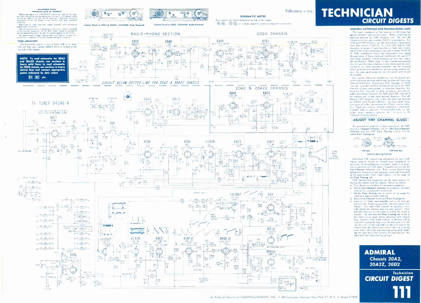
WAVEFORM DATAINVimMenns siren on
DANA
Waveforms taken with CONTRAST control set fully to the right,all other controls set for normal picture tin sync). DX Range Findercontrol set fully to the left Itit "0" position). Warning: Incorrectadjustment of the DX Range Finder control will cause waveformdistortion.
Waveforms at video and sync stages obtained with transmittedsignal input to receiver.
The oscilloscope sweep is adjusted for 30 cycles 1which is one-halfof the yertiul frequency), or for 7875 cycles (which is owe -half ofthe horizontal frequency) so that two pulses appear on the screen.
The peak.to.peak voltage 'endings shown are subject to some vari-ations due to response of the oscilloscope and parts tolerances.
FUSE LOCATIONThe horizontal output circuit jar fused with a 1u amp.,
250 volt fuse, part number 84A4-3 which is located on thetop side of the chassis.
NOTE: To read schematic for 20A2and 20A2Z chassis, use sections inheavy solid lines; to read schematicfor 20D2 chassis, use sections in heavydotted lines and connect appropriatepoints indicated by dots coded
1121 etc.
11111.1' IN OATEN
TV TUNER 94D46-4
11.1E, SWITCH SETTING SELICIS Ma OFCOILS 1101 1 002 FN Paint LTE51IE0
uaA
2002 CHASSIS1
n,
1510
1140
TV
7
0 102 6441 -112 M
PILOT LICHT
306_
68Z7RE AMP
0,0,
A0)030
5102 Clot no,OK 3-9
100
1106
1 IT)
3-9 0C01.1481(L 7014.414SLUG UNIUSTOISsr
Cowen' Nast in 20A2 4 20A2Z; CHANNEL Knob Itemarod.
ICICOLOR DOT T
T701-1702
M702 M701
M703CARTIIIRE
6470411010MOOR
8702PHO ON -OFF
M705
M706
5701E
Fs Ap0 RAOn
10 AC POWER P
ON 1501
4104
1500
11100
11021
asControl Pons! in 2002; CHANNEL Knelt Ransovissi.
RADIO-PHONO SECTION
L704£111116
6BE6CONVERTER
V701/1 Y
T 701
C104
68A6IF DIP0702 /$0
2
onir
February 1954SCHEMATIC NOTES
Run numbers are rubber stamped at the rear of the chassis.
0 0 O. On etc. indicate alignment points and alignment connections.
20D2 CHASSIS
TECHNICIANCIRCUIT DIGESTS
1702
/ =s1/1
2T1 IN
5103 010
150 T.00
8106
COI
100
0109100
MFG
CIRCUIT RELON DOTTED LINE FOR 2042 I 10421 01/45515
5011001 nlM IOTTON sibsOF OF
T301 1302
EIMELIO NIKES2 TEIFFIALS 5 I I
OF 1101
1105
;.J
i_102a
Cl05
5511
6J6
105 0106-1,
1106
0101
10
1F-5,sr ; 14-
H-
rT
010211
T20iI o4
so O o6no on
lvtiP0102.1
L109 COO
70:0"aLe
'09
4108
200
70
12
C2F0720
C201
6AU650340 ,7 AN)
v201 7201
10/ \x4303,
4202100
206 8203eAsoo-
005 130
6AL5WIC DII
V202or -rr
6206
500
C205
4510205 OA 11201
390
41f
.00r21I
16,:fof
S7018
6AV6AM DU 111C 6 SRO. IMP
0203
2/R209
1-1" tVOLUNE
C2,5NEC
C209
11208
ffil77014(
4212
0 I
I THE
0210 43 RH
'1 3
8210
82 5211
212
005
1215
211E6
()I- II
1181,
13150
88,11 /00 YAW/JO Y
6Y6C50550 OUTPUT
V204 5001 INf/ yapPfOY
/0Y 3 621
F.10Y TL.01
o WOK40
J1FD
1011011 6115 64203OF SOCKET 1011190f 11.116 SPEAKER
MCoi 64202 BLUE --
31=1111-12 3
TO PIII 07202
W 504 C501
C213
(-4 R2I5 1219
.0022 -1216 1220
8221tai C216 1200- BOWO 55
PNO RAD 1224
C OM A5 COO/55.
201110 BONFO
PHO RAD.-o--o 3291
71
-;VOla
8222
15223 1000
055701C DE 59
VOLUME
5206)1
NEC
0
20A2 8t 20A2Z CHASSIS6AV6
SOUND IMPV203 330
C24
5209Nv,e-
3904210
214IN
6
//Y
TONE
0210.0047=
C0011111Oa -.3
27-C214).01
4105' I MEC
52141 8217
4113 92 MEC 8215
365 00
%
6AS5SOUND OUTPLII
2204
/02 -
/JOY
8219
11005%
ASO I' /217.01
INY
0216
BOTTOM VIEW
Of SOCIET5201
2
TO PA 8 TO
OF 514 0501
BUJ
_ 64203SPEAKER ASSENEILT
1202.
.g
80 ME R22R222
2 5 163091
2100 211
C207/ 020111 .5 0 C101020 NEP. 60 Wilt ±417 MID
L1301:20_LC113
70
SY
6C86
5302
R30330
ST IF
v301
,JOr
R3048200 "5% R306
47
C10 0102
IJO
0104
1301717.
001 - 001 13011000
205
.00'
13101000
6CB6210 IfV302
Roll
JOY
S'.
I/26U8310 IF
A4)V3030
dal1302
11C
OY
2 -3,63014
C301 0"87/10-3-
11312
1000
6AL5DOE 0 OE 1 ACC
0304
COO
3oF2
T
H .3YC
"6F11,03t4
71.°i
Clot
'0"41-. I?'0
1100 13515
5305
1316eon,
567
0
0
4?, 1704
C311
Ri197
C311 Mt
Ills ~47 i OS'2110
01troicE111011
V301
0115Boo
1307ET
4-
-10033002^/3:1-3+
V201
1110110 MOTOR
64502
150,
To"
L105
0102
04
002
'MT -C) 1/--DTC)-4,-
2012 I 20121CHASSIS
V101
V305
0 0306
150,
M501
NTERLOCA
civic.1 /CIN5U4G
1 RECTIFIER
YELL0111;5v40
0501RIO
RE
RED
4
V40
R301 11110/C
1000
R301MN'2 /NEC
L 332
8321
5600C313-
630xi 45
12BY7r,DEO NIP
V305floor
432222iNibi
100C
CONTRAST
R32
33
T,1 !" !Pr' !r,Zest RFD ILL?
v
-.'111111
L 3-1 06' .4-:-22-'13'2::1 5-: J1117
-I
- -711326iT3 :°, ,y,.I -1
10335001.C.C43;3511F1311 r I. Rtili: 4333
2200
1
5, 101 i 7 2 V
3H-611410 KO ''_1:11701711111 -5
22 K 1 R331-1.-lers1;
01
R3249-15;02 ? --'-
.C.301 IS 0105/12210"sT4325 INV 011 IS II 3,17,
6.84 '0' POSIT/01 :- "1 _j 454030345,W.,
111111
.o
60
VERT
AND ANODE
VOLTAGE
16.5 IV
VERT 111111111111050 V
Ta50 V
NOME
50 V
VERT
E50V n
110512.,
-
i/212AVSYNC. SE P.
V40)13
JO Y
1.4711
_ 471
2 SPAR. FIELD6 OA CHORE 1501 ,
-eJUMPER IN ____--,170 y bi'5'.n.
8501 1201 cc, 0501 21502SPEAKER PLUG '
21011 A.7.11C20/01 L,-.1040913)III _LEO MID ___I! III
- _
0410
16 V
H0112.
011111111111111111
I/2 608
,F.00 I
R419 slot a,-
V3035SYNC. INV.
2200 11 1006
5%
406VEIT
L
4444
3.9 ME
4411
150 K
4121
4420
2201
/I
11771. 18vRORIZ
.(101
142?2200
0412
00)
44241004
5%
IA V
40112.
6AL5110)112. SYNC.
040314423-5Y
7c/Y
11
bod
7142700 22 T
A1,10941
4426
CO MO! 011-11
1401 3 1402 ...RIO!- ) 0106,,,,1401H-.-221 1200 1200
0047 950,2
"000T12- 004005 00015-- rT
1404
I /2 I2AUTVERT 05C04010
ti2Lis ku(vJOY
CUES -JOY
2 NEC R 1405
VE111 RED 1.2 NEC
204 vERTf-o/r--11(9_
NORIO.
35V
6SN7 CT80111. OSC.
PJOy 0404 /156'
54285600
/83
0410.0039
4431251
41112. NOLO
C420210 R434
C4I9
390 C42I 143,5ri-JOr
( 82
1430 R436
04 R432 I'1001
0122 :;PO
J
150 V
110112.
6BQ6 srHOR12. 01111111
040510% 5600
so 606VEIT.
/401,a)4 02
4 2- 0424
if 4439$8200
211
SY,
-I-ri", 6S4 7- ,__ ,
VERT.
C406-1- ,_ VIII OUTPUT / r402
\ 0402 BLUEI(
OF I.,,4 1 140y
[ 5409MEC
3 100011
R401 5iTt ''INEC ti011 0410 :7.5.n
i--§TrI IMO54052,5NC
5411011011 R410 3000.....A
4- 520MT 115
REO
1441
1404 4 In
5110A5
24A5
54401200
2111
NNW IfIr171PICT IS 01 HO/
1403A1412 VERTICAL
560 DEF ITIKE
5-6 4135.
413TOTAL
560
RED
RECTIE0R
0406
63C -12
2700 .011
IB3 CTCOU LATE C4213
R4I5
BO V
VERT
CHEER
CORO SHIELD
6AX4GTDAMPER
1 iA442 R111 1,4021000 Li, 1 MTH
" WHITE CONTROL
4:25
ME
410K
-0416 5433 HOW011141
44: CRE2E5NA-f
BLUE
040
Y
C4211-41 1443
000
T40373110411
DEF. YOKE
20 ro 38ATOTAL
WHITE rC430
C4262062 1 20420 CHASSIS
.011L403 -mom M40iMar
-0:4075 041
87'r 17411
2500V10112
avioo. SEE 11441/011181-1011 195011-C
3002 CHASSIS
1410-
M4013/1 AMP Ty SI°hIC
250 11
2IZP4131201221
2IZP4A12012 I 20021
CmMfal5E1,00.
ADMIRAL ANTENNAS AND TRANSMISSION LINESThe input impedance of this receiver is 300 ohms bal.
anced 1between antenna terminaLs). When connecting anexternal antenna for VHF reception only, 300 ohm Jiattransrnissinn line, part number 95A22.1 is mitinfartory. ForVHF and UHF reception, use 300 ohm tubular tranynissionline, part numbei 95A22-32. lot best VHF and/or UHFreception in areas of high humidity or high salt content,use 270 ohm foam transmission line, part number 95A22-34.In VHF installations where the transmission line paitesthrough reas of heavy electrical interference, the use of 75ohm large diameter coaxial transmission line may reducethe interference. When using 75 ohm coaxial transmissionline, connect the outer conductor to the chassis and the innerconductor to either antenna terminal; use the terminalwhich gives the most satisfactory picture on thc weakest sta-tion. In weak signal areas, the use of coaxial cable shouldbe avoided.
For outdoor television installations, we recommend anyof the following antennas which may be obtained from yourAdmiral distributor. Antenna kit AN5 (zig-zag or AN3B(conical) provides excellent all -channel reception for VHFchannels in most metropolitan or suburban locations. An-tenna kit ANI duo.vee ) or AN2 (trombone) provides ex-cellent all -channel reception for VHF and UHF channel, ifthe stations are in the same general direction. For all -channel UHF reception only, within 20 miles, use antennakit AN65A bow -tie and reflector); for long range recep-tion up to 65 miles, use antenna kit AN56A i corner reflector). Each kit contains. detailed installation instructions.Complete data on ntennas, recommended types for par-ticular areas, radiation patterns. etc.) is given in the
"Admiral Antenna Catalog-.
ADJUST VHF CHANNEL SLUGS
For purposes of simplicity in these instructions, the VHFreceiver's Channel Selector will be called Low -ChannelSelector and the VHF Fine Tuning control will be
called Fine Tuning tab.
f CnMMIL 400.7 .4. 44444
VHF -UHF Sets.
Channel Seltating Controls.
Individual VHF channel slug adjustment for each VHFstation received should be checked upon installation orservicing. If this adjustment is properly made, it is possi-ble to tune from one VHF station to another by turning theLow -Channel Selector only. With correct channel slugadjustment, best picture and adequate sound will be locatedat the approximate center (half rotation) of the range ofthe Fine Tuning tab.
VHF channel slug adjustment can be made without re-moving the chassis from the cabinet. Adjust as follows:a. Turn the set on and allow 15 minutese to warm up.b. Set the Low -Channel Selector for a station; set other
controls for normal picture and sound.c. Set the Fine Tuning tab at center of its range by
rotating it approximately half -way.d. Remove the Channel knobs and Fine Tuning tab.e. Insert a blade, non-metullie tool in the hole ad-
jacent to the channel tuning shaft (see front panel illus-tration). For each VHF channel in operation, care-fully adjust the channel slug for best picture. (Notethat this may not be the point at which the sound isloudest.) Be sure that the Fine Tuning tab is eel atthe center of its range before adjusting each channelslug. Caution: Only slight rotation of the slug will berequired; turning the slug in too far will cause it to fallinto the coil. (If the slug falls into the coil, remove thechassis from the cabinet and remove the coil from thetuner drum. Move the slug retaining spring aside, lightlytap the open end of the coil until the slug slips out. Re-place and reset slug retaining spring.)
ADMIRALChassis 20A2,20A2Z, 20D2
Technician
CIRCUIT DIGEST
1 1 1An Editorial Service of CALDWELL-CLEMENTS, INC. 480 Lexington Avenue, New York 17, N. Y. PLoza 9-7880

R303AlMEC
TECHNICIANCIRCUIT DIGESTS
February 1954
6CB6VID I -FV201
i-FA.G C
60B62ND VID I -F
V202138V
434g`
R204 0203 _?2061000 80 56
1-FA GC.
L
CON470
1,102 8-1
g MC I
71
45.25 Mc.:
6CB63P0 VID
V203 44 5M0
,r13 3 V
6-7 1..R208''106
C20601 R20
MF 220
R207470
0207690
6All6SOUND I -F AM6
VI01
CIO68
T203 1 0208910 DET
141*
R210
C205
470
140V
TrO
1/2 6T8RATIO DET
V1024
i/L 6T8AT A -F AMP
V1028
R105 0!O86104206336 Oi
R103 ic,34 8 t,6
47 1070 12200 rat 8108
CNO3 \ t.tvOL LIMEG
6W6G1,-1-F OUTPUT
0;03
I.2 SIR 09 RHO 8i 7-T4T-2
MEGMEG S
6CB6 140VSOURCE
- r--,
.276v
c,,.., R c2 P226 6227 004osiF 270 186 BRIGHTNESS,-----,viv -N,
._c 502B :
T6OF''It-- 280v
27B V
600--c4 14_RI -1 COMO CONNECTIONS NOT
208" USIVNENPICOHS611500:11111'2VOIND
VID AMP.V204
RFC ID T :g -..L20245096OR -OR -OR
R212{5600 R2(3
750CONTRAST
C5020
I 0210)1
- 5000
L203VI -VI -VI340,6
0214226
20OV
L204310414GRAY -GRAY -
GRAY
R -F
ACC
-FAOC-7
8221566
1301
R301106
2200 DOTTED CONNECTIONS NOT USED IN CHASSIS
I2AU7 WITH EVEN SERIAL NOS. BELOW 122892 ANDODD SERIAL NOS BELOW 125193.
SYNC. SEPARATOR SYNC. SPLITTER 8310 83220302 V3010 03015 3300 470150 0303
140,, _ _,\,\A,...,.63,,', ---140VI mF 95 .I0502,1II 7101010
_,_-3-10mF
R302R305 ME,. ,...-!,4 e 3300 a-
, R310
4782 -1 MO
470 6 H.2,I. 1II9 95 i4OV
P8t PC 3016304 63071506 B.2
MEG
1405
6AL5PHASE DET
V401
MAGNAVOXChassis 108A series
Technician
CIRCUIT DIGEST
112
. R3091330
Ca0124021006
41--rr
R4C3COK
I 226
I_ :
I 5000 5000-6- I
jsp2
4';0004
,A7,
10
CP.2'0F
-11--rVR2,5330K
,7,0 CPS
27, 71,C
R218 R2193306 I5K
4-^...V ^UV
' 6220mEG
22 4C2I6ICOO
Arr-00K
15750 CPS.007 P -O
4 C C
-200 r
111::'r- 101010 530 6
2 V , 111011,211L
YP11- ÷-4 7K T- yr,
R225 -*4 I33,3O
1 .
040 un
2COV
6S4B2v PP I \V c,i),I;UT60 CPS
2°°
RC390:06,c .7035
IP )111
041,1 307
61146 v2 s5MzEEG
9,5 V
3 R314
i.IMF 309-
60 CPS
O304
6 0 0took
6SN7GTA60 CPSV CSC 2701 P P
V3(
1'11'4 13A, 4V
R3,2 IC305I500--.047 R313!MEC
I 3 HOLD
z
6SN7GTACPS
47v PLp O.DC
0402
270V 0:6007
7
j-CE"sS/ Rr1";5IMF l'AIEC iN ti 0406
1500COO
IOV
2401H OSCCOIL
6406
4083900
M2DHF
82 6 3Is 409
8319COO
03203000
1606
2060409
1000
R41C256 +so CPS
MOLD ,to r.o
64121500
2809.
R413 040
H25OR
NER _ 4700
)
0410470R4I44700
08e
R4I54706
I.--. WAS 3342 INEARLY MODELS
TiDdels: CT, CU & CMU401A; CT, CU4CZA; CT, CU & Criu
401A; CT, CU & CMfJ 404A
6BQ6GH OUTPUT
1/40.5
3.
101010
60V
1,14121500
V206
16 KU
000 SENIAL NOS 1E108 113090
60 CPS1200v0PB
IB3GTH.V.HECT
V404
441310
MF
560 9
6A X 4GTDAMPERV5
0412
1,4E-7
5
6419
000
1402.
SIZE
0415047 MF
584204700
0414.047
OF
I(
L40211 LIN
5416
R5642I
4422 05018
TOME!F401
150MASLOW -SLOW
:BO.
4290V I409 I F L8D6
CMU CHASSIS TUNER CONNECTIONS
VHF TUNER
R FAGCIF
X 020162806 I 91
140V
CT CHASSIS TUNER CONNECTIONS
2009 2908. 6291!0:
t R5014,00
j1S501.4 .o.C56fr 40441
DOTTED CONNECTIONS NOT USED IN CHASSISWITH EVEN SERIAL NOS. BELOW 122892 ANDODD SERIAL NOS. BELOW 125193
.2009 62706 02809 02006
5U4GL.V. RECT.
V601
R/Y
PARTS LIST FOR THE 108A SERIES TELEVISION CHASSIS,CT, CU & CHU 401A; CT, CU & CMU 402A; CT, CU & CHU 403A; CT, CU & CHU 404A
314001. DESCRIPTION PART NO.
T 101T 1027 2017302T 103T 401
402T 301L 101L 201L 202L 203L 2041100L 5011202L 401L 402
110.TTTTT 12.40, N4L OotpotCoil, tat 1.F.0211, 3,4 I.F. 11 TrapCoil, 30 LI. S Dot.C 0, No aaaaaaaa 111416
T:::::47:75 N.C.Coil, lop., let I.F.Coil, 14.149, Or..Coll, V.I.Coll, Fes1149,Coil, Pos.., alto- aaaaaT aaaaaa tar, Vertical 041.1
ItaColl, DeflectleoCoil, 000000000 OseilletorC 00000 I,
360858-1.0025-1340861-1340552-I340883-11408110-1340.0-1300072-1340064-1160640-13.443-28340443-31360443-30340443-29320067-1340587-1340879-13401216-1
J501
511001. REECTOPTINI POST NO.
501C 101C 102C 103C 104C 1.C 1.C 107C 106C 1.c110C 301
C102C103C 204C 1040306C 207
.sets, FilterCerale Disc, .006 .24., 000 V.Cermic Dist, 60 mf., WO V
Capacitor, Cora.. Al.., .005 OR., KW) V.C oo male, DIsc, 470 =I., 500 V.Coulter,.lof, 400 V.Capacitor, Elect. 00000 4 .4., 00 V.Caput.., Pepoe, .01 mid., KO V.Copatitse, Pep., .01 ltd., 400 V.Ca 0000000 9220., .0047 22., 403 V.
I4., 180 V.Woo, 82 , 030 V. (OilCporitr, 00000 Klee, 91 5., 500 V.(CT
o 494.2. 012c, 00 at 0071 V.Comae 002, 400 220 V.Calais Disc, 470 osf., 000 V.C.o.s ', Console 0.7, .001 ord., 000 V.
Cs Carrie, Dl., .01 std., 000 V.Copeclbee, Coral, Disc, 600 000 V.
3110088-1180176-128.11-71110175-12/0062-117140212-300011-10250311-7210111-728.01-0VOW -203101161 1040080119-46110218-4240110-4200211-6280171-14280174-2240118-4
50002 DEKUPTION POT NO
c Aoe210
C 211C 211C 213E 214C 315C 216C 217C 301C 302C 303
304C 303C 306C 307C 208C 309L 401C 402C 43
2,32
4042.5
4011082394101141243414464.1101801003SO41011021031041001061071061041101111123011021032043011106307206
210
212211
2132142.216217215219220221
22432626271
2.21
200231232231301302303304303.63013093103113123133143133163113111312320321322
01402.34504.7
400409410411
:41445
16474IB
:g421
21501
503301501
001
.1401, 4.7 mt., 500 V.Ceposltrk 209903 002, 003 b0 V.
44por, .22 200 V.Capacitor, rrrrr 22 ofd. 200 V.C rrrrrr or, Cereal< Disc, .60s .ed.,
rrrrrr Doss .u. 600
tops , Gerrie Diee, .031 std. 500 V.Cana, , , .0033 aft, , 400 V.
tepee, .0022 fd. , 400 V.
4pacito r, Tare., 1.1 :7::'Y..0047.1e , 403
Cepeeltor, .047 fd., .3 V.Cepcltor suer 3900 oaf 400 V.
.1 .1e., 40D V.Leperitor, Pepe., .1 afd 470
Pepe, .047 44., 200 V.Oar,rrrrrrrrrrr .001 odd., 400 V.CH4eiter, rata., .4541 old., 400 vCapel.r, Pper, Id., 200 V..Copeeltor, rrrrr .12347- aid., 400 V.Cepecitr, taro, .047 014., 200 V.Capacitor, a., 1000 al., POO V.W. 240,... 500 V.Cepritor, 5ileee Ilc, 1f. 000 V.Leper , Peat, .001.84., 400 4.
511kor 14124, 470 t 500 V.
.... .047 t,40D .
Copocitor, tItetrolyttc, 10/3110 Se. 1.lolud..... .001 22., 400 V....... .027 std., 400 V.
Capacitor, ..... .1 W4., 100 V.Cs...... e, ElsOre ...... 30-40-10/310 V., 110/00 VCap<l
C.212, Olec,20-.0110-.144/3.10
090,1.1 1000 obso 12 I.
C41.644, 47 oboe, 4 ..Corbea, 31,000 oloe, .C
o,r 470,701 olo 4 1.O eci stop, Cola 1.2 6341,4, 2 411, 4 W.
Carla 1
4.:64": 270 oboe, 2 W ........... 111,11.1 or, C.2 4.6 470 or., 4 W.
oe.* 1000 ere, 4 .Gaeta 5200 oae, 2 51, 2 .Cobe 06 ea, 2 V.
CCa:loo".. 31.3 C.::: 470 *la, 4 W.B e. C'ar"."1,40 :600' eS42.10.4.1.1 5.
...... C::1.? 22 0006.91,4v.c.e. S.4,000 fa, 4 W.Cara 470,000 Oa, 4 Carla 470,000 ere,
O .11,.9, Carla 330,000 Mae, 2 0%, 4 Best CaCrn...". 10":°914e..7.O 114.1.4
Carlarba :1442'1.
Carla 2200 Ime, 1 1.
CCCFiblsboi
1100 erry ',N.' I.90,000 vas, 2 I
"*C'C:ar'r".1,4.4., 01710,00'77 461:7,.14:. IOW Version/. ,star, 3 227,.0,17,614:,. I V. 1C111.1
Co ro., 37,000 ea., 15. IONCarat 27,000 Ons, I I. 1061Me..., Carl. Am., .
12.1 ..... Ce,
rbeo, 470,000
Cara.. tr
424s, W.
0111
.1.1.ter, Ca 1,000 era, 4 .
.
Car....... , 476,000 ob., 2 VCarla, 0.2 oe.bo,
Seel Cara., 2700 sae t 51, 4 C2elos, 320 or., 11 Cara., 3324 re, 11, 4 Cara, 4.7 4Coe., 1000 Oa,
2..... :110..,0C04..e.a,ei. I
etr, 1
Ile el sr r, Carta., 0411 as 2 V.AINt ..... c1,, 6110,000Peteetle4142,11.11.r, 49142, 1000 elms, 4 W.trn o. ....soo. Cor:44, 100,010 oar. I 11""*. IN I',
Corbe ls, 100,000 464, a 43, 4 W.Carla, 470,00D or. , 41.Canoes, 4.7 4 W.
Seek Crboo, 1300 Gas, 2 011, .
.Seel Corr.. 611071"71:7,..2 '11; 4 W.0.1 Cora, 01,00 oloe 4
*71.''
W....:,866,wo oe:e, IS, 2..
26, 1006 Oro;23111., .:;;:. ".°°° *"*. '
C.a., 470,030 sloo, 2 Cerise, 100 oboe, 4
.31e Carlo, 1000 46-e, 1
Cara., 3 Oa, 1....E:: :?
W.. :::s,oco 2
Car.s, 22,003 One 1
Wire Iroosd axe NL, A
041 Le 1.1111 -VW..... ISO .4 sa..-Bly
....... .o.i..Tee,
280209-123250175-1203102-10200102-10210175-1250201-4270027-220017S-1400101-400211-3.119-9/3020-1300211-020202-1150161-11041adl-50211-I350211-1150213-2002111-260312-1223112-4220212-4200159-133250109-5060240161-1041250211-12110169-20611110211-53110211-11270027-33250211-11250211-11210201-13270021-22170021-51240219-2asool-230101-40230104-622301.-46230104-00230.4.190220126-15130104.106220104-44210094-13333004-2312.00-1.230106 -SS230094-197230104-42130104-61230104-62220024-101230104-47220104-58230044-127230104-5430.30210104-2123009,177220116-34230104 -la1301011-912301.-942301.-942M:094-119230104-74230094-205130044-201230.4-.7233105-.2.104-8230093-171
330104-77210122-37220104-912301.-4122010S-0122.06-792301.-79230100-79230104-741301.-44130104-1.230104-04230104-81230104-44220104-104330304-164330104-24230094-171230104-1.230104-.230108-09
20104-9111110126-192301.-713010,96
210136-402301.-40210121,3330100-81113010,310106-44.0044-107230014-1012101.-94220104-1042120106-7630044-
13004-179113230101-011.0136-311130094-314110104-1A210122-41230104-70220104-44130104-1103301.-4430104-3
2306-63100/11
30106-76230101-78wen,230100-11413113104-1
36-110038-11001.44160404-1100476-1
al11.64-1
RECTIFIERo.0
401_141
VEOUTPUT
74307.0 re:5.1.11107 O.
'010OUTeuT
074
602 6 6C66 6786lOc F 2ND
SOUND 1102223
STK 0111.7011PHASE 541.171111
01.1110 OUTPUT
TUBE LOCErl'650T
D4611 4_e
011621440401
101 0817.Easmetit
:It.(
.10DETECT.
2.0 61041.6
_ )
4047 P111 02DETECT.
An Editorial Service of CALDWELL-CLEMENTS, INC. 480 Lexington Avenue, New York 17, N. Y. PLaza 9-7880
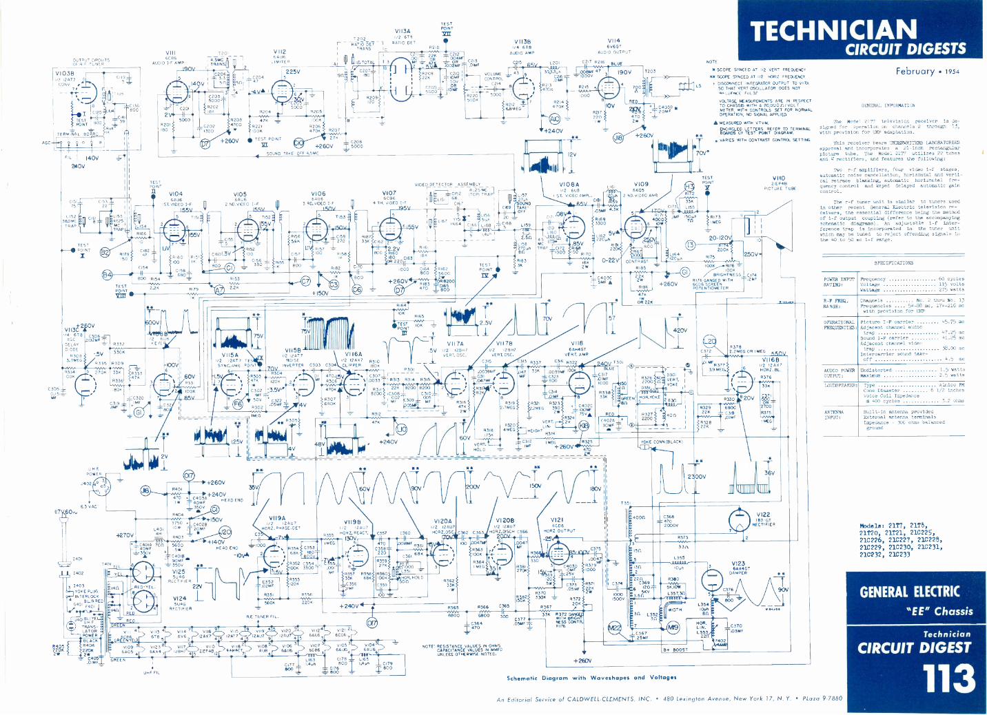
AGC
OUTPUT CIRCUITSOF R F TUNER
rtVI
0313I? 12517
CONY78
_ -
C120
TESTPOINT
TERMINAL 8026
800
IL 140V
340V
COG5 ;-
1
TIUS
800
014139 I
R14'.
ci51_L c1531_75
L152380MC
TRAP
VII/4 618AGC
DELAYDIODE
R3083.3 MEG
22
TESTPOINT
I
R334100K
C305 -0.15ZMF
N7, 0$,
1
L1534725MCTRAP
ILI54R166
VIII6CB6
AUDIO 1-F AMPIQ
7201
F1&441C206
I3.3 110204
V I 581 510147
L___ _J4
A iC2035000
R202186
TESTPOINT
V1046506
I ST. VIDEO I -F1.55V
6178ISO
0
C182 -47
CI54
`/ e00 R154
TESTPOINT
C306 -L-02MF -r
V- R332
600V
t/2 6u8E YE
TIN
6180100
155V
R15
C158_6801
..5V 3301
6335 R309
270
UHF.POWER
J402
6.3 VAC
1401
1403YOKE PlugINTERLOCK
BLAREDS4° F401
BLACKR40622062WC405.OIMF.
33K
6336
1809
C319.85F
6333476
3
-03204.iNF
+270V
6 II
IK
60V6331
1006
R203 476R2211006
TEST POINT
318.1
SOUND TAKE
VIO56AU6
2 NDVIDEO I -F155W
5 1152
filroL3V
G.1
R153
V
VI I3A1202 1/2 6T9
RATIO DET 1 RATIO DETTRANS IC
11111E1707AL
C208+260V Is000
OFF 4.5MC
V1066AU6
3 ROYCE° I -F[NO/
5 1153
iel$150V.
_ 1270R157 m-100 R158
IK
8156OAK
R152100 C157
0156 R330 116 800
LI
7
+150V
R182
IK
C 70
BOO
TESTPOINT
301
V1076C66
4 TH. VIDEO I -F
+260V
-1-_'°°041 C2I3.02MF1 .01MF
02I0 1 1 VOLUMECONTROL -
C214
50008220500K
VIDEO DETECTOR ASSEMBLYr-
1 WEL151
41.25 MCC152 (TOP) TRAP68
C167
5L167 7151 310(71L156
1664 0166
5 1.4(.14
R1625600
R 183
2WOR8200
470 :E100
L168
V11361/4 618
AUDIO AMP
0215
6212'68 MEG
C169
81-120
V1146V6GT
AUDIO OUTPUT
1.201
30}.39h
.08AF0216
L15727,111
SOUNDTAKE.OFF
-C168 1.159
1.'411
Q L1582700en
TESTPOINT
rz
R16336
R213470/1
R2144706
V108A V109L161
1/2 6U8 6505I ST. VIDEO AMPL. r'ITirrn- NO.viDEO AMR
CI81
11-88-Yvv...0w, 4.3665V
0171oeyA
DO
45-191.TaMC
ic,7211300
R1693300
ypeo5VA
2
0-22V CONTRA
Ri8
C173170V 1
Rill6 4NIf 4
**
TECHNICIANCIRCUIT DIGESTS
NOTE
it SCOPE SYNCED AT 112 vERT FRECUENCy
it* SCOPE SYNCED AT 1/2 $40212 FREOLIEECY
DISCCNNECT INTEGRATOR OUTPUT TO vh7ASO THAT VERT OSCILLATOR DOES NOTINFLUENCE F.11.3F
VcTAGE MEASUREMENTS ARE IN RESPECTTO CHASS6 WITH A to,000n$ VOL TMETER, WITH CONTROLS SET FOR NORMALOPERATION, NO SIGNAL APPLIED
A MEASURED WITH WAN.ENCiRCLED LETTERS REFER TO TERMINAL,.RDS OF TEST POINT DIAGRAM.
a VARIES WITH CONTRAST CONTROL SETTNG.
TESTPOINT
3r61 2
3361.155
800
Li64120ah
RI73I MEG
20-120
RI75
14174200K
C3280
2V
L40141.1
75V
VII5A1/2 MATT TESYNC.AM8 POINT
6
^L5V7
W
1:1Tg=15404
3750
+260V
,L25V
11
470 C403A+240VHEAD END
118+150VC402B.21eF
R403
C40IA 70n 5600-140MF 5,
3K1V t_I90MFC40113
aa
6 m. 350V R*
RECTIFIER T-VI255U4G
22V
VI 24 I_5U4G
RECTIFIER
%OH 4 VI 13
6ReEnEV1093
6T8
+140VHEAD END
VII66V62 12AK7
V1238 VII76405 64547 i2Bn,- 21E84Bi2 6040'
-r75V
InvR304 1.
R30347K 120K 2
C302 :3.5eIMF
VII5B12AT7
NOISEINVERTER C303
V 50V *C232 _R302 45MF
Yoh.IMEG
1R305
V
01F
C304
306
4706
R307
48V
VI 16A2 125117 6310
CLIPPER iSOK
C3075033
R3118200
6312
47K
6164
r"")6
POINTTEST
11/
P301r
6313 R314 6315
8165
tOK
t
.5V
--I
226 8200 8200
+240V
**
2.5V
V I I 7A
1/2 :28m7vERL
60VvERT.HOLD
VI1781/2 128117VERT OSC.
R319.7MEG
R3204 MEG
v1113
6A114GTVERT. AMP
C3I3 R337 C316 R322
MF C323
1C314
261,2., 1 R 323EG 390
2W
VERT 26
HEIGHTR374
MEG
+260V
C403CI5mF
C402A30MFI 01)1
22K2W
RI86-,NAAN-
476
OR 226
+260V
420V
D301 -VERT.YOKE
VI 102iEP413
PICTURE TUBE
10
250V.
1001),-.R176 -1006
EIRIGHTNESS_c174R 76 GANGED WITH6C06 SCREENPOTENTIOMETER
C372
DI MF9372
3.9 MEG.
63782.2MEG OR I MEG
114.1.
5,50VM
6330
R329 I 6E00022K
t R328226
V11661/2 12807HORZ. BL.
7 R376
e2OV
33K
ii$361
2900
R325
470
35V
VII9A1/2 i2AU7
HORZ. PHASE. DET
C3
1000
-lova 2
R.F. TUNER FIL.
Vii5 V11912517 MAU?
UHF FIL
V 1126AU6
LIMITER
8355
i MEG6354 0353
686BOOV180
6352 C354__ -1006 3300-1 .001
I MF
**
60V
VI198I 2 MAU?HORL REACT.
63531206
R356
220K
4 v120 V11249 12407 6111.163
VIIOIL vne2 v10e56118 6846
v10634 60864
L163C177 1.40800 I
8
**
C360
4700358
220
R35927K
)R357 R3583 636033K 68K 100K
-0356mF
+240V4 ---e
v121 26CD6
VM73 VI053 V1046A UG4 6AU64
CI78 LI65800 1 L448 C179
T 800
C359
R36i
C361 6"
1000L35I
501E150v
VI 20A1/2 I2AU7MORZ.OSC
110R.HOLD011
33KR362
I W
1
**
362 C363
100
R363100K
R364MEG
R365 6366
8800 6800
C364170
V12081/2 124U7
HORZ.OISCH C366
R381270K
300C377.0511F
ROTA RESISTANCE VALUES IN OHMSCAPACITANCE VALUES IN MMFDUNLESS OTHERWISE NOTED.
-11
180V
VI216CD6
HORZ OuTPUT
336
C375
R3791000
R37I
i2K
6372WITH 801NESS CONTR176
+260V
7351
YOKE CONFLIBLACK)
11*
300V36V
D 111111111 11111
2200369
MO5KV
511
C368:470
2COOW
R373
33A
L355
VI236Ax4GT
DAMPER
VI22153-GT
RECTIFIER
Schematic Diagram with Waveshapes and Voltages
February 1954
GENERAL INFORMATION
Tha Model 21T7 televislOn receiver is de-
signed for operation on channels 2 through 13,
with provision for UHF adaptation.
Thls receiver bears UNDERWRITERS IABORATORIESapproval and incorporates a 21 -inch rectangularpicture tube. The Model 2117 utilizes 22 tubesand 1. rectifiers, and features the following:
Tvo r -f amplifiers, four video 1-f stages,
automatic noise cancellation, horizontal and verti-cal retrace blanking, automatic horizontal fre-
quency control and keyed delayed automatic gaincontrol.
The r -f tuner unit is similar to tuners usedin other recent General Electric television re-ceivers, the essential difference being the methodof 1-f output coupling (refer to the accompanyingschematic diagxems). An adjustable 1-f inter-
ference trap is incorporated in the tuner unit
which may be tuned to reject offending signals inthe 40 to 50 mc 1-f range.
SPECIFICATIONS
POWER INFUTRATING:
Frequency 6o cycles
Voltage 115 voltsWattage 275 watts
R -F FM.RANGE:
Channels No. 2 thru No. 13Frequencies .... 54-88 mc, 174-216 MC
with provision for UM,
OPERATIONALFRRQUENCIF:3:
Picture I -F carrier 45.75 mcAdjacent channel audiotrap 47.25 mo
Sound I -F carrier 41.25 mcAdjacent channel videotrap 38.00 mc
Interoarrier take-off 4.5 mc
AUDIO POWEROUTPUT:
Undistorted . 1.5 watts
MX -1M= 2.5 watts
IDUI8PEAKER: Type Alnico PMCone Diameter 6 1/2 inchesVoice Coll ImpedanceM 400 cycles 3.2 ohms
ANTENNAINPUT:
Etuilt-in antenna providedExternal antenna terminalsImpedance - 300 ohms balancedground
Models: 2177, 211'8,21170, 21T21, 21C225,21C226, 21C227, 21C228,21C229, 21C230, 21C231,21C232, 21C233
GENERAL ELECTRIC
"EE" Chassis
Technician
CIRCUIT DIGEST
113An Editorial Service of CALDWFL1 CLEMENTS, INC. 480 Lexington Avenue, New York 17, N. Y. PLaza 9-7880

CAUTION NOTICE VIDEO I -F ALIGNMENT
GENERAL ELECTRIC
"EE" Chassis
Technician
CIRCUIT DIGEST
113
,00
120of,Afigle
Aso'.
444 99
5 100 SHOPN 1N cHANNEN POSITION
V101
6484Ie/RF
NiT
00
elZr7IeooDi -POLE No
L.0
C(23680680
SiO0A
SKTOB 510
Ii11648 it
C,28
',nee?
012.3 18xSIIIt'4o Ste
THE REGULAR Br VOLTAGES ARE DANGEROUS AND PRECAUTION SHOULD BE TAKEN WHEN THE CHASSIS IS REMOVED FROM THECABINET FOR SERVICE. THE HIGH VOLTAGE SUPPLY (16,000 VOLTS) AT THE PICTURE TUBE ANODE WILL GIVE AN UN-PLEASANT SHOCK BUT DOES NOT SUPPLY ENOUGH CURRENT TO GIVE A FATAL BURN OR SHOCK. HOWEVER, SECONDARY HUMANREACTIONS TO OTHERWISE HARMLESS SHOCKS HAVE BEEN KNOWN TO CAUSE INJURY. ALWAYS DISCHARGE THE PICTURE TUBEANODE TO THE RECEIVER CHASSIS BEFORE HANDLING THE TUBE. SINCE THE HIGH VOLTAGE IS OBTAINEM FROM THE BrVOLTAGE CERTAIN PORTIONS OF THE HIGH VOLTAGE GENERATING CIRCUIT ARE DANGEROUS AND EXTREME CAUTION SHOULD BEOBSERVED.THE PICTURE TUBE IS HIGHLY EVACUATED AND IF BROKEN, MASS FRAGMENTS WILL BE VIOLENTLY EXPFiben, WHEN
11411 90 11S PICTURE TUBE ALWAYS WEAR GOGGLES.
COO
Gs
or«
881680
13101
00
oda°
0103
;600
VAD3Ai c.300 050'503 '"" Ibe)12AT7
131ISO
uNING
4
V1026AK52.e RF
1,
)4sou SOO
Rne128
122
L
9 VI038CONV
(1,9)12 AT 7
ctoi1-I 8105
H4 IC136
oX
., BOO2208 j,
]1'
COAX ;FINE
BCC 1-F OUTPUT
c.,za sod
L 137s6 u h
0122
3SOO
IIP Tun, Schornotm Deogrorn
PRODUCTION CHANGES
1) Reduction of I -F Interference: - Ir. order toassist in the reduction of i-f Interference anadjacent channel trap shield can. RHS-112 and achassis bottom plate RHS-119 vas added to tie chas515. -
2) Video Amplifier: -The video amplifier :be
was changed from 6AQ5 to n 6CL6 type. Tr.e com-plete video amplifier circuitry nos been modfiedslightly using the following components: C4 'ABCD.L166, L16o R195 and R3,5.
3) Brightness Circuit.- This change was made toprovide greater consistency of raster size withrespect to changes in the brightness level. Re-ceivers incorporating this circuit may be identi-fied by the fact that a single unit brightnesscontrol potentiometer is used rather than a dualtype of the earlier production chassis.
REVISED BRIGHTNESS CONTROL CIRCUIT
'
07 (3,
41
AGE o -o t, o I
F, 250v0.0 140004
_J
R -F TUNER UNIT
5100 500NN IN L. no 2051110N
L.0, V68574 .'V1017-7-"
44
C1o1 Tr 9135
s'02 t 5
106
L
Ills12
V1034OSC
l',1)12AT7
CO
-II I
"81143
L ISO
c1 n
gm F letZEE TUNING
03
O° L 4 06146
V1026AK52.e RF
5.9 VI038CONV
V211241'7c 111
S 1105
iCISS
1120
BOO
LINE
OuTPo
1:40
TERM BOARD(BOTTOM
8200AGC VIEW(
211 25UVELC 140001.
501 COME EARL., snoTS USED A CHOKE= .C/a 521003 OF RIIL
REVISED "BIC" VERSION TUNER SCHEMATIC
RECEIVER ALIGNMENT
Although this tuner unit (Cat. No. RJX-051) isquite similar to tuner units used in recent re-ceivers it is not interchangeable with previousproduction tuner units because of changes in its1-f output coupling method. However, the r -f andoscillator alignment procedure is exactly the sameas used un the Model 17710 r -f tuner unit.
AUDI C. I -F ALIGNMENT
NOTES: -
1. Tune in a television signal. This will pro-vlae a 4.5 mc signal source for audio alignment.Keep the Volume control turned down unless thespeaker is connected.
E. Figure 2 shows a simple resistor networkneeded for the alignment of T202 secondary. These
MIL:"OFFLECTiee
Tie,.11113a
I mI STOsaes I
Tenet. ICM 9910courari
ayr
O
MT FOR 840
33 TEST
maneta000OeliSEvOLTaPle1011.10-evOLTS
11.45510EOWDMEseToas Fos
101KONE lalaleaNT.4Ano-ma MEMOT EM 5t OF COMM
090.000 03*52vaT5E oa Low1ST React
FIG. 2. T202 ALIGNMENT POINTS
two 100K resistors should be chosen as accuratelyas possible, for equal resistance. Be sure toremove these resistors after completing the align-ment. Align as follows: -
AURA' I -F ALIGNMENT CHART
STEP CONNECT VTVM OR20,000 CEPS/VOLTMETER
ADJUST METERINDICATION
REMARKS
1 To test point #6 andchassis.
L.I-. ' and 7201 (topand bottom cores) Adjust for
maximumdeflection
Voltage to be read isnegative with respect tochassis2 V115A, pin 2 and
Chassis.T202 primary,(bottom core)
3
Test Point #7 and centerof two 100K resistors.See Figure ..
T200 secondary, (topcore).
Adjust forcero voltsd -c output
Repeat steps 1, 2 and 3 toassure proper final adjust -went.
IM.RODUCTION:-
The following alignment data is divided into twoseparate procedures. Because of the extremelyhigh adjacent channel trap attenuation, the con-ventional method of sweep observation of teasetraps becomes difficult. Hence all traps shall bepre -tuned by applying an amplitude -modulated sig-nal and adjusted for minimum signal output.
The second portion of this procedure involvesthe shaping of the 1-f response curve in the con-ventional manner by the application of a sweepgenerator signal. During this procedure, observethe usual precautions regarding warm-up time,equipment cable lead dress and generator outputcable termination.
TRAP ALIGNMENT
GENERAL: -
As noted above, an AM signal is required fortrap alignment. In many cases, the technicianwill have a suitable AM signal generator availableIt should cover the range of 37 to 48 megacyclesat fundamental frequency, with available internal400 -cycle modulation. When this type of signal isused, the traps should be adjusted for minimum400 -cycle signal as observed on the oscilloscope.
Owners of General Electric sweep alignment equip-ment may obtain the required amplitude -modulatedcarrier frequencies by a simple manipulation of
the equipment controls as noted below.
Those technicians who do not have either of theabove equipment available are advised to omit thetrap alignment procedure. With the exception ofthe video amplifier 4.5 mc trap L160, the traps
will not become seriously mis-aligned due to tubechanges. The above -mentioned 4.5 mc trap may besweep -aligned, if desired, in which case a 4.5 mcsweep signal should be used in step 3, below. Thetrap may then be tuned to minimum response at 4.5mc which should be crystal marker calibrated.
Obtaining AM Output from G -E Sweep Equipment
The General Electric ST -4A Sweep Generator willprovide 60 -cycle square -wave amplitude -modulatedsignal. To obtain this signal proceed as follows:
1. Turn the sweep generator sweep width controlfully counter -clockwise. This will provide a
steady (zero sweep) carrier.
2. Turn the sweep generator blanking switch "on".This will square -wave -modulate the carrier at a60 -cycle rate.
3. The next step is to calibrate the frequencyof this AM carrier.
a). Turn the marker generator "on" and setthe dial to the desired frequency (4.5 mc, 38.0 mc,41.25 mc or 47.25 mc).
b.) Slowly tune the sweep generator throughthe desired frequency. As the desired frequencyis approached, a strong beat signal will be ob-served on the oscilloscope. At exact resonance, azero beat condition will be noticed, on each sideof which will appear a beat pattern. Minor sweepgenerator back -and -forth frequency drift may benoted. However, this drift is insignificant and
may be disregarded.
c.) Turn off the marker output.
LI. Apply this AM signal according to the in-structions in the chart below.
5. The signal observed on the oscilloscope ap-pears as two parallel lines. When the traps areproperly tuned the distance between these lineswill be at a minimum. NOTE: It may be necessaryto use full output of the sweep generator and nearmaximum oscilloscope gain to observe proper traptuning.
NOTES: -
1. Remove V121 plate cap. Temporarily connecta 2500 -ohm, 25 -watt resistor from No 260 V to chas-sis.
2. Remove V115 from its socket.
3. Turn the Volume control to minimum and thePicture Contrast control to maximum. Turn theBrightness control fully counter -clockwise.
4. Set Channel Selector to channel 11 position.Set the Fine Tuning control to its maximum counter-clockwise position.
5. Connect oscilloscope to test point #5 (Pio -tuie tube grid).
6. Allow receiver and test equipment to warm upfor. 20 minutes. Refer to figure 4 for trimmer lo-cation. Align as follows: -
TRAP ALIGNMENT CHART
TossFor
TUNER
STEP AM -GENERATORINPUT POINT
AM - GENERATORFREQUENCY
ADJUST FORMINIMUM OUTPUT
REMARKS
1
Test Point #1(R -F Tuner Unit)
41.25 mc 1151
47.25 mc L153 May require maximum oscilloscopevertical gain
2 38.0 mc L152May require maximum oscilloscopevertical gain. If insufficient"null" is observed, turn core ofL154 2 or 3 turns into coil.
3 Test Point #4(Diode Load)
4.5 mc L160Connect detector network betweenoscilloscope input and receivertest point #5 as shown in fig-ure 3. Remove V107 during thisstep.
ALIGNMINT.CHART
STEPCONNECT SWEEPGENERATOR ADJUST DESIRED REiPONSF REMARKS
1
Into Test Point #2and chassis thru.001 mf. Centersweep frequencyapprox. 44.0 mc.Sweep width approx.10 mc.
T151 for proper 42.0 mcresponse.TI53 for proper 45.'5 meresponse.T152 & 1167 for zero"tilt" and maximum gainwithout "saddle -back".
c 25K
42.0 .0,
s,, 'Is's,.
.4 oo.
Make indicated adjustmentsto obtain maximum gain con -
sistent wit, proper curve.Comers of curve peak mustshow slight rounding. Peakof curve may extend 10 %(max. beyond 45.0 an marker.
Into Test Point #1and chassis thru.001 mf. Centersweep frequencyapprox. 44.0 mc.Sveep width approx.10 mc.
L154 and 7105 (R -F Tuner)for maximum gain andproper marker position.
4. 25.4G
Cbtain maximum gain andproper marker positions.Peak ofkcurve should extend15% beyond 45.0 mc marker,with slight rounding.
42., /,,
4s% 45 ',Mt
42.sec cos45MC-MO%
3 Into H -F Tuner in-put thru balancedadapter and 300-ohm pad and line.Sweep channels2-13. Sweep widthapprox. 10 mc.
C108 (R -F Tuner'-
Align for zero "tilt" on ch. 12. Check chs. 7-13and make further compromise adjustment so thAt eachchannel will have no more than t205 "tilt" with theFine Tuning adjusted to provide the proper sound andpicture 1-f markers.
1124 & 1127 (R -F TunerAlign for zero "tilt" on channels 3 & 6. Check chs.2-6 and make further compromise adjustment, so thateach channel will have no more than /20% "tilt" withthe Pine Tuning adjusted to provide the proper soundand picture 1-f markers.
T401
TEsT e0INT It -
T,
TEST
A.,PONT
T TEST.4 -Poor
TEST s
POW
TEST TESTPCIEJJ,It 0
50)
sownN
b. aTEST vOleTIE
Jgatatown
Tont Point Minton.
L-. 1
aT.,
.....;.
neat
Tube end Trimmer Wootton
R NETWRII
I -F SYSTEM SWEEP ALIGNMENT
GENERAL: -
Now that the traps have been set at their properfrequencies the 1-f curve may be shaped.
NOTES: -
1. Turn Picture Contrast control to minimum.
2. Connect oscilloscope to test point #3 (junc-tion of R164 and R165). This vas shown in erroras test point #7 in publication 5-2177.
2. Apply a negative 6 -volt battery bias voltageto test point #9. Connect positive lead ofbattery to chassis.
4. Calibrate the vertical gain of the oscillo-scope to provide a 2 -inch deflection with appliedsignal, 1 5/4 volts peak -to -peak.
5. Note that the following procedure uses 45.0mcas the 100% reference point. Maintain the sweepgenerator output so that the baseline -to -45.0 mc-
marker amplitude equals 2 inches. Align as fol-lows,-
An Editorial Service of CALDWELL-CLEMENTS, INC. 480 Lexington Avenue, New York 17, N. Y. PLaza 9-7880 An Editorial Service of CALDWELL-CLEMENM, INC. 480 Lexington Avenue, New York 17, N. Y. PLaza 9-7880

February 1954WARNING
At all times during operation the chassis is at 125 volts DC potential above ground and it alsomay be of the line voltage potential depending on how the line cord plug is inserted in the power
receptacle.
Extreme caution must be observed when working with the chassis outside the cabinet and whenpower is applied to the receiver with Ike cabinet back removed. SEVERE SHOCK may result from
confect with chassis,
An isolation transformer between the line plug and power receptacle must be used when serviceis required. This removes AC line shock hazards. Damage to the receiver and test equipment mayresult without the use of an isolation transformer.
K.Aa7
v -H3
S6AV6
ERGS
12
GALA
V312AT7
v-26607A
ICU.
V-511064
siwe it wasLu4
40sER40CAI
:LT UAL,PER
MOMM11LuS
e we
6643V -1T
' ALS9
2245
v'I2AU43T
16506
V 206AX4
02
v-715515
,6
%COG
r1.31571615- ---IRLS;STOR WATTAGE S REPRESENTED IN III WATT VI-E THENwISE NOCATEO DENOTES 1000 DENDTES Z1000000
ALL MITONS ARE SNOWN IN THE POSITION TOO VNfA
WERETIf IIFTHK:C2'0',"SS ;"15"T's7Lira TAM40.4L ORER0r100.510 SIGNAL /OUT MCI LINE VOLTAGE AT HSV RC WHERECONTROL SETTINGS AFFECT vC4.110E READINGS THE oArNDAR4 APO mmINvNME INDCATED (SEE WANING
alEFLYCUM1=14GP. ON PLATE CAPS OF THE 1133 CALICOPIECTiElEtt AND 258013 .12012014TAL FuLSE APLIFIER CO 100T MEASuRE THISWl. DCRIE at. Ina ANOOE VOLTME WITH v PROSErat THE DC RESISTAKE FE0403 ROCOCO .TAR THE
COLS NAVE MEE 14 TAKEN WITH AN OHMMETER DAECT,BRASSTME COL DENG MEASURED COILS SHOWN 4.THOuT A RESISTANCE
REA0440 HAVE A DC RESISTANCE OF LESS THAN ONE OHM TOLERANCE_10 IS PERNISSIBLE CO NOT MEASURE WITH SET TuRNE0
HE WAVE FORMS ILLVSTRATED ARE EXACT COPIES CF5 ALASORATORT 09CILLOSCOPE THE WAVE FORMS WERE
TANEN UNDER POPPIAL OPERATNG CONDITONS, WITH TAINSIATTED :ANALANO THE PICTURE IN SYNC AT ALL TIMES WITH LARK.75(2 FORM IS THEPEAR'TO-PEAR va.TAGE NO A HOWIZONTAL OR VERTICAL MCITAT1C.REPRESENTING vERTiCAL 160 CYCLES) DR 140PiZONTAL 115,750 CTCLES)SCOPE FRED TNT WAVE FORM APO PEAK TO PEAR vOLTAGE READINGSIAN VARY SONEwmAT DEPENOPO CP. THE STRENGTH OF TIE SIGNAL. TMENCTLNE INFORMATIoN BEING TRANSmiTTED AND TIE ADJUSTMENT THEvARIOUS CONTRC4.3 AMEN CHECKANG WAVE roews.ccreact 05050LEM:IFNI. TIE OSCILLDSCOPE TO T.5 C.553 MO THE HOT LEAD TO 'HEPOSITION INDICATED 67 THE ARK/.
REPLACEMENT PARTS LISTRef No Part No. Description Ref No. Part No Description
20MCCapacitors
0200 8641892 22 mmf. ceramicC101 A.8 80.17142 5.20 mmf, dual trirranetC101 86.16045 110 mmf, ceramicC203 86-108P0 6 rrant. ceramic feedC104 86-11612 5000 nun). ceramic0705 8G-12495.8 1.5 mmf, ceramicC206 86.21747 1000 mmf. ceramicC207 201.12333 Ttimmer condenserC108 86.13101 1000 own), ceramicC109 86.12495.7 1.0 wnf, ceramicC210 86.13201 1000 men! ceremicC2Il 86.13017 15 mmf. ceramicC212 101.16141 Trimmer condenserC713 86,12495.1 1.0 mmf, ceramicC2I4 2014/333 Trimmer condenser0215 86.13101 1000 mmf, crarnicC216 8649314 4 rnml, ceramic0217 101./2333 Trimmer condenserC118 86.10878 1000 mmf, feed *Fru0219.720 86.13201 1000 non). ceramicC21I 86.12495.2 10 mmf, ceramic0121 86.19568 2.5 own). ceramicC113 86.11891 51 mrni, ceramicC224 101.22333 Trimmer condenserC215-176 86.20878 1000 mmf, ceramic feedC227 86.15224 7 mmf. ceramic0728 101.21333 Trimmer condenserC129 86-13201 1000 'Peel. ceramicC230 86.20879 6 rranf ceramic feed Ow,.C231 86.20878 1000 rramf ceramic feed TO,,
ResistorsR200 9131.94 470K ohm, V, watt, 10.,R101 981.62 1000 ohm, 1/2 watt, 109',13102 981.74 10K ohm, V, watt, 109,-,13203 981-38 10 ohm, V, watt, 101'aR204 981.78 22K ohm, v, waft, 10"R205 981.27 2/0K ohm, V, watt, 201,.R206 981.66 2200 ohm. V, wait, 10'.R207 981-74 10K ohm, 1/2 waft. 101-5208 981.13 1000 ohm, 1/2 watt, 201209 981.50 100 ohrn, v, wait. 10c.
VHF TUNER
T200T201
11001201L2323263L2041205L2061707208
1.209
S200-201202 201
Chokes, Transformers, Coils3E 22082 H B +len, 1,11510,,e
13E 2167111M 2078111M 2078017E 11046115 1714013E.11046131 17140164 .10777I 6A.17128130.1215513E 17140
L B Antenna Nonslorann,CescodeCalcode coilL RF primary coilH B RF chest., coilL 8 RI secondary coilH.B.RF secondary coilFilament coilOF choke coilL B Oscillator coilH B 074.11.10r Voll
Miscell71 16310 SI.d eg 1ch contact
201-22081
700,20772201.2076651.16311200.2077910 20893200 18824100.21803200 20881201 10769
49A 20763SM. 188072M.1627643A2.544451A1571351A 1716251 A2120051A1571551A-171612C-18004.12C.18805.149A.187992M.18P0021,4-712787M-19150.178-19313711.13050
Antenna trenslchmer assembly(Includes C200 C201A B C7048200, 7200 and T101)
Antenna shield assembleCod ahgnment stripSpook contact kolderSw;tch lever aernEloS.,ch lever brsiacket
Rem cShaft and front camBottom coverCapacitor plate aemble(Includes C218,126.ts216 730./311Hair p,n wingTreadle barCore munting clipsHey-nui.o 2.56.3 16
Iron core (white) for L209Iron cor (brown( For 1203-105Iron core (pink) for L108Iron CO, ( blue) for 1202Iron core (orange) for L204Front end plateRear end PktLink springFront linkRear linkFlat springTube shieldAntenna terminal board
C300Cl01C302C303C304.305C306C3070708C309-310C311C312.3130314C315C316C317C318.319C320
Capacitors86.19502 10 mmf, ceramic86.13962 5000 mmf, ceramic disk8E3-8 100 mmf, mica86.13101 1000 mmf, ceramic
Included with 13041000 mmf, ceramic1000 mmf, ceramic5000 sssi ssrsnns di"
8G-1952186.1320180-13962861 320186.71105
86.139628G-1320186-139628G-1 310186-1216686-12495-5
1000 mmf, ceramic680 mmf, mramicIncluded with L3D95000 mmf. ceramic disk1000 most, ceramic5000 mmf, ceramic dish1000 mmf, ceramic5 mmf, ceramic3.3 mmf. ceramic
20MC I F AMPLIFIER
83008301R302R303R304305R306R307R308.309R3I1R3I2R313
982-79981.73961-629131.46981-62981.80981-46
10 981-62
9131-499E11.62
Resistors27K ohm, 1 watt, 100,8200 ohm, watt, 10%1000 ohm, V, watt, 10%47 ohm, w 0+ ID%
V1000 ohm, , watt 10%33K ohm. V, watt, 10%47 ohm, 1/2 watt 10%1000 ohm, ..t. 10%Included with 130982 ohm, V, Het. 70%woo ohm, w ot. 70%
R314 9131.69 3900 ohm, V, watt, 10Elr.43I 5 941-80 13K ohm.
Chokes, Transformers, Coils1300 13812939 Output IF lren%ForreerL300 201-22924 Converter coil
SCHEMATIC DIAGRAM
TECHNICIANCIRCUIT DIGESTS
UNEANTENNATERMINAL
OSCCryIN82vC-. CAVITY
CRYSTAL
ci1_
0100
H0O 'Co LIO0 COssoo col
-11100C1,002
4 L09023
UO4
CA VSTACHECK 4
OMIT
"Ts'ICIO5A
I '°°°CIOS
m. 4M, Mt. aM MN. MOP MID MO Mt =MP IMP !MIMI 11 MI
LO3
4102 p08
2217000
0
6AF4UNPOSc
.1111:4
OSC WNW 470010
POINT 1C,00 =
4,- RV: C0038 L'
1 4104 = 000
UHF-VHESWITCH
NOTE PLUG NOT USED WHENUM' TUNER IS INCORPORATED.
.1;1.2. I
1, F PLUG
PLUG
IGO
V-19
6BK7CASCODE Am
8108
3900
LIOR
11107,500
22
T201
C20
4711
V PI FATE..TERMINALS
Nv.w.
.1.
A2011000
} 4202
C210
235V
5201
0215000 r
TC2.18.1.C2i7
000
l206 = =
L
5204225
`deb
8208220K
R208
T moo
V-312AT7L)ITIVERT OSC
4500
1
C231 000
P208
020°89 2 3 0
T
2200 10221 C22244 10 4.2
RFTEST
POINT
10221T0000
TV. 5203
C223414RIOT SI T
ov 4, 82044,2200 L208
L209
.000 T
322 7
C228 1000
404
0M -0,F SWITCHOM VOLUME
CONTROL
R4411--nTHESIS TORTYPE FUSE
10447 "150
IS MCS5
6AV6CAMEO2.14
07F
470N
25C5TROT)
.054
C414,HOW
30CMI
TOI
C2
IMF IFJUMPER PLUG
C300
V-46C86
0302
3303
8300 "CC*2;4
_L
L30
340e
2400
83018200
83021000
L304
830341
_r_C107 83041000
C308
3000
13°C5 6
03082000I
1000
u:,;C:1:17ER
630 ACE,
RP
L303E
118
1
C309
1-11000
v-36CB62,0 IF
L509 IrAt-a,.6r.TC3130
or132V
147'?7"Trm L304
70i4(
W L309
1310
--"*-1.0311 1312 61141
I680 az SWOT
uocL303
UHF POWER119
vJUMPER 1000PLUO
0405
o-$0
yr MOO
PLUG
41150
CSOemoo, r56!Satea
_MY
30 -00
1307
E DETECTOROUTPUT
34 8439loom
Y'19
10
1:0
Asox204
czoa
1.77W:4
T.
3331
54
C42404714
V -T50 Y IfsI2AUTv e C
350 -MOON
500A
250A
Im
ILLS
IS5
_C3C644-4714F
450 .400 C6a5410
R44.225
00
8419
1.10:50 VAL T403
654 8443OUTPU1 1805
P.I2A;
75010-354
=OP"'11442.11-52V...
1V.1.121LIM 8300D 4r
lit
L3I44101111
83143900
SOW PLUG
R44
Mt
040142011TAL
VOLE NAIG
Rel No. Part No, Description Rel. No. Pe.1 No. DeSCNption
L3L11
L301.303L304L3051104L3071308L3091310L311L311 3131314L315
16A-21656 RI choke coil16A17937 Filament c6ohs cod201,22917 IF coil assembly16A-17937 Filament choke coil16A18676 RI choke coil16A-17937 Filament choko coil164,18626 RF choke coil101.11919 IF coil assembly101.15608 RF choke coil16A.17937 Filament thole coil16A.11923 Peaking coil164.19365 Peaking coil101-20165 Peaking coil
Miscellaneous20.22153 Chassis bolt bracket39A-12252 Bracket insulator15C16007 7 -pin, tube socket2M-17589 Shield base15010440 RF Dower socket
198.19922
201.21651198.1191019A217447n-2781120,128093A22812200.279303M.12389290.72395700.22933200.21934098.1 23108000-1272238,1 23018430 1996728.229152C-71921201-229401H.17588
UHF IF socket end IF alignmentinput socket
UHF IF jumper plugUHF Tuner power socketUHF POW., iumper plugAC mounting board brecketTuning shalt bracketTuning shaftFollower plate and springDrivholt pin (3 used)Ring retainer (2 used)Drive pulley and bushingDrive cord and spring assemblyCircular retaining ringShield of lor 1304.309Cardboard insulator for aboveCoil fastener for 1300.304 309SALS bottom socket shieldIF socket shield plateF Output lead assemblytube shield
Models: M -2131A,C -2137A & C-21381 RAYTHEON
Chassis 21 T 11
Technician
CIRCUIT DIGEST
114An Editorial Service of CALDWELL-CLEMENTS, INC. 480 Lexington Avenue, New York 17, N. Y. PLaza 9-7880

RAYTHEONChassis 2 171 1
TexhAlcran
CIRCUIT DIGEST
114IIEPLACEMF:NT PAIITS LIST cconven
Ref. No. Part No. Description
C4000401C4024B C
0403C404C405C406C407C401C409C410C411C4I2C413C4144 B C
C4I5 81 20582C416 8622132C417 81 20382C4111 8J-16084C419 86-21708C410 81 16081C421 TIJ 16095C472 174 22376C423 8120580C424 8J-16081C425 8116096C426 81 16083C427 81 160970428 13C 22285C429 BC 227860410 8121505C431 86 11892C432 873 123C433 853 117C434 873 1I7C435 873 123C436 873 IIIC437 81 16082C438 8120578 0077"veld 100 volt moldedC439 873-119 310 mmf wcn0440 81 20613 0039 mfd 600 volt weldedC441 Included -016 7405C441 114 22376 Printed crrcuo
ResistorsR400R401R402R403R404R405R406R407R4OBR409R410R411R412.413R4I4R415R4I6R417841884198470R411
84228423R4148425R426R427R428R419R430R43184128411 4348435R436843784388439R440R441R442
21" DEFLECTION CHASSISCapacitors
81 16082 .22 old, 200 vol. molded81 16085 1 wild. 200 volt, molded80-22523 10 mfd 300 volt 60 mfd 50 volt
100 old 300 volt, 10.686.13961 5000 nwri4 ceramic d.s181 16083 .1 refit 400 volt, molded81 19751 022 add. 400 volt, moldedPG -17166 S rwei, ceramrc8612198 47 rrowl ceram1c86 13967 5000 mref ceram,c
Included re* 74008120634 .0022 mfd, 400 volt molded873.124 820 mmf. 300 volt In.cn
Included w1th 7400PG 13961 5000 rnmf ceramrcBC 21524 10 old. 15 volt 10 mfd 15 volt
20 mfd. 300 volt. 111.0.01 old 200 volt. rnolded5000 mrnf cerarnrc01 mid. 200 volt, molded01 mfd. 400 vol. molded
.01 ofd, cerarelc047 old, 400 volt molded22 mfd. 400 vol. moldedPrinted circuit0047 wild 100 volt molded047 old. 400 volt. molded047 old. 200 volt molded
1 old 400 volt moldedmid 600 volt molded
100 old 150 volt 111,100 wild 150 volt Iv,41 mfd 400 volt molded22 mml680 reref 300 .011 cn
720 Tr^i 500 vol. rwcw87 moot 500 volt rw re680 reml 300 V01. P700,1
220 mref 500 volt m.c.22 old 200 volt melded
981.9810B 17318961-92981.829BI 1009B1-82981.76984.829(31-7710B-21311981.76981-88984.68901 70108-21456981.90981.629131-65981.68381 86981 51984 71981 46981.1810A 27305981 78981110981 909BI 949112 519C1 1070961 102981 B29BI 869BI 10810E1173189BI 102981 86108 22)07981 10110E1 27104
I rnegohre, watt 10Sync Stabilaer control 3 meg3301 ohm, 1/2 watt 10
47K ohm ,1541 ohm 0
47K ohm 7 - ,18K ohm - 10Acture CC,' 530 06w15K ohm s 3, r 10150K ohm 3 or 10
3300 ohm 2 3.° 10''
4700 ohm o) 108r,91,1ness - 5001 ohm2201 ohm - or 10
1000 ohm 00 101800 010- -0 10
3307 3 , 30
8200.ow- 2 wet. 100,.41 ohm ' watt, 1041,22K ohm 1/1 we., 10",,0' 04 Volume control 1 meg77K ohm, 1/, watt. 10'10 megehre 14, watt 10
71041 ohm 2 104101 ohm 14, watt, 10120 ohm I .,alt. 107,3 9 ohm, 1., watt 10
2 2 megolwn watt 1047K ohm. ", watt 10100K ohm 07) watt 10
680090300. watt 10Vertical Hold 0000,01 3 wog7 2 mego6re we. 10''100K ohm ' ..111 10'V...1041 36e control 1501 ohm
1 2 wegohre ' watt 10
V. ,r rvI 6,164 contr.? 6000
8443 987 39 r 86K 36.4, I wet 10R444445 981 07 1e,00 06w we's 10R446 16M 22301 Res rsr, type lupR447 964 27831 150 03,, IS 10 -R448 SON 27775 2100 ..he 10 watt 10'
15000600 10 coo 108449 9BI 88 1501 03,01. 11, 0a11. 10#450 451 981 102 7 7 wegolwe U1 weft 108457 981 88 150K ohm V, watt 10R453 481 94 4100 ohm watt 108454 981 84 6841 ohm weft 10R455 OBI 96 680K chin 142 watt 10R456 9BI 64 1500 ohm 044 10R457 10811115 Her.reetel Hold 6,4,01 100K
06m8458 9131 96 680K crises watt. 10R459 9E12 14 10K ohm1 watt. 10'R460 081.90 220K ohm. V? watt 10
Transformers, Coils1400 114 22303 Rot, Detector transformer1401 12C 27508 Aud,o Output trweslorrew7402 726a 18741 Vert,cal Oscillator iransfcrre,1403 I2C 10161 2 rransforw,1404 120 22586 F,lemon1 transformer7405 11001 201.17691 041.ti..,, yoke assembly
8444 445C44I I
Rf, No. Part No_ Description
21" DEFLECTION CHASSIS Icont'eli14001401.4026403 (InaC406-407 8R420
1404L405 (Intl.
C440
16A 20021164-19486201 22581
16A 71114201 71301
Pealr1ng coil 1130UH1P.1179 so, I380UH)V'cloc, Trap Coil assns.
Frlter choke 126 HIH Hold cod wan.
Misc.!,21112263 Chassi, boll bracket394,22252 Bracket insulator41 M.22446 Fromt control insulator15C.16007 7 -pin tube socket2M-17589 7 -pin tube shield baseMT 7588 Tube shield
158.01968 654 tube socket15C21595 9 pin socket and sprieg a x00200-12737 9 -pin socket and adapter plate194.22525 Speaker socket198-22671 Vertical yoke socket1513-21186 Lytic moun11ng plate for 04291913.12541 H. V power socket144-22266 R446 terminal board14421267 Video input terminal board20.22564 Pilot light mounting bracket37422512 Pilot light shield47422513 1. H. Pilot Irght socket bracket474-21592 R. H. Pilot light socket brach.10.11002 Mounting clip for C4302D-12063 Mounting clip for C400.421.437211.20097 Selenium rectrfrer437,15390 Control mounting nut (8 used)514.11740 Iron core for 6405430.11666.1 Speed clip for 640520122551 AC Line cable asset.
(Includes 3 items Below)4IM-72434 Idount.ng plate194 19446 AC receptacle554.19819 8.rnr6 sleev1ng15131127E69 CRT socket and cable201,22441 RF power plug and cable514-22370 Iron core for 6403430.19967 Coil tube Testae,- for 140346A 10193 Pilot I,ght bulb148.20183 Welded w1re
C500C501C502C503C504C505C506C507
R500#50188028503R504R505R506
21" H.V. SUPPLYCapacitors
86 19863 47 wes0 cerww,c873.121 470 remf SOO von rercn8170589 0015 cold. 400 ...If molded8C-22544 50 old 450 volt, lyric8116081 041 wild 400 volt, molded8121505 47 old 400 volt molded136 21440 470 meg 1000 volt, crramw81 16082 22 old 200 vol. molded
981-88981 .50981 94984-7498265984.709C1.1070
Resistors
10C 3-470K r. e-100 oh..'1800 oke-4700 ohm3 9 ohm
Chokes, Transformers. C01160500 701.72196 H s
20-22253 r
Miscellaneous394.22151 Bracket .158.22335 Vole sort/ 156.10440 25806 lobe sccio158.20860 6A04 tube socket14412540 Dual H V power plug201.20811.1 183 Socket vssemblvI4C.12282 I H V Coble assembly1821263 Shield can28.12264 Sh1eId can cover30A.19991 Insulator Ow494-11633 Ring (1 used)20-11490 Mounang clip for C5032041053 Mountrng clip for C50720 11002 Mo0w1ng cl.p ler C505
21" C.R.T. MOUNTING ASSEMBLY1405 201-21697 Dellectioe yoke assembly
244,27664 Tube 11rap2D-21666 Tube Orap bracket20.12660 Tube mounting bracket23M-02106 Carriage boll 12 used)43414.22707 Carriage bolt nut10-12658 Tube supoot bracket10-21662 Yoe mounting bracket25M-11653 Retainer ring
Tie rodLrnearoy magnet
31e1 2265916M-22602166.4,22601164 206971644.1990641E155693218.20807201,22489201 22690
Center,ng 'eager.Ion trap megnetloneardy A An cosh,on w ng colYoke wng nutH Vole cable and plug Vole cable and plug
21 SUBURBAN CABINET PARTS740.22818 CaloWet 1M 11111240-22897 Calo1ne1 10 21371140-21893 Cabo,. IC 7138)30M-11485 Safety glass254420871 Rubber cuth'on 13 used)2134-22755 Back support20-21257.4136 Glass support channel2D -21257-A135 Glass support IC 2138 only;25H-11507 Gasket3106.21460 7101 Channel p1011ips screws3206.21460.7133 Channel pkrIlrEss screws IC 1138
only)25M-27756.1 Al 19 Mask2SM-22756-A135 Masi IC 1138 only)200-22559 Escutcheon assembly
(Includes 10 !ferns below)SC.22535 Escutcheon100-27600 0141 plate and pulley assembly430-22611 Push on fas1entr 11 used)60-22589 VHF dial scale6D-12590 UHF door! scaleSC 22397 Raytheon crest21,4 22517 Retainer spring1341 12511 Bead 0114.0200 22603 Pointer pad and bei
VIDEO IF ALIGNMENT
StepNo.
Signal 7Generator
Freq. (mc.)
1 26.3
2
SweepGenerator{mg (mc.)
Signal I
Input OutputPoint Point
Remarks Adjust Response
25IF alignment r S.°Po of IF !
defector 'inputoutput
Connect shortbetween pin
5 and 0 of tube 5
T300 pri. (top)1300 sec, (bot.)
Coupling rod_i
.__ _ _ _
Marke s should fall 10% down. If response curve is not as shown., readjust coupling rod (bottom T300)for proper bandwidth and 1300 primary and secondary for flat response and maximum gain.
21.2Converter
grid
VTVM at IFdetectoroutput
VTVM at IF26.5 Converter
griddetectoroutput
VTVM at IF21.2 Converter
griddetectoroutput
VTVM at IF6 24.0 Converter
griddetectoroutput
Converter VTVM at IF7 25.0 grid detector
output
8 25 Convertergrid
Scope at IFdetectoroutput
923.8
26.6525 Converter
grid
Scope at IFdefectoroutput
Remove short.Adjust L3096generator
for output of approx. (bottom core)2 volts DC.
Adjust generatorfor output of approx.
2 volts DC.1309A
(top core)
Adjust generatorfor output of approx.
2 volts DC.L3098
(bottom core)
Maximumreading
Maximumreading
Maximumreading
Adjust generatorfor output of approx.
2 volts DC.L304
Adjust generatorfor output of approx.
2 volts DC.L300
Markers should be50 down and re -
sponse curve shouldbe as shown. If not,repeat alignment
1300 pri. (top)
Checkpointonly
Maximumreading
Maximumreading
Rock for flatresponse
Picture IF frequency 26.75 MC - Sound IF frequency 22.25MC.
NOTE: A very short lead from the generator must be used to prevent regeneration.
VIDEO THAI' 1.1111. 1.-1031 .111611"ST'AIENT1. Tune in a station. 4. Turn the slug in (clockwise) until2. Adjust the tuner until sound bars just appear. the horizontal scanning lines are
23.9
3. Turn L-403 slug all the way out (counter-clockwise).smooth and continuous.
SAII"!III IF .%LIGNAIENTShort antenna to ground
4.5
2
3
4.5
4.5
IF DetectorOutput
VTVMacrossC.416
IF DetectorOutput
IF DefectorOutput
Scope41Cr0SI
C-416
ScopeRCM.C-416
1400 Primary MaximumReading on
(Botom of can) V.T.V.M.
Sweep approx. 100 T400 SecondaryKC. Adjust tot (Top of can)
maximum linearity
Sweep approx. 100 T400 PrimaryKC. Adjust formaximum linearity (Bofom of con)
L3TOP * BOT TOM00 25 OW
L304TTOM 24 OMG
L309A
L309BTTOM 1 MC
T300 er TTOM 2399283
*MARKER FREOUENCIES
000.. I. T.. Cwxth vu..
Ref. No. Part No, Description
21 SUBURBAN CABINET PARTS (conVell5164 722813106 11034 F10114M-2151014164.22846IBA 11116IBA 19927S13-2761758 2161356.20755.295B-13047201-10237200-12918
2312276220.72710144417395513422948151A-22758130-11961
Food,Escutcheon screwsSpeaker cable (1131Speaker cable5' PM speaker 11131) only8" PM speakerTo, ng knob*Oroe and volume 'mobStar knob5,c stabdifer knobVHF burlarn antennaCab,net back aosemble(Includes 3 'terns below)Cab -net, backlee cord mounUng bracketLree cord and 'slugsPlasfrc emblemCRT.shieldPush on lasleeer
1'111': -ALIGNMENT1. If sweep generator does not have a balanced output,
connect a 150 ohm resistor in series with the groundlead and 150 ohms minus the infernal resistance ofthe generator in series with the hot lead.
2. Connect a 1000 mmf capacitor across scope terminalsand a 10K ohm resistor in series with hot lead as closeto test point as possible.
3. Connect signal generator through a 1000 mmfcapacitor.
4. When aligning the IF Amplifier be sure tuner is setapproximately to channel 11.
If -videoS -sound
TUNED ALIGNMENT1. Preset trimmer screws C-212.217-207-214-228.224 fo dimensions shown, elgure 3.
2. Preset coil cores L-203-202-205-204.209.208 in the following manner.
(a) In low band position, turn tuner to top of stroke (cores furthest out of coil).(b) Switch will be in low band position.(c) Adjust coil cores 1.6 inch from cora to cad of coil form (use core aligning fool if available).
LOW BAND RF TR.9414,ING Turn Tuner to Channel 6.NOTE- Low Eland must be aligned before High Band.
SNPMc
Slinel SweepGenerator Generator
freq. (etc.) Freq. (etc)
SignalInputPaint
OutputPaint
Remarks Adjust Imponse
1V-83.25Antenna R. F. Adjust for maximum C-2018 1
__,
1
S-87.75 Channel 6 Terminals Test Point response J ,
2 V-43.255-87.75 Channel 6 Antenna
TerminalsR. F.
Test PointAdjust for maximum
response
C.207C-214 PA
V-77.25 Adjust tuner until re -S -81.75 Channel 5 sponse curve appearsV-67.25 on scope.5-71.75 Channel 4
Antenna R. F. Adjust trimmers for C-207V-61.25S-65.75
Channel 3 Terminals Test Point compromise whichwill give the best
C-214 JAV-55.25 Channel 2 overall response
S-59.75 across band.
HIGH BAND RF TRACKING Turn Tuner to Channel 13.
1S-215.75V-211.25
Channel 13Antenna
TerminalsR. F.
Test PointAdjust for maximum
response 0301-A(---\
2 V-211.25S-215.75 Channel 13 Antenna
TerminalsR. F.
Test PointAdjust for maximum
responseC-212C-217
J--'V-205.25S-209.75 Channel 12V-199.25 Adjust tuner until re -S. -203.75 Channel 11 sponse curve appearsV-193.25 611 scope.S-197.75 Channel 10 Antenna R. F. trimmers for C.212
$ V -18 7.25S--191.75V-181.25V-181.25
Channel 9 Terminals Test Point compromise whichwill give the best
overall response
C.217 \\s..'
S-185.75Channel 8 across band.
V-175.25 Channel 75-179.75
LOW BAND ORRI'ILLATOR TRACKING Turn Tuner to Channel 6
1 83.25 Channel 6Antenn. Scope at
Terminals IF DetectorOutput
Adjust until marker is50% down on lowfrequency slope
C-224 iww...
67.252
55.25
Channel 4
Channel 2Antenna Scope al
Terminals IF DefectorOutput
Marker should be50°o down on lowfrequency slope
HIGH HAND OSCILLATOR TRACKING Turn Tuner to Ghana': 13.
Scope at Adjust until marker is211.15 Channel 13
AntennaTerminals IF Detector 50% down on low
Output I frequency slope
Scope at Marker should be2
193.25 Channel 10 Antenna IF Detector 54% down on low175.25 Channel 7 Terminals Output frequency slope
C-228
TURN BOTH TUNER PULLEY AND TUNING SHAFTCOUNTER CLOCK -WISE AND RESTRING AS SHOWNBELOW
TENSIONSPRING
7 1/2 TURNS
-- TUNING SHAFT
)
TUNER PULLEY
wellferelk
CLIP I TURN
PIN
TREADLE BAR
REAR CAM
NC224 /i
LOW BAND OSC /6
C228HI BAND OSC / 6
0214LOW R -F SEC
C2I7HI R -F SEC 16'
C207LOW R -F PR/ /6
C212H/R-F PR/ fi
CORE RETAININGNUTS
THE DIMENSION SHOWN AREAPPROX FROM nit SHOULDEROF SCREW HEAD ro MOLAITING
Mb) BASE
12AT7 6132 7 -1-
BOTTOM COVER
SWITCH PLATEASSEMBLY
SWITCH PLATETENSION SPRING
-LINK SPRINGLINK
FRONT GEAR-FRONT SHAFT
.. I. 0141 3.71.14.
CONNECTION TO
CONVERTER
240 V
125V
6.3V AC
AGO
12AT 7 6 BZ7
I-209L209
L204205
1-202L 203
FRONTGEAR
C20113LOW BAND
ANT TRIMMER
C 2 0 I AHI- BAND
ANT TRIMMER
Nun 3. Tap VI* Toner View Figure 4. lothee. VHF Toiler View
An Editorial Service of CALDWELL-CLEMENTS, INC. 480 Lexington Avenue, New York 17, N. Y. PLaza 9-7880 An Editorial Service of CALDWELL-CLEMENTS, INC. 480 Lexington Avenue, New York 17, N. Y. PLaza 9-7880
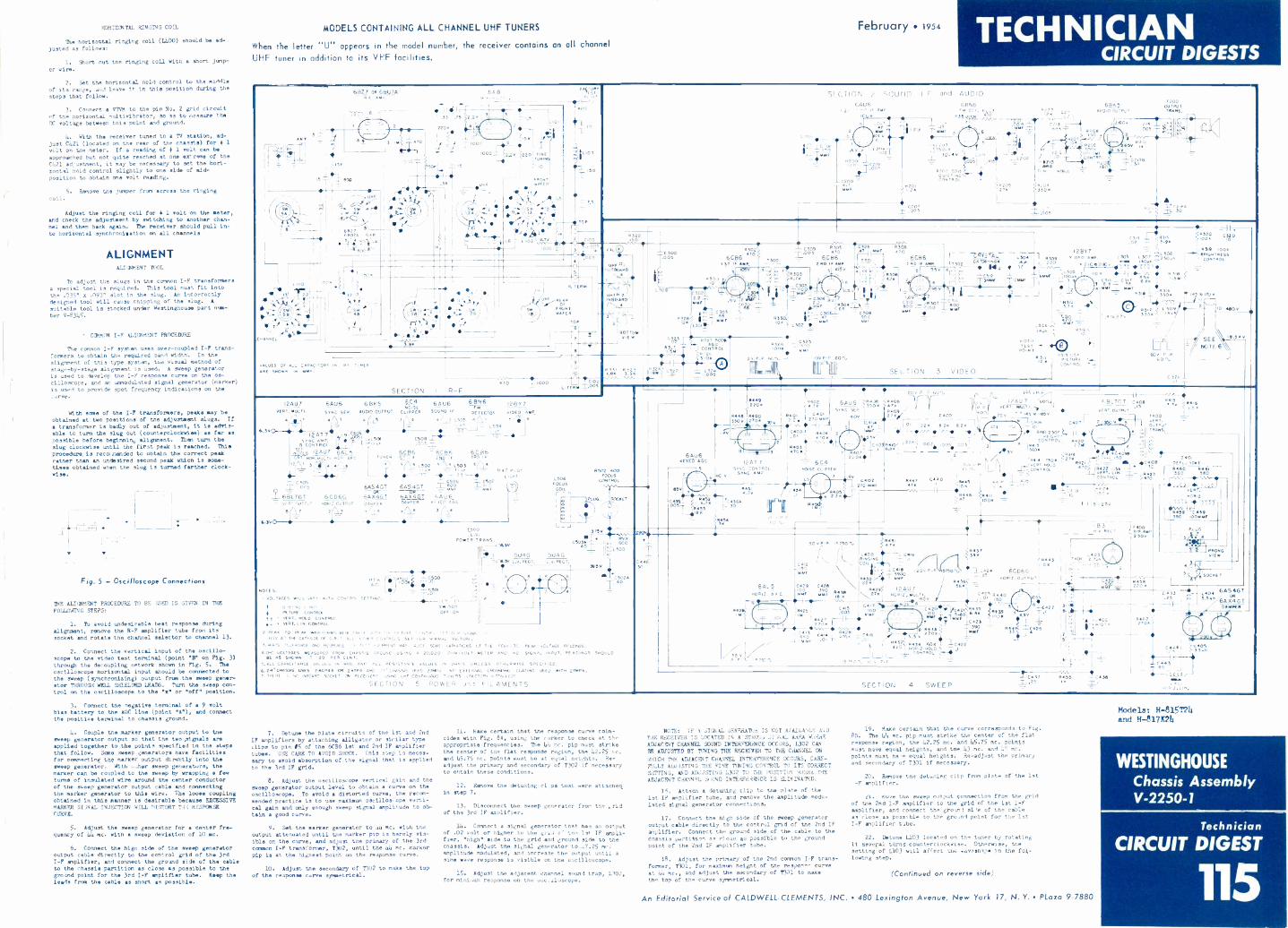
HORIZONTAL RINGING COIL February 1954The horizontal ringing coil (L400) should be ad-
justed a, follows,
1. Short out tne ringing coil with a short jasp-
er wire.
2. Set the horizontal hold control to the middleof its range, and leave it in this position during the
steps that follow.
3. Connect a V1VM to the pin No. 2 grid circuitof the horizontal eultivibrator, do as to measure theIX voltage between this point and ground.
L. With the receiver tuned to a TV station, ad-just C421 (located on the rear of the chassis) for 4 1volt on the meter. If a reading of 1 1 volt can beapproached but not quite reached at one extreme of theC421 adjustment, it may be necessary to set the hori-zontal hold control slightly to one aide of aid -
position to obtain one volt reading.
5. Remove the jumper from across the ringing
coil.
Adjust the ringing coil for 4 1 volt on the meter,and check the adjustment by 'witching to another chan-nel and then back again. The receiver should pull in-to horizontal synchronisation on all channels
ALIGNMENTALI474ENT TOOL
To adjust the slugs in the common I -F transforeersa special tool is required. This tool must fit into
the .035" x .093" slot in the slug. An incorrectlydesigned tool will cause chipping of the slug. A
suitable tool is stocked under Westinghouse part ntm-ber V-8345.
CCNMON I -F ALIGNMENT PROCEDURE
The common I -F system uses over -coupled I -F trans-
formers to obtain the required band width. In the
alignment of this type system, the visual method ofstage -by -stage alignment is used. A sweep generatoris used to develop the I -F response curve on the os-cilloscope, and an unmodulated signal generator (marker)is used to provide spot frequency indications on the
With some of the I -F transformers, peak. may beobtained at two positions of the adjustment slugs. If
transformer is badly out of adjustment, it is advis-able to turn the slug out (counterelockwiee) ae far aspossible before beginnin, alignment. Than turn theslug clockwise until the first peak is reached. This
procedure. is recoonended to obtain the correct peakratner than an undesired second peak which is some -tines obtained when the slug is turned farther clock-
wise.
Fig. 5 - Oscilloscope Connections
THE ALIGNMENT PRCCEDURE TO BE JS® IS GIVEN LN THE
FOLLOWING STEPS!
1. To avoid undesirable beat response duringalignment, remove the R -F amplifier tube from itssocket and rotate the channel selector to channel 13.
2. Connect the vertical input of the oscillo-scope to the video test terminal (point "B" on Fig. 3)through the decoupling network shown in Fig. 5. The
oscilloscope horisontal input should be connected tothe sweep (synchronizing) output from the sweep gener-stor THROUGH WELL SHIELDED LEADG. Turn the sweep con-trol on the oscilloscope to the "x" or "off" position.
3. Connect the negative terminal of a 9 voltbias battery to the AGC line (point "A"), and connectthe positive terminal to chassis ground.
L. Couple the marker generator output to thesweep generator output so that the two signals areapplied together to the points specified in the stepsthat follow. Some sweep generators have facilitieefor oonnecting the marker output dirottly 1060 the
sweep generator. With ..;her sweep generator., themarker can be coupled to the 'weep by wrapping fewturn. of insulated wire around the center conductorof the sweep generator output cable and connectingthe marker generator to this wire. The loos, couplingobtained in this manner is desirable because EXCESSIVEMARKER SI1NAL INJECTION WILL nISTORT Tdi RESPONSECURVIS.
5. Adjust the sweep generator for center fre-quency of 44 mc. with sweep deviation of 10 mc.
6. Connect the high side of the sweep generatoroutput cable directly to the control grid of the 3rdI -F amplifier, and connect the ground side of the cableto the chassis partition as close as possible to theground point for the 3rd I -F amplifier tube. Keep theleads from the cable as short as possible.
MODELS CONTAINING ALL CHANNEL UHF TUNERS
When the letter "U" appears in the model number, the receiver contains an all channelUHF tuner in addition to its VHF facilities.
TECHNICIANCIRCUIT DIGESTS
T
68270Ra/107A
33 .75
800-1-
000
5 7722...,-k- 24ni;-;r-
2'
.e827
508
UHF
"<6
02000
Fa hoe
7.5
ATOP
11(i/CR..;Tq-
SECTION 2 ',JUND I F cod AUDIO
Ga06lif
0 V
ZE.H200, 1
C200 -=
r'4.14'r
LZU
4 C07.005
GANGm Cc, Pr...6
09562e -V
T TAW
10..m COe0051 1,105
CONTROL -75 R205: 27K
L
1.02871 Par HERO,
II pos
ALWWTPoT
--4 luau.
01
T200OUTPUTTRANS.
_ei31.005
WV -11
2138
30
COOoo° S
X005UHF..
ouT20.0
ON
NF.80.1.10
T -8
'
'SCS:9-0
R. TERM
REAR
PUNTOF
w ER
TOP
a
v&LIES OF ALL CAPACrTOR6 IN Flo Tom,ARE SHOWN in
SECTION I R -F470 L 1000
2
BOTTOMVIE W
yc 300
°300
30oC302/R;
I ST. IF AMP,
050 -- C309 $005:Do05 470
6CK 6C136T300 ---2 18.) if .0
059
5
kI
A)P- ,:II0
=C 3 7i
Rots
1303.7N
?ScO<2 L302
31"°43
- tC.02L.TERN T.005
I2AU7VERT. MILT I .
64U6 681(56ost
6AU6 Mt 12807
svat 5E9 AUDIO OUTPUT CL OPEN 50000 IE DETECTOR 010E0. AMP
8. T' 5 3 . .4 .
L5,,
1,, AT 7 8 "°5 ` 4, , li Pcl, cSos E.
00,m9 COmiRce I
ZITIAm09 lAuUll. ,.Ofi"-Ac T.." Iii F
fo_WS 6 6C86ctili /
2 5 (T14i4 3 - 0 0
4 L502 3 L503
c 5005 6AS 4G T r g.,,r08
2_ 61-1.7GT 6AX4GT 5406-Mr -
- 3
vEmr Out PUT DAMPER 02 fit, A GC
e(
G. a412
'17i?-4-3/''14
NOTES.
6CD6GHORQ_CUTPuT
6AS4GTCPC"
60045TDAMPER
7
Cr 0-
01,.VOLTAGES Vo LL VAR. AITH GONTROI SETTING. I
SW 500-
OFF ON00011.5mOTURF GONTROI
VERT. .L0 CONTROLVERT. L CONTROL
2.PF - TO PE. *Am NORMS wi 4 AK. Kr... -Kr ff.!EN IR.. SIGNALWV A/ THE CATHODE OF C.R. /. A P f ENTROLS SET rOR NCE/MAL PK. TURF .
3.RIPTS 7,1RANCF ANO RESPONSE 0, TEST .31,16mEmT MA 6 ,AJSE SOW 3A116A,CNS 6F THE 4EA6 T6 .PEAR vCLTAGE RF ADM,VOLTAGES MEASURED FROM CHASSIS 60001.0 USING A 20,000 O.., VOLT METER AND NO SIGNAL INPUT. READINGS
BE .S SHOwN :1" 20 PER CENT.5. ALL CAPACITANCE VALUES IN RFD. AND A0 L RESISTANCE VALUES IN OHMS UNLESS OTHER wi SE SPECIFIED.
6. 24. CHASMS USES 24C PRA on 24TP4 AND 2, -CHASMS USf 5 2 N0 ExTERNAL CROW,. COAT!. USED WITH 2mP4.T. THERE 5 60 INBOARD SOCKET ON RECEIVE,. USOG UHF CONTINUOUS TUNERS (FACTOR, R STAB, CO)
SECTION 5 POWER old FILAMENTS
0 P. 44L.1J1W81, 50
0
6 C B6
TT4 2 460,LIGHT
1200
POwER TRANS.W--CA
5U4G5.014.55, v.v. ROOT
6-6
6501M .
14
L508FOCUS
COILr-
8502 400FOCUS
WN 3 NOL
3/5
C503... 5
eo: d
5U4G
385v
AM
32t50
SOCKET
C3.2 2
R 32.7G ZOOK
CONTROLR26
6AU6
FOS;
Et-fhKOC
sv
5
0448030,
ie. IE AMP
5r --95mMOST
114., J4..
050 3: I
3069v',M304: -IA 1-
- BOO
49i 83251000
26.P 60, WV P -P 60.1,
0326 5308IL,LI (TNT 470
6T301 C86
mer
.69L 310 ,8307woo so
TCSIVONNF RRE
1 T302Ri
12807 J1 RSe
7;
-e005
11N,
--"""BRIONTNESS
L506
t ,o 37v
7
_
'2.127:347,
L 3'09s 116-21-
p19).
I- liemoo
'1312
/,
1
SECTION 3 VIDEO
VIDEOTEST 66-- B 1}3.POINT
H313 1.56
OON; rp'1.
50492200
A4002900
n:eozoiJk
"52' 12Ho=r2;.'s&'TC400_, .4040,
.030012471 = 6C4
SYNC. CONTROLSYNC Ap
84524.7N
--
4.76
60,
434
NOISE CLIPPER
L
G02270 Met
20 6 P 60%
R40 9Ili u VI
271c Z400
al 221 at. 2.2---1
O m, ,c, ' loose6 --11'-. -1(406 . C406 5I F.,,T
7%0 I#-, '1,1'.'W ER''''''.- ' -31p 1 R.* 2500 t_ 11 1,2
C011gt R2Ce122. .002i .05,i..005J 5 ass ,,,,,
.8a
----- -1---- - ! 5 '1'-.!°'- :,: el, 217 ! C""-. f!"" 5'!11 --1- "01
- 2'Z''1,i1A _C".;=a00 ), !Ii!0 /-- '"dh-r* Cl!°8'(-1.6%1991
p663. C440 ( t' !--1-710'5vERT, GIN. =__ 580 560
, ...
-.
0 ....,...y, 6424
_1_ mOR4.
7N .
CONTROL , .0 ....,°.°:14 I '''. .0 VW
60%
( ----1",407 F BL7C I ceos
6 vER-rnIUL 1,34 M ISVERT. OUTPUT
TRANS.
3
0
"'"
'SEE/ NOTE 6
6
e,5
1,46
6000500
CS02A40
5001.0
30
6415,
00012. A.F C.
542IN
5 8 .5,50 IL.1
Rm6m6LC419i400
511
1100015. 25v 3606rIFM-0-!
jt
c°'lLeicele 6CD6G
C425 0025 \ 22x "360'
,10125
zA .1.1.
M1 150
II!
6 C:433
C414 C 4 i6 Ti. /TOT.01 , _,131
IM21
04.0_Lcers
390"NW
"..21* 0g4/ MI"C422
Li CONTROL' .06-4111
_L.15750 . v 4.P
1B3. 00_AEC T.: t,344010
1
401L4443
1 74C"...OK -
I
-
84-,-.C42
4.36
=006 I
11
-411-
SECTION 4 SWEEP
12
C30sa8P-1;
. -
a
gE=11 C432590 *ORME
PLUG
8
PRONGIce
2
OCTET
220 xI 6AS4GT
.25
PenOM
X4GT
1
I :KrOTH 210K,1
. 4
G4441
_L c4.3T A,
-
MR+
5
7. Icetune the plate circuits of the 1st and 2nd
IF amplifiers by attaching alligator or similar typeclips to pin OS of the 6C86 let and 2nd IF amplifiertubes. USE CARE TO AVOID SHOCK. this step is neces-
eery to avoid absorption of the signal that is applied
to the 3rd IF grid.
8. Adjust the oscilloscope Vertical gain and the
sweep generator output level to obtain curve on the
oscilloscope. To avoid distorted curve, the recom-mended practice is to use maximum oscines, Ope verti-
cal gain and only enough sweep 31011 amplitude to ob-
tain a good curve.
9. Set the marker generator to 44 me. with theoutput attenuated until the marker pip is barely vis-ible on the curve, and adjust the primary of the 3rd
COMM I -F transformer, T302, until the 44 mc. markerpip is at the highest point on the response curve.
10. Adjust the secondary of T302 to make the top
of the response curve symmetrical.
II. Hake certain that the response curve coin -cidee with Fig. BA, using the varker to check at theappropriate frequencies. The Lh mc. pip must strikethe center of the flat response region, the 42.25 Tx.end 45.75 me. points must be at equal neicjits. Re-adjust the primary and secondary of 7302 if necessaryto obtain these conditions.
12. Remove the detuning clAm that were attached.in step 7.
13. Disconnect the sweep generator fror the ,,ridof the 3rd IF amplifier.
1.4. Connect a signal generator that has an outputof .02 volt or higher to the grids the 1st IF ampli-fier, "high" side to the grid and ground side to thechassis. Adjust tne signal generator to 47.25 me.amplitude modulated, and increase the output until asine wave response is visible on the oscilloscope.
15. Adjust the adjacent channel sound trap, L302,for mini.im response on the ot.c.iloscope.
NOTE. IF k SIGNAL GENERATUR IS NOT AlAILA4LE ANDTHE RECEIVER IS LOCATED IN A SUM:, 31,AAL AREA WAREADJACENT CHANNEL SOUND INTERPERDICE OCCURS, 1302 CANBE ADJUSTED BY TUNING THE RECEIVER TO THE CAANNEL ON
WHICH THE ADJACENT CHANNEL INTERFERENCE OCCURS, CARE-FULLY AD.P.13TING 11E FIN! TUNING CONTROL TU ITS CORRECTSETTING, AND ADJUSTING 1302 TO THE POSIT/ON WHERE THEADJACENT CAANNEL SoUND INTERFERENCE IS ELIMINATED.
IA. Attach a detuning clip to the plate of thelet IF amplifier tube, and remove the amplitude modu-lated signal generator connection,.
17. Connect the high side of the sweep generatoroutput cable directly to the control grid of the 2nd IF
amplifier. Connect the ground side of the cable to thechassis partition os clop as possible to the groundpoint of the 2nd IF amplifier tube.
18. Adjust the primary of the 2nd common I -F trans-
former, T301, for maxieulm height of the respone, curveat 414 sc., and adjust the secondary of 1101 to makethe top of the curve symmetrical.
19. Make certain that the curve corresponds to Fig.
8B. The 44 me. pip must strike the center of the flatresponse region, the 42.25 mc. and 45.75 mc. points
must have equal heights, and the 43 me. and 41 mc.points must here equal heights. Re -adjust the primary
and secondary of T301 if necessary.
20. Remove the defusing clip from plate of the let
-F amplifier.
21. Move the sweep output connection from the gridof the 2nd I -F amplifier to the grid of the let I -Pamplifier, and connect the grouni si"e of the cableas close as possible to the gro.nd point for the 1stI -F amplifier tube.
22. Detune L103 located on the tuner by rotating
it several turns counterclockwise. Otherwise, tne
setting of 1.103 will affect the eavoshape in the fol-lowing step.
(Continued on reverse side)
Models: 1-1-815r24and H-8171[214
WESTINGHOUSEChassis AssemblyV-2250-1
Technician
CIRCUIT DIGEST
115An Editorial Serviceof CALDWELL-CLEMENTS, INC. 480 Lexington Avenue, New York 17, N. Y. PLaza 9-7880
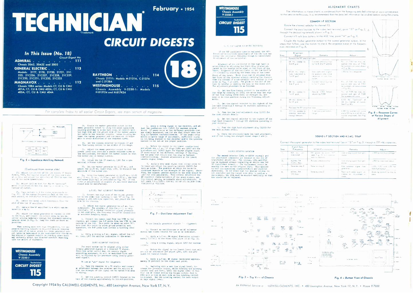
T CHNICIAN*In This Issue (No. 18)
Circuit Digest NoADMIRAL 111
Chassis 20A2, 20A2Z and 2002
GENERAL' ELECTRIC 113Models: 2117, 2118, 21120, 21121, 21C225, 21C226, 21C227, 21C228, 21C229,21C230, 21C231, 21C232, 21C233
MAGNAVOX 112Chassis 108A series: Models CT, CU 8 CMU401A; CT, CU & CMU 402A; CT, CU & CMU403A; CT, CU & CMU 404A
February 1954
CIRCUIT DIGESTS
RAYTHEONChassis 21111: Models. M -2131A, C -2137Aand C -2138A
WESTINGHOUSEChassis Assembly V-2250-1: ModelsH-815724 and H -817K24
114
115
For complete Index to all earlier Circuit Digests, see main section of magazine
150A
COirraEOANCE 0, Swree CABLE
10
,51 56Astn
52
160,0.Fig. 6 - Impedance Matching Network
(Continued from reverse side)23. Adjust the primary of the 1st cannon IF trans-
former, 1300, for maximum height of the response curveat 41 mc., and adjust toe secondary of T3o0 to make thetop of Lie curve symmetrical.
21. Adjust L133 so that the dip or 1.suck-outswhich it produces on the response ru. e is at 4.. re.(center of curve).
25. Make certain tipit tie curve corresponds toFig. 8C. If the marker frequencies fall at the cor-rect points, no transformer re -adjustments are required.
26. Remove the sweep output connection from thegrid of the let IF amplifier.
27. Replace the RF amplifier to e which was re-moved in s, ep 1.
28. Adjust the sweep generator to channel 13 (210to 216 etc.), and connect its output cable to the re-ceiver 11116511115 terminals through the impedance matchingnetwork shown in Fig. 6. Keep the leads as short aspoesible.
When working with very nigh frequencies, tne im-pedance matching network is required because responsecurves are of no value unless the sweep generator out-put cable is terminated in its characteristic impedance.Any mis-ea'ch present results in standing waves whichmay seriously affect the observed waveform dependingupon the amount of eds-match.
WESTINGHOUSEChassis AssemblyV-2250-1
CIRCUIT DIGEST
115
29. Couple the marker generator output to thesweep generator output by using the loose capacitivecoupling provided by one turn loop, or connect boththe high side and the ground side of the marker genera.tor cable to the receiver chassis. Loose coupling be-tween the marker generator and the receiver is desir-able to avoid distortion of the response curve.
30. Set the channel selector to channel 13 andthe fine tuning control to the middle of its range.
31. Adjust the 'weep generator output to thelowest level that provides a usable response curve onthe oscilloscope, and adjust the marker output so thatthe marker pip is barely visible.
32. Adjust the 1st IF reactor, L300 for a sym-metrical resnonae cone.
33. Set the marker generator to 11.25 mc., andadjust the 41.25 rec. sound trap, L301, to minimize theaplitude of the marker pip.
34. Using the marker generator at 11.25 Inc., 12.25mc., 1,3 mc., 44 mc., 15.75 ec., and 17.25 mc., see thatthe marker pips fall as indicated on Fig. PD. If thecurve is satisfactory on channel 11, all other channelsshould aleo be satisfactory.
4.5 MC. TRAP ALIGNelaT PROCEDURE
1. Connect the high side of the si,nal genera-tor to the video test terminal (point "13. on Fig. 3)through a .001 ofd mica capacitor, and ground the lowside to the chassis.
2. Adjust the signal generator to 4.5 mc. (un-modulated). The accuracy of this frequ-iicy is veryimportant. If a crystal controlled signal generator13 not available, the frequency should be checked withan accurate frequency meter.
3. Connect the common lead from the VTVM to thechaseis, and connect the R -F probe from the VTVM to thecathode of the CRT. This point is chosen as point 5C..Note that this point is above ground potential and,therefore, the R -F probe must contain blocking capa-citor.
4. Using a strong 4.5 cc. signal, adjust the 4.5mc. trap, 1.303 for minimum indication on the meter.
SOUND ALILTIMMT PROCEDURE
The sound system can be aligned using eitherlocally generated signals or a received TV signal.Since the latter method does not require signalgenerating equipment, it will be described first andwill he followed by the procedure using locally gener-ated signals.
use an "err" signal for eligtvnent,
1. Tine the receiver to a TV station and connectan attenuator between the receiver end the antenna sothat the strength of the Agnal .can be varied from weakto strong.
2. Set the quieting control (R202) located on theback of the chassis approximately to its mid -position.
3. Apply a strong signal to the receiver, and ad-just the quactrature coil (L202) for sexism programsound. If peaks occur at two different positions thatare widely separated, use the one that occurs when theslug is farthest counterclockwiee. If two peaks occurwithin a narrow range of adjustment, sufficient signalis not being applied to the receiver and/or the quietingcontrol is not net at the proper position.
4. Reduce the signal to its lowest useable leveland adjust the 1.5 mc. IF slugs (1200 and L201) and thecrattrature coil (1202) again for minimum program sound.If peaks occur at two different settings of the slug,use the peak that occurs when the slug is farthestcounterclockwise. Recheck adjustments at the lowestuseable signal. level.
5. Apply very weak signal that allows noise tobe heard and adjust the quieting control (R202) forminim noise. The position at which the noise isminimized depends on the strength of the signal; there-fore, the weakest useable station in the area should beused for this adjustment. This control determines theAM rejection characteristics pf the sound system, andit. correct setting la normally about mid -position. DO
NOT LEAVE ThE Q lIETING CONTROL SET AT ITS MAsIMUM COUN-TERCLOCKWI.E
_op, DE
- -12
111ACE r,,,2rrrrETA.,.10 sr.00up
Fig. 7 - Oscillator Adjustment Tool
To use locally generated signals ulignmentt
1. Connect an oscilloscope or an AC voltmeteracross the volume control for use as an indicator.
2. Apply 4.5 nc. FN signal (deviation Approxi-mately 7.5 kc.) to the video test point (B on Fig. 3).
3. using strong signal, adjust L202 for maximumoutput.
4. Reduce the signal to the lowest level that willproduce an indication and adjust 1.200, 1.201 and 1202again for maximum output.
5. Apply 4.5 cc. At4 signal (modulated approxi-mately 30 percent) to the video test point.
6. Beginning with a very low signal level, in-crease the generator output, while rotating the quietingcontrol back and forth, until the signal level is suchthat the PM output across the volume control dips to2n10 with rise on each aide as the quieting controlis rotated. Set the quieting control for zero outputat this signal level.
WESTINGHOUSEChassis AssemblyV.2250-1
TestraisiA
CIRCUIT DIGEST
115
H. F. 0SrILLATOR ALIe111,PNT PROCEDURE
If the 61B oscillator tube is replaced, the dif-ferent inter -electrode capacitance of the nee tube maychange the oscillator frequency enough to necessitatere -alignment of the oscillator.
Alignment of the oscillator on the high band isaccomplished by adjusting the brass slug located ad-jacent to the vernier drive wheel on the front of thetuner. Alignment of toe oscillator on the low band isdc,..mplished by adjusting the brass slug on the lowerfront of the tuner. These slugs can be adjusted fromthe front of the receiver without removing the chassisfrom the cabinet if a non-metallic tool similar to thatshown in Fig. 7 is used. The guide on the end of thetool is helpful in seating the tool in the screw slot.The adjustment procedure is as foliose:
1. Set the fine tuning control to the middle ofits range by rotating it until the arrow near the edgeof the fine tuning drive wheel is straight up, andkeep it in this position during the following adjust-ments.
2. Set the channel selector to the highest of thelow band (channels 2 through 6) stations operating inyour vicinity.
3. Peak the low band adjustment slug (L102) forthe best picture detail.
h. Set the channel selector to the highest of thehigh band (channels 7 through 13) stations operating inyour vicinity.
5. Peek the high band adjustment slug (1.101) forthe best picture detail.
6. Check the previously made low band adjustment,and if the tuning has changed repeat steps 2 and 3.
SerCND DETECTOR LOCATION
The second detector (11161 or C6706 crystal) andits associated components are located in the 3rd IFtransformer shield can. The crystal, 1304 and C312can be replaced without installing an entire new 3rdIF transformer assemblz. The replacement should beexactly the sane as the original part. This appliedto both its electrical characteristics and physicalctimensions. In the event that the maller crystal isnot available and the larger size 11461.4 is used as areplacement, the 11461 must be mounted vertically so thatthe shield can be replaced.
C.
ALIGNMENT CHARTS
The information in these charts is condensed from the foregoing detailed information as a convenienceto the service technician. It is recommended that the detailed information Lie studied before using the charts.
COMMON !-F SECTION
Rotate the channel selector to channel 13.
Connect the oscilloscope to the video test terminal, point "B" on Fig. 3, Athrough the decoupling network shown in Fig. 5.
Connect a 9 volt bias battery to the AGC line, point ''A" on Fig. 9.
Couple the marker generator output to the sweep generator output. In thesteps that follow, use the marker to check the response curve at the frequen-cies indicated on Fig. 8.
StepAlignment
Signal Remarks Adios, -1. Remove the RF amplifier tube.
2. 44 mc. ....mo to3rd IF grid
Coct detuning clopsto 1stnne A Ind IF plates
Prr. of 1301 for max. re -sponse and sec. of 1302for symmetricolcurve shownon Fig. 8A,
7. 17.25 mc. amp!,rude modulated to1st IF grid
Use suit gegen, signalto produce s.ne waveresponse °.` .'c'11.-scope.
1302 for min. response
d. 44 wc. sweep ro2nd IF grid
Connect detoning clipto I sr IF plate
Prt. of 1301 for max. re.sponse and sc. of T301for symmetrical Curve shown.n Fig. 88.
d4 inc. weep toIst IF grid
Detune L103 beforeadrust(ng 1300
Pr.. of 7300 he maresponse and sc. of 1300for synevon real curv
A. 44 me. sweep to
I., IF gr,clL103 for "suck -out" at
44 me. (center of curve),See F og. 8C.
Replace the RF amplifier robe
8. 213 mc. sweep roantenna termonalsthrough nelwori,
Fine toning set ro mid.'11°95
1300 I c, symmetrical curveand L301 Ice min. 41.25 mc.mocker ornoidude. See Fog.130
SOUND I -F SECTION AND 4.5 MC. TRAP
C
4575.4 40115 42 2545
Fig. 8 - Response Curvesof Various Stages of
Alignment
Connect the signal generator to the video test terminal (point "B" on Fig. 3) through a .001mfd.capacitor.
StepSignal Gen.Frequency VTVM Connections Remarks Adios, -
I. 4.5 me. or.modulated
RF probe to point -C"IS.. Frg. 91 and commonlead to chassis.
Use strong signal from gen-!rater
1303 for rAnrrnurn roAage
1. 4.5 Mc. FM7.5 Kc. Der.
Acres. volume conool Use strong signal from yen-erator
L202 log mon.morn ovrau,
3. Some as step 2 Some as step 1 Use weakest signal fromgeneral..
L100. 1201 and 1 202 toInfiailllunlpUlpul
4. 4.5 Mc. AM30: Mad.
Some as step 2 Strut .with weak signal oncrease as adersonent ismade.
Greeting control Ice dip toImo.
"iFrorL S ( PEI
(ii11;)11..,L...71. b.
120
Fig. 3 - Top Vi-- of Chassis
7-,..115.2.* rttraom 1f2Crior +/X":40
rico rssiAenlne
,r'r?or
w
-1 P17'IT
Fig. 4 - Bottom View of Chassis
Copyright 1954 by CALDWELL-CLEMENTS, Inc., 480 Lexington Avenue, New York 17, N.Y. An Editorial Service o ALDWELL-CLEMENTS, INC. 480 Lexington Avenue, New York 17, N. Y. Kozo 9-7880

capacitorreplacements
ADMIRAL CHASSIS 20A2,20A2Z, 20D2
Symbol Rating AcInilral SpragueNo. Mf @ WVDC Part No. Replacement
C205 4 @ 50 67A4-9 TVA -1303C207 60+40 @ 350/60@ 200/20 @ 150 67615-23 TVL-4609C409 80 @ 350/100 @ 50 67C15-22 TVL-3722C410 20 @ 475 67A21-1 TVA -1804
MAGNAVOX MODELS CT401 A, ETC.Symbol RatingNo. Mf @ WVDC
C106 4 @ 50C110 20 @ 350C215 2 @ 50C413 10 @ 350 SP.
C501 70+40+10 @ 350/50 @ 50
C502 20+10+5 @ 350/60@ 200PC301 Integrator Plate
MagnavoxPart No.
270027-10270027-20270027-22270027-23
270021-52
270021-51
250186-1
GENERAL ELECTRIC"E E" Chassis
SymbolNo.
RatingMf @ WVDC
SpragueReplacement
TVA -1303TVA -1608TVA -1301R-1468
S TVL-4659TVA -T308TVL-4620TVA -1413101 C1
G. E. SpraguePart No. Replacement
C210 1 @50C302 1050C320 1 @ 50C401 90+40 @ 350C402 30+20 @ 350/100 @ 75C403 40+20+5 @ 350/10 @ 25Note:
RCE-090RCE-090RCE-090RCE-154RCE-155RCE-156
TVA -1300TVA -1300TVA -1300TVL-2637TVL-3629TVL-4621
C210 may also be 10Mf5OV (G.E. #RCE-169). UseSprague TVA -1304 to replace.
RAYTHEON CHASSIS 21 T1 1SymbolNo.
Rating Raytheon SpragueMf @ WVDC Part No. Replacement
C402 100+10 @ 300/60 @ 50C414 20 @300/T0@75/10@ 15C428 100@ 150C429 100@ 150C503 50 @450C442 Integrator Plate
8C-22523 TVL-35748C-22524 R-14878C-22285 TVA -14208C-22286 TVL-14238C-22544 TVA -171317A-22376 101C1
Sprague makes more capacitors . . . inmore types . . . in more ratings . . .
than any other capacitor manufac-turer. Send 10c for 48 -page TVReplacement Capacitor Manual toSprague Products Co., 65 MarshallSt., North Adams. Mass., or get itFREE 'tom your Sprague distributor.
DON'T SF VAGUE...INSIST
FOR SETS OF THE MONTH
WESTINGHOUSE CHASSIS V-2250-1SymbolNo.
Rating Westinghouse SpragueMf @ WVDC Part No. Replacement
C21313C40911C4108C4118C216A 1C436AC502AC503AC320C426C446Z400
30 @ 500/10 @ 450/150+30 @ 50 V-11535-1 R-1488
40+40 @ 450/30+30 @ 350 V-9891 TVL-4720
10 @ 4504 @ 50
30 @ 450Integrator Plate
V-10293-1 TVA -1705V-4637 TVA -1303V-6570 TVA -1711V-11192-1 105C1
NEW!SPRAGUE "T -C" RULE
Use this handy pocket-size Sprague Tempera-ture Coefficient Rule to find quickly the valuesof stock N750 and NPO type ceramic capacitorsto connect in parallel to equal a capacitor ofdesired intermediate temperature coefficient ofthe required capacitance.
COLOR CODE CHARTSComplete charts for color codes on all types
of ceramic capacitors are on the back face ofthis rule.
Get your Sprague "T -C" Rules now fromyour Sprague distributor, or directly fromSprague Products Company, 65 Marshall Street,North Adams, Massachusetts. They're only 15¢each.
$50/000For Dealers and servicemeri' who use RCA Tubes
1954 DeSoto Automatic"Hard -Top" -170-H.1'. FireDome V8 engine, Power-Flite Trans-mission, Power Steering ... completelyequipped, including radio and heater.
Here's all you do-Get an entry blank from your RCA TubeDistributor Salesman. Complete the fol-lowing sentence in 25 additional wordsor less:-
"TELL S SELL"
CONTEST
1954 Dodge DeLuxe 1/2 -TonPanel Truck-complete with
"Truck-o-matic transmission,"radio,heater and accessories . plus a full set of
RCA Test Equipment, aluminum ladder, andwinner's business name and address on truck panel.
"I use and recommend RCA Tubes because"It's as easy as that ... and you may enteras often as you like, but each entry musthe on an official entry blank.
Hints to help you winSee your RCA DistributorSalesman right away. He hasa copy of the "clue book"waiting for you. This bookcontains full details on thewhole exciting "Tell and Sell"
Campaign, including contestrules.
You may win first prize . . . sodon't waste a moment. Con-test closes April 30, 1954.
*Your RCA Distributor Salesman will be glad to help you... because if you win, he wins a duplicate prize!
400FABULOUS
PRIZESincluding:
* TV sets* Watches* Cameras* Air
Conditioners* Test
Equipment* Radios* Ranges
RAD/0 CORPORATION of AMERICAELECTRON TUBES HARRISON. N.J.


