16
INSTRUCTION MANUAL V1002552 REV B Circuit Sentry TM Flo-Setter II Balance & Commissioning Valves with NPT Connections

INSTRUCTION MANUALV1002552 REV B
Circuit SentryTM Flo-Setter II Balance &Commissioning Valves with NPT Connections

Table of Contents
1 Introduction and Safety..............................................................................................................21.1 Introduction.......................................................................................................................... 21.2 Safety..................................................................................................................................... 2
1.2.1 Safety message levels...................................................................................................21.3 Protecting the environment................................................................................................3
2 Transportation and Storage...................................................................................................... 52.1 Inspect the delivery..............................................................................................................5
2.1.1 Inspect the package..................................................................................................... 52.1.2 Inspect the unit..............................................................................................................5
3 Product Description....................................................................................................................63.1 General description............................................................................................................. 63.2 Operational limits.................................................................................................................6
4 Installation....................................................................................................................................74.1 Installation precautions....................................................................................................... 74.2 Installation guidelines..........................................................................................................74.3 Install NPT connection.........................................................................................................84.4 Pipe hanging installations...................................................................................................8
5 Operation.....................................................................................................................................95.1 Recommended operating procedures............................................................................. 9
6 Maintenance..............................................................................................................................116.1 Precautions......................................................................................................................... 116.2 Valve inspection.................................................................................................................116.3 Reseal the valve..................................................................................................................116.4 Attach insulation................................................................................................................ 12
7 Product warranty...................................................................................................................... 13
Table of Contents
Circuit SentryTM Flo-Setter II Balance & Commissioning Valves with NPT Connections 1

1 Introduction and Safety1.1 IntroductionPurpose of this manual
The purpose of this manual is to provide necessary information for:
• Installation• Operation• Maintenance
CAUTION:
Read this manual carefully before installing and using the product. Improper use of theproduct can cause personal injury and damage to property, and may void the warranty.
NOTICE:
Save this manual for future reference, and keep it readily available at the location of theunit.
1.2 SafetyWARNING:
• The operator must be aware of safety precautions to prevent physical injury.• Operating, installing, or maintaining the unit in any way that is not covered in this
manual could cause death, serious personal injury, or damage to the equipment. Thisincludes any modification to the equipment or use of parts not provided by Xylem. Ifthere is a question regarding the intended use of the equipment, please contact aXylem representative before proceeding.
• Do not change the service application without the approval of an authorized Xylemrepresentative.
CAUTION:
You must observe the instructions contained in this manual. Failure to do so could resultin physical injury, damage, or delays.
1.2.1 Safety message levels
About safety messages
It is extremely important that you read, understand, and follow the safety messages andregulations carefully before handling the product. They are published to help preventthese hazards:
• Personal accidents and health problems• Damage to the product• Product malfunction
Definitions
Safety message level Indication
DANGER:
A hazardous situation which, if not avoided, will result indeath or serious injury
1 Introduction and Safety
2 Circuit SentryTM Flo-Setter II Balance & Commissioning Valves with NPT Connections

Safety message level Indication
WARNING:
A hazardous situation which, if not avoided, could resultin death or serious injury
CAUTION:
A hazardous situation which, if not avoided, could resultin minor or moderate injury
Electrical Hazard:
The possibility of electrical risks if instructions are notfollowed in a proper manner
NOTICE:
• A potential situation which, if not avoided, couldresult in undesirable conditions
• A practice not related to personal injury
Precautions before work
Observe these safety precautions before you work with the product or are in connectionwith the product:
• Provide a suitable barrier around the work area, for example, a guard rail.• Make sure that all safety guards are in place and secure.• Make sure that you have a clear path of retreat.• Make sure that the product cannot roll or fall over and injure people or damage
property.• Make sure that the lifting equipment is in good condition and is properly rated for the
load to be lifted.• Use a lifting harness and safety line, as required.• Allow all system and pump components to cool before you handle them.• Make sure that the product has been thoroughly cleaned.• Disconnect and lock out power before you install or service the valve.• Check the explosion risk before you weld or use electric hand tools.
Wash the skin and eyes
Follow these procedures for chemicals or hazardous fluids that have come into contactwith your eyes or your skin:
Condition Action
Chemicals or hazardous fluids ineyes
1. Hold your eyelids apart forcibly with your fingers.2. Rinse the eyes with eyewash or running water for at least 15 minutes.3. Seek medical attention.
Chemicals or hazardous fluids onskin
1. Remove contaminated clothing.2. Wash the skin with soap and water for at least 1 minute.3. Seek medical attention, if necessary.
1.3 Protecting the environmentEmissions and waste disposal
Observe the local regulations and codes regarding:
• Reporting of emissions to the appropriate authorities• Sorting, recycling and disposal of solid or liquid waste• Clean-up of spills
1 Introduction and Safety
Circuit SentryTM Flo-Setter II Balance & Commissioning Valves with NPT Connections 3
Exceptional sites
CAUTION: Radiation Hazard
Do NOT send the product to Xylem if it has been exposed to nuclear radiation, unlessXylem has been informed and appropriate actions have been agreed upon.
Recycling guidelines
Always follow local laws and regulations regarding recycling.
1 Introduction and Safety
4 Circuit SentryTM Flo-Setter II Balance & Commissioning Valves with NPT Connections
2 Transportation and Storage2.1 Inspect the delivery2.1.1 Inspect the package
1. Inspect the package for damaged or missing items upon delivery.
2. Note any damaged or missing items on the receipt and freight bill.
3. File a claim with the shipping company if anything is out of order.
If the product has been picked up at a distributor, make a claim directly to thedistributor.
2.1.2 Inspect the unit1. Remove packing materials from the product.
Dispose of all packing materials in accordance with local regulations.
2. Inspect the product to determine if any parts have been damaged or are missing.
3. If applicable, unfasten the product by removing any screws, bolts, or straps.
For your personal safety, be careful when you handle nails and straps.
4. Contact the local sales representative if there is any issue.
2 Transportation and Storage
Circuit SentryTM Flo-Setter II Balance & Commissioning Valves with NPT Connections 5

3 Product Description3.1 General description
The Circuit Sentry Flo-Setter II Balance & Commissioning Valves are precision engineeredvalves used in closed heating and cooling systems for the distribution of flow in varioussections of the system
WARNING:
California Proposition 65 warning! This product contains chemicals known to the state ofCalifornia to cause cancer and birth defects or other reproductive harm.
NOTICE:
This product is not intended for potable water applications.
NOTICE:
This product is not intended for use in open systems. An open system is one that isexposed to atmospheric pressure at any point, such as a cooling tower system.
The dynamic balancing and commissioning valve ensures easy and reliable balancing ofthe system, regardless of any fluctuations in the differential pressure of the system.
The Circuit Sentry Flo-Setter II limits the maximum flow in the system and can be used inboth variable and constant flow systems.
The clear GPM flow rate scale on the lockable handle ensures that flow setting is simpleand user friendly while the integral P/T ports allow verification of pressure.
3.2 Operational limits
ValveMaximum Limitations
Temperature °F (°C) Maximum Working Pressure (kPA)
Circuit Sentry Flo-Setter II 14°F (-10°C) to 250°F (120°C) 360 PSI (2500 kPA)
3 Product Description
6 Circuit SentryTM Flo-Setter II Balance & Commissioning Valves with NPT Connections
4 Installation4.1 Installation precautions
WARNING:
Installation and maintenance must be performed by a qualified professional.
CAUTION:
• The valve can be damaged if improper sweating (soldering) is used with the unionconnection. Before sweating the union connection to the valve, remove the union nutand O-ring from the valve body, then sweat the union tailpiece with union nut intoplace.
• Make sure that all connecting pipe work is water tight.
NOTICE:
• The valve body may be damaged if you overtighten when using PTFE pipe compoundor PTFE tape on pipe threads.
• Avoid damaging the valve operating mechanism by using too much joint compound.Apply compound sparingly to male threads only.
Safety rules
• Service should not be performed on any valve in an active hydronic loop.• Before attempting to make any required adjustments, properly isolate and drain the
branch loops or system that require service and allow the valves to reach a safehandling temperature and zero pressure condition.
• Use proper safety equipment including gloves, goggles, or similar tools to avoidcontact with system fluids and common hazards.
• Use proper tools and lifting equipment when installing or servicing the valve. Be sure itis properly supported at all times.
• Failure to follow these instructions could result in personal injury, death, and propertydamage.
4.2 Installation guidelines• The valves are uni-directional and can be installed in most attitudes. The preferred
installation is to mount the valve in the return piping where temperatures are lowerand where the sealing gland is less affected by strain.
• Installation of strainers and isolation valves is recommended.• Valves can be used with up to 50% ethylene or propylene glycol mixtures.• Be sure to install the valve with the arrow pointing in the direction of flow.• There must be a minimum of 4 in (100 mm) access space surrounding the valve.
NOTICE:
• The hydronic system must be properly vented to remove all entrained air. Liquidmedia containing debris or other particulates should be filtered to avoid damage to orobstruction of the valve, which could cause it to malfunction.
• Due to the different types of material used, Bell & Gossett Circuit Sentry Flo-Setter IIBalance & Commissioning Valves and accessories must be disassembled prior todisposal. Special handling of certain valve components may be required by law or maybe sensible from an ecological point of view.
4 Installation
Circuit SentryTM Flo-Setter II Balance & Commissioning Valves with NPT Connections 7

4.3 Install NPT connection1. Apply pipe compound conservatively to male connecting fittings only.
NOTICE:
– Do not overtighten when using PTFE impregnated pipe compound or PTFE tapeon pipe threads. Doing so may damage the valve body.
– Pipe compound should not be used in combination with PTFE thread sealing tape.Using both together can cause leakage and damage the valve or fitting.
2. Check connections for leaks.
4.4 Pipe hanging installationsBe aware of water weight in the valve and connected piping when installing your system.
NOTICE:
Never use the valve as a form of piping support. Support the valves and piping accordingto the local building code. Failure to follow these instructions may result in propertydamage.
4 Installation
8 Circuit SentryTM Flo-Setter II Balance & Commissioning Valves with NPT Connections
5 Operation5.1 Recommended operating proceduresPre-set flow balancing
1. Select the appropriate size valve, normally line size, for the required flow rate.
– The ideal valve selection should operate at about 80% of the maximum flow,enabling them to deliver spare capacity, if required.
2. Set the flow rate of the valve with the presetting scale in the valve handle inaccordance with the desired flow rate.
3. Once the valve has been set to the desired flow rate, the knob can be locked inposition. Remove the logo cap and tighten with a 2 mm hexagonal key. From thislocked position, the valve can be fully closed for isolation purposes and re-openedback to the required set point.
Commission a system
WARNING:
• Burn hazard. Water temperatures higher than 100°F (38°C) can be dangerous. Take allnecessary precautions to prevent water or steam leakage.
• Hot water leakage can occur from readout valves during probe insertion and duringhookup of readout kit. Follow the safety instructions supplied with readout probes andreadout kits.
• Installation and maintenance must be performed by a qualified professional.
CAUTION:
Avoid pipe strain. This can cause breakage and water loss over time.
1. Ensure that the valve is fully open.2. Using Bell & Gossett Model RP250–B Readout Probes, attach a Bell & Gossett
differential pressure readout kit to the readout valves on the desired valve.3. Measure the pressure differential across the readout valves (P/T ports) in the valve
body. Confirm that the value obtained is greater than the minimum value indicated inthe valve submittal. If it is not, then investigate the causes and if necessary, report tothe designer.
4. Adjust the pre-setting dial for the specified design flow rate. Lock the dial in positionand record the setting.
5. Repeat the process for all of the Flo-Setter II valves on the branch.6. Measure the flow rate indicated at the flow measurement device on the branch.
Confirm that the value recorded is equal to the sum of the flows set at downstream Flo-Setter II valves. If this is not the case investigate the causes and, if necessary, report tothe designer. If a flow measurement device is not present on the branch, measure thedifferential pressure across the valve and verify the minimum differential pressurelisted in the submittal required to achieve the desired flow rate.
7. Repeat this procedure until all Flo-Setter II valves in the system have been set and theirsummated flows checked against upstream flow measurement devices or differentialpressure verification.
8. Measure the differential pressure across the Flo-Setter II valve on the system indexterminal (usually the most remote terminal from the pump). Adjust the pump speeduntil the pressure differential across this valve is equal to the minimum value indicatedin the product submittal.
5 Operation
Circuit SentryTM Flo-Setter II Balance & Commissioning Valves with NPT Connections 9
9. Determine the pressure differential at the sensor location. Set the pump speed tocontrol such that the value indicated at the sensor is maintained constant under allconditions.
10.Measure and record the total flow rate, pressure differential and energy consumptionat the pump.
NOTICE:
The Flo-Setter II valve should be fully open when flushing or pressure testing the hydronicsystem. Strong pressure impacts, or water hammer, can damage closed Flo-Setter IIvalves.
5 Operation
10 Circuit SentryTM Flo-Setter II Balance & Commissioning Valves with NPT Connections
6 Maintenance6.1 Precautions
WARNING:
• All procedures must be performed by qualified personnel.• When the process fluid is hazardous, thermal (hot or cold), or corrosive, take extra
precautions. Employ the appropriate safety devices and be prepared to control aprocess media leak.
• Always wear protective clothing and equipment to safeguard the eyes, face, hands,skin, and lungs from the particular fluid in the line.
6.2 Valve inspectionPeriodically inspect the valve for signs of leakage or corrosion.
WARNING:
Risk for property damage, serious personal injury or death. You must replace the valve ifcorrosion or leakage is found.
6.3 Reseal the valveThe P/T readout ports and drain plugs come pre-assembled with a leading industrialthread sealant, Loctite, and are tightened to appropriate levels. Any field adjustment offactory installed components breaks the original thread seal and could cause leakage.This adjustment necessitates the removal, cleaning, and resealing of those parts per thefollowing instructions.
1. Remove the desired component from the valve.
2. Clean off all of the old thread sealant using a wire brush and gentle abrasion ifnecessary.
If the component or valve appears to have been damaged, replace it.
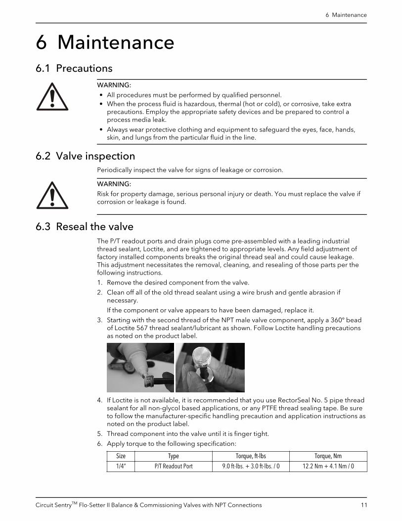
3. Starting with the second thread of the NPT male valve component, apply a 360º beadof Loctite 567 thread sealant/lubricant as shown. Follow Loctite handling precautionsas noted on the product label.
4. If Loctite is not available, it is recommended that you use RectorSeal No. 5 pipe threadsealant for all non-glycol based applications, or any PTFE thread sealing tape. Be sureto follow the manufacturer-specific handling precaution and application instructions asnoted on the product label.
5. Thread component into the valve until it is finger tight.
6. Apply torque to the following specification:
Size Type Torque, ft-lbs Torque, Nm
1/4” P/T Readout Port 9.0 ft-lbs. + 3.0 ft-lbs. / 0 12.2 Nm + 4.1 Nm / 0
6 Maintenance
Circuit SentryTM Flo-Setter II Balance & Commissioning Valves with NPT Connections 11
NOTICE:
– The use of thread sealants and lubricants on threads also provides lubricity. Over-application of torque can damage the valve port or component.
– Thread sealant should not be used in combination with PTFE thread sealing tape.Using both together can cause leakage and damage the valve or fitting.
7. Properly assembled valve components will immediately seal to moderate pressure (6bar [100 PSI] or less). For maximum pressure resistance, allow the Loctite 5671 orRectorSeal No. 52 thread sealant to cure for 24 hours. PTFE tape typically does notrequire curing to achieve maximum pressure resistance.
6.4 Attach insulationTo maximize energy savings, attach insulation to the valve after the system has beenbalanced. Tape or other acceptable means can be used to secure the insulation to thevalve. The insulation must not cover the valve handle.
1 Loctite and Loctite 567 are registered trademarks of Henkel Ag & Co.2 RectorSeal No.5 is a registered trademark of RectorSeal Corporation.
6 Maintenance
12 Circuit SentryTM Flo-Setter II Balance & Commissioning Valves with NPT Connections

7 Product warrantyCommercial warranty
Warranty. For goods sold to commercial buyers, Seller warrants the goods sold to Buyerhereunder (with the exception of membranes, seals, gaskets, elastomer materials,coatings and other "wear parts" or consumables all of which are not warranted except asotherwise provided in the quotation or sales form) will be (i) be built in accordance withthe specifications referred to in the quotation or sales form, if such specifications areexpressly made a part of this Agreement, and (ii) free from defects in material andworkmanship for a period of one (1) year from the date of installation or eighteen (18)months from the date of shipment (which date of shipment shall not be greater than thirty(30) days after receipt of notice that the goods are ready to ship), whichever shall occurfirst, unless a longer period is specified in the product documentation (the “Warranty”).
Except as otherwise required by law, Seller shall, at its option and at no cost to Buyer,either repair or replace any product which fails to conform with the Warranty providedBuyer gives written notice to Seller of any defects in material or workmanship within ten(10) days of the date when any defects or non-conformance are first manifest. Undereither repair or replacement option, Seller shall not be obligated to remove or pay for theremoval of the defective product or install or pay for the installation of the replaced orrepaired product and Buyer shall be responsible for all other costs, including, but notlimited to, service costs, shipping fees and expenses. Seller shall have sole discretion as tothe method or means of repair or replacement. Buyer’s failure to comply with Seller’srepair or replacement directions shall terminate Seller’s obligations under this Warrantyand render the Warranty void. Any parts repaired or replaced under the Warranty arewarranted only for the balance of the warranty period on the parts that were repaired orreplaced. Seller shall have no warranty obligations to Buyer with respect to any product orparts of a product that have been: (a) repaired by third parties other than Seller or withoutSeller’s written approval; (b) subject to misuse, misapplication, neglect, alteration,accident, or physical damage; (c) used in a manner contrary to Seller’s instructions forinstallation, operation and maintenance; (d) damaged from ordinary wear and tear,corrosion, or chemical attack; (e) damaged due to abnormal conditions, vibration, failureto properly prime, or operation without flow; (f) damaged due to a defective powersupply or improper electrical protection; or (g) damaged resulting from the use ofaccessory equipment not sold or approved by Seller. In any case of products notmanufactured by Seller, there is no warranty from Seller; however, Seller will extend toBuyer any warranty received from Seller’s supplier of such products.
THE FOREGOING WARRANTY IS EXCLUSIVE AND IN LIEU OF ANY AND ALL OTHEREXPRESS OR IMPLIED WARRANTIES, GUARANTEES, CONDITIONS OR TERMS OFWHATEVER NATURE RELATING TO THE GOODS PROVIDED HEREUNDER, INCLUDINGWITHOUT LIMITATION ANY IMPLIED WARRANTIES OF MERCHANTABILITY ANDFITNESS FOR A PARTICULAR PURPOSE, WHICH ARE HEREBY EXPRESSLY DISCLAIMEDAND EXCLUDED. EXCEPT AS OTHERWISE REQUIRED BY LAW, BUYER’S EXCLUSIVEREMEDY AND SELLER’S AGGREGATE LIABILITY FOR BREACH OF ANY OF THEFOREGOING WARRANTIES ARE LIMITED TO REPAIRING OR REPLACING THE PRODUCTAND SHALL IN ALL CASES BE LIMITED TO THE AMOUNT PAID BY THE BUYER FOR THEDEFECTIVE PRODUCT. IN NO EVENT SHALL SELLER BE LIABLE FOR ANY OTHER FORMOF DAMAGES, WHETHER DIRECT, INDIRECT, LIQUIDATED, INCIDENTAL,CONSEQUENTIAL, PUNITIVE, EXEMPLARY OR SPECIAL DAMAGES, INCLUDING BUTNOT LIMITED TO LOSS OF PROFIT, LOSS OF ANTICIPATED SAVINGS OR REVENUE,LOSS OF INCOME, LOSS OF BUSINESS, LOSS OF PRODUCTION, LOSS OFOPPORTUNITY OR LOSS OF REPUTATION.
Limited consumer warranty
Warranty. For goods sold for personal, family or household purposes, Seller warrants thegoods purchased hereunder (with the exception of membranes, seals, gaskets, elastomer
7 Product warranty
Circuit SentryTM Flo-Setter II Balance & Commissioning Valves with NPT Connections 13

materials, coatings and other "wear parts" or consumables all of which are not warrantedexcept as otherwise provided in the quotation or sales form) will be free from defects inmaterial and workmanship for a period of one (1) year from the date of installation oreighteen (18) months from the product date code, whichever shall occur first, unless alonger period is provided by law or is specified in the product documentation (the“Warranty”).
Except as otherwise required by law, Seller shall, at its option and at no cost to Buyer,either repair or replace any product which fails to conform with the Warranty providedBuyer gives written notice to Seller of any defects in material or workmanship within ten(10) days of the date when any defects or non-conformance are first manifest. Undereither repair or replacement option, Seller shall not be obligated to remove or pay for theremoval of the defective product or install or pay for the installation of the replaced orrepaired product and Buyer shall be responsible for all other costs, including, but notlimited to, service costs, shipping fees and expenses. Seller shall have sole discretion as tothe method or means of repair or replacement. Buyer’s failure to comply with Seller’srepair or replacement directions shall terminate Seller’s obligations under this Warrantyand render this Warranty void. Any parts repaired or replaced under the Warranty arewarranted only for the balance of the warranty period on the parts that were repaired orreplaced. The Warranty is conditioned on Buyer giving written notice to Seller of anydefects in material or workmanship of warranted goods within ten (10) days of the datewhen any defects are first manifest.
Seller shall have no warranty obligations to Buyer with respect to any product or parts of aproduct that have been: (a) repaired by third parties other than Seller or without Seller’swritten approval; (b) subject to misuse, misapplication, neglect, alteration, accident, orphysical damage; (c) used in a manner contrary to Seller’s instructions for installation,operation and maintenance; (d) damaged from ordinary wear and tear, corrosion, orchemical attack; (e) damaged due to abnormal conditions, vibration, failure to properlyprime, or operation without flow; (f) damaged due to a defective power supply orimproper electrical protection; or (g) damaged resulting from the use of accessoryequipment not sold or approved by Seller. In any case of products not manufactured bySeller, there is no warranty from Seller; however, Seller will extend to Buyer any warrantyreceived from Seller’s supplier of such products.
THE FOREGOING WARRANTY IS PROVIDED IN PLACE OF ALL OTHER EXPRESSWARRANTIES. ALL IMPLIED WARRANTIES, INCLUDING BUT NOT LIMITED TO THEIMPLIED WARRANTIES OF MERCHANTABILITY AND FITNESS FOR A PARTICULARPURPOSE, ARE LIMITED TO ONE (1) YEAR FROM THE DATE OF INSTALLATION OREIGHTEEN (18) MONTHS FROM THE PRODUCT DATE CODE , WHICHEVER SHALLOCCUR FIRST. EXCEPT AS OTHERWISE REQUIRED BY LAW, BUYER’S EXCLUSIVEREMEDY AND SELLER’S AGGREGATE LIABILITY FOR BREACH OF ANY OF THEFOREGOING WARRANTIES ARE LIMITED TO REPAIRING OR REPLACING THE PRODUCTAND SHALL IN ALL CASES BE LIMITED TO THE AMOUNT PAID BY THE BUYER FOR THEDEFECTIVE PRODUCT. IN NO EVENT SHALL SELLER BE LIABLE FOR ANY OTHER FORMOF DAMAGES, WHETHER DIRECT, INDIRECT, LIQUIDATED, INCIDENTAL,CONSEQUENTIAL, PUNITIVE, EXEMPLARY OR SPECIAL DAMAGES, INCLUDING BUTNOT LIMITED TO LOSS OF PROFIT, LOSS OF ANTICIPATED SAVINGS OR REVENUE,LOSS OF INCOME, LOSS OF BUSINESS, LOSS OF PRODUCTION, LOSS OFOPPORTUNITY OR LOSS OF REPUTATION.
Some states do not allow limitations on how long an implied warranty lasts, so the abovelimitation may not apply to you. Some states do not allow the exclusion or limitation ofincidental or consequential damages, so the above exclusions may not apply to you. Thiswarranty gives you specific legal rights, and you may also have other rights which mayvary from state to state.
To make a warranty claim, check first with the dealer from whom you purchased theproduct or visit www.xyleminc.com for the name and location of the nearest dealerproviding warranty service.
7 Product warranty
14 Circuit SentryTM Flo-Setter II Balance & Commissioning Valves with NPT Connections
Xylem |’zīləm|
1) The tissue in plants that brings water upward from the roots;2) a leading global water technology company.
We’re a global team unified in a common purpose: creating advancedtechnology solutions to the world’s water challenges. Developing newtechnologies that will improve the way water is used, conserved, and re-used inthe future is central to our work. Our products and services move, treat, analyze,monitor and return water to the environment, in public utility, industrial,residential and commercial building services, and agricultural settings. With itsOctober 2016 acquisition of Sensus, Xylem added smart metering, networktechnologies and advanced data analytics for water, gas and electric utilities toits portfolio of solutions. In more than 150 countries, we have strong, long-standing relationships with customers who know us for our powerfulcombination of leading product brands and applications expertise with a strongfocus on developing comprehensive, sustainable solutions.
For more information on how Xylem can help you, go to www.xylem.com
Xylem Inc.8200 N. Austin AvenueMorton Grove IL 60053Tel: (847) 966–3700Fax: (847) 965–8379www.bellgossett.com
Visit our Web site for the latest version of this documentand more information
The original instruction is in English. All non-Englishinstructions are translations of the original instruction.
© 2016 Xylem Inc
Bell & Gossett is a trademark of Xylem Inc or one of itssubsidiaries.
V1002552_B_12-2016


