CRITERIA FOR PERFORMING SITE ACCEPTABILITY STUDIES FOR SOLID WASTE LANDFILLS IN GEORGIA William H. McLemore Paul D. Perriello Department of Natural Resources Environmental Protection Division Georgia Geologic Survey CIRCULAR 14
Transcript
CRITERIA FOR PERFORMING SITEACCEPTABILITY STUDIES FOR SOLID
WASTE LANDFILLS IN GEORGIA
William H. McLemorePaul D. Perriello
Department of Natural ResourcesEnvironmental Protection Division
Georgia Geologic Survey
CIRCULAR 14
CRITERIA FOR PERFORMING SITE ACCEPTABILITY STUDIESFOR SOLID WASTE LANDFILLS IN GEORGIA
William H. McLemorePaul D. Perriello
Georgia Department of Natural ResourcesLonice C. Barrett, Commissioner
Environmental Protection DivisionHarold F. Reheis, Director
Georgia Geologic SurveyWilliam H. McLemore, State Geologist
Table I - Format for Municipal Solid Waste Landfill Site Acceptability Studies. . . . . . . . . . . . . . . . . . . . . . . . . . . . . . . . . . 19
�
CRITERIA FOR PERFORMING SITE ACCEPTABILITY STUDIESFOR SOLID WASTE LANDFILLS IN GEORGIA
William H. McLemorePaul D. Perriello
Background
Siting of municipal solid waste landfills rarely was ascientific process prior to the reorganization of StateGovernment and the creation of the Georgia EnvironmentalProtection Division (EPD) in 1972. Wastes of all typeswere often "dumped" in local borrow pits, quarries orsimply alongside rural roads. However, with passage of theSolid Waste1 Management Act in 1972, site selection formunicipal solid waste landfills became a rigorous applica-tion of both engineering and geology. Almost all municipalsolid waste landfill site evaluations were performed by EPDgeologists between 1973 and 1983. Since 1984, consultingengineers and geologists have performed progressively moreevaluations. While consultants in 1984 rarely performedanything more than drilling and logging boreholes, theircurrent activities often include substantial evaluations of theground-water flow regime, the behavior of potential pollut-ants in the subsurface, and the design of liner/leachatecollection systems. The Georgia Department of NaturalResources' 5-year plan called for EPD to require all solidwaste landfill applicants to conduct their own site accept-ability assessments on all proposed solid waste sites begin-ning in 1989, as opposed to EPD conducting the assessment.
This circular does not provide information as to howa site acceptability study should be performed or what EPDwill regard as an acceptable site. Rather, the purpose of thismanual is to explain how EPD will evaluate the complete-ness of consultants' reports so that EPD will be in a positionto make a determination as to whether or not a letter of site
acceptability should be issued for a proposed landfill. Thiswill be done by reviewing how the various laws and rulesaffect landfill siting.
In reviewing reports, EPD will base its decision-making on (a) actual measurements versus estimates; (b)direct measurements versus indirect measurements; and (c)consistency with commonly accepted engineering andgeologic practices. EPD recognizes that strict adherence tothe above is not always possible. For example, EPD wouldnot necessarily expect a consultant to make water-levelmeasurements over a year's period of time simply to evalu-ate seasonal ground-water fluctuations. An estimate basedon EPD-USGS monitoring wells in similar geologic terranesshould be adequate in this case.
One final point needs to be made; simply because aconsultant's report is complete and thorough does not meanthat the site is acceptable. There are some sites that cannotbe reasonably made suitable for solid wastes without posingan undue risk to public health and the environment.
Types of Landfills Considered
From a regulatory perspective, there are four types ofsolid waste landfills:
A municipal solid waste landfill, as defined by theRules for Solid Waste Management, is a disposal site wheresolid wastes from homes, commercial buildings, govern-mental buildings or institutional facilities are disposed of bymeans of placing an earth cover thereon. Industrial solidwaste is solid waste generated by manufacturing or indus-trial processes that is not a hazardous waste under regula-tions promulgated by the Board of Natural Resources,Chapter 391-3-11. A construction/demolition solid wastelandfill accepts waste building materials and rubble resultingfrom construction, remodeling, repair and demolitionoperations of pavements, houses, commercial buildingsand/or other structures. Such wastes include, but are notnecessarily limited to wood, bricks, metal, concrete, wallboard, paper or cardboard. An inert solid waste landfill, on
the other hand, is a disposal site accepting only wastes thatwill not or is not likely to produce leachate that is deleteri-ous to the environment (such wastes are limited to earth andearth-like products, concrete, cured asphalt, rock, bricks,yard trimmings, stumps, limbs and leaves; this definitionexcludes industrial and some types of demolition solidwaste). Site assessments are not required for inert wastelandfills, but EPD does expect that such wastes will bedisposed of in a manner that does not adversely affectadjacent properties and surface waters.
This guidance manual is directed primarily at the sitingof municipal solid waste landfills. Guidance is also pro-vided for industrial solid waste landfills and construc-tion/demolition solid waste landfills in Appendices A and Brespectively.2
Statutory Authority
General
There are several Georgia laws that directly affect thesiting of municipal solid waste landfills. The primary lawrelevant to site evaluation is the Comprehensive GeorgiaSolid Waste Management Act (O.C.G.A. 12-8-20). Rulespromulgated thereunder specify geologic, hydrologic andother criteria that must be satisfied for an acceptable site.Rules for recharge area and watershed protection promul-gated under the Growth Strategies Planning Act (O.C.G.A.12-2-8); rules for wellhead protection, promulgated underthe Georgia Safe Drinking Water Act of 1977 (O.C.G.A. 12-5-170); rules governing development along designated"trout streams," promulgated under the Georgia Erosion andSedimentation Act of 1975 (O. C. G. A. 12-7-1), may affectthe siting and/or the development of a landfill.
Significant Recharge Areas
The Growth Strategies Planning Act required that EPDpromulgate rules or standards that give Significant Ground-Water Recharge Areas special protection (Chapter 391-3-16-.02). For the purposes of solid waste management, aSignificant Ground-Water Recharge Area means any area sodesignated on Hydrologic Atlas 18, Most SignificantGround-Water Recharge Areas of Georgia, 1989, as pub-lished by the Georgia Geologic Survey, Environmental
Protection Division, Georgia Department of Natural Re-sources. Any municipal solid waste landfill that is sited ina Most Significant Ground-Water Recharge Area shall havea synthetic liner and a leachate collection system. A furtherrestriction has been placed on sites located in significantground-water recharge areas. In particular, the Comprehen-sive Solid Waste Management Act (§12-8-25.3(d)) statesthat: "No permit shall be issued for a municipal solid wastelandfill within two miles of a federally restricted military airspace which is used for a bombing range."
Limits on the Number of Solid Waste Facilitiesin a Given Area
The Comprehensive Solid Waste Management Act(§12-8-25.4(b)) also limits the number of private wastedisposal facilities that may be permitted in a given geo-graphic area. No permit shall be issued for a privateindustry solid waste disposal facility if any part of the areaproposed for permitting would lie within a geographic areawhich would meet the following criteria:
(1) The geographic area is in the shape of a circle witha two mile radius, the centerpoint of which may be anypoint within the area proposed for permitting; and
(2) The circular geographic area already includes allor a portion of three or more landfills (including the landfillproposed for permitting in the case of a proposed expan-sion).
Erosion Control Along "Trout Streams"
Under the Georgia Erosion and Sedimentation Act of1975, as amended through 1995 (§12-7-6.(b)(16)) land-disturbing activities are regulated along designated "troutstreams" in Georgia. The implementation of this act mayaffect landfill siting decisions, and will certainly affect thedesign and construction of landfills sited adjacent to thedesignated "trout streams." The act states that:
Land-disturbing activities shall not be conductedwithin 100 horizontal feet, as measured from the pointwhere vegetation has been wrested by normal streamflow or wave action, of banks of any state watersclassified as "trout streams" pursuant to Article 2 ofChapter 5 of this title, the "Georgia Water QualityAct," unless a variance for such activity is granted bythe Director except where a roadway drainage struc-ture must be constructed, provided that adequateerosion control measures are incorporated in theproject plans and specifications and are implemented.
If a proposed landfill site is located adjacent to aperennial stream, it is the applicant’s responsibility to
determine if the stream is a designated "trout stream", and tosummarize this determination in the site assessment report.
Protection of Water Supply Watersheds
The Rules for Environmental Planning Criteria(Chapter 391-3-16-.01) specify certain minimum protectioncriteria for water supply watersheds. In particular:
(1) Within seven (7) miles upstream of a govern-mentally owned public drinking water supply intake orwater supply reservoir, there shall be a 100 foot buffer onboth sides of perennial streams as measured from the streambanks.
(2) Within seven (7) miles upstream of a govern-mentally owned public drinking water supply intake orwater supply reservoir, no impervious surface shall beconstructed within a 150 foot setback as measured from thestream banks of any perennial stream. (Note: This meansthat if the site is to be lined, no portion of the liner shall bewithin 150 feet of a perennial stream).
(3) Beyond the aforementioned seven miles, and if thewatershed is less than 100 square miles, the perennial streambuffer and setback shall be 50 feet and 75 feet respectively.
(4) If the watershed is less than 100 square miles, newmunicipal solid waste landfills are allowed only if they havesynthetic liners and leachate collection systems.
Wellhead Protection
The Rules for Safe Drinking Water (Chapter 391-3-5-.40) specify a wellhead protection area around wells andsprings used as sources of water supply for communitypublic water systems serving municipalities, counties, andauthorities, to protect them from nearby pollution sources.Every wellhead protection area consists of two zones, asmaller (15 to 25 feet) control zone and a larger manage-ment zone. Within the management zone, certain potentialpollution sources are prohibited or certain activities must beperformed in accordance with the wellhead protection rules.The management zone, in turn, has two parts: an innermanagement zone and an outer management zone. The sizeand shape of the management zone will vary according toaquifer type, aquifer hydraulic conductivity, pumpage rate,hydrologic province, and proximity to recharge. EPD shalldelineate the size and shape of the management zone of awellhead protection area as follows:
(1) Wells determined by EPD as drawing water onlyfrom confined aquifers shall have an inner managementzone extending outward from the center of the borehole fora radius of 100 feet. No outer management zone is required
for such wells.
(2) Wells drawing water from unconfined aquifers asdetermined by EPD and springs, except those determined byEPD to lie in areas of karst, shall have an inner managementzone extending outward from the center of the borehole orspring head for a radius of 250 feet.
(3) Wells drawing water from unconfined aquifers asdetermined by EPD and springs, which EPD has identifiedas being in areas of karst, shall have an inner managementzone extending outward from the center of the borehole orspring head for a radius of 500 feet.
(4) Unconfined wells which EPD has determinedutilize fractured crystalline rock aquifers shall have an outermanagement zone determined according to the "CaptureZone Curve" contained in the EPA approved GeorgiaWellhead Protection Plan.
(5) Unconfined aquifer wells determined by EPD aslying in karst regions and all springs shall have an outermanagement zone determined by hydrogeologic mapping.
(6) Other wells not meeting the above criteria shallhave their outer management zones determined by timetravel calculations (a minimum of a 5-year time of travel) orby volumetric calculations as appropriate.
EPD will not issue any new permits for municipalsolid waste landfills, industrial waste landfills or construc-tion/demolition waste landfills within the inner and outermanagement zones of those existing wells and springs, forwhich a wellhead protection plan has been developed.Delineation of wellhead protection areas for municipal watersupply wells is ongoing and should be completed by July 1,2003. The assessment report must show the outer manage-ment zone of all applicable wells that are located within twomiles of the proposed landfill site boundary. (Note: Whileit is EPD's responsibility to delineate the size and shape ofthe management zone of a wellhead protection area, it is theapplicant's responsibility to provide EPD with sufficient datato make the delineation when a management zone has notalready been established for a well).
Areas Poorly Suited For a MunicipalSolid Waste Landfill
EPD has completed a series of maps showing areasconsidered to be poorly suited for a municipal solid wastelandfill. These maps, at a scale of 1:100,000 (one centime-
�
ter equals one kilometer) are available for each of theRegional Development Centers, with the first maps beingavailable around March 1, 1990.
The maps were created by putting demographic,topographic, hydrologic and geologic data into a computer-based Geographic Information System (GIS) and thenintegrating the data. This integration or "stacking" of databases results in a composite map that depicts, in red, areasconsidered by EPD to be geotechnically poorly suited forthe construction and/or operation of a municipal solid wastelandfill. In a map area denoted by red, the potential forfinding a municipal solid waste landfill that will be accept-able in its natural state is unlikely, but not impossible.
Uncolored areas on the GIS composite maps representland where the available data suggest that the potential forfinding a viable municipal solid waste landfill site is better.Actual site investigations meeting the State's Rules for SolidWaste Management, will have to be performed before anysite approval can be given. These maps should help identifyareas where the potential for siting a municipal solid wastelandfill is least favorable, so that applicants can direct theirsite selection activities to those areas where the potential forsuccessful siting is better.
One note of caution about using these maps must begiven. In some counties, such as those in the DoughertyPlain area of southwest Georgia, virtually all of the land areais poorly suited for solid waste landfilling, because it islocated in a karst terrain. EPD would not preclude theconstruction of a municipal solid waste landfill where this isthe case, but rather, EPD would require the applicant toimplement engineering designs that would ensure that theintegrity of the structural components in the landfill wouldnot be disrupted. A digital GIS data base showing areaspoorly suited for a municipal solid waste landfill is availablefor sale from the Georgia Geologic Survey.
Proximity to County Boundaries andto Significant Ground-Water Recharge
Areas
No permit shall be issued to any applicant for a solidwaste disposal facility in any county, if any part of the siteis within one-half mile of an adjoining county, without theapplicant first receiving express approval from the govern-ing authority of the adjoining county. EPD does notinterpret these statutes to apply to counties of adjacentstates. A site within one-half mile of the Florida borderdoes not need the approval of the adjoining Florida countyin order to be permitted.
The Comprehensive Solid Waste Management Actalso stipulates:
"that no permit shall be issued for any municipal solidwaste landfill, which accepts waste generated outside
the county, if any part of the site is within a MostSignificant Ground-Water Recharge Area, unless theboundaries of the counties (or special districts) ap-proved to engage in solid waste management activitiesare contiguous and such counties (or special districts)have entered into a joint contract for the collectionand disposal of solid waste."
Criteria for Siting
The following criteria must be met for a site proposedas a municipal solid waste landfill:
(A) Zoning: The site must conform to all localzoning/land use ordinances. Written verification must besubmitted to the Division by the applicant demonstratingthat the proposed site complies with local zoning and landuse ordinances, if any. This verification shall include aletter from the local governmental authority stating that theproposed site complies with local zoning or land useordinances, if any. This verification shall be provided at thetime of submission of a permit application and reaffirmed bythe governmental authority prior to permit issuance.
(B) Disposal Facility Siting Decision: Whenever anycounty, municipality, group of counties, or authority beginsa process to select a site for a municipal solid waste disposalfacility, documentation shall be submitted which demon-strates compliance with O.C.G.A. 12-8-26(a), and wheneverthe governing authority of any county or municipality takesaction resulting in a publicly or privately owned municipalsolid waste disposal facility siting decision, documentationshall be submitted which demonstrates compliance withO.C.G.A 12-8-26(b).
(C) Airport Safety:
(1) New Municipal Solid Waste Landfill(MSWLF) units or lateral expansions of existing units shallnot be located within 10,000 feet (3,048 meters) of anypublic-use or private-use runway end used by turbojetaircraft or within 5,000 feet (1,524 meters) of any public-useor private-use airport runway end used by only piston-typeaircraft.
(2) Owners or operators of existing MSWLFunits, that are located within 10,000 feet (3,048 meters) ofany public-use or private-use airport runway end used byturbojet aircraft or within 5,000 feet (1,524 meters) of anypublic-use or private-use airport runway end used by onlypiston-type aircraft must demonstrate that the units aredesigned and operated so that the MSWLF units do not posea bird hazard to aircraft.
(3) Owners or operators proposing to site new
�
MSWLF units and lateral expansions within a five-mileradius of any public-use or private-use airport runway endused by turbojet or piston-type aircraft must notify theaffected airport and the Federal Aviation Administration(FAA).
(4) The owner or operator must place thedemonstration in paragraph (2) of this section of theoperating record and notify the Director that it has beenplaced in the operating record not later than October 1,1993.
(5) For purposes of this section:
(a) "Public-use airport" means an airportopen to the public without prior permission and withoutrestrictions within the physical capacities of availablefacilities.
(b) "Private-use airport" means an airportthat is not open to the public and which may not be usedwithout prior permission of the airport owner and which hasrestrictions other than the physical capacities of availablefacilities and such airport is shown on the SectionalAeronautical Charts published by the U. S. Department ofCommerce for Atlanta, Jacksonville, or New Orleans, whichcharts are dated at least one year prior to the submission ofa MSWLF permit or major permit modification application.
(c) "Bird hazard" means an increase in thelikelihood of bird/aircraft collisions that may cause damageto the aircraft or injury to its occupants.
(D) Floodplains: A solid waste handling facilitylocated in the 100-year floodplain shall not restrict the flowof the 100-year flood, reduce the temporary water storagecapacity of the floodplain, or result in a washout of solidwaste so as to pose a hazard to human health and theenvironment. The owner or operator must place ademonstration of compliance in the operating record andnotify the Director that it has been placed in the operatingrecord.
(1) For purposes of this section:
(a) "Floodplain" means the lowland andrelatively flat areas adjoining inland and coastal waters,including flood-prone areas of offshore islands, that areinundated by the 100-year flood.
(b) "100-year flood" means a flood that hasa 1-percent or greater chance of recurring in any given yearor a flood of a magnitude equaled or exceeded once in 100years on the average over a significantly long period.
(c) "Washout" means the carrying away ofsolid waste by waters of the base flood.
(E) Wetlands: A solid waste handling facility shallnot be located in wetlands, as defined by the U. S. Corps ofEngineers, unless evidence is provided to the Director, bythe applicant, that use of such wetlands has been permittedor otherwise authorized under all other applicable state andfederal laws and rules. The owner or operator must place ademonstration of compliance in the operating record andnotify the Director that it has been placed in the operatingrecord.
(F) Fault Areas:3
(1) New landfill units and lateral expansions ofexisting landfills shall not be located within 200 feet (60meters) of a fault that has had displacement in Holocenetime unless the owner or operator demonstrates to theDirector that an alternative setback distance of less than 200feet (60 meters) will prevent damage to the structuralintegrity of the landfill unit and will be protective of humanhealth and the environment.
(2) For the purposes of this section:
(a) "Fault" means a fracture or a zone offractures in any material along which strata on one side havebeen displaced with respect to that on the other side.
(b) "Displacement" means the relativemovement of any two sides of a fault measured in anydirection.
(c) "Holocene" means the most recentepoch of the Quaternary period, extending from the end ofthe Pleistocene Epoch to the present.
(G) Seismic Impact Zones:
(1) New landfill units and lateral expansionsshall not be located in seismic impact zones, unless theowner or operator demonstrates to the Director that allcontainment structures, including liners, leachate collectionsystems, and surface water control systems, are designed toresist the maximum horizontal acceleration in lithified earthmaterial for the site. The owner or operator must place thedemonstration in the operating record and notify theDirector that it has been placed in the operating record.
(a) Seismic impact zone means an area witha ten percent or greater probability that the maximumhorizontal acceleration in lithified earth material, expressedas a percentage of the earth's gravitational pull will exceed0.10g in 250 years.
(b) Maximum horizontal acceleration inlithified earth material means the maximum expectedhorizontal acceleration depicted on a seismic hazard map,with a 90 percent or greater probability that the accelerationwill not be exceeded in 250 years, or the maximum expectedhorizontal acceleration based on a site-specific seismic riskassessment.
(c) Lithified earth material means all rock,including all naturally occurring and naturally formedaggregates or masses of minerals or small particles of olderrock that formed by crystallization of magma or byinduration of loose sediments. This term does not includeman-made materials, such as fill, concrete, and asphalt, orunconsolidated earth materials, soil, or regolith lying at ornear the earth surface.
(H) Unstable areas:
(1) Owners or operators of new landfill units,existing landfill units, and lateral expansions located in anunstable area must demonstrate that the engineeringmeasures have been incorporated into the landfill unit'sdesign to ensure that the integrity of the structuralcomponents of the landfill unit will not be disrupted. Theowner or operator must place the demonstration in theoperating record and notify the Director that it has beenplaced in the operating record. The owner or operator mustconsider the following factors, at a minimum, whendetermining whether an area is unstable:
(a) on-site or local soil conditions that mayresult in significant differential settling;
(b) on-site or local geologic or geo-morphologic features; and
(c) on-site or local human-made features orevents (both surface and subsurface).
(2) For the purposes of this section:
(a) "Unstable area" means a location that issusceptible to natural or human-induced events or forcescapable of impairing the integrity of some or all of thelandfill structural components responsible for preventingreleases from a landfill. Unstable areas can include poorfoundation conditions, areas susceptible to mass move-ments, and karst terrains.
(b) "Structural components" means liners,leachate collection systems, final covers, run-on/run-off sys-tems, and any other component used in the construction andoperation of the landfill that is necessary for the protectionof human health and the environment.
(c) "Poor foundation conditions" meansthose areas where features exist which indicate that anatural or man-induced event may result in inadequatefoundation support for the structural components of alandfill unit.
(d) "Areas susceptible to mass movement"mean those areas of influence (i.e., areas characterized ashaving an active or substantial possibility of massmovement) where the movement of earth material at,beneath, or adjacent to the landfill unit, because of natural orman-induced events, results in the downslope transport ofsoil and rock material by means of gravitational influence.Areas of mass movement include, but are not limited to,landslides, avalanches, debris slides and flows, soil fluction,block sliding, and rock fall.
(e) "Karst terrains" means areas wherekarst topography, with its characteristic surface andsubterranean features, is developed as the result ofdissolution of limestone, dolomite, or other soluble rock.Characteristic physiographic features present in karstterrains include, but are not limited to, sinkholes, sinkingstreams, caves, large springs, and blind valleys.
(I) Closure of existing municipal solid waste landfillunits:
(1) Existing MSWLF units that cannot make thedemonstration specified in section (C), pertaining toairports, section (D), pertaining to floodplains, or section(H), pertaining to unstable areas, must close by October 9,1996 in accordance with Rule 391-3-4-.11 and conduct post-closure care activities in accordance with Rule 391-3-4-.12.
(2) The deadline for closure required bysubparagraph (1) of this paragraph may be extended up totwo years if the owner or operator demonstrates to theDirector that:
(a) there is no available alternative disposalcapacity; and
(b) there is no immediate threat to humanhealth and the environment.
(J) Significant Ground-Water Recharge Areas: A newmunicipal solid waste landfill or lateral expansion of anexisting municipal solid waste landfill shall not have any
�
part of such site located within two miles of any area thathas been designated by the Director as a significant ground-water recharge area unless such municipal solid wastelandfill will have a liner and leachate collection system. Inthe case of a regional landfill which accepts municipal solidwaste generated outside of the counties or special districtsconstituting the region or a solid waste landfill whichaccepts solid waste generated outside the county in whichthe landfill is located, no part of such site shall be locatedwithin any area that has been designated as a MostSignificant Ground-Water Recharge Area.
(K) Hydrogeological Assessment: A hydrogeologicalsite investigation shall be conducted with the followingfactors, as a minimum, evaluated:
(1) Distance to nearest point of public or privatedrinking water supply: all public water supply wells orsurface water intakes within two miles and private(domestic) water supply wells within one-half (½) mile of alandfill must be identified.
(2) Depth to the uppermost aquifer: for landfills,the thickness and nature of the unsaturated zone and itsability for natural contamination control must be evaluated.
(3) Uppermost aquifer gradient: for landfills, thedirection and rate of flow of ground water shall bedetermined in order to properly evaluate the potential forcontamination at a specific site. Measurements of waterlevels in site exploratory borings and the preparation ofwater table maps are required. Borings to water are requiredto estimate the configuration and gradient of the uppermostaquifer.
(4) Topographic setting: features which shall beprovided include, but are not limited to, all upstream anddownstream drainage areas affecting or affected by theproposed site, floodplains, gullies, karst conditions, wet-lands, unstable soils and percent slope.
(5) Geologic setting: for landfills, the depth tobedrock, the type of bedrock and the amount of fracturingand jointing in the bedrock shall be determined. Inlimestone or dolostone regions, obvious karst terrain shallnot be used for waste disposal. This consideration does notpreclude the siting of landfills in limestone terrains, butrather is intended to prevent landfills from being sited in oradjacent to sinkholes, provided, however, that thedemonstration required by section (H) has been made.
(6) Hydraulic conductivity: evaluation of landfillsites shall take into consideration the hydraulic conductivityof the surface material in which the wastes are to be buried,as well as the hydraulic conductivity of the subsurface
materials underlying the fill.
(7) Sorption and attenuation capacity: forlandfills, the sorptive characteristics of an earth material andits ability to absorb contaminants shall be determined.
(8) Distance to surface water: municipal solidwaste landfills shall not be situated within two milesupgradient of any surface water intake for a public drinkingwater source unless engineering modifications such as linersand leachate collection systems and ground-watermonitoring systems are provided.
(L) Proximity to National Historic Sites: Municipalsolid waste landfills shall not be located within 5,708 yardsof a National Historic Site.
(M) Proximity to County Boundaries: Municipalsolid waste landfills shall not be located within one-half (½)mile of a county boundary except when the governingauthority of the adjoining county gives written approval.
Construction/demolition waste landfills must complywith the siting criteria specified in "Criteria for PerformingSite Acceptability Studies for Solid Waste Landfills inGeorgia", Circular 14, Appendix B.
Industrial waste landfills permitted to receive only asingle type of waste (monofill) or receive only a singleindustry's waste, must comply with the siting criteriaspecified in "Criteria for Performing Site AcceptabilityStudies for Solid Waste Landfills in Georgia", Circular 14,Appendix A. Commercial industrial waste landfills mustmeet the same siting criteria as municipal solid wastelandfills.
A site assessment report addressing the criteria listedabove shall be prepared by a geologist registered in Georgiaor a geotechnical engineer registered in Georgia and shall besubmitted to the Environmental Protection Division forreview at the time of submitting a permit application. Ageologist, registered to practice in Georgia, must be part ofthe work effort if the assessment report title contains theword "hydrogeologic" or if the assessment report containssubstantial geologic work. The person signing a report as aregistered geologist should be either:
(1) a full time employee, if the consultant isrepresenting the work as their own; or,
(2) a clearly identified subcontractor. (Note:consultants, at their option, may choose to subcontractthe geological portions of their work to registeredgeologists. If this is the case, the subcontractor'sgeological report should be separated from the mainbody of the report as a separate and clearlyidentifiable chapter or as an appendix).
The site assessment report shall be prepared inaccordance with Circular 14, 1991 (amended, 1997), aspublished by the Georgia Geologic Survey, GeorgiaEnvironmental Protection Division.
Monitoring wells and borings shall be constructed bya driller having a valid and current bond with the WaterWell Standards Advisory Council.
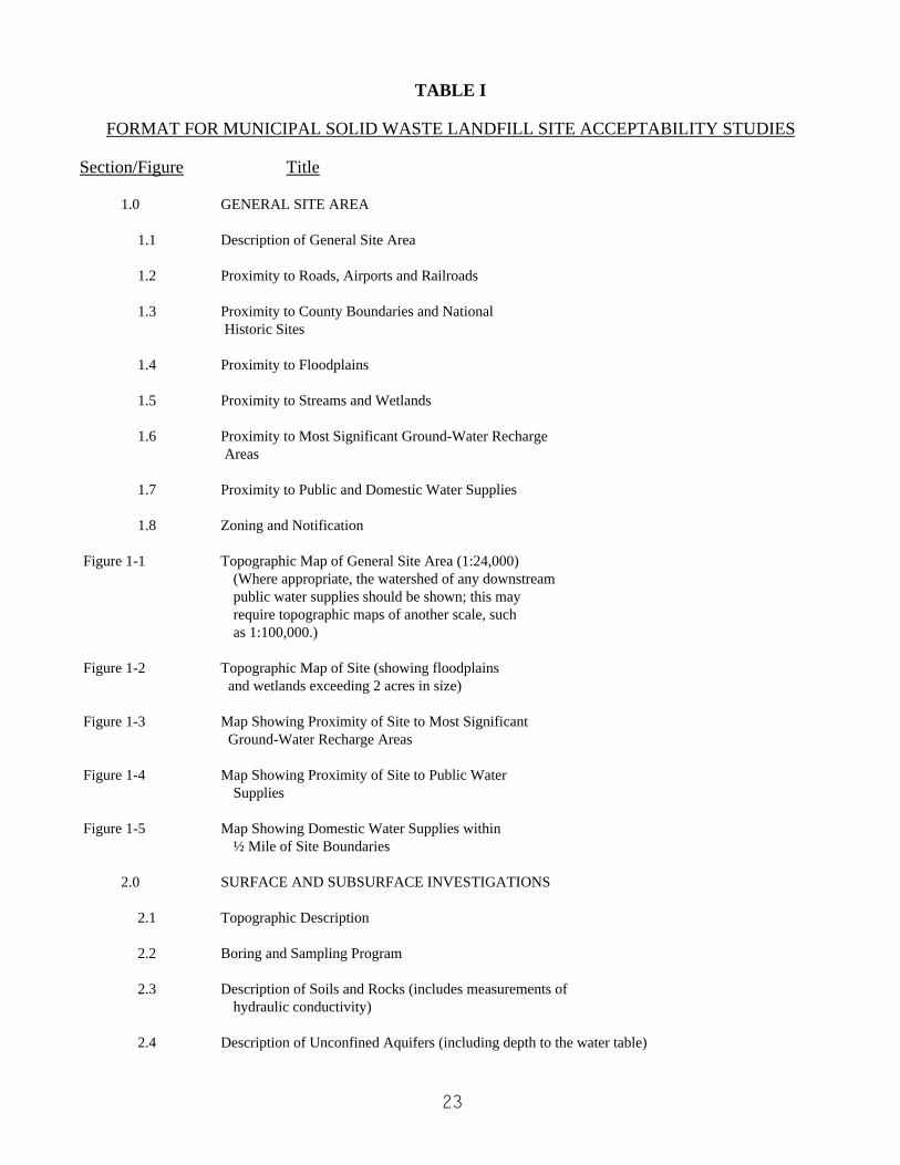
Report Format
In order to better assure consistency of municipal solidwaste landfill site assessments, EPD recommends thatconsultants' reports follow a prescribed format (Table I).This means that reports prepared by different consultants fordifferent sites would have a similar technical content andformat even though actual site conditions will be quitedifferent. All site assessments, for example, need to have aninventory of domestic drinking water wells within one-halfmile of the site boundary. The inventory for some sites mayreveal only a few domestic wells, whereas for other sitesthere may be a relatively large number of domestic wells.
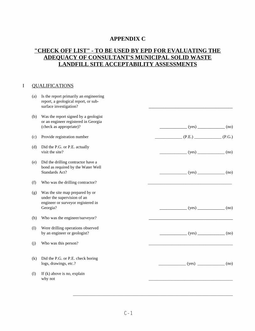
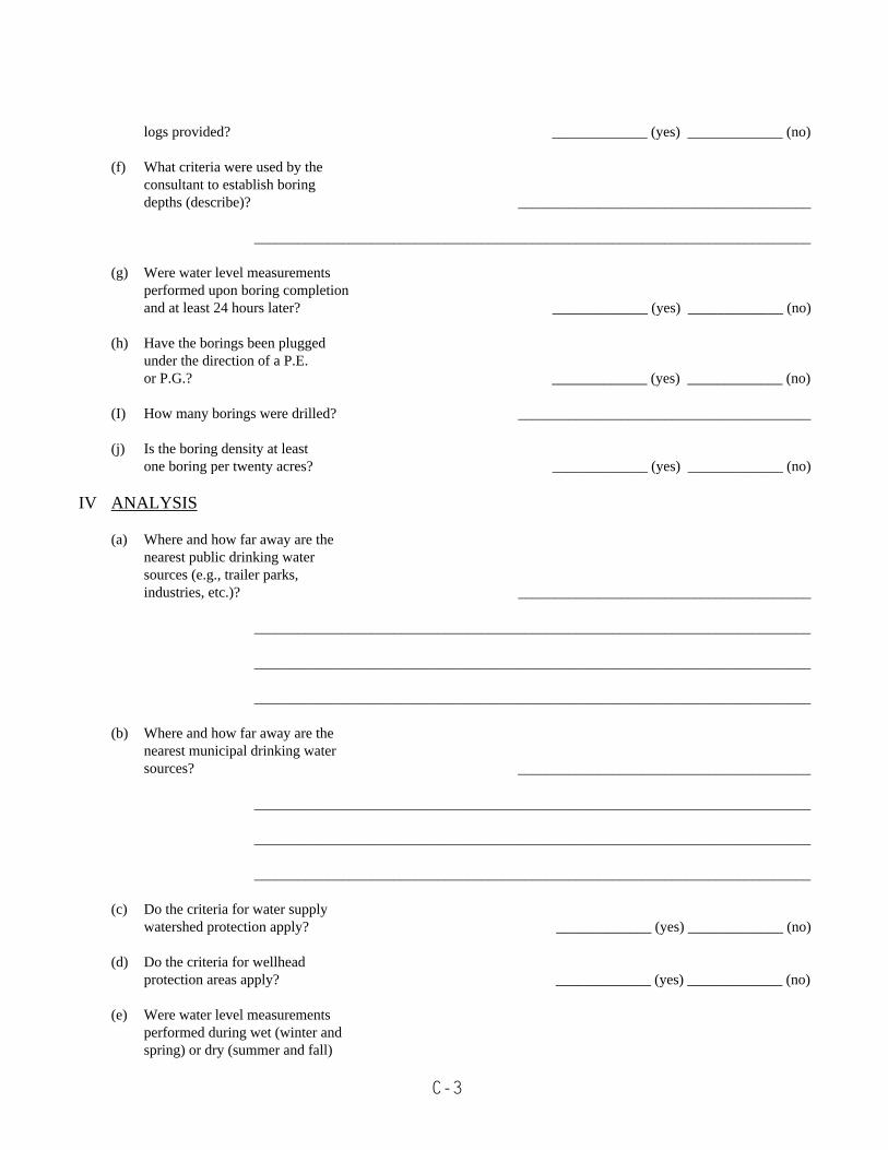
Having reports written in a consistent format willpermit EPD to utilize "check-off" sheets (see Appendix C)so that the completeness of site assessment reports can bedetermined readily. Consultants can use the "check-off"sheets in a similar fashion to assess whether their report willmeet EPD's criteria. If a particular part of the assessmentwere missing (e.g., the aforementioned inventory ofdomestic water wells), then the consultant would know inadvance that the assessment was incomplete and would runthe risk of being rejected by EPD.
Standards
EPD will not review any landfill site assessment studynot prepared under the technical direction of a geologistand/or a geotechnical engineer registered to practice inGeorgia. That geologist or engineer is expected to sign thereport. EPD may request documentation that the geologistor engineer actually directed the study and actually visitedthe site. Simply bringing in a registered geologist orengineer to review and then sign the final report isprofessionally unacceptable. Site topographic maps andborehole locations, with elevations, should be establishedunder the supervision of a land-surveyor or an engineerregistered to practice in Georgia. All investigations andanalytical procedures should either be performed accordingto:
(1) published methods generally accepted in theprofessional practice of geology and geotechnicalengineering (e.g., ASTM, USGS, EPA, etc.); or
(2) published methods generally recognized in theprofessional practice of geology and geotechnical
engineering (e.g., Jacob Method for calculating aquiferproperties, etc.).
These "accepted" and "recognized" procedures shouldbe cited or described in sufficient detail so that EPD canmake a determination as to their appropriateness. Ifmathematical formulae are used in calculations (e.g.,calculations of ground-water flow velocities) then theformulae should be cited.
Site Acceptability Report
General
As mentioned earlier, EPD recommends a format formunicipal solid waste landfill site assessments (refer toTable I). Consultants may deviate from, expand or contractthe format, as appropriate, to make their reports morereadable or more understandable. Because of the widevariety of geologic, hydrologic and engineering conditionsin Georgia, it is not possible to identify or discuss all of thepossible investigative techniques that might need to beemployed for a thorough site evaluation. There is nosubstitute for good professional engineering and goodprofessional geological judgement during the investigativeprocess.
General Site Area
The discussion of the general site area in Section l.lshould contain sufficient information so that EPD can havea basic understanding of the physical and demo-graphic/cultural character of the site. The following issuesshould be addressed: general character and sources of thewastes (e.g., particularly if wastes are special solid waste),general character of the site (i.e., urban, rural or suburban);the presence of facilities permitted by either the state orfederal governments (e.g., industrial operations handlinghazardous materials, ground-water withdrawal wells, naturalgas pipelines, etc.); current land use (i.e., agricultural, forest,mixed, etc.); population and population trends; generaltopography and physiography (including area relief andtypical slope gradient); general geology, including proximityto major geologic features such as faults or shear zones(Note: if faults and shear zones are present, their hydrauliccharacteristics should be discussed); general hydrology,including proximity to aquifers, streams, rivers and lakes;general traffic conditions on adjoining roads; wildlife habitatas well as a general review of flora and fauna; and thelatitude and longitude of the approximate geographic centerof the site.
Sections l.2 and l.3 address proximity to roads,airports, federally restricted military air space which is usedfor a bombing range, railroads, county boundaries andNational Historic Sites. These should be described and,
where possible, shown on a 1:24,000 USGS topographicmap of the site area. Sections l.4 and l.5 deal with surfacehydrology. Data for these sections should be presented ona site topographic map (prepared by or under the supervisionof an engineer or surveyor registered to practice in Georgia).Generally the map scale should not be smaller than 1:2,400,but the scale should not be so large that the entire site cannotbe represented on a 2' x 3' sheet of paper. The topographiccontour interval should not be larger than five feet. The sitetopographic map should show the surveyed boundaries ofthe site as well as all rivers, streams (including intermittentstreams), ponds, lakes, reservoirs, wetlands, sinkholes andsprings (or seeps) occurring within or immediately adjacentto the site. Where available, 100-year flood elevation datafrom FEMA flood insurance maps should be shown on thesite topographic map. If FEMA maps are not available, thegeneral elevation of the 100-year flood may be calculated byan engineer and shown on the site topographic map. (Note:There are few, if any, valid reasons for locating a municipalsolid waste landfill in a 100-year floodplain.) Wetlands(meeting the criteria of 33 CFR parts 320 through 330 and40 CFR part 230) should be located by site traverses andshown on the aforementioned site topographic map. (Note:EPD will not review a site acceptability report notaccompanied by a map delimiting on-site wetlands.)Section l.6 should describe, through narrative and mapinformation, the site proximity to the nearest MostSignificant Ground-Water Recharge Area as shown inHydrologic Atlas No. 18.
Information on proximity of the site to public anddomestic water supplies (Section l.7) is critical to sitedesign. Any site, which in its natural state might allowleachate to adversely affect identified drinking watersources, would have to be specially engineered to mitigateleachate migration. The consultant will need (a) to identifythe nearest downstream surface water withdrawal facility, ifany, and (b) to inventory all public drinking water wellswithin two miles and all domestic water wells within one-half mile of the site.4 The consultant should also provideinformation about the character of the watersheddownstream from the site; the information should addressthe watershed protection criteria promulgated under theGrowth Strategies Planning Act. The inventory of domesticwells generally will have to be performed by identifying allresidences and making an evaluation of whether eachresidence is or is not served by a well. The mere presence of
municipal water lines in rural or suburban areas should notbe considered as evidence that some people do not derivetheir water from wells. People often do not choose to"hook-up" to municipal water supplies and instead continueto use their wells. Conversations with local water supplyofficials or with nearby residents can provide informationregarding ground-water use in the vicinity of the site.
Section l.8 should contain a copy (on letterhead) fromthe appropriate governmental authority stating that the siteconforms with local zoning and land-use ordinances.
Surface and Subsurface Investigations
The general topography of the site should be discussedin Section 2.l and shown on a site topographic map. (Note:this should be the base map used to illustrate surfacehydrology; see Sections l.4 and l.5.) The map also shouldshow the location of all borings and monitoring wells, thelocation of cross-sections, rock outcrops (if any) and anyareas where slopes exceed 25 percent. All borings andmonitoring wells should be located (vertically andhorizontally) by surveying methods as well as referenced tothe same datum as the topographic map.
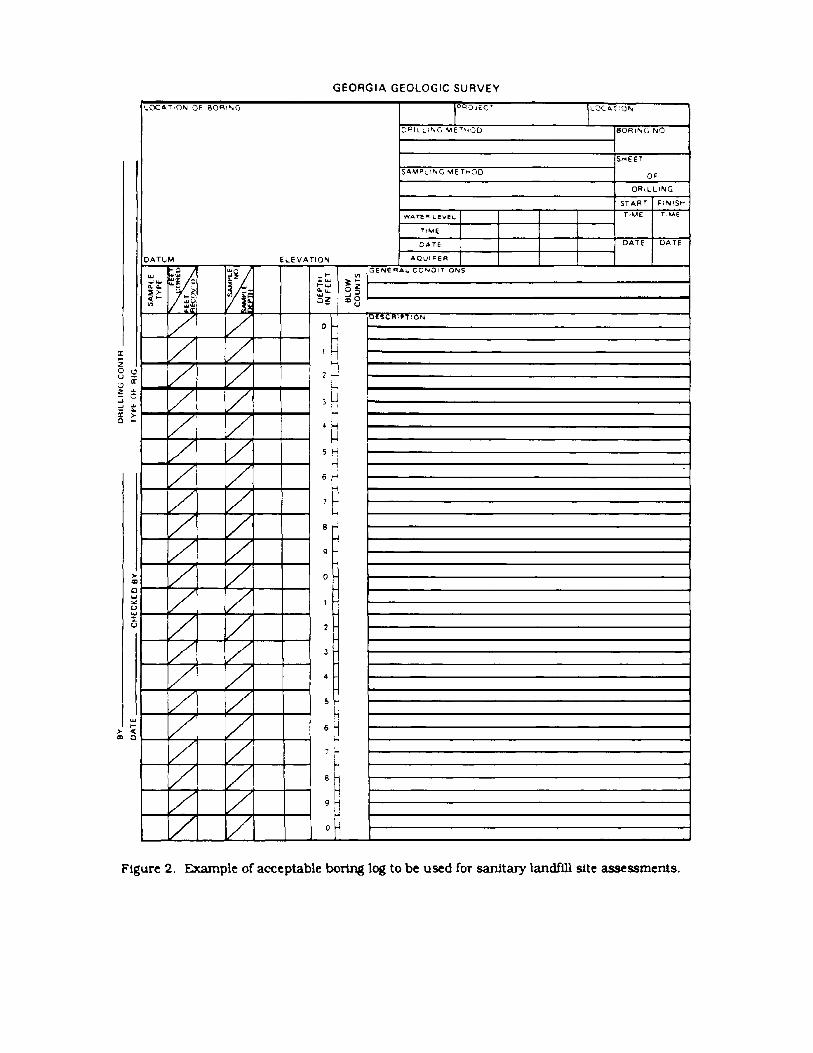
The boring plan and sampling program should bedescribed in detail in Section 2.2. The number of borings atany site is a function of actual site conditions, but certainguidelines can be applied. There should be a minimum ofthree borings per site or per permanent drainage divide (e.g.,per each isolated drainage regime at the site) and at least oneboring per twenty acres.5 Figure 1 illustrates an imaginaryPiedmont site and provides the methodology for calculatingthe minimum number of borings. The borings should be ofsufficient depth to extend through all perched water zones totwenty feet below the water table. All borings should bewitnessed and logged by a geologist or geotechnicalengineer. Boring logs should include the following types ofinformation: boring number, dates of drilling, drillingcontractor, boring method (i.e., hollow stem auger, rockcoring, etc.), surveyed elevation, depth, description ofcuttings (an actual description as well as the Unified SoilClassification), sample intervals (at least one split spoonsample every five feet), blow counts, core recovery, andwater levels (immediately after drilling and after a 24 to 48hour stabilization period) with date(s) of measurements.Figure 2 represents an example of an acceptable boring log.(Note: Hollow stem auger boring and rock coring are thepreferred drilling methods; use of other drilling methods(mud rotary, air rotary, etc.) should be discussed with EPD
personnel prior to initiating the subsurface investigation).Undisturbed samples, such as Shelby Tubes, should becollected from some of the borings; generally there will beat least as many undisturbed samples as there are borings(i.e., if there were seven borings at a site, at least sevenundisturbed samples would be collected; it is not necessary,however, that there be one undisturbed sample for everyboring). The undisturbed samples should be tested for grainsize, hydraulic conductivity, and, if appropriate, forengineering design characteristics such as consolidation andshear strength. The undisturbed samples should be collectedat different stratigraphic intervals so that a representativepicture can be obtained of the subsurface distribution of soiland rock properties. Hydraulic conductivities of thematerial in which solid waste is to be buried and hydraulicconductivities of the material that will underlie the solidwaste should be evaluated. This should involve testing bothhorizontal and vertical hydraulic conductivity, either by fieldor laboratory methods. EPD expects that hydraulicconductivity should be established by direct measurementsrather than estimated. There should be some measurementsmade of infiltration rates so that flow through the vadosezone can be generally described (see Section 2.3).
If bedrock (weathered or unweathered) at the siteoccurs within 20 feet of the water table, continuous core(generally NX-sized) of the bedrock should be collected anddescribed with RQD's calculated.6 Coring should extend atleast 10 feet below the top of bedrock or until recoveryexceeds 95% for each of the last five feet.7 Eachsignificantly different type of bedrock identified at the siteshould be cored and described with RQD's calculated. Inaddition to coring and RQD calculations of bedrock, anyrock outcrops at or near the site should be mapped (i.e.,strike and dip) with emphasis placed on the orientation of
any observed fracturing and/or jointing patterns.Consultants should be aware that all drillers
constructing borings, coreholes, and installing monitoringwells shall have a valid bond on file with the Water WellStandards Advisory Council and shall carry out such drillingunder the direct supervision of a registered professionalgeologist or a registered professional engineer. Borings andother drilling operations carried out for landfill siteinvestigations shall meet the requirements of the Water-WellStandards Act. EPD will not review MSWLF siteacceptability reports not meeting these two criteria.
Soils and rocks should be described in Section 2.3.The description should be of sufficient detail so that EPDcan have a basic understanding of the site's frameworkgeology. At least two cross-sections should be presented(one generally parallel to geologic strike or parallel totopographic contour lines and one generally perpendicularto geologic strike or perpendicular to topographic contourlines); the cross-sections should be tied to borings and/ormonitoring wells. The cross-sections should not have avertical exaggeration exceeding 1:10 (vertical:horizontal),and should use hydrologic and lithologic symbols consistentwith those used by the USGS.
Sections 2.4, 2.5 and 2.6 include descriptions of thegeneral ground-water flow regime including that of thevadose zone. The descriptions should be accompanied by apotentiometric map of the uppermost aquifer (generallyunconfined). Ground-water gradients and flow velocities ofthe uppermost aquifer should be measured and calculated.Confining units and their areal distribution should bedescribed.
Information also should be provided on estimated recharge,on discharge locations, on seasonal ground-waterfluctuations, on changes in aquifer and confining unitfacies, and on the potential for all aquifers underlying thesite to be sources of drinking water.
Potential geologic or natural hazards should bedescribed in Section 2.7. Examples of these include karst(sinkhole collapse), hurricane tidal surge, subsidence-proneareas, seismic impact zones, fault areas, unstable areas,swelling clays, paleolandslides and bedrock shear zoneshaving high hydraulic conductivity. Sinkholes are the mostsignificant of these, because they could lead to acatastrophic failure of the landfill. For this reason, all sitesunderlain by carbonate rocks should be assessed forsinkholes. The assessment should include (a) visuallyinspecting the site, and (b) examining soils maps, aerialphotographs and USGS 1:24,000 topographic maps of thesite and adjacent lands. If any of the above suggest thepresence of sinkholes on or bordering the site, a drillingsurvey or a geophysical survey (i.e., ground-penetratingradar, electromagnetism, micro-gravity, seismic refractionor possibly resistivity) should be performed at a detailadequate to evaluate the presence or absence of solutioncavities beneath the site. If any of these surveys indicatesignificant voids beneath the site, the anomalous areasshould be core drilled to a depth of at least 25 feet into rock.Alternate methodologies may be considered if, in theconsultants evaluation, drilling and geophysics appearinappropriate. The consultant should bring this matter toEPD's attention before initiating such alternate evaluationtechnologies.
Although faults and fault zones are fairly common inGeorgia, very few, if any, have been recognized as havinghad displacement in Holocene time. However, any faultedmaterial noted at a site should be described in detail in thetext portion of the report; particular emphasis should begiven to discussing the potential for enhanced permeabilityin the fault or fault zone. The trace of the fault should beshown on the cross sections and on the site topographicbase map. A Holocene fault should be described in greatdetail; additional borings or additional geologic field workmay be required to quantify the amount of displacement anddelineate the fault trace.
Portions of Georgia, slightly less than one half (½) ofthe State, mainly in the northern part of the State and alongthe Savannah River, are located in a seismic impact zone, asdefined in the Rules for Solid Waste Management (Chapter391-3-4-.05(1)(g)(2.)(a.)). In Georgia the upper limit ofhorizontal acceleration, with a 90% probability of not beingexceeded in 250 years, is 0.22 g.8 If a new landfill unit or
a lateral expansion is located in a seismic impact zone, aGeorgia registered professional engineer should stamp andseal all design engineering drawings with the accompanyingwritten notation:
I have reviewed the information presented on thisdrawing, and in my professional opinion, allcontainment structures are designed to resist amaximum horizontal ground acceleration of 0.15g/0.20 g/0.22 g (zone dependent) in 250 years. (Note:It is the consultants responsibility to ascertain inwhich seismic impact zone the landfill will be located,and to recommend the appropriate designrequirements for that zone.)
All design drawings having the above statement shall meetthe Director's demonstration requirement as stipulated in theRules.
Pathway Analysis
The purpose of the pathway analysis is to evaluatehow leachate might percolate downward from the wasteburial areas to the water table and then migrate offsite tohuman receptors. This analysis is significant because if theanalysis demonstrates that leachate could reach localdomestic or public water supplies, the site would have to bedesigned to mitigate pollutants moving offsite.
The inter-relationship between the vadose zone, theuppermost aquifer and deeper aquifers should be describedin Section 3.l and illustrated in a schematic cross-sectionaldiagram. The hydraulic interconnection between the baseof the burial trenches and underlying permeable zonesshould be evaluated in particular. The analysis shouldaddress: seasonal and yearly fluctuations in the water table;recharge mechanisms, including leakage from overlying andunderlying strata; pinchouts or lenses of permeable andimpermeable materials; variation of hydraulic conductivitywith depth; variations of flow velocity and flow directionbetween aquifers; protective clay strata and so forth.
Horizontal ground-water flow velocities of theuppermost aquifer should be calculated and discussed inSection 3.2 so that EPD can have some understanding ofhow fast leachate could migrate from the site. For mostCoastal Plain and Piedmont/Blue Ridge saprolite/soil siteswhere the uppermost aquifer is a porous media, thecalculation should be based on the Darcy Equation:
where: V is the average linear velocity, K is thehydraulic conductivity (based on laboratory and fieldtests), n is the effective porosity (based on laboratorytests), and �h/�l is the hydraulic gradient (based onthe potentiometric map of the uppermost aquifer).
For those sites where there have been multiplemeasurements of hydraulic conductivity, velocity should becalculated firstly by using an average of all measurementsof hydraulic conductivity and secondly by using the highestmeasured value of hydraulic conductivity (Note: this wouldprovide typical as well as worst-case scenario values).Effective porosity and hydraulic gradient should be basedon typical or average measurements. For those situationswhere Darcy's Equation may not be appropriate (e.g., somekarstic, carbonate terranes; crystalline terranes; etc.), theconsultant should discuss and provide some estimate orcalculation of horizontal ground-water flow velocities.
Section 3.3 should be a discussion of ground-waterpollution potential of sites in their natural state. Pollutantsin ground water generally tend to be removed or reduced inconcentration with time and with distance traveled.Mechanisms of such attenuation include: filtration, sorption,chemical processes, microbiological decomposition anddilution. Sorptive capacity (generally cation/anionexchange capacity) should be measured in at least twolocations in each significant soil type encountered on thesite. The soil should be tested for constituents that wouldbe found in leachate. At each test location the sorptivecapacity should be measured at varying depths (i.e., at adepth lateral to and at depths of five to ten feet below theproposed solid waste fill or the proposed depth of the liner),and, if appropriate, at least one point several feet above therock-soil interface.
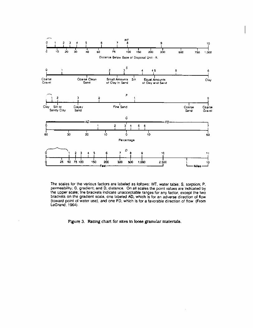
The rate of pollution attenuation depends on the typeof pollutant as well as the local hydrogeological conditions.In evaluating the ground-water pollution potential frommunicipal solid waste landfills and as an adjunct to makingmeasurements of sorption and estimations or modeling ofattenuation, EPD plans to follow a somewhat moreconservative version of the empirical point-count systemdeveloped by LeGrand (see LeGrand, H.E., 1964, Systemfor Evaluation of Contamination Potential of Some WasteDisposal Sites; Journal American Water WorksAssociation, v. 56, no. 8, pp. 959-974).9
However, as pointed out by LeGrand, the method isnot foolproof and should not imply precision. Nevertheless,the method does provide a reasonable qualification of thepollution potential of municipal solid waste landfill sites.
The method is not appropriate if the critical consideration isthe movement of chemical wastes that attenuate slowly.The LeGrand method only applies to unconfined groundwater conditions for two types of solid-waste landfill sitesettings:
(1) Unconsolidated granular materials extending 100feet or more below the ground surface (typical Coastal Plainsites) - see Figure 3.
(2) Two-media sites characterized by unconsolidatedgranular materials at the ground surface underlain atshallow depths by dense rocks with linear openings (typicalPiedmont/Blue Ridge sites with soil-saprolite overlyingcrystalline bedrock) - see Figure 4.
LeGrand's concept, which is the basis of EPA'srecently developed DRASTIC pollution susceptibilitymethodology, assumes the uppermost aquifer is unconfinedand considers the following factors: depth to water table,sorption above the water table, aquifer permeability, watertable gradient, horizontal distance, and the thickness ofunconsolidated material at two-media sites. Addition ofpoints from each of the factors provides a measure ofpollution potential as follows:
Total PointsPollution Potential of a Site in
Its Natural Condition
0-4 Imminent
4-8 Probable
8-12 Possible
12-25 Possible, but not likely
25+ Approaching impossible
LeGrand's method only considers sites in their naturalstate and does not take into account engineered sites havingliners and leachate collection systems. If a site is to belined, the consultant may,:
(a) for a compacted clay lined site without a leachatecollection system, assume maximum sorption (LeGrandgives a sorption rating of either 4 or 6 for clay);
(b) for a compacted clay liner with a leachatecollection system, assume maximum sorption and afavorable water table gradient;
(c) for a synthetic liner with a leachate collectionsystem, assume maximum sorption, a favorable water tablegradient, and a permeability rating of 3.
(d) for a composite liner (e.g. compacted clay plus asynthetic liner) without a leachate collection system assumemaximum sorption (see (a) above), or with a leachatecollection system assume maximum sorption, a favorablewater table gradient, and a permeability r ating of 3 (see (c)above).
Sites having an imminent or probable pollutionpotential in their natural state should have their pollutionpotential reduced through design engineering.
The general pathways and travel time for leachate tomigrate from a landfill and reach receptors (e.g., persons oranimals that might drink polluted ground water or surfacewater) should be evaluated in Section 3.4 and 3.5 respec-tively. The evaluation should be directed at identifyingwhich receptors, if any, might be exposed to leachatecontaminated ground or surface water as well as the timeframe over which exposure might occur. The consultant, athis/her option, may include in his/her evaluation thefollowing: the effects of liners and leachate-collectionsystems, presence or absence of ground-water divides,attenuation, likely alternate sources of water and so forth.
Recommendations for mitigation should be providedin Section 3.6 if geologic or natural hazards are present atthe site.
Recommendations for Designs
There are very few sites in Georgia that are suitable intheir natural state for the disposal of solid wastes. Mostsites will require some engineering modifications beforethey can be made suitable. Therefore, the site assessmentreport should provide general recommendations for siteengineering modifications. The recommendations shouldcontain sufficient specifics (e.g., maximum depth ofexcavation, areas not deemed suitable for waste disposal,areas were there are steep slopes, areas that have highlyerodible soils, etc.) so that EPD may incorporate them aspart of the general approval conditions of site acceptabilityand so that the design engineer can use them to develop thedesign and operation plans. Actual landfill design, how-ever, is the responsibility of the design engineer and is to beprovided in the design and operation plans.
The consultant should identify, in Sections 4.l and 4.2,those areas that appear to be favorable or unfavorable forthe disposal of solid waste. The technical bases for deter-mining suitability should be stated in the evaluation, andboth areas should be shown on the site topographic map.The unfavorable areas will generally include floodplains,wetlands, permanent and intermittent streams with setbacks,areas underlain by shallow ground water and shallowbedrock, karstic areas, excessively steep slopes and buffersaround the site perimeter and around environmentallysensitive areas.
Proposed cell depths throughout the favorable areasshould be delineated in Section 4.4 and shown on the site
topographic map. A minimum separation of five feet willnormally be required between the liner and the seasonalhigh water table at a site. If information on the seasonalfluctuation of the ground-water table (based on measure-ments, not speculation) is not provided in the assessmentreport, EPD will arbitrarily increase the minimum verticalseparation distance between the liner of the landfill and themeasured ground-water table. (Note: for some CoastalPlain sites, the water table approaches the ground surfaceduring wet periods; where this is the case raised or elevatedsites are appropriate.) Alternatively, to compensate forseasonal fluctuations of the ground-water table, a French orother drain system could be constructed between the bottomof the landfill and the water table. The applicant shoulddemonstrate, through standard engineering analysis, that theunder-drain system can keep the ground water from rising,at any point between the drain lines, to within the requisiteseparation distance between the bottom of the landfill andthe ground-water table. A conceptual design of the under-drain system should be incorporated in the assessmentreport package that is submitted to EPD.
The consultant may recommend other separationsbetween the seasonal high water table and the base of thetrench or liner, depending on the site's hydrogeologicalcharacteristics. Recommendations for sites underlain bybedrock should provide for the removal of rock encounteredduring cell excavation and the replacing of such rock withcompacted fill having hydraulic characteristics similar tothe in-situ soils.
Site drainage and erosion control measures, to theextent that they affect site acceptability, should be discussedin Section 4.5. These control measures possibly couldinclude, but should not be necessarily restricted to Frenchdrains, diversion ditches, rerouting of streams, berms,settling basins, setbacks from streams, culverts, cut and fillpractices, revegetation and so forth.10
Buffer zones around the site perimeter and adjacent tostreams and wetlands, as well as around any otherenvironmentally sensitive areas, should be recommended inSection 4.6. (Note: EPD requires at least a 200 foot bufferbe maintained around the site perimeter, and a minimum500 foot buffer between the waste boundary and anyoccupied dwelling and the dwelling's water supply well.)Buffers and setbacks, consistent with the water supplywatershed protection criteria, also should be recommended.The location of ground-water monitoring stations should berecommended in Section 4.7, along with samplingschedules and chemical parameters. The general design ofmonitoring wells also should be recommended.11
The Water Well Standards Act requires that allgeologic and engineering borings be plugged in a timelymanner. The responsibility for such plugging rests with thegeologist or geotechnical engineer who supervised thedrilling. Normally this would be the consultant. (Note:Boreholes clearly located in proposed waste disposal areasand boreholes that may be located in proposed wastedisposal areas should be grouted with a cement or abentonite-cement slurry from the bottom of the hole to atleast within five feet of the existing ground surface, andthen backfilled with clean soil. Boreholes clearly locatedoutside of proposed waste disposal areas may be filled inwith bentonite.) Borehole plugging and abandonmentschedules should be provided in Section 4.8.
References Cited/Methods
Procedures, methods and technical references shouldbe identified, and where appropriate, described in Section5.0.
FORMAT FOR MUNICIPAL SOLID WASTE LANDFILL SITE ACCEPTABILITY STUDIES
Section/Figure Title
1.0 GENERAL SITE AREA
1.1 Description of General Site Area
1.2 Proximity to Roads, Airports and Railroads
1.3 Proximity to County Boundaries and National Historic Sites
1.4 Proximity to Floodplains
1.5 Proximity to Streams and Wetlands
1.6 Proximity to Most Significant Ground-Water Recharge Areas
1.7 Proximity to Public and Domestic Water Supplies
1.8 Zoning and Notification
Figure 1-1 Topographic Map of General Site Area (1:24,000)(Where appropriate, the watershed of any downstreampublic water supplies should be shown; this mayrequire topographic maps of another scale, suchas 1:100,000.)
Figure 1-2 Topographic Map of Site (showing floodplains and wetlands exceeding 2 acres in size)
Figure 1-3 Map Showing Proximity of Site to Most Significant Ground-Water Recharge Areas
Figure 1-4 Map Showing Proximity of Site to Public WaterSupplies
Figure 1-5 Map Showing Domestic Water Supplies within½ Mile of Site Boundaries
2.0 SURFACE AND SUBSURFACE INVESTIGATIONS
2.1 Topographic Description
2.2 Boring and Sampling Program
2.3 Description of Soils and Rocks (includes measurements ofhydraulic conductivity)
2.4 Description of Unconfined Aquifers (including depth to the water table)
��
2.5 Description of Confined Aquifers
2.6 Potential of Unconfined and Confined Aquifersas Sources of Drinking Water
2.7 Description of Geologic and/or Natural Hazards and for Seismic Impact Zone
Figure 2-1 Topographic Map of Site (showing boringlocations and rock outcrops, if any)
Figure 2-2 Cross-Section of Site Showing Distribution of SubsurfaceConditions (parallel to strike or parallel to topographic contour lines)
Figure 2-3 Cross-Section of Site Showing Distribution of SubsurfaceConditions (perpendicular to strike or perpendicular to topographic contour lines)
Figure 2-4 Potentiometric Map of Unconfined Aquifer
Figure 2-5 Boring Logs
Figure 2-6 Grain Size Curves
Figure 2-7 Other Tests (e.g., compaction tests, pump test curves, etc.)
3.0 PATHWAY ANALYSIS
3.1 Description of Inter-Relationships Between the VadoseZone, the Uppermost Aquifer, and Deeper Aquifers
3.2 Calculated Ground-Water Flow Velocities
3.3 Ground-Water Pollution Potential
3.4 Description of the Inter-Relationship BetweenGround-Water Flow Directions and Potential Receptors
3.5 Estimated Travel Time for Leachate to ReachPotential Receptors
3.6 Mitigation of Geologic and/or Natural Hazards
Figure 3-1 Schematic Cross-Sectional Diagram Showing RelationshipBetween Landfill and Aquifer(s)
Figure 3-2 Map Showing Downgradient Receptors
4.0 RECOMMENDATIONS FOR DESIGN
4.1 Favorable Areas
4.2 Unfavorable Areas
4.3 Liner/Leachate Collection Systems
4.4 Cell Depths (including relationship to the water table)
��
4.5 Site Drainage and Erosion Control
4.6 Buffer Zones
4.7 Monitoring
4.8 Disposition of Borings
4.9 Other Recommendations
Figure 4-1 Map Showing Areas Favorable and Unfavorable for Municipal Solid Waste Landfilling
Figure 4-3 Map Showing Surface- and Ground-Water MonitoringLocations
Figure 4-4 Monitoring Well Design Recommendations
5.0 REFERENCES CITED/METHODS
APPENDICES
� �
APPENDIX A
CRITERIA FOR INDUSTRIAL WASTE LANDFILLS
Waste generated by industrial and manufacturing processes can range from relatively benign scrap lumber and broken
concrete blocks to materials that, while non-hazardous, can pollute ground and surface waters if improperly managed. This
means that site acceptability criteria are variable and dependent upon the characteristics of the wastes as well as the characteristics
of the site. Relatively simple criteria would be required for wastes such as scrap lumber and metal, which merely need to be sited
in a relatively dry area. Industrial process waste which can dissolve and leach into ground water may require acceptability criteria
almost as rigid as those for municipal solid waste landfills. Finally, commercial landfill sites accepting industrial waste must
meet the same criteria as municipal solid waste landfills, because these sites may handle waste with a high potential to pollute
ground water.
EPD has established three categories of industrial wastes based on their potential to pollute ground water. These are:
(1) LOW POTENTIAL: Industrial wastes having a low potential to contaminate ground water include various scrapmetals, processed wood and paper products, nonmetallic mine tailings, inorganic sludges with low heavy metalscontent, and other nonputrescible waste not likely to leach hazardous constituents. Siting criteria for these types ofwastes are the same as for construction/demolition wastes (see Appendix B).
(2) MODERATE POTENTIAL: Such wastes might include, incinerator bottom ash, fixed fly ash or fly ash with minorquantities of heavy metals, uncontaminated dredging waste, lime muds, etc. While these types of wastes need notbe disposed of in lined sites, the site acceptability criteria are dependent upon whether the site is located within a MostSignificant Ground-Water Recharge Area as shown on Hydrologic Atlas No. 18. If the site is located within a MostSignificant Ground-Water Recharge Area, the acceptability criteria applicable for a municipal solid waste landfill,exclusive of information on the proximity to airports, shall apply. Sites located outside of Most Significant Ground-Water Recharge Areas which will handle moderate potential wastes will require the following information.
(A) Zoning: The site must conform to all local zoning/land use ordinances. Written verification must be submittedto the Division by the applicant demonstrating that the proposed site complies with local zoning and land useordinances, if any. This verification shall include a letter from the local governmental authority stating that theproposed site complies with local zoning or land use ordinances, if any. This verification shall be provided atthe time of submission of a permit application and reaffirmed by the governmental authority prior to permitissuance.
(B) Floodplains: An industrial waste landfill located in the 100-year floodplain shall not restrict the flow of the 100-year flood, reduce the temporary water storage capacity of the floodplain, or result in a washout of solid wasteso as to pose a hazard to human health and the environment. The owner or operator must place a demonstrationof compliance in the operating record and notify the Director that it has been placed in the operating record.
(1) For purposes of this section:
(a) "Floodplain" means the lowland and relatively flat areas adjoining inland and coastal waters,including flood-prone areas of offshore islands, that are inundated by the 100-year flood.
� �
(b) "100-year flood" means a flood that has a 1-percent or greater chance of recurring in any given yearor a flood of a magnitude equaled or exceeded once in 100 years on the average over a significantlylong period.
(c) "Washout" means the carrying away of solid waste by waters of the base flood.
(C) Wetlands: An industrial waste landfill shall not be located in wetlands, as defined by the U. S. Corps ofEngineers, unless evidence is provided to the Director, by the applicant, that use of such wetlands has beenpermitted or otherwise authorized under all other applicable state and federal laws and rules. The owner oroperator must place a demonstration of compliance in the operating record and notify the Director that it hasbeen placed in the operating record.
(D) Fault Areas:
(1) New industrial landfill units and lateral expansions of existing industrial landfills shall not be locatedwithin 200 feet (60 meters) of a fault that has had displacement in Holocene time unless the owner oroperator demonstrates to the Director that an alternative setback distance of less than 200 feet (60 meters)will prevent damage to the structural integrity of the landfill unit and will be protective of human healthand the environment.
(2) For the purposes of this section:
(a) "Fault" means a fracture or a zone of fractures in any material along which strata on one side havebeen displaced with respect to that on the other side.
(b) "Displacement" means the relative movement of any two sides of a fault measured in any direction.
(c) "Holocene" means the most recent epoch of the Quaternary period, extending from the end of thePleistocene Epoch to the present.
(E) Seismic Impact Zones:
(1) New industrial landfill units and lateral expansions shall not be located in seismic impact zones, unlessthe owner or operator demonstrates to the Director that all containment structures, including liners,leachate collection systems, and surface water control systems, are designed to resist the maximumhorizontal acceleration in lithified earth material for the site. The owner or operator must place thedemonstration in the operating record and notify the Director that it has been placed in the operatingrecord.
(2) For the purposes of this section:
(a) Seismic impact zone means an area with a ten percent or greater probability that the maximumhorizontal acceleration in lithified earth material, expressed as a percentage of the earth'sgravitational pull will exceed 0.10g in 250 years.
(b) Maximum horizontal acceleration in lithified earth material means the maximum expected horizontalacceleration depicted on a seismic hazard map, with a 90 percent or greater probability that theacceleration will not be exceeded in 250 years, or the maximum expected horizontal accelerationbased on a site-specific seismic risk assessment.
(c) Lithified earth material means all rock, including all naturally occurring and naturally formedaggregates or masses of minerals or small particles of older rock that formed by crystallization ofmagma or by induration of loose sediments. This term does not include man-made materials, such
� �
as fill, concrete, and asphalt, or unconsolidated earth materials, soil, or regolith lying at or near theearth surface.
(F) Unstable areas:
(1) Owners or operators of new industrial landfill units, existing industrial landfill units, and lateralexpansions located in an unstable area must demonstrate that the engineering measures have beenincorporated into the landfill unit's design to ensure that the integrity of the structural components of thelandfill unit will not be disrupted. The owner or operator must place the demonstration in the operatingrecord and notify the Director that it has been placed in the operating record. The owner or operator mustconsider the following factors, at a minimum, when determining whether an area is unstable:
(a) On-site or local soil conditions that may result in significant differential settling;
(b) On-site or local geologic or geomorphologic features; and
(c) On-site or local human-made features or events (both surface and subsurface).
(2) For the purposes of this section:
(a) "Unstable area" means a location that is susceptible to natural or human-induced events or forcescapable of impairing the integrity of some or all of the landfill structural components responsiblefor preventing releases from a landfill. Unstable areas can include poor foundation conditions, areassusceptible to mass movements, and karst terrains.
(b) "Structural components" means liners, leachate collection systems, final covers, run-on/run-offsystems, and any other component used in the construction and operation of the landfill that isnecessary for the protection of human health and the environment.
(c) "Poor foundation conditions" means those areas where features exist which indicate that a naturalor man-induced event may result in inadequate foundation support for the structural components ofa landfill unit.
(d) "Areas susceptible to mass movement" mean those areas of influence (i.e., areas characterized ashaving an active or substantial possibility of mass movement) where the movement of earth materialat, beneath, or adjacent to the landfill unit, because of natural or man-induced events, results in thedownslope transport of soil and rock material by means of gravitational influence. Areas of massmovement include, but are not limited to, landslides, avalanches, debris slides and flows, soilfluction, block sliding, and rock fall.
(e) "Karst terrains" means areas where karst topography, with its characteristic surface and subterraneanfeatures, is developed as the result of dissolution of limestone, dolomite, or other soluble rock.Characteristic physiographic features present in karst terrains include, but are not limited to,sinkholes, sinking streams, caves, large springs, and blind valleys.
(G) Hydrogeological Assessment: A hydrogeological site investigation shall be conducted with the followingfactors, as a minimum, evaluated:
(1) Distance to nearest point of public or private drinking water supply: all public water supply wells orsurface water intakes within two miles and private (domestic) water supply wells within one-half (½) mileof an industrial landfill must be identified.
(2) Depth to the uppermost aquifer: for industrial landfills, the thickness and nature of the unsaturated zone
� �
and its ability for natural contamination control must be evaluated.
(3) Uppermost aquifer gradient: for industrial landfills, the direction and rate of flow of ground water shallbe determined in order to properly evaluate the potential for contamination at a specific site. Measure-ments of water levels in site exploratory borings and the preparation of water table maps are required.Borings to water are required to estimate the configuration and gradient of the uppermost aquifer.
(4) Topographic setting: features which shall be provided include, but are not limited to, all upstream anddownstream drainage areas affecting or affected by the proposed site, floodplains, gullies, karstconditions, wetlands, unstable soils and percent slope.
(5) Geologic setting: for industrial landfills, the depth to bedrock, the type of bedrock and the amount offracturing and jointing in the bedrock shall be determined. In limestone or dolostone regions, obviouskarst terrain shall not be used for waste disposal. This consideration does not preclude the siting oflandfills in limestone terrains, but rather is intended to prevent landfills from being sited in or adjacent tosinkholes, provided, however, that the demonstration required by section (F) has been made.
(6) Hydraulic conductivity: evaluation of industrial landfill sites shall take into consideration the hydraulicconductivity of the surface material in which the wastes are to be buried, as well as the hydraulicconductivity of the subsurface materials underlying the fill.
(7) Sorption and attenuation capacity: for industrial landfills, the sorptive characteristics of an earth materialand its ability to absorb contaminants shall be determined.
(8) Distance to surface water: industrial solid waste landfills shall not be situated within two miles upgradientof any surface water intake for a public drinking water source unless engineering modifications such asliners and leachate collection systems and ground-water monitoring systems are provided.
(H) Proximity to National Historic Sites: Industrial solid waste landfills shall not be located within 5,708 yards ofa National Historic Site.
(I) Proximity to County Boundaries: Industrial solid waste landfills shall not be located within one-half (½) mileof a county boundary except when the governing authority of the adjoining county gives written approval.
(J) Wellhead Protection: EPD will not issue any new permits for industrial waste landfills within the inner andouter management zones of existing wells and springs used as sources of water supply for community publicwater systems serving municipalities, counties, and authorities. Delineation of well head protection areas formunicipal water supply wells is ongoing and should be completed by July 1, 2003. The assessment report mustshow the outer management zone of all applicable wells that are located within two miles of the proposedlandfill site boundary. (Note: While it is EPD's responsibility to delineate the size and shape of the managementzone of a wellhead protection area, it is the applicant's responsibility to provide EPD with sufficient data tomake the delineation when a management zone has not already been established for a well).
(3) HIGH POTENTIAL: All industrial waste landfills receiving industrial wastes containing small quantities ofhazardous wastes, wastes that are putrescible, wastes which contain any hazardous constituents which could leachinto the groundwater, or commercial industrial sites accepting waste from multiple industries must meet the samecriteria as a municipal solid waste landfill.
A topographic map of the site (prepared by or under the supervision of an engineer or surveyor registered to practice in
Georgia) shall be presented in the assessment report; the topographic map must be both signed and stamped by said engineer
or surveyor. Generally the map scale should not be smaller than 1:2,400, but the scale should not be so large that the entire site
� �
cannot be represented on a 2' x 3' sheet of paper. The topographic contour interval should not be larger than five feet. The site
topographic map shall show the surveyed boundaries of the site as well as all rivers, streams (including intermittent streams),
ponds, lakes, reservoirs, wetlands, sinkholes and springs (or seeps) occurring within or immediately adjacent to the site. Where
available, 100-year flood elevation data from FEMA flood insurance maps should be shown on the site topographic map. If
FEMA maps are not available, the general elevation of the 100-year flood may be calculated by an engineer. (Note: There are
few, if any, valid reasons for locating a industrial waste landfill in a 100-year floodplain.)
Wetlands (meeting the criteria of 33 CFR parts 320 through 330 and 40 CFR part 230) should be located by site traverses
and shown on the aforementioned site topographic map. (Note: EPD will not review a site acceptability report not accompanied
by a map delimiting on-site wetlands.)
Industrial waste landfills shall be sited so that the wastes do not adversely affect any floodplain, any wetland, any spring,
or any perennial or intermittent stream. The base of all burial trenches or the liner shall be at least five feet above the wet season
water table and/or bedrock, which has been established by borings. If information on the seasonal fluctuation of the ground-water
table (based on measurements, not speculation) is not provided in the assessment report, EPD will arbitrarily increase the
minimum vertical separation distance between the bottom of the landfill or liner and the measured ground-water table by 10 to
25 feet, depending on the permeability of the soil at the site. A description of the general ground-water flow regime shall be
presented in the assessment report. The descriptions should be accompanied by a potentiometric map of the uppermost aquifer
(generally unconfined). The site topographic map should be used as the base map for the potentiometric map. There shall be
a minimum of three borings per site or hydrologic regime and at least one boring per twenty acres.
Consultants should be aware that all drillers constructing borings, coreholes, and installing monitoring wells shall have a
valid bond on file with the Water Well Standards Advisory Council and shall carry out such drilling under the direct supervision
of a registered professional geologist or a registered professional engineer. Borings and other drilling operations carried out for
landfill site investigations shall meet the requirements of the Water-Well Standards Act. EPD will not review landfill site
acceptability reports not meeting these two criteria.
Information on proximity of the site to public and domestic water supplies, through narrative and map information, shall
be presented in the site assessment report. The consultant will need (a) to identify the nearest downstream surface water
withdrawal facility, if any, and (b) to inventory all public drinking water wells within two miles and all domestic water wells
within one-half mile of the site.
� �
For those sites receiving industrial process wastes having moderate or high potential to pollute ground and surface waters,
the consultant should apply the LeGrand method to estimate pollution potential. Sites having a high pollution potential in their
natural state should have their pollution potential reduced through design engineering. Prior to proceeding with a site
acceptability study, it is recommended that the applicant provide EPD with sufficient information to allow classification of its
waste streams into one of the above three classifications. If the applicant elects to proceed with the site acceptability study prior
to classification, the applicant should provide a clear and concise description of the ground-water pollution potential of the
wastes. In the absence of such a description, EPD will assume that the waste has a high potential for ground-water pollution and
will expect site acceptability studies consistent with those required for a municipal solid waste landfill.
A site acceptability study for an industrial waste landfill shall be performed under the direction of a geotechnical engineer
registered to practice in Georgia or a geologist registered to practice in Georgia. A geologist, registered to practice in Georgia,
must be part of the work effort if the assessment report title contains the word "hydrogeologic" or if the assessment report
contains substantial geologic work.
� �
APPENDIX B
CRITERIA FOR CONSTRUCTION/DEMOLITION WASTE LANDFILLS
Construction/demolition wastes are benign wastes generally including waste building materials and rubble resulting from
the construction, remodeling, repair and demolition of buildings and pavements. These wastes typically include processed wood,
metal, bricks, concrete, wallboard, paper, cardboard, etc. These materials are not considered as sources of pollution to ground
and surface waters, nor do they require frequent cover; therefore, siting criteria need not be overly restrictive. It is important to
note that some construction/demolition wastes may contain leachable, hazardous constituents or asbestos (e.g., wood flooring
of a pesticide formulation facility). Where this is the case, these materials must be separated from the construction/demolition
wastes. Site acceptability criteria for construction/demolition waste landfills include:
(1) Zoning: The site must conform to all local zoning/land use ordinances. Written verification must be submitted tothe Division by the applicant demonstrating that the proposed site complies with local zoning and land use ordinances,if any. This verification shall include a letter from the local governmental authority stating that the proposed sitecomplies with local zoning or land use ordinances, if any. This verification shall be provided at the time ofsubmission of a permit application and reaffirmed by the governmental authority prior to permit issuance.
(2) Floodplains: A construction/demolition waste landfill located in the 100-year floodplain shall not restrict the flowof the 100-year flood, reduce the temporary water storage capacity of the floodplain, or result in a washout of solidwaste so as to pose a hazard to human health and the environment. The owner or operator must place a demonstrationof compliance in the operating record and notify the Director that it has been placed in the operating record.
(A) For purposes of this section:
(1.) "Floodplain" means the lowland and relatively flat areas adjoining inland and coastal waters, includingflood-prone areas of offshore islands, that are inundated by the 100-year flood.
(2.) "100-year flood" means a flood that has a 1-percent or greater chance of recurring in any given year ora flood of a magnitude equaled or exceeded once in 100 years on the average over a significantly longperiod.
(3.) "Washout means the carrying away of solid waste by waters of the base flood.
(3) Wetlands: A construction/demolition waste landfill shall not be located in wetlands, as defined by the U. S. Corpsof Engineers, unless evidence is provided to the Director, by the applicant, that use of such wetlands has beenpermitted or otherwise authorized under all other applicable state and federal laws and rules. The owner or operatormust place a demonstration of compliance in the operating record and notify the Director that it has been placed inthe operating record.
(4) Proximity to National Historic Sites: Construction/demolition waste landfills shall not be located within 5,708 yardsof a National Historic Site.
(5) Proximity to County Boundaries: Construction/demolition landfills shall not be located within one-half (½) mile of
� �
a county boundary except when the governing authority of the adjoining county gives written approval.
(6) Wellhead Protection: EPD will not issue any new permits for construction/demolition waste landfills within the innerand outer management zones of existing wells and springs used as sources of water supply for community publicwater systems serving municipalities, counties, and authorities. Delineation of well head protection areas formunicipal water supply wells is ongoing and should be completed by July 1, 2003. The assessment report must showthe outer management zone of all applicable wells that are located within two miles of the proposed landfill siteboundary. (Note: While it is EPD's responsibility to delineate the size and shape of the management zone of awellhead protection area, it is the applicant's responsibility to provide EPD with sufficient data to make thedelineation when a management zone has not already been established for a well).
A topographic map of the site (prepared by or under the supervision of an engineer or surveyor registered to practice in
Georgia) shall be presented in the assessment report; the topographic map must be both signed and stamped by said engineer
or surveyor. Generally the map scale should not be smaller than 1:2,400, but the scale should not be so large that the entire site
cannot be represented on a 2' x 3' sheet of paper. The topographic contour interval should not be larger than five feet. The site
topographic map shall show the surveyed boundaries of the site as well as all rivers, streams (including intermittent streams),
ponds, lakes, reservoirs, wetlands, sinkholes and springs (or seeps) occurring within or immediately adjacent to the site. Where
available, 100-year flood elevation data from FEMA flood insurance maps should be shown on the site topographic map. If
FEMA maps are not available, the general elevation of the 100-year flood may be calculated by an engineer. (Note: There are
few, if any, valid reasons for locating a construction/demolition waste landfill in a 100-year floodplain.)
Wetlands (meeting the criteria of 33 CFR parts 320 through 330 and 40 CFR part 230) should be located by site traverses
and shown on the aforementioned site topographic map. (Note: EPD will not review a site acceptability report not accompanied
by a map delimiting on-site wetlands.)
Construction/demolition landfills shall be sited so that the wastes do not adversely affect any floodplain, any wetland, any
spring, or any perennial or intermittent stream. The base of all burial trenches, which need not be lined, shall be at least five feet
above the wet season water table and/or bedrock, which has been established by borings. If information on the seasonal
fluctuation of the ground-water table (based on measurements, not speculation) is not provided in the assessment report, EPD
will arbitrarily increase the minimum vertical separation distance between the bottom of the landfill and the measured ground-
water table by 10 to 25 feet, depending on the permeability of the soil at the site. A description of the general ground-water flow
regime shall be presented in the assessment report. The descriptions should be accompanied by a potentiometric map of the
uppermost aquifer (generally unconfined). The site topographic map should be used as the base map for the potentiometric map.
There shall be a minimum of three borings per site or hydrologic regime and at least one boring per twenty acres. This work shall
� �
be performed under the direction of a geotechnical engineer registered to practice in Georgia or a geologist registered to practice
in Georgia. A geologist, registered to practice in Georgia, must be part of the work effort if the assessment report title contains
the word "hydrogeologic", or if the assessment report contains substantial geologic work. Consultants should be aware that all
drillers constructing borings, coreholes, and installing monitoring wells shall have a valid bond on file with the Water Well
Standards Advisory Council and shall carry out such drilling under the direct supervision of a registered professional geologist
or a registered professional engineer. Borings and other drilling operations carried out for landfill site investigations shall meet
the requirements of the Water-Well Standards Act. EPD will not review landfill site acceptability reports not meeting these two
criteria.
Information on proximity of the site to public and domestic water supplies, through narrative and map information, shall
be presented in the site assessment report. The consultant will need (a) to identify the nearest downstream surface water
withdrawal facility, if any, and (b) to inventory all public drinking water wells within two miles and all domestic water wells
within one-half mile of the site.
� �
APPENDIX C
"CHECK OFF LIST" - TO BE USED BY EPD FOR EVALUATING THEADEQUACY OF CONSULTANT'S MUNICIPAL SOLID WASTE
LANDFILL SITE ACCEPTABILITY ASSESSMENTS
I QUALIFICATIONS
(a) Is the report primarily an engineeringreport, a geological report, or sub-surface investigation? ________________________________________
(b) Was the report signed by a geologistor an engineer registered in Georgia(check as appropriate)? _____________ (yes) _____________ (no)
(c) Provide registration number _____________ (P.E.) _____________ (P.G.)
(d) Did the P.G. or P.E. actuallyvisit the site? _____________ (yes) _____________ (no)
(e) Did the drilling contractor have a bond as required by the Water WellStandards Act? _____________ (yes) _____________ (no)
(f) Who was the drilling contractor? ________________________________________
(g) Was the site map prepared by orunder the supervision of anengineer or surveyor registered inGeorgia? _____________ (yes) _____________ (no)
(h) Who was the engineer/surveyor? ________________________________________
(I) Were drilling operations observedby an engineer or geologist? _____________ (yes) _____________ (no)
(j) Who was this person? ________________________________________
(k) Did the P.G. or P.E. check boringlogs, drawings, etc.? _____________ (yes) _____________ (no)
(l) If (k) above is no, explainwhy not ________________________________________
(a) Were site topographic maps showingperennial and intermittent streams,surface water bodies, wetlands, rockoutcroppings, borehole locations,site boundaries, steep slopesand other environmental, geological,engineering, or cultural/demographicfeatures provided? _____________ (yes) _____________ (no)
(b) Was a potentiometric map of thewater table provided? _____________ (yes) _____________ (no)
(c) Was a map showing drinking waterwells (public or domestic) within½ mile of the site boundariesprovided? _____________ (yes) _____________ (no)
(d) Was a map showing the approximatelocation of the 100-year floodelevation provided? _____________ (yes) _____________ (no)
(e) Was a map showing recommendedground- and surface-watermonitoring locations provided? _____________ (yes) _____________ (no)
III BORINGS
(a) What type of drilling rigperformed the boring operations? ________________________________________
(g) Were water level measurementsperformed upon boring completionand at least 24 hours later? _____________ (yes) _____________ (no)
(h) Have the borings been pluggedunder the direction of a P.E.or P.G.? _____________ (yes) _____________ (no)
(I) How many borings were drilled? ________________________________________
(j) Is the boring density at leastone boring per twenty acres? _____________ (yes) _____________ (no)
IV ANALYSIS
(a) Where and how far away are thenearest public drinking watersources (e.g., trailer parks,industries, etc.)? ________________________________________
(c) Do the criteria for water supplywatershed protection apply? _____________ (yes) _____________ (no)
(d) Do the criteria for wellheadprotection areas apply? _____________ (yes) _____________ (no)
(e) Were water level measurementsperformed during wet (winter andspring) or dry (summer and fall)
� �
seasons? _____________ (wet) _____________ (dry)
(f) Have ground-water flow directionsbeen identified? _____________ (yes) _____________ (no)
(g) What is the annual anticipatedfluctuation in the water table? ____________________________________ feet
(h) Has an analysis been performedto identify maximum trench depth? _____________ (yes) _____________ (no)
(I) What are the measured horizontal and verticalhydraulic conductivities? __________________________________ cm/sec
(j) Were any actual field measurementsmade of horizontal hydraulicconductivity and laboratorymeasurements made of verticalhydraulic conductivity? _____________ (yes) _____________ (no)
(k) What is the recommended separationbetween the top of the water table(wet season) and the base of theliner? ____________________________________ feet
(l) Is the site entirely or partiallywithin a Most Significant Ground- Water Recharge Area? _____________ (yes) _____________ (no)
(m) Have water quality monitoringlocations been recommended? _____________ (yes) _____________ (no)
(n) Are monitoring specifications(including well design, analy-tical parameters, samplingfrequency, etc.) recommended? _____________ (yes) _____________ (no)
(o) Where and how far away is thenearest airport? ________________________________________
(p) Is the site zoned for solidwaste disposal? _____________ (yes) _____________ (no)
(q) Where and how far away is thenearest commercial development? ____________________________________ feet
(r) Describe this development: ________________________________________
(s) Is the site within ½ mile of a county boundary or within5,708 yards of a National HistoricSite? _____________ (yes) _____________ (no)
(t) Is the site susceptible to sinkholes,expansive soils, erosion, seismicimpact zones, or any other geologic,topographic, or other feature thatcould impact the integrity of thelandfill? _____________ (yes) _____________ (no)
(u) Is an undisturbed buffer zonerecommended? _____________ (yes) _____________ (no)
(v) If (u) above is yes, what is therecommended width? ____________________________________ feet
(w) Was an analysis performed ofpotential pathways wherebyleachate could reach humanreceptors? _____________ (yes) _____________ (no)
(x) Are there any unique flora orfauna habitats within the siteboundary? _____________ (yes) _____________ (no)
(y) Describe the general character ofhighway access to the site: ________________________________________
(z) Is the applicant under any sortof time constraint (e.g., option topurchase, existing landfill haslimited capacity, etc.)? _____________ (yes) _____________ (no)
(aa) If (z) above is yes, describe: ________________________________________
(bb) Using the LeGrand method, what isthe pollution potential of the siteunder natural conditions? ________________________________________
(cc) What is the general anticipated life expectancy of the site? ___________________________________ years
(dd) Approximately how many people liveor work within ½ mile of the siteboundary? _________________________________ persons
(ee) What percentage of these personsobtain drinking water from: ________% domestic wells
________% public water supply
________% municipal water supply
(ff) What would be the pollution potentialof the site after installing a liner (using EPD's recommendedmodifications to the LeGrand method)? ________________________________________
(gg) If water supply watershed protection criteria are appropriate, whatis the recommended buffer _________ (in feet) and the recommendedsetback _________ (in feet).
(Note: The above checklist is only intended to be used as a tool to insure that EPD will receive as complete a report as possible.An omission of any particular piece or pieces of information will not necessarily result in an automatic rejection of the siteassessment report.)
Editor: P. Dennis Perriello
Cartographer: Don Shellenberger
Copies 750Cost: $XXXX.XX
The Department of Natural Resources is an equal opportunity employer and offers all persons the opportunity to competeand participate in each area of DNR employment regardless of race, color, religion, natural origin, age, handicap, or non-