Table of Contents Introduction ................................................................................................................................................. 3
PolyScience Circulating Baths with the Standard Digital Temperature Controller ................................... 3 General Safety Information ....................................................................................................................... 4 Safety Recommendations......................................................................................................................... 5 Regulatory Compliance and Testing ........................................................................................................ 6 Unpacking Your Circulator ........................................................................................................................ 6 Contents ................................................................................................................................................... 7 Controls and Components ........................................................................................................................ 8
Installation and Startup ............................................................................................................................ 14 General Site Requirements .................................................................................................................... 14 Adding Liquid to the Bath Reservoir ....................................................................................................... 14 Pump Inlet and Outlet Connections ........................................................................................................ 15 External Closed Loop Circulation ........................................................................................................... 15 Refrigeration Control Connections (Refrigerating/Heating Circulators only) .......................................... 16 Electrical Power ...................................................................................................................................... 16 RS232 Serial Communication ................................................................................................................ 17 Controller Setup ...................................................................................................................................... 18
Power ................................................................................................................................................. 18 Safety Set Temperature ..................................................................................................................... 19
Normal Operation ...................................................................................................................................... 20 Keys and Controls .................................................................................................................................. 20 Turning Your Circulator ON .................................................................................................................... 20 Main Operational Display (Home) .......................................................................................................... 21 Set-Up Sub-Menus ................................................................................................................................. 21 Adjusting the Temperature Set Point ...................................................................................................... 22 Selecting the Temperature Unit .............................................................................................................. 23 Selecting the Pump Speed ..................................................................................................................... 24 Calibrating Your Circulator...................................................................................................................... 25 Setting the Low Limit Temperature ......................................................................................................... 26 Setting the High Limit Temperature ........................................................................................................ 27 Selecting the Serial Communication Baud Rate .................................................................................... 28 Setting the Auto Cool Temperature ........................................................................................................ 29 Resetting the Factory Default Values ..................................................................................................... 29 Changing Your Circulator's Viewing Angle ............................................................................................. 30 Loss of Power Restart ............................................................................................................................ 30 Inert Gas Purge ...................................................................................................................................... 31 Tap Water Cooling .................................................................................................................................. 31 Reservoir Cover Storage ........................................................................................................................ 31
Display Messages and Alarms ................................................................................................................ 32
Routine Maintenance and Troubleshooting ........................................................................................... 33 Maintaining Clear Bath Water ................................................................................................................. 33 Draining the Bath Reservoir ................................................................................................................... 33 Checking the Over-Temperature Safety System .................................................................................... 34 Cleaning Your Circulator......................................................................................................................... 35
Temperature Controller ...................................................................................................................... 35 Bath Reservoir .................................................................................................................................... 35 Pump Impeller .................................................................................................................................... 35 Condenser, Air Vents, and Reusable Filter (Refrigerating / Heating Circulators only) ...................... 35
Temperature Controller Removal and Re-Installation ............................................................................ 36 Removal ............................................................................................................................................. 36
Introduction Thank you for choosing a PolyScience Circulating Bath with Standard Digital Temperature Controller. Extremely easy to use and maintain, it combines design innovation with highly intuitive operation to deliver convenient and reliable liquid temperature control for a wide range of applications.
WARNING: PolyScience Circulating Baths are not intended for directly controlling the temperature of foods, pharmaceuticals, medicines, or other objects which may be ingested by or injected in humans or animals. Any such objects must be isolated from contact with the bath fluid and bath surfaces.
Here are some of the features that make your Circulating Bath so user-friendly:
• Simple, intuitive operation
• Extra-large digital readout that displays actual and set point temperature simultaneously
• Powerful two-speed pressure pump with external circulation capability for closed-loop applications
• 180° viewing radius (Swivel 180™ rotating control head)
• Suitable for use with Class I non-flammable fluids per DIN 12876-1
It will take you very little time to get your new Circulating Bath installed and running. This Operator’s Manual is designed to guide you quickly through the process. We recommend that you read it thoroughly before you begin.
PolyScience Circulating Baths with the Standard Digital Temperature Controller
Model Type Reservoir Capacity
Temperature Range
°C °F
SD07R-20 Refrigerating / Heating Bath 7 liters -20° to 170°C -7° to 338°F
SD7LR-20 Refrigerating / Heating Bath 7 liters -20° to 170°C -7° to 338°F
SD15R-30 Refrigerating / Heating Bath 15 liters -30° to 170°C -22° to 338°F
SD20R-30 Refrigerating / Heating Bath 20 liters -30° to 170°C -22° to 338°F
SD28R-30 Refrigerating / Heating Bath 28 liters -30° to 170°C -22° to 338°F
SD07H170 Heating Only Bath 7 liters Ambient +10° to 170°C Ambient +20° to 338°F
SD15H170 Heating Only Bath 15 liters Ambient +10° to 170°C Ambient +20° to 338°F
SD20H170 Heating Only Bath 20 liters Ambient +10° to 170°C Ambient +20° to 338°F
SD28H170 Heating Only Bath 28 liters Ambient +10° to 170°C Ambient +20° to 338°F
SD29VB3S Polycarbonate Viscosity Bath 29 liters Ambient +10° to 85°C (1) Ambient +20° to 185°F (1)
SD29VB5R Polycarbonate Viscosity Bath 29 liters Ambient +10° to 85°C (1) Ambient +20° to 185°F (1)
1. Maximum operating temperature for polycarbonate tank; Standard Digital Temperature Controller capable of higher temperatures.
110-512 PSC/EN 3
General Safety Information When installed, operated, and maintained according to the directions in this manual and common safety procedures, your Circulating Bath should provide safe and reliable temperature control. Please ensure that all individuals involved in the installation, operation, or maintenance of this Circulating Bath read this manual thoroughly prior to working with the unit.
This symbol alerts you to a wide range of potential dangers.
This symbol advises you of danger from electricity or electric shock.
This symbol indicates that a hot surface may be present.
This symbol marks information that is particularly important.
This symbol indicates alternating current.
/ These symbols on the Power Switch / Circuit Breaker indicate that they place the main power supply ON / OFF.
This symbol on the Power Key indicates that it places the unit in a standby mode. It DOES NOT fully disconnect the unit from the power supply.
This symbol indicates a protective conductor terminal.
Read all instructions pertaining to safety, set-up, and operation. Proper operation and maintenance is the user’s responsibility.
110-512 PSC/EN 4
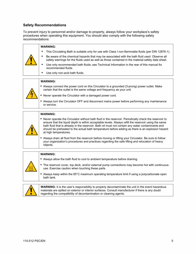
Safety Recommendations
To prevent injury to personnel and/or damage to property, always follow your workplace’s safety procedures when operating this equipment. You should also comply with the following safety recommendations:
WARNING: • This Circulating Bath is suitable only for use with Class I non-flammable fluids (per DIN 12876-1).
• Be aware of the chemical hazards that may be associated with the bath fluid used. Observe all safety warnings for the fluids used as well as those contained in the material safety data sheet.
• Use only recommended bath fluids; see Technical Information in the rear of this manual for recommended fluids.
• Use only non-acid bath fluids.
WARNING: • Always connect the power cord on this Circulator to a grounded (3-prong) power outlet. Make
certain that the outlet is the same voltage and frequency as your unit.
• Never operate the Circulator with a damaged power cord.
• Always turn the Circulator OFF and disconnect mains power before performing any maintenance or service.
WARNING: • Never operate the Circulator without bath fluid in the reservoir. Periodically check the reservoir to
ensure that the liquid depth is within acceptable levels. Always refill the reservoir using the same bath fluid that is already in the reservoir. Bath oil must not contain any water contaminants and should be preheated to the actual bath temperature before adding as there is an explosion hazard at high temperatures.
• Always drain all fluid from the reservoir before moving or lifting your Circulator. Be sure to follow your organization’s procedures and practices regarding the safe lifting and relocation of heavy objects.
WARNING: • Always allow the bath fluid to cool to ambient temperature before draining.
• The reservoir cover, top deck, and/or external pump connections may become hot with continuous use. Exercise caution when touching these parts.
• Always keep within the 85°C maximum operating temperature limit if using a polycarbonate open bath tank.
WARNING: It is the user’s responsibility to properly decontaminate the unit in the event hazardous materials are spilled on exterior or interior surfaces. Consult manufacturer if there is any doubt regarding the compatibility of decontamination or cleaning agents.
110-512 PSC/EN 5
Regulatory Compliance and Testing
This equipment is compliant with the European Directive 2002/95/EC and its latest amendments on Restrictions on Hazardous Substances (RoHS) and below the given limits of hazardous substances.
ETL Intertek (60 Hz units)
UL 61010-1 / CSA C22.2 No. 61010-1 — Safety Requirements for Measurement, Control, and Laboratory Use; Part 1: General Requirements
UL 61010A-2-010 / CSA C22.2 No. 61010-2-010:04 — Safety Requirements for Measurement, Control, and Laboratory Use; Part 2-010: Particular Requirements for Laboratory Equipment for the Heating of Materials
UL 61010A-2-051 / CSA C22.2 No. 61010-2-051:04 — Safety Requirements for Measurement, Control, and Laboratory Use; Part 2-051: Particular Requirements for Laboratory Equipment for the Mixing and Stirring
Your Circulator was packed in a special carton or cartons. You should keep the packaging, along with all packing materials, until the unit has been installed and you are certain it is working properly.
CAUTION: Remove any loose packing material that may have fallen into the heater/pump housing during shipping. Before powering up, check that nothing remains around the heater or Circulator pump.
We recommend that you begin using your Circulator immediately to confirm proper operation, since beyond one week you may be eligible for warranty repair only (rather than replacement). You’ll find complete warranty information in the back of this manual.
In the unlikely event that the unit was damaged or does not operate properly, contact the transportation company, file a damage claim, and contact the company where your Circulator was purchased.
110-512 PSC/EN 6
Contents
The items included with your Circulator will vary depending on which model Circulating Bath you purchased.
Refrigerating / Heating Bath
Heating Only Bath
Viscosity Bath
Resource Disk with Operator’s Manual ● ● ●
Reservoir Lid ● ● 3-ft / 0.91 m IEC to IEC Power Cord ● N/A N/A
6-ft / 1.82 m IEC to Mains Power Cord ● ● ●
Refrigeration Control Cable ● N/A N/A
Fittings
1/4 in. NPT to 3/16 in. barbed adapter (1) 1/4 in. NPT to 1/4 in. barbed adapter (1) 1/4 in. NPT to 3/8 in. barbed adapter (1)
¼ in. NPT to M16 barbed adapter (2)
Cooling Coil N/A Integral Integral Certificate of Compliance ● ● ● Quick-Start Guide ● ● ●
1. 120V and 240V models 2. 240V models only
110-512 PSC/EN 7
Controls and Components
Standard Digital Controller
3.75” Color LCD Display
Touch Scroll Bar
Set Key
Menu Key
Power Key
Home Key
Swivel 180 Latch Release
IEC Power Cord
Power Switch / Circuit Breaker
(located on Refrigeration Power Module on
Refrigerating/Heating Circulators)
Safety Set Thermostat
Refrigeration Control Connection (functional on Refrigerating/Heating Circulators only)
Fluid Inlet Connection
RS232 Serial Port
Fluid Outlet Connection
Inert Gas Injection Port IEC Electrical Connection
Bypass Tubing Safety Set Reset
Access
110-512 PSC/EN 8
Refrigerating/Heating Baths
Standard Digital Temperature Controller
Reservoir Cover
Reservoir Drain Valve and Port (behind access panel)
Side access on SD7LR-20)
Drain Valve and Port (right side on SD7LR-20)
Washable Air Filter (behind access panel)
IEC Power Connection to Refrigeration Power Module
IEC Power Connection to Mains
Refrigeration Power Module
IEC Power Connection to Controller
Power Switch / Circuit Breaker Refrigeration Control Connection
Cooling System Status Display
Refrigeration Control Connection
Power
Cooling
Fan
Cooling Fault
110-512 PSC/EN 9
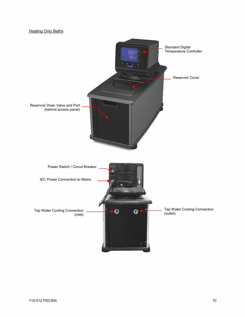
Heating Only Baths
Standard Digital Temperature Controller
Reservoir Cover
Reservoir Drain Valve and Port (behind access panel)
Tap Water Cooling Connection (outlet)
Tap Water Cooling Connection (inlet)
Power Switch / Circuit Breaker
IEC Power Connection to Mains
110-512 PSC/EN 10
Viscosity Baths
WARNING: The top deck on Viscosity Baths is not attached. Do not remove deck while Circulator is operating. Do not lift bath by grasping the Temperature Controller or top deck. Always disconnect electrical power and drain fluid from bath before moving.
WARNING: To avoid the potential for burns, allow the Circulator to cool completely before cleaning or performing any maintenance.
Standard Digital Controller
Lidded Viscometer Ports
Reservoir Drain Port
Tap Water Cooling Coil
110-512 PSC/EN 11
Quick-Start Unless otherwise specified, quick-start instructions apply to all models.
See Installation and Startup for additional information.
1 Fill reservoir with fluid
2 Connect all electrical power cords and control cables
3 Place Power Switch / Circuit Breaker in ON position
Maximum: 1 in. / 2.54 cm below underside of top deck
Minimum: 4.5 in. / 11.5 cm below top deck
Heating only models
IEC power cord from Controller to
Refrigeration Power Module Refrigeration
control cable
Refrigerating / heating models
Heating only models
Refrigerating / heating models
110-512 PSC/EN 12
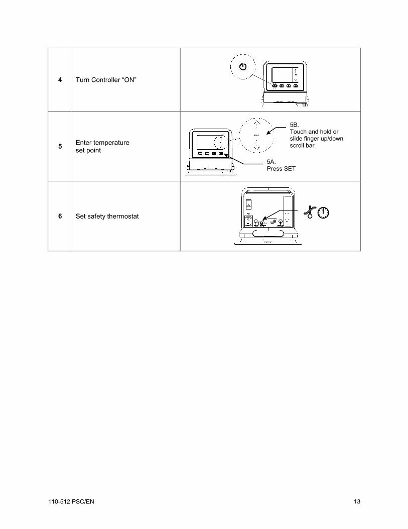
4 Turn Controller “ON”
5 Enter temperature set point
6 Set safety thermostat
5A. Press SET
5B. Touch and hold or slide finger up/down scroll bar
110-512 PSC/EN 13
Installation and Startup Your Circulating Bath with Standard Digital Temperature Controller is designed to be simple to set-up and install. The only tools required are a flat-head screwdriver and a container for adding water or other suitable fluid to the bath reservoir.
General Site Requirements
Locate your Circulator on a level surface free from drafts and direct sunlight. Do not place it where there are corrosive fumes, excessive moisture, high room temperatures, or in excessively dusty areas.
Refrigerating / Heating Circulators must be 10.2 cm / 4 inches or more away from walls or vertical surfaces so that airflow is not restricted.
Avoid voltage drops by using properly grounded power outlets wired with 14 gauge or larger diameter wire and if possible, be close to the power distribution panel. The use of extension cords is not recommended; this will reduce the potential for problems caused by low line voltage.
Adding Liquid to the Bath Reservoir
WARNING: Read the safety data sheet for the bath fluid being used carefully before filling reservoir.
WARNING: See Technical Information in the rear of this manual for a list of compatible liquids.
WARNING: If the proper fluid level is not maintained, the heater coil may become exposed and possibly damaged (fluid level too low) or the bath may overflow (fluid level too high).
The liquid in the reservoir should be maintained at a depth between 1 inch / 2.54 cm and 4.5 inches / 11.5 cm below the underside of the bath’s top deck. Upon start up, it may be necessary to add fluid to the bath to compensate for the fluid required for external circulation. Likewise, be sure to compensate for fluid displacement when placing samples or other materials in the Circulator’s reservoir.
WARNING: Always drain all fluid from the reservoir before moving or lifting your Circulator. Be sure to follow your organization’s procedures and practices regarding the safe lifting and relocation of heavy objects.
WARNING: To avoid the potential for burns, allow the Circulator to cool completely before cleaning or performing any maintenance.
Maximum Fluid Level = 1 inch / 2.54 cm below underside of top deck Minimum Fluid Level =
4.5 inches / 11.5 cm below underside of top
deck
110-512 PSC/EN 14
Pump Inlet and Outlet Connections
WARNING: When connecting tubing to an external application, it is the user’s responsibility to make sure that the tubing and fittings connected to the Circulator are suitable for the fluid being used and the temperature range of operation. CAUTION: The Circulator’s bypass tubing is secured to the fluid inlet and outlet connections by high temperature nylon hose clamps, which can be removed by carefully cutting them with diagonal cutters. CAUTION: Secure the tubing to the inlet and outlet fittings using hose clamps with a minimum ID of 7/8 inch (22 mm). Do not operate the unit without hose clamps.
WARNING: If the Circulating Bath will not be used for external circulation, the inlet and outlet ports should remain connected using the Buna N bypass tubing provided with the unit.
The pump inlet and outlet ports are female ¼ inch NPT connections that permit use of barbed tubing adapters or hard plumbing fittings. ½ inch (13 mm) ID tubing may also be slid over these connections and held in place with hose clamps (minimum 7/8 inch / 22 mm) ID.
If the pump inlet and outlet are not used for external circulation, the Bypass Tubing provided with the unit should be left in place in order to optimize fluid mixing within the reservoir.
The nylon barbed tubing adapter fittings supplied with the unit are intended for applications from -40° to 93°C. For applications above 93°C, brass, stainless steel, or Teflon® fittings are recommended. ¼ inch NPT to M16 stainless steel male adapter fittings are provided with all 50Hz models.
NOTE: The use of quick-connect fittings is not recommended as they typically restrict flow rate.
External Closed Loop Circulation
Connect the pump inlet and outlet to the external apparatus. To maintain adequate flow, avoid restrictions in the tubing. When connecting the Circulator to more than two closed loops, the use of a manifold made of “Y” adapters to divide the fluid into multiple banks is recommended. After setting up multiple closed loops, check for adequate flow at the return manifold of each loop and check that the bath fluid is at an adequate level. A booster pump may be added to closed loops without damaging the Circulator’s pump.
The temperature control stability of a closed loop system is better at the external apparatus than in the Circulator reservoir (provided the control point of the apparatus represents a constant load and is well insulated). For example, if you circulate fluid through a viscometer at 50°C, the temperature variation observed in the Circulator reservoir may be ±0.1°C while the temperature variation in the viscometer may be only ±0.05°C.
Although temperature stability is generally better at the external apparatus control point, depending on the length of tubing used and the efficiency of the insulation, the actual temperature reading at the external apparatus may be slightly different than the temperature reading at the Circulator reservoir.
110-512 PSC/EN 15
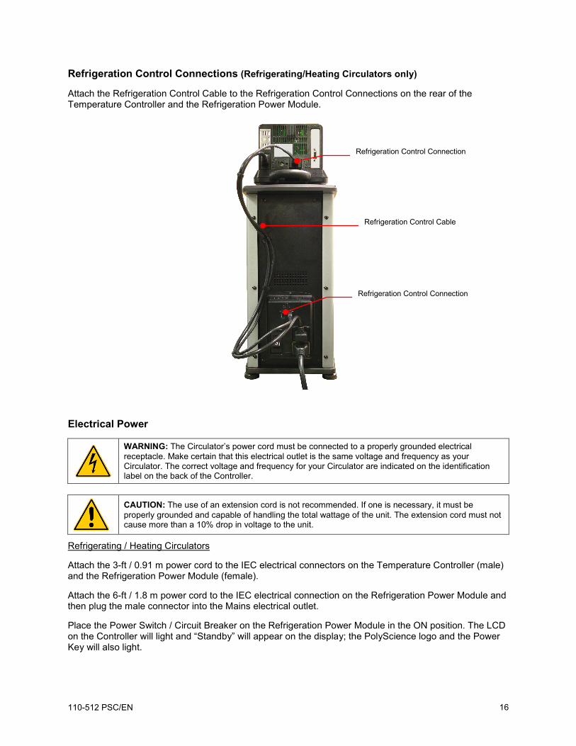
Refrigeration Control Connections (Refrigerating/Heating Circulators only)
Attach the Refrigeration Control Cable to the Refrigeration Control Connections on the rear of the Temperature Controller and the Refrigeration Power Module.
Electrical Power
WARNING: The Circulator’s power cord must be connected to a properly grounded electrical receptacle. Make certain that this electrical outlet is the same voltage and frequency as your Circulator. The correct voltage and frequency for your Circulator are indicated on the identification label on the back of the Controller.
CAUTION: The use of an extension cord is not recommended. If one is necessary, it must be properly grounded and capable of handling the total wattage of the unit. The extension cord must not cause more than a 10% drop in voltage to the unit.
Refrigerating / Heating Circulators
Attach the 3-ft / 0.91 m power cord to the IEC electrical connectors on the Temperature Controller (male) and the Refrigeration Power Module (female).
Attach the 6-ft / 1.8 m power cord to the IEC electrical connection on the Refrigeration Power Module and then plug the male connector into the Mains electrical outlet.
Place the Power Switch / Circuit Breaker on the Refrigeration Power Module in the ON position. The LCD on the Controller will light and “Standby” will appear on the display; the PolyScience logo and the Power Key will also light.
Refrigeration Control Connection
Refrigeration Control Connection
Refrigeration Control Cable
110-512 PSC/EN 16
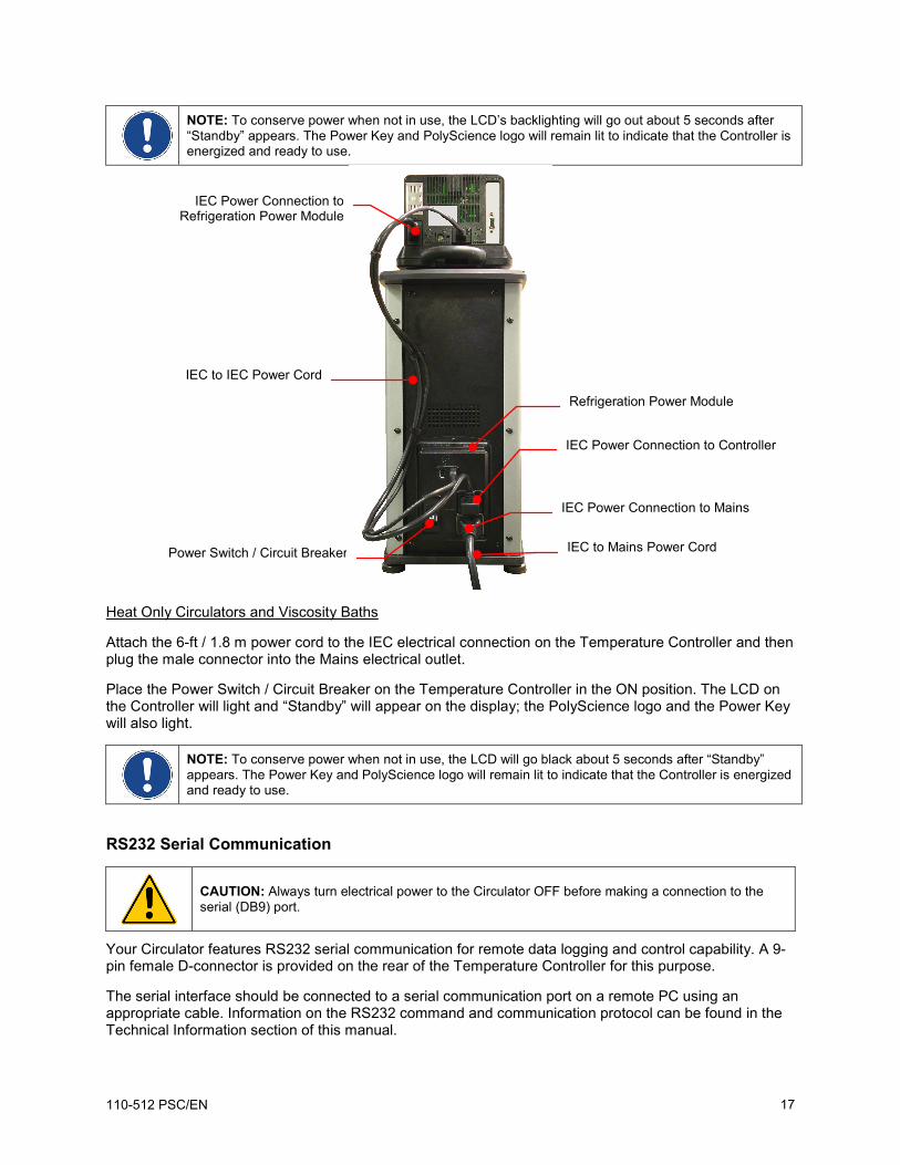
NOTE: To conserve power when not in use, the LCD’s backlighting will go out about 5 seconds after “Standby” appears. The Power Key and PolyScience logo will remain lit to indicate that the Controller is energized and ready to use.
Heat Only Circulators and Viscosity Baths
Attach the 6-ft / 1.8 m power cord to the IEC electrical connection on the Temperature Controller and then plug the male connector into the Mains electrical outlet.
Place the Power Switch / Circuit Breaker on the Temperature Controller in the ON position. The LCD on the Controller will light and “Standby” will appear on the display; the PolyScience logo and the Power Key will also light.
NOTE: To conserve power when not in use, the LCD will go black about 5 seconds after “Standby” appears. The Power Key and PolyScience logo will remain lit to indicate that the Controller is energized and ready to use.
RS232 Serial Communication
CAUTION: Always turn electrical power to the Circulator OFF before making a connection to the serial (DB9) port.
Your Circulator features RS232 serial communication for remote data logging and control capability. A 9-pin female D-connector is provided on the rear of the Temperature Controller for this purpose.
The serial interface should be connected to a serial communication port on a remote PC using an appropriate cable. Information on the RS232 command and communication protocol can be found in the Technical Information section of this manual.
IEC Power Connection to Refrigeration Power Module
IEC Power Connection to Mains
IEC to IEC Power Cord
Refrigeration Power Module
IEC Power Connection to Controller
IEC to Mains Power Cord Power Switch / Circuit Breaker
110-512 PSC/EN 17
Controller Setup
Power
Press . The Circulator will begin running, actual and set point temperatures will be displayed, and the word “SET” will be continuously lit. The circulating symbol will also be lit and the heating or refrigerating symbol may be lit or flashing.
Heating Symbol
Circulating Symbol
Refrigerating Symbol
110-512 PSC/EN 18
Safety Set Temperature
This is a “Do Not Exceed” temperature setting for your Circulator and is the temperature at which the heater will be turned OFF should the liquid level in the bath drop too low or the heater malfunctions. It is normally set about 5° higher than the desired operating temperature. Setting the Safety Set temperature is a multi-step process.
WARNING: The Safety Thermostat is user-adjustable from approximately 40° to 170°C. Do not force the indicator dial beyond the stops at either end of the dial’s range. The “12:00” o’clock position represents approximately 100°C. NOTE: The Safety Set must be manually reset whenever it is tripped. The Reset is located in the vertical slot to the left of the Safety Thermostat.
1. Using a small flat blade screwdriver, rotate the Safety Thermostat clockwise until it stops.
2. Press . The arrow around the word “SET” and the numerals to the left of the decimal point will begin flashing. Small blue lights will also begin flashing on the touch scroll bar.
3. Place your finger on the touch scroll bar and slide it up / down until the set point temperature is equal to your desired Safety Set temperature. “SET” will stop flashing about 10 seconds after the temperature has been set. Allow the bath to stabilize at this temperature.
4. Once the bath temperature has stabilized, slowly rotate the Safety Thermostat counter-clockwise until the OVERTEMP or LOW FLUID alarm message appears on the display and the alarm sounds. At this point, the heater will also turn OFF.
5. Press to turn the Circulator OFF.
6. Allow the bath to cool and then reset the Safety Set by inserting the blade of the screwdriver or the end of a paperclip into the access slot and pressing until you hear the Safety Set reset (an audible click).
7. Press to turn the Circulator back ON. If the alarm re-activates, repeat steps 5 and 6 until the alarm no longer activates when the Circulator is turned back ON. You are now ready to start normal operation.
Safety Set Reset access Safety Set
Thermostat
110-512 PSC/EN 19
Normal Operation Keys and Controls
Power
Turns the Circulator’s Temperature Controller ON.
Home
Returns the LCD to the Main Operational Display (from any screen).
Menu
Accesses the Temperature Controller’s set-up sub-menus. The items in these sub-menus are used to configure the Controller’s general operational parameters (temperature unit, pump speed, upper and low temperature limits, etc. (see Set-up Sub-Menus, below).
SET
Used in conjunction with the Touch Scroll Bar to change the set point temperature.
Touch Scroll Bar
• Used to make temperature set point and other operational changes. Slide finger up / down scroll bar or touch upper / lower sections to make minor adjustments; press and hold to make large adjustments.
Turning Your Circulator ON
Press the key.
When the Circulator begins running, the actual and set point temperatures will be displayed and the circulating symbol will be lit.
If the actual bath temperature is lower than the set point temperature, the heating symbol will also be lit.
Refrigerating/Heating Models: If the actual bath temperature is higher than the set point temperature, the refrigerating symbol will be lit. It is normal for both the heating and refrigerating symbols to be lit simultaneously when nearing or maintaining the set point temperature.
110-512 PSC/EN 20
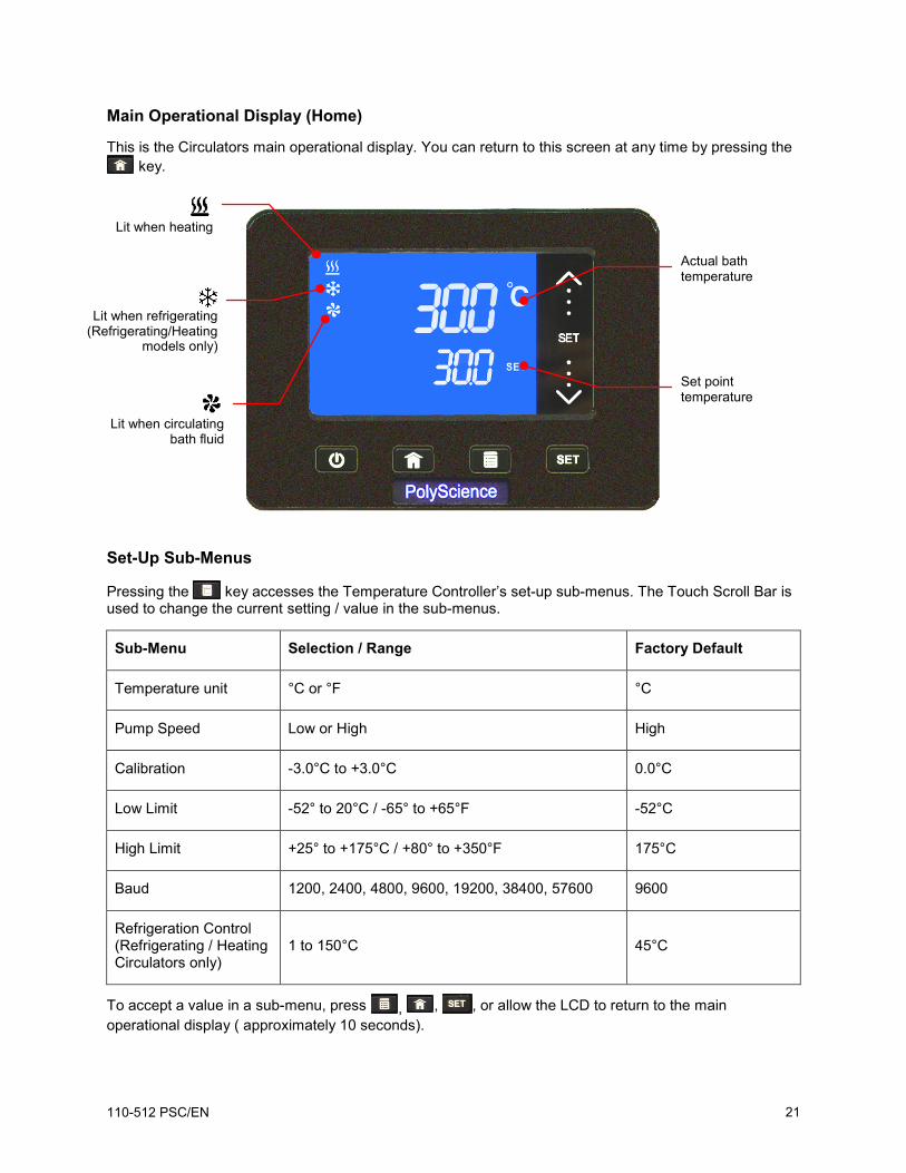
Main Operational Display (Home)
This is the Circulators main operational display. You can return to this screen at any time by pressing the key.
Set-Up Sub-Menus
Pressing the key accesses the Temperature Controller’s set-up sub-menus. The Touch Scroll Bar is used to change the current setting / value in the sub-menus.
Refrigeration Control (Refrigerating / Heating Circulators only)
1 to 150°C 45°C
To accept a value in a sub-menu, press , , , or allow the LCD to return to the main operational display ( approximately 10 seconds).
Actual bath temperature
Set point temperature
Lit when heating
Lit when circulating
bath fluid
Lit when refrigerating
(Refrigerating/Heating models only)
110-512 PSC/EN 21
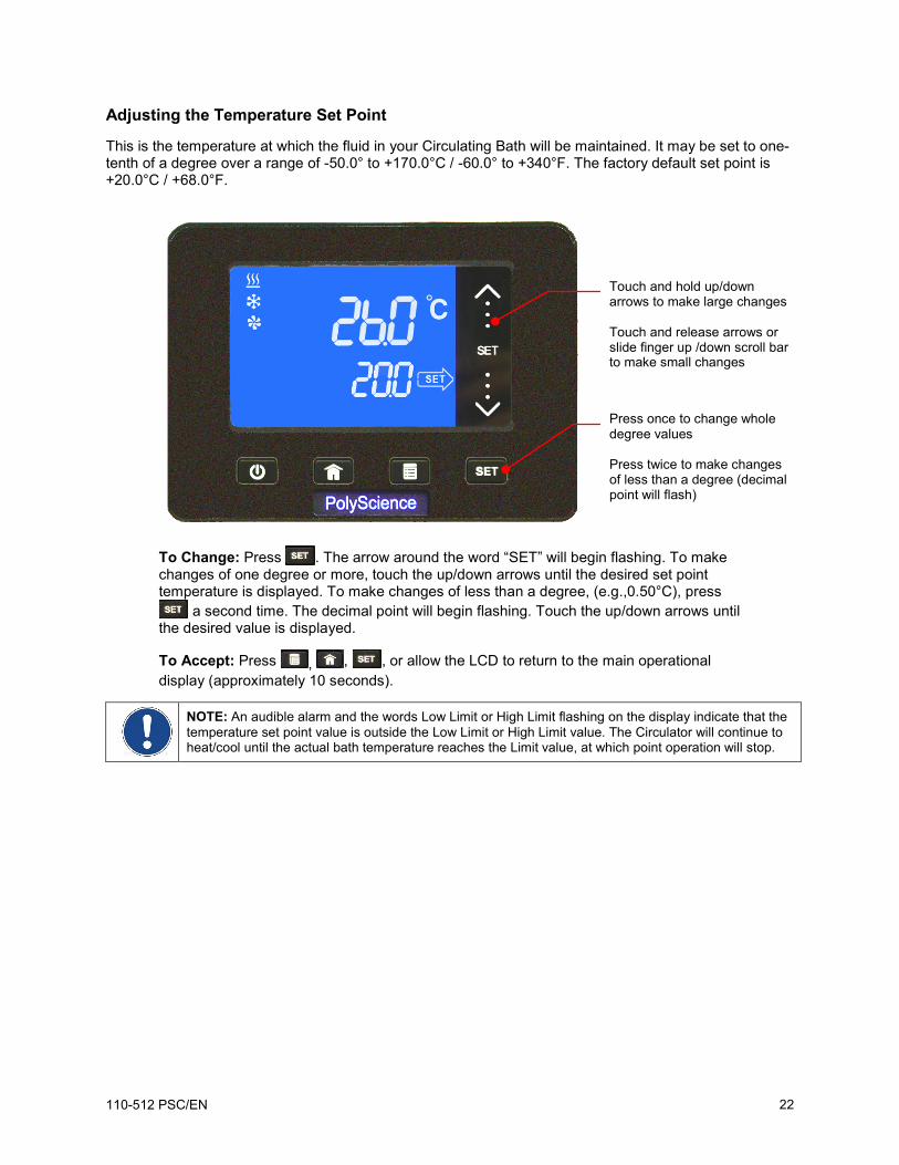
Adjusting the Temperature Set Point
This is the temperature at which the fluid in your Circulating Bath will be maintained. It may be set to one-tenth of a degree over a range of -50.0° to +170.0°C / -60.0° to +340°F. The factory default set point is +20.0°C / +68.0°F.
To Change: Press . The arrow around the word “SET” will begin flashing. To make changes of one degree or more, touch the up/down arrows until the desired set point temperature is displayed. To make changes of less than a degree, (e.g.,0.50°C), press
a second time. The decimal point will begin flashing. Touch the up/down arrows until the desired value is displayed.
To Accept: Press , , , or allow the LCD to return to the main operational display (approximately 10 seconds).
NOTE: An audible alarm and the words Low Limit or High Limit flashing on the display indicate that the temperature set point value is outside the Low Limit or High Limit value. The Circulator will continue to heat/cool until the actual bath temperature reaches the Limit value, at which point operation will stop.
Touch and hold up/down arrows to make large changes Touch and release arrows or slide finger up /down scroll bar to make small changes
Press once to change whole degree values Press twice to make changes of less than a degree (decimal point will flash)
110-512 PSC/EN 22
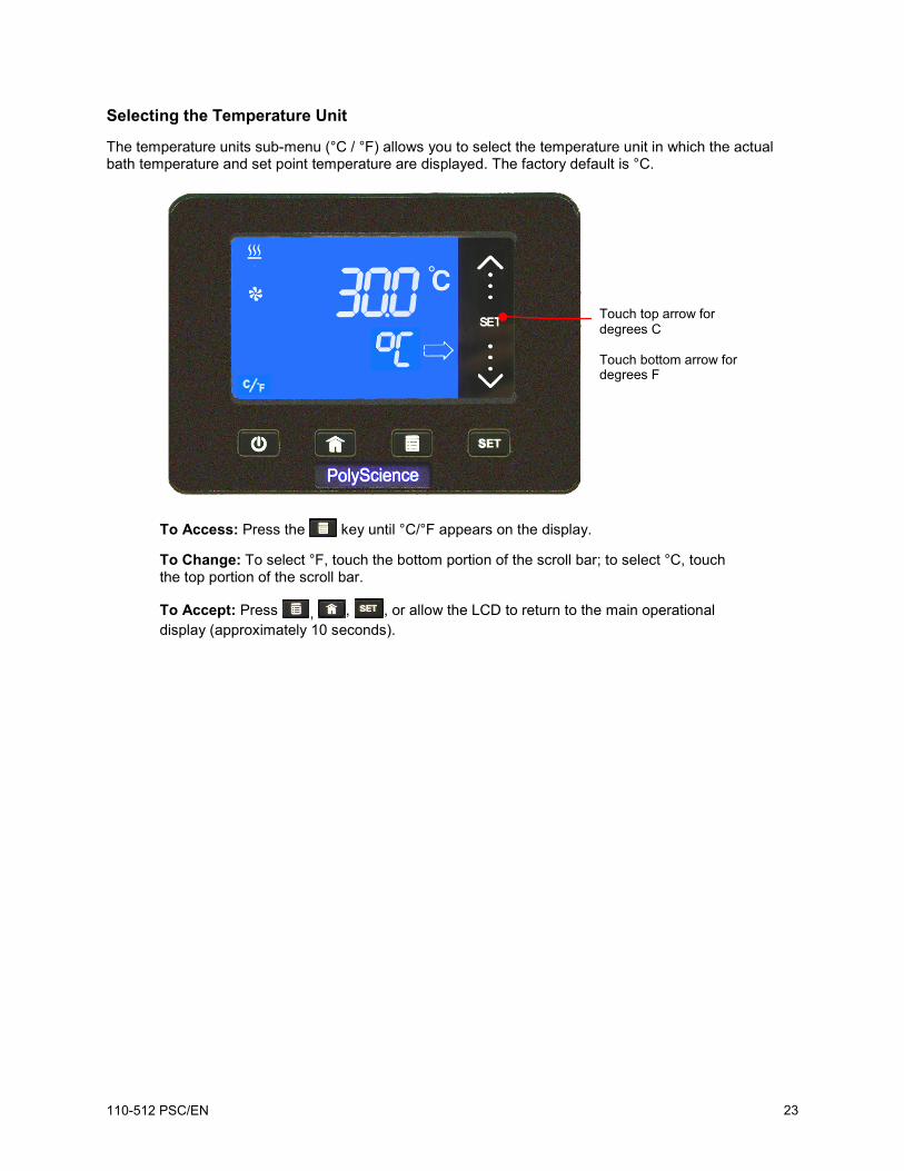
Selecting the Temperature Unit
The temperature units sub-menu (°C / °F) allows you to select the temperature unit in which the actual bath temperature and set point temperature are displayed. The factory default is °C.
To Access: Press the key until °C/°F appears on the display.
To Change: To select °F, touch the bottom portion of the scroll bar; to select °C, touch the top portion of the scroll bar.
To Accept: Press , , , or allow the LCD to return to the main operational display (approximately 10 seconds).
Touch top arrow for degrees C Touch bottom arrow for degrees F
110-512 PSC/EN 23
Selecting the Pump Speed
This sub-menu allows you to select your Circulator’s pump speed. The choices are Low (LO) and High (HI); the factory default is High (HI).
To Access: Press the key until PUMP appears on the display.
To Change: To select the low pump speed, touch the top arrow; to select the high pump speed, touch the bottom arrow.
To Accept: Press , , , or allow the LCD to return to the main operational display (approximately 10 seconds).
Touch top arrow to select High Touch bottom arrow to select Low
110-512 PSC/EN 24
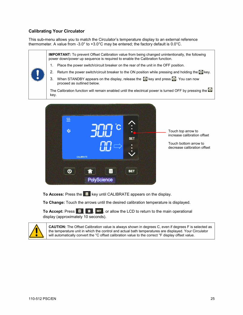
Calibrating Your Circulator
This sub-menu allows you to match the Circulator’s temperature display to an external reference thermometer. A value from -3.0° to +3.0°C may be entered; the factory default is 0.0°C.
IMPORTANT: To prevent Offset Calibration value from being changed unintentionally, the following power down/power up sequence is required to enable the Calibration function.
1. Place the power switch/circuit breaker on the rear of the unit in the OFF position.
2. Return the power switch/circuit breaker to the ON position while pressing and holding the key.
3. When STANDBY appears on the display, release the key and press . You can now proceed as outlined below.
The Calibration function will remain enabled until the electrical power is turned OFF by pressing the key.
To Access: Press the key until CALIBRATE appears on the display.
To Change: Touch the arrows until the desired calibration temperature is displayed.
To Accept: Press , , , or allow the LCD to return to the main operational display (approximately 10 seconds).
CAUTION: The Offset Calibration value is always shown in degrees C, even if degrees F is selected as the temperature unit in which the control and actual bath temperatures are displayed. Your Circulator will automatically convert the °C offset calibration value to the correct °F display offset value.
Touch top arrow to increase calibration offset Touch bottom arrow to decrease calibration offset
110-512 PSC/EN 25
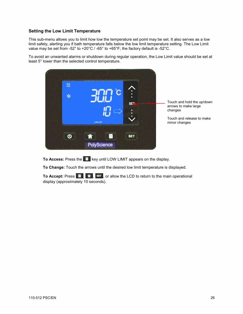
Setting the Low Limit Temperature
This sub-menu allows you to limit how low the temperature set point may be set. It also serves as a low limit safety, alerting you if bath temperature falls below the low limit temperature setting. The Low Limit value may be set from -52° to +20°C / -65° to +65°F; the factory default is -52°C.
To avoid an unwanted alarms or shutdown during regular operation, the Low Limit value should be set at least 5° lower than the selected control temperature.
To Access: Press the key until LOW LIMIT appears on the display.
To Change: Touch the arrows until the desired low limit temperature is displayed.
To Accept: Press , , , or allow the LCD to return to the main operational display (approximately 10 seconds).
Touch and hold the up/down arrows to make large changes Touch and release to make minor changes
110-512 PSC/EN 26
Setting the High Limit Temperature
This sub-menu allows you to limit how high the temperature set point may be set. It also serves as a high limit safety, alerting you if bath temperature rises above the high limit temperature setting. The High Limit value may be set from +25° to +175°C / +80° to +350°F; the factory default is 175°C.
To avoid an unwanted shutdown during regular operation, the High Limit value should be set at least 5° higher than the selected control temperature.
To Access: Press the key until HIGH LIMIT appears on the display.
To Change: Touch the arrows until the desired high limit temperature is displayed.
To Accept: Press , , , or allow the LCD to return to the main operational display (approximately 10 seconds).
Touch and hold up/down arrows to make large changes Touch and release to make minor changes
110-512 PSC/EN 27
Selecting the Serial Communication Baud Rate
This sub-menu allows you to select the speed at which your Circulator will transmit data. The setting on both the Circulator and the device it is connected to should match. The baud rate setting may be 1200, 2400, 4800, 9600, 19200; 38400, or 57600; the factory default is 9600.
To Access: Press the key until BAUD appears on the display.
To Change: To select the 1200 baud rate setting, touch the bottom of the scroll bar; to select the 57600 setting, touch the top of the scroll bar. Rates between these two extremes are selected by touching the corresponding area of the scroll bar (e.g. 9600 baud is at the mid-point of the scroll bar).
To Accept: Press , , , or allow the LCD to return to the main operational display (approximately 10 seconds).
NOTE: When using RS232 communication, the Circulator’s baud rate must match that of the connected device.
Touch top for fastest baud rate Touch bottom for slowest baud rate
110-512 PSC/EN 28
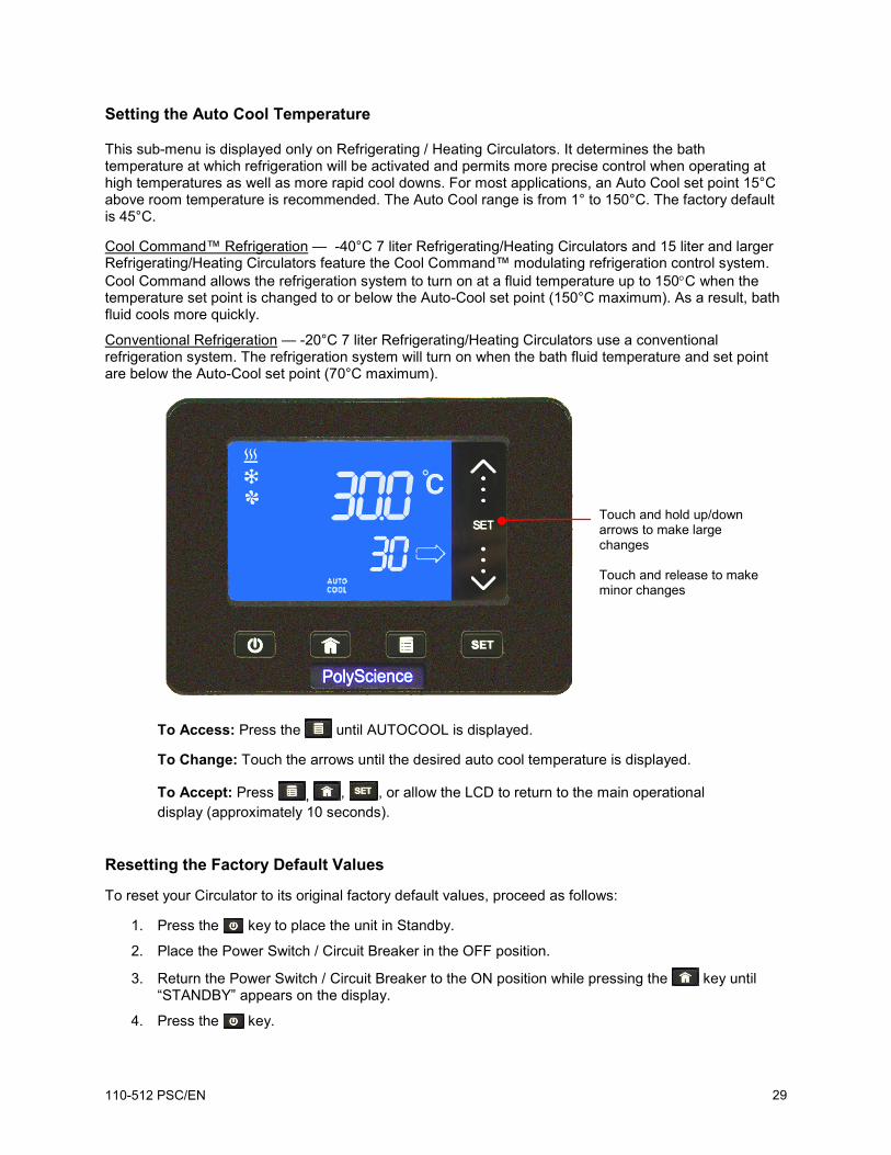
Setting the Auto Cool Temperature
This sub-menu is displayed only on Refrigerating / Heating Circulators. It determines the bath temperature at which refrigeration will be activated and permits more precise control when operating at high temperatures as well as more rapid cool downs. For most applications, an Auto Cool set point 15°C above room temperature is recommended. The Auto Cool range is from 1° to 150°C. The factory default is 45°C.
Cool Command™ Refrigeration — -40°C 7 liter Refrigerating/Heating Circulators and 15 liter and larger Refrigerating/Heating Circulators feature the Cool Command™ modulating refrigeration control system. Cool Command allows the refrigeration system to turn on at a fluid temperature up to 150°C when the temperature set point is changed to or below the Auto-Cool set point (150°C maximum). As a result, bath fluid cools more quickly.
Conventional Refrigeration — -20°C 7 liter Refrigerating/Heating Circulators use a conventional refrigeration system. The refrigeration system will turn on when the bath fluid temperature and set point are below the Auto-Cool set point (70°C maximum).
To Access: Press the until AUTOCOOL is displayed.
To Change: Touch the arrows until the desired auto cool temperature is displayed.
To Accept: Press , , , or allow the LCD to return to the main operational display (approximately 10 seconds).
Resetting the Factory Default Values
To reset your Circulator to its original factory default values, proceed as follows:
1. Press the key to place the unit in Standby.
2. Place the Power Switch / Circuit Breaker in the OFF position.
3. Return the Power Switch / Circuit Breaker to the ON position while pressing the key until “STANDBY” appears on the display.
4. Press the key.
Touch and hold up/down arrows to make large changes Touch and release to make minor changes
110-512 PSC/EN 29
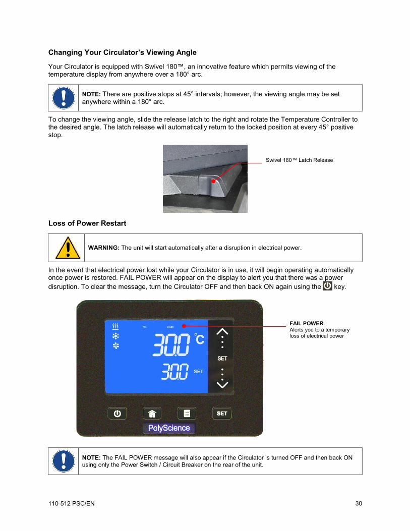
Changing Your Circulator’s Viewing Angle
Your Circulator is equipped with Swivel 180™, an innovative feature which permits viewing of the temperature display from anywhere over a 180° arc.
NOTE: There are positive stops at 45° intervals; however, the viewing angle may be set anywhere within a 180° arc.
To change the viewing angle, slide the release latch to the right and rotate the Temperature Controller to the desired angle. The latch release will automatically return to the locked position at every 45° positive stop.
Loss of Power Restart
WARNING: The unit will start automatically after a disruption in electrical power.
In the event that electrical power lost while your Circulator is in use, it will begin operating automatically once power is restored. FAIL POWER will appear on the display to alert you that there was a power disruption. To clear the message, turn the Circulator OFF and then back ON again using the key.
NOTE: The FAIL POWER message will also appear if the Circulator is turned OFF and then back ON using only the Power Switch / Circuit Breaker on the rear of the unit.
Swivel 180™ Latch Release
FAIL POWER Alerts you to a temporary loss of electrical power
110-512 PSC/EN 30
Inert Gas Purge
A 0.125 in. / 3 mm port on the rear of the Temperature Controller is provided to allow you to blanket the surface of the liquid in the bath reservoir with nitrogen or another inert gas to help prevent condensation and dilution of the bath fluid.
Tap Water Cooling
Tap water cooling allows for more rapid bath cool down from high temperatures and/or more precise operation at temperatures near ambient.
Heat only Circulating Baths feature an integrated cooling coil as standard equipment. The tap water connections are made on the rear of the unit. Two 0.25 inch / 6.4 mm female NPT fittings are provided for these connections.
Polycarbonate Viscosity Baths feature a cooling coil with two 0.375 inch / 9.5 mm OD straight barb fittings at which the fluid inlet and outlet connections can be made. Either connection may serve as the fluid inlet or outlet. Be sure to secure the tubing with the appropriate size hose clamps.
An optional cooling coil is available for use on Stainless Steel Open Bath systems. This cooling coil has two 0.375 inch / 9.5 mm OD straight barb fittings at which the fluid inlet and outlet connections can be made. Either connection may serve as the fluid inlet or outlet. Be sure to secure the tubing with the appropriate size hose clamps.
WARNING: The fluid outlet must be connected and flow to a suitable drain or vessel located at a level below that of the inlet.
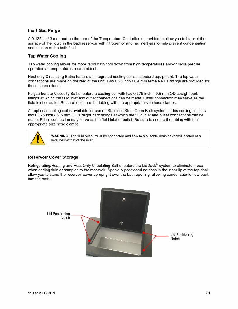
Reservoir Cover Storage
Refrigerating/Heating and Heat Only Circulating Baths feature the LidDock® system to eliminate mess when adding fluid or samples to the reservoir. Specially positioned notches in the inner lip of the top deck allow you to stand the reservoir cover up upright over the bath opening, allowing condensate to flow back into the bath.
Lid Positioning Notch
Lid Positioning Notch
110-512 PSC/EN 31
Display Messages and Alarms Message
and/or Symbol
Description Corrective Action
FAIL POWER Informational Message: Indicates that electrical power was lost during operation.
Using the key, turn the Circulator OFF and then back ON. This will clear the message.
(flashing)
Warning: The temperature set point is below the Low Limit temperature value.
Decrease the Low Limit temperature value or increase the temperature set point.
(flashing)
Warning: The temperature set point is above the High Limit temperature value.
Increase the High Limit temperature value or decrease the set point temperature.
Alarm: The bath temperature has fallen below the Low Limit temperature value. Power to the compressor and pump will remain OFF until the problem is corrected.
Allow bath to warm or add heat load. Decrease the Low Limit temperature value.
Alarm: The bath temperature has risen above the High Limit temperature value. Power to the heater and pump will remain OFF until the problem is corrected.
Allow bath to cool or increase High Limit temperature value.
Replace fluid.
Alarm: The liquid in the bath has dropped too low or the temperature of the bath fluid has exceeded the Safety Set temperature. Power to the heater will remain OFF until the problem is corrected.
Fluid level in reservoir has fallen below minimum level; add fluid as required. Fluid temperature is higher than Safety Set temperature; increase Safety Set temperature setting. Controller failure; consult factory.
Fault: The Circulator’s temperature sensor has failed. Consult factory.
Fault: The Circulator’s heater has failed. Consult factory.
110-512 PSC/EN 32
Routine Maintenance and Troubleshooting
WARNING: Always turn your Circulator OFF and disconnect it from the electrical power outlet before performing any maintenance or service.
WARNING: To avoid the potential for burns, allow the Circulator to cool completely before cleaning or performing any maintenance.
WARNING: Always drain all fluid from the reservoir before moving or lifting your Circulator. Be sure to follow your organization’s procedures and practices regarding the safe lifting and relocation of heavy objects.
Maintaining Clear Bath Water
Optimum temperature and moisture conditions for algae growth existing when using water as a bath fluid. To prevent algae contamination and minimize the frequency of draining the reservoir, an algaecide such as polyclean Bath Algaecide (004-300040) should be used.
WARNING: Do not use chlorine bleach.
Draining the Bath Reservoir
WARNING: Bath fluids should be stored and disposed of according to applicable laws and regulations.
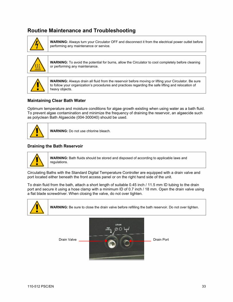
Circulating Baths with the Standard Digital Temperature Controller are equipped with a drain valve and port located either beneath the front access panel or on the right hand side of the unit.
To drain fluid from the bath, attach a short length of suitable 0.45 inch / 11.5 mm ID tubing to the drain port and secure it using a hose clamp with a minimum ID of 0.7 inch / 18 mm. Open the drain valve using a flat blade screwdriver. When closing the valve, do not over tighten.
WARNING: Be sure to close the drain valve before refilling the bath reservoir. Do not over tighten.
Drain Valve Drain Port
110-512 PSC/EN 33
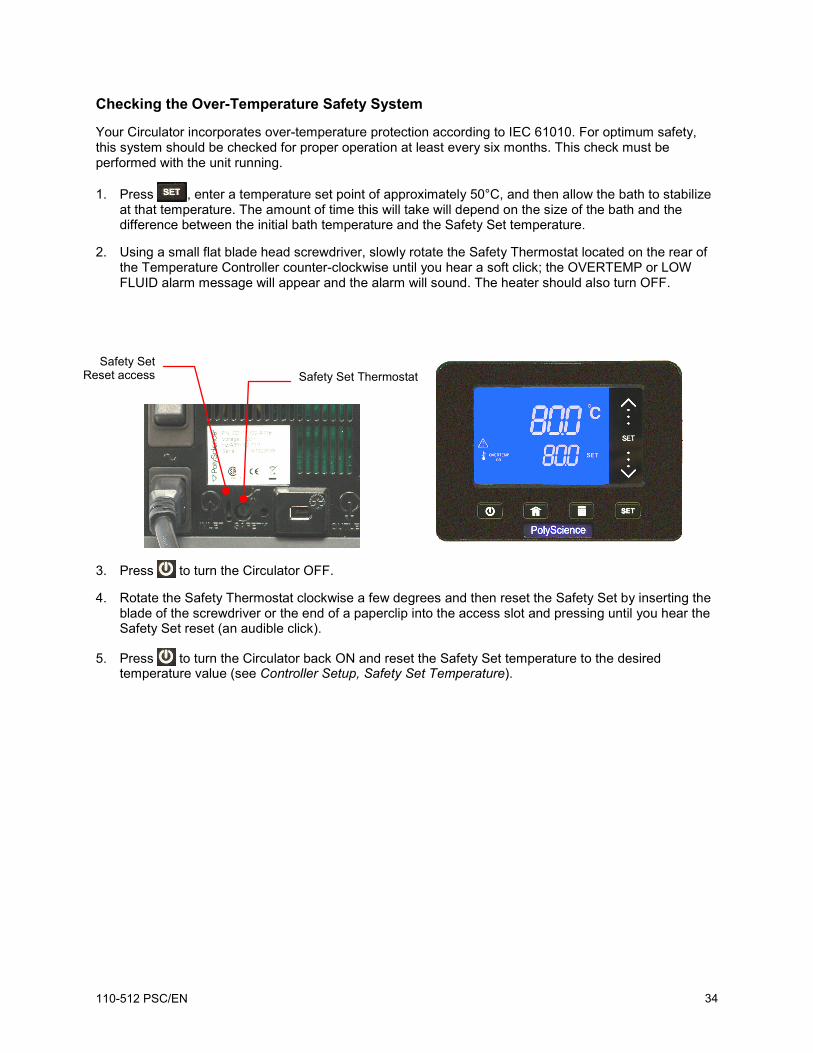
Checking the Over-Temperature Safety System
Your Circulator incorporates over-temperature protection according to IEC 61010. For optimum safety, this system should be checked for proper operation at least every six months. This check must be performed with the unit running.
1. Press , enter a temperature set point of approximately 50°C, and then allow the bath to stabilize at that temperature. The amount of time this will take will depend on the size of the bath and the difference between the initial bath temperature and the Safety Set temperature.
2. Using a small flat blade head screwdriver, slowly rotate the Safety Thermostat located on the rear of the Temperature Controller counter-clockwise until you hear a soft click; the OVERTEMP or LOW FLUID alarm message will appear and the alarm will sound. The heater should also turn OFF.
3. Press to turn the Circulator OFF.
4. Rotate the Safety Thermostat clockwise a few degrees and then reset the Safety Set by inserting the blade of the screwdriver or the end of a paperclip into the access slot and pressing until you hear the Safety Set reset (an audible click).
5. Press to turn the Circulator back ON and reset the Safety Set temperature to the desired temperature value (see Controller Setup, Safety Set Temperature).
Safety Set Reset access Safety Set Thermostat
110-512 PSC/EN 34
Cleaning Your Circulator
WARNING: It is the user’s responsibility to properly decontaminate the unit in the event hazardous materials are spilled on exterior or interior surfaces. Consult the manufacturer if there is any doubt regarding the compatibility of decontamination or cleaning agents.
Temperature Controller
Turn the Temperature Controller OFF by pressing and unplug power cord from the electrical outlet.
Wipe the housing with a clean cloth dampened with a mild detergent and water or mild all-purpose cleaner.
CAUTION: Do not spray cleaning liquids directly onto the Temperature Controller or allow them to enter the Controller’s vents. Do not use abrasives as these could scratch the housing or the digital display.
Bath Reservoir
Bath Reservoir and Wetted Components — A concentrated bath cleaner (polyclean Bath Cleaner, part number 004-300050) is available to remove mineral deposits from the stainless steel reservoir and the Temperature Controller’s wetted parts. The cleaner should be added to the bath reservoir at the prescribed dosage and circulated at 60°C / 140°F until the scale is removed.
CAUTION: Do not use steel wool to clean your Circulator’s bath reservoir.
External Surfaces — Only mild detergents and water or an approved cleaner should be used on the top deck and other external surfaces of your Circulator. Do not allow cleaning liquids or sprays to enter the vents on the rear of the Temperature Controller.
Pump Impeller
In the unlikely event that debris becomes lodged in the pump impeller, a soft brush can be used to remove any lodged particles. If necessary, soak in a solution of distilled water and polyclean Bath Cleaner to soften before brushing.
CAUTION: Do not use hard utensils or abrasive pads to remove trapped debris.
Condenser, Air Vents, and Reusable Filter (Refrigerating / Heating Circulators only)
To keep the refrigeration system operating at optimum cooling capacity, the condenser, removable air filter, and all air vents (front, side, back) should be kept free of dust and dirt. Be sure to check them on a regular basis and clean as required.
The reusable filter is easily accessed from the front of the unit by simply removing the access panel. Use a mild detergent and water solution to wash off any accumulated dust and dirt. Rinse and dry thoroughly before reinstalling.
Reusable Filter
110-512 PSC/EN 35
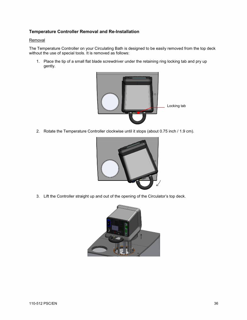
Temperature Controller Removal and Re-Installation
Removal
The Temperature Controller on your Circulating Bath is designed to be easily removed from the top deck without the use of special tools. It is removed as follows:
1. Place the tip of a small flat blade screwdriver under the retaining ring locking tab and pry up gently.
2. Rotate the Temperature Controller clockwise until it stops (about 0.75 inch / 1.9 cm).
3. Lift the Controller straight up and out of the opening of the Circulator’s top deck.
Locking tab
110-512 PSC/EN 36
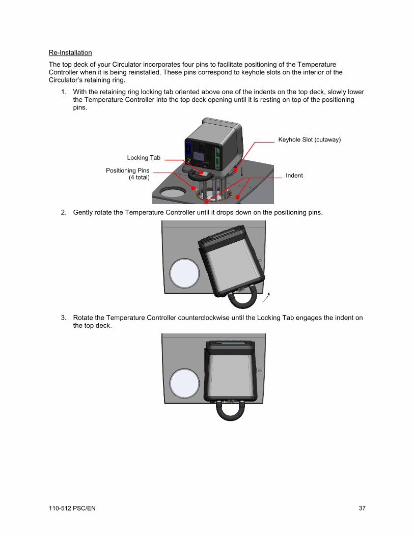
Re-Installation
The top deck of your Circulator incorporates four pins to facilitate positioning of the Temperature Controller when it is being reinstalled. These pins correspond to keyhole slots on the interior of the Circulator’s retaining ring.
1. With the retaining ring locking tab oriented above one of the indents on the top deck, slowly lower the Temperature Controller into the top deck opening until it is resting on top of the positioning pins.
2. Gently rotate the Temperature Controller until it drops down on the positioning pins.
3. Rotate the Temperature Controller counterclockwise until the Locking Tab engages the indent on
the top deck.
Positioning Pins (4 total)
Keyhole Slot (cutaway)
Locking Tab
Indent
110-512 PSC/EN 37
Troubleshooting Chart
Problem Possible Causes Corrective Action
Unit does not run (Digital Display is blank)
No power to unit Check that the electrical cord is secure and connected to an operating electrical outlet.
Unit does not run (STANDBY appears on Digital Display)
Unit in Standby mode Press Power Key on front panel.
No fluid circulation Insufficient fluid in reservoir Pump impeller jammed
Add fluid to reservoir. Inspect pump and remove debris as required.
Insufficient circulation Fluid viscosity too high External tubing diameter too small Low line voltage
Replace with lower viscosity bath fluid. Replace with larger diameter tubing. Check and correct as required.
Unit does not heat Insufficient fluid in reservoir Temperature set point too low Safety Set Temperature too low
Add fluid to reservoir. Increase temperature set point. Increase Safety Set temperature.
Insufficient heating Insufficient circulation Low line voltage Ambient temperature too cool Excessive heat loss
See Insufficient Circulation, above. Check and correct as required. Increase ambient temperature or relocate unit. Check for heat loss from external tanks and hoses; Check for vapor/heat loss from internal reservoir.
Temperature unstable
Insufficient circulation Debris or mineral build-up on pump, heater, or temperature sensor.
Check pump flow and operation. Clean as required.
Unit does not cool Dust build up on air filter or condenser Blocked air ventilation screens Temperature set point is too high Excessive heat load Ambient air temperature too high (>35°C / 95°F) Low or high line voltage
Clean air filter and/or condenser as required. Remove blockages as required. Decrease temperature set point. Check that heat load does not exceed capacity of bath; correct as required. Decrease ambient air temperature. Check and correct as required.
110-512 PSC/EN 38
Problem Possible Causes Corrective Action
Insufficient cooling Dust build up on air filter or condenser Blocked air ventilation screens Temperature set point is too high Excessive heat load Ambient air temperature too high (>35°C / 95°F) Low or high line voltage
Clean air filter and/or condenser as required. Remove blockages as required. Decrease temperature set point. Check that heat load does not exceed capacity of bath; correct as required. Decrease ambient air temperature. Check and correct as required.
Unable to achieve low end extreme temperatures
Pump speed too high Incorrect bath fluid Insufficient insulation on external fluid lines Ambient air temperature too high (>35°C / 95°F) Low or high line voltage Dust build up on air filter or condenser Blocked air ventilation screens Excessive heat load
Reduce pump speed. Check that the fluid being circulated is capable of reaching the required temperature. Check external fluid lines for proper insulation. Decrease ambient air temperature as required. Check and correct as required. Clean air filter or condenser as required. Remove blockages as required. Check that heat load does not exceed capacity of bath; correct as required.
110-512 PSC/EN 39
Technical Information Performance Specifications
Operating Temperature Range: Model dependent; see table below
Temperature Stability: ±0.04C (±0.08°F)
Pump Type: 2-speed pressure
60Hz models 50Hz models
Maximum Pressure: 3.5 psi (0.24 bar) 2.9 psi (0.20 bar)
SD07R-20 Refrigerating / Heating Bath 7 liters -20° to 170°C -7° to 338°F
120V, 60Hz, 12A
240V, 50Hz, 12A
SD7LR-20 Refrigerating / Heating Bath 7 liters -20° to 170°C -7° to 338°F
120V, 60Hz, 12A
240V, 50Hz, 12A
SD15R-30 Refrigerating / Heating Bath 15 liters -30° to 170°C -22° to 338°F
120V, 60Hz, 13A
240V, 50Hz, 13A
SD20R-30 Refrigerating / Heating Bath 20 liters -30° to 170°C -22° to 338°F
120V, 60Hz, 13A
240V, 50Hz, 13A
SD28R-30 Refrigerating / Heating Bath 28 liters -30° to 170°C -22° to 338°F
120V, 60Hz, 13A
240V, 50Hz, 13A
SD07H170 Heating Only Bath 7 liters Ambient +10° to 170°C Ambient +20° to 338°F
120V, 60Hz, 10A
240V, 50Hz, 10A
SD15H170 Heating Only Bath 15 liters Ambient +10° to 170°C Ambient +20° to 338°F
120V, 60Hz, 10A
240V, 50Hz, 10A
SD20H170 Heating Only Bath 20 liters Ambient +10° to 170°C Ambient +20° to 338°F
120V, 60Hz, 10A
240V, 50Hz, 10A
SD28H170 Heating Only Bath 28 liters Ambient +10° to 170°C Ambient +20° to 338°F
120V, 60Hz, 10A
240V, 50Hz, 10A
SD29VB3S Polycarbonate Viscosity Bath 29 liters Ambient +10° to 85°C Ambient +20° to 185°F (1)
120V, 60Hz, 10A
240V, 50Hz, 10A
SD29VB5R Polycarbonate Viscosity Bath 29 liters Ambient +10° to 85°C Ambient +20° to 185°F (1)
120V, 60Hz, 10A
240V, 50Hz, 10A
1. Maximum working temperature for polycarbonate tank; Standard Digital Temperature Controller capable of higher temperatures.
Environmental Conditions Indoor use only Maximum Altitude: 2000 meter Operating Ambient: 5° to 35°C (41° to 95°F) Relative Humidity: 80%, non-condensing Installation Category: II Pollution Degree: 2 Ingress Protection: IP 31 Climate Class: SN Software Class: B Output Waveform: Sinusoidal
Specifications subject to change without notice.
110-512 PSC/EN 40
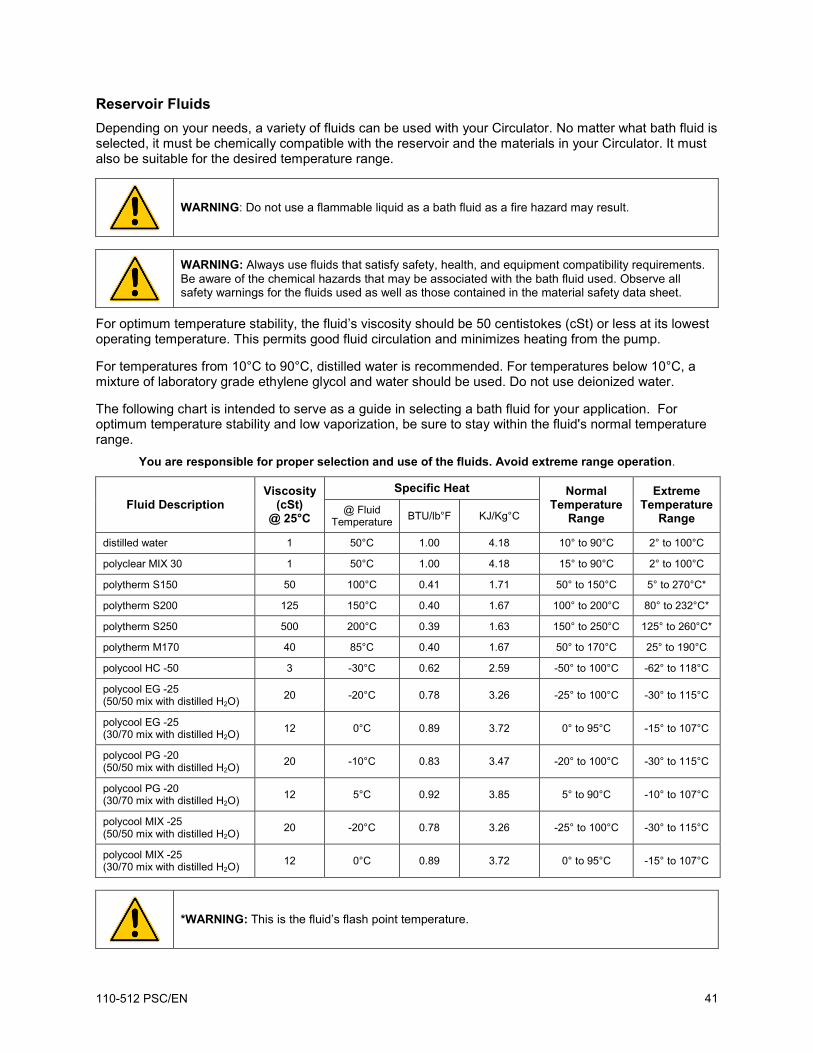
Reservoir Fluids Depending on your needs, a variety of fluids can be used with your Circulator. No matter what bath fluid is selected, it must be chemically compatible with the reservoir and the materials in your Circulator. It must also be suitable for the desired temperature range.
WARNING: Do not use a flammable liquid as a bath fluid as a fire hazard may result.
WARNING: Always use fluids that satisfy safety, health, and equipment compatibility requirements. Be aware of the chemical hazards that may be associated with the bath fluid used. Observe all safety warnings for the fluids used as well as those contained in the material safety data sheet.
For optimum temperature stability, the fluid’s viscosity should be 50 centistokes (cSt) or less at its lowest operating temperature. This permits good fluid circulation and minimizes heating from the pump.
For temperatures from 10°C to 90°C, distilled water is recommended. For temperatures below 10°C, a mixture of laboratory grade ethylene glycol and water should be used. Do not use deionized water.
The following chart is intended to serve as a guide in selecting a bath fluid for your application. For optimum temperature stability and low vaporization, be sure to stay within the fluid's normal temperature range.
You are responsible for proper selection and use of the fluids. Avoid extreme range operation.
Fluid Description Viscosity
(cSt) @ 25°C
Specific Heat Normal Temperature
Range
Extreme Temperature
Range @ Fluid
Temperature BTU/lb°F KJ/Kg°C
distilled water 1 50°C 1.00 4.18 10° to 90°C 2° to 100°C
polyclear MIX 30 1 50°C 1.00 4.18 15° to 90°C 2° to 100°C
polytherm S150 50 100°C 0.41 1.71 50° to 150°C 5° to 270°C*
polytherm S200 125 150°C 0.40 1.67 100° to 200°C 80° to 232°C*
polytherm S250 500 200°C 0.39 1.63 150° to 250°C 125° to 260°C*
polytherm M170 40 85°C 0.40 1.67 50° to 170°C 25° to 190°C
polycool HC -50 3 -30°C 0.62 2.59 -50° to 100°C -62° to 118°C
polycool EG -25 (50/50 mix with distilled H2O) 20 -20°C 0.78 3.26 -25° to 100°C -30° to 115°C
polycool EG -25 (30/70 mix with distilled H2O) 12 0°C 0.89 3.72 0° to 95°C -15° to 107°C
polycool PG -20 (50/50 mix with distilled H2O) 20 -10°C 0.83 3.47 -20° to 100°C -30° to 115°C
polycool PG -20 (30/70 mix with distilled H2O) 12 5°C 0.92 3.85 5° to 90°C -10° to 107°C
polycool MIX -25 (50/50 mix with distilled H2O) 20 -20°C 0.78 3.26 -25° to 100°C -30° to 115°C
polycool MIX -25 (30/70 mix with distilled H2O) 12 0°C 0.89 3.72 0° to 95°C -15° to 107°C
*WARNING: This is the fluid’s flash point temperature.
110-512 PSC/EN 41
WARNING: DO NOT USE THE FOLLOWING LIQUIDS: • Automotive antifreeze with additives**
• Hard tap water**
• Deionized water with a specific resistance > 1 meg ohm
• Any flammable fluids
• Concentrations of acids or bases
• Solutions with halides: chlorides, fluorides, bromides, iodides or sulfur
• Bleach (Sodium Hypochlorite)
• Solutions with chromates or chromium salts
• Glycerine
• Syltherm fluids
** At temperatures above 40°C, additives or mineral deposits can adhere to the heater. If deposits are allowed to build up, the heater may overheat and fail. Higher temperatures and higher concentrations of additives will hasten deposit build up.
Application Notes
At a fluid's low temperature extreme:
• The presence of ice or slush adversely affects temperature stability. • A viscosity above 10 centistokes adversely affects temperature uniformity. • A high fluid viscosity and high pump speed adds heat to the fluid being pumped.
At a fluid's temperature above ambient without refrigeration:
• If your set point temperature is less than 15°C above the ambient temperature, the viscosity of the fluid should be 10 centistokes or less to minimize friction heating of the fluid.
• Heat loss should be encouraged by uncovering the fluid and lowering the pump speed.
At fluid's high temperature extreme:
• Heat loss from vapor adversely affects temperature stability. • To prevent the accumulation of vapors inside the room, the reservoir may need to be
placed in a fume hood. • Use a cover and/or floating hollow balls to help prevent heat and vapor loss. • Replenish fluid lost from vapor frequently.
110-512 PSC/EN 42
Tubing and Fitting Temperature Ranges
Material Temperature Range
Buna N tubing -40° to 120°C
Viton® tubing -32° to 200°C
Braided Teflon® tubing -50° to 225°C
Stainless steel fittings -45° to 225°C
Nylon fittings -40° to 90°C
Brass fittings -40° to 80°C
Fluid Compatibility
Buna N Tubing
Viton Tubing
Braided Teflon Tubing
Stainless Steel Fittings
Nylon Fittings
Brass Fittings
polycool EG -25 A A A B A B polycool PG -20 A A A B B polycool HC -50 B B A B B B polytherm S150 B B A B B polytherm S200 B B A B B polytherm S250 B B A B B polytherm M170) A A A A B polycool MIX -25 A A A B A B polyclear MIX 30 A A A A A A
A = Excellent B = Good
110-512 PSC/EN 43
RS232 Communications
CAUTION: Always turn electrical power to the Circulator OFF before making a connection to the serial (DB9) port.
Serial Connector — A DB9 connector is provided on the back panel of the Controller for RS232 data communication.
Serial Communications Protocol — The Controller uses the following serial communications settings:
Data bits — 8 Parity — None Stop bits — 1 Flow control — None Baud rate — Selectable (Controller/PC baud rates must match). 57600 is recommended.
Communications Commands — RS232 commands must be entered using the command only. All commands must be entered in the exact format shown. Do not send a [LF] (line feed) after the [CR] (carriage return). Be sure to follow character case exactly.
A response followed by an exclamation point (!) indicates that a command was executed correctly. A question mark (?) indicates that the Controller could not execute the command (either because it was in an improper format or the values were outside the allowable range). A response must be received from the Controller before another command can be sent. All responses are terminated with a single [CR].
110-512 PSC/EN 44
Command Format Values Return Message
Set Command Echo SEi[CR] Echo: i = 1 No Echo: i = 0 ![CR]
Set Set Point SSiii.i[CR] i = any integer from 0-9 ![CR]
Set On Off SOi[CR] On: i = 1 Off: i = 0 ![CR]
Set High Alarm SHiii[CR] i = any integer from 0-9 ![CR]
Set Low Alarm SLiii[CR] i = any integer from 0-9 ![CR]
Set Pump Speed SMi[CR] Low: i = 1 High: i = 2 ![CR]
Read Set Point Temperature RS[CR] iii.i[CR]
Read Units of Operation RU[CR] C[CR] or F[CR]
Read Internal Temperature RT[CR] iii.i[CR]
Read Operating Status RO[CR] Running: i = 1 Standby: i = 0 i[CR]
Read High Alarm Setting RH[CR] iii[CR]
Read Low Alarm Setting RL[CR] iii[CR]
Read Pump Speed RM[CR] Low: i = 1 High: i = 2 i[CR]
Read Alarm Status RF[CR] No Faults: i = 0 Fault: i = 1 i[CR]
Read the Auto-Cool Set Point RA[CR] ii[CR]
Read the Firmware Version RB[CR] viiii[CR]
110-512 PSC/EN 45
Equipment Disposal (WEEE Directive)
or
This equipment is marked with the crossed out wheeled bin symbol to indicate it is covered by the Waste Electrical and Electronic Equipment (WEEE) Directive and is not to be disposed of as unsorted municipal waste. Any products marked with this symbol must be collected separately, according to the regulatory guidelines in your area.
It is your responsibility to correctly dispose of this equipment at lifecycle-end by handing it over to an authorized facility for separate collection and recycling. It is also your responsibility to decontaminate the equipment in case of biological, chemical and/or radiological contamination, so as to protect the persons involved in the disposal and recycling of the equipment from health hazards. By doing so, you will help to conserve natural and environmental resources and you will ensure that your equipment is recycled in a manner that protects human health.
Requirements for waste collection, reuse, recycling, and recovery programs vary by regulatory authority at your location. Contact your local responsible body (e.g., your laboratory manager) or authorized representative for information regarding applicable disposal regulations.
110-512 PSC/EN 46
Replacement Parts and Accessories
Description Part Number
IEC to IEC Power Cord (Refrigerating/Heating Circulators) 120V, 60Hz 225-661
IEC to Mains Power Cord, U.S. plug type, 120V, 60Hz (7 to 28 liter Refrigerating/Heating Circulators) 225-473
IEC to Mains Power Cord, European plug type, 240V, 50Hz (Refrigerating/Heating Circulators) 225-346
IEC to Mains Power Cord, U.S. plug type, 120V, 60Hz (Heating Circulators) 225-227
IEC to Mains Power Cord, European plug type, 240V, 50Hz (Heating Circulators) 225-228
Refrigeration Control Cable (Refrigerating/Heating Circulators) 225-651
Reservoir Cover for 7L Refrigerating/Heating and Heat only Circulators 510-726
Reservoir Cover for 15L Refrigerating/Heating and Heat only Circulators 510-727
Reservoir Cover for 20L Refrigerating/Heating and Heat only Circulators 510-728
Reservoir Cover for 28L Refrigerating/Heating and Heat only Circulators 510-729
Lid for Viscosity Tube Opening, round, 2.25 inch diameter 300-760
Lid for Viscosity Tube Opening, square, 3.5 inch 300-758
Viscosity Bath Top with 5 round holes and hole covers (for 29L Viscosity Bath) 510-707
Viscosity Bath Top with 9 round holes and hole covers (for 29L Viscosity Bath) 510-708
Viscosity Bath Top with 3 square holes and hole covers (for 29L Viscosity Bath) 510-709
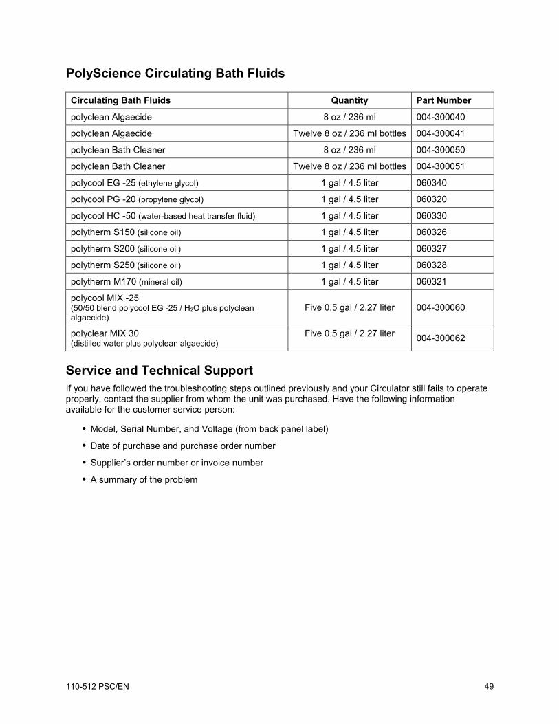
polyclear MIX 30 (distilled water plus polyclean algaecide)
Five 0.5 gal / 2.27 liter 004-300062
Service and Technical Support If you have followed the troubleshooting steps outlined previously and your Circulator still fails to operate properly, contact the supplier from whom the unit was purchased. Have the following information available for the customer service person:
• Model, Serial Number, and Voltage (from back panel label)
• Date of purchase and purchase order number
• Supplier’s order number or invoice number
• A summary of the problem
110-512 PSC/EN 49
Warranty The manufacturer agrees to correct for the original user of the product, either by repair (using new or refurbished parts), or at the manufacturer’s election, by replacement (with a new or refurbished product), any defects in material or workmanship which develop during the warranty period. The standard warranty is twenty-four (24) months after delivery of the product. In the event of replacement, the replacement unit will be warranted for the remainder of the original warranty period or ninety (90) days, whichever is longer. For purposes of this limited warranty, “refurbished” means a product or part that has been returned to its original specifications. In the event of a defect, these are your exclusive remedies.
If the product should require service, contact the manufacturer’s/supplier’s office for instructions. When return of the product is necessary, a return authorization number is assigned and the product should be shipped, transportation charges pre-paid, in either its original packaging or packaging affording an equal degree of protection to the indicated service center. To insure prompt handling, the return authorization number must be placed on the outside of the package. A detailed explanation of the defect should be enclosed with the item.
The warranty shall not apply if the defect or malfunction was caused by accident, neglect, unreasonable use, improper service, acts of God, modification by any party other than PolyScience, or other causes not arising out of defects in material or workmanship.
EXCLUSION OF IMPLIED WARRANTIES. THERE ARE NO WARRANTIES, EXPRESSED OR IMPLIED, INCLUDING, BUT NOT LIMITED TO, THOSE OF MERCHANTABILITY OR FITNESS FOR A PARTICULAR PURPOSE WHICH EXTEND BEYOND THE DESCRIPTION AND PERIOD AS STATED IN THE OPERATOR’S MANUAL INCLUDED WITH EACH PRODUCT.
LIMITATION ON DAMAGES. THE MANUFACTURER’S SOLE OBLIGATION UNDER THE WARRANTY IS LIMITED TO THE REPAIR OR REPLACEMENT OF A DEFECTIVE PRODUCT AND POLYSCIENCE SHALL NOT, IN ANY EVENT, BE LIABLE FOR ANY INCIDENTAL OR CONSEQUENTIAL DAMAGES OF ANY KIND RESULTING FROM USE OR POSSESSION OF THIS PRODUCT.
Some states do not allow: (A) limitations on how long an implied warranty lasts; or (B) the exclusion or limitation of incidental or consequential damages, so the above limitations or exclusions may not apply to you. This warranty gives you specific legal rights and you may have other rights that vary from state to state.
Manufactured by:
PolyScience 6600 W. Touhy Avenue Niles, IL 60714 U.S.A.