Cisco 1721, 1760, 2621XM, 2651XM, 2691, 3725, and 3745 Modular Access Routers and 7206-VXR NPE-400 Router FIPS 140-2 Non-Proprietary Security Policy
Level 2 ValidationVersion 2.4November 19, 2004
IntroductionThis is the non-proprietary Cryptographic Module Security Policy for the Cisco 1721, 1760, 2621XM, 2651XM, 2691, 3725, 3745, and 7206 VXR NPE-400 routers. This security policy describes how the routers meet the security requirements of FIPS 140-2, and how to operate the routers in a secure FIPS 140-2 mode. This policy was prepared as part of the Level 2 FIPS 140-2 certification of the routers.
FIPS 140-2 (Federal Information Processing Standards Publication 140-2—Security Requirements for Cryptographic Modules) details the U.S. Government requirements for cryptographic modules. More information about the FIPS 140-2 standard and validation program is available on the NIST website at
http://csrc.nist.gov/cryptval/.
This document contains the following sections:
• Introduction, page 1
• The Cisco 1721, 1760, 2621XM, 2651XM, 2691, 3725, 3745, and 7206 VXR NPE-400 Routers, page 3
• Secure Operation of the Cisco 1721, 1760, 2621XM, 2651XM, 2691, 3725, 3745, and 7206 VXR NPE-400 Routers, page 42
• Obtaining Additional Publications and Information, page 47
ReferencesThis document deals only with operations and capabilities of the 1721, 1760, 2621XM, 2651XM, 2691, 3725, 3745, and 7206 VXR NPE-400 routers in the technical terms of a FIPS 140-2 cryptographic module security policy. More information is available on the routers from the following sources:
• The Cisco Systems website contains information on the full line of products at www.cisco.com.
– The 1700 Series product descriptions can be found at:
• For answers to technical or sales related questions please refer to the contacts listed on the Cisco Systems website at www.cisco.com.
• The NIST Validated Modules website (http://csrc.nist.gov/cryptval) contains contact information for answers to technical or sales-related questions for the module
TerminologyIn this document, the Cisco 1721, 1760, 2621XM, 2651XM, 2691, 3725, 3745, and 7206 VXR NPE-400 routers are referred to as the routers, the modules, or the systems.
Document OrganizationThe Security Policy document is part of the FIPS 140-2 Submission Package. In addition to this document, the Submission Package contains:
• Vendor Evidence document
• Finite State Machine
• Module Software Listing
• Other supporting documentation as additional references
This document provides an overview of the routers and explains the secure configuration and operation of the modules. This introduction section is followed by the “The Cisco 1721, 1760, 2621XM, 2651XM, 2691, 3725, 3745, and 7206 VXR NPE-400 Routers” section, which details the general features and functionality of the routers. The “Secure Operation of the Cisco 1721, 1760, 2621XM, 2651XM, 2691, 3725, 3745, and 7206 VXR NPE-400 Routers” section specifically addresses the required configuration for the FIPS-mode of operation.
2Cisco 1721, 1760, 2621XM, 2651XM, 2691, 3725, and 3745 Modular Access Routers and 7206-VXR NPE-400 Router FIPS 140-2 Non-Proprietary
The Cisco 1721, 1760, 2621XM, 2651XM, 2691, 3725, 3745, and 7206 VXR NPE-400 Routers
With the exception of this Non-Proprietary Security Policy, the FIPS 140-2 Certification Submission Documentation is Cisco-proprietary and is releasable only under appropriate non-disclosure agreements. For access to these documents, please contact Cisco Systems.
The Cisco 1721, 1760, 2621XM, 2651XM, 2691, 3725, 3745, and 7206 VXR NPE-400 Routers
Branch office networking requirements are dramatically evolving, driven by web and e-commerce applications to enhance productivity and merging the voice and data infrastructure to reduce costs. The Cisco 1721, 1760, 2621XM, 2651XM, 2691, 3725, 3745, and 7206 VXR NPE-400 modular multi-service routers offer versatility, integration, and security to branch offices. With numerous WAN Interface Cards (WICs) and Network Modules (NMs) available, the modular architecture of the Cisco router easily allows interfaces to be upgraded to accommodate network expansion. The Cisco 1721, 1760, 2621XM, 2651XM, 2691, 3725, 3745, and 7206 VXR NPE-400 provide a scalable, secure, manageable remote access server that meets FIPS 140-2 Level 2 requirements as a multiple-chip embedded module. This section describes the general features and functionality provided by the Cisco 1721, 1760, 2621XM, 2651XM, 2691, 3725, 3745, and 7206 VXR NPE-400 routers. Additional adapters (e.g. WICs and other modules) are excluded from the validation.
• The Cisco 1721/1760 Cryptographic Module, page 4
• Cisco 1721 and 1760 Module Interfaces, page 5
• The Cisco 2621XM/2651XM Cryptographic Module, page 10
• Cisco 2621XM and 2651XM Module Interfaces, page 10
• The Cisco 2691 Cryptographic Module, page 13
• Cisco 2691 Module Interfaces, page 14
• The Cisco 3725/3745 Cryptographic Module, page 18
• Cisco 3725 and 3745 Module Interfaces, page 18
• The Cisco 7206 VXR NPE-400 Cryptographic Module, page 24
3Cisco 1721, 1760, 2621XM, 2651XM, 2691, 3725, and 3745 Modular Access Routers and 7206-VXR NPE-400 Router FIPS 140-2 Non-Proprietary
OL-6083-01
The Cisco 1721, 1760, 2621XM, 2651XM, 2691, 3725, 3745, and 7206 VXR NPE-400 Routers
The Cisco 1721/1760 Cryptographic Module
Figure 1 The Cisco 1721 and Cisco 1760 Routers
The cryptographic boundary is defined as encompassing the "top," "front," "left," "right," and "bottom" surfaces of the case; all portions of the "backplane" of the case which are not designed to accommodate a WIC; and the inverse of the three-dimensional space within the case that would be occupied by an installed WIC. The cryptographic boundary includes the connection apparatus between the WIC and the motherboard/daughterboard that hosts the WIC, but the boundary does not include the WIC itself. In other words, the cryptographic boundary encompasses all hardware components within the case of the device except any installed modular WICs. All of the functionality discussed in this document is provided by components within this cryptographic boundary.
The 1760 requires that a special opacity shield be installed over the right-hand side air vents in order to operate in FIPS-approved mode. The shield decreases the effective size of the vent holes, reducing visibility within the cryptographic boundary to FIPS-approved specifications. The shield is self-adhering to the side of the chassis. To install the shield, remove it from its paper backing and apply the shield to the chassis, aligning the holes on the shield with the vent-holes on the side of the chassis. Figure 2 demonstrates the proper application of the shield.
Figure 2 Cisco 1760 Opacity Shield Application
9939
0
Cisco 1700 Series
PWR
ACT
ACT/CH0
ACT/CH1
OK
ACT/CH0
WIC0 WIC1
ETH
ACT/CH1
COL
Cisco1700S E R I E SROUTER
10/100 ETHERNETAUX
CONSOLE
PVDM 0OK
OKPWR
10SLOT 0
OK
PVDM 1OK
MODOK
10SLOT 1
OK
LINK100
FDXACT COL
10SLOT 2
OK10
SLOT 3OK
9939
5
4Cisco 1721, 1760, 2621XM, 2651XM, 2691, 3725, and 3745 Modular Access Routers and 7206-VXR NPE-400 Router FIPS 140-2 Non-Proprietary
OL-6083-01
The Cisco 1721, 1760, 2621XM, 2651XM, 2691, 3725, 3745, and 7206 VXR NPE-400 Routers
Cisco IOS features such as tunneling, data encryption, and termination of Remote Access WANs via IPSec, Layer 2 Forwarding (L2F) and Layer 2 Tunneling Protocols (L2TP) make the Cisco 1700 an ideal platform for building virtual private networks or outsourced dial solutions. Cisco 1700`s RISC-based processor provides the power needed for the dynamic requirements of the remote branch office.
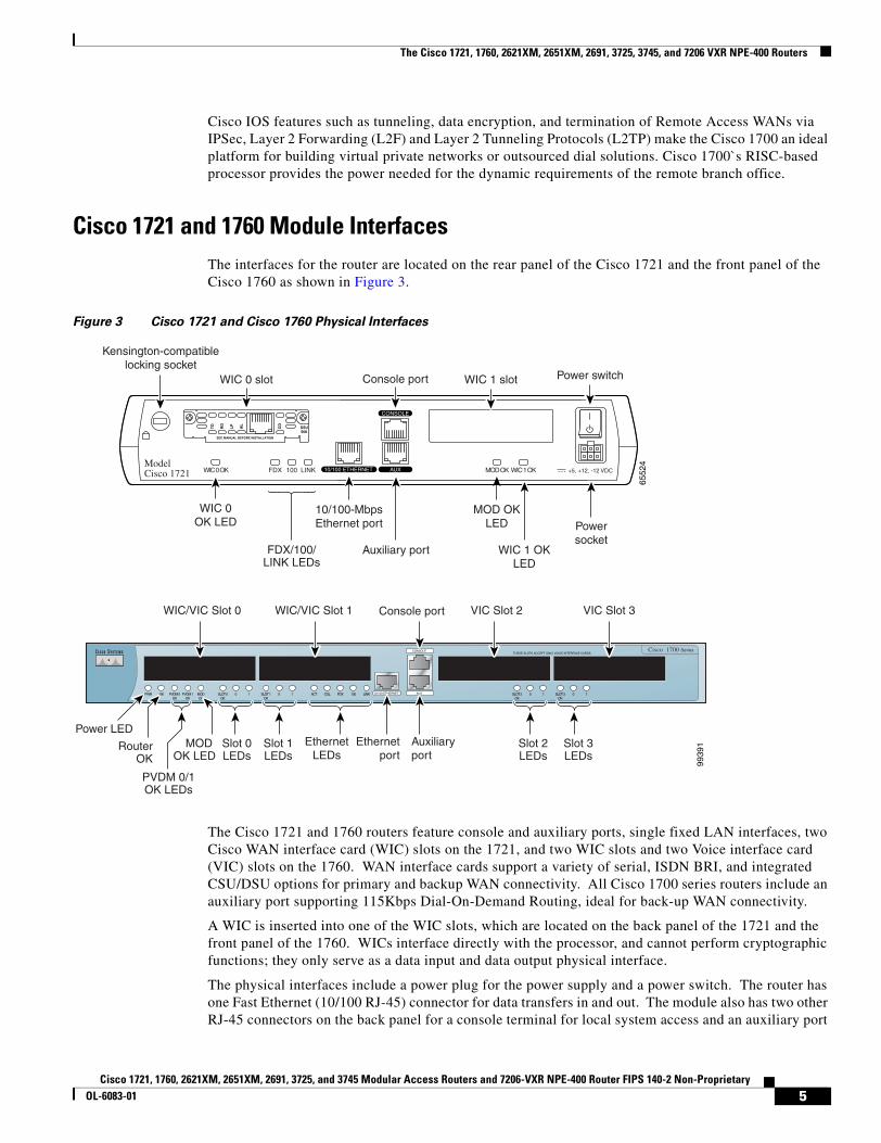
Cisco 1721 and 1760 Module Interfaces The interfaces for the router are located on the rear panel of the Cisco 1721 and the front panel of the Cisco 1760 as shown in Figure 3.
Figure 3 Cisco 1721 and Cisco 1760 Physical Interfaces
The Cisco 1721 and 1760 routers feature console and auxiliary ports, single fixed LAN interfaces, two Cisco WAN interface card (WIC) slots on the 1721, and two WIC slots and two Voice interface card (VIC) slots on the 1760. WAN interface cards support a variety of serial, ISDN BRI, and integrated CSU/DSU options for primary and backup WAN connectivity. All Cisco 1700 series routers include an auxiliary port supporting 115Kbps Dial-On-Demand Routing, ideal for back-up WAN connectivity.
A WIC is inserted into one of the WIC slots, which are located on the back panel of the 1721 and the front panel of the 1760. WICs interface directly with the processor, and cannot perform cryptographic functions; they only serve as a data input and data output physical interface.
The physical interfaces include a power plug for the power supply and a power switch. The router has one Fast Ethernet (10/100 RJ-45) connector for data transfers in and out. The module also has two other RJ-45 connectors on the back panel for a console terminal for local system access and an auxiliary port
Cisco 1700 Series
10/100 ETHERNET AUX
CONSOLE
PWR OK PVDM 0OK
PVDM 1OK
MODOK
ACT COL FDX 100 LINKSLOT 0OK
0 1 SLOT 1OK
0 1 SLOT 2OK
0 1 SLOT 3OK
0 1
9939
1
THESE SLOTS ACCEPT ONLY VOICE INTERFACE CARDS
Powersocket
+5, +12, -12 VDC
CONSOLE
10/100 ETHERNET AUXFDX LINK100WIC 0 OK WIC 1 OKMOD OK
5Cisco 1721, 1760, 2621XM, 2651XM, 2691, 3725, and 3745 Modular Access Routers and 7206-VXR NPE-400 Router FIPS 140-2 Non-Proprietary
OL-6083-01
The Cisco 1721, 1760, 2621XM, 2651XM, 2691, 3725, 3745, and 7206 VXR NPE-400 Routers
for remote system access or dial backup using a modem. The 10/100Base-T LAN port has Link/Activity, 10/100Mbps, and half/full duplex LEDs. Figure 4 shows the LEDs located on the rear panel of the Cisco 1721 with descriptions detailed in Table 1:
Figure 4 Cisco 1721 Rear Panel LEDs
Figure 5 shows the front panel LEDs of the 1721 and 1760, which provide overall status of the router's operation. The front panel of the 1721 displays whether or not the router is booted, overall activity/link status, and collision information. The front panel of the 1760 displays whether or not the router is booted, overall activity/link status, collision information, and specific information for each installed interface.
Table 1 Cisco 1721 Rear Panel LEDs and Descriptions
LED Indication Description
WIC 0 OK Green A WIC is correctly inserted in the card slot
Off No WIC present / WIC incorrectly inserted in the card slot
WIC 1 OK Green A WIC is correctly inserted in the card slot
Off No WIC present / WIC incorrectly inserted in the card slot
FDX Green The interface is transmitting data in full-duplex mode
Off When off, the interface is transmitting data in half-duplex mode
100 Mbps Green The speed of the interface is 100 Mbps
Off The speed of the interface is 10 Mbps or no link is established
LINK Green An Ethernet link has been established
Off No Ethernet link established
MOD OK Green VPN hardware encryption module is installed and recognized by Cisco IOS
Off VPN hardware encryption module not installed / not recognized by Cisco IOS
6Cisco 1721, 1760, 2621XM, 2651XM, 2691, 3725, and 3745 Modular Access Routers and 7206-VXR NPE-400 Router FIPS 140-2 Non-Proprietary
OL-6083-01
The Cisco 1721, 1760, 2621XM, 2651XM, 2691, 3725, 3745, and 7206 VXR NPE-400 Routers
Figure 5 Cisco 1721 and 1760 Front Panel LEDs
Table 2 and Table 3 provide more detailed information conveyed by the LEDs on the front panel of the Cisco 1721 and 1760 routers:
Cisco 1700 Series
10/100 ETHERNET AUX
CONSOLE
PWR OK PVDM 0OK
PVDM 1OK
MODOK
ACT COL FDX 100 LINKSLOT 0OK
0 1 SLOT 1OK
0 1 SLOT 2OK
0 1 SLOT 3OK
0 1
9939
3
THESE SLOTS ACCEPT ONLY VOICE INTERFACE CARDS
Slot 3LEDs
Slot 2LEDs
Slot 1LEDs
Slot 0LEDs
PVDM 0/1OK LEDs
MOD OK LED
Router OK
Power LEDAuxiliaryport
Ethernetport
EthernetLEDs
PWR ACTACT/CH0
ACT/CH1OK
ACT/CH0WIC0 WIC1 ETH
ACT/CH1 COL
Table 2 Cisco 1721 Front Panel LEDs and Descriptions
LED Indication Description
PWR Green Power is supplied to the router
Off The router is not powered on
OK Green The router has successfully booted up and the software is functional. This LED blinks during the power-on self-test (POST)
Off The router has not successfully booted up
WIC 0 ACT/CH0
Green Serial and DSU/CSU cards—Blinks when data is being sent to or received from the port on the card in the WIC0 slot
ISDN cards—On solid when the first ISDN B channel is up for the card in the WIC0 slot
2-port serial cards—Blinks when data is being sent to or received from the first port on the 2-port card in the WIC0 slot
WIC 0 ACT/CH1
Green Serial and CSU/DSU cards—Remains off
ISDN cards—On solid when the second ISDN B channel is up for the card in the WIC0 slot
2-port serial cards—Blinks when data is being sent to or received from the second port on the 2-port card in the WIC0 slot
WIC 1 ACT/CH0
Green Serial and DSU/CSU cards—Blinks when data is being sent to or received from the port on the card in the WIC1 slot
ISDN cards—On solid when the first ISDN B channel is up for the card in the WIC1 slot
2-port serial cards—Blinks when data is being sent to or received from the first port on the 2-port card in the WIC1 slot
7Cisco 1721, 1760, 2621XM, 2651XM, 2691, 3725, and 3745 Modular Access Routers and 7206-VXR NPE-400 Router FIPS 140-2 Non-Proprietary
OL-6083-01
The Cisco 1721, 1760, 2621XM, 2651XM, 2691, 3725, 3745, and 7206 VXR NPE-400 Routers
WIC 1 ACT/CH1
Green Serial and CSU/DSU cards—Remains off
ISDN cards—On solid when the second ISDN B channel is up for the card in the WIC1 slot
2-port serial cards—Blinks when data is being sent to or received from the second port on the 2-port card in the WIC1 slot
ETH ACT Green Blinks when there is network activity on the Ethernet port
ETH COL Yellow Blinks when there are packet collisions on the local Ethernet network
Table 3 Cisco 1760 Front Panel LEDs and Descriptions
LED Indication Description
PWR Green Power is supplied to the router
Off The router is not powered on
OK Green The router has successfully booted up and the software is functional. This LED blinks during the power-on self-test (POST)
Off The router has not successfully booted up
PVDM 0 OK
Green On when a packet voice data module (PVDM) is correctly inserted in PVDM card slot 0
PVDM 1 OK
Green n when a packet voice data module (PVDM) is correctly inserted in PVDM card slot 1
MOD OK Green On when a VPN module is present
FDX Green The interface is transmitting data in full-duplex mode
Off When off, the interface is transmitting data in half-duplex mode
100 Mbps Green The speed of the interface is 100 Mbps
Off The speed of the interface is 10 Mbps or no link is established
LINK Green An Ethernet link has been established
Off No Ethernet link established
SLOT 0 OK Green On when either a WIC or a VIC is correctly inserted in the card slot
0 Green ISDN—On when the first ISDN B channel is connected
Serial, CSU/DSU, and VIC—Blinks when data is being sent to or received from port 0 in slot 0. For the VIC-2BRI-ST-NT/TE, blinks when data is being sent to or received from any of the B channels
1 Green ISDN—On when the second ISDN B channel is connected
Serial and VIC—Blinks when data is being sent to or received from port 1 in slot 0
SLOT 1 OK Green On when either a WIC or a VIC is correctly inserted in the card slot
0 Green ISDN—On when the first ISDN B channel is connected
Serial, CSU/DSU, and VIC—Blinks when data is being sent to or received from port 0 in slot 1
Table 2 Cisco 1721 Front Panel LEDs and Descriptions (Continued)
LED Indication Description
8Cisco 1721, 1760, 2621XM, 2651XM, 2691, 3725, and 3745 Modular Access Routers and 7206-VXR NPE-400 Router FIPS 140-2 Non-Proprietary
OL-6083-01
The Cisco 1721, 1760, 2621XM, 2651XM, 2691, 3725, 3745, and 7206 VXR NPE-400 Routers
All of these physical interfaces are separated into the logical interfaces from FIPS 140-2 as described in the Table 4:
1 Green ISDN—On when the second ISDN B channel is connected
Serial and VIC—Blinks when data is being sent to or received from port 1 in slot 1
SLOT 2 OK Green On when a VIC is correctly inserted in the card slot
0 Green VIC—Blinks when data is being sent to or received from port 0 in slot 2
1 Green VIC—Blinks when data is being sent to or received from port 1 in slot 2
SLOT 3 OK Green On when a VIC is correctly inserted in the card slot
0 Green VIC—Blinks when data is being sent to or received from port 0 in slot 3
1 Green VIC—Blinks when data is being sent to or received from port 1 in slot 3
Table 3 Cisco 1760 Front Panel LEDs and Descriptions (Continued)
LED Indication Description
Table 4 Cisco 1721 and Cisco 1760 FIPS 140-2 Logical Interfaces
Router Physical Interface FIPS 140-2 Logical Interface
10/100BASE-TX LAN PortWIC/VIC InterfaceConsole PortAuxiliary Port
Data Input Interface
10/100BASE-TX LAN PortWIC/VIC InterfaceConsole PortAuxiliary Port
Data Output Interface
10/100BASE-TX LAN PortWIC/VIC InterfacePower SwitchConsole PortAuxiliary Port
Control Input Interface
10/100BASE-TX LAN PortWIC/VIC InterfaceLAN Port LEDs10/100BASE-TX LAN Port LEDsPower LEDActivity LEDConsole PortAuxiliary Port
Status Output Interface
Power Plug Power Interface
9Cisco 1721, 1760, 2621XM, 2651XM, 2691, 3725, and 3745 Modular Access Routers and 7206-VXR NPE-400 Router FIPS 140-2 Non-Proprietary
OL-6083-01
The Cisco 1721, 1760, 2621XM, 2651XM, 2691, 3725, 3745, and 7206 VXR NPE-400 Routers
The Cisco 2621XM/2651XM Cryptographic Module
Figure 6 The Cisco 2621XM/2651XM Router
The cryptographic boundary is defined as encompassing the "top," "front," "left," "right," and "bottom" surfaces of the case; all portions of the "backplane" of the case which are not designed to accommodate a WIC or Network Module; and the inverse of the three-dimensional space within the case that would be occupied by an installed WIC or Network Module. The cryptographic boundary includes the connection apparatus between the WIC or Network Module and the motherboard/daughterboard that hosts the WIC or Network Module, but the boundary does not include the WIC or Network Module itself. In other words, the cryptographic boundary encompasses all hardware components within the case of the device except any installed modular WICs or Network Modules. All of the functionality discussed in this document is provided by components within this cryptographic boundary.
Cisco IOS features such as tunneling, data encryption, and termination of Remote Access WANs via IPSec, Layer 2 Forwarding (L2F) and Layer 2 Tunneling Protocols (L2TP) make the Cisco 2600 an ideal platform for building virtual private networks or outsourced dial solutions. Cisco 2600`s RISC-based processor provides the power needed for the dynamic requirements of the remote branch office, achieving wire speed Ethernet to Ethernet routing with up to 30 thousand packets per second (Kpps) throughput capacity for the 2621XM, and 40 Kpps for the 2651XM.
Cisco 2621XM and 2651XM Module Interfaces The interfaces for the router are located on the rear panel as shown in Figure 7.
Figure 7 Cisco 2621XM and Cisco 2651XM Physical Interfaces
POWER RPS ACTIVITY
Cisco 2600SERIES
9949
3
SEE MANUAL BEFORE INSTALLATION
SERIAL 1
SERIAL 0CONN
CONNWIC2A/S
SEE MANUAL BEFORE INSTALLATION
SERIAL 1
SERIAL 0CONN
CONNWIC
2T
Cisco 2650
W1
100-240V– 1A50/60 Hz 47 W
W0
AUXCONSOLEETHERNET 0 ACTLINKETHERNET 1 ACTLINK
10/100BASE-T Ethernet 0/0
(RJ-45)
10/100BASE-T Ethernet 0/1
(RJ-45) Auxiliary port
(RJ-45)Consoleport (RJ-45)
Cisco 2650
9949
4
Networkmodule
WIC slots
10Cisco 1721, 1760, 2621XM, 2651XM, 2691, 3725, and 3745 Modular Access Routers and 7206-VXR NPE-400 Router FIPS 140-2 Non-Proprietary
OL-6083-01
The Cisco 1721, 1760, 2621XM, 2651XM, 2691, 3725, 3745, and 7206 VXR NPE-400 Routers
The Cisco 2621XM and 2651XM routers feature a console port, an auxiliary port, dual fixed LAN interfaces, a Network Module slot, and two WIC slots.
LAN support includes single and dual Ethernet options; 10/100 Mbps auto-sensing Ethernet; mixed Token-Ring and Ethernet; and single Token Ring chassis versions.
WAN interface cards support a variety of serial, ISDN BRI, and integrated CSU/DSU options for primary and backup WAN connectivity. Available Network Modules support multi-service voice/data/fax integration, departmental dial concentration, and high-density serial options
All Cisco 2600 series routers include an auxiliary port supporting 115Kbps Dial-On-Demand Routing, ideal for back-up WAN connectivity.
When a Network Module is inserted, it fits into an adapter called the Network Module expansion bus. The expansion bus interacts with the PCI bridge in the same way that the fixed LAN ports do; therefore, no critical security parameters pass through the Network Module (just as they don't pass through the LAN ports). Network modules do not perform any cryptographic functions.
WICs are similar to Network Modules in that they greatly increase the router's flexibility. A WIC is inserted into one of two slots, which are located above the fixed LAN ports. WICs interface directly with the processor. They do not interface with the cryptographic card; therefore no security parameters will pass through them. WICs cannot perform cryptographic functions; they only serve as a data input and data output physical interface.
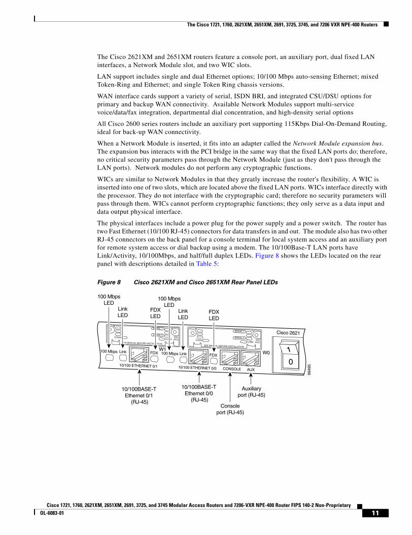
The physical interfaces include a power plug for the power supply and a power switch. The router has two Fast Ethernet (10/100 RJ-45) connectors for data transfers in and out. The module also has two other RJ-45 connectors on the back panel for a console terminal for local system access and an auxiliary port for remote system access or dial backup using a modem. The 10/100Base-T LAN ports have Link/Activity, 10/100Mbps, and half/full duplex LEDs. Figure 8 shows the LEDs located on the rear panel with descriptions detailed in Table 5:
Figure 8 Cisco 2621XM and Cisco 2651XM Rear Panel LEDs
9949
5
SEE MANUAL BEFORE INSTALLATION
SERIAL 1
SERIAL 0CONN
CONNWIC2A/SSEE MANUAL BEFORE INSTALLATION
SERIAL 1
SERIAL 0CONN
CONNWIC2A/S
Cisco 2621
W0W1
AUXCONSOLE10/100 ETHERNET 0/010/100 ETHERNET 0/1
10/100BASE-T Ethernet 0/0
(RJ-45)
10/100BASE-T Ethernet 0/1
(RJ-45)
Auxiliaryport (RJ-45)
Consoleport (RJ-45)
FDXLED
FDXLED
Link FDX FDX
LinkLED
100 Mbps
100 MbpsLED
Link
LinkLED
100 Mbps
100 MbpsLED
11Cisco 1721, 1760, 2621XM, 2651XM, 2691, 3725, and 3745 Modular Access Routers and 7206-VXR NPE-400 Router FIPS 140-2 Non-Proprietary
OL-6083-01
The Cisco 1721, 1760, 2621XM, 2651XM, 2691, 3725, 3745, and 7206 VXR NPE-400 Routers
Figure 9 shows the front panel LEDs, which provide overall status of the router's operation. The front panel displays whether or not the router is booted, if the redundant power is (successfully) attached and operational, and overall activity/link status.
Figure 9 Cisco 2621XM and Cisco 2651XM Front Panel LEDs
Table 6 provides more detailed information conveyed by the LEDs on the front panel of the router:
All of these physical interfaces are separated into the logical interfaces from FIPS 140-2 as described in Table 7:
Table 5 Cisco 2621XM and Cisco 2651XM Rear Panel LEDs and Descriptions
LED Indication Description
LINK Green An Ethernet link has been established
Off No Ethernet link established
FDX Green The interface is transmitting data in full-duplex mode
Off When off, the interface is transmitting data in half-duplex mode
100 Mbps Green The speed of the interface is 100 Mbps
Off The speed of the interface is 10 Mbps or no link is established
POWER RPS ACTIVITY
9949
6
Table 6 Cisco 2621XM and Cisco 2651XM Front Panel LEDs and Descriptions
LED Indication Description
Power Green Power is supplied to the router and the router is operational
Off The router is not powered on
RPS1
1. RPS = Redundant Power System
Green RPS is attached and operational
Off No RPS is attached
Blink RPS is attached, but has a failure
Activity Off In the Cisco IOS software, but no network activity
Blink (500 ms ON, 500 ms OFF) In ROMMON, no errors
Blink (500 ms ON, 500 ms OFF, 2 sec between codes)
In ROMMON, error detected
Blink (less than 500 ms) In the Cisco IOS software, the blink rate reflects the level of activity
12Cisco 1721, 1760, 2621XM, 2651XM, 2691, 3725, and 3745 Modular Access Routers and 7206-VXR NPE-400 Router FIPS 140-2 Non-Proprietary
OL-6083-01
The Cisco 1721, 1760, 2621XM, 2651XM, 2691, 3725, 3745, and 7206 VXR NPE-400 Routers
The Cisco 2691 Cryptographic Module
Figure 10 The Cisco 2691 Router
Table 7 Cisco 2621XM and Cisco 2651XM FIPS 140-2 Logical Interfaces
Router Physical Interface FIPS 140-2 Logical Interface
10/100BASE-TX LAN PortWIC InterfaceNetwork Module InterfaceConsole PortAuxiliary Port
Data Input Interface
10/100BASE-TX LAN PortWIC InterfaceNetwork Module InterfaceConsole PortAuxiliary Port
Data Output Interface
10/100BASE-TX LAN PortWIC InterfaceNetwork Module InterfacePower SwitchConsole PortAuxiliary Port
Control Input Interface
10/100BASE-TX LAN PortWIC InterfaceNetwork Module InterfaceLAN Port LEDs10/100BASE-TX LAN Port LEDsPower LEDRedundant Power LEDActivity LEDConsole PortAuxiliary Port
Status Output Interface
Power Plug Power Interface
9949
9
SEE MANUAL BEFORE INSTALLATION
AL
CD
LPRDTD
SEE MANUAL BEFORE INSTALLATIONDSU56K
AL
CD
LPRDTD
SEE MANUAL BEFORE INSTALLATIONDSU56K
ENV0
BANK 4 BANK 3 BANK 2 BANK 1 BANK 0
NM-HDV
VWIC2MFT-E1 SEE
MANUALBEFOREINSTALLATION
CTRLR E2CTRLR E1
AL
LP
CD
13Cisco 1721, 1760, 2621XM, 2651XM, 2691, 3725, and 3745 Modular Access Routers and 7206-VXR NPE-400 Router FIPS 140-2 Non-Proprietary
OL-6083-01
The Cisco 1721, 1760, 2621XM, 2651XM, 2691, 3725, 3745, and 7206 VXR NPE-400 Routers
The cryptographic boundary is defined as encompassing the "top," "front," "left," "right," and "bottom" surfaces of the case; all portions of the "backplane" of the case which are not designed to accommodate a WIC or Network Module; and the inverse of the three-dimensional space within the case that would be occupied by an installed WIC or Network Module. The cryptographic boundary includes the connection apparatus between the WIC or Network Module and the motherboard/daughterboard that hosts the WIC or Network Module, but the boundary does not include the WIC or Network Module itself. In other words, the cryptographic boundary encompasses all hardware components within the case of the device except any installed modular WICs or Network Modules. All of the functionality discussed in this document is provided by components within this cryptographic boundary.
Cisco IOS features such as tunneling, data encryption, and termination of Remote Access WANs via IPSec, Layer 2 Forwarding (L2F) and Layer 2 Tunneling Protocols (L2TP) make the Cisco 2600 an ideal platform for building virtual private networks or outsourced dial solutions. Cisco 2600`s RISC-based processor provides the power needed for the dynamic requirements of the remote branch office, achieving wire speed Ethernet to Ethernet routing with up to 70 thousand packets per second (Kpps) throughput capacity.
Cisco 2691 Module Interfaces The interfaces for the router are located on the rear panel as shown in Figure 11.
Figure 11 Cisco 2691 Physical Interfaces
The Cisco 2691 router features console and auxiliary ports, dual fixed LAN interfaces, a Network Module slot, two Cisco WAN interface card (WIC) slots, and a Compact Flash slot.
LAN support includes single and dual Ethernet options; 10/100 Mbps auto-sensing Ethernet; mixed Token-Ring and Ethernet; and single Token Ring chassis versions. WAN interface cards support a variety of serial, ISDN BRI, and integrated CSU/DSU options for primary and backup WAN connectivity, while available Network Modules support multi-service voice/data/fax integration, departmental dial concentration, and high-density serial options. The AIM slot supports integration of advanced services such as hardware-assisted data compression and encryption. All Cisco 2600 series routers include an auxiliary port supporting 115Kbps Dial-On-Demand Routing, ideal for back-up WAN connectivity.
When a Network Module is inserted, it fits into an adapter called the Network Module expansion bus. The expansion bus interacts with the PCI bridge in the same way that the fixed LAN ports do; therefore, no critical security parameters pass through the Network Module (just as they don't pass through the LAN ports). Network modules do not perform any cryptographic functions.
9950
0
SEE MANUAL BEFORE INSTALLATION
AL
CD
LPRDTD
SEE MANUAL BEFORE INSTALLATIONDSU56K
AL
CD
LPRDTD
SEE MANUAL BEFORE INSTALLATIONDSU56K
ENV0
BANK 4 BANK 3 BANK 2 BANK 1 BANK 0
NM-HDV
VWIC2MFT-E1 SEE
MANUALBEFOREINSTALLATION
CTRLR E2CTRLR E1
AL
LP
CD
2
3 5
6 94
87
1
14Cisco 1721, 1760, 2621XM, 2651XM, 2691, 3725, and 3745 Modular Access Routers and 7206-VXR NPE-400 Router FIPS 140-2 Non-Proprietary
OL-6083-01
The Cisco 1721, 1760, 2621XM, 2651XM, 2691, 3725, 3745, and 7206 VXR NPE-400 Routers
WICs are similar to Network Modules in that they greatly increase the router's flexibility. A WIC is inserted into one of two slots, which are located above the fixed LAN ports. WICs interface directly with the processor. They do not interface with the cryptographic card; therefore no security parameters will pass through them. WICs cannot perform cryptographic functions; they only serve as a data input and data output physical interface.
The physical interfaces include a power plug for the power supply and a power switch. The router has two Fast Ethernet (10/100 RJ-45) connectors for data transfers in and out. The module also has two other RJ-45 connectors on the back panel for a console terminal for local system access and an auxiliary port for remote system access or dial backup using a modem. The 10/100Base-T LAN ports have Link/Activity, 10/100Mbps, and half/full duplex LEDs. Figure 12 shows the LEDs located on the rear panel with descriptions detailed in Table 8:
Figure 12 Cisco 2691 Rear Panel LEDs
Table 8 Cisco 2691 Rear Panel LEDs and Descriptions
LED Indication Description
LINK On An Ethernet link has been established
Off No Ethernet link established
ACT On The interface is transmitting or receiving packets
Off The interface is not transmitting or receiving packets
100 Mbps On The speed of the interface is 100 Mbps
Off The speed of the interface is 10 Mbps or no link is established
CF1 On The Flash device is being accessed in either READ or WRITE mode
Off The Flash device is not being accessed
9950
1
SEE MANUAL BEFORE INSTALLATION
CONSOLEAUX
FAST ETHERNET 0/1 FAST ETHERNET 0/0
AL
CD
LPRDTD
SEE MANUAL BEFORE INSTALLATIONDSU56K
AL
CD
LPRDTD
SEE MANUAL BEFORE INSTALLATIONDSU56K
ACT LED100 Mbps LEDLINK LED
CF1 LEDFastEthernet 0/1
FastEthernet 0/0
ACT100 Mbps
LINK ACT100 MbpsLINK
CF1
CISCO2691
CompactFlashslot
Consoleport
Auxiliaryport
15Cisco 1721, 1760, 2621XM, 2651XM, 2691, 3725, and 3745 Modular Access Routers and 7206-VXR NPE-400 Router FIPS 140-2 Non-Proprietary
OL-6083-01
The Cisco 1721, 1760, 2621XM, 2651XM, 2691, 3725, 3745, and 7206 VXR NPE-400 Routers
Figure 13 shows the front panel LEDs, which provide overall status of the router's operation. The front panel displays whether or not the router is booted, if the redundant power is (successfully) attached and operational, and overall activity/link status.
Figure 13 Cisco 2691 Front Panel LEDs
Table 9 provides more detailed information conveyed by the LEDs on the front panel of the router:
All of these physical interfaces are separated into the logical interfaces from FIPS 140-2 as described in Table 10:
SYS
RPS
PWR ACT
9950
2
Table 9 Cisco 2691 Front Panel LEDs and Descriptions
LED Indication Description
PWR On Power is supplied to the router
Off The router is not powered on
SYS/RPS Rapid blinking System is booting
Slow blinking System error
On System OK
ACT Off No system activity
Blinking System activity
16Cisco 1721, 1760, 2621XM, 2651XM, 2691, 3725, and 3745 Modular Access Routers and 7206-VXR NPE-400 Router FIPS 140-2 Non-Proprietary
OL-6083-01
The Cisco 1721, 1760, 2621XM, 2651XM, 2691, 3725, 3745, and 7206 VXR NPE-400 Routers
Table 10 Cisco 2691 FIPS 140-2 Logical Interfaces
Router Physical Interface FIPS 140-2 Logical Interface
10/100BASE-TX LAN PortWIC InterfaceNetwork Module InterfaceConsole PortAuxiliary PortCompact Flash slot
Data Input Interface
10/100BASE-TX LAN PortWIC InterfaceNetwork Module InterfaceConsole PortAuxiliary PortCompact Flash slot
Data Output Interface
10/100BASE-TX LAN PortWIC InterfaceNetwork Module Interface Power SwitchConsole PortAuxiliary Port
Control Input Interface
10/100BASE-TX LAN PortWIC InterfaceNetwork Module InterfaceLAN Port LEDs10/100BASE-TX LAN Port LEDsPower LEDActivity LEDConsole PortAuxiliary Port
Status Output Interface
Power Plug Power Interface
17Cisco 1721, 1760, 2621XM, 2651XM, 2691, 3725, and 3745 Modular Access Routers and 7206-VXR NPE-400 Router FIPS 140-2 Non-Proprietary
OL-6083-01
The Cisco 1721, 1760, 2621XM, 2651XM, 2691, 3725, 3745, and 7206 VXR NPE-400 Routers
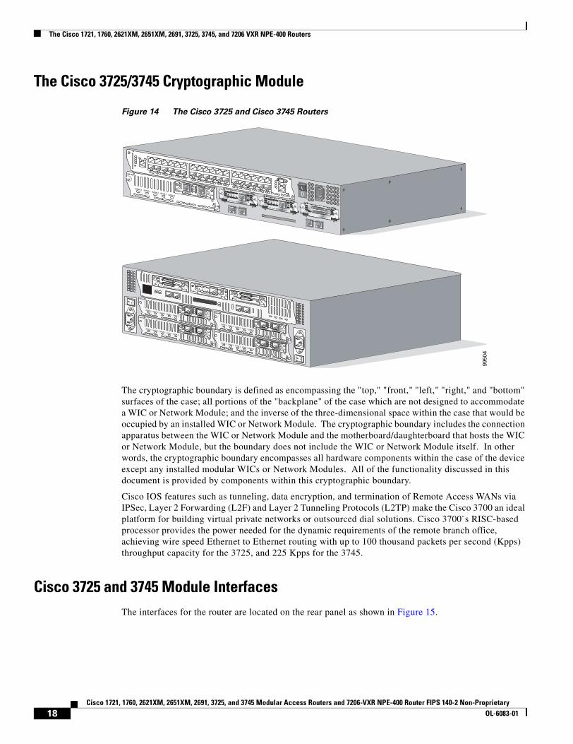
The Cisco 3725/3745 Cryptographic Module
Figure 14 The Cisco 3725 and Cisco 3745 Routers
The cryptographic boundary is defined as encompassing the "top," "front," "left," "right," and "bottom" surfaces of the case; all portions of the "backplane" of the case which are not designed to accommodate a WIC or Network Module; and the inverse of the three-dimensional space within the case that would be occupied by an installed WIC or Network Module. The cryptographic boundary includes the connection apparatus between the WIC or Network Module and the motherboard/daughterboard that hosts the WIC or Network Module, but the boundary does not include the WIC or Network Module itself. In other words, the cryptographic boundary encompasses all hardware components within the case of the device except any installed modular WICs or Network Modules. All of the functionality discussed in this document is provided by components within this cryptographic boundary.
Cisco IOS features such as tunneling, data encryption, and termination of Remote Access WANs via IPSec, Layer 2 Forwarding (L2F) and Layer 2 Tunneling Protocols (L2TP) make the Cisco 3700 an ideal platform for building virtual private networks or outsourced dial solutions. Cisco 3700`s RISC-based processor provides the power needed for the dynamic requirements of the remote branch office, achieving wire speed Ethernet to Ethernet routing with up to 100 thousand packets per second (Kpps) throughput capacity for the 3725, and 225 Kpps for the 3745.
Cisco 3725 and 3745 Module Interfaces The interfaces for the router are located on the rear panel as shown in Figure 15.
SEE MANUAL BEFORE INSTALLATION
AL
CD
LPRDTD
SEE MANUAL BEFORE INSTALLATIONDSU56K
AL
CD
LPRDTD
SEE MANUAL BEFORE INSTALLATIONDSU56K
ENV0
BANK 4 BANK 3 BANK 2 BANK 1 BANK 0
NM-HDV
VWIC2MFT-E1 SEE
MANUALBEFOREINSTALLATION
CTRLR E2CTRLR E1
AL
LP
CD
9950
4
EN
V0
BANK 4 BANK 3 BANK 2 BANK 1 BANK 0
NM-HDV
VWIC2MFT-E1 SEE
MANUALBEFOREINSTALLATION
CTRLR E2
CTRLR E1
AL
LP
CD
EN
V0
BANK 4 BANK 3 BANK 2 BANK 1 BANK 0
NM-HDV
VWIC2MFT-E1 SEE
MANUALBEFOREINSTALLATION
CTRLR E2
CTRLR E1
AL
LP
CD
EN
V0
BANK 4 BANK 3 BANK 2 BANK 1 BANK 0
NM-HDV
VWIC2MFT-E1 SEE
MANUALBEFOREINSTALLATION
CTRLR E2
CTRLR E1
AL
LP
CD
EN
V0
BANK 4 BANK 3 BANK 2 BANK 1 BANK 0
NM-HDV
VWIC2MFT-E1 SEE
MANUALBEFOREINSTALLATION
CTRLR E2
CTRLR E1
AL
LP
CD
SEE MANUAL BEFORE INSTALLATION
SERIAL 1
SERIAL 0
CONN
CONNWIC
2T
SEE MANUAL BEFORE INSTALLATION
SERIAL 1
SERIAL 0
CONN
CONNWIC
2T
SEE MANUAL BEFORE INSTALLATIONDSU56K
CD
ALLPRDTD
18Cisco 1721, 1760, 2621XM, 2651XM, 2691, 3725, and 3745 Modular Access Routers and 7206-VXR NPE-400 Router FIPS 140-2 Non-Proprietary
OL-6083-01
The Cisco 1721, 1760, 2621XM, 2651XM, 2691, 3725, 3745, and 7206 VXR NPE-400 Routers
Figure 15 Cisco 3725 and Cisco 3745 Physical Interfaces
The Cisco 3725 and 3745 routers feature console and auxiliary ports, dual fixed LAN interfaces, two network module slots on the 3725 and four on the 3745, three Cisco WAN interface card (WIC) slots, and a Compact Flash slot.
LAN support includes single and dual Ethernet options; 10/100 Mbps auto-sensing Ethernet; mixed Token-Ring and Ethernet; and single Token Ring chassis versions. WAN interface cards support a variety of serial, ISDN BRI, and integrated CSU/DSU options for primary and backup WAN connectivity, while available network modules support multi-service voice/data/fax integration, departmental dial concentration, and high-density serial options. All Cisco 3700 series routers include an auxiliary port supporting 115Kbps Dial-On-Demand Routing, ideal for back-up WAN connectivity.
1 Interface Card Slots 5 FastEthernet 0/1
2 Network Modules 6 Compact Flash Slot
3 Power Supply 7 Auxiliary Port
4 FastEthernet 0/0 8 Console Port
SEE MANUAL BEFORE INSTALLATION
AL
CD
LPRDTD
SEE MANUAL BEFORE INSTALLATIONDSU56K
AL
CD
LPRDTD
SEE MANUAL BEFORE INSTALLATIONDSU56K
ENV0
BANK 4 BANK 3 BANK 2 BANK 1 BANK 0
NM-HDV
VWIC2MFT-E1 SEE
MANUALBEFOREINSTALLATION
CTRLR E2CTRLR E1
AL
LP
CD
1 32
467
9
8
9950
5
EN
V0
BANK 4 BANK 3 BANK 2 BANK 1 BANK 0
NM-HDV
VWIC2MFT-E1 SEE
MANUALBEFOREINSTALLATION
CTRLR E2
CTRLR E1
AL
LP
CD
EN
V0
BANK 4 BANK 3 BANK 2 BANK 1 BANK 0
NM-HDV
VWIC2MFT-E1 SEE
MANUALBEFOREINSTALLATION
CTRLR E2
CTRLR E1
AL
LP
CD
EN
V0
BANK 4 BANK 3 BANK 2 BANK 1 BANK 0
NM-HDV
VWIC2MFT-E1 SEE
MANUALBEFOREINSTALLATION
CTRLR E2
CTRLR E1
AL
LP
CD
EN
V0
BANK 4 BANK 3 BANK 2 BANK 1 BANK 0
NM-HDV
VWIC2MFT-E1 SEE
MANUALBEFOREINSTALLATION
CTRLR E2
CTRLR E1
AL
LP
CD
SEE MANUAL BEFORE INSTALLATION
SERIAL 1
SERIAL 0
CONN
CONNWIC
2T
SEE MANUAL BEFORE INSTALLATION
SERIAL 1
SERIAL 0
CONN
CONNWIC
2T
SEE MANUAL BEFORE INSTALLATIONDSU56K
CD
ALLPRDTD
5
8
7 6
9
3
5
4 2
1
10
19Cisco 1721, 1760, 2621XM, 2651XM, 2691, 3725, and 3745 Modular Access Routers and 7206-VXR NPE-400 Router FIPS 140-2 Non-Proprietary
OL-6083-01
The Cisco 1721, 1760, 2621XM, 2651XM, 2691, 3725, 3745, and 7206 VXR NPE-400 Routers
When a network module is inserted, it fits into an adapter called the network module expansion bus. The expansion bus interacts with the PCI bridge in the same way that the fixed LAN ports do; therefore, no critical security parameters pass through the network module (just as they don't pass through the LAN ports). Network modules do not perform any cryptographic functions.
WICs are similar to network modules in that they greatly increase the router's flexibility. A WIC is inserted into one of two slots, which are located above the fixed LAN ports. WICs interface directly with the processor. They do not interface with the cryptographic card; therefore no security parameters will pass through them. WICs cannot perform cryptographic functions; they only serve as a data input and data output physical interface.
The physical interfaces include a power plug for the power supply and a power switch. The router has two Fast Ethernet (10/100 RJ-45) connectors for data transfers in and out. The module also has two other RJ-45 connectors on the back panel for a console terminal for local system access and an auxiliary port for remote system access or dial backup using a modem. The 10/100Base-T LAN ports have Link/Activity, 10/100Mbps, and half/full duplex LEDs. Figure 16 shows the LEDs located on the rear panel with descriptions detailed in Table 11 and Table 12:
Figure 16 Cisco 3725 and Cisco 3745 Rear Panel LEDs
SEE MANUAL BEFORE INSTALLATION
AL
CD
LPRDTD
SEE MANUAL BEFORE INSTALLATIONDSU56K
AL
CD
LPRDTD
SEE MANUAL BEFORE INSTALLATIONDSU56K
ENV0
BANK 4 BANK 3 BANK 2 BANK 1 BANK 0
NM-HDV
VWIC2MFT-E1 SEE
MANUALBEFOREINSTALLATION
CTRLR E2CTRLR E1
AL
LP
CD
9950
6
EN
V0
BANK 4 BANK 3 BANK 2 BANK 1 BANK 0
NM-HDV
VWIC2MFT-E1 SEE
MANUALBEFOREINSTALLATION
CTRLR E2
CTRLR E1
AL
LP
CD
EN
V0
BANK 4 BANK 3 BANK 2 BANK 1 BANK 0
NM-HDV
VWIC2MFT-E1 SEE
MANUALBEFOREINSTALLATION
CTRLR E2
CTRLR E1
AL
LP
CD
EN
V0
BANK 4 BANK 3 BANK 2 BANK 1 BANK 0
NM-HDV
VWIC2MFT-E1 SEE
MANUALBEFOREINSTALLATION
CTRLR E2
CTRLR E1
AL
LP
CD
EN
V0
BANK 4 BANK 3 BANK 2 BANK 1 BANK 0
NM-HDV
VWIC2MFT-E1 SEE
MANUALBEFOREINSTALLATION
CTRLR E2
CTRLR E1
AL
LP
CD
SEE MANUAL BEFORE INSTALLATION
SERIAL 1
SERIAL 0
CONN
CONNWIC
2T
SEE MANUAL BEFORE INSTALLATION
SERIAL 1
SERIAL 0
CONN
CONNWIC
2T
SEE MANUAL BEFORE INSTALLATIONDSU56K
CD
ALLPRDTD
FastEthernet 0/1
FastEthernet 0/0
FastEthernet 0/1FastEthernet 0/0
CF
POWER SYSTEM
SYSTEM
ETM NPA AIM1 AIM0
POWER SYSTEMCF
ETM NPA AIM1 AIM0
20Cisco 1721, 1760, 2621XM, 2651XM, 2691, 3725, and 3745 Modular Access Routers and 7206-VXR NPE-400 Router FIPS 140-2 Non-Proprietary
OL-6083-01
The Cisco 1721, 1760, 2621XM, 2651XM, 2691, 3725, 3745, and 7206 VXR NPE-400 Routers
Table 11 Cisco 3725 Rear Panel LEDs and Descriptions
LED Indication Description
CF Solid or blinking green Do not eject Compact Flash (CF); device is busy
Off CF can be ejected; device is idle
FastEthernet 0/0 ACTandFastEthernet 0/1 ACT
Solid or blinking green Interface receiving packets
Solid green The speed of the interface is 10 Mbps or no link is established
Off The speed of the interface is 100 Mbps
ETM Solid green Enhanced timing module (ETM) present and enabled
Amber ETM present with failure
Off ETM not present
NPA Not used Reserved for future development
AIM0andAIM1
Solid green Advanced Integration Module (AIM) present and enabled
Amber AIM present with failure
Off AIM not present
21Cisco 1721, 1760, 2621XM, 2651XM, 2691, 3725, and 3745 Modular Access Routers and 7206-VXR NPE-400 Router FIPS 140-2 Non-Proprietary
OL-6083-01
The Cisco 1721, 1760, 2621XM, 2651XM, 2691, 3725, 3745, and 7206 VXR NPE-400 Routers
Figure 17 Cisco 3725 and Cisco 3745 Front Panel LEDs
Figure 17 shows the front panel LEDs, which provide overall status of the router's operation. The front panel displays whether or not the router is booted, if the redundant power is (successfully) attached and operational, and overall activity/link status.
Table 13 and Table 14 provide more detailed information conveyed by the LEDs on the front panel of the routers:
SYS LEDACT LED
SYS PS1 LED-48V PS1 LED
-48 PS2 LEDSYS PS2 LED
PWR LEDSYS/RPS LED
ACT LED
PWR SYSRPS
ACT
9950
7
Table 13 Cisco 3725 Front Panel LEDs and Descriptions
LED Indication Description
PWR Solid green Router is receiving power
Off Router is not receiving power
SYS/RPS Solid green System is operating normally
Rapid blinking System is booting up or in ROM monitor mode
Blinking once per second Redundant power system has failed
Off Router is not receiving power
ACT Blinking System is actively transferring packets
Off No packet transfers are occurring
Table 14 Cisco 3745 Front Panel LEDs and Descriptions
LED Indication Description
SYS Solid green System is operating normally
Blinking green Running ROM monitor with no errors detected
Amber Router is receiving power but malfunctioning
Off Router is not receiving power
22Cisco 1721, 1760, 2621XM, 2651XM, 2691, 3725, and 3745 Modular Access Routers and 7206-VXR NPE-400 Router FIPS 140-2 Non-Proprietary
OL-6083-01
The Cisco 1721, 1760, 2621XM, 2651XM, 2691, 3725, 3745, and 7206 VXR NPE-400 Routers
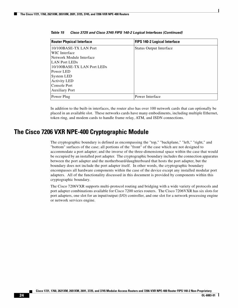
All of these physical interfaces are separated into the logical interfaces from FIPS 140-2 as described in Table 15:
ACT Solid or blinking green System is receiving interrupts, or is actively transferring packets
Off No interrupts or packet transfers are occurring
SYS PS1andSYS PS2
Solid green Power supply installed and operating normally
Amber Power supply installed and powered off, or fault condition occurred
Off Power supply not present, or failed
-48V PS1and-48V PS2
Solid green -48V power module installed and operating normally
Amber -48V power module installed and powered off, or fault condition occurred
Off -48V power module not present, or failed
Table 14 Cisco 3745 Front Panel LEDs and Descriptions (Continued)
LED Indication Description
Table 15 Cisco 3725 and Cisco 3745 FIPS 140-2 Logical Interfaces
Router Physical Interface FIPS 140-2 Logical Interface
10/100BASE-TX LAN PortWIC InterfaceNetwork Module InterfaceConsole PortAuxiliary PortCompact Flash slot
Data Input Interface
10/100BASE-TX LAN PortWIC InterfaceNetwork Module InterfaceConsole PortAuxiliary PortCompact Flash slot
Data Output Interface
10/100BASE-TX LAN PortWIC InterfaceNetwork Module InterfacePower SwitchConsole PortAuxiliary Port
Control Input Interface
23Cisco 1721, 1760, 2621XM, 2651XM, 2691, 3725, and 3745 Modular Access Routers and 7206-VXR NPE-400 Router FIPS 140-2 Non-Proprietary
OL-6083-01
The Cisco 1721, 1760, 2621XM, 2651XM, 2691, 3725, 3745, and 7206 VXR NPE-400 Routers
In addition to the built-in interfaces, the router also has over 100 network cards that can optionally be placed in an available slot. These networks cards have many embodiments, including multiple Ethernet, token ring, and modem cards to handle frame relay, ATM, and ISDN connections.
The Cisco 7206 VXR NPE-400 Cryptographic ModuleThe cryptographic boundary is defined as encompassing the "top," "backplane," "left," "right," and "bottom" surfaces of the case; all portions of the "front" of the case which are not designed to accommodate a port adapter; and the inverse of the three-dimensional space within the case that would be occupied by an installed port adapter. The cryptographic boundary includes the connection apparatus between the port adapter and the motherboard/daughterboard that hosts the port adapter, but the boundary does not include the port adapter itself. In other words, the cryptographic boundary encompasses all hardware components within the case of the device except any installed modular port adapters. All of the functionality discussed in this document is provided by components within this cryptographic boundary.
The Cisco 7206VXR supports multi-protocol routing and bridging with a wide variety of protocols and port adapter combinations available for Cisco 7200 series routers. The Cisco 7206VXR has six slots for port adapters, one slot for an input/output (I/O) controller, and one slot for a network processing engine or network services engine.
10/100BASE-TX LAN PortWIC InterfaceNetwork Module InterfaceLAN Port LEDs10/100BASE-TX LAN Port LEDsPower LEDSystem LEDActivity LEDConsole PortAuxiliary Port
Status Output Interface
Power Plug Power Interface
Table 15 Cisco 3725 and Cisco 3745 FIPS 140-2 Logical Interfaces (Continued)
Router Physical Interface FIPS 140-2 Logical Interface
24Cisco 1721, 1760, 2621XM, 2651XM, 2691, 3725, and 3745 Modular Access Routers and 7206-VXR NPE-400 Router FIPS 140-2 Non-Proprietary
OL-6083-01
The Cisco 1721, 1760, 2621XM, 2651XM, 2691, 3725, 3745, and 7206 VXR NPE-400 Routers
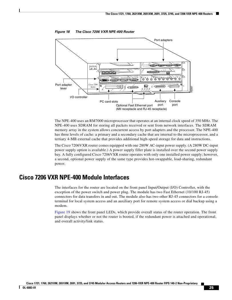
Figure 18 The Cisco 7206 VXR NPE-400 Router
The NPE-400 uses an RM7000 microprocessor that operates at an internal clock speed of 350 MHz. The NPE-400 uses SDRAM for storing all packets received or sent from network interfaces. The SDRAM memory array in the system allows concurrent access by port adapters and the processor. The NPE-400 has three levels of cache: a primary and a secondary cache that are internal to the microprocessor, and a tertiary 4-MB external cache that provides additional high-speed storage for data and instructions.
The Cisco 7206VXR router comes equipped with one 280W AC-input power supply. (A 280W DC-input power supply option is available.) A power supply filler plate is installed over the second power supply bay. A fully configured Cisco 7206VXR router operates with only one installed power supply; however, a second, optional power supply of the same type provides hot-swappable, load-sharing, redundant power.
Cisco 7206 VXR NPE-400 Module InterfacesThe interfaces for the router are located on the front panel Input/Output (I/O) Controller, with the exception of the power switch and power plug. The module has two Fast Ethernet (10/100 RJ-45) connectors for data transfers in and out. The module also has two other RJ-45 connectors for a console terminal for local system access and an auxiliary port for remote system access or dial backup using a modem.
Figure 19 shows the front panel LEDs, which provide overall status of the router operation. The front panel displays whether or not the router is booted, if the redundant power is attached and operational, and overall activity/link status.
H59
97
ETHERNET 10BT
ENABLE
D
0 2
1 3
LINK
0 1 2 3
FAST SERIAL
ENTD TC RD RC LB CD TD TC RD RC LB CD TD TC RD RC LB CD TD TC RD RC LB CD
ENABLE
D
MII
LIN
K
RJ4
5
FAST ETHERNET
0
TOKEN RING
0 1 2 3
MII
EN R
J45
EN R
J45
LINK
1O P
WR
OK
RJ-45
CPU RESET
FAST ETHERNET INPUT/OUTPUT CONTROLLER
ENABLED
PCMCIA
EJECT
SLOT 0
SLOT 1
FE MII
Auxiliaryport
Consoleport
Port adapterlever
I/O controller
0
2
4
1
3
56
ETHERNET-10BFL
EN
RX
0 1 2 3 4TX RX TX RX TX RX TX RX TX
Port adapters
Cisco 7200Series
PC card slotsOptional Fast Ethernet port(MII receptacle and RJ-45 receptacle)
25Cisco 1721, 1760, 2621XM, 2651XM, 2691, 3725, and 3745 Modular Access Routers and 7206-VXR NPE-400 Router FIPS 140-2 Non-Proprietary
OL-6083-01
The Cisco 1721, 1760, 2621XM, 2651XM, 2691, 3725, 3745, and 7206 VXR NPE-400 Routers
Figure 19 Cisco 7206 VXR NPE-400 I/O Controller
Table 16 provides detailed information conveyed by the LEDs on the front panel of the I/O Controller.
.
DUAL FAST ETHERNET INPUT/OUTPUT CONTROLLER
CONSOLEAUX
100 Mbps
LINK
100 Mbps
LINK
SLOT 0
EJECT
PCMCIA
SLOT 1
ENABLED
CPU
RESET
IO P
WR
OK
3344
4
CPU
RESET
IO P
WR
OK
100 Mbps
LINK
SLOT 0
SLOT 1
C7200-I/O-2FE/E
ENABLED
FE/E 0
FE/E 1
Table 16 Cisco 7206 VXR NPE-400 Front Panel LEDs and Descriptions
LED Indication Description
Enabled Green Indicates that the network processing engine or network services engine and the I/O controller are enabled for operation by the system; however, it does not mean that the Fast Ethernet port on the I/O controller is functional or enabled. This LED goes on during a successful router boot and remains on during normal operation of the router.
IO POWER OK Amber Indicates that the I/O controller is on and receiving DC power from the router midplane. This LED comes on during a successful router boot and remains on during normal operation of the router.
Off Powered off or failed.
Slot 0
Slot 1
Green These LEDs indicate which PC Card slot is in use by coming on when either slot is being accessed by the system. These LEDs remain off during normal operation of the router.
Link Green Indicates that the Ethernet RJ-45 receptacle has established a valid link with the network.
Off This LED remains off during normal operation of the router unless there is an incoming carrier signal
100 Mbps Green Indicates that the port is configured for 100-Mbps operation (speed 100), or if configured for autonegotiation (speed auto), the port has detected a valid link at 100 Mbps.
Off If the port is configured for 10-Mbps operation, or if it is configured for autonegotiation and the port has detected a valid link at 10 Mbps, the LED remains off.
26Cisco 1721, 1760, 2621XM, 2651XM, 2691, 3725, and 3745 Modular Access Routers and 7206-VXR NPE-400 Router FIPS 140-2 Non-Proprietary
OL-6083-01
The Cisco 1721, 1760, 2621XM, 2651XM, 2691, 3725, 3745, and 7206 VXR NPE-400 Routers
All of these physical interfaces are separated into the logical interfaces from FIPS as described in Table 17.
In addition to the built-in interfaces, the router also has additional port adapters that can optionally be placed in an available slot. These port adapters have many embodiments, including multiple Ethernet, token ring, and modem cards to handle frame relay, ATM, and ISDN connections.
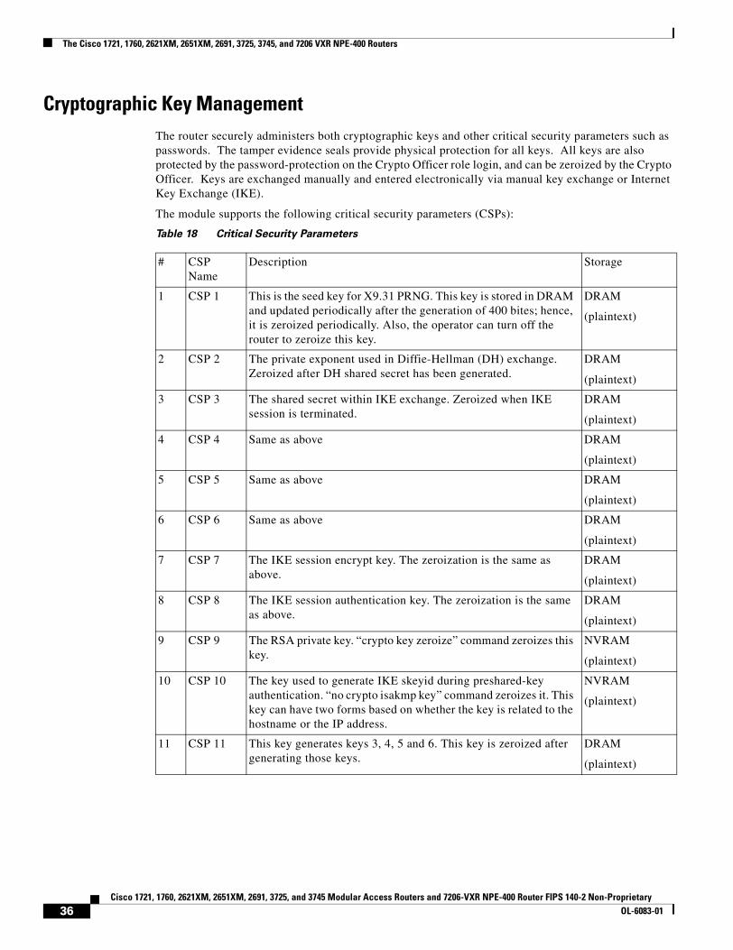
Roles and ServicesAuthentication is role-based. There are two main roles in the router that operators may assume: the Crypto Officer role and the User role. The administrator of the router assumes the Crypto Officer role in order to configure and maintain the router using Crypto Officer services, while the Users exercise only the basic User services. Both roles are authenticated by providing a valid username and password. The configuration of the encryption and decryption functionality is performed only by the Crypto Officer after authentication to the Crypto Officer role by providing a valid Crypto Officer username and password. Once the Crypto Officer has configured the encryption and decryption functionality, the User can use this functionality after authentication to the User role by providing a valid User username and password. The Crypto Officer can also use the encryption and decryption functionality after authentication to the Crypto Officer role. The module supports RADIUS and TACACS+ for authentication and they are used in the FIPS mode. A complete description of all the management and configuration capabilities of the Cisco Routers can be found in the Performing Basic System Management manuals and in the online help for the routers.
The User and Crypto Officer passwords and the RADIUS/TACACS+ shared secrets must each be at least 8 alphanumeric characters in length. See the “Secure Operation of the Cisco 1721, 1760, 2621XM, 2651XM, 2691, 3725, 3745, and 7206 VXR NPE-400 Routers” section on page 42 for more information.
Table 17 Cisco 7206 VXR NPE-400 FIPS 140-1 Logical Interfaces
Router Physical Interface FIPS 140-1 Logical Interface
10/100BASE-TX LAN PortPort Adapter InterfaceConsole PortAuxiliary PortPCMCIA Slot
Data Input Interface
10/100BASE-TX LAN PortPort Adapter InterfaceConsole Port Auxiliary PortPCMCIA Slot
Data Output Interface
Power SwitchConsole PortAuxiliary Port
Control Input Interface
10/100BASE-TX LAN Port LEDs Enabled LEDPCMCIA LEDsIO Pwr Ok LEDConsole PortAuxiliary Port
Status Output Interface
Power Plug Power Interface
27Cisco 1721, 1760, 2621XM, 2651XM, 2691, 3725, and 3745 Modular Access Routers and 7206-VXR NPE-400 Router FIPS 140-2 Non-Proprietary
OL-6083-01
The Cisco 1721, 1760, 2621XM, 2651XM, 2691, 3725, 3745, and 7206 VXR NPE-400 Routers
If only integers 0-9 are used without repetition for an 8 digit PIN, the probability of randomly guessing the correct sequence is 1 in 1,814,400. Including the rest of the alphanumeric characters drastically decreases the odds of guessing the correct sequence.
Crypto Officer Services
During initial configuration of the router, the Crypto Officer password (the "enable" password) is defined. A Crypto Officer may assign permission to access the Crypto Officer role to additional accounts, thereby creating additional Crypto Officers.
The Crypto Officer role is responsible for the configuration and maintenance of the router. The Crypto Officer services consist of the following:
• Configure the router—define network interfaces and settings, create command aliases, set the protocols the router will support, enable interfaces and network services, set system date and time, and load authentication information.
• Define Rules and Filters—create packet Filters that are applied to User data streams on each interface. Each Filter consists of a set of Rules, which define a set of packets to permit or deny based characteristics such as protocol ID, addresses, ports, TCP connection establishment, or packet direction.
• Status Functions—view the router configuration, routing tables, active sessions, use Gets to view SNMP MIB II statistics, health, temperature, memory status, voltage, packet statistics, review accounting logs, and view physical interface status.
• Manage the router—log off users, shutdown or reload the outer, manually back up router configurations, view complete configurations, manager user rights, and restore router configurations.
• Set Encryption/Bypass—set up the configuration tables for IP tunneling. Set keys and algorithms to be used for each IP range or allow plaintext packets to be set from specified IP address.
• Change WAN Interface Cards/Network Modules—insert and remove WICs or NMs as described in the second bullet in the “Initial Setup” section on page 43 of this document.
User Services
A User enters the system by accessing the console port with a terminal program. The IOS prompts the User for their password. If the password is correct, the User is allowed entry to the IOS executive program. The services available to the User role consist of the following:
• Status Functions—view state of interfaces, state of layer 2 protocols, version of IOS currently running
• Network Functions—connect to other network devices through outgoing telnet, PPP, etc. and initiate diagnostic network services (i.e., ping, mtrace)
• Terminal Functions—adjust the terminal session (e.g., lock the terminal, adjust flow control)
• Directory Services—display directory of files kept in flash memory
28Cisco 1721, 1760, 2621XM, 2651XM, 2691, 3725, and 3745 Modular Access Routers and 7206-VXR NPE-400 Router FIPS 140-2 Non-Proprietary
OL-6083-01
The Cisco 1721, 1760, 2621XM, 2651XM, 2691, 3725, 3745, and 7206 VXR NPE-400 Routers
Physical SecurityThe router is entirely encased by a thick steel chassis. WIC slots, on-board LAN connectors, Console/Auxiliary connectors, power cable connections, and power switches are provided on the router. Specific portions of the chassis may be removed to allow access to the motherboard, memory, and expansion slots.
Any WIC or other module slot, which is not populated with a WIC or a module, must be populated with an appropriate slot cover in order to operate in a FIPS compliant mode. Slot covers are included with each router, and additional covers may be ordered from Cisco. The same procedure mentioned below to apply tamper evidence labels for WICs and other modules must also be followed to apply tamper evidence labels for the slot covers.
Once the router has been configured in to meet FIPS 140-2 Level 2 requirements, the router cannot be accessed without signs of tampering. To seal the system, apply serialized tamper-evidence labels as follows:
To apply serialized tamper-evidence labels to the Cisco 1721:
Step 1 Clean the cover of any grease, dirt, or oil before applying the tamper evidence labels. Alcohol-based cleaning pads are recommended for this purpose. The temperature of the router should be above 10°C.
Step 2 Place the first label on the router as shown in Figure 20. The tamper evidence label should be placed so that the one half of the tamper evidence label covers the top-half of the right side of the enclosure and the other half covers the bottom-half of the right side of the router. Any attempt to remove the enclosure will leave tamper evidence.
Step 3 Place the second label on the router as shown in Figure 20. The tamper evidence label should be placed so that the one half of the tamper evidence label covers the top-half of the left side of the enclosure and the other half covers the bottom-half of the left side of the router. Any attempt to remove the enclosure will leave tamper evidence.
Step 4 Place the third label on the router as shown in Figure 20. The tamper evidence label should be placed so that the half of the label covers the enclosure and the other half covers the left WAN interface card slot. Any attempt to remove a WAN interface card will leave tamper evidence.
Step 5 Place the fourth label on the router as shown in Figure 20. The tamper evidence label should be placed so that one half of the label covers the enclosure and the other half covers the right WAN interface card slot. Any attempt to remove a WAN interface card will leave tamper evidence.
Step 6 The labels completely cure within five minutes.
To apply serialized tamper-evidence labels to the Cisco 1760:
Step 1 Clean the cover of any grease, dirt, or oil before applying the tamper evidence labels. Alcohol-based cleaning pads are recommended for this purpose. The temperature of the router should be above 10°C.
Step 2 Place the first label on the router as shown in Figure 20. The tamper evidence label should be placed so that the one half of the tamper evidence label covers the right side of the enclosure and the other half covers the right side of the front of the router. Any attempt to remove the enclosure will leave tamper evidence.
Step 3 Place the second label on the router as shown in Figure 20. The tamper evidence label should be placed so that the one half of the tamper evidence label covers the left side of the enclosure and the other half covers the left side of the front of the router. Any attempt to remove the enclosure will leave tamper evidence.
29Cisco 1721, 1760, 2621XM, 2651XM, 2691, 3725, and 3745 Modular Access Routers and 7206-VXR NPE-400 Router FIPS 140-2 Non-Proprietary
OL-6083-01
The Cisco 1721, 1760, 2621XM, 2651XM, 2691, 3725, 3745, and 7206 VXR NPE-400 Routers
Step 4 Place the third label on the router as shown in Figure 20. The tamper evidence label should be placed so that the half of the label covers the bottom of the enclosure and the other half covers the first WAN interface card slot. Any attempt to remove a WAN interface card will leave tamper evidence.
Step 5 Place the fourth label on the router as shown in Figure 20. The tamper evidence label should be placed so that the half of the label covers the bottom of the enclosure and the other half covers the second WAN interface card slot. Any attempt to remove a WAN interface card will leave tamper evidence.
Step 6 Place the fifth label on the router as shown in Figure 20. The tamper evidence label should be placed so that the half of the label covers the bottom of the enclosure and the other half covers the third WAN interface card slot. Any attempt to remove a WAN interface card will leave tamper evidence.
Step 7 Place the sixth label on the router as shown in Figure 20. The tamper evidence label should be placed so that the half of the label covers the bottom of the enclosure and the other half covers the fourth WAN interface card slot. Any attempt to remove a WAN interface card will leave tamper evidence.
Step 8 The labels completely cure within five minutes.
To apply serialized tamper-evidence labels to the Cisco 2621XM and Cisco 2651XM:
Step 1 Clean the cover of any grease, dirt, or oil before applying the tamper evidence labels. Alcohol-based cleaning pads are recommended for this purpose. The temperature of the router should be above 10°C.
Step 2 Place the first label on the router as shown in Figure 21. The tamper evidence label should be placed so that the one half of the tamper evidence label covers the enclosure and the other half covers the side of the router. Any attempt to remove the enclosure will leave tamper evidence.
Step 3 Place the second label on the router as shown in Figure 21. The tamper evidence label should be placed so that the one half of the tamper evidence label covers the enclosure and the other half covers the side of the router. Any attempt to remove the enclosure will leave tamper evidence.
Step 4 Place the third label on the router as shown in Figure 21. The tamper evidence label should be placed so that the one half of the label covers the enclosure and the other half covers the Network Module slot. Any attempt to remove a Network Module will leave tamper evidence.
30Cisco 1721, 1760, 2621XM, 2651XM, 2691, 3725, and 3745 Modular Access Routers and 7206-VXR NPE-400 Router FIPS 140-2 Non-Proprietary
OL-6083-01
The Cisco 1721, 1760, 2621XM, 2651XM, 2691, 3725, 3745, and 7206 VXR NPE-400 Routers
Step 5 Place the fourth label on the router as shown in Figure 21. The tamper evidence label should be placed so that the half of the label covers the enclosure and the other half covers the WAN interface card slot. Any attempt to remove a WAN interface card will leave tamper evidence.
Step 6 Place the fifth label on the router as shown in Figure 21. The tamper evidence label should be placed so that one half of the label covers the enclosure and the other half covers the WAN interface card slot. Any attempt to remove a WAN interface card will leave tamper evidence.
Step 7 The labels completely cure within five minutes.
To apply serialized tamper-evidence labels to the Cisco 2691:
Step 1 Clean the cover of any grease, dirt, or oil before applying the tamper evidence labels. Alcohol-based cleaning pads are recommended for this purpose. The temperature of the router should be above 10°C.
Step 2 Place the first label on the router as shown in Figure 22. The tamper evidence label should be placed so that the one half of the tamper evidence label covers the enclosure and the other half covers the right side of the router. Any attempt to remove the enclosure will leave tamper evidence.
Step 3 Place the second label on the router as shown in Figure 22. The tamper evidence label should be placed so that the one half of the tamper evidence label covers the enclosure and the other half covers the left side of the router. Any attempt to remove the enclosure will leave tamper evidence.
Step 4 Place the third label on the router as shown in Figure 22. The tamper evidence label should be placed so that the one half of the label covers the enclosure and the other half covers the Network Module slot. Any attempt to remove a Network Module will leave tamper evidence.
Step 5 Place the fourth label on the router as shown in Figure 22. The tamper evidence label should be placed so that the half of the label covers the enclosure and the other half covers the left WAN interface card slot. Any attempt to remove a WAN interface card will leave tamper evidence.
Step 6 Place the fifth label on the router as shown in Figure 22. The tamper evidence label should be placed so that one half of the label covers the enclosure and the other half covers the middle WAN interface card slot. Any attempt to remove a WAN interface card will leave tamper evidence.
Step 7 Place the sixth label on the router as shown in Figure 22. The tamper evidence label should be placed so that one half of the label covers the enclosure and the other half covers the right WAN interface card slot. Any attempt to remove a WAN interface card will leave tamper evidence.
9949
8
SEE MANUAL BEFORE INSTALLATION
SERIAL 1
SERIAL 0CONN
CONNWIC2A/S
SEE MANUAL BEFORE INSTALLATION
SERIAL 1
SERIAL 0CONN
CONNWIC
2T
Cisco 2611 100-240V– 1A50/60 Hz 47 W
W0
AUXCONSOLEETHERNET 0 ACTLINKACTETHERNET 1LINK
W1
POWER RPS ACTIVITY
Cisco 2600SERIES
31Cisco 1721, 1760, 2621XM, 2651XM, 2691, 3725, and 3745 Modular Access Routers and 7206-VXR NPE-400 Router FIPS 140-2 Non-Proprietary
OL-6083-01
The Cisco 1721, 1760, 2621XM, 2651XM, 2691, 3725, 3745, and 7206 VXR NPE-400 Routers
Step 8 Place the seventh label on the router as shown in Figure 22. The tamper evidence label should be placed so that one half of the label covers the enclosure and the other half covers the Compact Flash slot. Any attempt to remove a CF card will leave tamper evidence.
Step 9 The labels completely cure within five minutes.
Figure 22 Tamper Evidence Label Placement
To apply tamper-evidence labels to the Cisco 3725:
Step 1 Clean the cover of any grease, dirt, or oil before applying the tamper evidence labels. Alcohol-based cleaning pads are recommended for this purpose. The temperature of the router should be above 10°C.
Step 2 Place the first label on the router as shown in Figure 23. The tamper evidence label should be placed so that the one half of the tamper evidence label covers the enclosure and the other half covers the right side of the router. Any attempt to remove the enclosure will leave tamper evidence.
Step 3 Place the second label on the router as shown in Figure 23. The tamper evidence label should be placed so that the one half of the tamper evidence label covers the enclosure and the other half covers the left side of the router. Any attempt to remove the enclosure will leave tamper evidence.
Step 4 Place the third label on the router as shown in Figure 23. The tamper evidence label should be placed so that the one half of the label covers the enclosure and the other half covers the top double-sized Network Module slot. Any attempt to remove a network module will leave tamper evidence.
Step 5 Place the fourth label on the router as shown in Figure 23. The tamper evidence label should be placed so that the half of the label covers the enclosure and the other half covers the bottom Network Module slot. Any attempt to remove a network module will leave tamper evidence.
Step 6 Place the fifth label on the router as shown in Figure 23. The tamper evidence label should be placed so that one half of the label covers the enclosure and the other half covers the left WAN interface card slot. Any attempt to remove a WAN interface card will leave tamper evidence.
Step 7 Place the sixth label on the router as shown in Figure 23. The tamper evidence label should be placed so that one half of the label covers the enclosure and the other half covers the middle WAN interface card slot. Any attempt to remove a WAN interface card will leave tamper evidence.
SEE MANUAL BEFORE INSTALLATION
AL
CD
LPRDTD
SEE MANUAL BEFORE INSTALLATIONDSU56K
AL
CD
LPRDTD
SEE MANUAL BEFORE INSTALLATION
DSU56K
ENV0
BANK 4 BANK 3 BANK 2 BANK 1 BANK 0
NM-HDV
VWIC2MFT-E1 SEE
MANUALBEFOREINSTALLATION
CTRLR E2CTRLR E1
AL
LP
CD
SERIES SERIES
995
03
32Cisco 1721, 1760, 2621XM, 2651XM, 2691, 3725, and 3745 Modular Access Routers and 7206-VXR NPE-400 Router FIPS 140-2 Non-Proprietary
OL-6083-01
The Cisco 1721, 1760, 2621XM, 2651XM, 2691, 3725, 3745, and 7206 VXR NPE-400 Routers
Step 8 Place the seventh label on the router as shown in Figure 23. The tamper evidence label should be placed so that one half of the label covers the enclosure and the other half covers the right WAN interface card slot. Any attempt to remove a WAN interface card will leave tamper evidence.
Step 9 Place the eighth label on the router as shown in Figure 23. The tamper evidence label should be placed so that one half of the label covers the enclosure and the other half covers the Compact Flash slot. Any attempt to remove a CF card will leave tamper evidence.
Step 10 The labels completely cure within five minutes.
To apply tamper-evidence labels to the Cisco 3745:
Step 1 Clean the cover of any grease, dirt, or oil before applying the tamper evidence labels. Alcohol-based cleaning pads are recommended for this purpose. The temperature of the router should be above 10°C.
Step 2 Place the first label on the router as shown in Figure 23. The tamper evidence label should be placed so that the one half of the tamper evidence label covers the enclosure and the other half covers the right side of the router. Any attempt to remove the enclosure will leave tamper evidence.
Step 3 Place the second label on the router as shown in Figure 23. The tamper evidence label should be placed so that the one half of the tamper evidence label covers the enclosure and the other half covers the left side of the router. Any attempt to remove the enclosure will leave tamper evidence.
Step 4 Place the third label on the router as shown in Figure 23. The tamper evidence label should be placed so that the one half of the label covers the enclosure and the other half covers the top-left Network Module slot. Any attempt to remove a network module will leave tamper evidence.
Step 5 Place the fourth label on the router as shown in Figure 23. The tamper evidence label should be placed so that the half of the label covers the enclosure and the other half covers the bottom-left Network Module slot. Any attempt to remove a network module will leave tamper evidence.
Step 6 Place the fifth label on the router as shown in Figure 23. The tamper evidence label should be placed so that the one half of the label covers the enclosure and the other half covers the top-right Network Module slot. Any attempt to remove a network module will leave tamper evidence.
Step 7 Place the sixth label on the router as shown in Figure 23. The tamper evidence label should be placed so that the half of the label covers the enclosure and the other half covers the bottom-right Network Module slot. Any attempt to remove a network module will leave tamper evidence.
Step 8 Place the seventh label on the router as shown in Figure 23. The tamper evidence label should be placed so that one half of the label covers the enclosure and the other half covers the left WAN interface card slot. Any attempt to remove a WAN interface card will leave tamper evidence.
Step 9 Place the eighth label on the router as shown in Figure 23. The tamper evidence label should be placed so that one half of the label covers the enclosure and the other half covers the middle WAN interface card slot. Any attempt to remove a WAN interface card will leave tamper evidence.
Step 10 Place the ninth label on the router as shown in Figure 23. The tamper evidence label should be placed so that one half of the label covers the enclosure and the other half covers the right WAN interface card slot. Any attempt to remove a WAN interface card will leave tamper evidence.
Step 11 Place the tenth label on the router as shown in Figure 23. The tamper evidence label should be placed so that one half of the label covers the enclosure and the other half covers the Compact Flash slot. Any attempt to remove a CF card will leave tamper evidence.
Step 12 The labels completely cure within five minutes.
33Cisco 1721, 1760, 2621XM, 2651XM, 2691, 3725, and 3745 Modular Access Routers and 7206-VXR NPE-400 Router FIPS 140-2 Non-Proprietary
OL-6083-01
The Cisco 1721, 1760, 2621XM, 2651XM, 2691, 3725, 3745, and 7206 VXR NPE-400 Routers
To apply tamper-evidence labels to the Cisco 7206 VXR NPE-400:
Step 1 Clean the cover of any grease, dirt, or oil before applying the tamper evidence labels. Alcohol-based cleaning pads are recommended for this purpose. The temperature of the router should be above 10°C.
Step 2 Place the first label on the router as shown in Figure 24. The tamper evidence label should be placed so that the one half of the label covers the enclosure and the other half covers the 7206 VXR NPE-400 Input/Output Controller.
Step 3 Place the second label on the router as shown in Figure 24. The tamper evidence label should be placed over the Flash PC Card slots on the Input/Output Controller.
Step 4 Place the third label on the router as shown in Figure 24. The tamper evidence label should be placed so that one half of the label covers the enclosure and the other half covers the port adapter slot 1.
Step 5 Place the fourth label on the router as shown in Figure 24. The tamper evidence label should be placed so that one half of the label covers the enclosure and the other half covers the port adapter slot 2.
Step 6 Place the fifth label on the router as shown in Figure 24. The tamper evidence label should be placed so that one half of the label covers the enclosure and the other half covers the port adapter slot 3.
Step 7 Place the sixth label on the router as shown in Figure 24. The tamper evidence label should be placed so that one half of the label covers the enclosure and the other half covers the port adapter slot 4.
Step 8 Place the seventh label on the router as shown in Figure 24. The tamper evidence label should be placed so that one half of the label covers the enclosure and the other half covers the port adapter slot 5.
Step 9 Place the eighth label on the router as shown in Figure 24. The tamper evidence label should be placed so that one half of the label covers the enclosure and the other half covers the port adapter slot 6.
Step 10 Place the ninth label on the router as shown in Figure 24. The tamper evidence label should be placed so that one half of the label covers the enclosure and the other half covers the network processing engine.
SEE MANUAL BEFORE INSTALLATION
AL
CD
LPRDTD
SEE MANUAL BEFORE INSTALLATIONDSU56K
AL
CD
LPRDTD
SEE MANUAL BEFORE INSTALLATIONDSU56K
ENV0
BANK 4 BANK 3 BANK 2 BANK 1 BANK 0
NM-HDV
VWIC2MFT-E1 SEE
MANUALBEFOREINSTALLATION
CTRLR E2CTRLR E1
AL
LP
CD
9950
8
EN
V0
BANK 4 BANK 3 BANK 2 BANK 1 BANK 0
NM-HDV
VWIC2MFT-E1 SEE
MANUALBEFOREINSTALLATION
CTRLR E2
CTRLR E1
AL
LP
CD
EN
V0
BANK 4 BANK 3 BANK 2 BANK 1 BANK 0
NM-HDV
VWIC2MFT-E1 SEE
MANUALBEFOREINSTALLATION
CTRLR E2
CTRLR E1
AL
LP
CD
EN
V0
BANK 4 BANK 3 BANK 2 BANK 1 BANK 0
NM-HDV
VWIC2MFT-E1 SEE
MANUALBEFOREINSTALLATION
CTRLR E2
CTRLR E1
AL
LP
CD
EN
V0
BANK 4 BANK 3 BANK 2 BANK 1 BANK 0
NM-HDV
VWIC2MFT-E1 SEE
MANUALBEFOREINSTALLATION
CTRLR E2
CTRLR E1
AL
LP
CD
SEE MANUAL BEFORE INSTALLATION
SERIAL 1
SERIAL 0
CONN
CONNWIC
2T
SEE MANUAL BEFORE INSTALLATION
SERIAL 1
SERIAL 0
CONN
CONNWIC
2T
SEE MANUAL BEFORE INSTALLATIONDSU56K
CD
ALLPRDTD
34Cisco 1721, 1760, 2621XM, 2651XM, 2691, 3725, and 3745 Modular Access Routers and 7206-VXR NPE-400 Router FIPS 140-2 Non-Proprietary
OL-6083-01
The Cisco 1721, 1760, 2621XM, 2651XM, 2691, 3725, 3745, and 7206 VXR NPE-400 Routers
Step 11 Place the tenth label on the router as shown in Figure 24. The tamper evidence label should be placed so that one half of the label covers the enclosure and the other half covers the power supply plate.
Step 12 Place the eleventh label on the router as shown in Figure 24. The tamper evidence label should be placed so that one half of the label covers the enclosure and the other half covers the redundant power supply plate.
Step 13 The labels completely cure within five minutes.
The tamper evidence seals are produced from a special thin gauge vinyl with self-adhesive backing. Any attempt to open the router or remove components will damage the tamper evidence seals or the painted surface and metal of the module cover. Since the tamper evidence seals have non-repeated serial numbers, they may be inspected for damage and compared against the applied serial numbers to verify that the module has not been tampered. Tamper evidence seals can also be inspected for signs of tampering, which include the following: curled corners, bubbling, crinkling, rips, tears, and slices. The word "OPEN" may appear if the label was peeled back.
6122
8
ETHERNET 10BT
ENABLE
D
0 2
1 3
LINK
0 1 2 3
FAST SERIAL
ENTD TC RD RC LB CD TD TC RD RC LB CD TD TC RD RC LB CD TD TC RD RC LB CD
ENABLE
D
MII
LIN
K
RJ4
5
FAST ETHERNET
0
TOKEN RING
0 1 2 3
MII
EN R
J45
EN R
J45
LINK
1O P
WR
OK
RJ-45
CPU RESET
FAST ETHERNET INPUT/OUTPUT CONTROLLER
ENABLED
PCMCIA
EJECT
SLOT 0
SLOT 1
FE MII
Auxiliaryport
Consoleport
Port adapterlever
I/O controller
0
2
4
1
3
56
ETHERNET-10BFL
EN
RX
0 1 2 3 4TX RX TX RX TX RX TX RX TX
Port adapters
Blank port adapter
PC Card slotsOptional Fast Ethernet port(MII receptacle and RJ-45 receptacle)
35Cisco 1721, 1760, 2621XM, 2651XM, 2691, 3725, and 3745 Modular Access Routers and 7206-VXR NPE-400 Router FIPS 140-2 Non-Proprietary
OL-6083-01
The Cisco 1721, 1760, 2621XM, 2651XM, 2691, 3725, 3745, and 7206 VXR NPE-400 Routers
Cryptographic Key ManagementThe router securely administers both cryptographic keys and other critical security parameters such as passwords. The tamper evidence seals provide physical protection for all keys. All keys are also protected by the password-protection on the Crypto Officer role login, and can be zeroized by the Crypto Officer. Keys are exchanged manually and entered electronically via manual key exchange or Internet Key Exchange (IKE).
The module supports the following critical security parameters (CSPs):
Table 18 Critical Security Parameters
# CSP Name
Description Storage
1 CSP 1 This is the seed key for X9.31 PRNG. This key is stored in DRAM and updated periodically after the generation of 400 bites; hence, it is zeroized periodically. Also, the operator can turn off the router to zeroize this key.
DRAM
(plaintext)
2 CSP 2 The private exponent used in Diffie-Hellman (DH) exchange. Zeroized after DH shared secret has been generated.
DRAM
(plaintext)
3 CSP 3 The shared secret within IKE exchange. Zeroized when IKE session is terminated.
DRAM
(plaintext)
4 CSP 4 Same as above DRAM
(plaintext)
5 CSP 5 Same as above DRAM
(plaintext)
6 CSP 6 Same as above DRAM
(plaintext)
7 CSP 7 The IKE session encrypt key. The zeroization is the same as above.
DRAM
(plaintext)
8 CSP 8 The IKE session authentication key. The zeroization is the same as above.
DRAM
(plaintext)
9 CSP 9 The RSA private key. “crypto key zeroize” command zeroizes this key.
NVRAM
(plaintext)
10 CSP 10 The key used to generate IKE skeyid during preshared-key authentication. “no crypto isakmp key” command zeroizes it. This key can have two forms based on whether the key is related to the hostname or the IP address.
NVRAM
(plaintext)
11 CSP 11 This key generates keys 3, 4, 5 and 6. This key is zeroized after generating those keys.
DRAM
(plaintext)
36Cisco 1721, 1760, 2621XM, 2651XM, 2691, 3725, and 3745 Modular Access Routers and 7206-VXR NPE-400 Router FIPS 140-2 Non-Proprietary
OL-6083-01
The Cisco 1721, 1760, 2621XM, 2651XM, 2691, 3725, 3745, and 7206 VXR NPE-400 Routers
12 CSP 12 The RSA public key used to validate signatures within IKE. These keys are expired either when CRL (certificate revocation list) expires or 5 secs after if no CRL exists. After above expiration happens and before a new public key structure is created this key is deleted. This key does not need to be zeroized because it is a public key; however, it is zeroized as mentioned here.
DRAM
(plaintext)
13 CSP 13 The fixed key used in Cisco vendor ID generation. This key is embedded in the module binary image and can be deleted by erasing the Flash.
NVRAM
(plaintext)
14 CSP 14 The IPSec encryption key. Zeroized when IPSec session is terminated.
DRAM
(plaintext)
15 CSP 15 The IPSec authentication key. The zeroization is the same as above.
DRAM
(plaintext)
16 CSP 16 The RSA public key of the CA. “no crypto ca trust <label>” command invalidates the key and it frees the public key label which in essence prevent use of the key. This key does not need to be zeroized because it is a public key.
NVRAM
(plaintext)
17 CSP 17 This key is a public key of the DNS server. Zeroized using the same mechanism as above. “no crypto ca trust <label>” command invalidate the DNS server’s public key and it frees the public key label which in essence prevent use of that key. This label is different from the label in the above key. This key does not need to be zeroized because it is a public key.
NVRAM
(plaintext)
18 CSP 18 The SSL session key. Zeroized when the SSL connection is terminated.
DRAM
(plaintext)
19 CSP 19 The ARAP key that is hardcoded in the module binary image. This key can be deleted by erasing the Flash.
Flash
(plaintext)
20 CSP 20 This is an ARAP user password used as an authentication key. A function uses this key in a DES algorithm for authentication.
DRAM
(plaintext)
21 CSP 21 The key used to encrypt values of the configuration file. This key is zeroized when the “no key config-key” is issued.
NVRAM
(plaintext)
22 CSP 22 This key is used by the router to authenticate itself to the peer. The router itself gets the password (that is used as this key) from the AAA server and sends it onto the peer. The password retrieved from the AAA server is zeroized upon completion of the authentication attempt.
DRAM
(plaintext)
23 CSP 23 The RSA public key used in SSH. Zeroized after the termination of the SSH session. This key does not need to be zeroized because it is a public key; However, it is zeroized as mentioned here.
DRAM
(plaintext)
24 CSP 24 The authentication key used in PPP. This key is in the DRAM and not zeroized at runtime. One can turn off the router to zeroize this key because it is stored in DRAM.
DRAM
(plaintext)
Table 18 Critical Security Parameters (Continued)
37Cisco 1721, 1760, 2621XM, 2651XM, 2691, 3725, and 3745 Modular Access Routers and 7206-VXR NPE-400 Router FIPS 140-2 Non-Proprietary
OL-6083-01
The Cisco 1721, 1760, 2621XM, 2651XM, 2691, 3725, 3745, and 7206 VXR NPE-400 Routers
The services accessing the CSPs, the type of access and which role accesses the CSPs are listed in Table 19.
25 CSP 25 This key is used by the router to authenticate itself to the peer. The key is identical to #22 except that it is retrieved from the local database (on the router itself). Issuing the “no username password” zeroizes the password (that is used as this key) from the local database.
NVRAM
(plaintext)
26 CSP 26 This is the SSH session key. It is zeroized when the SSH session is terminated.
DRAM
(plaintext)
27 CSP 27 The password of the User role. This password is zeroized by overwriting it with a new password.
NVRAM
(plaintext)
28 CSP 28 The plaintext password of the CO role. This password is zeroized by overwriting it with a new password.
NVRAM
(plaintext)
29 CSP 29 The ciphertext password of the CO role. However, the algorithm used to encrypt this password is not FIPS approved. Therefore, this password is considered plaintext for FIPS purposes. This password is zeroized by overwriting it with a new password.
NVRAM
(plaintext)
30 CSP 30 The RADIUS shared secret. This shared secret is zeroized by executing the “no” form of the RADIUS shared secret set command.
NVRAM (plaintext), DRAM (plaintext)
31 CSP 31 The TACACS+ shared secret. This shared secret is zeroized by executing the “no” form of the TACACS+ shared secret set command.
NVRAM (plaintext), DRAM (plaintext)
Table 18 Critical Security Parameters (Continued)
Table 19 Role and Service Access to CSPs
SRDI/Role/Service Access Policy Role
/Ser
vice
Use
r Rol
e
Stat
us F
unct
ions
Net
wor
k Fu
nctio
ns
Term
inal
Fun
ctio
ns
Dir
ecto
ry S
ervi
ces
Cryp
to-O
ffice
r Rol
e
Conf
igur
e th
e Ro
uter
Def
ine
Rule
s an
d Fi
lters
Stat
us F
unct
ions
Man
age
the
Rout
er
Set E
ncry
ptio
ns/B
ypas
s
Chan
ge W
AN
Inte
rfac
e Ca
rds
Security Relevant Data Item
CSP 1 r d rwd
CSP 2 r rwd
38Cisco 1721, 1760, 2621XM, 2651XM, 2691, 3725, and 3745 Modular Access Routers and 7206-VXR NPE-400 Router FIPS 140-2 Non-Proprietary
OL-6083-01
The Cisco 1721, 1760, 2621XM, 2651XM, 2691, 3725, 3745, and 7206 VXR NPE-400 Routers
CSP 3 r rwd
CSP 4 r rwd
CSP 5 r rwd
CSP 6 r rwd
CSP 7 r rwd
CSP 8 r rwd
CSP 9 r rwd
CSP 10 r rwd
CSP 11 r rwd
CSP 12 r rwd
CSP 13 r rwd
CSP 14 r rwd
Table 19 Role and Service Access to CSPs (Continued)
SRDI/Role/Service Access Policy Role
/Ser
vice
Use
r Rol
e
Stat
us F
unct
ions
Net
wor
k Fu
nctio
ns
Term
inal
Fun
ctio
ns
Dir
ecto
ry S
ervi
ces
Cryp
to-O
ffice
r Rol
e
Conf
igur
e th
e Ro
uter
Def
ine
Rule
s an
d Fi
lters
Stat
us F
unct
ions
Man
age
the
Rout
er
Set E
ncry
ptio
ns/B
ypas
s
Chan
ge W
AN
Inte
rfac
e Ca
rds
39Cisco 1721, 1760, 2621XM, 2651XM, 2691, 3725, and 3745 Modular Access Routers and 7206-VXR NPE-400 Router FIPS 140-2 Non-Proprietary
OL-6083-01
The Cisco 1721, 1760, 2621XM, 2651XM, 2691, 3725, 3745, and 7206 VXR NPE-400 Routers
CSP 15 r rwd
CSP 16 r rw
CSP 17 r rwd
CSP 18 r rwd
CSP 19 r rwd
CSP 20 r rwd
CSP 21 rwd
rwd
CSP 22 r rwd
CSP 23 r rwd
CSP 24 r d rw
CSP 25 r rwd
CSP 26 r rwd
Table 19 Role and Service Access to CSPs (Continued)
SRDI/Role/Service Access Policy Role
/Ser
vice
Use
r Rol
e
Stat
us F
unct
ions
Net
wor
k Fu
nctio
ns
Term
inal
Fun
ctio
ns
Dir
ecto
ry S
ervi
ces
Cryp
to-O
ffice
r Rol
e
Conf
igur
e th
e Ro
uter
Def
ine
Rule
s an
d Fi
lters
Stat
us F
unct
ions
Man
age
the
Rout
er
Set E
ncry
ptio
ns/B
ypas
s
Chan
ge W
AN
Inte
rfac
e Ca
rds
40Cisco 1721, 1760, 2621XM, 2651XM, 2691, 3725, and 3745 Modular Access Routers and 7206-VXR NPE-400 Router FIPS 140-2 Non-Proprietary
OL-6083-01
The Cisco 1721, 1760, 2621XM, 2651XM, 2691, 3725, 3745, and 7206 VXR NPE-400 Routers
The module supports DES (only for legacy systems), 3DES, DES-MAC, TDES-MAC, AES, SHA-1, HMAC-SHA-1, MD5, MD4, HMAC MD5, Diffie-Hellman, RSA (for digital signatures and encryption/decryption (for IKE authentication)), cryptographic algorithms. The MD5, HMAC MD5, and MD4 algorithms are disabled when operating in FIPS mode.
The module supports three types of key management schemes:
• Manual key exchange method that is symmetric. DES/3DES/AES key and HMAC-SHA-1 key are exchanged manually and entered electronically.
• Internet Key Exchange method with support for exchanging pre-shared keys manually and entering electronically.
– The pre-shared keys are used with Diffie-Hellman key agreement technique to derive DES, 3DES or AES keys.
– The pre-shared key is also used to derive HMAC-SHA-1 key.
• Internet Key Exchange with RSA-signature authentication.
All pre-shared keys are associated with the CO role that created the keys, and the CO role is protected by a password. Therefore, the CO password is associated with all the pre-shared keys. The Crypto Officer needs to be authenticated to store keys. All Diffie-Hellman (DH) keys agreed upon for individual tunnels are directly associated with that specific tunnel only via the IKE protocol.
CSP 27 r rwd
CSP 28 rwd
CSP 29 rwd
CSP 30 rwd
CSP 31 rwd
Table 19 Role and Service Access to CSPs (Continued)
SRDI/Role/Service Access Policy Role
/Ser
vice
Use
r Rol
e
Stat
us F
unct
ions
Net
wor
k Fu
nctio
ns
Term
inal
Fun
ctio
ns
Dir
ecto
ry S
ervi
ces
Cryp
to-O
ffice
r Rol
e
Conf
igur
e th
e Ro
uter
Def
ine
Rule
s an
d Fi
lters
Stat
us F
unct
ions
Man
age
the
Rout
er
Set E
ncry
ptio
ns/B
ypas
s
Chan
ge W
AN
Inte
rfac
e Ca
rds
41Cisco 1721, 1760, 2621XM, 2651XM, 2691, 3725, and 3745 Modular Access Routers and 7206-VXR NPE-400 Router FIPS 140-2 Non-Proprietary
OL-6083-01
Secure Operation of the Cisco 1721, 1760, 2621XM, 2651XM, 2691, 3725, 3745, and 7206 VXR NPE-400 Routers
Key Zeroization
All the keys and CSPs of the module can be zeroized. Please refer to the Description column of Table 18 for information on methods to zeroize each key and CSP.
Self-TestsIn order to prevent any secure data from being released, it is important to test the cryptographic components of a security module to insure all components are functioning correctly. The router includes an array of self-tests that are run during startup and periodically during operations. If any of the self-tests fail, the router transitions into an error state. Within the error state, all secure data transmission is halted and the router outputs status information indicating the failure.
Self-tests performed by the IOS image:
• Power-up tests:
– Firmware integrity test
– RSA signature KAT (both signature and verification)
– DES KAT
– TDES KAT
– AES KAT
– SHA-1 KAT
– PRNG KAT
– Power-up bypass test
– Diffie-Hellman self-test
– HMAC-SHA-1 KAT
• Conditional tests:
– Conditional bypass test
– Pairwise consistency test on RSA signature
– Continuous random number generator tests
Secure Operation of the Cisco 1721, 1760, 2621XM, 2651XM, 2691, 3725, 3745, and 7206 VXR NPE-400 Routers
The Cisco 1721, 1760, 2621XM, 2651XM, 2691, 3725, 3745, and 7206 VXR NPE-400 Modular Access Routers meet all the Level 2 requirements for FIPS 140-2. Follow the setting instructions provided below to place the module in FIPS mode. Operating these routers without maintaining the following settings will remove the module from the FIPS approved mode of operation.
42Cisco 1721, 1760, 2621XM, 2651XM, 2691, 3725, and 3745 Modular Access Routers and 7206-VXR NPE-400 Router FIPS 140-2 Non-Proprietary
OL-6083-01
Secure Operation of the Cisco 1721, 1760, 2621XM, 2651XM, 2691, 3725, 3745, and 7206 VXR NPE-400 Routers
Initial Setup• The Crypto Officer must apply tamper evidence labels as described in the “Physical Security”
section of this document.
• Only a Crypto Officer may add and remove WAN Interface Cards. When removing the tamper evidence label, the Crypto Officer should remove the entire label from the router and clean the cover of any grease, dirt, or oil with an alcohol-based cleaning pad. The Crypto Officer must re-apply tamper evidence labels on the router as described in the “Physical Security” section of this document.
• The Crypto Officer must apply the opacity shield as described in the “The Cisco 1721/1760 Cryptographic Module” of this document.
System Initialization and Configuration• The Crypto Officer must perform the initial configuration. Cisco IOS version 12.3(3d) is the only
allowable image; no other image may be loaded.
• For Cisco 1700, 2600, and 3700 series routers, the value of the boot field must be 0x0101. For Cisco 7200 series routers, the value of the boot field must be 0x0102. This setting disables break from the console to the ROM monitor and automatically boots the Cisco IOS image. From the “configure terminal” command line, the Crypto Officer enters the following syntax:
– For Cisco 7200 series routers, enter:
config-register 0x0102
– For Cisco 1700, 2600, and 3700 series routers, enter
config-register 0x0101
• The Crypto Officer must create the “enable” password for the Crypto Officer role. The password must be at least 8 characters and is entered when the Crypto Officer first engages the “enable” command. The Crypto Officer enters the following syntax at the “#” prompt:
enable secret <PASSWORD>
• The Crypto Officer must always assign passwords (of at least 8 characters) to users. Identification and authentication on the console port is required for Users. From the “configure terminal” command line, the Crypto Officer enters the following syntax:
line con 0password <PASSWORD>login local
• The Crypto Officer shall only assign users to a privilege level 1 (the default).
• The Crypto Officer shall not assign a command to any privilege level other than its default.
• The Crypto Officer may configure the module to use RADIUS or TACACS+ for authentication. Configuring the module to use RADIUS or TACACS+ for authentication is optional. If the module is configured to use RADIUS or TACACS+, the Crypto-Officer must define RADIUS or TACACS+ shared secret keys that are at least 8 characters long.
• If the Crypto Officer loads any IOS image onto the router, this will put the router into a non-FIPS mode of operation.
43Cisco 1721, 1760, 2621XM, 2651XM, 2691, 3725, and 3745 Modular Access Routers and 7206-VXR NPE-400 Router FIPS 140-2 Non-Proprietary
OL-6083-01
Related Documentation
IPSec Requirements and Cryptographic Algorithms• There are two types of key management method that are allowed in FIPS mode: Internet Key
Exchange (IKE) and IPSec manually entered keys.
• Although the Cisco IOS implementation of IKE allows a number of algorithms, only the following algorithms are allowed in a FIPS 140-2 configuration:
– ah-sha-hmac
– esp-des
– esp-sha-hmac
– esp-3des
– esp-aes
• The following algorithms are not FIPS approved and should be disabled:
– MD-4 and MD-5 for signing
– MD-5 HMAC
ProtocolsAll SNMP operations must be performed within a secure IPSec tunnel.
Remote Access • Telnet access to the module is only allowed via a secure IPSec tunnel between the remote system
and the module. The Crypto officer must configure the module so that any remote connections via telnet are secured through IPSec.
• SSH access to the module is only allowed if SSH is configured to use a FIPS-approved algorithm. The Crypto officer must configure the module so that SSH uses only FIPS-approved algorithms.
Related DocumentationFor more information about the Cisco 1721, 1760, 2621XM, 2651XM, 2691, 3725, 3745, and 7206 VXR modular access routers, refer to the following documents:
• Cisco 1700 Series Router Software Configuration Guide
• Cisco 2600 Series Modular Routers Quick Start Guide
• Cisco 2600 Series Hardware Installation Guide
• Software Configuration Guide for Cisco 2600 Series, Cisco 3600 Series, and Cisco 3700 Series Routers
• Cisco 3725 Router Quick Start Guide
• Cisco 3745 Router Quick Start Guide
44Cisco 1721, 1760, 2621XM, 2651XM, 2691, 3725, and 3745 Modular Access Routers and 7206-VXR NPE-400 Router FIPS 140-2 Non-Proprietary
OL-6083-01
Obtaining Documentation
• Cisco 3700 Series Hardware Installation Guide
• Cisco 7200 VXR Installation and Configuration Guide
• Cisco 7200 VXR Quick Start Guide
• Cisco 7200 Series Routers Documentation Master Index
Obtaining DocumentationCisco documentation and additional literature are available on Cisco.com. Cisco also provides several ways to obtain technical assistance and other technical resources. These sections explain how to obtain technical information from Cisco Systems.
Cisco.comYou can access the most current Cisco documentation on the World Wide Web at this URL:
http://www.cisco.com/univercd/home/home.htm
You can access the Cisco website at this URL:
http://www.cisco.com
International Cisco websites can be accessed from this URL:
• Nonregistered Cisco.com users can order documentation through a local account representative by calling Cisco Systems Corporate Headquarters (California, USA) at 408 526-7208 or, elsewhere in North America, by calling 800 553-NETS (6387).
45Cisco 1721, 1760, 2621XM, 2651XM, 2691, 3725, and 3745 Modular Access Routers and 7206-VXR NPE-400 Router FIPS 140-2 Non-Proprietary
Documentation FeedbackYou can submit e-mail comments about technical documentation to [email protected].
You can submit comments by using the response card (if present) behind the front cover of your document or by writing to the following address:
Cisco SystemsAttn: Customer Document Ordering170 West Tasman DriveSan Jose, CA 95134-9883
We appreciate your comments.
Obtaining Technical AssistanceFor all customers, partners, resellers, and distributors who hold valid Cisco service contracts, the Cisco Technical Assistance Center (TAC) provides 24-hour-a-day, award-winning technical support services, online and over the phone. Cisco.com features the Cisco TAC website as an online starting point for technical assistance. If you do not hold a valid Cisco service contract, please contact your reseller.
Cisco TAC WebsiteThe Cisco TAC website provides online documents and tools for troubleshooting and resolving technical issues with Cisco products and technologies. The Cisco TAC website is available 24 hours a day, 365 days a year. The Cisco TAC website is located at this URL:
http://www.cisco.com/tac
Accessing all the tools on the Cisco TAC website requires a Cisco.com user ID and password. If you have a valid service contract but do not have a login ID or password, register at this URL:
http://tools.cisco.com/RPF/register/register.do
Opening a TAC CaseUsing the online TAC Case Open Tool is the fastest way to open P3 and P4 cases. (P3 and P4 cases are those in which your network is minimally impaired or for which you require product information.) After you describe your situation, the TAC Case Open Tool automatically recommends resources for an immediate solution. If your issue is not resolved using the recommended resources, your case will be assigned to a Cisco TAC engineer. The online TAC Case Open Tool is located at this URL:
http://www.cisco.com/tac/caseopen
For P1 or P2 cases (P1 and P2 cases are those in which your production network is down or severely degraded) or if you do not have Internet access, contact Cisco TAC by telephone. Cisco TAC engineers are assigned immediately to P1 and P2 cases to help keep your business operations running smoothly.
46Cisco 1721, 1760, 2621XM, 2651XM, 2691, 3725, and 3745 Modular Access Routers and 7206-VXR NPE-400 Router FIPS 140-2 Non-Proprietary
TAC Case Priority DefinitionsTo ensure that all cases are reported in a standard format, Cisco has established case priority definitions.
Priority 1 (P1)—Your network is “down” or there is a critical impact to your business operations. You and Cisco will commit all necessary resources around the clock to resolve the situation.
Priority 2 (P2)—Operation of an existing network is severely degraded, or significant aspects of your business operation are negatively affected by inadequate performance of Cisco products. You and Cisco will commit full-time resources during normal business hours to resolve the situation.
Priority 3 (P3)—Operational performance of your network is impaired, but most business operations remain functional. You and Cisco will commit resources during normal business hours to restore service to satisfactory levels.
Priority 4 (P4)—You require information or assistance with Cisco product capabilities, installation, or configuration. There is little or no effect on your business operations.
Obtaining Additional Publications and InformationInformation about Cisco products, technologies, and network solutions is available from various online and printed sources.
• Cisco Marketplace provides a variety of Cisco books, reference guides, and logo merchandise. Go to this URL to visit the company store:
http://www.cisco.com/go/marketplace/
• The Cisco Product Catalog describes the networking products offered by Cisco Systems, as well as ordering and customer support services. Access the Cisco Product Catalog at this URL:
http://cisco.com/univercd/cc/td/doc/pcat/
• Cisco Press publishes a wide range of general networking, training and certification titles. Both new and experienced users will benefit from these publications. For current Cisco Press titles and other information, go to Cisco Press online at this URL:
http://www.ciscopress.com
• Packet magazine is the Cisco quarterly publication that provides the latest networking trends, technology breakthroughs, and Cisco products and solutions to help industry professionals get the most from their networking investment. Included are networking deployment and troubleshooting tips, configuration examples, customer case studies, tutorials and training, certification information, and links to numerous in-depth online resources. You can access Packet magazine at this URL:
http://www.cisco.com/packet
47Cisco 1721, 1760, 2621XM, 2651XM, 2691, 3725, and 3745 Modular Access Routers and 7206-VXR NPE-400 Router FIPS 140-2 Non-Proprietary
• iQ Magazine is the Cisco bimonthly publication that delivers the latest information about Internet business strategies for executives. You can access iQ Magazine at this URL:
http://www.cisco.com/go/iqmagazine
• Internet Protocol Journal is a quarterly journal published by Cisco Systems for engineering professionals involved in designing, developing, and operating public and private internets and intranets. You can access the Internet Protocol Journal at this URL:
http://www.cisco.com/ipj
• Training—Cisco offers world-class networking training. Current offerings in network training are listed at this URL:
http://www.cisco.com/en/US/learning/index.html
48Cisco 1721, 1760, 2621XM, 2651XM, 2691, 3725, and 3745 Modular Access Routers and 7206-VXR NPE-400 Router FIPS 140-2 Non-Proprietary