Cisco Systems, Inc. www.cisco.com Cisco Aironet Series 1700/2700/3700 Access Point Deployment Guide Last Updated: October, 2014 Cisco Aironet Series 3700 Access Point Abstract This section covers the Cisco 3700 Series Access Points theory of operation and installation as part of a Cisco wireless LAN (WLAN) solution. Subjects related include: • Choosing the right Access Point (AP). • Differences between AP 3700 and AP 3600. • Feature module and ClientLink support. • Physical/Hardware details, mounting options, bracket choices, and installation considerations. • Antenna options, radiation patterns, and external antenna deployments. • Understanding spatial streams, MCS rates and beam-forming (802.11n Primer). • Review of 802.11ac and Wave-1 module for AP 3600. • Understanding 802.11ac and Wave-1 for the AP 3700. • Best Practices–Understanding Channel usage, 80 MHz, and available 11ac clients. • 802.11ac performance considerations. This document is intended for trained and experienced technical personnel familiar with the existing Cisco Wireless Networking Group (WNG) product line and features.
Transcript
Cisco Aironet Series 1700/2700/3700 Access Point Deployment Guide
Last Updated: October, 2014
Cisco Aironet Series 3700 Access Point
AbstractThis section covers the Cisco 3700 Series Access Points theory of operation and installation as part of a Cisco wireless LAN (WLAN) solution. Subjects related include:
• Choosing the right Access Point (AP).
• Differences between AP 3700 and AP 3600.
• Feature module and ClientLink support.
• Physical/Hardware details, mounting options, bracket choices, and installation considerations.
• Antenna options, radiation patterns, and external antenna deployments.
• Understanding spatial streams, MCS rates and beam-forming (802.11n Primer).
• Review of 802.11ac and Wave-1 module for AP 3600.
• Understanding 802.11ac and Wave-1 for the AP 3700.
• Best Practices–Understanding Channel usage, 80 MHz, and available 11ac clients.
• 802.11ac performance considerations.
This document is intended for trained and experienced technical personnel familiar with the existing Cisco Wireless Networking Group (WNG) product line and features.
Cisco Systems, Inc.www.cisco.com
Cisco Aironet Series 3700 Access Point
Choosing the Right Access Point
Models
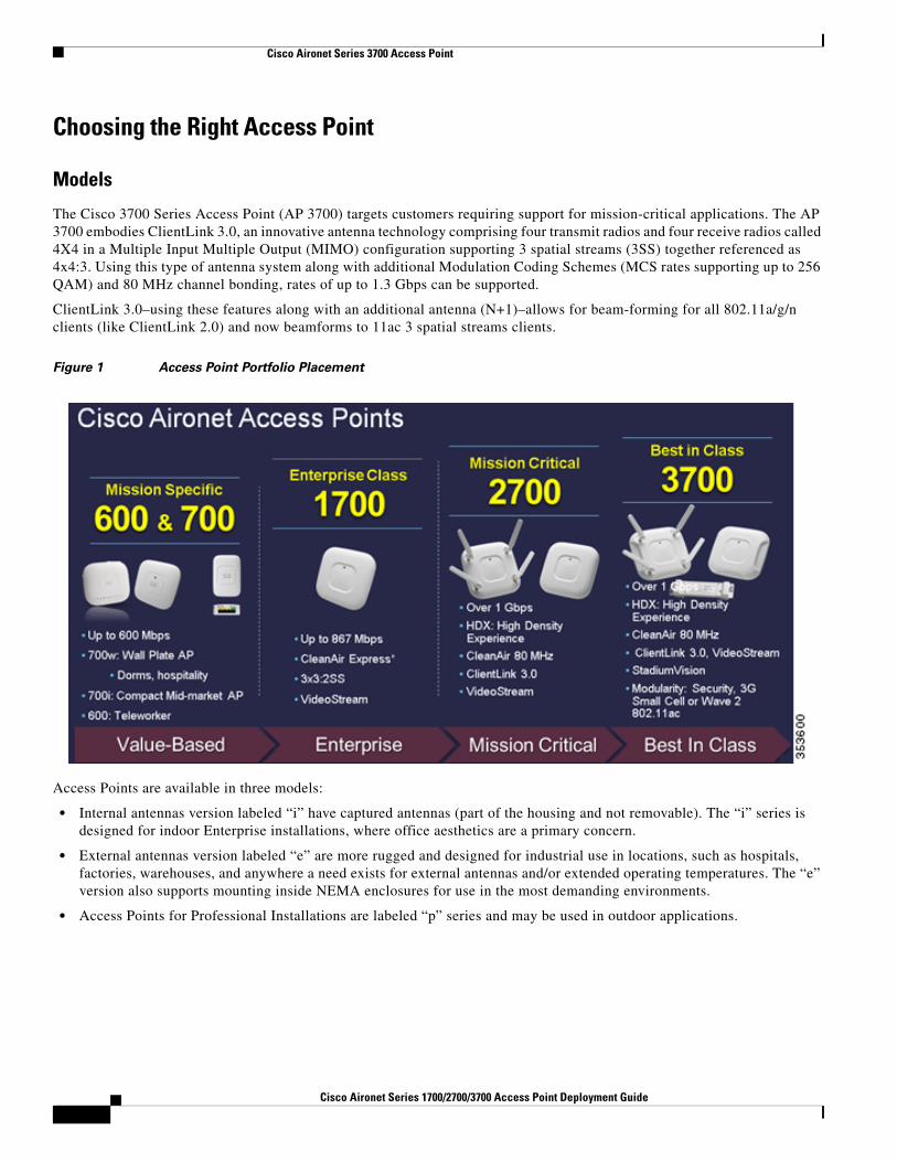
The Cisco 3700 Series Access Point (AP 3700) targets customers requiring support for mission-critical applications. The AP 3700 embodies ClientLink 3.0, an innovative antenna technology comprising four transmit radios and four receive radios called 4X4 in a Multiple Input Multiple Output (MIMO) configuration supporting 3 spatial streams (3SS) together referenced as 4x4:3. Using this type of antenna system along with additional Modulation Coding Schemes (MCS rates supporting up to 256 QAM) and 80 MHz channel bonding, rates of up to 1.3 Gbps can be supported.
ClientLink 3.0–using these features along with an additional antenna (N+1)–allows for beam-forming for all 802.11a/g/n clients (like ClientLink 2.0) and now beamforms to 11ac 3 spatial streams clients.
Figure 1 Access Point Portfolio Placement
Access Points are available in three models:
• Internal antennas version labeled “i” have captured antennas (part of the housing and not removable). The “i” series is designed for indoor Enterprise installations, where office aesthetics are a primary concern.
• External antennas version labeled “e” are more rugged and designed for industrial use in locations, such as hospitals, factories, warehouses, and anywhere a need exists for external antennas and/or extended operating temperatures. The “e” version also supports mounting inside NEMA enclosures for use in the most demanding environments.
• Access Points for Professional Installations are labeled “p” series and may be used in outdoor applications.
2Cisco Aironet Series 1700/2700/3700 Access Point Deployment Guide
Cisco Aironet Series 3700 Access Point
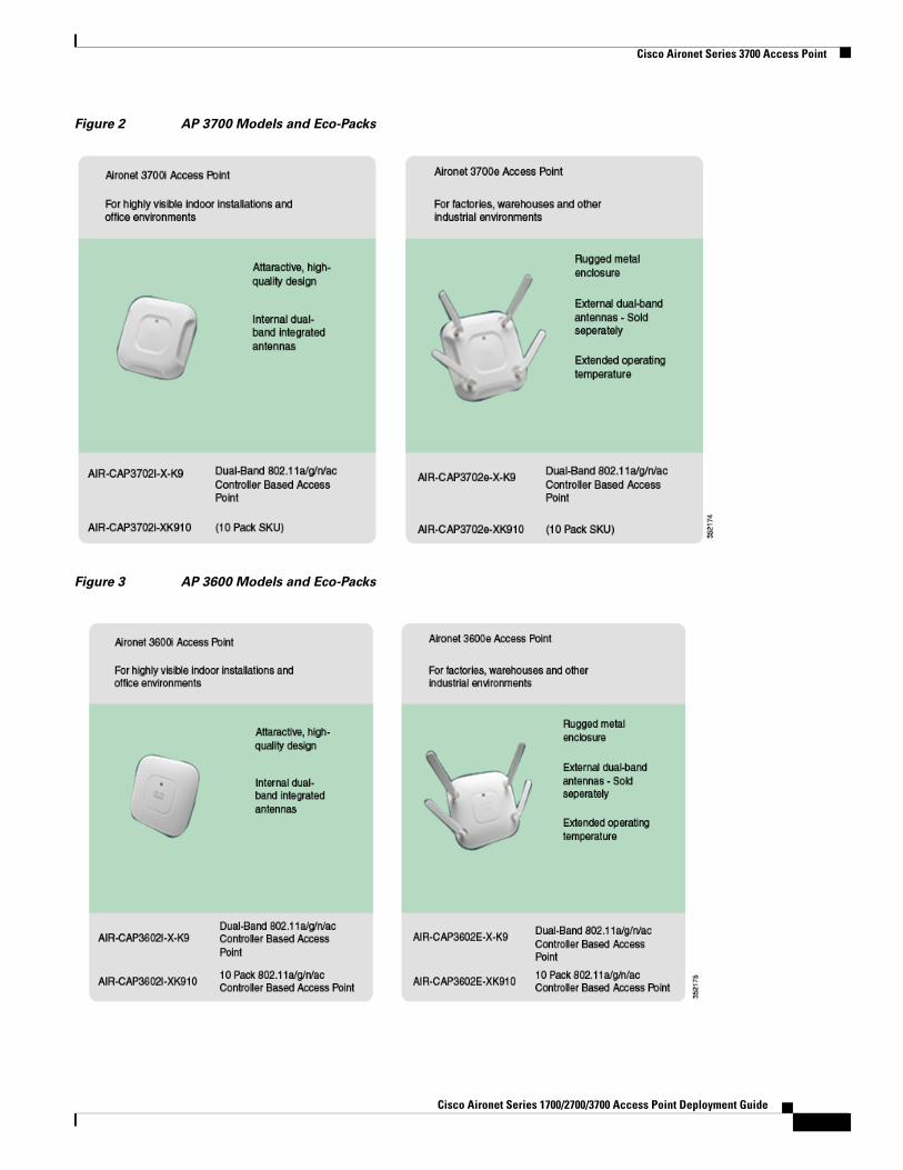
Figure 2 AP 3700 Models and Eco-Packs
Figure 3 AP 3600 Models and Eco-Packs
Cisco Aironet Series 1700/2700/3700 Access Point Deployment Guide
Cisco Aironet Series 3700 Access Point
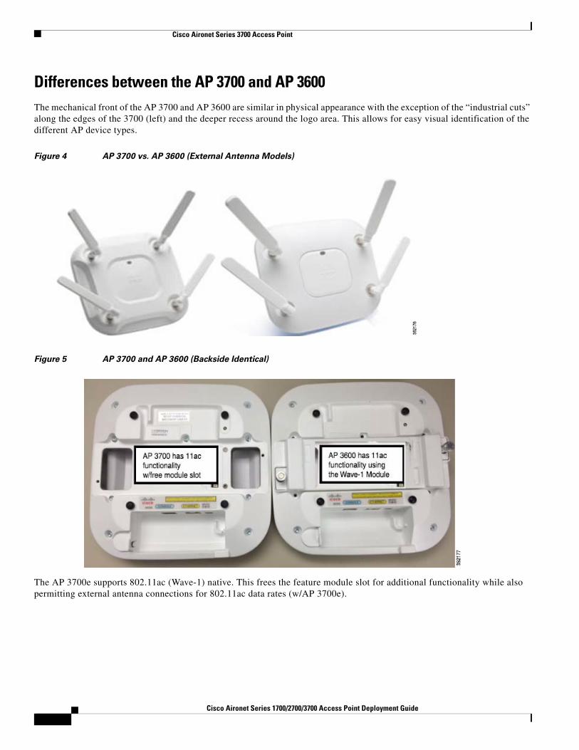
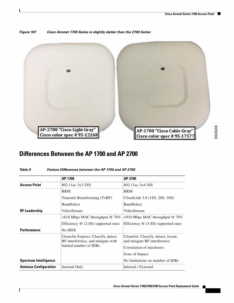
Differences between the AP 3700 and AP 3600The mechanical front of the AP 3700 and AP 3600 are similar in physical appearance with the exception of the “industrial cuts” along the edges of the 3700 (left) and the deeper recess around the logo area. This allows for easy visual identification of the different AP device types.
Figure 4 AP 3700 vs. AP 3600 (External Antenna Models)
Figure 5 AP 3700 and AP 3600 (Backside Identical)
The AP 3700e supports 802.11ac (Wave-1) native. This frees the feature module slot for additional functionality while also permitting external antenna connections for 802.11ac data rates (w/AP 3700e).
4Cisco Aironet Series 1700/2700/3700 Access Point Deployment Guide
Cisco Aironet Series 3700 Access Point
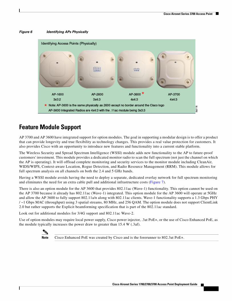
Figure 6 Identifying APs Physically
Feature Module SupportAP 3700 and AP 3600 have integrated support for option modules. The goal in supporting a modular design is to offer a product that can provide longevity and true flexibility as technology changes. This provides a real value protection for customers. It also provides Cisco with an opportunity to introduce new features and functionality into a current stable platform.
The Wireless Security and Spread Spectrum Intelligence (WSSI) module adds new functionality to the AP to future-proof customers' investment. This module provides a dedicated monitor radio to scan the full spectrum (not just the channel on which the AP is operating). It will offload complete monitoring and security services to the monitor module including CleanAir, WIDS/WIPS, Context-aware Location, Rogue Detection, and Radio Resource Management (RRM). This module allows for full spectrum analysis on all channels on both the 2.4 and 5 GHz bands.
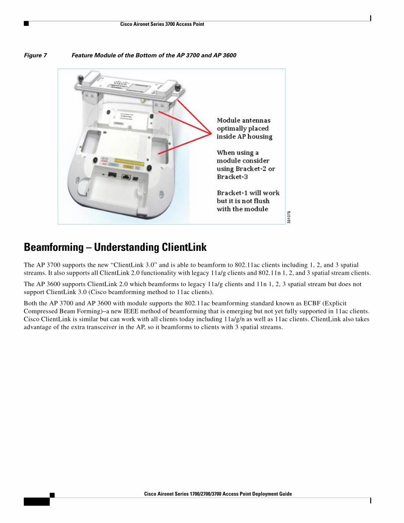
Having a WSSI module avoids having the need to deploy a separate, dedicated overlay network for full spectrum monitoring and eliminates the need for an extra cable pull and additional infrastructure costs (Figure 7).
There is also an option module for the AP 3600 that provides 802.11ac (Wave-1) functionality. This option cannot be used on the AP 3700 because it already has 802.11ac (Wave-1) integrated. This option module for the AP 3600 will operate at 5GHz and allow the AP 3600 to fully support 802.11a/n along with 802.11ac clients. Wave-1 functionality supports a 1.3 Gbps PHY / ~1 Gbps MAC (throughput) using 3 spatial streams, 80 MHz, and 256 QAM. The option module does not support ClientLink 2.0 but rather supports the Explicit beamforming specification that is part of the 802.11ac standard.
Look out for additional modules for 3/4G support and 802.11ac Wave-2.
Use of option modules may require local power supply, Cisco power injector, .3at PoE+, or the use of Cisco Enhanced PoE, as the module typically increases the power draw to greater than 15.4 W (.3af).
Note Cisco Enhanced PoE was created by Cisco and is the forerunner to 802.3at PoE+.
Cisco Aironet Series 1700/2700/3700 Access Point Deployment Guide
Cisco Aironet Series 3700 Access Point
Figure 7 Feature Module of the Bottom of the AP 3700 and AP 3600
Beamforming – Understanding ClientLinkThe AP 3700 supports the new “ClientLink 3.0” and is able to beamform to 802.11ac clients including 1, 2, and 3 spatial streams. It also supports all ClientLink 2.0 functionality with legacy 11a/g clients and 802.11n 1, 2, and 3 spatial stream clients.
The AP 3600 supports ClientLink 2.0 which beamforms to legacy 11a/g clients and 11n 1, 2, 3 spatial stream but does not support ClientLink 3.0 (Cisco beamforming method to 11ac clients).
Both the AP 3700 and AP 3600 with module supports the 802.11ac beamforming standard known as ECBF (Explicit Compressed Beam Forming)–a new IEEE method of beamforming that is emerging but not yet fully supported in 11ac clients. Cisco ClientLink is similar but can work with all clients today including 11a/g/n as well as 11ac clients. ClientLink also takes advantage of the extra transceiver in the AP, so it beamforms to clients with 3 spatial streams.
6Cisco Aironet Series 1700/2700/3700 Access Point Deployment Guide
Cisco Aironet Series 3700 Access Point
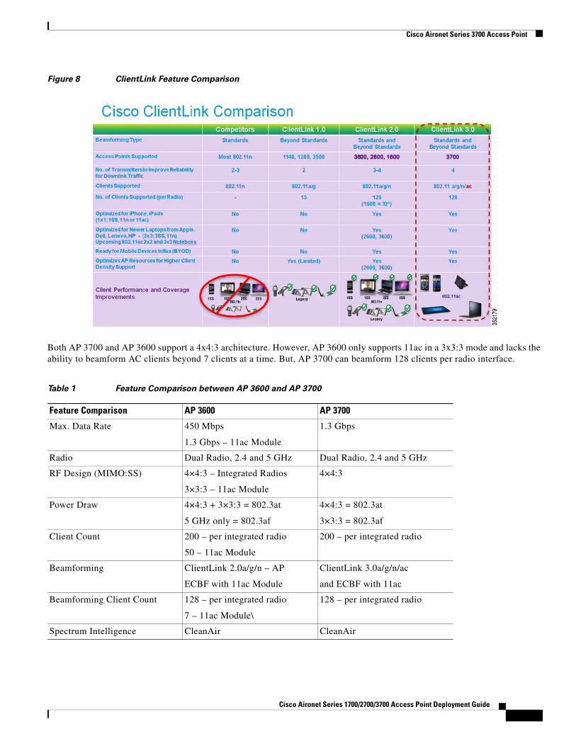
Figure 8 ClientLink Feature Comparison
Both AP 3700 and AP 3600 support a 4x4:3 architecture. However, AP 3600 only supports 11ac in a 3x3:3 mode and lacks the ability to beamform AC clients beyond 7 clients at a time. But, AP 3700 can beamform 128 clients per radio interface.
Table 1 Feature Comparison between AP 3600 and AP 3700
Feature Comparison AP 3600 AP 3700
Max. Data Rate 450 Mbps
1.3 Gbps – 11ac Module
1.3 Gbps
Radio Dual Radio, 2.4 and 5 GHz Dual Radio, 2.4 and 5 GHz
RF Design (MIMO:SS) 4×4:3 – Integrated Radios
3×3:3 – 11ac Module
4×4:3
Power Draw 4×4:3 + 3×3:3 = 802.3at
5 GHz only = 802.3af
4×4:3 = 802.3at
3×3:3 = 802.3af
Client Count 200 – per integrated radio
50 – 11ac Module
200 – per integrated radio
Beamforming ClientLink 2.0a/g/n – AP
ECBF with 11ac Module
ClientLink 3.0a/g/n/ac
and ECBF with 11ac
Beamforming Client Count 128 – per integrated radio
7 – 11ac Module\
128 – per integrated radio
Spectrum Intelligence CleanAir CleanAir
Cisco Aironet Series 1700/2700/3700 Access Point Deployment Guide
Cisco Aironet Series 3700 Access Point
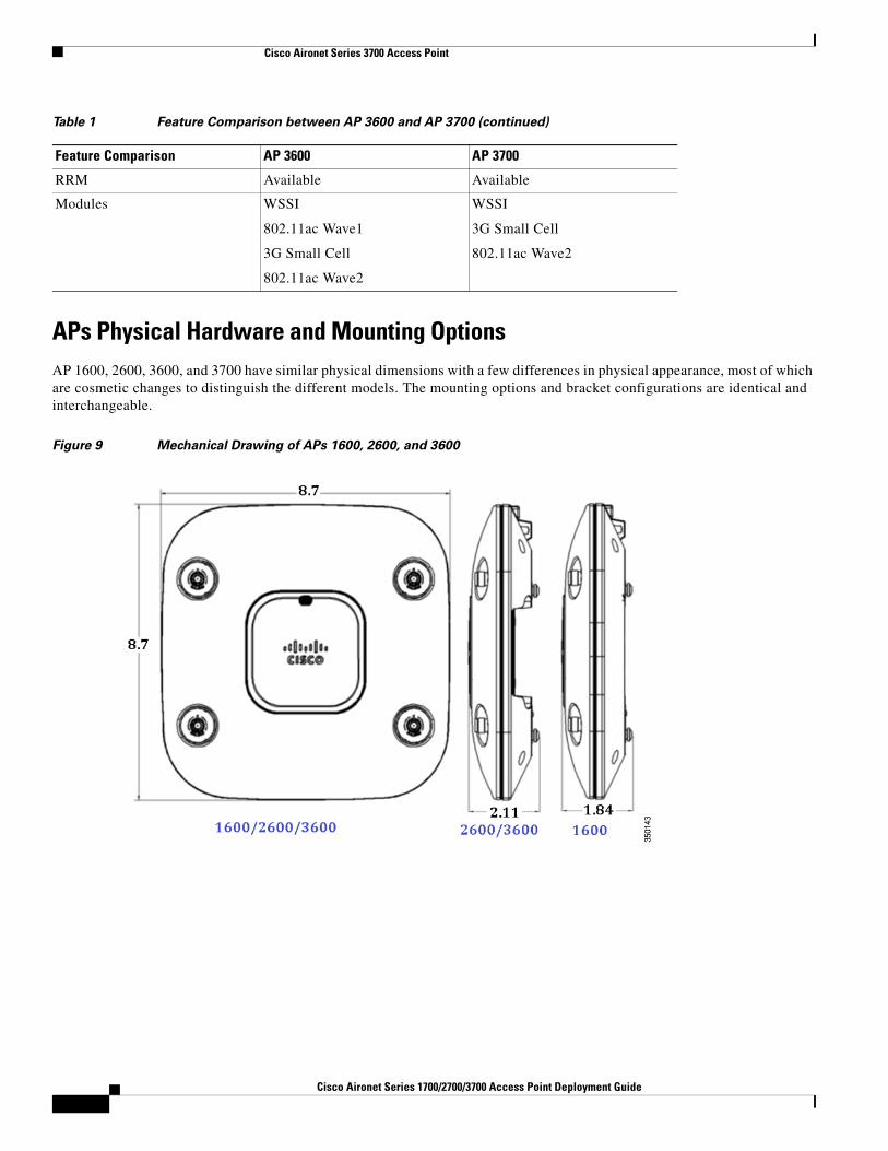
APs Physical Hardware and Mounting OptionsAP 1600, 2600, 3600, and 3700 have similar physical dimensions with a few differences in physical appearance, most of which are cosmetic changes to distinguish the different models. The mounting options and bracket configurations are identical and interchangeable.
Figure 9 Mechanical Drawing of APs 1600, 2600, and 3600
RRM Available Available
Modules WSSI
802.11ac Wave1
3G Small Cell
802.11ac Wave2
WSSI
3G Small Cell
802.11ac Wave2
Table 1 Feature Comparison between AP 3600 and AP 3700 (continued)
Feature Comparison AP 3600 AP 3700
8Cisco Aironet Series 1700/2700/3700 Access Point Deployment Guide
Cisco Aironet Series 3700 Access Point
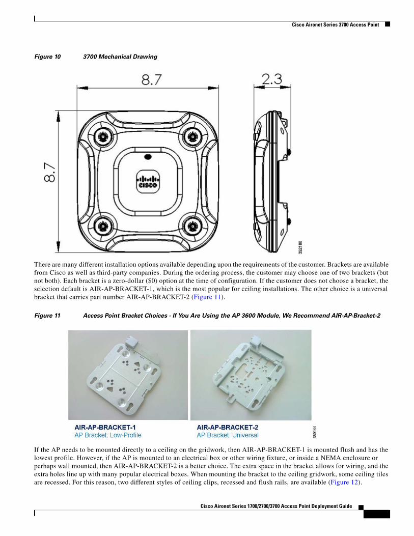
Figure 10 3700 Mechanical Drawing
There are many different installation options available depending upon the requirements of the customer. Brackets are available from Cisco as well as third-party companies. During the ordering process, the customer may choose one of two brackets (but not both). Each bracket is a zero-dollar ($0) option at the time of configuration. If the customer does not choose a bracket, the selection default is AIR-AP-BRACKET-1, which is the most popular for ceiling installations. The other choice is a universal bracket that carries part number AIR-AP-BRACKET-2 (Figure 11).
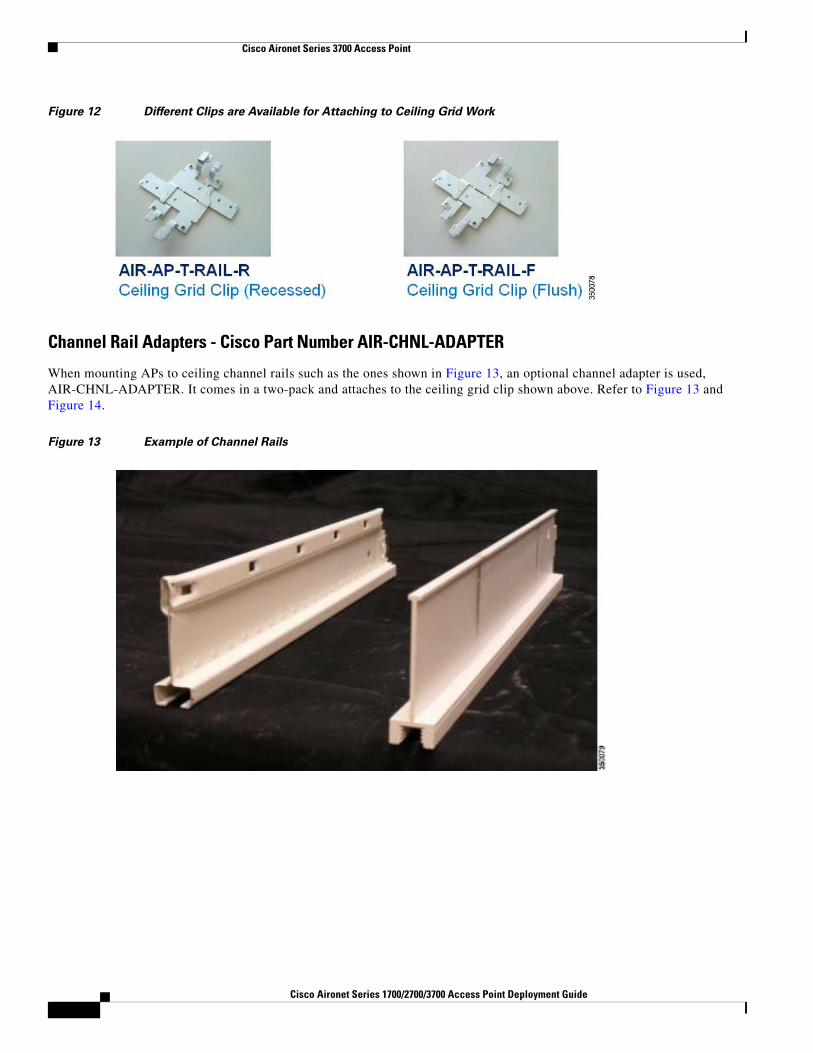
Figure 11 Access Point Bracket Choices - If You Are Using the AP 3600 Module, We Recommend AIR-AP-Bracket-2
If the AP needs to be mounted directly to a ceiling on the gridwork, then AIR-AP-BRACKET-1 is mounted flush and has the lowest profile. However, if the AP is mounted to an electrical box or other wiring fixture, or inside a NEMA enclosure or perhaps wall mounted, then AIR-AP-BRACKET-2 is a better choice. The extra space in the bracket allows for wiring, and the extra holes line up with many popular electrical boxes. When mounting the bracket to the ceiling gridwork, some ceiling tiles are recessed. For this reason, two different styles of ceiling clips, recessed and flush rails, are available (Figure 12).
Cisco Aironet Series 1700/2700/3700 Access Point Deployment Guide
Cisco Aironet Series 3700 Access Point
Figure 12 Different Clips are Available for Attaching to Ceiling Grid Work
Channel Rail Adapters - Cisco Part Number AIR-CHNL-ADAPTER
When mounting APs to ceiling channel rails such as the ones shown in Figure 13, an optional channel adapter is used, AIR-CHNL-ADAPTER. It comes in a two-pack and attaches to the ceiling grid clip shown above. Refer to Figure 13 and Figure 14.
Figure 13 Example of Channel Rails
1Cisco Aironet Series 1700/2700/3700 Access Point Deployment Guide
Cisco Aironet Series 3700 Access Point
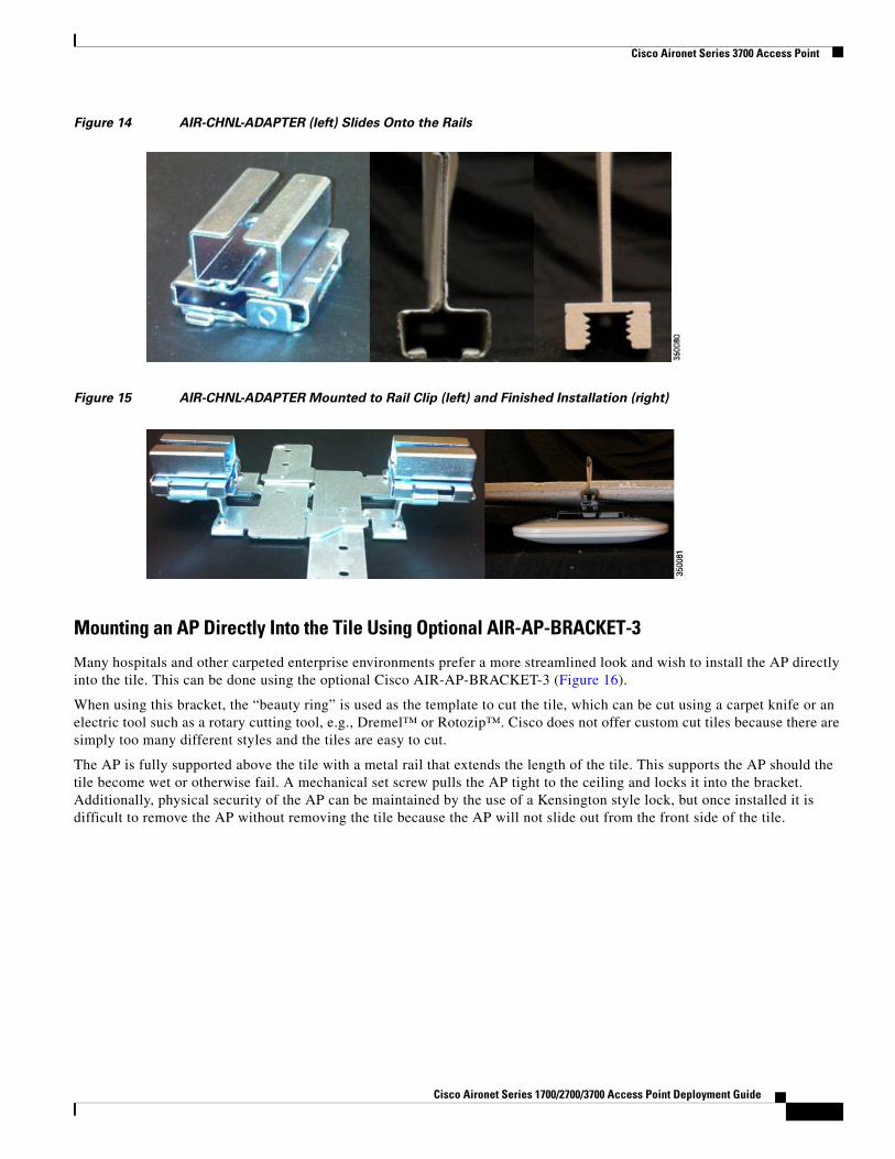
Figure 14 AIR-CHNL-ADAPTER (left) Slides Onto the Rails
Figure 15 AIR-CHNL-ADAPTER Mounted to Rail Clip (left) and Finished Installation (right)
Mounting an AP Directly Into the Tile Using Optional AIR-AP-BRACKET-3
Many hospitals and other carpeted enterprise environments prefer a more streamlined look and wish to install the AP directly into the tile. This can be done using the optional Cisco AIR-AP-BRACKET-3 (Figure 16).
When using this bracket, the “beauty ring” is used as the template to cut the tile, which can be cut using a carpet knife or an electric tool such as a rotary cutting tool, e.g., Dremel™ or Rotozip™. Cisco does not offer custom cut tiles because there are simply too many different styles and the tiles are easy to cut.
The AP is fully supported above the tile with a metal rail that extends the length of the tile. This supports the AP should the tile become wet or otherwise fail. A mechanical set screw pulls the AP tight to the ceiling and locks it into the bracket. Additionally, physical security of the AP can be maintained by the use of a Kensington style lock, but once installed it is difficult to remove the AP without removing the tile because the AP will not slide out from the front side of the tile.
Cisco Aironet Series 1700/2700/3700 Access Point Deployment Guide
Cisco Aironet Series 3700 Access Point
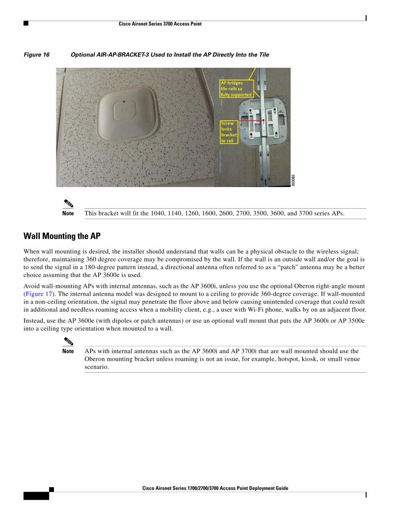
Figure 16 Optional AIR-AP-BRACKET-3 Used to Install the AP Directly Into the Tile
Note This bracket will fit the 1040, 1140, 1260, 1600, 2600, 2700, 3500, 3600, and 3700 series APs.
Wall Mounting the AP
When wall mounting is desired, the installer should understand that walls can be a physical obstacle to the wireless signal; therefore, maintaining 360 degree coverage may be compromised by the wall. If the wall is an outside wall and/or the goal is to send the signal in a 180-degree pattern instead, a directional antenna often referred to as a “patch” antenna may be a better choice assuming that the AP 3600e is used.
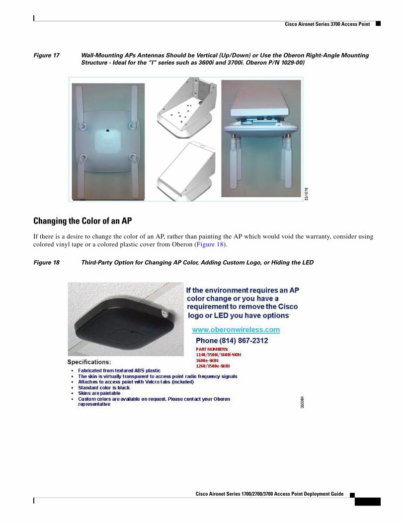
Avoid wall-mounting APs with internal antennas, such as the AP 3600i, unless you use the optional Oberon right-angle mount (Figure 17). The internal antenna model was designed to mount to a ceiling to provide 360-degree coverage. If wall-mounted in a non-ceiling orientation, the signal may penetrate the floor above and below causing unintended coverage that could result in additional and needless roaming access when a mobility client, e.g., a user with Wi-Fi phone, walks by on an adjacent floor.
Instead, use the AP 3600e (with dipoles or patch antennas) or use an optional wall mount that puts the AP 3600i or AP 3500e into a ceiling type orientation when mounted to a wall.
Note APs with internal antennas such as the AP 3600i and AP 3700i that are wall mounted should use the Oberon mounting bracket unless roaming is not an issue, for example, hotspot, kiosk, or small venue scenario.
1Cisco Aironet Series 1700/2700/3700 Access Point Deployment Guide
Cisco Aironet Series 3700 Access Point
Figure 17 Wall-Mounting APs Antennas Should be Vertical (Up/Down) or Use the Oberon Right-Angle Mounting
Structure - Ideal for the “I” series such as 3600i and 3700i. Oberon P/N 1029-00)
Changing the Color of an AP
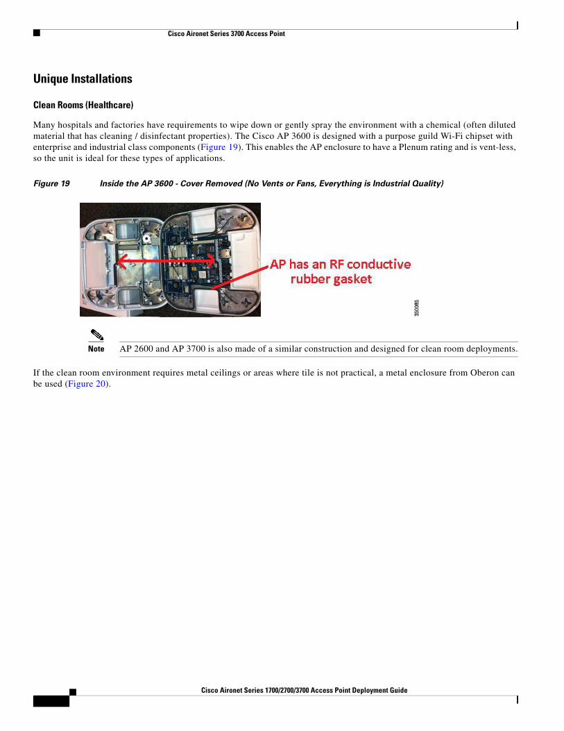
If there is a desire to change the color of an AP, rather than painting the AP which would void the warranty, consider using colored vinyl tape or a colored plastic cover from Oberon (Figure 18).
Figure 18 Third-Party Option for Changing AP Color, Adding Custom Logo, or Hiding the LED
Cisco Aironet Series 1700/2700/3700 Access Point Deployment Guide
Cisco Aironet Series 3700 Access Point
Unique Installations
Clean Rooms (Healthcare)
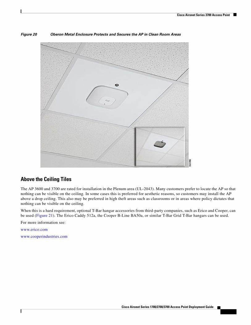
Many hospitals and factories have requirements to wipe down or gently spray the environment with a chemical (often diluted material that has cleaning / disinfectant properties). The Cisco AP 3600 is designed with a purpose guild Wi-Fi chipset with enterprise and industrial class components (Figure 19). This enables the AP enclosure to have a Plenum rating and is vent-less, so the unit is ideal for these types of applications.
Figure 19 Inside the AP 3600 - Cover Removed (No Vents or Fans, Everything is Industrial Quality)
Note AP 2600 and AP 3700 is also made of a similar construction and designed for clean room deployments.
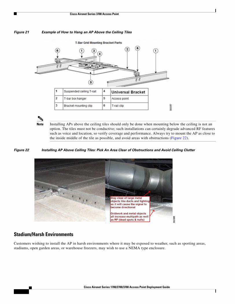
If the clean room environment requires metal ceilings or areas where tile is not practical, a metal enclosure from Oberon can be used (Figure 20).
1Cisco Aironet Series 1700/2700/3700 Access Point Deployment Guide
Cisco Aironet Series 3700 Access Point
Figure 20 Oberon Metal Enclosure Protects and Secures the AP in Clean Room Areas
Above the Ceiling Tiles
The AP 3600 and 3700 are rated for installation in the Plenum area (UL-2043). Many customers prefer to locate the AP so that nothing can be visible on the ceiling. In some cases this is preferred for aesthetic reasons, so customers may install the AP above a drop ceiling. This also may be preferred in high theft areas such as classrooms or in areas where policy dictates that nothing can be visible on the ceiling.
When this is a hard requirement, optional T-Bar hangar accessories from third-party companies, such as Erico and Cooper, can be used (Figure 21). The Erico Caddy 512a, the Cooper B-Line BA50a, or similar T-Bar Grid T-Bar hangars can be used.
For more information see:
www.erico.com
www.cooperindustries.com
Cisco Aironet Series 1700/2700/3700 Access Point Deployment Guide
Figure 21 Example of How to Hang an AP Above the Ceiling Tiles
Note Installing APs above the ceiling tiles should only be done when mounting below the ceiling is not an option. The tiles must not be conductive; such installations can certainly degrade advanced RF features such as voice and location, so verify coverage and performance. Always try to mount the AP as close to the inside middle of the tile as possible, and avoid areas with obstructions (Figure 22).
Figure 22 Installing AP Above Ceiling Tiles: Pick An Area Clear of Obstructions and Avoid Ceiling Clutter
Stadium/Harsh Environments
Customers wishing to install the AP in harsh environments where it may be exposed to weather, such as sporting areas, stadiums, open garden areas, or warehouse freezers, may wish to use a NEMA type enclosure.
1Cisco Aironet Series 1700/2700/3700 Access Point Deployment Guide
Cisco Aironet Series 3700 Access Point
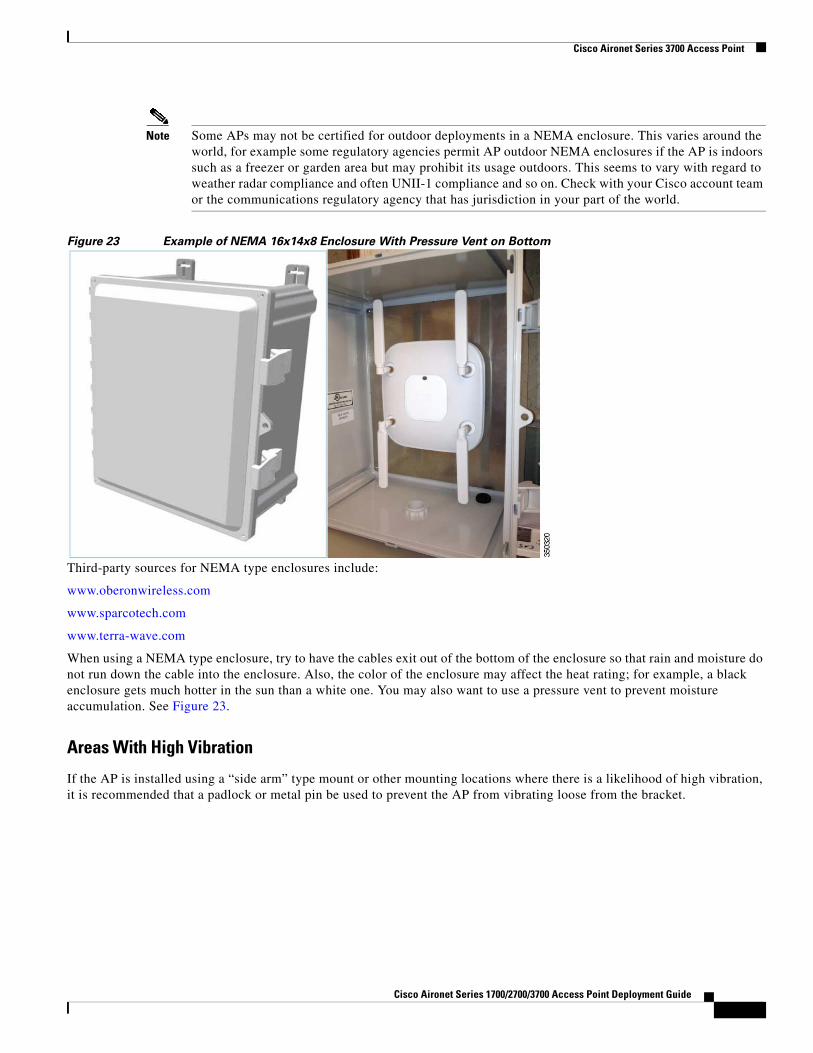
Note Some APs may not be certified for outdoor deployments in a NEMA enclosure. This varies around the world, for example some regulatory agencies permit AP outdoor NEMA enclosures if the AP is indoors such as a freezer or garden area but may prohibit its usage outdoors. This seems to vary with regard to weather radar compliance and often UNII-1 compliance and so on. Check with your Cisco account team or the communications regulatory agency that has jurisdiction in your part of the world.
Figure 23 Example of NEMA 16x14x8 Enclosure With Pressure Vent on Bottom
Third-party sources for NEMA type enclosures include:
www.oberonwireless.com
www.sparcotech.com
www.terra-wave.com
When using a NEMA type enclosure, try to have the cables exit out of the bottom of the enclosure so that rain and moisture do not run down the cable into the enclosure. Also, the color of the enclosure may affect the heat rating; for example, a black enclosure gets much hotter in the sun than a white one. You may also want to use a pressure vent to prevent moisture accumulation. See Figure 23.
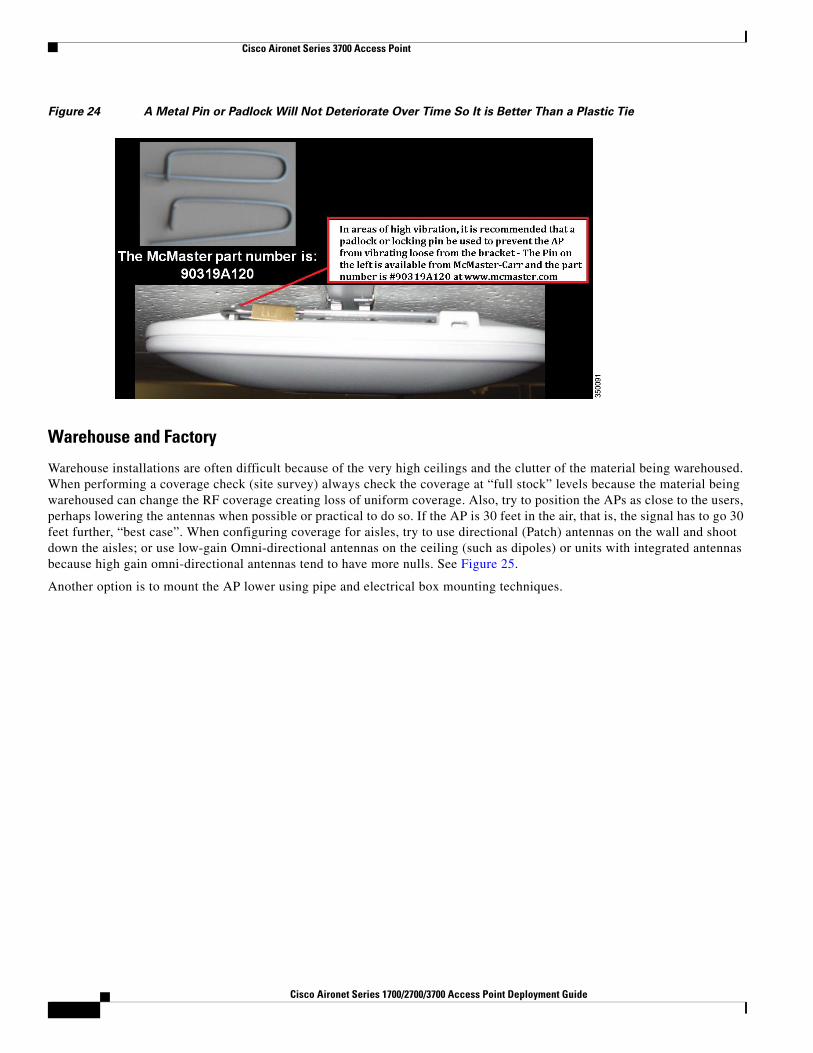
Areas With High Vibration
If the AP is installed using a “side arm” type mount or other mounting locations where there is a likelihood of high vibration, it is recommended that a padlock or metal pin be used to prevent the AP from vibrating loose from the bracket.
Cisco Aironet Series 1700/2700/3700 Access Point Deployment Guide
Figure 24 A Metal Pin or Padlock Will Not Deteriorate Over Time So It is Better Than a Plastic Tie
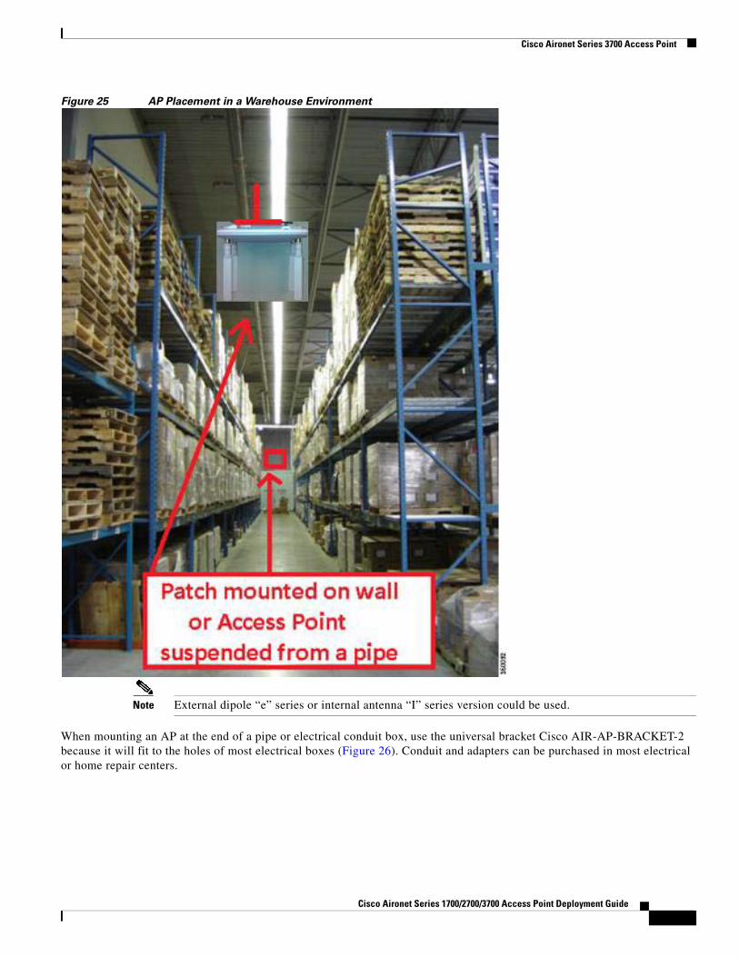
Warehouse and Factory
Warehouse installations are often difficult because of the very high ceilings and the clutter of the material being warehoused. When performing a coverage check (site survey) always check the coverage at “full stock” levels because the material being warehoused can change the RF coverage creating loss of uniform coverage. Also, try to position the APs as close to the users, perhaps lowering the antennas when possible or practical to do so. If the AP is 30 feet in the air, that is, the signal has to go 30 feet further, “best case”. When configuring coverage for aisles, try to use directional (Patch) antennas on the wall and shoot down the aisles; or use low-gain Omni-directional antennas on the ceiling (such as dipoles) or units with integrated antennas because high gain omni-directional antennas tend to have more nulls. See Figure 25.
Another option is to mount the AP lower using pipe and electrical box mounting techniques.
1Cisco Aironet Series 1700/2700/3700 Access Point Deployment Guide
Cisco Aironet Series 3700 Access Point
Figure 25 AP Placement in a Warehouse Environment
Note External dipole “e” series or internal antenna “I” series version could be used.
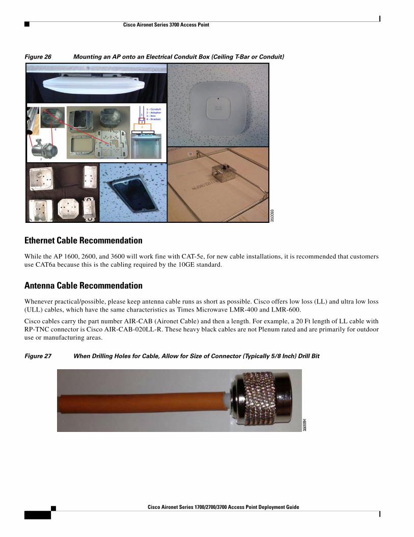
When mounting an AP at the end of a pipe or electrical conduit box, use the universal bracket Cisco AIR-AP-BRACKET-2 because it will fit to the holes of most electrical boxes (Figure 26). Conduit and adapters can be purchased in most electrical or home repair centers.
Cisco Aironet Series 1700/2700/3700 Access Point Deployment Guide
Cisco Aironet Series 3700 Access Point
Figure 26 Mounting an AP onto an Electrical Conduit Box (Ceiling T-Bar or Conduit)
Ethernet Cable Recommendation
While the AP 1600, 2600, and 3600 will work fine with CAT-5e, for new cable installations, it is recommended that customers use CAT6a because this is the cabling required by the 10GE standard.
Antenna Cable Recommendation
Whenever practical/possible, please keep antenna cable runs as short as possible. Cisco offers low loss (LL) and ultra low loss (ULL) cables, which have the same characteristics as Times Microwave LMR-400 and LMR-600.
Cisco cables carry the part number AIR-CAB (Aironet Cable) and then a length. For example, a 20 Ft length of LL cable with RP-TNC connector is Cisco AIR-CAB-020LL-R. These heavy black cables are not Plenum rated and are primarily for outdoor use or manufacturing areas.
Figure 27 When Drilling Holes for Cable, Allow for Size of Connector (Typically 5/8 Inch) Drill Bit
2Cisco Aironet Series 1700/2700/3700 Access Point Deployment Guide
Cisco Aironet Series 3700 Access Point
Access Point Spacing Recommendations
If you have a Wi-Fi device such as an AP and you are going to use another AP in the vicinity on a different channel, it is recommended that you space each AP apart by approximately 6 Ft (2 meters). Avoid clustering the APs or the antennas from different APs together because this could cause degradation in performance. This recommended distance is based on the assumption that both devices operate in the unlicensed band and do not transmit RF energy more than 23 dB–that is, 200 mW. If higher power is used, space the APs farther apart.
Should you have other devices that transmit, especially if they operate in the same frequency ranges, for example, frequency hopping legacy APs or other devices that operate close in frequency to those of the AP (think below or above the 2.4 and 5 GHz band), you should consider moving or separating the devices as far apart as can reasonably be done. After you have done this, check for interference by testing both devices at the same time under heavy utilization (load) and then characterize each system independently to see how much, if any, degradation exists.
Warning In order to comply with FCC, EU, and EFTA RF exposure limits, antennas should be located at a minimum of 7.9 inches (20 cm) or more from the body of all persons. See the installation guide under declaration of conformity for more on this.
Installations in IDF Closets (Telecommunications or Other Electrical Equipment)
When installing APs near other electrical or telecommunications equipment, keep all wiring and metal away from the antennas and avoid placing the antennas near electrical lines. Do not route wiring electrical or Ethernet in the near field (6-15 inches) from the antenna. Try to refrain from installing the AP in the electrical closet because the best place for the AP is as close to users as possible/practical. If you have remote antenna cables from such a closet, you may be required to use Plenum rated cable (see local fire/safety regulations for more on this).
Below are a few URLs for understanding interference:
While not defined in the specification sheet for the AP 3600 and AP 3700, these APs passed functional checks after a Non-Operational altitude test of 25C @ 15,000 Ft was performed. Additionally, they fully passed a functional test during an operational altitude test of 40C @ 9,843 Ft.
All units in the test group were connected to at least one WLAN client and monitored for continual operation passing traffic, while performing constant ping testing throughout the operational altitude test.
Installations Using a Common or Distributed Antenna System (DAS)
Due to the dual-band nature of the antenna system on the AP 3700 and AP 3600, along with key features such as ClientLink beamforming, it is not recommended for deployments on DAS.
Customers wishing to integrate a Wi-Fi over DAS solution should understand that Cisco does not certify, endorse, or provide RF support for Wi-Fi deployments over any DAS.
The DAS vendor and/or systems integrator is solely responsible for the support of the DAS products. The DAS vendor and/or systems integrator also provides adequate RF coverage and supports any RF related issues. This support includes, but is not exclusive to location accuracy, RF coverage, roaming issues related to RF, multipath issues, and scalability.
Cisco Aironet Series 1700/2700/3700 Access Point Deployment Guide
Additionally, the DAS vendor and/or systems integrator is responsible for understanding that the deployed DAS system meets the requirements of all of the customer's Wi-Fi devices and applications over the DAS system; this statement includes, but is not exclusive to, all Voice over WLAN (VoWLAN) and medical devices.
While Cisco Technical Assistance Center (TAC) and Cisco field teams do not provide support for RF issues that arise in a Cisco WLAN used over a DAS, they provide support for non-RF related issues in Cisco products as per the customer's support agreement with Cisco Systems.
Elevator coverage can sometimes be accomplished by placing APs in the near field of an elevator, typically on each floor near the elevator door. Because elevators often have metal doors and the shafts are often concrete or contain other materials that degrade Wi-Fi coverage, it is important to check the coverage inside the elevator. While such coverage can be challenging it is often do-able, especially if the elevator is only a few floors.
High rise elevators are more challenging because roaming issues are problematic; the client is cycling through a large number of APs rather quickly. Some companies that do in-elevator advertising put a patch antenna on the floor inside the shaft and a patch antenna on the bottom of the elevator car, while other companies use leaky coaxial cable running on the side of the shaft.
When installing any Wi-Fi equipment inside the elevator cars or shafts, local regulations need to be followed because many times such installations are prohibited either for safety reasons or because the building owner or local fire department may prohibit the same. Also, it is dangerous and only elevator repair persons or contractors who have experience with this kind of work should be in those areas.
External Antenna Options and Patterns
For Use with 1600/2600/3600 and 3700e APs
The following antennas are available for use with APs 1600e*/2600e and 3600e:
AIR-ANT2524V4C-R – Dual-band Omni-directional (1 required) – 2/4 dBi Ceiling mount Omni use
AIR-ANT2544V4M-R– Dual-band Omni-directional (1 required) – 4/4 dBi Wall mount Omni use
AIR-ANT2566P4W-R– Dual band directional (1 required) – 6 dBi Patch wall mount use
Note These are all dual-band, dual-resonant antennas. Do not use single-band antennas on this product unless you choose to disable the other radio band within the AP. Also, in the case of the AP 1600 only three dipole antennas are required (not 4). If using the ceiling, wall, or patch mount, simply leave the 4th antenna lead unused.
2Cisco Aironet Series 1700/2700/3700 Access Point Deployment Guide
In the U.S., installers who wish to deploy APs outdoors are recommended to use the “P” series products. The following antennas may be used with the AP 3600p and AP 3700p series.
AIR-ANT2524V4C-R – Dual-band Omni-directional (1 required) – 2/4 dBi Ceiling mount Omni use
AIR-ANT2544V4M-R– Dual-band Omni-directional (1 required) – 4/4 dBi Wall mount Omni use
AIR-ANT2566P4W-R– Dual band directional (1 required) – 6 dBi Patch wall mount use
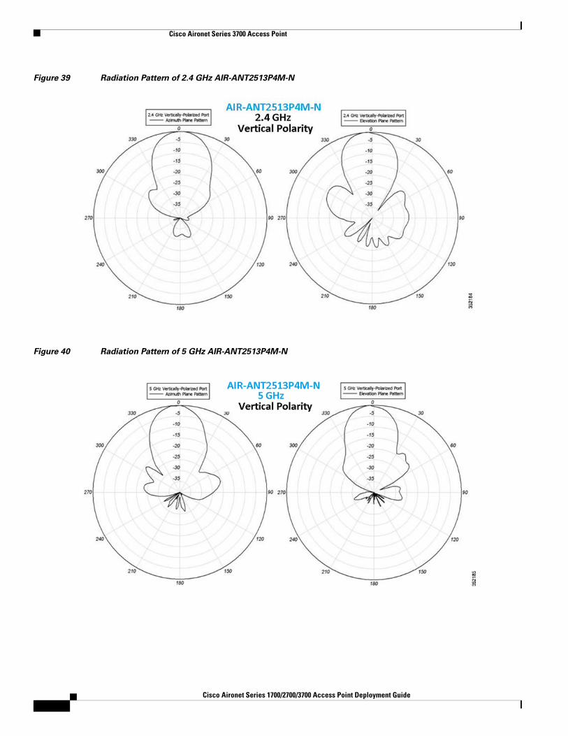
Additionally, the AP 3700p has FCC approval for outdoor use with a higher gain antenna used for Stadium applications. Cisco AIR-ANT2513P4M-N is a Dual-band 13 dBi Patch antenna with “N” style connectors.
Note Cable assembly: RP-TNC to N (AIR-CAB005LL-R-N) may be required depending on installation.
For additional information on Cisco antennas, refer Cisco Aironet Antennas and Accessories Reference Guide.
The antenna reference guide will have details of all Cisco antennas; you can also find individual datasheets at this URL: http://www.cisco.com/en/US/products/hw/wireless/ps469/index.html.
Note Always use Cisco antennas whenever possible – refer to the following URL: http://www.cisco.com/en/US/prod/collateral/wireless/ps5678/ps10981/white_paper_c11-671769.pdf
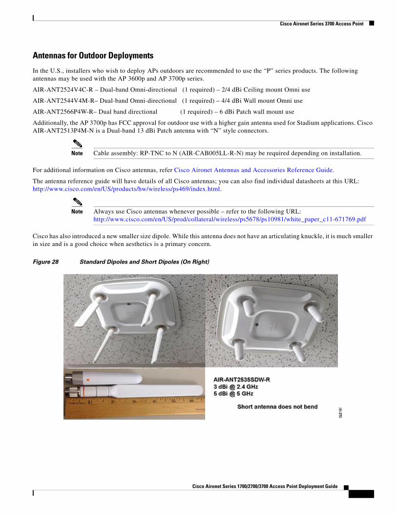
Cisco has also introduced a new smaller size dipole. While this antenna does not have an articulating knuckle, it is much smaller in size and is a good choice when aesthetics is a primary concern.
Figure 28 Standard Dipoles and Short Dipoles (On Right)
Cisco Aironet Series 1700/2700/3700 Access Point Deployment Guide
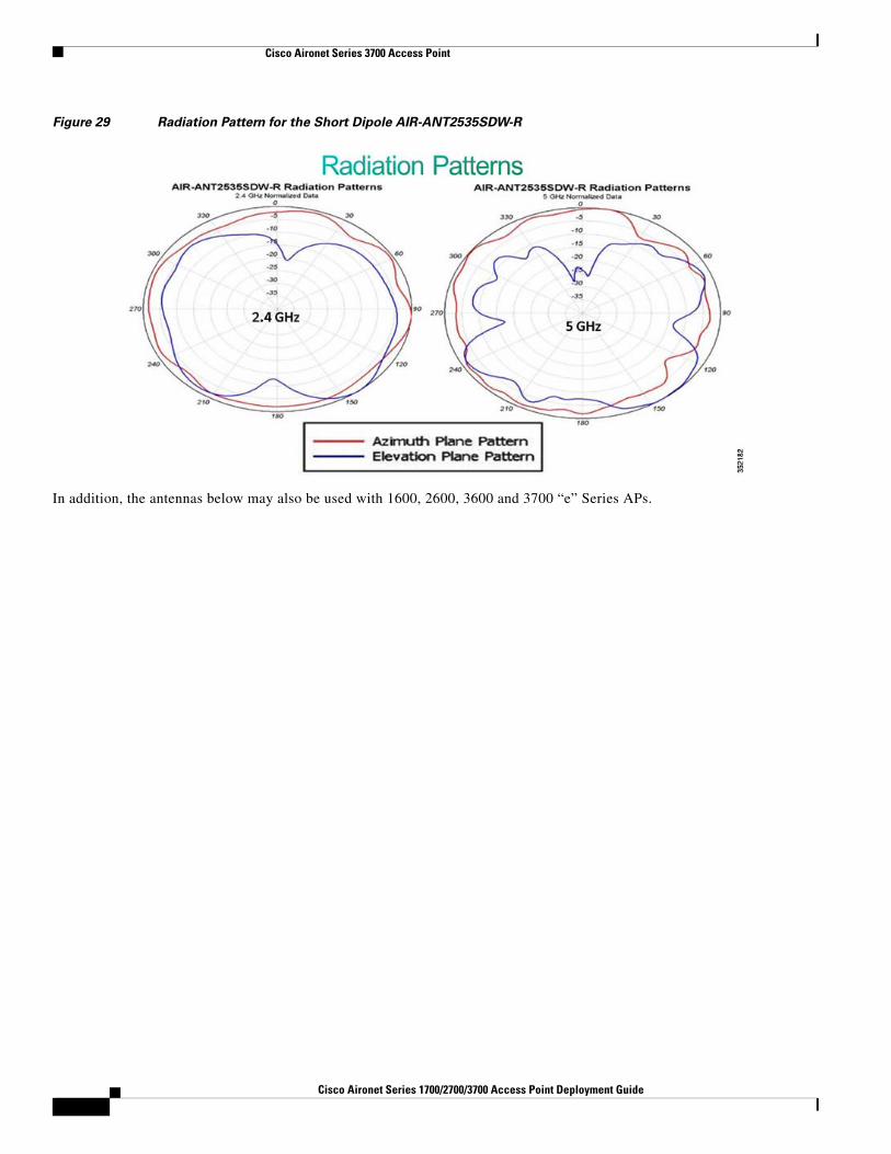
Figure 29 Radiation Pattern for the Short Dipole AIR-ANT2535SDW-R
In addition, the antennas below may also be used with 1600, 2600, 3600 and 3700 “e” Series APs.
2Cisco Aironet Series 1700/2700/3700 Access Point Deployment Guide
Cisco Aironet Series 3700 Access Point
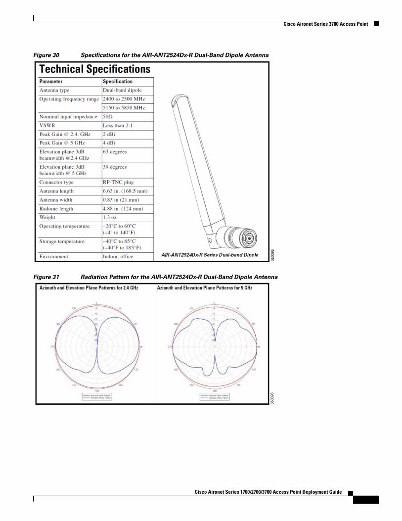
Figure 30 Specifications for the AIR-ANT2524Dx-R Dual-Band Dipole Antenna
Figure 31 Radiation Pattern for the AIR-ANT2524Dx-R Dual-Band Dipole Antenna
Cisco Aironet Series 1700/2700/3700 Access Point Deployment Guide
Cisco Aironet Series 3700 Access Point
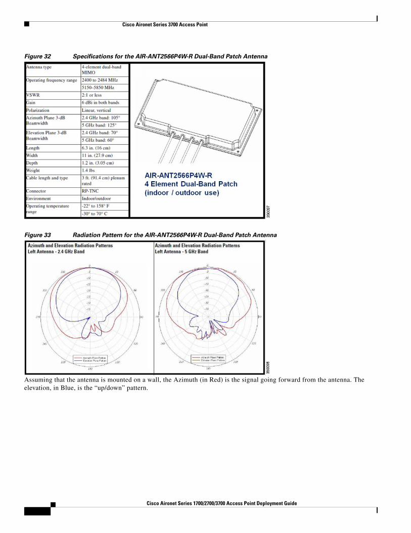
Figure 32 Specifications for the AIR-ANT2566P4W-R Dual-Band Patch Antenna
Figure 33 Radiation Pattern for the AIR-ANT2566P4W-R Dual-Band Patch Antenna
Assuming that the antenna is mounted on a wall, the Azimuth (in Red) is the signal going forward from the antenna. The elevation, in Blue, is the “up/down” pattern.
2Cisco Aironet Series 1700/2700/3700 Access Point Deployment Guide
Cisco Aironet Series 3700 Access Point
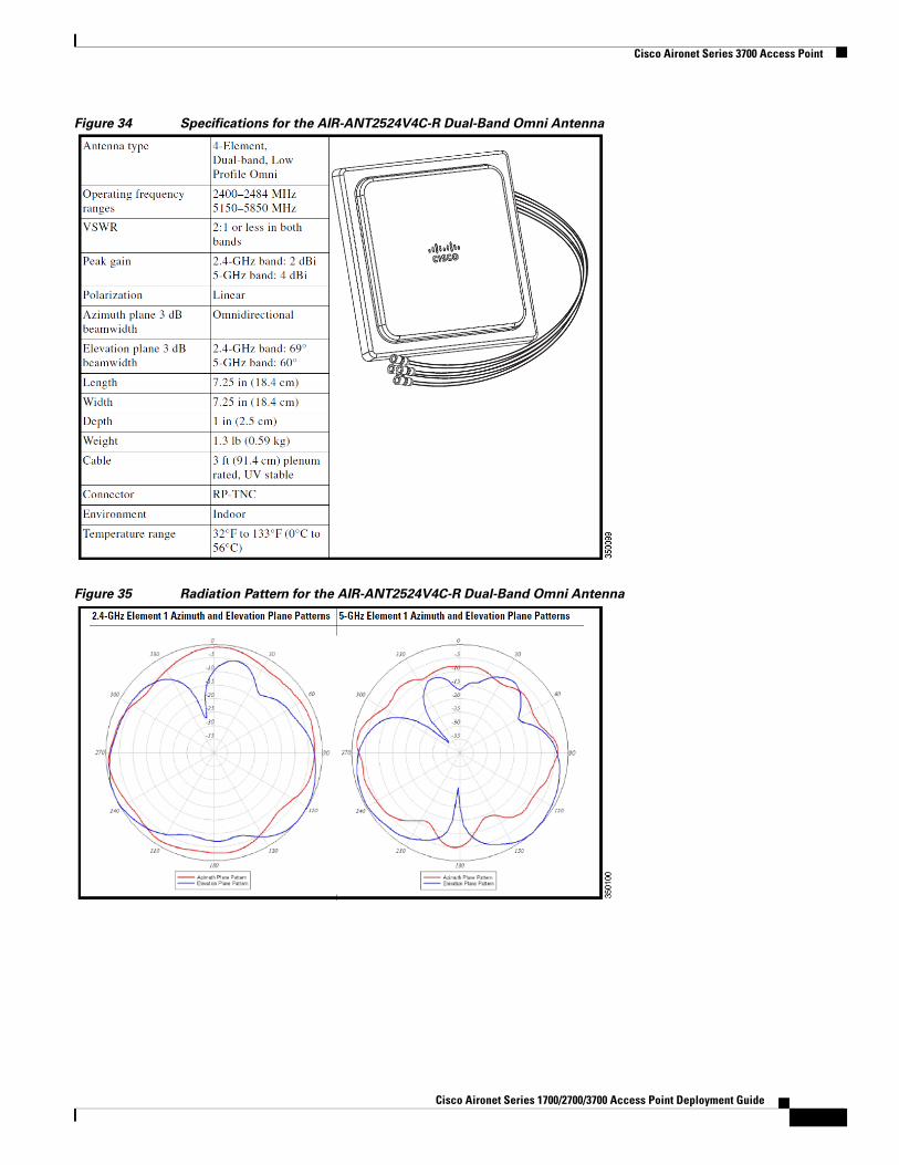
Figure 34 Specifications for the AIR-ANT2524V4C-R Dual-Band Omni Antenna
Figure 35 Radiation Pattern for the AIR-ANT2524V4C-R Dual-Band Omni Antenna
Cisco Aironet Series 1700/2700/3700 Access Point Deployment Guide
Cisco Aironet Series 3700 Access Point
Figure 36 Specifications for the AIR-ANT2544V4M-R Dual-Band Omni Antenna
Figure 37 Radiation Patterns for the AIR-ANT2544V4M-R Dual-Band Omni Antenna
Note For granular pattern, refer to the individual specification sheet of the respective antennas.
Stadium Antenna Option for AP 3702p
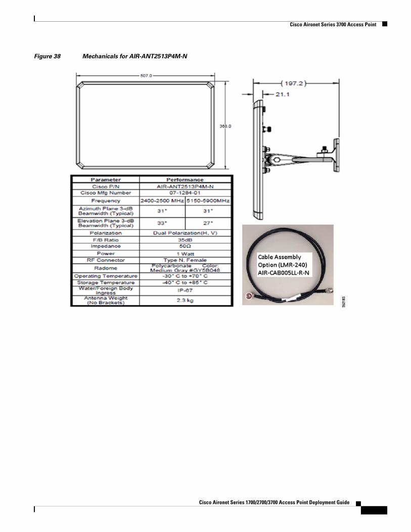
This antenna is often used by professional installation for outdoor deployments often requiring higher gain. This antenna has 2 vertically polarized and 2 horizontally polarized ports. Antenna connectors on the back of the antenna are “N” style female RF connectors. An optional cable assembly (4 cables) can be ordered–part number AIR-CAB005LL-R-N or the installers can use their own cable assemblies.
2Cisco Aironet Series 1700/2700/3700 Access Point Deployment Guide
Cisco Aironet Series 3700 Access Point
Figure 38 Mechanicals for AIR-ANT2513P4M-N
Cisco Aironet Series 1700/2700/3700 Access Point Deployment Guide
Cisco Aironet Series 3700 Access Point
Figure 39 Radiation Pattern of 2.4 GHz AIR-ANT2513P4M-N
Figure 40 Radiation Pattern of 5 GHz AIR-ANT2513P4M-N
3Cisco Aironet Series 1700/2700/3700 Access Point Deployment Guide
Cisco Aironet Series 3700 Access Point
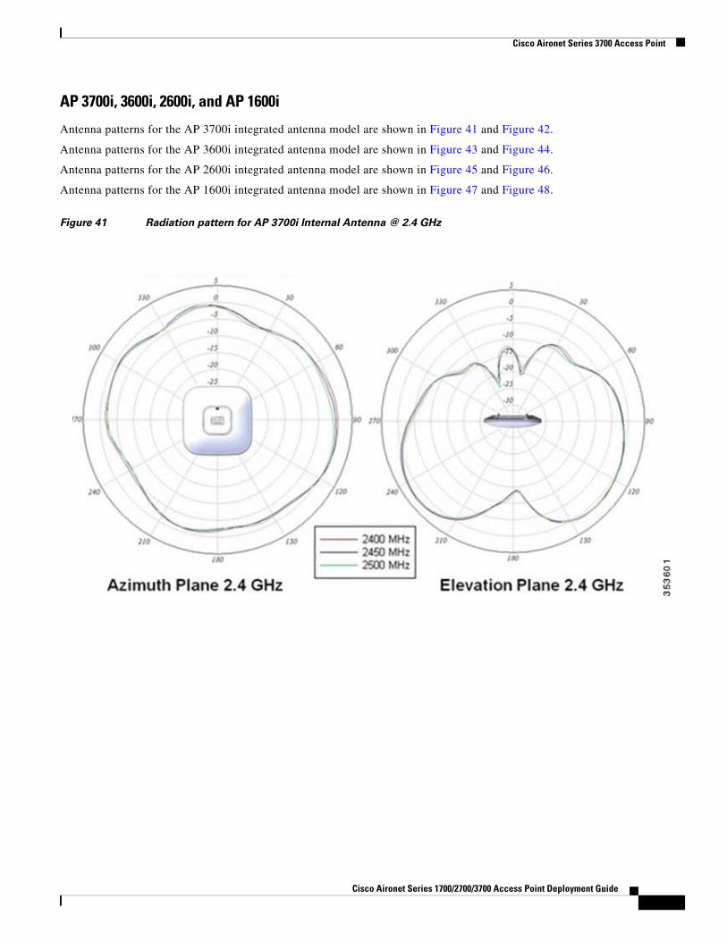
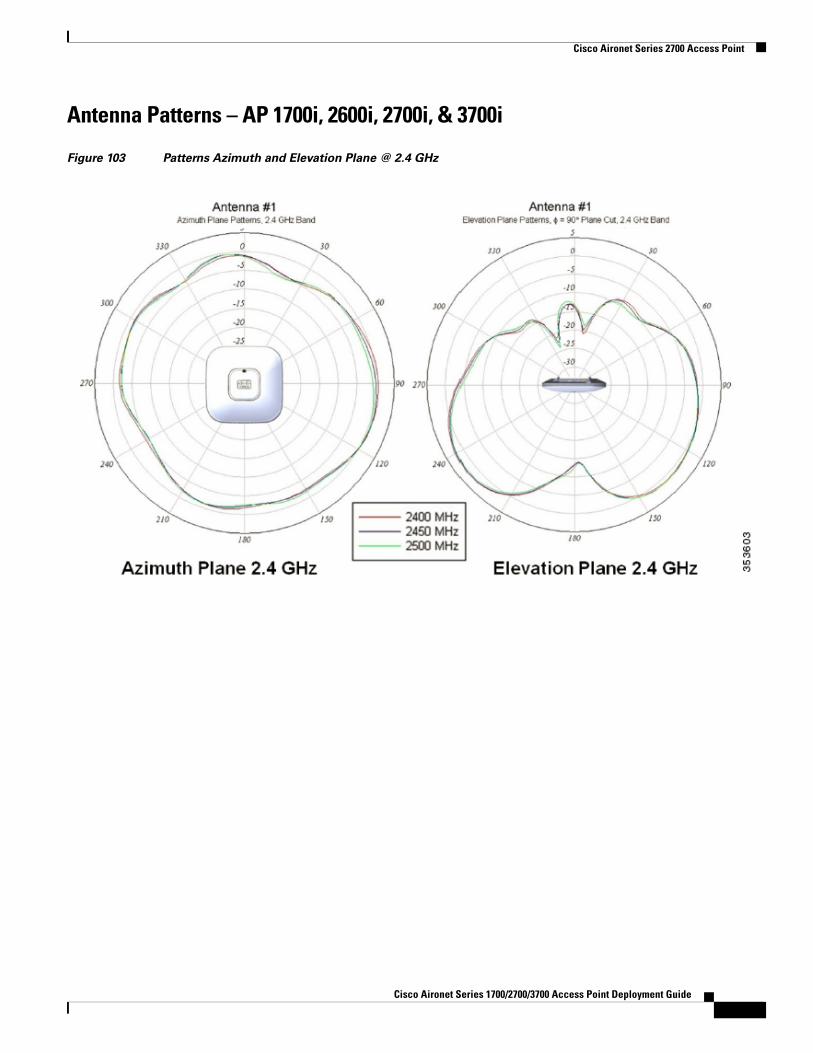
AP 3700i, 3600i, 2600i, and AP 1600i
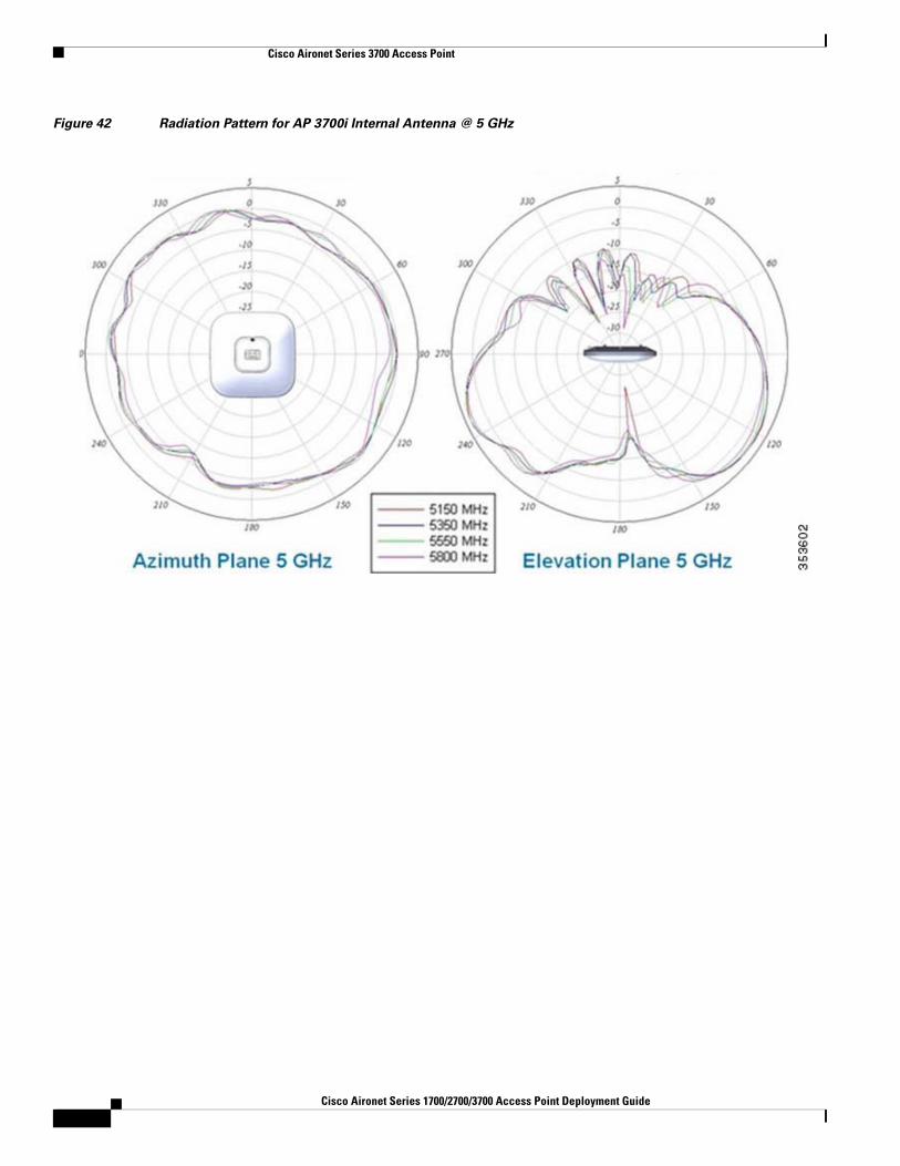
Antenna patterns for the AP 3700i integrated antenna model are shown in Figure 41 and Figure 42.
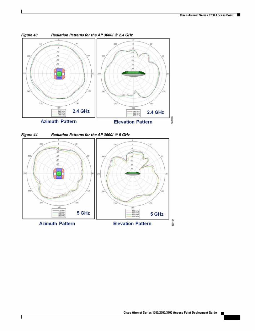
Antenna patterns for the AP 3600i integrated antenna model are shown in Figure 43 and Figure 44.
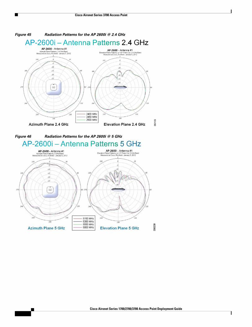
Antenna patterns for the AP 2600i integrated antenna model are shown in Figure 45 and Figure 46.
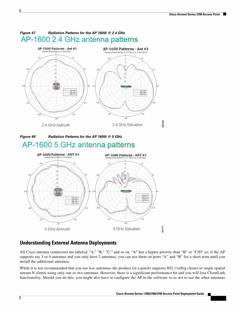
Antenna patterns for the AP 1600i integrated antenna model are shown in Figure 47 and Figure 48.
Figure 41 Radiation pattern for AP 3700i Internal Antenna @ 2.4 GHz
Cisco Aironet Series 1700/2700/3700 Access Point Deployment Guide
Cisco Aironet Series 3700 Access Point
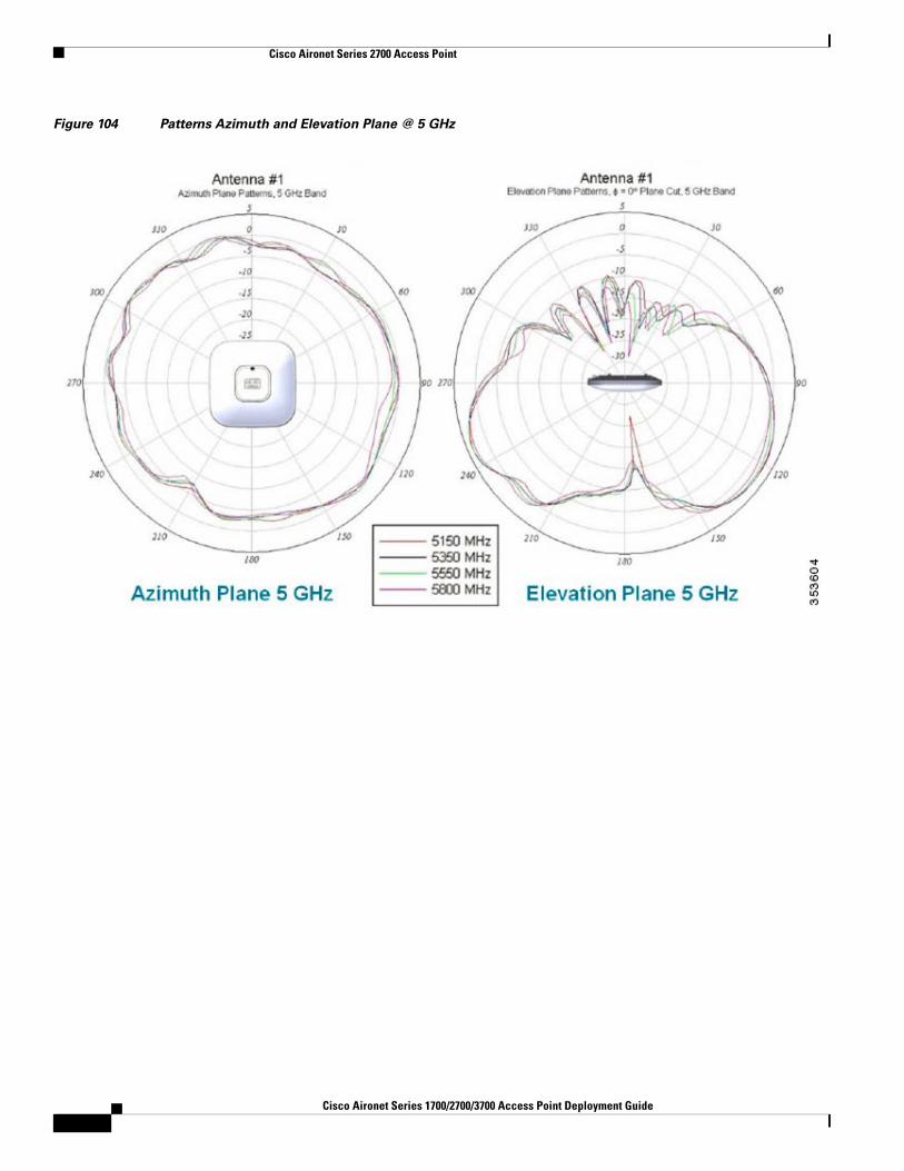
Figure 42 Radiation Pattern for AP 3700i Internal Antenna @ 5 GHz
3Cisco Aironet Series 1700/2700/3700 Access Point Deployment Guide
Cisco Aironet Series 3700 Access Point
Figure 43 Radiation Patterns for the AP 3600i @ 2.4 GHz
Figure 44 Radiation Patterns for the AP 3600i @ 5 GHz
Cisco Aironet Series 1700/2700/3700 Access Point Deployment Guide
Cisco Aironet Series 3700 Access Point
Figure 45 Radiation Patterns for the AP 2600i @ 2.4 GHz
Figure 46 Radiation Patterns for the AP 2600i @ 5 GHz
3Cisco Aironet Series 1700/2700/3700 Access Point Deployment Guide
Cisco Aironet Series 3700 Access Point
Figure 47 Radiation Patterns for the AP 1600i @ 2.4 GHz
Figure 48 Radiation Patterns for the AP 1600i @ 5 GHz
Understanding External Antenna Deployments
All Cisco antenna connectors are labeled; “A,” “B,” “C,” and so on. “A” has a higher priority than “B” or “C/D” so, if the AP supports say 3 or 4 antennas and you only have 2 antennas, you can use them on ports “A” and “B” for a short term until you install the additional antennas.
While it is not recommended that you use less antennas–the product (in a pinch) supports 802.11a/b/g clients or single spatial stream N clients using only one or two antennas. However, there is a significant performance hit and you will lose ClientLink functionality. Should you do this, you might also have to configure the AP in the software so as not to use the other antennas.
Cisco Aironet Series 1700/2700/3700 Access Point Deployment Guide
Cisco Aironet Series 3700 Access Point
Note The AP 1600 has three antenna ports (not configurable because it is an entry level AP). The AP 2600/3600 has four configurable antenna ports–one extra transceiver (receiver/transmitter per band).
When using a MIMO (dual-radiating element antennas) such as:
AIR-ANT2524V4C-R – Dual-band Omni-directional – 2/4 dBi Ceiling mount Omni use
AIR-ANT2544V4M-R– Dual-band Omni-directional – 4/4 dBi Wall mount Omni use
AIR-ANT2566P4W-R– Dual band directional – 6 dBi Patch wall mount use
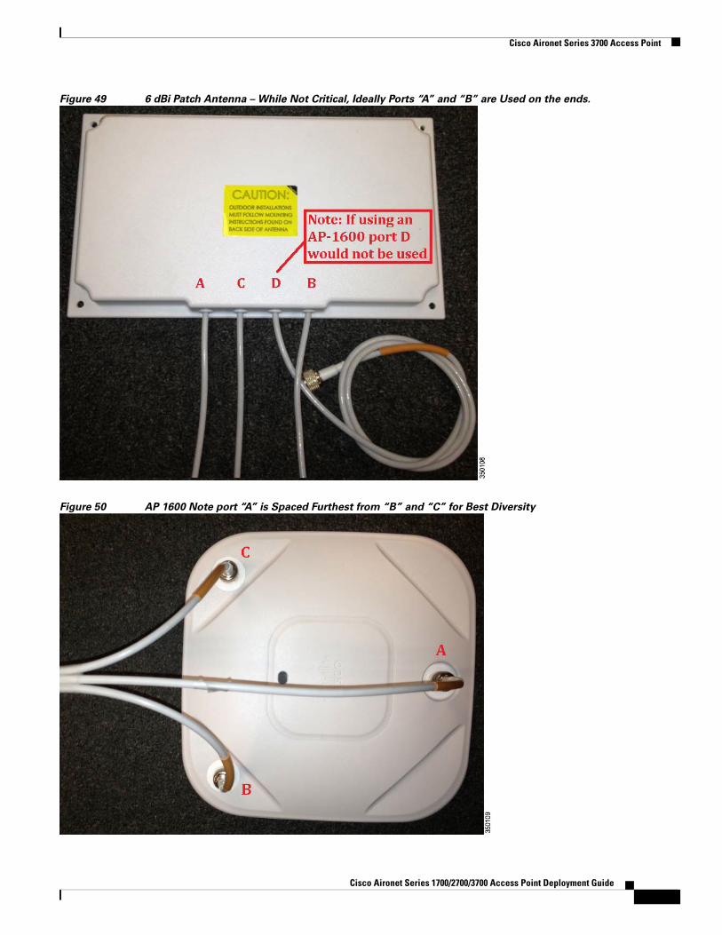
It is not critical which antenna lead goes onto which antenna port on the AP as long as all the antenna ports on the AP are connected to the antennas. In the case of the Patch antenna AIR-ANT2566P4W-R, because the elements are spaced physically apart (side by side) in the plastic housing, there will be a slight improvement if you use the outer two elements on the Patch on ports “A” and “B”. This is only a small improvement and not a critical one and that is why we do not label them.
3Cisco Aironet Series 1700/2700/3700 Access Point Deployment Guide
Cisco Aironet Series 3700 Access Point
Figure 49 6 dBi Patch Antenna – While Not Critical, Ideally Ports “A” and “B” are Used on the ends.
Figure 50 AP 1600 Note port “A” is Spaced Furthest from “B” and “C” for Best Diversity
Cisco Aironet Series 1700/2700/3700 Access Point Deployment Guide
Cisco Aironet Series 3700 Access Point
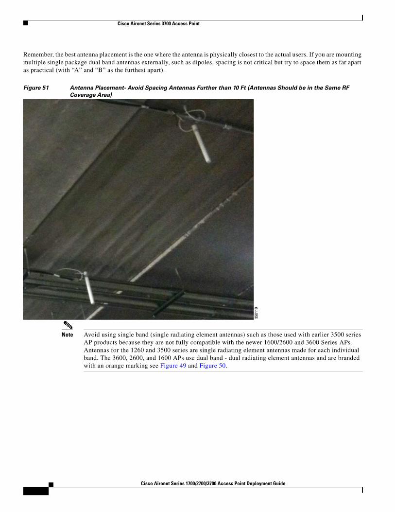
Remember, the best antenna placement is the one where the antenna is physically closest to the actual users. If you are mounting multiple single package dual band antennas externally, such as dipoles, spacing is not critical but try to space them as far apart as practical (with “A” and “B” as the furthest apart).
Figure 51 Antenna Placement- Avoid Spacing Antennas Further than 10 Ft (Antennas Should be in the Same RF
Coverage Area)
Note Avoid using single band (single radiating element antennas) such as those used with earlier 3500 series AP products because they are not fully compatible with the newer 1600/2600 and 3600 Series APs. Antennas for the 1260 and 3500 series are single radiating element antennas made for each individual band. The 3600, 2600, and 1600 APs use dual band - dual radiating element antennas and are branded with an orange marking see Figure 49 and Figure 50.
3Cisco Aironet Series 1700/2700/3700 Access Point Deployment Guide
Cisco Aironet Series 3700 Access Point
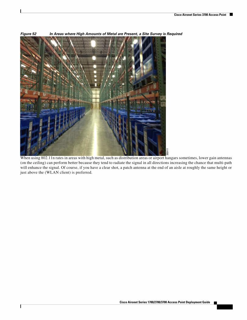
Figure 52 In Areas where High Amounts of Metal are Present, a Site Survey is Required
When using 802.11n rates in areas with high metal, such as distribution areas or airport hangars sometimes, lower gain antennas (on the ceiling) can perform better because they tend to radiate the signal in all directions increasing the chance that multi-path will enhance the signal. Of course, if you have a clear shot, a patch antenna at the end of an aisle at roughly the same height or just above the (WLAN client) is preferred.
Cisco Aironet Series 1700/2700/3700 Access Point Deployment Guide
Cisco Aironet Series 3700 Access Point
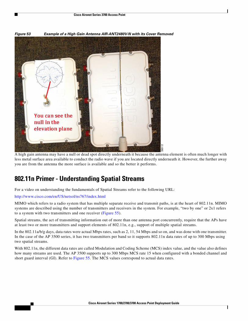
Figure 53 Example of a High Gain Antenna AIR-ANT2480V-N with its Cover Removed
A high gain antenna may have a null or dead spot directly underneath it because the antenna element is often much longer with less metal surface area available to conduct the radio wave if you are located directly underneath it. However, the further away you are from the antenna the more surface is available and so the better it performs.
802.11n Primer - Understanding Spatial StreamsFor a video on understanding the fundamentals of Spatial Streams refer to the following URL:
MIMO which refers to a radio system that has multiple separate receive and transmit paths, is at the heart of 802.11n. MIMO systems are described using the number of transmitters and receivers in the system. For example, “two by one” or 2x1 refers to a system with two transmitters and one receiver (Figure 55).
Spatial streams, the act of transmitting information out of more than one antenna port concurrently, require that the APs have at least two or more transmitters and support elements of 802.11n, e.g., support of multiple spatial streams.
In the 802.11a/b/g days, data rates were actual Mbps rates, such as 2, 11, 54 Mbps and so on, and was done with one transmitter. In the case of the AP 3500 series, it has two transmitters per band so it supports 802.11n data rates of up to 300 Mbps using two spatial streams.
With 802.11n, the different data rates are called Modulation and Coding Scheme (MCS) index value, and the value also defines how many streams are used. The AP 3500 supports up to 300 Mbps MCS rate 15 when configured with a bonded channel and short guard interval (GI). Refer to Figure 55. The MCS values correspond to actual data rates.
4Cisco Aironet Series 1700/2700/3700 Access Point Deployment Guide
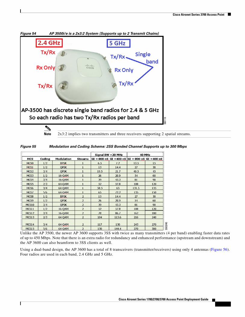
Figure 54 AP 3500i/e is a 2x3:2 System (Supports up to 2 Transmit Chains)
Note 2x3:2 implies two transmitters and three receivers supporting 2 spatial streams.
Figure 55 Modulation and Coding Scheme: 2SS Bonded Channel Supports up to 300 Mbps
Unlike the AP 3500, the newer AP 3600 supports 3SS with twice as many transmitters (4 per band) enabling faster data rates of up to 450 Mbps. Note that there is an extra radio for redundancy and enhanced performance (upstream and downstream) and the AP 3600 can also beamform to 3SS clients as well.
Using a dual-band design, the AP 3600 has a total of 8 transceivers (transmitter/receivers) using only 4 antennas (Figure 56). Four radios are used in each band, 2.4 GHz and 5 GHz.
Cisco Aironet Series 1700/2700/3700 Access Point Deployment Guide
Cisco Aironet Series 3700 Access Point
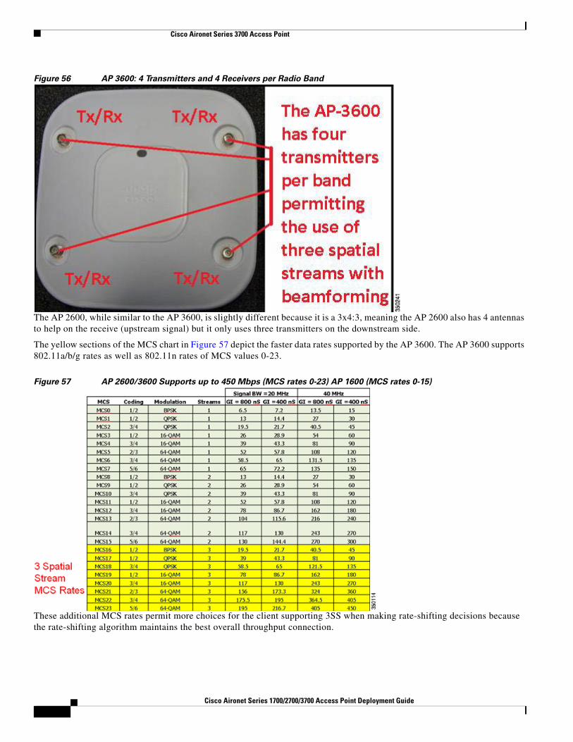
Figure 56 AP 3600: 4 Transmitters and 4 Receivers per Radio Band
The AP 2600, while similar to the AP 3600, is slightly different because it is a 3x4:3, meaning the AP 2600 also has 4 antennas to help on the receive (upstream signal) but it only uses three transmitters on the downstream side.
The yellow sections of the MCS chart in Figure 57 depict the faster data rates supported by the AP 3600. The AP 3600 supports 802.11a/b/g rates as well as 802.11n rates of MCS values 0-23.
Figure 57 AP 2600/3600 Supports up to 450 Mbps (MCS rates 0-23) AP 1600 (MCS rates 0-15)
These additional MCS rates permit more choices for the client supporting 3SS when making rate-shifting decisions because the rate-shifting algorithm maintains the best overall throughput connection.
4Cisco Aironet Series 1700/2700/3700 Access Point Deployment Guide
Cisco Aironet Series 3700 Access Point
Clients that Support 3 Spatial Streams
Clients with 3SS support are starting to become commonplace. Because the new 802.11ac specification starts to get traction, many newer client adapters will have the newer chipsets and support 3SS as a subset to 802.11ac. Additionally, unlike many of our competitors the Cisco AP 1600/2600/3600 and 3700 fully supports all the DFS channels for more usable channels in the 5 GHz range. More clients, especially 802.11ac clients, will start to emerge supporting these newer channels in 802.11n modes as well.
Currently the most popular 3SS client is the Apple 2011 MacBook Pro, because it is based upon the Broadcom BCM4331 chipset and a small USB adapter by Trendnet, “TEW 684UB”, based on the Ralink chipset.
Additionally, the Intel 5300 and 6300 has supported 3SS for a long time. Perhaps, because of the different hardware platforms this card is installed in, testers have observed good throughput on many notebooks (+320 Mbps) and reduced throughput on other notebooks such as 240 Mbps. If you experience low throughput using the Intel card, one suggestion might be to try a MacBook Pro or Trendnet adapter, and if they perform well try another notebook with the Intel card or perhaps open a case with Intel or the laptop manufacturer for a possible remedy. During the AP 3600 beta trials, we observed differences in performance with different notebooks using the Intel 6300 card.
Note Sometimes it can be difficult to reliably maintain a 3SS link because it is easy for the client to rate-shift out of the 3SS mode. The client plays an important role in the ability to maintain a 3SS link, so it can vary with the quality of the client being used and the test environment.
The AP 3600 with its extra radio per band can use the extra redundant radio to beamform (because of ClientLink 2.0) and uses this to maintain the advantage of 3SS links. Cisco ClientLink 2.0 can also improve the overall performance of 802.11n clients using 1, 2, and 3 spatial streams and legacy .11a/g clients.
Understanding Beamforming – Legacy ClientLink 1.0 and 2.0
ClientLink 1.0 was first introduced with the 1250 and 1140 series APs; it is a method of creating a stronger signal on the downlink side for 802.11a/g clients by hearing the clients on the uplink and then adjusting the transmitter timing so the signal appears much stronger at the client end.
This feature used to be user configurable; however, starting with 7.2 code stream it is now switched on by default and is not user configurable as there is no benefit to disabling it.
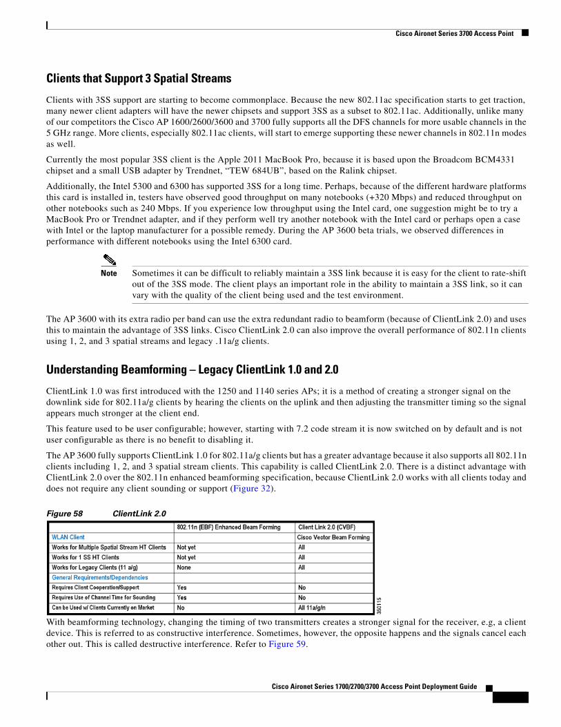
The AP 3600 fully supports ClientLink 1.0 for 802.11a/g clients but has a greater advantage because it also supports all 802.11n clients including 1, 2, and 3 spatial stream clients. This capability is called ClientLink 2.0. There is a distinct advantage with ClientLink 2.0 over the 802.11n enhanced beamforming specification, because ClientLink 2.0 works with all clients today and does not require any client sounding or support (Figure 32).
Figure 58 ClientLink 2.0
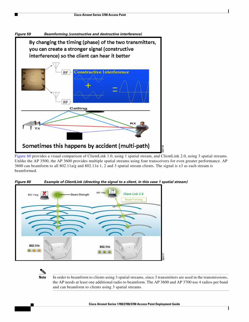
With beamforming technology, changing the timing of two transmitters creates a stronger signal for the receiver, e.g, a client device. This is referred to as constructive interference. Sometimes, however, the opposite happens and the signals cancel each other out. This is called destructive interference. Refer to Figure 59.
Cisco Aironet Series 1700/2700/3700 Access Point Deployment Guide
Cisco Aironet Series 3700 Access Point
Figure 59 Beamforming (constructive and destructive interference)
Figure 60 provides a visual comparison of ClientLink 1.0, using 1 spatial stream, and ClientLink 2.0, using 3 spatial streams. Unlike the AP 3500, the AP 3600 provides multiple spatial streams using four transceivers for even greater performance. AP 3600 can beamform to all 802.11a/g and 802.11n 1, 2 and 3 spatial stream clients. The signal is x3 as each stream is beamformed.
Figure 60 Example of ClientLink (directing the signal to a client, in this case 1 spatial stream)
Note In order to beamform to clients using 3 spatial streams, since 3 transmitters are used in the transmissions, the AP needs at least one additional radio to beamform. The AP 3600 and AP 3700 use 4 radios per band and can beamform to clients using 3 spatial streams.
4Cisco Aironet Series 1700/2700/3700 Access Point Deployment Guide
Cisco Aironet Series 3700 Access Point
To summarize, Cisco ClientLink takes the received signals heard from the client on the uplink, calculates how the multipath signal looks from those streams, and then on the reciprocal side (transmit downlink) figures out the optimal way using all four radios to best form the signal (transmit beamforming) to enable the client to best decode (receive the signal on the downlink) with the least amount of retries.
ClientLink 3.0 with AP 3700 enables beamforming to all 802.11n and 11ac clients, including 3SS clients. ClientLink 2.0 with AP 3600 enables beamforming to all 802.11n clients, including 3SS clients, and can do so for up to 128 clients at a time.
Note AP 1600 supports less clients (32) and does not support 3-ss. ClientLink 1.0 supported a maximum of 15 clients at a time. ClientLink 2.0 significantly improves throughput and coverage of up to 60% on the downlink side for a much better 802.11n client connectivity and enhancing the Bring Your Own Device (BYOD) experience.
Understanding Cisco TxBF (ClientLink) and IEEE (ECBF)
Understanding the need and value of ClientLink 3.0
Enhanced Beam Forming (EBF) did not make it in 802.11n, but it is now in 802.11ac. This was achieved with 802.11ac after a single sounding method was finally agreed upon. Note that EBF is changed to Explicit Compressed Beam Forming (ECBF).
But, today, 802.11ac clients do not support ECBF yet. Because, clients are still emerging and ECBF traction is slow.
ClientLink 3.0 with four antennas can also perform T×BF to 3-SS clients. No one else can do T×BF to 802.11ac 3-spatial stream clients, because you need four antennas to beamform to a three spatial stream client (n+1) to beamform.
Cisco AP 3700 supports ECBF (802.11ac method) and ClientLink 3.0.
Cisco ClientLink 3.0 works with all 802.11a/g/n and 802.11ac clients today.
For more information on Cisco ClientLink refer to the following URL:
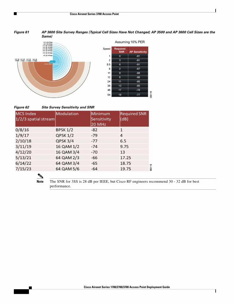
Site Survey ConsiderationsWhile ClientLink dynamically beamforms and helps to maintain a robust signal which results in fewer retries, it was not designed to change the cell range. ClientLink creates a better connection experience, not larger cell size.
For this reason, when conducting a survey it is important to keep in mind that the AP 3600 cell sizes are generally the same or very similar to other Cisco APs. Figure 61 depicts typical ranges in the 1 - 54 Mbps range. While it is always recommended to survey with the equipment you intend to deploy, a previous survey done with say an AP 3500 – would not be invalid for an AP 3600 deployment. Figure 62 and Figure 63 provide examples of the modulation types and signal-to-noise ratio (SNR).
Cisco Aironet Series 1700/2700/3700 Access Point Deployment Guide
Figure 61 AP 3600 Site Survey Ranges (Typical Cell Sizes Have Not Changed; AP 3500 and AP 3600 Cell Sizes are the
Same)
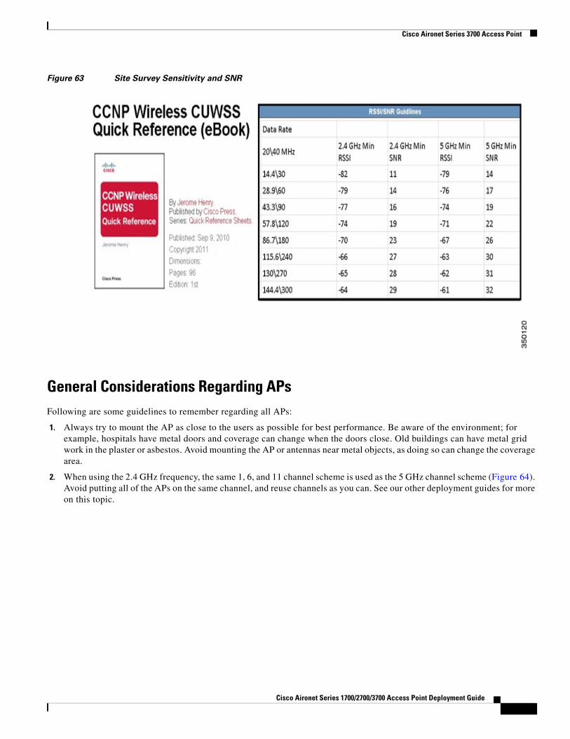
Figure 62 Site Survey Sensitivity and SNR
Note The SNR for 3SS is 28 dB per IEEE, but Cisco RF engineers recommend 30 - 32 dB for best performance.
4Cisco Aironet Series 1700/2700/3700 Access Point Deployment Guide
Cisco Aironet Series 3700 Access Point
Figure 63 Site Survey Sensitivity and SNR
General Considerations Regarding APsFollowing are some guidelines to remember regarding all APs:
1. Always try to mount the AP as close to the users as possible for best performance. Be aware of the environment; for example, hospitals have metal doors and coverage can change when the doors close. Old buildings can have metal grid work in the plaster or asbestos. Avoid mounting the AP or antennas near metal objects, as doing so can change the coverage area.
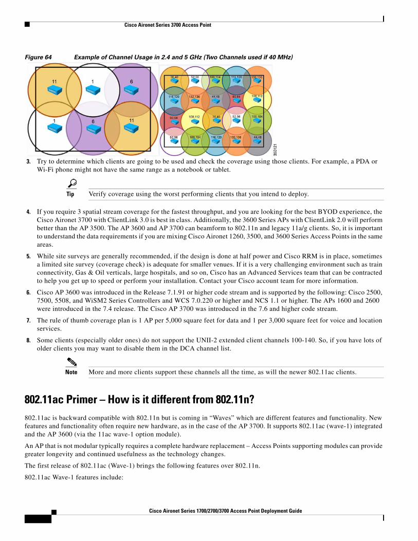
2. When using the 2.4 GHz frequency, the same 1, 6, and 11 channel scheme is used as the 5 GHz channel scheme (Figure 64). Avoid putting all of the APs on the same channel, and reuse channels as you can. See our other deployment guides for more on this topic.
Cisco Aironet Series 1700/2700/3700 Access Point Deployment Guide
Cisco Aironet Series 3700 Access Point
Figure 64 Example of Channel Usage in 2.4 and 5 GHz (Two Channels used if 40 MHz)
3. Try to determine which clients are going to be used and check the coverage using those clients. For example, a PDA or Wi-Fi phone might not have the same range as a notebook or tablet.
Tip Verify coverage using the worst performing clients that you intend to deploy.
4. If you require 3 spatial stream coverage for the fastest throughput, and you are looking for the best BYOD experience, the Cisco Aironet 3700 with ClientLink 3.0 is best in class. Additionally, the 3600 Series APs with ClientLink 2.0 will perform better than the AP 3500. The AP 3600 and AP 3700 can beamform to 802.11n and legacy 11a/g clients. So, it is important to understand the data requirements if you are mixing Cisco Aironet 1260, 3500, and 3600 Series Access Points in the same areas.
5. While site surveys are generally recommended, if the design is done at half power and Cisco RRM is in place, sometimes a limited site survey (coverage check) is adequate for smaller venues. If it is a very challenging environment such as train connectivity, Gas & Oil verticals, large hospitals, and so on, Cisco has an Advanced Services team that can be contracted to help you get up to speed or perform your installation. Contact your Cisco account team for more information.
6. Cisco AP 3600 was introduced in the Release 7.1.91 or higher code stream and is supported by the following: Cisco 2500, 7500, 5508, and WiSM2 Series Controllers and WCS 7.0.220 or higher and NCS 1.1 or higher. The APs 1600 and 2600 were introduced in the 7.4 release. The Cisco AP 3700 was introduced in the 7.6 and higher code stream.
7. The rule of thumb coverage plan is 1 AP per 5,000 square feet for data and 1 per 3,000 square feet for voice and location services.
8. Some clients (especially older ones) do not support the UNII-2 extended client channels 100-140. So, if you have lots of older clients you may want to disable them in the DCA channel list.
Note More and more clients support these channels all the time, as will the newer 802.11ac clients.
802.11ac Primer – How is it different from 802.11n?802.11ac is backward compatible with 802.11n but is coming in “Waves” which are different features and functionality. New features and functionality often require new hardware, as in the case of the AP 3700. It supports 802.11ac (wave-1) integrated and the AP 3600 (via the 11ac wave-1 option module).
An AP that is not modular typically requires a complete hardware replacement – Access Points supporting modules can provide greater longevity and continued usefulness as the technology changes.
The first release of 802.11ac (Wave-1) brings the following features over 802.11n.
802.11ac Wave-1 features include:
4Cisco Aironet Series 1700/2700/3700 Access Point Deployment Guide
Cisco Aironet Series 3700 Access Point
• Faster PHY rate 1.3 Gbps over the typical 450 Mbps of 802.11n.
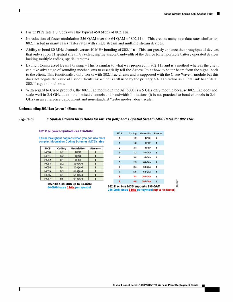
• Introduction of faster modulation 256 QAM over the 64 QAM of 802.11n – This creates many new data rates similar to 802.11n but in many cases faster rates with single stream and multiple stream devices.
• Ability to bond 80 MHz channels versus 40 MHz bonding of 802.11n – This can greatly enhance the throughput of devices that only support 1 spatial stream by extending the usable bandwidth of the device (often portable battery operated devices lacking multiple radios) spatial streams.
• Explicit Compressed Beam Forming – This is similar to what was proposed in 802.11n and is a method whereas the client can take advantage of sounding mechanisms to essentially tell the Access Point how to better beam form the signal back to the client. This functionality only works with 802.11ac clients and is supported with the Cisco Wave-1 module but this does not negate the value of Cisco ClientLink which is still used by the primary 802.11n radios as ClientLink benefits all 802.11a,g, and n clients.
• With regard to Cisco products, the 802.11ac module in the AP 3600 is a 5 GHz only module because 802.11ac does not scale well in 2.4 GHz due to the limited channels and bandwidth limitations (it is not practical to bond channels in 2.4 GHz) in an enterprise deployment and non-standard “turbo modes” don’t scale.
Understanding 802.11ac (wave-1) Elements:
Figure 65 1 Spatial Stream MCS Rates for 801.11n (left) and 1 Spatial Stream MCS Rates for 802.11ac
Cisco Aironet Series 1700/2700/3700 Access Point Deployment Guide
Cisco Aironet Series 3700 Access Point
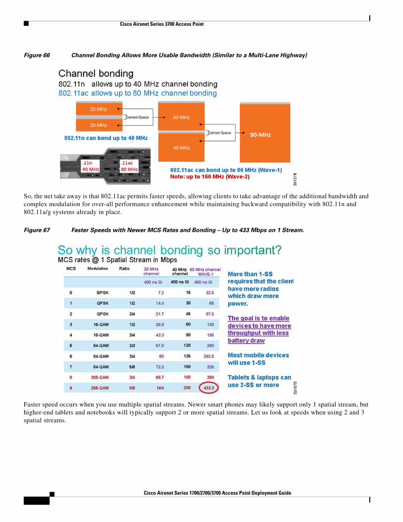
Figure 66 Channel Bonding Allows More Usable Bandwidth (Similar to a Multi-Lane Highway)
So, the net take away is that 802.11ac permits faster speeds, allowing clients to take advantage of the additional bandwidth and complex modulation for over-all performance enhancement while maintaining backward compatibility with 802.11n and 802.11a/g systems already in place.
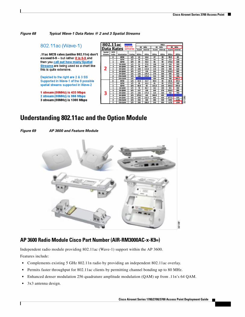
Figure 67 Faster Speeds with Newer MCS Rates and Bonding – Up to 433 Mbps on 1 Stream.
Faster speed occurs when you use multiple spatial streams. Newer smart phones may likely support only 1 spatial stream, but higher-end tablets and notebooks will typically support 2 or more spatial streams. Let us look at speeds when using 2 and 3 spatial streams.
5Cisco Aironet Series 1700/2700/3700 Access Point Deployment Guide
Cisco Aironet Series 3700 Access Point
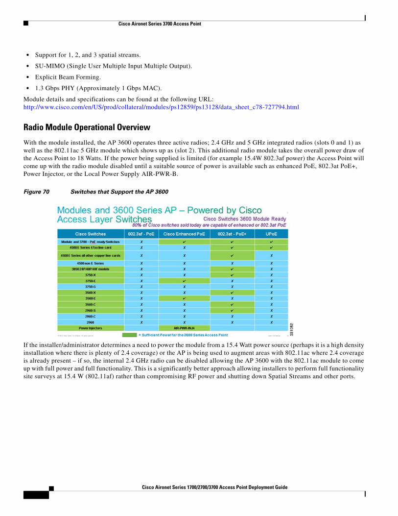
Figure 68 Typical Wave-1 Data Rates @ 2 and 3 Spatial Streams
Understanding 802.11ac and the Option Module
Figure 69 AP 3600 and Feature Module
AP 3600 Radio Module Cisco Part Number (AIR-RM3000AC-x-K9=)
Independent radio module providing 802.11ac (Wave-1) support within the AP 3600.
Features include:
• Complements existing 5 GHz 802.11n radio by providing an independent 802.11ac overlay.
• Permits faster throughput for 802.11ac clients by permitting channel bonding up to 80 MHz.
• Enhanced denser modulation 256 quadrature amplitude modulation (QAM) up from .11n’s 64 QAM.
• 3x3 antenna design.
Cisco Aironet Series 1700/2700/3700 Access Point Deployment Guide
Cisco Aironet Series 3700 Access Point
• Support for 1, 2, and 3 spatial streams.
• SU-MIMO (Single User Multiple Input Multiple Output).
• Explicit Beam Forming.
• 1.3 Gbps PHY (Approximately 1 Gbps MAC).
Module details and specifications can be found at the following URL: http://www.cisco.com/en/US/prod/collateral/modules/ps12859/ps13128/data_sheet_c78-727794.html
Radio Module Operational Overview
With the module installed, the AP 3600 operates three active radios; 2.4 GHz and 5 GHz integrated radios (slots 0 and 1) as well as the 802.11ac 5 GHz module which shows up as (slot 2). This additional radio module takes the overall power draw of the Access Point to 18 Watts. If the power being supplied is limited (for example 15.4W 802.3af power) the Access Point will come up with the radio module disabled until a suitable source of power is available such as enhanced PoE, 802.3at PoE+, Power Injector, or the Local Power Supply AIR-PWR-B.
Figure 70 Switches that Support the AP 3600
If the installer/administrator determines a need to power the module from a 15.4 Watt power source (perhaps it is a high density installation where there is plenty of 2.4 coverage) or the AP is being used to augment areas with 802.11ac where 2.4 coverage is already present – if so, the internal 2.4 GHz radio can be disabled allowing the AP 3600 with the 802.11ac module to come up with full power and full functionality. This is a significantly better approach allowing installers to perform full functionality site surveys at 15.4 W (802.11af) rather than compromising RF power and shutting down Spatial Streams and other ports.
5Cisco Aironet Series 1700/2700/3700 Access Point Deployment Guide
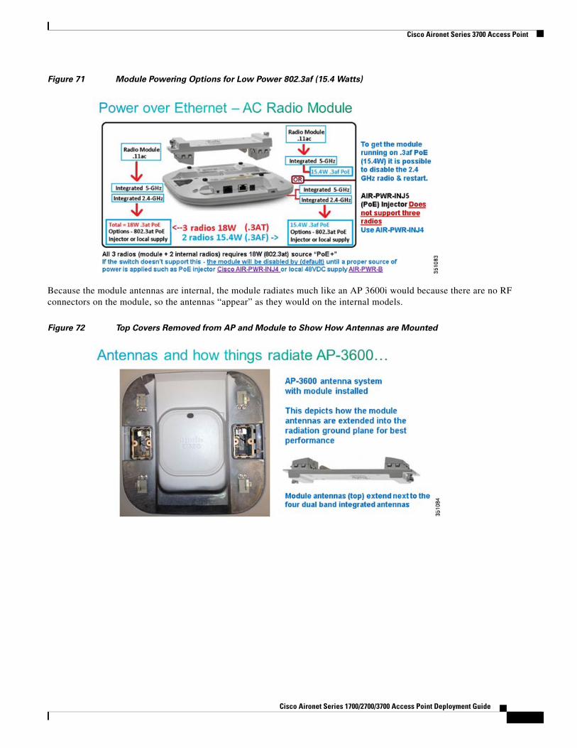
Figure 71 Module Powering Options for Low Power 802.3af (15.4 Watts)
Because the module antennas are internal, the module radiates much like an AP 3600i would because there are no RF connectors on the module, so the antennas “appear” as they would on the internal models.
Figure 72 Top Covers Removed from AP and Module to Show How Antennas are Mounted
Cisco Aironet Series 1700/2700/3700 Access Point Deployment Guide
Cisco Aironet Series 3700 Access Point
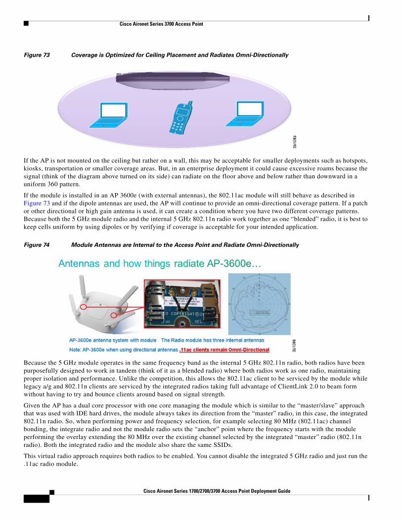
Figure 73 Coverage is Optimized for Ceiling Placement and Radiates Omni-Directionally
If the AP is not mounted on the ceiling but rather on a wall, this may be acceptable for smaller deployments such as hotspots, kiosks, transportation or smaller coverage areas. But, in an enterprise deployment it could cause excessive roams because the signal (think of the diagram above turned on its side) can radiate on the floor above and below rather than downward in a uniform 360 pattern.
If the module is installed in an AP 3600e (with external antennas), the 802.11ac module will still behave as described in Figure 73 and if the dipole antennas are used, the AP will continue to provide an omni-directional coverage pattern. If a patch or other directional or high gain antenna is used, it can create a condition where you have two different coverage patterns. Because both the 5 GHz module radio and the internal 5 GHz 802.11n radio work together as one “blended” radio, it is best to keep cells uniform by using dipoles or by verifying if coverage is acceptable for your intended application.
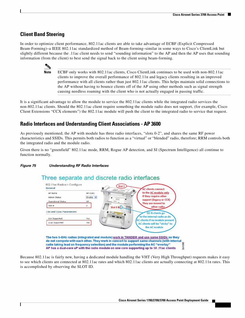
Figure 74 Module Antennas are Internal to the Access Point and Radiate Omni-Directionally
Because the 5 GHz module operates in the same frequency band as the internal 5 GHz 802.11n radio, both radios have been purposefully designed to work in tandem (think of it as a blended radio) where both radios work as one radio, maintaining proper isolation and performance. Unlike the competition, this allows the 802.11ac client to be serviced by the module while legacy a/g and 802.11n clients are serviced by the integrated radios taking full advantage of ClientLink 2.0 to beam form without having to try and bounce clients around based on signal strength.
Given the AP has a dual core processor with one core managing the module which is similar to the “master/slave” approach that was used with IDE hard drives, the module always takes its direction from the “master” radio, in this case, the integrated 802.11n radio. So, when performing power and frequency selection, for example selecting 80 MHz (802.11ac) channel bonding, the integrate radio and not the module radio sets the “anchor” point where the frequency starts with the module performing the overlay extending the 80 MHz over the existing channel selected by the integrated “master” radio (802.11n radio). Both the integrated radio and the module also share the same SSIDs.
This virtual radio approach requires both radios to be enabled. You cannot disable the integrated 5 GHz radio and just run the .11ac radio module.
5Cisco Aironet Series 1700/2700/3700 Access Point Deployment Guide
Cisco Aironet Series 3700 Access Point
Client Band Steering
In order to optimize client performance, 802.11ac clients are able to take advantage of ECBF (Explicit Compressed Beam-Forming)–a IEEE 802.11ac standardized method of Beam-forming–similar in some ways to Cisco’s ClientLink but slightly different because the .11ac client needs to send “sounding information” to the AP and then the AP uses that sounding information (from the client) to best send the signal back to the client using beam-forming.
Note ECBF only works with 802.11ac clients, Cisco ClientLink continues to be used with non-802.11ac clients to improve the overall performance of 802.11n and legacy clients resulting in an improved performance with all clients rather than just 802.11ac clients. This helps maintain solid connections to the AP without having to bounce clients off of the AP using other methods such as signal strength causing needless roaming with the client who is not actually engaged in passing traffic.
It is a significant advantage to allow the module to service the 802.11ac clients while the integrated radio services the non-802.11ac clients. Should the 802.11ac client require something the module radio does not support, (for example, Cisco Client Extensions “CCX elements”) the 802.11ac module will push the client to the integrated radio to service that request.
Radio Interfaces and Understanding Client Associations - AP 3600
As previously mentioned; the AP with module has three radio interfaces, “slots 0-2”, and shares the same RF power characteristics and SSIDs. This permits both radios to function as a “virtual” or “blended” radio, therefore; RRM controls both the integrated radio and the module radio.
Given there is no “greenfield” 802.11ac mode, RRM, Rogue AP detection, and SI (Spectrum Intelligence) all continue to function normally.
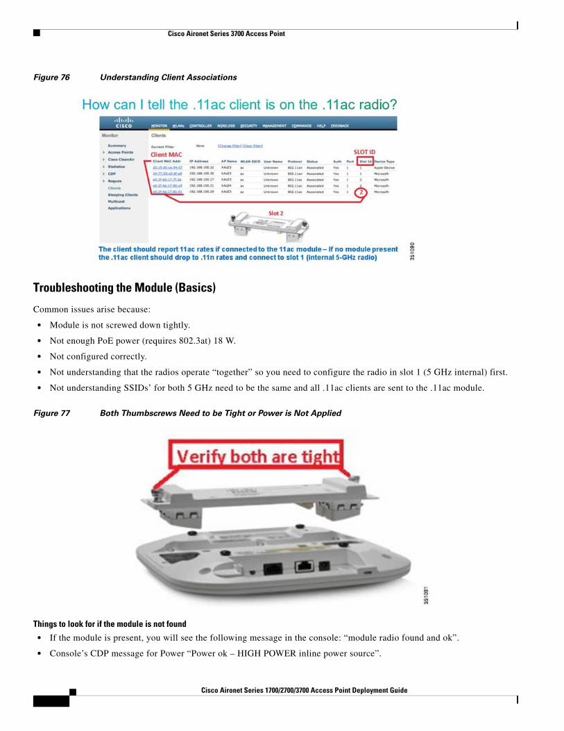
Figure 75 Understanding RF Radio Interfaces
Because 802.11ac is fairly new, having a dedicated module handling the VHT (Very High Throughput) requests makes it easy to see which clients are connected at 802.11ac rates and which 802.11ac clients are actually connecting at 802.11n rates. This is accomplished by observing the SLOT ID.
Cisco Aironet Series 1700/2700/3700 Access Point Deployment Guide
Cisco Aironet Series 3700 Access Point
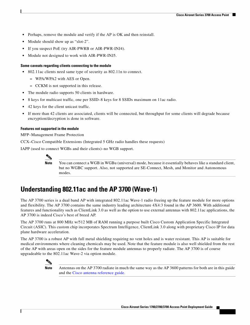
Figure 76 Understanding Client Associations
Troubleshooting the Module (Basics)
Common issues arise because:
• Module is not screwed down tightly.
• Not enough PoE power (requires 802.3at) 18 W.
• Not configured correctly.
• Not understanding that the radios operate “together” so you need to configure the radio in slot 1 (5 GHz internal) first.
• Not understanding SSIDs’ for both 5 GHz need to be the same and all .11ac clients are sent to the .11ac module.
Figure 77 Both Thumbscrews Need to be Tight or Power is Not Applied
Things to look for if the module is not found
• If the module is present, you will see the following message in the console: “module radio found and ok”.
• Console’s CDP message for Power “Power ok – HIGH POWER inline power source”.
5Cisco Aironet Series 1700/2700/3700 Access Point Deployment Guide
Cisco Aironet Series 3700 Access Point
• Perhaps, remove the module and verify if the AP is OK and then reinstall.
• Module should show up as “slot-2”.
• If you suspect PoE (try AIR-PWRB or AIR-PWR-INJ4).
• Module not designed to work with AIR-PWR-INJ5.
Some caveats regarding clients connecting to the module
• 802.11ac clients need same type of security as 802.11n to connect.
– WPA/WPA2 with AES or Open.
– CCKM is not supported in this release.
• The module radio supports 50 clients in hardware.
• 8 keys for multicast traffic, one per SSID–8 keys for 8 SSIDs maximum on 11ac radio.
• 42 keys for the client unicast traffic.
• If more than 42 clients are associated, clients will be connected, but throughput for some clients will degrade because encryption/decryption is done in software.
Features not supported in the module
MFP–Management Frame Protection
CCX–Cisco Compatible Extensions (Integrated 5 GHz radio handles these requests)
IAPP (used to connect WGBs and their clients)–no WGB support.
Note You can connect a WGB in WGBu (universal) mode, because it essentially behaves like a standard client, but no WGBC support. Also, not supported are SE-Connect, Mesh, and Monitor and Autonomous modes.
Understanding 802.11ac and the AP 3700 (Wave-1)The AP 3700 series is a dual band AP with integrated 802.11ac Wave-1 radio freeing up the feature module for more options and flexibility. The AP 3700 contains the same industry leading architecture 4X4:3 found in the AP 3600. With additional features and functionality such as ClientLink 3.0 as well as the option to use external antennas with 802.11ac applications, the AP 3700 is indeed Cisco’s best of breed AP.
The AP 3700 runs at 800 MHz w/512 MB of RAM running a purpose built Cisco Custom Application Specific Integrated Circuit (ASIC). This custom chip incorporates Spectrum Intelligence, ClientLink 3.0 along with proprietary Cisco IP for data plane hardware acceleration.
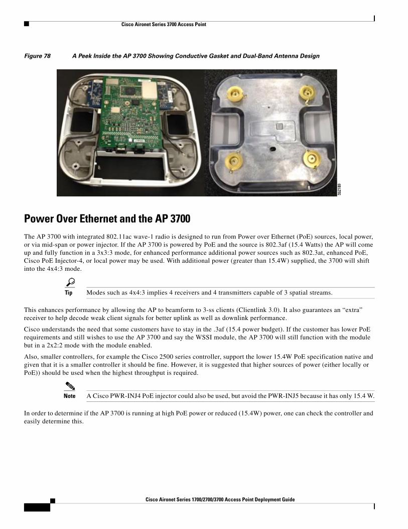
The AP 3700 is a robust AP with full metal shielding requiring no vent holes and is water resistant. This AP is suitable for medical environments where cleaning chemicals may be used. Note that the feature module is also well shielded from the rest of the AP with areas open on the sides for the feature module antennas to properly radiate. The AP 3700 is of course upgradeable to the 802.11ac Wave-2 via option module.
Note Antennas on the AP 3700 radiate in much the same way as the AP 3600 patterns for both are in this guide and the Cisco antenna reference guide.
Cisco Aironet Series 1700/2700/3700 Access Point Deployment Guide
Figure 78 A Peek Inside the AP 3700 Showing Conductive Gasket and Dual-Band Antenna Design
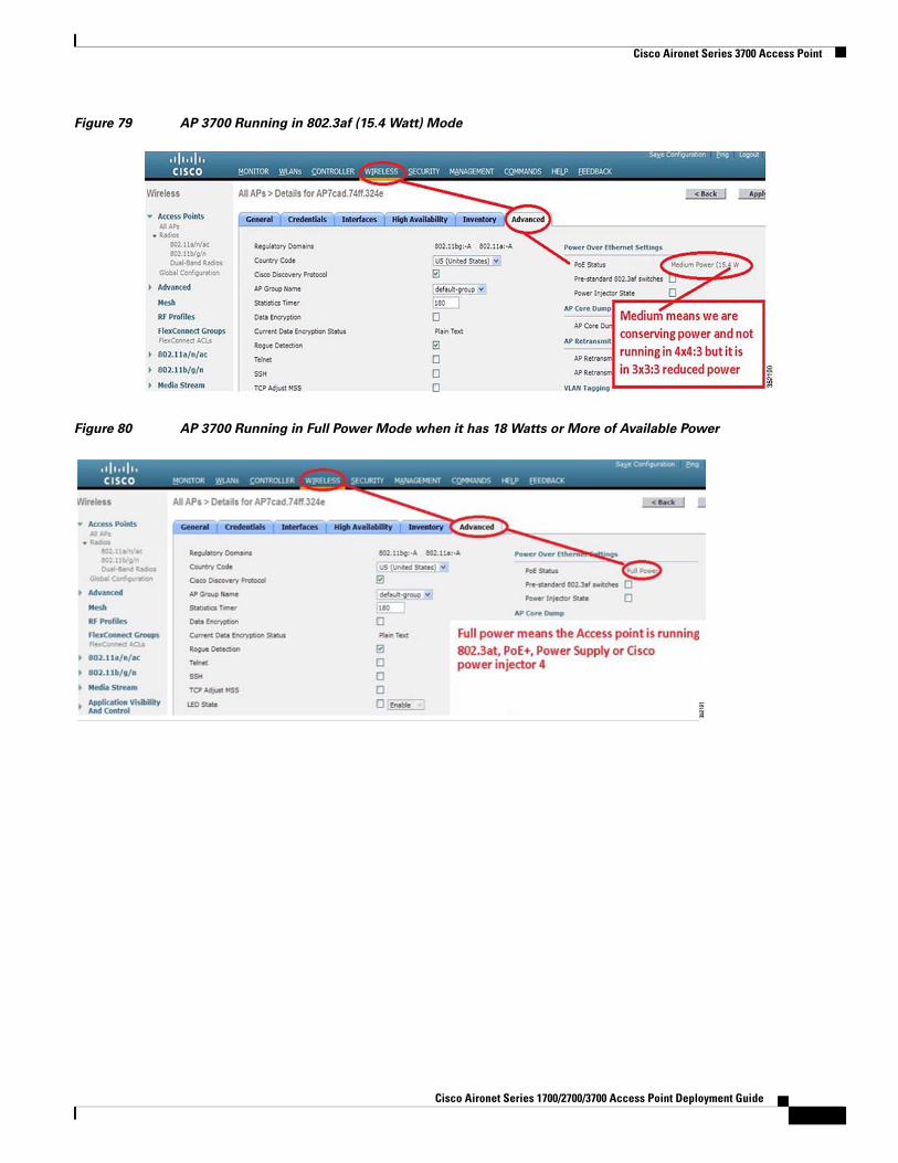
Power Over Ethernet and the AP 3700The AP 3700 with integrated 802.11ac wave-1 radio is designed to run from Power over Ethernet (PoE) sources, local power, or via mid-span or power injector. If the AP 3700 is powered by PoE and the source is 802.3af (15.4 Watts) the AP will come up and fully function in a 3x3:3 mode, for enhanced performance additional power sources such as 802.3at, enhanced PoE, Cisco PoE Injector-4, or local power may be used. With additional power (greater than 15.4W) supplied, the 3700 will shift into the 4x4:3 mode.
Tip Modes such as 4x4:3 implies 4 receivers and 4 transmitters capable of 3 spatial streams.
This enhances performance by allowing the AP to beamform to 3-ss clients (Clientlink 3.0). It also guarantees an “extra” receiver to help decode weak client signals for better uplink as well as downlink performance.
Cisco understands the need that some customers have to stay in the .3af (15.4 power budget). If the customer has lower PoE requirements and still wishes to use the AP 3700 and say the WSSI module, the AP 3700 will still function with the module but in a 2x2:2 mode with the module enabled.
Also, smaller controllers, for example the Cisco 2500 series controller, support the lower 15.4W PoE specification native and given that it is a smaller controller it should be fine. However, it is suggested that higher sources of power (either locally or PoE)) should be used when the highest throughput is required.
Note A Cisco PWR-INJ4 PoE injector could also be used, but avoid the PWR-INJ5 because it has only 15.4 W.
In order to determine if the AP 3700 is running at high PoE power or reduced (15.4W) power, one can check the controller and easily determine this.
5Cisco Aironet Series 1700/2700/3700 Access Point Deployment Guide
Cisco Aironet Series 3700 Access Point
Figure 79 AP 3700 Running in 802.3af (15.4 Watt) Mode
Figure 80 AP 3700 Running in Full Power Mode when it has 18 Watts or More of Available Power
Cisco Aironet Series 1700/2700/3700 Access Point Deployment Guide
Cisco Aironet Series 3700 Access Point
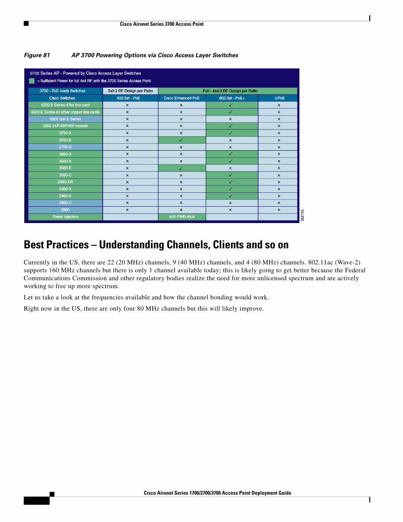
Figure 81 AP 3700 Powering Options via Cisco Access Layer Switches
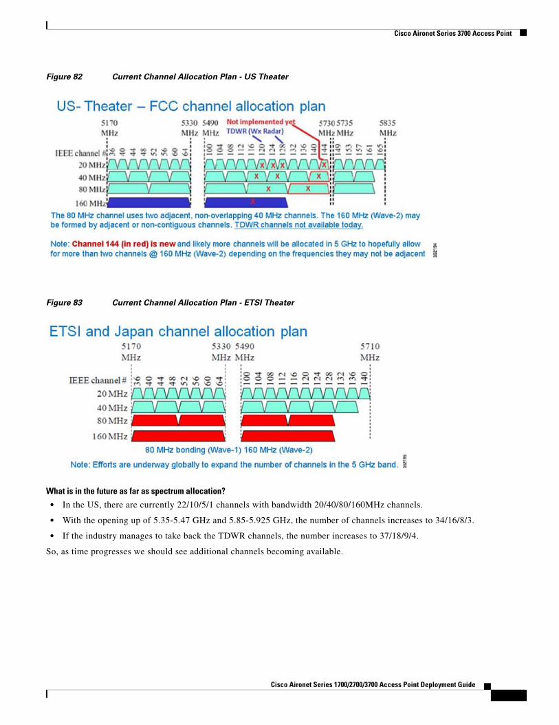
Best Practices – Understanding Channels, Clients and so onCurrently in the US, there are 22 (20 MHz) channels, 9 (40 MHz) channels, and 4 (80 MHz) channels. 802.11ac (Wave-2) supports 160 MHz channels but there is only 1 channel available today; this is likely going to get better because the Federal Communications Commission and other regulatory bodies realize the need for more unlicensed spectrum and are actively working to free up more spectrum.
Let us take a look at the frequencies available and how the channel bonding would work.
Right now in the US, there are only four 80 MHz channels but this will likely improve.
6Cisco Aironet Series 1700/2700/3700 Access Point Deployment Guide
Cisco Aironet Series 3700 Access Point
Figure 82 Current Channel Allocation Plan - US Theater
Figure 83 Current Channel Allocation Plan - ETSI Theater
What is in the future as far as spectrum allocation?
• In the US, there are currently 22/10/5/1 channels with bandwidth 20/40/80/160MHz channels.
• With the opening up of 5.35-5.47 GHz and 5.85-5.925 GHz, the number of channels increases to 34/16/8/3.
• If the industry manages to take back the TDWR channels, the number increases to 37/18/9/4.
So, as time progresses we should see additional channels becoming available.
Cisco Aironet Series 1700/2700/3700 Access Point Deployment Guide
Cisco Aironet Series 3700 Access Point
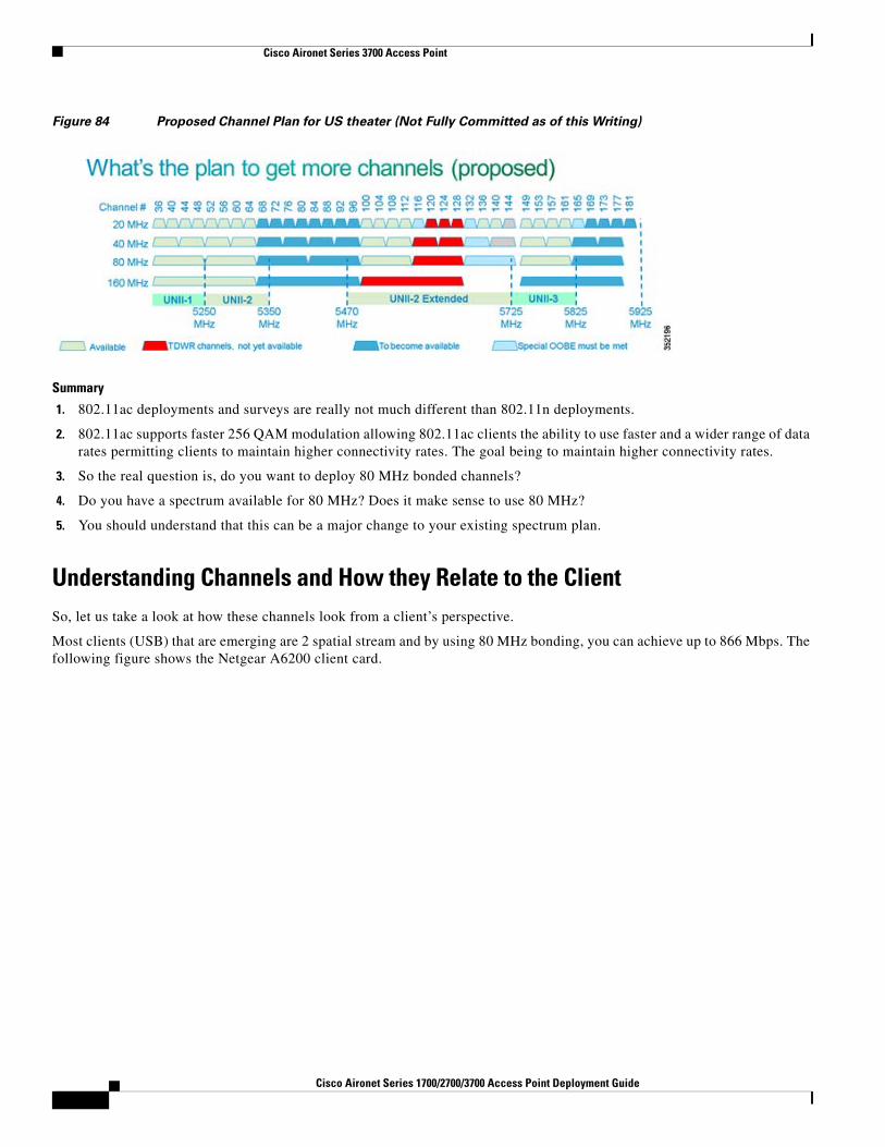
Figure 84 Proposed Channel Plan for US theater (Not Fully Committed as of this Writing)
Summary
1. 802.11ac deployments and surveys are really not much different than 802.11n deployments.
2. 802.11ac supports faster 256 QAM modulation allowing 802.11ac clients the ability to use faster and a wider range of data rates permitting clients to maintain higher connectivity rates. The goal being to maintain higher connectivity rates.
3. So the real question is, do you want to deploy 80 MHz bonded channels?
4. Do you have a spectrum available for 80 MHz? Does it make sense to use 80 MHz?
5. You should understand that this can be a major change to your existing spectrum plan.
Understanding Channels and How they Relate to the ClientSo, let us take a look at how these channels look from a client’s perspective.
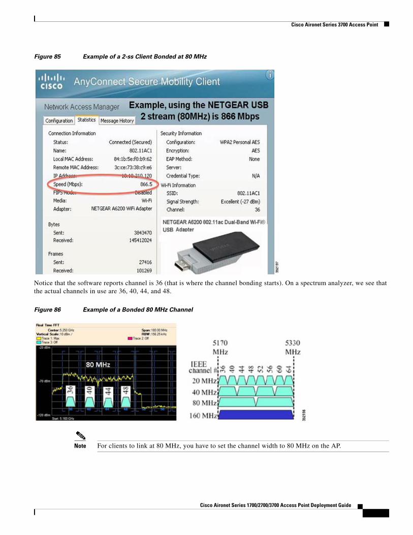
Most clients (USB) that are emerging are 2 spatial stream and by using 80 MHz bonding, you can achieve up to 866 Mbps. The following figure shows the Netgear A6200 client card.
6Cisco Aironet Series 1700/2700/3700 Access Point Deployment Guide
Cisco Aironet Series 3700 Access Point
Figure 85 Example of a 2-ss Client Bonded at 80 MHz
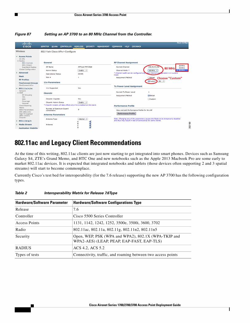
Notice that the software reports channel is 36 (that is where the channel bonding starts). On a spectrum analyzer, we see that the actual channels in use are 36, 40, 44, and 48.
Figure 86 Example of a Bonded 80 MHz Channel
Note For clients to link at 80 MHz, you have to set the channel width to 80 MHz on the AP.
Cisco Aironet Series 1700/2700/3700 Access Point Deployment Guide
Cisco Aironet Series 3700 Access Point
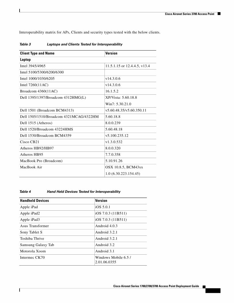
Figure 87 Setting an AP 3700 to an 80 MHz Channel from the Controller.
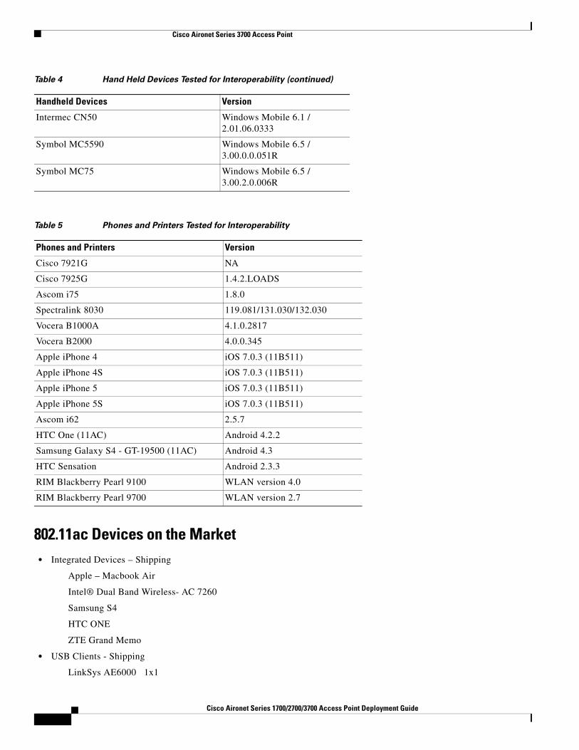
802.11ac and Legacy Client RecommendationsAt the time of this writing, 802.11ac clients are just now starting to get integrated into smart phones. Devices such as Samsung Galaxy S4, ZTE’s Grand Memo, and HTC One and new notebooks such as the Apple 2013 Macbook Pro are some early to market 802.11ac devices. It is expected that integrated notebooks and tablets (those devices often supporting 2 and 3 spatial streams) will start to become commonplace.
Currently Cisco’s test bed for interoperability (for the 7.6 release) supporting the new AP 3700 has the following configuration types.
Table 2 Interoperability Matrix for Release 7.6Type
Hardware/Software Parameter Hardware/Software Configurations Type
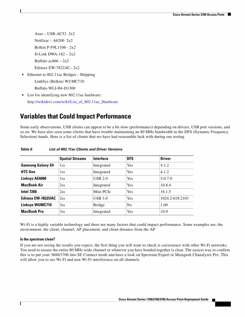
Variables that Could Impact PerformanceSome early observations, USB clients can appear to be a bit slow (performance) depending on drivers, USB port versions, and so on. We have also seen some clients that have trouble maintaining an 80 MHz bandwidth in the DFS (Dynamic Frequency Selection) bands. Here is a list of clients that we have had reasonable luck with during our testing.
Wi-Fi is a highly variable technology and there are many factors that could impact performance. Some examples are; the environment, the client, channel, AP placement, and client distance from the AP.
Is the spectrum clean?
If you are not seeing the results you expect, the first thing you will want to check is coexistence with other Wi-Fi networks. You need to ensure the entire 80 MHz wide channel or whatever you have bonded together is clear. The easiest way to confirm this is to put your 3600/3700 into SE Connect mode and have a look on Spectrum Expert or Metageek Chanalyzer Pro. This will allow you to see Wi-Fi and non-Wi-Fi interference on all channels.
Table 6 List of 802.11ac Clients and Driver Versions
Spatial Streams Interface DFS Driver
Samsung Galaxy S4 1ss Integrated Yes 4.1.2
HTC One 1ss Integrated Yes 4.1.2
Linksys AE6000 1ss USB 2.0 Yes 5.0.7.0
MacBook Air 2ss Integrated Yes 10.8.4
Intel 7260 2ss Mini PCIe Yes 16.1.5
Edimax EW-7822UAC 2ss USB 3.0 Yes 1024.2.618.2103
Linksys WUMC710 3ss Bridge No 1.00
MacBook Pro 3ss Integrated Yes 10.9
Cisco Aironet Series 1700/2700/3700 Access Point Deployment Guide
The client will have a big impact on performance. First, is the client 1, 2, or 3 spatial stream? Second, what is the interface? A USB 3.0 client will perform much better than a USB 2.0 client. Integrated radios are the best of all because they are able to take advantage of a fast bus speed as well as the built-in antennas of the device. For this reason, we recommend devices such as the Samsung Galaxy s4 (1x1) or the Apple MacBook Air (2x2) over USB clients. We certainly recommend USB 3.0 products over USB 2.0 products.
What channel are you using?
If you will be doing a Rate versus Range demo, it is important to choose your channel carefully. Obviously you need to ensure that the channel is clear, but beyond that, not all channels are created equal. Some channels have total output power restrictions. It is for that reason we recommend UNII-3 or UNII-2, over UNII-1 when the goal is to show best performance.
How far is the client from the access point?
The next thing to consider is distance. How far is the client from the AP? 802.11ac introduces 256 QAM, and it is a more complex modulation so that modulation is harder to maintain over distance. If you want to consistently show 256 QAM, which equates to m8 and m9, we recommend keeping the client within 25’. Beyond 25’, you will still see m8/m9, but not consistently.
Keep in mind, m7 is the same for 11n and 11ac. The difference being, 11ac allows for 80 MHz channels. Under ideal conditions you should expect 11ac to have an almost 3x gain over 11n at m9 and a 2x gain at m7. The AP 3700 also does a better job of linking at 11ac rates further out than the AP 3600 module.
How is the AP mounted?
AP placement needs to be considered. For close-in tests, less than 10’, placement is not so important, just make sure that the AP is not obstructed. For other tests, you should take care to mount the AP in a proper location (ceiling or high on a wall in the right orientation).
Try to follow these best practices: avoid mounting the AP near metal, mount it horizontally on a ceiling, and so on.
What data rate is the AP transmitting to the client at?
It is often useful to monitor the data rate of the client. The data rate has a direct impact on performance. There are several ways to monitor the data rate.
The easiest method is to check on the GUI.
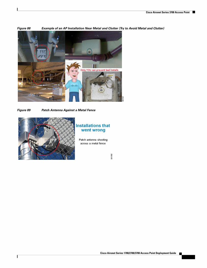
A Quick Look at a Few “Non-Optimal” InstallationsThe figures below present examples of installations that are not recommended. It is very difficult to provide good Wi-Fi service with a poor installation. Always try to avoid metal and clutter.
6Cisco Aironet Series 1700/2700/3700 Access Point Deployment Guide
Cisco Aironet Series 3700 Access Point
Figure 88 Example of an AP Installation Near Metal and Clutter (Try to Avoid Metal and Clutter)
Figure 89 Patch Antenna Against a Metal Fence
Cisco Aironet Series 1700/2700/3700 Access Point Deployment Guide
Cisco Aironet Series 3700 Access Point
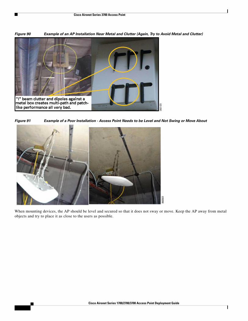
Figure 90 Example of an AP Installation Near Metal and Clutter (Again, Try to Avoid Metal and Clutter)
Figure 91 Example of a Poor Installation - Access Point Needs to be Level and Not Swing or Move About
When mounting devices, the AP should be level and secured so that it does not sway or move. Keep the AP away from metal objects and try to place it as close to the users as possible.
7Cisco Aironet Series 1700/2700/3700 Access Point Deployment Guide
Cisco Aironet Series 3700 Access Point
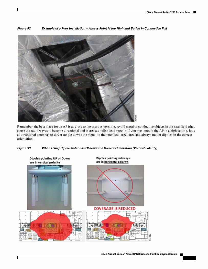
Figure 92 Example of a Poor Installation – Access Point is too High and Buried in Conductive Foil
Remember, the best place for an AP is as close to the users as possible. Avoid metal or conductive objects in the near field (they cause the radio waves to become directional and increases nulls (dead spots)). If you must mount the AP in a high ceiling, look at directional antennas to direct (angle down) the signal to the intended target area and always mount dipoles in the correct orientation.
Figure 93 When Using Dipole Antennas Observe the Correct Orientation (Vertical Polarity)
Cisco Aironet Series 1700/2700/3700 Access Point Deployment Guide
Cisco Aironet Series 3700 Access Point
Tip When mounting antennas outside, always mount with the WIRES DOWN and never obstruct or put weather proofing material over the drain holes.
Figure 94 Always Mount Antennas Outdoors with Leads DOWN (Indoors Does not Matter)
Figure 95 If Antenna Connectors are Exposed to Weather – Coax-Seal Should be Used but if Present, Do Not Cover
Antenna Drain Holes.
7Cisco Aironet Series 1700/2700/3700 Access Point Deployment Guide
Cisco Aironet Series 2700 Access Point
Cisco Aironet Series 2700 Access Point
Cisco Aironet series 2700 AP is a 802.11ac Wave-1 and 3x4:3 MIMO AP. It supports the following features:
• An additional non-PoE GigE port for downward device connectivity
• ClientLink 3.0 Beam-forming
• Existing hardware mounting options and bracket choices
• Existing external antennas (similar to AP 3700)
• 802.3af (15.4W PoE) scaling to 3x3:3 @ 5 GHz and 2x2:2 @ 2.4 GHz
• High Density Experience (HDX)
• Optimized Roaming and Videostream applications
• CleanAir Spectrum analysis including @ 80 MHz
Unlike the 3700 series AP, 2700 series AP does not have module support.
Cisco Aironet Series 1700/2700/3700 Access Point Deployment Guide
Cisco Aironet Series 2700 Access Point
Figure 96 Updated AP Lineup Listing AP 2700
Identifying Cisco Access Points
Figure 97 AP 2700 shares the same physical size and mounting as these Access Points
All the standard modes are supported:
• Local mode
• Flex Mode
• OEAP Mode
• Monitor Mode
• Enhanced Local Mode (with wIPS)
• SE Connect Mode
• Indoor Mesh Mode
• Support for wIDS/wIPS solutions on the 11ac radio
• BandSelect, VideoStream, QoS in hardware, and DTLS
7Cisco Aironet Series 1700/2700/3700 Access Point Deployment Guide
Cisco Aironet Series 2700 Access Point
Figure 98 AP 2700 supports all standard modes of operation
Auxiliary Ethernet Port (New Feature)AP 2700 has an additional Ethernet port labeled “AUX” for Auxiliary port used for downstream traffic.
The Ethernet uplink port to the controller on the AP 3700 is labeled Ethernet, on the AP 2700 it is shortened to PoE.
This AUX port is designed to function as a downstream port. The AUX port is ideal for devices such as video cameras, projectors, IP Phones, Point of Sale terminals, and other end point devices. It is not designed to perform port aggregation nor will it provide PoE out.
Additionally, this AUX port will be disabled if the AP is being powered by a limited 15.4 W .3af PoE source because it requires PoE+, .3at, or local power (wall brick type power supply) to properly function.
Note In release 7.6 MR2/8.0, this port is not manageable and is simply bridged back to the controller. Avoid connecting another AP to this port or devices such as switches/hubs or the same switch or uplink as the PoE port because it can create spanning tree loop issues.
For example, if you configure the switch port (to AP 2700) as access in VLAN 5, then the traffic comes from the AUX port.
If you configure the switch port to trunk, the AP 2700 will be in the native VLAN and the AUX will also be in native by default. Traffic from the AUX port will not be sent to the WLC, and the AP 2700's built-in switch will drop the traffic in the native VLAN.
Cisco Aironet Series 1700/2700/3700 Access Point Deployment Guide
Cisco Aironet Series 2700 Access Point
Figure 99 Ethernet Uplink Port to Controller is Labeled PoE and Auxiliary Port is Labeled AUX
Note The auxiliary port is not manageable in software. So, if you do not want the auxiliary port enabled, you need to limit PoE to 15.4 W. This will be fixed in the next release 8.0MR or 8.1.
Figure 100 AUX port is active when PoE status is at FULL power or when a local power supply is used
Table 7 2700 Power Requirements
Description AP Functionality
PoE Budgeta (Watts)
a. This is the power required at the PSE, which is a switch or injector.
802.3af E-PoE
802.3at PoE+PWRINJ4
PoE+802.3at
2700 – Out of the Box 4x4:3 on 5G & 3x4:3 on 2.4G
Auxiliary Ethernet Port enabled
16.1 Not Available
Available Available
PoE+802.3af
2700 – Out of the Box (7.6 code)
Auxiliary Ethernet Port disabled
2x2:2 on 5G & 2x2:2 on 2.4G
15.4 Available NA NA
2700 – Out of the Box (8.0.x.x code)
Auxiliary Ethernet Port disabled
3x3:3 on 5G & 3x3:3 on 2.4G
15.4 Available NA NA
2700 – Out of the Box (8.0MR or 8.1)
Auxiliary Ethernet Port enabled
3x3:3 on 5G & 3x3:3 on 2.4G
15.4 Available NA NA
7Cisco Aironet Series 1700/2700/3700 Access Point Deployment Guide
Cisco Aironet Series 2700 Access Point
Mounting OptionsCisco Bracket-1, Bracket-2, or the flush mount Bracket-3 may be used.
Figure 101 All mounting brackets are Orderable Options and Fully Supported
Cisco Aironet Series 1700/2700/3700 Access Point Deployment Guide
Cisco Aironet Series 2700 Access Point
Figure 102 Internal and external model has the same physical dimensions (scale is in inches)
Supported Antennas (AP 2700e Model)
Table 8 Supported antennas for AP 2700
Frequency Part Number Antenna Type Antenna Gain (dBi)
7Cisco Aironet Series 1700/2700/3700 Access Point Deployment Guide
Cisco Aironet Series 2700 Access Point
Antenna Patterns – AP 1700i, 2600i, 2700i, & 3700i
Figure 103 Patterns Azimuth and Elevation Plane @ 2.4 GHz
Cisco Aironet Series 1700/2700/3700 Access Point Deployment Guide
Cisco Aironet Series 2700 Access Point
Figure 104 Patterns Azimuth and Elevation Plane @ 5 GHz
8Cisco Aironet Series 1700/2700/3700 Access Point Deployment Guide
Cisco Aironet Series 2700 Access Point
Figure 105 Heat maps are similar between AP 2700 and AP 3700 because antennas are similar
Cisco Aironet Series 1700/2700/3700 Access Point Deployment Guide
Cisco Aironet Series 1700 Access Point
Cisco Aironet Series 1700 Access PointFigure 106 Cisco Aironet Series 1700 Access Point
Cisco Aironet Series 1700 AP is an 802.11ac Wave-1 and 3x3:2 MIMO AP. It supports the following features and caveats:
• No need to specify Unified or Autonomous image (both present on the AP)
• An additional non-PoE GigE port for downward device connectivity
• Standards based Beamforming (does not support ClientLink 3.0)
• Existing hardware mounting options and bracket choices
• 802.3af (15.4 W PoE)
• CleanAir Express (light version of CleanAir)
• CleanAir Spectrum analysis including @ 80 MHz
• HDX and external antenna options are not supported on the 1700 series
8Cisco Aironet Series 1700/2700/3700 Access Point Deployment Guide
Cisco Aironet Series 1700 Access Point
Figure 107 Cisco Aironet 1700 Series is slightly darker than the 2700 Series
Differences Between the AP 1700 and AP 2700
Table 9 Feature Differences between the AP 1700 and AP 2700
AP 1700 AP 2700
Access Point 802.11ac 3x3:2SS 802.11ac 3x4:3SS
RF Leadership
RRM
Transmit Beamforming (TxBF)
BandSelect
VideoStream
RRM
ClientLink 3.0 (1SS, 2SS, 3SS)
BandSelect
VideoStream
Performance
<610 Mbps MAC throughput @ 70%
Efficiency @ (2-SS) supported rates
No HDX
>910 Mbps MAC throughput @ 70%
Efficiency @ (3-SS) supported rates
Spectrum Intelligence
CleanAir Express: Classify, detect RF interference, and mitigate with limited number of IDRs
CleanAir: Classify, detect, locate, and mitigate RF interference
Correlation of interferers
Zone of Impact
No limitations on number of IDRs
Antenna Configuration Internal Only Internal / External
Cisco Aironet Series 1700/2700/3700 Access Point Deployment Guide
Cisco Aironet Series 1700 Access Point
Changing the Operation of the Access Point to Autonomous ModeBoth unified and autonomous images are installed in the AP 1700 similar to the AP 1530.
To change the operation of the access point from unified mode to autonomous (stand-alone) mode, perform the following steps:
Step 1 Power the AP and connect a console cable.
Step 2 From the Command Line, enter the following command in privileged EXEC mode (#):
AP # capwap ap autonomous
The system responds with “Convert to Autonomous image. Proceed?
Step 3 Type Yes to confirm.
The Unit re-boots and loads the Autonomous (aIOS) image.
Once the autonomous image is loaded, the unified image is erased.
Differences between CleanAir and CleanAir ExpressCleanAir Express is available today and requires controller code 8.0 or higher. CleanAir Express is a fully functional version of Cisco Systems CleanAir.
The main difference with CleanAir Express is the 1600/1700 series access point (AP), referred to as the (1K series), has less dedicated memory for local CleanAir operations. So, the 1600/1700 series AP needs to off-load portions of the Spectrum Intelligence (SI) functions on the 1K series to host memory.
The Cisco 2K and 3K series has more memory and processes the SI functions locally.
The AP 1600/1700 contains the Cisco custom silicon “CleanAir hardware chip” and therefore can recognize all the interferers that the 2K and 3K series AP can recognize.
The core differences with CleanAir Express are the limitations of core memory and processing power of AP 1600. This makes the AP 1600/1700 to only track three devices per radio interface. The 2K and 3K series can track ten devices per radio.
Also, when scanning in monitor mode, 2K and 3K series APs can scan processing spectrum in 40 MHz segments. Therefore, these APs can spend less time, in the scan cycle, looking for interferers (11.4%). But, AP 1600/1700 (1K series) must process the spectrum looking at a smaller 20 MHz segment at a time. Therefore, the scan cycle for 1K series APs is a bit longer (22.8%).
Thus, the longer scan cycle extends the detection time for other monitor functions such as (wIPS, rogues, and so on.)
Table 10 Feature List for CleanAir Express
CleanAir Express CleanAirCleanAir with WSSI
Access Point 1600/1700 2600/3600/2700/3700 3600/3700
RF Interference Detection Available Available Available
RF Interference Classification Available Available Available
RF Interference Mitigation Available Available Available
RF Interference Location Available Available Available
Zone of Impact Not Available Available Available
8Cisco Aironet Series 1700/2700/3700 Access Point Deployment Guide
Misc. Q & A
Power over Ethernet requirements for AP 1700The AP 1700 only requires 802.3af (15.4 W) for full functionality. The 802.3at or PoE+ sources will also power the access point (AP) as they are backward compatible to the lower power 802.3af standard.
The AIR-PWRINJ5 is the ideal power injector for the AP1700. The AIR-PWRINJ4 and local power supply AIR-PWR-B= may also be used.
Misc. Q & AQ. Which AP is the best for manufacturing and warehouse areas?
A. Generally speaking, the AP 3600e or 2600e are first choices because these external antenna models have the highest operating temperature range -20 to 55 C°. The AP 1600, 2700, and 3700 can also be used but has a slightly lower operating temperature range -20 to 50 C°. If temperature is not a concern then the internal antenna “I” series 1600, 2600, and 3600 may be used.
Q. What if I am in a country where the regulatory agency may not approve the AP to be used outdoors because of UNII-1 band restrictions? or if I wish to use higher gain antennas?
A. Consider deploying the Cisco Mesh products (1550 and 1530 series) or look for Access Points ending in “P” for professional install, such as the 3702P series or our outdoor bridging products.
Q. Which AP is best for high density deployments?
A. Both the 3700 and 3600 have virtually identical AP density for coverage based design as well as Capacity-based designed (smaller-cells).
Alert Correlation Not Available Available Available
Air Quality Index Not Available Available Available
Top Severity List Not Available Available Available
Performance Optimized Not Available Available Available
Off Channel Scanning Not Available Not Available Available
Proactive Intelligent Channel Switching with RRM
Not Available Not Available Available
Table 11 PoE requirements for AP-1700
Description AP Functionality
PoE Budget (Watts)
802.3af or PWRINJ5 E-PoE
802.3at PoE+PWRINJ5
PoE 802.3af
1700 – Out of the Box (8.0.x.x)
3x3:2 (both bands)
Auxiliary port enabled
15.4 Available Available Available
Table 10 Feature List for CleanAir Express (continued)
CleanAir Express CleanAirCleanAir with WSSI
Cisco Aironet Series 1700/2700/3700 Access Point Deployment Guide
Misc. Q & A
Q. Cisco has a newer Power Injector (AIR-PWR-INJ5). How is this different from the (AIR-PWR-INJ4)?
A. The newer AIR-PWR-INJ5 is a low cost injector for use with the AP 1600 and AP 2600 Series Products. It is an 802.3af (15.4W injector). The AIR-PWR-INJ4 is a more powerful injector designed to work with the AP 3700 and AP 3600 (when optional modules are used). The AIR-PWR-INJ5 can be used with the AP 3600 but not if the optional module is used.
Q. Can industrial wireless motion or smoke detectors cause WLAN interference?
A. Yes, some products such as United Technologies DD475 and Optex MX-50 operate in the 2.4 GHz band as do other wireless “chimes”, cameras, and other industrial equipment from other manufacturers.
Q. How much power in Watts does the AP 3600 draw when an option module is used?
A. 18 Watts – AP 3600 draws slightly more than 802.3af (15.4W) with the module installed. Powering options include 802.3at PoE+, local Power Supply AIR-PWR-B, or injector AIR-PWR-INJ4. If performing Surveys or 2.4 GHz support is not needed, that radio may be disabled allowing the module to have full power and functionality using 802.3af (15.4 Watts).
Q. What is the Ethernet requirement for 802.11ac (Wave-1)?
A. A single GbE cable is fine for Wave-1. While it is true 802.11ac (Wave-2) will exceed GbE speeds, there is no need or requirement for cabling greater then GbE for 802.11ac Wave-1. Installers wishing to future proof new installations should consider pulling CAT-6a cables <at least 1> and either another CAT6a or a CAT5e cable (this allows you to fall back to 2 GbE ports) for some iterations of Wave-2 and/or support 10GbE should this emerge as the method. 10GbE has some challenges such as PoE standardization. Again, for the foreseeable future, a single GbE is all that is needed.
Q. Is it true that 802.11ac is coming in “waves” and that new hardware is required for each “wave”?
A. The first iteration of 802.11ac (Wave-1) is available today, and both Wave-1 and Wave-2 requires new hardware to take advantage of the new features in each “wave” or iteration. Fortunately, with a modular AP approach such as the AP 3600, upgrading to Wave-1 today is easy. Also, unlike the competition, both the AP 3600 and newer Cisco Access Points such as the AP 3700 with modular support will make upgrading to Wave-2 a painless process without having to perform a complete rip and replace.
Q. With the 802.11ac Module installed in the AP3600, will all 3 radios be active?
A. Yes. All 3 radios will be active
The 2.4 GHz radio continues to support legacy b/g clients as well as n clients. The two 5 GHz radios (integrated + module) will work in tandem so they are not competing with each other but working in concert to support the same channels. For instance:
• The 802.11ac module adopts an 80 MHz wide channel on 100-104-108-112.
• The 802.11a/n integrated radio operates on Channels 100-104 and a 40 MHz wide channel for 802.11n clients, and 802.11a clients communicate with the integrated radio via Channel 100 and a 20 MHz wide channel.
The AP 3600 with the new 802.11ac module installed, will provide concurrent support for both the 2.4 and 5 GHz bands and support for 802.11 a, b, g, n, and new 802.11ac clients.
Note On the 5 GHz side, it is possible to have a 20 MHz wide 11ac channel and a 40 MHz wide 11n channel, the only requirement is that the primary channel should be the same for both slots and is determined by the primary channel setting on the integrated 11n radio.
Q. Can both 5 GHz radios (integrated and 802.11ac module) be on different channels?
A. No. The two 5 GHz radios will work together on the same channels, which does not allow the 5 GHz radios to compete with each other and allows us to maximize the number of clients supported per radio. The primary (integrated .11n) radio will take the lead with the module radio “extending” or bonding from the primary channel set on the integrated radio.
8Cisco Aironet Series 1700/2700/3700 Access Point Deployment Guide
URL Links and Other Resources
Q. Any other thoughts when installing wireless APs?
A. When installing wireless APs:
• It is all about placing the APs as reasonably close to the actual users as possible.
• Make sure that you have coverage (to a known requirement) and compensate for nulls or dead spots regardless of what product you choose to deploy. This is called a site survey.
• Installations should be done based on lessons learned from the site survey – the better the survey the less likely any connectivity problems will occur.
• Cisco has an advanced services team that can perform WLAN surveys or help with the wireless design if a partner is not available or able to do the same.
• When possible, use Cisco brand antennas listed in this document (with the orange band).
• Do not mount antennas against metal objects. Similar to a light bulb, antennas work best when there are no obstructions in the path.
• AP 1600, 2600, and 3600 are not weatherproof and have an IP rating of 40.