INTRODUCTION Enterprise computing environments are larger and more complex than ever. Today’s IT infrastructures often include servers from multiple vendors, diverse network connectivity technologies, and heterogeneous, tiered storage environments. To keep pace, storage administrators need a uniform, easy way to perform essential management operations that masks and simplifies the underlying and increasing complexity of the infrastructure.
As information assets become more important to maintaining competitive advantage, IT must deliver on increasingly demanding service levels. These demands come in two forms.
The first demand is for increased data availability. “High availability” in the usual sense refers to a system that is able to circumvent unplanned outages. But, as organizations increasingly want 24-hour operations capability, the ability to eliminate unplanned downtime is not enough. Planned downtime, which may result from operational requirements such as data center moves, upgrades, or platform migrations across the infrastructure, regardless of storage vendor, must also be addressed. Eliminating both types of downtime will provide for the new, required standard of “continuous data availability.”
The second demand is for an increased ability to deliver on the information requirements of the business. Storage infrastructures need to deliver the right information to the right place at the right time. Storage resources across an organization need to be effectively allocated and dynamically reallocated based on business policy and the value of the data to the business at any point in time. The process by which this is accomplished is called “information lifecycle management” (ILM), and it is essential to cost-effectively meet the new service-level demands for information availability and access.
Network-based storage virtualization, which simplifies management of complex infrastructures, addresses both challenges: enabling non-disruptive operations and facilitating critical elements of a proactive ILM strategy. However, it can only do so if it delivers the right capability on a suitable platform. Today, a new class of storage virtualization technologies is emerging that delivers this capability in the infrastructure, as part of the storage network. EMC and Cisco Systems® have collaborated on such a network-hosted storage virtualization solution: EMC Invista® running on the Cisco® MDS 9000 Family multilayer directors and switches.
EMC Invista Overview EMC’s storage virtualization product Invista provides intelligence to allow various host operating systems to access virtual volumes residing on heterogeneous storage arrays. Business continuance and disaster recovery applications could previously communicate only with the same type of storage arrays within the same storage vendor. With EMC’s Invista, volume management, business continuance, and disaster recovery can now span across multiple storage vendors and across heterogeneous storage arrays. The following are the features that EMC Invista provides.
Important notices, privacy statements, and trademarks of Cisco Systems, Inc. can be found on cisco.com. Page 2 of 18
EMC Invista Features With the first release of EMC Invista, the following features and functionality are available:
Dynamic Volume Management Benefits: Dynamic Volume Management enables higher levels of storage utilization through “just-in-time” provisioning of storage. Storage administrators can allocate an initial storage volume size and, as hosts fill up their storage allocation, the volume can easily be increased non-disruptively. Volumes can be dynamically reconfigured without disruption or downtime to optimize performance based on application requirements.
Point-in-Time Copies—Clones Benefits: “Point-in-time copies” enable business continuity through an instantaneous snapshot of a volume where I/O is quiesced such that items like databases are in a consistent state. These point-in-time copies may then be used for purposes such as backups (backing up data in a consistent fashion) or for keeping a copy of data prior to a major change (for example, a database batch-update or application upgrade). If the application or processing fails in any way, there is still a copy of the data at a “consistent” point-in-time prior to any corruption.
Dynamic Volume Migration Benefits: Dynamic Volume Migration enables applications or business data to be migrated from one virtual volume to another heterogeneous virtual volume. Storage arrays that are at the end of a lease agreement can now be easily migrated to a new storage array without any disruption to the host application. With ILM, this allows ease of migrating data from differing types of storage, such as Tier 1 to Tier 3 storage arrays, so as to efficiently use higher-performance storage arrays for more critical application data.
EMC Invista Terminology The following terms are helpful when discussing EMC Invista and its implementation in a Cisco MDS architecture.
• Data Path Controllers (DPCs)—Where all read and write data flows through (fast-path). EMC Invista always uses Cisco Storage Services Modules (SSMs) installed within Cisco MDS 9000 Family switches as the fast-path for managing all read and write operations.
• Control Path Cluster (CPC)—The CPC is a pair of redundant external controllers used to manage control data. They manage the provisioning of the DPCs.
• Back-End VSAN—This VSAN is where the pool of physical storage under Invista control resides (disk VSAN). • Front-End VSAN—This VSAN is where the hosts and “virtual target” reside. Hosts can access the virtualized storage (VLUNs) through the
“host initiator—virtual target—Virtual LUN” (ITL) path. • Virtual Target—A logical entity that acts as a SCSI target and that presents virtual volumes to initiators (hosts) on a SAN. Virtual targets are
presented by the network-based storage virtualization layer on the front-end VSAN. Hosts perform I/O on these virtual target devices. • Front-End Port—A virtual device on the front-end VSAN where a virtual target resides. Hosts are configured to see these virtual front-end ports
through Fibre Channel zoning. • Storage Element—A logical SCSI disk presented to an Invista instance by a storage array. Storage elements are located in the back-end VSAN.
Note that storage elements have to be explicitly “imported” into an Invista instance before it can be used. • Virtual Volume—Volumes created within the network storage virtualization layer encapsulating the back-end storage. Virtual volumes can be
constructed from either a portion of a storage element, an entire storage element, or multiple storage elements. A virtual volume can span across storage elements through concatenation or striping (RAID 0).
• Virtual Frame—A collection of one or more virtual volumes connected to one or more servers. A virtual frame has the following components: – One or more host bus adaptors (HBAs)
An HBA can reside in one or more virtual frames
– One or more front-end ports or virtual targets
A front-end port or virtual target can reside in one or more virtual frames
Important notices, privacy statements, and trademarks of Cisco Systems, Inc. can be found on cisco.com. Page 4 of 18
Cisco MDS Storage Services Module Overview The Cisco Storage Services Module (SSM) is an intelligent line-card module for Cisco MDS 9500 Series multilayer directors or Cisco MDS 9200 Series multilayer fabric switches that enables network-based storage virtualization. Each SSM contains multiple embedded processors providing a distributed architecture capable of inline SCSI processing for more than 480,000 IOPS and 20 Gbps of throughput per module. Multiple SSMs can be deployed in a chassis for higher aggregate performance, and multiple SSMs can be distributed across multiple chassis for higher levels of performance and availability.
Each SSM contains 32 Fibre Channel front-panel ports. However, network-based storage virtualization is not restricted to only those Fibre Channel ports on the SSM itself. Virtualization services are provided to any hosts deployed on the front-end VSAN even where the front-end VSAN spans across multiple physical switches. As a best practice, hosts that are going to be virtualized should connect directly to the SSM ports. Also storage ports should connect to standard 16-port Fibre Channel line cards or Fibre Channel ports on the Multi-Protocol Service (MPS) module.
EMC INVISTA TOPOLOGY In the first release, EMC Invista supports up to four SSMs in a dual-fabric environment. The environment can consist of either four Cisco MDS 9200 Series switches each with an SSM or two Cisco MDS 9500 Series directors switches where each director can have up to two SSMs each. In both topologies, there are no restrictions on other switches in the physical topology. See Figure 2.
The components that make up a single Invista instance are as follows.
Hardware • Invista Control Path Cluster (CPC) • Minimum of two SSMs and up to four SSMs in a dual fabric environment—4 x Cisco MDS 9216 or 2 x Cisco MDS 9500 • A single SSM is allowed with EMC Invista, which will be in a non-Highly Available environment but is not recommended for production
environments • Dual Ethernet switches
Software • CPC Software
– Invista Storage Virtualization Services Version 1.0
– Invista X Virtualizer Option for 1/2/4 DPC support
– Invista SnapView Services for Point-in-Time Copy/Cloning capability
• Cisco MDS SAN OS – System and Kickstart Version 2.1.2b or later
– Storage Services Image (SSI) Version 2.1.2i or later
Important notices, privacy statements, and trademarks of Cisco Systems, Inc. can be found on cisco.com. Page 5 of 18
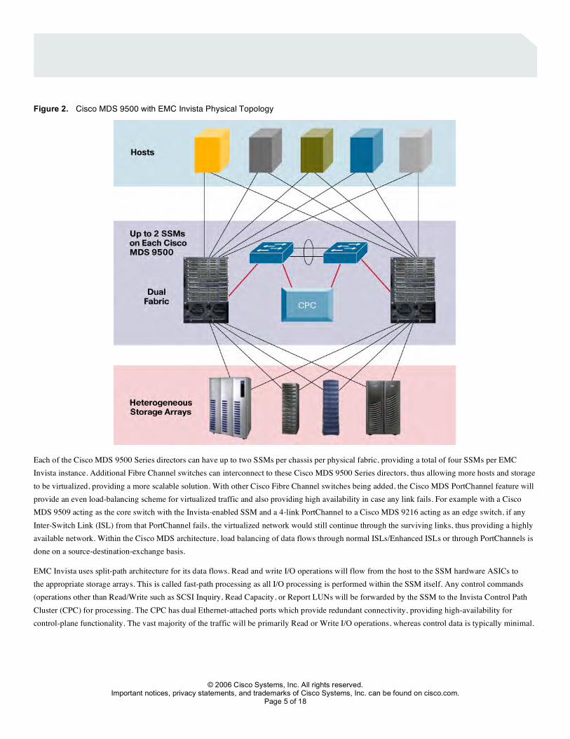
Figure 2. Cisco MDS 9500 with EMC Invista Physical Topology
Each of the Cisco MDS 9500 Series directors can have up to two SSMs per chassis per physical fabric, providing a total of four SSMs per EMC Invista instance. Additional Fibre Channel switches can interconnect to these Cisco MDS 9500 Series directors, thus allowing more hosts and storage to be virtualized, providing a more scalable solution. With other Cisco Fibre Channel switches being added, the Cisco MDS PortChannel feature will provide an even load-balancing scheme for virtualized traffic and also providing high availability in case any link fails. For example with a Cisco MDS 9509 acting as the core switch with the Invista-enabled SSM and a 4-link PortChannel to a Cisco MDS 9216 acting as an edge switch, if any Inter-Switch Link (ISL) from that PortChannel fails, the virtualized network would still continue through the surviving links, thus providing a highly available network. Within the Cisco MDS architecture, load balancing of data flows through normal ISLs/Enhanced ISLs or through PortChannels is done on a source-destination-exchange basis.
EMC Invista uses split-path architecture for its data flows. Read and write I/O operations will flow from the host to the SSM hardware ASICs to the appropriate storage arrays. This is called fast-path processing as all I/O processing is performed within the SSM itself. Any control commands (operations other than Read/Write such as SCSI Inquiry, Read Capacity, or Report LUNs will be forwarded by the SSM to the Invista Control Path Cluster (CPC) for processing. The CPC has dual Ethernet-attached ports which provide redundant connectivity, providing high-availability for control-plane functionality. The vast majority of the traffic will be primarily Read or Write I/O operations, whereas control data is typically minimal.
Important notices, privacy statements, and trademarks of Cisco Systems, Inc. can be found on cisco.com. Page 6 of 18
VSAN AND ZONING CONSIDERATION Using VSAN technology to segregate fabric services allows the pooling of storage to be in one VSAN without allowing any hosts to access the virtualized storage. EMC Invista with Cisco MDS SSM creates virtual targets that reside in any front-end VSANs. This added security allows host connections to only access virtual targets, eliminating the possibility of accidentally permitting access to real storage ports from the host ports. While zoning within a homogenous SAN is allowed, the best practice is to create separate VSANs for the back-end virtualized storage and one or more front-end VSANs for virtualized hosts. Default zoning policy on front-end VSANs should be set to “deny” with explicit zoning to permit hosts access to virtual targets. It is recommended that a separate management VSAN be created for communication between the SSMs and CPCs. A default zoning policy of “permit” may be used in this VSAN. Communication from the CPC and the Cisco MDS switch uses Simple Network Management Protocol Version 2 (SNMPv2), which requires a community to be created on the Cisco MDS switch with read/write capability. Figure 3 depicts the topology of EMC Invista with Cisco MDS technology.
Figure 3. Topology of EMC Invista with Cisco MDS Technology
Important notices, privacy statements, and trademarks of Cisco Systems, Inc. can be found on cisco.com. Page 7 of 18
Management VSAN Management connectivity is required between EMC’s CPC and the Cisco SSMs. Best practice recommendations are to create a dedicated VSAN for Invista management traffic between the SSMs and the EMC CPC. Initial management connectivity is in the form of IP over Ethernet with subsequent Invista releases moving this to IP over Fibre Channel. Communication goes through the management port of the Cisco MDS switch. The internal communication from the management port to the SSM is done by creating and assigning private IP addresses for the control path processor (CPP) on the SSM and the management VSAN. To complete the communication between the Cisco MDS SSM and Invista CPC, a static route is created on the Cisco MDS switch to help ensure proper routing. This way the control traffic is only forwarded to the external CPC.
As a best practice with the Cisco MDS 9500 Series switches, if there is more than one SSM in the chassis being used for Invista, all of the SSM’s CPP IP addresses should be assigned to the same subnet. For example where a Cisco MDS 9509 has two SSMs, one in slot 1 and another in slot 7, and the management VSAN is set to VSAN 10, then the following IP addresses should be assigned to the two SSMs in this Cisco MDS 9509.
The syntax for assigning IP addresses on the SSM is “interface cpp X/Y/Z” where X=Slot #, Y=1, Z=VSAN number.
VSAN 10: interface vsan 10 ip address 10.10.10.1 255.255.255.0 SSM in slot 1: interface cpp 1/1/10 ip address 10.10.10.2 255.255.255.0 SSM in slot 7: interface cpp 7/1/10 ip address 10.10.10.3 255.255.255.0
As with security on the management port of the Cisco MDS switch, the Cisco MDS Family provides SNMPv3 support and Secure Shell (SSH) protocol access, standard with all Cisco MDS switches. Support of TACACS+ and RADIUS servers provides a very centralized and secure network for management access. In the case where the management port of the Cisco MDS switch fails, the added capability for management of the Cisco MDS fabrics can be used through a Fibre Channel access, using IP over Fibre Channel, providing a backup method to manage the storage network. In networks that have firewalls in the environment, standard ports for telnet, SSH, or SNMP ports can be allowed to pass through the firewall for access. The Cisco MDS switch also provides rate limiting of the management port in case of denial-of-service (DoS) attacks, thus increasing the availability of network management capabilities. For more information on LAN and SAN security, please visit: http://www.cisco.com/application/pdf/en/us/guest/netsol/ns513/c654/cdccont_0900aecd80281e21.pdf
Back-End VSAN Once EMC Invista has imported and brought online the Cisco MDS switch and DPC/SSM, nine entries, known as Virtual Initiators, will be added to the back-end VSAN Fibre Channel Name Server (FCNS) database. Eight of the entries are the Cisco MDS fast-path data path processors (fast-path DPPs) and the ninth is the Cisco MDS control path processor (CPP). The default zone of the back-end VSAN should be set to “deny.” For storage that will be virtualized, the following zoning is recommended for these storage ports: Create a zone for each storage port being virtualized that will include all nine “virtual initiators” created by Invista and the storage port. Even though Invista can see all physical disks associated with the target ports, not all physical disks have to be virtualized. Choosing which disk or set of disks to be virtualized can be filtered by selecting these disk(s) to be imported into Invista.
Front-End VSAN With the Cisco MDS SSM providing 32 Fibre Channel ports, EMC Invista has implemented a mapping of each port to be a “front-end port” or “virtual target,” and that virtual target will reside in whatever port-VSAN membership that Fibre Channel port was defined. For example, when the first port on the SSM has a port-VSAN membership of 10, then when EMC Invista enables that port as a “front-end port”, then a virtual target Port World Wide Name (PWWN) will be added to VSAN 10 Fibre Channel Name Server database. Because there are up to 32 front-end ports with EMC
Important notices, privacy statements, and trademarks of Cisco Systems, Inc. can be found on cisco.com. Page 8 of 18
Invista with Cisco MDS switches, it is recommended to enable all 32 front-end ports and define what port-VSAN membership the SSM ports should reside in first, prior to bringing the DPC/SSM online. It is recommended that hosts that are being virtualized be connected to the SSM ports. The storage that is being virtualized should be connected to the standard 16-port Fibre Channel line cards or the Multi-Protocol Services module. EMC Invista automatically creates virtual targets for the 32 front-panel ports on the SSMs once the DPC is set online. The first port on the SSM will be “Virtual Target 1” and the thirty-second port on the SSM will be “Virtual Target 32.” For the first release of EMC Invista, virtual targets are mapped to front-end VSANs based on whatever VSAN the SSM front-panel port is configured into—thus, up to 32 front-end VSANs are allowed per SSM.
EMC INVISTA DATA FLOW WITH CISCO MDS TECHNOLOGY Network-based storage virtualization of heterogeneous storage arrays provides tremendous scalability and management benefits for SANs. Understanding how host application I/O is affected and where data flows in a virtualized storage environment will make it easier to understand the benefits that Invista on the Cisco MDS switches provides. The split-path architecture enables all read and write I/Os to flow directly from the host to the fast-path DPP ASICs on the SSM to the appropriate storage frames. Control frames flow from the host to the SSM and are then forwarded to the Invista CPC through IP. These control frames traffic are typically infrequent and only utilizes minimal bandwidth of the management port on the Cisco MDS switches.
Regular I/O Flow Hosts that access virtualized storage for volume management will access these volumes as they are regular storage volumes. EMC Invista with Cisco MDS switches masks the hardware details of the physical storage array to the host, such that the hosts only sees an EMC Invista volume (virtual target). Virtual volumes can be built from either a single physical storage array such as an EMC DMX or HP EVA (or any other supported storage array) or can be built through concatenating or striping across multiple physical heterogeneous storage arrays. Figure 4 depicts application I/O flow for reads and writes.
Important notices, privacy statements, and trademarks of Cisco Systems, Inc. can be found on cisco.com. Page 10 of 18
Data Flow Through Point-in-Time Copies The Point-in-Time Copy feature of Invista provides the capability to copy data from one virtual volume to another, while the application server is still continuing to read and write data. This provides the capability to make multiple copies of the primary-source data so that it can be used for backup purposes or any other purpose without affecting the primary-source volume. This process is non-disruptive to the application server and the data movement is done by the Cisco MDS SSM ASICs. The terminology used in EMC Invista is called “Cloning,” where a source virtual volume can clone multiple copies of equal or greater size to the target virtual volume that can be from heterogeneous storage arrays. Figure 5 shows how the data flows when a Cloning process is started
Figure 5. Data Flow Through a Cloning Session
After the completion of the cloning process and the source and target volume(s) are in sync, the host application has an added benefit that it can now read from either the original source volume (VLUN 0) or the cloned volume (Clone 1). With the cloned volume synced with the source volume, the clone volume can now be split (fractured) from the source volume and can then be mounted to another server for backup or any other purposes. In case of disaster recovery, this fractured clone can be used to restore the original source volume (VLUN 0) in case VLUN 0 is corrupted, which will provide a quicker data recovery. When the clone volume is fractured and then re-established, the resynchronization process only copies the delta since the fracture of the cloned volume. This provides a faster synchronization process time.
Important notices, privacy statements, and trademarks of Cisco Systems, Inc. can be found on cisco.com. Page 11 of 18
Data Flow Through Data Mobility The Data Mobility feature provides the capability to migrate existing data from a virtual volume to another virtualized volume that is physically on a different storage frame. This is extremely beneficial for end-of-lease storage frames that need to be migrated to a new storage frame or for Information Lifecycle Management can be move to different tiered storage arrays. With the dynamic capability of this feature, there is no downtime for the host application during this migration process.
Importing a non-virtualized array into Invista control will require some level of disruption to the application server, in the first release. Existing data on the disks will not be altered or encapsulated, but it is now exposed to the servers through a new SCSI virtual target. Mapping the server to see the virtualized volume, exposed through a new target PWWN, will likely cause a small disruption, though minimal as compared to other options. Once under Invista control, data migration to the other storage array is now transparent and non-disruptive to the application server. Subsequent migrations from one storage array to another heterogeneous array is non-disruptive to the host, because the LUNs on the array are already virtualized and under Invista control.
As with Snapshot Copy functionality, host application data flow during the migration process is exactly the same. The only difference is when the Data Mobility process has completed. With Snapshot Copy, the target “Clone” volume is synced with the source volume and both volumes are accessible to the host. Whereas with Data Mobility, once the process has completed, the target volume becomes the source virtual volume accessible to the host application. All of the properties that were from the original source volume are now moved to the target volume (for example, VLUN number, host LUN number, etc.). So the host application data migration is transparent to the physical changed done by the migration from one physical array to another. The original source volume is then moved back into the storage pool. Figure 6 depicts data flow for a Data Mobility session, which is similar to the Cloning process. Figure 7 depicts this process during the completion of the Data Mobility procedure.
Important notices, privacy statements, and trademarks of Cisco Systems, Inc. can be found on cisco.com. Page 13 of 18
Figure 7. Data Mobility Completion Process
SCALABILITY WITH INVISTA ON CISCO MDS SWITCHES With the Cisco SSM being a modular line card and the Cisco MDS 9500 Series Director being the only director-level switch supporting EMC Invista, scaling to a large virtualized network is made easier with the Cisco MDS Family of switches. With up to 224 ports per chassis, there is no need for wasted Fibre Channel ports for ISL to other switches as the network grows. With appliance-switch implementation of virtualization, ports will be needed to utilize as ISL (E-ports) so that the network can grow to accommodate more servers and storage ports. This type of implementation will significantly limit the scalability of a virtualized network.
With 32 virtual targets per SSM, more hosts can access the virtualized network without stressing the virtual targets. So with up to 64 virtual targets per physical fabric, an EMC Invista instance can scale up to 128 virtual targets, providing scalability for host connections to the virtualized network.
The Cisco MDS 9000 Family’s modular design allows interchangeable modules to be inserted into the chassis. By inserting a Cisco MDS 9000 Family Storage Services Module (SSM) into open slots in one or more Cisco MDS 9000 Family multilayer directors and switches, fabric-hosted applications can easily be deployed on existing SAN infrastructures. A small virtualization network can be initiated with EMC Invista and Cisco MDS 9200 Series multilayer fabric switches. As this network grows and requires a director-level switch, a Cisco MDS 9500 Series director with an SSM in any of the available slots can provide investment protection.
With the advance features integrated in the Cisco MDS Family of switches, such as VSAN, Port Channeling, Multi-Protocol, SPAN, etc., the virtualization network can grow as EMC Invista grows. Providing up to 239 Domain IDs per VSAN and supporting 128 VSANs per physical fabric, the Cisco MDS Family brings superior scalability to virtualization networks.
Important notices, privacy statements, and trademarks of Cisco Systems, Inc. can be found on cisco.com. Page 14 of 18
SAN DESIGN, CONNECTIVITY, AND HIGH AVAILABILITY In a dual-redundant fabric architecture, redundant paths exist between Fibre Channel initiators, virtual targets, virtual initiators, and physical targets. If any component on one path becomes unstable or fails, the redundant path will maintain full availability, with the appropriate multi-pathing on the host and redundant controllers on the storage.
Some of the concerns around single-fabric configurations are due to scalability issues, user errors, and SAN instability such as an unsupported HBA. The dual-redundant fabric architecture addresses the following:
• Earlier HBAs were not as resilient—upgrading two HBAs at the same time could cause both fabrics to fail (resulting in best practices to update one HBA, make sure it is working properly, and then update the next HBA)
• Merging of fabrics caused instability • Dual-redundant fabric avoids propagation of errors • It also reduces user errors (zoning errors, for example)
SAN Design The following recommendations describe the configuration of a single fabric. The second fabric in a dual-fabric design should be constructed in the same manner. The environment does not support Inter-VSAN Routing (IVR).
• In the absence of IVR, virtual targets must be created and placed into each front-end VSAN that contains hosts that want to see virtualized storage. • All of the back-end storage should be placed in a single VSAN that is different from the hosts’ front-end VSAN. This VSAN must be specified as
the back-end VSAN when importing the Cisco DPC (SSM). • Physical HBAs should connect to the port on the SSM or somewhere in the physical fabric where the DPC is accessible.
Issues Surrounding VSAN Membership When a DPC is imported, as part of the import process, the Invista administrator is required to select a port-role. Configuring the port to become a front-end port defines a virtual target to be created on that port. This causes the virtual target to be created as a member of the VSAN to which the port belongs. This implies that the Invista administrator must be aware of which VSANs contain the host-based initiators and know the VSAN membership of the SSM ports before deciding where the virtual targets are to be instantiated. In the initial release, the virtual targets cannot be moved within VSANs while the SSM card is online. To change the VSAN membership of a virtual target, its DPC must first be brought offline, the VSAN membership of the port must then be changed, then the DPC brought back online.
High-Availability Considerations It is recommended that SSMs be configured in pairs where each SSM of the pair is placed in a different switch/director. Hosts should be configured to use multi-path software to access volumes presented through targets on the pair of SSMs.
As with any typical high-availability topologies, any component that fails in an Invista environment will still allow the host application I/O to continue on the secondary path. The host multi-pathing software will be aware that there exists a secondary path to the virtualized LUN. In the event that the Ethernet link on the Cisco MDS switch or director fails, I/O will still continue from the host application down the secondary path and an alert will be sent about the Ethernet failure. Figure 8 depicts a typical high-availability topology in an Invista environment.
Important notices, privacy statements, and trademarks of Cisco Systems, Inc. can be found on cisco.com. Page 15 of 18
Figure 8. High-Availability Topology
The Invista SAN Support Matrix lists the supported components in an Invista environment, with the number of virtual LUNs per virtual target, number of hosts per virtual target, list of storage arrays, etc. Please check EMC’s SAN Support Matrix for complete list at http://powerlink.emc.com.
Note: The Cisco MDS feature called “Dynamic Port VSAN Membership” (DPVM) allows the VSAN membership of a physical device (physical initiator or physical target) to follow the device within the physical fabric of the Cisco MDS switch, in the event that the device is plugged into a different port. At the time of writing, this feature needs to be validated by EMC’s E-lab, but Cisco has tested and validated that DPVM does work in an Invista environment and does not affect virtual components. Table 1 below are some deployment recommendations for the Invista environment.
Table 1. Deployment Recommendations
Recommendation Description When using direct host connections, connect the host directly to a port of the SSM where the volume is mapped
The lowest latency for fast-path I/Os can be obtained by connecting a host directly to one of the four ports whose ASIC has been loaded with the virtual target being accessed by the host. This avoids an extra routing hop within the switch. Additionally, it reduces the amount of traffic going in and out of the backplane of the switch.
Create separate VSAN for all host access to virtual targets
This will help prevent undesired direct host access to the back-end storage arrays. The exception to this rule is certain environments needing data migration from a non-virtualized storage array to a virtualized storage array.
Use role-based management for back-end VSAN administration
Unintended changes to the back-end VSAN configuration will be prevented by this approach.
Important notices, privacy statements, and trademarks of Cisco Systems, Inc. can be found on cisco.com. Page 16 of 18
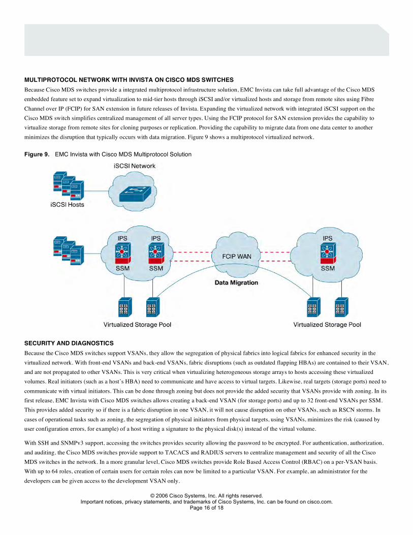
MULTIPROTOCOL NETWORK WITH INVISTA ON CISCO MDS SWITCHES Because Cisco MDS switches provide a integrated multiprotocol infrastructure solution, EMC Invista can take full advantage of the Cisco MDS embedded feature set to expand virtualization to mid-tier hosts through iSCSI and/or virtualized hosts and storage from remote sites using Fibre Channel over IP (FCIP) for SAN extension in future releases of Invista. Expanding the virtualized network with integrated iSCSI support on the Cisco MDS switch simplifies centralized management of all server types. Using the FCIP protocol for SAN extension provides the capability to virtualize storage from remote sites for cloning purposes or replication. Providing the capability to migrate data from one data center to another minimizes the disruption that typically occurs with data migration. Figure 9 shows a multiprotocol virtualized network.
Figure 9. EMC Invista with Cisco MDS Multiprotocol Solution
SECURITY AND DIAGNOSTICS Because the Cisco MDS switches support VSANs, they allow the segregation of physical fabrics into logical fabrics for enhanced security in the virtualized network. With front-end VSANs and back-end VSANs, fabric disruptions (such as outdated flapping HBAs) are contained to their VSAN, and are not propagated to other VSANs. This is very critical when virtualizing heterogeneous storage arrays to hosts accessing these virtualized volumes. Real initiators (such as a host’s HBA) need to communicate and have access to virtual targets. Likewise, real targets (storage ports) need to communicate with virtual initiators. This can be done through zoning but does not provide the added security that VSANs provide with zoning. In its first release, EMC Invista with Cisco MDS switches allows creating a back-end VSAN (for storage ports) and up to 32 front-end VSANs per SSM. This provides added security so if there is a fabric disruption in one VSAN, it will not cause disruption on other VSANs, such as RSCN storms. In cases of operational tasks such as zoning, the segregation of physical initiators from physical targets, using VSANs, minimizes the risk (caused by user configuration errors, for example) of a host writing a signature to the physical disk(s) instead of the virtual volume.
With SSH and SNMPv3 support, accessing the switches provides security allowing the password to be encrypted. For authentication, authorization, and auditing, the Cisco MDS switches provide support to TACACS and RADIUS servers to centralize management and security of all the Cisco MDS switches in the network. In a more granular level, Cisco MDS switches provide Role Based Access Control (RBAC) on a per-VSAN basis. With up to 64 roles, creation of certain users for certain roles can now be limited to a particular VSAN. For example, an administrator for the developers can be given access to the development VSAN only.
Important notices, privacy statements, and trademarks of Cisco Systems, Inc. can be found on cisco.com. Page 17 of 18
Because communications between EMC Invista CPC and Cisco MDS switches are through IP, static routes are needed on both the CPC and the Cisco MDS switches. This communication flows through both the CPC and Cisco MDS management ports. EMC Invista provides two management roles through SNMPv2, which are network-admin and network-operator.
With the complexity of a virtualized network, troubleshooting and analyzing problems can be very cumbersome. With the advanced diagnostics capabilities on the Cisco MDS switches, such as Switched Port Analyzer (SPAN), debugging virtual objects and correlating them back to physical objects are made easier. The Cisco MDS debug features allow debugging any Fibre Channel operations that associate with the virtual targets or virtual initiators, allowing administrators to pinpoint where the actual problem is in the virtualized network.
Important notices, privacy statements, and trademarks of Cisco Systems, Inc. can be found on cisco.com. Page 18 of 18
Corporate Headquarters Cisco Systems, Inc. 170 West Tasman Drive San Jose, CA 95134-1706 USA www.cisco.com Tel: 408 526-4000 800 553-NETS (6387) Fax: 408 526-4100
European Headquarters Cisco Systems International BV Haarlerbergpark Haarlerbergweg 13-19 1101 CH Amsterdam The Netherlands www-europe.cisco.com Tel: 31 0 20 357 1000 Fax: 31 0 20 357 1100
Americas Headquarters Cisco Systems, Inc. 170 West Tasman Drive San Jose, CA 95134-1706 USA www.cisco.com Tel: 408 526-7660 Fax: 408 527-0883
Asia Pacific Headquarters Cisco Systems, Inc. 168 Robinson Road #28-01 Capital Tower Singapore 068912 www.cisco.com Tel: +65 6317 7777 Fax: +65 6317 7799
Cisco Systems has more than 200 offices in the following countries and regions. Addresses, phone numbers, and fax numbers are listed on
the Cisco Website at www.cisco.com/go/offices. Argentina • Australia • Austria • Belgium • Brazil • Bulgaria • Canada • Chile • China PRC • Colombia • Costa Rica • Croatia • Cyprus Czech Republic • Denmark • Dubai, UAE • Finland • France • Germany • Greece • Hong Kong SAR • Hungary • India • Indonesia • Ireland • Israel Italy • Japan • Korea • Luxembourg • Malaysia • Mexico • The Netherlands • New Zealand • Norway • Peru • Philippines • Poland • Portugal Puerto Rico • Romania • Russia • Saudi Arabia • Scotland • Singapore • Slovakia • Slovenia • South Africa • Spain • Sweden • Switzerland • Taiwan Thailand • Turkey • Ukraine • United Kingdom • United States • Venezuela • Vietnam • Zimbabwe
Copyright 2006 Cisco Systems, Inc. All rights reserved. CCSP, CCVP, the Cisco Square Bridge logo, Follow Me Browsing, and StackWise are trademarks of Cisco Systems, Inc.; Changing the Way We Work, Live, Play, and Learn, and iQuick Study are service marks of Cisco Systems, Inc.; and Access Registrar, Aironet, BPX, Catalyst, CCDA, CCDP, CCIE, CCIP, CCNA, CCNP, Cisco, the Cisco Certified Internetwork Expert logo, Cisco IOS, Cisco Press, Cisco Systems, Cisco Systems Capital, the Cisco Systems logo, Cisco Unity, Enterprise/Solver, EtherChannel, EtherFast, EtherSwitch, Fast Step, FormShare, GigaDrive, GigaStack, HomeLink, Internet Quotient, IOS, IP/TV, iQ Expertise, the iQ logo, iQ Net Readiness Scorecard, LightStream, Linksys, MeetingPlace, MGX, the Networkers logo, Networking Academy, Network Registrar, Packet, PIX, Post-Routing, Pre-Routing, ProConnect, RateMUX, ScriptShare, SlideCast, SMARTnet, The Fastest Way to Increase Your Internet Quotient, and TransPath are registered trademarks of Cisco Systems, Inc. and/or its affiliates in the United States and certain other countries. All other trademarks mentioned in this document or Website are the property of their respective owners. The use of the word partner does not imply a partnership relationship between Cisco and any other company. (0601R) Printed in the USA 205545.P 03/06
SUMMARY Invista on the Cisco MDS 9000 switches enables flexible provisioning of heterogeneous storage, non-disruptive operations, and data protection. With the ability to pool all of your storage, you can more effectively provision the appropriate tier of storage to the associated application. You can easily incorporate new storage and maintain the same services and scripts, all from a single point of management. Additionally, your storage environment is now virtualized, enabling continuous data operations, so you can migrate data nondisruptively, and protect data with advanced copy services. The Cisco MDS 9000 Family provides the scalability, flexibility, security, and high availability necessary for EMC Invista to deliver an end-to-end solution for growing data centers.