173
78-20762-01 Cisco AS Series Media Processor Software 6.2 Operation Manual v 6.2 Americas Headquarters Cisco Systems, Inc. 175 West Tasman Drive San Jose, CA 95134-1706 USA 1 408 526 7209
78-20762-01
Cisco AS Series Media Processor Software 6.2
Operation Manual
v 6.2
Americas Headquarters Cisco Systems, Inc. 175 West Tasman Drive San Jose, CA 95134-1706 USA 1 408 526 7209

1 800 553 2447
78-20762-01 ii
Notices
Trademark Acknowledgments Cisco and the Cisco logo are trademarks or registered trademarks of Cisco and/or its affiliates in the U.S. and other countries. A listing of Cisco's trademarks can be found at www.cisco.com/go/trademarks.
Third party trademarks mentioned are the property of their respective owners.
The use of the word partner does not imply a partnership relationship between Cisco and any other company. (1009R)
Publication Disclaimer Cisco Systems, Inc. assumes no responsibility for errors or omissions that may appear in this publication. We reserve the right to change this publication at any time without notice. This document is not to be construed as conferring by implication, estoppel, or otherwise any license or right under any copyright or patent, whether or not the use of any information in this document employs an invention claimed in any existing or later issued patent.
Copyright © 2012 Cisco and/or its affiliates. All rights reserved. Printed in the United States of America.
Information in this publication is subject to change without notice. No part of this publication may be reproduced or transmitted in any form, by photocopy, microfilm, xerography, or any other means, or incorporated into any information retrieval system, electronic or mechanical, for any purpose, without the express permission of Cisco Systems, Inc.
The Inlet Technologies Spinnaker S6000 Encoder has been renamed as the Cisco AS6000 Series Media
Processor. Beginning June 15, 2011, you will begin to see the Cisco name and company logo, along with the
new product name on the hardware, software, documentation and packaging. During this transition process you
may see both Inlet Technologies and Cisco brands and former product names. These products meet the same
high standards and quality that both Inlet Technologies and Cisco are known for in the industry.
78-20762-01 iii
Contents Notices ...................................................................................................................................... ii
Trademark Acknowledgments ........................................................................................... ii Publication Disclaimer ....................................................................................................... ii Copyright ............................................................................................................................. ii
1 INTRODUCTION ....................................................................................................................... 1 Open Source and Third Party Software ................................................................................. 4
2 GETTING STARTED ................................................................................................................. 5 Equipment Setup ..................................................................................................................... 5
Provision the UCS Server .................................................................................................. 5 Provision the Operating System ....................................................................................... 6 Assign Roles and Features ................................................................................................ 6 Configure Network Interfaces ............................................................................................ 6
Prepare the UCS Blade for Cisco AS Series Media Processor Software ........................... 7 Install the Network License Server ........................................................................................ 7 Configure Network Licensing ................................................................................................. 8 Install the Cisco AS Series Media Processor Software ....................................................... 8 Individualize for Microsoft PlayReady (Optional) ................................................................. 9
3 WEB INTERFACE ................................................................................................................... 10 Remote Management via the Web ........................................................................................ 10
Opening the Interface ....................................................................................................... 10 Logging In .......................................................................................................................... 11 Home Page ........................................................................................................................ 14 Presets Page ..................................................................................................................... 26 Input Page .......................................................................................................................... 29 VC1 Page ........................................................................................................................... 36 VP6 Page ............................................................................................................................ 60 H264 Page .......................................................................................................................... 68 H263 Page ........................................................................................................................ 109 Scheduling Page ............................................................................................................. 117 System Page .................................................................................................................... 119 Global Configurations Page ........................................................................................... 129 Recovery Page ................................................................................................................ 131 Message Service Page ................................................................................................... 132 Help Page ......................................................................................................................... 132 Starting/Stopping Encodes ............................................................................................ 132
APPENDIX A: TECHNICAL GUIDE .............................................................................................. 134 Smooth Streaming ............................................................................................................... 134
VC-1 Video Page ............................................................................................................. 134 H.264 Video Page ............................................................................................................ 134 Smooth Output Page ...................................................................................................... 135 Audio Enable ................................................................................................................... 137 Smooth PlayReady ......................................................................................................... 138 Timecode Options and Smooth Controls ..................................................................... 139 Sample Presets ............................................................................................................... 142
iv 78-20762-01
Error Conditions ............................................................................................................. 142 Cisco Media Processor Metadata for TS Streams ............................................................ 143
Cue Point Payloads ........................................................................................................ 145 Using a DFXP Track for Captions/Subtitles ...................................................................... 147
Caption / Subtitle Track .................................................................................................. 147 Caption / Subtitle Setup on Video Encode Tab ............................................................ 148 Customizing the CC/Subtitle Style ................................................................................ 149
Understanding VC-1 ............................................................................................................ 152 VC-1 codec specification ............................................................................................... 152
Setting up Cisco Media Processor to write to a network drive ....................................... 152 MIB for SNMP ....................................................................................................................... 154
APPENDIX B: MANAGING USER ACCOUNTS .......................................................................... 156
APPENDIX C: TROUBLESHOOTING .......................................................................................... 157 Troubleshooting Tools ........................................................................................................ 157
UDP Tool .......................................................................................................................... 157 Recovery Page ................................................................................................................ 158
Troubleshooting Scenarios ................................................................................................ 160 Resolve Security Certificate Warning ........................................................................... 160 Problems streaming to a Limelight/Akamai Server ..................................................... 162 Authentication retry fails after entering incorrect username ..................................... 164
APPENDIX D: SPECIFICATIONS ................................................................................................. 165 Inputs .................................................................................................................................... 165
Video ................................................................................................................................ 165 Audio ................................................................................................................................ 165
Formats and Codecs ........................................................................................................... 165 Windows Media ............................................................................................................... 165 Flash VP6 (available as an optional upgrade) .............................................................. 165 H.264 Flash ...................................................................................................................... 166 H.264 iOS ......................................................................................................................... 166 H.264 Multicast MPEG-2 Transport Stream .................................................................. 166 3GPP ................................................................................................................................ 166
Control .................................................................................................................................. 166 Processing ............................................................................................................................ 167
Pre-processing ................................................................................................................ 167
INDEX ............................................................................................................................... 168
CISCO MEDIA PROCESSOR
78-20762-01 1
1 IInnttrroodduuccttiioonn
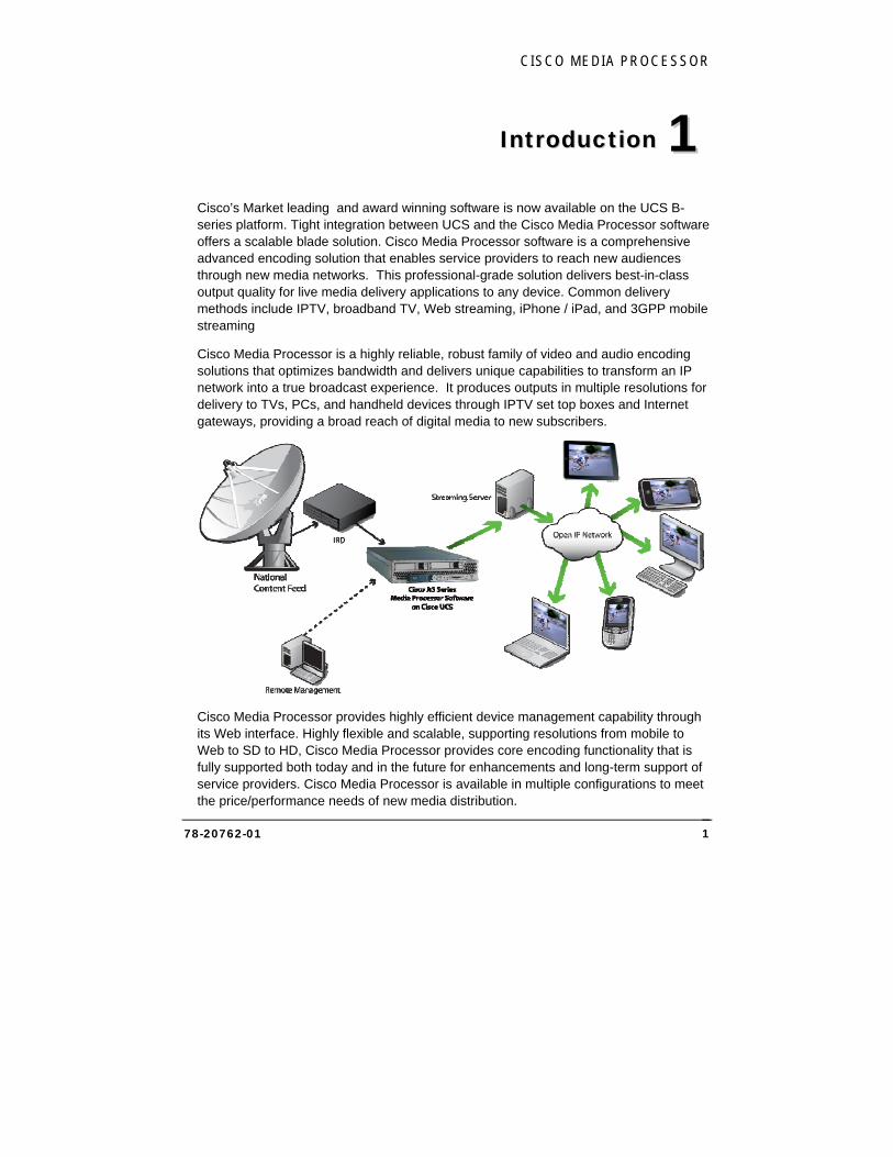
Cisco’s Market leading and award winning software is now available on the UCS B-series platform. Tight integration between UCS and the Cisco Media Processor software offers a scalable blade solution. Cisco Media Processor software is a comprehensive advanced encoding solution that enables service providers to reach new audiences through new media networks. This professional-grade solution delivers best-in-class output quality for live media delivery applications to any device. Common delivery methods include IPTV, broadband TV, Web streaming, iPhone / iPad, and 3GPP mobile streaming
Cisco Media Processor is a highly reliable, robust family of video and audio encoding solutions that optimizes bandwidth and delivers unique capabilities to transform an IP network into a true broadcast experience. It produces outputs in multiple resolutions for delivery to TVs, PCs, and handheld devices through IPTV set top boxes and Internet gateways, providing a broad reach of digital media to new subscribers.
Cisco Media Processor provides highly efficient device management capability through its Web interface. Highly flexible and scalable, supporting resolutions from mobile to Web to SD to HD, Cisco Media Processor provides core encoding functionality that is fully supported both today and in the future for enhancements and long-term support of service providers. Cisco Media Processor is available in multiple configurations to meet the price/performance needs of new media distribution.
11
CISCO SYSTEMS, INC.
78-20762-01 2
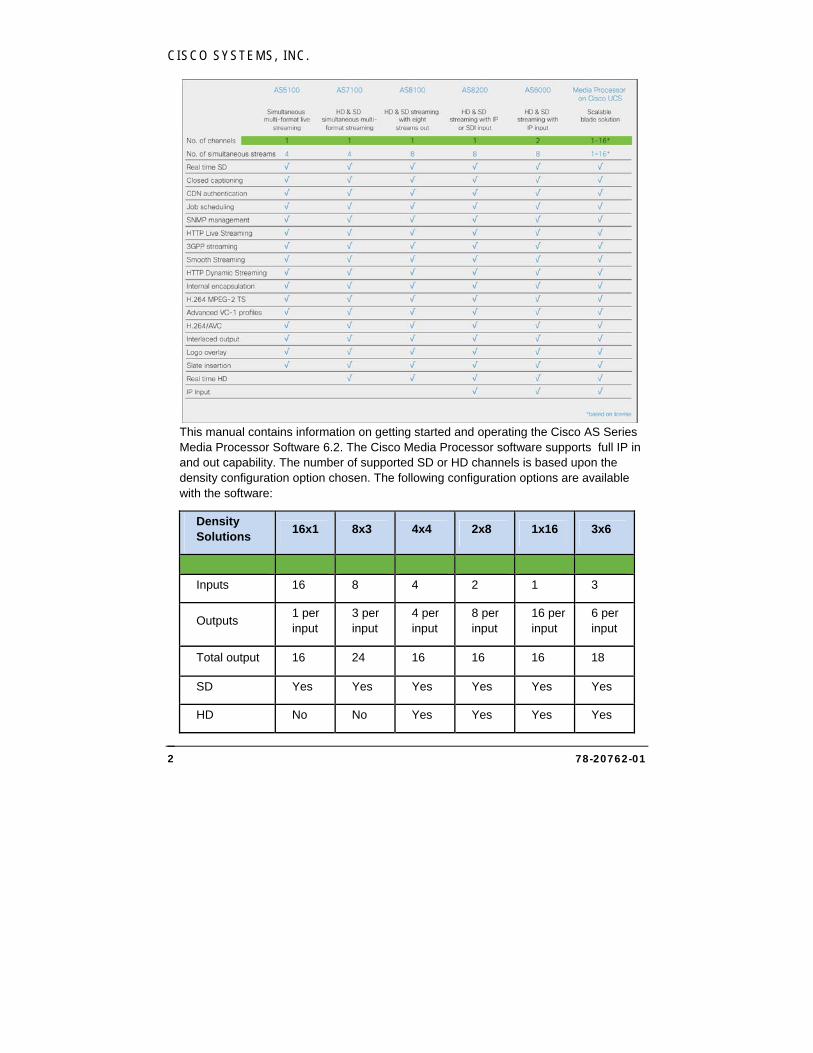
This manual contains information on getting started and operating the Cisco AS Series Media Processor Software 6.2. The Cisco Media Processor software supports full IP in and out capability. The number of supported SD or HD channels is based upon the density configuration option chosen. The following configuration options are available with the software:
Density Solutions
16x1 8x3 4x4 2x8 1x16 3x6
Inputs 16 8 4 2 1 3
Outputs 1 per input
3 per input
4 per input
8 per input
16 per input
6 per input
Total output 16 24 16 16 16 18
SD Yes Yes Yes Yes Yes Yes
HD No No Yes Yes Yes Yes
CISCO MEDIA PROCESSOR
78-20762-01 3
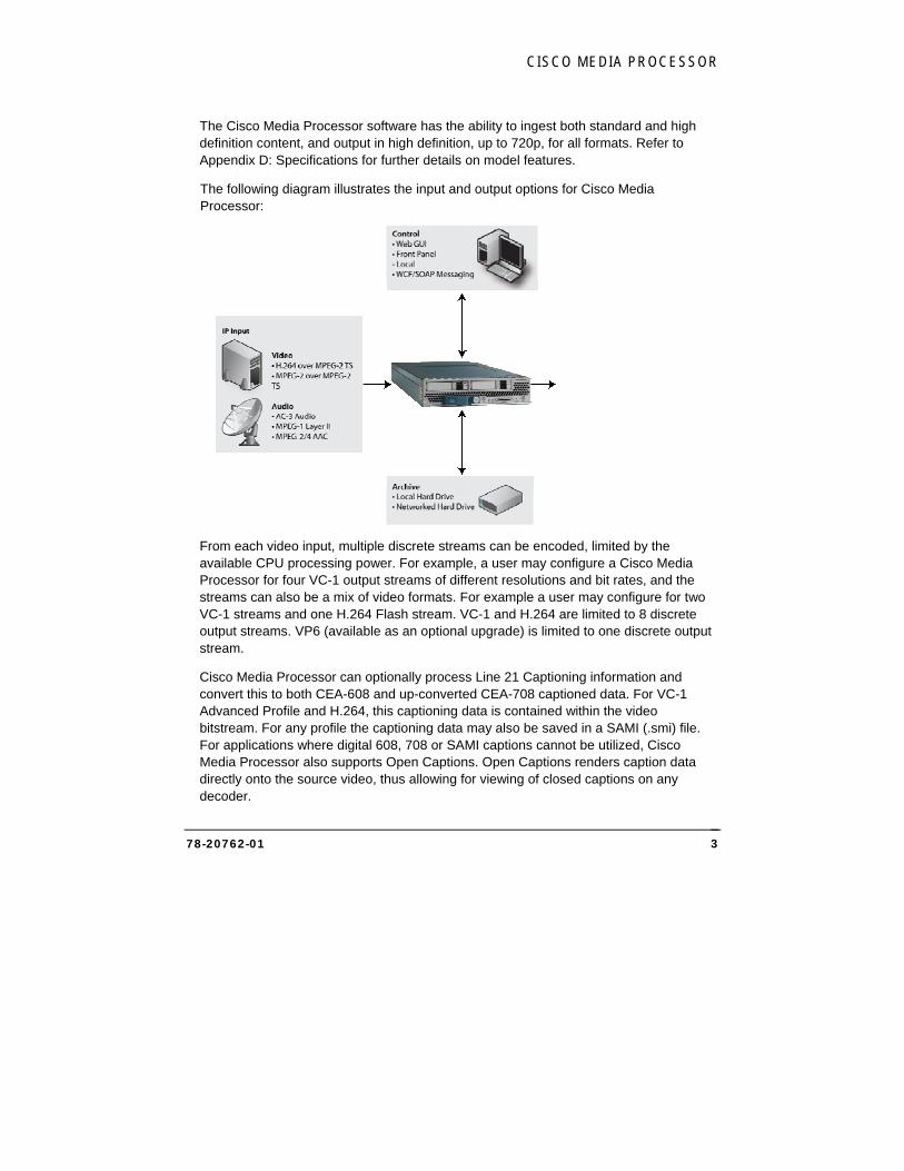
The Cisco Media Processor software has the ability to ingest both standard and high definition content, and output in high definition, up to 720p, for all formats. Refer to Appendix D: Specifications for further details on model features.
The following diagram illustrates the input and output options for Cisco Media Processor:
From each video input, multiple discrete streams can be encoded, limited by the available CPU processing power. For example, a user may configure a Cisco Media Processor for four VC-1 output streams of different resolutions and bit rates, and the streams can also be a mix of video formats. For example a user may configure for two VC-1 streams and one H.264 Flash stream. VC-1 and H.264 are limited to 8 discrete output streams. VP6 (available as an optional upgrade) is limited to one discrete output stream.
Cisco Media Processor can optionally process Line 21 Captioning information and convert this to both CEA-608 and up-converted CEA-708 captioned data. For VC-1 Advanced Profile and H.264, this captioning data is contained within the video bitstream. For any profile the captioning data may also be saved in a SAMI (.smi) file. For applications where digital 608, 708 or SAMI captions cannot be utilized, Cisco Media Processor also supports Open Captions. Open Captions renders caption data directly onto the source video, thus allowing for viewing of closed captions on any decoder.
CISCO SYSTEMS, INC.
78-20762-01 4
VC-1 compressed data streams can be encapsulated in ASF or saved to disk as a .wmv file. The ASF Stream can be pulled from the encoder and/or pushed to a Windows Media Server.
A VP6 Flash stream with MP3 audio can be streamed to a Flash Media Server and/or saved to disk as a .flv file.
A H.264 stream with AAC audio can be streamed to a Flash Media Server and/or saved to disk as a .mp4 file. Additionally, it can be formatted as an MPEG-2 Single Program Transport Stream and sent over IP-Multicast, saved to disk as a .ts file and delivered for iOS streaming.
NOTE:
Cisco Media Processor is a software based encoding platform. The number of output streams is dependent on the available processing power. Also, the types of output streams in terms of format, resolution, frame rate, bit rate, and advanced compression parameters will affect how many simultaneous streams can be output.
Open Source and Third Party Software Cisco Media Processor software uses intellectual property licensed by their respective owners under Open Source Software and commercial third party software licenses. For more information, please see:
C:\Program Files\Inlet Technologies\Spinnaker\Third Party Notices and Additional Terms and Conditions - Spinnaker-SMC.pdf.
CISCO MEDIA PROCESSOR
78-20762-01 5
2 GGeettttiinngg SSttaarrtteedd
Equipment Setup The following steps will prepare the UCS blade to function as a Cisco Media Processor:
Provision the UCS Server The following must be configured through the UCS manager for each blade on which the Cisco AS Series Media Processor Software will be installed. These specifications are based on the UCS B200 M2 Server Blade:
Cisco Media Processor Software Version 6.2 is supported on Bare Metal installations only. Virtualization is planned for a future release.
Map the appropriate VLANs to enable network connectivity for the data and control plane connections of the Cisco Media Processor. One native mode VLAN per vNIC is recommended. Be sure to note the MAC addresses of each vNIC and the corresponding network function of the mapped VLAN for use later.
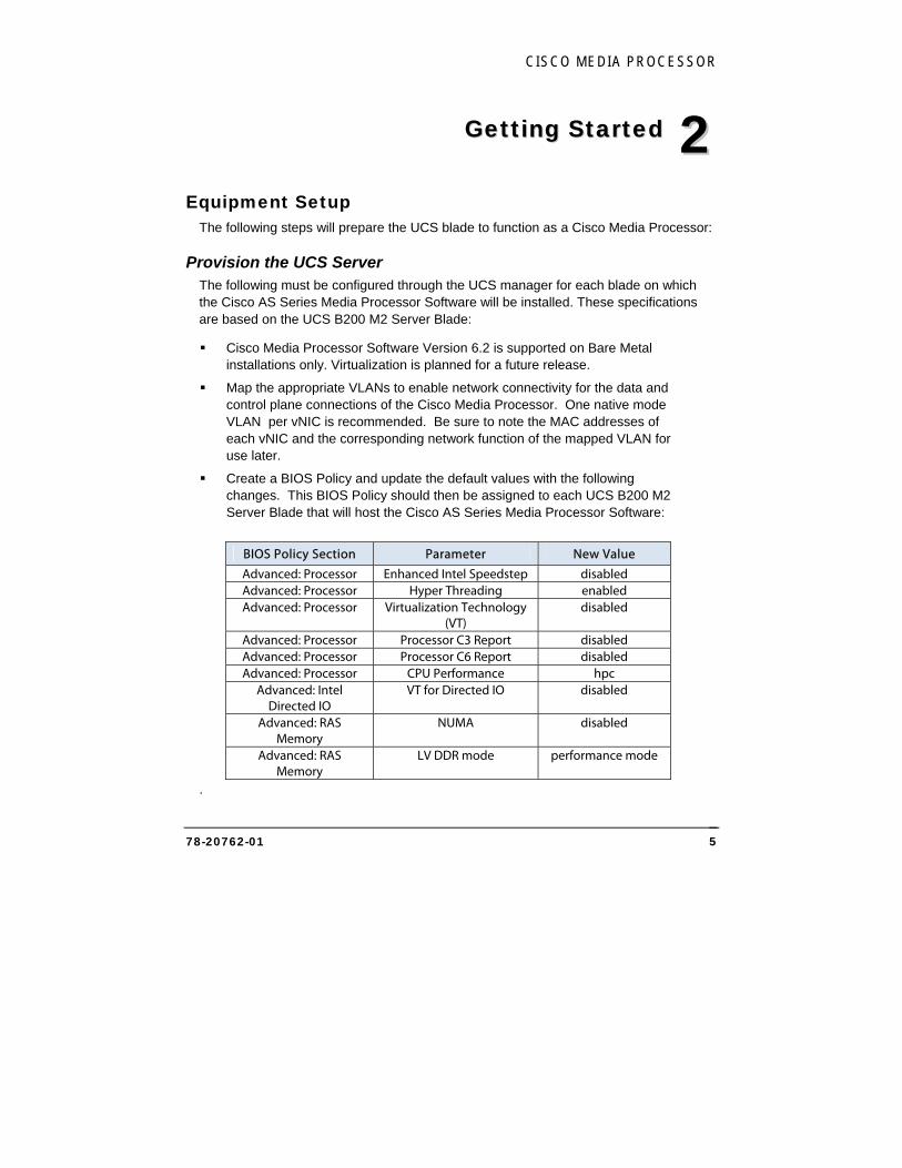
Create a BIOS Policy and update the default values with the following changes. This BIOS Policy should then be assigned to each UCS B200 M2 Server Blade that will host the Cisco AS Series Media Processor Software:
BIOS Policy Section Parameter New Value
Advanced: Processor Enhanced Intel Speedstep disabled Advanced: Processor Hyper Threading enabled Advanced: Processor Virtualization Technology
(VT) disabled
Advanced: Processor Processor C3 Report disabled Advanced: Processor Processor C6 Report disabled Advanced: Processor CPU Performance hpc
Advanced: Intel Directed IO
VT for Directed IO disabled
Advanced: RAS Memory
NUMA disabled
Advanced: RAS Memory
LV DDR mode performance mode
.
22
CISCO SYSTEMS, INC.
78-20762-01 6
Provision the Operating System Cisco AS Series Media Processor Software 6.2 requires Microsoft Windows® Server 2008 32-bit Enterprise Edition. The full installation option should be used to install this operating system once the UCS B200 M2 blade configuration has been completed.
After the installation of Microsoft Windows® Server 2008, install all necessary drivers through the Windows Device Manager. See the UCS B200 M2 documentation for the location of the complete driver set on Cisco.com.
Assign Roles and Features Add the following Role and associated Services through the Windows Server Manager:
Web Server IIS
ASP.NET
IIS 6 Management Compatibility
Add the following Features through the Windows Server Manager:
.NET Framework 3.0
Desktop Experience
SNMP Services
Configure Network Interfaces The vNICs created earlier will appear in the Windows Network Connections view. This order may or may not align with the order of the vNICs as shown in the UCS Manager.
Each Network Interface will need to be renamed in the Windows Network Connections view to align with the expected Interface names for the Cisco Media Processor Software. Please reference the MAC addresses noted in the earlier step to identify which Network Interface maps to which VLAN in the UCS. The MAC address is listed in the “Details” view for each Network Connection.
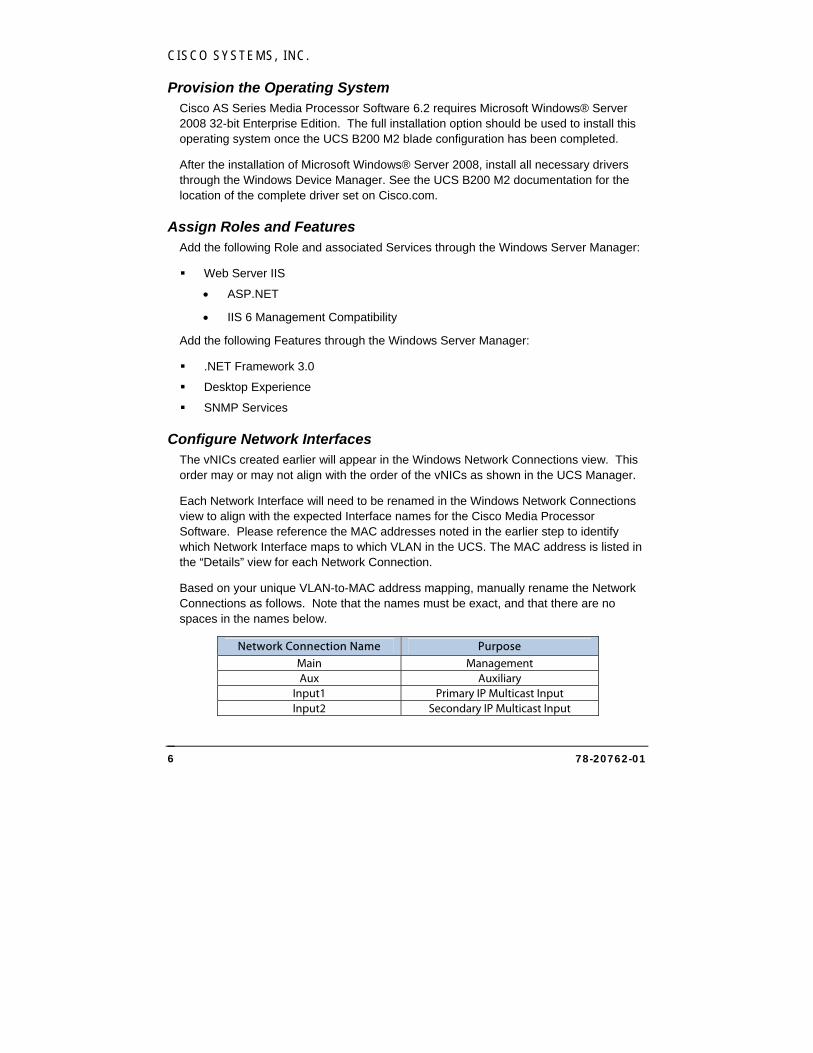
Based on your unique VLAN-to-MAC address mapping, manually rename the Network Connections as follows. Note that the names must be exact, and that there are no spaces in the names below.
Network Connection Name Purpose Main Management Aux Auxiliary
Input1 Primary IP Multicast Input Input2 Secondary IP Multicast Input
CISCO MEDIA PROCESSOR
78-20762-01 7
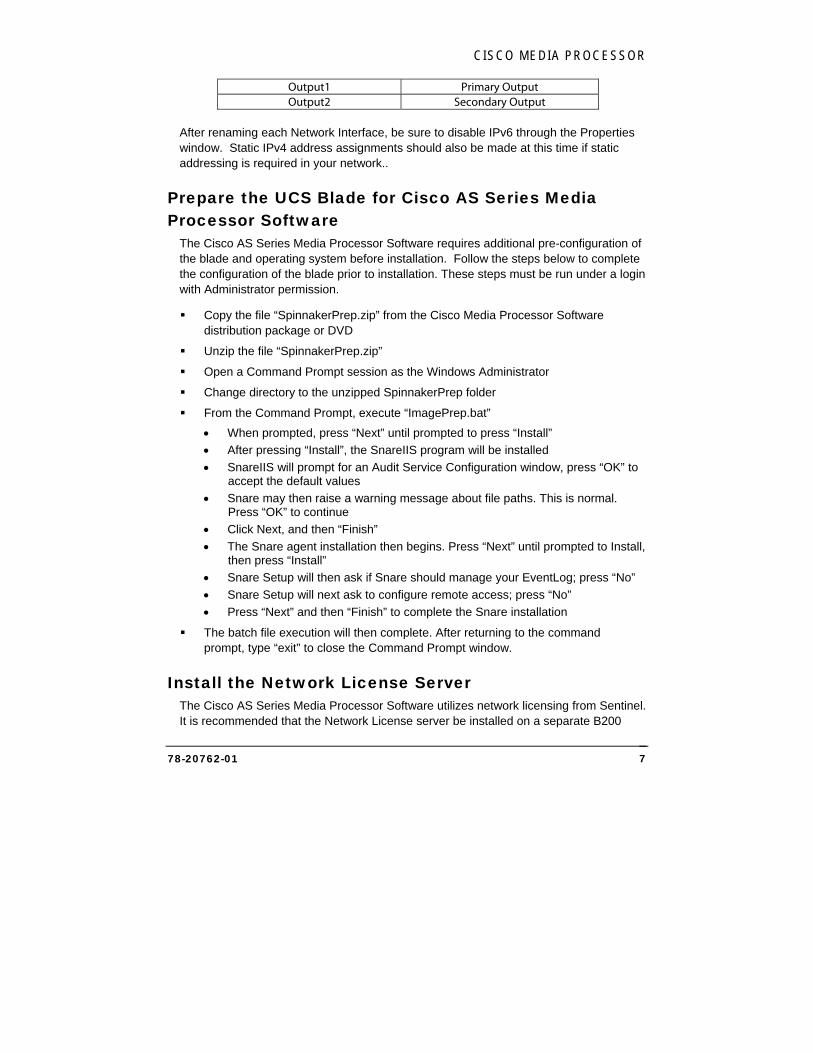
Output1 Primary Output Output2 Secondary Output
After renaming each Network Interface, be sure to disable IPv6 through the Properties window. Static IPv4 address assignments should also be made at this time if static addressing is required in your network..
Prepare the UCS Blade for Cisco AS Series Media Processor Software
The Cisco AS Series Media Processor Software requires additional pre-configuration of the blade and operating system before installation. Follow the steps below to complete the configuration of the blade prior to installation. These steps must be run under a login with Administrator permission.
Copy the file “SpinnakerPrep.zip” from the Cisco Media Processor Software distribution package or DVD
Unzip the file “SpinnakerPrep.zip”
Open a Command Prompt session as the Windows Administrator
Change directory to the unzipped SpinnakerPrep folder
From the Command Prompt, execute “ImagePrep.bat”
When prompted, press “Next” until prompted to press “Install”
After pressing “Install”, the SnareIIS program will be installed
SnareIIS will prompt for an Audit Service Configuration window, press “OK” to accept the default values
Snare may then raise a warning message about file paths. This is normal. Press “OK” to continue
Click Next, and then “Finish”
The Snare agent installation then begins. Press “Next” until prompted to Install, then press “Install”
Snare Setup will then ask if Snare should manage your EventLog; press “No”
Snare Setup will next ask to configure remote access; press “No”
Press “Next” and then “Finish” to complete the Snare installation
The batch file execution will then complete. After returning to the command prompt, type “exit” to close the Command Prompt window.
Install the Network License Server The Cisco AS Series Media Processor Software utilizes network licensing from Sentinel. It is recommended that the Network License server be installed on a separate B200
CISCO SYSTEMS, INC.
78-20762-01 8
blade (Bare Metal only) or workstation utilizing Windows 2008 Server. Prior to plugging the HASP Network key into the system, run the “NetworkLicenseSetup.exe”. Once the installer has completed, plug in the HASP Network key into a USB port on this computer. Make note of this computer’s IP address and provide this IP address to the UCS blades during the “InletSpinnakerUpdate.exe” install.
Configure Network Licensing The licensing service must now be configured to reach the licensing server prior to installation of the Cisco AS Series Media Processor Software. Follow the steps below to configure the licensing service:
Open a web browser on the UCS server and navigate to the URL http://localhost:1947
Click “Configuration”
Under the “Basic Settings” tab, check “Allow Remote Access to ACC” and click “Submit”
Under the “Access to Remote License Managers” tab:
Check “Allow Access to Remote Licenses”
Uncheck “Broadcast Search for Remote Licenses”
Check “Aggressive Search for Remote Licenses”
Enter the IP address of the Network License Server in the “Specify Search Parameters” box and click “Submit”
In the Windows File Explorer, navigate to the uncompressed SpinnakerPrep folder. Double-click the registry file “LicenseNet.reg” to update the Windows Registry
Install the Cisco AS Series Media Processor Software
After completing all of the above steps, navigate to the file “InletSpinnakerUpdate.exe,” which is included in the Cisco AS Series Media Processor Software distribution package or CD. Double-click on InletSpinnakerUpdate.exe to install the Media Processor Software.
The blade will reboot once the Media Processor Software installation completes. After the reboot completes, log in to the Media Processor’s recovery page (https://<management IP address>/encadmin/Recovery.aspx) in order to verify the correct license configuration has been applied. The Network HASP USB license incudes support for the six configurations outlined in the table in the Introduction chapter. The license server will allow you to switch between these configurations on
CISCO MEDIA PROCESSOR
78-20762-01 9
each blade (license) that is purchased. Note that updating the license configuration may take several minutes and will automatically restart the encoding services.
Individualize for Microsoft PlayReady (Optional) If you do not plan to use Microsoft PlayReady, please continue to the next section.
PlayReady requires that systems go through a one-time process called “individualization”, and this process requires communication to a Microsoft Server. In order to perform this process, the encoder must be connected to the internet and be able to resolve DNS. Once individualized, the system does not need to be on an open network unless the system is calling out to a PlayReady Platform Provider for dynamic encryption key information. If your system will have access to the internet and can resolve DNS, then you do not need to perform these steps.
Follow the steps below to individualize:
Confirm the system has a connection to the internet
Open a Command Prompt and type “C:\Spinnaker\Individualize\Individualize.exe”
During the process, you will see several lines regarding individualization. Toward the end, a line will state “CPRIndividualize::IndividualizePC:Individualization completed successfully”.
At this point, the individualization process is complete and you can continue to the next section.

CISCO SYSTEMS, INC.
78-20762-01 10
3 WWeebb IInntteerrffaaccee
Remote Management via the Web The Cisco Media Processor Web interface will allow you to manage the encoder by browsing to its IP address. With this interface, you can:
Load and save encoding presets
Configure the encoding parameters
Start and stop the encoder
Monitor status and general encoding statistics
Display system information
Manage the system
Opening the Interface To open the Web interface of the encoder, simply browse to:
https://<machine name or IP>/encadmin
For example:
https://192.168.1.33/encadmin
If logged into Media Processor locally or remotely through Remote Desktop Protocol software, you can bring up the Web interface via:
https://localhost/encadmin
33
CISCO MEDIA PROCESSOR
78-20762-01 11
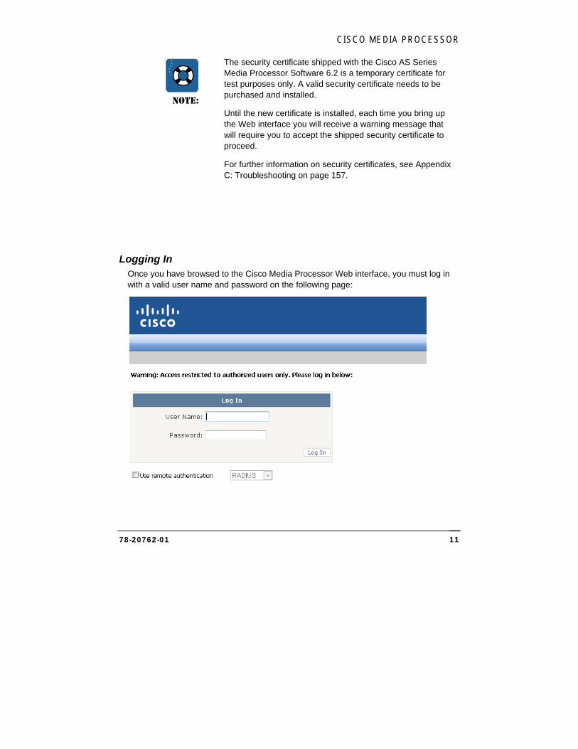
NOTE:
The security certificate shipped with the Cisco AS Series Media Processor Software 6.2 is a temporary certificate for test purposes only. A valid security certificate needs to be purchased and installed.
Until the new certificate is installed, each time you bring up the Web interface you will receive a warning message that will require you to accept the shipped security certificate to proceed.
For further information on security certificates, see Appendix C: Troubleshooting on page 157.
Logging In Once you have browsed to the Cisco Media Processor Web interface, you must log in with a valid user name and password on the following page:
CISCO SYSTEMS, INC.
78-20762-01 12
You may also log in with a domain account in the format domain\user.name if the Media Processor has been previously added to the network domain.
Cisco Media Processor defines two user groups: encoder users and encoder administrators. Encoder users are only allowed to view the status of the system. Encoder administrators are allowed to configure, start and stop the system.
A new installation will always have a factory-provided initial user name and password for each group. The Use remote authentication checkbox must be unchecked to use these user names. The initial encoder administrator name is:
User Name: admin
Password: encAdm1n
The initial encoder user name is:
User Name: user
Password: encUs3rs
The login page will indicate if a login attempt is made with an expired password. Under the System tab, the User Account page allows passwords to be changed. Refer to the User Account Page description on page 125 for further information. On this same tab, the System Information page allows deletion and disabling of user accounts. Refer to the System Page description on page 119 for further details.
See Appendix B: Managing User Accounts on page 156 for information on how to create new users.
To log out, click the Logout link on the upper right of any page, then close the Web browser. If no activity is detected for the duration specified on the System Information page, you will be logged out automatically.
After logging out, it is still possible to view cached web pages by manually entering them into the browser's address box. These pages, however, are simply cached from the last time that page was visited; they do not reflect the current state nor can they be used to modify the encoder state. The user must re-login in order to read or edit current values.
CISCO MEDIA PROCESSOR
78-20762-01 13
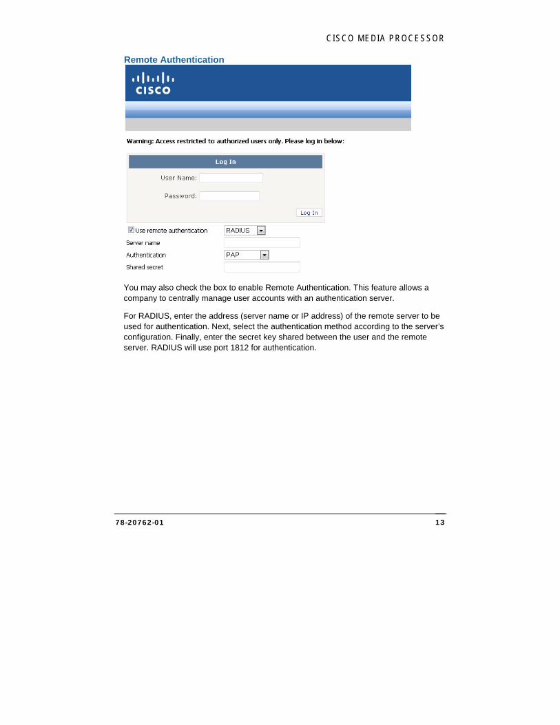
Remote Authentication
You may also check the box to enable Remote Authentication. This feature allows a company to centrally manage user accounts with an authentication server.
For RADIUS, enter the address (server name or IP address) of the remote server to be used for authentication. Next, select the authentication method according to the server’s configuration. Finally, enter the secret key shared between the user and the remote server. RADIUS will use port 1812 for authentication.
CISCO SYSTEMS, INC.
78-20762-01 14
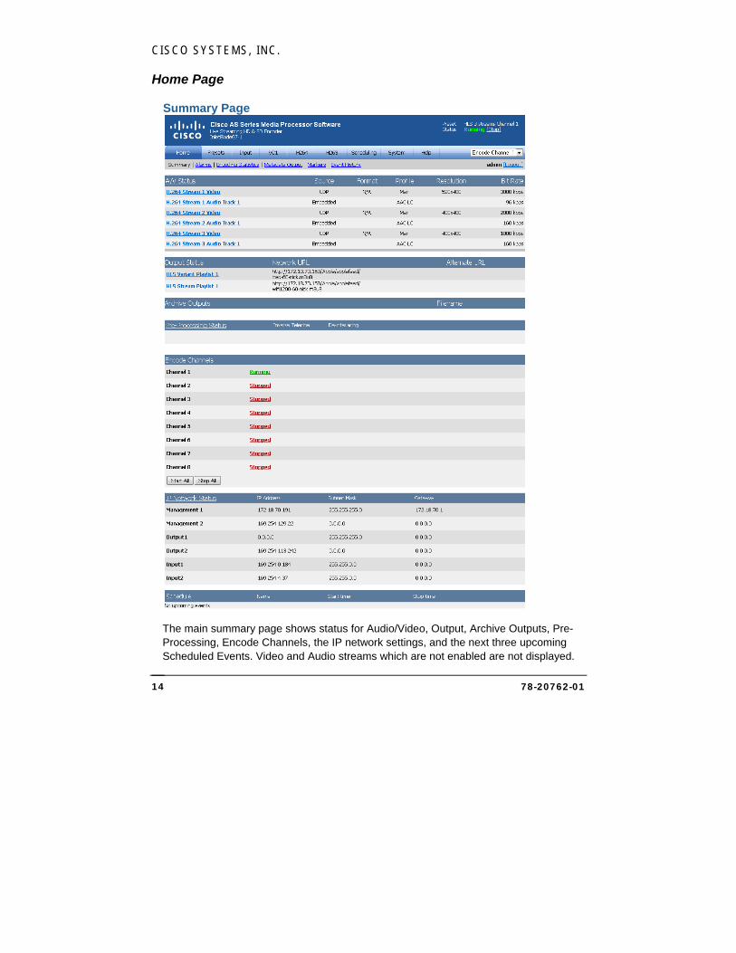
Home Page
Summary Page
The main summary page shows status for Audio/Video, Output, Archive Outputs, Pre-Processing, Encode Channels, the IP network settings, and the next three upcoming Scheduled Events. Video and Audio streams which are not enabled are not displayed.
CISCO MEDIA PROCESSOR
78-20762-01 15
The titles of some status sections and some status items are clickable links to the page that can modify those settings. Each Cisco Media Processor Web interface page indicates in the top right whether the encoder is running or stopped.
Cisco AS Series Media Processor Software offers multiple encoding channels based on licensing configuration. Choose the appropriate channel on any Web page to view or modify information related to that channel. System information options will apply to all channels.
NOTE:
When changing a setting on any page, you must click Apply before proceeding to a different page. Otherwise, the settings will not be saved. Click Reload to return to the previously applied settings for that page.
Make all setting changes while the Media Processor is stopped. Any changes made while the Media Processor is running will not be able to be applied, and will be erased when it is stopped.
CISCO SYSTEMS, INC.
78-20762-01 16
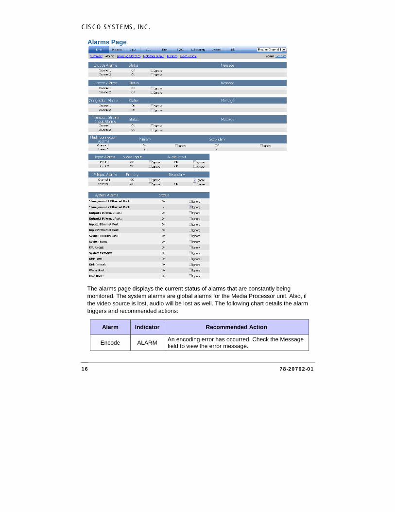
Alarms Page
The alarms page displays the current status of alarms that are constantly being monitored. The system alarms are global alarms for the Media Processor unit. Also, if the video source is lost, audio will be lost as well. The following chart details the alarm triggers and recommended actions:
Alarm Indicator Recommended Action
Encode ALARM An encoding error has occurred. Check the Message field to view the error message.
CISCO MEDIA PROCESSOR
78-20762-01 17
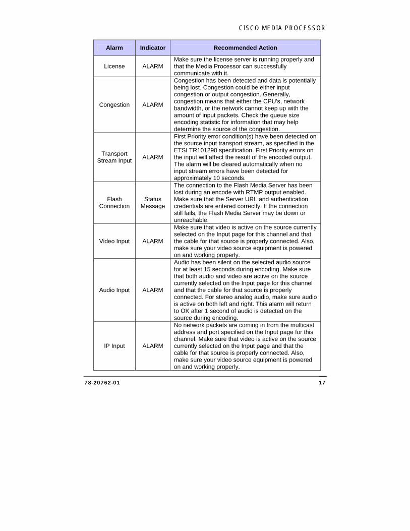
Alarm Indicator Recommended Action
License ALARM Make sure the license server is running properly and that the Media Processor can successfully communicate with it.
Congestion ALARM
Congestion has been detected and data is potentially being lost. Congestion could be either input congestion or output congestion. Generally, congestion means that either the CPU's, network bandwidth, or the network cannot keep up with the amount of input packets. Check the queue size encoding statistic for information that may help determine the source of the congestion.
Transport Stream Input
ALARM
First Priority error condition(s) have been detected on the source input transport stream, as specified in the ETSI TR101290 specification. First Priority errors on the input will affect the result of the encoded output. The alarm will be cleared automatically when no input stream errors have been detected for approximately 10 seconds.
Flash Connection
Status Message
The connection to the Flash Media Server has been lost during an encode with RTMP output enabled. Make sure that the Server URL and authentication credentials are entered correctly. If the connection still fails, the Flash Media Server may be down or unreachable.
Video Input ALARM
Make sure that video is active on the source currently selected on the Input page for this channel and that the cable for that source is properly connected. Also, make sure your video source equipment is powered on and working properly.
Audio Input ALARM
Audio has been silent on the selected audio source for at least 15 seconds during encoding. Make sure that both audio and video are active on the source currently selected on the Input page for this channel and that the cable for that source is properly connected. For stereo analog audio, make sure audio is active on both left and right. This alarm will return to OK after 1 second of audio is detected on the source during encoding.
IP Input ALARM
No network packets are coming in from the multicast address and port specified on the Input page for this channel. Make sure that video is active on the source currently selected on the Input page and that the cable for that source is properly connected. Also, make sure your video source equipment is powered on and working properly.
CISCO SYSTEMS, INC.
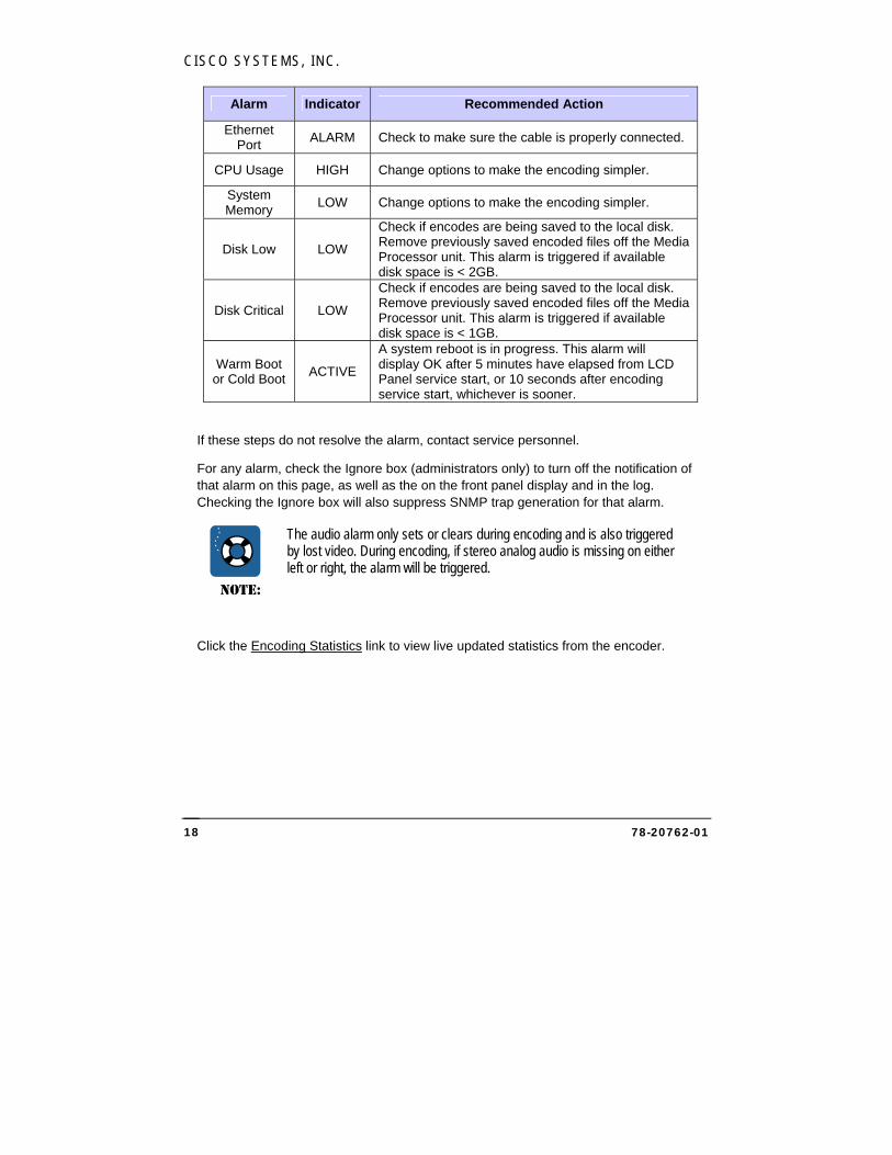
78-20762-01 18
Alarm Indicator Recommended Action
Ethernet Port
ALARM Check to make sure the cable is properly connected.
CPU Usage HIGH Change options to make the encoding simpler.
System Memory
LOW Change options to make the encoding simpler.
Disk Low LOW
Check if encodes are being saved to the local disk. Remove previously saved encoded files off the Media Processor unit. This alarm is triggered if available disk space is < 2GB.
Disk Critical LOW
Check if encodes are being saved to the local disk. Remove previously saved encoded files off the Media Processor unit. This alarm is triggered if available disk space is < 1GB.
Warm Boot or Cold Boot
ACTIVE
A system reboot is in progress. This alarm will display OK after 5 minutes have elapsed from LCD Panel service start, or 10 seconds after encoding service start, whichever is sooner.
If these steps do not resolve the alarm, contact service personnel.
For any alarm, check the Ignore box (administrators only) to turn off the notification of that alarm on this page, as well as the on the front panel display and in the log. Checking the Ignore box will also suppress SNMP trap generation for that alarm.
NOTE:
The audio alarm only sets or clears during encoding and is also triggered by lost video. During encoding, if stereo analog audio is missing on either left or right, the alarm will be triggered.
Click the Encoding Statistics link to view live updated statistics from the encoder.
CISCO MEDIA PROCESSOR
78-20762-01 19
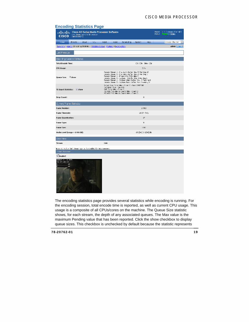
Encoding Statistics Page
The encoding statistics page provides several statistics while encoding is running. For the encoding session, total encode time is reported, as well as current CPU usage. This usage is a composite of all CPUs/cores on the machine. The Queue Size statistic shows, for each stream, the depth of any associated queues. The Max value is the maximum Pending value that has been reported. Click the show checkbox to display queue sizes. This checkbox is unchecked by default because the statistic represents
CISCO SYSTEMS, INC.
78-20762-01 20
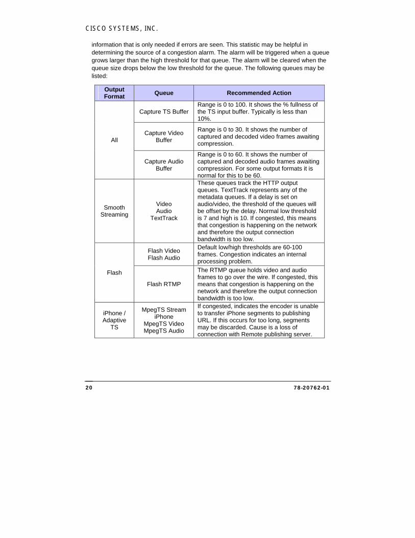
information that is only needed if errors are seen. This statistic may be helpful in determining the source of a congestion alarm. The alarm will be triggered when a queue grows larger than the high threshold for that queue. The alarm will be cleared when the queue size drops below the low threshold for the queue. The following queues may be listed:
Output Format
Queue Recommended Action
All
Capture TS Buffer Range is 0 to 100. It shows the % fullness of the TS input buffer. Typically is less than 10%.
Capture Video Buffer
Range is 0 to 30. It shows the number of captured and decoded video frames awaiting compression.
Capture Audio Buffer
Range is 0 to 60. It shows the number of captured and decoded audio frames awaiting compression. For some output formats it is normal for this to be 60.
Smooth Streaming
Video Audio
TextTrack
These queues track the HTTP output queues. TextTrack represents any of the metadata queues. If a delay is set on audio/video, the threshold of the queues will be offset by the delay. Normal low threshold is 7 and high is 10. If congested, this means that congestion is happening on the network and therefore the output connection bandwidth is too low.
Flash
Flash Video Flash Audio
Default low/high thresholds are 60-100 frames. Congestion indicates an internal processing problem.
Flash RTMP
The RTMP queue holds video and audio frames to go over the wire. If congested, this means that congestion is happening on the network and therefore the output connection bandwidth is too low.
iPhone / Adaptive
TS
MpegTS Stream iPhone
MpegTS Video MpegTS Audio
If congested, indicates the encoder is unable to transfer iPhone segments to publishing URL. If this occurs for too long, segments may be discarded. Cause is a loss of connection with Remote publishing server.
CISCO MEDIA PROCESSOR
78-20762-01 21
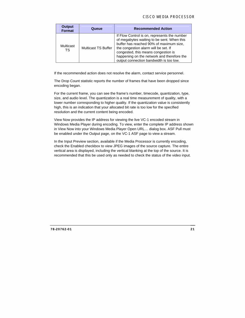
Output Format
Queue Recommended Action
Multicast TS
Multicast TS Buffer
If Flow Control is on, represents the number of megabytes waiting to be sent. When this buffer has reached 90% of maximum size, the congestion alarm will be set. If congested, this means congestion is happening on the network and therefore the output connection bandwidth is too low.
If the recommended action does not resolve the alarm, contact service personnel.
The Drop Count statistic reports the number of frames that have been dropped since encoding began.
For the current frame, you can see the frame’s number, timecode, quantization, type, size, and audio level. The quantization is a real time measurement of quality, with a lower number corresponding to higher quality. If the quantization value is consistently high, this is an indication that your allocated bit rate is too low for the specified resolution and the current content being encoded.
View Now provides the IP address for viewing the live VC-1 encoded stream in Windows Media Player during encoding. To view, enter the complete IP address shown in View Now into your Windows Media Player Open URL… dialog box. ASF Pull must be enabled under the Output page, on the VC-1 ASF page to view a stream.
In the Input Preview section, available if the Media Processor is currently encoding, check the Enabled checkbox to view JPEG images of the source capture. The entire vertical area is displayed, including the vertical blanking at the top of the source. It is recommended that this be used only as needed to check the status of the video input.
CISCO SYSTEMS, INC.
78-20762-01 22
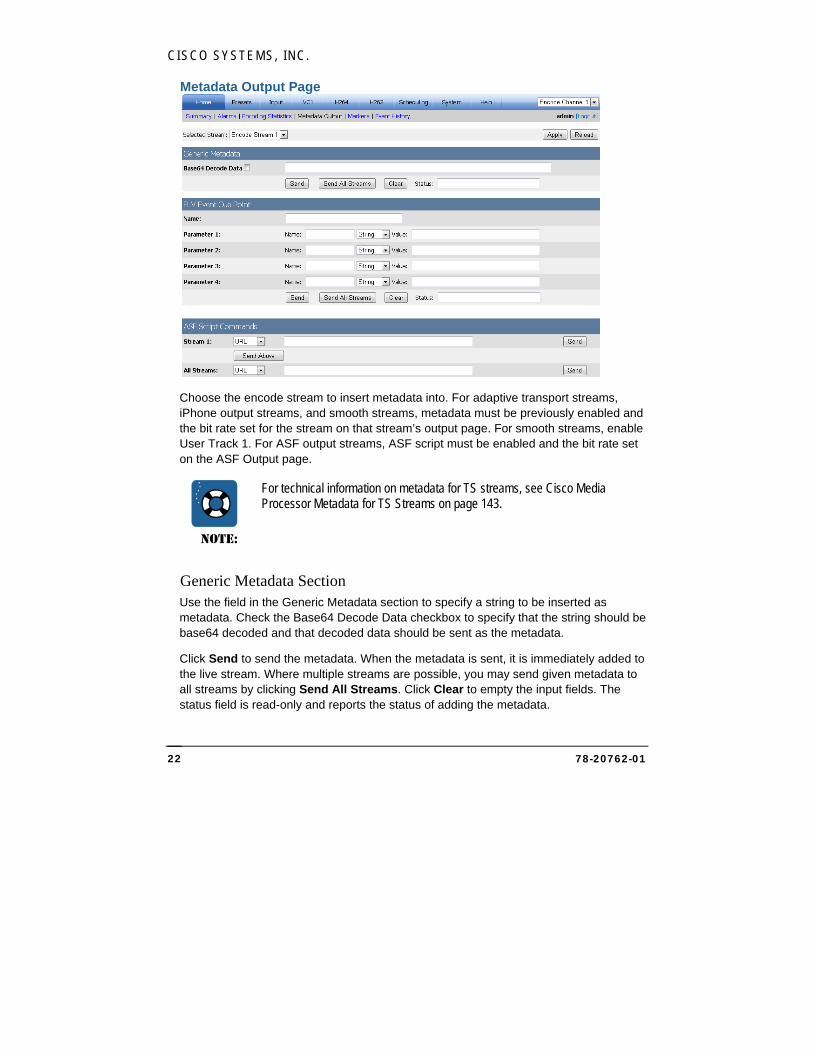
Metadata Output Page
Choose the encode stream to insert metadata into. For adaptive transport streams, iPhone output streams, and smooth streams, metadata must be previously enabled and the bit rate set for the stream on that stream’s output page. For smooth streams, enable User Track 1. For ASF output streams, ASF script must be enabled and the bit rate set on the ASF Output page.
NOTE:
For technical information on metadata for TS streams, see Cisco Media Processor Metadata for TS Streams on page 143.
Generic Metadata Section Use the field in the Generic Metadata section to specify a string to be inserted as metadata. Check the Base64 Decode Data checkbox to specify that the string should be base64 decoded and that decoded data should be sent as the metadata.
Click Send to send the metadata. When the metadata is sent, it is immediately added to the live stream. Where multiple streams are possible, you may send given metadata to all streams by clicking Send All Streams. Click Clear to empty the input fields. The status field is read-only and reports the status of adding the metadata.
CISCO MEDIA PROCESSOR
78-20762-01 23
FLV Event Cue Point Section The encoder can optionally insert live cue points in the encoded stream. A cue point name must be specified in the Name field.
Optionally up to four cue point parameters may be supplied. Each parameter has its own name and value. Cisco Media Processor supports parameter values of type String, Number and Boolean. The Boolean must be “True” (case insensitive) or “1” in order to be considered true, otherwise it is assumed to be false.
For Video Mute, which keeps the stream active, but stops video and audio, use the cue point name Mute (not case sensitive), parameter name Mute, type String, and value ON to start Video Mute and Off to stop.
Click Send to send the cue point. When a cue point is sent, it is immediately added to the live stream. Where multiple streams are possible, you may send a given cue point to all streams by clicking Send All Streams. Click Clear to empty the cue point input fields. The status field is read-only and reports the status of adding the cue point. The status field will display an error message if you try to add a cue point to an invalid stream or when not encoding.
ASF Script Commands Section The ASF Script Commands section provides a method for inserting script commands for each stream independently, or a single command may be inserted for all streams. Each script command is made up of two strings, the command type and the command data. The following script command types may be used:
URL Sends the specified Internet URL to the browser for display to the user. When a reading application that supports script commands of this type receives this command, it will open the specified address in a browser window.
If an embedded player control is being used, you can add a specific frame reference to the URL by using the &&framename syntax.
Caption Sends a text string to be displayed in the captions area of Windows Media Player. This command type supports standard HTML formatting.
Text Sends a text string of plain text, SAMI, or HTML formatted text to be displayed in the captions area of Windows Media Player.
CISCO SYSTEMS, INC.
78-20762-01 24
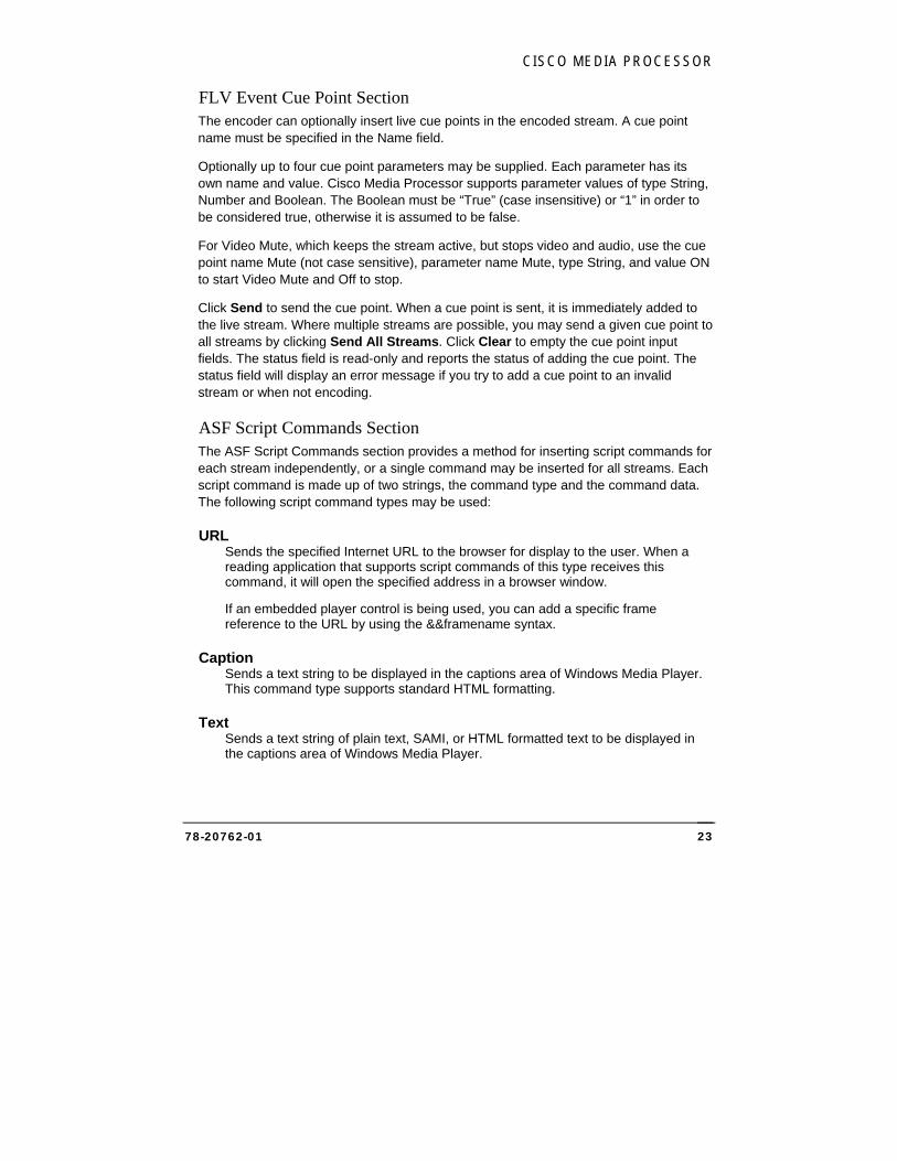
Markers Page
For Smooth streams, markers may be manually inserted.
Mark Out Use this setting to specify the time to insert the marker that specifies a break out of the currently encoding stream(s), such as to an advertisement. Set Mark Out Pre-Roll to 0 to insert the marker immediately, or specify a time in the future with a pre-roll value in ms. You may also specify a Duration for the mark out to last, in ms. If a Mark Out has a Duration, there is generally no need to also manually create a Mark In. Click Insert to insert the marker.
Mark In Use this setting to specify the time to insert the marker that specifies a return to the currently encoding stream(s). Set Mark In Pre-Roll to 0 to insert the marker immediately, or specify a time in the future with a pre-roll value in ms. Click Insert to insert the marker.
Slate Use this setting to specify a slate to be inserted during the Mark Out period. Click a slate file name to replace the input video with a slate file image that has previously been uploaded to the Media Processor. To upload a new slate file, click Browse… to browse to the file, then click Upload. The slate file may be either 24-bit BMP or 24-bit JPG.
NOTE:
Markers are currently available for Smooth Streams only, and apply to all currently encoding streams.
CISCO MEDIA PROCESSOR
78-20762-01 25
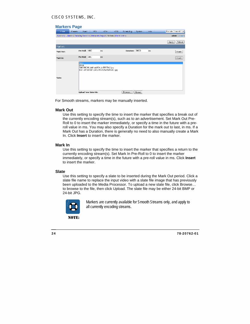
Event History Page
The event history page displays information, warning, and error event entries from the event log for the Media Processor for the selected encode channel. You can use the type filter to only display certain event types. You can also modify the start date and end date for the history shown.
The following information is shown for each event:
Type – Icon that shows the severity level of the events:
Informational – Just information, no action needed
Warning – Potential issue, may require user attention
Error – Likely a problem, requires user attention
Timestamp – Date and time the event happened. Default shows most recent event first; Click the Timestamp column heading to display the oldest entries first.
CISCO SYSTEMS, INC.
78-20762-01 26
Area – Indicates which Media Processor component/subsystem generated the message. The most common areas are General and Info; most other areas typically only appear when the Media Processor is encountering a problem.
Details - Description of the event. For certain events that contain diagnostic
information, a magnifier icon indicates that the entry can be expanded by clicking on the row. An entry that has been expanded can be collapsed by clicking on the row again.
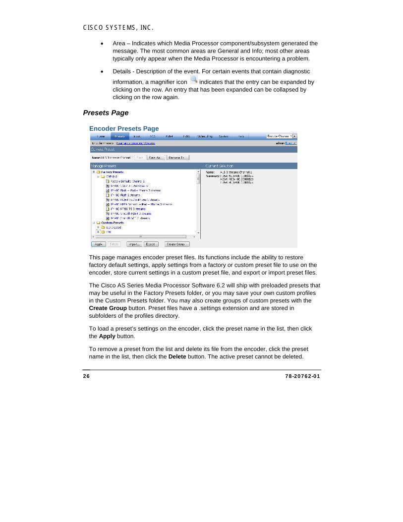
Presets Page
Encoder Presets Page
This page manages encoder preset files. Its functions include the ability to restore factory default settings, apply settings from a factory or custom preset file to use on the encoder, store current settings in a custom preset file, and export or import preset files.
The Cisco AS Series Media Processor Software 6.2 will ship with preloaded presets that may be useful in the Factory Presets folder, or you may save your own custom profiles in the Custom Presets folder. You may also create groups of custom presets with the Create Group button. Preset files have a .settings extension and are stored in subfolders of the profiles directory.
To load a preset’s settings on the encoder, click the preset name in the list, then click the Apply button.
To remove a preset from the list and delete its file from the encoder, click the preset name in the list, then click the Delete button. The active preset cannot be deleted.
CISCO MEDIA PROCESSOR
78-20762-01 27
For the currently loaded preset, you can save the encoder’s current settings to the preset by clicking the Save button. To create a new preset file using the encoder’s current settings, type the new preset name, then click the Save As… button, then type the preset name and optionally choose a destination group, then click Save Copy. The preset name will be displayed in the preset list. The preset file will be saved with the same name and a .settings extension. You may also rename the current preset and/or relocate its group with the Rename To… button.
NOTE:
Renaming or editing of presets outside of the Cisco Media Processor web interface or the Cisco Media Processor Management Console is not supported. Set the preset name and all settings before exporting the preset file.
For each stream in the currently selected preset, the output format, resolution, bit rate, and archive file name (if any) will be displayed at the right side of the preset page for reference.
The preset whose settings are currently applied will be designated on this page with (active) next to its name, and its name will also will be displayed in the upper right corner of each Web page. For example, on the main summary page displayed on page 14, the preset name in use is HLS 3 streams Channel 1. When the current settings have been modified from the preset’s original settings but not saved, the preset name will be listed as Custom with the original preset name in parentheses.
To import a preset file, click the Import… button, then click Browse to locate the file. Next, choose the destination group (if any) for the file in the Custom Presets folder. Finally, click Import, which will copy the file to the Media Processor and display it in the list. To export a preset to a file, click the preset name and click Export to download the specified preset to the client computer. You will be prompted to specify the file name and path. Note that this file name is only the name of the file where the preset is stored, not the name of the preset itself.
CISCO SYSTEMS, INC.
78-20762-01 28
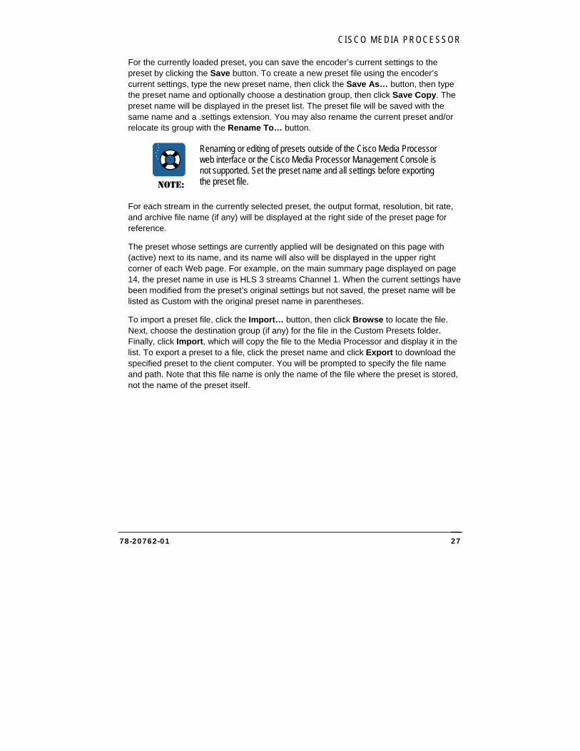
Rearrange Encoding Streams Page
This page allows you to rearrange and copy stream settings between available streams.
Rearrange Streams Section This section lists all of the Media Processor’s streams in stream number order. Enabled streams will display the stream’s output format, stream number, resolution, and bit rate.
To rearrange streams, click a stream and drag it to the desired position. Repeat the process for any other streams to be rearranged. When stream settings are in the desired order, click Apply. After applying, the first stream will be Stream 1, and so forth.
Copy Streams Section The Copy Encode dropdown lists all of the Media Processor’s streams. Enabled streams will display the stream’s output format, stream number, resolution, and bit rate.
To copy streams, choose the stream to be copied in the Copy Encode dropdown. Next, choose the stream to overwrite in the second dropdown. Finally, click Copy to copy the settings from the first stream to the second. The settings from the second stream will be lost.
CISCO MEDIA PROCESSOR
78-20762-01 29
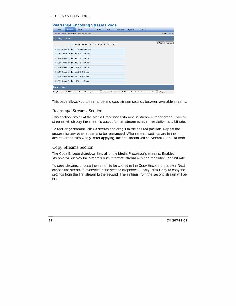
Input Page
Video/Audio/Teletext Page
The Input page allows for viewing or modification of the following settings:
Video Input Section Specify the multicast address and port that Cisco Media Processor should use for IP input. Optionally, specify a source address. You may also check the Enabled checkbox for an optional secondary source carrying the same transport stream. If a secondary source is enabled and valid input is not detected on the primary source when encoding starts, Cisco Media Processor will encode with the secondary source. If, during encoding, one source stops receiving valid input but the other source’s input is valid, the Media Processor will switch sources.
After specifying the primary and optional secondary multicast address and port, you may click the Detect Streams link for each source to detect any streams. The information for these streams will be displayed at the bottom of the Input page. If there are multiple streams, you may select between them. Select a stream by clicking the appropriate radio button, and its values will be populated in the Selected Input Streams section. You may also select multiple audio streams, mapping them to channels in the Audio Channel Assignments area. Whether or not you detect streams, you may modify the values for the selected streams. Audio levels for each channel may be adjusted in a range from +60dB to -60dB for volume control. A dB change of 6 is a doubling of audio level. Default is 0, which means the audio level will not be adjusted.
CISCO SYSTEMS, INC.
78-20762-01 30
Slate on Video Loss Check Enable to replace the input video with a slate file image if the video is lost. The Slate File field must include the path to the existing image file either on the Media Processor (recommended) or a network share accessible by the Media Processor. The slate file may be either 24-bit BMP or 24-bit JPG.
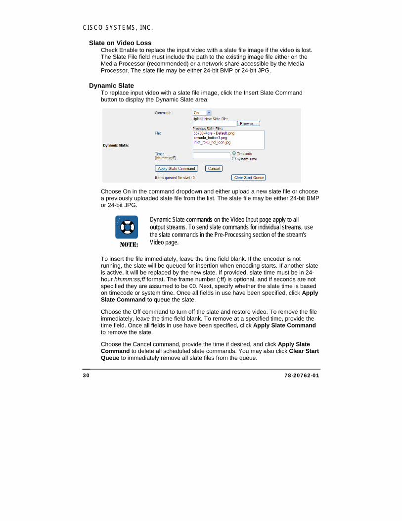
Dynamic Slate To replace input video with a slate file image, click the Insert Slate Command button to display the Dynamic Slate area:
Choose On in the command dropdown and either upload a new slate file or choose a previously uploaded slate file from the list. The slate file may be either 24-bit BMP or 24-bit JPG.
NOTE:
Dynamic Slate commands on the Video Input page apply to all output streams. To send slate commands for individual streams, use the slate commands in the Pre-Processing section of the stream’s Video page.
To insert the file immediately, leave the time field blank. If the encoder is not running, the slate will be queued for insertion when encoding starts. If another slate is active, it will be replaced by the new slate. If provided, slate time must be in 24-hour hh:mm:ss;ff format. The frame number (;ff) is optional, and if seconds are not specified they are assumed to be 00. Next, specify whether the slate time is based on timecode or system time. Once all fields in use have been specified, click Apply Slate Command to queue the slate.
Choose the Off command to turn off the slate and restore video. To remove the file immediately, leave the time field blank. To remove at a specified time, provide the time field. Once all fields in use have been specified, click Apply Slate Command to remove the slate.
Choose the Cancel command, provide the time if desired, and click Apply Slate Command to delete all scheduled slate commands. You may also click Clear Start Queue to immediately remove all slate files from the queue.
CISCO MEDIA PROCESSOR
78-20762-01 31
Pre-Encoding Preview You may click the Start button to display JPEG images of the source video that will be encoded. This option is not available during encoding. Click Stop to stop preview.
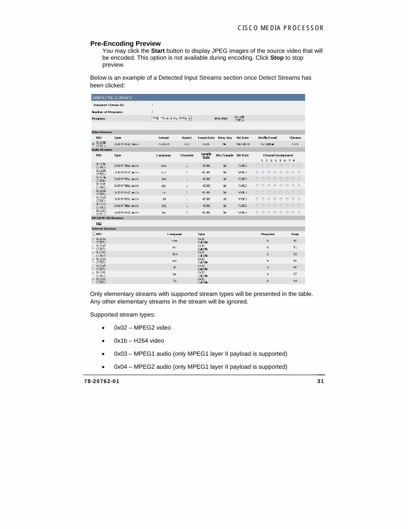
Below is an example of a Detected Input Streams section once Detect Streams has been clicked:
Only elementary streams with supported stream types will be presented in the table. Any other elementary streams in the stream will be ignored.
Supported stream types:
0x02 – MPEG2 video
0x1b – H264 video
0x03 – MPEG1 audio (only MPEG1 layer II payload is supported)
0x04 – MPEG2 audio (only MPEG1 layer II payload is supported)
CISCO SYSTEMS, INC.
78-20762-01 32
0x0f – AAC audio
0x11 – AAC audio
0x81 – AC3 audio
0x06 – AC3 audio (AC-3 registration descriptor must be present)
0x06 – EN 300 472 / EN 301 775 Teletext (descriptor 0x56 must be present)
0x06 – EN 300 743 Subtitling (descriptor 0x59 must be present)
0x80 – MPEG2 video
0x86 – DPI (SCTE35)
Ingest of mono, 2.0 and 5.1 audio is supported. If the audio is 5.1, it will be automatically downmixed to 2.0 with a normalized downmix matrix. If the audio is mono, it will be automatically copied to 2.0. Then, the normal stereo-to-mono conversions that Cisco Media Processor supports can be applied if mono output is desired.
If the source contains multiple audio streams, you may map each stream to an audio input channel. Click the radio button for any combination of streams to map them to input channels, and their PIDs will be populated in the Audio Channel Assignments area.
If the source contains one or more teletext streams, check the box for any stream that should be available as an output stream.
The displayed video bit rate is based on an optional parameter in the stream. If it is not available, it will be reported as “Not specified”.
If the input is a MPTS (Multiple Program Transport Stream) then the detected streams table shows the elementary streams of one Program at a time. When the selected Program is changed, the displayed elementary stream information is updated.
CISCO MEDIA PROCESSOR
78-20762-01 33
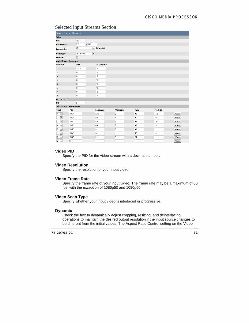
Selected Input Streams Section
Video PID Specify the PID for the video stream with a decimal number.
Video Resolution Specify the resolution of your input video.
Video Frame Rate Specify the frame rate of your input video. The frame rate may be a maximum of 60 fps, with the exception of 1080p50 and 1080p60.
Video Scan Type Specify whether your input video is interlaced or progressive.
Dynamic Check the box to dynamically adjust cropping, resizing, and deinterlacing operations to maintain the desired output resolution if the input source changes to be different from the initial values. The Aspect Ratio Control setting on the Video
CISCO SYSTEMS, INC.
78-20762-01 34
page specifies the method that will be used to control how the output aspect ratio is maintained. If Dynamic is not checked and the input differs from preset values, no automatic adjustment is done and the output may be incorrect. Default is unchecked.
Audio PID For each audio channel that will be used, specify the PID for the audio stream with a decimal number. Specify a PID of 0 to disable ingest of audio.
Audio Level Audio levels for all channels may be adjusted in a range from +60dB to -60dB for volume control. A dB change of 6 is a doubling of audio level. Default is 0, which means the audio level will not be adjusted.
DPI (SCTE-35) PID Specify the PID for the DPI (SCTE-35) stream with a decimal number to have SCTE-35 messages passed through. Specify a PID of 0 to disable ingest of SCTE-35.
Teletext For any detected teletext tracks that are enabled with a checkbox, you may load the PID and other settings for that track by selecting its number in the dropdown. You may also specify the settings for the teletext track. Track ID defaults to the language, or may be modified.
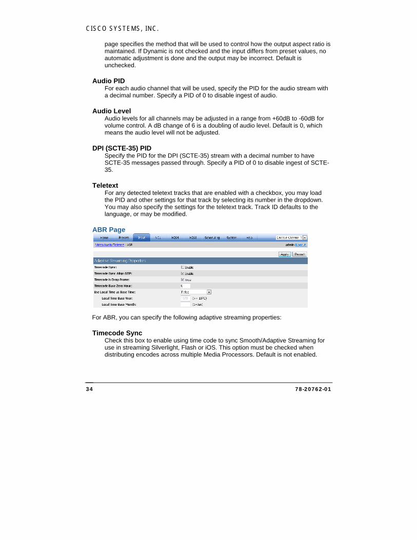
ABR Page
For ABR, you can specify the following adaptive streaming properties:
Timecode Sync Check this box to enable using time code to sync Smooth/Adaptive Streaming for use in streaming Silverlight, Flash or iOS. This option must be checked when distributing encodes across multiple Media Processors. Default is not enabled.

CISCO MEDIA PROCESSOR
78-20762-01 35
Timecode Sync Align GOP This option should always be enabled.
Timecode is Drop Frame If your NTSC timecode is not Drop Frame then uncheck this box (this is unusual and not typical). Default is True.
Timecode Base Zero Hour Timecode of 0 is assumed to be midnight. The box Timecode Base Zero Hour can be used indicate that Timecode 0 is not midnight. For example, entering 1 here indicates that Timecode of 0 is 1 a.m. This setting is usually left at 0 even if your timecode has no relation to clock time.
Use Local Time as Base Time If using a single system and not using timecode, then the time of samples in the encode stream defaults starting at 0. Optionally, you can use the “Use Local Time as Base Time” option to set this base start time. It can set to use the current system time or the current system time measured since midnight on the first day of the specified base year and month.
CISCO SYSTEMS, INC.
78-20762-01 36
VC1 Page
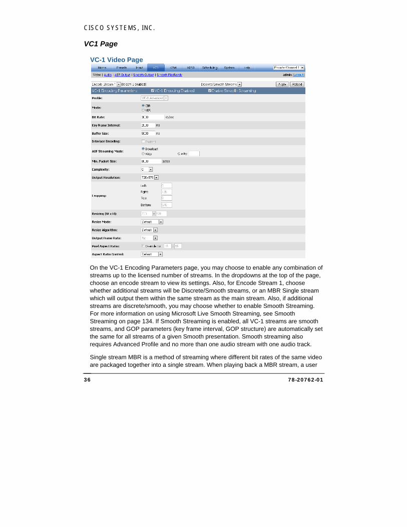
VC-1 Video Page
On the VC-1 Encoding Parameters page, you may choose to enable any combination of streams up to the licensed number of streams. In the dropdowns at the top of the page, choose an encode stream to view its settings. Also, for Encode Stream 1, choose whether additional streams will be Discrete/Smooth streams, or an MBR Single stream which will output them within the same stream as the main stream. Also, if additional streams are discrete/smooth, you may choose whether to enable Smooth Streaming. For more information on using Microsoft Live Smooth Streaming, see Smooth Streaming on page 134. If Smooth Streaming is enabled, all VC-1 streams are smooth streams, and GOP parameters (key frame interval, GOP structure) are automatically set the same for all streams of a given Smooth presentation. Smooth streaming also requires Advanced Profile and no more than one audio stream with one audio track.
Single stream MBR is a method of streaming where different bit rates of the same video are packaged together into a single stream. When playing back a MBR stream, a user
CISCO MEDIA PROCESSOR
78-20762-01 37
will receive one of the sub-streams based on the network bandwidth. When encoding to an MBR Single Stream, each additional MBR stream should be composed of a lower video/audio data rate than preceding streams. For example, if your main VC-1 encode is set up for 1Mb video and 192Kb audio, your first additional MBR stream should have a lower video and audio rate (say 500Kb video and 128Kb audio). If you add another stream, its video and audio rates should be set up less than the previous one (say 100Kb video and 64Kb audio). If the primary stream has an audio stream, the child MBRs must also have audio streams. The user interface will enforce this rule when setting up an MBR stream.
Separate streams can produce up to 8 independent streams of different bit rates. These streams are on separate ports, and are transported individually. When encoding to separate streams, it is not necessary for each successive stream to have a lower bit rate than its predecessor; the streams are independent and may be configured as needed.
For up to 8 streams, you may enable VC-1 encoding, then view or modify the following settings:
Profile Profiles for encoding include VC-1 Advanced Profile, VC-1 Main Profile, and VC-1 Simple Profile. Choose from the profiles available in the drop-down box. Smooth Streaming requires Advanced profile. See Appendix D: Specifications on page 165 for information on which units support each profile.
Mode Choose CBR (Constant Bit Rate) or VBR (Variable Bit Rate) encoding. If the mode is VBR, a parameter to specify Maximum Bit Rate in kb/sec will appear and the Buffer Size parameter will be grayed. The VBR mode will automatically set the buffer size based on the target and peak bit rate.
Bit Rate This setting indicates bits/sec in units of kb/sec. For example, a value of 1500 is 1.5Mbits/sec.
Key Frame Interval This value (in milliseconds) sets the maximum distance between key frames. The encoder may output key frames sooner than this interval (if it detects a scene change, for example). If using Smooth Streaming, all streams must have the same key frame interval.
Buffer Size The buffer size value (in milliseconds) sets the encoder buffer size. Two seconds (2000 milliseconds) is a typical buffer size. To reduce the buffer size below 1.5 seconds, you will need to use a low delay WMA audio bit rate.
CISCO SYSTEMS, INC.
78-20762-01 38
Interlace Encoding Check this box if you want to perform interlaced based encoding. If not checked, the encoder will process video as progressive. Interlace encoding is only available for VC-1 Advanced Profile. VC-1 Main and Simple profiles do not support interlace encoding. If you are not encoding as interlaced, then you should either choose to de-interlace your video (for video content) or perform an inverse telecine (IVT) on your video (for film based content). The Pre-Processing section is where these two options are set.
ASF Streaming Mode Choose between Broadcast and Web for the ASF streaming mode. If Web is chosen, specify a value for Quality. The quality setting, from 0 to 100, is a tradeoff between smoother video (Quality 0) and better quality video (Quality 100). Thus with a higher quality setting the encoder may choose to drop more frames to achieve a target bit rate, versus keeping the frames but encoding them at a lower quality. If you prefer smoother video (less playback stutter), then choose a lower quality setting (25 for example). If you prefer slower motion video (more stutter) with higher quality, choose a high quality setting (80 for example).
When Broadcast streaming is selected with Main Profile, the encoder emphasizes smoother video over quality video, equivalent to Web streaming mode with Quality 0. In this mode, the encoder may drop (not encode) frames as needed. When Broadcast streaming is selected with Advanced Profile, the encoder can encode skip frames for frames the Main Profile encoder would drop. This allows for the preservation of critical metadata, such as captioning and timecode.
Min. Packet Size Use this setting to specify the minimum size of the packets in the ASF stream. The actual packet size may be larger based on audio and video compression requirements. For streaming applications, a value no more than approximately 1/15th your compressed video data byte rate is suggested. For example, 8000 is a good setting for a 1Mb/sec stream. If you are unsure about this setting, set it to 0 to let the internal ASF mux decide on the value.
Complexity Specify the complexity setting from 0 to 4 to trade off between the needs of Better Performance (0) versus Better Quality (4) encoding.
Encoder complexity tells the encoder how hard to work to gain maximum compression efficiency. For complex content, higher encoder complexities will yield better quality at the same data rate. Simple, static content will not show nearly as much of a difference. For Live Streams, a complexity setting of 2 or less is recommended. Setting complexity to 3 or 4 could result in dropped frames.

CISCO MEDIA PROCESSOR
78-20762-01 39
Output Resolution Choose from the available resolutions or choose Custom, which will make the Cropping and Resizing settings available for modification. The pixel aspect ratio is auto set for each of these presets.
Cropping The cropping parameters apply a crop to the input image. Note that if an odd number of lines are cropped from the top, the sense of which field is first (top or bottom) will change and you will need to set the Field Order option on the Video Input page accordingly.
Resizing Specify the output resolution to be applied to the cropped image. If the resolution is different than the original, scaling will be performed. The minimum supported resolution is 64x64.
Resize Mode Choose Progressive mode, Interlaced mode, or Single Field mode to manually specify how the resizer will process the source video. Single field mode, which should only be used for interlace source material, scales to the destination image using only a single field of the source video instead of doing a deinterlace operation. It is highly recommended to use single field mode for producing progressive frames from a 1080i source. For example, to stream a 1280x720p from a 1920x1080i source, it is recommended to choose the single field mode and resize to 1280x720 instead of performing a deinterlace operation.
Resize Algorithm Choose Nearest, Linear, Cubic, or Super to specify the algorithm to be used by the resize operation. By default linear is used. Nearest (also referred to as Nearest neighbor) is the worst quality and has the lowest CPU requirements. Cubic is a higher quality scaler than linear, and Super is a higher quality algorithm than Cubic. However, Super is very processor intensive and is only used for downscaling, and only when the resize is less than about ½ the source size. For example, if scaling single field mode from 1920x1080i, the field size is 1920x540, so use Super if the output size is <= 270 in height.
Output Frame Rate Choose 1x to specify the input frame rate, or reduce the input frame rate for telecine purposes or frame rate decimation. Available options listed are the input frame rate and 1/2, 1/3, 1/4, 1/5, and 1/6 the input rate.
Pixel Aspect Ratio To override the automatically set pixel aspect ratio, check the override box and modify the calculated ratio to the new ratio. If this box is not checked, the pixel aspect ratio is calculated based on the output size of the video for the preset sizes. Overriding is useful in cases where source video has a non-standard aspect ratio.
CISCO SYSTEMS, INC.
78-20762-01 40
For example, a 720x480 input source may have been produced anamorphically, and by indicating the aspect ratio here players can correctly resize video on playback to the non-anamorphic size.
Aspect Ratio Control When Dynamic is checked on the Input page, choose Default, Manual, Letter/Pillar, or Crop to specify the method that will be used to maintain the output aspect ratio when the input resolution or aspect ratio changes during encoding. Manual specifies not to automatically adjust for the aspect ratio. Letter/Pillar will add letterboxing or pillarboxing to achieve the specified output aspect ratio. Crop will modify the crop settings to achieve the specified output aspect ratio. Default is currently set to Crop.
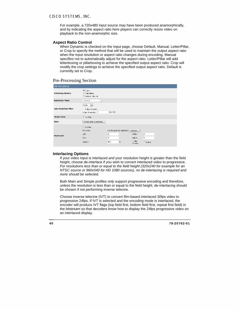
Pre-Processing Section
Interlacing Options If your video input is interlaced and your resolution height is greater than the field height, choose de-interlace if you wish to convert interlaced video to progressive. For resolutions less than or equal to the field height (320x240 for example for an NTSC source or 960x540 for HD 1080 sources), no de-interlacing is required and none should be selected.
Both Main and Simple profiles only support progressive encoding and therefore, unless the resolution is less than or equal to the field height, de-interlacing should be chosen if not performing inverse telecine.
Choose inverse telecine (IVT) to convert film-based interlaced 30fps video to progressive 24fps. If IVT is selected and the encoding mode is interlaced, the encoder will produce IVT flags (top field first, bottom field first, repeat first field) in the bitstream so that decoders know how to display the 24fps progressive video on an interlaced display.
CISCO MEDIA PROCESSOR
78-20762-01 41
Deinterlace Mode If deinterlacing is chosen, Cisco Media Processor provides multiple methods for deinterlacing. The default, a motion adaptive deinterlace, attempts to preserve spatial information in areas of motion while removing interlace artifacts in areas of motion. The blend mode will blend two fields, maintaining temporal information through motion blur. The interpolate mode removes temporal information and interpolates even fields from odd fields, while interpolate denoise applies a noise reduction filter after the deinterlace. The line double option simply creates even field lines as direct copies of the odd field lines.
Noise Reduction Filter Cisco Media Processor provides for various noise reducing filters. Choose None for no filter. The Light filter uses less noticeable filtering that should have less impact on picture quality. The normal filter provides for moderate noise reduction. The smooth filter provides for large noise reduction at the expense of softer images.
If you choose one of the above filters, you may also check Edge Enhance and specify a threshold to add the edge enhance mode to the filter. This mode detects edges in the image, and the detected edges are not processed by the filtering. The intent of this mode is to preserve edges and sharpness while still applying noise reduction to smoother areas. The edge threshold specifies the sensitivity of the edge detection. Lower values increase sensitivity, while higher values may detect few if any edges. Range 8-128.
Median Filter Check Enabled to use the Median filter. This filter is a standard image processing filter best used on noisy images.
Watermark To add a watermark image, click Enabled . If no watermark file is selected, or to change the selected file, click Replace… and either upload a new watermark file or choose a previously uploaded watermark file from the list, then click Select. The watermark image file may be of type .gif, .bmp, .jpg, .jpeg, .png, .tif, or .tiff. You may use the same image file for different streams.
Left and Top specify the pixel location where the upper left pixel of the watermark will be placed. Default Left 0, Top 0 is the upper left of the image.
Width and Height cause the watermark image to be resized (enlarged or reduced) to be width pixels wide and height pixels high. Resizing is not supported for bitmaps that have an alpha channel. Both the original and resized watermark must be no larger than the encoded image size. Default Width 0, Height 0 specifies no resizing. You may want to use different resolution watermark images for different streams to preserve observed watermark size, or the same image could be scaled to different sizes.
If desired, specify the opacity of the watermark. Default is 100% opaque.
CISCO SYSTEMS, INC.
78-20762-01 42
Check NoChroma to remove color information from the watermark image to display it in black and white.
Check the Banner checkbox to cause the watermark image to move two pixels per frame across the output image from right to left.
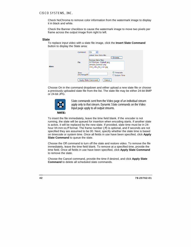
Slate To replace input video with a slate file image, click the Insert Slate Command button to display the Slate area:
Choose On in the command dropdown and either upload a new slate file or choose a previously uploaded slate file from the list. The slate file may be either 24-bit BMP or 24-bit JPG.
NOTE:
Slate commands sent from the Video page of an individual stream apply only to that stream. Dynamic Slate commands on the Video Input page apply to all output streams.
To insert the file immediately, leave the time field blank. If the encoder is not running, the slate will be queued for insertion when encoding starts. If another slate is active, it will be replaced by the new slate. If provided, slate time must be in 24-hour hh:mm:ss;ff format. The frame number (;ff) is optional, and if seconds are not specified they are assumed to be 00. Next, specify whether the slate time is based on timecode or system time. Once all fields in use have been specified, click Apply Slate Command to queue the slate.
Choose the Off command to turn off the slate and restore video. To remove the file immediately, leave the time field blank. To remove at a specified time, provide the time field. Once all fields in use have been specified, click Apply Slate Command to remove the slate.
Choose the Cancel command, provide the time if desired, and click Apply Slate Command to delete all scheduled slate commands.
CISCO MEDIA PROCESSOR
78-20762-01 43
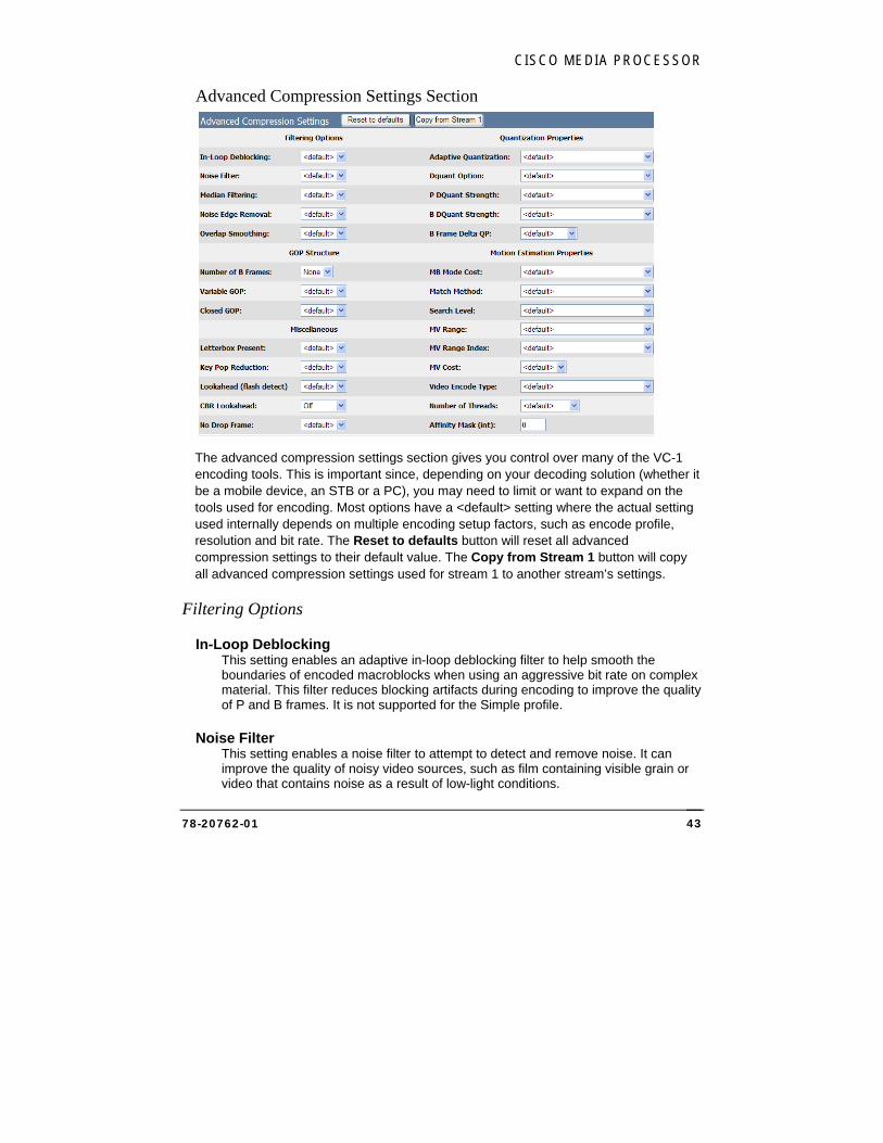
Advanced Compression Settings Section
The advanced compression settings section gives you control over many of the VC-1 encoding tools. This is important since, depending on your decoding solution (whether it be a mobile device, an STB or a PC), you may need to limit or want to expand on the tools used for encoding. Most options have a <default> setting where the actual setting used internally depends on multiple encoding setup factors, such as encode profile, resolution and bit rate. The Reset to defaults button will reset all advanced compression settings to their default value. The Copy from Stream 1 button will copy all advanced compression settings used for stream 1 to another stream’s settings.
Filtering Options
In-Loop Deblocking This setting enables an adaptive in-loop deblocking filter to help smooth the boundaries of encoded macroblocks when using an aggressive bit rate on complex material. This filter reduces blocking artifacts during encoding to improve the quality of P and B frames. It is not supported for the Simple profile.
Noise Filter This setting enables a noise filter to attempt to detect and remove noise. It can improve the quality of noisy video sources, such as film containing visible grain or video that contains noise as a result of low-light conditions.
CISCO SYSTEMS, INC.
78-20762-01 44
Median Filtering This setting enables a median filter that improves motion estimation processing by factoring out noise artifacts. This can improve the quality of very noisy video and may reduce the video’s encoded size, but may also introduce compression artifacts such as motion trails behind moving objects in an image.
Noise Edge Removal This setting will attempt to detect noisy frame edges and remove them by duplicating adjacent lines to fill in the frame.
Overlap Smoothing This setting helps to reduce blocking artifacts by smoothing the borders between adjacent macroblocks. This tends to make the image appear softer, but can improve the appearance of low bit rate video that contains many blocking artifacts.
GOP Structure
Number of B Frames This setting specifies the number of B frames to use between other types of frames, up to 7. It is not supported for the Simple profile. The Lookahead (flash detect) option can also cause insertion of B frames even if the number of B frames set here is 0. To turn off all B frames, make sure this parameter is set to 0 and also set Lookahead (flash detect) to Off. Smooth Streaming requires that all streams have the same number of B frames.
Variable GOP This setting (Group of Pictures), when set to “off”, will force a key frame exactly at the maximum key frame distance interval. So if the key frame interval is 2 seconds, you will get a key frame (I frame) at time 0, time 2, time 4, etc. In the default or “on” mode, the forced placement of a key frame as defined by the key frame distance resets with each key frame inserted in the stream. For example, if the key frame interval is 2 seconds, but a scene change happens at time 1 that causes the output of a key frame, you will get a key frame at time 0, time 1, time 3, time 5, etc. Smooth Streaming requires fixed GOP.
Closed GOP This setting, when set to “true”, will specify that a GOP does not contain frames that depend on adjacent GOPs. Smooth Streaming requires Closed GOP.
Miscellaneous
Letterbox Present This setting, when set to true, will enable letterbox detection.

CISCO MEDIA PROCESSOR
78-20762-01 45
Key Pop Reduction This setting, when not set to “off”, specifies the key pop reduction settings of light, medium, strong, and strongest.
Lookahead (flash detect) This setting, when set to “on” (available only in CBR encoding mode), will specify whether the encoder evaluates future frames before encoding the current frame. Specifically, this mode looks for ideal places to insert B frames. This occurs when a single frame stands out as being very different from the frames around it. If this “different” frame were to be used for prediction, quality could suffer because there would be little to predict from. Therefore, the encoder may choose to change the frame type of this frame to B so that it will not be used for prediction. A camera “flash” is one common example of when this occurs, thus the name “flash detect”.
CBR Lookahead This setting, when set to Mode 1 or 2 (available only in CBR encoding mode), will enable lookahead rate control. This mode attempts to provide smoother / tighter CBR bit rates by analyzing future frames before encoding current frames. Mode 2 is recommended over Mode 1.
No Drop Frame This setting, when set to true (available only in CBR encoding mode), will specify that the encoder should not drop frames. In the cases where the encoder would normally drop frames, the encoder will output skip frames instead. This allows for the preservation of metadata (such as time code and embedded captions) while still allowing a high quality setting.
Quantization Properties
Adaptive Quantization This setting specifies the type of adaptive quantization to use. Higher values mean stronger quantization. Choose Adaptive Deadzone 1-15 for the conservative range, or Aggressive Adaptive Deadzone (ADZ) 1-5 for the strongest quantization.
Dquant Option This setting enables DQuant perceptual optimization, which can improve quality in smooth areas of video, at the cost of increased encoding computation. This option is not available when using Simple Profile. If this optimization is enabled, you may choose to optimize only I frames, only I and P frames, or I, P, and B frames.
P Dquant Strength and B Dquant Strength If DQuant Optimization is enabled, these settings specify the strength of optimization to use for P and B frames respectively. Greater strength indicates the encoding is more CPU-intensive.

CISCO SYSTEMS, INC.
78-20762-01 46
B Frame Delta QP This value, from 1 to 30, specifies the amount of the increase in QP for B-frames relative to the anchor frame QP on a per-macroblock basis. A higher QP value means a higher compression ratio. Increasing B-frame delta QP can sometimes result in better video quality because this can free up bits to better compress the key frames from which the B-frames are temporally predicted. This option is only available when using VC-1 Advanced Profile.
Motion Estimation Properties
MB Mode Cost This setting specifies the cost method used by the codec to determine which macroblock mode to use. SAD/Hadamard only uses distortion to compute cost, while RD accounts for both rate and distortion in the computation.
Match Method This setting specifies the method to use for motion searching. Choose SAD (best performance), Hadamard (best quality), or Macroblock-adaptive, which allows the codec to determine which method to use on each macroblock. This can potentially reduce overall computation required for encoding by performing the computationally-intensive Hadamard transform only when appropriate.
Search Level This setting specifies which types of video information that motion search operations will use. You may choose Luma only (best performance) , Luma with nearest-integer chroma, Luma with true chroma (best quality), Macroblock-adaptive with true chroma, and Macroblock-adaptive with nearest-integer chroma.
MV Range This setting specifies the range, in pixels, that will be used in motion searches. This option is not available when using Simple Profile. Choose from the horizontal (H) and vertical (V) ranges or Macroblock-adaptive..
MV Range Index This setting specifies the method used to code the motion vector information in field pictures. This setting is only available when using VC-1 Advanced Profile. Choose Encoder defaults, or choose to improve encoding efficiency for highly spread-out horizontal delta motion vector distributions, vertical distributions, or both.
MV Cost This setting specifies the method used to estimate the cost (amount of processing needed) of motion vector coding. The codec uses the cost to determine which features will be used in encoding. Choose Static or Dynamic motion vector cost, which is varied between blocks to achieve optimal visual quality.
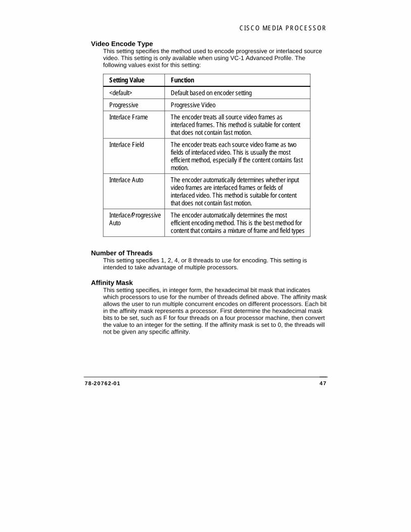
CISCO MEDIA PROCESSOR
78-20762-01 47
Video Encode Type This setting specifies the method used to encode progressive or interlaced source video. This setting is only available when using VC-1 Advanced Profile. The following values exist for this setting:
Setting Value Function
<default> Default based on encoder setting
Progressive Progressive Video
Interlace Frame The encoder treats all source video frames as interlaced frames. This method is suitable for content that does not contain fast motion.
Interlace Field The encoder treats each source video frame as two fields of interlaced video. This is usually the most efficient method, especially if the content contains fast motion.
Interlace Auto The encoder automatically determines whether input video frames are interlaced frames or fields of interlaced video. This method is suitable for content that does not contain fast motion.
Interlace/Progressive Auto
The encoder automatically determines the most efficient encoding method. This is the best method for content that contains a mixture of frame and field types
Number of Threads This setting specifies 1, 2, 4, or 8 threads to use for encoding. This setting is intended to take advantage of multiple processors.
Affinity Mask This setting specifies, in integer form, the hexadecimal bit mask that indicates which processors to use for the number of threads defined above. The affinity mask allows the user to run multiple concurrent encodes on different processors. Each bit in the affinity mask represents a processor. First determine the hexadecimal mask bits to be set, such as F for four threads on a four processor machine, then convert the value to an integer for the setting. If the affinity mask is set to 0, the threads will not be given any specific affinity.
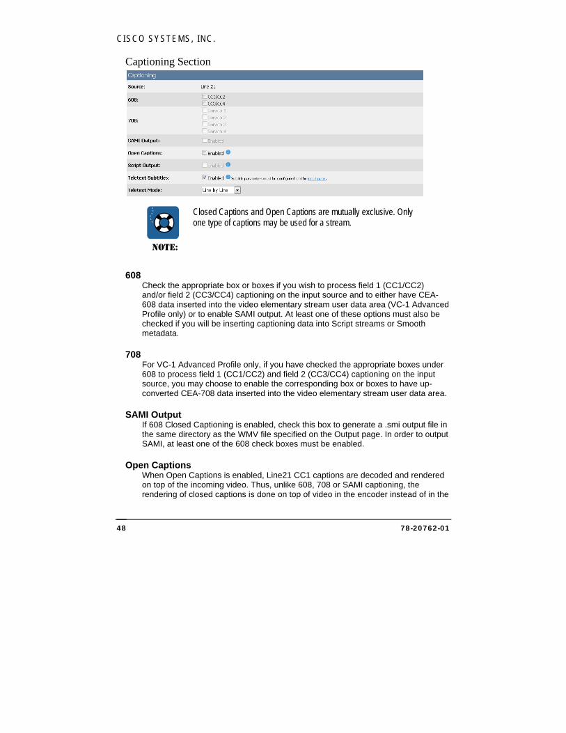
CISCO SYSTEMS, INC.
78-20762-01 48
Captioning Section
NOTE:
Closed Captions and Open Captions are mutually exclusive. Only one type of captions may be used for a stream.
608 Check the appropriate box or boxes if you wish to process field 1 (CC1/CC2) and/or field 2 (CC3/CC4) captioning on the input source and to either have CEA-608 data inserted into the video elementary stream user data area (VC-1 Advanced Profile only) or to enable SAMI output. At least one of these options must also be checked if you will be inserting captioning data into Script streams or Smooth metadata.
708 For VC-1 Advanced Profile only, if you have checked the appropriate boxes under 608 to process field 1 (CC1/CC2) and field 2 (CC3/CC4) captioning on the input source, you may choose to enable the corresponding box or boxes to have up-converted CEA-708 data inserted into the video elementary stream user data area.
SAMI Output If 608 Closed Captioning is enabled, check this box to generate a .smi output file in the same directory as the WMV file specified on the Output page. In order to output SAMI, at least one of the 608 check boxes must be enabled.
Open Captions When Open Captions is enabled, Line21 CC1 captions are decoded and rendered on top of the incoming video. Thus, unlike 608, 708 or SAMI captioning, the rendering of closed captions is done on top of video in the encoder instead of in the
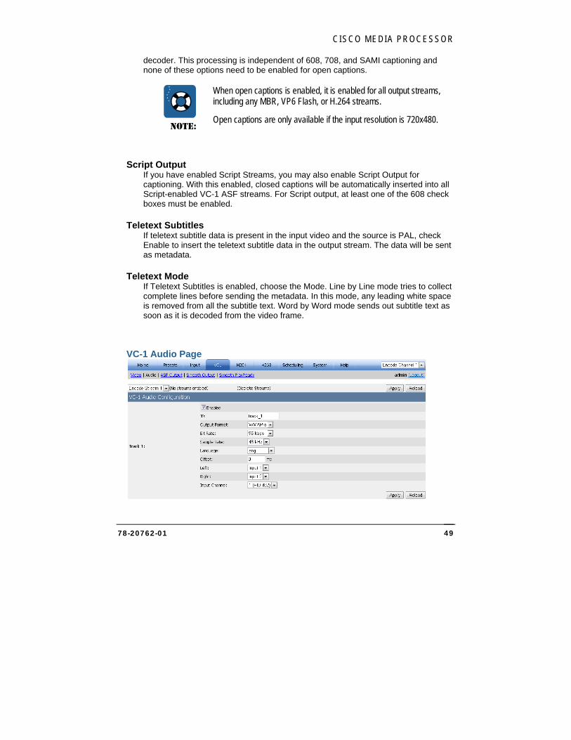
CISCO MEDIA PROCESSOR
78-20762-01 49
decoder. This processing is independent of 608, 708, and SAMI captioning and none of these options need to be enabled for open captions.
NOTE:
When open captions is enabled, it is enabled for all output streams, including any MBR, VP6 Flash, or H.264 streams.
Open captions are only available if the input resolution is 720x480.
Script Output If you have enabled Script Streams, you may also enable Script Output for captioning. With this enabled, closed captions will be automatically inserted into all Script-enabled VC-1 ASF streams. For Script output, at least one of the 608 check boxes must be enabled.
Teletext Subtitles If teletext subtitle data is present in the input video and the source is PAL, check Enable to insert the teletext subtitle data in the output stream. The data will be sent as metadata.
Teletext Mode If Teletext Subtitles is enabled, choose the Mode. Line by Line mode tries to collect complete lines before sending the metadata. In this mode, any leading white space is removed from all the subtitle text. Word by Word mode sends out subtitle text as soon as it is decoded from the video frame.
VC-1 Audio Page
CISCO SYSTEMS, INC.
78-20762-01 50
The encoder may optionally encode a WMA audio stream. This stream is a stereo track (unless defined as mono) and you may choose between the two audio inputs for the track’s left and right outputs. Check the Enabled box to enable encoding of an audio track.
For Smooth Streaming, currently Cisco Media Processor only allows a single stereo audio track per video stream. Therefore, if the multiple audio use case requires 3 audio tracks, at least 3 video streams are required.
NOTE:
Currently for Smooth Streaming, audio compression settings must be the same for all audio tracks. They must have the same bit rate, sample rate, complexity, offset and number of channels. The Web interface does not currently enforce this rule, so care must be taken to ensure this.
ID Specify the ID for the audio track. Each Smooth audio track must have a unique ID. The client player should allow the user to choose between various audio IDs.
Output Format Use this setting to specify whether to encode audio using WMA or WMAPro. (To enable WMA Pro, you must have stereo audio inputs selected.)
Bit Rate Choose from the list of available audio bit rates. The “odd” value bit rates (such as 191) indicate the use of the low delay WMA codec.
Sample Rate Sample rate is 48 kHz.
Language Choose the ISO-639-2/T language label to apply to the stream.
Offset Use this setting to specify an offset (in milliseconds) between audio and video. The offset can be a positive or negative value. Typically this value is 0 unless you know that your source audio and video are not in sync. If not in sync, you may use this setting to adjust timing such that they are re-synced prior to encoding.
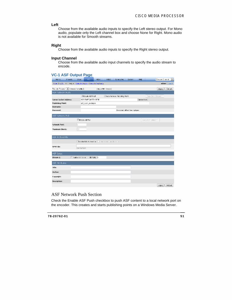
CISCO MEDIA PROCESSOR
78-20762-01 51
Left Choose from the available audio inputs to specify the Left stereo output. For Mono audio, populate only the Left channel box and choose None for Right. Mono audio is not available for Smooth streams.
Right Choose from the available audio inputs to specify the Right stereo output.
Input Channel Choose from the available audio input channels to specify the audio stream to encode.
VC-1 ASF Output Page
ASF Network Push Section Check the Enable ASF Push checkbox to push ASF content to a local network port on the encoder. This creates and starts publishing points on a Windows Media Server.
CISCO SYSTEMS, INC.
78-20762-01 52
Click the Copy from Stream 1 button to populate a stream’s settings from the primary stream’s settings.
Server Socket Address Enter the name of the Windows Media server. This can be an alias, a fully qualified domain name, or an IP address of the Windows Media Server. The port is the UDP port that the stream should be sent on.
Publishing Point Enter the name of the publishing point on the server through which the encoded stream will be broadcast. A checkbox is available on this page to automatically remove the publishing point once the encoder is stopped.
If your Windows Media Server requires authentication, enter the username and password and click Apply to store them in the registry. The password characters will not be displayed.
ASF Network Pull Section Check the Enable ASF Pull checkbox to enable Windows Media Servers and Windows Media Players to retrieve (“pull”) content as it is being encoded from the encoder UDP port. Click the Copy from Stream 1 button to populate a stream’s settings from the primary stream’s settings.
Network Port Enter the UDP port that the Windows Media Server will pull the stream from.
Maximum Clients Enter the maximum number of servers that can connect to the UDP port/stream.
ASF Archive File Section To save encoded data to the encoder hard disk, click Enable ASF Archive File for the main stream and any MBR streams.
WMV File The encoder will optionally save encoded data to the encoder hard disk or network drive, and any additional streams may also be saved. Use this section to save each stream to a user-specified WMV file by checking the appropriate checkbox and supplying a path and file name. When using a network drive, a fully-qualified UNC path is required and the Encoding Service must have permission to create directories and copy files to the destination (for instructions see Setting up Cisco Media Processor to write to a network drive on page 152).
Note if no path information is given, the file output is stored at C:\inetpub\wwwroot\encadmin\output. Click the Generate unique file name
CISCO MEDIA PROCESSOR
78-20762-01 53
checkbox to append the current date and time to the file name, which will ensure that previous archive files will not be overwritten.
ASF Script Section The ASF Script section allows the use of an ASF script stream. An ASF script stream can deliver URL, text and caption data / commands to players. To have captions delivered, you must enable Script Output in the Captioning section of the Video page. The script commands are delivered in presentation time order. Players such as the Windows Media player can be optionally configured to process these commands as they encounter them.
The ASF script section may be used to independently enable an ASF script stream for each ASF stream by checking the appropriate box. Also, set the bit rate to be used for the script commands in kb/sec. A typical bit rate is 5. For information on ASF script commands, see the Metadata Output Page on page 22.
ASF Attributes Section The ASF Attributes section defines information that is associated with the encoded media. These attributes are placed in the ASF header for Windows Media/VC-1 files, and players such as Windows Media Player display the attributes. You can edit the contents of the following attributes:
Title
Author
Copyright
Description

CISCO SYSTEMS, INC.
78-20762-01 54
VC-1 Smooth Output Page
Streaming to Primary/Secondary Media Server Sections Check the Enable checkbox to enable VC-1 Smooth Streaming to an IIS Server with IIS Media Services installed. You may also use an additional Auxiliary server. Click the Copy from Stream 1 button to populate a stream’s settings from the primary stream’s settings.
Server Enter the name of the IIS server. This can be an alias, a fully qualified domain name, or an IP address of the server. The default port is 80.
Publishing Point Enter the name of the publishing point on the server through which the encoded stream will be broadcast.
CISCO MEDIA PROCESSOR
78-20762-01 55
Stream Manifest File Enter the name and location of the stream manifest file to be used. For more information on using Smooth Streaming, see Smooth Streaming on page 134.
Username and Password If your IIS Server requires authentication, enter the username and password and click Apply to store them in the registry. The password characters will not be displayed.
Publisher Retry Count Set to the number of times the Media Processor will retry connecting to the configured server.
Publisher Retry Delay Set to the delay in seconds between retry attempts.
Additional Settings Section
Audio Tracks Included Check the box for the available audio track ID to include audio for a given encode stream in the Smooth output. This checkbox only appears if audio has been enabled for the corresponding encode stream on the VC-1 Audio page.
Target Fragment Duration Specify (in msec) the target duration for smooth streaming fragments. This setting should normally be the same as the key frame interval set on the video page. Although this duration setting appears on the Smooth Streaming output page for each encode stream, there is only one global setting and it affects all VC-1 smooth streams.
Video/Audio Delay Enter the msec delay for the output streams. Although this delay setting appears on the Smooth Streaming output page for each encode stream, there is only one global setting and it affects all VC-1 smooth streams.
Custom Video Parameter The text in this field will be inserted as a custom attribute in the live server manifest. An example use for this field is for multiple camera angles. Smooth streams are uniquely identified by a quality level which is essentially the bit rate. Two streams of the same bit rate cannot be distinguished without custom attributes. This field provides the custom attribute to identify this stream. For multiple camera angles, this attribute could identify the specific video input.
An example format for this field is:
<param name ="cameraAngle" value="coach-cam" valuetype="data" />

CISCO SYSTEMS, INC.
78-20762-01 56
Thus two different Media Processors could provide two different camera angles. Each Media Processor has the same number of streams and bit rates for those streams. However, one Media Processor has for each stream, for example, a custom video parameter of:
<param name ="cameraAngle" value="main" valuetype="data" />
and the other Media Processor has for each stream a custom video parameter of:
<param name ="cameraAngle" value="alternate" valuetype="data" />
Max Size Override Check the Enabled checkbox to override the maximum output video size, and specify the new maximum width and height for this stream.
Use this setting to handle anamorphic / widescreen video. For example, 16x9 content is often anamorphically resized to 720x480 for delivery over SDI. Instead of resizing this 720x480 video back to 848x480 prior to compression, simply compress the content as is and set the max size override to 848x480. You should only need to do this to your top resolution stream. On playback, the Silverlight player will handle reversing the anamorphic processing and will display the content resized back to its original 16x9 848x480 size.
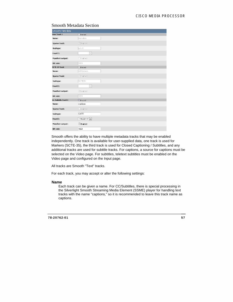
CISCO MEDIA PROCESSOR
78-20762-01 57
Smooth Metadata Section
Smooth offers the ability to have multiple metadata tracks that may be enabled independently. One track is available for user-supplied data, one track is used for Markers (SCTE-35), the third track is used for Closed Captioning / Subtitles, and any additional tracks are used for subtitle tracks. For captions, a source for captions must be selected on the Video page. For subtitles, teletext subtitles must be enabled on the Video page and configured on the Input page.
All tracks are Smooth "Text" tracks.
For each track, you may accept or alter the following settings:
Name Each track can be given a name. For CC/Subtitles, there is special processing in the Silverlight Smooth Streaming Media Element (SSME) player for handling text tracks with the name "captions," so it is recommended to leave this track name as captions.
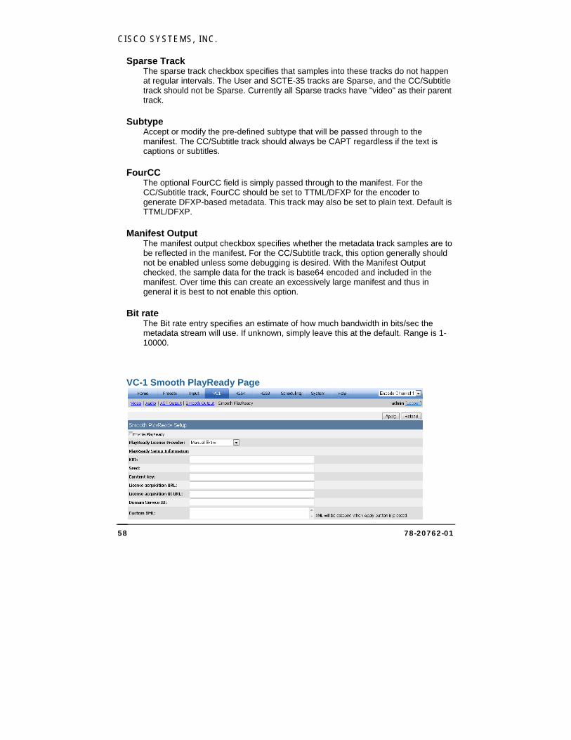
CISCO SYSTEMS, INC.
78-20762-01 58
Sparse Track The sparse track checkbox specifies that samples into these tracks do not happen at regular intervals. The User and SCTE-35 tracks are Sparse, and the CC/Subtitle track should not be Sparse. Currently all Sparse tracks have "video" as their parent track.
Subtype Accept or modify the pre-defined subtype that will be passed through to the manifest. The CC/Subtitle track should always be CAPT regardless if the text is captions or subtitles.
FourCC The optional FourCC field is simply passed through to the manifest. For the CC/Subtitle track, FourCC should be set to TTML/DFXP for the encoder to generate DFXP-based metadata. This track may also be set to plain text. Default is TTML/DFXP.
Manifest Output The manifest output checkbox specifies whether the metadata track samples are to be reflected in the manifest. For the CC/Subtitle track, this option generally should not be enabled unless some debugging is desired. With the Manifest Output checked, the sample data for the track is base64 encoded and included in the manifest. Over time this can create an excessively large manifest and thus in general it is best to not enable this option.
Bit rate The Bit rate entry specifies an estimate of how much bandwidth in bits/sec the metadata stream will use. If unknown, simply leave this at the default. Range is 1-10000.
VC-1 Smooth PlayReady Page
CISCO MEDIA PROCESSOR
78-20762-01 59
PlayReady provides encryption support for Smooth Streaming.
Check the Enable PlayReady checkbox to use Smooth PlayReady. In order to complete the rest of the PlayReady setup you will need a third party PlayReady License provider. This provider may provide you with setup information which you can manually enter in the boxes provided. Some third party PlayReady Platforms have been integrated in order to automatically retrieve the setup information. In order to use the third party approach, you will also need a business relationship with the third party.
If a third party provider such as BuyDRM is specified, there will be additional settings that will appear on the page. This information will be provided to you by the third party. t. Select the Request Key button and Cisco Media Processor will automatically contact the provider to retrieve the PlayReady settings. Once filled in, press the Apply button to save the settings. Playready settings are stored in presets so this process only needs to occur once unless your PlayReady provider requires you to retrieve new settings for each event.
If Manual Entry is specified, provide values for the following settings:
KID Enter the Key ID. This value is required. The KID must be supplied as a GUID.
GUID should be entered in the form of: {cab50618-c7e1-4e84-b683-c086d15170eb}
Seed The encryption seed. Either a seed or a content key is required.
Content Key The encryption content key. Either a seed or a content key is required
License Acquisition URL Enter the URL. A License acquisition URL is required.
License Acquisition user interface URL This is an optional field. If supplied, enter the URL.
Domain Service ID This is an optional field. If supplied, enter a Domain Service ID. The ID may be supplied as either a GUID or Base64 string.
GUID should be entered in the form of: {cab50618-c7e1-4e84-b683-c086d15170eb}
An example Base64 string is: GAa1yuHHhE62g8CG0VFw6w==
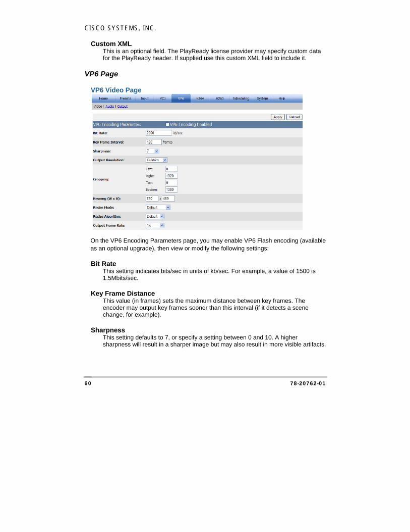
CISCO SYSTEMS, INC.
78-20762-01 60
Custom XML This is an optional field. The PlayReady license provider may specify custom data for the PlayReady header. If supplied use this custom XML field to include it.
VP6 Page
VP6 Video Page
On the VP6 Encoding Parameters page, you may enable VP6 Flash encoding (available as an optional upgrade), then view or modify the following settings:
Bit Rate This setting indicates bits/sec in units of kb/sec. For example, a value of 1500 is 1.5Mbits/sec.
Key Frame Distance This value (in frames) sets the maximum distance between key frames. The encoder may output key frames sooner than this interval (if it detects a scene change, for example).
Sharpness This setting defaults to 7, or specify a setting between 0 and 10. A higher sharpness will result in a sharper image but may also result in more visible artifacts.
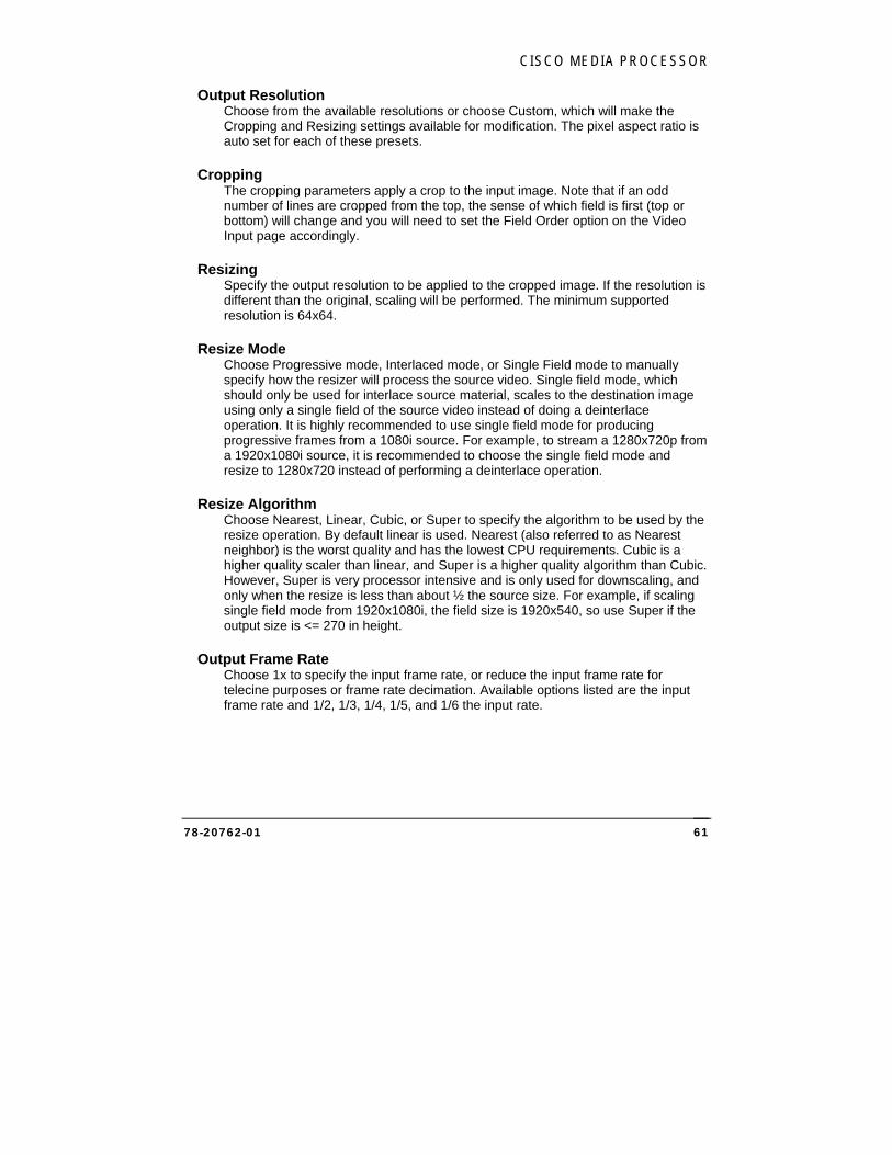
CISCO MEDIA PROCESSOR
78-20762-01 61
Output Resolution Choose from the available resolutions or choose Custom, which will make the Cropping and Resizing settings available for modification. The pixel aspect ratio is auto set for each of these presets.
Cropping The cropping parameters apply a crop to the input image. Note that if an odd number of lines are cropped from the top, the sense of which field is first (top or bottom) will change and you will need to set the Field Order option on the Video Input page accordingly.
Resizing Specify the output resolution to be applied to the cropped image. If the resolution is different than the original, scaling will be performed. The minimum supported resolution is 64x64.
Resize Mode Choose Progressive mode, Interlaced mode, or Single Field mode to manually specify how the resizer will process the source video. Single field mode, which should only be used for interlace source material, scales to the destination image using only a single field of the source video instead of doing a deinterlace operation. It is highly recommended to use single field mode for producing progressive frames from a 1080i source. For example, to stream a 1280x720p from a 1920x1080i source, it is recommended to choose the single field mode and resize to 1280x720 instead of performing a deinterlace operation.
Resize Algorithm Choose Nearest, Linear, Cubic, or Super to specify the algorithm to be used by the resize operation. By default linear is used. Nearest (also referred to as Nearest neighbor) is the worst quality and has the lowest CPU requirements. Cubic is a higher quality scaler than linear, and Super is a higher quality algorithm than Cubic. However, Super is very processor intensive and is only used for downscaling, and only when the resize is less than about ½ the source size. For example, if scaling single field mode from 1920x1080i, the field size is 1920x540, so use Super if the output size is <= 270 in height.
Output Frame Rate Choose 1x to specify the input frame rate, or reduce the input frame rate for telecine purposes or frame rate decimation. Available options listed are the input frame rate and 1/2, 1/3, 1/4, 1/5, and 1/6 the input rate.
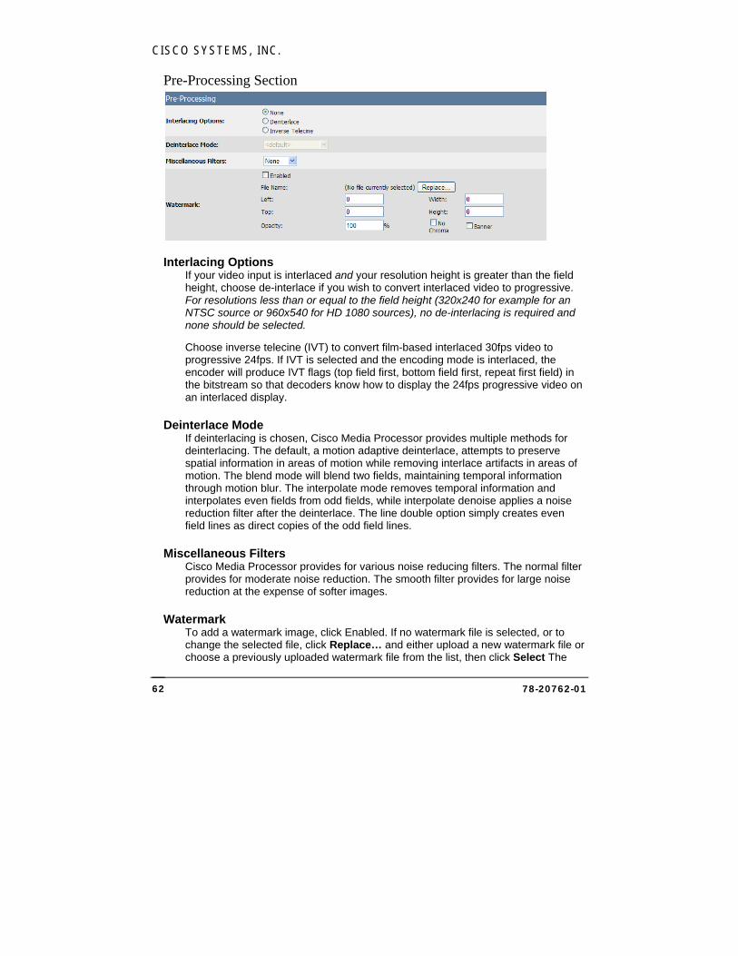
CISCO SYSTEMS, INC.
78-20762-01 62
Pre-Processing Section
Interlacing Options If your video input is interlaced and your resolution height is greater than the field height, choose de-interlace if you wish to convert interlaced video to progressive. For resolutions less than or equal to the field height (320x240 for example for an NTSC source or 960x540 for HD 1080 sources), no de-interlacing is required and none should be selected.
Choose inverse telecine (IVT) to convert film-based interlaced 30fps video to progressive 24fps. If IVT is selected and the encoding mode is interlaced, the encoder will produce IVT flags (top field first, bottom field first, repeat first field) in the bitstream so that decoders know how to display the 24fps progressive video on an interlaced display.
Deinterlace Mode If deinterlacing is chosen, Cisco Media Processor provides multiple methods for deinterlacing. The default, a motion adaptive deinterlace, attempts to preserve spatial information in areas of motion while removing interlace artifacts in areas of motion. The blend mode will blend two fields, maintaining temporal information through motion blur. The interpolate mode removes temporal information and interpolates even fields from odd fields, while interpolate denoise applies a noise reduction filter after the deinterlace. The line double option simply creates even field lines as direct copies of the odd field lines.
Miscellaneous Filters Cisco Media Processor provides for various noise reducing filters. The normal filter provides for moderate noise reduction. The smooth filter provides for large noise reduction at the expense of softer images.
Watermark To add a watermark image, click Enabled. If no watermark file is selected, or to change the selected file, click Replace… and either upload a new watermark file or choose a previously uploaded watermark file from the list, then click Select The
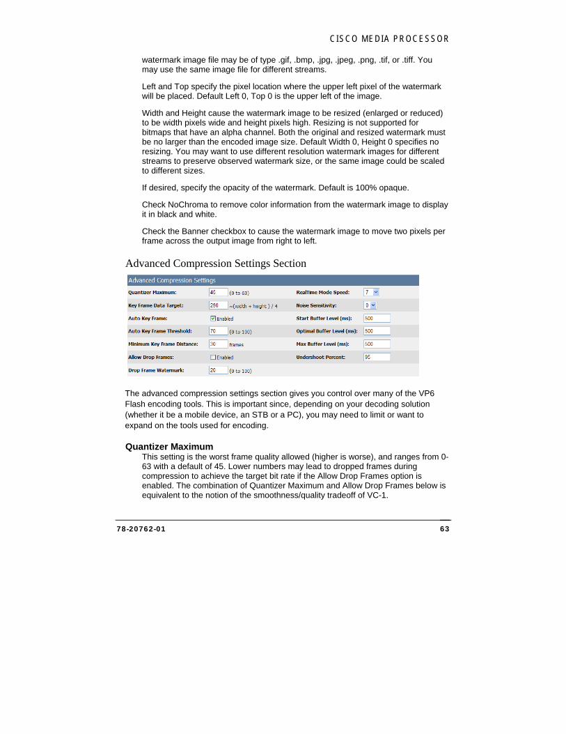
CISCO MEDIA PROCESSOR
78-20762-01 63
watermark image file may be of type .gif, .bmp, .jpg, .jpeg, .png, .tif, or .tiff. You may use the same image file for different streams.
Left and Top specify the pixel location where the upper left pixel of the watermark will be placed. Default Left 0, Top 0 is the upper left of the image.
Width and Height cause the watermark image to be resized (enlarged or reduced) to be width pixels wide and height pixels high. Resizing is not supported for bitmaps that have an alpha channel. Both the original and resized watermark must be no larger than the encoded image size. Default Width 0, Height 0 specifies no resizing. You may want to use different resolution watermark images for different streams to preserve observed watermark size, or the same image could be scaled to different sizes.
If desired, specify the opacity of the watermark. Default is 100% opaque.
Check NoChroma to remove color information from the watermark image to display it in black and white.
Check the Banner checkbox to cause the watermark image to move two pixels per frame across the output image from right to left.
Advanced Compression Settings Section
The advanced compression settings section gives you control over many of the VP6 Flash encoding tools. This is important since, depending on your decoding solution (whether it be a mobile device, an STB or a PC), you may need to limit or want to expand on the tools used for encoding.
Quantizer Maximum This setting is the worst frame quality allowed (higher is worse), and ranges from 0-63 with a default of 45. Lower numbers may lead to dropped frames during compression to achieve the target bit rate if the Allow Drop Frames option is enabled. The combination of Quantizer Maximum and Allow Drop Frames below is equivalent to the notion of the smoothness/quality tradeoff of VC-1.

CISCO SYSTEMS, INC.
78-20762-01 64
Key Frame Data Target This setting is the bit rate in Kbps to use when compressing key frames.
Auto Key Frame Check this box to enable the encoder to determine where to place key frames.
Auto Key Frame Threshold This setting specifies the threshold of how different frames must be before a key frame is generated. A higher number means fewer key frames. The range is 0-100 with a default of 70.
Minimum Key Frame Distance This setting is the minimum number of frames allowed between key frames. Default is 30.
Allow Drop Frames Check this box to allow the encoder to drop frames to achieve the desired bit rate. If this box is not checked, the encoder will not drop frames and may output a higher bit rate than desired.
Drop Frame Watermark This setting is the percentage of the buffer below which the encoder will start dropping frames. Default is 20%.
RealTime Mode Speed This setting determines what proportion of the available processor cycles the encoder will use to compress the video. At speed 0, the encoder will use all available cycles; at 8, it will use half; at 16, it will use none. Default is 7.
Noise Sensitivity This setting is the level of noise pre-processing to apply, with 0 being no pre-processing and 6 being the highest level of temporal pre-processing. Default is 0.
Start Buffer Level This setting is the amount of data in ms preloaded by the media player before starting playback. Range is 0-300000, with a default of 120.
Optimal Buffer Level This setting is the buffer size the encoder will attempt to reach and maintain. Range is 0-300000, with a default of 200.
Max Buffer Level This setting determines the maximum size of the buffer, in ms. Range is 0-300000, with a default of 200.
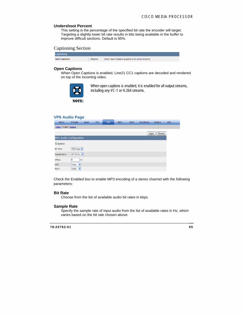
CISCO MEDIA PROCESSOR
78-20762-01 65
Undershoot Percent This setting is the percentage of the specified bit rate the encoder will target. Targeting a slightly lower bit rate results in bits being available in the buffer to improve difficult sections. Default is 95%.
Captioning Section
Open Captions When Open Captions is enabled, Line21 CC1 captions are decoded and rendered on top of the incoming video.
NOTE:
When open captions is enabled, it is enabled for all output streams, including any VC-1 or H.264 streams.
VP6 Audio Page
Check the Enabled box to enable MP3 encoding of a stereo channel with the following parameters:
Bit Rate Choose from the list of available audio bit rates in kbps.
Sample Rate Specify the sample rate of input audio from the list of available rates in Hz, which varies based on the bit rate chosen above.
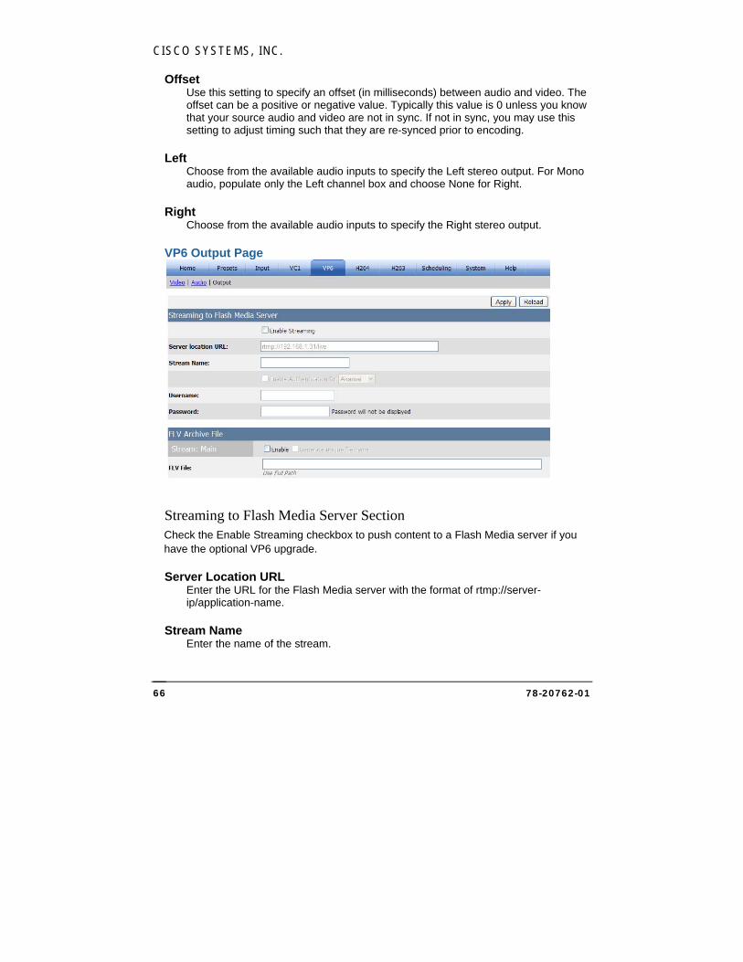
CISCO SYSTEMS, INC.
78-20762-01 66
Offset Use this setting to specify an offset (in milliseconds) between audio and video. The offset can be a positive or negative value. Typically this value is 0 unless you know that your source audio and video are not in sync. If not in sync, you may use this setting to adjust timing such that they are re-synced prior to encoding.
Left Choose from the available audio inputs to specify the Left stereo output. For Mono audio, populate only the Left channel box and choose None for Right.
Right Choose from the available audio inputs to specify the Right stereo output.
VP6 Output Page
Streaming to Flash Media Server Section Check the Enable Streaming checkbox to push content to a Flash Media server if you have the optional VP6 upgrade.
Server Location URL Enter the URL for the Flash Media server with the format of rtmp://server-ip/application-name.
Stream Name Enter the name of the stream.
CISCO MEDIA PROCESSOR
78-20762-01 67
Check the Enable Authentication checkbox and select the CDN (content distribution network) from the dropdown to enable authentication with a Flash Media Server before the stream can be published. Enter the username and password and click Apply to store them in the registry. The password characters will not be displayed.
FLV Archive File Section The encoder can optionally save the VP6 Flash stream to disk. Click the Enable checkbox and supply a path and file name to save to a user-specified FLV file.
When using a network drive, a fully-qualified UNC path is required and the Encoding Service must have permission to create directories and copy files to the destination (for instructions see Setting up Cisco Media Processor to write to a network drive on page 152).
Note if no path information is given, the file output is stored at C:\inetpub\wwwroot\encadmin\output. Click the Generate unique file name checkbox to append the current date and time to the file name, which will ensure that previous archive files will not be overwritten.
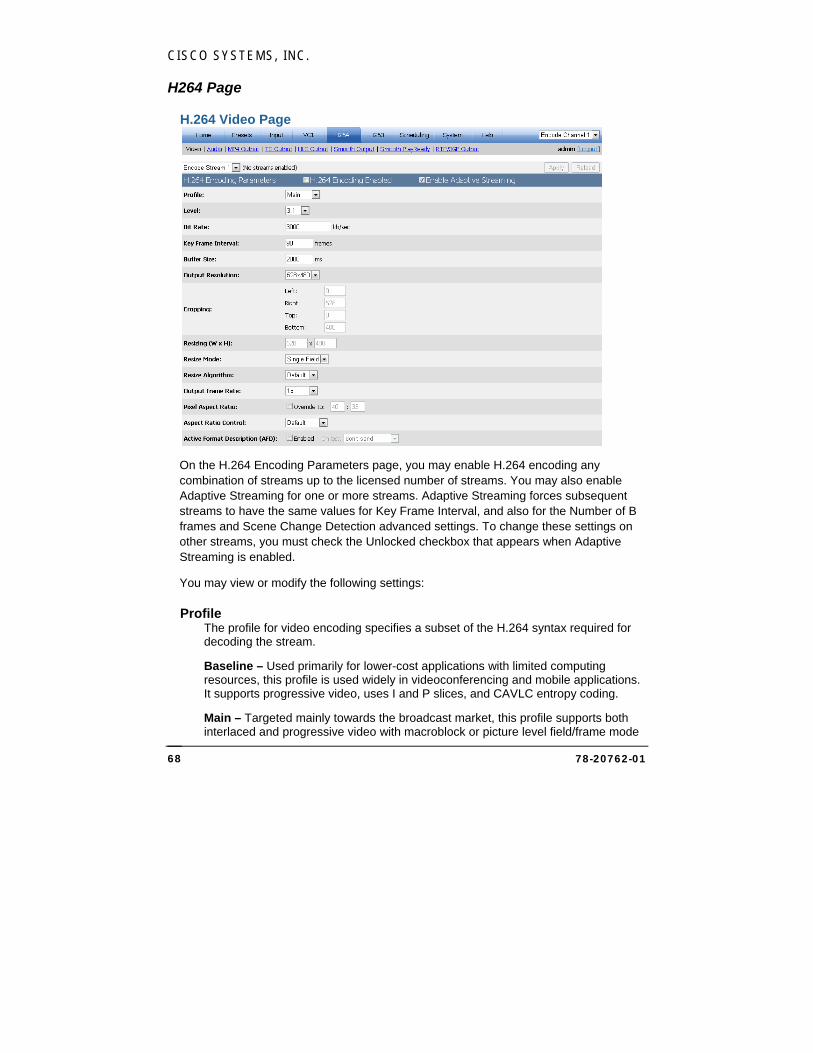
CISCO SYSTEMS, INC.
78-20762-01 68
H264 Page
H.264 Video Page
On the H.264 Encoding Parameters page, you may enable H.264 encoding any combination of streams up to the licensed number of streams. You may also enable Adaptive Streaming for one or more streams. Adaptive Streaming forces subsequent streams to have the same values for Key Frame Interval, and also for the Number of B frames and Scene Change Detection advanced settings. To change these settings on other streams, you must check the Unlocked checkbox that appears when Adaptive Streaming is enabled.
You may view or modify the following settings:
Profile The profile for video encoding specifies a subset of the H.264 syntax required for decoding the stream.
Baseline – Used primarily for lower-cost applications with limited computing resources, this profile is used widely in videoconferencing and mobile applications. It supports progressive video, uses I and P slices, and CAVLC entropy coding.
Main – Targeted mainly towards the broadcast market, this profile supports both interlaced and progressive video with macroblock or picture level field/frame mode

CISCO MEDIA PROCESSOR
78-20762-01 69
selection. Uses I, P, and B slices, weighted prediction, and both CAVLC and CABAC for entropy coding.
High – An extension of the Main profile for effective coding of High Definition content, this profile uses adaptive 8x8 or 4x4 transform and enables perceptual quantization matrices.
Level This setting specifies constraints for the encoding parameters.
Bit Rate This setting indicates bits/sec in units of kb/sec. For example, a value of 1500 is 1.5Mbits/sec. The default is 3000 kb/sec.
Key Frame Interval This value (in frames) sets the maximum distance between key frames. Default is 60 frames for non-Pal video and 50 frames for PAL video, which is 2 seconds of video. The encoder may output key frames sooner than this interval (if it detects a scene change, for example). Adaptive Streaming requires this interval to be the same for all adaptive streams, and should be a multiple of the frame rate..
Buffer Size The buffer size value (in milliseconds) sets the encoder buffer size.
Output Resolution Choose from the available resolutions or choose Custom, which will make the Cropping and Resizing settings available for modification. The pixel aspect ratio is auto set for each of these presets.
Cropping The cropping parameters apply a crop to the input image. Note that if an odd number of lines are cropped from the top, the sense of which field is first (top or bottom) will change and you will need to set the Field Order option on the Video Input page accordingly.
Resizing Specify the output resolution to be applied to the cropped image. If the resolution is different than the original, scaling will be performed. The minimum supported resolution is 64x64.
Resize Mode Choose Progressive mode, Interlaced mode, or Single Field mode to manually specify how the resizer will process the source video. Single field mode, which should only be used for interlace source material, scales to the destination image using only a single field of the source video instead of doing a deinterlace operation. It is highly recommended to use single field mode for producing
CISCO SYSTEMS, INC.
78-20762-01 70
progressive frames from a 1080i source. For example, to stream a 1280x720p from a 1920x1080i source, it is recommended to choose the single field mode and resize to 1280x720 instead of performing a deinterlace operation.
Resize Algorithm Choose Nearest, Linear, Cubic, or Super to specify the algorithm to be used by the resize operation. By default linear is used. Nearest (also referred to as Nearest neighbor) is the worst quality and has the lowest CPU requirements. Cubic is a higher quality scaler than linear, and Super is a higher quality algorithm than Cubic. However, Super is very processor intensive and is only used for downscaling, and only when the resize is less than about ½ the source size. For example, if scaling single field mode from 1920x1080i, the field size is 1920x540, so use Super if the output size is <= 270 in height.
Output Frame Rate Choose 1x to specify the input frame rate, or reduce the input frame rate for telecine purposes or frame rate decimation. Available options listed are the input frame rate and 1/2, 1/3, 1/4, 1/5, and 1/6 the input rate.
Pixel Aspect Ratio To override the automatically set pixel aspect ratio, check the override box and modify the calculated ratio to the new ratio. If this box is not checked, the pixel aspect ratio is calculated based on the output size of the video. Refer to the VC-1 description of Pixel Aspect Ratio on page 39 for further information.
Aspect Ratio Control When Dynamic is checked on the Input page, choose Default, Manual, Letter/Pillar, or Crop to specify the method that will be used to maintain the output aspect ratio when the input resolution or aspect ratio changes during encoding. Manual specifies not to automatically adjust for the aspect ratio. Letter/Pillar will add letterboxing or pillarboxing to achieve the specified output aspect ratio. Crop will modify the crop settings to achieve the specified output aspect ratio. Default is currently set to Crop.
Active Format Description (AFD) Check Enabled to pass the Active Format Description through to H.264 user data. Also, choose from the dropdown to specify whether the encoder should not send AFD or repeat the last value if the AFD input is lost.
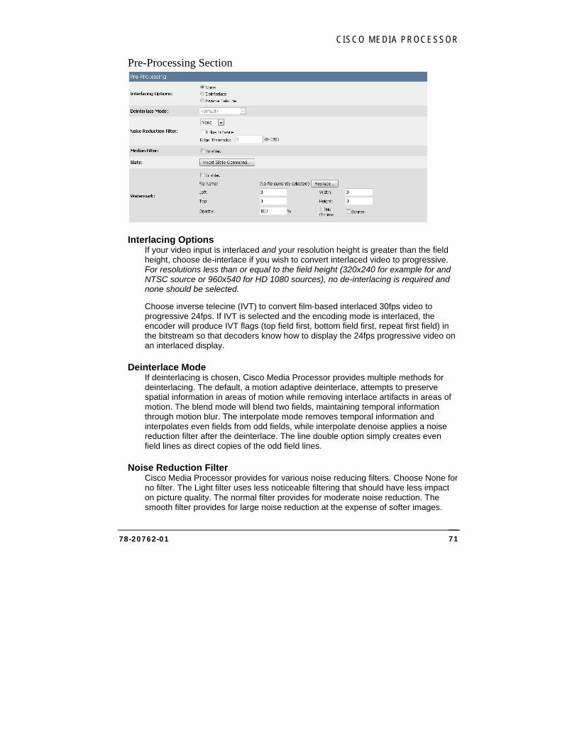
CISCO MEDIA PROCESSOR
78-20762-01 71
Pre-Processing Section
Interlacing Options If your video input is interlaced and your resolution height is greater than the field height, choose de-interlace if you wish to convert interlaced video to progressive. For resolutions less than or equal to the field height (320x240 for example for and NTSC source or 960x540 for HD 1080 sources), no de-interlacing is required and none should be selected.
Choose inverse telecine (IVT) to convert film-based interlaced 30fps video to progressive 24fps. If IVT is selected and the encoding mode is interlaced, the encoder will produce IVT flags (top field first, bottom field first, repeat first field) in the bitstream so that decoders know how to display the 24fps progressive video on an interlaced display.
Deinterlace Mode If deinterlacing is chosen, Cisco Media Processor provides multiple methods for deinterlacing. The default, a motion adaptive deinterlace, attempts to preserve spatial information in areas of motion while removing interlace artifacts in areas of motion. The blend mode will blend two fields, maintaining temporal information through motion blur. The interpolate mode removes temporal information and interpolates even fields from odd fields, while interpolate denoise applies a noise reduction filter after the deinterlace. The line double option simply creates even field lines as direct copies of the odd field lines.
Noise Reduction Filter Cisco Media Processor provides for various noise reducing filters. Choose None for no filter. The Light filter uses less noticeable filtering that should have less impact on picture quality. The normal filter provides for moderate noise reduction. The smooth filter provides for large noise reduction at the expense of softer images.

CISCO SYSTEMS, INC.
78-20762-01 72
If you choose one of the above filters, you may also check Edge Enhance and specify a threshold to add the edge enhance mode to the filter. This mode detects edges in the image, and the detected edges are not processed by the filtering. The intent of this mode is to preserve edges and sharpness while still applying noise reduction to smoother areas. The edge threshold specifies the sensitivity of the edge detection. Lower values increase sensitivity, while higher values may detect few if any edges. Range 8-128.
Median Filter Check Enabled to use the Median filter. This filter is a standard image processing filter best used on noisy images.
Watermark To add a watermark image, click Enabled. If no watermark file is selected, or to change the selected file, click Replace… and either upload a new watermark file or choose a previously uploaded watermark file from the list, then click Select The watermark image file may be of type .gif, .bmp, .jpg, .jpeg, .png, .tif, or .tiff. You may use the same image file for different streams.
Left and Top specify the pixel location where the upper left pixel of the watermark will be placed. Default Left 0, Top 0 is the upper left of the image.
Width and Height cause the watermark image to be resized (enlarged or reduced) to be width pixels wide and height pixels high. Resizing is not supported for bitmaps that have an alpha channel. Both the original and resized watermark must be no larger than the encoded image size. Default Width 0, Height 0 specifies no resizing. You may want to use different resolution watermark images for different streams to preserve observed watermark size, or the same image could be scaled to different sizes.
If desired, specify the opacity of the watermark. Default is 100% opaque.
Check NoChroma to remove color information from the watermark image to display it in black and white.
Check the Banner checkbox to cause the watermark image to move two pixels per frame across the output image from right to left.
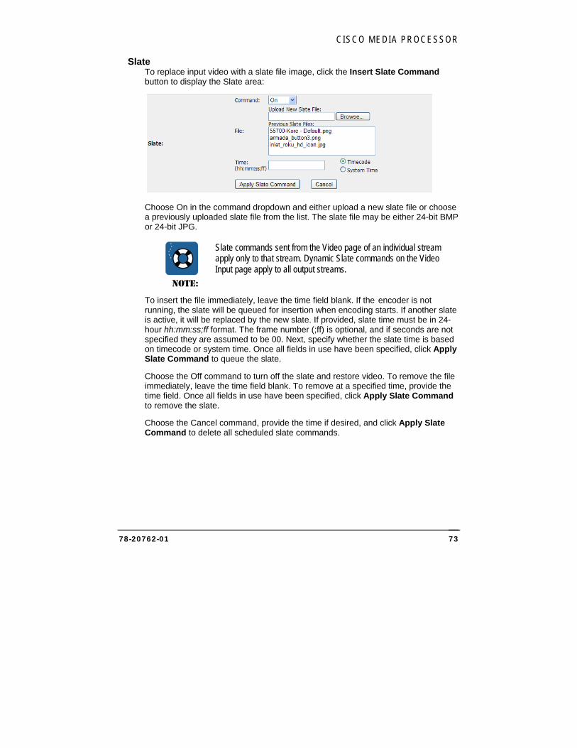
CISCO MEDIA PROCESSOR
78-20762-01 73
Slate To replace input video with a slate file image, click the Insert Slate Command button to display the Slate area:
Choose On in the command dropdown and either upload a new slate file or choose a previously uploaded slate file from the list. The slate file may be either 24-bit BMP or 24-bit JPG.
NOTE:
Slate commands sent from the Video page of an individual stream apply only to that stream. Dynamic Slate commands on the Video Input page apply to all output streams.
To insert the file immediately, leave the time field blank. If the encoder is not running, the slate will be queued for insertion when encoding starts. If another slate is active, it will be replaced by the new slate. If provided, slate time must be in 24-hour hh:mm:ss;ff format. The frame number (;ff) is optional, and if seconds are not specified they are assumed to be 00. Next, specify whether the slate time is based on timecode or system time. Once all fields in use have been specified, click Apply Slate Command to queue the slate.
Choose the Off command to turn off the slate and restore video. To remove the file immediately, leave the time field blank. To remove at a specified time, provide the time field. Once all fields in use have been specified, click Apply Slate Command to remove the slate.
Choose the Cancel command, provide the time if desired, and click Apply Slate Command to delete all scheduled slate commands.
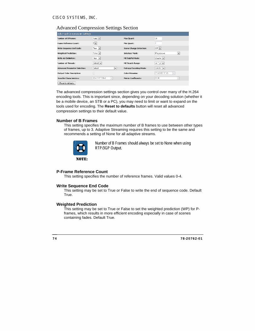
CISCO SYSTEMS, INC.
78-20762-01 74
Advanced Compression Settings Section
The advanced compression settings section gives you control over many of the H.264 encoding tools. This is important since, depending on your decoding solution (whether it be a mobile device, an STB or a PC), you may need to limit or want to expand on the tools used for encoding. The Reset to defaults button will reset all advanced compression settings to their default value.
Number of B Frames This setting specifies the maximum number of B frames to use between other types of frames, up to 3. Adaptive Streaming requires this setting to be the same and recommends a setting of None for all adaptive streams.
NOTE:
Number of B Frames should always be set to None when using RTP/3GP Output.
P-Frame Reference Count This setting specifies the number of reference frames. Valid values 0-4.
Write Sequence End Code This setting may be set to True or False to write the end of sequence code. Default True.
Weighted Prediction This setting may be set to True or False to set the weighted prediction (WP) for P-frames, which results in more efficient encoding especially in case of scenes containing fades. Default True.
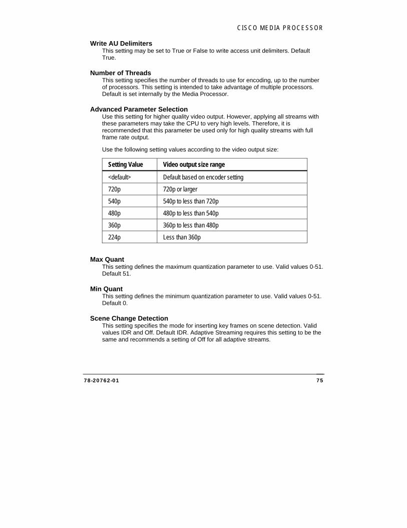
CISCO MEDIA PROCESSOR
78-20762-01 75
Write AU Delimiters This setting may be set to True or False to write access unit delimiters. Default True.
Number of Threads This setting specifies the number of threads to use for encoding, up to the number of processors. This setting is intended to take advantage of multiple processors. Default is set internally by the Media Processor.
Advanced Parameter Selection Use this setting for higher quality video output. However, applying all streams with these parameters may take the CPU to very high levels. Therefore, it is recommended that this parameter be used only for high quality streams with full frame rate output.
Use the following setting values according to the video output size:
Setting Value Video output size range
<default> Default based on encoder setting
720p 720p or larger
540p 540p to less than 720p
480p 480p to less than 540p
360p 360p to less than 480p
224p Less than 360p
Max Quant This setting defines the maximum quantization parameter to use. Valid values 0-51. Default 51.
Min Quant This setting defines the minimum quantization parameter to use. Valid values 0-51. Default 0.
Scene Change Detection This setting specifies the mode for inserting key frames on scene detection. Valid values IDR and Off. Default IDR. Adaptive Streaming requires this setting to be the same and recommends a setting of Off for all adaptive streams.
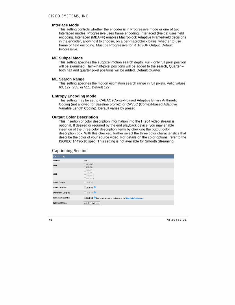
CISCO SYSTEMS, INC.
78-20762-01 76
Interlace Mode This setting controls whether the encoder is in Progressive mode or one of two Interlaced modes. Progressive uses frame encoding. Interlaced (Fields) uses field encoding. Interlaced (MBAFF) enables Macroblock Adaptive Frame/Field decisions in the encoder, allowing it to choose, on a per-macroblock basis, whether to use frame or field encoding. Must be Progressive for RTP/3GP Output. Default Progressive.
ME Subpel Mode This setting specifies the subpixel motion search depth. Full - only full pixel position will be examined, Half – half-pixel positions will be added to the search, Quarter – both half and quarter pixel positions will be added. Default Quarter.
ME Search Range This setting specifies the motion estimation search range in full pixels. Valid values 63, 127, 255, or 511. Default 127.
Entropy Encoding Mode This setting may be set to CABAC (Context-based Adaptive Binary Arithmetic Coding (not allowed for Baseline profile)) or CAVLC (Context-based Adaptive Variable Length Coding). Default varies by preset.
Output Color Description This Insertion of color description information into the H.264 video stream is optional. If desired or required by the end playback device, you may enable insertion of the three color description items by checking the output color description box. With this checked, further select the three color characteristics that describe the color of your source video. For details on the color options, refer to the ISO/IEC 14496-10 spec. This setting is not available for Smooth Streaming.
Captioning Section
CISCO MEDIA PROCESSOR
78-20762-01 77
NOTE:
Closed Captions and Open Captions are mutually exclusive. Only one type of captions may be used for a stream.
608 Check the appropriate box or boxes if you wish to process field 1 (CC1/CC2) and/or field 2 (CC3/CC4) captioning on the input source and to either have CEA-608 data inserted into the video elementary stream user data area or to enable SAMI output. At least one of these options must also be checked if you will be inserting captioning data into Flash streams as cue points or into Smooth metadata.
708 If you have checked the appropriate boxes under 608 to process field 1 (CC1/CC2) and field 2 (CC3/CC4) captioning on the input source, you may choose to enable the corresponding box or boxes to have up-converted CEA-708 data inserted into the video elementary stream user data area.
SAMI Output If 608 Closed Captioning is enabled, check this box to generate a .smi output file in the same directory as the WMV file specified on the Output page. In order to output SAMI, at least one of the 608 check boxes must be enabled.
Open Captions When Open Captions is enabled, Line21 CC1 captions are decoded and rendered on top of the incoming video. Thus, unlike 608, 708 or SAMI captioning, the rendering of closed captions is done on top of video in the encoder instead of in the decoder. This processing is independent of 608, 708, and SAMI captioning and none of these options need to be enabled for open captions.
NOTE:
When open captions is enabled, it is enabled for all output streams, including any VC-1 or VP6 Flash streams.
Open captions are only available if the input resolution is 720x480.
Cue Point Output When cue point output is enabled, NTSC caption information is automatically inserted into the Flash stream as a cue point.
CISCO SYSTEMS, INC.
78-20762-01 78
NOTE:
When cue point output is enabled, it is enabled for all Flash output streams.
Teletext Subtitles If teletext subtitle data is present in the input video and the source is PAL, and teletext has been configured on the Video/Audio/Teletext page, check Enable to insert the teletext subtitle data in the output stream. The data will be sent as Cue Points in the Flash output stream, and will be sent in all Flash output streams.
Teletext Mode If Teletext Subtitles is enabled, choose the Mode. Line by Line mode tries to collect complete lines before sending the cue point. In this mode, any leading white space is removed from all the subtitle text. Word by Word mode sends out subtitle text as soon as it is decoded from the video frame.

CISCO MEDIA PROCESSOR
78-20762-01 79
H.264 Audio Page
For H.264 audio configuration, check the Enabled box on the Track line to enable encoding of a stereo channel. For Smooth Streaming, currently the Media Processor only allows a single audio track per video stream. Therefore, if the multiple audio use case requires 3 audio tracks, at least 3 video streams are required.

CISCO SYSTEMS, INC.
78-20762-01 80
NOTE:
Currently for Smooth Streaming, audio compression settings must be the same for all audio tracks. They must have the same bit rate, sample rate, complexity, offset and number of channels. The Web interface does not currently enforce this rule, so care must be taken to ensure this.
Bit Rate Choose from the list of available audio bit rates.
Sample Rate Specify the sample rate of input audio from the list of available rates in Hz, which varies based on the bit rate chosen above. The input audio will be resampled as needed to this target sample rate prior to encoding the audio.
Complexity The complexity defaults to Low complexity, or choose HE v1 or HE v2.
Offset Use this setting to specify an offset (in milliseconds) between audio and video. The offset can be a positive or negative value. Typically this value is 0 unless you know that your source audio and video are not in sync. If not in sync, you may use this setting to adjust timing such that they are re-synced prior to encoding.
AC-3 Pass-through Click Enabled to pass through AC-3 audio. Bit Rate, Sample Rate, Complexity, Left, and Right settings are not available when audio is passed through.
Input Channel Choose from the available audio input channels to specify the audio stream to encode.
Left Choose from the available audio inputs to specify the Left stereo output. For Mono audio, populate only the Left channel box and choose None for Right.
Right Choose from the available audio inputs to specify the Right stereo output.
Lang Choose the ISO-639-2/T language label to apply to each stream.
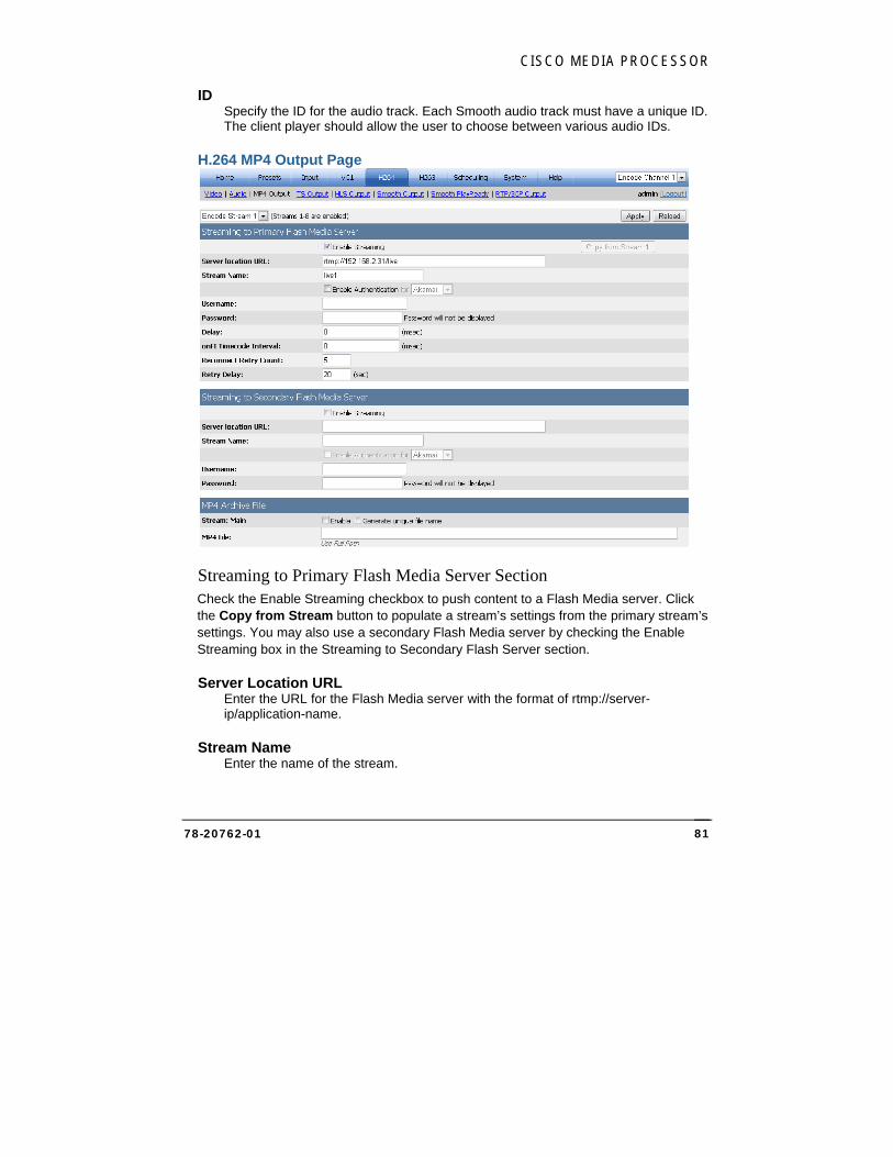
CISCO MEDIA PROCESSOR
78-20762-01 81
ID Specify the ID for the audio track. Each Smooth audio track must have a unique ID. The client player should allow the user to choose between various audio IDs.
H.264 MP4 Output Page
Streaming to Primary Flash Media Server Section Check the Enable Streaming checkbox to push content to a Flash Media server. Click the Copy from Stream button to populate a stream’s settings from the primary stream’s settings. You may also use a secondary Flash Media server by checking the Enable Streaming box in the Streaming to Secondary Flash Server section.
Server Location URL Enter the URL for the Flash Media server with the format of rtmp://server-ip/application-name.
Stream Name Enter the name of the stream.
CISCO SYSTEMS, INC.
78-20762-01 82
Check the Enable Authentication checkbox and select the CDN (content distribution network) from the dropdown to enable authentication with a Flash Media Server before the stream can be published. Enter the username and password and click Apply to store them in the registry. The password characters will not be displayed.
Delay Enter the msec delay for the output streams. Although this delay setting appears on the H.264 MP4 output page for each encode stream, there is only one global setting and it affects all H264 Flash streams.
onFI Timecode Interval The onFI Timecode Interval can be used to insert timecode metadata into the Flash RTMP stream. The interval in msec specifies the interval between sending onFI messages. If set to 0 (default) this is turned off. Timecode must be provided to the encoder, otherwise no timecode will be sent. Also, the following Global Configuration option must be set to true: "Insert Timecode into H264 User Data". For information about global configuration, see Global Configurations Page on page 129.
Reconnect Retry Count Set to the number of times the Media Processor will retry connecting to the configured server. This setting applies to all H.264 Flash streams. Default is 5.
Retry Delay Set to the delay in seconds between retry attempts. This setting applies to all H.264 Flash streams. Default is 20 seconds.
MP4 Archive File Section The encoder can optionally save the H.264 stream to disk. Click the Enable checkbox and supply a path and file name to save to a user-specified MP4 file. The default MP4 file output format is QuickTime.
When using a network drive, a fully-qualified UNC path is required and the Encoding Service must have permission to create directories and copy files to the destination (for instructions see Setting up Cisco Media Processor to write to a network drive on page 152).
Note if no path information is given, the file output is stored at C:\inetpub\wwwroot\encadmin\output. Click the Generate unique file name checkbox to append the current date and time to the file name, which will ensure that previous archive files will not be overwritten.
MP4 archives cannot be written at the same time as TS archives.
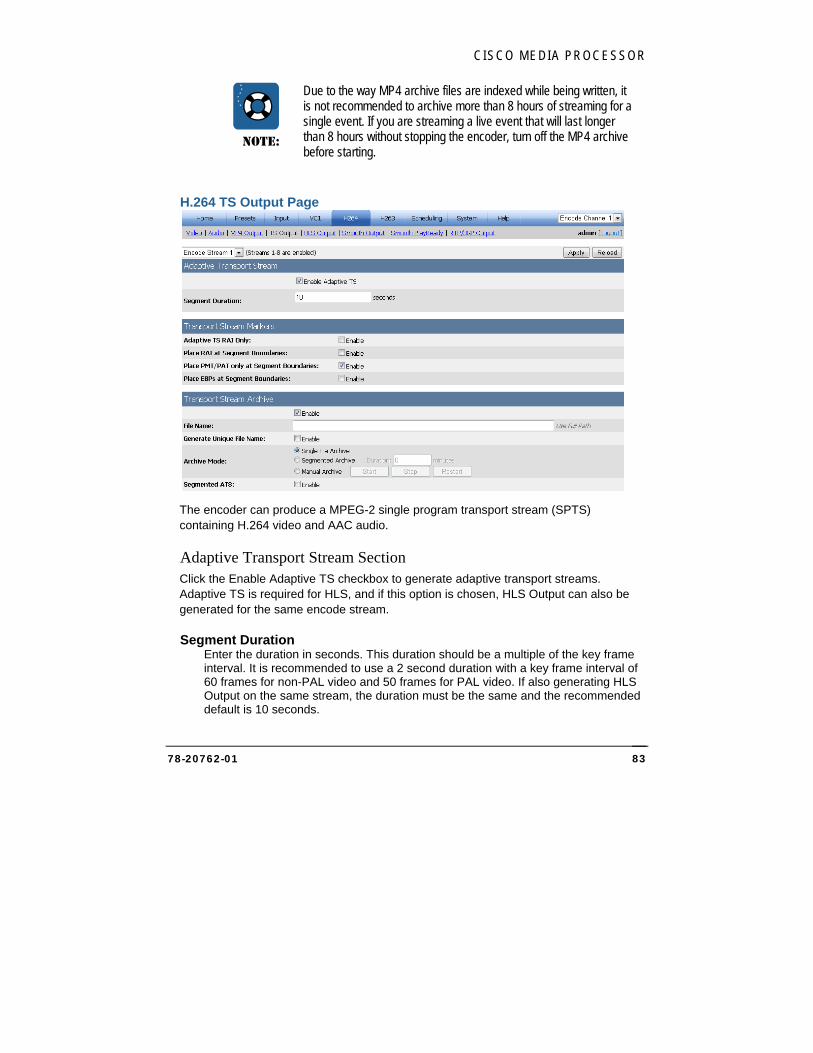
CISCO MEDIA PROCESSOR
78-20762-01 83
NOTE:
Due to the way MP4 archive files are indexed while being written, it is not recommended to archive more than 8 hours of streaming for a single event. If you are streaming a live event that will last longer than 8 hours without stopping the encoder, turn off the MP4 archive before starting.
H.264 TS Output Page
The encoder can produce a MPEG-2 single program transport stream (SPTS) containing H.264 video and AAC audio.
Adaptive Transport Stream Section Click the Enable Adaptive TS checkbox to generate adaptive transport streams. Adaptive TS is required for HLS, and if this option is chosen, HLS Output can also be generated for the same encode stream.
Segment Duration Enter the duration in seconds. This duration should be a multiple of the key frame interval. It is recommended to use a 2 second duration with a key frame interval of 60 frames for non-PAL video and 50 frames for PAL video. If also generating HLS Output on the same stream, the duration must be the same and the recommended default is 10 seconds.
CISCO SYSTEMS, INC.
78-20762-01 84
Transport Stream Markers Section This section includes settings that specify how to mark segments in an adaptive transport stream.
Adaptive TS RAI Only When creating ATS streams, use this option to create a single TS stream (not an Apple Segmented stream), which uses only the TS RAI bit to mark segment boundaries and no further processing or segmentation is applied. If false, the ATS stream will be segmented in discrete segments. Audio alignment is not available for this option.
Place RAI at Segment Boundaries When creating ATS streams, including Apple Segmented data, the RAI (Random Access Indicator) option controls whether a segment’s initial IDR frame has the TS RAI bit set. If false, the RAI bit is never set.
Place PMT/PAT only at Segment Boundaries When creating ATS streams, including Apple Segmented data, the PMT/PAT option controls whether a segment only has one PMT/PAT at the beginning. If false, PMT/PAT will also occur within the segment.
Place EBPs at Segment Boundaries When creating ATS streams, check Enable to place Encoder Boundary Points at segment boundaries.
Transport Stream Archive Section The encoder can optionally save the transport stream to disk. Use this section to save the stream to a user-specified TS file by clicking the checkbox and supplying a path and file name. When using a network drive, a fully-qualified UNC path is required and the Encoding Service must have permission to create directories and copy files to the destination (for instructions see Setting up Cisco Media Processor to write to a network drive on page 152).
Note if no path information is given, the file output is stored at C:\inetpub\wwwroot\encadmin\output. Click the Generate unique file name checkbox to append the current date and time to the file name, which will ensure that previous archive files will not be overwritten. If an output file is not required, then the file name should be left blank.
If Adaptive TS is enabled, archive files will be adaptive TS files.
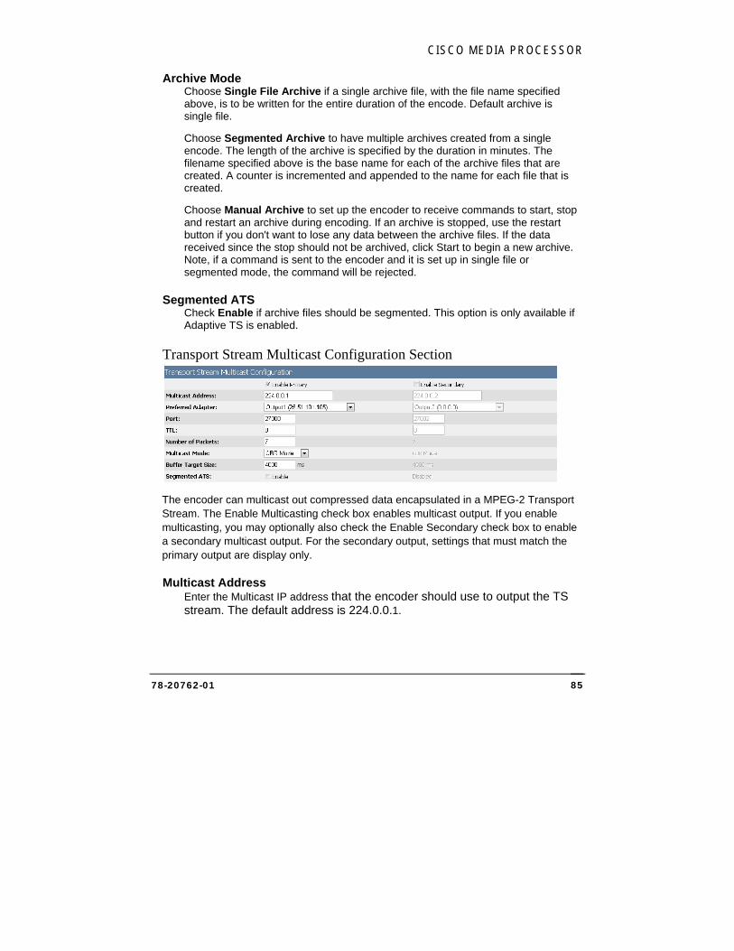
CISCO MEDIA PROCESSOR
78-20762-01 85
Archive Mode Choose Single File Archive if a single archive file, with the file name specified above, is to be written for the entire duration of the encode. Default archive is single file.
Choose Segmented Archive to have multiple archives created from a single encode. The length of the archive is specified by the duration in minutes. The filename specified above is the base name for each of the archive files that are created. A counter is incremented and appended to the name for each file that is created.
Choose Manual Archive to set up the encoder to receive commands to start, stop and restart an archive during encoding. If an archive is stopped, use the restart button if you don't want to lose any data between the archive files. If the data received since the stop should not be archived, click Start to begin a new archive. Note, if a command is sent to the encoder and it is set up in single file or segmented mode, the command will be rejected.
Segmented ATS Check Enable if archive files should be segmented. This option is only available if Adaptive TS is enabled.
Transport Stream Multicast Configuration Section
The encoder can multicast out compressed data encapsulated in a MPEG-2 Transport Stream. The Enable Multicasting check box enables multicast output. If you enable multicasting, you may optionally also check the Enable Secondary check box to enable a secondary multicast output. For the secondary output, settings that must match the primary output are display only.
Multicast Address Enter the Multicast IP address that the encoder should use to output the TS stream. The default address is 224.0.0.1.
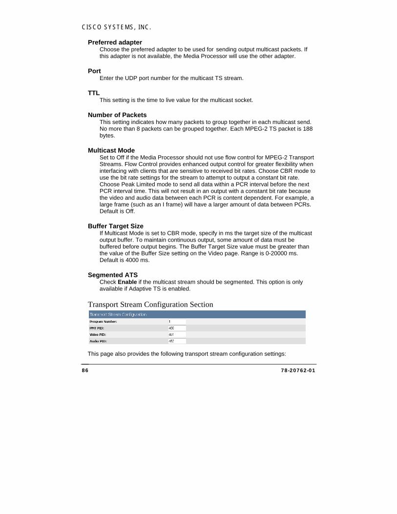
CISCO SYSTEMS, INC.
78-20762-01 86
Preferred adapter Choose the preferred adapter to be used for sending output multicast packets. If this adapter is not available, the Media Processor will use the other adapter.
Port Enter the UDP port number for the multicast TS stream.
TTL This setting is the time to live value for the multicast socket.
Number of Packets This setting indicates how many packets to group together in each multicast send. No more than 8 packets can be grouped together. Each MPEG-2 TS packet is 188 bytes.
Multicast Mode Set to Off if the Media Processor should not use flow control for MPEG-2 Transport Streams. Flow Control provides enhanced output control for greater flexibility when interfacing with clients that are sensitive to received bit rates. Choose CBR mode to use the bit rate settings for the stream to attempt to output a constant bit rate. Choose Peak Limited mode to send all data within a PCR interval before the next PCR interval time. This will not result in an output with a constant bit rate because the video and audio data between each PCR is content dependent. For example, a large frame (such as an I frame) will have a larger amount of data between PCRs. Default is Off.
Buffer Target Size If Multicast Mode is set to CBR mode, specify in ms the target size of the multicast output buffer. To maintain continuous output, some amount of data must be buffered before output begins. The Buffer Target Size value must be greater than the value of the Buffer Size setting on the Video page. Range is 0-20000 ms. Default is 4000 ms.
Segmented ATS Check Enable if the multicast stream should be segmented. This option is only available if Adaptive TS is enabled.
Transport Stream Configuration Section
This page also provides the following transport stream configuration settings:
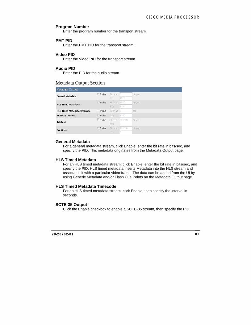
CISCO MEDIA PROCESSOR
78-20762-01 87
Program Number Enter the program number for the transport stream.
PMT PID Enter the PMT PID for the transport stream.
Video PID Enter the Video PID for the transport stream.
Audio PID Enter the PID for the audio stream.
Metadata Output Section
General Metadata For a general metadata stream, click Enable, enter the bit rate in bits/sec, and specify the PID. This metadata originates from the Metadata Output page.
HLS Timed Metadata For an HLS timed metadata stream, click Enable, enter the bit rate in bits/sec, and specify the PID. HLS timed metadata inserts Metadata into the HLS stream and associates it with a particular video frame. The data can be added from the UI by using Generic Metadata and/or Flash Cue Points on the Metadata Output page.
HLS Timed Metadata Timecode For an HLS timed metadata stream, click Enable, then specify the interval in seconds.
SCTE-35 Output Click the Enable checkbox to enable a SCTE-35 stream, then specify the PID.
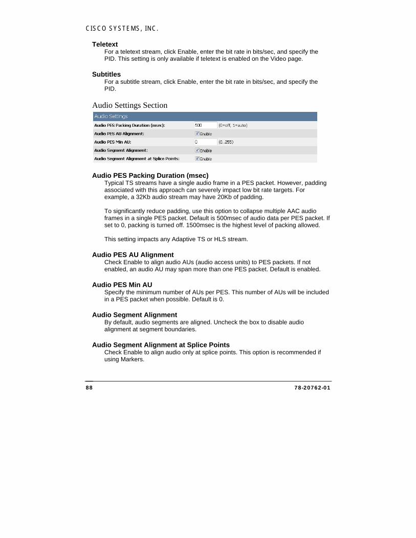
CISCO SYSTEMS, INC.
78-20762-01 88
Teletext For a teletext stream, click Enable, enter the bit rate in bits/sec, and specify the PID. This setting is only available if teletext is enabled on the Video page.
Subtitles For a subtitle stream, click Enable, enter the bit rate in bits/sec, and specify the PID.
Audio Settings Section
Audio PES Packing Duration (msec) Typical TS streams have a single audio frame in a PES packet. However, padding associated with this approach can severely impact low bit rate targets. For example, a 32Kb audio stream may have 20Kb of padding. To significantly reduce padding, use this option to collapse multiple AAC audio frames in a single PES packet. Default is 500msec of audio data per PES packet. If set to 0, packing is turned off. 1500msec is the highest level of packing allowed. This setting impacts any Adaptive TS or HLS stream.
Audio PES AU Alignment Check Enable to align audio AUs (audio access units) to PES packets. If not enabled, an audio AU may span more than one PES packet. Default is enabled.
Audio PES Min AU Specify the minimum number of AUs per PES. This number of AUs will be included in a PES packet when possible. Default is 0.
Audio Segment Alignment By default, audio segments are aligned. Uncheck the box to disable audio alignment at segment boundaries.
Audio Segment Alignment at Splice Points Check Enable to align audio only at splice points. This option is recommended if using Markers.
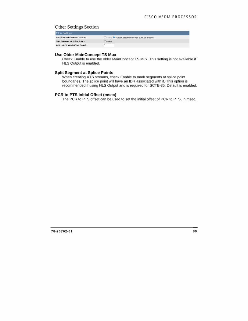
CISCO MEDIA PROCESSOR
78-20762-01 89
Other Settings Section
Use Older MainConcept TS Mux Check Enable to use the older MainConcept TS Mux. This setting is not available if HLS Output is enabled.
Split Segment at Splice Points When creating ATS streams, check Enable to mark segments at splice point boundaries. The splice point will have an IDR associated with it. This option is recommended if using HLS Output and is required for SCTE-35. Default is enabled.
PCR to PTS Initial Offset (msec) The PCR to PTS offset can be used to set the initial offset of PCR to PTS, in msec.
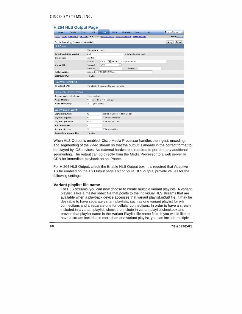
CISCO SYSTEMS, INC.
78-20762-01 90
H.264 HLS Output Page
When HLS Output is enabled, Cisco Media Processor handles the ingest, encoding, and segmenting of the video stream so that the output is already in the correct format to be played by iOS devices. No external hardware is required to perform any additional segmenting. The output can go directly from the Media Processor to a web server or CDN for immediate playback on an iPhone.
For H.264 HLS Output, check the Enable HLS Output box. It is required that Adaptive TS be enabled on the TS Output page.To configure HLS output, provide values for the following settings:
Variant playlist file name For HLS streams, you can now choose to create multiple variant playlists. A variant playlist is like a master index file that points to the individual HLS streams that are available when a playback device accesses that variant playlist.m3u8 file. It may be desirable to have separate variant playlists, such as one variant playlist for wifi connections and a separate one for cellular connections. In order to have a stream included in a variant playlist, check the Include in variant playlist checkbox and provide that playlist name in the Variant Playlist file name field. If you would like to have a stream included in more than one variant playlist, you can include multiple
CISCO MEDIA PROCESSOR
78-20762-01 91
file names, separated by commas. For example: Wifistreams, cellstreams. For each HLS Output stream that is enabled, you can choose to have that stream included in none of the variant playlists, one of them, some of them, or all of them.
The iOS player should be pointed to one of these variant playlist files, and based on the detected bandwidth, it will play the appropriate stream. Over time, as bandwidth conditions change, the player will automatically be switched up to higher bandwidth streams or down to lower bandwidth streams to always deliver the best possible stream without buffering.
Stream name Specify the stream name, which is used as the name of the playlist (.m3u8) file and also the name for the folder where the Media Processor copies the segment (.ts) files. Stream name must contain valid characters for a file/folder name, and spaces are not recommended. Each stream on the Media Processor must use a different stream name. Use the dropdown box to select each enabled stream to provide a unique name for each.
NOTE:
If the Generate Unique Names setting is enabled, Cisco Media Processor will generate unique names for segment files by appending the starting date and time for the encode to each segment file, so that stopping and restarting the encoder does not overwrite previous files. This also fixes some issues with file caching at the CDN. For information about global configuration, see Global Configurations Page on page 129.
If VOD mode is enabled, a second VOD mode playlist file will be generated with the same name except “_vod” will be appended to the name. When the Media Processor is stopped, the live playlist file will be replaced by the VOD playlist file.
Storage URL To specify the URL for where the Media Processor will copy files, first choose the Address in the dropdown, then enter the remainder of the URL. Based on the address, you may be required to specify additional settings. For all address types except file and webdav, you must specify a username and password.
Using HTTP POST or PUT:
First choose http:// in the dropdown, then provide the remainder of the address in the second address field. Examples are:
x.y.com/apple/
x.y.com:8080/apple/
Choose POST in the Command dropdown to specify that HTTP transfer will use a POST command to transfer a file, or choose PUT for the PUT command, which requires the HTTP handler to place the content in the specified location. The target
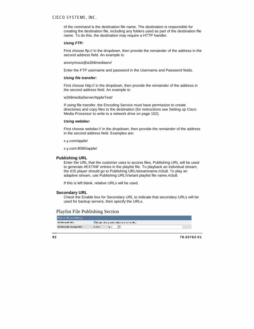
CISCO SYSTEMS, INC.
78-20762-01 92
of the command is the destination file name. The destination is responsible for creating the destination file, including any folders used as part of the destination file name. To do this, the destination may require a HTTP handler.
Using FTP:
First choose ftp:// in the dropdown, then provide the remainder of the address in the second address field. An example is:
anonymous@w2k8mediasrv/
Enter the FTP username and password in the Username and Password fields.
Using file transfer:
First choose http:// in the dropdown, then provide the remainder of the address in the second address field. An example is:
w2k8mediaServer/AppleTest/
If using file transfer, the Encoding Service must have permission to create directories and copy files to the destination (for instructions see Setting up Cisco Media Processor to write to a network drive on page 152).
Using webdav:
First choose webdav:// in the dropdown, then provide the remainder of the address in the second address field. Examples are:
x.y.com/apple/
x.y.com:8080/apple/
Publishing URL Enter the URL that the customer uses to access files. Publishing URL will be used to generate #EXTINF entries in the playlist file. To playback an individual stream, the iOS player should go to Publishing URL/streamname.m3u8. To play an adaptive stream, use Publishing URL/Variant playlist file name.m3u8.
If this is left blank, relative URLs will be used.
Secondary URL Check the Enable box for Secondary URL to indicate that secondary URLs will be used for backup servers, then specify the URLs.
Playlist File Publishing Section
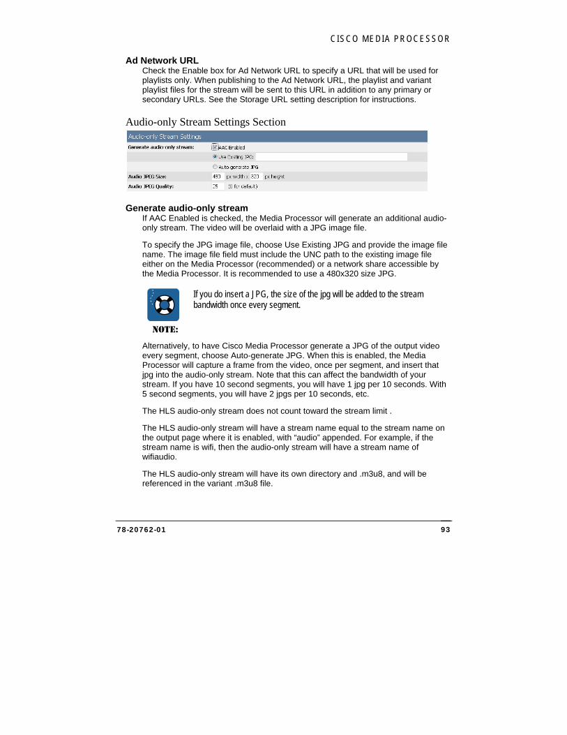
CISCO MEDIA PROCESSOR
78-20762-01 93
Ad Network URL Check the Enable box for Ad Network URL to specify a URL that will be used for playlists only. When publishing to the Ad Network URL, the playlist and variant playlist files for the stream will be sent to this URL in addition to any primary or secondary URLs. See the Storage URL setting description for instructions.
Audio-only Stream Settings Section
Generate audio-only stream If AAC Enabled is checked, the Media Processor will generate an additional audio-only stream. The video will be overlaid with a JPG image file.
To specify the JPG image file, choose Use Existing JPG and provide the image file name. The image file field must include the UNC path to the existing image file either on the Media Processor (recommended) or a network share accessible by the Media Processor. It is recommended to use a 480x320 size JPG.
NOTE:
If you do insert a JPG, the size of the jpg will be added to the stream bandwidth once every segment.
Alternatively, to have Cisco Media Processor generate a JPG of the output video every segment, choose Auto-generate JPG. When this is enabled, the Media Processor will capture a frame from the video, once per segment, and insert that jpg into the audio-only stream. Note that this can affect the bandwidth of your stream. If you have 10 second segments, you will have 1 jpg per 10 seconds. With 5 second segments, you will have 2 jpgs per 10 seconds, etc.
The HLS audio-only stream does not count toward the stream limit .
The HLS audio-only stream will have a stream name equal to the stream name on the output page where it is enabled, with “audio” appended. For example, if the stream name is wifi, then the audio-only stream will have a stream name of wifiaudio.
The HLS audio-only stream will have its own directory and .m3u8, and will be referenced in the variant .m3u8 file.
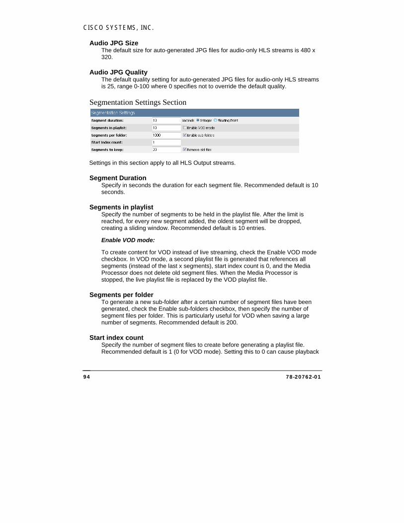
CISCO SYSTEMS, INC.
78-20762-01 94
Audio JPG Size The default size for auto-generated JPG files for audio-only HLS streams is 480 x 320.
Audio JPG Quality The default quality setting for auto-generated JPG files for audio-only HLS streams is 25, range 0-100 where 0 specifies not to override the default quality.
Segmentation Settings Section
Settings in this section apply to all HLS Output streams.
Segment Duration Specify in seconds the duration for each segment file. Recommended default is 10 seconds.
Segments in playlist Specify the number of segments to be held in the playlist file. After the limit is reached, for every new segment added, the oldest segment will be dropped, creating a sliding window. Recommended default is 10 entries.
Enable VOD mode:
To create content for VOD instead of live streaming, check the Enable VOD mode checkbox. In VOD mode, a second playlist file is generated that references all segments (instead of the last x segments), start index count is 0, and the Media Processor does not delete old segment files. When the Media Processor is stopped, the live playlist file is replaced by the VOD playlist file.
Segments per folder To generate a new sub-folder after a certain number of segment files have been generated, check the Enable sub-folders checkbox, then specify the number of segment files per folder. This is particularly useful for VOD when saving a large number of segments. Recommended default is 200.
Start index count Specify the number of segment files to create before generating a playlist file. Recommended default is 1 (0 for VOD mode). Setting this to 0 can cause playback
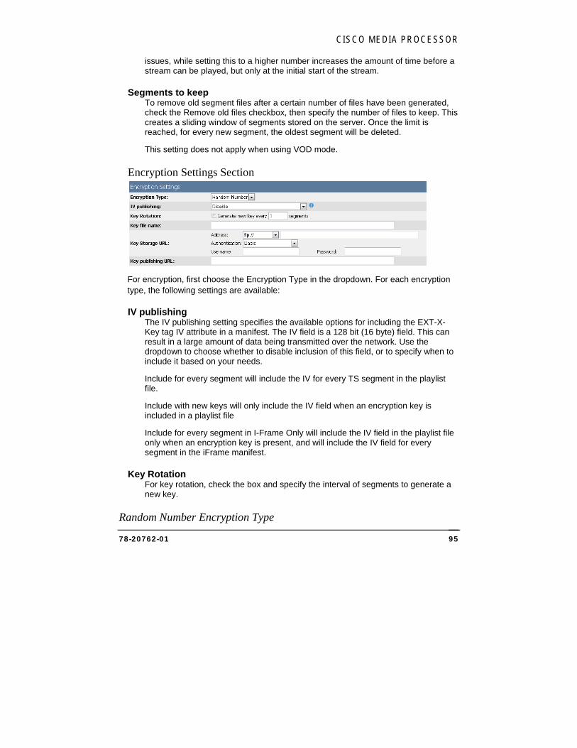
CISCO MEDIA PROCESSOR
78-20762-01 95
issues, while setting this to a higher number increases the amount of time before a stream can be played, but only at the initial start of the stream.
Segments to keep To remove old segment files after a certain number of files have been generated, check the Remove old files checkbox, then specify the number of files to keep. This creates a sliding window of segments stored on the server. Once the limit is reached, for every new segment, the oldest segment will be deleted.
This setting does not apply when using VOD mode.
Encryption Settings Section
For encryption, first choose the Encryption Type in the dropdown. For each encryption type, the following settings are available:
IV publishing The IV publishing setting specifies the available options for including the EXT-X-Key tag IV attribute in a manifest. The IV field is a 128 bit (16 byte) field. This can result in a large amount of data being transmitted over the network. Use the dropdown to choose whether to disable inclusion of this field, or to specify when to include it based on your needs.
Include for every segment will include the IV for every TS segment in the playlist file.
Include with new keys will only include the IV field when an encryption key is included in a playlist file
Include for every segment in I-Frame Only will include the IV field in the playlist file only when an encryption key is present, and will include the IV field for every segment in the iFrame manifest.
Key Rotation For key rotation, check the box and specify the interval of segments to generate a new key.
Random Number Encryption Type
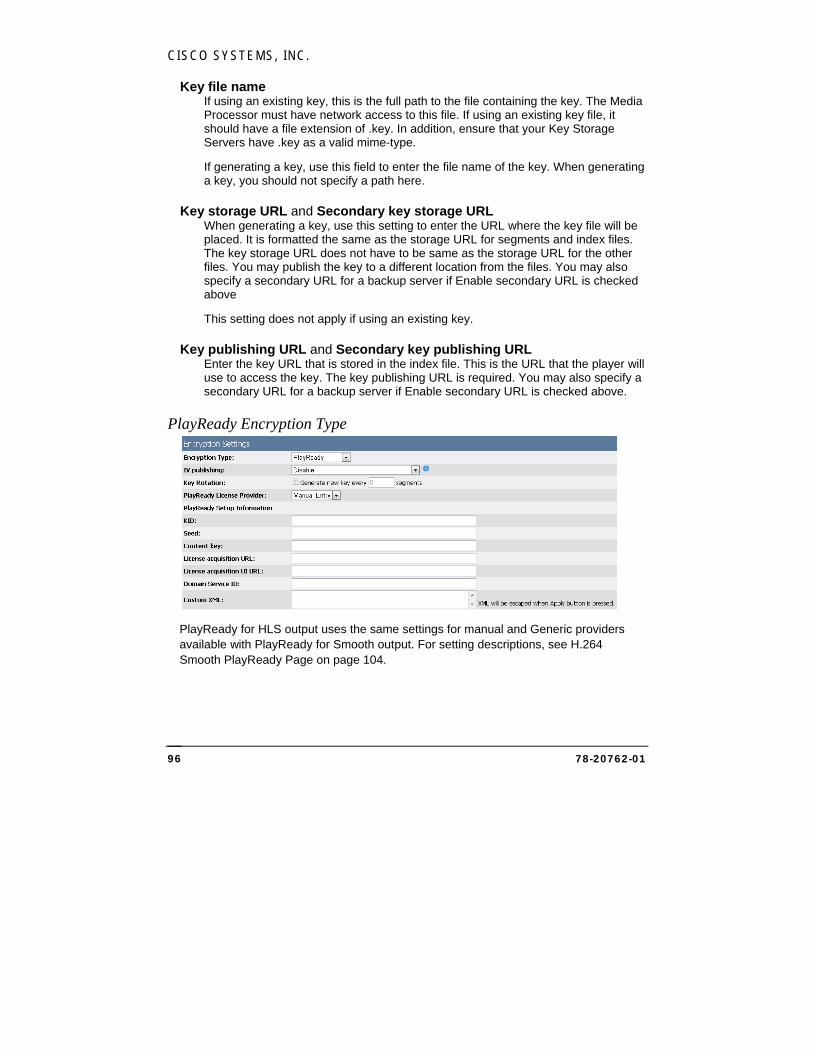
CISCO SYSTEMS, INC.
78-20762-01 96
Key file name If using an existing key, this is the full path to the file containing the key. The Media Processor must have network access to this file. If using an existing key file, it should have a file extension of .key. In addition, ensure that your Key Storage Servers have .key as a valid mime-type.
If generating a key, use this field to enter the file name of the key. When generating a key, you should not specify a path here.
Key storage URL and Secondary key storage URL When generating a key, use this setting to enter the URL where the key file will be placed. It is formatted the same as the storage URL for segments and index files. The key storage URL does not have to be same as the storage URL for the other files. You may publish the key to a different location from the files. You may also specify a secondary URL for a backup server if Enable secondary URL is checked above
This setting does not apply if using an existing key.
Key publishing URL and Secondary key publishing URL Enter the key URL that is stored in the index file. This is the URL that the player will use to access the key. The key publishing URL is required. You may also specify a secondary URL for a backup server if Enable secondary URL is checked above.
PlayReady Encryption Type
PlayReady for HLS output uses the same settings for manual and Generic providers available with PlayReady for Smooth output. For setting descriptions, see H.264 Smooth PlayReady Page on page 104.
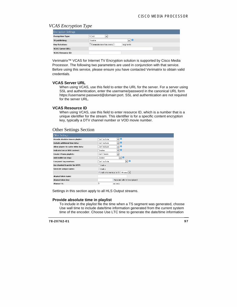
CISCO MEDIA PROCESSOR
78-20762-01 97
VCAS Encryption Type
Verimatrix™ VCAS for Internet TV Encryption solution is supported by Cisco Media Processor. The following two parameters are used in conjunction with that service. Before using this service, please ensure you have contacted Verimatrix to obtain valid credentials.
VCAS Server URL When using VCAS, use this field to enter the URL for the server. For a server using SSL and authentication, enter the username/password in the canonical URL form https://username:password@domain:port. SSL and authentication are not required for the server URL.
VCAS Resource ID When using VCAS, use this field to enter resource ID, which is a number that is a unique identifier for the stream. This identifier is for a specific content encryption key, typically a DTV channel number or VOD movie number.
Other Settings Section
Settings in this section apply to all HLS Output streams.
Provide absolute time in playlist To include in the playlist file the time when a TS segment was generated, choose Use wall time to include date/time information generated from the current system time of the encoder. Choose Use LTC time to generate the date/time information
CISCO SYSTEMS, INC.
78-20762-01 98
from LTC time, if available. To use LTC (Linear Time Code), you must check True for the Insert Timecode into H264 User Data setting on the Global Configurations page.
Include additional time data This setting, unless set to Don’t Include, will add a custom field to the EXTINF tag for each TS segment in the playlist. This field provides additional time information for the segment, which can be used to help the client player decide which segment to transition to when changing bit rates and using hardware decryption. Choose from the dropdown to include either LTC (if available) or PTS for the first video frame of the TS segment. To use LTC (Linear Time Code), you must check True for the Insert Timecode into H264 User Data setting on the Global Configurations page.
Allow players to cache video data This setting, unless set to Don’t Include, will include a EXT-X-ALLOW-CACHE tag in the playlist that indicates whether the player may cache video segments for later playback. Choose Yes to allow the player to cache TS segments, or choose No to explicitly indicate that the client player is not allowed to cache TS segments. Don’t Include will not include the tag, which implies that caching is not allowed.
Indicate live or VOD content Choose Enable to include the EXT-X-PLAYLIST-TYPE tag in the playlist file. This tag indicates whether the playlist type is VOD or EVENT, based on the type of playlist being generated. Disable indicates that the tag will not be included.
Create I-frame playlists Choose Create to create I-frame Only playlists in addition to other playlists.
Add endlist on stop To add an end-of-stream indicator to the playlist when the encode is stopped, choose For live and VOD manifest if the indicator should be added for both live and VOD. Choose For VOD manifest only if the indicator should only be added for VOD. Disable indicates that the indicator will not be included. Note that VOD options only apply when VOD mode is enabled.
Cue point tag insertion To include cue point tags in the playlist, choose Include IN and OUT tags if CUE-IN and CUE-OUT markers should be included. Choose Include IN/OUT/CONT tags for Freewheel® if CUE-IN, CUE-OUT, and CUE-OUT-CONT tags should be included.
Use chunked transfer for HTTP Contact your CDN for the correct setting. Default is False.
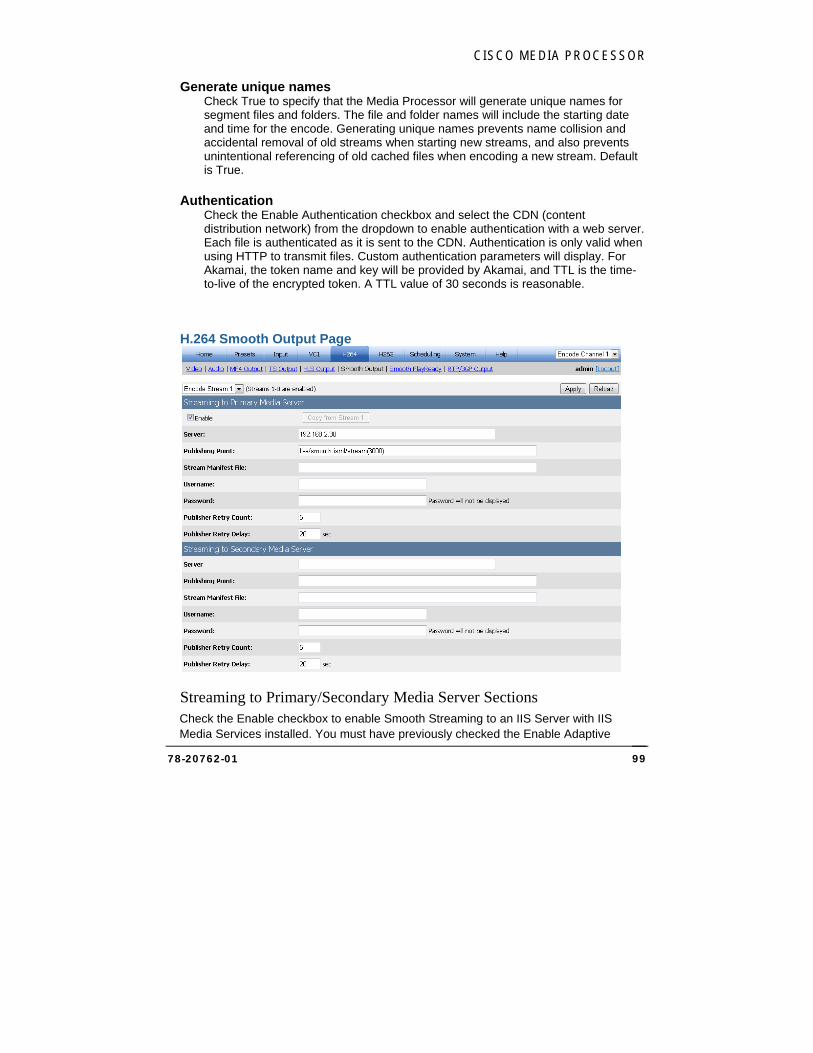
CISCO MEDIA PROCESSOR
78-20762-01 99
Generate unique names Check True to specify that the Media Processor will generate unique names for segment files and folders. The file and folder names will include the starting date and time for the encode. Generating unique names prevents name collision and accidental removal of old streams when starting new streams, and also prevents unintentional referencing of old cached files when encoding a new stream. Default is True.
Authentication Check the Enable Authentication checkbox and select the CDN (content distribution network) from the dropdown to enable authentication with a web server. Each file is authenticated as it is sent to the CDN. Authentication is only valid when using HTTP to transmit files. Custom authentication parameters will display. For Akamai, the token name and key will be provided by Akamai, and TTL is the time-to-live of the encrypted token. A TTL value of 30 seconds is reasonable.
H.264 Smooth Output Page
Streaming to Primary/Secondary Media Server Sections Check the Enable checkbox to enable Smooth Streaming to an IIS Server with IIS Media Services installed. You must have previously checked the Enable Adaptive
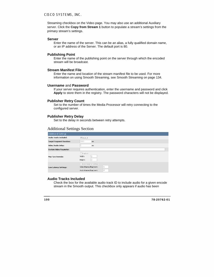
CISCO SYSTEMS, INC.
78-20762-01 100
Streaming checkbox on the Video page. You may also use an additional Auxiliary server. Click the Copy from Stream 1 button to populate a stream’s settings from the primary stream’s settings.
Server Enter the name of the server. This can be an alias, a fully qualified domain name, or an IP address of the Server. The default port is 80.
Publishing Point Enter the name of the publishing point on the server through which the encoded stream will be broadcast.
Stream Manifest File Enter the name and location of the stream manifest file to be used. For more information on using Smooth Streaming, see Smooth Streaming on page 134.
Username and Password If your server requires authentication, enter the username and password and click Apply to store them in the registry. The password characters will not be displayed.
Publisher Retry Count Set to the number of times the Media Processor will retry connecting to the configured server.
Publisher Retry Delay Set to the delay in seconds between retry attempts.
Additional Settings Section
Audio Tracks Included Check the box for the available audio track ID to include audio for a given encode stream in the Smooth output. This checkbox only appears if audio has been

CISCO MEDIA PROCESSOR
78-20762-01 101
enabled for the corresponding encode stream on the H.264 Audio page. At least one Smooth stream must have audio included.
Target Fragment Duration Specify (in msec) the target duration for smooth streaming fragments. This setting should normally be the same as the key frame interval set on the video page. Default key frame interval is 60 frames for non-Pal video and 50 frames for PAL video, which is 2000 msec of video. Although this duration setting appears on the Smooth Streaming output page for each encode stream, there is only one global setting and it affects all H.264 smooth streams.
Video/Audio Delay Enter the msec delay for the output streams. Although this delay setting appears on the Smooth Streaming output page for each encode stream, there is only one global setting and it affects all H.264 smooth streams.
Custom Video Parameter The text in this field will be inserted as a custom attribute in the live server manifest. An example use for this field is for multiple camera angles. Smooth streams are uniquely identified by a quality level which is essentially the bit rate. Two streams of the same bit rate cannot be distinguished without custom attributes. This field provides the custom attribute to identify this stream. For multiple camera angles, this attribute could identify the specific video input.
An example format for this field is:
<param name ="cameraAngle" value="coach-cam" valuetype="data" />
Thus two different Media Processors could provide two different camera angles. Each Media Processor has the same number of streams and bit rates for those streams. However, one Media Processor has for each stream, for example, a custom video parameter of:
<param name ="cameraAngle" value="main" valuetype="data" />
and the other Media Processor has for each stream a custom video parameter of:
<param name ="cameraAngle" value="alternate" valuetype="data" />
Max Size Override Check the Enabled checkbox to override the maximum output video size, and specify the new maximum width and height for this stream.
Use this setting to handle anamorphic / widescreen video. For example, 16x9 content is often anamorphically resized to 720x480 for delivery over SDI. Instead of resizing this 720x480 video back to 848x480 prior to compression, simply compress the content as is and set the max size override to 848x480. You should only need to do this to your top resolution stream. On playback, the Silverlight
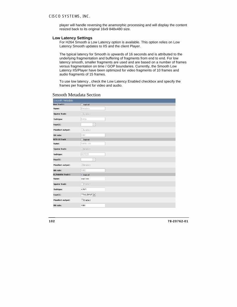
CISCO SYSTEMS, INC.
78-20762-01 102
player will handle reversing the anamorphic processing and will display the content resized back to its original 16x9 848x480 size.
Low Latency Settings For H264 Smooth a Low Latency option is available. This option relies on Low Latency Smooth updates to IIS and the client Player. The typical latency for Smooth is upwards of 16 seconds and is attributed to the underlying fragmentation and buffering of fragments from end to end. For low latency smooth, smaller fragments are used and are based on a number of frames versus fragmentation on time / GOP boundaries. Currently, the Smooth Low Latency IIS/Player have been optimized for video fragments of 10 frames and audio fragments of 15 frames.
To use low latency , check the Low Latency Enabled checkbox and specify the frames per fragment for video and audio.
Smooth Metadata Section

CISCO MEDIA PROCESSOR
78-20762-01 103
Smooth offers the ability to have multiple metadata tracks that may be enabled independently. One track is available for user-supplied data, one track is used for Markers (SCTE-35), the third track is used for Closed Captioning / Subtitles, and any additional tracks are used for subtitle tracks. For captions, a source for captions must be selected on the Video page. For subtitles, teletext subtitles must be enabled on the Video page and configured on the Input page.
All tracks are Smooth "Text" tracks.
For each track, you may accept or alter the following settings:
Name Each track can be given a name. For CC/Subtitles, there is special processing in the Silverlight Smooth Streaming Media Element (SSME) player for handling text tracks with the name "captions," so it is recommended to leave this track name as captions.
Sparse Track The sparse track checkbox specifies that samples into these tracks do not happen at regular intervals. The User and SCTE-35 tracks are Sparse, and the CC/Subtitle track should not be Sparse. Currently all Sparse tracks have "video" as their parent track.
Subtype Accept or modify the pre-defined subtype that will be passed through to the manifest. The CC/Subtitle track should always be CAPT regardless if the text is captions or subtitles.
FourCC The optional FourCC field is simply passed through to the manifest. For the CC/Subtitle track, FourCC should be set to TTML/DFXP for the encoder to generate DFXP-based metadata. This track may also be set to plain text. Default is TTML/DFXP.
Manifest Output The manifest output checkbox specifies whether the metadata track samples are to be reflected in the manifest. For the CC/Subtitle track, this option generally should not be enabled unless some debugging is desired. With the Manifest Output checked, the sample data for the track is base64 encoded and included in the manifest. Over time this can create an excessively large manifest and thus in general it is best to not enable this option.
Bit rate The Bit rate entry specifies an estimate of how much bandwidth in bits/sec the metadata stream will use. If unknown, simply leave this at the default. Range is 1-10000.
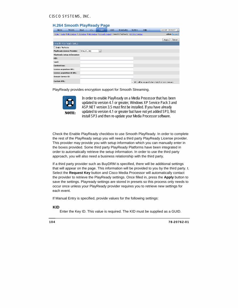
CISCO SYSTEMS, INC.
78-20762-01 104
H.264 Smooth PlayReady Page
PlayReady provides encryption support for Smooth Streaming.
NOTE:
In order to enable PlayReady on a Media Processor that has been updated to version 4.1 or greater, Windows XP Service Pack 3 and ASP.NET version 3.5 must first be installed. If you have already updated to version 4.1 or greater but have not yet added SP3, first install SP3 and then re-update your Media Processor software.
Check the Enable PlayReady checkbox to use Smooth PlayReady. In order to complete the rest of the PlayReady setup you will need a third party PlayReady License provider. This provider may provide you with setup information which you can manually enter in the boxes provided. Some third party PlayReady Platforms have been integrated in order to automatically retrieve the setup information. In order to use the third party approach, you will also need a business relationship with the third party.
If a third party provider such as BuyDRM is specified, there will be additional settings that will appear on the page. This information will be provided to you by the third party. t. Select the Request Key button and Cisco Media Processor will automatically contact the provider to retrieve the PlayReady settings. Once filled in, press the Apply button to save the settings. Playready settings are stored in presets so this process only needs to occur once unless your PlayReady provider requires you to retrieve new settings for each event.
If Manual Entry is specified, provide values for the following settings:
KID Enter the Key ID. This value is required. The KID must be supplied as a GUID.
CISCO MEDIA PROCESSOR
78-20762-01 105
GUID should be entered in the form of: {cab50618-c7e1-4e84-b683-c086d15170eb}
Seed The encryption seed. Either a seed or a content key is required.
Content Key The encryption content key. Either a seed or a content key is required
License Acquisition URL Enter the URL. A License acquisition URL is required.
License Acquisition user interface URL This is an optional field. If supplied, enter the URL.
Domain Service ID This is an optional field. If supplied, enter a Domain Service ID. The ID may be supplied as either a GUID or Base64 string.
GUID should be entered in the form of: {cab50618-c7e1-4e84-b683-c086d15170eb}
An example Base64 string is: GAa1yuHHhE62g8CG0VFw6w==
Custom XML This is an optional field. The PlayReady license provider may specify custom data for the PlayReady header. If supplied use this custom XML field to include it.
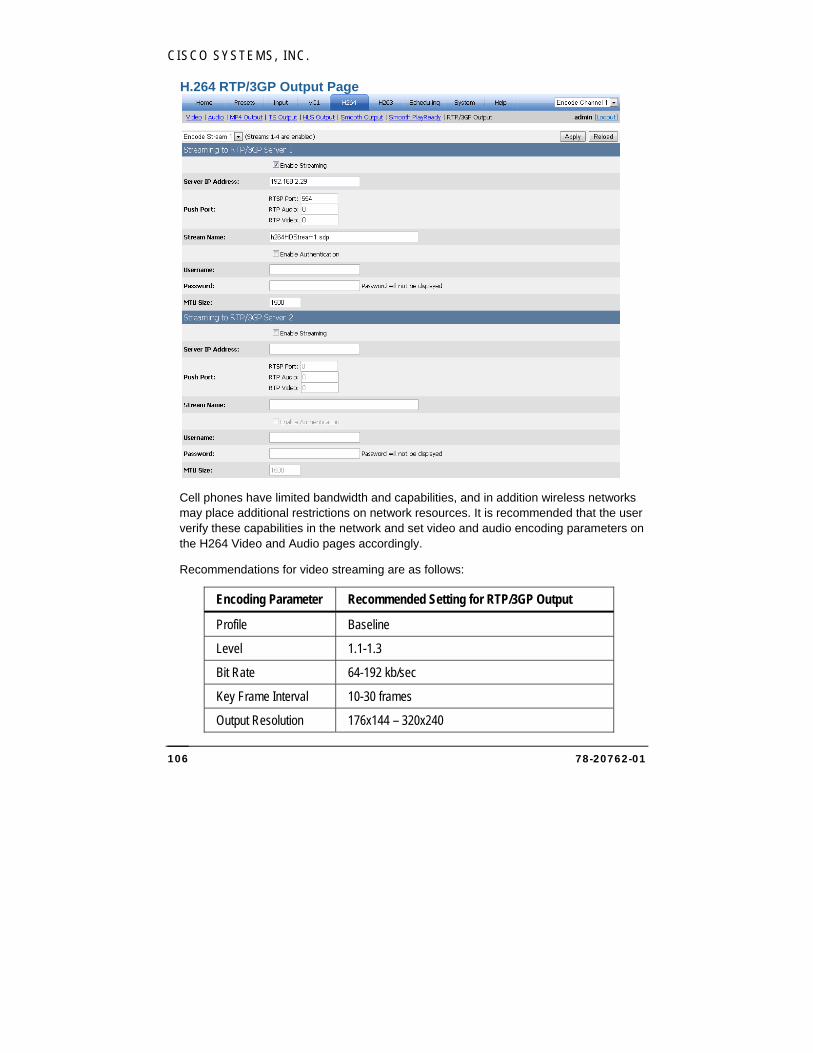
CISCO SYSTEMS, INC.
78-20762-01 106
H.264 RTP/3GP Output Page
Cell phones have limited bandwidth and capabilities, and in addition wireless networks may place additional restrictions on network resources. It is recommended that the user verify these capabilities in the network and set video and audio encoding parameters on the H264 Video and Audio pages accordingly.
Recommendations for video streaming are as follows:
Encoding Parameter Recommended Setting for RTP/3GP Output
Profile Baseline
Level 1.1-1.3
Bit Rate 64-192 kb/sec
Key Frame Interval 10-30 frames
Output Resolution 176x144 – 320x240
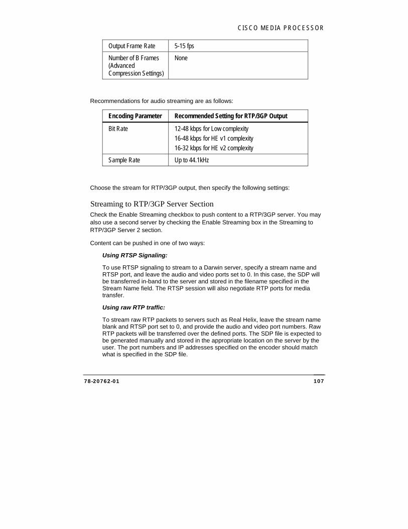
CISCO MEDIA PROCESSOR
78-20762-01 107
Output Frame Rate 5-15 fps
Number of B Frames (Advanced Compression Settings)
None
Recommendations for audio streaming are as follows:
Encoding Parameter Recommended Setting for RTP/3GP Output
Bit Rate 12-48 kbps for Low complexity
16-48 kbps for HE v1 complexity
16-32 kbps for HE v2 complexity
Sample Rate Up to 44.1kHz
Choose the stream for RTP/3GP output, then specify the following settings:
Streaming to RTP/3GP Server Section Check the Enable Streaming checkbox to push content to a RTP/3GP server. You may also use a second server by checking the Enable Streaming box in the Streaming to RTP/3GP Server 2 section.
Content can be pushed in one of two ways:
Using RTSP Signaling:
To use RTSP signaling to stream to a Darwin server, specify a stream name and RTSP port, and leave the audio and video ports set to 0. In this case, the SDP will be transferred in-band to the server and stored in the filename specified in the Stream Name field. The RTSP session will also negotiate RTP ports for media transfer.
Using raw RTP traffic:
To stream raw RTP packets to servers such as Real Helix, leave the stream name blank and RTSP port set to 0, and provide the audio and video port numbers. Raw RTP packets will be transferred over the defined ports. The SDP file is expected to be generated manually and stored in the appropriate location on the server by the user. The port numbers and IP addresses specified on the encoder should match what is specified in the SDP file.

CISCO SYSTEMS, INC.
78-20762-01 108
Server IP Address Enter the IP Address for the RTP/3GP server.
Push Port If using RTSP signaling, enter only the RTSP port number. If streaming raw RTP packets, enter only the audio and video port numbers. These port numbers must be even. If audio and video traffic is expected to be on the same port, specify the same port number for each.
Stream Name Enter the name of the stream if using RTSP signaling. If streaming raw RTP packets, this field will be ignored.
Check the Enable Authentication checkbox to enable authentication before the stream can be published. Enter the username and password and click Apply to store them in the registry. The password characters will not be displayed.
MTU Size Set the maximum packet size for RTP. Default is 1500.
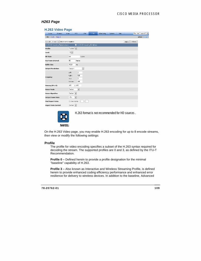
CISCO MEDIA PROCESSOR
78-20762-01 109
H263 Page
H.263 Video Page
NOTE:
H.263 format is not recommended for HD sources .
On the H.263 Video page, you may enable H.263 encoding for up to 8 encode streams, then view or modify the following settings:
Profile The profile for video encoding specifies a subset of the H.263 syntax required for decoding the stream. The supported profiles are 0 and 3, as defined by the ITU-T Recommendation.
Profile 0 – Defined herein to provide a profile designation for the minimal "baseline" capability of H.263.
Profile 3 – Also known as Interactive and Wireless Streaming Profile, is defined herein to provide enhanced coding efficiency performance and enhanced error resilience for delivery to wireless devices. In addition to the baseline, Advanced
CISCO SYSTEMS, INC.
78-20762-01 110
INTRA Coding, Deblocking Filter, Slice Structured Mode and Modified Quantization are supported.
Level This setting specifies constraints for the encoding parameters.
Level 10 – Bit rate up to 64 kb/sec, output resolutions: QCIF (176x144), Sub-QCIF (128x96), Output frame rate up to 15 fps.
Level 20 – Bit rate up to 128 kb/sec, output resolutions: CIF (352x288), QCIF (176x144), Sub-QCIF (128x96), Output frame rate up to 15 fps for CIF, 30fps for QCIF and Sub-QCIF.
Level 30 – Bit rate up to 384 kb/sec, output resolutions: CIF (352x288), QCIF (176x144), Sub-QCIF (128x96), Output frame rate up to 30 fps.
Bit Rate This setting indicates bits/sec in units of kb/sec. For example, a value of 1500 is 1.5Mbits/sec. Bit rate defaults vary by level.
Key Frame Interval This value (in frames) sets the maximum distance between key frames. The encoder may output key frames sooner than this interval (if it detects a scene change, for example).
Buffer Size The buffer size value (in milliseconds) sets the encoder buffer size.
Output Resolution Choose from the available resolutions or choose Custom, which will make the Cropping and Resizing settings available for modification. The pixel aspect ratio is auto set for each of these presets.
Cropping The cropping parameters apply a crop to the input image. Note that if an odd number of lines are cropped from the top, the sense of which field is first (top or bottom) will change and you will need to set the Field Order option on the Video Input page accordingly.
Resizing Specify the output resolution to be applied to the cropped image. If the resolution is different than the original, scaling will be performed. The minimum supported resolution is 64x64.
CISCO MEDIA PROCESSOR
78-20762-01 111
Resize Mode Choose Progressive mode, Interlaced mode, or Single Field mode to manually specify how the resizer will process the source video. Single field mode, which should only be used for interlace source material, scales to the destination image using only a single field of the source video instead of doing a deinterlace operation. It is highly recommended to use single field mode for producing progressive frames from a 1080i source. For example, to stream a 1280x720p from a 1920x1080i source, it is recommended to choose the single field mode and resize to 1280x720 instead of performing a deinterlace operation.
Resize Algorithm Choose Nearest, Linear, Cubic, or Super to specify the algorithm to be used by the resize operation. By default linear is used. Nearest (also referred to as Nearest neighbor) is the worst quality and has the lowest CPU requirements. Cubic is a higher quality scaler than linear, and Super is a higher quality algorithm than Cubic. However, Super is very processor intensive and is only used for downscaling, and only when the resize is less than about ½ the source size. For example, if scaling single field mode from 1920x1080i, the field size is 1920x540, so use Super if the output size is <= 270 in height.
Output Frame Rate Choose 1x to specify the input frame rate, or reduce the input frame rate for telecine purposes or frame rate decimation. Available options listed are the input frame rate and 1/2, 1/3, 1/4, 1/5, and 1/6 the input rate.
Pixel Aspect Ratio To override the automatically set pixel aspect ratio, check the override box and modify the calculated ratio to the new ratio. If this box is not checked, the pixel aspect ratio is calculated based on the output size of the video. Refer to the VC-1 description of Pixel Aspect Ratio on page 39 for further information.
Aspect Ratio Control When Dynamic is checked on the Input page, choose Default, Manual, Letter/Pillar, or Crop to specify the method that will be used to maintain the output aspect ratio when the input resolution or aspect ratio changes during encoding. Manual specifies not to automatically adjust for the aspect ratio. Letter/Pillar will add letterboxing or pillarboxing to achieve the specified output aspect ratio. Crop will modify the crop settings to achieve the specified output aspect ratio. Default is currently set to Crop.
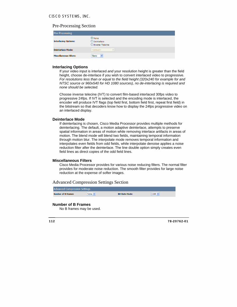
CISCO SYSTEMS, INC.
78-20762-01 112
Pre-Processing Section
Interlacing Options If your video input is interlaced and your resolution height is greater than the field height, choose de-interlace if you wish to convert interlaced video to progressive. For resolutions less than or equal to the field height (320x240 for example for and NTSC source or 960x540 for HD 1080 sources), no de-interlacing is required and none should be selected.
Choose inverse telecine (IVT) to convert film-based interlaced 30fps video to progressive 24fps. If IVT is selected and the encoding mode is interlaced, the encoder will produce IVT flags (top field first, bottom field first, repeat first field) in the bitstream so that decoders know how to display the 24fps progressive video on an interlaced display.
Deinterlace Mode If deinterlacing is chosen, Cisco Media Processor provides multiple methods for deinterlacing. The default, a motion adaptive deinterlace, attempts to preserve spatial information in areas of motion while removing interlace artifacts in areas of motion. The blend mode will blend two fields, maintaining temporal information through motion blur. The interpolate mode removes temporal information and interpolates even fields from odd fields, while interpolate denoise applies a noise reduction filter after the deinterlace. The line double option simply creates even field lines as direct copies of the odd field lines.
Miscellaneous Filters Cisco Media Processor provides for various noise reducing filters. The normal filter provides for moderate noise reduction. The smooth filter provides for large noise reduction at the expense of softer images.
Advanced Compression Settings Section
Number of B Frames No B frames may be used.
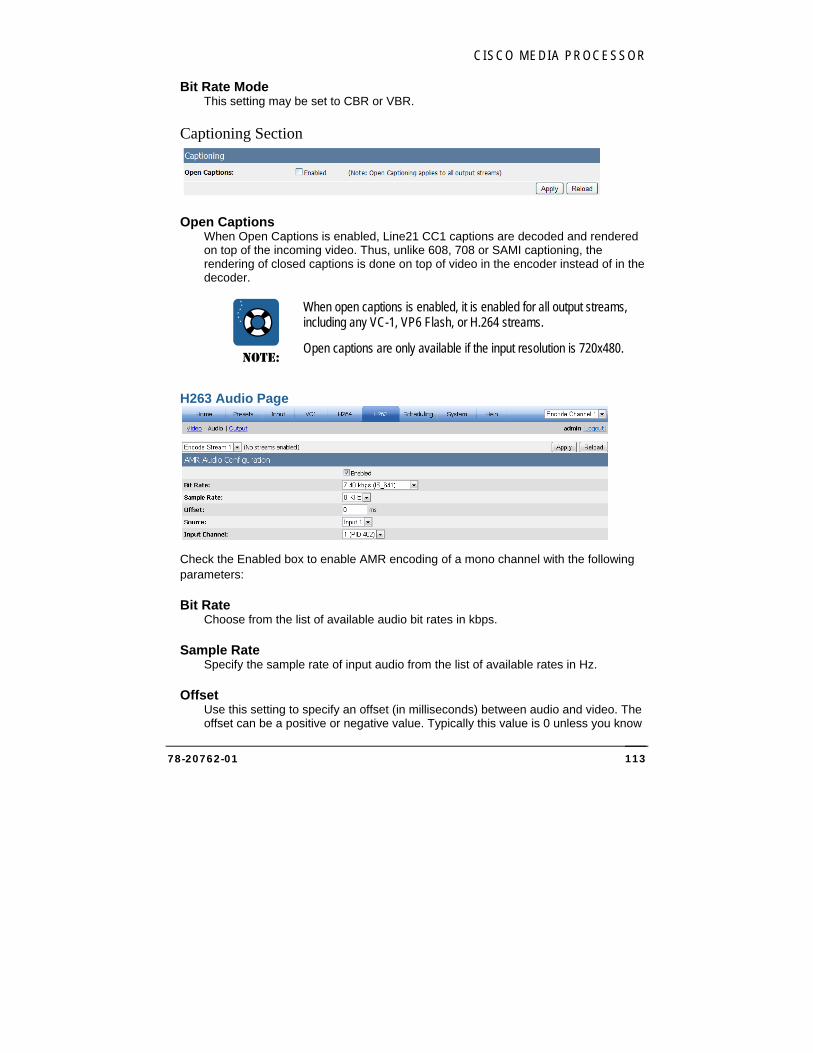
CISCO MEDIA PROCESSOR
78-20762-01 113
Bit Rate Mode This setting may be set to CBR or VBR.
Captioning Section
Open Captions When Open Captions is enabled, Line21 CC1 captions are decoded and rendered on top of the incoming video. Thus, unlike 608, 708 or SAMI captioning, the rendering of closed captions is done on top of video in the encoder instead of in the decoder.
NOTE:
When open captions is enabled, it is enabled for all output streams, including any VC-1, VP6 Flash, or H.264 streams.
Open captions are only available if the input resolution is 720x480.
H263 Audio Page
Check the Enabled box to enable AMR encoding of a mono channel with the following parameters:
Bit Rate Choose from the list of available audio bit rates in kbps.
Sample Rate Specify the sample rate of input audio from the list of available rates in Hz.
Offset Use this setting to specify an offset (in milliseconds) between audio and video. The offset can be a positive or negative value. Typically this value is 0 unless you know
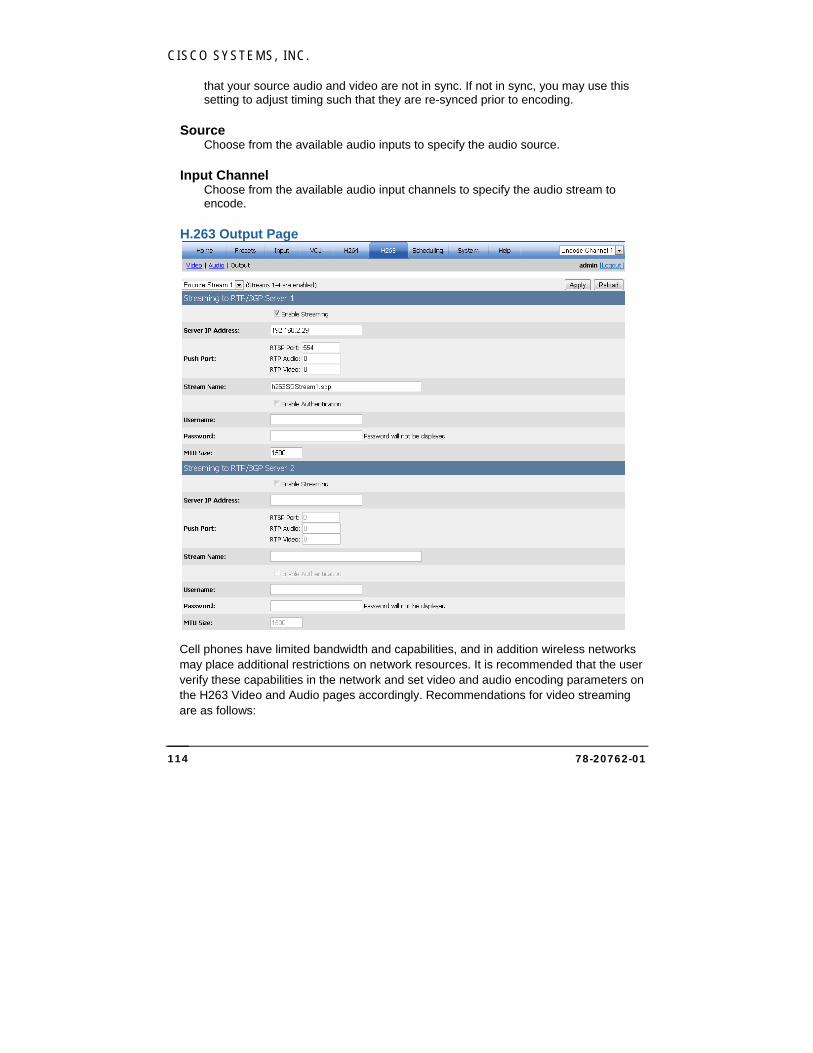
CISCO SYSTEMS, INC.
78-20762-01 114
that your source audio and video are not in sync. If not in sync, you may use this setting to adjust timing such that they are re-synced prior to encoding.
Source Choose from the available audio inputs to specify the audio source.
Input Channel Choose from the available audio input channels to specify the audio stream to encode.
H.263 Output Page
Cell phones have limited bandwidth and capabilities, and in addition wireless networks may place additional restrictions on network resources. It is recommended that the user verify these capabilities in the network and set video and audio encoding parameters on the H263 Video and Audio pages accordingly. Recommendations for video streaming are as follows:
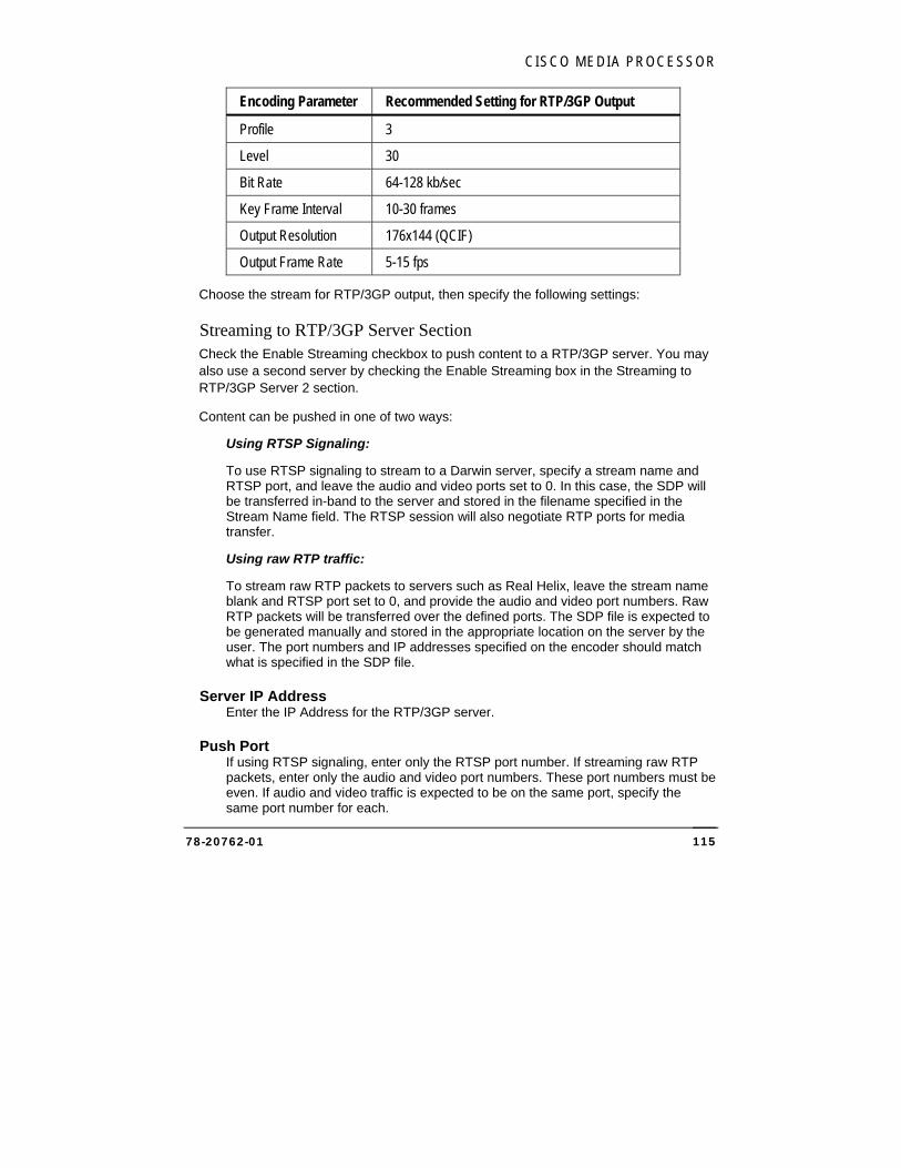
CISCO MEDIA PROCESSOR
78-20762-01 115
Encoding Parameter Recommended Setting for RTP/3GP Output
Profile 3
Level 30
Bit Rate 64-128 kb/sec
Key Frame Interval 10-30 frames
Output Resolution 176x144 (QCIF)
Output Frame Rate 5-15 fps
Choose the stream for RTP/3GP output, then specify the following settings:
Streaming to RTP/3GP Server Section Check the Enable Streaming checkbox to push content to a RTP/3GP server. You may also use a second server by checking the Enable Streaming box in the Streaming to RTP/3GP Server 2 section.
Content can be pushed in one of two ways:
Using RTSP Signaling:
To use RTSP signaling to stream to a Darwin server, specify a stream name and RTSP port, and leave the audio and video ports set to 0. In this case, the SDP will be transferred in-band to the server and stored in the filename specified in the Stream Name field. The RTSP session will also negotiate RTP ports for media transfer.
Using raw RTP traffic:
To stream raw RTP packets to servers such as Real Helix, leave the stream name blank and RTSP port set to 0, and provide the audio and video port numbers. Raw RTP packets will be transferred over the defined ports. The SDP file is expected to be generated manually and stored in the appropriate location on the server by the user. The port numbers and IP addresses specified on the encoder should match what is specified in the SDP file.
Server IP Address Enter the IP Address for the RTP/3GP server.
Push Port If using RTSP signaling, enter only the RTSP port number. If streaming raw RTP packets, enter only the audio and video port numbers. These port numbers must be even. If audio and video traffic is expected to be on the same port, specify the same port number for each.

CISCO SYSTEMS, INC.
78-20762-01 116
Stream Name Enter the name of the stream if using RTSP signaling. If streaming raw RTP packets, this field will be ignored.
Check the Enable Authentication checkbox to enable authentication before the stream can be published. Enter the username and password and click Apply to store them in the registry. The password characters will not be displayed.
MTU Size Set the maximum packet size for RTP. Default is 1500.
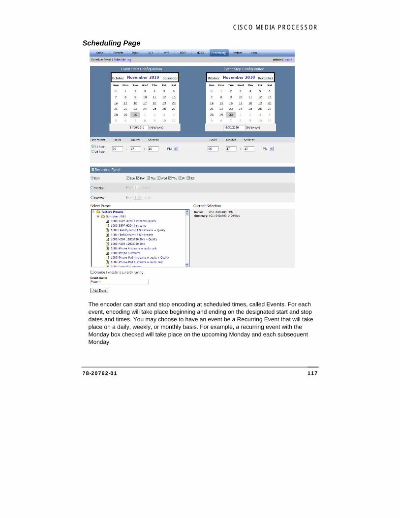
CISCO MEDIA PROCESSOR
78-20762-01 117
Scheduling Page
The encoder can start and stop encoding at scheduled times, called Events. For each event, encoding will take place beginning and ending on the designated start and stop dates and times. You may choose to have an event be a Recurring Event that will take place on a daily, weekly, or monthly basis. For example, a recurring event with the Monday box checked will take place on the upcoming Monday and each subsequent Monday.
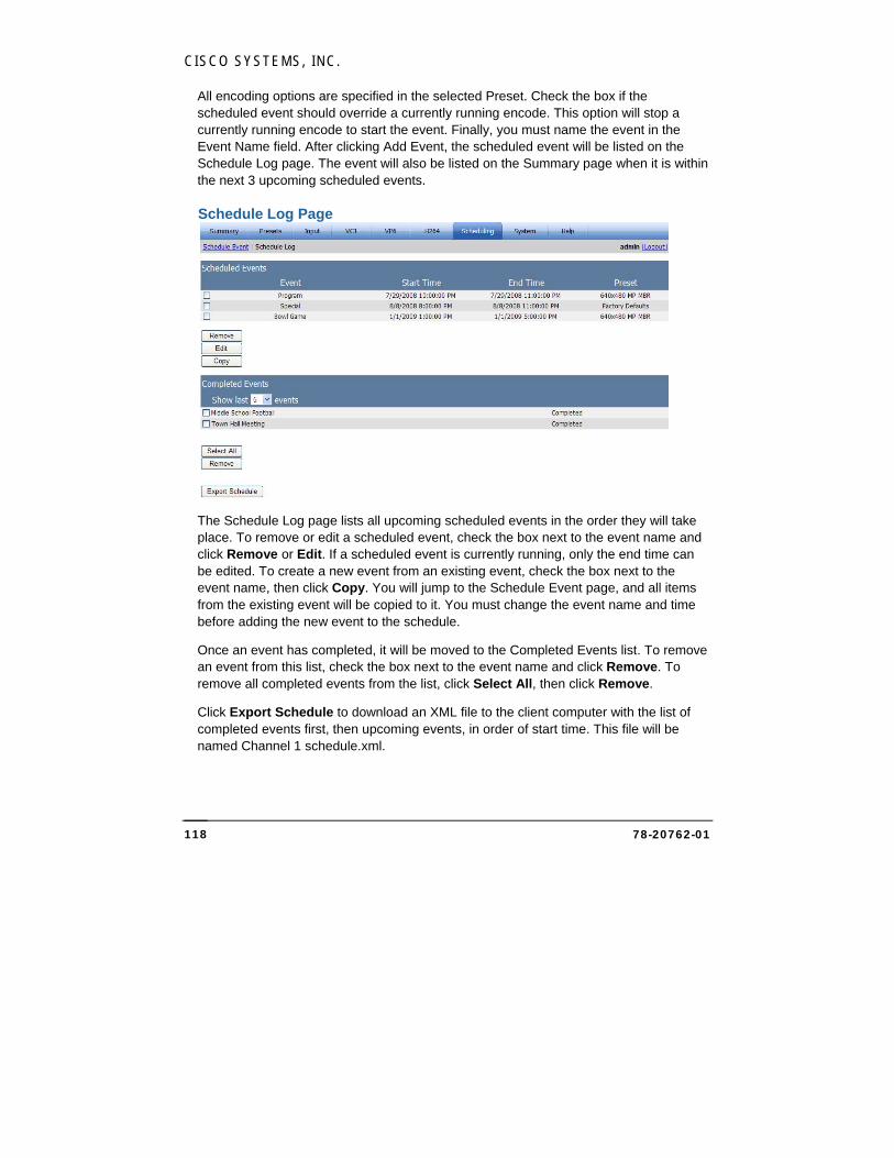
CISCO SYSTEMS, INC.
78-20762-01 118
All encoding options are specified in the selected Preset. Check the box if the scheduled event should override a currently running encode. This option will stop a currently running encode to start the event. Finally, you must name the event in the Event Name field. After clicking Add Event, the scheduled event will be listed on the Schedule Log page. The event will also be listed on the Summary page when it is within the next 3 upcoming scheduled events.
Schedule Log Page
The Schedule Log page lists all upcoming scheduled events in the order they will take place. To remove or edit a scheduled event, check the box next to the event name and click Remove or Edit. If a scheduled event is currently running, only the end time can be edited. To create a new event from an existing event, check the box next to the event name, then click Copy. You will jump to the Schedule Event page, and all items from the existing event will be copied to it. You must change the event name and time before adding the new event to the schedule.
Once an event has completed, it will be moved to the Completed Events list. To remove an event from this list, check the box next to the event name and click Remove. To remove all completed events from the list, click Select All, then click Remove.
Click Export Schedule to download an XML file to the client computer with the list of completed events first, then upcoming events, in order of start time. This file will be named Channel 1 schedule.xml.
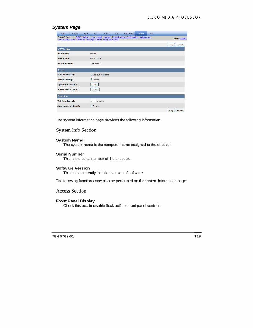
CISCO MEDIA PROCESSOR
78-20762-01 119
System Page
The system information page provides the following information:
System Info Section
System Name The system name is the computer name assigned to the encoder.
Serial Number This is the serial number of the encoder.
Software Version This is the currently installed version of software.
The following functions may also be performed on the system information page:
Access Section
Front Panel Display Check this box to disable (lock out) the front panel controls.

CISCO SYSTEMS, INC.
78-20762-01 120
Remote Desktop Check this box to allow remote desktop access to the encoder.
Expired User Accounts Click the Delete button to delete any user accounts that have expired.
Inactive User Accounts Click the Disable button to disable accounts that have been inactive.
Operation Section
Web Page Timeout This setting specifies the time of inactivity in minutes before a user will be automatically logged out.
Auto-Encode on Reboot Check the box to enable the encoder to automatically resume encoding after an unexpected system shutdown.
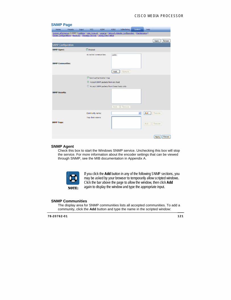
CISCO MEDIA PROCESSOR
78-20762-01 121
SNMP Page
SNMP Agent Check this box to start the Windows SNMP service. Unchecking this box will stop the service. For more information about the encoder settings that can be viewed through SNMP, see the MIB documentation in Appendix A.
NOTE:
If you click the Add button in any of the following SNMP sections, you may be asked by your browser to temporarily allow scripted windows. Click the bar above the page to allow the window, then click Add again to display the window and type the appropriate input.
SNMP Communities The display area for SNMP communities lists all accepted communities. To add a community, click the Add button and type the name in the scripted window:
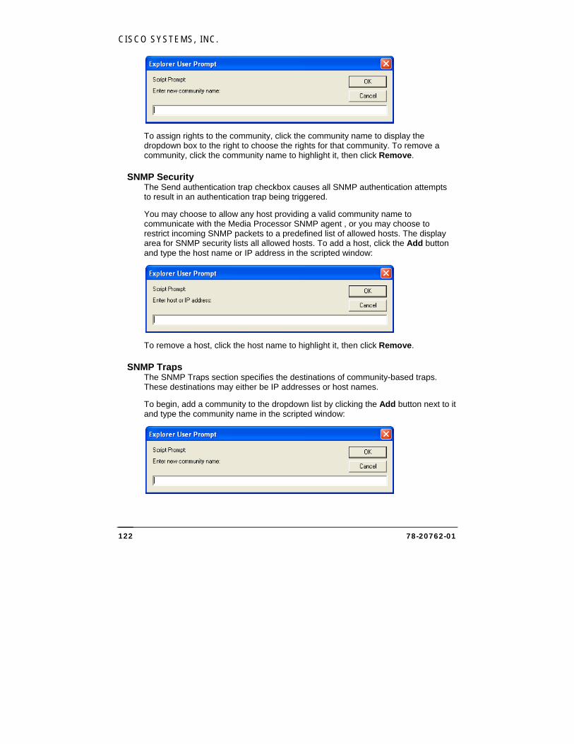
CISCO SYSTEMS, INC.
78-20762-01 122
To assign rights to the community, click the community name to display the dropdown box to the right to choose the rights for that community. To remove a community, click the community name to highlight it, then click Remove.
SNMP Security The Send authentication trap checkbox causes all SNMP authentication attempts to result in an authentication trap being triggered.
You may choose to allow any host providing a valid community name to communicate with the Media Processor SNMP agent , or you may choose to restrict incoming SNMP packets to a predefined list of allowed hosts. The display area for SNMP security lists all allowed hosts. To add a host, click the Add button and type the host name or IP address in the scripted window:
To remove a host, click the host name to highlight it, then click Remove.
SNMP Traps The SNMP Traps section specifies the destinations of community-based traps. These destinations may either be IP addresses or host names.
To begin, add a community to the dropdown list by clicking the Add button next to it and type the community name in the scripted window:
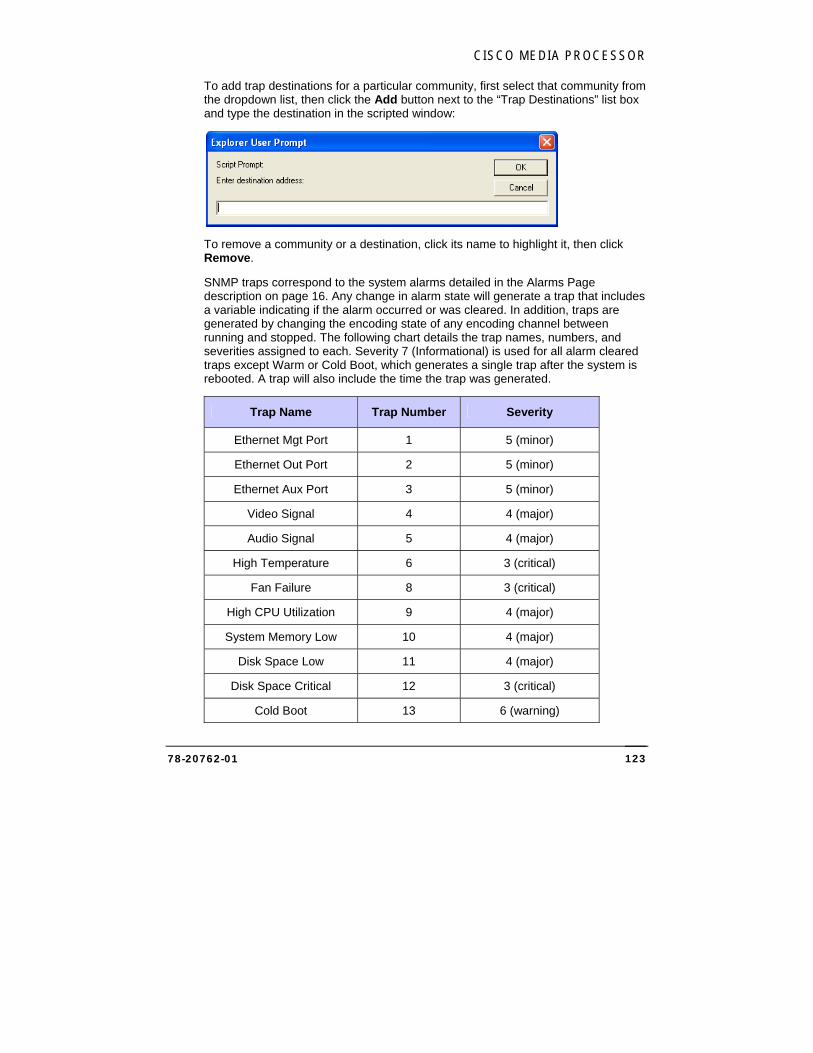
CISCO MEDIA PROCESSOR
78-20762-01 123
To add trap destinations for a particular community, first select that community from the dropdown list, then click the Add button next to the “Trap Destinations” list box and type the destination in the scripted window:
To remove a community or a destination, click its name to highlight it, then click Remove.
SNMP traps correspond to the system alarms detailed in the Alarms Page description on page 16. Any change in alarm state will generate a trap that includes a variable indicating if the alarm occurred or was cleared. In addition, traps are generated by changing the encoding state of any encoding channel between running and stopped. The following chart details the trap names, numbers, and severities assigned to each. Severity 7 (Informational) is used for all alarm cleared traps except Warm or Cold Boot, which generates a single trap after the system is rebooted. A trap will also include the time the trap was generated.
Trap Name Trap Number Severity
Ethernet Mgt Port 1 5 (minor)
Ethernet Out Port 2 5 (minor)
Ethernet Aux Port 3 5 (minor)
Video Signal 4 4 (major)
Audio Signal 5 4 (major)
High Temperature 6 3 (critical)
Fan Failure 8 3 (critical)
High CPU Utilization 9 4 (major)
System Memory Low 10 4 (major)
Disk Space Low 11 4 (major)
Disk Space Critical 12 3 (critical)
Cold Boot 13 6 (warning)
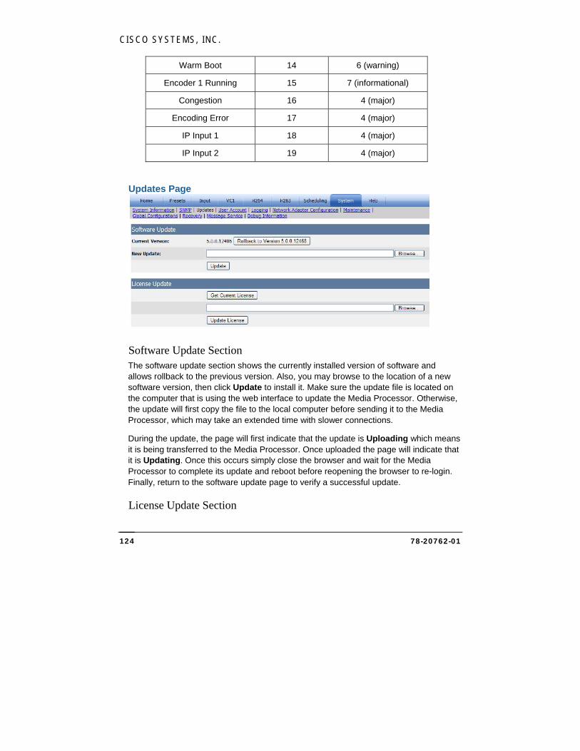
CISCO SYSTEMS, INC.
78-20762-01 124
Warm Boot 14 6 (warning)
Encoder 1 Running 15 7 (informational)
Congestion 16 4 (major)
Encoding Error 17 4 (major)
IP Input 1 18 4 (major)
IP Input 2 19 4 (major)
Updates Page
Software Update Section The software update section shows the currently installed version of software and allows rollback to the previous version. Also, you may browse to the location of a new software version, then click Update to install it. Make sure the update file is located on the computer that is using the web interface to update the Media Processor. Otherwise, the update will first copy the file to the local computer before sending it to the Media Processor, which may take an extended time with slower connections.
During the update, the page will first indicate that the update is Uploading which means it is being transferred to the Media Processor. Once uploaded the page will indicate that it is Updating. Once this occurs simply close the browser and wait for the Media Processor to complete its update and reboot before reopening the browser to re-login. Finally, return to the software update page to verify a successful update.
License Update Section
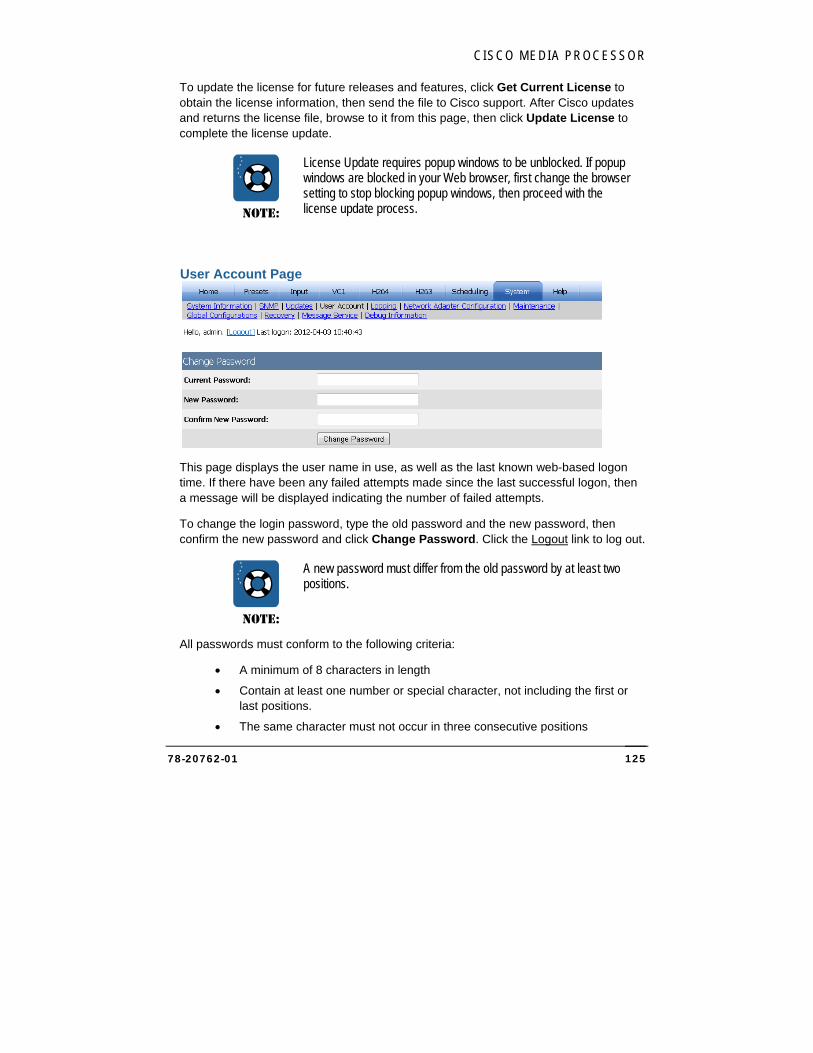
CISCO MEDIA PROCESSOR
78-20762-01 125
To update the license for future releases and features, click Get Current License to obtain the license information, then send the file to Cisco support. After Cisco updates and returns the license file, browse to it from this page, then click Update License to complete the license update.
NOTE:
License Update requires popup windows to be unblocked. If popup windows are blocked in your Web browser, first change the browser setting to stop blocking popup windows, then proceed with the license update process.
User Account Page
This page displays the user name in use, as well as the last known web-based logon time. If there have been any failed attempts made since the last successful logon, then a message will be displayed indicating the number of failed attempts.
To change the login password, type the old password and the new password, then confirm the new password and click Change Password. Click the Logout link to log out.
NOTE:
A new password must differ from the old password by at least two positions.
All passwords must conform to the following criteria:
A minimum of 8 characters in length
Contain at least one number or special character, not including the first or last positions.
The same character must not occur in three consecutive positions
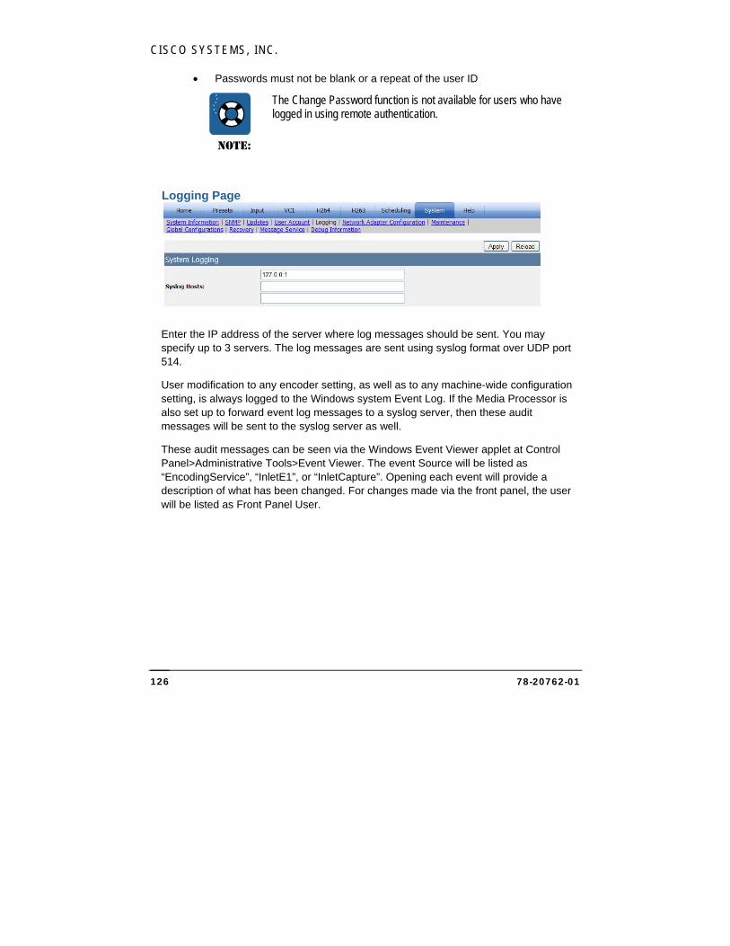
CISCO SYSTEMS, INC.
78-20762-01 126
Passwords must not be blank or a repeat of the user ID
NOTE:
The Change Password function is not available for users who have logged in using remote authentication.
Logging Page
Enter the IP address of the server where log messages should be sent. You may specify up to 3 servers. The log messages are sent using syslog format over UDP port 514.
User modification to any encoder setting, as well as to any machine-wide configuration setting, is always logged to the Windows system Event Log. If the Media Processor is also set up to forward event log messages to a syslog server, then these audit messages will be sent to the syslog server as well.
These audit messages can be seen via the Windows Event Viewer applet at Control Panel>Administrative Tools>Event Viewer. The event Source will be listed as “EncodingService”, “InletE1”, or “InletCapture”. Opening each event will provide a description of what has been changed. For changes made via the front panel, the user will be listed as Front Panel User.
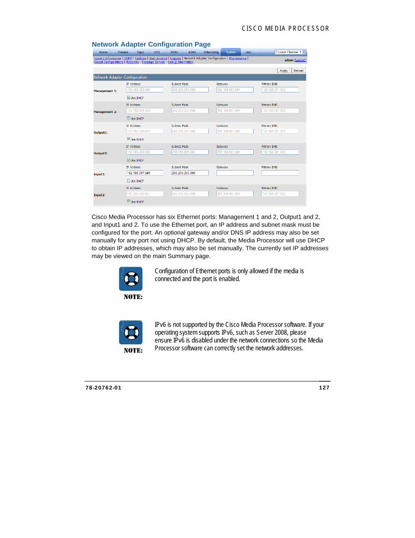
CISCO MEDIA PROCESSOR
78-20762-01 127
Network Adapter Configuration Page
Cisco Media Processor has six Ethernet ports: Management 1 and 2, Output1 and 2, and Input1 and 2. To use the Ethernet port, an IP address and subnet mask must be configured for the port. An optional gateway and/or DNS IP address may also be set manually for any port not using DHCP. By default, the Media Processor will use DHCP to obtain IP addresses, which may also be set manually. The currently set IP addresses may be viewed on the main Summary page.
NOTE:
Configuration of Ethernet ports is only allowed if the media is connected and the port is enabled.
NOTE:
IPv6 is not supported by the Cisco Media Processor software. If your operating system supports IPv6, such as Server 2008, please ensure IPv6 is disabled under the network connections so the Media Processor software can correctly set the network addresses.
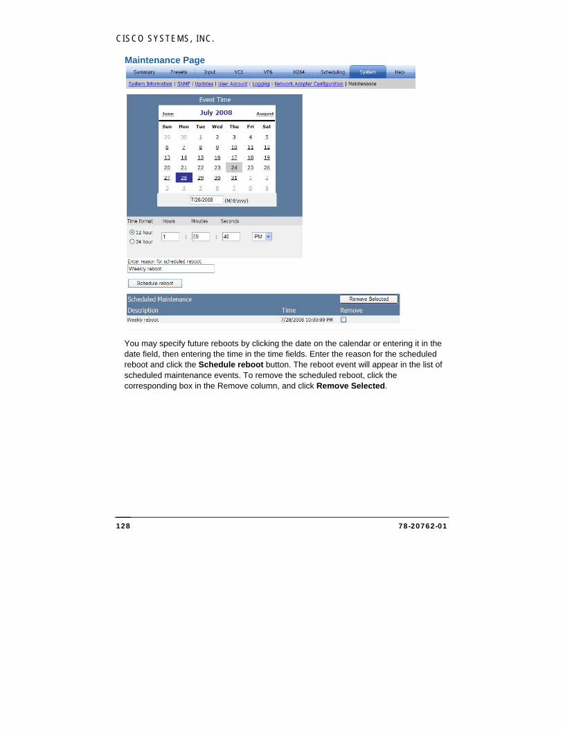
CISCO SYSTEMS, INC.
78-20762-01 128
Maintenance Page
You may specify future reboots by clicking the date on the calendar or entering it in the date field, then entering the time in the time fields. Enter the reason for the scheduled reboot and click the Schedule reboot button. The reboot event will appear in the list of scheduled maintenance events. To remove the scheduled reboot, click the corresponding box in the Remove column, and click Remove Selected.
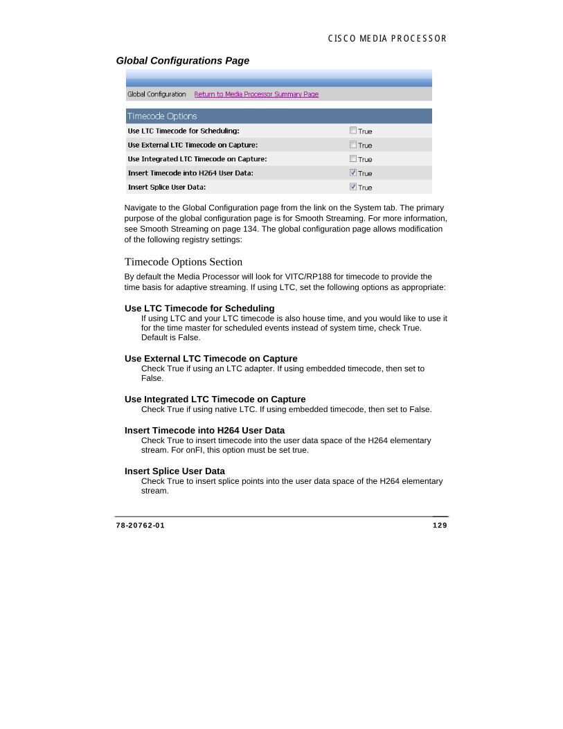
CISCO MEDIA PROCESSOR
78-20762-01 129
Global Configurations Page
Navigate to the Global Configuration page from the link on the System tab. The primary purpose of the global configuration page is for Smooth Streaming. For more information, see Smooth Streaming on page 134. The global configuration page allows modification of the following registry settings:
Timecode Options Section By default the Media Processor will look for VITC/RP188 for timecode to provide the time basis for adaptive streaming. If using LTC, set the following options as appropriate:
Use LTC Timecode for Scheduling If using LTC and your LTC timecode is also house time, and you would like to use it for the time master for scheduled events instead of system time, check True. Default is False.
Use External LTC Timecode on Capture Check True if using an LTC adapter. If using embedded timecode, then set to False.
Use Integrated LTC Timecode on Capture Check True if using native LTC. If using embedded timecode, then set to False.
Insert Timecode into H264 User Data Check True to insert timecode into the user data space of the H264 elementary stream. For onFI, this option must be set true.
Insert Splice User Data Check True to insert splice points into the user data space of the H264 elementary stream.
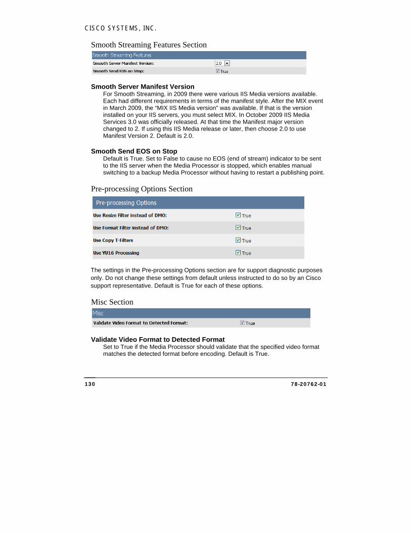
CISCO SYSTEMS, INC.
78-20762-01 130
Smooth Streaming Features Section
Smooth Server Manifest Version For Smooth Streaming, in 2009 there were various IIS Media versions available. Each had different requirements in terms of the manifest style. After the MIX event in March 2009, the “MIX IIS Media version” was available. If that is the version installed on your IIS servers, you must select MIX. In October 2009 IIS Media Services 3.0 was officially released. At that time the Manifest major version changed to 2. If using this IIS Media release or later, then choose 2.0 to use Manifest Version 2. Default is 2.0.
Smooth Send EOS on Stop Default is True. Set to False to cause no EOS (end of stream) indicator to be sent to the IIS server when the Media Processor is stopped, which enables manual switching to a backup Media Processor without having to restart a publishing point.
Pre-processing Options Section
The settings in the Pre-processing Options section are for support diagnostic purposes only. Do not change these settings from default unless instructed to do so by an Cisco support representative. Default is True for each of these options.
Misc Section
Validate Video Format to Detected Format Set to True if the Media Processor should validate that the specified video format matches the detected format before encoding. Default is True.
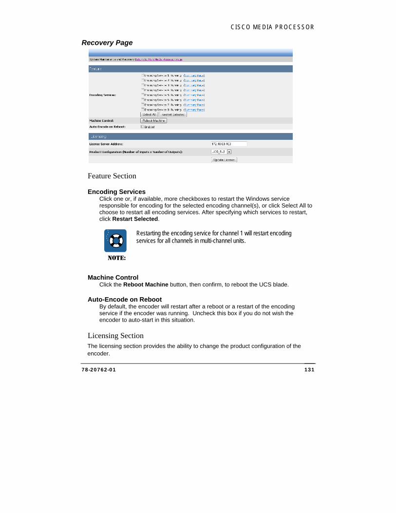
CISCO MEDIA PROCESSOR
78-20762-01 131
Recovery Page
Feature Section
Encoding Services Click one or, if available, more checkboxes to restart the Windows service responsible for encoding for the selected encoding channel(s), or click Select All to choose to restart all encoding services. After specifying which services to restart, click Restart Selected.
NOTE:
Restarting the encoding service for channel 1 will restart encoding services for all channels in multi-channel units.
Machine Control Click the Reboot Machine button, then confirm, to reboot the UCS blade.
Auto-Encode on Reboot By default, the encoder will restart after a reboot or a restart of the encoding service if the encoder was running. Uncheck this box if you do not wish the encoder to auto-start in this situation.
Licensing Section The licensing section provides the ability to change the product configuration of the encoder.
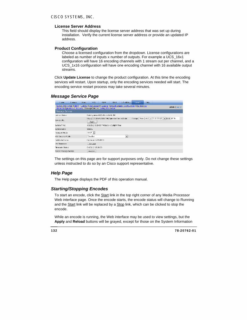
CISCO SYSTEMS, INC.
78-20762-01 132
License Server Address This field should display the license server address that was set up during installation. Verify the current license server address or provide an updated IP address.
Product Configuration Choose a licensed configuration from the dropdown. License configurations are labeled as number of inputs x number of outputs. For example a UCS_16x1 configuration will have 16 encoding channels with 1 stream out per channel, and a UCS_1x16 configuration will have one encoding channel with 16 available output streams.
Click Update License to change the product configuration. At this time the encoding services will restart. Upon startup, only the encoding services needed will start. The encoding service restart process may take several minutes.
Message Service Page
The settings on this page are for support purposes only. Do not change these settings unless instructed to do so by an Cisco support representative.
Help Page The Help page displays the PDF of this operation manual.
Starting/Stopping Encodes To start an encode, click the Start link in the top right corner of any Media Processor Web interface page. Once the encode starts, the encode status will change to Running and the Start link will be replaced by a Stop link, which can be clicked to stop the encode.
While an encode is running, the Web interface may be used to view settings, but the Apply and Reload buttons will be grayed, except for those on the System Information

CISCO MEDIA PROCESSOR
78-20762-01 133
page and the Logging page. To make changes to other settings, stop the encode, then apply changes and restart.
Session Timeouts After a period of inactivity on the Web pages, your login session will time out and you will be redirected to the login page. The default value is 15 minutes, and can be modified on the System Information page.
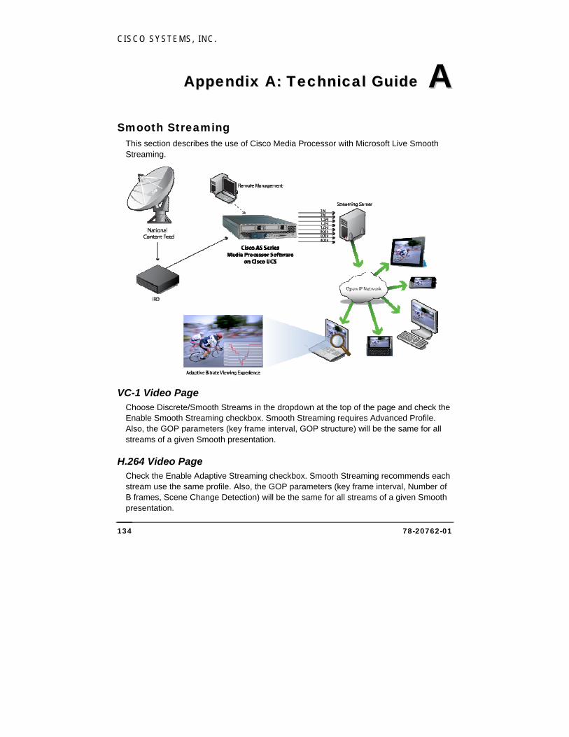
CISCO SYSTEMS, INC.
78-20762-01 134
AAppppeennddiixx AA:: TTeecchhnniiccaall GGuuiiddee
Smooth Streaming This section describes the use of Cisco Media Processor with Microsoft Live Smooth Streaming.
VC-1 Video Page Choose Discrete/Smooth Streams in the dropdown at the top of the page and check the Enable Smooth Streaming checkbox. Smooth Streaming requires Advanced Profile. Also, the GOP parameters (key frame interval, GOP structure) will be the same for all streams of a given Smooth presentation.
H.264 Video Page Check the Enable Adaptive Streaming checkbox. Smooth Streaming recommends each stream use the same profile. Also, the GOP parameters (key frame interval, Number of B frames, Scene Change Detection) will be the same for all streams of a given Smooth presentation.
AA
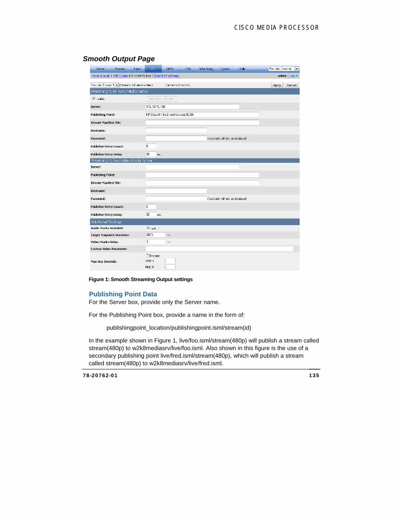
CISCO MEDIA PROCESSOR
78-20762-01 135
Smooth Output Page
Figure 1: Smooth Streaming Output settings
Publishing Point Data For the Server box, provide only the Server name.
For the Publishing Point box, provide a name in the form of:
publishingpoint_location/publishingpoint.isml/stream(id)
In the example shown in Figure 1, live/foo.isml/stream(480p) will publish a stream called stream(480p) to w2k8mediasrv/live/foo.isml. Also shown in this figure is the use of a secondary publishing point live/fred.isml/stream(480p), which will publish a stream called stream(480p) to w2k8mediasrv/live/fred.isml.
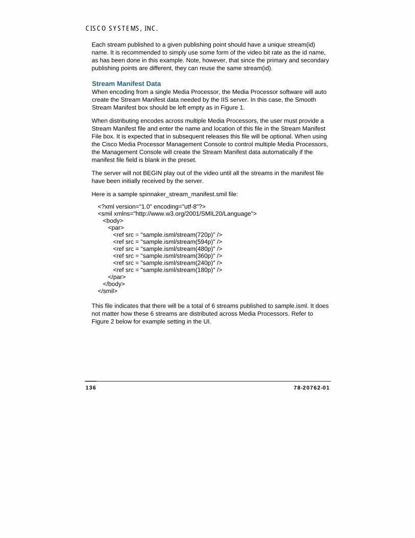
CISCO SYSTEMS, INC.
78-20762-01 136
Each stream published to a given publishing point should have a unique stream(id) name. It is recommended to simply use some form of the video bit rate as the id name, as has been done in this example. Note, however, that since the primary and secondary publishing points are different, they can reuse the same stream(id).
Stream Manifest Data When encoding from a single Media Processor, the Media Processor software will auto create the Stream Manifest data needed by the IIS server. In this case, the Smooth Stream Manifest box should be left empty as in Figure 1.
When distributing encodes across multiple Media Processors, the user must provide a Stream Manifest file and enter the name and location of this file in the Stream Manifest File box. It is expected that in subsequent releases this file will be optional. When using the Cisco Media Processor Management Console to control multiple Media Processors, the Management Console will create the Stream Manifest data automatically if the manifest file field is blank in the preset.
The server will not BEGIN play out of the video until all the streams in the manifest file have been initially received by the server.
Here is a sample spinnaker_stream_manifest.smil file:
<?xml version="1.0" encoding="utf-8"?> <smil xmlns="http://www.w3.org/2001/SMIL20/Language"> <body> <par> <ref src = "sample.isml/stream(720p)" /> <ref src = "sample.isml/stream(594p)" /> <ref src = "sample.isml/stream(480p)" /> <ref src = "sample.isml/stream(360p)" /> <ref src = "sample.isml/stream(240p)" /> <ref src = "sample.isml/stream(180p)" /> </par> </body> </smil>
This file indicates that there will be a total of 6 streams published to sample.isml. It does not matter how these 6 streams are distributed across Media Processors. Refer to Figure 2 below for example setting in the UI.
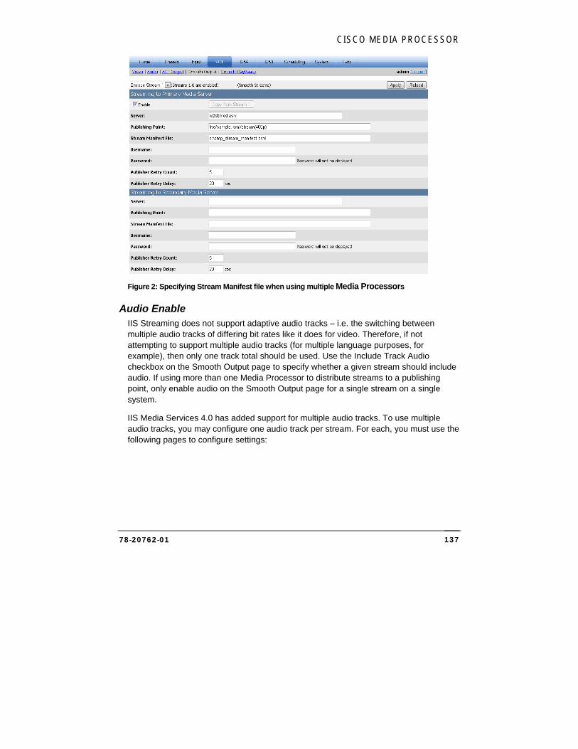
CISCO MEDIA PROCESSOR
78-20762-01 137
Figure 2: Specifying Stream Manifest file when using multiple Media Processors
Audio Enable IIS Streaming does not support adaptive audio tracks – i.e. the switching between multiple audio tracks of differing bit rates like it does for video. Therefore, if not attempting to support multiple audio tracks (for multiple language purposes, for example), then only one track total should be used. Use the Include Track Audio checkbox on the Smooth Output page to specify whether a given stream should include audio. If using more than one Media Processor to distribute streams to a publishing point, only enable audio on the Smooth Output page for a single stream on a single system.
IIS Media Services 4.0 has added support for multiple audio tracks. To use multiple audio tracks, you may configure one audio track per stream. For each, you must use the following pages to configure settings:
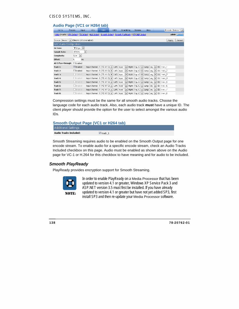
CISCO SYSTEMS, INC.
78-20762-01 138
Audio Page (VC1 or H264 tab)
Compression settings must be the same for all smooth audio tracks. Choose the language code for each audio track. Also, each audio track must have a unique ID. The client player should provide the option for the user to select amongst the various audio IDs.
Smooth Output Page (VC1 or H264 tab)
Smooth Streaming requires audio to be enabled on the Smooth Output page for one encode stream. To enable audio for a specific encode stream, check an Audio Tracks Included checkbox on this page. Audio must be enabled as shown above on the Audio page for VC-1 or H.264 for this checkbox to have meaning and for audio to be included.
Smooth PlayReady PlayReady provides encryption support for Smooth Streaming.
NOTE:
In order to enable PlayReady on a Media Processor that has been updated to version 4.1 or greater, Windows XP Service Pack 3 and ASP.NET version 3.5 must first be installed. If you have already updated to version 4.1 or greater but have not yet added SP3, first install SP3 and then re-update your Media Processor software.
CISCO MEDIA PROCESSOR
78-20762-01 139
Check the Enable PlayReady checkbox to use Smooth PlayReady which will initialize the encrypter, then choose the PlayReady License Provider Information source from the dropdown. If a third party provider such as BuyDRM is specified, there will be additional settings that will appear on the page. Fill in the new fields with information supplied by the third party provider. Select the Request Key button and the PlayReady settings will be filled in with information from the provider. If Manual Entry is specified, provide values for all required and any optional settings.
NOTE:
Content owners use Microsoft PlayReady™ content access technology to protect their intellectual property, including copyrighted content. This software uses PlayReady technology to create PlayReady-protected content. If the software fails to properly enforce restrictions on content usage, content owners may require Microsoft to revoke the software’s ability to create PlayReady protected content. Revocation should not affect unprotected content, or content protected by other content access technologies. Content owners may require you to upgrade PlayReady to access their content. If you decline an upgrade, you will not be able to access content that requires the upgrade.
Timecode Options and Smooth Controls
Global Configuration Page Currently a special UI page is used to set up some requirements for Smooth Streaming. This global configuration page is accessible via the System tab or can be reached directly by going to: https://spinnaker/encadmin/registryitems.aspx. The installer for current builds will reset some of these items and thus you should revisit this page after an update. In future updates the need to revisit this page and re-check items will be removed.
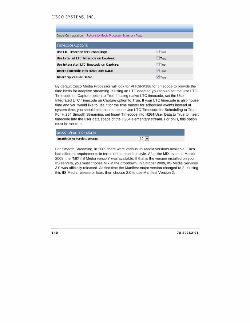
CISCO SYSTEMS, INC.
78-20762-01 140
By default Cisco Media Processor will look for VITC/RP188 for timecode to provide the time basis for adaptive streaming. If using an LTC adapter, you should set the Use LTC Timecode on Capture option to True. If using native LTC timecode, set the Use Integrated LTC Timecode on Capture option to True. If your LTC timecode is also house time and you would like to use it for the time master for scheduled events instead of system time, you should also set the option Use LTC Timecode for Scheduling to True. For H.264 Smooth Streaming, set Insert Timecode into H264 User Data to True to insert timecode into the user data space of the H264 elementary stream. For onFI, this option must be set true.
For Smooth Streaming, in 2009 there were various IIS Media versions available. Each had different requirements in terms of the manifest style. After the MIX event in March 2009, the “MIX IIS Media version” was available. If that is the version installed on your IIS servers, you must choose Mix in the dropdown. In October 2009, IIS Media Services 3.0 was officially released. At that time the Manifest major version changed to 2. If using this IIS Media release or later, then choose 2.0 to use Manifest Version 2.
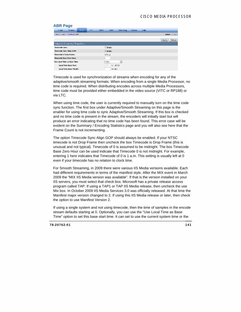
CISCO MEDIA PROCESSOR
78-20762-01 141
ABR Page
Timecode is used for synchronization of streams when encoding for any of the adaptive/smooth streaming formats. When encoding from a single Media Processor, no time code is required. When distributing encodes across multiple Media Processors, time code must be provided either embedded in the video source (VITC or RP188) or via LTC.
When using time code, the user is currently required to manually turn on the time code sync function. The first box under Adaptive/Smooth Streaming on this page is the enabler for using time code to sync Adaptive/Smooth Streaming. If this box is checked and no time code is present in the stream, the encoders will initially start but will produce an error indicating that no time code has been found. This error case will be evident on the Summary / Encoding Statistics page and you will also see here that the Frame Count is not incrementing.
The option Timecode Sync Align GOP should always be enabled. If your NTSC timecode is not Drop Frame then uncheck the box Timecode is Drop Frame (this is unusual and not typical). Timecode of 0 is assumed to be midnight. The box Timecode Base Zero Hour can be used indicate that Timecode 0 is not midnight. For example, entering 1 here indicates that Timecode of 0 is 1 a.m. This setting is usually left at 0 even if your timecode has no relation to clock time.
For Smooth Streaming, in 2009 there were various IIS Media versions available. Each had different requirements in terms of the manifest style. After the MIX event in March 2009 the “MIX IIS Media version was available”. If that is the version installed on your IIS servers, you must select that check box. Microsoft has a private release access program called TAP. If using a TAP1 or TAP IIS Media release, then uncheck the use Mix box. In October 2009 IIS Media Services 3.0 was officially released. At that time the Manifest major version changed to 2. If using this IIS Media release or later, then check the option to use Manifest Version 2.
If using a single system and not using timecode, then the time of samples in the encode stream defaults starting at 0. Optionally, you can use the “Use Local Time as Base Time” option to set this base start time. It can set to use the current system time or the
CISCO SYSTEMS, INC.
78-20762-01 142
current system time measured since midnight on the first day of the specified year and month.
Sample Presets Several Smooth streaming presets are provided for the user to modify. All of these presets start with the word ‘Smooth’. For example, there are a pair of presets using a 1080i input source called “Smooth 1080i 6 streams 1st encoder” and “Smooth 1080i 6 streams 2nd encoder” and another pair using a 720p input.
To use a single Media Processor to generate the Smooth stream, use the preset ending with ‘1st encoder.’ This preset sets up 3 streams. On the VC-1 Output tab, the Smooth Stream Manifest box should be empty, as the Media Processor will automatically create a correct manifest file.
To use the pre-existing presets to have two Media Processors generate a Smooth stream that contains 6 different bit rates, load a preset ending with ‘1st encoder’ on one Media Processor, and the matching preset ending with ‘2nd encoder’ on the other Media Processor. On the VC-1 Output tab on both encoders, the Smooth Stream Manifest box should contain the following entry: “C:\spinnaker_ss_stream_manifest_6_streams.smil”. This manifest file will work for any of the pre-existing preset pairs. The Media Processors will ship with that manifest file in the C:\ directory.
Error Conditions The following describes some of the common error messages that could be displayed in the UI:
CSmoothPublisher: HttpSession Failed to Write Header. Is Publishing Point Started? This message can occur if
The publishing point is invalid
The publishing point has not been started on the IIS server
After a previous encode, the publishing point has not been stopped and restarted on the IIS server.
CSmoothPublisher: HttpSession Failed. Is Publishing Point Valid? This message can occur if the publishing point is invalid.
CSmoothPublisher: Failed HttpSession WriteData D This message can occur if the publishing point has not been started on the IIS server.
CISCO MEDIA PROCESSOR
78-20762-01 143
CSmoothPublisher: HttpSession Failed to Publish Server Manifest. Is Publishing Point Started? This message can occur if the publishing point has not been started on the IIS server.
CSmoothPublisher: WinHttpWriteData Failed to Publishing Point 1. Did connection get lost or was publishing point closed? This message can occur if
The connection is lost or the publishing point was stopped/shutdown while encoding. The connection could be lost because IP connection to the server was lost or if the IIS server had an issue.
The publishing point has not been started on the IIS server
After a previous encode, the publishing point has not been stopped and restarted on the IIS server.
CSmoothPublisher: HttpSession Failed: Is Server Valid? This message can occur if the Media Processor cannot reach the IIS server. The server address could be wrong or not available.
CSmoothPublisher: HttpSession Authentication Failed This message can occur if the IIS Server initiates the authentication process and the Media Processor cannot successfully complete it. This can occur if the username or password is incorrect.
Player doesn’t start playing video If the server is not providing video and streams are coming from more than one device, note that the server will not BEGIN play out of the video until all the streams in the manifest file have been initially received by the server. The IIS server will wait for all streams listed in the stream manifest before delivering streams to client players. So if two or more systems are used to deliver streams for a single presentation and the user provided a stream manifest to describe all streams, all systems will have to be started before the IIS server will deliver streams to the client player.
Cisco Media Processor Metadata for TS Streams Cisco Media Processor supports a single metadata stream for TS output. This is a Private Stream 1 as defined by ISO/IEC 13818-1. Currently the PID for this stream is hard coded to 0x3F3.
The payload of the private data stream has a 4 BYTE preamble
0x49 0x4D 0x44 0x50.

CISCO SYSTEMS, INC.
78-20762-01 144
The preamble is followed by a 1 BYTE payload type
0 : NULL
1 : Cue Point
2 : Binary
The rest of the payload is the actual metadata
There will always be a single NULL metadata packet at the start of a TS stream.
The purpose of a Cue Point payload is so that the payload can be directly sent to a Flash stream w/out further conversion.
If Cue Point formatting is not required, the generic “Binary” method handles any type of metadata. Any data can base64 encoded and sent to Cisco Media Processor which can optionally 1) base64 decode the data and insert the binary result as the payload or 2) insert the base64 encoded version directly.
Here is a sample NULL packet:
0000 | 47 43 F3 30 A3 00 FF FF FF FF FF FF FF FF FF FF | GC.0............ 0010 | FF FF FF FF FF FF FF FF FF FF FF FF FF FF FF FF | ................ 0020 | FF FF FF FF FF FF FF FF FF FF FF FF FF FF FF FF | ................ 0030 | FF FF FF FF FF FF FF FF FF FF FF FF FF FF FF FF |................ 0040 | FF FF FF FF FF FF FF FF FF FF FF FF FF FF FF FF | ................ 0050 | FF FF FF FF FF FF FF FF FF FF FF FF FF FF FF FF | ................ 0060 | FF FF FF FF FF FF FF FF FF FF FF FF FF FF FF FF | ................ 0070 | FF FF FF FF FF FF FF FF FF FF FF FF FF FF FF FF | ................ 0080 | FF FF FF FF FF FF FF FF FF FF FF FF FF FF FF FF | ................ 0090 | FF FF FF FF FF FF FF FF FF FF FF FF FF FF FF FF | ................ 00A0 | FF FF FF FF FF FF FF FF 00 00 01 BD 00 0E 84 80 | ................ 00B0 | 05 21 00 01 46 63 49 4D 44 50 00 00 | .!..FcIMDP..
Here is a sample Cue Point packet (in this example the entire payload was contained in one TS packet but that may not always be the case).
0000 | 47 43 F3 31 3F 00 FF FF FF FF FF FF FF FF FF FF | GC.1?........... 0010 | FF FF FF FF FF FF FF FF FF FF FF FF FF FF FF FF | ................ 0020 | FF FF FF FF FF FF FF FF FF FF FF FF FF FF FF FF | ................ 0030 | FF FF FF FF FF FF FF FF FF FF FF FF FF FF FF FF | ................ 0040 | FF FF FF FF 00 00 01 BD 00 72 84 80 05 21 00 C5 | .........r...!.. 0050 | 9B F9 49 4D 44 50 01 02 00 0A 6F 6E 43 75 65 50 | ..IMDP....onCueP 0060 | 6F 69 6E 74 08 00 00 00 04 00 04 6E 61 6D 65 02 | oint.......name. 0070 | 00 04 74 65 73 74 00 0A 70 61 72 61 6D 65 74 65 | ..test..paramete 0080 | 72 73 08 00 00 00 01 00 08 6D 79 20 70 61 72 61 | rs.......my para 0090 | 6D 02 00 05 68 65 6C 6C 6F 00 00 09 00 04 74 69 | m...hello.....ti 00A0 | 6D 65 00 3F BF 67 9D 3E 99 80 E6 00 04 74 79 70 | me.?.g.>.....typ 00B0 | 65 02 00 05 65 76 65 6E 74 00 00 09 | e...event...

CISCO MEDIA PROCESSOR
78-20762-01 145
Cue Point Payloads
A cue point is defined as having a string name and one or more parameters where each parameter has 1) name, 2) type and 3) value. We support types of String, Number and Boolean. A Flash cue point has this information embedded in an onCuePoint data message. The following open spec has a small section (called Data Tags) that covers some details: www.adobe.com/devnet/flv/pdf/video_file_format_spec_v9.pdf
The onCuePoint data message has the following binary layout:
T2 Len16 “onCuePoint”
T8 Len32(4)
Len16 “name” T2 Len16 “cue point name”
Len16 “parameters” T8 Len32(number of parameters)
A given parameter one of the following 3 forms:
Len16 “parameter name” T2 Len16 “string value”
Len16 “parameter name” T0 8 bytes of double
Len16 “parameter name” T1 then one byte either 0 or 1
Len24(9) (this closes the array)
Len16 “time” T0 8 bytes of time double value
Len16 “type” T2 Len16 “event”
Len24(9) (this closes the array)
In above, Tn refers to the Flash Type and is a single byte value. So T2 is a single byte of value 2. Types are:
T0 double
T1 boolean
T2 string
T8 array
T12 strings larger than 65535 bytes
In above Len32 refers to the encoding of a length value in 32 bits. Len16 uses 16 bits and Len24 uses 24bits.
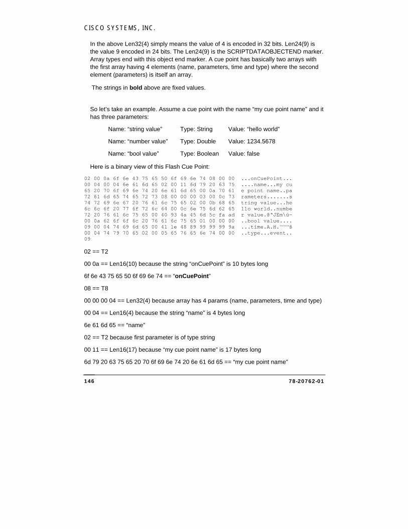
CISCO SYSTEMS, INC.
78-20762-01 146
In the above Len32(4) simply means the value of 4 is encoded in 32 bits. Len24(9) is the value 9 encoded in 24 bits. The Len24(9) is the SCRIPTDATAOBJECTEND marker. Array types end with this object end marker. A cue point has basically two arrays with the first array having 4 elements (name, parameters, time and type) where the second element (parameters) is itself an array.
The strings in bold above are fixed values.
So let’s take an example. Assume a cue point with the name “my cue point name” and it has three parameters:
Name: “string value” Type: String Value: “hello world”
Name: “number value” Type: Double Value: 1234.5678
Name: “bool value” Type: Boolean Value: false
Here is a binary view of this Flash Cue Point:
02 00 0a 6f 6e 43 75 65 50 6f 69 6e 74 08 00 00 ...onCuePoint... 00 04 00 04 6e 61 6d 65 02 00 11 6d 79 20 63 75 ....name...my cu 65 20 70 6f 69 6e 74 20 6e 61 6d 65 00 0a 70 61 e point name..pa 72 61 6d 65 74 65 72 73 08 00 00 00 03 00 0c 73 rameters.......s 74 72 69 6e 67 20 76 61 6c 75 65 02 00 0b 68 65 tring value...he 6c 6c 6f 20 77 6f 72 6c 64 00 0c 6e 75 6d 62 65 llo world..numbe 72 20 76 61 6c 75 65 00 40 93 4a 45 6d 5c fa ad r value.@“JEm\ú- 00 0a 62 6f 6f 6c 20 76 61 6c 75 65 01 00 00 00 ..bool value.... 09 00 04 74 69 6d 65 00 41 1e 48 89 99 99 99 9a ...time.A.H.™™™š 00 04 74 79 70 65 02 00 05 65 76 65 6e 74 00 00 ..type...event.. 09 02 == T2
00 0a == Len16(10) because the string “onCuePoint” is 10 bytes long
6f 6e 43 75 65 50 6f 69 6e 74 == “onCuePoint”
08 == T8
00 00 00 04 == Len32(4) because array has 4 params (name, parameters, time and type)
00 04 == Len16(4) because the string “name” is 4 bytes long
6e 61 6d 65 == “name”
02 == T2 because first parameter is of type string
00 11 == Len16(17) because “my cue point name” is 17 bytes long
6d 79 20 63 75 65 20 70 6f 69 6e 74 20 6e 61 6d 65 == “my cue point name”
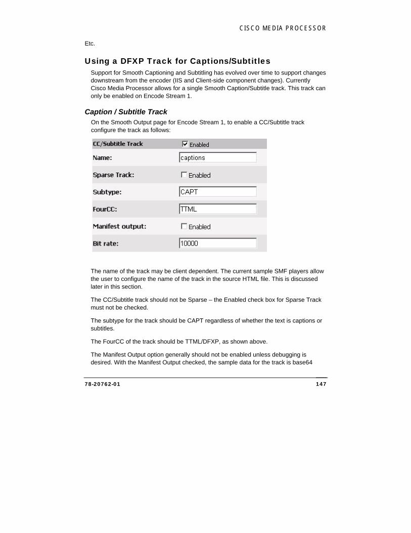
CISCO MEDIA PROCESSOR
78-20762-01 147
Etc.
Using a DFXP Track for Captions/Subtitles Support for Smooth Captioning and Subtitling has evolved over time to support changes downstream from the encoder (IIS and Client-side component changes). Currently Cisco Media Processor allows for a single Smooth Caption/Subtitle track. This track can only be enabled on Encode Stream 1.
Caption / Subtitle Track On the Smooth Output page for Encode Stream 1, to enable a CC/Subtitle track configure the track as follows:
The name of the track may be client dependent. The current sample SMF players allow the user to configure the name of the track in the source HTML file. This is discussed later in this section.
The CC/Subtitle track should not be Sparse – the Enabled check box for Sparse Track must not be checked.
The subtype for the track should be CAPT regardless of whether the text is captions or subtitles.
The FourCC of the track should be TTML/DFXP, as shown above.
The Manifest Output option generally should not be enabled unless debugging is desired. With the Manifest Output checked, the sample data for the track is base64
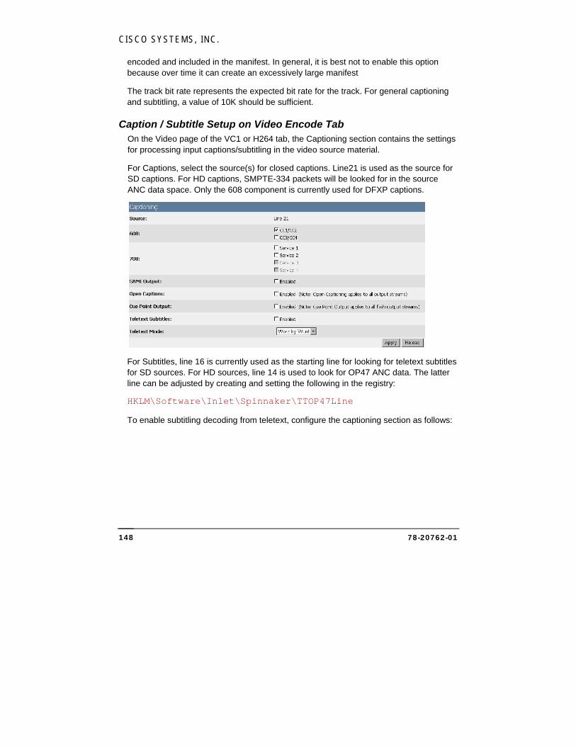
CISCO SYSTEMS, INC.
78-20762-01 148
encoded and included in the manifest. In general, it is best not to enable this option because over time it can create an excessively large manifest
The track bit rate represents the expected bit rate for the track. For general captioning and subtitling, a value of 10K should be sufficient.
Caption / Subtitle Setup on Video Encode Tab On the Video page of the VC1 or H264 tab, the Captioning section contains the settings for processing input captions/subtitling in the video source material.
For Captions, select the source(s) for closed captions. Line21 is used as the source for SD captions. For HD captions, SMPTE-334 packets will be looked for in the source ANC data space. Only the 608 component is currently used for DFXP captions.
For Subtitles, line 16 is currently used as the starting line for looking for teletext subtitles for SD sources. For HD sources, line 14 is used to look for OP47 ANC data. The latter line can be adjusted by creating and setting the following in the registry:
HKLM\Software\Inlet\Spinnaker\TTOP47Line
To enable subtitling decoding from teletext, configure the captioning section as follows:
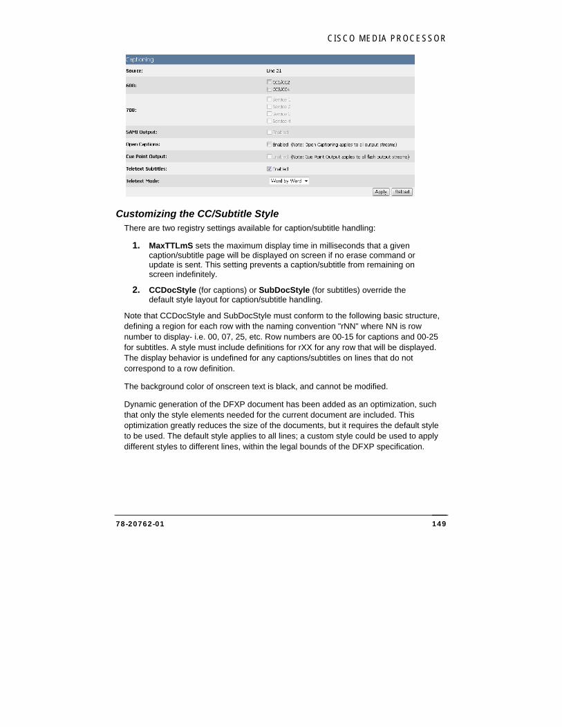
CISCO MEDIA PROCESSOR
78-20762-01 149
Customizing the CC/Subtitle Style There are two registry settings available for caption/subtitle handling:
1. MaxTTLmS sets the maximum display time in milliseconds that a given caption/subtitle page will be displayed on screen if no erase command or update is sent. This setting prevents a caption/subtitle from remaining on screen indefinitely.
2. CCDocStyle (for captions) or SubDocStyle (for subtitles) override the default style layout for caption/subtitle handling.
Note that CCDocStyle and SubDocStyle must conform to the following basic structure, defining a region for each row with the naming convention "rNN" where NN is row number to display- i.e. 00, 07, 25, etc. Row numbers are 00-15 for captions and 00-25 for subtitles. A style must include definitions for rXX for any row that will be displayed. The display behavior is undefined for any captions/subtitles on lines that do not correspond to a row definition.
The background color of onscreen text is black, and cannot be modified.
Dynamic generation of the DFXP document has been added as an optimization, such that only the style elements needed for the current document are included. This optimization greatly reduces the size of the documents, but it requires the default style to be used. The default style applies to all lines; a custom style could be used to apply different styles to different lines, within the legal bounds of the DFXP specification.
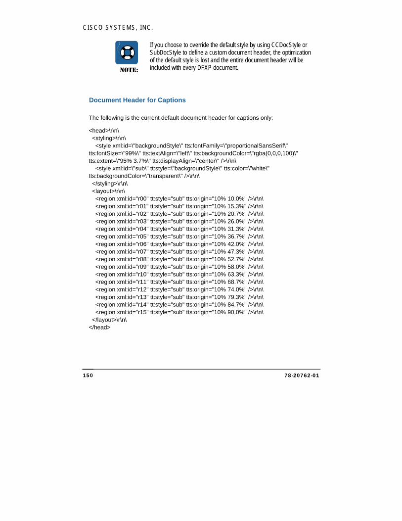
CISCO SYSTEMS, INC.
78-20762-01 150
NOTE:
If you choose to override the default style by using CCDocStyle or SubDocStyle to define a custom document header, the optimization of the default style is lost and the entire document header will be included with every DFXP document.
Document Header for Captions
The following is the current default document header for captions only:
<head>\r\n\ <styling>\r\n\ <style xml:id=\"backgroundStyle\" tts:fontFamily=\"proportionalSansSerif\" tts:fontSize=\"99%\" tts:textAlign=\"left\" tts:backgroundColor=\"rgba(0,0,0,100)\" tts:extent=\"95% 3.7%\" tts:displayAlign=\"center\" />\r\n\ <style xml:id=\"sub\" tt:style=\"backgroundStyle\" tts:color=\"white\" tts:backgroundColor=\"transparent\" />\r\n\ </styling>\r\n\ <layout>\r\n\ <region xml:id="r00" tt:style="sub" tts:origin="10% 10.0%" />\r\n\ <region xml:id=”r01" tt:style="sub" tts:origin="10% 15.3%" />\r\n\ <region xml:id="r02" tt:style="sub" tts:origin="10% 20.7%" />\r\n\ <region xml:id="r03" tt:style="sub" tts:origin="10% 26.0%" />\r\n\ <region xml:id="r04" tt:style="sub" tts:origin="10% 31.3%" />\r\n\ <region xml:id="r05" tt:style="sub" tts:origin="10% 36.7%" />\r\n\ <region xml:id="r06" tt:style="sub" tts:origin="10% 42.0%" />\r\n\ <region xml:id="r07" tt:style="sub" tts:origin="10% 47.3%" />\r\n\ <region xml:id="r08" tt:style="sub" tts:origin="10% 52.7%" />\r\n\ <region xml:id="r09" tt:style="sub" tts:origin="10% 58.0%" />\r\n\ <region xml:id="r10" tt:style="sub" tts:origin="10% 63.3%" />\r\n\ <region xml:id="r11" tt:style="sub" tts:origin="10% 68.7%" />\r\n\ <region xml:id="r12" tt:style="sub" tts:origin="10% 74.0%" />\r\n\ <region xml:id="r13" tt:style="sub" tts:origin="10% 79.3%" />\r\n\ <region xml:id="r14" tt:style="sub" tts:origin="10% 84.7%" />\r\n\ <region xml:id="r15" tt:style="sub" tts:origin="10% 90.0%" />\r\n\ </layout>\r\n\ </head>

CISCO MEDIA PROCESSOR
78-20762-01 151
Document Header for Subtitles
The following is the current default document header for subtitles only: <head>\r\n\ <styling>\r\n\ <style xml:id=\"backgroundStyle\" tts:fontFamily=\"proportionalSansSerif\" tts:fontSize=\"99%\" tts:textAlign=\"left\" tts:backgroundColor=\"rgba(0,0,0,100)\" tts:extent=\"95% 3.7%\" tts:displayAlign=\"center\" />\r\n\ <style xml:id=\"sub\" tt:style=\"backgroundStyle\" tts:color=\"white\" tts:backgroundColor=\"transparent\" />\r\n\ </styling>\r\n\ <layout>\r\n\ <region xml:id=\"r00\" tt:style=\"sub\" tts:origin=\"10% 3%\" />\r\n\ <region xml:id=\"r01\" tt:style=\"sub\" tts:origin=\"10% 6.7%\" />\r\n\ <region xml:id=\"r02\" tt:style=\"sub\" tts:origin=\"10% 10.4%\" />\r\n\ <region xml:id=\"r03\" tt:style=\"sub\" tts:origin=\"10% 14.1%\" />\r\n\ <region xml:id=\"r04\" tt:style=\"sub\" tts:origin=\"10% 17.8%\" />\r\n\ <region xml:id=\"r05\" tt:style=\"sub\" tts:origin=\"10% 21.5%\" />\r\n\ <region xml:id=\"r06\" tt:style=\"sub\" tts:origin=\"10% 25.2%\" />\r\n\ <region xml:id=\"r07\" tt:style=\"sub\" tts:origin=\"10% 28.9%\" />\r\n\ <region xml:id=\"r08\" tt:style=\"sub\" tts:origin=\"10% 32.6%\" />\r\n\ <region xml:id=\"r09\" tt:style=\"sub\" tts:origin=\"10% 36.3%\" />\r\n\ <region xml:id=\"r10\" tt:style=\"sub\" tts:origin=\"10% 40%\" />\r\n\ <region xml:id=\"r11\" tt:style=\"sub\" tts:origin=\"10% 43.7%\" />\r\n\ <region xml:id=\"r12\" tt:style=\"sub\" tts:origin=\"10% 47.4%\" />\r\n\ <region xml:id=\"r13\" tt:style=\"sub\" tts:origin=\"10% 51.1%\" />\r\n\ <region xml:id=\"r14\" tt:style=\"sub\" tts:origin=\"10% 54.8%\" />\r\n\ <region xml:id=\"r15\" tt:style=\"sub\" tts:origin=\"10% 58.5%\" />\r\n\ <region xml:id=\"r16\" tt:style=\"sub\" tts:origin=\"10% 62.2%\" />\r\n\ <region xml:id=\"r17\" tt:style=\"sub\" tts:origin=\"10% 65.9%\" />\r\n\ <region xml:id=\"r18\" tt:style=\"sub\" tts:origin=\"10% 69.6%\" />\r\n\ <region xml:id=\"r19\" tt:style=\"sub\" tts:origin=\"10% 73.3%\" />\r\n\ <region xml:id=\"r20\" tt:style=\"sub\" tts:origin=\"10% 77%\" />\r\n\ <region xml:id=\"r21\" tt:style=\"sub\" tts:origin=\"10% 80.7%\" />\r\n\ <region xml:id=\"r22\" tt:style=\"sub\" tts:origin=\"10% 84.4%\" />\r\n\ <region xml:id=\"r23\" tt:style=\"sub\" tts:origin=\"10% 88.1%\" />\r\n\ <region xml:id=\"r24\" tt:style=\"sub\" tts:origin=\"10% 91.8%\" />\r\n\ <region xml:id=\"r25\" tt:style=\"sub\" tts:origin=\"10% 95.5%\" />\r\n\ </layout>\r\n\ </head>
CISCO SYSTEMS, INC.
78-20762-01 152
Understanding VC-1 Cisco Media Processor supports the following video profiles:
VC-1 Simple Profile (WMV3)
VC-1 Main Profile (WMV3)
VC-1 Advanced Profile (WVC1)
Files encoded according to these profiles are identified by their Four Character Code (FOURCC). The FOURCC identifier is located at the beginning of a digital media file and tells the system what libraries to utilize for decoding the file. Note that these profiles are also equivalent to Windows Media 9 Video Simple, Main and Advanced.
VC-1 codec specification The VC-1 standard was approved by SMPTE and is referenced as SMPTE 421M. Although VC-1 and WMV9 refer to the same codec technology as far as Microsoft is concerned, VC-1 is actually a superset of WMV9, containing more coding tools for interlaced video sequences than the original WMV9 codec which concentrated on progressive encoding for computer displays. The main goal of VC-1/WMV9 Advanced Profile development and standardization was to support the compression of interlaced content without first converting it to progressive, making the codec more attractive to broadcast and video industry professionals. Leading content companies, solutions providers and consumer electronics manufacturers are adopting Windows Media Video 9 (VC-1) to drive the widespread delivery of high-definition experiences to consumers. VC-1 has been accepted by both of the next-generation DVD committees, HD-DVD and Blu-ray Disc.
VC-1 contains a number of profile and level combinations that support the encoding of many types of video. The profile determines the codec features that are available, and determines the required decoder complexity. VC-1 supports the following three profiles: Simple, Main, and Advanced. The Simple and Main profiles have been complete for several years, and are most commonly referred to as WMV9. The completion of the Advanced profile and consequent standardization of all profiles in the VC-1(SMPTE 421M) spec represents the final step in a comprehensive specification that delivers high definition content—either interlaced or progressive—across any medium and to any capable device.
Setting up Cisco Media Processor to write to a network drive
To enable the Media Processor to archive or write a file to a network drive, the Encoding Service needs to have read and write capabilities on the network drives on your network.
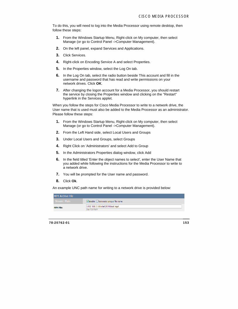
CISCO MEDIA PROCESSOR
78-20762-01 153
To do this, you will need to log into the Media Processor using remote desktop, then follow these steps:
1. From the Windows Startup Menu, Right-click on My computer, then select Manage (or go to Control Panel ->Computer Management).
2. On the left panel, expand Services and Applications.
3. Click Services.
4. Right-click on Encoding Service A and select Properties.
5. In the Properties window, select the Log On tab.
6. In the Log On tab, select the radio button beside This account and fill in the username and password that has read and write permissions on your network drives. Click OK.
7. After changing the logon account for a Media Processor, you should restart the service by closing the Properties window and clicking on the "Restart" hyperlink in the Services applet.
When you follow the steps for Cisco Media Processor to write to a network drive, the User name that is used must also be added to the Media Processor as an administrator. Please follow these steps:
1. From the Windows Startup Menu, Right-click on My computer, then select Manage (or go to Control Panel ->Computer Management).
2. From the Left Hand side, select Local Users and Groups
3. Under Local Users and Groups, select Groups
4. Right Click on 'Administrators' and select Add to Group
5. In the Administrators Properties dialog window, click Add
6. In the field titled 'Enter the object names to select', enter the User Name that you added while following the instructions for the Media Processor to write to a network drive.
7. You will be prompted for the User name and password.
8. Click Ok.
An example UNC path name for writing to a network drive is provided below:
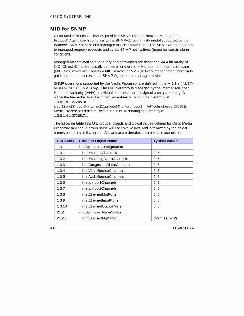
CISCO SYSTEMS, INC.
78-20762-01 154
MIB for SNMP Cisco Media Processor devices provide a SNMP (Simple Network Management Protocol) Agent which conforms to the SNMPv2c community model supported by the Windows SNMP service and managed via the SNMP Page. The SNMP Agent responds to managed property requests and sends SNMP notifications (traps) for certain alarm conditions.
Managed objects available for query and notification are described via a hierarchy of OID (Object ID) nodes, usually defined in one or more Management information base (MIB) files, which are used by a MIB Browser or NMS (network management system) to guide their interaction with the SNMP Agent on the managed device.
SNMP operations supported by the Media Processor are defined in the MIB file (INLET-VIDEO-ENCODER-MIB.my). The OID hierarchy is managed by the Internet Assigned Numbers Authority (IANA). Individual enterprises are assigned a unique starting ID within the hierarchy. Inlet Technologies entries fall within the hierarchy at: 1.3.6.1.4.1.27265 or [.iso(1).org(3).dod(6).internet(1).private(4).enterprises(1).inletTechnologies(27265)]. Media Processor entries fall within the Inlet Technologies hierarchy at 1.3.6.1.4.1.27265.71.
The following table lists OID groups, objects and typical values defined for Cisco Media Processor devices. A group name will not have values, and is followed by the object names belonging to that group. A lowercase n denotes a numerical placeholder.
OID Suffix Group or Object Name Typical Values
1.3 inletSpinnakerConfiguration
1.3.1 inletEncoderChannels 0..8
1.3.2 inletEncodingAlarmChannels 0..8
1.3.3 inletCongestionAlarmChannels 0..8
1.3.4 inletVideoSourceChannels 0..8
1.3.5 inletAudioSourceChannels 0..8
1.3.6 inletIpInput1Channels 0..8
1.3.7 inletIpInput2Channels 0..8
1.3.8 inletEthernetMgtPorts 0..8
1.3.9 inletEthernetInputPorts 0..8
1.3.10 inletEthernetOutputPorts 0..8
21.2 inletSpinnakerAlarmStates
21.2.1 inletEthernetMgtState alarm(1), ok(2)
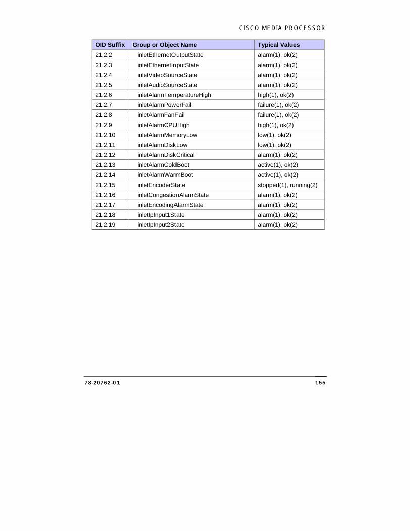
CISCO MEDIA PROCESSOR
78-20762-01 155
OID Suffix Group or Object Name Typical Values
21.2.2 inletEthernetOutputState alarm(1), ok(2)
21.2.3 inletEthernetInputState alarm(1), ok(2)
21.2.4 inletVideoSourceState alarm(1), ok(2)
21.2.5 inletAudioSourceState alarm(1), ok(2)
21.2.6 inletAlarmTemperatureHigh high(1), ok(2)
21.2.7 inletAlarmPowerFail failure(1), ok(2)
21.2.8 inletAlarmFanFail failure(1), ok(2)
21.2.9 inletAlarmCPUHigh high(1), ok(2)
21.2.10 inletAlarmMemoryLow low(1), ok(2)
21.2.11 inletAlarmDiskLow low(1), ok(2)
21.2.12 inletAlarmDiskCritical alarm(1), ok(2)
21.2.13 inletAlarmColdBoot active(1), ok(2)
21.2.14 inletAlarmWarmBoot active(1), ok(2)
21.2.15 inletEncoderState stopped(1), running(2)
21.2.16 inletCongestionAlarmState alarm(1), ok(2)
21.2.17 inletEncodingAlarmState alarm(1), ok(2)
21.2.18 inletIpInput1State alarm(1), ok(2)
21.2.19 inletIpInput2State alarm(1), ok(2)

CISCO SYSTEMS, INC.
78-20762-01 156
AAppppeennddiixx BB:: MMaannaaggiinngg UUsseerr AAccccoouunnttss
To add a new user account to Cisco Media Processor, perform the following steps:
1. Log in through Remote Desktop.
2. Right click My Computer, then select Manage.
3. In the console tree, click Users (choose System Tools, then Local Users and Groups, then Users).
4. On the Action menu, click New User.
5. Type the appropriate information in the dialog box.
6. Select or clear the check boxes for:
User must change password at next logon
User cannot change password
Password never expires
Account is disabled
7. Click Create, then click Close.
8. In the console tree, click Groups (choose System Tools, then Local Users and Groups, then Groups) and add the new user to either the Encoder Users group or the Encoder Administrators group. To do so, right click either group and select Add To Group. In the Properties dialog, click the Add… button. In the “Enter the object names to select” window, type the user name and then click OK.
BB
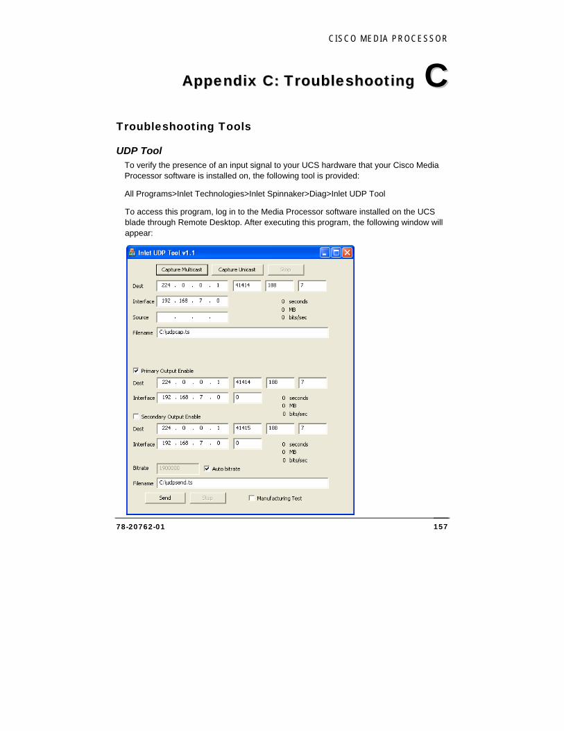
CISCO MEDIA PROCESSOR
78-20762-01 157
AAppppeennddiixx CC:: TTrroouubblleesshhoooottiinngg
Troubleshooting Tools
UDP Tool To verify the presence of an input signal to your UCS hardware that your Cisco Media Processor software is installed on, the following tool is provided:
All Programs>Inlet Technologies>Inlet Spinnaker>Diag>Inlet UDP Tool
To access this program, log in to the Media Processor software installed on the UCS blade through Remote Desktop. After executing this program, the following window will appear:
CC
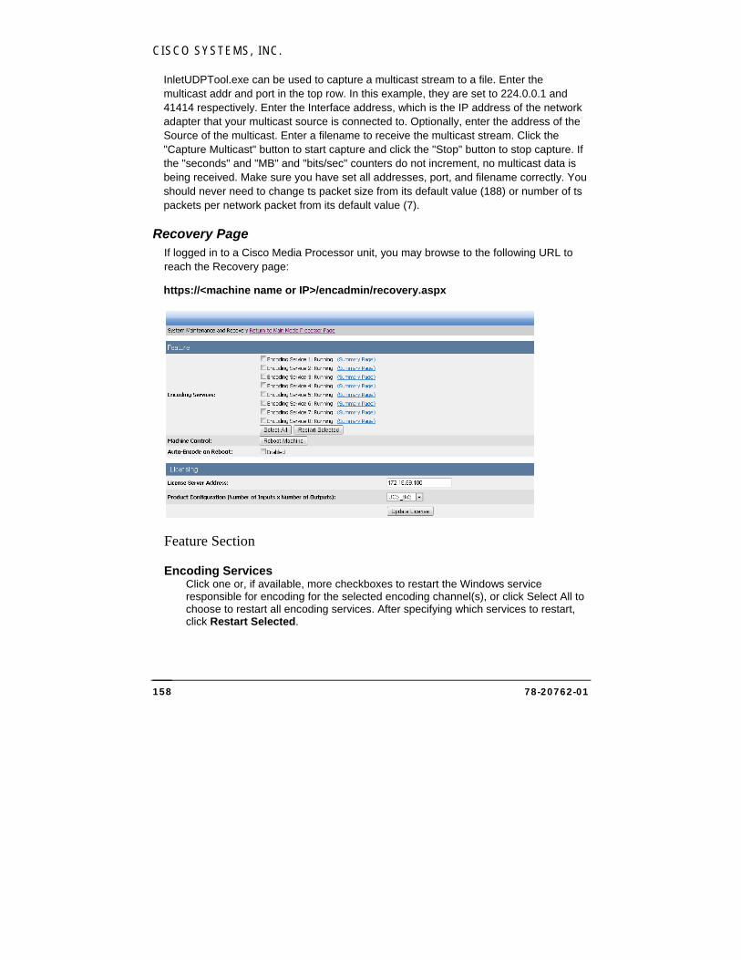
CISCO SYSTEMS, INC.
78-20762-01 158
InletUDPTool.exe can be used to capture a multicast stream to a file. Enter the multicast addr and port in the top row. In this example, they are set to 224.0.0.1 and 41414 respectively. Enter the Interface address, which is the IP address of the network adapter that your multicast source is connected to. Optionally, enter the address of the Source of the multicast. Enter a filename to receive the multicast stream. Click the "Capture Multicast" button to start capture and click the "Stop" button to stop capture. If the "seconds" and "MB" and "bits/sec" counters do not increment, no multicast data is being received. Make sure you have set all addresses, port, and filename correctly. You should never need to change ts packet size from its default value (188) or number of ts packets per network packet from its default value (7).
Recovery Page If logged in to a Cisco Media Processor unit, you may browse to the following URL to reach the Recovery page:
https://<machine name or IP>/encadmin/recovery.aspx
Feature Section
Encoding Services Click one or, if available, more checkboxes to restart the Windows service responsible for encoding for the selected encoding channel(s), or click Select All to choose to restart all encoding services. After specifying which services to restart, click Restart Selected.
CISCO MEDIA PROCESSOR
78-20762-01 159
NOTE:
Restarting the encoding service for channel 1 will restart encoding services for all channels in multi-channel units.
Machine Control Click the Reboot Machine button, then confirm, to reboot the UCS blade.
Auto-Encode on Reboot By default, the encoder will restart after a reboot or a restart of the encoding service if the encoder was running. Uncheck this box if you do not wish the encoder to auto-start in this situation.
Licensing Section The licensing section provides the ability to change the product configuration of the encoder.
License Server Address This field should display the license server address that was set up during installation. Verify the current license server address or provide an updated IP address.
Product Configuration Choose a licensed configuration from the dropdown. License configurations are labeled as number of inputs x number of outputs. For example a UCS_16x1 configuration will have 16 encoding channels with 1 stream out per channel, and a UCS_1x16 configuration will have one encoding channel with 16 available output streams.
Click Update License to change the product configuration. At this time the encoding services will restart. Upon startup, only the encoding services needed will start. The encoding service restart process may take several minutes.
CISCO SYSTEMS, INC.
78-20762-01 160
Troubleshooting Scenarios
Resolve Security Certificate Warning
Installing a Security Certificate Perform the following steps to install a valid, purchased security certificate:
NOTE:
Individual steps may vary, depending upon where the security certificate is purchased. Instructions from the chosen certificate company should supersede these steps when in conflict.
1. Open the Internet Services Manager (IIS):
Click Start, then click Control Panel.
Double Click "Administrative Tools".
Double Click "Internet Information Services (IIS) Manager".
2. Under Web Sites, right-click your Web site and select Properties.
3. Click the Directory Security tab.
4. Under Secure Communications, click Server Certificate. If this button is grayed, no security certificate has yet been imported into the machine. Follow these steps to import a certificate:
Click Start, then click Run, and enter “mmc.exe”.
Click File, then click Add/Remove Snap-in.
In the dialog, click Add, select “Certificates”, then click Add.
Select “Computer account” and click Next.
Select “Local Computer” and click Finish.
Click Close to close the “Add Standalone Snap-in” box.
Click OK to close the “Add/Remove Snap-in” box.
Expand the “Certificates (Local Computer)” tree.
Right click “Personal”, select “All Tasks”, and select “Import”.
Browse to find your certificate file.
Click Next, then click Finish.
Close the “Console1” window and save settings.

CISCO MEDIA PROCESSOR
78-20762-01 161
Return to the IIS management window and click Server Certificate in the “Default Web Site Properties” box.
5. The Web Site Certificate Wizard will open. Click Next.
6. Choose “Process the Pending Request and Install the Certificate”, then click Next.
Important: The pending request must match the response file. If you deleted the pending request in error you must generate a new CSR and replace this certificate.
7. Select the location of the certificate response file, and then click Next.
8. Read the summary screen to be sure that you are processing the correct certificate and then click Next. You see a confirmation screen.
9. After you read this information, click Next.
10. Restart the World Wide Web Publishing service:
Click Start.
Right click My Computer, then select “Manage”.
Double click “Services and Applications”.
Double click “Services”.
Right click World Wide Web Publishing, then select “Restart”.
Turning Off Https Alternately, you may choose to turn off https to resolve the security certificate warning message.
WARNING:
If you choose to turn off https, your password will not be encrypted.
Perform the following steps to turn off https for a Cisco Media Processor unit’s Web interface:
1. Rename the file C:\Inetpub\wwwroot\encadmin\bin\WebPageSecurity.dll to *.bak (or any backup extension).
2. Rename the file C:\Inetpub\wwwroot\encadmin\Web.Config to *.bak (or any backup extension).
CISCO SYSTEMS, INC.
78-20762-01 162
3. Restart the World Wide Web Publishing service:
Click Start.
Right click My Computer, then select “Manage”.
Double click “Services and Applications”.
Double click “Services”.
Right click World Wide Web Publishing, then select “Restart”.
After turning off https, use http to browse to the Web interface of your unit.
Problems streaming to a Limelight/Akamai Server If you receive the following error message:
[A] Code: 0x80000007 Msg: 'Invalid Akamai Server address for Streamname::h264stream2@4176' Value: [0][0x0]
First, make sure you have a valid IP address. If it is valid, it is possible that it is not using the correct Ethernet port.
If any one of the Ethernet ports is not authorized to send/receive external data, there might be an issue with streaming to the Limelight/Akamai server. To make sure that the authorized port is the port of choice, look in the Advanced Network Connection settings.
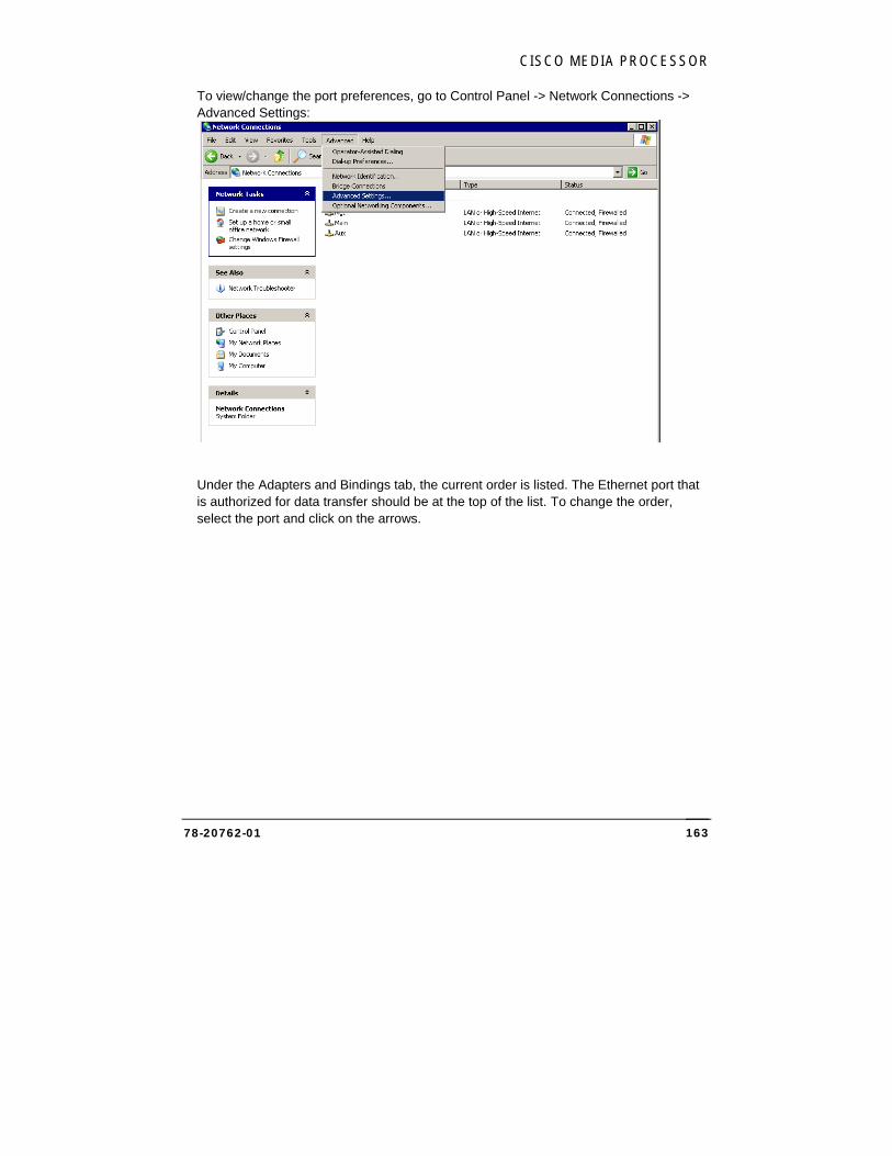
CISCO MEDIA PROCESSOR
78-20762-01 163
To view/change the port preferences, go to Control Panel -> Network Connections -> Advanced Settings:
Under the Adapters and Bindings tab, the current order is listed. The Ethernet port that is authorized for data transfer should be at the top of the list. To change the order, select the port and click on the arrows.
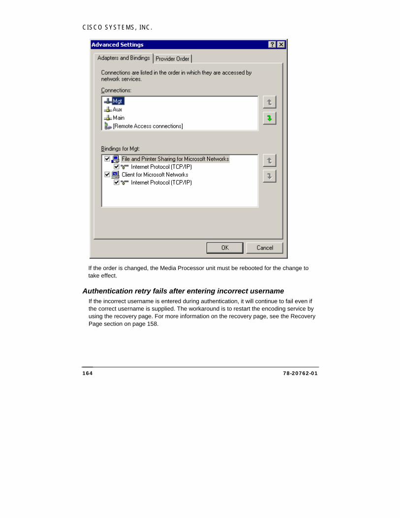
CISCO SYSTEMS, INC.
78-20762-01 164
If the order is changed, the Media Processor unit must be rebooted for the change to take effect.
Authentication retry fails after entering incorrect username If the incorrect username is entered during authentication, it will continue to fail even if the correct username is supplied. The workaround is to restart the encoding service by using the recovery page. For more information on the recovery page, see the Recovery Page section on page 158.
CISCO MEDIA PROCESSOR
78-20762-01 165
AAppppeennddiixx DD:: SSppeecciiffiiccaattiioonnss
The following specifications outlined below are for the Cisco Media Processor AS-Series Software, which are based upon the B200 M2 UCS Blade. Features may vary between models and some features may not be available at time of printing.
Inputs Video 2 x Ethernet (10/100/1000 Base-T) Standard Definition and High Definition H.264 over MPEG-2 TS MPEG-2 over MPEG-2 TS
Audio AC-3 Audio MPEG-1 Layer II MPEG-2/4 AAC
Formats and Codecs
Windows Media Smooth Streaming to IIS Server Windows Media 9 (WMV3) – Simple, Main Profiles VC-1 (WVC1) – Simple, Main, Advanced Profiles - Advanced profile for S-5000, S-7100, and S-8100 Windows Media Audio Windows Media Audio Professional VC-1 / Windows Media ASF File (.wmv) VC-1 – Push or Pull mode from encoder
Flash VP6 (available as an optional upgrade) On2 Live VP6 (Flash 8)
Cisco Media Processor uses On2 Flix® technology powered by On2 TrueMotion® video. © 1992-2011 On2 Technologies, Inc. All Rights Reserved. For more information, visit: http://www.on2.com.
MP3 audio
DD
CISCO SYSTEMS, INC.
78-20762-01 166
H.264 Flash Dynamic Flash streaming to Flash Media Server RTMP stream over TCP to Flash Media Server H.264/AVC – Baseline, Main, High profiles
Cisco Media Processor uses the MainConcept Filter Pack.
© 1999/2000-2012 MainConcept AG
AAC audio (Low Complexity, HE-AAC v1, HE-AAC v2) H.264 / AAC – MP4 archive file
H.264 iOS H.264/AVC – Baseline (iPhone), Baseline, Main (iPad) AAC audio (Low Complexity, HE-AAC v1, HE-AAC v2) Integrated iPhone segmenter – streams transport stream segments directly to Web server
H.264 Multicast MPEG-2 Transport Stream H.264/AVC – Baseline, Main, High Profiles AAC audio (Low Complexity, HE-AAC v1, HE-AAC v2) Standard or Adaptive Transport stream Archive can be started / stopped while the encoder is running
3GPP H.264/AVC – Baseline AAC audio (Low Complexity, HE-AAC v1, HE-AAC v2) H.263 Profile 0,3; Levels 10, 20, 30 AMR-NB Audio RTSP/RTP/SDP output Raw RTP output
Control Remote Web-based GUI LCD front panel Customizable encoding templates Local User Interface SNMP XML SOAP messaging service

CISCO MEDIA PROCESSOR
78-20762-01 167
Processing Pre-processing Scaling Cropping De-interlacing Inverse telecine Adaptive image filtering

CISCO SYSTEMS, INC.
78-20762-01 168
IInnddeexx
Advanced Compression, 43, 63, 74, 112
Alarms, 16 ASF Pull, 52 ASF Push, 51, 54, 59, 99, 139 Audio, 60 Bit Rate, 23, 24, 34, 37, 50, 51, 60,
65, 66, 69, 80, 90, 91, 96, 110, 113, 114
Buffer Size, 37, 60, 69, 110 Captioning, 48, 65, 76, 113 Connections, 5 Cropping, 39, 61, 69, 110 DHCP, 127 DNS, 127 Encoding Parameters, 36, 68, 109 Encoding statistics, 19, 25 Events, 117 Field Order, 30, 31 Flash, 60, 66, 81 FLV file, 82 Front Panel Display, 55, 82, 100,
119, 130 Interlace Encoding, 38 Interlacing, 40, 62, 71, 112 Key Frame Distance, 37, 60, 69, 110 Language, 50 License Update, 124 Logging, 126 Logging In, 11
MBR, 36 MP3, 65, 113 Network Adapter Configuration, 127 Open Captions, 48, 65, 77, 113 Output Resolution, 39, 40, 61, 69, 70,
110, 111 Packet Size, 38 Password, 12, 125 PlayReady, 104 Pre-Processing, 14, 40, 62, 71, 112 Presets, 26 Recovery Page, 158 Remote Authentication, 13 Remote Management, 10 Resizing, 39, 61, 69, 70, 110, 111 SAMI, 48, 77 Schedule Log, 118 Schedule reboot, 128 Security Certificate, 160, 161 Session Timeouts, 120, 133 SNMP Agent, 121 SNMP Traps, 122 Software Update, 118, 124 Software Version, 119 Transport Stream, 84 Troubleshooting, 157 TTL, 86 User Accounts, 12, 125, 156 VC-1, 37, 149, 152
II


