Cisco Systems, Inc. www.cisco.com Cisco has more than 200 offices worldwide. Addresses, phone numbers, and fax numbers are listed on the Cisco website at www.cisco.com/go/offices. Cisco ASA Legacy Feature Guide Released: April 24, 2014
Transcript
Cisco ASA Legacy Feature GuideReleased: April 24, 2014
Cisco Systems, Inc.www.cisco.com
Cisco has more than 200 offices worldwide. Addresses, phone numbers, and fax numbers are listed on the Cisco website at www.cisco.com/go/offices.
THE SPECIFICATIONS AND INFORMATION REGARDING THE PRODUCTS IN THIS MANUAL ARE SUBJECT TO CHANGE WITHOUT NOTICE. ALL STATEMENTS, INFORMATION, AND RECOMMENDATIONS IN THIS MANUAL ARE BELIEVED TO BE ACCURATE BUT ARE PRESENTED WITHOUT WARRANTY OF ANY KIND, EXPRESS OR IMPLIED. USERS MUST TAKE FULL RESPONSIBILITY FOR THEIR APPLICATION OF ANY PRODUCTS.
THE SOFTWARE LICENSE AND LIMITED WARRANTY FOR THE ACCOMPANYING PRODUCT ARE SET FORTH IN THE INFORMATION PACKET THAT SHIPPED WITH THE PRODUCT AND ARE INCORPORATED HEREIN BY THIS REFERENCE. IF YOU ARE UNABLE TO LOCATE THE SOFTWARE LICENSE OR LIMITED WARRANTY, CONTACT YOUR CISCO REPRESENTATIVE FOR A COPY.
NOTWITHSTANDING ANY OTHER WARRANTY HEREIN, ALL DOCUMENT FILES AND SOFTWARE OF THESE SUPPLIERS ARE PROVIDED “AS IS” WITH ALL FAULTS. CISCO AND THE ABOVE-NAMED SUPPLIERS DISCLAIM ALL WARRANTIES, EXPRESSED OR IMPLIED, INCLUDING, WITHOUT LIMITATION, THOSE OF MERCHANTABILITY, FITNESS FOR A PARTICULAR PURPOSE AND NONINFRINGEMENT OR ARISING FROM A COURSE OF DEALING, USAGE, OR TRADE PRACTICE.
IN NO EVENT SHALL CISCO OR ITS SUPPLIERS BE LIABLE FOR ANY INDIRECT, SPECIAL, CONSEQUENTIAL, OR INCIDENTAL DAMAGES, INCLUDING, WITHOUT LIMITATION, LOST PROFITS OR LOSS OR DAMAGE TO DATA ARISING OUT OF THE USE OR INABILITY TO USE THIS MANUAL, EVEN IF CISCO OR ITS SUPPLIERS HAVE BEEN ADVISED OF THE POSSIBILITY OF SUCH DAMAGES.
Cisco and the Cisco logo are trademarks or registered trademarks of Cisco and/or its affiliates in the U.S. and other countries. To view a list of Cisco trademarks, go to this URL: www.cisco.com/go/trademarks. Third-party trademarks mentioned are the property of their respective owners. The use of the word partner does not imply a partnership relationship between Cisco and any other company. (1110R)
Any Internet Protocol (IP) addresses and phone numbers used in this document are not intended to be actual addresses and phone numbers. Any examples, command display output, network topology diagrams, and other figures included in the document are shown for illustrative purposes only. Any use of actual IP addresses or phone numbers in illustrative content is unintentional and coincidental.
• Obtaining Documentation and Submitting a Service Request, page viii
Document ObjectivesThis guide includes supported legacy features for the Cisco ASA series. While you can use these features in your configuration, there may be better alternative features described in the configuration guides.
Related DocumentationFor more information, see Navigating the Cisco ASA Series Documentation at http://www.cisco.com/go/asadocs.
ConventionsThis document uses the following conventions:
Convention Indication
bold font Commands and keywords and user-entered text appear in bold font.
italic font Document titles, new or emphasized terms, and arguments for which you supply values are in italic font.
[ ] Elements in square brackets are optional.
{x | y | z } Required alternative keywords are grouped in braces and separated by vertical bars.
[ x | y | z ] Optional alternative keywords are grouped in brackets and separated by vertical bars.
Tip Means the following information will help you solve a problem.
Caution Means reader be careful. In this situation, you might perform an action that could result in equipment damage or loss of data.
Obtaining Documentation and Submitting a Service RequestFor information on obtaining documentation, using the Cisco Bug Search Tool (BST), submitting a service request, and gathering additional information, see What’s New in Cisco Product Documentation at: http://www.cisco.com/c/en/us/td/docs/general/whatsnew/whatsnew.html.
Subscribe to What’s New in Cisco Product Documentation, which lists all new and revised Cisco technical documentation, as an RSS feed and deliver content directly to your desktop using a reader application. The RSS feeds are a free service.
string A nonquoted set of characters. Do not use quotation marks around the string or the string will include the quotation marks.
courier font Terminal sessions and information the system displays appear in courier font.
courier bold font Commands and keywords and user-entered text appear in bold courier font.
courier italic font Arguments for which you supply values are in courier italic font.
< > Nonprinting characters such as passwords are in angle brackets.
[ ] Default responses to system prompts are in square brackets.
!, # An exclamation point (!) or a pound sign (#) at the beginning of a line of code indicates a comment line.
This chapter describes how to configure the ASA to route data, perform authentication, and redistribute routing information, using the Routing Information Protocol (RIP).
This chapter includes the following sections:
• Information About RIP, page 1-1
• Licensing Requirements for RIP, page 1-3
• Guidelines and Limitations, page 1-3
• Configuring RIP, page 1-4
• Restarting the RIP Process, page 1-14
• Monitoring RIP, page 1-14
• Configuration Example for RIP, page 1-15
• Feature History for RIP, page 1-16
Information About RIPThis section includes the following topics:
• Routing Update Process, page 1-2
• RIP Routing Metric, page 1-2
• RIP Stability Features, page 1-2
• RIP Timers, page 1-2
The Routing Information Protocol, or RIP, as it is more commonly called, is one of the most enduring of all routing protocols. RIP has four basic components: routing update process, RIP routing metrics, routing stability, and routing timers. Devices that support RIP send routing-update messages at regular intervals and when the network topology changes. These RIP packets include information about the networks that the devices can reach, as well as the number of routers or gateways that a packet must travel through to reach the destination address. RIP generates more traffic than OSPF, but is easier to configure.
RIP is a distance-vector routing protocol that uses hop count as the metric for path selection. When RIP is enabled on an interface, the interface exchanges RIP broadcasts with neighboring devices to dynamically learn about and advertise routes.
1-1Cisco ASA Legacy Feature Guide
Chapter 1 Configuring RIPInformation About RIP
The ASA supports both RIP Version 1 and RIP Version 2. RIP Version 1 does not send the subnet mask with the routing update. RIP Version 2 sends the subnet mask with the routing update and supports variable-length subnet masks. Additionally, RIP Version 2 supports neighbor authentication when routing updates are exchanged. This authentication ensures that the ASA receives reliable routing information from a trusted source.
RIP has advantages over static routes because the initial configuration is simple, and you do not need to update the configuration when the topology changes. The disadvantage to RIP is that there is more network and processing overhead than in static routing.
Routing Update ProcessRIP sends routing-update messages at regular intervals and when the network topology changes. When a router receives a routing update that includes changes to an entry, it updates its routing table to reflect the new route. The metric value for the path is increased by 1, and the sender is indicated as the next hop. RIP routers maintain only the best route (the route with the lowest metric value) to a destination. After updating its routing table, the router immediately begins transmitting routing updates to inform other network routers of the change. These updates are sent independently of the regularly scheduled updates that RIP routers send.
RIP Routing MetricRIP uses a single routing metric (hop count) to measure the distance between the source and a destination network. Each hop in a path from source to destination is assigned a hop count value, which is typically 1. When a router receives a routing update that contains a new or changed destination network entry, the router adds 1 to the metric value indicated in the update and enters the network in the routing table. The IP address of the sender is used as the next hop.
RIP Stability Features RIP prevents routing loops from continuing indefinitely by implementing a limit on the number of hops allowed in a path from the source to a destination. The maximum number of hops in a path is 15. If a router receives a routing update that contains a new or changed entry, and if increasing the metric value by 1 causes the metric to be infinity (that is, 16), the network destination is considered unreachable. The downside of this stability feature is that it limits the maximum diameter of a RIP network to less than 16 hops.
RIP includes a number of other stability features that are common to many routing protocols. These features are designed to provide stability despite potentially rapid changes in network topology. For example, RIP implements the split horizon and hold-down mechanisms to prevent incorrect routing information from being propagated.
RIP Timers RIP uses numerous timers to regulate its performance. These include a routing-update timer, a route-timeout timer, and a route-flush timer. The routing-update timer clocks the interval between periodic routing updates. Generally, it is set to 30 seconds, with a small random amount of time added whenever the timer is reset. This is done to help prevent congestion, which could result from all routers
1-2Cisco ASA Legacy Feature Guide
78-xxxxx-xx
Chapter 1 Configuring RIPLicensing Requirements for RIP
simultaneously attempting to update their neighbors. Each routing table entry has a route-timeout timer associated with it. When the route-timeout timer expires, the route is marked invalid but is retained in the table until the route-flush timer expires.
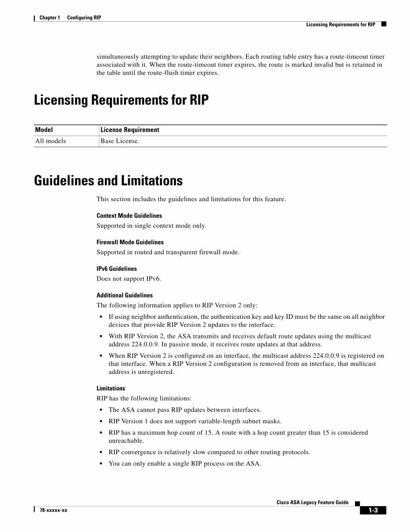
Licensing Requirements for RIP
Guidelines and LimitationsThis section includes the guidelines and limitations for this feature.
Context Mode Guidelines
Supported in single context mode only.
Firewall Mode Guidelines
Supported in routed and transparent firewall mode.
IPv6 Guidelines
Does not support IPv6.
Additional Guidelines
The following information applies to RIP Version 2 only:
• If using neighbor authentication, the authentication key and key ID must be the same on all neighbor devices that provide RIP Version 2 updates to the interface.
• With RIP Version 2, the ASA transmits and receives default route updates using the multicast address 224.0.0.9. In passive mode, it receives route updates at that address.
• When RIP Version 2 is configured on an interface, the multicast address 224.0.0.9 is registered on that interface. When a RIP Version 2 configuration is removed from an interface, that multicast address is unregistered.
Limitations
RIP has the following limitations:
• The ASA cannot pass RIP updates between interfaces.
• RIP Version 1 does not support variable-length subnet masks.
• RIP has a maximum hop count of 15. A route with a hop count greater than 15 is considered unreachable.
• RIP convergence is relatively slow compared to other routing protocols.
• You can only enable a single RIP process on the ASA.
Model License Requirement
All models Base License.
1-3Cisco ASA Legacy Feature Guide
78-xxxxx-xx
Chapter 1 Configuring RIPConfiguring RIP
Configuring RIP• Enabling RIP, page 1-4
• Configuring the RIP Version, page 1-5
• Configuring Passive Interfaces for RIP, page 1-6
• Configuring the RIP Send and Receive Version on an Interface, page 1-7
• Configuring Route Summarization, page 1-8
• Filtering Networks in RIP, page 1-9
• Redistributing Routes into the RIP Routing Process, page 1-10
• Enabling RIP Authentication, page 1-12
Enabling RIPYou can only enable one RIP routing process on the ASA. After you enable the RIP routing process, you must define the interfaces that will participate in that routing process using the network command.
Note If you want to redistribute a route by defining which of the routes from the specified routing protocol are allowed to be redistributed into the target routing process, you must first generate a default route.
Detailed Steps
CLI
ASDM
Step 1 In the main ASDM window, choose Configuration > Device Setup > Routing > RIP > Setup.
The main RIP Setup pane appears.
From this pane, you can perform the following tasks:
Command Purpose
Step 1 router rip
Example:ciscoasa(config)# router rip
Starts the RIP routing process and places you in router configuration mode.
Use the no router rip command to remove the entire RIP configuration that you have enabled. After the configuration is cleared, you must reconfigure RIP using the router rip command.
Step 2 network network_address
Example:ciscoasa(config-router)# network 10.0.0.0
Specifies the interfaces that will participate in the RIP routing process.
If an interface belongs to a network defined by this command, the interface will participate in the RIP routing process. If an interface does not belong to a network defined by this command, the interface will not send or receive RIP updates.
1-4Cisco ASA Legacy Feature Guide
78-xxxxx-xx
Chapter 1 Configuring RIPConfiguring RIP
• Enable Auto-summarization. See the “Configuring Route Summarization” section on page 1-8.
• Enable RIP version. See the “Configuring the RIP Version” section on page 1-5.
• Enable default information origination.
• Define an IP Address for a Network to Add. See the “Filtering Networks in RIP” section on page 1-9.
• Configure an Interface. See the “Configuring Passive Interfaces for RIP” section on page 1-6.
Step 2 Check the Enable RIP routing check box.
After the Enable RIP routing box has been checked, you can enable RIP on the ASA and configure global RIP protocol parameters. You can only enable a single RIP process on the ASA. When you enable RIP, it is enabled on all interfaces. Checking this check box also enables the other fields in this pane. Uncheck this check box to disable RIP routing on the ASA.
Step 3 Click Apply.
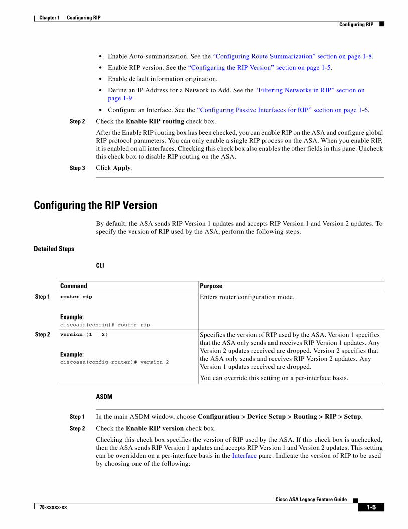
Configuring the RIP VersionBy default, the ASA sends RIP Version 1 updates and accepts RIP Version 1 and Version 2 updates. To specify the version of RIP used by the ASA, perform the following steps.
Detailed Steps
CLI
ASDM
Step 1 In the main ASDM window, choose Configuration > Device Setup > Routing > RIP > Setup.
Step 2 Check the Enable RIP version check box.
Checking this check box specifies the version of RIP used by the ASA. If this check box is unchecked, then the ASA sends RIP Version 1 updates and accepts RIP Version 1 and Version 2 updates. This setting can be overridden on a per-interface basis in the Interface pane. Indicate the version of RIP to be used by choosing one of the following:
Command Purpose
Step 1 router rip
Example:ciscoasa(config)# router rip
Enters router configuration mode.
Step 2 version {1 | 2}
Example:ciscoasa(config-router)# version 2
Specifies the version of RIP used by the ASA. Version 1 specifies that the ASA only sends and receives RIP Version 1 updates. Any Version 2 updates received are dropped. Version 2 specifies that the ASA only sends and receives RIP Version 2 updates. Any Version 1 updates received are dropped.
You can override this setting on a per-interface basis.
1-5Cisco ASA Legacy Feature Guide
78-xxxxx-xx
Chapter 1 Configuring RIPConfiguring RIP
• Version 1, which specifies that the ASA only sends and receives RIP Version 1 updates. Any Version 2 updates received are dropped.
• Version 2, which specifies that the ASA only sends and receives RIP Version 2 updates. Any Version 1 updates received are dropped.
Step 3 Click Apply.
Configuring Passive Interfaces for RIPIf you have an interface that you do not want to have participate in RIP routing, but that is attached to a network that you want advertised, you can configure the network (using the network command) that includes the network to which the interface is attached, and configure the passive interfaces (using the passive-interface command) to prevent that interface from using RIP. Additionally, you can specify the version of RIP that is used by the ASA for updates.
Detailed Steps
CLI
ASDM
Step 1 In the main ASDM window, choose Configuration > Device Setup > Routing > RIP > Setup.
Step 2 In the Passive Interfaces area, check the check box in the Passive column for those interfaces that you want to have operate in passive mode. The other interfaces will still send and receive RIP broadcasts.
Note Individual interfaces can be made passive only if the global passive mode is not enabled. Uncheck the Global Passive check box to make individual interfaces passive using the Passive Interfaces table.
Specifies an interface to operate in passive mode.
Using the default keyword causes all interfaces to operate in passive mode. Specifying an interface name sets only that interface to passive mode. In passive mode, RIP routing updates are accepted by, but not sent out of, the specified interface. You can enter this command for each interface that you want to set to passive mode.
1-6Cisco ASA Legacy Feature Guide
78-xxxxx-xx
Chapter 1 Configuring RIPConfiguring RIP
Configuring the RIP Send and Receive Version on an InterfaceYou can override the globally-set version of RIP that the ASA uses to send and receive RIP updates on a per-interface basis.
To configure the RIP version for sending and receiving updates, perform the following steps:
Detailed Steps
CLI
ASDM
Step 1 In the main ASDM window, choose Configuration > Device Setup > Routing > RIP > Setup.
The Edit RIP Interface Entry dialog box appears, which allows you to configure the interface-specific RIP settings for sending and receiving.
Step 4 In the Send Version area, check the Override global send version check box to specify the RIP version sent by the interface. Choose one of the following:
• Version 1
• Version 2
• Version 1 & 2
Unchecking this check box restores the global setting.
Step 5 In the Receive Version area, check the Override global receive version check box to specify the RIP version accepted by the interface. If a RIP updated from an unsupported version of RIP is received by the interface, it is dropped. Choose one of from the following:
• Version 1
• Version 2
• Version 1 & 2
Command Purpose
Step 1 interface phy_if
Example:ciscoasa(config)# interface phy_if
Enters interface configuration mode for the interface that you are configuring.
Step 2 rip send version {[1] [2]}
Example:ciscoasa(config-if)# rip send version 1
Specifies the version of RIP to use when sending RIP updates out of the interface.
Step 3 rip receive version {[1] [2]}
Example:ciscoasa(config-if)# rip receive version 2
Specifies the version of RIP advertisements permitted to be received by an interface. RIP updates received on the interface that do not match the allowed version are dropped.
1-7Cisco ASA Legacy Feature Guide
78-xxxxx-xx
Chapter 1 Configuring RIPConfiguring RIP
Unchecking this check box restores the global setting.
Step 6 Click Apply.
Configuring Route Summarization
Note RIP Version 1 always uses automatic route summarization. You cannot disable this feature for RIP Version 1. RIP Version 2 uses automatic route summarization by default.
The RIP routing process summarizes on network number boundaries, which can cause routing problems if you have noncontiguous networks.
For example, if you have a router with the networks 192.168.1.0, 192.168.2.0, and 192.168.3.0 connected to it, and those networks all participate in RIP, the RIP routing process creates the summary address 192.168.0.0 for those routes. If an additional router is added to the network with the networks 192.168.10.0 and 192.168.11.0, and those networks participate in RIP, they will also be summarized as 192.168.0.0. To prevent the possibility of traffic being routed to the wrong location, you should disable automatic route summarization on the routers that are creating conflicting summary addresses.
Because RIP Version 1 always uses automatic route summarization, and RIP Version 2 always uses automatic route summarization by default, when configuring automatic route summarization, you only need to disable it.
Detailed Steps
CLI
ASDM
Step 1 In the main ASDM window, choose Configuration > Device Setup > Routing > RIP > Setup.
Step 2 Check the Enable Auto-Summarization check box.
Uncheck this check box to disable automatic route summarization. Check this check box to reenable automatic route summarization. RIP Version 1 always uses automatic summarization. You cannot disable automatic route summarization for RIP Version 1. If you are using RIP Version 2, you can turn off
Command Purpose
Step 1 router rip
Example:ciscoasa(config)# router rip
Enables the RIP routing process and places you in router configuration mode.
Step 2 no auto-summarize
Example:ciscoasa(config-router):# no auto-summarize
Disables automatic route summarization.
1-8Cisco ASA Legacy Feature Guide
78-xxxxx-xx
Chapter 1 Configuring RIPConfiguring RIP
automatic route summarization by unchecking this check box. Disable automatic route summarization if you must perform routing between disconnected subnets. When automatic route summarization is disabled, subnets are advertised.
Step 3 Click Apply.
Filtering Networks in RIPTo filter the networks received in updates, perform the following steps:
Note Before you begin, you must create a standard ACL that permits the networks that you want the RIP process to allow in the routing table and denies the networks that you want the RIP process to discard.
Detailed Steps
CLI
ASDM
Step 1 In the main ASDM window, choose Configuration > Device Setup > Routing > RIP > Setup.
The Add or Edit Filter Rule dialog box appears, which allows you to create or edit filter rules that apply to all interfaces or to a specific interface.
Step 4 From the Direction drop-down list, choose the direction in which the filter should act.
Choosing In filters networks on incoming RIP updates. Additionally, only the Interface drop-down list is visible.
If you choose Out as the filter direction, skip to Step 8.
Step 5 Choose the Interface type from the Interface drop-down list.
Command Purpose
Step 1 router rip
Example:ciscoasa(config)# router rip
Enables the RIP routing process and places you in router configuration mode.
Example:ciscoasa(config-router)# distribute-list acl2 in [interface interface1]ciscoasa(config-router)# distribute-list acl3 out [connected]
Filters the networks sent in updates.
You can specify an interface to apply the filter to only those updates that are received or sent by that interface. You can enter this command for each interface to which you want to apply a filter. If you do not specify an interface name, the filter is applied to all RIP updates.
1-9Cisco ASA Legacy Feature Guide
78-xxxxx-xx
Chapter 1 Configuring RIPConfiguring RIP
This setting allows you to choose a specific interface for the filter rule, or you can choose the All Interfaces option to apply the filter to all interfaces.
Step 6 (Optional) Add a network rule by clicking Add.
The Network Rule dialog box appears.
Step 7 Choose the action from the Action drop-down list. The default is Permit.
• Choose Permit if the specified network is not filtered from incoming or outgoing RIP advertisements.
• Choose Deny if the specified network is to be filtered from incoming or outgoing RIP advertisements.
Step 8 Enter the IP address for the network being filtered, if different than what is displayed, in the IP Address field.
By default, the IP Address field displays the IP Address for the network being filtered.
Step 9 Enter the netmask, if different than what is displayed, in the Netmask field.
By default, the Netmask field displays the network mask applied to the IP address.
Step 10 Click OK.
Step 11 Choose Out to filter networks from outgoing RIP updates. Additionally, the Interface and Routing Process drop-down list becomes visible.
• Click the Interface radio button to choose a specific interface for the filter rule from the Interface drop-down list, or click the All Interfaces option to apply the filter to all interfaces.
• Click the Routing Process radio button to activate the Routing process drop-down list. Choose from the following routing process types:
– connected
– static
– OSPF
– RIP
– EIGRP
Redistributing Routes into the RIP Routing ProcessYou can redistribute routes from the OSPF, EIGRP, static, and connected routing processes into the RIP routing process.
Note Before you begin this procedure, you must create a route map to further define which routes from the specified routing protocol are redistributed in to the RIP routing process.
1-10Cisco ASA Legacy Feature Guide
78-xxxxx-xx
Chapter 1 Configuring RIPConfiguring RIP
Detailed Steps
CLI
ASDM
Step 1 In the main ASDM window, choose Configuration > Device Setup > Routing > RIP > Redistribution.
The Redistribution pane displays the routes that are being redistributed from other routing processes into the RIP routing process.
Step 2 Click Add or Edit.
If you clicked Add, the Add Route Redistribution dialog box allows you to add a new redistribution rule. If you clicked Edit, the Edit Route Redistribution dialog box allows you to change an existing rule.
Step 3 In the Protocol area, choose the routing protocol to redistribute into the RIP routing process:
Redistributes routes from an EIGRP routing process into the RIP routing process.
1-11Cisco ASA Legacy Feature Guide
78-xxxxx-xx
Chapter 1 Configuring RIPConfiguring RIP
• Connected, for directly connected networks.
• OSPF and OSPF ID, for routes discovered by the OSPF routing process. If you choose OSPF, you must also enter the OSPF process ID. Additionally, you can select the specific types of OSPF routes to redistribute from the Match area.
• EIGRP and EIGRP ID, for routes discovered by the EIGRP routing process. If you choose EIGRP, you must also specify the autonomous system number of the EIGRP routing process in the EIGRP ID field.
Step 4 In the Metrics area, check the Configure Metric Type check box to specify a metric for the redistributed routes. If not specified, the routes are assigned a default metric of 0. When the check box is checked, choose from one of the following available values:
• Transparent to cause the current route metric to be used.
• Value to assign a specific metric value. Valid values range from 0 to 16.
Step 5 In the Optional area, choose the route map from the Route Map drop-down list. This route map specifies the name of a route map that must be specified before the route can be redistributed into the RIP routing process. Click Manage to configure a specific route map.
Step 6 In the Match area, choose specific types of OSPF routes to redistribute by checking the check box next to the route type. This area is not active unless OSPF has been chosen in the Protocol area.
If you do not check any route types, Internal, External 1, and External 2 routes are redistributed by default. The Match types are:
• Internal, in which routes internal to the AS are redistributed.
• External 1, in which Type 1 routes external to the AS are redistributed.
• External 2, in which Type 2 routes external to the AS are redistributed.
• NSSA External 1, in which Type 1 routes external to an NSSA are redistributed.
• NSSA External 2, in which Type 2 routes external to an NSSA are redistributed.
Step 7 Click OK.
Enabling RIP Authentication
Note The ASA supports RIP message authentication for RIP Version 2 messages.
RIP route authentication provides MD5 authentication of routing updates from the RIP routing protocol. The MD5 keyed digest in each RIP packet prevents the introduction of unauthorized or false routing messages from unapproved sources.
RIP route authentication is configured on a per-interface basis. All RIP neighbors on interfaces configured for RIP message authentication must be configured with the same authentication mode and key for adjacencies to be established.
Note Before you can enable RIP route authentication, you must enable RIP.
The Edit RIP Interface Entry dialog box appears, which allows you to configure the interface-specific RIP settings.
Step 3 In the Authentication area, check the Enable Authentication check box to enable RIP authentication. Uncheck this check box to disable RIP authentication.
Step 4 In the Key field, enter the key used by the authentication method. This entry can include up to 16 characters.
Step 5 In the Key ID field, enter the key ID. Valid values range from 0 to 255.
Step 6 Choose the type of authentication mode that you want to use by clicking one of the following options:
• MD5 to use MD5 for RIP message authentication.
• cleartext to use cleartext for RIP message authentication (not recommended).
Step 7 Click Apply.
Command Purpose
Step 1 router rip as-num
Example:ciscoasa(config)# router rip 2
Creates the RIP routing process and enters router configuration mode for this RIP process.
The as-num argument is the autonomous system number of the RIP routing process.
Step 2 interface phy_if
Example:ciscoasa(config)# interface phy_if
Enters interface configuration mode for the interface on which you are configuring RIP message authentication.
Configures the authentication key used by the MD5 algorithm.
The key argument can include up to 16 characters.
The key-id argument is a number from 0 to 255.
1-13Cisco ASA Legacy Feature Guide
78-xxxxx-xx
Chapter 1 Configuring RIPRestarting the RIP Process
Restarting the RIP ProcessTo remove the entire RIP configuration, enter the following commandperform the following steps:
Detailed Steps
CLI
ASDM
Step 1 In the main ASDM window, choose Configuration > Device Setup > Routing > RIP > Setup.
Step 2 Click Reset.
Monitoring RIPWe recommend that you only use the debug commands to troubleshoot specific problems or during troubleshooting sessions with the Cisco TAC.
Debugging output is assigned high priority in the CPU process and can render the ASA unusable. It is best to use debug commands during periods of lower network traffic and fewer users. Debugging during these periods decreases the likelihood that increased debug command processing overhead will affect performance. For examples and descriptions of the command output, see the command reference.
To monitor or debug various RIP routing statistics, enter one of the following commands:
Removes the entire RIP configuration that you have enabled. After the configuration is cleared, you must reconfigure RIP again using the router rip command.
Command Purpose
Monitoring RIP Routing
show rip database Display the contents of the RIP routing database.
show running-config router rip
Displays the RIP commands.
show route cluster Displays additional route synchronization details for clustering.
Debugging RIP
debug rip events Displays RIP processing events.
debug rip database Displays RIP database events.
debug route cluster Enables RIB table replication trace messages to determine if the RIB is correctly synchronized to the slave units in clustering.
1-14Cisco ASA Legacy Feature Guide
78-xxxxx-xx
Chapter 1 Configuring RIPConfiguration Example for RIP
To monitor or display various RIP routing statistics in ASDM, perform the following steps:
Step 1 In the main ASDM window, choose Monitoring > Routing > Routes.
Step 2 From this pane, you can choose to monitor the following:
• IPv4
• IPv6
• Both
Configuration Example for RIPThe following example shows how to enable and configure RIP with various optional processes:
Step 11 In the Metric area, check the Configure Metric Type check box and choose Transparent Mode (default).
Step 12 In the Optional area, choose a route map from the Route Map drop-down list.
Step 13 Click Manage to configure a specific route map.
Step 14 Click OK.
1-15Cisco ASA Legacy Feature Guide
78-xxxxx-xx
Chapter 1 Configuring RIPFeature History for RIP
Feature History for RIPTable 1-1 lists each feature change and the platform release in which it was implemented. ASDM is backward-compatible with multiple platform releases, so the specific ASDM release in which support was added is not listed.
Table 1-1 Feature History for RIP
Feature Name Releases Feature Information
RIP support 7.0(1) Support was added for routing data, performing authentication, and redistributing and monitoring routing information using the Routing Information Protocol (RIP).
We introduced the route rip command.
We introduced the following screen: Configuration > Device Setup > Routing > RIP.
Clustering 9.0(1) For RIP, bulk synchronization, route synchronization, and layer 2 load balancing are supported in the clustering environment.
We introduced or modified the following commands: show route cluster, debug route cluster, show mfib cluster, debug mfib cluster.
1-16Cisco ASA Legacy Feature Guide
78-xxxxx-xx
78-xxxxx-xx
C H A P T E R 2
AAA Rules for Network Access
This chapter describes how to enable AAA (pronounced “triple A”) for network access.
• AAA Performance, page 2-1
• Licensing Requirements for AAA Rules, page 2-1
• Guidelines and Limitations, page 2-2
• Configuring Authentication for Network Access, page 2-2
• Configuring Authorization for Network Access, page 2-18
• Configuring Accounting for Network Access, page 2-27
• Using MAC Addresses to Exempt Traffic from Authentication and Authorization, page 2-30
• Feature History for AAA Rules, page 2-32
AAA PerformanceThe ASA uses “cut-through proxy” to significantly improve performance compared to a traditional proxy server. The performance of a traditional proxy server suffers because it analyzes every packet at the application layer of the OSI model. The ASA cut-through proxy challenges a user initially at the application layer and then authenticates with standard AAA servers or the local database. After the ASA authenticates the user, it shifts the session flow, and all traffic flows directly and quickly between the source and destination while maintaining session state information.
Licensing Requirements for AAA RulesThe following table shows the licensing requirements for this feature:
Model License Requirement
All models Base License.
2-1Cisco ASA Legacy Feature Guide
Chapter 2 AAA Rules for Network AccessGuidelines and Limitations
Guidelines and LimitationsThis section includes the guidelines and limitations for this feature.
Context Mode Guidelines
Supported in single and multiple context mode.
Firewall Mode Guidelines
Supported in routed and transparent firewall mode.
IPv6 Guidelines
Supports IPv6.
Additional Guidelines
In clustering, this feature is only supported on the master unit.
Configuring Authentication for Network AccessThis section includes the following topics:
• (ASDM) Enabling the Redirection Method of Authentication for HTTP and HTTPS, page 2-10
• Enabling Secure Authentication of Web Clients, page 2-11
• Authenticating Directly with the ASA, page 2-13
• (ASDM) Configuring the Authentication Proxy Limit, page 2-18
Information About AuthenticationThe ASA lets you configure network access authentication using AAA servers. This section includes the following topics:
• One-Time Authentication, page 2-2
• Applications Required to Receive an Authentication Challenge, page 2-3
• ASA Authentication Prompts, page 2-3
• AAA Prompts and Identity Firewall, page 2-4
• AAA Rules as a Backup Authentication Method, page 2-5
• Static PAT and HTTP, page 2-5
One-Time Authentication
A user at a given IP address only needs to authenticate one time for all rules and types, until the authentication session expires. (CLI: See the timeout uauth command in the command reference for timeout values.) (ASDM: See the Configuration > Firewall > Advanced > Global Timeouts pane for
2-2Cisco ASA Legacy Feature Guide
78-xxxxx-xx
Chapter 2 AAA Rules for Network AccessConfiguring Authentication for Network Access
timeout values.) For example, if you configure the ASA to authenticate Telnet and FTP, and a user first successfully authenticates for Telnet, then as long as the authentication session exists, the user does not also have to authenticate for FTP.
Applications Required to Receive an Authentication Challenge
Although you can configure the ASA to require authentication for network access to any protocol or service, users can authenticate directly with HTTP, HTTPS, Telnet, or FTP only. A user must first authenticate with one of these services before the ASA allows other traffic requiring authentication.
The authentication ports that the ASA supports for AAA are fixed as follows:
• Port 21 for FTP
• Port 23 for Telnet
• Port 80 for HTTP
• Port 443 for HTTPS
ASA Authentication Prompts
For Telnet and FTP, the ASA generates an authentication prompt.
For HTTP, the ASA uses basic HTTP authentication by default, and provides an authentication prompt. You can optionally configure the ASA to redirect users to an internal web page where they can enter their username and password (CLI: configured with the aaa authentication listener command) (ASDM: configured in the Configuration > Firewall > AAA Rules > Advanced > AAA Rules Advanced Options dialog box; see the “(ASDM) Enabling the Redirection Method of Authentication for HTTP and HTTPS” section on page 2-10).
For HTTPS, the ASA generates a custom login screen. You can optionally configure the ASA to redirect users to an internal web page where they can enter their username and password (CLI: configured with the aaa authentication listener command) (ASDM: configured in the Configuration > Firewall > AAA Rules > Advanced > AAA Rules Advanced Options dialog box; see the “(ASDM) Enabling the Redirection Method of Authentication for HTTP and HTTPS” section on page 2-10).
Redirection is an improvement over the basic method because it provides an improved user experience during authentication, and an identical user experience for HTTP and HTTPS in both Easy VPN and firewall modes. It also supports authentication directly with the ASA.
You might want to continue to use basic HTTP authentication for the following reasons:
• You do not want the ASA to open listening ports.
• You use NAT on a router and you do not want to create a translation rule for the web page served by the ASA.
• Basic HTTP authentication might work better with your network.
For example non-browser applications, as when a URL is embedded in e-mail, might be more compatible with basic authentication.
After you authenticate correctly, the ASA redirects you to your original destination. If the destination server also has its own authentication, the user enters another username and password. If you use basic HTTP authentication and need to enter another username and password for the destination server, then you need to configure virtual HTTP (CLI: the virtual http command) (ASDM: see the Configuration >Firewall > Advanced Options > Virtual Access pane).
2-3Cisco ASA Legacy Feature Guide
78-xxxxx-xx
Chapter 2 AAA Rules for Network AccessConfiguring Authentication for Network Access
Note If you use HTTP authentication, by default the username and password are sent from the client to the ASA in clear text; in addition, the username and password are sent on to the destination web server as well. See the “Enabling Secure Authentication of Web Clients” section on page 2-11 for information to secure your credentials.
For FTP, a user has the option of entering the ASA username followed by an at sign (@) and then the FTP username (name1@name2). For the password, the user enters the ASA password followed by an at sign (@) and then the FTP password (password1@password2). For example, enter the following text:
name> name1@name2password> password1@password2
This feature is useful when you have cascaded firewalls that require multiple logins. You can separate several names and passwords by multiple at signs (@).
AAA Prompts and Identity Firewall
In an enterprise, some users log into the network by using other authentication mechanisms, such as authenticating with a web portal (cut-through proxy). For example, users with a Mac and Linux client might log into a web portal (cut-through proxy). Therefore, you must configure the identity firewall to allow these types of authentication in connection with identity-based access policies.
Figure 2-1 shows a deployment to support a cut-through proxy authentication captive portal. Active Directory servers and the AD Agent are installed on the main site LAN. However, the identity firewall is configured to support authentication of clients that are not part of the Active Directory domain.
The ASA designates users logging in through a web portal (cut-through proxy) as belonging to the Active Directory domain with which they authenticated.
The ASA reports users logging in through a web portal (cut-through proxy) to the AD Agent, which distributes the user information to all registered ASA devices. In this case, the identity firewall can associate the users with their Active Directory domain. Specifically, the user identity-IP address mappings of authenticated users are forwarded to all ASA contexts that contain the input interface where packets are received and authenticated.
Users can log in by using HTTP/HTTPS, FTP, Telnet, or SSH. When users log in with these authentication methods, the following guidelines apply:
• For HTTP/HTTPS traffic, an authentication window appears for unauthenticated users.
Inside Enterprise
3345
48
ASA
AD ServersAD Agent
mktg.sample.com
10.1.1.2
WMI
LDAP
RADIUS
ADAgent
WAN / LAN
HTTP/HTTPS
Windows Clients(Domain Members)
Non-domain Member Clients
2-4Cisco ASA Legacy Feature Guide
78-xxxxx-xx
Chapter 2 AAA Rules for Network AccessConfiguring Authentication for Network Access
• For Telnet and FTP traffic, users must log in through the cut-through proxy server and again to the Telnet and FTP servers.
• A user can specify an Active Directory domain while providing login credentials (in the format, domain\username). The ASA automatically selects the associated AAA server group for the specified domain.
• If a user specifies an Active Directory domain while providing login credentials (in the format, domain\username), the ASA parses the domain and uses it to select an authentication server from the AAA servers that have been configured for the identity firewall. Only the username is passed to the AAA server.
• If the backslash (\) delimiter is not found in the login credentials, the ASA does not parse the domain and authentication is conducted with the AAA server that corresponds to the default domain configured for the identity firewall.
• If a default domain or a server group is not configured for that default domain, the ASA rejects the authentication.
• If the domain is not specified, the ASA selects the AAA server group for the default domain that is configured for the identity firewall.
AAA Rules as a Backup Authentication Method
An authentication rule (also known as “cut-through proxy”) controls network access based on the user. Because this function is very similar to an access rule plus an identity firewall, AAA rules can now be used as a backup method of authentication if a user AD login expires or a valid user has not yet logged into AD. For example, for any user without a valid login, you can trigger a AAA rule. To ensure that the AAA rule is only triggered for users that do not have valid logins, you can specify special usernames in the extended ACL that are used for the access rule and for the AAA rule: None (users without a valid login) and Any (users with a valid login). In the access rule, configure your policy as usual for users and groups, but then include a rule that permits all None users before deny any any; you must permit these users so they can later trigger a AAA rule. Then, configure a AAA rule that does not match Any users (these users are not subject to the AAA rule, and were handled already by the access rule), but matches all None users only to trigger AAA authentication for these users. After the user has successfully logged in via cut-through proxy, the traffic will flow normally again.
Static PAT and HTTP
For HTTP authentication, the ASA checks real ports when static PAT is configured. If it detects traffic destined for real port 80, regardless of the mapped port, the ASA intercepts the HTTP connection and enforces authentication.
For example, assume that outside TCP port 889 is translated to port 80 and that any relevant ACLs permit the traffic:
Then when users try to access 10.48.66.155 on port 889, the ASA intercepts the traffic and enforces HTTP authentication. Users see the HTTP authentication page in their web browsers before the ASA allows HTTP connection to complete.
If the local port is different than port 80, as in the following example:
Chapter 2 AAA Rules for Network AccessConfiguring Authentication for Network Access
nat (inside,outside) static 10.48.66.155 service tcp 111 889
Then users do not see the authentication page. Instead, the ASA sends an error message to the web browser, indicating that the user must be authenticated before using the requested service.
When a mapped address is used for static PAT, it is automatically placed into the dynamic PAT pool.
The second line ensures that all PAT bindings are accounted for.This accounting is necessary to avoid connection failure from port collision.
As the the mapped address is placed under dynamic PAT, any additional service that is to be accessed through the mapped address, must also be explicitly configured.
For example, the following is the correct configuration for three services through address 192.150.49.10. Additionally, the SMTP and HTTP services also reside at a host with the same address as the mapped address, 192.150.49.10.
Example:ciscoasa(config)# access-list MAIL_AUTH extended permit tcp any any eq smtp
Creates an ACL that identifies the source addresses and destination addresses of traffic that you want to authenticate. The syntax shown here is just an example.
If you specify identity firewall arguments in the ACL, then the following keywords in the ACL are specifically relevant to AAA rules. The keywords user-group any and user-group none can be specified to support cut-through proxy authentication.
• any—The ACL matches any IP addresses that has already been associated with any users.
• none—The ACL matches any IP addresses that has not been associated with any IP address.
Step 3 aaa authentication match acl_name interface_name server_group [user-identity]
Example:ciscoasa(config)# aaa authentication match MAIL_AUTH inside AuthOutbound
Configures authentication.
The acl_name argument is the name of the ACL that you created in Step 2. The interface_name argument is the name of the interface specified with the nameif command. The server_group argument is the AAA server group that you created in Step 1.
Note You can alternatively use the aaa authentication include command (which identifies traffic within the command). However, you cannot use both methods in the same configuration. See the command reference for more information.
The user-identity keyword matches authentication to the identity firewall.
2-7Cisco ASA Legacy Feature Guide
78-xxxxx-xx
Chapter 2 AAA Rules for Network AccessConfiguring Authentication for Network Access
ASDM
Step 1 In the Configuration > Firewall > AAA Rules pane, choose Add > Add Authentication Rule.
The Add Authentication Rule dialog box appears.
Step 2 In the Interface drop-down list, choose the interface for applying the rule.
Tip In the Action field, click one of the following, depending on the implementation:
• Authenticate
• Do not Authenticate
Step 3 In the AAA Server Group drop-down list, choose a server group. To add a AAA server to the server group, click Add Server.
If you chose LOCAL for the AAA server group, you can optionally add a new user by clicking Add User. See the .
Step 4 In the Source field, add the source IP address, or click the ellipsis (...) to choose an IP address already defined in ASDM.
Step 5 In the Destination field, enter the destination IP address, or click the ellipsis (...) to choose an IP address already defined in ASDM.
(Optional) Enables the redirection method of authentication for HTTP or HTTPS connections.
The interface_name argument is the interface on which you want to enable listening ports. The port portnum argument specifies the port number on which the ASA listens; the defaults are 80 (HTTP) and 443 (HTTPS).
You can use any port number and retain the same functionality, but be sure your direct authentication users know the port number; redirected traffic is sent to the correct port number automatically, but direct authenticators must specify the port number manually.
Enter this command separately for HTTP and for HTTPS.
Step 5 aaa local authentication attempts max-fail number
Example:ciscoasa(config)# aaa local authentication attempts max-fail 7
(Optional) Uses the local database for network access authentication and limits the number of consecutive failed login attempts that the ASA allows any given user account (with the exception of users with a privilege level of 15. This feature does not affect level 15 users). The number argument value is between 1 and 16.
Tip To clear the lockout status of a specific user or all users, use the clear aaa local user lockout command.
Command Purpose
2-8Cisco ASA Legacy Feature Guide
78-xxxxx-xx
Chapter 2 AAA Rules for Network AccessConfiguring Authentication for Network Access
Step 6 In the Service field, enter an IP service name or number for the destination service, or click the ellipsis (...) to choose a service.
Step 7 (Optional) In the Description field, enter a description.
Step 8 (Optional) Click More Options to do any of the following:
• To specify a source service for TCP or UDP, enter a TCP or UDP service in the Source Service field.
• The destination service and source service must be the same. Copy and paste the destination Service field to the Source Service field.
• To make the rule inactive, clear the Enable Rule check box.
You may not want to remove a rule, but instead turn it off.
• To set a time range for the rule, In the Time Range drop-down list, choose an existing time range. To add a new time range, click the ellipsis (...).
Step 9 Click OK.
The Add Authentication Rule dialog box closes and the rule appears in the AAA Rules table.
Step 10 Click Apply.
The changes are saved to the running configuration.
Examples
The following example authenticates all inside HTTP traffic and SMTP traffic:
ciscoasa(config)# aaa-server AuthOutbound protocol tacacs+ciscoasa(config-aaa-server-group)# exitciscoasa(config)# aaa-server AuthOutbound (inside) host 10.1.1.1ciscoasa(config-aaa-server-host)# key TACPlusUauthKeyciscoasa(config-aaa-server-host)# exitciscoasa(config)# access-list MAIL_AUTH extended permit tcp any any eq smtpciscoasa(config)# access-list MAIL_AUTH extended permit tcp any any eq wwwciscoasa(config)# aaa authentication match MAIL_AUTH inside AuthOutboundciscoasa(config)# aaa authentication listener http inside redirect
The following example authenticates Telnet traffic from the outside interface to a particular server (209.165.201.5):
The following example shows a typical cut-through proxy configuration to allow a user to log in through the ASA. In this example, the following conditions apply:
• The ASA IP address is 192.168.123.10.
• The Active Directory domain controller has the IP address 10.1.2.10.
• The end user client has the IP address 192.168.123.10 and uses HTTPS to log in through a web portal.
• The user is authenticated by the Active Directory domain controller via LDAP.
2-9Cisco ASA Legacy Feature Guide
78-xxxxx-xx
Chapter 2 AAA Rules for Network AccessConfiguring Authentication for Network Access
• The ASA uses the inside interface to connect to the Active Directory domain controller on the corporate network.
hostname(config)# access-list AUTH extended permit tcp any 192.168.123.10 255.255.255.0 eq httphostname(config)# access-list AUTH extended permit tcp any 192.168.123.10 255.255.255.0 eq httpshostname(config)# aaa-server LDAP protocol ldaphostname(config-aaa-server-group)# aaa-server LDAP (inside) host 10.1.2.10hostname(config-aaa-server-host)# ldap-base-dn DC=cisco,DC=comhostname(config-aaa-server-host)# ldap-group-base-dn DC=cisco,DC=comhostname(config-aaa-server-host)# ldap-scope subtreehostname(config-aaa-server-host)# ldap-login-dn cn=kao,OU=Employees,OU=Cisco Users,DC=cisco,DC=comhostname(config-aaa-server-host)# ldap-login-password *****hostname(config-aaa-server-host)# ldap-over-ssl enablehostname(config-aaa-server-host)# server-type microsofthostname(config-aaa-server-host)# aaa authentication match AUTH inside LDAPhostname(config)# hostname(config)# http server enablehostname(config)# http 0.0.0.0 0.0.0.0 insidehostname(config)# hostname(config)# auth-prompt prompt Enter Your Authentication hostname(config)# auth-prompt accept You are Good hostname(config)# auth-prompt reject Goodbye
In this example, the following guidelines apply:
• In access-list commands, you should configure permit user NONE rules before entering the access-list 100 ex deny any any command to allow unauthenticated incoming users to trigger AAA cut-through proxy.
• In access-list AUTH commands, permit user NONE rules specify that only unauthenticated users can trigger AAA cut-through proxy.
hostname(config)# access-list listenerAuth extended permit tcp any anyhostname(config)# aaa authentication match listenerAuth inside ldaphostname(config)# aaa authentication listener http inside port 8888hostname(config)# access-list 100 ex permit ip user SAMPLE\user1 any anyhostname(config)# access-list 100 ex deny ip user SAMPLE\user2 any anyhostname(config)# access-list 100 ex permit ip user NONE any any hostname(config)# access-list 100 ex deny any anyhostname(config)# access-group 100 in interface insidehostname(config)# aaa authenticate match 100 inside user-identity
The following example shows how you can use AAA rules plus identity firewall (cut-through proxy) to authenticate successfully:
hostname(config)# access-list 100 ex permit ip user CISCO\xyz any anyhostname(config)# access-list 100 ex deny ip user CISCO\abc any anyhostname(config)# access-list 100 ex permit ip user NONE any any hostname(config)# access-list 100 ex deny any any hostname(config)# access-group 100 in interface inside hostname(config)# access-list 200 ex permit user NONE any anyhostname(config)# aaa authenticate match 200 inside user-identity
(ASDM) Enabling the Redirection Method of Authentication for HTTP and HTTPS
This method of authentication enables HTTP(S) listening ports to authenticate network users. When you enable a listening port, the ASA serves an authentication page for direct connections and, by enabling redirection, for through traffic. This method also prevents the authentication credentials from continuing
2-10Cisco ASA Legacy Feature Guide
78-xxxxx-xx
Chapter 2 AAA Rules for Network AccessConfiguring Authentication for Network Access
to the destination server. See the “ASA Authentication Prompts” section on page 2-3 for more information about the redirection method compared to the basic method.
Detailed Steps
Step 1 In the Configuration > Firewall > AAA Rules pane, click Advanced.
The AAA Rules Advanced Options dialog box appears.
Step 2 Under Interactive Authentication, click Add.
The Add Interactive Authentication Entry dialog box appears.
Step 3 For the Protocol, choose either HTTP or HTTPS. You can enable both by repeating this procedure and creating two separate rules.
Step 4 In the Interface drop-down list, choose the interface on which you want to enable the listener.
Step 5 In the Port drop-down list, choose the port or enter a number.
This is the port that the ASA listens on for direct or redirected traffic; the defaults are 80 (HTTP) and 443 (HTTPS). You can use any port number and retain the same functionality, but be sure your direct authentication users know the port number; redirected traffic is sent to the correct port number automatically, but direct authenticators must specify the port number manually.
Step 6 (Optional) Check Redirect network users for authentication request.
This option redirects through traffic to an authentication web page served by the ASA. Without this option, only traffic directed to the ASA interface can access the authentication web pages.
Note If you enable the redirect option, you cannot also configure static PAT for the same interface where you translate the interface IP address and the same port that is used for the listener; NAT succeeds, but authentication fails.
Step 7 Click OK, and then click OK again to close the AAA Rules Advanced Options dialog box.
Step 8 Click Apply.
The changes are saved to the running configuration.
Enabling Secure Authentication of Web ClientsIf you use HTTP authentication, by default the username and password are sent from the client to the ASA in clear text; in addition, the username and password are sent to the destination web server as well.
The ASA provides the following methods for securing HTTP authentication:
• Enable the redirection method of authentication for HTTP—CLI: Use the aaa authentication listener command with the redirect keyword. ASDM: See the “(ASDM) Enabling the Redirection Method of Authentication for HTTP and HTTPS” section on page 2-10. This method prevents the authentication credentials from continuing to the destination server. See the “ASA Authentication Prompts” section on page 2-3 for more information about the redirection method compared to the basic method.
2-11Cisco ASA Legacy Feature Guide
78-xxxxx-xx
Chapter 2 AAA Rules for Network AccessConfiguring Authentication for Network Access
• Enable virtual HTTP—Virtual HTTP lets you authenticate separately with the ASA and with the HTTP server. Even if the HTTP server does not need a second authentication, this command achieves the effect of stripping the basic authentication credentials from the HTTP GET request. See the “Authenticating HTTP(S) Connections with a Virtual Server” section on page 2-13 for more information.
• Enable the exchange of usernames and passwords between a web client and the ASA with HTTPS—CLI: Use the aaa authentication secure-http-client command to enable the exchange of usernames and passwords between a web client and the ASA with HTTPS. ASDM: To enable the exchange of usernames and passwords between a web client and the ASA with HTTPS, perform the following steps:
a. In the Configuration > Firewall > AAA Rules pane, click Advanced. The AAA Rules Advanced Options dialog box appears.
b. Under Secure HTTP, click Enable Secure HTTP.
c. Click OK, and then click OK again to close the AAA Rules Advanced Options dialog box.
d. Click Apply.
This is the only method that protects credentials between the client and the ASA, as well as between the ASA and the destination server. You can use this method alone, or in conjunction with either of the other methods so you can maximize your security.
After enabling this feature, when a user requires authentication when using HTTP, the ASA redirects the HTTP user to an HTTPS prompt. After you authenticate correctly, the ASA redirects you to the original HTTP URL.
Secured, web-client authentication has the following limitations:
– A maximum of 64 concurrent HTTPS authentication sessions are allowed. If all 64 HTTPS authentication processes are running, a new connection requiring authentication will not succeed.
– When the uauth timeout is set to unlimited (CLI: the uauth timeout 0 command), HTTPS authentication might not work. If a browser initiates multiple TCP connections to load a web page after HTTPS authentication, the first connection is let through, but the subsequent connections trigger authentication. As a result, users are continuously presented with an authentication page, even if the correct username and password are entered each time. To work around this, set the uauth timeout to one second ( CLI: the timeout uauth 0:0:1 command) (ASDM: see the Configuration > Firewall > Advanced > Global Timeouts pane). However, this workaround opens a 1-second window of opportunity that might allow unauthenticated users to go through the firewall if they are coming from the same source IP address.
Because HTTPS authentication occurs on the SSL port 443, users must not configure an access rule to block traffic from the HTTP client to the HTTP server on port 443. Furthermore, if static PAT is configured for web traffic on port 80, it must also be configured for the SSL port.
– In the following example, the first set of commands configures static PAT for web traffic, and the second set of commands must be added to support the HTTPS authentication configuration:
Chapter 2 AAA Rules for Network AccessConfiguring Authentication for Network Access
Authenticating Directly with the ASA If you do not want to allow HTTP, HTTPS, Telnet, or FTP through the ASA but want to authenticate other types of traffic, you can authenticate with the ASA directly using HTTP, HTTPS, or Telnet.
• Authenticating HTTP(S) Connections with a Virtual Server, page 2-13
• Authenticating Telnet Connections with a Virtual Server, page 2-16
Authenticating HTTP(S) Connections with a Virtual Server
If you enabled the redirection method of HTTP and HTTPS authentication in the “Configuring Network Access Authentication” section on page 2-7, then you have also automatically enabled direct authentication.
When you use HTTP authentication on the ASA (see the“Configuring Network Access Authentication” section on page 2-7), the ASA uses basic HTTP authentication by default.
You can change the authentication method so that the ASA redirects HTTP connections to web pages generated by the ASA itself using the “(ASDM) Enabling the Redirection Method of Authentication for HTTP and HTTPS” section on page 2-10.
However, if you continue to use basic HTTP authentication, then you might need the virtual HTTP server when you have cascading HTTP authentications.
If the destination HTTP server requires authentication in addition to the ASA, then virtual HTTP lets you authenticate separately with the ASA (via a AAA server) and with the HTTP server. Without virtual HTTP, the same username and password that you used to authenticate with the ASA is sent to the HTTP server; you are not prompted separately for the HTTP server username and password. Assuming the username and password are not the same for the AAA and HTTP servers, then the HTTP authentication fails.
This feature redirects all HTTP connections that require AAA authentication to the virtual HTTP server on the ASA. The ASA prompts for the AAA server username and password. After the AAA server authenticates the user, the ASA redirects the HTTP connection back to the original server, but it does not include the AAA server username and password. Because the username and password are not included in the HTTP packet, the HTTP server prompts the user separately for the HTTP server username and password.
For inbound users (from lower security to higher security), you must also include the virtual HTTP address as a destination interface in the access rule applied to the source interface. Moreover, you must add a static NAT rule for the virtual HTTP IP address, even if NAT is not required. An identity NAT rule is typically used (where you translate the address to itself).
For outbound users, there is an explicit permit for traffic, but if you apply an access rule to an inside interface, be sure to allow access to the virtual HTTP address. A static NAT rule is not required.
Note Do not set the uauth timeout duration to 0 seconds when using virtual HTTP, because this setting prevents HTTP connections to the real web server.
You can authenticate directly with the ASA at the following URLs when you enable AAA for the interface:
(Optional) Enables the redirection method of authentication for HTTP or HTTPS connections.
The interface_name argument is the interface on which you want to enable listening ports. The port portnum argument specifies the port number on which the ASA listens; the defaults are 80 (HTTP) and 443 (HTTPS).
You can use any port number and retain the same functionality, but be sure your direct authentication users know the port number; redirected traffic is sent to the correct port number automatically, but direct authenticators must specify the port number manually.
Enter this command separately for HTTP and for HTTPS.
2-14Cisco ASA Legacy Feature Guide
78-xxxxx-xx
Chapter 2 AAA Rules for Network AccessConfiguring Authentication for Network Access
ASDM
Step 1 In the Configuration > Firewall > Advanced > Virtual Access > Virtual HTTP Server area, check the Enable check box.
Step 2 In the Virtual HTTP Server field, add the IP address of the virtual HTTP server.
Make sure this address is an unused address that is routed to the ASA. For example, if you perform NAT for inside addresses accessing an outside server, and you want to provide outside access to the virtual HTTP server, you can use one of the global NAT addresses for the virtual HTTP server address.
Step 3 (Optional) If you are using text-based browsers, where redirection does not happen automatically, check the Display redirection warning check box. This enables an alert to notify users when the HTTP connection is being redirected.
virtual http
Example:ciscoasa(config)# virtual http
Redirects all HTTP connections that require AAA authentication to the virtual HTTP server on the ASA. The ASA prompts for the AAA server username and password. After the AAA server authenticates the user, the ASA redirects the HTTP connection back to the original server, but it does not include the AAA server username and password. Because the username and password are not included in the HTTP packet, the HTTP server prompts the user separately for the HTTP server username and password.
For inbound users (from lower security to higher security), you must also include the virtual HTTP address as a destination interface in the ACL applied to the source interface. In addition, you must add a static NAT command for the virtual HTTP IP address, even if NAT is not required. An identity NAT command is typically used (where you translate the address to itself).
For outbound users, there is an explicit permit for traffic, but if you apply an ACL to an inside interface, be sure to allow access to the virtual HTTP address. A static statement is not required.
Note Do not set the timeout uauth command duration to 0 seconds when using the virtual http command, because this setting prevents HTTP connections to the actual web server.
You can authenticate directly with the ASA at the following URLs when you enable AAA for the interface:
Without virtual HTTP, the same username and password that you used to authenticate with the ASA are sent to the HTTP server; you are not prompted separately for the HTTP server username and password. Assuming the username and password are not the same for the AAA and HTTP servers, then the HTTP authentication fails.
Command Purpose
2-15Cisco ASA Legacy Feature Guide
78-xxxxx-xx
Chapter 2 AAA Rules for Network AccessConfiguring Authentication for Network Access
Step 4 Click Apply.
The virtual server is added and the changes are saved to the running configuration.
Authenticating Telnet Connections with a Virtual Server
Although you can configure network access authentication for any protocol or service (CLI: see the aaa authentication match or aaa authentication include command) (ASDM: see the “Configuring Network Access Authentication” section on page 2-7), you can authenticate directly with HTTP, Telnet, or FTP only. A user must first authenticate with one of these services before other traffic that requires authentication is allowed through. If you do not want to allow HTTP, Telnet, or FTP traffic through the ASA, but want to authenticate other types of traffic, you can configure virtual Telnet; the user Telnets to a given IP address configured on the ASA, and the ASA issues a Telnet prompt.
When an unauthenticated user connects to the virtual Telnet IP address, the user is challenged for a username and password, and then authenticated by the AAA server. After the user is authenticated, the message “Authentication Successful” appears. Then the user can successfully access other services that require authentication.
For inbound users (from lower security to higher security), you must also include the virtual Telnet address as a destination interface in the access rule applied to the source interface. In addition, you must add a static NAT rule for the virtual Telnet IP address, even if NAT is not required. An identity NAT rule is typically used (where you translate the address to itself).
For outbound users, there is an explicit permit for traffic, but if you apply an access rule to an inside interface, be sure to allow access to the virtual Telnet address. A static NAT rule is not required.
To log out from the ASA, reconnect to the virtual Telnet IP address; you are prompted to log out.
2-16Cisco ASA Legacy Feature Guide
78-xxxxx-xx
Chapter 2 AAA Rules for Network AccessConfiguring Authentication for Network Access
Detailed Steps
CLI
ASDM
Step 1 In the Configuration > Firewall > Advanced > Virtual Access > Virtual Telnet Server area, check the Enable check box.
Step 2 In the Virtual Telnet Server field, enter the IP address of the virtual Telnet server.
Make sure that this address is an unused address that is routed to the ASA. For example, if you perform NAT for inside addresses accessing an outside server, and you want to provide outside access to the virtual HTTP server, you can use one of the global NAT addresses for the virtual HTTP server address.
Step 3 Click Apply.
The virtual server is added and the changes are saved to the running configuration.
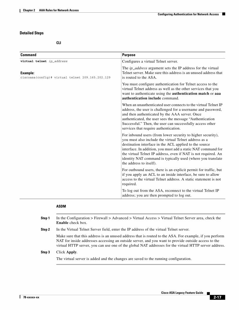
The ip_address argument sets the IP address for the virtual Telnet server. Make sure this address is an unused address that is routed to the ASA.
You must configure authentication for Telnet access to the virtual Telnet address as well as the other services that you want to authenticate using the authentication match or aaa authentication include command.
When an unauthenticated user connects to the virtual Telnet IP address, the user is challenged for a username and password, and then authenticated by the AAA server. Once authenticated, the user sees the message “Authentication Successful.” Then, the user can successfully access other services that require authentication.
For inbound users (from lower security to higher security), you must also include the virtual Telnet address as a destination interface in the ACL applied to the source interface. In addition, you must add a static NAT command for the virtual Telnet IP address, even if NAT is not required. An identity NAT command is typically used (where you translate the address to itself).
For outbound users, there is an explicit permit for traffic, but if you apply an ACL to an inside interface, be sure to allow access to the virtual Telnet address. A static statement is not required.
To log out from the ASA, reconnect to the virtual Telnet IP address; you are then prompted to log out.
2-17Cisco ASA Legacy Feature Guide
78-xxxxx-xx
Chapter 2 AAA Rules for Network AccessConfiguring Authorization for Network Access
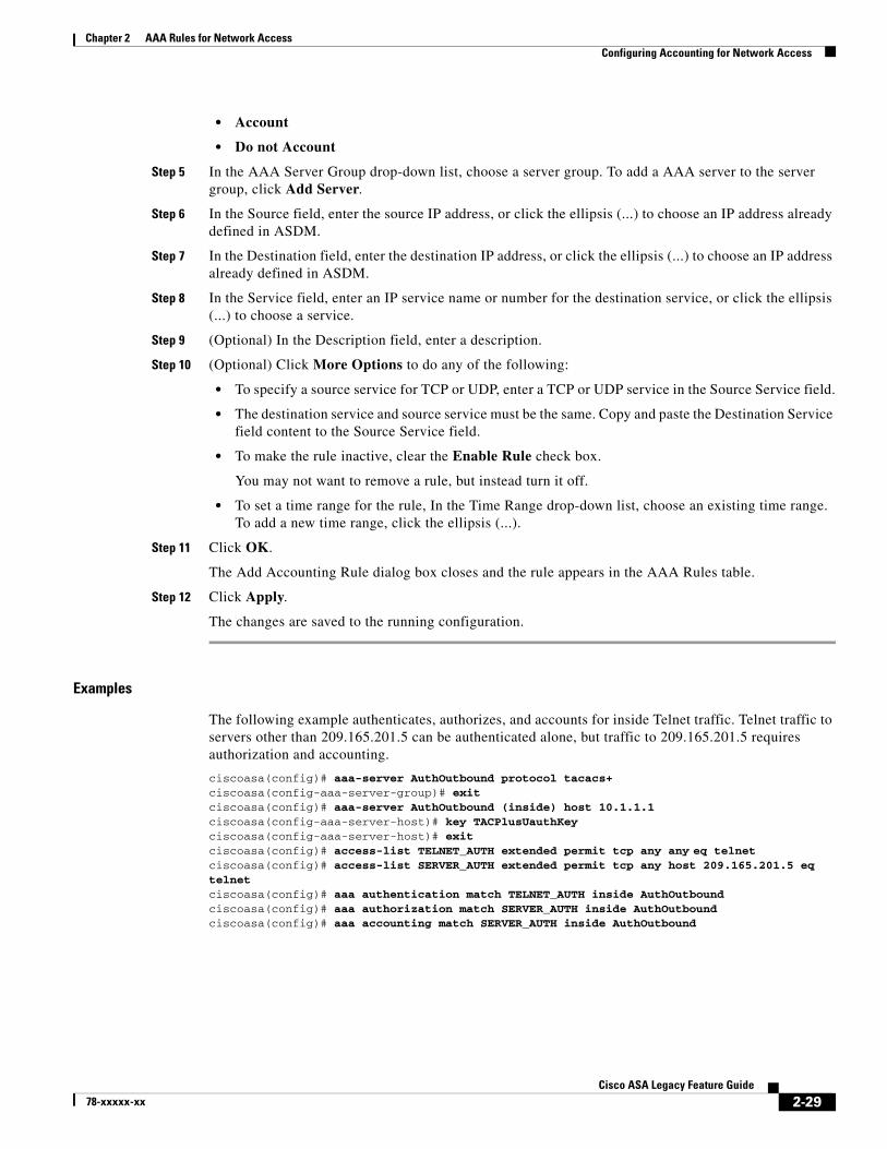
Examples
The following example shows how to enable virtual Telnet together with AAA authentication for other services:
ciscoasa(config)# virtual telnet 209.165.202.129ciscoasa(config)# access-list ACL-IN extended permit tcp any host 209.165.200.225 eq smtpciscoasa(config)# access-list ACL-IN remark This is the SMTP server on the insideciscoasa(config)# access-list ACL-IN extended permit tcp any host 209.165.202.129 eq telnetciscoasa(config)# access-list ACL-IN remark This is the virtual Telnet addressciscoasa(config)# access-group ACL-IN in interface outsideciscoasa(config)# network object obj-209.165.202.129-01ciscoasa(config-network-object)# host 209.165.202.129ciscoasa(config-network-object)# nat (inside,outside) static 209.165.202.129ciscoasa(config)# access-list AUTH extended permit tcp any host 209.165.200.225 eq smtpciscoasa(config)# access-list AUTH remark This is the SMTP server on the insideciscoasa(config)# access-list AUTH extended permit tcp any host 209.165.202.129 eq telnetciscoasa(config)# access-list AUTH remark This is the virtual Telnet addressciscoasa(config)# aaa authentication match AUTH outside tacacs+
(ASDM) Configuring the Authentication Proxy LimitYou can manually configure the uauth session limit by setting the maximum number of concurrent proxy connections allowed per user.
The AAA Rules Advanced Options dialog box appears.
Step 2 In the Proxy Limit area, check the Enable Proxy Limit check box.
Step 3 In the Proxy Limit field, enter the number of concurrent proxy connections allowed per user, from 1 to 128.
Step 4 Click OK, then click Apply.
The changes are saved to the running configuration.
Configuring Authorization for Network AccessAfter a user authenticates for a given connection, the ASA can use authorization to further control traffic from the user.
This section includes the following topics:
• Configuring TACACS+ Authorization, page 2-19
• Configuring RADIUS Authorization, page 2-22
2-18Cisco ASA Legacy Feature Guide
78-xxxxx-xx
Chapter 2 AAA Rules for Network AccessConfiguring Authorization for Network Access
Configuring TACACS+ AuthorizationYou can configure the ASA to perform network access authorization with TACACS+. CLI: You identify the traffic to be authorized by specifying ACLs that authorization rules must match. Alternatively, you can identify the traffic directly in authorization rules themselves.
Tip Using ACLs to identify traffic to be authorized can greatly reduced the number of authorization commands that you must enter. This is because each authorization rule that you enter can specify only one source and destination subnet and service, whereas an ACL can include many entries.
Authentication and authorization statements are independent; however, any unauthenticated traffic matched by an authorization rule will be denied. For authorization to succeed:
1. A user must first authenticate with the ASA.
Because a user at a given IP address only needs to authenticate one time for all rules and types, if the authentication session has not expired, authorization can occur even if the traffic is not matched by an authentication rule.
2. After a user authenticates, the ASA checks the authorization rules for matching traffic.
3. If the traffic matches the authorization rule, the ASA sends the username to the TACACS+ server.
4. The TACACS+ server responds to the ASA with a permit or a deny for that traffic, based on the user profile.
5. The ASA enforces the authorization rule in the response.
See the documentation for your TACACS+ server for information about configuring network access authorizations for a user.
Identifies your AAA servers. If you have already identified them, continue to the next step.
Step 2 access-list
Example:ciscoasa(config)# access-list MAIL_AUTH extended permit tcp any any eq smtp
Creates an ACL that identifies the source addresses and destination addresses of traffic you want to authenticate.
The permit ACEs mark matching traffic for authentication, while deny entries exclude matching traffic from authentication. Be sure to include the destination ports for either HTTP, HTTPS, Telnet, or FTP in the ACL, because the user must authenticate with one of these services before other services are allowed through the ASA.
2-19Cisco ASA Legacy Feature Guide
78-xxxxx-xx
Chapter 2 AAA Rules for Network AccessConfiguring Authorization for Network Access
Step 3 aaa authentication match acl_name interface_name server_group
Example:ciscoasa(config)# aaa authentication match MAIL_AUTH inside AuthOutbound
Configures authentication. The acl_name argument is the name of the ACL that you created in Step 2., The interface_name argument is the name of the interface specified with the nameif command, and the server_group argument is the AAA server group that you created in Step 1.
Note You can alternatively use the aaa authentication include command (which identifies traffic within the command). However, you cannot use both methods in the same configuration. See the command reference for more information.
(Optional) Enables the redirection method of authentication for HTTP or HTTPS connections.
The interface_name argument is the interface on which you want to enable listening ports. The port portnum argument specifies the port number on which the ASA listens; the defaults are 80 (HTTP) and 443 (HTTPS).
You can use any port number and retain the same functionality, but be sure your direct authentication users know the port number; redirected traffic is sent to the correct port number automatically, but direct authenticators must specify the port number manually.
Enter this command separately for HTTP and for HTTPS.
Step 5 aaa local authentication attempts max-fail number
Example:ciscoasa(config)# aaa local authentication attempts max-fail 7
(Optional) Uses the local database for network access authentication and limits the number of consecutive failed login attempts that the ASA allows any given user account (with the exception of users with a privilege level of 15. This feature does not affect level 15 users). The number argument value is between 1 and 16.
Tip To clear the lockout status of a specific user or all users, use the clear aaa local user lockout command.
Command Purpose
2-20Cisco ASA Legacy Feature Guide
78-xxxxx-xx
Chapter 2 AAA Rules for Network AccessConfiguring Authorization for Network Access
ASDM
Step 1 Enable authentication. For more information, see the “Configuring Network Access Authentication” section on page 2-7. If you have already enabled authentication, continue to the next step.
Step 2 In the Configuration > Firewall > AAA Rules pane, choose Add > Add Authorization Rule.
The Add Authorization Rule dialog box appears.
Step 3 In the Interface drop-down list, choose the interface for applying the rule.
Step 4 In the Action field, click one of the following, depending on the implementation:
• Authorize
• Do not Authorize
Step 5 In the AAA Server Group drop-down list, choose a server group. To add a AAA server to the server group, click Add Server.
Only TACACS+ servers are supported.
Step 6 In the Source field, add the source IP address, or click the ellipsis (...) to choose an IP address already defined in ASDM.
Step 6 access-list
Example:ciscoasa(config)# access-list TELNET_AUTH extended permit tcp any any eq telnet
Create an ACL that identifies the source addresses and destination addresses of traffic that you want to authorize.
The permit ACEs mark matching traffic for authorization, while deny entries exclude matching traffic from authorization. The ACL that you use for authorization matching should include rules that are equal to or a subset of the rules in the ACL used for authentication matching.
Note If you have configured authentication and want to authorize all the traffic being authenticated, you can use the same ACL that you created for use with the aaa authentication match command.
Step 7 aaa authorization match acl_name interface_name server_group
Example:ciscoasa(config)# aaa authentication match TELNET_AUTH inside AuthOutbound
Enables authorization.
The acl_name argument is the name of the ACL you created in Step 6, the interface_name argument is the name of the interface as specified with the nameif command or by default, and the server_group argument is the AAA server group that you created when you enabled authentication.
Note Alternatively, you can use the aaa authorization include command (which identifies traffic within the command) but you cannot use both methods in the same configuration. See the command reference for more information.
Command Purpose
2-21Cisco ASA Legacy Feature Guide
78-xxxxx-xx
Chapter 2 AAA Rules for Network AccessConfiguring Authorization for Network Access
Step 7 In the Destination field, enter the destination IP address, or click the ellipsis (...) to choose an IP address already defined in ASDM.
Step 8 In the Service field, enter an IP service name or number for the destination service, or click the ellipsis (...) to choose a service.
Step 9 (Optional) In the Description field, enter a description.
Step 10 (Optional) Click More Options to do any of the following:
• To specify a source service for TCP or UDP, enter a TCP or UDP service in the Source Service field.
• The destination service and source service must be the same. Copy and paste the Destination Service field content into the Source Service field.
• To make the rule inactive, clear the Enable Rule check box.
You may not want to remove a rule, but instead turn it off.
• To set a time range for the rule, in the Time Range drop-down list, choose an existing time range. To add a new time range, click the ellipsis (...).
Step 11 Click OK.
The Add Authorization Rule dialog box closes, and the rule appears in the AAA Rules table.
Step 12 Click Apply.
The changes are saved to the running configuration.
Examples
The following example authenticates and authorizes inside Telnet traffic. Telnet traffic to servers other than 209.165.201.5 can be authenticated alone, but traffic to 209.165.201.5 requires authorization.
ciscoasa(config)# access-list TELNET_AUTH extended permit tcp any any eq telnetciscoasa(config)# access-list SERVER_AUTH extended permit tcp any host 209.165.201.5 eq telnetciscoasa(config)# aaa-server AuthOutbound protocol tacacs+ciscoasa(config-aaa-server-group)# exitciscoasa(config)# aaa-server AuthOutbound (inside) host 10.1.1.1ciscoasa(config-aaa-server-host)# key TACPlusUauthKeyciscoasa(config-aaa-server-host)# exitciscoasa(config)# aaa authentication match TELNET_AUTH inside AuthOutboundciscoasa(config)# aaa authorization match SERVER_AUTH inside AuthOutbound
Configuring RADIUS AuthorizationWhen authentication succeeds, the RADIUS protocol returns user authorizations in the access-accept message sent by a RADIUS server. For more information about configuring authentication, see the “Configuring Network Access Authentication” section on page 2-7.
When you configure the ASA to authenticate users for network access, you are also implicitly enabling RADIUS authorizations; therefore, this section contains no information about configuring RADIUS authorization on the ASA. It does provide information about how the ASA handles ACL information received from RADIUS servers.
You can configure a RADIUS server to download an ACL to the ASA or an ACL name at the time of authentication. The user is authorized to do only what is permitted in the user-specific ACL.
2-22Cisco ASA Legacy Feature Guide
78-xxxxx-xx
Chapter 2 AAA Rules for Network AccessConfiguring Authorization for Network Access
Note If you have enabled the Per User Override Setting (ASDM: see the Configuration > Firewall > Access Rules > Advanced > Access Rules Advanced Options dialog box; CLI: see the access-group per-user-override keyword), be aware of the following effects on authorization by user-specific ACLs:
• Without the per-user-override feature, traffic for a user session must be permitted by both the interface ACL and the user-specific ACL.
• With the per-user-override feature, the user-specific ACL determines what is permitted.
This section includes the following topics:
• Configuring a RADIUS Server to Send Downloadable Access Control Lists, page 2-23
• Configuring a RADIUS Server to Download Per-User Access Control List Names, page 2-27
Configuring a RADIUS Server to Send Downloadable Access Control Lists
This section describes how to configure Cisco Secure ACS or a third-party RADIUS server and includes the following topics:
• About the Downloadable ACL Feature and Cisco Secure ACS, page 2-23
• Configuring Cisco Secure ACS for Downloadable ACLs, page 2-25
• Configuring Any RADIUS Server for Downloadable ACLs, page 2-25
• Converting Wildcard Netmask Expressions in Downloadable ACLs, page 2-26
About the Downloadable ACL Feature and Cisco Secure ACS
Downloadable ACLs is the most scalable means of using Cisco Secure ACS to provide the appropriate ACLs for each user. It provides the following capabilities:
• Unlimited ACL size—Downloadable ACLs are sent using as many RADIUS packets as required to transport the full ACL from Cisco Secure ACS to the ASA.
• Simplified and centralized management of ACLs—Downloadable ACLs enable you to write a set of ACLs once and apply it to many user or group profiles and distribute it to many ASAs.
This approach is most useful when you have very large ACL sets that you want to apply to more than one Cisco Secure ACS user or group; however, its ability to simplify Cisco Secure ACS user and group management makes it useful for ACLs of any size.
The ASA receives downloadable ACLs from Cisco Secure ACS using the following process:
1. The ASA sends a RADIUS authentication request packet for the user session.
2. If Cisco Secure ACS successfully authenticates the user, Cisco Secure ACS returns a RADIUS access-accept message that includes the internal name of the applicable downloadable ACL. The Cisco IOS cisco-av-pair RADIUS VSA (vendor 9, attribute 1) includes the following attribute-value pair to identify the downloadable ACL set:
ACS:CiscoSecure-Defined-ACL=acl-set-name
where acl-set-name is the internal name of the downloadable ACL, which is a combination of the name assigned to the ACL by the Cisco Secure ACS administrator and the date and time that the ACL was last modified.
2-23Cisco ASA Legacy Feature Guide
78-xxxxx-xx
Chapter 2 AAA Rules for Network AccessConfiguring Authorization for Network Access
3. The ASA examines the name of the downloadable ACL and determines if it has previously received the named downloadable ACL.
– If the ASA has previously received the named downloadable ACL, communication with Cisco Secure ACS is complete and the ASA applies the ACL to the user session. Because the name of the downloadable ACL includes the date and time that it was last modified, matching the name sent by Cisco Secure ACS to the name of an ACL previously downloaded means that the ASA has the most recent version of the downloadable ACL.
– If the ASA has not previously received the named downloadable ACL, it may have an out-of-date version of the ACL or it may not have downloaded any version of the ACL. In either case, the ASA issues a RADIUS authentication request using the downloadable ACL name as the username in the RADIUS request and a null password attribute. In a cisco-av-pair RADIUS VSA, the request also includes the following attribute-value pairs:
AAA:service=ip-admissionAAA:event=acl-download
In addition, the ASA signs the request with the Message-Authenticator attribute (IETF RADIUS attribute 80).
4. After receipt of a RADIUS authentication request that has a username attribute that includes the name of a downloadable ACL, Cisco Secure ACS authenticates the request by checking the Message-Authenticator attribute. If the Message-Authenticator attribute is missing or incorrect, Cisco Secure ACS ignores the request. The presence of the Message-Authenticator attribute prevents malicious use of a downloadable ACL name to gain unauthorized network access. The Message-Authenticator attribute and its use are defined in RFC 2869, RADIUS Extensions, available at http://www.ietf.org.
5. If the ACL required is less than approximately 4 KB in length, Cisco Secure ACS responds with an access-accept message that includes the ACL. The largest ACL that can fit in a single access-accept message is slightly less than 4 KB, because part of the message must be other required attributes.
Cisco Secure ACS sends the downloadable ACL in a cisco-av-pair RADIUS VSA. The ACL is formatted as a series of attribute-value pairs that each include an ACE and are numbered serially:
6. If the ACL required is more than approximately 4 KB in length, Cisco Secure ACS responds with an access-challenge message that includes a portion of the ACL, formatted as described previously, and a State attribute (IETF RADIUS attribute 24), which includes control data used by Cisco Secure ACS to track the progress of the download. Cisco Secure ACS fits as many complete attribute-value pairs into the cisco-av-pair RADIUS VSA as it can without exceeding the maximum RADIUS message size.
The ASA stores the portion of the ACL received and responds with another access-request message that includes the same attributes as the first request for the downloadable ACL, plus a copy of the State attribute received in the access-challenge message.
This process repeats until Cisco Secure ACS sends the last of the ACL in an access-accept message.
Chapter 2 AAA Rules for Network AccessConfiguring Authorization for Network Access
Configuring Cisco Secure ACS for Downloadable ACLs
You can configure downloadable ACLs on Cisco Secure ACS as a shared profile component and then assign the ACL to a group or to an individual user.
The ACL definition consists of one or more ASA commands that are similar to the extended access-list command (see command reference), except without the following prefix:
access-list acl_name extended
The following example is a downloadable ACL definition on Cisco Secure ACS version 3.3:
+--------------------------------------------+| Shared profile Components || || Downloadable IP ACLs Content || || Name: acs_ten_acl || || ACL Definitions || || permit tcp any host 10.0.0.254 || permit udp any host 10.0.0.254 || permit icmp any host 10.0.0.254 || permit tcp any host 10.0.0.253 || permit udp any host 10.0.0.253 || permit icmp any host 10.0.0.253 || permit tcp any host 10.0.0.252 || permit udp any host 10.0.0.252 || permit icmp any host 10.0.0.252 || permit ip any any |+--------------------------------------------+
For more information about creating downloadable ACLs and associating them with users, see the user guide for your version of Cisco Secure ACS.
On the ASA, the downloaded ACL has the following name:
#ACSACL#-ip-acl_name-number
The acl_name argument is the name that is defined on Cisco Secure ACS (acs_ten_acl in the preceding example), and number is a unique version ID generated by Cisco Secure ACS.
The downloaded ACL on the ASA consists of the following lines:
access-list #ACSACL#-ip-asa-acs_ten_acl-3b5385f7 permit tcp any host 10.0.0.254access-list #ACSACL#-ip-asa-acs_ten_acl-3b5385f7 permit udp any host 10.0.0.254access-list #ACSACL#-ip-asa-acs_ten_acl-3b5385f7 permit icmp any host 10.0.0.254access-list #ACSACL#-ip-asa-acs_ten_acl-3b5385f7 permit tcp any host 10.0.0.253access-list #ACSACL#-ip-asa-acs_ten_acl-3b5385f7 permit udp any host 10.0.0.253access-list #ACSACL#-ip-asa-acs_ten_acl-3b5385f7 permit icmp any host 10.0.0.253access-list #ACSACL#-ip-asa-acs_ten_acl-3b5385f7 permit tcp any host 10.0.0.252access-list #ACSACL#-ip-asa-acs_ten_acl-3b5385f7 permit udp any host 10.0.0.252access-list #ACSACL#-ip-asa-acs_ten_acl-3b5385f7 permit icmp any host 10.0.0.252access-list #ACSACL#-ip-asa-acs_ten_acl-3b5385f7 permit ip any any
Configuring Any RADIUS Server for Downloadable ACLs
You can configure any RADIUS server that supports Cisco IOS RADIUS VSAs to send user-specific ACLs to the ASA in a Cisco IOS RADIUS cisco-av-pair VSA (vendor 9, attribute 1).
In the cisco-av-pair VSA, configure one or more ACEs that are similar to the access-list extended command (see command reference), except that you replace the following command prefix:
2-25Cisco ASA Legacy Feature Guide
78-xxxxx-xx
Chapter 2 AAA Rules for Network AccessConfiguring Authorization for Network Access
access-list acl_name extended
with the following text:
ip:inacl#nnn=
The nnn argument is a number in the range from 0 to 999999999 that identifies the order of the command statement to be configured on the ASA. If this parameter is omitted, the sequence value is 0, and the order of the ACEs inside the cisco-av-pair RADIUS VSA is used.
The following example is an ACL definition as it should be configured for a cisco-av-pair VSA on a RADIUS server:
Downloaded ACLs have two spaces between the word “access-list” and the name. These spaces serve to differentiate a downloaded ACL from a local ACL. In this example, “79AD4A08” is a hash value generated by the ASA to help determine when ACL definitions have changed on the RADIUS server.
Converting Wildcard Netmask Expressions in Downloadable ACLs
If a RADIUS server provides downloadable ACLs to Cisco VPN 3000 series concentrators as well as to the ASA, you may need the ASA to convert wildcard netmask expressions to standard netmask expressions. This is because Cisco VPN 3000 series concentrators support wildcard netmask expressions, but the ASA only supports standard netmask expressions. Configuring the ASA to convert wildcard netmask expressions helps minimize the effects of these differences on how you configure downloadable ACLs on your RADIUS servers. Translation of wildcard netmask expressions means that downloadable ACLs written for Cisco VPN 3000 series concentrators can be used by the ASA without altering the configuration of the downloadable ACLs on the RADIUS server.
You configure ACL netmask conversion on a per-server basis: CLI: using the acl-netmask-convert command, available in the aaa-server configuration mode; when you add a server to a server group in the Configuration > Device Management > Users/AAA > AAA Server Groups > AAA Server Groups area.
2-26Cisco ASA Legacy Feature Guide
78-xxxxx-xx
Chapter 2 AAA Rules for Network AccessConfiguring Accounting for Network Access
Configuring a RADIUS Server to Download Per-User Access Control List Names
To download a name for an ACL that you already created on the ASA from the RADIUS server when a user authenticates, configure the IETF RADIUS filter-id attribute (attribute number 11) as follows:
filter-id=acl_name
Note In Cisco Secure ACS, the values for filter-id attributes are specified in boxes in the HTML interface, omitting filter-id= and entering only acl_name.
For information about making the filter-id attribute value unique per user, see the documentation for your RADIUS server.
Configuring Accounting for Network AccessThe ASA can send accounting information to a RADIUS or TACACS+ server about any TCP or UDP traffic that passes through the ASA. If that traffic is also authenticated, then the AAA server can maintain accounting information by username. If the traffic is not authenticated, the AAA server can maintain accounting information by IP address. Accounting information includes session start and stop times, username, the number of bytes that pass through the ASA for the session, the service used, and the duration of each session.
2-27Cisco ASA Legacy Feature Guide
78-xxxxx-xx
Chapter 2 AAA Rules for Network AccessConfiguring Accounting for Network Access
Detailed Steps
CLI
ASDM
Step 1 If you want the ASA to provide accounting data per user, you must enable authentication. For more information, see the “Configuring Network Access Authentication” section on page 2-7. If you want the ASA to provide accounting data per IP address, enabling authentication is not necessary and you can continue to the next step.
Step 2 In the Configuration > Firewall > AAA Rules pane, choose Add > Add Accounting Rule.
The Add Accounting Rule dialog box appears.
Step 3 In the Interface drop-down list, choose the interface for applying the rule.
Step 4 In the Action field, click one of the following, depending on the implementation:
Command Purpose
Step 1 access-list
Example:ciscoasa(config)# access-list TELNET_AUTH extended permit tcp any any eq telnet
If you want the ASA to provide accounting data per user, you must enable authentication. For more information, see the “Configuring Network Access Authentication” section on page 2-7. If you want the ASA to provide accounting data per IP address, enabling authentication is not necessary.
Creates an ACL that identifies the source addresses and destination addresses of traffic for which you want accounting data.
The permit ACEs mark matching traffic for accounting, while deny entries exclude matching traffic from accounting.
Note If you have configured authentication and want accounting data for all the traffic being authenticated, you can use the same ACL that you created for use with the aaa authentication match command.
Step 2 aaa accounting match acl_name interface_name server_group
Example:ciscoasa(config)# aaa accounting match SERVER_AUTH inside AuthOutbound
Enables accounting.
The acl_name argument is the ACL name set in the access-list command.
The interface_name argument is the interface name set in the nameif command.
The server_group argument is the server group name set in the aaa-server command.
Note Alternatively, you can use the aaa accounting include command (which identifies traffic within the command), but you cannot use both methods in the same configuration. See the command reference for more information.
2-28Cisco ASA Legacy Feature Guide
78-xxxxx-xx
Chapter 2 AAA Rules for Network AccessConfiguring Accounting for Network Access
• Account
• Do not Account
Step 5 In the AAA Server Group drop-down list, choose a server group. To add a AAA server to the server group, click Add Server.
Step 6 In the Source field, enter the source IP address, or click the ellipsis (...) to choose an IP address already defined in ASDM.
Step 7 In the Destination field, enter the destination IP address, or click the ellipsis (...) to choose an IP address already defined in ASDM.
Step 8 In the Service field, enter an IP service name or number for the destination service, or click the ellipsis (...) to choose a service.
Step 9 (Optional) In the Description field, enter a description.
Step 10 (Optional) Click More Options to do any of the following:
• To specify a source service for TCP or UDP, enter a TCP or UDP service in the Source Service field.
• The destination service and source service must be the same. Copy and paste the Destination Service field content to the Source Service field.
• To make the rule inactive, clear the Enable Rule check box.
You may not want to remove a rule, but instead turn it off.
• To set a time range for the rule, In the Time Range drop-down list, choose an existing time range. To add a new time range, click the ellipsis (...).
Step 11 Click OK.
The Add Accounting Rule dialog box closes and the rule appears in the AAA Rules table.
Step 12 Click Apply.
The changes are saved to the running configuration.
Examples
The following example authenticates, authorizes, and accounts for inside Telnet traffic. Telnet traffic to servers other than 209.165.201.5 can be authenticated alone, but traffic to 209.165.201.5 requires authorization and accounting.
ciscoasa(config)# aaa-server AuthOutbound protocol tacacs+ciscoasa(config-aaa-server-group)# exitciscoasa(config)# aaa-server AuthOutbound (inside) host 10.1.1.1ciscoasa(config-aaa-server-host)# key TACPlusUauthKeyciscoasa(config-aaa-server-host)# exitciscoasa(config)# access-list TELNET_AUTH extended permit tcp any any eq telnetciscoasa(config)# access-list SERVER_AUTH extended permit tcp any host 209.165.201.5 eq telnetciscoasa(config)# aaa authentication match TELNET_AUTH inside AuthOutboundciscoasa(config)# aaa authorization match SERVER_AUTH inside AuthOutboundciscoasa(config)# aaa accounting match SERVER_AUTH inside AuthOutbound
2-29Cisco ASA Legacy Feature Guide
78-xxxxx-xx
Chapter 2 AAA Rules for Network AccessUsing MAC Addresses to Exempt Traffic from Authentication and Authorization
Using MAC Addresses to Exempt Traffic from Authentication and Authorization
The ASA can exempt from authentication and authorization any traffic from specific MAC addresses. For example, if the ASA authenticates TCP traffic originating on a particular network, but you want to allow unauthenticated TCP connections from a specific server, you would use a MAC exempt rule to exempt from authentication and authorization any traffic from the server specified by the rule.
This feature is particularly useful to exempt devices such as IP phones that cannot respond to authentication prompts.
Guidelines
The order of entries matters, because the packet uses the first entry it matches, instead of a best match scenario. If you have a permit entry, and you want to deny an address that is allowed by the permit entry, be sure to enter the deny entry before the permit entry.
The id argument is the hexadecimal number that you assign to the MAC list. To group a set of MAC addresses, enter the mac-list command as many times as needed with the same ID value. Because you can only use one MAC list for AAA exemption, be sure that your MAC list includes all the MAC addresses that you want to exempt. You can create multiple MAC lists, but you can only use one at a time.
The mac argument specifies the source MAC address in 12-digit hexadecimal form; that is, nnnn.nnnn.nnnn.
The macmask argument specifies the portion of the MAC address that should be used for matching. For example, ffff.ffff.ffff matches the MAC address exactly. ffff.ffff.0000 matches only the first 8 digits.
Step 2 aaa mac-exempt match id
Example:ciscoasa(config)# aaa mac-exempt match 1
Exempts traffic for the MAC addresses specified in a particular MAC list.
The id argument is the string identifying the MAC list that includes the MAC addresses whose traffic is to be exempt from authentication and authorization.
You can only enter one instance of the aaa mac-exempt match command.
2-30Cisco ASA Legacy Feature Guide
78-xxxxx-xx
Chapter 2 AAA Rules for Network AccessUsing MAC Addresses to Exempt Traffic from Authentication and Authorization
ASDM
Step 1 In the Configuration > Firewall > AAA Rules pane, choose Add > Add MAC Exempt Rule.
The Add MAC Exempt Rule dialog box appears.
Step 2 In the Action drop-down list, click one of the following options, depending on the implementation:
• MAC Exempt
• No MAC Exempt
The MAC Exempt option allows traffic from the MAC address without having to authenticate or authorize. The No MAC Exempt option specifies a MAC address that is not exempt from authentication or authorization. You might need to add a deny entry if you permit a range of MAC addresses using a MAC address mask such as ffff.ffff.0000, and you want to force a MAC address in that range to be authenticated and authorized.
Step 3 In the MAC Address field, specify the source MAC address in 12-digit hexadecimal form; that is, nnnn.nnnn.nnnn.
Step 4 In the MAC Mask field, specify the portion of the MAC address that should be used for matching. For example, ffff.ffff.ffff matches the MAC address exactly. ffff.ffff.0000 matches only the first 8 digits.
Step 5 Click OK.
The Add MAC Exempt Rule dialog box closes and the rule appears in the AAA Rules table.
Step 6 Click Apply.
The changes are saved to the running configuration.
Examples
The following example bypasses authentication for a single MAC address:
ciscoasa(config)# mac-list abc permit 00a0.c95d.0282 ffff.ffff.ffffciscoasa(config)# aaa mac-exempt match abc
The following example bypasses authentication for all Cisco IP Phones, which have the hardware ID 0003.E3:
ciscoasa(config)# mac-list acd permit 0003.E300.0000 FFFF.FF00.0000ciscoasa(config)# aaa mac-exempt match acd
The following example bypasses authentication for a a group of MAC addresses except for 00a0.c95d.02b2. Enter the deny statement before the permit statement, because 00a0.c95d.02b2 matches the permit statement as well, and if it is first, the deny statement will never be matched.
Chapter 2 AAA Rules for Network AccessFeature History for AAA Rules
Feature History for AAA RulesTable 2-1 lists each feature change and the platform release in which it was implemented. ASDM is backwards-compatible with multiple platform releases, so the specific ASDM release in which support was added is not listed.
Table 2-1 Feature History for AAA Rules
Feature NamePlatform Releases Feature Information
AAA Rules 7.0(1) AAA Rules describe how to enable AAA for network access.
Authentication using Cut-Through Proxy 9.0(1) You can authenticate using AAA rules in conjunction with the Identity Firewall feature.
We modified the following command:
aaa authentication match.
2-32Cisco ASA Legacy Feature Guide
78-xxxxx-xx
78-xxxxx-xx
C H A P T E R 3
Using Protection Tools
This chapter describes some of the many tools available to protect your network and includes the following sections:
• Preventing IP Spoofing, page 3-1
• Configuring the Fragment Size, page 3-2
• (CLI) Blocking Unwanted Connections, page 3-3
• (ASDM) Configuring TCP Options, page 3-4
• Configuring IP Audit for Basic IPS Support, page 3-6
Preventing IP SpoofingThis section lets you enable Unicast Reverse Path Forwarding on an interface. Unicast RPF guards against IP spoofing (a packet uses an incorrect source IP address to obscure its true source) by ensuring that all packets have a source IP address that matches the correct source interface according to the routing table.
Normally, the ASA only looks at the destination address when determining where to forward the packet. Unicast RPF instructs the ASA to also look at the source address; this is why it is called Reverse Path Forwarding. For any traffic that you want to allow through the ASA, the ASA routing table must include a route back to the source address. See RFC 2267 for more information.
For outside traffic, for example, the ASA can use the default route to satisfy the Unicast RPF protection. If traffic enters from an outside interface, and the source address is not known to the routing table, the ASA uses the default route to correctly identify the outside interface as the source interface.
If traffic enters the outside interface from an address that is known to the routing table, but is associated with the inside interface, then the ASA drops the packet. Similarly, if traffic enters the inside interface from an unknown source address, the ASA drops the packet because the matching route (the default route) indicates the outside interface.
Unicast RPF is implemented as follows:
• ICMP packets have no session, so each packet is checked.
• UDP and TCP have sessions, so the initial packet requires a reverse route lookup. Subsequent packets arriving during the session are checked using an existing state maintained as part of the session. Non-initial packets are checked to ensure they arrived on the same interface used by the initial packet.
3-1Cisco ASA Legacy Feature Guide
Chapter 3 Using Protection ToolsConfiguring the Fragment Size
Detailed Steps
CLI
To enable Unicast RPF, enter the following command:
ciscoasa(config)# ip verify reverse-path interface interface_name
• Anti-Spoofing Enabled—Shows whether an interface has Unicast RPF enabled, Yes or No.
• Enable—Enables Unicast RPF for the selected interface.
• Disable—Disables Unicast RPF for the selected interface.
Configuring the Fragment SizeBy default, the ASA allows up to 24 fragments per IP packet, and up to 200 fragments awaiting reassembly. You might need to let fragments on your network if you have an application that routinely fragments packets, such as NFS over UDP. However, if you do not have an application that fragments traffic, we recommend that you do not allow fragments through the ASA. Fragmented packets are often used as DoS attacks.
Detailed Steps
CLI
To set disallow fragments, enter the following command:
ciscoasa(config)# fragment chain 1 [interface_name]
Enter an interface name if you want to prevent fragmentation on a specific interface. By default, this command applies to all interfaces.
ASDM
To modify the IP fragment database parameters of an interface, perform the following steps:
Step 1 Choose the Configuration > Firewall > Advanced > Fragment pane, choose the interface to change in the Fragment table, and click Edit.
The Edit Fragment dialog box appears.
Step 2 In the Size field, set the maximum number of packets that can be in the IP reassembly database waiting for reassembly. The default is 200.
Step 3 In the Chain field, set the maximum number of packets into which a full IP packet can be fragmented. The default is 24 packets.
Step 4 In the Timeout field, set the maximum number of seconds to wait for an entire fragmented packet to arrive.
3-2Cisco ASA Legacy Feature Guide
78-xxxxx-xx
Chapter 3 Using Protection Tools(CLI) Blocking Unwanted Connections
The timer starts after the first fragment of a packet arrives. If all fragments of the packet do not arrive by the number of seconds specified, all fragments of the packet that were already received will be discarded. The default is 5 seconds.
Step 5 Click OK.
Step 6 Click Apply.
Step 7 To view the fragment statistics, click Show Fragment. See the “(ASDM) Show Fragment” section on page 3-3 for more information.
(ASDM) Show FragmentThe Configuration > Properties > Fragment > Show Fragment pane displays the current IP fragment database statistics for each interface.
Fields
• Size—Display only. Displays the number of packets in the IP reassembly database waiting for reassembly. The default is 200.
• Chain—Display only. Displays the number of packets into which a full IP packet can be fragmented. The default is 24 packets.
• Timeout—Display only. Displays the number of seconds to wait for an entire fragmented packet to arrive. The timer starts after the first fragment of a packet arrives. If all fragments of the packet do not arrive by the number of seconds displayed, all fragments of the packet that were already received will be discarded. The default is 5 seconds.
• Threshold—Display only. Displays the IP packet threshold, or the limit after which no new chains can be created in the reassembly module.
• Queue—Display only. Displays the number of IP packets waiting in the queue for reassembly.
• Assembled—Display only. Displays the number of IP packets successfully reassembled.
• Fail—Display only. Displays the number of failed reassembly attempts.
• Overflow—Display only. Displays the number of IP packets in the overflow queue.
(CLI) Blocking Unwanted ConnectionsIf you know that a host is attempting to attack your network (for example, system log messages show an attack), then you can block (or shun) connections based on the source IP address. All existing connections and new connections are blocked until you remove the shun.
Note If you have an IPS that monitors traffic, such as an AIP SSM, then the IPS can shun connections automatically.
Detailed Steps
Step 1 If necessary, view information about the connection by entering the following command:
ciscoasa# show conn
3-3Cisco ASA Legacy Feature Guide
78-xxxxx-xx
Chapter 3 Using Protection Tools(ASDM) Configuring TCP Options
The ASA shows information about each connection, such as the following:
TCP out 64.101.68.161:4300 in 10.86.194.60:23 idle 0:00:00 bytes 1297 flags UIO
Step 2 To shun connections from the source IP address, enter the following command:
If you enter only the source IP address, then all future connections are shunned; existing connections remain active.
To drop an existing connection, as well as blocking future connections from the source IP address, enter the destination IP address, source and destination ports, and the protocol. By default, the protocol is 0 for IP. Note that specifying the additional parameters is a convenient way to also drop a specific current connection; the shun, however, remains in place for all future connections from the source IP address, regardless of destination parameters.
For multiple context mode, you can enter this command in the admin context, and by specifying a VLAN ID that is assigned to an interface in other contexts, you can shun the connection in other contexts.
Step 3 To remove the shun, enter the following command:
ciscoasa(config)# no shun src_ip [vlan vlan_id]
(ASDM) Configuring TCP OptionsThe Configuration > Firewall > Advanced > TCP Options pane lets you set parameters for TCP connections.
Fields
• Inbound and Outbound Reset—Sets whether to reset denied TCP connections for inbound and outbound traffic.
– Interface—Shows the interface name.
– Inbound Reset—Shows the interface reset setting for inbound TCP traffic, Yes or No. Enabling this setting causes the ASA to send TCP resets for all inbound TCP sessions that attempt to transit the ASA and are denied by the ASA based on ACLs or AAA settings. Traffic between same security level interfaces is also affected. When this option is not enabled, the ASA silently discards denied packets.
– Outbound Reset—Shows the interface reset setting for outbound TCP traffic, Yes or No. Enabling this setting causes the ASA to send TCP resets for all outbound TCP sessions that attempt to transit the ASA and are denied by the ASA based on ACLs or AAA settings. Traffic between same security level interfaces is also affected. When this option is not enabled, the ASA silently discards denied packets.
– Edit—Sets the inbound and outbound reset settings for the interface.
• Other Options—Sets additional TCP options.
– Send Reset Reply for Denied Outside TCP Packets—Enables resets for TCP packets that terminate at the least secure interface and are denied by the ASA based on ACLs or AAA settings. When this option is not enabled, the ASA silently discards denied packets. If you enable Inbound Resets for the least secure interface (see TCP Reset Settings), then you do not
3-4Cisco ASA Legacy Feature Guide
78-xxxxx-xx
Chapter 3 Using Protection Tools(ASDM) Configuring TCP Options
also have to enable this setting; Inbound Resets handle to-the-ASA traffic as well as through the ASA traffic.
– Force Maximum Segment Size for TCP—Sets the maximum TCP segment size in bytes, between 48 and any maximum number. The default value is 1380 bytes. You can disable this feature by setting the bytes to 0. Both the host and the server can set the maximum segment size when they first establish a connection. If either maximum exceeds the value you set here, then the ASA overrides the maximum and inserts the value you set. For example, if you set a maximum size of 1200 bytes, when a host requests a maximum size of 1300 bytes, then the ASA alters the packet to request 1200 bytes.
– Force Minimum Segment Size for TCP—Overrides the maximum segment size to be no less than the number of bytes you set, between 48 and any maximum number. This feature is disabled by default (set to 0). Both the host and the server can set the maximum segment size when they first establish a connection. If either maximum is less than the value you set for the Force Minimum Segment Size for TCP Proxy field, then the ASA overrides the maximum and inserts the “minimum” value you set (the minimum value is actually the smallest maximum allowed). For example, if you set a minimum size of 400 bytes, if a host requests a maximum value of 300 bytes, then the ASA alters the packet to request 400 bytes.
– Force TCP Connection to Linger in TIME_WAIT State for at Least 15 Seconds—Forces each TCP connection to linger in a shortened TIME_WAIT state of at least 15 seconds after the final normal TCP close-down sequence. You might want to use this feature if an end host application default TCP terminating sequence is a simultaneous close. The default behavior of the ASA is to track the shutdown sequence and release the connection after two FINs and the ACK of the last FIN segment. This quick release heuristic enables the ASA to sustain a high connection rate, based on the most common closing sequence, known as the normal close sequence. However, in a simultaneous close, both ends of the transaction initiate the closing sequence, as opposed to the normal close sequence where one end closes and the other end acknowledges prior to initiating its own closing sequence (see RFC 793). Thus, in a simultaneous close, the quick release forces one side of the connection to linger in the CLOSING state. Having many sockets in the CLOSING state can degrade the performance of an end host. For example, some WinSock mainframe clients are known to exhibit this behavior and degrade the performance of the mainframe server. Using this feature creates a window for the simultaneous close down sequence to complete.
TCP Reset SettingsThe Configuration > Firewall > Advanced > TCP Options > TCP Reset Settings dialog box sets the inbound and outbound reset settings for an interface.
Fields
• Send Reset Reply for Denied Inbound TCP Packets—Sends TCP resets for all inbound TCP sessions that attempt to transit the ASA and are denied by the ASA based on ACLs or AAA settings. Traffic between same security level interfaces is also affected. When this option is not enabled, the ASA silently discards denied packets.
You might want to explicitly send resets for inbound traffic if you need to reset identity request (IDENT) connections. When you send a TCP RST (reset flag in the TCP header) to the denied host, the RST stops the incoming IDENT process so that you do not have to wait for IDENT to time out. Waiting for IDENT to time out can cause traffic to slow because outside hosts keep retransmitting the SYN until the IDENT times out, so the service resetinbound command might improve performance.
3-5Cisco ASA Legacy Feature Guide
78-xxxxx-xx
Chapter 3 Using Protection ToolsConfiguring IP Audit for Basic IPS Support
• Send Reset Reply for Denied Outbound TCP Packets—Sends TCP resets for all outbound TCP sessions that attempt to transit the ASA and are denied by the ASA based on ACLs or AAA settings. Traffic between same security level interfaces is also affected. When this option is not enabled, the ASA silently discards denied packets. This option is enabled by default. You might want to disable outbound resets to reduce the CPU load during traffic storms, for example.
Configuring IP Audit for Basic IPS SupportThe IP audit feature provides basic IPS support for the ASA that does not have an AIP SSM. It supports a basic list of signatures, and you can configure the ASA to perform one or more actions on traffic that matches a signature.
This section includes the following topics:
• (CLI) Configuring IP Audit, page 3-6
• (ASDM) IP Audit Policy, page 3-7
• (ASDM) Add/Edit IP Audit Policy Configuration, page 3-7
• (ASDM) IP Audit Signatures, page 3-8
• IP Audit Signature List, page 3-8
(CLI) Configuring IP AuditTo enable IP audit, perform the following steps:
Step 1 To define an IP audit policy for informational signatures, enter the following command:
ciscoasa(config)# ip audit name name info [action [alarm] [drop] [reset]]
Where alarm generates a system message showing that a packet matched a signature, drop drops the packet, and reset drops the packet and closes the connection. If you do not define an action, then the default action is to generate an alarm.
Step 2 To define an IP audit policy for attack signatures, enter the following command:
ciscoasa(config)# ip audit name name attack [action [alarm] [drop] [reset]]
Where alarm generates a system message showing that a packet matched a signature, drop drops the packet, and reset drops the packet and closes the connection. If you do not define an action, then the default action is to generate an alarm.
Step 3 To assign the policy to an interface, enter the following command:
ip audit interface interface_name policy_name
Step 4 To disable signatures, or for more information about signatures, see the ip audit signature command in the command reference.
3-6Cisco ASA Legacy Feature Guide
78-xxxxx-xx
Chapter 3 Using Protection ToolsConfiguring IP Audit for Basic IPS Support
(ASDM) IP Audit PolicyThe Configuration > Firewall > Advanced > IP Audit > IP Audit Policy pane lets you add audit policies and assign them to interfaces. You can assign an attack policy and an informational policy to each interface. The attack policy determines the action to take with packets that match an attack signature; the packet might be part of an attack on your network, such as a DoS attack. The informational policy determines the action to take with packets that match an informational signature; the packet is not currently attacking your network, but could be part of an information-gathering activity, such as a port sweep. For a complete list of signatures, see the IP Audit Signature List.
Fields
• Name—Shows the names of the defined IP audit policies. Although the default actions for a named policy are listed in this table (“--Default Action--”), they are not named policies that you can assign to an interface. Default actions are used by named policies if you do not set an action for the policy. You can modify the default actions by selecting them and clicking the Edit button.
• Type—Shows the policy type, either Attack or Info.
• Action—Shows the actions taken against packets that match the policy, Alarm, Drop, and/or Reset. Multiple actions can be listed.
• Add—Adds a new IP audit policy.
• Edit—Edits an IP audit policy or the default actions.
• Delete—Deletes an IP audit policy. You cannot delete a default action.
• Policy-to-Interface Mappings—Assigns an attack and informational policy to each interface.
– Interface—Shows the interface name.
– Attack Policy—Lists the attack audit policy names available. Assign a policy to an interface by clicking the name in the list.
– Info Policy—Lists the informational audit policy names available. Assign a policy to an interface by clicking the name in the list.
(ASDM) Add/Edit IP Audit Policy ConfigurationThe Configuration > Firewall > Advanced > IP Audit > IP Audit Policy > Add/Edit IP Audit Policy Configuration dialog box lets you add or edit a named IP audit policy that you can assign to interfaces, and lets you modify the default actions for each signature type.
Fields
• Policy Name—Sets the IP audit policy name. You cannot edit the name after you add it.
• Policy Type—Sets the policy type. You cannot edit the policy type after you add it.
– Attack—Sets the policy type as attack.
– Information—Sets the policy type as informational.
• Action—Sets one or more actions to take when a packet matches a signature. If you do not choose an action, then the default policy is used.
– Alarm—Generates a system message showing that a packet matched a signature. For a complete list of signatures, see IP Audit Signature List.
– Drop—Drops the packet.
3-7Cisco ASA Legacy Feature Guide
78-xxxxx-xx
Chapter 3 Using Protection ToolsConfiguring IP Audit for Basic IPS Support
– Reset—Drops the packet and closes the connection.
(ASDM) IP Audit SignaturesThe Configuration > Firewall > Advanced > IP Audit > IP Audit Signatures pane lets you disable audit signatures. You might want to disable a signature if legitimate traffic continually matches a signature, and you are willing to risk disabling the signature to avoid large numbers of alarms.
For a complete list of signatures, see the “IP Audit Signature List” section on page 3-8.
Fields
• Enabled—Lists the enabled signatures.
• Disabled—Lists the disabled signatures.
• Disable—Moves the selected signature to the Disabled pane.
• Enable—Moves the selected signature to the Enabled pane.
IP Audit Signature ListTable 3-1 lists supported signatures and system message numbers.
Table 3-1 Signature IDs and System Message Numbers
Signature ID
Message Number Signature Title Signature Type Description
1000 400000 IP options-Bad Option List Informational Triggers on receipt of an IP datagram where the list of IP options in the IP datagram header is incomplete or malformed. The IP options list contains one or more options that perform various network management or debugging tasks.
1001 400001 IP options-Record Packet Route Informational Triggers on receipt of an IP datagram where the IP option list for the datagram includes option 7 (Record Packet Route).
1002 400002 IP options-Timestamp Informational Triggers on receipt of an IP datagram where the IP option list for the datagram includes option 4 (Timestamp).
1003 400003 IP options-Security Informational Triggers on receipt of an IP datagram where the IP option list for the datagram includes option 2 (Security options).
1004 400004 IP options-Loose Source Route Informational Triggers on receipt of an IP datagram where the IP option list for the datagram includes option 3 (Loose Source Route).
1005 400005 IP options-SATNET ID Informational Triggers on receipt of an IP datagram where the IP option list for the datagram includes option 8 (SATNET stream identifier).
3-8Cisco ASA Legacy Feature Guide
78-xxxxx-xx
Chapter 3 Using Protection ToolsConfiguring IP Audit for Basic IPS Support
1006 400006 IP options-Strict Source Route Informational Triggers on receipt of an IP datagram in which the IP option list for the datagram includes option 9(Strict Source Routing).
1100 400007 IP Fragment Attack Attack Triggers when any IP datagram is received with an offset value less than 5 but greater than 0 indicated in the offset field.
1102 400008 IP Impossible Packet Attack Triggers when an IP packet arrives with source equal to destination address. This signature will catch the so-called Land Attack.
1103 400009 IP Overlapping Fragments (Teardrop) Attack Triggers when two fragments contained within the same IP datagram have offsets that indicate that they share positioning within the datagram. This could mean that fragment A is being completely overwritten by fragment B, or that fragment A is partially being overwritten by fragment B. Some operating systems do not properly handle fragments that overlap in this manner and may throw exceptions or behave in other undesirable ways upon receipt of overlapping fragments, which is how the Teardrop attack works to create a DoS.
2000 400010 ICMP Echo Reply Informational Triggers when a IP datagram is received with the protocol field of the IP header set to 1 (ICMP) and the type field in the ICMP header set to 0 (Echo Reply).
2001 400011 ICMP Host Unreachable Informational Triggers when an IP datagram is received with the protocol field of the IP header set to 1 (ICMP) and the type field in the ICMP header set to 3 (Host Unreachable).
2002 400012 ICMP Source Quench Informational Triggers when an IP datagram is received with the protocol field of the IP header set to 1 (ICMP) and the type field in the ICMP header set to 4 (Source Quench).
2003 400013 ICMP Redirect Informational Triggers when a IP datagram is received with the protocol field of the IP header set to 1 (ICMP) and the type field in the ICMP header set to 5 (Redirect).
2004 400014 ICMP Echo Request Informational Triggers when a IP datagram is received with the protocol field of the IP header set to 1 (ICMP) and the type field in the ICMP header set to 8 (Echo Request).
Table 3-1 Signature IDs and System Message Numbers (continued)
Signature ID
Message Number Signature Title Signature Type Description
3-9Cisco ASA Legacy Feature Guide
78-xxxxx-xx
Chapter 3 Using Protection ToolsConfiguring IP Audit for Basic IPS Support
2005 400015 ICMP Time Exceeded for a Datagram Informational Triggers when a IP datagram is received with the protocol field of the IP header set to 1 (ICMP) and the type field in the ICMP header set to 11(Time Exceeded for a Datagram).
2006 400016 ICMP Parameter Problem on Datagram
Informational Triggers when a IP datagram is received with the protocol field of the IP header set to 1 (ICMP) and the type field in the ICMP header set to 12 (Parameter Problem on Datagram).
2007 400017 ICMP Timestamp Request Informational Triggers when a IP datagram is received with the protocol field of the IP header set to 1 (ICMP) and the type field in the ICMP header set to 13 (Timestamp Request).
2008 400018 ICMP Timestamp Reply Informational Triggers when a IP datagram is received with the protocol field of the IP header set to 1 (ICMP) and the type field in the ICMP header set to 14 (Timestamp Reply).
2009 400019 ICMP Information Request Informational Triggers when a IP datagram is received with the protocol field of the IP header set to 1 (ICMP) and the type field in the ICMP header set to 15 (Information Request).
2010 400020 ICMP Information Reply Informational Triggers when a IP datagram is received with the protocol field of the IP header set to 1 (ICMP) and the type field in the ICMP header set to 16 (ICMP Information Reply).
2011 400021 ICMP Address Mask Request Informational Triggers when a IP datagram is received with the protocol field of the IP header set to 1 (ICMP) and the type field in the ICMP header set to 17 (Address Mask Request).
2012 400022 ICMP Address Mask Reply Informational Triggers when a IP datagram is received with the protocol field of the IP header set to 1 (ICMP) and the type field in the ICMP header set to 18 (Address Mask Reply).
2150 400023 Fragmented ICMP Traffic Attack Triggers when a IP datagram is received with the protocol field of the IP header set to 1 (ICMP) and either the more fragments flag is set to 1 (ICMP) or there is an offset indicated in the offset field.
2151 400024 Large ICMP Traffic Attack Triggers when a IP datagram is received with the protocol field of the IP header set to 1(ICMP) and the IP length > 1024.
Table 3-1 Signature IDs and System Message Numbers (continued)
Signature ID
Message Number Signature Title Signature Type Description
3-10Cisco ASA Legacy Feature Guide
78-xxxxx-xx
Chapter 3 Using Protection ToolsConfiguring IP Audit for Basic IPS Support
2154 400025 Ping of Death Attack Attack Triggers when a IP datagram is received with the protocol field of the IP header set to 1(ICMP), the Last Fragment bit is set, and (IP offset * 8) + (IP data length) > 65535 that is to say, the IP offset (which represents the starting position of this fragment in the original packet, and which is in 8 byte units) plus the rest of the packet is greater than the maximum size for an IP packet.
3040 400026 TCP NULL flags Attack Triggers when a single TCP packet with none of the SYN, FIN, ACK, or RST flags set has been sent to a specific host.
3041 400027 TCP SYN+FIN flags Attack Triggers when a single TCP packet with the SYN and FIN flags are set and is sent to a specific host.
3042 400028 TCP FIN only flags Attack Triggers when a single orphaned TCP FIN packet is sent to a privileged port (having port number less than 1024) on a specific host.
3153 400029 FTP Improper Address Specified Informational Triggers if a port command is issued with an address that is not the same as the requesting host.
3154 400030 FTP Improper Port Specified Informational Triggers if a port command is issued with a data port specified that is <1024 or >65535.
4050 400031 UDP Bomb attack Attack Triggers when the UDP length specified is less than the IP length specified. This malformed packet type is associated with a denial of service attempt.
4051 400032 UDP Snork attack Attack Triggers when a UDP packet with a source port of either 135, 7, or 19 and a destination port of 135 is detected.
4052 400033 UDP Chargen DoS attack Attack This signature triggers when a UDP packet is detected with a source port of 7 and a destination port of 19.
6050 400034 DNS HINFO Request Informational Triggers on an attempt to access HINFO records from a DNS server.
6051 400035 DNS Zone Transfer Informational Triggers on normal DNS zone transfers, in which the source port is 53.
6052 400036 DNS Zone Transfer from High Port Informational Triggers on an illegitimate DNS zone transfer, in which the source port is not equal to 53.
6053 400037 DNS Request for All Records Informational Triggers on a DNS request for all records.
6100 400038 RPC Port Registration Informational Triggers when attempts are made to register new RPC services on a target host.
Table 3-1 Signature IDs and System Message Numbers (continued)
Signature ID
Message Number Signature Title Signature Type Description
3-11Cisco ASA Legacy Feature Guide
78-xxxxx-xx
Chapter 3 Using Protection ToolsConfiguring IP Audit for Basic IPS Support
6101 400039 RPC Port Unregistration Informational Triggers when attempts are made to unregister existing RPC services on a target host.
6102 400040 RPC Dump Informational Triggers when an RPC dump request is issued to a target host.
6103 400041 Proxied RPC Request Attack Triggers when a proxied RPC request is sent to the portmapper of a target host.
6150 400042 ypserv (YP server daemon) Portmap Request
Informational Triggers when a request is made to the portmapper for the YP server daemon (ypserv) port.
Informational Triggers when a call to the rexd program is made. The remote execution daemon is the server responsible for remote program execution. This may be indicative of an attempt to gain unauthorized access to system resources.
6190 400050 statd Buffer Overflow Attack Triggers when a large statd request is sent. This could be an attempt to overflow a buffer and gain access to system resources.
Table 3-1 Signature IDs and System Message Numbers (continued)
Signature ID
Message Number Signature Title Signature Type Description
3-12Cisco ASA Legacy Feature Guide
78-xxxxx-xx
78-xxxxx-xx
C H A P T E R 4
Configuring Filtering Services
This chapter describes how to use filtering services to provide greater control over traffic passing through the ASA and includes the following sections:
• Information About Web Traffic Filtering, page 4-1
• (ASDM) Configuring Filtering Rules, page 4-15
• (ASDM) Filtering the Rule Table, page 4-20
• (ASDM) Defining Queries, page 4-21
• (CLI) Configuring ActiveX Filtering, page 4-2
• Configuring Java Applet Filtering, page 4-4
• Filtering URLs and FTP Requests with an External Server, page 4-6
Information About Web Traffic FilteringYou can use web traffic filtering in two distinct ways:
• Filtering ActiveX objects or Java applets
• Filtering with an external filtering server
Instead of blocking access altogether, you can remove specific undesirable objects from web traffic, such as ActiveX objects or Java applets, that may pose a security threat in certain situations.
You can use web traffic filtering to direct specific traffic to an external filtering server, such an Secure Computing SmartFilter (formerly N2H2) or the Websense filtering server. You can enable long URL, HTTPS, and FTP filtering using either Websense or Secure Computing SmartFilter for web traffic filtering. Filtering servers can block traffic to specific sites or types of sites, as specified by the security policy.
Note URL caching will only work if the version of the URL server software from the URL server vendor supports it.
Because web traffic filtering is CPU-intensive, using an external filtering server ensures that the throughput of other traffic is not affected. However, depending on the speed of your network and the capacity of your web traffic filtering server, the time required for the initial connection may be noticeably slower when filtering traffic with an external filtering server.
(CLI) Configuring ActiveX FilteringThis section includes the following topics:
• Information About ActiveX Filtering, page 4-2
• Licensing Requirements for ActiveX Filtering, page 4-2
• Guidelines and Limitations for ActiveX Filtering, page 4-3
• Configuring ActiveX Filtering, page 4-3
• Configuration Examples for ActiveX Filtering, page 4-3
• Feature History for ActiveX Filtering, page 4-4
Information About ActiveX Filtering ActiveX objects may pose security risks because they can contain code intended to attack hosts and servers on a protected network. You can disable ActiveX objects with ActiveX filtering.
ActiveX controls, formerly known as OLE or OCX controls, are components that you can insert in a web page or another application. These controls include custom forms, calendars, or any of the extensive third-party forms for gathering or displaying information. As a technology, ActiveX creates many potential problems for network clients including causing workstations to fail, introducing network security problems, or being used to attack servers.
The filter activex command blocks the HTML object commands by commenting them out within the HTML web page. ActiveX filtering of HTML files is performed by selectively replacing the <APPLET> and </APPLET>, and <OBJECT CLASSID> and </OBJECT> tags with comments. Filtering of nested tags is supported by converting top-level tags to comments.
Caution The filter activex command also blocks any Java applets, image files, or multimedia objects that are embedded in object tags.
If the <object> or </object> HTML tags split across network packets or if the code in the tags is longer than the number of bytes in the MTU, the ASA cannot block the tag.
ActiveX blocking does not occur when users access an IP address referenced by the alias command or for clientless SSL VPN traffic.
Licensing Requirements for ActiveX FilteringThe following table shows the licensing requirements for this feature:
Model License Requirement
All models Base License.
4-2Cisco ASA Legacy Feature Guide
78-xxxxx-xx
Chapter 4 Configuring Filtering ServicesLicensing Requirements for ActiveX Filtering
Guidelines and Limitations for ActiveX FilteringThis section includes the guidelines and limitations for this feature.
Context Mode Guidelines
Supported in single and multiple context mode.
Firewall Mode Guidelines
Supported in routed and transparent firewall mode.
IPv6 Guidelines
Does not support IPv6.
Configuring ActiveX FilteringTo remove ActiveX objects in HTTP traffic that is passing through the ASA, enter the following command:
Configuration Examples for ActiveX FilteringYou can set either address to 0.0.0.0 (or in shortened form, 0) to specify all hosts. You can use 0.0.0.0 for either mask (or in shortened form, 0) to specify all masks. This command specifies that the ActiveX object blocking applies to HTTP traffic on port 80 from any local host and for connections to any foreign host.
The following example shows how to configure ActiveX filtering to block all outbound connections:
ciscoasa(config)# filter activex 80 0 0 0 0
The following example shows how to remove ActiveX filtering:
Removes ActiveX objects. To use this command, replace port[-port] with the TCP port to which filtering is applied. Typically, this is port 80, but other values are accepted. The http or url literal can be used for port 80. You can specify a range of ports by using a hyphen between the starting port number and the ending port number. The local IP address and mask identify one or more internal hosts that are the source of the traffic to be filtered. The foreign address and mask specify the external destination of the traffic to be filtered.
Feature History for ActiveX FilteringTable 4-1 lists the release history for ActiveX Filtering. ASDM is backwards-compatible with multiple platform releases, so the specific ASDM release in which support was added is not listed.
Configuring Java Applet FilteringThis section includes the following topics:
• Information About Java Applet Filtering, page 4-4
• Licensing Requirements for Java Applet Filtering, page 4-4
• Guidelines and Limitations for Java Applet Filtering, page 4-5
• Configuring Java Applet Filtering, page 4-5
• Configuration Examples for Java Applet Filtering, page 4-5
• Feature History for Java Applet Filtering, page 4-6
Information About Java Applet FilteringJava applets may pose security risks because they can contain code intended to attack hosts and servers on a protected network. You can remove Java applets with the filter java command.
Note Use the filter activex command to remove Java applets that are embedded in <object> tags.
The filter java command filters out Java applets that return to the ASA from an outbound connection. You still receive the HTML page, but the web page source for the applet is commented out so that the applet cannot execute. The filter java command does not filter clientless SSL VPN traffic.
Licensing Requirements for Java Applet FilteringThe following table shows the licensing requirements for Java applet filtering:
Table 4-1 Feature History for ActiveX Filtering
Feature NamePlatform Releases Feature Information
ActiveX filtering 7.0(1) Filters specific undesirable objects from HTTP traffic, such as ActiveX objects, which may pose a security threat in certain situations.
Removes Java applets in HTTP traffic passing through the ASA.
To use this command, replace port[-port] with the TCP port to which filtering is applied. Typically, this is port 80, but other values are accepted. The http or url literal can be used for port 80. You can specify a range of ports by using a hyphen between the starting port number and the ending port number.
The local IP address and mask identify one or more internal hosts that are the source of the traffic to be filtered. The foreign address and mask specify the external destination of the traffic to be filtered.
You can set either address to 0.0.0.0 (or in shortened form, 0) to specify all hosts. You can use 0.0.0.0 for either mask (or in shortened form, 0) to specify all hosts.
You can set either address to 0.0.0.0 (or in shortened form, 0) to specify all hosts. You can use 0.0.0.0 for either mask (or in shortened form, 0) to specify all hosts.
4-5Cisco ASA Legacy Feature Guide
78-xxxxx-xx
Chapter 4 Configuring Filtering ServicesFiltering URLs and FTP Requests with an External Server
The following example removes the configuration for downloading Java applets to a host on a protected network:
ciscoasa(config)# no filter java http 192.168.3.3 255.255.255.255 0 0
This command allows host 192.168.3.3 to download Java applets.
Feature History for Java Applet FilteringTable 4-1 lists the release history for Java applet filtering. ASDM is backwards-compatible with multiple platform releases, so the specific ASDM release in which support was added is not listed.
Filtering URLs and FTP Requests with an External ServerThis section describes how to filter URLs and FTP requests with an external server and includes the following topics:
• Information About URL Filtering, page 4-6
• Licensing Requirements for URL Filtering, page 4-7
• Guidelines and Limitations for URL Filtering, page 4-7
Information About URL Filtering You can apply filtering to connection requests originating from a more secure network to a less secure network. Although you can use ACLs to prevent outbound access to specific content servers, managing usage this way is difficult because of the size and dynamic nature of the Internet. You can simplify configuration and improve ASA performance by using a separate server running one of the following Internet filtering products:
• Websense Enterprise for filtering HTTP, HTTPS, and FTP.
• McAfee SmartFilter (formerly N2H2) for filtering HTTP, HTTPS, FTP, and long URL filtering.
In long URLs, the URL in the Referer field might contain a “host:” text string, which could cause the HTTP GET header to be incorrectly parsed as containing the HTTP Host parameter. The ASA, however, correctly parses the Referer field even when it contains a “host:” text string and forwards the header to the McAfee SmartFilter server with the correct Referer URL.
Table 4-3 Feature History for Java Applet Filtering
Feature NamePlatform Releases Feature Information
Java applet filtering 7.0(1) Filters specific undesirable objects from HTTP traffic, such as Java applets, which may pose a security threat in certain situations.
4-6Cisco ASA Legacy Feature Guide
78-xxxxx-xx
Chapter 4 Configuring Filtering ServicesFiltering URLs and FTP Requests with an External Server
Note URL caching will only work if the version of the URL server software from the URL server vendor supports it.
Although ASA performance is less affected when using an external server, you might notice longer access times to websites or FTP servers when the filtering server is remote from the ASA.
When filtering is enabled and a request for content is directed through the ASA, the request is sent to the content server and to the filtering server at the same time. If the filtering server allows the connection, the ASA forwards the response from the content server to the originating client. If the filtering server denies the connection, the ASA drops the response and sends a message or return code indicating that the connection was not successful.
If user authentication is enabled on the ASA, then the ASA also sends the username to the filtering server. The filtering server can use user-specific filtering settings or provide enhanced reporting about usage.
Licensing Requirements for URL FilteringThe following table shows the licensing requirements for URL filtering:
Guidelines and Limitations for URL FilteringThis section includes the guidelines and limitations for this feature.
Context Mode Guidelines
Supported in single and multiple context mode.
Firewall Mode Guidelines
Supported in routed and transparent firewall mode.
IPv6 Guidelines
Does not support IPv6.
Identifying the Filtering ServerYou can identify up to four filtering servers per context. The ASA uses the servers in order until a server responds. In single mode, a maximum of 16 of the same type of filtering servers are allowed. You can only configure a single type of server (Websense or Secure Computing SmartFilter) in your configuration.
Note You must add the filtering server before you can configure filtering for HTTP or HTTPS.
Table 4-4 Licensing Requirements
Model License Requirement
All models Base License.
4-7Cisco ASA Legacy Feature Guide
78-xxxxx-xx
Chapter 4 Configuring Filtering ServicesFiltering URLs and FTP Requests with an External Server
Example:ciscoasa(config)# url-server (perimeter) host 10.0.1.1 protocol TCP version 4
Identifies the address of the filtering server. if_name is the name of the ASA interface connected to the filtering server (the default is inside). For the vendor {secure-computing | n2h2} option, use secure-computing as the vendor string; however, n2h2 is acceptable for backward compatibility. When the configuration entries are generated, secure-computing is saved as the vendor string. The host local_ip option is the IP address of the URL filtering server. The port number option is the Secure Computing SmartFilter server port number of the filtering server; the ASA also listens for UDP replies on this port.
Note The default port is 4005, which is used by the Secure Computing SmartFilter server to communicate to the ASA via TCP or UDP. For information about changing the default port, see the Filtering by N2H2 Administrator's Guide.
The timeout seconds option is the number of seconds that the ASA should keep trying to connect to the filtering server. The connections number option is the number of tries to make a connection between the host and server.
The example identifies a Websense filtering server with the IP address 10.0.1.1 on a perimeter interface of the ASA.Version 4, which is enabled in this example, is recommended by Websense because it supports caching.
The example identifies redundant Secure Computing SmartFilter servers that are both on a perimeter interface of the ASA.
4-8Cisco ASA Legacy Feature Guide
78-xxxxx-xx
Chapter 4 Configuring Filtering ServicesFiltering URLs and FTP Requests with an External Server
ASDM
Step 1 In the ASDM main window, choose Configuration > Firewall > URL Filtering Servers.
Step 2 In the URL Filtering Server Type area, click one of the following options:
• Websense
• Secure Computing SmartFilter
Step 3 If you chose the second option, enter the Secure Computing SmartFilter port number if it is different than the default port number, which is 4005.
Step 4 In the URL Filtering Servers area, click Add.
If you chose the Websense option, the Add Parameters for Websense URL Filtering dialog box appears.
• Choose the interface on which the URL filtering server is connected from the drop-down list.
• Enter the IP address of the URL filtering server.
• Enter the number of seconds after which the request to the URL filtering server times out. The default is 30 seconds.
• In the Protocol area, to specify which TCP version to use to communicate with the URL filtering server, click one of the following radio buttons:
– TCP 1
– TCP 4
– UDP 4
• Enter the maximum number of TCP connections allowed for communicating with the URL filtering server, and click OK.
The new Websense URL filtering server properties appear in the URL Filtering Servers pane. To change these properties, click Edit. To add more Websense URL filtering servers after you have added the first Websense URL filtering server, click Add or Insert. To remove a Websense URL filtering server, click Delete.
If you chose the Secure Computing SmartFilter URL Filtering option, the Add Parameters for Secure Computing SmartFilter URL Filtering dialog box appears.
• Choose the interface on which the URL filtering server is connected from the drop-down list.
• Enter the IP address of the URL filtering server.
• Enter the number of seconds after which the request to the URL filtering server times out. The default is 30 seconds.
• In the Protocol area, to specify which protocol type to use to communicate with the URL filtering server, click one of the following radio buttons:
– TCP
– UDP
• Enter the maximum number of TCP connections allowed for communicating with the URL filtering server, and click OK.
The new Secure Computing SmartFilter URL filtering server properties appear in the URL Filtering Servers pane. To change these properties, click Edit. To add more Secure Computing SmartFilter URL filtering servers after you have defined the first Secure Computing SmartFilter URL filtering server, click Add or Insert. To remove a Secure Computing SmartFilter URL filtering server, click Delete.
4-9Cisco ASA Legacy Feature Guide
78-xxxxx-xx
Chapter 4 Configuring Filtering ServicesFiltering URLs and FTP Requests with an External Server
Configuring Additional URL Filtering SettingsAfter you have accessed a website, the filtering server can allow the ASA to cache the server address for a certain period of time, as long as each website hosted at the address is in a category that is permitted at all times. When you access the server again, or if another user accesses the server, the ASA does not need to consult the filtering server again to obtain the server address.
Note Requests for cached IP addresses are not passed to the filtering server and are not logged. As a result, this activity does not appear in any reports.
This section describes how to configure additional URL filtering settings and includes the following topics:
• Buffering the Content Server Response, page 4-10
• Caching Server Addresses, page 4-11
• Filtering HTTP URLs, page 4-12
• (CLI) Filtering HTTPS URLs, page 4-14
• (CLI) Filtering FTP Requests, page 4-15
Buffering the Content Server Response
When you issue a request to connect to a content server, the ASA sends the request to the content server and to the filtering server at the same time. If the filtering server does not respond before the content server, the server response is dropped. This behavior delays the web server response for the web client, because the web client must reissue the request.
By enabling the HTTP response buffer, replies from web content servers are buffered, and the responses are forwarded to the requesting client if the filtering server allows the connection. This behavior prevents the delay that might otherwise occur.
Detailed Steps
CLI
Command Purpose
Step 1 url-block block block-buffer-limit
Example:ciscoasa# url-block 3000
Enables buffering of responses for HTTP or FTP requests that are pending a response from the filtering server.
Replaces block-buffer with the maximum number of HTTP responses that can be buffered while awaiting responses from the URL server.
Note Buffering of URLs longer than 3072 bytes is not supported.
Step 2 url-block mempool-size memory-pool-size
Example:ciscoasa# url-block mempool-size 5000
Configures the maximum memory available for buffering pending URLs (and for buffering long URLs).
Replaces memory-pool-size with a value from 2 to 10240 for a maximum memory allocation of 2 KB to 10 MB.
4-10Cisco ASA Legacy Feature Guide
78-xxxxx-xx
Chapter 4 Configuring Filtering ServicesFiltering URLs and FTP Requests with an External Server
ASDM
Step 1 In the URL Filtering Servers pane, click Advanced to display the Advanced URL Filtering dialog box.
Step 2 In the URL Buffer Size area, check the Enable buffering check box.
Step 3 Enter the number of 1550-byte buffers. Valid values range from 1 to 128.
Step 4 Click OK to close this dialog box.
Caching Server Addresses
After you access a website, the filtering server can allow the ASA to cache the server address for a certain period of time, as long as each website hosted at the address is in a category that is permitted at all times. When you access the server again, or if another user accesses the server, the ASA does not need to consult the filtering server again.
Note Requests for cached IP addresses are not passed to the filtering server and are not logged. As a result, this activity does not appear in any reports. You can accumulate Websense run logs before using the url-cache command.
Detailed Steps
CLI
ASDM
Step 1 In the URL Filtering Servers pane, click Advanced to display the Advanced URL Filtering dialog box.
Step 2 In the URL Cache Size area, check the Enable caching based on check box to enable caching according to the specified criteria.
Step 3 Click one of the following radio buttons:
• Destination Address—This option caches entries according to the URL destination address. Choose this setting if all users share the same URL filtering policy on the Websense server.
Command Purpose
url-cache dst | src_dst size
Example:ciscoasa## url-cache src_dst 100
Replaces size with a value for the cache size within the range from 1 to 128 (KB).
Uses the dst keyword to cache entries based on the URL destination address. Choose this option if all users share the same URL filtering policy on the Websense server.
Uses the src_dst keyword to cache entries based on both the source address initiating the URL request as well as the URL destination address. Choose this option if users do not share the same URL filtering policy on the Websense server.
4-11Cisco ASA Legacy Feature Guide
78-xxxxx-xx
Chapter 4 Configuring Filtering ServicesFiltering URLs and FTP Requests with an External Server
• Source/Destination Address—This option caches entries according to both the source address that initiates the URL request and the URL destination address. Choose this setting if users do not share the same URL filtering policy on the server.
Step 4 Enter the cache size within the range from 1 to 128 (KB).
Step 5 Click OK to close this dialog box.
Filtering HTTP URLs
This section describes how to configure HTTP filtering with an external filtering server and includes the following topics:
• (CLI) Enabling HTTP Filtering, page 4-12
• Enabling Filtering of Long HTTP URLs, page 4-13
• (CLI) Truncating Long HTTP URLs, page 4-13
• (CLI) Exempting Traffic from Filtering, page 4-14
(CLI) Enabling HTTP Filtering
You must identify and enable the URL filtering server before enabling HTTP filtering. When the filtering server approves an HTTP connection request, the ASA allows the reply from the web server to reach the originating client. If the filtering server denies the request, the ASA redirects you to a block page, indicating that access was denied.
To enable HTTP filtering, enter the following command:
Replaces port[-port] with one or more port numbers if a different port than the default port for HTTP (80) is used.
Replaces local_ip and local_mask with the IP address and subnet mask of a user or subnetwork making requests.
Replaces foreign_ip and foreign_mask with the IP address and subnet mask of a server or subnetwork responding to requests.
The allow option causes the ASA to forward HTTP traffic without filtering when the primary filtering server is unavailable. Use the proxy-block command to drop all requests to proxy servers.
4-12Cisco ASA Legacy Feature Guide
78-xxxxx-xx
Chapter 4 Configuring Filtering ServicesFiltering URLs and FTP Requests with an External Server
Enabling Filtering of Long HTTP URLs
By default, the ASA considers an HTTP URL to be a long URL if it is greater than 1159 characters. You can increase the maximum length allowed.
Detailed Steps
CLI
ASDM
Step 1 In the URL Filtering Servers pane, click Advanced to display the Advanced URL Filtering dialog box.
Step 2 In the Long URL Support area, check the Use Long URL check box to enable long URLs for filtering servers.
Step 3 Enter the maximum URL length allowed, up to a maximum of 4 KB.
Step 4 Enter the memory allocated for long URLs in KB.
Step 5 Click OK to close this dialog box.
(CLI) Truncating Long HTTP URLs
By default, if a URL exceeds the maximum permitted size, then it is dropped. To avoid this occurrence, truncate a long URL by entering the following command:
Command Purposeurl-block url-size long-url-size
Example:ciscoasa# url-block url-size 3
Replaces the long-url-size with the maximum size in KB for each long URL being buffered. For Websense servers, this is a value from 2 to 4 for a maximum URL size from 2 KB to 4 KB; for Secure Computing SmartFilter servers, this is a value between 2 and 3 for a maximum URL size from 2 KB to 3 KB. The default value is 2.
The longurl-truncate option causes the ASA to send only the hostname or IP address portion of the URL for evaluation to the filtering server when the URL is longer than the maximum length permitted. Use the longurl-deny option to deny outbound URL traffic if the URL is longer than the maximum permitted.
Use the cgi-truncate option to truncate CGI URLs to include only the CGI script location and the script name without any parameters. Many long HTTP requests are CGI requests. If the parameters list is very long, waiting and sending the complete CGI request, including the parameter list, can use up memory resources and affect ASA performance.
4-13Cisco ASA Legacy Feature Guide
78-xxxxx-xx
Chapter 4 Configuring Filtering ServicesFiltering URLs and FTP Requests with an External Server
(CLI) Exempting Traffic from Filtering
To exempt traffic from filtering, enter following command:
(CLI) Filtering HTTPS URLs
You must identify and enable the URL filtering server before enabling HTTPS filtering.
Note Websense and Secure Computing Smartfilter currently support HTTPS; older versions of the Secure Computing SmartFilter (formerly N2H2) do not support HTTPS filtering.
Because HTTPS content is encrypted, the ASA sends the URL lookup without directory and filename information. When the filtering server approves an HTTPS connection request, the ASA allows the completion of SSL connection negotiation and allows the reply from the web server to reach the originating client. If the filtering server denies the request, the ASA prevents the completion of SSL connection negotiation. The browser displays an error message, such as “The Page or the content cannot be displayed.”
Note The ASA does not provide an authentication prompt for HTTPS, so you must authenticate with the ASA using HTTP or FTP before accessing HTTPS servers.
To enable HTTPS filtering, enter the following command:
Replaces port[-port] with a range of port numbers if a different port than the default port for HTTPS (443) is used.
Replaces local_ip and local_mask with the IP address and subnet mask of a user or subnetwork making requests.
Replaces foreign_ip and foreign_mask with the IP address and subnet mask of a server or subnetwork responding to requests.
The allow option causes the ASA to forward HTTPS traffic without filtering when the primary filtering server is unavailable.
4-14Cisco ASA Legacy Feature Guide
78-xxxxx-xx
Chapter 4 Configuring Filtering ServicesFiltering URLs and FTP Requests with an External Server
(CLI) Filtering FTP Requests
You must identify and enable the URL filtering server before enabling FTP filtering.
Note Websense and Secure Computing Smartfilter currently support FTP; older versions of Secure Computing SmartFilter (formerly known as N2H2) did not support FTP filtering.
When the filtering server approves an FTP connection request, the ASA allows the successful FTP return code to reach the originating client. For example, a successful return code is “250: CWD command successful.” If the filtering server denies the request, the FTP return code is changed to show that the connection was denied. For example, the ASA changes code 250 to “550 Requested file is prohibited by URL filtering policy.”
To enable FTP filtering, enter the following command:
(ASDM) Configuring Filtering RulesBefore you can add an HTTP, HTTPS, or FTP filter rule, you must enable a URL filtering server. To enable a URL filtering server, choose Configuration > Firewall > URL Filtering Servers.
To configure filtering rules, perform the following steps:
Step 1 From the ASDM main window, choose Configuration > Firewall > Filter Rules.
Step 2 In the toolbar, click Add to display the types of filter rules that are available to add from the following list:
Replaces port[-port] with a range of port numbers if a different port than the default port for FTP (21) is used.
Replaces local_ip and local_mask with the IP address and subnet mask of a user or subnetwork making requests.
Replaces foreign_ip and foreign_mask with the IP address and subnet mask of a server or subnetwork responding to requests.
The allow option causes the ASA to forward HTTPS traffic without filtering when the primary filtering server is unavailable.
Use the interact-block option to prevent interactive FTP sessions that do not provide the entire directory path. An interactive FTP client allows you to change directories without typing the entire path. For example, you might enter cd ./files instead of cd /public/files.
4-15Cisco ASA Legacy Feature Guide
78-xxxxx-xx
Chapter 4 Configuring Filtering ServicesFiltering URLs and FTP Requests with an External Server
Step 3 If you chose Add Filter ActiveX Rule, specify the following settings:
• Click one of the following radio buttons: Filter ActiveX or Do not filter ActiveX.
• Enter the source of the traffic to which the filtering action applies. To enter the source, choose from the following options:
– Enter any to indicate any source address.
– Enter a hostname.
– Enter an IP address and optional network mask. You can express the netmask in CIDR or dotted decimal notation. For example, you can enter 10.1.1.0/24 or 10.1.1.0/255.255.255.0.
– Click the ellipses to display the Browse Source dialog box. Choose a host or address from the drop-down list.
• Enter the destination of the traffic to which the filtering action applies. To enter the source, choose from the following options:
– Enter any to indicate any destination address.
– Enter a hostname.
– Enter an IP address and optional network mask. You can express the netmask in CIDR or dotted decimal notation. For example, you can enter 10.1.1.0/24 or 10.1.1.0/255.255.255.0.
– Click the ellipses to display the Browse Destination dialog box. Choose a host or address from the drop-down list.
• Identify the service of the traffic to which the filtering action applies. To identify the service, enter one of the following:
– tcp/port—The port number can range from 1 to 65535. Additionally, you can use the following modifiers with the TCP service:
!=—Not equal to. For example, !=tcp/443.
<—Less than. For example, <tcp/2000.
>—Greater than. For example, >tcp/2000.
- —Range. For example, tcp/2000-3000.
– Enter a well-known service name, such as HTTP or FTP.
– Click the ellipses to display the Browse Service dialog box. Choose a service from the drop-down list.
• Click OK to close this dialog box.
• Click Apply to save your changes.
Step 4 If you chose Add Filter Java Rule, specify the following settings:
• Click one of the following radio buttons: Filter Java or Do not filter Java.
• Enter the source of the traffic to which the filtering action applies. To enter the source, choose from the following options:
– Enter any to indicate any source address.
– Enter a hostname.
– Enter an IP address and optional network mask. You can express the netmask in CIDR or dotted decimal notation. For example, you can enter 10.1.1.0/24 or 10.1.1.0/255.255.255.0.
– Click the ellipses to display the Browse Source dialog box. Choose a host or address from the drop-down list.
4-16Cisco ASA Legacy Feature Guide
78-xxxxx-xx
Chapter 4 Configuring Filtering ServicesFiltering URLs and FTP Requests with an External Server
• Enter the destination of the traffic to which the filtering action applies. To enter the source, choose from the following options:
– Enter any to indicate any destination address.
– Enter a hostname.
– Enter an IP address and optional network mask. You can express the netmask in CIDR or dotted decimal notation. For example, you can enter 10.1.1.0/24 or 10.1.1.0/255.255.255.0.
– Click the ellipses to display the Browse Destination dialog box. Choose a host or address from the drop-down list.
• Identify the service of the traffic to which the filtering action applies. To identify the service, enter one of the following:
– tcp/port—The port number can be from 1 to 65535. Additionally, you can use the following modifiers with the TCP service:
!=—Not equal to. For example, !=tcp/443.
<—Less than. For example, <tcp/2000.
>—Greater than. For example, >tcp/2000.
- —Range. For example, tcp/2000-3000.
– Enter a well-known service name, such as HTTP or FTP.
– Click the ellipses to display the Browse Service dialog box. Choose a service from the drop-down list.
• Click OK to close this dialog box.
• Click Apply to save your changes.
Step 5 If you chose Add Filter HTTP Rule, specify the following settings:
• Click one of the following radio buttons: Filter HTTP or Do not filter HTTP.
• Enter the source of the traffic to which the filtering action applies. To enter the source, choose from the following options:
– Enter any to indicate any source address.
– Enter a hostname.
– Enter an IP address and optional network mask. You can express the netmask in CIDR or dotted decimal notation. For example, you can enter 10.1.1.0/24 or 10.1.1.0/255.255.255.0.
– Click the ellipses to display the Browse Source dialog box. Choose a host or address from the drop-down list.
• Enter the destination of the traffic to which the filtering action applies. To enter the source, choose from the following options:
– Enter any to indicate any destination address.
– Enter a hostname.
– Enter an IP address and optional network mask. You can express the netmask in CIDR or dotted decimal notation. For example, you can enter 10.1.1.0/24 or 10.1.1.0/255.255.255.0.
– Click the ellipses to display the Browse Destination dialog box. Choose a host or address from the drop-down list.
• Identify the service of the traffic to which the filtering action applies. To identify the service, enter one of the following:
4-17Cisco ASA Legacy Feature Guide
78-xxxxx-xx
Chapter 4 Configuring Filtering ServicesFiltering URLs and FTP Requests with an External Server
– tcp/port—The port number can range from 1 to 65535. Additionally, you can use the following modifiers with the TCP service:
!=—Not equal to. For example, !=tcp/443.
<—Less than. For example, <tcp/2000.
>—Greater than. For example, >tcp/2000.
- —Range. For example, tcp/2000-3000.
– Enter a well-known service name, such as HTTP or FTP.
– Click the ellipses to display the Browse Service dialog box. Choose a service from the drop-down list.
• Choose the action to take when the URL exceeds the specified size from the drop-down list.
• Check the Allow outbound traffic if URL server is not available check box to connect without URL filtering being performed. When this check box is unchecked, you cannot connect to Internet websites if the URL server is unavailable.
• Check the Block users from connecting to an HTTP proxy server check box to prevent HTTP requests made through a proxy server.
• Check the Truncate CGI parameters from URL sent to URL server check box to have the ASA forward only the CGI script location and the script name, without any parameters, to the filtering server.
• Click OK to close this dialog box.
• Click Apply to save your changes.
Step 6 If you chose Add Filter HTTPS Rule, specify the following settings:
• Click one of the following radio buttons: Filter HTTPS or Do not filter HTTPS.
• Enter the source of the traffic to which the filtering action applies. To enter the source, choose from the following options:
– Enter any to indicate any source address.
– Enter a hostname.
– Enter an IP address and optional network mask. You can express the netmask in CIDR or dotted decimal notation. For example, you can enter 10.1.1.0/24 or 10.1.1.0/255.255.255.0.
– Click the ellipses to display the Browse Source dialog box. Choose a host or address from the drop-down list.
• Enter the destination of the traffic to which the filtering action applies. To enter the source, choose from the following options:
– Enter any to indicate any destination address.
– Enter a hostname.
– Enter an IP address and optional network mask. You can express the netmask in CIDR or dotted decimal notation. For example, you can enter 10.1.1.0/24 or 10.1.1.0/255.255.255.0.
– Click the ellipses to display the Browse Destination dialog box. Choose a host or address from the drop-down list.
• Identify the service of the traffic to which the filtering action applies. To identify the service, enter one of the following:
– tcp/port—The port number can range from 1 to 65535. Additionally, you can use the following modifiers with the TCP service:
4-18Cisco ASA Legacy Feature Guide
78-xxxxx-xx
Chapter 4 Configuring Filtering ServicesFiltering URLs and FTP Requests with an External Server
!=—Not equal to. For example, !=tcp/443
<—Less than. For example, <tcp/2000.
>—Greater than. For example, >tcp/2000.
- —Range. For example, tcp/2000-3000.
– Enter a well-known service name, such as HTTP or FTP.
– Click the ellipses to display the Browse Service dialog box. Choose a service from the drop-down list.
• Check the Allow outbound traffic if URL server is not available check box to connect without URL filtering being performed. When this check box is unchecked, you cannot connect to Internet websites if the URL server is unavailable.
• Click OK to close this dialog box.
• Click Apply to save your changes.
Step 7 If you chose Add Filter FTP Rule, specify the following settings:
• Click one of the following radio buttons: Filter FTP or Do not filter FTP.
• Enter the source of the traffic to which the filtering action applies. To enter the source, choose from the following options:
– Enter any to indicate any source address.
– Enter a hostname.
– Enter an IP address and optional network mask. You can express the netmask in CIDR or dotted decimal notation. For example, you can enter 10.1.1.0/24 or 10.1.1.0/255.255.255.0.
– Click the ellipses to display the Browse Source dialog box. Choose a host or address from the drop-down list.
• Enter the destination of the traffic to which the filtering action applies. To enter the source, choose from the following options:
– Enter any to indicate any destination address.
– Enter a hostname.
– Enter an IP address and optional network mask. You can express the netmask in CIDR or dotted decimal notation. For example, you can enter 10.1.1.0/24 or 10.1.1.0/255.255.255.0.
– Click the ellipses to display the Browse Destination dialog box. Choose a host or address from the drop-down list.
• Identify the service of the traffic to which the filtering action applies. To identify the service, enter one of the following:
– tcp/port—The port number can range from 1 to 65535. Additionally, you can use the following modifiers with the TCP service:
!=—Not equal to. For example, !=tcp/443
<—Less than. For example, <tcp/2000.
>—Greater than. For example, >tcp/2000.
- —Range. For example, tcp/2000-3000.
– Enter a well-known service name, such as http or ftp.
– Click the ellipses to display the Browse Service dialog box. Choose a service from the drop-down list.
4-19Cisco ASA Legacy Feature Guide
78-xxxxx-xx
Chapter 4 Configuring Filtering ServicesFiltering URLs and FTP Requests with an External Server
• Check the Allow outbound traffic if URL server is not available check box to connect without URL filtering being performed. When this check box is unchecked, you cannot connect to Internet websites if the URL server is unavailable.
• Check the Block interactive FTP sessions (block if absolute FTP path is not provided) check box to drop FTP requests if they use a relative path name to the FTP directory.
• Click OK to close this dialog box.
• Click Apply to save your changes.
Step 8 To modify a filtering rule, select it and click Edit to display the Edit Filter Rule dialog box for the specified filtering rule.
Step 9 Make the required changes, then click OK to close this dialog box.
Step 10 Click Apply to save your changes.
(ASDM) Filtering the Rule TableTo find a specific rule if your rule table includes a lot of entries, you can apply a filter to the rule table to show only the rules specified by the filter. To filter the rule table, perform the following steps:
Step 1 Click Find on the toolbar to display the Filter toolbar.
Step 2 Choose the type of filter from the Filter drop-down list:
• Source—Displays rules based on the specified source address or hostname.
• Destination—Displays rules based on the specified destination address or hostname.
• Source or Destination—Displays rules based on the specified source or destination address or hostname.
• Service—Displays rules based on the specified service.
• Rule Type—Displays rules based on the specified rule type.
• Query—Displays rules based on a complex query composed of source, destination, service, and rule type information.
Step 3 For Source, Destination, Source or Destination, and Service filters, perform the following steps:
a. Enter the string to match using one of the following methods:
– Type the source, destination, or service name in the adjacent field.
– Click the ellipses to open a Browse dialog box from which you can choose existing services, IP addresses, or host names.
b. Choose the match criteria from the drop-down list. Choose is for exact string matches or contains for partial string matches.
Step 4 For Rule Type filters, choose the rule type from the list.
Step 5 For Query filters, click Define Query. To define queries, see the “(ASDM) Defining Queries” section on page 4-21.
Step 6 To apply the filter to the rule table, click Filter.
Step 7 To remove the filter from the rule table and display all rule entries, click Clear.
Step 8 To show the packet trace for the selected rule, click Packet Trace.
Step 9 To show and hide the selected rule diagram, click Diagram.
Step 10 To remove a filter rule and place it elsewhere, click Cut.
Step 11 To copy a filter rule, click Copy. Then to move the copied filter rule elsewhere, click Paste.
Step 12 To delete a selected filter rule, click Delete.
(ASDM) Defining QueriesTo define queries, perform the following steps:
Step 1 Enter the IP address or hostname of the source. Choose is for an exact match or choose contains for a partial match. Click the ellipses to display the Browse Source dialog box. You can specify a network mask using CIDR notation (address/bit-count). You can specify multiple addresses by separating them with commas.
Step 2 Enter the IP address or hostname of the destination. Choose is for an exact match or choose contains for a partial match. Click the ellipses to display the Browse Destination dialog box. You can specify a network mask using CIDR notation (address/bit-count). You can specify multiple addresses by separating them with commas.
Step 3 Enter the IP address or hostname of the source or destination. Choose is for an exact match or choose contains for a partial match. Click the ellipses to display the Browse Source dialog box. You can specify a network mask using CIDR notation (address/bit-count). You can specify multiple addresses by separating them with commas.
Step 4 Enter the protocol, port, or name of a service. Choose is for an exact match or choose contains for a partial match. Click the ellipses to display the Browse Service dialog box. You can specify a network mask using CIDR notation (address/bit-count). You can specify multiple addresses by separating them with commas.
Step 5 Choose the rule type from the drop-down list.
Step 6 Click OK to close this dialog box.
After you click OK, the filter is immediately applied to the rule table. To remove the filter, click Clear.
(CLI) Monitoring Filtering StatisticsTo monitor filtering statistics, enter one of the following commands:
Command Purpose
show url-server Shows information about the URL filtering server.
show url-server statistics Shows URL filtering statistics.
show url-block Shows the number of packets held in the url-block buffer and the number (if any) dropped because of exceeding the buffer limit or retransmission.
show url-block block statistics Shows the URL block statistics.
show url-cache stats Shows the URL cache statistics.
The following is sample output from the show url-server command:
ciscoasa# show url-serverurl-server (outside) vendor n2h2 host 128.107.254.202 port 4005 timeout 5 protocol TCP
The following is sample output from the show url-server statistics command:
ciscoasa# show url-server statistics
Global Statistics:--------------------URLs total/allowed/denied 13/3/10URLs allowed by cache/server 0/3URLs denied by cache/server 0/10HTTPSs total/allowed/denied 138/137/1HTTPSs allowed by cache/server 0/137HTTPSs denied by cache/server 0/1FTPs total/allowed/denied 0/0/0FTPs allowed by cache/server 0/0FTPs denied by cache/server 0/0Requests dropped 0Server timeouts/retries 0/0Processed rate average 60s/300s 0/0 requests/secondDenied rate average 60s/300s 0/0 requests/secondDropped rate average 60s/300s 0/0 requests/second
Server Statistics:--------------------10.125.76.20 UP Vendor websense Port 15868 Requests total/allowed/denied 151/140/11 Server timeouts/retries 0/0 Responses received 151 Response time average 60s/300s 0/0
URL Packets Sent and Received Stats:------------------------------------Message Sent ReceivedSTATUS_REQUEST 1609 1601LOOKUP_REQUEST 1526 1526LOG_REQUEST 0 NA
Errors:-------RFC noncompliant GET method 0URL buffer update failure 0
The following is sample output from the show url-block command:
The following is sample output from the show url-block block statistics command:
ciscoasa# show url-block block statistics
URL Pending Packet Buffer Stats with max block 128 ----------------------------------------------------- Cumulative number of packets held: 896Maximum number of packets held (per URL): 3Current number of packets held (global): 38Packets dropped due to exceeding url-block buffer limit: 7546 HTTP server retransmission: 10Number of packets released back to client: 0
The following is sample output from the show url-cache stats command:
ciscoasa# show url-cache statsURL Filter Cache Stats---------------------- Size : 128KB Entries : 1724 In Use : 456 Lookups : 45 Hits : 8
This shows how the cache is used.
The following is sample output from the show perfmon command:
The following is sample output from the show filter command:
ciscoasa# show filterfilter url http 0.0.0.0 0.0.0.0 0.0.0.0 0.0.0.0
Feature History for URL FilteringTable 4-5 lists the release history for URL filtering. ASDM is backwards-compatible with multiple platform releases, so the specific ASDM release in which support was added is not listed.
Table 4-5 Feature History for URL Filtering
Feature NamePlatform Releases Feature Information
URL filtering 7.0(1) Filters URLs based on an established set of filtering criteria.