Americas Headquarters Cisco Systems, Inc. 170 West Tasman Drive San Jose, CA 95134-1706 USA http://www.cisco.com Tel: 408 526-4000 800 553-NETS (6387) Fax: 408 527-0883 Cisco ASR 9000 Series Aggregation Services Routers MIB Specifications Guide Cisco IOS XR Software Text Part Number: OL-29006-05
Transcript
Cisco ASR 9000 Series Aggregation Services Routers MIB Specifications Guide
Cisco IOS XR Software
Americas HeadquartersCisco Systems, Inc.170 West Tasman DriveSan Jose, CA 95134-1706 USAhttp://www.cisco.comTel: 408 526-4000
THE SPECIFICATIONS AND INFORMATION REGARDING THE PRODUCTS IN THIS MANUAL ARE SUBJECT TO CHANGE WITHOUT NOTICE. ALL STATEMENTS, INFORMATION, AND RECOMMENDATIONS IN THIS MANUAL ARE BELIEVED TO BE ACCURATE BUT ARE PRESENTED WITHOUT WARRANTY OF ANY KIND, EXPRESS OR IMPLIED. USERS MUST TAKE FULL RESPONSIBILITY FOR THEIR APPLICATION OF ANY PRODUCTS.
THE SOFTWARE LICENSE AND LIMITED WARRANTY FOR THE ACCOMPANYING PRODUCT ARE SET FORTH IN THE INFORMATION PACKET THAT SHIPPED WITH THE PRODUCT AND ARE INCORPORATED HEREIN BY THIS REFERENCE. IF YOU ARE UNABLE TO LOCATE THE SOFTWARE LICENSE OR LIMITED WARRANTY, CONTACT YOUR CISCO REPRESENTATIVE FOR A COPY.
NOTWITHSTANDING ANY OTHER WARRANTY HEREIN, ALL DOCUMENT FILES AND SOFTWARE OF THESE SUPPLIERS ARE PROVIDED “AS IS” WITH ALL FAULTS. CISCO AND THE ABOVE-NAMED SUPPLIERS DISCLAIM ALL WARRANTIES, EXPRESSED OR IMPLIED, INCLUDING, WITHOUT LIMITATION, THOSE OF MERCHANTABILITY, FITNESS FOR A PARTICULAR PURPOSE AND NONINFRINGEMENT OR ARISING FROM A COURSE OF DEALING, USAGE, OR TRADE PRACTICE.
IN NO EVENT SHALL CISCO OR ITS SUPPLIERS BE LIABLE FOR ANY INDIRECT, SPECIAL, CONSEQUENTIAL, OR INCIDENTAL DAMAGES, INCLUDING, WITHOUT LIMITATION, LOST PROFITS OR LOSS OR DAMAGE TO DATA ARISING OUT OF THE USE OR INABILITY TO USE THIS MANUAL, EVEN IF CISCO OR ITS SUPPLIERS HAVE BEEN ADVISED OF THE POSSIBILITY OF SUCH DAMAGES.
Cisco and the Cisco Logo are trademarks of Cisco Systems, Inc. and/or its affiliates in the U.S. and other countries. A listing of Cisco's trademarks can be found at www.cisco.com/go/trademarks. Third party trademarks mentioned are the property of their respective owners. The use of the word partner does not imply a partnership relationship between Cisco and any other company. (1005R)
Obtaining Documentation and Submitting a Service Request 3
iii-3
C H A P T E R 1 Cisco ASR 9000 Series Routers MIB Overview 1-1
Benefits of MIB Enhancements 1-1
SNMP Overview 1-1
MIB Description 1-2
SNMP Notifications 1-2
SNMP Versions 1-3
Requests For Comments 1-4
Object Identifiers 1-5
SNMP Configuration Information 1-5
C H A P T E R 2 Configuring MIB Support 2-1
Downloading and Compiling MIBs 2-1
Considerations for Working with MIBs 2-1
Downloading MIBs 2-2
Compiling MIBs 2-3
Enabling SNMP Support 2-3
C H A P T E R 3 Cisco ASR 9000 Series Routers MIB Specifications 3-1
Cisco ASR 9000 Series Routers MIBs 3-1
Cisco ASR 9000 Series Routers MIB Categories 3-2
Supported MIBs 3-2
Unsupported MIBs 3-2
MIB Version String Description 3-2
MIBs in the Cisco ASR 9000 Series Routers 3-2
MIB Notification Names in the Cisco ASR 9000 Series Routers 3-25
iiiCisco ASR 9000 Series Aggregation Services Routers MIB Specifications Guide
Contents
ATM-MIB 3-27
MIB Constraints 3-27
ATM-FORUM-MIB 3-28
ATM2-MIB 3-29
MIB Constraints 3-31
BGP4-MIB 3-33
MIB Constraints 3-33
BRIDGE-MIB 3-34
MIB Constraints 3-35
CISCO-AAA-SERVER-MIB 3-36
CISCO-ACL-MIB 3-36
CISCO-ATM-EXT-MIB 3-37
MIB Constraints 3-38
CISCO-ATM-QOS-MIB 3-38
MIB Constraints 3-39
CISCO-BGP4-MIB 3-40
MIB Constraints 3-41
CISCO-BGP-POLICY-ACCOUNTING-MIB 3-41
CISCO-BULK-FILE-MIB 3-41
MIB Constraints 3-42
CISCO-CDP-MIB 3-42
MIB Constraints 3-43
CISCO-CLASS-BASED-QOS-MIB 3-43
MIB Tables 3-44
MIB Constraints 3-46
CISCO-CONFIG-COPY-MIB 3-48
MIB Constraints 3-49
CISCO-CONFIG-MAN-MIB 3-50
CISCO-CONTEXT-MAPPING-MIB 3-50
MIB Constraints 3-51
CISCO-DS3-MIB 3-52
MIB Constraints 3-53
CISCO-ENHANCED-IMAGE-MIB 3-55
CISCO-ENHANCED-MEMPOOL-MIB 3-56
MIB Constraints 3-57
CISCO-ENTITY-ASSET-MIB 3-58
MIB Tables 3-58
ivCisco ASR 9000 Series Aggregation Services Routers MIB Specifications Guide
OL-29006-02
Contents
MIB Constraints 3-59
CISCO-ENTITY-FRU-CONTROL-MIB 3-59
MIB Tables 3-59
MIB Constraints 3-60
CISCO-ENTITY-REDUNDANCY-MIB 3-62
MIB Tables 3-62
MIB Constraints 3-63
CISCO-ENTITY-SENSOR-MIB 3-65
MIB Tables 3-65
MIB Constraints 3-65
MIB Usage Values for Cisco Transceivers 3-65
CISCO-ENTITY-STATE-EXT-MIB 3-67
MIB Tables 3-67
MIB Constraints 3-68
CISCO-FLASH-MIB 3-68
MIB Constraints 3-70
CISCO-FLOW-CLONE-MIB 3-71
MIB Tables 3-71
MIB Constraints 3-71
CISCO-FLOW-MONITOR-MIB 3-72
MIB Constraints 3-72
CISCO-FRAME-RELAY-MIB 3-76
CISCO-FTP-CLIENT-MIB 3-77
CISCO-HSRP-EXT-MIB 3-77
MIB Constraints 3-77
CISCO-HSRP-MIB 3-78
MIB Constraints 3-78
CISCO-IETF-BFD-MIB 3-79
MIB Tables 3-79
MIB Constraints 3-79
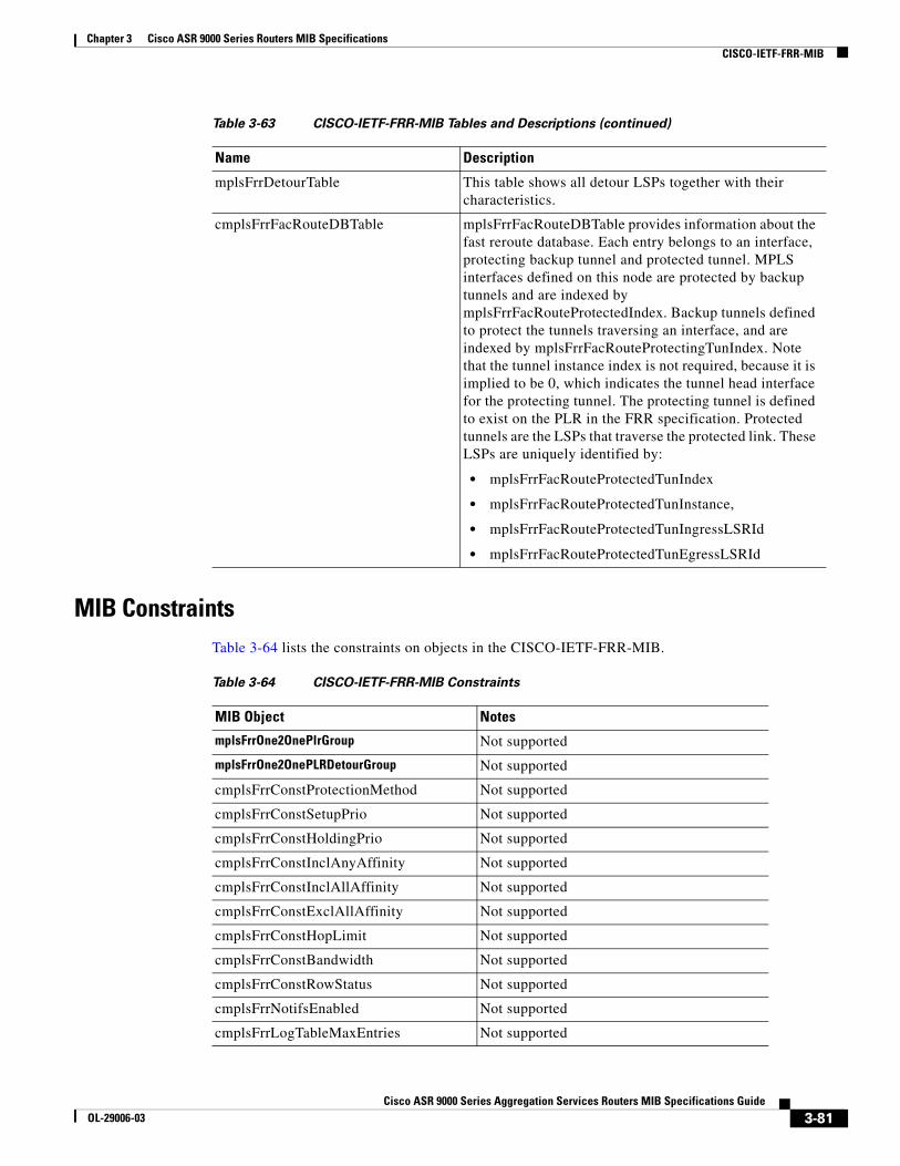
CISCO-IETF-FRR-MIB 3-80
MIB Constraints 3-81
CISCO-IETF-MPLS-TE-P2MP-STD-MIB 3-82
MIB Objects 3-82
MIB Constraints 3-82
CISCO-IETF-IPMROUTE-MIB 3-83
MIB Constraints 3-84
CISCO-IETF-MSDP-MIB 3-84
vCisco ASR 9000 Series Aggregation Services Routers MIB Specifications Guide
OL-29006-02
Contents
MIB Constraints 3-85
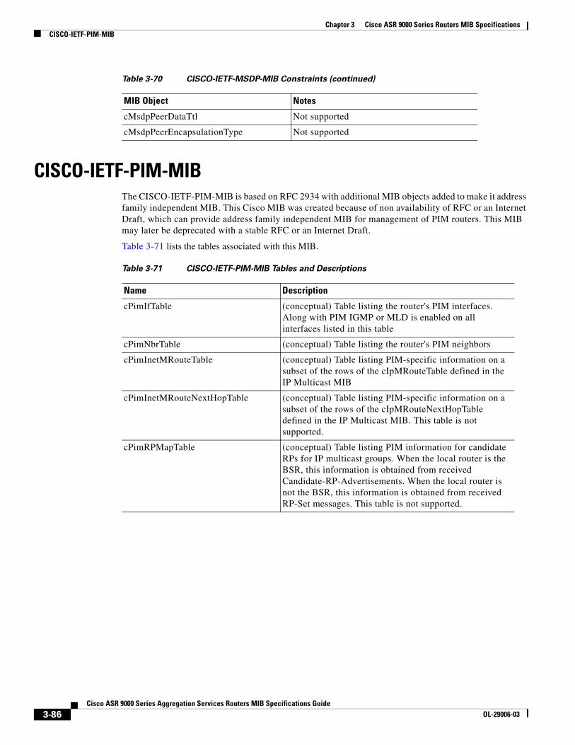
CISCO-IETF-PIM-MIB 3-86
MIB Constraints 3-87
CISCO-IETF-PIM-EXT-MIB 3-87
MIB Constraints 3-89
CISCO-IETF-PW-ENET-MIB 3-89
MIB Constraints 3-90
CISCO-IETF-PW-MIB 3-90
MIB Constraints 3-91
CISCO-IETF-PW-FR-MIB 3-92
MIB Objects 3-93
MIB Constraints 3-93
CISCO-IETF-PW-MPLS-MIB 3-94
MIB Constraints 3-94
CISCO-IETF-PW-TC-MIB 3-95
CISCO-IETF-VPLS-BGP-EXT-MIB 3-95
MIB Constraints 3-96
CISCO-IETF-VPLS-GENERIC-MIB 3-96
MIB Tables 3-96
MIB Constraints 3-97
CISCO-IETF-VPLS-LDP-MIB 3-97
MIB Constraints 3-98
CISCO-IF-EXTENSION-MIB 3-98
MIB Tables 3-98
MIB Constraints 3-99
CISCO-IP-CBR-METRICS-MIB 3-101
MIB Objects 3-101
MIB Constraints 3-101
CISCO-IP-TAP-MIB 3-102
MIB Tables 3-102
MIB Constraints 3-103
CISCO-IP-STAT-MIB 3-103
MIB Tables 3-104
CISCO-IPSEC-MIB 3-104
MIB Objects 3-105
MIB Constraints 3-105
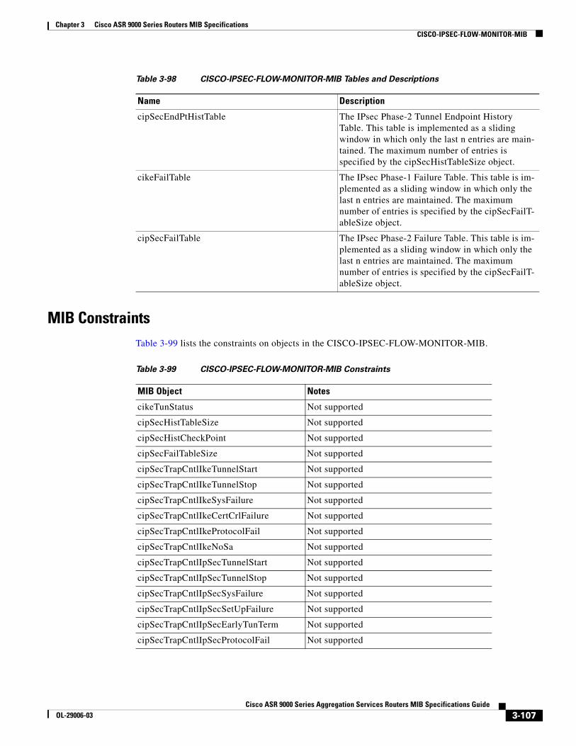
CISCO-IPSEC-FLOW-MONITOR-MIB 3-105
MIB Objects 3-106
viCisco ASR 9000 Series Aggregation Services Routers MIB Specifications Guide
OL-29006-02
Contents
MIB Constraints 3-107
CISCO-LICENSE-MGMT-MIB 3-108
MIB Objects 3-109
MIB Constraints 3-110
CISCO-LPTS-MIB 3-111
CISCO-MEMORY-POOL-MIB 3-112
CISCO-MLD-SNOOPING-MIB 3-112
MIB Objects 3-113
MIB Constraints 3-113
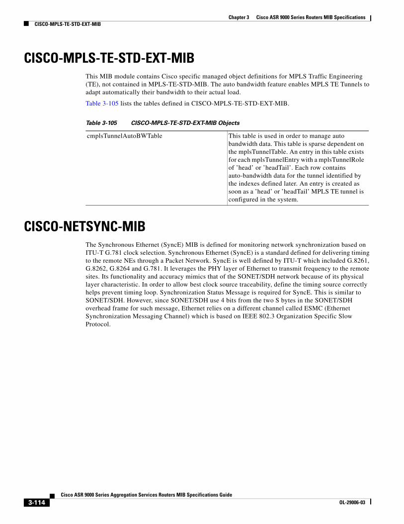
CISCO-MPLS-TE-STD-EXT-MIB 3-114
CISCO-NETSYNC-MIB 3-114
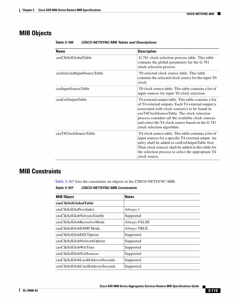
MIB Objects 3-115
MIB Constraints 3-115
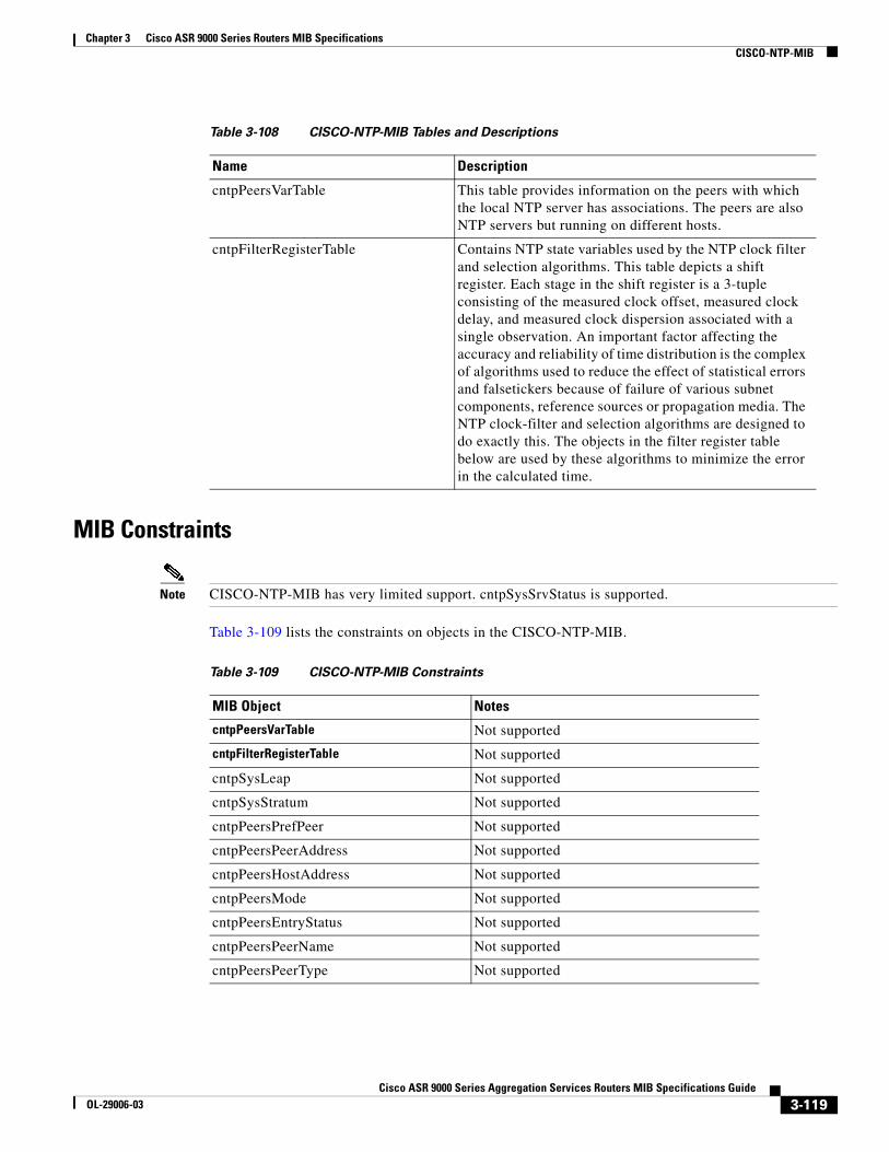
CISCO-NTP-MIB 3-117
MIB Constraints 3-119
CISCO-OAM-MIB 3-120
MIB Objects 3-120
MIB Constraints 3-120
CISCO-OTN-IF-MIB 3-120
MIB Objects 3-120
CISCO-PTP-MIB 3-122
MIB Objects 3-122
MIB Constraints 3-123
CISCO-P2P-IF-MIB 3-127
MIB Constraints 3-127
CISCO-PIM-MIB 3-128
CISCO-PING-MIB 3-128
MIB Constraints 3-128
CISCO-PROCESS-MIB 3-129
CISCO-RF-MIB 3-129
MIB Constraints 3-130
CISCO-RTTMON-MIB 3-131
MIB Constraints 3-138
CISCO-SELECTIVE-VRF-DOWNLOAD-MIB 3-139
MIB Tables 3-139
MIB Constraints 3-139
CISCO-SONET-MIB 3-140
MIB Tables 3-140
viiCisco ASR 9000 Series Aggregation Services Routers MIB Specifications Guide
OL-29006-02
Contents
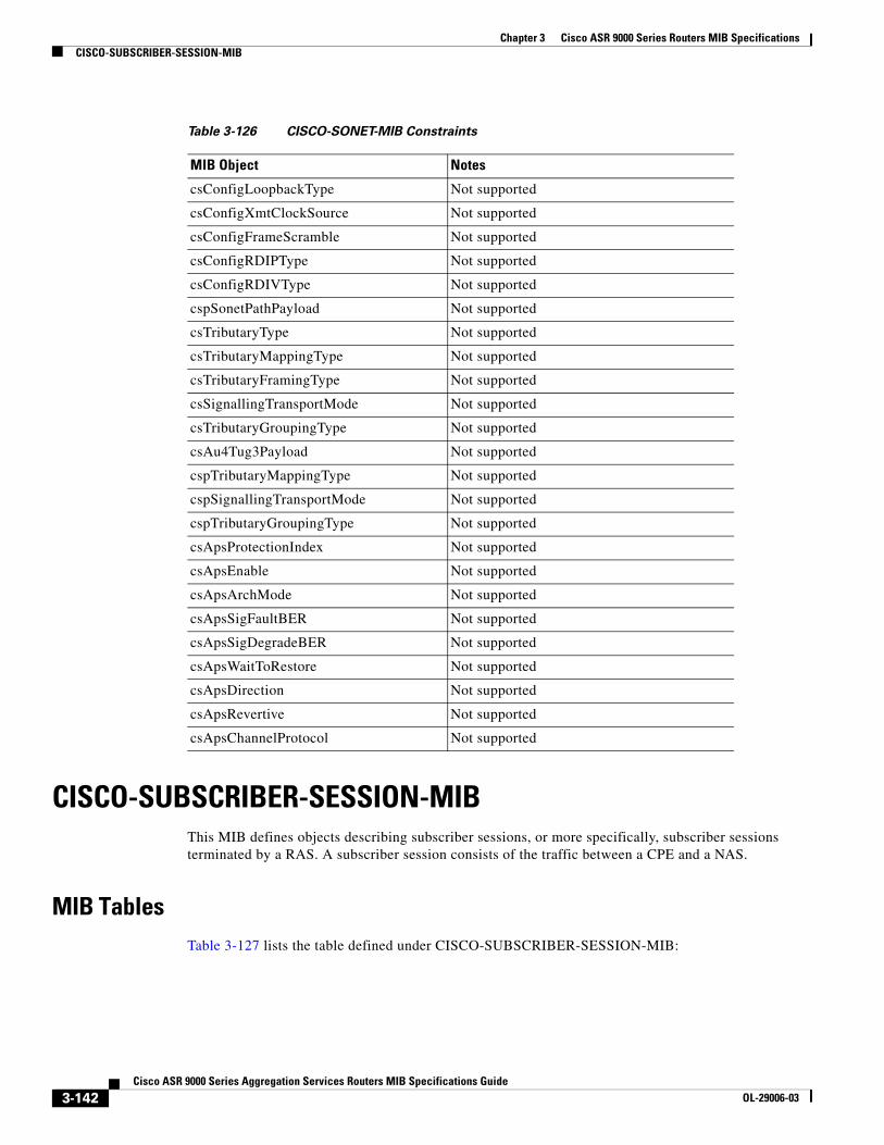
MIB Constraints 3-141
CISCO-SUBSCRIBER-SESSION-MIB 3-142
MIB Tables 3-142
CISCO-SYSLOG-MIB 3-143
MIB Constraints 3-144
CISCO-SYSTEM-MIB 3-144
MIB Constraints 3-144
CISCO-TAP2-MIB 3-144
MIB Objects 3-145
MIB Constraints 3-145
CISCO-TCP-MIB 3-146
CISCO-VPDN-MGMT-MIB 3-147
MIB Objects 3-147
CISCO-VLAN-IFTABLE-RELATIONSHIP-MIB 3-147
DISMAN-EXPRESSION-MIB 3-148
MIB Tables 3-148
DOT3-OAM-MIB 3-148
MIB Tables 3-148
MIB Constraints 3-149
DS1-MIB (RFC 2495) 3-151
MIB Tables 3-151
MIB Constraints 3-154
DS3-MIB 3-154
MIB Tables 3-154
MIB Constraints 3-155
ENERGY-OBJECT-MIB 3-156
ENTITY-MIB (RFC 2737) 3-156
MIB Tables 3-157
MIB Constraints 3-158
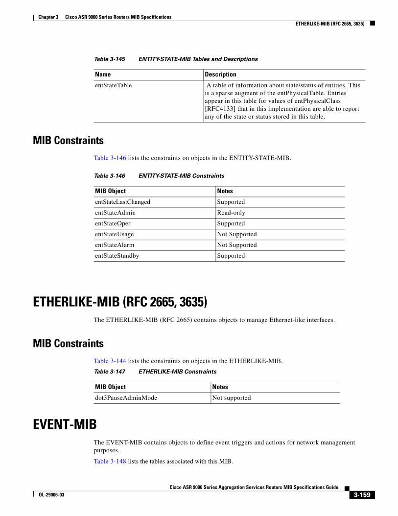
ENTITY-STATE-MIB 3-158
MIB Constraints 3-159
ETHERLIKE-MIB (RFC 2665, 3635) 3-159
MIB Constraints 3-159
EVENT-MIB 3-159
MIB Constraints 3-160
EXPRESSION-MIB 3-160
FRAME-RELAY-DTE-MIB 3-161
viiiCisco ASR 9000 Series Aggregation Services Routers MIB Specifications Guide
OL-29006-02
Contents
MIB Constraints 3-161
IEEE8021-CFM-MIB 3-163
MIB Objects 3-164
MIB Constraints 3-165
IEEE8023-LAG-MIB 3-166
MIB Constraints 3-167
IETF-TCP-MIB 3-168
MIB Tables 3-168
IETF-UDP-MIB 3-168
MIB Tables 3-168
IF-MIB (RFC 2863) 3-169
MIB Tables 3-169
MIB Constraints 3-170
IMA-MIB 3-170
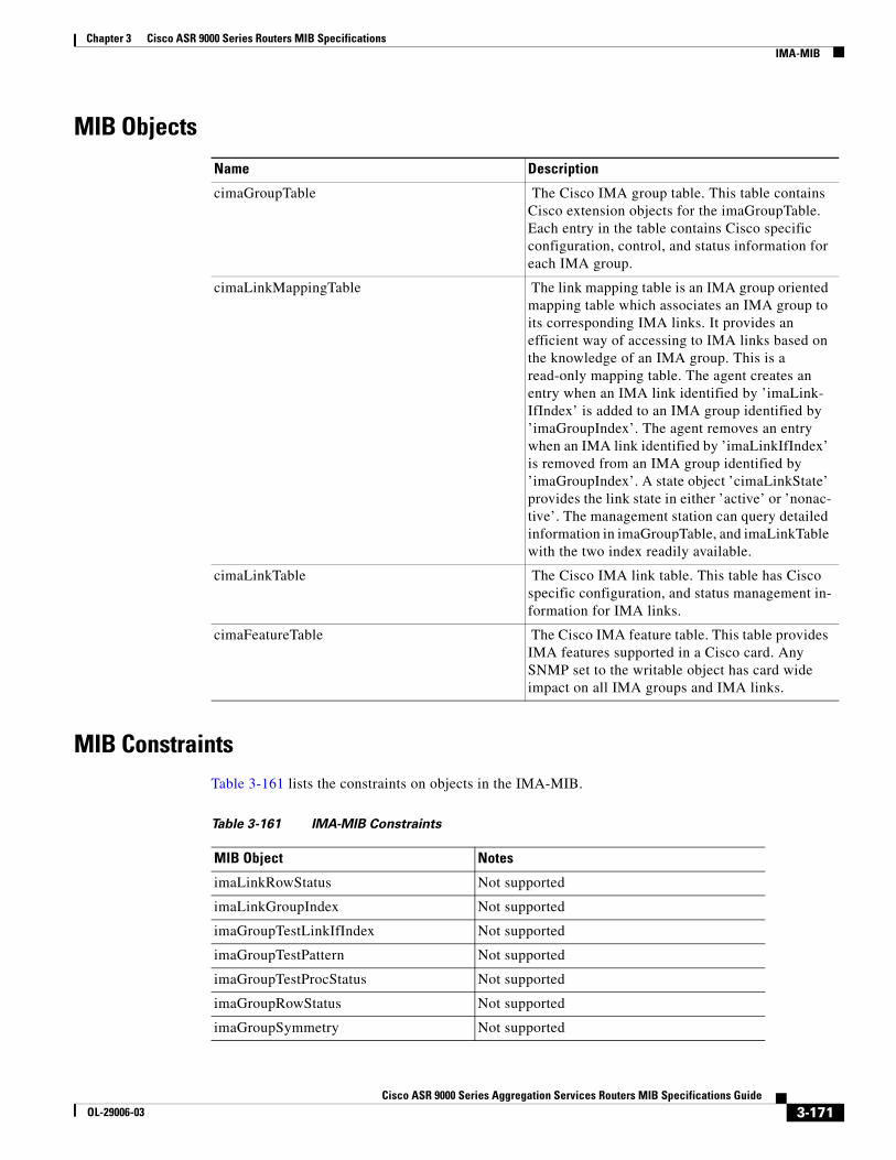
MIB Objects 3-171
MIB Constraints 3-171
IP-FORWARD-MIB 3-172
MIB Constraints 3-172
IP-MIB 3-173
MIB Tables 3-173
MIB Constraints 3-174
IPV6-MIB 3-176
MIB Tables 3-176
MIB Constraints 3-177
IPV6-FORWARD-MIB 3-178
MIB Objects 3-178
MIB Constraints 3-178
IPV6-MLD-MIB 3-179
MIB Objects 3-179
MIB Constraints 3-179
IPV6-TC 3-179
ISIS-MIB 3-179
MIB Constraints 3-181
MAU-MIB 3-183
MIB Constraints 3-183
MEF-SOAM-PM-MIB 3-184
MFR-MIB 3-191
MIB Objects 3-191
ixCisco ASR 9000 Series Aggregation Services Routers MIB Specifications Guide
OL-29006-02
Contents
MIB Constraints 3-191
MGMD-STD-MIB 3-192
MIB Objects 3-193
MIB Constraints 3-193
MPLS-L3VPN-STD-MIB 3-194
MIB Constraints 3-194
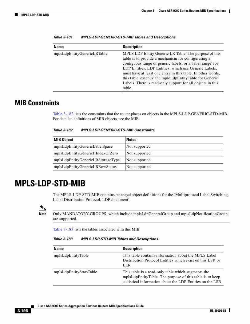
MPLS-LDP-GENERIC-STD-MIB 3-195
MIB Constraints 3-196
MPLS-LDP-STD-MIB 3-196
MIB Constraints 3-197
MPLS-LSR-STD-MIB 3-198
MIB Constraints 3-200
MPLS-TC-STD-MIB 3-200
MPLS-TE-STD-MIB 3-201
MIB Constraints 3-203
NOTIFICATION-LOG-MIB 3-204
OSPF-MIB 3-205
MIB Tables 3-205
MIB Constraints 3-207
OSPF-TRAP-MIB 3-208
OSPFV3-MIB 3-208
MIB Constraints 3-209
PIM-MIB 3-211
MIB Objects 3-212
MIB Constraints 3-213
RADIUS-ACC-CLIENT-MIB 3-213
RADIUS-AUTH-CLIENT-MIB 3-213
RFC1213-MIB 3-214
MIB Objects 3-214
RFC 2011-MIB 3-214
MIB Objects 3-215
MIB Constraints 3-215
RFC 2465-MIB 3-215
MIB Objects 3-216
MIB Constraints 3-216
RSVP-MIB 3-217
MIB Constraints 3-217
xCisco ASR 9000 Series Aggregation Services Routers MIB Specifications Guide
OL-29006-02
Contents
SNMP-COMMUNITY-MIB (RFC 2576) 3-220
SNMP-FRAMEWORK-MIB (RFC 2571) 3-220
SNMP-NOTIFICATION-MIB (RFC 2573) 3-220
SNMP-TARGET-MIB (RFC 2573) 3-220
SNMP-USM-MIB (RFC 2574) 3-221
SNMPv2-MIB (RFC 1907) 3-221
SNMP-VACM-MIB 3-221
SONET-MIB (RFC 2558) 3-221
MIB Tables 3-222
MIB Constraints 3-222
TCP-MIB 3-223
MIB Constraints 3-224
UDP-MIB 3-224
MIB Constraints 3-225
VRRP-MIB 3-226
MIB Constraints 3-226
3-226
C H A P T E R 4 Monitoring Notifications 4-1
SNMP Notification Overview 4-1
Enabling Notifications 4-2
Cisco SNMP Notifications 4-2
Environmental or Functional Notifications 4-3
Flash Card Notifications 4-5
Interface Notifications 4-5
Routing Protocol Notifications 4-5
Redundancy Framework Notifications 4-6
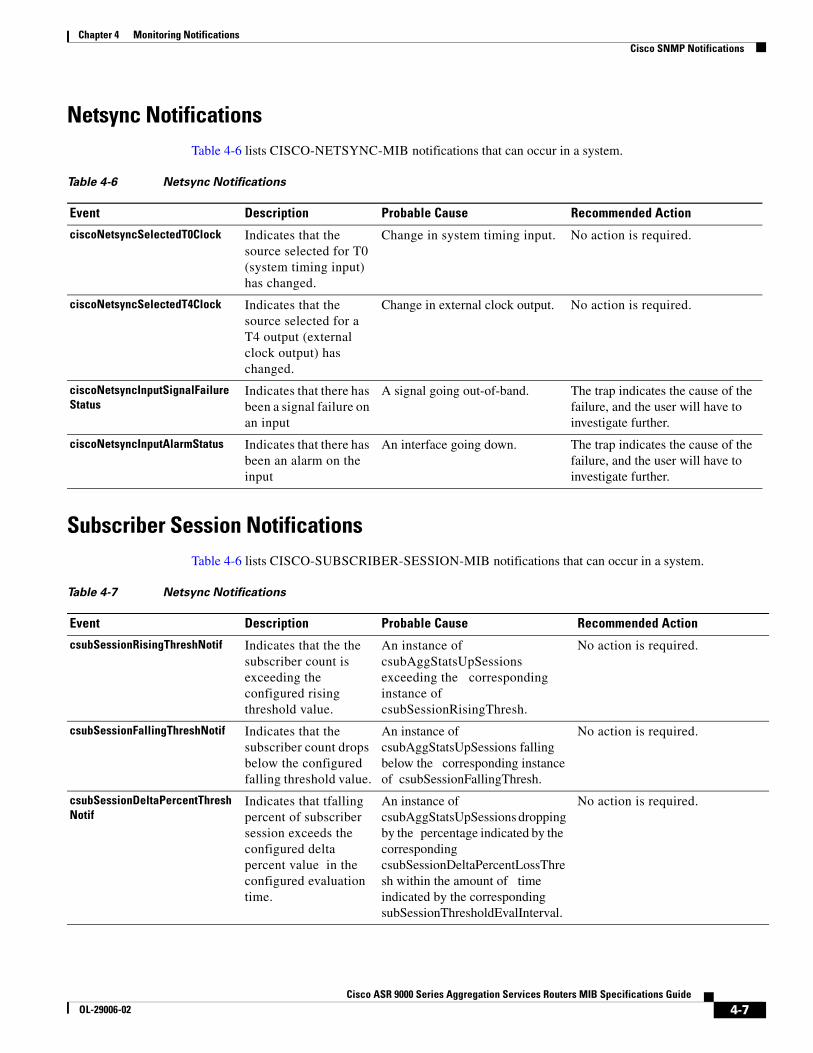
Netsync Notifications 4-7
Subscriber Session Notifications 4-7
A P P E N D I X 1 Using MIBs 1-1
Cisco Unique Device Identifier Support 1-1
Cisco Redundancy Features 1-2
Levels of Redundancy 1-2
Verifying the Cisco ASR 9000 Series Router Redundancy 1-3
Managing Physical Entities 1-3
Purpose and Benefits 1-4
xiCisco ASR 9000 Series Aggregation Services Routers MIB Specifications Guide
OL-29006-02
Contents
Performing Inventory Management 1-4
Monitoring and Configuring FRU Status 1-10
Generating SNMP Notifications 1-10
Monitoring Quality of Service 1-12
Cisco ASR 9000 Series Router QoS Basics 1-12
CISCO-CLASS-BASED-QOS-MIB Overview 1-12
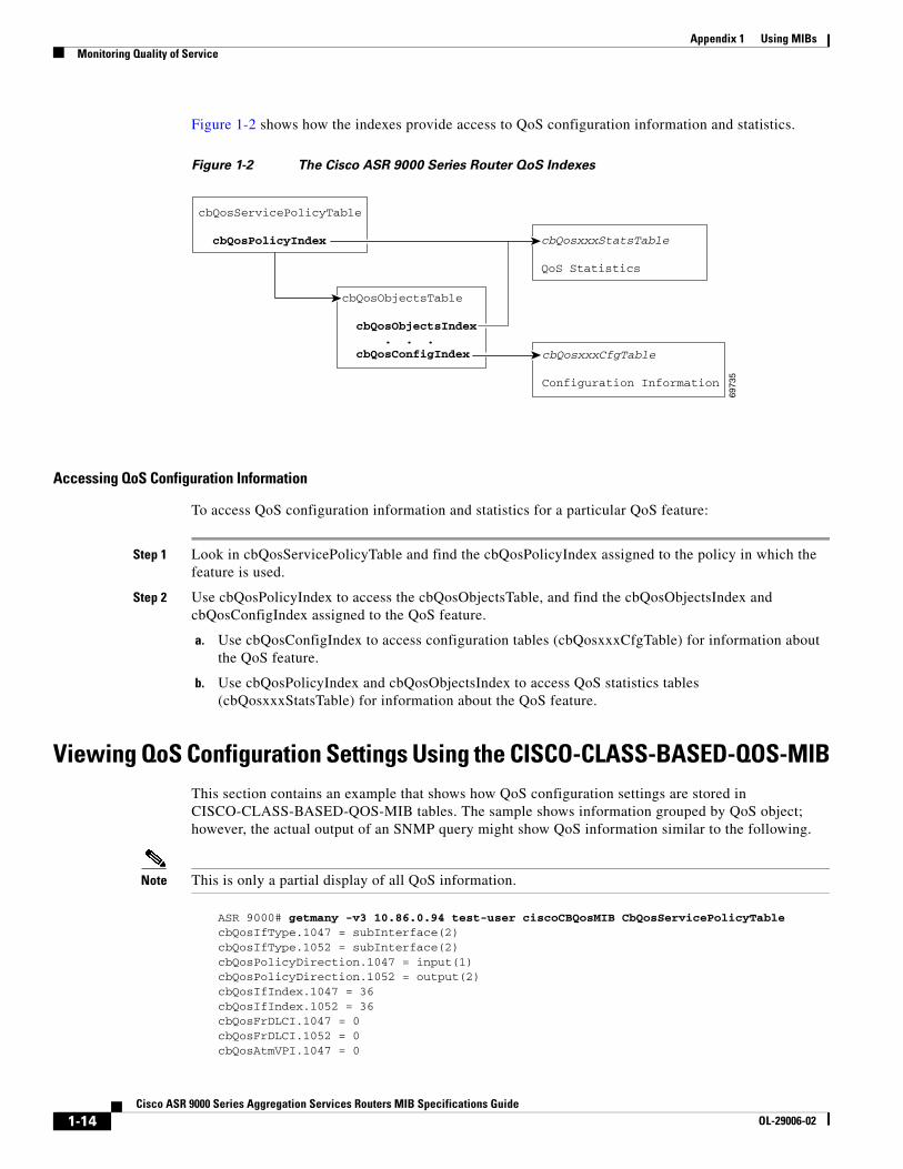
Viewing QoS Configuration Settings Using the CISCO-CLASS-BASED-QOS-MIB 1-14
Monitoring QoS Using the CISCO-CLASS-BASED-QOS-MIB 1-15
Considerations for Processing QoS Statistics 1-16
Sample QoS Applications 1-18
Monitoring Router Interfaces 1-21
Check the Operational and Administrative Status of Interface 1-21
Monitor linkDown and linkUp Notifications 1-21
Enabling Interface linkUp and linkDown Notifications 1-22
Billing Customers for Traffic 1-22
Input and Output Interface Counts 1-22
Determining the Amount of Traffic to Bill to a Customer 1-23
Scenario for Demonstrating QoS Traffic Policing 1-23
Using IF-MIB Counters 1-26
Sample Counters 1-27
A P P E N D I X 2 QoS MIB Implementation 2-1
Implementing the CISCO-CLASS-BASED-QOS-MIB 2-1
QoS MIB Policy Action Support Matrix 2-4
G L O S S A R Y
I N D E X
xiiCisco ASR 9000 Series Aggregation Services Routers MIB Specifications Guide
OL-29006-02
Preface
This guide describes the implementation of the Simple Network Management Protocol (SNMP) and Management Information Base (MIB) for Cisco ASR 9000 Series Aggregation Services Routers. SNMP provides a set of commands for setting and retrieving the values of operating parameters on the Cisco ASR 9000 Series router. The router information is stored in a virtual storage area called a Management Information Base (MIB), which contains many MIB objects that describe router components and provides information about the status of the components.
This preface provides an overview of this guide with the following sections:
• Revision History
• Audience
• Organization
• Terminology and Definitions
• Obtaining Documentation and Submitting a Service Request
Revision HistoryThe following Revision History tables record technical changes, additions, and corrections to this document. The table shows the release number and document revision number for the change, the date of the change, and a summary of the change.
Cisco IOS XR Release Part Number Publication Date
5.2.0 OL-29006-05 Updated with Cisco IOS XR Release 5.2.0 MIB implementation. The following MIBS have been added:
5.1.1 OL-29006-03 Updated with Cisco IOS XR Release 5.1.0 and Cisco IOS XR Release 5.1.1 MIB support information.
4.3.1 OL-29006-02 June 2013
1Cisco ASR 9000 Series Aggregation Services Routers MIB Specifications Guide
OL-29006-02
Preface
AudienceThis guide is intended for system and network administrators who must configure the Cisco ASR 9000 Series router for operation and monitor its performance in the network.
This guide may also be useful for application developers who are developing management applications for the Cisco ASR 9000 Series router.
OrganizationThis guide contains the following chapters:
Terminology and DefinitionsThis section discusses conventions and terminology used in this guide.
• Alarm—In SNMP, the word alarm is commonly misused to mean the same as a trap (see the Trap definition below). Alarm represents a condition which causes an SNMP trap to be generated.
Note Many commands use the word traps in the command syntax. Unless there is an option in the command to select traps. Use the snmp-server host and snmp-server notification command to specify whether to send SNMP notifications as traps.
Chapter Description
Chapter 1, “Cisco ASR 9000 Series Routers MIB Overview”
Provides background information about SNMP and its implementation on the Cisco ASR 9000 Series router.
Chapter 2, “Configuring MIB Support” Provides instructions for configuring SNMP management support on the Cisco ASR 9000 Series router.
Chapter 3, “Cisco ASR 9000 Series Routers MIB Specifications”
Describes each MIB included on the Cisco ASR 9000 Series router. Each description lists any constraints as to how the MIB is implemented on the router.
Chapter 4, “Monitoring Notifications” Describes the SNMP notifications supported by the Cisco ASR 9000 Series router, provides a description of each notification, a probable cause, and recommended action to take.
Appendix 1, “Using MIBs” Provides information about how to use SNMP to perform system functions such as bulk-file retrieval and Quality of Service (QoS).
Appendix 2, “QoS MIB Implementation” Provides information about how to implement Quality of Service (QoS) in addition to a matrix that defines which objects support QoS policy actions.
2Cisco ASR 9000 Series Aggregation Services Routers MIB Specifications Guide
OL-29006-02
Preface
• Element Management System (EMS)—An EMS manages a specific portion of the network. For example, the SunNet Manager, an SNMP management application, is used to manage SNMP-manageable elements. Element Managers may manage asynchronous lines, multiplexers, Private Automatic Branch Extension (PABX), proprietary systems, or an application.
• Management Information Base (MIB)—The management objects available in an SNMP managed device. The information is represented in Abstract Syntax Notation 1 (ASN.1). This is a way of logically grouping data so that it is easily understood by all.
• MIB-II—The successor to MIB-I, which was the original standard SNMP MIB.
• Multiprotocol Label Switching (MPLS)—MPLS is the standardized version of the Cisco original tag-switching proposal. It uses a label-forwarding paradigm (forward packets based on labels).
• Simple Network Management Protocol (SNMP)—An application layer protocol that allows you to remotely manage networked devices. The simple in SNMP is only in contrast to protocols that are thought to be even more complex than SNMP. SNMP consists of the following components: a management protocol, a definition of management information and events, a core set of management information and events, and a mechanism and approach used to manage the use of the protocol including security and access control.
• Trap—A device-initiated SNMP notification message. The contents of the message might be simply informational, but it is mostly used to report real-time trap information. Traps can be used in conjunction with other SNMP mechanisms, as in trap-directed polling.
• User Datagram Protocol (UDP)—A connectionless, non-reliable IP-based transport protocol.
Obtaining Documentation and Submitting a Service RequestFor information on obtaining documentation, submitting a service request, and gathering additional information, see the monthly What’s New in Cisco Product Documentation, which also lists all new and revised Cisco technical documentation, at:
Subscribe to the What’s New in Cisco Product Documentation as an RSS feed and set content to be delivered directly to your desktop using a reader application. The RSS feeds are a free service. Cisco currently supports RSS Version 2.0.
3Cisco ASR 9000 Series Aggregation Services Routers MIB Specifications Guide
4Cisco ASR 9000 Series Aggregation Services Routers MIB Specifications Guide
OL-29006-02
Cisco ASR 9000 Series AggrOL-29006-02
C H A P T E R 1
Cisco ASR 9000 Series Routers MIB Overview
This chapter provides an overview of the Cisco ASR 9000 Series router management feature. This chapter contains the following topics:
• Benefits of MIB Enhancements, page 1-1
• SNMP Overview, page 1-1
• Object Identifiers, page 1-5
Benefits of MIB EnhancementsThe Cisco ASR 9000 Series router management feature allows the router to be managed through the Simple Network Management Protocol (SNMP).
Using the Cisco ASR 9000 Series router management feature, you can:
• Manage and monitor the Cisco ASR 9000 Series router resources through an SNMP-based Network Management System (NMS)
• Use SNMP set and get requests to access information in Cisco ASR 9000 Series router MIBs
• Reduce the amount of time and system resources required to perform functions such as inventory management
Other benefits include:
• A standards-based technology (SNMP) for monitoring faults and performance on the router
• Support for all SNMP versions (SNMPv1, SNMPv2c, and SNMPv3)
• Notification of faults, alarms, and conditions that might affect services
• A way to access router information other than through the Command-Line Interface (CLI) or Extensible Markup Language (XML).
SNMP OverviewThe Simple Network Management Protocol (SNMP) is an application-layer protocol that provides a standardized framework and a common language used for monitoring and managing devices in a network.
Chapter 1 Cisco ASR 9000 Series Routers MIB OverviewSNMP Overview
• SNMP manager—A system used to control and monitor the activities of network hosts using SNMP. The most common managing system is called a NMS. The term NMS can be applied to either a dedicated device used for network management, or the applications used on a network management device. A variety of network management applications are available for use with SNMP. These features range from simple command-line applications to feature-rich graphical user interfaces (such as the CiscoWorks2000 line of products).
• SNMP agent—A software component in a managed device that maintains the data for the device and reports the data, as needed, to managing systems. The agent and MIB reside on the routing device (router, access server, or switch). To enable the SNMP agent on a managed device, you must define the relationship between the manager and the agent (see the “Enabling SNMP Support” section on page 2-3).
• Management Information Base (MIB)— A MIB is a database of objects that can be managed on a device. This database describes various components and provides information about the attributes of the components of a network device.
Instead of defining a large set of commands, SNMP places all operations in a get-request, get-next-request, and set-request format. For example, an SNMP manager can get a value from an SNMP agent or set a value in that SNMP agent.
MIB DescriptionA MIB is a database of the objects that can be managed on a device. The managed objects or variables can be set or read to provide information on the network devices and interfaces and are organized hierarchically. The MIB consists of collections of managed objects identified by object identifiers. MIBs are accessed using a network management protocol such as SNMP. A managed object (sometimes called a MIB object or an object) is one of a number of characteristics of a managed device, such as a router. Managed objects comprise one or more object instances, which are essentially variables. The Cisco implementation of SNMP uses the definitions of MIB II variables described in RFC 1213.
MIBs contain two types of managed objects:
• Scalar objects—Define a single object instance (for example, ifNumber in the IF-MIB and bgpVersion in the BGP4-MIB).
• Columnar objects—Define multiple related objects such as zero, one, or more instances at any point in time that are grouped together in MIB tables (for example, ifTable in the IF-MIB defines the interface).
System MIB variables are accessible through SNMP as follows:
• Accessing a MIB variable—Function is initiated by the SNMP agent in response to a request from the NMS. The agent retrieves the value of the requested MIB variable and responds to the NMS with that value.
• Setting a MIB variable—Function is initiated by the SNMP agent in response to a message from the NMS. The SNMP agent changes the value of the MIB variable to the value requested by the NMS.
SNMP NotificationsAn SNMP agent can notify the SNMP manager when important system events occur, such as the following:
• An interface or card starts or stops running
• Temperature thresholds are crossed
1-2Cisco ASR 9000 Series Aggregation Services Routers MIB Specifications Guide
OL-29006-02
Chapter 1 Cisco ASR 9000 Series Routers MIB OverviewSNMP Overview
• Authentication failures occur
When an agent detects an alarm condition, the agent:
• Logs information about the time, type, and severity of the condition
• Generates a notification message, which it then sends to a designated IP host
SNMP notifications are sent as one of the following:
• Traps—Unreliable messages, which do not require receipt acknowledgment from the SNMP manager.
The Cisco implementation of SNMP uses the definitions of SNMP traps described in RFC 1215.
When an agent detects an alarm condition, it logs information about the time, type, and severity of the condition and generates a notification message, which it then sends to a designated IP host. SNMP notifications is sent as traps. See the “Enabling Notifications” section on page 4-2 for instructions on how to enable notifications and traps on the Cisco ASR 9000 Series router. Use the snmp-server host command to specify that SNMP notifications are sent as traps. See Chapter 4, “Monitoring Notifications,” for information about Cisco ASR 9000 Series router traps.
SNMP VersionsCisco IOS XR Software supports the following versions of SNMP:
• SNMPv1—The Simple Network Management Protocol: An Internet standard, defined in RFC 1157. Security is based on community strings.
• SNMPv2c—The community-string based administrative framework for SNMPv2. SNMPv2c is an update of the protocol operations and data types of SNMPv2p (SNMPv2 classic).
• SNMPv3—Version 3 of SNMP. SNMPv3 uses the following security features to provide secure access to devices:
– Message integrity—Ensuring that a packet has not been tampered with in transit.
– Authentication—Determining that the message is from a valid source.
– Encryption—Scrambling the contents of a packet to prevent it from being learned by an unauthorized source.
SNMPv1 and SNMPv2c
Both SNMPv1 and SNMPv2c use a community-based form of security. The community of managers who are able to access the agent MIB is defined by an IP address access control list and password.
SNMPv2c support includes a bulk-retrieval mechanism and more detailed error message reporting to management stations. The bulk-retrieval mechanism supports the retrieval of tables and large quantities of information, minimizing the number of round-trip transmissions required. SNMPv2c improved error-handling support includes expanded error codes that distinguish different kinds of error conditions; these conditions are reported through a single error code in SNMPv1. Error return codes report the error type. Three kinds of exceptions are also reported:
• No such object
• No such instance
• End of MIB view
1-3Cisco ASR 9000 Series Aggregation Services Routers MIB Specifications Guide
OL-29006-02
Chapter 1 Cisco ASR 9000 Series Routers MIB OverviewSNMP Overview
SNMPv3
SNMPv3 provides security models and security levels:
• A security model is an authentication strategy that is set up for a user and the group in which the user resides.
• A security level is the permitted level of security within a security model.
• A combination of a security model and a security level determines the security mechanism employed when handling an SNMP packet.
SNMP Security Models and Levels
Table 1-1 describes the security models and levels provided by the different SNMP versions.
You must configure the SNMP agent to use the version of SNMP supported by the management station. An agent can communicate with multiple managers; for this reason, you can configure the Cisco IOS XR Software to support communications with one management station using the SNMPv1 protocol, one using the SNMPv2c protocol, and another using SMNPv3.
Requests For CommentsMIB modules are typically defined in Request for Comment (RFC) documents that have been submitted to the Internet Engineering Task Force (IETF) for formal discussion and approval. RFCs are written by individuals or groups for consideration by the Internet Society and the Internet community as a whole.
Before getting RFC status, recommendations are published as Internet Draft (I-D) documents. RFCs that have become recommended standards are also labeled as standards (STD) documents. For more information, see the Internet Society and IETF websites (http://www.isoc.org and http://www.ietf.org).
We provide private MIB extensions with each Cisco system. Cisco enterprise MIBs comply with the guidelines described in the relevant RFCs unless otherwise noted in the documentation.
Table 1-1 SNMP Security Models and Levels
Model Level Authentication Encryption Description
v1 noAuthNoPriv Community string
No Uses match on community string for authentication.
v2c noAuthNoPriv Community string
No Uses match on community string for authentication.
v3 noAuthNoPriv User name No Uses match on user name for authentication.
authNoPriv MD5 or SHA No Provides authentication based on HMAC-MD5 or HMAC-SHA algorithm.
authPriv MD5 or SHA DES Provides authentication based on HMAC-MD5 or HMAC-SHA algorithm. Also provides DES 56-bit encryption based on CBC-DES (DES-56) standard.
1-4Cisco ASR 9000 Series Aggregation Services Routers MIB Specifications Guide
OL-29006-02
Chapter 1 Cisco ASR 9000 Series Routers MIB OverviewObject Identifiers
Object IdentifiersAn object identifier (OID) uniquely identifies a MIB object on a managed network device. The OID identifies the MIB object’s location in the MIB hierarchy, and provides a means of accessing the MIB object in a network of managed devices:
• Standard RFC MIB OIDs are assigned by the Internet Assigned Numbers Authority (IANA).
• Enterprise MIB OIDs are assigned by Cisco Assigned Numbers Authority (CANA).
Each number in the OID corresponds to a level of MIB hierarchy. For example, the OID 1.3.6.1.4.1.9.9.xyz represents the.xyz with the location in the MIB hierarchy as follows. Note that the numbers in parentheses are included to help show correspondence to the MIB hierarchy. In actual use, OIDs are represented as numerical values only.
You can uniquely identify a managed object, such as ifNumber in the IF-MIB, by its object name (iso.org.dod.internet.mgmt.enterprises.interfaces.ifNumber) or by its OID (1.3.6.1.2.1.2.1).
For a list of OIDs assigned to MIB objects, go to the following URL:
ftp://ftp.cisco.com/pub/mibs/oid/
SNMP Configuration InformationThe following references provide information about configuring SNMP:
• Implementing SNMP module provides general information about configuring and implementing SNMP support. It is part of the Cisco IOS XR System Management Configuration Guide.
• SNMP Server Commands module provides information about SNMP commands. It is part of the Cisco IOS XR System Management Command Reference.
1-5Cisco ASR 9000 Series Aggregation Services Routers MIB Specifications Guide
Chapter 1 Cisco ASR 9000 Series Routers MIB OverviewObject Identifiers
1-6Cisco ASR 9000 Series Aggregation Services Routers MIB Specifications Guide
OL-29006-02
Cisco ASR 9000 Series AggrOL-29006-02
C H A P T E R 2
Configuring MIB Support
This chapter describes how to configure SNMP and MIB support for the Cisco ASR 9000 Series router. It includes the following sections:
• Downloading and Compiling MIBs, page 2-1
• Enabling SNMP Support, page 2-3
Downloading and Compiling MIBsThe following sections provide information about how to download and compile MIBs for the Cisco ASR 9000 Series router:
• Considerations for Working with MIBs, page 2-1
• Downloading MIBs, page 2-2
• Compiling MIBs, page 2-3
Considerations for Working with MIBsWhile working with MIBs, consider the following:
• Mismatches on datatype definitions might cause compiler errors or warning messages. Although Cisco MIB datatype definitions are not mismatched, some standard RFC MIBs do mismatch, as in the following example:
MIB A defines: SomeDatatype ::= INTEGER(0..100) MIB B defines: SomeDatatype ::= INTEGER(1..50)
This example is considered to be a trivial error and the MIB loads successfully with a warning message.
The following example is considered as a nontrivial error (even though the two definitions are essentially equivalent), and the MIB is not successfully parsed:
MIB A defines: SomeDatatype ::= DisplayString MIB B defines: SomeDatatype ::= OCTET STRING (SIZE(0..255))
If your MIB compiler treats these as errors, or you want to delete the warning messages, edit one of the MIBs that defines this same datatype so that the definitions match.
Chapter 2 Configuring MIB SupportDownloading and Compiling MIBs
• Many MIBs import definitions from other MIBs. If your management application requires MIBs to be loaded, and you experience problems with undefined objects, you might want to load the following MIBs in this order:
Downloading MIBsFollow these steps to download the MIBs onto your system if they are not already there:
Step 1 Review the considerations in the “Considerations for Working with MIBs” section.
Step 2 Go to one of the following Cisco URLs. If the MIB you want to download is not there, try the other URL; otherwise, go to one of the URLs in Step 5.
• ftp://ftp.cisco.com/pub/mibs/v2
• ftp://ftp.cisco.com/pub/mibs/v1
Step 3 Click the link for a MIB to download that MIB to your system.
Step 4 Select File > Save or File > Save As to save the MIB on your system.
2-2Cisco ASR 9000 Series Aggregation Services Routers MIB Specifications Guide
Chapter 2 Configuring MIB SupportEnabling SNMP Support
Step 5 You can download industry-standard MIBs from the following URLs:
• http://www.ietf.org
• http://www.ipmplsforum.org/
Compiling MIBsIf you plan to integrate the Cisco ASR 9000 Series router with an SNMP-based management application, then you must compile the MIBs for that platform. For example, if you are running HP OpenView on a UNIX operating system, you must compile Cisco ASR 9000 Series router MIBs with the HP OpenView Network Management System (NMS).
Enabling SNMP SupportThe following procedure summarizes how to configure the Cisco ASR 9000 Series router for SNMP support.
For detailed information about SNMP commands, go to the following URL:
• Implementing SNMP module provides general information about configuring and implementing SNMP support. It is part of the Cisco IOS XR System Management Configuration Guide.
• SNMP Server Commands provides information about SNMP commands. It is part of the Cisco IOS XR System Management Command Reference.
To configure the Cisco ASR 9000 Series router for SNMP support, follow these steps:
Step 1 Set up your basic SNMP configuration through the command-line interface (CLI) on the router. Note that these basic configuration commands are issued for SNMPv2c. For SNMPv3, you must also set up SNMP users and groups. (See the preceding list of documents for command and setup information.)
a. Define SNMP read-only and read-write communities:
Router (config)# snmp-server community Read_Only_Community_Name ro SystemOwnerRouter (config)# snmp-server community Read_Write_Community_Name rw SystemOwner
b. Configure SNMP views (to limit the range of objects accessible to different SNMP user groups):
For information about how to configure SNMP community strings, refer the SNMP Server Commands module in the Cisco IOS XR System Management Command Reference.
2-3Cisco ASR 9000 Series Aggregation Services Routers MIB Specifications Guide
Chapter 2 Configuring MIB SupportEnabling SNMP Support
2-4Cisco ASR 9000 Series Aggregation Services Routers MIB Specifications Guide
OL-29006-02
Cisco ASR 9000 Series AggrOL-29006-03
C H A P T E R 3
Cisco ASR 9000 Series Routers MIB Specifications
This chapter describes the Management Information Base (MIB) on the Cisco ASR 9000 Series router. Each MIB description lists any constraints on how the MIB or its object identifiers (OIDs) are implemented on the Cisco ASR 9000 Series router.
Unless noted otherwise, the Cisco ASR 9000 Series router implementation of a MIB follows the standard MIB that has been defined. Any MIB table or object not listed in the table is implemented as defined in the standard MIB definition.
This chapter includes the following sections:
• Cisco ASR 9000 Series Routers MIBs, page 3-1
• Cisco ASR 9000 Series Routers MIB Categories, page 3-2
• MIB Version String Description, page 3-2
Cisco ASR 9000 Series Routers MIBsEach MIB description lists relevant constraints about the MIB’s implementation on the Cisco ASR 9000 Series router platform. Any objects not listed in a table are implemented as defined in the MIB. For detailed MIB descriptions, see the standard MIB.
Note • Not all MIBs included in a Cisco IOS XR Software release are fully supported by the router. Some MIBs are not supported at all. Other MIBs might work, but they have not been tested on the router. In addition, some MIBs are deprecated but cannot be removed from the software. When a MIB is included in the image, this does not necessarily mean it is supported by the Cisco ASR 9000 Series Router platform.
• Certain MIBs return a numeric value along with the MIB object. These numerical values are shown in parentheses in the Cisco ASR 9000 Series Aggregation Services Routers MIB Specifications Guide. For example, the CISCO-ENHANCED-FRU-CONTROL-MIB, returns a MIB object cempMemPoolType of value processorMemory and an actual value 2. This is shown as processorMemory(2).
To determine which MIBs are included in other releases, see the “Downloading and Compiling MIBs” section on page 2-1.
Chapter 3 Cisco ASR 9000 Series Routers MIB SpecificationsCisco ASR 9000 Series Routers MIB Categories
Cisco ASR 9000 Series Routers MIB CategoriesThe MIBs in the Cisco ASR 9000 Series Image on the Cisco ASR 9000 Series router are categorized into three types:
• Supported MIBs
• Unsupported MIBs
Supported MIBsThe MIB exists in the image, the code is implemented.
Unsupported MIBsThe MIB exists in the image but is not supported. These MIBs are not supported for the Cisco ASR 9000 Series routers.
MIB Version String DescriptionThe MIB version string indicates the date and time that the module was most recently modified. The format is YYMMDDHHMMZ or YYYYMMDDHHMMZ, where:
• YY is the last two digits of the year (only years between 1900 and 1999).
• YYYY is all four digits of the year (any year).
• MM is the month (01 through 12).
• DD is the day of the month (01 through 31).
• HH is hours (00 through 23).
• MM is minutes (00 through 59).
• Z (the ASCII character Z) denotes Coordinated Universal Time (UTC, formerly Greenwich Mean Time, GMT). This datatype stores the date and time fields YEAR, MONTH, DAY, HOUR, MINUTE, SECOND, TIMEZONE_HOUR, and TIMEZONE_MINUTE.
Note For example, 9502192015Z and 199509122015Z represent 8:15 GMT on 19 February 1995. Years after 1999 use the four-digit format. Years 1900-1999 may use the two or four digit format.
Note In the following table, you might see the term Revision not available. This term refers to the MIB module that does not have a recorded time stamp indicating the latest modification.
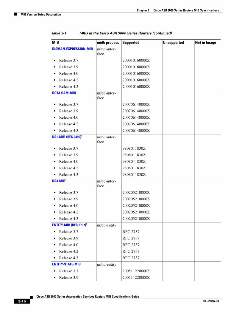
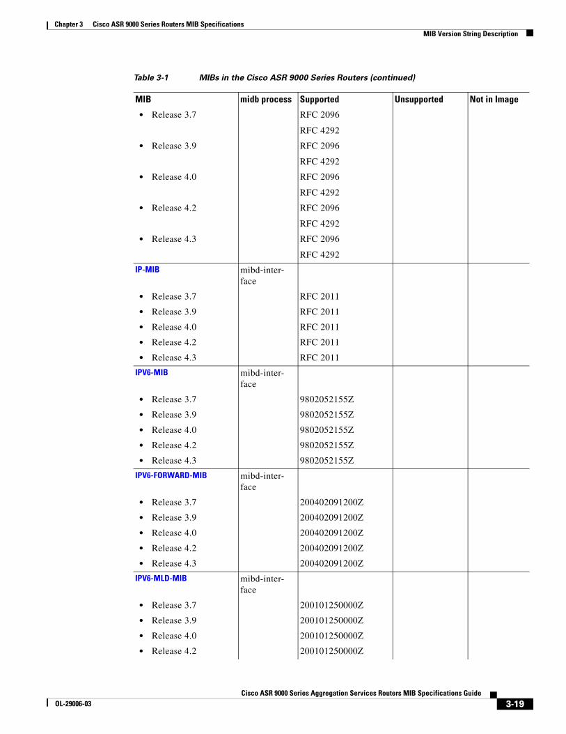
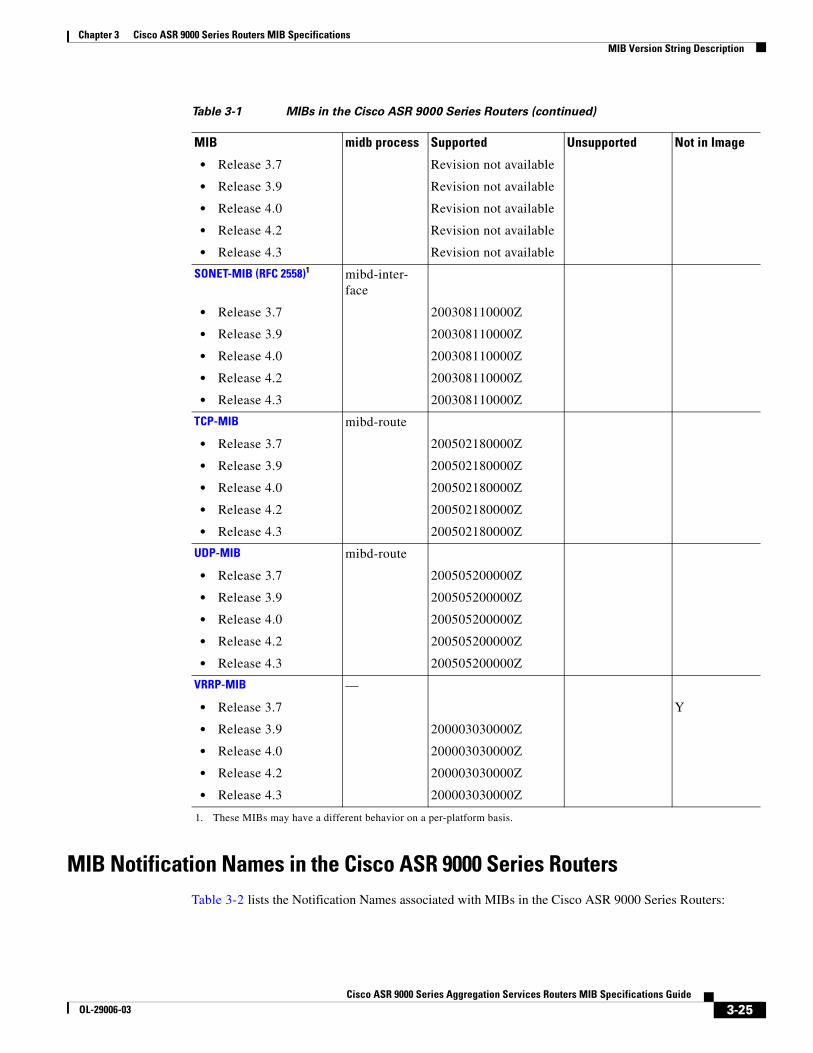
MIBs in the Cisco ASR 9000 Series RoutersTable 3-1 lists the MIBs in the Cisco ASR 9000 Series routers:
3-2Cisco ASR 9000 Series Aggregation Services Routers MIB Specifications Guide
OL-29006-03
Chapter 3 Cisco ASR 9000 Series Routers MIB SpecificationsMIB Version String Description
Table 3-1 MIBs in the Cisco ASR 9000 Series Routers
MIB midb process Supported Unsupported Not in Image
ATM-MIB1 mibd-interface
• Release 3.7 9810191200Z
• Release 3.9 9810191200Z
• Release 4.0 9810191200Z
• Release 4.2 9810191200Z
• Release 4.3 9810191200Z
ATM-FORUM-MIB1
• Release 3.7 — Revision not available
• Release 3.9 Revision not available
• Release 4.0 Revision not available
• Release 4.2 Revision not available
• Release 4.3 Revision not available
ATM2-MIB1 mibd-interface
• Release 3.7 200309230000Z
• Release 3.9 200309230000Z
• Release 4.0 200309230000Z
• Release 4.2 200309230000Z
• Release 4.3 200309230000Z
BGP4-MIB mibd-route
• Release 3.7 RFC 4273
• Release 3.9 RFC 4273
• Release 4.0 RFC 4273
• Release 4.2 RFC 4273
• Release 4.3 RFC 4273
BRIDGE-MIB1 mibd-interface
• Release 3.7 RFC 4188
• Release 3.9 RFC 4188
• Release 4.0 RFC 4188
• Release 4.2 RFC 4188
• Release 4.3 RFC 4188
CISCO-AAA-SERVER-MIB1 mibd-interface
• Release 3.7
• Release 3.9
3-3Cisco ASR 9000 Series Aggregation Services Routers MIB Specifications Guide
OL-29006-03
Chapter 3 Cisco ASR 9000 Series Routers MIB SpecificationsMIB Version String Description
• Release 4.0
• Release 4.2
• Release 4.3 200311170000Z
CISCO-ATM-EXT-MIB1 mibd-interface
• Release 3.7 200301060000Z
• Release 3.9 200301060000Z
• Release 4.0 200301060000Z
• Release 4.2 200301060000Z
• Release 4.3 200301060000Z
CISCO-ATM-QOS-MIB1 mibd-interface
• Release 3.7 200206100000Z
• Release 3.9 200206100000Z
• Release 4.0 200206100000Z
• Release 4.2 200206100000Z
• Release 4.3 200206100000Z
CISCO-BGP4-MIB mibd-route
• Release 3.7 200302240000Z
• Release 3.9 200302240000Z
• Release 4.0 200302240000Z
• Release 4.2 200302240000Z
• Release 4.3 200302240000Z
CISCO-BGP-POL-ICY-ACCOUNTING-MIB
mibd-interface
• Release 3.7 200207260000Z
• Release 3.9 200207260000Z
• Release 4.0 200207260000Z
• Release 4.2 200207260000Z
• Release 4.3 200207260000Z
CISCO-BULK-FILE-MIB1 mibd-infra
• Release 3.7 200206100000Z
• Release 3.9 200206100000Z
• Release 4.0 200206100000Z
• Release 4.2 200207260000Z
• Release 4.3 200206100000Z
Table 3-1 MIBs in the Cisco ASR 9000 Series Routers (continued)
MIB midb process Supported Unsupported Not in Image
3-4Cisco ASR 9000 Series Aggregation Services Routers MIB Specifications Guide
OL-29006-03
Chapter 3 Cisco ASR 9000 Series Routers MIB SpecificationsMIB Version String Description
CISCO-CDP-MIB mibd-interface
• Release 3.7 9812100000Z
• Release 3.9 9812100000Z
• Release 4.0 9812100000Z
• Release 4.2 9812100000Z
• Release 4.3 9812100000Z
CISCO-CLASS-BASED-QOS-MIB1
mibd-interface
• Release 3.7 200901260000Z
• Release 3.9 200901260000Z
• Release 4.0 200901260000Z
• Release 4.2 200901260000Z
• Release 4.3 200901260000Z
CISCO-CONFIG-COPY-MIB mibd-infra
• Release 3.7 200504060000Z
• Release 3.9 200504060000Z
• Release 4.0 200504060000Z
• Release 4.2 200504060000Z
• Release 4.3 200504060000Z
CISCO-CONFIG-MAN-MIB mibd-infra
• Release 3.7 200704270000Z
• Release 3.9 200704270000Z
• Release 4.0 200704270000Z
• Release 4.2 200704270000Z
• Release 4.3 200704270000Z
CISCO-CONTEXT-MAP-PING-MIB
mibd-infra
• Release 3.7 200811220000Z
• Release 3.9 200811220000Z
• Release 4.0 200811220000Z
• Release 4.2 200811220000Z
• Release 4.3 200811220000Z
CISCO-DS3-MIB1 mibd-interface
• Release 3.7 200205210000Z
• Release 3.9 200205210000Z
Table 3-1 MIBs in the Cisco ASR 9000 Series Routers (continued)
MIB midb process Supported Unsupported Not in Image
3-5Cisco ASR 9000 Series Aggregation Services Routers MIB Specifications Guide
OL-29006-03
Chapter 3 Cisco ASR 9000 Series Routers MIB SpecificationsMIB Version String Description
• Release 4.0 200205210000Z
• Release 4.2 200205210000Z
• Release 4.3 200205210000Z
CISCO-ENHANCED-IMAGE-MIB1
mibd-entity
• Release 3.7 200501060000Z
• Release 3.9 200501060000Z
• Release 4.0 200501060000Z
• Release 4.2 200501060000Z
• Release 4.3 200501060000Z
CISCO-ENHANCED-MEM-POOL-MIB1
mibd-entity
• Release 3.7 200812050000Z
• Release 3.9 200812050000Z
• Release 4.0 200812050000Z
• Release 4.2 200812050000Z
• Release 4.3 200812050000Z
CISCO-ENTITY-ASSET-MIB1 mibd-entity
• Release 3.7 200309180000Z
• Release 3.9 200309180000Z
• Release 4.0 200309180000Z
• Release 4.2 200309180000Z
• Release 4.3 200309180000Z
CISCO-ENTITY-FRU-CON-TROL-MIB1
mibd-entity
• Release 3.7 200810080000Z
• Release 3.9 200810080000Z
• Release 4.0 200810080000Z
• Release 4.2 200810080000Z
CISCO-ENTITY-REDUN-DANCY-MIB1
mibd-entity
• Release 3.7
• Release 3.9
• Release 4.0
• Release 4.2
• Release 4.3 200510010000Z
CISCO-ENTITY-SEN-SOR-MIB1
mibd-entity
Table 3-1 MIBs in the Cisco ASR 9000 Series Routers (continued)
MIB midb process Supported Unsupported Not in Image
3-6Cisco ASR 9000 Series Aggregation Services Routers MIB Specifications Guide
OL-29006-03
Chapter 3 Cisco ASR 9000 Series Routers MIB SpecificationsMIB Version String Description
• Release 3.7 200711120000Z
• Release 3.9 200711120000Z
• Release 4.0 200711120000Z
• Release 4.2 200711120000Z
• Release 4.3 200711120000Z
CISCO-ENTITY-STATE-EXT-MIB1
mibd-infra
• Release 3.7 201006160000Z
• Release 3.9 201006160000Z
• Release 4.0 201006160000Z
• Release 4.2 201006160000Z
• Release 4.3 201006160000Z
CISCO-FLASH-MIB1 mibd-infra
• Release 3.7 200906030000Z
• Release 3.9 200906030000Z
• Release 4.0 200906030000Z
• Release 4.2 200906030000Z
• Release 4.3 200906030000Z
CISCO-FLOW-CLONE-MIB mibd-entity
• Release 3.7 201010190000Z
• Release 3.9 201010190000Z
• Release 4.0 201010190000Z
• Release 4.2 201010190000Z
• Release 4.3 201010190000Z
CISCO-FLOW-MONITOR-MIB
mibd-entity
• Release 3.7 201104190000Z
• Release 3.9 201104190000Z
• Release 4.0 201104190000Z
• Release 4.2 201104190000Z
• Release 4.3 201104190000Z
CISCO-FRAME-RELAY-MIB1 mibd-interface
• Release 3.7 200010130000Z
• Release 3.9 200010130000Z
• Release 4.0 200010130000Z
• Release 4.2 200010130000Z
Table 3-1 MIBs in the Cisco ASR 9000 Series Routers (continued)
MIB midb process Supported Unsupported Not in Image
3-7Cisco ASR 9000 Series Aggregation Services Routers MIB Specifications Guide
OL-29006-03
Chapter 3 Cisco ASR 9000 Series Routers MIB SpecificationsMIB Version String Description
• Release 4.3 200010130000Z
CISCO-FTP-CLIENT-MIB1 mibd-infra
• Release 3.7 200603310000Z
• Release 3.9 200603310000Z
• Release 4.0 200603310000Z
• Release 4.2 200603310000Z
• Release 4.3 200603310000Z
CISCO-HSRP-EXT-MIB mibd-interface
• Release 3.7 9808030000Z
• Release 3.9 9808030000Z
• Release 4.0 9808030000Z
• Release 4.2 9808030000Z
• Release 4.3 9808030000Z
CISCO-HSRP-MIB mibd-interface
• Release 3.7 9808030000Z
• Release 3.9 9808030000Z
• Release 4.0 9808030000Z
• Release 4.2 9808030000Z
• Release 4.3 9808030000Z
CISCO-IETF-BFD-MIB mibd-route
• Release 3.7 200804240000Z
• Release 3.9 200804240000Z
• Release 4.0 200804240000Z
• Release 4.2 200804240000Z
• Release 4.3 200804240000Z
CISCO-IETF-FRR-MIB mibd-route
• Release 3.7 200804291200Z
• Release 3.9 200804291200Z
• Release 4.0 200804291200Z
• Release 4.2 200804291200Z
• Release 4.3 200804291200Z
CISCO-IETF-MPLS-TE-P2MP-STD-MIB
mibd-inter-face
• Release 3.7 200909300000Z
• Release 3.9 200909300000Z
Table 3-1 MIBs in the Cisco ASR 9000 Series Routers (continued)
MIB midb process Supported Unsupported Not in Image
3-8Cisco ASR 9000 Series Aggregation Services Routers MIB Specifications Guide
OL-29006-03
Chapter 3 Cisco ASR 9000 Series Routers MIB SpecificationsMIB Version String Description
• Release 4.0 200909300000Z
• Release 4.2 200909300000Z
• Release 4.3 200909300000Z
CISCO-IETF-IPMROUTE-MIB mibd-inter-face
• Release 3.7 200608240000Z
• Release 3.9 200608240000Z
• Release 4.0 200608240000Z
• Release 4.2 200608240000Z
• Release 4.3 200608240000Z
CISCO-IETF-MSDP-MIB mibd-inter-face
• Release 3.7 200605190000Z
• Release 3.9 200605190000Z
• Release 4.0 200605190000Z
• Release 4.2 200605190000Z
• Release 4.3 200605190000Z
CISCO-IETF-PIM-MIB —
• Release 3.7 200502220000Z
• Release 3.9 200502220000Z
• Release 4.0 200502220000Z
• Release 4.2 200502220000Z
CISCO-IETF-PIM-EXT-MIB mibd-inter-face
• Release 3.7 200608250000Z
• Release 3.9 200608250000Z
• Release 4.0 200608250000Z
• Release 4.2 200608250000Z
• Release 4.3 200608250000Z
CISCO-IETF-PW-MIB mibd-inter-face
• Release 3.7 200512200000Z
• Release 3.9 200512200000Z
• Release 4.0 200512200000Z
• Release 4.2 200512200000Z
• Release 4.3 200512200000Z
Table 3-1 MIBs in the Cisco ASR 9000 Series Routers (continued)
MIB midb process Supported Unsupported Not in Image
3-9Cisco ASR 9000 Series Aggregation Services Routers MIB Specifications Guide
OL-29006-03
Chapter 3 Cisco ASR 9000 Series Routers MIB SpecificationsMIB Version String Description
CISCO-IETF-PW-ENET-MIB mibd-inter-face
• Release 3.7 200209221200Z
• Release 3.9 200209221200Z
• Release 4.0 200209221200Z
• Release 4.2 200209221200Z
• Release 4.3 200209221200Z
CISCO-IETF-PW-FR-MIB mibd-inter-face
• Release 3.7 200312160000Z
• Release 3.9 200312160000Z
• Release 4.0 200312160000Z
• Release 4.2 200312160000Z
• Release 4.3 200312160000Z
CISCO-IETF-PW-MPLS-MIB mibd-inter-face
• Release 3.7 200302261200Z
• Release 3.9 200302261200Z
• Release 4.0 200302261200Z
• Release 4.2 200302261200Z
• Release 4.3 200302261200Z
CISCO-IETF-VPLS-BGP-EXT-MIB
mibd-inter-face
• Release 3.7 200810240000Z
• Release 3.9 200810240000Z
• Release 4.0 200810240000Z
• Release 4.2 200810240000Z
• Release 4.3 200810240000Z
CISCO-IETF-VPLS-GENERIC-MIB1
mibd-inter-face
• Release 3.7 200710221200Z
• Release 3.9 200710221200Z
• Release 4.0 200710221200Z
• Release 4.2 200710221200Z
• Release 4.3 200710221200Z
CISCO-IETF-VPLS-LDP-MIB1 mibd-inter-face
• Release 3.7 200711221200Z
Table 3-1 MIBs in the Cisco ASR 9000 Series Routers (continued)
MIB midb process Supported Unsupported Not in Image
3-10Cisco ASR 9000 Series Aggregation Services Routers MIB Specifications Guide
OL-29006-03
Chapter 3 Cisco ASR 9000 Series Routers MIB SpecificationsMIB Version String Description
• Release 3.9 200711221200Z
• Release 4.0 200711221200Z
• Release 4.2 200711221200Z
• Release 4.3 200711221200Z
CISCO-IF-EXTENSION-MIB1 mibd-inter-face
• Release 3.7 200707230000Z
• Release 3.9 200707230000Z
• Release 4.0 200707230000Z
• Release 4.2 200707230000Z
• Release 4.3 200707230000Z
CISCO-IP-CBR-MET-RICS-MIB
mibd-inter-face
• Release 3.7 200906110000Z
• Release 3.9 200906110000Z
• Release 4.0 200906110000Z
• Release 4.2 200906110000Z
• Release 4.3 200906110000Z
CISCO-IP-TAP-MIB mibd-inter-face
• Release 3.7 200403110000Z
• Release 3.9 200403110000Z
• Release 4.0 200403110000Z
• Release 4.2 200403110000Z
• Release 4.3 200403110000Z
CISCO-IP-STAT-MIB mibd-inter-face
• Release 3.7 200112202300Z
• Release 3.9 200112202300Z
• Release 4.0 200112202300Z
• Release 4.2 200112202300Z
• Release 4.3 200112202300Z
CISCO-IPSEC-MIB
• Release 3.7 mibd-inter-face
200008071139Z
• Release 3.9 200008071139Z
• Release 4.0 200008071139Z
Table 3-1 MIBs in the Cisco ASR 9000 Series Routers (continued)
MIB midb process Supported Unsupported Not in Image
3-11Cisco ASR 9000 Series Aggregation Services Routers MIB Specifications Guide
OL-29006-03
Chapter 3 Cisco ASR 9000 Series Routers MIB SpecificationsMIB Version String Description
• Release 4.2 200008071139Z
• Release 4.3 200008071139Z
CISCO-IPSEC-FLOW-MONITOR-MIB
mibd-inter-face
• Release 3.7 200710240000Z
• Release 3.9 200710240000Z
• Release 4.0 200710240000Z
• Release 4.2 200710240000Z
• Release 4.3 200710240000Z
CISCO-LICENSE-MGMT-MIB1
mibd-infra
• Release 3.7 200107310000Z
• Release 3.9 200107310000Z
• Release 4.0 200107310000Z
• Release 4.2 200107310000Z
• Release 4.3 200107310000Z
CISCO-MLD-SNOOPING-MIB
• Release 3.7 mibd-inter-face
201007020000Z
• Release 3.9 201007020000Z
• Release 4.0 201007020000Z
• Release 4.2 201007020000Z
• Release 4.3 201007020000Z
CISCO-NETSYNC-MIB mibd-inter-face
• Release 3.7
• Release 3.9
• Release 4.0
• Release 4.2
• Release 4.3 201010150000Z
CISCO-NTP-MIB mibd-inter-face
• Release 3.7 200607310000Z
• Release 3.9 200607310000Z
• Release 4.0 200607310000Z
• Release 4.2 200607310000Z
• Release 4.3 200607310000Z
Table 3-1 MIBs in the Cisco ASR 9000 Series Routers (continued)
MIB midb process Supported Unsupported Not in Image
3-12Cisco ASR 9000 Series Aggregation Services Routers MIB Specifications Guide
OL-29006-03
Chapter 3 Cisco ASR 9000 Series Routers MIB SpecificationsMIB Version String Description
CISCO-OAM-MIB
• Release 3.7 mibd-inter-face
200602170000Z
• Release 3.9 200602170000Z
• Release 4.0 200602170000Z
• Release 4.2 200602170000Z
• Release 4.3 200602170000Z
CISCO-PTP-MIB mibd-inter-face
• Release 3.7
• Release 3.9
• Release 4.0
• Release 4.2
• Release 4.3 201101280000Z
CISCO-P2P-IF-MIB mibd-inter-face
• Release 3.7 200808120000Z
• Release 3.9 200808120000Z
• Release 4.0 200808120000Z
• Release 4.2 200808120000Z
• Release 4.3 200808120000Z
CISCO-PIM-MIB mibd-inter-face
• Release 3.7 200011020000Z
• Release 3.9 200011020000Z
• Release 4.0 200011020000Z
• Release 4.2 200011020000Z
• Release 4.3 200011020000Z
CISCO-PING-MIB mibd-route
• Release 3.7 200108280000Z
• Release 3.9 200108280000Z
• Release 4.0 200108280000Z
• Release 4.2 200108280000Z
• Release 4.3 200108280000Z
CISCO-PROCESS-MIB1 mibd-entity
• Release 3.7 200910120000Z
• Release 3.9 200910120000Z
Table 3-1 MIBs in the Cisco ASR 9000 Series Routers (continued)
MIB midb process Supported Unsupported Not in Image
3-13Cisco ASR 9000 Series Aggregation Services Routers MIB Specifications Guide
OL-29006-03
Chapter 3 Cisco ASR 9000 Series Routers MIB SpecificationsMIB Version String Description
• Release 4.0 200910120000Z
• Release 4.2 200910120000Z
• Release 4.3 200910120000Z
CISCO-RF-MIB1 mibd-infra
• Release 3.7 200803180000Z
• Release 3.9 200803180000Z
• Release 4.0 200803180000Z
• Release 4.2 200803180000Z
• Release 4.3 200803180000Z
CISCO-RTTMON-MIB mibd_entity
• Release 3.7 200803240000Z
• Release 3.9 200803240000Z
• Release 4.0 200803240000Z
• Release 4.2 200803240000Z
• Release 4.3 200803240000Z
CISCO-SELEC-TIVE-VRF-DOWNLOAD-MIB
mibd-infra
• Release 3.7 201106220000Z
• Release 3.9 201106220000Z
• Release 4.0 201106220000Z
• Release 4.2 201106220000Z
• Release 4.3 201106220000Z
CISCO-SONET-MIB1 mibd-inter-face
• Release 3.7 200303070000Z
• Release 3.9 200303070000Z
• Release 4.0 200303070000Z
• Release 4.2 200303070000Z
• Release 4.3 200303070000Z
CISCO-SUBSCRIBER-SES-SION-MIB
mibd-infra
• Release 3.7
• Release 3.9
• Release 4.0
• Release 4.2
• Release 4.3 201208080000Z
CISCO-SYSLOG-MIB mibd-infra
Table 3-1 MIBs in the Cisco ASR 9000 Series Routers (continued)
MIB midb process Supported Unsupported Not in Image
3-14Cisco ASR 9000 Series Aggregation Services Routers MIB Specifications Guide
OL-29006-03
Chapter 3 Cisco ASR 9000 Series Routers MIB SpecificationsMIB Version String Description
• Release 3.7 200512030000Z
• Release 3.9 200512030000Z
• Release 4.0 200512030000Z
• Release 4.2 200512030000Z
• Release 4.3 200512030000Z
CISCO-SYSTEM-MIB mibd-infra
• Release 3.7 200709160000Z
• Release 3.9 200709160000Z
• Release 4.0 200709160000Z
• Release 4.2 200709160000Z
• Release 4.3 200709160000Z
CISCO-TAP2-MIB mibd-route
• Release 3.7 200809100000Z
• Release 3.9 200809100000Z
• Release 4.0 200809100000Z
• Release 4.2 200809100000Z
• Release 4.3 200809100000Z
CISCO-TCP-MIB mibd-route
• Release 3.7 200111120000Z
• Release 3.9 200111120000Z
• Release 4.0 200111120000Z
• Release 4.2 200111120000Z
• Release 4.3 200111120000Z
CISCO-VPDN-MGMT-MIB mibd-inter-face
• Release 3.7
• Release 3.9
• Release 4.0
• Release 4.2
• Release 4.3 200906160000Z
CISCO-VLAN-IFTABLE-RELA-TIONSHIP-MIB
mibd-inter-face
• Release 3.7 9904010530Z
• Release 3.9 9904010530Z
• Release 4.0 9904010530Z
• Release 4.2 9904010530Z
• Release 4.3 9904010530Z
Table 3-1 MIBs in the Cisco ASR 9000 Series Routers (continued)
MIB midb process Supported Unsupported Not in Image
3-15Cisco ASR 9000 Series Aggregation Services Routers MIB Specifications Guide
OL-29006-03
Chapter 3 Cisco ASR 9000 Series Routers MIB SpecificationsMIB Version String Description
DISMAN-EXPRESSION-MIB mibd-inter-face
• Release 3.7 200010160000Z
• Release 3.9 200010160000Z
• Release 4.0 200010160000Z
• Release 4.2 200010160000Z
• Release 4.3 200010160000Z
DOT3-OAM-MIB mibd-inter-face
• Release 3.7 200706140000Z
• Release 3.9 200706140000Z
• Release 4.0 200706140000Z
• Release 4.2 200706140000Z
• Release 4.3 200706140000Z
DS1-MIB (RFC 2495)1 mibd-inter-face
• Release 3.7 9808011830Z
• Release 3.9 9808011830Z
• Release 4.0 9808011830Z
• Release 4.2 9808011830Z
• Release 4.3 9808011830Z
DS3-MIB1 mibd-inter-face
• Release 3.7 200205210000Z
• Release 3.9 200205210000Z
• Release 4.0 200205210000Z
• Release 4.2 200205210000Z
• Release 4.3 200205210000Z
ENTITY-MIB (RFC 2737)1 mibd-entity
• Release 3.7 RFC 2737
• Release 3.9 RFC 2737
• Release 4.0 RFC 2737
• Release 4.2 RFC 2737
• Release 4.3 RFC 2737
ENTITY-STATE-MIB mibd-entity
• Release 3.7 200511220000Z
• Release 3.9 200511220000Z
Table 3-1 MIBs in the Cisco ASR 9000 Series Routers (continued)
MIB midb process Supported Unsupported Not in Image
3-16Cisco ASR 9000 Series Aggregation Services Routers MIB Specifications Guide
OL-29006-03
Chapter 3 Cisco ASR 9000 Series Routers MIB SpecificationsMIB Version String Description
• Release 4.0 200511220000Z
• Release 4.2 200511220000Z
• Release 4.3 200511220000Z
ETHERLIKE-MIB (RFC 2665, 3635)
mibd-entity
• Release 3.7 200309190000Z
• Release 3.9 200309190000Z
• Release 4.0 200309190000Z
• Release 4.2 200309190000Z
• Release 4.3 200309190000Z
EVENT-MIB mibd-infra
• Release 3.7 RFC 2981
• Release 3.9 RFC 2981
• Release 4.0 RFC 2981
• Release 4.2 RFC 2981
• Release 4.3 RFC 2981
EXPRESSION-MIB mibd-infra
• Release 3.7 200511240000Z
• Release 3.9 200511240000Z
• Release 4.0 200511240000Z
• Release 4.2 200511240000Z
• Release 4.3 200511240000Z
FRAME-RELAY-DTE-MIB1 mibd-inter-face
• Release 3.7 9705010229Z
• Release 3.9 9705010229Z
• Release 4.0 9705010229Z
• Release 4.2 9705010229Z
• Release 4.3 9705010229Z
IEEE8021-CFM-MIB mibd-inter-face
• Release 3.7 200706100000Z
• Release 3.9 200706100000Z
• Release 4.0 200706100000Z
• Release 4.2 200706100000Z
• Release 4.3 200706100000Z
Table 3-1 MIBs in the Cisco ASR 9000 Series Routers (continued)
MIB midb process Supported Unsupported Not in Image
3-17Cisco ASR 9000 Series Aggregation Services Routers MIB Specifications Guide
OL-29006-03
Chapter 3 Cisco ASR 9000 Series Routers MIB SpecificationsMIB Version String Description
IEEE8023-LAG-MIB mibd-inter-face
• Release 3.7 200006270000Z
• Release 3.9 200006270000Z
• Release 4.0 200006270000Z
• Release 4.2 200006270000Z
• Release 4.3 200006270000Z
IETF-TCP-MIB1 mibd-inter-face
• Release 3.7 200402040000Z
• Release 3.9 200402040000Z
• Release 4.0 200402040000Z
• Release 4.2 200402040000Z
• Release 4.3 200402040000Z
IETF-UDP-MIB1 mibd-inter-face
• Release 3.7 200410180000Z
• Release 3.9 200410180000Z
• Release 4.0 200410180000Z
• Release 4.2 200410180000Z
• Release 4.3 200410180000Z
IF-MIB (RFC 2863)1 mibd-inter-face
• Release 3.7 RFC 2233
• Release 3.9 RFC 2233
• Release 4.0 RFC 2233
• Release 4.2 RFC 2233
• Release 4.3 RFC 2233
IMA-MIB mibd-inter-face
• Release 3.7 200303260000Z
• Release 3.9 200303260000Z
• Release 4.0 200303260000Z
• Release 4.2 200303260000Z
• Release 4.3 200303260000Z
IP-FORWARD-MIB mibd-route
Table 3-1 MIBs in the Cisco ASR 9000 Series Routers (continued)
MIB midb process Supported Unsupported Not in Image
3-18Cisco ASR 9000 Series Aggregation Services Routers MIB Specifications Guide
OL-29006-03
Chapter 3 Cisco ASR 9000 Series Routers MIB SpecificationsMIB Version String Description
• Release 3.7 RFC 2096
RFC 4292
• Release 3.9 RFC 2096
RFC 4292
• Release 4.0 RFC 2096
RFC 4292
• Release 4.2 RFC 2096
RFC 4292
• Release 4.3 RFC 2096
RFC 4292
IP-MIB mibd-inter-face
• Release 3.7 RFC 2011
• Release 3.9 RFC 2011
• Release 4.0 RFC 2011
• Release 4.2 RFC 2011
• Release 4.3 RFC 2011
IPV6-MIB mibd-inter-face
• Release 3.7 9802052155Z
• Release 3.9 9802052155Z
• Release 4.0 9802052155Z
• Release 4.2 9802052155Z
• Release 4.3 9802052155Z
IPV6-FORWARD-MIB mibd-inter-face
• Release 3.7 200402091200Z
• Release 3.9 200402091200Z
• Release 4.0 200402091200Z
• Release 4.2 200402091200Z
• Release 4.3 200402091200Z
IPV6-MLD-MIB mibd-inter-face
• Release 3.7 200101250000Z
• Release 3.9 200101250000Z
• Release 4.0 200101250000Z
• Release 4.2 200101250000Z
Table 3-1 MIBs in the Cisco ASR 9000 Series Routers (continued)
MIB midb process Supported Unsupported Not in Image
3-19Cisco ASR 9000 Series Aggregation Services Routers MIB Specifications Guide
OL-29006-03
Chapter 3 Cisco ASR 9000 Series Routers MIB SpecificationsMIB Version String Description
• Release 4.3 200101250000Z
ISIS-MIB mibd-route
• Release 3.7 200604040000Z
• Release 3.9 200604040000Z
• Release 4.0 200604040000Z
• Release 4.2 200604040000Z
• Release 4.3 200604040000Z
MAU-MIB mibd-route
• Release 3.7 200704210000Z
• Release 3.9 200704210000Z
• Release 4.0 200704210000Z
• Release 4.2 200704210000Z
• Release 4.3 200704210000Z
MFR-MIB mibd-route
• Release 3.7 200011300000Z
• Release 3.9 200011300000Z
• Release 4.0 200011300000Z
• Release 4.2 200011300000Z
• Release 4.3 200011300000Z
MGMD-STD-MIB mibd-route
• Release 3.7 200302240000Z
• Release 3.9 200302240000Z
• Release 4.0 200302240000Z
• Release 4.2 200302240000Z
• Release 4.3 200302240000Z
MPLS-L3VPN-STD-MIB mibd-route
• Release 3.7 200601230000Z
• Release 3.9 200601230000Z
• Release 4.0 200601230000Z
• Release 4.2 200601230000Z
• Release 4.3 200601230000Z
MPLS-LDP-GENERIC-STD-MIB
mibd-route
• Release 3.7 200406030000Z
• Release 3.9 200406030000Z
• Release 4.0 200406030000Z
Table 3-1 MIBs in the Cisco ASR 9000 Series Routers (continued)
MIB midb process Supported Unsupported Not in Image
3-20Cisco ASR 9000 Series Aggregation Services Routers MIB Specifications Guide
OL-29006-03
Chapter 3 Cisco ASR 9000 Series Routers MIB SpecificationsMIB Version String Description
• Release 4.2 200406030000Z
• Release 4.3 200406030000Z
MPLS-LDP-STD-MIB mibd-route
• Release 3.7 200406030000Z
• Release 3.9 200406030000Z
• Release 4.0 200406030000Z
• Release 4.2 200406030000Z
• Release 4.3 200406030000Z
MPLS-LSR-STD-MIB mibd-route
• Release 3.7 200406030000Z
• Release 3.9 200406030000Z
• Release 4.0 200406030000Z
• Release 4.2 200406030000Z
• Release 4.3 200406030000Z
MPLS-TE-STD-MIB mibd-route
• Release 3.7 RFC 3812
• Release 3.9 RFC 3812
• Release 4.0 RFC 3812
• Release 4.2 RFC 3812
• Release 4.3 RFC 3812
NOTIFICATION-LOG-MIB mibd-infra
• Release 3.7 200011270000Z
• Release 3.9 200011270000Z
• Release 4.0 200011270000Z
• Release 4.2 200011270000Z
• Release 4.3 200011270000Z
OSPF-MIB mibd-route
• Release 3.7 200611100000Z
• Release 3.9 200611100000Z
• Release 4.0 200611100000Z
• Release 4.2 200611100000Z
• Release 4.3 200611100000Z
OSPF-TRAP-MIB —
• Release 3.7 200611100000Z
• Release 3.9 200611100000Z
• Release 4.0 200611100000Z
Table 3-1 MIBs in the Cisco ASR 9000 Series Routers (continued)
MIB midb process Supported Unsupported Not in Image
3-21Cisco ASR 9000 Series Aggregation Services Routers MIB Specifications Guide
OL-29006-03
Chapter 3 Cisco ASR 9000 Series Routers MIB SpecificationsMIB Version String Description
• Release 4.2 200611100000Z
• Release 4.3 200611100000Z
OSPFV3-MIB mibd-route
• Release 3.7 200709171200Z
• Release 3.9 200709171200Z
• Release 4.0 200709171200Z
• Release 4.2 200709171200Z
• Release 4.3 200709171200Z
RADIUS-ACC-CLIENT-MIB1 mibd-infra
• Release 3.7 200300000000Z
• Release 3.9 200300000000Z
• Release 4.0 200300000000Z
• Release 4.2 200300000000Z
• Release 4.3 200300000000Z
RADIUS-AUTH-CLIENT-MIB1 mibd-infra
• Release 3.7 200300000000Z
• Release 3.9 200300000000Z
• Release 4.0 200300000000Z
• Release 4.2 200300000000Z
• Release 4.3 200300000000Z
RFC1213-MIB1 —
• Release 3.7 Revision not available
• Release 3.9 Revision not available
• Release 4.0 Revision not available
• Release 4.2 Revision not available
• Release 4.3 Revision not available
RFC 2011-MIB —
• Release 3.7 9411010000Z
• Release 3.9 9411010000Z
• Release 4.0 9411010000Z
• Release 4.2 9411010000Z
• Release 4.3 9411010000Z
RFC 2465-MIB —
• Release 3.7 9802052155Z
• Release 3.9 9802052155Z
• Release 4.0 9802052155Z
Table 3-1 MIBs in the Cisco ASR 9000 Series Routers (continued)
MIB midb process Supported Unsupported Not in Image
3-22Cisco ASR 9000 Series Aggregation Services Routers MIB Specifications Guide
OL-29006-03
Chapter 3 Cisco ASR 9000 Series Routers MIB SpecificationsMIB Version String Description
• Release 4.2 9802052155Z
• Release 4.3 9802052155Z
RSVP-MIB1 mibd-inter-face
• Release 3.7 9808251820Z
• Release 3.9 9808251820Z
• Release 4.0 9808251820Z
• Release 4.2 9808251820Z
• Release 4.3 9808251820Z
SNMP-COMMUNITY-MIB (RFC 2576)
snmpd
• Release 3.7 200210140000Z
• Release 3.9 200210140000Z
• Release 4.0 200210140000Z
• Release 4.2 200210140000Z
• Release 4.3 200210140000Z
SNMP-FRAMEWORK-MIB (RFC 2571)
snmpd
• Release 3.7 200210140000Z
• Release 3.9 200210140000Z
• Release 4.0 200210140000Z
• Release 4.2 200210140000Z
• Release 4.3 200210140000Z
SNMP-RESEARCH-MIB snmpd
• Release 3.7 Revision not available
• Release 3.9 Revision not available
• Release 4.0 Revision not available
• Release 4.2 Revision not available
• Release 4.3 Revision not available
SNMP-MPD-MIB snmpd
• Release 3.7 9905041636Z
• Release 3.9 9905041636Z
• Release 4.0 9905041636Z
• Release 4.2 9905041636Z
• Release 4.3 9905041636Z
SNMP-NOTIFICATION-MIB (RFC 2573)
snmpd
• Release 3.7 9808040000Z
Table 3-1 MIBs in the Cisco ASR 9000 Series Routers (continued)
MIB midb process Supported Unsupported Not in Image
3-23Cisco ASR 9000 Series Aggregation Services Routers MIB Specifications Guide
OL-29006-03
Chapter 3 Cisco ASR 9000 Series Routers MIB SpecificationsMIB Version String Description
• Release 3.9 9808040000Z
• Release 4.0 9808040000Z
• Release 4.2 9808040000Z
• Release 4.3 9808040000Z
SNMP-TARGET-MIB (RFC 2573)
snmpd
• Release 3.7 9808040000Z
• Release 3.9 9808040000Z
• Release 4.0 9808040000Z
• Release 4.2 9808040000Z
• Release 4.3 9808040000Z
SNMP-USM-AES-MIB snmpd
• Release 3.7 200406140000Z
• Release 3.9 200406140000Z
• Release 4.0 200406140000Z
• Release 4.2 200406140000Z
• Release 4.3 200406140000Z
SNMP-USM-MIB (RFC 2574) snmpd
• Release 3.7 9901200000Z
• Release 3.9 9901200000Z
• Release 4.0 9901200000Z
• Release 4.2 9901200000Z
• Release 4.3 9901200000Z
SNMP-VACM-MIB snmpd
• Release 3.7 RFC 2575
• Release 3.9 RFC 2575
• Release 4.0 RFC 2575
• Release 4.2 RFC 2575
• Release 4.3 RFC 2575
SNMPv2-MIB (RFC 1907) snmpd
• Release 3.7 RFC 1904
• Release 3.9 RFC 1904
• Release 4.0 RFC 1904
• Release 4.2 RFC 1904
• Release 4.3 RFC 1904
SNMPv2-TM snmpd
Table 3-1 MIBs in the Cisco ASR 9000 Series Routers (continued)
MIB midb process Supported Unsupported Not in Image
3-24Cisco ASR 9000 Series Aggregation Services Routers MIB Specifications Guide
OL-29006-03
Chapter 3 Cisco ASR 9000 Series Routers MIB SpecificationsMIB Version String Description
MIB Notification Names in the Cisco ASR 9000 Series RoutersTable 3-2 lists the Notification Names associated with MIBs in the Cisco ASR 9000 Series Routers:
• Release 3.7 Revision not available
• Release 3.9 Revision not available
• Release 4.0 Revision not available
• Release 4.2 Revision not available
• Release 4.3 Revision not available
SONET-MIB (RFC 2558)1 mibd-inter-face
• Release 3.7 200308110000Z
• Release 3.9 200308110000Z
• Release 4.0 200308110000Z
• Release 4.2 200308110000Z
• Release 4.3 200308110000Z
TCP-MIB mibd-route
• Release 3.7 200502180000Z
• Release 3.9 200502180000Z
• Release 4.0 200502180000Z
• Release 4.2 200502180000Z
• Release 4.3 200502180000Z
UDP-MIB mibd-route
• Release 3.7 200505200000Z
• Release 3.9 200505200000Z
• Release 4.0 200505200000Z
• Release 4.2 200505200000Z
• Release 4.3 200505200000Z
VRRP-MIB —
• Release 3.7 Y
• Release 3.9 200003030000Z
• Release 4.0 200003030000Z
• Release 4.2 200003030000Z
• Release 4.3 200003030000Z
1. These MIBs may have a different behavior on a per-platform basis.
Table 3-1 MIBs in the Cisco ASR 9000 Series Routers (continued)
MIB midb process Supported Unsupported Not in Image
3-25Cisco ASR 9000 Series Aggregation Services Routers MIB Specifications Guide
OL-29006-03
Chapter 3 Cisco ASR 9000 Series Routers MIB SpecificationsMIB Version String Description
Table 3-2 MIB Notification Names in the Cisco ASR 9000 Series Routers
3-26Cisco ASR 9000 Series Aggregation Services Routers MIB Specifications Guide
OL-29006-03
Chapter 3 Cisco ASR 9000 Series Routers MIB SpecificationsATM-MIB
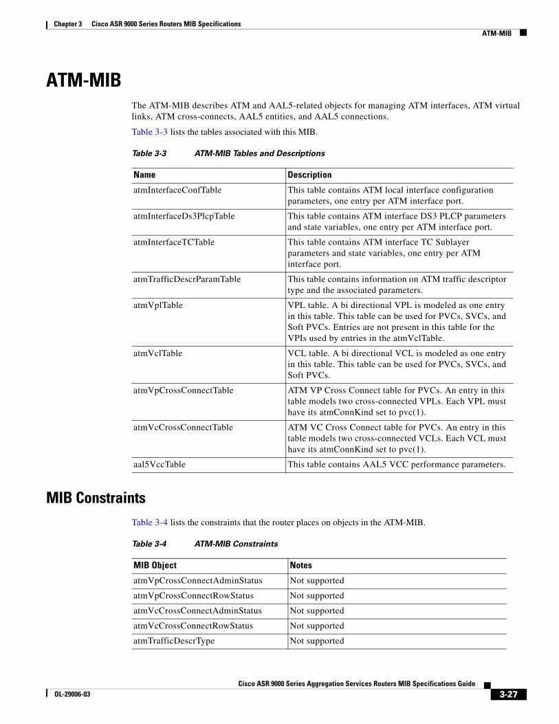
ATM-MIBThe ATM-MIB describes ATM and AAL5-related objects for managing ATM interfaces, ATM virtual links, ATM cross-connects, AAL5 entities, and AAL5 connections.
Table 3-3 lists the tables associated with this MIB.
MIB ConstraintsTable 3-4 lists the constraints that the router places on objects in the ATM-MIB.
Table 3-3 ATM-MIB Tables and Descriptions
Name Description
atmInterfaceConfTable This table contains ATM local interface configuration parameters, one entry per ATM interface port.
atmInterfaceDs3PlcpTable This table contains ATM interface DS3 PLCP parameters and state variables, one entry per ATM interface port.
atmInterfaceTCTable This table contains ATM interface TC Sublayer parameters and state variables, one entry per ATM interface port.
atmTrafficDescrParamTable This table contains information on ATM traffic descriptor type and the associated parameters.
atmVplTable VPL table. A bi directional VPL is modeled as one entry in this table. This table can be used for PVCs, SVCs, and Soft PVCs. Entries are not present in this table for the VPIs used by entries in the atmVclTable.
atmVclTable VCL table. A bi directional VCL is modeled as one entry in this table. This table can be used for PVCs, SVCs, and Soft PVCs.
atmVpCrossConnectTable ATM VP Cross Connect table for PVCs. An entry in this table models two cross-connected VPLs. Each VPL must have its atmConnKind set to pvc(1).
atmVcCrossConnectTable ATM VC Cross Connect table for PVCs. An entry in this table models two cross-connected VCLs. Each VCL must have its atmConnKind set to pvc(1).
aal5VccTable This table contains AAL5 VCC performance parameters.
Table 3-4 ATM-MIB Constraints
MIB Object Notes
atmVpCrossConnectAdminStatus Not supported
atmVpCrossConnectRowStatus Not supported
atmVcCrossConnectAdminStatus Not supported
atmVcCrossConnectRowStatus Not supported
atmTrafficDescrType Not supported
3-27Cisco ASR 9000 Series Aggregation Services Routers MIB Specifications Guide
OL-29006-03
Chapter 3 Cisco ASR 9000 Series Routers MIB SpecificationsATM-FORUM-MIB
ATM-FORUM-MIBThe ATM-FORUM-MIB is one of the ATM Forum's ILMI MIBs, supporting the UNI 4.0 specification.
Table 3-5 lists the tables associated with this MIB:
atmTrafficDescrParam1 Not supported
atmTrafficDescrParam2 Not supported
atmTrafficDescrParam3 Not supported
atmTrafficDescrParam4 Not supported
atmTrafficDescrParam5 Not supported
atmTrafficDescrRowStatus Not supported
atmServiceCategory Not supported
atmTrafficFrameDiscard Not supported
atmVclReceiveTrafficDescrIndex Not supported
atmVclTransmitTrafficDescrIndex Not supported
atmVclRowStatus Not supported
atmVclCastType Not supported
atmVclConnKind Not supported
atmInterfaceMaxVpcs Not supported
atmInterfaceMaxVccs Not supported
atmInterfaceMaxActiveVpiBits Not supported
atmInterfaceMaxActiveVciBits Not supported
atmInterfaceIlmiVpi Not supported
atmInterfaceIlmiVci Not supported
atmInterfaceMyNeighborIpAddress Not supported
atmInterfaceMyNeighborIfName Not supported
atmInterfaceSubscrAddress Not supported
atmVplReceiveTrafficDescrIndex Not supported
atmVplTransmitTrafficDescrIndex Not supported
atmVplRowStatus Not supported
atmVplCastType Not supported
atmVplConnKind Not supported
Table 3-4 ATM-MIB Constraints
MIB Object Notes
3-28Cisco ASR 9000 Series Aggregation Services Routers MIB Specifications Guide
OL-29006-03
Chapter 3 Cisco ASR 9000 Series Routers MIB SpecificationsATM2-MIB
ATM2-MIBThe ATM2-MIB supplements the ATM-MIB as defined in RFC 2515.
Table 3-6 lists the tables associated with this MIB.
Table 3-5 ATM-FORUM-MIB Tables and Descriptions
Name Description
atmfPortTable Table of physical layer status and parameter information for the physical interface of ATM Interface.
atmfAtmLayerTable Table of ATM layer status and parameter information for the ATM Interface.
atmfAtmStatsTable This group is deprecated and should not be implemented except as required for backward compatibility with version 3.1 of the UNI specification.
atmfVpcTable Table of status and parameter information on the virtual path connections which cross this ATM Interface. There is one entry in this table for each permanent virtual path connection.
atmfVpcAbrTable Table of operational parameters related to the ABR virtual path connections which cross this ATM Interface. There is one entry in this table for each ABR virtual path connection. Each virtual path connection represented in this table must also be represented by an entry in the atmfVpcTable.
atmfVccTable Table of status and parameter information on the virtual channel connections which are visible at this ATM Interface. There is one entry in this table for each permanent virtual channel connection, including reserved VCCs that are supported; that is, signaling, OAM flows, and ILMI, but not unassigned cells.
atmfVccAbrTable Table of operational parameters related to the ABR virtual channel connections which cross this ATM Interface. There is one entry in this table for each ABR virtual channel connection. Each virtual channel connection represented in this table must also be represented by an entry in the atmfVccTable.
3-29Cisco ASR 9000 Series Aggregation Services Routers MIB Specifications Guide
OL-29006-03
Chapter 3 Cisco ASR 9000 Series Routers MIB SpecificationsATM2-MIB
Table 3-6 ATM2-MIB Tables and Descriptions
Name Description
atmSvcVpCrossConnectTable ATM SVPC Cross-Connect table. A bi directional VP cross-connect between two switched VPLs is modeled as one entry in this table. A Soft PVPC cross-connect, between a soft permanent VPL and a switched VPL, is also modeled as one entry in this table.
atmSvcVcCrossConnectTable ATM SVCC Cross-Connect table. A bi directional VC cross-connect between two switched VCLs is modeled as one entry in this table. A Soft PVCC cross-connect, between a soft permanent VCL and a switched VCL, is also modeled as one entry in this table.
atmSigStatTable This table contains ATM interface signaling statistics, one entry per ATM signaling interface.
atmSigSupportTable This table contains ATM local interface configuration parameters, one entry per ATM signaling interface.
atmSigDescrParamTable Table contains signaling capabilities of VCLs except the Traffic Descriptor. Traffic descriptors are described in the atmTrafficDescrParamTable.
atmIfRegisteredAddrTable This table contains a list of ATM addresses that can be used for calls to and from a given interface by a switch or service. The ATM addresses are either registered by the endsystem via ILMI or statically configured. This table does not expose PNNI reachability information. ILMI registered addresses cannot be deleted using this table. This table only applies to switches and network services.
atmVclAddrTable This table provides a mapping between the atmVclTable and the ATM called party/calling party address. This table can be used to retrieve the calling party and called party ATM address pair for a given VCL. Note that there can be more than one pair of calling party and called party ATM addresses for a VCL in a point to multi-point call.
atmAddrVclTable This table provides an alternative way to retrieve the atmVclTable. This table can be used to retrieve the indexing to the atmVclTable by an ATM address.
atmVplStatTable This table contains all statistics counters per VPL. It is used to monitor the usage of the VPL in terms of incoming cells and outgoing cells.
atmVplLogicalPortTable Indicates whether the VPL is an ATM Logical Port interface (ifType = 80).
atmVclStatTable This table contains all statistics counters per VCL. It is used to monitor the usage of the VCL in terms of incoming cells and outgoing cells.
atmAal5VclStatTable This table provides a collection of objects providing AAL5 configuration and performance statistics of a VCL.
atmVclGenTable General Information for each VC.
3-30Cisco ASR 9000 Series Aggregation Services Routers MIB Specifications Guide
OL-29006-03
Chapter 3 Cisco ASR 9000 Series Routers MIB SpecificationsATM2-MIB
MIB ConstraintsTable 3-7 lists the constraints that the router places on objects in the ATM2-MIB.
atmInterfaceExtTable This table contains ATM interface configuration and monitoring information not defined in the atmInterfaceConfTable from the ATM-MIB. This includes the type of connection setup procedures, ILMI information, and information on the VPI/VCI range.
atmIlmiSrvcRegTable This table contains a list of all the ATM network services known by this device. The characteristics of these services are made available through the ILMI, using the ILMI general-purpose service registry MIB. These services may be made available to all ATM interfaces (atmIlmiSrvcRegIndex = 0) or to some specific ATM interfaces only (atmIlmiSrvcRegIndex = ATM interface index).
atmIlmiNetworkPrefixTable Table specifying per-interface network prefix(es) supplied by the network side of the UNI during ILMI address registration. When no network prefixes are specified for a particular interface, one or more network prefixes based on the switch address(es) may be used for ILMI address registration.
atmVpCrossConnectXTable This table contains one row per VP Cross-Connect represented in the atmVpCrossConnectTable.
atmVcCrossConnectXTable This table contains one row per VC Cross-Connect represented in the atmVcCrossConnectTable.
atmCurrentlyFailingPVplTable Table indicating all VPLs for which there is an active row in the atmVplTable having an atmVplConnKind value of pvc and an atmVplOperStatus with a value other than up.
atmCurrentlyFailingPVclTable Table indicating all VCLs for which there is an active row in the atmVclTable having an atmVclConnKind value of pvc and an atmVclOperStatus with a value other than up.
Table 3-6 ATM2-MIB Tables and Descriptions (continued)
Name Description
Table 3-7 ATM2-MIB Constraints
MIB Object Notes
atmSigDescrParamAalType Not supported
atmSigDescrParamAalSscsType Not supported
atmSigDescrParamBhliType Not supported
atmSigDescrParamBhliInfo Not supported
atmSigDescrParamBbcConnConf Not supported
atmSigDescrParamBlliLayer2 Not supported
3-31Cisco ASR 9000 Series Aggregation Services Routers MIB Specifications Guide
OL-29006-03
Chapter 3 Cisco ASR 9000 Series Routers MIB SpecificationsATM2-MIB
atmSigDescrParamBlliLayer3 Not supported
atmSigDescrParamBlliPktSize Not supported
atmSigDescrParamBlliSnapId Not supported
atmSigDescrParamBlliOuiPid Not supported
atmVpCrossConnectUserName Not supported
atmVcCrossConnectUserName Not supported
atmSwitchAddressAddress Not supported
atmSwitchAddressRowStatus Not supported
atmVplLogicalPortDef Not supported
atmInterfaceConfMaxSvpcVpi Not supported
atmInterfaceConfMaxSvccVpi Not supported
atmInterfaceConfMinSvccVci Not supported
atmIntfSigVccRxTrafficDescrIndex Not supported
atmIntfSigVccTxTrafficDescrIndex Not supported
atmIntfPvcNotificationInterval Not supported
atmIntfPvcFailuresTrapEnable Not supported
atmIntfConfigType Not supported
atmIntfConfigSide Not supported
atmIntfIlmiAdminStatus Not supported
atmIntfIlmiEstablishConPollIntvl Not supported
atmIntfIlmiCheckConPollIntvl Not supported
atmIntfIlmiConPollInactFactor Not supported
atmIntfIlmiPublicPrivateIndctr Not supported
atmIlmiSrvcRegATMAddress Not supported
atmIlmiSrvcRegParm1 Not supported
atmIlmiSrvcRegRowStatus Not supported
atmIlmiNetPrefixRowStatus Not supported
atmSvcVpCrossConnectRowStatus Not supported
atmSvcVcCrossConnectRowStatus Not supported
atmIfRegAddrOrgScope Not supported
atmVclAddrType Not supported
atmVclAddrRowStatus Not supported
atmSigSupportClgPtyNumDel Not supported
atmSigSupportClgPtySubAddr Not supported
atmSigSupportCldPtySubAddr Not supported
atmSigSupportHiLyrInfo Not supported
Table 3-7 ATM2-MIB Constraints
MIB Object Notes
3-32Cisco ASR 9000 Series Aggregation Services Routers MIB Specifications Guide
OL-29006-03
Chapter 3 Cisco ASR 9000 Series Routers MIB SpecificationsBGP4-MIB
BGP4-MIBThe BGP4-MIB (RFC 1657) provides access to information related to the implementation of the Border Gateway Protocol (BGP). The MIB provides:
• BGP configuration information
• Information about BGP peers and messages exchanged with them
• Information about advertised networks
Table 3-8 lists the tables associated with this MIB.
MIB ConstraintsTable 3-9 lists the constraints that the router places on objects in the BGP4-MIB.
atmSigSupportLoLyrInfo Not supported
atmSigSupportBlliRepeatInd Not supported
atmSigSupportAALInfo Not supported
Table 3-7 ATM2-MIB Constraints
MIB Object Notes
Table 3-8 BGP4-MIB Tables and Descriptions
Name Description
bgpPeerTable BGP peer table. This table contains one entry per BGP peer and information about the connections with BGP peers.
bgpRcvdPathAttrTable BGP Received Path Attribute Table contains information about paths to destination networks received from all peers running BGP version 3 or fewer. This table is not supported.
bgp4PathAttrTable BGP-4 Received Path Attribute Table contains information about paths to destination networks received from all BGP4 peers.
Table 3-9 BGP4-MIB Constraints
MIB Object Notes
bgpRcvdPathAttrTable Not supported
bgpPeerAdminStatus Not supported
bgpPeerConnectRetryInterval Not supported
bgpPeerHoldTimeConfigured Not supported
bgpPeerKeepAliveConfigured Not supported
3-33Cisco ASR 9000 Series Aggregation Services Routers MIB Specifications Guide
OL-29006-03
Chapter 3 Cisco ASR 9000 Series Routers MIB SpecificationsBRIDGE-MIB
BRIDGE-MIBThe BRIDGE-MIB contains objects to manage Media Access Control (MAC) bridges between Local Area Network (LAN) segments, as defined by the IEEE 802.1D-1990 standard. This MIB is extracted from RFC 1493 and is intended for use with network management protocols in TCP/IP based internets.
Note To access bridge domain data, the corresponding SNMP context must be used (i.e. v2 comunity or v3 group mapped to context).
Table 3-10 lists the tables associated with this MIB.
bgpPeerMinASOriginationInterval Not supported
bgpPeerMinRouteAdvertisementInterval
Not supported
Table 3-9 BGP4-MIB Constraints
MIB Object Notes
Table 3-10 BRIDGE-MIB Tables and Descriptions
Name Description
dot1dBasePortTable Table that contains generic information about every port that is associated with this bridge. Transparent, source-route, and srt ports are included.
dot1dStpPortTable Table that contains port-specific information for the Spanning Tree Protocol
dot1dTpFdbTable Table that contains information about unicast entries for which the bridge has forwarding and filtering information. This information is used by the transparent bridging function in determining how to propagate a received frame.
dot1dTpPortTable Table that contains information about every port that is associated with this transparent bridge.
dot1dStaticTable Table containing filtering information configured into the bridge by (local or network) management specifying the set of ports to which frames received from specific ports and containing specific destination addresses are allowed to be forwarded. The value of zero in this table, as the port number from which frames with a specific destination address are received, is used to specify all ports for which there is no specific entry in this table for that particular destination address. Entries are valid for unicast and for group and broadcast addresses.
3-34Cisco ASR 9000 Series Aggregation Services Routers MIB Specifications Guide
OL-29006-03
Chapter 3 Cisco ASR 9000 Series Routers MIB SpecificationsBRIDGE-MIB
MIB ConstraintsTable 3-11 lists the constraints that the router places on objects in the BRIDGE-MIB. For detailed definitions of MIB objects, see the MIB. This MIB only supports managing two types of bridges (CE and VPLS bridges).
Note Set Operation on BRIDGE-MIB objects is not supported.
Table 3-11 BRIDGE-MIB Constraints
MIB Object Notes
dot1dStp Subtree Objects Not supported for VPLS Bridges
newRoot Not supported for VPLS Bridges
TCN Traps Not supported for VPLS Bridges
dot1dStpPortPathCost32 Not supported
dot1dStaticAddress Not supported
dot1dStaticReceivePort Not supported
dot1dStaticAllowedToGoTo Not supported
dot1dStaticStatus Not supported
dot1dStpPortPriority Not supported
dot1dStpPortEnable Not supported
dot1dStpPortPathCost Not supported
dot1dStpPortPriority Not supported
dot1dStpPortEnable Not supported
dot1dStpPortPathCost32 Not supported
dot1dTpAgingTime Not supported
dot1dStpPriority Not supported
dot1dStpBridgeMaxAge Not supported
dot1dStpBridgeHelloTime Not supported
dot1dStpBridgeHelloTime Not supported
3-35Cisco ASR 9000 Series Aggregation Services Routers MIB Specifications Guide
OL-29006-03
Chapter 3 Cisco ASR 9000 Series Routers MIB SpecificationsCISCO-AAA-SERVER-MIB
CISCO-AAA-SERVER-MIBThe MIB module for monitoring communications and status of AAA Server operation.
Table 3-12 lists the tables associated with this MIB.
CISCO-ACL-MIBThis MIB module defines objects that describe Cisco Access Control Lists (ACL). This MIB describes different objects that enable the network administrator to remotely configure ACLs, apply them to interfaces and monitor their usage statistics.
However, A typical application of this MIB module will facilitate monitoring of ACL match (sometimes referred as hit) counts. However, by no means does the definition of this MIB module prevent other applications from using it.
An ACL is an ordered list of statements that deny or permit packets based on matching fields contained within the packet header (layer 3 source and destination addresses, layer 4 protocol, layer 4 source and destination port numbers, etc.) In addition, there is an implicit *Deny All* at the end of the ACL.
ACLs are used to perform packet filtering to control which packets are allowed through the network. Such control can help limit network traffic, and restrict the access of applications and devices on the network. Each one of these statements is referred to as an Access List Control Entry (ACE).
Here is an example of an ACL configuration: ipv4 access-list V4Example 10 permit tcp any any ! ipv6 access-list V6Example 10 permit tcp any any !
The mechanism for monitoring ACL usage is by configuring, in the desired ACEs, a counter label. A counter label is a name that is given to a counter and is defined in any ACE. ACEs that share the same Counter label name will have their counters aggregated into the same label.
Here is an example of how to use counter labels: ipv4 access-list V4CounterExample 10 permit tcp any any counter CountPermits 20 permit udp any any counter CountPermits.
The same applies to IPv6 ACLs.
Table 3-13 lists the tables defined in CISCO-ACL-MIB
Table 3-12 CISCO-AAA-SERVER-MIB Tables and Descriptions
Name Description
casConfigTable This table shows current configurations for each AAA server, allows existing servers to be removed and new ones to be created.
casStatisticsTable This table shows statistics for each AAA server.
3-36Cisco ASR 9000 Series Aggregation Services Routers MIB Specifications Guide
OL-29006-03
Chapter 3 Cisco ASR 9000 Series Routers MIB SpecificationsCISCO-ATM-EXT-MIB
CISCO-ATM-EXT-MIBThe CISCO-ATM-EXT-MIB is an extension to the Cisco ATM MIB module for managing ATM implementations.
Table 3-14 lists the tables associated with this MIB.
Table 3-13 CISCO-ACL-MIB Objects
caAclCfgTable A table of ACL definitions. Each entry in this table defines a unique IPV4 or IPV6 ACL.
caAclIPV4ACECfgTable A table of IPV4 ACE definitions. The ACE definition controls whether packets are accepted or rejected. The access control may be applied before sending the packet to the forwarding engine, or may be applied after the packet is processed by the forwarding engine. If two ACE entries with the same sequence number are configured the latter will overwrite the former.
caAclIPV6ACECfgTable A table of IPV6 ACE definitions. The ACE definition controls whether packets are accepted or rejected. The access control may be applied before sending the packet to the forwarding engine, or may be applied after the packet is processed by the forwarding engine.
caAclAccessGroupCfgTable This table lists the ACLs configured on the device and applied on an interface in the ingress or egress direction.
caAclLabelIntfStatsTable This table describes the statistics for all ACEs with assigned counter labels, attached to interfaces on the device. An entry in this table is created when an ACL containing an ACE that references the specified counter label name is applied to an interface. An entry in this table is deleted when an ACL containing an ACE that references the specified counter label name is removed from an interface.
Table 3-14 CISCO-ATM-EXT-MIB Tables and Descriptions
Name Description
cAal5VccExtTable This table contains AAL5 VCC performance parameters beyond that provided by cAal5VccEntry.
catmxVclOamTable This table contains VCL1 Oam configuration and state information. This table augments the atmVclTable.
1. VCL = Virtual Channel Link
3-37Cisco ASR 9000 Series Aggregation Services Routers MIB Specifications Guide
OL-29006-03
Chapter 3 Cisco ASR 9000 Series Routers MIB SpecificationsCISCO-ATM-QOS-MIB
MIB ConstraintsTable 3-11 lists the constraints that the router places on objects in the BRIDGE-MIB. For detailed definitions of MIB objects, see the MIB. This MIB only supports managing two types of bridges (CE and VPLS bridges).
Note Set Operation on BRIDGE-MIB objects is not supported.
CISCO-ATM-QOS-MIBThe CISCO-ATM-QOS-MIB is created to provide ATM QoS information in the following areas:
• Traffic shaping on a per-VC basis
• Traffic shaping on a per-VP basis
• Per-VC queuing or buffering
Although the initial requirements of the MIB are driven to support the GSR TAZ line card, CISCO-ATM-QOS-MIB is designed as a generic MIB to support ATM interfaces cross all platforms.
Table 3-16 lists the tables associated with this MIB.
Table 3-15 CISCO-ATM-EXT-MIB Constraints
MIB Object Notes
catmxVclOamLoopbackFreq Not supported
catmxVclOamRetryFreq Not supported
catmxVclOamUpRetryCount Not supported
catmxVclOamDownRetryCount Not supported
catmxVclOamEndCCActCount Not supported
catmxVclOamEndCCDeActCount Not supported
catmxVclOamEndCCRetryFreq Not supported
catmxVclOamSegCCActCount Not supported
catmxVclOamSegCCDeActCount Not supported
catmxVclOamSegCCRetryFreq Not supported
catmxVclOamManage Not supported
Table 3-16 CISCO-ATM-QOS-MIB Tables and Descriptions
Name Description
caqVccParamsTable This table is defined to provide QoS information for each active ATM VC existing on the interface.
caqVpcParamsTable This table is defined to provide QoS information for each active ATM VP existing on the interface.
3-38Cisco ASR 9000 Series Aggregation Services Routers MIB Specifications Guide
OL-29006-03
Chapter 3 Cisco ASR 9000 Series Routers MIB SpecificationsCISCO-ATM-QOS-MIB
MIB ConstraintsTable 3-17 lists the constraints that the router places on objects in the CISCO-ATM-QOS-MIB.
caqQueuingParamsTable This table provides queuing related information for a VC existing on an ATM interface.
caqQueuingParamsClassTable This table provides queuing information for all queuing classes associating with a VC.
Table 3-16 CISCO-ATM-QOS-MIB Tables and Descriptions (continued)
Name Description
Table 3-17 CISCO-ATM-QOS-MIB Constraints
MIB Object Notes
caqVccParamsType Not supported
caqVccParamsPcrIn0 Not supported
caqVccParamsPcrIn01 Not supported
caqVccParamsPcrOut0 Not supported
caqVccParamsPcrOut01 Not supported
caqVccParamsScrIn0 Not supported
caqVccParamsScrIn01 Not supported
caqVccParamsScrOut0 Not supported
caqVccParamsScrOut01 Not supported
caqVccParamsBcsIn0 Not supported
caqVccParamsBcsIn01 Not supported
caqVccParamsBcsOut0 Not supported
caqVccParamsBcsOut01 Not supported
caqVccParamsMcrIn Not supported
caqVccParamsMcrOut Not supported
caqVccParamsInvRdf Not supported
caqVccParamsInvRif Not supported
caqVccParamsCdvt Not supported
caqVccParamsIcr Not supported
caqVccParamsTbe Not supported
caqVccParamsFrtt Not supported
caqVccParamsNrm Not supported
caqVccParamsInvTrm Not supported
caqVccParamsInvCdf Not supported
caqVccParamsAdtf Not supported
3-39Cisco ASR 9000 Series Aggregation Services Routers MIB Specifications Guide
OL-29006-03
Chapter 3 Cisco ASR 9000 Series Routers MIB SpecificationsCISCO-BGP4-MIB
CISCO-BGP4-MIBThe CISCO-BGP4-MIB provides access to information related to the implementation of the Border Gateway Protocol (BGP). The MIB provides:
• BGP configuration information
• Information about BGP peers and messages exchanged with them
• Information about advertised networks
Table 3-18 lists the tables associated with this MIB.
Table 3-18 CISCO-BGP4-MIB Tables and Descriptions
Name Description
cbgpRouteTable This table contains information about routes to destination networks from all BGP4 peers. Because BGP4 can carry routes for multiple Network Layer protocols, this table has the AFI1 of the Network Layer protocol as the first index. Further for a given AFI, routes carried by BGP4 are distinguished based on SAFI. Hence, that is used as the second index. Conceptually there is a separate Loc-RIB maintained by the BGP speaker for each combination of AFI and SAFI supported by it.
1. AFI = Address Family Identifiers
cbgpPeerTable BGP peer table. This table contains, one entry per BGP peer, information about the connections with BGP peers.
cbgpPeerCapsTable This table contains the capabilities that are supported by a peer. Capabilities of a peer are received during BGP connection establishment. Values corresponding to each received capability are stored in this table. When a new capability is received, this table is updated with a new entry. When an existing capability is not received during the latest connection establishment, the corresponding entry is deleted from the table.
cbgpPeerAddrFamilyTable This table contains information related to address families supported by a peer. Supported address families of a peer are known during BGP connection establishment. When a new supported address family is known, this table is updated with a new entry. When an address family is not supported any more, corresponding entry is deleted from the table.
cbgpPeerAddrFamilyPrefixTable This table contains prefix related information related to address families supported by a peer. Supported address families of a peer are known during BGP connection establishment. When a new supported address family is known, this table is updated with a new entry. When an address family is not supported any more, corresponding entry is deleted from the table.
3-40Cisco ASR 9000 Series Aggregation Services Routers MIB Specifications Guide
OL-29006-03
Chapter 3 Cisco ASR 9000 Series Routers MIB SpecificationsCISCO-BGP-POLICY-ACCOUNTING-MIB
MIB ConstraintsTable 3-19 lists the constraints that the router places on objects in the CISCO-BGP4-MIB.
CISCO-BGP-POLICY-ACCOUNTING-MIBThe CISCO-BGP-POLICY-ACCOUNTING-MIB describes BGP policy based accounting information. Support is provided for both source and destination IP address based statistics for ingress and egress traffic.
Note CISCO-BGP-POLICY-ACCOUNTING-MIB support is in the context of IPv4 traffic. This MIB is not supported for IPv6.
Table 3-20 lists the tables associated with this MIB.
CISCO-BULK-FILE-MIBThe CISCO-BULK-FILE-MIB contains objects to create and delete SNMP data bulk files for file transfer.
Table 3-21 lists the tables associated with this MIB.
Table 3-19 CISCO-BGP4-MIB Constraints
MIB Object Notes
cbgpNotifsEnable Not supported
cbgpPeer2AdminStatus Not supported
cbgpPeer2ConnectRetryInterval Not supported
cbgpPeer2HoldTimeConfigured Not supported
cbgpPeer2KeepAliveConfigured Not supported
cbgpPeer2MinASOriginationInterval Not supported
cbgpPeer2MinRouteAdvertisementInterval
Not supported
cbgpPeer2PrefixAdminLimit Not supported
cbgpPeer2PrefixThreshold Not supported
cbgpPeerPrefixAdminLimit Not supported
cbgpPeerPrefixThreshold Not supported
Table 3-20 CISCO-BGP-POLICY-ACCOUNTING-MIB Tables and Descriptions
Name Description
cbpAcctTable cbpAcctTable provides statistics about ingress and egress traffic on an interface. This data could be used for purposes like billing.
3-41Cisco ASR 9000 Series Aggregation Services Routers MIB Specifications Guide
OL-29006-03
Chapter 3 Cisco ASR 9000 Series Routers MIB SpecificationsCISCO-CDP-MIB
MIB ConstraintsTable 3-22 lists the constraints that the router places on objects in the CISCO-BULK-FILE-MIB. For detailed definitions of MIB objects, see the MIB.
CISCO-CDP-MIBThe CISCO-CDP-MIB module manages the Cisco Discovery Protocol in Cisco devices.
Table 3-23 lists the tables associated with this MIB.
Table 3-21 CISCO-BULK-FILE-MIB Tables and Descriptions
Name Description
cbfDefineFileTable Table of bulk file definition and creation controls
cbfDefineObjectTable Table of objects to go in bulk files
cbfStatusFileTable Table of bulk file status
Table 3-22 CISCO-BULK-FILE-MIB Constraints
MIB Object Notes
cbfDefineFileTable
• cbfDefinedFileStorage Only ephemeral type of file storage is supported.
Note The ephemeral bulk file created can be moved to a remote FTP server using CISCO-FTP-CLIENT-MIB.
• cbfDefinedFileFormat Only bulkBinary and bulkASCII file formats are supported.
The cbfDefienFileTable has objects that are required for defining a bulk file and for controlling its creation. The cbfDefineObjectTable has information regarding the contents (SNMP data) that go into the bulk file.
When an entry in the cbfDefineFileTable and its corresponding entries in the cbfDefineObjectTable are active, then cbfDefineFileNow can then be set to create. This causes a bulkFile to be created as defined in cbfDefineFileTable and it will also create an entry in the cbfStatusFileTable.
Table 3-23 CISCO-CDP-MIB Tables and Descriptions
Name Description
cdpInterfaceTable (conceptual) Table containing the status of CDP on the device interfaces.
cdpInterfaceExtTable This table contains the additional CDP configuration on the interface of the device. This table is not supported.
3-42Cisco ASR 9000 Series Aggregation Services Routers MIB Specifications Guide
OL-29006-03
Chapter 3 Cisco ASR 9000 Series Routers MIB SpecificationsCISCO-CLASS-BASED-QOS-MIB
MIB ConstraintsTable 3-24 lists the constraints that the router places on objects in the CISCO-CDP-MIB. For detailed definitions of MIB objects, see the MIB.
CISCO-CLASS-BASED-QOS-MIBThe CISCO-CLASS-BASED-QOS-MIB provides read access to Quality of Service (QoS) configuration information and statistics for Cisco platforms that support the modular Quality of Service command-line interface (modular QoS CLI).
To understand how to navigate the CISCO-CLASS-BASED-QOS-MIB tables, it is important to understand the relationship among different QoS objects. QoS objects consists of:
• Match statement – Specific match criteria to identify packets for classification purposes.
• Class map – A user-defined traffic class that contains one or more match statements used to classify packets into different categories.
• Feature action – Action taken on classified traffic. Features include police, traffic shaping, queueing, random detect, and packet marking. After the traffic is classified actions are applied to packets matching each traffic class.
• Policy map – A user-defined policy that associates QoS feature actions to user-defined class maps as policy maps can have multiple class maps.
• Service policy – A policy map that has been attached to an interface.
The MIB uses the following indices to identify QoS features:
• cbQosObjectsIndex – Identifies each QoS feature on the router.
• cbQoSConfigIndex n- Identifies a type of QoS configuration. This index is shared by QoS objects that have identical configurations.
cdpCacheTable (conceptual) Table containing the cached information obtained via receiving CDP messages.
cdpCtAddressTable (conceptual) Table containing the list of network-layer addresses of a neighbor interface, as reported in the Address TLV of the most recently received CDP message. The first address included in the Address TLV is saved in cdpCacheAddress. This table contains the remainder of the addresses in the Address TLV. This table is not supported.
Table 3-23 CISCO-CDP-MIB Tables and Descriptions (continued)
Name Description
Table 3-24 CISCO-CDP-MIB Constraints
MIB Object Notes
cdpInterfaceExtTable Not supported
cdpCtAddressTable Not supported
3-43Cisco ASR 9000 Series Aggregation Services Routers MIB Specifications Guide
OL-29006-03
Chapter 3 Cisco ASR 9000 Series Routers MIB SpecificationsCISCO-CLASS-BASED-QOS-MIB
• cbQosPolicyIndex – Uniquely identifies a service policy.
QoS MIB information is stored in:
• Configuration instances – Includes all class maps, policy maps, match statements, and feature action configuration parameters. Might have multiple identical instances. Multiple instances of the same QoS feature share a single configuration object, which is identified by cbQosConfigIndex.
• Runtime Statistics instances—Includes summary counts and rates by traffic class before and after any configured QoS policies are enforced. In addition, detailed feature-specific statistics are available for select Policy Map features. Each has a unique run-time instance. Run-time instances of QoS objects are each assigned a unique identifier (cbQosObjectsIndex) to distinguish among multiple objects with matching configurations.
MIB TablesTable 3-25 lists the tables in a CISCO-CLASS-BASED-QOS-MIB:
Table 3-25 CISCO-CLASS-BASED-QOS-MIB Tables
MIB Table Description
cbQosQueueingClassCfgTable Specifies the configuration information for a weighted queue limit action for each IP precedence.
cbQosMeasureIPSLACfgTable Specifies the configuration information for measure type IPSLA action. The measure action maps to the policy class to a specific IPSLAs auto group. Use this table to retrieve the measure action configuration information.
cbQosServicePolicyTable Describes the logical interfaces , media types, and the corresponding policy-maps attached.
cbQosInterfacePolicyTable Describes the service policies attached to the main and sub-interfaces.
cbQosFrameRelayPolicyTable Describes the service policies attached to the Frame Relay DLCIs.
cbQosATMPVCPolicyTable Describes the policies that are attached to an ATM PVC.
cbQosObjectsTable Specifies the QoS objects (classmap, policymap, match statements, and actions) hierarchy and provides a relationship between each PolicyIndex, ObjectsIndex pair, and the ConfigIndex. ConfigIndex is essential for querying any configuration tables.
cbQosPolicyMapCfgTable Specifies the policy-map configuration information.
cbQosCMCfgTable Specifies the class map configuration information.
cbQosMatchStmtCfgTable Specifies the class map configuration information.
3-44Cisco ASR 9000 Series Aggregation Services Routers MIB Specifications Guide
OL-29006-03
Chapter 3 Cisco ASR 9000 Series Routers MIB SpecificationsCISCO-CLASS-BASED-QOS-MIB
cbQosQueueingCfgTable Specifies the Queueing Action configuration information.
cbQosREDCfgTable Specifies the WRED action configuration information.
cbQosREDClassCfgTable Specifies WRED action configuration information on a per IP precedence basis.
3-47Cisco ASR 9000 Series Aggregation Services Routers MIB Specifications Guide
OL-29006-03
Chapter 3 Cisco ASR 9000 Series Routers MIB SpecificationsCISCO-CONFIG-COPY-MIB
CISCO-CONFIG-COPY-MIBThe CISCO-CONFIG-COPY-MIB contains objects to copy configuration files on the router. For example, the MIB enables the SNMP agent to copy:
• Configuration files to and from the network
• The running configuration to the startup configuration and startup to running
• The startup or running configuration files to and from a local Cisco IOS XR Software file system
cbQosTrafficShapingDelayCountersGroup Not supported
3-48Cisco ASR 9000 Series Aggregation Services Routers MIB Specifications Guide
OL-29006-03
Chapter 3 Cisco ASR 9000 Series Routers MIB SpecificationsCISCO-CONFIG-COPY-MIB
Table 3-27 lists the tables associated with this MIB.
MIB ConstraintsTable 3-28 lists the constraints that the router places on objects in the CISCO-CONFIG-COPY-MIB.
Table 3-27 CISCO-CONFIG-COPY-MIB Tables and Descriptions
Name Description
ccCopyTable Table of config-copy requests.
ccCopyErrorTable Table containing information about the failure cause of the config copy operation. An entry is created only when the value of ccCopyState changes to 'failed' for a config copy operation. Not all combinations of ccCopySourceFileType and ccCopyDestFileType need to be supported. For example, an implementation may choose to support only the following combination: ccCopySourceFileType = 'runningConfig' ccCopyDestFileType = 'fabricStartupConfig'. In this case where a fabric wide config copy operation is being performed, for example by selecting ccCopyDestFileType value to be 'fabricStartupConfig', it is possible that the fabric could have more than one device. In such cases this table would have one entry for each device in the fabric. In this case even if the operation succeeded in one device and failed in another, the operation as such has failed, so the global state represented by ccCopyState 'failed', but for the device on which it was success, ccCopyErrorDescription would have the distinguished value, 'success'. After the config copy operation finishes and if an entry gets instantiated, the management station should retrieve the values of the status objects of interest. After an entry in ccCopyTable is deleted by management station, all the corresponding entries with the same ccCopyIndex in this table are also deleted. To prevent old entries from clogging the table, entries age out at the same time as the corresponding entry with same ccCopyIndex in ccCopyTable ages out.
Table 3-28 CISCO-CONTEXT-MAPPING-MIB Constraints
MIB Object Notes
ccCopyProtocol rcp (3) is not supported.
ccCopySourceFileType startupConfig(3) and terminal (5) are not supported.
ccCoypDestFileType startupConfig(3) and terminal (5) are not supported.
3-49Cisco ASR 9000 Series Aggregation Services Routers MIB Specifications Guide
OL-29006-03
Chapter 3 Cisco ASR 9000 Series Routers MIB SpecificationsCISCO-CONFIG-MAN-MIB
CISCO-CONFIG-MAN-MIBThe CISCO-CONFIG-MAN-MIB contains objects to track and save changes to the router configuration. The MIB represents a model of the configuration data that exists in the router and in the peripheral devices. Its main purpose is to report changes to the running configuration through the SNMP notification ciscoConfigManEvent.
Table 3-29 lists the tables associated with this MIB.
CISCO-CONTEXT-MAPPING-MIBThe CISCO-CONTEXT-MAPPING-MIB provides option to associate an SNMP context to a feature package group. This MIB allows manageability of license MIB objects specific to a feature package group.
A single SNMP agent sometimes needs to support multiple instances of the same MIB module, and does so through the use of multiple SNMP contexts. This typically occurs because the technology has evolved to have extra dimensions; that is, one or more extra data value, identifier value or both which are different in the different contexts, but were not defined in INDEX clauses of the original MIB module. In such cases, network management applications need to know the specific data or identifier values in each context, and this MIB module provides mapping tables which contain that information.
Within a network there can be multiple VPNs configured using Virtual Routing and Forwarding Instances (VRFs). Within a VPN there can be multiple topologies when Multi-topology Routing (MTR) is used. Also, Interior Gateway Protocols (IGPs) can have multiple protocol instances running on the device. A network can have multiple broadcast domains configured using Bridge Domain Identifiers.
With MTR routing, VRFs, and Bridge domains, a router now needs to support multiple instances of several existing MIB modules, and this can be achieved if the SNMP agent of the router provides access to each instance of the same MIB module via a different SNMP context (see Section 3.1.1 of RFC 3411). For MTR routing, VRFs, and Bridge domains, a different SNMP context is needed depending on one or more of the following: the VRF, the topology-identifier, the routing protocol instance, and the bridge domain identifier. In other words, the management information of the router can be accessed through multiple SNMP contexts where each such context represents a specific VRF, a specific topology-identifier, a specific routing protocol instance or a bridge domain identifier. This MIB module provides a mapping of each such SNMP context to the corresponding VRF, the corresponding topology, the corresponding routing protocol instance, and the corresponding bridge domain identifier. Some SNMP contexts are independent of VRFs, independent of a topology, independent of a routing protocol instance, or independent of a bridge domain and in such a case, the mapping is to the zero length string.
With the Cisco package licensing strategy, the features available in the image are grouped into multiple packages and each package can be managed to operate at different feature levels based on the available license.
Table 3-30 lists the tables associated with this MIB.
Table 3-29 CISCO-CONFIG-MAN-MIB Tables and Descriptions
Name Description
ccmHistoryEventTable Table of configuration events on this router
ccmCLIHistoryCommandTable Table of CLI commands that took effect during configuration events
3-50Cisco ASR 9000 Series Aggregation Services Routers MIB Specifications Guide
OL-29006-03
Chapter 3 Cisco ASR 9000 Series Routers MIB SpecificationsCISCO-CONTEXT-MAPPING-MIB
MIB ConstraintsTable 3-31 lists the constraints that the router places on objects in the CISCO-CONTEXT-MAPPING-MIB.
Table 3-30 CISCO-CONTEXT-MAPPING-MIB Tables and Descriptions
Name Description
cContextMappingTable This table contains information on which cContextMappingVacmContextName is mapped to which VRF, topology, and routing protocol instance. This table is indexed by SNMP VACM context. Configuring a row in this table for an SNMP context does not require that the context be already defined; that is, a row can be created in this table for a context before the corresponding row is created in RFC 3415 vacmContextTable. To create a row in this table, a manager must set cContextMappingRowStatus to either 'createAndGo' or 'createAndWait'. To delete a row in this table, a manager must set cContextMappingRowStatus to 'destroy'.
cContextMappingBridgeDomainTable This table contains information on which cContextMappingVacmContextName is mapped to which bridge domain. A Bridge Domain is one of the means by which it is possible to define an Ethernet broadcast domain on a bridging device. A network can have multiple broadcast domains configured. This table helps the network management personnel to find out the details of various broadcast domains configured in the network. An entry need to exist in cContextMappingTable, to create an entry in this table.
cContextMappingBridgeInstanceTable This table contains information on mapping between cContextMappingVacmContextName and bridge instance. Bridge instance is an instance of a physical or logical bridge that has unique bridge-id. If an entry is deleted from cContextMappingTable, the corresponding entry in this table also gets deleted. If an entry needs to be created in this table, the corresponding entry must exist in cContextMappingTable.
cContextMappingLicenseGroupTable This table contains information on which cContextMappingVacmContextName is mapped to a License Group. Group level licensing is used where each Technology Package is enabled via a License.
Table 3-31 CISCO-CONTEXT-MAPPING-MIB Constraints
MIB Object Notes
cContextMappingBridgeInstName Not supported
cContextMappingBridgeInstStorage-Type
Not supported
3-51Cisco ASR 9000 Series Aggregation Services Routers MIB Specifications Guide
OL-29006-03
Chapter 3 Cisco ASR 9000 Series Routers MIB SpecificationsCISCO-DS3-MIB
CISCO-DS3-MIBThe CISCO-DS3-MIB describes DS3 line objects. This is an extension to the standard DS3 MIB (RFC 2496).
Table 3-32 lists the tables associated with this MIB.
cContextMappingBridgeInstRowSta-tus
Not supported
cContextMappingVrfName Not supported
cContextMappingTopologyName Not supported
cContextMappingProtoInstName Not supported
cContextMappingStorageType Not supported
cContextMappingRowStatus Not supported
cContextMappingBridgeDomainIden-tifier
Not supported
cContextMappingBridgeDomainStora-geType
Not supported
cContextMappingBridgeDomainRow-Status
Not supported
Table 3-31 CISCO-CONTEXT-MAPPING-MIB Constraints
MIB Object Notes
Table 3-32 CISCO-DS3-MIB Tables and Descriptions
Name Description
cds3ConfigTable This table has objects for configuring a T3/E3 line.
cds3AlarmConfigTable This table contains the parameters associated with detecting and declaring alarms for the interface. The parameters include severity of alarm, alarm integration parameters, and 15-minute and 24-hour thresholds.
cds3StatsTable T3/E3 Statistics table. This table maintains the number of times the line encountered LOS1, LOF2, AIS3, RAI4, CCV5, FE6, from the time it is up. Line fails and goes down. When the line is brought back up again by the user the error statistics are cleared.
cds3AlarmConfigPlcpTable ATM interface PLCP alarm configuration table. PLCP is a sublayer over the DS3 interface, that carries ATM cells.
cds3AlarmPlcpTable Plcp interface alarm table. This table maintains the CV,ES,SES, SEFS and UAS for DS3 line with Plcp framing selected. See RFC 2496 for description of these various error statistics.
3-52Cisco ASR 9000 Series Aggregation Services Routers MIB Specifications Guide
OL-29006-03
Chapter 3 Cisco ASR 9000 Series Routers MIB SpecificationsCISCO-DS3-MIB
MIB ConstraintsTable 3-33 lists the constraints that the router places on objects in the CISCO-DS3-MIB.
cds3AlarmPlcpTable Plcp interface alarm table. This table maintains the CV,ES,SES, SEFS and UAS for DS3 line with Plcp framing selected. See RFC 2496 for description of these various error statistics.
cds3PlcpStatsTable T3 Plcp Statistics table. This table maintains the errors encountered by the T3 line with Plcp frame format selected, from the time the line is up. Line fails and goes down. When the line is brought back up again by the user after eliminating the error conditions, the statistics are cleared.
cds3PlcpStatsTable T3 Plcp Statistics table. This table maintains the errors encountered by the T3 line with Plcp frame format selected, from the time the line is up. Line fails and goes down. When the line is brought back up again by the user after eliminating the error conditions, the statistics are cleared.
cds3IntervalTable DS3 interface interval table.
cds3Current24HrTable DS3 interface current 24-hour table. This table contains counters for current 24-hour interval. Threshold on this counters are configured through cds3AlarmConfigTable table. 24-hour interval is aligned to wall clock.
cds3Previous24HrTable DS3 interface previous 24-hour table. This table contains counters for previous 24-hour interval. Implementation of this table is optional.
1. LOS = loss of signal
2. LOF = out of frame
3. AIS = alarm indication signals
4. RAI = remote alarm indications
5. CCV = C-bit coding violations
6. FE = framing errors
Table 3-32 CISCO-DS3-MIB Tables and Descriptions (continued)
Name Description
Table 3-33 CISCO-DS3-MIB Constraints
MIB Object Notes
cds3PlcpStatisticalAlarmSeverity Not supported
cds3PlcpBip8CV15MinThreshold Not supported
cds3PlcpBip8CV24HrThreshold Not supported
cds3PlcpBip8ES15MinThreshold Not supported
cds3PlcpBip8ES24HrThreshold Not supported
cds3PlcpBip8SES15MinThreshold Not supported
3-53Cisco ASR 9000 Series Aggregation Services Routers MIB Specifications Guide
OL-29006-03
Chapter 3 Cisco ASR 9000 Series Routers MIB SpecificationsCISCO-DS3-MIB
cds3PlcpBip8SES24HrThreshold Not supported
cds3PlcpSEFS15MinThreshold Not supported
cds3PlcpSEFS24HrThreshold Not supported
cds3PlcpUAS15MinThreshold Not supported
cds3PlcpUAS24HrThreshold Not supported
cds3LineType Not supported
cds3LineAIScBitsCheck Not supported
cds3LineRcvFEACValidation Not supported
cds3LineOOFCriteria Not supported
cds3TraceToTransmit Not supported
cds3TraceToExpect Not supported
cds3InternalEqualizer Not supported
cds3NEAlarmUpCount Not supported
cds3NEAlarmDownCount Not supported
cds3NEAlarmThreshold Not supported
cds3FEAlarmUpCount Not supported
cds3FEAlarmDownCount Not supported
cds3FEAlarmThreshold Not supported
cds3StatisticalAlarmSeverity Not supported
cds3LCV15MinThreshold Not supported
cds3LCV24HrThreshold Not supported
cds3LES15MinThreshold Not supported
cds3LES24HrThreshold Not supported
cds3PCV15MinThreshold Not supported
cds3PCV24HrThreshold Not supported
cds3PES15MinThreshold Not supported
cds3PES24HrThreshold Not supported
cds3PSES15MinThreshold Not supported
cds3PSES24HrThreshold Not supported
cds3SEFS15MinThreshold Not supported
cds3SEFS24HrThreshold Not supported
cds3UAS15MinThreshold Not supported
cds3UAS24HrThreshold Not supported
cds3CCV15MinThreshold Not supported
cds3CCV24HrThreshold Not supported
cds3CES15MinThreshold Not supported
Table 3-33 CISCO-DS3-MIB Constraints
MIB Object Notes
3-54Cisco ASR 9000 Series Aggregation Services Routers MIB Specifications Guide
OL-29006-03
Chapter 3 Cisco ASR 9000 Series Routers MIB SpecificationsCISCO-ENHANCED-IMAGE-MIB
CISCO-ENHANCED-IMAGE-MIBThe CISCO-ENHANCED-IMAGE-MIB provides information about events running on the system. This MIB has Image table containing the following information related to the running the Cisco IOS XR Software image:
• Entity index
• Image name
• Family
• Feature set
• Version
• Media
• Description
Note Only ceImageTable is supported in this MIB.
Table 3-34 lists the tables associated with this MIB.
cds3CES24HrThreshold Not supported
cds3CSES15MinThreshold Not supported
cds3CSES24HrThreshold Not supported
cds3LSES15MinThreshold Not supported
cds3LSES24HrThreshold Not supported
Table 3-33 CISCO-DS3-MIB Constraints
MIB Object Notes
Table 3-34 CISCO-ENHANCED-IMAGE-MIB Tables and Descriptions
Name Description
ceImageTable This table provides information describing the executing image. For modular operating systems this table provides base image or MBI.
ceImageLocationTable This table is applicable to modular operating systems. A location describes where on the file system the installed software is placed. This table consists of list of all locations along with status of image at that location. ceImageLocationRunningStatus is true only for the location from where system is currently operational. The agent may add entries to this table when a new image is installed on the system. The agent may delete entries from this table when an image has been removed from the system.
3-55Cisco ASR 9000 Series Aggregation Services Routers MIB Specifications Guide
OL-29006-03
Chapter 3 Cisco ASR 9000 Series Routers MIB SpecificationsCISCO-ENHANCED-MEMPOOL-MIB
CISCO-ENHANCED-MEMPOOL-MIBThe CISCO-ENHANCED-MEMPOOL-MIB contains objects to monitor memory pools on all of the physical entities on a managed system. Represents the different types of memory pools that may be present in a managed device. Memory use information is provided to users at three different intervals of time: 1 minute, 5 minutes, and 10 minutes. Memory pools can be categorized into two groups, predefined pools and dynamic pools. The following pool types are currently predefined:
• 1:Processor memory
• 2:I/O memory
• 3:PCI memory
• 4:Fast memory
• 5:Multibus memory
Dynamic pools have a pool type value greater than any of the predefined types listed above. Only the processor pool is required to be supported by all devices. Support for other pool types is dependent on the device being managed.Table 3-35 lists the tables associated with this MIB.
ceImageInstallableTable This table specifies a list of software drivers installed on the system. This table is applicable to operating systems which support installables. A modular operating system can consist of base image or MBI and installables. The value of ceImageLocationIndex can be used as index to retrieve installables installed at a particular location. Every image has a table of installables. Entries are added in this table when an installable is installed on the image. Entries are deleted from this table when installables are removed or rolled back from the image.
ceImageTagTable A tag is a virtual label placed by a user that indicates a point deemed to be stable. It can be used to rollback to a system after an install that negatively impacts the functionality of the system. It gives point in system where user can go back to, to remove drivers installed after that point of time. When a tag is placed on an image, an entry appears in this table. An entry is removed from this table when tag is removed from the system. The value of ceImageLocationIndex is used as index to get all the tags that are placed on the image at this location.
Table 3-34 CISCO-ENHANCED-IMAGE-MIB Tables and Descriptions (continued)
Name Description
3-56Cisco ASR 9000 Series Aggregation Services Routers MIB Specifications Guide
OL-29006-03
Chapter 3 Cisco ASR 9000 Series Routers MIB SpecificationsCISCO-ENHANCED-MEMPOOL-MIB
MIB ConstraintsTable 3-36 lists the constraints on objects in the CISCO-ENHANCED-MEMPOOL-MIB. For detailed definitions of MIB objects, see the MIB.
Table 3-35 CISCO-ENHANCED-MEMPOOL-MIB Tables and Descriptions
Name Description
cempMemPoolTable Table of memory pool monitoring entries for all physical entities on a managed system.
cempMemBufferPoolTable Entries in this table define entities (buffer pools in this case) which are contained in an entity (memory pool) defined by an entry from cempMemPoolTable.
cempMemBufferCachePoolTable Table that lists the cache buffer pools configured on a managed system.
• To provide a noticeable performance boost, Cache Pool can be used. A Cache Pool is effectively a lookaside list of free buffers that can be accessed quickly. Cache Pool is tied to Buffer Pool.
• Cache pools can optionally have a threshold value on the number of cache buffers used in a pool. This can provide flow control management by having an implementation specific approach such as invoking a vector when pool cache rises above the optional threshold set for it on creation.
Table 3-36 CISCO-ENHANCED-MEMPOOL-MIB Constraints
MIB Object Notes
ciscoMemoryPoolTable
cempMemPoolType Values are:
• processorMemory (2)
• ioMemory (3)
cempMemPoolAlternate Always 0
cempMemPoolPlatformMemory Always 0
cempMemBufferNotifyEnabled Not supported
cempMemBufferSize Not supported
cempMemBufferMin Not supported
cempMemBufferMax Not supported
cempMemBufferPermanent Not supported
cempMemBufferTransient Not supported
3-57Cisco ASR 9000 Series Aggregation Services Routers MIB Specifications Guide
OL-29006-03
Chapter 3 Cisco ASR 9000 Series Routers MIB SpecificationsCISCO-ENTITY-ASSET-MIB
CISCO-ENTITY-ASSET-MIBThe CISCO-ENTITY-ASSET-MIB provides asset tracking information for the physical components in the ENTITY-MIB (RFC 2737) entPhysicalTable.
The ceAssetTable contains an entry (ceAssetEntry) for each physical component on the router. Each entry provides information about the component, such as its orderable part number, serial number, hardware revision, manufacturing assembly number, and manufacturing revision.
Most physical components are programmed with a standard Cisco generic Identification Programmable Read-Only Memory (IDPROM) value that specifies asset information for the component. If possible, the MIB accesses the component’s IDPROM information.
MIB TablesTable 3-37 lists the tables in the CISCO-ENTITY-ASSET-MIB:
Table 3-37 CISCO-ENTITY-ASSET-MIB Tables
Table 3-38 gives more information on the objects associated with this MIB.
MIB Table Description
ceAssetTable Provides this information for the entities in the ENTITY-MIB entPhysicalTable:
• Orderable part number
• Serial number
• Hardware revision
• Manufacturing assembly number
• Revision number
• FirmwareID and revision if any
• SoftwareID and revision if any
Table 3-38 CISCO-ENTITY-ASSET-MIB Objects and Value Information
Name Description
ceAssetMfgAssyNumber Top-level assembly number stored in IDPROM
ceAssetMfgAssyRevision This object should reflect the revision of the TAN stored in IDPROM.
ceAssetFirmwareID This object value should be the same as entPhysicalFirmwareRev of ENTITY-MIB.
ceAssetSoftwareID This object value should be the same as entPhysicalSoftwareRev of ENTITY-MIB.
ceAssetCLEI This object should reflect the value of the CLEI stored in the IDPROM supported by the physical entity.
3-58Cisco ASR 9000 Series Aggregation Services Routers MIB Specifications Guide
OL-29006-03
Chapter 3 Cisco ASR 9000 Series Routers MIB SpecificationsCISCO-ENTITY-FRU-CONTROL-MIB
MIB ConstraintsTable 3-39 lists the constraints that the Cisco ASR 9000 Series router places on objects in the CISCO-ENTITY-ASSET-MIB.
CISCO-ENTITY-FRU-CONTROL-MIBThe CISCO-ENTITY-FRU-CONTROL-MIB contains objects to configure and monitor the operational status of field replaceable units (FRUs) on the Cisco ASR 9000 Series router listed in the ENTITY-MIB entPhysicalTable. A FRU is a hardware component (such as a line card and module, fan, or power supply) that can be replaced on site.
MIB TablesTable 3-40 lists the tables in the CISCO-ENTTY-FRU-CONTROL-MIB:
Table 3-40 CISCO-ENTITY-FRU-CONTROL-MIB Tables
Table 3-39 CISCO-ENTITY-ASSET-MIB Constraints
MIB Object Notes
ceAssetAlias Not supported
ceAssetTag Not supported
MIB Table Description
cefcFRUPowerSupplyGroupTable Displays the redundancy mode and the operational status of the power supply groups in the system.
cefcFRUPowerStatusTable Displays the power-related administrative status and operational status of the manageable components in the system.
cefcFRUPowerSupplyValueTable Displays the power capacity of a power FRU in the system if it provides variable power. This table supplements the information in the cefcFRUPowerStatusTable for power supply FRUs. The cefcFRUCurrent attribute in cefcFRUPowerStatusTable table indicates the type of power the FRU can supply.
cefcModuleTable Displays the operational and administrative status information for ENTITY-MIB entPhysicalTable entries for the manageable components of type PhysicalClass module(9).
3-59Cisco ASR 9000 Series Aggregation Services Routers MIB Specifications Guide
OL-29006-03
Chapter 3 Cisco ASR 9000 Series Routers MIB SpecificationsCISCO-ENTITY-FRU-CONTROL-MIB
MIB ConstraintsTable 3-41 lists the constraints that the router places on objects in the CISCO-ENTITY-FRU-CONTROL-MIB.
cefcIntelliModuleTable A cefcIntelliModuleTable entry lists the information specific to intelligent modules that are not listed under the cefcModuleTable. This table supplements the cefcModuleTable (every row in this table corresponds to a row in the cefcModuleTable but not necessarily vice-versa).
cefcFanTrayStatusTable Provides the operational status information for all the ENTITY-MIB entPhysicalTable entries that have an entPhysicalClass valus as fan. The entPhysicalClass valus as fan indicates either:
• A physical fan
• A combination of multiple fans.
cefcPhysicalTable Displays a single row for each physical entity.
cefcPowerSupplyInputTable Provides the power input information for all the power supplies that have entPhysicalTable entries with powerSupply as the entPhysicalClass.
cefcPowerSupplyOutputTable Displays the output modes for the power supplies and the modes that are operational within the system.
cefcChassisCoolingTable Displays the cooling capacity information of the chassis (for ENTITY-MIB entPhysicalTable entries having an entPhysicalClass value as chassis).
cefcFanCoolingTable Displays the cooling capacity information of the fans (for ENTITY-MIB entPhysicalTable entries having an entPhysicalClass value as fanI).
cefcModuleCoolingTable Specifies the cooling requirement for all the manageable components having entPhysicalClass value as module.
cefcFanCoolingCapTable Displays the possible cooling capacity modes and properties of the fans(for ENTITY-MIB entPhysicalTable entries having entPhysicalClass value fan).
cefcConnectorRatingTable Specifies the connector power ratings of FRUs.
cefcModulePowerConsumptionTable Provides the total power consumption information for modules (for ENTITY-MIB entPhysicalTable entries having entPhysicalClass value as module).
MIB Table Description
3-60Cisco ASR 9000 Series Aggregation Services Routers MIB Specifications Guide
OL-29006-03
Chapter 3 Cisco ASR 9000 Series Routers MIB SpecificationsCISCO-ENTITY-FRU-CONTROL-MIB
3-61Cisco ASR 9000 Series Aggregation Services Routers MIB Specifications Guide
OL-29006-03
Chapter 3 Cisco ASR 9000 Series Routers MIB SpecificationsCISCO-ENTITY-REDUNDANCY-MIB
CISCO-ENTITY-REDUNDANCY-MIB The CISCO-ENTITY-REDUNDANCY-MIB management information module supports configuration, control and monitoring of redundancy protection for various kinds of components on Cisco managed devices. It is meant to be generic enough to handle basic redundancy control and monitoring for many types of redundant member components and redundancy architectures as long as there is an Entity MIB entPhysicalIndex and entPhysicalVendorType assigned to each member component. It is designed so that the tables can be augmented in other extension MIBS which build upon this MIB by adding additional objects that may be specific to a particular type of redundancy or member component. This MIB can also be used in cases where some types of redundancy groups and members don’t require explicit user configuration. One example may be redundant fan assemblies. In those cases, the managed system should internally assign group and member indexes, so that it can provide read-only access to the group and member tables. This allows MIB monitoring for these types of redundant entities. The CISCO-ENTITY-REDUNDANCY-MIB is supported from Release 4.2.1 onwards.
MIB TablesTable 3-42 lists the tables in CISCO-ENTITY-REDUNDANCY-MIB:
Table 3-42 CISCO-ENTITY-REDUNDANCY-MIB Tables
MIB Table Description
ceRedunGroupTypesTable This table lists the basic types of redundancy groups supported on the managed device along with additional information about each group type.
ceRedunVendorTypesTable This table lists all entPhysicalVendorTypes allowed as members for a specific ceRedunGroupTypeIndex on the managed device, inclusive for all configurable values for ceRedunType, ceRedunScope, ceRedunArch, etc. If the ceRedunGroupDefinitionChanged object changes for a particular ceRedunGroupTypeIndex, then this table may have changed and should be read again. Note: Although a specific ceRedunGroupTypeIndex may allow groups of different entPhysicalVendorTypes, managed devices typically enforce all members within a specific group to have the same entPhysicalVendorType.
ceRedunInternalStatesTable This table allows the managed system to report a read-only list of internal state numbers and the corresponding descriptions which apply for the members of a particular redundancy group type. If the ceRedunGroupDefinitionChanged object changes for a particular ceRedunGroupTypeIndex, then this table may have changed and should be read again.
3-62Cisco ASR 9000 Series Aggregation Services Routers MIB Specifications Guide
OL-29006-03
Chapter 3 Cisco ASR 9000 Series Routers MIB SpecificationsCISCO-ENTITY-REDUNDANCY-MIB
MIB ConstraintsTable 3-43 lists the constraints that the router places on the objects in the CISCO-ENTITY-REDUNDANCY-MIB. For detailed definitions of MIB objects, see the MIB.
ceRedunSwitchoverReasonTable This table allows the managed system to report a read-only list of switchover reason indexes and the corresponding descriptions. If the ceRedunGroupDefinitionChanged object changes for a particular ceRedunGroupTypeIndex, then this table may have changed and should be read again.
ceRedunGroupTable This table lists group configuration and status objects for a specific redundancy group. However, the members are configured separately in the ceRedunMbrTable.
ceRedunMbrConfigTable This table lists the group members and generic redundancy objects which are associated with configuring redundancy group members. The switchover granularity should be for one member at a time. In other words if a member is allowed to be an individual port, then switchovers on multi-port linecards would be expected to take place independently for each port on the linecard. But if the members are full linecards, then all ports on the linecard would be expected to switch at the same time.
ceRedunMbrStatusTable This table lists the redundancy status and other read-only redundancy objects which are associated with redundancy group members. Status associated with member alarm conditions should be reported separately using the CISCO-ENTITY-ALARM-MIB.
ceRedunCommandTable This table allows switchover commands to be sent to members of configured redundancy groups.
3-64Cisco ASR 9000 Series Aggregation Services Routers MIB Specifications Guide
OL-29006-03
Chapter 3 Cisco ASR 9000 Series Routers MIB SpecificationsCISCO-ENTITY-SENSOR-MIB
• The ceRedunGroupTable and ceRedunMbrConfigTable have RowStatus objects and they are implemented as read-only. The access for other objects in these tables will be implemented as read-only.
CISCO-ENTITY-SENSOR-MIBThe CISCO-ENTITY-SENSOR-MIB contains objects to monitor the values and thresholds of sensors in the ENTITY-MIB entPhysicalTable.
MIB TablesTable 3-44 lists the tables in CISCO-ENTITY-SENSOR-MIB:
Table 3-44 CISCO-ENTITY-SENSOR-MIB Tables
MIB ConstraintsTable 3-45 lists the constraints that the router places on the objects in the CISCO-ENTITY-SENSOR-MIB. For detailed definitions of MIB objects, see the MIB.
Note SPA Transceiver sensors are not support in ASR 9000 release 3.9.
MIB Usage Values for Cisco TransceiversThe tables in this section list each type of sensor value represented in the entSensorValueTable and the entSensorThresholdTable.
MIB Table Description
entSensorValueTable Displays the type, scale, and current value of a sensor listed in the Entity-MIB entPhysicalTable.
entSensorThresholdTable Displays the threshold severity, relation, and comparison value for a sensor listed in the Entity-MIB entPhysicalTable.
Table 3-45 CISCO-ENTITY-SENSOR-MIB Constraints
MIB Object Notes
entSensorThresholdTable
• entSensorThresholdRelation Read-only
• entSensorThresholdSeverity Read-only
• entSensorThresholdValue Read-only
3-65Cisco ASR 9000 Series Aggregation Services Routers MIB Specifications Guide
OL-29006-03
Chapter 3 Cisco ASR 9000 Series Routers MIB SpecificationsCISCO-ENTITY-SENSOR-MIB
Table 3-46 lists CISCO-ENTITY-SENSOR-MIB sensor objects and their usage values for Cisco ASR 9000 Series transceivers in the entSensorValueTable.
Table 3-46 CISCO-ENTITY-SENSOR-MIB Usage Values in the entSensorValueTable for Cisco
Transceivers
MIB Sensor Object Notes
Module Temperature Sensor
• entSensorType celsius (8)
• entSensorScale units (9)
• entSensorPrecision 1
• entSensorStatus ok (1)
• entSensorValue Reports most recent measurement seen by the sensor
• entSensorValueTimeStamp Value indicates the age of the value reported by entSensorValue object
• entSensorValueUpdateRate Value indicates the rate that the agent updates entSensorValue in seconds, for example, 60 seconds.
Module Voltage Sensor
• entSensorType voltsDC(4)
• entSensorScale milli (8)
• entSensorPrecision 1
• entSensorStatus ok (1)
• entSensorValue Reports most recent measurement seen by the sensor
• entSensorValueTimeStamp Value indicates the age of the value reported by entSensorValue object
• entSensorValueUpdateRate Value indicates the rate that the agent updates entSensorValue in seconds, for example, 60 seconds.
Tx Laser Current Sensor
• entSensorType amperes (5)
• entSensorScale milli(8)
• entSensorPrecision 1
• entSensorStatus ok (1)
• entSensorValue Reports most recent measurement seen by the sensor
• entSensorValueTimeStamp Value indicates the age of the value reported by entSensorValue object
• entSensorValueUpdateRate Value indicates the rate that the agent updates entSensorValue in seconds, for example, 60 seconds.
Transmit Power Sensor (Optical Tx) and
Receive Power Sensor (Optical Rx)
• entSensorType watts (6)
• entSensorScale milli (8)
• entSensorPrecision 1
3-66Cisco ASR 9000 Series Aggregation Services Routers MIB Specifications Guide
OL-29006-03
Chapter 3 Cisco ASR 9000 Series Routers MIB SpecificationsCISCO-ENTITY-STATE-EXT-MIB
Each Cisco transceiver sensor has four threshold values corresponding to the four alarm states listed in Table 3-47. The entSensorValueTable is indexed by both entPhysicalIndex and entSensorThresholdIndex. The Cisco ASR 9000 Series router entSensorThresholdIndices range from 1 to 4. For N/A, a value of zero is returned.
Table 3-47 lists the default values for the Cisco transceivers in the entSensorThresholdTable.
CISCO-ENTITY-STATE-EXT-MIB The CISCO-ENTITY-STATE-EXT-MIB is a Cisco Specific extension of ENTITY-STATE-MIB specified in RFC 4268. This MIB module is to add objects which provide additional information related to entity states. This MIB define notifications which are generated when a entity undergoes a redundancy switchover.
MIB TablesTable 3-48 lists the tables in CISCO-ENTITY-STATE-EXT-MIB :
Table 3-48 CISCO-ENTITY-STATE-EXT-MIB Tables
• entSensorStatus ok (1)
• entSensorValue Reports most recent measurement seen by the sensor
• entSensorValueTimeStamp Value indicates the age of the value reported by entSensorValue object
• entSensorValueUpdateRate Value indicates the rate that the agent updates entSensorValue in seconds, for example, 60 seconds.
Table 3-46 CISCO-ENTITY-SENSOR-MIB Usage Values in the entSensorValueTable for Cisco
Transceivers (continued)
MIB Sensor Object Notes
Table 3-47 Default Values in the entSensorThreshold Table for Cisco Transceivers
MIB Sensor Object High Alarm High Warning Low Warning Low Alarm
Temperature 70.0 60.0 5.0 0.0
Voltage N/A Not applicable Not applicable Not applicable
Tx Bias Current 80.0 75.0 15.0 10.0
Tx Optical Power 2.0 0.9 -4.0 -9.7
Rx Optical Power 2.0 0.4 -11.9 -15.0
MIB Table Description
ceStateExtTable An extension of the entStateTable, defined in ENTITY-STATE-MIB (rfc 4268) providing additional information and control objects for the entities listed in the table.
3-67Cisco ASR 9000 Series Aggregation Services Routers MIB Specifications Guide
OL-29006-03
Chapter 3 Cisco ASR 9000 Series Routers MIB SpecificationsCISCO-FLASH-MIB
MIB ConstraintsTable 3-49 lists the constraints that the router places on the objects in the CISCO-ENTITY-STATE-EXT-MIB. For detailed definitions of MIB objects, see the MIB.
CISCO-FLASH-MIBThe CISCO-FLASH-MIB contains objects to manage flash cards and flash card operations.
Table 3-50 lists the tables associated with this MIB.
3-68Cisco ASR 9000 Series Aggregation Services Routers MIB Specifications Guide
OL-29006-03
Chapter 3 Cisco ASR 9000 Series Routers MIB SpecificationsCISCO-FLASH-MIB
Table 3-50 CISCO-FLASH-MIB Tables and Descriptions
Name Description
ciscoFlashDeviceTable Table of Flash device properties for each initialized Flash device. Each Flash device installed in a system is detected, sized, and initialized when the system image boots up. For removable Flash devices, the device properties are dynamically deleted and recreated as the device is removed and inserted. Note that in this case, the newly inserted device may not be the same as the earlier removed one. The ciscoFlashDeviceInitTime object is available for a management station to determine the time at which a device was initialized, and thereby detect the change of a removable device. A removable device that has not been installed also has an entry in this table. This is to let a management station know about a removable device that has been removed. Since a removed device obviously cannot be sized and initialized, the table entry for such a device has ciscoFlashDeviceSize equal to zero, and the following objects have an indeterminate value: ciscoFlashDeviceMinPartitionSize, ciscoFlashDeviceMaxPartitions, ciscoFlashDevicePartitions, and ciscoFlashDeviceChipCount. ciscoFlashDeviceRemovable is true to indicate it is removable.
ciscoFlashChipTable Table of Flash device chip properties for each initialized Flash device. This table is meant primarily for aiding error diagnosis.
ciscoFlashPartitionTable Table of flash device partition properties for each initialized flash partition. Whenever there is no explicit partitioning done, a single partition spanning the entire device is assumed to exist. Therefore, there is always at least one partition on a device.
ciscoFlashFileTable Entry in the table of Flash file properties for each initialized Flash partition. Each entry represents a file and gives details about the file. An entry is indexed using the device number, partition number within the device, and file number within the partition.
ciscoFlashFileByTypeTable Table of information for files on the manageable flash devices sorted by File Types.
ciscoFlashCopyTable Table of Flash copy operation entries. Each entry represents a Flash copy operation (to or from Flash) that has been initiated.
3-69Cisco ASR 9000 Series Aggregation Services Routers MIB Specifications Guide
OL-29006-03
Chapter 3 Cisco ASR 9000 Series Routers MIB SpecificationsCISCO-FLASH-MIB
MIB ConstraintsTable 3-51 lists the constraints that the Cisco ASR 9000 Series router places on the objects in CISCO-FLASH-MIB.
ciscoFlashPartitioningTable Table of Flash partitioning operation entries. Each entry represents a Flash partitioning operation that has been initiated.
ciscoFlashMiscOpTable Table of misc Flash operation entries. Each entry represents a Flash operation that has been initiated.
Table 3-50 CISCO-FLASH-MIB Tables and Descriptions (continued)
Name Description
Table 3-51 CISCO-FLASH-MIB Constraints
MIB Object Notes
ciscoFlashCfgDevInsNotifEnable Not supported
ciscoFlashCfgDevRemNotifEnable Not supported
miscOpTable Verify and erase operations not supported
ciscoFlashPartitioningTable Not supported
ciscoFlashDeviceInitTime Not supported
ciscoFlashPhyEntIndex Not supported
ciscoFlashPartitioningCommand Not supported
ciscoFlashPartitioningDestinationName Not supported
ciscoFlashPartitioningPartitionCount Not supported
ciscoFlashPartitioningPartitionSizes Not supported
3-70Cisco ASR 9000 Series Aggregation Services Routers MIB Specifications Guide
OL-29006-03
Chapter 3 Cisco ASR 9000 Series Routers MIB SpecificationsCISCO-FLOW-CLONE-MIB
CISCO-FLOW-CLONE-MIBThis MIB module defines objects that manage flow cloning feature. A flow cloning can be described as a hardware or software entity, that is responsible to clone (or duplicate) flows to the specified destination port in the device. These cloned packets will be sent to an external device for a more fine-grained analysis of the flows. A typical application of this MIB module will facilitate cloning media flows. However, by no means does the definition of this MIB module prevents other applications from using it.
MIB TablesTable 3-52 lists the tables in CISCO-FLOW-CLONE-MIB:
Table 3-52 CISCO-FLOW-CLONE-MIB Tables
MIB ConstraintsTable 3-53 lists the constraints that the Cisco ASR 9000 Series router places on the objects in CISCO-FLOW-CLONE-MIB.
Table 3-53 CISCO-FLOW-CLONE-MIB Constraints
MIB Table Description
cfcCloneProfileTable This table lists the clone profiles contained by the device.
cfcFlowIpTable This table lists the IP traffic flows that are cloned by corresponding clone profile supported by the device. This table has an expansion dependent relationship on the cfcCloneProfileTable, containing zero or more rows for each clone profile.
cfcFlowStatsTable This table contains data relating to the collection of statistics for the flows cloned by the corresponding clone profiles supported by the device. This table has a sparse dependent relationship on the flow tables, containing a row for each row in the flow table (cfcFlowIpTable in case of IP flows) for which the device is actively cloning the packets.
MIB Table Description
cfcCloneProfileTable
cfcCloneProfileId Not-accessible
cfcCloneProfileStatus Read-create
cfcCloneProfileStorageType Read-create
cfcCloneProfileName Read-create
3-71Cisco ASR 9000 Series Aggregation Services Routers MIB Specifications Guide
OL-29006-03
Chapter 3 Cisco ASR 9000 Series Routers MIB SpecificationsCISCO-FLOW-MONITOR-MIB
CISCO-FLOW-MONITOR-MIBThis MIB module defines objects that describe flow monitoring. A typical application of this MIB module will facilitate monitoring media flows, especially flows carrying video streams. However, by no means does the definition of this MIB module prevents other applications from using it.
MIB ConstraintsTable 3-51 lists the constraints on the objects in CISCO-FLOW-MONITOR-MIB.
cfcCloneProfileDescription Read-create
cfcCloneProfileCreateTime Not-supported
cfcCloneProfileFlowCount Not-supported
cfcCloneProfileFlowType Read-create
cfcCloneTargetType Not-supported
cfcCloneTargetIfIndex Not-supported
cfcCloneProfileEgressIfType Read-create
cfcCloneProfileEgressIf Read-create
cfcFlowIpTable
cfcFlowIndex Not-accessible
cfcFlowIpStatus Read-create
cfcFlowIpStorageType Read-create
cfcFlowIpAddrSrcType Read-create
cfcFlowIpAddrSrc Read-create
cfcFlowIpAddrDstType Read-create
cfcFlowIpAddrDst Read-create
cfcFlowIpCreateTime Not-supported
cfcFlowStatsTable
cfcFlowPkts Read-only
cfcFlowOctets Not-supported
MIB Table Description
Table 3-54 CISCO-FLOW-MONITOR-MIB Constraints
MIB Object Notes
cfmFlowMonitorTable
cfmFlowMonitorId Not-accessible
cfmFlowMonitorDescr Read-only
cfmFlowMonitorCaps Read-only
3-72Cisco ASR 9000 Series Aggregation Services Routers MIB Specifications Guide
OL-29006-03
Chapter 3 Cisco ASR 9000 Series Routers MIB SpecificationsCISCO-FLOW-MONITOR-MIB
cfmFlowMonitorFlowCount Read-only
cfmFlowMonitorConditionsProfile Read-only
cfmFlowMonitorConditions Read-only
cfmFlowMonitorAlarms Read-only
cfmFlowMonitorAlarmSeverity Read-only
cfmFlowMonitorAlarmCriticalCount Read-only
cfmFlowMonitorAlarmMajorCount Read-only
cfmFlowMonitorAlarmMinorCount Not-supported
cfmFlowMonitorAlarmWarningCount Not-supported
cfmFlowMonitorAlarmInfoCount Not-supported
cfmFlowTable
cfmFlowId Not-accessible,
cfmFlowDescr Read-only
cfmFlowNext Read-only
cfmFlowCreateTime Read-only
cfmFlowDiscontinuityTime Not-supported
cfmFlowExpirationTime Read-only
cfmFlowDirection Read-only
cfmFlowAdminStatus Read-write
cfmFlowOperStatus Not-supported
cfmFlowIngressType Read-only
cfmFlowIngress Read-only
cfmFlowEgressType Not-supported
cfmFlowEgress Not-supported
cfmFlowL2VlanTable
cfmFlowL2VlanNext Not-supported
cfmFlowL2VlanId Not-supported
cfmFlowL2VlanCos Not-supported
cfmFlowIpTable
cfmFlowIpNext Read-only
cfmFlowIpAddrType Read-only
cfmFlowIpAddrSrc Read-only
cfmFlowIpAddrDst Read-only
cfmFlowIpValid Read-only
cfmFlowIpTrafficClass Not-supported
cfmFlowIpHopLimit Read-only
Table 3-54 CISCO-FLOW-MONITOR-MIB Constraints
MIB Object Notes
3-73Cisco ASR 9000 Series Aggregation Services Routers MIB Specifications Guide
OL-29006-03
Chapter 3 Cisco ASR 9000 Series Routers MIB SpecificationsCISCO-FLOW-MONITOR-MIB
cfmFlowUdpTable
cfmFlowUdpNext Read-only
cfmFlowUdpPortSrc Read-only
cfmFlowUdpPortDst Read-only
cfmFlowTcpTable
cfmFlowTcpNext Not-supported
cfmFlowTcpPortSrc Not-supported
cfmFlowTcpPortDst Not-supported
cfmFlowRtpTable
cfmFlowRtpNext Not-supported
cfmFlowRtpVersion Not-supported
cfmFlowRtpSsrc Not-supported
cfmFlowRtpPayloadType Not-supported
cfmFlowMetricsTable
cfmFlowMetricsCollected Read-only
cfmFlowMetricsIntervalTime Read-only
cfmFlowMetricsMaxIntervals Read-only
cfmFlowMetricsElapsedTime Not-supported
cfmFlowMetricsIntervals Read-only
cfmFlowMetricsInvalidIntervals Read-only
cfmFlowMetricsConditionsProfile Read-only
cfmFlowMetricsConditions Read-only
cfmFlowMetricsAlarms Not-supported
cfmFlowMetricsAlarmSeverity Not-supported
cfmFlowMetricsPkts Read-only
cfmFlowMetricsOctets Read-only
cfmFlowMetricsBitRateUnits Read-only
cfmFlowMetricsBitRate Read-only
cfmFlowMetricsPktRate Read-only
cfmFlowMetricsIntTable
cfmFlowMetricsIntNumber Not-accessible
cfmFlowMetricsIntValid Read-only
cfmFlowMetricsIntTime Read-only
cfmFlowMetricsIntConditions Read-only
cfmFlowMetricsIntAlarms Read-only
cfmFlowMetricsIntAlarmSeverity Read-only
Table 3-54 CISCO-FLOW-MONITOR-MIB Constraints
MIB Object Notes
3-74Cisco ASR 9000 Series Aggregation Services Routers MIB Specifications Guide
OL-29006-03
Chapter 3 Cisco ASR 9000 Series Routers MIB SpecificationsCISCO-FLOW-MONITOR-MIB
cfmFlowMetricsIntPkts Read-only
cfmFlowMetricsIntOctets Read-only
cfmFlowMetricsIntBitRateUnits Read-only
cfmFlowMetricsIntBitRate Read-only
cfmFlowMetricsIntPktRate Read-only
cfmConditionTable
cfmConditionProfile Not-accessible
cfmConditionId Not-accessible
cfmConditionDescr Read-only
cfmConditionMonitoredElement Read-only
cfmConditionType Read-only
cfmConditionThreshRiseScale Read-only
cfmConditionThreshRisePrecision Read-only
cfmConditionThreshRise Read-only
cfmConditionThreshFallScale Read-only
cfmConditionThreshFallPrecision Read-only
cfmConditionThreshFall Read-only
cfmConditionSampleType Not-supported
cfmConditionSampleWindow Not-supported
cfmConditionAlarm Read-only
cfmConditionAlarmActions Read-only
cfmConditionAlarmSeverity Read-only
cfmConditionAlarmGroup Not-supported
cfmAlarmGroupTable
cfmAlarmGroupId Not-accessible
cfmAlarmGroupDescr Read-only
cfmAlarmGroupConditionsProfile Read-only
cfmAlarmGroupConditionId Read-only
cfmAlarmGroupFlowSet Read-only
cfmAlarmGroupFlowCount Read-only
cfmAlarmGroupThresholdUnits Read-only
cfmAlarmGroupThreshold Read-only
cfmAlarmGroupRaised Read-only
cfmAlarmGroupCurrentCount Read-only
cfmAlarmGroupFlowTable
cfmAlarmGroupFlowSetId Not-accessible
Table 3-54 CISCO-FLOW-MONITOR-MIB Constraints
MIB Object Notes
3-75Cisco ASR 9000 Series Aggregation Services Routers MIB Specifications Guide
OL-29006-03
Chapter 3 Cisco ASR 9000 Series Routers MIB SpecificationsCISCO-FRAME-RELAY-MIB
CISCO-FRAME-RELAY-MIBThe CISCO-FRAME-RELAY-MIB provides Frame Relay specific information that are either excluded by RFC 1315 (FR DTE MIB) or specific to Cisco products.
Table 3-55 lists the tables associated with this MIB.
cfmAlarmGroupFlowMonitorId Not-accessible
cfmAlarmGroupFlowId Read-only
cfmAlarmHistorySize Read-write
cfmAlarmHistoryLastId Read-only
cfmAlarmHistoryTable
cfmAlarmHistoryId Read-only
cfmAlarmHistoryType Read-only
cfmAlarmHistoryEntity Read-only
cfmAlarmHistoryConditionsProfile Read-only
cfmAlarmHistoryConditionId Read-only
cfmAlarmHistorySeverity Read-only
cfmAlarmHistoryTime Read-only
cfmNotifyEnable Read-write
Table 3-54 CISCO-FLOW-MONITOR-MIB Constraints
MIB Object Notes
Table 3-55 CISCO-FRAME-RELAY Tables and Descriptions
Name Description
cfrLmiTable Table of Frame Relay LMI information that are either supplemental to the frDlcmiTable of RFC 1315 or specific to Cisco's implementation.
cfrCircuitTable Table of descriptive and statistics information that are generic to Frame Relay virtual circuits.
cfrExtCircuitTable Table of Cisco implementation specific FR circuit information. This is a Cisco extension for the frCircuitTable of RFC 1315.
cfrMapTable Table of protocols and addresses mapping information of FR virtual circuit.
cfrSvcTable Table of FR SVC specific, descriptive and statistics information.
cfrElmiTable Table of Cisco Frame Relay ELMI information that is specific to Cisco implementation.
cfrElmiNeighborTable Table of Cisco Frame Relay Neighbor ELMI information that is specific to Cisco implementation.
3-76Cisco ASR 9000 Series Aggregation Services Routers MIB Specifications Guide
OL-29006-03
Chapter 3 Cisco ASR 9000 Series Routers MIB SpecificationsCISCO-FTP-CLIENT-MIB
CISCO-FTP-CLIENT-MIBThe CISCO-FTP-CLIENT-MIB contains objects to invoke File Transfer Protocol (FTP) operations for network management. This MIB has no known constraints and all objects are implemented as defined in the MIB.
Table 3-56 lists the tables associated with this MIB.
CISCO-HSRP-EXT-MIBThe CISCO-HSRP-EXT-MIB provides an extension to the CISCO-HSRP-MIB, which defines the Cisco proprietary Hot Standby Routing Protocol (HSRP), defined in RFC 2281. The extensions cover assigning of secondary HSRP ip addresses and modifying priority of an HSRP Group by tracking the operational status of interfaces.
Table 3-57 lists the tables associated with this MIB.
MIB ConstraintsTable 3-58 lists the constraints on the objects in CISCO-HSRP-EXT-MIB.
cfrFragTable Table of Frame Relay Fragmentation information. These are specific to Cisco implementation.
cfrConnectionTable Table of Frame Relay/Frame Relay and Frame Relay/ATM Network/Service Interworking connection information. These are specific to Cisco implementation.
Table 3-55 CISCO-FRAME-RELAY Tables and Descriptions (continued)
Name Description
Table 3-56 CISCO-FTP-CLIENT-MIB Tables and Descriptions
Name Description
cfcRequestTable Table of FTP client requests
Table 3-57 CISCO-HSRP-EXT-MIB Tables and Descriptions
Name Description
cHsrpExtIfTrackedTable Table containing information about tracked interfaces per HSRP group
cHsrpExtSecAddrTable Table containing information about secondary HSRP IP Addresses per interface and group
cHsrpExtIfTable HSRP-specific configurations for each physical interface
3-77Cisco ASR 9000 Series Aggregation Services Routers MIB Specifications Guide
OL-29006-03
Chapter 3 Cisco ASR 9000 Series Routers MIB SpecificationsCISCO-HSRP-MIB
CISCO-HSRP-MIBThe CISCO-HSRP-MIB provides a means to monitor and configure the Cisco IOS Proprietary Hot Standby Router Protocol (HSRP). Cisco HSRP protocol is defined in RFC 2281.
Table 3-59 lists the tables associated with this MIB.
MIB ConstraintsTable 3-60 lists the constraints on the objects in CISCO-HSRP-MIB.
Table 3-58 CISCO-HSRP-EXT-MIB Constraints
MIB Object Notes
cHsrpExtIfTrackedPriority Not supported
cHsrpExtIfTrackedRowStatus Not supported
cHsrpExtSecAddrRowStatus Not supported
cHsrpExtIfUseBIA Not supported
cHsrpExtIfRowStatus Not supported
Table 3-59 CISCO-HSRP-MIB Tables and Descriptions
Name Description
cHsrpGrpTable Table containing information on each HSRP group for each interface
Table 3-60 CISCO-HSRP-MIB Constraints
MIB Object Notes
cHsrpConfigTimeout Not supported
cHsrpGrpAuth Not supported
cHsrpGrpPriority Not supported
cHsrpGrpPreempt Not supported
cHsrpGrpPreemptDelay Not supported
cHsrpGrpConfiguredHelloTime Not supported
cHsrpGrpConfiguredHoldTime Not supported
cHsrpGrpVirtualIpAddr Not supported
cHsrpGrpEntryRowStatus Not supported
3-78Cisco ASR 9000 Series Aggregation Services Routers MIB Specifications Guide
OL-29006-03
Chapter 3 Cisco ASR 9000 Series Routers MIB SpecificationsCISCO-IETF-BFD-MIB
CISCO-IETF-BFD-MIBThe CISCO-IETF-BFD-MIB contains objects to manage Bidirectional Forwarding Detection(BFD) Protocol. BFD is a protocol to detect faults in the bidirectional path between two forwarding engines, including interfaces, and data link(s) with very low latency. This protocol operates independently of media, data protocols, and routing protocols.
MIB TablesTable 3-61 lists the tables in CISCO-IETF-BFD-MIB:
Table 3-61 CISCO-IETF-BFD-MIB Tables
MIB ConstraintsTable 3-62 lists the constraints on objects in the CISCO-IETF-BFD-MIB.
ciscoBfdSessMapTable Maps the complex indexing of the BFD sessions to the flat CiscoBfdSessIndexTC defined in the ciscoBfdSessTable.
ciscoBfdSessDiscMapTable Maps a local discriminator value to the associated CiscoBfdSessIndexTC attribute of BFD session defined in the ciscoBfdSessTable.
ciscoBfdSessIpMapTable Maps the ciscoBfdSessInterface, ciscoBfdSessAddrType, and ciscoBbfdSessAddr to an associated CiscoBfdSessIndexTC attribute of BFD session defined in the ciscoBfdSessTable. This table contains two IP type BFD sessions:
• singleHop(1)
• multiHop(2).
Table 3-62 CISCO-IETF-BFD-MIB Constraints
MIB Object Notes
ciscoBfdSessMapTable Not supported
ciscoBfdSessNotificationsEnable Not supported
ciscoBfdAdminStatus Not supported
ciscoBfdSessAddrType Not supported
ciscoBfdSessAddr Not supported
ciscoBfdSessUdpPort Not supported
ciscoBfdSessDemandModeDesiredFlag Not supported
3-79Cisco ASR 9000 Series Aggregation Services Routers MIB Specifications Guide
OL-29006-03
Chapter 3 Cisco ASR 9000 Series Routers MIB SpecificationsCISCO-IETF-FRR-MIB
CISCO-IETF-FRR-MIBThe CISCO-IETF-FRR-MIB contains managed object definitions for MPLS Fast Reroute (FRR) as defined in:Pan, P., Gan, D., Swallow, G., Vasseur, J.Ph., Cooper, D., Atlas, A., Jork, M., Fast Reroute Techniques in RSVP-TE, draft-ietf-mpls-rsvp-lsp-fastreroute- 00.txt, January 2002.
Table 3-63 lists the tables associated with this MIB.
Table 3-63 CISCO-IETF-FRR-MIB Tables and Descriptions
Name Description
cmplsFrrConstTable This table shows detour setup constraints
cmplsFrrLogTable Fast reroute log table records fast reroute events such as protected links going up or down or the FRR feature starting.
mplsFrrOne2OnePlrTable This table shows the lists of PLRs that initiated detour LSPs, which affect this node.
3-80Cisco ASR 9000 Series Aggregation Services Routers MIB Specifications Guide
OL-29006-03
Chapter 3 Cisco ASR 9000 Series Routers MIB SpecificationsCISCO-IETF-FRR-MIB
MIB ConstraintsTable 3-64 lists the constraints on objects in the CISCO-IETF-FRR-MIB.
mplsFrrDetourTable This table shows all detour LSPs together with their characteristics.
cmplsFrrFacRouteDBTable mplsFrrFacRouteDBTable provides information about the fast reroute database. Each entry belongs to an interface, protecting backup tunnel and protected tunnel. MPLS interfaces defined on this node are protected by backup tunnels and are indexed by mplsFrrFacRouteProtectedIndex. Backup tunnels defined to protect the tunnels traversing an interface, and are indexed by mplsFrrFacRouteProtectingTunIndex. Note that the tunnel instance index is not required, because it is implied to be 0, which indicates the tunnel head interface for the protecting tunnel. The protecting tunnel is defined to exist on the PLR in the FRR specification. Protected tunnels are the LSPs that traverse the protected link. These LSPs are uniquely identified by:
• mplsFrrFacRouteProtectedTunIndex
• mplsFrrFacRouteProtectedTunInstance,
• mplsFrrFacRouteProtectedTunIngressLSRId
• mplsFrrFacRouteProtectedTunEgressLSRId
Table 3-63 CISCO-IETF-FRR-MIB Tables and Descriptions (continued)
Name Description
Table 3-64 CISCO-IETF-FRR-MIB Constraints
MIB Object Notes
mplsFrrOne2OnePlrGroup Not supported
mplsFrrOne2OnePLRDetourGroup Not supported
cmplsFrrConstProtectionMethod Not supported
cmplsFrrConstSetupPrio Not supported
cmplsFrrConstHoldingPrio Not supported
cmplsFrrConstInclAnyAffinity Not supported
cmplsFrrConstInclAllAffinity Not supported
cmplsFrrConstExclAllAffinity Not supported
cmplsFrrConstHopLimit Not supported
cmplsFrrConstBandwidth Not supported
cmplsFrrConstRowStatus Not supported
cmplsFrrNotifsEnabled Not supported
cmplsFrrLogTableMaxEntries Not supported
3-81Cisco ASR 9000 Series Aggregation Services Routers MIB Specifications Guide
OL-29006-03
Chapter 3 Cisco ASR 9000 Series Routers MIB SpecificationsCISCO-IETF-MPLS-TE-P2MP-STD-MIB
CISCO-IETF-MPLS-TE-P2MP-STD-MIB This MIB module contains managed object definitions for Point-to-Multipoint (P2MP) MPLS Traffic Engineering (TE) defined in: 1. Signaling Requirements for Point-to-Multipoint Traffic-Engineered MPLS Label Switched Paths (LSPs), S. Yasukawa, RFC 4461, April 2006. 2. Extensions to Resource Reservation Protocol - Traffic Engineering (RSVP-TE) for Point-to-Multipoint TE Label Switched Paths (LSPs), Aggarwal, R., Papadimitriou, D., and Yasukawa, S., RFC 4875, May 2007.
Table 3-65 lists the tables associated with this MIB.
MIB Objects
MIB ConstraintsTable 3-64 lists the constraints on objects in the CISCO-IETF-MPLS-TE-P2MP-STD-MIB.
Table 3-65 CISCO-IETF-MPLS-TE-P2MP-STD-MIB Tables and Description
Name Description
cmplsTeP2mpTunnelTable The cmplsTeP2mpTunnelTable allows new P2MP MPLS tunnels to be created between an LSR and one or more remote end-points, and existing P2MP tunnels to be reconfigured or removed. This table sparse augments mplsTun-nelTable in MPLS-TE-STD-MIB such that entries in that table can be flagged as point-to-multipoint, and can be configured and monitored appropriate-ly.
cmplsTeP2mpTunnelDestTable The cmplsTeP2mpTunnelDestTable allows new destinations of P2MP MPLS tunnels to be added to and removed from P2MP tunnels.
cmplsTeP2mpTunnelBranchPerfTable This table provides per-tunnel branch MPLS per-formance information. This table is not valid for switching types other than packet.
3-82Cisco ASR 9000 Series Aggregation Services Routers MIB Specifications Guide
OL-29006-03
Chapter 3 Cisco ASR 9000 Series Routers MIB SpecificationsCISCO-IETF-IPMROUTE-MIB
CISCO-IETF-IPMROUTE-MIBThe CISCO-IETF-IPMROUTE-MIB is an address family-independent MIB module to manage IP Multicast routing. It is independent of the specific multicast routing protocol. This MIB module is based on RFC 2932 with additional MIB objects to provide address family-independent functionality.
This MIB module contains two scalars and five tables.The tables are:
• The IP Multicast Route Table containing multicast routing information for IP datagrams sent by a source to the IP multicast groups known to a router.
• The IP Multicast Routing Next Hop Table containing information on the next hops for the routing IP multicast datagrams.
• The IP Multicast Routing Interface Table containing multicast routing information specific to interfaces.
• The IP Multicast Scope Boundary Table containing the boundaries configured for multicast scopes.
• The IP Multicast Scope Name Table containing names of multicast scope.
Table 3-67 lists the tables associated with this MIB.
Table 3-67 CISCO-IETF-IPMROUTE-MIB Tables and Descriptions
Name Description
cIpMRouteTable (conceptual) Table containing multicast routing information for IP datagrams sent by particular sources to the IP multicast groups known to this router.
cIpMRouteNextHopTable (conceptual) Table containing information on the next- hops on outgoing interfaces for routing IP multicast datagrams. Each entry is one of a list of next-hops on outgoing interfaces for particular sources sending to a particular multicast group address.
cIpMRouteInterfaceTable (conceptual) Table containing multicast routing information specific to interfaces.
3-83Cisco ASR 9000 Series Aggregation Services Routers MIB Specifications Guide
OL-29006-03
Chapter 3 Cisco ASR 9000 Series Routers MIB SpecificationsCISCO-IETF-MSDP-MIB
MIB ConstraintsTable 3-68 lists the constraints on objects in the CISCO-IETF-IPMROUTE-MIB.
CISCO-IETF-MSDP-MIBThe CISCO-IETF-MSDP-MIB is an experimental MIB module for MSDP Management and Monitoring. Version draft-ietf-mboned-msdp-mib-01.txt is ciscoized.
Table 3-69 lists the tables associated with this MIB.
cIpMRouteBoundaryTable (conceptual) Table listing the scoped multicast address boundaries of the router.
cIpMRouteScopeNameTable (conceptual) Table listing the multicast scope names. This table is not supported.
Table 3-67 CISCO-IETF-IPMROUTE-MIB Tables and Descriptions (continued)
Name Description
Table 3-68 CISCO-IETF-IPMROUTE-MIB Constraints
MIB Object Notes
cIpMRouteScopeNameTable This table is not supported.
cIpMRouteBoundaryStatus Not supported
cIpMRouteScopeNameString Not supported
cIpMRouteScopeNameDefault Not supported
cIpMRouteScopeNameStatus Not supported
cIpMRouteBoundaryNameString Not supported
cIpMRouteEnable Not supported
cIpMRouteInterfaceTtl Not supported
cIpMRouteInterfaceRateLimit Not supported
3-84Cisco ASR 9000 Series Aggregation Services Routers MIB Specifications Guide
OL-29006-03
Chapter 3 Cisco ASR 9000 Series Routers MIB SpecificationsCISCO-IETF-MSDP-MIB
MIB ConstraintsTable 3-70 lists the constraints on objects in the CISCO-IETF-MSDP-MIB.
Table 3-69 CISCO-IETF-MSDP-MIB Tables and Descriptions
Name Description
cMsdpRequestsTable (conceptual) Table listing group ranges and MSDP peers used when deciding where to send an SA Request message when required. If SA Requests are not enabled, this table may be empty. To choose a peer to whom to send an SA Request for a given group G, the subset of entries in this table whose (cMsdpRequestsPeerType, cMsdpRequestsPeer) tuple represents a peer whose cMsdpPeerState is established are examined. The set is further reduced by examining only those entries for which cMsdpPeerRequestsGroupAddressType equals the address type of G, and the entries with the highest value of cMsdpRequestsGroupPrefix are considered, where the group G falls within the range described by the combination of cMsdpRequestsGroup and cMsdpRequestsGroupPrefix. (This sequence is commonly known as a 'longest-match' lookup.) Finally, if multiple entries remain, the entry with the lowest value of cMsdpRequestsPriority is chosen. The SA Request message is sent to the peer described by this row.
cMsdpPeerTable (conceptual) Table listing the MSDP speaker's peers.
cMsdpSACacheTable (conceptual) Table listing the MSDP SA advertisements currently in the MSDP speaker's cache.
cMsdpMeshGroupTable (conceptual) Table listing MSDP Mesh Group configuration.
Table 3-70 CISCO-IETF-MSDP-MIB Constraints
MIB Object Notes
cMsdpEnabled Not supported
cMsdpRPAddress Not supported
cMsdpCacheLifetime Not supported
cMsdpSACacheStatus Not supported
cMsdpMeshGroupStatus Not supported
cMsdpPeerLocalAddress Not supported
cMsdpPeerConnectRetryInterval Not supported
cMsdpPeerHoldTimeConfigured Not supported
cMsdpPeerKeepAliveConfigured Not supported
cMsdpPeerStatus Not supported
3-85Cisco ASR 9000 Series Aggregation Services Routers MIB Specifications Guide
OL-29006-03
Chapter 3 Cisco ASR 9000 Series Routers MIB SpecificationsCISCO-IETF-PIM-MIB
CISCO-IETF-PIM-MIBThe CISCO-IETF-PIM-MIB is based on RFC 2934 with additional MIB objects added to make it address family independent MIB. This Cisco MIB was created because of non availability of RFC or an Internet Draft, which can provide address family independent MIB for management of PIM routers. This MIB may later be deprecated with a stable RFC or an Internet Draft.
Table 3-71 lists the tables associated with this MIB.
Table 3-71 CISCO-IETF-PIM-MIB Tables and Descriptions
Name Description
cPimIfTable (conceptual) Table listing the router's PIM interfaces. Along with PIM IGMP or MLD is enabled on all interfaces listed in this table
cPimNbrTable (conceptual) Table listing the router's PIM neighbors
cPimInetMRouteTable (conceptual) Table listing PIM-specific information on a subset of the rows of the cIpMRouteTable defined in the IP Multicast MIB
cPimInetMRouteNextHopTable (conceptual) Table listing PIM-specific information on a subset of the rows of the cIpMRouteNextHopTable defined in the IP Multicast MIB. This table is not supported.
cPimRPMapTable (conceptual) Table listing PIM information for candidate RPs for IP multicast groups. When the local router is the BSR, this information is obtained from received Candidate-RP-Advertisements. When the local router is not the BSR, this information is obtained from received RP-Set messages. This table is not supported.
3-86Cisco ASR 9000 Series Aggregation Services Routers MIB Specifications Guide
OL-29006-03
Chapter 3 Cisco ASR 9000 Series Routers MIB SpecificationsCISCO-IETF-PIM-EXT-MIB
MIB ConstraintsTable 3-72 lists the constraints on objects in the CISCO-IETF-PIM-MIB.
CISCO-IETF-PIM-EXT-MIBThe CISCO-IETF-PIM-EXT-MIB extends PIM management capabilities defined in CISCO-IETF-PIM-MIB.
Table 3-73 lists the tables associated with this MIB.
cPimCRPTable (conceptual) Table listing the IP multicast groups for which the local router is to advertise itself as a Candidate-RP when the value of cPimComponentCRPHoldTime is non-zero. If this table is empty, then the local router advertises itself as a Candidate-RP for all groups (providing the value of cPimComponentCRPHoldTime is non- zero). This table is not supported.
cPimComponentTable (conceptual) Table containing objects specific to a PIM domain. One row exists for each domain to which the router is connected. A PIM-SM domain is defined as an area of the network over which Bootstrap messages are forwarded. Typically, a PIM-SM router is a member of exactly one domain. This table also supports routers that may form a border between two PIM-SM domains and do not forward Bootstrap messages between them. This table is not supported.
Table 3-71 CISCO-IETF-PIM-MIB Tables and Descriptions (continued)
Name Description
Table 3-72 CISCO-IETF-PIM-MIB Constraints
MIB Object Notes
cPimInetMRouteNextHopTable This table is not supported.
cPimRPMapTable This table is not supported.
cPimCRPTable This table is not supported.
cPimComponentTable This table is not supported.
3-87Cisco ASR 9000 Series Aggregation Services Routers MIB Specifications Guide
OL-29006-03
Chapter 3 Cisco ASR 9000 Series Routers MIB SpecificationsCISCO-IETF-PIM-EXT-MIB
Table 3-73 CISCO-IETF-PIM-EXT-MIB Tables and Descriptions
Name Description
cpimExtIfTable (conceptual) Table listing the router's PIM interfaces. IGMP and PIM are enabled on all interfaces listed in this table. This table is augmented to cPimIfTable. This table is not supported.
cpimExtNbrTable (conceptual) Table listing the router's PIM neighbors. This table is augmented to cPimNbrTable. This table is not supported.
cpimExtNbrSecAddressTable (conceptual) Table listing the Secondary InetAddresses advertised by each PIM neighbor (on a subset of the rows of the cPimNbrTable defined in CISCO-IETF-PIM-MIB)
cpimExtMRouteTable (conceptual) Table listing PIM-specific information on a subset of the rows of the cIpMRouteTable defined in the IP Multicast MIB. This table is augmented to cPimInetMRouteTable. This table is not supported.
cpimExtMRouteNextHopTable (conceptual) Table listing PIM-specific information on a subset of the rows of the cIpMRouteNextHopTable defined in the IP Multicast Routing Table MIB-IPMROUTE-MIB. This table is augmented to cPimInetMRouteNextHopTable. This table is not supported.
cpimExtBidirDFTable (conceptual) Table listing the Per-RP DF1 Election state for each interface for all the RPs in Bidir mode.
1. DF = designated forwarder
cpimExtRPSetTable (conceptual) Table listing PIM information for available RPs for IP multicast groups. An entry is learnt from one of {static, bsr, embedded} methods, as defined by the cpimExtRPSetType object. When the cpimExtRPSetType object has a value {static}, the entry is a mapping provided by user-configuration. A value of {embedded} indicates that the RP-address is embedded in the Group-address. When the value is {bsr}, this entry is obtained from received Candidate-RP-Advertisements when the local router is the BSR, and is obtained from received RP-Set messages when the local router is not the BSR.
cpimExtCRPTable (conceptual) Table listing the IP multicast groups for which the local router is to advertise itself as a Candidate-RP when the value of cPimComponentCRPHoldTime is non-zero. If this table is empty, the local router advertises itself as a Candidate-RP for all groups (providing the value of cPimComponentCRPHoldTime is non- zero). This table is not supported.
3-88Cisco ASR 9000 Series Aggregation Services Routers MIB Specifications Guide
OL-29006-03
Chapter 3 Cisco ASR 9000 Series Routers MIB SpecificationsCISCO-IETF-PW-ENET-MIB
MIB ConstraintsTable 3-74 lists the constraints on objects in the CISCO-IETF-PIM-EXT-MIB.
CISCO-IETF-PW-ENET-MIBThe CISCO-IETF-PW-ENET-MIB describes a model for managing Ethernet point-to-point pseudo wire services over a Packet Switched Network (PSN).
Table 3-75 lists the tables associated with this MIB.
Table 3-74 CISCO-IETF-PIM-EXT-MIB Constraints
MIB Object Notes
cpimExtIfTable Not supported
cpimExtNbrTable Not supported
cpimExtMRouteTable Not supported
cpimExtMRouteNextHopTable Not supported
cpimExtCRPTable Not supported
cpimExtIfTrigHelloInterval Not supported
cpimExtIfHelloHoldtime Not supported
cpimExtIfLanPruneDelay Not supported
cpimExtIfPropagationDelay Not supported
cpimExtIfOverrideInterval Not supported
cpimExtIfGenerationID Not supported
cpimExtIfJoinPruneHoldtime Not supported
cpimExtIfGraftRetryInterval Not supported
cpimExtIfMaxGraftRetries Not supported
cpimExtIfSRTTLThreshold Not supported
cpimExtIfDRPriority Not supported
cpimExtIfBSRBorder Not supported
cpimExtSourceLifetime Not supported
cpimExtStateRefreshInterval Not supported
cpimExtStateRefreshLimitInterval Not supported
cpimExtStateRefreshTimeToLive Not supported
cpimExtInterfaceStateChangeNotifEn-abled
Not supported
cpimExtRPMappingChangeNotifEn-abled
Not supported
cpimExtCRPBidir Not supported
3-89Cisco ASR 9000 Series Aggregation Services Routers MIB Specifications Guide
OL-29006-03
Chapter 3 Cisco ASR 9000 Series Routers MIB SpecificationsCISCO-IETF-PW-MIB
MIB ConstraintsTable 3-77 lists the constraints on objects in the CISCO-IETF-PW-ENET-MIB.
CISCO-IETF-PW-MIBThe CISCO-IETF-PW-MIB contains managed object definitions for pseudo wire operations. The indexes of CISCO-IETF-PW-MIB are also used to index the PSN-specific tables and the VC-specific tables. This MIB enables you to use the underlying PSN.
Table 3-77 lists the tables associated with this MIB.
Table 3-75 CISCO-IETF-PW-ENET-MIB Tables and Descriptions
Name Description
cpwVcEnetTable This table contains the index to the Ethernet tables associated with this ETH VC, the VLAN configuration and VLAN mode.
cpwVcEnetMplsPriMappingTable This table may be used for MPLS PSNs if there is a need to hold multiple VC, each with different COS, for the same user service (port + PW VLAN). Such a need may arise if the MPLS network is capable of L-LSP or E-LSP without multiple COS capabilities. Each row is indexed by the cpwVcIndex and indicate the PRI bits on the packet received from the user port (or VPLS virtual port) that are classified to this VC. Note that the EXP bit value of the VC is configured in the CISCO-IETF-PW-MPLS-MIB.
cpwVcEnetStatsTable This table contains statistical counters specific for Ethernet PW.
Table 3-76 CISCO-IETF-PW-ENET-MIB Constraints
MIB Object Notes
cpwVcEnetTable
cpwVcEnetPwVlan Read-only
cpwVcEnetVlanMode Read-only
cpwVcEnetPortVlan Read-only
cpwVcEnetPortIfIndex Read-only
cpwVcEnetVcIfIndex Read-only
cpwVcEnetRowStatus Read-only
cpwVcEnetStorageType Read-only
cpwVcEnetStatsTable
cpwVcEnetStatsIllegalVlan Not Implemented
cpwVcEnetStatsIllegalLength Not Implemented
3-90Cisco ASR 9000 Series Aggregation Services Routers MIB Specifications Guide
OL-29006-03
Chapter 3 Cisco ASR 9000 Series Routers MIB SpecificationsCISCO-IETF-PW-MIB
MIB ConstraintsTable 3-78 lists the constraints on objects in the CISCO-IETF-PW-MIB.
Table 3-77 CISCO-IETF-PW-MIB Tables and Descriptions
Name Description
cpwVcTable This table specifies information for connecting various emulated services to various tunnel type.
cpwVcPerfCurrentTable This table provides per-VC performance information for the current interval.
cpwVcPerfIntervalTable This table provides per-VC performance information for each interval.
cpwVcPerfTotalTable This table provides per-VC Performance information from VC start time.
cpwVcIdMappingTable This table provides reverse mapping of the existing VCs based on vc type and VC ID ordering. This table is typically useful for EMS ordered query of existing VCs.
cpwVcPeerMappingTable This table provides reverse mapping of the existing VCs based on vc type and VC ID ordering. This table is typically useful for EMS ordered query of existing VCs.
Table 3-78 CISCO-IETF-PW-MIB Constraints
MIB Object Notes
cpwVcType Not supported
cpwVcOwner Not supported
cpwVcPsnType Not supported
cpwVcSetUpPriority Not supported
cpwVcHoldingPriority Not supported
cpwVcInboundMode Not supported
cpwVcPeerAddrType Not supported
cpwVcPeerAddr Not supported
cpwVcID Not supported
cpwVcLocalGroupID Not supported
cpwVcControlWord Not supported
cpwVcLocalIfMtu Not supported
cpwVcLocalIfString Not supported
cpwVcRemoteControlWord Not supported
cpwVcOutboundVcLabel Not supported
cpwVcInboundVcLabel Not supported
cpwVcName Not supported
3-91Cisco ASR 9000 Series Aggregation Services Routers MIB Specifications Guide
OL-29006-03
Chapter 3 Cisco ASR 9000 Series Routers MIB SpecificationsCISCO-IETF-PW-FR-MIB
CISCO-IETF-PW-FR-MIBCisco Pseudo Wire Frame Relay MIB This MIB describes network management objects defined for FRoPW services over a Packet Switched Network (PSN). As described in the IETF Frame Relay over Pseudowire (FRoPW) draft, draft-ietf-pwe3-frame-relay-01.txt, FR VCs and PW can be mapped in 2 modes: One-to-one mapping mode: a FR VC is mapped to a PW. This mode is described by cpwVcFrTable. Many-to-one mapping mode (a.k.a. port mode): multiple FR VCs assigned to a port are mapped to a PW. This mode is addressed by cpwVcFrPortModeTable. In this mode, all data frames are directed to the associated PSN tunnel regardless of DLCI.
Table 3-79 lists the tables associated with this MIB.
cpwVcDescr Not supported
cpwVcAdminStatus Not supported
cpwVcRowStatus Not supported
cpwVcStorageType Not supported
cpwVcUpDownNotifEnable Not supported
cpwVcNotifRate Not supported
Table 3-78 CISCO-IETF-PW-MIB Constraints
MIB Object Notes
3-92Cisco ASR 9000 Series Aggregation Services Routers MIB Specifications Guide
OL-29006-03
Chapter 3 Cisco ASR 9000 Series Routers MIB SpecificationsCISCO-IETF-PW-FR-MIB
MIB Objects
MIB ConstraintsTable 3-80 lists the constraints on objects in the CISCO-IETF-PW-FR-MIB.
Table 3-79 CISCO-IETF-PW-FR-MIB Tables and Descriptions
Name Description
cpwVcFrTable The PW-FR connection table. Each entry in this table represents a FRoPW connection operating in one-to-one mapping mode. This table uses the same index as the generic PW MIB’s VC table. Therefore, each entry in cpwVcFrTable has a mapping entry to the generic PW MIB VC table associated by the PW VC index. An entry is created in this table by the agent for every entry in the generic PW MIB VC table with a VcType of ’frameRelay’.
cpwVcFrPMTable The PW-FR port mode connection table. Each entry in this table represents a FRoPW connection operating in the port mode. This table uses the same index as the generic PW MIB’s VC table. Therefore, each entry in cpwVcFrTable has a mapping entry to the generic PW MIB VC table associated by the PW VC index. An entry is created in this table by the agent for every entry in the generic PW MIB VC table with a VcType of ’frameRelayPortMode’.
Table 3-80 CISCO-IETF-PW-FR-MIB Constraints
MIB Object Notes
cpwVcFrIfIndex Read-only
cpwVcFrDlci Read-only
cpwVcFrAdminStatus Read-only
cpwVcFrRowStatus Read-only
cpwVcFrStorageType Read-only
cpwVcFrPMAdminStatus Not supported
cpwVcFrPMRowStatus Not supported
cpwVcFrPMStorageType Not supported
3-93Cisco ASR 9000 Series Aggregation Services Routers MIB Specifications Guide
OL-29006-03
Chapter 3 Cisco ASR 9000 Series Routers MIB SpecificationsCISCO-IETF-PW-MPLS-MIB
CISCO-IETF-PW-MPLS-MIBThe CISCO-IETF-PW-MPLS-MIB complements the CISCO-IETF-PW-MIB for pseudo wire operation over Multiprotocol Label Switching (MPLS).
Table 3-81 lists the tables associated with this MIB.
MIB ConstraintsTable 3-82 lists the constraints on objects in the CISCO-IETF-PW-MPLS-MIB.
Table 3-81 CISCO-IETF-PW-MPLS-MIB Tables and Descriptions
Name Description
cpwVcMplsTable This table specifies information for VC to be carried over MPLS PSN.
cpwVcMplsOutboundTable This table associates VCs using MPLS PSN with the outbound MPLS tunnels (that is toward the PSN) or the physical interface in case of VC only.
cpwVcMplsInboundTable This table associates VCs using MPLS PSN with the inbound MPLS tunnels (that is, for packets coming from the PSN), if such association is desired (mainly for security reasons).
cpwVcMplsNonTeMappingTable This table maps an inbound/outbound Tunnel to a VC in non-TE applications.
cpwVcMplsTeMappingTable This table maps an inbound/outbound Tunnel to a VC in MPLS-TE applications.
Table 3-82 CISCO-IETF-PW-MPLS-MIB Constraints
MIB Object Notes
cpwVcMplsInboundLsrXcIndex Not supported
cpwVcMplsInboundTunnelIndex Not supported
cpwVcMplsInboundTunnelInstance Not supported
cpwVcMplsInboundTunnelLclLSR Not supported
cpwVcMplsInboundTunnelPeerLSR Not supported
cpwVcMplsInboundIfIndex Not supported
cpwVcMplsInboundRowStatus Not supported
cpwVcMplsInboundStorageType Not supported
cpwVcMplsOutboundLsrXcIndex Not supported
cpwVcMplsOutboundTunnelIndex Not supported
cpwVcMplsOutboundTunnelInstance Not supported
cpwVcMplsOutboundTunnelLclLSR Not supported
cpwVcMplsOutboundTunnelPeerLSR Not supported
3-94Cisco ASR 9000 Series Aggregation Services Routers MIB Specifications Guide
OL-29006-03
Chapter 3 Cisco ASR 9000 Series Routers MIB SpecificationsCISCO-IETF-PW-TC-MIB
CISCO-IETF-PW-TC-MIBThe CISCO-IETF-PW-TC-MIB provides textual conventions and OBJECT-IDENTITY objects to be used in pseudo wire services.
CISCO-IETF-VPLS-BGP-EXT-MIBThe CISCO-IETF-VPLS-BGP-EXT-MIB contains table objects to implement the underlying Pseudo Wire network and manage object definitions for BGP signalled VPLS.
Table 3-83 lists the tables defined in CISCO-IETF-VPLS-BGP-EXT-MIB.
cpwVcMplsOutboundIfIndex Not supported
cpwVcMplsOutboundRowStatus Not supported
cpwVcMplsOutboundStorageType Not supported
cpwVcMplsMplsType Not supported
cpwVcMplsExpBitsMode Not supported
cpwVcMplsExpBits Not supported
cpwVcMplsTtl Not supported
cpwVcMplsLocalLdpID Not supported
cpwVcMplsLocalLdpEntityID Not supported
cpwVcMplsStorageType Not supported
Table 3-82 CISCO-IETF-PW-MPLS-MIB Constraints
MIB Object Notes
Table 3-83 CISCO-IETF-VPLS-BGP-EXT-MIB Tables
MIB Table Description
ciVplsBgpExtConfigTable Contains attributes to configure and monitor BGP-specific parameters for VPLS.
civplsBgpExtRTTable Contains the list of Route Targets imported or exported by BGP during VPLS auto-discovery.
ciVplsBgpExtVETable Contains objets to associates VPLS Edge devices to a VPLS.
ciVplsBgpExtPwBindTable Contains objects to store BGP-specific information for an association between a VPLS and the corresponding Pseudo Wires. A VPLS service can have association with multiple Pseudo Wires.
3-95Cisco ASR 9000 Series Aggregation Services Routers MIB Specifications Guide
OL-29006-03
Chapter 3 Cisco ASR 9000 Series Routers MIB SpecificationsCISCO-IETF-VPLS-GENERIC-MIB
MIB ConstraintsTable 3-84 lists the constraints on objects in the CISCO-IETF-VPLS-BGP-EXT-MIB.
CISCO-IETF-VPLS-GENERIC-MIBThe CISCO-IETF-VPLS-GENERIC-MIB contains table objects to store and manage generic managed object definitions for Virtual Private LAN Services (VPLS). This MIB module enables you to use the underlying pseudo wire network.
This MIB is based on the following IETF document: http://tools.ietf.org/html/draft-ietf-l2vpn-vpls-mib-05
MIB TablesTable 3-85 lists the tables defined in CISCO-IETF-VPLS-GENERIC-MIB:
ciVplsBgpExtConfigRouteDistinguisher Not supported
ciVplsBgpExtConfigVERangeSize Not supported
ciVplsBgpExtRTType Not supported
ciVplsBgpExtRT Not supported
ciVplsBgpExtRTStorageType Not supported
ciVplsBgpExtRTRowStatus Not supported
Table 3-85 CISCO-IETF-VPLS-GENERIC-MIB Tables
MIB Table Description
cvplsConfigTable Contains information for configuring and monitoring Virtual Private Lan Services(VPLS).
cvplsStatusTable Contains information for monitoring Virtual Private Lan Services(VPLS).
cvplsPwBindTable Contains objects to associates VPLS service and the corresponding Pseudo Wires. A VPLS service can have association with multiple Pseudo Wires.
3-96Cisco ASR 9000 Series Aggregation Services Routers MIB Specifications Guide
Chapter 3 Cisco ASR 9000 Series Routers MIB SpecificationsCISCO-IETF-VPLS-LDP-MIB
MIB ConstraintsTable 3-86 lists the constraints on objects in the CISCO-IETF-VPLS-GENERIC-MIB.
CISCO-IETF-VPLS-LDP-MIBThe CISCO-IETF-VPLS-LDP-MIB contains table objects that define managed object definitions for LDP signalled Virtual Private LAN Services. This MIB enables the use of any underlying Pseudo Wire network. This MIB is based on the following IETF document.
Chapter 3 Cisco ASR 9000 Series Routers MIB SpecificationsCISCO-IF-EXTENSION-MIB
MIB ConstraintsTable 3-88 lists the constraints on objects in the CISCO-IETF-VPLS-LDP-MIB.
CISCO-IF-EXTENSION-MIBThe CISCO-IF-EXTENSION-MIB contains objects for extending the IF-MIB (RFC2863) to add objects that provide additional information about interfaces that are not available in other MIBS. This MIB replaces the OLD-CISCO-INTERFACES-MIB.
MIB TablesTable 3-89 lists the tables in CISCO-IF-EXTENSION-MIB:
Table 3-87 CISCO-IETF-VPLS-LDP-MIB Tables
MIB Table Description
cvplsLdpConfigTable Contains attributes to configure and monitor LDP specific parameters for Virtual Private Lan Services(VPLS).
cvplsLdpPwBindTable Contains attributes to associate a VPLS service and the corresponding Pseudo Wires. A VPLS service can have association with multiple Pseudo Wires.
Table 3-88 CISCO-IETF-VPLS-LDP-MIB Constraints
MIB Object Notes
cvplsLdpConfigMacAddrWithdraw Not supported
cvplsLdpPwBindMacAddressLimit Not supported
3-98Cisco ASR 9000 Series Aggregation Services Routers MIB Specifications Guide
OL-29006-03
Chapter 3 Cisco ASR 9000 Series Routers MIB SpecificationsCISCO-IF-EXTENSION-MIB
Table 3-89 CISCO-IF-EXTENSION-MIB Tables
MIB ConstraintsTable 3-90 lists the constraints on objects in the CISCO-IF-EXTENSION-MIB.
Name Description
cieIfPacketStatsTable Displays interface packet statistics that are not listed in IF-MIB(RFC2863). These interfaces are:
• Ethernet
• FastEthernet
• ATM
• BRI
• Sonet
• GigabitEthernet
cieIfInterfaceTable Provides extended information about interface properties that are not available in IF-MIB (RFC 2863).
cieIfStatusListTable Provides information such as ifIndex, interface operational mode, and interface operational cause for all the interfaces in modules. The table contains individual entries for all the 64 interfaces in a module.
cieIfDot1qCustomEtherTypeTable Displays the interfaces that support the 802.1q custom Ethertype feature.
cieIfUtilTable Displays the interface utilization rates for inbound and outbound traffic on an interface. The cieIfInOctetRate object and cieIfOutOctetRate object are used for reporting number of bytes of data transferred from/to an interface in a given time period.
cieIfDot1dBaseMappingTable Contains the mappings between ifIndex of an interface to its corresponding dot1dBasePort value.
cieIfNameMappingTable Provides mapping information between ifName and ifIndex. This table contains an entry for each valid ifName available in the system.
Table 3-90 CISCO-IF-EXTENSION-MIB Constraints
MIB Object Notes
cieSystemMtu Not supported
cieIfDot1qCustomAdminEtherType Not supported
cieLinkUpDownEnable Not supported
cieStandardLinkUpDownVarbinds Not supported
3-99Cisco ASR 9000 Series Aggregation Services Routers MIB Specifications Guide
OL-29006-03
Chapter 3 Cisco ASR 9000 Series Routers MIB SpecificationsCISCO-IF-EXTENSION-MIB
cieIfDhcpMode Not supported
cieIfMtu Not supported
cieIfAutoNegotiate Not supported
cieIfKeepAliveEnabled Not supported
cieIfLastInTime Not supported
cieIfLastOutTime Not supported
cieIfLastOutHangTime Not supported
cieIfPacketDiscontinuityTime Not supported
cieIfStatusListIndex Not supported
cieInterfaceOwnershipBitmap Not supported
cieIfInterfaceDiscontinuityTime Not supported
CieIfVlStatsEntry Not supported
cieIfNoDropVlInPkts Not supported
cieIfNoDropVlInOctets Not supported
cieIfNoDropVlOutPkts Not supported
cieIfNoDropVlOutOctets Not supported
cieIfDropVlInPkts Not supported
cieIfDropVlInOctets Not supported
cieIfDropVlOutPkts Not supported
cieIfDropVlOutOctets Not supported
cieIfIndexPersistence Not supported
cieIfIndexPersistenceEnabled Not supported
cieIfIndexPersistenceControl Not supported
cieDelayedLinkUpDownNotifEnable Not supported
cieDelayedLinkUpDownNotifDelay Not supported
cieIfIndexGlobalPersistence Not supported
cieLinkUpDownConfig Not supported
cieIfSpeedReceive Not supported
cieIfHighSpeedReceive Not supported
cieIfOwner Not supported
cieIfSharedConfig Not supported
cieIfSpeedGroupConfig Not supported
cieIfTransceiverFrequencyConfig Not supported
cieIfFillPatternConfig Not supported
cieIfIgnoreBitErrorsConfig Not supported
cieIfIgnoreInterruptThresholdConfig Not supported
Table 3-90 CISCO-IF-EXTENSION-MIB Constraints
MIB Object Notes
3-100Cisco ASR 9000 Series Aggregation Services Routers MIB Specifications Guide
OL-29006-03
Chapter 3 Cisco ASR 9000 Series Routers MIB SpecificationsCISCO-IP-CBR-METRICS-MIB
CISCO-IP-CBR-METRICS-MIBThis MIB module defines objects that describe the a set of metrics used to measure the quality of a IP CBR traffic flow. An IP CBR traffic flow consists of a stream of IP datagrams sent from one application to another with a constant packet rate or bit rate.
Table 3-91 lists the tables associated with this MIB.
MIB Objects
MIB ConstraintsTable 3-99 lists the constraints on objects in the CISCO-IP-CBR-METRICS-MIB.
Table 3-91 CISCO-IP-CBR-METRICS-MIB Tables and Descriptions
Name Description
cfmIpCbrMetricsTable This table contains aggregate data maintained by a flow monitor for traffic flows for which it is computing IP CBR metrics. This table has a sparse dependent relationship on the cfmFlowMetricsTable (defined by the CISCO-FLOW-MONITOR-MIB), containing a row for each row in the cfmFlowMetricsTable having a corresponding instance of cfmFlowMetricsCollected with the ’ipCbr’ bit set to one.
cfmIpCbrMetricsIntTable This table contains historic IP CBR metrics for the traffic flows monitored by each of the flow monitors supported by the device. This table has a sparse dependent relationship on the cfmFlowMetricsIntTable (defined by the CISCO-FLOW-MONITOR-MIB), containing a row for each row in the cfmFlowMetricsIntTable having a corresponding instance of cfmFlowMetricsCollected with the ’ipCbr’ bit set to one.
Table 3-92 CISCO-IP-CBR-METRICS-MIB Constraints
MIB Object Notes
cfmIpCbrMetricsTable
cfmIpCbrMetricsCfgRateType Read-only
cfmIpCbrMetricsCfgBitRate Read-only
cfmIpCbrMetricsCfgRate Read-only
cfmIpCbrMetricsCfgMediaPktSize Not-supported
cfmIpCbrMetricsValid Read-only
3-101Cisco ASR 9000 Series Aggregation Services Routers MIB Specifications Guide
OL-29006-03
Chapter 3 Cisco ASR 9000 Series Routers MIB SpecificationsCISCO-IP-TAP-MIB
CISCO-IP-TAP-MIBThe CISCO-IP-TAP-MIB manages Cisco’s intercept feature for IP. This MIB is used along with CISCO-TAP2-MIB to intercept IP traffic. CISCO-TAP2-MIB along with specific filter MIBs like this MIB replace CISCO-TAP-MIB. To create an IP intercept, an entry citapStreamEntry is created which contains the filter details. An entry cTap2StreamEntry of CISCO-TAP2-MIB is created, which is the common stream information for all kinds of intercepts and type of the specific stream is set to ip in this entry.
MIB TablesTable 3-93 lists the tables in CISCO-IP-TAP-MIB:
cfmIpCbrMetricsLostPkts Read-only
cfmIpCbrMetricsMrvScale Read-only
cfmIpCbrMetricsMrvPrecision Read-only
cfmIpCbrMetricsMrv Read-only
cfmIpCbrMetricsIntTable
cfmIpCbrMetricsIntValid Read-only
cfmIpCbrMetricsIntLostPkts Read-only
cfmIpCbrMetricsIntVbMin Not-supported
cfmIpCbrMetricsIntVbMax Not-supported
cfmIpCbrMetricsIntMrUnits Read-only
cfmIpCbrMetricsIntMr Read-only
cfmIpCbrMetricsIntDfScale Read-only
cfmIpCbrMetricsIntDfPrecision Read-only
cfmIpCbrMetricsIntDf Read-only
cfmIpCbrMetricsIntMrvScale Read-only
cfmIpCbrMetricsIntMrvPrecision Read-only
cfmIpCbrMetricsIntMrv Read-only
Table 3-92 CISCO-IP-CBR-METRICS-MIB Constraints
MIB Object Notes
3-102Cisco ASR 9000 Series Aggregation Services Routers MIB Specifications Guide
OL-29006-03
Chapter 3 Cisco ASR 9000 Series Routers MIB SpecificationsCISCO-IP-STAT-MIB
Table 3-93 CISCO-IP-TAP-MIB Tables
MIB ConstraintsTable 3-94 lists the constraints on objects in the CISCO-IP-TAP-MIB.
CISCO-IP-STAT-MIB The CISCO-IP-STAT-MIB incorporates objects to provide support for the Cisco IP statistics as implemented in command interfaces.
Name Description
citapStreamTable The Intercept Stream IP Table lists the IPv4 and IPv6 streams to be intercepted. The same data stream may be required by multiple taps, and one might assume that often the intercepted stream is a small subset of the traffic that could be intercepted. This essentially provides options for packet selection, only some of which might be used.
Table 3-94 CISCO-IP-TAP-MIB Constraints
MIB Object Notes
citapStreamCapabilities Read-only
citapStreamInterface Always 0. Read-create
citapStreamAddrType Read-create
citapStreamDestinationAddress Read-create
citapStreamDestinationLength Read-create
citapStreamSourceAddress Read-create
citapStreamSourceLength Read-create
citapStreamTosByte Read-create
citapStreamTosByteMask Read-create
citapStreamFlowId Read-create
citapStreamProtocol Read-create
citapStreamDestL4PortMin Read-create
citapStreamDestL4PortMax Read-create
citapStreamSourceL4PortMin Read-create
citapStreamSourceL4PortMax Read-create
citapStreamVRF Read-create
citapStreamStatus Read-create
3-103Cisco ASR 9000 Series Aggregation Services Routers MIB Specifications Guide
OL-29006-03
Chapter 3 Cisco ASR 9000 Series Routers MIB SpecificationsCISCO-IPSEC-MIB
MIB TablesTable 3-95 lists the tables in CISCO-IP-STAT-MIB:
Table 3-95 CISCO-IP-STAT-MIB Tables
CISCO-IPSEC-MIBThe MIB module for modeling Cisco-specific IPsec attributes. This MIB models the Cisco implementation-specific attributes of a Cisco entity that implements IPsec. This MIB is complementary to the standard IPsec MIB proposed jointly by Tivoli and Cisco. The ciscoIPsec MIB provides the operational information on Cisco’s IPsec tunnelling implementation. The following entities are managed: 1) ISAKMP Group: a) ISAKMP global parameters b) ISAKMP Policy Table 2) IPSec Group: a) IPSec Global Parameters b) IPSec Global Traffic Parameters c) Cryptomap Group - Cryptomap Set Table - Cryptomap Table - CryptomapSet Binding Table 3) System Capacity & Capability Group: a) Capacity Parameters b) Capability Parameters 4) Trap Control Group 5) Notifications Group
Table 3-96 lists the tables associated with this MIB.
Name Description
cipPrecedenceTable A table of entries sorted by the precedence of IP packets. The table is created and deleted via ip accounting command line interface.
cipMacTable A table is created and deleted via ip accounting command line interface.
cipMacFreeTable A table of free space available to store new MAC address information.
cipPrecedenceXTable This table contains additional objects for the cipPrecedenceTable.
cipMacXTable This table contains additional objects for thecipMacTable.
3-104Cisco ASR 9000 Series Aggregation Services Routers MIB Specifications Guide
OL-29006-03
Chapter 3 Cisco ASR 9000 Series Routers MIB SpecificationsCISCO-IPSEC-FLOW-MONITOR-MIB
MIB Objects
MIB ConstraintsTable 3-99 lists the constraints on objects in the CISCO-IPSEC-MIB.
CISCO-IPSEC-FLOW-MONITOR-MIB This is a MIB Module for monitoring the structures in IPSec-based Virtual Private Networks. The MIB has been designed to be adopted as an IETF standard.
Table 3-98 lists the tables associated with this MIB.
Table 3-96 CISCO-IPSEC-MIB Tables and Descriptions
Name Description
cipsIsakmpPolicyTable The table containing the list of all ISAKMP policy entries configured by the operator.
cipsStaticCryptomapSetTable The table containing the list of all cryptomap sets that are fully specified and are not wild-carded. The operator may include different types of cryp-tomaps in such a set - manual, CET, ISAKMP or dynamic.
cipsDynamicCryptomapSetTable The table containing the list of all dynamic cryp-tomaps that use IKE, defined on the managed entity.
cipsStaticCryptomapTable The table ilisting the member cryptomaps of the cryptomap sets that are configured on the managed entity.
cipsCryptomapSetIfTable The table lists the binding of cryptomap sets to the interfaces of the managed entity.
Table 3-97 CISCO-IPSEC-MIB Constraints
MIB Object Notes
cipsCntlIsakmpPolicyAdded Not supported
cipsCntlIsakmpPolicyDeleted Not supported
cipsCntlCryptomapAdded Not supported
cipsCntlCryptomapDeleted Not supported
cipsCntlCryptomapSetAttached Not supported
cipsCntlCryptomapSetDetached Not supported
cipsCntlTooManySAs Not supported
3-105Cisco ASR 9000 Series Aggregation Services Routers MIB Specifications Guide
OL-29006-03
Chapter 3 Cisco ASR 9000 Series Routers MIB SpecificationsCISCO-IPSEC-FLOW-MONITOR-MIB
MIB Objects Table 3-98 CISCO-IPSEC-FLOW-MONITOR-MIB Tables and Descriptions
Name Description
cikePeerTable The IPsec Phase-1 Internet Key Exchange Peer Table. There is one entry in this table for each IPsec Phase-1 IKE peer association which is currently associated with an active IPsec Phase-1 Tunnel. The IPsec Phase-1 IKE Tunnel associated with this IPsec Phase-1 IKE peer association may or may not be currently active.
cikeTunnelTable The IPsec Phase-1 Internet Key Exchange Tunnel Table. There is one entry in this table for each active IPsec Phase-1 IKE Tunnel.
cikePeerCorrTable The IPsec Phase-1 Internet Key Exchange Peer Association to IPsec Phase-2 Tunnel Correlation Table. There is one entry in this table for each active IPsec Phase-2 Tunnel.
cikePhase1GWStatsTable Phase-1 IKE stats information is included in this table. Each entry is related to a specific gateway which is identified by ’cmgwIndex’.
cipSecTunnelTable The IPsec Phase-2 Tunnel Table. There is one entry in this table for each active IPsec Phase-2 Tunnel.
cipSecEndPtTable The IPsec Phase-2 Tunnel Endpoint Table. This table contains an entry for each active endpoint associated with an IPsec Phase-2 Tunnel.
cipSecSpiTable The IPsec Phase-2 Security Protection Index Table. This table contains an entry for each active and expiring security association.
cipSecPhase2GWStatsTable Phase-2 IPsec stats information is included in this table. Each entry is related to a specific gateway which is identified by ’cmgwIndex’
cikeTunnelHistTable The IPsec Phase-1 Internet Key Exchange Tunnel History Table. This table is implemented as a sliding window in which only the last n entries are maintained. The maximum number of entries is specified by the cipSecHistTableSize object.
cipSecTunnelHistTable The IPsec Phase-2 Tunnel History Table. This table is implemented as a sliding window in which only the last n entries are maintained. The maximum number of entries is specified by the cipSecHistTableSize object.
3-106Cisco ASR 9000 Series Aggregation Services Routers MIB Specifications Guide
OL-29006-03
Chapter 3 Cisco ASR 9000 Series Routers MIB SpecificationsCISCO-IPSEC-FLOW-MONITOR-MIB
MIB ConstraintsTable 3-99 lists the constraints on objects in the CISCO-IPSEC-FLOW-MONITOR-MIB.
cipSecEndPtHistTable The IPsec Phase-2 Tunnel Endpoint History Table. This table is implemented as a sliding window in which only the last n entries are main-tained. The maximum number of entries is specified by the cipSecHistTableSize object.
cikeFailTable The IPsec Phase-1 Failure Table. This table is im-plemented as a sliding window in which only the last n entries are maintained. The maximum number of entries is specified by the cipSecFailT-ableSize object.
cipSecFailTable The IPsec Phase-2 Failure Table. This table is im-plemented as a sliding window in which only the last n entries are maintained. The maximum number of entries is specified by the cipSecFailT-ableSize object.
Table 3-98 CISCO-IPSEC-FLOW-MONITOR-MIB Tables and Descriptions
3-107Cisco ASR 9000 Series Aggregation Services Routers MIB Specifications Guide
OL-29006-03
Chapter 3 Cisco ASR 9000 Series Routers MIB SpecificationsCISCO-LICENSE-MGMT-MIB
CISCO-LICENSE-MGMT-MIBThe MIB module for managing licenses on the system. The licensing mechanism provides flexibility to enforce licensing for various features in the system.
Table 3-100 lists the tables associated with this MIB.
3-108Cisco ASR 9000 Series Aggregation Services Routers MIB Specifications Guide
OL-29006-03
Chapter 3 Cisco ASR 9000 Series Routers MIB SpecificationsCISCO-LICENSE-MGMT-MIB
MIB Objects Table 3-100 CISCO-LICENSE-MGMT-MIB Tables and Descriptions
clmgmtLicenseActionTable A table for invoking license management actions. Management application must create a row in this table to trigger any of the license management actions. The following are different actions that can be executed using this table. 1. install 2. clear 3. processPermissionTicket 4. regenerateLastRe-hostTicket 5. backup 6. generateEULA Refer to the description of clmgmtLicenseAction for more information on what these actions do on the device. Once the request completes, the manage-ment application should retrieve the values of the objects of interest, and then delete the entry. In order to prevent old entries from clogging the table, entries will be aged out, but an entry will never be deleted within 5 minutes of completion.
clmgmtLicenseActionResultTable This table contains results of license action if the license action involves multiple licenses. Entries in this table are not created for actions where there is only license that is subject of the action. For example, if there are 3 licenses in a license file when executing license install action, 3 entries will be created in this table, one for each license.
clmgmtLicenseStoreInfoTable This table contains information about all the license stores allocated on the device.
clmgmtLicenseDeviceInfoTable This table contains objects that provide licensing related information at the device level. Entries will exist only for entities that support licensing. For example, if it is a stand alone device and supports licensing, then there will be only one entry in this table. If it is stackable switch then there will be multiple entries with one entry for each device in the stack.
clmgmtLicenseInfoTable This table contains information about all the licenses installed on the device.
3-109Cisco ASR 9000 Series Aggregation Services Routers MIB Specifications Guide
OL-29006-03
Chapter 3 Cisco ASR 9000 Series Routers MIB SpecificationsCISCO-LICENSE-MGMT-MIB
MIB ConstraintsTable 3-101 lists the constraints on objects in the CISCO-LICENSE-MGMT-MIB.
clmgmtLicensableFeatureTable This table contains list of licensable features in the image. All the licensable features will have an entry each in this table irrespective of whether they are using any licenses currently. Entries in this table are created by the agent one for each li-censable feature in the image. These entries remain in the table permanently and can not be deleted. Management application can not create or delete entries from this table.
clmgmtDevCredExportActionTable A table for triggering device credentials export action. Management application must create this entry to trigger the export of device credentials from the device to a file. Once the request com-pletes, the management application should retrieve the values of the objects of interest, and then delete the entry. In order to prevent old entries from clogging the table, entries will be aged out, but an entry will never be deleted within 5 minutes of completion.
Table 3-100 CISCO-LICENSE-MGMT-MIB Tables and Descriptions
clmgmtLicenseActionTable A table for invoking license management actions. Management application must create a row in this table to trigger any of the license management actions. The following are different actions that can be executed using this table. 1. install 2. clear 3. processPermissionTicket 4. regenerateLastRe-hostTicket 5. backup 6. generateEULA Refer to the description of clmgmtLicenseAction for more information on what these actions do on the device. Once the request completes, the manage-ment application should retrieve the values of the objects of interest, and then delete the entry. In order to prevent old entries from clogging the table, entries will be aged out, but an entry will never be deleted within 5 minutes of completion.
Table 3-101 CISCO-LICENSE-MGMT-MIB Constraints
MIB Object Notes
clmgmtDevCredEntPhysicalIndex Not supported
clmgmtDevCredTransferProtocol Not supported
clmgmtDevCredServerAddressType Not supported
clmgmtDevCredServerAddress Not supported
clmgmtDevCredServerUsername Not supported
3-110Cisco ASR 9000 Series Aggregation Services Routers MIB Specifications Guide
OL-29006-03
Chapter 3 Cisco ASR 9000 Series Routers MIB SpecificationsCISCO-LPTS-MIB
CISCO-LPTS-MIBThe MIB module for Local Packet Transport Services(LPTS) related information like the flows and the policer values related to various flows present in the system. The number of packets coming into the system is controlled by the policer values associated with the protocol. Each protocol is classified into different flows and a rate limit is associated with the flows. Policer is a numerical value controlling the number of packets entering the box. The flows represent individual, specific protocols. Flow types also represent the degree of trust for a given packet. Example: BGP packets coming from established session is assigned one flow, packets from configured BGP peer are assigned different flow. Other BGP packets are assigned a third flow.
This table lists the tables associated with this MIB.
clmgmtDevCredServerPassword Not supported
clmgmtDevCredExportFile Not supported
clmgmtDevCredCommand Not supported
clmgmtDevCredStorageType Not supported
clmgmtDevCredRowStatus Not supported
clmgmtLicenseUsageNotifEnable Not supported
clmgmtLicenseDeploymentNotifEnable Not supported
clmgmtLicenseErrorNotifEnable Not supported
clmgmtLicenseComments Not supported
Table 3-101 CISCO-LICENSE-MGMT-MIB Constraints
MIB Object Notes
Name Description
clGlobalFlowTable This table respresents the flows configured globally and the configuration will be reflected across all the linecards
clLocalFlowTable This table represents the configurations for the local flow types & affects a particular nodeID for which config is applied. When local flow type is not configured & we have a global configuration then the clLocalFlowTable has global flow value. If neither local flow nor the global flows are configured, then clLocalFlowTable will have static values derived from the config file. If both the local flow and global flow is configured, then the local flow information takes precedence over the global flow information.
3-111Cisco ASR 9000 Series Aggregation Services Routers MIB Specifications Guide
OL-29006-03
Chapter 3 Cisco ASR 9000 Series Routers MIB SpecificationsCISCO-MEMORY-POOL-MIB
CISCO-MEMORY-POOL-MIBThe CISCO-MEMORY-POOL-MIB contains objects that represents the different types of memory pools that may be present in a managed device. Memory pools are categorized into two groups:
• Predefined pools
• Dynamic pools
Table 3-102 lists the tables associated with this MIB.
CISCO-MLD-SNOOPING-MIB This MIB module defines objects that describe IGMP/MLD snooping. It provides remote network management system the ability to manage the IGMP/MLD Snooping feature when snooping is operating at the system and port level. Virtual systems and related ports data can be accessed by NMS using appropriate SNMP context. For example, in order to access data related to a particular L2VPN bridge domain system, the user shall specify on the SNMP request the SNMP context related to that particular bridge domain.
Table 3-103 lists the tables associated with this MIB.
Table 3-102 CISCO-MEMORY-POOL-MIB Tables and Descriptions
Name Description
ciscoMemoryPoolTable Table of memory pool monitoring entries.
ciscoMemoryPoolUtilizationTable Table of memory pool utilization entries. Each of the objects provides a general idea of how much of the memory pool has been used over a given period of time. It is determined as a weighted decaying average.
3-112Cisco ASR 9000 Series Aggregation Services Routers MIB Specifications Guide
OL-29006-03
Chapter 3 Cisco ASR 9000 Series Routers MIB SpecificationsCISCO-MLD-SNOOPING-MIB
MIB Objects
MIB ConstraintsTable 3-104 lists the constraints on objects in the CISCO-MLD-SNOOPING-MIB.
Table 3-103 CISCO-MLD-SNOOPING-MIB Tables and Descriptions
Name Description
cmsProfileTable This table lists IGMP/MLD configuration for each profile available on the system.
cmsConfigPortTable This table lists snooping configuration for each port.
cmsMcastInfoTable This table lists the snooping multicast operational data for group/source addresses associated to a port.
cmsMRouterPortInfoTable This table provides IGMP/MLD snooping operational data for the multicast router ports available on the system.
cmsStatsPortTrfTable This table provides the IGMP/MLD snooping port traffic statistics. Each row contains traffic statistical data associated with a unique bridge domain port identified by the indexes. Conceptual rows can be seen by SNMP agents or NMS as containing statistical informations related to the indexes discovered on cbdBridgeDomainTable and cbdPortTable
Table 3-104 CISCO-MLD-SNOOPING-MIB Constraints
MIB Object Notes
cmsConfigPortProfileName Not supported
cmsProfileSnoopMinVersion Not supported
cmsProfileStatus Not supported
cmsProfileStorageType Not supported
cmsProfileIPAddress Not supported
cmsProfileRobustnessVariable Not supported
cmsProfileIntQuerierVersion Not supported
cmsProfileIPAddrType Not supported
cmsConfigPortStatus Not supported
cmsConfigPortStorageType Not supported
3-113Cisco ASR 9000 Series Aggregation Services Routers MIB Specifications Guide
OL-29006-03
Chapter 3 Cisco ASR 9000 Series Routers MIB SpecificationsCISCO-MPLS-TE-STD-EXT-MIB
CISCO-MPLS-TE-STD-EXT-MIBThis MIB module contains Cisco specific managed object definitions for MPLS Traffic Engineering (TE), not contained in MPLS-TE-STD-MIB. The auto bandwidth feature enables MPLS TE Tunnels to adapt automatically their bandwidth to their actual load.
Table 3-105 lists the tables defined in CISCO-MPLS-TE-STD-EXT-MIB.
CISCO-NETSYNC-MIBThe Synchronous Ethernet (SyncE) MIB is defined for monitoring network synchronization based on ITU-T G.781 clock selection. Synchronous Ethernet (SyncE) is a standard defined for delivering timing to the remote NEs through a Packet Network. SyncE is well defined by ITU-T which included G.8261, G.8262, G.8264 and G.781. It leverages the PHY layer of Ethernet to transmit frequency to the remote sites. Its functionality and accuracy mimics that of the SONET/SDH network because of its physical layer characteristic. In order to allow best clock source traceability, define the timing source correctly helps prevent timing loop. Synchronization Status Message is required for SyncE. This is similar to SONET/SDH. However, since SONET/SDH use 4 bits from the two S bytes in the SONET/SDH overhead frame for such message, Ethernet relies on a different channel called ESMC (Ethernet Synchronization Messaging Channel) which is based on IEEE 802.3 Organization Specific Slow Protocol.
Table 3-105 CISCO-MPLS-TE-STD-EXT-MIB Objects
cmplsTunnelAutoBWTable This table is used in order to manage auto bandwidth data. This table is sparse dependent on the mplsTunnelTable. An entry in this table exists for each mplsTunnelEntry with a mplsTunnelRole of ’head’ or ’headTail’. Each row contains auto-bandwidth data for the tunnel identified by the indexes defined later. An entry is created as soon as a ’head’ or ’headTail’ MPLS TE tunnel is configured in the system.
3-114Cisco ASR 9000 Series Aggregation Services Routers MIB Specifications Guide
OL-29006-03
Chapter 3 Cisco ASR 9000 Series Routers MIB SpecificationsCISCO-NETSYNC-MIB
MIB Objects
MIB ConstraintsTable 3-107 lists the constraints on objects in the CISCO-NETSYNC-MIB.
Table 3-106 CISCO-NETSYNC-MIB Tables and Descriptions
Name Description
cnsClkSelGlobalTable G.781 clock selection process table. This table contains the global parameters for the G.781 clock selection process.
cnsSelectedInputSourceTable T0 selected clock source table. This table contains the selected clock source for the input T0 clock.
cnsInputSourceTable T0 clock source table. This table contains a list of input sources for input T0 clock selection.
cnsExtOutputTable T4 external output table. This table contains a list of T4 external outputs. Each T4 external output is associated with clock source(s) to be found in cnsT4ClockSourceTable. The clock selection process considers all the available clock sources and select the T4 clock source based on the G.781 clock selection algorithm.
cnsT4ClockSourceTable T4 clock source table. This table contains a list of input sources for a specific T4 external output. An entry shall be added to cnsExtOutputTable first. Then clock sources shall be added in this table for the selection process to select the appropriate T4 clock source.
Table 3-107 CISCO-NETSYNC-MIB Constraints
MIB Object Notes
cnsClkSelGlobalTable
cnsClkSelGloProcIndex Always 1
cnsClkSelGlobNetsyncEnable Supported
cnsClkSelGlobRevertiveMode Always FALSE
cnsClkSelGlobESMCMode Always TRUE
cnsClkSelGlobEECOption Supported
cnsClkSelGlobNetworkOption Supported
cnsClkSelGlobWtrTime Supported
cnsClkSelGlobNofSources Supported
cnsClkSelGlobLastHoldoverSeconds Supported
cnsClkSelGlobCurrHoldoverSeconds Supported
3-115Cisco ASR 9000 Series Aggregation Services Routers MIB Specifications Guide
OL-29006-03
Chapter 3 Cisco ASR 9000 Series Routers MIB SpecificationsCISCO-NETSYNC-MIB
3-116Cisco ASR 9000 Series Aggregation Services Routers MIB Specifications Guide
OL-29006-03
Chapter 3 Cisco ASR 9000 Series Routers MIB SpecificationsCISCO-NTP-MIB
CISCO-NTP-MIBThe CISCO-NTP-MIB provides mechanisms to monitor an Network Time Protocol (NTP) server. The (NTP) Version 3 is used to synchronize timekeeping among a set of distributed time servers and clients. The service model is based on a returnable-time design which depends only on measured clock offsets, but does not require reliable message delivery. The synchronization subnet uses a self-organizing, hierarchical master-slave configuration, with synchronization paths determined by a minimum-weight spanning tree. While multiple masters (primary servers) may exist, there is no requirement for an election protocol.
3-117Cisco ASR 9000 Series Aggregation Services Routers MIB Specifications Guide
OL-29006-03
Chapter 3 Cisco ASR 9000 Series Routers MIB SpecificationsCISCO-NTP-MIB
In the NTP model several primary reference sources, synchronized by wire or radio to national standards, are connected to widely accessible resources, such as backbone gateways, and operated as primary time servers. The purpose of NTP is to convey timekeeping information from these servers to other time servers via the Internet and also to cross-check clocks and mitigate errors because of equipment or propagation failures. Some number of local-net hosts or gateways, acting as secondary time servers, run NTP with one or more of the primary servers. To reduce the protocol overhead, the secondary servers distribute time via NTP to the remaining local-net hosts. In the interest of reliability, selected hosts can be equipped with less accurate but less expensive radio clocks and used for backup in case of failure of the primary or secondary servers or communication paths between them.
NTP is designed to produce three products: clock offset, round-trip delay, and dispersion, all of which are relative to a selected reference clock. Clock offset represents the amount to adjust the local clock to bring it into correspondence with the reference clock. Roundtrip delay provides the capability to launch a message to arrive at the reference clock at a specified time. Dispersion represents the maximum error of the local clock relative to the reference clock. Because most host time servers synchronize via another peer time server, there are two components in each of these three products, those determined by the peer relative to the primary reference source of standard time and those measured by the host relative to the peer. Each of these components are maintained separately in the protocol to facilitate error control and management of the subnet itself. They provide not only precision measurements of offset and delay, but also definitive maximum error bounds, so that the user interface can determine not only the time, but the quality of the time as well.
In what may be the most common client/server model, a client sends an NTP message to one or more servers and processes the replies as received. The server interchanges addresses and ports, overwrites certain fields in the message, recalculates the checksum and returns the message immediately. Information included in the NTP message allows the client to determine the server time with respect to local time and adjust the local clock accordingly. Also, the message includes information to calculate expected timekeeping accuracy and reliability, as well as select the best from possibly several servers. Although the client/server model may suffice for use on local nets involving a public server and perhaps many workstation clients, the full generality of NTP requires distributed participation of a number of client/servers or peers arranged in a dynamically reconfigurable, hierarchically distributed configuration. It also requires sophisticated algorithms for association management, data manipulation and local-clock control.
Table 3-108 lists the tables associated with this MIB.
3-118Cisco ASR 9000 Series Aggregation Services Routers MIB Specifications Guide
OL-29006-03
Chapter 3 Cisco ASR 9000 Series Routers MIB SpecificationsCISCO-NTP-MIB
MIB Constraints
Note CISCO-NTP-MIB has very limited support. cntpSysSrvStatus is supported.
Table 3-109 lists the constraints on objects in the CISCO-NTP-MIB.
Table 3-108 CISCO-NTP-MIB Tables and Descriptions
Name Description
cntpPeersVarTable This table provides information on the peers with which the local NTP server has associations. The peers are also NTP servers but running on different hosts.
cntpFilterRegisterTable Contains NTP state variables used by the NTP clock filter and selection algorithms. This table depicts a shift register. Each stage in the shift register is a 3-tuple consisting of the measured clock offset, measured clock delay, and measured clock dispersion associated with a single observation. An important factor affecting the accuracy and reliability of time distribution is the complex of algorithms used to reduce the effect of statistical errors and falsetickers because of failure of various subnet components, reference sources or propagation media. The NTP clock-filter and selection algorithms are designed to do exactly this. The objects in the filter register table below are used by these algorithms to minimize the error in the calculated time.
Table 3-109 CISCO-NTP-MIB Constraints
MIB Object Notes
cntpPeersVarTable Not supported
cntpFilterRegisterTable Not supported
cntpSysLeap Not supported
cntpSysStratum Not supported
cntpPeersPrefPeer Not supported
cntpPeersPeerAddress Not supported
cntpPeersHostAddress Not supported
cntpPeersMode Not supported
cntpPeersEntryStatus Not supported
cntpPeersPeerName Not supported
cntpPeersPeerType Not supported
3-119Cisco ASR 9000 Series Aggregation Services Routers MIB Specifications Guide
OL-29006-03
Chapter 3 Cisco ASR 9000 Series Routers MIB SpecificationsCISCO-OAM-MIB
CISCO-OAM-MIB A MIB module for invoking OAM loopback Ping on ATM connections.
Table 3-110 lists the tables associated with this MIB.
MIB Objects
MIB ConstraintsTable 3-109 lists the constraints on objects in the CISCO-OAM-MIB.
CISCO-OTN-IF-MIBThe CISCO-OTN-IF-MIB defines the managed objects for physical layer characteristics of DWDM optical channel interfaces and performance statistics objects for protocol specific error counters in DWDM optical devices.
Performance monitoring (PM) parameters are used by service providers to gather, store, set thresholds for and report performance data for early detection of problems. Thresholds are used to set error levels for each PM parameter. During the accumulation cycle, if the current value of a performance monitoring parameter reaches or exceeds its corresponding threshold value, a threshold crossing alarm (TCA) is generated. The TCAs provide early detection of performance degradation.
MIB ObjectsTable 3-112 lists the tables associated with this MIB.
Table 3-110 CISCO-OAM-MIB Tables and Descriptions
Name Description
oamLoopbackPingTable A table of OAM loopback request entries. (This table is similar to the CISCO-PING-MIB.)
oamLoopbackSegEndPointTable This table contains a list of OAM loopback segment endpoints. When the endpoint is an OAM segment endpoint, it is able to send ATM segment loop back cells or loop back the cells to the origi-nator which initiates the OAM loop back ping test. The provisioning of this table is required if the loopback ping test type (oamLoopbackPingType) in oamLoopbackPingTable is ’segment’, and the endpoint under test or the remote ping endpoint is not OAM segment loopback endpoints.
Table 3-111 CISCO-OAM-MIB Constraints
MIB Object Notes
oamLoopSegRowStatus Not supported
3-120Cisco ASR 9000 Series Aggregation Services Routers MIB Specifications Guide
OL-29006-03
Chapter 3 Cisco ASR 9000 Series Routers MIB SpecificationsCISCO-OTN-IF-MIB
Table 3-112 CISCO-OTN-IF-MIB Tables and Descriptions
Name Description
coiIfControllerTable This table provides management information for physical layer related attributes of interfaces with an ifType of opticalChannel (195).
coiOtnNearEndThresholdsTable This table provides objects for configuring OTN (G.709) near end error thresholds on interfaces of ifType opticalChannel (195).
coiOtnFarEndThresholdsTable This table provides objects for configuring OTN (G.709) thresholds for far end of interfaces of ifType opticalChannel (195).
coiOtnNearEndCurrentTable This table contains the cumulative OTN (G.709) PM statistics for the near end of interfaces of ifType opticalChannel (195). The statistics are for the current interval of interval type identified by coiOtnNearEndCurIntervalType. The current PM statistics is the accumulated statistics for the time period defined by the interval type.
coiOtnFarEndCurrentTable This table contains the cumulative OTN (G.709) PM stats for the far end of interfaces of ifType opticalChannel (195). The statistics are for the current interval of interval type identified by coiOtnFarEndCurIntervalType. The current PM statistics is the accumulated statistics for the time period defined by the interval type.
coiOtnNearEndIntervalTable This table contains historical cumulative OTN (G.709) PM stats for the near end of interfaces of ifType opticalChannel (195), for the interval type identified by the index coiOtnNearEndIntervalType and the interval number as identified by the index coiOtnNearEndIntervalNum. The PM statistics is the accumulated stats for the time period defined by the interval type in the time interval as defined by interval number.
coiOtnFarEndIntervalTable This table contains historical cumulative OTN (G.709) PM stats for the far end interfaces of ifType opticalChannel (195), for the interval type identified by the index coiOtnFarEndIntervalType and the interval number as identified by coiOtnFarEndIntervalNum. The PM statistics is the accumulated stats for the time period defined by the interval type in the time interval as defined by interval number.
coiFECThresholdsTable This table contains the configurable thresholds for Forward Error Correction statistics.
3-121Cisco ASR 9000 Series Aggregation Services Routers MIB Specifications Guide
OL-29006-03
Chapter 3 Cisco ASR 9000 Series Routers MIB SpecificationsCISCO-PTP-MIB
CISCO-PTP-MIB The MIB module for PTPv2 (IEEE1588 - 2008) Overview of PTPv2 (IEEE 1588-2008) This IEEE standard defines a protocol enabling precise synchronization of clocks in measurement and control systems implemented with packet-based networks, the IEEE Standard PTPv2 1588 (2008). This MIB does not address the standard IEEE 1588 (2002). The protocol is applicable to network elements communicating using IP. The protocol enables heterogeneous systems that include clocks of various inherent precision, resolution, and stability to synchronize to a grandmaster clock. The protocol supports system-wide synchronization accuracy in the sub-microsecond range with minimal network and local clock computing resources. The standard uses UDP/IP. It includes formal mechanisms for message extensions, higher sampling rates, correction for asymmetry, a clock type to reduce error accumulation in large topologies, and specifications on how to incorporate the resulting additional data into the synchronization protocol. The standard defines conformance and management capability also. MIB description This MIB is to support the Precision Timing Protocol (PTP) feature of Cisco System devices.
MIB ObjectsTable 3-113 lists the tables associated with this MIB.
coiFECCurrentTable This table contains the cumulative FEC PM stats for the interfaces of ifType opticalChannel (195) for the current interval of interval type identified coiFECCurIntervalType.
coiFECIntervalTable This table contains historical cumulative FEC PM stats for the interfaces of ifType opticalChannel (195), for the interval type identified by the index coiFECIntervalType and the interval number as identified by index coiFECIntervalNum. The PM statistics is the accumulated stats for the time period defined by the interval type in the time interval as defined by interval number.
Table 3-112 CISCO-OTN-IF-MIB Tables and Descriptions (continued)
Name Description
Table 3-113 CISCO-PTP-MIB Tables and Descriptions
Name Description
cPtpSystemTable Table of count information about the PTP system for all domains.
cPtpSystemDomainTable Table of information about the PTP system for all clock modes -- ordinary, boundary or transparent.
cPtpClockNodeTable Table of information about the PTP system for a given domain.
cPtpClockCurrentDSTable Table of information about the PTP clock Current Datasets for all domains.
cPtpClockParentDSTable Table of information about the PTP clock Parent Datasets for all domains.
cPtpClockDefaultDSTable Table of information about the PTP clock Default Datasets for all domains.
3-122Cisco ASR 9000 Series Aggregation Services Routers MIB Specifications Guide
OL-29006-03
Chapter 3 Cisco ASR 9000 Series Routers MIB SpecificationsCISCO-PTP-MIB
MIB ConstraintsTable 3-114 lists the constraints that the Cisco ASR 9000 Series router places on objects in the CISCO-PTP-MIB.
cPtpClockRunningTable Table of information about the PTP clock Running Datasets for all domains.
cPtpClockTimePropertiesDSTable Table of information about the PTP clock Timeproperties Datasets for all domains.
cPtpClockTransDefaultDSTable Table of information about the PTP Transparent clock Default Datasets for all domains.
cPtpClockPortTable Table of information about the clock ports for a particular domain.
cPtpClockPortDSTable Table of information about the clock ports dataset for a particular domain.
cPtpClockPortRunningTable Table of information about the clock ports running dataset for a particular domain.
cPtpClockPortTransDSTable Table of information about the Transparent clock ports running dataset for a particular domain.
cPtpClockPortAssociateTable Table of information about a given port’s associated ports. For a master port - multiple slave ports which have established sessions with the current master port. For a slave port - the list of masters available for a given slave port. Session information (pkts, errors) to be displayed based on availability and scenario.
Table 3-113 CISCO-PTP-MIB Tables and Descriptions (continued)
3-126Cisco ASR 9000 Series Aggregation Services Routers MIB Specifications Guide
OL-29006-03
Chapter 3 Cisco ASR 9000 Series Routers MIB SpecificationsCISCO-P2P-IF-MIB
CISCO-P2P-IF-MIBThe CISCO-P2P-IF-MIB is a Point to Point Interface MIB module. This MIB defines table objects to manage the generic objects for Serial link or SONET/SDH like point to point network interfaces with the encapsulations of PPP (Point to Point Protocol), HDLC (High Level Data Link Control) or cHDLC (Cisco extension to High Level Data Link Control) framing.
Table 3-115 lists the tables defined in CISCO-P2P-IF-MIB.
MIB ConstraintsTable 3-116 lists the constraints on objects in the CISCO-P2P-IF-MIB.
cp2pIfCfgTable Contains Point to Point generic Configuration information.
cp2pIfStatsTable Contains Point to Point Interface Statistics information including the error statistics.
Table 3-116 CISCO-P2P-IF-MIB Constraints
MIB Object Notes
cp2pIfCfgCrcMode Not supported
cp2pIfCfgScramblingMode Not supported
cp2pIfCfgTransmitDelay Not supported
3-127Cisco ASR 9000 Series Aggregation Services Routers MIB Specifications Guide
OL-29006-03
Chapter 3 Cisco ASR 9000 Series Routers MIB SpecificationsCISCO-PIM-MIB
CISCO-PIM-MIBThe CISCO-PIM-MIB defines the Cisco specific variables for Protocol Independent Multicast (PIM) management. These definitions are an extension of those defined in the UETF PIM MIB (RFC 2934). This MIB has no tables. A Management Station pinging different Network elements can use this MIB to ping and get back the results if the Network Element is accessible or not. The number of packets, packet size, timeout, delay can be set to the appropriate values and tested. This MIB is superseded by the CISCO-RTTMON-MIB that provides this functionality in addition to other features.
CISCO-PING-MIBThe CISCO-PING-MIB is used to determine connectivity and reachability of network elements and devices via use of the PING protocol.
Table 3-117 lists the tables associated with this MIB.
MIB ConstraintsIPv6 support is not available for CISCO-PING-MIB.
Table 3-117 CISCO-PING-MIB Tables and Descriptions
Name Description
ciscoPingTable Ping request entry. A management station wishing to create an entry should first generate a pseudo-random serial number to be used as the index to this sparse table. The station should then create the associated instance of the row status and row owner objects. It must also, either in the same or in successive PDUs, create the associated instance of the protocol and address objects. It should also modify the default values for the other configuration objects if the defaults are not appropriate. After the appropriate instance of all the configuration objects have been created, either by an explicit SNMP set request or by default, the row status should be set to active to initiate the request. Note that this entire procedure may be initiated via a single set request which specifies a row status of createAndGo as well as specifies valid values for the non-defaulted configuration objects. After the ping sequence has been activated, it cannot be stopped—it runs until the configured number of packets have been sent. After the sequence completes, the management station should retrieve the values of the status objects of interest, and should then delete the entry. To prevent old entries from clogging the table, entries are aged out, but an entry is never deleted within 5 minutes of completing barring an explicit delete request from the management station.
3-128Cisco ASR 9000 Series Aggregation Services Routers MIB Specifications Guide
OL-29006-03
Chapter 3 Cisco ASR 9000 Series Routers MIB SpecificationsCISCO-PROCESS-MIB
CISCO-PROCESS-MIBThe CISCO-PROCESS-MIB describes active system processes. Virtual Machine refers to those OS which can run the code or process of a different executional model OS. Virtual processes assume the executional model of a OS which is different from Native IOS. Virtual Processes are also referred to as Tasks. Thread is a sequence of instructions to be executed within a program. A thread which adheres to POSIX standard is referred to as a POSIX thread.
Table 3-118 lists the tables associated with this MIB.
CISCO-RF-MIBThe CISCO-RF-MIB provides configuration control and status for the Redundancy Framework (RF) subsystem. RF provides a mechanism for logical redundancy of software functionality and is designed to support 1:1 redundancy on Route Switch Processors (RSPs). Redundancy duplicates data elements and software functions to provide an alternative in case of failure.
Note For information about the levels of redundancy and how to verify that the redundancy feature is available on the Cisco ASR 9000 Series routers, see Appendix 1, “Using MIBs.”
Table 3-119 lists the tables defined in CISCO-RF-MIB.
Table 3-118 CISCO-PROCESS-MIB Tables and Descriptions
Name Description
cpmCPUTotalTable Table of overall CPU statistics.
cpmProcessTable Table of generic information on all active processes on this device.
cpmProcessExtTable This table contains information that may or may not be available on all cisco devices. It contains additional objects for the more general cpmProcessTable. This object is deprecated by cpmProcessExtRevTable.
cpmProcessExtRevTable This table contains information that may or may not be available on all Cisco devices. It contains additional objects for the more general cpmProcessTable. This object deprecates cpmProcessExtTable.
cpmCPUThresholdTable This table contains the information about the thresholding values for CPU, configured by the user.
cpmCPUHistoryTable List of CPU utilization history entries.
cpmThreadTable This table contains generic information about POSIX threads in the device.
cpmVirtualProcessTable This table contains information about virtual processes in a virtual machine.
cpmCPUProcessHistoryTable List of process history entries. This table contains CPU utilization of processes which crossed the cpmCPUHistoryThreshold.
3-129Cisco ASR 9000 Series Aggregation Services Routers MIB Specifications Guide
OL-29006-03
Chapter 3 Cisco ASR 9000 Series Routers MIB SpecificationsCISCO-RF-MIB
MIB ConstraintsTable 3-120 lists the constraints that the Cisco ASR 9000 Series router places on objects in the CISCO-RF-MIB.
Table 3-119 CISCO-RF-MIB Tables
MIB Table Description
cRFStatusRFModeCapsTable This table containing a list of redundancy modes that can be supported on the device.
cRFStatusRFClientTable This table contains a list of RF clients that are registered on the device. RF clients are applications that have registered with the Redundancy Facility (RF) to receive RF events and notifications. The purpose of RF clients is to synchronize any relevant data with the standby unit.
cRFHistorySwitchOverTable A table that tracks the history of all switchovers that have occurred since system initialization. The maximum number of entries permissible in this table is defined by cRFHistoryTableMaxLength. When the number of entries in the table reaches the maximum limit, the next entry would replace the oldest existing entry in the table.
Table 3-120 CISCO-RF-MIB Constraints
MIB Object Notes
cRFCfgGroup
cRFCfgSplitMode Object is deprecated.
cRFCfgRedundancyMode Values: 6, 7, and 8.
cRFCfgMaintenanceMode Read-only. Supported value is false (2).
cRFHistoryGroup
cRFHistory There are three switchover modes: coldstand-by, warmstandby, and hoststandby. The only entries saved are those generated from a hot standby switchover.
cRFCfgKeepaliveThresh Not supported
cRFCfgKeepaliveTimer Not supported
cRFCfgNotifTimer Not supported
cRFCfgAdminAction Not supported
cRFCfgNotifsEnabled Not supported
cRFCfgMaintenanceMode Not supported
3-130Cisco ASR 9000 Series Aggregation Services Routers MIB Specifications Guide
OL-29006-03
Chapter 3 Cisco ASR 9000 Series Routers MIB SpecificationsCISCO-RTTMON-MIB
Note SNMP process placement was introduced in Cisco IOS XR Release 3.8.3. cRFStatusRFClientTable in CISCO-RF-MIB lists the status of all processes on DSC and their redundancy status. However, the redundancy status of all the processes (for example bgp, ospf) that are placeable is not correct when the process is placed on a different RP or DRP. To overcome this issue, use RFClientStatus definition to get redundancy information about the process and to get the process state use Processmib.
CISCO-RTTMON-MIBThe CISCO-RTTMON-MIB defines a MIB for Round Trip Time (RTT) monitoring of a list of targets, using a variety of protocols.
Table 3-121 lists the tables associated with this MIB.
cRFCfgRedundancyMode Not supported
cRFHistoryTableMaxLength Not supported
Table 3-120 CISCO-RF-MIB Constraints (continued)
MIB Object Notes
Table 3-121 CISCO-RTTMON-MIB Tables and Descriptions
Name Description
rttMonApplSupportedRttTypesTable Table of which contains the supported Rtt Monitor Types. See the RttMonRttType textual convention for the definition of each type.
rttMonApplSupportedProtocolsTable Table of which contains the supported Rtt Monitor Protocols. See the RttMonProtocol textual convention for the definition of each protocol.
rttMonApplPreConfigedTable Not supported.
rttMonApplAuthTable Not supported.
rttMonCtrlAdminTable Table of RTT monitoring definitions. The RTT administration control is in multiple tables. This first table, is used to create a conceptual RTT control row. The following tables contain objects which configure scheduling, information gathering, and notification/trigger generation. All of these tables create the same conceptual RTT control row as this table using this table index as their own index. This table is limited in size by the agent implementation. The object rttMonApplNumCtrlAdminEntry reflects this tables maximum number of entries.
rttMonEchoAdminTable Table that contains RTT specific definitions. This table is controlled via the rttMonCtrlAdminTable. Entries in this table are created via the rttMonCtrlAdminStatus object.
rttMonFileIOAdminTable Not supported.
3-131Cisco ASR 9000 Series Aggregation Services Routers MIB Specifications Guide
OL-29006-03
Chapter 3 Cisco ASR 9000 Series Routers MIB SpecificationsCISCO-RTTMON-MIB
rttMonScriptAdminTable Not supported.
rttMonScheduleAdminTable Table of RTT monitoring scheduling specific definitions. This table is controlled via the rttMonCtrlAdminTable. Entries in this table are created via the rttMonCtrlAdminStatus object.
rttMonReactAdminTable Not supported. This table was replaced by rttMonReactTable.
rttMonStatisticsAdminTable Table of Round Trip Time (RTT) monitoring statistics definitions. The definitions in this table control what and how many entries are placed into the rttMonStatsCaptureTable. The statistics capture table is a rollover table. When the rttMonStatisticsAdminNumHourGroups index value exceeds its value defined in this table, the oldest corresponding group is deleted and is replaced with the new group. All other indices only fill to there maximum size.
NOTE: The maximum size of this table is defined to be the product of thettMonCtrlAdminIndex times rttMonStatisticsAdminNumHourGroups times rttMonStatisticsAdminNumPaths times rttMonStatisticsAdminNumHops times rttMonStatisticsAdminNumDistBuckets.
Note Each of the 'Num' objects values in this have a special behavior. When one of the objects is set to a value larger than the RTT application can support the set succeeds, but the resultant value is set to the applications maximum value. The setting management station must reread this object to verify the actual value. This table augments the rttMonCtrlAdminTable.
Table 3-121 CISCO-RTTMON-MIB Tables and Descriptions (continued)
Name Description
3-132Cisco ASR 9000 Series Aggregation Services Routers MIB Specifications Guide
OL-29006-03
Chapter 3 Cisco ASR 9000 Series Routers MIB SpecificationsCISCO-RTTMON-MIB
rttMonHistoryAdminTable Table of RTT monitoring history definitions. The definitions in this table control what and how many entries are placed into the rttMonHistoryCollectionTable. The history collection table is a rollover table. When the rttMonHistoryAdminNumLives index value exceeds its value defined in this table, the oldest corresponding 'lives' group are deleted and are replaced with the new 'lives' group. All other indices only fill to their maximum size.
Note The maximum size of this table is defined to be the product of the rttMonCtrlAdminIndex times rttMonHistoryAdminNumLives times rttMonHistoryAdminNumBuckets times rttMonHistoryAdminNumSamples.
Note Each of the 'Num' objects values in this have a special behavior. When one of the objects is set to a value larger than the RTT application can support the set succeeds, but the resultant value is set to the applications maximum value. The setting management station must reread this object to verify the actual value.
Note This table is not applicable to http and jitter probes.
rttMonCtrlOperTable Table that contains the Operational values for the probe, and the conceptual RTT control row. This table augments the rttMonCtrlAdminTable.
rttMonLatestRttOperTable Table that contains the status of latest RTT operation. When the RttMonRttType is 'pathEcho', operations performed to the hops along the path will be recorded in this table. This table augments the RTT definition table, rttMonCtrlAdminTable
rttMonLatestHTTPOperTable Not supported.
rttMonLatestJitterOperTable Table that contains the status of the latest Jitter operation.
Table 3-121 CISCO-RTTMON-MIB Tables and Descriptions (continued)
Name Description
3-133Cisco ASR 9000 Series Aggregation Services Routers MIB Specifications Guide
OL-29006-03
Chapter 3 Cisco ASR 9000 Series Routers MIB SpecificationsCISCO-RTTMON-MIB
rttMonReactTriggerAdminTable Table that contains the list of conceptual RTT control rows that start to collect data when a reaction condition is violated and when rttMonReactAdminActionType is set to one of the following:
• triggerOnly
• trapAndTrigger
• nmvtAndTrigger
• trapNmvtAndTrigger or when a reaction condition is violated and when any of the row in rttMonReactTable has rttMonReactActionType as one of the following:
• triggerOnly
• trapAndTrigger
The goal of this table is to define one or more additional conceptual RTT control rows that become active and start to collect additional history and statistics (depending on the rows configuration values), when a problem has been detected. If the conceptual RTT control row is undefined, and a trigger occurs, no action takes place. If the conceptual RTT control row is scheduled to start at a later time, triggering that row has no effect. If the conceptual RTT control row is currently active, triggering that row has no effect on that row, but the rttMonReactTriggerOperState object transitions to 'active'. An entry in this table can only be triggered when it is not currently in a triggered state. The object rttMonReactTriggerOperState reflects the state of each entry in this table.
rttMonReactTriggerOperTable Table of which contains the operational state of each entry in the rttMonReactTriggerAdminTable. This table augments the RTT trigger definition table, rttMonReactTriggerAdminTable.
rttMonEchoPathAdminTable Table to store the hop addresses in a Loose Source Routing path. Response times are computed along the specified path using ping. This maximum table size is limited by the size of the maximum number of hop addresses that can fit in an IP header, which is eight. The object rttMonEchoPathAdminEntry reflects this tables maximum number of entries. This table is coupled with rttMonCtrlAdminStatus.
rttMonGrpScheduleAdminTable Not supported
Table 3-121 CISCO-RTTMON-MIB Tables and Descriptions (continued)
Name Description
3-134Cisco ASR 9000 Series Aggregation Services Routers MIB Specifications Guide
OL-29006-03
Chapter 3 Cisco ASR 9000 Series Routers MIB SpecificationsCISCO-RTTMON-MIB
rttMplsVpnMonCtrlTable Table of Auto SAA Layer 3 MPLS VPN definitions. The Auto SAA Layer 3 MPLS VPN administration control is in multiple tables. This first table, is used to create a conceptual Auto SAA Layer 3 MPLS VPN control row. The following tables contain objects which used in type specific configurations, scheduling and reaction configurations. All of these tables create the same conceptual control row as this table using this table index as their own index. In order for a row in this table to become active, the following objects must be defined. rttMplsVpnMonCtrlRttType, rttMplsVpnMonCtrlVrfName, and rttMplsVpnMonSchedulePeriod.
rttMplsVpnMonTypeTable Table that contains Auto SAA Layer 3 MPLS VPN configured RTT operation specific definitions. Table is controlled via the rttMplsVpnMonCtrlTable. Entries in this table are created via the rttMplsVpnMonCtrlStatus object.
rttMplsVpnMonScheduleTable Table of Auto SAA Layer 3 MPLS VPN monitoring scheduling specific definitions. This table is controlled via the rttMplsVpnMonCtrlTable. Entries in this table are created via the rttMplsVpnMonCtrlStatus object.
rttMplsVpnMonReactTable Table of Auto SAA Layer 3 MPLS VPN Notification definitions. This table augments the rttMplsVpnMonCtrlTable.
rttMonReactTable Table that contains the reaction configurations. Each conceptual row in rttMonReactTable corresponds to a reaction configured for the probe defined in rttMonCtrlAdminTable. For each reaction configured for a probe there is an entry in the table. Each Probe can have multiple reactions and hence there can be multiple rows for a particular probe. This table is coupled with rttMonCtrlAdminTable.
Table 3-121 CISCO-RTTMON-MIB Tables and Descriptions (continued)
Name Description
3-135Cisco ASR 9000 Series Aggregation Services Routers MIB Specifications Guide
OL-29006-03
Chapter 3 Cisco ASR 9000 Series Routers MIB SpecificationsCISCO-RTTMON-MIB
rttMonStatsCaptureTable The statistics capture database. The statistics capture table contains summarized information of the results for a conceptual RTT control row. A rolling accumulated history of this information is maintained in a series of hourly 'group(s)'. Each 'group' contains a series of 'path(s)', each 'path' contains a series of 'hop(s)', each 'hop' contains a series of 'statistics distribution bucket(s)'. Each conceptual statistics row has a current hourly group, into which RTT results are accumulated. At the end of each hour a new hourly group is created which then becomes current. The counters and accumulators in the new group are initialized to zero. The previous group is kept in the table until the table contains rttMonStatisticsAdminNumHourGroups groups for the conceptual statistics row; at this point, the oldest group is discarded and is replaced by the newly created one. The hourly group is uniquely identified by the rttMonStatsCaptureStartTimeIndex object. If the activity for a conceptual RTT control row ceases because the rttMonCtrlOperState object transitions to 'inactive', the corresponding current hourly group in this table is 'frozen', and a new hourly group is created when activity is resumed. If the activity for a conceptual RTT control row ceases because the rttMonCtrlOperState object transitions to 'pending' this whole table will be cleared and reset to its initial state. When the RttMonRttType is 'pathEcho', the path exploration RTT request statistics will not be accumulated in this table.
Note When the RttMonRttType is 'pathEcho', a source to target rttMonStatsCapturePathIndex path will be created for each rttMonStatsCaptureStartTimeIndex to hold all errors that occur when a specific path had not been found or connection has not be setup.
Using this rttMonStatsCaptureTable, a managing application can retrieve summarized data from accurately measured periods, which is synchronized across multiple conceptual RTT control rows. With the new hourly group creation being performed on a 60-minute period, the managing station has plenty of time to collect the data, and need not be concerned with the vagaries of network delays and lost PDU's when trying to get matching data. Also, the managing station can spread the data gathering over a longer period, which removes the need for a flood of get requests in a short period which otherwise would occur.
Table 3-121 CISCO-RTTMON-MIB Tables and Descriptions (continued)
Name Description
3-136Cisco ASR 9000 Series Aggregation Services Routers MIB Specifications Guide
OL-29006-03
Chapter 3 Cisco ASR 9000 Series Routers MIB SpecificationsCISCO-RTTMON-MIB
rttMonStatsCollectTable Not supported.
rttMonStatsTotalsTable Not supported.
rttMonHTTPStatsTable Not supported.
rttMonJitterStatsTable Jitter statistics collection database. The Jitter statistics table contains summarized information of the results for a conceptual RTT control row. A rolling accumulated history of this information is maintained in a series of hourly 'group(s)'. The operation of this table is same as that of rttMonStatsCaptureTable, except that this table stores 2 hours of data.
rttMonLpdGrpStatsTable Auto SAA Layer 3 MPLS VPN LPD Group Database.
The LPD Group statistics table contains summarized performance statistics for the LPD group.
LPD Group—Set of 'single probes' which are subset of the 'lspGroup' probe traversing set of paths between two PE end points are grouped together and called as the LPD group. The LPD group is uniquely referenced by the LPD Group ID.
A rolling accumulated history of this information is maintained in a series of hourly 'group(s)'.
Each conceptual statistics row has a current hourly group, into which RTT results are accumulated. At the end of each hour a new hourly group is created which then becomes current. The counters and accumulators in the new group are initialized to zero. The previous group(s) is kept in the table until the table contains rttMplsVpnMonTypeLpdStatHours groups for the conceptual statistics row; at this point, the oldest group is discarded and is replaced by the newly created one. The hourly group is uniquely identified by the rttMonLpdGrpStatsStartTimeIndex object.
rttMonHistoryCollectionTable History collection database. The history table contains a point by point rolling history of the most recent RTT operations for each conceptual RTT control row. The rolling history of this information is maintained in a series of 'live(s)', each containing a series of 'bucket(s)', each 'bucket' contains a series of 'sample(s)'. Each conceptual history row can have lives. A life is defined by the rttMonCtrlOperRttLife object. A new life is created when rttMonCtrlOperState transitions 'active'. When the number of lives become greater than rttMonHistoryAdminNumLives the oldest life is discarded and a new life is created by incrementing the index. The path exploration RTT operation is kept as an entry in this table.
Table 3-121 CISCO-RTTMON-MIB Tables and Descriptions (continued)
Name Description
3-137Cisco ASR 9000 Series Aggregation Services Routers MIB Specifications Guide
OL-29006-03
Chapter 3 Cisco ASR 9000 Series Routers MIB SpecificationsCISCO-RTTMON-MIB
MIB ConstraintsTable 3-122 lists the constraints on objects in the CISCO-RTTMON-MIB.
Table 3-122 CISCO-RTTMON-MIB Constraints
MIB Object Notes
rttMonApplPreConfigedTable Not supported—No back end IP SLA.
rttMonApplAuthTable Not supported—No back end IP SLA.
rttMonFileIOAdminTable Not supported—No back end IP SLA.
rttMonScriptAdminTable Not supported—No back end IP SLA.
rttMonReactAdminTable Not supported. This table is replaced by rtt-MonReactTable.
rttMonLatestHTTPOperTable Not supported—IP SLA in XR does not support HTTP probes.
rttMonGrpScheduleAdminTable Not supported—No back end IP SLA.
rttMonStatsCollectTable Not supported—No back end IP SLA.
rttMonStatsTotalsTable Not supported—No back end IP SLA.
rttMonHTTPStatsTable Not supported—IP SLA in XR does not support HTTP probes.
rttMonGrpScheduleAdminProbes Not supported
rttMonGrpScheduleAdminPeriod Not supported
rttMonGrpScheduleAdminFrequency Not supported
rttMonGrpScheduleAdminLife Not supported
rttMonGrpScheduleAdminAgeout Not supported
rttMonGrpScheduleAdminStatus Not supported
rttMonGrpScheduleAdminStartTime Not supported
rttMonGrpScheduleAdminAdd Not supported
rttMonGrpScheduleAdminDelete Not supported
rttMonGrpScheduleAdminReset Not supported
rttMonApplAuthKeyChain Not supported
rttMonApplAuthKeyString1 Not supported
rttMonApplAuthKeyString2 Not supported
rttMonApplAuthKeyString3 Not supported
rttMonApplAuthKeyString4 Not supported
rttMonApplAuthKeyString5 Not supported
rttMonApplAuthStatus Not supported
rttMonGrpScheduleAdminFreqMax Not supported
rttMonGrpScheduleAdminFreqMin Not supported
3-138Cisco ASR 9000 Series Aggregation Services Routers MIB Specifications Guide
OL-29006-03
Chapter 3 Cisco ASR 9000 Series Routers MIB SpecificationsCISCO-SELECTIVE-VRF-DOWNLOAD-MIB
CISCO-SELECTIVE-VRF-DOWNLOAD-MIB The CISCO-SELECTIVE-VRF-DOWNLOAD-MIB module defines objects describing selective VRF download. The selective VRF download feature makes a best effort to download only those prefixes and labels to a physical entity required to forward traffic through the physical entity. The feature accomplishes this by characterizing roles for physical entities based on their configuration.
For more information about the commands related to the CISCO-SELECTIVE-VRF-DOWNLOAD-MIB, see http://www.cisco.com/en/US/docs/routers/asr9000/software/asr9k_r4.2/system_management/command_reference/b_sysman_cr42asr9k_chapter_01101.html#wp2072088589
MIB TablesTable 3-123 lists the table defined under CISCO-SELECTIVE-VRF-DOWNLOAD-MIB:
MIB ConstraintsTable 3-124 lists the constraints that the Cisco ASR 9000 Series router places on objects in the CISCO-SELECTIVE-VRF-DOWNLOAD-MIB.
MIB Table Description
csvdStateTable This table lists the state relating to the selective VRF download feature for each physical entity capable of forwarding packets. This table has an expansion dependent relationship on the entPhysicalTable, containing zero or more rows each row in the entPhysicalEntity. If the physical entity is capable of forwarding packets, it contains a row for each address family it supports.
csvdRoleHistoryTable This table lists the role change history per address family (ipv4 and ipv6) for each physical entity capable of forwarding packets. This table has an expansion dependant relationship on csvdStateTable, containing zero or more rows for each row in csvdStateTable.
csvdVrfTable This table lists VRF tables selectively downloaded to each physical entity capable of forwarding packets. This table has an expansion dependent relationship on the csvdStateTable, containing zero or more rows for each address family supported by each physical entity capable of forwarding packets.
3-139Cisco ASR 9000 Series Aggregation Services Routers MIB Specifications Guide
Chapter 3 Cisco ASR 9000 Series Routers MIB SpecificationsCISCO-SONET-MIB
Note All objects are defined as read-only for the CISCO-SELECTIVE-VRF-DOWNLOAD-MIB.
CISCO-SONET-MIBThe CISCO-SONET-MIB contains objects to manage SONET/SDH interfaces on the router. This MIB is an extension to the standard SONET-MIB (RFC 2558) and has objects that provide additional SONET-related information not found in the SONET-MIB.
Note CISCO-SONET-MIB supports SONET traps that are seen when the linestatus, sectionstatus, pathstatus changes, and Notifications are enabled.
MIB TablesTable 3-125 lists the table defined under CISCO-SONET-MIB:
csvdEntityRoleChangeNotificationEnable Read-only. By default, this object is set to “False”.
csvdRoleHistorySize Read-only. By default, this object is set to 100.
MIB Table Description
csConfigTable Displays the objects to configure the sonet lines.
csVTConfigTable Displays the objects to configure the VT/VC (Virtual Tributary / Virtual Container) related properties of SONET/SDH lines.
csApsConfigTable Displays the objects to configure APS (Automatic Protection Switching) in a SONET Line. APS is the functionality to configure a pair of SONET lines for redundancy so that the hardware automatically switches the active line from working line to the backup line, within 60milliseconds, when the active line fails.
cssTotalTable Displays the cumulative sum of the various CSS total statistics for the 24 hour period preceding the current interval.
cssTraceTable Displays objects for tracing the sonet section.
3-140Cisco ASR 9000 Series Aggregation Services Routers MIB Specifications Guide
OL-29006-03
Chapter 3 Cisco ASR 9000 Series Routers MIB SpecificationsCISCO-SONET-MIB
MIB ConstraintsTable 3-126 lists the constraints that the Cisco ASR 9000 Series router places on objects in the CISCO-SONET-MIB.
cslTotalTable Displays the cumulative sum of the various CSL total statistics for the 24 hour period preceding the current interval.
cslFarEndTotalTable Displays the cumulative sum of the various SCL far end total statistics for the 24 hour period preceding the current interval.
cspTotalTable Displays the cumulative sum of the various CSP total statistics for the 24 hour period preceding the current interval.
cspFarEndTotalTable Displays the cumulative sum of the various CSP far end total statistics for the 24 hour period preceding the current interval. Far End is the remote end of the line.
cspTraceTable Displays the objects for tracing the sonet path.
csStatsTable Specifies the number of times a line encounters:
• Loss of signal(LOS)
• Loss of frame(LOF)
• Alarm indication signals(AISs)
• Remote failure indications(RFIs).
cspConfigTable Displays the Cisco extension to the SONET Path current table.
csAu4Tug3ConfigTable Displays the objects that configure the VC( Virtual Container) related properties of a TUG-3 within a AU-4 paths. This multiplexing structure is created using this table: STM-1/AU-4/TUG-3/TU-3/DS3 STM-1/AU-4/TUG-3/TU-3/E3 STM-1/AU-4/TUG-3/TUG-2/TU-11/DS1 STM-1/AU-4/TUG-3/TUG-2/TU-12/E1. Three entries are created in this table for a given AU-4 path when cspSonetPathPayload object is set to one of these:
• vt15vc11(4)
• vt2vc12(5)
• ds3(3)
• e3(8)
• vtStructured(9)
MIB Table Description
3-141Cisco ASR 9000 Series Aggregation Services Routers MIB Specifications Guide
OL-29006-03
Chapter 3 Cisco ASR 9000 Series Routers MIB SpecificationsCISCO-SUBSCRIBER-SESSION-MIB
CISCO-SUBSCRIBER-SESSION-MIBThis MIB defines objects describing subscriber sessions, or more specifically, subscriber sessions terminated by a RAS. A subscriber session consists of the traffic between a CPE and a NAS.
MIB TablesTable 3-127 lists the table defined under CISCO-SUBSCRIBER-SESSION-MIB:
Table 3-126 CISCO-SONET-MIB Constraints
MIB Object Notes
csConfigLoopbackType Not supported
csConfigXmtClockSource Not supported
csConfigFrameScramble Not supported
csConfigRDIPType Not supported
csConfigRDIVType Not supported
cspSonetPathPayload Not supported
csTributaryType Not supported
csTributaryMappingType Not supported
csTributaryFramingType Not supported
csSignallingTransportMode Not supported
csTributaryGroupingType Not supported
csAu4Tug3Payload Not supported
cspTributaryMappingType Not supported
cspSignallingTransportMode Not supported
cspTributaryGroupingType Not supported
csApsProtectionIndex Not supported
csApsEnable Not supported
csApsArchMode Not supported
csApsSigFaultBER Not supported
csApsSigDegradeBER Not supported
csApsWaitToRestore Not supported
csApsDirection Not supported
csApsRevertive Not supported
csApsChannelProtocol Not supported
3-142Cisco ASR 9000 Series Aggregation Services Routers MIB Specifications Guide
OL-29006-03
Chapter 3 Cisco ASR 9000 Series Routers MIB SpecificationsCISCO-SYSLOG-MIB
Table 3-127 CISCO-SUBSCRIBER-SESSION-MIB Tables
CISCO-SYSLOG-MIBThe CISCO-SYSLOG-MIB contains objects to manage all the system log messages generated by the Cisco IOS XR Software. The MIB provides a way to access the syslog messages through SNMP. All Cisco IOS XR syslog messages contain the message name and its severity, message text, the name of the entity generating the message, and an optional time stamp. The MIB also contains a history of syslog messages and counts related to syslog messages.
Note You can configure the Cisco ASR 9000 Series router to send syslog messages to a syslog server.
Note The MIB does not keep track of messages generated from debug commands entered through the command-line interface (CLI).
Table 3-128 lists the tables associated with this MIB.
MIB Table Description
csubAggStatsTable
csubAggStatsUpSessions Current number of active sessions.
csubAggStatsHighUpSessions Highest number of concurrently active sessions.
csubAggStatsDiscontinuityTime Time when the last event occurred where an event could be missed to invalidate the counters supported.
csubAggThreshTable
csubSessionRisingThresh Threshold for triggering csubSessionRisingNotif when session count rises above
csubSessionFallingThresh Threshold for triggering csubSessionFallingNotif when session count drops below
csubSessionDeltaPercentFallingThresh Threshold for triggering csubSessionDeltaPercentLossNotif when session count drops by the percentage over the measurement interval.
csubSessionThreshEvalInterval Interval of time for the periodic sampling of the session values.
3-143Cisco ASR 9000 Series Aggregation Services Routers MIB Specifications Guide
OL-29006-03
Chapter 3 Cisco ASR 9000 Series Routers MIB SpecificationsCISCO-SYSTEM-MIB
MIB ConstraintsTable 3-129 lists the constraints on objects in the CISCO-SYSLOG-MIB.
CISCO-SYSTEM-MIBThe CISCO-SYSTEM-MIB provides a standard set of basic system information. This MIB module contains Cisco-defined extensions to the systemGroup. This MIB has no tables.
MIB ConstraintsTable 3-130 lists the constraints on objects in the CISCO-SYSTEM-MIB.
CISCO-TAP2-MIBThe CISCO-TAP2-MIB manages Cisco’s intercept feature. This MIB replaces CISCO-TAP-MIB. This MIB defines a generic stream table that contains fields common to all intercept types. Specific intercept filters are defined in extension MIBs. They are CISCO-IP-TAP-MIB for IP intercepts, CISCO-802-TAP-MIB for IEEE 802 intercepts and CISCO-USER-CONNECTION-TAP-MIB for RADIUS-based user connection intercepts.
Table 3-128 CISCO-SYSLOG-MIB Tables and Descriptions
Name Description
clogHistoryTable Table of syslog messages generated by this device. All 'interesting' syslog messages (that is, severity <= clogMaxSeverity) are entered into this table.
clogServerConfigTable This table contains entries that allow application to configure syslog servers for the system. The maximum number of entries that can be created for this table is limited by the object clogMaxServers.
Table 3-129 CISCO-SYSLOG-MIB Constraints
MIB Object Notes
clogServerMaxTable Not supported
Table 3-130 CISCO-SYSTEM-MIB Constraints
MIB Object Notes
csyNotificationsEnable Not supported
3-144Cisco ASR 9000 Series Aggregation Services Routers MIB Specifications Guide
OL-29006-03
Chapter 3 Cisco ASR 9000 Series Routers MIB SpecificationsCISCO-TAP2-MIB
MIB ObjectsTable 3-131 lists the tables associated with this MIB.
MIB ConstraintsTable 3-132 lists the constraints that the Cisco ASR 9000 Series router places on objects in the CISCO-TAP2-MIB.
Table 3-131 CISCO-TAP2-MIB Tables and Descriptions
Name Description
cTap2MediationTable This table lists the Mediation Devices with which the intercepting device communicates. These may be on the same or different Mediation Devices. This table is written by the Mediation Device, and is always volatile. This is because intercepts may disappear during a restart of the intercepting equipment. Entries are added to this table via cTap2MediationStatus in accordance with the RowStatus convention.
cTap2StreamTable This table lists the traffic streams to be intercepted. The same data stream may be required by multiple taps, and one might assume that often the intercepted stream is a small subset of the traffic that could be intercepted. The Table consists of generic fields that are independent of the type of intercept. It contains type of the specific filter which is defined in an extension MIB and counters to account for packets intercepted or dropped by the attached filter specification. Note that the Mediation Device must make sure there is only one type of specific filter created with the same indices as that of a row in this table, otherwise the later creations will fail.
cTap2DebugTable This table contains Lawful Intercept debug messages generated by the implementing device. This table is used by ciscoTap2MediationDebug and ciscoTap2StreamDebug notifications. An entry in this table contains a debug message which is regarding either a Mediation Device or a intercept stream created by a Mediation Device.
cTap2DebugUserTable This table lists information of all the users configured in the system who are given permission by different Mediation Devices to access Lawful Intercept CLIs. This table will have dependancy on cTap2MediationTable. When entry in cTap2MediationTable is deleted or moved to ’notInService’, entries corresponding cTap2MediationContentId in this table will be deleted.
3-145Cisco ASR 9000 Series Aggregation Services Routers MIB Specifications Guide
OL-29006-03
Chapter 3 Cisco ASR 9000 Series Routers MIB SpecificationsCISCO-TCP-MIB
CISCO-TCP-MIBThe CISCO-TCP-MIB is an extension to the IETF MIB module for managing TCP implementations.
Table 3-133 lists the tables associated with this MIB.
Table 3-132 CISCO-TAP2-MIB Constraints
MIB Object Notes
cTap2MediationDestAddressType Read-create
cTap2MediationDestAddress Read-create
cTap2mediationDestPort Read-create
cTap2MediationSrcInterface Read-create
cTap2MediationRtcpPort Not Supported. Read-only
cTap2MediationDscp Read-create
cTap2MediationDataType Not Supported. Read-create
cTap2MediationRetransmitType Not Supported. Read-create
3-146Cisco ASR 9000 Series Aggregation Services Routers MIB Specifications Guide
OL-29006-03
Chapter 3 Cisco ASR 9000 Series Routers MIB SpecificationsCISCO-VPDN-MGMT-MIB
CISCO-VPDN-MGMT-MIBThis MIB is to support the Virtual Private Dialup Network (VPDN) feature. VPDN handles the forwarding of PPP links from an Internet Provider (ISP) to a Home Gateway. The VPDN MIB provides the operational information on Cisco’s VPDN tunnelling implementation. The following entities are managed:
1. Global VPDN information
2. VPDN tunnel information
3. VPDN tunnel’s user information
4. Failure history per user
MIB ObjectsTable 3-134 lists the tables associated with this MIB.
CISCO-VLAN-IFTABLE-RELATIONSHIP-MIBThe CISCO-VLAN-IFTABLE-RELATIONSHIP-MIB lists VLAN-id and ifIndex information for routed VLAN interfaces. The MIB contains entries for all sub-interfaces that have a basic 802.1Q VLAN Id configured, but excludes any sub-interfaces configured with a more complex encapsulation (that is double tagged, 802.1ad tagged, VLAN ranges).
Table 3-135 lists the tables associated with this MIB.
Table 3-134 CISCO-VPDN-MGMT-MIB Tables and Descriptions
Name Description
cvpdnSystemEntryTable
cvpdnSystemTunnelTotal.21 Indicates total number of tunnels
cvpdnSystemSessionTotal.2 Indicates total number of sessions.
1. .2 indicates tunnel type and VPDN mib supports l2 tunnels only.
Table 3-135 CISCO-VLAN-IFTABLE-RELATIONSHIP-MIB Tables and Descriptions
Name Description
cviVlanInterfaceIndexTable cviVlanInterfaceIndexTable provides a way to translate a VLAN-id in to an ifIndex, so that the routed VLAN interface routing configuration can be obtained from interface entry in ipRouteTable. Note that some routers can have interfaces to multiple VLAN management domains, and therefore can have multiple routed VLAN interfaces which connect to different VLANs having the same VLAN-id. Thus, it is possible to have multiple rows in this table for the same VLAN-id. The cviVlanInterfaceIndexTable also provides a way to find the VLAN-id from an ifTable VLAN ifIndex.
3-147Cisco ASR 9000 Series Aggregation Services Routers MIB Specifications Guide
OL-29006-03
Chapter 3 Cisco ASR 9000 Series Routers MIB SpecificationsDISMAN-EXPRESSION-MIB
DISMAN-EXPRESSION-MIBThe DISMAN-EXPRESSION-MIB module is used for defining expressions of MIB objects for management purposes.
MIB TablesTable 3-136 lists the tables in DISMAN-EXPRESSION-MIB:
DOT3-OAM-MIBThis MIB module manages the new Ethernet OAM features introduced by the Ethernet in the First Mile taskforce (IEEE 802.3ah). The functionality presented here is based on IEEE 802.3ah [802.3ah], released in October, 2004. [802.3ah] was prepared as an addendum to the standing version of IEEE 802.3 [802.3-2002]. Since then, [802.3ah] has been merged into the base IEEE 802.3 specification in [802.3-2005]. In particular, this MIB focuses on the new OAM functions introduced in Clause 57 of [802.3ah]. The OAM functionality of Clause 57 is controlled by new management attributes introduced in Clause 30 of [802.3ah]. The OAM functions are not specific to any particular Ethernet physical layer, and can be generically applied to any Ethernet interface of [802.3-2002]. An Ethernet OAM protocol data unit is a valid Ethernet frame with a destination MAC address equal to the reserved MAC address for Slow Protocols (See 43B of [802.3ah]), a lengthOrType field equal to the reserved type for Slow Protocols, and a Slow Protocols subtype equal to that of the subtype reserved for Ethernet OAM.
MIB TablesTable 3-137 lists the tables in DOT3-OAM-MIB:
Table 3-136 DISMAN-EXPRESSION-MIB Tables and Descriptions
Name Description
expExpressionTable A table of expression definitions.
expErrorTable A table of expression errors.
expObjectTable A table of object definitions for each expExpression. Wildcarding instance IDs: It is legal to omit all or part of the instance portion for some or all of the objects in an expression.
expValueTable A table of values from evaluated expressions.
Table 3-137 DOT3-OAM-MIB Tables and Descriptions
Name Description
dot3OamTable This table contains the primary controls and status for the OAM capabilities of an Ethernet-like interface. There will be one row in this table for each Ethernet-like interface in the system that supports the OAM functions defined in [802.3ah].
3-148Cisco ASR 9000 Series Aggregation Services Routers MIB Specifications Guide
OL-29006-03
Chapter 3 Cisco ASR 9000 Series Routers MIB SpecificationsDOT3-OAM-MIB
MIB ConstraintsTable 3-138 lists the constraints that the Cisco ASR 9000 Series router places on objects in the DOT3-OAM-MIB.
dot3OamPeerTable This table contains information about the OAM peer for a particular Ethernet-like interface. OAM entities communicate with a single OAM peer entity on Ethernet links on which OA is enabled and operating properly. There is one entry in this table for each entry in the dot3OamTable for which information on the peer OAM entity is available.
dot3OamLoopbackTable This table contains controls for the loopback state of the local link as well as indicates the status of the loopback function. There is one entry in this table for each entry in dot3OamTable that supports loopback functionality (where dot3OamFunctionsSupported includes the loopbackSupport bit set).
dot3OamStatsTable This table contains statistics for the OAM function on a particular Ethernet-like interface. There is an entry in the table for every entry in the dot3OamTable. The counters in this table are defined as 32-bit entries to match the counter size as defined in [802.3ah]. Given that the OA protocol is a slow protocol, the counters increment at a slow rate.
dot3OamEventConfigTable Ethernet OAM includes the ability to generate and receive Event Notification OAMPDUs to indicate various link problems. This table contains the mechanisms to enable Event Notifications and configure the thresholds to generate the standard Ethernet OAM events.
dot3OamEventLogTable This table records a history of the events that have occurred at the Ethernet OAM level.
Table 3-137 DOT3-OAM-MIB Tables and Descriptions (continued)
Name Description
Table 3-138 DOT3-OAM-MIB Constraints
MIB Object Notes
dot3OamTable
dot3OamEntry Read-only
dot3OamAdminState Read-only
dot3OamOperStatus Read-only
dot3OamMode Read-only
dot3OamMaxOamPduSize Read-only
dot3OamConfigRevision Read-only
dot3OamFunctionsSupported Read-only
dot3OamPeerTable
dot3OamPeerEntry Read-only
dot3OamPeerMacAddress Read-only
3-149Cisco ASR 9000 Series Aggregation Services Routers MIB Specifications Guide
OL-29006-03
Chapter 3 Cisco ASR 9000 Series Routers MIB SpecificationsDOT3-OAM-MIB
dot3OamPeerVendorOui Read-only
dot3OamPeerVendorInfo Read-only
dot3OamPeerMode Read-only
dot3OamPeerMaxOamPduSize Read-only
dot3OamPeerConfigRevision Read-only
dot3OamPeerFunctionsSupported Read-only
dot3OamLoopbackTable
dot3OamLoopbackEntry Read-only
dot3OamLoopbackStatus Read-only
dot3OamLoopbackIgnoreRx Read-only
dot3OamStatsTable
dot3OamStatsEntry Read-only
dot3OamInformationTx Read-only
dot3OamInformationRx Read-only
dot3OamUniqueEventNotificationTx Read-only
dot3OamUniqueEventNotificationRx Read-only
dot3OamDuplicateEventNotificationTx Read-only
dot3OamDuplicateEventNotificationRx Read-only
dot3OamLoopbackControlTx Read-only
dot3OamLoopbackControlRx Read-only
dot3OamVariableRequestTx Read-only
dot3OamVariableRequestRx Read-only
dot3OamVariableResponseTx Read-only
dot3OamVariableResponseRx Read-only
dot3OamOrgSpecificTx Read-only
dot3OamOrgSpecificRx Read-only
dot3OamUnsupportedCodesTx Read-only
dot3OamUnsupportedCodesRx Read-only
dot3OamFramesLostDueToOam Read-only
dot3OamEventConfigTable
dot3OamEventConfigEntry Read-only
dot3OamErrSymPeriodWindowHi Read-only
dot3OamErrSymPeriodWindowLo Read-only
dot3OamErrSymPeriodThresholdHi Read-only
dot3OamErrSymPeriodThresholdLo Read-only
dot3OamErrSymPeriodEvNotifEnable Read-only
Table 3-138 DOT3-OAM-MIB Constraints (continued)
MIB Object Notes
3-150Cisco ASR 9000 Series Aggregation Services Routers MIB Specifications Guide
OL-29006-03
Chapter 3 Cisco ASR 9000 Series Routers MIB SpecificationsDS1-MIB (RFC 2495)
DS1-MIB (RFC 2495) The DS1-MIB(RFC-2495) contains a description of DS1, E1, DS2, and E2 interfaces objects.
MIB TablesTable 3-139 lists the tables in DS1-MIB:
dot3OamErrFramePeriodWindow Read-only
dot3OamErrFramePeriodThreshold Read-only
dot3OamErrFramePeriodEvNotifEnable Read-only
dot3OamErrFrameWindow Read-only
dot3OamErrFrameThreshold Read-only
dot3OamErrFrameEvNotifEnable Read-only
dot3OamErrFrameSecsSummaryWindow Read-only
dot3OamErrFrameSecsSummaryThreshold Read-only
dot3OamErrFrameSecsEvNotifEnable Read-only
dot3OamDyingGaspEnable Read-only
dot3OamCriticalEventEnable Read-only
dot3OamEventLogTable
dot3OamEventLogEntry Read-only
dot3OamEventLogIndex Read-only
dot3OamEventLogTimestamp Read-only
dot3OamEventLogOui Read-only
dot3OamEventLogType Read-only
dot3OamEventLogLocation Read-only
dot3OamEventLogWindowHi Read-only
dot3OamEventLogWindowLo Read-only
dot3OamEventLogThresholdHi Read-only
dot3OamEventLogThresholdLo Read-only
dot3OamEventLogValue Read-only
dot3OamEventLogRunningTotal Read-only
dot3OamEventLogEventTotal Read-only
Table 3-138 DOT3-OAM-MIB Constraints (continued)
MIB Object Notes
3-151Cisco ASR 9000 Series Aggregation Services Routers MIB Specifications Guide
OL-29006-03
Chapter 3 Cisco ASR 9000 Series Routers MIB SpecificationsDS1-MIB (RFC 2495)
Table 3-139 DS1-MIB Tables and Descriptions
Name Description
dsx1ConfigTable DS1 Configuration table.
dsx1CurrentTable DS1 current table contains various statistics being collected for the current 15-minute interval.
dsx1IntervalTable DS1 Interval Table contains various statistics collected by each DS1 Interface over the previous 24-hours of operation. The past 24 hours are broken into 96 completed 15-minute intervals. Each row in this table represents one such interval (identified by dsx1IntervalNumber) for one specific instance (identified by dsx1IntervalIndex).
dsx1TotalTable DS1 Total Table contains the cumulative sum of the various statistics for the 24-hour period preceding the current interval.
dsx1ChanMappingTable DS1 Channel Mapping table. This table maps a DS1 channel number on a particular DS3 into an ifIndex. In the presence of DS2s, this table can be used to map a DS2 channel number on a DS3 into an ifIndex, or used to map a DS1 channel number on a DS2 onto an ifIndex.
dsx1FarEndCurrentTable DS1 Far End Current table contains various statistics being collected for the current 15-minute interval. The statistics are collected from the far end messages on the Facilities Data Link. The definitions are the same as described for the near-end information.
dsx1FarEndIntervalTable DS1 Far End Interval Table contains various statistics collected by each DS1 interface over the previous 24-hours of operation. The past 24 hours are broken into 96 completed 15-minute intervals. Each row in this table represents one such interval (identified by dsx1FarEndIntervalNumber) for one specific instance (identified by dsx1FarEndIntervalIndex).
dsx1FarEndTotalTable DS1 Far End Total Table contains the cumulative sum of the various statistics for the 24-hour period preceding the current interval.
3-152Cisco ASR 9000 Series Aggregation Services Routers MIB Specifications Guide
OL-29006-03
Chapter 3 Cisco ASR 9000 Series Routers MIB SpecificationsDS1-MIB (RFC 2495)
dsx1FracTable Table is deprecated, use ifStackTable. The table was mandatory for systems dividing a DS1 into channels containing different data streams that are of local interest. Systems which are indifferent to data content, such as CSUs, need not implement it. The DS1 fractional table identifies which DS1 channels associated with a CSU are being used to support a logical interface, that is, an entry in the interfaces table from the Internet-standard MIB. Consider an application managing a North American ISDN Primary Rate link whose division is a 384 kbit/s H1 _B_ Channel for Video, a second H1 for data to a primary routing peer, and 12 64 kbit/s H0 _B_ Channels. Consider that some subset of the H0 channels are used for voice and the remainder are available for dynamic data calls. There is a total of 14 interfaces multiplexed onto the DS1 interface. Six DS1 channels (for example, channels 1 to 6) are used for Video, six more (7 to 11 and 13) are used for data. The remaining 12 are in channels 12 and 14 to 24. If ifIndex 2 is of type DS1 and refers to the DS1 interface, and that the interfaces layered onto it are numbered 3 to 16.
dsx3FracIfIndex.2.1 = 3 dsx3FracIfIndex.2.2 = 3 dsx3FracIfIndex.2.3 = 3 dsx3FracIfIndex.2.4 = 3 dsx3FracIfIndex.2.5 = 3 dsx3FracIfIndex.2.6 = 3 dsx3FracIfIndex.2.7 = 4 dsx3FracIfIndex.2.8 = 4 dsx3FracIfIndex.2.9 = 4dsx3FracIfIndex.2.10 = 4dsx3FracIfIndex.2.11 = 4dsx3FracIfIndex.2.12 = 5dsx3FracIfIndex.2.13 = 4dsx3FracIfIndex.2.14 = 6dsx3FracIfIndex.2.15 = 7dsx3FracIfIndex.2.16 = 8dsx3FracIfIndex.2.17 = 9dsx3FracIfIndex.2.18 = 10dsx3FracIfIndex.2.19 = 11dsx3FracIfIndex.2.20 = 12dsx3FracIfIndex.2.21 = 13dsx3FracIfIndex.2.22 = 14dsx3FracIfIndex.2.23 = 15dsx3FracIfIndex.2.24 = 16For North American (DS1) interfaces, there are 24 legal channels, numbered 1 through 24. For G.704 interfaces, there are 31 legal channels, numbered 1 through 31. The channels (1 to 31) correspond directly to the equivalently numbered time-slots.
Table 3-139 DS1-MIB Tables and Descriptions (continued)
Name Description
3-153Cisco ASR 9000 Series Aggregation Services Routers MIB Specifications Guide
OL-29006-03
Chapter 3 Cisco ASR 9000 Series Routers MIB SpecificationsDS3-MIB
MIB ConstraintsTable 3-140 lists the constraints that the Cisco ASR 9000 Series router places on objects in the DSI-MIB(RFC-2495).
Note The intervals in a dsx1IntervalTable are reset during an OIR operation whereas the SONET intervals are not reset.
DS3-MIB The DS3-MIB contains objects that describe DS3 and E3 interfaces objects.
MIB TablesTable 3-141 lists the tables in DS3-MIB:
Table 3-140 DS1-MIB Constraints
MIB Object Notes
dsx1LineType Not supported
dsx1LineCoding Not supported
dsx1SendCode Not supported
dsx1CircuitIdentifier Not supported
dsx1LoopbackConfig Not supported
dsx1SignalMode Not supported
dsx1TransmitClockSource Not supported
dsx1Fdl Not supported
dsx1LineLength Not supported
dsx1Channelization Not supported
dsx1LineStatusChangeTrapEnable Not supported
dsx1LineType Not supported
dsx1LineCoding Not supported
dsx1SendCode Not supported
dsx1SignalMode Not supported
dsx1TransmitClockSource Not supported
dsx1Channelization Not supported
3-154Cisco ASR 9000 Series Aggregation Services Routers MIB Specifications Guide
OL-29006-03
Chapter 3 Cisco ASR 9000 Series Routers MIB SpecificationsMIB Constraints
Table 3-141 DS3-MIB Tables
MIB ConstraintsTable 3-142 lists the constraints that the Cisco ASR 9000 Series router places on objects in the DS3-MIB:
MIB Table Description
dsx3ConfigTable Provides the D3/S3 configuration information.
dsx3CurrentTable Provides statistics collected for the current 15 minute interval.
dsx3IntervalTable1 Provides statistics collected by each DS3/E3 Interface over the previous 24 hours of operation. The previous 24 hours are broken into 96 completed 15 minute intervals. Each row in this table represents one such interval (identified by dsx3IntervalNumber) and a specific interface (identifed by dsx3IntervalIndex).
dsx3TotalTable Provides cumulative statistics logged for the 24 hour period preceding the current interval.
dsx3FarEndConfigTable Provides configuration information reported in the C-bits from the remote end.
dsx3FarEndCurrentTable Provides statistics collected for the current 15 minute interval. The statistics are collected from the far end block error code within the C- bits.
dsx3FarEndIntervalTable provides statistics collected by each DS3 interface over the previous 24 hours of operation. The past 24 hours are broken into 96 completed 15 minute intervals.
dsx3FarEndTotalTable Provides cumulative sum of the various statistics for the 24 hour period preceding the current interval.
dsx3FracTable Deprecated, use ifStackTable instead.
1. Interval information in dsx3IntervalTable resets after an OIR operation is performed.
Table 3-142 DS3-MIB Constraints
MIB Object Notes
dsx3FarEndEquipCode Not supported
dsx3FarEndLocationIDCode Not supported
dsx3FarEndFrameIDCode Not supported
dsx3FarEndUnitCode Not supported
dsx3FarEndFacilityIDCode Not supported
dsx3LineStatusChangeTrapEnable Not supported
dsx3LineType Not supported
3-155Cisco ASR 9000 Series Aggregation Services Routers MIB Specifications Guide
OL-29006-03
Chapter 3 Cisco ASR 9000 Series Routers MIB SpecificationsENERGY-OBJECT-MIB
ENERGY-OBJECT-MIBThis MIB is used to monitor power and energy in devices. This table sparse extension of the eoTable from the ENERGY-AWARE-MIB. As a requirement [EMAN-AWARE-MIB] should be implemented. Module Compliance of ENTITY-MIB v4 with respect to entity4CRCompliance should be supported which requires implementation of 3 MIB objects (entPhysicalIndex, entPhysicalName and entPhysicalUUID).
This table lists the tables associated with this MIB.
ENTITY-MIB (RFC 2737)The ENTITY-MIB (RFC 2737) allows functional component discovery. It is used to represent physical and logical entities (components) in the router and manages those entities. It defines managed objects for representing multiple logical entities supported by a single SNMP agent.
The entity modeling is:
• Line card port with line card as the parent
• The Xcvr container with Line card port as the parent
• If Xcvr is present, Xcvr module with Xcvr container as parent
The current software release supports the RFC 2737 version of this MIB.
dsx3LineCoding Not supported
dsx3SendCode Not supported
dsx3CircuitIdentifier Not supported
dsx3LoopbackConfig Not supported
dsx3TransmitClockSource Not supported
dsx3LineLength Not supported
dsx3Channelization Not supported
dsx3Ds1ForRemoteLoop Not supported
Table 3-142 DS3-MIB Constraints (continued)
MIB Object Notes
Name Description
eoPowerTable This table lists Energy Objects.
eoPowerStateTable This table enumerates the maximum power usage, in watts, for every single supported Power State of each Energy Object. This table has an expansion-dependent relationship on the eoPowerTable, containing rows describing each Power State for the corresponding Energy Object. For every Energy Object in the eoPowerTable, there is a corresponding entry in this table.
3-156Cisco ASR 9000 Series Aggregation Services Routers MIB Specifications Guide
OL-29006-03
Chapter 3 Cisco ASR 9000 Series Routers MIB SpecificationsENTITY-MIB (RFC 2737)
The following are the conformance groups contained in the ENTITY-MIB:
• entityPhysical group—Describes the physical entities managed by a single agent.
• entityLogical group—Describes the logical entities managed by a single agent.
• entityMapping group—Describes the associations between the physical entities, logical entities, interfaces, and non-interface ports managed by a single agent.
• entityGeneral group—Describes general system attributes shared by potentially all types of entities managed by a single agent.
• entityNotifications group—Contains status indication notifications.
The following groups are added from RFC 2737:
• entityPhysical2 group—This group augments the entityPhysical group.
• entityLogical2 group—Describes the logical entities managed by a single agent, and replaces entityLogical group.
The MIB table entPhysicalTable identifies the physical entities in the router. The entPhysicalTable contains a single row for the Cisco ASR 9000 Series router chassis and a row for each entity in the chassis. A physical entity may contain other entities.
MIB TablesTable 3-143 lists the MIB tables in ENTITY-MIB:
Table 3-143 ENTITY-MIB Tables
MIB Table Description
entPhysicalTable Displays a single row for each physical entity.
entLogicalTable Displays a single row for each logical entity.
entLPMappingTable Displays rows representing association between a logical entity and the corresponding physical equipment. For each logical entity, there are zero or more mappings to the physical resources, which are used to identify the logical entity.
entAliasMappingTable Displays rows representing mappings of logical entity and physical component to external MIB identifiers. Each physical port in the system may be associated with a mapping to an external identifier, which itself is associated with a particular logical naming scope of an entity.
entPhysicalContainsTable Displays the container-to-containee relationships between the various physical entities. If a physical entity is contained by more than one physical entities (for example, double-wide modules), this table includes the additional mappings, which cannot be represented in the entPhysicalTable virtual containment tree.
3-157Cisco ASR 9000 Series Aggregation Services Routers MIB Specifications Guide
OL-29006-03
Chapter 3 Cisco ASR 9000 Series Routers MIB SpecificationsENTITY-STATE-MIB
MIB ConstraintsTable 3-144 lists the constraints that the Cisco ASR 9000 Series router places on objects in the ENTITY-MIB.
Note SPA Transceiver sensors are not modeled in ASR 9000 release 3.9.
ENTITY-STATE-MIB The ENTITY-STATE-MIB defines a state extension to the Entity MIB. Copyright (C) The Internet Society 2005. This version of this MIB module is part of RFC 4268; see the RFC itself for full legal notices.
Table 3-145 lists the tables associated with this MIB.
Table 3-144 ENTITY-MIB Constraints
MIB Object Notes
entPhysicalTable SNMP sets are not supported.Unable to show information for powered down LC modules.No entry for preconfigured interfaces.
cefcFRUPowerStatusTable SNMP sets not supported. (cefcFRUPow-erAdminStatus)
entModuleTable SNMP sets not supported. (cefcModuleAd-minStatus)
entLogicalTable entLogicalType not supported.
entLPMpapingTable
entLogicalCommunity Not supported.
entLogicalTAddress Not supported.
entLogicalTDomain Not supported.
entLogicalContextEngineID Not supported.
entLogicalContextName Not supported.
entPhysicalSerialNum Not supported.
entPhysicalAlias Not supported.
entPhysicalAssetID Not supported.
3-158Cisco ASR 9000 Series Aggregation Services Routers MIB Specifications Guide
OL-29006-03
Chapter 3 Cisco ASR 9000 Series Routers MIB SpecificationsETHERLIKE-MIB (RFC 2665, 3635)
MIB ConstraintsTable 3-146 lists the constraints on objects in the ENTITY-STATE-MIB.
MIB ConstraintsTable 3-144 lists the constraints on objects in the ETHERLIKE-MIB.
EVENT-MIBThe EVENT-MIB contains objects to define event triggers and actions for network management purposes.
Table 3-148 lists the tables associated with this MIB.
Table 3-145 ENTITY-STATE-MIB Tables and Descriptions
Name Description
entStateTable A table of information about state/status of entities. This is a sparse augment of the entPhysicalTable. Entries appear in this table for values of entPhysicalClass [RFC4133] that in this implementation are able to report any of the state or status stored in this table.
Table 3-146 ENTITY-STATE-MIB Constraints
MIB Object Notes
entStateLastChanged Supported
entStateAdmin Read-only
entStateOper Supported
entStateUsage Not Supported
entStateAlarm Not Supported
entStateStandby Supported
Table 3-147 ETHERLIKE-MIB Constraints
MIB Object Notes
dot3PauseAdminMode Not supported
3-159Cisco ASR 9000 Series Aggregation Services Routers MIB Specifications Guide
OL-29006-03
Chapter 3 Cisco ASR 9000 Series Routers MIB SpecificationsEXPRESSION-MIB
MIB ConstraintsTable 3-149 lists the constraints on objects in the EVENT-MIB.
EXPRESSION-MIBThe EXPRESSION-MIB defines expressions of MIB objects for network management purposes. This MIB is an early snapshot of work done by the IETF Distributed Management working group. After this snapshot was taken, the MIB was modified, had new OIDs assigned, and then published as RFC 2982.
Table 3-150 lists the tables associated with this MIB.
Table 3-148 EVENT-MIB Tables and Descriptions
Name Description
mteTriggerTable Table of management event trigger information
mteTriggerDeltaTable Table of management event trigger information for delta sampling
mteTriggerExistenceTable Table of management event trigger information for existence triggers
mteTriggerBooleanTable Table of management event trigger information for boolean triggers
mteTriggerThresholdTable Table of management event trigger information for threshold triggers
mteObjectsTable Table of objects that can be added to notifications based on the trigger, trigger test, or event, as pointed to by entries in those tables
mteEventTable Table of management event action information
mteEventNotificationTable Table of information about notifications to be sent as a consequence of management events
mteEventSetTable Table of management event action information
Table 3-149 EVENT-MIB Constraints
MIB Object Notes
mteTriggerDeltaDiscontinuityID Not supported.
mteTriggerDeltaDiscontinuityIDWildcard Not supported.
mteTriggerDeltaDiscontinuityIDType Not supported.
3-160Cisco ASR 9000 Series Aggregation Services Routers MIB Specifications Guide
OL-29006-03
Chapter 3 Cisco ASR 9000 Series Routers MIB SpecificationsFRAME-RELAY-DTE-MIB
FRAME-RELAY-DTE-MIBThe FRAME-RELAY-DTE-MIB describes the use of a Frame Relay interface by a DTE.
Table 3-151 lists the tables associated with this MIB.
MIB ConstraintsTable 3-149 lists the constraints on objects in the FRAME-RELAY-DTE-MIB.
Table 3-150 EXPRESSION-MIB Tables and Descriptions
Name Description
expNameTable Table of expression names, for creating and deleting expressions
expExpressionTable Table of expression definitions
expObjectTable Table of object definitions for each expExpression. Wildcarding instance IDs: It is legal to omit all or part of the instance portion for some or all of the objects in an expression. (See the description of expObjectID for details). However, note that if more than one object in the same expression is wildcarded in this way, they all must be objects where that portion of the instance is the same. In other words, all objects may be in the same sequence or in different sequences but with the same semantic index value (that is, a value of ifIndex) for the wildcarded portion
expValueTable Table of values from evaluated expressions
Table 3-151 FRAME-RELAY-DTE-MIB Tables and Descriptions
Name Description
frDlcmiTable Parameters for the Data Link Connection Management Interface for the frame relay service on this interface.
frCircuitTable Table containing information about specific DLC1 or virtual circuits.
1. DLC = data link connections
frErrTable Table containing information about Errors on the Frame Relay interface. Discontinuities in the counters contained in this table are the same as apply to the ifEntry associated with the Interface.
3-161Cisco ASR 9000 Series Aggregation Services Routers MIB Specifications Guide
OL-29006-03
Chapter 3 Cisco ASR 9000 Series Routers MIB SpecificationsFRAME-RELAY-DTE-MIB
Table 3-152 FRAME-RELAY-DTE-MIB Constraints
MIB Object Notes
frTrapState Not supported.
frTrapMaxRate Not supported.
frCircuitState Not supported.
frCircuitCommittedBurst Not supported.
frCircuitExcessBurst Not supported.
frCircuitThroughput Not supported.
frDlcmiState Not supported.
frDlcmiAddress Not supported.
frDlcmiAddressLen Not supported.
frDlcmiPollingInterval Not supported.
frDlcmiFullEnquiryInterval Not supported.
frDlcmiErrorThreshold Not supported.
frDlcmiMonitoredEvents Not supported.
frDlcmiMaxSupportedVCs Not supported.
frDlcmiMulticast Not supported.
frDlcmiRowStatus Not supported.
frCircuitState Not supported.
frCircuitCommittedBurst Not supported.
frCircuitExcessBurst Not supported.
frCircuitThroughput Not supported.
frCircuitMulticast Not supported.
frCircuitLogicalIfIndex Not supported.
frCircuitRowStatus Not supported.
frTrapState Not supported.
3-162Cisco ASR 9000 Series Aggregation Services Routers MIB Specifications Guide
OL-29006-03
Chapter 3 Cisco ASR 9000 Series Routers MIB SpecificationsIEEE8021-CFM-MIB
IEEE8021-CFM-MIBThe IEEE8021-CFM-MIB is a Connectivity Fault Management (CFM) module for managing IEEE 802.1ag.
Table 3-150 lists the tables associated with this MIB.
3-163Cisco ASR 9000 Series Aggregation Services Routers MIB Specifications Guide
OL-29006-03
Chapter 3 Cisco ASR 9000 Series Routers MIB SpecificationsIEEE8021-CFM-MIB
MIB Objects Table 3-153 IEEE8021-CFM-MIB Tables and Descriptions
Names Descriptions
OBJECT-TYPE There is one CFM Stack table per bridge. It permits the retrieval of information about the Maintenance Points configured on any given in-terface.
OBJECT-TYPE This table defines the association of VIDs into VLANs. There is an entry in this table, for each component of the bridge, for each VID that is: a) a VID belonging to a VLAN associated with more than one VID; and b) not the Primary VLAN of that VID.
OBJECT-TYPE For each bridge component, the Default MD Level Managed Object controls MHF creation for VIDs that are not attached to a specific Mainte-nance Association Managed Object, and Sender ID TLV transmission by those MHFs.
OBJECT-TYPE The CFM Configuration Error List table provides a list of Interfaces and VIDs that are incorrectly configured.
OBJECT-TYPE The Maintenance Domain table. Each row in the table represents a different Maintenance Domain. A Maintenance Domain is described in 802.1ag (3.21) as the network or the part of the network for which faults in connectivity are to be managed.
OBJECT-TYPE The Maintenance Association table. Each row in the table represents an MA. An MA is a set of MEPs, each configured with a single service instance.
OBJECT-TYPE The Maintenance Association table. Each row in the table represents an MA. An MA is a set of MEPs, each configured with a single service instance. This is the part of the complete MA table that is variable across the Bridges in a Mainte-nance Domain, or across the components of a single Bridge.
OBJECT-TYPE List of MEPIDs that belong to this MA. Clause 12.14.6.1.3 specifies that a list of MEPIDs in all bridges in that MA, but since SNMP SMI does not allow to state in a MIB that an object in a table is an array, the information has to be stored in another table with two indices, being the first index, the index of the table that contains the list or array.
3-164Cisco ASR 9000 Series Aggregation Services Routers MIB Specifications Guide
OL-29006-03
Chapter 3 Cisco ASR 9000 Series Routers MIB SpecificationsIEEE8021-CFM-MIB
MIB ConstraintsTable 3-156 lists the constraints on objects in the IEEE8021-CFM-MIB.
OBJECT-TYPE The Maintenance Association End Point (MEP) table. Each row in the table represents a different MEP. A MEP is an actively managed CFM entity, associated with a specific DSAP of a Service Instance, which can generate and receive CFM PDUs and track any responses.
OBJECT-TYPE This table extends the MEP table and contains a list of Linktrace replies received by a specific MEP in response to a linktrace message.
OBJECT-TYPE The MEP Database. A database, maintained by every MEP, that maintains received information about other MEPs in the Maintenance Domain.
Table 3-153 IEEE8021-CFM-MIB Tables and Descriptions
Names Descriptions
Table 3-154 IEEE8021-CFM-MIB Constraints
MIB Object Notes
dot1agCfmVlanPrimaryVid Not supported
dot1agCfmVlanRowStatus Not supported
dot1agCfmMdName Not supported
dot1agCfmMdFormat Not supported
dot1agCfmMdMdLevel Not supported
dot1agCfmMdMhfCreation Not supported
dot1agCfmMdMhfIdPermission Not supported
dot1agCfmMdRowStatus Not supported
dot1agCfmDefaultMdDefLevel Not supported
dot1agCfmDefaultMdDefMhfCreation Not supported
dot1agCfmDefaultMdDefIdPermission Not supported
dot1agCfmDefaultMdLevel Not supported
dot1agCfmDefaultMdMhfCreation Not supported
dot1agCfmDefaultMdIdPermission Not supported
dot1agCfmMepIfIndex Not supported
dot1agCfmMepDirection Not supported
dot1agCfmMepPrimaryVid Not supported
dot1agCfmMepActive Not supported
dot1agCfmMepCciEnabled Not supported
dot1agCfmMepCcmLtmPriority Not supported
3-165Cisco ASR 9000 Series Aggregation Services Routers MIB Specifications Guide
OL-29006-03
Chapter 3 Cisco ASR 9000 Series Routers MIB SpecificationsIEEE8023-LAG-MIB
IEEE8023-LAG-MIBThe IEEE8023-LAG-MIB is the Link Aggregation module for managing IEEE Std. 802.3ad.
Table 3-155 lists the tables associated with this MIB.
Table 3-155 IEEE8023-LAG-MIB Tables and Descriptions
Name Description
dot3adAggTable Table that contains information about every Aggregator running the IEEE 802.3ad Link Aggregation Control Protocol that is associated with this System
3-166Cisco ASR 9000 Series Aggregation Services Routers MIB Specifications Guide
OL-29006-03
Chapter 3 Cisco ASR 9000 Series Routers MIB SpecificationsIEEE8023-LAG-MIB
MIB ConstraintsTable 3-156 lists the constraints on objects in the IEEE8023-LAG-MIB.
dot3adAggPortListTable Table that contains a list of all the ports associated with each Aggregator running the IEEE 802.3ad Link Aggregation Control Protocol.
dot3adAggPortTable Table that contains Link Aggregation Control configuration information about every Aggregation Port running the IEEE 802.3ad Link Aggregation Control Protocol associated with this device. A row appears in this table for each physical port
dot3adAggPortStatsTable Table that contains Link Aggregation information about every port running the IEEE 802.3ad Link Aggregation Control Protocol that is associated with this device. A row appears in this table for each physical port
dot3adAggPortDebugTable Table that contains Link Aggregation debug information about every port running the IEEE 802.3ad Link Aggregation Control Protocol that is associated with this device. A row appears in this table for each physical port
dot3adTablesLastChanged This object indicates the time of the most recent change to the dot3adAggTable, dot3adAggPortListTable or dot3AggPortTable.
Table 3-155 IEEE8023-LAG-MIB Tables and Descriptions (continued)
Name Description
Table 3-156 IEEE8023-LAG-MIB Constraints
MIB Object Notes
dot3adAggPortListTable dot3adAggPortListPorts is not supported.
dot3adAggActorSystemPriority Not supported
dot3adAggActorAdminKey Not supported
dot3adAggCollectorMaxDelay Not supported
dot3adAggPortActorSystemPriority Not supported
dot3adAggPortActorAdminKey Not supported
dot3adAggPortActorOperKey Not supported
dot3adAggPortPartnerAdminSystemPri-ority
Not supported
dot3adAggPortPartnerAdminSystemID Not supported
dot3adAggPortPartnerAdminKey Not supported
dot3adAggPortActorPortPriority Not supported
dot3adAggPortPartnerAdminPort Not supported
dot3adAggPortPartnerAdminPortPriority Not supported
3-167Cisco ASR 9000 Series Aggregation Services Routers MIB Specifications Guide
OL-29006-03
Chapter 3 Cisco ASR 9000 Series Routers MIB SpecificationsIETF-TCP-MIB
IETF-TCP-MIBThe IETF-TCP-MIB module is used for managing TCP implementations. Copyright (C) The Internet Society (2004). This version of this MIB module is a part of RFC xxxx; see the RFC itself for full legal notices.
MIB TablesTable 3-157 lists the tables in IETF-TCP-MIB:
Table 3-157 IETF-TCP-MIB Tables
IETF-UDP-MIB The IETF-UDP-MIB module manages UDP implementations.
MIB TablesTable 3-159 lists the tables in IETF-UDP-MIB:
tcpConnectionTable A table containing information about existing TCP connections. Note that unlike earlier TCP MIBs, there is a separate table for connections in the LISTEN state.
tcpListenerTable A table containing information about TCP listeners.
MIB Table Description
udpEndpointTable A table containing information about this entity’s UDP endpoints on which a local application is currently accepting or sending datagrams. The address type in this table represents the address type used for the communication, irrespective of the higher-layer abstraction.
3-168Cisco ASR 9000 Series Aggregation Services Routers MIB Specifications Guide
OL-29006-03
Chapter 3 Cisco ASR 9000 Series Routers MIB SpecificationsIF-MIB (RFC 2863)
IF-MIB (RFC 2863)The IF-MIB (RFC 2863) describes the attributes of physical and logical interfaces (network interface sublayers). The router supports the ifGeneralGroup of MIB objects for all layers (ifIndex, ifDescr, ifType, ifSpeed, ifPhysAddress, ifAdminStatus, ifOperStatus, ifLastChange, ifName, ifLinkUpDownTrapEnable, and ifHighSpeed).
One of the most commonly used identifiers in SNMP-based network management applications is the Interface Index (ifIndex) value. IfIndex is a unique identifying number associated with a physical or logical interface.
To provide access to information on selected interfaces stored in IF-MIB table to a user, this MIB is made vrf-aware. This makes management of IF-MIB table for VRF based networks more secure. Context based community can be used only when VRF based polling needs to be done.
Note • The ifHighSpeed and ifSpeed for an interface with type ds1 is zero.
• The object ifNumber is not commited on SNMP Data Collection Manager (DCM).
MIB TablesTable 3-159 lists the tables in IF-MIB:
Table 3-159 IF-MIB Tables
MIB Table Description
ifTable List of the interface entries (represented by the value of ifNumber). This table is vrf-aware.
ifXTable List of interface entries (represented by the value of ifNumber). This table contains additional objects for the interface table. This table is vrf-aware.
ifStackTable Provides the information about the relationships between the multiple sub-layers of network interfaces.
3-169Cisco ASR 9000 Series Aggregation Services Routers MIB Specifications Guide
OL-29006-03
Chapter 3 Cisco ASR 9000 Series Routers MIB SpecificationsIMA-MIB
MIB ConstraintsTable 3-156 lists the constraints on objects in the IF-MIB.
IMA-MIB The MIB module describes Cisco IMA objects. This is an extension to the standard of ATM Forum IMA version 1.1.
ifRcvAddressTable Displays an entry for each address (broadcast, multicast, or unicast) for which the system receives packets/frames on a particular interface. The ifRcvAddressTable is vrf-aware.
Exceptions are (Exceptions are not clear, please explain):
• For an interface operating in promiscuous mode, entries are only required for those addresses for which the system would receive frames were it not operating in promiscuous mode.
• For 802.5 functional addresses, only one entry is required, for the address which has the functional address bit ANDed with the bit mask of all functional addresses for which the interface will accept frames.
A system is able to use any unicast address, which corresponds to an entry in this table as a source address.
ifTestTable Displays an entry for each interface and lists the objects that allow a network manager to instruct an agent to test an interface for various faults. Tests for an interface are defined in the media-specific MIB for that interface.
MIB Table Description
Table 3-160 IF-MIB Constraints
MIB Object Notes
dot3adAggPortListTable dot3adAggPortListPorts is not supported.
ifRcvAddressStatus Supported
ifRcvAddressType Supported
ifStackStatus Supported
ifTestTable Not supported
3-170Cisco ASR 9000 Series Aggregation Services Routers MIB Specifications Guide
OL-29006-03
Chapter 3 Cisco ASR 9000 Series Routers MIB SpecificationsIMA-MIB
MIB Objects
MIB ConstraintsTable 3-161 lists the constraints on objects in the IMA-MIB.
Name Description
cimaGroupTable The Cisco IMA group table. This table contains Cisco extension objects for the imaGroupTable. Each entry in the table contains Cisco specific configuration, control, and status information for each IMA group.
cimaLinkMappingTable The link mapping table is an IMA group oriented mapping table which associates an IMA group to its corresponding IMA links. It provides an efficient way of accessing to IMA links based on the knowledge of an IMA group. This is a read-only mapping table. The agent creates an entry when an IMA link identified by ’imaLink-IfIndex’ is added to an IMA group identified by ’imaGroupIndex’. The agent removes an entry when an IMA link identified by ’imaLinkIfIndex’ is removed from an IMA group identified by ’imaGroupIndex’. A state object ’cimaLinkState’ provides the link state in either ’active’ or ’nonac-tive’. The management station can query detailed information in imaGroupTable, and imaLinkTable with the two index readily available.
cimaLinkTable The Cisco IMA link table. This table has Cisco specific configuration, and status management in-formation for IMA links.
cimaFeatureTable The Cisco IMA feature table. This table provides IMA features supported in a Cisco card. Any SNMP set to the writable object has card wide impact on all IMA groups and IMA links.
Table 3-161 IMA-MIB Constraints
MIB Object Notes
imaLinkRowStatus Not supported
imaLinkGroupIndex Not supported
imaGroupTestLinkIfIndex Not supported
imaGroupTestPattern Not supported
imaGroupTestProcStatus Not supported
imaGroupRowStatus Not supported
imaGroupSymmetry Not supported
3-171Cisco ASR 9000 Series Aggregation Services Routers MIB Specifications Guide
OL-29006-03
Chapter 3 Cisco ASR 9000 Series Routers MIB SpecificationsIP-FORWARD-MIB
IP-FORWARD-MIBThe IP-FORWARD-MIB contains objects to control the display of Classless Interdomain Routing (CIDR) multipath IP routes.
To provide selective access to information stored in IP forwarding table to user, the IP-FORWARD-MIB is made vrf-aware. This makes management of IP forwarding table for VRF based networks more secure.
Table 3-162 lists the tables associated with this MIB.
MIB ConstraintsTable 3-156 lists the constraints on objects in the IP-FORWARD-MIB.
imaGroupMinNumTxLinks Not supported
imaGroupMinNumRxLinks Not supported
imaGroupNeTxClkMode Not supported
imaGroupTxImaId Not supported
imaGroupTxFrameLength Not supported
imaGroupDiffDelayMax Not supported
imaGroupAlphaValue Not supported
imaGroupBetaValue Not supported
imaGroupGammaValue Not supported
Table 3-161 IMA-MIB Constraints (continued)
MIB Object Notes
Table 3-162 IP-FORWARD-MIB Tables and Descriptions
Name Description
inetCidrRouteTable This entity’s IP Routing table (when MIB is used to poll IPv6 route information).
ipCidrRouteTable This entity’s IP Routing table. This table has been deprecated in favor of the IP version neutral inetCidrRouteTable. The ipCidrRouteTable is vrf-aware.
ipForwardTable This entity’s IP Routing table. The ipForwardNumber object is vrf-aware.
Table 3-163 IP-FORWARD-MIB Constraints
MIB Object Notes
ipCidrRouteIfIndex Supported
ipCidrRouteType Supported
ipCidrRouteInfo Supported
ipCidrRouteNextHopAS Supported
3-172Cisco ASR 9000 Series Aggregation Services Routers MIB Specifications Guide
OL-29006-03
Chapter 3 Cisco ASR 9000 Series Routers MIB SpecificationsIP-MIB
IP-MIBThe IP-MIB contains objects for managing IP and Internet Control Message Protocol (ICMP) implementations.
Note The IP-MIB does not provide functionality to manage IP routes.
ipv4InterfaceTable Provides IPv4-specific information for each interface.
ipv6InterfaceTable Provides IPv6-specific information for each interface.
ipSystemStatsTable Provides system wide IP version specific traffic statistics.
ipIfStatsTable Provides traffic statistics for each interface.
ipAddressPrefixTable Provides information that helps a user to determine the source of an IP address or set of IP addresses. The information in this table is linked to other tables through reference. For example, when the node configures both a unicast and anycast address for a prefix, the ipAddressPrefix objects for those addresses point to a single row in this table. This table primarily provides support for IPv6 prefixes.
3-173Cisco ASR 9000 Series Aggregation Services Routers MIB Specifications Guide
OL-29006-03
Chapter 3 Cisco ASR 9000 Series Routers MIB SpecificationsIP-MIB
MIB ConstraintsTable 3-165 lists the constraints that the router places on objects in the IP-MIB. For detailed definitions of MIB objects, see the MIB.
Note Tables which are specific to IPv4 are not implemented.
ipAddressTable Provides addressing information related to the interfaces. This table does not contain multicast address information. This table is used for storing and managing temporary interface entries.
Note When including IPv6 link-local addresses in this table, the entry must use an InetAddressType of ipv6z to differentiate between the possible interfaces.
ipNetToPhysicalTable Provides mapping information between IP addresses and physical addresses. The address translation tables contain the IP address to the corresponding physical address. Some interfaces do not use translation tables for determining address equivalences (for example, DDN-X.25 has an algorithmic method); if all interfaces do not use this table, then this table is empty.
ipv6ScopeZoneIndexTable Displays IPv6 unicast and multicast scope zones.
ipDefaultRouterTable Displays the default routers known to a specific entity.
ipv6RouterAdvertTable Provides information used to construct router advertisements.
icmpStatsTable Displays the generic system-wide ICMP counters.
icmpMsgStatsTable Displays the system-wide per-version, per-message type ICMP counters.
ipAddrTable Provides addressing information pertinent to IPv4 addresses for an entity. Deprecated, use ipAddressTable instead.
ipNetToMediaTable Provides mapping between IPv4 addresses and physical addresses. Deprecated, use ipNetToPhysicalTable instead.
MIB Table Description
3-174Cisco ASR 9000 Series Aggregation Services Routers MIB Specifications Guide
OL-29006-03
Chapter 3 Cisco ASR 9000 Series Routers MIB SpecificationsIP-MIB
Table 3-165 IP-MIB Constraints
MIB Object Notes
ipv6InterfaceTable
• ipv6InterfaceIdentifier Lower n bits of link local address, where n=128 - pre-fix-len
• ipv6InterfaceEnableStatus up (1) if link local address is configured else down (2)
• ipv6InterfaceForwarding ipv6InterfaceForwarding(1) if IPv6 is configured on LC or notForwarding(2) if IPv6 is configured on RP
ipSystemStatsTable
• ipSystemStatsinOctets Not supported
• ipSystemStatsinNoRoutes Not supported
• ipSystemStatsInAddrErrors Not supported
• ipSystemStatsInDiscards Not supported
• ipSystemStatsOutNoRoutes Not supported
• ipSystemStatsOutForwDatagrams Not supported
• ipSystemStatsOutDiscards Not supported
• ipSystemStatsOutTransmits Not supported
• ipSystemStatsOutOctets Not supported
• ipSystemStatsInMcastPkts Not supported
• ipSystemStatsInMcastOctets Not supported
• ipSystemStatsOutMcastPkts Not supported
• ipSystemStatsOutMcastOctets Not supported
• ipSystemStatsInBcastPkts Not supported
• ipSystemStatsOutBcastPkts Not supported
• ipSystemStatsDiscontinuityTime Not supported
ipIfStatsTable Table only applicable to IPv6
• ipIfStatsRefreshRate Not supported
• Protocol related counters on per-interface basis (22 objects in this table)
Not supported
ipAddressPrefixTable
• ipAddressPrefixPrefix First n bits of ipv6_addr () where n=prefix_len
• ipAddressPrefixLength prefix_len field
• ipAddressPrefixOrigin manual(2) if prefix is taken from global address or well-known(3) if prefix is taken from link local address
• ipAddressPrefixAutonomousFlag False(2) for link local and True(1) for others
• ipAddressPrefixAdvPreferredLife-time
Not supported
• ipAddressPrefixAdvValidLifetime Not supported
3-175Cisco ASR 9000 Series Aggregation Services Routers MIB Specifications Guide
OL-29006-03
Chapter 3 Cisco ASR 9000 Series Routers MIB SpecificationsIPV6-MIB
IPV6-MIBThe MIB module for entities implementing the IPv6 protocol.
MIB TablesTable 3-166 lists the Tables in IPV6-MIB:
Table 3-166 IPV6-MIB Tables
ipAddressTable
• ipAddressPrefix First n bits of ipv6_addr () where n=prefix_len
• ipAddressOrigin ‘manual’ is address if global or ‘linklayer’ if it is link local
• ipAddressCreated Not supported
• ipAddressLastChanged Not supported
ipv6ScopeZoneIndexTable Not supported
ipDefaultRouterTable Not supported
ipRouterAdvertTable Not supported
icmpStatsTable
• icmpStatsOutErrors Not supported
Scalar Objects
• ipv6InterfaceTableLastChange Not supported
• ipv6IpDefaultHopLimit Not supported
Table 3-165 IP-MIB Constraints (continued)
MIB Object Notes
MIB Tables Description
ipv6IfTable Provides information on the entity internetwork-layer interfaces. An IPv6 interface constitutes a logical network layer attachedt to the layer immediately below IPv6 layer including internet layer tunnels.
ipv6AddrPrefixTable Displays IPv6 address prefixes for IPv6 interfaces.
ipv6AddrTable Provides information related to interface addresses for a node.
3-176Cisco ASR 9000 Series Aggregation Services Routers MIB Specifications Guide
OL-29006-03
Chapter 3 Cisco ASR 9000 Series Routers MIB SpecificationsIPV6-MIB
MIB ConstraintsTable 3-167 lists the constraints that the router places on objects in the IPV6-MIB. For detailed definitions of MIB objects, see the MIB.
ipv6RouteTable Not supported
ipv6NetToMediaTable Provides mapping information from IPv6 addresses to physical addresses. The IPv6 address translation table contain the Ipv6Address to the corresponding physical address.
MIB Tables Description
Table 3-167 IPV6-MIB Constraints
MIB Object Notes
ipDefaultRouterTable Not supported
ipv6ScopeZoneIndexTable Not supported
ipv4InterfaceTable Not supported
ipIfStatsTableLastChange Not supported
ipAddressSpinLock Not supported
ipAddressIfIndex Not supported
ipAddressType Not supported
ipAddressStatus Not supported
ipAddressRowStatus Not supported
ipAddressStorageType Not supported
ipv6IpForwarding Not supported
ipv6IpDefaultHopLimit Not supported
ipv4InterfaceEnableStatus Not supported
ipNetToPhysicalPhysAddress Not supported
ipNetToPhysicalType Not supported
ipNetToPhysicalRowStatus Not supported
ipv6InterfaceEnableStatus Not supported
ipv6InterfaceForwarding Not supported
ipv6RouterAdvertSpinLock Not supported
ipv6RouterAdvertSendAdverts Not supported
ipv6RouterAdvertMaxInterval Not supported
ipv6RouterAdvertMinInterval Not supported
ipv6RouterAdvertManagedFlag Not supported
ipv6RouterAdvertOtherConfigFlag Not supported
ipv6RouterAdvertLinkMTU Not supported
3-177Cisco ASR 9000 Series Aggregation Services Routers MIB Specifications Guide
OL-29006-03
Chapter 3 Cisco ASR 9000 Series Routers MIB SpecificationsIPV6-FORWARD-MIB
IPV6-FORWARD-MIBThe MIB module describes the management of CIDR multipath IP Routes.
Table 3-170 lists the tables associated with this MIB.
MIB Objects
MIB ConstraintsTable 3-167 lists the constraints that the router places on objects in the IPV6-FORWARD-MIB. For detailed definitions of MIB objects, see the MIB.
ipv6RouterAdvertReachableTime Not supported
ipv6RouterAdvertRetransmitTime Not supported
ipv6RouterAdvertCurHopLimit Not supported
ipv6RouterAdvertDefaultLifetime Not supported
ipv6RouterAdvertRowStatus Not supported
Table 3-167 IPV6-MIB Constraints (continued)
MIB Object Notes
ipDefaultRouterTable Not supported
Table 3-168 IPV6-MLD-MIB Tables and Descriptions
Name Description
inetCidrRouteTable This entity's IP Routing table.
inetCidrRouteEntry A particular route to a particular destination, under a particular policy (as reflected in the inetCidrRoutePolicy object).
Table 3-169 IPV6-FORWARD-MIB Constraints
MIB Object Notes
ipv6Forwarding Not supported
ipv6DefaultHopLimit Not supported
ipv6IfDescr Not supported
ipv6IfIdentifier Not supported
ipv6IfIdentifierLength Not supported
ipv6IfAdminStatus Not supported
ipv6RouteValid Not supported
ipv6NetToMediaValid Not supported
3-178Cisco ASR 9000 Series Aggregation Services Routers MIB Specifications Guide
OL-29006-03
Chapter 3 Cisco ASR 9000 Series Routers MIB SpecificationsIPV6-MLD-MIB
IPV6-MLD-MIBThe IPV6-MLD-MIB is the MIB module for MLD management.
Table 3-170 lists the tables associated with this MIB.
MIB Objects
MIB ConstraintsTable 3-167 lists the constraints that the router places on objects in the IPV6-MIB. For detailed definitions of MIB objects, see the MIB.
IPV6-TCThe IPV6-TC contains TCs for IPV6. There are no tables associated with this MIB.
ISIS-MIBThe IS-IS MIB describes a management information base for the IS-IS Routing protocol, as described in ISO 10589, when it is used to construct routing tables for IP networks, as described in RFC 1195.
Table 3-170 IPV6-MLD-MIB Tables and Descriptions
Name Description
mldInterfaceTable (conceptual) Table listing the interfaces on which MLD is enabled
mldCacheTable (conceptual) Table listing the IPv6 multicast groups for which there are members on a particular interface
Table 3-171 IPV6-MIB Constraints
MIB Object Notes
mldInterfaceProxyIfIndex Not supported
mldInterfaceQueryInterval Not supported
mldInterfaceVersion Not supported
mldInterfaceQueryMaxRespDelay Not supported
mldInterfaceRobustness Not supported
mldInterfaceLastListenQueryIntvl Not supported
mldCacheSelf Not supported
mldCacheStatus Not supported
mldInterfaceStatus Not supported
3-179Cisco ASR 9000 Series Aggregation Services Routers MIB Specifications Guide
OL-29006-03
Chapter 3 Cisco ASR 9000 Series Routers MIB SpecificationsISIS-MIB
Table 3-172 lists the tables associated with this MIB.
Table 3-172 ISIS-MIB Tables and Descriptions
Name Description
isisManAreaAddrTable Set of manual area addresses configured on this Intermediate System. At least one row in which the value of isisManAreaAddrExistState is active must be present. The maximum number of rows in this table for which the object isisManAreaAddrExistState has the value active is three. An attempt to create more than three rows of isisManAreaAddrEntry with state 'active' in one instance of the IS-IS protocol should return inconsistentValue
isisAreaAddrTable Union of the sets of area addresses reported in all Level 1 LSPs with fragment number zero generated by this Intermediate System, or received from other Intermediate Systems that are reachable via Level 1 routing
isisSummAddrTable Set of IP summary addresses to use in forming summary TLVs originated by this Intermediate System. An administrator may use a summary address to combine and modify IP Reachability announcements. If the Intermediate system can reach any subset of the summary address, the summary address must be announced instead, at the configured metric
isisRedistributeAddrTable This table provides criteria to decide if a route should be leaked from Layer 2 to Layer 1 when Domain Wide Prefix leaking is enabled. Addresses that match the summary mask in the table MUST be announced at Layer 1 by routers when isisSysL2toL1Leaking is enabled. Routes that fall into the ranges specified are announced as is, without being summarized. Routes that do not match a summary mask are not announced
isisRouterTable Set of hostnames and router ID
isisSysLevelTable Level specific information about the System
isisCircTable The table of circuits used by this Intermediate System
isisCircLevelTable Level specific information about circuits used by IS-IS
isisSystemCounterTable System-wide counters for this Intermediate System
isisCircuitCounterTable Circuit specific counters for this Intermediate System
isisPacketCounterTable Information about IS-IS protocol traffic at one level, on one circuit, in one direction
isisISAdjTable Table of adjacencies to Intermediate Systems
isisISAdjAreaAddrTable This table contains the set of Area Addresses of neighboring Intermediate Systems as reported in received IIH PDUs
isisISAdjIPAddrTable This table contains the set of IP Addresses of neighboring Intermediate Systems as reported in received IIH PDUs
3-180Cisco ASR 9000 Series Aggregation Services Routers MIB Specifications Guide
OL-29006-03
Chapter 3 Cisco ASR 9000 Series Routers MIB SpecificationsISIS-MIB
MIB ConstraintsTable 3-173 lists the constraints that the router places on objects in the ISIS-MIB. For detailed definitions of MIB objects, see the MIB.
SNMP sets are not supported.
isisISAdjProtSuppTable This table contains the set of protocols supported by neighboring Intermediate Systems as reported in received IIH PDUs
isisRATable Table of Reachable Addresses to NSAPs or Address Prefixes
isisIPRATable Table of IP Reachable Addresses to networks, subnetworks, or hosts either manually configured or learned from another protocol
isisLSPSummaryTable Table of LSP Headers
isisLSPTLVTable Table of LSPs in the database
Table 3-172 ISIS-MIB Tables and Descriptions (continued)
Name Description
Table 3-173 ISIS-MIB Constraints
MIB Object Notes
isisAreaAddrTable isisAreaAddr not supported
isisCircuitGroup Not supported
isisISAdjGroup Not supported
isisISIPRADestGroup Not supported
isisLSPGroup Not supported
isisManAreaAddrTable isisManAreaAddrExistState not supported
3-181Cisco ASR 9000 Series Aggregation Services Routers MIB Specifications Guide
OL-29006-03
Chapter 3 Cisco ASR 9000 Series Routers MIB SpecificationsISIS-MIB
isisSysPollESHelloRate Not supported
isisSysWaitTime Not supported
isisSysAdminState Not supported
isisSysL2toL1Leaking Not supported
isisSysMaxAge Not supported
isisSysNotificationEnable Not supported
isisManAreaAddrExistState Not supported
isisSysLevelOrigLSPBuffSize Not supported
isisSysLevelMinLSPGenInt Not supported
isisSysLevelSetOverload Not supported
isisSysLevelSetOverloadUntil Not supported
isisSysLevelMetricStyle Not supported
isisSysLevelSPFConsiders Not supported
isisSysLevelTEEnabled Not supported
isisSysReceiveLSPBufferSize Not supported
isisSummAddrExistState Not supported
isisSummAddrMetric Not supported
isisSummAddrFullMetric Not supported
isisRedistributeAddrExistState Not supported
isisRAExistState Not supported
isisRAAdminState Not supported
isisRAAddrPrefix Not supported
isisRAMapType Not supported
isisRAMetric Not supported
isisRAMetricType Not supported
isisRASNPAAddress Not supported
isisRASNPAMask Not supported
isisRASNPAPrefix Not supported
isisRAType Not supported
isisIPRANextHopType Not supported
isisIPRANextHop Not supported
isisIPRAType Not supported
isisIPRAExistState Not supported
isisIPRAAdminState Not supported
isisIPRAMetric Not supported
isisIPRAFullMetric Not supported
Table 3-173 ISIS-MIB Constraints
MIB Object Notes
3-182Cisco ASR 9000 Series Aggregation Services Routers MIB Specifications Guide
OL-29006-03
Chapter 3 Cisco ASR 9000 Series Routers MIB SpecificationsMAU-MIB
MAU-MIB This section describes the management information for 802.3 MAUs. This MIB has no tables.
MIB ConstraintsTable 3-180 lists the constraints that the router places on objects in the MAU-MIB. For detailed definitions of MIB objects, see the MIB.
isisIPRAMetricType Not supported
isisIPRASNPAAddress Not supported
isisCircAdminState Not supported
isisCircExistState Not supported
isisCircType Not supported
isisCircExtDomain Not supported
isisCircLevelType Not supported
isisCircPassiveCircuit Not supported
isisCircMeshGroupEnabled Not supported
isisCircMeshGroup Not supported
isisCircSmallHellos Not supported
isisCirc3WayEnabled Not supported
isisCircExtendedCircID Not supported
isisCircIfIndex Not supported
isisCircLevelMetric Not supported
isisCircLevelWideMetric Not supported
isisCircLevelISPriority Not supported
isisCircLevelHelloMultiplier Not supported
isisCircLevelHelloTimer Not supported
isisCircLevelDRHelloTimer Not supported
isisCircLevelLSPThrottle Not supported
isisCircLevelMinLSPRetransInt Not supported
isisCircLevelCSNPInterval Not supported
isisCircLevelPartSNPInterval Not supported
Table 3-173 ISIS-MIB Constraints
MIB Object Notes
3-183Cisco ASR 9000 Series Aggregation Services Routers MIB Specifications Guide
OL-29006-03
Chapter 3 Cisco ASR 9000 Series Routers MIB SpecificationsMEF-SOAM-PM-MIB
MEF-SOAM-PM-MIBThis MIB module contains the management objects for the management of Ethernet Services Operations, Administration and Maintenance for Performance Monitoring.
This table lists the tables associated with this MIB.
Table 3-174 MAU-MIB Constraints
MIB Object Notes
ifMauStatus Not supported
ifMauAutoNegRemoteFaultAdvertised Not supported
ifMauAutoNegAdminStatus Not supported
ifMauAutoNegCapAdvertisedBits Not supported
ifMauAutoNegRestart Not supported
ifMauDefaultType Not supported
Nam Descriptions
mefSoamPmMepTable This table is an extension of the dot1agCfmMepTable and rows are automatically added or deleted from this table based upon row creation and destruction of the dot1agCfmMepTable. This table represents the local MEP PM configuration table. The primary purpose of this table is provide local parameters for the SOAM PM function found in [Y.1731] and [MEF SOAM-PM] and instantiated at a MEP.
mefSoamLmCfgTable This table includes configuration objects and operations for the Frame Loss Measurement function defined in [Y.1731] and [MEF SOAM-PM]. Each row in the table represents a Loss Measurement session for the defined MEP. This table uses four indices. The first three indices are the indices of the Maintenance Domain, MaNet, and MEP tables. The fourth index is the specific LM session on the selected MEP. A Loss Measurement session is created on an existing MEP by first accessing the mefSoamPmMepOperNextIndex object and using this value as the mefSoamLmCfgIndex in the row creation. Some writable objects in this table are only applicable in certain cases (as described under each object), and attempts to write values for them in other cases will be ignored. The writable objects in this table need to be persistent upon reboot or restart of a device.
3-184Cisco ASR 9000 Series Aggregation Services Routers MIB Specifications Guide
OL-29006-03
Chapter 3 Cisco ASR 9000 Series Routers MIB SpecificationsMEF-SOAM-PM-MIB
mefSoamLmMeasuredStatsTable This object contains the last measured results for a SOAM Loss Measurement session. Each row in the table represents a Loss Measurement session for the defined MEP. This table uses four indices. The first three indices are the indices of the Maintenance Domain, MaNet, and MEP tables. The fourth index is the specific LM session on the selected MEP. Instances of this managed object are created automatically by the SNMP Agent when the Loss Measurement session is running. Each object in this table applies only if the corresponding bit is set in mefSoamLmCfgMeasurementEnable. The objects in this table do not need to be persistent upon reboot or restart of a device.
mefSoamLmCurrentAvailStatsTable This object contains the current results for a SOAM Loss Measurement session for availability statistics gathered during the interval indicated by mefSoamLmCfgAvailabilityMeasurementInterval. Each row in the table represents a Loss Measurement session for the defined MEP. This table uses four indices. The first three indices are the indices of the Maintenance Domain, MaNet, and MEP tables. The fourth index is the specific LM session on the selected MEP. Instances of this managed object are created automatically by the SNMP Agent when the Loss Measurement session is running. The objects in this table apply regardless of the value of mefSoamLmCfgType unless otherwise specified in the object description. Except for mefSoamLmCurrentAvailStatsIndex, mefSoamLmCurrentAvailStatsStartTime, mefSoamLmCurrentAvailStatsElapsedTime and mefSoamLmCurrentAvailStatsSuspect, each object in this table applies only if the corresponding bit is set in mefSoamLmCfgMeasurementEnable. The objects in this table may be persistent upon reboot or restart of a device.
Nam Descriptions
3-185Cisco ASR 9000 Series Aggregation Services Routers MIB Specifications Guide
OL-29006-03
Chapter 3 Cisco ASR 9000 Series Routers MIB SpecificationsMEF-SOAM-PM-MIB
mefSoamLmCurrentStatsTable This table contains the results for the current Measurement Interval in a SOAM Loss Measurement session gathered during the interval indicated by mefSoamLmCfgMeasurementInterval. A row in this table is created automatically by the SNMP Agent when the Loss Measurement session is configured. Each row in the table represents the current statistics for a Loss Measurement session for the defined MEP. This table uses four indices. The first three indices are the indices of the Maintenance Domain, MaNet, and MEP tables. The fourth index is the specific LM session on the selected MEP. There may be more than one LM session per MEP. The main use case for this is to allow multiple CoS instances to be operating simultaneously for a MEP. The objects in this table apply regardless of the value of mefSoamLmCfgType unless otherwise specified in the object description. Except for mefSoamLmCurrentStatsIndex, mefSoamLmCurrentStatsStartTime, mefSoamLmCurrentStatsElapsedTime and mefSoamLmCurrentStatsSuspect, each object in this table applies only if the corresponding bit is set in mefSoamLmCfgMeasurementEnable. The objects in this table do not need to be persistent upon reboot or restart of a device.
Nam Descriptions
3-186Cisco ASR 9000 Series Aggregation Services Routers MIB Specifications Guide
OL-29006-03
Chapter 3 Cisco ASR 9000 Series Routers MIB SpecificationsMEF-SOAM-PM-MIB
mefSoamLmHistoryAvailStatsTable This table contains the results for availability history Measurement Intervals in a SOAM Loss Measurement session. Rows of this table object are created automatically by the SNMP Agent when the Loss Measurement session is running and a Measurement Interval is completed. Each row in the table represents the history statistics for a Loss Measurement session availability Measurement Interval for the defined MEP. This table uses five indices. The first three indices are the indices of the Maintenance Domain, MaNet, and MEP tables. The fourth index is the specific LM session on the selected MEP. The fifth index index the specific Measurement Interval. At least 32 completed Measurement Intervals are to be supported. 96 completed Measurement Intervals are recommended to be supported. If there are at least 32 rows in the table and a new Measurement Interval completes and a new row is to be added to the table, the oldest completed Measurement Interval can be deleted (row deletion). If the availability Measurement Interval is other than 15 minutes then a minimum of 8 hours of completed Measurement Intervals are to be supported and 24 hours are recommended to be supported. Except for mefSoamLmHistoryAvailStatsIndex, mefSoamLmHistoryAvailStatsEndTime, mefSoamLmHistoryAvailStatsElapsedTime and mefSoamLmHistoryAvailStatsSuspect, each object in this table applies only if the corresponding bit is set in mefSoamLmCfgMeasurementEnable. The rows and objects in this table are to be persistent upon reboot or restart of a device.
Nam Descriptions
3-187Cisco ASR 9000 Series Aggregation Services Routers MIB Specifications Guide
OL-29006-03
Chapter 3 Cisco ASR 9000 Series Routers MIB SpecificationsMEF-SOAM-PM-MIB
mefSoamLmHistoryStatsTable This table contains the results for history Measurement Intervals in a SOAM Loss Measurement session. Rows of this table object are created automatically by the SNMP Agent when the Loss Measurement session is running and a Measurement Interval is completed. Each row in the table represents the history statistics for a Loss Measurement session Measurement Interval for the defined MEP. This table uses five indices. The first three indices are the indices of the Maintenance Domain, MaNet, and MEP tables. The fourth index is the specific LM session on the selected MEP. The fifth index index the specific Measurement Interval. At least 32 completed Measurement Intervals are to be supported. 96 completed Measurement Intervals are recommended to be supported. If there are at least 32 rows in the table and a new Measurement Interval completes and a new row is to be added to the table, the oldest completed Measurement Interval may be deleted (row deletion). If the measurement interval is other than 15 minutes then a minimum of 8 hours of completed Measurement Intervals are to be supported and 24 hours are recommended to be supported. Except for mefSoamLmHistoryStatsIndex, mefSoamLmHistoryStatsEndTime, mefSoamLmHistoryStatsElapsedTime and mefSoamLmHistoryStatsSuspect, each object in this table applies only if the corresponding bit is set in mefSoamLmCfgMeasurementEnable. The rows and objects in this table are to be persistent upon reboot or restart of a device.
Nam Descriptions
3-188Cisco ASR 9000 Series Aggregation Services Routers MIB Specifications Guide
OL-29006-03
Chapter 3 Cisco ASR 9000 Series Routers MIB SpecificationsMEF-SOAM-PM-MIB
mefSoamDmCfgTable This table includes configuration objects and operations for the Delay Measurement function. Each row in the table represents a Delay Measurement session for the defined MEP. This table uses four indices. The first three indices are the indices of the Maintenance Domain, MaNet, and MEP tables. The fourth index is the specific DM session on the selected MEP. A Delay Measurement session is created on an existing MEP by first accessing the mefSoamDmOperNextIndex object and using this value as the mefSoamDmCfgIndex in the row creation. Some writable objects in this table are only applicable in certain cases (as described under each object), and attempts to write values for them in other cases will be ignored. The writable objects in this table need to be persistent upon reboot or restart of a device.
Nam Descriptions
3-189Cisco ASR 9000 Series Aggregation Services Routers MIB Specifications Guide
OL-29006-03
Chapter 3 Cisco ASR 9000 Series Routers MIB SpecificationsMEF-SOAM-PM-MIB
mefSoamDmCfgMeasBinTable This table includes configuration objects for the Delay Measurement bins to collect stats. Each row in the table is automatically created when the Delay Measurement session is defined for the selected MEP. The number of rows created is based upon three items: the DM type, the number of bins defined for each type, and whether bins are enabled for each type. The first four indices are the same as used to create the DM session: Maintenance Domain, MaNet, MEP identification, and mefSoamDmCfgIndex. The fifth index is the type of bin, and the sixth index is the bin number. For a dmDmm session all nine types of bins can be created. For a dm1DmmTx session no bins are created. For a dm1DmmRx session only types forwardFrameDelay, forwardIfdv, and forwardFrameDelayRange can be created. The number of bins created for a bin type is based upon: the mefSoamDmCfgNumMeasBinsPerFrameDelayInterval object, the mefSoamDmCfgNumMeasBinsPerInterFrameDelayVariationInterval object, the mefSoamDmCfgNumMeasBinsPerFrameDelayRangeInterval object, and the mefSoamDmCfgMeasurementEnable object. For instance, if a dmDmm session with Bins per Frame Delay Interval set to 5, Bins per Frame Delay Variation Interval set to 3, and Frame Delay Range set to 2 (default), all of the appropriate bits set in mefSoamDmMeasurementCfgEnable, the following number of rows would be created: For bin types TwoWayFrameDelay(1), forwardFrameDelay(2), and backwardFrameDelay(3) = 5 bins * 3 types = 15 rows For bin types TwoWayIfdv(4), forwardIfdv(5), backwardIfdv(6) = 3 bins * 3 types = 9 rows. For bins types twoWayFrameDelayRange(7), forwardFrameDelayRange(8), backwardFrameDelayRange(9) = 2 bins * 3 types = 6 rows. This gives a total of 30 rows created for the DMM session example. Each value in the bin defaults to 5000us greater than the previous bin, with the first bin default value set to 0. For the delay example above (5 bins), the following default values would be written to the bins: bin 1: 0 (range is 0us).
Nam Descriptions
3-190Cisco ASR 9000 Series Aggregation Services Routers MIB Specifications Guide
OL-29006-03
Chapter 3 Cisco ASR 9000 Series Routers MIB SpecificationsMFR-MIB
MFR-MIB The MFR-MIB is used to control and monitor the multilink frame relay (MFR) function described in FRF.16.
Table 3-172 lists the tables associated with this MIB.
MIB Objects
MIB ConstraintsTable 3-180 lists the constraints that the router places on objects in the MFR-MIB.
Table 3-175 MFR-MIB Tables and Descriptions
Name Descriptions
mfrBundleTable The bundle configuration and status table. There is a one-to-one correspondence between a bundle and an interface represented in the ifTable. The following objects of the ifTable have specific meaning for an MFR bundle: ifAdminStatus - the bundle admin status ifOperStatus - the bundle op-erational status ifSpeed - the current bandwidth of the bundle ifInUcastPkts - the number of frames received on the bundle ifOutUcastPkts - the number of frames transmitted on the bundle ifIn-Errors - frame (not fragment) errors ifOutErrors - frame (not fragment) errors
mfrBundleIfIndexMappingTable A table mapping the values of ifIndex to the mfr-BundleIndex. This is required in order to find the mfrBundleIndex given an ifIndex. The mapping of mfrBundleIndex to ifIndex is provided by the mfrBundleIfIndex entry in the mfrBundleTable.
mfrBundleLinkTable The bundle link configuration and status table. There is a one-to-one correspondence between a bundle link and a physical interface represented in the ifTable. The ifIndex of the physical interface is used to index the bundle link table, and to create rows. The following objects of the ifTable have specific meaning for an MFR bundle link: ifAd-minStatus - the bundle link admin status ifOper-Status - the bundle link operational status ifSpeed - the bandwidth of the bundle link interface ifInU-castPkts - the number of frames received on the bundle link ifOutUcastPkts - the number of frames transmitted on the bundle link ifInErrors - frame and fragment errors ifOutErrors - frame and fragment errors
3-191Cisco ASR 9000 Series Aggregation Services Routers MIB Specifications Guide
OL-29006-03
Chapter 3 Cisco ASR 9000 Series Routers MIB SpecificationsMGMD-STD-MIB
MGMD-STD-MIBThis MIB describes the MIB module for MGMD Management.
Table 3-176 MFR-MIB Constraints
MIB Object Notes
mfrBundleLinkRowStatus Not supported
mfrBundleLinkConfigBundleIndex Not supported
mfrBundleLinkNearEndName Not supported
mfrBundleNextIndex Not supported
mfrBundleRowStatus Not supported
mfrBundleNearEndName Not supported
mfrBundleFragmentation Not supported
mfrBundleMaxFragSize Not supported
mfrBundleTimerHello Not supported
mfrBundleTimerAck Not supported
mfrBundleCountMaxRetry Not supported
mfrBundleActivationClass Not supported
mfrBundleThreshold Not supported
mfrBundleMaxDiffDelay Not supported
mfrBundleSeqNumSize Not supported
3-192Cisco ASR 9000 Series Aggregation Services Routers MIB Specifications Guide
OL-29006-03
Chapter 3 Cisco ASR 9000 Series Routers MIB SpecificationsMGMD-STD-MIB
MIB Objects
MIB ConstraintsTable 3-178 lists the constraints that the router places on objects in the MGMD-STD-MIB. For detailed definitions of MIB objects, see the MIB.
Table 3-177 MGMD-STD-MIB Tables and Descriptions
Name Description
mgmdHostInterfaceTable The (conceptual) table listing the interfaces on which IGMP or MLD is enabled.
mgmdRouterInterfaceTable The (conceptual) table listing the interfaces on which IGMP or MLD is enabled.
mgmdHostCacheTable The (conceptual) table listing the IP multicast groups for which the host is a member on a partic-ular interface.
mgmdRouterCacheTable The (conceptual) table listing the IP multicast groups for which there are members on a particu-lar router interface.
mgmdInverseHostCacheTable The (conceptual) table listing the interfaces which are members of a particular group. This is a reverse lookup table for entries in the mgmdHost-CacheTable.
mgmdInverseRouterCacheTable The (conceptual) table listing the interfaces which are members of a particular group. This is a reverse lookup table for entries in the mgmdRou-terCacheTable.
mgmdHostSrcListTable The (conceptual) table listing the Source List entries corresponding to each interface and multicast group pair on a host.
mgmdRouterSrcListTable The (conceptual) table listing the Source List entries corresponding to each interface and multicast group pair on a Router.
Table 3-178 MGMD-STD-MIB Constraints
MIB Object Notes
mgmdHostInterfaceStatus Not supported
mgmdRouterInterfaceVersion Not supported
mgmdRouterInterfaceQueryMaxRe-sponseTime
Not supported
mgmdRouterInterfaceRobustness Not supported
mgmdRouterInterfaceLastMembQuery-Intvl
Not supported
mgmdRouterInterfaceStatus Not supported
3-193Cisco ASR 9000 Series Aggregation Services Routers MIB Specifications Guide
OL-29006-03
Chapter 3 Cisco ASR 9000 Series Routers MIB SpecificationsMPLS-L3VPN-STD-MIB
MPLS-L3VPN-STD-MIBThe MPLS-L3VPN-STD-MIB contains managed object definitions for the Layer-3 Multiprotocol Label Switching Virtual Private Networks.
Table 3-179 lists the tables associated with this MIB.
MIB ConstraintsTable 3-180 lists the constraints that the router places on objects in the MPLS-L3VPN-STD-MIB. For detailed definitions of MIB objects, see the MIB.
mgmdRouterInterfaceQueryInterval Not supported
mgmdRouterInterfaceProxyIfIndex Not supported
Table 3-178 MGMD-STD-MIB Constraints (continued)
MIB Object Notes
Table 3-179 MPLS-L3VPN-STD-MIB Tables and Descriptions
Name Description
mplsL3VpnIfConfTable This table specifies per-interface MPLS capability and associated information
mplsL3VpnVrfTable This table specifies per-interface MPLS L3VPN VRF Table capability and associated information. Entries in this table define VRF routing instances associated with MPLS/VPN interfaces. Note that multiple interfaces can belong to the same VRF instance. The collection of all VRF instances comprises an actual VPN
mplsL3VpnVrfRTTable This table specifies per-VRF route target association. Each entry identifies a connectivity policy supported as part of a VPN
mplsL3VpnVrfSecTable This table specifies per MPLS L3VPN VRF Table security-related counters
mplsL3VpnVrfPerfTable This table specifies per MPLS L3VPN VRF Table performance information
mplsL3VpnVrfRteTable This table specifies per-interface MPLS L3VPN VRF Table routing information. Entries in this table define VRF routing entries associated with the specified MPLS/VPN interfaces. Note that this table contains both BGP and Interior Gateway Protocol IGP routes, as both may appear in the same VRF
3-194Cisco ASR 9000 Series Aggregation Services Routers MIB Specifications Guide
OL-29006-03
Chapter 3 Cisco ASR 9000 Series Routers MIB SpecificationsMPLS-LDP-GENERIC-STD-MIB
MPLS-LDP-GENERIC-STD-MIB The MPLS-LDP-GENERIC-STD-MIB contains managed object definitions for configuring and monitoring the Multiprotocol Label Switching (MPLS), Label Distribution Protocol (LDP), utilizing ethernet as the Layer 2 media.
Table 3-181 lists the tables associated with this MIB.
Table 3-180 MPLS-L3VPN-STD-MIB Constraints
MIB Object Notes
mplsL3VpnVrfRteInetCidrIfIndex Not supported
mplsL3VpnVrfRteInetCidrType Not supported
mplsL3VpnVrfRteInetCidrNextHopAS Not supported
mplsL3VpnVrfRteInetCidrMetric1 Not supported
mplsL3VpnVrfRteInetCidrMetric2 Not supported
mplsL3VpnVrfRteInetCidrMetric3 Not supported
mplsL3VpnVrfRteInetCidrMetric4 Not supported
mplsL3VpnVrfRteInetCidrMetric5 Not supported
mplsL3VpnVrfRteXCPointer Not supported
mplsL3VpnVrfRteInetCidrStatus Not supported
mplsL3VpnIfVpnClassification Not supported
mplsL3VpnIfVpnRouteDistProtocol Not supported
mplsL3VpnIfConfStorageType Not supported
mplsL3VpnIfConfRowStatus Not supported
mplsL3VpnNotificationEnable Not supported
mplsL3VpnIllLblRcvThrsh Not supported
mplsL3VpnVrfVpnId Not supported
mplsL3VpnVrfDescription Not supported
mplsL3VpnVrfRD Not supported
mplsL3VpnVrfConfMidRteThresh Not supported
mplsL3VpnVrfConfHighRteThresh Not supported
mplsL3VpnVrfConfMaxRoutes Not supported
mplsL3VpnVrfConfRowStatus Not supported
mplsL3VpnVrfConfAdminStatus Not supported
mplsL3VpnVrfConfStorageType Not supported
mplsL3VpnVrfRTDescr Not supported
mplsL3VpnVrfRT Not supported
mplsL3VpnVrfRTRowStatus Not supported
mplsL3VpnVrfRTStorageType Not supported
3-195Cisco ASR 9000 Series Aggregation Services Routers MIB Specifications Guide
OL-29006-03
Chapter 3 Cisco ASR 9000 Series Routers MIB SpecificationsMPLS-LDP-STD-MIB
MIB ConstraintsTable 3-182 lists the constraints that the router places on objects in the MPLS-LDP-GENERIC-STD-MIB. For detailed definitions of MIB objects, see the MIB.
MPLS-LDP-STD-MIBThe MPLS-LDP-STD-MIB contains managed object definitions for the ‘Multiprotocol Label Switching, Label Distribution Protocol, LDP document’.
Note Only MANDATORY-GROUPS, which include mplsLdpGeneralGroup and mplsLdpNotificationGroup, are supported.
Table 3-183 lists the tables associated with this MIB.
Table 3-181 MPLS-LDP-GENERIC-STD-MIB Tables and Descriptions
Name Description
mplsLdpEntityGenericLRTable MPLS LDP Entity Generic LR Table. The purpose of this table is to provide a mechanism for configurating a contiguous range of generic labels, or a 'label range' for LDP Entities. LDP Entities, which use Generic Labels, must have at least one entry in this table. In other words, this table 'extends' the mpldLdpEntityTable for Generic Labels. There is read-only support for all objects in this table.
Table 3-182 MPLS-LDP-GENERIC-STD-MIB Constraints
MIB Object Notes
mplsLdpEntityGenericLabelSpace Not supported
mplsLdpEntityGenericIfIndexOrZero Not supported
mplsLdpEntityGenericLRStorageType Not supported
mplsLdpEntityGenericLRRowStatus Not supported
Table 3-183 MPLS-LDP-STD-MIB Tables and Descriptions
Name Description
mplsLdpEntityTable This table contains information about the MPLS Label Distribution Protocol Entities which exist on this LSR or LER
mplsLdpEntityStatsTable This table is a read-only table which augments the mplsLdpEntityTable. The purpose of this table is to keep statistical information about the LDP Entities on the LSR
3-196Cisco ASR 9000 Series Aggregation Services Routers MIB Specifications Guide
OL-29006-03
Chapter 3 Cisco ASR 9000 Series Routers MIB SpecificationsMPLS-LDP-STD-MIB
MIB ConstraintsTable 3-182 lists the constraints that the router places on objects in the MPLS-LDP-STD-MIB. For detailed definitions of MIB objects, see the MIB.
mplsLdpPeerTable Information about LDP peers known by Entities in the mplsLdpEntityTable. The information in this table is based on information from the Entity-Peer interaction during session initialization but is not appropriate for the mplsLdpSessionTable, because objects in this table may or may not be used in session establishment
mplsLdpSessionTable Table of Sessions between the LDP Entities and LDP Peers. This table AUGMENTS the mplsLdpPeerTable. Each row in this table represents a single session
mplsLdpSessionStatsTable Table of statistics for Sessions between LDP Entities and LDP Peers. This table AUGMENTS the mplsLdpPeerTable
mplsLdpHelloAdjacencyTable Table of Hello Adjacencies for Sessions
mplsFecTable This table represents the FEC Information associated with an LSP
mplsLdpSessionPeerAddrTable This table 'extends' the mplsLdpSessionTable. This table is used to store Label Address Information from Label Address Messages received by this LSR from Peers. This table is read-only and should be updated when Label Withdraw Address Messages are received, that is, Rows should be deleted as appropriate. NOTE: since more than one address may be contained in a Label Address Message, this table 'sparse augments', the mplsLdpSessionTable's information
Table 3-183 MPLS-LDP-STD-MIB Tables and Descriptions (continued)
Name Description
Table 3-184 MPLS-LDP-STD-MIB Constraints
MIB Object Notes
mplsLdpLspFecStorageType Not supported
mplsLdpLspFecRowStatus Not supported
mplsLdpEntityProtocolVersion Not supported
mplsLdpEntityAdminStatus Not supported
mplsLdpEntityTcpPort Not supported
mplsLdpEntityUdpDscPort Not supported
mplsLdpEntityMaxPduLength Not supported
mplsLdpEntityKeepAliveHoldTimer Not supported
mplsLdpEntityHelloHoldTimer Not supported
3-197Cisco ASR 9000 Series Aggregation Services Routers MIB Specifications Guide
OL-29006-03
Chapter 3 Cisco ASR 9000 Series Routers MIB SpecificationsMPLS-LSR-STD-MIB
MPLS-LSR-STD-MIB The MPLS-LSR-STD-MIB contains managed object definitions for the Multiprotocol Label Switching (MPLS) Router as defined in: Rosen, E., Viswanathan, A., and R. Callon, Multiprotocol Label Switching Architecture, RFC 3031, January 2001.
Note Only MANDATORY-GROUPS which include mplsInterfaceTable, mplsInSegmentTable, mplsOutSegmentTable, mplsXCTable and mplsInterfacePerfTable are supported.
Table 3-185 lists the tables associated with this MIB.
Table 3-185 MPLS-LSR-STD-MIB Tables and Descriptions
Name Description
mplsInterfaceTable This table specifies per-interface MPLS capability and associated information
mplsInterfacePerfTable This table provides MPLS performance information on a per-interface basis
3-198Cisco ASR 9000 Series Aggregation Services Routers MIB Specifications Guide
OL-29006-03
Chapter 3 Cisco ASR 9000 Series Routers MIB SpecificationsMPLS-LSR-STD-MIB
mplsInSegmentTable This table contains a description of the incoming MPLS segments (labels) to an LSR and their associated parameters. The index for this table is mplsInSegmentIndex. The index structure of this table is specifically designed to handle many different MPLS implementations that manage their labels both in a distributed and centralized manner. The table is also designed to handle existing MPLS labels as defined in RFC 3031 as well as longer ones that may be necessary in the future. In cases where the label cannot fit into the mplsInSegmentLabel object, the mplsInSegmentLabelPtr indicates this by being set to the first accessible column in the appropriate extension table's row. In this case an additional table MUST be provided and MUST be indexed by at least the indexes used by this table. In all other cases when the label is represented within the mplsInSegmentLabel object, the mplsInSegmentLabelPtr MUST be set to 0.0. Due to the fact that MPLS labels may not exceed 24 bits, the mplsInSegmentLabelPtr object is only a provision for future-proofing the MIB module. Thus, the definition of any extension tables is beyond the scope of this MIB module
mplsInSegmentPerfTable This table contains statistical information for incoming MPLS segments to an LSR
mplsOutSegmentTable This table contains a representation of the outgoing segments from an LSR
mplsOutSegmentPerfTable This table contains statistical information about outgoing segments from an LSR. The counters in this entry should behave in a manner similar to that of the interface
mplsXCTable This table specifies information for switching between LSP segments. It supports point-to-point, point-to-multipoint and multipoint-to-point connections. mplsLabelStackTable specifies the label stack information for a cross-connect LSR and is referred to from mplsXCTable
mplsLabelStackTable This table specifies the label stack to be pushed onto a packet, beneath the top label. Entries into this table are referred to from mplsXCTable
mplsInSegmentMapTable This table specifies the mapping from the mplsInSegmentIndex to the corresponding mplsInSegmentInterface and mplsInSegmentLabel objects. The purpose of this table is to provide the manager with an alternative means by which to locate in-segments
Table 3-185 MPLS-LSR-STD-MIB Tables and Descriptions (continued)
Name Description
3-199Cisco ASR 9000 Series Aggregation Services Routers MIB Specifications Guide
OL-29006-03
Chapter 3 Cisco ASR 9000 Series Routers MIB SpecificationsMPLS-TC-STD-MIB
MIB ConstraintsTable 3-186 lists the constraints that the router places on objects in the MPLS-LSR-STD-MIB. For detailed definitions of MIB objects, see the MIB.
MPLS-TC-STD-MIB The MPLS-TC-STD-MIB defines TEXTUAL-CONVENTIONs for concepts used in Multiprotocol Label Switching (MPLS) networks. This MIB has no tables.
Table 3-186 MPLS-LSR-STD-MIB Constraints
MIB Object Notes
mplsInSegmentInterface Not supported
mplsInSegmentLabel Not supported
mplsInSegmentLabelPtr Not supported
mplsInSegmentNPop Not supported
mplsInSegmentAddrFamily Not supported
mplsInSegmentRowStatus Not supported
mplsInSegmentStorageType Not supported
mplsInSegmentTrafficParamPtr Not supported
mplsLabelStackLabel Not supported
mplsLabelStackLabelPtr Not supported
mplsLabelStackRowStatus Not supported
mplsLabelStackStorageType Not supported
mplsXCLspId Not supported
mplsXCLabelStackIndex Not supported
mplsXCStorageType Not supported
mplsXCAdminStatus Not supported
mplsXCRowStatus Not supported
mplsXCNotificationsEnable Not supported
mplsOutSegmentInterface Not supported
mplsOutSegmentPushTopLabel Not supported
mplsOutSegmentTopLabel Not supported
mplsOutSegmentTopLabelPtr Not supported
mplsOutSegmentNextHopAddrType Not supported
mplsOutSegmentNextHopAddr Not supported
mplsOutSegmentRowStatus Not supported
mplsOutSegmentStorageType Not supported
mplsOutSegmentTrafficParamPtr Not supported
3-200Cisco ASR 9000 Series Aggregation Services Routers MIB Specifications Guide
OL-29006-03
Chapter 3 Cisco ASR 9000 Series Routers MIB SpecificationsMPLS-TE-STD-MIB
MPLS-TE-STD-MIBThe MPLS-TE-STD-MIB contains managed object definitions for the MPLS Traffic Engineering (TE).
Table 3-187 lists the tables associated with this MIB.
Table 3-187 MPLS-TE-STD-MIB Tables and Descriptions
Name Description
mplsTunnelTable mplsTunnelTable allows new MPLS tunnels to be created between an LSR and a remote endpoint, and existing tunnels to be reconfigured or removed. Note that only point-to-point tunnel segments are supported, although multipoint-to-point and point- to-multipoint connections are supported by an LSR acting as a cross-connect. Each MPLS tunnel can have one out-segment originating at this LSR or one in-segment terminating at this LSR
mplsTunnelHopTable mplsTunnelHopTable is used to indicate the hops, strict or loose, for an instance of an MPLS tunnel defined in mplsTunnelTable, when it is established via signaling, for the outgoing direction of the tunnel. Thus at a transit LSR, this table contains the desired path of the tunnel from this LSR onwards. Each row in this table is indexed by mplsTunnelHopListIndex which corresponds to a group of hop lists or path options. Each row also has a secondary index mplsTunnelHopIndex, which indicates a group of hops (also known as a path option). Finally, the third index, mplsTunnelHopIndex indicates the specific hop information for a path option. To specify a particular interface on the originating LSR of an outgoing tunnel for packets to exit the LSR, specify this as the first hop for this tunnel in mplsTunnelHopTable
mplsTunnelResourceTable mplsTunnelResourceTable allows a manager to specify which resources are desired for an MPLS tunnel. This table also allows several tunnels to point to a single entry in this table, implying that these tunnels should share resources
3-201Cisco ASR 9000 Series Aggregation Services Routers MIB Specifications Guide
OL-29006-03
Chapter 3 Cisco ASR 9000 Series Routers MIB SpecificationsMPLS-TE-STD-MIB
mplsTunnelARHopTable mplsTunnelARHopTable is used to indicate the hops for an MPLS tunnel defined in mplsTunnelTable, as reported by the MPLS signaling protocol. Thus at a transit LSR, this table (if the table is supported and if the signaling protocol is recording actual route information) contains the actual route of the whole tunnel. If the signaling protocol is not recording the actual route, this table MAY report the information from the mplsTunnelHopTable or the mplsTunnelCHopTable. Each row in this table is indexed by mplsTunnelARHopListIndex. Each row also has a secondary index mplsTunnelARHopIndex, corresponding to the next hop that this row corresponds to. Note that since the information necessary to build entries within this table is not provided by some MPLS signaling protocols, implementation of this table is optional. Furthermore, because the information in this table is actually provided by the MPLS signaling protocol after the path has been set-up, the entries in this table are provided only for observation, and hence, all variables in this table are accessible exclusively as read-only. Note also that the contents of this table may change while it is being read because of re-routing activities. A network administrator may verify that the actual route read is consistent by reference to the mplsTunnelLastPathChange object
mplsTunnelCHopTable mplsTunnelCHopTable is used to indicate the hops, strict or loose, for an MPLS tunnel defined in mplsTunnelTable, as computed by a constraint- based routing protocol, based on the mplsTunnelHopTable for the outgoing direction of the tunnel. Thus at a transit LSR, this table (if the table is supported) MAY contain the path computed by the CSPF engine on (or on behalf of) this LSR. Each row in this table is indexed by mplsTunnelCHopListIndex. Each row also has a secondary index mplsTunnelCHopIndex, corresponding to the next hop that this row corresponds to. In case we want to specify a particular interface on the originating LSR of an outgoing tunnel by which we want packets to exit the LSR, we specify this as the first hop for this tunnel in mplsTunnelCHopTable
mplsTunnelPerfTable This table provides per-tunnel instance MPLS performance information
mplsTunnelCRLDPResTable mplsTunnelCRLDPResTable allows a manager to specify which CR-LDP-specific resources are desired for an MPLS tunnel if that tunnel is signaled using CR-LDP. Note that these attributes are in addition to those specified in mplsTunnelResourceTable. This table also allows several tunnels to point to a single entry in this table, implying that these tunnels should share resources
Table 3-187 MPLS-TE-STD-MIB Tables and Descriptions (continued)
Name Description
3-202Cisco ASR 9000 Series Aggregation Services Routers MIB Specifications Guide
OL-29006-03
Chapter 3 Cisco ASR 9000 Series Routers MIB SpecificationsMPLS-TE-STD-MIB
MIB ConstraintsTable 3-188 lists the constraints on objects in the MPLS-TE-STD-MIB.
Table 3-188 MPLS-TE-STD-MIB Constraints
MIB Object Notes
mplsTunnelCRLDPResTable CRLDP signaling not supported for Traffic Engineering.
mplsTunnelNotificationMaxRate Not supported
mplsTunnelSetupPrio Not supported
mplsTunnelHoldingPrio Not supported
mplsTunnelSignallingProto Not supported
mplsTunnelLocalProtectInUse Not supported
mplsTunnelSessionAttributes Not supported
mplsTunnelHopAddrType Not supported
mplsTunnelHopIpAddr Not supported
mplsTunnelHopIpPrefixLen Not supported
mplsTunnelHopAddrUnnum Not supported
mplsTunnelHopAsNumber Not supported
mplsTunnelHopLspId Not supported
mplsTunnelHopType Not supported
mplsTunnelHopInclude Not supported
mplsTunnelHopPathOptionName Not supported
mplsTunnelHopEntryPathComp Not supported
mplsTunnelHopRowStatus Not supported
mplsTunnelHopStorageType Not supported
mplsTunnelIsIf Not supported
mplsTunnelCRLDPResMeanBurstSize Not supported
mplsTunnelCRLDPResExBurstSize Not supported
mplsTunnelCRLDPResFrequency Not supported
mplsTunnelCRLDPResWeight Not supported
mplsTunnelCRLDPResFlags Not supported
mplsTunnelCRLDPResRowStatus Not supported
mplsTunnelCRLDPResStorageType Not supported
mplsTunnelSignallingProto Not supported
mplsTunnelIsIf Not supported
mplsTunnelName Not supported
mplsTunnelDescr Not supported
mplsTunnelXCPointer Not supported
3-203Cisco ASR 9000 Series Aggregation Services Routers MIB Specifications Guide
OL-29006-03
Chapter 3 Cisco ASR 9000 Series Routers MIB SpecificationsNOTIFICATION-LOG-MIB
NOTIFICATION-LOG-MIBThe NOTIFICATION-LOG-MIB is for logging SNMP Notifications, that is, Traps and Informs.
Table 3-189 lists the tables associated with this MIB.
Table 3-189 NOTIFICATION-LOG-MIB Tables and Descriptions
Name Description
nlmConfigLogTable Table of logging control entries
nlmStatsLogTable Table of Notification log statistics entries
3-204Cisco ASR 9000 Series Aggregation Services Routers MIB Specifications Guide
OL-29006-03
Chapter 3 Cisco ASR 9000 Series Routers MIB SpecificationsOSPF-MIB
OSPF-MIBThe OSPF-MIB contains objects to describe the OSPF Version 2 Protocol.
MIB TablesTable 3-190 lists the tables in OSPF-MIB:
Table 3-190 OSPF-MIB Tables
nlmLogTable Table of Notification log entries. It is an implementation-specific matter whether entries in this table are preserved across initializations of the management system. In general, one would expect that they are not. Note that keeping entries across initializations of the management system leads to some confusion with counters and TimeStamps, since both of those are based on sysUpTime, which resets on management initialization. In this situation, counters apply only after the reset and nlmLogTime for entries made before the reset must be set to 0
nlmLogVariableTable Table of variables to go with Notification log entries
Table 3-189 NOTIFICATION-LOG-MIB Tables and Descriptions
Name Description
MIB Tables Description
ospfAreaTable Provides information about the configured parameters and cumulative statistics of the router’s attached areas. The interfaces and virtual links are configured as part of these areas. For example, area 0.0.0.0, is defined as the backbone area.
ospfStubAreaTable Displays the set of metrics that are advertised by a default area border router into a stub area.
ospfLsdbTable Contains the OSPF Process link state database (LSDB) that provides the information about the link state advertisements in the area for the attached devices.
ospfAreaRangeTable Displays the address range summaries and supplements the information available in the ospfAreaTable. It contains a set of IP address ranges specified by an IP address/IP network mask pair. Deprecated, use ospfAreaAggregateTable.
3-205Cisco ASR 9000 Series Aggregation Services Routers MIB Specifications Guide
OL-29006-03
Chapter 3 Cisco ASR 9000 Series Routers MIB SpecificationsOSPF-MIB
Note To access OSPF data, the corresponding SNMP context must be used (i.e. v2 comunity or v3 group mapped to context).
ospfHostTable Provides this information about the host:
• List of the hosts that are directly attached to the router.
• Lists the metrics and types of service that should be advertised.
• Lists the areas where the host is visible.
ospfIfTable Provides information about interfaces and supplements the information contained in ipAddrTable.
ospfIfMetricTable Displays the metrics to be advertised for an interface at the various types of service.
ospfVirtIfTable Provides information about the virtual interfaces for which an OSPF process is configured for a router.
ospfNbrTable Lists all the non-virtual neighbors in the locality of the OSPF router.
ospfVirtNbrTable Lists all virtual neighbors. This table is read-only because the virtual links are configured in the virtual interface table.
ospfExtLsdbTable Provides the external link state advertisement information. This table is basically external LSA link state database for OSPF processes.
ospfAreaAggregateTable Displays the address aggregates that are configured to be propagated from an area. The ospfAreaAggregateTable suplements the information provided in the ospfAreaTable. It contains a set of IP address ranges specified by an IP address/IP network mask pair.
ospfLocalLsdbTable Displays the link-local Link State Advertisements for non-virtual links. This table lists the link-local LSAs for each non-virtual interface.
ospfVirtLocalLsdbTable Displays the link-local Link State Advertisements for virtual links. This table lists the link-local LSAs for each virtual interface.
ospfAsLsdbTable Displays the AS-scope link state advertisements received from the connected areas. This table lists AS-scope LSAs for each router.
3-206Cisco ASR 9000 Series Aggregation Services Routers MIB Specifications Guide
OL-29006-03
Chapter 3 Cisco ASR 9000 Series Routers MIB SpecificationsOSPF-MIB
MIB ConstraintsTable 3-188 lists the constraints on objects in the OSPF-MIB.
Table 3-191 OSPF-MIB Constraints
MIB Object Notes
ospfHostMetric Not supported
ospfHostStatus Not supported
ospfHostCfgAreaID Not supported
ospfVirtIfTransitDelay Not supported
ospfVirtIfRetransInterval Not supported
ospfVirtIfHelloInterval Not supported
ospfVirtIfRtrDeadInterval Not supported
ospfVirtIfAuthType Not supported
ospfVirtIfAuthKey Not supported
ospfVirtIfStatus Not supported
ospfRouterId Not supported
ospfAdminStat Not supported
ospfASBdrRtrStatus Not supported
ospfTOSSupport Not supported
ospfExtLsdbLimit Not supported
ospfMulticastExtensions Not supported
ospfExitOverflowInterval Not supported
ospfDemandExtensions Not supported
ospfRFC1583Compatibility Not supported
ospfReferenceBandwidth Not supported
ospfRestartSupport Not supported
ospfRestartInterval Not supported
ospfRestartStrictLsaChecking Not supported
ospfStubRouterAdvertisement Not supported
ospfAreaAggregateStatus Not supported
ospfAreaAggregateEffect Not supported
ospfAreaAggregateExtRouteTag Not supported
ospfStubMetric Not supported
ospfStubMetricType Not supported
ospfIfMetricValue Not supported
ospfIfMetricStatus Not supported
ospfIfAreaId Not supported
ospfIfType Not supported
3-207Cisco ASR 9000 Series Aggregation Services Routers MIB Specifications Guide
OL-29006-03
Chapter 3 Cisco ASR 9000 Series Routers MIB SpecificationsOSPF-TRAP-MIB
OSPF-TRAP-MIBThe OSPF-TRAP-MIB describes the traps for OSPF Version 2 Protocol. This MIB has no tables.
OSPFV3-MIBThe OSPFV3-MIB is the MIB module for OSPF version 3.
Table 3-192 lists the tables associated with this MIB.
ospfIfAdminStat Not supported
ospfIfRtrPriority Not supported
ospfIfTransitDelay Not supported
ospfIfRetransInterval Not supported
ospfIfHelloInterval Not supported
ospfIfRtrDeadInterval Not supported
ospfIfPollInterval Not supported
ospfIfAuthType Not supported
ospfIfAuthKey Not supported
ospfIfStatus Not supported
ospfIfMulticastForwarding Not supported
ospfIfDemand Not supported
ospfNbrPriority Not supported
ospfNbmaNbrStatus Not supported
ospfImportAsExtern Not supported
ospfAreaSummary Not supported
ospfAreaStatus Not supported
ospfAreaNssaTranslatorRole Not supported
ospfAreaNssaTranslatorStabilityInterval Not supported
Table 3-191 OSPF-MIB Constraints (continued)
MIB Object Notes
Table 3-192 OSPFV3-MIB Tables and Descriptions
Name Description
ospfv3AreaTable OSPFv3 Process's AS-Scope LSDB. The LSDB contains the AS-Scope Link State Advertisements from throughout the areas that the device is attached to.
ospfv3AsLsdbTable OSPFv3 Process's AS-Scope LSDB. The LSDB contains the AS-Scope Link State Advertisements from throughout the areas that the device is attached to.
3-208Cisco ASR 9000 Series Aggregation Services Routers MIB Specifications Guide
OL-29006-03
Chapter 3 Cisco ASR 9000 Series Routers MIB SpecificationsOSPFV3-MIB
MIB ConstraintsTable 3-188 lists the constraints on objects in the OSPFV3-MIB.
ospfv3AreaLsdbTable OSPFv3 Process's Area-Scope LSDB. The LSDB contains the Area-Scope Link State Advertisements from throughout the area that the device is attached to.
ospfv3LinkLsdbTable OSPFv3 Process's Link-Scope LSDB for non-virtual interfaces. The LSDB contains the Link-Scope Link State Advertisements from the interfaces that the device is attached to
ospfv3HostTable Host/Metric Table indicates what hosts are directly attached to the router and their corresponding metrics
ospfv3IfTable OSPFv3 Interface Table describes the interfaces from the viewpoint of OSPFv3
ospfv3VirtIfTable Information about this router's virtual interfaces that the OSPFv3 Process is configured to carry on
ospfv3NbrTable A table describing all neighbors in the locality of the OSPFv3 router
ospfv3CfgNbrTable Table describing all configured neighbors
ospfv3VirtNbrTable Table describing all virtual neighbors
ospfv3AreaAggregateTable Area Aggregate Table acts as an adjunct to the Area Table. It describes those address aggregates that are configured to be propagated from an area. Its purpose is to reduce the amount of information that is known beyond an Area's borders. A range of IPv6 prefixes specified by a prefix/prefix length pair. Note that if ranges are configured such that one range subsumes another range the most specific match is the preferred one
ospfv3VirtLinkLsdbTable OSPFv3 Process's Link-Scope LSDB for virtual interfaces. The LSDB contains the Link-Scope Link State Advertisements from virtual interfaces
Table 3-192 OSPFV3-MIB Tables and Descriptions (continued)
Name Description
Table 3-193 OSPFV3-MIB Constraints
MIB Object Notes
ospfv3RouterId Not supported
ospfv3AdminStat Not supported
ospfv3ASBdrRtrStatus Not supported
ospfv3ExtAreaLsdbLimit Not supported
ospfv3MulticastExtensions Not supported
ospfv3ExitOverflowInterval Not supported
3-209Cisco ASR 9000 Series Aggregation Services Routers MIB Specifications Guide
OL-29006-03
Chapter 3 Cisco ASR 9000 Series Routers MIB SpecificationsOSPFV3-MIB
ospfv3DemandExtensions Not supported
ospfv3TrafficEngineeringSupport Not supported
ospfv3ReferenceBandwidth Not supported
ospfv3RestartSupport Not supported
ospfv3RestartInterval Not supported
ospfv3ImportAsExtern Not supported
ospfv3AreaSummary Not supported
ospfv3AreaStatus Not supported
ospfv3StubMetric Not supported
ospfv3AreaNssaTranslatorRole Not supported
ospfv3AreaNssaTranslatorStabilityInterval
Not supported
ospfv3AreaStubMetricType Not supported
ospfv3NbmaNbrPriority Not supported
ospfv3NbmaNbrStorageType Not supported
ospfv3NbmaNbrStatus Not supported
ospfv3VirtIfIndex Not supported
ospfv3VirtIfTransitDelay Not supported
ospfv3VirtIfRetransInterval Not supported
ospfv3VirtIfHelloInterval Not supported
ospfv3VirtIfRtrDeadInterval Not supported
ospfv3VirtIfStatus Not supported
ospfv3AreaAggregateStatus Not supported
ospfv3AreaAggregateEffect Not supported
ospfv3AreaAggregateRouteTag Not supported
ospfv3IfAreaId Not supported
ospfv3IfType Not supported
ospfv3IfAdminStat Not supported
ospfv3IfRtrPriority Not supported
ospfv3IfTransitDelay Not supported
ospfv3IfRetransInterval Not supported
ospfv3IfHelloInterval Not supported
ospfv3IfRtrDeadInterval Not supported
ospfv3IfPollInterval Not supported
ospfv3IfStatus Not supported
ospfv3IfMulticastForwarding Not supported
Table 3-193 OSPFV3-MIB Constraints (continued)
MIB Object Notes
3-210Cisco ASR 9000 Series Aggregation Services Routers MIB Specifications Guide
OL-29006-03
Chapter 3 Cisco ASR 9000 Series Routers MIB SpecificationsPIM-MIB
PIM-MIBThe MIB module for management of PIM routers.
Table 3-194 lists the tables associated with this MIB.
ospfv3IfDemand Not supported
ospfv3IfMetricValue Not supported
ospfv3IfInstId Not supported
ospfv3IfDemandNbrProbe Not supported
ospfv3IfDemandNbrProbeRetxLimit Not supported
ospfv3IfDemandNbrProbeInterval Not supported
ospfv3HostMetric Not supported
ospfv3HostStatus Not supported
ospfv3HostAreaID Not supported
Table 3-193 OSPFV3-MIB Constraints (continued)
MIB Object Notes
3-211Cisco ASR 9000 Series Aggregation Services Routers MIB Specifications Guide
OL-29006-03
Chapter 3 Cisco ASR 9000 Series Routers MIB SpecificationsPIM-MIB
MIB Objects Table 3-194 PIM-MIB Tables and Descriptions
Name Description
pimInterfaceTable The (conceptual) table listing the router’s PIM interfaces. IGMP and PIM are enabled on all interfaces listed in this table.
pimNeighborTable The (conceptual) table listing the router’s PIM neighbors.
pimIpMRouteTable The (conceptual) table listing PIM-specific information on a subset of the rows of the ipMRouteTable defined in the IP Multicast MIB.
pimIpMRouteNextHopTable The (conceptual) table listing PIM-specific information on a subset of the rows of the ipMRouteNextHopTable defined in the IP Multicast MIB.
pimRPTable The (conceptual) table listing PIM version 1 information for the Rendezvous Points (RPs) for IP multicast groups. This table is deprecated since its function is replaced by the pimRPSetTable for PIM version 2.
pimRPSetTable The (conceptual) table listing PIM information for candidate Rendezvous Points (RPs) for IP multicast groups. When the local router is the BSR, this information is obtained from received Candidate-RP-Advertisements. When the local router is not the BSR, this information is obtained from received RP-Set messages.
pimCandidateRPTable The (conceptual) table listing the IP multicast groups for which the local router is to advertise itself as a Candidate-RP when the value of pimComponentCRPHoldTime is non-zero. If this table is empty, then the local router will advertise itself as a Candidate-RP for all groups (providing the value of pimComponentCRPHoldTime is non- zero).
pimComponentTable The (conceptual) table containing objects specific to a PIM domain. One row exists for each domain to which the router is connected. A PIM-SM domain is defined as an area of the network over which Bootstrap messages are forwarded. Typically, a PIM-SM router will be a member of exactly one domain. This table also supports, however, routers which may form a border between two PIM-SM domains and do not forward Bootstrap messages between them.
3-212Cisco ASR 9000 Series Aggregation Services Routers MIB Specifications Guide
OL-29006-03
Chapter 3 Cisco ASR 9000 Series Routers MIB SpecificationsRADIUS-ACC-CLIENT-MIB
MIB ConstraintsTable 3-188 lists the constraints on objects in the PIM-MIB.
RADIUS-ACC-CLIENT-MIBThe RADIUS-ACC-CLIENT-MIB is the MIB module for entities implementing the client side of the RADIUS accounting protocol.
Table 3-196 lists the tables associated with this MIB.
RADIUS-AUTH-CLIENT-MIBThe RADIUS-AUTH-CLIENT-MIB is the MIB module for entities implementing the client side of the RADIUS authentication protocol.
Table 3-197 lists the tables associated with this MIB.
Table 3-195 PIM-MIB Constraints
MIB Object Notes
pimInterfaceHelloInterval Not supported
pimInterfaceStatus Not supported
pimInterfaceMode Not supported
pimCandidateRPAddress Not supported
pimCandidateRPRowStatus Not supported
pimJoinPruneInterval Not supported
pimInterfaceJoinPruneInterval Not supported
pimInterfaceCBSRPreference Not supported
pimComponentCRPHoldTime Not supported
pimComponentStatus Not supported
Table 3-196 RADIUS-ACC-CLIENT-MIB Tables and Descriptions
Name Description
radiusAccServerTable (conceptual) Table listing the RADIUS accounting servers with which the client shares a secret.
Table 3-197 RADIUS-AUTH-CLIENT-MIB Tables and Descriptions
Name Description
radiusAuthServerTable (conceptual) Table listing the RADIUS authentication servers with which the client shares a secret.
3-213Cisco ASR 9000 Series Aggregation Services Routers MIB Specifications Guide
OL-29006-03
Chapter 3 Cisco ASR 9000 Series Routers MIB SpecificationsRFC1213-MIB
RFC1213-MIBThe RFC1213-MIB is the second version of the MIB-II used with network management protocols in TCP-based networks.
Table 3-198 lists the tables associated with this MIB.
MIB Objects
RFC 2011-MIBThis MIB describes the module for managing IP and ICMP implementations, but excluding their management of IP routes.
Table 3-203 lists the tables associated with this MIB.
Table 3-198 RFC 1213-MIB Tables and Descriptions
Name Description
ifTable List of interface entries. The number of entries is given by the value of ifNumber.
atTable Address Translation tables contain the NetworkAddress to `physical' address equivalences. Some interfaces do not use translation tables for determining address equivalences (for example, DDN-X.25 has an algorithmic method); if all interfaces are of this type, then the Address Translation table is empty, in other words, has zero entries.
ipAddrTable Table of addressing information relevant to this entity's IP addresses.
ipRouteTable This entity's IP Routing table.
ipNetToMediaTable IP Address Translation table used for mapping from IP addresses to physical addresses.
3-214Cisco ASR 9000 Series Aggregation Services Routers MIB Specifications Guide
OL-29006-03
Chapter 3 Cisco ASR 9000 Series Routers MIB SpecificationsRFC 2465-MIB
MIB Objects
MIB Constraints Table 3-204 lists the constraints on objects in the RFC 2011-MIB.
RFC 2465-MIBThe MIB module for entities implementing the IPv6 protocol.
Table 3-198 lists the tables associated with this MIB.
Table 3-199 RFC 2011-MIB Tables and Descriptions
Name Description
ipAddrTable The table of addressing information relevant to this entity’s IP addresses.
ipNetToMediaTable The IP Address Translation table used for mapping from IP addresses to physical addresses.
Table 3-200 RFC 2011-MIB Constraints
MIB Object Notes
ipForwarding Not supported
ipDefaultTTL Not supported
3-215Cisco ASR 9000 Series Aggregation Services Routers MIB Specifications Guide
OL-29006-03
Chapter 3 Cisco ASR 9000 Series Routers MIB SpecificationsRFC 2465-MIB
MIB Objects
MIB Constraints Table 3-204 lists the constraints on objects in the RFC 2465-MIB.
Table 3-201 RFC 2465-MIB Tables and Descriptions
Name Description
ipv6IfTable The IPv6 Interfaces table contains information on the entity’s internetwork-layer interfaces. An IPv6 interface constitutes a logical network layer attachment to the layer immediately below IPv6 including internet layer ’tunnels’, such as tunnels over IPv4 or IPv6 itself.
ipv6AddrPrefixTable The list of IPv6 address prefixes of IPv6 interfac-es.
ipv6AddrTable The table of addressing information relevant to this node’s interface addresses.
ipv6RouteTable IPv6 Routing table. This table contains an entry for each valid IPv6 unicast route that can be used for packet forwarding determination.
ipv6NetToMediaTable The IPv6 Address Translation table used for mapping from IPv6 addresses to physical address-es. The IPv6 address translation table contain the Ipv6Address to ‘physical’ address equivalencies. Some interfaces do not use translation tables for determining address equivalencies; if all interfac-es are of this type, then the Address Translation table is empty, i.e., has zero entries.
Table 3-202 RFC 2465-MIB Constraints
MIB Object Notes
ipv6Forwarding Not supported
ipv6DefaultHopLimit Not supported
ipv6IfDescr Not supported
ipv6IfIdentifier Not supported
ipv6IfIdentifierLength Not supported
ipv6IfAdminStatus Not supported
ipv6RouteValid Not supported
ipv6NetToMediaValid Not supported
3-216Cisco ASR 9000 Series Aggregation Services Routers MIB Specifications Guide
OL-29006-03
Chapter 3 Cisco ASR 9000 Series Routers MIB SpecificationsRSVP-MIB
MIB Constraints Table 3-204 lists the constraints on objects in the RSVP-MIB.
Table 3-203 RSVP-MIB Tables and Descriptions
Name Description
ifTable List of interface entries. The number of entries is given by the value of ifNumber.
atTable Address Translation tables contain theNetwork Address to physical address equivalences. Some interfaces do not use translation tables for determining address equivalences (that is, DDN-X.25 has an algorithmic method); if all interfaces are of this type, then the Address Translation table is empty, that is, has zero entries.
ipAddrTable Table of addressing information relevant to this entity's IP addresses.
ipRouteTable This entity's IP Routing table.
ipNetToMediaTable IP Address Translation table used for mapping from IP addresses to physical addresses.
3-217Cisco ASR 9000 Series Aggregation Services Routers MIB Specifications Guide
OL-29006-03
Chapter 3 Cisco ASR 9000 Series Routers MIB SpecificationsRSVP-MIB
rsvpSenderHopLih Not supported
rsvpSenderInterface Not supported
rsvpSenderTSpecRate Not supported
rsvpSenderTSpecPeakRate Not supported
rsvpSenderTSpecBurst Not supported
rsvpSenderTSpecMinTU Not supported
rsvpSenderTSpecMaxTU Not supported
rsvpSenderInterval Not supported
rsvpSenderStatus Not supported
rsvpSenderRSVPHop Not supported
rsvpSenderPolicy Not supported
rsvpSenderAdspecBreak Not supported
rsvpSenderAdspecHopCount Not supported
rsvpSenderAdspecPathBw Not supported
rsvpSenderAdspecMinLatency Not supported
rsvpSenderAdspecMtu Not supported
rsvpSenderAdspecGuaranteedSvc Not supported
rsvpSenderAdspecGuaranteedBreak Not supported
rsvpSenderAdspecGuaranteedCtot Not supported
rsvpSenderAdspecGuaranteedDtot Not supported
rsvpSenderAdspecGuaranteedCsum Not supported
rsvpSenderAdspecGuaranteedDsum Not supported
rsvpSenderAdspecGuaranteedHopCount Not supported
rsvpSenderAdspecGuaranteedPathBw Not supported
rsvpSenderAdspecGuaranteedMinLaten-cy
Not supported
rsvpSenderAdspecGuaranteedMtu Not supported
rsvpSenderAdspecCtrlLoadSvc Not supported
rsvpSenderAdspecCtrlLoadBreak Not supported
rsvpSenderAdspecCtrlLoadHopCount Not supported
rsvpSenderAdspecCtrlLoadPathBw Not supported
rsvpSenderAdspecCtrlLoadMinLatency Not supported
rsvpSenderAdspecCtrlLoadMtu Not supported
rsvpSenderNewIndex Not supported
rsvpIfEnabled Not supported
rsvpIfUdpRequired Not supported
Table 3-204 RSVP-MIB Constraints (continued)
MIB Object Notes
3-218Cisco ASR 9000 Series Aggregation Services Routers MIB Specifications Guide
OL-29006-03
Chapter 3 Cisco ASR 9000 Series Routers MIB SpecificationsRSVP-MIB
rsvpIfRefreshBlockadeMultiple Not supported
rsvpIfRefreshMultiple Not supported
rsvpIfRefreshInterval Not supported
rsvpIfTTL Not supported
rsvpIfRouteDelay Not supported
rsvpIfStatus Not supported
rsvpResvType Not supported
rsvpResvDestAddr Not supported
rsvpResvSenderAddr Not supported
rsvpResvDestAddrLength Not supported
rsvpResvSenderAddrLength Not supported
rsvpResvProtocol Not supported
rsvpResvDestPort Not supported
rsvpResvPort Not supported
rsvpResvHopAddr Not supported
rsvpResvHopLih Not supported
rsvpResvInterface Not supported
rsvpResvService Not supported
rsvpResvTSpecRate Not supported
rsvpResvTSpecBurst Not supported
rsvpResvTSpecPeakRate Not supported
rsvpResvTSpecMinTU Not supported
rsvpResvTSpecMaxTU Not supported
rsvpResvRSpecRate Not supported
rsvpResvRSpecSlack Not supported
rsvpResvInterval Not supported
rsvpResvScope Not supported
rsvpResvShared Not supported
rsvpResvExplicit Not supported
rsvpResvRSVPHop Not supported
rsvpResvPolicy Not supported
rsvpResvStatus Not supported
rsvpResvNewIndex Not supported
rsvpSessionNewIndex Not supported
rsvpNbrProtocol Not supported
rsvpNbrStatus Not supported
Table 3-204 RSVP-MIB Constraints (continued)
MIB Object Notes
3-219Cisco ASR 9000 Series Aggregation Services Routers MIB Specifications Guide
OL-29006-03
Chapter 3 Cisco ASR 9000 Series Routers MIB SpecificationsSNMP-COMMUNITY-MIB (RFC 2576)
SNMP-COMMUNITY-MIB (RFC 2576) The SNMP-COMMUNITY-MIB (RFC 2576) contains objects that help support coexistence between SNMPv1, SNMPv2c, and SNMPv3.
Table 3-205 lists the tables associated with this MIB.
SNMP-FRAMEWORK-MIB (RFC 2571)The SNMP-FRAMEWORK-MIB (RFC 2571) contains objects that describe the SNMP management architecture. There are no constraints on this MIB.
SNMP-NOTIFICATION-MIB (RFC 2573)The SNMP-NOTIFICATION-MIB contains managed objects for SNMPv3 notifications. The MIB also defines a set of filters that limit the number of notifications generated by a particular entity (snmpNotifyFilterProfileTable and snmpNotifyFilterTable).
Objects in the snmpNotifyTable are used to select entities in the SNMP-TARGET-MIB snmpTargetAddrTable and specify the types of supported SNMP notifications.
SNMP-TARGET-MIB (RFC 2573)The SNMP-TARGET-MIB (RFC 2573) contains objects to remotely configure the parameters used by an entity to generate SNMP notifications. The MIB defines the addresses of the destination entities for SNMP notifications and contains a list of tag values that are used to filter the notifications sent to the entities (see the SNMP-NOTIFICATION-MIB). There are no constraints on this MIB.
Table 3-206 lists the tables associated with this MIB.
Table 3-205 SNMP-COMMUNITY-MIB Tables and Descriptions
Name Description
snmpCommunityTable Table of community strings configured in the SNMP engine's LCD.
snmpTargetAddrExtTable Table of mask and mms values associated with the snmpTargetAddrTable. The snmpTargetAddrExtTable augments the snmpTargetAddrTable with a transport address mask value and a maximum message size value. The transport address mask allows entries in the snmpTargetAddrTable to define a set of addresses instead of just a single address. The maximum message size value allows the maximum message size of another SNMP entity to be configured for use in SNMPv1 (and SNMPv2c) transactions, where the message format does not specify a maximum message size.
3-220Cisco ASR 9000 Series Aggregation Services Routers MIB Specifications Guide
OL-29006-03
Chapter 3 Cisco ASR 9000 Series Routers MIB SpecificationsSNMP-USM-MIB (RFC 2574)
SNMP-USM-MIB (RFC 2574)The SNMP-USM-MIB (RFC 2574) contains objects that describe the SNMP user-based security model.
SNMPv2-MIB (RFC 1907)The SNMPv2-MIB contains objects SNMPv2 entities. The SNMPv2-MIB contains the following mandatory object groups:
• SNMP group—Collection of objects providing basic instrumentation and control of an SNMP entity.
• System group—Collection of objects common to all managed systems.
• snmpSetGroup—Collection of objects that allow several cooperating SNMPv2 entities, all acting in a manager role, to coordinate their use of the SNMPv2 set operation.
• snmpBasicNotificationsGroup—The two notifications are coldStart and authenticationFailure, which an SNMPv2 entity is required to implement.
SNMP-VACM-MIBThe SNMP-VACM-MIB contains objects to manage the View-Based Access Control Model (VACM) for SNMP clients and managers. The MODULE-IDENTITY for the SNMP-VACM-MIB is snmpVacmMIB, and its top-level OID is 1.3.6.1.6.3.16 (iso.org.dod.internet.snmpv2.snmpModules.snmpVacmMIB).
SONET-MIB (RFC 2558)The SONET-MIB (RFC 2558) provides both configuration and performance monitoring objects for SONET interfaces.
Note When the SONET path is initialized and no active alarms exist, the value of sonetPathCurrentStatus object is zero.
Table 3-206 SNMP-TARGET-MIB Tables and Descriptions
Name Description
snmpTargetAddrTable Table of transport addresses to be used in the generation of SNMP messages
snmpTargetParamsTable Table of SNMP target information to be used in the generation of SNMP messages
3-221Cisco ASR 9000 Series Aggregation Services Routers MIB Specifications Guide
OL-29006-03
Chapter 3 Cisco ASR 9000 Series Routers MIB SpecificationsSONET-MIB (RFC 2558)
Note If an alarm is triggered and cleared, the value of sonetPathNoDefect object is one.
Note The intervals in a dsx1IntervalTable are reset during an OIR operation whereas the SONET intervals are not reset.
MIB TablesTable 3-207 lists the tables in SONET-MIB:
Table 3-207 SONET-MIB Tables
MIB ConstraintsTable 3-208 lists the constraints that the Cisco ASR 9000 Series router places on objects in the Sonet-MIB(RFC 2558).
MIB Table Description
sonetMediumTable The SONET/SDH Medium table.
sonetSectionCurrentTable The SONET/SDH Section Current table
sonetSectionIntervalTable The SONET/SDH Section Interval table.
sonetLineCurrentTable The SONET/SDH Line Current table.
sonetLineIntervalTable The SONET/SDH Line Interval table.
sonetFarEndLineCurrentTable The SONET/SDH Far End Line Current table.
sonetFarEndLineIntervalTable The SONET/SDH Far End Line Interval table.
sonetPathCurrentTable The SONET/SDH Path Current table.
sonetPathIntervalTable The SONET/SDH Path Interval table.
sonetFarEndPathCurrentTable The SONET/SDH Far End Path Current table.
sonetFarEndPathIntervalTable The SONET/SDH Far End Path Interval table.
sonetVTCurrentTable The SONET/SDH VT Current table.
sonetVTIntervalTable The SONET/SDH VT Interval table.
sonetFarEndVTCurrentTable The SONET/SDH Far End VT Current table.
sonetFarEndVTIntervalTable The SONET/SDH Far End VT Interval table.
Table 3-208 Sonet-MIB Constraints
MIB Object Notes
sonetPathCurrentTable
• sonetPathCurrentWidth Read-only
sonetVTCurrentTable Not Implemented.
3-222Cisco ASR 9000 Series Aggregation Services Routers MIB Specifications Guide
OL-29006-03
Chapter 3 Cisco ASR 9000 Series Routers MIB SpecificationsTCP-MIB
TCP-MIBThe TCP-MIB is the MIB module for managing TCP implementations.
Table 3-209 lists the tables associated with this MIB.
sonetVTIntervalTable Not Implemented.
sonetFarEndVTCurrentTable Not Implemented.
sonetFarEndVTIntervalTable Not Implemented.
SonetMediumTable
• sonetMediumLineCoding Read-only.
• sonetMediumLineType Read-only.
• sonetMediumCircuitIdentifier Read-only.
• sonetMediumLoopbackConfig Read-only.
sonetSESthresholdSet Not Implemented.
Table 3-208 Sonet-MIB Constraints (continued)
MIB Object Notes
Table 3-209 TCP-MIB Tables and Descriptions
Name Description
tcpConnectionTable Table containing information about existing TCP connections. Note that unlike earlier TCP MIBs, there is a separate table for connections in the LISTEN state
3-223Cisco ASR 9000 Series Aggregation Services Routers MIB Specifications Guide
OL-29006-03
Chapter 3 Cisco ASR 9000 Series Routers MIB SpecificationsUDP-MIB
MIB ConstraintsTable 3-210 lists the constraints that the router places on objects in the TCP-MIB.
UDP-MIBThe UDP-MIB is the MIB module for UDP implementations. See RFC 4113.
Table 3-211 lists the tables associated with this MIB.
tcpListenerTable Table containing information about TCP listeners. A listening application can be represented in three possible ways:
1. An application that is willing to accept both IPv4 and IPv6 datagrams is represented by a tcpListenerLocalAddressType of unknown (0) and a tcpListenerLocalAddress of ‘h’ (a zero-length octet-string).
2. An application that is willing to accept only IPv4 or IPv6 datagrams is represented by a tcpListenerLocalAddressType of the appropriate address type and a tcpListenerLocalAddress of '0.0.0.0' or '::' respectively.
3. An application that is listening for data destined only to a specific IP address, but from any remote system, is represented by a tcpListenerLocalAddressType of an appropriate address type, with tcpListenerLocalAddress as the specific local address.
Note The address type in this table represents the address type used for the communication, irrespective of the higher-layer abstraction. For example, an application using IPv6 'sockets' to communicate via IPv4 between ::ffff:10.0.0.1 and ::ffff:10.0.0.2 would use InetAddressType IPv4(1))
tcpConnTable Table containing information about existing IPv4-specific TCP connections or listeners. This table has been deprecated in favor of the version neutral tcpConnectionTable
Table 3-209 TCP-MIB Tables and Descriptions (continued)
Name Description
Table 3-210 TCP-MIB Constraints
MIB Object Notes
tcpConnectionTable
tcpConnectionProcess Not supported
3-224Cisco ASR 9000 Series Aggregation Services Routers MIB Specifications Guide
OL-29006-03
Chapter 3 Cisco ASR 9000 Series Routers MIB SpecificationsUDP-MIB
MIB ConstraintsTable 3-212 lists the constraints that the router places on objects in the UDP-MIB. For detailed definitions of MIB objects, see the MIB.
Table 3-211 UDP-MIB Tables and Descriptions
Name Description
udpEndpointTable Table containing information about this entity's UDP endpoints on which a local application is currently accepting or sending datagrams. The address type in this table represents the address type used for the communication, irrespective of the higher-layer abstraction. For example, an application using IPv6 'sockets' to communicate via IPv4 between ::ffff:10.0.0.1 and ::ffff:10.0.0.2 would use InetAddressType IPv4(1). Unlike the udpTable in RFC 2013, this table also allows the representation of an application that completely specifies both local and remote addresses and ports. A listening application is represented in three possible ways:1) An application that is willing to accept both IPv4 and IPv6 datagrams is represented by a udpEndpointLocalAddressType of unknown(0) and a udpEndpointLocalAddress of h (a zero-length octet-string). 2) An application that is willing to accept only IPv4 or only IPv6 datagrams is represented by a udpEndpointLocalAddressType of the appropriate address type and a udpEndpointLocalAddress of '0.0.0.0' or '::' respectively. 3) An application that is listening for datagrams only for a specific IP address but from any remote system is represented by a udpEndpointLocalAddressType of the appropriate address type, with udpEndpointLocalAddress specifying the local address. In all cases where the remote is a wildcard, the udpEndpointRemoteAddressType is unknown(0), the udpEndpointRemoteAddress is h (a zero-length octet-string), and the udpEndpointRemotePort is 0. If the operating system is demultiplexing UDP packets by remote address and port, or if the application has 'connected' the socket specifying a default remote address and port, the udpEndpointRemote* values should be used to reflect this
udpTable Table containing IPv4-specific UDP listener information. It contains information about all local IPv4 UDP end-points on which an application is currently accepting datagrams. This table has been replaced by the version neutral udpEndpointTable but is currently still supported on IOS XR.
Table 3-212 UDP-MIB Constraints
MIB Object Notes
tcpConnectionTable
udpEndPointProcess Not supported
3-225Cisco ASR 9000 Series Aggregation Services Routers MIB Specifications Guide
OL-29006-03
Chapter 3 Cisco ASR 9000 Series Routers MIB SpecificationsVRRP-MIB
MIB ConstraintsTable 3-214 lists the constraints that the router places on objects in the VRRP-MIB. For detailed definitions of MIB objects, see the MIB.
Table 3-213 VRRP-MIB Tables
MIB Table Description
vrrpOperTable Defines vrrpOperEntry attribute that contains information about the state of each VRRP virtual router.
vrrpAssoIpAddrTable Contains the virtual IP addresses (operational) associated with a virtual router
vrrpRouterStatsTable Contains statistical information about the state changes and packets sent or received for a virtual router.
Table 3-214 VRRP-MIB Constraints
MIB Object Notes
vrrpNotificationCntl Not supported
vrrpOperAdminState Not supported
vrrpOperPriority Not supported
vrrpOperPrimaryIpAddr Not supported
vrrpOperAuthType Not supported
vrrpOperAuthKey Not supported
vrrpOperAdvertisementInterval Not supported
vrrpOperPreemptMode Not supported
vrrpOperProtocol Not supported
vrrpOperRowStatus Not supported
vrrpAssoIpAddrRowStatus Not supported
3-226Cisco ASR 9000 Series Aggregation Services Routers MIB Specifications Guide
OL-29006-03
Cisco ASR 9000 Series AggrOL-29006-02
C H A P T E R 4
Monitoring Notifications
This chapter describes the Cisco ASR 9000 Series router notifications supported by the MIB enhancements feature introduced in Cisco IOS XR Software Release 3.7. SNMP uses notifications to report events on a managed device. The notifications are traps for different events. The router also supports other notifications not listed.
This chapter contains the following sections:
• SNMP Notification Overview, page 4-1
• Enabling Notifications, page 4-2
• Cisco SNMP Notifications, page 4-2
SNMP Notification OverviewAn SNMP agent can notify the SNMP manager when important system events occur, such as the following:
• An interface or card starts or stops running
• Temperature thresholds are crossed
• Authentication failures occur
When an agent detects an alarm condition, the agent:
• Logs information about the time, type, and severity of the condition
• Generates a notification message, which it then sends to a designated IP host
SNMP notifications are sent as one of the following:
• Traps—Unreliable messages, which do not require receipt acknowledgement from the SNMP manager.
To use SNMP notifications on your system, you must specify their recipients. These recipients indicate where Network Registrar notifications are directed. By default, all notifications are enabled, but no recipients are defined. Until you define the recipients, no notifications are sent.
Many commands use the keyword traps in the command syntax.
Note Most notification types are disabled by default. However, some notification types cannot be controlled with the snmp command. For example, some notification types can be enabled by snmp or CLI and other types are enabled by a combination of CLI and snmp. The linkUpDown notifications are controlled by the snmp trap link-status and snmp-server trap link ietf commands.
Specify the trap types if you do not want all traps to be sent. Then use multiple snmp-server traps commands, one for each of the trap types that you used in the snmp host command.
Enabling NotificationsYou can enable MIB notifications using either of the following procedures:
• Using the command-line interface (CLI)—Specify the recipient of the trap message and specify the types of traps sent. The enabling command also specifies which types of traps are enabled. For detailed procedures, go to the following URL:
• Performing an SNMP SET operation with the setany command—To enable or disable MIB notifications, perform an SNMP SET operation on a specific object.
– To enable the notifications, set the object to true (1).
– To disable the notifications, set the object to false (2).
For detailed procedures, go to the following URL:http://www.cisco.com/en/US/docs/ios_xr_sw/iosxr_r3.7/system_management/command/reference/yr37snmp.html
Note If you issue the snmp-server traps command without a notification-type argument, the router generates traps for all types of events, which might not be desirable. Some MIBs require the user to set additional objects to enable some notifications.
Cisco SNMP NotificationsThis section contains tables that describe a MIB event, why the event occurred, and a recommendation as to how to handle the event. Each table lists the following information:
• Event—The event display
• Description—What the event indicates
• Probable cause—What might have caused the notification
• Recommended action—Recommendation as to what should be done when the particular notification occurs
Note In the following tables, where “no action is required” is documented, there might be instances where an application, such as trouble ticketing, occurs. For detailed information, go to the following URL:http://www.cisco.com/en/US/docs/ios_xr_sw/iosxr_r3.7/system_management/command/reference/yr37snmp.html
4-2Cisco ASR 9000 Series Aggregation Services Routers MIB Specifications Guide
Environmental or Functional NotificationsTable 4-1 lists notifications generated for events that might indicate the failure of the Cisco ASR 9000 Series router or conditions that might affect router functionality.
Table 4-1 Environmental or Functional Notifications
Event Description Probable Cause Recommended Action
cefcModuleStatusChange Indicates that the status of a module has changed.
Module has unknown state. Enter the show platform command to view error message details. For syslog messages associated with this event, consult Messages and Recovery Procedures.
Module is operational. No action is required.
Module has failed due to some condition.
Enter the show module command to view error message details. For syslog messages associated with this event, consult Messages and Recovery Procedures.
cefcPowerStatusChange Indicates that the power status of a FRU has changed.
FRU is powered off due to unknown problem.
Enter the show environment command to check the actual power usage. For syslog messages associated with this event, consult Messages and Recovery Procedures.
FRU is powered on. No action is required.
FRU is administratively off. No action is required.
FRU is powered off as the available system power is insufficient.
Enter the show environment command to check the actual power usage.
cefcFRUInserted Indicates that a FRU was inserted.
A new field-replaceable unit such as a fan, transceiver, power supply, or redundant power supply was added.
No action is required.
cefcFRURemoved Indicates that a FRU was removed.
A field-replaceable unit such as a fan, transceiver, power supply, or redundant power supply was removed.
Replace the field-replaceable unit.
4-3Cisco ASR 9000 Series Aggregation Services Routers MIB Specifications Guide
dsx1LineStatusChange The dsx1LineStatus is a bit map that contains loopback state and failure state information.
When a failure is detected, the corresponding dsx1LineStatus bit should change to reflect the failure. For example, when a Receiving LOS failure is detected, the corresponding bit (bit 64) should be set to indicate the failure and as a result the dsx1LineStatus changes.
When the dsx1LineStatus reports failures, the recommended action is correction of the conditions causing the error.
ciscoSonetSectionStatusChange
Indicates that the value of sonetSectionCurrentStatus has changed.
Section loss of:
• Frame failure
• Signal failure
Enter the show controllers command for the interface and check that the Alarm Defects are None and Active Alarms are Zero.
ciscoSonetPathStatusChange
Indicates that the value of sonetPathCurrentStatus has changed.
Caused due to:
• sonetPathSTSLOP
• sonetPathSTSAIS
• sonetPathSTSRDI
• sonetPathUnequipped
• sonetPathSignalLabelMismatch
Enter the show controllers command for the interface and check that the Alarm defects are None and Active Alarms are Zero.
ciscoSonetLineStatusChange
Indicates that the value of sonetLineCurrentStatus has changed.
Caused due to:
• sonetLineAIS
• sonetLineRDI
Enter the show controllers command for the interface and check that the Alarm Defects are None and Active Alarms are Zero.
dsx3LineStatusChange Indicates that the value of dsx3LineStatus has changed. It is a bit map containing loopback state and failure state information.
Caused due to:
• link failure
• hardware issue
If a link fails or a hardware issue appears, alarms (single or mulitple depending on the failure) are generated.
A bit position is defined for each failure and the sum of all the failed bit positions is set to dsx3LineStaus. A dsx3LineStatusChange notification is generated whenever there is a change in the value of dsx3LineStatus.
When the dsx3LineStatus reports failures, check for the bit position to identify the cause of failure.
Table 4-1 Environmental or Functional Notifications (continued)
Event Description Probable Cause Recommended Action
4-4Cisco ASR 9000 Series Aggregation Services Routers MIB Specifications Guide
Flash Card NotificationsTable 4-2 lists CISCO-FLASH-MIB notifications generated by Cisco ASR 9000 Series router flash cards. These notifications indicate the failure of a flash card or error conditions on the card that might affect the functionality of all interfaces.
Interface NotificationsTable 4-3 lists notifications generated by the router for link-related (interface) events.
Routing Protocol NotificationsTable 4-4 lists BGP4-MIB notifications that are Border Gateway Protocol (BGP) state changes generated by the Cisco ASR 9000 Series router to indicate error conditions for routing protocols and services.
Table 4-2 Flash Card Notifications
Event Description Probable Cause Recommended Action
ciscoFlashDeviceInsertedNotif Indicates a removable flash device was inserted into the router.
A removable flash device was inserted into the router.
Check for the flash card that was inserted from ciscoFlashDeviceTable.
This information is also provided in the notification itself.
ciscoFlashDeviceRemovedNotif Indicates a removable flash card was removed from the router.
A removable flash device was removed from the router.
Check the ciscoFlashDeviceTable to identify the removed flash card.
This information is also provided in the notification itself.
Table 4-3 Interface Notifications
Event Description Probable Cause Recommended Action
linkDown Indicates that a link is about to enter the down state, which means it cannot transmit or receive traffic. The ifOperStatus object shows the previous state of the link. Value is down(2).
An internal software error might have occurred.
Use the CLI command, show ip interface brief, to determine the cause of the interface down.
linkUp Indicates that the link is up. The value of ifOperStatus indicates the new link state. Value is up(1).
The port manager reactivated a port in the linkdown state during a switchover.
No action is required.
4-5Cisco ASR 9000 Series Aggregation Services Routers MIB Specifications Guide
Redundancy Framework NotificationsTable 4-5 lists CISCO-RF-MIB notifications that can occur in a redundant system. There are two types of notifications:
• Switch of Activity (SWACT)—Either a forced or automatic switch of active status from the active unit to the standby unit. The former standby unit is now referred to as the active unit.
• Progression—The process of making the redundancy state of the standby unit equivalent to that of the active unit. This includes transitioning the RF state machine through several states, which drives the clients on the active unit to synchronize any relevant data with their peer on the standby unit.
Table 4-4 Routing Protocol Notifications
Event Description Probable Cause Recommended Action
bgpEstablished The BGP Finite State Machine (FSM) enters the ESTABLISHED state. It becomes active on the router.
The BGP routing protocol changed status.
No action is required.
bgpBackwardTransition Indicates BGP protocol transition from a higher-level state to a lower-level state. The prefix count for an address family on a BGP session exceeded the configured threshold value.
The BGP routing protocol changed status.
This threshold value is configured using the CLI command neighbor nbr_addr max_prefixes [threshold] [warning-only]
Table 4-5 Redundancy Framework Notifications
Event Description Probable Cause Recommended Action
ciscoRFSwactNotif Indicates that the RF state changed.
A switch of activity notification is sent by the newly active redundant unit.
A switch of activity occurs. If a SWACT event is indistinguishable from a reset event, then a network management station should use this notification to differentiate the activity.
If the switchover occurred because the active unit failed (indicated by cRFStatusLastSwactReasonCode), see if there are any hardware failures; otherwise, no action is required.
ciscoRFProgressionNotif Indicates that the RF state changed.
The active redundant unit RF state changed or the RF state of the peer unit changed.
To avoid an increase of notifications for all state transitions, send notifications for transitions to the following RF states:
• standbyCold(5)
• standbyHot(9)
• active(14)
• activeExtraload(15)
4-6Cisco ASR 9000 Series Aggregation Services Routers MIB Specifications Guide
Netsync NotificationsTable 4-6 lists CISCO-NETSYNC-MIB notifications that can occur in a system.
Subscriber Session NotificationsTable 4-6 lists CISCO-SUBSCRIBER-SESSION-MIB notifications that can occur in a system.
Table 4-6 Netsync Notifications
Event Description Probable Cause Recommended Action
ciscoNetsyncSelectedT0Clock Indicates that the source selected for T0 (system timing input) has changed.
Change in system timing input. No action is required.
ciscoNetsyncSelectedT4Clock Indicates that the source selected for a T4 output (external clock output) has changed.
Change in external clock output. No action is required.
ciscoNetsyncInputSignalFailureStatus
Indicates that there has been a signal failure on an input
A signal going out-of-band. The trap indicates the cause of the failure, and the user will have to investigate further.
ciscoNetsyncInputAlarmStatus Indicates that there has been an alarm on the input
An interface going down. The trap indicates the cause of the failure, and the user will have to investigate further.
Table 4-7 Netsync Notifications
Event Description Probable Cause Recommended Action
csubSessionRisingThreshNotif Indicates that the the subscriber count is exceeding the configured rising threshold value.
An instance of csubAggStatsUpSessions exceeding the corresponding instance of csubSessionRisingThresh.
No action is required.
csubSessionFallingThreshNotif Indicates that the subscriber count drops below the configured falling threshold value.
An instance of csubAggStatsUpSessions falling below the corresponding instance of csubSessionFallingThresh.
No action is required.
csubSessionDeltaPercentThreshNotif
Indicates that tfalling percent of subscriber session exceeds the configured delta percent value in the configured evaluation time.
An instance of csubAggStatsUpSessions dropping by the percentage indicated by the corresponding csubSessionDeltaPercentLossThresh within the amount of time indicated by the corresponding subSessionThresholdEvalInterval.
No action is required.
4-7Cisco ASR 9000 Series Aggregation Services Routers MIB Specifications Guide
Cisco Unique Device Identifier SupportThe ENTITY-MIB supports the Cisco compliance effort for a unique device identifier (UDI) standard stored in Identification Programmable Read-Only Memory (IDPROM).
The Cisco UDI provides a unique identity for every Cisco product. The UDI is composed of three separate data elements that must be stored in the entPhysicalTable:
• Orderable product identifier (PID)—The alphanumeric identifier used by customers to order Cisco products. Two examples include A9K-RSP-4G and A9K-4T-E. PID is limited to 18 characters and must be stored in the entPhysicalModelName object.
• Version identifier (VID)— The version of the PID. The VID indicates the number of times a product has versioned in ways that are reported to a customer. For example, the product identifier A9K-RSP-4G may have a VID of V04. VID is limited to three alphanumeric characters and must be stored in the entPhysicalHardwareRev object.
• Serial number (SN)—The 11-character identifier used to identify a specific part within a product and must be stored in the entPhysicalSerialNum object. Serial number content is defined by manufacturing part number 7018060-0000. The SN is accessed at the following website by searching on the part number 701806-0000:
Note The Version ID returns NULL for those old or existing cards with IDPROMs that do not have the Version ID field. Therefore, corresponding entPhysicalHardwareRev returns NULL for cards that do not have the Version ID field in IDPROM.
Cisco Redundancy Features Redundancy creates a duplication of data elements and software functions to provide an alternative in case of failure. The goal of Cisco redundancy features is to cut over without affecting the link and protocol states associated with each interface and continue packet forwarding. The state of the interfaces and subinterfaces is maintained, along with the state of line cards and various packet processing hardware.
This section describes Cisco redundancy feature:
• Levels of Redundancy, page 1-2
• Verifying the Cisco ASR 9000 Series Router Redundancy, page 1-3
Levels of RedundancyThis section describes the levels of redundancy supported on the Cisco ASR 9000 Series router and how to verify that this feature is available. The Cisco ASR 9000 Series routers supports fault resistance by allowing a Cisco redundant Route Switch Processor (RSP) to take over if the active RSP fails. Redundancy prevents equipment failures from causing service outages, and supports hitless maintenance and upgrade activities. The state of the interfaces and subinterfaces is maintained along with the state of line cards and various packet processing hardware.
Redundant systems support two RSP. One acts as the active RSPs while the other acts as the standby RSPs.
The redundancy feature provides high availability for the Cisco routers by switching when one of the following conditions occur:
• Cisco IOS XR Software failure
• Software upgrade
• Maintenance procedure
The Cisco ASR 9000 Series routers operates in Nonstop Forwarding/Stateful Switchover (NSF/SSO) mode.
Nonstop Forwarding/Stateful Switchover
This section describes the Nonstop Forwarding/Stateful Switchover mode. With NSF/SSO, the Cisco ASR 9000 Series routers can change from the active to the standby RSPs almost immediately while continuing to forward packets. Cisco IOS XR Software NSF/SSO support on this platform enables immediate failover.
1-2Cisco ASR 9000 Series Aggregation Services Routers MIB Specifications Guide
OL-29006-02
Appendix 1 Using MIBsManaging Physical Entities
In networking devices running NSF/SSO, both RSPs must be running the same configuration so that the standby RSP is always ready to assume control following a fault on the active RSP. The configuration information is synchronized from the active RSP to the standby RSP at startup and each timechanges to the active RSP configuration occur.
Following an initial synchronization between the two RSPs, NFS/SSO maintains RSP state information between them, including forwarding information.
The Cisco Nonstop Forwarding (NSF) works with Stateful Switchover (SSO) to minimize the amount of time a network is unavailable to its users following a Route Switching Processor (RSP) fail-over in a router with dual RSPs. NSF/SSO capability allows routers to detect a switchover and take the necessary actions to continue forwarding network traffic and to recover route information from peer devices.
The Cisco NSF works with the Stateful Switchover (SSO) feature in Cisco IOS XR Software to minimize the amount of time a network is unavailable to its users following a switchover. The main objective of the Cisco NSF/SSO is to continue forwarding data packets along known routes while the routing protocol information is restored following a route switchover.
Verifying the Cisco ASR 9000 Series Router RedundancyTo display information about the active and standby RSP engines installed in the Cisco ASR 9000 Series router, use the show redundancy command and show redundancy states command.
Example
RSP/0/RSP0/CPU0:aus-ASR-9010-18#show redundancy Fri Feb 20 01:15:10.213 PST PST Redundancy information for node 0/RSP0/CPU0: ========================================== Node 0/RSP0/CPU0 is in ACTIVE role Partner node (0/RSP1/CPU0) is in STANDBY role Standby node in 0/RSP1/CPU0 is ready Standby node in 0/RSP1/CPU0 is NSR-ready
Reload and boot info ---------------------- A9K-RSP-4G reloaded Thu Feb 19 09:29:24 2009: 15 hours, 45 minutes ago Active node booted Thu Feb 19 10:40:02 2009: 14 hours, 35 minutes ago Last switch-over Thu Feb 19 21:45:59 2009: 3 hours, 29 minutes ago Standby node boot Thu Feb 19 21:46:57 2009: 3 hours, 28 minutes ago Standby node last went not ready Thu Feb 19 21:49:06 2009: 3 hours, 26 minutes ago Standby node last went ready Thu Feb 19 21:49:06 2009: 3 hours, 26 minutes ago Standby node last went not NSR-ready Thu Feb 19 21:49:27 2009: 3 hours, 25 minutes ago Standby node last went NSR-ready Thu Feb 19 21:49:27 2009: 3 hours, 25 minutes ago There have been 2 switch-overs since reload
Managing Physical EntitiesThis section describes how to use SNMP to manage the physical entities (components) in the router by:
• Performing Inventory Management, page 1-4
• Monitoring and Configuring FRU Status, page 1-10
• Generating SNMP Notifications, page 1-10
1-3Cisco ASR 9000 Series Aggregation Services Routers MIB Specifications Guide
OL-29006-02
Appendix 1 Using MIBsManaging Physical Entities
Purpose and BenefitsThe physical entity management feature of the Cisco ASR 9000 Series router SNMP implementation does the following:
• Monitors and configures the status of field-replaceable units (FRUs)
• Provides information about physical port to interface mappings
• Provides asset information for asset tagging
• Provides firmware and software information for chassis components
MIBs Used for Physical Entity Management
• CISCO-ENTITY-ASSET-MIB—Contains asset tracking information (IDPROM contents) for the physical entities listed in the entPhysicalTable of the ENTITY-MIB. The MIB provides device-specific information for physical entities, including orderable part number, serial number, manufacturing assembly number, and hardware, software, and firmware information.
• CISCO-ENTITY-FRU-CONTROL-MIB—Contains objects used to monitor and configure the administrative and operational status of field-replaceable units (FRUs), such as fans, RSPs, and transceivers that are listed in the entPhysicalTable of the ENTITY-MIB.
• CISCO-ENTITY-SENSOR-MIB—Contains information about entities in the entPhysicalTable with an entPhysicalClass value of sensor.
• ENTITY-MIB—Contains information for managing physical entities on the router. It also organizes the entities into a containment tree that depicts their hierarchy and relationship to each other. The MIB contains the following tables:
– The entPhysicalTable describes each physical component (entity) in the router. The table contains an entry for the top-level entity (the chassis) and for each entity in the chassis. Each entry provides information about that entity: its name, type, vendor, and a description, and a description of how the entity fits into the hierarchy of chassis entities.
Each entity is identified by a unique index (entPhysicalIndex) that is used to access information about the entity in this and other MIBs.
– The entAliasMappingTable maps each physical port’s entPhysicalIndex value to its corresponding ifIndex value in the IF-MIB ifTable.
– The entPhysicalContainsTable shows the relationship between physical entities in the chassis. For each physical entity, the table lists the entPhysicalIndex for each of the entity’s child objects.
Performing Inventory ManagementTo obtain information about entities in the router, perform a MIB walk on the ENTITY-MIB entPhysicalTable.
As you examine sample entries in the ENTITY-MIB entPhysicalTable, consider the following objects:
• entPhysicalIndex—Uniquely identifies each entity in the chassis. This index is also used to access information about the entity in other MIBs.
• entPhysicalContainedIn—Indicates the entPhysicalIndex of a component’s parent entity.
• entPhysicalParentRelPos—Shows the relative position of same-type entities that have the same entPhysicalContainedIn value (for example, chassis slots and line card ports).
1-4Cisco ASR 9000 Series Aggregation Services Routers MIB Specifications Guide
OL-29006-02
Appendix 1 Using MIBsManaging Physical Entities
Note The container is applicable if the physical entity class is capable of containing one or more removable physical entities. For example, each (empty or full) slot in a chassis is modeled as a container. All removable physical entities should be modeled within a container entity, such as field-replaceable modules, fans, or power supplies.
Sample of ENTITY-MIB entPhysicalTable Entries
The samples in this section show how information is stored in the entPhysicalTable. You can perform asset inventory by examining entPhysicalTable entries.
Note The sample outputs and values that appear throughout this appendix are examples of data you can view when using MIBs.
The following display shows the ENTITY-MIB entPhysicalTable sample entries:
entPhysicalDescr.186 = 4-Port 10GE Extended Line Card, Requires XFPsentPhysicalDescr.187 = Ten GigabitEthernet PortentPhysicalDescr.188 = GigeEthernet XFP containerentPhysicalDescr.189 = entPhysicalDescr.190 = Transceiver Temperature SensorentPhysicalDescr.191 = Transceiver Tx Power SensorentPhysicalDescr.192 = Transceiver Rx Power SensorentPhysicalDescr.193 = Transceiver Transmit Bias Current SensorentPhysicalDescr.194 = Line Card host entPhysicalDescr.195 = Inlet Temperature SensorentPhysicalDescr.196 = Hot Temperature SensorentPhysicalDescr.197 = Voltage Sensor - IBVentPhysicalDescr.198 = Voltage Sensor - 5.0VentPhysicalDescr.199 = Voltage Sensor - VP3P3_CANentPhysicalDescr.200 = Voltage Sensor - 3.3V
Where entPhysicalDescr identifies the manufacturer name for the physical entity.
Where entPhysicalParentRelPos indicates the relative position of this child among the other entities.
entPhysicalName.186 = module 0/5/CPU0entPhysicalName.187 = TenGigE0/5/0/1entPhysicalName.188 = slot mau 0/5/CPU0/1entPhysicalName.189 = module mau 0/5/CPU0/1entPhysicalName.190 = temperature 0/5/CPU0/1entPhysicalName.191 = power Tx 0/5/CPU0/1entPhysicalName.192 = power Rx 0/5/CPU0/1entPhysicalName.193 = current 0/5/CPU0/1entPhysicalName.194 = module 0/5/CPU0entPhysicalName.195 = temperature 0/5/CPU0entPhysicalName.196 = temperature 0/5/CPU0
1-6Cisco ASR 9000 Series Aggregation Services Routers MIB Specifications Guide
OL-29006-02
Appendix 1 Using MIBsManaging Physical Entities
entPhysicalName.197 = voltage 0/5/CPU0entPhysicalName.198 = voltage 0/5/CPU0entPhysicalName.199 = voltage 0/5/CPU0entPhysicalName.200 = voltage 0/5/CPU0
Where entPhysicalName provides the textual name of the physical entity.
Where entPhysicalIsFRU indicates whether or not this physical entity is considered a field-replaceable unit (FRU).
Note the following about the sample configuration:
• All chassis slots and line card ports have the same entPhysicalContainedIn value:
– For chassis slots, entPhysicalContainedIn = 1 (the entPhysicalIndex of the chassis).
– For line card ports, entPhysicalContainedIn = 26 (the entPhysicalIndex of the line card).
• Each chassis slot and line card port has a different entPhysicalParentRelPos to show its relative position within the parent object.
1-9Cisco ASR 9000 Series Aggregation Services Routers MIB Specifications Guide
OL-29006-02
Appendix 1 Using MIBsManaging Physical Entities
Determining the ifIndex Value for a Physical Port
The ENTITY-MIB entAliasMappingIdentifier maps a physical port to an interface by mapping the port’s entPhysicalIndex to its corresponding ifIndex value in the IF-MIB ifTable. The following sample shows that the physical port with a entPhysicalIndex value of 35 is associated with the interface with the ifIndex value of four:
entAliasMappingIdentifer.35.0 = ifIndex.4
Note See the MIB for detailed descriptions of possible MIB values.
Monitoring and Configuring FRU StatusView objects in the CISCO-ENTITY-FRU-CONTROL-MIB cefcModuleTable to determine the administrative and operational status of FRUs, such as power supplies and line cards:
• cefcModuleAdminStatus—The administrative state of the FRU. This object is read-only and returns enable.
• cefcModuleOperStatus—The current operational state of the FRU.
Figure 1-1 shows a cefcModuleTable entry for a line card with the entPhysicalIndex value of 24.
Figure 1-1 Sample cefcModuleTable Entry
See the “FRU Status Changes” section on page 1-12 for information about how the router generates notifications to indicate changes in FRU status.
Generating SNMP NotificationsThis section provides information about the SNMP notifications generated in response to events and conditions on the router, and describes how to identify which hosts are to receive notifications.
• Identifying Hosts to Receive Notifications, page 1-10
• Configuration Changes, page 1-11
• FRU Status Changes, page 1-12
Identifying Hosts to Receive Notifications
You can use the CLI or SNMP to identify hosts to receive SNMP notifications and to specify the types of notifications they are to receive (notifications). For CLI instructions, see the “Enabling Notifications” section on page 4-2. To use SNMP to configure this information:
1-10Cisco ASR 9000 Series Aggregation Services Routers MIB Specifications Guide
OL-29006-02
Appendix 1 Using MIBsManaging Physical Entities
Use SNMP-NOTIFICATION-MIB objects, including the following, to select target hosts and specify the types of notifications to generate for those hosts:
• snmpNotifyTable—Contains objects to select hosts and notification types:
– snmpNotifyTag is an arbitrary octet string (a tag value) used to identify the hosts to receive SNMP notifications. Information about target hosts is defined in the snmpTargetAddrTable (SNMP-TARGET-MIB), and each host has one or more tag values associated with it. If a host in snmpTargetAddrTable has a tag value that matches this snmpNotifyTag value, the host is selected to receive the types of notifications specified by snmpNotifyType.
– snmpNotifyType is the type of SNMP notification to send: notification(1) or inform(2).
• snmpNotifyFilterProfileTable and snmpNotifyFilterTable—Use objects in these tables to create notification filters to limit the types of notifications sent to target hosts.
Use SNMP-TARGET-MIB objects to configure information about the hosts to receive notifications:
• snmpTargetAddrTable—Transport addresses of hosts to receive SNMP notifications. Each entry provides information about a host address, including a list of tag values:
– snmpTargetAddrTagList—A set of tag values associated with the host address. If a host tag value matches snmpNotifyTag, the host is selected to receive the types of notifications defined by snmpNotifyType.
• snmpTargetParamsTable—SNMP parameters to use when generating SNMP notifications.
Use the notification enable objects in appropriate MIBs to enable and disable specific SNMP notifications.
Configuration Changes
If entity notifications are enabled, the router generates an entConfigChange notification (ENTITY-MIB) when the information in any of the following tables changes (which indicates a change to the router configuration):
• entPhysicalTable
• entAliasMappingTable
• entPhysicalContainsTable
Note A management application that tracks configuration changes checks the value of the entLastChangeTime object to detect any entConfigChange notifications that were missed as a result of throttling or transmission loss.
Enabling Notifications for Configuration Changes
To configure the router to generate an entConfigChange notification each time its configuration changes, enter the snmp-sever trap entity command from the CLI. Use the no form of the command to disable the notifications.
Router(config)# snmp-server traps entity Router(config)# no snmp-server traps entity
1-11Cisco ASR 9000 Series Aggregation Services Routers MIB Specifications Guide
OL-29006-02
Appendix 1 Using MIBsMonitoring Quality of Service
FRU Status Changes
If FRU notifications are enabled, the router generates the following notifications in response to changes in the status of a FRU:
• cefcModuleStatusChange—The operational status (cefcModuleOperStatus) of a FRU changes.
• cefcFRUInserted—A FRU is inserted in the chassis. The notification indicates the entPhysicalIndex of the FRU and the container in which it was inserted.
• cefcFRURemoved—A FRU is removed from the chassis. The notification indicates the entPhysicalIndex of the FRU and the container from which it was removed.
Note See the CISCO-ENTITY-FRU-CONTROL-MIB for more information about these notifications.
Enabling FRU Notifications
To configure the router to generate notifications for FRU events, enter the snmp-server traps fru-ctrl command from the CLI. Use the no form of the command to disable the notifications.
Router(config)# snmp-server traps fru-ctrl Router(config)# no snmp-server traps fru-ctrl
To enable FRU notifications through SNMP, set cefcMIBEnableStatusNotification to true(1). Disable the notifications by setting cefcMIBEnableStatusNotification to false(2).
Monitoring Quality of ServiceThis section provides the following information about using Quality of Service (QoS) in your configuration:
• Cisco ASR 9000 Series Router QoS Basics, page 1-12
• CISCO-CLASS-BASED-QOS-MIB Overview, page 1-12
• Viewing QoS Configuration Settings Using the CISCO-CLASS-BASED-QOS-MIB, page 1-14
• Monitoring QoS Using the CISCO-CLASS-BASED-QOS-MIB, page 1-15
• Considerations for Processing QoS Statistics, page 1-16
• Sample QoS Applications, page 1-18
Cisco ASR 9000 Series Router QoS BasicsThe Cisco ASR 9000 Series router distributes QoS features across the line cards. Line cards are designed to provide QoS features on packets that flow through the line cards.
CISCO-CLASS-BASED-QOS-MIB Overview The CISCO-CLASS-BASED-QOS-MIB provides read-only access to Quality of Service (QoS) configuration information and statistics for Cisco platforms that support the modular Quality of Service command-line interface (modular QoS CLI).
1-12Cisco ASR 9000 Series Aggregation Services Routers MIB Specifications Guide
OL-29006-02
Appendix 1 Using MIBsMonitoring Quality of Service
CISCO-CLASS-BASED-QOS-MIB Object Relationship
To understand how to navigate the CISCO-CLASS-BASED-QOS-MIB tables, it is important to understand the relationship among different QoS objects. QoS objects consists of:
• Match statement—Specific match criteria to identify packets for classification purposes.
• Class map—A user-defined traffic class that contains one or more match statements used to classify packets into different categories.
• Feature action – Action taken on classified traffic. Features include police, traffic shaping, queueing, random detect, and packet marking. After the traffic is classified actions are applied to packets matching each traffic class.
• Policy map – A user-defined policy that associates QoS feature actions to user-defined class maps as policy maps can have multiple class maps.
• Service policy—A policy map that has been attached to an interface.
The MIB uses the following indices to identify QoS features and distinguish among instances of those features:
• cbQosObjectsIndex – Identifies each QoS feature on the router.
• cbQoSConfigIndex – Identifies a type of QoS configuration. This index is shared by QoS objects that have identical configurations.
• cbQosPolicyIndex – Identifies a unique service policy.
QoS MIB Information Storage
CISCO-CLASS-BASED-QOS-MIB information is stored as:
• Configuration information— Includes all the QoS configuration objects, such as class maps, policy map, match statements, and feature action configuration parameters. The configuration may have multiple identical instances. Configuration objects are identified by cbQosConfigIndex attribute. Multiple instances of the same QoS feature share a single configuration object that is identified by the same cbQosConfigIndex value.
• Service-policy information— Includes instances of all QoS objects, such as service-policies, classes, match statements, and feature actions. Service-policies are identified by cbQosPolicyIndex and instances of QoS objects are identified by the combination of cbQosPolicyIndex and cbQosObjectsIndex attributes.
QoS Hardware Configuration and Statistic Support
The CISCO-CLASS-BASED-QOS-MIB does not cover all the Cisco ASR 9000 Series router QoS hardware configuration and statistics.
The Cisco ASR 9000 Series router supports the concept of ‘shared policy instance’ where, based on the configuration, the resources for individual service policies are shared among multiple interfaces. The cbQosMIB attribute does not indicate whether the service-policies are shared-policy instances or non-shared policy instances.
The interfaces associated with the shared policy instance have a separate entry in the cbQosServicePolicyTable. The MIB entries, associated with each interface that is a part of the same shared-policy-instance, have the same data values, for example, everything except for the cbQosServicePolicyTable is identical for the rows associated with the values of cbQosPolicyIndex for such interfaces.
1-13Cisco ASR 9000 Series Aggregation Services Routers MIB Specifications Guide
OL-29006-02
Appendix 1 Using MIBsMonitoring Quality of Service
Figure 1-2 shows how the indexes provide access to QoS configuration information and statistics.
Figure 1-2 The Cisco ASR 9000 Series Router QoS Indexes
Accessing QoS Configuration Information
To access QoS configuration information and statistics for a particular QoS feature:
Step 1 Look in cbQosServicePolicyTable and find the cbQosPolicyIndex assigned to the policy in which the feature is used.
Step 2 Use cbQosPolicyIndex to access the cbQosObjectsTable, and find the cbQosObjectsIndex and cbQosConfigIndex assigned to the QoS feature.
a. Use cbQosConfigIndex to access configuration tables (cbQosxxxCfgTable) for information about the QoS feature.
b. Use cbQosPolicyIndex and cbQosObjectsIndex to access QoS statistics tables (cbQosxxxStatsTable) for information about the QoS feature.
Viewing QoS Configuration Settings Using the CISCO-CLASS-BASED-QOS-MIBThis section contains an example that shows how QoS configuration settings are stored in CISCO-CLASS-BASED-QOS-MIB tables. The sample shows information grouped by QoS object; however, the actual output of an SNMP query might show QoS information similar to the following.
Note This is only a partial display of all QoS information.
Monitoring QoS Using the CISCO-CLASS-BASED-QOS-MIBThis section describes how to monitor QoS on the router by checking the QoS statistics in the CISCO-CLASS-BASED-QOS-MIB tables.
Note The CISCO-CLASS-BASED-QOS-MIB may contain more information than what is displayed in the output of CLI show commands.
Table 1-1 lists the types of QoS statistics tables.
Table 1-1 QoS Statistics Tables
QoS Table Statistics
cbQosCMStatsTable Class map—Counts of packets, bytes, and bit rate before and after QoS policies are executed. Counts of dropped packets and bytes.
cbQosPoliceStatsTable Police action—Counts of packets, bytes, and bit rate that conforms to, exceeds, and violates police actions.
cbQosQueueingStatsTable Queueing—Counts of discarded packets and bytes, and queue depths.
1-15Cisco ASR 9000 Series Aggregation Services Routers MIB Specifications Guide
OL-29006-02
Appendix 1 Using MIBsMonitoring Quality of Service
Considerations for Processing QoS StatisticsThe router maintains 64-bit counters for most QoS statistics. However, some QoS counters are implemented as a 32-bit counter with a 1-bit overflow flag. In the following samples, the counters are shown as 33-bit counters.
When accessing QoS counter statistics, consider the following:
• SNMPv2c or SNMPv3 applications—Access the entire 64 bits of the QoS counter through cbQosxxx64 MIB objects.
• SNMPv1 applications—Access QoS statistics in the MIB as follows:
– Access the lower 32 bits of the counter through cbQosxxx MIB objects.
– Access the upper 32 bits of the counter through cbQosxxxOverflow MIB objects.
Sample QoS Statistics Tables
The samples in this section show the counters in CISCO-CLASS-BASED-QOS-MIB statistics tables:
• Figure 1-3 shows the counters in the cbQosCMStatsTable and the indexes for accessing these and other statistics.
• Figure 1-4 shows the counters in cbQosMatchStmtStatsTable, cbQosPoliceStatsTable, cbQosQueueingStatsTable, cbQosTSStatsTable, and cbQosREDClassStatsTable.
For ease-of-use, the following figures show some counters as a single object even though the counter is implemented as three objects. For example, cbQosCMPrePolicyByte is implemented as:
• cbQosCMPrePolicyByteOverflow
• cbQosCMPrePolicyByte
• cbQosCMPrePolicyByte64
cbQosTSStatsTable Traffic shaping—Counts of delayed and dropped packets and bytes, the state of a feature, and queue size.
cbQosREDClassStatsTable Random early detection—Counts of packets and bytes dropped when queues are full, and counts of bytes and octets transmitted.
Table 1-1 QoS Statistics Tables
QoS Table Statistics
1-16Cisco ASR 9000 Series Aggregation Services Routers MIB Specifications Guide
OL-29006-02
Appendix 1 Using MIBsMonitoring Quality of Service
Figure 1-3 QoS Class Map Statistics and Indexes
cbQosServicePolicyTable
cbQosPolicyIndex = 1047 . . .
Use the cbQosPolicyIndex and cbQosObjectsIndex of a QoS feature to access its statistics.
1-17Cisco ASR 9000 Series Aggregation Services Routers MIB Specifications Guide
OL-29006-02
Appendix 1 Using MIBsMonitoring Quality of Service
Figure 1-4 QoS Statistics Tables
Sample QoS ApplicationsThis section presents examples of code showing how to retrieve information from the CISCO-CLASS-BASED-QOS-MIB to use for QoS billing operations. You can use the examples to help you develop billing applications. The topics include:
• Checking Customer Interfaces for Service Policies, page 1-19
• Retrieving QoS Billing Information, page 1-20
6974
1* Counts in cbQosREDClassStatsTable are maintained per class, not cbQosREDValue. All instances of a counter that have the same cbQosREDValue also have the same count.
1-18Cisco ASR 9000 Series Aggregation Services Routers MIB Specifications Guide
OL-29006-02
Appendix 1 Using MIBsMonitoring Quality of Service
Checking Customer Interfaces for Service Policies
This section describes a sample algorithm that checks the CISCO-CLASS-BASED-QOS-MIB for customer interfaces with service policies, and marks those interfaces for further application processing (such as billing for QoS services).
The algorithm uses two SNMP get-next requests for each customer interface. For example, if the router has 2000 customer interfaces, 4000 SNMP get-next requests are required to determine if those interfaces have transmit and receive service policies associated with them.
Note This algorithm is for informational purposes only. Your application needs may be different.
Check the MIB to see which interfaces are associated with a customer. Create a pair of flags to show if a service policy has been associated with the transmit and receive directions of a customer interface. Mark noncustomer interfaces TRUE (so no more processing is required for them).
FOR each ifEntry DOIF (ifEntry represents a customer interface) THEN
Examine the cbQosServicePolicyTable and mark each customer interface that has a service policy attached to it. Also note the direction of the interface.
x = 0;done = FALSE;WHILE (!done)
status = snmp-getnext (ifIndex = cbQosIfIndex.x,direction = cbQosPolicyDirection.x
);IF (status != ‘noError’) THEN
done = TRUEELSE
x = extract cbQosPolicyIndex from response;IF (direction == ‘output’) THEN
Manage cases in which a customer interface does not have a service policy attached to it.
FOR each ifEntry DOIF (!servicePolicyAssociated[ifIndex].transmit) THEN
Perform processing for customer interface without a transmit service policy.END-IFIF (!servicePolicyAssociated[ifIndex].receive) THEN
Perform processing for customer interface without a receive service policy.END-IF
END-FOR
1-19Cisco ASR 9000 Series Aggregation Services Routers MIB Specifications Guide
OL-29006-02
Appendix 1 Using MIBsMonitoring Quality of Service
Retrieving QoS Billing Information
This section describes a sample algorithm that uses the CISCO-CLASS-BASED-QOS-MIB for QoS billing operations. The algorithm periodically retrieves post-policy input and output statistics, combines them, and sends the result to a billing database.
The algorithm uses the following:
• One SNMP get request per customer interface—To retrieve the ifAlias.
• Two SNMP get-next requests per customer interface—To retrieve service policy indexes.
• Two SNMP get-next requests per customer interface for each object in the policy—To retrieve post-policy bytes. For example, if there are 100 interfaces and 10 objects in the policy, the algorithm requires 2000 get-next requests (2 x 100 x 10).
Note This algorithm is for informational purposes only. Your application needs may be different.
Set up customer billing information.
FOR each ifEntry DOIF (ifEntry represents a customer interface) THEN
status = snmp-getnext (id = ifAlias.ifIndex);IF (status != ‘noError’) THEN
x = extract cbQosPolicyIndex from response;y = extract cbQosObjectsIndex from response;IF (x == policy AND type == ‘classmap’)
status = snmp-get (bytes = cbQosCMPostPolicyByte64.x.y);IF (status == ‘noError’)
total += bytes;END-IF
END-IFEND-IF
END-WHILERETURN total;
Monitoring Router InterfacesThis section provides information about how to monitor the status of router interfaces to see if there is a problem or a condition that might affect service on the interface. To determine if an interface is Down or experiencing problems, you can:
• Check the Operational and Administrative Status of Interface
• Monitor linkDown and linkUp Notifications
Check the Operational and Administrative Status of InterfaceTo check the status of an interface, view the following IF-MIB objects for the interface:
• ifAdminStatus—The administratively configured (desired) state of an interface. Use ifAdminStatus to enable or disable the interface.
• ifOperStatus—The current operational state of an interface.
Monitor linkDown and linkUp NotificationsTo determine if an interface has failed, you can monitor linkDown and linkUp notifications for the interface. See the “Enabling Interface linkUp and linkDown Notifications” section on page 1-22 for instructions on how to enable the following notifications:
• linkDown—Indicates that an interface failed or is about to fail.
• linkUp—Indicates that an interface is no longer in the down state.
1-21Cisco ASR 9000 Series Aggregation Services Routers MIB Specifications Guide
OL-29006-02
Appendix 1 Using MIBsBilling Customers for Traffic
Enabling Interface linkUp and linkDown NotificationsTo configure SNMP to send a notification when a router interface changes state to up (ready) or down (not ready), perform the following steps to enable linkUp and linkDown notifications:
Step 1 Issue the following CLI command to enable linkUp and linkDown notifications for most, but not necessarily all, interfaces:
Step 2 View the setting of the ifLinkUpDownTrapEnable object (IF-MIB ifXTable) for each interface to determine if linkUp and linkDown notifications are enabled or disabled for that interface.
Step 3 To enable linkUp and linkDown notifications on an interface, set ifLinkUpDownTrapEnable to enabled(1).
Step 4 To enable the Internet Engineering Task Force (IETF) standard for linkUp and linkDown notifications, issue the snmp-server trap link ietf command. (The IETF standard is based on RFC 2233.)
Router(config)# snmp-server trap link ietf
Step 5 To disable notifications, use the no form of the snmp-server command.
Billing Customers for TrafficThis section describes how to use SNMP interface counters and QoS data information to determine the amount to bill customers for traffic. It also includes a scenario for demonstrating that a QoS service policy attached to an interface is policing traffic on that interface.
This section contains the following topics:
• Input and Output Interface Counts, page 1-22
• Determining the Amount of Traffic to Bill to a Customer, page 1-23
• Scenario for Demonstrating QoS Traffic Policing, page 1-23
Input and Output Interface CountsThe router maintains information about the number of packets and bytes that are received on an input interface and transmitted on an output interface.
For detailed constraints about IF-MIB counter support, see the “IF-MIB (RFC 2863)” section on page 3-169.
Consider the following important information about IF-MIB counter support:
• Unless noted, all IF-MIB counters are supported on the Cisco ASR 9000 Series router interfaces.
• For IF-MIB high capacity counter support, Cisco conforms to the RFC 2863 standard. The RFC 2863 standard states that for interfaces that operate:
– At 20 million bits per second or less, 32-bit and packet counters must be supported.
1-22Cisco ASR 9000 Series Aggregation Services Routers MIB Specifications Guide
OL-29006-02
Appendix 1 Using MIBsBilling Customers for Traffic
– Faster than 20 million bits per second and slower than 650 million bits per second, 32-bit packet counters and 64-bit octet counters must be supported.
– At 650 million bits per second or faster, 64-bit packet counters and 64-bit octet counters must be supported.
• When a QoS service policy is attached to an interface, the router applies the rules of the policy to traffic on the interface and increments the packet and byte counts on the interface.
The following CISCO-CLASS-BASED-QOS-MIB objects provide interface counts:
• cbQosCMDropPkt and cbQosCMDropByte (cbQosCMStatsTable)—Total number of packets and bytes that were dropped as they exceeded the limits set by the service policy. These counts include only those packets and bytes that were dropped as they exceeded service policy limits. The counts do not include packets and bytes dropped for other reasons.
• cbQosPoliceConformedPkt and cbQosPoliceConformedByte (cbQosPoliceStatsTable)—Total number of packets and bytes that conformed to the limits of the service policy and were transmitted.
Determining the Amount of Traffic to Bill to a CustomerPerform the following steps to determine how much traffic on an interface is billable to a particular customer:
Step 1 Determine which service policy on the interface applies to the customer.
Step 2 Determine the index values of the service policy and class map used to define the customer’s traffic. You need this information in the following steps.
Step 3 Access the cbQosPoliceConformedPkt object (cbQosPoliceStatsTable) for the customer to determine the amount of traffic on the interface that is billable to this customer.
Step 4 (Optional) Access the cbQosCMDropPkt object (cbQosCMStatsTable) for the customer to determine how much of the customer’s traffic was dropped as it exceeded service policy limits.
Scenario for Demonstrating QoS Traffic PolicingThis section describes a scenario that demonstrates the use of SNMP QoS statistics to determine how much traffic on an interface is billable to a particular customer. It also shows how packet counts are affected when a service policy is applied to traffic on the interface.
To create the scenario, perform the following steps (each step described in the section below):
1. Create and attach a service policy to an interface.
2. View packet counts before the service policy is applied to traffic on the interface.
3. Issue a ping command to generate traffic on the interface. Note that the service policy is applied to the traffic.
4. View packet counts after the service policy is applied to determine how much traffic to bill the customer for:
• Conformed packets—The number of packets within the range set by the service policy and for which you can charge the customer.
1-23Cisco ASR 9000 Series Aggregation Services Routers MIB Specifications Guide
OL-29006-02
Appendix 1 Using MIBsBilling Customers for Traffic
• Exceeded or dropped packets—The number of packets that were not transmitted because they were outside the range of the service policy. These packets are not billable to the customer.
Note In this scenario, the Cisco ASR 9000 Series router is used as an interim device (that is, traffic originates elsewhere and is destined for another device).
Service Policy Configuration
The following example uses policy map configuration.
policy-map police-out class BGPclass police 8000 1000 2000 conform-action transmit exceed-action drop
interface GigabitEthernet0/1/0/0.10 description VLAN voor klant encapsulation dot1Q 10 ip address 10.0.0.17 255.255.255.248 service-policy output police-out
Packet Counts Before the Service Policy Is Applied
The following CLI and SNMP output shows the output traffic for interface before the service policy is applied:
The following set of ping commands generates traffic:
ASR 9000#pingProtocol [ip]:
1-24Cisco ASR 9000 Series Aggregation Services Routers MIB Specifications Guide
OL-29006-02
Appendix 1 Using MIBsBilling Customers for Traffic
Target IP address: 10.0.0.18Repeat count [5]: 99 Datagram size [100]: 1400Timeout in seconds [2]: 1Extended commands [n]:Sweep range of sizes [n]: Type escape sequence to abort.
Sending 100, 1400-byte ICMP Echos to 10.0.0.18, timeout is 1 seconds:..!!..!..!..!..!.!.!..!.!..!.!..!.!.!..!.!..!.!..!.!.!..!.!..!.!..!.!.!..!.!..!.!..!.!.!..!.!..!.!..!.! Success rate is 42 percent (42/100), round-trip min/avg/max = 1/1/1 ms
Packet Counts After the Service Policy Is Applied
After you generate traffic using the ping command, look at the number of packets that exceeded and conformed to the committed access rate (CAR) set by the police command:
• 42 packets conformed to the police rate and were transmitted
• 57 packets exceeded the police rate and were dropped
The following CLI and SNMP output show the counts on the interface after the service policy is applied. (In the output, conformed and exceeded packet counts are shown in boldface.)
CLI Command OutputASR 9000# show policy-map interface g6/0/0.10
Class-map: class-default (match-any) 15 packets, 1086 bytes 30 second offered rate 0 bps, drop rate 0 bps Match: any Output queue: 0/8192; 48/59940 packets/bytes output, 0 drops
SNMP OutputASR 9000# getmany -v2c 10.86.0.63 public ciscoCBQosMIB
. . .cbQosCMDropPkt.1143.1145 = 57
. . .cbQosPoliceConformedPkt.1143.1151 = 42
. . .
1-25Cisco ASR 9000 Series Aggregation Services Routers MIB Specifications Guide
OL-29006-02
Appendix 1 Using MIBsUsing IF-MIB Counters
Using IF-MIB Counters This section describes the IF-MIB counters and how you can use them on various interfaces and subinterfaces. The subinterface counters are specific to the protocols. This section addresses the IF-MIB counters for ATM interfaces.
The IF-MIB counters are defined with respect to lower and upper layers:
• ifInDiscards—The number of inbound packets that were discarded, even though no errors were detected to prevent their being deliverable to a higher-layer protocol. One reason for discarding such a packet is to free up buffer space.
• IfInErrors—The number of inbound packets that contained errors preventing them from being deliverable to a higher-layer protocol for packet-oriented interfaces.
• ifInUnknownProtos—The number of packets received through the interface that were discarded because of an unknown or unsupported protocol for packet-oriented interfaces.
• ifOutDiscards—The number of outbound packets that were discarded even though no errors were detected to prevent their being transmitted. One reason for discarding such a packet is to free up buffer space.
• ififOutErrors—The number of outbound packets that could not be transmitted because of errors for packet-oriented interfaces.
The logical flow for counters works as follows:
1. When a packet arrives on an interface, check for the following:
a. Error in packet—If any errors are detected, increment ifInErrors and drop the packet.
b. Protocol errors—If any errors are detected, increment ifInUnknownProtos and drop the packet.
c. Resources (buffers)—If unable to get resources, increment ifInDiscards and drop the packet.
d. Increment ifInUcastPkts/ifInNUcastPkts and process the packet (at this point, increment ifInOctets with the size of packet).
2. When a packet is to be sent out of an interface:
a. Increment ifOutUcastPkts/ifOutNUcastPkts (increment ifOutOctets with the size of packet).
b. Check for errors in packet and if there are any errors in packet, increment ifOutErrors and drop the packet.
c. Check for resources (buffers) and if you cannot get resources, then increment ifOutDiscards and drop the packet.
This following output is an example of IF-MIB entries:
Sample CountersThe high capacity counters are 64-bit versions of the basic ifTable counters. They have the same basic semantics as their 32-bit counterparts; their syntax is extended to 64 bits.
1-27Cisco ASR 9000 Series Aggregation Services Routers MIB Specifications Guide
OL-29006-02
Appendix 1 Using MIBsUsing IF-MIB Counters
1-28Cisco ASR 9000 Series Aggregation Services Routers MIB Specifications Guide
OL-29006-02
Cisco ASR 9000 Series AggregationOL-29006-02
A
P P E N D I X 2 QoS MIB Implementation
This appendix provides information about QoS-based features that are implemented on the Cisco ASR 9000 Series router line cards and what tables and objects in the QoS MIB support these QoS features. The Cisco ASR 9000 Series router line card families each have a different QoS implementation. Do not assume that the QoS features across line card families are equivalent. Some of the QOS configuration is done at the PFC2 (policy feature card) level and others at the parallel express forwarding (PXF) processor level in each line card.
This appendix contain the following topics:
• Implementing the CISCO-CLASS-BASED-QOS-MIB, page 2-1
• QoS MIB Policy Action Support Matrix, page 2-4
Implementing the CISCO-CLASS-BASED-QOS-MIBThis section describes which objects from the CISCO-CLASS-BASED-QOS-MIB are implemented, which objects are relevant to the features available for the Cisco ASR 9000 Series router line cards, and which QoS features are supported by each Cisco ASR 9000 Series router line card.
2-1 Services Routers MIB Specifications Guide
Appendix 2 QoS MIB ImplementationImplementing the CISCO-CLASS-BASED-QOS-MIB
Table 2-1 defines the expected values for Policy Actions.
Table 2-1 QoS Policy Action Parameters
Policy Action Definition Notes
Bandwidth A rate limiting function. The difference between the highest and lowest frequencies available for network signals. Bandwidth divides the link bandwidth among different traffic streams into multiple queues.
Must be set before you enable WRED.
Aggregate bandwidth rate limits match all of the packets on an interface or subinterface. Granular bandwidth rate limits match a particular type of traffic based on precedence, MAC address, or other parameters.
Priority Priority queuing allows you to assign a guaranteed minimum bandwidth to one queue to minimize the packet delay variance for delay-sensitive traffic.
A routing feature in which frames in an output queue are prioritized based on various characteristics, such as packet size and interface type.
Shape A shaper typically delays excess traffic using a buffer or queueing mechanism to hold packets and shape the flow when the data rate of the source is higher than expected. (For example, Generic traffic Shaping (GTS) uses a weighted fair queue to delay packets to shape the flow, and Frame Relay Traffic Shaping (FRTS) uses either a priority queue (PQ), a custom queue (CQ), or a first-in, first-out (FIFO) queue for the same, depending on how you configure it.)
Shapers identify traffic descriptor violations.
Police A policer typically drops traffic. (For example, Committed Access Rate (CAR) rate-limiting policer either drops the packet or rewrites its IP precedence, resetting the packet header type of service bits.)
Policing is the process by which the OSR limits the bandwidth consumed by a flow of traffic. Policing can mark or drop traffic.
2-2Cisco ASR 9000 Series Aggregation Services Routers MIB Specifications Guide
OL-29006-02
Appendix 2 QoS MIB ImplementationImplementing the CISCO-CLASS-BASED-QOS-MIB
Queue limit Parameter specifies the number of packets held by the queue. It operates on the default packet drop method of congestion management.
A Cisco queuing technique. A flow-based queuing algorithm that creates bit-wise fairness by allowing each queue to be serviced fairly in terms of byte count. For example, if queue 1 has 100-byte packets and queue 2 has 50-byte packets, the Weighted Fair Queuing (WFQ) algorithm takes two packets from queue 2 for each one packet from queue 1. This makes service fair for each queue: 100 bytes each time the queue is serviced.
WFQ ensures that queues do not starve for bandwidth and that traffic gets predictable service. Low-volume traffic streams–which comprise the majority of traffic–receive increased service, transmitting the same number of bytes as high-volume streams. This behavior results in what appears to be preferential treatment for low-volume traffic, when in actuality it is creating fairness.
Fair queue Traffic shaping smooths traffic by storing traffic above the configured rate in a queue. When a packet arrives at the interface for transmission, the following happens:
• If the queue is empty, the arriving packet is processed by the traffic shaper.
• If possible, the traffic shaper sends the packet. Otherwise, the packet is placed in the queue.
• If the queue is not empty, the packet is placed in the queue.
When there are packets in the queue, the traffic shaper removes the number of packets it can transmit from the queue at each time interval.
A Cisco queuing technique. A flow-based queuing algorithm that creates bit-wise fairness by allowing each queue to be serviced fairly in terms of byte count. For example, if queue 1 has 100-byte packets and queue 2 has 50-byte packets, the WFQ algorithm takes two packets from queue 2 for each one packet from queue 1. This makes service fair for each queue: 100 bytes each time the queue is serviced.
2-3Cisco ASR 9000 Series Aggregation Services Routers MIB Specifications Guide
OL-29006-02
Appendix 2 QoS MIB ImplementationQoS MIB Policy Action Support Matrix
Notes About QoS:
• Congestion-management tools include priority queuing (PQ), custom queuing (CQ), weighted fair queuing (WFQ), and class-based weighted fair queuing (CBWFQ).
• Police and shape are traffic regulation mechanisms:
– Shaping is used to create a traffic flow that limits the full bandwidth potential of the flows. This is used many times to prevent the overflow problem. For instance, many network topologies use Frame Relay in a hub-and-spoke design. In this case, the central site normally has a high-bandwidth link (such as T1), while remote sites have a low-bandwidth link in comparison (such as 384 Kbps). In this case, it is possible for traffic from the central site to overflow the low bandwidth link at the other end. Shaping is a good way to pace traffic closer to 384 Kbps to avoid the overflow of the remote link. Traffic above the configured rate is buffered for transmission later to maintain the rate configured.
– Policing is similar to shaping, but it differs in one important way; traffic that exceeds the configured rate is not buffered (and normally is discarded).
QoS MIB Policy Action Support MatrixThe tables in this section describe which objects from the CISCO-CLASS-BASED-QOS-MIB are implemented and which ones are relevant to the different features available for the Cisco ASR 9000 Series router line cards. The tables are divided into objects on the Cisco ASR 9000 Series router platform that are:
• Supported, implemented, and instrumented (works as defined in the MIB)—Table 2-3
• Not supported or support is limited—Table 2-4
Weighted Random Early Detection(WRED)
Action that randomly discards packets during IP precedence settings congestion.
Precedence is a value of 0 to 7 where zero is low priority traffic and 7 represents high priority traffic.
Set (precedence)
The IP precedence (QoS) bits in the packet header are rewritten. The packet is then transmitted. You can use this action to either color (set precedence) or recolor (modify existing packet precedence) the packet.
2-4Cisco ASR 9000 Series Aggregation Services Routers MIB Specifications Guide
OL-29006-02
Appendix 2 QoS MIB ImplementationQoS MIB Policy Action Support Matrix
Table 2-2 lists the definitions of the values that are returned by objects listed in Table 2-3 and Table 2-4. Policy actions are dependent on return values.
Table 2-3 lists QoS MIB table objects that are supported and implemented on the Cisco ASR 9000 Series router platform and the QoS policy actions that these objects support.
Table 2-2 QoS Table Return Values
Identifier Definition
Value is V. Returns valid data
Value is I. The object is not supported by this platform.
Returns invalid data
Value is a dash (–). Not instantiated (Does not instantiate [return] any value for this object.)
Table 2-3 Supported QoS MIB Objects
Policy Actions
MIB Tables and ObjectsBand-width
Priority Shape Police Queue Limit
FairQueue
WRED SetNotes
cbQosCMStatsTable
cbQosCMPrePolicyPktOverflow
V V V V V V V V The objects listed with a value of V are supported and return valid data.
cbQosCMPrePolicyPkt V V V V V V V V
cbQosCMPrePolicyPkt64 V V V V V V V V
cbQosCMPrePolicyByteOverflow
V V V V V V V V
cbQosCMPrePolicyByte V V V V V V V V
cbQosCMPrePolicyByte64 V V V V V V V V
cbQosCMPrePolicyBitRate V V V V V V V V
cbQosCMPostPolicyByteOverflow
V V V V V V V V
cbQosCMPostPolicyByte V V V V V V V V
cbQosCMPostPolicyByte64
V V V V V V V V
cbQosCMPostPolicyBitRate
V V V V V V V V
cbQosCMDropPktOverflow
V V V V V V V V
cbQosCMDropPkt V V V V V V V V
cbQosCMDropPkt64 V V V V V V V V
cbQosCMDropByteOverflow
V V V V V V V V
2-5Cisco ASR 9000 Series Aggregation Services Routers MIB Specifications Guide
OL-29006-02
Appendix 2 QoS MIB ImplementationQoS MIB Policy Action Support Matrix
cbQosCMDropByte V V V V V V V V
cbQosCMDropByte64 V V V V V V V V
cbQosCMDropBitRate V V V V V V V V
cbQosMatchStmtStatsTable
cbQosMatchPrePolicyPktOverflow
I I I V I I I I The objects listed with a value of I (invalid) are supported but return invalid data for all actions except for Police action (the return data is valid).
cbQosMatchPrePolicyPkt I I I V I I I I
cbQosMatchPrePolicyPkt64
I I I V I I I I
cbQosMatchPrePolicyByteOverflow
I I I V I I I I
cbQosMatchPrePolicyByte I I I V I I I I
cbQosMatchPrePolicyBitRate
I I I V I I I I
cbQosMatchPrePolicyByte64
I I I V I I I I
cbQosPoliceStatsTable
cbQosPoliceConformedPktOverflow
– – – V – – – – The objects listed are supported but only return V data for Police action.
cbQosPoliceConformedPkt – – – V – – – –
cbQosPoliceConformedPkt64
– – – V – – – – The objects listed are supported but only return V data for Police action.
cbQosPoliceConformedByteOverflow
– – – V – – – –
cbQosPoliceConformedByte
– – – V – – – –
cbQosPoliceConformedByte64
– – – V – – – –
cbQosPoliceConformedBitRate
– – – V – – – –
Table 2-3 Supported QoS MIB Objects (continued)
Policy Actions
MIB Tables and ObjectsBand-width
Priority Shape Police Queue Limit
FairQueue
WRED SetNotes
2-6Cisco ASR 9000 Series Aggregation Services Routers MIB Specifications Guide
OL-29006-02
Appendix 2 QoS MIB ImplementationQoS MIB Policy Action Support Matrix
cbQosPoliceExceededPktOverflow
– – – V – – – –
cbQosPoliceExceededPkt – – – V – – – –
cbQosPoliceExceededPkt64
– – – V – – – –
cbQosPoliceExceededByteOverflow
– – – V – – – –
cbQosPoliceExceededByte – – – V – – – –
cbQosPoliceExceededByte64
– – – V – – – –
cbQosPoliceExceededBitRate
– – – V – – – –
cbQosQueueingStatsTable
cbQosQueueingCurrentQDepth
V V – – V V – – The objects listed are supported but return valid data only for Bandwidth, Priority, Queue Limit, and Fair Queue.
cbQosQueueingMaxQDepth
V V – – V V – –
cbQosQueueingDiscardByteOverflow
V V – – V V – –
cbQosQueueingDiscardByte
V V – – V V – –
cbQosQueueingDiscardByte64
V V – – V V – –
cbQosQueueingDiscardPktOverflow
V V – – V V – –
cbQosQueueingDiscardPkt V V – – V V – –
cbQosQueueingDiscardPkt64
V V – – V V – –
cbQosTSStatsTable The objects listed are supported but only V data for only Shape, Queue Limit, Fair Queue, and WRED.
cbQosTSStatsDropByteOverflow
– – V – V V V –
Table 2-3 Supported QoS MIB Objects (continued)
Policy Actions
MIB Tables and ObjectsBand-width
Priority Shape Police Queue Limit
FairQueue
WRED SetNotes
2-7Cisco ASR 9000 Series Aggregation Services Routers MIB Specifications Guide
OL-29006-02
Appendix 2 QoS MIB ImplementationQoS MIB Policy Action Support Matrix
cbQosTSStatsDropByte – – V – V V V –
cbQosTSStatsDropByte64 – – V – V V V –
cbQosTSStatsDropPktOverflow
– – V – V V V –
cbQosTSStatsDropPkt – – V – V V V –
cbQosTSStatsDropPkt64 – – V – V V V –
cbQosTSStatsCurrentQSize – – V – V V V –
cbQosREDClassStatsTable Not instantiated for Shape even though the CLI shows values for random and tail counters.
cbQosREDRandomDropPktOverflow
– – – – – – V – The objects are supported but only V data for WRED action only.
cbQosREDRandomDropPkt – – – – – – V –
cbQosREDRandomDropPkt64
– – – – – – V –
cbQosREDRandomDropByteOverflow
– – – – – – V –
cbQosREDRandomDropByte
– – – – – – V –
cbQosREDRandomDropByte64
– – – – – – V –
cbQosREDTailDropPktOverflow
– – – – – – V –
cbQosREDTailDropPkt – – – – – – V – The objects are supported but only V data for WRED action only.
cbQosREDTailDropPkt64 – – – – – – V –
cbQosREDTailDropByteOverflow
– – – – – – V –
cbQosREDTailDropByte – – – – – – V –
cbQosREDTailDropByte64
– – – – – – V –
cbQosREDTransmitPktOverflow
– – – – – – V –
cbQosREDTransmitPkt – – – – – – V –
Table 2-3 Supported QoS MIB Objects (continued)
Policy Actions
MIB Tables and ObjectsBand-width
Priority Shape Police Queue Limit
FairQueue
WRED SetNotes
2-8Cisco ASR 9000 Series Aggregation Services Routers MIB Specifications Guide
OL-29006-02
Appendix 2 QoS MIB ImplementationQoS MIB Policy Action Support Matrix
cbQosREDTransmitPkt64 – – – – – – V –
cbQosREDTransmitByteOverflow
– – – – – – V –
cbQosREDTransmitByte – – – – – – V –
cbQosREDTransmitByte64 – – – – – – V –
Table 2-3 Supported QoS MIB Objects (continued)
Policy Actions
MIB Tables and ObjectsBand-width
Priority Shape Police Queue Limit
FairQueue
WRED SetNotes
2-9Cisco ASR 9000 Series Aggregation Services Routers MIB Specifications Guide
OL-29006-02
Appendix 2 QoS MIB ImplementationQoS MIB Policy Action Support Matrix
Table 2-4 lists QoS MIB table objects that are unsupported or have limited support on the Cisco ASR 9000 Series router platform and the QoS policy actions that these objects support.
Table 2-4 QoS MIB Objects—Unsupported or Limited Support
MIB Tables and Objects
Policy Actions
Band-width
Priority Shape Police Queue Limit
FairQueue
WRED SetNotes
cbQosCMStatsTable The objects listed are not supported, but return valid data which is always zero (0).
cbQosCMNoBufDropPktOverflow
V V V V V V V V
cbQosCMNoBufDropPkt V V V V V V V V
cbQosCMNoBufDropPkt64
V V V V V V V V
cbQosPoliceStatsTable The objects listed are not supported, but return valid data for Police action which is always zero (0).
cbQosPoliceViolatedPktOverflow
– – – V – – – –
cbQosPoliceViolatedPkt – – – V – – – –
cbQosPoliceViolatedPkt64 – – – V – – – –
cbQosPoliceViolatedByteOverflow
– – – V – – – –
cbQosPoliceViolatedByte – – – V – – – –
cbQosPoliceViolatedByte64
– – – V – – – –
cbQosPoliceViolatedBitRate
– – – V – – – –
cbQosTSStatsTable The objects listed are not supported but do return valid data which is always zero (0) for Shape, Queue Limit, Fair Queue, and WRED.
cbQosTSStatsDelayedByteOverflow
– – V V V V –
cbQosTSStatsDelayedByte – – V V V V –
cbQosTSStatsDelayedByte64
– – V V V V –
2-10Cisco ASR 9000 Series Aggregation Services Routers MIB Specifications Guide
OL-29006-02
Appendix 2 QoS MIB ImplementationQoS MIB Policy Action Support Matrix
cbQosTSStatsDelayedPktOverflow
– – V V V V –
cbQosTSStatsDelayedPkt – – V V V V –
cbQosTSStatsDelayedPkt64
– – V V V V –
cbQosTSStatsActive – – I I I I – This object is not supported and returns invalid data which is always zero (0) for a truthValue type.
cbQosREDClassStatsTable The objects listed with a dash (-) are not supported.
cbQosREDECNMarkPktOverflow
– – – – – – – –
cbQosREDECNMarkPkt – – – – – – – –
cbQosREDECNMarkPkt64 – – – – – – – –
cbQosREDECNMarkByteOverflow
– – – – – – – –
cbQosREDECNMarkByte – – – – – – – –
cbQosREDECNMarkByte64 – – – – – – – –
cbQosREDMeanQSizeUnits – – – – – – – –
cbQosREDMeanQSize – – – – – – – –
cbQosSetStatsTable The objects listed with a dash (-) are not supported.
cbQosSetDscpPkt64 – – – – – – – –
cbQosSetPrecedencePkt64 – – – – – – – –
cbQosSetQosGroupPkt64 – – – – – – – –
cbQosSetFrDePkt64 – – – – – – – –
cbQosSetAtmClpPkt64 – – – – – – – –
cbQosSetL2CosPkt64 – – – – – – – –
cbQosSetMplsExpImpositionPkt64
– – – – – – – –
cbQosSetDiscardClassPkt64 – – – – – – – –
cbQosSetMplsExpTopMostPkt64
– – – – – – – –
cbQosSetSrpPriorityPkt64 – – – – – – – –
Table 2-4 QoS MIB Objects—Unsupported or Limited Support (continued)
MIB Tables and Objects
Policy Actions
Band-width
Priority Shape Police Queue Limit
FairQueue
WRED SetNotes
2-11Cisco ASR 9000 Series Aggregation Services Routers MIB Specifications Guide
OL-29006-02
Appendix 2 QoS MIB ImplementationQoS MIB Policy Action Support Matrix
cbQosSetFrFecnBecnPkt64 – – – – – – – –
cbQosSetDscpTunnelPkt64 – – – – – – – –
cbQosSetPrecedenceTunnelPkt64
– – – – – – – –
cbQosPoliceColorStatsTable The objects listed with a dash (-) are not supported.
cbQosPoliceCfmColorCfmPkt64
– – – – – – – –
cbQosPoliceCfmColorCfmByte64
– – – – – – – –
cbQosPoliceCfmColorExdPkt64
– – – – – – – –
cbQosPoliceCfmColorExdByte64
– – – – – – – –
cbQosPoliceCfmColorVltPkt64
– – – – – – – –
cbQosPoliceCfmColorVltByte64
– – – – – – – –
cbQosPoliceExdColorExdPkt64 – – – – – – – –
cbQosPoliceExdColorExdByte64
– – – – – – – –
cbQosPoliceExdColorVltPkt64 – – – – – – – –
cbQosPoliceExdColorVltByte64
– – – – – – – –
cbQosPoliceVltColorVltPkt64 – – – – – – – –
cbQosPoliceVltColorVltByte64
– – – – – – – –
Table 2-4 QoS MIB Objects—Unsupported or Limited Support (continued)
MIB Tables and Objects
Policy Actions
Band-width
Priority Shape Police Queue Limit
FairQueue
WRED SetNotes
2-12Cisco ASR 9000 Series Aggregation Services Routers MIB Specifications Guide
OL-29006-02
Appendix 2 QoS MIB ImplementationQoS MIB Policy Action Support Matrix
2-13Cisco ASR 9000 Series Aggregation Services Routers MIB Specifications Guide
OL-29006-02
Appendix 2 QoS MIB ImplementationQoS MIB Policy Action Support Matrix
2-14Cisco ASR 9000 Series Aggregation Services Routers MIB Specifications Guide
OL-29006-02
Cisco ASR 9000 Series AggrOL-29006-02
G L O S S A R Y
B
bandwidth The difference between the highest and lowest frequencies available for network signals. The term is also used to describe the rated throughput capacity of a given network medium or protocol.
broadcast storm Undesirable network event in which many broadcasts are sent simultaneously across all network segments. A broadcast storm uses substantial network bandwidth and, typically, causes network time-outs.
C
CANA Cisco Assigned Numbers Authority. The central clearing house for allocation of unique names and numbers that are embedded in Cisco software.
CLI command-line interface
CNEM Consistent Network Element Manageability
columnar object One type of managed object that defines a MIB table that contains no rows or more than one row, and each row can contain one or more scalar objects (for example, ifTable in the IF-MIB defines the interface).
community name Defines an access environment for a group of NMSs. NMSs within the community are said to exist within the same administrative domain. Community names serve as a weak form of authentication because devices that do not know the proper community name are precluded from SNMP operations.
critical alarm
severity type
Indicates a severe, service-affecting condition has occurred and that immediate corrective action is imperative, regardless of the time of day or day of the week. For example, online insertion and removal of line cards or loss of signal failure when a physical port link is down.
CWDM Coarse Wavelength Division Multiplexing
D
dBm Decibel (milliwatts). 10 * log10 (power in milliwatts). For example, 2 milliwatts is 10 * log10 (2) = 10 * 0.3010 = 3.01 dBm
DOM Digital Optical Monitoring
display string A printable ASCII string. It is typically a name or description. For example, the variable netConfigName provides the name of the network configuration file for a device.
EMS Element Management System. An EMS manages a specific portion of the network. For example the SunNet Manager, an SNMP management application, is used to manage SNMP manageable elements. Element Managers may manage asynchronous lines, multiplexers, PABXs, proprietary systems, or an application.
encapsulation The wrapping of data in a particular protocol header. For example, Ethernet data is wrapped in a specific Ethernet header before network transit. Also, when bridging dissimilar networks, the entire frame from one network is simply placed in the header used by the data link layer protocol of the other network.
F
FRU field-replaceable unit. Term applied to the Cisco 6400 components that can be replaced in the field, including the NLC, NSP, NRP, and PEM units, and the blower fans.
forwarding Process of sending a frame toward its ultimate destination by way of an internetworking device.
frame Logical grouping of information sent as a data link layer unit over a transmission medium. Often refers to the header and trailer, used for synchronization and error control, that surround the user data contained in the unit. The terms cell, datagram, message, packet, and segment are also used to describe logical information groupings at various layers of the OSI reference model and in various technology circles.
H
HSRP Hot Standby Routing Protocol. Protocol used among a group of routers for selecting an active router and a standby router. (An active router is the router of choice for routing packets; a standby router is a router that takes over the routing duties when an active router fails, or when preset conditions are met.)
I
IEEE 802.2 IEEE LAN protocol that specifies an implementation of the LLC sublayer of the data link layer. IEEE 802.2 handles errors, framing, flow control, and the network layer (Layer 3) service interface. Used in IEEE 802.3 and IEEE 802.5 LANs.
IEEE 802.3 IEEE LAN protocol that specifies an implementation of the physical layer and the MAC sublayer of the data link layer. IEEE 802.3 uses CSMA/CD access at a variety of speeds over a variety of physical media. Extensions to the IEEE 802.3 standard specify implementations for Fast Ethernet.
IEEE 802.5 IEEE LAN protocol that specifies an implementation of the physical layer and the MAC sublayer of the data link layer. IEEE 802.5 uses token passing access at 4 or 16 Mbps over STP cabling and is similar to IBM Token Ring.
GL-2Cisco ASR 9000 Series Aggregation Services Routers MIB Specifications Guide
OL-29006-02
Glossary
IETF The Internet Engineering Task Force
ifIndex Each row of the interfaces table has an associated number, called an ifIndex. You use the ifIndex number to get a specific instance of an interfaces group object. For example, ifInNUcastPkts.1 would find you the number of broadcast packets received on interface number one. You can then find the description of interface number one by looking at the object that holds the interface description (from MIB-II) ifDescr.
info Notification about a condition that could lead to an impending problem or notification of an event that improves operation.
integer A numeric value that can be an actual number. For example, the number of lost IP packets on an interface. It also can be a number that represents a nonnumeric value. For example, the variable tsLineType returns the type of terminal services line to the SNMP manager.
interface counters Interface management over SNMP is based on two tables: ifTable and its extension, ifXTable, described in RFC 1213 and RFC 2233. Interfaces can have several layers, depending on the media, and each sublayer is represented by a separate row in the table. The relationship between the higher layer and lower layers is described in the ifStackTable.
internetwork Collection of networks interconnected by routers and other devices that functions as a single network. Sometimes called an internet, which is not to be confused with the Internet.
interoperability Ability of computing equipment manufactured by different vendors to communicate with one another successfully over a network.
IP Address The variable hostConfigAddr indicates the IP address of the host that provided the host configuration file for a device.
K
keepalive message Message sent by one network device to inform another network device that the virtual circuit between the two is still active.
L
label A short, fixed-length identifier that is used to determine the forwarding of a packet.
LDP Label Distribution Protocol
LR Long Reach
LSR Label Switching Router. A device that forwards MPLS packets based on the value of a fixed-length label encapsulated in each packet.
LSP Label Switched Path
LX/LH Long wavelength/long haul
GL-3Cisco ASR 9000 Series Aggregation Services Routers MIB Specifications Guide
OL-29006-02
Glossary
M
major alarm severity
type
Used for hardware or software conditions. Indicates a serious disruption of service or the malfunctioning or failure of important hardware. Requires immediate attention and response of a technician to restore or maintain system stability. The urgency is less than in critical situations because of a lesser effect on service or system performance.
minor alarm
severity type
Used for troubles that do not have a serious effect on service to customers or for alarms in hardware that are not essential to the operation of the system.
MIB Management Information Base. Database of network management information that is used and maintained by a network management protocol such as SNMP. The value of a MIB object can be changed or retrieved by means of SNMP commands, usually through a network management system. MIB objects are organized in a tree structure that includes public (standard) and private (proprietary) branches.
MIB II MIB-II is the follow on to MIB-I which was the original standard SNMP MIB. MIB-II provided some much needed enhancements to MIB-I. MIB-II is very old, and most of it has been updated (that which has not is mostly obsolete). It includes objects that describe system related data, especially data related to a system’s interfaces.
MPLS Multiprotocol Label Switching. MPLS is a method for forwarding packets (frames) through a network. It enables routers at the edge of a network to apply labels to packets (frames). ATM switches or existing routers in the network core can switch packets according to the labels with minimal lookup overhead.
MPLS interface An interface on which MPLS traffic is enabled. MPLS is the standardized version of Cisco original tag switching proposal. It uses a label forwarding paradigm (forward packets based on labels).
MTU Maximum transmission unit. Maximum packet size, in bytes, that a particular interface can handle.
N
NAS Network access server. Cisco platform or collection of platforms such as an AccessPath system, which interfaces between the Internet and the circuit world, Public Switched Telephone Network (PSTN).
NHLFE Next Hop Label Forwarding Entry
NMS Network management system. System responsible for managing at least part of a network. An NMS is generally a reasonably powerful and well-equipped computer, such as an engineering workstation. NMSs communicate with agents to help keep track of network statistics and resources.
GL-4Cisco ASR 9000 Series Aggregation Services Routers MIB Specifications Guide
OL-29006-02
Glossary
O
OID Object identifier. Values are defined in specific MIB modules. The EVENT-MIB allows you or an NMS to watch over specified objects and to set event triggers based on existence, threshold, and Boolean tests. An event occurs when a trigger is fired; this means that a specified test on an object returns a value of true. To create a trigger, you or an NMS configures a trigger entry in the mteTriggerTable of the EVENT-MIB. This trigger entry specifies the OID of the object to be watched. For each trigger entry type, corresponding tables (existence, threshold, and Boolean tables) are populated with the information required for carrying out the test. The MIB can be configured so that when triggers are activated (fired) either an SNMP Set is performed, a notification is sent out to the interested host, or both.
OIR online insertion and removal
P
PAP Password Authentication Protocol. Authentication protocol that allows PPP peers to authenticate one another. The remote router attempting to connect to the local router is required to send an authentication request.
PEM Power Entry Module
polling Access method in which a primary network device inquires, in an orderly fashion, whether secondaries have data to transmit. The inquiry occurs in the form of a message to each secondary that gives the secondary the right to transmit.
PPP Point-to-Point Protocol. Provides router-to-router and host-to-network connections over synchronous and asynchronous circuits. PPP is designed to work with several network layer protocols, such as IP, IPX, and ARA. PPP also has built-in security mechanisms, such as CHAP and PAP. PPP relies on two protocols: LCP and NCP.
Q
QoS Quality of Service. Measure of performance for a transmission system that reflects its transmission quality and service availability.
R
RADIUS Remote Authentication Dial-In User Service. RADIUS is a distributed client/server system that secures networks against unauthorized access. In the Cisco implementation, RADIUS clients run on Cisco routers and send authentication requests to a central RADIUS server that contains all user authentication and network service access information.
read-only A read-only variable can be used to monitor information only. For example, the locIPUnreach variable, whose access is read-only, indicates whether Internet Control Message Protocol (ICMP) packets concerning an unreachable address will be sent.
GL-5Cisco ASR 9000 Series Aggregation Services Routers MIB Specifications Guide
OL-29006-02
Glossary
read-write A read-write variable can be used to monitor information and to set a new value for the variable. For example, the tsMsgSend variable, whose access is read-write, determines what action to take after a message has been sent.
The possible integer values for this variable follow:
1 = nothing2 = reload3 = message done4 = abort
RFC Requests for Comments, started in 1969, form a series of notes about the Internet (originally the ARPANET). The notes discuss many aspects of computer communication, focusing on networking protocols, procedures, programs, and concepts, but also include meeting notes, opinions, and sometimes humor.
The specification documents of the Internet protocol suite, as defined by the Internet Engineering Task Force (IETF) and its steering group, the Internet Engineering Steering Group (IESG), are published as RFCs. Thus, the RFC publication process plays an important role in the Internet standards process.
RSVP Resource Reservation Protocol. Protocol that supports the reservation of resources across an IP network. Applications running on IP end systems can use RSVP to indicate to other nodes the nature (bandwidth, jitter, maximum burst, and so forth) of the packet streams they want to receive. RSVP depends on IPv4. Also known as Resource Reservation Setup Protocol.
S
scalar object One type of managed object that is a single object instance (for example, ifNumber in the IF-MIB and bgpVersion in the BGP4-MIB).
security model A security model is an authentication strategy that is set up for a user and the group in which the user resides. A security level is the permitted level of security within a security model. A combination of a security model and a security level determines which security mechanism is employed when handling an SNMP packet.
SEEPROM Serial Electrically Erasable Programmable Read-only Memory
SR Short Reach
SNMPv1 The Simple Network Management Protocol: An Internet standard, defined in RFC 1157. Security is based on community strings. SNMPv1 uses a community-based form of security. The community of managers who are able to access the agent MIB is defined by an IP address access control list and password.
GL-6Cisco ASR 9000 Series Aggregation Services Routers MIB Specifications Guide
OL-29006-02
Glossary
SNMPv2 The community-string based administrative framework for SNMPv2. SNMPv2c is an update of the protocol operations and data types of SNMPv2p (SNMPv2 classic), and uses the community-based security model of SNMPv1.
SNMPv2c support includes a bulk-retrieval mechanism and more detailed error message reporting to management stations. The bulk-retrieval mechanism supports the retrieval of tables and large quantities of information, minimizing the number of round-trip transmissions required. SNMPv2c improved error-handling support includes expanded error codes that distinguish different kinds of error conditions; these conditions are reported through a single error code in SNMPv1. Error return codes now report the error type. Three kinds of exceptions are also reported:
• No such object exceptions
• No such instance exceptions
• End of MIB view exceptions
SNMPv3 SNMPv3—Version 3 of SNMP. SNMPv3 uses the following security features to provide secure access to devices:
• Message integrity—Ensuring that a packet has not been tampered with in transit.
• Authentication—Determining that the message is from a valid source.
• Encryption—Scrambling the contents of a packet to prevent it from being learned by an unauthorized source.
SNMP agent A software component in a managed device that maintains the data for the device and reports the data, as needed, to managing systems. The agent and MIB reside on the routing device (router, access server, or switch). To enable the SNMP agent on a managed device, you must define the relationship between the manager and the agent.
SNMP manager A system used to control and monitor the activities of network hosts using SNMP. The most common managing system is called a Network Management System (NMS). The term NMS can be applied to either a dedicated device used for network management, or the applications used on a network management device. A variety of network management applications are available for use with SNMP. These features range from simple command-line applications to feature-rich graphical user interfaces.
SX Short wavelength
T
TE Traffic engineered
time stamp Provides the amount of time that has elapsed between the last network re-initialization and generation of the trap.
TLV Type Length Value. Dynamic format for storing data in any order. Used by the Cisco Generic ID PROM for storing asset information.
traffic engineering
tunnel
A label-switched tunnel that is used for traffic engineering. Such a tunnel is set up through means other than normal Layer 3 routing; it is used to direct traffic over a path different from the one that Layer 3 routing could cause the tunnel to take.
GL-7Cisco ASR 9000 Series Aggregation Services Routers MIB Specifications Guide
OL-29006-02
Glossary
trap An trap is an unsolicited (device-initiated) message. The contents of the message might be simply informational, but it is mostly used to report real-time trap information. Because a trap is a UDP datagram, sole reliance upon them to inform you of network problems (for example, passive network monitoring) is not wise. A trap can be used in conjunction with other SNMP mechanisms, as in trap-directed polling, or the SNMP inform mechanism can be used when a reliable fault reporting system is required.
tunnel A secure communication path between two peers, such as routers.
U
UDI Cisco Unique Device Identifier
UDP User Datagram Protocol
V
VRF VPN Routing and Forwarding Tables
VTP VLAN Trunking Protocol
W
WFQ Weighted Fair Queueing
write-only The write-only variable can be used to set a new value for the variable only. For example, the writeMem variable, whose access is write-only, writes the current (running) router configuration into nonvolatile memory where it can be stored and retained even if the router is reloaded. If the value is set to 0, the writeMem variable erases the configuration memory.
write view A view name (not to exceed 64 characters) for each group; the view name defines the list of object identifiers (OIDs) that can be created or modified by users of the group.
X
XCVR Transceiver
GL-8Cisco ASR 9000 Series Aggregation Services Routers MIB Specifications Guide