188
Cisco CCIE/CCDE Written Exam Evolving Technologies Study Guide Nicholas Russo — CCIE #42518 (RS/SP) CCDE #20160041 June 22, 2019 1

Cisco CCIE/CCDE Written Exam EvolvingTechnologies Study Guide
Nicholas Russo — CCIE #42518 (RS/SP) CCDE #20160041
June 22, 2019
1

Abstract
Nicholas Russo holds active CCIE certifications in Routing and Switching and Service Provider, as wellas CCDE. Nick authored a comprehensive study guide for the CCIE Service Provider version 4 examina-tion and this document provides updates to the written test for all CCIE/CCDE tracks. Nick also holds aBachelor’s of Science in Computer Science, from the Rochester Institute of Technology (RIT) and is a fre-quent programmer in the field of network automation. Nick lives in Maryland, USA with his wife, Carla, anddaughter, Olivia. For updates to this document and Nick’s other professional publications, please follow theauthor on his Twitter, LinkedIn, and personal website.
Technical Reviewers: Angelos Vassiliou, Leonid Danilov, and many from the RouterGods team.
This material is not sponsored or endorsed by Cisco Systems, Inc. Cisco, Cisco Systems, CCIE andthe CCIE Logo are trademarks of Cisco Systems, Inc. and its affiliates. All Cisco products, features, ortechnologies mentioned in this document are trademarks of Cisco. This includes, but is not limited to, CiscoIOS, Cisco IOS-XE, and Cisco IOS-XR. The information herein is provided on an “as is” basis, withoutany warranties or representations, express, implied or statutory, including without limitation, warranties ofnoninfringement, merchantability or fitness for a particular purpose.
Author’s Notes
This book is designed for the CCIE and CCDE certification tracks that introduce the “Evolving Technologies”section of the blueprint for the written qualification exam. It is not specific to any certification track andprovides an overview of the three key evolving technologies: Cloud, Network Programmability, and Internetof Things (IoT). Italic text represents cited text from another not created by the author. This is typicallydirectly from a Cisco document, which is appropriate given that this is a summary of Cisco’s vision on thetopics therein. This book is not an official publication, does not have an ISBN assigned, and is not protectedby any copyright. It is not for sale and is intended for free, unrestricted distribution. The book will alwaysbe free. The opinions expressed in this study guide and its corresponding documentation belong to theauthor and do not necessarily represent those of Cisco.
I wrote this book because I believe that free and open-source software is the way of the future. So too do Ibelieve that the manner in which this book is published represents the future of publishing. I hope this bookserves its obviously utility as a technical reference, but also as an inspiration for others to meaningfullycontribute to the open-source community.
By: Nicholas Russo http://njrusmc.net 2

Contents1 Cloud 7
1.1 Introduction . . . . . . . . . . . . . . . . . . . . . . . . . . . . . . . . . . . . . . . . . . . . . . 71.2 Infrastructure, platform, and software as a service (XaaS) . . . . . . . . . . . . . . . . . . . . 131.3 Performance, scalability, and high availability . . . . . . . . . . . . . . . . . . . . . . . . . . . 151.4 Security implications, compliance, and policy . . . . . . . . . . . . . . . . . . . . . . . . . . . 171.5 Workload migration . . . . . . . . . . . . . . . . . . . . . . . . . . . . . . . . . . . . . . . . . . 181.6 Compute virtualization . . . . . . . . . . . . . . . . . . . . . . . . . . . . . . . . . . . . . . . . 19
1.6.1 Virtual Machines . . . . . . . . . . . . . . . . . . . . . . . . . . . . . . . . . . . . . . . 191.6.2 Containers with Docker Demonstration . . . . . . . . . . . . . . . . . . . . . . . . . . . 201.6.3 Python Virtual Environments (venv) for Refactoring . . . . . . . . . . . . . . . . . . . . 28
1.7 Connectivity . . . . . . . . . . . . . . . . . . . . . . . . . . . . . . . . . . . . . . . . . . . . . . 321.7.1 Virtual Switches . . . . . . . . . . . . . . . . . . . . . . . . . . . . . . . . . . . . . . . 331.7.2 Software-Defined Wide Area Network (SD-WAN Viptela Demonstration) . . . . . . . . 331.7.3 Software-Defined Access (SDA) . . . . . . . . . . . . . . . . . . . . . . . . . . . . . . 371.7.4 Software-Defined Data Center (SD-DC) . . . . . . . . . . . . . . . . . . . . . . . . . . 38
1.8 Virtualization functions . . . . . . . . . . . . . . . . . . . . . . . . . . . . . . . . . . . . . . . . 401.8.1 Network Functions Virtualization infrastructure (NFVi) . . . . . . . . . . . . . . . . . . 401.8.2 Virtual Network Functions with NFVIS Demonstration . . . . . . . . . . . . . . . . . . 41
1.9 Automation and orchestration tools . . . . . . . . . . . . . . . . . . . . . . . . . . . . . . . . . 471.9.1 Cloud Center . . . . . . . . . . . . . . . . . . . . . . . . . . . . . . . . . . . . . . . . . 471.9.2 Digital Network Architecture Center (DNA-C) Demonstration . . . . . . . . . . . . . . 481.9.3 Kubernetes Orchestration with minikube Demonstration . . . . . . . . . . . . . . . . . 531.9.4 Amazon Web Services (AWS) CLI Demonstration . . . . . . . . . . . . . . . . . . . . 591.9.5 Infrastructure as Code using Terraform . . . . . . . . . . . . . . . . . . . . . . . . . . . 66
1.10 References and Resources . . . . . . . . . . . . . . . . . . . . . . . . . . . . . . . . . . . . . 78
2 Network Programmability 792.1 Data models and structures . . . . . . . . . . . . . . . . . . . . . . . . . . . . . . . . . . . . . 79
2.1.1 YANG . . . . . . . . . . . . . . . . . . . . . . . . . . . . . . . . . . . . . . . . . . . . . 792.1.2 YAML . . . . . . . . . . . . . . . . . . . . . . . . . . . . . . . . . . . . . . . . . . . . . 832.1.3 JSON . . . . . . . . . . . . . . . . . . . . . . . . . . . . . . . . . . . . . . . . . . . . . 832.1.4 XML . . . . . . . . . . . . . . . . . . . . . . . . . . . . . . . . . . . . . . . . . . . . . . 84
2.2 Device programmability . . . . . . . . . . . . . . . . . . . . . . . . . . . . . . . . . . . . . . . 852.2.1 Google Remote Procedure Call (gRPC) on IOS-XR . . . . . . . . . . . . . . . . . . . 852.2.2 Python paramiko Library on IOS-XE . . . . . . . . . . . . . . . . . . . . . . . . . . . . 922.2.3 Python netmiko Library on IOS-XE . . . . . . . . . . . . . . . . . . . . . . . . . . . . . 942.2.4 NETCONF using netconf-console on IOS-XE . . . . . . . . . . . . . . . . . . . . . . . 952.2.5 NETCONF using Python and jinja2 on IOS-XE . . . . . . . . . . . . . . . . . . . . . . 992.2.6 REST API on IOS-XE . . . . . . . . . . . . . . . . . . . . . . . . . . . . . . . . . . . . 1012.2.7 RESTCONF on IOS-XE . . . . . . . . . . . . . . . . . . . . . . . . . . . . . . . . . . . 106
2.3 Controller based network design . . . . . . . . . . . . . . . . . . . . . . . . . . . . . . . . . . 1072.4 Configuration management tools and version control systems . . . . . . . . . . . . . . . . . . 112
2.4.1 Agent-based Summary . . . . . . . . . . . . . . . . . . . . . . . . . . . . . . . . . . . 1122.4.2 Agent-less Summary . . . . . . . . . . . . . . . . . . . . . . . . . . . . . . . . . . . . . 1132.4.3 Agent-less Demonstration with Ansible (SSH/CLI) . . . . . . . . . . . . . . . . . . . . 1142.4.4 NETCONF-based Infrastructure as Code with Ansible . . . . . . . . . . . . . . . . . . 1172.4.5 RESTCONF-based Infrastructure as Code with Ansible . . . . . . . . . . . . . . . . . 1212.4.6 Agent-less Demonstration with Nornir . . . . . . . . . . . . . . . . . . . . . . . . . . . 1252.4.7 Version Control Overview . . . . . . . . . . . . . . . . . . . . . . . . . . . . . . . . . . 1322.4.8 Git with Github . . . . . . . . . . . . . . . . . . . . . . . . . . . . . . . . . . . . . . . . 1322.4.9 Git with AWS CodeCommit and CodeBuild . . . . . . . . . . . . . . . . . . . . . . . . 1352.4.10 Subversion (SVN) and comparison to Git . . . . . . . . . . . . . . . . . . . . . . . . . 143
By: Nicholas Russo http://njrusmc.net 3

2.5 References and Resources . . . . . . . . . . . . . . . . . . . . . . . . . . . . . . . . . . . . . 148
3 Internet of Things 1493.1 IoT Technology Stack . . . . . . . . . . . . . . . . . . . . . . . . . . . . . . . . . . . . . . . . 149
3.1.1 IoT Network Hierarchy . . . . . . . . . . . . . . . . . . . . . . . . . . . . . . . . . . . . 1513.1.2 Data Acquisition and Flow . . . . . . . . . . . . . . . . . . . . . . . . . . . . . . . . . . 152
3.2 IoT standards and protocols . . . . . . . . . . . . . . . . . . . . . . . . . . . . . . . . . . . . . 1533.3 IoT security . . . . . . . . . . . . . . . . . . . . . . . . . . . . . . . . . . . . . . . . . . . . . . 1563.4 IoT Edge and Fog Computing . . . . . . . . . . . . . . . . . . . . . . . . . . . . . . . . . . . . 158
3.4.1 Data Aggregation . . . . . . . . . . . . . . . . . . . . . . . . . . . . . . . . . . . . . . . 1583.4.2 Edge Intelligence . . . . . . . . . . . . . . . . . . . . . . . . . . . . . . . . . . . . . . . 161
3.5 References and Resources . . . . . . . . . . . . . . . . . . . . . . . . . . . . . . . . . . . . . 162
4 Blueprint v1.0 Legacy Topics 1634.1 Cloud . . . . . . . . . . . . . . . . . . . . . . . . . . . . . . . . . . . . . . . . . . . . . . . . . 163
4.1.1 Troubleshooting and Management . . . . . . . . . . . . . . . . . . . . . . . . . . . . . 1634.1.2 OpenStack components with PackStack Demonstration . . . . . . . . . . . . . . . . . 1634.1.3 Cloud Comparison Chart . . . . . . . . . . . . . . . . . . . . . . . . . . . . . . . . . . 173
4.2 Network Programmability . . . . . . . . . . . . . . . . . . . . . . . . . . . . . . . . . . . . . . 1734.2.1 SDN Controllers . . . . . . . . . . . . . . . . . . . . . . . . . . . . . . . . . . . . . . . 1734.2.2 DevOps methodologies, tools and workflows . . . . . . . . . . . . . . . . . . . . . . . 1754.2.3 Basic Jenkins Setup Demonstration . . . . . . . . . . . . . . . . . . . . . . . . . . . . 177
4.3 Internet of Things . . . . . . . . . . . . . . . . . . . . . . . . . . . . . . . . . . . . . . . . . . . 1844.3.1 Performance, Reliability, and Scalability . . . . . . . . . . . . . . . . . . . . . . . . . . 184
5 Glossary of Terms 185
List of Figures1 Public Cloud High Level . . . . . . . . . . . . . . . . . . . . . . . . . . . . . . . . . . . . . . . 82 Private Cloud High Level . . . . . . . . . . . . . . . . . . . . . . . . . . . . . . . . . . . . . . . 83 Virtual Private Cloud High Level . . . . . . . . . . . . . . . . . . . . . . . . . . . . . . . . . . . 94 Connecting Cloud via Private WAN . . . . . . . . . . . . . . . . . . . . . . . . . . . . . . . . . 115 Connecting Cloud via IXP . . . . . . . . . . . . . . . . . . . . . . . . . . . . . . . . . . . . . . 126 Connecting Cloud via Internet VPN . . . . . . . . . . . . . . . . . . . . . . . . . . . . . . . . . 137 Comparing Virtual Machines and Containers . . . . . . . . . . . . . . . . . . . . . . . . . . . 208 Viptela SD-WAN High Level . . . . . . . . . . . . . . . . . . . . . . . . . . . . . . . . . . . . . 359 Viptela Home Dashboard . . . . . . . . . . . . . . . . . . . . . . . . . . . . . . . . . . . . . . 3510 Viptela Node Summary . . . . . . . . . . . . . . . . . . . . . . . . . . . . . . . . . . . . . . . 3611 Viptela Event Logging . . . . . . . . . . . . . . . . . . . . . . . . . . . . . . . . . . . . . . . . 3612 Viptela Flow Exploration . . . . . . . . . . . . . . . . . . . . . . . . . . . . . . . . . . . . . . . 3713 Viptela VoIP QoS Policy . . . . . . . . . . . . . . . . . . . . . . . . . . . . . . . . . . . . . . . 3714 Cisco ACI SD-DC High Level . . . . . . . . . . . . . . . . . . . . . . . . . . . . . . . . . . . . 4015 Cisco NFVIS Home Dashboard . . . . . . . . . . . . . . . . . . . . . . . . . . . . . . . . . . . 4416 Cisco NFVIS Image Repository . . . . . . . . . . . . . . . . . . . . . . . . . . . . . . . . . . . 4517 Cisco NFVIS Image Profiles . . . . . . . . . . . . . . . . . . . . . . . . . . . . . . . . . . . . . 4518 Cisco NFVIS Topology Builder . . . . . . . . . . . . . . . . . . . . . . . . . . . . . . . . . . . 4619 Cisco NFVIS Log Reporting . . . . . . . . . . . . . . . . . . . . . . . . . . . . . . . . . . . . . 4620 DNA-C Home Dashboard . . . . . . . . . . . . . . . . . . . . . . . . . . . . . . . . . . . . . . 4921 DNA-C Geographic View . . . . . . . . . . . . . . . . . . . . . . . . . . . . . . . . . . . . . . 4922 DNA-C Network Setings . . . . . . . . . . . . . . . . . . . . . . . . . . . . . . . . . . . . . . . 5023 DNA-C Network Profile for VNFs . . . . . . . . . . . . . . . . . . . . . . . . . . . . . . . . . . 5124 DNA-C Images for Physical Devices . . . . . . . . . . . . . . . . . . . . . . . . . . . . . . . . 5125 DNA-C Images for Virtual Devices . . . . . . . . . . . . . . . . . . . . . . . . . . . . . . . . . 51
By: Nicholas Russo http://njrusmc.net 4

26 DNA-C Policy Main Page . . . . . . . . . . . . . . . . . . . . . . . . . . . . . . . . . . . . . . 5227 DNA-C Site Topology Viewer . . . . . . . . . . . . . . . . . . . . . . . . . . . . . . . . . . . . 5328 DNA-C Site Event Logging . . . . . . . . . . . . . . . . . . . . . . . . . . . . . . . . . . . . . 5329 Kubernetes Main Dashboard . . . . . . . . . . . . . . . . . . . . . . . . . . . . . . . . . . . . 5730 Kubernetes Application Scaling . . . . . . . . . . . . . . . . . . . . . . . . . . . . . . . . . . . 5731 Kubernetes Application Scaling . . . . . . . . . . . . . . . . . . . . . . . . . . . . . . . . . . . 5832 Kubernetes Workload Status . . . . . . . . . . . . . . . . . . . . . . . . . . . . . . . . . . . . 5833 Kubernetes Pods Summary . . . . . . . . . . . . . . . . . . . . . . . . . . . . . . . . . . . . . 5834 AWS User/Group Assignments for Terraform . . . . . . . . . . . . . . . . . . . . . . . . . . . 5935 AWS EC2 Permissions for Terraform . . . . . . . . . . . . . . . . . . . . . . . . . . . . . . . . 6036 Verifying EC2 Instances Made By Terraform . . . . . . . . . . . . . . . . . . . . . . . . . . . . 7337 Verifying VPC Subnet Made By Terraform . . . . . . . . . . . . . . . . . . . . . . . . . . . . . 7438 SDN Model — Distributed . . . . . . . . . . . . . . . . . . . . . . . . . . . . . . . . . . . . . . 10839 SDN Model — Augmented . . . . . . . . . . . . . . . . . . . . . . . . . . . . . . . . . . . . . . 10840 SDN Model — Hybrid . . . . . . . . . . . . . . . . . . . . . . . . . . . . . . . . . . . . . . . . 10941 SDN Model — Centralized . . . . . . . . . . . . . . . . . . . . . . . . . . . . . . . . . . . . . . 11042 SDN Communications Channels . . . . . . . . . . . . . . . . . . . . . . . . . . . . . . . . . . 11143 Github Changes — Summary . . . . . . . . . . . . . . . . . . . . . . . . . . . . . . . . . . . . 13444 Github Changes — Detailed Differences . . . . . . . . . . . . . . . . . . . . . . . . . . . . . . 13545 Creating a New AWS IAM User and Group . . . . . . . . . . . . . . . . . . . . . . . . . . . . 13546 Assigning AWS IAM Permissions . . . . . . . . . . . . . . . . . . . . . . . . . . . . . . . . . . 13647 Creating a New AWS CodeCommit Repository . . . . . . . . . . . . . . . . . . . . . . . . . . 13648 AWS CodeCommit README File . . . . . . . . . . . . . . . . . . . . . . . . . . . . . . . . . . 13849 AWS CodeCommit Repository with Files . . . . . . . . . . . . . . . . . . . . . . . . . . . . . . 14050 AWS CodeCommit Fibonacci Source Code . . . . . . . . . . . . . . . . . . . . . . . . . . . . 14151 AWS CodeBuild Build Start . . . . . . . . . . . . . . . . . . . . . . . . . . . . . . . . . . . . . 14152 AWS CodeBuild Build Progress . . . . . . . . . . . . . . . . . . . . . . . . . . . . . . . . . . . 14253 AWS CodeBuild Build Log . . . . . . . . . . . . . . . . . . . . . . . . . . . . . . . . . . . . . . 14254 AWS CodeCommit Build History . . . . . . . . . . . . . . . . . . . . . . . . . . . . . . . . . . 14255 SVN Repository — Initial Login . . . . . . . . . . . . . . . . . . . . . . . . . . . . . . . . . . . 14356 SVN Repository — Empty Project . . . . . . . . . . . . . . . . . . . . . . . . . . . . . . . . . 14457 SVN Repository — Files Present . . . . . . . . . . . . . . . . . . . . . . . . . . . . . . . . . . 14658 SVN Repository — Viewing Code . . . . . . . . . . . . . . . . . . . . . . . . . . . . . . . . . . 14659 IoT Network Architecture High Level . . . . . . . . . . . . . . . . . . . . . . . . . . . . . . . . 15160 IoT Network Architecture With Example . . . . . . . . . . . . . . . . . . . . . . . . . . . . . . 15361 Openstack Component Interconnections . . . . . . . . . . . . . . . . . . . . . . . . . . . . . . 16562 Openstack Projects Page . . . . . . . . . . . . . . . . . . . . . . . . . . . . . . . . . . . . . . 16763 Openstack Projects Page . . . . . . . . . . . . . . . . . . . . . . . . . . . . . . . . . . . . . . 16764 Openstack Edit Project Information . . . . . . . . . . . . . . . . . . . . . . . . . . . . . . . . . 16765 Openstack Edit Project Members . . . . . . . . . . . . . . . . . . . . . . . . . . . . . . . . . . 16766 Openstack Launch Details . . . . . . . . . . . . . . . . . . . . . . . . . . . . . . . . . . . . . . 16867 Openstack Launch Source . . . . . . . . . . . . . . . . . . . . . . . . . . . . . . . . . . . . . 16868 Openstack Launch Flavor . . . . . . . . . . . . . . . . . . . . . . . . . . . . . . . . . . . . . . 16969 Openstack Launch Security Groups . . . . . . . . . . . . . . . . . . . . . . . . . . . . . . . . 16970 Openstack Key Pair Creation . . . . . . . . . . . . . . . . . . . . . . . . . . . . . . . . . . . . 17071 Openstack Mapping Key Pair to Instance . . . . . . . . . . . . . . . . . . . . . . . . . . . . . 17072 Openstack Instances (Compute) . . . . . . . . . . . . . . . . . . . . . . . . . . . . . . . . . . 17173 Openstack Instances (Volumes) . . . . . . . . . . . . . . . . . . . . . . . . . . . . . . . . . . . 17174 Cisco IWAN High Level Architecture . . . . . . . . . . . . . . . . . . . . . . . . . . . . . . . . 17575 Jenkins git Plugins . . . . . . . . . . . . . . . . . . . . . . . . . . . . . . . . . . . . . . . . . . 17876 Jenkins Personal Github Access Token . . . . . . . . . . . . . . . . . . . . . . . . . . . . . . 17877 Jenkins Personal Access Tokens . . . . . . . . . . . . . . . . . . . . . . . . . . . . . . . . . . 17878 Jenkins User-specific Plugins . . . . . . . . . . . . . . . . . . . . . . . . . . . . . . . . . . . . 17879 Setting up Github Integration on Jenkins . . . . . . . . . . . . . . . . . . . . . . . . . . . . . . 179
By: Nicholas Russo http://njrusmc.net 5

80 Github SSH Keys for Jenkins Access . . . . . . . . . . . . . . . . . . . . . . . . . . . . . . . . 18081 Github Repository URL for Jenkins Demo . . . . . . . . . . . . . . . . . . . . . . . . . . . . . 18182 Jenkins Source Code Management via git . . . . . . . . . . . . . . . . . . . . . . . . . . . . . 18183 Jenkins Project Workspace . . . . . . . . . . . . . . . . . . . . . . . . . . . . . . . . . . . . . 18284 AWS EC2 Plugin for Jenkins Integration . . . . . . . . . . . . . . . . . . . . . . . . . . . . . . 18285 Adding Jenkins User in AWS IAM . . . . . . . . . . . . . . . . . . . . . . . . . . . . . . . . . . 18386 Jenkins AWS Credential Creation . . . . . . . . . . . . . . . . . . . . . . . . . . . . . . . . . . 18387 Adding AWS Cloud Option via Jenkins . . . . . . . . . . . . . . . . . . . . . . . . . . . . . . . 18388 Testing Connection from AWS to Jenkins . . . . . . . . . . . . . . . . . . . . . . . . . . . . . 18389 Jenkins AMIs within EC2 . . . . . . . . . . . . . . . . . . . . . . . . . . . . . . . . . . . . . . 184
List of Tables1 Cloud Design Comparison . . . . . . . . . . . . . . . . . . . . . . . . . . . . . . . . . . . . . . 172 Cloud Security Comparison . . . . . . . . . . . . . . . . . . . . . . . . . . . . . . . . . . . . . 183 NFV Advantages and Disadvantages . . . . . . . . . . . . . . . . . . . . . . . . . . . . . . . . 415 Git and SVN Comparison . . . . . . . . . . . . . . . . . . . . . . . . . . . . . . . . . . . . . . 1486 IoT Transport Protocol Comparison . . . . . . . . . . . . . . . . . . . . . . . . . . . . . . . . . 1557 IoT Data Aggregation Protocol Comparison . . . . . . . . . . . . . . . . . . . . . . . . . . . . 1608 Commercial Cloud Provider Comparison . . . . . . . . . . . . . . . . . . . . . . . . . . . . . . 1739 Software Development Methodology Comparison . . . . . . . . . . . . . . . . . . . . . . . . . 176
By: Nicholas Russo http://njrusmc.net 6

1 Cloud
1.1 Introduction
Cisco has defined cloud as follows:
IT resources and services that are abstracted from the underlying infrastructure and provided on-demandand at scale in a multitenant environment.
Cisco identifies three key components from this definition that differentiate cloud deployments from ordinarydata center (DC) outsourcing strategies:
1. “On-demand” means that resources can be provisioned immediately when needed, released when nolonger required, and billed only when used.
2. “At-scale” means the service provides the illusion of infinite resource availability in order to meetwhatever demands are made of it.
3. “Multitenant environment” means that the resources are provided to many consumers from a singleimplementation, saving the provider significant costs.
These distinctions are important for a few reasons. Some organizations joke that migrating to cloud issimple; all they have to do is update their on-premises DC diagram with the words “Private Cloud” andupper management will be satisfied. While it is true that the term “cloud” is often abused, it is important todifferentiate it from a traditional private DC.
Cloud architectures generally come in four variants:
1. Public: Public clouds are generally the type of cloud most people think about when the word “cloud”is spoken. They rely on a third party organization (off-premise) to provide infrastructure where acustomer pays a subscription fee for a given amount of compute/storage, time, data transferred, orany other metric that meaningfully represents the customer’s “use” of the cloud provider’s sharedinfrastructure. Naturally, the supported organizations do not need to maintain the cloud’s physicalequipment. This is viewed by many businesses as a way to reduce capital expenses (CAPEX) sincepurchasing new DC equipment is unnecessary. It can also reduce operating expenses (OPEX) sincethe cost of maintaining an on-premise DC, along with trained staff, could be more expensive than apublic cloud solution. A basic public cloud design is shown in the diagram that follows; the enter-prise/campus edge uses some kind of transport to reach the Cloud Service Provider (CSP) network.The transport could be the public Internet, an Internet Exchange Point (IXP), a private Wide AreaNetwork (WAN), or something else.
By: Nicholas Russo http://njrusmc.net 7

Figure 1: Public Cloud High Level
2. Private: Like the joke above, this model is like an on-premises DC except it must supply the threekey ingredients identified by Cisco to be considered a “private cloud”. Specifically, this implies au-tomation/orchestration, workload mobility, and compartmentalization must all be supported in an on-premises DC to qualify. The organization is responsible for maintaining the cloud’s physical equip-ment, which is extended to include the automation and provisioning systems. This can increase OPEXas it requires trained staff. Like the on-premises DC, private clouds provide application services to agiven organization and multi-tenancy is generally limited to business units or projects/programs withinthat organization (as opposed to external customers). The diagram that follows illustrates a high-levelexample of a private cloud.
Figure 2: Private Cloud High Level
3. Virtual Private: A virtual private cloud is a combination of public and private clouds. An organizationmay decide to use this to offload some (but not all) of its DC resources into the public cloud, whileretaining some things in-house. This can be seen as a phased migration to public cloud, or by someskeptics, as a non-committal trial. This allows a business to objectively assess whether the cloudis the “right business decision”. This option is a bit complex as it may require moving workloadsbetween public/private clouds on a regular basis. At the very minimum, there is the initial private-to-public migration; this could be time consuming, challenging, and expensive. This design is sometimescalled a “hybrid cloud” and could, in fact, represent a business’ IT end-state. The diagram that follows
By: Nicholas Russo http://njrusmc.net 8

illustrates a high-level example of a virtual-private (hybrid) cloud.
Figure 3: Virtual Private Cloud High Level
4. Inter-cloud: Like the Internet (an interconnection of various autonomous systems provide reachabilitybetween all attached networks), Cisco suggests that, in the future, the contiguity of cloud computingmay extend between many third-party organizations. This is effectively how the Internet works; acustomer signs a contract with a given service provider (SP) yet has access to resources from severalthousand other service providers on the Internet. The same concept could be applied to cloud andthis is an active area of research for Cisco.
Below is a based-on-a-true-story discussion that highlights some of the decisions and constraints relatingto cloud deployments.
1. An organization decides to retain their existing on-premises DC for legal/compliance reasons. Byadding automation/orchestration and multi-tenancy components, they are able to quickly increaseand decrease virtual capacity. Multiple business units or supported organizations are free to adjusttheir security policy requirements within the shared DC in a manner that is secure and invisible toother tenants; this is the result of compartmentalization within the cloud architecture. This deploymentwould qualify as a “private cloud”.
2. Years later, the same organization decides to keep their most important data on-premises to meetseemingly-inflexible Government regulatory requirements, yet feels that migrating a portion of theirprivate cloud to the public cloud is a solution to reduce OPEX long term. This increases the scalabilityof the systems for which the Government does not regulate, such as virtualized network componentsor identity services, as the on-premises DC is bound by CAPEX reductions. The private cloud footprintcan now be reduced as it is used only for a subset of tightly controlled systems, while the more genericplatforms can be hosted from a cloud provider at lower cost. Note that actually exchanging/migratingworkloads between the two clouds at will is not appropriate for this organization as they are simplytrying to outsource capacity to reduce cost. As discussed earlier, this deployment could be considereda “virtual private cloud” by Cisco, but is also commonly referred to as a “hybrid cloud”.
3. Years later still, this organization considers a full migration to the public cloud. Perhaps this is madepossible by the relaxation of the existing Government regulations or by the new security enhance-
By: Nicholas Russo http://njrusmc.net 9

ments offered by cloud providers. In either case, the organization can migrate its customized systemsto the public cloud and consider a complete decommission of their existing private cloud. Such de-commissioning could be done gracefully, perhaps by first shutting down the entire private cloud andleaving it in “cold standby” before removing the physical racks. Rather than using the public cloud toaugment the private cloud (like a virtual private cloud), the organization could migrate to a fully publiccloud solution.
Cloud implementation can be broken into 2 main categories: how the cloud provider works, and how cus-tomers connect to the cloud. The second question is more straightforward to answer and is discussed first.There are three main options for connecting to a cloud provider, but this list is by no means exhaustive:
1. Private WAN (like MPLS L3VPN): Using the existing private WAN, the cloud provider is connected asan extranet. To use MPLS L3VPN as an example, the cloud-facing PE exports a central service route-target (RT) and imports corporate VPN RT. This approach could give direct cloud access to all sitesin a highly scalable, highly performing fashion. Traffic performance would (should) be protected underthe ISP’s SLA to cover both site-to-site customer traffic and site-to-cloud/cloud-to-site customer traffic.The ISP may even offer this cloud service natively as part of the service contract. Certain servicescould be collocated in an SP POP as part of that SP’s cloud offering. The private WAN approachis likely to be expensive and as companies try to drive OPEX down, a private WAN may not evenexist. Private WAN is also good for virtual private (hybrid) cloud assuming the ISP’s SLA is honoredand is routinely measuring better performance than alternative connectivity options. Virtual privatecloud makes sense over private WAN because the SLA is assumed to be better, therefore the intra-DC traffic (despite being inter-site) will not suffer performance degradation. Services could be spreadbetween the private and public clouds assuming the private WAN bandwidth is very high and latencyis very low, both of which would be required in a cloud environment. It is not recommended to do thisas the amount of intra-workflow bandwidth (database server on-premises and application/web serverin the cloud, for example) is expected to be very high. The diagram that follows depicts private WANconnectivity assuming MPLS L3VPN. In this design, branches could directly access cloud resourceswithout transiting the main site.
By: Nicholas Russo http://njrusmc.net 10

Figure 4: Connecting Cloud via Private WAN
2. Internet Exchange Point (IXP): A customer’s network is connected via the IXP LAN (might be aLAN/VLAN segment or a layer-2 overlay) into the cloud provider’s network. The IXP network is gen-erally access-like and connects different organizations together so that they can peer with BorderGateway Protocol (BGP) directly, but typically does not provide transit services between sites like aprivate WAN. Some describe an IXP as a “bandwidth bazaar” or “bandwidth marketplace” where suchexchanges can happen in a local area. A strict SLA may not be guaranteed but performance would beexpected to be better than the Internet VPN. This is likewise an acceptable choice for virtual private(hybrid) cloud but lacks the tight SLA typically offered in private WAN deployments. A company could,for example, use internet VPNs for inter-site traffic and an IXP for public cloud access. A private WANfor inter-site access is also acceptable.
By: Nicholas Russo http://njrusmc.net 11

Figure 5: Connecting Cloud via IXP
3. Internet VPN: By far the most common deployment, a customer creates a secure VPN over theInternet (could be multipoint if outstations require direct access as well) to the cloud provider. Itis simple and cost effective, both from a WAN perspective and DC perspective, but offers no SLAwhatsoever. Although suitable for most customers, it is likely to be the most inconsistently performingoption. While broadband Internet connectivity is much cheaper than private WAN bandwidth (in termsof price per Mbps), the quality is often lower. Whether this is “better” is debatable and depends on thebusiness drivers. Also note that Internet VPNs, even high bandwidth ones, offer no latency guaranteesat all. This option is best for fully public cloud solutions since the majority of traffic transiting this VPNtunnel should be user service flows. The solution is likely to be a poor choice for virtual private clouds,especially if workloads are distributed between the private and public clouds. The biggest drawbackof the Internet VPN access design is that slow cloud performance as a result of the “Internet” issomething a company cannot influence; buying more bandwidth is the only feasible solution. In thisexample, the branches don’t have direct Internet access (but they could), so they rely on an existingprivate WAN to reach the cloud service provider.
By: Nicholas Russo http://njrusmc.net 12

Figure 6: Connecting Cloud via Internet VPN
The answer to the first question detailing how a cloud provider network is built, operated, and maintained isdiscussed in the remaining sections.
1.2 Infrastructure, platform, and software as a service (XaaS)
Cisco defines four critical service layers of cloud computing:
1. Software as a Service (SaaS) is where application services are delivered over the network on a sub-scription and on-demand basis. A simple example would be to create a document but not installing theappropriate text editor on a user’s personal computer. Instead, the application is hosted “as a service”that a user can access anywhere, anytime, from any machine. SaaS is an interface between usersand a hosted application, often times a hosted web application. Examples of SaaS include Cisco We-bEx, Microsoft Office 365, github.com, blogger.com, and even Amazon Web Services (AWS) Lambdafunctions. This last example is particularly interesting since, according to Amazon, the “more gran-ular model provides us with a much richer set of opportunities to align tenant activity with resourceconsumption”. Being “serverless”, lambda functions execute a specific task based on what the cus-tomer needs, and only the resources consumed during that task’s execution (compute, storage, andnetwork) are billed.
2. Platform as a Service (PaaS) consists of run-time environments and software development frame-works and components delivered over the network on a pay-as-you-go basis. PaaS offerings are typi-cally presented as API to consumers. Similar to SaaS, PaaS is focused on providing a complete devel-opment environment for computer programmers to test new applications, typically in the development(dev) phase. Although less commonly used by organizations using mostly commercial-off-the-shelf(COTS) applications, it is a valuable offering for organizations developing and maintaining specific,in-house applications. PaaS is an interface between a hosted application and a development/scriptingenvironment that supports it. Cisco provides WebEx Connect as a PaaS offering. Other examples
By: Nicholas Russo http://njrusmc.net 13

of PaaS include the specific-purpose AWS services like Route 53 for Domain Name Service (DNS)support, CloudFront/CloudWatch for collecting performance metrics, and a wide variety of RelationalDatabase Service (RDS) offerings for storing data. The customer consumes these services but doesnot have to maintain them (patching, updates, etc.) as part of their network operations.
3. Infrastructure as a Service (IaaS) is where compute, network, and storage are delivered over thenetwork on a pay-as-you-go basis. The approach that Cisco is taking is to enable service providersto move into this area. This is likely the first thing that comes to mind when individuals think of“cloud”. It represents the classic “outsourced DC” mentality that has existed for years and givesthe customer flexibility to deploy any applications they wish. Compared to SaaS, IaaS just providesthe “hardware”, roughly speaking, while SaaS provides both the underlying hardware and softwareapplication running on it. IaaS may also provide a virtualization layer by means of a hypervisor. Agood example of an IaaS deployment could be a miniature public cloud environment within an SPpoint of presence (POP) which provides additional services for each customer: firewall, intrusionprevention, WAN acceleration, etc. IaaS is effectively an interface between an operating system andthe underlying hardware resources. More general-purpose EC2 services such as Elastic ComputeCloud (EC2) and Simple Storage Service (S3) qualify as IaaS since the AWS’ management is limitedto the underlying infrastructure, not the objects within each service. The customer is responsible forbasic maintenance (patching, hardening, etc.) of these virtual instances and data products.
4. IT foundation is the basis of the above value chain layers. It provides basic building blocks to architectand enable the above layers. While more abstract than the XaaS layers already discussed, the ITfoundation is generally a collection of core technologies that evolve over time. For example, DCvirtualization became very popular about 15 years ago and many organizations spent most of thelast decade virtualizing “as much as possible”. DC fabrics have also changed in recent years; theoriginal designs represented a traditional core/distribution/access layer design yet the newer designsrepresent leaf/spine architectures. These are “IT foundation” changes that occur over time which helpshape the XaaS offerings, which are always served using the architecture defined at this layer. Ciscoviews DC evolution in five phases:
(a) Consolidation: Driven mostly by business needs to reduce costs, this phase focused on reduc-ing edge computing and reducing the number of total DCs within an enterprise. DCs started totake form with two major components:
i. Data Center Network (DCN): Provides the underlying reachability between attached devicesin the DC, such as compute, storage, and management tools.
ii. Storage Area Network (SAN): While this may be integrated or entirely separate from theDCN, it is a core component in the DC. Storage devices are interconnected over a SANwhich typically extends to servers needing to access the storage.
(b) Abstraction: To further reduce costs and maximize return on investment (ROI), this phase intro-duces pervasive virtualization. This provides virtual machine/workload mobility and availability toDC operators.
(c) Automation: To improve business agility, automation can rapidly and consistently “do things”within a DC. These things include routine system management, service provisioning, or business-specific tasks like processing credit card information.
(d) Cloud: With the previous phases complete, the cloud model of IT services delivered as a utilitybecomes possible for many enterprises. Such designs may include a mix of public and privatecloud solutions.
(e) Intercloud: Discussed earlier, this is Cisco’s vision of cloud interconnection to generally mirrorthe Internet concept. At this phase, internal and external clouds will coexist, federate, and shareresources dynamically.
Although not defined in formal Cisco documentation, there are many more flavors of XaaS. Below are someadditional examples of storage related services commonly offered by large cloud providers:
By: Nicholas Russo http://njrusmc.net 14

1. Database-as-a-Service: Some applications require databases, especially relational databases likethe SQL family. This service would provide the database itself and the ability for the database toconnect to the application so it can be utilized. AWS RDS services qualify as offerings in this category.
2. Object-Storage-as-a-Service: Sometimes cloud users only need access to files independent from aspecific application. Object storage is effectively a remote file share for this purpose, which in manycases can also be utilized by an application internally. This service provides the object storage serviceas well as the interfaces necessary for users and applications to access it. AWS S3 is an example ofthis service, which in some cases is a subset of IaaS/PaaS.
3. Block-Storage-as-a-Service: These services are commonly tied to applications that require accessto the disks themselves. Applications can format the disks and add whatever file system is necessary,or perhaps use the disk for some other purpose. This service provides the block storage assets (disks,logical unit number or LUNs, etc.) and the interfaces to connect the storage assets to the applicationsthemselves. AWS Elastic Block Storage (EBS) is an example of this service.
This book provides a more complete look into popular cloud service offerings in the OpenStack section.Note OpenStack was removed from the new v1.1 blueprint but was retained at the end of this book.
1.3 Performance, scalability, and high availability
Assessing the performance and reliability of cloud networks presents an interesting set of trade-offs. Foryears, network designers have considered creating “failure domains” in the network so as to isolate faults.With routing protocols, this is conceptually easy to understand, but often times difficult to design and imple-ment, especially when considering business/technical constraints. Designing a DC comes with its own setof trade-offs when identifying the “failure domains” (which are sometimes called “availability zones” within afabric), but that is outside the scope of this document. The real trade-offs with a cloud environment revolvearound the introduction of automation. Automation is discussed in detail elsewhere, but the trade-offs arediscussed here as they directly influence the performance and reliability of a system. Note that this discus-sion is typically relevant for private and virtual private clouds, as a public cloud provider will always be largeenough to warrant several automation tools.
Automation usually reduces the total cost of ownership (TCO), which is desirable for any business. Thisis the result of reducing the time (and labor wages) it takes for individuals to “do things”: provision a newservice, create a backup, add VLANs to switches, test MPLS traffic-engineering tunnel computations, etc.The trade-off is that all software (including the automation system being discussed) requires maintenance,whether that is in the form of in-house development or a subscription fee from a third-party. If in the form ofin-house development, software engineers are paid to maintain and troubleshoot the software which couldpotentially be more expensive than just doing things manually, depending on how much maintenance andunit testing the software requires. Most individuals who have worked as software developers (including theauthor) know that bugs or feature requests always seem to pop up, and maintenance is continuous for anynon-trivial piece of code. Businesses must also consider the cost of the subscription for the automationsoftware against the cost of not having it (in labor wages). Typically this becomes a simple choice as thenetwork grows; automation often shines here. Automation is such a key component of cloud environmentsbecause the cost of dealing with software maintenance is almost always less than the cost of a large ITstaff.
Automation can also be used for root cause analysis (RCA) whereby the tool can examine all the compo-nents of a system to test for faults. For example, suppose an eBGP session fails between two organizations.The script might test for IP reachability between the eBGP routers first, followed by verifying no changes tothe infrastructure access lists applied on the interface. It might also collect performance characteristics ofthe inter-AS link to check for packet loss. Last, it might check for fragmentation on the link by sending largepings with “don’t fragment” set. This information can feed into the RCA which is reviewed by the networkstaff and presented to management after an outage.
The main takeaway is that automation should be deployed where it makes sense (TCO reduction) andwhere it can be maintained with a reasonable amount of effort. Failing to provide the maintenance re-
By: Nicholas Russo http://njrusmc.net 15

sources needed to sustain an automation infrastructure can lead to disastrous results. With automation,the “blast radius”, or potential scope of damage, can be very large. A real-life story from the author: whenupdating SNMPv3 credentials, the wrong privacy algorithm was configured, causing 100% of devices to beunmanageable via SNMPv3 for a short time. Correcting the change was easily done using automation, andthe business impact was minimal, but it negatively affected every router, switch, and firewall in the network.
Automation helps maximize the performance and reliability of a cloud environment. Another key aspect ofcloud design is accessibility, which assumes sufficient network bandwidth to reach the cloud environment.A DC that was once located at a corporate site with 2,000 employees was accessible to those employeesover a company’s campus LAN architecture. Often times this included high-speed core and DC edge layerswhereby accessing DC resources was fast and highly available. With public cloud, the Internet/private WANbecomes involved, so cloud access becomes an important consideration.
Achieving cloud scalability is often reliant on many components supporting the cloud architecture. Thesecomponents include the network fabric, the application design, the virtualization/segmentation design, andothers. The ability of cloud networks to provide seamless and simple interoperability between applicationscan be difficult to assess. Applications that are written in-house will probably interoperate better in theprivate cloud since the third-party provider may not have a simple mechanism to integrate with these customapplications. This is very common in the military space as in-house applications are highly customized andoften lack standards-based APIs. Some cloud providers may not have this problem, but this dependsentirely on their network/application hosting software (OpenStack is one example discussed later in thisdocument). If the application is coded “correctly”, APIs would be exposed so that additional provider-hostedapplications can integrate with the in-house application. Too often, custom applications are written in a silowhere no such APIs are presented.
The table that follows compares access methods, reliability, and other characteristics of the different cloudsolutions.
Public Cloud Private Cloud Virtual PrivateCloud
Inter-Cloud
Network Access Often times relieson Internet VPN,but could alsouse an InternetExchange (IX) orprivate WAN
Corporate LAN orWAN, which isoften private.Could beInternet-based ifSD-WANdeployments (e.g.Viptela) areconsidered
Combination ofcorporate WANfor the privatecloudcomponents andwhatever thepublic cloudaccess method is
Same as publiccloud, exceptrelies on theInternet astransportbetweenclouds/clouddeployments
Reliability andAccessibility
Heavilydependent onhighly-availableandhigh-bandwidthlinks to the cloudprovider
Often times highgiven thecommon usage ofprivate WANs(backed by carrierSLAs)
Typically higherreliability toaccess theprivate WANcomponents, butdepends entirelyon the publiccloud accessmethod
Assumingapplications aredistributed,reliability can bequite high if atleast one “cloud”is accessible(anycast)
By: Nicholas Russo http://njrusmc.net 16

Fault Tolerance Typically high asthe cloud provideris expected tohave a highlyredundantarchitecturebased on cost
Often constrainedby corporateCAPEX, tends tobe a bit lowerthan a managedcloud servicegiven the smallerDCs
Unlike public orprivate, thenetworking linkbetween clouds isan importantconsideration forfault tolerance
Assumingapplications aredistributed,fault-tolerancecan be quite highif at least one“cloud” isaccessible(anycast)
Performance Typically high asthe cloud provideris expected tohave a verydensecompute/storagearchitecture
Often constrainedby corporateCAPEX, tends tobe a bit lowerthan a managedcloud servicegiven the smallerDCs
Unlike public orprivate, thenetworking linkbetween clouds isan importantconsideration,especially whenapplications aredistributed acrossthe two clouds
Unlike public orprivate, thenetworking linkbetween clouds isan importantconsideration,especially whenapplications aredistributed acrossthe two clouds
Scalability Appears to be“infinite” whichallows thecustomer toprovision newservices quickly
High CAPEX andOPEX to expandit, which limitsscale within abusiness
Scales well givenpublic cloudresources
Highest;massivelydistributedarchitecture
Table 1: Cloud Design Comparison
1.4 Security implications, compliance, and policy
From a purely network-focused perspective, many would argue that public cloud security is superior toprivate cloud security. This is the result of hiring an organization whose entire business revolves aroundproviding a secure, high-performing, and highly-available network. A business where “the network is notthe business” may be less inclined or less interested in increasing OPEX within the IT department, thedreaded cost center. The counter-argument is that public cloud physical security is always questionable,even if the digital security is strong. Should a natural disaster strike a public cloud facility where disk drivesare scattered across a large geographic region (tornado comes to mind), what is the cloud provider’s planto protect customer data? What if the data is being stored in a region of the world known to have unfriendlyrelations towards the home country of the supported business? These are important questions to askbecause when data is in the public cloud, the customer never really knows exactly “where” the data isphysically stored. This uncertainty can be offset by using “availability zones” where some cloud providerswill ensure the data is confined to a given geographic region. In many cases, this sufficiently addressesthe concern for most customers, but not always. As a customer, it is also hard to enforce and prove this.This sometimes comes with an additional cost, too. Note that disaster recovery (DR) is also a componentof business continuity (BC) but like most things, it has security considerations as well.
Privacy in the cloud is achieved mostly by introducing multi-tenancy separation. Compartmentalization atthe host, network, and application layers ensure that the entire cloud architecture keeps data private; thatis to say, customers can never access data from other customers. Sometimes this multi-tenancy can bedone as crudely as separating different customers onto different hosts, which use different VLANs and areprotected behind different virtual firewall contexts. Sometimes the security is integrated with an applicationshared by many customers using some kind of public key infrastructure (PKI). Often times maintaining thissecurity and privacy is a combination of many techniques. Like all things, the security posture is a continuum
By: Nicholas Russo http://njrusmc.net 17

which could be relaxed between tenants if, for example, the two of them were partners and wanted to shareinformation within the same public cloud provider (like a cloud extranet).
The table that follows compares the security and privacy characteristics between the different cloud deploy-ment options.
Public Cloud Private Cloud Virtual PrivateCloud
Inter-Cloud
Digital security Typically has besttrained staff,focused on thenetwork and notmuch else(network is thebusiness)
Focused IT staffbut likely notIT-focused uppermanagement(network is likelynot the business)
Coordinationbetween cloudscould provideattack surfaces,but isn’twide-spread
Coordinationbetween cloudscould provideattack surfaces(like whatBGPsec isdesigned tosolve)
Physicalsecurity
One cannotpinpoint their datawithin the cloudprovider’snetwork
Generally high asa business knowswhere the data isstored, breachesnotwithstanding
Combination ofpublic andprivate; dependson applicationcomponentdistribution
One cannotpinpoint their dataanywhere in theworld
Privacy Transport frompremises to cloudshould besecured (InternetVPN, secureprivate WAN,etc.)
Generally secureassumingcorporate WAN issecure
Need to ensureany replicatedtraffic betweenpublic/privateclouds isprotected;generally this istrue with site tosite VPNs
Need to ensureany replicatedtraffic betweendistributed publicclouds isprotected;customers can’tperform it, butcloud providersshould provide it
Table 2: Cloud Security Comparison
1.5 Workload migration
Workload mobility is a generic goal and has been around since the first virtualized DCs were created. Thisgives IT administrators an increased ability to share resources amount different workloads within the virtualDC (which could consist of multiple DCs connected across a Data Center Interconnect, or DCI). It alsoallows workloads to be balanced across a collection of resources. For example, if 4 hosts exist in a cluster,one of them might be performing more than 50% of the computationally-expensive work while the othersare underutilized. The ability to move these workloads is an important capability.
It is important to understand that workload mobility is not necessarily the same thing as VM mobility. Forexample, a workload’s accessibility can be abstracted using anycast while the application exists in multipleavailability zones (AZ) spread throughout the cloud provider’s network. Using Domain Name System (DNS),different application instances can be utilized based on geographic location, time of day, etc. The VMs havenot actually moved but the resource performing the workload may vary.
Although this concept has been around since the initial virtualization deployments, it is even more relevantin cloud, since the massively scalable and potentially distributed nature of that environment is abstractedinto a single “cloud” entity. Using the cluster example from above, those 4 hosts might not even be in thesame DC, or even within the same cloud provider (with hybrid or Inter-cloud deployments). The concept
By: Nicholas Russo http://njrusmc.net 18

of workload mobility needs to be extended large-scale; note that this doesn’t necessarily imply layer-2extensions across the globe. It simply implies that the workload needs to be moved or distributed differently,which can be solved with geographically-based anycast solutions, for example.
As discussed in the automation/orchestration section above, orchestrating workloads is a major goal ofcloud computing. The individual tasks that are executed in sequence (and conditionally) by the orchestrationengine could be distributed throughout the cloud. The task itself (and the code for it) is likely centralized ina code repository, which helps promote the “infrastructure as code” concept. The task/script code can bemodified, ultimately changing the infrastructure without logging into individual devices. This has CM benefitsfor the managed device, since the device’s configuration does not need to be under CM at all anymore.
1.6 Compute virtualization
Conceptually, containers and virtual machines are similar in that they are a way to virtualize services/machineson a single platform, effectively achieving multi-tenancy. The subsections of this section will focus on theirdifferences and use cases, rather than discuss them at the top-level section.
A brief discussion on two new design paradigms popular within any data center is warranted. Hyper-convergence and disaggregation are polar opposites but are both highly effective in solving specificbusiness problems.
Hyper-convergence attempts to address issues with data center management and resource provisioning.For example, the traditional DC architecture will consist of four main components: network, storage, com-pute, and services (firewalls, load balancers, etc.). These decoupled items could be combined into a singleand unified management infrastructure. The virtualization and management layers are integrated into asingle appliance, and these appliances can be bolted together to scale-out linearly. Cisco sometimes refersto this as the Lego block model. This reduces the capital investments a business must make over timesince the architecture need not change as the business grows. Hyper-converged systems, by virtue of theirintegrated management solution, simplify life cycle management of DC assets as the “single pane of glass”concept can be used to manage all components. Cisco’s Hyperflex (also called Flexpod) is an example ofa hyper-converged solution.
Disaggregation is the opposite of hyper-convergence in that rather than combining functions (storage, net-work, and compute) into a single entity, it breaks them apart even further. A network appliance, such as arouter or switch, can be decoupled from its network operating system (NOS). A white box or brite box switchcan be purchased at low cost with some other NOS installed, such as Cumulus Linux. Cumulus generallydoes not sell hardware, only a NOS, much like VMware. Server/computer disaggregation has been aroundfor decades since the introduction of the personal computer (PC) whereby the common Microsoft Windowsoperating system was installed on machines from a variety of manufacturers. Disaggregation in the networkrealm has been adopted more slowly but has merit for the same reasons.
1.6.1 Virtual Machines
Virtual machine systems rely on a hypervisor, which is a software shim that sits between the VMs them-selves and the underlying hardware. The hardware chipset would need to support this virtualization, whichis a technique to present hardware to VMs through the hypervisor. Each VM has its own OS which isindependent from the hypervisor. Hypervisors come in two flavors:
1. Type 1: Runs on bare metal and is effectively an OS by itself. VMware ESXi and Linux Kernel-basedVirtual Machine (KVM) and are examples.
2. Type 2: Requires an underlying OS and provides virtualization services on top through a hardwareabstraction layer (HAL). VMware Workstation and VirtualBox are examples.
VMs are considered quite heavyweight with respect to the overhead needed to run them. This can reducethe efficiency of a hardware platform as the VM count grows. It is especially inefficient when all of the VMs
By: Nicholas Russo http://njrusmc.net 19

run the same OS with very few differences other than configuration. A demonstration of virtual machines isincluded in the NFVIS section of this document and is focused on virtual network functions (VNF).
1.6.2 Containers with Docker Demonstration
Containers on a given machine all share the same OS, unlike with VMs. This reduces the amount ofoverhead, such as idle memory taxes, storage space for VM OS images, and the general maintenanceassociated with maintaining VMs. Multi-tenancy is achieved by memory isolation, effectively segmenting thedifferent services deployed in different containers. There is still a thin software shim between the underlyingOS and the containers known as the container manager, which enforces the multi-tenancy via memoryisolation and other techniques.
The main drawback of containers is that all containers must share the same OS. For applications or ser-vices where such behavior is desired (for example, a container per customer consuming a specific service),containers are a good choice. As a general-purpose virtualization platform in environments where require-ments may change often (such as military networks), containers are a poor choice.
Docker and Linux Containers (LXC) are popular examples of container engines. The image that follow isfrom from www.docker.com that compares VMs to containers at a high level.
Figure 7: Comparing Virtual Machines and Containers
This book does not detail the full Docker installation on CentOS because it is already well-documented andnot relevant to learning about containers. Once Docker has been installed, run the following verificationcommands to ensure it is functioning correctly. Any modern version of Docker is sufficient to follow theexample that will be discussed.
[centos@docker build]$ which docker && docker --version
/usr/bin/docker
Docker version 17.09.1-ce, build 19e2cf6
Begin by running a new CentOS7 container. These images are stored on DockerHub and are automaticallydownloaded when they are not locally present. For example, this machine has not run any containers yet,and no images have been explicitly downloaded. Thus, Docker is smart enough to pull the proper imagefrom DockerHub and spin up a new container. This only takes a few seconds on a high-speed Internetconnection. Once complete, Docker drops the user into a new shell as the root user inside the container.The -i and -t options enable an interactive TTY session, respectively, which is great for demonstrations.Note that running Docker containers in the background is much more common as there are typically manycontainers.
[centos@docker build]$ docker container run -it centos:7
Unable to find image 'centos:7' locally
7: Pulling from library/centos
By: Nicholas Russo http://njrusmc.net 20

469cfcc7a4b3: Pull complete
Digest: sha256:989b936d56b1ace20ddf855a301741e52abca38286382cba7f44443210e96d16
Status: Downloaded newer image for centos:7
[root@088bbd2a7544 /]#
To verify that the correct container was downloaded, run the following command. Then, exit from thecontainer, as the only use for CentOS7 in our example is to serve as a “base” image for the custom Ansibleimage to be created.
[root@088bbd2a7544 /]# cat /etc/redhat-release
CentOS Linux release 7.4.1708 (Core)
[root@088bbd2a7544 /]# exit
Exiting from the container effectively halts it, much like a process exiting in Linux. Two interesting thingshave occurred. First, the image that was downloaded is now stored locally in the image list. The imagecame from the “centos” repository with a tag of 7. Tags typically differentiate between variants of a commonimage, such as version numbers or special features. Second, the container list shows a CentOS7 containerthat recently exited. Every container gets a random hexadecimal ID and random text names for reference.The output can be very long, and so has been edited to fit the page neatly.
[centos@docker build]$ docker image ls
REPOSITORY TAG IMAGE ID CREATED SIZE
centos 7 e934aafc2206 7 weeks ago 199MB
[centos@docker build]$ docker container ls -a
CONTAINER ID IMAGE COMMAND CREATED STATUS PORTS NAMES
088bbd2a7544 centos:7 "/bin/bash" 1 minutes ago Exited (0) 31 s ago c wise_banach
To build a custom image, one creates a Dockerfile. It is a plain text file that closely resembles a shell scriptand is designed to procedurally assemble the required components of a container image for use later. Theauthor already created a Dockerfile using a CentOS7 image as a basic image and added some additionalfeatures to it. Every step has been commented for clarity.
Dockerfiles are typically written to minimize the both number of “layers” and amount of build time. Eachinstruction generally qualifies as a layer. The more complex and less variable layers should be placedtowards the top of the Dockerfile, making them deeper layers. For example, installing key packages andcloning the code necessary for the containers primary purpose occurs early. Layers that are more likelyto change, such as version-specific Ansible environment setup parameters, can come later. This way, ifthe Ansible environment changes and the image needs to be rebuilt, only the layers at or after the pointof modification must be rebuilt. The base CentOS7 image and original yum package installations remainunchanged, substantially reducing the image build time. Fewer RUN directives also results in fewer layers,which explains the extensive use of && and \ in the Dockerfile.
[centos@docker build]$ cat Dockerfile
# Start from CentOS 7 base image.
FROM centos:7
# Perform a number of shell commands to prepare the image:
# * Update existing packages and install some new ones (alphabetical order)
# * Clear the yum cache to reduce image size
# * Minimally clone the specific branch to test
# * Set up ansible environment
# * Install PIP
# * Install remaining ansible requirements through pip
RUN yum update -y && \
yum install -y git \
tree \
By: Nicholas Russo http://njrusmc.net 21

which && \
yum clean all && \
\
git clone \
--branch command_authorization_failed_ios_regex \
--depth 1 \
--single-branch \
--recursive \
https://github.com/rcarrillocruz/ansible.git
# Setup the ansible environment and install dependencies via pip.
RUN /bin/bash -c "source /ansible/hacking/env-setup" && \
echo "source /ansible/hacking/env-setup -q" >> /root/.bashrc && \
\
curl "https://bootstrap.pypa.io/get-pip.py" -o "get-pip.py" && \
python get-pip.py && \
rm -f get-pip.py && \
\
pip install -r /ansible/requirements.txt
# When starting a shell, start here to save a "cd" command.
# The ansible.cfg file, along with example inventories and playbooks,
# are located in this directory.
WORKDIR /ansible/examples
# Verify ansible on this image is functional for a "healthy" status.
# This only checks that the Ansible binary is in our PATH. A more interesting
# check could be running a simple Ansible playbook or "ansible -{version",
# but for this demo, the check is kept very basic.
HEALTHCHECK --interval=5m CMD which ansible || exit 1
The Dockerfile is effectively a set of instructions used to build a custom image. To build the image based onthe Dockerfile, issue the command below. The -t option specifies a tag, and in this case, cmd_authz is usedsince this particular Dockerfile is using a specific branch from a specific Ansible developer’s personal Githubpage. It would be unwise to call this simple ansible or ansible:latest due to the very specific nature ofthis container and subsequent test. Because the user is in the same directory as the Dockerfile, specify the .
to choose the current directory. Each of the 5 steps in the Dockerfile (FROM, RUN, RUN, WORKDIR, HEALTHCHECK)are logged in the output below. The output looks almost identical to what one would see through stdout.
[centos@docker build]$ docker image build -t ansible:cmd_authz .
Sending build context to Docker daemon 7.168kB
Step 1/5 : FROM centos:7
---> e934aafc2206
Step 2/5 : RUN yum update -y && yum install -y git [snip]
Loaded plugins: fastestmirror, ovl
Determining fastest mirrors
* base: mirrors.lga7.us.voxel.net
* extras: repo1.ash.innoscale.net
* updates: repos-va.psychz.net
Resolving Dependencies
--> Running transaction check
---> Package acl.x86_64 0:2.2.51-12.el7 will be updated
[snip, many more packages]
Complete!
Loaded plugins: fastestmirror, ovl
Cleaning repos: base extras updates
Cleaning up everything
Cleaning up list of fastest mirrors
By: Nicholas Russo http://njrusmc.net 22

Cloning into 'ansible'...
---> b6b3ec4a0efb
Removing intermediate container 84f969f5ee06
Step 3/5 : RUN /bin/bash -c "source /ansible/hacking/env-setup" && [snip]
[snip, progress messages]
Done!
% Total % Received % Xferd Average Speed Time Time Time Current
Dload Upload Total Spent Left Speed
100 1603k 100 1603k 0 0 6836k 0 --:--:-- --:--:-- --:--:-- 6854k
Collecting pip
Downloading https://files.pythonhosted.org/packages/0f/74/ecd13431bcc [snip]
Collecting setuptools
[snip, pip installations]
Successfully installed MarkupSafe-1.0 [snip]
Removing intermediate container f8344dfe7384
Step 4/5 : WORKDIR /ansible/examples
---> 62ef1320c8da
Removing intermediate container f6b0e7ba51e1
Step 5/5 : HEALTHCHECK --interval=5m CMD which ansible || exit 1
---> Running in d17db16564d2
---> a8a6ac1b44e2
Removing intermediate container d17db16564d2
Successfully built a8a6ac1b44e2
Successfully tagged ansible:cmd_authz
Once complete, there will be a new image in the image list. Note that there are not any new containers,since this image has not been run yet. It is ready to be instantiated as a container, or even pushed upto DockerHub for others to use. Last, note that the container more than doubled in size. Because manynew packages were added for specific purposes, this makes the container less portable. Smaller is alwaysbetter, especially for generic images.
[centos@docker build]$ docker image ls
REPOSITORY TAG IMAGE ID CREATED SIZE
ansible cmd_authz a8a6ac1b44e2 2 minutes ago 524MB
centos 7 e934aafc2206 7 weeks ago 199MB
For additional detail about this image, the following command returns extensive data in JSON format.Docker uses a technique called layering whereby each command in a Dockerfile is a layer, and makingchanges later in the Dockerfile won’t affect the lower layers. This is why the things least likely to changeshould be placed towards the top, such as the base image, common package installs, etc. This reducesimage building time when Dockerfiles are changed.
[centos@docker build]$ docker image inspect a8a6ac1b44e2 | head -5
[
{
"Id": "sha256:a8a6ac1b44e28f654572bfc57761aabb5a92019c[snip]",
"RepoTags": [
"ansible:cmd_authz"
To run a container, use the same command shown earlier to start the CentOS7 container. Specify the imagename and in less than second, the new container is 100% operational. Ansible should be installed on thiscontainer as part of the image creation process, so be sure to test this. Running the “setup” module on thecontrol machine (the container itself) should yield several lines of JSON output about the device itself. Notethat, towards the bottom of this output dump, ansible is aware that it is inside a Docker container.
[centos@docker build]$ docker container run -it ansible:cmd_authz
[root@04eb3ee71a52 examples]# which ansible && ansible -m setup localhost
By: Nicholas Russo http://njrusmc.net 23

/ansible/bin/ansible
localhost | SUCCESS => {
"ansible_facts": {
[snip, lots of information]
"ansible_virtualization_type": "docker",
"gather_subset": [
"all"
],
"module_setup": true
},
"changed": false
}
Next, create the playbook used to test the specific issue. The full playbook is shown below. For those notfamiliar with Ansible at all, please see the Ansible demonstration in this book, or go to the author’s Githubpage for many production-quality examples. This 3 step playbook is simple:
1. Define the login credentials so Ansible can log into the router.
2. Log into the router, enter configuration mode, and run “do show clock”. Store the output.
3. Print out the value of the output variable and look for the date/time in the JSON structure.
---
# issue31575.yml
- hosts: csr1.njrusmc.net
gather_facts: false
connection: network_cli
tasks:
- name: "SYS >> Define router credentials"
set_fact:
provider:
host: "{{ inventory_hostname }}"
username: "ansible"
password: "ansible"
- name: "IOS >> Run show command from config mode"
ios_config:
provider: "{{ provider }}"
commands: "do show clock"
match: none
register: output
- name: "DEBUG >> Print output"
debug:
var: output
...
Before running this playbook, a few Ansible adjustments are needed. First, adjust the ansible.cfg file to usethe hosts.yml inventory file and disable host key checking. Ansible needs to know which network devicesare in its inventory and how to handle unknown SSH keys.
[root@04eb3ee71a52 examples]# head -20 ansible.cfg
[snip, comments]
[defaults]
# some basic default values...
inventory = hosts.yml
host_key_checking = False
By: Nicholas Russo http://njrusmc.net 24

Next, ensure the inventory contains the specific router in question. In this case, it is a Cisco CSR1000vrunning in AWS. Note that we would have used echo commands in our Dockerfile to address these issuesin advance, but this specific information makes the docker image less useful and less portable.
---
# hosts.yml
#
# This is the default ansible 'hosts' file.
#
# It should live in /etc/ansible/hosts
# but can be renamed to hosts.yml
all:
hosts:
csr1.njrusmc.net
Before connecting, ensure your container can use DNS to resolve the IP address for the router’s host-name (assuming you are using DNS), and ensure the container can ping the router. This rules out anynetworking problems. The author does not show the initial setup of the CSR1000v, which includes addinga username/password of ansible/ansible, and nothing else.
[root@04eb3ee71a52 examples]# ping -c 3 csr1.njrusmc.net
PING csr1.njrusmc.net (18.x.x.x) 56(84) bytes of data.
64 bytes from ec2-18-x-x-x.x.com (18.x.x.x): icmp_seq=1 ttl=253 time=0.884 ms
64 bytes from ec2-18-x-x-x.x.com (18.x.x.x): icmp_seq=2 ttl=253 time=1.03 ms
64 bytes from ec2-18-x-x-x.x.com (18.x.x.x): icmp_seq=3 ttl=253 time=0.971 ms
--- csr1.njrusmc.net ping statistics ---
3 packets transmitted, 3 received, 0% packet loss, time 2002ms
The last step executes the playbook from inside the container. This illustrates the original issue that theios config module, at the time of this writing, does not return device output. The author’s personal prefer-ence is to always print the Ansible version number before running playbooks designed to test issues. Thisreduces the likelihood of invalid test results due to version confusion. In the DEBUG step below, there is nodate/time output, which helps illustrate the Ansible issue that is being investigated.
[root@9bc07956b416 examples]# ansible --version | head -1
ansible 2.6.0dev0 (command_authorization_failed_ios_regex 5a1568c753) [snip]
[root@04eb3ee71a52 examples]# ansible-playbook issue31575.yml
PLAY [csr1.njrusmc.net] **************************************
TASK [SYS >> Define router credentials] **********************
ok: [csr1.njrusmc.net]
TASK [IOS >> Run show command from config mode] **************
changed: [csr1.njrusmc.net]
TASK [DEBUG >> Print output] *********************************
ok: [csr1.njrusmc.net] => {
"output": {
"banners": {},
"changed": true,
"commands": [
"do show clock"
],
"failed": false,
"updates": [
"do show clock"
]
By: Nicholas Russo http://njrusmc.net 25

}
}
PLAY RECAP ****************************************************
csr1.njrusmc.net : ok=3 changed=1 unreachable=0 failed=0
After exiting this container, check the list of containers again. Now, there were 2 containers in the past, thenewest one at the top. This was the Ansible container we just exited after completing our test. Again, someoutput has been truncated to make the table fit neatly.
[centos@docker build]$ docker container ls -a
CONTAINER ID IMAGE COMMAND CREATED STATUS PORTS NAMES
04eb3ee71a52 ans:cmd_authz "/bin/bash" 33 m ago Exited (127) 7 s ago adoring_mestorf
088bbd2a7544 centos:7 "/bin/bash" 43 m ago Exited (0) 42 m ago wise_banach
This manual “start and stop” approach to containerization has several drawbacks. Two are listed below:
1. To retest this solution, the playbook would have to be created again, and the Ansible environment files(ansible.cfg, hosts.yml) would need to be updated again. Because containers are ephemeral,this information is not stored automatically.
2. The commands are difficult to remember and it can be a lot to type, especially when starting manycontainers. Since containers were designed for microservices and expected to be deployed in depen-dent groups, this management strategy scales poorly.
Docker includes a feature called docker-compose. Using YAML syntax, developers can specify all thecontainers they want to start, along with any minor options for those containers, then execute the composefile like a script. It is better than a shell script since it is more portable and easier to read. It is also an easyway to add volumes to Docker. There are different kinds of volumes, but in short, volumes allow persistentdata to be passed into and retrieved from containers. In this example, a simple directory mapping (knownas a “bind mount” in Docker) is built from the local mnt_files/ folder to the container’s file system. In thisfolder, one can copy the Ansible files (issue31575.yml, ansible.cfg, hosts.yml) so the container hasimmediate access. While it is possible to handle volume mounting from the commands viewed previously,it is tedious and complex.
# docker-compose.yml
version: '3.2'
services:
ansible:
image: ansible:cmd_authz
hostname: cmd_authz
# Next two lines are equivalent of -i and -t, respectively
stdin_open: true
tty: true
volumes:
- type: bind
source: ./mnt_files
target: /ansible/examples/mnt_files
The contents of these files was shown earlier, but ensure they are all placed in the mnt_files/ directorywith relation to where the docker-compose.yml file is located.
[centos@docker compose]$ tree --charset=ascii
.
|-- docker-compose.yml
`-- mnt_files
|-- ansible.cfg
|-- hosts.yml
`-- issue31575.yml
To run the docker-compose file, use the command below. It will build containers for all keys specified under
By: Nicholas Russo http://njrusmc.net 26

the services dictionary. In this case, there is only one container called ansible which is based on theansible:cmd_authz image created earlier from the custom Dockerfile. The -i and -t options are enabled toallow for interactive shell access. The -d option with the docker-compose command specifies the “detach”operation, which runs the containers in the background. View the list of containers to see the new Ansiblecontainer running successfully.
[centos@docker compose]$ docker-compose up -d
Starting compose_ansible_1 ... done
[centos@docker compose]$ docker container ls
CONTAINER ID IMAGE COMMAND CREATED STATUS PORTS NAMES
d3f1365f3145 ans:cmd_authz "/bin/bash" 1 m ago Up 32 s (health: ...) compose_ansible_1
The command below says “execute, on the ansible container, the bash command” which grants shell ac-cess. Ensure that the mnt_files/ directory exists and contains all the necessary files. Copy the contentsto the current directly, which will overwrite the basic ansible.cfg and hosts.yml files provided by Ansible.
[centos@docker compose]$ docker-compose exec ansible bash
[root@cmd_authz examples]# tree mnt_files/ --charset=ascii
mnt_files/
|-- ansible.cfg
|-- hosts.yml
`-- issue31575.yml
[root@cmd_authz examples]# cp mnt_files/* .
cp: overwrite './ansible.cfg'? y
cp: overwrite './hosts.yml'? y
Run the playbook again, and observe the same results as before. Now, assuming that this issue remainsopen for a long period of time, docker-compose helps reduce the test setup time.
[root@cmd_authz examples]# ansible-playbook issue31575.yml
PLAY [csr1.njrusmc.net] ****************************************
TASK [SYS >> Define router credentials] ************************
[snip]
Exit from the container and check the container list again. Notice that, despite exiting, the container con-tinues to run. This is because docker-compose created the container in a detached state, meaning theabsence of the shell does not cause the container to stop. Manually stop the container using the com-mands below. Note that only the first few characters of the container ID can be used for these operations.
[centos@docker compose]$ docker container ls -a
CONTAINER ID IMAGE COMMAND CREATED STATUS PORTS NAMES
c16452e2a6b4 ansible:cmd_authz "/bin/bash" 12 m ago Up 10 m (health: ...) compose_ansible_1
04eb3ee71a52 ansible:cmd_authz "/bin/bash" 2 h ago Exited (127) 2 h ago adoring_mestorf
088bbd2a7544 centos:7 "/bin/bash" 2 h ago Exited (0) 2 h ago wise_banach
[centos@docker compose]$ docker container stop c16
c16
[centos@docker compose]$ docker container ls -a
CONTAINER ID IMAGE COMMAND CREATED STATUS PORTS NAMES
c16452e2a6b4 ansible:cmd_authz "/bin/bash" 12 m ago Exited (137) 1 m ago compose_ansible_1
04eb3ee71a52 ansible:cmd_authz "/bin/bash" 2 h ago Exited (127) 2 h ago adoring_mestorf
088bbd2a7544 centos:7 "/bin/bash" 2 h ago Exited (0) 2 h ago wise_banach
For total cleanup, delete these stale containers from the demonstration so that they are not accidentallyused for future use. Remember, containers are ephemeral, and should be built and discarded regularly.
By: Nicholas Russo http://njrusmc.net 27

[centos@docker compose]$ docker container rm c16 04e 088
c16
04e
088
[centos@docker compose]$ docker container ls -a
CONTAINER ID IMAGE COMMAND CREATED STATUS PORTS NAMES
[no further output]
1.6.3 Python Virtual Environments (venv) for Refactoring
Just as containers are lighter than virtual machines in terms of their computing and storage requirements,virtual environments are lighter than containers. Python virtual environments, or “venv” for short, are ef-fectively separate directory structures that contain separate storage areas for libraries, binaries, and otherinformation specific to a development effort. The demonstration in this section is based on a real-life Ansiblerefactoring effort of the author’s free open-source Ansible projects.
When Ansible network modules such as ios_command and ios_config were introduced, they requiredprovider dictionaries to log into network devices. This dictionary wrapped basic login information suchas hostname/IP address, username, password, and timeouts into a single dictionary object. While thistechnique was brilliant for its day, the Ansible team acknowledged that this made network devices “different”and having a unified SSH access method would be a better long-term solution. These features wereintroduced in Ansible 2.5, but suppose you wrote all your playbooks in Ansible 2.4. How could you safelyrun two versions of Ansible on a single machine to perform the necessary refactoring? Python virtualenvironments (venv for short) are a good solution to this problem.
First, create a new venv for Ansible 2.4.2 to demonstrate the now-deprecated provider dictionary method.The command below creates a new directory called ansible242/ and populates it with many files neededto create a separate development environment. This book does not explore the inner workings of venv, butdoes include a link in the references section.
[ec2-user@devbox venv]$ virtualenv ansible242
New python executable in /home/ec2-user/venv/ansible242/bin/python2
Also creating executable in /home/ec2-user/venv/ansible242/bin/python
Installing setuptools, pip, wheel...done.
[ec2-user@devbox venv]$ ls -l
total 0
drwxrwxr-x. 5 ec2-user ec2-user 82 Aug 22 07:06 ansible242
[ec2-user@devbox venv]$ ls -l ansible242/
total 4
drwxrwxr-x. 2 ec2-user ec2-user 248 Aug 22 07:06 bin
drwxrwxr-x. 2 ec2-user ec2-user 23 Aug 22 07:06 include
drwxrwxr-x. 3 ec2-user ec2-user 23 Aug 22 07:06 lib
lrwxrwxrwx. 1 ec2-user ec2-user 3 Aug 22 07:06 lib64 -> lib
-rw-rw-r--. 1 ec2-user ec2-user 59 Aug 22 07:06 pip-selfcheck.json
The purpose of venv is to create a virtual Python workspace, so any Python utilities and libraries shouldbe used within the venv. To activate the venv, use the source command to update your current shell. Theprompt changes to show the venv name at the far left. Use which to reveal that the pip binary has beenselected from within the venv.
[ec2-user@devbox venv]$ which pip
/usr/bin/pip
[ec2-user@devbox venv]$ cd ansible242/
[ec2-user@devbox ansible242]$ source bin/activate
By: Nicholas Russo http://njrusmc.net 28

(ansible242) [ec2-user@devbox ansible242]$ which pip
~/venv/ansible242/bin/pip
At this point, custom packages can be installed within the venv without interfering with the platform-levelPython packages, if any exist.
(ansible242) [ec2-user@devbox ansible242]$ ls -l lib/python2.7/site-packages/
total 16
-rw-rw-r--. 1 ec2-user ec2-user 126 Aug 22 07:06 easy_install.py
-rw-rw-r--. 1 ec2-user ec2-user 317 Aug 22 07:06 easy_install.pyc
drwxrwxr-x. 4 ec2-user ec2-user 116 Aug 22 07:06 pip
drwxrwxr-x. 2 ec2-user ec2-user 130 Aug 22 07:06 pip-18.0.dist-info
drwxrwxr-x. 4 ec2-user ec2-user 117 Aug 22 07:06 pkg_resources
drwxrwxr-x. 5 ec2-user ec2-user 4096 Aug 22 07:06 setuptools
drwxrwxr-x. 2 ec2-user ec2-user 174 Aug 22 07:06 setuptools-40.2.0.dist-info
drwxrwxr-x. 4 ec2-user ec2-user 4096 Aug 22 07:06 wheel
drwxrwxr-x. 2 ec2-user ec2-user 130 Aug 22 07:06 wheel-0.31.1.dist-info
Install the correct version of Ansible using pip, and then check the site-packages within the venv to see thatAnsible 2.4.2 has been installed.
(ansible242) [ec2-user@devbox ansible242]$ pip install ansible==2.4.2.0
Collecting ansible==2.4.2.0
Collecting cryptography (from ansible==2.4.2.0)
[snip, many packages]
Successfully installed MarkupSafe-1.0 PyYAML-3.13 ansible-2.4.2.0 [snip]
(ansible242) [ec2-user@devbox ansible242]$ ls -l lib/python2.7/site-packages/
total 1040
drwxrwxr-x. 17 ec2-user ec2-user 4096 Aug 22 07:09 ansible
drwxrwxr-x. 2 ec2-user ec2-user 87 Aug 22 07:09 ansible-2.4.2.0.dist-info
[snip, many packages]
drwxrwxr-x. 2 ec2-user ec2-user 4096 Aug 22 07:09 yaml
(ansible242) [ec2-user@devbox ansible242]$ ansible --version
ansible 2.4.2.0
The venv now has a functional Ansible 2.4.2 environment where playbook development can begin. Thisdemonstration shows a simple login playbook that the author has used in production just to SSH into alldevices. It’s the Cisco IOS equivalent of the Ansible ping module which is used primarily for testing SSHreachability to Linux hosts. The source code is shown below. Note that there are only two variables defined.The first tells Ansible which Python binary to use to ensure the proper libraries are used. A fully qualified filename must be used as shortcuts like ~ are not allowed. The second variable is a nested login credentialsdictionary.
(ansible242) [ec2-user@devbox login]$ tree --charset=ascii
.
|-- group_vars
| `-- routers.yml
|-- inv.yml
`-- login.yml
---
# group_vars/routers.yml
ansible_python_interpreter: "/home/ec2-user/venv/ansible242/bin/python"
login_creds:
host: "{{ inventory_hostname }}"
username: "ansible"
password: "ansible"
...
By: Nicholas Russo http://njrusmc.net 29

---
# inv.yml
all:
children:
routers:
hosts:
csr1:
...
---
# login.yml
- name: "Login to all routers"
hosts: routers
connection: local
gather_facts: false
tasks:
- name: "Run 'show clock' command"
ios_command:
provider: "{{ login_creds }}"
commands: "show clock"
...
Running the playbook with the custom inventory (containing one router called csr1) and verbosity enabledso the CLI output is printed to standard output.
(ansible242)[ec2-user@devbox login]$ ansible-playbook login.yml -i inv.yml -v
Using /etc/ansible/ansible.cfg as config file
PLAY [Login to all routers] ***********************************************
TASK [Run 'show clock' command] *******************************************
ok: [csr1] => {
"changed": false
}
STDOUT:
[u'*11:26:15.420 UTC Wed Aug 22 2018']
PLAY RECAP ****************************************************************
csr1 : ok=1 changed=0 unreachable=0 failed=0
With the first test complete, exit the venv using the deactivate command, which is a custom binary specificto venv that effectively reverses what the source bin/activate command did. The shell returns to normal.Note that the deactivate command only exists inside of the venv.
(ansible242) [ec2-user@devbox login]$ deactivate
[ec2-user@devbox login]$
[ec2-user@devbox login]$ which deactivate
/usr/bin/which: no deactivate in (/usr/local/bin:/usr/bin:/usr/local/sbin:/usr/sbin)
To refactor this playbook from the old provider-style login to the new network_cli login, create a secondvenv alongside the existing one. It is is named ansible263 which is the current version of Ansible at thetime of this writing. The steps are shown below but are not explained in detail as they were in the firstexample.
[ec2-user@devbox venv]$ virtualenv ansible263
New python executable in /home/ec2-user/venv/ansible263/bin/python2
Also creating executable in /home/ec2-user/venv/ansible263/bin/python
Installing setuptools, pip, wheel...done.
By: Nicholas Russo http://njrusmc.net 30

[ec2-user@devbox venv]$ cd ansible263/
[ec2-user@devbox ansible263]$ source bin/activate
(ansible263) [ec2-user@devbox ansible263]$ pip install ansible==2.6.3
Collecting ansible==2.6.3
Collecting PyYAML (from ansible==2.6.3)
[snip, many packages]
Successfully installed MarkupSafe-1.0 PyYAML-3.13 ansible-2.6.3 [snip]
\begin{minted}{text}
(ansible263) [ec2-user@devbox login]$ ansible --version
ansible 2.6.3
Ansible playbook development can begin now, and to save some time, recursively copy the login playbookfrom the old venv into the new one. Because Python virtual environments are really just separate directorystructures, moving source code between them is easy. It is worth noting that source code does not haveto exist inside a venv. It may exist in one specific location and the refactoring effort could be done on aversion control feature branch. In this way, multiple venvs could access a common code base. In thissimple example, code is copied between venvs.
(ansible263) [ec2-user@devbox ansible263]$ cp -R ../ansible242/login/ .
(ansible263) [ec2-user@devbox ansible263]$ tree login/ --charset=ascii
login/
|-- group_vars
| `-- routers.yml
|-- inv.yml
`-- login.yml
Modify the group variables and playbook files according to the code shown below. Rather than definea custom dictionary with login credentials, one can specify some values for the well-known Ansible loginparameters. At the playbook, the connection changes from local to network_cli and the inclusion of theprovider key under ios_command is no longer needed. Last, note that the Python interpreter path is updatedfor this specific venv using the directory ansible263/.
---
# group_vars/routers.yml
ansible_python_interpreter: "/home/ec2-user/venv/ansible263/bin/python"
ansible_network_os: "ios"
ansible_user: "ansible"
ansible_ssh_pass: "ansible"
...
---
# login.yml
- name: "Login to all routers"
hosts: routers
connection: network_cli
gather_facts: false
tasks:
- name: "Run 'show clock' command"
ios_command:
commands: "show clock"
...
Running this playbook should yield the exact same behavior as the original playbook except modernizedfor the new version of Ansible. Using virtual environments to accomplish this simplifies library and binaryexecutable management when testing multiple versions.
(ansible263)[ec2-user@devbox login]$ ansible-playbook login.yml -i inv.yml -v
By: Nicholas Russo http://njrusmc.net 31

Using /etc/ansible/ansible.cfg as config file
PLAY [Login to all routers] ***********************************************
TASK [Run 'show clock' command] *******************************************
ok: [csr1] => {
"changed": false
}
STDOUT:
[u'*11:39:28.966 UTC Wed Aug 22 2018']
PLAY RECAP ****************************************************************
csr1 : ok=1 changed=0 unreachable=0 failed=0
1.7 Connectivity
Network virtualization is often misunderstood as being something as simple as “virtualize this device usinga hypervisor and extend some VLANs to the host”. Network virtualization is really referring to the creation ofvirtual topologies using a variety of technologies to achieve a given business goal. Sometimes these virtualtopologies are overlays, sometimes they are forms of multiplexing, and sometimes they are a combinationof the two. Here are some common examples (not a complete list) of network virtualization using well-known technologies. Before discussing specific technical topics like virtual switches and SDN, it is worthdiscussing basic virtualization techniques upon which all of these solutions rely.
1. Ethernet VLANs using 802.1q encapsulation. Often used to create virtual networks at layer 2for security segmentation, traffic hair pinning through a service chain, etc. This is a form of datamultiplexing over Ethernet links. It isn’t a tunnel/overlay since the layer 2 reachability information(MAC address) remains exposed and used for forwarding decisions.
2. VPN Routing and Forwarding (VRF) tables or other layer-3 virtualization techniques. Similaruses as VLANs except virtualizes an entire routing instance, and is often used to solve a similar set ofproblems. Can be combined with VLANs to provide a complete virtual network between layers 2 and3. Can be coupled with GRE for longer-range virtualization solutions over a core network that may ormay not have any kind of virtualization. This is a multiplexing technique as well but is control-planeonly since there is no change to the packets on the wire, nor is there any inherent encapsulation (notan overlay).
3. Frame Relay DLCI encapsulation. Like a VLAN, creates segmentation at layer 2 which might beuseful for last-mile access circuits between PE and CE for service multiplexing. The same is truefor Ethernet VLANs when using EV services such as EV-LINE, EV-LAN, and EV-TREE. This is adata-plane multiplexing technique specific to Frame Relay.
4. MPLS VPNs. Different VPN customers, whether at layer 2 or layer 3, are kept completely isolated bybeing placed in a separate virtual overlay across a common core that has no/little native virtualization.This is an example of an overlay type of virtual network.
5. Virtual eXtensible Area Network (VXLAN). Just like MPLS VPNs; creates virtual overlays atop apotentially non-virtualized core. VXLAN is a MAC-in-IP/UDP tunneling encapsulation designed toprovide layer-2 mobility across a data center fabric with an IP-based underlay network. The advantageis that the large layer-2 domain, while it still exists, is limited to the edges of the network, not thecore. VXLAN by itself uses a “flood and learn” strategy so that the layer-2 edge devices can learnthe MAC addresses from remote edge devices, much like classic Ethernet switching. This is not agood solution for large fabrics where layer-2 mobility is required, so VXLAN can be paired with BGP’sEthernet VPN (EVPN) address family to provide MAC routing between endpoints. Being UDP-based,the VXLAN source ports can be varied per flow to provide better underlay (core IP transport) load
By: Nicholas Russo http://njrusmc.net 32

sharing/multipath routing, if required.
6. Network Virtualization using Generic Routing Encapsulation (NVGRE). This technology extendsclassic GRE tunneling to include a subnet identifier within the GRE header, allowing GRE to tunnellayer-2 Ethernet frames over IP/GRE. The use cases for NVGRE are also identical to VXLAN exceptthat, being a GRE packet, layer-4 port-based load sharing is not supported. Some devices can supportGRE key-based hashing, but this does not have flow-level visibility.
7. OTV. Just like MPLS VPNs; creates virtual overlays atop a potentially non-virtualized core, exceptprovides a control-plane for MAC routing. IP multicast traffic is also routed intelligently using GREencapsulation with multicast destination addresses. This is another example of an overlay type ofvirtual network.
1.7.1 Virtual Switches
The term “virtual switch” has multiple meanings. As discussed in the previous section, the most genericinterpretation of the term would be “VLAN”. A VLAN is, quite literally, a virtual switch, which shares thesame hardware as all the other VLANs next to it, but remains logically isolated. Along these lines, a VRF isa virtual router and a Cisco ASA context is a virtual firewall.
However, it is likely that this section of the Evolving Technologies blueprint is more interested in discussingvirtual switches in the context of hypervisors. Simply put, a virtual switch serves as a bridge betweenthe applications and the physical network. Virtual machines map their virtual NICs to the virtual switchports, much like a physical server connects into a data center access switch. The virtual switches are alsoconnected to the physical server NICs, often times with 802.1q VLAN trunking enabled, just like a realswitch. Each port (or group of ports) can map to a single VLAN, providing VLAN-tagged transport to thephysical network and untagged transport to the applications, as expected. Some engineers prefer to thinkabout virtual switches as the true access switch in the network, with the top of rack (TOR) switch being anaggregation device of sorts.
There are many types of virtual switches:
1. Standalone/basic: As described above, these switches support basic features such as access ports,trunk ports, and some basic security settings such as policing, and MAC spoof protection. They areindependently managed on each server, and while simple to build, they become difficult to maintainas the data center computing environment scales.
2. Distributed: A distributed virtual switch is managed as a single entity despite being spread acrossmany servers. Loosely analogous to Cisco StackWise or Virtual Switching System (VSS) technolo-gies, this reduces the management burden. The individual servers still have local switches thatcan tolerate a management outage, but are centrally managed. Distributed virtual switches tendto have more features than standalone ones, such as LACP, QoS, private VLANs, Netflow, and more.VMware’s distribution virtual switch (DVS) is available in vCenter-enabled deployments and is onesuch example.
3. Vendor-specific software: Several vendors offer software-based virtual switches with comprehen-sive feature sets. Cisco’s Nexus 1000v, for example, is one such product. These solutions typically of-fer strong CLI/API support for better integration into a uniform management strategy. Other solutionsmay even be integrated with the hypervisor’s management system despite being add-on products.Many modern virtual switches can, for example, terminate VXLAN tunnels. This brings multi-tenancyall the way to the server without introducing the complexity into the data center physical switches.
1.7.2 Software-Defined Wide Area Network (SD-WAN Viptela Demonstration)
The Viptela SD-WAN solution provides a highly capable and adaptive WAN solution to help customersreduce WAN costs (OPEX and CAPEX), gain additional performance/monitoring insight, and optimize per-formance. It has four main components:
By: Nicholas Russo http://njrusmc.net 33

1. vSmart Controller: The centralized control-plane and policy injection service for the network.
2. vEdge: The branch device that registers to the vSmart controllers to receive policy updates. EachvEdge router requires about 100 kbps of bandwidth back to the vSmart controller.
3. vManage: The single-pane-of-glass management front-end that provides visibility, analytics, and easypolicy adjustment.
4. vBond: Technology used for Zero Touch Provisioning (ZTP), enabling the vEdge devices to discoveravailable vSmart controllers. This component is effectively a communications broker between SD-WAN endpoints (vEdge) and their controllers (vSmart).
The control-plane is TLS-based and is formed between vEdge devices and vSmart controllers. The digitalcertificates for Viptela’s PKI solution are internal and easily managed within vManage; a complex, preexist-ing PKI is not necessary. The routing design is similar in logic to BGP route-reflectors whereby individualvEdge devices can send traffic directly between one another without directly exchanging any reachabil-ity/policy information. To provide high-scale network services, the Overlay Management Protocol (OMP)is a BGP-like protocol that carries a variety of attributes. These attributes include application/QoS specificrouting policy, multicast routing information, IPsec keys, and more.
The solution supports both IPsec ESP and GRE data-plane encapsulations for its overlay networks. Be-cause OMP carries IPsec keys within the system’s control-plane, Internet Key Exchange (IKE) betweenvEdge endpoints is unnecessary. This optimization obviates the need for IKE, reducing both vEdge devicestate and spoke-to-spoke tunnel setup time.
Like many SD-WAN solutions, Viptela can classify traffic based on traditional mechanisms such as ports,protocols, IP addresses, and DSCP values. It can also perform application-specific classification with poli-cies tuned for each specific application. All policies are configured through the vManage interface whichare then communicated to the controller. The controller then communicates this to the vEdge devices.
Although the definitions are imperfect, it is mostly correct to say that the vManage-to-vSmart controllerinterface is a northbound interface (except that vManage is a management console, not a business appli-cation). Likewise, the vSmart-to-vEdge interface is like a southbound interface. Also note that, unlike trulycentralized control planes, the failure of a vSmart controller or the path by which a vEdge uses to reach avSmart controller results in the vEdge reverting back to the last applied policy. This means that the WANcan function like a distributed control-plane provided changes are not needed. As such, the Viptela solutioncan be generally classified as a hybrid SDN solution.
ZTP relies on vBond, which is an orchestration process that allows vEdge devices to join the SD-WANinstance without any pre-configuration on the remote devices. Each device comes with an embedded SSLcertificate stored within a Trusted Platform Module (TPM). Via vManage, the network administrator can trustor not trust this particular client device. Revoking trust for a device is useful for cases where the vEdge islost or stolen, much like issuing a Certificate Revocation List (CRL). Once the trust settings are updated,vManage notifies the vSmart controllers so they can accept or reject the SSL sessions from vEdge devices.
The Viptela SD-WAN solution also supports network-based multi-tenancy. A 4-byte shim header called alabel (not to be confused with MPLS labels) is added to each packet within a specific tenant’s overlay as amembership identifier. As such, Viptela can tie into existing networks using technologies like VRF + VLANin a back-to-back fashion, much like Inter-AS MPLS Option A (RFC 4364 Section 10a). The diagram thatfollows summarizes Viptela at a high level.
By: Nicholas Russo http://njrusmc.net 34

Figure 8: Viptela SD-WAN High Level
The remainder of this section walks through a high-level demonstration of the Viptela SD-WAN solution’svarious interfaces. Upon login to vManage, the centralized and multi-tenant management system, the useris presented with a comprehensive dashboard. At its most basic, the dashboard alerts the administrator toany obvious issues, such as sites being down or other errors needing repair.
Figure 9: Viptela Home Dashboard
Clicking on the vEdge number “4”, one can explore the status of the four remote sites. While not particularlyinteresting in a network where everything is working, this provides additional details about the sites in thenetwork, and is a good place to start troubleshooting when issues arise.
By: Nicholas Russo http://njrusmc.net 35

Figure 10: Viptela Node Summary
Next, the administrator can investigate a specific node in greater detail to identify any faults recorded in theevent log. The screenshot on the following page is from SDWAN4, which provides a visual representationof the current events and the text details in one screen.
Figure 11: Viptela Event Logging
The screenshot below depicts the bandwidth consumed between different hosts on the network. Moregranular details such as ports, protocols, and IP addresses are available between the different monitoringoptions from the left-hand pane. This screenshot provides output from the “Flows” option on the SDWAN4node, which is a physical vEdge-100m appliance.
By: Nicholas Russo http://njrusmc.net 36

Figure 12: Viptela Flow Exploration
Last, the solution allows for granular flow-based policy control, similar to traditional policy-based routing,except centrally controlled and fully dynamic. The screenshot below shows a policy to match DSCP 46,typically used for expedited forwarding of inelastic, interactive VOIP traffic. The preferred color (preferredlink in this case) is the direct Ethernet-based Internet connection this particular node has. Not shownis the backup 4G LTE link this vEdge-100m node also has. This link is slower, higher latency, and lesspreferable for voice transport, so we administratively prefer the wireline Internet link. Not shown is the SLAconfiguration and other policy parameters to specify the voice performance characteristics that must bemet. For example: 150 ms one way latency, less than 0.1% packet loss, and less than 30 ms jitter. If thewireline Internet exceeds any of these thresholds, the vSmart controllers with automatically start using the4G LTE link, assuming that its performance is within the SLA’s specification.
Figure 13: Viptela VoIP QoS Policy
For those interested in replicating this demonstration, please visit Cisco dCloud. Note that the com-pute/storage requirements for these Cisco SD-WAN components is very low, making it easy to run almostanywhere. The only exception is the vManage component and its VM requirements can be found here. TheVMs can be run either on VMware ESXi or Linux KVM-based hypervisors (which includes Cisco NFVISdiscussed later in this book).
1.7.3 Software-Defined Access (SDA)
Cisco’s SDA architecture is a holistic, intent-based networking solution designed for enterprises to operate,maintain, and secure their access layer networks. Campus Fabric is one of the core components of thisdesign, and is of particular interest to network engineers.
Cisco’s Campus Fabric is a main component of the Digital Network Architecture (DNA), a major Cisconetworking initiative. Campus Fabric relies on a VXLAN-based data plane, encapsulating traffic at theedges of the fabric inside IP packets to provide L2VPN and L3VPN service. Any Security Group Tags(SGT) along with the VXLAN Virtual Network ID (VNI) are carried in the VXLAN header, giving the overlaynetwork some ability to apply policy to production traffic. Campus Fabric was designed with mobility, scale,
By: Nicholas Russo http://njrusmc.net 37

and performance in mind.
The solution uses Location/Identification Separation Protocol (LISP) as its control-plane. LISP is like acombination of DNS and NHRP as a mapping server binds endpoint IDs (EIDs) to routing locations (RLOCs)in a centralized manner. Like NHRP, LISP is a reactive control plane whereby EIDs are exchanged betweenendpoints via “conversational learning”. That is to say, edge nodes don’t retain all state at all times, butrather only when it is needed. The initial setup of communications between two nodes when the state isabsent can take some time as LISP converges. Unlike DNS, the LISP mapping server does not reply directlyto LISP edge nodes as such a reply is not a guarantee that two edge nodes can actually communicate. TheLISP mapping server forwards the request to the remote edge node authoritative for a given EID, whichgenerates the response. This behavior is similar to how NHRP works in DMVPN phases 2 and 3 whenspoke-to-spoke tunnels are dynamically built.
Campus Fabric offers separation using both policy-based segmentation via Security Group Tags (SGT)and network-based segmentation via VXLAN/LISP. These options are not mutually exclusive and can bedeployed together for even better separation between virtual networks. Extending virtual networks outsideof the fabric is done using VRF-Lite in an MPLS Inter-AS Option A fashion, effectively extending the virtualnetworks without merging the control-planes. This architecture can be thought of like an SD-LAN althoughCisco (and the industry in general) do not use this term. The IP routed underlay is kept simple with complex,tenant-specific overlays added on top according to the business needs.
Note that Campus Fabric is the LAN networking component of the overall SDA architecture. Fabric bordernodes are similar to fabric edge nodes (access switches) except that they connect the fabric to upstreamresources, such as the core network. This is how users access other places in the network, such as WAN,data center, Internet edge, etc. DNA-C, ISE, Network Data Platform (NDP) analytics, and wireless LANcontrollers (WLC) are typically locally in the data center and control the entire SDA architecture. Beingable to express intent in human language through DNA-C, then have the system map this intent to deviceconfiguration automatically, is a major advantage SDA deployment.
At the time of this writing, the SDA solution is supported on most modern Cisco switch product lines. Someof the common ones include the Catalyst 9000, Catalyst 3650/3850, and Nexus 7000 lines. DNA-C withinthe SDA architecture is analogous to an SDN controller as it asserts the desired configuration/state onto themanaged devices within the SDA architecture. DNA-C is programmable through a northbound REST APIto allow business applications to communicate their intent to DNA-C, which uses its southbound interfaces(SSH, SNMP, and/or HTTPS) to program network devices.
1.7.4 Software-Defined Data Center (SD-DC)
SD-DC as a generic term describes a data center design model whereby all DC resources are virtualizedand on-demand. That is to say, SD-DC brings cloud-like provisioning of all DC resources (compute, network,and storage) to support specific applications in automated fashion. Security within application components(e.g. front-end, application, and database containers) and between different applications (e.g. APIs) is in-herent with any SD-DC solution. Resources are pooled and shared between resources for maximum costeffectiveness, flexibility, and ability to respond to changing market demands.
One example of an SD-DC solution is Cisco’s Application Centric Infrastructure (ACI). As discussed earlier,ACI separates policy from reachability and could be considered a hybrid SDN solution, much like Cisco’soriginal SD-WAN solution, Intelligent WAN (IWAN). ACI is more revolutionary than IWAN as it reuses lesstechnology and relies on custom hardware and software. Specifically, ACI is supported on the Cisco Nexus9000 product line using a version of software specific to ACI. This differs from the original NX-OS whichis considered a “standalone” or “non-ACI” deployment of the Nexus 9000. Unlike IWAN, ACI is positionedwithin the data center as a software defined data center (SDDC) solution.
The creation of ACI, to include its complement of customized hardware, was driven by a number of factors(not a comprehensive list):
By: Nicholas Russo http://njrusmc.net 38

1. Software alone cannot solve the migration of 1Gbps to 10Gbps in the server access layer or 10Gbpsto 40Gbps/100Gbps in the DC aggregation and core layers.
2. The overall design of the DC has to change to better support east/west (lateral flows within the DC)traffic flows being generated by distributed, multi-tiered applications. Traditional DC designs focusedon north/south (into and out of the DC) traffic for user application access.
3. There is a need for rapid service deployment for internal IT consumers in a secure and scalableway. This prevents individuals from going “elsewhere” (unauthorized third-parties, for example) whenenterprise IT providers cannot meet their needs.
4. Central management isn’t a new thing, but has traditionally failed as network devices did not havemachine-friendly interfaces since they were often configured directly by humans (SNMP is an excep-tion). Such interfaces are called Application Programmability Interfaces (API) which are discussedlater in this document.
The controller used for ACI is known as the Application Policy Infrastructure Controller (APIC). Cisco’sapproach in developing this controller was different from the classic thought process of “the controller needsto get a packet from point A to point B”. Networks have traditionally done this job well. Instead, APIC focuseson when the packets can move and what happens when they do. That is to say, under what policy conditionsa packet should be forward, dropped, rerouted over an alternative link, etc. Packet forwarding continuesin the distributed control-plane model as discussed before, but the APIC is able to configure any node inthe network with specific policy, to include security policy, or to enhance/modify any given flow in the datacenter. Policy is retained in the nodes even in the event of a controller failure, but policy can only be modifiedby the APIC control point.
The ACI infrastructure is built on a leaf/spine network fabric which has a number of interesting characteris-tics:
1. Adding bandwidth is achieved by adding spines and linking the leaves to it.
2. Adding access density is achieved by adding leaves and linking them to the spines.
3. “Border” leaves are identified as the egress point from the fabric, not the spines.
4. Nothing connects to the spines other than leaves (no services).
5. Spines are never connected laterally.
This architecture is not new (in general), but is becoming popular in DC fabrics for its superior distribution ofbandwidth for north/south and east/west DC flows. The significant advantage of this design for any SDN DCsolution is that it is universally useful; other SDN vendors in the DC space typically prefer that the underlyingarchitecture look this way. This topology need not change even as the APIC policies change significantlysince it is designed only for high-speed transport. In an ACI network, the network makes no attempt toautomatically classify, treat, and prioritize specific applications absent input from the user (via APIC). Thatis to say, it is both cost prohibitive and error prone for the network to make such a classification when thebusiness drivers (i.e. human input) are what drives the prioritization, security policy, and other treatmentcharacteristics of a given application’s traffic.
Policy applied to the APIC is applied to the network using several constructs:
1. Application Network Profile: Logical template for how the application connects and works. All tiersof a given application are encompassed by this profile. The profile can contain multiple policies whichare applied between the components of an application. These policies can define things like QoS,availability, and security requirements. This “declarative” model is intuitive and is application-focused.The policy also follows applications across the DC as they migrate for mobility purposes.
2. Endpoint Groups (EPG): EPGs are designed to group elements that share a common policy to-gether. Consider a classic three-tier application. All web servers would be in one EPG, while the
By: Nicholas Russo http://njrusmc.net 39

application servers would be in a second. The database servers would be in a third. The policy ap-plication would occur between these endpoint groups. Components are placed into groups based onany number of fields, such as VLAN, IP address, port (physical or layer-4), and other fields.
3. Contracts: Contracts determine the types of traffic (and their treatment) between EPGs. The contractis the application of policy between EPGs which effectively represents an agreement between twoentities to exchange information. Contracts are aptly named as it is not possible to violate a contract;this is enforced by the APIC policies, which are driven by business requirements.
The diagram below depicts a high level image of the ACI infrastructure provided by Cisco.
Figure 14: Cisco ACI SD-DC High Level
1.8 Virtualization functions
Virtualization, speaking generally, has already been discussed in great detail thus far. This section focusesprimarily on network functions virtualization (NFV), virtual network functions (VNF), and the componentsthat tie everything together. The section includes some Cisco product demonstrations as well to providesome real-life context around modern NFV solutions.
1.8.1 Network Functions Virtualization infrastructure (NFVi)
Before discussing NFV infrastructure, the concepts surrounding NFV must be fully understood. NFV takesspecific network functions, virtualizes them, and assembles them in a sequence to meet specific businessneeds. NFV is generally synonymous with creating virtual instances of things which were once physical.Many vendors offer virtual routers (Cisco CSR1000v, Cisco IOS-XR9000v, etc), security appliances (CiscoASAv, Cisco NGIPSv, etc), telephony and collaboration components (Cisco UCM, CUC, IMP, UCCX, etc)and many other virtual products that were once physical appliances. Separating these products into virtualfunctions allows a wide variety of organizations, from cloud providers to small enterprises, to realize severaladvantages:
1. Can be run on any hardware, not vendor-specific platforms or solutions
By: Nicholas Russo http://njrusmc.net 40

2. Can be run on-premises or in the cloud (or both), which can reduce cost
3. Easy and fast scale up, down, in, or out to meet customer demand
Traditionally, value-added services required specialized hardware appliances, such as carrier-grade NAT(CGN), encryption, broadband aggregation, deep packet inspection, and more. In addition to being largecapital investments, their installation and maintenance required truck rolls (i.e., a trip to the POP) by qual-ified engineers. Note that some of these appliances, such as firewalls, could have been on the customerpremises but managed by the carrier. The NFV concept, and subsequent NFV infrastructure, can thereforebe extended all the way to the customer edge. In summary, NFV can provide elasticity for businesses todecouple network functions from their hardware appliances. The European Telecommunications StandardsInstitute (ETSI) has released a pair of documents that help describe the NFV architectural framework andits use cases, challenges, and value propositions. These documents are linked in the references, andthe author discusses it briefly here. At a high level, hardware resources such as compute, storage, andnetworking are encompassed in the infrastructure layer, which rests beneath the hypervisor and its asso-ciated operating system (the “virtualization layer” in ETSI terms). ETSI also defines a level of hardwareabstraction in what is called the NFV Infrastructure (NFVI) layer where virtual compute, virtual storage, andvirtual networking can be exposed to VNFs. These VNFs are VMs or containers that sit at the apex of theframework and perform some kind of network function, such as firewall, load balancer, WAN accelerator,etc. The ETSI whitepaper is protected by copyright and the author has not yet received written permissionto use the graphic detailing this architecture. Readers are encouraged to reference page 10 of the ETSINFV Architectural document.
Note that the description of a VNF in the previous paragraph may suggest that a VNF must be a virtual ma-chine. That is, a server with its own operating system, virtual hardware, and networking support. VNFs canalso be containers which, as discussed earlier in the document, inherit these properties from the base OSrunning the container management software. The “use case” whitepaper (not protected by any copyrights)is written by a diverse group of network operators and uses a more conversational tone. This documentdiscusses some of the advantages and challenges of NFV which are pertinent to understanding the valueproposition of NFV in general. Examples from that document are listed in the table that follows.
Advantage/Benefit Disadvantage/Challenge
Faster rollout of value added services Likely to observe decreased performance
Reduced CAPEX and OPEX Scalability exists only in purely NFV environment
Less reliance on vendor hardware refresh cycle Interoperability between different VNFs
Mutually beneficial to SDN (complementary) Mgmt and orchestration alongside legacy systems
Table 3: NFV Advantages and Disadvantages
NFV infrastructure (NFVi) encompasses all of the NFV related components, such as virtualized networkfunctions (VNF), management, orchestration, and the underlying hardware devices (compute, network, andstorage). That is, the totality of all components within an NFV system can be considered an NFVI instance.Suppose a large service provider is interested in NFVI in order to reduce time to market for new serviceswhile concurrently reducing operating costs. Each regional POP could be outfitted with a “mini data center”consisting of NFIV components. Some call this an NFVI POP, which would house VNFs for customers withinthe region it serves. It would typically be centrally managed by the service provider’s NOC, along with all ofthe other NFVI POPs deployed within the network. The amalgamation of these NFVI POPs are parts of anorganization’s overall NFVI design.
1.8.2 Virtual Network Functions with NFVIS Demonstration
NFV exists to abstract the network functions from their underlying hardware. More generically, the word“hardware” can be expanded to include all lower level connectivity within the Open System Interconnection
By: Nicholas Russo http://njrusmc.net 41

(OSI) model. This 7-layer model is a common thought process for vertically segmenting components in thenetwork stack, and is a model in which all network engineers are familiar. NFV provides abstraction at thefirst four layers of the OSI model, starting from the bottom:
1. Physical layer (L1): The layer in which physical transmission of data is conducted. Media types suchas copper/fiber cabling and wireless radio communications are examples. More in the context of NFVwould be the underlying NFV abstracts this transport
2. Data Link (L2): The layer in which the consolidation of data into batches (frames, cells, etc) is definedaccording to some specification for transmission across the physical network. Ethernet, frame-relay,ATM, and PPP are examples. With NFV, this refers to the abstraction of the internal virtual switchingbetween VNFs in a given service chain. These individual virtual networks are automatically createdand configured by the underlying NFV management/orchestration system, and removed when nolonger needed.
3. Network (L3): This layer provides end-to-end delivery of data packets across many independent datalink layer technologies. Traditional IP routing through a service chain may not be easy to implementor intuitive, so new technologies exist to solve this problem at layer-3. Service chaining technologiesare discussed in greater detail shortly
4. Transport (L4): This layer provides additional delivery features such as flow/congestion control, ex-plicit acknowledges, and more. NFV helps abstract some of these technologies in that administratorsand developers no longer need to determine which layer-04 protocol to choose (TCP, UDP, etc) asthe construction of the VNF service chain will be done according to the operator’s intent. Put anotherway, the VNF service chain seeks to optimize application performance while abstracting all of thetransport-like layers of the OSI model through the NFVI management and orchestration software.
Service chaining, especially in cloud/NFV environments, can be achieved in a variety of technical ways. Forexample, one organization may require routing and firewall, while another may require routing and intrusionprevention. The per-customer granularity is a powerful offering of service chaining in general. The maintakeaway is that all of these solutions are network virtualization solutions of sorts, even if their use casesextend beyond service function chaining.
1. MPLS and Segment Routing: Some headend LSR needs to impose different MPLS labels for eachservice in the chain that must be visited to provide a given service. MPLS is a natural choice heregiven the label stacking capabilities and theoretically-unlimited label stack depth.
2. Networking Services Header (NSH): Similar to the MPLS option except is purpose-built for servicechaining. Being purpose-built, NSH can be extended or modified in the future to better support newservice chaining requirements, where doing so with MPLS shim header formats is less likely. MPLSwould need additional headers or other ways to carry “more” information.
3. Out of band centralized forwarding: Although it seems unmanageable, a centralized controllercould simply instruct the data-plane devices to forward certain traffic through the proper serviceswithout any in-band encapsulation being added to the flow. This would result in an explosion of corestate which could limit scalability, similar to policy-based routing at each hop.
4. Cisco vPath: This is a Cisco innovation that is included with the Cisco Nexus 1000v series switch foruse as a distributed virtual switch (DVS) in virtualized server environments. Each service is known asa virtual service node (VSN) and the administrator can select the sequence in which each node shouldbe transited in the forwarding path. Traffic transiting the Nexus 1000v switch is subject to redirectionusing some kind of overlay/encapsulation technology. Specifically, MAC-in-MAC encapsulation is usedfor layer-2 tunnels while MAC-in-UDP is used for layer-4 tunnels.
Cisco has at least two specific NFV infrastructure solutions, NFVI and NFVIS, which are described in detailnext. The former is a larger, collaborative effort with Red Hat known simply as NFV Infrastructure andis targeted for service providers. The hardware complement includes Cisco UCS servers for compute andCisco Nexus switches for networking. Cisco’s Virtual Infrastructure Manager (VIM) is a fully automated cloudlifecycle management system and is designed for private cloud. This is not to be confused with the world’s
By: Nicholas Russo http://njrusmc.net 42

best text editor. At a high level, VIM is a wrapper for Red Hat OpenStack and Docker containers behind thescenes, since managing these technologies independently is technically challenging. In summary, VIM isthe NFVI software platform. The solution has many subcomponents. Two particularly interesting ones arediscussed below.
1. Cisco Virtual Topology System (VTS): A standards-based, open, overlay management and provi-sioning system for data center networks. It automates DC overlay fabric provisioning for physical andvirtual workloads. This is an optional service that is available through Cisco VIM. In summary, VTSprovides policy-based (declarative) configuration to create secure, multi-tenant overlays. Its controlplane uses Cisco IOS-XRv software for BGP EVPN route-reflection and VXLAN for data plane encap-sulation between the Nexus switches in the NFVI fabric. VTS is an optional enhancement to VIM andNFVI.
2. Cisco Virtual Topology Forwarder (VTF): Included with VTS, VTF leverages Vector Packet Pro-cessing (VPP) to provide high performance Layer 2 and Layer 3 VXLAN packet forwarding. VTF iseffectively a VXLAN-capable software switch. Being able to host VTEPs inside the server itself, ratherthan on the top of rack (TOR) Nexus switch, simplifies the Nexus fabric configuration and manage-ment. VTS and VTF together appear comparable, at least in concept, to VMware’s NSX solution.
Cisco also has a solution called NFV Infrastructure Software (NFVIS). This solution is a self-containedKVM-based hypervisor (running on CentOS 7.3) which can be installed on a bare metal server to provide avirtualized environment. It comes with specialized drivers for a variety of underlying physical components,such as NICs. NFVIS can run on many third-party hardware platforms as well as Cisco’s Enterprise NetworkComputing System (ENCS) solution. This platform was designed specifically for NFV-enabled branch sitesfor customers desiring a complete Cisco solution.
1. Hardware platform: the hypervisor is installed on a hardware platform. There are a variety of sup-ported hardware platforms. This gives customers freedom of choice. NFVIS provides hardware-specific drivers for these platforms, and the official hardware compatibility list is included on the NFVISdata sheet here.
2. Virtualization layer: Decouples underlying hardware and software on top, achieving hardware/softwareindependence.
3. Virtual Network Functions (VNFs): The virtual machines themselves that are managed through thehypervisor. They deliver consistent, trusted network services across all platforms. NFVIS supportsmany common image types, including ISO, OVA, QCOW, QCOW2, and RAW. Images can be certifiedby Cisco after extensively testing and integration which is a desirable accomplishment for productionoperations. The current list of certified third-party VNFs can be found here.
4. SDN applications: These applications can integrate with NFVIS to provide centralized orchestrationand management. This is effectively a northbound interface, providing hooks for business applicationsto influence how NFVIS operates.
The author has personally run NFVIS on both ENCS and third party x86-based servers. In this way, NFVIS iscomparable to VIM within the aforementioned NFVI solution, except is lighter weight and only a standaloneoperating system. NFVIS brings the following capabilities:
1. Local management options: NFVIS supports an intuitive web interface that does not require anyCisco-specific clients to be installed on the management stations. The device has a lightweight CLI,accessible both through SSH via out of band management and via serial console.
2. VNF repository: The NFVIS platform can store VNF images on its local disks for deployment. Forexample, a branch site might require router, firewall, and WAN acceleration VNFs. Each of thesedevices can come with a “day zero” configuration for rapid deployment. Cisco officially supports manythird-party VNFs (Palo Alto virtual firewalls are one notable example) within the NFVIS hypervisor.
3. Drag-and-drop networking: VNFs can be clicked and dragged from inventory onto a blank canvasand connected, at a high level, with different virtual network. VNFs can be chained together in the
By: Nicholas Russo http://njrusmc.net 43

proper sequence. The network administrator does not have to manually create virtual switches, port-groups, VLANs, or any other internal plumbing between the VNFs.
4. Performance reporting and lifecycle management: The dashboards of NFVIS are effective moni-toring points for the NFVIS system as a whole. This allows administrators to quickly diagnose prob-lems and spot anomalies in their environment.
NFVIS has many open source components. A few common ones are listed below:
1. Open vSwitch (OVS) An open-source virtual switching solution that has both a rich feature set andcan be easily automated. This is used for the internal networking of NFVIS as well as the user-facingswitch ports.
2. Quick Emulator (QEMU): Open source machine emulator which can run code written for one CPUarchitecture on a different one. For example, running x86 code on an ARM CPU becomes possible.
3. Linux daemons: A collection of well-known Linux daemons, such as snmpd, syslogd, and collectdrun in the background to handle basic system management using common methods.
Because NFVIS is designed for branch sites, zero-touch provisioning is useful for the platform itself (notcounting VNFs). Cisco’s plug-n-play (PnP) network service is used for this. Similar to the way in whichwireless access points discover their wireless LAN controller (WLC), NFVIS can discover a DNA-C usingmanually configured IP address, DHCP option 43, DNS lookup, or Cisco Cloud redirection, in that order.The PnP agent on NFVIS reaches out to the PnP server on DNA-C to be added to the DNA-C manageddevice inventory.
Cisco NFVIS dashboard provides a performance summary of how many virtual machines (typically VNFs tobe more specific) are running on the device. It also provides a quick status of resource allocation, and point-and-click hyperlinks to perform routine management activities, such as adding a new VNF or troubleshootingan existing one.
Figure 15: Cisco NFVIS Home Dashboard
The VNF repository can store VNF images for rapid deployment. Each image can also be instantiated manytimes with different settings, know as profiles. For example, the system depicted in the screenshots belowhas two images: Cisco ASAv firewall and the Viptela vEdge SD-WAN router.
By: Nicholas Russo http://njrusmc.net 44

Figure 16: Cisco NFVIS Image Repository
The Cisco ASAv, for example, has multiple performance tiers based on scale. The ASAv5 is better suitedto small branch sites with the larger files being able to process more concurrent flows, remote-access VPNclients, and other processing/memory intensive activities. The NFVIS hypervisor can store many different“flavors” of a single VNF to allow for rapidly upgrading a VNF’s performance capabilities as the organization’sIT needs grow.
Figure 17: Cisco NFVIS Image Profiles
Once the images with their corresponding profiles have been created, each item can be dragged-and-dropped onto a topology canvas to create a virtual network or service chain. Each LAN network icon iseffectively a virtual switch (a VLAN), connecting virtual NICs on different VNFs together to form the correctflow path. On many other hypervisors, the administrator needs to manually build this connectivity as VMscome and go, or possibly script it. With NFVIS, the intuitive GUI makes it easier for network operators toadjust the switched topology of the intra-NFVIS network.
Note that the bottom of the screen has some ports identified as single root input/output virtualization (SR-IOV). These are high-performance connection points for specific VNFs to bypass the hypervisor-managedinternal switching infrastructure and connect directly to Peripheral Component Interconnect express (PCIe)resources. This improves performance and is especially useful for high bandwidth use cases.
By: Nicholas Russo http://njrusmc.net 45

Figure 18: Cisco NFVIS Topology Builder
Last, NFVIS provides local logging management for all events on the hypervisor. This is particularly usefulfor remote sites where WAN outages separate the NFVIS from the headend logging servers. The on-boxlogging and its ease of navigation can simplify troubleshooting during or after an outage.
Figure 19: Cisco NFVIS Log Reporting
By: Nicholas Russo http://njrusmc.net 46

1.9 Automation and orchestration tools
Automation and orchestration are two different things although are sometimes used interchangeably (andincorrectly so). Automation refers to completing a single task, such as deploying a virtual machine, shut-ting down an interface, or generating a report. Orchestration refers to assembling/coordinating a pro-cess/workflow, which is effectively an ordered set of tasks glued together with conditions. For example,deploy this virtual machine, and if it fails, shutdown this interface and generate a report. Automation is totask as orchestration is to process/workflow.
Often times the task to automate is what an engineer would configure using some programming/scriptinglanguage such as Java, C, Python, Perl, Ruby, etc. The variance in tasks can be very large since anengineer could be presented with a totally different task every hour. Creating 500 VLANs on 500 switchesisnt difficult, but is monotonous, so writing a short script to complete this task is ideal. Adding this scriptas an input for an orchestration engine could properly insert this task into a workflow. For example, runthe VLAN-creation script after the nightly backups but before 6:00 AM the following day. If it fails, theorchestrator can revert all configurations so that the developer can troubleshoot any script errors.
With all the advances in network automation, it is important to understand the role of configuration man-agement (CM) and how new technologies may change the logic. Depending on the industry, the term CMmay be synonymous with source code management (SCM) or version control (VC). Traditional networkingCM typically consisted of a configuration control board (CCB) along with an organization that maintaineddevice configurations. While the corporate governance gained by the CCB has value, the maintenance ofdevice configurations may not. Using the “infrastructure as code” concept, organizations can template/scripttheir device configurations and apply CM practices only to the scripts. One example is using Ansible withthe Jinja2 template language. Simply maintaining these scripts, along with their associated playbooks andvariable files, has many benefits:
1. Less to manage: A network with many nodes is likely to have many device configurations that arealmost identical. One such example would be restaurant/retail chains as it relates to WAN sites. Bycreating a template for a common architecture, then maintaining site-specific variable files, updatingconfigurations becomes simpler.
2. Enforcement: Simply running the script will baseline the entire network based on the CCBs policy.This can be done on a regular basis to wipe away and vestigial (or malicious/damaging) configurationsfrom devices quickly.
3. Easy to test: Running the scripts in a development environment, such as on some VMs in a privatedata center or compute instances in public cloud, can simplify the testing of your code before applyingit to the production network.
1.9.1 Cloud Center
Cisco Cloud Center (formerly CliQr) is a software solution design for application deployment in multi-cloudenvironments. Large organizations often use a variety of cloud providers for different purposes. For exam-ple, a company may use Amazon AWS for code development and integration testing using the CodeCommitand CodeBuild SaaS offerings, respectively. The same organization could be using Microsoft Azure for itsActive Directory (AD) services as Azure offers AD as a service. Last, the organization may use a privatecloud (e.g. OpenStack or VMware) to host sensitive applications which are Government-regulated and havestrict data protection requirements.
Managing each of these clouds independently, using their respective dashboards and APIs, can becomecumbersome. Cisco Cloud Center is designed to be another level of abstraction in an organization’s cloudmanagement strategy by providing a single point for applications to be deployed based on user policy. Us-ing the example above, there are certain applications that are best operated on a specific cloud provider.Other applications may not have strict requirements, but Cloud Center can deploy and migrate applicationsbetween clouds based on user policy. For example, one application may require very high disk read/writecapabilities, and perhaps this is less expensive in Azure. Another application may require very high avail-
By: Nicholas Russo http://njrusmc.net 47

ability, and perhaps this is best achieved in AWS. Note that these are examples only and not indicative ofany cloud provider in particular.
Applications can be abstracted into individual components, usually virtual machines or containers, andCloud Center can deploy those applications where they best serve the organization’s needs. The adminis-trator can “just say go” and Cloud Center interacts with the different cloud providers through their variousAPIs, reducing development costs for large organizations that would need to develop their own. Cloud Cen-ter also has southbound APIs to other Cisco Data Center products, such as UCS Director, to help manageapplication deployment in private cloud environments.
1.9.2 Digital Network Architecture Center (DNA-C) Demonstration
DNA-C is Cisco’s enterprise management and control solution for the Digital Network Architecture (DNA).DNA is Cisco’s intent-based networking solution which means that the desired state is configured withinDNA-C, and the system makes this desired state a reality in the network without the administrator needingto know or care about the current state. The solution is like a “manager of managers” and can tie intoother Cisco management products, such as Identity Services Engine (ISE) and Viptela vManage, usingREST APIs. These integrations allow DNA-C to seamlessly support SDA and SD-WAN within an enterpriseLAN/WAN environment. DNA-C is broken down into three sequential workflow types:
1. Design: This is where the administrators define the “intent” for the network. For example, an admin-istrator may region a geographical region everywhere the company operates, and add sites into eachregion. There can be regionally-significant variables and design criteria which are supplemented bysite-specified design criteria. One example could be IP pools, whereby the entire region fits into alarge /14 and each individual site gets a /24, allowing up to 1024 sites per region and keeping the IPnumbering scheme predictable. There are many more options here; some are covered briefly in theupcoming demonstration.
2. Policy: Generally relates to SDA security policies and gives granular control to the administrator.Access and LAN security technologies are configured here, such as 802.1x, Trustsec using securitygroup tags (SGT), virtual networking and segmentation, and traffic copying via encapsulated remoteswitch port analyzer (ERSPAN). Some of these features require ISE integration, such as Trustsec, butnot all do. As such, DNA-C can provide improved security for the LAN environment even without ISEpresent.
3. Provision: After the network has been designed with its appropriate policies attached, DNA-C canprovision these new sites. This workflow usually includes pushing VNF images and their correspond-ing day 0 configurations onto hypervisors, such as NFVIS. This is detailed in the upcoming demon-stration as describing it in the abstract is difficult.
The demonstration in this session ties in with the previous NFVIS demonstration which discussed the hy-pervisor and its local management capabilities. Specifically, DNA-C provides improved orchestration overthe NFVIS nodes. DNA-C can provide day 0 configurations and setup for a variety of VNFs on NFVIS. Itcan also provide the NFVIS hypervisor software itself, allowing for scaled software updates. Upon logginginto DNAC, the screenshot below is displayed. The three main workflows (design, policy, and provision) arenavigable hyperlinks, making it easy to get started. DNA-C version 1.2 is used in this demonstration.Today, Cisco provides DNA-C as a physical UCS server.
By: Nicholas Russo http://njrusmc.net 48

Figure 20: DNA-C Home Dashboard
After clicking on the Design option, the main design screen displays a geographic map of the network in theNetwork Hierarchy view. In this small network, the region of Aberdeen has two sites within it, Site200 andSite300. Each of these sites has a Cisco ENCS 5412 platform running NFVIS 3.8.1-FC3; they representlarge branch sites. Additional sites can be added manually or imported from a comma-separated values(CSV) file. Each of the other subsections is worth a brief discussion:
1. Network Settings: This is where the administrator defines basic network options such as IP addresspools, QoS settings, and integration with wireless technologies.
2. Image Repository: The inventory of all images, virtual and physical, that are used in the network.Multiple flavors of an image can be stored, with one marked as the “golden image” that DNA-C willensure is running on the corresponding network devices.
3. Network Profiles: These network profiles bind the specific VNF instances to a network hierarchy,serving as network-based intent instructions for DNA-C. A profile can be applied globally, regionally,or to a site. In this demonstration, the “Routing & NFV” profile is used, but DNA-C also supports a“Switching” profile and a “Wireless” profile, both of which simplify SDA operations.
4. Auth Template: These templates enable faster IEEE 802.1x configuration. The 3 main options includeclosed authentication (strict mode), easy connect (low impact mode), and open authentication (anyonecan connect). Administrators can add their own port-based authentication profiles here for moregranularity. Since 802.1x is not used in this demonstration, this particular option is not discussedfurther.
Figure 21: DNA-C Geographic View
By: Nicholas Russo http://njrusmc.net 49

The Network Settings tab warrants some additional discussion. In this tab, there are additional options tofurther customize your network. Brief descriptions and provided below. Recall that these settings can beconfigured at the global, regional, or site level.
1. Network: Basic network settings such as DHCP/DNS server addresses and domain name. It mightbe sensible to define the domain name at the global level and DHCP/DNS servers at the regional orsite level, for example.
2. Device Credentials: Because DNA-C can directly manage network devices, it must know the cre-dentials to access them. Options including SSH, SNMP, and HTTP protocols.
3. IP Address Pools: Discussed briefly earlier, this is where administrators defined the IP ranges usedat the global, regional, and site levels. DNA-C helps manage these IP pools to reduce that manualburden from network operators.
4. SP Profiles: Many carriers use different QoS models. For example, some use a 3-class model (gold,silver, bronze) while others use granular 8-class or 12-class models. By assigned specific SP profilesto regions or sites, DNA-C helps keep QoS configuration consistent to improve the user experience.
5. Wireless: DNA-C can tie into Cisco Mobile eXperiences (CMX) family of products to manage largewireless networks. It is particularly useful for those with extensive mobility/roaming. The administratorcan set up both enterprise and guest wireless LANs, RF profiles, and more. DNA-C also supportsintegration with Meraki products without an additional license requirement.
Figure 22: DNA-C Network Setings
Additionally, the Network Profiles tab is particularly interesting for this demonstration as VNFs are beingprovisioned on remote ENCS platforms running NFVIS. On a global, regional, or per site basis, the ad-ministrator can identify which VNFs should run on which NFVIS-enabled sites. For example, sites in oneregion may only have access to high-latency WAN transport, and thus could benefit from WAN optimizationVNFs. Such an expense may not be required in other regions where all transports are relatively low-latency.The screenshot below shows an example. Note the similarities with the NFVIS drag-and-drop GUI; in thissolution, the administrator checks boxes on the left hand side of the screen to add or remove VNFs. Thevirtual networking between VNFs is defined elsewhere in the profile and is not discussed in detail here.
By: Nicholas Russo http://njrusmc.net 50

Figure 23: DNA-C Network Profile for VNFs
After configuring all of the network settings, administrators can populate their Image Repository. Thiscontains a list of all virtual and physical images currently loaded onto DNA-C. There are two screenshotsbelow. The first shows the physical platform images, in this case, the NFVIS hypervisor. Appliance software,such as a router IOS image, could also appear here. The second screenshot shows the virtual networkfunctions (VNFs) that are present in DNA-C. In this example, there is a Viptela vEdge SD-WAN router andASAv image.
Figure 24: DNA-C Images for Physical Devices
Figure 25: DNA-C Images for Virtual Devices
After completing all of the design steps (for brevity, several were not discussed in detail here), navigateback to the main screen and explore the Policy section. The policy section is SDA-focused and provides
By: Nicholas Russo http://njrusmc.net 51

security enhancements through traffic filtering and network segmentation techniques. The dashboard pro-vides a summary of the current policy configuration. In this example, SDA was not configured, since theENCS/NFVIS provisioning demonstration does not include a campus environment. The policy options aresummarized below:
1. Group-Based Access Control: This performs ACL style filtering based on group tags or SGTs de-fined earlier. This is the core element of Cisco’s Trustsec model, which is a technique for deploymentstateless traffic filters throughout the network without the operational burden that normally follows it.This option requires Cisco ISE integration.
2. IP Based Access Control: When Cisco ISE is absent or the switches in the network do not supportTrustsec, DNA-C can still help manage traditional IP access list support on network devices. This canimprove security without needing cutting-edge Cisco hardware and software products.
3. Traffic Copy: This feature uses ERSPAN to capture network traffic and tunnel it inside GRE to acollector. This can be useful for troubleshooting large networks and provide improved visibility tonetwork operators.
4. Virtual Networks: This feature provides logical separation between and users at layer-2 or layer-3.This requires ISE integration and, upon authenticating to the network, ISE and DNA-C team up toassign users to a particular virtual network. This logical separation is another method of increasingsecurity through segmentation. By default, all end users in a virtual network can communicate withone another unless explicitly blocked by a blacklist policy.
Figure 26: DNA-C Policy Main Page
After applying any SDA-related security policies into the network, it’s time to provision the VNFs on theremote ENCS platforms running NFVIS. The screenshot below targets site 200. For the initial day 0configuration bootstrapping, the administrator must tell DNA-C what the publicly-accessible IP address ofthe remote NFVIS is. This management IP could change as the ENCS is placed behind NAT devices or indifferent SP-provided DHCP pools. In this example, bogus IPs are used as an illustration.
Note that the screenshot is on the second step of the provisioning process. The first step just confirms thenetwork profile created earlier, which identifies the VNFs to be deployed at a specific level in the networkhierarchy (global, regional, or site). The third step allows the user to specific access port configuration, suchas VLAN membership and interface descriptions. The summary tab gives the administrator a review of theprovisioning process before deployment.
By: Nicholas Russo http://njrusmc.net 52

Figure 27: DNA-C Site Topology Viewer
The screenshot that follows shows a log of the provisioning process. This gives the administrator confidencethat all the necessary steps were completed, and also provides a mechanism for troubleshooting any issuesthat arise. Serial numbers and public IP addresses are masked for security.
Figure 28: DNA-C Site Event Logging
In summary, DNA-C is a powerful tool that unifies network design, SDA policy application, and VNF provi-sioning across an enterprise environment.
1.9.3 Kubernetes Orchestration with minikube Demonstration
Kubernetes is an open-source container orchestration platform. It is commonly used to abstract resourceslike compute, network, and storage away from the containerized applications that run on top. Kubernetesis to VMware vCenter as Docker is to VMware virtual machines; Docker abstracts individual application
By: Nicholas Russo http://njrusmc.net 53

components and Kubernetes allows the application to scale, be made highly available, and be centrallymanaged/monitored. Kubernetes is not a CI/CD system for deploying code, but managing the containers inwhich the code has already been deployed.
Kubernetes introduces many new terms which are critical to understand its operation. The most importantterms, at least for the demonstration in this section, are discussed next.
A pod is the smallest building block of a Kubernetes deployment. Pods contain application containersand are managed a single entity. It is common to place exactly one container in each pod, giving theadministrator granular control over each container. However, it is possible to place multiple containers ina pod, and makes sense when multiple containers are needed to provide a single service. A pod cannotbe split, which implies that all containers within a pod “move together” between resources in a Kubernetescluster. Like Docker containers, pods get one IP address and can have volumes for data storage. Scalingpods is of particular interest, and using replica sets is a common way to do this. This creates more copiesof a pod within a deployment.
A deployment is an overarching term to define the entire application in its totality. This typically includesmultiple pods communicating between one another to make the application functional. Newly created de-ployments are placed into servers in the cluster to be executed. High availability is built into Kubernetesas any failure of the server running the application would prompt Kubernetes to move the application else-where. A deployment can define a desired state of an application and all of its components (pods, replicasets, etc.)
A node is a worker machine in Kubernetes, which can be physical or virtual. Where the pods are com-ponents of a deployment/application, nodes are components of a cluster. Although an administrator andjust “create” nodes in Kubernetes, this creation is just a representation of a node. The usability/health ofa node depends on whether the Kubernetes master can communicate with the node. Because nodes canbe virtual platforms and hostnames can be DNS-resolvable, the definition of these nodes can be portablebetween physical infrastructures.
A cluster is a collection of nodes that are capable of running pods, deployments, replica sets, etc. TheKubernetes master is a special type of node which facilitates communications within the cluster. It is re-sponsible for scheduling pods onto nodes and responding to events within the cluster. A node-down event,for example, would require the master to reschedule pods running on that node elsewhere.
A service is concept used to group pods of similar functionality together. For example, many databasecontainers contain content for a web application. The database group could be scaled up or down (i.e.they change often), and the application servers must target the correct database containers to read/writedata. The service often has a label, such as “database”, which would also exist on pods. Whenever theweb application communicates to the service over TCP/IP, the service communicates to any pod with the“database” tag. Services could include node-specific ports, which is a simple port forwarding mechanismto access pods on a node. Advanced load balancing services are also available but are not discussed indetail in this book.
Labels are an important Kubernetes concept and warrant further discussion. Almost any resource in Ku-bernetes can carry a collection of labels, which is a key/value pair. For example, consider the blue/greendeployment model for an organization. This architecture has two identical production-capable softwareinstances (blue and green), and one is in production while the other is upgraded/changed. Using JSONsyntax, one set of pods (or perhaps an entire deployment) might be labeled as {"color": "blue"} whilethe other is {"color": "green"}. The key of “color” is the same so the administrator can query for “color”label to get the value, and then make a decision based on that. One Cisco engineer described labels asflexible and extensible source of metadata. They can reference releases of code, locations, or any sort oflogical groupings. There is no limitation of how many labels can be applied. In this way, labels are similarto tags in Ansible which can be used to pick-and-choose certain tasks to execute or skip, depending.
The minikube solution provides a relatively easy way to get started with Kubernetes. It is a VM that can runon Linux, Windows, or Mac OS using a variety of underlying hypervisors. It represents a tiny Kubernetes
By: Nicholas Russo http://njrusmc.net 54

cluster for learning the basics. The command line utility used to interact with Kubernetes is known askubectl and is installed independently of minikube.
The installation of kubectl and minikube on Mac OS is well-documented. The author recommends usingVirtualBox, not xhyve or VMware Fusion. Despite being technically supported, the author was not ableto get the latter options working. After installation, ensure both binaries exist and are in the shell PATHenvironment variable.
Nicholass-MBP:localkube nicholasrusso$ which minikube kubectl
/usr/local/bin/minikube
/usr/local/bin/kubectl
Starting minikube is as easy as the command below. Check the status of the Kubernetes cluster to ensurethere are no errors. Note that a local IP address is allocated to minikube to support outside-in access topods and the cluster dashboard.
Nicholass-MBP:localkube nicholasrusso$ minikube start
Starting local Kubernetes v1.10.0 cluster...
Starting VM...
Getting VM IP address...
Moving files into cluster...
Setting up certs...
Connecting to cluster...
Setting up kubeconfig...
Starting cluster components...
Kubectl is now configured to use the cluster.
Loading cached images from config file.
Nicholass-MBP:localkube nicholasrusso$ minikube status
minikube: Running
cluster: Running
kubectl: Correctly Configured: pointing to minikube-vm at 192.168.99.100
Next, check on the cluster to ensure it resolves to the minikube IP address.
Nicholass-MBP:localkube nicholasrusso$ kubectl cluster-info
Kubernetes master is running at https://192.168.99.100:8443
KubeDNS is running at https://192.168.99.100:8443/api/v1/
namespaces/kube-system/services/kube-dns:dns/proxy
We are ready to start deploying applications. The hello-minikube application is the equivalent of “helloworld” and is a good way to get started. Using the command below, the Docker container with this applica-tion is downloaded from Google’s container repository and is accessible on TCP port 8080. The name ofthe deployment is hello-minikube and, at this point, contains one pod.
Nicholass-MBP:localkube nicholasrusso$ kubectl run hello-minikube \
> --image=gcr.io/google_containers/echoserver:1.4 --port=8080
deployment.apps "hello-minikube" created
As discussed earlier, there is a variety of port exposing techniques. The “NodePort” option allows outsideaccess into the deployment using TCP port 8080 which was defined when the deployment was created.
Nicholass-MBP:localkube nicholasrusso$ kubectl expose deployment \
> hello-minikube --type=NodePort
service "hello-minikube" exposed
Check the pod status quickly to see that the pod is still in a state of creating the container. A few secondslater, the pod is operational.
Nicholass-MBP:localkube nicholasrusso$ kubectl get pod
NAME READY STATUS RESTARTS AGE
hello-minikube-c8b6b4fdc-nz5nc 0/1 ContainerCreating 0 17s
By: Nicholas Russo http://njrusmc.net 55

Nicholass-MBP:localkube nicholasrusso$ kubectl get pod
NAME READY STATUS RESTARTS AGE
hello-minikube-c8b6b4fdc-nz5nc 1/1 Running 0 51s
Viewing the network services, Kubernetes reports which resources are reachable using which IP/port com-binations. Actually reaching these IP addresses may be impossible depending on how the VM is set up onyour local machine, and considering minikube is not meant for production, it isn’t a big deal.
Nicholass-MBP:localkube nicholasrusso$ kubectl get service
NAME TYPE CLUSTER-IP XTERNAL-IP PORT(S) AGE
hello-minikube NodePort 10.98.210.206 <none> 8080:31980/TCP 15s
kubernetes ClusterIP 10.96.0.1 <none> 443/TCP 7h
Next, we will scale the application by increasing the replica sets (rs) from 1 to 2. Replica sets, as discussedearlier, are copies of pods typically used to add capacity to an application in an automated and easy way.Kubernetes has built-in support for load balancing to replica sets as well.
Nicholass-MBP:localkube nicholasrusso$ kubectl get rs
NAME DESIRED CURRENT READY AGE
hello-minikube-c8b6b4fdc 1 1 1 1m
The command below creates a replica of the original pod, resulting in two total pods.
Nicholass-MBP:localkube nicholasrusso$ kubectl scale \
> deployments/hello-minikube --replicas=2
deployment.extensions "hello-minikube" scaled
Get the pod information to see the new replica up and running. Theoretically, the capacity of this applicationhas been doubled and can now handle twice the workload (again, assuming load balancing has been setup and the application operates in such a way where this is useful).
Nicholass-MBP:localkube nicholasrusso$ kubectl get pod
NAME READY STATUS RESTARTS AGE
hello-minikube-c8b6b4fdc-l5jgn 1/1 Running 0 6s
hello-minikube-c8b6b4fdc-nz5nc 1/1 Running 0 1m
The minikube cluster comes with a GUI interface accessible via HTTP. The Kubernetes web dashboardcan be quickly verified from the shell. First, you can see the URL using the command below, then feed theoutput from this command into curl to issue an HTTP GET request.
Nicholass-MBP:localkube nicholasrusso$ minikube service hello-minikube --url
http://192.168.99.100:31980
Nicholass-MBP:localkube nicholasrusso$ curl \
> $(minikube service hello-minikube --url)/health
CLIENT VALUES:
client_address=172.17.0.1
command=GET
real path=/health
query=nil
request_version=1.1
request_uri=http://192.168.99.100:8080/health
SERVER VALUES:
server_version=nginx: 1.10.0 - lua: 10001
HEADERS RECEIVED:
accept=*/*
host=192.168.99.100:31980
user-agent=curl/7.43.0
BODY:
-no body in request-
By: Nicholas Russo http://njrusmc.net 56

The command below opens up a web browser to the Kubernetes dashboard.
Nicholass-MBP:localkube nicholasrusso$ minikube dashboard
Opening kubernetes dashboard in default browser...
The screenshot below shows the overview dashboard of Kubernetes, focusing on the number of pods thatare deployed. At present, there is 1 deployment called hello-minikube which has 2 total pods.
Figure 29: Kubernetes Main Dashboard
We can scale the application further from the GUI by increasing the replicas from 2 to 3. On the far rightof the deployments window, click the three vertical dots, then scale. Enter the number of replicas desired.The screenshot below shows the prompt window. The screen reminds the user that there are currently 2pods, but we desire 3 now.
Figure 30: Kubernetes Application Scaling
After scaling this application, the dashboard changes to show new pods being added in the diagram thatfollows. After a few seconds, the dashboard reflects 3 healthy pods (not shown for brevity). During thisstate, the third replica set is still being initialized and is not available for workload processing yet.
By: Nicholas Russo http://njrusmc.net 57

Figure 31: Kubernetes Application Scaling
Figure 32: Kubernetes Workload Status
Scrolling down further in the dashboard, the individual pods and replica sets are listed. This is similar to theoutput displayed earlier from the kubectl get pods command.
Figure 33: Kubernetes Pods Summary
Checking the CLI again, the new replica set (ending in cxxlg) created from the dashboard appears here.
Nicholass-MBP:localkube nicholasrusso$ kubectl get pods
NAME READY STATUS RESTARTS AGE
hello-minikube-c8b6b4fdc-cxxlg 1/1 Running 0 21s
hello-minikube-c8b6b4fdc-l5jgn 1/1 Running 0 8m
By: Nicholas Russo http://njrusmc.net 58

hello-minikube-c8b6b4fdc-nz5nc 1/1 Running 0 10m
To delete the deployment when testing is complete, use the command below. The entire deployment (ap-plication) and all associated pods are removed.
Nicholass-MBP:localkube nicholasrusso$ kubectl delete deployment hello-minikube
deployment.extensions "hello-minikube" deleted
Nicholass-MBP:localkube nicholasrusso$ kubectl get pods
No resources found.
Kubernetes can also run as-a-service in many public cloud providers. For example, Google KubernetesEngine (GKE), AWS Elastic Container Service for Kubernetes (EKS), and Microsoft Azure Kubernetes Ser-vice (AKS). The author has done a brief investigation into EKS in particular, but all of these SaaS servicesare similar in their core concept. The main driver for Kubernetes as-a-service was to avoid building clustersmanually using IaaS building blocks, such as AWS EC2, S3, VPC, etc. Achieving high availability is difficultdue to coordination between multiple masters in a common cluster. With the SaaS offerings, the cloudproviders offer a fully managed service with which users interface directly. Specifically for EKS, the host-name provided to a customer would look something like mycluster.eks.amazonaws.com. Administratorscan SSH to this hostname and issue kubectl commands as usual, along with all dashboard functionalityone would expect.
1.9.4 Amazon Web Services (AWS) CLI Demonstration
The AWS command line interface (CLI) is a simple way to interact with AWS programmatically. Like mostAPIs, consumers can both read and write data, which simplifies interaction. Initially setting up the AWS CLIis relatively simple and many tutorials exist, so this book covers the main points using some AWS consolescreenshots.
First, create a user and group with permissions to, at a minimum, create and delete EC2 instances. Fordemonstration purposes, the “terraform” user is placed in the “terraform” group which has full EC2 access(create, delete, change power state, etc.) Note that the word “terraform” is used because this section servesas a primer for the Terraform demo in the following section. Take note of the user Amazon Resource Name(ARN) as this can be used for verifying AWS CLI connectivity.
Figure 34: AWS User/Group Assignments for Terraform
By: Nicholas Russo http://njrusmc.net 59

Figure 35: AWS EC2 Permissions for Terraform
Next, generate specific programmatic credentials for the “terraform” user. The access key is used by AWSto communicate the username and other unique data about your AWS account, and the secret key is apassword that should not be shared.
Once the new “terraform” user exists in the proper group with the proper permissions and a valid accesskey, run aws configure from the shell. The aws binary can be installed via Python pip, but if you are likethe author and are using an EC2 instance to run the AWS CLI, it comes pre-installed on Amazon Linux.Simply answer the questions as they appear, and always copy/paste the access and secret keys to avoidtypos. Choose a region near you and use “json” for the output format, which is the most programmaticallyappropriate answer.
[ec2-user@devbox ~]$ aws configure
AWS Access Key ID [None]: AKIAJKRONVDHHQ3GJYGA
AWS Secret Access Key [None]: [hidden]
Default region name [None]: us-east-1
Default output format [None]: json
To quickly test whether AWS CLI is set up correctly, use the command below. Be sure to match up the Arn
number and username to what is shown in the screenshots above.
[ec2-user@devbox ~]$ aws sts get-caller-identity
{
"Account": "043535020805",
"UserId": "AIDAINLWE2QY3Q3U6EVF4",
"Arn": "arn:aws:iam::043535020805:user/terraform"
}
The goal of this short demonstration is to deploy a Cisco CSR1000v into the default VPC within the avail-ability zone us-east-1a. Building out a whole new virtual environment using the AWS CLI manually is not
By: Nicholas Russo http://njrusmc.net 60

terribly difficult but would be time consuming (and likely boring) for readers. Many of the AWS CLI “get-ter” commands are prefixed with the word describe. To get information about VPCs, use describe-vpcs
shown below. The current environment has two VPCs: the default VPC and a custom Ansible VPC used forAnsible development. The VPC without a name is the default. Record the VpcId of the default VPC whichis vpc-889b03ee.
[ec2-user@devbox ~]$ aws ec2 describe-vpcs
{
"Vpcs": [
{
"VpcId": "vpc-7d5a7b1b",
"InstanceTenancy": "default",
"Tags": [
{
"Value": "VPC_Ansible",
"Key": "Name"
}
],
"CidrBlockAssociationSet": [
{
"AssociationId": "vpc-cidr-assoc-7d5c0815",
"CidrBlock": "10.125.0.0/16",
"CidrBlockState": {
"State": "associated"
}
}
],
"State": "available",
"DhcpOptionsId": "dopt-4d2cb42a",
"CidrBlock": "10.125.0.0/16",
"IsDefault": false
},
{
"VpcId": "vpc-889b03ee",
"InstanceTenancy": "default",
"CidrBlockAssociationSet": [
{
"AssociationId": "vpc-cidr-assoc-c66fe2ae",
"CidrBlock": "172.31.0.0/16",
"CidrBlockState": {
"State": "associated"
}
}
],
"State": "available",
"DhcpOptionsId": "dopt-4d2cb42a",
"CidrBlock": "172.31.0.0/16",
"IsDefault": true
}
]
}
Armed with the VPC ID from above, ask for the subnets available in this VPC. By default, every AZ withinthis region has a default subnet, but since this demonstration is focused on us-east-1a, we can apply somefilters. First, we filter subnets only contained in the default VPC, then additionally only on the us-east-1a AZsubnets. One subnet is returned with SubnetId of subnet-f1dfa694.
[ec2-user@devbox ~]$ aws ec2 describe-subnets --filters \
> 'Name=vpc-id,Values=vpc-889b03ee' 'Name=availability-zone,Values=us-east-1a'
By: Nicholas Russo http://njrusmc.net 61

{
"Subnets": [
{
"AvailabilityZone": "us-east-1a",
"AvailableIpAddressCount": 4091,
"DefaultForAz": true,
"Ipv6CidrBlockAssociationSet": [],
"VpcId": "vpc-889b03ee",
"State": "available",
"MapPublicIpOnLaunch": true,
"SubnetId": "subnet-f1dfa694",
"CidrBlock": "172.31.64.0/20",
"AssignIpv6AddressOnCreation": false
}
]
}
Armed with the proper subnet for the CSR1000v, an Amazon Machine Image (AMI) must be identifiedto deploy. Since there are many flavors of CSR1000v available, such as bring your own license (BYOL),maximum performance, and security, apply a filter to target the specific image desired. The example belowshows a name-based filter searching for a string containing 16.09 as the version followed later by BYOL, thelowest cost option. Record the ImageId, which is ami-0d1e6af4c329efd82, as this is the image to deploy.Note: Cisco images require the user to accept the terms of a license agreement before usage. One mustnavigate to the following page first, subscribe, and accept the terms prior to attempting to start this instanceor launch will result in an error. Visit this link for details.
[ec2-user@devbox ~]$ aws ec2 describe-images --filters \
> 'Name=name,Values=cisco-CSR-.16.09*BYOL*'
{
"Images": [
{
"ProductCodes": [
{
"ProductCodeId": "5tiyrfb5tasxk9gmnab39b843",
"ProductCodeType": "marketplace"
}
],
"Description": "cisco-CSR-trhardy-20180727122305.16.09.01-BYOL-HVM",
"VirtualizationType": "hvm",
"Hypervisor": "xen",
"ImageOwnerAlias": "aws-marketplace",
"EnaSupport": true,
"SriovNetSupport": "simple",
"ImageId": "ami-0d1e6af4c329efd82",
"State": "available",
"BlockDeviceMappings": [
{
"DeviceName": "/dev/xvda",
"Ebs": {
"Encrypted": false,
"DeleteOnTermination": true,
"VolumeType": "standard",
"VolumeSize": 8,
"SnapshotId": "snap-010a7ddb206eb016e"
}
}
],
"Architecture": "x86_64",
By: Nicholas Russo http://njrusmc.net 62

"ImageLocation": "aws-marketplace/cisco-CSR-.16.09.01-BYOL-HVM-[snip]",
"RootDeviceType": "ebs",
"OwnerId": "679593333241",
"RootDeviceName": "/dev/xvda",
"CreationDate": "2018-09-19T00:59:25.000Z",
"Public": true,
"ImageType": "machine",
"Name": "cisco-CSR-.16.09.01-BYOL-[snip]"
}
]
}
Two other minor pieces of information are needed. First, capture the available key chains and choose themost appropriate one for this instance. One key pair is available. The name “EC2-key-pair” will be usedwhen deploying the CSR1000v.
[ec2-user@devbox ~]$ aws ec2 describe-key-pairs
{
"KeyPairs": [
{
"KeyName": "EC2-key-pair",
"KeyFingerprint": "fc:41:d4:[snip]"
}
]
}
Next, capture the available security groups and choose one. Be sure to filter on the default VPC to avoidcluttering output with any Ansible VPC related security groups. The default security group, in this case, iswide open and permits all traffic. The GroupId of sg-4d3a5c31 can be used when deploying the CSR1000v.
[ec2-user@devbox ~]$ aws ec2 describe-security-groups --filter \
> 'Name=vpc-id,Values=vpc-889b03ee'
{
"SecurityGroups": [
{
"IpPermissionsEgress": [
{
"IpProtocol": "-1",
"PrefixListIds": [],
"IpRanges": [
{
"CidrIp": "0.0.0.0/0"
}
],
"UserIdGroupPairs": [],
"Ipv6Ranges": []
}
],
"Description": "default VPC security group",
"IpPermissions": [
{
"IpProtocol": "-1",
"PrefixListIds": [],
"IpRanges": [
{
"CidrIp": "0.0.0.0/0"
}
],
"UserIdGroupPairs": [],
By: Nicholas Russo http://njrusmc.net 63

"Ipv6Ranges": []
}
],
"GroupName": "default",
"VpcId": "vpc-889b03ee",
"OwnerId": "043535020805",
"GroupId": "sg-4d3a5c31"
}
]
}
With all the key information collected, use the command below with the appropriate inputs to create the newEC2 instance. After running the command, a string is returned with the instance ID of the new instance;this is why the --query argument is handy when deploying new instances using AWS CLI. The CSR1000vwill take a few minutes to fully power up.
[ec2-user@devbox ~]$ aws ec2 run-instances --image-id ami-0d1e6af4c329efd82 \
> --subnet-id subnet-f1dfa694 \
> --security-group-ids sg-4d3a5c31 \
> --count 1 \
> --instance-type t2.medium \
> --key-name EC2-key-pair \
> --query "Instances[0].InstanceId"
"i-08808ba7abf0d2242"
In the meantime, collect information about the instance using the command below. Use the --instance-ids
option to supply a list of strings, each containing a specific instance ID. The value returned above is pastedbelow. The status is still “initializing”.
[ec2-user@devbox ~]$ aws ec2 describe-instance-status --instance-ids 'i-08808ba7abf0d2242'
{
"InstanceStatuses": [
{
"InstanceId": "i-08808ba7abf0d2242",
"InstanceState": {
"Code": 16,
"Name": "running"
},
"AvailabilityZone": "us-east-1a",
"SystemStatus": {
"Status": "ok",
"Details": [
{
"Status": "passed",
"Name": "reachability"
}
]
},
"InstanceStatus": {
"Status": "initializing",
"Details": [
{
"Status": "initializing",
"Name": "reachability"
}
]
}
}
]
By: Nicholas Russo http://njrusmc.net 64

}
You can continue running the above command every few minutes until the status changes to ok. Someextra information has been removed from the output.
[ec2-user@devbox ~]$ aws ec2 describe-instance-status \
> --instance-ids 'i-08808ba7abf0d2242'
{
"InstanceStatus": {
"Status": "ok",
"Details": [
{
"Status": "passed",
"Name": "reachability"
}
]
}
}
In order to connect to the instance to configure it, the public IP or public DNS hostname is required. Thecommand below targets this specific information without a massive JSON dump. Simply feed in the instanceID. Without the complex query, one could manually scan the JSON to find the address, but this solution ismore targeted and elegant.
[ec2-user@devbox ~]$ aws ec2 describe-instances \
> --instance-ids i-08808ba7abf0d2242 --output text \
> --query 'Reservations[*].Instances[*].PublicIpAddress'
34.201.13.127
Assuming your private key is already present with the proper permissions (read-only for owner), SSH intothe instance using the newly-discovered public IP address. A quick check of the IOS XE version suggeststhat the deployment succeeded.
[ec2-user@devbox ~]$ ls -l privkey.pem
-r-------- 1 ec2-user ec2-user 1670 Jan 1 16:54 privkey.pem
[ec2-user@devbox ~]$ ssh -i privkey.pem [email protected]
ip-172-31-66-99#show version | include IOS XE
Cisco IOS XE Software, Version 16.09.01
Termination is simple as well. The only challenge is that, generally, one would have to rediscover theinstance ID assuming the termination happened long after the instance was created. The alternative ismanually writing some kind of shell script to store that data in a file, which must be manually read back in todelete the instance. The next section on Terraform helps overcome these state problems in a simple way,but for now, simply delete the CSR1000v using the command below. The JSON output confirms that theinstance is shutting down.
[ec2-user@devbox ~]$ aws ec2 terminate-instances --instance-ids i-08808ba7abf0d2242
{
"TerminatingInstances": [
{
"InstanceId": "i-08808ba7abf0d2242",
"CurrentState": {
"Code": 32,
"Name": "shutting-down"
},
"PreviousState": {
"Code": 16,
"Name": "running"
By: Nicholas Russo http://njrusmc.net 65

}
}
]
}
This CurrentState of shutting-down will remain for a few minutes until the instance is gone. Running thecommand again confirms the instance no longer exists as the state is terminated.
[ec2-user@devbox ~]$ aws ec2 terminate-instances --instance-ids i-08808ba7abf0d2242
{
"TerminatingInstances": [
{
"InstanceId": "i-08808ba7abf0d2242",
"CurrentState": {
"Code": 48,
"Name": "terminated"
},
"PreviousState": {
"Code": 48,
"Name": "terminated"
}
}
]
}
1.9.5 Infrastructure as Code using Terraform
Terraform, like Ansible (discussed later in this book), is relatively easy to get started using. Understand-ing Terraform’s value is best understood by contrasting it with the AWS CLI demonstrated in the previoussection. While the AWS CLI provides a simple and powerful method to interact with AWS, it has severaldrawbacks. Think of a traditional shell script that simply runs commands and has basic logical constructslike conditionals, loops, and variables. Suppose one wants to make the script state-aware so that it onlytakes the necessary actions. For example, it doesn’t create EC2 instances that already exist and doesn’ttry to delete non-existent instances. To accomplish this, the programmer would have to constantly test forthe presence or absence of certain characteristics (the presence of an instance, the presence of a line ofa text in a file, etc.) before taking action. This makes the script complex and quickly gets out of control forany non-trivial problem.
Terraform solves this problem through abstraction using a domain-specific language (DSL), like Ansible.This simplified pseudo-code allows programmers to declare their intent/endstate and Terraform implementsthe plan. Like many automation tools, it is often used as “infrastructure as code” whereby the desiredsystem is described in its entirety, checked into version control, and centrally enforced. Terraform has acollection of providers, which are specific libraries used to interact with a variety of platforms. For example,the forthcoming demonstration will use several AWS-specific providers. Because Terraform is an abstractionlayer, it does not reinvent the AWS CLI, but rather relies on it behind the scenes.
Terraform’s DSL is a completely new format, known as Hashicorp Configuration Language (HCL). Thelanguage resembles a simplified JSON format with the addition of single and multi line comments. It isdesigned to be both human and machine friendly.
In this demonstration, Terraform will provision a new virtual networking environment within AWS known asa virtual private cloud (VPC) that has a large IP supernet from which all subnets must be contained. A newsubnet will be created which represents a DMZ for public facing enterprise services offered by a fictitiouscompany. A Cisco ASAv serves as the Internet edge firewall. Within the DMZ, a Cisco CSR1000v servesas a VPN concentrator for site-to-site VPNs. These devices won’t be configured at a CLI-level by Terraform,but will be provisioned and properly connected using AWS networking constructs. Subsequent configura-tion management using Ansible, Nornir, or homemade scripts would generally occur after provisioning by
By: Nicholas Russo http://njrusmc.net 66

Terraform.
Armed with basic knowledge about Terraform and the task at hand, the demonstration will provision severalAWS resources:
1. Build a new VPC (region us-east-1) for our DMZ devices using the aws_vpc resource
2. Build a new DMZ subnet using the aws_subnet resource in the us-east-1a availability zone
3. Deploy an unlicensed Cisco CSR1000v using the aws_instance resource
4. Deploy an unlicensed Cisco ASAv using the aws_instance resource
Note that the preparatory work described in the AWS CLI section must be completed before continuing.The author strongly recommends completing that demonstration first before jumping into Terraform. Thisensures that Terraform can use the AWS CLI credentials to access AWS programmatically.
Installing Terraform requires downloading the proper package for your operating system from here. For thisdemonstration, the Linux 64-bit package is downloaded via wget below.
[ec2-user@devbox ~]$ wget \
> https://releases.hashicorp.com/terraform/0.11.11/terraform_0.11.11_linux_amd64.zip
[snip, downloading file]
2019-01-01 15:26:18 (53.2 MB/s) - ‘terraform_0.11.11_linux_amd64.zip’ saved
[ec2-user@devbox ~]$ ls -l
-rw-rw-r-- 1 ec2-user ec2-user 20971661 Dec 14 21:21 terraform_0.11.11_linux_amd64.zip
Unzip the package to reveal a single binary. At this point, Terraform operators have 3 options:
1. Move the binary to a directory in your PATH. This is the author’s preferred choice and what is donebelow.
2. Add the current directory (where the terraform binary exists) to the shell PATH.
3. Prefix the binary with ./ every time you want to use it.
[ec2-user@devbox ~]$ unzip terraform_0.11.11_linux_amd64.zip
Archive: terraform_0.11.11_linux_amd64.zip
inflating: terraform
[ec2-user@devbox ~]$ file terraform
terraform: ELF 64-bit LSB executable, x86-64, version 1 (SYSV), statically linked, stripped
[ec2-user@devbox ~]$ echo $PATH
/usr/local/bin:/usr/bin:/usr/local/sbin:/usr/sbin:/home/ec2-user/.local/bin:/home/ec2-user/bin
[ec2-user@devbox ~]$ sudo mv terraform /usr/local/bin/
Test to ensure your shell recognizes terraform as a command before continuing.
[ec2-user@devbox ~]$ which terraform
/usr/local/bin/terraform
[ec2-user@devbox ~]$ terraform --version
Terraform v0.11.11
Last, the author recommends creating a directory for this particular Terraform project as shown below.Change into that directly and create a new text file called “network.tf”. Open the file in your favorite editorto begin creating the Terraform plan.
[ec2-user@devbox ~]$ mkdir tf-demo && cd tf-demo
[ec2-user@devbox tf-demo]$
By: Nicholas Russo http://njrusmc.net 67

First, invoke the AWS provider using the code below. While this is technically not needed, specifying theregion in the Terraform plan means that Terraform will not interactively prompt to hand-type a region everytime. Note that the access and secret keys are not needed because AWS CLI has already been configured.
# This avoids interaction prompting. The rest of the AWS CLI
# parameters (access and secret keys) should already be defined.
provider "aws" {
region = "us-east-1"
}
Next, use the aws_vpc resource to create a new VPC. The documentation suggests that only the cidr_block
argument is required. The author suggests adding a Name tag to help organize resources as well. Note thatthere is a large list of “attribute” fields on the documentation page. These are the pieces of data returnedby Terraform, such as the VPD ID and Amazon Resource Name (ARN). These are dynamically allocated atruntime and referencing these values can simply the Terraform plan later.
# Create a new VPC for DMZ services
resource "aws_vpc" "tfvpc" {
cidr_block = "203.0.113.0/24"
tags = {
Name = "tfvpc"
}
}
Next, use the aws_subnet resource to create a new IP subnet. The documentation indicates that cidr_blockand vpc_id arguments are needed. The former is self-explanatory as it represents a subnet within the VPCnetwork of 203.0.113.0/24; this demonstration uses 203.0.113.64/26. The VPC ID is returned from theaws_vpc resource and can be referenced using the ${} syntax shown below. The name tfvpc has anattribute called id that identifies the VPC in which this new subnet should be created. Like the aws_vpc
resource, aws_subnet also returns an ID which can be referenced later when creating EC2 instances.
# Create subnet within the new VPC for the DMZ
resource "aws_subnet" "dmz" {
vpc_id = "${aws_vpc.tfvpc.id}"
cidr_block = "203.0.113.64/26"
availability_zone = "us-east-1a"
tags = {
Name = "dmz"
}
}
Now that the basic network constructs have been configured, its time to add EC2 instances to construct theDMZ. One could just add a few more resource invocations to the existing network.tf file. For variety, theauthor is going to create a second file for the EC2 compute devices. When multiple *.tf configuration filesexist, they are loaded in alphabetical order, but that’s largely irrelevant since Terraform is smart enough tocreate/destroy resources in the appropriate sequence regardless of the file names.
Edit a file called “services.tf” in your favorite text editor and apply the following configuration to deploy aCisco ASAv and CSR1000v within the us-east-1a AZ. The AMI for the CSR1000v is the same one used inthe AWS CLI demonstration. The AMI for the ASAv is the BYOL version, which was derived using the AWSCLI describe-instances. Both instances are placed in the newly created subnet within the newly createdVPC, keeping everything separate from any existing AWS resources. Just like with the CSR1000v images,Cisco requires the user to accept the terms of a license agreement before usage. One must navigate thethe following page first, subscribe, and accept the terms prior to attempting to start this instance or launchwill result in an error. Visit this link for details.
# Cisco ASAv BYOL
resource "aws_instance" "dmz_asav" {
ami = "ami-4fbf3c30"
instance_type = "m4.large"
By: Nicholas Russo http://njrusmc.net 68

subnet_id = "${aws_subnet.dmz.id}"
tags = {
Name = "dmz_asav"
}
}
# Cisco CSR1000v BYOL
resource "aws_instance" "dmz_csr1000v" {
ami = "ami-0d1e6af4c329efd82"
instance_type = "t2.medium"
subnet_id = "${aws_subnet.dmz.id}"
tags = {
Name = "dmz_csr1000v"
}
}
Once the Terraform plan files have been configured, use terraform init. This scans all the plan files forany required plugins. In this case, the AWS provider is needed given the types of resource invocationspresent. To keep the initial Terraform binary small, individual provider plugins are not included and aredownloaded as-needed. Like most good tools, Terraform is very verbose and provides hints and help alongthe way. The output below represents a successful setup.
[ec2-user@devbox tf-demo]$ terraform init
Initializing provider plugins...
- Checking for available provider plugins on https://releases.hashicorp.com...
- Downloading plugin for provider "aws" (1.54.0)...
The following providers do not have any version constraints in configuration,
so the latest version was installed.
To prevent automatic upgrades to new major versions that may contain breaking
changes, it is recommended to add version = "..." constraints to the
corresponding provider blocks in configuration, with the constraint strings
suggested below.
* provider.aws: version = "~> 1.54"
Terraform has been successfully initialized!
[snip]
Now, run terraform plan which loads all the HCL files (.tf) and determines what changes are needed.Since there is no state already and this plan hasn’t been written to a file, its best to use this output asan opportunity to review the plan. The fields labeled as <computed> are automatically generated and areavailable for use by the Terraform operator later. The output is very long, and future iterations of this outputwill be snipped for brevity.
[ec2-user@devbox tf-demo]$ terraform plan
Refreshing Terraform state in-memory prior to plan...
The refreshed state will be used to calculate this plan, but will not be
persisted to local or remote state storage.
------------------------------------------------------------------------
An execution plan has been generated and is shown below.
Resource actions are indicated with the following symbols:
+ create
Terraform will perform the following actions:
By: Nicholas Russo http://njrusmc.net 69

+ aws_instance.dmz_asav
id: <computed>
ami: "ami-4fbf3c30"
arn: <computed>
associate_public_ip_address: <computed>
availability_zone: <computed>
cpu_core_count: <computed>
cpu_threads_per_core: <computed>
ebs_block_device.#: <computed>
ephemeral_block_device.#: <computed>
get_password_data: "false"
host_id: <computed>
instance_state: <computed>
instance_type: "m4.large"
ipv6_address_count: <computed>
ipv6_addresses.#: <computed>
key_name: <computed>
network_interface.#: <computed>
network_interface_id: <computed>
password_data: <computed>
placement_group: <computed>
primary_network_interface_id: <computed>
private_dns: <computed>
private_ip: <computed>
public_dns: <computed>
public_ip: <computed>
root_block_device.#: <computed>
security_groups.#: <computed>
source_dest_check: "true"
subnet_id: "${aws_subnet.dmz.id}"
tags.%: "1"
tags.Name: "dmz_asav"
tenancy: <computed>
volume_tags.%: <computed>
vpc_security_group_ids.#: <computed>
+ aws_instance.dmz_csr1000v
id: <computed>
ami: "ami-0d1e6af4c329efd82"
arn: <computed>
associate_public_ip_address: <computed>
availability_zone: <computed>
cpu_core_count: <computed>
cpu_threads_per_core: <computed>
ebs_block_device.#: <computed>
ephemeral_block_device.#: <computed>
get_password_data: "false"
host_id: <computed>
instance_state: <computed>
instance_type: "t2.medium"
ipv6_address_count: <computed>
ipv6_addresses.#: <computed>
key_name: <computed>
network_interface.#: <computed>
network_interface_id: <computed>
password_data: <computed>
placement_group: <computed>
primary_network_interface_id: <computed>
private_dns: <computed>
By: Nicholas Russo http://njrusmc.net 70

private_ip: <computed>
public_dns: <computed>
public_ip: <computed>
root_block_device.#: <computed>
security_groups.#: <computed>
source_dest_check: "true"
subnet_id: "${aws_subnet.dmz.id}"
tags.%: "1"
tags.Name: "dmz_csr1000v"
tenancy: <computed>
volume_tags.%: <computed>
vpc_security_group_ids.#: <computed>
+ aws_subnet.dmz
id: <computed>
arn: <computed>
assign_ipv6_address_on_creation: "false"
availability_zone: "us-east-1a"
availability_zone_id: <computed>
cidr_block: "203.0.113.64/26"
ipv6_cidr_block: <computed>
ipv6_cidr_block_association_id: <computed>
map_public_ip_on_launch: "false"
owner_id: <computed>
tags.%: "1"
tags.Name: "dmz"
vpc_id: "${aws_vpc.tfvpc.id}"
+ aws_vpc.tfvpc
id: <computed>
arn: <computed>
assign_generated_ipv6_cidr_block: "false"
cidr_block: "203.0.113.0/24"
default_network_acl_id: <computed>
default_route_table_id: <computed>
default_security_group_id: <computed>
dhcp_options_id: <computed>
enable_classiclink: <computed>
enable_classiclink_dns_support: <computed>
enable_dns_hostnames: <computed>
enable_dns_support: "true"
instance_tenancy: "default"
ipv6_association_id: <computed>
ipv6_cidr_block: <computed>
main_route_table_id: <computed>
owner_id: <computed>
tags.%: "1"
tags.Name: "tfvpc"
Plan: 4 to add, 0 to change, 0 to destroy.
------------------------------------------------------------------------
Note: You didn't specify an "-out" parameter to save this plan, so Terraform
can't guarantee that exactly these actions will be performed if
"terraform apply" is subsequently run.
Running the command again and specifying an optional output file allows the plan to be saved to disk.
By: Nicholas Russo http://njrusmc.net 71

[ec2-user@devbox tf-demo]$ terraform plan -out=plan.tfstate
[snip]
+ aws_instance.dmz_asav
[snip]
+ aws_instance.dmz_csr1000v
[snip]
+ aws_subnet.dmz
[snip]
+ aws_vpc.tfvpc
[snip]
Plan: 4 to add, 0 to change, 0 to destroy.
------------------------------------------------------------------------
This plan was saved to: plan.tfstate
To perform exactly these actions, run the following command to apply:
terraform apply "plan.tfstate"
Executing terraform apply plan.tfstate instructs Terraform to make this plan (the intended configu-ration) become the new reality. Terraform is smart enough to deploy the resources in the correct se-quence when dependencies exist, such as the subnet referencing the VPC, and the EC2 instances ref-erencing the subnet. The output from the apply command is similar to plan in its formatting and display,but because it is running in realtime, it provides status updates. Also note that the newly-created subnetsubnet-01461157fed507e7b was correctly referenced by the EC2 instances.
[ec2-user@devbox tf-demo]$ terraform apply plan.tfstate
aws_vpc.tfvpc: Creating...
arn: "" => "<computed>"
assign_generated_ipv6_cidr_block: "" => "false"
cidr_block: "" => "203.0.113.0/24"
[snip]
tags.%: "" => "1"
tags.Name: "" => "tfvpc"
aws_vpc.tfvpc: Creation complete after 1s (ID: vpc-0edde0f2f198451e1)
aws_subnet.dmz: Creating...
arn: "" => "<computed>"
assign_ipv6_address_on_creation: "" => "false"
availability_zone: "" => "us-east-1a"
availability_zone_id: "" => "<computed>"
cidr_block: "" => "203.0.113.64/26"
[snip]
tags.%: "" => "1"
tags.Name: "" => "dmz"
vpc_id: "" => "vpc-0edde0f2f198451e1"
aws_subnet.dmz: Creation complete after 1s (ID: subnet-01461157fed507e7b)
aws_instance.dmz_csr1000v: Creating...
ami: "" => "ami-0d1e6af4c329efd82"
arn: "" => "<computed>"
[snip]
source_dest_check: "" => "true"
subnet_id: "" => "subnet-01461157fed507e7b"
tags.%: "" => "1"
tags.Name: "" => "dmz_csr1000v"
tenancy: "" => "<computed>"
By: Nicholas Russo http://njrusmc.net 72

volume_tags.%: "" => "<computed>"
vpc_security_group_ids.#: "" => "<computed>"
aws_instance.dmz_asav: Creating...
ami: "" => "ami-4fbf3c30"
arn: "" => "<computed>"
[snip]
source_dest_check: "" => "true"
subnet_id: "" => "subnet-01461157fed507e7b"
tags.%: "" => "1"
tags.Name: "" => "dmz_asav"
tenancy: "" => "<computed>"
volume_tags.%: "" => "<computed>"
vpc_security_group_ids.#: "" => "<computed>"
aws_instance.dmz_csr1000v: Still creating... (10s elapsed)
aws_instance.dmz_asav: Still creating... (10s elapsed)
aws_instance.dmz_asav: Creation complete after 15s (ID: i-03ac772e458bb9282)
aws_instance.dmz_csr1000v: Still creating... (20s elapsed)
aws_instance.dmz_csr1000v: Still creating... (30s elapsed)
aws_instance.dmz_csr1000v: Creation complete after 32s (ID: i-04e2992781578b002)
Apply complete! Resources: 4 added, 0 changed, 0 destroyed.
Quickly verify that the instances were successfully created and are powering up. It’s best to do this verifica-tion outside of Terraform just to confirm from multiple sources that the infrastructure is working as expected.Using the AWS CLI with a detailed query, one can limit the output to just a few lines, effectively only collect-ing the Status value. Note that the two instance IDs specified here are annotated above in the output fromTerraform.
[ec2-user@devbox tf-demo]$ aws ec2 describe-instance-status \
> --instance-ids 'i-03ac772e458bb9282' 'i-04e2992781578b002' \
> --query InstanceStatuses[*].InstanceStatus.Status
[
"initializing",
"initializing"
]
For those preferring visual confirmation, below is a screenshot from the AWS console showing these par-ticular instances running. Note that both instances are in the correct AZ of us-east-1a as well.
Figure 36: Verifying EC2 Instances Made By Terraform
Quickly checking the subnet details in the AWS console confirm that the subnet is in the correct VPC, AZ,and has the right IPv4 CIDR range.
By: Nicholas Russo http://njrusmc.net 73

Figure 37: Verifying VPC Subnet Made By Terraform
Going back to Terraform, notice that a new terraform.tfstate file has been created. This represents thenew infrastructure state after the Terraform plan was applied. Use terraform show to view the file, whichcontains all the computed fields filled in, such as the ARN value.
[ec2-user@devbox tf-demo]$ ls -l
total 28
-rw-rw-r-- 1 ec2-user ec2-user 533 Jan 1 18:54 network.tf
-rw-rw-r-- 1 ec2-user ec2-user 7437 Jan 1 19:00 plan.tfstate
-rw-rw-r-- 1 ec2-user ec2-user 417 Jan 1 18:59 services.tf
-rw-rw-r-- 1 ec2-user ec2-user 10917 Jan 1 19:01 terraform.tfstate
[ec2-user@devbox tf-demo]$ terraform show
aws_instance.dmz_asav:
id = i-03ac772e458bb9282
ami = ami-4fbf3c30
arn = arn:aws:ec2:us-east-1:043535020805:instance/i-03ac772e458bb9282
associate_public_ip_address = false
availability_zone = us-east-1a
cpu_core_count = 1
cpu_threads_per_core = 2
credit_specification.# = 1
credit_specification.0.cpu_credits = standard
[snip]
Running terraform plan again provides a diff-like report on what changes need to be made to the in-frastructure to implement the plan. Since no new changes have been made manually to the environment(outside of Terraform), no updates are needed.
[ec2-user@devbox tf-demo]$ terraform plan
Refreshing Terraform state in-memory prior to plan...
The refreshed state will be used to calculate this plan, but will not be
persisted to local or remote state storage.
aws_vpc.tfvpc: Refreshing state... (ID: vpc-0edde0f2f198451e1)
aws_subnet.dmz: Refreshing state... (ID: subnet-01461157fed507e7b)
aws_instance.dmz_csr1000v: Refreshing state... (ID: i-04e2992781578b002)
aws_instance.dmz_asav: Refreshing state... (ID: i-03ac772e458bb9282)
------------------------------------------------------------------------
No changes. Infrastructure is up-to-date.
This means that Terraform did not detect any differences between your
configuration and real physical resources that exist. As a result, no
actions need to be performed.
Suppose a clumsy user accidentally deletes the CSR1000v as shown below. Wait for the instance to beterminated.
[ec2-user@devbox tf-demo]$ aws ec2 terminate-instances \
By: Nicholas Russo http://njrusmc.net 74

> --instance-ids i-04e2992781578b002
{
"TerminatingInstances": [
{
"InstanceId": "i-04e2992781578b002",
"CurrentState": {
"Code": 32,
"Name": "shutting-down"
},
"PreviousState": {
"Code": 16,
"Name": "running"
}
}
]
}
Using terraform plan now detects a change and suggests needing to add 1 more resource to the infras-tructure make the intended plan a reality. Simple use terraform apply to update the infrastructure andanswer yes to confirm. Note that you cannot simply rerun plan.tfstate because it was created against anold state (ie, an old diff between intended and actual states).
[ec2-user@devbox tf-demo]$ terraform plan
Refreshing Terraform state in-memory prior to plan...
The refreshed state will be used to calculate this plan, but will not be
persisted to local or remote state storage.
aws_vpc.tfvpc: Refreshing state... (ID: vpc-0edde0f2f198451e1)
aws_subnet.dmz: Refreshing state... (ID: subnet-01461157fed507e7b)
aws_instance.dmz_asav: Refreshing state... (ID: i-03ac772e458bb9282)
aws_instance.dmz_csr1000v: Refreshing state... (ID: i-04e2992781578b002)
------------------------------------------------------------------------
An execution plan has been generated and is shown below.
Resource actions are indicated with the following symbols:
+ create
Terraform will perform the following actions:
+ aws_instance.dmz_csr1000v
id: <computed>
ami: "ami-0d1e6af4c329efd82"
arn: <computed>
[snip]
Plan: 1 to add, 0 to change, 0 to destroy.
[ec2-user@devbox tf-demo]$ terraform apply
aws_vpc.tfvpc: Refreshing state... (ID: vpc-0edde0f2f198451e1)
aws_subnet.dmz: Refreshing state... (ID: subnet-01461157fed507e7b)
aws_instance.dmz_asav: Refreshing state... (ID: i-03ac772e458bb9282)
aws_instance.dmz_csr1000v: Refreshing state... (ID: i-04e2992781578b002)
An execution plan has been generated and is shown below.
Resource actions are indicated with the following symbols:
+ create
By: Nicholas Russo http://njrusmc.net 75

Terraform will perform the following actions:
+ aws_instance.dmz_csr1000v
id: <computed>
ami: "ami-0d1e6af4c329efd82"
arn: <computed>
[snip]
source_dest_check: "true"
subnet_id: "subnet-01461157fed507e7b"
tags.%: "1"
tags.Name: "dmz_csr1000v"
tenancy: <computed>
volume_tags.%: <computed>
vpc_security_group_ids.#: <computed>
Plan: 1 to add, 0 to change, 0 to destroy.
Do you want to perform these actions?
Terraform will perform the actions described above.
Only 'yes' will be accepted to approve.
Enter a value: yes
aws_instance.dmz_csr1000v: Creating...
ami: "" => "ami-0d1e6af4c329efd82"
arn: "" => "<computed>"
[snip]
source_dest_check: "" => "true"
subnet_id: "" => "subnet-01461157fed507e7b"
tags.%: "" => "1"
tags.Name: "" => "dmz_csr1000v"
tenancy: "" => "<computed>"
volume_tags.%: "" => "<computed>"
vpc_security_group_ids.#: "" => "<computed>"
aws_instance.dmz_csr1000v: Still creating... (10s elapsed)
aws_instance.dmz_csr1000v: Still creating... (20s elapsed)
aws_instance.dmz_csr1000v: Still creating... (30s elapsed)
aws_instance.dmz_csr1000v: Creation complete after 32s (ID: i-05d5bb841cf4e2ad1)
Apply complete! Resources: 1 added, 0 changed, 0 destroyed.
The new instance is currently initializing, and Terraform plan says all is well.
[ec2-user@devbox tf-demo]$ aws ec2 describe-instance-status \
> --instance-ids 'i-05d5bb841cf4e2ad1' \
> --query InstanceStatuses[*].InstanceStatus.Status
[
"initializing"
]
[ec2-user@devbox tf-demo]$ terraform plan
[snip]
No changes. Infrastructure is up-to-date.
To cleanup, use terraform plan -destroy to view a plan to remove all of the resources added by Ter-raform. This is a great way to ensure no residual AWS resources are left in place (and costing money) longafter they are needed.
[ec2-user@devbox tf-demo]$ terraform plan -destroy
By: Nicholas Russo http://njrusmc.net 76

Refreshing Terraform state in-memory prior to plan...
The refreshed state will be used to calculate this plan, but will not be
persisted to local or remote state storage.
aws_vpc.tfvpc: Refreshing state... (ID: vpc-0edde0f2f198451e1)
aws_subnet.dmz: Refreshing state... (ID: subnet-01461157fed507e7b)
aws_instance.dmz_csr1000v: Refreshing state... (ID: i-05d5bb841cf4e2ad1)
aws_instance.dmz_asav: Refreshing state... (ID: i-03ac772e458bb9282)
------------------------------------------------------------------------
An execution plan has been generated and is shown below.
Resource actions are indicated with the following symbols:
- destroy
Terraform will perform the following actions:
- aws_instance.dmz_asav
- aws_instance.dmz_csr1000v
- aws_subnet.dmz
- aws_vpc.tfvpc
Plan: 0 to add, 0 to change, 4 to destroy.
The command above serves as a good preview into what terraform destroy will perform. Below, theinfrastructure is torn down in the reverse order it was created. Note that -auto-approve can be appendedto both apply and destroy actions to remove the interactive prompt asking for yes.
[ec2-user@devbox tf-demo]$ terraform destroy -auto-approve
aws_vpc.tfvpc: Refreshing state... (ID: vpc-0edde0f2f198451e1)
aws_subnet.dmz: Refreshing state... (ID: subnet-01461157fed507e7b)
aws_instance.dmz_csr1000v: Refreshing state... (ID: i-05d5bb841cf4e2ad1)
aws_instance.dmz_asav: Refreshing state... (ID: i-03ac772e458bb9282)
aws_instance.dmz_csr1000v: Destroying... (ID: i-05d5bb841cf4e2ad1)
aws_instance.dmz_asav: Destroying... (ID: i-03ac772e458bb9282)
aws_instance.dmz_asav: Still destroying... (ID: i-03ac772e458bb9282, 10s elapsed)
aws_instance.dmz_csr1000v: Still destroying... (ID: i-05d5bb841cf4e2ad1, 10s elapsed)
aws_instance.dmz_csr1000v: Still destroying... (ID: i-05d5bb841cf4e2ad1, 20s elapsed)
aws_instance.dmz_asav: Still destroying... (ID: i-03ac772e458bb9282, 20s elapsed)
aws_instance.dmz_asav: Still destroying... (ID: i-03ac772e458bb9282, 30s elapsed)
aws_instance.dmz_csr1000v: Still destroying... (ID: i-05d5bb841cf4e2ad1, 30s elapsed)
aws_instance.dmz_asav: Destruction complete after 40s
aws_instance.dmz_csr1000v: Still destroying... (ID: i-05d5bb841cf4e2ad1, 40s elapsed)
[snip, waiting for CSR1000v to terminate]
aws_instance.dmz_csr1000v: Still destroying... (ID: i-05d5bb841cf4e2ad1, 2m50s elapsed)
aws_instance.dmz_csr1000v: Destruction complete after 2m51s
aws_subnet.dmz: Destroying... (ID: subnet-01461157fed507e7b)
aws_subnet.dmz: Destruction complete after 1s
aws_vpc.tfvpc: Destroying... (ID: vpc-0edde0f2f198451e1)
aws_vpc.tfvpc: Destruction complete after 0s
Destroy complete! Resources: 4 destroyed.
Using terraform plan -destroy again says there is nothing left to destroy, indicating that everything hasbeen cleaned up. Further verification via AWS CLI or AWS console may be desirable, but for brevity, theauthor excludes it here.
By: Nicholas Russo http://njrusmc.net 77

[ec2-user@devbox tf-demo]$ terraform plan -destroy
[snip]
No changes. Infrastructure is up-to-date.
1.10 References and Resources
1. Cisco Cloud Homepage
2. Openstack Components
3. Unleashing IT (Cisco)
4. Openstack Whitepaper
5. Installing Packstack
6. Cisco Cloud Fundamentals
7. Designing Networks and Services for the Cloud
8. Cisco DNA Center (DNA-C)
9. Cisco Software Defined Access (SDA)
10. Cisco Cloud Center
11. Docker Overview
12. Kubernetes Overview
13. ETSI NFV Whitepaper
14. ETSI NFV Architectural Framework
15. Cisco NFV Infrastructure For Service Providers
16. Cisco NFV Infrastructure Software
17. Cisco Application Centric Infrastructure (ACI)
18. Cisco SD-WAN Infographic
19. AWS CLI Index Page
20. Terraform Main Page
By: Nicholas Russo http://njrusmc.net 78

2 Network Programmability
2.1 Data models and structures
Other protocols and languages, such as NETCONF and YANG, also help automate/simplify network man-agement indirectly. NETCONF (RFC6241) is the protocol by which configurations are installed and changed.YANG (RFC6020) is the modeling language used to represent device configuration and state, much likeeXtensible Markup Language (XML). Put simply, NETCONF is a transport vessel for YANG information tobe transferred from a network management system (NMS) to a network device. Although YANG can bequite complex to humans, it is similar to SNMP; it is simple for machines. YANG is an abstraction awayfrom network device CLIs which promotes simplified management in cloud environments and a progres-sive migration toward one of the SDN models discussed later in this document. Devices that implementNETCONF/YANG provide a uniform manageability interface which means vendor hardware/software canbe swapped in a network without affecting the management architecture, operations, or strategy.
Previous revisions of this document claimed that NETCONF is to YANG as HTTP is to HTML. This isnot technically accurate, as NETCONF serializes data using XML. In HTML, Document Type Definitions(DTDs) describe the building blocks of how the data is structured. This is the same role played by YANGas it relates to XML. It would be more correct to say that DTD is to HTML over HTTP as YANG is to XMLover NETCONF. YANG can also be considered to be a successor to Simple Network Management Protocol(SNMP) Management Information Base (MIB) definitions. These MIBs define how data is structured andSNMP itself provides a transport, similar to NETCONF.
2.1.1 YANG
YANG defines how data is structured/modeled rather than containing data itself. Below is snippet fromRFC 6020 which defines YANG (section 4.2.2.1). The YANG model defines a “host-name” field as a string(array of characters) with a human-readable description. Pairing YANG with NETCONF, the XML syntaxreferences the data field by its name to set a value.
YANG Example:
leaf host-name {
type string;
description "Hostname for this system";
}
NETCONF XML Example:
<host-name>my.example.com</host-name>
This section explores a YANG validation example using Cisco CSR1000v on modern “Everest” software.This router is running as an EC2 instance inside AWS. Although the NETCONF router is not used untillater, it is imported to check the software version to ensure we clone the right YANG models.
NETCONF_TEST#show version | include IOS_Software
Cisco IOS Software [Everest], Virtual XE Software (X86_64_LINUX_IOSD-UNIVERSALK9-M),
Version 16.6.1, RELEASE SOFTWARE (fc2)
YANG models for this particular version are publicly available on Github. Below, the repository is clonedusing SSH which captures all of the YANG models for all supported products, across all versions. Therepository is not particularly large, so cloning the entire thing is beneficial for future testing.
Nicholas-MBP:YANG nicholasrusso$ git clone [email protected]:YangModels/yang.git
Cloning into 'yang'...
remote: Counting objects: 10372, done.
remote: Compressing objects: 100% (241/241), done.
remote: Total 10372 (delta 74), reused 292 (delta 69), pack-reused 10062
Receiving objects: 100% (10372/10372), 19.95 MiB | 4.81 MiB/s, done.
Resolving deltas: 100% (6556/6556), done.
By: Nicholas Russo http://njrusmc.net 79

Checking connectivity... done.
Checking out files: 100% (9212/9212), done.
Changing into the directory specific to the current IOS-XE version, verify that the EIGRP YANG model usedfor this test is present. There are 245 total files in this directory which are the YANG models for many otherCisco features, but are outside the scope of this demonstration.
Nicholass-MBP:~ nicholasrusso$ cd yang/vendor/cisco/xe/1661/
Nicholass-MBP:1661 nicholasrusso$ ls -1 | grep eigrp
Cisco-IOS-XE-eigrp.yang
Nicholass-MBP:1661 nicholasrusso$ ls -1 | wc
245 2198 20770
The YANG model itself is a C-style declaration of how data should be structured. The file is very long, andthe text below focuses on a few key EIGRP parameters. Specifically, the bandwidth-percent, hello-interval,and hold-time. These are configured under the af-interface stanza within EIGRP named-mode. The af-interface declaration is a list element with many leaf elements beneath it, which correspond to individualconfiguration parameters.
Nicholass-MBP:1661 nicholasrusso$ cat Cisco-IOS-XE-eigrp.yang
module Cisco-IOS-XE-eigrp {
namespace "http://cisco.com/ns/yang/Cisco-IOS-XE-eigrp";
prefix ios-eigrp;
import ietf-inet-types {
prefix inet;
}
import Cisco-IOS-XE-types {
prefix ios-types;
}
import Cisco-IOS-XE-interface-common {
prefix ios-ifc;
}
// [snip]
// the lines that follow are under "router eigrp address-family"
grouping eigrp-address-family-grouping {
list af-interface {
description
"Enter Address Family interface configuration";
key "name";
leaf name {
type string;
}
leaf bandwidth-percent {
description
"Set percentage of bandwidth percentage limit";
type uint32 {
range "1..999999";
}
}
leaf hello-interval {
description
"Configures hello interval";
type uint16;
}
leaf hold-time {
description
By: Nicholas Russo http://njrusmc.net 80

"Configures hold time";
type uint16;
}
// [snip]
Before exploring NETCONF, which will use this model to get/set configuration data on the router, this demon-stration explores the pyang tool. This is a conversion tool to change YANG into different formats. The pyangtool is available here. After extracting the archive, the tool is easily installed.
Nicholass-MBP:pyang-1.7.3 nicholasrusso$ python3 setup.py install
running install
running bdist_egg
running egg_info
writing top-level names to pyang.egg-info/top_level.txt
writing pyang.egg-info/PKG-INFO
writing dependency_links to pyang.egg-info/dependency_links.txt
[snip]
Nicholass-MBP:pyang-1.7.3 nicholasrusso$ which pyang
/Library/Frameworks/Python.framework/Versions/3.5/bin/pyang
The most basic usage of the pyang tool is to validate valid YANG syntax. Beware that running the toolagainst a YANG model in a different directory means that pyang considers the local directory (not the onecontaining the YANG model) for the search point for any YANG module dependencies. Below, an erroroccurs since pyang cannot find imported modules relevant for the EIGRP YANG model.
Nicholass-MBP:YANG nicholasrusso$ pyang yang/vendor/cisco/xe/1661/Cisco-IOS-XE-eigrp.yang
yang/vendor/cisco/xe/1661/Cisco-IOS-XE-eigrp.yang:5: error: module
"ietf-inet-types" not found in search path
yang/vendor/cisco/xe/1661/Cisco-IOS-XE-eigrp.yang:10: error: module
"Cisco-IOS-XE-types" not found in search path
[snip]
Nicholass-MBP:YANG nicholasrusso$ echo $?
1
One could specify the module path using the --path option, but it is simpler to just navigate to the directory.This allows pyang to see the imported data types such as those contained within ietf-inet-types. Whenusing pyang from this location, no output is returned, and the program exits successfully. It is usually a goodidea to validate YANG models before doing anything with them, especially committing them to a repository.
Nicholass-MBP:YANG nicholasrusso$ cd yang/vendor/cisco/xe/1661/
Nicholass-MBP:1661 nicholasrusso$ pyang Cisco-IOS-XE-eigrp.yang
Nicholass-MBP:1661 nicholasrusso$ echo $?
0
This confirms that the model has valid syntax. The pyang tool can also convert between different formats.Below is a simple and lossless conversion of YANG syntax into XML. This YANG-to-XML format is knownas YIN, and pyang can generate pretty XML output based on the YANG model. This is an alternative wayto view, edit, or create data models. YIN format might be useful for Microsoft Powershell users. Powershellmakes XML parsing easy, and may not be as friendly to the YANG syntax.
Nicholass-MBP:1661 nicholasrusso$ pyang Cisco-IOS-XE-eigrp.yang \
> --format=yin --yin-pretty-strings
<?xml version="1.0" encoding="UTF-8"?>
<module name="Cisco-IOS-XE-eigrp"
xmlns="urn:ietf:params:xml:ns:yang:yin:1"
xmlns:ios-eigrp="http://cisco.com/ns/yang/Cisco-IOS-XE-eigrp"
xmlns:inet="urn:ietf:params:xml:ns:yang:ietf-inet-types"
xmlns:ios-types="http://cisco.com/ns/yang/Cisco-IOS-XE-types"
By: Nicholas Russo http://njrusmc.net 81

xmlns:ios-ifc="http://cisco.com/ns/yang/Cisco-IOS-XE-interface-common"
xmlns:ios="http://cisco.com/ns/yang/Cisco-IOS-XE-native">
<namespace uri="http://cisco.com/ns/yang/Cisco-IOS-XE-eigrp"/>
<prefix value="ios-eigrp"/>
<import module="ietf-inet-types">
<prefix value="inet"/>
</import>
<import module="Cisco-IOS-XE-types">
<prefix value="ios-types"/>
</import>
<import module="Cisco-IOS-XE-interface-common">
<prefix value="ios-ifc"/>
</import>
[snip]
<grouping name="eigrp-address-family-grouping">
<list name="af-interface">
<description>
<text>
Enter Address Family interface configuration
</text>
</description>
<key value="name"/>
<leaf name="name">
<type name="string"/>
</leaf>
<leaf name="bandwidth-percent">
<description>
<text>
Set percentage of bandwidth percentage limit
</text>
</description>
<type name="uint32">
<range value="1..999999"/>
</type>
</leaf>
<leaf name="hello-interval">
<description>
<text>
Configures hello interval
</text>
</description>
<type name="uint16"/>
</leaf>
<leaf name="hold-time">
<description>
<text>
Configures hold time
</text>
</description>
<type name="uint16"/>
</leaf>
[snip]
Everything shown above is unrelated to the NETCONF/YANG testing on the Cisco CSR1000v and is morefocused on viewing, validating, and converting YANG models between different formats. These YANGmodels are already loaded into the Cisco IOS-XE images and do not need to be present on the managementstation’s disks. Please see the NETCONF section for more information.
By: Nicholas Russo http://njrusmc.net 82

2.1.2 YAML
There are many options for storing data, as opposed to modeling it or defining its composition. One suchoption is YAML Ain’t Markup Language (YAML). It solves a similar problem as XML since it is primarilyused for configuration files, but contains a subset of XML’s functionality as it was specifically designed to besimpler. Below is an example of a YAML configuration, most likely some input for a provisioning script orsomething similar. Note that YAML files typically begin with --- and end with ... as a best practice.
---
- process: "update static routes"
vrf: "customer1"
nexthop: "10.0.0.1"
devices:
- net: "192.168.0.0"
mask: "255.255.0.0"
state: "present"
- net: "172.16.0.0"
mask: "255.240.0.0"
state: "absent"
...
Note that YAML is technically not in the blueprint but the author is certain it is a critical skill for anyoneworking with any form of network programmability.
2.1.3 JSON
JavaScript Object Notation (JSON) is another data modeling language that is similar to YAML in concept. Itwas designed to be simpler than traditional markup languages and uses key/value pairs to store information.The “value” of a given pair can be another key/value pair, which enables hierarchical data nesting. Thekey/value pair structure and syntax is very similar to the dict data type in Python. Like YAML, JSON isalso commonly used for maintaining configuration files or as a form of structured feedback from a query orAPI call. The next page displays a syntax example of JSON which represents the same data and samestructure as the YAML example.
[
{
"process": "update static routes",
"vrf": "customer1",
"nexthop": "10.0.0.1",
"devices": [
{
"net": "192.168.0.0",
"mask": "255.255.0.0",
"state": "present"
},
{
"net": "172.16.0.0",
"mask": "255.240.0.0",
"state": "absent"
}
]
}
]
More discussion around YAML and JSON is warranted since these two formats are very commonly usedtoday. YAML is considered to be a strict (or proper) superset of JSON. That is, any JSON data can be rep-resented in YAML, but not vice versa. This is important to know when converting back and forth; convertingJSON to YAML should always succeed, but converting YAML to JSON may fail or yield unintended results.Below is a straightforward conversion between YAML and JSON without any hidden surprises.
By: Nicholas Russo http://njrusmc.net 83

---
mylist:
- item: "pizza"
quantity: 1
- item: "wings"
quantity: 12
...
{
"mylist": [
{
"item": "pizza",
"quantity": 1
},
{
"item": "wings",
"quantity": 12
}
]
}
Next, observe an example of some potentially unexpected conversion results. While the JSON result istechnically correct, it lacks the shorthand “anchoring” technique available in YAML. The anchor, for exam-ple, creates information that can be inherited by other dictionaries later. While the information is identicalbetween these two blocks and has no functional difference, some of these YAML shortcuts are advanta-geous for encouraging code/data reuse. Another difference is that YAML natively supports comments usingthe hash symbol # while JSON does not natively support comments.
---
anchor: anchor&
name: "Nick"
age: 31
clone:
<<: *anchor
...
{
"anchor": {
"name": "Nick",
"age": 31
},
"clone": {
"name": "Nick",
"age": 31
}
}
YANG isn’t directly comparable with YAML, JSON, and XML because it solves a different problem. If anyone of these languages solved all of the problems, then the others would not exist. Understanding thebusiness drivers and the problems to be solved using these tools is the key to choosing to right one.
2.1.4 XML
Data structured in XML is very common and has been popular for decades. XML is very verbose andexplicit, relying on starting and ending tags to identify the size/scope of specific data fields. The next pageshows an example of XML code resembling a similar structure as the previous YAML and JSON examples.Note that the topmost root wrapper key is needed in XML but not for YAML or JSON.
By: Nicholas Russo http://njrusmc.net 84

<?xml version="1.0" encoding="UTF-8" ?>
<root>
<process>update static routes</process>
<vrf>customer1</vrf>
<nexthop>10.0.0.1</nexthop>
<devices>
<net>192.168.0.0</net>
<mask>255.255.0.0</mask>
<state>present</state>
</devices>
<devices>
<net>172.16.0.0</net>
<mask>255.240.0.0</mask>
<state>absent</state>
</devices>
</root>
2.2 Device programmability
An Application Programmability Interface (API) is meant to define a standard way of interfacing with asoftware application or operating system. It may consist of functions (methods, routines, etc), protocols,system call constructs, and other “hooks” for integration. Both the controllers and business applicationswould need the appropriate APIs revealed for integration between the two. This makes up the northboundcommunication path as discussed in section 2.1.5. By creating a common API for communications betweencontrollers and business applications, either one can be changed at any time without significantly impactingthe overall architecture.
A common API that is discussed within the networking world is the Representational State Transfer (REST)API. REST represents an “architectural style” of transferring information between clients and servers. Inessence, it is a way of defining attributes or characteristics of how data is moved. REST is commonlyused with HTTP by combining traditional HTTP methods (GET, POST, PUT, DELETE, etc) and UniversalResource Identifiers (URI). The end result is that API requests look like URIs and are used to fetch/writespecific pieces of data to a target machine. This simplification helps promote automation, especially forweb-based applications or services. Note that HTTP is stateless which means the server does not storesession information for individual flows; REST API calls retain this stateless functionality as well. This allowsfor seamless REST operation across HTTP proxies and gateways.
2.2.1 Google Remote Procedure Call (gRPC) on IOS-XR
Google defined gRPC as gRPC Remote Procedure Call framework, borrowing the idea of recursive acronymspopular in the open source world. The RPC concept is not a new one; Distributed Component Object Model(DCOM) from Microsoft has long existed, among others. These RPC mechanisms are both highly complexand considered legacy today. Despite its utility, gRPC is open source and free at the time of this writing.
gRPC attempts to solve a number of shortcomings of REST-based APIs. For example, there is no formalmachine definition of a REST API. Each API is custom-built following REST architectural principles. APIconsumers must always read documents pertaining to the specific API in order to determine its usagespecifications. Furthermore, streaming operations (sending a stream of messages in response to a client’srequest, or vice versa) are very difficult as HTTP 1.1, the specification upon which most REST-based APIsare built, does not support this. Instead, gRPC is based on HTTP/2 which supports this functionality.
The gRPC framework also solves the time-consuming and expensive problem of writing client libraries. WithREST-based APIs, individual client libraries must be written in whatever language a developer needs forgRPC API invocations. Using the Interface Definition Language (IDL), which is loosely analogous to YANG,developers can identify both the service interface and the structure of the payload messages. Because IDLfollows a standard format (it’s a language after all), it can be compiled. The outputs from this compilation
By: Nicholas Russo http://njrusmc.net 85

process include client libraries for many different languages, such as C, C#, Java, and Python to name afew.
Error reporting in gRPC is also improved when compared to REST-based APIs. Rather than relying ongeneric HTTP status codes, gRPC has a formalized set of errors specific to API usage, which is bettersuited to machine-based communications. To facilitate this communication technique, gRPC forms a singleTCP session with many API calls transported within; this allows multiple in-flight API calls concurrently.
Today, gRPC is supported on Cisco’s IOS-XR platform. To follow this demonstration, any Linux developmentplatform will work, assuming it has Python installed. Testing gRPC on IOS-XR is not particularly differentthan other APIs, but requires many setup steps. Each one is covered briefly before the demonstrationbegins. First, install the necessary underlying libraries needed to use gRPC. The “docopt” package helpswith using CLI commands and is used by the Cisco IOS-XR cli.py client.
[root@devbox ec2-user]# pip install grpcio docopt
Collecting grpcio
Downloading
[snip]
Collecting docopt
Downloading
[snip]
Next, install the Cisco IOS-XR specific libraries needed to communicate using gRPC. This could be bundledinto the previous step, but was separated in this document for cleanliness.
[root@devbox ec2-user]# pip install iosxr_grpc
Collecting iosxr_grpc
[snip]
Clone this useful gRPC client library, written by Karthik Kumaravel. It contains a number of wrapper func-tions to simplify using gRPC for both production and learning purposes. Using the ls command, ensure theios-xr-grpc-python/ directory has files in it. This indicates a successful clone. More skilled developersmay skip this step and write custom Python code using the iosxr_grpc library directly.
[root@devbox ec2-user]# git clone \
> https://github.com/cisco-grpc-connection-libs/ios-xr-grpc-python.git
Cloning into 'ios-xr-grpc-python'...
remote: Counting objects: 419, done.
remote: Total 419 (delta 0), reused 0 (delta 0), pack-reused 419
Receiving objects: 100% (419/419), 99.68 KiB | 0 bytes/s, done.
Resolving deltas: 100% (219/219), done.
[root@devbox ec2-user]# ls ios-xr-grpc-python/
examples iosxr_grpc LICENSE README.md requirements.txt setup.py tests
To better understand how the data modeling works, clone the YANG models repository. To save downloadtime and disk space, one could specify a more targeted clone. Use ls again to ensure the clone operationsucceeded.
[root@devbox ec2-user]# git clone https://github.com/YangModels/yang.git
Cloning into 'yang'...
remote: Counting objects: 13479, done.
remote: Total 13479 (delta 0), reused 0 (delta 0), pack-reused 13478
Receiving objects: 100% (13479/13479), 22.93 MiB | 20.26 MiB/s, done.
Resolving deltas: 100% (9244/9244), done.
Checking out files: 100% (12393/12393), done.
[root@devbox ec2-user]# ls yang/
experimental ieee802-dot1ab-lldp.yang README.md setup.py [snip]
Install the pyang tool, which is a Python utility for managing YANG models. This same tool is used to
By: Nicholas Russo http://njrusmc.net 86

examine YANG models in conjunction with NETCONF on IOS-XE elsewhere in this book.
[root@devbox ec2-user]# pip install pyang
Collecting pyang
Downloading
[snip]
[root@devbox ec2-user]# which pyang
/bin/pyang
Using pyang, examine the YANG model on IOS-XR for OSPFv3, which is the topic of this demonstration.This tree structure defines the JSON representation of the device configuration that gRPC requires. NET-CONF uses XML encoding and gRPC uses JSON encoding, but both are the exact same representation ofthe data structure.
[root@devbox ec2-user]# cd yang/vendor/cisco/xr/631/
[root@devbox 631]# pyang -f tree Cisco-IOS-XR-ipv6-ospfv3-cfg.yang
module: Cisco-IOS-XR-ipv6-ospfv3-cfg
+--rw ospfv3
+--rw processes
| +--rw process* [process-name]
| +--rw default-vrf
| | +--rw ldp-sync? boolean
| | +--rw prefix-suppression? boolean
| | +--rw spf-prefix-priority-disable? empty
| | +--rw area-addresses
| | | +--rw area-address* [address]
| | | | +--rw address inet:ipv4-address-no-zone
| | | | +--rw authentication
| | | | | +--rw enable? boolean
[snip]
Before continuing, ensure you have a functional IOS-XR platform running version 6.0 or later. Log into theIOS-XR platform via SSH and enable gRPC. It’s very simple and only requires identifying a TCP port onwhich to listen. Additionally, TLS-based security options are available but omitted for this demonstration.This IOS-XR platform is an XRv9000 running in AWS on version 6.3.1.
RP/0/RP0/CPU0:XRv_gRPC#show version
Cisco IOS XR Software, Version 6.3.1
Copyright (c) 2013-2017 by Cisco Systems, Inc.
Build Information:
Built By : ahoang
Built On : Wed Sep 13 18:30:01 PDT 2017
Build Host : iox-ucs-028
Workspace : /auto/srcarchive11/production/6.3.1/xrv9k/workspace
Version : 6.3.1
Location : /opt/cisco/XR/packages/
cisco IOS-XRv 9000 () processor
System uptime is 21 minutes
RP/0/RP0/CPU0:XRv_gRPC#show running-config grpc
grpc
port 10033
!
Once enabled, check the gRPC status and statistics, respectively, to ensure it is running. The TCP port is10033 and TLS is disabled for this test. The statistics do not show any gRPC activity yet. This makes sensesince no API calls have been executed.
RP/0/RP0/CPU0:XRv_gRPC#show grpc status
By: Nicholas Russo http://njrusmc.net 87

*************************show gRPC status**********************
---------------------------------------------------------------
transport : grpc
access-family : tcp4
TLS : disabled
trustpoint : NotSet
listening-port : 10033
max-request-per-user : 10
max-request-total : 128
vrf-socket-ns-path : global-vrf
_______________________________________________________________
*************************End of showing status*****************
RP/0/RP0/CPU0:XRv_gRPC#show grpc statistics
*************************show gRPC statistics******************
---------------------------------------------------------------
show-cmd-txt-request-recv : 0
show-cmd-txt-response-sent : 0
get-config-request-recv : 0
get-config-response-sent : 0
cli-config-request-recv : 0
cli-config-response-sent : 0
get-oper-request-recv : 0
get-oper-response-sent : 0
merge-config-request-recv : 0
merge-config-response-sent : 0
commit-replace-request-recv : 0
commit-replace-response-sent : 0
delete-config-request-recv : 0
delete-config-response-sent : 0
replace-config-request-recv : 0
replace-config-response-sent : 0
total-current-sessions : 0
commit-config-request-recv : 0
commit-config-response-sent : 0
action-json-request-recv : 0
action-json-response-sent : 0
_______________________________________________________________
*************************End of showing statistics*************
Manually configure some OSPFv3 parameters via CLI to start. Below is a configuration snippet from theIOS-XRv platform running gRPC.
RP/0/RP0/CPU0:XRv_gRPC#show running-config router ospfv3
router ospfv3 42518
router-id 10.10.10.2
log adjacency changes detail
area 0
interface Loopback0
passive
!
interface GigabitEthernet0/0/0/0
cost 1000
network point-to-point
hello-interval 1
!
!
address-family ipv6 unicast
Navigate to the examples/ directory inside of the cloned IOS-XR gRPC client utility. The cli.py utility can
By: Nicholas Russo http://njrusmc.net 88

be run directly from the shell with a handful of CLI arguments to specify the username/password, TCP port,and gRPC operation. Performing a get-config operation first will return the properly-structured JSON ofthe entire configuration. Because it is so long, the author redirects this into a file for further processing. TheJSON shown below is also truncated for brevity.
[root@devbox ec2-user]# cd ios-xr-grpc-python/examples/
[root@devbox examples]# ./cli.py -i xrv_grpc -p 10033 -u root -pw grpctest \
> -r get-config | tee json/ospfv3.json
{
"data": {
"Cisco-IOS-XR-ip-static-cfg:router-static": {
"default-vrf": {
"address-family": {
"vrfipv4": {
"vrf-unicast": {
"vrf-prefixes": {
"vrf-prefix": [
Using the popular jq (JSON query) utility, one can pull out the OSPFv3 configuration from the file.
[root@devbox examples]# jq '.data."Cisco-IOS-XR-ipv6-ospfv3-cfg:ospfv3"' json/ospfv3.json
{
"processes": {
"process": [
{
"process-name": 42518,
"default-vrf": {
"router-id": "10.10.10.2",
"log-adjacency-changes": "detail",
"area-addresses": {
"area-area-id": [
{
"area-id": 0,
"enable": [
null
],
"interfaces": {
"interface": [
{
"interface-name": "Loopback0",
"enable": [
null
],
"passive": true
},
{
"interface-name": "GigabitEthernet0/0/0/0",
"enable": [
null
],
"cost": 1000,
"network": "point-to-point",
"hello-interval": 1
}
]
}
}
]
}
By: Nicholas Russo http://njrusmc.net 89

},
"af": {
"af-name": "ipv6",
"saf-name": "unicast"
},
"enable": [
null
]
}
]
}
}
Run the jq command again except redirect the output to a new file. This new file represents the configura-tion updates to be pushed via gRPC.
[root@devbox examples]# jq '.data."Cisco-IOS-XR-ipv6-ospfv3-cfg:ospfv3"' \
> json/ospfv3.json >> json/merge.json
Using a text editor, manually update the merge.json file by adding the top-level key of “Cisco-IOS-XR-ipv6-ospfv3-cfg:ospfv3” and changing some minor parameters. In the example below, the author updatesGig0/0/0 cost, network type, and hello interval. Don’t forget the trailing } at the bottom of the file after addingthe top-level key discussed above or else the JSON data will be syntactically incorrect.
[root@devbox examples]# cat json/merge.json
{
"Cisco-IOS-XR-ipv6-ospfv3-cfg:ospfv3": {
"processes": {
"process": [
{
"process-name": 42518,
"default-vrf": {
"router-id": "10.10.10.2",
"log-adjacency-changes": "detail",
"area-addresses": {
"area-area-id": [
{
"area-id": 0,
"enable": [
null
],
"interfaces": {
"interface": [
{
"interface-name": "Loopback0",
"enable": [
null
],
"passive": true
},
{
"interface-name": "GigabitEthernet0/0/0/0",
"enable": [
null
],
"cost": 123,
"network": "broadcast",
"hello-interval": 17
}
By: Nicholas Russo http://njrusmc.net 90

]
}
}
]
}
},
"af": {
"af-name": "ipv6",
"saf-name": "unicast"
},
"enable": [
null
]
}
]
}
}
}
Use the cli.py utility again except with the merge-config option. Specify the merge.json file as theconfiguration delta to merge with the existing configuration. This API call does not return any output, butchecking the return code indicates it succeeded.
[root@devbox examples]# ./cli.py -i xrv_grpc -p 10033 -u root -pw grpctest \
> -r merge-config --file json/merge.json
\begin{minted}{text}
[root@devbox examples]# echo $?
0
Log into the IOS-XR platform again and confirm via CLI that the configuration was updated.
RP/0/RP0/CPU0:XRv_gRPC#sh run router ospfv3
router ospfv3 42518
router-id 10.10.10.2
log adjacency changes detail
area 0
interface Loopback0
passive
!
interface GigabitEthernet0/0/0/0
cost 123
network broadcast
hello-interval 17
!
!
address-family ipv6 unicast
The gRPC statistics are updated as well. The first get-config request came from the devbox and theresponse was sent from the router. The same transactional communication is true for merge-config.
RP/0/RP0/CPU0:XRv_gRPC#show grpc statistics
*************************show gRPC statistics******************
---------------------------------------------------------------
show-cmd-txt-request-recv : 0
show-cmd-txt-response-sent : 0
get-config-request-recv : 1
get-config-response-sent : 1
cli-config-request-recv : 0
cli-config-response-sent : 0
get-oper-request-recv : 0
By: Nicholas Russo http://njrusmc.net 91

get-oper-response-sent : 0
merge-config-request-recv : 1
merge-config-response-sent : 1
commit-replace-request-recv : 0
commit-replace-response-sent : 0
delete-config-request-recv : 0
delete-config-response-sent : 0
replace-config-request-recv : 0
replace-config-response-sent : 0
total-current-sessions : 0
commit-config-request-recv : 0
commit-config-response-sent : 0
action-json-request-recv : 0
action-json-response-sent : 0
_______________________________________________________________
*************************End of showing statistics*************
2.2.2 Python paramiko Library on IOS-XE
Many of the traditional scripts that network engineers have written to interact with devices have usedPython’s paramiko library. Before simplified wrapper tools like Ansible, networkers could interact with anetwork device shell by sending raw commands and receiving byte strings in return. The mechanics aregenerally simple but less elegant than modern tools. This brief demonstration uses paramiko to both collectinformation from, and push information to, a Cisco CSR1000v running in AWS. The relevant version andpackage information is listed below. You may need to use pip to install paramiko.
[ec2-user@devbox ~]$ python3 --version
Python 3.6.5
[ec2-user@devbox ~]$ python3 -m pip list | grep paramiko
paramiko (2.4.2)
Below is the code for the demonstration. The comments included in-line help explain what is happening ata basic level. The file is cisco_paramiko.py.
import time
import paramiko
def send_cmd(conn, command):
"""
Given an open connection and a command, issue the command and wait
500 ms for the command to be processed.
"""
conn.send(command + '\n')
time.sleep(0.5)
def get_output(conn):
"""
Given an open connection, read all the data from the buffer and
decode the byte string as UTF-8.
"""
return conn.recv(65535).decode('utf-8')
def main():
"""
Execution starts here by creating an SSHClient object, assigning login
parameters, and opening a new shell via SSH.
"""
conn_params = paramiko.SSHClient()
By: Nicholas Russo http://njrusmc.net 92

conn_params.set_missing_host_key_policy(paramiko.AutoAddPolicy())
conn_params.connect(hostname='172.31.31.144', port=22,
username='python', password='python',
look_for_keys=False, allow_agent=False)
conn = conn_params.invoke_shell()
print(f'Logged into {get_output(conn).strip()} successfully')
# Run some exec commands and print the output, including
# prompt returns and newlines.
commands = ['terminal length 0', 'show version', 'show inventory']
for command in commands:
send_cmd(conn, command)
print(get_output(conn))
# Run some configuration commands after issuing "conf t" and
# discard the output. Issue "end" afterwards
services = ['service nagle', 'service sequence-numbers', 'service dhcp']
send_cmd(conn, 'configure terminal')
for service in services:
send_cmd(conn, service)
send_cmd(conn, 'end')
if __name__ == '__main__':
main()
Before running this code, examine the configuration of the router’s services. Notice that DHCP is explicitlydisabled while nagle and sequence-numbers are disabled by default.
CSR1000V#show running-config | include service
service timestamps debug datetime msec
service timestamps log datetime msec
no service dhcp
Run the script using the command below, which logs into the router, gathers some basic information, andapplies some configuration updates.
[ec2-user@devbox ~]$ python3 cisco_paramiko.py
Logged into CSR1000V# successfully
terminal length 0
CSR1000V#
show version
Cisco IOS XE Software, Version 16.09.01
Cisco IOS Software [Fuji], Virtual XE Software (X86_64_LINUX_IOSD-UNIVERSALK9-M),
Version 16.9.1, RELEASE SOFTWARE (fc2)
[version output truncated]
Configuration register is 0x2102
CSR1000V#
show inventory
NAME: "Chassis", DESCR: "Cisco CSR1000V Chassis"
PID: CSR1000V , VID: V00 , SN: 9CZ120O2S1L
NAME: "module R0", DESCR: "Cisco CSR1000V Route Processor"
PID: CSR1000V , VID: V00 , SN: JAB1303001C
NAME: "module F0", DESCR: "Cisco CSR1000V Embedded Services Processor"
PID: CSR1000V , VID: , SN:
CSR1000V#
By: Nicholas Russo http://njrusmc.net 93

After running this code, all three specified services are enabled. DHCP does not show up because it isenabled by default, but no service dhcp is absent, implying service dhcp is enabled.
CSR1000V#show running-config | include service
service nagle
service timestamps debug datetime msec
service timestamps log datetime msec
service sequence-numbers
2.2.3 Python netmiko Library on IOS-XE
While paramiko is relatively easy to use, especially with simple wrapper functions for sending commandsand reading output, it has some weaknesses. First, it is unlikely that network engineers care about seeingthe exec shell prompt, the echoed command, and flurry of whitespace that accompanies much of the datawritten to the receive buffer. Additionally, specifying a buffer read size, measured in bytes, to pull datafrom the shell session is a low-level operation that could be abstracted. The netmiko library expands onthe capabilities of paramiko specifically for network engineers. This library was created and is currentlymaintained by Kirk Byers. It serves as the base networking library for Network To Code (NTC) Ansiblemodules and is popular in the network automation community, even for traditional Python coders. Theversion and package information is below. The netmiko package can be installed using pip.
[ec2-user@devbox ~]$ python3 --version
Python 3.6.5
[ec2-user@devbox ~]$ python3 -m pip list | grep netmiko
netmiko (2.3.0)
Below is the code for the demonstration. Like the paramiko example, comments included in-line help explainthe steps. Notice that there is significantly less code, and the code that does exist is relatively simple and ab-stract. The code accomplishes the same general tasks as the paramiko code. The file is cisco_netmiko.py.
from netmiko import ConnectHandler
def main():
"""
Execution starts here by creating a new connection with several
keyword arguments to log into the device.
"""
conn = ConnectHandler(device_type='cisco_ios', ip='172.31.31.144',
username='python', password='python')
print(f'Logged into {conn.find_prompt()} successfully')
# Run some exec commands and print the output, but don't need
# to define a custom function to send commands cleanly
commands = ['terminal length 0', 'show version', 'show inventory']
for command in commands:
print(conn.send_command(command))
# Run some configuration commands, don't need "conf t" anymore
# and don't need to build our own for loop
services = ['service nagle', 'service sequence-numbers', 'service dhcp']
conn.send_config_set(services)
if __name__ == '__main__':
main()
For completeness, below is a snippet of the services currently enabled. Just like in the paramiko example,the three services we want to enable (DHCP, nagle, and sequence-numbers) are currently disabled.
By: Nicholas Russo http://njrusmc.net 94

CSR1000V#show running-config | include service
service timestamps debug datetime msec
service timestamps log datetime msec
no service dhcp
Running the code, there is far less output since netmiko cleanly masks the shell prompt from being returnedwith each command output, instead only returning the relevant/useful data.
[ec2-user@devbox ~]$ python3 cisco_netmiko.py
Logged into CSR1000V# successfully
Cisco IOS XE Software, Version 16.09.01
Cisco IOS Software [Fuji], Virtual XE Software (X86_64_LINUX_IOSD-UNIVERSALK9-M),
Version 16.9.1, RELEASE SOFTWARE (fc2)
[snip]
Configuration register is 0x2102
NAME: "Chassis", DESCR: "Cisco CSR1000V Chassis"
PID: CSR1000V , VID: V00 , SN: 9CZ120O2S1L
NAME: "module R0", DESCR: "Cisco CSR1000V Route Processor"
PID: CSR1000V , VID: V00 , SN: JAB1303001C
NAME: "module F0", DESCR: "Cisco CSR1000V Embedded Services Processor"
PID: CSR1000V , VID: , SN:
After running this code, all three specified services in the services list are automatically configured withminimal effort. Recall that service dhcp is enabled by default.
CSR1000V#show running-config | include service
service nagle
service timestamps debug datetime msec
service timestamps log datetime msec
service sequence-numbers
2.2.4 NETCONF using netconf-console on IOS-XE
YANG as a modeling language was discussed earlier in this document. This was lacking context becauseYANG by itself provides little value. There needs to be some mechanism to transport the data that conformsto these machine-friendly models. One of those transport options is NETCONF.
This section explores a short NETCONF/YANG example using Cisco CSR1000v on modern Everest soft-ware. This router is running as an EC2 instance inside AWS. Using the EIGRP YANG model exploredearlier in this document, this section demonstrates configuration updates relating to EIGRP.
The simplest way to enable NETCONF/YANG is with the netconf-yang global command with no additionalarguments.
NETCONF_TEST#show running-config | include netconf
netconf-yang
RFC6242 describes NETCONF over SSH and TCP port 830 has been assigned for this service. A quicktest of the ssh shell command on port 830 shows a successful connection with several lines of XML beingreturned. Without understanding what this data means, the names of several YANG modules are returned,including the EIGRP one of interest.
Nicholass-MBP:ssh nicholasrusso$ ssh -p 830 [email protected]
[email protected]'s password:
<?xml version="1.0" encoding="UTF-8"?>
<hello xmlns="urn:ietf:params:xml:ns:netconf:base:1.0">
By: Nicholas Russo http://njrusmc.net 95

<capabilities>
<capability>urn:ietf:params:netconf:base:1.0</capability>
<capability>urn:ietf:params:netconf:base:1.1</capability>
<capability>urn:ietf:params:netconf:capability:writable-running:1.0</capability>
<capability>urn:ietf:params:netconf:capability:xpath:1.0</capability>
<capability>urn:ietf:params:netconf:capability:validate:1.0</capability>
[snip]
<capability>http://cisco.com/ns/yang/Cisco-IOS-XE-eigrp?module=Cisco-IOS-XE-eigrp&
revision=2017-02-07</capability>
[snip]
The netconf-console.py tool is a simple way to interface with network devices that use NETCONF. This isthe same tool used in the Cisco blog post mentioned earlier. Rather than specify basic SSH login informationas command line arguments, the author suggests editing these values in the Python code to avoid typoswhile testing. These options begin around line 540 of the netconf-console.py file.
parser.add_option("-u", "--user", dest="username", default="nctest",
help="username")
parser.add_option("-p", "--password", dest="password", default="nctest",
help="password")
parser.add_option("--host", dest="host", default="netconf.njrusmc.net",
help="NETCONF agent hostname")
parser.add_option("--port", dest="port", default=830, type="int",
help="NETCONF agent SSH port")
Run the playbook using Python 2 (not Python 3, as the code is not syntactically compatible) with the--hello option to collect the list of supported capabilities from the router. Verify that the EIGRP mod-ule is present. This output is similar to the native SSH shell test from above except it is handled through thenetconf-console.py tool.
Nicholass-MBP:YANG nicholasrusso$ python netconf-console.py --hello
<?xml version="1.0" encoding="UTF-8"?>
<hello xmlns="urn:ietf:params:xml:ns:netconf:base:1.0">
<capabilities>
<capability>urn:ietf:params:netconf:base:1.0</capability>
<capability>urn:ietf:params:netconf:base:1.1</capability>
<capability>urn:ietf:params:netconf:capability:writable-running:1.0</capability>
<capability>urn:ietf:params:netconf:capability:xpath:1.0</capability>
<capability>urn:ietf:params:netconf:capability:validate:1.0</capability>
<capability>urn:ietf:params:netconf:capability:validate:1.1</capability>
<capability>urn:ietf:params:netconf:capability:rollback-on-error:1.0</capability>
<capability>[snip, many capabilities here]</capability>
<capability>http://cisco.com/ns/yang/Cisco-IOS-XE-eigrp?module=Cisco-IOS-XE-eigrp&
revision=2017-02-07</capability>
</capabilities>
<session-id>26801</session-id>
</hello>
This device claims to support EIGRP configuration via NETCONF as verified above. To simplify the initialconfiguration, an EIGRP snippet is provided below which adjusts the variables in scope for this test. Theseare CLI commands and are unrelated to NETCONF.
# Applied to NETCONF_TEST router
router eigrp NCTEST
address-family ipv4 unicast autonomous-system 65001
af-interface GigabitEthernet1
bandwidth-percent 9
hello-interval 7
hold-time 8
By: Nicholas Russo http://njrusmc.net 96

When querying the router for this data, start at the topmost layer under the data field and drill down to theinteresting facts. The text below shows the current router eigrp configuration on the device using the--get-config -x option set. Omitting any options and simply using --get-config will provide the entireconfiguration, which is useful for finding out what the structure of the different CLI stanzas are.
Nicholass-MBP:YANG nicholasrusso$ python netconf-console.py \
> --get-config -x "native/router/eigrp"
<?xml version="1.0" encoding="UTF-8"?>
<rpc-reply xmlns="urn:ietf:params:xml:ns:netconf:base:1.0" message-id="1">
<data>
<native xmlns="http://cisco.com/ns/yang/Cisco-IOS-XE-native">
<router>
<eigrp xmlns="http://cisco.com/ns/yang/Cisco-IOS-XE-eigrp">
<id>NCTEST</id>
<address-family>
<type>ipv4</type>
<af-ip-list>
<unicast-multicast>unicast</unicast-multicast>
<autonomous-system>65001</autonomous-system>
<af-interface>
<name>GigabitEthernet1</name>
<bandwidth-percent>9</bandwidth-percent>
<hello-interval>7</hello-interval>
<hold-time>8</hold-time>
</af-interface>
</af-ip-list>
</address-family>
</eigrp>
</router>
</native>
</data>
</rpc-reply>
Next, a small change will be applied using NETCONF. Each of the three variables will be incrementedby 10. Simply copy the eigrp data field from the remote procedure call (RPC) feedback, save it to afile (eigrp-updates.xml for example), and hand-modify the variable values. Correcting the indentationby removing leading whitespace is not strictly required but is recommended for readability. Below is anexample of the configuration parameters that NETCONF can push to the device.
Nicholass-MBP:YANG nicholasrusso$ cat eigrp-updates.xml
<native xmlns="http://cisco.com/ns/yang/Cisco-IOS-XE-native">
<router>
<eigrp xmlns="http://cisco.com/ns/yang/Cisco-IOS-XE-eigrp">
<id>NCTEST</id>
<address-family>
<type>ipv4</type>
<af-ip-list>
<unicast-multicast>unicast</unicast-multicast>
<autonomous-system>65001</autonomous-system>
<af-interface>
<name>GigabitEthernet1</name>
<bandwidth-percent>19</bandwidth-percent>
<hello-interval>17</hello-interval>
<hold-time>18</hold-time>
</af-interface>
</af-ip-list>
</address-family>
</eigrp>
By: Nicholas Russo http://njrusmc.net 97

</router>
</native>
Using the --edit-config option, write these changes to the device. NETCONF will return an ok messagewhen complete.
Nicholass-MBP:YANG nicholasrusso$ python netconf-console.py \
> --edit-config=./eigrp-updates.xml
<?xml version="1.0" encoding="UTF-8"?>
<rpc-reply xmlns="urn:ietf:params:xml:ns:netconf:base:1.0" message-id="1">
<ok/>
</rpc-reply>
Perform the get operation once more to ensure the value were updated correctly by NETCONF.
Nicholass-MBP:YANG nicholasrusso$ python netconf-console.py \
> --get-config -x "native/router/eigrp"
<?xml version="1.0" encoding="UTF-8"?>
<rpc-reply xmlns="urn:ietf:params:xml:ns:netconf:base:1.0" message-id="1">
<data>
<native xmlns="http://cisco.com/ns/yang/Cisco-IOS-XE-native">
<router>
<eigrp xmlns="http://cisco.com/ns/yang/Cisco-IOS-XE-eigrp">
<id>NCTEST</id>
<address-family>
<type>ipv4</type>
<af-ip-list>
<unicast-multicast>unicast</unicast-multicast>
<autonomous-system>65001</autonomous-system>
<af-interface>
<name>GigabitEthernet1</name>
<bandwidth-percent>19</bandwidth-percent>
<hello-interval>17</hello-interval>
<hold-time>18</hold-time>
</af-interface>
</af-ip-list>
</address-family>
</eigrp>
</router>
</native>
</data>
</rpc-reply>
Logging into the router’s shell via SSH as a final check, the configuration changes made by NETCONF wereretained. Additionally, a syslog message suggests that the configuration was updated by NETCONF, whichhelps differentiate it from regular CLI changes.
%DMI-5-CONFIG_I: F0: nesd: Configured from NETCONF/RESTCONF by nctest, transaction-id 81647
NETCONF_TEST#show running-config | section eigrp
router eigrp NCTEST
!
address-family ipv4 unicast autonomous-system 65001
!
af-interface GigabitEthernet1
bandwidth-percent 19
hello-interval 17
hold-time 18
By: Nicholas Russo http://njrusmc.net 98

2.2.5 NETCONF using Python and jinja2 on IOS-XE
While the netconf-console.py utility is an easy way to explore using NETCONF, a more realistic applicationof the technology includes custom programming. The Python library ncclient, or NETCONF client forshort, provides an easily-consumable NETCONF API for Python programmers. The following program waswritten by Dmitry Figol and was slightly modified by the author to fit this book’s format and style. Commentsare included throughout the code to provide high-level explanations of the process. In a sentence, the codecollects the running configuration and prints some basic system data, then adds some new loopbacks tothe router. The file is called pynetconf.py.
#!/usr/bin/python3
import jinja2
import xmltodict
from ncclient import manager
def get_config(connection_params):
# Open connection using the parameter dictionary
with manager.connect(**connection_params) as connection:
config_xml = connection.get_config(source='running').data_xml
config = xmltodict.parse(config_xml)['data']
return config
def configure_device(connection_params, config_data, template_name):
# Load the jinja2 templates and process the template to build XML config
j2_tmp = jinja2.Environment(
loader=jinja2.FileSystemLoader(searchpath='./'))
template = j2_tmp.get_template(template_name)
config = template.render(config_data)
# Push XML configuration to network device
with manager.connect(**connection_params) as connection:
response = connection.edit_config(target='running', config=config)
def main():
# Login information for the router
connection_params = {
'host': '172.31.55.203',
'username': 'cisco',
'password': 'cisco',
'hostkey_verify': False,
}
# The data we want to push. We can define this structure
# however it makes sense for our environment.
config_data = {
'loopbacks': [
{
'number': '42518',
'description': 'No IP on this one yet!'
},
{
'number': '53592',
'ipv4_address': '192.0.2.1',
'ipv4_mask': '255.255.255.0'
}
]
}
# Get the configuration before making changes
By: Nicholas Russo http://njrusmc.net 99

config = get_config(connection_params)
# Print a subset of available configuration information
sw_version = config['native']['version']
hostname = config['native']['hostname']
top_keys = list(config['native'].keys())
print(f'SW version: {sw_version}')
print(f'Hostname: {hostname}')
print(f'top level keys: {top_keys}')
# Configure the device using parameters defined above
configure_device(connection_params=connection_params,
config_data=config_data, template_name='loopbacks.j2')
if __name__ == '__main__':
main()
The file below is a jinja2 template file. Jinja2 is a text templating language commonly used with Pythonapplications and their derivative products, such as Ansible. It contains basic programming logic such asconditionals, iteration, and variable substitution. By substituting variables into an XML template, the outputis a data structure that NETCONF can push to the devices. The variable fields have been highlighted toshow the relevant logic.
<config>
<native xmlns="http://cisco.com/ns/yang/Cisco-IOS-XE-native">
<interface>
{% for loopback in loopbacks %}
<Loopback>
<name>{{ loopback.number }}</name>
{% if loopback.description is defined %}
<description>{{ loopback.description }}</description>
{% endif %}
{% if loopback.ipv4_address is defined %}
<ip>
<address>
<primary>
<address>{{ loopback.ipv4_address }}</address>
<mask>{{ loopback.ipv4_mask }}</mask>
</primary>
</address>
</ip>
{% endif %}
</Loopback>
{% endfor %}
</interface>
</native>
</config>
Before running the code, verify that netconf-yang is configured as explained during the NETCONF consoledemonstration, along with a privilege 15 user. The code above reveals that the demo username/passwordis cisco/cisco. After running the code, the output below is printed to standard output. The author hasincluded the “top level keys” just to show a few other high level options available. Collecting information viaNETCONF is far superior to CLI-based screen scraping via regular expressions for text parsing.
[ec2-user@devbox]$ python3 pynetconf.py
SW version: 16.9
Hostname: CSR1000v
top level keys: ['@xmlns', 'version', 'boot-start-marker', 'boot-end-marker',
'service', 'platform', 'hostname', 'username', 'vrf', 'ip', 'interface',
'control-plane', 'logging', 'multilink', 'redundancy', 'spanning-tree',
By: Nicholas Russo http://njrusmc.net 100

'subscriber', 'crypto', 'license', 'line', 'iox', 'diagnostic']
For those who are also logged into the router via SSH, the log message below will be generated when theNETCONF client accesses the device. This can be useful for troubleshooting unexpected changes or rogueNETCONF logins.
%DMI-5-AUTH_PASSED: R0/0: dmiauthd: User 'cisco' authenticated successfully
from 172.31.61.35:47284 and was authorized for netconf over ssh. External groups: PRIV15
Using basic show commands, verify that the two loopbacks were added successfully. The nested dictionaryabove indicates that Loopback 42518 has a description defined by no IP addresses. Likewise, Loopback53592 has an IPv4 address and subnet mask defined, but no description. The Jinja2 template supplied,which generates the XML configuration to be pushed to the router, makes both of these parameters optional.
CSR1000v#show running-config interface Loopback42518
interface Loopback42518
description No IP on this one yet!
no ip address
CSR1000v#show running-config interface Loopback53592
interface Loopback53592
ip address 192.0.2.1 255.255.255.0
Last, check the statistics to see the incoming NETCONF sessions and corresponding incoming remoteprocedure calls (RPCs). This indicates that everything is working correctly.
CSR1000v#show netconf-yang statistics
netconf-start-time : 2018-12-09T01:04:44+00:00
in-rpcs : 8
in-bad-rpcs : 0
out-rpc-errors : 0
out-notifications : 0
in-sessions : 4
dropped-sessions : 0
in-bad-hellos : 0
2.2.6 REST API on IOS-XE
This section will detail a basic IOS XE REST API call to a Cisco router. While there are more powerful GUIsto interact with the REST API on IOS XE devices, this demonstration will use the curl CLI utility, whichis supported on Linux, Mac, and Windows operating systems. These tests were conducted on a Linuxmachine in Amazon Web Services (AWS) which was targeting a Cisco CSR1000v. Before beginning, all ofthe relevant version information is shown on the follow page for reference.
RTR_CSR1#show version | include RELEASE
Cisco IOS Software, CSR1000V Software (X86_64_LINUX_IOSD-UNIVERSALK9-M),
Version 15.5(3)S4a, RELEASE SOFTWARE (fc1)
[root@ip-10-125-0-100 restapi]# uname -a
Linux ip-10-125-0-100.ec2.internal 3.10.0-514.16.1.el7.x86_64 #1 SMP
Fri Mar 10 13:12:32 EST 2017 x86_64 x86_64 x86_64 GNU/Linux
[root@ip-10-125-0-100 restapi]# curl -V
curl 7.29.0 (x86_64-redhat-linux-gnu) libcurl/7.29.0 NSS/3.21 [snip]
Protocols: dict file ftp ftps gopher http https [snip]
Features: AsynchDNS GSS-Negotiate IDN NTLM NTLM_WB SSL libz unix-sockets
First, the basic configuration to enable the REST API feature on IOS XE devices is shown below. A briefverification shows that the feature is enabled and uses TCP port 55443 by default. This port number isimportant later as the curl command will need to know it.
By: Nicholas Russo http://njrusmc.net 101

interface GigabitEthernet1
description MGMT INTERFACE
ip address dhcp
! or a static IP address
virtual-service csr_mgmt
ip shared host-interface GigabitEthernet1
activate
ip http secure-server
transport-map type persistent webui HTTPS_WEBUI
secure-server
transport type persistent webui input HTTPS_WEBUI
remote-management
restful-api
RTR_CSR1#show virtual-service detail | section ^Proc|^Feat|estful
Process Status Uptime # of restarts
restful_api UP 0Y 0W 0D 0:49: 7 0
Feature Status Configuration
Restful API Enabled, UP port: 55443
auto-save-timer: 30 seconds
socket: unix:/usr/local/nginx/[snip]
single-session: Disabled
Using curl for IOS XE REST API invocations requires a number of options. Those options are summa-rized next. They are also described in the manual pages for curl (use the man curl shell command).This specific demonstration will be limited to obtaining an authentication token, posting a QoS class-mapconfiguration, and verifying that it was written.
Main argument: /api/v1/qos/class-map
X: custom request is forthcoming
v: verbose. Prints all debugging output which is useful for troubleshooting and learning.
u: username:password for device login
H: Extra header needed to specify that JSON is being used. Every new POST
request must contain JSON in the body of the request. It is also used with
GET, POST, PUT, and DELETE requests after an authentication token has been obtained.
d: sends the specified data in an HTTP POST request
k: insecure. This allows curl to accept certificates not signed by a trusted
CA. For testing purposes, this is required to accept the router’s self-signed
certificate. It is not a good idea to use it in production networks.
3: force curl to use SSLv3 for the transport to the managed device. This can
be detrimental and should be used cautiously (discussed later).
The first step is obtaining an authentication token. This allows the HTTPS client to supply authenticationcredentials once, such as username/password, and then can use the token for authentication for all futureAPI calls. The initial attempt at obtaining this token fails. This is a common error so the troubleshooting toresolve this issue is described in this document. The two HTTPS endpoints cannot communicate due to notsupporting the same cipher suites. Note that it is critical to specify the REST API port number (55443) inthe URL, otherwise the standard HTTPS server will respond on port 443 and the request will fail.
[root@ip-10-125-0-100 restapi]# curl -v \
By: Nicholas Russo http://njrusmc.net 102

> -X POST https://csr1:55443/api/v1/auth/token-services \
> -H "Accept:application/json" -u "ansible:ansible" -d "" -k -3
* About to connect() to csr1 port 55443 (#0)
* Trying 10.125.1.11...
* Connected to csr1 (10.125.1.11) port 55443 (#0)
* Initializing NSS with certpath: sql:/etc/pki/nssdb
* NSS error -12286 (SSL_ERROR_NO_CYPHER_OVERLAP)
* Cannot communicate securely with peer: no common encryption algorithm(s).
* Closing connection 0
curl: (35) Cannot communicate securely with peer: no common encryption algorithm(s).
Sometimes installing/update the following packages can solve the issue. In this case, these updates did nothelp.
[root@ip-10-125-0-100 restapi]# yum install -y nss nss-util nss-sysinit nss-tools
Loaded plugins: amazon-id, rhui-lb, search-disabled-repos
Package nss-3.28.4-1.0.el7_3.x86_64 already installed and latest version
Package nss-util-3.28.4-1.0.el7_3.x86_64 already installed and latest version
Package nss-sysinit-3.28.4-1.0.el7_3.x86_64 already installed and latest version
Package nss-tools-3.28.4-1.0.el7_3.x86_64 already installed and latest version
Nothing to do
If that fails, curl the following website. It will return a JSON listing of all ciphers supported by your currentHTTPS client. Piping the output into jq, a popular utility for querying JSON structures, pretty-prints theJSON output for human readability.
[root@ip-10-125-0-100 restapi]# curl https://www.howsmyssl.com/a/check | jq
% Total % Received % Xferd Average Speed Time Time Time Current
Dload Upload Total Spent Left Speed
100 1417 100 1417 0 0 9572 0 --:--:-- --:--:-- --:--:-- 9639
{
"given_cipher_suites": [
"TLS_ECDHE_ECDSA_WITH_AES_256_GCM_SHA384",
"TLS_ECDHE_ECDSA_WITH_AES_256_CBC_SHA",
"TLS_ECDHE_ECDSA_WITH_AES_128_GCM_SHA256",
"TLS_ECDHE_ECDSA_WITH_AES_128_CBC_SHA",
"TLS_ECDHE_RSA_WITH_AES_256_GCM_SHA384",
"TLS_ECDHE_RSA_WITH_AES_256_CBC_SHA",
"TLS_ECDHE_RSA_WITH_AES_128_GCM_SHA256",
"TLS_ECDHE_RSA_WITH_AES_128_CBC_SHA",
"TLS_DHE_RSA_WITH_AES_256_GCM_SHA384",
"TLS_DHE_RSA_WITH_AES_256_CBC_SHA",
"TLS_DHE_DSS_WITH_AES_256_CBC_SHA",
"TLS_DHE_RSA_WITH_AES_256_CBC_SHA256",
"TLS_DHE_RSA_WITH_AES_128_GCM_SHA256",
"TLS_DHE_RSA_WITH_AES_128_CBC_SHA",
"TLS_DHE_DSS_WITH_AES_128_CBC_SHA",
"TLS_DHE_RSA_WITH_AES_128_CBC_SHA256",
"TLS_DHE_RSA_WITH_3DES_EDE_CBC_SHA",
"TLS_DHE_DSS_WITH_3DES_EDE_CBC_SHA",
"TLS_RSA_WITH_AES_256_GCM_SHA384",
"TLS_RSA_WITH_AES_256_CBC_SHA",
"TLS_RSA_WITH_AES_256_CBC_SHA256",
"TLS_RSA_WITH_AES_128_GCM_SHA256",
"TLS_RSA_WITH_AES_128_CBC_SHA",
"TLS_RSA_WITH_AES_128_CBC_SHA256",
"TLS_RSA_WITH_3DES_EDE_CBC_SHA",
"TLS_RSA_WITH_RC4_128_SHA",
"TLS_RSA_WITH_RC4_128_MD5"
By: Nicholas Russo http://njrusmc.net 103

],
"ephemeral_keys_supported": true,
"session_ticket_supported": false,
"tls_compression_supported": false,
"unknown_cipher_suite_supported": false,
"beast_vuln": false,
"able_to_detect_n_minus_one_splitting": false,
"insecure_cipher_suites": {
"TLS_RSA_WITH_RC4_128_MD5": [
"uses RC4 which has insecure biases in its output"
],
"TLS_RSA_WITH_RC4_128_SHA": [
"uses RC4 which has insecure biases in its output"
]
},
"tls_version": "TLS 1.2",
"rating": "Bad"
}
The utility sslscan can help find the problem. The issue is that the CSR1000v only supports the TLSv1versions of the ciphers, not the SSLv3 version. The curl command issued above forced curl to use SSLv3with the -3 option as prescribed by the documentation. This is a minor error in the documentation whichhas been reported and may be fixed at the time of your reading. This troubleshooting excursion is likely tohave value for those learning about REST APIs on IOS XE devices in a general sense, since establishingHTTPS transport is a prerequisite.
[root@ip-10-125-0-100 ansible]# sslscan --version
sslscan version 1.10.2
OpenSSL 1.0.1e-fips 11 Feb 2013
[root@ip-10-125-0-100 restapi]# sslscan csr1 | grep " RC4-SHA"
RC4-SHA
RC4-SHA
RC4-SHA
RC4-SHA
Rejected SSLv3 112 bits RC4-SHA
Accepted TLSv1 112 bits RC4-SHA
Failed TLS11 112 bits RC4-SHA
Failed TLS12 112 bits RC4-SHA
Removing the -3 option will fix the issue. Using sslscan was still useful because, ignoring the RC4 cipher it-self used with grep, one can note that the TLSv1 variant was accepted while the SSLv3 variant was rejected,which would suggest a lack of support for SSLv3 ciphers. It appears that the TLS_DHE_RSA_WITH_AES_256_CBC_SHA
cipher was chosen for the connection when the curl command is issued again. Below is the correct outputfrom a successful curl.
[root@ip-10-125-0-100 restapi]# curl -v -X \
> POST https://csr1:55443/api/v1/auth/token-services \
> -H "Accept:application/json" -u "ansible:ansible" -d "" -k
* About to connect() to csr1 port 55443 (#0)
* Trying 10.125.1.11...
* Connected to csr1 (10.125.1.11) port 55443 (#0)
* Initializing NSS with certpath: sql:/etc/pki/nssdb
* skipping SSL peer certificate verification
* SSL connection using TLS_DHE_RSA_WITH_AES_256_CBC_SHA
* Server certificate:
* subject: CN=restful_api,ST=California,O=Cisco,C=US
* start date: May 26 05:32:46 2013 GMT
* expire date: May 24 05:32:46 2023 GMT
By: Nicholas Russo http://njrusmc.net 104

* common name: restful_api
* issuer: CN=restful_api,ST=California,O=Cisco,C=US
* Server auth using Basic with user 'ansible'
> POST /api/v1/auth/token-services HTTP/1.1
[snip]
>
< HTTP/1.1 200 OK
< Server: nginx/1.4.2
< Date: Sun, 07 May 2017 16:35:18 GMT
< Content-Type: application/json
< Content-Length: 200
< Connection: keep-alive
<
* Connection #0 to host csr1 left intact
{"kind": "object#auth-token", "expiry-time": "Sun May 7 16:50:18 2017",
"token-id": "YGSBUtzTpfK2QumIEk8dt9rXhHjZfAJSZXYXDXg162Q=",
"link": "https://csr1:55443/api/v1/auth/token-services/6430558689"}
The final step is using an HTTPS POST request to write new data to the router. One can embed the JSONtext as a single line into the curl command using the -d option. The command appears intimidating at aglance. Note the single quotes (”) surrounding the JSON data with the -d option; these are required sincethe keys and values inside the JSON structure have “double quotes”. Additionally, the username/passwordis omitted from the request, and additional headers (-H) are applied to include the authentication tokenstring and the JSON content type.
[root@ip-10-125-0-100 restapi]# curl -v -H "Accept:application/json" \
> -H "X-Auth-Token: YGSBUtzTpfK2QumIEk8dt9rXhHjZfAJSZXYXDXg162Q=" \
> -H "content-type: application/json" -X POST https://csr1:55443/api/v1/qos/class-map
> -d '{"cmap-name": "CMAP_AF11","description": "QOS CLASS MAP FROM REST API CALL", \
> "match-criteria": {"dscp": [{"value": "af11","ip": false}]}}' -k
* About to connect() to csr1 port 55443 (#0)
* Trying 10.125.1.11...
* Connected to csr1 (10.125.1.11) port 55443 (#0)
* Initializing NSS with certpath: sql:/etc/pki/nssdb
* skipping SSL peer certificate verification
* SSL connection using TLS_DHE_RSA_WITH_AES_256_CBC_SHA
* Server certificate:
* subject: CN=restful_api,ST=California,O=Cisco,C=US
* start date: May 26 05:32:46 2013 GMT
* expire date: May 24 05:32:46 2023 GMT
* common name: restful_api
* issuer: CN=restful_api,ST=California,O=Cisco,C=US
> POST /api/v1/qos/class-map HTTP/1.1
> User-Agent: curl/7.29.0
[snip]
< HTTP/1.1 201 CREATED
< Server: nginx/1.4.2
< Date: Sun, 07 May 2017 16:48:05 GMT
< Content-Type: text/html; charset=utf-8
< Content-Length: 0
< Connection: keep-alive
< Location: https://csr1:55443/api/v1/qos/class-map/CMAP_AF11
<
* Connection #0 to host csr1 left intact
This newly-configured class-map can be verified using an HTTPS GET request. The data field is stripped tothe empty string, POST is changed to GET, and the class-map name is appended to the URL. The verboseoption (-v) is omitted for brevity. Writing this output to a file and using the jq utility can be a good way to
By: Nicholas Russo http://njrusmc.net 105

query for specific fields. Piping the output to tee allows it to be written to the screen and redirected to a file.
[root@ip-10-125-0-100 restapi]# curl -H "Accept:application/json" \
> -H "X-Auth-Token: YGSBUtzTpfK2QumIEk8dt9rXhHjZfAJSZXYXDXg162Q="
> -H "content-type: application/json" \
> -X GET https://csr1:55443/api/v1/qos/class-map/CMAP_AF11
> -d "" -k | tee cmap_af11.json
% Total % Received % Xferd Average Speed Time Time Time Current
Dload Upload Total Spent Left Speed
100 195 100 195 0 0 792 0 --:--:-- --:--:-- --:--:-- 792
{"cmap-name": "CMAP_AF11", "kind": "object#class-map", "match-criteria":
{"dscp": [{"ip": false, "value": "af11"}]}, "match-type": "match-all",
"description": " QOS CLASS MAP FROM REST API CALL"}
[root@ip-10-125-0-100 restapi]# jq '.description' cmap_af11.json
" QOS CLASS MAP FROM REST API CALL"
Logging into the router to verify the request via CLI is a good idea while learning, although using HTTPSGET verified the same thing.
RTR_CSR1#show running-config class-map
[snip]
class-map match-all CMAP_AF11
description QOS CLASS MAP FROM REST API CALL
match dscp af11
end
2.2.7 RESTCONF on IOS-XE
RESTCONF is a relatively new API offered by Cisco IOS XE. RESTCONF is a new API introduced intoCisco IOS XE 16.3.1 which has some characteristics of NETCONF and the classic REST API. It usesHTTP/HTTPS for transport much like the REST API, but appears to be simpler. It is like NETCONF in termsof its usefulness for configuring devices using data modeled in YANG; it supports JSON and XML formatsfor retrieved data. The version of the router is shown below as it differs from the router used in other tests.
DENALI#show version | include RELEASE
Cisco IOS Software [Denali], CSR1000V Software (X86_64_LINUX_IOSD-UNIVERSALK9-M),
Version 16.3.1a, RELEASE SOFTWARE (fc4)
Enabling RESTCONF requires a single hidden command in global configuration, shown below as simplyrestconf. This feature is not TAC supported at the time of this writing and should be used for experimenta-tion only. Additionally, a loopback interface with an IP address and description is configured. For simplicity,RESTCONF testing will be limited to insecure HTTP to demonstrate the capability without dealing withSSL/TLS ciphers.
DENALI#show running-config | include restconf
restconf
DENALI#show running-config interface loopback 42518
interface Loopback42518
description COOL INTERFACE
ip address 172.16.192.168 255.255.255.255
The curl utility is useful with RESTCONF as it was with the class REST API. The difference is that the dataretrieval process is more intuitive. First, we query the interface IP address, then the description. Both ofthe URLs are simple and the overall curl command syntax is easy to understand. The output comes backin easy-to-read XML which is convenient for machines that will use this information. Some data is nested,like the IP address, as there could be multiple IP addresses. Other data, like the description, need not benested as there is only ever one description per interface.
By: Nicholas Russo http://njrusmc.net 106

[root@ip-10-125-0-100 ~]# curl \
> http://denali/restconf/api/config/native/interface/Loopback/42518/ip/address \
> -u "username:password"
<address xmlns="http://cisco.com/ns/yang/ned/ios"
xmlns:y="http://tail-f.com/ns/rest"
xmlns:ios="http://cisco.com/ns/yang/ned/ios">
<primary>
<address>172.16.192.168</address>
<mask>255.255.255.255</mask>
</primary>
</address>
[root@ip-10-125-0-100 ~]# curl \
> http://denali/restconf/api/config/native/interface/Loopback/42518/description \
> -u "username:password"
<description xmlns="http://cisco.com/ns/yang/ned/ios"
xmlns:y="http://tail-f.com/ns/rest"
xmlns:ios="http://cisco.com/ns/yang/ned/ios">COOL INTERFACE
</description>
This section does not detail other HTTP operations such as POST, PUT, and DELETE using RESTCONF.The feature is still very new and is tightly integrated with postman, a tool that generates HTTP requestsautomatically.
2.3 Controller based network design
Software-Defined Networking (SDN) is a concept that networks can be both programmable and disaggre-gated concurrently, ultimately providing additional flexibility, intelligence, and customization for the networkadministrators. Because the definition of SDN varies so widely within the network community, it should bethought of as a continuum of different models rather than a single, prescriptive solution.
There are four main SDN models as defined in The Art of Network Architecture: Business-Driven Designby Russ White and Denise Donohue (Cisco Press 2014). The models are discussed briefly below.
1. Distributed: Although not really an “SDN” model at all, it is important to understand the status quo.Network devices today each have their own control-plane components which rely on distributed routingprotocols (such as OSPF, BGP, etc). These protocols form paths in the network between all relevantendpoints (IP prefixes, etc). Devices typically do not influence one another’s routing decisions indi-vidually as traffic is routed hop-by-hop through the network without centralized oversight. This modeltotally distributes the control-plane across all devices. Such control-planes are also autonomous; withminimal administrative effort, they often form neighborships and advertise topology and/or reachabilityinformation. Some of the drawbacks include potential routing loops (typically transient ones during pe-riods of convergence) and complex routing schemes in poorly designed/implemented networks. Thediagram that follows depicts several routers each with their own control-plane and no centralization.
By: Nicholas Russo http://njrusmc.net 107

Figure 38: SDN Model — Distributed
2. Augmented: This model relies on a fully distributed control-plane by adding a centralized controllerthat can apply policy to parts of the network at will. Such a controller could inject shorter-match IPprefixes, policy-based routing (PBR), security features (ACL), or other policy objects. This model is agood compromise between distributing intelligence between nodes to prevent singles points of failure(which a controller introduces) by using a known-good distributed control-plane underneath. Thepolicy injection only happens when it “needs to”, such as offloading traffic from an overloaded link ina DC fabric or traffic from a long-haul fiber link between two points of presence (POPs) in an SP core.Cisco’s Performance Routing (PfR) is an example of the augmented model which uses the MasterController (MC) to push policy onto remote forwarding nodes. Another example includes offline pathcomputation element (PCE) servers for automated MPLS TE tunnel creation. In both cases, a smallset of routers (PfR border routers or TE tunnel head-ends) are modified, yet the remaining routers areuntouched. This model has a lower impact on the existing network because the wholesale failure ofthe controller simply returns the network to the distributed model, which is a viable solution for manybusinses cases. The diagram that follows depicts the augmented SDN model.
Figure 39: SDN Model — Augmented
By: Nicholas Russo http://njrusmc.net 108

3. Hybrid: This model is very similar to the augmented model except that controller-originated policycan be imposed anywhere in the network. This gives additional granularity to network administrators;the main benefit over the augmented model is that the hybrid model is always topology-independent.The topological restrictions of which nodes the controller can program/affect are not present in thismodel. Cisco’s Application Centric Infrastructure (ACI) is a good example of this model. ACI separatesreachability from policy, which is critical from both survivability and scalability perspectives. Thissolution uses the Application Policy Infrastructure Controller (APIC) as the policy application tool. Thefailure of the centralized controller in these models has an identical effect to that of a controller in theaugmented model; the network falls back to a distributed model. The impact of a failed controller isa more significant since more devices are affected by the controller’s policy when compared to theaugmented model. The diagram that follows depicts the augmented SDN model.
Figure 40: SDN Model — Hybrid
4. Centralized: This is the model most commonly referenced when the phrase “SDN” is used. It relieson a single controller, which hosts the entire control-plane. Ultimately, this device commands all ofthe devices in the forwarding-plane. These controllers push their forwarding tables with the properinformation (which doesn’t necessarily have to be an IP-based table, it could be anything) to theforwarding hardware as specified by the administrators. This offers very granular control, in manycases, of individual flows in the network. The hardware forwarders can be commoditized into whiteboxes (or branded white boxes, sometimes called brite boxes) which are often inexpensive. Anothervalue proposition of centralizing the control-plane is that a “device” can be almost anything: router,switch, firewall, load-balancer, etc. Emulating software functions on generic hardware platforms canadd flexibility to the business.
The most significant drawback is the newly-introduced single point of failure and the inability to cre-ate failure domains as a result. Some SDN scaling architectures suggest simply adding additionalcontrollers for fault tolerance or to create a hierarchy of controllers for larger networks. While this isa valid technique, it somewhat invalidates the “centralized” model because with multiple controllers,the distributed control-plane is reborn. The controllers still must synchronize their routing informationusing some network-based protocol and the possibility of inconsistencies between the controllers isreal. When using this multi-controller architecture, the network designer must understand that thereis, in fact, a distributed control-plane in the network; it has just been moved around. The failure ofall controllers means the entire failure domain supported by those controllers will be inoperable. Thefailure of the communication paths between controllers could likewise cause inconsistent/intermittentproblems with forwarding, just like a fully distributed control-plane. OpenFlow is a good example ofa fully-centralized model. Nodes colored gray in the diagram that follows have no standalone control
By: Nicholas Russo http://njrusmc.net 109

plane of their own, relying entirely on the controller.
Figure 41: SDN Model — Centralized
These SDN designs warrant additional discussion, specifically around the communications channels thatallow them to function. An SDN controller sits “in the middle” of the SDN notional architecture. It usesnorthbound and southbound communication paths to operate with other components of the architecture.
The northbound interfaces are considered APIs which are interfaces to existing business applications.This is generally used so that applications can make requests of the network, which could include specificperformance requirements (bandwidth, latency, etc). Because the controller “knows” this information bycommunicating with the infrastructure devices via management agents, it can determine the best pathsthrough the network to satisfy these constraints. This is loosely analogous to the original intent of theIntegrated Services QoS model using Resource Reservation Protocol (RSVP) where applications wouldreserve bandwidth on a per-flow basis. It is also similar to MPLS TE constrained SPF (CSPF) where asingle device can source-route traffic through the network given a set of requirements. The logic is beingextended to applications with a controller “shim” in between, ultimately providing a full network view foroptimal routing. A REST API is an example of a northbound interface.
The southbound interfaces include the control-plane protocol between the centralized controller and thenetwork forwarding hardware. These are the less intelligent network devices used for forwarding only (as-suming a centralized model). A common control-plane used for this purpose would be OpenFlow; thecontroller determines the forwarding tables per flow per network device, programs this information, andthen the devices obey it. Note that OpenFlow is not synonymous with SDN; it is just an example of onesouthbound control-plane protocol. Because the SDN controller is sandwiched between the northboundand southbound interfaces, it can be considered “middleware” in a sense. The controller is effectively ableto evaluate application constraints and produce forwarding-table outputs.
The image that follows depicts a very high-level diagram of the SDN layers as it relates to interactionbetween components.
By: Nicholas Russo http://njrusmc.net 110

Figure 42: SDN Communications Channels
There are many trade-offs between the different SDN models. The table that follows attempts to capturethe most important ones. Looking at the SDN market at the time of this writing, many solutions seem to beeither hybrid or augmented models. SD-WAN solutions, such as Cisco Viptela, only make changes at theedge of the network and use overlays/tunnels as the primary mechanism to implement policy.
Distributed Augmented Hybrid Centralized
Availability Dependent on theprotocolconvergencetimes andredundancy in thenetwork. Highlyautomonous andheals itselfwithout a centralbrain
Dependent on theprotocolconvergencetimes andredundancy in thenetwork. Doesntmatter how badthe SDNcontroller is itsfailure is tolerable
Dependent on theprotocolconvergencetimes andredundancy in thenetwork. Doesntmatter how badthe SDNcontroller is itsfailure is tolerable
Heavily reliant ona single SDNcontroller, unlessone addscontrollers to splitfailure domains orto make onefailure domainresilient (bothintroduce adistributedcontrol-plane)
Granularity /control
Generally low forIGPs but betterfor BGP. Alldevices generallyneed a commonview of thenetwork toprevent loopsindependently.MPLS TE helpssomewhat.
Better thandistributed sincepolicy injectioncan happen atthe network edge,or a small set ofnodes. Can becombined withMPLS TE formore granularselection.
Moderatelygranular sinceSDN policydecisions areextended to allnodes. Caninfluencedecisions basedon any arbitraryinformation withina datagram
Very highlygranular;complete controlover all routingdecisions basedon any arbitraryinformation withina datagram
By: Nicholas Russo http://njrusmc.net 111

Scalability Very high in aproperly designednetwork (failuredomain isolation,topologysummarization,reachabilityaggregation, etc)
High, but getsworse with morepolicy injection.Policies aregenerally limitedto key nodes(such as borderrouters)
Moderate, butgets worse withmore policyinjection. Policy isproliferatedacross thenetwork to allnodes (exactquantity may varyper node)
Depends; alldevices retainstate for alltransiting flows.Hardware-dependent onTCAM andwhether it canuse other tablessuch as L4 portsor IPv6 flowlabels
2.4 Configuration management tools and version control systems
This section discussions a variety of configuration management tools, typically ones that enable “infrastruc-ture as code”. It also contains specific version control systems with a high level comparison to help codersdecide which is best for them.
2.4.1 Agent-based Summary
Management agents are typically on-box, add-on software components that allow an automation, orches-tration, or monitoring tool to communicate with the managed device. The agent exposes an API that wouldhave otherwise not been available. On the topic of monitoring, the agents allow the device to report traf-fic conditions back to the controller (telemetry). Given this information, the controller can sense (or, withanalytics, predict) congestion, route around failures, and perform all manner of fancy traffic-engineering asrequired by the business applications. Many of these agents perform the same general function as SNMPyet offer increased flexibility and granularity as they are programmable.
Agents could also be used for non-management purposes. Interface to the Routing System (I2RS) is anSDN technique where a specific control-plane agent is required on every data-plane forwarder. This agent iseffectively the control-plane client that communicates northbound towards the controller. This is the channelby which the controller consults its RIB and populates the FIB of the forwarding devices. The same is truefor OpenFlow (OF) which is a fully centralized SDN model. The agent can be considered an interface to adata-plane forwarder for a control-plane SDN controller.
A simple categorization method is to quantify management strategies as “agent based” or “agent-lessbased”. Agent is pull-based, which means the agent connects with master. Changes made on masterare pulled down when agent is “ready”. This can be significant since if a network device is currently experi-encing a microburst, the management agent can wait until the contention abates before passing telemetrydata to the master. Agent-less is push-based like SNMP traps, where the triggering of an event on a net-work device creates a message for the controller in unsolicited fashion. The other direction also holds true;a master can use SSH to access a device for programming whenever the master is “ready”.
Although not specific to “agents”, there are several common applications/frameworks that are used forautomation. Some of them rely on agents while others do not. Three of them are discussed briefly belowas these are found in Cisco’s NX-OS DevNet Network Automation Guide. Note that subsets of the exactdefinitions are added here. Since these are third-party products, the author does not want to misrepresentthe facts or capabilities as understood by Cisco.
1. Puppet (by Puppet Labs): The Puppet software package is an open source automation toolset formanaging servers and other resources by enforcing device states, such as configuration settings.Puppet components include a puppet agent which runs on the managed device (client) and a puppetmaster (server) that typically runs on a separate dedicated server and serves multiple devices. ThePuppet master compiles and sends a configuration manifest to the agent. The agent reconciles this
By: Nicholas Russo http://njrusmc.net 112

manifest with the current state of the node and updates state based on differences. A puppet manifestis a collection of property definitions for setting the state on the device. Manifests are commonly usedfor defining configuration settings, but they can also be used to install software packages, copy files,and start services.
In summary, Puppet is agent-based (requiring software installed on the client) and pushes complexdata structures to managed nodes from the master server. Puppet manifests are used as data struc-tures to track node state and display this state to the network operators. Puppet is not commonlyused for managing Cisco devices as most Cisco products, at the time of this writing, do not supportthe Puppet agent. The follow products support Puppet today:
(a) Cisco Nexus 7000 and 7700 switches running NX-OS 7.3(0)D1(1) or later
(b) Cisco Nexus 9300, 9500, 3100, and 300 switches running NX-OS 7.3(0)I2(1) or later
(c) Cisco Network Convergence System (NCS) 5500 running IOS-XR 6.0 or later
(d) Cisco ASR9000 routers running IOS-XR 6.0 or later
2. Chef (by Chef Software): Chef is a systems and cloud infrastructure automation framework thatdeploys servers and applications to any physical, virtual, or cloud location, no matter the size of theinfrastructure. Each organization is comprised of one or more workstations, a single server, andevery node that will be configured and maintained by the chef-client. A cookbook defines a scenarioand contains everything that is required to support that scenario, including libraries, recipes, files,and more. A Chef recipe is a collection of property definitions for setting state on the device. Whilerecipes are commonly used for defining configuration settings, they can also be used to install softwarepackages, copy files, start services, and more.
In summary, Chef is very similar to Puppet in that it requires agents and manages devices usingcomplex data structures. The concepts of cookbooks and recipes are specific to Chef (hence thename) which contribute to a hierarchical data structure management system. A Chef cookbook isloosely equivalent to a Puppet manifest. Like Puppet, Chef is not commonly used to manage Ciscodevices due to requiring the installation of an agent. Below is a list of supported platforms that supportbeing managed by Chef:
(a) Cisco Nexus 7000 and 7700 switches running NX-OS 7.3(0)D1(1) or later
(b) Cisco Nexus 9300, 9500, 3100, and 300 switches running NX-OS 7.3(0)I2(1) or later
(c) Cisco Network Convergence System (NCS) 5500 running IOS-XR 6.0 or later
(d) Cisco ASR9000 routers running IOS-XR 6.0 or later
2.4.2 Agent-less Summary
The concept of agent-less software was briefly discussed in the previous section. Simply put, no specialclient-side software is needed on the managed entity. This typically makes agent-less solutions faster to de-ploy and easier to learn. The main drawback is their limited power and often lack of visibility, but since manynetwork devices deployed in production today do not support modern APIs (especially in small/mediumbusinesses), agent-less solutions can be quite popular. This section focuses on Ansible, a common taskexecution engine for network devices.
1. Ansible (by Red Hat): Ansible is an open source IT configuration management and automation tool.Unlike Puppet and Chef, Ansible is agent-less, and does not require a software agent to be installedon the target node (server or switch) in order to automate the device. By default, Ansible requiresSSH and Python support on the target node, but Ansible can also be easily extended to use any API.Ansible operators write most of their code in YAML, a format discussed earlier in the book.
2. Nornir (community product): Nornir has quite a lot in common with Ansible at a conceptual level.It’s open source and agent-less, based on Python, and doesn’t usually require special software on
By: Nicholas Russo http://njrusmc.net 113

its managed targets. Nornir runbooks are written in Python. Unlike many other CM tools, Nornir waswritten primarily for network automation.
In summary, agent-less tools tend to be lighter-weight than their agent-based counterparts. No customsoftware needs to be installed on any device provided that it supports SSH. This can be a drawback sinceindividual device CLIs must be exposed to network operators (or, at best, the agent-less automation engine)instead of using a more abstract API design. Ansible is very commonly used to manage Cisco networkdevices as it requires no agent installation on the managed devices. Nornir is rapidly gaining popularity,too. Any Cisco device that can be accessed using SSH can be managed by these agent-less tools. Thisincludes Cisco ASA firewalls, older Cisco ISRs, and older Cisco Catalyst switches.
2.4.3 Agent-less Demonstration with Ansible (SSH/CLI)
The author has deployed Ansible in production and is most familiar with Ansible when compared againstPuppet or Chef. This section will illustrate the value of automation using a simple but powerful playbook.These tests were conducted on a Linux machine in Amazon Web Services (AWS) which was targeting aCisco CSR1000v. Before beginning, all of the relevant version information is shown below for reference.
RTR_CSR1#show version | include RELEASE
Cisco IOS Software, CSR1000V Software (X86_64_LINUX_IOSD-UNIVERSALK9-M),
Version 15.5(3)S4a, RELEASE SOFTWARE (fc1)
[ec2-user@devbox ansible]# uname -a
Linux ip-10-125-0-100.ec2.internal 3.10.0-514.16.1.el7.x86_64 #1 SMP
Fri Mar 10 13:12:32 EST 2017 x86_64 x86_64 x86_64 GNU/Linux
[ec2-user@devbox ansible]# ansible-playbook --version
ansible-playbook 2.3.0.0
config file = /etc/ansible/ansible.cfg
configured module search path = Default w/o overrides
python version = 2.7.5 (default, Aug 2 2016, 04:20:16) [GCC 4.8.5 20150623 (Red Hat 4.8.5-4)]
Ansible playbooks are collections of plays. Each play targets a specific set of hosts and contains a list oftasks. In YAML, arrays/lists are denoted with a hyphen (-) character. The first play in the playbook beginswith a hyphen since it’s the first element in the array of plays. The play has a name, target hosts, and someother minor options. Gathering facts can provide basic information like time and date, which are used inthis script. When connection: local is used, the python commands used with Ansible are executed on thecontrol machine (Linux) and not on the target. This is required for many Cisco devices being managed bythe CLI.
The first task defines a credentials dictionary. This contains transport information like SSH port (default is22), target host, username, and password. The ios_config and ios_command modules, for example, re-quire this to log into the device. The second task uses the ios_config module to issue specific commands.The commands will specify the SNMPv3 user/group and update the auth/priv passwords for that user. Foraccountability reasons, a timestamp is written to the configuration as well using the “facts” gathered earlierin the play. Minor options to the ios_config module, such as save_when: always and match: none areoptional. The first option saves the configuration after the commands are issued while the second does notcare about what the router already has in its configuration. The commands in the task will forcibly overwritewhatever is already configured; this is not typically done in production, but is done to illustrate a simple ex-ample. The changed_when: false option tells Ansible to always report a status of ok rather than changed
which makes the script “succeed” from an operations perspective. The > operator is used in YAML to denotefolded text for readability, and the input is assumed to always be a string. This particular example is notidempotent. Idempotent is a term used to describe the behavior of only making the necessary changes.This implies that when no changes need to be made, the tool does nothing. Although considered a bestpractice, achieving idempotence is not a prerequisite for creating effective Ansible playbooks.
[ec2-user@devbox ansible]# cat snmp.yml
By: Nicholas Russo http://njrusmc.net 114

---
- name: "Updating SNMPv3 pre-shared keys"
hosts: csr1
gather_facts: true
connection: local
tasks:
- name: "SYS >> Define router credentials"
set_fact:
CREDENTIALS:
host: "{{ inventory_hostname }}"
username: "ansible"
password: "ansible"
- name: "IOS >> Issue commands to update SNMPv3 passwords, save config"
ios_config:
provider: "{{ CREDENTIALS }}"
commands:
- >
snmp-server user {{ snmp.user }} {{ snmp.group }} v3 auth
sha {{ snmp.authpass }} priv aes 256 {{ snmp.privpass }}
- >
snmp-server contact PASSWORDS UPDATED
{{ ansible_date_time.date }} at {{ ansible_date_time.time }}
save_when: always
match: none
changed_when: false
...
The playbook above makes a number of assumptions that have not been reconciled yet. First, one shouldverify that csr1 is defined and reachable. It is configured as a static hostname-to-IP mapping in the systemhosts file. Additionally, it is defined in the Ansible hosts file as a valid host. Last, it is valuable to ping thehost to ensure that it is powered on and responding over the network. The verification for all aforementionedsteps is below.
[ec2-user@devbox ansible]# grep csr1 /etc/hosts
10.125.1.11 csr1
[ec2-user@devbox ansible]# grep csr1 /etc/ansible/hosts
csr1
[ec2-user@devbox ansible]# ping csr1 -c 3
PING csr1 (10.125.1.11) 56(84) bytes of data.
64 bytes from csr1 (10.125.1.11): icmp_seq=1 ttl=255 time=3.41 ms
64 bytes from csr1 (10.125.1.11): icmp_seq=2 ttl=255 time=2.85 ms
64 bytes from csr1 (10.125.1.11): icmp_seq=3 ttl=255 time=2.82 ms
--- csr1 ping statistics ---
3 packets transmitted, 3 received, 0% packet loss, time 2003ms
rtt min/avg/max/mdev = 2.821/3.028/3.411/0.278 ms
Next, Ansible needs to populate variables for things like snmp.user and snmp.group. Ansible is smartenough to look for file names matching the target hosts in a folder called host_vars/ and automatically addall variables to the play. These files are in YAML format and items can be nested as shown below. Thismakes it easier to organize variables for different features. Some miscellaneous BGP variables are shownin the file below even though our script doesn’t care about them. Note that if groups are used in the Ansiblehosts file, variable files can contain the names of those groups inside the group_vars/ directly for similartreatment. Note that there are secure ways to deal with plain-text passwords with Ansible, such as AnsibleVault. This feature is not demonstrated in this document.
By: Nicholas Russo http://njrusmc.net 115

[ec2-user@devbox ansible]# cat host_vars/csr1.yml
---
# Host variables for csr1
snmp:
user: USERV3
group: GROUPV3
authpass: ABC123
privpass: DEF456
bgp:
asn: 65021
rid: 192.0.2.1
...
The final step is to execute the playbook. Debugging is enabled so that the generated commands areshown in the output below, which normally does not happen. Note that the variable substitution, as wellas the Ansible timestamp, appears to be working. The play contained three tasks, all of which succeed.Although gather_facts didn’t look like a task in the playbook, behind the scenes the setup module wasexecuted on the control machine, which counts as a task.
[ec2-user@devbox ansible]# ansible-playbook snmp.yml -v
Using /etc/ansible/ansible.cfg as config file
PLAY [Updating SNMPv3 pre-shared keys] **************************************
TASK [Gathering Facts] ******************************************************
ok: [csr1]
TASK [SYS >> Define router credentials] *************************************
ok: [csr1] => {"ansible_facts": {"provider": {"host": "csr1",
"password": "ansible", "username": "ansible"}}, "changed": false}
TASK [IOS >> Issue commands to update SNMPv3 passwords, save config] ********
ok: [csr1] =>
{
"banners": {}, "changed": false, "commands":
[
"snmp-server user USERV3 GROUPV3 v3 auth sha ABC123 priv aes 256 DEF456",
"snmp-server contact PASSWORDS UPDATED 2017-05-07 at 18:05:27"
],
"updates":
[
"snmp-server user USERV3 GROUPV3 v3 auth sha ABC123 priv aes 256 DEF456",
"snmp-server contact PASSWORDS UPDATED 2017-05-07 at 18:05:27"
]
}
PLAY RECAP ******************************************************************
csr1 : ok=3 changed=0 unreachable=0 failed=0
To verify that the configuration was successfully applied, log into the target router to manually verify theconfiguration. To confirm that the configuration was saved, check the startup-configuration manually aswell. The verification is shown below.
RTR_CSR1#show snmp contact
PASSWORDS UPDATED 2017-05-07 at 18:05:27
RTR_CSR1#show snmp user USERV3
User name: USERV3
Engine ID: 800000090300126BF529F95A
By: Nicholas Russo http://njrusmc.net 116

storage-type: nonvolatile active
Authentication Protocol: SHA
Privacy Protocol: AES256
Group-name: GROUPV3
RTR_CSR1#show startup-config | include contact
snmp-server contact PASSWORDS UPDATED 2017-05-07 at 18:05:27
This simple example only scratches the surface of Ansible. The author has written a comprehensive OSPFtroubleshooting playbook which is simple to set up, executes quickly, and is 100% free. The link to theGithub repository where this playbook is hosted is provided below, and in the references section. There aremany other, unrelated Ansible playbooks available at the author’s Github page as well.
Nick’s OSPF TroubleShooter (nots) — https://github.com/nickrusso42518/nots
2.4.4 NETCONF-based Infrastructure as Code with Ansible
Earlier sections of this book introduced NETCONF, both as a protocol and integrated into a Python pro-grammability demonstration. Ansible can also utilize NETCONF for managing network devices, and this isquickly becoming a common infrastructure-as-code alternative to legacy SSH/CLI administration.
This demonstration will solve the same problem as my popular open-source vpnm repository available onGithub. The playbook ensures that the correct MPLS layer-3 VPN route-targets are configured, intelligentlyadding and removing import and export route-targets where needed. The playbook above is SSH/CLIbased, which makes it universally consumable by devices of any age, but is quite complex to understandand maintain. Using NETCONF, operators can simplify the maintenance of their desired state.
Ansible allows for any arbitrary NETCONF RPC calls using the netconf_rpc module, but effectively usingthis module is tricky. The author recommends first trying netconf_get and netconf_config modules forread and write operations, respectively, and falling back to netconf_rpc for more customized actions if thewrapper modules don’t work.
Presumably, readers already have some familiarity with Ansible at this point, so I won’t explain every detail.The variables file contains a list of VRFs that should exist on a target router, such as an MPLS provideredge (PE). Each item in the list is a dictionary, which contains two keys of interest, route_import androute_export. These are lists of strings where each element is a route-target. If an RT is present inthis list, it will be present on the device. If an RT is absent from this list, it will be removed from the device.Operators can determine RT membership simply by editing this file and running the Ansible playbook, whichis how infrastructure as code is supposed to work.
---
# host_vars/csr1.yml
vrfs:
- name: "VPN1"
description: "FIRST VRF"
rd: "1:1"
route_import:
- "100:1"
route_export:
- "100:2"
- name: "VPN2"
description: "SECOND VRF"
rd: "2:2"
route_import:
- "200:1"
- "200:2"
route_export: []
Let’s explore the playbook next to see how the modules are used. Thankfully, Ansible makes this very easy.
By: Nicholas Russo http://njrusmc.net 117

All the operator must do is specify the XML text to pass in. Coming up with the XML can be challenging, butwe will visit that soon. For now, assume that we “just know” it. Just like using jinja2 for plain-text templating,it works well for XML templates, too.
---
# nc_update.yml
- name: "Infrastructure-as-code using NETCONF"
hosts: routers
connection: netconf
tasks:
- name: "Update VRF config with NETCONF from XML template"
netconf_config:
content: "{{ lookup('template', 'templates/vpn.j2') }}"
Admittedly, the template is the most complex part of the solution, but such is the price (sometimes) paid forhaving nicely structured data. This structure is based on the “native” YANG model, as opposed to somethinglike OpenConfig, so that needs to be specified. Notice the jinja2 for loops. The outer loop iterates overeach VRF, creating a new <definition> block for each. Basic data, such as name, description, andrd are applied for each VRF. Then, a pair of nested for loops iterate over the export and import routetargets, adding the appropriate XML blocks for each one. As such, the size and composition of the templatechanges every time the operator changes the “desired state” in the YAML variables files.
<config>
<native xmlns="http://cisco.com/ns/yang/Cisco-IOS-XE-native">
<vrf operation="replace">
{% for vrf in vrfs %}
<definition>
<name>{{ vrf.name }}</name>
<description>{{ vrf.description }}</description>
<rd>{{ vrf.rd }}</rd>
<address-family>
<ipv4/>
<ipv6/>
</address-family>
<route-target>
{% for rte in vrf.route_export %}
<export>
<asn-ip>{{ rte }}</asn-ip>
</export>
{% endfor %}
{% for rti in vrf.route_import %}
<import>
<asn-ip>{{ rti }}</asn-ip>
</import>
{% endfor %}
</route-target>
</definition>
{% endfor %}
</vrf>
</native>
</config>
First, check the router configuration. There are no VRFs on the device at all. Be sure netconf-yang isenabled, not netconf, in order for this technology to work correctly.
CSR1#show vrf
[no output]
CSR1#show running-config | include netconf-yang
netconf-yang
By: Nicholas Russo http://njrusmc.net 118

Next, run the playbook. Notice that the system reports changed. At present, the author cannot find anobvious way to report exactly what changed, but these modules are rather new and are likely to be updatedover time. At least we know that a change was made, and in Ansible land, that means notifying handlersand other useful activities.
[centos@devbox netconf]$ ansible-playbook nc_update.yml
PLAY [Infrastructure-as-code using NETCONF] *******************************
TASK [Update VRF config with NETCONF] *************************************
changed: [csr1]
PLAY RECAP ****************************************************************
csr1 : ok=1 changed=1 unreachable=0 failed=0
Run the playbook once more and the task reports ok, implying that there were no necessary changes sincethe state did not change.
[centos@devbox netconf]$ ansible-playbook nc_update.yml
PLAY [Infrastructure-as-code using NETCONF] *******************************
TASK [Update VRF config with NETCONF] *************************************
ok: [csr1]
PLAY RECAP ****************************************************************
csr1 : ok=1 changed=0 unreachable=0 failed=0
Using SSH, log into the router’s CLI and check the VRF configuration. Notice that both VPNs have theexactly correct VPN configuration. Any changes to this configuration will be reverted anytime the playbookruns again.
CSR1#show running-config | section vrf_definition
vrf definition VPN1
description FIRST VRF
rd 1:1
route-target export 100:1
route-target import 100:2
!
address-family ipv4
exit-address-family
!
address-family ipv6
exit-address-family
vrf definition VPN2
description SECOND VRF
rd 2:2
route-target import 200:1
route-target import 200:2
!
address-family ipv4
exit-address-family
!
address-family ipv6
exit-address-family
Let’s grab the current VRF configuration using NETCONF. This is how the author grabbed the initial XMLsnippet to build the jinja2 template above. Another approach could be converting the native YANG modelto XML using pyang or something like it. This playbook is a little more involved since there are some post-processing steps needed to beautify the XML for human readability and write it to disk. Using the filter
By: Nicholas Russo http://njrusmc.net 119

option with netconf_get can limit the output just to a certain section, in this case, just VRFs. Omitting thisoption captures the entire configuration.
---
# nc_get.yml
- name: "Update VRF state via NETCONF"
hosts: routers
connection: netconf
tasks:
- name: "Get VRF config with NETCONF"
netconf_get:
source: running
lock: always
filter: "<native><vrf></vrf></native>"
register: nc_vrf
- name: "Format XML for easy viewing"
xml:
xmlstring: "{{ nc_vrf.stdout }}"
pretty_print: true
register: pretty_config
changed_when: false
- name: "Ensure vrf_configs/ folder exists"
file:
path: "{{ playbook_dir }}/vrf_configs"
state: directory
- name: "Write XML to disk"
copy:
content: "{{ pretty_config.xmlstring }}"
dest: "vrf_configs/{{ inventory_hostname }}_netconf.xml"
Running this playbook grabs the VRF configuration as represented by YANG and encoded as XML data.
[centos@devbox netconf]$ ansible-playbook nc_get.yml
PLAY [Update VRF state via NETCONF] **********************************
TASK [Get VRF config with NETCONF] ****************************************
ok: [csr1]
TASK [Format XML for easy viewing] ****************************************
ok: [csr1]
TASK [Ensure vrf_configs/ folder exists] **********************************
ok: [csr1]
TASK [Write XML to disk] **************************************************
changed: [csr1]
PLAY RECAP ****************************************************************
csr1 : ok=4 changed=1 unreachable=0 failed=0
Look at the contents of the file to see how the pieces fit together. Also notice how the proper route-targetstate is in place. The ns numbering is referencing XML namespaces, which like programming names-paces, can provide uniqueness when same-named constructs are referenced from a single program. Thenamespaces shouldn’t be included when building XML templates, though. Administrators can use theseNETCONF captures as a way of doing configuration state backups also.
By: Nicholas Russo http://njrusmc.net 120

[centos@devbox netconf]$ cat vrf_configs/csr1_netconf.xml
<?xml version='1.0' encoding='UTF-8'?>
<ns0:data xmlns:ns0="urn:ietf:params:xml:ns:netconf:base:1.0"
xmlns:ns1="http://cisco.com/ns/yang/Cisco-IOS-XE-native">
<ns1:native>
<ns1:vrf>
<ns1:definition>
<ns1:name>VPN1</ns1:name>
<ns1:description>FIRST VRF</ns1:description>
<ns1:rd>1:1</ns1:rd>
<ns1:address-family>
<ns1:ipv4/>
<ns1:ipv6/>
</ns1:address-family>
<ns1:route-target>
<ns1:export>
<ns1:asn-ip>100:2</ns1:asn-ip>
</ns1:export>
<ns1:import>
<ns1:asn-ip>100:1</ns1:asn-ip>
</ns1:import>
</ns1:route-target>
</ns1:definition>
<ns1:definition>
<ns1:name>VPN2</ns1:name>
<ns1:description>SECOND VRF</ns1:description>
<ns1:rd>2:2</ns1:rd>
<ns1:address-family>
<ns1:ipv4/>
<ns1:ipv6/>
</ns1:address-family>
<ns1:route-target>
<ns1:import>
<ns1:asn-ip>200:1</ns1:asn-ip>
</ns1:import>
<ns1:import>
<ns1:asn-ip>200:2</ns1:asn-ip>
</ns1:import>
</ns1:route-target>
</ns1:definition>
</ns1:vrf>
</ns1:native>
</ns0:data>
2.4.5 RESTCONF-based Infrastructure as Code with Ansible
Suppose you love the idea of using something better than SSH/CLI but find the XML templating withinNETCONF to be rather confusing. While it is possible to write some kind of translation from YAML/JSONAnsible variables directly into XML, this would be rather complex for the average network automation engi-neer. RESTCONF offers an alternative. Using Ansible’s generic uri module to run HTTP-based operationson network devices, operators can pass variables directly into the message body of an HTTP PUT to con-figure a device as JSON data.
The variables structure has to change a bit to fit the YANG model we saw above, except using YAML (orJSON) formatting. I’ll use YAML for brevity, and assuming operators are willing to restructure the statevariables files, this data can be passed straight into uri by referencing the topmost dictionary key of vrfsfrom the body option.
By: Nicholas Russo http://njrusmc.net 121

---
# host_vars/csr1.yml
vrfs:
vrf:
definition:
- name: "VPN1"
description: "FIRST VRF"
rd: "1:1"
address-family:
ipv4: {}
ipv6: {}
route-target:
export:
- asn-ip: "100:2"
import:
- asn-ip: "100:1"
- name: "VPN2"
description: "SECOND VRF"
rd: "2:2"
address-family:
ipv4: {}
ipv6: {}
route-target:
import:
- asn-ip: "200:1"
- asn-ip: "200:2"
Next, examine the playbook. Like NETCONF, there is only one task to perform the update. This modulerequires quite a bit more data, including login information given connection: local at the play level. Theother fields help construct the correct HTTP headers needed to configure the device via RESTCONF. Thereare no jinja2 templates required at all.
---
# rc_update.yml
- name: "Infrastructure-as-code using RESTCONF"
hosts: routers
connection: local
tasks:
- name: "Update VRF config with HTTP PUT"
uri:
# YAML folded syntax won't work here, shown for readability only
url: >-
https://{{ ansible_host }}/restconf/data/
Cisco-IOS-XE-native:native/Cisco-IOS-XE-native:vrf
user: "ansible"
password: "ansible"
method: PUT
headers:
Content-Type: "application/yang-data+json"
Accept: "application/yang-data+json, application/yang-data.errors+json"
body_format: json
body: "{{ vrfs }}"
validate_certs: false
return_content: true
status_code:
- 200 # OK
- 204 # NO CONTENT
The device has no VRFs on it, just like before. RESTCONF will add them. Be sure restconf is enabled!
By: Nicholas Russo http://njrusmc.net 122

CSR1#show vrf
[no output]
CSR1#show running-config | include restconf
restconf
Run the playbook, and notice that the task reports ok. Like NETCONF, RESTCONF is idempotent andeasy to prgrom using Ansible. Unlike NETCONF, there is no notification in the HTTP response messagethat indicates whether a change was made or not. This could be problematic if there are handlers requiringnotification, but often times is not a big issue. Administrators can see if changes were made using an HTTPGET operation which is coming up next. It is possible that Cisco will update their RESTCONF API to includethis in the future.
[centos@devbox restconf]$ ansible-playbook rc_update.yml
PLAY [Infrastructure-as-code using RESTCONF] ******************************
TASK [Update VRF config with HTTP PUT] ************************************
ok: [csr1]
PLAY RECAP ****************************************************************
csr1 : ok=1 changed=0 unreachable=0 failed=0
Quickly check the VRF configuration on the CLI to ensure it matches the declarative state from the variablesfile. This output should be identical to the output what NETCONF returned, since both methods do the exactsame thing.
CSR1#show run | section vrf definition
vrf definition VPN1
description FIRST VRF
rd 1:1
route-target export 100:2
route-target import 100:1
!
address-family ipv4
exit-address-family
!
address-family ipv6
exit-address-family
vrf definition VPN2
description SECOND VRF
rd 2:2
route-target import 200:1
route-target import 200:2
!
address-family ipv4
exit-address-family
!
address-family ipv6
exit-address-family
In case operators don’t know what the correct data structure looks like, use the uri module again for theHTTP GET operation. The playbook below allows operators to execute an HTTP GET, collect data, andwrite it to a file. It doesn’t require quite as much post-processing as XML since Ansible can beautify JSONrather easily.
---
# rc_get.yml
- name: "Collect VRF config with RESTCONF"
hosts: routers
connection: local
By: Nicholas Russo http://njrusmc.net 123

- name: "Get VRF config with RESTCONF"
uri:
# YAML folded syntax won't work here, shown for readability only
url: >-
https://{{ ansible_host }}/restconf/data/
Cisco-IOS-XE-native:native/Cisco-IOS-XE-native:vrf
user: "{{ ansible_user }}"
password: "{{ ansible_password }}"
method: GET
return_content: true
headers:
Accept: 'application/yang-data+json'
validate_certs: false
register: rc_vrf
- name: "Ensure vrf_configs/ folder exists"
file:
path: "{{ playbook_dir }}/vrf_configs"
state: directory
- name: "Write JSON to disk"
copy:
content: "{{ rc_vrf.json | to_nice_json }}"
dest: "vrf_configs/{{ inventory_hostname }}_restconf.json"
Quickly run the playbook to gather the current VRF state and store it as a JSON file.
[centos@devbox restconf]$ ansible-playbook rc_get.yml
PLAY [Collect VRF config with RESTCONF] ***********************************
TASK [Get VRF config with RESTCONF] ***************************************
ok: [csr1]
TASK [Ensure vrf_configs/ folder exists] **********************************
ok: [csr1]
TASK [Write JSON to disk] *************************************************
changed: [csr1]
PLAY RECAP ****************************************************************
csr1 : ok=3 changed=1 unreachable=0 failed=0
Check the contents of the file to see the JSON returned from RESTCONF. Operators can use this as theirvariables template starting point. Simply modify this JSON structure, optionally converting to YAML first ifthat is easier, and pass the result into Ansible to manage your infrastructure as code using JSON insteadof CLI commands.
[centos@devbox restconf]$ cat vrf_configs/csr1_restconf.json
{
"Cisco-IOS-XE-native:vrf": {
"definition": [
{
"address-family": {
"ipv4": {},
"ipv6": {}
},
"description": "FIRST VRF",
"name": "VPN1",
"rd": "1:1",
By: Nicholas Russo http://njrusmc.net 124

"route-target": {
"export": [
{
"asn-ip": "100:2"
}
],
"import": [
{
"asn-ip": "100:1"
}
]
}
},
{
"address-family": {
"ipv4": {},
"ipv6": {}
},
"description": "SECOND VRF",
"name": "VPN2",
"rd": "2:2",
"route-target": {
"import": [
{
"asn-ip": "200:1"
},
{
"asn-ip": "200:2"
}
]
}
}
]
}
}
2.4.6 Agent-less Demonstration with Nornir
Nornir is an open source project created by David Barroso and is maintained by several well-known net-work programmability experts. Nornir uses many common, open-source projects under the hood, such astextfsm, NAPALM, and netmiko. This makes it easily consumable by organizations already using theselibraries for other purposes. Nornir was formerly known as Brigade and is a task execution engine, likeAnsible, with a few key differences:
1. No domain specific language (DSL). Yes, Nornir makes you write Python, while Ansible lets you writesimpler YAML. Doing simple things is easy in DSL, but complex hard things is extremely challenging.Even moderately complex nested iteration requires multiple files in Ansible, but doing so in Python istrivial. With Nornir, you get pure Python without complex integrations via DSL.
2. Python debugger (pdb) works natively, simplifying debugging. In Ansible, your best tools are verbosityoptions from the shell (i.e. ansible-playbook test.yml -vvv) or the debug module, neither of whichhave the power of pdb.
3. The number of supplemental Python support tools (such as pylint, bandit, and black) is enormous.These can easily be leveraged for Nornir runbook maintenance, typically within CI/CD pipelines.
4. Nornir tends to be faster than Ansible, given that it does not need to serialize/deserialize betweenYAML/JSON and Python continuously. More data referenced within Ansible means more processingtime, and thus slower execution.
By: Nicholas Russo http://njrusmc.net 125

Because the author has extensive experience with Ansible across a variety of production use cases, com-parisons between Nornir and Ansible are common throughout this section. Given Ansible’s popularity andmarket penetration at the time of this writing, it is likely that readers will be able to compare and contrast,too.
Installing Nornir is simple using pip. The author recommends using Python 3.6 or newer and Nornir 2.0.0or newer. The Linux and Cisco CSR1000v versions are the same as those shown in the previous Ansibledemonstration, and thus are not repeated.
[ec2-user@devbox ~]$ python3 --version
Python 3.6.5
[ec2-user@devbox ~]$ python3 -m pip install nornir
[snip, installation output]
[ec2-user@devbox nornir-test]$ python3 -m pip list | grep nornir
nornir (2.0.0)
Nornir is comprised of several main components. First, an optional configuration file is used to specifyglobal parameters, typically default settings for the execution of Nornir runbooks, which can simplify Nornircoding later. The same concept exists in Ansible. Exploring the configuration file is not terribly important tounderstanding Nornir basics and is not covered in this demonstration.
Also like Ansible, Nornir supports robust options for managing inventory, which is a collection of hosts andgroups. Nornir can even consume existing Ansible inventories for those looking to migrate from Ansible toNornir. The inventory file is called hosts.yaml and is required when using Nornir’s default inventory plugin.The groups file is called groups.yaml and is optional, though often used. Many more advanced inventoryoptions exist, but this demonstration uses the “simple” inventory method, which is the default.
The simplest possible hosts.yaml file is shown below. There are many other minor options for host fields,such as a site identifier, role, and group list. This demonstration uses only a single CSR1000v, named assuch in the inventory as a top level key. The variables specific to this host are the subways listed under it.
---
# hosts.yaml
csr1000v:
hostname: "csr1000v.lab.local" # or IP address
username: "cisco"
password: "cisco"
platform: "ios"
For the sake of a more interesting example, consider the case of multiple CSR1000v routers with the samelogin information. Copy/pasting host-level variables such as usernames and passwords is undesirable,especially at scale, so using group-level variables via groups.yaml is a better design. Each CSR is assignedto group csr which contains the common login information as group-level variables. While the format differsfrom Ansible’s YAML inventory, the general logic of data inheritance is the same. More generic variabledefinitions, such as group variables, can be overridden on a per-host basis if necessary.
---
# hosts.yaml
csr1000v_1:
hostname: "172.16.1.1"
groups: ["csr"]
csr1000v_2:
hostname: "172.16.1.2"
groups: ["csr"]
csr1000v_3:
hostname: "172.16.1.3"
groups: ["csr"]
csr1000v_4:
By: Nicholas Russo http://njrusmc.net 126

hostname: "172.16.1.4"
groups: ["csr"]
---
# groups.yaml
csr:
username: "cisco"
password: "cisco"
platform: "ios"
The demonstration below is a simple runbook from Patrick Ogenstad, one of the Nornir developers. Theauthor has adapted it slightly to fit this book’s format and added comments to briefly explain each step. ThePython file below is named get_facts_ios.py.
from nornir import InitNornir
from nornir.plugins.tasks.networking import napalm_get
from nornir.plugins.functions.text import print_result
# Initialize a Nornir object.
nr = InitNornir()
# Execute a task against the hosts defined in the inventory.
# Specifically, gather basic router facts using NAPALM getters
# behind the scenes, much like Ansible's "ios_facts" module.
facts = nr.run(
napalm_get,
getters=['get_facts'])
# Pretty-print the result to stdout in a colorful JSON-style format.
print_result(facts)
Running this code yields the following output. Like Ansible, individual tasks are printed in easy-to-delineatestanzas which contains specific output from that task. Here, the data returned by the device is printed,along with many of the dictionary keys needed to access individual fields, if necessary. This simple methodis great for troubleshooting but often times, programmers will have to perform specific actions on specificpieces of data.
[ec2-user@devbox nornir-test]$ python3 get_facts_ios.py
napalm_get**************************************************************
* csr1000v ** changed : False ******************************************
vvvv napalm_get ** changed : False vvvvvvvvvvvvvvvvvvvvvvvvvvvvvvvvvvvvv INFO
{ 'get_facts': { 'fqdn': 'CSR1000v.ec2.internal',
'hostname': 'CSR1000v',
'interface_list': ['GigabitEthernet1', 'VirtualPortGroup0'],
'model': 'CSR1000V',
'os_version': 'Virtual XE Software '
'(X86_64_LINUX_IOSD-UNIVERSALK9-M), Version '
'16.9.1, RELEASE SOFTWARE (fc2)',
'serial_number': '9RJTDVAF3DP',
'uptime': 5160,
'vendor': 'Cisco'}}
^^^^ END napalm_get ^^^^^^^^^^^^^^^^^^^^^^^^^^^^^^^^^^^^^^^^^^^^^^^^^^^^
The result object is a key component in Nornir, albeit a complex one. The general structure is as fol-lows, shown in pseudo-YAML format with some minor technical inaccuracies intentionally. This quick visualindication can help those new to Nornir to understand the general structure of data returned by a Nornirrun.
result_from_nornir:
By: Nicholas Russo http://njrusmc.net 127

host1:
- task1:
other_stuff1: interesting values here
other_stuff2: ...
more_details_a: ...
more_details_b: ...
- task2: ...
host2:
- task1: ...
- task2: ...
More accurately, the result_from_nornir is not a pure dictionary but is a dict-like object called AggregatedResult,which combines all of the results across all hosts. Each host is referenced by hostname as a dictionary key,which returns a MultiResult object. This is a list-like structure which can be indexed by integer, iteratedover, sliced, etc. The elements of these lists are Result objects which contain extra interesting data that isbe accessible from a given task. This extra interesting data is wrapped in a dictionary which is accessiblethrough the result attribute of the object, NOT indexable as a dictionary key. The pseudo-YAML below isslightly more accurate in showing the object structure used for Nornir results.
AggregatedResult:
MultiResult:
- Result:
changed: !!bool
failed: !!bool
name: !!str
result:
specific_field1: ...
specific_field2: ...
- Result: ...
MultiResult:
- Result: ...
- Result: ...
If this seems tricky, it is, and the demonstration below helps explain it. Without digging into the source codeof these custom objects, one can use the Python debugger (pdb) to do some basic discovery. This under-standing makes programmatically accessing individual fields easier, which Nornir automatically parses andstores as structured data. Simply add this line of code to the end of the Python script above. This is theprogramming equivalent of setting a breakpoint; Python calls them traces.
import pdb; pdb.set_trace()
After running the code and seeing the pretty JSON output displayed, a (Pdb) prompt waits for user input.Mastering pdb is outside the scope of this book and we will not be exploring pdb-specific commands in anydepth. What pdb enables is a real-time Python command line environment, allowing us to inject arbitrarycode at the trace. Just type facts to start, the name of the object returned by the Nornir run. This alonereveals a fair amount of information.
(Pdb) facts
AggregatedResult (napalm_get): {'csr1000v': MultiResult: [Result: "napalm_get"]}
First, the facts object is an AggregatedResult, a dict-like object as annotated by the curly braces withkey:value mappings inside. It has one key called csr1000v, the name of our test host. The value of thiskey is a MultiResult object which is a list-like structure as annotated by the [square brackets]. Thus,pdb should indicate that facts['csr1000v'] returns a MultiResult object, which contains a Result objectnamed napalm_get.
(Pdb) facts['csr1000v']
MultiResult: [Result: "napalm_get"]
Since there was only 1 task that Nornir ran (getting the IOS facts), the length of this list-like object shouldbe 1. Quickly test that using the Python len() function.
By: Nicholas Russo http://njrusmc.net 128

(Pdb) len(facts['csr1000v'])
1
Index the task results manually by using the [0] index method. This is yields a Result object, which isneither list-like nor dict-like.
(Pdb) facts['csr1000v'][0]
Result: "napalm_get"
The Result object has some metadata fields, such as changed and failed (much like Ansible) to indicatewhat happened when a task was executed. The real meat of the results is buried in a field called result.Using Python’s dir() function to explore these fields is useful, as shown below. For brevity, the author hasmanually removed some fields not relevant to this discovery exercise.
(Pdb) dir(facts['csr1000v'][0])
[..., 'changed', 'diff', 'exception', 'failed', 'host', 'name', 'result', 'severity_level']
Feel free to casually explore some of these fields by simply referencing them. For example, since this wasa read-only task that succeeded, both changed and failed fields should be false. If this were a task withconfiguration changes, changed could potentially be true if actual changes were necessary. Also note thatthe name of this task was napalm_get, the default name as our script did not specify one. Nornir canconsume netmiko and NAPALM connection handlers, which provides expansive support for many networkplatforms, and this helps prove it.
(Pdb) facts['csr1000v'][0].changed
False
(Pdb) facts['csr1000v'][0].failed
False
(Pdb) facts['csr1000v'][0].name
'napalm_get'
After digging through all of the custom objects, we can test the result field for its type, which results in abasic dictionary with a top-level key of get_facts. The value is another dictionary with a handful of keyscontaining device information. Simply printing out this field displays the dictionary that was pretty-printed bythe print_result() function shown earlier. The long get_facts dict output is broken up to fit the screen.
(Pdb) type(facts['csr1000v'][0].result)
<class 'dict'>
(Pdb) facts['csr1000v'][0].result
{'get_facts': {'uptime': 2340, 'vendor': 'Cisco',
'os_version': 'Virtual XE Software (X86_64_LINUX_IOSD-UNIVERSALK9-M),
Version 16.9.1, RELEASE SOFTWARE (fc2)', 'serial_number': '9RJTDVAF3DP',
'model': 'CSR1000V', 'hostname': 'CSR1000v', 'fqdn': 'CSR1000v.ec2.internal',
'interface_list': ['GigabitEthernet1', 'VirtualPortGroup0']}}
Using pdb to reference individual fields, we can add some custom code to test our understanding. Forexample, suppose we want to create a string containing the hostname and serial number in a hyphenatedstring. Using the new f-string feature of Python 3.6, this is simple and clean.
(Pdb) data = facts['csr1000v'][0].result['get_facts']
(Pdb) important_info = f"{data['hostname']}-{data['serial_number']}"
(Pdb) important_info
'CSR1000v-9RJTDVAF3DP'
Armed with this new understanding, we can add these exact lines to our existing runbook and continuedevelopment using the data dictionary as a handy shortcut to access the IOS facts.
It is worthwhile to explain Nornir’s run() function in greater depth. The run() function takes in a taskobject, which is just another function. Because everything can be treated like an object in Python, passingfunctions as parameters into other functions to be executed later is easy. This parameter function is a taskand contains the logic to perform some action, like run a command, gather facts, or make configuration
By: Nicholas Russo http://njrusmc.net 129

changes. The remaining keyword arguments (kwargs) are the inputs for the parameter function passed intorun(). In short, run() is a Nornir wrapper to execute the parameter function with its kwargs, but do sowithin the framework of Nornir.
To group tasks together, one does not create a “list of tasks” as in Ansible. Instead, use a wrapper functionthat has many run() invocations to sequence the tasks in the correct order. Nornir consumers can easilyinsert additional logic in between run() calls, such as printing output, inserting pdb traces, writing to files, orwhatever other things don’t directly qualify as Nornir tasks. This wrapper function is passed into run() fromthe calling function level as if it were a task itself. Be sure to include any kwargs needed for this wrapperto operate. The example below expands our previous Nornir runbook to both collect basic facts and applyconfiguration. For cleanliness, the author has added a main() function to this runbook.
The manage_router() function sequences the tasks to be run. Using NAPALM to configure network devicesintroduces a rich feature set of providing a “diff”, automatic rollback, and automatic configuration saving.Users should pass in a \n delineated string, which can be assembled by joining a list of strengths vianewline (or a variety of other techniques). Note that results from individual task calls are not saved insidethe wrapper; Nornir aggregates these results at the calling function level.
In the main() function, the calling function in this case, manage_router() is treated like a task and itsconfig_lines kwarg is populated with a list of service strings to apply. This task grouping wrapper isexecuted and its results are printed out. The Python file below is named manage_router_ios.py.
from nornir import InitNornir
from nornir.plugins.tasks.networking import napalm_get
from nornir.plugins.tasks.networking import napalm_configure
from nornir.plugins.functions.text import print_result
def manage_router(nr, config_lines):
# Task 1: Get basic information (same as before)
nr.run(task=napalm_get, getters=['get_facts'])
# Task 2: Use "napalm_configure" function along with kwargs
# representing the configuration as a newline-joined string.
nr.run(task=napalm_configure, configuration='\n'.join(config_lines))
def main():
# Initialize a Nornir object.
nr = InitNornir()
# Define services as a list of strings
services = [
'service nagle',
'service sequence-numbers',
'no service pad'
]
# Run the grouped task function to get facts and apply config.
from_tasks = nr.run(task=manage_router, config_lines=services)
# Pretty-print the result to stdout in a pretty JSON format.
print_result(from_tasks)
if __name__ == '__main__':
main()
Running this code yields the following output. Tasks are printed out in the sequence in which they wereinvoked. This particular router required Nagle and sequence-number services to be enabled, and needed
By: Nicholas Russo http://njrusmc.net 130

to have the PAD service disabled, per the diff included in the output.
[ec2-user@devbox nornir-test]$ python3 manage_router_ios.py
manage_router***********************************************************
* csr1000v ** changed : True ***************************************************
vvvv manage_router ** changed : False vvvvvvvvvvvvvvvvvvvvvvvvvvvvvvvvvvvvvvvvvv INFO
---- napalm_get ** changed : False ------------------------------------- INFO
{ 'get_facts': { 'fqdn': 'CSR1000v.ec2.internal',
'hostname': 'CSR1000v',
'interface_list': ['GigabitEthernet1', 'VirtualPortGroup0'],
'model': 'CSR1000V',
'os_version': 'Virtual XE Software '
'(X86_64_LINUX_IOSD-UNIVERSALK9-M), Version '
'16.9.1, RELEASE SOFTWARE (fc2)',
'serial_number': '9RJTDVAF3DP',
'uptime': 1560,
'vendor': 'Cisco'}}
---- napalm_configure ** changed : True -------------------------------- INFO
+service nagle
+service sequence-numbers
-no service pad
^^^^ END manage_router ^^^^^^^^^^^^^^^^^^^^^^^^^^^^^^^^^^^^^^^^^^^^^^^^^
Because NAPALM is idempotent with respect to IOS configuration management, running the runbook againshould yield no changes when the napalm_configure task is executed. The changed return value changesfrom True in the previous output to False below. No diff is supplied as a result.
[ec2-user@devbox nornir-test]$ python3 manage_router_ios.py
manage_router***********************************************************
* csr1000v ** changed : False **************************************************
vvvv manage_router ** changed : False vvvvvvvvvvvvvvvvvvvvvvvvvvvvvvvvvvvvvvvvvv INFO
---- napalm_get ** changed : False ------------------------------------- INFO
{ 'get_facts': { 'fqdn': 'CSR1000v.ec2.internal',
'hostname': 'CSR1000v',
'interface_list': ['GigabitEthernet1', 'VirtualPortGroup0'],
'model': 'CSR1000V',
'os_version': 'Virtual XE Software '
'(X86_64_LINUX_IOSD-UNIVERSALK9-M), Version '
'16.9.1, RELEASE SOFTWARE (fc2)',
'serial_number': '9RJTDVAF3DP',
'uptime': 2040,
'vendor': 'Cisco'}}
---- napalm_configure ** changed : False ------------------------------- INFO
^^^^ END manage_router ^^^^^^^^^^^^^^^^^^^^^^^^^^^^^^^^^^^^^^^^^^^^^^^^^
Rerunning the code with a pdb trace applied at the end of the program allows Nornir users to explore thefrom_tasks variable in more depth. For each host (in this case csr1000v), there is a list of MultiResultobjects. This list includes results from the wrapper function, not just the inner tasks, so its length should be3: the grouped function followed by the 2 tasks. For troubleshooting they can be indexed as shown below.Notice the empty-string diff returned by NAPALM from the second task, an indicator that our network hasn’texperienced any changes since the last Nornir run.
[ec2-user@devbox nornir-test]$ python3 manage_router_ios.py
> /home/ec2-user/nornir-test/manage_router_ios.py(31)main()
-> print_result(from_tasks)
(Pdb) from_tasks
AggregatedResult (manage_router): {'csr1000v': MultiResult:
By: Nicholas Russo http://njrusmc.net 131

[Result: "manage_router", Result: "napalm_get", Result: "napalm_configure"]}
(Pdb) from_tasks['csr1000v']
MultiResult: [Result: "manage_router", Result: "napalm_get",
Result: "napalm_configure"]
(Pdb) len(from_tasks['csr1000v'])
3
(Pdb) from_tasks['csr1000v'][0]
Result: "manage_router"
(Pdb) from_tasks['csr1000v'][1]
Result: "napalm_get"
(Pdb) from_tasks['csr1000v'][2]
Result: "napalm_configure"
(Pdb) from_tasks['csr1000v'][2].diff
''
2.4.7 Version Control Overview
Automation in general is a fundamental topic of an effective automation design. In all case, a program-mer needs to write the code in the first place, and like all pieces of code, it must be maintained, tested,versioned, and continuously monitored. Examples of popular repositories for text file configuration man-agement include Github and Amazon Web Services (AWS) CodeCommit. The sections that follow includedemonstrations using a variety of version control systems and remote repositories.
2.4.8 Git with Github
In the first example, a Google Codejam solution is shown in the code that follows. The challenge was findingthe minimal scalar product between two vectors of equal length. The solution is to sort both vectors: onesorted greatest-to-least, and one sorted least-to-greatest. Then, performing the basic scalar product logic,the problem is solved. This code is not an exercise in absolute efficiency or optimization as it was writtento be modular and readable. The example below was written in Python 3.5.2 and the name of the file isVectorPair.py.
Nicholass-MBP:min-scalar-prod nicholasrusso$ python3 --version
Python 3.5.2
class VectorPair:
"""
Class defining a VectorPair object with helper methods.
"""
def __init__(self, v1, v2, n):
"""
Constructor takes in two vectors and the vector length.
"""
self.v1 = v1
self.v2 = v2
self.n = n
def _resolve_sp(self, v1, v2):
"""
Given two vectors of equal length, the scalar product is pairwise
multiplication of values and the sum of all pairwise products.
By: Nicholas Russo http://njrusmc.net 132

"""
sp = 0
# Iterate over elements in the array and compute
# the scalar product
for i in range(self.n):
sp += v1[i] * v2[i]
return sp
def resolve_msp(self):
"""
Given two vectors of equal length, the minimum scalar product is
the smallest number that exists given all permutations of
multiplying numbers between the two vectors.
"""
# Sort v1 low->high and v2 high->low
# This ensures the smallest values of one list are
# paired with the largest values of the other
v1sort = sorted(self.v1, reverse=False)
v2sort = sorted(self.v2, reverse=True)
# Invoke the internal method for resolution
return self._resolve_sp(v1sort, v2sort)
This Github account is used to demonstrate a revision control example. Suppose that a change to thePython script above is required, and specifically, a trivial comment change. Checking the git status first,the repository is up to date as no changes have been made. It explores git at a very basic level and doesnot include branches, forks, pull requests, etc.
Nicholass-MBP:min-scalar-prod nicholasrusso$ git status
On branch master
Your branch is up-to-date with 'origin/master'.
nothing to commit, working directory clean
The verbiage of a comment relating to the constructor method is now changed.
Nicholass-MBP:min-scalar-prod nicholasrusso$ grep Constructor VectorPair.py
Constructor takes in the vector length and two vectors.
### OPEN THE TEXT EDITOR AND MAKE CHANGES (NOT SHOWN) ###
Nicholass-MBP:min-scalar-prod nicholasrusso$ grep Constructor VectorPair.py
Constructor takes in two vectors and the vector length.
git status now reports that VectorPair.py has been modified but not added to the set of files to becommitted to the repository. The changes not staged for commit indicates that the files are not currentlyin the staging area.
Nicholass-MBP:min-scalar-prod nicholasrusso$ git status
On branch master
Your branch is up-to-date with 'origin/master'.
Changes not staged for commit:
(use "git add <file>..." to update what will be committed)
(use "git checkout -- <file>..." to discard changes in working directory)
modified: VectorPair.py
no changes added to commit (use "git add" and/or "git commit -a")
By: Nicholas Russo http://njrusmc.net 133

Adding this file to the list of changed files effectively stages it for commitment to the repository. Thechanges to be committed verbiage word from the terminal indicates this.
Nicholass-MBP:min-scalar-prod nicholasrusso$ git add VectorPair.py
Nicholass-MBP:min-scalar-prod nicholasrusso$ git status
On branch master
Your branch is up-to-date with 'origin/master'.
Changes to be committed:
(use "git reset HEAD <file>..." to unstage)
modified: VectorPair.py
Next, the file is committed with a comment explaining the change. This command does not update theGithub repository, only the local one. Code contained in the local repository is, by definition, one program-mer’s local work. Other programmers may be contributing to the remote repository while another workslocally for some time. This is why git is considered a “distributed” version control system.
Nicholass-MBP:min-scalar-prod nicholasrusso$ git commit -m "evolving tech comment update"
[master 74ed39a] evolving tech comment update
1 file changed, 2 insertions(+), 2 deletions(-)
Nicholass-MBP:min-scalar-prod nicholasrusso$ git status
On branch master
Your branch is ahead of 'origin/master' by 1 commit.
(use "git push" to publish your local commits)
nothing to commit, working directory clean
To update the remote repository, the committed updates must be pushed. After this is complete, thegit status utility informs us that there are no longer any changes.
Nicholass-MBP:min-scalar-prod nicholasrusso$ git push -u
Counting objects: 4, done.
Delta compression using up to 8 threads.
Compressing objects: 100% (4/4), done.
Writing objects: 100% (4/4), 455 bytes | 0 bytes/s, done.
Total 4 (delta 2), reused 0 (delta 0)
remote: Resolving deltas: 100% (2/2), completed with 2 local objects.
To https://github.com/nickrusso42518/google-codejam.git
e8d0c54..74ed39a master -> master
Branch master set up to track remote branch master from origin.
Nicholass-MBP:min-scalar-prod nicholasrusso$ git status
On branch master
Your branch is up-to-date with 'origin/master'.
nothing to commit, working directory clean
Logging into the Github web page, one can verify the changes were successful. At the root directorycontaining all of the Google Codejam challenges, the comment added to the last commit is visible.
Figure 43: Github Changes — Summary
Looking into the min-scalar-prod directory and specifically the VectorPair.py file, git clearly displays the
By: Nicholas Russo http://njrusmc.net 134

additions/removals from the file. As such, git is a powerful tool that can be used for scripting, data files(YAML, JSON, XML, YANG, etc.) and any other text documents that need to be revision controlled. Thescreenshot is shown below.
Figure 44: Github Changes — Detailed Differences
2.4.9 Git with AWS CodeCommit and CodeBuild
Although AWS services are not on the blueprint, a basic understanding of developer services available inpublic cloud (PaaS and SaaS options) is worth examining. This example uses the CodeCommit service,which is comparable to Github, acting as a remote Git repository. Additionally, CodeBuild CI services areintegrated into the test repository, similar to Travis CI or Jenkins, for testing the code.
This section does not walk through all of the detailed AWS setup as there are many tutorials and documentsdetailing it. However, some key points are worth mentioning. First, an Identity and Access Management(IAM) group should be created for any developers accessing the project. The author also created a usercalled nrusso and added him to the Development group.
Figure 45: Creating a New AWS IAM User and Group
Note that the permissions of the Development group should include AWSCodeCommitFullAccess.
By: Nicholas Russo http://njrusmc.net 135

Figure 46: Assigning AWS IAM Permissions
Navigating to the CodeCommit service, create a new repository called awsgit without selecting any otherfancy options. This initializes and empty repository. This is the equivalent of creating a new repository inGithub without having pushed any files to it.
Figure 47: Creating a New AWS CodeCommit Repository
Next, perform a clone operation from the AWS CodeCommit repository using HTTPS. While the repositoryis empty, this establishes successful connectivity with AWS CodeCommit.
Nicholass-MBP:projects nicholasrusso$ git clone \
> https://git-codecommit.us-east-1.amazonaws.com/v1/repos/awsgit
Cloning into 'awsgit'...
Username for 'https://git-codecommit.us-east-1.amazonaws.com': nrusso-at-043535020805
Password for 'https://[email protected]':
warning: You appear to have cloned an empty repository.
Checking connectivity... done.
Nicholass-MBP:projects nicholasrusso$ ls -l awsgit/
Nicholass-MBP:projects nicholasrusso$
Change into the directory and check the Git remote repositories. The AWS CodeCommit repository namedawsgit has been added automatically after the clone operation. We can tell this is a Git repository since itcontains the .git hidden folder.
Nicholass-MBP:projects nicholasrusso$ cd awsgit/
Nicholass-MBP:awsgit nicholasrusso$ git remote -v
origin https://git-codecommit.us-east-1.amazonaws.com/v1/repos/awsgit (fetch)
origin https://git-codecommit.us-east-1.amazonaws.com/v1/repos/awsgit (push)
Nicholass-MBP:awsgit nicholasrusso$ ls -la
total 0
drwxr-xr-x 3 nicholasrusso staff 102 May 5 14:45 .
By: Nicholas Russo http://njrusmc.net 136

drwxr-xr-x 8 nicholasrusso staff 272 May 5 14:45 ..
drwxr-xr-x 10 nicholasrusso staff 340 May 5 14:46 .git
Create a file. Below is an example of a silly README.md file in markdown. Markdown is a simple way ofwriting HTML code that many repository systems can render nicely.
# DevOps in Cloud
This is pretty cool
## Hopefully markdown works
That would make this file look good
> Note: Important message
```
code
block
```
Following the basic git workflow, we add the file to the staging area, commit it to the local repository, thenpush it to AWS CodeCommit repository called awsgit.
Nicholass-MBP:awsgit nicholasrusso$ git add .
Nicholass-MBP:awsgit nicholasrusso$ git commit -m "added readme"
[master (root-commit) 99bfff2] added readme
1 file changed, 12 insertions(+)
create mode 100644 README.md
Nicholass-MBP:awsgit nicholasrusso$ git push -u origin master
Counting objects: 3, done.
Delta compression using up to 8 threads.
Compressing objects: 100% (2/2), done.
Writing objects: 100% (3/3), 337 bytes | 0 bytes/s, done.
Total 3 (delta 0), reused 0 (delta 0)
To https://git-codecommit.us-east-1.amazonaws.com/v1/repos/awsgit
* [new branch] master -> master
Branch master set up to track remote branch master from origin.
Check the AWS console to see if the file was correctly received by the repository. It was, and even better,CodeCommit supports Markdown rendering just like Github, Gitlab, and many other GUI-based systems.
By: Nicholas Russo http://njrusmc.net 137

Figure 48: AWS CodeCommit README File
To build on this basic repository, we can enable continuous integration (CI) using AWS CodeBuild service. Itties in seamlessly to CodeCommit which, unlike other common integrations (Github + Jenkins) which requiremany manual steps. The author creates a sample project below based on Fibonacci numbers, which arenumbers whereby the next number is the sum of the previous two. Some additional error-checking is addedto check for non-integer inputs, which makes the test cases more interesting. The Python file below is calledfibonacci.py.
#!/bin/python
def fibonacci(n):
if not isinstance(n, int):
raise ValueError('Please use an integer')
elif n < 2:
return n
else:
return fibonacci(n-1) + fibonacci(n-2)
Any good piece of software should come with unit tests. Some software development methodologies, suchas Test Driven Development (TDD), even suggest writing the unit tests before the code itself! Below are theenumerated test cases used to test the Fibonacci function defined above. The three test cases evaluatezero/negative number inputs, bogus string inputs, and valid integer inputs. The test script below is calledfibotest.py.
By: Nicholas Russo http://njrusmc.net 138

#!/bin/python
import unittest
from fibonacci import fibonacci
class fibotest(unittest.TestCase):
def test_input_zero_neg(self):
self.assertEqual(fibonacci(0), 0)
self.assertEqual(fibonacci(-1), -1)
self.assertEqual(fibonacci(-42), -42)
def test_input_invalid(self):
try:
n = fibonacci('oops')
self.fail()
except ValueError:
pass
except:
self.fail()
def test_input_valid(self):
self.assertEqual(fibonacci(1), 1)
self.assertEqual(fibonacci(2), 1)
self.assertEqual(fibonacci(10), 55)
self.assertEqual(fibonacci(20), 6765)
self.assertEqual(fibonacci(30), 832040)
The test cases above are executed using the unittest toolset which loads in all the test functions andexecutes them in a test environment. The file below is called runtest.py.
#!/bin/python
import unittest
import sys
from fibotest import fibotest
def runtest():
testRunner = unittest.TextTestRunner()
testSuite = unittest.TestLoader().loadTestsFromTestCase(fibotest)
testRunner.run(testSuite)
runtest()
To manually run the tests, simply execute the runtest.py code. There are, of course, many different waysto test Python code. A simpler alternative could have been to use pytest but using the unittest strategyis just as effective.
Nicholass-MBP:awsgit nicholasrusso$ python runtest.py
...
----------------------------------------------------------------------
Ran 3 tests in 0.970s
OK
However, the goal of CodeBuild is to offload this testing to AWS based on triggers, which can be manualscheduling, commit-based, time-based, and more. In order to provide the build specifications for AWS so itknows what to test, the buildspec.yml file can be defined. Below is simple, one-stage CI pipeline that justruns the test code we developed.
# buildspec.yml
By: Nicholas Russo http://njrusmc.net 139

version: 0.2
phases:
pre_build:
commands:
- python runtest.py
Add, commit, and push these new files to the repository (not shown). Note that the author also added a.gitignore file so that the Python machine code (.pyc) files would be ignored by git. Verify that the sourcecode files appear in CodeCommit.
Figure 49: AWS CodeCommit Repository with Files
Click on the fibonacci.py file as a sanity check to ensure the text was transferred successfully. Notice thatCodeCommit does some syntax highlighting to improve readability.
By: Nicholas Russo http://njrusmc.net 140

Figure 50: AWS CodeCommit Fibonacci Source Code
At this point, you can schedule a build in CodeBuild to test out your code. The author does not walk throughsetting up CodeBuild because there are many tutorials on it, and it is simple. A basic screenshot belowshows the process at a high level. CodeBuild will automatically spin up a test instance of sorts (in this case,Ubuntu Linux with Python 3.5.2) to execute the buildspec.yml file.
Figure 51: AWS CodeBuild Build Start
After the manual build (in our case, just a unit test, we didn’t “build” anything), the detailed results aredisplayed on the screen. The phases that were not defined in the buildspec.yml file, such as INSTALL,BUILD, and POST_BUILD, instantly succeed as they do not exist. Actually testing the code in the PRE_BUILD
phase only took 1 second. If you want to see this test take longer, define test cases use larger numbers forthe Fibonacci function input, such as 50.
By: Nicholas Russo http://njrusmc.net 141

Figure 52: AWS CodeBuild Build Progress
Below these results is the actual machine output, which matches the test output we generated when runningthe tests manually. This indicates a successful CI pipeline integration between CodeCommit and CodeBuild.Put another way, it is a fully integrated development environment without the manual setup of Github +Jenkins, Bitbucket + Travis CI, or whatever other combination of SCM + CI you can think of.
Figure 53: AWS CodeBuild Build Log
Note that build history, as it is in every CI system, is also available. The author initially failed the first buildtest due to a configuration problem within buildspec.yml, which illustrates the value of maintaining buildhistory.
Figure 54: AWS CodeCommit Build History
By: Nicholas Russo http://njrusmc.net 142

The main drawback of these fully-integrated services is that they are specific to your cloud provider. Somewould call this “vendor lock-in”, since portability is limited. To move, you could clone your Git repositoriesand move elsewhere, but that may require retooling your CI environment. It may also be time consuming andrisky for large projects with many developers and many branches, whereby any coordinated work stoppagewould be challenging to execute.
2.4.10 Subversion (SVN) and comparison to Git
Subversion (SVN) is another version control system, though in the author’s experience, is less commonlyused today when compared to git. SVN is a centralized version control system whereby the commit actionpushes changes to the central repository. The checkout action pulls changes down from the repository. Ingit, these two actions govern activity against the local repository with additional commands like push, pull(fetch and merge), and clone being available for interaction with remote repositories.
This section assumes the reader has already set up a basic SVN server. A link in the references providessimple instructions for building a local SVN server on CentOS7. The author used this procedure, with somebasic modifications for Amazon Linux, for hosting on AWS EC2. It’s public URL is http://svn.njrusmc.net/(the URL is dead at the time of this writing) for this demonstration. A repository called repo1 has been cre-ated on the server with a test user of nrusso with full read/write permissions.
The screenshots below show the basic username/password login and the blank repository. Do not continueuntil, at a minimum, you have achieved this functionality.
Figure 55: SVN Repository — Initial Login
By: Nicholas Russo http://njrusmc.net 143

Figure 56: SVN Repository — Empty Project
The remainder of this section is focused on SVN client-side operations, where the author uses anotherAmazon Linux EC2 instance to represent a developer’s workstation.
First, SVN must be installed using the command below. Like git, it is a relatively small program with a fewsmall dependencies. Last, ensure the svn command is in your path, which should happen automatically.
[root@devbox ec2-user]# yum install subversion
Loaded plugins: amazon-id, rhui-lb, search-disabled-repos
[snip]
Installed:
subversion.x86_64 0:1.7.14-14.el7
Complete!
[root@devbox ec2-user]# which svn
/bin/svn
Use the command below to checkout (similar to git’s pull or clone) the empty repository built on the SVNserver. The author put little effort into securing this environment, as evidenced by using HTTP and withoutany data protection on the server itself. Production repositories would likely not see the authenticationwarning below.
[root@devbox ~]# svn co --username nrusso http://svn.njrusmc.net/svn/repo1 repo1
Authentication realm: <http://svn.njrusmc.net:80> SVN Repos
Password for 'nrusso':
-----------------------------------------------------------------------
ATTENTION! Your password for authentication realm:
[snip password warning]
Checked out revision 0.
The SVN system will automatically create a directory called "repo1" in the
working directory where the SVN checkout was performed. There are no
version-controlled files in it, since the repository has no code yet.
[root@devbox ~]# ls -l repo1/
total 0
Next, change to this repository directory and look at the repository information. There is nothing particularlyinteresting, but it is handy in case you forget the URL or current revision.
[root@devbox ~]# cd repo1/
By: Nicholas Russo http://njrusmc.net 144

[root@devbox repo1]# svn info
Path: .
Working Copy Root Path: /root/repo1
URL: http://svn.njrusmc.net/svn/repo1
Repository Root: http://svn.njrusmc.net/svn/repo1
Repository UUID: 26c9a9fa-97ad-4cdc-a0ad-9d84bf11e78a
Revision: 0
Node Kind: directory
Schedule: normal
Last Changed Rev: 0
Last Changed Date: 2018-05-05 09:45:25 -0400 (Sat, 05 May 2018)
Next, create a file. The author created a simple but highly suboptimal exponentiation function using recur-sion in Python. A few test cases are included at the end of the file. The name of the Python file below issvn_test.py.
#!/bin/python
def pow(base, exponent):
if(exponent == 0):
return 1
else:
return base * pow(base, exponent - 1)
print('2^4 is {}'.format(pow(2, 4)))
print('3^5 is {}'.format(pow(3, 5)))
print('4^6 is {}'.format(pow(4, 6)))
print('5^7 is {}'.format(pow(5, 7)))
Quickly test the code by executing it with the command below (not that the mathematical correctness mattersfor this demonstration).
[root@devbox repo1]# python svn_test.py
2^4 is 16
3^5 is 243
4^6 is 4096
5^7 is 78125
Like git, SVN has a status option. The question mark next to the new Python files suggests SVN doesnot know what this file is. In git terms, it is an untracked file that needs to be added to the version controlsystem.
[root@devbox repo1]# svn status
? svn_test.py
The SVN add command is somewhat similar to git add with the exception that files are only added once. Ingit, add moves files from the working directory to the staging area. In SVN, add moves untracked files intoa tracked status. The A at the beginning of the line indicates the file was added.
[root@devbox repo1]# svn add svn_test.py
A svn_test.py
In case you missed the output above, you can use the status command (st is a built-in alias) to verify thatthe file was added.
[root@devbox repo1]# svn st
A svn_test.py
The last step involves the commit action to push changes to the SVN repository. The output indicates weare now on version 1.
By: Nicholas Russo http://njrusmc.net 145

[root@devbox repo1]# svn commit svn_test.py -m"python recursive exponent function"
Adding svn_test.py
Transmitting file data .
Committed revision 1.
The SVN status shows no changes. This similar to a git “clean working directory” but is implicit given thelack of output.
[root@devbox repo1]# svn st
[root@devbox repo1]#
Below are screenshots of the repository as viewed from a web browser. Now, our new file is present.
Figure 57: SVN Repository — Files Present
As in most git-based repository systems with GUIs, such as Github or Gitlab, you can click on the file tosee its contents. While this version of SVN server is a simple Apache2-based, no-frills implementation, thisfeature still works. Clicking on the hyperlink reveals the source code contained in the file.
Figure 58: SVN Repository — Viewing Code
Next, make some changes to the file. In this case, remove one test case and add a new one. Verify thechanges were saved.
By: Nicholas Russo http://njrusmc.net 146

[root@devbox repo1]# tail -4 svn_test.py
print('2^4 is {}'.format(pow(2, 4)))
print('4^6 is {}'.format(pow(4, 6)))
print('5^7 is {}'.format(pow(5, 7)))
print('6^8 is {}'.format(pow(6, 8)))
SVN status now reports the file as modified, similar to git. Use the diff command to view the changes.Plus signs (+) and minus signs (-) are used to indicate additions and deletions, respectively.
[root@devbox repo1]# svn status
M svn_test.py
[root@devbox repo1]# svn diff
Index: svn_test.py
===================================================================
--- svn_test.py (revision 1)
+++ svn_test.py (working copy)
@@ -7,6 +7,6 @@
return base * pow(base, exponent - 1)
print('2^4 is {}'.format(pow(2, 4)))
-print('3^5 is {}'.format(pow(3, 5)))
print('4^6 is {}'.format(pow(4, 6)))
print('5^7 is {}'.format(pow(5, 7)))
+print('6^8 is {}'.format(pow(6, 8)))
Unlike git, there is no staging area, so the add command used again fails. The file is already under versioncontrol and so can be directly committed to the repository.
[root@devbox repo1]# svn add svn_test.py
svn: warning: W150002: '/root/repo1/svn_test.py' is already under version control
svn: E200009: Could not add all targets because some targets are already versioned
svn: E200009: Illegal target for the requested operation
Using the built-in ci alias for commit, push the changes to the repository. The current code version isincremented to 2.
[root@devbox repo1]# svn ci svn_test.py -m"different numbers"
Sending svn_test.py
Transmitting file data .
Committed revision 2.
To view log entries, use the update command first to bring changes from the remote repository into ourworkspace. This ensures that the subsequent log command works correctly, similar to git’s log command.Using the verbose option, one can see all of the relevant history for these code modifications.
[root@devbox repo1]# svn update
Updating '.':
At revision 2.
[root@devbox repo1]# svn log -v
------------------------------------------------------------------------
r2 | nrusso | 2018-05-05 10:52:37 -0400 (Sat, 05 May 2018) | 1 line
Changed paths:
M /svn_test.py
different numbers
------------------------------------------------------------------------
r1 | nrusso | 2018-05-05 10:47:03 -0400 (Sat, 05 May 2018) | 1 line
Changed paths:
A /svn_test.py
By: Nicholas Russo http://njrusmc.net 147

python recursive exponent function
------------------------------------------------------------------------
The table that follows briefly compares the git and SVN version control systems. One is not better than theother; they are simply different. Tools like git is best suited for highly technical, distributed teams wherelocal version control and frequent offline development occurs. SVN is generally simpler and it is easier todo simple tasks, such as manager a single-branch repository with checkout and commit actions.
Git Subversion (SVN)
General design Distributed; local and remote repo Centralized; central repo only
Staging area? Yes; can split work across commits No, commit means push
Learning curve Hard; many commands to learn Easy; fewer moving pieces
Branching and merging Easy, simple, and fast Complex and laborious
Revisions None; SHA1 commit IDs instead Simple numbers; easy for non-techs
Directory support Tracks only files, not directories Tracks directories (empty ones too)
Data tracked Content of the files Files themselves
Windows support Generally poor Tortoise SVN plugin is a good option
Table 5: Git and SVN Comparison
2.5 References and Resources
1. CLN Recorded SDN Seminars
2. Cisco Devnet Homepage
3. Cisco IOS-XE REST PI
4. Cisco IOS-XE RESTCONF
5. Cisco IOS-XR gRPC by Nicolas Leiva
6. Jinja2 Template Language
7. RFC6020 - YANG
8. RFC6241 - NETCONF
9. RFC6242 - NETCONF over SSH
10. Learn YAML in Y Minutes
11. Learn JSON in Y Minutes
12. Learn XML in Y Minutes
13. Ansible ios-config module
14. Ansible ios-command module
15. Subversion SVN Server on CentOS7 Setup
By: Nicholas Russo http://njrusmc.net 148

3 Internet of Things
3.1 IoT Technology Stack
IoT, sometimes called Internet of Everything (IoE), is a concept that many non-person entities (NPEs) orformerly non-networked devices in the world would suddenly be networked. This typically includes thingslike window blinds, light bulbs, water treatment plant sensors, home heating/cooling units, street lights, andanything else that could be remotely controlled or monitored. The business drivers for IoT are substantial:electrical devices (like lights and heaters) could consume less energy by being smartly adjusted based onchanging conditions, window blinds can open and close based on the luminosity of a room, and chemicallevels can be adjusted in a water treatment plant by networked sensors. These are all real-life applicationsof IoT and network automation in general.
The term Low-power and Lossy Networks (LLN) is commonly used in the IoT space since it describes thevast majority of IoT networks. LLNs have the following basic characteristics (incomplete list):
1. Bandwidth constraints
2. Highly unreliable
3. Limited resources (power, CPU, and memory)
4. Extremely high scale (hundreds of millions and possibly more)
Recently, the term Operational Technology (OT) has been introduced within the context of IoT. OT is de-scribed by Gartner as hardware and software that detects or causes a change through the direct monitoringand/or control of physical devices, processes and events in the enterprise. OT encompasses the technolo-gies that organizations use to operate their businesses.
For example, a manufacturer has expensive machines, many of which use custom protocols and softwareto operate. These machines have historically not been tied into the Information Technology (IT) networkingequipment that network engineers typically manage. The concept of IT/OT convergence is made possibleby new developments in IoT. One benefit, as it pertains to the manufacturing example, helps enhance “justin time” production. Market data from IT systems tied into the Material Requirement Planning (MRP) systemcauses production to occur only based on actual sales/demand, not a long-term forecast. The result is areduction in inventories (raw material, work in process, and finished goods), lead time, and overall costs fora plant.
IoT combines a number of emerging technologies into its generalized network architecture. The architectureconsists primarily of four layers:
1. Data center (DC) Cloud: Although not a strict requirement, the understanding that a public cloudinfrastructure exists to support IoT is a common one. A light bulb manufacturer could partner witha networking vendor to develop network-addressable light bulbs which are managed from a customapplication running in the public cloud. This might be better than a private cloud solution since, if theapplication is distributed, regionalized instances could be deployed in geographically dispersed areasusing an “anycast” design for scalability and performance improvements. As such, public cloud isgenerally assumed to be the DC presence for IoT networks.
2. Core Networking and Services: This could be a number of transports to connect the public cloudto the sensors. The same is true for any connection to public cloud, in reality, since even businessesneed to consider the manner in which they connect to public cloud. The primary three options (privateWAN, IXP, or Internet VPN) were discussed in the Cloud section. The same options apply here. Acommon set of technologies/services seen within this layer include IP, MPLS, mobile packet core,QoS, multicast, security, network services, hosted cloud applications, big data, and centralized devicemanagement (such as a network operations facility).
3. Multi-service Edge (access network): Like most SP networks, the access technologies tend tovary greatly based on geography, cost, and other factors. Access networks can be optically-basedto provide Ethernet handoffs to IoT devices; this would make sense for relatively large devices that
By: Nicholas Russo http://njrusmc.net 149

would have Ethernet ports and would be generally immobile. Mobile devices, or those that are smallor remote, might use cellular technologies such as 2G, 3G, or 4G/LTE for wireless backhaul to theclosest POP. A combination of the two could be used by extending Ethernet to a site and using802.11 Wi-Fi to connect the sensors to the WLAN. The edge network may require use of “gateways”as a short-term solution for bridging (potentially non-IP) IoT networks into traditional IP networks. Thegateways come with an associated high CAPEX and OPEX since they are custom devices to solve avery specific use-case. Specifically, gateways are designed to perform some subset of the followingfunctions, according to Cisco:
(a) Map semantics between two heterogeneous domains: The word semantics in this contextrefers to the way in which two separate networks operate and how each network interpretsthings. If the embedded systems network is a transparent radio mesh using a non-standardset of protocols while the multi-service edge uses IP over cellular, the gateway is responsiblefor “presenting” common interfaces to both networks. This allows devices in both networks tocommunicate using a “language” that is common to each.
(b) Perform translation in terms of routing, QoS security, management, etc: These items aresome concrete examples of semantics. An appropriate analogy for IP networkers is statelessNAT64; an inside-local IPv4 host must send traffic to some outside-local IPv4 address whichrepresents an outside-global IPv6 address. The source of that packet becomes an IPv6 inside-global address so that the IPv6 destination can properly reply.
(c) Do more than just protocol changes: The gateways serve as interworking devices betweenarchitectures at an architectural level. The gateways might have a mechanism for presentingnetwork status/health between layers, and more importantly, be able to fulfill their architecturalrole in ensuring end-to-end connectivity across disparate network types.
4. Embedded Systems (Smart Things Network): This layer represents the host devices themselves.They can be wired or wireless, smart or less smart, or any other classification that is useful to catego-rize an IoT component. Often times, such devices support zero-touch provisioning (ZTP) which helpswith the initial deployment of massive-scale IoT deployments. For static components, these compo-nents are literally embedded in the infrastructure and should be introduced during the constructionof a building, factory, hospital, etc. These networks are rather stochastic (meaning that behavior canbe unpredictable). The author classifies wireless devices into three general categories which helpexplain what kind of RF-level transmission methods are most sensible:
(a) Long range: Some devices may be placed very far from their RF base stations/access pointsand could potentially be highly mobile. Smart automobiles are a good example of this; suchdevices are often equipped with cellular radios, such as 4G/LTE. Such an option is not optimalfor supporting LLNs given the cost of radios and power required to run them. To operate aprivate cellular network, the RF bands must be licensed (in the USA, at least), which creates anexpensive and difficult barrier for entry.
(b) Short range with “better” performance: Devices that are within a local area, such as a build-ing, floor of a large building, or courtyard area, could potentially use unlicensed frequency bandswhile transmitting at low power. These devices could be CCTV sensors, user devices (phones,tablets, laptops, etc), and other general-purpose things whereby maximum battery life and costsavings are eclipsed by the need for superior performance. IEEE 802.11 Wi-Fi is commonly usedin such environments. IEEE 802.16 WiMAX could also be used but, in the author’s experience,it is rare.
(c) Short range with “worse” performance: Many IoT devices fall into this final category wherebythe device itself has a very small set of tasks it must perform, such as sending a small burstof data when an event occurs (i.e., some nondescript sensor). Devices are expected to beinstalled one time, rarely maintained, procured/operated at low cost, and be value-engineeredto perform a limited number of functions. These devices are less commonly deployed in homeenvironments since many homes have Wi-Fi; they are more commonly seen spread across cities.
By: Nicholas Russo http://njrusmc.net 150

Examples might include street lights, sprinklers, and parking/ticketing meters. IEEE has defined802.15.4 to support low-rate wireless personal area networks (LR-PANS) which is used for manysuch IoT devices. Note that 802.15.4 is the foundation for upper-layer protocols such as ZigBeeand WirelessHART. ZigBee, for example, is becoming popular in homes to network some IoTdevices, such as thermostats, which may not support Wi-Fi in their hardware.
IEEE 802.15.4 is worth a brief discussion by itself. Unlike Wi-Fi, all nodes are “full-function” and can act asboth hosts and routers; this is typical for mesh technologies. A device called a PAN coordinator is analogousto a Wi-Fi access point (WAP) which connects the PAN to the wired infrastructure; this technically qualifiesthe PAN coordinator as a “gateway” discussed earlier.
3.1.1 IoT Network Hierarchy
The basic IoT architecture is depicted in the diagram that follows.
Figure 59: IoT Network Architecture High Level
As a general comment, one IoT strategy is to “mesh under” and “route over”. This loosely follows the 7-layer OSI model by attempting to constrain layers 1 and 2 to the IoT network, to include RF networking andlink-layer communications, then using some kind of IP overlay of sorts for network reachability. Additionaldetails about routing protocols for IoT are discussed later in this document.
The mobility of an IoT device is going to be largely determined by its access method. Devices that are on802.11 Wi-Fi within a factory will likely have mobility through the entire factory, or possibly the entire com-plex, but will not be able to travel large geographic distances. For some specific manufacturing work carts(containing tools, diagnostic measurement machines, etc), this might be an appropriate method. Devicesconnected via 4G LTE will have greater mobility but will likely represent something that isn’t supposed to beconstrained to the factory, such as a service truck or van. Heavy machinery bolted to the factory floor mightbe wired since it is immobile.
Migrating to IoT need not be swift. For example, consider an organization which is currently running a virtualprivate cloud infrastructure with some critical in-house applications in their private cloud. All remainingcommercial applications are in the public cloud. Assume this public cloud is hosted locally by an ISPand is connected via an MPLS L3VPN extranet into the corporate VPN. If this corporation owns a largemanufacturing company and wants to begin deploying various IoT components, it can begin with the largeand immobile pieces.
By: Nicholas Russo http://njrusmc.net 151

The multi-service edge (access) network from the regional SP POP to the factory likely already supportsEthernet as an access technology, so devices can use that for connectivity. Over time, a corporate WLANcan be extended for 802.11 Wi-Fi capable devices. Assuming this organization is not deploying a private4G/5G LTE network, sensors can immediately be added using cellular as well. Power line communication(PLC) technologies for transmitting data over existing electrical infrastructure can also be used at this tierin the architecture. The migration strategy towards IoT is very similar to adding new remote branch sites,except the number of hosts could be very large. The LAN, be it wired or wireless, still must be designedcorrectly to support all of the devices.
Environment impacts are especially important for IoT given the scale of devices deployed. Although wirelesstechnologies become more resilient over time, they remain susceptible to interference and other naturalphenomena which can degrade network connectivity. Some wireless technologies are even impacted byrain, a common occurrence in many parts of the world. The significance of this with IoT is to consider whento use wired or wireless communications for a sensor. Some sensors may even be able to support multiplecommunication styles in an active/standby design. As is true in most networks, resilient design is importantin ensuring that IoT-capable devices are operable.
3.1.2 Data Acquisition and Flow
Understanding data flow through an IoT network requires tracing all of the communication steps from thesensors in the field up to the business applications in the private data center or cloud. This is best explainedwith an example to help solidify the high-level IoT architecture discussed in the previous section.
Years ago, the author worked in a factory as a product quality assurance (QA) technician for a large ra-dio manufacturer. The example is based on a true story with some events altered to better illustrate therelevance to IoT data flow.
Stationed immediately after final assembly, newly-built products were tested within customized test fixturesto ensure proper operation. The first series of tests, for example, measured transmit power output, receiversensitivity, and other core radio functions. The next series required radios to be secured to a large machinewhich would apply shock and vibration treatment to the radios, ensuring they could tolerate the harsh treat-ment. The final series consisted of environmental testing conducted in a temperature-controlled chamber.The machine tested very hot temperatures, very cold temperatures, and ambient temperature. Productshad to pass all tests to be considered of satisfactory quality for customer shipment.
None of this equipment was Ethernet or IP enabled, yet still had to report test data back to a centralized sys-tem. This served a short term purpose of tracking defects to redirect defective products to the rework area.It also was useful in the long-term to identify trends relating to faulty product design or testing procedures.All of this equipment is considered OT.
The test equipment described above is like an IoT sensor; it performs specific measurements and reportsthe data back upstream. The first device in the path is an IoT gateway, discussed in the previous section,which collects data from many sensors. The gateway is responsible for reducing the data sent furtherupstream. As such, a gateway is an aggregation node for many sensors. For example, if 1 out of each 100products fail QA, providing all relevant data about the failed test is useful, but perhaps only a summary reportabout the other 99 is sufficient. In this example, the IoT gateway was located in the plant and connectedinto the corporate IT network. The gateway was, in effect, an IT/OT interworking device. A Cisco IR 819 orIR 829 router is an example of a gateway device. Additional intelligence (filtering, aggregation, processing,etc.) could be added via fog/edge computing resources collocated with the IoT gateway.
The gateway passes data to a data broker, such as a Cisco Kinetic Edge and Fog Module (EFM) broker.This device facilitates communication between the IoT network as a whole and the business applications.Thus, the broker is another level of aggregation above the gateway as many gateways communicate toit. The broker serves as an entry point (i.e., an API) for developers using Kinetic EFM to tie into theirIoT networks through the gateways. Please see the “fog computing” section for more information on thissolution, as it also includes database functionality suited for IoT.
By: Nicholas Russo http://njrusmc.net 152

The data collected by the sensors can now be consumed by manufacturing business applications, using thestory described earlier. At its most benign, the information presented to business leaders may just be usedfor reporting, followed by human-effected downstream adjustments. For example, industrial engineers mayadjust the tolerance of a specific machine after noticing some anomalies with the data.
A more modern approach to IoT would be using the business application’s intelligence to issue these com-mands automatically. Higher technology machines can often times adjust themselves, and sometimeswithout human intervention. The test equipment on the plant floor could be adjusted without the factoryemployees needing to halt production to perform these tasks. The modifications could be pushed from thebusiness application down through the broker and gateway to each individual device, but more commonly,an actor (opposite of a sensor) is used for this purpose. The actor IoT devices do not monitor anythingabout the environment, but serve to make adjustments to sensors based on business needs.
The diagram that follows depicts a flow diagram of the IoT components and data flow across the IoT ar-chitecture. For consistency, the same IoT high level diagram is shown again but with additional details tosupport the aforementioned example.
Figure 60: IoT Network Architecture With Example
3.2 IoT standards and protocols
Several new protocols have been introduced specifically for IoT, some of which are standardized:
1. RPL — IPv6 Routing Protocol for LLNs (RFC 6550): RPL is a distance-vector routing protocolspecifically designed to support IoT. At a high-level, RPL is a combination of control-plane and for-warding logic of three other technologies: regular IP routing, multi-topology routing (MTR), and MPLStraffic-engineering (MPLS TE). RPL is similar to regular IP routing in that directed acyclic graphs(DAG) are created through the network. This is a fancy way of saying “loop-free shortest path” be-tween two points. These DAGs can be “colored” into different topologies which represent differentnetwork characteristics, such as high bandwidth or low latency. This forwarding paradigm is similarto MTR in concept. Last, traffic can be assigned to a colored DAG based on administratively-definedconstraints, including node state, node energy, hop count, throughput, latency, reliability, and color(administrative preference). This is similar to MPLS TE’s constrained shortest path first (CSPF) pro-cess which is used for defining administrator-defined paths through a network based on a set ofconstraints, which might have technical and/or business drivers behind them.
2. 6LoWPAN — IPv6 over Low Power WPANs (RFC 4944): This technology was specifically developed
By: Nicholas Russo http://njrusmc.net 153

to be an adaptation layer for IPv6 for IEEE 802.15.4 wireless networks. Specifically, it “adapts” IPv6to work over LLNs which encompasses many functions:
(a) MTU correction: The minimum MTU for IPv6 across a link, as defined in RFC2460, is 1280bytes. The maximum MTU for IEEE 802.15.4 networks is 127 bytes. Clearly, no value canmathematically satisfy both conditions concurrently. 6LoWPAN performs fragmentation and re-assembly by breaking the large IPv6 packets into IEEE 802.15.4 frames for transmission acrossthe wireless network.
(b) Header compression: Many compression techniques are stateful and CPU-hungry. This strat-egy would not be appropriate for low-cost LLNs, so 6LoWPAN utilizes an algorithmic (stateless)mechanism to reduce the size of the IPv6 header and, if present, the UDP header. RFC4944defines some common assumptions:
i. The version is always IPv6.
ii. Both source and destination addresses are link-local.
iii. The low-order 64-bits of the link-local addresses can be derived from the layer-2 networkaddressing in an IEEE 802.15.4 wireless network.
iv. The packet length can be derived from the layer-2 header.
v. Next header is always ICMP, TCP, or UDP.
vi. Flow label and traffic class are always zero.
vii. As an example, an IPv6 header (40 bytes) and a UDP header (8 bytes) are 48 bytes longwhen concatenated. This can be compressed down to 7 bytes by 6LoWPAN.
(c) Mesh routing: Somewhat similar to Wi-Fi, mesh networking is possible, but requires up to 4unique addresses. The original source/destination addresses can be retained in a new “meshheader” while the per-hop source/destination addresses are written to the MAC header.
(d) MAC level retransmissions: IP was designed to be fully stateless and any retransmission orflow control was the responsibility of upper-layer protocols, such as TCP. When using 6LoWPAN,retransmissions can occur at layer-2.
3. CoAP — Constrained Application Protocol (RFC7252): At a high-level, CoAP is very similar toHTTP in terms of the capabilities it provides. It is used to support the transfer of application datausing common methods such as GET, POST, PUT, and DELETE. CoAP runs over UDP port 5683by default (5684 for secure CoAP) and was specifically designed to be lighter weight and faster thanHTTP. Like the other IoT protocols, CoAP is designed for LLNs, and more specifically, to supportmachine-to-machine communications. Despite CoAP being designed for maximum efficiency, it is nota general replacement for HTTP. It only supports a subset of HTTP capabilities and should only beused within IoT environments. To interwork with HTTP, one can deploy an HTTP/CoAP proxy as a“gateway” device between the multi-service edge and smart device networks. CoAP has a number ofuseful features and characteristics:
(a) Supports multicast: Because it is UDP-based, IP multicast is possible. This can be used bothfor application discovery (in lieu of DNS) or efficient data transfer.
(b) Built-in security: CoAP supports using datagram TLS (DTLS) with both pre-shared key anddigital certificate support. As mentioned earlier, CoAP DTLS uses UDP port 5684.
(c) Small header: The CoAP overhead adds only 4 bytes.
(d) Fast response: When a client sends a CoAP GET to a server, the requested data is immediatelyreturned in an ACK message, which is the fastest possible data exchange.
4. Message Queuing Telemetry Transport (ISO/IEC 20922:2016): MQTT is, in a sense, the predeces-sor of CoAP in that it was created in 1999 and was specifically designed for lightweight, web-based,
By: Nicholas Russo http://njrusmc.net 154

machine-to-machine communications. Like HTTP, it relies on TCP, except uses ports 1883 and 8883for plain-text and TLS communications, respectively. Being based on TCP also implies a client/servermodel, similar to HTTP, but not necessary like CoAP. Compared to CoAP, MQTT is losing tractiongiven the additional benefits specific to modern IoT networks that CoAP offers.
The table that follows briefly compares CoAP, MQTT, and HTTP.
CoAP MQTT HTTP
Transport and ports UDP 5683/5684 TCP 1883/1889 TCP 80/443
Security support DTLS via PSK/PKI TLS via PSK/PKI TLS via PSK/PKI
Multicast support Yes, but no encryption support yet No No
Lightweight Yes Yes No
Standardized Yes No; in progress Yes
Rich feature set No No Yes
Table 6: IoT Transport Protocol Comparison
Because IoT is so different than traditional networking, it is worth examining some of the layer-1 and layer-2protocols relevant to IoT. One common set of physical layer enhancements that found traction in the IoTspace are power line communication (PLC) technologies. PLCs enable data communications transfer overpower lines and other electrical infrastructure devices. Two examples of PLC standards are discussedbelow:
1. IEEE 1901.2–2013: This specification allows for up to 500 kbps of data transfer across alternatingcurrent, direct current, and
non-energized electric power lines. Smart grid applications used to operate and maintain municipalelectrical delivery systems can rely on the existing power line infrastructure for limited data communi-cations.
2. HomePlug GreenPHY: This technology is designed for home appliances such as refrigerators, stoves(aka ranges), microwaves, and even plug-in electric vehicles (PEV). The technology allows devices tobe integrated with existing smart grid applications, similar to IEEE 1901.2–2013 discussed above. Thecreator of this technology says that GreenPHY is a “manufacturer’s profile” of the IEEE specification,and suggests that interworking is seamless.
Ethernet has become ubiquitous in most networks. Originally designed for LAN communications, it isspreading into the WAN via “Carrier Ethernet” and into data center storage network via “Fiber Channel overEthernet”, to name a few examples. In IoT, new “Industrial Ethernet” standards are challenging older “fieldbus” standards. The author describes some of the trade-offs between these two technology sets below.
1. Field bus: Seen as a legacy family of technologies by some, field bus networks are still widely de-ployed in industrial environments. This is partially due to its incumbency and the fact that many end-points on the network have interfaces that support various field bus protocols (MODBUS, CANBUS,etc). Field bus networks are economical as transmitting power over them is easier than power overEthernet. Field bus technologies are less sensitive to electrical noise, have greater physical rangewithout repeaters (copper Ethernet is limited to about 100 meters), and provide determinism to helpkeep machine communications synchronized.
2. Industrial Ethernet: To overcome the lack of deterministic and reliable transport of traditional Ether-net within the industrial sector, a variety of Ethernet-like protocols have been created. Two examplesinclude EtherCAT and PROFINET. While speeds of industrial Ethernet are much slower than modernEthernet (10 Mbps to 1 Gbps), these technologies introduce deterministic data transfer. In summary,
By: Nicholas Russo http://njrusmc.net 155

these differences allow for accurate and timely delivery of traffic at slower speeds, compared to accu-rate and fast delivery at indeterminate times. Last, the physical connectors are typically ruggedized tofurther protect them in industrial environments.
Standardization must also consider Government regulation. Controlling access and identifying areas ofresponsibility can be challenging with IoT. Cisco provides the following example: For example, Smart TrafficLights where there are several interested parties such as Emergency Services (User), Municipality (owner),Manufacturer (Vendor). Who has provisioning access? Who accepts Liability?
There is more than meets the eye with respect to standards and compliance for street lights. Most municipal-ities (such as counties or townships within the United States) have ordinances that dictate how street lightingworks. The light must be a certain color, must not “trespass” into adjacent streets, must not negatively affecthomeowners on that street, etc. This complicates the question above because the lines become blurredbetween organizations rather quickly. In cases like this, the discussions must occur between all stakehold-ers, generally chaired by a Government/company representative (depending on the consumer/customer),to draw clear boundaries between responsibilities.
Radio frequency (RF) spectrum is a critical point as well. While Wi-Fi can operate in the 2.4 GHz and 5.0GHz bands without a license, there are no unlicensed 4G LTE bands at the time of this writing. Deploying4G LTE capable devices on an existing carrier’s network within a developed country may not be a problem.Deploying 4G LTE in developing or undeveloped countries, especially if 4G LTE spectrum is tightly regulatedbut poorly accessible, can be a challenge.
3.3 IoT security
Providing security and privacy for IoT devices is challenging mostly due to the sheer size of the accessnetwork and supported clients (IoT devices). Similar best practices still apply as they would for normalhosts except for needing to work in a massively scalable and distributed network. The best practices alsotake into account the computational constraints of IoT devices to the greatest extent possible:
1. Use IEEE 802.1x for wired and wireless authentication for all devices. This is normally tied into aNetwork Access Control (NAC) architecture which authorizes a set of permissions per device.
2. Encrypt wired and wireless traffic using MACsec/IPsec as appropriate.
3. Maintain physical accounting of all devices, especially small ones, to prevent theft and reverse engi-neering.
4. Do not allow unauthorized access to sensors; ensure remote locations are secure also.
5. Provide malware protection for sensors so that the compromise of a single sensor is detected quicklyand suppressed.
6. Rely on cloud-based threat analysis (again, assumes cloud is used) rather than a distributed modelgiven the size of the IoT access network and device footprint. Sometimes this extension of the cloudis called the “fog” and encompasses other things that produce and act on IoT data.
Another discussion point on the topic of security is determining how/where to “connect” an IoT network.This is going to be determined based on the business needs, as always, but the general logic is similar towhat traditional corporate WANs use. Note that the terms “producer-oriented” and “consumer-oriented” arecreations of the author and exist primarily to help explain IoT concepts.
1. Fully private connections: Some IoT networks have no need to be accessible via the public Internet.Such examples would include Government sensor networks which may be deployed in a battlefieldsupport capacity. More common examples might include Cisco’s “Smart Grid” architecture which isused for electricity distribution and management within a city. Exposing such a critical resource toa highly insecure network offers little value since the public works department can likely control itfrom a dedicated NOC. System updates can be performed in-house and the existence of the IoT
By: Nicholas Russo http://njrusmc.net 156

network can be (and often times, should be) largely unknown by the general population. In general,IoT networks that fall into this category are “producer-oriented” networks. While Internet-based VPNs(discussed next) could be less expensive than private transports, not all IoT devices can support thehigh computing requirements needed for IPsec. Additionally, some security organizations still see theInternet as too dirty for general transport and would prefer private, isolated solutions.
2. Public Internet: Other IoT networks are designed to have their information shared or made publicbetween users. One example might be a managed thermostat service; users can log into a web portalhosted by the service provider to check their home heating/cooling statistics, make changes, pay bills,request refunds, submit service tickets, and the like. Other networks might be specifically targetedto sharing information publicly, such as fitness watches that track how long an individual exercises.The information could be posted publicly and linked to one’s social media page so others can see it.A more practical and useful example could include public safety information via a web portal hostedby the Government. In general, IoT networks that fall into this category are “consumer-oriented”networks. Personal devices, such as fitness watches, are more commonly known within the generalpopulation, and they typically use Wi-Fi for transport.
The topics in this section, thus far, have been on generic IoT security considerations and solutions. Ciscoidentifies three core IoT security challenges and their associated high-level solutions. These challengesare addressed by the Cisco IoT Threat Defense, which is designed to protect IoT environments, reducingdowntime and business disruption.
1. Antiquated equipment and technology: Cisco recommends using improved visibility to help secureaging systems. Many legacy technologies use overly-simplistic network protocols and strategies tocommunicate. The author personally worked with electronic test equipment which used IP broadcaststo communicate. Because this test equipment needed to report to a central manager for calibrationand measurement reporting, all of these components were placed into a common VLAN, and thisVLAN was supposed to be dedicated only to this test equipment. Due to poor visibility (and conve-nience), other devices unrelated to the test equipment were connected to this VLAN and thereforeforced to process the IP broadcasts. Being able to see this poor design and its inherent security risksis the first step towards fixing it. To paraphrase Cisco: Do not start with the firewall, start with visibility.You cannot begin segmentation until you know what is on your network.
2. Insecure design: Cisco recommends using access control to segment the network and isolate de-vices, systems, or networks to contain any security breaches between unrelated activities. For exam-ple, a small manufacturer may operate in a single plant where all the fabrication activities that feedassembly are located near one another. For industrial engineers skilled in production engineering butunskilled in network engineering, a “flat” network with all devices connected seems like an appropri-ate business decision. Suppose that the cutting specifications on one of the milling machines wasmalicious adjusted. Then, using the machine as a launch point, the attacker changed the tooling inassembly accordingly so that the defective part still fit snugly into the final product. The manufactureris unaware of the problem until the customer receives the product, only to discover a defect. In sum-mary, use “the principle of least privilege” in building communications streams between devices onlyas necessary.
3. Lack of OT security skills: Cisco recommends advancing the IT/OT convergence effort to addressthis issue. The previous two examples could be considered derivatives of this one. By intelligently andsecurely combining IT and OT within an organization, many of the relatively modern technologies usedwithin IT can be leveraged within the OT environment. In addition to the business benefits discussedearlier, IT/OT converge can increase security for the OT environment at low cost. It obviates the needto deploy OT-specific security tools and solutions with a separate OT security team.
The following Cisco products form the basis of the Cisco IoT Threat Defense solution set:
1. Identity Services Engine (ISE): Profiles devices and creates IoT group policies
By: Nicholas Russo http://njrusmc.net 157

2. Stealthwatch: Baselines traffic and detects unusual activity
3. Next-generation Firewall (NGFW): Identifies and blocks malicious traffic
4. Umbrella: Analyzes DNS and web traffic
5. Catalyst 9000 switches: Enforce segmentation and containment policies (via Trustsec)
6. AnyConnect: Protects remote devices from threats off-net. NGFW and ISE team up to protect againstremote threats and place remote users in the proper groups with proper permissions
3.4 IoT Edge and Fog Computing
A new term which is becoming more popular in the IoT space is “fog” computing. It is sometimes referredto as “edge” computing outside of Cisco environments, which is a more self-explanatory term. Fog comput-ing distributes storage, compute, and networking from a centralized cloud environment closer to the userswhere a given service is being consumed. The drivers for edge computing typically revolve around perfor-mance, notably latency reduction, as content is closer to users. The concept is somewhat similar to ContentDistribution Networking (CDN) in that users should not need to reach back to a small number of remote,central sites to consume a service.
Cisco defines fog computing as an architecture that extends the Compute, Networking, and Storage ca-pabilities from the Cloud to the Edge of IoT networks. The existence of fog computing is driven, in largepart, by the shift in dominant endpoints. Consumer products such as laptops, phones, and tablets are de-signed primarily for human-to-human or human-to-machine interactions. Enterprise and OT products suchas sensors, smart objects, and clustered systems primarily use machine-to-machine communications be-tween one another and/or their controllers, such as an MRP system. As such, many of these OT productsdeployed far away from the cloud need to communicate directly, and in a timely, secure, and reliable fash-ion. Having compute, network, and storage resources closer to these lines of communication helps achievethese goals.
Fog computing is popular in IoT environments not just for performance reasons, but consumer convenience.Wearing devices that are managed/tethered to other personally owned devices are a good example. Someexamples might be smart watches, smart calorie trackers, smart heart monitors, and other wearable devicesthat “register” to a user’s cell phone or laptop rather than a large aggregation machine in the cloud.
With respect to cost reduction when deploying a new service, comparing “cloud” versus “fog” can be chal-lenging and should be evaluated on a case-by-case basis. If the cost of backbone bandwidth from the edgeto the cloud is expensive, then fog computing might be affordable despite needing a capital investmentin distributed compute, storage, and networking. If transit bandwidth and cloud services are cheap whiledistributed compute/storage resources are expensive, then fog computing is likely a poor choice. That is tosay, fog computing will typically be more expensive that cloud centralization.
Finally, it is worth noting the endless cycle between the push to centralize and decentralize. Many technicalauthors (Russ White in particular) have noted this recurring phenomenon dating back many decades. Fromthe mainframe to the PC to the cloud to the fog, the pendulum continues to swing. The most realistic andsupportable solution is one that embraces both extremes, as well as moderate approaches, deploying theproper solutions to meet the business needs. A combination of cloud and fog, as suggested by Cisco andothers in the IoT space, is likely to be the most advantageous solution.
3.4.1 Data Aggregation
Data aggregation in IoT is a sizable topic with a broad range of techniques across the layers of the OSImodel. Cisco states that data filtering, aggregation, and compression are performed at the edge, in the fog,or at the center. Aggregation of data is a scaling technique that reduces the amount of traffic transmittedover the network, often times to conserve bandwidth, power, and storage requirements. A simple exampleincludes logging. If hundreds of sensors are all in a healthy state, and report this in their regular updates,a middle-tier collector could send a single message upstream to claim “All the sensors from my last update
By: Nicholas Russo http://njrusmc.net 158

are still valid. There is nothing new to report.”
Because IoT devices are often energy constrained, much of the data aggregation research has been placedin the physical layer protocols and designs around them. The remainder of this section discusses many ofthese physical layer protocols/methods and compares them. Many of these protocols seek to maximize thenetwork lifetime, which is the elapsed time until the first node fails due to power loss.
1. Direct transmission: In this design, there is no aggregation or clustering of nodes. All nodes sendtheir traffic directly back to the base station. This simple solution is appropriate if the coverage area issmall or it is electrically expensive to receive traffic, implying that a minimal hop count is beneficial.
2. Low-Energy Adaptive Clustering Hierarchy (LEACH): LEACH introduces the concept of a “cluster”,which is a collection of nodes in close proximity for the purpose of aggregation. A cluster head (CH) isselected probabilistically within each cluster and serves as an aggregation node. All other nodes in thecluster send traffic to the CH, which communicates upstream to the base station. This relatively long-haul transmission consumes more energy, so rotating the CH role is advantageous to the network asa whole. Last, it supports some local processing/aggregation of data to reduce traffic sent upstream(which consumes energy). Compared to direct transmission, LEACH prolongs network lifetime andreduces energy consumption.
3. LEACH-Centralized (LEACH-C): This protocol modifies LEACH by centralizing the CH selection pro-cess. All nodes report location and energy to the base station, which finds average of energy levels.Those with above average remaining energy levels in each cluster are selected as CH. The base sta-tion also notifies all other nodes of this decision. The CH may not change at regular intervals (rounds)since the CH selection is more deliberate than with LEACH. LEACH distributes the CH role betweennodes in a probabilistic (randomized) fashion, whereby LEACH-C relies on the base station to makethis determination. The centralization comes at an energy cost since all nodes are transmitting theircurrent energy status back to the base station between rounds. The logic of the base station itselfalso becomes more complex with LEACH-C compared to LEACH.
4. Threshold-sensitive Energy Efficiency Network (TEEN): This protocol differs from LEACH in thatit is reactive, not proactive. The radio stays off unless there is a significant change worth reporting.This implies there are no periodic transmissions, which saves energy. Similar to the LEACH family,each node becomes the CH for some time (cluster period) to distribute the energy burden of long-haulcommunication to the base station. If the trigger thresholds are not crossed, nodes have no reason tocommunicate. TEEN is excellent for intermittent, alert-based communications as opposed to routinecommunications. This is well suited for event-driven, time sensitive applications.
5. Power Efficient Gathering in Sensor Info Systems (PEGASIS): Unlike the LEACH and TEEN fam-ilies, PEGASIS is a chain based protocol. Nodes are connected in round-robin fashion (a ring); datais sent only to a node’s neighbors, not to a CH within a cluster. These short transmission distanceshis further minimize energy consumption. Rather than rotate the burdensome CH role, all nodes do alittle more work at all times. Only one node communicates with the base station. This allows nodes todetermine which other nodes are closest to them. Discovery is done by measuring the receive signalstrength indicator (RSSI) of incoming radio signals to find the closest nodes. PEGASIS is optimizedfor dense networks.
6. Minimum Transmission of Energy (MTE): MTE is conceptually similar to PEGASIS in that it is achain based protocol designed to minimize the energy required to communicate between nodes. Incontrast with direct transmission, MTE assumes that the cost to receive traffic is low, and works wellover long distances with sparse networks. MTE is more computationally complex than PEGASIS,again assuming that the energy cost of radio transmission is greater than the energy cost of localprocessing. This may be true in some environments, such as long-haul power line systems andinterstate highway emergency phone booths.
7. Static clustering: Like the LEACH and TEEN families, static clustering requires creating geograph-ically advantageous clusters for the purpose of transmission aggregation. This technique is static in
By: Nicholas Russo http://njrusmc.net 159

that the CH doesn’t rotate; it is statically configured by the network designer. This technique is use-ful in heterogeneous environments where the CH is known to be a higher energy node. Consider asimple, non-redundant example. Suppose that each building has 20 sensors, 1 of which is a moreexpensive variant with greater energy capacity. The network is heterogeneous because not all 20nodes are the same, and thus statically identifying the most powerful node as the permanent CH mayextend the network lifetime.
8. Distributed Energy Efficient Clustering (DEEC): Similar to static clustering, the DEEC family ofprotocols is designed for heterogeneous networks containing a mix of node types. DEEC introducesthe concept of “normal” and “advanced;; nodes, with the latter having greater initial energy than theformer. Initial energy is assigned to normal nodes, with a little more initial energy assigned to ad-vanced nodes. CH selection is done based on whichever node has the largest initial energy. As such,advanced nodes are more likely to be selected as the CH.
9. Developed DEEC (DDEEC): A newer variant of DEEC, DDEEC addresses the concern that advancednodes become CH more often, and will deplete their energy more rapidly. At some point, they’ll looklike normal nodes, and should be treated as such as it relates to CH selection. Making a long-term CHdecision based on initial energy levels is can reduce the overall network lifetime. DDEEC improves theCH selection process to consider initial and residual (remaining) energy in its calculation. EnhancedDEEC (EDEEC) further extends DDEEC by adding a third class of nodes, called “super” nodes, whichhave even greater initial energy than advanced nodes. Its operation is similar to DDEEC otherwise.
The chart that follows summarizes these protocols comparatively.
Method Tx Target Design Operation Used in Network life
Direct Tx BS Point-to-point links toBS
Send to BSindependently
Homogenous Poor
LEACH CH Proactive/Cluster
Distributed(random)
Homogenous Good in general
LEACH-C CH Proactive/Cluster
Centralizedassignment
Homogenous Good in general
TEEN CH Reactive/Cluster
Threshold-basedalerts
Homogenous Great with fewcomms
PEGASIS Neighbor Greedychain
Find closest node Homogenous Great with densenodes
MTE Neighbor Optimalchain
Find closest node Homogenous Great with sparsenodes
Staticclustering
CH Cluster Manual CHconfiguration
Heterogenous Variable, butusually poor
DEEC CH Cluster Distributed usinginitial energy only
Heterogenous Good
DDEEC/EDEEC
CH Cluster Distributed usinginitial/residualenergy
Heterogenous Great
Table 7: IoT Data Aggregation Protocol Comparison
Note that many of these protocols are still under extensive development, research, and testing.
By: Nicholas Russo http://njrusmc.net 160

3.4.2 Edge Intelligence
Cisco products relevant to the fog computing space include small Wi-Fi/LTE routers (Cisco IR 819/829series) and programmable RF gateways (IR910). These devices bring all the power of Cisco IOS softwarein a small form factor suitable for industrial applications. As with many IoT topics, demonstrating edgeintelligence is best accomplished with a real-life example. Edge intelligence often refers to distributedanalytics systems that can locally evaluate, reduce/aggregation, and act on sensor data to avoid expensivebackhaul to a centralized site. It can also generically refer to any intelligent decision making at the networkedge (where the sensors/users are), which is discussed in the example below.
The author personally used the IR 819 and IR 829 platforms in designing a large, distributed campus areanetwork in an austere environment. The IR 819s were LTE-only and could be placed on vehicles or remotefacilities within a few kilometers of the LTE base station. The IR 829s used LTE and Wi-Fi, with Wi-Fi beingthe preferred path. This allowed the vehicles equipped with IR 829s to use Wi-Fi for superior performancewhen they were very close to the base station (say, for refueling or resupply). Both the IR 819 and IR 829equipped vehicles had plug-and-play Ethernet capability for when they were parked in the maintenance bayfor software updates and other bandwidth-intensive operations.
An IPsec overlay secured with next-generation encryption provided strong protection, and running CiscoEIGRP ensured fast failover between the different transports. Using only IPv6, this network was fully dy-namic and each remote IR 819 and IR 829 had the exact same configuration. The headend used IPv6 prefixdelegation through DHCP to assign prefixes to each node. The mobile routers, in turn, used these dele-gated prefixes to seed their stateless address auto-configuration (SLAAC) processes for LAN clients. Whilethe solution did not introduce fog/edge compute or storage technology, it brought an intelligent, dynamic,and scalable network to the most remote users. Future plans for the design included small, ruggedizedthird-party servers with IoT analytics software locally hosted to reduce gateway backhaul bandwidth re-quirements.
Cisco also has products to perform edge aggregation and analytics, such as Data in Motion (DMo). DMo isa software technology that provides data management and first-order analysis at the edge. DMo convertsraw data to useful/actionable information for transmission upstream. The previous section discussed “Dataaggregation” in greater detail, and DMo offers that capability. DMo is a virtual machine which has RESTfulAPI support, encrypted transport options, and local caching capabilities.
Many IoT environments require a level of customization best suited for a business’ internal developers tobuild. Cisco’s Kinetic Edge and Fog Module (EFM) is a development platform that customers can usefor operating and managing their IoT networks. Kinetic EFM is a distributed microservices platform foracquiring telemetry, moving it, analyzing it while it’s moving and putting it to rest. The solution follows thesemain steps as defined by Cisco:
1. Extract data from its sources and makes it usable.
2. Compute data to transform it, apply rules, and perform distributed micro-processing from edge toendpoint.
3. Move data programmatically to the right applications at the right time.
Furthermore, the solution has three main components:
1. IoT message broker: Utilizes publish/subscribe exchanges with endpoints. It has a small footprintand runs at the edge. It also supports various QoS levels to provide the correct treatment for applica-tions.
2. Link: Synonymous with “microservice”. Many links already exist and are open source for Kinetic EFMdevelopers to utilize. For more information on microservices, please review the “containers” sectionof this document.
By: Nicholas Russo http://njrusmc.net 161

3. Historian (formerly ParStream): SQL style database which can scale massively for IoT. It has excel-lent performance and is well-suited to IoT architectures. The main drawback is that is only supportsthe INSERT operation, not transactional operations like UPDATE or DELETE. To rapidly retrieve infor-mation from the database, users have two options. One can send a query using the EFM as a querymechanism directly. Alternatively, one can form an Open Database Connectivity (ODBC) connectiondirectly to the Historian database.
3.5 References and Resources
1. Cisco IoT Security
2. Cisco IoT General Information
3. Cisco IoT Assessment
4. Cisco IoT Homepage
5. BRKCRS-2444: The Internet of Things
6. BRKSPG-2611 - IP Routing in Smart Object Networks
7. BRKIOT-2020 - The Evolution from Machine-to-Machine (M2M) to the Internet of Everything
8. DEVNET-1108 - Cisco Executives Discuss the Internet of Things
9. LEACH, PEGASIS, and TEEN Comparison
10. The DEEC Family of Protocols
11. RFC6550 - RPL
12. RFC4944 - 6LoWPAN (see RFC4919 for informational draft)
13. RFC7252 - CoAP
14. MQTT Website
15. MQTT Specification
By: Nicholas Russo http://njrusmc.net 162

4 Blueprint v1.0 Legacy Topics
Topics in this section did not easily fit into the new blueprint. Rather than force them into the new blueprintwhere they likely do not belong, the content for these topics is retained in this section.
4.1 Cloud
4.1.1 Troubleshooting and Management
One of the fundamental tenets of managing a cloud network is automation. Common scripting languages,such as Python, can be used to automate a specific management task or set of tasks. Other network devicemanagement tools, such as Ansible, allow an administrator to create a custom script and execute it on manydevices concurrently. This is one example of the method by which administrators can directly apply taskautomation in the workplace.
Troubleshooting a cloud network is often reliant on real-time network analytics. Collecting network perfor-mance statistics is not a new concept, but designing software to intelligently parse, correlate, and presentthe information in a human-readable format is becoming increasingly important to many businesses. Witha good analytics engine, the NMS can move/provision flows around the network (assuming the network isboth disaggregated and programmable) to resolve any problems. For problems that cannot be resolvedautomatically, the issues are brought to the administrator’s attention using these engines. The administratorcan use other troubleshooting tools or NMS features to isolate and repair the fault. Sometimes these ana-lytics tools will export reports in YAML, JSON, or XML, which can be archived for reference. They can alsobe fed into in-house scripts for additional, business-specific analysis. Put simply, analytics reduces “data”into “actionable information”.
4.1.2 OpenStack components with PackStack Demonstration
Before discussing the OpenStack components, OpenStack’s background is discussed first. Although Open-Stack seems similar to a hypervisor, it adds additional abstractions for virtual instances to reduce the man-agement burden on administrators. OpenStack is part of the notion that technology is moving “from virtualMachines (VM) to APIs”. VMs allow users to dynamically instantiate a server abstracted from physical re-sources, which has been popular for years. The idea of cloud computing (and specifically OpenStack) is toextend that abstraction to all resources (compute, storage, network, management, etc). All of these thingscould be managed through APIs rather than vendor-specific prompts and user interfaces, such as GUIs,CLIs, etc.
The fundamental idea is to change the way IT is consumed (including compute, storage, and network). Thevalue proposition of this change includes increasing efficiency (peak of sums, not sum of peaks) and on-demand elastic provisioning (faster engineering processes). For cost reduction in both CAPEX and OPEX,the cost models generally resemble “pay for what you use”. A customer can lease the space from a publiccloud provider for a variable amount of time. In some cases, entire IT shops might migrate to a public cloudindefinitely. In others, a specific virtual workload may need to be executed one time for 15 minutes in thepublic cloud since some computationally-expensive operations may take too long in the on-premises DC.“Cloud bursting” is an example of utilizing a large amount of cloud resources for a very short period of time,perhaps to reduce/compress a large chunk of data, which is a one-time event.
OpenStack releases are scheduled every 6 months and many vendors from across the stack contributeto the code. The entire goal is to have an open-source cloud computing platform; while it may not be asfeature-rich as large-scale public cloud implementations, it is considered a viable and stable alternative.OpenStack is composed of multiple projects which follow a basic process:
1. External: The idea phase
2. Incubated: Mature the software, migrate to OpenStack after 2 milestones of incubation
3. Integrated: Release as part of OpenStack
By: Nicholas Russo http://njrusmc.net 163

OpenStack has several components (and growing) which are discussed briefly below. The componentshave code-names for quick reference within the OpenStack community; these are included in parentheses.Many of the components are supplementary and don’t comprise core OpenStack deployments, but can addvalue for specific cloud needs. Note that OpenStack compares directly to existing public cloud solutionsoffered by large vendors, except is open source with all code being available under the Apache 2.0 license.
1. Compute (Nova): Fabric controller (the main part of an IaaS system). Manages pools of computeresources. A compute resource could be a VM, container, or bare metal server. Side note: Containersare similar to VMs except they share a kernel. They are otherwise independent, like VMs, and areconsidered a lighter-weight yet secure alternative to VMs.
2. Networking (Neutron): Manages networks and IP addresses. Ensures the network is not a bottle-neck or otherwise limiting factor in a production environment. This is technology-agnostic networkabstraction which allows the user to create custom virtual networks, topologies, etc. For example,virtual network creation includes adding a subnet, gateway address, DNS, etc.
3. Block Storage (Cinder): Manages creation, attaching, and detaching of block storage devices toservers. This is not an implementation of storage itself, but provides an API to access that storage.Many storage appliance vendors often have a Cinder plug-in for OpenStack integration; this ultimatelyabstracts the vendor-specific user interfaces from the management process. Storage volumes canbe detached and moved between instances (an interesting form of file transfer, for example) to shareinformation and migrate data between projects.
4. Identity (Keystone): Directory service contains users mapped to services they can access. Some-what similar to group policies applied in corporate deployments. Tenants (business units, groups/teams,customers, etc) are stored here which allows them to access resources/services within OpenStack;commonly this is access to the OpenStack Dashboard (Horizon) to manage an OpenStack environ-ment.
5. Image (Glance): Provides discovery, registration, and retrieval of virtual machine images. It supportsa RESTful API to query image metadata and the image itself.
6. Object Storage (Swift): Storage system with built-in data replication and integrity. Objects and filesare written to disk using this interface which manages the I/O details. Scalable and resilient storagefor all objects like files, photos, etc. This means the customer doesn’t have to deploy a block-storagesolution themselves, then manage the storage protocols (iSCSI, NFS, etc).
7. Dashboard (Horizon): The GUI for administrators and users to access, provision, and automateresources. The dashboard is based on the Python Django framework and is layered on top of serviceAPIs. Logging in relies on Keystone for identity management which secures access to the GUI. Thedashboard supports different tenants with separate permissions and credentials; this is effectivelyrole-based access control. The GUI provides the most basic/common functionality for users withoutneeding CLI access, which is supported for advanced functions. The “security group” construct is usedto enforce access control (administrators often need to configure this before being able to access newinstances).
8. Orchestration (Heat): Orchestrates cloud applications via templates using a variety of APIs.
9. Workflow (Mistral): Manages user-created workflows (triggered manually or by some event).
10. Telemetry (Ceilometer): Provides a Single Point of Contact for billing systems used within the cloudenvironment.
11. Database (Trove): This is a Database-as-a-service provisioning engine.
12. Elastic Map Reduce (Sahara): Automated way to provision Hadoop clusters, like a wizard.
13. Bare Metal (Ironic): Provisions bare metal machines rather than virtual machines.
14. Messaging (Zaqar): Cloud messaging service for Web Developments (full RESTful API) used tocommunicate between SaaS and mobile applications.
By: Nicholas Russo http://njrusmc.net 164

15. Shared File System (Manila): Provides an API to manage shares in a vendor agnostic fashion(create, delete, grant/deny access, etc).
16. DNS (Designate): Multi-tenant REST API for managing DNS (DNS-as-a-service).
17. Search (Searchlight): Provides search capabilities across various cloud services and is being inte-grated into the Dashboard. Searching for compute instance status and storage system names arecommon uses cases for administrators.
18. Key Manager (Barbican): Provides secure storage, provisioning, and management of secrets (pass-words).
The key components of OpenStack and their interactions are depicted on the diagram that follows. Thesource of this image is included in the references as it was not created by the author. This depicts a near-minimal OpenStack deploy with respect to the number of services depicted. At the time of this writing andaccording to OpenStack’s help forum, the minimum services required appear to be Nova, Keystone, Glance,and Horizon. Such a deployment would not have any networking or remote storage support, but could beused for developers looking to run code on OpenStack compute instances in isolation.
Figure 61: Openstack Component Interconnections
This section briefly explores installing OpenStack on Amazon AWS as an EC2 instance. This is effec-tively “cloud inside of cloud” and while easy and inexpensive to install, is difficult to operate. As such, thisdemonstration details basic GUI navigation, CLI troubleshooting, and Nova instance creation using Cinderfor storage.
For simplicity, packstack running on CentOS7 is used. The packstack package is a pre-made collectionof OpenStack’s core services, including but not limited to Nova, Cinder, Neutron (limited), Horizon, andKeystone. Only these five services are explored in this demonstration.
The installation process for packstack on CentOS7 and RHEL7 can be found at RDOproject. The authorrecommends using a t2.large or t2.xlarge AWS EC2 instance for the CentOS7/RHEL7 base operatingsystem. At the time of this writing, these instances cost less than 0.11 USD/hour and are affordable,assuming the instance is terminated after the demonstration is complete. The author used AWS Route53(DNS) service to map the packstack public IP to http://packstack.njrusmc.net (link is dead at the timeof this writing) to simplify access (this process is not shown). This is not required, but may simplify thepackstack HTTP server configuration later. Be sure to record the DNS name of the EC2 instance if you arenot using Route53 explicitly for hostname resolution; this name is auto-generated by AWS assuming theEC2 instance is placed in the default VPC. Also, after installation completes, take note of the instructionsfrom the installer which provide access to the administrator password for initial login.
By: Nicholas Russo http://njrusmc.net 165

The author has some preparatory recommendations before logging into Horizon via the web GUI. Addition-ally, be sure to execute these steps before rebooting or powering off the packstack instance.
Follow the current AWS guidance on how to change the hostname of a CentOS7/RHEL7 EC2 instance. Thereason is because, on initial provisioning, the hostname lacks the FQDN text which includes the domainname (hostname versus hostname.ec2.internal). Change the hostname to remove all of the FQDN do-main information for consistency within packstack. This will alleviate potential issues with false negatives asit relates to nova compute nodes being down. The hostname command and the /etc/hostname file shouldlook like the output below:
[root@ip-172-31-9-84 ~(keystone_admin)]# hostname
ip-172-31-9-84
[root@ip-172-31-9-84 ~(keystone_admin)]# cat /etc/hostname
ip-172-31-9-84
In order to use the OpenStack CLI, many environment variables must be set. These variables can be setin the keystonerc_admin file. It is easiest to source the file within root’s bash profile, then issue su - whenswitching to the root user after logging in as “centos”. Alternatively, the contents of the file can be manuallypasted in the CLI as well. The author has already exported these environment variables which is why theprompt in the output below says “keystone admin”.
root@ip-172-31-9-84 ~(keystone_admin)]# cat keystonerc_admin
unset OS_SERVICE_TOKEN
export OS_USERNAME=admin
export OS_PASSWORD=5e6ec577785047a8
export OS_AUTH_URL=http://172.31.9.84:5000/v3
export PS1='[\u@\h \W(keystone_admin)]\$ '
export OS_PROJECT_NAME=admin
export OS_USER_DOMAIN_NAME=Default
export OS_PROJECT_DOMAIN_NAME=Default
export OS_IDENTITY_API_VERSION=3
[root@ip-172-31-9-84 ~(keystone_admin)]# echo "source keystonerc_admin" >> ~/.bash_profile
[root@ip-172-31-9-84 ~(keystone_admin)]# tail -1 ~/.bash_profile
source keystonerc_admin
Next, if Horizon is behind a NAT device (which is generally true for AWS deployments), be sure to add aServerAlias in /etc/httpd/conf.d/15-horizon_vhost.conf, as shown below. This will allow HTTP GETrequests to the specific URL to be properly handled by the HTTP server running on the packstack instance.Note that the VirtualHost tags already exist and the ServerAlias must be added within those bounds.
<VirtualHost *:80>
[snip]
ServerAlias packstack.njrusmc.net
[snip]
</VirtualHost>
The final pre-operations step recommended by the author is to reboot the system. The packstack installermay also suggest this is required. After reboot, log back into packstack via SSH, switch to root with a fulllogin, and verify the hostname has been retained. Additionally, all packstack related environmental variablesshould be automatically loaded, simplifying CLI operations.
Navigate to the packstack instance’s DNS hostname in a web browser. The OpenStack GUI somewhatresembles that of AWS, which makes sense since both are meant to be cloud dashboards. The screenshotthat follows shows the main GUI page after login, which is the Identity -> Projects page. Note thata “demo” project already exists, and fortunately for those new to OpenStack, there is an entire samplestructure built around this. This document will explore the demo project specifically.
By: Nicholas Russo http://njrusmc.net 166

Figure 62: Openstack Projects Page
This demonstration begins by exploring Keystone. Click on the Identity -> Users page, find the demouser, and select “Edit”. The screen that follows shows some of the fields required, and most are self-evident(name, email, password, etc). Update a few of the fields to add an email address and select a primaryproject, though neither is required. For brevity, this demonstration does not explore groups and roles, butthese options are useful for management of larger OpenStack deployments.
Figure 63: Openstack Projects Page
Next, click on Identity -> Project and edit the demo project. The screenshots that follow depict thedemonstration configuration for the basic project information and team members. Only the demo useris part of this project. Note that the Quota tab can be used in a multi-tenant environment, such as ahosted OpenStack-as-a-service solution, to ensure that an individual project does not consume too manyresources.
Figure 64: Openstack Edit Project Information
The project members tab is shown below. Only the demo user is a member of the demo project by default,and this demonstration does not make any modifications to this.
Figure 65: Openstack Edit Project Members
By: Nicholas Russo http://njrusmc.net 167

Nova is explored next. Navigate to Project -> Compute -> Images. There is already a CirrOS imagepresent, which is a small Linux-based OS designed for testing in cloud environments. Without much work,we can quickly spin up a CirrOS instance on packstack for testing. Click on Launch next to the CirrOS imageto create a new instance. The Details tab is currently selected. The instance name will be CirrOS1; notethat there is only one availability zone. The dashboard also shows the result of adding these new instancesagainst the remaining limits of the system.
Figure 66: Openstack Launch Details
Under the Source tab, select Yes for Delete Volume on Instance Delete. This ensures that when theinstance is terminated, the storage along with it is deleted also. This is nice for testing when instances areterminated regularly and their volumes are no longer needed. It’s also good for public cloud environmentswhere residual, unused volumes cost money (lesson learned the hard way). Click on the up arrow next tothe CirrOS instance to move it from the Available menu to the Allocated menu.
Figure 67: Openstack Launch Source
Under Flavor, select m1.tiny which is appropriate for CirrOS. These flavors are general sizing models forthe instance as it relates to compute, memory, and storage.
By: Nicholas Russo http://njrusmc.net 168

Figure 68: Openstack Launch Flavor
At this point, it is technically possible to launch the instance, but there are other important fields to consider.It would be exhaustive to document every single instance option, so only the most highly relevant ones areexplored next.
Under Security Groups, note that the instance is part of the default security group since no explicit oneswere created. This group allows egress communication to any IPv4 or IPv6 address, but no unsolicitedingress communication. Security Groups are stateful, so that returning traffic is allowed to reach the in-stance on ingress. This is true in the opposite direction as well; if ingress rules were defined, returningtraffic would be allowed outbound even if the egress rules were not explicit matched. AWS EC2 instancesecurity groups work similarly, except only in the ingress direction. No changes are needed on this page forthis demonstration.
Figure 69: Openstack Launch Security Groups
Packstack does not come with any key pairs by default, which make sense since the private key is onlyavailable once at the key pair creation time. Under Key Pair, click on Create Key Pair. Be sure to storethe private key somewhere secure that provides confidentiality, integrity, and availability. Any Nova instancesdeployed using this key pair can only be accessed using the private key file, much like a specific key opensa specific lock.
By: Nicholas Russo http://njrusmc.net 169
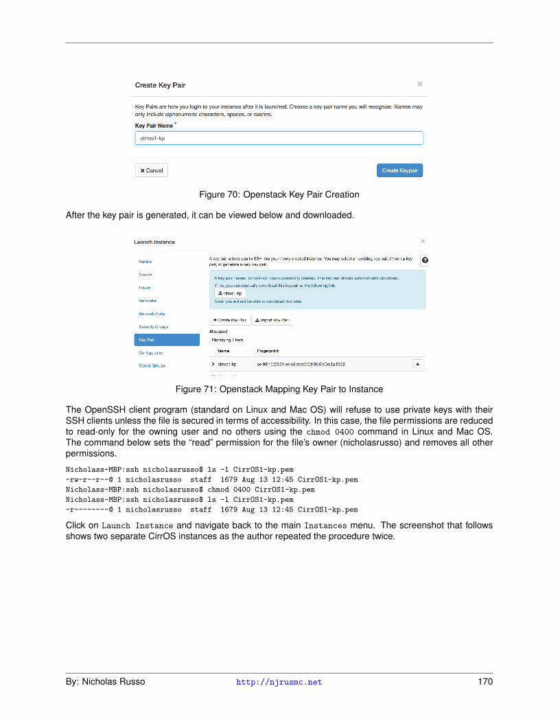
Figure 70: Openstack Key Pair Creation
After the key pair is generated, it can be viewed below and downloaded.
Figure 71: Openstack Mapping Key Pair to Instance
The OpenSSH client program (standard on Linux and Mac OS) will refuse to use private keys with theirSSH clients unless the file is secured in terms of accessibility. In this case, the file permissions are reducedto read-only for the owning user and no others using the chmod 0400 command in Linux and Mac OS.The command below sets the “read” permission for the file’s owner (nicholasrusso) and removes all otherpermissions.
Nicholass-MBP:ssh nicholasrusso$ ls -l CirrOS1-kp.pem
-rw-r--r--@ 1 nicholasrusso staff 1679 Aug 13 12:45 CirrOS1-kp.pem
Nicholass-MBP:ssh nicholasrusso$ chmod 0400 CirrOS1-kp.pem
Nicholass-MBP:ssh nicholasrusso$ ls -l CirrOS1-kp.pem
-r--------@ 1 nicholasrusso staff 1679 Aug 13 12:45 CirrOS1-kp.pem
Click on Launch Instance and navigate back to the main Instances menu. The screenshot that followsshows two separate CirrOS instances as the author repeated the procedure twice.
By: Nicholas Russo http://njrusmc.net 170

Figure 72: Openstack Instances (Compute)
Exploring the volumes for these instances shows the iSCSI disks (block storage on Cinder) mapped to eachCirrOS compute instance.
Figure 73: Openstack Instances (Volumes)
Accessing these instances, given the “cloud inside of cloud architecture”, is non-trivial. The author does notcover the advanced Neutron configuration to make this work, so accessing the instances is not covered inthis demonstration. Future releases of this document may detail this.
Moving back to the CLI, there are literally hundreds of OpenStack commands used for configuration andtroubleshooting of the cloud system. The author’s favorite three Nova commands are shown next. Notethat some of the columns were omitted to have it fit nicely on the screen, but the information removed wasnot terribly relevant for this demonstration. The host-list shows the host names and their services. Theservice-list is very useful to see if any hosts or services are down or disabled. The general list enumeratesthe configured instances. The two instances created above are displayed there.
[root@ip-172-31-9-84 ~(keystone_admin)]# nova host-list
+----------------+-------------+----------+
| host_name | service | zone |
+----------------+-------------+----------+
| ip-172-31-9-84 | cert | internal |
| ip-172-31-9-84 | conductor | internal |
| ip-172-31-9-84 | scheduler | internal |
| ip-172-31-9-84 | consoleauth | internal |
| ip-172-31-9-84 | compute | nova |
+----------------+-------------+----------+
[root@ip-172-31-9-84 ~(keystone_admin)]# nova service-list
+----+------------------+----------------+----------+----------+-------+
| Id | Binary | Host | Zone | Status | State |
By: Nicholas Russo http://njrusmc.net 171

+----+------------------+----------------+----------+----------+-------+
| 6 | nova-cert | ip-172-31-9-84 | internal | enabled | up |
| 7 | nova-conductor | ip-172-31-9-84 | internal | enabled | up |
| 8 | nova-scheduler | ip-172-31-9-84 | internal | enabled | up |
| 9 | nova-consoleauth | ip-172-31-9-84 | internal | enabled | up |
| 10 | nova-compute | ip-172-31-9-84 | nova | enabled | up |
+----+------------------+----------------+----------+----------+-------+
[root@ip-172-31-9-84 ~(keystone_admin)]# nova list
+----------------------+---------+--------+---------+--------------------+
| ID | Name | Status | Power | Networks |
+----------------------+---------+--------+---------+--------------------+
| 9dca3460-36b6-(snip) | CirrOS1 | ACTIVE | Running | public=172.24.4.13 |
| 2e4607d0-c49b-(snip) | CirrOS2 | ACTIVE | Running | public=172.24.4.2 |
+----------------------+---------+--------+---------+--------------------+
When the CirrOS instances were created, each was given a 1 GiB disk via iSCSI, which is block storage.This is the Cinder service in action. The chart below shows each volume mapped to a given instance; notethat a single instance could have multiple disks, just like any other machine.
[root@ip-172-31-9-84 ~(keystone_admin)]# cinder list
+-----------------+--------+------+--------+----------+-----------------+
| ID | Status | Size | Volume | Bootable | Attached |
+-----------------+--------+------+--------+----------+-----------------+
| 0681343e-(snip) | in-use | 1 | iscsi | true | 9dca3460-(snip) |
| 08554c2f-(snip) | in-use | 1 | iscsi | true | 2e4607d0-(snip) |
+-----------------+--------+------+--------+----------+-----------------+
The command that follows shows basic information about the public subnet that comes with the packstackinstaller by default. Neutron was not explored in depth in this demonstration.
[root@ip-172-31-9-84 ~(keystone_admin)]# neutron net-show public
+---------------------------+--------------------------------------+
| Field | Value |
+---------------------------+--------------------------------------+
| admin_state_up | True |
| availability_zone_hints | |
| availability_zones | nova |
| created_at | 2017-08-14T01:53:35Z |
| description | |
| id | f627209e-a468-4924-9ee8-2905a8cf69cf |
| ipv4_address_scope | |
| ipv6_address_scope | |
| is_default | False |
| mtu | 1500 |
| name | public |
| project_id | d20aa04a11f94dc182b07852bb189252 |
| provider:network_type | flat |
| provider:physical_network | extnet |
| provider:segmentation_id | |
| revision_number | 5 |
| router:external | True |
| shared | False |
| status | ACTIVE |
| subnets | cbb8bad6-8508-45a0-bbb9-86546f853ae8 |
| tags | |
| tenant_id | d20aa04a11f94dc182b07852bb189252 |
| updated_at | 2017-08-14T01:53:39Z |
+---------------------------+--------------------------------------+
By: Nicholas Russo http://njrusmc.net 172

4.1.3 Cloud Comparison Chart
Those who don’t need to create and operate their own private clouds may be inclined to use a well-knownand trusted public cloud provider. At the time of this writing, the three most popular cloud providers areAmazon Web Services (AWS), Microsoft Azure, and Google Cloud Platform (GCP). The table below com-pares the OpenStack components to their counterparts in the aforementioned public cloud providers. Thechart below is the result of the author’s personal research and will likely change over time as thesecloud providers modify their cloud offerings.
Component/Utility OpenStack AWS MS Azure GCP
Compute Nova EC2 VMs Compute Engine
Network Neutron VPC Virtual Network VPC
Block Storage Cinder EBS Storage Disk Persistent Disk
Identity Keystone IAM Active Directory Cloud IAM
Image Glance Lightsail VMs and Images Cloud Vision API
Object Storage Swift S3 Storage Cloud Storage
Dashboard Horizon Console Portal Console
Orchestration Heat Batch Batch Cloud Dataflow
Workflow Mistral SWF Logic Apps Cloud Dataflow
Telemetry Ceilometer CloudWatch VS App Insights Cloud Pub/Sub
Database Trove RDS SQL Database Cloud Spanner
Map Reduce Sahara EMR HDInsight BigQuery
Messaging Zaqar SQS Queue Storage Cloud Pub/Sub
Shared Files Manila EFS File Storage FUSE
DNS Designate Route 53 DNS Cloud DNS
Search Searchlight Elastic Search Elastic Search SearchService
Key Manager Barbican KMS Key Vault Cloud KMS
Table 8: Commercial Cloud Provider Comparison
4.2 Network Programmability
4.2.1 SDN Controllers
Controllers are components that are responsible for programming forwarding tables of data-plane devices.Controllers themselves could even be routers, like Cisco’s PfR operating as a master controller (MC), orthey could be software-only appliances, as seen with OpenFlow networks or Cisco’s Application PolicyInfrastructure Controller (APIC) used with ACI. The models discussed above help detail the significance ofthe controller; this is entirely dependent on the deployment model. The more involved a controller is, themore flexibility the network administrator gains. This must be weighed against the increased reliance on thecontroller itself.
A well-known example of an SDN controller is Open DayLight (ODL). ODL is commonly used as the SDNcontroller for OpenFlow deployments. OpenFlow is the communications protocol between ODL and thedata-plane devices responsible for forwarding packets (southbound). ODL communicates with businessapplications via APIs so that the network can be programmed to meet the requirements of the applications(northbound).
By: Nicholas Russo http://njrusmc.net 173

It is worth discussing a few of Cisco’s solutions in this section as they are both popular with customers andrelevant to Cisco’s vision of the future of networking. Cisco’s Intelligent WAN (IWAN) is an evolutionary strat-egy to bring policy abstraction to the WAN to meet modern design requirements, such as path optimization,cost reduction via commodity transport, and transport independence. IWAN has several key components:
1. Dynamic Multipoint Virtual Private Network (DMVPN): This feature is a multipoint IP tunnelingmechanism that allows sites to communicate to a central hub site without the hub needing to config-ure every remote spoke. Some variants of DMVPN allow for direct spoke-to-spoke traffic exchangeusing a reactive control-plane used to map overlay and underlay addresses into pairs. DMVPN canprovide transport independence as it can be used as an overlay atop the public Internet, private WANs(MPLS), or any other transport that carries IP.
2. IP Service Level Agreement (IP SLA): This feature is used to synthesize traffic to match applicationflows on the network. By sending probes that look like specific applications, IWAN can test applicationperformance and make adjustments. This is called “active monitoring”. The newest version of PfR(version 3) used within IWAN 2.0 no longer uses IP SLA. Instead, it uses Cisco-specific “SmartProbes” which provide some additional monitoring capabilities.
3. Netflow: Like probes, Netflow is used to measure the performance of specific applications across anIWAN deployment, but does so without sending traffic. These measurements can be used to estimatebandwidth utilization, among other things. This is called “passive monitoring”.
4. IP Routing: Although not a new feature, some kind of overlay routing protocol is still needed. One ofIWAN’s greatest strengths is that it can still rely on IP routing for a subset of flows, while choosing tooptimize others. A total failure of the IWAN “intelligence” constructs will allow the WAN to fall back toclassic IP routing, which is a known-good design and guaranteed to work. For this reason, existingdesign best practices and requirements gathering cannot be skipped when IWAN is deployed as thesedecisions can have significant business impacts.
5. Performance Routing (PfR): PfR is the glue of IWAN that combines all of the aforementioned fea-tures into a comprehensive and functional system. It enhances IP routing in a number of ways:
(a) Adjusting routing attributes, such as BGP local-preference, to prefer certain paths
(b) Injecting longer matches to prefer certain paths
(c) Installing dynamic route-maps for policy-routing when application packets are to be forwardedbased on something other than their destination IP address
When PfR is deployed, PfR speakers are classified as master controllers (MC) or border routers (BR). MCsare the SDN “controllers” where policy is configured and distributed. The BRs are relatively unintelligentin that they consume commands from the MC and apply the proper policy. There can be a hierarchy ofMC/BR as well to provide greater availability for remote sites that lose WAN connectivity. MCs are typicallydeployed in a stateless HA pair using loopback addresses with variable lengths; the MCs typically exist inor near the corporate data centers.
The diagram that follows depicts a high-level drawing of how IWAN works (from Cisco’s IWAN wiki page).IWAN is generally positioned as an SD-WAN solution as a way to connect branch offices to HQ locations,such as data centers.
By: Nicholas Russo http://njrusmc.net 174

Figure 74: Cisco IWAN High Level Architecture
4.2.2 DevOps methodologies, tools and workflows
The term “DevOps” is relatively new and is meant to describe not just a job title but a cultural shift in servicedelivery, management, and operation. It was formerly known as “agile system administration” or “agilemethodology”. The keyword “agile” typically refers to the integration of development and operations staffthroughout the entire lifecycle of a service. The idea is to tear down the silos and the resulting poor servicedelivery that both teams facilitate. Often times, developers will create applications without understandingthe constraints of the network, while the network team will create a network (ineffective QoS, slow rerouting,etc) policies that don’t support the business-critical applications.
The tools and workflows used within the DevOps community are things that support an information sharingenvironment. Many of them are focused on version control, service monitoring, configuration management,orchestration, containerization, and everything else needed to typically support a service through its lifecy-cle. The key to DevOps is that using a specific DevOps tool does not mean an organization has embracedthe DevOps culture or mentality. A good phrase is “People over Process over Tools”, as the importance ofa successful DevOps team is reliance on those things, in that order.
DevOps also introduces several new concepts. Two critical ones are continuous integration (CI) and con-tinuous delivery (CD). The CI/CD mindset suggests several changes to traditional software development.Some of the key points are listed here.
1. Everyone can see the changes: Dev, Ops, Quality Assurance (QA), management, etc.
2. Verification is an exact clone of the production environment, not simply a smoke-test on a developer’stest bed
3. The build and deployment/upgrade process is automated
4. Provide software in short timeframes and ensure releases are always available in increments
5. Reduce friction, increase velocity
6. Reduce silos, increase collaboration
On the topic of software development models, it is beneficial to compare the commonly used models withthe new agile or DevOps mentality. Additional details on these software development models can be foundin the references. The table that follows contains a comparison chart of the different models.
Waterfall Iterative Agile
By: Nicholas Russo http://njrusmc.net 175

Summary Five serial phases, nofeedback
1. Requirements2. Design3. Implementation4. Verification5. Maintenance
Like the waterfallmodel, but operates inloops. This creates afeedback mechanismat each cycle topromote a faster andmore flexible process.
Advances when thecurrent function or stepis complete; cyclicalmodel.
Pros Simple, wellunderstood, longhistory, requiresminimal resources andmanagement oversight
Simple, wellunderstood,opportunity to adjust,requires slightly moreresources thanwaterfall (but stillreasonable)
Customer is engaged(better feedback), earlydetection of issuesduring rapid codedevelopment periods(sprints)
Cons Difficult to revert,customer is notengaged until the end,higher risk, slow todeliver
Can be inefficient,customer feedbackcomes at the end of aniteration (not within)
High quantity ofresources required,more focusedmanagement andcustomer interactionneeded
Table 9: Software Development Methodology Comparison
There are a number of popular Agile methodologies. Two of them are discussed below.
1. Scrum is considered lightweight as the intent of most Agile methodologies is to maximize the amountof productive work accomplished during a given time period. In Scrum, a “sprint” is a period of timeupon which certain tasks are expected to be accomplished. At the beginning of the sprint, the ScrumMaster (effectively a task manager) holds a ˜4 hour planning meeting whereby work is prioritized andassigned to individuals. Tasks are pulled from the sprint backlog into a given sprint. The only meetingsthereafter (within a sprint) are typically 15 minute daily stand-ups to report progress or problems (andadvance items across the Scrum board). If a sprint is 2 weeks ( 80 hours) then only about 6 hours ofit is spent in meetings. This may or may not include a retrospective discussion at the end of a sprint todiscuss what went well/poorly. Tasks such as bugs, features, change requests, and more topics aretracked on a “scrum board” which drives the work for the entire sprint.
2. Kanban is another Agile methodology which seeks to further optimize useful work done. Unlikescrum, it is less structured in terms of time and it lacks the concept of a sprint. As such, there isneither a sprint planning session nor a sprint retrospective. Rather than limit work by units of time,it limits work by the number of concurrent tasks occurring at once. The Kanban board, therefore, ismore focused on tracking the number of tasks (sometimes called stories) within a single chronologicalpoint in the development cycle (often called Work In Progress or WIP). The most basic Kanban boardmight have three columns: To Do, Doing, Done. Ensuring that there is not too much work in anycolumn keeps productivity high. Additionally, there is no official task manager in Kanban, though anindividual may assume a similar role given the size/scope of the project. Finally, release cycles arenot predetermined, which means releases can be more frequent.
Although these Agile methodologies were initially intended for software development, they can be adaptedfor work in any industry. The author has personally seen Scrum used within a network security engineeringteam to organize tasks, limit the scope of work over a period of time, and regularly deliver production-readydesigns, solutions, and consultancy to a large customer. The author personally uses Kanban for personaltask management, as well as network operations and even home construction projects. Both strategieshave universal applicability.
By: Nicholas Russo http://njrusmc.net 176

4.2.3 Basic Jenkins Setup Demonstration
Several CI/CD tools exist today. A common, open-source tool is known as Jenkins which can be used formany CI/CD workflows. The feature list from Jenkins’ website (included in the references) nicely summa-rizes the features of the tool.
1. Continuous Integration and Continuous Delivery: As an extensible automation server, Jenkinscan be used as a simple CI server or turned into the continuous delivery hub for any project.
2. Easy installation: Jenkins is a self-contained Java-based program, ready to run out-of-the-box, withpackages for Windows, Mac OS X and other Unix-like operating systems.
3. Easy configuration: Jenkins can be easily set up and configured via its web interface, which includeson-the-fly error checks and built-in help.
4. Plugins: With hundreds of plugins in the Update Center, Jenkins integrates with practically every toolin the continuous integration and continuous delivery toolchain.
5. Extensible: Jenkins can be extended via its plugin architecture, providing nearly infinite possibilitiesfor what Jenkins can do.
6. Distributed: Jenkins can easily distribute work across multiple machines, helping drive builds, testsand deployments across multiple platforms faster.
In this demonstration, the author explores two common Jenkins usages. The first is utilizing the Git andGithub plugins to create a “build server” for code maintained in a repository. The demonstration will belimited to basic Jenkins installation, configuration, and integration with a Github repository. The actualtesting of the code itself is a follow-on step that readers can perform according to their CI/CD needs. Thisdemonstration uses an Amazon Linux EC2 instance in AWS, which is similar to Redhat Linux.
Before installing Jenkins on a target Linux machine, ensure Java 1.8.0 is installed to prevent any issues.The commands below accomplish this, but the outputs are not shown for brevity.
yum install -y java-1.8.0-openjdk.x86_64
alternatives --set java /usr/lib/jvm/jre-1.8.0-openjdk.x86_64/bin/java
alternatives --set javac /usr/lib/jvm/jre-1.8.0-openjdk.x86_64/bin/javac
To install Jenkins, issue these commands as root (indentation included for readability). Technically, some ofthese commands can be issued from a non-root user. The AWS installation guide for Jenkins, included inthe references, suggests doing so as root.
wget -O /etc/yum.repos.d/jenkins.repo \
http://pkg.jenkins-ci.org/redhat/jenkins.repo
rpm --import https://pkg.jenkins.io/redhat/jenkins.io.key
yum install jenkins
service jenkins start
Verify Jenkins is working after the completing the installation. Also, download the jenkins.war file ( 64MB)to get Jenkins CLI access, which is useful for bypassing the GUI for some tasks. Because the file is large,users may want to run it as a background task by appending & to the command (not shown). It is usedbelow to check the Jenkins version.
[root@ip-10-125-0-85 .ssh]# service jenkins status
jenkins (pid 2666) is running...
[root@ip-10-125-0-85 jenkins]# wget -q http://mirrors.jenkins.io/war/1.649/jenkins.war
[root@ip-10-125-0-85 jenkins]# java -jar jenkins.war --version
1.649
Once installed, log into Jenkins at http://jenkins.njrusmc.net:8080/, substituting the correct host ad-dress. Enable the Git plugins via Manage Jenkins > Manage Plugins > Available tab. Enter git in the
By: Nicholas Russo http://njrusmc.net 177

search bar. Select the plugs shown below and install them. Each one will be installed, along with all theirdependencies.
Figure 75: Jenkins git Plugins
Log into Github and navigate to Settings > Developer settings > Personal access tokens. Thesetokens can be used as an easy authentication method via shared-secret to access Github’s API. Whengenerating a new token, admin:org_hook must be granted at a minimum, but in the interest of experimen-tation, the author selected a few other options as depicted in the image that follows.
Figure 76: Jenkins Personal Github Access Token
After the token has been generated and the secret copied, go to Credentials > Global Credentials andcreate a new credential. The graphic below depicts all parameters. This credential will be used for theGithub API integration.
Figure 77: Jenkins Personal Access Tokens
Next, navigate to Manage Jenkins > Configure System, then scroll down to the Git and Github configura-tions. Configure the Git username and email under the Git section. For the Github section, the secret textauthentication method should be used to allow Github API access.
Figure 78: Jenkins User-specific Plugins
By: Nicholas Russo http://njrusmc.net 178

Figure 79: Setting up Github Integration on Jenkins
The global Jenkins configuration for Git/Github integration is complete. Next, create a new repository (oruse an existing one) within Github. This process is not described as Github basics are covered elsewherein this book. The author created a new repository called jenkins-demo.
After creating the Github repository, the following commands are issued on the user’s machine to make afirst commit. Github provides these commands in an easy copy/paste format to get started quickly. Theassumption is that the user’s laptop already has the correct SSH integration with Github.
MacBook-Pro:jenkins-demo nicholasrusso$ echo "# jenkins-demo" >> README.md
MacBook-Pro:jenkins-demo nicholasrusso$ git init
Initialized empty Git repository in /Users/nicholasrusso/projects/jenkins-demo/.git/
MacBook-Pro:jenkins-demo nicholasrusso$ git add README.md
MacBook-Pro:jenkins-demo nicholasrusso$ git commit -m "first commit"
[master (root-commit) ac98dd9] first commit
1 file changed, 1 insertion(+)
create mode 100644 README.md
MacBook-Pro:jenkins-demo nicholasrusso$ git remote add origin \
> [email protected]:nickrusso42518/jenkins-demo.git
MacBook-Pro:jenkins-demo nicholasrusso$ git push -u origin master
Counting objects: 3, done.
Writing objects: 100% (3/3), 228 bytes | 0 bytes/s, done.
Total 3 (delta 0), reused 0 (delta 0)
To [email protected]:nickrusso42518/jenkins-demo.git
* [new branch] master -> master
Branch master set up to track remote branch master from origin.
After this initial commit, a simple Ansible playbook has been added as our source code. Intermediatefile creation and Git source code management (SCM) steps are omitted for brevity, but there are now twocommits in the Git log. As it relates to Cisco Evolving Technologies, one would probably commit customizedcode for Cisco Network Services Orchestration (NSO) or perhaps Cisco-specific Ansible playbooks fortesting. Jenkins would be able to access these files, test it (or on a slave processing node within the Jenkinssystem), and provide feedback about the build’s quality. Jenkins can be configured to initiate software builds(including compilation) using a variety of tools and these builds can be triggered from a variety of events.These features are not explored in detail in this demonstration.
---
# sample-pb.yml
- hosts: localhost
connection: local
gather_facts: false
tasks:
- file:
path: "/etc/ansible/ansible.cfg"
state: present
...
By: Nicholas Russo http://njrusmc.net 179

MBP:jenkins-demo nicholasrusso$ git log --oneline --decorate
bb91945 (HEAD -> master, origin/master) Create sample-pb.yml
ac98dd9 first commit
Next, log into the Jenkins box, wherever it exists (the author is using AWS EC2 to host Jenkins for this demoon an m3.medium instance). SSH keys must be generated in the Jenkins users’ home directory since this isthe user running the software. In the current release of Jenkins, the home directory is /var/lib/jenkins/.
[root@ip-10-125-0-85 ~]# grep jenkins /etc/passwd
jenkins:x:498:497:Jenkins Automation Server:/var/lib/jenkins:/bin/false
The intermediate Linux file system steps to create the ~/.ssh/ directory and ~/.ssh/known_hosts file arenot shown for brevity. Additionally, generating RSA2048 keys is not shown. Navigating to the .ssh directoryis recommended since there are additional commands that use these files.
[root@ip-10-125-0-85 .ssh]# pwd
/var/lib/jenkins/.ssh
[root@ip-10-125-0-85 .ssh]# ls
id_rsa id_rsa.pub known_hosts
Next, add the Jenkins user’s public key to Github under either your personal username or a Jenkins utilityuser (preferred). The author uses his personal username for brevity in this example shown in the diagramthat follows.
[root@ip-10-125-0-85 .ssh]# cat id_rsa.pub
ssh-rsa AAAAB3NzaC1yc2EAAAADAQABAAABAQDd6qISM3f/mhmSeauR6DSFMhvlT8QkXyyY73Tk8Nu
f+SytelhP15gqTao3iA08LlpOBOnvtGXVwHEyQhMu0JTfFwRsTOGRRl3Yp9n6Y2/8AGGNTp+Q4tGpcz
Zkh/Xs7LFyQAK3DIVBBnfF0eOiX20/dC5W72aF3IzZBIsNyc9Bcka8wmVb2gdYkj1nQg6VQI1C6yayL
wyjFxEDgArGbWk0Z4GbWqgfJno5gLT844SvWmOWEJ1jNIw1ipoxSioVSSc/rsA0A3e9nWZ/HQGUbbhI
OGx7k4ruQLTCPeduU+VgIIj3Iws1tFRwc+lXEn58qicJ6nFlIbAW1kJj8I/+1fEj jenkins-ssh-key
Figure 80: Github SSH Keys for Jenkins Access
The commands below verify that the keys are functional. Note that the -i flag must be used because thecommand is run as root, and a different identity file (Jenkins’ user private key) should be used for this test.
[root@ip-10-125-0-85 .ssh]# ssh -T [email protected] -i id_rsa
Hi nickrusso42518! You've successfully authenticated, but GitHub does not provide shell access.
Before continuing, edit the /etc/passwd file as root to give the Jenkins user access to any valid shell (bashor sh). Additionally, use yum or apt-get to install git so that Jenkins can issue git commands. The git
installation via yum is not shown for brevity.
[root@ip-10-125-0-85 plugins]# grep jenkins /etc/passwd
jenkins:x:498:497:Jenkins Automation Server:/var/lib/jenkins:/bin/bash
Once Git is installed and Jenkins has shell access, copy the repository URL in SSH format from Github andsubstitute it as the repository argument in the command below. This is the exact command that Jenkins tries
By: Nicholas Russo http://njrusmc.net 180

to run when a project’s SCM is set to git; this tests reachability to a repository using SSH. If you accidentallyrun the command as root, it will fail due to using root’s public key rather than Jenkins’ public key. Switch tothe Jenkins user, try again, and test the return code (0 means success).
[root@ip-10-125-0-85 plugins]# git ls-remote -h \
[email protected]:nickrusso42518/jenkins-demo.git HEAD
Permission denied (publickey).
fatal: Could not read from remote repository.
Please make sure you have the correct access rights
and the repository exists.
[root@ip-10-125-0-85 plugins]# su jenkins
bash-4.2$ git ls-remote -h \
> [email protected]:nickrusso42518/jenkins-demo.git HEAD
bash-4.2$ echo $?
0
The URL above can be copied by starting to clone the Github repository as shown below. Be sure to selectSSH to get the correct repository link.
Figure 81: Github Repository URL for Jenkins Demo
At this point, adding a new Jenkins project should succeed when the repository link is supplied. This is anoption under SCM for the project whereby the only choices are git and None. If it fails, an error message willbe prominently displayed on the screen and the error is normally related to SSH setup. Do not specify anycredentials for this because the SSH public key method is inherent with the setup earlier. The screenshotthat follows depicts this process.
Figure 82: Jenkins Source Code Management via git
As a final check, you can view the Console Output for this project/build by clicking the icon on the left.It reveals the git commands executed by Jenkins behind the scenes to perform the pull, which is mostly
By: Nicholas Russo http://njrusmc.net 181

git fetch to pull down new data from the Github repository associated with the project.
Started by user anonymous
Building in workspace /var/lib/jenkins/workspace/jenkins-demo
Cloning the remote Git repository
Cloning repository [email protected]:nickrusso42518/jenkins-demo.git
> git init /var/lib/jenkins/workspace/jenkins-demo # timeout=10
Fetching upstream changes from [email protected]:nickrusso42518/jenkins-demo.git
> git --version # timeout=10
> git fetch --tags --progress [email protected]:nickrusso42518/jenkins-demo.git \
> +refs/heads/*:refs/remotes/origin/*
> git config remote.origin.url [email protected]:nickrusso42518/jenkins-demo.git # timeout=10
[snip]
Commit message: "Create sample-pb.yml"
First time build. Skipping changelog.
Finished: SUCCESS
The project workspace shows the files in the repository, which includes the newly created Ansible playbook.
Figure 83: Jenkins Project Workspace
This section briefly explores configuring Jenkins integration with AWS EC2. There are many more detailedguides on the Internet which describe this process; this book includes the author’s personal journey intosetting it up. Just like with Git, the AWS EC2 plugins must be installed. Look for the AWS EC2 plugin asshown in the diagram that follows, and install it. The Jenkins wiki concisely describes how this integrationworks and what problems it can solve:
Allow Jenkins to start slaves on EC2 or Eucalyptus on demand, and kill them as they get unused. With thisplugin, if Jenkins notices that your build cluster is overloaded, it’ll start instances using the EC2 API andautomatically connect them as Jenkins slaves. When the load goes down, excessive EC2 instances will beterminated. This set up allows you to maintain a small in-house cluster, then spill the spiky build/test loadsinto EC2 or another EC2 compatible cloud.
Figure 84: AWS EC2 Plugin for Jenkins Integration
Log into the AWS console and navigate to the Identity Access Management (IAM) service. Create a newuser that has full EC2 access which effectively grants API access to EC2 for Jenkins. The user will comewith an access ID and secret access key. Copy both pieces of information as Jenkins must know both.
By: Nicholas Russo http://njrusmc.net 182

Figure 85: Adding Jenkins User in AWS IAM
Next, create a new credential of type AWS credential. Populate the fields as shown below.
Figure 86: Jenkins AWS Credential Creation
Navigate back to Manage Jenkins > Configure System > Add a new cloud. Choose Amazon EC2 andpopulate the credentials option with the recently created AWS credentials using the secret access key forthe IAM user jenkins. You must select a specific AWS region. Additionally, you’ll need to paste the EC2private key used for any EC2 instances managed by Jenkins. This is not for general AWS API access butfor shell access to EC2 instances in order to control them. For security, you can create a new key pair withinAWS (recommended but not shown) for Jenkins-based hosts in case the general-purpose EC2 private keyis stolen.
Figure 87: Adding AWS Cloud Option via Jenkins
You can validate the connection using the Test Connection button which should result in success.
Figure 88: Testing Connection from AWS to Jenkins
The final step is determining what kind of AMIs Jenkins should create within AWS. There can be multipleAMIs for different operating systems, including Windows, depending on the kind of testing that needs to bedone. Perhaps it is useful to run the tests on different OS’ as part of a more comprehensive testing strategyfor software portability. There are many options to enter and the menu is somewhat similar to launchingnative instances within EC2. A subset of options is shown here; note that you can validate the spelling ofthe AMI codes (accessible from the AWS EC2 console) using the Check AMI button. More details on thisprocess can be found in the references.
By: Nicholas Russo http://njrusmc.net 183

Figure 89: Jenkins AMIs within EC2
With both Github and AWS EC2 integration set up, a developer can create large projects complete withautomated testing from SCM repository and automatic scaling within the public cloud. Provided there wasa larger, complex project which requires slave processing nodes, EC2 nodes would be dynamically createdbased on the need or the administrator assigned labels within a project.
Jenkins is not the only commonly used CI/CD tool. Gitlab, which is private (on-premises) version of Github,supports source code management (SCM) and CI/CD together. A real-life example of this implementationis provided in the references. All of these options come at a very low price and allow individuals to deployhigher quality code more rapidly, which is a core tenant of Agile software development. The author hasparticipated in a number of free podcasts on CI/CD and has used a variety of different providers. Thesepodcasts are linked in the references.
4.3 Internet of Things
4.3.1 Performance, Reliability, and Scalability
The performance of IoT devices is going to be a result of the desired security and the access type. ManyIoT devices will be equipped with relatively inexpensive and weak hardware; this is sensible from a businessperspective as the device only needs to perform a few basic functions. This could be seen as a compro-mise of security since strong ciphers typically require more computational power for encryption/decryptionfunctionality. In addition, some IoT devices may be expected to last for decades while it is highly unlikelythat the same is true about cryptographic ciphers. In short, more expensive hardware is going to be moresecure and resilient.
The access type is mostly significant when performance is discussed. Although 4G LTE is very popularand widespread in the United States and other countries, it is not available everywhere. Some parts ofthe world are still heavily reliant on 2G/3G cellular service which is less capable and slower. A widelydistributed IoT network may have a combination of these access types with various levels of performance.Higher performing 802.11 Wi-Fi speeds typically require more expensive radio hardware, more electricity,and a larger physical size. Physical access types (wired devices) will be generally immobilized which couldbe considered a detriment to physical performance, if mobility is required for an IoT device to do its jobeffectively.
By: Nicholas Russo http://njrusmc.net 184

5 Glossary of Terms
Acronym Definition/Meaning
6LoWPAN IPv6 over Low Power WPANs
ACI Application Centric Infrastructure
AFV Application Function Virtualization
AMI Amazon Machine Instance (AWS)
API Application Programming Interface
APIC Application Policy Infrastructure Controller (ACI)
ARN Amazon Resource Name
ASA Adaptive Security Appliance (virtual)
AWS Amazon Web Services
AZ Availability Zone
BGP Border Gateway Protocol
BR Border Router
CAPEX Capital Expenditures
CCB Configuration Control Board
CI/CD Continuous Integration/Continuous Development
CH Cluster Head (see LEACH, TEEN, etc.)
CM Configuration Management
COAP Constrained Application Protocol
COTS Commercial Off The Shelf
CSP Cloud Service Provider
CSPF Constrained Shortest Path First (see MPLS, TE)
CUC Cisco Unity Connection
DC Data Center
DCN Data Center Network
DCOM Distributed Component Object Model (Microsoft)
DEEC Distributed Energy Efficient Clustering
DDEEC Developed Distributed Energy Efficient Clustering
DHCP Dynamic Host Configuration Protocol
DMVPN Dynamic Multipoint VPN
DNA Digital Network Architecture
DNA-C Digital Network Architecture Center
DNS Domain Name System
DTD Document Type Definition (see HTML)
DTLS Datagram TLS (UDP)
DVS Distributed Virtual Switch
By: Nicholas Russo http://njrusmc.net 185

EBS Elastic Block Storage (AWS)
EC2 Elastic Compute Cloud (AWS)
EDEEC Enhanced Distributed Energy Efficient Clustering
EID Endpoint Identifier (see LISP)
GRE Generic Routing Encapsulation
gRPC Google Remote Procedure Call
HAL Hardware Abstraction Layer
HCL Hasicorp Configuration Language (Terraform)
HTML HyperText Markup Language
HTTP HyperText Transport Protocol (see HTML)
I2RS Interface to the Routing System
IaaS Infrastructure as a service (generic)
IDL Interface Definition Language (gRPC)
IMP Instant Messaging and Presence
IoT Internet of Things
iSCSI Internet Small Computer System Interface (see SAN)
ISP Internet Service Provider
ISR Integrated Services Router
IT Information Technology
IX/IXP Internet eXchange/Point
JSON JavaScript Object Notation
KVM Kernel-based Virtual Machine (Linux)
LAN Local Area Network
LEACH Low-Energy Adaptive Clustering Hierarchy
LEACH-C Low-Energy Adaptive Clustering Hierarchy – Centralized
LISP Locator/Identifier Separation Protocol
LLN Low power and Lossy Networks
LSP Label Switched Patch (see MPLS)
LXC Linux Containers
MC Master Controller (MC)
MIB Management Information Base (see SNMP)
MPLS Multi Protocol Label Switching
MQTT Message Queuing Telemetry Transport
MTE Minimum Transfer of Energy
MTU Maximum Transmission Unit
RPC Remote Procedure Call (NETCONF)
NFV Network Function Virtualization
NFVI Network Function Virtualization Infrastructure
By: Nicholas Russo http://njrusmc.net 186

NFVIS Network Function Virtualization Infrastructure Software (hypervisor)
NGIPSv Next-Generation Intrusion Prevention System (virtual)
NHRP Next-hop Resolution Protocol
NMS Network Management System
NOS Network Operating System
NSH Network Services Header
NSP Network Service Provider
NVGRE Network Virtualization using GRE
ODBC Open Database Connectivity
ODL Open DayLight (see SDN)
OF OpenFlow (see SDN)
OSI Open Systems Interconnection model
OPEX Operational Expenditures
OT Operations Technology
OVS Open vSwitch
PaaS Platform as a service (generic)
PEGASIS Power Efficient Gathering in Sensor Info Systems
PfR Performance Routing
PKI Public Key Infrastructure
PLC Power Line Communications (IoT multi-service edge transport)
POP Point of Presence
PSK Pre-shared Key
QEMU Quick Emulator
RCA Root Cause Analysis
REST Representation State Transfer
RIB Routing Information Base
RLOC Routing Locator (see LISP)
ROI Return on Investment
RPL IPv6 Routing Protocol for LLNs
S3 Simple Storage Service (AWS)
SaaS Software as a service (generic)
SAN Storage Area Network (see DC)
SCM Source Code Management (see CM)
SDN Software Defined Network
SLA Service Level Agreement
SNMP Simple Network Management Protocol
TCO Total Cost of Ownership
TE Traffic Engineering (see MPLS)
By: Nicholas Russo http://njrusmc.net 187

TEEN Threshold-sensitive Energy Efficient Network
TLS Transport Layer Security (TCP)
UCCX Unified Contact Center eXpress
UCM Unified Communications Manager
URI Universal Resource Identifier
VC Version Control (see CM)
VM Virtual Machine
VPC Virtual Private Cloud (AWS)
VPN Virtual Private Network
VRF VPN Routing and Forwarding (see MPLS)
VSN Virtual Service Node
VSS Virtual Switching System
VTF Virtual Topology Forwarder
VTS Virtual Topology System
VXLAN Virtual eXtensible Local Area Network
WAN Wide Area Network
WIP Work In Progress or Work In Process
WLAN Wireless Local Area Network
WLC Wireless LAN Controller
WPAN Wireless Personal Area Network
XaaS X as a service (generic)
XML eXtensible Markup Language
YAML YAML Ain’t Markup Language (formerly Yet Another Markup Language)
ZTP Zero Touch Provisioning (Viptela)
By: Nicholas Russo http://njrusmc.net 188


![BRKCCIE-3003.ppt .ppt [Read-Only] · • The CCDE Is a certification with relevance to what I actually do Provides a target for those coming into design Much like the original CCIE,](https://static.documents.pub/doc/80x56/5e893676dae1740ee76f94f9/brkccie-3003ppt-ppt-read-only-a-the-ccde-is-a-certification-with-relevance.jpg)


