1 Cisco Systems, Inc. www.cisco.com Preface This describes the objectives, audience, organization and conventions of this guide, and describes related documents. These topics are discussed: Objectives, page 1 Audience, page 1 Organization, page 1 Conventions, page 2 Searching for Cisco Documents, page 3 Obtaining Documentation and Submitting a Service Request, page 3 Objectives This guide provides an overview and explains how to install, connect, and perform initial configuration for the Cisco 2010 Connected Grid Routers. For warranty, service, and support information, see the “Cisco Warranty Terms” section in the Readme First for the Cisco CGR 2010 document that was shipped with your router. Audience This documentation is designed for the person installing, configuring, and maintaining the router, who should be familiar with electronic circuitry and wiring practices and has experience as an electronic or electromechanical technician. It identifies certain procedures that should be performed only by trained and qualified personnel. Organization This guide includes the following sections: Chapter Title Description 1 Overview of the Router, page 5 Describes the chassis views, information for locating the serial number, PID 1 , and UDI 2 , general hardware features, slot, port, and interface information, and LED indicators, 2 Preparing for Router Installation, page 15 Describes site requirements and equipment needed to install the routers. 3 Installing and Connecting the Router, page 25 Provides information about mounting the router in a rack and connecting the cables needed to install your Cisco CGR 2010 router, including how to connect AC and DC power to the router.
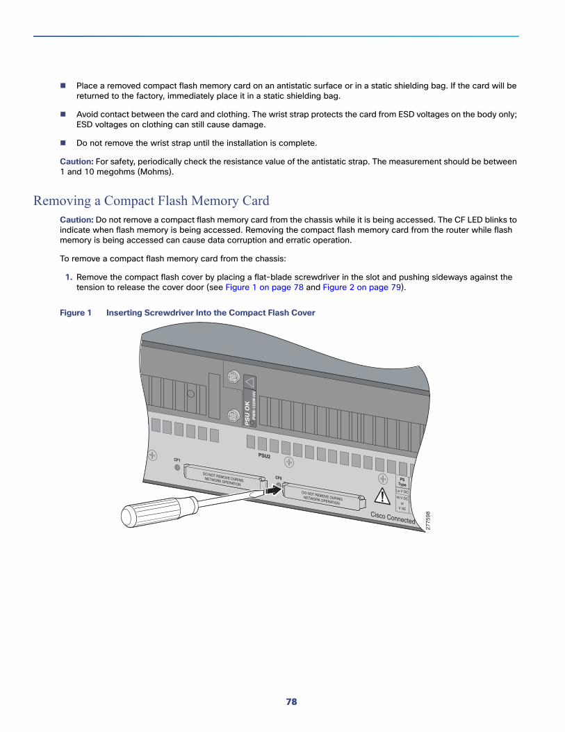
Transcript
PrefaceThis describes the objectives, audience, organization and conventions of this guide, and describes related documents.
These topics are discussed:
Objectives, page 1
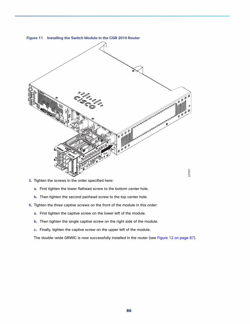
Audience, page 1
Organization, page 1
Conventions, page 2
Searching for Cisco Documents, page 3
Obtaining Documentation and Submitting a Service Request, page 3
ObjectivesThis guide provides an overview and explains how to install, connect, and perform initial configuration for the Cisco 2010 Connected Grid Routers.
For warranty, service, and support information, see the “Cisco Warranty Terms” section in the Readme First for the Cisco CGR 2010 document that was shipped with your router.
AudienceThis documentation is designed for the person installing, configuring, and maintaining the router, who should be familiar with electronic circuitry and wiring practices and has experience as an electronic or electromechanical technician. It identifies certain procedures that should be performed only by trained and qualified personnel.
OrganizationThis guide includes the following sections:
Chapter Title Description
1 Overview of the Router, page 5 Describes the chassis views, information for locating the serial number, PID1, and UDI2, general hardware features, slot, port, and interface information, and LED indicators,
2 Preparing for Router Installation, page 15 Describes site requirements and equipment needed to install the routers.
3 Installing and Connecting the Router, page 25 Provides information about mounting the router in a rack and connecting the cables needed to install your Cisco CGR 2010 router, including how to connect AC and DC power to the router.
1
Cisco Systems, Inc. www.cisco.com
Preface
Conventions
ConventionsThis document uses the following conventions: This document uses the following conventions.
Note: Means reader take note. Notes contain helpful suggestions or references to material not covered in the manual.
Caution: Means reader be careful. In this situation, you might perform an action that could result in equipment damage or loss of data.
Warning: IMPORTANT SAFETY INSTRUCTIONS
Means danger. You are in a situation that could cause bodily injury. Before you work on any equipment, be aware of the hazards involved with electrical circuitry and be familiar with standard practices for preventing accidents. Use the statement number provided at the end of each warning to locate its translation in the translated safety warnings that accompanied this device.
SAVE THESE INSTRUCTIONS
Regulatory: Provided for additional information and to comply with regulatory and customer requirements.
Access the Regulatory Compliance and Safety Information for Cisco 2010 Connected Grid Router at:
Warning: Do not use this product near water; for example, near a bath tub, wash bowl, kitchen sink or laundry tub, in a wet basement, or near a swimming pool. Statement 1035
4 Configuring the Router, page 55 Describes how to configure your Cisco CGR 2010.
5 Installing and Upgrading Internal Modules, page 77
Describes how to connect your Cisco CGR 2010 to SFP modules, single-wide and double-wide GRWICS, and to networks and external devices.
1 PID = product ID.
2 UID = universal device identifier.
Chapter Title Description
Conventions Indication
bold font Commands and keywords and user-entered text appear in bold font.
italic font Document titles, new or emphasized terms, and arguments for which you supply values are in italic font.
[ ] Elements in square brackets are optional.
{x | y | z } Required alternative keywords are grouped in braces and separated by vertical bars.
[ x | y | z ] Optional alternative keywords are grouped in brackets and separated by vertical bars.
string A nonquoted set of characters. Do not use quotation marks around the string or the string will include the quotation marks.
courier font Terminal sessions and information the system displays appear in courier font.
< > Nonprinting characters such as passwords are in angle brackets.
[ ] Default responses to system prompts are in square brackets.
!, # An exclamation point (!) or a pound sign (#) at the beginning of a line of code indicates a comment line.
Warning: Never touch uninsulated telephone wires or terminals unless the telephone line has been disconnected at the network interface. Statement 1037
Warning: Avoid using a telephone (other than a cordless type) during an electrical storm. There may be a remote risk of electric shock from lightning. Statement 1038
Searching for Cisco DocumentsTo search a HTML document using a web browser, press Ctrl-F (Windows) or Cmd-F (Apple). In most browsers, the option to search whole words only, invoke case sensitivity, or search forward and backward is also available.
To search a PDF document in Adobe Reader, use the basic Find toolbar (Ctrl-F) or the Full Reader Search window (Shift-Ctrl-F). Use the Find toolbar to find words or phrases within a specific document. Use the Full Reader Search window to search multiple PDF files simultaneously and to change case sensitivity and other options. Adobe Reader online help has more information about how to search PDF documents.
Obtaining Documentation and Submitting a Service RequestFor information on obtaining documentation, using the Cisco Bug Search Tool (BST), submitting a service request, and gathering additional information, see What’s New in Cisco Product Documentation at: http://www.cisco.com/c/en/us/td/docs/general/whatsnew/whatsnew.html.
Subscribe to What’s New in Cisco Product Documentation, which lists all new and revised Cisco technical documentation as an RSS feed and delivers content directly to your desktop using a reader application. The RSS feeds are a free service.
Overview of the RouterThe Cisco 2010 Connected Grid Router is the first router in the Cisco 2000 Series Connected Grid solutions. The CGR 2010 router is a ruggedized power utility substation router, which offers data functionality through Gigabit Ethernet ports, and security functionality with a VPN accelerator.
Ruggedized routers comply with specifications IEEE 1613 and IEC 61850, for products that meet stringent environmental, surge, and electromagnetic Interference (EMI) requirements for utility substation environments without moving parts or fans.
This Cisco CGR 2010 router has new rugged grid router WAN interface card (GRWIC) slots (for both single-wide and double-wide GRWICS) that support the rugged product power utility market.
These topics are discussed:
Chassis Views, page 5
Hardware Features, page 6
Slot, Port, and Interface Information, page 11
LED Indicators, page 11
Specifications, page 14
Chassis ViewsThis section has views of the power supply side and cable side panels of the Cisco CGR 2010 router, showing locations of the interfaces, module slots, status indicators, and chassis identification labels.
Figure 1 on page 6 shows the Cisco 2010 Connected Grid Router chassis.
Figure 2 on page 6 shows the power supply side view of the Cisco CGR 2010 router.
Figure 3 on page 6 shows the cable side panel of the Cisco CGR 2010 router.
5
Cisco Systems, Inc. www.cisco.com
Overview of the Router
Hardware Features
Figure 1 Cisco CGR 2010 Router Chassis
Figure 2 Power Supply Side View of the Cisco CGR 2010 Router
Figure 3 Cable Side View of the Cisco CGR 2010 Router
Hardware FeaturesThis section describes the hardware features in Cisco CGR 2010 router.
Locating Chassis Features and Functions, page 6
Built-in Interface Ports, page 8
Removable and Interchangeable Modules and Cards, page 9
Real-Time Clock, page 11
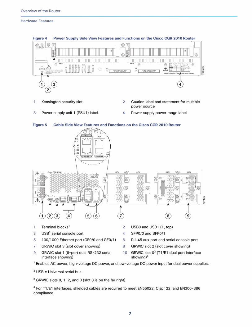
Locating Chassis Features and FunctionsFigure 4 on page 7 shows the different chassis features and functions available on the power supply side view of the Cisco CGR 2010 router. Figure 5 on page 7 shows the different chassis features and functions available on the cable side view of the Cisco CGR 2010 router.
2774
00
SFP 0/0SFP 0/1
GE 0/0
GE 0/1
CONSOLE
AUX
EN
EN
Cisco CGR 2010
PS
U2
PS
U1
L
N
N
L
+Lo-
-Lo+
-
HI
+
+
HI
-
0
1
EN
SPD
CF1
PS2ACT
SYS 0 1 SL
SL
SLOT 3
SLOT 2
SLOT 1
SLOT 0CO
NN
CO
NN
0-3 4
-7
CD
/LP
AL
CD
/LP
AL
P1
P0
2773
98
PSU1 PSU2
PS
U O
KP
WR
-150
W-H
V
PS
U O
KP
WR
-150
W-H
V
SYS SPD SPD SPD SPD 2 0 1
USBCONACT
SFP0/1EN
SFP0/0EN
GE0/1
LINK
GE0/0
LINKPSU
23 1
CONSOLE
SLOT
CF1
DO NOT REMOVE DURINGNETWORK OPERATION
CF0
DO NOT REMOVE DURINGNETWORK OPERATION
Cisco Connected Grid Router 2000 Series
PS TypeLoV dcHiV dcV ac, 50/60 Hz
10A2A2A
Input Rating Per Sources24-60V100-270V100-240V ~
CAUTION: This unit may have more thanone power source. Disconnect all powersources before servicing to avoidelectric shock.
2773
97
SFP 0/0 GE 0/0
GE 0/1
SFP 0/1 CONSOLE
PS
U2
L
N
N
L
+Lo-
-Lo+
-
HI
+
+
HI
-
Cisco CGR 2010
0
1
EN
EN
SPD
CF1
PS2ACT
SYS 0 1 S L
S LAUX
EN
SLOT 3 SLOT 2 SLOT 1 SLOT 0
CO
NN
CO
NN
0-3
4-7
GR
WIC
–8A/8-232
GR
WIC
–2CE
1T1-P
RI
CD
/LP
AL
CD
/LP
AL
P1
P0
PS
U1
6
Overview of the Router
Hardware Features
Figure 4 Power Supply Side View Features and Functions on the Cisco CGR 2010 Router
Figure 5 Cable Side View Features and Functions on the Cisco CGR 2010 Router
1 Kensington security slot 2 Caution label and statement for multiple power source
3 Power supply unit 1 (PSU1) label 4 Power supply power range label
1 Terminal blocks1 2 USB0 and USB1 (1, top)
3 USB2 serial console port 4 SFP0/0 and SFP0/1
5 100/1000 Ethernet port (GE0/0 and GE0/1) 6 RJ-45 aux port and serial console port
9 GRWIC slot 1 (8-port dual RS-232 serial interface showing)
10 GRWIC slot 03 (T1/E1 dual port interface showing)4
1 Enables AC power, high-voltage DC power, and low-voltage DC power input for dual power supplies.
2 USB = Universal serial bus.
3 GRWIC slots 0, 1, 2, and 3 (slot 0 is on the far right).
4 For T1/E1 interfaces, shielded cables are required to meet EN55022, Cispr 22, and EN300-386 compliance.
2489
45
PSU1 PSU2
PS
U O
KP
WR
-150
W-H
V
PS
U O
KP
WR
-150
W-H
V
SYS SPD SPD SPD SPD 2 0 1
USBCONACT
SFP0/1EN
SFP0/0EN
GE0/1
LINK
GE0/0
LINKPSU
23 1
CONSOLE
SLOT
CF1
DO NOT REMOVE DURINGNETWORK OPERATION
CF0
DO NOT REMOVE DURINGNETWORK OPERATION
Cisco Connected Grid Router 2000 Series
CAUTION: This unit may have more thanone power source. Disconnect all powersources before servicing to avoidelectric shock.
PSType
Input TerminalSymbol
Input RatingPer Source
Lo V DC
Hi V DC
Lo 24 - 60 V 10A
100-250V 2A
100-240V ~ 2A50-60 Hz
Hior
V AC~
12
3 4
SFP 0/0 GE 0/0
GE 0/1
SFP 0/1 CONSOLE
PS
U2
L
N
N
L
+Lo-
-Lo+
-
HI
+
+
HI
-
Cisco CGR 2010
0
1
EN
EN
SPD
CF1
PS2ACT
SYS 0 1 S L
S LAUX
EN
SLOT 3 SLOT 2 SLOT 1 SLOT 0
CO
NN
CO
NN
0-3
4-7
GR
WIC
–8A/8-232
GR
WIC
–2CE
1T1-P
RI
CD
/LP
AL
CD
/LP
AL
P1
P0
PS
U1
GE 0/0
GE 0/1
CONSOLE
CF1
PS2
0 1 S L
S LAUX
EN
1 652 3 7 984
2774
45
7
Overview of the Router
Hardware Features
GRWIC Installation OptionsThe CGR 2010 four slots with two removable dividers allow the following GRWIC installation options:
4 single-wide GRWICs
2 single-wide GRWICs and 1 double-wide GRWIC
2 double-wide GRWICs
Built-in Interface PortsTable 1 on page 8 summarizes the interface ports built into the router chassis.
Gigabit Ethernet Ports
There are two different types of Gigabit Ethernet ports available on Cisco CGR 2010 router.
Gigabit Ethernet Ports, page 8
SFP Ports, page 8
Gigabit Ethernet Ports
The Gigabit Ethernet RJ-45 copper interface ports support 100BASE-TX and 1000BASE-T.
SFP Ports
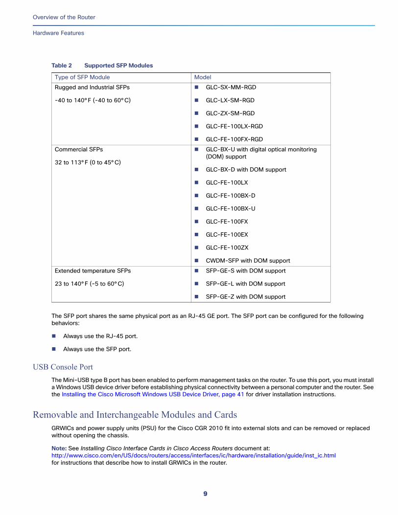
The small form factor pluggable (SFP) ports on the Cisco CGR 2010 router support the SFP modules listed in Table 2 on page 9.
Table 1 Summary of Cisco CGR 2010 Built-In Interfaces
Data Ports Management Ports
Router Model 10/100/1000GE RJ-45
100/1000 SFP USB Type A Console,Serial, RJ-45
Console, Mini-USB (Type B)
Auxiliary,RJ-45
Cisco CGR 2010 2 2 2 1 1 1
8
Overview of the Router
Hardware Features
The SFP port shares the same physical port as an RJ-45 GE port. The SFP port can be configured for the following behaviors:
Always use the RJ-45 port.
Always use the SFP port.
USB Console Port
The Mini-USB type B port has been enabled to perform management tasks on the router. To use this port, you must install a Windows USB device driver before establishing physical connectivity between a personal computer and the router. See the Installing the Cisco Microsoft Windows USB Device Driver, page 41 for driver installation instructions.
Removable and Interchangeable Modules and CardsGRWICs and power supply units (PSU) for the Cisco CGR 2010 fit into external slots and can be removed or replaced without opening the chassis.
Note: See Installing Cisco Interface Cards in Cisco Access Routers document at:http://www.cisco.com/en/US/docs/routers/access/interfaces/ic/hardware/installation/guide/inst_ic.htmlfor instructions that describe how to install GRWICs in the router.
Table 2 Supported SFP Modules
Type of SFP Module Model
Rugged and Industrial SFPs
-40 to 140°F (-40 to 60°C)
GLC-SX-MM-RGD
GLC-LX-SM-RGD
GLC-ZX-SM-RGD
GLC-FE-100LX-RGD
GLC-FE-100FX-RGD
Commercial SFPs
32 to 113°F (0 to 45°C)
GLC-BX-U with digital optical monitoring (DOM) support
GRWICs are the latest generation of interface cards. GRWICs are installed in the GRWIC slots on the router (see Figure 7 on page 83).
The router can accommodate four single-wide GRWICS, or two single-wide GRWICs and one double-wide GRWIC, or two double-wide GRWICs at any one time. See Installing Grid Router WAN Interface Cards, page 82.
Memory
Cisco CGR 2010 routers contain the following types of memory:
DDR2—Stores the running configuration and routing tables, and is used for packet buffering by the network interfaces. Cisco IOS software executes from DRAM memory. Supports 1-GB on board DDR2.
Boot/NVRAM—Stores the bootstrap program (ROM monitor), the configuration register, and the startup configuration.
Flash memory—External flash memory. Stores the operating system software image. Supports two external 4 GB I-temp compact flash memory cards.
Two 1-GB USB flash memory sticks (MEMUSB-1024FT), one each in drives USB 0 and USB 1.
Power Supplies
Cisco CGR 2010 supports three PSUs (power supply units). Power supplies are field replaceable, externally accessible, and hot swappable.
Table 3 on page 10 summarizes the three power supply options.
Note: Any combination of power supplies can be inserted into the chassis. Dual power supply configurations are load sharing in redundancy mode. A single power supply is sufficient for supporting power needs to the system.
Caution: Two types of power supplies are supported on the Cisco CGR 2010 router: a low-voltage DC power supply and a high-voltage DC/AC power supply. Take caution when selecting the correct input voltage for the power supply installed or damage will result. For details on connecting AC and DC power supplies, see the Power-Supply Modules, page 30.
Table 4 on page 11 summarizes the power options.
Table 3 Power-Supply Modules
Model Description
PWR-RGD-AC-DC High-voltage AC or DC power supply.
PWR-RGD-LOW-DC Low-voltage DC power supply.
PWR-RGD-AC-DC-C High-voltage AC or DC power supply. China-specific model.
10
Overview of the Router
Slot, Port, and Interface Information
Real-Time ClockUpon system power up, the internal real-time clock with battery backup provides the system software with time of day. This allows the system to verify the validity of the certification authority (CA) certificate. The Cisco CGR 2010 has a lithium battery. This battery lasts the life of the router under the operating environmental conditions specified for the router and is not field-replaceable.
Note: If the lithium battery in a Cisco CGR 2010 router should fail, the router must be returned to Cisco for repair.
Slot, Port, and Interface InformationOn the Cisco CGR 2010 router, the numbering format for slots and ports is defined as follows: interface type 0/slot/port. “0” indicates slots that are built into the chassis of a router.
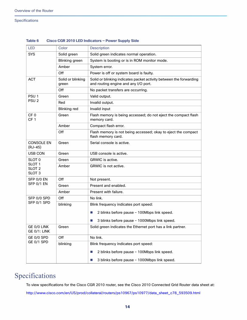
LED IndicatorsFigure 6 on page 12 summarizes the LED indicators that are located on the router bezel or chassis, but not on the removable interface cards.
Table 4 Cisco CGR 2010 Power Options
Router AC AC + POE DC Hot Swap Internal RPS1 Dual DC2
CGR 2010 Yes No Yes Yes Yes No1 Internal RPS means that additional power supply can be added to the PS2 slot.
2 Dual DC means two separate DC lines input to the same power supply.
11
Overview of the Router
LED Indicators
Figure 6 Power Supply Side View LEDs on the Cisco CGR 2010 Router
Figure 7 Cable Side View LEDs on the Cisco CGR 2010 Router
Preparing for Router InstallationThis section provides preinstallation information such as recommendations and requirements to review prior to installing your router.
The following sections prepare you for installation.
Safety Recommendations, page 16
General Site Requirements, page 17
Rack Requirements, page 17
Router Environmental Requirements, page 17
Power Guidelines and Requirements, page 18
Required Tools and Equipment for Installation and Maintenance, page 22
Installation Checklist, page 23
Creating a Site Log, page 24
Note: To see translated warnings that appear in this publication, see the Cisco Connected Grid Routers Series Regulatory Compliance and Safety Information document.
Warning: Only trained and qualified personnel should be allowed to install, replace, or service this equipment. Statement 1030
Warning: Ultimate disposal of this product should be handled according to all national laws and regulations. Statement 1040
Warning: This equipment must be installed and maintained by service personnel as defined by AS/NZS 3260. Incorrectly connecting this equipment to a general-purpose outlet could be hazardous. The telecommunications lines must be disconnected 1) before unplugging the main power connector or 2) while the housing is open, or both. Statement 1043
Warning: This unit might have more than one power supply connection. All connections must be removed to de-energize the unit. Statement 1028
Warning: This product relies on the building’s installation for short-circuit (overcurrent) protection. Ensure that the protective device is rated not greater than: Maximum 15 A, 120 Vac or Maximum 10 A, 230 Vac Statement 1005
Warning: Take care when connecting units to the supply circuit so that wiring is not overloaded. Statement 1018
Warning: Hazardous network voltages are present in WAN ports regardless of whether power to the unit is OFF or ON. To avoid electric shock, use caution when working near WAN ports. When detaching cables, detach the end away from the unit first. Statement 1026
Warning: Installation of the equipment must comply with local and national electrical codes. Statement 1074
Warning: This unit is intended for installation in restricted access areas. A restricted access area can be accessed only through the use of a special tool, lock and key, or other means of security. Statement 1017
Warning: Blank faceplates and cover panels serve three important functions: they prevent exposure to hazardous voltages and currents inside the chassis; they contain electromagnetic interference (EMI) that might disrupt other equipment; and they direct the flow of cooling air through the chassis. Do not operate the system unless all cards, faceplates, front covers, and rear covers are in place. Statement 1029
Safety RecommendationsFollow these guidelines to ensure general safety:
Keep the chassis area clear and dust-free during and after installation.
Keep tools and chassis components away from walk areas.
Do not wear loose clothing that could get caught in the chassis. Fasten your tie or scarf and roll up your sleeves.
Wear safety glasses when working under conditions that might be hazardous to your eyes.
Do not perform any action that creates a hazard to people or makes the equipment unsafe.
Safety with ElectricityFollow these guidelines when working on equipment powered by electricity:
Locate the emergency power-off switch in the room in which you are working. If an electrical accident occurs, you can quickly turn off the power.
Disconnect all power before doing the following:
— Installing or removing a chassis
— Working near power supplies
Look carefully for possible hazards in your work area, such as moist floors, ungrounded power extension cables, frayed power cords, and missing safety grounds.
Do not work alone if hazardous conditions exist.
Never assume that power is disconnected from a circuit. Always check.
Never open the enclosure of the router’s internal power supply.
If an electrical accident occurs, proceed as follows:
— Use caution; do not become a victim yourself.
— Turn off power to the device.
— If possible, send another person to get medical aid. Otherwise, assess the victim’s condition and then call for help.
— Determine if the person needs rescue breathing or external cardiac compressions; then take appropriate action.
Warning: This unit might have more than one power supply connection. All connections must be removed to de-energize the unit. Statement 1028
Warning: Do not work on the system or connect or disconnect cables during periods of lightning activity. Statement 1001
Warning: Read the installation instructions before connecting the system to the power source. Statement 1004
16
Preparing for Router Installation
General Site Requirements
Preventing Electrostatic Discharge Damage Electrostatic discharge (ESD) can damage equipment and impair electrical circuitry. It can occur if electronic printed circuit cards are improperly handled and can cause complete or intermittent failures. Always follow ESD prevention procedures when removing and replacing modules:
Ensure that the router chassis is electrically connected to earth ground.
Wear an ESD-preventive wrist strap, ensuring that it makes good skin contact. Connect the clip to an unpainted surface of the chassis frame to channel unwanted ESD voltages safely to ground. To guard against ESD damage and shocks, the wrist strap and cord must operate effectively.
If no wrist strap is available, ground yourself by touching a metal part of the chassis.
Caution: For the safety of your equipment, periodically check the resistance value of the antistatic strap. It should be between 1 and 10 megohms (Mohm).
General Site RequirementsThis section describes the requirements your site must meet for safe installation and operation of your router. Ensure that the site is properly prepared before beginning installation. If you are experiencing shutdowns or unusually high errors with your existing equipment, this section can also help you isolate the cause of failures and prevent future problems.
Rack RequirementsThe following information will help you plan your equipment rack configuration:
Allow clearance around the rack for maintenance.
Allow at least one rack unit of vertical space between routers.
Enclosed racks must have adequate ventilation. Ensure that the rack is not congested, because each router generates heat. An enclosed rack should have louvered sides and a fan to provide cooling air. Heat generated by equipment near the bottom of the rack can be drawn upward into the intake ports of the equipment above.
Router Environmental RequirementsMount the Cisco CGR 2010 routers in a rack. The location of your router and the layout of your equipment rack or wiring room are extremely important considerations for proper operation. Equipment placed too close together, inadequate ventilation, and inaccessible panels can cause malfunctions and shutdowns, and can make maintenance difficult. Plan for access to both power supply side and cable side panels of the router.
Note: Allow at least one rack unit of vertical space above the router.
When planning your site layout and equipment locations, refer to General Site Requirements, page 17. If you are currently experiencing shutdowns or an unusually high number of errors with your existing equipment, these precautions and recommendations may help you isolate the cause of failure and prevent future problems.
Ensure that the room where your router operates has adequate air circulation. Electrical equipment generates heat. Without adequate air circulation, ambient air temperature may not cool equipment to acceptable operating temperatures.
Always follow ESD-prevention procedures described in Preventing Electrostatic Discharge Damage, page 17 to avoid damage to equipment. Damage from static discharge can cause immediate or intermittent equipment failure.
17
Preparing for Router Installation
Power Guidelines and Requirements
Ensure that the chassis cover and module cable side panels are secure. All empty interface card slots and power supply bays must have filler panels installed.
When equipment installed in a rack (particularly in an enclosed rack) fails, try operating the equipment by itself, if possible. Power off other equipment in the rack (and in adjacent racks) to allow the router under test a maximum of cooling air and clean power.
Power Guidelines and RequirementsCheck the power at your site to ensure that you are receiving “clean” power (free of spikes and noise). Install a power conditioner if necessary.
The AC power supply includes the autoselect feature for either 110 V or 220 V operation.
Caution: Two types of power supplies are supported on the Cisco CGR 2010: a low-voltage DC power supply and a high-voltage DC/AC power supply. Take caution when selecting the correct input voltage for the power supply installed or damage will result.
Network Cabling SpecificationsThe following sections describe the cables needed to install your Cisco CGR 2010 router:
Console and Auxiliary Port Considerations, page 18
Preparing for Network Connections, page 19
Console and Auxiliary Port ConsiderationsThe Cisco CGR 2010 router includes an asynchronous serial console port and an auxiliary port. The console and auxiliary ports provide access to the router either locally using a console terminal connected to the console port, or remotely using a modem connected to the auxiliary port. This section discusses important cabling information to consider before connecting the router to a console terminal or modem.
The main difference between the console and auxiliary ports is that the auxiliary port supports hardware flow control and the console port does not. Flow control paces the transmission of data between a sending device and a receiving device. Flow control ensures that the receiving device can absorb the data sent to it before the sending device sends more. When the buffers on the receiving device are full, a message is sent to the sending device to suspend transmission until the data in the buffers has been processed. Because the auxiliary port supports flow control, it is ideally suited for use with the high-speed transmissions of a modem. Console terminals send data at slower speeds than modems; therefore, the console port is ideally suited for use with console terminals.
Console Port Connections
The router has both EIA/TIA-232 asynchronous (RJ-45) and USB 5-pin mini Type B, 2.0 compliant serial console ports. The console ports do not have any hardware flow control. Shielded USB cables with properly terminated shields are recommended.
EIA/TIA-232 Port
Depending on the cable and the adapter used, this port appears as a DTE or DCE device at the end of the cable. Only one port can be used at the same time.
The default parameters for the console port are 9600 baud, 8 data bits, no parity, and 1 stop bit. The console port does not support hardware flow control. For detailed information about installing a console terminal, see Connecting to a Console Terminal or Modem, page 38.
For cable and port pinouts, see Cisco Modular Access Router Cable Specifications.
The USB serial console port connects directly to the USB connector of a PC using a USB Type A to 5-pin mini USB Type-B cable. The USB Console supports full speed (12Mb/s) operation. The console port does not support hardware flow control.
Note: Always use shielded USB cables with a properly terminated shield.
The default parameters for the console port are 9600 baud, 8 data bits, no parity, and 1 stop bit. The console port does not support mode control. For detailed information about installing a console terminal, see Connecting to a Console Terminal or Modem, page 38.
For operation with Microsoft Windows, the Cisco Windows USB Console Driver must be installed on every PC connected to the console port. If the driver is not installed, prompts guide you through a simple installation process. For detailed information about installing the Cisco Windows USB Console Driver see Installing the Cisco Microsoft Windows USB Device Driver, page 41.
The Cisco Windows USB Console Driver allows plugging and unplugging the USB cable from the console port without affecting Windows HyperTerminal operations. No special drivers are needed for Mac OS X or Linux.
Only one console port can be active at a time. When a cable is plugged into the USB console port the RJ-45 port becomes inactive. Conversely, when the USB cable is removed from the USB port, the RJ-45 port becomes active.
Baud rates for the USB console port are 1200, 2400, 4800, 9600, 19200, 38400, 57600, and 115200 bps.
Note: 4-pin mini USB Type-B connectors are easily confused with 5-pin mini USB Type-B connectors. They are not compatible. Only the 5-pin mini USB Type-B can be used.
Auxiliary Port Connections
The router has an EIA/TIA-232 asynchronous serial auxiliary port (RJ-45) that supports flow control. Depending on the cable and the adapter used, this port appears as a DTE or DCE device at the end of the cable.
Preparing for Network ConnectionsWhen setting up your router, consider distance limitations and potential electromagnetic interference (EMI) as defined by the applicable local and international regulations.
Network connection considerations are provided for several types of network interfaces and are described in the following sections:
Ethernet Connections, page 20
Serial Connections, page 20
See the following document for more information about network connections and interfaces:
Cisco Modular Access Router Cable Specifications
Warning: To avoid electric shock, do not connect safety extra-low voltage (SELV) circuits to telephone-network voltage (TNV) circuits. LAN ports contain SELV circuits, and WAN ports contain TNV circuits. Some LAN and WAN ports both use RJ-45 connectors. Statement 1021
The IEEE has established Ethernet as standard IEEE 802.3. The Cisco CGR 2010 router supports the following Ethernet implementations:
1000BASE-X—1000 Mb/s full-duplex transmission over a Category 5 or better unshielded twisted-pair (UTP) cable (IEEE 802.3z). Supports the Ethernet maximum length of 328 feet (100 meters).
1000BASE-T—1000 Mb/s full-duplex transmission over a Category 5 or better unshielded twisted-pair (UTP) cable (IEEE 802.3ab). Supports the Ethernet maximum length of 328 feet (100 meters).
100BASE-TX—100 Mb/s full-duplex transmission over a Category 5 or better unshielded twisted-pair (UTP) cable (IEEE 802.3u). Supports the Ethernet maximum length of 328 feet (100 meters).
See Cisco Modular Access Router Cable Specifications at www.cisco.com for information about Ethernet cables, connectors, and pinouts.
Serial Connections
Serial connections are provided by the grid router WAN interface card (GRWIC). Before you connect a device to a serial port, you need to know the following:
Type of device, data terminal equipment (DTE) or data communications equipment (DCE), you are connecting to the synchronous serial interface
Type of connector, male or female, required to connect to the device
Signaling standard required by the device
Configuring Serial Connections
The serial ports on the asynchronous/synchronous serial network modules and the serial grid router WAN interface card use a GRWIC-8A/S cable with a DB-25 connector. Serial ports can be configured as DTE or DCE, depending on the serial cable used.
Serial DTE or DCE Devices
A device that communicates over a synchronous serial interface is either a DCE or DTE device. A DCE device provides a clock signal that paces the communications between the device and the router. A DTE device does not provide a clock signal. DTE devices usually connect to DCE devices. The documentation that accompanied the device should indicate whether it is a DTE or DCE device. (Some devices have a jumper to select either DTE or DCE mode.) The following table lists typical DTE and DCE devices.
Device Type Gender Typical Devices
DTE Male1 Terminal
PC
DCE Female2 Modem
CSU/DSU
Multiplexer1 If pins protrude from the base of the connector, the connector is male.
2 If the connector has holes to accept pins, the connector is female.
The synchronous serial ports available for the router support the following signaling standards: EIA/TIA-232 (EIA-323). You can order a Cisco DB-25 shielded serial transition cable that has the appropriate connector for the standard you specify. The documentation for the device should indicate the standard used for that device. The router end of the shielded serial transition cable has a DB-25 connector, which connects to the DB-25 port on a serial grid router WAN interface card. The other end of the serial transition cable is available with a connector appropriate for the standard you specify. For a list of the serial cables supported for GRWICs as well as the pinouts, see Connectors and Cabling for the 8-Port Asynchronous/ Synchronous RS-232 GRWIC, page 51.
The synchronous serial port can be configured as DTE or DCE, depending on the attached cable.
All serial ports configured as DTE require external clocking from a CSU/DSU or other DCE device.
Distance Limitations
Serial signals can travel a limited distance at any given bit rate; generally, the slower the data rate, the greater the distance. All serial signals are subject to distance limits, beyond which a signal significantly degrades or is completely lost.
Table 1 on page 21 lists the recommended maximum speeds and distances for each serial interface type; however, you might get good results at speeds and distances greater than those listed, if you understand the electrical problems that might arise and can compensate for them. For instance, the recommended maximum rate for V.35 is 2 Mb/s, but 4 Mb/s is commonly used.
Asynchronous/Synchronous Serial Module Baud Rates
The following baud-rate limitations apply to the slow-speed serial interfaces found in the asynchronous/synchronous serial modules:
Asynchronous interface—Maximum baud rate is 115.2 kbps.
Synchronous interface—Maximum baud rate is 128 kbps full duplex.
Table 1 Serial Signal Transmission Speeds and Distances
Distance for EIA/TIA-232
Distance for X.21 and V.35
Distance for USB
Rate (bps) Feet Meters Feet Meters Feet Meters
2400 200 60 4100 1250 16.4 5
4800 100 30 2050 625 16.4 5
9600 50 15 1025 312 16.4 5
19200 25 7.6 513 156 16.4 5
38400 12 3.7 256 78 16.4 5
56000 8.6 2.6 102 31 16.4 5
1544000 (T1) — — 50 15 16.4 5
21
Preparing for Router Installation
Required Tools and Equipment for Installation and Maintenance
Required Tools and Equipment for Installation and MaintenanceYou need the following tools and equipment to install and upgrade the router and its components:
ESD-preventive cord and wrist strap
Number 2 Phillips screwdriver
Phillips screwdrivers: small, 3/16-in. (4 to 5 mm) and medium, 1/4-in. (6 to 7 mm)
Screws that fit your rack
In addition, depending on the type of modules you plan to use, you might need the following equipment to connect a port to an external network:
Cables for connection to the WAN and LAN ports (dependent on configuration).
For more information on cable specifications, see Cisco Modular Access Router Cable Specifications at www.cisco.com.
Ethernet hub or PC with a network interface card for connection to an Ethernet (LAN) port.
Console terminal (an ASCII terminal or a PC running HyperTerminal or similar terminal emulation software) configured for 9600 baud, 8 data bits, 1 stop bit, no flow control, and no parity.
Modem for connection to the auxiliary port for remote administrative access (optional).
Data service unit (DSU) or channel service unit/data service unit (CSU/DSU) as appropriate for serial interfaces.
External CSU for any CT1/PRI modules without a built-in CSU.
Installation ChecklistThe sample installation checklist on page 23lists items and procedures for installing a new router. Make a copy of this checklist and mark the entries when completed. Include a copy of the checklist for each router in your site log (described in Creating a Site Log, page 24).
Installation checklist for site_____________________________________________
ASCII terminal (for local configuration) or modem (for remote configuration) available
Signal distance limits verified
Startup sequence steps completed
Initial operation verified
Software image verified
23
Preparing for Router Installation
Creating a Site Log
Creating a Site LogThe Site Log provides a record of all actions related to the router. Keep it in an accessible place near the chassis where anyone who performs tasks has access to it. Use the installation checklist to verify steps in the installation and maintenance of the router. Site Log entries might include the following information:
Installation progress—Make a copy of the installation checklist and insert it into the site log. Make entries as each procedure is completed.
Upgrade and maintenance procedures—Use the site log as a record of ongoing router maintenance and expansion history. A site log might include the following events:
— Installation of GRWICs
— Removal or replacement of GRWICs and other upgrades
— Configuration changes
— Maintenance schedules and requirements
— Maintenance procedures performed
— Intermittent problems
— Comments and notes
Inspect all items for shipping damage. If anything appears to be damaged or you encounter problems installing or configuring your router, contact Cisco customer service. Warranty, service, and support information is in the quick start guide that shipped with your router.
24
Installing and Connecting the RouterThis section describes how to install and connect Cisco CGR 2010 routers to a LAN or WAN, as well as how to connect AC or DC power to the router.
These topics are discussed.
What you Need to Know, page 26
Before You Begin, page 27
Unpacking the Router, page 27
Installing the Router in a Rack, page 27
Power-Supply Modules, page 30
Connecting to a Console Terminal or Modem, page 38
Installing the Cisco Microsoft Windows USB Device Driver, page 41
Uninstalling the Cisco Microsoft Windows USB Driver, page 42
Connecting to the Auxiliary Port, page 43
Connecting WAN and LAN Interfaces, page 44
Auxiliary Port, Console Port, and Adapter Pinouts for the Cisco CGR 2010 Router, page 45
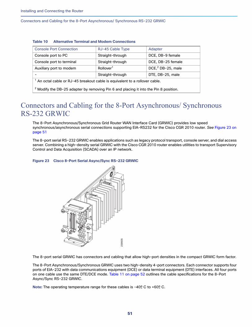
Connectors and Cabling for the 8-Port Asynchronous/ Synchronous RS-232 GRWIC, page 51
Note: To see translations of the warnings that appear in this publication, see Cisco Connected Grid Routers Series Regulatory Compliance and Safety Information.
Caution: For the optimum temperature ranges, do not operate it in an area that less than the minimum of 40°C and exceeds a maximum recommended ambient temperature of 60°C.
Note: To view specifications for the CGR 2010 router, see the Cisco 2010 Connected Grid Router data sheet at:
Warning: Only trained and qualified personnel should be allowed to install, replace, or service this equipment. Statement 1030
Warning: This unit might have more than one power supply connection. All connections must be removed to de-energize the unit. Statement 1028
Warning: Hazardous network voltages are present in WAN ports regardless of whether power to the unit is OFF or ON. To avoid electric shock, use caution when working near WAN ports. When detaching cables, detach the end away from the unit first. Statement 1026
Warning: Do not use this product near water; for example, near a bath tub, wash bowl, kitchen sink or laundry tub, in a wet basement, or near a swimming pool. Statement 1035
Warning: Avoid using a telephone (other than a cordless type) during an electrical storm. There may be a remote risk of electric shock from lightning. Statement 1038
Warning: This unit is intended for installation in restricted access areas. A restricted access area can be accessed only through the use of a special tool, lock and key, or other means of security. Statement 1017
Warning: Stability hazard. The rack stabilizing mechanism must be in place, or the rack must be bolted to the floor before you slide the unit out for servicing. Failure to stabilize the rack can cause the rack to tip over. Statement 1048
Warning: The chassis should be mounted on a rack that is permanently affixed to the building. Statement 1049
Warning: Blank faceplates and cover panels serve three important functions: they prevent exposure to hazardous voltages and currents inside the chassis; they contain electromagnetic interference (EMI) that might disrupt other equipment; and they direct the flow of cooling air through the chassis. Do not operate the system unless all cards, faceplates, front covers, and rear covers are in place. Statement 1029
Warning: A ground wire must always be a single piece of wire. Never splice two wires together for a ground. Corrosion and weathering can lead to a poor connection at the splice, making the ground ineffective and dangerous. Statement 270
Warning: To reduce the risk of fire, use only No. 26 AWG or larger telecommunication line cord. Statement 1023
Warning: Use copper conductors only. Statement 1025
Warning: A readily accessible two-poled disconnect device must be incorporated in the fixed wiring. Statement 1022
Warning: Invisible laser radiation may be emitted from the end of the unterminated fiber cable or connector. Do not view directly with optical instruments. Viewing the laser output with certain optical instruments (for example, eye loupes, magnifiers, and microscopes) within a distance of 100 mm may pose an eye hazard. Statement 1056
Warning: To prevent the system from overheating, do not operate it in an area that exceeds the maximum recommended ambient temperature of: 60°C (140°F). Statement 1047
Warning: Hot surface. Statement 1079
Caution: Heat sinks applicable to warning statement 1079, can exceed 90º C in a 60º C ambient. Suitable precautions should be taken to avoid burns.
Warning: This equipment needs to be grounded. Use a green and yellow 12 to 14 AWG ground wire to connect the host to earth ground during normal use. Statement 242
What you Need to Know
CLI Console AccessUse the new USB console port on the router to access the Cisco Internet Operating System (IOS) Command Line Interface (CLI) on the router and perform configuration tasks. A terminal emulation program, such as Microsoft Windows HyperTerminal, is required to establish communication between the router and a PC. See Connecting to a Console Terminal or Modem, page 38.
Note: A Microsoft Windows USB driver must be installed before you establish physical connectivity between the router and the PC.
Slot and Port NumbersCisco CGR 2010 routers have built-in ports and new slots. The new slots accommodate new grid router WAN interface cards (GRWICs). See Slot, Port, and Interface Information, page 11 for slot and port numbering
26
Installing and Connecting the Router
Before You Begin
Before You BeginBefore installing and connecting a Cisco CGR 2010 router, read the safety warnings and gather the following tools and equipment:
ESD-preventive cord and wrist strap
Number 2 Phillips screwdriver
Flat-blade screwdrivers: small, 3/16-in. (4 to 5 mm) and medium, 1/4-in. (6 to 7 mm)
— To install or remove GRWICs
— To remove the cover, if you are upgrading memory or other components
Screws that fit your rack
In addition, depending on the type of modules you plan to use, you might need the following equipment to connect a port to an external network:
Cables for connection to the WAN and LAN ports (dependent on configuration).
For more information on cable specifications, see Cisco Modular Access Router Cable Specifications on www.cisco.com.
Ethernet hub or PC with a network interface card for connection to an Ethernet (LAN) port.
Console terminal (an ASCII terminal or a PC running HyperTerminal or similar terminal emulation software) configured for 9600 baud, 8 data bits, 1 stop bit, no flow control, and no parity.
Modem for connection to the auxiliary port for remote administrative access (optional).
Data service unit (DSU) or channel service unit/data service unit (CSU/DSU) as appropriate for serial interfaces.
External CSU for any CT1/PRI modules without a built-in CSU.
NT1 device for ISDN BRI S/T interfaces (if not supplied by your service provider).
Caution: Sites with ambient temperatures consistently above 25 degrees C (77 degrees F) and with potentially high levels of dust or debris may require periodic preventative maintenance cleaning.
Unpacking the RouterDo not unpack the router until you are ready to install it. If the final installation site will not be ready for some time, keep the chassis in its shipping container to prevent accidental damage. When you are ready to install the router, proceed with unpacking it.
The router, accessory kit, publications, and any optional equipment you ordered may be shipped in more than one container. When you unpack the containers, check the packing list to ensure that you received all of the items on the list.
Installing the Router in a RackThe Cisco CGR 2010 router can only be mounted in a rack.
Caution: To prevent damage to the chassis, never attempt to lift or tilt the chassis by holding it by the plastic panel on the front. Always hold the chassis by the sides of the metal body.
Note: Allow at least one rack unit of vertical space above the router.
Rack-Mounting the ChassisThe Cisco CGR 2010 router can be installed in a 19-inch (48.26-cm) standard rack.
You can mount the router in the following ways:
Power-supply side mounting—Brackets attached at the power supply side of the chassis with the power-supply side facing forward.
Cable-side mounting—Brackets attached at the cable side of the chassis with the cable side facing forward.
Figure 1 on page 28 shows the rack-mount brackets used with the Cisco CGR 2010 router.
Figure 1 Rack-Mount Brackets for the Cisco CGR 2010 Router
Attaching Rack-Mount Brackets to Cisco CGR 2010 Routers
To attach the long side of each bracket to the Cisco CGR 2010 router, use four of the supplied number-8 Phillips flat-head screws.
Figure 2 on page 28 shows how to attach the brackets to the sides of the router with the power-supply side forward.
Figure 2 Bracket Installation for Power-Supply Side Mounting
Figure 3 on page 29 shows how to attach the brackets to the sides of the router with the cable-side forward.
2492
18
2775
68
PSU1
PSU2
PS
U O
KP
WR
-150
W-H
V
SYS SPD SPD SPD SPD 2 01
USBCON
ACT
SFP0/1EN
SFP0/0EN
GE0/1
LINK
GE0/0
LINK PSU2
3 1
CONSOLE
SLOT
CF1
CF0
PS
U O
KP
WR
-150
W-H
V
Cisco Connected Grid Router 2000 Series
CAUTION: This unit may have more than
one power source. Disconnect all power
sources before servicing to avoidelectric shock.
DO NOT REMOVE DURINGNETWORK OPERATION
DO NOT REMOVE DURINGNETWORK OPERATION
PSType
Input TerminalSymbol Input RatingPer SourceLo V DCHi V DC
Lo24 - 60 V
10A100-250V2A100-240V ~2A
50-60 Hz
Hior
V AC ~
28
Installing and Connecting the Router
Installing the Router in a Rack
Figure 3 Bracket Installation for Cable-Side Mounting
Caution: Do not over-torque the screws. The recommended torque is 15 to 18 inch-lb (1.7 to 2.0 N-m).
Attach the second bracket to the opposite side of the chassis. Use a number 2 Phillips screwdriver to install the number-8 bracket screws.
Caution: Your chassis installation must allow unrestricted airflow for chassis cooling.
Mounting the Router in a Rack
After you attach the rack-mount brackets to the router chassis, use the screws provided with the rack to install the chassis in the rack. See Figure 4 on page 30
Note: The screw slots in the brackets are spaced to line up with every second pair of screw holes in the rack. When the correct screw holes are used, the small threaded holes in the brackets line up with unused screw holes in the rack. If the small holes do not line up with the rack holes, you must raise or lower the brackets to the next rack hole.
Caution: A space of 1 RU above each Cisco CGR 2010 router is required for sufficient air ventilation.
Figure 4 on page 30 shows a typical installation in a rack.
SFP 0/0SFP 0/1
GE 0/0
GE 0/1
CONSOLE
AUX
EN
EN
Cisco CGR 2010
PS
U2
PS
U1
L
N
N
L
+Lo-
-Lo+
2774
47
-
HI
+
+
HI
-
0
1
EN
SPD
CF1
PS2ACT
SYS 0 1 SL
SL
SLOT 3
SLOT 2
SLOT 1
SLOT 0CO
NN
CO
NN
0-3 4
-7
CD
/LP
AL
CD
/LP
AL
P1
P0
29
Installing and Connecting the Router
Power-Supply Modules
Figure 4 Mounting the Chassis in a Rack (Typical Installation)
Power-Supply ModulesThis section describes how to connect AC power and DC power to the Cisco CGR 2010 router. This section also describes how to protect the Cisco CGR 2010 router terminal block from exposure with the terminal block cover and shut off power.
Table 1 on page 30 summarizes the three power-supply modules available for the Cisco CGR 2010 router.
See Figure 5 on page 31.
1 Mounting screws (4)
SFP 0/0SFP 0/1
GE 0/0
GE 0/1
CONSOLE
AUX
EN
EN
Cisco CGR 2010
PS
U2
PS
U1
L
N
N
L
+Lo
-
-Lo+
-
HI
+
+
HI
-
0
1
EN
SPD
CF1
PS2ACT
SYS 0 1 SL
SL
SLOT 3
SLOT 2
SLOT 1
SLOT 0
2774
48
CO
NN
CO
NN
0-3 4
-7
CD
/LP
AL
CD
/LP
AL
P1
P0
1
Table 1 Power-Supply Modules
Model Description Voltage Range
PWR-RGD-AC-DC High-voltage AC or DC. 100-240VAC
100-250VDC
PWR-RGD-LOW-DC Low-voltage DC. 24-60VDC 10 amps
PWR-RGD-AC-DC-C High-voltage AC or DC. China-specific model.
100-240VAC
100-250VDC
30
Installing and Connecting the Router
Power-Supply Modules
Figure 5 Cisco CGR 2010 Router Power Supply Inserted Into the Router
Connecting AC PowerThis section explains how to connect AC power to the Cisco CGR 2010 router.
Warning: Read the installation instructions before connecting the system to the power source. Statement 1004
To connect an AC power supply:
1. Verify that power is off to the circuit on the power supply that you are removing. As an added precaution, place the appropriate safety flag and lockout devices at the source power circuit breaker, or place a piece of adhesive tape over the circuit breaker handle to prevent accidental power restoration while you are working on the circuit.
2. Observe the power-input terminal on the left edge of the router’s cable side. See Figure 6 on page 32
1 Power supply 2 Power supply captive screws
2775
97
PSU1
PSU2
PS
U O
KP
WR
-150
W-H
V
SYS SPD SPD SPD SPD 2 01
USBCON
ACT
SFP0/0EN
SFP0/1EN
GE0/1
LINK
GE0/0
LINK PSU2
3 1 CONSOLE
SLOT
CF1
DO NOT REMOVE DURINGNETWORK OPERATION
CF0
DO NOT REMOVE DURINGNETWORK OPERATIONCisco 2935R
“CAUTION: This unit may have more than one power source.
Disconnect all power sources before servicing to avoid electric chock.”
PS TypeLoV dcHiV dcV ac, 50/60 Hz
10A2A2A
Input Rating Per Sources24-60V100-270V100-240V ~
PSU1
PSU2
PS
U O
KP
WR
-150
W-H
V
SYS SPD SPD SPD SPD 2 01
USBCON
ACT
SFP0/1EN
SFP0/0EN
GE0/1
LINK
GE0/0
LINK PSU2
3 1
CONSOLE
SLOT
CF1
CF0
PS
U O
KP
WR
-150
W-H
V
DO NOT REMOVE DURINGNETWORK OPERATIONDO NOT REMOVE DURINGNETWORK OPERATION
Cisco Connected Grid Router 2000 Series
CAUTION: This unit may have more than
one power source. Disconnect all power
sources before servicing to avoidelectric shock.
PS
U O
KP
WR
-150W
-HV
21
2 PSType
Input TerminalSymbol Input RatingPer SourceLo V DCHi V DC
Lo24 - 60 V
10A100-250V2A100-240V ~2A
50-60 Hz
Hior
V AC ~
31
Installing and Connecting the Router
Power-Supply Modules
Figure 6 Power-Input Terminal Designations
Note: The power-supply module 1 connection is labeled PSU1, and the power-supply module 2 connection is labeled PSU2. Ensure that you connect the wires to the correct terminal screws.
3. Use twisted-pair copper wire to connect from the power-input terminal to the power source.
Note: Use 12-AWG (minimum) for the low-voltage DC power supply module. Use 14-AWG (minimum) or 12-AWG (maximum) for the high-voltage DC or AC power supply module.
4. Strip each of the two wires to 0.25 inch (6.3 mm) ± 0.02 inch (0.5 mm). See Figure 7 on page 32
Figure 7 Stripping the Input Power Source Wire
Note: Do not strip more than 0.27 inch (6.8 mm) of insulation from the wire. Stripping more than the recommended amount of wire can leave exposed wire from the connector after installation.
5. To connect AC power:
Warning: When installing or replacing the unit, the ground connection must always be made first and disconnected last. Statement 1046
a. Connect the Ground wire (the green or green/yellow lead of the cable) into the terminal marked with the ground symbol. See item 7 in Figure 6 on page 32
b. Connect the Line wire (the black or brown lead of the cable) into the terminal screw labeled L. See item 1 in Figure 9 on page 34.
1 Line connection for AC power1 4 Positive connection for high-voltage DC
2 Neutral connection for AC power 5 Negative connection for low-voltage DC
3 Negative connection for high-voltage DC 6 Positive connection for low-voltage DC
7 Ground connection1 Note that the line connection for AC power and the negative connection for high-voltage DC power share the same power input terminal—that is, this terminal can be used for either AC or DC power. The same is true for the terminal for the neutral connection for AC power and the positive connection for high-voltage DC power—the same terminal can be used for either AC or DC power.
2
7
6
1 3
4
5
PS
U2
2393
11
0.25 in. (6.3 mm) ± 0.02 in. (0.5 mm)
6053
1
32
Installing and Connecting the Router
Power-Supply Modules
c. Connect the Neutral wire (the white or blue lead of the cable) into the terminal screw labeled N. See item 2 in Figure 9 on page 34.
Note: Ensure that you cannot see any wire lead. Only wire with insulation should extend from the terminal screw.
d. Use a tie wrap to secure the cable to the central strain relief tab next to the terminal block on the chassis. Secure the cable immediately adjacent to the terminal block to minimize strain on the cable.
The strain relief mechanism consists of three metal loops built into the chassis next to the terminal block. See Figure 8 on page 33.
Note: Do not overtighten the tie wrap to the loops. This could damage the wiring insulation. An overtightened tie wrap could cause cold-flow of the wire insulation, which in turn could cause shorting of the power source to the chassis.
Figure 8 Using Tie Wraps with the Strain Relief Mechanism
Caution: Ensure that all strands of a stranded wire are properly captured into the terminal block. A loose strand could possibly short the chassis and result in a hazard.
e. Use minimum 14 AWG or maximum 12 AWG copper wire to connect the router to a 15 A branch circuit in accordance with local electrical code requirements.
6. Fully insert the un-insulated lead in to the terminal block and screw each captive screw on the terminal block tight to ensure proper connection.
Caution: The AWG size of the wires feeding power to the input terminal block is a minimum of 14 AWG (2.0 mm2) or a maximum of 12 AWG (3.309 mm2), all for a 15 Amp branch circuit. 12 AWG is the largest wire that the terminal block will accept.
7. Torque the captive screws (above the wires) to 8.5 in-lb (± 0.5 in-lb).
Caution: Do not touch the terminal block when energy is restored. The terminal block screw heads and any exposed wiring could have hazardous line voltages (depending on the voltage source). The Cisco CGR 2010 router is intended to be installed in a restricted access location and serviced by trained personnel only.
8. Connect the other end of the line wire (the wire connected to L) to the line terminal on the AC power source.
9. Connect the other end of the neutral wire (the wire connected to N) to the neutral terminal on the AC power source.
10. Turn on the power at the AC circuit, then verify that the following LEDs are green:
— On the power-supply module: PSU OK LED. See Figure 6 on page 12
— On the router: PSU1 (bottom) or PSU2 LED (top). See Figure 6 on page 12
1 Tie wraps to the central strain relief tab.
1995
87
SFP 0/0SFP 0/1
GE 0/0
GE 0/1
CONSOLE
AUX
EN
EN
Cisco CGR 2010
PS
U2
PS
U1
L
N
N
L
+Lo-
-Lo+
-
HI
+
+
HI
-
0
1
EN
SPD
CF1
PS2ACT
SYS 0 1 SL
SL
SLOT 3
SLOT 2
SLOT 1
SLOT 0CO
NN
CO
NN
0-3 4
-7
CD
/LP
AL
CD
/LP
AL
P1
P0
1
33
Installing and Connecting the Router
Power-Supply Modules
— Verify that the voltage at the router is within the rated operating voltage range of the product by using a meter or issuing the show environment command. For normal operating voltages, see Table 1 on page 30
11. If you have two power supplies, install the second power supply in the available slot and repeat Step 1 through Step 10.
Connecting DC PowerThis section explains how to connect DC power to the Cisco CGR 2010 router.
Warning: Read the installation instructions before connecting the system to the power source. Statement 1004
To connect an DC power supply:
1. Verify that power is off to the circuit on the power supply that you are removing. As an added precaution, place the appropriate safety flag and lockout devices at the source power circuit breaker, or place a piece of adhesive tape over the circuit breaker handle to prevent accidental power restoration while you are working on the circuit.
2. Observe the power-input terminal on the left edge of the router cable side. See Figure 9 on page 34.
Figure 9 Power-Input Terminal Designations
Note: The power-supply module 1 connection is labeled PSU1, and the power-supply module 2 connection is labeled PSU2. Ensure that you connect the wires to the correct terminal screws.
3. Use twisted-pair copper wire to connect from the power-input terminal to the power source.
Note: Use 12-AWG (minimum) for the low-voltage DC power supply module. Use 14-AWG (minimum) or 12-AWG (maximum) for the high-voltage DC or AC power supply module.
4. Strip each of the two wires to 0.25 inch (6.3 mm) ± 0.02 inch (0.5 mm). See Figure 10 on page 35.
1 Line connection for AC power1 4 Positive connection for high-voltage DC
2 Neutral connection for AC power 5 Negative connection for low-voltage DC
3 Negative connection for high-voltage DC 6 Positive connection for low-voltage DC
7 Ground connection1 Note that the line connection for AC power and the negative connection for high-voltage DC power share the same power input terminal—that is, this terminal can be used for either AC or DC power. The same is true for the terminal for the neutral connection for AC power and the positive connection for high-voltage DC power—the same terminal can be used for either AC or DC power.
2
7
6
1 3
4
5
PS
U2
2393
11
34
Installing and Connecting the Router
Power-Supply Modules
Figure 10 Stripping the Input Power Source Wire
Note: Do not strip more than 0.27 inch (6.8 mm) of insulation from the wire. Stripping more than the recommended amount of wire can leave exposed wire from the connector after installation.
5. To connect DC power:
Warning: When installing or replacing the unit, the ground connection must always be made first and disconnected last. Statement 1046
a. Connect the Ground wire (the green or green/yellow lead of the cable) into the terminal marked with the ground symbol. See item 7 in Figure 9 on page 34.
b. Connect the Positive wire into the terminal screw labeled +.
c. Connect the Negative wire into the terminal screw labeled -.
Note: Ensure that you cannot see any wire lead. Only wire with insulation should extend from the terminal screw.
Note: If you have a low-voltage DC power-supply module, connect the wires to the terminals labeled Lo. See items 5 and 6 in Figure 9 on page 34.
If you have a high-voltage DC power-supply module, connect the wires to the terminals labeled Hi. See items 3 and 4 in Figure 9 on page 34.
Caution: Do not use a power cable to connect the chassis low-voltage DC input to a voltage source. If you inadvertently plug a cable into a 120 VAC source, the low-voltage supply will be damaged and hazard could result.
If you need a cable to connect to the low-voltage DC power supply, cut off the plug from the power cord and hard-wire the Cisco CGR 2010 low-voltage DC input directly to its power source, observing the correct polarity markings.
d. Use a tie wrap to secure the cable to the central strain relief tab next to the terminal block on the chassis. Secure the cable immediately adjacent to the terminal block to minimize strain on the cable.
The strain relief mechanism consists of three metal loops built into the chassis next to the terminal block. See Figure 11 on page 36.
Note: Do not overtighten the tie wrap to the loops, which could damage the wiring insulation. An overtightened tie wrap could cause cold-flow of the wire insulation, which in turn could cause shorting of the power source to the chassis.
0.25 in. (6.3 mm) ± 0.02 in. (0.5 mm)
6053
1
35
Installing and Connecting the Router
Power-Supply Modules
Figure 11 Using Tie Wraps with the Strain Relief Mechanism
Caution: Ensure that all strands of a stranded wire are properly captured into the terminal block. A loose strand could possibly short the chassis and result in a hazard.
e. Use minimum 14-AWG or maximum 12-AWG copper wire to connect the router to a 15-A branch circuit in accordance with local electrical code requirements.
6. Fully insert the un-insulated lead in to the terminal block and screw each captive screw on the terminal block tight to ensure proper connection.
Caution: The AWG size of the wires feeding power to the input terminal block is a minimum of 14 AWG (2.0 mm2) or a maximum of 12 AWG (3.309 mm2), all for a 15 Amp branch circuit. 12 AWG is the largest wire that the terminal block will accept.
7. Torque the captive screws (above the wires) to 8.5 in-lb (± 0.5 in-lb).
Caution: Do not touch the terminal block after energy is restored. The terminal block screw heads and any exposed wiring could have hazardous line voltages (depending on the voltage source). The Cisco CGR 2010 router is intended to be installed in a restricted access location and serviced by trained personnel only.
8. Connect the other end of the positive wire (the wire connected to +) to the positive terminal on the DC power source.
9. Connect the other end of the negative wire (the wire connected to -) to the negative terminal on the DC power source.
10. Turn on the power at the DC circuit, then verify that the following LEDs are green:
— On the power-supply module: PSU OK LED. See Figure 6 on page 12.
— On the router: PSU1 (bottom) or PSU2 LED (top). See Figure 6 on page 12).
— Verify that the voltage at the router is within the rated operating voltage range of the product by using a meter or issuing the show environment command. For normal operating voltages, see Table 1 on page 30.
11. If you have two power supplies, install the second power supply in the available slot and repeat Step 1 through Step 10.
Protecting the Terminal Block from ExposureYou can protect the Cisco CGR 2010 router terminal block from exposure with the terminal block cover. See Figure 12 on page 37.
1 Tie wraps to the central strain relief tab.
1995
87
SFP 0/0SFP 0/1
GE 0/0
GE 0/1
CONSOLE
AUX
EN
EN
Cisco CGR 2010P
SU
2P
SU
1
L
N
N
L
+Lo-
-Lo+
-
HI
+
+
HI
-
0
1
EN
SPD
CF1
PS2ACT
SYS 0 1 SL
SL
SLOT 3
SLOT 2
SLOT 1
SLOT 0CO
NN
CO
NN
0-3 4
-7
CD
/LP
AL
CD
/LP
AL
P1
P0
1
36
Installing and Connecting the Router
Power-Supply Modules
Note: The terminal block cover is intended to protect against inadvertent contact with the exposed terminals of the input terminal block. The terminal block cover does not comply with the safety standard requirements for enclosures. Consequently, even with the terminal block cover installed, the CGR 2010 router still needs to be located in a restricted access location, accessible only by trained service personnel who recognize the hazards in that environment and are trained to take the necessary precautions.
Figure 12 CGR 2010 Power Terminal Cover
To attach the CGR 2010 terminal block cover:
1. Access the cable side of the router.
2. Locate the terminal blocks on the left side of the chassis.
3. To secure the terminal block cover, first insert the two clips on the right side, then insert the single clip on the left side, as shown in Figure 12 on page 37.
4. You can funnel cables into the terminal block through the cable routing holes on the left side of the cover.
Shutting Off PowerEven though shutting off power to the Cisco CGR 2010 router is anticipated to be infrequent, there may be occasion to turn off the router. There is no on/off switch on the Cisco CGR 2010 router. This ensures that there will not be any accidental shutdown due to inadvertently turning off a power switch; thus, guaranteeing a high reliability in keeping the router up. To shut off power to the router, there are two options:
Pull the power supply modules out of the Cisco CGR 2010 router. See Replacing Power Supplies and Redundant Power Supplies, page 38.
The power supplies on the Cisco CGR 2010 router are hot swappable, so merely removing them from the router will remove power from the router and shut it down.
Install a disconnect device for the Cisco CGR 2010 router.
A disconnect device must be located in the proximity of the Cisco CGR 2010 router and must be readily accessible. The disconnect device must also comply with IEC 60947-1 and IEC 60947-3 or an equivalent approved disconnect device appropriate for the country of installation and be identified as the disconnect device for this equipment.
SFP 0/0
GE 0/0
GE 0/1
SFP 0/1
CONSOLE
PS
U2
L
N
N
L
+Lo-
-Lo+
-
HI
+
+
HI
-
Cisco CGR 2010
01
EN
EN
SPD
CF1
PS2
ACT
SYS 0 1S
L
SL
AUX
EN
PS
U1
2391
94
37
Installing and Connecting the Router
Connecting to a Console Terminal or Modem
Note: The maximum current rating for the power disconnect circuit breaker or overcurrent device must be 15 Amps. Operational power must be internally fused. This fuse cannot be replaced by the user. In the event of the disconnect device failing, return the unit to the factory for repair.
Replacing Power Supplies and Redundant Power SuppliesBefore you perform power supply replacement, read the Safety Warnings, page 77 and disconnect power when noted.
The Cisco CGR 2010 routers have replaceable power supplies. Use a Number 2 Phillips screwdriver to remove or install the power supply.
Caution: Any combination of power supplies can be inserted into the chassis. Dual power supply configurations are load sharing in redundancy mode.
A single power supply is sufficient for supporting power needs to the system. A single PSU can be deployed in either slot 1 (PSU1) or slot 2 (PSU2).
Note: The power supplies are hot swappable. The power supply LED must show it is properly functioning before removing the other power supply in the router.
Replacing the Cisco CGR 2010 Router Power Supply
For the following steps see Figure 13 on page 38 for the locations of connectors and other components within the Cisco CGR 2010 router.
To replace the power supply in a Cisco CGR 2010 router:
1. Loosen the captive screws that fasten the power supply to the chassis.
2. Pull the power supply out of the chassis. See Figure 13 on page 38.
Figure 13 Removing the Cisco CGR 2010 Router Power Supply
3. Insert the replacement power supply into the chassis. See Figure 13 on page 38.
4. Tighten the captive screws that fasten the power supply to the chassis.
Connecting to a Console Terminal or ModemThe router has asynchronous serial ports and auxiliary ports. These ports provide administrative access to the router either locally (with a console terminal or a PC) or remotely (with a modem). To configure the router through the Cisco IOS command-line interface (CLI), you must establish a connection between the router console port and either a terminal or a PC.
1 Power supply 2 Power supply captive screws
2775
97
PSU1
PSU2
PS
U O
KP
WR
-150
W-H
V
SYS SPD SPD SPD SPD 2 01
USBCON
ACT
SFP0/0EN
SFP0/1EN
GE0/1
LINK
GE0/0
LINK PSU2
3 1 CONSOLE
SLOT
CF1
DO NOT REMOVE DURINGNETWORK OPERATION
CF0
DO NOT REMOVE DURINGNETWORK OPERATIONCisco 2935R
“CAUTION: This unit may have more than one power source.
Disconnect all power sources before servicing to avoid electric chock.”
PS TypeLoV dcHiV dcV ac, 50/60 Hz
10A2A2A
Input Rating Per Sources24-60V100-270V100-240V ~
PSU1
PSU2
PS
U O
KP
WR
-150
W-H
V
SYS SPD SPD SPD SPD 2 01
USBCON
ACT
SFP0/1EN
SFP0/0EN
GE0/1
LINK
GE0/0
LINK PSU2
3 1
CONSOLE
SLOT
CF1
CF0
PS
U O
KP
WR
-150
W-H
V
DO NOT REMOVE DURINGNETWORK OPERATIONDO NOT REMOVE DURINGNETWORK OPERATION
Cisco Connected Grid Router 2000 Series
CAUTION: This unit may have more than
one power source. Disconnect all power
sources before servicing to avoidelectric shock.
PS
U O
KP
WR
-150W
-HV
21
2 PSType
Input TerminalSymbol Input RatingPer SourceLo V DCHi V DC
Lo24 - 60 V
10A100-250V2A100-240V ~2A
50-60 Hz
Hior
V AC ~
38
Installing and Connecting the Router
Connecting to a Console Terminal or Modem
Table 2 on page 39 shows cables and adapters to establish a local or remote connection.
Connecting to the Serial Port with Microsoft WindowsThis section describes using Microsoft Windows to connect to the serial port.
Note: Install the USB device driver before establishing a physical connection between the router and the PC using the USB Console cable plugged into the USB serial port, otherwise the connection will fail. See Installing the Cisco Microsoft Windows USB Device Driver, page 41.
1. Connect the end of the console cable with the RJ-45 connector to the light blue console port on the router.
or
Connect a USB 5-pin mini USB Type-B to the USB console port, as shown in Figure 14 on page 40. If you are using the USB serial port for the first time on a Windows-based PC, install the USB driver now according to the instructions in the following sections.
Installing the Cisco Microsoft Windows XP USB Driver, page 41
Installing the Cisco Microsoft Windows 2000 USB Driver, page 42
Installing the Cisco Microsoft Windows Vista USB Driver, page 42
Note: You cannot use the USB port and the EIA port concurrently. See Connecting to the Auxiliary Port, page 43. When the USB port is used, it takes priority over the RJ-45 EIA port.
2. Connect the end of the cable with the DB-9 connector (or USB Type-A) to the terminal or PC. If your terminal or PC has a console port that does not accommodate a DB-9 connector, you must provide an appropriate adapter for that port.
Note: To identify the COM port assigned to the USB console port, use the Control Panel to open the Device Manager, and expand the Ports section. The assigned COM port is shown in parenthesis at the end of the line with the following entry: Cisco USB System Management Console.
3. To communicate with the router, start a terminal emulator application, such as Microsoft Windows HyperTerminal. This software should be configured with the following parameters:
— 9600 baud
— 8 data bits
— no parity
— 1 stop bit
— no flow control
Table 2 Local and Remote Connections
Port Type Cable Section
Serial (RJ-45) EIA RJ-45 Connecting to the Serial Port with Microsoft Windows, page 39Serial (USB) USB 5-pin mini USB Type-B-to-USB Type-A
Auxiliary (Modem) DB-9-to-DB-25 Connecting to the Auxiliary Port, page 43
39
Installing and Connecting the Router
Connecting to a Console Terminal or Modem
Figure 14 Connecting the USB Console Cable to the Cisco CGR 2010 Router
Connecting to the Console Port with Mac OS XTo connect a Mac OS X system USB port to the console using the built-in OS X Terminal utility:
1. Use the Finder to go to Applications > Utilities > Terminal.
2. Connect the OS X USB port to the router.
3. Enter the following commands to find the OS X USB port number:
macbook:user$ cd /devmacbook:user$ ls -ltr /dev/*usb*crw-rw-rw- 1 root wheel 9, 66 Apr 1 16:46 tty.usbmodem1a21 DT-macbook:dev user$
4. Connect to the USB port with the following command followed by the router USB port speed:
1 USB 5-pin mini USB type-B console port 2 USB 5-pin mini USB type-B to USB type-A console cable
3 USB Type-A
SFP 0/0SFP 0/1
GE 0/0
GE 0/1
CONSOLE
AUX
EN
EN
Cisco CGR 2010
PS
U2
PS
U1
L
N
N
L
+Lo-
-Lo+
2775
70
-
HI
+
+
HI
-
0
1
EN
SPD
CF1
PS2ACT
SYS 0 1 SL
SL
SLOT 3
SLOT 2
SLOT 1
SLOT 0
3
2
2
EN
1
1
CO
NN
CO
NN
0-3 4
-7
CD
/LP
AL
CD
/LP
AL
P1
P0
40
Installing and Connecting the Router
Installing the Cisco Microsoft Windows USB Device Driver
macbook:user$ screen /dev/tty.usbmodem1a21 9600
5. To disconnect the OS X USB console from the terminal window:
a. Enter Ctrl+A followed by Ctrl+\
Connecting to the Console Port with LinuxTo connect a Linux system USB port to the console using the built-in Linux Terminal utility:
1. Open the Linux Terminal window.
2. Connect the Linux USB port to the router.
3. Enter the following commands to find the Linux USB port number:
root@usb-suse# cd /devroot@usb-suse /dev# ls -ltr *ACM*crw-r--r-- 1 root root 188, 0 Jan 14 18:02 ttyACM0root@usb-suse /dev#
4. Connect to the USB port with the following command followed by the router USB port speed:
root@usb-suse /dev# screen /dev/ttyACM0 9600
5. To disconnect the Linux USB console from the terminal window:
a. Enter Ctrl+A followed by :, and then type quit.
Installing the Cisco Microsoft Windows USB Device DriverA USB device driver must be installed the first time a Microsoft Windows-based PC is connected to the USB serial port on the router.
These topics are discussed:
Installing the Cisco Microsoft Windows XP USB Driver, page 41
Installing the Cisco Microsoft Windows 2000 USB Driver, page 42
Installing the Cisco Microsoft Windows Vista USB Driver, page 42
Installing the Cisco Microsoft Windows XP USB DriverTo install the Microsoft Windows XP USB driver:
1. Obtain the file Cisco_usbconsole_driver.zip from www.cisco.com website and unzip it.
2. If using 32-bit Windows XP, double-click the setup.exe file from the Windows_32 folder. If using 64-bit Windows XP, double-click the setup(x64).exe file from the Windows_64 folder.
3. The Cisco Virtual Com InstallShield Wizard begins. Click Next.
4. The Ready to Install the Program window appears. Click Install.
5. The InstallShield Wizard Completed window appears. Click Finish.
6. Connect the USB cable to the PC and router USB console ports. See Table 2 on page 39.
41
Installing and Connecting the Router
Uninstalling the Cisco Microsoft Windows USB Driver
The EN LED for the USB console port turns green, and the Found New Hardware wizard appears.
7. Follow the Found New Hardware wizard instructions to complete the installation of the driver.
The USB console is now ready for use.
Installing the Cisco Microsoft Windows 2000 USB DriverTo install the Microsoft Windows 2000 USB driver:
1. Obtain the file Cisco_usbconsole_driver.zip from www.cisco.com and unzip it.
2. Double-click the file setup.exe.
3. The Cisco Virtual Com InstallShield Wizard begins. Click Next.
4. The Ready to Install the Program window appears. Click Install.
5. The InstallShield Wizard Completed window appears. Click Finish.
6. Connect the USB cable to the PC and router USB console ports. See Table 2 on page 39.
The EN LED for the USB console port turns green, and the Found New Hardware wizard appears.
7. Follow the Found New Hardware wizard instructions to complete the installation of the driver.
The USB console is now ready for use.
Installing the Cisco Microsoft Windows Vista USB DriverTo install the Microsoft Windows Vista USB driver:
1. Obtain the file Cisco_usbconsole_driver.zip from www.cisco.com and unzip it.
2. If using 32-bit Windows Vista, double-click the setup.exe file from the Windows_32 folder, or if using 64-bit Windows Vista, double-click the setup(x64).exe file from the Windows_64 folder.
3. The Cisco Virtual Com InstallShield Wizard begins. Click Next.
4. The Ready to Install the Program window appears. Click Install.
Note: If a User Account Control warning appears, click “Allow - I trust this program...” to proceed.
5. The InstallShield Wizard Completed window appears. Click Finish.
6. Connect the USB cable to the PC and router USB console ports. See Table 2 on page 39.
The EN LED for the USB console port turns green, and a pop-up window is displayed stating “Installing device driver software.”
7. Follow the instructions to complete the installation of the driver.
The USB console is ready for use.
Uninstalling the Cisco Microsoft Windows USB DriverThis section provides instructions for how to uninstall the Cisco Microsoft Windows USB device driver.
Uninstalling the Cisco Microsoft Windows XP and 2000 USB Driver, page 43
42
Installing and Connecting the Router
Connecting to the Auxiliary Port
Uninstalling the Cisco Microsoft Windows Vista USB Driver, page 43
Uninstalling the Cisco Microsoft Windows XP and 2000 USB DriverYou can remove Microsoft Windows XP and the 2000 USB driver using the Windows Add or Remove Programs utility or the setup.exe program.
To uninstall both the Microsoft Windows XP and 2000 USB driver using the Add Remove Programs utility:
Note: Disconnect the router console terminal before uninstalling the driver.
1. Click Start > Control Panel > Add or Remove Programs.
2. Scroll to Cisco Virtual Com and click Remove.
3. When the Program Maintenance window appears, select the Remove radio button, then click Next.
To uninstall both the Microsoft Windows XP and 2000 USB driver using the Setup.exe program:
Note: Disconnect the router console terminal before uninstalling the driver.
1. Run the setup.exe for Windows 32-bit or setup(x64).exe for Windows-64bit. Click Next.
2. The InstallShield Wizard for Cisco Virtual Com appears. Click Next.
3. When the Program Maintenance window appears, select the Remove radio button, then click Next.
4. When the Remove the Program window appears, click Remove.
5. When the InstallShield Wizard Completed window appears, click Finish.
Uninstalling the Cisco Microsoft Windows Vista USB DriverTo uninstall the Microsoft Windows Vista USB driver:
Note: Disconnect the router console terminal before uninstalling the driver.
1. Run the setup.exe file for Windows 32-bit or the setup(x64).exe file for Windows 64-bit. Click Next.
2. The InstallShield Wizard for Cisco Virtual Com appears. Click Next.
3. When the Program Maintenance window appears, select the Remove radio button, then click Next.
4. When the Remove the Program window appears, click Remove.
Note: If a User Account Control warning appears, click “Allow - I trust this program...” to proceed.
5. When the InstallShield Wizard Completed window appears, click Finish.
Connecting to the Auxiliary PortWhen a modem is connected to the auxiliary port, a remote user can dial in to the router and configure it.
To connect a modem to the router:
1. Connect the RJ-45 end of the adapter cable to the black AUX port on the router (Figure 15 on page 44).
43
Installing and Connecting the Router
Connecting WAN and LAN Interfaces
Figure 15 Connecting a Modem to the Cisco CGR 2010 Router
2. Connect the DB-9 end of the console cable to the DB-9 end of the modem adapter.
3. Connect the DB-25 end of the modem adapter to the modem.
4. Ensure that your modem and the router auxiliary port are configured for the same transmission speed (up to 115200 bps is supported) and for mode control with data carrier detect (DCD) and data terminal ready (DTR) operations.
Connecting WAN and LAN InterfacesThis section describes how to connect WAN and LAN interface cables.
Note: One or two Ethernet cables are typically provided with the router. Additional cables and transceivers can be ordered from Cisco. For ordering information, contact customer service. For cable pinouts, see Cisco Modular Access Router Cable Specifications.
Warning: Do not work on the system or connect or disconnect cables during periods of lightning activity. Statement 1001
Warning: To avoid electric shock, do not connect safety extra-low voltage (SELV) circuits to telephone-network voltage (TNV) circuits. LAN ports contain SELV circuits, and WAN ports contain TNV circuits. Some LAN and WAN ports both use RJ-45 connectors. Use caution when connecting cables. Statement 1021
Warning: Hazardous network voltages are present in WAN ports regardless of whether power to the unit is OFF or ON. To avoid electric shock, use caution when working near WAN ports. When detaching cables, detach the end away from the unit first. Statement 1026
Auxiliary Port, Console Port, and Adapter Pinouts for the Cisco CGR 2010 Router
Connection Procedures and PrecautionsTo properly connect cables:
1. Connect each WAN and LAN cable to the appropriate connector on the chassis or on an interface card.
2. Position the cables carefully, so that they do not put strain on the connectors.
3. Organize cables in bundles so that cables do not intertwine.
4. Inspect the cables to make sure that the routing and bend radius is satisfactory. Reposition cables, if necessary.
Note: Install cable ties in accordance with site requirements.
For cable pinouts, see Cisco Modular Access Router Cable Specifications on www.cisco.com.
Ports and CablingTable 3 on page 45 summarizes typical WAN and LAN connections for Cisco CGR 2010 routers. The connections summarized here are also described in detail in Cisco Modular Access Router Cable Specifications.
Auxiliary Port, Console Port, and Adapter Pinouts for the Cisco CGR 2010 Router
This section explains the different ports and adapter pinouts available for the Cisco CGR 2010 router.
Table 3 WAN, LAN, and Voice Connections
Port or Connection Port Type, Color1 Connection: Cable
Ethernet RJ-45, yellow Ethernet hub or Ethernet switch Category 5 or higher Ethernet
T1/E1 WAN RJ-48C/CA81A T1 or E1 network RJ-48 T1/E12
Cisco serial 60-pin D-sub, blue CSU/DSU and serial network or equipment
Cisco serial transition cable that matches the signaling protocol (EIA/TIA-232, V.35 or X.21 and the serial port operating mode (DTE or DCE).3
Cisco Smart serial Cisco Smart compact connector, blue
CSU/DSU and serial network or equipment
56/64-kbps DSU/CSU
8-pin modular, blue RJ-48S interface in subrate device or network
RJ-48 straight-through
T1/FT1 DSU/CSU 8-pin modular, blue RJ-48C interface RJ-48 straight-through
Gigabit Ethernet SFP, optical
LC, color according to optical wavelength
1000BASE-SX, -LX, -ZX, 100BASE-FX and 100BASE-LX
Optical fiber as specified on applicable data sheet
Gigabit Ethernet SFP, copper
RJ-45 1000BASE-T Category 5, 5e, 6 UTP
1 Cable color codes are specific to Cisco cables.
2 For T1/E1 interfaces, shielded cables are required to meet EN55022, Cispr 22, and EN300-386 compliance.
3 See Cisco Modular Access Router Cable Specifications for information about choosing these cables.
Auxiliary Port, Console Port, and Adapter Pinouts for the Cisco CGR 2010 Router
Auxiliary and Console Ports The console and auxiliary ports on Cisco IOS® routers are asynchronous serial ports. The console port and the auxiliary port are configured as data terminal equipment (DTE). For Cisco 2000 Series Routers, the console and auxiliary ports both use RJ-45 connectors. Adapters are available for connections to PC terminals, modems, or other external communications equipment.
Table 4 on page 46 shows the console port pinouts for the RJ-45 connector. Any pin not referenced is not connected.
Table 5 on page 46 shows the auxiliary port pinouts for the RJ-45 connector. Any pin not referenced is not connected.
Identify a Rollover Cable To identify a rollover cable, compare the two modular ends of the cable (Figure 16 on page 47). Hold the cables in your hand, side-by-side, with the tab at the back. The wire connected to the pin on the outside of the left connector (pin 1) must be the same color as the pin on the outside of the right connector (pin 8).
On Cisco cables, pin 1 is white on one connector, and pin 8 is white on the other connector.
Table 4 Console Port Pinouts for the RJ-45 Connector
Console Port (DTE)
Pin Signal Input/Output
1 - -
2 DTR Output
3 TxD Output
4 GND -
5 GND -
6 RxD Input
7 DSR Input
8 - -
Table 5 Auxiliary Port Pinouts for the RJ-45 Connector
Auxiliary Port (DTE)
Pin Signal Input/Output
1 RTS Output
2 DTR Output
3 TxD Output
4 GND -
5 GND -
6 RxD Input
7 DSR Input
8 CTS Input
46
Installing and Connecting the Router
Auxiliary Port, Console Port, and Adapter Pinouts for the Cisco CGR 2010 Router
Figure 16 Identifying a Rollover Cable
Table 6 on page 47 shows the RJ-45 rolled (console) cable pinouts:
Console Port Connection to a PC To connect a PC terminal to the console port, use the RJ-45-to-RJ-45 rollover cable, and either the RJ-45-to-DB-25 female DTE adapter or the RJ-45-to-DB-9 female DTE adapter (labeled TERMINAL).
The default parameters for the console port are:
9600 baud
8 data bits
No parity generated or checked
1 stop bit
No Flow Control
Console Port Signaling and Cabling with a DB-9 Adapter
This section describes the console port signaling and cabling with a DB-9 adapter. See Figure 17 on page 48 and Figure 18 on page 48).
Table 6 RJ-45 Rolled Console Cable Pinouts
Signal Pin Pin Signal
- 1 8 -
- 2 7 -
- 3 6 -
- 4 5 -
- 5 4 -
- 6 3 -
- 7 2 -
- 8 1 -
Pin 1
2397
80
Pin 8
Pin 1 on one connector and pin 8 on the other connectorshould be the same color.
47
Installing and Connecting the Router
Auxiliary Port, Console Port, and Adapter Pinouts for the Cisco CGR 2010 Router
Figure 17 RJ-45 Cable to DB-9 Female Adapter
Figure 18 RJ-45 to RJ-45 Rollover Cable
Table 7 on page 48 shows the pinout descriptions for the DB-9 connections:
Console Port Signaling and Cabling with a DB-25 Adapter
This section describes the console port signaling and cabling with a DB-25 adapter as shown in Figure 19 on page 48 and Figure 20 on page 49.
Figure 19 RJ-45 to DB-25 Adapter (Terminal)
Table 7 Pinout Descriptions for the DB-9 Connections
Console Port (DTE)
RJ-45 to RJ-45 Rollover Cable
RJ-45 to DB-9 Terminal Adapter
Console Device
Signal RJ-45 Pin RJ-45 Pin DB-9 Pin Signal
RTS 11 8 8 CTS
DTR 2 7 6 DSR
TxD 3 6 2 RxD
GND 4 5 5 GND
GND 5 4 5 GND
RxD 6 3 3 TxD
DSR 7 2 4 DTR
CTS 8 1 7 RTS1 Pin 1 is connected internally to Pin 8.
TE
RM
INA
L
9
6
5
1
RJ-45 cable
8 1
RJ-45-to-DB-9 female adapter
2397
81
PC
RJ-45-to-DB-9adapter
(labeled TERMINAL)
RJ-45-to-RJ45roll-over cable
Router
2397
92
Terminal
RJ-45-to-DB-25adapter
(labeled TERMINAL)
RJ-45-to-RJ45roll-over cable
Router
2397
93
48
Installing and Connecting the Router
Auxiliary Port, Console Port, and Adapter Pinouts for the Cisco CGR 2010 Router
Figure 20 RJ-45 to DB-25 Female Adapter
Table 8 on page 49 shows the pinout descriptions for the DB-25 connections:
Auxiliary Port Connection to a ModemTo connect a PC terminal to the router, use the RJ-45-to-RJ-45 rollover cable and either the RJ-45-to-DB-25 female DTE adapter or the RJ-45-to-DB-9 female DTE adapter (labeled TERMINAL).
This section lists the pinout descriptions for both DB-9 and DB-25 connections.
To connect a modem to the auxiliary port, use the RJ-45-to-RJ-45 rollover cable and the RJ-45-to-DB-25 male DCE adapter (labeled MODEM).
Auxiliary Port Signaling and Cabling Using a DB-25 Adapter
This section describes the auxiliary port signaling and cabling using a DB-25 adapter as shown in Figure 21 on page 50 and Figure 22 on page 50.
Table 8 Pinout Descriptions for the DB-25 Connections
Console Port (DTE)1 RJ-45 to RJ-45 Rollover Cable
RJ-45 to DB-25 Terminal Adapter Console Device
Signal RJ-45 Pin RJ-45 Pin DB-25 Pin Signal
RTS 12 8 5 CTS
DTR 2 7 6 DSR
TxD 3 6 3 RxD
GND 4 5 7 GND
GND 5 4 7 GND
RxD 6 3 2 TxD
DSR 7 2 20 DTR
CTS 8 1 4 RTS1 You can use the same cabling to connect a console to the auxiliary port.
2 Pin 1 is connected internally to Pin 8.
TE
RM
INA
LC
AB
-50
0D
TF
13RJ-45 cable
8 1
RJ-45-to-DB-25 female adapter
2397
82
1
14
25
49
Installing and Connecting the Router
Auxiliary Port, Console Port, and Adapter Pinouts for the Cisco CGR 2010 Router
Figure 21 RJ-45 to DB-25 Adapter (Terminal)
Figure 22 RJ-45 to DB-25 Male Adapter
Table 9 on page 50 provides the pinout description for the modem connection:
Alternative Terminal and Modem Connections
Table 10 on page 51 describes the alternative terminal and modem connections:
Table 9 Pinout Descriptions for the Modem Connection
Auxiliary Port (DTE) RJ-45 to RJ-45 Rollover Cable
RJ-45 to DB-25 Modem Adapter Modem
Signal RJ-45 Pin RJ-45 Pin DB-25 Pin Signal
RTS 11 8 5 CTS
DTR 2 7 6 DSR
TxD 3 6 3 RxD
GND 4 5 7 GND
GND 5 4 7 GND
RxD 6 3 2 TxD
DSR 7 2 20 DTR
CTS 8 1 4 RTS1 Pin 1 is connected internally to Pin 8.
Modem
RJ-45-to-DB-25adapter
(labeled Modem)
RJ-45-to-RJ45roll-over cable
Router
2397
94
MO
DE
MC
AB
-5M
OD
CMRJ-45 cable
RJ-45-to-DB-25 male adapter
2397
838 1
1
25
13
14
50
Installing and Connecting the Router
Connectors and Cabling for the 8-Port Asynchronous/ Synchronous RS-232 GRWIC
Connectors and Cabling for the 8-Port Asynchronous/ Synchronous RS-232 GRWIC
The 8-Port Asynchronous/Synchronous Grid Router WAN Interface Card (GRWIC) provides low speed synchronous/asynchronous serial connections supporting EIA-RS232 for the Cisco CGR 2010 router. See Figure 23 on page 51
The 8-port serial RS-232 GRWIC enables applications such as legacy protocol transport, console server, and dial access server. Combining a high-density serial GRWIC with the Cisco CGR 2010 router enables utilities to transport Supervisory Control and Data Acquisition (SCADA) over an IP network.
Figure 23 Cisco 8-Port Serial Async/Sync RS-232 GRWIC
The 8-port serial GRWIC has connectors and cabling that allow high-port densities in the compact GRWIC form factor.
The 8-Port Asynchronous/Synchronous GRWIC uses two high-density 4-port connectors. Each connector supports four ports of EIA-232 with data communications equipment (DCE) or data terminal equipment (DTE) interfaces. All four ports on one cable use the same DTE/DCE mode. Table 11 on page 52 outlines the cable specifications for the 8-Port Async/Sync RS-232 GRWIC.
Note: The operating temperature range for these cables is -40º C to +60º C.
Table 10 Alternative Terminal and Modem Connections
Console Port Connection RJ-45 Cable Type Adapter
Console port to PC Straight-through DCE, DB-9 female
Console port to terminal Straight-through DCE, DB-25 female
Auxiliary port to modem Rollover1 DCE,2 DB-25, male
- Straight-through DTE, DB-25, male1 An octal cable or RJ-45 breakout cable is equivalent to a rollover cable.
2 Modify the DB-25 adapter by removing Pin 6 and placing it into the Pin 8 position.
2399
35
51
Installing and Connecting the Router
Connectors and Cabling for the 8-Port Asynchronous/ Synchronous RS-232 GRWIC
Pinouts for the Synchronous/Asynchronous CablesThis section provides the pinouts for the five serial cables for the 8-Port Async/Sync RS-232 GRWIC.
RS-232 DB-25 Cable Pinouts
The RS-232 DB-25 connector is capable of supporting two separate connections, each with its own optional clock when used in Synchronous mode or Bit-Synchronous mode. Table 12 on page 53 shows the pinouts for the CAB-HD4-232FC and CAB-HD4-232MT serial cables.
Note: In the Direction column, Input means data input to the CGR 2010 router; Output means output from the CGR 2010 router.
Table 11 High-Density Synchronous/Asynchronous Cabling for the 8-Port Async/Sync RS-232 GRWIC
Product Number/ Part Number
Cable Type Length Connector Type
CAB-HD4-232FCPN: 74-4025-01
4-port EIA-232 DCE 10 ft. (3m) Female DB-25
CAB-HD4-232MTPN: 74-4024-01
4-port EIA-232 DTE 10 ft. (3m) Male DB-25
CAB-QUAD-ASYNC-FPN: 37-1298-01
4-port EIA-232 DTE 18 in. (0.46m) Female RJ-45
CAB-QUAD-ASYNC-MPN: 37-1303-01
4-port EIA-232 DTE 10 ft. (3m) Male RJ-45
CAB-9AS-MPN: 37-1300-01
4-port EIA-232 DTE 10 ft. (3m) Male DB-9
52
Installing and Connecting the Router
Connectors and Cabling for the 8-Port Asynchronous/ Synchronous RS-232 GRWIC
RS-232 DB-9 Cable Pinouts
Table 13 on page 53 shows the pinouts for the CAB-9AS-M (High Density 4-port EIA-232 to DB-9, DTE) cable.
Table 12 Pinouts for Male and Female DB-25 Cables
Pin Signal Direction Description
1 SHIELD GND
— Shield Ground
2 TXD Input Transmit Data. Arriving data from DCE.
3 RXD Output Transmit Data. Sending data from DTE.
4 RTS Input Request to Send
5 CTS Output Clear to Send
6 DSR Output Data Set Ready
7 GND — Ground
8 DCD Output Carrier Detect
9 — — Reserved for data set testing.
10 — — Reserved for data set testing.
11 — — Unassigned
12 — — Unassigned
13 — — Unassigned
14 — — Unassigned
15 TXC Output Transmit Clock
16 — — Unassigned
17 RXC Output Receive Clock
18 LTST Input Loopback Test (also Local Loopback)
19 — — Unassigned
20 DTR Input Data Terminal Ready
21 — — Unassigned
22 — — Unassigned
23 — — Unassigned
24 TXCE Input Transmit Clock Enable
25 — — Unassigned
Table 13 Pinouts for CAB-9AS-M (Male DB-9)
Pin Signal Direction Description
1 — —
2 RD Input Receive Data. Arriving data from DCE.
3 TD Output Transmit Data. Sending data from DTE.
4 — —
5 SGND — Ground
6 — —
53
Installing and Connecting the Router
Connectors and Cabling for the 8-Port Asynchronous/ Synchronous RS-232 GRWIC
RS-232 RJ-45 Cable Pinouts
Table 14 on page 54 shows the pinouts for the CAB-QUAD-ASYNC-M (High Density 4-port EIA-232 to Male RJ45, DTE) and CAB-QUAD-ASYNC-F RJ-45 (High Density 4-port EIA-232 to Female RJ45, 18 inches, DTE) cables:
7 RTS Output Request to Send. Raised by DCE when it wishes to send. Expects CTS from DTE.
8 CTS Input Clear to Send. Raised by DCE in response to RTS from DTE.
9 — —
Table 13 Pinouts for CAB-9AS-M (Male DB-9) (continued)
Pin Signal Direction Description
Table 14 Pinouts for the Male and Female RJ-45 Cables
Pin Signal Description
1 RTS Request to Send
2 — Unassigned
3 TXD Transmit Data
4 SGND Signal Ground
5 GRND Ground
6 RXD Transmit Data
7 — Unassigned
8 CTS Clear to Send
54
Configuring the RouterThis section describes how to power up the router and perform the initial configuration.
These topics are discussed:
Powering up the Router, page 55
Performing the Initial Configuration on the Router, page 57
Verifying the Initial Configuration, page 76
Powering up the RouterWarning: Blank faceplates and cover panels serve three important functions: they prevent exposure to hazardous voltages and currents inside the chassis; they contain electromagnetic interference (EMI) that might disrupt other equipment; and they direct the flow of cooling air through the chassis. Do not operate the system unless all cards, faceplates, front covers, and rear covers are in place. Statement 1029
These topics are discussed:
Powering up the Router, page 55
Performing the Initial Configuration on the Router, page 57
Verifying Network Connectivity, page 72
Verifying the Initial Configuration, page 76
Checklist for Power UpCheck the following items before powering up the router:
Chassis is securely mounted and grounded.
Interface cables are connected.
Compact flash memory card is properly seated into its slot. For installation instructions, see Removing and Installing Compact Flash Memory Cards, page 77.
PC with terminal emulation program (HyperTerminal or equivalent) is connected to the console port and configured for 9600 baud, 8 data bits, 1 stop bit, no parity, and flow control is set to “none.”
Suitable PC COM port is selected in the terminal emulation program.
Passwords for access control are selected.
IP addresses for the Ethernet and serial interfaces have been determined.
55
Cisco Systems, Inc. www.cisco.com
Configuring the Router
Powering up the Router
Power Up ProcedureThis procedure powers up the router and verifies that it has performed the initialization and self-test. When the procedure completes, the router is ready to configure. If you encounter problems while powering on the router, see the Troubleshooting page for the router on www.cisco.com.
For information about the ROM monitor and the bootstrap program, see Using the ROM Monitor in the software configuration guide for the router. For information about the configuration register, see Changing the Configuration Register Settings in the software configuration guide for the router.
Note: To view the boot sequence, you must establish console connection to the Cisco router before it powers up.
To power up your Cisco router:
1. Ensure that your PC is powered up and connected as described in Checklist for Power Up, page 55.
2. Make connectivity to the power blocks.
— SYS LED on the front of the chassis begins blinking green.
— Startup messages appear in your Console window. When the startup messages finish, the SYS LED appears solid green.
Caution: Do not press any keys on the keyboard until the messages stop and the SYS LED is solid green. Any keys pressed during this time are interpreted as the first command typed when the messages stop, which might cause the router to power off and start over. It takes a few minutes for the messages to stop.
If you encounter a problem during the power up process, see Troubleshooting on the www.cisco.com product page.
3. Use any of the following tools to perform the initial configuration.
— Cisco Configuration Professional Express, page 57
Note: We recommend using Cisco Configuration Professional Express to perform the initial configuration on the router because it provides a web-based graphical-user interface. See Cisco Configuration Professional Express, page 57.
— Cisco Setup Command Facility, page 56
— Cisco Command Line Interface, page 57
Cisco Setup Command Facility
Cisco Setup Command Facility lets you configure the initial router settings through a configuration dialog. If you see the following messages, the router has booted and is ready for initial configuration using the setup command facility.
--- System Configuration Dialog ---
At any point you may enter a question mark '?' for help.Use ctrl-c to abort configuration dialog at any prompt.Default settings are in square brackets '[]'.
Would you like to enter the initial configuration dialog? [yes/no]:
See Performing the Initial Configuration on the Router, page 57 for additional information.
Note: If the system configuration dialog message does not appear, a default configuration file was installed on the router prior to shipping. See Using Cisco Configuration Professional Express, page 60 to configure the router.
Performing the Initial Configuration on the Router
Cisco Configuration Professional Express
Use the Cisco Configuration Professional Express web-based application to configure the initial router settings. See Cisco Configuration Professional Express User Guide on www.cisco.com for detailed instructions.
Cisco Command Line Interface
Cisco Command Line Interface (CLI) lets you configure the initial router settings manually. If you see the following messages, the router has booted and is ready for initial configuration using the CLI. For how to use the CLI to configure the router, see Using Cisco IOS CLI—Manual Configuration, page 60.
Note: If the rommon 1> prompt appears, your system has booted in ROM monitor mode. For information on the ROM monitor, see Using the ROM Monitor in the software configuration guide for the router.
Verifying the Power Supply Side LED Indications
The front-panel indicator LEDs described in Table 5 on page 13 provide power, activity, and status information useful during power up.
Performing the Initial Configuration on the RouterUse the following tools to perform the initial configuration on the router:
Using the Cisco Setup Command Facility, page 57
Using Cisco Configuration Professional Express, page 60
Using Cisco IOS CLI—Manual Configuration, page 60
Using the Cisco Setup Command FacilityThe setup command facility prompts you to enter the information that is needed to configure a router quickly. The facility guides you through a initial configuration, including LAN and WAN interfaces. For more general information about the setup command facility, see the following document:
Cisco IOS Configuration Fundamentals Configuration Guide, Release 12.4, Part 2: Cisco IOS User Interfaces: Using AutoInstall and Setup:
This section explains how to configure a hostname for the router, set passwords, and configure an interface for communication with the management network.
Note: The following example and the user entries (in bold) are shown as examples only.
Note: If you make a mistake while using the setup command facility, you can exit and run the setup command facility again. Press Ctrl-C, and enter the setup command in privileged EXEC mode (Router#).
1. Enter the setup command facility by using one of the following methods:
— From the Cisco IOS CLI, enter the setup command in privileged EXEC mode:
Performing the Initial Configuration on the Router
Continue with configuration dialog? [yes/no]:
You are now in the Setup Configuration Utility.
The following steps and the user entries (in bold) are shown as examples only.
Note: If you make a mistake while using the setup command facility, you can exit and run the setup command facility again. Press Ctrl-C, and enter the setup command at the privileged EXEC mode prompt (Router#). For more information on using the setup command facility, see The Setup Command chapter in Cisco IOS Configuration Fundamentals Command Reference, Release 12.2T:
2. To proceed using the setup command facility, enter yes.
Continue with configuration dialog? [yes/no]:
At any point you may enter a question mark '?' for help.
Use ctrl-c to abort configuration dialog at any prompt.Default settings are in square brackets '[]'.
Basic management setup configures only enough connectivity.
Would you like to enter basic management setup? [yes/no]: yes
3. Enter a hostname for the router (this example uses myrouter):
Configuring global parameters:Enter host name [Router]: my router
4. Enter an enable secret password. This password is encrypted (for more security) and cannot be seen when viewing the configuration.
The enable secret is a password used to protect access toprivileged EXEC and configuration modes. This password, afterentered, becomes encrypted in the configuration.Enter enable secret: password1
5. Enter an enable password that is different from the enable secret password. This password is not encrypted (and is less secure) and can be seen when viewing the configuration.
The enable password is used when you do not specify anenable secret password, with some older software versions, andsome boot images.Enter enable password: password2
6. Enter the virtual terminal password, which prevents unauthenticated access to the router through ports other than the console port:
The virtual terminal password is used to protectaccess to the router over a network interface.Enter virtual terminal password: password3
7. Respond to the following prompts as appropriate for your network:
Configure SNMP Network Management? [no]: yes Community string [public]:
A summary of the available interfaces is displayed.
Note: The interface summary includes interface numbering, which is dependent on the router model and the installed modules and interface cards.
Performing the Initial Configuration on the Router
Current interface summary
Interface IP-Address OK? Method Status ProtocolGigabitEthernet0/0 unassigned YES NVRAM administratively down down GigabitEthernet0/1 10.10.10.12 YES DHCP up up SSLVPN-VIF0 unassigned NO unset up
Any interface listed with OK? value "NO" does not have a valid configuration
8. Select one of the available interfaces for connecting the router to the management network:
Enter interface name used to connect to themanagement network from the above interface summary: gigabitethernet0/1
9. Respond to the following prompts as appropriate for your network:
Configuring interface GigabitEthernet0/1: Configure IP on this interface? [yes]: yes IP address for this interface [10.10.10.12]: Subnet mask for this interface [255.0.0.0] : 255.255.255.0 Class A network is 10.0.0.0, 24 subnet bits; mask is /24
The following configuration command script is created:
hostname myrouterenable secret 5 $1$t/Dj$yAeGKviLLZNOBX0b9eifO0 enable password cisco123 line vty 0 4 password cisco snmp-server community public !no ip routing
!interface GigabitEthernet0/0shutdownno ip address!interface GigabitEthernet0/1no shutdownip address 10.10.10.12 255.255.255.0!end
10. Respond to the following prompts. Select [2] to save the initial configuration:
[0] Go to the IOS command prompt without saving this config.[1] Return back to the setup without saving this config.[2] Save this configuration to nvram and exit.
Enter your selection [2]: 2Building configuration...Use the enabled mode 'configure' command to modify this configuration.
Press RETURN to get started! RETURN
The user prompt appears:
myrouter>
When using the Cisco Setup, and after you have provided all the information requested by the facility, the final configuration appears. The facility prompts you to save the configuration.
If you answer no, the configuration information you entered is not saved, and you return to the router enable prompt (Router#). Enter setup to return to the System Configuration Dialog.
59
Configuring the Router
Performing the Initial Configuration on the Router
If you answer yes, the configuration is saved, and you are returned to the user EXEC prompt (Router>).
Use this configuration? {yes/no} : yesBuilding configuration...Use the enabled mode 'configure' command to modify this configuration.
Press RETURN to get started!
%LINK-3-UPDOWN: Interface Ethernet0/0, changed state to up%LINK-3-UPDOWN: Interface Ethernet0/1, changed state to up%LINK-3-UPDOWN: Interface Serial1/0, changed state to up
<Additional messages omitted.>
To complete router configuration:
11. When the messages stop appearing on your screen, press Return to get the Router> prompt.
Note: If you see the next message, it means that no other routers were found on the network attached to the port.
%AT-6-ONLYROUTER: Ethernet0/0: AppleTalk port enabled; no neighbors found
12. The Router> prompt indicates that you are now at the command-line interface (CLI) and you have just completed a initial router configuration. Nevertheless, this is not a complete configuration. At this point, you have two choices:
Run the setup command facility again, and create another configuration:
Router> enablePassword: passwordRouter# setup
Modify the existing configuration or configure additional features by using the CLI:
Using Cisco Configuration Professional ExpressUse Cisco Configuration Professional Express web-based application to configure the initial router settings. See Cisco Configuration Professional Express User Guide on www.cisco.com for detailed instructions.
For help with interface and port numbering, see Slot, Port, and Interface Information, page 11.
Using Cisco IOS CLI—Manual ConfigurationThis section shows you how to access the command-line interface (CLI) to perform the initial configuration on the router.
If the system configuration dialog message does not appear, a default configuration file was installed on the router prior to shipping. See Using Cisco Configuration Professional Express, page 60 to configure the router.
For help with interface and port numbering, see Slot, Port, and Interface Information, page 11.
To access the command-line interface (CLI) and perform the initial configuration on the router:
1. Enter the following answer when the system message appears on the router.
--- System Configuration Dialog ---
At any point you may enter a question mark '?' for help.
Configuring the Auxiliary Line, page 72 (Optional)
Configuring the Router Hostname
The hostname is used in CLI prompts and default configuration filenames. If you do not configure the router hostname, the router uses the factory-assigned default hostname “Router.”
Do not expect capitalization and lower casing to be preserved in the hostname. Uppercase and lowercase characters are treated as identical by many Internet software applications. It may seem appropriate to capitalize a name as you would ordinarily do, but conventions dictate that computer names appear in all lowercase characters. For more information, see the RFC 1178, Choosing a Name for Your Computer.
The name must also follow the rules for Advanced Research Projects Agency Network (ARPANET) hostnames. They must start with a letter, end with a letter or digit, and have as interior characters only letters, digits, and hyphens. Names must be 63 characters or fewer. For more information, see the RFC 1035, Domain Names—Implementation and Specification.
61
Configuring the Router
Performing the Initial Configuration on the Router
This is a summary of the steps required to assign a router hostname:
1. enable
2. configure terminal
3. hostname name
4. Verify that the router prompt displays your new hostname.
5. end
Configuring the Enable and Enable Secret Passwords
To provide an additional layer of security, particularly for passwords that cross the network or are stored on a TFTP server, use either the enable password command or the enable secret command. Both commands accomplish the same thing—they allow you to establish an encrypted password that users must enter to access privileged EXEC (enable) mode.
We recommend that you use the enable secret command because it uses an improved encryption algorithm. Use the enable password command only if you boot an older version of the Cisco IOS software or if you boot older boot ROMs that do not recognize the enable secret command.
For more information, see the “Configuring Passwords and Privileges” chapter in Cisco IOS Security Configuration Guide. Also see Cisco IOS Password Encryption Facts and Improving Security on Cisco Routers.
Restrictions
If you configure the enable secret command, it takes precedence over the enable password command; the two commands cannot be in effect simultaneously.
Table 1 Detailed Steps
Command or Action Purpose
Step 1 enable
Example:Router> enable
Enables privileged EXEC mode.
Enter your password if prompted.
Step 2 configure terminal
Example:Router# configure terminal
Enters global configuration mode.
Step 3 hostname name
Example:Router(config)# hostname myrouter
Specifies or modifies the hostname for the network server.
Step 4 Verify that the router prompt displays your new hostname.
Performing the Initial Configuration on the Router
This is a summary of the steps required to enable configure the enable secret command:
1. enable
2. configure terminal
3. enable password password
4. enable secret password
5. end
6. enable
7. end
Table 2 Detailed Steps
Command or Action Purpose
Step 1 enable
Example:Router> enable
Enables privileged EXEC mode.
Enter your password if prompted.
Step 2 configure terminal
Example:Router# configure terminal
Enters global configuration mode.
Step 3 enable password password
Example:Router(config)# enable password pswd2
(Optional) Sets a local password to control access to various privilege levels.
We recommend that you perform this step only if you boot an older image of the Cisco IOS software or if you boot older boot ROMs that do not recognize the enable secret command.
Step 4 enable secret password
Example:Router(config)# enable secret greentree
Specifies an additional layer of security over the enable password command.
Do not use the same password that you entered in Step 3.
Step 5 end
Example:Router(config)# end
Returns to privileged EXEC mode.
Step 6 enable
Example:Router> enable
Enables privileged EXEC mode.
Verify that your new enable or enable secret password works.
Step 7 end
Example:Router(config)# end
(Optional) Returns to privileged EXEC mode.
63
Configuring the Router
Performing the Initial Configuration on the Router
Configuring the Console Idle Privileged EXEC Timeout
This section describes how to configure the console line idle privileged EXEC timeout. By default, the privileged EXEC command interpreter waits 10 minutes to detect user input before timing out.
When you configure the console line, you can also set communication parameters, specify autobaud connections, and configure terminal operating parameters for the terminal that you are using. For more information on configuring the console line, see the Cisco IOS Configuration Fundamentals and Network Management Configuration Guide. In particular, see the “Configuring Operating Characteristics for Terminals” and “Troubleshooting and Fault Management” chapters.
This is a summary of the steps required to configure the console line idle privileged EXEC timeout:
1. enable
2. configure terminal
3. line console 0
4. exec-timeout minutes [seconds]
5. end
6. show running-config
Table 3 Detailed Steps
Command or Action Purpose
Step 1 enable
Example:Router> enable
Enables privileged EXEC mode.
Enter your password if prompted.
Step 2 configure terminal
Example:Router# configure terminal
Enters global configuration mode.
Step 3 line console 0
Example:Router(config)# line console 0
Configures the console line and starts the line configuration command collection mode.
64
Configuring the Router
Performing the Initial Configuration on the Router
EXAMPLES The following example shows how to set the console idle privileged EXEC timeout to 2 minutes 30 seconds:
line console exec-timeout 2 30
The following example shows how to set the console idle privileged EXEC timeout to 10 seconds:
line console exec-timeout 0 10
Configuring Gigabit and FastEthernet Interfaces
This section shows how to assign an IP address and interface description to a Gigabit interface and an Ethernet interface on your router.
For comprehensive configuration information on Gigabit Ethernet interfaces, see chapter “Configuring LAN Interfaces” in Cisco IOS Interface and Hardware Component Configuration Guide.
For information on interface numbering, see the software configuration guide for your router.
This is a summary of the steps required to assign an IP address and interface description to a Gigabit interface and an Ethernet interface on your router:
Sets the idle privileged EXEC timeout, which is the interval that the privileged EXEC command interpreter waits until user input is detected.
The example shows how to specify no timeout. Setting the exec-timeout value to 0 will cause the router to never log out once logged in. This could have security implications if you leave the console without manually logging out using the disable command.
Step 5 end
Example:Router(config)# end
Returns to privileged EXEC mode.
Step 6 show running-config
Example:Router(config)# show running-config
Displays the running configuration file.
Verify that you properly configured the idle privileged EXEC timeout.
Specifies the Ethernet interface and enters interface configuration mode.
Note For information on interface numbering, see the software configuration guide.
Step 5 description string
Example:Router(config-if)# description GE int to 2nd floor south wing
(Optional) Adds a description to an interface configuration.
The description helps you remember what is attached to this interface. The description can be useful for troubleshooting.
Step 6 ip address ip-address mask
Example:Router(config-if)# ip address 172.16.74.3 255.255.255.0
Sets a primary IP address for an interface.
Step 7 no shutdown
Example:Router(config-if)# no shutdown
Enables an interface.
Step 8 end
Example:Router(config)# end
Returns to privileged EXEC mode.
Step 9 show ip interface brief
Example:Router# show ip interface brief
Displays a brief status of the interfaces that are configured for IP.
Verify that the Ethernet interfaces are up and configured correctly.
66
Configuring the Router
Performing the Initial Configuration on the Router
EXAMPLES Configuring the GigabitEthernet Interface:
! interface GigabitEthernet0/0 description GE int to HR group ip address 172.16.3.3 255.255.255.0 duplex auto speed auto no shutdown!
Sample output for the show ip interface brief command:
Router# show ip interface brief
Interface IP-Address OK? Method Status ProtocolGigabitEthernet0/0 172.16.3.3 YES NVRAM up upGigabitEthernet0/1 unassigned YES NVRAM administratively down downRouter#
Specifying a Default Route or Gateway of Last Resort
This section describes how to specify a default route with IP routing enabled. For alternative methods of specifying a default route, see Configuring a Gateway of Last Resort Using IP Commands.
The Cisco IOS software uses the gateway (router) of last resort if it does not have a better route for a packet and if the destination is not a connected network. This section describes how to select a network as a default route (a candidate route for computing the gateway of last resort). The way in which routing protocols propagate the default route information varies for each protocol.
Configuring IP Routing and IP Protocols
For comprehensive configuration information about IP routing and IP routing protocols, see Cisco IOS IP Routing Protocols Configuration Guide, Release 12.4T on www.cisco.com.
IP Routing
You can configure integrated routing and bridging (IRB) so the router can route and bridge simultaneously. The router acts as an IP host on the network whether routing is enabled or not.
IP routing is automatically enabled in the Cisco IOS software. When IP routing is configured, the system uses a configured or learned route to forward packets, including a configured default route.
Note: This task section does not apply when IP routing is disabled. To specify a default route when IP routing is disabled, see Configuring a Gateway of Last Resort Using IP Commands on www.cisco.com.
Default Routes
A router might not be able to determine the routes to all other networks. To provide complete routing capability, the common practice is to use some routers as smart routers and give the remaining routers default routes to the smart router. (Smart routers have routing table information for the entire internetwork.) These default routes can be passed along dynamically, or can be configured into the individual routers.
Most dynamic interior routing protocols include a mechanism for causing a smart router to generate dynamic default information that is then passed along to other routers.
Performing the Initial Configuration on the Router
Default Network
If a router has an interface that is directly connected to the specified default network, the dynamic routing protocols running on the router generates or sources a default route. In the case of RIP, the router advertises the pseudonetwork 0.0.0.0. In the case of IGRP, the network itself is advertised and flagged as an exterior route.
A router that is generating the default for a network also may need a default of its own. One way a router can generate its own default is to specify a static route to the network 0.0.0.0 through the appropriate device.
Gateway of Last Resort
When default information is being passed along through a dynamic routing protocol, no further configuration is required. The system periodically scans its routing table to choose the optimal default network as its default route. In the case of RIP, there is only one choice, network 0.0.0.0. In the case of IGRP, there might be several networks that can be candidates for the system default. The Cisco IOS software uses both administrative distance and metric information to determine the default route (gateway of last resort). The selected default route appears in the gateway of last resort display of the show ip route EXEC command.
If dynamic default information is not being passed to the software, candidates for the default route are specified with the ip default-network global configuration command. In this usage, the ip default-network command takes an unconnected network as an argument. If this network appears in the routing table from any source (dynamic or static), it is flagged as a candidate default route and is a possible choice as the default route.
If the router has no interface on the default network, but does have a route to it, it considers this network as a candidate default path. The route candidates are examined and the best one is chosen, based on administrative distance and metric. The gateway to the best default path becomes the gateway of last resort.
This is a summary of the steps required to specify a default route with IP routing enabled
1. enable
2. configure terminal
3. ip routing
4. ip route dest-prefix mask next-hop-ip-address [admin-distance] [permanent]
5. ip default-network network-number orip route dest-prefix mask next-hop-ip-address
6. end
7. show ip route
68
Configuring the Router
Performing the Initial Configuration on the Router
EXAMPLESSpecifying a default route:
!ip routing
Table 5 Detailed Steps
Command or Action Purpose
Step 1 enable
Example:Router> enable
Enables privileged EXEC mode.
Enter your password if prompted.
Step 2 configure terminal
Example:Router# configure terminal
Enters global configuration mode.
Step 3 ip routing
Example:Router(config)# ip routing
Enables IP routing.
Step 4 ip route dest-prefix mask next-hop-ip-address [admin-distance] [permanent]
Example:Router(config)# ip route 192.168.24.0 255.255.255.0 172.28.99.2
Establishes a static route.
Step 5 ip default-network network-number
or
ip route dest-prefix mask next-hop-ip-address
Example:Router(config)# ip default-network 192.168.24.0
Example:Router(config)# ip route 0.0.0.0 0.0.0.0 172.28.99.1
Selects a network as a candidate route for computing the gateway of last resort.
Creates a static route to network 0.0.0.0 0.0.0.0 for computing the gateway of last resort.
Step 6 end
Example:Router(config)# end
Returns to privileged EXEC mode.
Step 7 show ip route
Example:Router# show ip route
Displays the current routing table information.
Verify that the gateway of last resort is set.
69
Configuring the Router
Performing the Initial Configuration on the Router
Codes: C - connected, S - static, I - IGRP, R - RIP, M - mobile, B - BGP D - EIGRP, EX - EIGRP external, O - OSPF, IA - OSPF inter area E1 - OSPF external type 1, E2 - OSPF external type 2, E - EGP i - IS-IS, L1 - IS-IS level-1, L2 - IS-IS level-2, * - candidate defaultGateway of last resort is 172.28.99.2 to network 192.168.24.0 172.24.0.0 255.255.255.0 is subnetted, 1 subnetsC 172.24.192.0 is directly connected, FastEthernet0S 172.24.0.0 255.255.0.0 [1/0] via 172.28.99.0 S* 192.168.24.0 [1/0] via 172.28.99.2 172.16.0.0 255.255.255.0 is subnetted, 1 subnetsC 172.16.99.0 is directly connected, FastEthernet1Router#
Configuring Virtual Terminal Lines for Remote Console Access
Virtual terminal (vty) lines are used to allow remote access to the router. This section shows you how to configure the virtual terminal lines with a password, so that only authorized users can remotely access the router.
The router has five virtual terminal lines by default. However, you can create additional virtual terminal lines as described in Cisco IOS Terminal Services Configuration Guide, Release 12.4. See http://www.cisco.com/en/US/docs/ios/termserv/configuration/guide/tsv_term_op_char_dialin_ps6350_TSD_Products_Configuration_Guide_Chapter.html.
Line passwords and password encryption is described in the Cisco IOS Security Configuration Guide, Release 12.4. See http://www.cisco.com/en/US/docs/ios/security/configuration/guide/12_4/sec_12_4_book.pdf.
Note: To secure the vty lines with an access list, see http://www.cisco.com/en/US/products/index.html
Performing the Initial Configuration on the Router
EXAMPLES The following example shows how to configure virtual terminal lines with a password:
!line vty 0 4 password anynamelogin
!
Table 6 Detailed Steps
Command or Action Purpose
Step 1 enable
Example:Router> enable
Enables privileged EXEC mode.
Enter your password if prompted.
Step 2 configure terminal
Example:Router# configure terminal
Enters global configuration mode.
Step 3 line vty line-number [ending-line-number]
Example:Router(config)# line vty 0 4
Starts the line configuration command collection mode for the virtual terminal lines (vty) for remote console access.
Ensure that you configure all vty lines on your router.
Note: To verify the number of vty lines on your router, use the line vty ? command.
Step 4 password password
Example:Router(config-line)# password guessagain
Specifies a password on a line.
Step 5 login
Example:Router(config-line)# login
Enables password checking at login.
Step 6 end
Example:Router(config-line)# end
Returns to privileged EXEC mode.
Step 7 show running-config
Example:Router# show running-config
Displays the running configuration file.
Verify that you properly configured the virtual terminal lines for remote access.
Step 8 From another network device, attempt to open a Telnet session to the router.
Example:Router# 172.16.74.3 Password:
Verifies that you can remotely access the router and that the virtual terminal line password is correctly configured.
71
Configuring the Router
Performing the Initial Configuration on the Router
What to Do Next
After you configure the vty lines, follow these steps:
(Optional) To encrypt the virtual terminal line password, see the “Configuring Passwords and Privileges” chapter in Cisco IOS Security Configuration Guide. Also see the Cisco IOS Password Encryption Facts tech note.
(Optional) To secure the VTY lines with an access list, see the “Part 3: Traffic Filtering and Firewalls” chapter in Cisco IOS Security Configuration Guide.
Configuring the Auxiliary Line
This section describes how to enter line configuration mode for the auxiliary line. How you configure the auxiliary line depends on your particular implementation of the auxiliary (AUX) port. See Configuring a Modem on the AUX Port for EXEC Dialin Connectivity.
These are the required summary steps to enter line configuration mode for the auxiliary line
1. enable
2. configure terminal
3. line aux 0
Note: See the tech notes and sample configurations to configure the line for your particular implementation of the AUX port.
Verifying Network ConnectivityThis section describes how to verify network connectivity for your router.
Prerequisites
Complete all previous configuration tasks in this document.
The router must be connected to a properly configured network host.
Table 7 Detailed Steps
Command or Action Purpose
Step 1 enable
Example:Router> enable
Enables privileged EXEC mode.
Enter your password if prompted.
Step 2 configure terminal
Example:Router# configure terminal
Enters global configuration mode.
Step 3 line aux 0
Example:Router(config)# line aux 0
Starts the line configuration command collection mode for the auxiliary line.
Step 4 See the tech notes and sample configurations to configure the line for your particular implementation of the AUX port.
Performing the Initial Configuration on the Router
These are the required summary steps to verify network connectivity for your router:
1. enable
2. ping [ip-address | hostname]
3. telnet {ip-address | hostname}
EXAMPLES Sample output for the ping command when you ping the IP address 192.168.7.27:
Router# ping
Protocol [ip]:Target IP address: 192.168.7.27 Repeat count [5]:Datagram size [100]:Timeout in seconds [2]:Extended commands [n]:Sweep range of sizes [n]:Type escape sequence to abort.Sending 5, 100-byte ICMP Echos to 192.168.7.27, timeout is 2 seconds:!!!!!Success rate is 100 percent, round-trip min/avg/max = 1/2/4 ms
Sample output for the ping command when you ping the IP hostname donald:
Router# ping donald
Type escape sequence to abort.Sending 5, 100-byte ICMP Echos to 192.168.7.27, timeout is 2 seconds:!!!!!Success rate is 100 percent, round-trip min/avg/max = 1/3/4 ms
Saving Your Router ConfigurationThis section describes how to avoid losing your configuration at the next system reload or power cycle by saving the running configuration to the startup configuration in NVRAM. The NVRAM provides 256 KB of storage on the router.
Table 8 Detailed Steps
Command or Action Purpose
Step 1 enable
Example:Router> enable
Enables privileged EXEC mode.
Enter your password if prompted.
Step 2 ping [ip-address | hostname]
Example:Router# ping 172.16.74.5
Diagnoses initial network connectivity.
To verify connectivity, ping the next hop router or connected host for each configured interface to.
Step 3 telnet {ip-address | hostname}
Example:Router# telnet 10.20.30.40
Logs in to a host that supports Telnet.
To test the vty line password, perform this step from a different network device, and use your router’s IP address.
73
Configuring the Router
Performing the Initial Configuration on the Router
These are the required summary steps to avoid losing your configuration at the next system reload:
1. enable
2. copy running-config startup-config
Saving Backup Copies of Configuration and System ImageTo aid file recovery and minimize downtime in case of file corruption, we recommend that you save backup copies of the startup configuration file and the Cisco IOS software system image file on a server.
These are the required summary steps to aid file recovery and minimize downtime:
Saves the running configuration to the startup configuration.
74
Configuring the Router
Performing the Initial Configuration on the Router
EXAMPLES
Copying the Startup Configuration to a TFTP Server: The following example shows the startup configuration being copied to a TFTP server:
Router# copy nvram:startup-config tftp:
Remote host[]? 172.16.101.101
Name of configuration file to write [rtr2-confg]? <cr> Write file rtr2-confg on host 172.16.101.101?[confirm] <cr> ![OK]
Copying from Flash Memory to a TFTP Server: The following example shows the use of the show {flash0 | flash1}: command in privileged EXEC mode to determine the name of the system image file, and the use of the copy {flash0|flash1}: tftp: command in privileged EXEC mode to copy the system image to a TFTP server. The router uses the default username and password.
Router# show {flash0|flash1}:
System flash directory:File Length Name/status1 4137888 cCGR2010-c2is-mz[4137952 bytes used, 12639264 available, 16777216 total]16384K bytes of processor board System flash (Read/Write)\
Router# copy {flash0|flash1}: tftp:
IP address of remote host [255.255.255.255]? 172.16.13.110 filename to write on tftp host? cCGR2010-c2is-mz
Note: To avoid losing work you have completed, be sure to save your configuration occasionally as you proceed. Use the copy running-config startup-config command to save the configuration to NVRAM.
Verifying the Initial ConfigurationEnter the following commands in the Cisco IOS to verify the initial configuration on the router:
show version—Displays the system hardware version; the installed software version; the names and sources of configuration files; the boot images; and the amount of installed DRAM, NVRAM, and flash memory.
show diag—Lists and displays diagnostic information about the installed controllers, interface processors, and port adapters.
show interfaces—Shows interfaces are operating correctly and that the interfaces and line protocol are in the correct state—up or down.
show ip interface brief—Displays a summary status of the interfaces configured for IP protocol.
show configuration—Verifies that you have configured the correct hostname and password.
When you have completed and verified the initial configuration, the specific features and functions are ready to be configured. See the Cisco Connected Grid Router 2010 Software Configuration Guide.
Note: If you need help with the interface and port numbering, see Slot, Port, and Interface Information, page 11.
76
Installing and Upgrading Internal ModulesThis section describes how to install and upgrade internal modules in Cisco CGR 2010 router in the following sections:
Safety Warnings, page 77
Removing and Installing Compact Flash Memory Cards, page 77
Installing SFP Modules, page 81
Installing Grid Router WAN Interface Cards, page 82
Note: Before you perform any module replacement, read Safety Warnings, page 77 and disconnect power when noted.
Safety WarningsWarning: Only trained and qualified personnel should be allowed to install, replace, or service this equipment. Statement 1030
Warning: Do not work on the system or connect or disconnect cables during periods of lightning activity. Statement 1001
Warning: Read the installation instructions before connecting the system to the power source. Statement 1004
Warning: Hazardous network voltages are present in WAN ports regardless of whether power to the unit is OFF or ON. To avoid electric shock, use caution when working near WAN ports. When detaching cables, detach the end away from the unit first. Statement 1026
Removing and Installing Compact Flash Memory Cards This section describes installing and replacing compact flash (CF) memory cards in Cisco CGR 2010 routers. It contains the following sections:
Preventing Electrostatic Discharge DamageCompact flash memory cards are sensitive to electrostatic discharge (ESD) damage, which can occur when electronic cards or components are handled improperly, results in complete or intermittent failures.
To prevent ESD damage, follow these guidelines:
Always use an ESD wrist or ankle strap and ensure that it makes good skin contact.
Connect the equipment end of the strap to an unfinished chassis surface.
77
Cisco Systems, Inc. www.cisco.com
Place a removed compact flash memory card on an antistatic surface or in a static shielding bag. If the card will be returned to the factory, immediately place it in a static shielding bag.
Avoid contact between the card and clothing. The wrist strap protects the card from ESD voltages on the body only; ESD voltages on clothing can still cause damage.
Do not remove the wrist strap until the installation is complete.
Caution: For safety, periodically check the resistance value of the antistatic strap. The measurement should be between 1 and 10 megohms (Mohms).
Removing a Compact Flash Memory CardCaution: Do not remove a compact flash memory card from the chassis while it is being accessed. The CF LED blinks to indicate when flash memory is being accessed. Removing the compact flash memory card from the router while flash memory is being accessed can cause data corruption and erratic operation.
To remove a compact flash memory card from the chassis:
1. Remove the compact flash cover by placing a flat-blade screwdriver in the slot and pushing sideways against the tension to release the cover door (see Figure 1 on page 78 and Figure 2 on page 79).
Figure 1 Inserting Screwdriver Into the Compact Flash Cover
PSU2
PS
U O
KP
WR
-150
W-H
V
CF1
CF0DO NOT REMOVE DURINGNETWORK OPERATION
Cisco Connected
DO NOT REMOVE DURINGNETWORK OPERATION
2775
98
PSType
Lo V DCHi V DC
orV AC
78
Figure 2 Removing the Compact Flash Cover
2. Press the ejector button next to the compact flash memory card. The ejector button moves outward so that it projects from the panel.
3. Press the ejector button again (see Figure 3 on page 80). This ejects the compact flash memory card part-way out of its slot.
4. Pull the compact flash memory card out of its slot.
5. Push the ejector button in until the button is flush with the bezel.
Caution: To prevent damage to the ejector mechanism, the ejector button must remain pressed in all the way (flush against the bezel) when not being used to eject a compact flash memory card.
Installing a Compact Flash Memory CardTo install a compact flash memory card:
1. Ensure that the ejector button is fully seated until it is flush with the bezel.
Note: If the ejector button is projecting out from the panel, push it in until it is flush with the bezel.
2. Insert the compact flash memory card into the slot until it is fully seated. The ejector button remains flush with the panel.
Note: If the ejector button is projecting from the panel after you insert the compact flash memory card, remove the compact flash memory card, press the ejector button until it clicks, and reinsert the compact flash memory card.
Caution: To prevent damage to the ejector mechanism, the ejector button must remain fully seated when not being used to eject a compact flash memory card.
3. Replace the compact flash cover by inserting the cover lip into the chassis then pushing the over to snap it back into place.
1 Ejector button 2 Compact flash slot
2776
00
PSU2P
SU
OK
PW
R-1
50W
-HV
CF1
CF0DO NOT REMOVE DURINGNETWORK OPERATION
12
DO NOT REMOVE DURINGNETWORK OPERATION Cisco Connected
PSType
Lo V DCHi V DC
orV AC
80
Installing SFP ModulesThis section describes how to install optional small-form-factor pluggable (SFP) modules in Cisco CGR 2010 routers to provide optical Gigabit Ethernet connectivity.
The rugged SFP SKUs supported on the Cisco CGR 2010 router:
GLC-FE-100FX-RGD=
GLC-FE-100LX-RGD=
GLC-SX-MM-RGD=
GLC-LX-SM-RGD=
GLC-ZX-SM-RGD=
The SFP module installs into a slot on the router’s cable side panel. When selected in Cisco IOS software, it is assigned port gigabitethernet 0/0. The default is the built-in RJ-45 1000 Base-T connector, which is enabled on this port.
Tip: Use the show controller command at the Cisco IOS prompt to determine whether you are using an SFP certified by Cisco.
Laser Safety GuidelinesOptical SFPs use a small laser to generate the fiber-optic signal. Keep the optical transmit and receive ports covered whenever a cable is not connected to the port.
To install an SFP module in a Cisco CGR 2010 router:
1. Slide the SFP into the router connector until it locks into position (see Figure 4 on page 81).
Tip: If the SFP uses a bale-clasp latch (see Figure 4 on page 81), the handle should be on top of the SFP module.
Figure 4 Installing an SFP Module
Caution: Do not remove the optical port plugs from the SFP until you are ready to connect cabling.
2. Connect the network cable to the SFP module.
Removing SFP ModulesTo remove an SFP from a Cisco CGR 2010 router:
1. Disconnect all cables from the SFP.
SFP 0/0SFP 0/1
GE 0/0
GE 0/1
C
EN2
1
1ACT
EN
SPDSYS 0
PSUCF
277601
81
Caution: The latching mechanism used on many SFPs locks the SFP into place when cables are connected. Do not pull on the cabling in an attempt to remove the SFP.
2. Disconnect the SFP latch (see Figure 5 on page 82).
Note: SFP modules use various latch designs to secure the module in the SFP port. Latch designs are not linked to SFP model or technology type. For information on the SFP technology type and model, see the label on the side of the SFP.
Figure 5 Disconnecting SFP Latch Mechanisms
Tip: Use a pen, screwdriver, or other small straight tool to gently release a bale-clasp handle if you cannot reach it with your fingers.
3. Grasp the SFP on both sides and remove it from the router.
Installing Grid Router WAN Interface CardsThis section describes how to install grid router WAN interface cards (GRWIC) in Cisco CGR 2010 routers.
The router can accommodate four single-wide GRWICS, or two single-wide GRWICs and one double-wide GRWIC, or two double-wide GRWICs at any one time.
Installing Single-Wide GRWICsA single-wide GRWIC installs into one of four slots on the cable side panel of the router (see Figure 6 on page 83).
1 Sliding latch 3 Bale-clasp latch
2 Swing and slide latch 4 Plastic collar latch
1177
22
1 2 3 4
A
B
82
Figure 6 Single-Wide GRWICs for the Cisco CGR 2010 Router
To install a single-wide GRWIC in a Cisco CGR 2010 router:
1. Slide the single-wide GRWIC in to the router slot (see Figure 7 on page 83).
Figure 7 Proper Installation of Multiple GRWICs
2. Tighten the three captive screws on the front of the interface card.
Caution: For T1/E1 interfaces, shielded cables are required to meet EN55022, Cispr 22, and EN300-386 compliance.
Note: When installing multiple GRWICs, the GRWICs must overlap, as shown in Figure 8 on page 84, to ensure a secure fit.
2774
02
CD
/LP
AL
CD
/LP
AL
P1
P0
2492
24SFP 0/0
SFP 0/1
GE 0/0
GE 0/1
CONSOLE
AUX
EN
EN
Cisco CGR 2010
PS
U2
PS
U1
L
N
N
L
+Lo-
-Lo+
-
HI
+
+
HI
-
0
1
EN
SPD
CF1
PS2ACT
SYS 0 1 SL
SL
SLOT 3
SLOT 2
SLOT 1
SLOT 0
CO
NN
CO
NN
0-3 4
-7
CD
/LP
AL
CD
/LP
AL
P1
P0
83
Figure 8 Proper Installation of Multiple GRWICs
Installing Double-Wide GRWICsTo install the double-wide GRWICs in the Cisco CGR 2010 router:
1. Before you install (or remove) a double-wide GRWIC in the host CGR 2010 router, you must power down the router as described in Shutting Off Power, page 37.
2. Facing the I/O side of the Cisco CGR 2010 router, use a No. 2 Phillips screwdriver to remove the slot divider between the slots where you intend to install the switch module (either slots 0 and 1 or slots 2 and 3). See Figure 9 on page 84.
a. Remove the two screws on the slot divider.
b. Remove the slot divider and set it aside.
Figure 9 Removing the Slot Divider From the CGR 2010 Router
3. Stand the GRWIC on end to install it into the Cisco CGR 2010 router slot (see Figure 10 on page 85).
2773
97
SFP 0/0 GE 0/0
GE 0/1
SFP 0/1 CONSOLE
PS
U2
L
N
N
L
+Lo-
-Lo+
-
HI
+
+
HI
-
Cisco CGR 2010
0
1
EN
EN
SPD
CF1
PS2ACT
SYS 0 1 S L
S LAUX
EN
SLOT 3 SLOT 2 SLOT 1 SLOT 0
CO
NN
CO
NN
0-3
4-7
GR
WIC
–8A/8-232
GR
WIC
–2CE
1T1-P
RI
CD
/LP
AL
CD
/LP
AL
P1
P0
PS
U1
2378
94
84
Figure 10 Positioning the Double-Wide GRWIC to Install in the Router
4. Grasp the handles and carefully slide the module into the card guide, then push with both hands until the module is flush against the router chassis (see Figure 11 on page 86).
2379
67
85
Figure 11 Installing the Switch Module in the CGR 2010 Router
5. Tighten the screws in the order specified here:
a. First tighten the lower flathead screw to the bottom center hole.
b. Then tighten the second panhead screw to the top center hole.
6. Tighten the three captive screws on the front of the module in this order:
a. First tighten the captive screw on the lower left of the module.
b. Then tighten the single captive screw on the right side of the module.
c. Finally, tighten the captive screw on the upper left of the module.
The double-wide GRWIC is now successfully installed in the router (see Figure 12 on page 87).
2379
27
86
Figure 12 The Double-Wide GRWIC Installed in the CGR 2010 Router