Corporate Headquarters Cisco Systems, Inc. 170 West Tasman Drive San Jose, CA 95134-1706 USA http://www.cisco.com Tel: 408 526-4000 800 553-NETS (6387) Fax: 408 526-4100 Cisco IOS LAN Switching Command Reference Release 12.4T Text Part Number: OL-7905-01
Transcript
Corporate HeadquartersCisco Systems, Inc.170 West Tasman DriveSan Jose, CA 95134-1706 USAhttp://www.cisco.comTel: 408 526-4000
800 553-NETS (6387)Fax: 408 526-4100
Cisco IOS LAN SwitchingCommand ReferenceRelease 12.4T
THE SPECIFICATIONS AND INFORMATION REGARDING THE PRODUCTS IN THIS MANUAL ARE SUBJECT TO CHANGE WITHOUT NOTICE. ALL STATEMENTS, INFORMATION, AND RECOMMENDATIONS IN THIS MANUAL ARE BELIEVED TO BE ACCURATE BUT ARE PRESENTED WITHOUT WARRANTY OF ANY KIND, EXPRESS OR IMPLIED. USERS MUST TAKE FULL RESPONSIBILITY FOR THEIR APPLICATION OF ANY PRODUCTS.
THE SOFTWARE LICENSE AND LIMITED WARRANTY FOR THE ACCOMPANYING PRODUCT ARE SET FORTH IN THE INFORMATION PACKET THAT SHIPPED WITH THE PRODUCT AND ARE INCORPORATED HEREIN BY THIS REFERENCE. IF YOU ARE UNABLE TO LOCATE THE SOFTWARE LICENSE OR LIMITED WARRANTY, CONTACT YOUR CISCO REPRESENTATIVE FOR A COPY.
NOTWITHSTANDING ANY OTHER WARRANTY HEREIN, ALL DOCUMENT FILES AND SOFTWARE OF THESE SUPPLIERS ARE PROVIDED “AS IS” WITH ALL FAULTS. CISCO AND THE ABOVE-NAMED SUPPLIERS DISCLAIM ALL WARRANTIES, EXPRESSED OR IMPLIED, INCLUDING, WITHOUT LIMITATION, THOSE OF MERCHANTABILITY, FITNESS FOR A PARTICULAR PURPOSE AND NONINFRINGEMENT OR ARISING FROM A COURSE OF DEALING, USAGE, OR TRADE PRACTICE.
IN NO EVENT SHALL CISCO OR ITS SUPPLIERS BE LIABLE FOR ANY INDIRECT, SPECIAL, CONSEQUENTIAL, OR INCIDENTAL DAMAGES, INCLUDING, WITHOUT LIMITATION, LOST PROFITS OR LOSS OR DAMAGE TO DATA ARISING OUT OF THE USE OR INABILITY TO USE THIS MANUAL, EVEN IF CISCO OR ITS SUPPLIERS HAVE BEEN ADVISED OF THE POSSIBILITY OF SUCH DAMAGES.
CCSP, CCVP, the Cisco Square Bridge logo, Follow Me Browsing, and StackWise are trademarks of Cisco Systems, Inc.; Changing the Way We Work, Live, Play, and Learn, and iQuick Study are service marks of Cisco Systems, Inc.; and Access Registrar, Aironet, BPX, Catalyst, CCDA, CCDP, CCIE, CCIP, CCNA, CCNP, Cisco, the Cisco Certified Internetwork Expert logo, Cisco IOS, Cisco Press, Cisco Systems, Cisco Systems Capital, the Cisco Systems logo, Cisco Unity, Enterprise/Solver, EtherChannel, EtherFast, EtherSwitch, Fast Step, FormShare, GigaDrive, GigaStack, HomeLink, Internet Quotient, IOS, IP/TV, iQ Expertise, the iQ logo, iQ Net Readiness Scorecard, LightStream, Linksys, MeetingPlace, MGX, the Networkers logo, Networking Academy, Network Registrar, Packet, PIX, Post-Routing, Pre-Routing, ProConnect, RateMUX, ScriptShare, SlideCast, SMARTnet, The Fastest Way to Increase Your Internet Quotient, and TransPath are registered trademarks of Cisco Systems, Inc. and/or its affiliates in the United States and certain other countries.
All other trademarks mentioned in this document or Website are the property of their respective owners. The use of the word partner does not imply a partnership relationship between Cisco and any other company. (0601R)
Any Internet Protocol (IP) addresses used in this document are not intended to be actual addresses. Any examples, command display output, and figures included in the document are shown for illustrative purposes only. Any use of actual IP addresses in illustrative content is unintentional and coincidental.
Cisco IOS LAN Switching and Multilayer Switching Commands LSW-3
Contents
ivCisco IOS LAN Switching Command Reference
LSW-1Cisco IOS LAN Switching Command Reference
Introduction
This document describes the commands used to configure LAN switching and multilayer switching features in Cisco IOS software.
The commands for configuring LAN Emulation (LANE) features are presented in the Cisco IOS Asynchronous Transfer Mode Command Reference, Release 12.4T.
Note Prior to Cisco IOS Release 12.4, the commands for configuring LANE, LAN switching, and multilayer switching features were presented in the Cisco IOS Switching Services Command Reference.
Introduction
LSW-2Cisco IOS LAN Switching Command Reference
LSW-3Cisco IOS LAN Switching Command Reference
Cisco IOS LAN Switching and Multilayer Switching Commands
Cisco IOS LAN Switching and Multilayer Switching Commandsclear mac-address-table
LSW-4Cisco IOS LAN Switching Command Reference
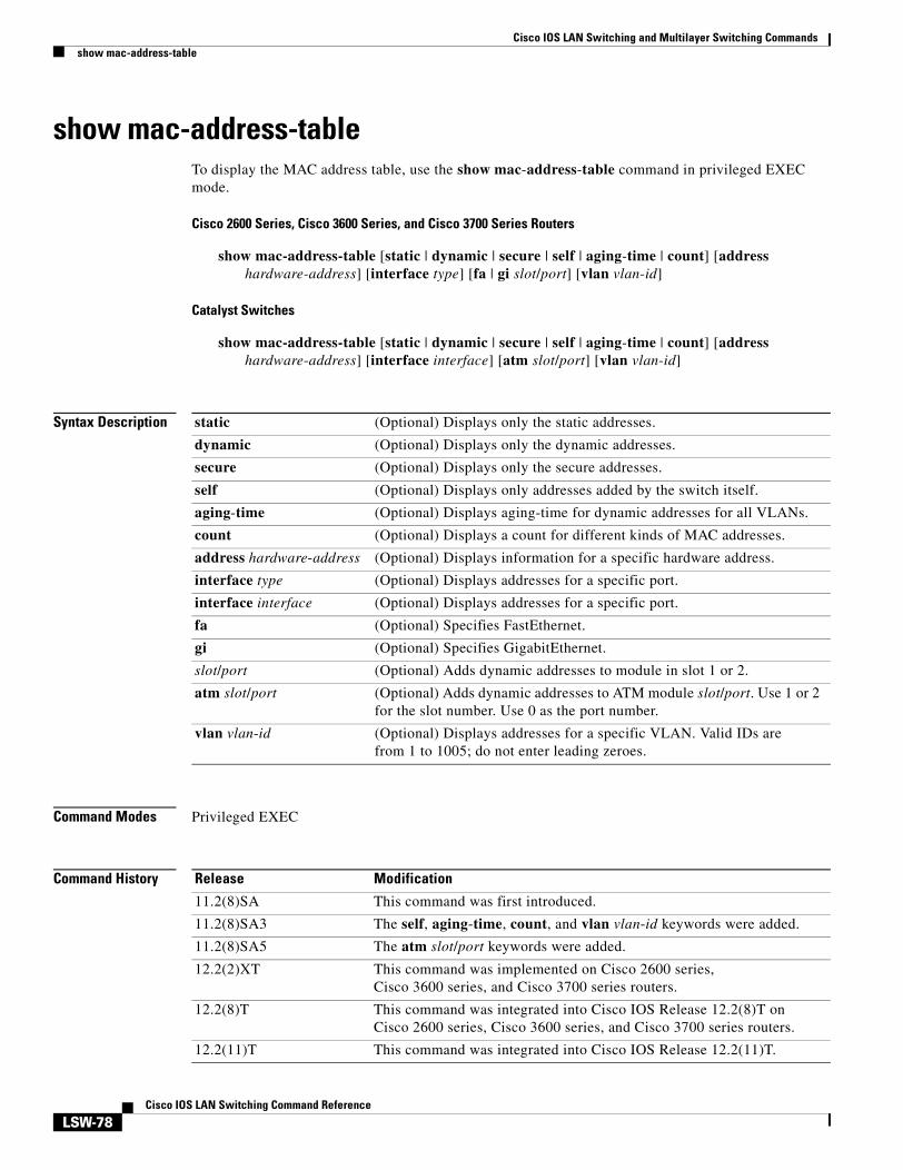
clear mac-address-tableTo remove a specified address (or set of addresses) from the MAC address table, use the clear mac-address-table command in privileged EXEC mode.
Cisco 2600 Series, Cisco 3600 Series, and Cisco 3700 Series Routers
Syntax Description dynamic (Optional) Clears only dynamic addresses.
secure (Optional) Clears only secure addresses.
static (Optional) Clears only static addresses.
restricted static (Optional) Clears only restricted static addresses.
permanent (Optional) Clears only permanent addresses.
address (Optional) Clears only a specified address.
mac-address (Optional) Target MAC address.
interface Clears all addresses for an interface.
type (Optional) Interface type: ethernet, fastethernet, fddi, atm, or port channel.
slot (Optional) The module interface number.
module (Optional) The module interface number:
• 0 for fixed
• 1 or A for module A
• 2 or B for module B
port (Optional)
Cisco 2600 Series, Cisco 3600 Series, and Cisco 3700 Series Routers
Port interface number ranges based on type of Ethernet switch network module used:
• 0 to 15 for NM-16ESW
• 0 to 35 for NM-36ESW
• 0 to 1 for GigabitEthernet
Catalyst Switches
Port interface number ranging from 1 to 28:
• 1 to 25 for Ethernet (fixed)
• 26, 27 for Fast Ethernet (fixed)
• Port channel
Cisco IOS LAN Switching and Multilayer Switching Commandsclear mac-address-table
LSW-5Cisco IOS LAN Switching Command Reference
Command Default Cisco 2600 Series, Cisco 3600 Series, and Cisco 3700 Series Routers
All MAC addresses on the router being configured are cleared.
Catalyst Switches
The dynamic addresses are cleared.
Command Modes Privileged EXEC
Command History
Usage Guidelines Cisco 2600 Series, Cisco 3600 Series, and Cisco 3700 Series Routers
If the clear mac-address-table command is invoked with no options, all MAC addresses are removed. If you specify an address but do not specify an interface, the address is deleted from all interfaces. If you specify an interface but do not specify an address, all addresses on the specified interface are removed.
Catalyst Switches
If the clear mac-address-table command is invoked with no options, all dynamic addresses are removed. If you specify an address but do not specify an interface, the address is deleted from all interfaces. If you specify an interface but do not specify an address, all addresses on the specified interface are removed.
If a targeted address is not present in the MAC forwarding table, the following error message appears:
MAC address not found
Examples Cisco 2600 Series, Cisco 3600 Series, and Cisco 3700 Series Routers
The following example shows how to clear all dynamic addresses in the MAC forwarding table:
Router# clear mac-address-table dynamic
The following example shows how to clear the static address 0040.C80A.2F07 on Ethernet port 1:
12.2(2)XT This command was introduced on Cisco 2600 series, Cisco 3600 series, and Cisco 3700 series routers.
12.2(8)T This command was integrated into Cisco IOS Release 12.2(8)T on Cisco 2600 series, Cisco 3600 series, and Cisco 3700 series routers.
12.2(11)T This command was integrated into Cisco IOS Release 12.2(11)T.
Cisco IOS LAN Switching and Multilayer Switching Commandsclear mac-address-table
LSW-6Cisco IOS LAN Switching Command Reference
Related Commands Cisco 2600 Series, Cisco 3600 Series, and Cisco 3700 Series Routers
Catalyst Switches
Command Description
mac-address-table (aging-time) Configures the length of time the switch keeps dynamic MAC addresses in memory before discarding.
mac-address-table (secure) Associates a secure static address with a particular switched port interface.
mac-address-table (static) Associates a static unicast or multicast MAC address with a particular switched port interface.
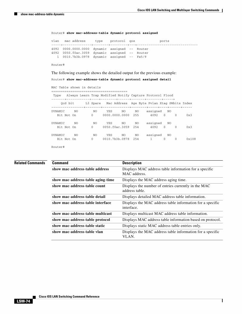
show (mac-address-table) Displays addresses in the MAC address table for a switched port or module.
show (mac-address-table secure) Displays the addressing security configuration.
Command Description
mac-address-table (aging-time) Configures the length of time the switch keeps dynamic MAC addresses in memory before discarding.
mac-address-table (permanent) Associates a permanent unicast or multicast MAC address with a particular switched port interface.
mac-address-table (restricted static)
Associates a restricted static address with a particular switched port interface.
show (mac-address-table) Displays addresses in the MAC address table for a switched port or module.
show (mac-address-table security) Displays the addressing security configuration.
Cisco IOS LAN Switching and Multilayer Switching Commandsclear vlan mapping
LSW-7Cisco IOS LAN Switching Command Reference
clear vlan mappingTo delete existing 802.1Q virtual LAN (VLAN) to Inter-Switch Link (ISL) VLAN-mapped pairs, use the clear vlan mapping command in privileged EXEC mode.
clear vlan mapping dot1q {1q-vlan | all}
Syntax Description
Command Modes Privileged EXEC
Command History
Examples The following example shows how to clear an existing mapped 802.1Q VLAN (VLAN 1044) from the mapping table:
1q-vlan Number of the 802.1Q VLAN for which to remove the mapping.
all Clears the mapping table of all entries.
Release Modification
12.0 This command was introduced.
Command Description
set vlan mapping Maps 802.1Q VLANs to ISL VLANs.
show vlan mapping Displays VLAN mapping table information.
Cisco IOS LAN Switching and Multilayer Switching Commandsclear vlan
LSW-8Cisco IOS LAN Switching Command Reference
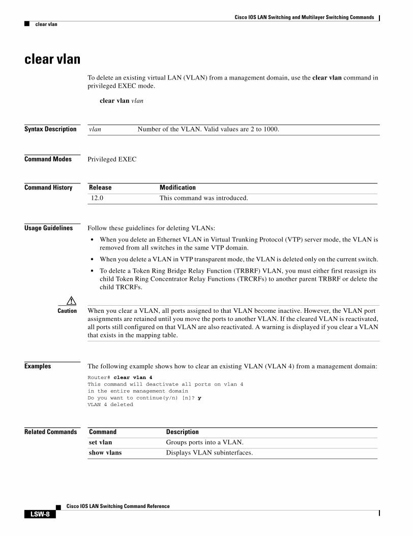
clear vlanTo delete an existing virtual LAN (VLAN) from a management domain, use the clear vlan command in privileged EXEC mode.
clear vlan vlan
Syntax Description
Command Modes Privileged EXEC
Command History
Usage Guidelines Follow these guidelines for deleting VLANs:
• When you delete an Ethernet VLAN in Virtual Trunking Protocol (VTP) server mode, the VLAN is removed from all switches in the same VTP domain.
• When you delete a VLAN in VTP transparent mode, the VLAN is deleted only on the current switch.
• To delete a Token Ring Bridge Relay Function (TRBRF) VLAN, you must either first reassign its child Token Ring Concentrator Relay Functions (TRCRFs) to another parent TRBRF or delete the child TRCRFs.
Caution When you clear a VLAN, all ports assigned to that VLAN become inactive. However, the VLAN port assignments are retained until you move the ports to another VLAN. If the cleared VLAN is reactivated, all ports still configured on that VLAN are also reactivated. A warning is displayed if you clear a VLAN that exists in the mapping table.
Examples The following example shows how to clear an existing VLAN (VLAN 4) from a management domain:
Router# clear vlan 4This command will deactivate all ports on vlan 4in the entire management domainDo you want to continue(y/n) [n]? yVLAN 4 deleted
Related Commands
vlan Number of the VLAN. Valid values are 2 to 1000.
Release Modification
12.0 This command was introduced.
Command Description
set vlan Groups ports into a VLAN.
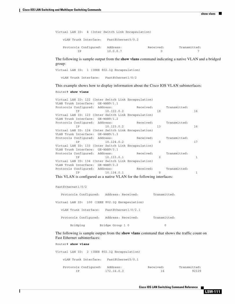
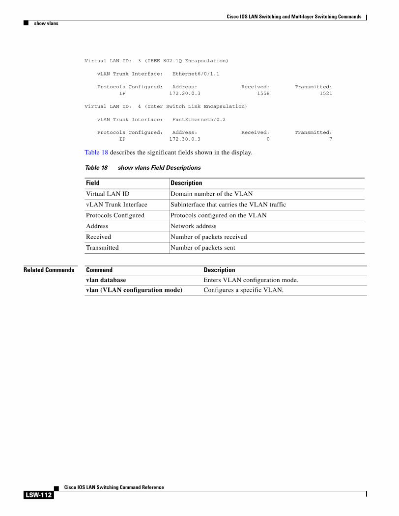
show vlans Displays VLAN subinterfaces.
Cisco IOS LAN Switching and Multilayer Switching Commandsencapsulation isl
LSW-9Cisco IOS LAN Switching Command Reference
encapsulation islTo enable the Inter-Switch Link (ISL), use the encapsulation isl command in subinterface configuration mode. To disable the ISL, use the no form of this command.
encapsulation isl vlan-identifier
no encapsulation vlan-identifier
Syntax Description
Command Default ISL is disabled.
Command Modes Subinterface configuration
Command History
Usage Guidelines ISL is a Cisco protocol for interconnecting multiple switches and routers, and for defining VLAN topologies.
ISL encapsulation is configurable on Fast Ethernet interfaces.
ISL encapsulation adds a 26-byte header to the beginning of the Ethernet frame. The header contains a 10-bit VLAN identifier that conveys VLAN membership identities between switches.
To enter the subinterface configuration mode, you must enter the interface configuration mode first and then enter the interface command to specify a subinterface.
Examples The following example shows how to enable ISL on Fast Ethernet subinterface 2/1.20:
vlan-identifier Virtual LAN (VLAN) identifier. Valid values on all platforms except the Cisco 7600 series are from 1 to 1000. On the Cisco 7600 series, valid values are from 1 to 4096.
Release Modification
11.1 This command was introduced.
12.2(14)SX Support for this command was introduced on the Supervisor Engine 720.
12.2(17d)SXB Support for this command was introduced on the Supervisor Engine 2.
Command Description
bridge-group Assigns each network interface to a bridge group.
show bridge vlan Displays virtual LAN subinterfaces.
Cisco IOS LAN Switching and Multilayer Switching Commandsencapsulation isl
LSW-10Cisco IOS LAN Switching Command Reference
show interfaces Displays statistics for all interfaces configured on the router or access server.
show vlans Displays VLAN subinterfaces.
Command Description
Cisco IOS LAN Switching and Multilayer Switching Commandsencapsulation sde
LSW-11Cisco IOS LAN Switching Command Reference
encapsulation sdeTo enable IEEE 802.10 encapsulation of traffic on a specified subinterface in virtual LANs (VLANs), use the encapsulation sde command in subinterface configuration mode.
encapsulation sde sa-id
Syntax Description
Command Default IEEE 802.10 encapsulation is disabled.
Command Modes Subinterface configuration
Command History
Usage Guidelines IEEE 802.10 is a standard protocol for interconnecting multiple switches and routers and for defining VLAN topologies.
Secure Data Exchange (SDE) encapsulation is configurable only on the following interface types:
• IEEE 802.10 routing: FDDI
• IEEE 802.10 transparent bridging:
– Ethernet
– FDDI
– HDLC serial
– Transparent mode
– Token Ring
Examples The following example shows how to enable SDE on FDDI subinterface 2/0.1 and assigns a VLAN identifier of 9999:
sa-id Security association identifier. This value is used as the VLAN identifier. The valid range is from 0 to 0xFFFFFFFE.
Release Modification
10.3 This command was introduced.
12.2(33)SRA This command was integrated into Cisco IOS Release 12.2(33)SRA.
Command Description
bridge-group Assigns each network interface to a bridge group.
Cisco IOS LAN Switching and Multilayer Switching Commandsencapsulation sde
LSW-12Cisco IOS LAN Switching Command Reference
show interfaces Displays statistics for all interfaces configured on the router or access server.
show vlans Displays VLAN subinterfaces.
Command Description
Cisco IOS LAN Switching and Multilayer Switching Commandsmac-address-table aging-time
LSW-13Cisco IOS LAN Switching Command Reference
mac-address-table aging-timeTo configure the maximum aging time for entries in the Layer 2 table, use the mac-address-table aging-time command in global configuration mode. To reset the seconds value to the default setting, use the no form of this command.
Cisco 2600 Series, Cisco 3600 Series, and Cisco 3700 Series Routers
no mac-address-table aging-time seconds [vlan vlan-id]
Syntax Description
Command Default The system uses a default of 300 seconds for the mac-address-table aging-time when the mac-address-table aging-time command has not been configured.
Command Modes Global configuration
Command History
Usage Guidelines Cisco 2600 Series, Cisco 3600 Series, and Cisco 3700 Series Routers
The aging time entry will take the specified value. Valid entries are from 10 to 1000000 seconds.
This command cannot be disabled.
seconds MAC address table entry maximum age. Valid values are 0, and from 10 to 1000000 seconds. Aging time is counted from the last time that the switch saw the mac-address. The default value is 300 seconds.
vlan vlan-id (Optional) Specifies the VLAN to which the changed aging time should be applied. Valid values are from 2 to 1001.
Release Modification
12.0(7)XE This command was introduced on Catalyst 6000 series switches.
12.1(1)E This command was implemented on Catalyst 6000 series switches.
12.2(2)XT This command was introduced on Cisco 2600 series, Cisco 3600 series, and Cisco 3700 series routers.
12.2(8)T This command was integrated into Cisco IOS Release 12.2(8)T on Cisco 2600 series, Cisco 3600 series, and Cisco 3700 series routers.
12.2(11)T This command was integrated into Cisco IOS Release 12.2(11)T.
12.2(18)SFX This command was integrated into Cisco IOS Release 12.2(18)SFX.
Cisco IOS LAN Switching and Multilayer Switching Commandsmac-address-table aging-time
LSW-14Cisco IOS LAN Switching Command Reference
Catalyst Switches
If you do not enter a VLAN, the change is applied to all routed-port VLANs.
Enter 0 seconds to disable aging.
Examples Cisco 2600 Series, Cisco 3600 Series, and Cisco 3700 Series Routers
The following example shows the aging time being configured:
Router(config)# mac-address-table aging-time 300
Catalyst Switches
The following example shows the aging time being configured:
Router(config)# mac-address-table aging-time 400
The following example shows the aging time being disabled:
Router(config)# mac-address-table aging-time 0
Related Commands Command Description
show mac-address-table aging-time
Displays the MAC address aging time.
Cisco IOS LAN Switching and Multilayer Switching Commandsmac-address-table dynamic
LSW-15Cisco IOS LAN Switching Command Reference
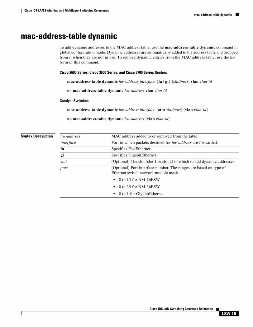
mac-address-table dynamicTo add dynamic addresses to the MAC address table, use the mac-address-table dynamic command in global configuration mode. Dynamic addresses are automatically added to the address table and dropped from it when they are not in use. To remove dynamic entries from the MAC address table, use the no form of this command.
Cisco 2600 Series, Cisco 3600 Series, and Cisco 3700 Series Routers
no mac-address-table dynamic hw-address [vlan vlan-id]
Syntax Description hw-address MAC address added to or removed from the table.
interface Port to which packets destined for hw-address are forwarded.
fa Specifies FastEthernet.
gi Specifies GigabitEthernet.
slot (Optional) The slot (slot 1 or slot 2) to which to add dynamic addresses.
port (Optional) Port interface number. The ranges are based on type of Ethernet switch network module used:
• 0 to 15 for NM-16ESW
• 0 to 35 for NM-36ESW
• 0 to 1 for GigabitEthernet
Cisco IOS LAN Switching and Multilayer Switching Commandsmac-address-table dynamic
LSW-16Cisco IOS LAN Switching Command Reference
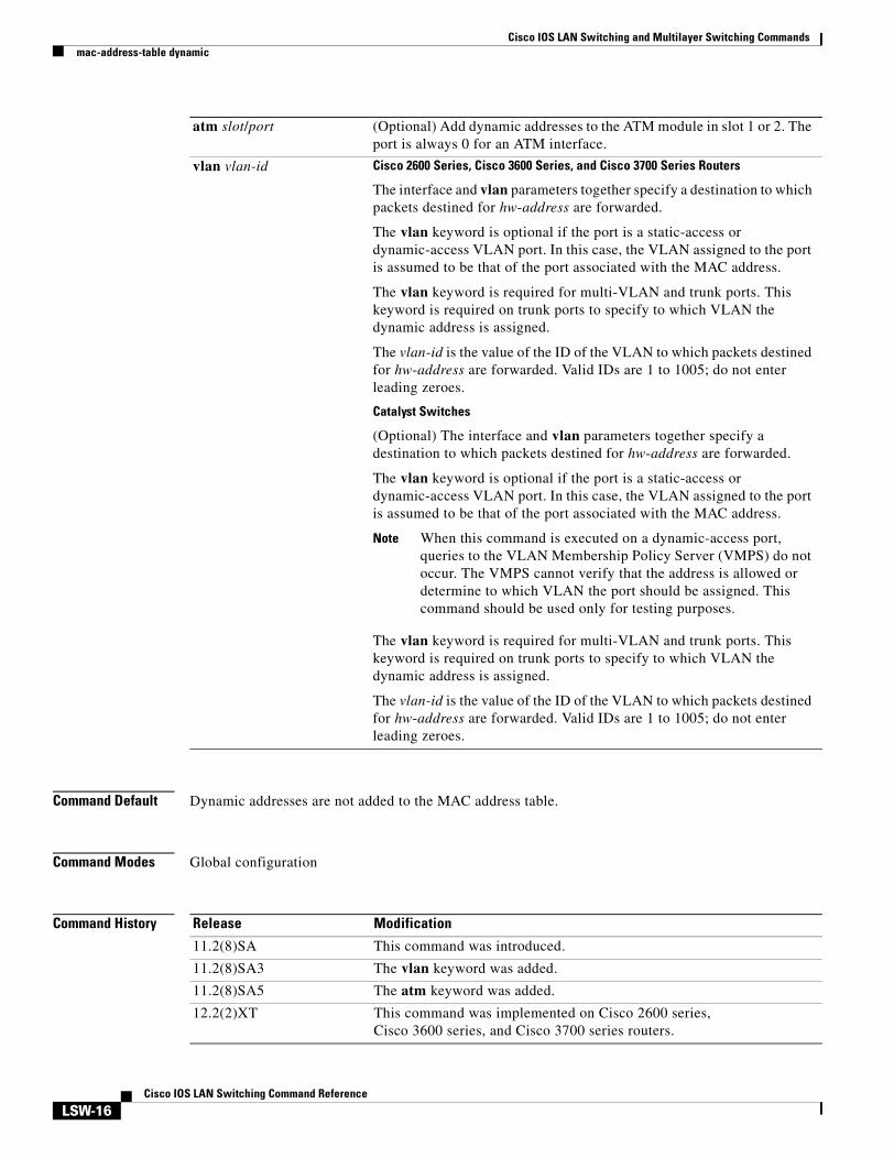
Command Default Dynamic addresses are not added to the MAC address table.
Command Modes Global configuration
Command History
atm slot/port (Optional) Add dynamic addresses to the ATM module in slot 1 or 2. The port is always 0 for an ATM interface.
vlan vlan-id Cisco 2600 Series, Cisco 3600 Series, and Cisco 3700 Series Routers
The interface and vlan parameters together specify a destination to which packets destined for hw-address are forwarded.
The vlan keyword is optional if the port is a static-access or dynamic-access VLAN port. In this case, the VLAN assigned to the port is assumed to be that of the port associated with the MAC address.
The vlan keyword is required for multi-VLAN and trunk ports. This keyword is required on trunk ports to specify to which VLAN the dynamic address is assigned.
The vlan-id is the value of the ID of the VLAN to which packets destined for hw-address are forwarded. Valid IDs are 1 to 1005; do not enter leading zeroes.
Catalyst Switches
(Optional) The interface and vlan parameters together specify a destination to which packets destined for hw-address are forwarded.
The vlan keyword is optional if the port is a static-access or dynamic-access VLAN port. In this case, the VLAN assigned to the port is assumed to be that of the port associated with the MAC address.
Note When this command is executed on a dynamic-access port, queries to the VLAN Membership Policy Server (VMPS) do not occur. The VMPS cannot verify that the address is allowed or determine to which VLAN the port should be assigned. This command should be used only for testing purposes.
The vlan keyword is required for multi-VLAN and trunk ports. This keyword is required on trunk ports to specify to which VLAN the dynamic address is assigned.
The vlan-id is the value of the ID of the VLAN to which packets destined for hw-address are forwarded. Valid IDs are 1 to 1005; do not enter leading zeroes.
Release Modification
11.2(8)SA This command was introduced.
11.2(8)SA3 The vlan keyword was added.
11.2(8)SA5 The atm keyword was added.
12.2(2)XT This command was implemented on Cisco 2600 series, Cisco 3600 series, and Cisco 3700 series routers.
Cisco IOS LAN Switching and Multilayer Switching Commandsmac-address-table dynamic
LSW-17Cisco IOS LAN Switching Command Reference
Usage Guidelines If the vlan-id argument is omitted and the no form of the command is used, the MAC address is removed from all VLANs.
Examples The following example shows how to add a MAC address on port fa1/1 to VLAN 4:
12.2(8)T This command was integrated into Cisco IOS Release 12.2(8)T, on Cisco 2600 series, Cisco 3600 series, and Cisco 3700 series routers.
12.2(11)T This command was integrated into Cisco IOS Release 12.2(11)T.
Release Modification
Command Description
clear mac-address-table Deletes entries from the MAC address table.
mac-address-table aging-time Sets the length of time that a dynamic entry remains in the MAC address table after the entry is used or updated.
mac-address-table static Adds static addresses to the MAC address table.
show mac-address-table Displays the MAC address table.
Cisco IOS LAN Switching and Multilayer Switching Commandsmac-address-table secure
LSW-18Cisco IOS LAN Switching Command Reference
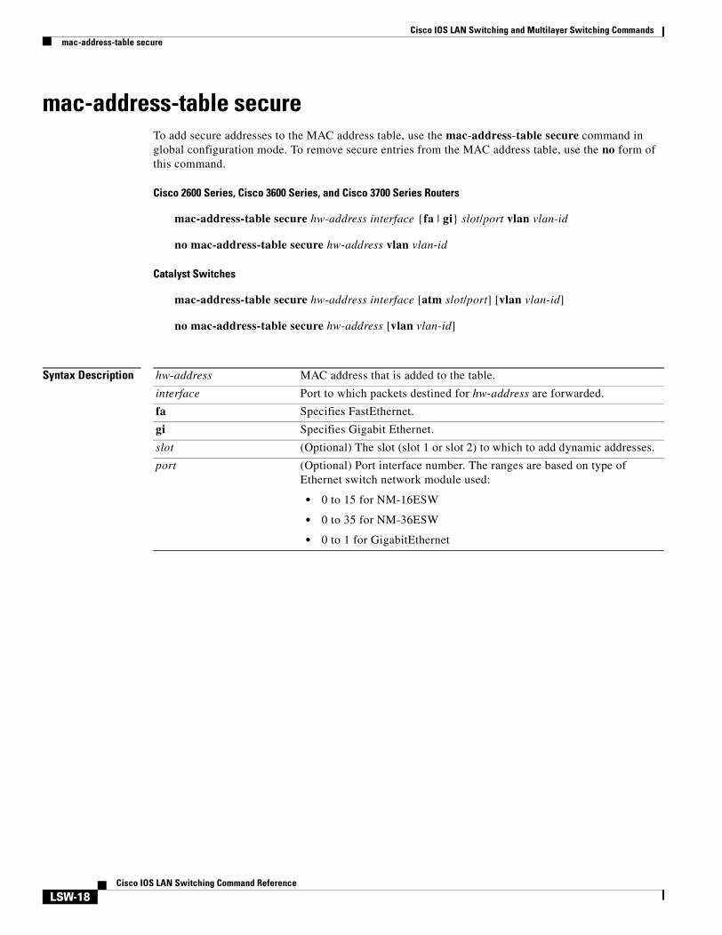
mac-address-table secureTo add secure addresses to the MAC address table, use the mac-address-table secure command in global configuration mode. To remove secure entries from the MAC address table, use the no form of this command.
Cisco 2600 Series, Cisco 3600 Series, and Cisco 3700 Series Routers
no mac-address-table secure hw-address [vlan vlan-id]
Syntax Description hw-address MAC address that is added to the table.
interface Port to which packets destined for hw-address are forwarded.
fa Specifies FastEthernet.
gi Specifies Gigabit Ethernet.
slot (Optional) The slot (slot 1 or slot 2) to which to add dynamic addresses.
port (Optional) Port interface number. The ranges are based on type of Ethernet switch network module used:
• 0 to 15 for NM-16ESW
• 0 to 35 for NM-36ESW
• 0 to 1 for GigabitEthernet
Cisco IOS LAN Switching and Multilayer Switching Commandsmac-address-table secure
LSW-19Cisco IOS LAN Switching Command Reference
Command Default Secure addresses are not added to the MAC address table.
Command Modes Global configuration
Command History
Usage Guidelines Cisco 2600 Series, Cisco 3600 Series, and Cisco 3700 Series Routers
Secure addresses can be assigned to only one port at a time. Therefore, if a secure address table entry for the specified MAC address and VLAN already exists on another port, it is removed from that port and assigned to the specified one.
atm slot/port (Optional) Add secure addresses to the ATM module in slot 1 or 2. The port is always 0 for an ATM interface.
vlan vlan-id Cisco 2600 Series, Cisco 3600 Series, and Cisco 3700 Series Routers
The interface and vlan parameters together specify a destination to which packets destined for hw-address are forwarded.
The vlan keyword is optional if the port is a static-access VLAN port. In this case, the VLAN assigned to the port is assumed to be that of the port associated with the MAC address. This keyword is required for multi-VLAN and trunk ports.
The value of vlan-id is the ID of the VLAN to which secure entries are added. Valid IDs are 1 to 1005; do not enter leading zeroes.
Catalyst Switches
(Optional) The interface and vlan parameters together specify a destination to which packets destined for hw-address are forwarded.
The vlan keyword is optional if the port is a static-access VLAN port. In this case, the VLAN assigned to the port is assumed to be that of the port associated with the MAC address. This keyword is required for multi-VLAN and trunk ports.
The value of vlan-id is the ID of the VLAN to which secure entries are added. Valid IDs are 1 to 1005; do not enter leading zeroes.
Release Modification
11.2(8)SA This command was introduced.
11.2(8)SA3 The vlan keyword was added.
11.2(8)SA5 The atm keyword was added.
12.2(2)XT This command was implemented on Cisco 2600 series, Cisco 3600 series, and Cisco 3700 series routers.
12.2(8)T This command was integrated into Cisco IOS Release 12.2(8)T, on Cisco 2600 series, Cisco 3600 series, and Cisco 3700 series routers.
12.2(11)T This command was integrated into Cisco IOS Release 12.2(11)T.
Cisco IOS LAN Switching and Multilayer Switching Commandsmac-address-table secure
LSW-20Cisco IOS LAN Switching Command Reference
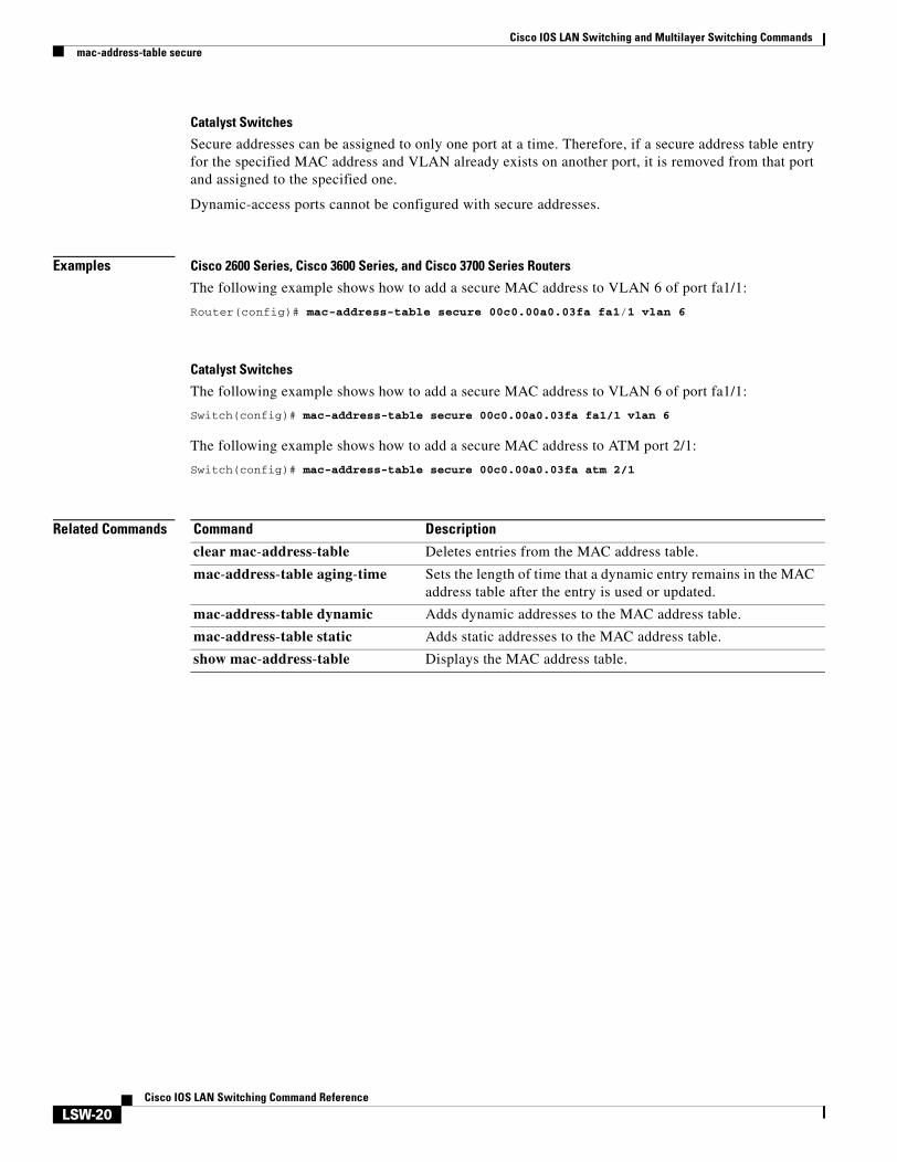
Catalyst Switches
Secure addresses can be assigned to only one port at a time. Therefore, if a secure address table entry for the specified MAC address and VLAN already exists on another port, it is removed from that port and assigned to the specified one.
Dynamic-access ports cannot be configured with secure addresses.
Examples Cisco 2600 Series, Cisco 3600 Series, and Cisco 3700 Series Routers
The following example shows how to add a secure MAC address to VLAN 6 of port fa1/1:
clear mac-address-table Deletes entries from the MAC address table.
mac-address-table aging-time Sets the length of time that a dynamic entry remains in the MAC address table after the entry is used or updated.
mac-address-table dynamic Adds dynamic addresses to the MAC address table.
mac-address-table static Adds static addresses to the MAC address table.
show mac-address-table Displays the MAC address table.
Cisco IOS LAN Switching and Multilayer Switching Commandsmac-address-table static
LSW-21Cisco IOS LAN Switching Command Reference
mac-address-table staticTo add static entries to the MAC address table or to disable Internet Group Multicast Protocol (IGMP) snooping for a particular static multicast MAC address, use the mac-address-table static command in global configuration mode. To remove entries profiled by the combination of specified entry information, use the no form of this command. See the “Usage Guidelines” section for other information about the no form of this command.
Cisco 2600 Series, Cisco 3600 Series, and Cisco 3700 Series Routers
mac-address-table static mac-address vlan vlan-id interface type slot/port
no mac-address-table static mac-address vlan vlan-id interface type slot/port
Syntax Description mac-address Address to add to the MAC address table.
vlan vlan-id Specifies the VLAN associated with the MAC address entry; valid values are from 2 to 100.
interface type slot/portorinterface int
Specifies the interface type and the slot and port configured. On the Catalyst switches, the int argument should specify the interface type and the slot/port or slot/subslot/port numbers (for example, interface pos 5/0 or interface atm 8/0/1).
drop Drops all traffic that is received from and going to the configured MAC address in the specified VLAN.
disable-snooping (Optional) Disables IGMP snooping on the multicast MAC address.
dlci dlci (Optional) Specifies the data-link connection identifier (DLCI) to be mapped to this MAC address. The valid range is from 16 to 1007.
Note This option is valid only if Frame Relay encapsulation has been enabled on the specified interface.
pvc vpi/vci (Optional) Specifies the permanent virtual circuit (PVC) to be mapped to this MAC address. You must specify both a virtual path identifier (VPI) and virtual circuit identifier (VCI), separated by a slash.
Note This option is valid only for ATM interfaces.
auto-learn (Optional) Specifies that if the router sees this same MAC address on a different port, the MAC entry should be updated with the new port.
disable-snooping (Optional) Disables IGMP snooping on the Frame Relay DLCI or ATM PVC.
protocol (Optional) Specifies the protocol associated with the entry.
ip (Optional) Specifies the IP protocol.
ipx (Optional) Specifies the Internetwork Packet Exchange (IPX) protocol.
assigned (Optional) Specifies assigned protocol bucket accounts for protocols such as DECnet, Banyan VINES, and AppleTalk.
Cisco IOS LAN Switching and Multilayer Switching Commandsmac-address-table static
LSW-22Cisco IOS LAN Switching Command Reference
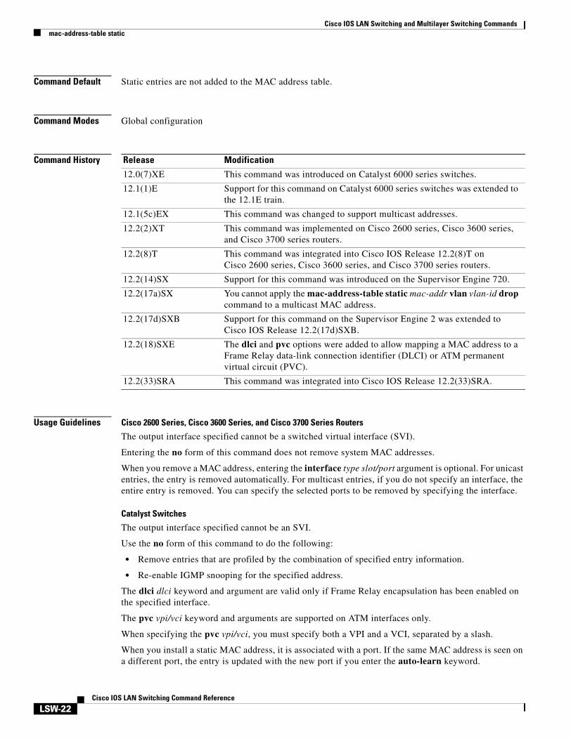
Command Default Static entries are not added to the MAC address table.
Command Modes Global configuration
Command History
Usage Guidelines Cisco 2600 Series, Cisco 3600 Series, and Cisco 3700 Series Routers
The output interface specified cannot be a switched virtual interface (SVI).
Entering the no form of this command does not remove system MAC addresses.
When you remove a MAC address, entering the interface type slot/port argument is optional. For unicast entries, the entry is removed automatically. For multicast entries, if you do not specify an interface, the entire entry is removed. You can specify the selected ports to be removed by specifying the interface.
Catalyst Switches
The output interface specified cannot be an SVI.
Use the no form of this command to do the following:
• Remove entries that are profiled by the combination of specified entry information.
• Re-enable IGMP snooping for the specified address.
The dlci dlci keyword and argument are valid only if Frame Relay encapsulation has been enabled on the specified interface.
The pvc vpi/vci keyword and arguments are supported on ATM interfaces only.
When specifying the pvc vpi/vci, you must specify both a VPI and a VCI, separated by a slash.
When you install a static MAC address, it is associated with a port. If the same MAC address is seen on a different port, the entry is updated with the new port if you enter the auto-learn keyword.
Release Modification
12.0(7)XE This command was introduced on Catalyst 6000 series switches.
12.1(1)E Support for this command on Catalyst 6000 series switches was extended to the 12.1E train.
12.1(5c)EX This command was changed to support multicast addresses.
12.2(2)XT This command was implemented on Cisco 2600 series, Cisco 3600 series, and Cisco 3700 series routers.
12.2(8)T This command was integrated into Cisco IOS Release 12.2(8)T on Cisco 2600 series, Cisco 3600 series, and Cisco 3700 series routers.
12.2(14)SX Support for this command was introduced on the Supervisor Engine 720.
12.2(17a)SX You cannot apply the mac-address-table static mac-addr vlan vlan-id drop command to a multicast MAC address.
12.2(17d)SXB Support for this command on the Supervisor Engine 2 was extended to Cisco IOS Release 12.2(17d)SXB.
12.2(18)SXE The dlci and pvc options were added to allow mapping a MAC address to a Frame Relay data-link connection identifier (DLCI) or ATM permanent virtual circuit (PVC).
12.2(33)SRA This command was integrated into Cisco IOS Release 12.2(33)SRA.
Cisco IOS LAN Switching and Multilayer Switching Commandsmac-address-table static
LSW-23Cisco IOS LAN Switching Command Reference
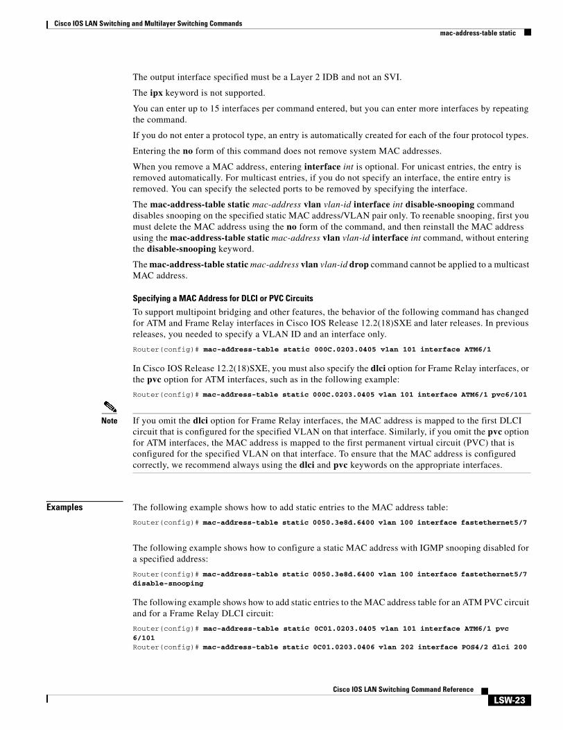
The output interface specified must be a Layer 2 IDB and not an SVI.
The ipx keyword is not supported.
You can enter up to 15 interfaces per command entered, but you can enter more interfaces by repeating the command.
If you do not enter a protocol type, an entry is automatically created for each of the four protocol types.
Entering the no form of this command does not remove system MAC addresses.
When you remove a MAC address, entering interface int is optional. For unicast entries, the entry is removed automatically. For multicast entries, if you do not specify an interface, the entire entry is removed. You can specify the selected ports to be removed by specifying the interface.
The mac-address-table static mac-address vlan vlan-id interface int disable-snooping command disables snooping on the specified static MAC address/VLAN pair only. To reenable snooping, first you must delete the MAC address using the no form of the command, and then reinstall the MAC address using the mac-address-table static mac-address vlan vlan-id interface int command, without entering the disable-snooping keyword.
The mac-address-table static mac-address vlan vlan-id drop command cannot be applied to a multicast MAC address.
Specifying a MAC Address for DLCI or PVC Circuits
To support multipoint bridging and other features, the behavior of the following command has changed for ATM and Frame Relay interfaces in Cisco IOS Release 12.2(18)SXE and later releases. In previous releases, you needed to specify a VLAN ID and an interface only.
In Cisco IOS Release 12.2(18)SXE, you must also specify the dlci option for Frame Relay interfaces, or the pvc option for ATM interfaces, such as in the following example:
Note If you omit the dlci option for Frame Relay interfaces, the MAC address is mapped to the first DLCI circuit that is configured for the specified VLAN on that interface. Similarly, if you omit the pvc option for ATM interfaces, the MAC address is mapped to the first permanent virtual circuit (PVC) that is configured for the specified VLAN on that interface. To ensure that the MAC address is configured correctly, we recommend always using the dlci and pvc keywords on the appropriate interfaces.
Examples The following example shows how to add static entries to the MAC address table:
Cisco IOS LAN Switching and Multilayer Switching Commandsmac-address-table static
LSW-24Cisco IOS LAN Switching Command Reference
Related Commands Command Description
show mac-address-table address Displays MAC address table information for a specific MAC address.
Cisco IOS LAN Switching and Multilayer Switching Commandsmls qos cos
LSW-25Cisco IOS LAN Switching Command Reference
mls qos cosTo define the default multilayer switching (MLS) class of service (CoS) value of a port or to assign the default CoS value to all incoming packets on the port, use the mls qos cos command in interface configuration mode. To return to the default CoS setting, use the no form of this command.
mls qos cos {default-cos | override}
no mls qos cos {default-cos | override}
Syntax Description
Command Default The default CoS value for a port is 0.CoS override is disabled.
Command Modes Interface configuration
Command History
Usage Guidelines You can assign the default CoS and DSCP value to all packets entering a port if the port has been configured by use of the override keyword.
Use the override keyword when all incoming packets on certain ports deserve a higher or lower priority than packets entering from other ports. Even if a port was previously set to trust DSCP or CoS, this command overrides that trust state, and all the CoS values on the incoming packets are changed to the default CoS value that is configured with the mls qos cos command. If an incoming packet is tagged, the CoS value of the packet is modified at the ingress port. It is changed to the default CoS of that port.
Use the show mls qos interface privileged EXEC command to verify your settings.
default-cos Assigns a default CoS value to a port. If the port is CoS trusted and packets are untagged, the default CoS value is used to select one output queue as an index into the CoS-to-differentiated services code point (DSCP) map. The CoS range is 0 to 7. The default is 0.
override Overrides the CoS of the incoming packets and applies the default CoS value on the port to all incoming packets.
Release Modification
12.1(6)EA2 This command was introduced. It replaced the switchport priority command.
12.2(15)ZJ This command was implemented on the following platforms: Cisco 2600 series, Cisco 3600 series, and Cisco 3700 series routers.
12.3(4)T This command was integrated into Cisco IOS Release 12.3(4)T on the following platforms: Cisco 2600 series, Cisco 3600 series, and Cisco 3700 series routers.
Cisco IOS LAN Switching and Multilayer Switching Commandsmls qos cos
LSW-26Cisco IOS LAN Switching Command Reference
Examples The following example shows how to assign 4 as the default port CoS:
The following example shows how to assign 4 as the default port CoS value for all packets entering the port:
Router(config)# interface gigabitethernet0/1Router(config-if)# mls qos cos 4Router(config-if)# mls qos cos override
Related Commands Command Description
mls qos map Defines the CoS-to-DSCP map or the DSCP-to-CoS map.
mls qos trust Configures the port trust state.
show interface fax/y switchport
Displays switch port interfaces.
show mls qos interface Displays QoS information.
Cisco IOS LAN Switching and Multilayer Switching Commandsmls qos map
LSW-27Cisco IOS LAN Switching Command Reference
mls qos mapTo define the multilayer switching (MLS) class of service (CoS)-to-differentiated services code point (DSCP) map or DSCP-to-CoS map, use the mls qos map command in global configuration mode. To return to the default map, use the no form of this command.
mls qos map {cos-dscp dscp1...dscp8 | dscp-cos dscp-list to cos}
no mls qos map {cos-dscp | dscp-cos}
Syntax Description
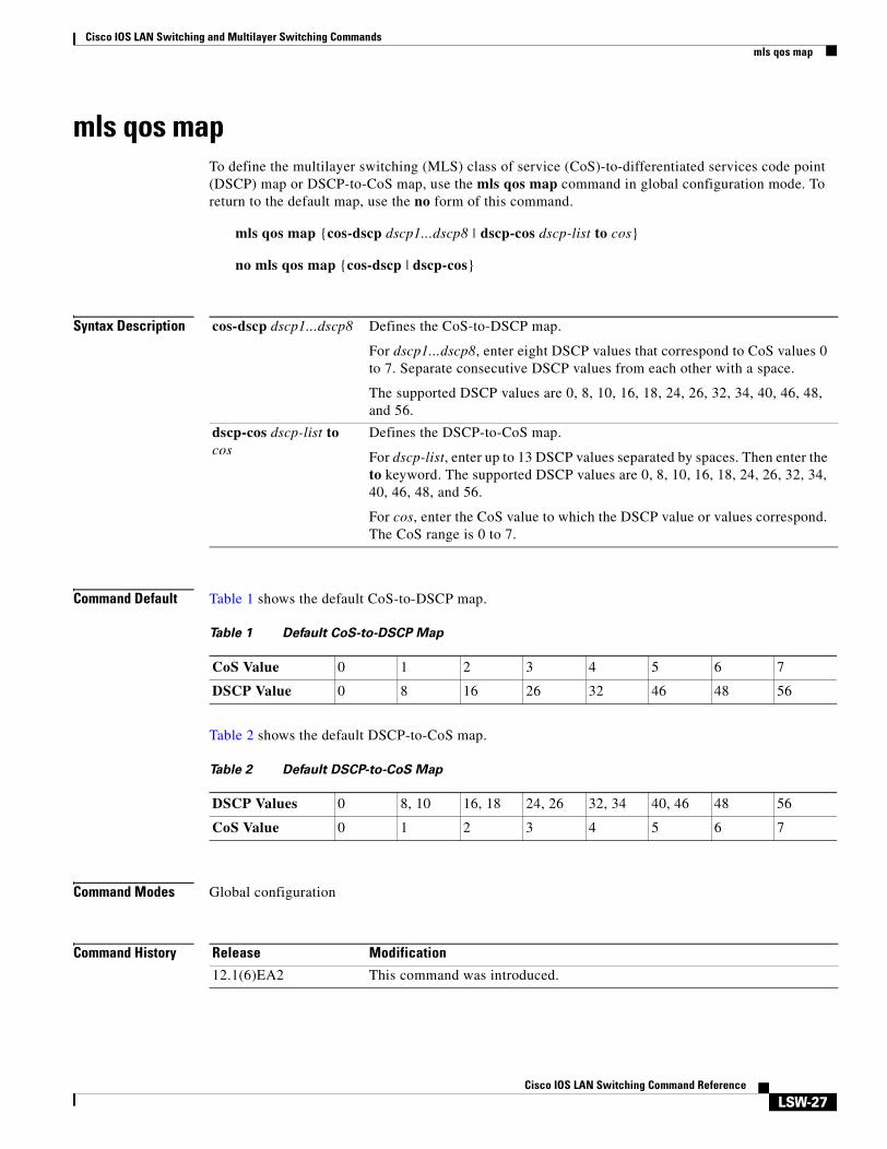
Command Default Table 1 shows the default CoS-to-DSCP map.
Table 2 shows the default DSCP-to-CoS map.
Command Modes Global configuration
Command History
cos-dscp dscp1...dscp8 Defines the CoS-to-DSCP map.
For dscp1...dscp8, enter eight DSCP values that correspond to CoS values 0 to 7. Separate consecutive DSCP values from each other with a space.
The supported DSCP values are 0, 8, 10, 16, 18, 24, 26, 32, 34, 40, 46, 48, and 56.
dscp-cos dscp-list to cos
Defines the DSCP-to-CoS map.
For dscp-list, enter up to 13 DSCP values separated by spaces. Then enter the to keyword. The supported DSCP values are 0, 8, 10, 16, 18, 24, 26, 32, 34, 40, 46, 48, and 56.
For cos, enter the CoS value to which the DSCP value or values correspond. The CoS range is 0 to 7.
Cisco IOS LAN Switching and Multilayer Switching Commandsmls qos map
LSW-28Cisco IOS LAN Switching Command Reference
Usage Guidelines All of the CoS-to-DSCP and DSCP-to-CoS maps are globally defined. You apply all maps to all ports.
If you enter the mls qos trust cos command, the default CoS-to-DSCP map is applied.
If you enter the mls qos trust dscp command, the default DSCP-to-CoS map is applied.
After a default map is applied, you can define the CoS-to-DSCP or DSCP-to-CoS map by entering consecutive mls qos map commands.
If the mls qos trust dscp command is entered and a packet with an untrusted DSCP value is at an ingress port, the packet CoS value is set to 0.
Use the show mls qos maps privileged EXEC command to verify your settings.
Examples The following example shows how to define the DSCP-to-CoS map. DSCP values 16, 18, 24, and 26 are mapped to CoS 1. DSCP values 0, 8, and 10 are mapped to CoS 0.
12.2(15)ZJ This command was implemented on the following platforms: Cisco 2600 series, Cisco 3600 series, and Cisco 3700 series routers.
12.3(4)T This command was integrated into Cisco IOS Release 12.3(4)T on the following platforms: Cisco 2600 series, Cisco 3600 series, and Cisco 3700 series routers.
Release Modification
Command Description
mls qos cos Defines the default CoS value of a port or assigns the default CoS to all incoming packets on the port.
mls qos trust Configures the port trust state.
show mls qos maps Displays QoS mapping information.
Cisco IOS LAN Switching and Multilayer Switching Commandsmls qos trust
LSW-29Cisco IOS LAN Switching Command Reference
mls qos trustTo configure the multilayer switching (MLS) port trust state and classify traffic by an examination of the class of service (CoS) or differentiated services code point (DSCP) value, use the mls qos trust command in interface configuration mode. To return a port to its untrusted state, use the no form of this command.
mls qos trust [cos | dscp]
no mls qos trust [cos | dscp]
Syntax Description
Command Default The port is not trusted. If no keyword is specified, the default is dscp.
Command Modes Interface configuration
Command History
Usage Guidelines Packets entering a quality of service (QoS) domain are classified at its edge. Because the packets are classified at the edge, the switch port within the QoS domain can be configured to one of the trusted states; there is no need to classify the packets at every switch within the domain. Use the mls qos trust command to specify whether the port is trusted and to indicate which fields of the packet are for the classifying of traffic.
When a port is configured with trust DSCP and the incoming packet is a non-IP packet, the CoS value for the packet is set to 0, and the DSCP-to-CoS map is not applied.
If DSCP is trusted, the DSCP field of the IP packet is not modified. However, it is still possible that a DSCP-to-CoS map can modify the CoS value of the packet.
If CoS is trusted, the packet CoS is not modified. However, a CoS-to-DSCP map could still modify the DSCP value of the packet if it is an IP packet.
Use the show mls qos interface privileged EXEC command to verify your settings.
cos (Optional) Classifies ingress packets that have packet CoS values. For untagged packets, use the port default CoS value.
dscp (Optional) Classifies ingress packets that have packet DSCP values (most significant 6 bits of 8-bit service-type field). For non-IP packets, the packet CoS value is 0.
Release Modification
12.1(6)EA2 This command was introduced.
12.2(15)ZJ This command was implemented on the following platforms: Cisco 2600 series, Cisco 3600 series, and Cisco 3700 series routers.
12.3(4)T This command was integrated into Cisco IOS Release 12.3(4)T on the following platforms: Cisco 2600 series, Cisco 3600 series, and Cisco 3700 series routers.
Cisco IOS LAN Switching and Multilayer Switching Commandsmls qos trust
LSW-30Cisco IOS LAN Switching Command Reference
Examples The following example shows how to configure a port to be a DSCP-trusted port:
The following example shows how to configure a VLAN interface to be a DSCP-trusted port. DSCP-to-COS mapping occurs for all packets that have the configured VLAN ID of 60 and that are egressing from the CPU to the physical port.
mls qos cos Defines the default CoS value of a port or assigns the default CoS to all incoming packets on the port.
mls qos map Defines the CoS-to-DSCP map or the DSCP-to-CoS map.
show mls qos interface Displays QoS information.
Cisco IOS LAN Switching and Multilayer Switching Commandsmls rp ip multicast management-interface
LSW-31Cisco IOS LAN Switching Command Reference
mls rp ip multicast management-interfaceTo assign a different interface (other than the default) to act as the management interface for Multilayer Switching (MLS), use the mls rp ip multicast management-interface command in interface configuration mode. To restore the default interface as the management interface, use the no form of this command.
mls rp ip multicast management-interface
no mls rp ip multicast management-interface
Syntax Description This command has no arguments or keywords.
Command Default When IP multicast MLS is enabled, the subinterface (or virtual LAN [VLAN] interface) that has the lowest VLAN ID and is active (in the “up” state) is automatically selected as the management interface.
Command Modes Interface configuration
Command History
Usage Guidelines When you enable IP multicast MLS, the subinterface (or VLAN interface) that has the lowest VLAN ID and is active (in the “up” state) is automatically selected as the management interface. The one-hop protocol Multilayer Switching Protocol (MLSP) is used between a router and a switch to pass messages about hardware-switched flows. MLSP packets are sent and received on the management interface. Typically, the interface in VLAN 1 is chosen (if that interface exists). Only one management interface is allowed on a single trunk link.
In most cases, we recommend that the management interface be determined by default. However, you can optionally use this command to specify a different router interface or subinterface as the management interface. We recommend using a subinterface with minimal data traffic so that multicast MLSP packets can be sent and received more quickly.
If the user-configured management interface goes down, the router uses the default interface (the active interface with the lowest VLAN ID) until the user-configured interface comes up again.
Examples The following example shows how to configure the Fast Ethernet interface as the management interface:
Router(config)# interface fastethernet1/0.1Router(config-if)# mls rp ip multicast management-interface
Release Modification
12.0(5)T This command was introduced.
Cisco IOS LAN Switching and Multilayer Switching Commandsmls rp ip multicast management-interface
LSW-32Cisco IOS LAN Switching Command Reference
Related Commands Command Description
mls rp ip multicast Enables IP multicast MLS (hardware switching) on an external or internal router in conjunction with Layer 3 switching hardware for the Catalyst 5000 switch.
Cisco IOS LAN Switching and Multilayer Switching Commandsmls rp ip multicast
LSW-33Cisco IOS LAN Switching Command Reference
mls rp ip multicastTo enable IP multicast multilayer switching (MLS) (hardware switching) on an external or internal router in conjunction with Layer 3 switching hardware for the Catalyst 5000, use the mls rp ip multicast command in interface configuration mode. To disable IP multicast MLS on the interface or virtual LAN (VLAN), use the no form of this command.
mls rp ip multicast
no mls rp ip multicast
Syntax Description This command has no arguments or keywords.
Command Default IP multicast MLS is enabled.
Command Modes Interface configuration
Command History
Usage Guidelines This command is available only on specific router platforms connected to a Catalyst 5000 switch. Use this command to reduce multicast load on the router. The switch performs the multicast packet replication and forwarding.
IP multicast MLS is enabled by default on an interface after IP multicast routing and Protocol Independent Multicast (PIM) are enabled.
Examples The following example shows how to disable IP multicast MLS:
Router(config)# interface fastethernet1/0.1Router(config-if)# no mls rp ip multicast
Related Commands
Release Modification
12.0(5)T This command was introduced.
Command Description
mls rp ip multicast management-interface
Assigns a different interface (other than the default) to act as the management interface for MLSP.
show ip mroute Displays the contents of the IP multicast routing table.
show mls rp interface Displays hardware-switched multicast flow information about IP multicast MLS.
Cisco IOS LAN Switching and Multilayer Switching Commandsmls rp ip
LSW-34Cisco IOS LAN Switching Command Reference
mls rp ipTo enable the Multilayer Switching Protocol (MLSP) and multilayer switching (MLS), use the mls rp ip command in global configuration mode. To disable MLS, use the no form of this command.
mls rp ip
no mls rp ip
Syntax Description This command has no arguments or keywords.
Command Default MLS is disabled.
Command Modes Global configuration
Command History
Usage Guidelines Use this command to enable MLS, either globally or on a specific interface. MLSP is the protocol that runs between the switches and routers.
Examples The following example enables MLS:
Router(config)# mls rp ip
Related Commands
Release Modification
11.3(3) WA4(4) This command was introduced.
Command Description
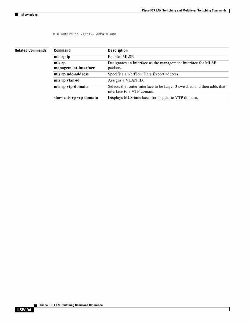
mls rp management-interface
Designates an interface as the management interface for MLSP packets.
mls rp nde-address Specifies a NetFlow Data Export address.
mls rp vlan-id Assigns a VLAN ID.
mls rp vtp-domain Selects the router interface to be Layer 3 switched and then adds that interface to a Virtual Trunking Protocol (VTP) domain.
show mls rp Displays MLS details, including specifics for MLSP.
show mls rp vtp-domain Displays MLS interfaces for a specific VTP domain.
Cisco IOS LAN Switching and Multilayer Switching Commandsmls rp ipx (global)
LSW-35Cisco IOS LAN Switching Command Reference
mls rp ipx (global)To enable the router as a multilayer switching (MLS) IPX Route Processor (RP), or to allow the external systems to enable MLS IPX to a Multilayer Switch Feature Card (MSFC), use the mls rp ipx command in global configuration mode. To disable MLS IPX on the router or MSFC, use the no form of this command.
mls rp ipx [input-acl]
no mls rp ipx [input-acl]
Syntax Description
Command Default MLS IPX is disabled.
Command Modes Global configuration
Command History
Usage Guidelines Multilayer Switching Protocol (MLSP) is the protocol that runs between the MLS switching engine and the MLS RP.
This command is not supported on Cisco 7600 series routers that are configured with a Supervisor Engine 720.
Examples The following example enables MLS IPX on the MLS RP:
Router(config)# mls rp ipx
This example shows how to allow the external systems to enable MLS IPX to the MSFC and override ACLs:
Router(config)# mls rp ipx input-aclRouter(config)#
Related Commands
input-acl (Optional - Cisco 7600 series only) Enables MLS IPX and overrides ACLs.
Release Modification
12.0(5)T This command was introduced.
12.2(17d)SXB This command was integrated into Cisco IOS 12.2(17d)SXB and introduced on the Supervisor Engine 2.
Command Description
mls rp ipx (interface) Enables MLS IPX on a router interface.
mls rp locate ipx Displays information about all switches currently shortcutting for the specified IPX flows.
Cisco IOS LAN Switching and Multilayer Switching Commandsmls rp ipx (global)
LSW-36Cisco IOS LAN Switching Command Reference
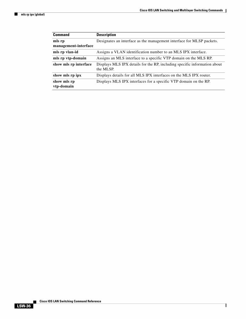
mls rp management-interface
Designates an interface as the management interface for MLSP packets.
mls rp vlan-id Assigns a VLAN identification number to an MLS IPX interface.
mls rp vtp-domain Assigns an MLS interface to a specific VTP domain on the MLS RP.
show mls rp interface Displays MLS IPX details for the RP, including specific information about the MLSP.
show mls rp ipx Displays details for all MLS IPX interfaces on the MLS IPX router.
show mls rp vtp-domain
Displays MLS IPX interfaces for a specific VTP domain on the RP.
Command Description
Cisco IOS LAN Switching and Multilayer Switching Commandsmls rp ipx (interface)
LSW-37Cisco IOS LAN Switching Command Reference
mls rp ipx (interface)To enable multilayer switching (MLS) Internetwork Packet Exchange (IPX) on a router interface, use the mls rp ipx command in interface configuration mode. To disable MLS IPX on a router interface, use the no form of this command.
mls rp ipx
no mls rp ipx
Syntax Description This command has no arguments or keywords.
Command Default MLS IPX is disabled.
Command Modes Interface configuration
Command History
Usage Guidelines Multilayer Switching Protocol (MLSP) is the protocol that runs between the MLS Switching Engine and the MLS RP.
This command is not supported on Cisco 7600 series routers that are configured with a Supervisor Engine 720.
Examples The following example shows how to enable MLS IPX on a router interface:
Router(config-if)# mls rp ipx
Related Commands
Release Modification
12.0(5)T This command was introduced.
12.2(17d)SXB This command was integrated into Cisco IOS 12.2(17d)SXB and introduced on the Supervisor Engine 2.
Command Description
mls rp ipx (global) Enables the router as an MLS IPX RP, or allows the external systems to enable MLS IPX to a Multilayer Switch Feature Card (MSFC)
mls rp locate ipx Displays information about all switches currently shortcutting for the specified IPX flows.
mls rp management-interface
Designates an interface as the management interface for MLSP packets.
mls rp vlan-id Assigns a VLAN identification number to an MLS IPX interface.
mls rp vtp-domain Assigns an MLS interface to a specific VTP domain on the MLS RP.
Cisco IOS LAN Switching and Multilayer Switching Commandsmls rp ipx (interface)
LSW-38Cisco IOS LAN Switching Command Reference
show mls rp interface Displays MLS IPX details for the RP, including specific information about the MLSP.
show mls rp ipx Displays details for all MLS IPX interfaces on the MLS IPX router.
show mls rp vtp-domain Displays MLS IPX interfaces for a specific VTP domain on the RP.
Command Description
Cisco IOS LAN Switching and Multilayer Switching Commandsmls rp locate ipx
LSW-39Cisco IOS LAN Switching Command Reference
mls rp locate ipxTo display information about all switches currently shortcutting for the specified Internetwork Packet Exchange (IPX) flows, use the mls rp locate ipx command in privileged EXEC mode.
mls rp locate ipx destination-network.destination-node [source-network]
Syntax Description
Command Modes Privileged EXEC
Command History
Examples The following example shows how to display the switch that is shortcutting routed flows to the specified IPX flow:
Router# mls rp locate ipx 30.0000.1111.2222
locator response from switch id 0010.1400.601f
Related Commands
destination-network.destination-node The destination network and destination node of IPX packet flows. The destination network address consists of 1 to 8 hexadecimal numbers in the format xxxxxxxx. The destination node address consists of 12 hexadecimal numbers in the format xxxx.xxxx.xxxx.
source-network (Optional) The source network of the IPX flow. The address of the source network consists of 1 to 8 hexadecimal numbers in the format yyyyyyyy.
Release Modification
12.0(5)T This command was introduced.
Command Description
mls rp ipx (global) Enables the router as an IPX MLS RP.
mls rp management-interface
Designates an interface as the management interface for MLSP packets.
mls rp vlan-id Assigns a VLAN identification number to an IPX MLS interface.
mls rp vtp-domain Assigns an MLS interface to a specific Virtual Trunking Protocol (VTP) domain on the MLS RP.
show mls rp interface Displays IPX MLS details for the RP, including specific information about the MLSP.
show mls rp ipx Displays details for all IPX MLS interfaces on the IPX MLS router.
show mls rp vtp-domain
Displays IPX MLS interfaces for a specific VTP domain on the RP.
Cisco IOS LAN Switching and Multilayer Switching Commandsmls rp management-interface
LSW-40Cisco IOS LAN Switching Command Reference
mls rp management-interfaceTo specify an interface as the management interface, use the mls rp management-interface command in interface configuration mode. To remove an interface as the management interface, use the no form of this command.
mls rp management-interface
no mls rp management-interface
Syntax Description This command has no keywords or arguments.
Command Default No interface is specified as the management interface.
Command Modes Interface configuration
Command History
Usage Guidelines Multilayer Switching Protocol (MLSP) packets are sent and received through the management interface.
Select only one IPX multilayer switching (MLS) interface connected to the switch. If you fail to select this interface, no connection between the MLS route processor (RP) and the MLS switching engine occurs, and any routing updates or changes to access lists are not reflected on the switch.
Examples The following example shows how to select a management interface:
Router(config-if)# mls rp management-interface
Related Commands
Release Modification
11.3(3)WA4(4) This command was introduced.
12.2(14)SX Support for this command was introduced on the Supervisor Engine 720.
12.2(17d)SXB Support for this command on the Supervisor Engine 2 was extended to the 12.2 SX release.
Command Description
mls rp ipx (global) Enables the router as an IPX MLS RP.
mls rp locate ipx Displays information about all switches currently shortcutting for the specified IPX flows.
mls rp vlan-id Assigns a VLAN identification number to an IPX MLS interface.
mls rp vtp-domain Assigns an MLS interface to a specific VTP domain on the MLS RP.
show mls rp interface Displays IPX MLS details for the RP, including specific information about the MLSP.
Cisco IOS LAN Switching and Multilayer Switching Commandsmls rp management-interface
LSW-41Cisco IOS LAN Switching Command Reference
show mls rp ipx Displays details for all IPX MLS interfaces on the IPX MLS router.
show mls rp vtp-domain Displays IPX MLS interfaces for a specific VTP domain on the RP.
Command Description
Cisco IOS LAN Switching and Multilayer Switching Commandsmls rp nde-address
LSW-42Cisco IOS LAN Switching Command Reference
mls rp nde-addressTo specify a NetFlow Data Export (NDE) address, use the mls rp nde-address command in global configuration mode.
mls rp nde-address [ip-addr]
no mls rp nde-address [ip-addr]
Syntax Description
Command Default No NDE address is specified.
Command Modes Global configuration
Command History
Usage Guidelines Use this command on a route processor (RP) to specify the NDE address for a router. If you do not specify an NDE IP address for the multilayer switching (MLS) RP, the MLS RP automatically selects one of its interface’s IP addresses and uses that IP address as its NDE IP address and its MLS IP address.
Use the following syntax to specify an IP subnet address:
• ip-subnet-addr—Short subnet address format. The trailing decimal number 00 in an IP address YY.YY.YY.00 specifies the boundary for an IP-subnet address. For example, 172.22.36.00 indicates a 24-bit subnet address (subnet mask 172.22.36.00/255.255.255.0), and 172.24.00.00 indicates a 16-bit subnet address (subnet mask 172.24.00.00/255.255.0.0). However, this format can identify only a subnet address of 8, 16, or 24 bits.
• ip-addr/subnet-mask—Long subnet address format. For example, 172.22.252.00/255.255.252.00 indicates a 22-bit subnet address. This format can specify a subnet address of any bit number. To provide more flexibility, the ip-addr is a full host address, such as 172.22.253.1/255.255.252.00.
• ip-addr/maskbits—Simplified long subnet address format. The mask bits specify the number of bits of the network masks. For example, 172.22.252.00/22 indicates a 22-bit subnet address. The ip-addr is a full host address, such as 192.168.253.1/22, which has the same subnet address as the ip-subnet-addr.
Examples The following example shows how to set the NDE address to 172.25.2.1:
Router(config)# mls rp nde-address 172.25.2.1
ip-address NDE IP address.
Release Modification
11.3(3)WA4(4) This command was introduced.
12.2(14)SX Support for this command was introduced on the Supervisor Engine 720.
12.2(17d)SXB Support for this command on the Supervisor Engine 2 was extended to the 12.2(17d)SXB release.
Cisco IOS LAN Switching and Multilayer Switching Commandsmls rp nde-address
LSW-43Cisco IOS LAN Switching Command Reference
Related Commands Command Description
mls rp ip Enables MLSP.
mls rp management-interface
Designates an interface as the management interface for MLSP packets.
mls rp vlan-id Assigns a VLAN ID.
mls rp vtp-domain Selects the router interface to be Layer 3 switched and then adds that interface to a VTP domain.
show mls rp Displays MLS details, including specifics for MLSP.
show mls rp vtp-domain Displays MLS interfaces for a specific VTP domain.
Cisco IOS LAN Switching and Multilayer Switching Commandsmls rp vlan-id
LSW-44Cisco IOS LAN Switching Command Reference
mls rp vlan-idTo assign a virtual LAN (VLAN) identification number to an Internetwork Packet Exchange (IPX) multilayer switching (MLS) interface, use the mls rp vlan-id command in interface configuration mode. To remove a VLAN identification number, use the no form of this command.
mls rp vlan-id vlan-id-number
no mls rp vlan-id vlan-id-number
Syntax Description
Command Default No VLAN identification number is assigned.
Command Modes Interface configuration
Command History
Usage Guidelines The assigned IPX MLS interface must be either an Ethernet or Fast Ethernet interface—both without subinterfaces.
Examples The following example shows how to assign the VLAN identification number 23 to an IPX MLS interface:
Router(config-if)# mls rp vlan-id 23
Related Commands
vlan-id-number A VLAN identification number from 1 to 4096.
Release Modification
11.3(3)WA4(4) This command was introduced.
Command Description
mls rp ipx (global) Enables the router as an IPX MLS RP.
mls rp locate ipx Displays information about all switches currently shortcutting for the specified IPX flows.
mls rp management-interface
Designates an interface as the management interface for MLSP packets.
mls rp vtp-domain Assigns an MLS interface to a specific Virtual Trunking Protocol (VTP) domain on the MLS RP.
show mls rp interface Displays IPX MLS details for the RP, including specific information about the MLSP.
show mls rp ipx Displays details for all IPX MLS interfaces on the IPX MLS router.
show mls rp vtp-domain Displays IPX MLS interfaces for a specific VTP domain on the RP.
Cisco IOS LAN Switching and Multilayer Switching Commandsmls rp vtp-domain
LSW-45Cisco IOS LAN Switching Command Reference
mls rp vtp-domainTo assign a multilayer switching (MLS) interface to a specific Virtual Trunking Protocol (VTP) domain on the MLS route processor (RP), use the mls rp vtp-domain command in interface configuration mode. To remove a VTP domain, use the no form of this command.
mls rp vtp-domain domain-name
no mls rp vtp-domain domain-name
Syntax Description
Command Default The interface is assigned to the null domain.
Command Modes Interface configuration
Command History
Usage Guidelines The assigned IPX MLS interface must be either an Ethernet interface or a Fast Ethernet interface—both without subinterfaces.
Examples The following example shows how to assign the MLS interface to the VTP domain named engineering:
Router(config-if)# mls rp vtp-domain engineering
Related Commands
domain-name The name of the VTP domain assigned to an MLS interface and its related switches.
Release Modification
11.3(3)WA4(4) This command was introduced.
12.2(14)SX Support for this command was introduced on the Supervisor Engine 720.
12.2(17d)SXB Support for this command on the Supervisor Engine 2 was extended to the 12.2 SX release.
Command Description
mls rp ipx (global) Enables the router as an IPX MLS RP.
mls rp locate ipx Displays information about all switches currently shortcutting for the specified IPX flows.
mls rp management-interface
Designates an interface as the management interface for MLSP packets.
mls rp vlan-id Assigns a VLAN identification number to an IPX MLS interface.
show mls rp interface Displays IPX MLS details for the RP, including specific information about the MLSP.
vtp Configures the global VTP state.
Cisco IOS LAN Switching and Multilayer Switching Commandsmls rp vtp-domain
LSW-46Cisco IOS LAN Switching Command Reference
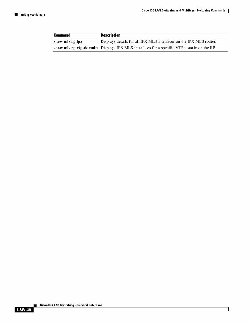
show mls rp ipx Displays details for all IPX MLS interfaces on the IPX MLS router.
show mls rp vtp-domain Displays IPX MLS interfaces for a specific VTP domain on the RP.
Command Description
Cisco IOS LAN Switching and Multilayer Switching Commandsmonitor session
LSW-47Cisco IOS LAN Switching Command Reference
monitor sessionCisco 2600 Series, Cisco 3600 Series, and Cisco 3700 Series Routers
To start a new Switched Port Analyzer (SPAN) session, add or delete interfaces from an existing SPAN session, or delete a SPAN session, use the monitor session command in global configuration mode. To remove one or more source interfaces or destination interfaces from the SPAN session, use the no form of this command.
no monitor session session {destination {interface type/slot/port} [, | -]}}
Session
monitor session session
no monitor session session
Catalyst Switches
To start a new SPAN session, add or delete interfaces or VLANs to or from an existing SPAN session, filter SPAN traffic to specific VLANs, or delete a SPAN session, use the monitor session command in global configuration mode. To remove one or more source or destination interfaces from the SPAN session or a source VLAN from the SPAN session, use the no form of this command.
no monitor session session {filter {vlan vlan-id} [, | -]}
Cisco IOS LAN Switching and Multilayer Switching Commandsmonitor session
LSW-48Cisco IOS LAN Switching Command Reference
Syntax Description
Command Default A trunking interface monitors all VLANs and all received and transmitted traffic.
Command Modes Global configuration
Command History
session Number of the SPAN session; valid values are 1 and 2.
source Specifies the SPAN source.
destination Specifies the SPAN destination interface.
interface type (Optional) Specifies the interface type; valid values are fastethernet and gigabitethernet.
slot (Optional) Specifies interface number; valid entries are 1 or 2.
port (Optional) Port interface number ranges based on type of Ethernet switch network module used:
0 to 15 for NM-16ESW 0 to 35 for NM-36ESW0 to 1 for GigabitEthernet
interface type number Specifies the interface type and number; valid values are ethernet (1 to 9), fastethernet (1 to 9), gigabitethernet (1 to 9), and port-channel (see the “Usage Guidelines” section).
filter Limits SPAN source traffic to specific VLANs.
Note The filter keyword is not supported on the Cisco 2600 series or the Cisco 3600 series routers.
vlan vlan-id Specifies the VLAN; valid values are from 1 to 1005.
, (Optional) Specifies another range of SPAN VLANs; valid values are from 1 to 1005.
- (Optional) Specifies a range of SPAN VLANs.
rx (Optional) Specifies monitor received traffic only.
both (Optional) Specifies monitor received and transmitted traffic.
Release Modification
12.0(7)XE This command was introduced on the Catalyst 6000 family switches.
12.1(1)E Support for this command on the Catalyst 6000 family switches was extended to the E train.
12.1(3a)E3 The number of valid values for the port-channel number was changed; see the “Usage Guidelines” section for valid values.
Cisco IOS LAN Switching and Multilayer Switching Commandsmonitor session
LSW-49Cisco IOS LAN Switching Command Reference
Usage Guidelines Cisco 2600 Series, Cisco 3600 Series, and Cisco 3700 Series Routers
The port-channel number supports six EtherChannels and eight ports in each channel.
Only one SPAN destination for a SPAN session is supported. If you attempt to add another destination interface to a session that already has a destination interface configured, you will get an error. You must first remove a SPAN destination interface before changing the SPAN destination to a different interface.
Catalyst Switches
The number of valid values for port-channel number depends on the software release. For Cisco IOS releases prior to software Release 12.1(3a)E3, valid values are from 1 to 256; for Cisco IOS Release 12.1(3a)E3, 12.1(3a)E4, and 12.1(4)E1, valid values are from 1 to 64. Cisco IOS Release 12.1(5c)EX and later support a maximum of 64 values ranging from 1 to 256.
Only one destination per SPAN session is supported. If you attempt to add another destination interface to a session that already has a destination interface configured, you get an error. You must first remove a SPAN destination interface before changing the SPAN destination to a different interface.
You can configure up to 64 SPAN destination interfaces, but you can have one egress SPAN source interface and up to 64 ingress source interfaces only.
A SPAN session can either monitor VLANs or monitor individual interfaces, but it cannot monitor both specific interfaces and specific VLANs. Configuring a SPAN session with a source interface and then trying to add a source VLAN to the same SPAN session causes an error. Configuring a SPAN session with a source VLAN and then trying to add a source interface to that session also causes an error. You must first clear any sources for a SPAN session before switching to another type of source.
If you enter the filter keyword on a monitored trunk interface, only traffic on the set of specified VLANs is monitored.
Port channel interfaces display in the list of interface options if you have them configured. VLAN interfaces are not supported. However, you can span a particular VLAN by entering the monitor session session source vlan vlan-id command.
Examples Cisco 2600 Series, Cisco 3600 Series, and Cisco 3700 Series Routers
The following example shows how to add a destination VLAN to an existing SPAN session:Router(config)# monitor session 1 destination interface fastEthernet 2/0
12.1(5c)EX These SPAN support restrictions were added:
• If your switch has a Switch Fabric Module installed, SPAN is supported among supervisor engines and nonfabric-enabled modules.
• If your switch does not have a Switch Fabric Module installed, SPAN is supported on all modules, including fabric-enabled modules.
• SPAN on DFC-equipped modules is not supported.
12.2(2)XT This command was implemented on the Cisco 2600 series, Cisco 3600 series, and Cisco 3700 series routers.
12.2(8)T This command was integrated into Cisco IOS Release 12.2(8)T on the Cisco 2600 series, Cisco 3600 series, and Cisco 3700 series routers.
Release Modification
Cisco IOS LAN Switching and Multilayer Switching Commandsmonitor session
LSW-50Cisco IOS LAN Switching Command Reference
Catalyst Switches
The following example shows how to add a destination VLAN to an existing SPAN session:
Cisco IOS LAN Switching and Multilayer Switching Commandsset port flowcontrol
LSW-51Cisco IOS LAN Switching Command Reference
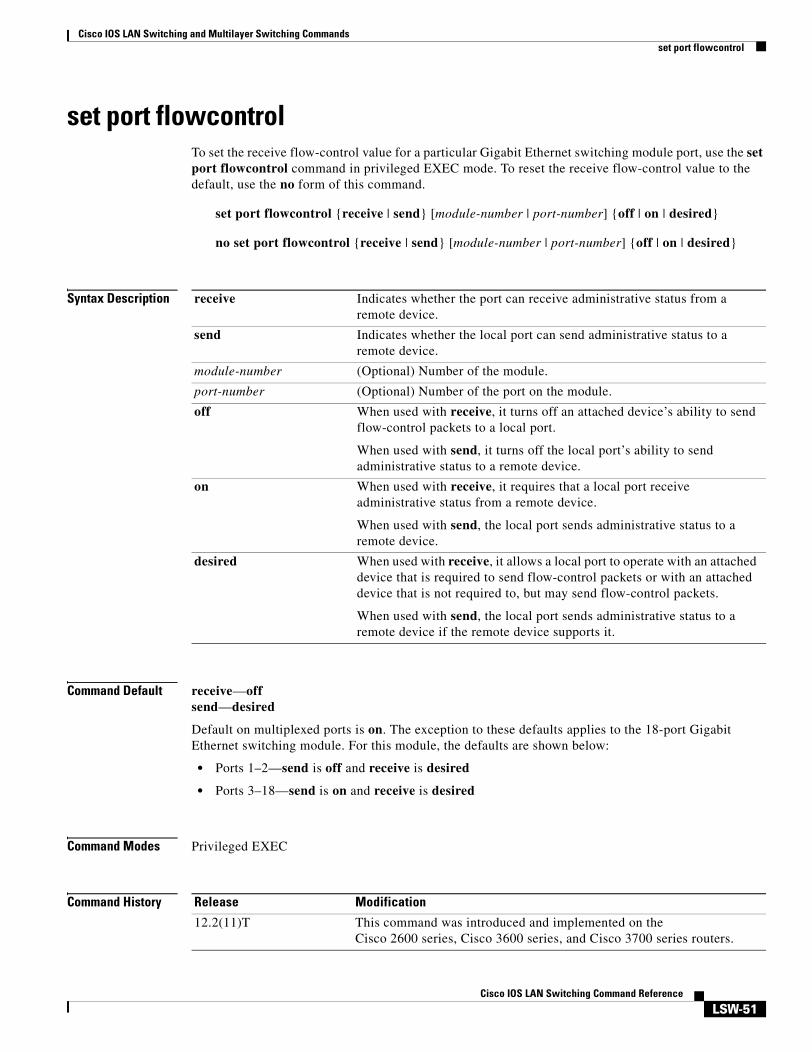
set port flowcontrolTo set the receive flow-control value for a particular Gigabit Ethernet switching module port, use the set port flowcontrol command in privileged EXEC mode. To reset the receive flow-control value to the default, use the no form of this command.
set port flowcontrol {receive | send} [module-number | port-number] {off | on | desired}
no set port flowcontrol {receive | send} [module-number | port-number] {off | on | desired}
Syntax Description
Command Default receive—offsend—desired
Default on multiplexed ports is on. The exception to these defaults applies to the 18-port Gigabit Ethernet switching module. For this module, the defaults are shown below:
• Ports 1–2—send is off and receive is desired
• Ports 3–18—send is on and receive is desired
Command Modes Privileged EXEC
Command History
receive Indicates whether the port can receive administrative status from a remote device.
send Indicates whether the local port can send administrative status to a remote device.
module-number (Optional) Number of the module.
port-number (Optional) Number of the port on the module.
off When used with receive, it turns off an attached device’s ability to send flow-control packets to a local port.
When used with send, it turns off the local port’s ability to send administrative status to a remote device.
on When used with receive, it requires that a local port receive administrative status from a remote device.
When used with send, the local port sends administrative status to a remote device.
desired When used with receive, it allows a local port to operate with an attached device that is required to send flow-control packets or with an attached device that is not required to, but may send flow-control packets.
When used with send, the local port sends administrative status to a remote device if the remote device supports it.
Release Modification
12.2(11)T This command was introduced and implemented on the Cisco 2600 series, Cisco 3600 series, and Cisco 3700 series routers.
Cisco IOS LAN Switching and Multilayer Switching Commandsset port flowcontrol
LSW-52Cisco IOS LAN Switching Command Reference
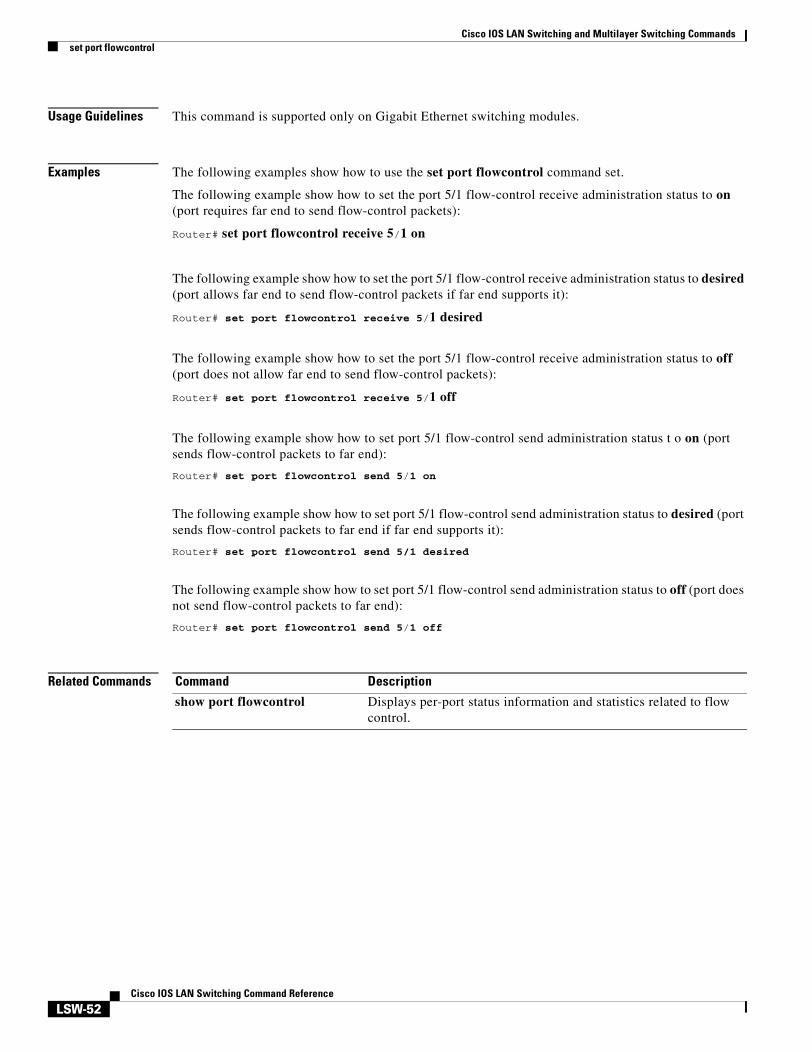
Usage Guidelines This command is supported only on Gigabit Ethernet switching modules.
Examples The following examples show how to use the set port flowcontrol command set.
The following example show how to set the port 5/1 flow-control receive administration status to on (port requires far end to send flow-control packets):
Router# set port flowcontrol receive 5/1 on
The following example show how to set the port 5/1 flow-control receive administration status to desired (port allows far end to send flow-control packets if far end supports it):
Router# set port flowcontrol receive 5/1 desired
The following example show how to set the port 5/1 flow-control receive administration status to off (port does not allow far end to send flow-control packets):
Router# set port flowcontrol receive 5/1 off
The following example show how to set port 5/1 flow-control send administration status t o on (port sends flow-control packets to far end):
Router# set port flowcontrol send 5/1 on
The following example show how to set port 5/1 flow-control send administration status to desired (port sends flow-control packets to far end if far end supports it):
Router# set port flowcontrol send 5/1 desired
The following example show how to set port 5/1 flow-control send administration status to off (port does not send flow-control packets to far end):
Router# set port flowcontrol send 5/1 off
Related Commands Command Description
show port flowcontrol Displays per-port status information and statistics related to flow control.
Cisco IOS LAN Switching and Multilayer Switching Commandsset vlan mapping
LSW-53Cisco IOS LAN Switching Command Reference
set vlan mappingTo map 802.1Q virtual LANs (VLANs) to Inter-Switch Link (ISL) VLANs, use the set vlan mapping command in privileged EXEC mode.
set vlan mapping dot1q 1q-vlan-number isl isl-vlan-number
Syntax Description
Command Default No 802.1Q-to-ISL mappings are defined.
Command Modes Privileged EXEC
Usage Guidelines IEEE 802.1Q VLAN trunks support VLANs 1 through 4095. ISL VLAN trunks support VLANs 1 through 1000. The switch automatically maps 802.1Q VLANs 1000 and lower to ISL VLANs with the same number.
The native VLAN of the 802.1Q trunk cannot be used in the mapping.
Use this feature to map 802.1Q VLANs above 1000 to ISL VLANs. If you map an 802.1Q VLAN over 1000 to an ISL VLAN, the corresponding 802.1Q VLAN will be blocked. For example, if you map 802.1Q VLAN 2000 to ISL VLAN 200, then 802.1Q VLAN 200 will be blocked.
You can map up to seven VLANs. Only one 802.1Q VLAN can be mapped to an ISL VLAN. For example, if 802.1Q VLAN 800 has been automatically mapped to ISL VLAN 800, do not manually map any other 802.1Q VLANs to ISL VLAN 800.
You cannot overwrite existing 802.1Q VLAN mapping. If the 802.1Q VLAN number is in the mapping table, the command is aborted. You must first clear that mapping.
If vlan-number does not exist, then either of the following occurs:
• If the switch is in server or transparent mode, the VLAN is created with all default values.
• If the switch is in client mode, then the command proceeds without creating the VLAN. A warning is given indicating that the VLAN does not exist.
If the table is full, the command is aborted with an error message indicating the table is full.
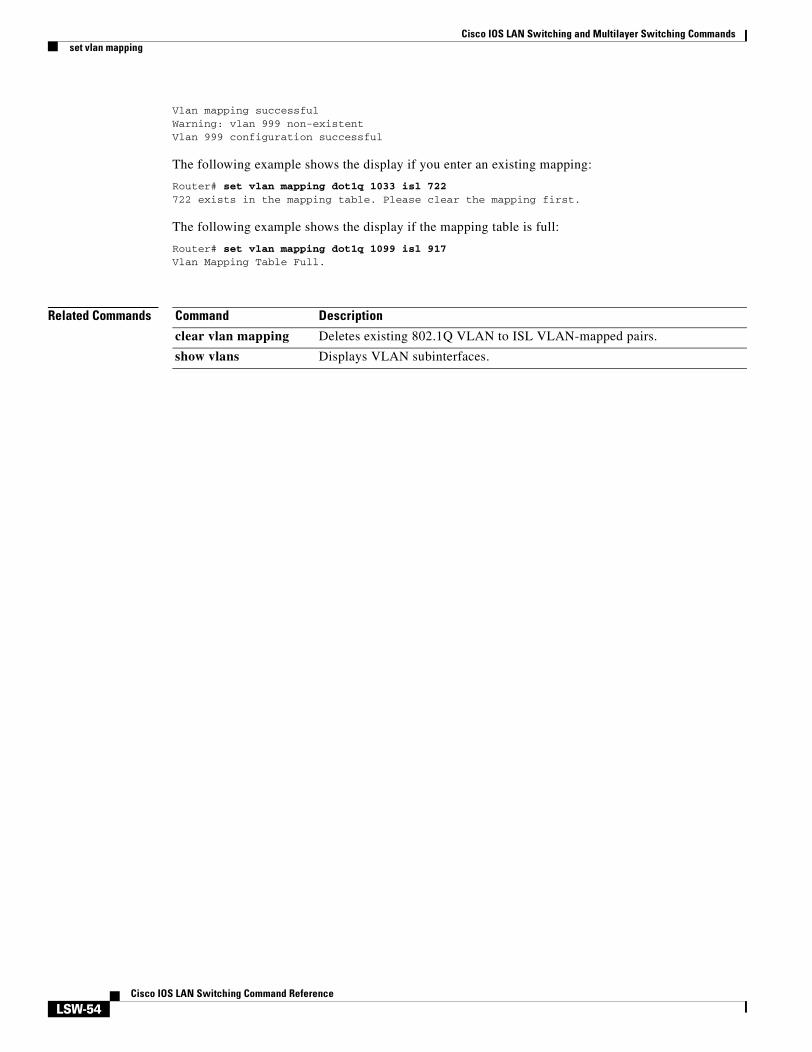
Examples The following example shows how to map VLAN 1022 to ISL VLAN 850:
Syntax Description vlan-number Number identifying the VLAN.
module Number of the module. This argument is not valid for defining or configuring Token Ring Bridge Relay Functions (TRBRFs).
port Number of the port on the module belonging to the VLAN; this argument does not apply to TRBRFs.
name name (Optional) Defines a text string used as the name of the VLAN (1 to 32 characters).
type {ethernet | fddi | fddinet | trcrf | trbrf}
(Optional) Identifies the VLAN type. The default type is Ethernet.
state {active | suspend}
(Optional) Specifies whether the state of the VLAN is active or suspended. VLANs in suspended state do not pass packets. The default state is active.
sa-id sa-id (Optional) Specifies the security association identifier. Possible values are 1 to 4294967294. The default is 100001 for VLAN1, 100002 for VLAN 2, 100003 for VLAN 3, and so on. This argument does not apply to Token Ring Concentrator Relay Functions (TRCRFs) or TRBRFs.
mtu mtu (Optional) Specifies the maximum transmission unit (packet size, in bytes) that the VLAN can use. Possible values are 576 to 18190. The default is 1500 bytes.
ring hex-ring-number (Optional) Specifies the logical ring number for Token Ring VLANs. Possible values are hexadecimal numbers 0x1 to 0xFFF. This argument is valid and required only when you define a TRCRF.
decring decimal-ring-number
(Optional) Specifies the logical ring number for Token Ring VLANs. Possible values are decimal numbers 1 to 4095. This argument is valid and required only when you define a TRCRF.
bridge bridge-number (Optional) Specifies the identification number of the bridge. Possible values are hexadecimal numbers 0x1 to 0xF. For Token Ring VLANs, the default is 0F. This argument is not valid for TRCRFs.
parent vlan-number (Optional) Sets a parent VLAN. The range for vlan-number is 2 to 1005. This argument identifies the TRBRF to which a TRCRF belongs and is required when you define a TRCRF.
mode {srt | srb} (Optional) Specifies the TRCRF bridging mode.
Cisco IOS LAN Switching and Multilayer Switching Commandsset vlan
LSW-56Cisco IOS LAN Switching Command Reference
Command Default The default configuration has all switched Ethernet ports and Ethernet repeater ports in VLAN 1. Additional defaults are:
• SAID: 100001 for VLAN 1, 100002 for VLAN 2, 100003 for VLAN 3, and so on
• Type: Ethernet
• MTU: 1500 bytes
• State: Active
Defaults for TRBRFs and TRCRFs are:
• TRBRF : 1005
• TRCRF: 1003
• MTU for TRBRFs and TRCRFs : 4472.
• State: Active.
• aremaxhop: 7
• stemaxhop: 7.
Command Modes Privileged EXEC
Usage Guidelines You cannot use the set vlan command until the networking device is in Virtual Trunking Protocol (VTP) transparent mode (set vtp mode) or until a VTP domain name has been set (set vtp).
Valid MTU values for a Token Ring VLAN are 1500 or 4472. You can enter any value but it defaults to the next lowest valid value.
You cannot set multiple VLANs for Inter-Switch Link (ISL) ports using this command. The VLAN name can be from 1 to 32 characters in length. If you add a new VLAN, the VLAN number must be within the range of 2 to 1001. When you modify a VLAN, the valid range for the VLAN number is 2 to 1005.
On a new Token Ring VLAN, if you do not specify the parent parameter for a TRCRF, the default TRBRF (1005) is used.
stp {ieee | ibm | auto} (Optional) Specifies the Spanning Tree Protocol version for a TRBRF to use: source-routing transparent (ieee), source-route bridging (ibm), or automatic source selection (auto).
translation vlan-number
(Optional) Specifies a VLAN used to translate FDDI to Ethernet. Valid values are from 1 to 1005. This argument is not valid for defining or configuring Token Ring VLANs.
backupcrf {off | on} (Optional) Specifies whether the TRCRF is a backup path for traffic.
aremaxhop hop-count (Optional) Specifies the maximum number of hops for All-Routes Explorer frames. Possible values are 1 to 14. The default is 7. This argument is valid only when you define or configure TRCRFs.
stemaxhop hop-count (Optional) Specifies the maximum number of hops for Spanning-Tree Explorer frames. Possible values are 1 to 14. The default is 7. This argument is valid only when you define or configure TRCRFs.
Cisco IOS LAN Switching and Multilayer Switching Commandsset vlan
LSW-57Cisco IOS LAN Switching Command Reference
Examples The following example shows how to set VLAN 850 to include ports 4 through 7 on module 3. Because ports 4 through 7 were originally assigned to TRCRF 1003, the message reflects the modification of VLAN 1003.
clear vlan Deletes an existing VLAN from a management domain.
show vlans Displays VLAN subinterfaces.
Cisco IOS LAN Switching and Multilayer Switching Commandsshow controllers fastethernet
LSW-58Cisco IOS LAN Switching Command Reference
show controllers fastethernetTo display information about initialization block, transmit ring, receive ring, Fast Ethernet interface information, applicable MAC destination address and VLAN filtering tables, and errors for the Fast Ethernet controller chip, use the show controllers fastethernet command in user EXEC or privileged EXEC mode.
Standard Syntax
show controllers fastethernet number
Cisco 7200 Series
show controllers fastethernet slot/port
Cisco 7500 Series
show controllers fastethernet slot/port-adapter/port
Shared Port Adapter
show controllers fastethernet slot/subslot/port [detail]
Syntax Description
Command Modes User EXECPrivileged EXEC
Command History
number Port, connector, or interface card number. On a Cisco 4500 or Cisco 4700 router, specifies the network processor module (NPM) number. The numbers are assigned at the factory at the time of installation or when added to a system.
slot Slot number. Refer to the appropriate hardware manual for slot information.
/port Port number. Refer to the appropriate hardware manual for port information.
/port-adapter Port adapter number. Refer to the appropriate hardware manual for information about port adapter compatibility.
/subslot (Optional) Secondary slot number on a jacket card where a SPA is installed.
detail Specifies display of additional low-level diagnostic information.
Release Modification
11.2 This command was introduced.
12.2S This command was integrated into Cisco IOS Release 12.2S.
12.2(20)S2 This command was implemented on the 4-Port 10/100 Fast Ethernet SPA on the Cisco 7304 router and introduced a new address format and output.
Cisco IOS LAN Switching and Multilayer Switching Commandsshow controllers fastethernet
LSW-59Cisco IOS LAN Switching Command Reference
Usage Guidelines The output from this command is generally useful for diagnostic tasks performed by technical support.
Shared Port Adapter Usage Guidelines
The output from the show controllers fastethernet command for the 4-Port 10/100 Fast Ethernet SPA provides several different sections of information and statistics that are organized according to the internal hardware devices and the various paths in the flow of data on the SPA. The following sections are provided:
• Interface configuration information—Table 3 on page 62
• Media Access Control (MAC) device counters—Table 4 on page 63
• Field programmable gate array (FPGA) device counters—Table 5 on page 64
• SPA carrier card counters—Table 6 on page 65
• SPA error counters—Table 7 on page 66
• MAC destination address filtering table—Table 8 on page 67
• Virtual LAN (VLAN) filtering table—Table 9 on page 68
The following is sample output from the show controllers fastethernet command for the first interface (port 0) on a 4-Port 10/100 Fast Ethernet SPA that is located in the top subslot (0), of the MSC that is installed in slot 4 on a Cisco 7304 router:
Router# show controllers fastethernet 4/0/0Interface FastEthernet4/0/0 Hardware is SPA-4FE-7304 Connection mode is auto-negotiation Interface state is up, link is up Configuration is Auto Speed, Auto Duplex Selected media-type is RJ45 Promiscuous mode is off, VLAN filtering is enabled MDI crossover status: MDI Auto-negotiation configuration and status: Auto-negotiation is enabled and is completed Speed/duplex is resolved to 100 Mbps, full duplex
Cisco IOS LAN Switching and Multilayer Switching Commandsshow controllers fastethernet
LSW-62Cisco IOS LAN Switching Command Reference
General errors: input = 0, output = 0 SPI4 errors: ingress dip4 = 0, egress dip2 = 0SPA Error counters: SPI4 TX out of frame error = 2 (00:02:31 ago) SPI4 TX Train valid error = 1 (00:02:11 ago) SPI4 TX DIP4 error = 1 (00:01:30 ago) SPI4 RX out of frame error = 1 (00:00:36 ago) SPI4 RX DIP2 error = 1 (00:00:13 ago)MAC destination address filtering table: Table entries: Total = 512, Used = 4, Available = 508 Index MAC destination address Mask ----- ----------------------- -------------- 1 0007.0ed3.ba80 ffff.ffff.ffff 2 ffff.ffff.ffff ffff.ffff.ffff 3 0100.0000.0000 0100.0000.0000 4 0100.0ccc.cccc ffff.ffff.ffffVLAN filtering table: Number of VLANs configured on this interface = 0 Table entries: Total = 1024, Used = 2, Available = 1022 Index VLAN identifier Enabled Tunnel ----- --------------- ------- ------ 1 0 No No 2 0 Yes NoPlatform details: PXF tif number: 0x10
Table 3 describes the fields shown in the interface configuration section of the display. This section is useful for verifying the status of autonegotiation and configured parameters on the link, and the amount of traffic being handled by the interface.
Table 3 show controllers Command Field Descriptions—Interface Section
Field Description
Interface Name of the interface.
Hardware Type of hardware.
Connection mode Indicator of autonegotiation used to establish the connection.
Link State of the link.
Configuration Configuration of the speed and duplex operation on the interface.
Selected media-type Interface port media type. RJ-45 is the only type supported on the 4-Port 10/100 Fast Ethernet SPA.
Promiscuous mode State of promiscuous mode (on or off). When promiscuous mode is on, the SPA disables MAC destination address and VLAN filtering. When promiscuous mode is off, the SPA enables MAC destination address and VLAN filtering.
VLAN filtering Status of ternary content addressable memory (TCAM) filtering of VLANs (enabled or disabled). By default, the SPA always enables VLAN filtering.
The SPA disables VLAN filtering if the TCAM table is full, or if the SPA is operating in promiscuous mode.
Note VLAN filtering is not enabled or disabled using any command-line interface (CLI) command.
Cisco IOS LAN Switching and Multilayer Switching Commandsshow controllers fastethernet
LSW-63Cisco IOS LAN Switching Command Reference
Table 4 describes the fields shown in the MAC counters section of the display. This section is useful for verifying the status of packets processed by the MAC device for the interface. This information is useful for Cisco Systems technical support personnel.
MDI crossover status State of the media dependent interface (MDI) for the PHY device on the specified interface. The possible values are MDI for straight-through cables or media dependent interface crossover (MDI-X) for crossover cables.
Auto-negotiation State of autonegotiation (enabled or disabled) on the interface and its current status.
Speed/duplex is resolved to Results of autonegotiated parameter values (speed and duplex) currently being used on the link.
Advertised capabilities List of the possible combinations of speed and duplex modes (in speed/duplex format) and flow control that the local interface has advertised it supports to the remote device:
• For speed—10M is 10 Mbps, and 100M is 100 Mbps.
• For duplex—HD is half duplex, and FD is full duplex.
• For flow control—“Pause capable (Asymmetric)” means that the SPA advertises support of the PAUSE flow control bit and the ASM_DIR (asymmetric) flow control bit.
Partner capabilities List of the possible combinations of speed and duplex modes (in speed/duplex format) and flow control that the remote device has advertised it supports to the local interface:
• For speed—10M is 10 Mbps, and 100M is 100 Mbps.
• For duplex—HD is half duplex, and FD is full duplex.
• For flow control—“Pause capable” means that the remote device supports implementation of the PAUSE flow control bit; “Pause capable (Asymmetric)” means that the remote device supports implementation of the PAUSE flow control bit and the ASM_DIR (asymmetric) flow control bit.
Table 3 show controllers Command Field Descriptions—Interface Section (continued)
Field Description
Table 4 show controllers Command Field Descriptions—MAC Counters Section
Field Description
Input: packets, bytes Total number of packets and bytes received by the MAC device for the interface since it was activated or cleared.
You can clear these counters using the clear counters privileged EXEC command.
Input: FIFO full/reset removed Total number of packets removed by the MAC device due to a first-in, first-out (FIFO) overflow condition in the input buffer for the interface.
Cisco IOS LAN Switching and Multilayer Switching Commandsshow controllers fastethernet
LSW-64Cisco IOS LAN Switching Command Reference
Table 5 describes the fields shown in the FPGA counters section of the display. This section is useful for verifying the status of packets processed by the FPGA device for the interface. This information is useful for Cisco Systems technical support personnel.
Input: error drop Total number of input packets with errors that are dropped by the MAC device for the interface.
Output: packets, bytes Total number of packets and bytes transmitted by the MAC device for the interface since it was activated or cleared.
You can clear these counters using the clear counters privileged EXEC command.
Output: FIFO full/reset removed Total number of packets removed by the MAC device due to a first-in, first-out (FIFO) overflow condition in the output buffer for the interface.
Output: error drop Total number of output packets with errors that are dropped by the MAC device for the interface.
Total pause frames Total number of Ethernet 802.3x pause frames transmitted and received by the MAC device for flow control on the interface.
Table 4 show controllers Command Field Descriptions—MAC Counters Section (continued)
Field Description
Table 5 show controllers Command Field Descriptions—FPGA Counters Section
Field Description
Input: Total (good & bad) packets Total number of packets received by the FPGA device in the ingress direction for the interface.
Input: TCAM drops Total number of packets dropped by the FPGA device in the ingress direction for the interface due to a ternary content addressable memory (TCAM) lookup failure. This counter increments when the interface receives a frame with a destination MAC address or VLAN identifier that is not present in the TCAM table.
Input: Satisfy (host-backpressure) drops
Total number of packets dropped by the FPGA device in the ingress direction for the interface due to back-pressure from the MSC.
Input: CRC drops Total number of packets dropped by the FPGA device in the ingress direction for the interface due to cyclic redundancy check (CRC) errors.
Input: PL3 RERRs Total number of packets with errors received for the interface by the FPGA device in the ingress direction over the System Packet Interface Level 3 (SPI3) (also called PL3) path from the MAC device to the FPGA device.
Output: EOP (SPI4) errors Total number of packets with end-of-packet (EOP) errors received by the FPGA device in the egress direction for the interface over the System Packet Interface Level 4 (SPI4) path from the MSC to the FPGA device.
Cisco IOS LAN Switching and Multilayer Switching Commandsshow controllers fastethernet
LSW-65Cisco IOS LAN Switching Command Reference
Table 6 describes the fields shown in the SPA carrier card counters section of the display. This section is useful for verifying the status of packets processed by the MSC for the interface. This information is useful for Cisco Systems technical support personnel.
Table 7 describes the fields shown in the SPA error counters section of the display. This section appears only when one of the SPI4 transmit or receive errors occurs on the interface. This information is useful for Cisco Systems technical support personnel.
Note None of the SPA SPI4 error counters appear in show controllers fastethernet command output until at least one of those types of SPI4 errors occurs.
Table 6 show controllers Command Field Descriptions—SPA Carrier Card Counters Section
Field Description
Input: packets, bytes, drops Total number of packets, bytes, and packet drops that have occurred on the SPI4 path from the FPGA device to the MSC.
Output: packets, bytes, drops Total number of packets, bytes, and packet drops that have occurred on the SPI4 path from the MSC to the FPGA device.
Egress flow control status Status of flow control between the MSC and the Route Processor (RP). The possible values are:
• XON—A control frame has been sent by the MSC to the RP to indicate that the MSC is ready to accept data.
• XOFF—A control frame has been sent by the MSC to the RP to indicate congestion on the MSC. The MSC cannot accept any more data from the RP during this condition.
General errors Total number of errors (such as parity) on the MSC in the ingress and egress direction.
SPI4 errors: ingress dip4 Total number of 4-bit Diagonal Interleaved Parity (DIP4) errors in the ingress direction on the SPI4 path from the FPGA device to the MSC.
DIP4 is a parity algorithm where a 4-bit odd parity is computed diagonally over control and data words.
SPI4 errors: egress dip2 Total number of 2-bit Diagonal Interleaved Parity (DIP2) errors in the egress direction on the SPI4 path from the FPGA device to the MSC.
DIP2 is a parity algorithm where a 2-bit odd parity is computed diagonally over status words.
Cisco IOS LAN Switching and Multilayer Switching Commandsshow controllers fastethernet
LSW-66Cisco IOS LAN Switching Command Reference
All of the errors in the SPA error counters section are subject to the SPA automatic recovery process when certain thresholds are reached. For more information about this process on the Cisco 7304 router, refer to the “Understanding SPA Automatic Recovery” section of the Cisco 7304 Router Modular Services Card and Shared Port Adapter Software Configuration Guide.
Table 7 show controllers Command Field Descriptions—SPA Error Counters Section
Field Description
SPI4 TX out of frame error = (hh:mm:ss ago)
Number of SPI4 out-of-frame errors (events) detected in the transmit direction (toward the network), from the MSC to the SPA FPGA device. The time stamp indicates how long ago (in hours:minutes:seconds) from the current system time, that the last error was detected.
This error indicates a loss of synchronization between the synchronization block and the data received on the SPI4 path. When synchronization is reacquired, the error no longer occurs.
SPI4 TX Train valid error = (hh:mm:ss ago)
Number of times that a low-level synchronization problem was detected in the transmit direction (toward the network), from the MSC to the SPA FPGA device. The time stamp indicates how long ago (in hours:minutes:seconds) from the current system time, that the last error was detected.
SPI4 TX DIP4 error = (hh:mm:ss ago)
Number of 4-bit Diagonal Interleaved Parity (DIP4) errors in the transmit direction (toward the network), from the MSC to the SPA FPGA device. The time stamp indicates how long ago (in hours:minutes:seconds) from the current system time, that the last error was detected.
DIP4 is a parity algorithm where a 4-bit odd parity is computed diagonally over control and data words.
SPI4 RX out of frame error = (hh:mm:ss ago)
Number of SPI4 out-of-frame errors (events) detected in the receive direction (from the network), from the SPA FPGA device to the MSC. The time stamp indicates how long ago (in hours:minutes:seconds) from the current system time, that the last error was detected.
This error indicates a loss of synchronization between the synchronization block and the data received on the SPI4 path. When synchronization is reacquired, the error no longer occurs.
SPI4 RX DIP2 error = (hh:mm:ss ago)
Number of 2-bit Diagonal Interleaved Parity (DIP2) errors in the receive direction (from the network), from the SPA FPGA device to the MSC. The time stamp indicates how long ago (in hours:minutes:seconds) from the current system time, that the last error was detected.
DIP2 is a parity algorithm where a 2-bit odd parity is computed diagonally over status words.
Cisco IOS LAN Switching and Multilayer Switching Commandsshow controllers fastethernet
LSW-67Cisco IOS LAN Switching Command Reference
Table 8 describes the fields shown in the MAC destination address filtering table section of the display. This section is useful for verifying the multicast destination addresses that are in the TCAM table and permitted by the interface. This information is useful for Cisco Systems technical support personnel.
Table 8 show controllers Command Field Descriptions—MAC Destination Address Filtering Table
Section
Field Description
Table entries: Total, Used, Available Total number of MAC destination address entries possible in the TCAM table for the interface, the number of table entries currently used by the interface, and the number of table entries that remain available.
The 4-Port 10/100 Fast Ethernet SPA supports a 512-entry MAC filtering table for each supported interface (2048 entries total on the card).
Index Table entry identifier.
MAC destination address MAC destination address (multicast) permitted by the interface and used in the TCAM lookup table for packet filtering.
The multicast MAC entries typically come from routing protocols [such as Open Shortest Path First (OSPF) and Enhanced IGRP (EIGRP)], and other protocols including the Hot Standby Router Protocol (HSRP).
When the router reloads, three addresses appear by default in the MAC filtering table: the unicast address of the local interface, the Ethernet broadcast address, and the Ethernet multicast address.
Mask Mask for the corresponding destination address. The SPA uses the bits that are set in the mask to look up the address in the TCAM table.
Cisco IOS LAN Switching and Multilayer Switching Commandsshow controllers fastethernet
LSW-68Cisco IOS LAN Switching Command Reference
Table 9 describes the fields shown in the VLAN filtering table section of the display. This section is useful for verifying the VLANs that are in the TCAM table and are permitted by the interface. This information is useful for Cisco Systems technical support personnel.
Table 9 show controllers Command Field Descriptions—VLAN Filtering Table Section
Field Description
Number of VLANs configured on this interface
Number of VLANs that are configured on the interface.
If the number of VLANs configured on the interface is 1022 or less, then the VLAN filtering table also shows an index entry for every VLAN ID. The number of VLANs configured on the interface can be 0, while the number of used table entries reports 2, because the SPA always uses two entries to provide valid matching criteria for promiscuous mode and non-VLAN packets.
Table entries: Total, Used, Available Total number of VLAN entries possible in the TCAM filtering table for the interface, the number of table entries currently used by the interface (two are always in use by default), and the number of table entries that remain available.
The 4-Port 10/100 Fast Ethernet SPA supports a 1024-entry VLAN filtering table for each supported interface (4096 entries total on the card).
Index Table entry identifier.
VLAN identifier Number of the VLAN. Two VLAN ID 0 entries always appear in the table and represent the local interface port for handling of promiscuous mode and non-VLAN packets.
Other VLAN entries appear in this table when VLANs are configured on the interface.
Cisco IOS LAN Switching and Multilayer Switching Commandsshow controllers fastethernet
LSW-69Cisco IOS LAN Switching Command Reference
Table 10 describes the fields shown in the Platform details section of the display.
Related Commands
Enabled Status of the VLAN ID for TCAM filtering, with the following possible values:
• No—The entry is disabled for filtering.
• Yes—The entry is enabled for filtering.
The TCAM filter uses the “first-match” rule to filter packets that the SPA receives against entries in the table. The matching assessment begins at the top of the table with the VLAN ID 0 entries.
Note The SPA always supports two VLAN ID 0 entries. The first VLAN ID 0 entry of the TCAM table is used for promiscuous mode. It has a value of “No,” meaning it is disabled, whenever promiscuous mode is disabled for the interface. The second VLAN ID 0 entry is used for filtering of non-VLAN packets.
Tunnel Status of tunneling for the interface, with the following possible values:
• No—Tunneling is disabled and the SPA performs MAC destination address filtering.
• Yes—Tunneling is enabled and the SPA does not perform MAC destination address filtering.
Note If promiscuous mode is enabled, then the first VLAN ID 0 entry shows tunnel = Yes. All other VLAN ID entries show tunnel = No.
Table 9 show controllers Command Field Descriptions—VLAN Filtering Table Section (continued)
Field Description
Table 10 show controllers Command Field Descriptions—Platform Details Section
Field Description
PXF tif number Number of the interface (in hexadecimal format) used for PXF on the network services engine (NSE) or by the Hyper Transport (HT) FPGA device on the network processing engine (NPE).
Command Description
show interfaces fastethernet Displays information about the Fast Ethernet interfaces.
Cisco IOS LAN Switching and Multilayer Switching Commandsshow mac-address-table aging-time
LSW-70Cisco IOS LAN Switching Command Reference
show mac-address-table aging-timeTo display the MAC address aging time, use the show mac-address-table aging-time command in privileged EXEC mode.
Cisco 2600 Series, Cisco 3600 Series, and Cisco 3700 Series Routers
Examples The following example shows how to display the current configured aging time for all VLANs:
Cisco 2600 Series, Cisco 3600 Series, and Cisco 3700 Series RoutersRouter# show mac-address-table aging-time
Mac address aging time 300
Catalyst SwitchesRouter# show mac-address-table aging-time
Vlan Aging Time---- ----------100 300
vlan vlan (Optional) Specifies a VLAN; valid values are from 1 to 1005.
begin (Optional) Specifies that the output display begin with the line that matches the expression.
exclude (Optional) Specifies that the output display exclude lines that match the expression.
include (Optional) Specifies that the output display include lines that match the specified expression.
expression Expression in the output to use as a reference point.
Release Modification
12.0(7)XE This command was introduced on Catalyst 6000 series switches.
12.2(2)XT This command was implemented on Cisco 2600 series, Cisco 3600 series, and Cisco 3700 series routers.
12.2(8)T This command was integrated into Cisco IOS Release 12.2(8)T on Cisco 2600 series, Cisco 3600 series, and Cisco 3700 series routers.
12.2(11)T This command was integrated into Cisco IOS Release 12.2(11)T.
Cisco IOS LAN Switching and Multilayer Switching Commandsshow mac-address-table aging-time
LSW-71Cisco IOS LAN Switching Command Reference
200 1000
The following example shows how to display the current configured aging time for a specific VLAN:
Router# show mac-address-table aging-time vlan 100
Vlan Aging Time---- ---------- 100 300
Related Commands Command Description
show mac-address-table address Displays MAC address table information for a specific MAC address.
show mac-address-table count Displays the number of entries currently in the MAC address table.
show mac-address-table detail Displays detailed MAC address table information.
show mac-address-table dynamic Displays dynamic MAC address table entries only.
show mac-address-table interface Displays the MAC address table information for a specific interface.
show mac-address-table multicast Displays multicast MAC address table information.
show mac-address-table protocol Displays MAC address table information based on protocol.
show mac-address-table static Displays static MAC address table entries only.
show mac-address-table vlan Displays the MAC address table information for a specific VLAN.
Cisco IOS LAN Switching and Multilayer Switching Commandsshow mac-address-table dynamic
LSW-72Cisco IOS LAN Switching Command Reference
show mac-address-table dynamicTo display dynamic MAC address table entries only, use the show mac-address-table dynamic command in privileged EXEC mode.
Cisco 2600 Series, Cisco 3600 Series, and Cisco 3700 Series Routers
show mac-address-table dynamic [address mac-address | interface type slot/port | vlan vlan]
Catalyst Switches
show mac-address-table dynamic [address mac-address | detail | interface type number | protocol protocol | vlan vlan] [[begin |exclude | include] expression]
Syntax Description
Command Modes Privileged EXEC
address mac-address (Optional) Specifies a 48-bit MAC address; valid format is H.H.H.
detail (Optional) Specifies a detailed display of MAC address table information.
interface type number (Optional) Specifies an interface to match; valid type values are FastEthernet and GigabitEthernet, valid number values are from 1 to 9.
interface type (Optional) Specifies an interface to match; valid type values are FastEthernet and GigabitEthernet.
slot (Optional) Adds dynamic addresses to module in slot 1 or 2.
port (Optional) Port interface number ranges based on type of Ethernet switch network module used:
• 0 to 15 for NM-16ESW
• 0 to 35 for NM-36ESW
• 0 to 1 for GigabitEthernet
protocol protocol (Optional) Specifies a protocol. See the “Usage Guidelines” section for keyword definitions.
vlan vlan (Optional) Displays entries for a specific VLAN; valid values are from 1 to 1005.
begin (Optional) Specifies that the output display begin with the line that matches the expression.
exclude (Optional) Specifies that the output display exclude lines that match the expression.
include (Optional) Specifies that the output display include lines that match the specified expression.
expression Expression in the output to use as a reference point.
Cisco IOS LAN Switching and Multilayer Switching Commandsshow mac-address-table dynamic
LSW-73Cisco IOS LAN Switching Command Reference
Command History
Usage Guidelines Cisco 2600 Series, Cisco 3600 Series, and Cisco 3700 Series Routers
The show mac-address-table dynamic command output for an EtherChannel interface changes the port-number designation (for example, 5/7) to a port-group number.
Catalyst Switches
The keyword definitions for the protocol argument are:
The show mac-address-table dynamic command output for an EtherChannel interface changes the port-number designation (for example, 5/7) to a port-group number.
Examples The following examples show how to display all dynamic MAC address entries.
Cisco 2600 Series, Cisco 3600 Series, and Cisco 3700 Series RoutersRouter# show mac-address-table dynamic
The following example shows the detailed output for the previous example:
Router# show mac-address-table dynamic protocol assigned detail
MAC Table shown in details======================================== Type Always Learn Trap Modified Notify Capture Protocol Flood-------+------------+----+--------+------+-------+--------+-----+ QoS bit L3 Spare Mac Address Age Byte Pvlan Xtag SWbits Index-----------------+--------+--------------+--------+-----+----+------+-----DYNAMIC NO NO YES NO NO assigned NO Bit Not On 0 0000.0000.0000 255 4092 0 0 0x3 DYNAMIC NO NO YES NO NO assigned NO Bit Not On 0 0050.f0ac.3059 254 4092 0 0 0x3 DYNAMIC NO NO YES NO NO assigned NO Bit Not On 0 0010.7b3b.0978 254 1 0 0 0x108 Router#
Related Commands Command Description
show mac-address-table address Displays MAC address table information for a specific MAC address.
show mac-address-table aging-time Displays the MAC address aging time.
show mac-address-table count Displays the number of entries currently in the MAC address table.
show mac-address-table detail Displays detailed MAC address table information.
show mac-address-table interface Displays the MAC address table information for a specific interface.
show mac-address-table multicast Displays multicast MAC address table information.
show mac-address-table protocol Displays MAC address table information based on protocol.
show mac-address-table static Displays static MAC address table entries only.
show mac-address-table vlan Displays the MAC address table information for a specific VLAN.
Cisco IOS LAN Switching and Multilayer Switching Commandsshow mac-address-table static
LSW-75Cisco IOS LAN Switching Command Reference
show mac-address-table staticTo display static MAC address table entries only, use the show mac-address-table static command in privileged EXEC mode.
Cisco 2600 Series, Cisco 3600 Series, and Cisco 3700 Series Routers
show mac-address-table static [address mac-address | interface type slot/port | vlan vlan]
Catalyst Switches
show mac-address-table static [address mac-address | detail | interface type number | protocol protocol | vlan vlan] [[begin | exclude | include] expression]
Syntax Description
Command Modes Privileged EXEC
address mac-address (Optional) Specifies a 48-bit MAC address to match; valid format is H.H.H.
detail (Optional) Specifies a detailed display of MAC address table information.
interface type number (Optional) Specifies an interface to match; valid type values are Ethernet, FastEthernet, and Gigabit Ethernet and valid number values are from 1 to 9.
interface type (Optional) Specifies an interface to match; valid type values are FastEthernet and Gigabit Ethernet.
slot (Optional) Adds dynamic addresses to module in slot 1 or 2.
port (Optional) Port interface number ranges based on type of Ethernet switch network module used:
• 0 to 15 for NM-16ESW
• 0 to 35 for NM-36ESW
• 0 to 1 for Gigabit Ethernet
protocol protocol (Optional) Specifies a protocol. See the “Usage Guidelines” section for keyword definitions.
vlan vlan (Optional) Displays entries for a specific VLAN; valid values are from 1 to 1005.
begin (Optional) Specifies that the output display begin with the line that matches the expression.
exclude (Optional) Specifies that the output display exclude lines that match the expression.
include (Optional) Specifies that the output display include lines that match the expression.
expression Expression in the output to use as a reference point.
Cisco IOS LAN Switching and Multilayer Switching Commandsshow mac-address-table static
LSW-76Cisco IOS LAN Switching Command Reference
Command History
Usage Guidelines Catalyst Switches
The keyword definitions for the protocol argument are:
The following example shows the detailed output for the previous example:
Router# show mac-address-table static protocol assigned detail
MAC Table shown in details======================================== Type Always Learn Trap Modified Notify Capture Protocol Flood-------+------------+----+--------+------+-------+--------+-----+ QoS bit L3 Spare Mac Address Age Byte Pvlan Xtag SWbits Index-----------------+--------+--------------+--------+-----+----+------+-----STATIC NO NO NO NO NO assigned NO Bit Not On 0 0050.3e8d.6400 254 200 1 0 0x3 STATIC NO NO NO NO NO assigned NO Bit Not On 0 0050.3e8d.6400 254 100 1 0 0x3 STATIC NO NO NO NO NO assigned NO Bit Not On 0 0050.3e8d.6400 254 5 1 0 0x3 S Bit Not On 0 0050.f0ac.3058 254 4092 1 0 0x3 ...
Related Commands Command Description
show mac-address-table address Displays MAC address table information for a specific MAC address.
show mac-address-table aging-time Displays the MAC address aging time.
show mac-address-table count Displays the number of entries currently in the MAC address table.
show mac-address-table detail Displays detailed MAC address table information.
show mac-address-table dynamic Displays dynamic MAC address table entries only.
show mac-address-table interface Displays the MAC address table information for a specific interface.
show mac-address-table multicast Displays multicast MAC address table information.
show mac-address-table protocol Displays MAC address table information based on protocol.
show mac-address-table vlan Displays the MAC address table information for a specific VLAN.
Cisco IOS LAN Switching and Multilayer Switching Commandsshow mac-address-table
LSW-78Cisco IOS LAN Switching Command Reference
show mac-address-tableTo display the MAC address table, use the show mac-address-table command in privileged EXEC mode.
Cisco 2600 Series, Cisco 3600 Series, and Cisco 3700 Series Routers
static (Optional) Displays only the static addresses.
dynamic (Optional) Displays only the dynamic addresses.
secure (Optional) Displays only the secure addresses.
self (Optional) Displays only addresses added by the switch itself.
aging-time (Optional) Displays aging-time for dynamic addresses for all VLANs.
count (Optional) Displays a count for different kinds of MAC addresses.
address hardware-address (Optional) Displays information for a specific hardware address.
interface type (Optional) Displays addresses for a specific port.
interface interface (Optional) Displays addresses for a specific port.
fa (Optional) Specifies FastEthernet.
gi (Optional) Specifies GigabitEthernet.
slot/port (Optional) Adds dynamic addresses to module in slot 1 or 2.
atm slot/port (Optional) Adds dynamic addresses to ATM module slot/port. Use 1 or 2 for the slot number. Use 0 as the port number.
vlan vlan-id (Optional) Displays addresses for a specific VLAN. Valid IDs are from 1 to 1005; do not enter leading zeroes.
Release Modification
11.2(8)SA This command was first introduced.
11.2(8)SA3 The self, aging-time, count, and vlan vlan-id keywords were added.
11.2(8)SA5 The atm slot/port keywords were added.
12.2(2)XT This command was implemented on Cisco 2600 series, Cisco 3600 series, and Cisco 3700 series routers.
12.2(8)T This command was integrated into Cisco IOS Release 12.2(8)T on Cisco 2600 series, Cisco 3600 series, and Cisco 3700 series routers.
12.2(11)T This command was integrated into Cisco IOS Release 12.2(11)T.
Cisco IOS LAN Switching and Multilayer Switching Commandsshow mac-address-table
LSW-79Cisco IOS LAN Switching Command Reference
Usage Guidelines This command displays the MAC address table for the switch. Specific views can be defined by using the optional keywords and values. If more than one optional keyword is used, then all the conditions must be true for that entry to be displayed.
Examples Cisco 2600 Series, Cisco 3600 Series, and Cisco 3700 Series Routers
The following is sample output from the show mac-address-table command:
clear mac-address-table Deletes entries from the MAC address table.
Cisco IOS LAN Switching and Multilayer Switching Commandsshow mls masks
LSW-80Cisco IOS LAN Switching Command Reference
show mls masksTo display the details of the access control parameters (ACPs) that are used for multilayer switching (MLS) quality of service (QoS) and security access control lists (ACLs), use the show mls masks command in privileged EXEC mode.
show mls masks [qos | security]
Syntax Description
Note ACPs are called masks in the command-line interface (CLI) commands and output.
Command Modes Privileged EXEC
Command History
Usage Guidelines Use the show mls mask command without keywords to display all ACPs configured on the switch.
Use this command with the qos keyword to display the ACPs used for QoS ACLs.
Use this command with the security keyword to display the ACPs used for security ACLs.
Note You can configure up to four ACPs (QoS and security) on a switch.
Examples The following is sample output from the show mls masks command. In this example, Mask 1 is a QoS ACP consisting of an IP source address (with wildcard bits 0.0.0.255), an IP destination address, and Layer 4 destination port fields. This ACP is used by the QoS policy maps pmap1 and pmap2.
qos (Optional) Displays details of ACPs used for QoS ACLs.
security (Optional) Displays details of ACPs used for security ACLs.
Release Modification
12.1(6)EA2 This command was introduced.
12.2(15)ZJ This command was implemented on the following platforms: Cisco 2600 series, Cisco 3600 series, and Cisco 3700 series routers.
12.3(4)T This command was integrated into Cisco IOS Release 12.3(4)T on the following platforms: Cisco 2600 series, Cisco 3600 series, and Cisco 3700 series routers.
Cisco IOS LAN Switching and Multilayer Switching Commandsshow mls masks
LSW-81Cisco IOS LAN Switching Command Reference
Interfaces: Fa0/1, Fa0/5, Fa0/13
Related Commands Command Description
ip access-group Applies an IP ACL to an interface.
policy-map Creates or modifies a policy map that can be attached to one or more interfaces to specify a service policy.
Cisco IOS LAN Switching and Multilayer Switching Commandsshow mls qos interface
LSW-82Cisco IOS LAN Switching Command Reference
show mls qos interfaceTo display Multilayer Switching (MLS) quality of service (QoS) information at the interface level, use the show mls qos interface command in privileged EXEC mode.
show mls qos interface [interface-id] [policers]
Syntax Description
Command Modes Privileged EXEC
Command History
Usage Guidelines Use the show mls qos interface command without keywords to display parameters for all interfaces.
Use the show mls qos interface interface-id command to display the parameters for a specific interface.
Examples The following is sample output from the show mls qos interface fastethernet0/1 command:
interface-id (Optional) Specifies the interface for which QoS information is to be displayed.
policers (Optional) Displays all the policers configured on the interface, their settings, and the number of policers unassigned.
Release Modification
12.1(6)EA2 This command was introduced.
12.2(15)ZJ This command was implemented on the following platforms: Cisco 2600 series, Cisco 3600 series, and Cisco 3700 series routers.
12.3(4)T This command was integrated into Cisco IOS Release 12.3(4)T on the following platforms: Cisco 2600 series, Cisco 3600 series, and Cisco 3700 series routers.
Command Description
mls qos cos Defines the default MLS CoS value of a port or assigns the default CoS value to all incoming packets on the port.
mls qos map Defines the MLS CoS-to-DSCP map and DSCP-to-CoS map.
mls qos trust Configures the MLS port trust state and classifies traffic by an examination of the CoS or DSCP value.
Cisco IOS LAN Switching and Multilayer Switching Commandsshow mls qos maps
LSW-83Cisco IOS LAN Switching Command Reference
show mls qos mapsTo display multilayer switching (MLS) quality of service (QoS) mapping information, use the show mls qos maps command in privileged EXEC mode.
show mls qos maps [cos-dscp | dscp-cos]
Syntax Description
Command Modes Privileged EXEC
Command History
Usage Guidelines Maps are used to generate an internal DSCP value, which represents the priority of the traffic. Use the show mls qos maps command without keywords to display all maps.
Use this command with the cos-dscp keyword to display the CoS-to-DSCP map.
Use this command with the dscp-cos keyword to display the DSCP-to-CoS map.
Examples The following is sample output from the show mls qos maps cos-dscp command:
The following is sample output from the show mls qos maps command:
Router# show mls qos maps
cos-dscp (Optional) Displays the class of service (CoS)-to-differentiated services code point (DSCP) map.
dscp-cos (Optional) Displays the DSCP-to-CoS map.
Release Modification
12.1(6)EA2 This command was introduced.
12.2(15)ZJ This command was implemented on the following platforms: Cisco 2600 series, Cisco 3600 series, and Cisco 3700 series routers.
12.3(4)T This command was integrated into Cisco IOS Release 12.3(4)T on the following platforms: Cisco 2600 series, Cisco 3600 series, and Cisco 3700 series routers.
Cisco IOS LAN Switching and Multilayer Switching Commandsshow mls qos maps
mls qos map Defines the CoS-to-DSCP map and DSCP-to-CoS map.
Cisco IOS LAN Switching and Multilayer Switching Commandsshow mls rp interface
LSW-85Cisco IOS LAN Switching Command Reference
show mls rp interfaceTo display Internetwork Packet Exchange (IPX) multilayer switching (MLS) details for the route processor (RP), including specific information about the Multilayer Switching Protocol (MLSP), use the show mls rp interface command in user EXEC or privileged EXEC mode.
show mls rp interface type number
Syntax Description
Command Modes User EXECPrivileged EXEC
Command History
Examples The following displays sample output from the show mls rp interface command. The interface type is VLAN, and its number is 10.
Router# show mls rp interface vlan 10
IPX MLS active on Vlan 10, domain WBU
Related Commands
type Interface type.
number Interface number.
Release Modification
12.0(5)T This command was introduced.
Command Description
mls rp ipx (global) Enables the router as an IPX MLS RP.
mls rp locate ipx Displays information about all switches currently shortcutting for the specified IPX flow(s).
mls rp vtp-domain Assigns an MLS interface to a specific Virtual Trunking Protocol (VTP) domain on the MLS RP.
mls rp management-interface
Designates an interface as the management interface for MLSP packets.
mls rp vlan-id Assigns a VLAN identification number to an IPX MLS interface.
show mls rp ipx Displays details for all IPX MLS interfaces on the IPX MLS router.
show mls rp vtp-domain
Displays IPX MLS interfaces for a specific VTP domain on the route processor.
Cisco IOS LAN Switching and Multilayer Switching Commandsshow mls rp ip multicast
LSW-86Cisco IOS LAN Switching Command Reference
show mls rp ip multicastTo display hardware-switched multicast flow information about IP multicast multilayer switching (MLS), use the show mls rp ip multicast command in user EXEC mode or privileged EXEC mode.
show mls rp ip multicast [locate] [group [source] [vlan-id]] | [statistics] | [summary]
Syntax Description
Command Modes User EXECPrivileged EXEC
Command History
Examples The following is sample output of the show mls rp ip multicast command using the locate keyword:
L2 entry not found error: 0 LTL entry not found error: 0 MET entry not found error: 0 L3 entry not found error: 0 L3 entry exists error : 0 Hash collision error : 0 Sequence number error : 0 None-supported error : 0 Generic error : 0
The following is sample output of the show mls rp ip multicast command using the summary keyword:
Router# show mls rp ip multicast summary
Cisco IOS LAN Switching and Multilayer Switching Commandsshow mls rp ip multicast
mls rp ip multicast Enables IP multicast MLS (hardware switching) on an external or internal router in conjunction with Layer 3 switching hardware for the Catalyst 5000 switch.
Cisco IOS LAN Switching and Multilayer Switching Commandsshow mls rp ipx
LSW-89Cisco IOS LAN Switching Command Reference
show mls rp ipxTo display details for all Internetwork Packet Exchange (IPX) multilayer switching (MLS) interfaces on the IPX MLS router, use the show mls rp ipx command in privileged EXEC mode.
show mls rp ipx
Syntax Description This command has no arguments or keywords.
Command Modes Privileged EXEC
Command History
Usage Guidelines This command gives you details about the following:
• MLS status (enabled or disabled) for switch interfaces and subinterfaces
• Flow mask required when creating Layer 3 switching entries for the router
• Current settings for the keepalive timer, retry timer, and retry count
• MLS identifier used in Multilayer Switching Protocol (MLSP) messages
• List of all interfaces in all Virtual Trunking Protocol (VTP) domains enabled for MLS
Examples The following example shows sample output from the show mls rp ipx command for all IPX MLS interfaces on an MLS route processor (RP):
Router# show mls rp ipx
ipx multilayer switching is globally enabledipx mls inbound acl override is globally disabledmls id is 0050.73ff.b580mls ip address 5.5.5.155IPX MLS flow mask is source-destinationnumber of domains configured for mls 1
vlan domain name:Engineering current ipx flow mask:source-destination ipx current/next global purge:false/false ipx current/next purge count:0/0 current sequence number:4086390283 current/maximum retry count:0/10 current domain state:no-change domain uptime:03:13:09 keepalive timer expires in 3 seconds retry timer not running change timer not running
1 management interface(s) currently defined: vlan 21 on Vlan21
Release Modification
12.0(5)T This command was introduced.
Cisco IOS LAN Switching and Multilayer Switching Commandsshow mls rp ipx
LSW-90Cisco IOS LAN Switching Command Reference
2 mac-vlan(s) enabled for ipx multi-layer switching:
mac 0010.0738.2917 vlan id(s) 22
mac 0050.73ff.b5b8 vlan id(s) 21
router currently aware of following 1 switch(es): switch id 00e0.fe4a.aeff
Related Commands Command Description
mls rp ipx (global) Enables the router as an IPX MLS RP.
mls rp locate ipx Displays information about all switches currently shortcutting for the specified IPX flows.
mls rp management-interface Designates an interface as the management interface for MLSP packets.
mls rp vlan-id Assigns a VLAN identification number to an IPX MLS interface.
show mls rp interface Displays IPX MLS details for the RP, including specific information about the MLSP.
show mls rp vtp-domain Displays IPX MLS interfaces for a specific VTP domain on the RP.
Cisco IOS LAN Switching and Multilayer Switching Commandsshow mls rp vtp-domain
LSW-91Cisco IOS LAN Switching Command Reference
show mls rp vtp-domainTo display Internetwork Packet Exchange (IPX) multilayer switching (MLS) interfaces for a specific Virtual Trunking Protocol (VTP) domain on a route processor (RP), use the show mls rp vtp-domain command in privileged EXEC mode.
show mls rp vtp-domain domain-name
Syntax Description
Command Modes Privileged EXEC
Command History
Examples This example shows details about IPX MLS interfaces in a VTP domain named WBU:
router currently aware of following 1 switch(es): switch id 0010.141f.6fff
Related Commands Command Description
mls rp ipx (global) Enables the router as an IPX MLS RP.
mls rp locate ipx Displays information about all switches currently shortcutting for the specified IPX flows.
mls rp management-interface Designates an interface as the management interface for MLSP packets.
mls rp vlan-id Assigns a VLAN identification number to an IPX MLS interface.
show mls rp interface Displays IPX MLS details for the RP, including specific information about the MLSP.
show mls rp ipx Displays details for all IPX MLS interfaces on the IPX MLS router.
show mls rp vtp-domain Displays IPX MLS interfaces for a specific VTP domain on the RP.
Cisco IOS LAN Switching and Multilayer Switching Commandsshow mls rp
LSW-93Cisco IOS LAN Switching Command Reference
show mls rpTo display multilayer switching (MLS) details, including specifics for the Multilayer Switching Protocol (MLSP), use the show mls rp command in user EXEC mode or privileged EXEC mode.
show mls rp [interface]
Syntax Description
Command Modes User EXECPrivileged EXEC
Command History
Examples The following is sample output for the show mls rp command:
Router# show mls rp
multilayer switching is globally enabledmls id is 00e0.fefc.6000mls ip address 10.20.26.64mls flow mask is ip-flowvlan domain name: WBU current flow mask: ip-flow current sequence number: 80709115 current/maximum retry count: 0/10 current domain state: no-change current/next global purge: false/false current/next purge count: 0/0 domain uptime: 13:03:19 keepalive timer expires in 9 seconds retry timer not running change timer not running fcp subblock count = 7 1 management interface(s) currently defined: vlan 1 on Vlan1 7 mac-vlan(s) configured for multi-layer switching: mac 00e0.fefc.6000 vlan id(s) 1 10 91 92 93 95 100 router currently aware of following 1 switch(es): switch id 0010.1192.b5ff
The following is sample output for the show mls rp command for a specific interface:
Router# show mls rp int vlan 10
interface (Optional) Displays information for one interface. Without this argument, detailed views of all interfaces are displayed.
Release Modification
11.3(3)WA4(4) This command was introduced.
Cisco IOS LAN Switching and Multilayer Switching Commandsshow mls rp
LSW-94Cisco IOS LAN Switching Command Reference
mls active on Vlan10, domain WBU
Related Commands Command Description
mls rp ip Enables MLSP.
mls rp management-interface
Designates an interface as the management interface for MLSP packets.
mls rp nde-address Specifies a NetFlow Data Export address.
mls rp vlan-id Assigns a VLAN ID.
mls rp vtp-domain Selects the router interface to be Layer 3 switched and then adds that interface to a VTP domain.
show mls rp vtp-domain Displays MLS interfaces for a specific VTP domain.
Cisco IOS LAN Switching and Multilayer Switching Commandsshow port flowcontrol
LSW-95Cisco IOS LAN Switching Command Reference
show port flowcontrolTo display per-port status information and statistics related to flow control, use the show port flowcontrol command in privileged EXEC mode.
show port flowcontrol [module-number[/port-number]]
Syntax Description
Command Modes Privileged EXEC
Command History
Usage Guidelines The Catalyst 2948G is a fixed configuration switch. All ports are located on module 2; for this reason, if you enter module-number/port-number 1/N, an error message is displayed.
Examples The following example shows how to display the flow-control port status and statistics:
Router# show port flowcontrol
Port Send-Flowcontrol Receive-Flowcntl RxPause TxPause Admin Oper Admin Oper----- ---------------- ---------------- ------- ------ 3/1 on disagree on disagree 0 0 3/2 off off off off 0 0 3/3 desired on desired off 10 10
Table 11 describes the fields shown in the display.
module-number (Optional) Number of the module.
/port-number (Optional) Number of the port on the module. If you do not specify a number, filters configured on all the ports on the module are shown.
Release Modification
12.2(11)T This command was introduced and implemented on the Cisco 2600 series, Cisco 3600 series, and Cisco 3700 series routers.
Table 11 show port flowcontrol Field Descriptions
Field Description
Port Module and port number.
Send-Flowcontrol Admin Flow-control administration. Possible settings:
• On indicates the local port sends flow control to the far end.
• Off indicates the local port does not send flow control to the far end.
• Desired indicates the local end sends flow control to the far end if the far end supports it.
Cisco IOS LAN Switching and Multilayer Switching Commandsshow port flowcontrol
LSW-96Cisco IOS LAN Switching Command Reference
Related Commands
Send-Flowcontrol Oper Flow-control operation. Possible settings:
• Disagree indicates the two ports could not agree on a link protocol.
• Off indicates that the local port cannot send flow control to a remote port.
Receive-Flowcntl Admin Flow-control administration. Possible settings:
• On indicates the local port requires the far end to send flow control.
• Off indicates the local port does not allow the far end to send flow control.
• Desired indicates the local end allows the far end to send flow control.
Receive-Flowcntl Oper Flow-control operation. Possible settings:
• Disagree indicates the two ports could not agree on a link protocol.
• Off indicates that the local port cannot receive flow control from a remote port.
RxPause Number of pause frames received.
TxPause Number of pause frames transmitted.
Table 11 show port flowcontrol Field Descriptions (continued)
Field Description
Command Description
set port flowcontrol Sets the receive flow-control value for a particular Gigabit Ethernet switching module port.
Cisco IOS LAN Switching and Multilayer Switching Commandsshow spanning-tree
LSW-97Cisco IOS LAN Switching Command Reference
show spanning-treeTo display spanning-tree information for the specified spanning-tree instances, use the show spanning-tree command in privileged EXEC mode.
blockedports (Optional) Displays blocked port information.
bridge (Optional) Displays status and configuration of this switch.
brief (Optional) Specifies a brief summary of interface information.
inconsistentports (Optional) Displays information about inconsistent ports.
interface interface-id (Optional) Specifies a list of interfaces for which spanning-tree information appears. Enter each interface designator, using a space to separate it from the one before and the one after. Ranges are not supported. Valid interfaces include physical ports and virtual LANs (VLANs).
pathcost method (Optional) Displays the default path cost method.
root (Optional) Displays root-switch status and configuration.
summary (Optional) Specifies a summary of port states.
totals (Optional) Displays the total lines of the spanning-tree state section.
vlan vlan-id (Optional) Specifies the VLAN ID. The range is 1 to 1005. If the vlan-id value is omitted, the command applies to the spanning-tree instance for all VLANs.
Release Modification
12.0(1)T This command was introduced.
12.0(5.2)WC(1) This command was integrated into Cisco IOS Release 12.0(5.2)WC(1).
12.1(6)EA2 This command was integrated into Cisco IOS Release 12.1(6)EA2. The bridge-group argument and the active, backbonefast, blockedports, bridge, inconsistentports, pathcost method, root, totals, and uplinkfast keywords were added.
12.2(15)ZJ The syntax added in Cisco IOS Release 12.1(6)EA2 was implemented on the Cisco 2600 series, Cisco 3600 series, and Cisco 3700 series routers.
12.3(4)T The platform support and syntax added in Cisco IOS Release 12.2(15)ZJ was integrated into Cisco IOS Release 12.3(4)T.
Cisco IOS LAN Switching and Multilayer Switching Commandsshow spanning-tree
LSW-98Cisco IOS LAN Switching Command Reference
Usage Guidelines The keywords and arguments that are available with the show spanning-tree command vary depending on the platform you are using and the network modules that are installed and operational.
Examples The following example shows that bridge group 1 is running the VLAN Bridge Spanning Tree Protocol:
Router# show spanning-tree 1 Bridge group 1 is executing the VLAN Bridge compatible Spanning Tree ProtocolBridge Identifier has priority 32768, address 0000.0c37.b055Configured hello time 2, max age 30, forward delay 20We are the root of the spanning treePort Number size is 10 bitsTopology change flag not set, detected flag not setTimes: hold 1, topology change 35, notification 2
hello 2, max age 30, forward delay 20Timers: hello 0, topology change 0, notification 0
bridge aging time 300 Port 8 (Ethernet1) of Bridge group 1 is forwarding
Port path cost 100, Port priority 128Designated root has priority 32768, address 0000.0c37.b055Designated bridge has priority 32768, address 0000.0c37.b055Designated port is 8, path cost 0Timers: message age 0, forward delay 0, hold 0BPDU: sent 184, received 0
The following is sample output from the show spanning-tree summary command:
Port DesignatedName Port ID Prio Cost Sts Cost Bridge ID Port ID------- ------- ---- ---- --- ---- -------------- -------Fa0/22 128.28 128 100 BLK 38 0404.0400.0001 128.28Fa0/23 128.29 128 100 BLK 38 0404.0400.0001 128.29Fa0/24 128.30 128 100 BLK 38 0404.0400.0001 128.30 Hello Time 2 sec Max Age 20 sec Forward Delay 15 sec
Table 13 describes the significant fields shown in the display.
Table 13 show spanning-tree brief Field Descriptions
Field Description
VLAN VLAN for which spanning-tree information is shown.
Spanning tree enabled protocol Type of spanning tree (IEEE, IBM, CISCO).
ROOT ID Indicates the root bridge.
Priority Priority indicator.
Address MAC address of the port.
Hello Time Amount of time, in seconds, that the bridge sends bridge protocol data units (BPDUs).
Max Age Amount of time, in seconds, that a BPDU packet should be considered valid.
Forward Delay Amount of time, in seconds, that the port spends in listening or learning mode.
Port Name Interface type and number of the port.
Port ID Identifier of the named port.
Prio Priority associated with the port.
Cost Cost associated with the port.
Sts Status of the port.
Cisco IOS LAN Switching and Multilayer Switching Commandsshow spanning-tree
LSW-100Cisco IOS LAN Switching Command Reference
The following is sample output from the show spanning-tree vlan 1 command:
Router# show spanning-tree vlan 1
Spanning tree 1 is executing the IEEE compatible Spanning Tree protocol Bridge Identifier has priority 32768, address 00e0.1eb2.ddc0 Configured hello time 2, max age 20, forward delay 15 Current root has priority 32768, address 0010.0b3f.ac80 Root port is 5, cost of root path is 10 Topology change flag not set, detected flag not set, changes 1 Times: hold 1, topology change 35, notification 2 hello 2, max age 20, forward delay 15 Timers: hello 0, topology change 0, notification 0
Interface Fa0/1 in Spanning tree 1 is down Port path cost 100, Port priority 128 Designated root has priority 32768, address 0010.0b3f.ac80Designated bridge has priority 32768, address 00e0.1eb2.ddc0 Designated port is 1, path cost 10 Timers: message age 0, forward delay 0, hold 0 BPDU: sent 0, received 0
.
.
.
Table 14 describes the significant fields shown in the display.
The following is sample output from the show spanning-tree interface fastethernet0/3 command:
Router# show spanning-tree interface fastethernet0/3
Interface Fa0/3 (port 3) in Spanning tree 1 is down Port path cost 100, Port priority 128 Designated root has priority 6000, address 0090.2bba.7a40 Designated bridge has priority 32768, address 00e0.1e9f.4abf Designated port is 3, path cost 410 Timers: message age 0, forward delay 0, hold 0 BPDU: sent 0, received 0
Designated Cost Designated cost for the path.
Designated Bridge ID Bridge identifier of the bridge assumed to be the designated bridge for the LAN associated with the port.
Table 13 show spanning-tree brief Field Descriptions (continued)
Field Description
Table 14 show spanning-tree vlan Field Descriptions
Field Description
Spanning tree Type of spanning tree (IEEE, IBM, CISCO).
Bridge Identifier Part of the bridge identifier and taken as the most significant part for bridge ID comparisons.
address Bridge MAC address.
Root port Identifier of the root port.
Topology change Flags and timers associated with topology changes.
Cisco IOS LAN Switching and Multilayer Switching Commandsshow spanning-tree
LSW-101Cisco IOS LAN Switching Command Reference
Related Commands Command Description
spanning-tree vlan Enables the Spanning Tree Protocol on a VLAN.
Cisco IOS LAN Switching and Multilayer Switching Commandsshow spantree
LSW-102Cisco IOS LAN Switching Command Reference
show spantreeTo display spanning-tree information for a virtual LAN (VLAN) or port, use the show spantree command in privileged EXEC mode.
show spantree [vlan] [active]
show spantree mod/port
Syntax Description
Command Modes Privileged EXEC
Command History
Usage Guidelines If you do not specify the VLAN number, VLAN 1 is displayed.
If you are in Multiple Instances of Spanning Tree (MISTP) mode, instance information is not displayed.
The maximum length of the channel port list is 47. The space in the Port(s) column might not be enough to display the entire list in one line. If this is the case, the port list is split into multiple lines. For example, in the following display, ports 6/5-8, 6/13, 6/15, 6/17, 6/19 are channeling:
The Link Aggregation Control Protocol (LACP) for channels does not support half-duplex links. If a port is in active/passive mode and becomes half duplex, the port is suspended (and a syslog message is generated).
vlan (Optional) Number of the VLAN; valid values are from 1 to 1001 and from 1025 to 4094.
active (Optional) Displays only the active ports.
mod/port Number of the module and the port on the module. The slash mark is required.
Release Modification
12.0(7)XE This command was introduced on the Catalyst 6000 series switches.
12.2(2)XT This command was implemented on the Cisco 2600 series, Cisco 3600 series, and Cisco 3700 series routers.
12.2(8)T This command was integrated into Cisco IOS Release 12.2(8)T on the Cisco 2600 series, Cisco 3600 series, and Cisco 3700 series routers.
12.2(33)SRA This command was integrated into Cisco IOS Release 12.2(33)SRA.
Cisco IOS LAN Switching and Multilayer Switching Commandsshow spantree
LSW-103Cisco IOS LAN Switching Command Reference
The port is shown as “connected” if you use the show port command and as “not connected” if you use the show spantree command. This discrepancy occurs because the port is physically connected but never joined the active spanning-tree topology. To get the port to join the active spanning- tree topology, either set the duplex to full or set the channel mode to off for that port.
Examples The following example shows how to display the active spanning tree port configuration for VLAN 1 while in Per VLAN Spanning Tree (PVST+ mode):
Router# (enable) show spantree 1 activeVLAN 1Spanning tree mode PVST+Spanning tree type ieeeSpanning tree enabled Designated Root 00-60-70-4c-70-00Designated Root Priority 16384Designated Root Cost 19Designated Root Port 2/3Root Max Age 14 sec Hello Time 2 sec Forward Delay 10 sec Bridge ID MAC ADDR 00-d0-00-4c-18-00Bridge ID Priority 32768Bridge Max Age 20 sec Hello Time 2 sec Forward Delay 15 sec Port Vlan Port-State Cost Prio Portfast Channel_id------------------------ ---- ------------- --------- ---- -------- ---------- 2/3 1 forwarding 19 32 disabled 0 2/12 1 forwarding 19 32 disabled 0
The following example shows how to display the active spanning-tree port configuration for VLAN 1 (while in MISTP mode):
Router# (enable) show spantree 1 active
VLAN 1Spanning tree mode MISTPSpanning tree type ieeeSpanning tree enabledVLAN mapped to MISTP Instance: 1 Port Vlan Port-State Cost Prio Portfast Channel_id------------------------ ---- ------------- --------- ---- -------- ---------- 2/3 1 forwarding 200000 32 disabled 0 2/12 1 forwarding 200000 32 disabled 0
Table 15 describes the significant fields shown in the displays.
Table 15 show spantree Field Descriptions
Field Description
VLAN VLAN for which the spanning-tree information is shown.
Spanning tree mode Indicates the current mode that spanning tree is operating in:
• PVST—Per VLAN Spanning Tree
• MSTP—Multiple Spanning Tree Protocol
Cisco IOS LAN Switching and Multilayer Switching Commandsshow spantree
LSW-104Cisco IOS LAN Switching Command Reference
Related Commands
Spanning tree type Indicates the current Spanning Tree Protocol type:
• IEEE—IEEE Spanning Tree
• DEC—Digital Equipment Corporation Spanning Tree
Spanning tree enabled Indicates whether Spanning Tree Protocol is enabled or disabled.
Designated Root MAC address of the designated spanning-tree root bridge.
Designated Root Priority Priority of the designated root bridge.
Designated Root Cost Total path cost to reach the root.
Designated Root Port Port through which the root bridge can be reached. (Shown only on nonroot bridges.)
Root Max Age Amount of time a bridge packet data unit (BPDU) packet should be considered valid.
Hello Time Number of times the root bridge sends BPDUs.
Forward Delay Amount of time the port spends in listening or learning mode.
Port Port number.
Vlan VLAN to which the port belongs.
Port-State Spanning tree port state (disabled, inactive, not-connected, blocking, listening, learning, forwarding, bridging, or type-pvid-inconsistent).
Cost Cost associated with the port.
Prio Priority associated with the port.
Portfast Status of whether the port is configured to use the PortFast feature.
Channel_id Channel ID number.
Table 15 show spantree Field Descriptions (continued)
Field Description
Command Description
show spantree backbonefast Displays whether the spanning-tree BackboneFast Convergence feature is enabled.
show spantree blockedports Displays only the blocked ports on a per-VLAN or per-instance basis.
show spantree portvlancost Shows the path cost for the VLANs or extended-range VLANs.
show spantree statistics Shows spanning tree statistical information
show spantree summary Displays a summary of spanning-tree information.
show spantree uplinkfast Shows the UplinkFast feature settings.
Cisco IOS LAN Switching and Multilayer Switching Commandsshow vlans dot1q
LSW-105Cisco IOS LAN Switching Command Reference
show vlans dot1qTo display statistics about 802.1Q virtual LAN (VLAN) subinterfaces, use the show vlans dot1q command in privileged EXEC mode.
Usage Guidelines If no arguments or keywords are entered, statistics for all of the 802.1Q VLAN IDs are displayed.
The any keyword is not supported for IPoQ-in-Q because IP routing is not supported on ambiguous subinterfaces. However, the second-dot1q inner-id command can be used on IPoQ-in-Q for a specific inner VLAN ID that is not an ambiguous subinterface.
internal (Optional) Displays internal Q-in-Q VLAN tag termination information. Used for troubleshooting purposes. The Q-in-Q VLAN Tag Termination feature on the subinterface level preserves VLAN IDs and keeps traffic in different customer VLANs segregated.
interface-type (Optional) Interface type.
interface-number (Optional) Interface number.
.subinterface-number (Optional) Subinterface number in the range 1 to 4294967293. A period (.) must be entered between the interface-number argument and the subinterface-number argument.
detail (Optional) Displays detailed information.
outer-id (Optional) Outer VLAN identifier. The allowed range is from 1 to 4095.
inner-id (Optional) Inner VLAN identifier. The allowed range is from 1 to 4095.
any (Optional) Displays information for all the inner VLAN subinterfaces configured as “any.”
Note The any keyword is not supported on a subinterface configured for IPoQ-in-Q because IP routing is not supported on ambiguous subinterfaces.
Release Modification
12.3(7)T This command was introduced.
12.3(7)XI7 This command was integrated into Cisco IOS Release 12.3(7)XI7 and implemented on the Cisco 10000 series routers.
Cisco IOS LAN Switching and Multilayer Switching Commandsshow vlans dot1q
LSW-106Cisco IOS LAN Switching Command Reference
Note On the Cisco 10000 series router, the following is an implementation limitation—when a service policy is applied to a PPPoEoQ-in-Q or IPoQ-in-Q subinterface and the service policy drops some packets, the packets dropped are still displayed in the outgoing packet counters as output.
Examples The following sample output from the show vlans dot1q command displays the statistics for all the 802.1Q VLAN IDs. Only the outer VLAN IDs are displayed here.
Table 16 describes the significant fields shown in the display.
The following sample output from the show vlans dot1q command displays the statistics for the 802.1Q VLAN subinterface configured on Gigabit Ethernet interface 5/0:
Router# show vlans dot1q GigabitEthernet5/0.1011001
Table 17 describes the significant fields shown in the display.
Table 16 show vlans dot1q Field Descriptions
Field Description
Total statistics for 802.1Q VLAN 1
Statistics are shown for the VLAN ID with the specified outer ID.
packets Number of packets encapsulated by the 802.1Q Q-in-Q VLAN.
bytes input Number of bytes input.
bytes output Number of bytes output.
Cisco IOS LAN Switching and Multilayer Switching Commandsshow vlans dot1q
LSW-107Cisco IOS LAN Switching Command Reference
The following sample output from the show vlans dot1q command displays the summary statistics for all of the VLAN subinterfaces under the physical interface Gigabit Ethernet 5/0 that have an outer VLAN ID of 101:
Router# show vlans dot1q 101 GigabitEthernet5/0
Total statistics for 802.1Q VLAN 101 on GigabitEthernet5/0: 5218 packets, 513444 bytes input 3042 packets, 369567 bytes output
The following sample output from the show vlans dot1q command displays the individual subinterface statistics and summary statistics for all the VLAN subinterfaces under the physical interface Gigabit Ethernet 5/0 that have an outer VLAN ID of 101:
Router# show vlans dot1q 101 GigabitEthernet5/0 detail
The following sample output from the show vlans dot1q command displays the statistics for an outer VLAN and inner VLAN ID combination. This is a summary that displays the total for all the subinterfaces on the router that are configured with the specified IDs.
Note When multiple inner VLANs are used, the statistics displayed are at subinterface-level granularity, not VLAN-ID granularity. For example, when a range of inner VLAN IDs is assigned to a subinterface, the statistics are reported only at the subinterface level. Statistics are not available for each inner VLAN ID.
Router# show vlans dot1q 101 second-dot1q 1001 detail
Table 17 show vlans dot1q (subinterface) Field Descriptions
Field Description
GigabitEthernet5/0.1011001 (101/1001)
Statistics are shown for subinterface Gigabit Ethernet 5/0.1011001 with an outer VLAN ID of 101 and an inner VLAN ID of 1001.
packets Number of packets encapsulated by the 802.1Q Q-in-Q VLAN.
bytes input Number of bytes input.
bytes output Number of bytes output.
Cisco IOS LAN Switching and Multilayer Switching Commandsshow vlans dot1q
LSW-108Cisco IOS LAN Switching Command Reference
1023 packets, 125136 bytes output
The following sample output from the show vlans dot1q command displays the statistics for a specific outer VLAN ID of 301 and an inner VLAN ID of any. This is a summary that displays the total for all of the subinterfaces on the router that are configured with the specified IDs.
The following sample output from the show vlans dot1q command displays some internal information about the Q-in-Q subsystem and is used for troubleshooting purposes (typically by Cisco engineers):
encapsulation dot1q Enables IEEE 802.1Q encapsulation of traffic on a specified subinterface in a VLAN.
Cisco IOS LAN Switching and Multilayer Switching Commandsshow vlans dot1q
LSW-109Cisco IOS LAN Switching Command Reference
vlan (VLAN configuration mode) Configures a specific VLAN.
vlan database Enters VLAN configuration mode.
Command Description
Cisco IOS LAN Switching and Multilayer Switching Commandsshow vlans
LSW-110Cisco IOS LAN Switching Command Reference
show vlansTo view virtual LAN (VLAN) subinterfaces, use the show vlans command in privileged EXEC mode.
show vlans
Catalyst 6500 Series Switches and Cisco 7600 Series Routers
show vlans [vlan]
Syntax Description
Command Modes Privileged EXEC
Command History
Usage Guidelines On the Catalyst 6500 series switches and Cisco 7600 series routers, the EXEC show vlan command displays information about the Layer 2 VLAN. The privileged EXEC show vlans command displays information about the VLAN subinterface in Layer 3.
When entering the show vlans command, you cannot shorten the vlans keyword.
Examples The following is sample output from the show vlans command:
Router# show vlans
Virtual LAN ID: 2 (IEEE 802.1Q Encapsulation)
vLAN Trunk Interface: FastEthernet5/0.1
Protocols Configured: Address: Received: Transmitted: IP 10.0.0.3 16 92129
Virtual LAN ID: 3 (IEEE 802.1Q Encapsulation)
vLAN Trunk Interface: Ethernet6/0/1.1
Protocols Configured: Address: Received: Transmitted: IP 10.0.0.5 1558 1521
vlan (Optional) VLAN ID number; valid values are from 1 to 4094.
Release Modification
11.0 This command was introduced.
12.1(3)T This command was modified to display traffic count on FastEthernet subinterfaces.
12.1(7)E This command was integrated into Cisco IOS Release 12.1(7)E.
12.2(14)S This command was integrated into Cisco IOS Release 12.2(14)S.
12.2(14)SX Support for this command was introduced on the Supervisor Engine 720.
12.2(17d)SXB Support for this command was introduced on the Supervisor Engine 2.
Cisco IOS LAN Switching and Multilayer Switching Commandsshow vlans
LSW-111Cisco IOS LAN Switching Command Reference
Virtual LAN ID: 4 (Inter Switch Link Encapsulation)
vLAN Trunk Interface: FastEthernet5/0.2
Protocols Configured: Address: Received: Transmitted: IP 10.0.0.7 0 7
The following is sample output from the show vlans command indicating a native VLAN and a bridged group:
Virtual LAN ID: 1 (IEEE 802.1Q Encapsulation)
vLAN Trunk Interface: FastEthernet1/0/2
This example shows how to display information about the Cisco IOS VLAN subinterfaces:
Router# show vlans
Virtual LAN ID: 122 (Inter Switch Link Encapsulation)VLAN Trunk Interface: GE-WAN9/1.1 Protocols Configured: Address: Received: Transmitted: IP 10.122.0.2 18 16Virtual LAN ID: 123 (Inter Switch Link Encapsulation)VLAN Trunk Interface: GE-WAN9/1.2 Protocols Configured: Address: Received: Transmitted: IP 10.123.0.2 13 16Virtual LAN ID: 124 (Inter Switch Link Encapsulation)VLAN Trunk Interface: GE-WAN9/1.3 Protocols Configured: Address: Received: Transmitted: IP 10.124.0.2 0 17Virtual LAN ID: 133 (Inter Switch Link Encapsulation)VLAN Trunk Interface: GE-WAN9/3.1 Protocols Configured: Address: Received: Transmitted: IP 10.133.0.1 0 1Virtual LAN ID: 134 (Inter Switch Link Encapsulation)VLAN Trunk Interface: GE-WAN9/3.2 Protocols Configured: Address: Received: Transmitted: IP 10.134.0.1 0 1
This VLAN is configured as a native VLAN for the following interfaces:
Table 19 describes the significant fields shown in the display.
Table 19 show vlan Field Descriptions
Field Description
VLAN VLAN number.
Name Name, if configured, of the VLAN.
Status Status of the VLAN (active or suspend).
Ports Ports that belong to the VLAN.
Type Media type of the VLAN.
SAID Security association ID value for the VLAN.
MTU Maximum transmission unit size for the VLAN.
Parent Parent VLAN, if one exists.
RingNo Ring number for the VLAN, if applicable.
BridgeNo Bridge number for the VLAN, if applicable.
Stp Spanning-Tree Protocol type used on the VLAN.
BrdgMode Bridging mode for this VLAN—possible values are source-route bridging (SRB) and source-route transparent bridging (SRT); the default is SRB.
Trans1, Trans2 Types of translational bridges that the VLAN in the VLAN column is configured to translate to. Translational bridge VLANs must be a VLAN media type different from the affected VLAN; if two VLANs are specified, each one must be a different type.
Common VLAN types include Ethernet (enet), FDDI (fdnet), and Token Ring (tnet). The numbers in the “Trans1” and “Trans2” columns refer to the VLAN ID numbers of the translational bridge VLANs.
Note The term “VLAN translation” is also used in Cisco configuration guides for mapping specific VLANs in a given trunk to another VLAN that is of the same media type. In this context the term “VLAN translation” refers to a form of VLAN mapping that is using the term “VLAN translation” to describe it.>
Cisco IOS LAN Switching and Multilayer Switching Commandsshow vtp
LSW-115Cisco IOS LAN Switching Command Reference
show vtpTo display general information about the virtual LAN (VLAN) Trunking Protocol (VTP) management domain, status, and counters, use the show vtp command in privileged EXEC mode.
show vtp {counters | status}
Syntax Description
Command Modes Privileged EXEC
Command History
Examples The following is sample output from the show vtp counters command:
Router# show vtp counters
VTP statistics:Summary advertisements received : 38Subset advertisements received : 0Request advertisements received : 0Summary advertisements transmitted : 13Subset advertisements transmitted : 3Request advertisements transmitted : 0Number of config revision errors : 0Number of config digest errors : 0Number of V1 summary errors : 0
VTP pruning statistics: Trunk Join Transmitted Join Received Summary advts received from non-pruning-capable device---------------- ---------------- ---------------- ---------------------------Fa0/9 827 824 0Fa0/10 827 823 0 Fa0/11 827 823 0
This example shows how to display only those lines in the show vtp output that contain the word Summary:
counters Displays the VTP counters for the switch.
status Displays general information about the VTP management domain.
Release Modification
11.2(8)SA4 This command was introduced.
12.2(2)XT This command was implemented on the Cisco 2600 series, Cisco 3600 series, and Cisco 3700 series routers.
12.2(8)T This command was integrated into Cisco IOS Release 12.2(8)T on the Cisco 2600 series, Cisco 3600 series, and Cisco 3700 series routers.
12.2(14)SX Support for this command was introduced on the Supervisor Engine 720.
12.2(17d)SXB Support for this command on the Supervisor Engine 2 was extended to12.2(17d)SXB.
Cisco IOS LAN Switching and Multilayer Switching Commandsshow vtp
LSW-116Cisco IOS LAN Switching Command Reference
Router# show vtp counters | include Summarym
Summary advertisements received : 1Summary advertisements transmitted : 32Trunk Join Transmitted Join Received Summary advts received from
Table 20 describes the significant fields shown in the display.
Table 20 show vtp counters Field Descriptions
Field Description
Summary advertisements received Number of summary advertisements received by this switch on its trunk ports. Summary advertisements contain the management domain name, the configuration revision number, the update time stamp and identity, the authentication checksum, and the number of subset advertisements to follow.
Subset advertisements received Number of subset advertisements received by this switch on its trunk ports. Subset advertisements contain all the VTP information for one or more VLANs.
Request advertisements received Number of advertisement requests received by this switch on its trunk ports. Advertisement requests normally request information on all VLANs. They can also request information on a subset of VLANs.
Summary advertisements transmitted
Number of summary advertisements sent by this switch on its trunk ports. Summary advertisements contain the management domain name, the configuration revision number, the update timestamp and identity, the authentication checksum, and the number of subset advertisements to follow.
Subset advertisements transmitted Number of subset advertisements sent by this switch on its trunk ports. Subset advertisements contain all the VTP information for one or more VLANs.
Request advertisements transmitted Number of advertisement requests sent by this switch on its trunk ports. Advertisement requests normally request information on all VLANs. They can also request information on a subset of VLANs.
Number of config revision errors Number of revision errors.
Whenever you define a new VLAN, delete an existing VLAN, suspend or resume an existing VLAN, or modify the parameters on an existing VLAN, the configuration revision number of the switch increments.
Revision errors increment whenever the switch receives an advertisement whose revision number matches the revision number of the switch, but the message digest algorithm 5 (MD5) values do not match. This error indicates that the VTP password in the two switches is different, or the switches have different configurations.
These errors indicate that the switch is filtering incoming advertisements, which causes the VTP database to become unsynchronized across the network.
Cisco IOS LAN Switching and Multilayer Switching Commandsshow vtp
LSW-117Cisco IOS LAN Switching Command Reference
The following is sample output from the show vtp status command:
Router# show vtp status
VTP Version : 2Configuration Revision : 1Maximum VLANs supported locally : 68Number of existing VLANs : 7VTP Operating Mode : ServerVTP Domain Name : test1VTP Pruning Mode : DisabledVTP V2 Mode : DisabledVTP Traps Generation : DisabledMD5 digest : 0x3D 0x02 0xD4 0x3A 0xC4 0x46 0xA1 0x03Configuration last modified by 172.20.130.52 at 3-4-93 22:25:
Table 21 describes the significant fields shown in the display.
Number of config digest errors Number of MD5 errors.
Digest errors increment whenever the MD5 digest in the summary packet and the MD5 digest of the received advertisement calculated by the switch do not match. This error usually indicates that the VTP passwords in the two switches are different. To solve this problem, make sure the VTP password on all switches is the same.
These errors indicate that the switch is filtering incoming advertisements, which causes the VTP database to become unsynchronized across the network.
Number of V1 summary errors Number of version 1 errors.
Version 1 summary errors increment whenever a switch in VTP V2 mode receives a VTP version 1 frame. These errors indicate that at least one neighboring switch is either running VTP version 1 or VTP version 2 with V2-mode disabled. To solve this problem, change the configuration of the switches in VTP V2-mode to disabled.
Join Transmitted Number of VTP pruning messages transmitted on the trunk.
Join Received Number of VTP pruning messages received on the trunk.
Summary advts received from non-pruning-capable device
Number of VTP summary messages received on the trunk from devices that do not support pruning.
Table 20 show vtp counters Field Descriptions (continued)
Field Description
Cisco IOS LAN Switching and Multilayer Switching Commandsshow vtp
LSW-118Cisco IOS LAN Switching Command Reference
Table 21 show vtp status Field Descriptions
Field Description
VTP Version Cisco 2600 Series, Cisco 3600 Series, and Cisco 3700 Series Routers
Displays the VTP version operating on the switch. By default, switches implement version 1.
Catalyst Switches
Displays the VTP version operating on the switch. By default, Catalyst 2900 and 3500 XL switches implement version 1 but can be set to version 2.
Configuration Revision Current configuration revision number on this switch.
Maximum VLANs Supported Locally
Maximum number of VLANs supported locally.
Number of Existing VLANs Number of existing VLANs.
Cisco IOS LAN Switching and Multilayer Switching Commandsshow vtp
LSW-119Cisco IOS LAN Switching Command Reference
VTP Operating Mode Displays the VTP operating mode, which can be server, client, or transparent.
Server—A switch in VTP server mode is enabled for VTP and sends advertisements. You can configure VLANs on it. The switch guarantees that it can recover all VLAN information in the current VTP database from nonvolatile storage after reboot. By default, every switch is a VTP server.
Client—A switch in VTP client mode is enabled for VTP, can send advertisements, but does not have enough nonvolatile storage to store VLAN configurations. You cannot configure VLANs on it. When a VTP client starts up, it does not transmit VTP advertisements until it receives advertisements to initialize its VLAN database.
Transparent—A switch in VTP transparent mode is disabled for VTP, does not transmit advertisements or learn from advertisements sent by other devices, and cannot affect VLAN configurations on other devices in the network. The switch receives VTP advertisements and forwards them on all trunk ports except the one on which the advertisement was received. The configuration of multi-VLAN ports causes the switch to automatically enter transparent mode.
Note Catalyst 2912MF, 2924M, and 3500 XL switches support up to 250 VLANs. All other Catalyst 2900 XL switches support up to 64 VLANs.
For Catalyst 2912MF, 2924M, and 3500 XL switches, if you define more than 250 VLANs or if the switch receives an advertisement that contains more than 250 VLANs, the switch automatically enters VTP transparent mode and operates with the VLAN configuration preceding the one that sent it into transparent mode.
For all other Catalyst 2900 XL switches, if you define more than 64 VLANs or if the switch receives an advertisement that contains more than 64 VLANs, the switch automatically enters VTP transparent mode and operates with the VLAN configuration preceding the one that sent it into transparent mode.
VTP Domain Name Name that identifies the administrative domain for the switch.
Table 21 show vtp status Field Descriptions (continued)
Field Description
Cisco IOS LAN Switching and Multilayer Switching Commandsshow vtp
LSW-120Cisco IOS LAN Switching Command Reference
Related Commands
VTP Pruning Mode Cisco 2600 Series, Cisco 3600 Series, and Cisco 3700 Series Routers
VTP pruning mode is not supported on the Cisco 2600, Cisco 3600, and 3700 series routers.
Catalyst Switches
Displays whether pruning is enabled or disabled. Enabling pruning on a VTP server enables pruning for the entire management domain. Pruning restricts flooded traffic to those trunk links that the traffic must use to access the appropriate network devices.
VTP V2 Mode Displays if VTP version 2 mode is enabled. All VTP version 2 switches operate in version 1 mode by default. Each VTP switch automatically detects the capabilities of all other VTP devices. A network of VTP devices should be configured to version 2 only if all VTP switches in the network can operate in version 2 mode.
VTP Traps Generation Displays whether VTP traps are transmitted to a network management station.
MD5 digest 16-byte checksum of the VTP configuration.
Configuration last modified Displays the date and time of the last configuration modification. Displays the IP address of the switch that caused the configuration change to the database.
Table 21 show vtp status Field Descriptions (continued)
Field Description
Command Description
clear vtp counters Clears the VTP and pruning counters.
vtp Configures the VTP mode.
Cisco IOS LAN Switching and Multilayer Switching Commandsspanning-tree backbonefast
LSW-121Cisco IOS LAN Switching Command Reference
spanning-tree backbonefastTo enable the BackboneFast feature, use the spanning-tree backbonefast command in global configuration mode. To return to the default setting, use the no form of this command.
spanning-tree backbonefast
no spanning-tree backbonefast
Syntax Description This command has no arguments or keywords.
Command Default BackboneFast is disabled.
Command Modes Global configuration
Command History
Usage Guidelines BackboneFast should be enabled on all of the Cisco routers containing an Ethernet switch network module. BackboneFast provides for fast convergence in the network backbone after a spanning-tree topology change. It enables the switch to detect an indirect link failure and to start the spanning-tree reconfiguration sooner than it would under normal spanning-tree rules.
Use the show spanning-tree privileged EXEC command to verify your settings.
Examples The following example shows how to enable BackboneFast on the switch:
Router(config)# spanning-tree backbonefast
Related Commands
Release Modification
12.1(6)EA2 This command was introduced.
12.2(15)ZJ This command was implemented on the Cisco 2600 series, Cisco 3600 series, and Cisco 3700 series routers.
12.3(4)T This command was integrated into Cisco IOS Release 12.3(4)T on the following platforms: Cisco 2600 series, Cisco 3600 series, and Cisco 3700 series routers.
Command Description
show spanning-tree Displays spanning-tree information for the specified spanning-tree instances.
Cisco IOS LAN Switching and Multilayer Switching Commandsspanning-tree cost
LSW-122Cisco IOS LAN Switching Command Reference
spanning-tree costTo set the path cost of the interface for Spanning Tree Protocol (STP) calculations, use the spanning-tree cost command in interface configuration mode. To revert to the default value, use the no form of this command.
spanning-tree cost cost
no spanning-tree cost
Syntax Description
Command Default The default path cost is computed from the bandwidth setting of the interface; default path costs are:
Usage Guidelines When you specify a value for the cost argument, higher values indicate higher costs. This range applies regardless of the protocol type specified.
Examples The following example shows how to access an interface and set a path cost value of 250 for the spanning tree VLAN associated with that interface:
cost Path cost; valid values are from 1 to 200000000 for Cisco IOS Releases 12.1(3a)E and later releases and from 1 to 65535 for Cisco IOS releases prior to Cisco IOS Release 12.1(3a)E.
Release Modification
12.0(7)XE This command was introduced on the Catalyst 6000 family switches.
12.1(3a)E This command was modified to support 32-bit path cost.
12.2(2)XT This command was introduced on the Cisco 2600 series, Cisco 3600 series, and Cisco 3700 series routers.
12.2(8)T This command was integrated into Cisco IOS Release 12.2(8)T on the Cisco 2600 series, Cisco 3600 series, and Cisco 3700 series routers.
12.2(14)SX Support for this command was introduced on the Supervisor Engine 720.
12.2(17d)SXB Support for this command on the Supervisor Engine 2 was extended to 12.2(17d)SXB.
Cisco IOS LAN Switching and Multilayer Switching Commandsspanning-tree cost
Enables PortFast mode, where the interface is immediately put into the forwarding state upon linkup without waiting for the timer to expire.
spanning-tree uplinkfast Enables the UplinkFast feature.
spanning-tree vlan Configures STP on a per-VLAN basis.
Cisco IOS LAN Switching and Multilayer Switching Commandsspanning-tree port-priority
LSW-124Cisco IOS LAN Switching Command Reference
spanning-tree port-priorityTo set an interface priority when two bridges tie for position as the root bridge, use the spanning-tree port-priority command in interface configuration mode. To revert to the default value, use the no form of this command.
spanning-tree port-priority port-priority
no spanning-tree port-priority
Syntax Description
Command Default The port priority is 128.
Command Modes Interface configuration
Command History
Usage Guidelines The priority you set breaks the tie.
Examples The following example shows how to increase the likelihood that spanning-tree instance 20 is chosen as the root-bridge on interface ethernet 2/0:
Enables PortFast mode, which places the interface immediately into the forwarding state upon linkup without waiting for the timer to expire.
spanning-tree uplinkfast Enables the UplinkFast feature.
spanning-tree vlan Configures STP on a per-VLAN basis.
Command Description
Cisco IOS LAN Switching and Multilayer Switching Commandsspanning-tree vlan
LSW-126Cisco IOS LAN Switching Command Reference
spanning-tree vlanTo configure Spanning Tree Protocol (STP) on a per-virtual LAN (VLAN) basis, use the spanning-tree vlan command in global configuration mode. To return to the default value, use the no form of this command.
Command Default forward-time: 15 secondshello-time: 2 secondsmax-age: 20 secondspriority: The default with IEEE STP enabled is 32,768; with STP enabled, the default is 128.protocol: IEEEroot: No STP root
Command Modes Global configuration
Command History
vlan-id VLAN identification number; valid values are from 1 to 1005.
forward-time seconds (Optional) Sets the STP forward delay time; valid values are from 4 to 30 seconds.
hello-time seconds (Optional) Specifies in seconds, the duration between the generation of configuration messages by the root switch; valid values are from 1 to 10 seconds.
max-age seconds (Optional) Sets the maximum number of seconds the information in a bridge packet data unit (BPDU) is valid; valid values are from 6 to 40 seconds.
priority priority (Optional) Sets the STP bridge priority; valid values are from 0 to 65535.
protocol protocol (Optional) Sets the STP. See the “Usage Guidelines” section for a list of valid values.
root primary (Optional) Forces this switch to be the root bridge.
root secondary (Optional) Specifies this switch to act as the root switch should the primary root fail.
diameter net-diameter (Optional) Specifies the maximum number of bridges between any two points of attachment of end stations; valid values are from 2 through 7.
Release Modification
12.0(7)XE This command was introduced on the Catalyst 6000 series switches.
12.1(1)E Support for this command on the Catalyst 6000 series switches was extended to the E train.
Cisco IOS LAN Switching and Multilayer Switching Commandsspanning-tree vlan
LSW-127Cisco IOS LAN Switching Command Reference
Usage Guidelines When you set the max-age seconds parameter, if a bridge does not hear bridge protocol data units (BPDUs) from the root bridge within the specified interval, it assumes that the network has changed and recomputes the spanning-tree topology.
Valid values for protocol are dec (Digital STP), ibm (IBM STP), ieee (IEEE Ethernet STP), and vlan-bridge (VLAN Bridge STP).
The spanning-tree root primary command alters this switch’s bridge priority to 8,192. If you enter the spanning-tree root primary command and the switch does not become the root switch, then the bridge priority is changed to 100 less than the bridge priority of the current bridge. If the switch still does not become the root, an error results.
The spanning-tree root secondary command alters this switch’s bridge priority to 16,384. If the root switch should fail, this switch becomes the next root switch.
Use the spanning-tree root commands on backbone switches only.
Examples The following example shows how to enable spanning tree on VLAN 200:
Router(config)# spanning-tree vlan 200
The following example shows how to configure the switch as the root switch for VLAN 10 with a network diameter of 4:
Enables PortFast mode, where the interface is immediately put into the forwarding state upon linkup, without waiting for the timer to expire.
spanning-tree uplinkfast Enables the UplinkFast feature.
Command Description
Cisco IOS LAN Switching and Multilayer Switching Commandsvlan database
LSW-129Cisco IOS LAN Switching Command Reference
vlan databaseTo enter virtual LAN (VLAN) configuration mode, use the vlan database command in privileged EXEC mode.
vlan database
Syntax Description This command has no arguments or keywords.
Command Modes Privileged EXEC
Command History
Usage Guidelines
Note If you are running in RPR+ mode on a Cisco 7600 series router or Catalyst 6500 series switch, do not configure a VLAN in VLAN-database mode. Performance problems might occur during configuration synchronization between the active and standby supervisor engines.
Once you are in VLAN configuration mode, you can access the VLAN database editing buffer manipulation commands, including:
• abort—Used to exit mode without applying the changes.
• apply—Used to apply current changes and bump revision number.
• exit—Used to apply changes, bump revision number, and exit mode.
• no—Used to negate a command or set its defaults; valid values are vlan and vtp.
• reset—Used to abandon current changes and reread current database.
• show—Used to display database information.
• vlan—Used to access subcommands to add, delete, or modify values associated with a single VLAN. For information about the vlan subcommands, see the vlan (VLAN configuration mode) command.
Release Modification
12.0(7)XE This command was introduced on the Catalyst 6000 series switches.
12.1(1)E Support for this command on the Catalyst 6000 series switches was extended to the E release.
12.2(2)XT This command was implemented on the Cisco 2600 series, Cisco 3600 series, and Cisco 3700 series routers.
12.2(8)T This command was integrated into Cisco IOS Release 12.2(8)T on the Cisco 2600 series, Cisco 3600 series, and Cisco 3700 series routers.
12.2(14)SX Support for this command was introduced on the Supervisor Engine 720.
12.2(17d)SXB Support for this command on the Supervisor Engine 2 was extended to 12.2(17d)SXB.
Cisco IOS LAN Switching and Multilayer Switching Commandsvlan database
LSW-130Cisco IOS LAN Switching Command Reference
• vtp—Used to access subcommands to perform Virtual Trunking Protocol (VTP) administrative functions. For information about the vtp subcommands, see the vtp client command.
Examples The following example shows how to enter VLAN configuration mode:
Router# vlan databaseRouter(vlan)#
The following example shows how to exit VLAN configuration mode without applying changes after you are in VLAN configuration mode:
Router(vlan)# abortAborting....Router#
The following example shows how to delete a VLAN after you are in VLAN configuration mode:
Router(vlan)# no vlan 100Deleting VLAN 100...Router(vlan)#
This example shows how to delete a VLAN after you are in VLAN-configuration mode:
Router(vlan)# no vlan 100Deleting VLAN 100...Router(vlan)#
This example shows how to turn off pruning after you are in VLAN-configuration mode:
Router(vlan)# no vtp pruningPruning switched OFFRouter(vlan)#
Related Commands Command Description
show vlan Displays VLAN information.
Cisco IOS LAN Switching and Multilayer Switching Commandsvlan (VLAN configuration mode)
LSW-131Cisco IOS LAN Switching Command Reference
vlan (VLAN configuration mode)To configure a specific virtual LAN (VLAN), use the vlan command in VLAN configuration mode. To delete a VLAN, use the no form of this command without additional options.
• vlan-name—VLANxxxx where xxxx represents four numeric digits (including leading zeros) equal to the VLAN ID number.
• media type—ethernet.
vlan-id Number of the VLAN; valid values are from 2 to 1001.
are hops (Optional) Specifies the maximum number of All Route Explorer hops for this VLAN. Valid values are from 0 to 13. Zero is assumed if no value is specified.
backupcrf mode (Optional) Enables or disables the backup concentrator relay function (CRF) mode of the VLAN; valid values are enable or disable.
bridge type | bridge-number
(Optional) Specifies the bridging characteristics of the VLAN or identification number of the bridge; valid type values are srb or srt. Valid bridge-number values are from 0 to 15.
media type (Optional) Specifies the media type of the VLAN; valid values are ethernet, fd-net, fddi, trcrf, and trbrf.
mtu mtu-size (Optional) Specifies the maximum transmission unit (packet size, in bytes) that the VLAN can use; valid values are from 576 to 18190.
name vlan-name (Optional) Defines a text string used as the name of the VLAN (1 to 32 characters).
parent parent-vlan-id (Optional) Specifies the ID number of the parent VLAN for FDDI or Token Ring-type VLANs; valid values are from 2 to 1001.
ring ring-number (Optional) Specifies the ring number of FDDI or Token Ring-type VLANs; valid values are from 2 to 1001.
said sa-id-value (Optional) Specifies the security association identifier; valid values are from 1 to 4294967294
state {suspend | active} (Optional) Specifies whether the state of the VLAN is active or suspended. VLANs in suspended state do not pass packets.
stp type type (Optional) Specifies the Spanning Tree Protocol (STP) type; valid values are ieee, ibm, and auto.
tb-vlan1 tb-vlan1-id (Optional) Specifies the ID number of the first translational VLAN for this VLAN; valid values are from 2 to 1001. Zero is the default value.
tb-vlan2 tb-vlan2-id (Optional) Specifies the ID number of the second translational VLAN for this VLAN; valid values are from 2 to 1001. Zero is the default value.
Cisco IOS LAN Switching and Multilayer Switching Commandsvlan (VLAN configuration mode)
LSW-132Cisco IOS LAN Switching Command Reference
• state—Active.
• said-value—100000 plus the VLAN ID number.
• mtu-size—dependent upon the VLAN type:
ethernet—1500
fddi—1500
trcrf—1500 if V2 is not enabled, 4472 if it is enabled
fd-net—1500
trbrf—1500 if V2 is not enabled, 4472 if it is enabled
• ring-number—No ring number is specified.
• bridge-number—No bridge number is specified.
• parent-vlan-id—No parent VLAN is specified.
• type—No STP type is specified.
• tb-vlan1 and tb-vlan2—0, which means no translational bridge VLAN is specified.
Command Modes VLAN configuration
Command History
Usage Guidelines VLAN 1 parameters are configured at the factory and cannot be changed.
When you define vlan-name, the name must be unique within the administrative domain.
The security association ID (SAID) is documented in 802.10. When the no form is used, the VLAN’s SAID is returned to the default value.
When you define the said-value, the name must be unique within the administrative domain.
The bridge-number argument is used only for Token Ring-net and FDDI-net VLANs and is ignored in other types of VLANs. When the no form is used, the VLAN’s source-routing bridge number returns to the default value.
The parent VLAN resets to the default if the parent VLAN is deleted or the media keyword changes the VLAN type or the VLAN type of the parent VLAN.
The tb-vlan1 and tb-vlan2 keywords are used to configure translational bridge VLANs of a specified type and are not allowed in other types of VLANs. Translational bridge VLANs must differ in type from the affected VLAN; if two VLANs are specified, the two must be different VLAN types.
Release Modification
12.0(7)XE This command was introduced on the Catalyst 6000 series switches.
12.1(1)E Support for this command on the Catalyst 6000 series switch was extended to the E train.
12.2(2)XT This command was implemented on the Cisco 2600 series, Cisco 3600 series, and Cisco 3700 series routers.
12.2(8)T This command was integrated into Cisco IOS Release 12.2(8)T on the Cisco 2600 series, Cisco 3600 series, and Cisco 3700 series routers.
Cisco IOS LAN Switching and Multilayer Switching Commandsvlan (VLAN configuration mode)
LSW-133Cisco IOS LAN Switching Command Reference
A translational bridge VLAN resets to the default if the translational bridge VLAN is deleted or the media keyword changes the VLAN type or the VLAN type of the corresponding translational bridge VLAN.
Examples The following example shows how to add a new VLAN with all default parameters to the new VLAN database:
Router(vlan)# vlan 2
Note If the VLAN already exists, no action occurs.
The following example shows how to cause the device to add a new VLAN, specify the media type and parent VLAN ID number 3, and set all other parameters to the defaults:
Router(vlan)# vlan 2 media ethernet parent 3
VLAN 2 modified: Media type ETHERNET Parent VLAN 3
The following example shows how to delete VLAN 2:
Router(vlan)# no vlan 2
The following example shows how to return the maximum transmission unit (MTU) to the default for its type and return translational bridging VLANs to the default:
Router(vlan)# no vlan 2 mtu tb-vlan1 tb-vlan2
Related Commands Command Description
show vlan Displays VLAN information.
vlan database Enters VLAN configuration mode.
Cisco IOS LAN Switching and Multilayer Switching Commandsvtp client
LSW-134Cisco IOS LAN Switching Command Reference
vtp clientTo place the device in Virtual Trunking Protocol (VTP) client mode, use the vtp client command in virtual LAN (VLAN) configuration mode. To return to VTP server mode, use the no form of this command.
vtp client
no vtp client
Syntax Description This command has no arguments or keywords.
Command Default VLAN mode
Command Modes VLAN configuration
Command History
Usage Guidelines If the receiving switch is in client mode, the client switch changes its configuration to duplicate the configuration of the server. If you have switches in client mode, be sure to make all VTP or VLAN configuration changes on a switch in server mode.
The vtp server command is the functional equivalent of no vtp client command except that it does not return an error if the device is not in client mode.
Examples The following example shows how to place the device in VTP client mode:
Router(vlan)# vtp client
Related Commands
Release Modification
12.0(7)XE This command was introduced on the Catalyst 6000 series switches.
12.2(2)XT This command was implemented on the Cisco 2600 series, Cisco 3600 series, and Cisco 3700 series routers.
12.2(8)T This command was integrated into Cisco IOS Release 12.2(8)T on the Cisco 2600 series, Cisco 3600 series, and Cisco 3700 series routers.
Command Description
show vtp Displays VTP statistics and domain information.
vtp (global configuration) Modifies the name of the VTP configuration storage file.
vtp server Places a device in VTP server mode.
vtp transparent Places a device in VTP transparent mode.
Cisco IOS LAN Switching and Multilayer Switching Commandsvtp domain
LSW-135Cisco IOS LAN Switching Command Reference
vtp domainTo configure the administrative domain name for the device, use the vtp domain command in virtual LAN (VLAN) configuration mode.
vtp domain domain-name
Syntax Description
Command Default This command has no default setting.
Command Modes VLAN configuration
Command History
Usage Guidelines When you define the domain-name argument, the domain name is case sensitive.
Until a domain name is set, the device is in the no-management-domain state. In this state, the device does not transmit any VLAN Trunking Protocol (VTP) advertisements regardless of changes to local VLAN configuration. The device leaves the no-management-domain state upon receiving the first VTP summary packet on any port that is currently trunking or when it receives a domain name configured by the vtp domain command. If the device receives its domain from a summary packet, it resets its configuration revision number to 0.
When the device leaves the no-management-domain state, it can never be configured to reenter it, except by the cleaning of NVRAM and the reloading of the device.
Examples The following example shows how to set the device’s administrative domain to DomainChandon:
Router(vlan)# vtp domain DomainChandon
Related Commands
domain-name Domain name.
Release Modification
12.0(7)XE This command was introduced on the Catalyst 6000 series switches.
12.2(2)XT This command was implemented on the Cisco 2600 series, Cisco 3600 series, and Cisco 3700 series routers.
12.2(8)T This command was integrated into Cisco IOS Release 12.2(8)T on the Cisco 2600 series, Cisco 3600 series, and Cisco 3700 series routers.
Command Description
show vtp Displays VTP statistics and domain information.
vtp (global configuration) Modifies the name of the VTP configuration storage file.
Cisco IOS LAN Switching and Multilayer Switching Commandsvtp password
LSW-136Cisco IOS LAN Switching Command Reference
vtp passwordTo create a Virtual Trunking Protocol (VTP) domain password, use the vtp password command in virtual LAN (VLAN) configuration mode. To delete the password, use the no form of this command.
vtp password password-value
no vtp password
Syntax Description
Command Default The default is no password.
Command Modes VLAN configuration
Command History
Usage Guidelines The value of the password-value argument is an ASCII string from 1 to 32 characters.
Examples The following example shows how to create the VTP domain password for DomainChandon:
Router(vlan)# vtp password DomainChandon
The following example shows how to delete the VTP domain password:
Router(vlan)# no vtp passwordClearing device VLAN database password.
Related Commands
password-value Specifies the password. The value is an ASCII string from 1 to 32 characters.
Release Modification
12.0(7)XE This command was introduced on the Catalyst 6000 series switches.
12.1(1)E Support for this command on the Catalyst 6000 series switches was extended to the E train.
12.2(2)XT This command was implemented on the Cisco 2600 series, Cisco 3600 series, and Cisco 3700 series routers.
12.2(8)T This command was integrated into Cisco IOS Release 12.2(8)T on the Cisco 2600 series, Cisco 3600 series, and Cisco 3700 series routers.
Command Description
show vtp Displays VTP statistics and domain information.
vtp (global configuration) Modifies the name of the VTP configuration storage file.
Cisco IOS LAN Switching and Multilayer Switching Commandsvtp server
LSW-137Cisco IOS LAN Switching Command Reference
vtp serverTo place the device in Virtual Trunking Protocol (VTP) server mode, use the vtp server command in virtual LAN (VLAN) configuration mode.
vtp server
Syntax Description This command has no arguments or keywords.
Command Default The default is VTP server mode.
Command Modes VLAN configuration
Command History
Usage Guidelines If you make a change to the VTP or VLAN configuration on a switch in server mode, that change is propagated to all the switches in the same VTP domain.
VTP can be set to either server or client mode only when dynamic VLAN creation is disabled.
If the receiving switch is in server mode, the configuration is not changed.
The vtp server command is the functional equivalent of the no vtp client command, except that it does not return an error if the device is not in client mode.
Examples The following example shows how to place the device in VTP server mode:
Router(vlan)# vtp server
Related Commands
Release Modification
12.0(7)XE This command was introduced on the Catalyst 6000 series switches.
12.1(1)E Support for this command on the Catalyst 6000 series switches was extended to the E train.
12.2(2)XT This command was implemented on the Cisco 2600 series, Cisco 3600 series, and Cisco 3700 series routers.
12.2(8)T This command was integrated into Cisco IOS Release 12.2(8)T on the Cisco 2600 series, Cisco 3600 series, and Cisco 3700 series routers.
Command Description
show vtp Displays VTP statistics and domain information.
vtp (global configuration) Modifies the name of the VTP configuration storage file.
vtp client Places a device in VTP client mode.
vtp transparent Places a device in VTP transparent mode.
Cisco IOS LAN Switching and Multilayer Switching Commandsvtp transparent
LSW-138Cisco IOS LAN Switching Command Reference
vtp transparentTo place the device in Virtual Trunking Protocol (VTP) transparent mode, use the vtp transparent command in virtual LAN (VLAN) configuration mode. To return to VTP server mode, use the no form of this command.
vtp transparent
no vtp transparent
Syntax Description This command has no arguments or keywords.
Command Default The default is VTP server mode.
Command Modes VLAN configuration
Command History
Usage Guidelines The vtp transparent command disables VTP from the domain but does not remove the domain from the switch.
If the receiving switch is in transparent mode, the configuration is not changed. Switches in transparent mode do not participate in VTP. If you make VTP or VLAN configuration changes on a switch in transparent mode, the changes are not propagated to the other switches in the network.
The vtp server command is similar to the no vtp transparent command, except that it does not return an error if the device is not in transparent mode.
Examples The following example shows how to place the device in VTP transparent mode:
Router(vlan)# vtp transparent
The following example shows how to return the device to VTP server mode:
Router(vlan)# no vtp transparent
Release Modification
12.0(7)XE This command was introduced on the Catalyst 6000 series switches.
12.1(1)E Support for this command on the Catalyst 6000 series switches was extended to the E train.
12.2(2)XT This command was implemented on the Cisco 2600 series, Cisco 3600 series, and Cisco 3700 series routers.
12.2(8)T This command was integrated into Cisco IOS Release 12.2(8)T on the Cisco 2600 series, Cisco 3600 series, and Cisco 3700 series routers.
Cisco IOS LAN Switching and Multilayer Switching Commandsvtp transparent
LSW-139Cisco IOS LAN Switching Command Reference
Related Commands Command Description
show vtp Displays VTP statistics and domain information.
vtp (global configuration) Modifies the name of the VTP configuration storage file.
vtp client Places a device in VTP client mode.
vtp server Places a device in VTP server mode.
Cisco IOS LAN Switching and Multilayer Switching Commandsvtp v2-mode
LSW-140Cisco IOS LAN Switching Command Reference
vtp v2-modeTo enable Virtual Trunking Protocol (VTP) version 2 mode, use the vtp v2-mode command in virtual LAN (VLAN) configuration mode. To disable version 2 mode, use the no form of this command.
vtp v2-mode
no vtp v2-mode
Syntax Description This command has no arguments or keywords.
Command Default Version 2 mode is disabled.
Command Modes VLAN configuration
Command History
Usage Guidelines All switches in a VTP domain must run the same version of VTP. VTP version 1 and VTP version 2 do not operate on switches in the same VTP domain.
If all switches in a domain are VTP version 2-capable, you must enable VTP version 2 only on one switch; the version number is then propagated to the other version 2-capable switches in the VTP domain.
If you toggle the version 2 mode, parameters of certain default VLANs are modified.
Examples The following example shows how to enable version 2 mode in the VLAN database:
Router(vlan)# vtp v2-mode
The following example shows how to disable version 2 mode in the VLAN database:
Router(vlan)# no vtp v2-mode
Release Modification
12.0(7)XE This command was introduced on the Catalyst 6000 series switches.
12.1(1)E This command was integrated into Cisco IOS Release 12.1(1) E on the Catalyst 6000 series switches.
12.2(2)XT This command was implemented on the Cisco 2600 series, Cisco 3600 series, and Cisco 3700 series routers.
12.2(8)T This command was integrated into Cisco IOS Release 12.2(8)T on the Cisco 2600 series, Cisco 3600 series, and Cisco 3700 series routers.
Cisco IOS LAN Switching and Multilayer Switching Commandsvtp v2-mode
LSW-141Cisco IOS LAN Switching Command Reference
Related Commands Command Description
show vtp Displays VTP statistics and domain information.
vtp (global configuration) Modifies the name of the VTP configuration storage file.
Cisco IOS LAN Switching and Multilayer Switching Commandsvtp v2-mode