27 April 2020 Cisco Meeting Server Configuration Report Customer As-Built Documentation for project This report has been automatically generated by the Uplinx Report Tool. Nothing has been edited (apart from this note). Please note that due to aliasing, some borders might not DISPLAY correctly on the screen. This depends on the resolution of the screen. All lines appear perfectly in print.
Transcript
27 April 2020
Cisco Meeting Server Configuration Report Customer As-Built Documentation for project
This report has been automatically generated by the Uplinx Report Tool. Nothing has been edited (apart from this note). Please note that due to aliasing, some borders might not DISPLAY correctly on the screen. This depends on the resolution of the screen. All lines appear perfectly in print.
Cisco Meeting Server Configuration Report
Page 2 of 27
Table of Content 1 Report Information ......................................................................................................................................... 4
2 Status .............................................................................................................................................................. 4
2.1 General Status .......................................................................................................................................... 4
3 System ............................................................................................................................................................. 6
3.1 General Configuration .............................................................................................................................. 6
3.5 Web Bridges ............................................................................................................................................. 7
4.1 Active Directory ....................................................................................................................................... 9
6.1 User Profiles ........................................................................................................................................... 14
6.2 CMA User Settings ................................................................................................................................. 15
7 Tenants and Tenant Groups .......................................................................................................................... 17
7.2 Tenant Groups ....................................................................................................................................... 17
10 Command Line Output ................................................................................................................................ 24
10.1 Server 10.5.1.127 ................................................................................................................................. 24
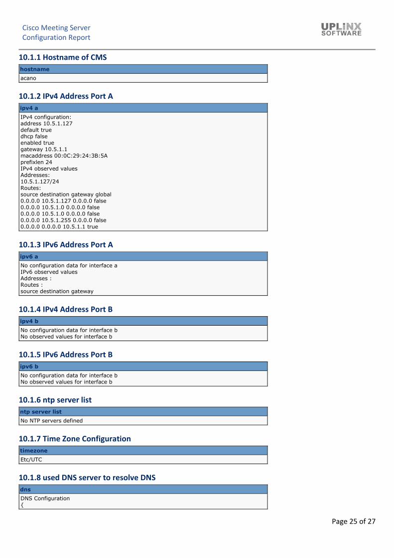
10.1.1 Hostname of CMS ......................................................................................................................... 25
10.1.2 IPv4 Address Port A ....................................................................................................................... 25
10.1.3 IPv6 Address Port A ....................................................................................................................... 25
10.1.4 IPv4 Address Port B ....................................................................................................................... 25
10.1.5 IPv6 Address Port B ....................................................................................................................... 25
10.1.6 ntp server list ................................................................................................................................ 25
10.1.7 Time Zone Configuration .............................................................................................................. 25
10.1.8 used DNS server to resolve DNS ................................................................................................... 25
10.1.9 User List ......................................................................................................................................... 26
Cisco Meeting Server carries on-premise audio, video and web communication. It works with third-party devices and can be integrated with Cisco Communications Manager for adhoc video meetings.
Participants can join the meeting via Cisco or third-party video endpoints, a Cisco Jabber client, Cisco Meeting App, either native or via a WebRTC-compatible browser, or Skype for Business to participate in the meeting.
Cisco Meeting Server, Cisco Meeting App, and Cisco Meeting Management have been optimized to be installed with Cisco Unified Communications Manager, Cisco Expressway or Video Communication Server (VCS) for call control, Cisco Expressway for firewall traversal, and Cisco TelePresence Management Suite for scheduling.
Most configurations of the Cisco Meeting Server are performed through the CMS API via XML requests. The CMS also includes a Web Admin with limited configuration options that include:
▪ General Configuration ▪ Active Directory Configuration for one main LDAP server. Muliple servers need to be configured via the API ▪ Call Settings ▪ Incoming and Outgoing Call setup with Rules and Dial Transforms ▪ CDR Configuration ▪ Spaces, also reffered to in the API as CoSpaces ▪ CMA user setting to allow/disallow incoming calls
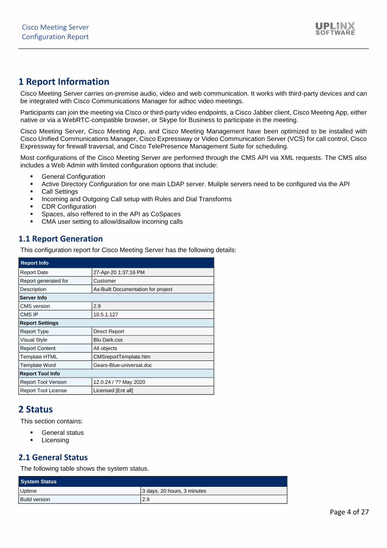
1.1 Report Generation
This configuration report for Cisco Meeting Server has the following details:
Report Info
Report Date 27-Apr-20 1:37:16 PM
Report generated for Customer
Description As-Built Documentation for project
Server Info
CMS version 2.9
CMS IP 10.5.1.127
Report Settings
Report Type Direct Report
Visual Style Blu Dark.css
Report Content All objects
Template HTML CMSreportTemplate.htm
Template Word Gears-Blue-universal.doc
Report Tool Info
Report Tool Version 12.0.24 / ?? May 2020
Report Tool License Licensed [Ent all]
2 Status
This section contains:
▪ General status ▪ Licensing
2.1 General Status
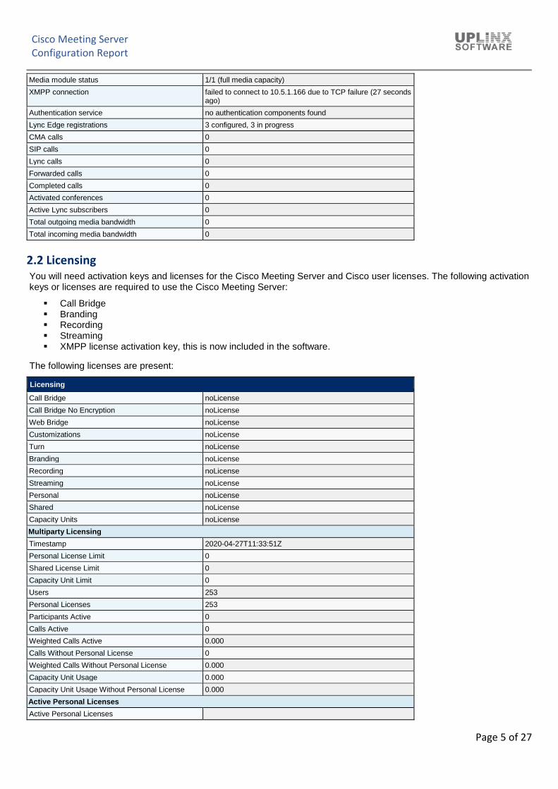
The following table shows the system status.
System Status
Uptime 3 days, 20 hours, 3 minutes
Build version 2.9
Cisco Meeting Server Configuration Report
Page 5 of 27
Media module status 1/1 (full media capacity)
XMPP connection failed to connect to 10.5.1.166 due to TCP failure (27 seconds ago)
Authentication service no authentication components found
Lync Edge registrations 3 configured, 3 in progress
CMA calls 0
SIP calls 0
Lync calls 0
Forwarded calls 0
Completed calls 0
Activated conferences 0
Active Lync subscribers 0
Total outgoing media bandwidth 0
Total incoming media bandwidth 0
2.2 Licensing
You will need activation keys and licenses for the Cisco Meeting Server and Cisco user licenses. The following activation keys or licenses are required to use the Cisco Meeting Server:
▪ Call Bridge ▪ Branding ▪ Recording ▪ Streaming ▪ XMPP license activation key, this is now included in the software.
The following licenses are present:
Licensing
Call Bridge noLicense
Call Bridge No Encryption noLicense
Web Bridge noLicense
Customizations noLicense
Turn noLicense
Branding noLicense
Recording noLicense
Streaming noLicense
Personal noLicense
Shared noLicense
Capacity Units noLicense
Multiparty Licensing
Timestamp 2020-04-27T11:33:51Z
Personal License Limit 0
Shared License Limit 0
Capacity Unit Limit 0
Users 253
Personal Licenses 253
Participants Active 0
Calls Active 0
Weighted Calls Active 0.000
Calls Without Personal License 0
Weighted Calls Without Personal License 0.000
Capacity Unit Usage 0.000
Capacity Unit Usage Without Personal License 0.000
Active Personal Licenses
Active Personal Licenses
Cisco Meeting Server Configuration Report
Page 6 of 27
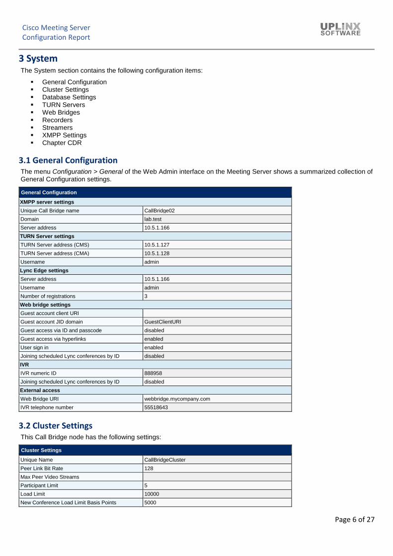
3 System
The System section contains the following configuration items:
The menu Configuration > General of the Web Admin interface on the Meeting Server shows a summarized collection of General Configuration settings.
General Configuration
XMPP server settings
Unique Call Bridge name CallBridge02
Domain lab.test
Server address 10.5.1.166
TURN Server settings
TURN Server address (CMS) 10.5.1.127
TURN Server address (CMA) 10.5.1.128
Username admin
Lync Edge settings
Server address 10.5.1.166
Username admin
Number of registrations 3
Web bridge settings
Guest account client URI
Guest account JID domain GuestClientURI
Guest access via ID and passcode disabled
Guest access via hyperlinks enabled
User sign in enabled
Joining scheduled Lync conferences by ID disabled
IVR
IVR numeric ID 888958
Joining scheduled Lync conferences by ID disabled
External access
Web Bridge URI webbridge.mycompany.com
IVR telephone number 55518643
3.2 Cluster Settings
This Call Bridge node has the following settings:
Cluster Settings
Unique Name CallBridgeCluster
Peer Link Bit Rate 128
Max Peer Video Streams
Participant Limit 5
Load Limit 10000
New Conference Load Limit Basis Points 5000
Cisco Meeting Server Configuration Report
Page 7 of 27
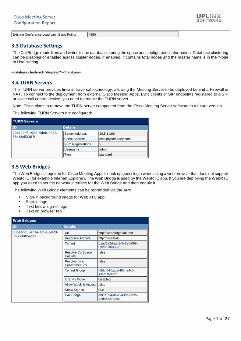
Existing Conference Load Limit Basis Points 4980
3.3 Database Settings
The CallBridge reads from and writes to the database storing the space and configuration information. Database clustering can be disabled or enabled across cluster nodes. If enabled, it contains total nodes and the master name is in the 'Node In Use' setting.
<database clustered="disabled"></database>
3.4 TURN Servers
The TURN server provides firewall traversal technology, allowing the Meeting Server to be deployed behind a Firewall or NAT. To connect to the deployment from external Cisco Meeting Apps, Lync clients or SIP endpoints registered to a SIP or voice call control device, you need to enable the TURN server.
Note: Cisco plans to remove the TURN server component from the Cisco Meeting Server software in a future version.
The following TURN Servers are configured:
TURN Servers
ID Details
23ca225f-1987-4d0b-9948-5848bdf23d7f
Server Address 10.5.1.166
Client Address cms.mycompany.com
Num Registrations 5
Username admin
Type standard
3.5 Web Bridges
The Web Bridge is required for Cisco Meeting Apps to look up guest login when using a web browser that does not support WebRTC (for example Internet Explorer). The Web Bridge is used by the WebRTC app. If you are deploying the WebRTC app you need to set the network interface for the Web Bridge and then enable it.
The following Web Bridge elements can be rebranded via the API:
▪ Sign-in background image for WebRTC app ▪ Sign-in logo ▪ Text below sign-in logo ▪ Text on browser tab
Web Bridges
ID Details
b0ba4cd3-473a-4c0e-b029-856380b5ecea
Url http://webbridge.lab.test
Resource Archive http://localhost
Tenant b1ad5a2d-aaf1-4c8e-b098-592067fb980c
Resolve Co Space Call Ids
false
Resolve Lync Conference Ids
false
Tenant Group f0fdcf04-1ac1-483f-a4c5-13cd8f699ff7
Id Entry Mode disabled
Allow Weblink Access false
Show Sign In true
Call Bridge abf7a694-8a70-430b-be35-b2da6d37cdc2
Cisco Meeting Server Configuration Report
Page 8 of 27
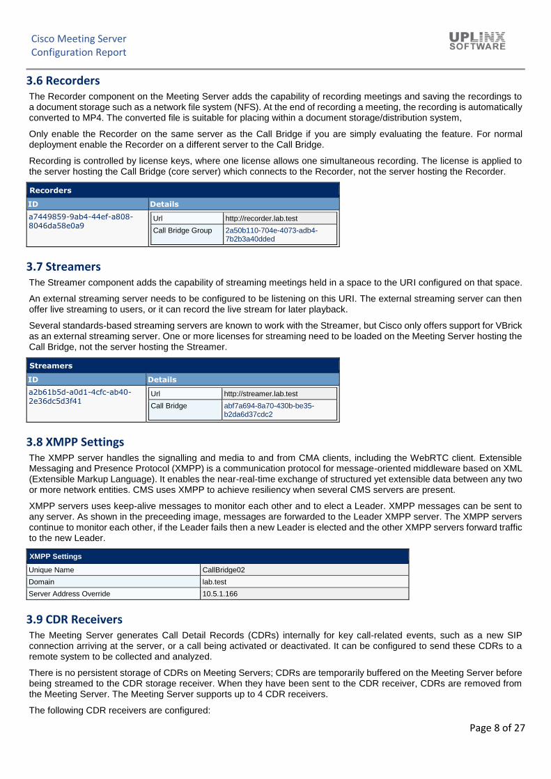
3.6 Recorders
The Recorder component on the Meeting Server adds the capability of recording meetings and saving the recordings to a document storage such as a network file system (NFS). At the end of recording a meeting, the recording is automatically converted to MP4. The converted file is suitable for placing within a document storage/distribution system,
Only enable the Recorder on the same server as the Call Bridge if you are simply evaluating the feature. For normal deployment enable the Recorder on a different server to the Call Bridge.
Recording is controlled by license keys, where one license allows one simultaneous recording. The license is applied to the server hosting the Call Bridge (core server) which connects to the Recorder, not the server hosting the Recorder.
Recorders
ID Details
a7449859-9ab4-44ef-a808-8046da58e0a9
Url http://recorder.lab.test
Call Bridge Group 2a50b110-704e-4073-adb4-7b2b3a40dded
3.7 Streamers
The Streamer component adds the capability of streaming meetings held in a space to the URI configured on that space.
An external streaming server needs to be configured to be listening on this URI. The external streaming server can then offer live streaming to users, or it can record the live stream for later playback.
Several standards-based streaming servers are known to work with the Streamer, but Cisco only offers support for VBrick as an external streaming server. One or more licenses for streaming need to be loaded on the Meeting Server hosting the Call Bridge, not the server hosting the Streamer.
Streamers
ID Details
a2b61b5d-a0d1-4cfc-ab40-2e36dc5d3f41
Url http://streamer.lab.test
Call Bridge abf7a694-8a70-430b-be35-b2da6d37cdc2
3.8 XMPP Settings
The XMPP server handles the signalling and media to and from CMA clients, including the WebRTC client. Extensible Messaging and Presence Protocol (XMPP) is a communication protocol for message-oriented middleware based on XML (Extensible Markup Language). It enables the near-real-time exchange of structured yet extensible data between any two or more network entities. CMS uses XMPP to achieve resiliency when several CMS servers are present.
XMPP servers uses keep-alive messages to monitor each other and to elect a Leader. XMPP messages can be sent to any server. As shown in the preceeding image, messages are forwarded to the Leader XMPP server. The XMPP servers continue to monitor each other, if the Leader fails then a new Leader is elected and the other XMPP servers forward traffic to the new Leader.
XMPP Settings
Unique Name CallBridge02
Domain lab.test
Server Address Override 10.5.1.166
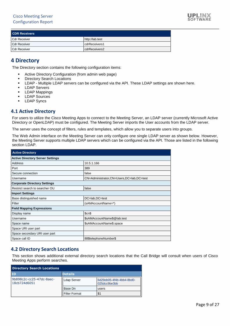
3.9 CDR Receivers
The Meeting Server generates Call Detail Records (CDRs) internally for key call-related events, such as a new SIP connection arriving at the server, or a call being activated or deactivated. It can be configured to send these CDRs to a remote system to be collected and analyzed.
There is no persistent storage of CDRs on Meeting Servers; CDRs are temporarily buffered on the Meeting Server before being streamed to the CDR storage receiver. When they have been sent to the CDR receiver, CDRs are removed from the Meeting Server. The Meeting Server supports up to 4 CDR receivers.
The following CDR receivers are configured:
Cisco Meeting Server Configuration Report
Page 9 of 27
CDR Receivers
Cdr Receiver http://lab.test
Cdr Receiver cdrReceivers1
Cdr Receiver cdrReceivers2
4 Directory
The Directory section contains the following configuration items:
▪ Active Directory Configuration (from admin web page) ▪ Directory Search Locations ▪ LDAP - Multiple LDAP servers can be configured via the API. These LDAP settings are shown here. ▪ LDAP Servers ▪ LDAP Mappings ▪ LDAP Sources ▪ LDAP Syncs
4.1 Active Directory
For users to utilize the Cisco Meeting Apps to connect to the Meeting Server, an LDAP server (currently Microsoft Active Directory or OpenLDAP) must be configured. The Meeting Server imports the User accounts from the LDAP server.
The server uses the concept of filters, rules and templates, which allow you to separate users into groups.
The Web Admin interface on the Meeting Server can only configure one single LDAP server as shown below. However, the Meeting Server supports multiple LDAP servers which can be configured via the API. Those are listed in the following section LDAP.
This section shows additional external directory search locations that the Call Bridge will consult when users of Cisco Meeting Apps perform searches.
Directory Search Locations
ID Details
9b898c2c-cc25-47dc-8aec-18cb724d6051
Ldap Server 6d29eb05-4f4b-4bb4-8bd0-025dcc9be3bb
Base Dn users
Filter Format $1
Cisco Meeting Server Configuration Report
Page 10 of 27
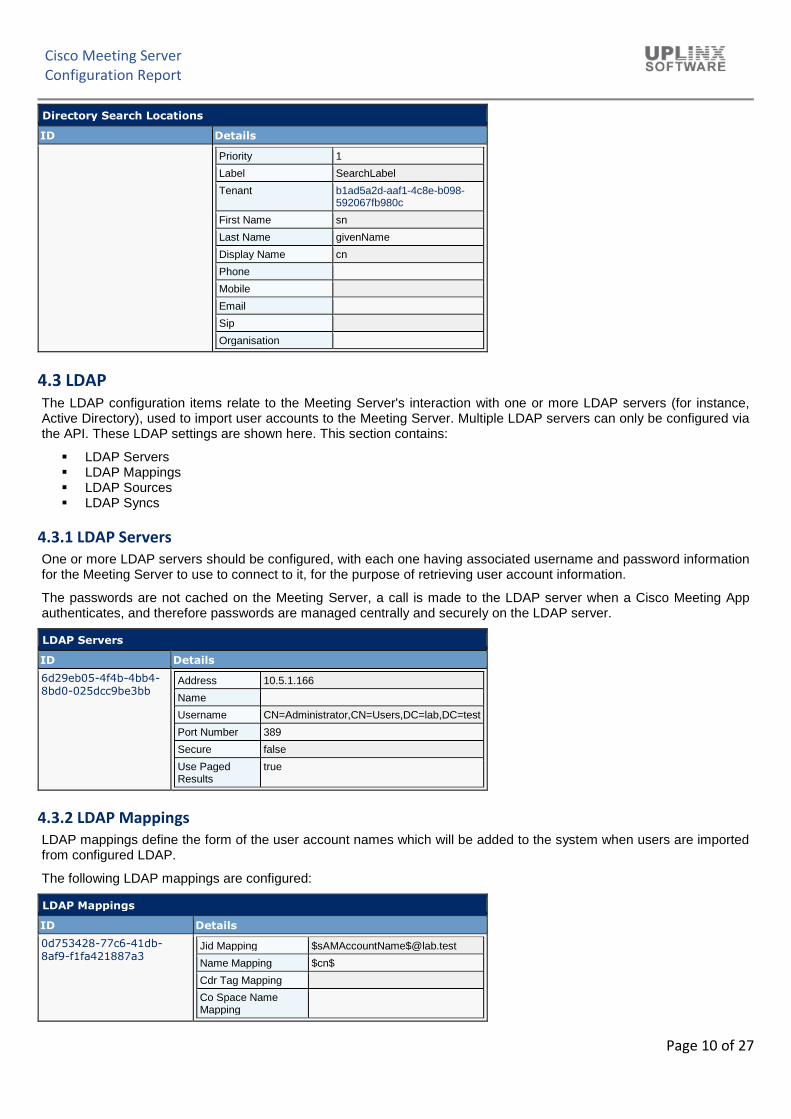
Directory Search Locations
ID Details
Priority 1
Label SearchLabel
Tenant b1ad5a2d-aaf1-4c8e-b098-592067fb980c
First Name sn
Last Name givenName
Display Name cn
Phone
Mobile
Email
Sip
Organisation
4.3 LDAP
The LDAP configuration items relate to the Meeting Server's interaction with one or more LDAP servers (for instance, Active Directory), used to import user accounts to the Meeting Server. Multiple LDAP servers can only be configured via the API. These LDAP settings are shown here. This section contains:
One or more LDAP servers should be configured, with each one having associated username and password information for the Meeting Server to use to connect to it, for the purpose of retrieving user account information.
The passwords are not cached on the Meeting Server, a call is made to the LDAP server when a Cisco Meeting App authenticates, and therefore passwords are managed centrally and securely on the LDAP server.
LDAP Servers
ID Details
6d29eb05-4f4b-4bb4-8bd0-025dcc9be3bb
Address 10.5.1.166
Name
Username CN=Administrator,CN=Users,DC=lab,DC=test
Port Number 389
Secure false
Use Paged Results
true
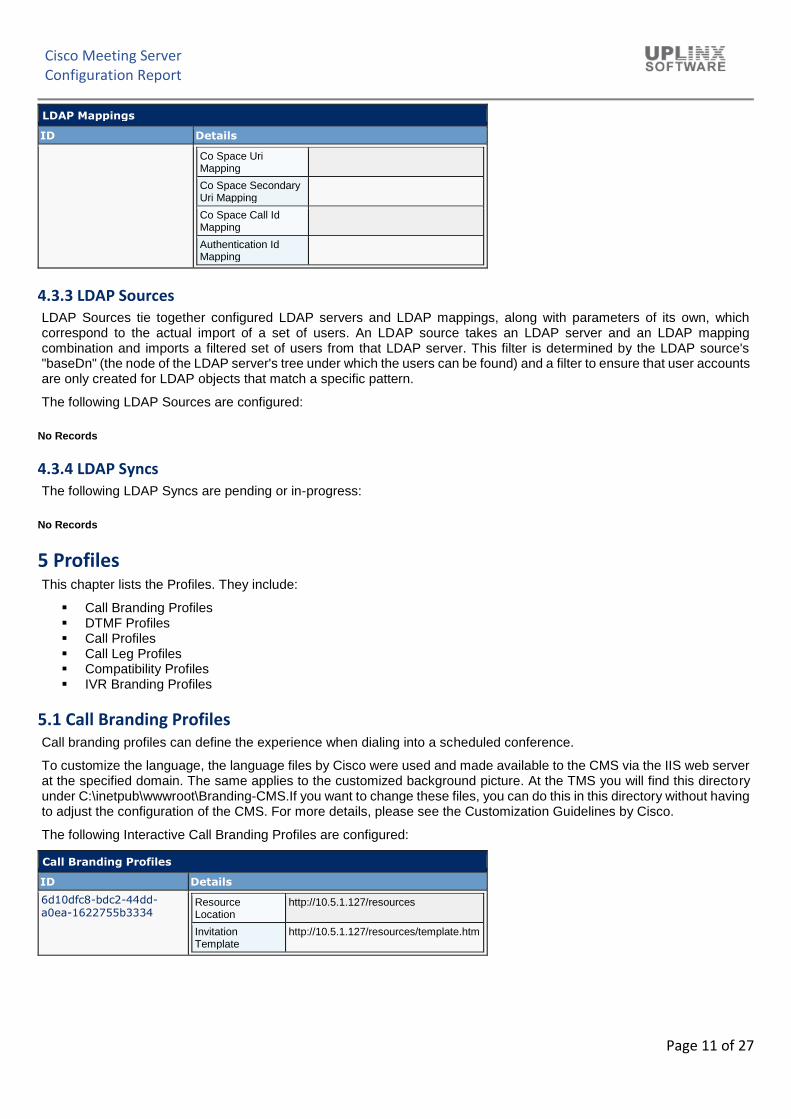
4.3.2 LDAP Mappings
LDAP mappings define the form of the user account names which will be added to the system when users are imported from configured LDAP.
LDAP Sources tie together configured LDAP servers and LDAP mappings, along with parameters of its own, which correspond to the actual import of a set of users. An LDAP source takes an LDAP server and an LDAP mapping combination and imports a filtered set of users from that LDAP server. This filter is determined by the LDAP source's "baseDn" (the node of the LDAP server's tree under which the users can be found) and a filter to ensure that user accounts are only created for LDAP objects that match a specific pattern.
The following LDAP Sources are configured:
No Records
4.3.4 LDAP Syncs
The following LDAP Syncs are pending or in-progress:
Call branding profiles can define the experience when dialing into a scheduled conference.
To customize the language, the language files by Cisco were used and made available to the CMS via the IIS web server at the specified domain. The same applies to the customized background picture. At the TMS you will find this directory under C:\inetpub\wwwroot\Branding-CMS.If you want to change these files, you can do this in this directory without having to adjust the configuration of the CMS. For more details, please see the Customization Guidelines by Cisco.
The following Interactive Call Branding Profiles are configured:
Call Branding Profiles
ID Details
6d10dfc8-bdc2-44dd-a0ea-1622755b3334
Resource Location
http://10.5.1.127/resources
Invitation Template
http://10.5.1.127/resources/template.htm
Cisco Meeting Server Configuration Report
Page 12 of 27
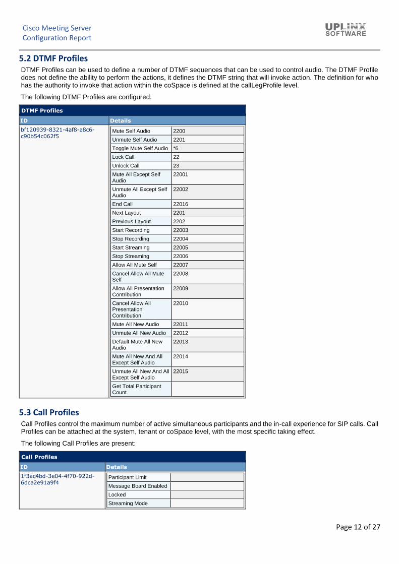
5.2 DTMF Profiles
DTMF Profiles can be used to define a number of DTMF sequences that can be used to control audio. The DTMF Profile does not define the ability to perform the actions, it defines the DTMF string that will invoke action. The definition for who has the authority to invoke that action within the coSpace is defined at the callLegProfile level.
The following DTMF Profiles are configured:
DTMF Profiles
ID Details
bf120939-8321-4af8-a8c6-c90b54c062f5
Mute Self Audio 2200
Unmute Self Audio 2201
Toggle Mute Self Audio *6
Lock Call 22
Unlock Call 23
Mute All Except Self Audio
22001
Unmute All Except Self Audio
22002
End Call 22016
Next Layout 2201
Previous Layout 2202
Start Recording 22003
Stop Recording 22004
Start Streaming 22005
Stop Streaming 22006
Allow All Mute Self 22007
Cancel Allow All Mute Self
22008
Allow All Presentation Contribution
22009
Cancel Allow All Presentation Contribution
22010
Mute All New Audio 22011
Unmute All New Audio 22012
Default Mute All New Audio
22013
Mute All New And All Except Self Audio
22014
Unmute All New And All Except Self Audio
22015
Get Total Participant Count
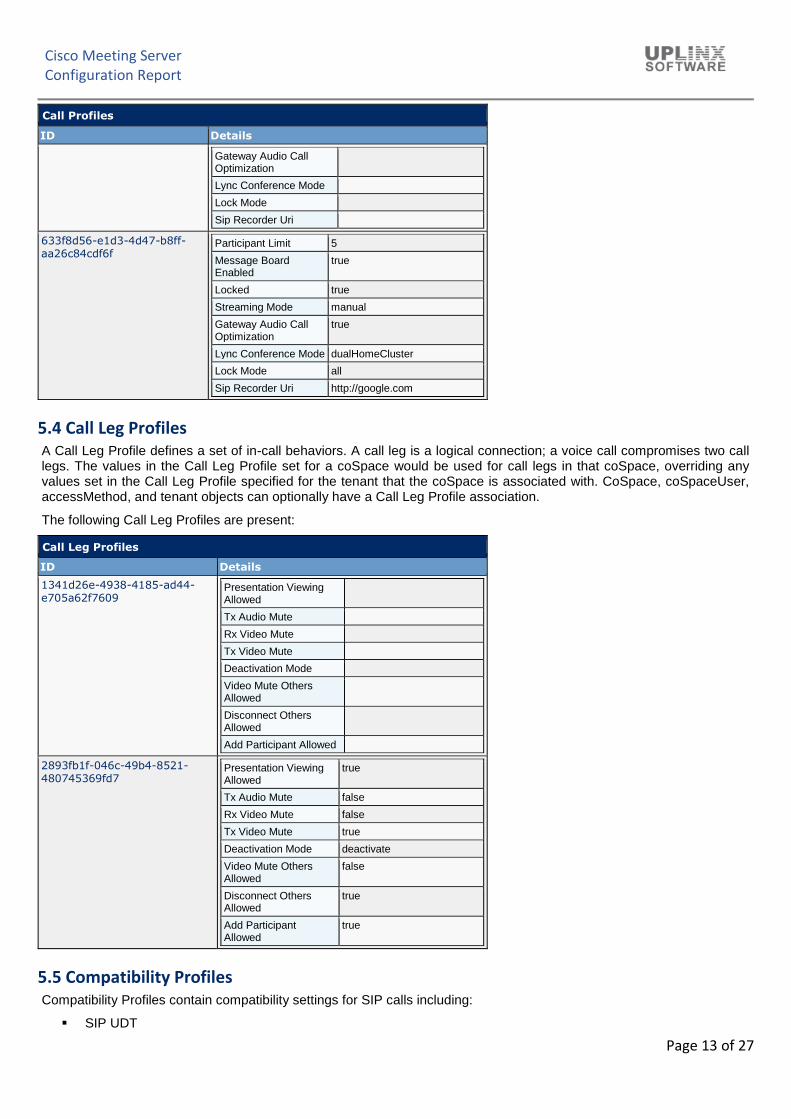
5.3 Call Profiles
Call Profiles control the maximum number of active simultaneous participants and the in-call experience for SIP calls. Call Profiles can be attached at the system, tenant or coSpace level, with the most specific taking effect.
The following Call Profiles are present:
Call Profiles
ID Details
1f3ac4bd-3e04-4f70-922d-6dca2e91a9f4
Participant Limit
Message Board Enabled
Locked
Streaming Mode
Cisco Meeting Server Configuration Report
Page 13 of 27
Call Profiles
ID Details
Gateway Audio Call Optimization
Lync Conference Mode
Lock Mode
Sip Recorder Uri
633f8d56-e1d3-4d47-b8ff-aa26c84cdf6f
Participant Limit 5
Message Board Enabled
true
Locked true
Streaming Mode manual
Gateway Audio Call Optimization
true
Lync Conference Mode dualHomeCluster
Lock Mode all
Sip Recorder Uri http://google.com
5.4 Call Leg Profiles
A Call Leg Profile defines a set of in-call behaviors. A call leg is a logical connection; a voice call compromises two call legs. The values in the Call Leg Profile set for a coSpace would be used for call legs in that coSpace, overriding any values set in the Call Leg Profile specified for the tenant that the coSpace is associated with. CoSpace, coSpaceUser, accessMethod, and tenant objects can optionally have a Call Leg Profile association.
The following Call Leg Profiles are present:
Call Leg Profiles
ID Details
1341d26e-4938-4185-ad44-e705a62f7609
Presentation Viewing Allowed
Tx Audio Mute
Rx Video Mute
Tx Video Mute
Deactivation Mode
Video Mute Others Allowed
Disconnect Others Allowed
Add Participant Allowed
2893fb1f-046c-49b4-8521-480745369fd7
Presentation Viewing Allowed
true
Tx Audio Mute false
Rx Video Mute false
Tx Video Mute true
Deactivation Mode deactivate
Video Mute Others Allowed
false
Disconnect Others Allowed
true
Add Participant Allowed
true
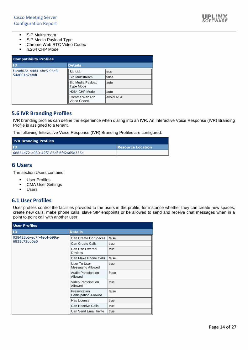
5.5 Compatibility Profiles
Compatibility Profiles contain compatibility settings for SIP calls including:
▪ SIP UDT
Cisco Meeting Server Configuration Report
Page 14 of 27
▪ SIP Multistream ▪ SIP Media Payload Type ▪ Chrome Web RTC Video Codec ▪ h.264 CHP Mode
Compatibility Profiles
ID Details
f1cad02a-44d4-4bc5-95e3-54a001b748df
Sip Udt true
Sip Multistream false
Sip Media Payload Type Mode
auto
H264 CHP Mode auto
Chrome Web Rtc Video Codec
avoidH264
5.6 IVR Branding Profiles
IVR branding profiles can define the experience when dialing into an IVR. An Interactive Voice Response (IVR) Branding Profile is assigned to a tenant.
The following Interactive Voice Response (IVR) Branding Profiles are configured:
IVR Branding Profiles
ID Resource Location
68854d72-a080-42f7-85df-6fd2665d335e
6 Users
The section Users contains:
▪ User Profiles ▪ CMA User Settings ▪ Users
6.1 User Profiles
User profiles control the facilities provided to the users in the profile, for instance whether they can create new spaces, create new calls, make phone calls, slave SIP endpoints or be allowed to send and receive chat messages when in a point to point call with another user.
User Profiles
ID Details
038428bb-ed7f-4ec4-b99a-6833c72bb0a0
Can Create Co Spaces false
Can Create Calls true
Can Use External Devices
true
Can Make Phone Calls false
User To User Messaging Allowed
true
Audio Participation Allowed
false
Video Participation Allowed
true
Presentation Participation Allowed
false
Has License true
Can Receive Calls true
Can Send Email Invite true
Cisco Meeting Server Configuration Report
Page 15 of 27
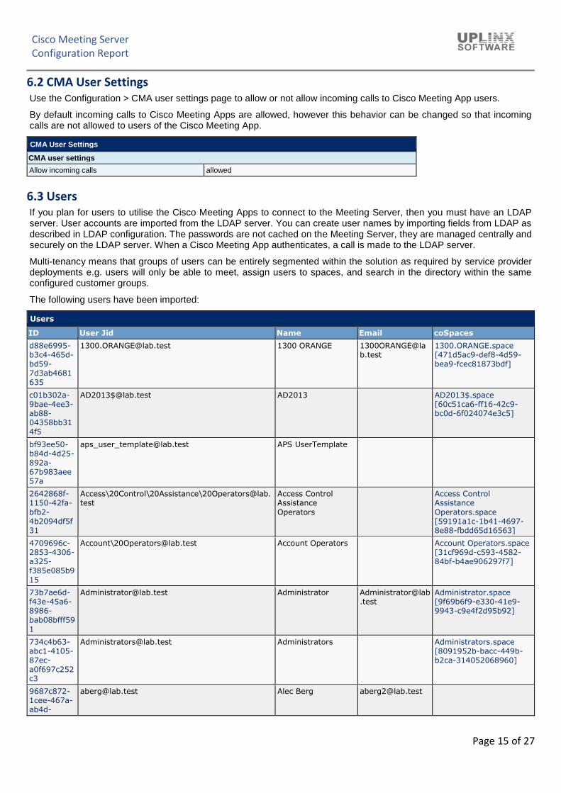
6.2 CMA User Settings
Use the Configuration > CMA user settings page to allow or not allow incoming calls to Cisco Meeting App users.
By default incoming calls to Cisco Meeting Apps are allowed, however this behavior can be changed so that incoming calls are not allowed to users of the Cisco Meeting App.
CMA User Settings
CMA user settings
Allow incoming calls allowed
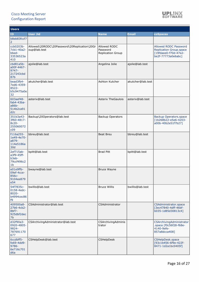
6.3 Users
If you plan for users to utilise the Cisco Meeting Apps to connect to the Meeting Server, then you must have an LDAP server. User accounts are imported from the LDAP server. You can create user names by importing fields from LDAP as described in LDAP configuration. The passwords are not cached on the Meeting Server, they are managed centrally and securely on the LDAP server. When a Cisco Meeting App authenticates, a call is made to the LDAP server.
Multi-tenancy means that groups of users can be entirely segmented within the solution as required by service provider deployments e.g. users will only be able to meet, assign users to spaces, and search in the directory within the same configured customer groups.
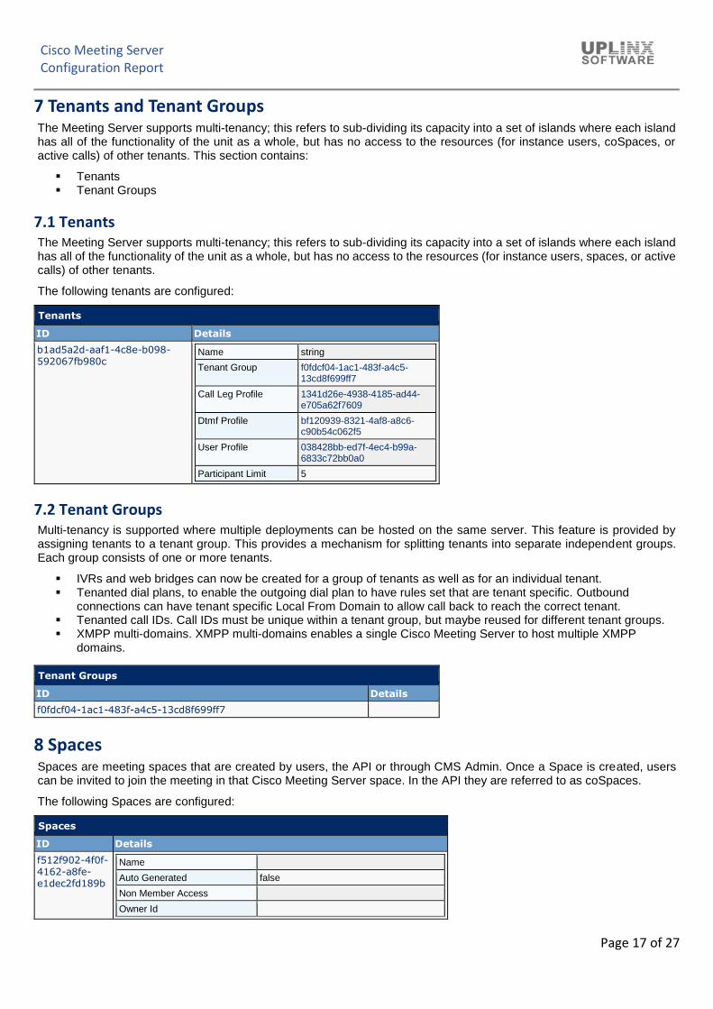
The Meeting Server supports multi-tenancy; this refers to sub-dividing its capacity into a set of islands where each island has all of the functionality of the unit as a whole, but has no access to the resources (for instance users, coSpaces, or active calls) of other tenants. This section contains:
▪ Tenants ▪ Tenant Groups
7.1 Tenants
The Meeting Server supports multi-tenancy; this refers to sub-dividing its capacity into a set of islands where each island has all of the functionality of the unit as a whole, but has no access to the resources (for instance users, spaces, or active calls) of other tenants.
The following tenants are configured:
Tenants
ID Details
b1ad5a2d-aaf1-4c8e-b098-592067fb980c
Name string
Tenant Group f0fdcf04-1ac1-483f-a4c5-13cd8f699ff7
Call Leg Profile 1341d26e-4938-4185-ad44-e705a62f7609
Dtmf Profile bf120939-8321-4af8-a8c6-c90b54c062f5
User Profile 038428bb-ed7f-4ec4-b99a-6833c72bb0a0
Participant Limit 5
7.2 Tenant Groups
Multi-tenancy is supported where multiple deployments can be hosted on the same server. This feature is provided by assigning tenants to a tenant group. This provides a mechanism for splitting tenants into separate independent groups. Each group consists of one or more tenants.
▪ IVRs and web bridges can now be created for a group of tenants as well as for an individual tenant. ▪ Tenanted dial plans, to enable the outgoing dial plan to have rules set that are tenant specific. Outbound
connections can have tenant specific Local From Domain to allow call back to reach the correct tenant. ▪ Tenanted call IDs. Call IDs must be unique within a tenant group, but maybe reused for different tenant groups. ▪ XMPP multi-domains. XMPP multi-domains enables a single Cisco Meeting Server to host multiple XMPP
domains.
Tenant Groups
ID Details
f0fdcf04-1ac1-483f-a4c5-13cd8f699ff7
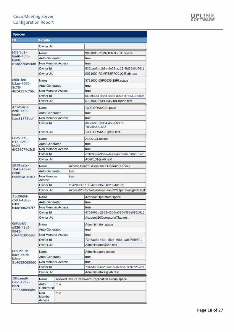
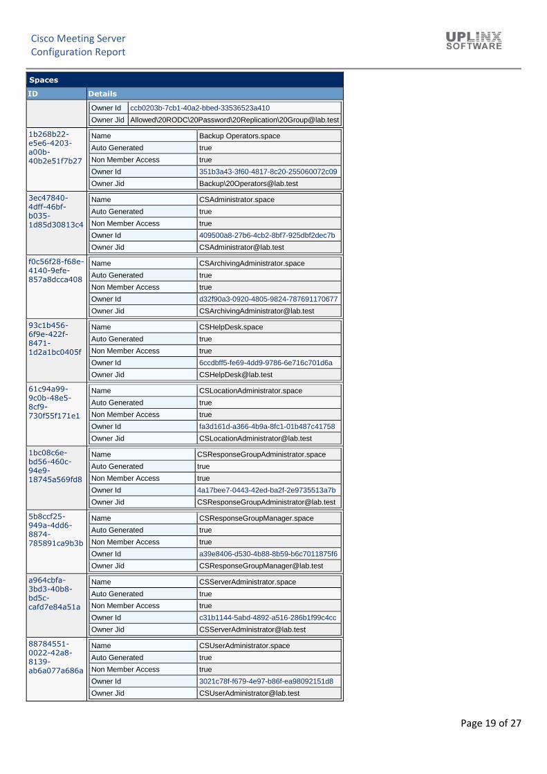
8 Spaces
Spaces are meeting spaces that are created by users, the API or through CMS Admin. Once a Space is created, users can be invited to join the meeting in that Cisco Meeting Server space. In the API they are referred to as coSpaces.
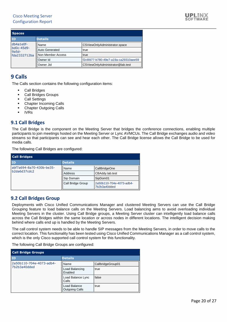
The Call Bridge is the component on the Meeting Server that bridges the conference connections, enabling multiple participants to join meetings hosted on the Meeting Server or Lync AVMCUs. The Call Bridge exchanges audio and video streams so that participants can see and hear each other. The Call Bridge license allows the Call Bridge to be used for media calls.
The following Call Bridges are configured:
Call Bridges
ID Details
abf7a694-8a70-430b-be35-b2da6d37cdc2
Name CallBridgeOne
Address CBAddy.lab.test
Sip Domain SipDom01
Call Bridge Group 2a50b110-704e-4073-adb4-7b2b3a40dded
9.2 Call Bridges Group
Deployments with Cisco Unified Communications Manager and clustered Meeting Servers can use the Call Bridge Grouping feature to load balance calls on the Meeting Servers. Load balancing aims to avoid overloading individual Meeting Servers in the cluster. Using Call Bridge groups, a Meeting Server cluster can intelligently load balance calls across the Call Bridges within the same location or across nodes in different locations. The intelligent decision making behind where calls end up is handled by the Meeting Servers.
The call control system needs to be able to handle SIP messages from the Meeting Servers, in order to move calls to the correct location. This functionality has been tested using Cisco Unified Communications Manager as a call control system, which is the only Cisco supported call control system for this functionality.
The following Call Bridge Groups are configured:
Call Bridge Groups
ID Details
2a50b110-704e-4073-adb4-7b2b3a40dded
Name CallbridgeGroup01
Load Balancing Enabled
true
Load Balance Lync Calls
false
Load Balance Outgoing Calls
true
Cisco Meeting Server Configuration Report
Page 21 of 27
Call Bridge Groups
ID Details
Load Balance User Calls
true
Load Balance Indirect Calls
false
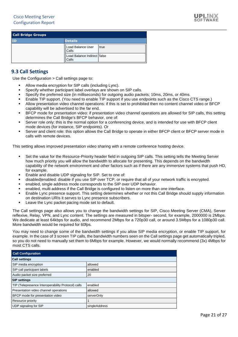
9.3 Call Settings
Use the Configuration > Call settings page to:
▪ Allow media encryption for SIP calls (including Lync). ▪ Specify whether participant label overlays are shown on SIP calls. ▪ Specify the preferred size (in milliseconds) for outgoing audio packets; 10ms, 20ms, or 40ms. ▪ Enable TIP support. (You need to enable TIP support if you use endpoints such as the Cisco CTS range.) ▪ Allow presentation video channel operations: if this is set to prohibited then no content channel video or BFCP
capability will be advertised to the far end. ▪ BFCP mode for presentation video: if presentation video channel operations are allowed for SIP calls, this setting
determines the Call Bridge's BFCP behavior, one of: ▪ Server role only: this is the normal option for a conferencing device, and is intended for use with BFCP client
mode devices (for instance, SIP endpoints). Or ▪ Server and client role: this option allows the Call Bridge to operate in either BFCP client or BFCP server mode in
calls with remote devices.
This setting allows improved presentation video sharing with a remote conference hosting device.
▪ Set the value for the Resource-Priority header field in outgoing SIP calls. This setting tells the Meeting Server how much priority you will allow the bandwidth to allocate for presenting. This depends on the bandwidth capability of the network environment and other factors such as if there are any immersive systems that push HD, for example.
▪ Enable and disable UDP signaling for SIP. Set to one of: ▪ disabled|enabled: disable if you use SIP over TCP, or require that all of your network traffic is encrypted. ▪ enabled, single address mode corresponds to the SIP over UDP behavior. ▪ enabled, multi address if the Call Bridge is configured to listen on more than one interface. ▪ Enable Lync presence support. This setting determines whether or not this Call Bridge should supply information
on destination URIs it serves to Lync presence subscribers. ▪ Leave the Lync packet pacing mode set to default.
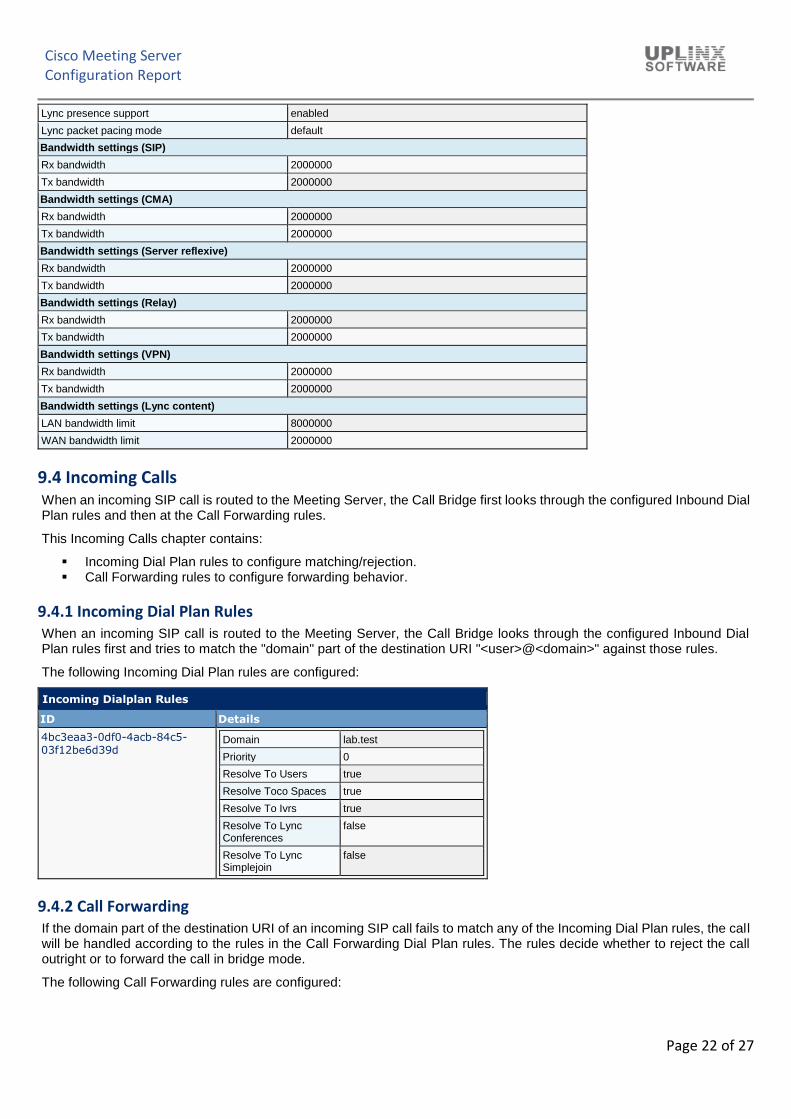
The Call settings page also allows you to change the bandwidth settings for SIP, Cisco Meeting Server (CMA), Server reflexive, Relay, VPN, and Lync content. The settings are measured in bitsper- second, for example, 2000000 is 2Mbps. We dedicate at least 64kbps for audio, and recommend 2Mbps for a 720p30 call, or around 3.5Mbps for a 1080p30 call. More bandwidth would be required for 60fps.
You may need to change some of the bandwidth settings if you allow SIP media encryption, or enable TIP support, for example. In the case of 3 screen TIP calls, the bandwidth numbers seen on the Call settings page get automatically tripled, so you do not need to manually set them to 6Mbps for example. However, we would normally recommend (3x) 4Mbps for most CTS calls.
Call Configuration
Call settings
SIP media encryption allowed
SIP call participant labels enabled
Audio packet size preferred 20
SIP settings
TIP (Telepresence Interoperability Protocol) calls enabled
Presentation video channel operations allowed
BFCP mode for presentation video serverOnly
Resource priority 1
UDP signaling for SIP singleAddress
Cisco Meeting Server Configuration Report
Page 22 of 27
Lync presence support enabled
Lync packet pacing mode default
Bandwidth settings (SIP)
Rx bandwidth 2000000
Tx bandwidth 2000000
Bandwidth settings (CMA)
Rx bandwidth 2000000
Tx bandwidth 2000000
Bandwidth settings (Server reflexive)
Rx bandwidth 2000000
Tx bandwidth 2000000
Bandwidth settings (Relay)
Rx bandwidth 2000000
Tx bandwidth 2000000
Bandwidth settings (VPN)
Rx bandwidth 2000000
Tx bandwidth 2000000
Bandwidth settings (Lync content)
LAN bandwidth limit 8000000
WAN bandwidth limit 2000000
9.4 Incoming Calls
When an incoming SIP call is routed to the Meeting Server, the Call Bridge first looks through the configured Inbound Dial Plan rules and then at the Call Forwarding rules.
This Incoming Calls chapter contains:
▪ Incoming Dial Plan rules to configure matching/rejection. ▪ Call Forwarding rules to configure forwarding behavior.
9.4.1 Incoming Dial Plan Rules
When an incoming SIP call is routed to the Meeting Server, the Call Bridge looks through the configured Inbound Dial Plan rules first and tries to match the "domain" part of the destination URI "<user>@<domain>" against those rules.
The following Incoming Dial Plan rules are configured:
Incoming Dialplan Rules
ID Details
4bc3eaa3-0df0-4acb-84c5-03f12be6d39d
Domain lab.test
Priority 0
Resolve To Users true
Resolve Toco Spaces true
Resolve To Ivrs true
Resolve To Lync Conferences
false
Resolve To Lync Simplejoin
false
9.4.2 Call Forwarding
If the domain part of the destination URI of an incoming SIP call fails to match any of the Incoming Dial Plan rules, the call will be handled according to the rules in the Call Forwarding Dial Plan rules. The rules decide whether to reject the call outright or to forward the call in bridge mode.
The following Call Forwarding rules are configured:
Cisco Meeting Server Configuration Report
Page 23 of 27
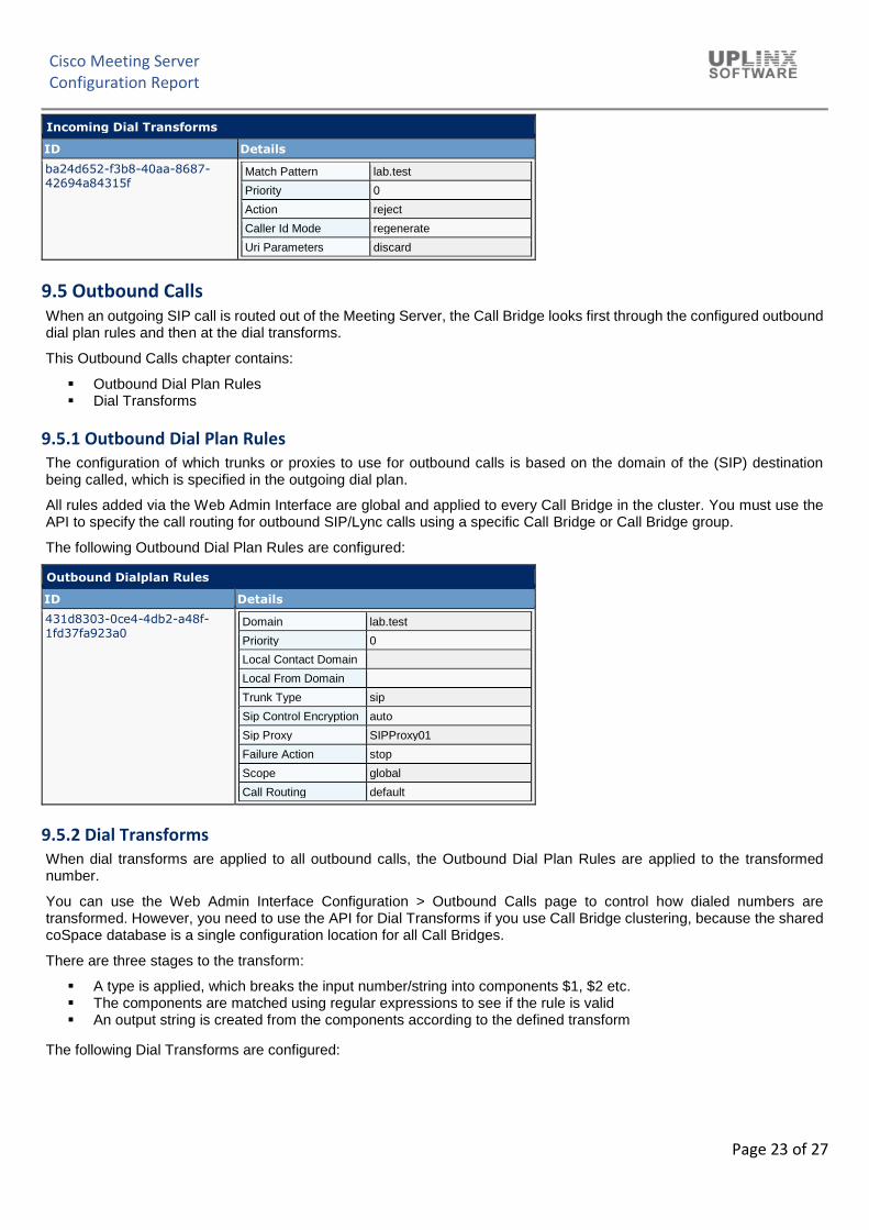
Incoming Dial Transforms
ID Details
ba24d652-f3b8-40aa-8687-42694a84315f
Match Pattern lab.test
Priority 0
Action reject
Caller Id Mode regenerate
Uri Parameters discard
9.5 Outbound Calls
When an outgoing SIP call is routed out of the Meeting Server, the Call Bridge looks first through the configured outbound dial plan rules and then at the dial transforms.
This Outbound Calls chapter contains:
▪ Outbound Dial Plan Rules ▪ Dial Transforms
9.5.1 Outbound Dial Plan Rules
The configuration of which trunks or proxies to use for outbound calls is based on the domain of the (SIP) destination being called, which is specified in the outgoing dial plan.
All rules added via the Web Admin Interface are global and applied to every Call Bridge in the cluster. You must use the API to specify the call routing for outbound SIP/Lync calls using a specific Call Bridge or Call Bridge group.
The following Outbound Dial Plan Rules are configured:
Outbound Dialplan Rules
ID Details
431d8303-0ce4-4db2-a48f-1fd37fa923a0
Domain lab.test
Priority 0
Local Contact Domain
Local From Domain
Trunk Type sip
Sip Control Encryption auto
Sip Proxy SIPProxy01
Failure Action stop
Scope global
Call Routing default
9.5.2 Dial Transforms
When dial transforms are applied to all outbound calls, the Outbound Dial Plan Rules are applied to the transformed number.
You can use the Web Admin Interface Configuration > Outbound Calls page to control how dialed numbers are transformed. However, you need to use the API for Dial Transforms if you use Call Bridge clustering, because the shared coSpace database is a single configuration location for all Call Bridges.
There are three stages to the transform:
▪ A type is applied, which breaks the input number/string into components $1, $2 etc. ▪ The components are matched using regular expressions to see if the rule is valid ▪ An output string is created from the components according to the defined transform
The following Dial Transforms are configured:
Cisco Meeting Server Configuration Report
Page 24 of 27
Outbound Dial Transforms
ID Details
6fa5c6a1-f7b0-49b0-bbc0-93fc4a9dba1c
Type strip
Match ($1/^9?\+?[^+]+$/)
Transform 9$1{/^9//}{/\+/00/}
Priority 0
Action accept
f9c1d5dc-2f0c-4f65-a365-494352ab1718
Type raw
Match
Transform
Priority 0
Action accept
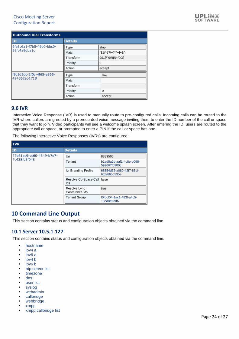
9.6 IVR
Interactive Voice Response (IVR) is used to manually route to pre-configured calls. Incoming calls can be routed to the IVR where callers are greeted by a prerecorded voice message inviting them to enter the ID number of the call or space that they want to join. Video participants will see a welcome splash screen. After entering the ID, users are routed to the appropriate call or space, or prompted to enter a PIN if the call or space has one.
The following Interactive Voice Responses (IVRs) are configured:
This section contains status and configuration objects obtained via the command line.
10.1 Server 10.5.1.127 This section contains status and configuration objects obtained via the command line.
▪ hostname ▪ ipv4 a ▪ ipv6 a ▪ ipv4 b ▪ ipv6 b ▪ ntp server list ▪ timezone ▪ dns ▪ user list ▪ syslog ▪ webadmin ▪ callbridge ▪ webbridge ▪ xmpp ▪ xmpp callbridge list
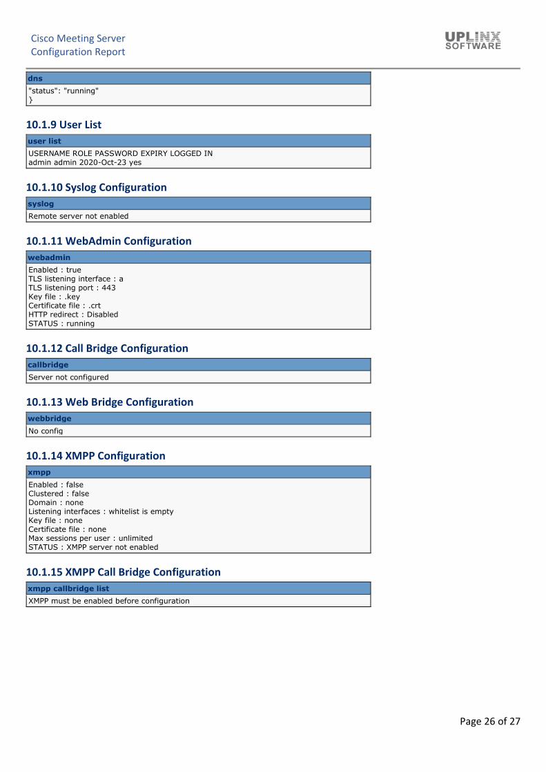
Enabled : false Clustered : false Domain : none Listening interfaces : whitelist is empty Key file : none Certificate file : none Max sessions per user : unlimited STATUS : XMPP server not enabled