Cisco Meraki - Teridion Deployment Guide A Teridion Technical Guide Teridion Product Management June 2019 A Technical Guide For Integration Of The Teridion for Enterprise Cloud WAN Service and Cisco Meraki MX/Z Security Appliances
Transcript
Cisco Meraki - Teridion
Deployment Guide
A Teridion Technical Guide
Teridion Product Management June 2019
A Technical Guide For Integration Of The Teridion for Enterprise
Cloud WAN Service and Cisco Meraki MX/Z Security Appliances
A TERIDION TECHNICAL PAPER | 2
CONTENTS
Introduction
Solution Overview
Prerequisites
Initial Preparations
Connecting the Appliances
Creating the Teridion Network
Configuration of the Cloud Gateway Appliance
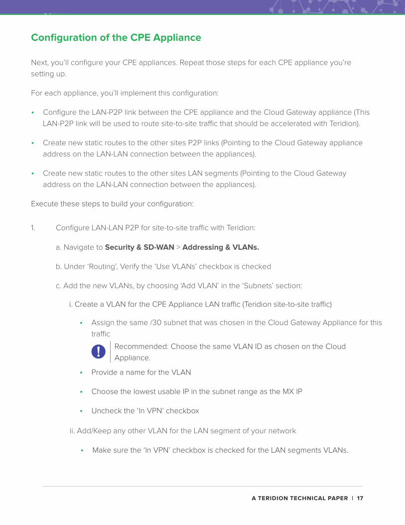
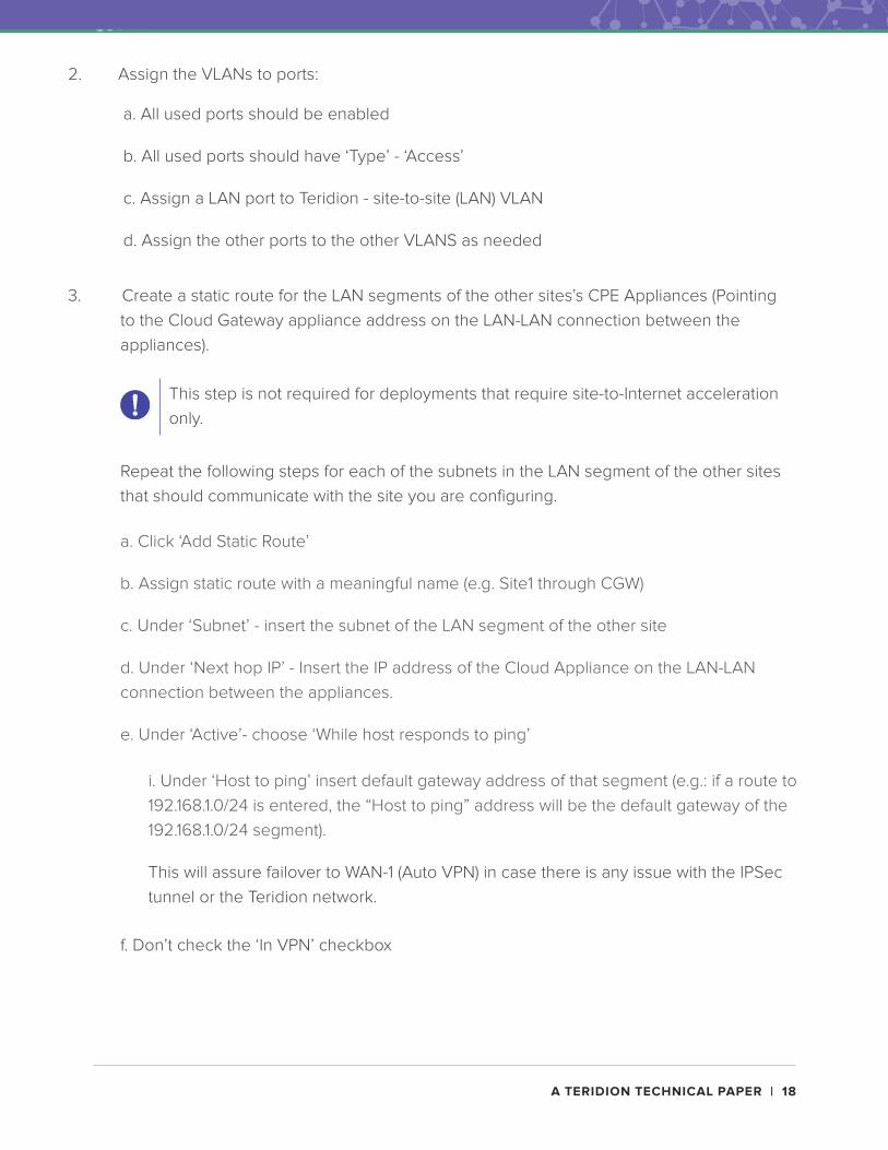
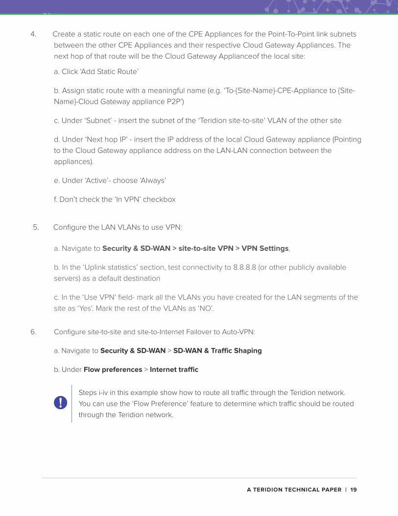
Configuration of the CPE Appliance
Extra Configuations
Additional Resources
3
4
5
6
7
9
12
17
21
22
A TERIDION TECHNICAL PAPER | 3
Introduction
Together, Teridion and Cisco Meraki provide a powerful end-to-end WAN solution. The
complementary nature of the features of both products gives the enterprise a comprehensive,
high-performance WAN solution.
This guide is a reference document that details the optimal integration configuration for Cisco
Meraki MX series appliances and Teridion For Enterprise. The Cisco Meraki - Teridion reference
deployment takes just minutes to implement, and supports Teridion’s acceleration for site-to-site
and site-to-internet combined with Cisco Meraki SD-WAN capabilities, including failover to Auto
VPN for high availability. This fully integrated solution delivers optimized end-to-end performance
and reliability.
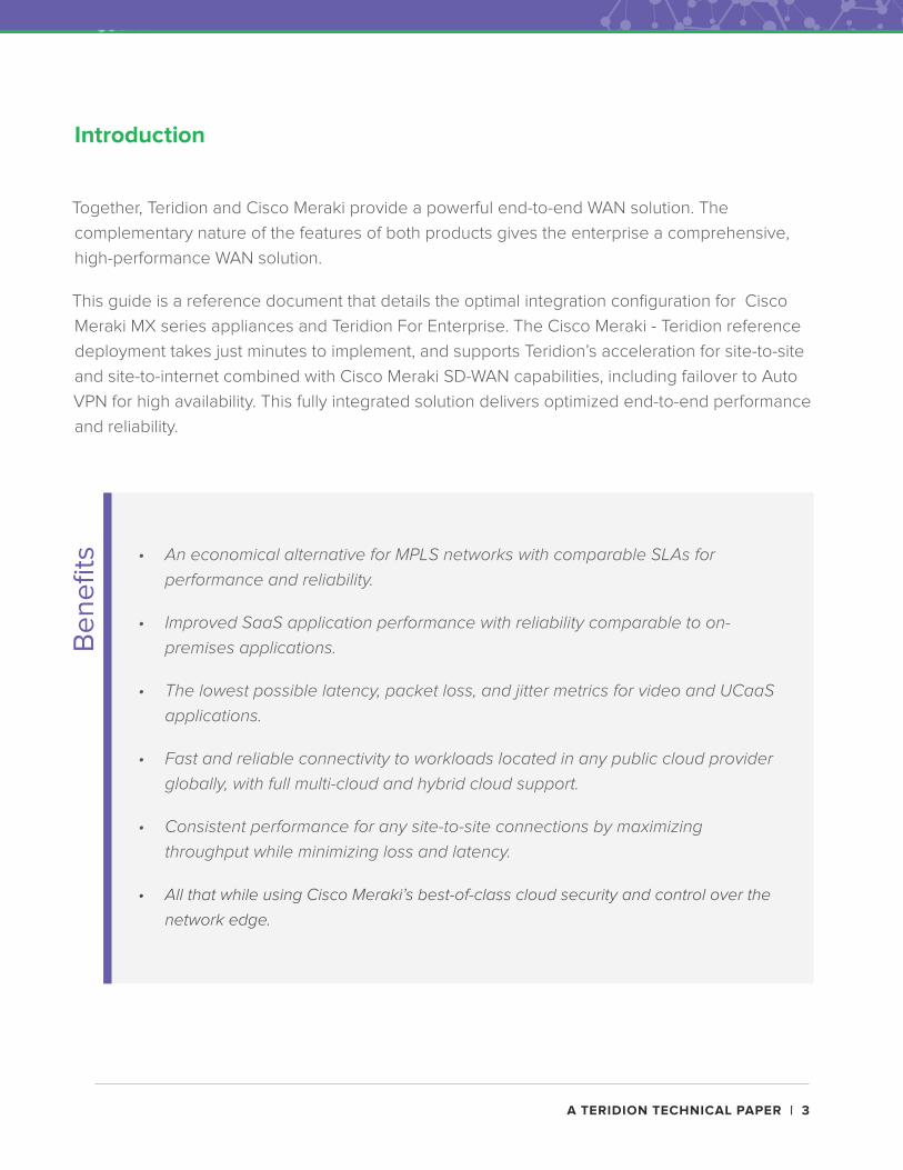
• An economical alternative for MPLS networks with comparable SLAs for performance and reliability.
• Improved SaaS application performance with reliability comparable to on-premises applications.
• The lowest possible latency, packet loss, and jitter metrics for video and UCaaS applications.
• Fast and reliable connectivity to workloads located in any public cloud provider globally, with full multi-cloud and hybrid cloud support.
• Consistent performance for any site-to-site connections by maximizing throughput while minimizing loss and latency.
• All that while using Cisco Meraki’s best-of-class cloud security and control over the
network edge.
Be
ne
fits
A TERIDION TECHNICAL PAPER | 4
Solution Overview
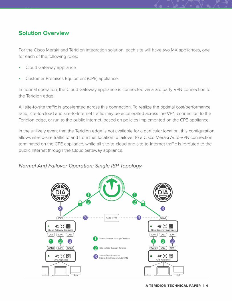
For the Cisco Meraki and Teridion integration solution, each site will have two MX appliances, one
for each of the following roles:
• Cloud Gateway appliance
• Customer Premises Equipment (CPE) appliance.
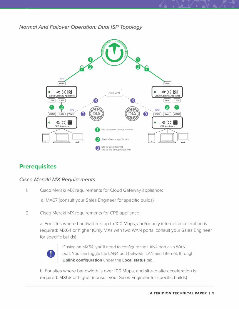
In normal operation, the Cloud Gateway appliance is connected via a 3rd party VPN connection to
the Teridion edge.
All site-to-site traffic is accelerated across this connection. To realize the optimal cost/performance
ratio, site-to-cloud and site-to-Internet traffic may be accelerated across the VPN connection to the
Teridion edge, or run to the public Internet, based on policies implemented on the CPE appliance.
In the unlikely event that the Teridion edge is not available for a particular location, this configuration
allows site-to-site traffic to and from that location to failover to a Cisco Meraki Auto-VPN connection
terminated on the CPE appliance, while all site-to-cloud and site-to-Internet traffic is rerouted to the
public Internet through the Cloud Gateway appliance.
Normal And Failover Operation: Single ISP Topology
A TERIDION TECHNICAL PAPER | 5
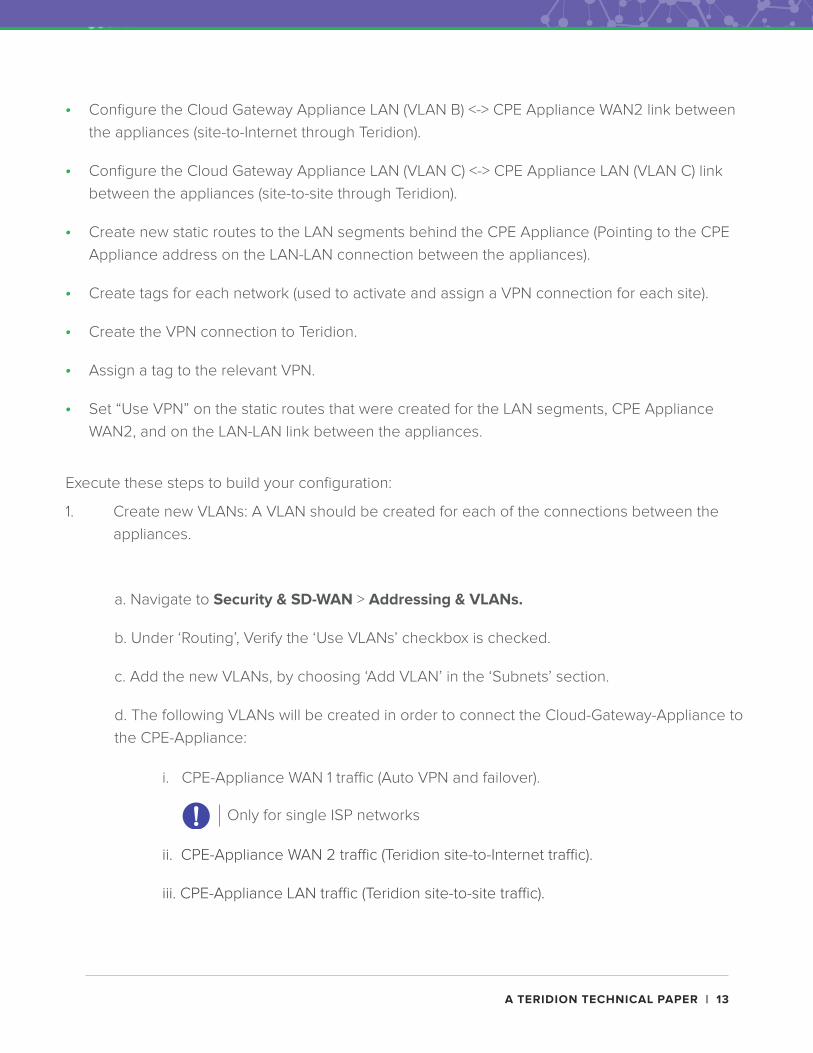
a. For sites where bandwidth is up to 100 Mbps, and/or only internet acceleration is
required: MX64 or higher (Only MXs with two WAN ports, consult your Sales Engineer
for specific builds)
b. For sites where bandwidth is over 100 Mbps, and site-to-site acceleration is
required: MX68 or higher (consult your Sales Engineer for specific builds)
Normal And Failover Operation: Dual ISP Topology
Prerequisites
Cisco Meraki MX Requirements
1. Cisco Meraki MX requirements for Cloud Gateway appliance:
2. Cisco Meraki MX requirements for CPE appliance:
If using an MX64, you’ll need to configure the LAN4 port as a WAN
port: You can toggle the LAN4 port between LAN and Internet, through
Uplink configuration under the Local status tab.
a. MX67 (consult your Sales Engineer for specific builds)
A TERIDION TECHNICAL PAPER | 6
Organizations and Networks
Two organizations are required. You’ll assign all the Cloud Gateway appliances to one
organization, and all the CPE appliances to the other. You can find instructions on how to create
new organizations here.
For each MX, a new “Network” must be created in the relevant organization and the MX
appliances allocated to those new networks. You can find the instructions on how to create new
networks and claim devices to them here.
Initial preparations
1. Create a new organization for the Cloud-Gateway appliances and give it a name (e.g.:
“{Company-Name}-Cloud-Appliance-Org”).
2. Create a new organization for the CPE appliances and give it a name (e.g.: “{Company-
Name}-CPE-Applicance-Org”).
3. Create a new network in the Cisco Meraki Dashboard for each one of the MX appliances in
the relevant organization according to this guide.
The CPE organization can be any existing organization in the Cisco- Meraki
dashboard.
a. Give your new network a meaningful name (e.g.: “Cloud Gateway Appliance - London”).
b. Under “Network Type”, choose “Security appliance”.
c. Under “Network Configuration”, choose “Default Meraki configuration”.
d. In the “Devices” section, click “Add devices” and enter the serial number of the relevant
MX appliance to add it to the inventory.
e. Attach the added device to the newly created network.
Appliances can be connected to a single ISP, or to dual ISPs for additional redundancy. Set your
appliance connections according to the relevant instructions below.
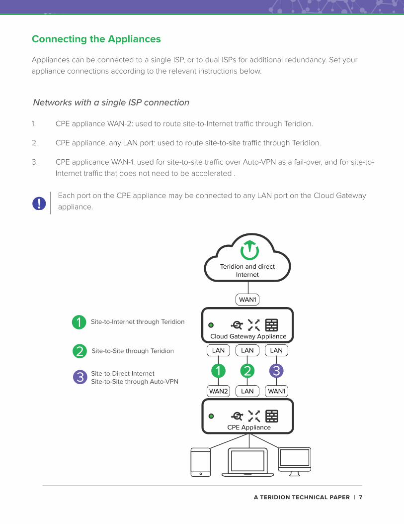
1. CPE appliance WAN-2: used to route site-to-Internet traffic through Teridion.
2. CPE appliance, any LAN port: used to route site-to-site traffic through Teridion.
3. CPE applicance WAN-1: used for site-to-site traffic over Auto-VPN as a fail-over, and for site-to-
Internet traffic that does not need to be accelerated .
Networks with a single ISP connection
Each port on the CPE appliance may be connected to any LAN port on the Cloud Gateway
appliance.
A TERIDION TECHNICAL PAPER | 8
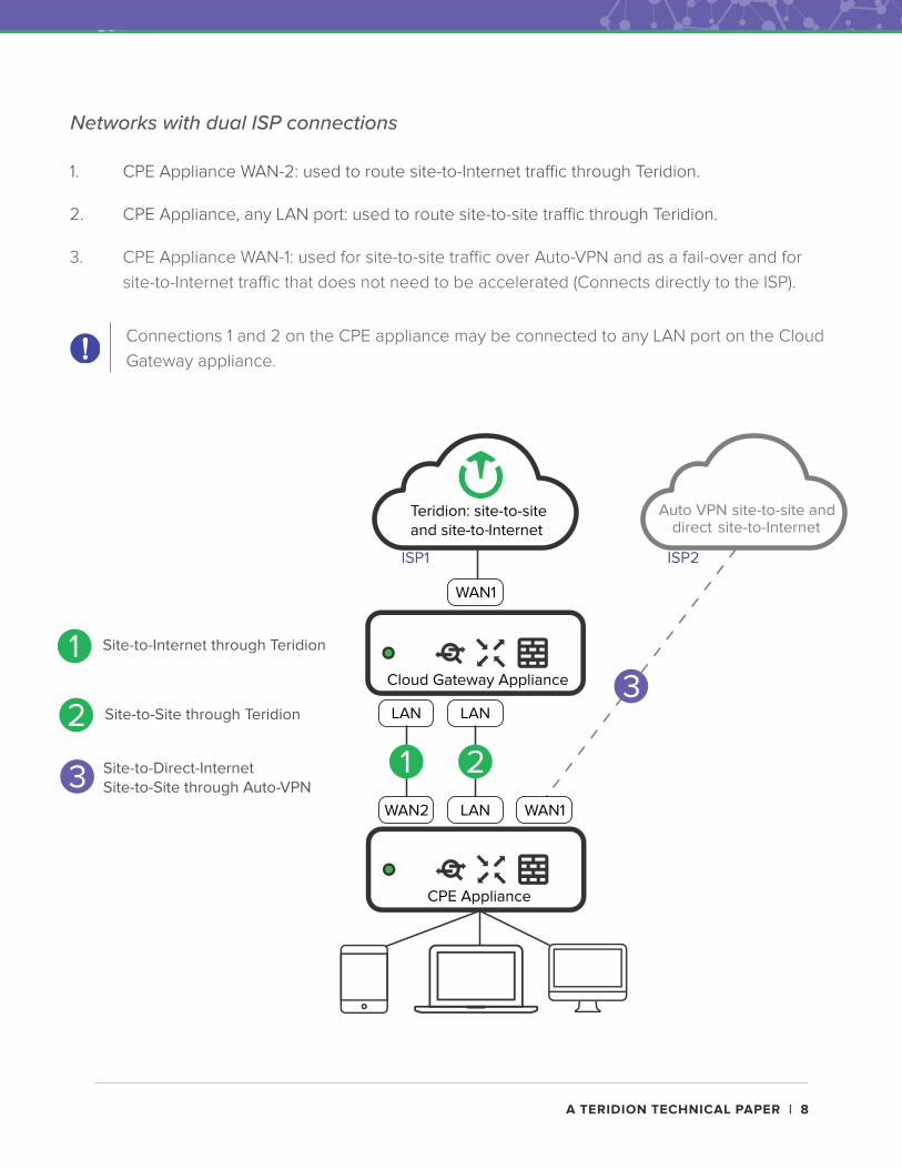
1. CPE Appliance WAN-2: used to route site-to-Internet traffic through Teridion.
2. CPE Appliance, any LAN port: used to route site-to-site traffic through Teridion.
3. CPE Appliance WAN-1: used for site-to-site traffic over Auto-VPN and as a fail-over and for
site-to-Internet traffic that does not need to be accelerated (Connects directly to the ISP).
Networks with dual ISP connections
Connections 1 and 2 on the CPE appliance may be connected to any LAN port on the Cloud
Gateway appliance.
A TERIDION TECHNICAL PAPER | 9
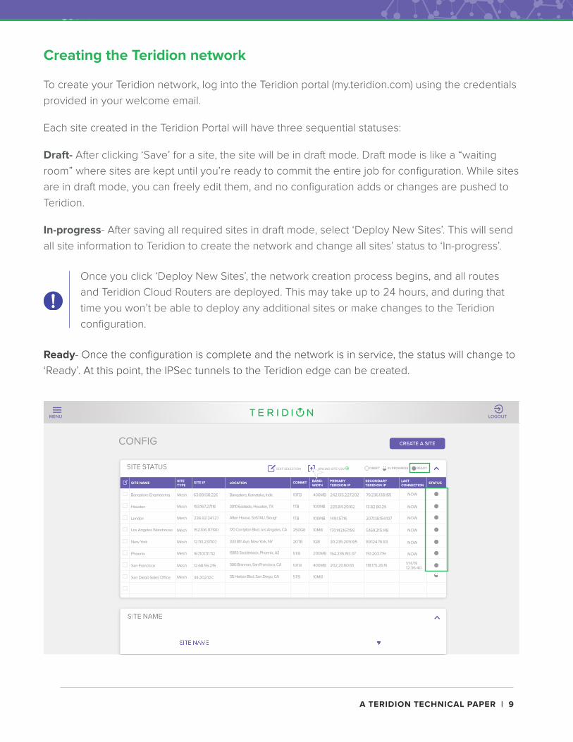
Creating the Teridion network
To create your Teridion network, log into the Teridion portal (my.teridion.com) using the credentials
provided in your welcome email.
Each site created in the Teridion Portal will have three sequential statuses:
Draft- After clicking ‘Save’ for a site, the site will be in draft mode. Draft mode is like a “waiting
room” where sites are kept until you’re ready to commit the entire job for configuration. While sites
are in draft mode, you can freely edit them, and no configuration adds or changes are pushed to
Teridion.
In-progress- After saving all required sites in draft mode, select ‘Deploy New Sites’. This will send
all site information to Teridion to create the network and change all sites’ status to ‘In-progress’.
Ready- Once the configuration is complete and the network is in service, the status will change to
‘Ready’. At this point, the IPSec tunnels to the Teridion edge can be created.
Once you click ‘Deploy New Sites’, the network creation process begins, and all routes
and Teridion Cloud Routers are deployed. This may take up to 24 hours, and during that
time you won’t be able to deploy any additional sites or make changes to the Teridion
configuration.
CONFIG
Value of FormSITE NAME
SITE NAME
SITE STATUS
Afton House, SL67AU, Slough
SITE NAME
Bangalore Engineering
Houston
London
Bangalore, Karnataka, India63.89.138.226
SITE TYPE
Mesh
Mesh
Mesh
Mesh
Mesh
Mesh
Mesh
Mesh
236.92.241.27
193.167.27.116
SITE IP
333 8th Ave, New York, NY
15813 Saddleback, Phoenix, AZ
300 Brannan, San Francisco, CA
35 Harbor Blvd, San Diego, CA
170 Compton Blvd, Los Angeles, CA
3010 Eastside, Houston, TX
LOCATION COMMIT
10TB
1TB
1TB
250GB
20TB
5TB
10TB
5TB
LAST CONNECTION
NOW
NOW
NOW
NOW
NOW
NOW
1/14/19 12:36:40
BAND- WIDT H
400MB
100MB
100MB
10MB
1GB
200MB
400MB
10MB
SECONDARY TERIDION IP
79.236.138.155
13.82.80.29
207.138.154.107
5.169.215.148
89.124.76.83
151.203.7.19
118.175.26.19
PRIMARY TERIDION IP
242.135.227.202
225.84.29.162
149.1.57.16
170.143.167.199
30.235.209.165
164.235.193.37
202.20.60.65
STATUS
IN PROGRESSDRAFT READYUPLOAD SITE CSVEDIT SELECTION
CREATE A SITE
LOGOUTMENU
Los Angeles Warehouse 152.106.97.190
New York 12.113.237.107
167.101.111.112
12.68.55.215
44.202.12.0
Phoenix
San Francisco
San Diego Sales O�ce
A TERIDION TECHNICAL PAPER | 10
CONFIGPREFERENCES
CONFIG
HEALTH NETWORK
LOREM IPSUM
LOREM IPSUM
SITE STATUS
SITE NAME SITE TYPE SITE IP LOCATION LICENSE BANDWIDT H SECONDARY TERIDIAN IP
PRIMARY TERIDIAN IP STATUS
ADD YOUR SITES Manually Configure your site or Upload a CSV file
1
CONFIGURE A SITE
BULK UPLOAD CSV
GET TEMPLATE
CREATE YOUR NETWORK. After you deploy your sites, configuration will be locked
for up to 24 hours as Teridion completes your setup.
2
DEPLOY NEW SITES
LOGOUTMENU
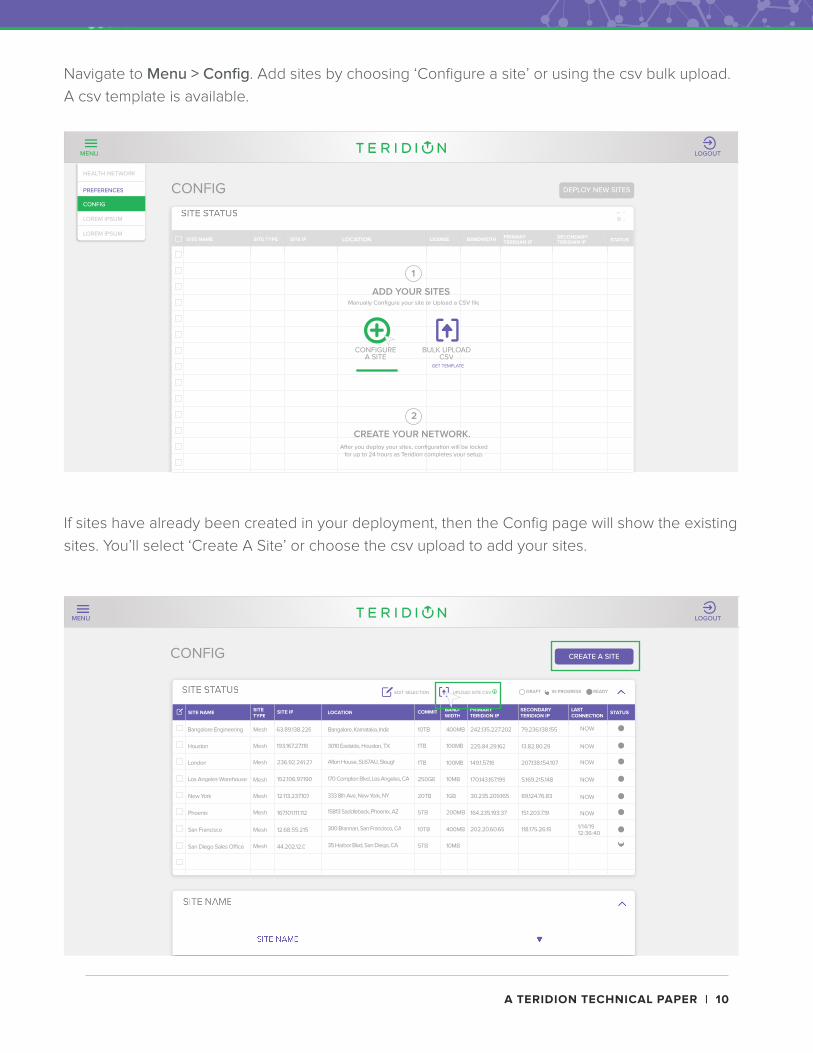
Navigate to Menu > Config. Add sites by choosing ‘Configure a site’ or using the csv bulk upload.
A csv template is available.
If sites have already been created in your deployment, then the Config page will show the existing
sites. You’ll select ‘Create A Site’ or choose the csv upload to add your sites.
CONFIG
Value of FormSITE NAME
SITE NAME
SITE STATUS
Afton House, SL67AU, Slough
SITE NAME
Bangalore Engineering
Houston
London
Bangalore, Karnataka, India63.89.138.226
SITE TYPE
Mesh
Mesh
Mesh
Mesh
Mesh
Mesh
Mesh
Mesh
236.92.241.27
193.167.27.116
SITE IP
333 8th Ave, New York, NY
15813 Saddleback, Phoenix, AZ
300 Brannan, San Francisco, CA
35 Harbor Blvd, San Diego, CA
170 Compton Blvd, Los Angeles, CA
3010 Eastside, Houston, TX
LOCATION COMMIT
10TB
1TB
1TB
250GB
20TB
5TB
10TB
5TB
LAST CONNECTION
NOW
NOW
NOW
NOW
NOW
NOW
1/14/19 12:36:40
BAND- WIDT H
400MB
100MB
100MB
10MB
1GB
200MB
400MB
10MB
SECONDARY TERIDION IP
79.236.138.155
13.82.80.29
207.138.154.107
5.169.215.148
89.124.76.83
151.203.7.19
118.175.26.19
PRIMARY TERIDION IP
242.135.227.202
225.84.29.162
149.1.57.16
170.143.167.199
30.235.209.165
164.235.193.37
202.20.60.65
STATUS
IN PROGRESSDRAFT READYUPLOAD SITE CSVEDIT SELECTION
CREATE A SITE
LOGOUTMENU
Los Angeles Warehouse 152.106.97.190
New York 12.113.237.107
167.101.111.112
12.68.55.215
44.202.12.0
Phoenix
San Francisco
San Diego Sales O�ce
A TERIDION TECHNICAL PAPER | 11
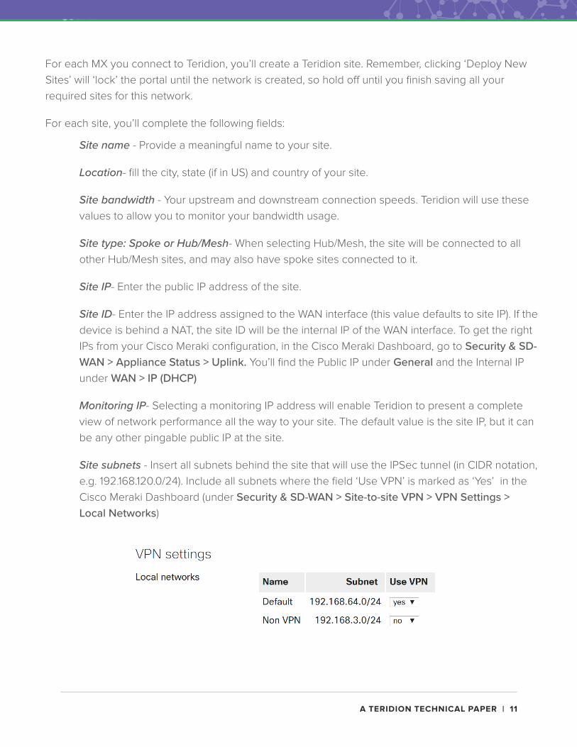
Site name - Provide a meaningful name to your site.
Location- fill the city, state (if in US) and country of your site.
Site bandwidth - Your upstream and downstream connection speeds. Teridion will use these
values to allow you to monitor your bandwidth usage.
Site type: Spoke or Hub/Mesh- When selecting Hub/Mesh, the site will be connected to all
other Hub/Mesh sites, and may also have spoke sites connected to it.
Site IP- Enter the public IP address of the site.
Site ID- Enter the IP address assigned to the WAN interface (this value defaults to site IP). If the
device is behind a NAT, the site ID will be the internal IP of the WAN interface. To get the right
IPs from your Cisco Meraki configuration, in the Cisco Meraki Dashboard, go to Security & SD-WAN > Appliance Status > Uplink. You’ll find the Public IP under General and the Internal IP
under WAN > IP (DHCP)
Monitoring IP- Selecting a monitoring IP address will enable Teridion to present a complete
view of network performance all the way to your site. The default value is the site IP, but it can
be any other pingable public IP at the site.
Site subnets - Insert all subnets behind the site that will use the IPSec tunnel (in CIDR notation,
e.g. 192.168.120.0/24). Include all subnets where the field ‘Use VPN’ is marked as ‘Yes’ in the