16
© 2019 Cisco and /or its affiliates. All rights res erved. This docu ment is Cisco Public Information. Page 1 of 16 Data Sheet Cisco NCS 2000 400 Gbps XPonder Line Card

© 2019 Cisco and /or its affil iates. All r ights res erved. This docu ment is Cisco Public Infor mation. Page 1 of 16
Data Sheet
Cisco NCS 2000 400 Gbps XPonder Line Card

© 2019 Cisco and /or its affil iates. All r ights res erved. This docu ment is Cisco Public Infor mation. Page 2 of 16
Contents
Product Overview 3
Challenge and Solution 3
Benefits 3
Product Description 4
Network Applications: Cisco NCS 2000 400 Gbps XPonder 8
Product Specifications 9
For More Information 15
Warranty 15
Cisco Services for Migrating Converged IP + Optical Solutions 15
Cisco Capital 16

© 2019 Cisco and /or its affil iates. All r ights res erved. This docu ment is Cisco Public Infor mation. Page 3 of 16
Product Overview
The Cisco®
Network Convergence System (NCS) 2000 400 Gbps XPonder line card dramatically enhance Dense
Wavelength-Division Multiplexing (DWDM) transmission. The XPonder provides 400 Gbps of Client, and 400 Gbps of
Trunk capacity on a single, two-slot wide line card capable of mapping Client traffic to either of two 200 Gbps Trunk ports,
or into a 400G dual-wavelength super-channel, all while leveraging software configurable Coherent modulation schemes.
Three Coherent modulation formats are supported to best suit network requirement:
● 100 Gbps Coherent polarization-multiplexed Quadrature Phase Shift Keying (QPSK)
● 150 Gbps Coherent polarization 8-state Quadrature Amplitude Modulation (8-QAM)
● 200 Gbps Coherent polarization 16-state Quadrature Amplitude Modulation (16-QAM)
The Cisco NCS 2000 400 Gbps XPonder Card (Figure 1) simplifies the integration and transport of 10 Gigabit, 40 Gigabit
and 100 Gigabit Ethernet and Optical Transport Unit Level 4 (OTU-4) interfaces and services into enterprises and service
provider optical networks.
Figure 1. Cisco NCS 2000 400 Gbps XPonder
Challenge and Solution
The bandwidth carried on core and metropolitan DWDM networks is growing exponentially, while operators’ revenues
struggle to keep pace. Internet traffic continues to grow at exponential rates, mainly due to demand for next -generation
services such as quadruple play (data, voice, video, and mobility), video distribution, Internet Protocol Television (IPTV),
and other high-bandwidth services. Complicating the issue is the varying state of migration between legacy and Packet
services that operators find themselves within, causing them to find creative ways to support a variety of service types.
The Cisco NCS 2000 400 Gbps XPonder solution can dramatically lower the cost to carry bandwidth, helping to maintain
and improve customers’ profitability with advanced modulation schemes, the ability to transmit 200 Gbps wavelengths
on existing or new DWDM systems for both metro and Long Haul distances, improves return on investment by increasing
the overall capacity per fiber pair without impacting the unregenerated transmission distance supported by the system.
The 200 Gbps 16QAM solution enables 25.4 Tbps capacity transmission over a single Fiber Pair.
The Cisco NCS 2000 400 Gbps XPonder Card also supports an embedded OTN switching functionality capable of
supporting ODU-2/4 switching between Clients and Trunk Ports.
Benefits
The Cisco NCS 2000 400 Gbps XPonder Card provides compelling benefits in the areas of Efficiency, Performance,
Flexibility and Density improvements.

© 2019 Cisco and /or its affil iates. All r ights res erved. This docu ment is Cisco Public Infor mation. Page 4 of 16
Efficiency
In a single, 2-slot wide line card, the 400 Gbps XPonder supports any mix of 40x 10G, 8x 40GE+8x10GE and 4x 100G
signals up to a maximum bandwidth of 400 Gbps, while providing the ability to selectively groom these services into 2
wavelengths capable of 200 Gbps each.
Performance Improvement
The latest generation of Digital Signal Processors (DSPs) provide a dramatic boost to the optical performance of 100 Gbps
QPSK and 200 Gbps 16-QAM. Availability of 8-QAM Modulation format further enhance the Long Haul capability of the
system, allowing to take advantage of additional transport capacity for all cases where 100 Gbps reach is not needed.
Flexibility
The service type of both Client and Trunk optics are based on pluggable modules, allowing a true pay-as-you-grow
investment profile where card personality is defined and redefined at the pluggable level. Due to the port-by-port service
type flexibility, this also radically reduces the variety of line cards an operator is required to inventory.
Density
Thanks to the adoption of the QSFP+ and QSFP28 form factors for the client interfaces, the Cisco NCS 2000 400 Gbps
XPonder is able to double the slot density compared with previous generation of Transponder card.
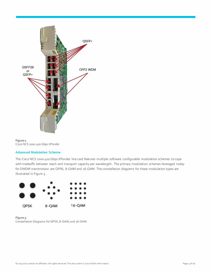
Product Description
The NCS 2000 400 Gbps XPonder (Figure 2) is a 2-slots wide line card that provides two high speed CFP2-based DWDM
ports capable of transmitting 100 Gbps, 150 Gbps and 200 Gbps over a single carrier.
The high speed Trunk ports provides:
● 100 Gbps coherent DWDM transmission with QPSK modulation
● 150 Gbps coherent DWDM transmission with 8-QAM modulation
● 200 Gbps coherent DWDM transmission with 16-QAM modulation
The transmission rate is software configurable and the line card provides high gain SD-FEC with 15% and 25% overhead.
The NCS 2000 400 Gbps XPonder supports six QSFP+ based client ports that can be equipped with 40 Gbps or 4x 10 Gbps
optics and four QSFP28/QSFP+ based client ports that can be equipped with 100 Gbps QSFP28, 40 Gbps QSFP+ and 4x 10
Gbps QSFP+.
© 2019 Cisco and /or its affil iates. All r ights res erved. This docu ment is Cisco Public Infor mation. Page 5 of 16
Figure 2. Cisco NCS 2000 400 Gbps XPonder
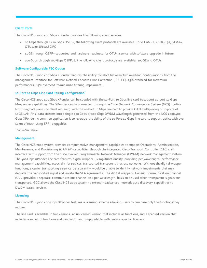
Advanced Modulation Scheme
The Cisco NCS 2000 400 Gbps XPonder line card features multiple software configurable modulation schemes to cope
with tradeoffs between reach and transport capacity per wavelength. The primary modulation schemes leveraged today
for DWDM transmission are QPSK, 8-QAM and 16-QAM. The constellation diagrams for these modulation types are
illustrated in Figure 3.
Figure 3. Constellation Diagrams for QPSK, 8-QAM, and 16-QAM

© 2019 Cisco and /or its affil iates. All r ights res erved. This docu ment is Cisco Public Infor mation. Page 6 of 16
While higher order modulation formats provide higher spectral efficiency, they are limited by reach.
Figure 4 shows variation of reach vs. spectral efficiency for QPSK, 8-QAM and 16-QAM using SMF and LEAF fiber for
various channel spacing.
Figure 4. The Chart Provides Capacity (Tbps) and Spectral Efficiency (bit/s/Hz) VS Maximum Reach (Lmax) for Different Modulation Scheme s. SMF Is Represented in Solid Lines and LEAF Is Represented in Dashed Lines.
Cisco Coherent Transmission technology greatly enhances the reach and reliability of transport performance while
providing the flexibility to select the optimal modulation scheme for a specific application. The primary benefits of Cisco
Coherent technology are:
● Strong optical signal-to-noise ratio performance
● Outstanding chromatic dispersion robustness, avoiding any additional cost related to optical chromatic dispersion
compensation equipment
● Extended polarization mode dispersion robustness
● Very high spectral efficiency, allowing wavelengths to be transmitted across a large number of ROADMs with
negligible penalty
Trunk CFP2 WDM Pluggables
The Cisco NCS 2000 400 Gbps XPonder Trunk ports supports Analog Coherent Optical (ACO) CFP2 WDM with software-
provisionable tuneability across the full C-Band, covering 96 Nyquist shaped channels on the 50GHz grid or gridless with
100MHz tuning granularity per channel. Different modulation schemes are also software configurable as described earlier.
© 2019 Cisco and /or its affil iates. All r ights res erved. This docu ment is Cisco Public Infor mation. Page 7 of 16
Client Ports
The Cisco NCS 2000 400 Gbps XPonder provides the following client services:
● 10 Gbps through 4x 10 Gbps QSFP+, the following client protocols are available: 10GE LAN-PHY, OC-192, STM-64,
OTU2/2e, 8/10/16G FC
● 40GE through QSFP+ supported and hardware readiness for OTU-3 service with software upgrade in future
● 100 Gbps through 100 Gbps QSFP28, the following client protocols are available: 100GE and OTU4
Software Configurable FEC Option
The Cisco NCS 2000 400 Gbps XPonder features the ability to select between two overhead configurations from the
management interface for Software Defined Forward Error Correction (SD FEC): 25% overhead for maximum
performances, 15% overhead to minimize filtering impairment.
10-Port 10 Gbps Line Card Pairing Configuration*
The Cisco NCS 2000 400 Gbps XPonder can be coupled with the 10 -Port 10 Gbps line card to support 10-port 10 Gbps
Muxponder capabilities. The XPonder can be connected through the Cisco Network Convergence System (NCS) 2006 or
NCS 2015 backplane (no client required) with the 10-Port 10 Gbps line card to provide OTN multiplexing of 10 ports of
10GE LAN-PHY data streams into a single 100 Gbps or 200 Gbps DWDM wavelength generated from the NCS 2000 400
Gbps XPonder. A common application is to leverage the ability of the 10-Port 10 Gbps line card to support optics with over
10km of reach using SFP+ pluggables.
* Future SW release.
Management
The Cisco NCS 2000 system provides comprehensive management capabilities to support Operations, Administration,
Maintenance, and Provisioning (OAM&P) capabilities through the integrated Cisco Transport Controller (CTC) craft
interface with support from the Cisco Evolved Programmable Network Manager (EPN-M) network management system.
The 400 Gbps XPonder line card features digital wrapper (G.709) functionality, providing per-wavelength performance
management capabilities, especially for services transported transparently across networks. Without the digital wrapper
functions, a carrier transporting a service transparently would be unable to identify network impairments that may
degrade the transported signal and violate the SLA agreements. The digital wrapper’s Generic Communication Channel
(GCC) provides a separate communications channel on a per-wavelength basis to be used when transparent signals are
transported. GCC allows the Cisco NCS 2000 system to extend its advanced network auto discovery capabilities to
DWDM-based services.
Licensing
The Cisco NCS 4000 400-Gbps XPonder features a licensing scheme allowing users to purchase only the functions they
require.
The line card is available in two versions: an unlicensed version that includes all functions, and a licensed version that
includes a subset of functions and bandwidth and is upgradable with feature-specific licenses.
© 2019 Cisco and /or its affil iates. All r ights res erved. This docu ment is Cisco Public Infor mation. Page 8 of 16
The licensed version of the card supports the following functions:
● 100Gbps of client bandwidth (can be 100G or 10x10G or 2x40GE + 2 x 10GE or 6x16GFC)
● Capability to use one trunk CFP2 WDM with 100G QPSK modulation scheme (no limitation of FEC usage or CD or
any optical performance)
Additional functions are offered through feature licenses; for example:
● Additional 100G client bandwidth (up to reach total of 400G maximum available client bandwidth)
● Capability to have the wavelength at 200G 16-QAM
● Capability to turn on second WDM port
Performance Monitoring
The Trunk ports on the Cisco NCS 2000 400 Gbps XPonder line card provides support for transparent signal performance
monitoring. The digital wrapper channel is monitored according to G.709 Optical Transport Network (OTN) and G.8021
standards. Performance monitoring of optical parameters on the client and DWDM interfaces include Loss of Signal
(LOS), laser bias current, transmit optical power, and receive optical power. Calculation and accumulation of the
performance monitoring data are supported in 15-minute and 24-hour intervals as per G.7710.
Physical system parameters measured at the wavelength level, such as mean polarization mode dispersion, accumulated
chromatic dispersion, or received optical signal to noise ratio, are also included in the set of performance monitoring
parameters. These can greatly simplify troubleshooting operations and enhance the set of data that can be collected
directly from the equipment. A detailed list of performance monitors is given in Table 8.
The XPonder card incorporates faceplate-mounted LEDs to provide a quick visual check of the operational status of the
card. An orange circle is printed on the faceplate, indicating the shelf slot in which you can install the card.
Network Applications: Cisco NCS 2000 400 Gbps XPonder
200 Gbps Muxponder Application (Metro, Long Haul)
The Cisco NCS 2000 400 Gbps XPonder line card with QSFP28 provides a very efficient two -slot solution to transport on a
single wavelengths 16-QAM 200 Gbps traffic by using both 100 Gbps optical client ports, directly managed by the QSFP28
(both LR4 or SR4) pluggable interface.
Cisco 100 Gbps SR4 or LR4 2xTransponder Application (Ultra Long Haul)
By leveraging QSFP28 pluggable Client transceivers and the two Coherent DWDM Trunk ports on the Cisco NCS 2000 400
Gbps XPonder line card, operators can leverage a very efficient two slot solution to transport two 100 Gbps client services
on to two QPSK 100 Gbps wavelengths directly managed by the QSFP28 (both LR4 or SR4) pluggable interface.

© 2019 Cisco and /or its affil iates. All r ights res erved. This docu ment is Cisco Public Infor mation. Page 9 of 16
10 Gbps, 40 Gbps Muxponder
The Cisco NCS 2000 400 Gbps XPonder line card can directly accept both LR and SR 10G clients, via QSFP+ 4x 10 Gbps
and 40 Gbps via QSFP+. Muxponder function can be done over both 100 Gbps and 200 Gbps transmission.
10 Gbps, 40 Gbps, and 100 Gbps Muxponder
The client ports of the NCS 2000 400 Gbps XPonder can be configured with a mix of 10 Gbps, 40 Gbps, and 100 Gbps
inputs limited only by the 400 Gbps capacity of the line card.
10/40/100 Gbps Encryption over 100/150/200G DWDM
NCS 2000 400 Gbps Xponder card supports Encryption at ODU4 level providing encryption in both Muxponder and
Xponder mode of operation.
OTN Switching
The Cisco NCS 2000 400 Gbps XPonder line card embeds an OTN Switching engine c apable to provide ODUk level
switching among any of the ports (Client and Trunks).
Provided switching capacity is 800 Gbps and supported ODUk containers are ODU -2 and ODU-4. Integrated OTN
switching capabilities allows to optimize wavelength usage across multiple locations in the network by efficiently
grooming Client services on a single 100 Gbps or 200 Gbps wavelength as represented in Figure 5.
Figure 5. 400 Gbps XPonder OTN Switching Application: Distributed Aggregation.
Product Specifications
Compact Design
● Dual-slot card design for high-density, 100/150/200 Gbps solutions
● Up to 3 cards per Cisco NCS 2006 shelf assembly, or 7 cards per NCS 2015 shelf assembly
© 2019 Cisco and /or its affil iates. All r ights res erved. This docu ment is Cisco Public Infor mation. Page 10 of 16
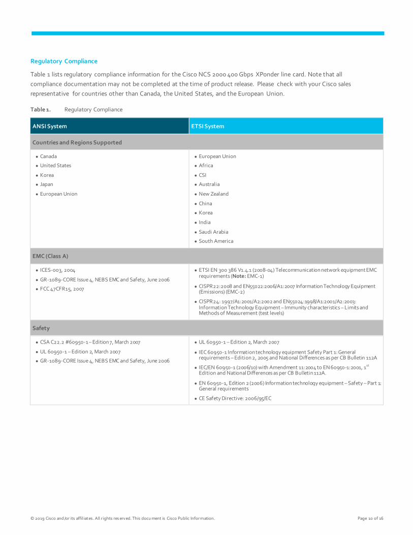
Regulatory Compliance
Table 1 lists regulatory compliance information for the Cisco NCS 2000 400 Gbps XPonder line card. Note that all
compliance documentation may not be completed at the time of product release. Please check with your Cisco sales
representative for countries other than Canada, the United States, and the European Union.
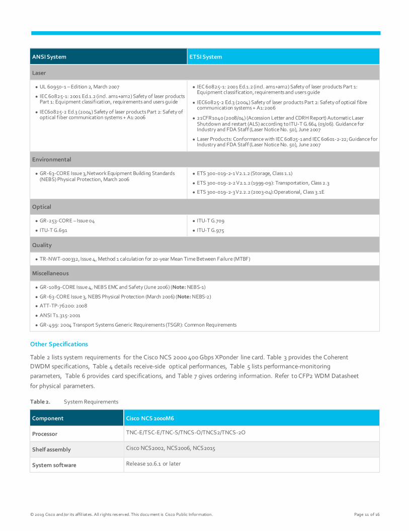
Table 1. Regulatory Compliance
ANSI System ETSI System
Countries and Regions Supported
● Canada
● United States
● Korea
● Japan
● European Union
● European Union
● Africa
● CSI
● Australia
● New Zealand
● China
● Korea
● India
● Saudi Arabia
● South America
EMC (Class A)
● ICES-003, 2004
● GR-1089-CORE Issue 4, NEBS EMC and Safety, June 2006
● FCC 47CFR15, 2007
● ETSI EN 300 386 V1.4.1 (2008-04) Telecommunication network equipment EMC requirements (Note: EMC-1)
● CISPR22:2008 and EN55022:2006/A1:2007 Information Technology Equipment (Emissions) (EMC-2)
● CISPR24: 1997/A1:2001/A2:2002 and EN55024:1998/A1:2001/A2:2003: Information Technology Equipment – Immunity characteristics – Limits and Methods of Measurement (test levels)
Safety
● CSA C22.2 #60950-1 – Edition 7, March 2007
● UL 60950-1 – Edition 2, March 2007
● GR-1089-CORE Issue 4, NEBS EMC and Safety, June 2006
● UL 60950-1 – Edition 2, March 2007
● IEC 60950-1 Information technology equipment Safety Part 1: General requirements – Edition 2, 2005 and National Differences as per CB Bulletin 112A
● IEC/EN 60950-1 (2006/10) with Amendment 11:2004 to EN 60950-1:2001, 1st Edition and National Differences as per CB Bulletin 112A.
● EN 60950-1, Edition 2 (2006) Information technology equipment – Safety – Part 1: General requirements
● CE Safety Directive: 2006/95/EC
© 2019 Cisco and /or its affil iates. All r ights res erved. This docu ment is Cisco Public Infor mation. Page 11 of 16
ANSI System ETSI System
Laser
● UL 60950-1 – Edition 2, March 2007
● IEC 60825-1: 2001 Ed.1.2 (incl. am1+am2) Safety of laser products Part 1: Equipment classification, requirements and users guide
● IEC60825-2 Ed.3 (2004) Safety of laser products Part 2: Safety of optical fiber communication systems + A1:2006
● IEC 60825-1: 2001 Ed.1.2 (incl. am1+am2) Safety of laser products Part 1: Equipment classification, requirements and users guide
● IEC60825-2 Ed.3 (2004) Safety of laser products Part 2: Safety of optical fibre communication systems + A1:2006
● 21CFR1040 (2008/04) (Accession Letter and CDRH Report) Automatic Laser Shutdown and restart (ALS) according to ITU-T G.664 (03/06). Guidance for Industry and FDA Staff (Laser Notice No. 50), June 2007
● Laser Products: Conformance with IEC 60825-1 and IEC 60601-2-22; Guidance for Industry and FDA Staff (Laser Notice No. 50), June 2007
Environmental
● GR-63-CORE Issue 3,Network Equipment Building Standards (NEBS) Physical Protection, March 2006
● ETS 300-019-2-1 V2.1.2 (Storage, Class 1.1)
● ETS 300-019-2-2 V2.1.2 (1999-09): Transportation, Class 2.3
● ETS 300-019-2-3 V2.2.2 (2003-04):Operational, Class 3.1E
Optical
● GR-253-CORE – Issue 04
● ITU-T G.691
● ITU-T G.709
● ITU-T G.975
Quality
● TR-NWT-000332, Issue 4, Method 1 calculation for 20-year Mean Time Between Failure (MTBF)
Miscellaneous
● GR-1089-CORE Issue 4, NEBS EMC and Safety (June 2006) (Note: NEBS-1)
● GR-63-CORE Issue 3, NEBS Physical Protection (March 2006) (Note: NEBS-2)
● ATT-TP-76200: 2008
● ANSI T1.315-2001
● GR-499: 2004 Transport Systems Generic Requirements (TSGR): Common Requirements
Other Specifications
Table 2 lists system requirements for the Cisco NCS 2000 400 Gbps XPonder line card. Table 3 provides the Coherent
DWDM specifications, Table 4 details receive-side optical performances, Table 5 lists performance-monitoring
parameters, Table 6 provides card specifications, and Table 7 gives ordering information. Refer to CFP2 WDM Datasheet
for physical parameters.
Table 2. System Requirements
Component Cisco NCS 2000M6
Processor TNC-E/TSC-E/TNC-S/TNCS-O/TNCS2/TNCS-2O
Shelf assembly Cisco NCS2002, NCS2006, NCS2015
System software Release 10.6.1 or later

© 2019 Cisco and /or its affil iates. All r ights res erved. This docu ment is Cisco Public Infor mation. Page 12 of 16
Table 3. DWDM Specifications
Parameter Value
Baud rate 31.3793 Gbaud ±20 ppm (OTU4 with SD-FEC 15% OH)
34.1660 Gbaud ±20 ppm (OTU4 with SD-FEC 25% OH)
Automatic laser shutdown and restart ITU-T G.664 (06/99)
Nominal wavelengths (Tnom) Full-tunable between 1528.77 and 1567.13 nm (C-Band)
Optical Transmitter
Type CP-QPSK modulation format
CP-8QAM modulation format
CP-16QAM modulation format
Optical Receiver
Chromatic dispersion tolerance (DLRmax) +/– 70,000, ps/nm with CP-QPSK formats
+/– 25,000, ps/nm with 16-QAM
DGD Tolerance 100 ps
Table 4. DWDM Receive-Side Optical Performances
Modulation FEC Type Pre-FEC BER Post-FEC BER Input Power Sensitivity*
DGD B2B OSNR (0.1 nm RWB)
CP-QPSK SD-FEC
(25% OH)
<4E(-2) <10E (–15) 0 to -14dBm – 11.3 dB
CP-QPSK SD-FEC
(15% OH)
<4E(-2) <10E (–15) 0 to -14dBm – 11.8 dB
CP-8QAM SD-FEC
(25% OH)
<3E(-2) <10E (–15) 0 to -14dBm – 16.1 dB
CP-8QAM SD-FEC
(15% OH)
<3E(-2) <10E (–15) 0 to -14dBm – 16.6 dB
CP-16QAM SD-FEC
(25% OH)
<3E(-2) <10E (–15) 0 to -14dBm – 19.6 dB
CP-16QAM SD-FEC
(15% OH)
<3E(-2) <10E (–15) 0 to -14dBm – 20.3 dB
* Receiver Sensitivity can be extended down to -20dBm allocating additional OSNR margins
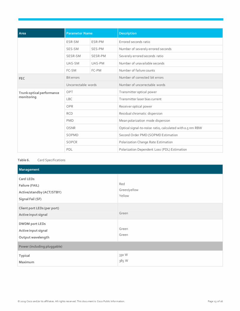
Table 5. Performance Monitoring Parameters
Area Parameter Name Description
OTN OTUk SM ODUk PM
BBE-SM BBE-PM Number of background block errors
BBER-SM BBER-PM Background block error ratio
ES-SM ES-PM Number of errored seconds
© 2019 Cisco and /or its affil iates. All r ights res erved. This docu ment is Cisco Public Infor mation. Page 13 of 16
Area Parameter Name Description
ESR-SM ESR-PM Errored seconds ratio
SES-SM SES-PM Number of severely errored seconds
SESR-SM SESR-PM Severely errored seconds ratio
UAS-SM UAS-PM Number of unavailable seconds
FC-SM FC-PM Number of failure counts
FEC Bit errors Number of corrected bit errors
Uncorrectable words Number of uncorrectable words
Trunk optical performance monitoring
OPT Transmitter optical power
LBC Transmitter laser bias current
OPR Receiver optical power
RCD Residual chromatic dispersion
PMD Mean polarization mode dispersion
OSNR Optical signal-to-noise ratio, calculated with 0.5 nm RBW
SOPMD Second Order PMD (SOPMD Estimation
SOPCR Polarization Change Rate Estimation
PDL Polarization Dependent Loss (PDL) Estimation
Table 6. Card Specifications
Management
Card LEDs
Failure (FAIL)
Active/standby (ACT/STBY)
Signal Fail (SF)
Red
Green/yellow
Yellow
Client port LEDs (per port)
Active input signal
Green
DWDM port LEDs
Active input signal
Output wavelength
Green
Green
Power (including pluggable)
Typical
Maximum
330 W
385 W

© 2019 Cisco and /or its affil iates. All r ights res erved. This docu ment is Cisco Public Infor mation. Page 14 of 16
Management
Physical
Dimensions Occupies 2 slot
Weight 6.8 lb (3.1 kg)
Reliability and availability
Mean Time Between Failures (MTBF) 272,380 hrs
Latency (end to end)
100GE SD – FEC 15% 28 microseconds
Storage temperature -40ºC to 70ºC (-40°F to 158°F)
Operating temperature
Normal
Short-term1
0ºC to 40°C (32°F to 104°F)
-5ºC to 55°C (23ºF to 131°F)
Relative humidity
Normal
Short-term1
5% to 85%, noncondensing
5% to 90% but not to exceed 0.024 kg water/kg of dry air
1 Short-term refers to a period of not more than 96 consecutive hours and a total of not more than 15 days in 1 year (a total of 360 hours in
any given year, but no more than 15 occurrences during that 1-year period). The values shown are valid for M6 or M2 chassis.
Table 7. Ordering Information
Part Number Description
NCS2K-400G-XP= 400G CFP2 MR xponder
NCS2K-400GXP-L-K9= 400G CFP2 MR XP licensed 100G client bandwidth + 1 port WDM
L-NCS2K-100G-LIC= 100G bandwidth client license
L-NCS2K-WDM-LIC= WDM port license
L-NCS2K-8QAM= WDM port license - upgrade to 8QAM (150G)
L-NCS2K-16QAM= WDM port license - upgrade to 16QAM (200G)
ONS-CFP2-WDM= 100G QPSK/200G 16-QAM - WDM CFP2 pluggable
ONS-QSFP28-LR4= 100Gbps multirate QSFP28, LR
ONS-QSFP-4X10-MLR= 4x10Gbps multirate QSFP+, LR (in future SW release)
QSFP-100G-LR4-S= 100GBASE LR4 QSFP transceiver, LC, 10km over SMF
QSFP-100G-SR4-S= 100GBASE SR4 QSFP transceiver, MPO, 100m over OM4 MMF

© 2019 Cisco and /or its affil iates. All r ights res erved. This docu ment is Cisco Public Infor mation. Page 15 of 16
Part Number Description
QSFP-4X10G-LR-S= QSFP 4x10G transceiver module, SM MPO, 10KM, enterprise class
QSFP-100G-SM-SR= 100GBASE CWDM4 Lite QSFP Transceiver, 2km over SMF, 10 - 60C
QSFP-40G-SR4= 40GBASE-SR4 QSFP Transceiver Module with MPO Connector
ONS-QC-16GFC-LW= 4 X 16G/8G Fiber Channel QSFP+, SM, C Temp
ONS-QC-16GFC-SW= 4 X 16G Channel QSFP+, MM, C Temp
QSFP-40G-SR-BD Cisco 40GBASE-SR Bi-Directional QSFP Module for Duplex MMF
QSFP-40/100-SRBD 100G and 40GBASE SR-BiDi QSFP Transceiver, LC, 100m OM4 MMF
QSFP-40G-LR4-S=* QSFP 40GBASE-LR4 transceiver module, LC, 10km, enterprise class
NCS2K-MF-8X10G-FO= 2x4x10G QSFP+ to 10G fan out
ONS-12MPO-MPO-2= Multifiber patchcord - MPO to MPO 12 fibers - 2m
ONS-12MPO-MPO-4= Multifiber patchcord - MPO to MPO 12 fibers - 4m
ONS-12MPO-MPO-6= Multifiber patchcord - MPO to MPO 12 fibers - 6m
ONS-12MPO-MPO-8= Multifiber patchcord - MPO to MPO 12 fibers - 8m
For More Information
For more information about the Cisco NCS 2000, visit https://www.cisco.com/c/en/us/products/optical-
networking/network-convergence-system-2000-series/index.html.
Warranty
The following warranty terms apply to the Cisco NCS 2002, NCS 2006 and NCS 2015, as well as services you may use
during the warranty period. Your formal warranty statement appears in the Cisco Information Packet that accompanies
your Cisco product.
● Hardware warranty duration: 5 years
● Software warranty duration: 1 year
● Hardware replacement, repair, or refund procedure: Cisco or our service center will use commercially reasonable
efforts to ship a replacement part for delivery within 15 working days after receipt of the defective product at
Cisco’s site. Actual delivery times of replacement products may vary depending on customer location.
Product warranty terms and other information applicable to Cisco products are available at:
https://www.cisco.com/go/warranty.
Cisco Services for Migrating Converged IP + Optical Solutions
Services from Cisco and our partners help you get the most value from your investments in the Cisco converged IP +
Optical solution quickly and cost-effectively. We can help you design, implement, and validate your solution to speed

© 2019 Cisco and /or its affil iates. All r ights res erved. This docu ment is Cisco Public Infor mation. Page 16 of 16
migration and cutover. Coordinate every step through to interworking. Strengthen your team. And make the most of
tomorrow’s opportunities. Learn more at https://www.cisco.com/go/spservices.
Cisco Capital
Flexible Payment Solutions to Help You Achieve Your Objectives
Cisco Capital makes it easier to get the right technology to achieve your objectives, enable business transformation
and help you stay competitive. We can help you reduce the total cost of ownership, conserve capital, and accelerate
growth. In more than 100 countries, our flexible payment solutions can help you acquire hardware, software, services and
complementary third-party equipment in easy, predictable payments. Learn more.
Printed in USAs C78-736916-02 04/19


