54
CISCO NX-OS DATA CENTER FEATURES Jack Ross CCIE #16728 1
| Date post: | 17-Mar-2018 |
| Category: |
Documents |
| Upload: | trinhhuong |
| View: | 216 times |
| Download: | 0 times |

1
CISCO NX-OS DATA CENTER FEATURESJack RossCCIE #16728
2
Agenda• Brief Hardware Overview• Software Versions• NX-OS Layer 2• NX-OS Layer 3• FabricPath• Virtual Device Contexts (VDC’s)• Fiber Channel Over Ethernet (FCoE)• Overlay Transport Virtualization (OTV)• Virtual Port Channels (vPC’s)
3
Nexus 7000 OverviewNexus 7000/7700 – Typically DC core or aggregation – High performance, density, & availability – Unified I/OFCoE switch but not a FC switch – Redundant Power, Line Cards and Supervisors
4
Nexus 7000 Platform Overview• Currently 7 form factors – 7018, 7010, 7009, 7004, 7718, 7710,7706• Currently 2 types of line cards – M Series Cards - Layer 3 cards • Feature rich cards – F Series Cards - Layer 2 cards* • Performance oriented cards

5
Line Card Features• M Series Specific – Layer 3 Routing – FEX – OTV – TrustSec• F Series Specific – FabricPath – vPC+ – FCoE
6
Nexus 5000 OverviewNexus 5000/5500– Typically End of Row (EoR) aggregation or Top of Rack (ToR) access– Typically Layer 2 but can do limited Layer 3 with add on daughter card in the 5500 Series Unified I/O– Both FCoE and native FC switching– Redundant power but not supervisors

7
Nexus 5000 Platform Overview• Currently 2 Generations – 1st Gen - Nexus 5000 – 5010 & 5020 – 2nd Gen - Nexus 5500 – 5548 & 5596• Mainly layer 2 switching – 5500 can support L3 add-in card• Supports Unified I/O – Both FCoE Forwarder (FCF) and native FC switching• 5500 supports Unified Ports (UP models) – Ports can run as Ethernet or native Fibre Channel – Ethernet ports allocated at port 1 and counts up – Fibre Channel ports allocated at last port and counts down – Requires a reboot to re-allocate port’s role (like UCS FI)
8
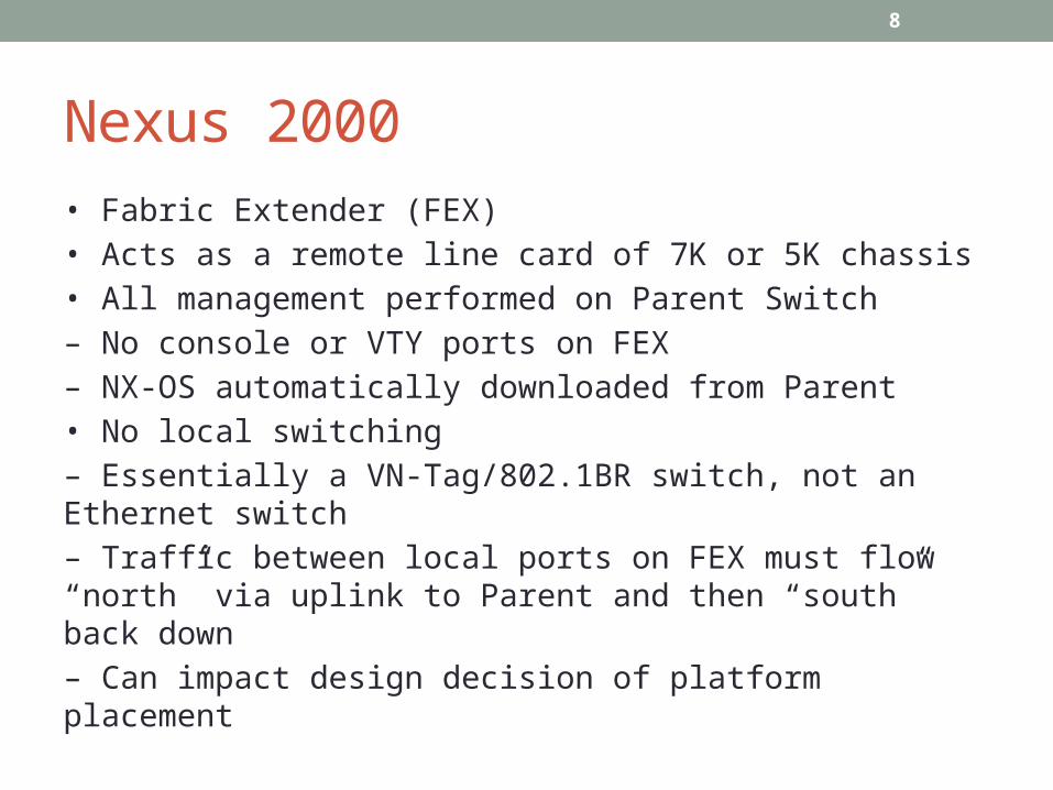
Nexus 2000• Fabric Extender (FEX)• Acts as a remote line card of 7K or 5K chassis• All management performed on Parent Switch– No console or VTY ports on FEX– NX-OS automatically downloaded from Parent• No local switching– Essentially a VN-Tag/802.1BR switch, not an Ethernet switch– Traffic between local ports on FEX must flow “north” via uplink to Parent and then “south” back down– Can impact design decision of platform placement

9
Software Versions for CCIE Lab• NX-OS v6.0(2) on Nexus 7000 Switches (6.2(6) latest)• NX-OS v5.1(3) on Nexus 5000 Switches• NX-OS v4.2(1) on Nexus 1000v• NX-OS v5.2(2) on MDS 9222i Switches• UCS Software release 2.0(1x) for UCS-6248 Fabric Interconnect

10
Nexus NX-OS BasicsNexus at its core is a Layer 2/3 SwitchSimilar in many aspects to Catalyst IOS – VLANs, Trunking, VTP, Rapid PVST, MST, EtherChannel, PVLANs, UDLD, FHRPs, IGPs, BGP, etc.Key new features beyond Catalyst IOS – FEX, vPC, Fabric Path, OTV, FC Switching, FCoE, etc
11
NX-OS Port Channels/EtherChannels
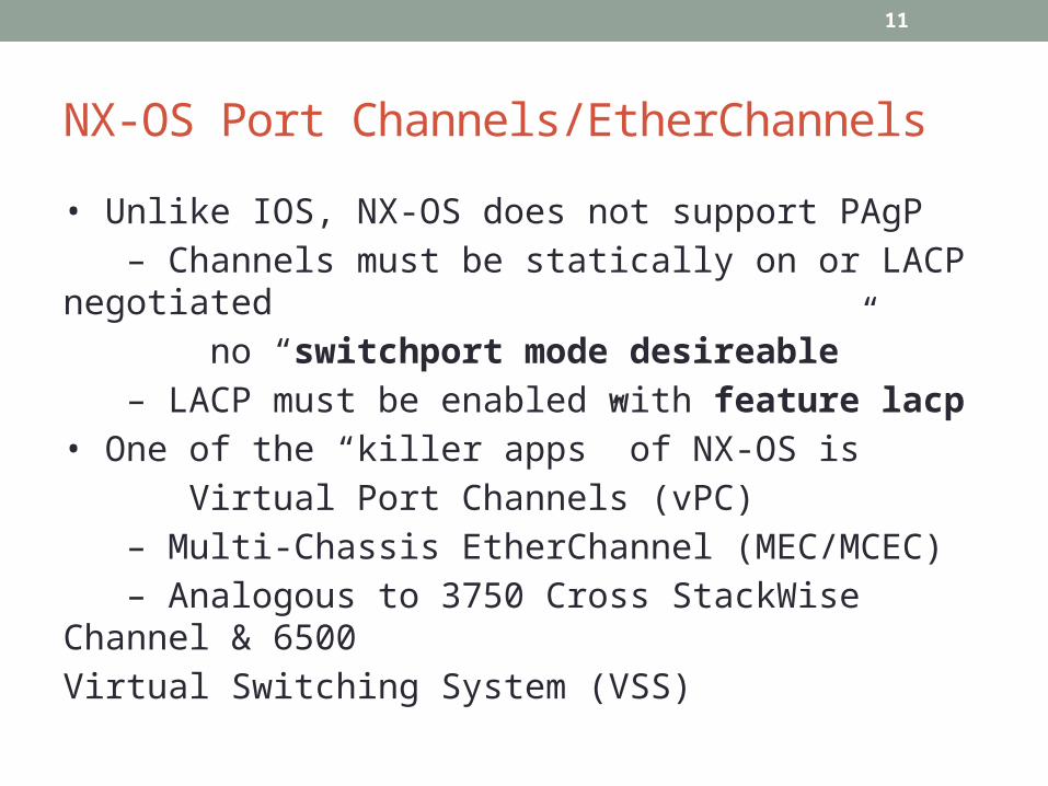
• Unlike IOS, NX-OS does not support PAgP – Channels must be statically on or LACP negotiated no “switchport mode desireable” – LACP must be enabled with feature lacp• One of the “killer apps” of NX-OS is Virtual Port Channels (vPC) – Multi-Chassis EtherChannel (MEC/MCEC) – Analogous to 3750 Cross StackWise Channel & 6500Virtual Switching System (VSS)
12
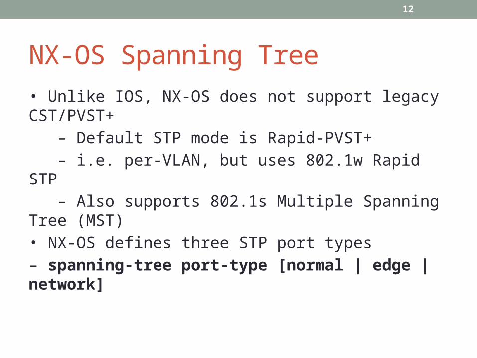
NX-OS Spanning Tree• Unlike IOS, NX-OS does not support legacy CST/PVST+ – Default STP mode is Rapid-PVST+ – i.e. per-VLAN, but uses 802.1w Rapid STP – Also supports 802.1s Multiple Spanning Tree (MST)• NX-OS defines three STP port types– spanning-tree port-type [normal | edge | network]

13
NX-OS Switchport Typesspanning-tree port-type normal – Normal ports act like Catalyst IOS ports – Default STP port type, run Rapid Per VLAN STP spanning-tree port-type edge – Edge ports are STP PortFast portsspanning-tree port-type network – Network ports run STP Bridge Assurance
14
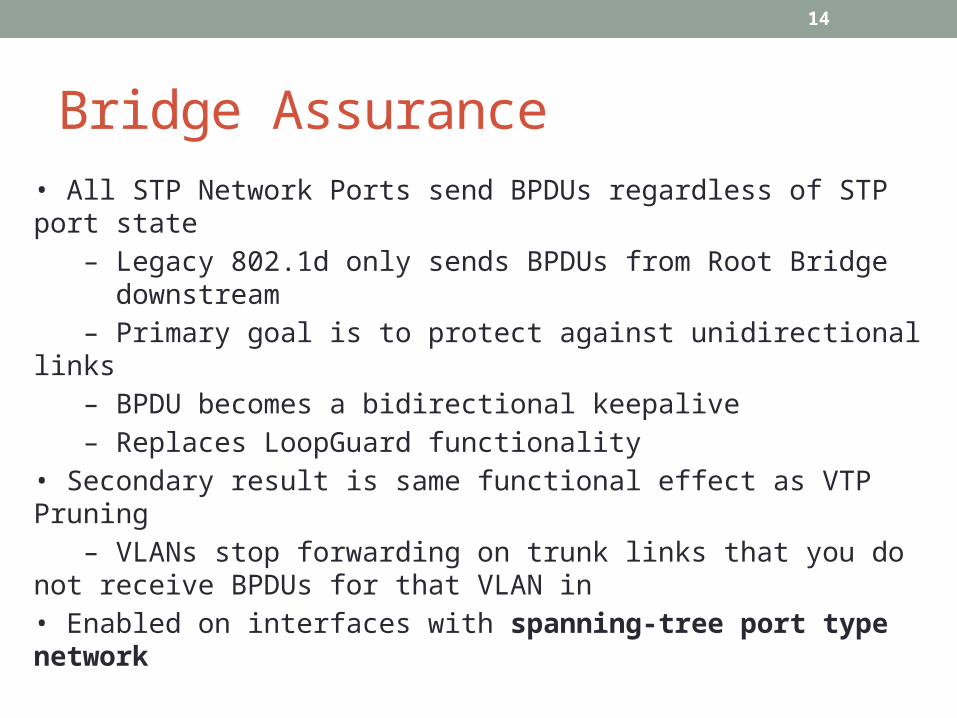
Bridge Assurance• All STP Network Ports send BPDUs regardless of STP port state – Legacy 802.1d only sends BPDUs from Root Bridge downstream – Primary goal is to protect against unidirectional links – BPDU becomes a bidirectional keepalive – Replaces LoopGuard functionality• Secondary result is same functional effect as VTP Pruning – VLANs stop forwarding on trunk links that you do not receive BPDUs for that VLAN in• Enabled on interfaces with spanning-tree port type network
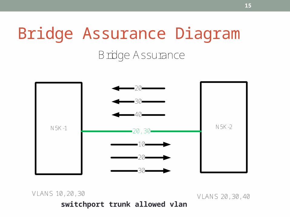
15
Bridge Assurance Diagram
N5K-1 N5K-2
VLANS 10, 20, 30 VLANS 20, 30, 40
10
20
30
20
30
40
20, 30
Bridge Assurance
switchport trunk allowed vlan

16
NX-OS Layer 3 Like Catalyst IOS, NX-OS supports… – Native layer 3 routed interfaces I.e. no switchport Switched Virtual Interfaces (SVIs) • I.e. VLAN interfaces • Must be enabled with feature interface-vlan
17
NX-OS Routing Protocols• Like IOS, NX-OS supports routing with… – Static routing – RIPv2 & RIPng – EIGRP & EIGRPv6 – OSPF & OSPFv3 – IS-IS – BGP – Policy Routing – No network command in IGP’s, activated on link• Not all protocols use the same license
18
NX-OS VRF• Like IOS, NX-OS Virtual Routing & Forwarding Instances are used to create separate logical routing tables – Layer 3 interfaces in different VRFs cannot exchange traffic by default• NX-OS VRFs behave slightly different than IOS, as… – All layer 3 interfaces are automatically in VRF table “default” – MGMT0 is automatically in vrf “management” – VRFs are defined as vrf context – Static routes are defined under the vrf context – Dynamic routing is VRF aware, but configured under the same process – Exec mode routing-context vrf can change the default VRF for verifications
19
NX-OS Redistribution• Unlike IOS, route-maps are required to perform redistribution on NX-OS – Same route-map match/set logic as IOS• Redistribution does not include directly connected interfaces – Requires redistribute direct route-map…

20
Fabric Path• Pre Standard version of TRILL• Essentially Layer 2 Ethernet Routing• Uses ISIS to route Layer 2 Frames instead of using STP• Can build arbitrary Topologies – Full Mesh, Partial Mesh,
Triangle, Square, etc• Adds a TTL in Layer 2• When using with vPC referred to as vPC+

21
Fabric Path Configuration• Very few commands necessary• Enable FabricPath – install feature-set fabricpath – feature-set fabricpath• Configure FabricPath VLANs – mode fabricpath under VLAN• Configure FabricPath Core Ports – switchport mode fabricpath

22
Virtual Device Contexts (VDC)VDCs used to virtualize physical hardware of Nexus 7000 – Loosely analogous to SDRs in IOS XR or Contexts in ASA• VDCs also virtualize control plane protocols of Nexus 7000 – Not analogous to VLANs or VRFs in IOS – Separate control plane per VDC
• VLAN 40 in VDC 1 is not VLAN 40 in VDC 2• OSPF PID 20 in VDC 1 is not OSPF PID 20 in VDC 2
23
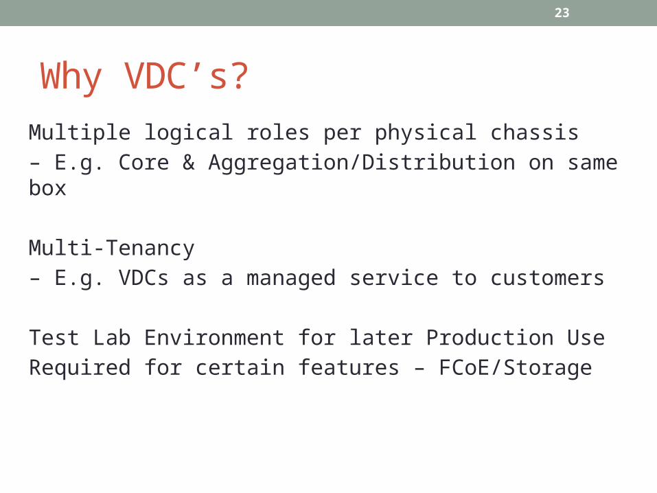
Why VDC’s?Multiple logical roles per physical chassis – E.g. Core & Aggregation/Distribution on same box
Multi-Tenancy– E.g. VDCs as a managed service to customers
Test Lab Environment for later Production UseRequired for certain features – FCoE/Storage
24
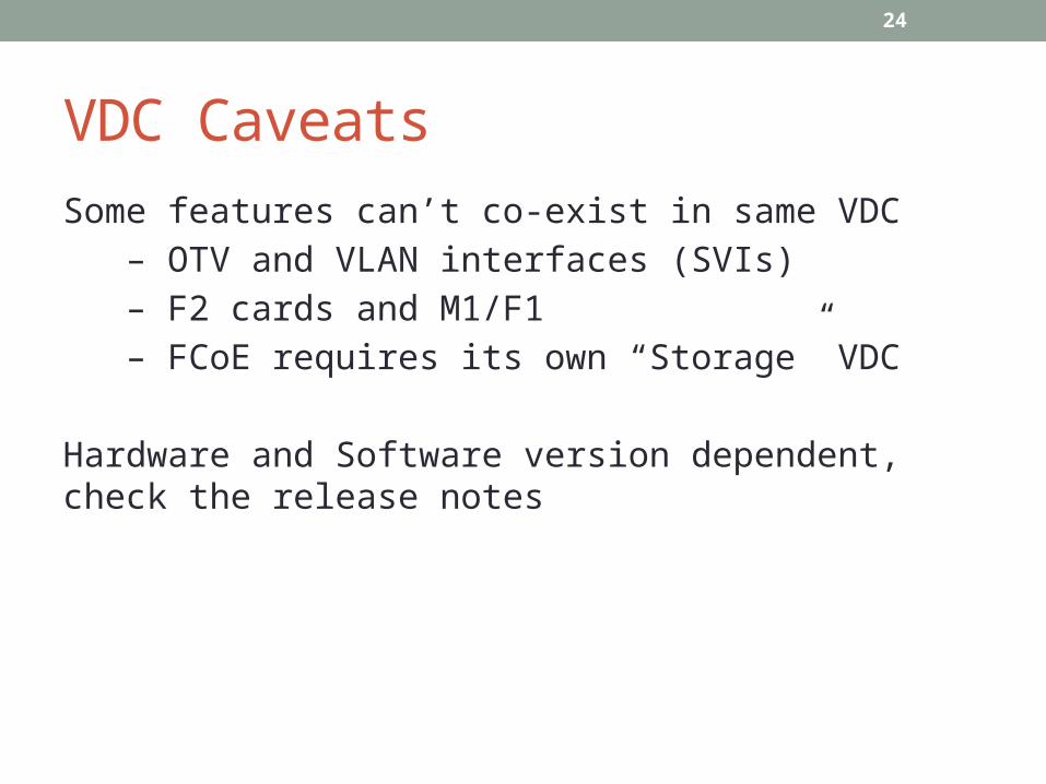
VDC CaveatsSome features can’t co-exist in same VDC – OTV and VLAN interfaces (SVIs) – F2 cards and M1/F1 – FCoE requires its own “Storage” VDC
Hardware and Software version dependent, check the release notes
25
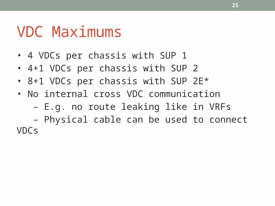
VDC Maximums• 4 VDCs per chassis with SUP 1• 4+1 VDCs per chassis with SUP 2• 8+1 VDCs per chassis with SUP 2E*• No internal cross VDC communication – E.g. no route leaking like in VRFs – Physical cable can be used to connect VDCs
26
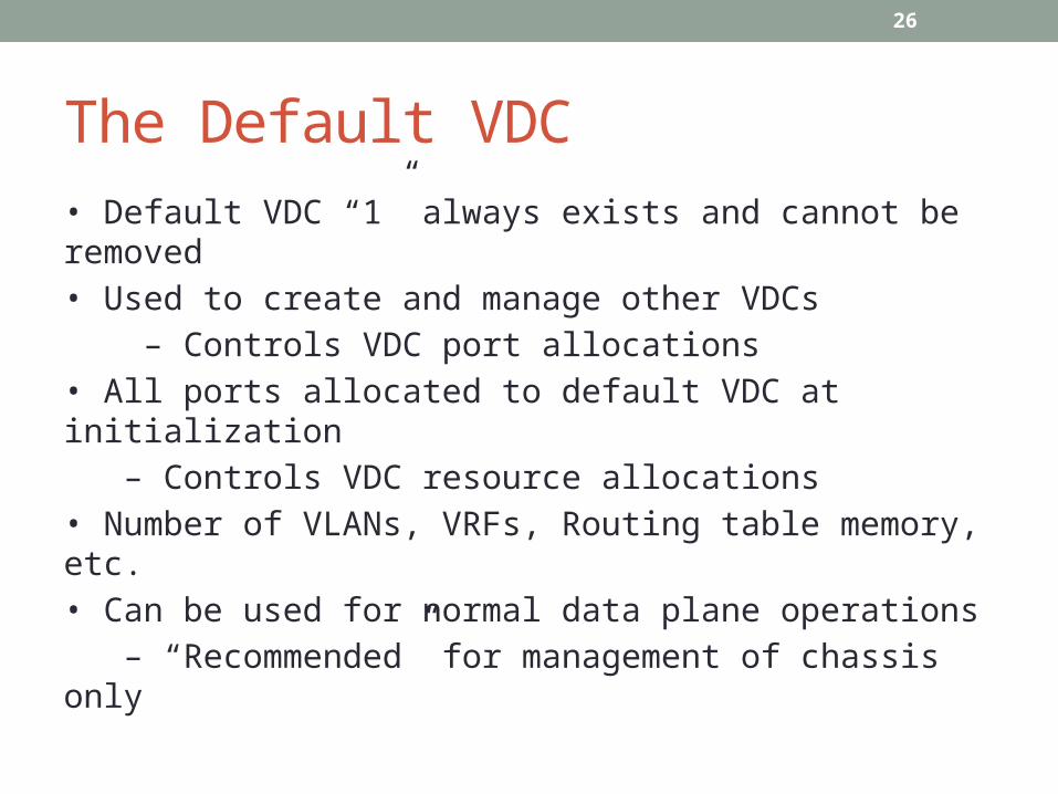
The Default VDC• Default VDC “1” always exists and cannot be removed• Used to create and manage other VDCs – Controls VDC port allocations• All ports allocated to default VDC at initialization – Controls VDC resource allocations• Number of VLANs, VRFs, Routing table memory, etc.• Can be used for normal data plane operations – “Recommended” for management of chassis only

27
Default VDC TasksSome tasks can only be performed in the default VDC – VDC creation/deletion/suspend – Resource allocation – interfaces, memory, MAC’s – NX-OS Upgrade across all VDCs – ISSU or EPLD Upgrade – Ethanalyzer captures – control plane traffic – Feature-set installation for Nexus 2000, FabricPath, FCoE – Control Plane Policing (CoPP) – Port Channel load balancing hash – Hardware IDS check control – ACL Capture feature enable – System-Wide QoS
28
Converged Ethernet or FCoE• Lots of terms that essentially mean the same thing – Unified Fabric – Unified Wire – Converged Ethernet – Converged Enhanced Ethernet – Data Center Ethernet – Data Center Bridging• What they all really mean…– You are running the physical framing for both Ethernet and Fibre Channel over the same physical links
29
FCoE Terms• FCoE Initialization Protocol (FIP)• FCoE Forwarder (FCF)• ENode – End Device• Virtual Fibre Channel (VFC) Interface

30
FC, FCoE, FCIP and iSCSI

31
How FCoE Works • FCoE replaces layer 1 & 2 transport for FC• All upper layer FC services remain – Domain IDs, FSPF, FCNS, FLOGI, Zoning.• New FCoE Initialization Protocol (FIP) to negotiate between Fabric and Node – Fabric is the FCF – Node is the ENode
32
FCoE Control and Data Planes• FIP is the control plane of FCoE• FCoE is the actual data plane• FIP – New EtherType 0x8914 – Used to discover FCFs and perform FLOGI _ UCS C when FCoE turned on uses LLDP to begin negotiation• FCoE – New Ethertype 0x8906 – Min length of 2240 bytes, FC has larger payload• Implies Jumbo Frames are required

33
OTV Basics• Overlay Transport Virtualization (OTV) – Layer 2 VPN over IPv4• Specifically OTV is… – IPv4/IPv6 over Ethernet… over MPLS… over GRE… over IPv4…
34
OTV vs. other Layer 2 DCI’sLayer 2 DCI is needed for Virtual Machine Workload Mobility i.e. VMware VMotion
• Many possible options for L2 DCI – Dark Fiber (CWDM/DWDM) – Layer 2 Transport Protocol (L2TPv3) – Any Transport over MPLS (AToM) – Virtual Private LAN Services (VPLS) – Bridging over GRE – Spanning Tree Bridge Group
• These options can be used for DCI, but OTV was made for DCI – Optimizes ARP flooding over DCI – Demarc of the STP domain – Can overlay multiple VLANs without complicated design – Allows multiple edge routers without complicated design

35
OTV Terms• OTV Edge Device – Edge router(s) running OTV• Authoritative Edge Device (AED) – Active edge router for a particular VLAN – Allows multiple redundant edge routers while preventing loops• Extend VLANs – VLAN being bridged over OTV• Site VLAN – Internal VLAN used to elect AED
36
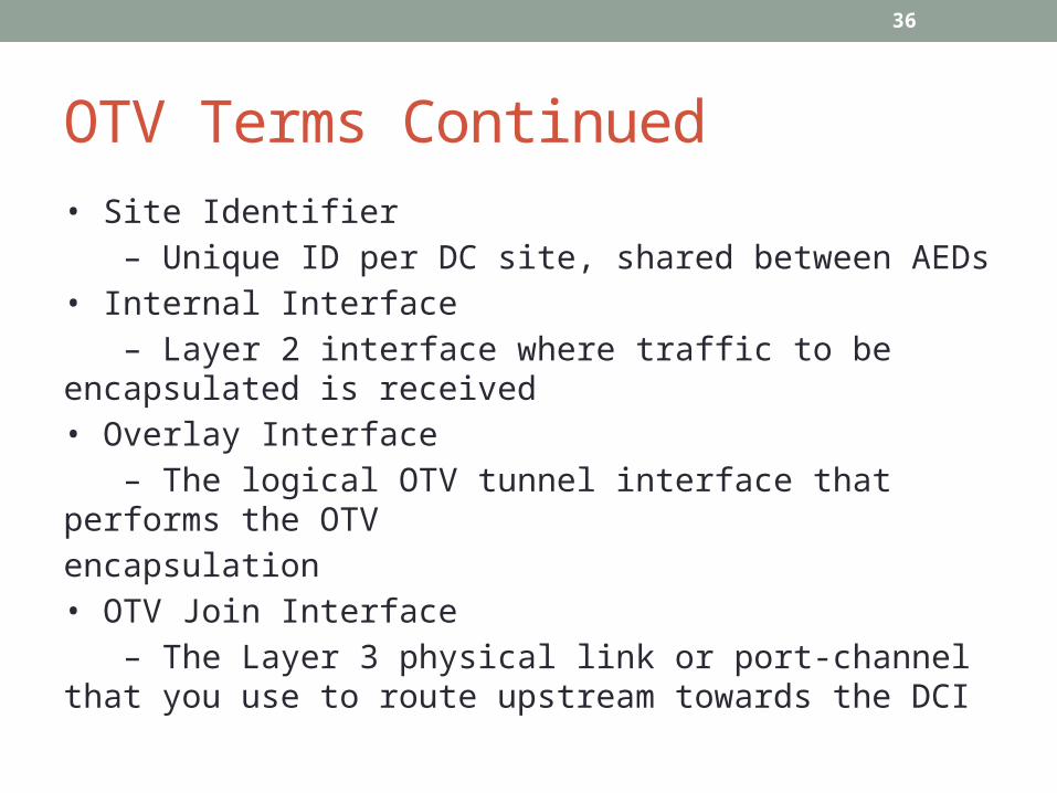
OTV Terms Continued• Site Identifier – Unique ID per DC site, shared between AEDs• Internal Interface – Layer 2 interface where traffic to be encapsulated is received• Overlay Interface – The logical OTV tunnel interface that performs the OTVencapsulation• OTV Join Interface – The Layer 3 physical link or port-channel that you use to route upstream towards the DCI
37
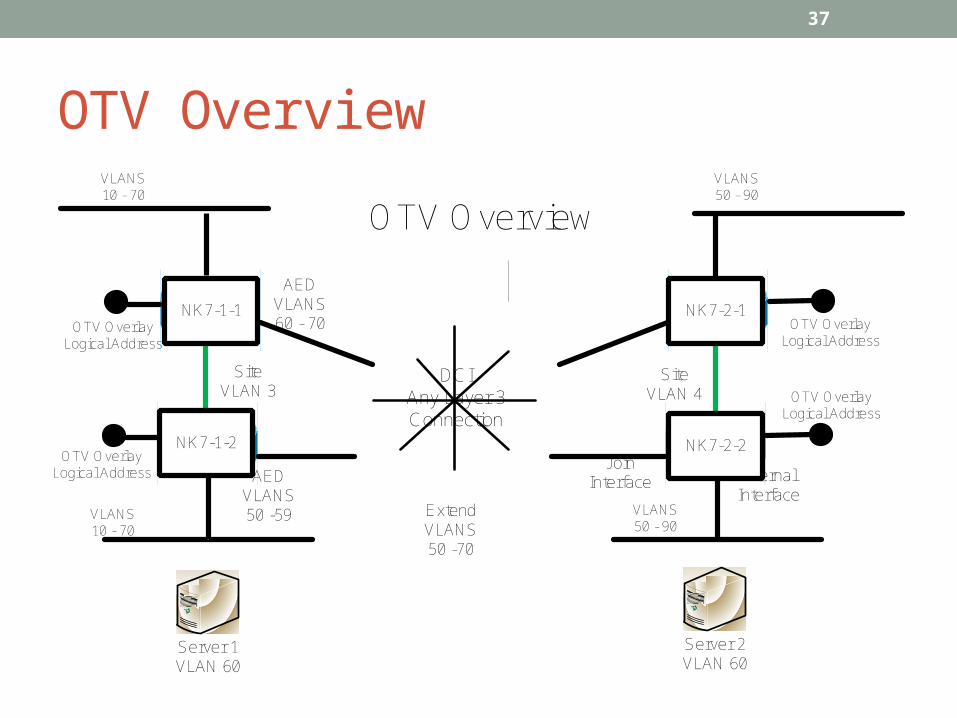
OTV Overview
VLANS 10 - 70
Server 1VLAN 60
Server 2VLAN 60
OTV Overview
DCIAny Layer 3 Connection
OTV OverlayLogical Address
OTV OverlayLogical Address
Join Interface Internal
InterfaceExtend VLANS50 -70
Site VLAN 4
VLANS 50 - 90
OTV OverlayLogical Address
OTV OverlayLogical Address
Site VLAN 3
AED VLANS 50 -59
AED VLANS 60 - 70
VLANS 10 - 70
VLANS 50 - 90
NK7-1-2
NK7-1-1
NK7-2-2
NK7-2-1

38
OTV Control Plane• Uses IS-IS to advertises MAC addresses between AEDs – Is it’s own transport and extensible
• ISIS Encapsulated as Control Group Multicast – IS-IS over Ethernet over MPLS over GRE over IPv4 Multicast – Implies that DCI must support ASM Multicast
39
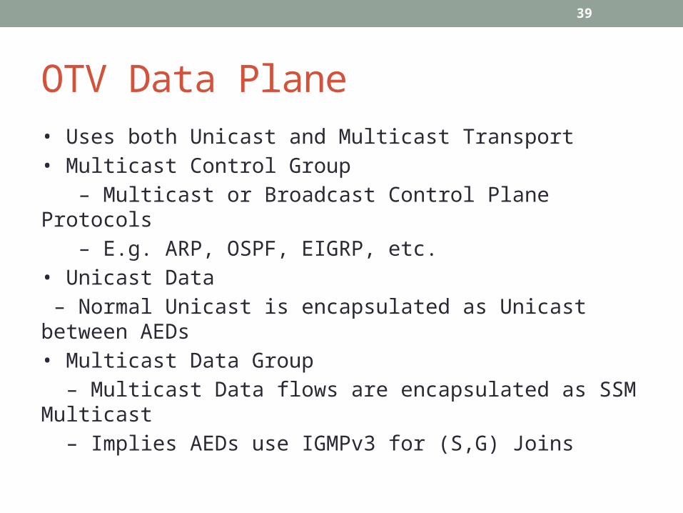
OTV Data Plane• Uses both Unicast and Multicast Transport• Multicast Control Group – Multicast or Broadcast Control Plane Protocols – E.g. ARP, OSPF, EIGRP, etc.• Unicast Data – Normal Unicast is encapsulated as Unicast between AEDs• Multicast Data Group – Multicast Data flows are encapsulated as SSM Multicast – Implies AEDs use IGMPv3 for (S,G) Joins

40
OTV Adjacency Server• Normally OTV requires that the DCI runs multicast – Needed to find and form IS-IS adjacencies and to tunnelmulticast data traffic• OTV Adjacency Server removes multicast requirement – One (or more) AEDs are configured as the adjacency server – All other AEDs register with the adjacency server – Now all endpoints are known• All control and data plane traffic is now unicast encapsulated – Will result in “Head End Replication” when more than 2 DC’s connected over the DCI

41
OTV DCI Optimizations• Other DCI options bridge all traffic over DCI – STP, ARP, L2 Flooding, broadcast storms, etc.
• OTV reduces unnecessary flooding by… – Proxy ARP/ICMPv6 Cache on AED – Terminating the STP domain on AED
42
vPC Port Channels
– Port Channels, EtherChannels, & NIC Teaming/Bonding terms used interchangeably– Regardless of vendor, 802.3ad (LACP) refers to Port Channeling
• Used to aggregate bandwidth of multiple links between devices– E.g. 4 x physical 1GigE links form a 4GigE logical Port Channel
• Appears as one logical link from STP’s perspective– Avoids active/standby and allows active/active

43
vPC Port Channels• Data flows are load balanced between member links – Single flow cannot exceed BW of any physical member link• E.g. increases lanes on the highway but not the speed limit• Does not perform LFI like PPP Multilink • Flows are load balanced based on L2, L3, & L4 headerinformation – SRC/DST VLAN, MAC, IP, & TCP/UDP Port• Default is SRC/DST L3 for IPv4/IPv6 and SRC/DST MACfor non IP – Can result in over/under subscribed links

44
Port Channels• Port Channeling was original between only 2 devices – 1 downstream device & 1 upstream device• E.g. end host to Catalyst 3550 via 2 x FE links – Increases BW but still has single point of failure• Multi Chassis EtherChannel (MCEC/MEC) is between3 devices – 1 downstream device & 2 upstream devices• E.g. end host to 2 x Catalyst 3750s via 2 x GigE links – Increases BW and resiliency – Logically appears the same as a 2 device Port Channel

45
Multi Chassis Ethernet Channels • 3750 StackWise & 6500 VSS single control plane – StackWise via Stacking Cable to connect BP – VSS via Virtual Switch Link (VSL)• vPC uses two separate control planes – Configurations managed independently – Separate control plane protocol instances• STP, FHRPs, IGPs, BGP, etc. – Synchronization via a Peer Link• Similar logic to VSS’s VSL
46
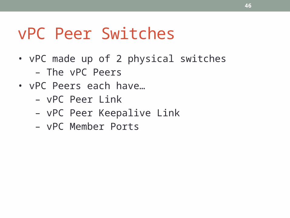
vPC Peer Switches• vPC made up of 2 physical switches – The vPC Peers• vPC Peers each have… – vPC Peer Link – vPC Peer Keepalive Link – vPC Member Ports

47
vPC Overview
N5K-1 N5K-2
N7K-1 N7K-2
Access Switch
Peer Link
Peer Keepalive
Member Ports Member Ports
48
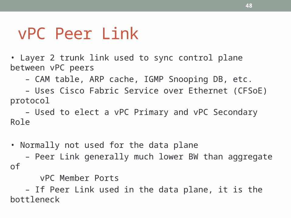
vPC Peer Link• Layer 2 trunk link used to sync control plane between vPC peers – CAM table, ARP cache, IGMP Snooping DB, etc. – Uses Cisco Fabric Service over Ethernet (CFSoE) protocol – Used to elect a vPC Primary and vPC Secondary Role
• Normally not used for the data plane – Peer Link generally much lower BW than aggregate of vPC Member Ports – If Peer Link used in the data plane, it is the bottleneck
49
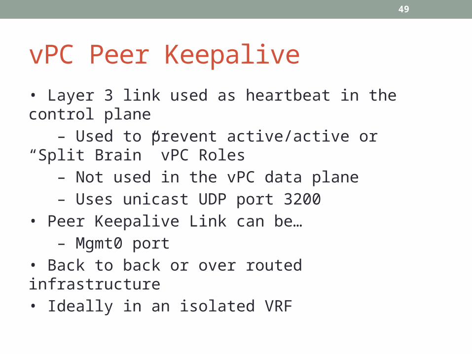
vPC Peer Keepalive• Layer 3 link used as heartbeat in the control plane – Used to prevent active/active or “Split Brain” vPC Roles – Not used in the vPC data plane – Uses unicast UDP port 3200• Peer Keepalive Link can be… – Mgmt0 port• Back to back or over routed infrastructure• Ideally in an isolated VRF
50
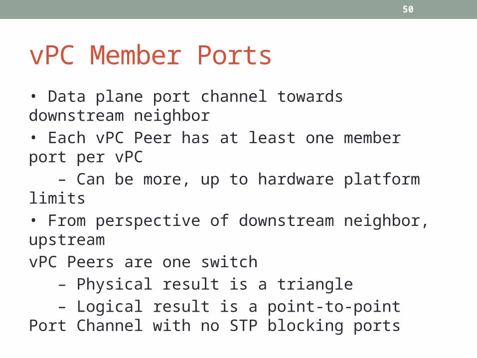
vPC Member Ports• Data plane port channel towards downstream neighbor• Each vPC Peer has at least one member port per vPC – Can be more, up to hardware platform limits• From perspective of downstream neighbor, upstreamvPC Peers are one switch – Physical result is a triangle – Logical result is a point-to-point Port Channel with no STP blocking ports
51
vPC Order of Operations• Enable feature vpc• Create a vPC domain• Configure the vPC peer keepalive link• Create the vPC peer link• Move member ports to a vPC– Configurations must be consistent to avoid Type 1 and Type 2 errors
52
vPC Loop Prevention• Goal of vPC is to hide redundant links from STP – Could result in layer 2 flooding loops• Loops are prevented via “vPC Check” behavior – Frames received in the vPC Peer Link cannot flood out a vPC Member Port while the remote vPC Peer has active vPC Members in the same vPC• vPC Check Exception – If vPC Peer’s Member Ports are down, the vPC Member Ports become “Orphan Ports” and the vPC Check is disabled – vPC Peer Link is essentially a last resort connection
53
vPC and FHRP• Nexus 7000 is typically L2 & L3 network boundary – N7K is vPC Peer but also end host’s FHRP Default Gateway• FHRP behavior changes to accommodate active/active forwardingover vPC – Traffic received in vPC Member Port of FHRP Standby to FHRPVirtual MAC is not forwarded over Peer Link to Active FHRP member – Essentially HSRP Standby acts as HSRP Active• FHRP vPC can break in certain non-standard vendor applications – Frames sent to FHRP Standby with physical DST MAC of FHRP Active are sent out the Peer Link– peer-gateway allows FHRP Standby to forward frames onbehalf of DST MAC of FHRP Active without going over Peer Link

54
vPC and Multicast
• When source is reachable via vPC Member Port, both vPC Peers act as PIM DR – Called “Dual DR” or “Proxy DR”
• Allows either vPC Primary or Secondary to receive traffic from source and forward it north without having to cross the vPC Peer Link – Respects vPC check rule


