Corporate Headquarters Cisco Systems, Inc. 170 West Tasman Drive San Jose, CA 95134-1706 USA http://www.cisco.com Tel: 408 526-4000 800 553-NETS (6387) Fax: 408 526-4100 Cisco ONS 15454 Reference Manual Product and Documentation Release 4.1.x and 4.5 Last Updated: January 24, 2005 Customer Order Number: DOC-7815670= Text Part Number: 78-15670-03
Transcript
Cisco ONS 15454 Reference ManualProduct and Documentation Release 4.1.x and 4.5Last Updated: January 24, 2005
Corporate HeadquartersCisco Systems, Inc.170 West Tasman DriveSan Jose, CA 95134-1706 USAhttp://www.cisco.comTel: 408 526-4000
800 553-NETS (6387)Fax: 408 526-4100
Customer Order Number: DOC-7815670=Text Part Number: 78-15670-03
THE SPECIFICATIONS AND INFORMATION REGARDING THE PRODUCTS IN THIS MANUAL ARE SUBJECT TO CHANGE WITHOUT NOTICE. ALL STATEMENTS, INFORMATION, AND RECOMMENDATIONS IN THIS MANUAL ARE BELIEVED TO BE ACCURATE BUT ARE PRESENTED WITHOUT WARRANTY OF ANY KIND, EXPRESS OR IMPLIED. USERS MUST TAKE FULL RESPONSIBILITY FOR THEIR APPLICATION OF ANY PRODUCTS.
THE SOFTWARE LICENSE AND LIMITED WARRANTY FOR THE ACCOMPANYING PRODUCT ARE SET FORTH IN THE INFORMATION PACKET THAT SHIPPED WITH THE PRODUCT AND ARE INCORPORATED HEREIN BY THIS REFERENCE. IF YOU ARE UNABLE TO LOCATE THE SOFTWARE LICENSE OR LIMITED WARRANTY, CONTACT YOUR CISCO REPRESENTATIVE FOR A COPY.
The following information is for FCC compliance of Class A devices: This equipment has been tested and found to comply with the limits for a Class A digital device, pursuant to part 15 of the FCC rules. These limits are designed to provide reasonable protection against harmful interference when the equipment is operated in a commercial environment. This equipment generates, uses, and can radiate radio-frequency energy and, if not installed and used in accordance with the instruction manual, may cause harmful interference to radio communications. Operation of this equipment in a residential area is likely to cause harmful interference, in which case users will be required to correct the interference at their own expense.
The following information is for FCC compliance of Class B devices: The equipment described in this manual generates and may radiate radio-frequency energy. If it is not installed in accordance with Cisco’s installation instructions, it may cause interference with radio and television reception. This equipment has been tested and found to comply with the limits for a Class B digital device in accordance with the specifications in part 15 of the FCC rules. These specifications are designed to provide reasonable protection against such interference in a residential installation. However, there is no guarantee that interference will not occur in a particular installation.
Modifying the equipment without Cisco’s written authorization may result in the equipment no longer complying with FCC requirements for Class A or Class B digital devices. In that event, your right to use the equipment may be limited by FCC regulations, and you may be required to correct any interference to radio or television communications at your own expense.
You can determine whether your equipment is causing interference by turning it off. If the interference stops, it was probably caused by the Cisco equipment or one of its peripheral devices. If the equipment causes interference to radio or television reception, try to correct the interference by using one or more of the following measures:
• Turn the television or radio antenna until the interference stops.
• Move the equipment to one side or the other of the television or radio.
• Move the equipment farther away from the television or radio.
• Plug the equipment into an outlet that is on a different circuit from the television or radio. (That is, make certain the equipment and the television or radio are on circuits controlled by different circuit breakers or fuses.)
Modifications to this product not authorized by Cisco Systems, Inc. could void the FCC approval and negate your authority to operate the product.
NOTWITHSTANDING ANY OTHER WARRANTY HEREIN, ALL DOCUMENT FILES AND SOFTWARE OF THESE SUPPLIERS ARE PROVIDED “AS IS” WITH ALL FAULTS. CISCO AND THE ABOVE-NAMED SUPPLIERS DISCLAIM ALL WARRANTIES, EXPRESSED OR IMPLIED, INCLUDING, WITHOUT LIMITATION, THOSE OF MERCHANTABILITY, FITNESS FOR A PARTICULAR PURPOSE AND NONINFRINGEMENT OR ARISING FROM A COURSE OF DEALING, USAGE, OR TRADE PRACTICE.
IN NO EVENT SHALL CISCO OR ITS SUPPLIERS BE LIABLE FOR ANY INDIRECT, SPECIAL, CONSEQUENTIAL, OR INCIDENTAL DAMAGES, INCLUDING, WITHOUT LIMITATION, LOST PROFITS OR LOSS OR DAMAGE TO DATA ARISING OUT OF THE USE OR INABILITY TO USE THIS MANUAL, EVEN IF CISCO OR ITS SUPPLIERS HAVE BEEN ADVISED OF THE POSSIBILITY OF SUCH DAMAGES.
CCVP, the Cisco logo, and the Cisco Square Bridge logo are trademarks of Cisco Systems, Inc.; Changing the Way We Work, Live, Play, and Learn is a service mark of Cisco Systems, Inc.; and Access Registrar, Aironet, BPX, Catalyst, CCDA, CCDP, CCIE, CCIP, CCNA, CCNP, CCSP, Cisco, the Cisco Certified Internetwork Expert logo, Cisco IOS, Cisco Press, Cisco Systems, Cisco Systems Capital, the Cisco Systems logo, Cisco Unity, Enterprise/Solver, EtherChannel, EtherFast, EtherSwitch, Fast Step, Follow Me Browsing, FormShare, GigaDrive, HomeLink, Internet Quotient, IOS, iPhone, IP/TV, iQ Expertise, the iQ logo, iQ Net Readiness Scorecard, iQuick Study, LightStream, Linksys, MeetingPlace, MGX, Networking Academy, Network Registrar, Packet, PIX, ProConnect, ScriptShare, SMARTnet, StackWise, The Fastest Way to Increase Your Internet Quotient, and TransPath are registered trademarks of Cisco Systems, Inc. and/or its affiliates in the United States and certain other countries.
All other trademarks mentioned in this document or Website are the property of their respective owners. The use of the word partner does not imply a partnership relationship between Cisco and any other company. (0705R)
Table 17-2 IETF Standard MIBs Implemented in the ONS 15454 and ONS 15327 SNMP Agent 17-4
Table 17-3 ONS 15454 Proprietary MIBs 17-5
Table 17-4 SNMPv2 Trap Variable Bindings 17-6
Table 17-5 Traps Supported in the ONS 15454 17-7
xxxvCisco ONS 15454 Reference Manual, R4.1.x and 4.5
February 2004
Tables
xxxviCisco ONS 15454 Reference Manual, R4.1.x and 4.5
February 2004
About this Manual
Note The terms "Unidirectional Path Switched Ring" and "UPSR" may appear in Cisco literature. These terms do not refer to using Cisco ONS 15xxx products in a unidirectional path switched ring configuration. Rather, these terms, as well as "Path Protected Mesh Network" and "PPMN," refer generally to Cisco's path protection feature, which may be used in any topological network configuration. Cisco does not recommend using its path protection feature in any particular topological network configuration.
This section explains the objectives, intended audience, and organization of this publication and describes the conventions that convey instructions and other information.
Revision History
This section provides the following information:
• Document Objectives
• Audience
• Document Organization
• Related Documentation
• Document Conventions
• Where to Find Safety and Warning Information
• Obtaining Documentation
• Obtaining Technical Assistance
• Obtaining Additional Publications and Information
Date Notes
03/30/2007 Revision History Table added for the first time.
08/15/2007 Updated About this Manual chapter.
xxxviiCisco ONS 15454 Reference Manual, R4.1.x and 4.5
February 2004
About this Manual
Document ObjectivesThis manual provides reference information for the Cisco ONS 15454.
AudienceTo use this publication, you should be familiar with Cisco or equivalent optical transmission hardware and cabling, telecommunications hardware and cabling, electronic circuitry and wiring practices, and preferably have experience as a telecommunications technician.
Document OrganizationTable 1 Cisco ONS 15454 Reference Manual Chapters
Title Summary
Chapter 1, “Shelf and Backplane Hardware” Includes descriptions of the rack, backplane, backplane pins, ferrites, power and ground, fan-tray assembly, air filter, card slots, cable, cable connectors, and cable routing
Chapter 2, “Common Control Cards” Includes descriptions of the TCC+, TCC2, XC, XCVT, XC10G, AIC, and AIC-I cards.
Chapter 3, “Electrical Cards” Includes descriptions of EC-1, DS-1, DS-3, and DS3E cards, card temperature ranges and compatibility
Chapter 4, “Optical Cards” Includes descriptions of the OC-3, OC-12, OC-48, OC-192, TXP_MR_10G, and MXP_2.5G_10G cards, as well as card temperature ranges and card compatibility
Chapter 5, “Ethernet Cards” Includes descriptions of the E-Series, G-Series, and ML-Series Ethernet cards and gigabit interface converters
Chapter 6, “DWDM Cards” Includes descriptions of the optical service channel cards, optical amplifier cards, multiplexer and demultiplexer cards, and optical add/drop multiplexer (OADM) cards.
Chapter 7, “Card Protection” Includes electrical and optical card protection methods
Chapter 8, “Cisco Transport Controller Operation”
Includes information about CTC installation, the CTC window, computer requirements, software versions, and database reset and revert
Chapter 9, “Security and Timing” Includes user set up and security, and node/network timing
xxxviiiCisco ONS 15454 Reference Manual, R4.1.x and 4.5
February 2004
About this Manual
Related DocumentationTo install, turn up, provision, and maintain a Cisco ONS 15454 node and network, refer to the Cisco ONS 15454 Procedure Guide, Release 4.1 and Release 4.5.
For alarm clearing, general troubleshooting, and hardware replacement procedures, refer to the Cisco ONS 15454 Troubleshooting Guide, Release 4.1 and Release 4.5.
Document ConventionsThis publication uses the following conventions:
Chapter 10, “Circuits and Tunnels” Includes STS and VT, bidirectional or unidirectional, revertive or non-revertive, electrical or optical, multiple and path trace circuit information, as well as DCC tunnels
Chapter 11, “SONET Topologies” Includes the SONET configurations used by the ONS 15454; includes BLSRs, path protection configurations, linear ADMs, subtending rings, and optical bus configurations, as well as information about upgrading optical speeds within any configuration
Chapter 12, “DWDM Topologies” Includes the DWDM configurations used by the ONS 15454; including hubbed rings, multihubbed rings, single span links, meshed rings, and linear configurations, as well as information about DWDM node types, automatic power control, automatic node setup, and DWDM network topology discovery.
Chapter 13, “IP Networking” Includes IP addressing scenarios and information about IP networking with the ONS 15454
Chapter 15, “Performance Monitoring” Includes performance monitoring statistics for all cards
Chapter 16, “Ethernet Operation” Includes Ethernet applications for the G series and E series Ethernet cards
Chapter 17, “SNMP” Explains Simple Network Management Protocol (SNMP) as implemented by the Cisco ONS 15454
Table 1 Cisco ONS 15454 Reference Manual Chapters (continued)
Title Summary
Convention Application
boldface Commands and keywords in body text.
italic Command input that is supplied by the user.
[ ] Keywords or arguments that appear within square brackets are optional.
xxxixCisco ONS 15454 Reference Manual, R4.1.x and 4.5
February 2004
About this Manual
Note Means reader take note. Notes contain helpful suggestions or references to material not covered in the document.
Caution Means reader be careful. In this situation, the user might do something that could result in equipment damage or loss of data.
Where to Find Safety and Warning InformationFor safety and warning information, refer to the Cisco Optical Transport Products Safety and Compliance Information document that accompanied the product. This publication describes the international agency compliance and safety information for the Cisco ONS 15xxx systems. It also includes translations of the safety warnings that appear in the ONS 15xxx system documentation.
Obtaining DocumentationCisco documentation and additional literature are available on Cisco.com. Cisco also provides several ways to obtain technical assistance and other technical resources. These sections explain how to obtain technical information from Cisco Systems.
{ x | x | x } A choice of keywords (represented by x) appears in braces separated by vertical bars. The user must select one.
Ctrl The control key. For example, where Ctrl + D is written, hold down the Control key while pressing the D key.
screen font Examples of information displayed on the screen.
boldface screen font Examples of information that the user must enter.
< > Command parameters that must be replaced by module-specific codes.
Warning IMPORTANT SAFETY INSTRUCTIONS
This warning symbol means danger. You are in a situation that could cause bodily injury. Before you work on any equipment, be aware of the hazards involved with electrical circuitry and be familiar with standard practices for preventing accidents. To see translations of the warnings that appear in this publication, refer to the translated safety warnings that accompanied this device.
Note: SAVE THESE INSTRUCTIONS
Note: This documentation is to be used in conjunction with the specific product installation guide that shipped with the product. Please refer to the Installation Guide, Configuration Guide, or other enclosed additional documentation for further details.
Convention Application
xlCisco ONS 15454 Reference Manual, R4.1.x and 4.5
February 2004
About this Manual
Cisco.comYou can access the most current Cisco documentation on the World Wide Web at this URL:
http://www.cisco.com/univercd/home/home.htm
You can access the Cisco website at this URL:
http://www.cisco.com
International Cisco websites can be accessed from this URL:
• Nonregistered Cisco.com users can order documentation through a local account representative by calling Cisco Systems Corporate Headquarters (California, USA) at 408 526-7208 or, elsewhere in North America, by calling 800 553-NETS (6387).
Cisco Optical Networking Product Documentation CD-ROMOptical networking-related documentation, including Cisco ONS 15454 product documentation, is available in a CD-ROM package that ships with your product. The Optical Networking Product Documentation CD-ROM is updated periodically and may be more current than printed documentation.
Documentation FeedbackYou can submit e-mail comments about technical documentation to [email protected].
You can submit comments by using the response card (if present) behind the front cover of your document or by writing to the following address:
Cisco SystemsAttn: Customer Document Ordering170 West Tasman DriveSan Jose, CA 95134-9883
We appreciate your comments.
xliCisco ONS 15454 Reference Manual, R4.1.x and 4.5
Obtaining Technical AssistanceFor all customers, partners, resellers, and distributors who hold valid Cisco service contracts, the Cisco Technical Assistance Center (TAC) provides 24-hour-a-day, award-winning technical support services, online and over the phone. Cisco.com features the Cisco TAC website as an online starting point for technical assistance. If you do not hold a valid Cisco service contract, please contact your reseller.
Cisco TAC WebsiteThe Cisco TAC website provides online documents and tools for troubleshooting and resolving technical issues with Cisco products and technologies. The Cisco TAC website is available 24 hours a day, 365 days a year. The Cisco TAC website is located at this URL:
http://www.cisco.com/tac
Accessing all the tools on the Cisco TAC website requires a Cisco.com user ID and password. If you have a valid service contract but do not have a login ID or password, register at this URL:
http://tools.cisco.com/RPF/register/register.do
Opening a TAC CaseUsing the online TAC Case Open Tool is the fastest way to open P3 and P4 cases. (P3 and P4 cases are those in which your network is minimally impaired or for which you require product information.) After you describe your situation, the TAC Case Open Tool automatically recommends resources for an immediate solution. If your issue is not resolved using the recommended resources, your case will be assigned to a Cisco TAC engineer. The online TAC Case Open Tool is located at this URL:
http://www.cisco.com/tac/caseopen
For P1 or P2 cases (P1 and P2 cases are those in which your production network is down or severely degraded) or if you do not have Internet access, contact Cisco TAC by telephone. Cisco TAC engineers are assigned immediately to P1 and P2 cases to help keep your business operations running smoothly.
To open a case by telephone, use one of the following numbers:
TAC Case Priority DefinitionsTo ensure that all cases are reported in a standard format, Cisco has established case priority definitions.
Priority 1 (P1)—Your network is “down” or there is a critical impact to your business operations. You and Cisco will commit all necessary resources around the clock to resolve the situation.
Priority 2 (P2)—Operation of an existing network is severely degraded, or significant aspects of your business operation are negatively affected by inadequate performance of Cisco products. You and Cisco will commit full-time resources during normal business hours to resolve the situation.
xliiCisco ONS 15454 Reference Manual, R4.1.x and 4.5
Priority 3 (P3)—Operational performance of your network is impaired, but most business operations remain functional. You and Cisco will commit resources during normal business hours to restore service to satisfactory levels.
Priority 4 (P4)—You require information or assistance with Cisco product capabilities, installation, or configuration. There is little or no effect on your business operations.
Obtaining Additional Publications and InformationInformation about Cisco products, technologies, and network solutions is available from various online and printed sources.
• Cisco Marketplace provides a variety of Cisco books, reference guides, and logo merchandise. Go to this URL to visit the company store:
http://www.cisco.com/go/marketplace/
• The Cisco Product Catalog describes the networking products offered by Cisco Systems, as well as ordering and customer support services. Access the Cisco Product Catalog at this URL:
http://cisco.com/univercd/cc/td/doc/pcat/
• Cisco Press publishes a wide range of general networking, training and certification titles. Both new and experienced users will benefit from these publications. For current Cisco Press titles and other information, go to Cisco Press online at this URL:
http://www.ciscopress.com
• Packet magazine is the Cisco quarterly publication that provides the latest networking trends, technology breakthroughs, and Cisco products and solutions to help industry professionals get the most from their networking investment. Included are networking deployment and troubleshooting tips, configuration examples, customer case studies, tutorials and training, certification information, and links to numerous in-depth online resources. You can access Packet magazine at this URL:
http://www.cisco.com/packet
• iQ Magazine is the Cisco bimonthly publication that delivers the latest information about Internet business strategies for executives. You can access iQ Magazine at this URL:
http://www.cisco.com/go/iqmagazine
• Internet Protocol Journal is a quarterly journal published by Cisco Systems for engineering professionals involved in designing, developing, and operating public and private internets and intranets. You can access the Internet Protocol Journal at this URL:
http://www.cisco.com/ipj
• Training—Cisco offers world-class networking training. Current offerings in network training are listed at this URL:
http://www.cisco.com/en/US/learning/index.html
xliiiCisco ONS 15454 Reference Manual, R4.1.x and 4.5
xlivCisco ONS 15454 Reference Manual, R4.1.x and 4.5
February 2004
Cisco ONSOctober 2004
C H A P T E R 1
Shelf and Backplane Hardware
Note The terms "Unidirectional Path Switched Ring" and "UPSR" may appear in Cisco literature. These terms do not refer to using Cisco ONS 15xxx products in a unidirectional path switched ring configuration. Rather, these terms, as well as "Path Protected Mesh Network" and "PPMN," refer generally to Cisco's path protection feature, which may be used in any topological network configuration. Cisco does not recommend using its path protection feature in any particular topological network configuration.
This chapter provides a description of Cisco ONS 15454 shelf and backplane hardware. Card descriptions are provided in Chapter 2, “Common Control Cards,” Chapter 3, “Electrical Cards,” Chapter 4, “Optical Cards,” Chapter 5, “Ethernet Cards,” and Chapter 6, “DWDM Cards.” To install equipment, refer to the Cisco ONS 15454 Procedure Guide.
Chapter topics include:
• Overview, page 2
• Rack Installation, page 3
• Front Door, page 7
• Backplane Covers, page 11
• Electrical Interface Assemblies, page 15
• Coaxial Cable, page 25
• DS-1 Cable, page 25
• Cable Routing and Management, page 26
• Alarm Expansion Panel, page 29
• Fan-Tray Assembly, page 36
• Power and Ground Description, page 37
• Alarm, Timing, LAN, and Craft Pin Connections, page 38
• Cards and Slots, page 42
• Ferrites, page 46
• Software and Hardware Compatibility, page 46
Note The Cisco ONS 15454 assembly is intended for use with telecommunications equipment only.
1-1 15454 Reference Manual, R4.1.x and 4.5
Chapter 1 Shelf and Backplane HardwareOverview
Warning Only trained and qualified personnel should be allowed to install, replace, or service this equipment.
Warning This equipment must be installed and maintained by service personnel as defined by AS/NZS 3260. Incorrectly connecting this equipment to a general purpose outlet could be hazardous. The telecommunications lines must be disconnected 1) before unplugging the main power connector and/or 2) while the front door is open.
Warning The ONS 15454 is intended for installation in restricted access areas. A restricted access area is where access can only be gained by service personnel through the use of a special tool, lock, key, or other means of security. A restricted access area is controlled by the authority responsible for the location.
Warning The ONS 15454 is suitable for mounting on concrete or other non-combustible surfaces only.
Caution Unused card slots should be filled with a blank faceplate (Cisco P/N 15454-BLANK). The blank faceplate ensures proper airflow when operating the ONS 15454 without the front door attached, although Cisco recommends that the front door remain attached.
Note The ONS 15454 is designed to comply with GR-1089-CORE Type 2 and Type 4. Install and operate the ONS 15454 only in environments that do not expose wiring or cabling to the outside plant. Acceptable applications include Central Office Environments (COEs), Electronic Equipment Enclosures (EEEs), Controlled Environment Vaults (CEVs), huts, and Customer Premise Environments (CPEs).
Note You can search for cross-referenced Cisco part numbers and CLEI (Common Language Equipment Identification) codes at the following link: http://www.cisco.com/cgi-bin/front.x/clei/code_search.cgi
1.1 OverviewWhen installed in an equipment rack, the ONS 15454 assembly is typically connected to a fuse and alarm panel to provide centralized alarm connection points and distributed power for the ONS 15454. Fuse and alarm panels are third-party equipment and are not described in this documentation. If you are unsure about the requirements or specifications for a fuse and alarm panel, consult the user documentation for the related equipment. The front door of the ONS 15454 allows access to the shelf assembly, fan-tray assembly, and cable-management area. The backplanes provide access to alarm contacts, external interface contacts, power terminals, and BNC/SMB connectors.
Warning The ONS 15454 relies on the protective devices in the building installation to protect against short circuit, overcurrent, and grounding faults. Ensure that the protective devices are properly rated to protect the system, and that they comply with national and local codes.
1-2Cisco ONS 15454 Reference Manual, R4.1.x and 4.5
October 2004
Chapter 1 Shelf and Backplane HardwareRack Installation
Warning Incorporate a readily-accessible, two-poled disconnect device in the fixed wiring.
You can mount the ONS 15454 in a 19- or 23-inch rack. The shelf assembly weighs approximately 55 pounds with no cards installed. The shelf assembly includes a front door for added security, a fan tray module for cooling, and extensive cable-management space.
ONS 15454 optical cards have SC and LC connectors on the card faceplate. Fiber optic cables are routed into the front of the destination cards. Electrical cards (DS-1, DS-3, DS3XM-6, and EC-1) require electrical interface assemblies (EIAs) to provide the cable connection points for the shelf assembly. In most cases, EIAs are ordered with the ONS 15454 and come pre-installed on the backplane. See the “Electrical Interface Assemblies” section on page 15 for more information about the EIAs.
The ONS 15454 is powered using –48 VDC power. Negative, return, and ground power terminals are accessible on the backplane.
Note In this chapter, the terms “ONS 15454” and “shelf assembly” are used interchangeably. In the installation context, these terms have the same meaning. Otherwise, shelf assembly refers to the physical steel enclosure that holds cards and connects power, and ONS 15454 refers to the entire system, both hardware and software.
Install the ONS 15454 in compliance with your local and national electrical codes:
• United States: National Fire Protection Association (NFPA) 70; United States National Electrical Code
• Canada: Canadian Electrical Code, Part I, CSA C22.1
• Other countries: If local and national electrical codes, are not available, refer to IEC 364, Part 1 through Part 7.
Warning Dispose of this product according to all national laws and regulations.
1.2 Rack Installation
Warning To prevent the equipment from overheating, do not operate it in an area that exceeds the maximum recommended ambient temperature of 131°F (55°C) unless configured for industrial temperature (I-temp). All I-temp rated components are –40°C to +65°C. To prevent airflow restriction, allow at least 1 inch (25.4 mm) of clearance around the ventilation openings.
The ONS 15454 is mounted in a 19- or 23-inch equipment rack. The shelf assembly projects five inches (127 mm) from the front of the rack. It mounts in both EIA-standard and Telcordia-standard racks. The shelf assembly is a total of 17 inches (431.8 mm) wide with no mounting ears attached. Ring runs are not provided by Cisco and may hinder side-by-side installation of shelves where space is limited.
The ONS 15454 measures 18.5 inches (469.9 mm) high, 19 or 23 inches (482.6 or 584.2 mm) wide (depending on which way the mounting ears are attached), and 12 inches (304.8 mm) deep. You can install up to four ONS 15454s in a seven-foot (2133.6 mm) equipment rack. The ONS 15454 must have one inch (25.4 mm) of airspace below the installed shelf assembly to allow air flow to the fan
1-3Cisco ONS 15454 Reference Manual, R4.1.x and 4.5
October 2004
Chapter 1 Shelf and Backplane HardwareRack Installation
intake. If a second ONS 15454 is installed underneath the shelf assembly, the air ramp on top of the lower shelf assembly provides the air spacing needed and should not be modified in any way. Figure 1-1 on page 1-4 shows the dimensions of the ONS 15454.
Note The 10 Gbps compatible shelf assembly (15454-SA-ANSI) and fan-tray assembly (15454-FTA3 or 15454-FTA3-T) are required if ONS 15454 XC10G cards are installed in the shelf.
Warning The ONS 15454 should be installed in the lower rack position or mounted above another ONS 15454 shelf assembly.
Warning The ONS 15454 must have 1 inch (25.4 mm) of airspace below the installed shelf assembly to allow air flow to the fan intake. The air ramp (the angled piece of sheet metal on top of the shelf assembly) provides this spacing and should not be modified in any way.
Figure 1-1 Cisco ONS 15454 Dimensions
Front ViewSide View
Top View
18.5 in.(46.99 cm)
2 in. (30.48 cm)
12 in.(30.48 cm)
5 in.(12.7 cm)
22 in. (55.88 cm) total width
19 in. (48.26 cm) or 23 in. (58.42 cm)between mounting screw holes
22 in. (55.88 cm) total width
19 in. (48.26 cm) or 23 in. (58.42 cm)between mounting screw holes
3209
9
1-4Cisco ONS 15454 Reference Manual, R4.1.x and 4.5
October 2004
Chapter 1 Shelf and Backplane HardwareRack Installation
1.2.1 Reversible Mounting Bracket
Caution Use only the fastening hardware provided with the ONS 15454 to prevent loosening, deterioration, and electromechanical corrosion of the hardware and joined material.
Caution When mounting the ONS 15454 in a frame with a non-conductive coating (such as paint, lacquer, or enamel) either use the thread-forming screws provided with the ONS 15454 shipping kit, or remove the coating from the threads to ensure electrical continuity.
The shelf assembly comes preset for installation in a 23-inch rack, but you can reverse the mounting bracket to fit the smaller 19-inch rack.
1.2.2 Mounting a Single NodeMounting the ONS 15454 in a rack requires a minimum of 18.5 inches (469.9 mm) of vertical rack space and one additional inch (25.4 mm) for air flow. To ensure the mounting is secure, use two to four #12-24 mounting screws for each side of the shelf assembly. Figure 1-2 shows the rack mounting position for the ONS 15454.
Figure 1-2 Mounting an ONS 15454 in a Rack
Two people should install the shelf assembly; however, one person can install it using the temporary set screws included. The shelf assembly should be empty for easier lifting. The front door can also be removed to lighten the shelf assembly.
FAN FAILCRIT
MAJMIN
Equipment rack
Universalear mounts(reversible)
3939
2
1-5Cisco ONS 15454 Reference Manual, R4.1.x and 4.5
October 2004
Chapter 1 Shelf and Backplane HardwareRack Installation
Note If you are installing the fan-tray air filter using the bottom (external) brackets provided, mount the brackets on the bottom of the shelf assembly before installing the ONS 15454 in a rack.
1.2.3 Mounting Multiple NodesMost standard (GR-63-CORE, 19-inch or 23-inch) seven-foot racks can hold four ONS 15454s and a fuse and alarm panel. However, unequal flange racks are limited to three ONS 15454s and a fuse and alarm panel or four ONS 15454s and a fuse and alarm panel from an adjacent rack.
If you are using the external (bottom) brackets to install the fan-tray air filter, you can install three shelf assemblies in a standard seven-foot rack. If you are not using the external (bottom) brackets, you can install four shelf assemblies in a rack. The advantage to using the bottom brackets is that you can replace the filter without removing the fan tray.
1.2.4 ONS 15454 Bay AssemblyThe Cisco ONS 15454 Bay Assembly simplifies ordering and installing the ONS 15454 because it allows you to order shelf assemblies pre-installed in a seven-foot rack. The Bay Assembly is available in a three- or four-shelf configuration. The three-shelf configuration includes three ONS 15454 shelf assemblies, a pre-wired fuse and alarm panel, and two cable-management trays. The four-shelf configuration includes four ONS 15454 shelf assemblies and a pre-wired fuse and alarm panel. You can order optional fiber channels with either configuration. Installation procedures are included in the Unpacking and Installing the Cisco ONS 15454 Four-Shelf and Zero-Shelf Bay Assembly document that ships with the Bay Assembly.
1.2.5 Typical DWDM Rack LayoutsTypical DWDM applications may include:
• 3 ONS 15454 shelves
• 1 DCUs
• 7 Patch Panels (or Fiber Storage tray(s))
Or, alternatively:
• 3 ONS 15454 shelves
• 2 DCUs
• 6 Patch Panels (or Fiber Storage tray(s)
See Figure 1-3 on page 1-7 for a typical rack layout. If you are installing a patch panel or fiber storage tray below the ONS 15454 shelf you must install the air ramp between the shelf and patch panel/fiber tray, or leave one RMU space open.
1-6Cisco ONS 15454 Reference Manual, R4.1.x and 4.5
October 2004
Chapter 1 Shelf and Backplane HardwareFront Door
Figure 1-3 Typical DWDM Equipment Layout
1.3 Front Door The Critical, Major, and Minor alarm LEDs visible through the front door indicate whether a critical, major, or minor alarm is present anywhere on the ONS 15454. These LEDs must be visible so technicians can quickly determine if any alarms are present on the ONS 15454 shelf or the network. You can use the LCD to further isolate alarms.
1-7Cisco ONS 15454 Reference Manual, R4.1.x and 4.5
October 2004
Chapter 1 Shelf and Backplane HardwareFront Door
The ONS 15454 features a locked door to the front compartment. A pinned hex key that unlocks the front door ships with the ONS 15454. A button on the right side of the shelf assembly releases the door. The front door (Figure 1-4) provides access to the shelf assembly, cable-management tray, fan-tray assembly, and LCD screen.
Figure 1-4 The ONS 15454 Front Door
You can remove the front door of the ONS 15454 to provide unrestricted access to the front of the shelf assembly. Before you remove the front door, you have to remove the ground strap of the front door (Figure 1-5 on page 1-9).
Door lock Door button
Viewholes for Critical, Major and Minor alarm LEDs33
923
CISCO ONS 15454Opt ica l Ne twork Sys t em
1-8Cisco ONS 15454 Reference Manual, R4.1.x and 4.5
October 2004
Chapter 1 Shelf and Backplane HardwareFront Door
Figure 1-5 ONS 15454 Front Door Ground Strap
7104
8
1-9Cisco ONS 15454 Reference Manual, R4.1.x and 4.5
October 2004
Chapter 1 Shelf and Backplane HardwareFront Door
Figure 1-6 on page 1-10 shows how to remove the front door.
Figure 1-6 Removing the ONS 15454 Front Door
An erasable label is pasted on the inside of the front door (Figure 1-7 on page 1-11). You can use the label to record slot assignments, port assignments, card types, node ID, rack ID, and serial number for the ONS 15454.
Door hinge
Assembly hinge pin
Assembly hinge
Translucentcircles for LEDviewing
3883
1
FAN FAILCRIT
MAJMIN
1-10Cisco ONS 15454 Reference Manual, R4.1.x and 4.5
October 2004
Chapter 1 Shelf and Backplane HardwareBackplane Covers
Figure 1-7 Front-Door Erasable Label
Note The front door label also includes the Class I and Class 1M laser warning (Figure 1-8).
Figure 1-8 Laser Warning on the Front-Door Label
1.4 Backplane CoversIf a backplane does not have an EIA panel installed, it should have two sheet metal backplane covers (one on each side of the backplane). See Figure 1-9 on page 1-12. Each cover is held in place with nine 6-32 x 3/8 inch Phillips screws.
Note See the “Electrical Interface Assemblies” section on page 15 for information on EIAs.
6184
0
6757
5
1-11Cisco ONS 15454 Reference Manual, R4.1.x and 4.5
October 2004
Chapter 1 Shelf and Backplane HardwareBackplane Covers
Figure 1-9 Backplane Covers
1.4.1 Lower Backplane CoverThe lower section of the ONS 15454 backplane is covered by a clear plastic protector, which is held in place by five 6-32 x 1/2 inch screws. Remove the lower backplane cover to access the alarm interface panel (AIP), alarm pin fields, frame ground, and power terminals (Figure 1-10).
Figure 1-10 Removing the Lower Backplane Cover
B A
3207
4
Lower Backplane Cover
Backplane Sheet Metal Covers
3206
9
Retainingscrews
1-12Cisco ONS 15454 Reference Manual, R4.1.x and 4.5
October 2004
Chapter 1 Shelf and Backplane HardwareBackplane Covers
1.4.2 Rear Cover The ONS 15454 has an optional clear plastic rear cover. This clear plastic cover provides additional protection for the cables and connectors on the backplane. Figure 1-11 shows the rear cover screw locations.
Figure 1-11 Backplane Attachment for Cover
You can also install the optional spacers if more space is needed between the cables and rear cover (Figure 1-12 on page 1-14).
3207
3
Screw locationsfor attaching the
rear cover
1-13Cisco ONS 15454 Reference Manual, R4.1.x and 4.5
October 2004
Chapter 1 Shelf and Backplane HardwareBackplane Covers
Figure 1-12 Installing the Plastic Rear Cover with Spacers
1.4.3 Alarm Interface PanelThe AIP is located above the alarm contacts on the lower section of the backplane. The AIP provides surge protection for the ONS 15454. It also provides an interface from the backplane to the fan-tray assembly and LCD. The AIP plugs into the backplane using a 96-pin DIN connector and is held in place with two retaining screws. The panel has a non-volatile memory chip that stores the unique node address (MAC address).
Note The 5-A AIP (73-7665-XX) is required when installing the new fan-tray assembly (15454-FTA3), which comes preinstalled on the shelf assembly (15454-SA-ANSI).
Note The MAC address identifies the nodes that support circuits. It allows CTC to determine circuit sources, destinations, and spans. The TCC+ or TCC2 cards in the ONS 15454 also use the MAC address to store the node database.
Note A blown fuse on the AIP board can cause the LCD display to go blank.
5537
4
RET 1
CAUTION: R
emove power from both
the BAT1 and te
rminal b
locks
prior to
servicing
SUITABLE FOR MOUNTIN
G ON
A NON-C
OMBUSTIBLE S
URFACE.
PLEASE REFER TO IN
STALLATION
INSTRUCTIO
NS.
-42 TO -57 V
dc
650 Watts
Maxim
um
BAT 1RET 2
BAT 2
1-14Cisco ONS 15454 Reference Manual, R4.1.x and 4.5
October 2004
Chapter 1 Shelf and Backplane HardwareElectrical Interface Assemblies
1.4.4 Alarm Interface Panel ReplacementIf the alarm interface panel (AIP) fails, a MAC Fail alarm displays on the CTC Alarms menu and/or the LCD display on the fan-tray assembly will go blank. To perform an in-service replacement of the AIP, you must contact Cisco Technical Assistance Center (TAC). For contact information, go to the TAC website at http://www.cisco.com/tac.
You can replace the AIP on an in-service system without affecting traffic (except Ethernet traffic on nodes running a software release earlier than Release 4.0). The circuit repair feature allows you to repair circuits affected by MAC address changes on one node at a time. Circuit repair will work when all nodes are running the same software version. Each individual AIP upgrade requires an individual circuit repair; if AIPs are replaced on two nodes, the circuit repair must be performed twice.
Caution Do not use a 2-A AIP with a 5-A fan-tray assembly; doing so will cause a blown fuse on the AIP.
Note Ensure that all nodes in the affected network are running the same software version before replacing the AIP and repairing circuits. If you need to upgrade nodes to the same software version, no hardware should be changed or circuit repair performed until after the software upgrade is complete.
Note Replace an AIP during a maintenance window. Resetting the active TCC+/TCC2 can cause a service disruption of less then 50 ms to optical (OC-N) or electrical (DS-N) traffic. Resetting the active TCC+/TCC2 will cause a service disruption of 3 to 5 minutes on all E-Series Ethernet traffic due to spanning tree reconvergence.
1.5 Electrical Interface AssembliesOptional EIA backplane covers are typically pre-installed when ordered with the ONS 15454. EIAs must be ordered when using DS-1, DS-3, DS3XM-6, or EC-1 cards. This section describes each EIA.
Four different EIA backplane covers are available for the ONS 15454: BNC, High-Density BNC, SMB, and AMP Champ. This section describes each EIA in detail. If the shelf was not shipped with the correct EIA interface, you must order and install the correct EIA.
EIAs are attached to the shelf assembly backplane to provide electrical interface cable connections. EIAs are available with SMB and BNC connectors for DS-3 or EC-1 cards. EIAs are available with AMP Champ connectors for DS-1 cards. You must use SMB EIAs for DS-1 twisted-pair cable installation. You can install EIAs on one or both sides of the ONS 15454 backplane in any combination (in other words, AMP Champ on Side A and BNC on Side B or High-Density BNC on side A and SMB on side B, and so forth).
As you face the rear of the ONS 15454 shelf assembly, the right-hand side is the A side and the left-hand side is the B side. The top of the EIA connector columns are labeled with the corresponding slot number, and EIA connector pairs are marked transmit (Tx) and receive (Rx) to correspond to transmit and receive cables.
1-15Cisco ONS 15454 Reference Manual, R4.1.x and 4.5
October 2004
Chapter 1 Shelf and Backplane HardwareElectrical Interface Assemblies
1.5.1 EIA Installation Optional EIA backplane covers are typically pre-installed when ordered with the ONS 15454. A minimum amount of assembly may be required when EIAs are ordered separately from the ONS 15454. If you are installing EIAs after the shelf assembly is installed, plug the EIA into the backplane. The EIA has six electrical connectors that plug into six corresponding backplane connectors. The EIA backplane must replace the standard sheet metal cover to provide access to the coaxial cable connectors. The EIA sheet metal covers use the same screw holes as the solid backplane panels, but they have 12 additional 6-32 x 1/2 inch Phillips screw holes so you can screw down the cover and the board using standoffs on the EIA board.
When using the RG-179 coaxial cable on an EIA, the maximum distance available (122 feet) is less than the maximum distance available with standard RG-59 (735A) cable (306 feet). The maximum distance when using the RG-59 (734A) cable is 450 feet. The shorter maximum distance available with the RG179 is due to a higher attenuation rate for the thinner cable. Attenuation rates are calculated using a DS-3 signal:
• For RG-179, the attenuation rate is 59 dB/kft at 22 MHz.
• For RG-59 (735A) the attenuation rate is 23 dB/kft at 22 MHz.
1.5.2 EIA ConfigurationsTable 1-1 gives the product numbers and common names for EIAs.
Table 1-1 EIA Configurations
EIA TypeCards Supported
A Side Hosts
A Side Columns Map to A Side Product Number
B Side Hosts
B Side Columns Map to B Side Product Number
BNC DS-3 DS3XM-6 EC-1
24 pairs of BNC connectors
Slot 2
Slot 4 15454-EIA-BNC-A24
24 pairs of
BNC connectors
Slot 14
Slot 16 15454-EIA-BNC-B24
High- Density BNC
DS-3 DS3XM-6 EC-1
48 pairs of BNC connectors
Slot 1
Slot 2
Slot 4
Slot 5
15454-EIA-BNC-A48
48 pairs of
BNC connectors
Slot 13
Slot 14
Slot 16
Slot 17
15454-EIA-BNC-B48
1-16Cisco ONS 15454 Reference Manual, R4.1.x and 4.5
October 2004
Chapter 1 Shelf and Backplane HardwareElectrical Interface Assemblies
1.5.3 BNC EIAThe ONS 15454 BNC EIA supports 24 DS-3 circuits on each side of the ONS 15454 (24 transmit and 24 receive connectors). If you install BNC EIAs on both sides of the shelf assembly, the ONS 15454 hosts up to 48 circuits. The BNC connectors on the EIA supports Trompeter UCBJ224 (75 ohm) 4 leg connectors (King or ITT are also compatible). Right-angle mating connectors for the connecting cable are AMP 413588-2 (75 Ohm) connectors. If preferred, you can also use a straight connector of the same type. Use RG-59/U cable to connect to the ONS 15454 BNC EIA. These cables are recommended to connect to a patch panel and are designed for long runs. You can use BNC EIAs for DS-3 (including the DS3XM-6) or EC-1 cards.
Figure 1-13 shows the ONS 15454 with pre-installed BNC EIAs.
To install coaxial cable with BNC connectors, refer to the Cisco ONS 15454 Procedure Guide.
SMB DS-1 DS-3 EC-1DS3XM-6
84 pairs of SMB connectors
Slot 1
Slot 2
Slot 3
Slot 4
Slot 5
Slot 6
15454-EIA-SMB-A84
84 pairs of SMB connectors
Slot 12
Slot 13
Slot 14
Slot 15
Slot 16
Slot 17
15454-EIA-SMB-B84
AMP Champ
DS-1 6 AMP Champconnectors
Slot 1
Slot 2
Slot 3
Slot 4
Slot 5
Slot 6
15454-EIA-AMP-A84
6 AMP Champconnectors
Slot 12
Slot 13
Slot 14
Slot 15
Slot 16
Slot 17
15454-EIA-AMP-B84
Table 1-1 EIA Configurations (continued)
EIA TypeCards Supported
A Side Hosts
A Side Columns Map to A Side Product Number
B Side Hosts
B Side Columns Map to B Side Product Number
1-17Cisco ONS 15454 Reference Manual, R4.1.x and 4.5
October 2004
Chapter 1 Shelf and Backplane HardwareElectrical Interface Assemblies
Figure 1-13 BNC Backplane for use in 1:1 Protection Schemes
1.5.3.1 BNC Connectors
The EIA side marked “A” has 24 pairs of BNC connectors. The first 12 pairs of BNC connectors correspond to Ports 1 to 12 for a 12-port card and map to Slot 2 on the shelf assembly. The BNC connector pairs are marked “Tx” and “Rx” to indicate transmit and receive cables for each port. You can install an additional card in Slot 1 as a protect card for the card in Slot 2. The second 12 BNC connector pairs correspond to Ports 1 to 12 for a 12-port card and map to Slot 4 on the shelf assembly. You can install an additional card in Slot 3 as a protect card for the card in Slot 4. Slots 5 and 6 do not support DS-3 cards when the standard BNC EIA panel connectors are used.
The EIA side marked “B” provides an additional 24 pairs of BNC connectors. The first 12 BNC connector pairs correspond to Ports 1 to 12 for a 12-port card and map to Slot 14 on the shelf assembly. The BNC connector pairs are marked “Tx” and “Rx” to indicate transmit and receive cables for each port. You can install an additional card in Slot 15 as a protect card for the card in Slot 14. The second 12 BNC connector pairs correspond to Ports 1 to 12 for a 12-port card and map to Slot 16 on the shelf assembly. You can install an additional card in Slot 17 as a protect card for the card in Slot 16. Slots 12 and 13 do not support DS-3 cards when the standard BNC EIA panel connectors are used.
When BNC connectors are used with a DS3N-12 card in Slot 3 or 15, the 1:N card protection extends only to the two slots adjacent to the 1:N card due to BNC wiring constraints.
1.5.3.2 BNC Insertion and Removal Tool
Due to the large number of BNC connectors on the High-Density BNC EIA, you might require a special tool for inserting and removing BNC EIAs (Figure 1-14). This tool also helps with ONS 15454 patch panel connections.
B A
BNC backplane connectors
Tie wrap posts
3207
6
1 7 1 7
2 8 2 8
3 9 3 9
4 10 4 10
5 11 5 11
6 12 6 12
16
TX RX TX RX TX RX TX RX
TX RX TX RX TX RX TX RX
1 7 1 7
2 8 2 8
3 9 3 9
4 10 4 10
5 11 5 11
6 12 6 12
TX RX TX RX TX RX TX RX
TX RX TX RX TX RX TX RX
14 4 2
1-18Cisco ONS 15454 Reference Manual, R4.1.x and 4.5
October 2004
Chapter 1 Shelf and Backplane HardwareElectrical Interface Assemblies
Figure 1-14 BNC Insertion and Removal Tool
This tool can be obtained with P/N 227-T1000 from:
Trompeter Electronics Inc. (www.trompeter.com)31186 La Baya DriveWestlake Village, CA 91362-4047Phone: (800) 982-2629 Fax: (818) 706-1040
1.5.4 High-Density BNC EIAThe ONS 15454 high-density BNC EIA supports 48 DS-3 circuits on each side of the ONS 15454 (48 transmit and 48 receive connectors). If you install BNC EIAs on both sides of the unit, the ONS 15454 hosts up to 96 circuits. The high-density BNC EIA supports Trompeter UCBJ224 (75 ohm) 4 leg connectors (King or ITT are also compatible). Use straight connectors on RG-59/U cable to connect to the high-density BNC EIA. Cisco recommends these cables for connection to a patch panel; they are designed for long runs. You can use high-density BNC EIAs for DS-3 (including the DS3XM-6) or EC-1 cards. Figure 1-15 on page 1-20 shows the ONS 15454 with pre-installed high-density BNC EIAs.
To install coaxial cable with high-density BNC connectors, refer to the Cisco ONS 15454 Procedure Guide.
4455
2
1-19Cisco ONS 15454 Reference Manual, R4.1.x and 4.5
October 2004
Chapter 1 Shelf and Backplane HardwareElectrical Interface Assemblies
Figure 1-15 High-Density BNC Backplane for use in 1:N Protection Schemes
The EIA side marked “A” hosts 48 pairs of BNC connectors. Each column of connector pairs is numbered and corresponds to the slot of the same number. The first column (12 pairs) of BNC connectors corresponds to Slot 1 on the shelf assembly, the second column to Slot 2, the third column to Slot 4, and the fourth column to Slot 5. The rows of connectors correspond to Ports 1 to 12 of a 12-port card.
The EIA side marked “B” provides an additional 48 pairs of BNC connectors. The first column (12 pairs) of BNC connectors corresponds to Slot 13 on the shelf assembly, the second column to Slot 14, the third column to Slot 16, and the fourth column to Slot 17. The rows of connectors correspond to Ports 1 to 12 of a 12-port card. The BNC connector pairs are marked “Tx” and “Rx” to indicate transmit and receive cables for each port. The High-Density BNC EIA supports both 1:1 and 1:N protection across all slots except Slots 6 and 12.
1.5.5 SMB EIAThe ONS 15454 SMB EIA supports AMP 415484-1 75 ohm 4 leg connectors. Right-angle mating connectors for the connecting cable are AMP 415484-2 (75 ohm) connectors. Use RG-179/U cable to connect to the ONS 15454 EIA. Cisco recommends these cables for connection to a patch panel; they are not designed for long runs. Range does not affect loopback testing.
You can use SMB EIAs with DS-1, DS-3 (including the DS3XM-6), and EC-1 cards. If you use DS-1 cards, use the DS-1 electrical interface adapter (balun) to terminate the twisted pair DS-1 cable to the SMB EIA (see the “Electrical Interface Adapters” section on page 25). SMB EIAs support 14 ports per slot when used with a DS-1 card, 12 ports per slot when used with a DS-3 or EC-1 card, and 6 ports per slot when used with a DS3XM-6 card.
Figure 1-16 on page 1-21 shows the ONS 15454 with pre-installed SMB EIAs and the sheet metal cover and screw locations for the EIA. The SMB connectors on the EIA are AMP 415504-3 (75 ohm) 4 leg connectors.
B A
BNC backplane connectors
3914
1
1 1 1 1
3 3 3 3
4 4 4 4
5 5 5 5
6 6 6 6
7 7 7 7
8 8 8 8
9 9 9 9
10 10 10 10
11 11 11 11
12 12 12 12
2 2 2 2
TX RX TX RX TX RX TX RX
TX RX TX RX TX RX TX RX
1 1 1 1
3 3 3 3
4 4 4 4
5 5 5 5
6 6 6 6
7 7 7 7
8 8 8 8
9 9 9 9
10 10 10 10
11 11 11 11
12 12 12 12
2 2 2 2
TX RX TX RX TX RX TX RX
TX RX TX RX TX RX TX RX
17 16 14 13 5 4 2 1
1-20Cisco ONS 15454 Reference Manual, R4.1.x and 4.5
October 2004
Chapter 1 Shelf and Backplane HardwareElectrical Interface Assemblies
To install SMB connectors, refer to the Cisco ONS 15454 Procedure Guide.
Figure 1-16 SMB EIA Backplane
The SMB EIA has 84 transmit and 84 receive connectors on each side of the ONS 15454 for a total of 168 SMB connectors (84 circuits).
The EIA side marked “A” hosts 84 SMB connectors in six columns of 14 connectors. The “A” side columns are numbered 1 to 6 and correspond to Slots 1 to 6 on the shelf assembly. The EIA side marked “B” hosts an additional 84 SMB connectors in six columns of 14 connectors. The “B” side columns are numbered 12 to 17 and correspond to Slots 12 to 17 on the shelf assembly. The connector rows are numbered 1 to 14 and correspond to the 14 ports on a DS-1 card.
For DS-3 or EC-1, the EIA supports 72 transmit and 72 receive connectors, for a total of 144 SMB connectors (72 circuits). If you use a DS-3 or EC-1 card, only Ports 1 to 12 are active. If you use a DS3XM-6 card, only Ports 1 to 6 are active. The SMB connector pairs are marked “Tx” and “Rx” to identify transmit and receive cables for each port. If you use SMB connectors, you can install DS-1, DS-3, or EC-1 cards in any multispeed slot (Slots 1 to 4 or 14 to 17).
1.5.6 AMP Champ EIAThe ONS 15454 AMP Champ EIA supports 64-pin (32 pair) AMP Champ connectors for each slot on both sides of the shelf assembly where the EIA is installed. Cisco AMP Champ connectors are female AMP # 552246-1 with AMP # 552562-2 bail locks. Each AMP Champ connector supports 14 DS-1 ports. You can use AMP Champ EIAs with DS-1 cards only. Figure 1-17 on page 1-22 shows the ONS 15454 with pre-installed AMP Champ EIAs and the corresponding sheet metal cover and screw locations for the EIA.
To install AMP Champ connector DS-1 cables, you must use 64-pin bundled cable connectors with a 64-pin male AMP Champ connector. You need an AMP Champ connector #552276-1 for the receptacle side and #1-552496-1 (for cable diameter .475in.–.540in.) or #2-552496-1 (for cable diameter
1-21Cisco ONS 15454 Reference Manual, R4.1.x and 4.5
October 2004
Chapter 1 Shelf and Backplane HardwareElectrical Interface Assemblies
.540in.–.605in.) for the right-angle shell housing (or their functional equivalent). The corresponding 64-pin female AMP Champ connector on the AMP Champ EIA supports one receive and one transmit for each DS-1 port for the corresponding card slot.
Because each DS1-14 card supports 14 DS-1 ports, only 56 pins (28 pairs) of the 64-pin connector are used. Prepare one 56-wire cable for each DS-1 facility installed.
Figure 1-17 AMP Champ EIA Backplane
Table 1-2 on page 1-23 shows the pin assignments for the AMP Champ connectors on the ONS 15454 AMP Champ EIA. The EIA side marked “A” hosts six AMP Champ connectors. The connectors are numbered 1 to 6 for the corresponding slots on the shelf assembly. Each AMP Champ connector on the backplane supports 14 DS-1 ports for a DS1-14 card, and each connector features 28 live pairs—one transmit pair and one receive pair—for each DS-1 port.
The EIA side marked “B” hosts six AMP Champ connectors. The connectors are labeled 12 to 17 for the corresponding slots on the shelf assembly. Each AMP Champ connector on the backplane supports 14 DS-1 ports for a DS1-14 card, and each connector features 28 live pairs—one transmit pair and one receive pair—for each DS-1 port.
Note EIAs are hot-swappable. You do not need to disconnect power to install or remove EIAs.
Caution Always use an electrostatic discharge (ESD) wristband when working with a powered ONS 15454. Plug the wristband cable into the ESD jack located on the lower-right outside edge of the shelf assembly.
AMP CHAMPconnector
3207
0
1-22Cisco ONS 15454 Reference Manual, R4.1.x and 4.5
October 2004
Chapter 1 Shelf and Backplane HardwareElectrical Interface Assemblies
Table 1-3 shows the pin assignments for the AMP Champ connectors on the ONS 15454 AMP Champ EIA for a shielded DS-1 cable.
1-23Cisco ONS 15454 Reference Manual, R4.1.x and 4.5
October 2004
Chapter 1 Shelf and Backplane HardwareElectrical Interface Assemblies
When using DS-1 AMP Champ cables, you must equip the ONS 15454 with an AMP Champ connector EIA on each side of the backplane where DS-1 cables will terminate. Each AMP Champ connector on the EIA corresponds to a slot in the shelf assembly and is numbered accordingly. The AMP Champ connectors have screw-down tooling at each end of the connector.
1.5.7 EIA ReplacementThe replacement procedure is the same for all the EIA types. However, installing the AMP Champ EIA requires the additional step of attaching the fastening plate to the bottom of the connector row. Before you attach a new EIA, you must remove the backplane cover or EIA already attached to the ONS 15454.
1-24Cisco ONS 15454 Reference Manual, R4.1.x and 4.5
October 2004
Chapter 1 Shelf and Backplane HardwareCoaxial Cable
1.6 Coaxial Cable
Caution Always use the supplied ESD wristband when working with a powered ONS 15454. Plug the wristband cable into the ESD jack located on the lower-right outside edge of the shelf assembly.
When using ONS 15454 DS-3 electrical cables, the cables must terminate on an EIA installed on the ONS 15454 backplane. All DS-3 cables connected to the ONS 15454 DS-3 card must terminate with coaxial cables using the desired connector type to connect to the specified EIA.
The electromagnetic compatibility (EMC) performance of the node depends on good-quality DS-3 coaxial cables, such as Shuner Type G 03233 D, or the equivalent.
1.7 DS-1 Cable DS-1 cables support AMP Champ connectors and twisted-pair wire-wrap cabling. Twisted-pair wire-wrap cables require SMB EIAs.
1.7.1 Twisted Pair Wire-Wrap CablesInstalling twisted-pair, wire-wrap DS-1 cables requires separate pairs of grounded twisted-pair cables for receive (in) and transmit (out). Prepare four cables, two for receive and two for transmit, for each DS-1 facility to be installed.
Caution Always use the supplied ESD wristband when working with a powered ONS 15454. Plug the wristband cable into the ESD jack located on the lower-right outside edge of the shelf assembly.
If you use DS-1 electrical twisted-pair cables, equip the ONS 15454 with an SMB EIA on each side of the backplane where DS-1 cables will terminate. You must install special DS-1 electrical interface adapters, commonly referred to as a balun, on every transmit and receive connector for each DS-1 termination.
1.7.2 Electrical Interface Adapters
Note DS-1 electrical interface adapters project an additional 1.72 inches (43.7 mm) from the ONS 15454 backplane.
If you install DS-1 cards in the ONS 15454, you must fit the corresponding transmit and receive SMB connectors on the EIA with a DS-1 electrical interface adapter. You can install the adapter on the SMB connector for the port. The adaptor has wire-wrap posts for DS-1 transmit and receive cables. Figure 1-18 on page 1-26 shows the DS-1 electrical interface adapter.
Note “EIA” refers to electrical interface assemblies and not electrical interface adapters. Electrical interface adapters are also known as baluns.
1-25Cisco ONS 15454 Reference Manual, R4.1.x and 4.5
October 2004
Chapter 1 Shelf and Backplane HardwareCable Routing and Management
Each DS-1 electrical interface adapter has a female SMB connector on one end and a pair of 0.045 inch (1.14 mm) square wire-wrap posts on the other end. The wire-wrap posts are 0.200 inches (5.08 mm) apart.
Caution Always use the supplied ESD wristband when working with a powered ONS 15454. Plug the wristband cable into the ESD jack located on the lower-right outside edge of the shelf assembly.
1.8 Cable Routing and ManagementThe ONS 15454 cable management facilities include the following:
• A cable-routing channel (behind the fold-down door) that runs the width of the shelf assembly, Figure 1-19 on page 1-27
• Plastic horseshoe-shaped fiber guides at each side opening of the cable-routing channel that ensure the proper bend radius is maintained in the fibers, Figure 1-20 on page 1-27
Note You can remove the fiber guide if necessary to create a larger opening (if you need to route CAT-5 Ethernet cables out the side, for example). To remove the fiber guide, take out the three screws that anchor it to the side of the shelf assembly.
• A fold-down door that provides access to the cable-management tray
• Cable tie-wrap facilities on EIAs that secure cables to the cover panel
• Reversible jumper routing fins that enable you to route cables out either side by positioning the fins as desired
• Jumper slack storage reels (2) on each side panel that reduce the amount of slack in cables that are connected to other devices
Note To remove the jumper slack storage reels, take out the screw in the center of each reel.
• Optional Fiber management tray (recommended for DWDM nodes)
Figure 1-19 on page 1-27 shows the cable management facilities that you can access through the fold-down front door, including the cable-routing channel and the jumper routing fins.
SMB ConnectorWire wrap posts
DS-1Electricalinterface
adapter
RingTip
3207
1
1-26Cisco ONS 15454 Reference Manual, R4.1.x and 4.5
October 2004
Chapter 1 Shelf and Backplane HardwareCable Routing and Management
Figure 1-19 Managing Cables on the Front Panel
1.8.1 Fiber ManagementThe jumper routing fins are designed to route fiber jumpers out of both sides of the shelf. Slots 1 to 6 exit to the left, and slots 12 to 17 exit to the right. Figure 1-20 shows fibers routed from cards in the left slots, down through the fins, then exiting out the fiber channel to the left. The maximum capacity of the fiber routing channel depends on the size of the fiber jumpers. Table 1-4 on page 1-28 gives the maximum capacity of the fiber channel for each side of the shelf, for the different fiber sizes.
Figure 1-20 Fiber Capacity
FAN FAILCRIT
MAJMIN
3423
8
Reversible jumperrouting fins
Fold downfront door
Fiber guides
9651
8
1-27Cisco ONS 15454 Reference Manual, R4.1.x and 4.5
October 2004
Chapter 1 Shelf and Backplane HardwareCable Routing and Management
Plan your fiber size according to the number of cards/ports installed in each side of the shelf. For example, if your port combination requires 36 fibers, 3 mm fiber is adequate. If your port combination requires 68 fibers, you must use 2 mm or smaller fibers.
1.8.2 Fiber BootsThe fiber boot, shown in Figure 1-21 on page 1-28, serves to hold the fiber cable bend radius in a non flexible position. The fiber boot is a rigid plastic sleeve with circular slots that allow you to insert the fiber boot over the fiber cable, and position over the strain relief shroud, next to the cable connector.
Figure 1-21 Fiber boot
1.8.3 Fiber Management using the Optional DWDM Fiber TrayCisco recommends installing a fiber storage tray in multi-node racks to facilitate fiber management for DWDM applications. Refer to Figure 1-3 on page 1-7 for typical mounting locations.
The fiber capacity for each tray is listed in Table 1-5.
Table 1-4 Fiber Capacity
Fiber Diameter Maximum Number of Fibers Exiting Each Side
1.6 mm 224
2 mm 144
3 mm 64
Fiber boot
SC cableconnector
Fiberoptic
line
3209
2
Strain relief shroud
Table 1-5 Fiber Tray Capacity
Fiber Diameter Maximum Number of Fibers Exiting Each Side
1.6 mm 62
1-28Cisco ONS 15454 Reference Manual, R4.1.x and 4.5
October 2004
Chapter 1 Shelf and Backplane HardwareAlarm Expansion Panel
1.8.4 Coaxial Cable ManagementCoaxial cables connect to EIAs on the ONS 15454 backplane using cable connectors. EIAs feature cable-management eyelets for tie wrapping or lacing cables to the cover panel.
1.8.5 DS-1 Twisted-Pair Cable ManagementConnect twisted pair/DS-1cables to SMB EIAs on the ONS 15454 backplane using cable connectors and DS-1 electrical interface adapters (baluns).
1.8.6 AMP Champ Cable ManagementEIAs have cable management eyelets to tiewrap or lace cables to the cover panel. Tie wrap or lace the AMP Champ cables according to local site practice and route the cables. If you configure the ONS 15454 for a 23-inch rack, two additional inches (50.8 mm) of cable management area is available on each side of the shelf assembly.
1.9 Alarm Expansion PanelThe optional ONS 15454 alarm expansion panel (AEP) can be used with the Alarm Interface Controller card (AIC-I) card to provide an additional 48 dry alarm contacts for the ONS 15454, 32 of which are inputs and 16 are outputs. The AEP is a printed circuit board assembly that is installed on the backplane. Figure 1-22 shows the AEP board. In Figure 1-22, the left connector is the input connector and the right connector is the output connector.
The AIC-I without an AEP already contains direct alarm contacts. These direct AIC-I alarm contacts are routed through the backplane to wire-wrap pins accessible from the back of the shelf. If you install an AEP, you cannot use the alarm contacts on the wire-wrap pins. For further information about the AIC-I, see the “AIC-I Card” section on page 29.
2 mm 48
3 mm 32
Table 1-5 Fiber Tray Capacity (continued)
Fiber Diameter Maximum Number of Fibers Exiting Each Side
1-29Cisco ONS 15454 Reference Manual, R4.1.x and 4.5
October 2004
Chapter 1 Shelf and Backplane HardwareAlarm Expansion Panel
Figure 1-22 AEP Printed Circuit Board Assembly
Figure 1-23 shows the AEP block diagram.
Figure 1-23 AEP Block Diagram
Each AEP alarm input port has provisionable label and severity. The alarm inputs have optocoupler isolation.They have one common 32 VDC output and a maximum of 2 mA per input. Each opto metal oxide semiconductor (MOS) alarm output can operate by definable alarm condition, a maximum open circuit voltage of 60 VDC, anda maximum current of 100 mA. See the “External Alarms and Controls” section on page 30 for further information.
1.9.1 Wire-Wrap and Pin ConnectionsFigure 1-24 shows the wire-wrapping connections on the backplane.
7847
1
Input Connector
Output Connector
AIC-I Interface(wire wrapping)
TIA/EIA 485 In Alarm Relays
Out Alarm Relays
Inventory data(EEPROM)
AEP/AIECPLD
Power Supply
7840
6
1-30Cisco ONS 15454 Reference Manual, R4.1.x and 4.5
October 2004
Chapter 1 Shelf and Backplane HardwareAlarm Expansion Panel
Figure 1-24 Wire-Wrapping Connections on the Backplane
Table 1-6 shows the wire-wrap pins and corresponding signals on the AIC-I and AEP.
A2 BITS Input 2 negative (–) A2/A14 Normally open output pair number 2
B2 BITS Input 2 positive (+) B2/B14
A3 BITS Output 1 negative (–) A3/A15 Normally open output pair number 3
B3 BITS Output 1 positive (+) B3/B15
A4 BITS Input 1 negative (–) A4/A16 Normally open output pair number 4
B4 BITS Input 1 positive (+) B4/B16
LAN Connecting to a hub, or switch ACO A1 Normally open ACO pair
A1 B1
B1 CRAFT A1 Receive (PC pin #2)
A2 A2 Transmit (PC pin #3)
B2 A3 Ground (PC pin #5)
A4 DTR (PC pin #4)
LOCALALARMS
AUD(Audible)
N/O
N/O
A1 Alarm output pair number 1: Remote audible alarm.B1 B1
ENVIRALARMS
IN
A2 Alarm output pair number 2: Critical audible alarm.B2
A3 Alarm output pair number 3: Major audible alarm.
A1
B3B1
A4 Alarm output pair number 4: Minor audible alarm.
A2
B4B2
LOCALALARMS
VIS(Visual)
A1 Alarm output pair number 1: Remotevisual alarm.
A3
B1
A2 Alarm output pair number 2: Criticalvisual alarm.B2
A3 Alarm output pair number 3: Majorvisual alarm.B3
A4 Alarm output pair number 4: Minor visual alarm.B4
A1
A2
B3
A4
B4
RJ-45 pin 2 TX–
RJ-45 pin 1 TX+
RJ-45 pin 2 RX–
RJ-45 pin 1 RX+
RJ-45 pin 6 TX–
Alarm input pair number 1: Reports closure on connected wires.
Alarm input pair number 2: Reports closure on connected wires.
Alarm input pair number 3: Reports closure on connected wires.
Alarm input pair number 4: Reportsclosure on connected wires.
A5
B5
Alarm input pair number 5: Reportsclosure on connected wires.
A6
B6
Alarm input pair number 6: Reportsclosure on connected wires.
A7
B7
Alarm input pair number 7: Reportsclosure on connected wires.
A8
B8
Alarm input pair number 8: Reportsclosure on connected wires.
A9
B9
Alarm input pair number 9: Reportsclosure on connected wires.
A10
B10
Alarm input pair number 10: Reportsclosure on connected wires.
A11
B11
Alarm input pair number 11: Reportsclosure on connected wires.
A12
B12
Alarm input pair number 12: Reportsclosure on connected wires.
Connecting to a PC/Workstation or router
RJ-45 pin 3 TX+B2
RJ-45 pin 3 RX+
RJ-45 pin 6 RX–
If you are using an AIC-I card, contacts provisioned as OUT are 1-4. Contacts provisioned as IN are 13-16.
1-31Cisco ONS 15454 Reference Manual, R4.1.x and 4.5
October 2004
Chapter 1 Shelf and Backplane HardwareAlarm Expansion Panel
Figure 1-25 is a circuit diagram of the alarm inputs (inputs #1 and #32 are shown in the example).
Figure 1-25 Alarm Input Circuit Diagram
Table 1-7 lists the connections to the external alarm sources.
Table 1-6 AEP Wire-Wrap Connections
Wire-Wrap Pin Signal on AIC-I Signal on AEP P1-pins on AEP
TIP_1 GND AEP_GND 7
TIP_2 AE_+5V AEP_+5V 8
TIP_3 VBAT– VBAT– 9
TIP_4 VB+ VB+ 10
TIP_6 AE_CLK_P AE_CLK_P 6
TIP_7 AE_CLK_N AE_CLK_N 5
TIP_8 AE_DIN_P AE_DOUT_P 4
TIP_9 AE_DIN_N AE_DOUT_P 3
TIP_10 AE_DOUT_P AE_DIN_P 2
TIP_11 AE_DOUT_N AE_DIN_N 1
7847
3
Station
48 V
max. 2 mA
AEP/AIE
GND
VBAT–
VBAT–
Input 1
Input 48
Table 1-7 Alarm Input Pin Association
AMP Champ Pin Number Signal name
AMP Champ Pin Number Signal name
1 ALARM_IN_1– 27 GND
2 GND 28 ALARM_IN_2–
3 ALARM_IN_3– 29 ALARM_IN_4–
4 ALARM_IN_5– 30 GND
1-32Cisco ONS 15454 Reference Manual, R4.1.x and 4.5
October 2004
Chapter 1 Shelf and Backplane HardwareAlarm Expansion Panel
Figure 1-26 is a circuit diagram of the alarm outputs (outputs #1 and #16 are shown in the example).
5 GND 31 ALARM_IN_6–
6 ALARM_IN_7– 32 ALARM_IN_8–
7 ALARM_IN_9– 33 GND
8 GND 34 ALARM_IN_10–
9 ALARM_IN_11– 35 ALARM_IN_12–
10 ALARM_IN_13– 36 GND
11 GND 37 ALARM_IN_14–
12 ALARM_IN_15– 38 ALARM_IN_16–
13 ALARM_IN_17– 39 GND
14 GND 40 ALARM_IN_18–
15 ALARM_IN_19– 41 ALARM_IN_20–
16 ALARM_IN_21– 42 GND
17 GND 43 ALARM_IN_22–
18 ALARM_IN_23– 44 ALARM_IN_24–
19 ALARM_IN_25– 45 GND
20 GND 46 ALARM_IN_26–
21 ALARM_IN_27– 47 ALARM_IN_28–
22 ALARM_IN_29– 48 GND
23 GND 49 ALARM_IN_30–
24 ALARM_IN_31– 50 N.C.
25 ALARM_IN_+ 51 GND1
26 ALARM_IN_0– 52 GND2
Table 1-7 Alarm Input Pin Association (continued)
AMP Champ Pin Number Signal name
AMP Champ Pin Number Signal name
1-33Cisco ONS 15454 Reference Manual, R4.1.x and 4.5
October 2004
Chapter 1 Shelf and Backplane HardwareAlarm Expansion Panel
Figure 1-26 Alarm Output Circuit Diagram
Use the pin numbers in Table 1-8 to connect to the external elements being switched by external alarms.
7847
4
Station
max. 60 V/100 mA
AEP/AIE
Output 1
Output 16
Table 1-8 Pin Association for Alarm Output Pins
AMP Champ Pin Number Signal name
AMP Champ Pin Number Signal name
1 N.C. 27 COM_0
2 COM_1 28 N.C.
3 NO_1 29 NO_2
4 N.C. 30 COM_2
5 COM_3 31 N.C.
6 NO_3 32 NO_4
7 N.C. 33 COM_4
8 COM_5 34 N.C.
9 NO_5 35 NO_6
10 N.C. 36 COM_6
11 COM_7 37 N.C.
12 NO_7 38 NO_8
13 N.C. 39 COM_8
14 COM_9 40 N.C.
15 NO_9 41 NO_10
16 N.C. 42 COM_10
17 COM_11 43 N.C.
18 NO_11 44 NO_12
19 N.C. 45 COM_12
1-34Cisco ONS 15454 Reference Manual, R4.1.x and 4.5
October 2004
Chapter 1 Shelf and Backplane HardwareAlarm Expansion Panel
1.9.2 AEP Specifications• Alarm inputs
– Number of inputs: 32
– Optocoupler isolated
– Label customer provisionable
– Severity customer provisionable
– Common 32 V output for all alarm-inputs
– Each input limited to 2 mA
– Termination: 50-pin AMP champ connector
• Alarm outputs
– Number of outputs: 16
– Switched by opto MOS (metal oxide semiconductor)
– Triggered by definable alarm condition
– Maximum allowed open circuit voltage: 60 VDC
– Maximum allowed closed circuit current: 100 mA
– Termination: 50-pin AMP champ connector
• Environmental
– Overvoltage protection: as in ITU-T G.703 Annex B
– Operating temperature: –40 to +65 degrees Celsius
– Operating humidity: 5 to 95%, non-condensing
– Power consumption: 3.00 W max., from +5 VDC from AIC-I, 10.2 BTU/Hr. max.
• Dimensions of AEP board
– Height: 20 mm (0.79 in.)
– Width: 330 mm (13.0 in.)
– Depth: 89 mm (3.5 in.)
– Weight: 0.18 kg (0.4 lb.)
20 COM_13 46 N.C.
21 NO_13 47 NO_14
22 N.C. 48 COM_14
23 COM_15 49 N.C.
24 NO_15 50 N.C.
25 N.C. 51 GND1
26 NO_0 52 GND2
Table 1-8 Pin Association for Alarm Output Pins (continued)
AMP Champ Pin Number Signal name
AMP Champ Pin Number Signal name
1-35Cisco ONS 15454 Reference Manual, R4.1.x and 4.5
October 2004
Chapter 1 Shelf and Backplane HardwareFan-Tray Assembly
• ComplianceInstalled ONS 15454 cards comply with these standards:
– Safety: IEC 60950, EN 60950, UL 60950, CSA C22.2 No. 60950, TS 001, AS/NZS 3260
1.10 Fan-Tray Assembly The fan-tray assembly is located at the bottom of the ONS 15454 fan-tray assembly. The fan tray is a removable drawer that holds fans and fan-control circuitry for the ONS 15454. The front door can be left in place or removed before installing the fan-tray assembly. After you install the fan tray, you should only need to access it if a fan failure occurs or you need to replace or clean the fan-tray air filter.
The front of the fan-tray assembly has an LCD screen that provides slot and port-level information for all ONS 15454 card slots, including the number of Critical, Major, and Minor alarms. The LCD also tells you whether the software load is SONET or SDH and the software version number.
The fan-tray assembly features an air filter at the bottom of the tray that you can install and remove by hand. Remove and visually inspect this filter every 30 days and keep spare filters in stock. Refer to the Cisco ONS 15454 Troubleshooting Guide for information about cleaning and maintaining the fan-tray air filter.
Note The 15454-SA-ANSI shelf assembly and 15454-FTA3 fan-tray assembly are required with any ONS 15454 that has XC10G cards.
Caution Do not operate an ONS 15454 without the mandatory fan-tray air filter.
Caution The 15454-FTA3-T fan-tray assembly can only be installed in ONS 15454 Release 3.1 and later shelf assemblies (15454-SA-ANSI, P/N: 800-19857). It includes a pin that does not allow it to be installed in ONS 15454 shelf assemblies released before ONS 15454 Release 3.1 (15454-SA-NEBS3E, 15454-SA-NEBS3, and 15454-SA-R1, P/N: 800-07149). Equipment damage can result from attempting to install the 15454-FTA3 in a non-compatible shelf assembly.
Note The 15454-FTA3 is not I-temp. To obtain an I-temp fan tray, install the 15454-FTA3-T fan-tray assembly in an ONS 15454 Release 3.1 shelf assembly (15454-SA-ANSI). However, do not install the ONS 15454 XC10G cross-connect cards with the 15454-FTA2 fan-tray assembly.
1.10.1 Fan SpeedIf one or more fans fail on the fan-tray assembly, replace the entire assembly. You cannot replace individual fans. The red Fan Fail LED on the front of the fan tray illuminates when one or more fans fail. For fan tray replacement instructions, refer to the Cisco ONS 15454 Troubleshooting Guide. The red Fan Fail LED clears after you install a working fan tray.
1-36Cisco ONS 15454 Reference Manual, R4.1.x and 4.5
October 2004
Chapter 1 Shelf and Backplane HardwarePower and Ground Description
Fan speed is controlled by TCC+/TCC2 card temperature sensors. The sensors measure the input air temperature at the fan-tray assembly. Fan speed options are low, medium, and high. If the TCC+/TCC2 card fails, the fans automatically shift to high speed. The temperature measured by the TCC+/TCC2 sensors is displayed on the LCD screen.
Table 1-9 lists power requirements for the fan-tray assembly.
1.10.2 Air Filter The ONS 15454 contains a reusable air filter; Model 15454-FTF2, that is installed either beneath the fan-tray assembly or in the optional external filter brackets. Earlier versions of the ONS 15454 used a disposable air filter that is installed beneath the fan-tray assembly only. However, the reusable air filter is backward compatible.
Warning Do not reach into a vacant slot or chassis while you install or remove a module or a fan. Exposed circuitry could constitute an energy hazard.
The reusable filter is made of a gray, open-cell, polyurethane foam that is specially coated to provide fire and fungi resistance. All versions of the ONS 15454 can use the reusable air filter. Spare filters should be kept in stock.
1.11 Power and Ground DescriptionGround the equipment according to Telcordia standards or local practices.
Cisco recommends the following wiring conventions, but customer conventions prevail:
• Red wire for battery connections (–48 VDC)
• Black wire for battery return connections (0 VDC)
The ONS 15454 has redundant –48 VDC #8 power terminals on the shelf-assembly backplane. The terminals are labeled BAT1, RET1, BAT2, and RET2 and are located on the lower section of the backplane behind a clear plastic cover.
To install redundant power feeds, use four power cables and one ground cable. For a single power feed, only two power cables (#10 AWG, 2.588 mm², copper conductor, 194°F [90°C]) and one ground cable (#6 AWG, 4.115 mm²) are required. Use a conductor with low impedance to ensure circuit overcurrent protection. However, the conductor must have the capability to safely conduct any faulty current that might be imposed.
Note If you are installing power on a Release 3.0 ONS 15454 shelf assembly (15454-SA-NEBS3E, 15454-SA-NEBS3, and 15454-SA-R1, P/N: 800-07149), the #12 to #14 AWG (2.053 to 1.628 mm²) power cable and #14 AWG (1.628 mm²) ground cable are required.
Table 1-9 Fan Tray Assembly Power Requirements
Fan Tray Assembly Watts Amps BTU/Hr.
FTA2 53 1.21 198
FTA3 -T 86.4 1.8 295
1-37Cisco ONS 15454 Reference Manual, R4.1.x and 4.5
October 2004
Chapter 1 Shelf and Backplane HardwareAlarm, Timing, LAN, and Craft Pin Connections
The existing ground post is a #10-32 bolt. The nut provided for a field connection is also a #10 AWG (2.588 mm²), with an integral lock washer. The lug must be a dual-hole type and rated to accept the #6 AWG (4.115 mm²) cable. Two posts are provided on the Cisco ONS 15454 to accommodate the dual-hole lug. Figure 1-27 shows the location of the ground posts.
Figure 1-27 Ground Posts on the ONS 15454 Backplane
For information about attaching ferrites to power cabling, refer to the “Ferrites” section on page 46.
1.12 Alarm, Timing, LAN, and Craft Pin Connections
Caution Always use the supplied ESD wristband when working with a powered ONS 15454. Plug the wristband cable into the ESD jack located on the lower-right outside edge of the shelf assembly.
The ONS 15454 has a backplane pin field located at the bottom of the backplane. The backplane pin field provides 0.045 square inch wire-wrap pins for enabling external alarms, timing input and output, and craft interface terminals. This section describes the backplane pin field and the pin assignments for the field. Figure 1-28 shows the wire-wrap pins on the backplane pin field. Beneath each wire-wrap pin is a frame ground pin. Frame ground pins are labeled FG1, FG2, FG3, etc. Install the ground shield of the cables connected to the backplane to the ground pin that corresponds to the pin field used.
Note The AIC-I requires a shelf assembly running Software Release 3.4.0 or higher. The backplane of the ANSI shelf contains a wire-wrap field with pin assignment according to the layout in Figure 1-28. The shelf assembly may be an existing shelf that has been upgraded to 3.4 or higher. In this case the backplane pin labeling will appear as indicated in Figure 1-29 on page 1-40. But you must use the pin assignments provided by the AIC-I as shown in Figure 1-28.
FRAME GROUND 6185
2
1-38Cisco ONS 15454 Reference Manual, R4.1.x and 4.5
October 2004
Chapter 1 Shelf and Backplane HardwareAlarm, Timing, LAN, and Craft Pin Connections
Figure 1-28 ONS 15454 Backplane Pinouts (Release 3.4 or Higher)
A2 BITS Input 2 negative (–) A2/A14 Normally open output pair number 2
B2 BITS Input 2 positive (+) B2/B14
A3 BITS Output 1 negative (–) A3/A15 Normally open output pair number 3
B3 BITS Output 1 positive (+) B3/B15
A4 BITS Input 1 negative (–) A4/A16 Normally open output pair number 4
B4 BITS Input 1 positive (+) B4/B16
LAN Connecting to a hub, or switch ACO A1 Normally open ACO pair
A1 B1
B1 CRAFT A1 Receive (PC pin #2)
A2 A2 Transmit (PC pin #3)
B2 A3 Ground (PC pin #5)
A4 DTR (PC pin #4)
LOCALALARMS
AUD(Audible)
N/O
N/O
A1 Alarm output pair number 1: Remote audible alarm.B1 B1
ENVIRALARMS
IN
A2 Alarm output pair number 2: Critical audible alarm.B2
A3 Alarm output pair number 3: Major audible alarm.
A1
B3B1
A4 Alarm output pair number 4: Minor audible alarm.
A2
B4B2
LOCALALARMS
VIS(Visual)
A1 Alarm output pair number 1: Remotevisual alarm.
A3
B1
A2 Alarm output pair number 2: Criticalvisual alarm.B2
A3 Alarm output pair number 3: Majorvisual alarm.B3
A4 Alarm output pair number 4: Minor visual alarm.B4
A1
A2
B3
A4
B4
RJ-45 pin 2 TX–
RJ-45 pin 1 TX+
RJ-45 pin 2 RX–
RJ-45 pin 1 RX+
RJ-45 pin 6 TX–
Alarm input pair number 1: Reports closure on connected wires.
Alarm input pair number 2: Reports closure on connected wires.
Alarm input pair number 3: Reports closure on connected wires.
Alarm input pair number 4: Reportsclosure on connected wires.
A5
B5
Alarm input pair number 5: Reportsclosure on connected wires.
A6
B6
Alarm input pair number 6: Reportsclosure on connected wires.
A7
B7
Alarm input pair number 7: Reportsclosure on connected wires.
A8
B8
Alarm input pair number 8: Reportsclosure on connected wires.
A9
B9
Alarm input pair number 9: Reportsclosure on connected wires.
A10
B10
Alarm input pair number 10: Reportsclosure on connected wires.
A11
B11
Alarm input pair number 11: Reportsclosure on connected wires.
A12
B12
Alarm input pair number 12: Reportsclosure on connected wires.
Connecting to a PC/Workstation or router
RJ-45 pin 3 TX+B2
RJ-45 pin 3 RX+
RJ-45 pin 6 RX–
If you are usiAIC-I card, coprovisioned aare 1-4. Contprovisioned aare 13-16.
1-39Cisco ONS 15454 Reference Manual, R4.1.x and 4.5
October 2004
Chapter 1 Shelf and Backplane HardwareAlarm, Timing, LAN, and Craft Pin Connections
Figure 1-29 ONS 15454 Backplane Pinouts (Release 3.3 and Earlier)
Note The X.25, Modem, and TBOS pin fields are not active.
1.12.1 Alarm Contact ConnectionsThe alarm pin field supports up to 17 alarm contacts, including four audible alarms, four visual alarms, one alarm cutoff (ACO), and four user-definable alarm input and output contacts.
Audible alarm contacts are in the LOCAL ALARM AUD pin field and visual contacts are in the LOCAL ALARM VIS pin field. Both of these alarms are in the LOCAL ALARMS category. User-definable contacts are in the ENVIR ALARM IN (external alarm) and ENVIR ALARM OUT (external control) pin fields. These alarms are in the ENVIR ALARMS category; you must have the AIC card installed to use the ENVIR ALARMS. Alarm contacts are Normally Open (N/O), meaning that the system closes the
Field Pin Function Field Pin Function
BITS A1 BITS Output 2 negative (-) ENVIR ALARMS
OUT
N/O
A1 Normally open output pair number 1
B1 BITS Output 2 positive (+) B1
A2 BITS Input 2 negative (-) A2 Normally open output pair number 2
B2 BITS Input 2 positive (+) B2
A3 BITS Output 1 negative (-) A3 Normally open output pair number 3
B3 BITS Output 1 positive (+) B3
A4 BITS Input 1 negative (-) A4 Normally open output pair number 4
B4 BITS Input 1 positive (+) B4
LAN Connecting to a hub, or switch ACO A1 Normally open ACO pair
A1 B1
B1 CRAFT A1 Receive (PC pin #2)
A2 A2 Transmit (PC pin #3)
B2 A3 Ground (PC pin #5)
A4 DTR (PC pin #4)
LOCALALARMS
AUD(Audible)
N/O
N/O
A1 Alarm output pair number 1: Remote audible alarm.B1 B1
ENVIRALARMS
IN
A2 Alarm output pair number 2: Critical audible alarm.B2
A3 Alarm output pair number 3: Major audible alarm.
A1
B3B1
A4 Alarm output pair number 4: Minor audible alarm.
A2
B4B2
LOCALALARMS
VIS(Visual)
A1 Alarm output pair number 1: Remotevisual alarm.
A3
B1
A2 Alarm output pair number 2: Criticalvisual alarm.B2
A3 Alarm output pair number 3: Majorvisual alarm.B3
A4 Alarm output pair number 4: Minor visual alarm.B4
A1
A2
B3
A4
B4
RJ-45 pin 2 TX-
RJ-45 pin 1 TX+
RJ-45 pin 2 RX-
RJ-45 pin 1 RX+
RJ-45 pin 6 TX-
Alarm input pair number 1: Reports closure on connected wires.
Alarm input pair number 2: Reports closure on connected wires.
Alarm input pair number 3: Reports closure on connected wires.
Alarm input pair number 4: Reportsclosure on connected wires.
Connecting to a PC/Workstation or router
RJ-45 pin 3 TX+B2
RJ-45 pin 3 RX+
RJ-45 pin 6 RX-
TBOS
AUDVISFG12FG11FG10FG9FG8FG7FG6FG5FG4FG3FG2
BITS LAN
FG1
111111111111
2222222222
3333333333
4444444444
2
3
4
2
ABABAABABABABABABABA B
LOCAL ALARMSCRAFTMODEM X . 25 ACO ENVIR ALARMSOUTIN
3853
3
1-40Cisco ONS 15454 Reference Manual, R4.1.x and 4.5
October 2004
Chapter 1 Shelf and Backplane HardwareAlarm, Timing, LAN, and Craft Pin Connections
alarm contacts when the corresponding alarm conditions are present. Each alarm contact consists of two wire-wrap pins on the shelf assembly backplane. Visual and audible alarm contacts are classified as critical, major, minor, and remote. Figure 1-29 on page 1-40 shows alarm pin assignments.
Visual and audible alarms are typically wired to trigger an alarm light or bell at a central alarm collection point when the corresponding contacts are closed. You can use the Alarm Cutoff pins to activate a remote ACO for audible alarms. You can also activate the ACO function by pressing the ACO button on the TCC+/TCC2 card faceplate. The ACO function clears all audible alarm indications. After clearing the audible alarm indication, the alarm is still present and viewable in the Alarms tab in CTC.
1.12.2 Timing ConnectionsThe ONS 15454 backplane supports two Building Integrated Timing Supply (BITS) clock pin fields. The first four BITS pins, rows 3 and 4, support output and input from the first external timing device. The last four BITS pins, rows 1 and 2, perform the identical functions for the second external timing device. Table 1-10 lists the pin assignments for the BITS timing pin fields.
Note For timing connection, use 100-ohm shielded BITS clock cable pair #22 or #24 AWG (0.51 mm² or 0.64 mm²), twisted-pair T1-type.
Note Refer to Telcordia SR-NWT-002224 for rules about provisioning timing references.
1.12.3 LAN ConnectionsUse the LAN pins on the ONS 15454 backplane to connect the ONS 15454 to a workstation or Ethernet LAN, or to a LAN modem for remote access to the node. You can also use the LAN port on the TCC+/TCC2 faceplate to connect a workstation or to connect the ONS 15454 to the network. Table 1-11 on page 1-42 shows the LAN pin assignments.
Table 1-10 BITS External Timing Pin Assignments
External Device Contact Tip and Ring Function
First external device A3 (BITS 1 Out) Primary ring (–) Output to external device
B3 (BITS 1 Out) Primary tip (+) Output to external device
A4 (BITS 1 In) Secondary ring (–) Input from external device
B4 (BITS 1 In) Secondary tip (+) Input from external device
Second external device A1 (BITS 2 Out) Primary ring (–) Output to external device
B1 (BITS 2 Out) Primary tip (+) Output to external device
A2 (BITS 2 In) Secondary ring (–) Input from external device
B2 (BITS 2 In) Secondary tip (+) Input from external device
1-41Cisco ONS 15454 Reference Manual, R4.1.x and 4.5
October 2004
Chapter 1 Shelf and Backplane HardwareCards and Slots
Before you can connect an ONS 15454 to other ONS 15454s or to a LAN, you must change the default IP address that is shipped with each ONS 15454 (192.1.0.2).
1.12.4 TL1 Craft Interface InstallationYou can use the craft pins on the ONS 15454 backplane or the EIA/TIA-232 port on the TCC+/TCC2 faceplate to create a VT100 emulation window to serve as a TL1 craft interface to the ONS 15454. Use a straight-through cable to connect to the EIA/TIA-232 port. Table 1-12 shows the pin assignments for the CRAFT pin field.
Note You cannot use the craft backplane pins and the EIA/TIA-232 port on the TCC+/TCC2 card simultaneously.
1.13 Cards and Slots ONS 15454 cards have electrical plugs at the back that plug into electrical connectors on the shelf- assembly backplane. When the ejectors are fully closed, the card plugs into the assembly backplane. Figure 1-30 on page 1-43 shows card installation.
Table 1-11 LAN Pin Assignments
Pin Field Backplane Pins RJ-45 Pins
LAN 1 Connecting to data circuit-terminating equipment (DCE1) (a hub or switch)
1. The Cisco ONS 15454 is DCE.
B2 1
A2 2
B1 3
A1 6
LAN 1Connecting to data terminal equipment (DTE) (a PC/workstation or router)
B1 1
A1 2
B2 3
A2 6
Table 1-12 Craft Interface Pin Assignments
Pin Field Contact Function
Craft A1 Receive
A2 Transmit
A3 Ground
A4 DTR
1-42Cisco ONS 15454 Reference Manual, R4.1.x and 4.5
October 2004
Chapter 1 Shelf and Backplane HardwareCards and Slots
Figure 1-30 Installing Cards in the ONS 15454
1.13.1 Card Slot RequirementsThe ONS 15454 shelf assembly has 17 card slots numbered sequentially from left to right. Slots 1 to 4 and 14 to 17 are multispeed slots. They can host any ONS 15454 card, except the OC48 IR 1310, OC48 LR 1550, OC48 ELR 1550, and OC192 LR 1550 cards. Slots 5, 6, 12, and 13 are high-speed slots. They can host all ONS 15454 cards, except the OC12/STM4-4 and OC3-8 cards. You can install the OC48 IR/STM16 SH AS 1310 and the OC48 LR/STM16 LH AS 1550 cards in any multispeed or high-speed card slot.
Slots 7 and 11 are dedicated to TCC+/TCC2 cards. Slots 8 and 10 are dedicated to cross-connect (XC, XCVT, XC10G) cards. Slot 9 is reserved for the optional Alarm Interface Controller (AIC or AIC-I) card. Slots 3 and 15 can also host DS1N-14 and DS3N-12 cards that are used in 1:N protection.
Caution Do not operate the ONS 15454 with a single TCC+ or TCC2 card or a single XC/XCVT/XC10G card installed. Always operate the shelf assembly with one working and one protect card of the same type.
Shelf assembly slots have symbols indicating the type of cards that you can install in them. Each ONS 15454 card has a corresponding symbol. The symbol on the card must match the symbol on the slot.
FAN FAILCRIT
MAJMIN
3939
1
Guide railEjector
1-43Cisco ONS 15454 Reference Manual, R4.1.x and 4.5
October 2004
Chapter 1 Shelf and Backplane HardwareCards and Slots
Table 1-13 shows the slot and card symbol definitions.
Note Protection schemes and EIA types can affect slot compatibility. Refer to the “Card Compatibility” section on page 2 for more detailed compatibility information.
Table 1-14 lists the number of ports, line rates, connector options, and connector locations for ONS 15454 optical and electrical cards.
Table 1-13 Slot and Card Symbols
Symbol Color/Shape Definition
Orange/Circle Slots 1 to 6 and 12 to 17. Only install ONS 15454 cards with a circle symbol on the faceplate.
Blue/Triangle Slots 5, 6, 12, and 13. Only install ONS 15454 cards with circle or a triangle symbol on the faceplate.
Purple/Square TCC+/TCC2 slot, Slots 7 and 11. Only install ONS 15454 cards with a square symbol on the faceplate.
Green/Cross Cross-connect (XC/XCVT/XC10G) slot, i.e. Slots 8 and 10. Only install ONS 15454 cards with a cross symbol on the faceplate.
Red/P Protection slot in 1:N protection schemes.
Red/Diamond AIC slot, that is Slot 9. Only install ONS 15454 cards with a diamond symbol on the faceplate.
Gold/Star Slots 1 to 4 and 14 to 17. Only install ONS 15454 cards with a star symbol on the faceplate.
Table 1-14 Card Ports, Line Rates, and Connectors
Card Ports Line Rate per Port Connector TypesConnector Location
1-44Cisco ONS 15454 Reference Manual, R4.1.x and 4.5
October 2004
Chapter 1 Shelf and Backplane HardwareCards and Slots
E100T-G 12 100 Mbps RJ-45 Faceplate
E1000-2-G 2 1 Gbps SC (GBIC) Faceplate
G1000-4 4 1 Gbps SC (GBIC) Faceplate
G1K-4 4 1 Gbps SC (GBIC) Faceplate
ML100T-12 12 100 Mbps RJ-45 Faceplate
ML1000-2 2 1 Gbps LC (SFP) Faceplate
OC-3 IR 4 155.52 Mbps (STS-3) SC Faceplate
OC3 IR/STM4 SH 1310-8
8 155.52 Mbps (STS-3) LC Faceplate
OC-12/STM4-4 (IR/LR)
4 622.08 Mbps (STS-12) SC Faceplate
OC-12 (IR/LR) 1 622.08 Mbps (STS-12) SC Faceplate
OC-48 (IR/LR/ELR)
1 2488.32 Mbps (STS-48) SC Faceplate
OC-48 AS (IR/LR) 1 2488.32 Mbps (STS-48) SC Faceplate
OC-48 ELR (100GHz, 200GHz)
1 2488.32 Mbps (STS-48) SC Faceplate
OC192 SR/STM64 IO 1310
1 9.95 Gbps (STS-192) SC Faceplate
OC192 IR/STM64 SH 1550
1 9.95 Gbps (STS-192) SC Faceplate
OC192 LR/STM64 LH 1550
1 9.95 Gbps (STS-192) SC Faceplate
OC192 LR/STM64 LH ITU 15xx.xx
1 9.95 Gbps (STS-192) SC Faceplate
TXP_MR_10G 1 (client)
1 (trunk)
9.95 Gbps (STS-192)
9.95 Gbps (STS-192)
SC
SC
Faceplate
MXP_2.5G_10G 4 (client)
1 (trunk)
2488.32 Mbps (STS-48)
9.95 Gbps (STS-192)
LC SFP
SC
Faceplate
1. When used as a protect card, the card does not have a physical external connection. The protect card connects to the working card(s) through the backplane and becomes active when the working card fails. The protect card then uses the physical connection of the failed card.
Table 1-14 Card Ports, Line Rates, and Connectors (continued)
Card Ports Line Rate per Port Connector TypesConnector Location
1-45Cisco ONS 15454 Reference Manual, R4.1.x and 4.5
October 2004
Chapter 1 Shelf and Backplane HardwareFerrites
1.13.2 Card ReplacementTo replace an ONS 15454 card with another card of the same type, you do not need to make any changes to the database; remove the old card and replace it with a new card. To replace a card with a card of a different type, physically remove the card and replace it with the new card, then delete the original card from CTC. For specifics, refer to the Cisco ONS 15454 Procedure Guide.
Caution Removing any active card from the ONS 15454 can result in traffic interruption. Use caution when replacing cards and verify that only inactive or standby cards are being replaced. If the active card needs to be replaced, switch it to standby prior to removing the card from the node. For traffic switching procedures, refer to the Cisco ONS 15454 Procedure Guide.
Note An improper removal (IMPROPRMVL) alarm is raised whenever a card pull (reseat) is performed, unless the card is deleted in CTC first. The alarm will clear after the card replacement is complete.
Note In a path protection, pulling the active XC/XCVT/XC10G without a lockout will cause path protection circuits to switch.
Warning Do not reach into a vacant slot or chassis while you install or remove a module or a fan. Exposed circuitry could constitute an energy hazard.
1.14 Ferrites Place third-party ferrites on certain cables to dampen electromagnetic interference (EMI) from the ONS 15454. Ferrites must be added to meet the requirements of Telcordia GR-1089-CORE. Refer to the ferrite manufacturer documentation for proper use and installation of the ferrites. Ferrite placements on the ONS 15454 can include power cables, AMP Champ connectors, baluns, BNC/SMB connectors, and the wire-wrap pin field.
1.15 Software and Hardware Compatibility Table 1-15 shows ONS 15454 software and hardware compatibility for systems configured with XC/XCVT cards for Releases 2.0, 2.1, 2.2.0, 3.0, 3.1, 3.2, 3.3, 3.4, 4.0, and 4.1.
Note The XC10G card is not supported before Release 3.1. Release 4.5 is not supported by x-connect cards.
1-46Cisco ONS 15454 Reference Manual, R4.1.x and 4.5
October 2004
Chapter 1 Shelf and Backplane HardwareSoftware and Hardware Compatibility
Table 1-15 ONS 15454 Software and Hardware Compatibility—XC/XCVT Configurations
1-47Cisco ONS 15454 Reference Manual, R4.1.x and 4.5
October 2004
Chapter 1 Shelf and Backplane HardwareSoftware and Hardware Compatibility
ML100T-12 Not Supported
Not Supported
Not Supported
Not Supported
Not Supported
Not Supported
Not Supported
Not Supported
Supported in Slots 5, 6, 12, 13
ML1000-2 Not Supported
Not Supported
Not Supported
Not Supported
Not Supported
Not Supported
Not Supported
Not Supported
Supported in Slots 5, 6, 12, 13
OC3 IR 4/STM1 SH 1310
Fully Compatible
Fully Compatible
Fully Compatible
Fully Compatible
Fully Compatible
Fully Compatible
Fully Compatible
Fully Compatible
Fully Compatible
OC3IR/STM1SH 1310-8
Not Supported
Not Supported
Not Supported
Not Supported
Not Supported
Not Supported
Not Supported
Not Supported
Fully Compatible
OC12 IR 1310
Fully Compatible
Fully Compatible
Fully Compatible
Fully Compatible
Fully Compatible
Fully Compatible
Fully Compatible
Fully Compatible
Fully Compatible
OC12 IR/4 1310
Not Supported
Not Supported
Not Supported
Not Supported
Not Supported
Not Supported
Not Supported
Not Supported
Fully Compatible
OC12 LR 1310
Fully Compatible
Fully Compatible
Fully Compatible
Fully Compatible
Fully Compatible
Fully Compatible
Fully Compatible
Fully Compatible
Fully Compatible
OC12 LR 1550
Fully Compatible
Fully Compatible
Fully Compatible
Fully Compatible
Fully Compatible
Fully Compatible
Fully Compatible
Fully Compatible
Fully Compatible
OC48 IR 1310
Fully Compatible
Fully Compatible
Fully Compatible
Fully Compatible
Fully Compatible
Fully Compatible
Fully Compatible
Fully Compatible
Fully Compatible
OC48 LR 1550
Fully Compatible
Fully Compatible
Fully Compatible
Fully Compatible
Fully Compatible
Fully Compatible
Fully Compatible
Fully Compatible
Fully Compatible
OC48 ELR DWDM
Fully Compatible
Fully Compatible
Fully Compatible
Fully Compatible
Fully Compatible
Fully Compatible
Fully Compatible
Fully Compatible
Fully Compatible
OC48 IR/STM16 SH AS 1310
Supported3 Fully Compatible
Fully Compatible
Fully Compatible
Fully Compatible
Fully Compatible
OC48 LR/STM16 LH AS 1550
Fully Compatible
Fully Compatible
Fully Compatible
Fully Compatible
Fully Compatible
OC192 SR/STM64 IO 1310
Not Supported
Not Supported
Not Supported
Not Supported
Not Supported
Not Supported
Not Supported
Not Supported
Not Supported
OC192 IR/STM64 SH 1550
Not Supported
Not Supported
Not Supported
Not Supported
Not Supported
Not Supported
Not Supported
Not Supported
Not Supported
OC192 LH/STM64 LH 1550
Not Supported
Not Supported
Not Supported
Not Supported
Not Supported
Not Supported
Not Supported
Not Supported
Not Supported
OC192 LR/STM64 LH ITU 15xx.xx
Not Supported
Not Supported
Not Supported
Not Supported
Not Supported
Not Supported
Not Supported
Not Supported
Not Supported
TXP_MR_2.5G
Not Supported
Not Supported
Not Supported
Not Supported
Not Supported
Not Supported
Not Supported
Not Supported
Fully Supported
Table 1-15 ONS 15454 Software and Hardware Compatibility—XC/XCVT Configurations (continued)
Hardware2.00.0x (2.0)
2.10.0x (2.1)
2.20.0x (2.2.0)
3.00.0x (3.0)
3.10.0x (3.1)
3.20.0x (3.2)
3.30.0x (3.3)
3.40.0x (3.4)
4.0.0x (4.0)4.1.0x (4.1)
1-48Cisco ONS 15454 Reference Manual, R4.1.x and 4.5
October 2004
Chapter 1 Shelf and Backplane HardwareSoftware and Hardware Compatibility
TXPP_MR_2.5G
Not Supported
Not Supported
Not Supported
Not Supported
Not Supported
Not Supported
Not Supported
Not Supported
Fully Supported
TXP_MR_10G
Not Supported
Not Supported
Not Supported
Not Supported
Not Supported
Not Supported
Not Supported
Not Supported
Fully Supported
MXP_2.5G_10G
Not Supported
Not Supported
Not Supported
Not Supported
Not Supported
Not Supported
Not Supported
Not Supported
Fully Supported
1. VT 1.5 provisioning is not supported for the XC.
2. In Software R2.0 – 2.2, extended features are not supported for the DS3-12E and DS3N-12E cards.
3. You must use the XC10G card (Table 1-16), the TCC+/TCC2 card, and Software R3.1 or higher to enable the any slot function on the OC48 IR/STM16 SH AS 1310 and OC48 LR/STM16 LH AS 1550 cards.
Table 1-16 shows the ONS 15454 software and hardware compatibility for nodes configured with XC10G cards for Releases 3.1, 3.2, 3.3, 3.4, and 4.0. The 15454-SA-ANSI shelf assembly is required to operate the XC10G card.
Table 1-16 ONS 15454 Software and Hardware Compatibility—XC10G Configurations
1-52Cisco ONS 15454 Reference Manual, R4.1.x and 4.5
October 2004
Cisco ONSFebruary 2004
C H A P T E R 2
Common Control Cards
Note The terms "Unidirectional Path Switched Ring" and "UPSR" may appear in Cisco literature. These terms do not refer to using Cisco ONS 15xxx products in a unidirectional path switched ring configuration. Rather, these terms, as well as "Path Protected Mesh Network" and "PPMN," refer generally to Cisco's path protection feature, which may be used in any topological network configuration. Cisco does not recommend using its path protection feature in any particular topological network configuration.
This chapter describes Cisco ONS 15454 common control card functions. For installation and turn-up procedures, refer to the Cisco ONS 15454 Procedure Guide.
Chapter topics include:
• Common Control Card Overview, page 1
• TCC+ Card, page 7
• TCC2 Card, page 10
• XC Card, page 15
• XCVT Card, page 17
• XC10G Card, page 21
• AIC Card, page 25
• AIC-I Card, page 29
2.1 Common Control Card OverviewThe card overview section summarizes card functions, power consumption, temperature ranges, and compatibility.
Note Each card is marked with a symbol that corresponds to a slot (or slots) on the ONS 15454 shelf assembly. The cards are then installed into slots displaying the same symbols. See the “Card Slot Requirements” section on page 43 for a list of slots and symbols.
2.1.1 Common Control CardsTable 2-1 lists seven common control cards for the Cisco ONS 15454 and summarizes card functions.
2-1 15454 Reference Manual, R4.1.x and 4.5
Chapter 2 Common Control CardsCommon Control Card Overview
2.1.2 Card CompatibilityThis sections lists ONS 15454 cards, compatible software versions, and compatible cross-connect cards. Read each card description for detailed information about the card. In the tables below, Yes means cards are compatible with the listed software versions and cross-connect cards. Table cells with dashes mean cards are not compatible with the listed software versions or cross-connect cards.
Table 2-1 Common Control Card Functions
Card Description For Additional Information...
TCC+ The TCC+ is the main processing center for the ONS 15454 and provides system initialization, provisioning, alarm reporting, maintenance, and diagnostics.
See the “TCC+ Card” section on page 7.
TCC2 The TCC2 is the main processing center for the ONS 15454 and provides system initialization, provisioning, alarm reporting, maintenance, and diagnostics. It has additional features compared to the TCC+, such as supply voltage monitoring, support for up to 84 data communication channel/generic communication channel (DCC/GCC) terminations, and on-card lamp test.
See the “TCC2 Card” section on page 10.
XC The XC card is the central element for switching; it establishes connections and performs time division switching (TDS).
See the “XC Card” section on page 15.
XCVT The XCVT card is the central element for switching; it establishes connections and performs TDS. The XCVT can manage STS and VT circuits up to 48c.
See the “XCVT Card” section on page 17.
XC10G The XC10G card is the central element for switching; it establishes connections and performs TDS. The XC10G can manage STS and VT circuits up to 192c. The XC10G allows up to four times the bandwidth of current XC and XCVT cards.
See the “XC10G Card” section on page 21.
AIC The AIC card provides customer-defined (environmental) alarms with its additional input/output alarm contact closures. It also provides orderwire.
See the “AIC Card” section on page 25.
AIC-I The AIC-I card provides customer-defined (environmental) alarms with its additional input/output alarm contact closures. It also provides orderwire, user-data channels, and supply voltage monitoring.
See the “AIC-I Card” section on page 29.
AEP The AEP board provides 48 dry alarm contacts, 32 inputs and 16 outputs. It can be used with the AIC-I card.
See the “Alarm Expansion Panel” section on page 29.
2-2Cisco ONS 15454 Reference Manual, R4.1.x and 4.5
February 2004
Chapter 2 Common Control CardsCommon Control Card Overview
Table 2-2 lists the Cisco Transport Controller software compatibility for each common-control card.
Table 2-3 lists the cross-connect card compatibility for each common-control card.
Table 2-4 lists the CTC software compatibility for each electrical card.
1. The XC10G card requires a TCC+/TCC2 card, Software R3.1 or later and the 15454-SA-ANSI shelf assembly to operate.
AIC Yes Yes Yes
AIC-I Yes Yes Yes
AEP Yes Yes Yes
Table 2-4 Electrical Card Software Compatibility
Electrical Card
Software R2.2.1
Software R2.2.2
Software R3.0.1
Software R3.1
Software R3.2
Software R3.3
Software R3.4
Software R4.0
Software R4.1
Software R4.5
EC1-12 Yes Yes Yes Yes Yes Yes Yes Yes Yes —
DS1-14 Yes Yes Yes Yes Yes Yes Yes Yes Yes —
DS1N-14 Yes Yes Yes Yes Yes Yes Yes Yes Yes —
DS3-12 Yes Yes Yes Yes Yes Yes Yes Yes Yes —
DS3N-12 Yes Yes Yes Yes Yes Yes Yes Yes Yes —
DS3-12E — Yes1 Yes Yes Yes Yes Yes Yes Yes —
2-3Cisco ONS 15454 Reference Manual, R4.1.x and 4.5
February 2004
Chapter 2 Common Control CardsCommon Control Card Overview
Table 2-5 lists the cross-connect card compatibility for each electrical card.
Table 2-6 lists the CTC software compatibility for each optical card.
DS3N-12E — Yes1 Yes Yes Yes Yes Yes Yes Yes —
DS3XM-6 (Transmux)
Yes Yes Yes Yes Yes Yes Yes Yes Yes —
1. Use Software R3.0 or later to enable all enhanced performance monitoring functions on the DS-3E cards. With Software R2.2.2, the DS-3E cards operate as the older DS-3 cards without enhanced performance monitoring.
1. To enable OC-192 and OC-48 any-slot card operation, use the XC10G card, the TCC+/TCC2 card, Software R3.1 or later, and the new 15454-SA-ANSI shelf assembly. Do not pair an XC or XCVT with an XC10G.
2. To enable OC-192 and OC-48 any-slot card operation, use the XC10G card, the TCC+/TCC2 card, Software R3.1 or later, and the new 15454-SA-ANSI shelf assembly. Do not pair an XC or XCVT with an XC10G.
3. The TXP_MR_2.5G card requires an XC10G card; it is not compatible with the XC or XCVT.
4. The TXPP_MR_2.5G card requires an XC10G card; it is not compatible with the XC or XCVT.
2-6Cisco ONS 15454 Reference Manual, R4.1.x and 4.5
February 2004
Chapter 2 Common Control CardsTCC+ Card
Table 2-9 lists the cross-connect card compatibility for each Ethernet card.
Note DWDM cards are compatible with Software R4.5 only. DWDM cards are not compatible with XC, XCVT, or XC10G cards.
2.2 TCC+ CardThe timing communications and control card (TCC+) performs system initialization, provisioning, alarm reporting, maintenance, diagnostics, IP address detection/resolution, SONET data communication channel/generic communication channel (DCC/GCC) termination, and system fault detection for the ONS 15454. The TCC+ also ensures that the system maintains Telcordia timing requirements. Figure 2-1 shows the TCC+ faceplate and a block diagram of the card.
1. The XC10G card requires a TCC+/TCC2 card, Software R3.1 or later and the new 15454-SA-ANSI shelf assembly to operate.
E100T-12 Yes Yes —
E1000-2 Yes Yes —
E100T-G Yes Yes Yes
E1000-2-G Yes Yes Yes
G1000-4 — — Yes
G1K-4 Yes, in Slots 5, 6, 12, 13 Yes, in Slots 5, 6, 12, 13 Yes
ML100T-12 Yes, in Slots 5, 6, 12, 13 Yes, in Slots 5, 6, 12, 13 Yes
ML1000-2 Yes, in Slots 5, 6, 12, 13 Yes, in Slots 5, 6, 12, 13 Yes
2-7Cisco ONS 15454 Reference Manual, R4.1.x and 4.5
February 2004
Chapter 2 Common Control CardsTCC+ Card
Figure 2-1 TCC+ Faceplate and Block Diagram
The node database, IP address, and system software are stored in TCC+ nonvolatile memory, which allows quick recovery in the event of a power or card failure.
The TCC+ supports multichannel, high-level data link control (HDLC) processing for the DCC/GCC. Up to 48 DCCs/GCCs can be routed over the Serial Communication Interface (SCI) and terminated at the TCC+. The TCC+ selects and processes ten DCCs/GCCs to facilitate remote system management interfaces.
The TCC+ performs all system-timing functions for each ONS 15454. The TCC+ monitors the recovered clocks from each traffic card and two DS-1 (BITS) interfaces for frequency accuracy. The TCC+ selects a recovered clock, a building integrated timing source (BITS), or an internal Stratum 3 reference as the system-timing reference. You can provision any of the clock inputs as primary or secondary timing sources. A slow-reference tracking loop allows the TCC+ to synchronize with the recovered clock, which provides holdover if the reference is lost.
Install TCC+ cards in Slots 7 and 11 for redundancy. If the active TCC+ fails, traffic switches to the protect TCC+. All TCC+ protection switches conform to protection switching standards of less than 50 ms.
The TCC+ features an RJ-45 10BASE-T LAN port and an EIA/TIA-232 DB9 type craft interface for user interfaces. The TL1 craft port runs at 9600 bps.
DCC Processor
Flash
ControlProcessor
Framer/ LIU
RAM
FlashRAM
TDM/SCC MuxMessageRouter
TDMCrossconnect
TimingController
10BaseT
Craft
10BaseT
Modem
EthernetHub
Front Panel
Backplane
6133
9
FAIL
ACT/STBY
ACO
CRIT
MIN
REM
SYNC
MAJ
ACO
LAN
CRAFT
TCC+
33678 12931
2-8Cisco ONS 15454 Reference Manual, R4.1.x and 4.5
February 2004
Chapter 2 Common Control CardsTCC+ Card
Caution Do not operate the ONS 15454 with only one TCC+ card. Two TCC+ cards must always be installed.
2.2.1 TCC+ Card-Level IndicatorsTable 2-10 describes the two card-level LEDs on the TCC+ faceplate.
2.2.2 Network-Level IndicatorsTable 2-11 describes the six network-level LEDs on the TCC+ faceplate.
2.2.3 TCC+ Card SpecificationsThe TCC+ has the following specifications:
• CTC software
– Interface: 10BASE-T LAN
– Backplane access: Wire wrap
Table 2-10 TCC+ Card-Level Indicators
Card-Level LEDs Definition
Red FAIL LED Indicates a TCC+ hardware problem. Replace the unit if the FAIL LED persists.
ACT/STBY LED
Green (Active)
Amber (Standby)
The ACT/STBY (Active/Standby) LED indicates that the TCC+ is active (green) or in standby (amber). The ACT/STBY LED also provides the timing reference and shelf control. When the active TCC+ is writing to its database or to the standby TCC+ database, the card LEDs blink.
To avoid memory corruption, only remove the TCC+ when it is in standby and when the LED is not blinking.
Table 2-11 TCC+ Network-Level Indicators
System-Level LEDs Definition
Red CRIT LED Indicates a critical alarm in the network at the local node.
Red MAJ LED Indicates a major alarm in the network at the local node.
Amber MIN LED Indicates a minor alarm in the network at the local node.
Red REM LED Provides first-level alarm isolation. The REM LED turns red when an alarm is present in one or more of the remote nodes.
Green SYNC LED Indicates that node timing is synchronized to an external reference.
Green ACO LED After pressing the alarm cutoff (ACO) button, the ACO LED turns green. The ACO button opens the audible alarm closure on the backplane. The ACO state is stopped if a new alarm occurs. After the originating alarm is cleared, the ACO LED and audible alarm control are reset.
2-9Cisco ONS 15454 Reference Manual, R4.1.x and 4.5
February 2004
Chapter 2 Common Control CardsTCC2 Card
• TL1 craft interface
– Speed: 9600 baud
– Front panel access: EIA/TIA-232 DB9 type connector
• Synchronization
– Stratum 3, per Telcordia GR-253-CORE
– Free running access: accuracy 4.6 ppm
– Holdover stability: 3.7 x10⁻⁷ ppm/day including temperature (< 255 slips in first 24 hours)
– Reference: External BITS, line, internal
• Environmental
– Operating temperature:
C-Temp (15454-TCC+): 32 to 131 degrees Fahrenheit (0 to +55 degrees Celsius)
I-Temp (15454-TCC+T): –40 to 149 degrees Fahrenheit (–40 to +65 degrees Celsius)
– Operating humidity: 5 to 95%, noncondensing
– Power consumption: 9.82 W, 0.20 A, 33.53 BTU/hr
• Dimensions
– Height: 12.650 in. (321.3 mm)
– Width: 0.716 in. (18.2 mm)
– Depth: 9.000 in. (228.6 mm)
– Card weight: 1.5 lb (0.7 kg)
• Compliance
– ONS 15454 cards, when installed in a system, comply with these standards: Safety: UL 1950, CSA C22.2 No. 950, EN 60950, IEC 60950
2.3 TCC2 CardThe Advanced Timing Communications and Control (TCC2) card performs system initialization, provisioning, alarm reporting, maintenance, diagnostics, IP address detection/resolution, SONET section overhead (SOH) DCC/GCC termination, and system fault detection for the ONS 15454. The TCC2 also ensures that the system maintains Stratum 3 (Telcordia GR-253-CORE) timing requirements. It monitors the supply voltage of the system.
Note The TCC2 card requires Software Release 4.0.0 or later.
Note The LAN interface of the TCC2 card meets the standard Ethernet specifications by supporting a cable length of 328 ft. (100 m) at temperatures from 32 to 149 degrees Fahrenheit (0 to 65 degrees Celsius). The interfaces can operate with a cable length of 32.8 ft. (10 m) maximum at temperatures from –40 to 32 degrees Fahrenheit (–40 to 0 degrees Celsius).
Figure 2-2 shows the TCC2 faceplate.
2-10Cisco ONS 15454 Reference Manual, R4.1.x and 4.5
February 2004
Chapter 2 Common Control CardsTCC2 Card
Figure 2-2 TCC2 Faceplate
Figure 2-3 shows a block diagram of the card.
8362
8
FAIL
A
PWR
B
ACT/STBY
ACO
CRIT
MIN
REM
SYNC
RS-232
TCP/IP
MAJ
ACO
TCC2
LAMP
2-11Cisco ONS 15454 Reference Manual, R4.1.x and 4.5
February 2004
Chapter 2 Common Control CardsTCC2 Card
Figure 2-3 TCC2 Block Diagram
The TCC2 supports multichannel, HDLC processing for the DCC/GCC. In Hardware R3.2 or later with Software R4.0 or later, up to 32 DCCs/GCCs can be routed over the TCC2 and up to 32 DCCs/GCCs can be terminated at the TCC2 (subject to the available optical digital communication channels). The TCC2 selects and processes 32 DCCs/GCCs to facilitate remote system management interfaces. The TCC2 hardware is prepared for 84 DCCs/GCCs, which will be available in a future software release.
The TCC2 also originates and terminates a cell bus carried over the module. The cell bus supports links between any two cards in the node, which is essential for peer-to-peer communication. Peer-to-peer communication accelerates protection switching for redundant cards.
The node database, IP address, and system software are stored in TCC2 nonvolatile memory, which allows quick recovery in the event of a power or card failure.
The TCC2 performs all system-timing functions for each ONS 15454. The TCC2 monitors the recovered clocks from each traffic card and two BITS ports for frequency accuracy. The TCC2 selects a recovered clock, a BITS, or an internal Stratum 3 reference as the system-timing reference. You can provision any of the clock inputs as primary or secondary timing sources. A slow-reference tracking loop allows the TCC2 to synchronize with the recovered clock, which provides holdover if the reference is lost.
The TCC2 monitors both supply voltage inputs of the shelf. An alarm is generated if one of the supply voltage inputs has a voltage out of the specified range.
Install TCC2 cards in Slots 7 and 11 for redundancy. If the active TCC2 fails, traffic switches to the protect TCC2. All TCC2 protection switches conform to protection switching standards when the bit error rate (BER) counts are not in excess of 1 * 10 exp – 3 and completion time is less than 50 ms.
DCC Processor
Flash
ControlProcessor
Framer/ LIU
RAM
FlashRAM
TDM/SCC MuxMessageRouter
TDMCrossconnect
TimingController
10BaseT
Craft
10BaseT
Modem
EthernetHub
VoltageMonitoring
Backplane
8362
9
2-12Cisco ONS 15454 Reference Manual, R4.1.x and 4.5
February 2004
Chapter 2 Common Control CardsTCC2 Card
The TCC2 card has two built-in interface ports for accessing the system: an RJ-45 10BASE-T LAN interface and an EIA/TIA-232 ASCII interface for local craft access. It also has a 10BASE-T LAN port for user interfaces via the backplane.
Note Cisco does not support operation of the ONS 15454 with only one TCC2 card. For full functionality and to safeguard your system, always operate in a redundant configuration.
Note When a second TCC2 card is inserted into a node, it synchronizes its software, its backup software, and its database with the active TCC2. If the software version of the new TCC2 does not match the version on the active TCC2, the newly inserted TCC2 copies from the active TCC2, taking about 15 to 20 minutes to complete. If the backup software version on the new TCC2 does not match the version on the active TCC2, the newly inserted TCC2 copies the backup software from the active TCC2 again, taking about 15 to 20 minutes. Copying the database from the active TCC2 takes about 3 minutes. Depending on the software version and backup version the new TCC2 started with, the entire process can take between 3 and 40 minutes.
2.3.1 TCC2 Card-Level IndicatorsThe TCC2 faceplate has eight LEDs. The first two LEDs are card-level indicators. These indicators are described in Table 2-12.
2.3.2 Network-Level IndicatorsTable 2-13 describes the six network-level LEDs on the TCC2 faceplate.
Table 2-12 TCC2 Card-Level Indicators
Card-Level LEDs Definition
Red FAIL LED This LED is on during reset. The FAIL LED flashes during the boot and write process. Replace the card if the FAIL LED persists.
ACT/STBY LED
Green (Active)
Yellow (Standby)
The ACT/STBY (Active/Standby) LED indicates the TCC2 is active (green) or in standby (yellow) mode. The ACT/STBY LED also provides the timing reference and shelf control. When the active TCC2 is writing to its database or to the standby TCC2 database, the card LEDs blink. To avoid memory corruption, do not remove the TCC2 when the active or standby LED is blinking.
Table 2-13 TCC2 Network-Level Indicators
System-Level LEDs Definition
Red CRIT LED Indicates critical alarms in the network at the local terminal.
Red MAJ LED Indicates major alarms in the network at the local terminal.
Yellow MIN LED Indicates a minor alarm in the network at the local terminal.
Red REM LED Provides first-level alarm isolation. The remote (REM) LED turns red when an alarm is present in one or more of the remote terminals.
2-13Cisco ONS 15454 Reference Manual, R4.1.x and 4.5
February 2004
Chapter 2 Common Control CardsTCC2 Card
2.3.3 TCC2 Card SpecificationsThe TCC2 card has the following specifications:
• CTC software
– Interface: EIA/TIA-232 (local craft access, on TCC2 faceplate)
– Interface: 10BASE-T LAN (on TCC2 faceplate)
– Interface: 10BASE-T LAN (via backplane)
• Synchronization
– Stratum 3, per Telcordia GR-253-CORE
– Free running access: Accuracy +/ – 4.6 ppm
– Holdover stability: 3.7 * 10 exp – 7 per day including temperature (< 255 slips in first 24 hours)
– Reference: External BITS, line, internal
• Supply voltage monitoring
– Both supply voltage inputs are monitored.
– Normal operation: –40.5 to –56.7 V
– Undervoltage: Major alarm
– Overvoltage: Major alarm
• Environmental
– Operating temperature: –40 to +149 degrees Fahrenheit (–40 to +65 degrees Celsius)
– Operating humidity: 5 to 95%, noncondensing
– Power consumption: 26.00 W, 0.54 A at –48 V, 88.8 BTU/hr
• Dimensions
– Height: 12.650 in. (321.3 mm)
– Width: 0.716 in. (18.2 mm)
– Depth: 9.000 in. (228.6 mm)
– Depth with backplane connector: 235 mm (9.250 in.)
– Weight not including clam shell: 0.7 kg (1.5 lb)
• Compliance: ONS 15454 cards, when installed in a system, comply with these standards:
– Safety: IEC 60950, EN 60950, UL 60950, CSA C22.2 No. 60950, TS 001, AS/NZS 3260
Green SYNC LED Indicates that node timing is synchronized to an external reference.
Green ACO LED After pressing the ACO button, the ACO LED turns green. The ACO button opens the audible alarm closure on the backplane. ACO state is stopped if a new alarm occurs. After the originating alarm is cleared, the ACO LED and audible alarm control are reset.
2-14Cisco ONS 15454 Reference Manual, R4.1.x and 4.5
February 2004
Chapter 2 Common Control CardsXC Card
2.4 XC CardThe cross-connect (XC) card is the central element for ONS 15454 switching. Available cross-connects are the XC, XCVT, and XC10G cards. The XC establishes connections and performs time division switching (TDS) at the STS-1 level between ONS 15454 traffic cards. Figure 2-4 shows the XC card faceplate and block diagram.
Figure 2-4 XC Card Faceplate and Block Diagram
The switch matrix on the XC card consists of 288 bidirectional ports.When creating bidirectional STS-1 cross-connects, each cross-connect uses two STS-1 ports. This results in 144 bidirectional STS-1 cross-connects. The switch matrix is fully crosspoint, nonblocking, and broadcast supporting. (Any STS-1 on any port can be connected to any other port, meaning that the STS cross-connections are nonblocking.) This allows network operators to concentrate or groom low-speed traffic from line cards onto high-speed transport spans and to drop low-speed traffic from transport spans onto line cards.
Line 1
Line 2
Line 3
Line 4
Span 1
Span 2
Span 3
Span 4
Line 5
Line 6
Line 7
Line 8
Cross-Connect
Main SCL
ProtectSCL
Ref Clk A
Ref Clk B
TCCAASIC
SCL Link
uP
uP Interface
uP Interface
Matrix
FLASH
RAM
Backplane
6134
0
XC
FAIL
33678 12931
ACT/STBY
2-15Cisco ONS 15454 Reference Manual, R4.1.x and 4.5
February 2004
Chapter 2 Common Control CardsXC Card
Figure 2-5 XC Cross-Connect Matrix
The XC card has 12 input ports and 12 output ports. Four input and output ports operate at either STS-12 or STS-48 rates. The remaining eight input and output ports operate at the STS-12 rate. An STS-1 on any of the input ports can be mapped to an STS-1 output port, thus providing full STS-1 time slot assignments (TSA).
The XC card works with the TCC+/TCC2 card to maintain connections and set up cross-connects within the ONS 15454. The XC, XCVT, or XC10G is required to operate the ONS 15454. You establish cross-connect and provisioning information through CTC. The TCC+/TCC2 establishes the proper internal cross-connect information and relays the setup information to the cross-connect card.
Caution Do not operate the ONS 15454 with only one XC, XCVT, or XC10G card. Two cross-connect cards of the same type (either two XC, two XCVT, or two XC10G cards) must always be installed.
The card has no external interfaces. All cross-connect card interfaces are provided through the ONS 15454 backplane.
2.4.1 XC Card-Level IndicatorsTable 2-14 describes the two card-level LEDs on the XC faceplate.
2.4.2 XC Card SpecificationsThe XC card has the following specifications:
• Cross-connect functionality
– Connection setup time: 5 ms
8 x
288x288 STS-1 Level
STS-128 x
STS-12
4 x STS- 12/48
4 x STS- 12/48
3250
7
Table 2-14 XC Card-Level Indicators
Card-Level Indicators Definition
Red FAIL LED The red FAIL LED indicates that the card’s processor is not ready. If the FAIL LED persists, replace the card.
ACT/STBY LED
Green (Active)
Amber (Standby)
The ACT/STBY LED indicates whether the XC card is active and carrying traffic (green) or in standby mode as a protect card (amber).
2-16Cisco ONS 15454 Reference Manual, R4.1.x and 4.5
February 2004
Chapter 2 Common Control CardsXCVT Card
– Latency: 270 ns
• Environmental
– Operating temperature:
C-Temp (15454-XC): 32 to 131 degrees Fahrenheit (0 to +55 degrees Celsius)
I-Temp (15454-XC-T):–40 to 149 degrees Fahrenheit (–40 to +65 degrees Celsius)
– Operating humidity: 5 to 95%, noncondensing
– Power consumption: 29 W, 0.6 A, 99 BTU/hr
• Dimensions
– Height: 12.650 in. (321.3 mm)
– Width: 0.716 in. (18.2 mm)
– Depth: 9.000 in. (228.6 mm)
– Card weight: 1.5 lb (0.7 kg)
• Compliance
– ONS 15454 cards, when installed in a system, comply with these standards: Safety: UL 1950, CSA C22.2 No. 950, EN 60950, IEC 60950
2.5 XCVT CardThe XCVT card provides the same STS capability as a standard XC card and also provides VT cross-connection. The XCVT provides nonblocking STS-48 capacity to Slots 5, 6, 12, and 13, and nonbidirectional blocking STS-12 capacity to Slots 1 to 5 and 14 to 17. Any STS-1 on any port can be connected to any other port, meaning that the STS cross-connections are nonblocking.
Figure 2-6 shows the XCVT faceplate and block diagram.
2-17Cisco ONS 15454 Reference Manual, R4.1.x and 4.5
February 2004
Chapter 2 Common Control CardsXCVT Card
Figure 2-6 XCVT Faceplate and Block Diagram
The STS-1 switch matrix on the XCVT card consists of 288 bidirectional ports and adds a VT matrix that can manage up to 336 bidirectional VT1.5 ports or the equivalent of a bidirectional STS-12. The VT1.5-level signals can be cross connected, dropped, or rearranged. The TCC+/TCC2 assigns bandwidth to each slot on a per STS-1 or per VT1.5 basis. The switch matrices are fully crosspoint and broadcast supporting.
The XC-VT provides:
• 288 STS Bi-directional Ports
• 144 STS Bi-directional Cross-connects
• 672 VT1.5 Ports Via 24 Logical STS Ports
• 336 VT1.5 Bi-directional Cross-connects
• Non-blocking @ STS Level
• STS-1/3c/6c/12c/48c Cross-connects
The XCVT card works with the TCC+/TCC2 card to maintain connections and set up cross-connects within the node. The XCVT, XC10G, or XC is required to operate the ONS 15454. You can establish cross-connect (circuit) information through CTC. The TCC+/TCC2 establishes the proper internal cross-connect information and relays the setup information to the XCVT card.
Inputports
Outputports
STS ASIC1
STS ASIC2
0
1
2
3
4
5
0
1
2
3
4
5
6
0
1
2
3
4
5
6
7
8
9
10
11
0
1
2
3
4
5
6
7
8
9
10
11
Ports Ports
6134
1
VT ASIC
XCVT
FAIL
33678 12931
ACT/STBY
2-18Cisco ONS 15454 Reference Manual, R4.1.x and 4.5
February 2004
Chapter 2 Common Control CardsXCVT Card
Caution Do not operate the ONS 15454 with only one XC, XCVT, or XC10G card. Two cross-connect cards of the same type (either two XC, two XCVT, or two XC10G cards) must always be installed.
Figure 2-7 shows the cross-connect matrix.
Figure 2-7 XCVT Cross-Connect Matrix
2.5.1 VT MappingThe VT structure is designed to transport and switch payloads below the DS-3 rate. The ONS 15454 performs Virtual Tributary (VT) mapping according to Telcordia GR-253-CORE standards. Table 2-15 shows the VT numbering scheme for the ONS 15454 as it relates to the Telcordia standard.
3212
5
1
2
3
4
5
Input Ports Output Ports
4XSTS-12/48
8XSTS-12
8XSTS-12
4XSTS-12/48
XCVT STS-1 Cross-connect ASIC (288x288 STS-1)
VT 1.5 Cross-connect ASIC
1
2
3
4
5
6
VTXC
336 bidirectional VT 1.5 cross-connects
Table 2-15 VT Mapping
ONS 15454 VT Number Telcordia Group/VT Number
VT1 Group1/VT1
VT2 Group2/VT1
VT3 Group3/VT1
VT4 Group4/VT1
VT5 Group5/VT1
VT6 Group6/VT1
VT7 Group7/VT1
VT8 Group1/VT2
VT9 Group2/VT2
VT10 Group3/VT2
VT11 Group4/VT2
VT12 Group5/VT2
2-19Cisco ONS 15454 Reference Manual, R4.1.x and 4.5
February 2004
Chapter 2 Common Control CardsXCVT Card
2.5.2 XCVT Hosting DS3XM-6The XCVT card works with DS3XM-6 (transmux) cards. A single DS3XM-6 can demultiplex (map down to a lower rate) six DS-3 signals into 168 VT1.5s that the XCVT card manages and cross connects. XCVT cards host a maximum of 336 bidirectional VT1.5s. In most network configurations, two DS3XM-6 cards are paired as working and protect cards.
2.5.3 XCVT Card-Level Indicators Table 2-16 shows the two card-level LEDs on the XCVT faceplate.
VT13 Group6/VT2
VT14 Group7/VT2
VT15 Group1/VT3
VT16 Group2/VT3
VT17 Group3/VT3
VT18 Group4/VT3
VT19 Group5/VT3
VT20 Group6/VT3
VT21 Group7/VT3
VT22 Group1/VT4
VT23 Group2/VT4
VT24 Group3/VT4
VT25 Group4/VT4
VT26 Group5/VT4
VT27 Group6/VT4
VT28 Group7/VT4
Table 2-15 VT Mapping (continued)
ONS 15454 VT Number Telcordia Group/VT Number
Table 2-16 XCVT Card-Level Indicators
Card-Level Indicators Definition
Red FAIL LED The red FAIL LED indicates that the card’s processor is not ready. Replace the card if the red FAIL LED persists.
ACT/STBY LED
Green (Active)
Amber (Standby)
The ACT/STBY (Active/Standby) LED indicates whether the XCVT is active and carrying traffic (green), or in standby mode to the active XCVT card (amber).
2-20Cisco ONS 15454 Reference Manual, R4.1.x and 4.5
February 2004
Chapter 2 Common Control CardsXC10G Card
2.5.4 XC/XCVT CompatibilityThe XCVT card is compatible with the XC cards. The XCVT supports run-time compatibility with the XC cross-connect both within a single node and within a ring of mixed XCVT and XC nodes. However, working and protect cards within a single ONS 15454 must be either two XC cards or two XCVT cards.
The XC and XCVT are supported in36 path protectionand bidirectional line switched ring (BLSR) configurations. VT and STS-level cross-connect and protection management are also supported in either type of ring. Nodes that rearrange or drop VTs must use an XCVT. Nodes that only rearrange or drop STSs can use an XC. You do not need to upgrade STS-only nodes to XCVT in a ring that can handle both VT and STS drop/rearrangement. In this scenario, however, the XC must run Software R2.0 or later.
When upgrading from XC to XCVT cards, the first XCVT card installed acts as an XC card until the second XCVT card is installed.
To create an STS-capable ring that allows VT drops at some nodes, all of the nodes in the ring must first run Software R2.0 or later. The nodes that allow VT drops must use XCVT, but the nodes that do not allow VT drops can use the XC or XCVT card.
2.5.5 XCVT Card SpecificationsThe XCVT card has the following specifications:
• Environmental
– Operating temperature:
C-Temp (15454-XC-VT): 32 to 131 degrees Fahrenheit (0 to +55 degrees Celsius)
I-Temp (15454-XC-VT-T): –40 to 149 degrees Fahrenheit (–40 to +65 degrees Celsius)
– Operating humidity: 5 to 95%, noncondensing
– Power consumption: 34.40 W, 0.72 A, 117.46 BTU/hr
• Dimensions
– Height: 12.650 in. (321.3 mm)
– Width: 0.716 in. (18.2 mm)
– Depth: 9.000 in. (228.6 mm)
– Card weight: 1.9 lb (0.8 kg)
• Compliance
– ONS 15454 cards, when installed in a system, comply with these standards: Safety: UL 1950, CSA C22.2 No. 950, EN 60950, IEC 60950
2.6 XC10G CardThe cross-connect 10 Gbps (XC10G) card cross connects STS-12, STS-48, and STS-192 signal rates. The XC10G allows up to four times the bandwidth of the XC and XCVT cards. The XC10G provides a maximum of 576 STS-1 cross-connections through 1152 STS-1 ports. Any STS-1 on any port can be connected to any other port, meaning that the STS cross-connections are nonblocking.
Figure 2-8 shows the XC10G faceplate and block diagram.
2-21Cisco ONS 15454 Reference Manual, R4.1.x and 4.5
February 2004
Chapter 2 Common Control CardsXC10G Card
Figure 2-8 XC10G Faceplate and Block Diagram
The XC10G card manages up to 672 bidirectional VT1.5 ports and 1152 bidirectional STS-1 ports. The TCC+/TCC2 assigns bandwidth to each slot on a per STS-1 or per VT1.5 basis.
The XC10G, XCVT, or XC is required to operate the ONS 15454. You can establish cross-connect (circuit) information through the Cisco Transport Controller (CTC). The TCC+/TCC2 establishes the proper internal cross-connect information and sends the setup information to the cross-connect card.
The XC10G card provides:
• 1152 STS Bidirectional ports
• 576 STS Bidirectional cross-connects
• 672 VT1.5 Ports Via 24 logical STS ports
• 336 VT1.5 Bidirectional cross-connects
• Non-blocking @ STS level
• STS-1/3c/6c/12c/48c/192c cross-connects
Caution Do not operate the ONS 15454 with only one XC, XCVT, or XC10G card. Two cross-connect cards of the same type (either two XC, two XCVT, or two XC10G cards) must always be installed.
Figure 2-9 shows the cross-connect matrix.
Line 1
Line 2
Line 3
Line 4
Span 1
Span 2
Span 3
Span 4
Line 5
Line 6
Line 7
Line 8
Cross-Connect
Main SCL
ProtectSCL
Ref Clk A
Ref Clk B
TCCAASIC
SCL Link
uP
VTCross-Connect
Matrix
uP Interface
uP Interface
Matrix
FLASH
RAM
Backplane
6134
2
FAIL
ACT/STBY
XC10G
2-22Cisco ONS 15454 Reference Manual, R4.1.x and 4.5
February 2004
Chapter 2 Common Control CardsXC10G Card
Figure 2-9 XC10G Cross-Connect Matrix
2.6.1 VT MappingThe VT structure is designed to transport and switch payloads below the DS-3 rate. The ONS 15454 performs VT mapping according to Telcordia GR-253-CORE standards. Table 2-17 shows the VT numbering scheme for the ONS 15454 as it relates to the Telcordia standard.
1
2
.
.
.
.
25
Input Ports Output Ports
4XSTS-192
8XSTS-48
8XSTS-48
4XSTS-192
XC10G STS-1 Cross-connect ASIC (1152x1152 STS-1)
VT 1.5 Cross-connect ASIC
336 bidirectional VT 1.5 cross-connects
5538
6
1
2
.
.
.
.
25
VTXC
VT cross-connection occurs on the 25th port.
Table 2-17 VT Mapping
ONS 15454 VT Number Telcordia Group/VT Number
VT1 Group1/VT1
VT2 Group2/VT1
VT3 Group3/VT1
VT4 Group4/VT1
VT5 Group5/VT1
VT6 Group6/VT1
VT7 Group7/VT1
VT8 Group1/VT2
VT9 Group2/VT2
VT10 Group3/VT2
VT11 Group4/VT2
VT12 Group5/VT2
VT13 Group6/VT2
VT14 Group7/VT2
VT15 Group1/VT3
VT16 Group2/VT3
2-23Cisco ONS 15454 Reference Manual, R4.1.x and 4.5
February 2004
Chapter 2 Common Control CardsXC10G Card
2.6.2 XC10G Hosting DS3XM-6The XC10G card works with the DS3XM-6 (transmux) card. A single DS3XM-6 can demultiplex (map down to a lower rate) six DS-3 signals into 168 VT1.5s that the XC10G card manages and cross connects. XC10G cards host a maximum of 336 bidirectional VT1.5 ports. In most network configurations two DS3XM-6 cards are paired as working and protect cards.
2.6.3 XC10G Card-Level Indicators Table 2-18 describes the two card-level LEDs on the XC10G faceplate.
2.6.4 XC/XCVT/XC10G CompatibilityThe XC10G supports the same features as the XC and XCVT cards. The XC10G card is required for OC-192 operation and OC-48 any-slot operation. Do not use the XCVT or XC cards if you are using the OC-192 card, or if you placed one of the OC-48 any-slot cards in any of the Slots 1 to 4 or 14 to 17.
VT17 Group3/VT3
VT18 Group4/VT3
VT19 Group5/VT3
VT20 Group6/VT3
VT21 Group7/VT3
VT22 Group1/VT4
VT23 Group2/VT4
VT24 Group3/VT4
VT25 Group4/VT4
VT26 Group5/VT4
VT27 Group6/VT4
VT28 Group7/VT4
Table 2-17 VT Mapping (continued)
ONS 15454 VT Number Telcordia Group/VT Number
Table 2-18 XC10G Card-Level Indicators
Card-Level Indicators Definition
Red FAIL LED The red FAIL LED indicates that the card’s processor is not ready. This LED illuminates during reset. The FAIL LED flashes during the boot process. Replace the card if the red FAIL LED persists.
ACT/STBY LED
Green (Active)
Amber (Standby)
The ACT/STBY (Active/Standby) LED indicates whether the XC10G is active and carrying traffic (green), or in standby mode to the active XC10G card (amber).
2-24Cisco ONS 15454 Reference Manual, R4.1.x and 4.5
February 2004
Chapter 2 Common Control CardsAIC Card
Note A configuration mismatch alarm occurs when a XC or XCVT cross-connect card co-exists with an OC-192 card placed in Slots 5, 6, 12, or 13, or with an OC-48 card placed in Slots 1 to 4 or 14 to 17.
The TCC+/TCC2 card, Software R3.1, or later and the new 15454-SA-ANSI shelf assembly are required for the operation of the XC10G. If you are using Ethernet cards, the E1000-2-G or the E100T-G must be used when the XC10G cross-connect card is in use. Do not pair an XC or XCVT with an XC10G. When upgrading from XC or XCVT to the XC10G card, refer to the Cisco ONS 15454 Procedure Guide for more information.
The upgrade procedure from the XC/XCVT cards to the XC10G card only applies to XC/XCVT cards that are installed in the 15454-SA-ANSI (Software R3.1 and later). You cannot perform this upgrade from shelves released prior to Software R3.1. The XC10G requires the 15454-SA-ANSI.
2.6.5 XC10G Card SpecificationsThe XC10G card has the following specifications:
• Environmental
– Operating temperature:
C-Temp (15454-XC-10G): 32 to 131 degrees Fahrenheit (0 to +55 degrees Celsius)
– Operating humidity: 5 to 85%, noncondensing
– Power consumption: 48 W, 1.64 A, 268.4 BTU/hr
• Dimensions
– Height: 12.650 in. (321.3 mm)
– Width: 0.716 in. (18.2 mm)
– Depth: 9.000 in. (228.6 mm)
– Card weight: 1.5 lb (0.6 kg)
• Compliance
– ONS 15454 cards, when installed in a system, comply with these standards: Safety: UL 1950, CSA C22.2 No. 950, EN 60950, IEC 60950
2.7 AIC CardThe optional Alarm Interface Controller (AIC) card provides customer-defined alarm input/output (I/O) and supports local and express orderwire. Figure 2-10 shows the AIC faceplate and a block diagram of the card.
2-25Cisco ONS 15454 Reference Manual, R4.1.x and 4.5
February 2004
Chapter 2 Common Control CardsAIC Card
Figure 2-10 AIC Faceplate and Block Diagram
2.7.1 External Alarms and ControlsThe AIC card provides input/output alarm contact closures. You can define up to four external alarms and four external controls. The physical connections are made using the backplane wire-wrap pins. The alarms are defined using CTC and TL1. For instructions, refer to the Cisco ONS 15454 Procedure Guide.
Each alarm contact has a corresponding LED on the front panel of the AIC that indicates the status of the alarm. External alarms (input contacts) are typically used for external sensors such as open doors, temperature sensors, flood sensors, and other environmental conditions. External controls (output contacts) are typically used to drive visual or audible devices such as bells and lights, but they can control other devices such as generators, heaters, and fans.
You can program each of the four input alarm contacts separately. Choices include Alarm on Closure or Alarm on Open, an alarm severity of any level (Critical, Major, Minor, Not Alarmed, Not Reported), a Service Affecting or Non-Service Affecting alarm-service level, and a 63-character alarm description for CTC display in the alarm log. You cannot assign the fan-tray abbreviation for the alarm; the abbreviation reflects the generic name of the input contacts. The alarm condition remains raised until the external input stops driving the contact or you provision the alarm input.
AIC
Fail
Express orderwire
Local orderwire
Express call
Local call
EEPROM
LED x12AIC FPGA
SCL links
Relay
Relay
Relay
Relay
Relaydetector
Relaydetector
Relaydetector
Relaydetector
Ringer
Act
Ring
Ring
Input 1
Input 2
Input 3
Input 4
Output 1
Output 2
Output 3
Output 4
6134
3
FAIL
ACT
INPUT 1
INPUT 2
INPUT 3
INPUT 4
OUTPUT 1
OUTPUT 2
OUTPUT 3
OUTPUT 4
RING
CALL
LOCAL OW
RING
CALL
EXPRESS OW
CONTACTSTATUS
AIC
2-26Cisco ONS 15454 Reference Manual, R4.1.x and 4.5
February 2004
Chapter 2 Common Control CardsAIC Card
The output contacts can be provisioned to close on a trigger or to close manually. The trigger can be a local alarm severity threshold, a remote alarm severity, or a virtual wire:
• Local NE alarm severity: A hierarchy of non-reported, non-alarmed, minor, major or critical alarm severities that you set to cause output closure. For example, if the trigger is set to minor, a minor alarm or above is the trigger.
• Remote NE alarm severity: Same as the Local NE alarm severity but applies to remote alarms only.
• Virtual wire entities: You can provision any environmental alarm input to raise a signal on any virtual wire on external outputs 1 through 4 when the alarm input is an event. You can provision a signal on any virtual wire as a trigger for an external control output.
You can also program the output alarm contacts (external controls) separately. In addition to provisionable triggers, you can manually force each external output contact to open or close. Manual operation takes precedence over any provisioned triggers that might be present.
2.7.2 OrderwireOrderwire allows a craftsperson to plug a phoneset into an ONS 15454 and communicate with craftspeople working at other ONS 15454s or other facility equipment. The orderwire is a pulse code modulation (PCM) encoded voice channel that uses E1 or E2 bytes in section/line overhead.
The AIC allows simultaneous use of both local (section overhead signal) and express (line overhead channel) orderwire channels on a SONET ring or particular optics facility. Local orderwire also allows communication at regeneration sites when the regenerator is not a Cisco device.
You can provision orderwire functions with CTC similar to the current provisioning model for DCC/GCC channels. In CTC you provision the orderwire communications network during ring turn-up so that all NEs on the ring can reach one another. Orderwire terminations (that is, the optics facilities that receive and process the orderwire channels) are provisionable. Both express and local orderwire can be configured as on or off on a particular SONET facility. The ONS 15454 supports up to four orderwire channel terminations per shelf. This allows linear, single ring, dual ring, and small hub-and-spoke configurations. Keep in mind that orderwire is not protected in ring topologies such as BLSR and path protection.
Caution Do not configure orderwire loops. Orderwire loops cause feedback that disables the orderwire channel.
The ONS 15454 implementation of both local and express orderwire is broadcast in nature. The line acts as a party line. There is no signaling for private point-to-point connections. Anyone who picks up the orderwire channel can communicate with all other participants on the connected orderwire subnetwork. The local orderwire party line is separate from the express orderwire party line. Up to four OC-N facilities for each local and express orderwire are provisionable as orderwire paths.
The AIC supports a “call” button on the module front panel which, when pressed, causes all ONS 15454 AICs on the orderwire subnetwork to “ring.” The ringer/buzzer resides on the AIC. There is also a “ring” LED that mimics the AIC ringer. It flashes when any “call” button is pressed on the orderwire subnetwork. The “call” button and ringer LED allow a remote craftsperson to get the attention of craftspeople across the network.
Table 2-19 shows the pins on the orderwire ports that correspond to the tip and ring orderwire assignments.
2-27Cisco ONS 15454 Reference Manual, R4.1.x and 4.5
February 2004
Chapter 2 Common Control CardsAIC Card
When provisioning the orderwire subnetwork, make sure that an orderwire loop does not exist. Loops cause oscillation and an unusable orderwire channel. Figure 2-11 shows the standard RJ-11 orderwire pins.
Figure 2-11 RJ-11 Connector
2.7.3 AIC Card SpecificationsThe AIC card has the following specifications:
• Environmental
– Operating temperature:
C-Temp (15454-AIC): 32 to 131 degrees Fahrenheit (0 to +55 degrees Celsius)
I-Temp (15454-AIC-T): –40 to 149 degrees Fahrenheit (–40 to +65 degrees Celsius)
– Operating humidity: 5 to 95%, noncondensing
– Power consumption: 6.01 W, 0.12 A, 20.52 BTU/hr
• Dimensions
– Height: 12.650 in. (321.3 mm)
– Width: 0.716 in. (18.2 mm)
– Depth: 9.000 in. (228.6 mm)
– Card weight: 1.6 lb (0.7 kg)
• Compliance
– ONS 15454 cards, when installed in a system, comply with these standards: Safety: UL 1950, CSA C22.2 No. 950, EN 60950, IEC 60950
Table 2-19 Orderwire Pin Assignments
RJ-11 Pin Number Description
1 Four-wire receive ring
2 Four-wire transmit tip
3 Two-wire ring
4 Two-wire tip
5 Four-wire transmit ring
6 Four-wire receive tip
6107
7
Pin 1 Pin 6
RJ-11
2-28Cisco ONS 15454 Reference Manual, R4.1.x and 4.5
February 2004
Chapter 2 Common Control CardsAIC-I Card
2.8 AIC-I CardThe optional Alarm Interface Controller-International (AIC-I) card provides customer-defined (environmental) alarms and controls and supports local and express orderwire. It provides 12 customer-defined input and 4 customer-defined input/output contacts. The physical connections are via the backplane wire-wrap pin terminals. If you use the additional alarm expansion panel (AEP), the AIC-I card can support up to 32 inputs and 16 outputs, which are connected on the AEP connectors. A power monitoring function monitors the supply voltage (–48 VDC). Figure 2-12 shows the AIC-I faceplate and a block diagram of the card.
Note After you have upgraded a shelf to the AIC-I card and have set new attributes, you cannot downgrade the shelf back to the AIC card.
Figure 2-12 AIC-I Faceplate and Block Diagram
AIC-I
Fail
Express orderwire
Local orderwire
EEPROM
LED x2 AIC-I FPGA
SCL links
4 x IN/OUT
PowerMonitoring
12/16 x IN
Ringer
Act
Ring
Ring
Input
Output
7882
8
FAIL
ACT
ACC
INPUT/OUTPUT
EOW
LOW
RING
AIC-1
(DTMF)
(DTMF)
UDC-AUDC-B
DCC-ADCC-B
ACC
PWR
A B
RING
DCC-B
DCC-A
UDC-B
UDC-A
2-29Cisco ONS 15454 Reference Manual, R4.1.x and 4.5
February 2004
Chapter 2 Common Control CardsAIC-I Card
2.8.1 AIC-I Card-Level IndicatorsTable 2-20 describes the eight card-evel LEDs on the AIC-I card faceplate.
2.8.2 External Alarms and ControlsThe AIC-I card provides input/output alarm contact closures. You can define up to 12 external alarm inputs and 4 external alarm inputs/outputs (user configurable). The physical connections are made using the backplane wire-wrap pins. See the “Alarm Expansion Panel” section on page 29 for information about increasing the number of input/output contacts.
LEDs on the front panel of the AIC-I indicate the status of the alarm lines, one LED representing all of he inputs and one LED representing all of the outputs. External alarms (input contacts) are typically used for external sensors such as open doors, temperature sensors, flood sensors, and other environmental conditions. External controls (output contacts) are typically used to drive visual or audible devices such as bells and lights, but they can control other devices such as generators, heaters, and fans.
You can program each of the twelve input alarm contacts separately. Choices include Alarm on Closure or Alarm on Open, an alarm severity of any level (Critical, Major, Minor, Not Alarmed, Not Reported), a Service Affecting or Non-Service Affecting alarm-service level, and a 63-character alarm description for CTC display in the alarm log. You cannot assign the fan-tray abbreviation for the alarm; the abbreviation reflects the generic name of the input contacts. The alarm condition remains raised until the external input stops driving the contact or you provision the alarm input.
Table 2-20 AIC-I Card-Level Indicators
Card-Level LEDs Description
Red FAIL LED The red FAIL LED indicates the card’s processor is not ready. This LED is on during Reset. The FAIL LED flashes during the boot process. Replace the card if the red FAIL LED persists.
Green ACT LED The green ACT LED indicates the AIC-I card is provisioned for operation.
Green/red PWR A LED The PWR A LED is green when a supply voltage within specified range has been sensed on supply input A. It is red when the input voltage on supply input A is out of range.
Green/red PWR B LED The PWR B LED is green when a supply voltage within specified range has been sensed on supply input B. It is red when the input voltage on supply input B is out of range.
Yellow INPUT LED The INPUT LED is yellow when there is an alarm condition on at least one of the alarm inputs.
Yellow OUTPUT LED The OUTPUT LED is yellow when there is an alarm condition on at least one of the alarm outputs.
Green RING LED The RING LED on the local orderwire (LOW) side is flashing green when a call is received on the LOW.
Green RING LED The RING LED on the express orderwire (EOW) side is flashing green when a call is received on the EOW.
2-30Cisco ONS 15454 Reference Manual, R4.1.x and 4.5
February 2004
Chapter 2 Common Control CardsAIC-I Card
The output contacts can be provisioned to close on a trigger or to close manually. The trigger can be a local alarm severity threshold, a remote alarm severity, or a virtual wire:
• Local NE alarm severity: A hierarchy of non-reported, non-alarmed, minor, major or critical alarm severities that you set to cause output closure. For example, if the trigger is set to minor, a minor alarm or above is the trigger.
• Remote NE alarm severity: Same as the Local NE alarm severity but applies to remote alarms only.
• Virtual wire entities: You can provision any environmental alarm input to raise a signal on any virtual wire on external outputs 1 through 4 when the alarm input is an event. You can provision a signal on any virtual wire as a trigger for an external control output.
You can also program the output alarm contacts (external controls) separately. In addition to provisionable triggers, you can manually force each external output contact to open or close. Manual operation takes precedence over any provisioned triggers that might be present.
Note The number of inputs and outputs can be increased using the AEP. The AEP is connected to the shelf backplane and requires an external wire-wrap panel.
2.8.3 OrderwireOrderwire allows a craftsperson to plug a phoneset into an ONS 15454 and communicate with craftspeople working at other ONS 15454s or other facility equipment. The orderwire is a pulse code modulation (PCM) encoded voice channel that uses E1 or E2 bytes in section/line overhead.
The AIC-I allows simultaneous use of both local (section overhead signal) and express (line overhead channel) orderwire channels on a SONET ring or particular optics facility. Express orderwire also allows communication via regeneration sites when the regenerator is not a Cisco device.
You can provision orderwire functions with CTC similar to the current provisioning model for DCC/GCC channels. In CTC you provision the orderwire communications network during ring turn-up so that all NEs on the ring can reach one another. Orderwire terminations (that is, the optics facilities that receive and process the orderwire channels) are provisionable. Both express and local orderwire can be configured as on or off on a particular SONET facility. The ONS 15454 supports up to four orderwire channel terminations per shelf. This allows linear, single ring, dual ring, and small hub-and-spoke configurations. Keep in mind that orderwire is not protected in ring topologies such as BLSR and path protection.
Caution Do not configure orderwire loops. Orderwire loops cause feedback that disables the orderwire channel.
The ONS 15454 implementation of both local and express orderwire is broadcast in nature. The line acts as a party line. Anyone who picks up the orderwire channel can communicate with all other participants on the connected orderwire subnetwork. The local orderwire party line is separate from the express orderwire party line. Up to four OC-N facilities for each local and express orderwire are provisionable as orderwire paths.
Note The OC3 IR 4/STM1 SH 1310 card does not support the express orderwire channel.
The AIC-I supports selective dual tone multifrequency (DTMF) dialing for telephony connectivity, which causes one AIC-I card or all ONS 15454 AIC-I cards on the orderwire subnetwork to “ring.” The ringer/buzzer resides on the AIC-I. There is also a “ring” LED that mimics the AIC-I ringer. It flashes
2-31Cisco ONS 15454 Reference Manual, R4.1.x and 4.5
February 2004
Chapter 2 Common Control CardsAIC-I Card
when a call is received on the orderwire subnetwork. A party line call is initiated pressing *0000 on the DTMF pad. Individual dialing is initiated by pressing * and the individual four-digit number on the DTMF pad.
Ports used for orderwire are standard RJ-11 connectors, shown in Figure 2-13. The pins on the orderwire connector correspond to the tip and ring orderwire assignments, shown in Table 2-21.
When provisioning the orderwire subnetwork, make sure that an orderwire loop does not exist. Loops cause oscillation and an unusable orderwire channel.
Figure 2-13 RJ-11 Connector
2.8.4 Power MonitoringThe AIC-I card provides a power monitoring circuit that monitors the supply voltage of –48 VDC for presence, undervoltage, or overvoltage.
2.8.5 User Data Channel The user data channel (UDC) features a dedicated data channel of 64 kbps (F1 byte) between two nodes in an ONS 15454 network. Each AIC-I card provides two user data channels, UDC-A and UDC-B, through separate RJ-11 connectors on the front of the AIC-I. Each UDC can be routed to an individual optical interface in the ONS 15454 system. For instructions, refer to the Cisco ONS 15454 Procedure Guide.
Table 2-21 Orderwire Pin Assignments
RJ-11 Pin Number Description
1 Four-wire receive ring
2 Four-wire transmit tip
3 Two-wire ring
4 Two-wire tip
5 Four-wire transmit ring
6 Four-wire receive tip
6107
7
Pin 1 Pin 6
RJ-11
2-32Cisco ONS 15454 Reference Manual, R4.1.x and 4.5
February 2004
Chapter 2 Common Control CardsAIC-I Card
The UDC ports are standard RJ-11 receptacles. Table 2-22 lists the UDC pin assignments.
2.8.6 Data Communications Channel/Generic Communications ChannelThe data communications channel/generic communication channel (DCC/GCC) features a dedicated data channel of 576 kbps (D4 to D12 bytes) between two nodes in an ONS 15454 network. Each AIC-I card provides two data communications channels, DCC-A and DCC-B, through separate RJ-45 connectors on the front of the AIC-I. Each DCC/GCC can be routed to an individual optical interface in the ONS 15454 system. For instructions, refer to the Cisco ONS 15454 Procedure Guide.
The DCC/GCC ports are standard RJ-45 receptacles. Table 2-23 lists the DCC/GCC pin assignments.
2.8.7 AIC-I Card SpecificationsThe AIC-I card has the following specifications:
• Alarm inputs
– Number of inputs: 12 without AEP, 32 with AEP
– Opto coupler isolated
– Label customer provisionable
– Severity customer provisionable
– Common 32 V output for all alarm inputs
Table 2-22 UDC Pin Assignments
RJ-11 Pin Number Description
1 For future use
2 TXN
3 RXN
4 RXP
5 TXP
6 For future use
Table 2-23 DCC/GCC Pin Assignments
RJ-45 Pin Number Description
1 TCLKP
2 TCLKN
3 TXP
4 TXN
5 RCLKP
6 RCLKN
7 RXP
8 RXN
2-33Cisco ONS 15454 Reference Manual, R4.1.x and 4.5
February 2004
Chapter 2 Common Control CardsAIC-I Card
– Each input limited to 2 mA
– Termination: Wire-wrap on backplane without AEP, on AEP connectors with AEP
• Alarm outputs
– Number of outputs: 4 (user configurable as inputs) without AEP, 16 with AEP
– Switched by opto MOS (metal oxide semiconductor)
– Triggered by definable alarm condition
– Maximum allowed open circuit voltage: 60 VDC
– Maximum allowed closed circuit current: 100 mA
– Termination: Wire-wrap on backplane without AEP, on AEP connectors with AEP
• EOW/LOW
– ITU-T G.711, ITU-T G.712, Telcordia GR-253-CORE
– A-law, mu-law
Note Due to the nature of mixed coding, in a mixed-mode configuration A-law/mu-law the orderwire is not ITU-T G.712 compliant.
– Orderwire party line
– DTMF signaling
• UDC
– Bit rate: 64 kbps, codirectional
– ITU-T G.703
– Input/output impedance: 120 ohm
– Termination: RJ-11 connectors
• DCC/GCC
– Bit rate: 576 kbps
– EIA/TIA-485/V11
– Input/output impedance: 120 ohm
– Termination: RJ-45 connectors
• ACC connection for additional alarm interfaces
– Connection to AEP
• Power monitoring alarming states:
– Power failure (0 to –38 VDC)
– Undervoltage (–38 to–40.5 VDC)
– Overvoltage (beyond –56.7 VDC)
• Environmental
– Operating temperature: –40 to 149 degrees Fahrenheit (–40 to +65 degrees Celsius)
– Operating humidity: 5 to 95%, noncondensing
– Power consumption (including AEP, if used): 8.00 W, 0.17 A, 27.3 BTU/hr
2-34Cisco ONS 15454 Reference Manual, R4.1.x and 4.5
February 2004
Chapter 2 Common Control CardsAIC-I Card
• Dimensions
– Height: 12.650 in. (321.3 mm)
– Width: 0.716 in. (18.2 mm)
– Depth: 9.000 in. (228.6 mm)
– Card weight: 1.8 lb (0.82 kg)
• Compliance
– ONS 15454 cards, when installed in a system, comply with these standards: Safety: UL 1950, CSA C22.2 No. 950, EN 60950, IEC 60950
2-35Cisco ONS 15454 Reference Manual, R4.1.x and 4.5
February 2004
Chapter 2 Common Control CardsAIC-I Card
2-36Cisco ONS 15454 Reference Manual, R4.1.x and 4.5
February 2004
Cisco ONSFebruary 2004
C H A P T E R 3
Electrical Cards
This chapter describes Cisco ONS 15454 electrical card features and functions. For installation and card turn-up procedures, refer to the Cisco ONS 15454 Procedure Guide. For information on the electrical interface assemblies (EIAs), see the “Electrical Interface Assemblies” section on page 15.
Chapter topics include:
• Electrical Card Overview, page 1
• Electrical Card Warnings, page 2
• EC1-12 Card, page 2
• DS1-14 and DS1N-14 Cards, page 5
• DS3-12 and DS3N-12 Cards, page 10
• DS3-12E and DS3N-12E Cards, page 14
• DS3XM-6 Card, page 18
3.1 Electrical Card OverviewFor software and cross-connect card compatibility information, see the “Card Compatibility” section on page 2.
Each card is marked with a symbol that corresponds to a slot (or slots) on the ONS 15454 shelf assembly. The cards are then installed into slots displaying the same symbols. See the “Cards and Slots” section on page 42 for a list of slots and symbols.
Table 3-1 lists the Cisco ONS 15454 electrical cards.
Table 3-1 Cisco ONS 15454 Electrical Cards
Electrical Card Name Description For additional information
EC1-12 The EC1-12 card provides 12 Telcordia-compliant, GR-253 STS-1 electrical ports per card. Each port operates at 51.840 Mbps over a single 750-ohm 728A or equivalent coaxial span.
See the “EC1-12 Card” section on page 2.
DS1-14 The DS1-14 card provides 14 Telcordia-compliant GR-499 DS-1 ports. Each port operates at 1.544 Mbps over a 100−ohm twisted-pair copper cable.
See the “DS1-14 and DS1N-14 Cards” section on page 5.
Warning Do not directly touch the backplane with your hand or any metal tool, or you could shock yourself.
Caution When working with cards, wear the supplied ESD wristband to avoid ESD damage to the card. Plug the wristband cable into the ESD jack located on the lower-right outside edge of the shelf assembly.
3.3 EC1-12 CardThe EC1-12 card provides 12 Telcordia-compliant, GR-253 STS-1 electrical ports per card. Each port operates at 51.840 Mbps over a single 75 ohm 728A or equivalent coaxial span.
STS path selection for UNEQ-P, AIS-P, and bit error rate (BER) thresholds is done on the SONET ring interfaces (optical cards) in conjunction with the STS cross-connect. The EC1-12 terminates but does not select the 12 working STS-1 signals from the backplane. The EC1-12 maps each of the 12 received EC1 signals into 12 STS-1s with visibility into the SONET path overhead.
DS1N-14 The DS1N-14 card supports the same features as the DS1-14 card but can also provide 1:N (N<5) protection.
See the “DS1-14 and DS1N-14 Cards” section on page 5.
DS3-12 The DS3-12 card provides 12 Telcordia-compliant GR-499 DS-3 ports per card. Each port operates at 44.736 Mbps over a single 75-ohm 728A or equivalent coaxial span.
See the “DS3-12 and DS3N-12 Cards” section on page 10.
DS3N-12 The DS3N-12 supports the same features as the DS3-12 but can also provide 1:N (N<5) protection.
See the “DS3-12 and DS3N-12 Cards” section on page 10.
DS3-12E The DS3-12E card provides 12 Telcordia-compliant ports per card. Each port operates at 44.736 Mbps over a single 75-ohm 728A or equivalent coaxial span. The DS3-12E card provides enhanced performance monitoring functions.
See the “DS3-12E and DS3N-12E Cards” section on page 14.
DS3N-12E The DS3N-12E card supports the same features as the DS3-12E but can also provide 1:N (N<5) protection.
See the “DS3-12E and DS3N-12E Cards” section on page 14.
DS3XM-6 (Transmux) The DS3XM-6 card provides six Telcordia-compliant GR-499-CORE M13 multiplexing functions. The DS3XM-6 converts six framed DS-3 network connections to 28x6 or 168 VT1.5s.
See the “DS3XM-6 Card” section on page 18.
Table 3-1 Cisco ONS 15454 Electrical Cards (continued)
Electrical Card Name Description For additional information
3-2Cisco ONS 15454 Reference Manual, R4.1.x and 4.5
February 2004
Chapter 3 Electrical CardsEC1-12 Card
An EC1-12 card can be 1:1 protected with another EC1-12 card but cannot protect more than one EC1-12 card. You must install the EC1-12 in an even-numbered slot to serve as a working card and in an odd-numbered slot to serve as a protect card.
3.3.1 EC1-12 Slots and ConnectorsYou can install the EC1-12 card in Slots 1 to 6 or 12 to 17 (multispeed or high-speed card slot) on the ONS 15454. Each EC1-12 interface features DSX-level (digital signal cross-connect frame) outputs supporting distances up to 450 ft (137 m) depending on facility conditions. See “Electrical Card Protection and the Backplane” section on page 4 for more information about electrical card slot protection and restrictions.
3.3.2 EC1-12 Faceplate and Block DiagramFigure 3-1 shows the EC1-12 faceplate and a block diagram of the card.
Figure 3-1 EC1-12 Faceplate and Block Diagram
LineInterface
Unit
main STS1
protect STS1
STS-12/12xSTS-1
Mux/DemuxASIC
BTCASIC
STS-1Framer
x12
6134
4
Backplane
FAIL
ACT/STBY
SF
EC112
3-3Cisco ONS 15454 Reference Manual, R4.1.x and 4.5
October 2003
Chapter 3 Electrical CardsEC1-12 Card
3.3.3 EC1-12 Hosted by XC, XCVT, or XC10GAll 12 STS-1 payloads from an EC1-12 card are carried to the XC, XCVT, or XC10G card where the payload is further aggregated for efficient transport. XC and XCVT cards can host a maximum of 288 bidirectional STS-1s. XC10G can host up to 1152 bidirectional STS-1s.
3.3.4 EC1-12 Card-Level IndicatorsTable 3-2 describes the three card-level LEDs on the EC1-12 card.
3.3.5 EC1-12 Port-Level IndicatorsYou can obtain the status of the EC1-12 card ports using the LCD screen on the ONS 15454 fan tray. Use the LCD to view the status of any port or card slot; the screen displays the number and severity of alarms for a given port or slot.
3.3.6 EC1-12 Card Specifications
Note The I-Temp symbol is displayed on the faceplate of an I-Temp compliant card. A card without this symbol is C-Temp compliant.
The EC1-12 card specifications are listed below:
• Input:
– Bit rate: 51.84 Mbps +/– 20 ppm
– Frame format: SONET
– Line code: B3ZS
– Termination: Unbalanced coaxial cable
– Input impedance: 75 ohms +/– 5%
– Cable loss: Max 450 ft 734A, RG-59, 728A/Max 79 ft RG-179
– AIS: TR-TSY-000191-compliant
Table 3-2 EC1-12 Card-Level Indicators
Card-Level Indicators Description
Red FAIL LED The red FAIL LED signifies that the EC1-12 card’s processor is not ready. Replace the unit if the FAIL LED persists.
Green ACT LED The green ACT LED indicates that the EC1-12 card is operational and ready to carry traffic.
Amber SF LED The amber SF LED indicates a signal failure or condition such as loss of signal (LOS), loss of frame (LOF) or high bit error rate (BER) on one or more of the card’s ports.
3-4Cisco ONS 15454 Reference Manual, R4.1.x and 4.5
February 2004
Chapter 3 Electrical CardsDS1-14 and DS1N-14 Cards
• Output:
– Bit rate: 51.84 Mbps +/– 20 ppm
– Frame format: SONET
– Line code: B3ZS
– Termination: Unbalanced coaxial cable
– Input impedance: 75 ohms +/–5%
– Cable loss: Max 450 ft 734A, RG-59, 728A/Max 79 ft RG-179
– AIS: TR-TSY-000191-compliant
– Power level: –1.8 – +5.7 dBm
– Pulse shape: ANSI T1.102-1988 Figure 8
– Pulse amplitude: 0.36 to 0.85 V peak to peak
– Loopback modes: Terminal and facility
– Line build out: 0 to 225 ft; 226 to 450 ft
• Electrical interface: BNC or SMB connectors
• Operating temperature:
– C-Temp (15454-EC1-12): 0 to +55 degrees Celsius
– I-Temp (15454-EC1-12-T): –40 to +65 degrees Celsius
• Operating humidity: 5 to 95%, noncondensing
• Power consumption: 36.60 W, 0.76 A, 124.97 BTU/hr
• Dimensions:
– Height: 321.3 mm (12.650 in.)
– Width: 18.2 mm (0.716 in.)
– Depth: 228.6 mm (9.000 in.)
– Card weight: 2.0 lbs, 0.9 kg
• Compliance: ONS 15454 cards, when installed in a system, comply with these standards: Safety: UL 1950, CSA C22.2 No. 950, EN 60950, IEC 60950
3.4 DS1-14 and DS1N-14 CardsThe ONS 15454 DS1-14 card provides 14 Telcordia-compliant, GR-499 DS-1 ports. Each port operates at 1.544 Mbps over a 100 ohm twisted-pair copper cable. The DS1-14 card can function as a working or protect card in 1:1 protection schemes and as a working card in 1:N protection schemes.
The DS1-14 card supports 1:1 protection. The DS1-14 can be a working card in a 1:N protection scheme with the proper backplane EIA and wire-wrap or AMP Champ connectors. You can also provision the DS1-14 to monitor for line and frame errors in both directions.
You can group and map DS1-14 card traffic in STS-1 increments to any other card in an ONS 15454 except DS-3 cards. Each DS-1 is asynchronously mapped into a SONET VT1.5 payload and the card carries a DS-1 payload intact in a VT1.5. For performance monitoring purposes, you can gather bidirectional DS-1 frame-level information (loss of frame, parity errors, cyclic redundancy check [CRC] errors, and so on).
3-5Cisco ONS 15454 Reference Manual, R4.1.x and 4.5
October 2003
Chapter 3 Electrical CardsDS1-14 and DS1N-14 Cards
3.4.1 DS1N-14 Features and FunctionsThe DS1N-14 card supports the same features as the DS1-14 card in addition to enhanced protection schemes. The DS1N-14 is capable of 1:N (N<5) protection with the proper backplane EIA and wire-wrap or AMP Champ connectors. The DS1N-14 card can function as a working or protect card in 1:1 or 1:N protection schemes.
3.4.2 DS1-14 and DS1N-14 Slots and ConnectorsYou can install the DS1-14 card in Slots 1 to 6 or 12 to 17 on the ONS 15454. Each DS1-14 port has DSX-level (digital signal cross-connect frame) outputs supporting distances up to 655 ft.
If you use the DS1N-14 as a standard DS-1 card in a 1:1 protection group, you can install the DS1N-14 card in Slots 1 to 6 or 12 to 17 on the ONS 15454. If you use the card’s 1:N functionality, you must install a DS1N-14 card in Slots 3 and 15. Each DS1N-14 port features DSX-level outputs supporting distances up to 655 ft depending on facility conditions.
3.4.3 DS1-14 and DS1N-14 Faceplate and Block DiagramFigure 3-2 shows the DS1-14 faceplate and the block diagram of the card.
3-6Cisco ONS 15454 Reference Manual, R4.1.x and 4.5
February 2004
Chapter 3 Electrical CardsDS1-14 and DS1N-14 Cards
Figure 3-2 DS1-14 Faceplate and Block Diagram
CrossConnect
14 LineInterface
Units
STS1 to14 DS1Mapper Matrix
FLASH DRAM
Mux/Demux ASIC
ProtectionRelayMatrix
STS-1 / STS-12
uP
BTCASIC
6134
5
Backplane
FAIL
ACT/STBY
DS1-14
SF
33678 12931
3-7Cisco ONS 15454 Reference Manual, R4.1.x and 4.5
October 2003
Chapter 3 Electrical CardsDS1-14 and DS1N-14 Cards
Figure 3-3 shows the DS1N-14 faceplate and a block diagram of the card.
Figure 3-3 DS1N-14 Faceplate and Block Diagram
3.4.4 DS1-14 and DS1N-14 Hosted by the Cross-ConnectAll 14 VT1.5 payloads from DS1-14 and DSIN-14 cards are carried in a single STS-1 to the XCVT or XC10G card where the payload is further aggregated for efficient STS-1 transport. The XC10G and XCVT cards manage up to 336 bidirectional VT1.5 ports.
3.4.5 DS1-14 and DS1N-14 Card-Level IndicatorsTable 3-3 describes the three card-level LEDs on the DS1-14 and DS1N-14 card faceplates.
14 LineInterface
Units
STS1 to14 DS1Mapper
FLASH DRAM
Mux/Demux ASIC
ProtectionRelayMatrix
STS-1 / STS-12
uP
6134
6
BTCASIC
Backplane
FAIL
ACT/STBY
SF
DS1N-14
33678 12931
3-8Cisco ONS 15454 Reference Manual, R4.1.x and 4.5
February 2004
Chapter 3 Electrical CardsDS1-14 and DS1N-14 Cards
3.4.6 DS1-14 and DS1N-14 Port-Level IndicatorsYou can obtain the status of the DS1-14 and DS1N-14 card ports using the LCD screen on the ONS 15454 fan-tray assembly. Use the LCD to view the status of any port or card slot; the screen displays the number and severity of alarms for a given port or slot.
3.4.7 DS1-14 and DS1N-14 Card Specifications
Note The I-Temp symbol is displayed on the faceplate of an I-Temp compliant card. A card without this symbol is C-Temp compliant.
DS1-14 and DS1N-14 card specifications are listed below:
• Input:
– Bit rate: 1.544 Mbps +/– 32 ppm
– Frame format: Off, SF (D4), ESF
– Line code: AMI, B8ZS
– Termination: Wire-wrap, AMP Champ
– Input impedance:100 ohms
– Cable loss: Max 655 ft ABAM #22 AWG
– AIS: TR-TSY-000191-compliant
• Output:
– Bit rate: 1.544 Mbps +/– 32 ppm
– Frame format: Off, SF (D4), ESF
– Line code: AMI, B8ZS
– Termination: Wire-wrap, AMP Champ
– Input impedance:100 ohms
– Cable loss: Max 655 ft ABAM #22 AWG
– AIS: TR-TSY-000191-compliant
Table 3-3 DS1-14 and DS1N-14 Card-Level Indicators
Card-Level Indicators Description
Red FAIL LED The red FAIL LED indicates that the card’s processor is not ready. Replace the card if the red FAIL LED persists.
ACT/STBY LED
Green (Active)
Amber (Standby)
The green/amber ACT/STBY LED indicates whether the DS1-14 card is operational and ready to carry traffic (green) or in standby mode (amber).
Amber SF LED The amber SF LED indicates a signal failure or condition such as LOS, LOF, or high BERs on one or more of the card’s ports.
3-9Cisco ONS 15454 Reference Manual, R4.1.x and 4.5
October 2003
Chapter 3 Electrical CardsDS3-12 and DS3N-12 Cards
– Power level: 12.5 to 17.9 dBm centered @ 772 KHz, –16.4 to –11.1 dBm centered at 1544 KHz
– Pulse shape: GR-499-CORE Figure 9-5
– Pulse amplitude: 2.4 to 3.6 V peak-to-peak
– Loopback modes: Terminal and facility
• Electrical interface: BNC or SMB connectors
• Surge protection: GR-1089
• Operating temperature:
– C-Temp (15454-DS1-14 and 15454-DS1N-14): 0 to +55 degrees Celsius
– I-Temp (15454-DS1-14-T and 15454-DS1N-14-T): –40 to +65 degrees Celsius
• Operating humidity: 5 to 95%, noncondensing
• Power consumption: 12.60 W, 0.26 A, 43.02 BTU/hr
• Dimensions:
– Height: 321.3 mm (12.650 in.)
– Width: 18.2 mm (0.716 in.)
– Depth: 228.6 mm (9.000 in.)
– Card weight: 0.8 kg (1.8 lbs), 0.8 kg
• Compliance: ONS 15454 cards, when installed in a system, comply with these standards: Safety: UL 1950, CSA C22.2 No. 950, EN 60950, IEC 60950
3.5 DS3-12 and DS3N-12 CardsThe ONS 15454 DS3-12 card provides 12 Telcordia-compliant, GR-499 DS-3 ports per card. Each port operates at 44.736 Mbps over a single 75 ohm 728A or equivalent coaxial span. The DS3-12 card operates as a working or protect card in 1:1 protection schemes and as a working card in 1:N protection schemes.
The DS3-12 card supports 1:1 protection with the proper backplane EIA. EIAs are available with BNC or SMB connectors.
Caution When a protection switch moves traffic from the DS3-12 working/active card to the DS3-12 protect/standby card, ports on the now active/standby card cannot be taken out of service. Lost traffic can result if you take a port out of service even if the DS3-12 standby card no longer carries traffic.
3.5.1 DS3N-12 Features and FunctionsOther than the protection capabilities, the DS3-12 and DS3N-12 cards are identical. The DS3N-12 can operate as the protect card in a 1:N (N<5) DS3 protection group. It has additional circuitry not present on the basic DS3-12 card that allows it to protect up to five working DS3-12 cards. The basic DS3-12 card can only function as the protect card for one other DS3-12 card.
3-10Cisco ONS 15454 Reference Manual, R4.1.x and 4.5
February 2004
Chapter 3 Electrical CardsDS3-12 and DS3N-12 Cards
3.5.2 DS3-12 and DS3N-12 Slots and ConnectorsYou can install the DS3-12 or DS3N-12 card in Slots 1 to 6 or 12 to 17 on the ONS 15454. Each DS3-12 or DS3N-12 card port features DSX-level outputs supporting distances up to 137 m (450 ft) depending on facility conditions. With the proper backplane EIA, the card supports BNC or SMB connectors. See “Electrical Card Protection and the Backplane” section on page 4 for more information about electrical card slot protection and restrictions.
3.5.3 DS3-12 and DS3N-12 Faceplate and Block DiagramFigure 3-4 shows the DS3-12 faceplate and a block diagram of the card.
Figure 3-4 DS3-12 Faceplate and Block Diagram
BTCASIC
DS3AASIC
6134
7Protection
RelayMatrix
Backplane
12Line
InterfaceUnits
FAIL
ACT/STBY
SF
DS312
33678 12931
3-11Cisco ONS 15454 Reference Manual, R4.1.x and 4.5
October 2003
Chapter 3 Electrical CardsDS3-12 and DS3N-12 Cards
Figure 3-5 shows the DS3N-12 faceplate and a block diagram of the card.
Figure 3-5 DS3N-12 Faceplate and Block Diagram
3.5.4 DS3-12 and DS3N-12 Card-Level IndicatorsTable 3-4 describes the three card-level LEDs on the DS3-12 and DS3N-12 card faceplates.
BTCASIC
DS3AASIC
6134
8
ProtectionRelayMatrix
Backplane
12Line
InterfaceUnits
FAIL
ACT/STBY
SF
DS3N12
1345987
Table 3-4 DS3-12 and DS3N-12 Card-Level Indicators
Card-Level Indicators Description
Red FAIL LED The red FAIL LED indicates that the card’s processor is not ready. Replace the card if the red FAIL LED persists.
ACT/STBY LED
Green (Active)
Amber (Standby)
When the ACTV/STBY LED is green, the DS3-12 card is operational and ready to carry traffic. When the ACTV/STBY LED is amber, the DS3-12 card is operational and in standby (protect) mode.
Amber SF LED The amber SF LED indicates a signal failure or condition such as port LOS.
3-12Cisco ONS 15454 Reference Manual, R4.1.x and 4.5
February 2004
Chapter 3 Electrical CardsDS3-12 and DS3N-12 Cards
3.5.5 DS3-12 and DS3N-12 Port-Level IndicatorsYou can find the status of the 12 DS3-12 and 12 DS3N-12 card ports using the LCD screen on the ONS 15454 fan-tray assembly. Use the LCD to view the status of any port or card slot; the screen displays the number and severity of alarms for a given port or slot.
3.5.6 DS3-12 and DS3N-12 Card Specifications
Note The I-Temp symbol is displayed on the faceplate of an I-Temp compliant card. A card without this symbol is C-Temp compliant.
DS3-12 and DS3N-12 card specifications are listed below:
• Input:
– Bit rate: 44.736 Mbps +/– 20 ppm
– Frame format: DS-3 ANSI T1.107-1988
– Line code: B3ZS
– Termination: Unbalanced coaxial cable
– Input impedance: 75 ohms +/–5%
– Cable loss: Max 450 ft 734A, RG-59, 728A/Max 79 ft RG-179
– AIS: TR-TSY-000191-compliant
• Output:
– Bit rate: 44.736 Mbps +/– 20 ppm
– Frame format: DS-3 ANSI T1.107-1988
– Line code: B3ZS
– Termination: Unbalanced coaxial cable
– Input impedance: 75 ohms +/–5%
– Cable loss: Max 450 ft 734A, RG-59, 728A/Max 79 ft RG-179
– AIS: TR-TSY-000191-compliant
– Power level: –1.8 to +5.7 dBm
– Pulse shape: ANSI T1.102-1988 Figure 8
– Pulse amplitude: 0.36 to 0.85 V peak-to-peak
– Loopback modes: Terminal and facility
– Line build out: 0 to 225 ft; 226 to 450 ft
• Electrical interface: BNC or SMB connectors
• Surge protection: GR-1089
• Operating temperature:
– C-Temp (15454-DS3-12 and 15454-DS3N-12): 0 to +55 degrees Celsius
– I-Temp (15454-DS3-12-T and 15454-DS3N-12-T): –40 to +65 degrees Celsius
3-13Cisco ONS 15454 Reference Manual, R4.1.x and 4.5
October 2003
Chapter 3 Electrical CardsDS3-12E and DS3N-12E Cards
• Operating humidity: 5 to 95%, noncondensing
• Power consumption: 38.20 W, 0.79 A, 130.43 BTU/hr
• Dimensions:
– Height: 321.3 mm (12.650 in.)
– Width: 18.2 mm (0.716 in.)
– Depth: 228.6 mm (9.000 in.)
– DS3-12: Card weight: 1.7 lbs, 0.7 kg
– DS3N-12: Card weight: 0.8 kg (1.8 lbs), 0.8 kg
• Compliance: ONS 15454 cards, when installed in a system, comply with these standards: Safety: UL 1950, CSA C22.2 No. 950, EN 60950, IEC 60950
3.6 DS3-12E and DS3N-12E CardsThe ONS 15454 DS3-12E card provides 12 Telcordia-compliant ports per card. Each port operates at 44.736 Mbps over a single 75 ohm 728A or equivalent coaxial span. The DS3-12E card provides enhanced performance monitoring functions. The DS3-12E can detect several different errored logic bits within a DS3 frame. This function allows the ONS 15454 to identify a degrading DS3 facility caused by upstream electronics (DS3 Framer). In addition, DS3 frame format auto detection and J1 path trace are supported. By monitoring additional overhead in the DS3 frame, subtle network degradations can be detected.
The following list summarizes DS3-12E card features:
• Provisionable framing format M23, C-bit or unframed
• Autorecognition and provisioning of incoming framing
• P-bit monitoring
• C-bit parity monitoring
• X-bit monitoring
• M-bit monitoring
• F-bit monitoring
• Far-end block errors (FEBE) monitoring
• Far-end alarm and control (FEAC) status and loop code detection
• Path trace byte support with TIM-P alarm generation
The DS3-12E supports a 1:1 protection scheme, meaning it can operate as the protect card for one other DS3-12E card.
3.6.1 DS3N-12E Features and FunctionsThe DS3N-12E can operate as the protect card in a 1:N (N<5) DS3 protection group. It has additional circuitry not present on the basic DS3-12E card that allows it to protect up to five working DS3-12E cards. The basic DS3-12E card can only function as the protect card for one other DS3-12E card.
3-14Cisco ONS 15454 Reference Manual, R4.1.x and 4.5
February 2004
Chapter 3 Electrical CardsDS3-12E and DS3N-12E Cards
3.6.2 DS3-12E and DS3N-12E Slots and ConnectorsYou can install the DS3-12E and DS3N-12E cards in Slots 1 to 6 or 12 to 17 on the ONS 15454. Each DS3-12E and DS3N-12E port features DSX-level outputs supporting distances up to 137 m (450 ft). With the proper backplane EIA, the card supports BNC or SMB connectors. See “Electrical Card Protection and the Backplane” section on page 4 for more information about electrical card slot protection and restrictions.
3.6.3 DS3-12E Faceplate and Block DiagramFigure 3-6 shows the DS3-12E faceplate and a block diagram of the card.
Figure 3-6 DS3-12E Faceplate and Block Diagram
6134
9
Backplane
DS3ASIC
Flash
uP bus
SDRAM
BTCASIC
LineInterfaceUnit #1
main DS3-m1
protect DS3-p1
LineInterfaceUnit #1
main DS3-m12
protect DS3-p12
Processor
OHPFPGA
BERTFPGA
FAIL
ACT
SF
DS3
12E
3-15Cisco ONS 15454 Reference Manual, R4.1.x and 4.5
October 2003
Chapter 3 Electrical CardsDS3-12E and DS3N-12E Cards
Figure 3-7 shows the DS3N-12E faceplate and a block diagram of the card.
Figure 3-7 DS3N-12E Faceplate and Block Diagram
3.6.4 DS3-12E and DS3N-12E Card-Level IndicatorsTable 3-5 describes the three card-level LEDs on the DS3-12E and DS3N-12E card faceplates.
6135
0
Backplane
DS3ASIC
Flash
uP bus
SDRAM
BTCASIC
LineInterfaceUnit #1
main DS3-m1
protect DS3-p1
LineInterfaceUnit #1
main DS3-m12
protect DS3-p12
Processor
OHPFPGA
BERTFPGA
FAIL
ACT/STBY
SF
DS3 N
12E
Table 3-5 DS3-12E and DS3N-12E Card-Level Indicators
Card-Level Indicators Description
Red FAIL LED The red FAIL LED indicates that the card’s processor is not ready. Replace the card if the red FAIL LED persists.
ACT/STBY LED
Green (Active)
Amber (Standby)
When the ACTV/STBY LED is green, the DS3-12E card is operational and ready to carry traffic. When the ACTV/STBY LED is amber, the DS3-12E card is operational and in standby (protect) mode.
Amber SF LED The amber SF LED indicates a signal failure or condition such as port LOS, AIS, and so on.
3-16Cisco ONS 15454 Reference Manual, R4.1.x and 4.5
February 2004
Chapter 3 Electrical CardsDS3-12E and DS3N-12E Cards
3.6.5 DS3-12E and DS3N-12E Port-Level IndicatorsYou can find the status of the DS3-12E and DS3N-12E card ports using the LCD screen on the ONS 15454 fan-tray assembly. Use the LCD to quickly view the status of any port or card slot; the screen displays the number and severity of alarms for a given port or slot.
3.6.6 DS3-12E and DS3N-12E Card Specifications
Note The I-Temp symbol is displayed on the faceplate of an I-Temp compliant card. A card without this symbol is C-Temp compliant.
DS3-12E and DS3N-12E card specifications are listed below:
• Input:
– Bit rate: 44.736 Mbps +/– 20 ppm
– Frame format: DS-3 ANSI T1.107-1988
– Line code: B3ZS
– Termination: Unbalanced coaxial cable
– Input impedance: 75 ohms +/–5%
– Cable loss: Max 450 ft 734A, RG-59, 728A/Max 79 ft RG-179
– AIS: TR-TSY-000191-compliant
• Output:
– Bit rate: 44.736 Mbps +/– 20 ppm
– Frame format: DS-3 ANSI T1.107-1988
– Line code: B3ZS
– Termination: Unbalanced coaxial cable
– Input impedance: 75 ohms +/–5%
– Cable loss: Max 450 ft 734A, RG-59, 728A/Max 79 ft RG-179
– AIS: TR-TSY-000191-compliant
– Power level: –1.8 to +5.7 dBm (The power level is for a signal of all ones and is measured at a center frequency of 22.368 MHz (+/-KHz) bandwidth.)
– Pulse shape: ANSI T1.102-1988 Figure 8
– Pulse amplitude: 0.36 - 0.85 V peak-to-peak
– Loopback modes: Terminal and facility
– Line build out: 0 to 225 ft; 226 to 450 ft
• Electrical interface: Connectors: BNC or SMB
• Surge protection: GR-1089
• Operating temperature: I-Temp (15454-DS3-12E-T and 15454-DS3N-12E-T): –40 to +65 degrees Celsius
• Operating humidity: 5 to 95%, noncondensing
3-17Cisco ONS 15454 Reference Manual, R4.1.x and 4.5
October 2003
Chapter 3 Electrical CardsDS3XM-6 Card
• Power consumption: 26.80 W, 0.56 A, 91.51 BTU/hr
• Dimensions:
– Height: 321.3 mm (12.650 in.)
– Width: 18.2 mm (0.716 in.)
– Depth: 228.6 mm (9.000 in.)
– Depth with backplane connector: 9.250 in.
– DS3-12E Card weight: 0.8 kg (1.8 lbs), 0.8 kg
– DS3N-12E Card weight: 1.9 lbs, 0.8 kg
• Compliance: ONS 15454 cards, when installed in a system, comply with these standards: Safety: UL 1950, CSA C22.2 No. 950, EN 60950, IEC 60950
3.7 DS3XM-6 Card The DS3XM-6 card, commonly referred to as a transmux card, provides six Telcordia-compliant, GR-499-CORE M13 multiplexing functions. The DS3XM-6 converts six framed DS-3 network connections to 28x6 or 168 VT1.5s. You cannot create circuits from a DS3XM-6 card to a DS-3 card. DS3XM-6 cards operate at the VT1.5 level.
3.7.1 DS3XM-6 Slots and ConnectorsThe DS3XM-6 card supports 1:1 protection with the proper backplane EIA. EIAs are available with BNC or SMB connectors.
You can install the DS3XM-6 in Slots 1 to 6 or 12 to 17. Each DS3XM-6 port features DSX-level outputs supporting distances up to 137 m (450 ft) depending on facility conditions. See “Electrical Card Protection and the Backplane” section on page 4 for more information about electrical card slot protection and restrictions.
3.7.2 DS3XM-6 Faceplate and Block DiagramFigure 3-8 shows the DS3XM-6 faceplate and a block diagram of the card.
3-18Cisco ONS 15454 Reference Manual, R4.1.x and 4.5
February 2004
Chapter 3 Electrical CardsDS3XM-6 Card
Figure 3-8 DS3XM-6 Faceplate and Block Diagram
3.7.3 DS3XM-6 Hosted By XCVTThe DS3XM-6 card works in conjunction with the XCVT card. A single DS3XM-6 can demultiplex (map down to a lower rate) six DS-3 signals into 168 VT1.5s that the XCVT card then manages and cross connects. XCVT cards host a maximum of 336 bidirectional VT1.5s or two DS3XM-6 cards. In most network configurations two DS3XM-6 cards are paired together as working and protect cards.
BTCASIC
6 x LineInterface
Units
6 STS1 to28 DS1Mapper
FLASH DC/DCunit
DRAM
Mux/Demux ASIC
ProtectionRelayMatrix
6 STS-1 / STS-12
uP
6 x M13Units
6135
1
Mapper unit
Backplane
FAIL
ACT
SF
DS3XM6
1345987
3-19Cisco ONS 15454 Reference Manual, R4.1.x and 4.5
October 2003
Chapter 3 Electrical CardsDS3XM-6 Card
3.7.4 DS3XM-6 Card-Level IndicatorsTable 3-6 describes the three card-level LEDs on the DS3XM-6 card faceplate.
3.7.5 DS3XM-6 Port-Level IndicatorsYou can find the status of the six DS3XM-6 card ports using the LCD screen on the ONS 15454 fan-tray assembly. Use the LCD to quickly view the status of any port or card slot; the screen displays the number and severity of alarms for a given port or slot.
3.7.6 DS3XM-6 Card Specifications
Note The I-Temp symbol is displayed on the faceplate of an I-Temp compliant card. A card without this symbol is C-Temp compliant.
DS3XM-6 card specifications are listed below:
• Input:
– Bit rate: 44.736 Mbps +/–20 ppm
– Frame format: DS-3 ANSI T1.107-1988
– Line code: B3ZS
– Termination: Unbalanced coaxial cable
– Input impedance: 75 ohms +/–5%
– Cable loss: Max 450 ft 734A, RG-59, 728A/Max 79 ft RG-179
– AIS: TR-TSY-000191-compliant
• Output:
– Bit rate: 44.736 Mbps +/– 20 ppm
– Frame format: DS-3 ANSI T1.107-1988
– Line code: B3ZS
– Termination: Unbalanced coaxial cable
– Input impedance: 75 ohms +/–5%
Table 3-6 DS3XM-6 Card-Level Indicators
Card-Level Indicators Description
Red FAIL LED The red FAIL LED indicates that the card’s processor is not ready. Replace the card if the red FAIL LED persists.
ACT/STBY LED
Green (Active)
Amber (Standby)
When the ACTV/STBY LED is green, the DS3XM-6 card is operational and ready to carry traffic. When the ACTV/STBY LED is amber, the DS3XM-6 card is operational and in standby in a 1:1 protection group.
Amber SF LED The amber SF LED indicates a signal failure or condition such as LOS, LOF, or high BER on one or more of the card’s ports.
3-20Cisco ONS 15454 Reference Manual, R4.1.x and 4.5
February 2004
Chapter 3 Electrical CardsDS3XM-6 Card
– Cable loss: Max 450 ft 734A, RG-59, 728A/Max 79 ft RG-179
– AIS: TR-TSY-000191-compliant
– Power level: –1.8 to +5.7 dBm
– Pulse shape: ANSI T1.102-1988 Figure 8
– Pulse amplitude: 0.36 to 0.85 V peak-to-peak
– Loopback modes: Terminal and facility
– Line build out: 0 to 225 ft; 226 to 450 ft
• Interface: BNC or SMB connectors
• Surge protection: GR-1089
• Operating temperature:
– C-Temp (15454-DS3XM-6): 0 to +55 degrees Celsius
– I-Temp (15454-DS3XM-6-T): –40 to +65 degrees Celsius
• Operating humidity: 5 to 95%, noncondensing
• Power consumption: 20 W, 0.42 A, 68 BTU/hr
• Dimensions:
– Height: 321.3 mm (12.650 in.)
– Width: 18.2 mm (0.716 in.)
– Depth: 228.6 mm (9.000 in.)
– Card weight: 0.8 kg (1.8 lbs)
• Compliance: ONS 15454 cards, when installed in a system, comply with these standards: Safety: UL 1950, CSA C22.2 No. 950, EN 60950, IEC 60950
3-21Cisco ONS 15454 Reference Manual, R4.1.x and 4.5
October 2003
Chapter 3 Electrical CardsDS3XM-6 Card
3-22Cisco ONS 15454 Reference Manual, R4.1.x and 4.5
February 2004
Cisco ONSJune 2004
C H A P T E R 4
Optical Cards
Note The terms "Unidirectional Path Switched Ring" and "UPSR" may appear in Cisco literature. These terms do not refer to using Cisco ONS 15xxx products in a unidirectional path switched ring configuration. Rather, these terms, as well as "Path Protected Mesh Network" and "PPMN," refer generally to Cisco's path protection feature, which may be used in any topological network configuration. Cisco does not recommend using its path protection feature in any particular topological network configuration.
This chapter describes the Cisco ONS 15454 optical card features and functions. It includes descriptions, hardware specifications, and block diagrams for each optical card. For installation and card turn-up procedures, refer to the Cisco ONS 15454 Procedure Guide.
Chapter topics include:
• Optical Card Overview, page 2
• OC3 IR 4/STM1 SH 1310 Card, page 6
• OC3 IR/STM1 SH 1310-8 Card, page 9
• OC12 IR/STM4 SH 1310 Card, page 13
• OC12 LR/STM4 LH 1310 Card, page 16
• OC12 LR/STM4 LH 1550 Card, page 19
• OC12 IR/STM4 SH 1310-4 Card, page 22
• OC48 IR 1310 Card, page 26
• OC48 LR 1550 Card, page 29
• OC48 IR/STM16 SH AS 1310 Card, page 32
• OC48 LR/STM16 LH AS 1550 Card, page 35
• OC48 ELR/STM16 EH 100 GHz Cards, page 38
• OC48 ELR 200 GHz Cards, page 42
• OC192 SR/STM64 IO 1310 Card, page 46
• OC192 IR/STM64 SH 1550 Card, page 50
• OC192 LR/STM64 LH 1550 Card, page 54
• OC192 LR/STM64 LH ITU 15xx.xx Card, page 59
• TXP_MR_10G Card, page 64
• MXP_2.5G_10G Card, page 70
4-1 15454 Reference Manual, R4.1.x and 4.5
Chapter 4 Optical CardsOptical Card Overview
• TXP_MR_2.5G and TXPP_MR_2.5G Cards, page 76
4.1 Optical Card OverviewFor software and cross-connect card compatibility information, see the “Card Compatibility” section on page 2.
Each card is marked with a symbol that corresponds to a slot (or slots) on the ONS 15454 shelf assembly. The cards are then installed into slots displaying the same symbols. See the “Cards and Slots” section on page 42 for a list of slots and symbols.
Table 4-1 lists the Cisco ONS 15454 optical cards.
Table 4-1 Optical Cards for the ONS 15454
Card Port Description For Additional Information...
OC3 IR 4 SH 1310 The OC3 IR 4 1310 card provides four intermediate or short-range OC-3 ports and operates at 1310 nm.
Note The OC3 IR 4 SH 1310 and OC3 IR 4/STM1 SH 1310 cards are functionally the same.
See the “OC3 IR 4/STM1 SH 1310 Card” section on page 6.
OC3 IR 4/ STM1 SH 1310
The OC3 IR 4/STM1 SH 1310 card provides four intermediate or short-range OC-3 ports and operates at 1310 nm.
See the “OC3 IR 4/STM1 SH 1310 Card” section on page 6.
OC3 IR/ STM1 SH 1310-8
The OC3 IR/STM1 SH 1310-8 card provides eight intermediate or short-range OC-3 ports and operates at 1310 nm. It operates in Slots 1 to 4 and 14 to 17.
See the “OC3 IR/STM1 SH 1310-8 Card” section on page 9.
OC12 IR 1310 The OC12 IR 1310 card provides one intermediate or short-range OC-12 port and operates at 1310 nm.
Note The OC12 IR 1310 and OC12/STM4 SH 1310 cards are functionally the same.
See the “OC12 IR/STM4 SH 1310 Card” section on page 13.
OC12 IR/STM4 SH 1310
The OC12 IR/STM4 SH 1310 card provides one intermediate or short-range OC-12 port and operates at 1310 nm.
See the “OC12 IR/STM4 SH 1310 Card” section on page 13.
OC12 LR 1310 The OC12 LR 1310 card provides one long-range OC-12 port and operates at 1310 nm.
Note The OC12 LR 1310 and OC12 LR/STM4 LH 1310 cards are functionally the same.
See the “OC12 LR/STM4 LH 1310 Card” section on page 16.
OC12 LR/STM4 LH 1310
The OC12 LR/STM4 LH 1310 card provides one long-range OC-12 port and operates at 1310 nm.
See the “OC12 LR/STM4 LH 1310 Card” section on page 16.
OC12 LR 1550 The OC12 LR 1550 card provides one long-range OC-12 port and operates at 1550 nm.
Note The OC12 LR 1550 and OC12 LR/STM4 LH 1550 cards are functionally the same.
See the “OC12 LR/STM4 LH 1550 Card” section on page 19.
OC12 LR/STM4 LH 1550
The OC12 LR/STM4 LH 1550 card provides one long-range OC-12 port and operates at 1550 nm.
See the “OC12 LR/STM4 LH 1550 Card” section on page 19.
4-2Cisco ONS 15454 Reference Manual, R4.1.x and 4.5
June 2004
Chapter 4 Optical CardsOptical Card Overview
OC12 IR/STM4 SH 1310-4
The OC12 IR/STM4 SH 1310-4 card provides four intermediate or short-range OC-12 ports and operates at 1310 nm.
See the “OC12 IR/STM4 SH 1310-4 Card” section on page 22.
OC48 IR 1310 The OC48 IR 1310 card provides one intermediate-range OC-48 port and operates at 1310 nm. This card functions in Slots 5, 6, 12, or 13 only.
See the “OC48 IR 1310 Card” section on page 26.
OC48 LR 1550 The OC48 LR 1550 card provides one long-range OC-48 port and operates at 1550 nm. This card functions in Slots 5, 6, 12, or 13 only.
See the “OC48 LR 1550 Card” section on page 29.
OC48 IR/STM16 SH AS 1310
The OC48 IR/STM16 SH AS 1310 card provides one intermediate-range OC-48 port at 1310 nm and operates in Slots 1 to 6 and 12 to 17.
See the “OC48 IR/STM16 SH AS 1310 Card” section on page 32.
OC48 LR/STM16 LH AS 1550
The OC48 LR/STM16 LH AS 1550 card provides one long-range OC-48 port at 1550 nm and operates in Slots 1 to 6 and 12 to 17.
See the “OC48 LR/STM16 LH AS 1550 Card” section on page 35.
OC48 ELR/STM16 EH 100 GHz
The OC48 ELR/STM16 EH 100 GHz card provides one long-range (enhanced) OC-48 port and operates in Slots 5, 6, 12, or 13. This card is available in 18 different wavelengths (9 in the blue band and 9 in the red band) in the 1550 nm range, every second wavelength in the ITU grid for 100-GHz spacing dense wavelength division multiplexing (DWDM).
See the “OC48 ELR/STM16 EH 100 GHz Cards” section on page 38.
OC48 ELR 200 GHz
The OC48 ELR 200 GHz card provides one long-range (enhanced) OC-48 port and operates in Slots 5, 6, 12, or 13. This card is available in 18 different wavelengths (9 in the blue band and 9 in the red band) in the 1550 nm range, every fourth wavelength in the ITU grid for 200-GHz spacing DWDM.
See the “OC48 ELR 200 GHz Cards” section on page 42.
OC192 SR/STM64 IO 1310
The OC192 SR/STM64 IO 1310 card provides one intra-office-haul OC-192 port at 1310 nm and operates in Slots 5, 6, 12, or 13 with the 10 Gb cross-connect (XC10G) card.
See the “OC192 SR/STM64 IO 1310 Card” section on page 46.
OC192 IR/STM64 SH 1550
The OC192 IR/STM64 SH 1550 card provides one intermediate-range OC-192 port at 1550 nm and operates in Slots 5, 6, 12, or 13 with the XC10G card.
See the “OC192 IR/STM64 SH 1550 Card” section on page 50.
OC192 LR/STM64 LH 1550
The OC192 LR/STM64 LH 1550 card provides one long-range OC-192 port at 1550 nm and operates in Slots 5, 6, 12, or 13 with the XC10G card.
See the “OC192 LR/STM64 LH 1550 Card” section on page 54.
OC192 LR/ STM64 LH ITU 15xx.xx
The OC192 LR/STM64 LH ITU 15xx.xx card provides one extended long-range OC-192 port and operates in Slots 5, 6, 12, or 13 with the XC10G card. This card is available in multiple wavelengths in the 1550 nm range of the ITU grid for 100-GHz-spaced DWDM.
See the “OC192 LR/STM64 LH ITU 15xx.xx Card” section on page 59.
Table 4-1 Optical Cards for the ONS 15454 (continued)
Card Port Description For Additional Information...
4-3Cisco ONS 15454 Reference Manual, R4.1.x and 4.5
June 2004
Chapter 4 Optical CardsOptical Card Overview
TXP_MR_10G The TXP_MR_10G (10-Gbps Transponder–100-GHz–Tunable xx.xx-xx.xx) card provides one extended long-range OC-192 port (trunk side) and one short-range OC-192 port (client side). It can process one standard OC-192 interface for use in a 100-GHz DWDM system. On the trunk side, it can provide forward error correction (FEC). The card operates in Slots 1 to 6 and 12 to 17. The card is tunable over two neighboring wavelengths in the 1550 nm, ITU 100-GHz range. It is available in four different versions, covering eight different wavelengths in the 1550 nm range. For the individual card, “xx.xx” is replaced with the wavelength intended to be used.
Note The trunk side is also known as the span side.
See the “TXP_MR_10G Card” section on page 64.
MXP_2.5G_10G The MXP_2.5G_10G (2.5-Gbps–10-Gbps Muxponder–100 GHz–Tunable xx.xx-xx.xx) card provides one extended long-range OC-192 port (trunk side) and four short-range OC-48 ports (client side). It can multiplex four standard OC-48 interfaces into one OC-192 interface for use in a 100-GHz DWDM system. On the trunk side, it can provide FEC. The card operates in Slots 1 to 6 and 12 to 17. The card is tunable over two neighboring wavelengths in the 1550 nm, ITU 100-GHz range. It is available in four different versions, covering eight different wavelengths in the 1550 nm range. For the individual card, “xx.xx” is replaced with the wavelength intended to be used.
See the “MXP_2.5G_10G Card” section on page 70.
Table 4-1 Optical Cards for the ONS 15454 (continued)
Card Port Description For Additional Information...
4-4Cisco ONS 15454 Reference Manual, R4.1.x and 4.5
June 2004
Chapter 4 Optical CardsOptical Card Overview
Note The Cisco OC3 IR/STM1 SH, OC12 IR/STM4 SH, and OC48 IR/STM16 SH interface optics, all working at 1310 nm, are optimized for the most widely used SMF-28 fiber, available from many suppliers.
Corning MetroCor fiber is optimized for optical interfaces that transmit at 1550 nm or in the C and L DWDM windows, and targets interfaces with higher dispersion tolerances than those found in OC3 IR/STM1 SH, OC12 IR/STM4 SH, and OC48 IR/STM16 SH interface optics. If you are using Corning MetroCor fiber, OC3 IR/STM1 SH, OC12 IR/STM4 SH, and OC48 IR/STM16 SH interface optics become dispersion limited before they become attenuation limited. In this case, consider using OC3 LR/STM1 LH, OC12 LR/STM4 LH, and OC48 LR/STM16 LH cards instead of OC3 IR/STM1 SH, OC12 IR/STM4 SH, and OC48 IR/STM16 SH cards.
With all fiber types, network planners/engineers should review the relative fiber type and optics specifications to determine attenuation, dispersion, and other characteristics to ensure appropriate deployment.
TXP_MR_2.5G The TXP_MR_2.5G (2.5-Gbps Multirate Transponder–100-GHz–tunable xx.xx-xx.xx) card provides one long-range OC-48 port (trunk side) and one client side interface ranging from 8 Mbps to 2.488 Gbps. It can process one standard OC-48 interface for use in a 100-GHz DWDM system. On the trunk side, it can provide forward error correction (FEC). The card operates in Slots 1 to 6 and 12 to 17. The card is tunable over four wavelengths in the 1550 nm, ITU 100-GHz range. It is available in eight different versions, covering 32 different wavelengths in the 1550 nm range. For the individual card, “xx.xx” is replaced with the wavelengths intended to be used.
See the “TXP_MR_2.5G and TXPP_MR_2.5G Cards” section on page 76
TXPP_MR_2.5G The TXPP_MR_2.5G (2.5-Gbps Multirate Transponder–100-GHz–tunable xx.xx-xx.xx) card provides two long-range OC-48 ports (trunk side) and one client side interface ranging from 8 Mbps to 2.488 Gbps. It can process one standard OC-48 interface for use in a 100-GHz DWDM system. On the trunk side, it can provide forward error correction (FEC). The card operates in Slots 1 to 6 and 12 to 17. The card is tunable over four wavelengths in the 1550 nm, ITU 100-GHz range. It is available in eight different versions, covering 32 different wavelengths in the 1550 nm range. For the individual card, “xx.xx” is replaced with the wavelengths intended to be used.
See the “TXP_MR_2.5G and TXPP_MR_2.5G Cards” section on page 76
Table 4-1 Optical Cards for the ONS 15454 (continued)
Card Port Description For Additional Information...
4-5Cisco ONS 15454 Reference Manual, R4.1.x and 4.5
June 2004
Chapter 4 Optical CardsOC3 IR 4/STM1 SH 1310 Card
4.2 OC3 IR 4/STM1 SH 1310 Card
Warning Class 1 laser product.
Warning Invisible laser radiation present.
Warning Use of controls, adjustments, or performing procedures other than those specified may result in hazardous radiation exposure.
The OC3 IR 4/STM1 SH 1310 card provides four intermediate or short range SONET/SDH OC-3 ports compliant with ITU-T G.707, ITU-T G.957, and Telcordia GR-253-CORE. Each port operates at 155.52 Mbps over a single-mode fiber span. The card supports VT and nonconcatenated or concatenated payloads at the STS-1 or STS-3c signal levels. Figure 4-1 shows the OC3 IR 4/STM1 SH 1310 faceplate and a block diagram of the card.
Note The OC3 IR 4 SH 1310 and OC3 IR 4/STM1 SH 1310 cards are functionally the same.
4-6Cisco ONS 15454 Reference Manual, R4.1.x and 4.5
June 2004
Chapter 4 Optical CardsOC3 IR 4/STM1 SH 1310 Card
Figure 4-1 OC3 IR 4/STM1 SH 1310 Faceplate and Block Diagram
You can install the OC3 IR 4/STM1 SH 1310 card in Slots 1 to 6 and 12 to 17. The card can be provisioned as part of a path protection or in a linear add/drop multiplexer (ADM) configuration. Each interface features a 1310 nm laser and contains a transmit and receive connector (labeled) on the card faceplate. The card uses SC connectors.
The OC3 IR 4/STM1 SH 1310 card supports 1+1 unidirectional or bidirectional protection switching. You can provision protection on a per port basis.
The OC3 IR 4/STM1 SH 1310 card detects loss of signal (LOS), loss of frame (LOF), loss of pointer (LOP), line-layer alarm indication signal (AIS-L), and line-layer remote defect indication (RDI-L) conditions. Refer to the Cisco ONS 15454 Troubleshooting Guide for a description of these conditions. The card also counts section and line bit interleaved parity (BIP) errors.
To enable automatic protection switching (APS), the OC3 IR 4/STM1 SH 1310 card extracts the K1 and K2 bytes from the SONET overhead to perform appropriate protection switches. The data communication channel/general communication channel (DCC/GCC) bytes are forwarded to the TCC2 card, which terminates the DCC/GCC.
uP bus
uP
Flash RAM
BTCASIC
Backplane
STS-12
STS-12/STS-3
Mux/Demux
OpticalTransceiver
OpticalTransceiver
OpticalTransceiver
OpticalTransceiver
STS-3termination/
framing
STS-3termination/
framing
STS-3termination/
framing
STS-3termination/
framing
OC-3
6135
2
1
33678 12931
Tx
Rx
2
Tx
Rx
4
Tx
Rx
3
Tx
Rx
FAIL
ACT
SF
OC3IR4STM1SH1310
4-7Cisco ONS 15454 Reference Manual, R4.1.x and 4.5
June 2004
Chapter 4 Optical CardsOC3 IR 4/STM1 SH 1310 Card
4.2.1 OC3 IR 4/STM1 SH 1310 Card-Level IndicatorsThe OC3 IR 4/STM1 SH 1310 card has three card-level LED indicators, described in Table 4-2.
4.2.2 OC3 IR 4/STM1 SH 1310 Port-Level IndicatorsEight bi-color LEDs show the status per port. The LEDs shows green if the port is available to carry traffic, is provisioned as in-service, and is part of a protection group, in the active mode. You can find the status of the four card ports using the LCD screen on the ONS 15454 fan-tray assembly. Use the LCD to view the status of any port or card slot; the screen displays the number and severity of alarms for a given port or slot. Refer to the Cisco ONS 15454 Troubleshooting Guide for a complete description of the alarm messages.
4.2.3 OC3 IR 4/STM1 SH 1310 Card SpecificationsThe OC3 IR 4/STM1 SH 1310 card has the following specifications:
Table 4-2 OC3 IR 4/STM1 SH 1310 Card-Level Indicators
Card-Level Indicators Description
Red FAIL LED The red FAIL LED indicates that the card’s processor is not ready. This LED is on during reset. The FAIL LED flashes during the boot process. Replace the card if the red FAIL LED persists.
Green ACT LED The green ACT LED indicates that the card is carrying traffic or is traffic-ready.
Amber SF LED The amber SF LED indicates a signal failure or condition such as LOS, LOF, AIS-L or high BER on one or more of the card’s ports. The amber SF LED is also on if the transmit and receive fibers are incorrectly connected. If the fibers are properly connected and the links are working, the light turns off.
4-8Cisco ONS 15454 Reference Manual, R4.1.x and 4.5
June 2004
Chapter 4 Optical CardsOC3 IR/STM1 SH 1310-8 Card
– Dispersion Ratio: 96 ps/nm
• Receiver
– Maximum receiver level: –8 dBm at BER 1 * 10 exp – 12
– Minimum receiver level: –28 dBm at BER 1 * 10 exp – 12
– Receiver: InGaAs/InP photodetector
– Link loss budget: 13 dB
– Receiver input wavelength range: 1274 to 1356 nm
– Jitter Tolerance: GR-253/G.823 Compliant
• Environmental
– Operating temperature:
C-Temp (15454-OC34IR1310): –5 to +45 degrees Celsius (+23 to +113 degrees Fahrenheit)
I-Temp (15454-OC34I13-T): –40 to +65 degrees Celsius (–40 to +149 degrees Fahrenheit)
– Operating humidity: 5 to 95%, noncondensing
– Power consumption: 19.20 W, 0.40 A at –48 V, 65.56 BTU/hr
• Dimensions
– Height: 12.650 in. (321.3 mm)
– Width: 0.716 in. (18.2 mm)
– Depth: 9.000 in. (228.6 mm)
– Depth with backplane connector: 9.250 in. (235 mm)
– Weight not including clam shell: 1.0 lb (0.4 kg)
• Compliance
ONS 15454 optical cards, when installed in a system, comply with these standards:
– Safety: IEC 60950, EN 60950, UL 60950, CSA C22.2 No. 60950, TS 001, AS/NZS 3260, IEC 60825-1, IEC 60825-2, 21 CFR 1040-10, and 21 CFR 1040.11
– Class 1 laser product
4.3 OC3 IR/STM1 SH 1310-8 Card
Warning Class 1 laser product.
Warning Invisible laser radiation present.
Warning Use of controls, adjustments, or performing procedures other than those specified may result in hazardous radiation exposure.
4-9Cisco ONS 15454 Reference Manual, R4.1.x and 4.5
June 2004
Chapter 4 Optical CardsOC3 IR/STM1 SH 1310-8 Card
The OC3 IR/STM1 SH 1310-8 card provides eight intermediate or short range SONET/SDH OC-3 ports compliant with ITU-T G.707, ITU-T G.957, and Telcordia GR-253-CORE. Each port operates at 155.52 Mbps over a single-mode fiber span. The card supports VT and nonconcatenated or concatenated payloads at the STS-1 or STS-3c signal levels. Figure 4-2 shows the card faceplate.
Figure 4-2 OC3IR/STM1SH 1310-8 Faceplate and Block diagram
Figure 4-3 shows a block diagram of the OC3 IR/STM1 SH 1310-8 card.
33678 12931
8364
2
FAIL
ACT
SF
OC3IRSTM1SH1310-8
4-10Cisco ONS 15454 Reference Manual, R4.1.x and 4.5
June 2004
Chapter 4 Optical CardsOC3 IR/STM1 SH 1310-8 Card
Figure 4-3 OC3IR/STM1SH 1310-8 Block Diagram
You can install the OC3 IR/STM1 SH 1310-8 card in Slots 1 to 4 and 14 to 17 (multispeed slots). The card can be provisioned as part of a path protection or in an add/drop multiplexer/terminal monitor (ADM/TM) configuration. Each interface features a 1310 nm laser and contains a transmit and receive connector (labeled) on the card faceplate. The card uses LC connectors on the faceplate, angled downward 12.5 degrees.
The OC3 IR/STM1 SH 1310-8 card supports 1+1 unidirectional and bidirectional protection switching. You can provision protection on a per port basis.
The OC3 IR/STM1SH 1310-8 card detects LOS, LOF, LOP, AIS-L, and RDI-L conditions. Refer to the Cisco ONS 15454 Troubleshooting Guide for a description of these conditions. The card also counts section and line BIP errors.
To enable APS, the OC3 IR/STM1SH 1310-8 card extracts the K1 and K2 bytes from the SONET overhead to perform appropriate protection switches. The OC3 IR/STM1SH 1310-8 card supports full DCC/GCC connectivity for remote network management.
uP bus
uPFlash RAM
Backplane
OpticalTransceiver #1
OpticalTransceiver #2
OpticalTransceiver #3
OpticalTransceiver #4
8364
3
BPIA RXProt
BPIA RXMain
BPIA TXProt
BPIA TXMain
OCEANASIC
STM-1
STM-1
STM-1
STM-1
OpticalTransceiver #5
OpticalTransceiver #6
OpticalTransceiver #7
OpticalTransceiver #8
STM-1
STM-1
STM-1
STM-1
4-11Cisco ONS 15454 Reference Manual, R4.1.x and 4.5
June 2004
Chapter 4 Optical CardsOC3 IR/STM1 SH 1310-8 Card
4.3.1 OC3 IR/STM1 SH 1310-8 Card-Level IndicatorsTable 4-3 describes the three card-level LEDs on the eight-port OC-3 card.
4.3.2 OC3 IR/STM1 SH 1310-8 Port-Level IndicatorsEight bi-color LEDs show the status per port. The LEDs shows green if the port is available to carry traffic, is provisioned as in-service, and is part of a protection group, in the active mode. You can also find the status of the eight card ports using the LCD screen on the ONS 15454 fan-tray assembly. Use the LCD to view the status of any port or card slot; the screen displays the number and severity of alarms for a given port or slot. Refer to the Cisco ONS 15454 Troubleshooting Guide for a complete description of the alarm messages.
4.3.3 OC3 IR/STM1SH 1310-8 Card SpecificationsThe OC3IR/STM1SH 1310-8 card has the following specifications:
Red FAIL LED The red FAIL LED indicates that the card’s processor is not ready. This LED is on during reset. The FAIL LED flashes during the boot process. Replace the card if the red FAIL LED persists.
Green ACT LED The green ACT LED indicates that the card is carrying traffic or is traffic-ready.
Amber SF LED The amber SF LED indicates a signal failure or condition such as LOS, LOF, AIS-L or high BER on one or more of the card’s ports. The amber SF LED is also on if the transmit and receive fibers are incorrectly connected. If the fibers are properly connected and the links are working, the light turns off.
4-12Cisco ONS 15454 Reference Manual, R4.1.x and 4.5
June 2004
Chapter 4 Optical CardsOC12 IR/STM4 SH 1310 Card
– Dispersion tolerance: 96 ps/nm
• Receiver
– Maximum receiver level: –8 dBm at BER 1 * 10 exp – 12
– Minimum receiver level: –28 dBm at BER 1 * 10 exp – 12
– Receiver: InGaAs/InP photodetector
– Link loss budget: 13 dB
– Receiver input wavelength range: 1261 to 1360 nm
– Jitter tolerance: GR-253/G.823 Compliant
• Environmental
– Operating temperature: –5 to +45 degrees Celsius (+23 to +113 degrees Fahrenheit)
– Operating humidity: 5 to 95%, noncondensing
– Power consumption: 23.00 W, 0.48 A at –48 V, 78.5 BTU/hr
• Dimensions
– Height: 12.650 in. (321.3 mm)
– Width: 0.716 in. (18.2 mm)
– Depth: 9.000 in. (228.6 mm)
– Depth with backplane connector: 9.250 in. (235 mm)
– Weight not including clam shell: 1.0 lb (0.4 kg)
• Compliance
ONS 15454 optical cards, when installed in a system, comply with these standards:
– Safety: IEC 60950, EN 60950, UL 60950, CSA C22.2 No. 60950, TS 001, AS/NZS 3260, IEC 60825-1, IEC 60825-2, 21 CFR 1040-10, and 21 CFR 1040.11
– Class 1 laser product
4.4 OC12 IR/STM4 SH 1310 Card
Warning Class 1 laser product.
Warning Invisible laser radiation present.
Warning Use of controls, adjustments, or performing procedures other than those specified may result in hazardous radiation exposure.
The OC12 IR/STM4 SH 1310 card provides one intermediate or short range SONET OC-12 port compliant with ITU-T G.707, ITU-T G.957, and Telcordia GR-253-CORE. The port operates at 622.08 Mbps over a single-mode fiber span. The card supports VT and nonconcatenated or concatenated payloads at STS-1, STS-3c, STS-6c or STS-12c signal levels. Figure 4-4 shows the OC12 IR/STM4 SH 1310 faceplate and a block diagram of the card.
4-13Cisco ONS 15454 Reference Manual, R4.1.x and 4.5
June 2004
Chapter 4 Optical CardsOC12 IR/STM4 SH 1310 Card
Note The OC12 IR 1310 and OC12/STM4 SH 1310 cards are functionally the same.
Figure 4-4 OC12 IR/STM4 SH 1310 Faceplate and Block Diagram
You can install the OC12 IR/STM4 SH 1310 card in Slots 1 to 6 and 12 to 17, and provision the card as a drop card or span card in a two-fiber BLSR, path protection, or in ADM (linear) configurations.
The OC12 IR/STM4 SH 1310 card interface features a 1310 nm laser and contains a transmit and receive connector (labeled) on the card faceplate. The OC12 IR/STM4 SH 1310 card uses SC optical connections and supports 1+1 unidirectional and bidirectional protection.
The OC12 IR/STM4 SH 1310 detects LOS, LOF, LOP, AIS-L, and RDI-L conditions. Refer to the Cisco ONS 15454 Troubleshooting Guide for a description of these conditions. The card also counts section and line BIT errors.
To enable APS, the OC12 IR/STM4 SH 1310 card extracts the K1 and K2 bytes from the SONET overhead to perform appropriate protection switches. The DCC/GCC bytes are forwarded to the TCC2 card, which terminates the DCC/GCC.
4.4.1 OC12 IR/STM4 SH 1310 Card-Level IndicatorsTable 4-4 describes the three card-level LEDs on the OC12 IR/STM4 SH 1310 card.
uP bus
uP
Flash RAM
STS-12
Mux/DemuxOptical
Transceiver
OC-12
Main SCI
Protect SCI
BTCASIC
STS-12 Backplane
6135
3
FAIL
ACT
SF
OC12IRSTM4SH1310
1
33678 12931
Tx
Rx
4-14Cisco ONS 15454 Reference Manual, R4.1.x and 4.5
June 2004
Chapter 4 Optical CardsOC12 IR/STM4 SH 1310 Card
4.4.2 OC12 IR/STM4 SH 1310 Port-Level IndicatorsYou can find the status of the OC-12 IR/STM4 SH 1310 card port using the LCD screen on the ONS 15454 fan-tray assembly. Use the LCD to view the status of any port or card slot; the screen displays the number and severity of alarms for a given port or slot. Refer to the Cisco ONS 15454 Troubleshooting Guide for a complete description of the alarm messages.
4.4.3 OC12 IR/STM4 SH 1310 Card SpecificationsThe OC12 IR/STM4 SH 1310 card has the following specifications:
– Maximum receiver level: –8 dBm at BER 1 * 10 exp – 12
– Minimum receiver level: –28 dBm at BER 1 * 10 exp – 12
Table 4-4 OC12 IR/STM4 SH 1310 Card-Level Indicators
Card-Level Indicators Description
Red FAIL LED The red FAIL LED indicates that the card’s processor is not ready. This LED is on during reset. The FAIL LED flashes during the boot process. Replace the card if the red FAIL LED persists.
Green ACT LED The green ACT LED indicates that the card is operational and is carrying traffic or is traffic-ready.
Amber SF LED The amber SF LED indicates a signal failure or condition such as LOS, LOF, AIS-L or high BERs on one or more of the card’s ports. The amber SF LED is also on if the transmit and receive fibers are incorrectly connected. If the fibers are properly connected and the link is working, the light turns off.
4-15Cisco ONS 15454 Reference Manual, R4.1.x and 4.5
June 2004
Chapter 4 Optical CardsOC12 LR/STM4 LH 1310 Card
– Receiver: InGa As/InP photodetector
– Link loss budget: 13 dB
– Receiver input wavelength range: 1274 to 1356 nm
– Jitter tolerance: GR-253/G.823 Compliant
• Environmental
– Operating temperature:
C-Temp (15454-OC121IR1310): –5 to +55 degrees Celsius (+23 to +131 degrees Fahrenheit)
I-Temp (15454-OC121I13-T): –40 to +65 degrees Celsius (–40 to +149 degrees Fahrenheit)
– Operating humidity: 5 to 95%, noncondensing
– Power consumption: 10.90 W, 0.23 A at –48 V, 37.22 BTU/hr
• Dimensions
– Height: 12.650 in. (321.3 mm)
– Width: 0.716 in. (18.2 mm)
– Depth: 9.000 in. (228.6 mm)
– Weight not including clam shell: 1.4 lb (0.6 kg)
• Compliance
ONS 15454 optical cards, when installed in a system, comply with these standards:
– Safety: IEC 60950, EN 60950, UL 60950, CSA C22.2 No. 60950, TS 001, AS/NZS 3260, IEC 60825-1, IEC 60825-2, 21 CFR 1040-10, and 21 CFR 1040.11
– Class 1 laser product
4.5 OC12 LR/STM4 LH 1310 Card
Warning Class 1 laser product.
Warning Invisible laser radiation present.
Warning Use of controls, adjustments, or performing procedures other than those specified may result in hazardous radiation exposure.
The OC12 LR/STM4 LH 1310 card provides one long-range SONET OC-12 port per card compliant with ITU-T G.707, ITU-T G.957, and Telcordia GR-253-CORE. The port operates at 622.08 Mbps over a single-mode fiber span. The card supports VT and nonconcatenated or concatenated payloads at STS-1, STS-3c, STS-6c or STS-12c signal levels. Figure 4-5 on page 4-17 shows the OC12 LR/STM4 LH 1310 faceplate and a block diagram of the card.
Note The OC12 LR 1310 and OC12 LR/STM4 LH 1310 cards are functionally the same.
4-16Cisco ONS 15454 Reference Manual, R4.1.x and 4.5
June 2004
Chapter 4 Optical CardsOC12 LR/STM4 LH 1310 Card
Figure 4-5 OC12 LR/STM4 LH 1310 Faceplate and Block Diagram
You can install the OC12 LR/STM4 LH 1310 card in Slots 1 to 6 and 12 to 17, and provision the card as a drop card or span card in a two-fiber bidirectional line switched ring (BLSR), path protection, or ADM (linear) configuration.
The OC12 LR/STM4 LH 1310 card interface features a 1310 nm laser and contains a transmit and receive connector (labeled) on the card faceplate. The card uses SC optical connections and supports 1+1 unidirectional and bidirectional protection.
The OC12 LR/STM4 LH 1310 detects LOS, LOF, LOP, AIS-L, and RDI-L conditions. Refer to the Cisco ONS 15454 Troubleshooting Guide for a description of these conditions. The card also counts section and line BIT errors.
To enable APS, the OC12 LR/STM4 LH 1310 card extracts the K1 and K2 bytes from the SONET overhead to perform appropriate protection switches. The DCC/GCC bytes are forwarded to the TCC2 card, which terminates the DCC/GCC.
4.5.1 OC12 LR/STM4 LH 1310 Card-Level IndicatorsTable 4-5 describes the three card-level LEDs on the OC12 LR/STM4 LH 1310 card.
uP bus
uP
Flash RAMBTCASIC
STS-12
Mux/DemuxOptical
Transceiver
OC-12
Main SCI
Protect SCI
STS-12 Backplane
6135
4
FAIL
ACT
SF
OC12LRSTM4LH1310
1
33678 12931
Tx
Rx
4-17Cisco ONS 15454 Reference Manual, R4.1.x and 4.5
June 2004
Chapter 4 Optical CardsOC12 LR/STM4 LH 1310 Card
4.5.2 OC12 LR/STM4 LH 1310 Port-Level IndicatorsYou can find the status of the OC12 LR/STM4 LH 1310 card port using the LCD screen on the ONS 15454 fan-tray assembly. Use the LCD to quickly view the status of any port or card slot; the screen displays the number and severity of alarms for a given port or slot.
Warning Invisible laser radiation may be emitted from the end of the unterminated fiber cable or connector. Do not stare into the beam or view directly with optical instruments. Viewing the laser output with certain optical instruments (for example, eye loupes, magnifiers, and microscopes) within a distance of 100 mm may pose an eye hazard. Use of controls or adjustments or performance of procedures other than those specified may result in hazardous radiation exposure.
4.5.3 OC12 LR/STM4 LH 1310 Card SpecificationsThe OC12 LR/STM4 LH 1310 card has the following specifications:
Red FAIL LED The red FAIL LED indicates that the card’s processor is not ready. Replace the card if the red FAIL LED persists.
Green ACT LED The green ACT LED indicates that the card is operational and is carrying traffic or is traffic-ready.
Amber SF LED The amber SF LED indicates a signal failure or condition such as LOS, LOF, AIS-L or high BERs on the card’s port. The amber SF LED is also on if the transmit and receive fibers are incorrectly connected. If the fibers are properly connected, the light turns off.
4-18Cisco ONS 15454 Reference Manual, R4.1.x and 4.5
June 2004
Chapter 4 Optical CardsOC12 LR/STM4 LH 1550 Card
– Dispersion tolerance: 190 ps/nm
• Receiver
– Maximum receiver level: –8 dBm at BER 1 * 10 exp – 12
– Minimum receiver level: –28 dBm at BER 1 * 10 exp – 12
– Receiver: InGaAs/InP photodetector
– Link loss budget: 25 dB
– Receiver input wavelength range: 1280 to 1335 nm
– Jitter tolerance: GR-253/G.823 Compliant
• Environmental
– Operating temperature:
C-Temp (15454-OC121LR1310): –5 to +55 degrees Celsius (+23 to +131 degrees Fahrenheit)
I-Temp (15454-OC121L13-T): –40 to +65 degrees Celsius (–40 to +149 degrees Fahrenheit)
– Operating humidity: 5 to 95%, noncondensing
– Power consumption: 9.28 W, 0.25 A, 41 BTU/hr
• Dimensions
– Height: 12.650 in. (321.3 mm)
– Width: 0.716 in. (18.2 mm)
– Depth: 9.000 in. (228.6 mm)
– Weight not including clam shell: 1.4 lb (0.6 kg)
• Compliance
ONS 15454 optical cards, when installed in a system, comply with these standards:
– Safety: UL 1950, CSA C22.2 No. 950, EN 60950, IEC 60950
– Eye safety compliance: Class 1
4.6 OC12 LR/STM4 LH 1550 Card
Warning Class 1 laser product.
Warning Invisible laser radiation present.
Warning Use of controls, adjustments, or performing procedures other than those specified may result in hazardous radiation exposure.
The OC12 LR/STM4 LH 1550 card provides one long-range SONET/SDH OC-12 port compliant with the ITU-T G.707, ITU-T G.957, and Telcordia GR-253-CORE. The port operates at 622.08 Mbps over a single-mode fiber span. The card supports VT and nonconcatenated or concatenated payloads at STS-1, STS-3c, STS-6c, or STS-12c signal levels. Figure 4-6 shows the OC12 LR/STM4 LH 1550 faceplate and a block diagram of the card.
4-19Cisco ONS 15454 Reference Manual, R4.1.x and 4.5
June 2004
Chapter 4 Optical CardsOC12 LR/STM4 LH 1550 Card
Note The OC12 LR 1550 and OC12 LR/STM4 LH 1550 cards are functionally the same.
Figure 4-6 OC12 LR/STM4 LH 1550 Faceplate and Block Diagram
You can install the OC12 LR/STM4 LH 1550 card in Slots 1 to 4 and 14 to 17. The OC12 LR/STM4 LH 1550 can be provisioned as part of a two-fiber BLSR, path protection, or linear ADM.
The OC12 LR/STM4 LH 1550 uses long-reach optics centered at 1550 nm and contains a transmit and receive connector (labeled) on the card faceplate. The OC12 LR/STM4 LH 1550 uses SC optical connections and supports 1+1 bidirectional or unidirectional protection switching.
The OC12 LR/STM4 LH 1550 detects LOS, LOF, LOP, AIS-L, and RDI-L conditions. The card also counts section and line BIT errors.
4.6.1 OC12 LR/STM4 LH 1550 Card-Level IndicatorsTable 4-6 describes the three card-level LEDs on the OC12 LR/STM4 LH 1550 card.
uP bus
uP
Flash RAM
BTCASIC
STS-12
Mux/DemuxOptical
Transceiver
OC-12
Main SCI
Protect SCI
STS-12 Backplane
6135
5
FAIL
ACT
SF
OC12LRSTM4LH1550
1
Tx
Rx
33678 12931
4-20Cisco ONS 15454 Reference Manual, R4.1.x and 4.5
June 2004
Chapter 4 Optical CardsOC12 LR/STM4 LH 1550 Card
4.6.2 OC12 LR/STM4 LH 1550 Port-Level IndicatorsYou can find the status of the OC12 LR/STM4 LH 1550 card port using the LCD screen on the ONS 15454 fan-tray assembly. Use the LCD to view the status of any port or card slot; the screen displays the number and severity of alarms for a given port or slot.
Warning Invisible laser radiation may be emitted from the end of the unterminated fiber cable or connector. Do not stare into the beam or view directly with optical instruments. Viewing the laser output with certain optical instruments (for example, eye loupes, magnifiers, and microscopes) within a distance of 100 mm may pose an eye hazard. Use of controls or adjustments or performance of procedures other than those specified may result in hazardous radiation exposure.
4.6.3 OC12 LR/STM4 LH 1550 Card Specifications The OC12 LR/STM4 LH 1550 card has the following specifications:
Red FAIL LED The red FAIL LED indicates that the card’s processor is not ready. Replace the card if the red FAIL LED persists.
Green ACT LED The green ACT LED indicates that the card is operational and ready to carry traffic.
Amber SF LED The amber SF LED indicates a signal failure or condition such as LOS, LOF, AIS-L or high BERs on the card’s port. The amber SF LED is also on if the transmit and receive fibers are incorrectly connected. If the fibers are properly connected, the light turns off.
4-21Cisco ONS 15454 Reference Manual, R4.1.x and 4.5
June 2004
Chapter 4 Optical CardsOC12 IR/STM4 SH 1310-4 Card
• Receiver
– Maximum receiver level: –8 dBm at BER 1 * 10 exp – 12
– Minimum receiver level: –28 dBm at BER 1 * 10 exp – 12
– Receiver: InGaAs/InP photodetector
– Link loss budget: 25 dB
– Receiver input wavelength range: 1480 to 1580 nm
– Jitter tolerance: GR-253/G.823 Compliant
• Environmental
– Operating temperature:
C-Temp (15454-OC121LR1550): –5 to +55 degrees Celsius (+23 to +131 degrees Fahrenheit)
I-Temp (15454-OC121L15-T): –40 to +65 degrees Celsius (–40 to +149 degrees Fahrenheit)
– Operating humidity: 5 to 95%, noncondensing
– Power consumption: 9.28 W, 0.19 A, 31.68 BTU/hr
• Dimensions
– Height: 12.650 in. (321.3 mm)
– Width: 0.716 in. (18.2 mm)
– Depth: 9.000 in. (228.6 mm)
– Weight not including clam shell: 1.4 lb (0.6 kg)
• Compliance
ONS 15454 optical cards, when installed in a system, comply with these standards:
– Safety: UL 1950, CSA C22.2 No. 950, EN 60950, IEC 60950
– Eye safety compliance: Class 1
4.7 OC12 IR/STM4 SH 1310-4 Card
Warning Class 1 laser product.
Warning Invisible laser radiation present.
Warning Use of controls, adjustments, or performing procedures other than those specified may result in hazardous radiation exposure.
The OC12 IR/STM4 SH 1310-4 card provides four intermediate or short range SONET/SDH OC-12/STM-4 ports compliant with the ITU-T G.707, ITU-T G.957, and Telcordia GR-253-CORE. Each port operates at 622.08 Mbps over a single-mode fiber span. The card supports VT and nonconcatenated or concatenated payloads at the STS-1, STS-3c, STS-6c, or STS-12c signal levels.
The OC12 IR/STM4 SH 1310-4 card supports 1+1 unidirectional or bidirectional protection switching. You can provision protection on a per port basis.
4-22Cisco ONS 15454 Reference Manual, R4.1.x and 4.5
June 2004
Chapter 4 Optical CardsOC12 IR/STM4 SH 1310-4 Card
The OC12 IR/STM4 SH 1310-4 detects LOS, LOF, LOP, AIS-L, and RDI-L conditions. The card also counts section and line BIP errors.
Note If you ever expect to upgrade an OC-12/STM-4 ring to a higher bit rate, you should not put an OC12 IR/STM4 SH 1310-4 in that ring. The four-port card is not upgradable to a single-port card. The reason is that four different spans, possibly going to four different nodes, cannot be merged to a single span.
4.7.1 OC12 IR/STM4 SH 1310-4 Slots and ConnectorsYou can install the OC12 IR/STM4 SH 1310-4 card in Slots 1 to 4 and 14 to 17. The card can be provisioned as part of a path protection or in an ADM configuration. Each port features a 1310 nm laser and contains a transmit and receive connector (labeled) on the card faceplate. The card uses SC connectors.
4.7.2 OC12 IR/STM4 SH 1310-4 Faceplate and Block DiagramFigure 4-7 shows the OC12 IR/STM4 SH 1310-4 faceplate and a block diagram of the card.
4-23Cisco ONS 15454 Reference Manual, R4.1.x and 4.5
June 2004
Chapter 4 Optical CardsOC12 IR/STM4 SH 1310-4 Card
Figure 4-7 OC12 IR/STM4 SH 1310-4 Faceplate and Block Diagram
uP bus
uP
Flash RAM
ASIC
Backplane
STS-12
OpticalTransceiver
OpticalTransceiver
OpticalTransceiver
OpticalTransceiver
STS-12/STM-4termination/
framing
STS-12/STM-4termination/
framing
STS-12/STM-4termination/
framing
STS-12/STM-4termination/
framing
OC-12STM-4
7809
5
1
33678 12931
Tx
Rx
2
Tx
Rx
4
Tx
Rx
3
Tx
Rx
FAIL
ACT
SF
OC12IRSTM4SH1310-4
4-24Cisco ONS 15454 Reference Manual, R4.1.x and 4.5
June 2004
Chapter 4 Optical CardsOC12 IR/STM4 SH 1310-4 Card
4.7.3 OC12 IR/STM4 SH 1310-4 Card-Level IndicatorsTable 4-7 describes the three card-level LEDs on the OC12 IR/STM4 SH 1310-4 card.
4.7.4 OC12 IR/STM4 SH 1310-4 Port-Level IndicatorsYou can find the status of the four card ports using the LCD screen on the ONS 15454 fan-tray assembly. Use the LCD to view the status of any port or card slot; the screen displays the number and severity of alarms for a given port or slot.
Warning Invisible laser radiation may be emitted from the end of the unterminated fiber cable or connector. Do not stare into the beam or view directly with optical instruments. Viewing the laser output with certain optical instruments (for example, eye loupes, magnifiers, and microscopes) within a distance of 100 mm may pose an eye hazard. Use of controls or adjustments or performance of procedures other than those specified may result in hazardous radiation exposure.
4.7.5 OC12 IR/STM4 SH 1310-4 SpecificationsThe OC12 IR/STM4 SH 1310-4 card has the following specifications:
Table 4-7 OC12 IR/STM4 SH 1310-4 Card-Level Indicators
Card-Level Indicators Description
Red FAIL LED The red FAIL LED indicates that the card’s processor is not ready. Replace the card if the red FAIL LED persists.
Green ACT LED The green ACT LED indicates that the card is carrying traffic or is traffic-ready.
Amber SF LED The amber SF LED indicates a signal failure or condition such as LOS, LOF, AIS-L or high BER on one or more of the card’s ports. The amber SF LED is also on if the transmit and receive fibers are incorrectly connected. If the fibers are properly connected, the light turns off.
4-25Cisco ONS 15454 Reference Manual, R4.1.x and 4.5
June 2004
Chapter 4 Optical CardsOC48 IR 1310 Card
– Transmitter: Fabry Perot laser
– Extinction ratio: 10 dB
– Dispersion tolerance: 190 ps/nm
• Receiver
– Maximum receiver level: –8 dBm
– Minimum receiver level: –30 dBm
– Receiver: InGaAs/InP photodetector
– Link loss budget: 15 dB
– Receiver input wavelength range: 1274 to 1356 nm
– Jitter tolerance: GR-253/G.823 Compliant
• Operating temperature
– C-Temp: –5 to +55 degrees Celsius (+23 to +131 degrees Fahrenheit)
• Operating humidity
– 5 to 95%, noncondensing
• Power consumption
– 28 W, 0.58 A, 100 BTU/hr
• Dimensions
– Height: 12.650 in. (321.3 mm)
– Width: 0.716 in. (18.2 mm)
– Depth: 9.000 in. (228.6 mm)
– Weight not including clam shell: 1.0 lb (0.4 kg)
• Compliance
ONS 15454 optical cards, when installed in a system, comply with these standards:
– Safety: UL 1950, CSA C22.2 No. 950, EN 60950, IEC 60950
– Eye safety compliance: Class 1
Note Minimum transmit power, Minimum receive power, and link loss budget might exceed standard specifications.
4.8 OC48 IR 1310 Card
Warning Class 1 laser product.
Warning Invisible laser radiation present.
4-26Cisco ONS 15454 Reference Manual, R4.1.x and 4.5
June 2004
Chapter 4 Optical CardsOC48 IR 1310 Card
Warning Use of controls, adjustments, or performing procedures other than those specified may result in hazardous radiation exposure.
The OC48 IR 1310 card provides one intermediate-range, SONET OC-48 port per card, compliant with Telcordia GR-253-CORE. Each port operates at 2.49 Gbps over a single-mode fiber span. The card supports VT and nonconcatenated or concatenated payloads at STS-1, STS-3c, STS-6c, STS-12c, or STS-48c signal levels. Figure 4-8 shows the OC48 IR 1310 faceplate and a block diagram of the card.
Figure 4-8 OC48 IR 1310 Faceplate and Block Diagram
You can install the OC48 IR 1310 card in Slots 5, 6, 12, and 13, and provision the card as a drop or span card in a two-fiber or four-fiber BLSR, path protection, or in an ADM (linear) configuration.
The OC-48 port features a 1310 nm laser and contains a transmit and receive connector (labeled) on the card faceplate. The OC48 IR 1310 uses SC connectors. The card supports 1+1 unidirectional and bidirectional protection switching.
The OC48 IR 1310 detects LOS, LOF, LOP, AIS-L, and RDI-L conditions. The card also counts section and line BIT errors.
uP bus
uP
Flash RAMBTCASIC
OpticalTransceiver
OC-48
Main SCI
Protect SCI
STS-48
6135
6
Mux/Demux B
ackplane
FAIL
ACT
SF
OC48IR1310
1
33678 12931
Tx
Rx
4-27Cisco ONS 15454 Reference Manual, R4.1.x and 4.5
June 2004
Chapter 4 Optical CardsOC48 IR 1310 Card
4.8.1 OC48 IR 1310 Card-Level IndicatorsTable 4-8 describes the three card-level LEDs on the OC48 IR 1310 card.
4.8.2 OC48 IR 1310 Port-Level IndicatorsYou can find the status of the OC48 IR 1310 card port using the LCD screen on the ONS 15454 fan-tray assembly. Use the LCD to view the status of any port or card slot; the screen displays the number and severity of alarms for a given port or slot.
Warning Invisible laser radiation may be emitted from the end of the unterminated fiber cable or connector. Do not stare into the beam or view directly with optical instruments. Viewing the laser output with certain optical instruments (for example, eye loupes, magnifiers, and microscopes) within a distance of 100 mm may pose an eye hazard. Use of controls or adjustments or performance of procedures other than those specified may result in hazardous radiation exposure.
4.8.3 OC48 IR 1310 Card SpecificationsThe OC48 IR 1310 card has the following specifications:
• Line
– Bit rate: 2.49 Gbps
– Code: Scrambled NRZ
– Fiber: 1310 nm single-mode
– Loopback modes: Terminal and facility
– Connectors: SC
– Compliance: Telcordia GR-253-CORE
• Transmitter
– Maximum transmitter output power: 0 dBm
– Minimum transmitter output power: –5 dBm
– Center wavelength: 1280 to 1350 nm
– Nominal wavelength: 1310 nm
Table 4-8 OC48 IR 1310 Card-Level Indicators
Card-Level Indicators Description
Red FAIL LED The red FAIL LED indicates that the card’s processor is not ready. Replace the card if the red FAIL LED persists.
Green ACT LED The green ACT LED indicates that the card is carrying traffic or is traffic-ready.
Amber SF LED The amber SF LED indicates a signal failure or condition such as LOS, LOF, AIS-L or high BERs on the card’s port. The amber SF LED is also on if the transmit and receive fibers are incorrectly connected. If the fibers are properly connected, the light turns off.
4-28Cisco ONS 15454 Reference Manual, R4.1.x and 4.5
June 2004
Chapter 4 Optical CardsOC48 LR 1550 Card
Transmitter: Uncooled direct modulated DFB
• Receiver
– Maximum receiver level: 0 dBm
– Minimum receiver level: –18 dBm
– Receiver: InGaAs InP photodetector
– Link loss budget: 13 dB minimum
– Receiver input wavelength range: 1280 to 1350 nm
• Environmental
– Operating temperature:
C-Temp (15454-OC481IR1310): –5 to +55 degrees Celsius (+23 to +131 degrees Fahrenheit)
– Operating humidity: 5 to 95%, noncondensing
– Power consumption: 32.20 W, 0.67 A, 109.94 BTU/hr
• Dimensions
– Height: 12.650 in. (321.3 mm)
– Width: 0.716 in. (18.2 mm)
– Depth: 9.000 in. (228.6 mm)
– Weight not including clam shell: 1.8 lb (0.8 kg)
• Compliance
ONS 15454 optical cards, when installed in a system, comply with these standards:
– Safety: UL 1950, CSA C22.2 No. 950, EN 60950, IEC 60950
– Eye safety compliance: Class 1
4.9 OC48 LR 1550 Card
Warning Class 1 laser product.
Warning Invisible laser radiation present.
Warning Use of controls, adjustments, or performing procedures other than those specified may result in hazardous radiation exposure.
The OC48 LR 1550 card provides one long-range, SONET OC-48 port per card, compliant with Telcordia GR-253-CORE. Each port operates at 2.49 Gbps over a single-mode fiber span. The card supports VT, nonconcatenated or concatenated payloads at STS-1, STS-3c, STS-6c, STS-12c,or STS-48c signal levels. Figure 4-9 shows the OC48 LR 1550 faceplate and a block diagram of the card.
4-29Cisco ONS 15454 Reference Manual, R4.1.x and 4.5
June 2004
Chapter 4 Optical CardsOC48 LR 1550 Card
Figure 4-9 OC48 LR 1550 Faceplate and Block Diagram
You can install OC48 LR 1550 cards in Slots 5, 6, 12, and 13 and provision the card as a drop or span card in a two-fiber or four-fiber BLSR, path protection, or in an ADM (linear) configuration.
The OC48 LR 1550 port features a 1550 nm laser and contains a transmit and receive connector (labeled) on the card faceplate. The card uses SC connectors, and it supports 1+1 unidirectional and bidirectional protection switching.
The OC48 LR 1550 detects LOS, LOF, LOP, AIS-L, and RDI-L conditions. The card also counts section and line BIT errors.
uP bus
uP
Flash RAMBTCASIC
OpticalTransceiver
OC-48
Main SCI
Protect SCI
STS-48
6135
9
Mux/Demux B
ackplane
FAIL
ACT
SF
OC48LR1550
1
33678 12931
Tx
Rx
4-30Cisco ONS 15454 Reference Manual, R4.1.x and 4.5
June 2004
Chapter 4 Optical CardsOC48 LR 1550 Card
4.9.1 OC48 LR 1550 Card-Level IndicatorsTable 4-9 describes the three card-level LEDs on the OC48 LR 1550 card.
4.9.2 OC48 LR 1550 Port-Level IndicatorsYou can find the status of the OC48 LR 1550 card port using the LCD screen on the ONS 15454 fan-tray assembly. Use the LCD to view the status of any port or card slot; the screen displays the number and severity of alarms for a given port or slot.
Warning Invisible laser radiation may be emitted from the end of the unterminated fiber cable or connector. Do not stare into the beam or view directly with optical instruments. Viewing the laser output with certain optical instruments (for example, eye loupes, magnifiers, and microscopes) within a distance of 100 mm may pose an eye hazard. Use of controls or adjustments or performance of procedures other than those specified may result in hazardous radiation exposure.
4.9.3 OC48 LR 1550 Card SpecificationsThe OC48 LR 1550 card has the following specifications:
• Line
– Bit rate: 2.49 Gbps
– Code: Scrambled NRZ
– Fiber: 1550 nm single-mode
– Loopback modes: Terminal and facility
– Connectors: SC
– Compliance: Telcordia GR-253-CORE
• Transmitter
– Maximum transmitter output power: +3 dBm
– Minimum transmitter output power: –2 dBm
– Center wavelength: 1520 to 1580 nm
– Nominal wavelength: 1550 nm
Table 4-9 OC48 LR 1550 Card-Level Indicators
Card-Level Indicators Description
Red FAIL LED The red FAIL LED indicates that the card’s processor is not ready. Replace the card if the red FAIL LED persists.
Green ACT LED The green ACT LED indicates that the card is carrying traffic or is traffic-ready.
Amber SF LED The amber SF LED indicates a signal failure or condition such as LOS, LOF or high BERs on the card’s port. The amber SF LED is also on if the transmit and receive fibers are incorrectly connected. If the fibers are properly connected, the light turns off.
4-31Cisco ONS 15454 Reference Manual, R4.1.x and 4.5
June 2004
Chapter 4 Optical CardsOC48 IR/STM16 SH AS 1310 Card
– Link loss budget: 26 dB minimum, with 1 dB dispersion penalty
– Receiver input wavelength range: 1520 to 1580 nm
• Environmental
– Operating temperature:
C-Temp (15454-OC481LR1550): –5 to +55 degrees Celsius (+23 to +131 degrees Fahrenheit)
– Operating humidity: 5 to 95%, noncondensing
– Power consumption: 26.80 W, 0.56 A, 91.50 BTU/hr
• Dimensions
– Height:12.650 in. (321.3 mm)
– Width: 0.716 in. (18.2 mm)
– Depth: 9.000 in. (228.6 mm)
– Weight not including clam shell: 1.8 lb (0.8 kg)
• Compliance
ONS 15454 optical cards, when installed in a system, comply with these standards:
– Safety: UL 1950, CSA C22.2 No. 950, EN 60950, IEC 60950
– Eye safety compliance: Class 1
4.10 OC48 IR/STM16 SH AS 1310 Card
Warning Class 1 laser product.
Warning Invisible laser radiation present.
Warning Use of controls, adjustments, or performing procedures other than those specified may result in hazardous radiation exposure.
The OC48 IR/STM16 SH AS 1310 card provides one intermediate-range SONET/SDH OC-48 port compliant with ITU-T G.707, ITU-T G.957, and Telcordia GR-253-CORE. The port operates at 2.49 Gbps over a single-mode fiber span. The card supports VT and nonconcatenated or concatenated payloads at STS-1, STS-3c, STS-6c, STS-12c, or STS-48c signal levels. Figure 4-10 shows the OC48 IR/STM16 SH AS 1310 faceplate and a block diagram of the card.
4-32Cisco ONS 15454 Reference Manual, R4.1.x and 4.5
June 2004
Chapter 4 Optical CardsOC48 IR/STM16 SH AS 1310 Card
Figure 4-10 OC48 IR/STM16 SH AS 1310 Faceplate and Block Diagram
You can install the OC48 IR/STM16 SH AS 1310 card in Slots 1 to 6 and 12 to 17 and provision the card as a drop or span card in a two-fiber or four-fiber BLSR, path protection, or in an ADM (linear) configuration.
The OC-48 port features a 1310 nm laser and contains a transmit and receive connector (labeled) on the card faceplate. The OC48 IR/STM16 SH AS 1310 uses SC connectors. The card supports 1+1 unidirectional and bidirectional protection switching.
The OC48 IR/STM16 SH AS 1310 detects LOS, LOF, LOP, AIS-L, and RDI-L conditions. The card also counts section and line BIT errors.
uP bus
uP
Flash RAMBTCASIC
OpticalTransceiver
OC-48
Main SCI
Protect SCI
STS-48
6135
7
Mux/Demux B
ackplane
FAIL
ACT
SF
TX
1
RX
OC48IR
STM16SH
AS
1310
4-33Cisco ONS 15454 Reference Manual, R4.1.x and 4.5
June 2004
Chapter 4 Optical CardsOC48 IR/STM16 SH AS 1310 Card
4.10.1 OC48 IR/STM16 SH AS 1310 Card-Level IndicatorsTable 4-10 lists the three card-level LEDs on the OC48 IR/STM16 SH AS 1310 card.
4.10.2 OC48 IR/STM16 SH AS 1310 Port-Level IndicatorsYou can find the status of the OC48 IR/STM16 SH AS 1310 card port using the LCD screen on the ONS 15454 fan-tray assembly. Use the LCD to view the status of any port or card slot; the screen displays the number and severity of alarms for a given port or slot.
Warning Invisible laser radiation may be emitted from the end of the unterminated fiber cable or connector. Do not stare into the beam or view directly with optical instruments. Viewing the laser output with certain optical instruments (for example, eye loupes, magnifiers, and microscopes) within a distance of 100 mm may pose an eye hazard. Use of controls or adjustments or performance of procedures other than those specified may result in hazardous radiation exposure.
4.10.3 OC48 IR/STM16 SH AS 1310 CompatibilityRefer to the “Optical Card Software Compatibility” table (Table 2-6 on page 2-4) for information on optical card compatibility.
4.10.4 OC48 IR/STM16 SH AS 1310 Card SpecificationsThe OC48 IR/STM16 SH AS 1310 card has the following specifications:
Table 4-10 OC48 IR/STM16 SH AS 1310 Card-Level Indicators
Card-Level Indicators Description
Red FAIL LED The red FAIL LED indicates that the card’s processor is not ready. Replace the card if the red FAIL LED persists.
Green ACT LED The green ACT LED indicates that the card is carrying traffic or is traffic-ready.
Amber SF LED The amber SF LED indicates a signal failure or condition such as LOS, LOF, AIS-L or high BERs on the card’s port. The amber SF LED is also on if the transmit and receive fibers are incorrectly connected. If the fibers are properly connected, the light turns off.
4-34Cisco ONS 15454 Reference Manual, R4.1.x and 4.5
June 2004
Chapter 4 Optical CardsOC48 LR/STM16 LH AS 1550 Card
• Transmitter
– Maximum transmitter output power: 0 dBm
– Minimum transmitter output power: –5 dBm
– Center wavelength: 1280 to 1350 nm
– Nominal wavelength: 1310 nm
– Transmitter: DFB laser
– Dispersion tolerance: 96 ps/nm
• Receiver
– Maximum receiver level: 0 dBm
– Minimum receiver level: –18 dBm
– Receiver: InGaAs InP photodetector
– Link loss budget: 13 dB minimum
– Receiver input wavelength range: 1280 to 1350 nm
– Jitter tolerance: GR-253/G.823 Compliant
• Environmental
– Operating temperature:
C-Temp (15454-OC481IR1310A): –5 to +55 degrees Celsius (+23 to +131 degrees Fahrenheit)
– Operating humidity: 5 to 95%, noncondensing
– Power consumption: 37.20 W, 0.77 A, 127.01 BTU/hr
• Dimensions
– Height: 12.650 in. (321.3 mm)
– Width: 0.716 in. (18.2 mm)
– Depth: 9.000 in. (228.6 mm)
– Weight not including clam shell: 2.2 lb (0.9 kg)
• Compliance
ONS 15454 optical cards, when installed in a system, comply with these standards:
– Safety: UL 1950, CSA C22.2 No. 950, EN 60950, IEC 60950
– Eye safety compliance: Class 1
4.11 OC48 LR/STM16 LH AS 1550 Card
Warning Class 1 laser product.
Warning Invisible laser radiation present.
4-35Cisco ONS 15454 Reference Manual, R4.1.x and 4.5
June 2004
Chapter 4 Optical CardsOC48 LR/STM16 LH AS 1550 Card
Warning Use of controls, adjustments, or performing procedures other than those specified may result in hazardous radiation exposure.
The OC48 LR/STM16 LH AS 1550 card provides one long-range SONET/SDH OC-48 port compliant with ITU-T G.707, ITU-T G.957, and Telcordia GR-253-CORE. Each port operates at 2.49 Gbps over a single-mode fiber span. The card supports VT and nonconcatenated or concatenated payloads at STS-1, STS-3c, STS-6c, STS-12c, or STS-48c signal levels. Figure 4-11 shows a block diagram and the faceplate of the OC48 LR/STM16 LH AS 1550 card.
Figure 4-11 OC48 LR/STM16 LH AS 1550 Faceplate and Block Diagram
You can install OC48 LR/STM16 LH AS 1550 cards in Slots 1 to 6 and 12 to 17 and provision the card as a drop or span card in a two-fiber or four-fiber BLSR, path protection, or in an ADM (linear) configuration.
The OC48 LR/STM16 LH AS 1550 port features a 1550 nm laser and contains a transmit and receive connector (labeled) on the card faceplate. The card uses SC connectors, and it supports 1+1 unidirectional and bidirectional protection switching.
The OC48 LR/STM16 LH AS 1550 detects LOS, LOF, LOP, AIS-L, and RDI-L conditions. The card also counts section and line BIT errors.
uP bus
uP
Flash RAMBTCASIC
OpticalTransceiver
OC-48
Main SCI
Protect SCI
STS-48
6135
8
Mux/Demux B
ackplane
FAIL
ACT
SF
TX
1
RX
OC48LR
STM16LH
AS
1550
4-36Cisco ONS 15454 Reference Manual, R4.1.x and 4.5
June 2004
Chapter 4 Optical CardsOC48 LR/STM16 LH AS 1550 Card
4.11.1 OC48 LR/STM16 LH AS 1550 Card-Level IndicatorsTable 4-11 describes the three card-level LEDs on the OC48 LR/STM16 LH AS 1550 card.
4.11.2 OC48 LR/STM16 LH AS 1550 Port-Level IndicatorsYou can find the status of the OC48 LR/STM16 LH AS 1550 card port using the LCD screen on the ONS 15454 fan-tray assembly. Use the LCD to view the status of any port or card slot; the screen displays the number and severity of alarms for a given port or slot.
Warning Invisible laser radiation may be emitted from the end of the unterminated fiber cable or connector. Do not stare into the beam or view directly with optical instruments. Viewing the laser output with certain optical instruments (for example, eye loupes, magnifiers, and microscopes) within a distance of 100 mm may pose an eye hazard. Use of controls or adjustments or performance of procedures other than those specified may result in hazardous radiation exposure.
4.11.3 OC48 LR/STM16 LH AS 1550 CompatibilityRefer to the “Optical Card Software Compatibility” table (Table 2-6 on page 2-4) for information on optical card compatibility.
4.11.4 OC48 LR/STM16 LH AS 1550 Card SpecificationsThe OC48 LR/STM16 LH AS 1550 card has the following specifications:
Table 4-11 OC48 LR/STM16 LH AS 1550 Card-Level Indicators
Card-Level Indicators Description
Red FAIL LED The red FAIL LED indicates that the card’s processor is not ready. Replace the card if the red FAIL LED persists.
Green ACT LED The green ACT LED indicates that the card is carrying traffic or is traffic-ready.
Amber SF LED The amber SF LED indicates a signal failure or condition such as LOS, LOF, or high BERs on the card’s port. The amber SF LED is also on if the transmit and receive fibers are incorrectly connected. If the fibers are properly connected, the light turns off.
4-37Cisco ONS 15454 Reference Manual, R4.1.x and 4.5
Warning Use of controls, adjustments, or performing procedures other than those specified may result in hazardous radiation exposure.
Thirty-seven distinct OC48 ELR/STM16 EH 100 GHz cards provide the ONS 15454 DWDM channel plan. Each OC48 ELR/STM16 EH 100 GHz card has one SONET OC-48/SDH STM-16 port that complies with Telcordia GR-253-CORE, ITU-T G.692, and ITU-T G.958.
The port operates at 2.49 Gbps over a single-mode fiber span. The card carries VT, concatenated, and nonconcatenated payloads at STS-1, STS-3c, STS-6c, STS-12c, or STS-48c signal levels. Figure 4-12 shows the OC48 ELR/STM16 EH 100 GHz faceplate and a block diagram of the card.
Nineteen of the cards operate in the blue band with spacing of 100 GHz on the ITU grid (1528.77 nm, 1530.33 nm, 1531.12 nm, 1531.90 nm, 1532.68 nm, 1533.47 nm, 1534.25 nm, 1535.04 nm, 1535.82 nm, 1536.61 nm, 1538.19 nm, 1538.98 nm, 1539.77 nm, 1540.56 nm, 1541.35 nm, 1542.14 nm, 1542.94 nm, 1543.73 nm, 1544.53 nm). ITU spacing conforms to ITU-T G.692 and Telcordia GR-2918-CORE, issue 2.
uP bus
uP
Flash RAMBTCASIC
OpticalTransceiver
OC-48
Main SCI
Protect SCI
STS-48
6161
3
Mux/Demux B
ackplane
FAIL
ACT/STBY
SF
TX
1
RX
OC48ELR
STM16EH
100GHz
1560.61
4-39Cisco ONS 15454 Reference Manual, R4.1.x and 4.5
The other 18 cards operate in the red band with spacing of 100 GHz on the ITU grid (1546.12 nm, 1546.92 nm, 1547.72 nm, 1548.51 nm,1549.32 nm, 1550.12 nm, 1550.92 nm, 1551.72 nm, 1552.52 nm, 1554.13 nm, 1554.94 nm, 1555.75 nm, 1556.55 nm, 1557.36 nm, 1558.17 nm, 1558.98 nm, and 1559.79 nm, 1560.61 nm). These cards are also designed to interoperate with the Cisco ONS 15216 DWDM solution.
You can install the OC48 ELR/STM16 EH 100 GHz cards in Slots 5, 6, 12, and 13, and provision the card as a drop or span card in a two-fiber or four-fiber BLSR, path protection, or in an ADM (linear) configuration. Each OC48 ELR/STM16 EH 100 GHz card uses extended long-reach optics operating individually within the ITU-T 100 GHz grid. The OC-48 DWDM cards are intended to be used in applications with long unregenerated spans of up to 300 km (186 miles) (with mid-span amplification). These transmission distances are achieved through the use of inexpensive optical amplifiers (flat gain amplifiers) such as Cisco ONS 15216 erbium-doped fiber amplifiers (EDFAs).
Maximum system reach in filterless applications is 26 dB without the use of optical amplifiers or regenerators. However, system reach also depends on the condition of the facilities, number of splices and connectors, and other performance-affecting factors. When used in combination with ONS 15216 100-GHz filters, the link budget is reduced by the insertion loss of the filters plus an additional 2-dB power penalty. The wavelength stability of the OC48 ELR/STM16 EH 100 GHz cards is +/- 0.12 nm for the life of the product and over the full range of operating temperatures. Each interface contains a transmitter and receiver.
The OC48 ELR/STM16 EH 100 GHz cards detect LOS, LOF, LOP, and AIS-L conditions. The cards also count section and line BIT errors.
4.12.1 OC48 ELR 100 GHz Card-Level IndicatorsTable 4-12 lists the three card-level LEDs on the OC48 ELR/STM16 EH 100 GHz cards.
4.12.2 OC48 ELR 100 GHz Port-Level IndicatorsYou can find the status of the OC48 ELR/STM16 EH 100 GHz card ports using the LCD screen on the ONS 15454 fan-tray assembly. Use the LCD to quickly view the status of any port or card slot; the screen displays the number and severity of alarms for a given port or slot.
Red FAIL LED The red FAIL LED indicates that the card’s processor is not ready. Replace the card if the red FAIL LED persists.
Green ACT LED The green ACT LED indicates that the card is carrying traffic or is traffic-ready.
Amber SF LED The amber SF LED indicates a signal failure or condition such as LOS, LOF or high BERs on the card’s port. The amber SF LED is also on if the transmit and receive fibers are incorrectly connected. If the fibers are properly connected, the light turns off.
4-40Cisco ONS 15454 Reference Manual, R4.1.x and 4.5
Warning Invisible laser radiation may be emitted from the end of the unterminated fiber cable or connector. Do not stare into the beam or view directly with optical instruments. Viewing the laser output with certain optical instruments (for example, eye loupes, magnifiers, and microscopes) within a distance of 100 mm may pose an eye hazard. Use of controls or adjustments or performance of procedures other than those specified may result in hazardous radiation exposure.
4.12.3 OC48 ELR 100 GHz Card SpecificationsThe OC48 ELR 100 GHz card has the following specifications:
– Link loss budget: 25 dB minimum at 1E–12 BER, (not including the power dispersion penalty)
– Dispersion Penalty: 2 dB for a dispersion of up to 5400 ps/nm
– Receiver input wavelength range: 1520 to 1580 nm
– Jitter tolerance: GR-253/G.823 Compliant
• Environmental
– Operating temperature: C-Temp: –5 to +55 degrees Celsius (+23 to +131 degrees Fahrenheit)
– Operating humidity: 5 to 95%, noncondensing
– Power consumption: 31.20 W, 0.65 A, 106.53 BTU/hr
• Dimensions
– Height:12.650 in. (321.3 mm)
– Width: 0.716 in. (18.2 mm)
– Depth: 9.000 in. (228.6 mm)
4-41Cisco ONS 15454 Reference Manual, R4.1.x and 4.5
June 2004
Chapter 4 Optical CardsOC48 ELR 200 GHz Cards
– Weight not including clam shell: 2.4 lb (1.1 kg)
• Compliance
ONS 15454 optical cards, when installed in a system, comply with these standards:
– Safety: UL 1950, CSA C22.2 No. 950, EN 60950, IEC 60950
– Eye safety compliance: Class 1
4.13 OC48 ELR 200 GHz Cards
Warning Class 1 laser product.
Warning Invisible laser radiation present.
Warning Use of controls, adjustments, or performing procedures other than those specified may result in hazardous radiation exposure.
Eighteen distinct OC48 ELR 200 GHz cards provide the ONS 15454 DWDM channel plan. Each OC48 ELR 200 GHz card provides one SONET OC-48 port that is compliant with Telcordia GR-253-CORE. The port operates at 2.49 Gbps over a single-mode fiber span. The card carries VT, concatenated, and nonconcatenated payloads at STS-1, STS-3c, STS-6c, STS-12c, or STS-48c signal levels. Figure 4-13 on page 4-43 shows the OC48 ELR 200 GHz faceplate and a block diagram of the card.
4-42Cisco ONS 15454 Reference Manual, R4.1.x and 4.5
June 2004
Chapter 4 Optical CardsOC48 ELR 200 GHz Cards
Figure 4-13 OC48 ELR 200 GHz Faceplate and Block Diagram
Nine of the cards operate in the blue band with spacing of 200 GHz on the ITU grid (1530.33 nm, 1531.90 nm, 1533.47 nm, 1535.04 nm, 1536.61 nm, 1538.19 nm, 1539.77 nm, 1541.35 nm, and 1542.94 nm).
The other nine cards operate in the red band with spacing of 200 GHz on the ITU grid (1547.72 nm, 1549.32 nm, 1550.92 nm, 1552.52 nm, 1554.13 nm, 1555.75 nm, 1557.36 nm, 1558.98 nm, and 1560.61 nm). These cards are also designed to interoperate with the Cisco ONS 15216 DWDM solution.
You can install the OC48 ELR 200 GHz cards in Slots 5, 6, 12, and 13, and provision the card as a drop or span card in a two-fiber or four-fiber BLSR, path protection, or in an ADM (linear) configuration. Each OC48 ELR 200 GHz card uses extended long-reach optics operating individually within the ITU-T 200-GHz grid. The OC48 ELR 200 GHz cards are intended to be used in applications with long unregenerated spans of up to 200 km (124 miles) (with mid-span amplification). These transmission distances are achieved through the use of inexpensive optical amplifiers (flat gain amplifiers) such as EDFAs. Using collocated amplification, distances up to 200 km (124 miles) can be achieved for a single channel, 160 km (99 miles) for 8 channels.
Maximum system reach in filterless applications is 24 dB or approximately 80 km (50 miles) without the use of optical amplifiers or regenerators. However, system reach also depends on the condition of the facilities, number of splices and connectors or other performance-affecting factors. The OC48 ELR DWDM cards feature wavelength stability of +/- 0.25 nm. Each interface contains a transmitter and receiver.
uP bus
uP
Flash RAMBTCASIC
OpticalTransceiver
OC-48
Main SCI
Protect SCI
STS-48
6136
0
Mux/Demux B
ackplane
FAIL
ACT/STBY
SF
TX
1
RX
OC48
ELR
1530.33
4-43Cisco ONS 15454 Reference Manual, R4.1.x and 4.5
June 2004
Chapter 4 Optical CardsOC48 ELR 200 GHz Cards
The OC48 ELR 200 GHz cards are the first in a family of cards meant to support extended long-reach applications in conjunction with optical amplification. Using electro-absorption technology, the OC48 DWDM cards provide a solution at the lower extended long-reach distances.
The OC48 ELR 200 GHz interface features a 1550 nm laser and contains a transmit and receive connector (labeled) on the card faceplate. The card uses SC connectors and supports 1+1 unidirectional and bidirectional protection switching.
The OC48 ELR 200 GHz cards detect LOS, LOF, LOP, AIS-L, and RDI-L conditions. The cards also count section and line BIT errors. To enable APS, the OC48 ELR 200 GHz cards extract the K1 and K2 bytes from the SONET overhead. The DCC bytes are forwarded to the TCC+/TCC2 card; the TCC+/TCC2 terminates the DCC/GCC.
4.13.1 OC48 ELR 200 GHz Card-Level IndicatorsTable 4-13 describes the three card-level LEDs on the OC48 ELR 200 GHz cards.
4.13.2 OC48 ELR 200 GHz Port-Level IndicatorsYou can find the status of the OC48 ELR 200 GHz card ports using the LCD screen on the ONS 15454 fan-tray assembly. Use the LCD to quickly view the status of any port or card slot; the screen displays the number and severity of alarms for a given port or slot.
Warning Invisible laser radiation may be emitted from the end of the unterminated fiber cable or connector. Do not stare into the beam or view directly with optical instruments. Viewing the laser output with certain optical instruments (for example, eye loupes, magnifiers, and microscopes) within a distance of 100 mm may pose an eye hazard. Use of controls or adjustments or performance of procedures other than those specified may result in hazardous radiation exposure.
4.13.3 OC48 ELR 200 GHz Card SpecificationsThe OC48 ELR 200 GHz card has the following specifications:
• Line
– Bit rate: 2.49 Gbps
– Code: Scrambled NRZ
Table 4-13 OC48 ELR 200 GHz Card-Level Indicators
Card-Level Indicators Description
Red FAIL LED The red FAIL LED indicates that the card’s processor is not ready. Replace the card if the red FAIL LED persists.
Green ACT LED The green ACT LED indicates that the card is carrying traffic or is traffic-ready.
Amber SF LED The amber SF LED indicates a signal failure or condition such as LOS, LOF or high BERs on the card’s port. The amber SF LED is also on if the transmit and receive fibers are incorrectly connected. If the fibers are properly connected, the light turns off.
4-44Cisco ONS 15454 Reference Manual, R4.1.x and 4.5
ONS 15454 optical cards, when installed in a system, comply with these standards:
– Safety: UL 1950, CSA C22.2 No. 950, EN 60950, IEC 60950
– Eye safety compliance: Class 1
4.14 OC192 SR/STM64 IO 1310 Card
Warning Class 1 laser product.
Warning Invisible laser radiation present.
Warning Use of controls, adjustments, or performing procedures other than those specified may result in hazardous radiation exposure.
The OC192 SR/STM64 IO 1310 card provides one intra-office haul SONET/SDH OC-192 port in the 1310 nm wavelength range, compliant with ITU-T G.707, ITU-T G.957, and Telcordia GR-253-CORE. The port operates at 9.95328 Gbps over unamplified distances up to 2 km (1.24 miles). The card supports VT and nonconcatenated or concatenated payloads. Figure 4-14 shows the OC192 SR/STM64 IO 1310 faceplate.
4-46Cisco ONS 15454 Reference Manual, R4.1.x and 4.5
You can install OC192 SR/STM64 IO 1310 cards in Slot 5, 6, 12, or 13. You can provision this card as part of an BLSR, a path protection, a linear configuration, or as a regenerator for longer span reaches.
The OC192 SR/STM64 IO 1310 port features a 1310 nm laser and contains a transmit and receive connector (labeled) on the card faceplate. The card uses a dual SC connector for optical cable termination. The card supports 1+1 unidirectional and bidirectional facility protection. It also supports 1:1 protection in four-fiber bidirectional line switched ring applications where both span switching and ring switching might occur.
The OC192 SR/STM64 IO 1310 card detects SF, LOS, or LOF conditions on the optical facility. Refer to the Cisco ONS 15454 Troubleshooting Guide for a description of these conditions. The card also counts section and line BIP errors from B1 and B2 byte registers in the section and line overhead.
4.14.1 OC192 SR/STM64 IO 1310 Card-Level IndicatorsTable 4-14 describes the three card-level LEDs on the OC192 SR/STM64 IO 1310 card.
Red FAIL LED The red FAIL LED indicates that the card’s processor is not ready. This LED is on during reset. The FAIL LED flashes during the boot process. Replace the card if the red FAIL LED persists.
ACT/STBY LED
Green (Active)
Amber (Standby)
If the ACTV/STBY LED is green, the card is operational and ready to carry traffic. If the ACTV/STBY LED is amber, the card is operational and in standby (protect) mode.
Amber SF LED The amber SF LED indicates a signal failure or condition such as LOS, LOF, or high BERs on one or more of the card’s ports. The amber SF LED is also on if the transmit and receive fibers are incorrectly connected. If the fibers are properly connected and the link is working, the light turns off.
4-48Cisco ONS 15454 Reference Manual, R4.1.x and 4.5
4.14.2 OC192 SR/STM64 IO 1310 Port-Level IndicatorsYou can find the status of the OC192 SR/STM64 IO 1310 card ports using the LCD screen on the ONS 15454 fan-tray assembly. Use the LCD to view the status of any port or card slot; the screen displays the number and severity of alarms for a given port or slot. Refer to the Cisco ONS 15454 Troubleshooting Guide for a complete description of the alarm messages.
4.14.3 OC192 SR/STM64 IO 1310 Card SpecificationsThe OC 192 SR/STM64 IO 1310 card has the following specifications:
• Line
– Bit rate: 9.95328 Gbps
– Code: Scrambled NRZ
– Fiber: 1310 nm single-mode
– Maximum chromatic dispersion allowance: 6.6 ps/nm
– Maximum receiver level: –1 dBm at BER 1 * 10 exp – 12
– Minimum receiver level: –11 dBm at BER 1 * 10 exp – 12
– Receiver: PIN diode
– Link loss budget: 5 dB minimum, plus 1 dB dispersion penaltyat BER = 1 * 10 exp – 12 including dispersion
– Receiver input wavelength range: 1290 to 1330 nm
– Dispersion Tolerance: 6.6 ps/nm
• Environmental
– Operating temperature: –5 to +55 degrees Celsius (+23 to +131 degrees Fahrenheit)
– Operating humidity: 5 to 95%, noncondensing
– Power consumption: 47.00 W, 0.98 A at –48 V, 160.5 BTU/hr
• Dimensions
– Height: 12.650 in. (321.3 mm)
– Width: 0.716 in. (18.2 mm)
4-49Cisco ONS 15454 Reference Manual, R4.1.x and 4.5
June 2004
Chapter 4 Optical CardsOC192 IR/STM64 SH 1550 Card
– Depth: 9.000 in. (228.6 mm)
– Depth with backplane connector: 9.250 in. (235 mm)
– Weight not including clam shell: 3.1 lb (1.3 kg)
• Compliance
ONS 15454 optical cards, when installed in a system, comply with these standards:
– Safety: UL 1950, CSA C22.2 No. 950, EN 60950, IEC 60950
– Eye safety compliance: Class 1
4.15 OC192 IR/STM64 SH 1550 Card
Warning Class 1 (CDRH) and Class 1M (IEC) laser products.
Warning Invisible laser radiation may be emitted from the end of the unterminated fiber cable or connector. Do not view directly with optical instruments. Viewing the laser output with certain optical instruments (for example, eye loupes, magnifiers, and microscopes) within a distance of 100 mm may pose an eye hazard.
Warning Use of controls, adjustments, or performing procedures other than those specified may result in hazardous radiation exposure.
Warning High-performance devices on this card can get hot during operation. To remove the card, hold it by the faceplate and bottom edge. Allow the card to cool before touching any other part of it or before placing it in an antistatic bag.
Warning Do not reach into a vacant slot or chassis while you install or remove a module or a fan. Exposed circuitry could constitute an energy hazard.
The OC192 IR/STM64 SH 1550 card provides one intermediate reach SONET/SDH OC-192 port in the 1550 nm wavelength range, compliant with ITU-T G.707, ITU-T G.957, and Telcordia GR-253-CORE. The port operates at 9.95328 Gbps over unamplified distances up to 40 km (25 miles) with SMF-28 fiber limited by loss and/or dispersion. The card supports VT and nonconcatenated or concatenated payloads. Figure 4-16 shows the OC192 IR/STM64 SH 1550 faceplate.
4-50Cisco ONS 15454 Reference Manual, R4.1.x and 4.5
June 2004
Chapter 4 Optical CardsOC192 IR/STM64 SH 1550 Card
Figure 4-16 OC192 IR/STM64 SH 1550 Faceplate
Figure 4-17 shows a block diagram of the OC192 IR/STM64 SH 1550 card.
FAIL
ACT
SF83
645
1
33678 12931
Tx
Rx
OC192IRSTM64SH1550
4-51Cisco ONS 15454 Reference Manual, R4.1.x and 4.5
June 2004
Chapter 4 Optical CardsOC192 IR/STM64 SH 1550 Card
Figure 4-17 OC192 IR/STM64 SH 1550 Block Diagram
Note You must use a 3 to 15 dB fiber attenuator (5 dB recommended) when working with the OC192 IR/STM64 SH 1550 card in a loopback. Do not use fiber loopbacks with the OC192 IR/STM64 SH 1550 card. Using fiber loopbacks can cause irreparable damage to the card.
You can install OC192 IR/STM64 SH 1550 cards in Slot 5, 6, 12, or 13. You can provision this card as part of an BLSR, path protection, or linear configuration, or also as a regenerator for longer span reaches.
The OC192 IR/STM64 SH 1550 port features a 1550 nm laser and contains a transmit and receive connector (labeled) on the card faceplate. The card uses a dual SC connector for optical cable termination. The card supports 1+1 unidirectional and bidirectional facility protection. It also supports 1:1 protection in four-fiber bidirectional line switched ring applications where both span switching and ring switching might occur.
The OC192 IR/STM64 SH 1550 card detects SF, LOS, or LOF conditions on the optical facility. Refer to the Cisco ONS 15454 Troubleshooting Guide for a description of these conditions. The card also counts section and line BIP errors from B1 and B2 byte registers in the section and line overhead.
4.15.1 OC192 IR/STM64 SH 1550 Card-Level IndicatorsTable 4-15 describes the three card-level LEDs on the OC192 IR/STM64 SH 1550 card.
6
DemuxCDR
Flash SRAM
Opticaltransceiver
ADC x 8
Demux
BTCASIC
STM-64/OC-192
STM-64/OC-192
STM-64 / OC192
STM-64 / OC192
SCL
Processor
6312
1
Backplane
MuxCK Mpy
Opticaltransceiver Mux SCL
Table 4-15 OC192 IR/STM64 SH 1550 Card-Level Indicators
Card-Level LED Description
Red FAIL LED The red FAIL LED indicates that the card’s processor is not ready. This LED is on during reset. The FAIL LED flashes during the boot process. Replace the card if the red FAIL LED persists.
4-52Cisco ONS 15454 Reference Manual, R4.1.x and 4.5
June 2004
Chapter 4 Optical CardsOC192 IR/STM64 SH 1550 Card
4.15.2 OC192 IR/STM64 SH 1550 Port-Level IndicatorsYou can find the status of the OC192 IR/STM64 SH 1550 card ports using the LCD screen on the ONS 15454 fan-tray assembly. Use the LCD to view the status of any port or card slot; the screen displays the number and severity of alarms for a given port or slot. Refer to the Cisco ONS 15454 Troubleshooting Guide for a complete description of the alarm messages.
4.15.3 OC192 IR/STM64 SH 1550 Card SpecificationsThe OC192 IR/STM64 SH 1550 card has the following specifications:
• Line
– Bit rate: 9.95328 Gbps
– Code: Scrambled NRZ
– Fiber: 1550 nm single-mode
– Maximum chromatic dispersion allowance: 800 ps/nm
– Loopback modes: Terminal and facility
Note You must use a 3 to 15 dB fiber attenuator (5 dB recommended) when working with the OC192 IR/STM64 SH 1550 card in a loopback. Do not use fiber loopbacks with the OC192 IR/STM64 SH 1550 card. Using fiber loopbacks can cause irreparable damage to the OC192 IR/STM64 SH 1550 card.
If the ACTV/STBY LED is green, the card is operational and ready to carry traffic. If the ACTV/STBY LED is amber, the card is operational and in standby (protect) mode.
Amber SF LED The amber SF LED indicates a signal failure or condition such as LOS, LOF, or high BERs on one or more of the card’s ports. The amber SF LED is also on if the transmit and receive fibers are incorrectly connected. If the fibers are properly connected and the link is working, the light turns off.
Table 4-15 OC192 IR/STM64 SH 1550 Card-Level Indicators (continued)
Card-Level LED Description
4-53Cisco ONS 15454 Reference Manual, R4.1.x and 4.5
– Maximum receiver level: –1 dBm at BER 1 * 10 exp – 12
– Minimum receiver level: –14 dBm at BER 1 * 10 exp – 12
– Receiver: PIN diode
– Link loss budget: 13 dB minimum, plus 2 dB dispersion penalty at BER = 1 * 10 exp – 12 including dispersion
– Receiver input wavelength range: 1530 to 1565 nm
– Dispersion Tolerance: 800 ps/nm
• Environmental
– Operating temperature: –5 to +55 degrees Celsius (+23 to +131 degrees Fahrenheit)
– Operating humidity: 5 to 95%, noncondensing
– Power consumption: 50.00 W, 1.04 A at –48 V, 170.7 BTU/hr
• Dimensions
– Height: 12.650 in. (321.3 mm)
– Width: 0.716 in. (18.2 mm)
– Depth: 9.000 in. (228.6 mm)
– Depth with backplane connector: 9.250 in. (235 mm)
– Weight not including clam shell: 3.1 lb (1.3 kg)
• Compliance
ONS 15454 optical cards, when installed in a system, comply with these standards:
– Safety: UL 1950, CSA C22.2 No. 950, EN 60950, IEC 60950
– Eye safety compliance: Class 1
4.16 OC192 LR/STM64 LH 1550 Card
Warning Class 1 laser product.
Warning Invisible laser radiation present.
Warning Use of controls, adjustments, or performing procedures other than those specified may result in hazardous radiation exposure.
The OC192 LR/STM64 LH 1550 card provides one long-range SONET/SDH OC-192 port compliant with ITU-T G.707, ITU-T G.957, and Telcordia GR-253-CORE (except minimum and maximum transmit power, and minimum receive power). The card port operates at 9.96 Gbps over unamplified distances up to 80 km (50 miles) with different types of fiber such as C-SMF or dispersion compensated fiber limited by loss and/or dispersion. The card supports VT and nonconcatenated or concatenated payloads.
Figure 4-18 shows the OC192 LR/STM64 LH 1550 faceplate and a block diagram of the card.
4-54Cisco ONS 15454 Reference Manual, R4.1.x and 4.5
Figure 4-18 OC192 LR/STM64 LH 1550 Faceplate and Block Diagram
Figure 4-19 shows an enlarged view of the faceplate warning.
DemuxCDR
Flash SRAM
Opticaltransceiver
DAC x 8ADC x 8
Dig Pol x 2
Mux
BTCASIC
STSOC-192
SCL
Processor
6136
1
Backplane
MuxCK Mpy
Opticaltransceiver Mux
STSOC-192
SCL
FAIL
ACT/STBY
SF
DANGER - INVISIBLE LASER RADIATION MAY BE EMITTED FROM THE END OF UNTERMINATED FIBER CABLE OR CONNECTOR. DO NOT STARE INTO BEAM OR VIEW DIRECTLY WITH OPTICAL INSTRUMENTS.
TX
TX
1
RX
OC192LR
STM64LH
1550
0
MAX INPUT POWER LEVEL
- 10dBm
RX
!
1
Class 1M (IEC)
Class 1 (CDRH)
4-55Cisco ONS 15454 Reference Manual, R4.1.x and 4.5
Figure 4-19 Enlarged Section of the OC192 LR/STM64 LH 1550 Faceplate
Caution You must use a 19 to 24 dB (20 recommended) fiber attenuator when connecting a fiber loopback to an OC192 LR/STM64 LH 1550 card. Never connect a direct fiber loopback. Using fiber loopbacks causes irreparable damage to the card. A transmit-to-receive (Tx-to-Rx) connection that is not attenuated damages the receiver.
You can install OC192 LR/STM64 LH 1550 cards in Slots 5, 6, 12, and 13 and provision the card as a drop or span card in a two-fiber or four-fiber BLSR, path protection, or in an ADM (linear) configuration.
The OC-192 card port features a 1550 nm laser and contains a transmit and receive connector (labeled) on the card faceplate.
Warning On the OC192 LR/STM64 LH 1550 card, the laser is on if the card is booted and the safety key is in the on position (labeled 1). The port does not have to be in service for the laser to be on. The laser is off when the safety key is off (labeled 0).
The card uses a dual SC connector for optical cable termination. The card supports 1+1 unidirectional and bidirectional facility protection. It also supports 1:1 protection in four-fiber bidirectional line switched ring applications where both span switching and ring switching might occur.
The OC192 LR/STM64 LH 1550 card detects SF, LOS, or LOF conditions on the optical facility. The card also counts section and line BIT errors from B1 and B2 byte registers in the section and line overhead.
DANGER - INVISIBLELASER RADIATIONMAY BE EMITTED
FROM THE END OFUNTERMINATEDFIBER CABLE ORCONNECTOR. DONOT STARE INTOBEAM OR VIEWDIRECTLY WITH
OPTICALINSTRUMENTS.
TX
MAX INPUT POWER LEVEL
- 10dBm
RX
!
6746
5Class 1M (IEC)
Class 1 (CDRH)
4-56Cisco ONS 15454 Reference Manual, R4.1.x and 4.5
4.16.1 OC192 LR/STM64 LH 1550 Card-Level IndicatorsTable 4-16 describes the three card-level LEDs on the OC192 LR/STM64 LH 1550 card.
4.16.2 OC192 LR/STM64 LH 1550 Port-Level IndicatorsYou can find the status of the OC192 LR/STM64 LH 1550 card port using the LCD screen on the ONS 15454 fan-tray assembly. Use the LCD to view the status of the port or card slot; the screen displays the number and severity of alarms for a given port or slot.
Warning Invisible laser radiation may be emitted from the end of the unterminated fiber cable or connector. Do not stare into the beam or view directly with optical instruments. Viewing the laser output with certain optical instruments (for example, eye loupes, magnifiers, and microscopes) within a distance of 100 mm may pose an eye hazard. Use of controls or adjustments or performance of procedures other than those specified may result in hazardous radiation exposure.
4.16.3 OC192 LR/STM64 LH 1550 CompatibilityRefer to the “Optical Card Software Compatibility” table (Table 2-6 on page 2-4) for information on optical card compatibility.
4.16.4 OC192 LR/STM64 LH 1550 Card SpecificationsThe OC192 LR/STM64 LH 1550 card has the following specifications:
Red FAIL LED The red FAIL LED indicates that the card’s processor is not ready. Replace the card if the red FAIL LED persists.
ACT/STBY LED
Green (Active)
amber (Standby)
If the ACTV/STBY LED is green, the card is operational and ready to carry traffic. If the ACTV/STBY LED is amber, the card is operational and in standby (protect) mode.
amber SF LED The amber SF LED indicates a signal failure or condition such as LOS, LOF or high BERs on the card’s port. The amber SF LED is also on if the transmit and receive fibers are incorrectly connected. If the fibers are properly connected, the light turns off.
4-57Cisco ONS 15454 Reference Manual, R4.1.x and 4.5
Note You must use a 19 to 24 dB (20 dB recommended) fiber attenuator when connecting a fiber loopback to an OC192 LR/STM64 LH 1550 card. Never connect a direct fiber loopback.
– Link loss budget: 24 dB minimum, with no dispersion or 22 dB optical path loss at BER = 1 – exp (–12) including dispersion
– Receiver input wavelength range: 1530 to 1565 nm
– Jitter tolerance: GR-253/G.823 Compliant
– Dispersion tolerance: 1360 ps/nm
• Environmental
– Operating temperature:
C-Temp (15454-OC192LR1550): –5 to +55 degrees Celsius (+23 to +131 degrees Fahrenheit)
– Operating humidity: 5 to 95%, noncondensing
– Power consumption: 72.20 W, 1.50 A, 246.52 BTU/hr
• Dimensions
– Height:12.650 in. (321.3 mm)
– Width: 0.716 in. (18.2 mm)
– Depth: 9.000 in. (228.6 mm)
– Weight not including clam shell: 3.1 lb (1.3 kg)
• Compliance
ONS 15454 optical cards, when installed in a system, comply with these standards:
– Safety: UL 1950, CSA C22.2 No. 950, EN 60950, IEC 60950
– Eye safety compliance: Class 1 (21 CFR 1040.10 and 1040.11) and Class 1M (IEC 60825-12001-01) laser products
4-58Cisco ONS 15454 Reference Manual, R4.1.x and 4.5
June 2004
Chapter 4 Optical CardsOC192 LR/STM64 LH ITU 15xx.xx Card
4.17 OC192 LR/STM64 LH ITU 15xx.xx Card
Warning Class 1 laser product.
Warning Invisible laser radiation present.
Warning Use of controls, adjustments, or performing procedures other than those specified may result in hazardous radiation exposure.
Sixteen distinct OC-192/STM-64 ITU 100 GHz DWDM cards comprise the ONS 15454 DWDM channel plan. The OC192 LR/STM64 LH ITU 15xx.xx card provides one long-reach STM-64/OC-192 port per card, compliant with ITU-T G.707, ITU-T G.957, and Telcordia GR-253-CORE (except minimum and maximum transmit power, and minimum receive power). The port operates at 9.95328 Gbps over unamplified distances up to 60 km (37 miles) with different types of fiber such as C-SMF or dispersion compensated fiber limited by loss and/or dispersion.
Note Longer distances are possible in an amplified system using dispersion compensation.
The card supports VT and nonconcatenated or concatenated payloads. Figure 4-20 shows the OC192 LR/STM64 LH ITU 15xx.xx faceplate.
4-59Cisco ONS 15454 Reference Manual, R4.1.x and 4.5
June 2004
Chapter 4 Optical CardsOC192 LR/STM64 LH ITU 15xx.xx Card
Figure 4-20 OC192 LR/STM64 LH ITU 15xx.xx Faceplate
Figure 4-21 shows a block diagram of the OC192 LR/STM64 LH ITU 15xx.xx card.
FAIL
ACT
SF
8364
6
1
33678 12931
Tx
Rx
OC192LRSTM64LHITU
RX
MAX INPUTPOWER LEVEL
-8 dBm
RX
MAX INPUTPOWER LEVEL
-8 dBm
4-60Cisco ONS 15454 Reference Manual, R4.1.x and 4.5
June 2004
Chapter 4 Optical CardsOC192 LR/STM64 LH ITU 15xx.xx Card
Figure 4-21 OC192 LR/STM64 LH ITU 15xx.xx Block Diagram
Note You must use a 20-dB fiber attenuator (15 to 25 dB) when working with the OC192 LR/STM64 LH 15xx.xx card in a loopback. Do not use fiber loopbacks with the OC192 LR/STM64 LH 15xx.xx card. Using fiber loopbacks causes irreparable damage to this card.
Eight of the cards operate in the blue band with a spacing of 100 GHz in the ITU grid (1534.25 nm, 1535.04 nm, 1535.82 nm, 1536.61 nm, 1538.19 nm, 1538.98 nm, 1539.77 nm, and 1540.56 nm). The other eight cards operate in the red band with a spacing of 100 GHz in the ITU grid (1550.12 nm, 1550.92 nm, 1551.72 nm, 1552.52 nm, 1554.13 nm, 1554.94 nm, 1555.75 nm, and 1556.55 nm).
You can install OC192 LR/STM64 LH ITU 15xx.xx cards in Slot 5, 6, 12, or 13. You can provision this card as part of an BLSR, path protection, or linear configuration or also as a regenerator for longer span reaches.
The OC192 LR/STM64 LH ITU 15xx.xx port features a laser on a specific wavelength in the 1550 nm range and contains a transmit and receive connector (labeled) on the card faceplate. The card uses a dual SC connector for optical cable termination. The card supports 1+1 unidirectional and bidirectional facility protection. It also supports 1:1 protection in four-fiber bidirectional line switched ring applications where both span switching and ring switching might occur.
The OC192 LR/STM64 LH ITU 15xx.xx card detects SF, LOS, or LOF conditions on the optical facility. Refer to the Cisco ONS 15454 Troubleshooting Guide for a description of these conditions. The card also counts section and line BIP errors from B1 and B2 byte registers in the section and line overhead.
6
DemuxCDR
Flash SRAM
Opticaltransceiver
ADC x 8
Demux
BTCASIC
STM-64/OC-192
STM-64/OC-192
STM-64 / OC192
STM-64 / OC192
SCL
Processor
6312
1
Backplane
MuxCK Mpy
Opticaltransceiver Mux SCL
4-61Cisco ONS 15454 Reference Manual, R4.1.x and 4.5
June 2004
Chapter 4 Optical CardsOC192 LR/STM64 LH ITU 15xx.xx Card
4.17.1 OC192 LR/STM64 LH ITU 15xx.xx Card-Level IndicatorsTable 4-17 describes the three card-level LEDs on the OC192 LR/STM64 LH ITU 15xx.xx card.
4.17.2 OC192 LR/STM64 LH ITU 15xx.xx Port-Level IndicatorsYou can find the status of the OC192 LR/STM64 LH ITU 15xx.xx card ports using the LCD screen on the ONS 15454 fan-tray assembly. Use the LCD to view the status of any port or card slot; the screen displays the number and severity of alarms for a given port or slot. Refer to the Cisco ONS 15454 Troubleshooting Guide for a complete description of the alarm messages.
4.17.3 OC192 LR/STM64 LH ITU 15xx.xx Card SpecificationsThe OC192 LR/STM64 LH ITU 15xx.xx card has the following specifications:
• Line
– Bit rate: 9.95328 Gbps
– Code: Scrambled NRZ
– Fiber: 1550 nm single-mode
– Maximum chromatic dispersion allowance: in deployments with DCU: +/- 1000 ps/nm, with ONSR of 19 dB (0.5 nm RBW)in deployments without DCU: +/- 1200 ps/nm, with ONSR of 23 dB (0.5 nm RBW)
– Loopback modes: Terminal and facility
Note You must use a 20-dB fiber attenuator (15 to 25 dB) when working with the OC192 LR/STM64 LH 15xx.xx card in a loopback. Do not use fiber loopbacks with the OC192 LR/STM64 LH 15xx.xx card. Using fiber loopbacks causes irreparable damage to this card.
Table 4-17 OC192 LR/STM64 LH ITU 15xx.xx Card-Level Indicators
Card-Level LED Description
Red FAIL LED The red FAIL LED indicates that the card’s processor is not ready. This LED is on during reset. The FAIL LED flashes during the boot process. Replace the card if the red FAIL LED persists.
ACT/STBY LED
Green (Active)
Amber (Standby)
If the ACTV/STBY LED is green, the card is operational and ready to carry traffic. If the ACTV/STBY LED is amber, the card is operational and in standby (protect) mode.
Amber SF LED The amber SF LED indicates a signal failure or condition such as LOS, LOF, or high BERs on one or more of the card’s ports. The amber SF LED is also on if the transmit and receive fibers are incorrectly connected. If the fibers are properly connected and the link is working, the light turns off.
4-62Cisco ONS 15454 Reference Manual, R4.1.x and 4.5
June 2004
Chapter 4 Optical CardsOC192 LR/STM64 LH ITU 15xx.xx Card
• Transmitter
– Maximum transmitter output power: +6 dBm
– Minimum transmitter output power: +3 dBm
– Center wavelength: See wavelength plan
– Center wavelength accuracy: +/– 0.040 nm
– Transmitter: LN external modulator transmitter
• Receiver
– Maximum receiver level: –9 dBm at BER 1 * 10 exp – 12
– Minimum receiver level: –22 dBm at BER 1 * 10 exp – 12
– Receiver: APD
– Link loss budget: 25 dB minimum, plus 2 dB dispersion penalty at BER = 1 * 10 exp – 12 including dispersion
– Receiver input wavelength range: 1529 to 1565 nm
• Environmental
– Operating temperature: –5 to +55 degrees Celsius (+23 to +131 degrees Fahrenheit)
– Operating humidity: 5 to 95%, noncondensing
– Power consumption: 52.00 W, 1.08 A at –48 V, 177.6 BTU/hr
• Dimensions
– Height: 12.650 in. (321.3 mm)
– Width: 0.716 in. (18.2 mm)
– Depth: 9.000 in. (228.6 mm)
– Depth with backplane connector: 9.250 in. (235 mm)
– Weight not including clam shell: 3.1 lb (1.3 kg)
• Compliance
ONS 15454 optical cards, when installed in a system, comply with these standards:
– Safety: IEC 60950, EN 60950, UL 60950, CSA C22.2 No. 60950, TS 001, AS/NZS 3260, IEC 60825-1, IEC 60825-2, 21 CFR 1040-10, and 21 CFR 1040.11
– Class 1 (IEC 60825-1 2001.01, 21 CFR 1040.10 and 1040.11) laser product
• Currently available wavelengths and versions of OC192 LR/STM64 LH ITU 15xx.xx card:
ITU grid blue band:
– 1534.25 +/– 0.040 nm, OC192 LR/STM64 LH ITU 1534.25
– 1535.04 +/– 0.040 nm, OC192 LR/STM64 LH ITU 1535.04
– 1535.82 +/– 0.040 nm, OC192 LR/STM64 LH ITU 1535.82
– 1536.61 +/– 0.040 nm, OC192 LR/STM64 LH ITU 1536.61
– 1538.19 +/– 0.040 nm, OC192 LR/STM64 LH ITU 1538.19
– 1538.98 +/– 0.040 nm, OC192 LR/STM64 LH ITU 1538.98
– 1539.77 +/– 0.040 nm, OC192 LR/STM64 LH ITU 1539.77
– 1540.56 +/– 0.040 nm, OC192 LR/STM64 LH ITU 1540.56
4-63Cisco ONS 15454 Reference Manual, R4.1.x and 4.5
June 2004
Chapter 4 Optical CardsTXP_MR_10G Card
ITU grid red band:
– 1550.12 +/– 0.040 nm, OC192 LR/STM64 LH ITU 1550.12
– 1550.92 +/– 0.040 nm, OC192 LR/STM64 LH ITU 1550.92
– 1551.72 +/– 0.040 nm, OC192 LR/STM64 LH ITU 1551.72
– 1552.52 +/– 0.040 nm, OC192 LR/STM64 LH ITU 1552.52
– 1554.13 +/– 0.040 nm, OC192 LR/STM64 LH ITU 1554.13
– 1554.94 +/– 0.040 nm, OC192 LR/STM64 LH ITU 1554.94
– 1555.75 +/– 0.040 nm, OC192 LR/STM64 LH ITU 1555.75
– 1556.55 +/– 0.040 nm, OC192 LR/STM64 LH ITU 1556.55
4.18 TXP_MR_10G Card
Warning Class 1 (CDRH) and Class 1M (IEC) laser products.
Warning Invisible laser radiation may be emitted from the end of the unterminated fiber cable or connector. Do not view directly with optical instruments. Viewing the laser output with certain optical instruments (for example, eye loupes, magnifiers, and microscopes) within a distance of 100 mm may pose an eye hazard.
Warning Use of controls, adjustments, or performing procedures other than those specified may result in hazardous radiation exposure.
Warning High-performance devices on this card can get hot during operation. To remove the card, hold it by the faceplate and bottom edge. Allow the card to cool before touching any other part of it or before placing it in an antistatic bag.
Warning Do not reach into a vacant slot or chassis while you install or remove a module or a fan. Exposed circuitry could constitute an energy hazard.
The TXP_MR_10G card (Transponder Multirate 10G) processes one 10-Gbps signal (client side) into one 10-Gbps, 100-GHz DWDM signal (trunk side). It provides one extended long-range STM-64/OC-192 port per card, compliant with ITU-T G.707, G709, ITU-T G.957, and Telcordia GR-253-CORE.
The TXP_MR_10G card is tunable over two neighboring wavelengths in the 1550 nm, ITU 100-GHz range. It is available in four different versions, covering eight different wavelengths in the 1550 nm range.
4-64Cisco ONS 15454 Reference Manual, R4.1.x and 4.5
June 2004
Chapter 4 Optical CardsTXP_MR_10G Card
Note ITU-T G.709 specifies a form of FEC that uses a “wrapper” approach. The digital wrapper lets you transparently take in a signal on the client side, wrap a frame around it and restore it to its original form. FEC enables longer fiber links because errors caused by the optical signal degrading with distance are corrected.
The port operates at 9.95328 Gbps (or 10.70923 Gbps with ITU-T G.709 Digital Wrapper/FEC) over unamplified distances up to 80 km (50 miles) with different types of fiber such as C-SMF or dispersion compensated fiber limited by loss and/or dispersion.
Caution Because the transponder has no capability to look into the payload and detect circuits, a TXP_MR_10G card does not display circuits under card view.
For the TXP_MR_10G card, protection is done using Y-cable protection. Two TXP_MR_10G cards can be joined in a Y-cable protection group. In Y-cable protection, the client ports of the two cards are joined by Y-cables. A single receive (Rx) client signal is injected into the Rx Y-cable and is split between the two TXP_MR_10G cards in the protection group. The transmit (Tx) client signals from the two protection group TXP_MR_10G cards are connected via the Tx Y-cable with only the active card signal passing through as the single Tx client signal.
Note If you create a GCC on either card of the protect group, the trunk (span) port stays permanently active, regardless of the switch state. When you provision a GCC, you are provisioning unprotected overhead bytes. The GCC is not protected by the protect group.
Figure 4-22 shows the TXP_MR_10G faceplate.
4-65Cisco ONS 15454 Reference Manual, R4.1.x and 4.5
June 2004
Chapter 4 Optical CardsTXP_MR_10G Card
Figure 4-22 TXP_MR_10G Faceplate
Figure 4-23 shows a block diagram of the TXP_MR_10G card.
2
Tx
Rx
3
Tx
Rx
8365
7FAIL
ACT/STBY
SF
10 Gb/sTP1538.191538.98
CLIENT
DWDM
4-66Cisco ONS 15454 Reference Manual, R4.1.x and 4.5
June 2004
Chapter 4 Optical CardsTXP_MR_10G Card
Figure 4-23 TXP_MR_10G Block Diagram
Caution You must use a 15-dB fiber attenuator (10 to 20 dB) when working with the TXP_MR_10G card in a loopback on the trunk port. Do not use direct fiber loopbacks with the TXP_MR_10G card. Using direct fiber loopbacks causes irreparable damage to the TXP_MR_10G card.
You can install TXP_MR_10G cards in Slots 1 to 6 and 12 to 17. You can provision this card in a linear configuration. TXP_MR_10G cards cannot be provisioned as BLSR, path protection, or as a regenerator. They can be used in the middle of BLSR or 1+1 spans. They can only be used in the middle of BLSR and 1+1 spans when the card is configured for transparent termination mode.
The TXP_MR_10G port features a 1550 nm laser for the trunk port and a 1310 nm laser for the client port and contains two transmit and receive connector pairs (labeled) on the card faceplate. The card uses dual LC connectors for optical cable termination.
The TXP_MR_10G card detects SF, LOS, or LOF conditions on the optical facility. Refer to the Cisco ONS 15454 Troubleshooting Guide for a description of these conditions. The card also counts section and line BIP errors from B1 and B2 byte registers in the section and line overhead.
uP bus
uPFlash RAM
ASIC
OpticalTransceiverSTM-64 / OC-192
9.953,10.3125,
10.709, or11.095 Gbps
SCI
8365
9
Backplane
OpticalTransceiverSTM-64 / OC-192
9.95328 or10.70923 Gbps
Framer/FEC/DWDMProcessor
DWDM (Trunk)
Client
4-67Cisco ONS 15454 Reference Manual, R4.1.x and 4.5
June 2004
Chapter 4 Optical CardsTXP_MR_10G Card
4.18.1 TXP_MR_10G Card-Level IndicatorsTable 4-18 lists the three card-level LEDs on the TXP_MR_10G card.
4.18.2 TXP_MR_10G Port-Level IndicatorsTable 4-19 lists the four port-level LEDs in the TXP_MR_10G card.
4.18.3 TXP_MR_10G Card SpecificationsThe TXP_MR_10G card has the following specifications:
• Line (trunk side)
– Bit rate: 9.95328 Gbps for OC-192/STM-64 or 10.70923 Gbps with ITU-T G.709 Digital Wrapper/FEC
– Code: Scrambled NRZ
– Fiber: 1550 nm single-mode
– Maximum chromatic dispersion allowance: 1000 ps/nm
Table 4-18 TXP_MR_10G Card-Level Indicators
Card-Level LED Description
Red FAIL LED The red FAIL LED indicates that the card’s processor is not ready. This LED is on during reset. The FAIL LED flashes during the boot process. Replace the card if the red FAIL LED persists.
ACT/STBY LED
Green (Active)
Amber (Standby)
If the ACTV/STBY LED is green, the card is operational (one or both ports active) and ready to carry traffic. If the ACTV/STBY LED is amber, the card is operational and in standby (protect) mode.
Amber SF LED The amber SF LED indicates a signal failure or condition such as LOS, LOF, or high BERs on one or more of the card’s ports. The amber SF LED is also on if the transmit and receive fibers are incorrectly connected. If the fibers are properly connected and the link is working, the light turns off.
Table 4-19 TXP_MR_10G Port-Level Indicators
Port-Level LED Description
Green Client LED The green Client LED indicates that the client port is in service and that it is receiving a recognized signal.
Green DWDM LED The green DWDM LED indicates that the DWDM port is in service and that it is receiving a recognized signal.
Green Wavelength 1 LED
Each port supports two wavelengths on the DWDM side. Each wavelength LED matches one of the wavelengths. This LED indicates that the board is configured for wavelength 1.
Green Wavelength 2 LED
Each port supports two wavelengths on the DWDM side. Each wavelength LED matches one of the wavelengths. This LED indicates that the board is configured for wavelength 2.
4-68Cisco ONS 15454 Reference Manual, R4.1.x and 4.5
June 2004
Chapter 4 Optical CardsTXP_MR_10G Card
– Loopback modes: Terminal and facility
Caution You must use a 15-dB fiber attenuator (10 to 20 dB) when working with the TXP_MR_10G card in a loopback on the trunk port. Do not use direct fiber loopbacks with the TXP_MR_10G card. Using direct fiber loopbacks causes irreparable damage to the TXP_MR_10G card.
– Minimum transmitter output power: –16 dBm (The optical output power on the trunk side is configurable from –16 to +3 dBm with an accuracy of +/–0.5 dB.)
4-69Cisco ONS 15454 Reference Manual, R4.1.x and 4.5
June 2004
Chapter 4 Optical CardsMXP_2.5G_10G Card
– Maximum transmitter output power: –1 dBm
– Minimum transmitter output power: –6 dBm
– Center wavelength: 1290 to 1330 nm
– Nominal wavelength: 1310 nm
– Transmitter: DFB laser
• Receiver (client side)
– Maximum receiver level: –1 dBm at BER 1 * 10 exp – 12
– Minimum receiver level: –14 dBm at BER 1 * 10 exp – 12
– Receiver: APD
– Link loss budget: 8 dB minimum, at BER = 1 * 10 exp – 12
– Receiver input wavelength range: 1290 to 1605 nm
• Environmental
– Operating temperature: –5 to +55 degrees Celsius (+23 to +113 degrees Fahrenheit)
– Operating humidity: 5 to 95%, noncondensing
– Power consumption: 35.00 W, 0.73 A at –48 V, 119.5 BTU/hr
• Dimensions
– Height: 12.650 in. (321.3 mm)
– Width: 0.716 in. (18.2 mm)
– Depth: 9.000 in. (228.6 mm)
– Depth with backplane connector: 9.250 in. (235 mm)
– Weight not including clam shell: 3.1 lb (1.3 kg)
• Compliance
ONS 15454 optical cards, when installed in a system, comply with these standards:
– Safety: IEC 60950, EN 60950, UL 60950, CSA C22.2 No. 60950, TS 001, AS/NZS 3260, IEC 60825-1, IEC 60825-2, 21 CFR 1040-10, and 21 CFR 1040.11
– Class 1M (IEC 60825-1 2001.01) and Class 1 (21 CFR 1040.10 and 1040.11) laser product
4.19 MXP_2.5G_10G Card
Warning Class 1 (CDRH) and Class 1M (IEC) laser products.
Warning Invisible laser radiation may be emitted from the end of the unterminated fiber cable or connector. Do not view directly with optical instruments. Viewing the laser output with certain optical instruments (for example, eye loupes, magnifiers, and microscopes) within a distance of 100 mm may pose an eye hazard.
4-70Cisco ONS 15454 Reference Manual, R4.1.x and 4.5
June 2004
Chapter 4 Optical CardsMXP_2.5G_10G Card
Warning Use of controls, adjustments, or performing procedures other than those specified may result in hazardous radiation exposure.
Warning High-performance devices on this card can get hot during operation. To remove the card, hold it by the faceplate and bottom edge. Allow the card to cool before touching any other part of it or before placing it in an antistatic bag.
Warning Do not reach into a vacant slot or chassis while you install or remove a module or a fan. Exposed circuitry could constitute an energy hazard.
The MXP_2.5G_10G card (Muxponder 2.5G/10G) multiplexes/demultiplexes four 2.5-Gbps signals (client side) into one 10-Gbps, 100-GHz DWDM signal (trunk side). It provides one extended long-range STM-64/OC-192 port per card on the trunk side (compliant with ITU-T G.707, G.709, ITU-T G.957, and Telcordia GR-253-CORE) and four intermediate or short-range OC-48/STM-16 ports per card on the client side. The port operates at 9.95328 Gbps over unamplified distances up to 80 km (50 miles) with different types of fiber such as C-SMF or dispersion compensated fiber limited by loss and/or dispersion.
The MXP_2.5G_10G card is tunable over two neighboring wavelengths in the 1550 nm, ITU 100-GHz range. It is available in four different versions, covering eight different wavelengths in the 1550 nm range.
Note ITU-T G.709 specifies a form of FEC that uses a “wrapper” approach. The digital wrapper lets you transparently take in a signal on the client side, wrap a frame around it and restore it to its original form. FEC enables longer fiber links because errors caused by the optical signal degrading with distance are corrected.
The port can also operate at 10.70923 Gbps in ITU-T G.709 Digital Wrapper/FEC mode.
Caution Because the transponder has no capability to look into the payload and detect circuits, an MXP_2.5G_10G card does not display circuits under card view.
For the MXP_2.5G_10G card, protection is done using Y-cable protection. Two MXP_2.5G_10G cards can be joined in a Y-cable protection group. In Y-cable protection, the client ports of the two cards are joined by Y-cables. A single receive (Rx) client signal is injected into the Rx Y-cable and is split between the two MXP_2.5G_10G cards in the protection group. The transmit (TX) client signals from the two protection group MXP_2.5G_10G cards are connected via the TX Y-cable with only the active card signal passing through as the single TX client signal.
Note If you create a GCC on either card of the protect group, the trunk port stays permanently active, regardless of the switch state. When you provision a GCC, you are provisioning unprotected overhead bytes. The GCC is not protected by the protect group.
Figure 4-24 shows the MXP_2.5G_10G faceplate.
4-71Cisco ONS 15454 Reference Manual, R4.1.x and 4.5
June 2004
Chapter 4 Optical CardsMXP_2.5G_10G Card
Figure 4-24 MXP_2.5G_10G Faceplate
Figure 4-25 shows a block diagram of the MXP_2.5G_10G card.
8365
8FAIL
ACT/STBY
SF
10 Gb/sMxP1542.141542.94
RX
TX
RX
TX
RX
TX
RX
TX
RX
TX
4-72Cisco ONS 15454 Reference Manual, R4.1.x and 4.5
June 2004
Chapter 4 Optical CardsMXP_2.5G_10G Card
Figure 4-25 MXP_2.5G_10G Block Diagram
Caution You must use a 20-dB fiber attenuator (15 to 25 dB) when working with the MXP_2.5G_10G card in a loopback on the trunk port. Do not use direct fiber loopbacks with the MXP_2.5G_10G card. Using direct fiber loopbacks causes irreparable damage to the MXP_2.5G_10G card.
You can install MXP_2.5G_10G cards in Slots 1 to 6 and 12 to 17. You can provision this card in a linear configuration. MXP_2.5G_10G cards cannot be provisioned as BLSR, path protection, or as a regenerator. They can be used in the middle of BLSR or 1+1 spans. They can only be used in the middle of BLSR and 1+1 spans when the card is configured for transparent termination mode.
The MXP_2.5G_10G port features a 1550 nm laser on the trunk port and four 1310 nm lasers on the client ports and contains five transmit and receive connector pairs (labeled) on the card faceplate. The card uses a dual LC connector on the trunk side and small form factor pluggable (SFP) connectors on the client side for optical cable termination.
The MXP_2.5G_10G card detects SF, LOS, or LOF conditions on the optical facility. Refer to the Cisco ONS 15454 Troubleshooting Guide for a description of these conditions. The card also counts section and line BIP errors from B1 and B2 byte registers in the section and line overhead.
uP bus
ASIC
DWDM (trunk)STM-64 / OC-192
9.95328 or10.70923 Gbps
SCI
Clients4 x
STM-16 OC-48
FEC/wrapper
ASIC
Mux/Demux
Opticaltransceiver
Opticaltransceiver
Opticaltransceiver
Opticaltransceiver
Opticaltransceiver
Backplane
4-73Cisco ONS 15454 Reference Manual, R4.1.x and 4.5
June 2004
Chapter 4 Optical CardsMXP_2.5G_10G Card
4.19.1 MXP_2.5G_10G Card-Level IndicatorsTable 4-20 describes the three card-level LEDs on the MXP_2.5G_10G card.
4.19.2 MXP_2.5G_10G Port-Level IndicatorsTable 4-20 describes the seven port-level LEDs on the MXP_2.5G_10G card.
4.19.3 MXP_2.5G_10G Card SpecificationsThe MXP_2.5G_10G card has the following specifications:
• Line (trunk side)
– Bit rate: 9.95328 Gbps for OC-192/STM-64 or 10.70923 Gbps with ITU-T G.709 Digital Wrapper/FEC
– Code: Scrambled NRZ
– Fiber: 1550 nm single-mode
Table 4-20 MXP_2.5G_10G Card-Level Indicators
Card-Level LED Description
Red FAIL LED The red FAIL LED indicates that the card’s processor is not ready. This LED is on during reset. The FAIL LED flashes during the boot process. Replace the card if the red FAIL LED persists.
ACT/STBY LED
Green (Active)
Amber (Standby)
If the ACTV/STBY LED is green, the card is operational (one or more ports active) and ready to carry traffic. If the ACTV/STBY LED is amber, the card is operational and in standby (protect) mode.
Amber SF LED The amber SF LED indicates a signal failure or condition such as LOS, LOF, or high BERs on one or more of the card’s ports. The amber SF LED is also on if the transmit and receive fibers are incorrectly connected. If the fibers are properly connected and the link is working, the light turns off.
Table 4-21 MXP_2.5G_10G Port-Level Indicators
Port-Level LED Description
Green Client LED(four LEDs)
The green Client LED indicates that the client port is in service and that it is receiving a recognized signal. The card has four client ports, and so has four Client LEDs.
Green DWDM LED The green DWDM LED indicates that the DWDM port is in service and that it is receiving a recognized signal.
Green Wavelength 1 LED
Each port supports two wavelengths on the DWDM side. Each wavelength LED matches one of the wavelengths. This LED indicates that the board is configured for wavelength 1.
Green Wavelength 2 LED
Each port supports two wavelengths on the DWDM side. Each wavelength LED matches one of the wavelengths. This LED indicates that the board is configured for wavelength 2.
4-74Cisco ONS 15454 Reference Manual, R4.1.x and 4.5
June 2004
Chapter 4 Optical CardsMXP_2.5G_10G Card
– Maximum chromatic dispersion allowance: 1000 ps/nm
– Loopback modes: Terminal and facility
Caution You must use a 20-dB fiber attenuator (15 to 25 dB) when working with the MXP_2.5G_10G card in a loopback on the trunk port. Do not use direct fiber loopbacks with the MXP_2.5G_10G card. Using direct fiber loopbacks causes irreparable damage to the MXP_2.5G_10G card.
– Minimum transmitter output power: –16 dBm (The optical output power on the trunk side is configurable from –16 to +3 dBm with an accuracy of +/–0.5 dB.)
4-75Cisco ONS 15454 Reference Manual, R4.1.x and 4.5
June 2004
Chapter 4 Optical CardsTXP_MR_2.5G and TXPP_MR_2.5G Cards
• Transmitter (client side)
– Depends on SFP that is used
• Receiver (client side)
– Depends on SFP that is used
• Environmental
– Operating temperature: –5 to +55 degrees Celsius (+23 to +113 degrees Fahrenheit)
– Operating humidity: 5 to 95%, noncondensing
– Power consumption: 50.00 W, 1.04 A at –48 V, 170.7 BTU/hr
• Dimensions
– Height: 12.650 in. (321.3 mm)
– Width: 0.716 in. (18.2 mm)
– Depth: 9.000 in. (228.6 mm)
– Depth with backplane connector: 9.250 in. (235 mm)
– Weight not including clam shell: 3.1 lb (1.3 kg)
• Compliance
ONS 15454 optical cards, when installed in a system, comply with these standards:
– Safety: IEC 60950, EN 60950, UL 60950, CSA C22.2 No. 60950, TS 001, AS/NZS 3260, IEC 60825-1, IEC 60825-2, 21 CFR 1040-10, and 21 CFR 1040.11
– Class 1M (IEC 60825-1 2001.01) and Class 1 (21 CFR 1040.10 and 1040.11) laser product
4.20 TXP_MR_2.5G and TXPP_MR_2.5G Cards
Warning Class 1 (CDRH) and Class 1M (IEC) laser products.
Warning Invisible laser radiation may be emitted from the end of the unterminated fiber cable or connector. Do not view directly with optical instruments. Viewing the laser output with certain optical instruments (for example, eye loupes, magnifiers, and microscopes) within a distance of 100 mm may pose an eye hazard.
Warning Use of controls, adjustments, or performing procedures other than those specified may result in hazardous radiation exposure.
Warning High-performance devices on this card can get hot during operation. To remove the card, hold it by the faceplate and bottom edge. Allow the card to cool before touching any other part of it or before placing it in an antistatic bag.
4-76Cisco ONS 15454 Reference Manual, R4.1.x and 4.5
June 2004
Chapter 4 Optical CardsTXP_MR_2.5G and TXPP_MR_2.5G Cards
Warning Do not reach into a vacant slot or chassis while you install or remove a module or a fan. Exposed circuitry could constitute an energy hazard.
The TXP_MR_2.5G card (2.5G Multirate Transponder) processes one 8-Mbps to 2.488-Gbps signal (client side) into one 8-Mbps to 2.5-Gbps, 100-GHz DWDM signal (trunk side). It provides one long reach STM-16/OC-48 port per card, compliant with ITU-T G.707, G.709, ITU-T G.957, and Telcordia GR-253-CORE.
The TXPP_MR_2.5G card (2.5G Multirate Transponder-Protected) processes one 8-Mbps to 2.488-Gbps signal (client side) into two 8-Mbps to 2.5-Gbps, 100-GHz DWDM signals (trunk side). It provides two long reach STM-16/OC-48 ports per card, compliant with ITU-T G.707, ITU-T G.957, and Telcordia GR-253-CORE.
The TXP_MR_2.5G and TXPP_MR_2.5G cards are tunable over four wavelengths in the 1550 nm, ITU 100-GHz range. They are available in eight different versions, covering 32 different wavelengths in the 1550 nm range.
Note ITU-T G.709 specifies a form of FEC that uses a “wrapper” approach. The digital wrapper lets you transparently take in a signal on the client side, wrap a frame around it and restore it to its original form. FEC enables longer fiber links because errors caused by the optical signal degrading with distance are corrected.
The trunk/line port operates at up to 2.488 Gbps (or up to 2.66 Gbps with ITU-T G.709 Digital Wrapper/FEC) over unamplified distances up to 360 km (223.7 miles) with different types of fiber such as C-SMF or higher if dispersion compensation is used.
Caution Because the transponder has no capability to look into the payload and detect circuits, a TXP_MR_2.5G or TXPP_MR_2.5G card does not display circuits under card view.
For the TXP_MR_2.5G card, protection is done using Y-cable protection. Two TXP_MR_2.5G cards can be joined in a Y-cable protection group. In Y-cable protection, the client ports of the two cards are joined by Y-cables. A single receive (Rx) client signal is injected into the Rx Y-cable and is split between the two TXP_MR_2.5G cards in the protection group. The transmit (TX) client signals from the two protection group TXP_MR_2.5G cards are connected via the TX Y-cable with only the active card signal passing through as the single TX client signal.
Note If you create a GCC on either card of the protect group, the trunk (span) port stays permanently active, regardless of the switch state. When you provision a GCC, you are provisioning unprotected overhead bytes. The GCC is not protected by the protect group.
For the TXPP_MR_2.5G card, protection is done using splitter protection. In splitter protection, the single client signal is injected into the client receive (Rx) port and is split into two separate signals on the two trunk transmit (Tx) ports and are transmitted over diverse paths. The far-end TXPP_MR_2.5G card will choose one of the two trunk receive (Rx) port signals and inject it into the transmit (Tx) client port. The TXPP_MR_2.5G card will switch the selected trunk receive (Rx) port signal in case of failure.
4-77Cisco ONS 15454 Reference Manual, R4.1.x and 4.5
June 2004
Chapter 4 Optical CardsTXP_MR_2.5G and TXPP_MR_2.5G Cards
The TXP_MR_2.5G and TXPP_MR_2.5G cards support 2R and 3R+ modes of operation where the client signal is mapped into a G.709 frame. The mapping function is simply done by placing a digital wrapper around the client signal. Only OC-48/STM-16 client signals are fully G.709 compliant, and the output bit rate depends on the input client signal. Table 4-22 shows the possible combinations of client interfaces, input bit rates, 2R and 3R modes, and G.709 monitoring.
The output bit rate is calculated for the trunk bit rate by using the 255/238 ratio as specified in G.709 for OTU1. Table 4-23 lists the calculated trunk bit rates for the client interfaces with G.709 enabled.
For 2R operation mode, the TXP_MR_2.5G and TXPP_MR_2.5G cards have the ability to pass data through transparently from client side interfaces to a trunk side interface, which resides on an ITU grid. The data may vary at any bit rate from 200-Mbps up to 2.38-Gbps, including ESCON and video signals. In this pass-through mode, no performance monitoring or digital wrapping of the incoming signal is provided, except for the usual PM outputs from the SFPs. Similarly, the ability to pass data through transparently from the trunk side interfaces to the client side interfaces with bit rates varying from 200-Mbps up to 2.38-Gbps. Again, no performance monitoring or digital wrapping of received signals is available in this pass-through mode.
Table 4-22 2R and 3R Mode and G.709 Compliance by Client Interface
High definition television (HDTV) 1.48 Gbps 2R N/A
Gigabit Ethernet (GE) 1.25 Gbps 3R On or Off
1 Gigabit Fiber Channel (1G-FC)/FICON 1.06 Gbps 3R On or Off
OC-12/STM-4 622 Mbps 3R On or Off
OC-3/STM-1 155 Mbps 3R On or Off
ESCON 200 Mbps 2R N/A
SDI/D1 Video 270 Mbps 2R N/A
Table 4-23 Trunk Bit Rates With G.709 Enabled
Client Interface G.709 Disabled G.709 Enabled
OC-48/STM-16 2.488 Gbps 2.66 Gbps
2G-FC 2.125 Gbps 2.27 Gbps
GE 1.25 Gbps 1.34 Gbps
1G-FC 1.06 Gbps 1.14 Gbps
OC-12/STM-3 622 Mbps 666.43 Mbps
OC-3/STM-1 155 Mbps 166.07 Mbps
4-78Cisco ONS 15454 Reference Manual, R4.1.x and 4.5
June 2004
Chapter 4 Optical CardsTXP_MR_2.5G and TXPP_MR_2.5G Cards
For 3R+ operation mode, the TXP_MR_2.5G and TXPP_MR_2.5G cards apply a digital wrapper to the incoming client interface signals (OC-n, 1G-FC, 2G-FC, GE). Performance monitoring on these signals is also available except for 2G-FC, and varies depending upon the type of signal. For client inputs other than OC-48/STM-16, a digital wrapper may be applied but the resulting signal will not be G.709 compliant. The card will apply a digital wrapper that is scaled to the frequency of the input signal.
The TXP_MR_2.5G and TXPP_MR_2.5G card has the ability to take digitally wrapped signals in from the trunk interface, remove the digital wrapper, and send the un-wrapped data through to the client interface. Performance monitoring of the G.709 OH, and SONET/SDH OH is implemented. Figure 4-26 shows the TXP_MR_10G and TXPP_MR_2.5G faceplate.
Figure 4-26 TXP_MR_2.5G and TXPP_MR_2.5G Faceplates
Figure 4-27 shows a block diagram of the TXP_MR_2.5G and TXPP_MR_2.5G cards.
TXP_MR_2.5G TXPP_MR_2.5G 9650
4
TXPMR2.5G
FAIL
ACT
SF
RX
CL
IEN
TD
WD
M
TX
RX
TX
TXPPMR2.5G
FAIL
ACT
SF
RX
CL
IEN
TD
WD
MA
DW
DM
B
TX
RX
TX
RX
TX
4-79Cisco ONS 15454 Reference Manual, R4.1.x and 4.5
June 2004
Chapter 4 Optical CardsTXP_MR_2.5G and TXPP_MR_2.5G Cards
Figure 4-27 TXP_MR_2.5G and TXPP_MR_2.5G Block Diagram
Caution You must use a 20-dB fiber attenuator (15 to 25 dB) when working with the TXP_MR_2.5G and TXPP_MR_2.5G cards in a loopback on the trunk port. Do not use direct fiber loopbacks with the TXP_MR_2.5G and TXPP_MR_2.5G cards. Using direct fiber loopbacks causes irreparable damage to the TXP_MR_2.5G and TXPP_MR_2.5G cards.
You can install TXP_MR_2.5G and TXPP_MR_2.5G cards in Slots 1 to 6 and 12 to 17. You can provision this card in a linear configuration. TXP_MR_10G and TXPP_MR_2.5G cards cannot be provisioned as BLSR, path protection, or as a regenerator. They can be used in the middle of BLSR or 1+1 spans. They can only be used in the middle of BLSR and 1+1 spans when the card is configured for transparent termination mode.
The TXP_MR_2.5G card features a 1550 nm laser for the trunk/line port and a 1310 nm laser for the client port and contains two transmit and receive connector pairs (labeled) on the card faceplate. The card uses dual LC connectors for optical cable termination.
The TXPP_MR_2.5G card features a 1550 nm laser for the trunk/line port and a 1310 nm or 850 nm laser (depending on the SFP) for the client port and contains three transmit and receive connector pairs (labeled) on the card faceplate. The card uses dual LC connectors for optical cable termination.
The TXP_MR_2.5G and TXPP_MR_2.5G cards detect SF, LOS, or LOF conditions on the optical facility. Refer to the Cisco ONS 15454 Troubleshooting Guide for a description of these conditions. The card also counts section and line BIP errors from B1 and B2 byte registers in the section and line overhead.
4.20.1 TXP_MR_2.5G and TXPP_MR_2.5G Safety LabelsThe TXP_MR_2.5G and TXPP_MR_2.5G cards have several safety labels that provide laser radiation and electrical shock warnings.
SFP Client SwitchSwitch Driver
TunableLaser
Switch CrossSwitch
LimitingAmp
LimitingAmp
MainAPD+TA
ProtectAPD+TA
MuxDemux Mux
Demux
MuxDemux
CPU
Main
ASIC
Protect
ASICFPGA
SCLFPGA
SCL BUS
2R Tx pathTrunkOut
2R Rx path
CELL BUS
CPUI/F
CELLBUS DCC
CPU toGCC
9663
6
4-80Cisco ONS 15454 Reference Manual, R4.1.x and 4.5
June 2004
Chapter 4 Optical CardsTXP_MR_2.5G and TXPP_MR_2.5G Cards
Figure 4-28 shows the laser radiation warning hazard level label. The faceplate of these cards are clearly labelled with warnings about the equipment radiation level. Personnel must understand all warning labels before working with these cards. The hazard level label warns the personnel against exposure to laser radiation of Class 1 limits calculated in accordance with IEC60825-1 Ed.1.2.
Figure 4-30 shows the FDA compliance label. This label shows the statement of compliance to FDA standards and that the hazard level classification is in accordance with IEC60825-1 Am.2 or Ed.1.2.
Figure 4-30 FDA Compliance Statement Label
Figure 4-31 shows the electrical energy hazard label. This label alerts personnel to electrical hazards within the card. The potential of shock hazard exists when adjacent cards are removed during maintenance and touching exposed electrical circuitry on the card itself.
HAZARDLEVEL 1
6554
2
COMPLIES WITH 21 CFR 1040.10AND 1040.11 EXCEPT FOR
DEVIATIONS PURSUANT TOLASER NOTICE NO.50,DATED JULY 26, 2001
9663
4
4-81Cisco ONS 15454 Reference Manual, R4.1.x and 4.5
June 2004
Chapter 4 Optical CardsTXP_MR_2.5G and TXPP_MR_2.5G Cards
Figure 4-31 Electrical Energy Hazard Label
4.20.2 TXP_MR_2.5G and TXPP_MR_2.5G Card-Level IndicatorsTable 4-24 lists the three card-level LEDs on the TXP_MR_2.5G and TXPP_MR_2.5G cards.
4.20.3 TXP_MR_2.5G and TXPP_MR_2.5G Port-Level IndicatorsTable 4-25 lists the four port-level LEDs on the TXP_MR_2.5G and TXPP_MR_2.5G cards.
4.20.4 TXP_MR_2.5G and TXPP_MR_2.5G Card SpecificationsThe TXP_MR_2.5G and TXPP_MR_2.5G cards have the following specifications:
• Line (trunk side)
6554
1
Table 4-24 TXP_MR_10G and TXPP_MR_2.5G Card-Level Indicators
Card-Level LED Description
Red FAIL LED The red FAIL LED indicates that the card’s processor is not ready. This LED is on during reset. The FAIL LED flashes during the boot process. Replace the card if the red FAIL LED persists.
ACT/STBY LED
Green (Active)
Amber (Standby)
If the ACTV/STBY LED is green, the card is operational (one or both ports active) and ready to carry traffic. If the ACTV/STBY LED is amber, the card is operational and in standby (protect) mode.
Amber SF LED The amber SF LED indicates a signal failure or condition such as LOS, LOF, or high BERs on one or more of the card’s ports. The amber SF LED is also on if the transmit and receive fibers are incorrectly connected. If the fibers are properly connected and the link is working, the light turns off.
Table 4-25 TXP_MR_10G Port-Level Indicators
Port-Level LED Description
Green Client LED The green Client LED indicates that the client port is in service and that it is receiving a recognized signal.
Green DWDM LED The green DWDM LED indicates that the DWDM port is in service and that it is receiving a recognized signal.
4-82Cisco ONS 15454 Reference Manual, R4.1.x and 4.5
June 2004
Chapter 4 Optical CardsTXP_MR_2.5G and TXPP_MR_2.5G Cards
– Bit rate: 2.488 Gbps for OC-48/STM-16 or 2.66 Gbps with ITU-T G.709 Digital Wrapper/FEC
– Code: Scrambled NRZ
– Fiber: 1550 nm single-mode
– Maximum chromatic dispersion allowance: 6000 ps/nm
– Loopback modes: Terminal and facility
Caution You must use a 20-dB fiber attenuator (15 to 25 dB) when working with the TXP_MR_2.5G and TXPP_MR_2.5G cards in a loopback on the trunk port. Do not use direct fiber loopbacks with the TXP_MR_2.5G and TXPP_MR_2.5G cards. Using direct fiber loopbacks causes irreparable damage to the TXP_MR_2.5G and TXPP_MR_2.5G cards.
– Minimum transmitter output power: –16 dBm (The optical output power on the trunk side is configurable from –16 to +3 dBm with an accuracy of +/–0.5 dB.)
– Maximum receiver level: –1 dBm at BER 1 * 10 exp – 12
– Minimum receiver level: –14 dBm at BER 1 * 10 exp – 12
– Receiver: APD
– Link loss budget: 8 dB minimum, at BER = 1 * 10 exp – 12
– Receiver input wavelength range: 1290 to 1605 nm
• Environmental
– Operating temperature: –5 to +45 degrees Celsius (+23 to +113 degrees Fahrenheit)
– Operating humidity: 5 to 95%, noncondensing
– Power consumption: 35.00 W, 0.73 A at –48 V, 119.5 BTU/hr
• Dimensions
– Height: 12.650 in. (321.3 mm)
– Width: 0.716 in. (18.2 mm)
– Depth: 9.000 in. (228.6 mm)
– Depth with backplane connector: 9.250 in. (235 mm)
– Weight not including clam shell: 3.1 lb (1.3 kg)
• Compliance
ONS 15454 optical cards, when installed in a system, comply with these standards:
– Safety: IEC 60950, EN 60950, UL 60950, CSA C22.2 No. 60950, TS 001, AS/NZS 3260, IEC 60825-1, IEC 60825-2, 21 CFR 1040-10, and 21 CFR 1040.11
– Class 1M (IEC 60825-1 2001.01) and Class 1 (21 CFR 1040.10 and 1040.11) laser product. Complies with 21 CFR 1040.10 and 1040.11 except for deviations pursuant to Laser Notice No.50, dated July 26, 2001.
4-84Cisco ONS 15454 Reference Manual, R4.1.x and 4.5
June 2004
Cisco ONSFebruary 2004
C H A P T E R 5
Ethernet Cards
Note The terms "Unidirectional Path Switched Ring" and "UPSR" may appear in Cisco literature. These terms do not refer to using Cisco ONS 15xxx products in a unidirectional path switched ring configuration. Rather, these terms, as well as "Path Protected Mesh Network" and "PPMN," refer generally to Cisco's path protection feature, which may be used in any topological network configuration. Cisco does not recommend using its path protection feature in any particular topological network configuration.
The Cisco ONS 15454 integrates Ethernet into a SONET platform through the use of Ethernet cards. This chapter describes the E-Series, G-Series, and ML-Series Ethernet cards. For G-Series and E-Series Ethernet application information, see Chapter 16, “Ethernet Operation.” For installation and card turn-up procedures, refer to the Cisco ONS 15454 Procedure Guide. For ML-Series configuration information, see the Cisco ONS 15454 SONET/SDH ML-Series Multilayer Ethernet Card Software Feature and Configuration Guide.
Chapter topics include:
• Ethernet Card Overview, page 1
• E100T-12 Card, page 4
• E100T-G Card, page 7
• E1000-2 Card, page 10
• E1000-2-G Card, page 13
• G1000-4 Card, page 16
• G1K-4 Card, page 19
• ML100T-12 Card, page 22
• ML1000-2 Card, page 26
• GBICs and SFPs, page 29
5.1 Ethernet Card OverviewThe card overview section summarizes card functions, power consumption, and temperature ranges. For software and cross-connect compatibility, see the Card Compatibility, page 2.
5-1 15454 Reference Manual, R4.1.x and 4.5
Chapter 5 Ethernet CardsEthernet Card Overview
Note Each card is marked with a symbol that corresponds to a slot (or slots) on the ONS 15454 shelf assembly. The cards are then installed into slots displaying the same symbols. Refer to the Cisco ONS 15454 Procedure Guide for a list of slots and symbols.
5-2Cisco ONS 15454 Reference Manual, R4.1.x and 4.5
February 2004
Chapter 5 Ethernet CardsEthernet Card Overview
5.1.1 Ethernet CardsTable 5-1 lists the Cisco ONS 15454 Ethernet cards.
5.1.2 Card Power RequirementsTable 5-2 lists power requirements for individual cards.
Table 5-1 Ethernet Cards for the ONS 15454
Card Port Description For Additional Information...
E100T-G The E100T-G card provides 12 switched, autosensing, 10/100BaseT Ethernet ports and is compatible with the XC10G card.
See the “E100T-G Card” section on page 7.
E1000-2 The E1000-2 card provides two IEEE-compliant, 1000-Mbps ports. GBICs are separate.
See the “E1000-2 Card” section on page 10.
E1000-2-G The E1000-2-G card provides two IEEE-compliant, 1000-Mbps ports. GBICs are separate. The E1000-2-G card is compatible with the XC10G card.
See the “E1000-2-G Card” section on page 13.
G1000-4 The G1000-4 card provides four IEEE-compliant, 1000-Mbps ports. GBICs are separate. The G1000-4 requires the XC10G card.
See the “G1000-4 Card” section on page 16.
G1K-4 The G1K-4 card provides four IEEE-compliant, 1000-Mbps ports. GBICs are separate. The G1K-4 card is functionally identical to the G1000-4 card, but can operate with XC, XCVT or XC10G cross-connect cards.
ML1000-2 The ML1000-2 card provides two IEEE-compliant, 1000-Mbps ports. Small form-factor pluggable (SFP) connectors are separate.
See the “ML1000-2 Card” section on page 26.
Table 5-2 Individual Card Power Requirements
Card Name Watts Amps BTU/hr
E100T-12 65.00 1.35 221.93
E100T-G 65.00 1.35 221.93
E1000-2 53.50 1.11 182.67
E1000-2-G 53.50 1.11 182.67
G1000-4 63.00incl. GBICs
1.31 215.11
G1K-4 63.00incl. GBICs
1.31 215.11
5-3Cisco ONS 15454 Reference Manual, R4.1.x and 4.5
February 2004
Chapter 5 Ethernet CardsE100T-12 Card
5.1.3 Card Temperature RangesTable 5-3 shows C-Temp and I-Temp compliant cards and their product names.
Note The I-Temp symbol is displayed on the faceplate of an I-Temp compliant card. A card without this symbol is C-Temp compliant.
5.2 E100T-12 CardThe ONS 15454 uses E100T-12 cards for Ethernet (10 Mbps) and Fast Ethernet (100 Mbps). Each card provides 12 switched, IEEE 802.3-compliant, 10/100BaseT Ethernet ports that can independently detect the speed of an attached device (autosense) and automatically connect at the appropriate speed. The ports autoconfigure to operate at either half or full duplex and determine whether to enable or disable flow control. You can also configure Ethernet ports manually. Figure 5-1 on page 5-5 shows the faceplate and a block diagram of the card.
ML100T-12 53.00 1.10 181.0
ML1000-2 49.00incl. SFPs
1.02 167.3
Table 5-2 Individual Card Power Requirements (continued)
Card Name Watts Amps BTU/hr
Table 5-3 Ethernet Card Temperature Ranges and Product Names for the ONS 15454
CardC-Temp Product Name (0 to +55 degrees Celsius)
I-Temp Product Name(–40 to +65 degrees Celsius)
E100T-12 15454-E100T —
E1000-2 15454-E1000-2 —
E100T-G 15454-E100T-G —
E1000-2-G 15454-E1000-2-G —
G1000-4 15454-G1000-4 —
G1K-4 15454-G1K-4 —
ML100T-12 15454-ML100T-12 —
ML1000-2 15454-ML1000-2 —
5-4Cisco ONS 15454 Reference Manual, R4.1.x and 4.5
February 2004
Chapter 5 Ethernet CardsE100T-12 Card
Figure 5-1 E100T-12 Faceplate and Block Diagram
The E100T-12 Ethernet card provides high-throughput, low-latency packet switching of Ethernet traffic across a SONET network while providing a greater degree of reliability through SONET “self-healing” protection services. This Ethernet capability enables network operators to provide multiple 10/100-Mbps access drops for high-capacity customer LAN interconnects, Internet traffic, and cable modem traffic aggregation. It enables the efficient transport and co-existence of traditional TDM traffic with packet-switched data traffic.
Each E100T-12 card supports standards-based, wire-speed, Layer 2 Ethernet switching between its Ethernet interfaces. The IEEE 802.1Q tag logically isolates traffic (typically subscribers). IEEE 802.1Q also supports multiple classes of service.
5.2.1 Slot CompatibilityYou can install the E100T-12 card in any multi-speed or high-speed slot (Slots 1 to 6 and 12 to 17). Multiple E-Series Ethernet cards installed in an ONS 15454 can act independently or as a single Ethernet switch. You can create logical SONET ports by provisioning STS channels to the packet switch entity within the ONS 15454. Logical ports can be created with a bandwidth granularity of STS-1. The E100T-12 supports STS-1, STS-3c, STS-6c, and STS-12c circuit sizes.
10/100PHYS
A/D Mux
Flash DRAM CPU
Buffermemory
Controlmemory
EthernetMACs/switch
6136
2
FPGA BTC
Backplane
1
2
3
4
5
6
7
8
9
10
11
12
FAIL
ACT
SF
E100T12
5-5Cisco ONS 15454 Reference Manual, R4.1.x and 4.5
February 2004
Chapter 5 Ethernet CardsE100T-12 Card
Note When making an STS-12c Ethernet circuit, the E-Series cards must be configured as single-card EtherSwitch.
5.2.2 E100T-12 Card-Level IndicatorsThe E100T-12 card faceplate has two card-level LED indicators (Table 5-4).
5.2.3 E100T-12 Port-Level IndicatorsThe E100T-12 card has 12 pairs of LEDs (one pair for each port) to indicate port conditions (Table 5-5). You can find the status of the E100T-12 card port using the LCD on the ONS 15454 fan-tray assembly. Use the LCD to view the status of any port or card slot; the screen displays the number and severity of alarms for a given port or slot.
5.2.4 E100T-12 CompatibilityDo not use the E100T-12 card with the XC10G card. The E100T-G is compatible with the XC10G.
Table 5-4 E100T-12 Card-Level Indicators
Card-Level Indicators Description
Red FAIL LED The red FAIL LED indicates that the card’s processor is not ready or catastrophic software failure occurred on the E100T-12 card. As part of the boot sequence, the FAIL LED is on until the software deems the card operational.
Green ACT LED A green ACT LED provides the operational status of the E100T-12. If the ACT LED is green, it indicates that the E100T-12 card is active and the software is operational.
SF LED Not used.
Table 5-5 E100T-12 Port-Level Indicators
LED State Description
Amber The port is active (transmitting and receiving data).
Solid Green The link is established.
Green Light Off The connection is inactive, or traffic is unidirectional.
5-6Cisco ONS 15454 Reference Manual, R4.1.x and 4.5
February 2004
Chapter 5 Ethernet CardsE100T-G Card
5.2.5 E100T-12 Card SpecificationsThe E100T-12 card has the following specifications:
• Environmental
– Operating temperature
C-Temp (15454-E100T): 0 to +55 degrees Celsius
– Operating humidity: 5 to 95%, noncondensing
– Power consumption: 65 W, 1.35 A, 221.93 BTU/hr
• Dimensions
– Height: 12.650 in.
– Width: 0.716 in.
– Depth: 9.000 in.
– Card weight: 1.0 kg (2.3 lb)
• Compliance
– ONS 15454 cards, when installed in a system, comply with these standards: Safety: UL 1950, CSA C22.2 No. 950, EN 60950, IEC 60950
5.3 E100T-G CardUse the E100T-G card when the XC10G card is in use. The ONS 15454 uses E100T-G cards for Ethernet (10 Mbps) and Fast Ethernet (100 Mbps). Each card provides 12 switched, IEEE 802.3-compliant, 10/100BaseT Ethernet ports that can independently detect the speed of an attached device (autosense) and automatically connect at the appropriate speed. The ports auto-configure to operate at either half or full duplex and determine whether to enable or disable flow control. You can also configure Ethernet ports manually. Figure 5-2 on page 5-8 shows the faceplate and a block diagram of the card.
5-7Cisco ONS 15454 Reference Manual, R4.1.x and 4.5
February 2004
Chapter 5 Ethernet CardsE100T-G Card
Figure 5-2 E100T-G Faceplate and Block Diagram
The E100T-G Ethernet card provides high-throughput, low-latency packet switching of Ethernet traffic across a SONET network while providing a greater degree of reliability through SONET “self-healing” protection services. This Ethernet capability enables network operators to provide multiple 10/100 Mbps access drops for high-capacity customer LAN interconnects, Internet traffic, and cable modem traffic aggregation. It enables the efficient transport and co-existence of traditional TDM traffic with packet-switched data traffic.
Each E100T-G card supports standards-based, wire-speed, Layer 2 Ethernet switching between its Ethernet interfaces. The IEEE 802.1Q tag logically isolates traffic (typically subscribers). IEEE 802.1Q also supports multiple classes of service.
Note When making an STS-12c Ethernet circuit, the E-Series cards must be configured as single-card EtherSwitch.
10/100PHYS
A/D Mux
Flash DRAM CPU
Buffermemory
Controlmemory
EthernetMACs/switch
6187
7
FPGA BTC
Backplane
1
2
3
4
5
6
7
8
9
10
11
12
FAIL
ACT
SF
E100T-G
5-8Cisco ONS 15454 Reference Manual, R4.1.x and 4.5
February 2004
Chapter 5 Ethernet CardsE100T-G Card
5.3.1 Slot CompatibilityYou can install the E100T-G card in any multi-speed or high-speed slot (Slots 1 to 6 and 12 to 17). Multiple E-Series Ethernet cards installed in an ONS 15454 can act independently or as a single Ethernet switch. You can create logical SONET ports by provisioning a number of STS channels to the packet switch entity within the ONS 15454. Logical ports can be created with a bandwidth granularity of STS-1. The ONS 15454 supports STS-1, STS-3c, STS-6c, or STS-12c circuit sizes.
5.3.2 E100T-G Card-Level IndicatorsThe E100T-G card faceplate has two card-level LED indicators (Table 5-6).
5.3.3 E100T-G Port-Level IndicatorsThe E100T-G card also has 12 pairs of LEDs (one pair for each port) to indicate port conditions (Table 5-7). You can find the status of the E100T-G card port using the LCD screen on the ONS 15454 fan-tray assembly. Use the LCD to view the status of any port or card slot; the screen displays the number and severity of alarms for a given port or slot.
Table 5-6 E100T-G Card-Level Indicators
Card-Level Indicators Description
Red FAIL LED The red FAIL LED indicates that the card’s processor is not ready or catastrophic software failure occurred on the E100T-G card. As part of the boot sequence, the FAIL LED is turned on until the software deems the card operational.
Green ACT LED A green ACT LED provides the operational status of the E100T-G. If the ACT LED is green it indicates that the E100T-G card is active and the software is operational.
SF LED Not used.
Table 5-7 E100T-G Port-Level Indicators
LED State Description
Yellow (A) Port is active (transmitting and/or receiving data). By default, indicates the transmitter is active but can be software controlled to indicate link status, duplex status, or receiver active.
Solid Green (L) Link is established. By default, indicates the link for this port is up, but can be software controlled to indicate duplex status, operating speed, or collision.
5-9Cisco ONS 15454 Reference Manual, R4.1.x and 4.5
February 2004
Chapter 5 Ethernet CardsE1000-2 Card
5.3.4 E100T-G Card SpecificationsThe E100T-G card has the following specifications:
• Environmental
– Operating temperature:
C-Temp (15454-E100T-G): 0 to +55 degrees Celsius
– Operating Humidity: 5 to 95%, noncondensing
– Power Consumption: 65 W, 1.35 A, 221.93 BTU/hr
• Dimensions
– Height: 12.650 in.
– Width: 0.716 in.
– Depth: 9.000 in.
– Card weight: 1.0 kg (2.3 lb)
• Compliance
– ONS 15454 cards, when installed in a system, comply with these standards: Safety: UL 1950, CSA C22.2 No. 950, EN 60950, IEC 60950
5.4 E1000-2 CardThe ONS 15454 uses E1000-2 cards for Gigabit Ethernet (1000 Mbps). The E1000-2 card provides two IEEE-compliant, 1000-Mbps ports for high-capacity customer LAN interconnections. Each port supports full-duplex operation.
The E1000-2 card uses GBIC modular receptacles for the optical interfaces. For details, see the “GBICs and SFPs” section on page 29.
Figure 5-3 on page 5-11 shows the card faceplate and a block diagram of the card.
5-10Cisco ONS 15454 Reference Manual, R4.1.x and 4.5
February 2004
Chapter 5 Ethernet CardsE1000-2 Card
Figure 5-3 E1000-2 Faceplate and Block Diagram
The E1000-2 Gigabit Ethernet card provides high-throughput, low-latency packet switching of Ethernet traffic across a SONET network while providing a greater degree of reliability through SONET “self-healing” protection services. This enables network operators to provide multiple 1000-Mbps access drops for high-capacity customer LAN interconnects. It enables efficient transport and co-existence of traditional TDM traffic with packet-switched data traffic.
Each E1000-2 card supports standards-based, Layer 2 Ethernet switching between its Ethernet interfaces and SONET interfaces on the ONS 15454. The IEEE 802.1Q VLAN tag logically isolates traffic (typically subscribers).
Multiple E-Series Ethernet cards installed in an ONS 15454 can act together as a single switching entity or as an independent single switch supporting a variety of SONET port configurations.
You can create logical SONET ports by provisioning STS channels to the packet switch entity within the ONS 15454. Logical ports can be created with a bandwidth granularity of STS-1. The ONS 15454 supports STS-1, STS-3c, STS-6c, or STS-12c circuit sizes.
Note When making an STS-12c circuit, the E-Series cards must be configured as single-card EtherSwitch.
Gigabit EthernetPHYS
A/D Mux
Flash DRAM CPU
Buffermemory
Controlmemory
EthernetMACs/switch
6136
3
FPGA BTC
Backplane
E10002
FAIL
ACT
1
SF
33678 12931
2
RX
TX
RX
TX
ACT/LINK
ACT/LINK
5-11Cisco ONS 15454 Reference Manual, R4.1.x and 4.5
February 2004
Chapter 5 Ethernet CardsE1000-2 Card
5.4.1 Slot CompatibilityYou can install the E1000-2 card in any multi-speed or high-speed card slots (Slots 1 to 6 and 12 to 17). The E1000-2 is compatible with the XC or XCVT cross-connect cards, but not the XC10G. The E1000-2-G is compatible with the XC10G.
5.4.2 E1000-2 Card-Level IndicatorsThe E1000-2 card faceplate has two card-level LED indicators (Table 5-8).
5.4.3 E1000-2 Port-Level IndicatorsThe E1000-2 card also has one bicolor LED per port (Table 5-9). When the green LINK LED is on, carrier is detected, meaning an active network cable is installed. When the green LINK LED is off, an active network cable is not plugged into the port, or the card is carrying unidirectional traffic. The amber port ACT LED flashes at a rate proportional to the level of traffic being received and transmitted over the port.
5.4.4 E1000-2 CompatibilityThe E1000-2 is compatible with XC or XCVT cross-connect cards. The XC10G requires the E1000-2-G.
Table 5-8 E1000-2 Card-Level Indicators
Card-Level Indicators Description
Red FAIL LED The red FAIL LED indicates that the card’s processor is not ready or catastrophic software failure occurred on the E1000-2 card. As part of the boot sequence, the FAIL LED is turned on until the software deems the card operational.
Green ACT LED A green ACT LED provides the operational status of the E1000-2. When the ACT LED is green it indicates that the E1000-2 card is active and the software is operational.
SF LED Not used.
Table 5-9 E1000-2 Port-Level Indicators
LED State Description
Amber The port is active (transmitting and receiving data).
Solid Green The link is established.
Green Light Off The connection is inactive, or traffic is unidirectional.
5-12Cisco ONS 15454 Reference Manual, R4.1.x and 4.5
February 2004
Chapter 5 Ethernet CardsE1000-2-G Card
5.4.5 E1000-2 Card SpecificationsThe E1000-2 card has the following specifications:
• Environmental
– Operating temperature:
C-Temp (15454-E1000-2): 0 to +55 degrees Celsius
– Operating humidity: 5 to 95%, noncondensing
– Power consumption: 53.50 W, 1.11 A, 182.67 BTU/hr
• Dimensions
– Height: 12.650 in.
– Width: 0.716 in.
– Depth: 9.000 in.
– Card weight: 0.9 kg (2.1 lb)
• Compliance
– ONS 15454 cards, when installed in a system, comply with these standards: Safety: UL 1950, CSA C22.2 No. 950, EN 60950, IEC 60950
– Eye Safety Compliance: Class I (21 CFR 1040.10 and 1040.11) and Class 1M (IEC 60825-1 2001-01) laser products
5.5 E1000-2-G CardUse the E1000-2-G with the XC10G card. The ONS 15454 uses E1000-2-G cards for Gigabit Ethernet (1000 Mbps). The E1000-2-G card provides two IEEE-compliant, 1000-Mbps ports for high-capacity customer LAN interconnections. Each port supports full-duplex operation.
The E1000-2-G card uses GBIC modular receptacles for the optical interfaces. For details, see the “GBICs and SFPs” section on page 29.
Figure 5-4 on page 5-14 shows the card faceplate and a block diagram of the card.
5-13Cisco ONS 15454 Reference Manual, R4.1.x and 4.5
February 2004
Chapter 5 Ethernet CardsE1000-2-G Card
Figure 5-4 E1000-2-G Faceplate and Block Diagram
The E1000-2-G Gigabit Ethernet card provides high-throughput, low-latency packet switching of Ethernet traffic across a SONET network while providing a greater degree of reliability through SONET “self-healing” protection services. This enables network operators to provide multiple 1000-Mbps access drops for high-capacity customer LAN interconnects. It enables efficient transport and co-existence of traditional TDM traffic with packet-switched data traffic.
Each E1000-2-G card supports standards-based, Layer 2 Ethernet switching between its Ethernet interfaces and SONET interfaces on the ONS 15454. The IEEE 802.1Q VLAN tag logically isolates traffic (typically subscribers).
Multiple E-Series Ethernet cards installed in an ONS 15454 can act together as a single switching entity or as an independent single switch supporting a variety of SONET port configurations.
Gigabit EthernetPHYS
A/D Mux
Flash DRAM CPU
Buffermemory
Controlmemory
EthernetMACs/switch
6187
8
FPGA BTC
Backplane
E1000-2-G
FAIL
ACT
1
SF
33678 12931
2
RX
TX
RX
TX
ACT/LINK
ACT/LINK
5-14Cisco ONS 15454 Reference Manual, R4.1.x and 4.5
February 2004
Chapter 5 Ethernet CardsE1000-2-G Card
You can create logical SONET ports by provisioning STS channels to the packet switch entity within the ONS 15454. Logical ports can be created with a bandwidth granularity of STS-1. The ONS 15454 supports STS-1, STS-3c, STS-6c, or STS-12c circuit sizes.
Note When making an STS-12c Ethernet circuit, the E-Series cards must be configured as a single-card EtherSwitch.
5.5.1 CompatibilityThe E1000-2-G is compatible with XC10G, XC or XCVT cross-connect cards. You can install the card in any multi-speed or high-speed card slots (Slots 1 to 6 and 12 to 17).
5.5.2 E1000-2-G Card-Level IndicatorsThe E1000-2-G card faceplate has two card-level LED indicators (Table 5-10).
5.5.3 E1000-2-G Port-Level IndicatorsThe E1000-2-G card also has one bicolor LED per port (Table 5-11). When the green LINK LED is on, carrier is detected, meaning an active network cable is installed. When the green LINK LED is off, an active network cable is not plugged into the port, or the card is carrying unidirectional traffic. The amber port ACT LED flashes at a rate proportional to the level of traffic being received and transmitted over the port.
Table 5-10 E1000-2-G Card-Level Indicators
Card-Level Indicators Description
Red FAIL LED The red FAIL LED indicates that the card’s processor is not ready or catastrophic software failure occurred on the E1000-2-G card. As part of the boot sequence, the FAIL LED is turned on until the software deems the card operational.
Green ACT LED A green ACT LED provides the operational status of the E1000-2-G. If the ACT LED is green it indicates that the E1000-2-G card is active and the software is operational.
SF LED Not used.
Table 5-11 E1000-2-G Port-Level Indicators
LED State Description
Amber The port is active (transmitting and receiving data).
Solid Green The link is established.
Green Light Off The connection is inactive, or traffic is unidirectional.
5-15Cisco ONS 15454 Reference Manual, R4.1.x and 4.5
February 2004
Chapter 5 Ethernet CardsG1000-4 Card
5.5.4 E1000-2-G Card SpecificationsThe E1000-2-G card has the following specifications:
• Environmental
– Operating temperature:
C-Temp (15454-E1000-2-G): 0 to +55 degrees Celsius
– Operating humidity: 5- 95%, noncondensing
– Power consumption: 53.50 W, 1.11 A, 182.67 BTU/hr
• Dimensions
– Height: 12.650 in.
– Width: 0.716 in.
– Depth: 9.000 in.
– Card weight: 0.9 kg (2.1 lb)
• Compliance
– ONS 15454 cards, when installed in a system, comply with these standards: Safety: UL 1950, CSA C22.2 No. 950, EN 60950, IEC 60950
– Eye Safety Compliance: Class I (21 CFR 1040.10 and 1040.11) and Class 1M (IEC 60825-1 2001-01) laser products
5.6 G1000-4 CardThe G1000-4 card requires the XC10G card. The ONS 15454 uses G1000-4 cards for Gigabit Ethernet (1000 Mbps). The G1000-4 card provides four ports of IEEE-compliant, 1000-Mbps interfaces. Each port supports full-duplex operation for a maximum bandwidth of OC-48 on each card.
The G1000-4 card uses GBIC modular receptacles for the optical interfaces. For details, see the “GBICs and SFPs” section on page 29.
Figure 5-5 on page 5-17 shows the card faceplate and the block diagram of the card.
5-16Cisco ONS 15454 Reference Manual, R4.1.x and 4.5
February 2004
Chapter 5 Ethernet CardsG1000-4 Card
Figure 5-5 G1000-4 Faceplate and Block Diagram
The G1000-4 Gigabit Ethernet card provides high-throughput, low latency transport of Ethernet encapsulated traffic (IP and other Layer 2 or Layer 3 protocols) across a SONET network. Carrier-class Ethernet transport is achieved by hitless (< 50 ms) performance in the event of any failures or protection switches (such as 1+1 APS, path protection, or BLSR). Full provisioning support is possible via CTC, TL1, or CTM.
The circuit sizes supported are STS-1, STS-3c, STS-6c, STS-9c, STS-12c, STS-24c and STS-48c.
5.6.1 STS-24c RestrictionDue to hardware constraints, the card imposes an additional restriction on the combinations of circuits that can be dropped onto a G-Series card. These restrictions are transparently enforced by the ONS 15454, and you do not need to keep track of restricted circuit combinations.
When a single STS-24c terminates on a card, the remaining circuits on that card can be another single STS-24c or any combination of circuits of STS-12c size or less that add up to no more than 12 STSs (that is a total of 36 STSs on the card).
Flash DRAM CPU
6786
3
Backplane
GBICs
DecodePLD
Trans-ceivers
EthernetMACs/switch
Mux/DemuxFPGA
Inter-face
FPGABTCPOS
Function
Buffermemory
Protect/MainRx/TxBPIAs
Power ClockGeneration
To FPGA, BTC, MACs
FAIL
ACT
G10004
RX
1
TX
RX
2
TX
RX
3
TX
RX
4
TX
ACT/LINK
ACT/LINK
ACT/LINK
ACT/LINK
5-17Cisco ONS 15454 Reference Manual, R4.1.x and 4.5
February 2004
Chapter 5 Ethernet CardsG1000-4 Card
If STS-24c circuits are not being dropped on the card, the full 48 STSs bandwidth can be used with no restrictions (for example using either a single STS-48c or 4 STS-12c circuits).
Note The STS-24c restriction only applies when a single STS-24c circuit is dropped; therefore, you can easily minimize the impact of this restriction. Group the STS-24c circuits together on a card separate from circuits of other sizes. The grouped circuits can be dropped on other G-Series cards on the ONS 15454.
5.6.2 G1000-4 Card-Level IndicatorsThe G1000-4 card faceplate has two card-level LED indicators (Table 5-12).
5.6.3 G1000-4 Port-Level IndicatorsThe G1000-4 card also has one bicolor LED per port. Table 5-13 describes the status that each color represents.
5.6.4 CompatibilityThe G1000-4 card requires Cisco ONS 15454 Release 3.2 or later system software and the XC10G cross-connect card. You can install the card into any multi-speed or high-speed traffic slots (Slots 1 to 6 and 12 to 17), for a total shelf capacity of 48 Gigabit Ethernet ports. The practical G1000-4 port per shelf limit is 40, because at least two slots are typically filled by OC-N trunk cards such as the OC-192.
Table 5-12 G1000-4 Card-Level Indicators
Card-Level LEDs Description
FAIL LED (red) The red FAIL LED indicates the card’s processor is not ready or a catastrophic software failure occurred on the G1000-4 card. As part of the boot sequence, the FAIL LED is turned on, and it turns off if the software is deemed operational.
The red FAIL LED blinks, when the card is loading software.
ACT LED (green) A green ACT LED provides the operational status of the G1000-4. If the ACT LED is green it indicates that the G1000-4 card is active and the software is operational.
Table 5-13 G1000-4 Port-Level Indicators
Port-Level LED Description
Off No link exists to the Ethernet port.
Steady Amber A link exists to the Ethernet port, but traffic flow is inhibited. For example, an unconfigured circuit, an error on line, or a nonenabled port may inhibit traffic flow.
Solid Green A link exists to the Ethernet port, but no traffic is carried on the port.
Flashing Green A link exists to the Ethernet port, and traffic is carried on the port. The LED flash rate reflects the traffic rate for the port.
5-18Cisco ONS 15454 Reference Manual, R4.1.x and 4.5
February 2004
Chapter 5 Ethernet CardsG1K-4 Card
5.6.5 G1000-4 Card SpecificationsThe G1000-4 card has the following specifications:
• Environmental
– Operating temperature: C-Temp (15454-G1000-4): 0 to +55 degrees Celsius
– Operating humidity: 5 to 95%, noncondensing
– Power consumption: 63.00 W, 1.31 A, 215.11 BTU/hr
• Dimensions
– Height: 12.650 in.
– Width: 0.716 in.
– Depth: 9.000 in.
– Card weight: 0.9 kg (2.1 lb)
5.7 G1K-4 CardThe G1K-4 card is the functional equivalent of the G1000-4 card and provides four ports of IEEE-compliant, 1000-Mbps interfaces. Each interface supports full-duplex operation for a maximum bandwidth of 1 Gbps or 2 Gbps bidirectional per port, and 2.5 Gbps or 5 Gbps bidirectional per card. Each port autonegotiates for full duplex and 802.3x flow control. The G1K-4 card uses GBIC modular receptacles for the optical interfaces. For details, see the “GBICs and SFPs” section on page 29.
Figure 5-6 on page 5-20 shows the card faceplate and the block diagram of the card.
Warning Class 1 laser product.
5-19Cisco ONS 15454 Reference Manual, R4.1.x and 4.5
February 2004
Chapter 5 Ethernet CardsG1K-4 Card
Figure 5-6 G1K-4 Faceplate and Block Diagram
Warning Invisible laser radiation may be emitted from disconnected fibers or connectors. Do not stare into beams or view directly with optical instruments.
The G1K-4 Gigabit Ethernet card provides high-throughput, low-latency transport of Ethernet encapsulated traffic (IP and other Layer 2 or Layer 3 protocols) across a SONET network while providing a greater degree of reliability through SONET “self-healing” protection services. Carrier-class Ethernet transport is achieved by hitless (< 50 ms) performance in the event of any failures or protection switches (such as 1+1 APS, path protection, BLSR, or optical equipment protection) and full provisioning and manageability, as in SONET service. Full provisioning support is possible via CTC or CTM. Each G1K-4 card performs independently of the other cards in the same shelf.
Flash DRAM CPU
8364
9
Backplane
GBICs
DecodePLD
Trans-ceivers
EthernetMACs/switch
Mux/DemuxFPGA
Inter-face
FPGABTCPOS
function
Buffermemory
Protect/MainRx/TxBPIAs
Power Clockgeneration
To FPGA, BTC, MACs
FAIL
ACT
G1K
RX
1
TX
RX
2
TX
RX
3
TX
RX
4
TX
ACT/LINK
ACT/LINK
ACT/LINK
ACT/LINK
5-20Cisco ONS 15454 Reference Manual, R4.1.x and 4.5
February 2004
Chapter 5 Ethernet CardsG1K-4 Card
5.7.1 STS-24c RestrictionDue to hardware constraints, the card imposes an additional restriction on the combinations of circuits that can be dropped onto a G-Series card. These restrictions are transparently enforced by the ONS 15454, and you do not need to keep track of restricted circuit combinations.
When a single STS-24c terminates on a card, the remaining circuits on that card can be another single STS-24c or any combination of circuits of STS-12c size or less that add up to no more than 12 STSs (that is a total of 36 STSs on the card).
If STS-24c circuits are not being dropped on the card, the full 48 STSs bandwidth can be used with no restrictions (for example using either a single STS-48c or 4 STS-12c circuits).
Note The STS-24c restriction only applies when a single STS-24c circuit is dropped; therefore, you can easily minimize the impact of this restriction. Group the STS-24c circuits together on a card separate from circuits of other sizes. The grouped circuits can be dropped on other G-Series cards on the ONS 15454.
5.7.2 CompatibilityWhen installed in ONS 15454s running software prior to Software Release 4.0, the G1K-4 cards require the XC10G card to operate. Software R4.0 and later identifies G1K-4 cards as G1K-4s upon physical installation. Software prior to R4.0 identifies both G1000-4 and G1K-4 cards as G1000-4s upon physical installation.
You can install the G1K-4 card into any multi-speed or high-speed traffic slots (Slots 1 to 6 and 12 to 17), for a total shelf capacity of 48 Gigabit Ethernet ports. (The practical limit is 40 ports because at least two slots are typically populated by optical cards such as OC-192).
However, when installed on an ONS 15454 running Software R4.0 and later, the G1K-4 card is not limited to installation in ONS 15454s with XC10G cards but can also be installed in ONS 15454s with XC and XCVT cards. When used with XC and XCVT cards on an ONS 15454 running Release 4.0 and later, the G1K-4 is limited to the high-speed slots (Slots 5, 6, 12, and 13.)
5.7.3 G1K-4 Card-Level IndicatorsThe G1K-4 card faceplate has two card-level LED indicators, listed in Table 5-14.
Table 5-14 G1K-4 Card-Level Indicators
Card-Level LEDs Description
FAIL LED (red) The red FAIL LED indicates that the card’s processor is not ready or that a catastrophic software failure occurred on the G1K-4 card. As part of the boot sequence, the FAIL LED is turned on, and it goes off when the software is deemed operational.
The red FAIL LED blinks, when the card is loading software.
ACT LED (green) A green ACT LED provides the operational status of the G1K-4. If the ACT LED is green, it indicates that the G1K-4 card is active and the software is operational.
5-21Cisco ONS 15454 Reference Manual, R4.1.x and 4.5
February 2004
Chapter 5 Ethernet CardsML100T-12 Card
5.7.4 G1K-4 Port-Level IndicatorsThe G1K-4 card has four bicolor LEDs (one LED per port). Table 5-15 describes these LEDs.
5.7.5 G1K-4 Card SpecificationsThe G1K-4 card has the following specifications:
• Environmental
– Operating temperature: –5 to +55 degrees Celsius (+23 to +131 degrees Fahrenheit)
– Operating humidity: 5- 95%, noncondensing
– Power consumption: 63.00 W, 1.31 A at –48 V, 215.1 BTU/hr
• Dimensions
– Height: 321.3 mm (12.650 in.)
– Width: 18.2 mm (0.716 in.)
– Depth: 228.6 mm (9.000 in.)
– Depth with backplane connector: 235 mm (9.250 in.)
– Weight not including clam shell: 0.9 kg (2.1 lb)
• Compliance
ONS 15454 optical cards, when installed in a system, comply with these standards:
– Safety: IEC 60950, EN 60950, UL 60950, CSA C22.2 No. 60950, TS 001, AS/NZS 3260, IEC 60825-1, IEC 60825-2, 21 CFR 1040-10, and 21 CFR 1040.11
– Class 1 laser product
5.8 ML100T-12 CardThe ML100T-12 card provides 12 ports of IEEE 802.3-compliant, 10/100 interfaces. Each interface supports full-duplex operation for a maximum bandwidth of 200 Mbps per port and 2.488 Gbps per card. Each port independently detects the speed of an attached device (autosenses) and automatically connects at the appropriate speed. The ports autoconfigure to operate at either half or full duplex and can
Table 5-15 G1K-4 Port-Level Indicators
Port-Level LED Description
Off No link exists to the Ethernet port.
Steady amber A link exists to the Ethernet port, but traffic flow is inhibited. For example, a lack of circuit setup, an error on the line, or a nonenabled port might inhibit traffic flow.
Solid green A link exists to the Ethernet port, but no traffic is carried on the port.
Flashing green A link exists to the Ethernet port, and traffic is carried on the port. The LED flash rate reflects the traffic rate for the port.
5-22Cisco ONS 15454 Reference Manual, R4.1.x and 4.5
February 2004
Chapter 5 Ethernet CardsML100T-12 Card
determine whether to enable or disable flow control.For ML-Series configuration information, see the Cisco ONS 15454 SONET/SDH ML-Series Multilayer Ethernet Card Software Feature and Configuration Guide.
Figure 5-7 shows the card faceplate.
Caution Shielded twisted-pair cabling should be used for inter-building applications.
Figure 5-7 ML100T-12 Faceplate
1
2
3
4
5
6
7
8
9
10
11
ACT
FAIL
ML100T12
8364
7
0
5-23Cisco ONS 15454 Reference Manual, R4.1.x and 4.5
February 2004
Chapter 5 Ethernet CardsML100T-12 Card
Figure 5-8 on page 5-24 shows a block diagram of the ML100T-12 card.
Figure 5-8 ML100T-12 Block Diagram
The ML100T-12 Ethernet card provides high-throughput, low-latency packet switching of Ethernet traffic across an SONET network while providing a greater degree of reliability through SONET “self-healing” protection services. This Ethernet capability enables network operators to provide multiple 10/100-Mbps access drops for high-capacity customer LAN interconnects, Internet traffic, and cable modem traffic aggregation. Efficient transport and co-existence of traditional TDM traffic with packet-switched data traffic are provided.
5.8.1 ML100T-12 Card-Level Indicators
The ML00T-12 card supports two card-level LED indicators. The card-level indicators are listed in
Table 5-16.
10/100PHYS
A/D Mux
Flash DRAM CPU
Buffermemory
Controlmemory
EthernetMACs/switch
34210
FPGA BTC
Backplane
Table 5-16 ML100T-12 Card-Level Indicators
Card-Level LEDs Description
Red FAIL LED The red FAIL LED indicates that the card’s processor is not ready or that a catastrophic software failure occurred on the ML100T-12 card. As part of the boot sequence, the FAIL LED is turned on until the software deems the card operational.
Green ACT LED A green ACT LED provides the operational status of the ML100T-12. If the ACT LED is green, it indicates that the ML100T-12 card is active and the software is operational.
5-24Cisco ONS 15454 Reference Manual, R4.1.x and 4.5
February 2004
Chapter 5 Ethernet CardsML100T-12 Card
5.8.2 ML100T-12 Port-Level IndicatorsThe ML100T-12 card provides a pair of LEDs for each Fast Ethernet port: an amber LED for Activity (ACT) and a green LED for Link. The port-level indicators are described in Table 5-17.
5.8.3 Slot CompatibilityThe ML100T-12 card works in any multi-speed or high-speed card slot (Slot 1 to 6 or 12 to 17) with the XC10G cross-connect card. It works only in high-speed slots (Slots 5, 6, 12, or 13) with the XC or XCVT cross-connect card.
5.8.4 ML100T-12 Card SpecificationsThe ML100T-12 card has the following specifications:
• Environmental
– Operating temperature: –5 to +55 degrees Celsius (+23 to +131 degrees Fahrenheit)
– Operating humidity: 5 to 95%, noncondensing
– Power consumption: 53.00 W, 1.10 A at –48 V, 181.0 BTU/hr
• Dimensions
– Height: 321.3 mm (12.650 in.)
– Width: 18.2 mm (0.716 in.)
– Depth: 228.6 mm (9.000 in.)
– Depth with backplane connector: 235 mm (9.250 in.)
– Weight not including clam shell: 1.0 kg (2.3 lb)
• Compliance
ONS 15454 cards, when installed in a system, comply with these standards:
– Safety: IEC 60950, EN 60950, UL 60950, CSA C22.2 No. 60950, TS 001, and AS/NZS 3260
Table 5-17 ML100T-12 Port-Level Indicators
Port-Level Indicators Description
ACT LED (Amber) • Steady amber LED indicates a link is detected, but there is an issue inhibiting traffic.
• Blinking amber LED means traffic flowing.
LINK LED (Green) • Steady green LED indicates that a link is detected, but there is no traffic.
• Blinking green LED flashes at a rate proportional to the level of traffic being received and transmitted over the port.
Both ACT and LINK LED • Unlit green and amber LEDs indicates no traffic.
5-25Cisco ONS 15454 Reference Manual, R4.1.x and 4.5
February 2004
Chapter 5 Ethernet CardsML1000-2 Card
5.9 ML1000-2 CardThe ML1000-2 card provides two ports of IEEE-compliant, 1000-Mbps interfaces. Each interface supports full-duplex operation for a maximum bandwidth of 2 Gbps per port and 4 Gbps per card. Each port autoconfigures for full duplex and IEEE 802.3x flow control.
SFP modules are offered as separate orderable products for maximum customer flexibility. For details, see the “GBICs and SFPs” section on page 29.
Figure 5-9 on page 5-26 shows the ML1000-2 card faceplate.
Warning Class 1 laser product.
Figure 5-9 ML1000-2 Faceplate
ML10002
FAIL
ACT
CONSOLE
ACT
LINK
TX
1
RX
ACT
LINK
TX
2
RX
8364
8
5-26Cisco ONS 15454 Reference Manual, R4.1.x and 4.5
February 2004
Chapter 5 Ethernet CardsML1000-2 Card
Figure 5-10 on page 5-27 shows a block diagram of the ML1000-2 card.
Figure 5-10 ML1000-2 Block Diagram
Warning Invisible laser radiation may be emitted from disconnected fibers or connectors. Do not stare into beams or view directly with optical instruments.
The ML1000-2 Gigabit Ethernet card provides high-throughput, low-latency packet switching of Ethernet encapsulated traffic (IP and other Layer 3 protocols) across an SONET network while providing a greater degree of reliability through SONET “self-healing” protection services. This enables network operators to provide multiple 1000-Mbps access drops for high-capacity customer LAN interconnects, Internet traffic, and cable modem traffic aggregation. Efficient transport and co-existence of traditional TDM traffic with packet-switched data traffic is provided.
5.9.1 ML1000-2 Card-Level IndicatorsThe ML1000-2 card faceplate has two card-level LED indicators. The card-level indicators are listed in Table 5-18.
Gigabit EthernetPHYS
A/D Mux
Flash DRAM CPU
Buffermemory
Controlmemory
EthernetMACs/switch
5529
3
FPGA BTC
Backplane
Table 5-18 ML1000-2 Card-Level Indicators
Card-Level LEDs Description
FAIL LED (Red) The red FAIL LED indicates that the card’s processor is not ready or that a catastrophic software failure occurred on the ML1000-2 card. As part of the boot sequence, the FAIL LED is turned on until the software deems the card operational.
ACT LED (Green) A green ACT LED provides the operational status of the ML1000-2. When the ACT LED is green, it indicates that the ML1000-2 card is active and the software is operational.
5-27Cisco ONS 15454 Reference Manual, R4.1.x and 4.5
February 2004
Chapter 5 Ethernet CardsML1000-2 Card
5.9.2 ML1000-2 Port-Level IndicatorsThe ML1000-2 card has two LEDs for each of the two Gigabit Ethernet ports. The port-level indicators are described in Table 5-18.
5.9.3 Slot CompatibilityThe ML1000-2 card works in any multi-speed or high-speed card slot, (Slot 1 to 6 or 12 to 17) with the XC10G cross-connect card. It works only in high-speed slots (Slots 5, 6, 12, or 13) with the XC or XCVT cross-connect card.
5.9.4 ML1000-2 Card SpecificationsThe ML1000-2 card has the following specifications:
• Environmental
– Operating temperature: –5 to +55 degrees Celsius (+23 to +131 degrees Fahrenheit)
– Operating humidity: 5 to 95%, noncondensing
– Power consumption: 49.00 W, 1.02 A at –48 V, 167.3 BTU/hr
• Dimensions
– Height: 321.3 mm (12.650 in.)
– Width: 18.2 mm (0.716 in.)
– Depth: 228.6 mm (9.000 in.)
– Depth with backplane connector: 235 mm (9.250 in.)
– Weight not including clam shell: 2.1 lb (0.9 kg)
• Compliance
ONS 15454 optical cards, when installed in a system, comply with these standards:
– Safety: IEC 60950, EN 60950, UL 60950, CSA C22.2 No. 60950, TS 001, AS/NZS 3260, IEC 60825-1, IEC 60825-2, 21 CFR 1040-10, and 21 CFR 1040.11
– Class 1 laser product
Port-Level Indicators Description
ACT LED (Amber) • Steady amber LED indicates a link is detected, but there is an issue inhibiting traffic.
• Blinking amber LED means traffic flowing.
LINK LED (Green) • Steady green LED indicates that a link is detected, but there is no traffic.
• Blinking green LED flashes at a rate proportional to the level of traffic being received and transmitted over the port.
Both ACT and LINK LED • Unlit green and amber LEDs indicates no traffic.
5-28Cisco ONS 15454 Reference Manual, R4.1.x and 4.5
February 2004
Chapter 5 Ethernet CardsGBICs and SFPs
000Ba
5454-S
ot Com
ot Com
ompat
es
310nm
270 to
5 to +5
1dBm
19dBm
3dBm
BIC anss than 1mode fib
50 me
50 me
0 Kilo
5.10 GBICs and SFPsThe ONS 15454 Ethernet cards use industry standard small form-factor pluggable connectors (SFPs) and gigabit interface converter (GBIC) modular receptacles. The ML-Series Gigabit Ethernet cards use standard Cisco SFPs. The Gigabit E-Series card and the G-Series card use standard Cisco GBICs. With Software Release 4.1 and later, G-Series cards can also be equipped with DWDM and CWDM GBICs to function as Gigabit Ethernet transponders.
For all Ethernet cards, the type of GBIC or SFP plugged into the card is displayed in CTC and TL1. Cisco offers SFPs and GBICs as separate orderable products.
Table 5-19 lists specifications for the non-WDM GBICs and SFPs.
Product Name 15454-GBIC-SX 15454-GBIC-LX 15454-GBIC-ZX 15454-SFP-LC-SX 1
E1000-2-G/E1000-2 Compatible Compatible Not Compatible Not Compatible N
G1K-4/G1000-4 Compatible Compatible Compatible Not Compatible N
ML1000-2 Not Compatible Not Compatible Not Compatible Compatible C
IEEE Compliant Yes Yes Yes Yes Y
CenterWavelength (Nominal)
850nm 1310nm 1550nm 850nm 1
Central Wavelength (Spectral Range)
770 to 860nm 1270 to 1355nm 1540 to 1570nm 770 to 860nm 1
Temperature Range (Ambient)
-5 to +55 Celsius -5 to +55 Celsius -5 to +50 Celsius -5 to +55 Celsius -
Transmitter Output Power (minimum)
-9.5dBm -11dBm 0dBm 9.5dBm 1
Optical Input Power (Rx)-Minimum
-17dBm -19dBm -24dBm -17dBm -
Optical Input Power (Rx)-Maximum
0dBm -3dBm -1dBm 0dBm -
Operating Range for 62.5-micron multimode fiber
220 meters 550 meters 1
1. When using an LX SFP or LX GBIC with multimode fiber, you must install a mode-conditioning patch cord between the SFP/Gfiber cable on both the transmit and receive ends of the link. The mode-conditioning patch cord is required for link distances leor greater than 300 m (984 feet). The mode-conditioning patch cord prevents overdriving the receiver for short lengths of multidifferential mode delay for long lengths of multimode fiber.
Not Compatible 220 meters 5
Operating Range for 50-micron multimode fiber
550 meters 550 meters1 Not Compatible 550 meters 5
Operating Range for 10-micron singlemode fiber
Not Compatible 10 Kilometers 70 Kilometers Not Compatible 1
5-29Cisco ONS 15454 Reference Manual, R4.1.x and 4.5
February 2004
Chapter 5 Ethernet CardsGBICs and SFPs
5.10.1 DWDM and CWDM Gigabit Interface Converters DWDM and CWDM GBICs operate in the ONS 15454 G-Series card when the card is configured in Gigabit Ethernet Transponding mode. DWDM and CWDM GBICs are both wavelength division multiplexing (WDM) technologies and operate over single-mode fibers with SC connectors. Cisco CWDM GBIC technology uses a 20-nm wavelength grid and Cisco ONS 15454 DWDM GBIC technology uses a 1-nm wavelength grid. CTC displays the specific wavelengths of the installed CWDM or DWDM GBICs. DWDM wavelengths are spaced closer together and require more precise lasers than CWDM. The DWDM spectrum allows for optical signal amplification. For more information on G-Series card transponding mode, see the“G-Series Gigabit Ethernet Transponder Mode” section on page 5.
The DWDM and CWDM GBICs receive across the full 1300-nm and 1500-nm bands, which includes all CWDM, DWDM, LX, ZX wavelengths, but transmit on one specified wavelength. This capability can be exploited in some of the G-Series transponding modes by receiving wavelengths that do not match the specific transmission wavelength.
Note G1000-4 cards support CWDM and DWDM GBICs. G1K-4 cards with the CLEI code of WM5IRWPCAA (manufactured after August 2003) support CWDM and DWDM GBICs. G1K-4 cards manufactured prior to August 2003 do not support CWDM or DWDM GBICs.
Caution Operating temperature of the DWDM GBICs is -5 degrees C to 40 degrees C.
The ONS 15454 supported CWDM GBICs reach up to 100 to 120 km over single mode fiber and support eight wavelengths:
• 1470 nm
• 1490 nm
• 1510 nm
• 1530 nm
• 1550 nm
• 1570 nm
• 1590 nm
• 1610 nm
The ONS 15455 supported DWDM GBICs support 32 different wavelengths in the red and blue bands. Paired with optical amplifiers, such as the Cisco ONS 15216, the DWDM GBICs allow maximum unregenerated spans of approximately 300 km (Table 5-20).
Table 5-20 32 ITU-100 GHz Wavelengths Supported by DWDM GBICs
Blue Band 1530.33 nm 1531.12 nm 1531.90 nm 1532.68 nm 1534.25 nm 1535.04 nm 1535.82 nm 1536.61 nm
5-30Cisco ONS 15454 Reference Manual, R4.1.x and 4.5
February 2004
Chapter 5 Ethernet CardsGBICs and SFPs
5.10.1.1 Placement of CWDM or DWDM GBICs
CWDM or DWDM GBICs for the G-Series card come in set wavelengths and are not provisionable. The wavelengths are printed on each GBIC, (example, CWDM-GBIC-1490). The user must insert the specific GBIC transmitting the wavelength required to match the input of the CWDM/DWDM device for successful operation (Figure 5-11 on page 5-31). Follow your site plan or network diagram for the required wavelengths.
Figure 5-11 CWDM GBIC with Wavelength Appropriate for Fiber-Connected Device
The Cisco ONS 15454 Procedure Guide contains specific procedures for attaching optical fiber to GBICs and inserting GBICs into the G-Series card.
5.10.1.2 Example of CWDM or DWDM GBIC Application
A G-Series card equipped with CWDM or DWDM GBICs supports the delivery of unprotected Gigabit Ethernet service over Metro DWDM and video on demand (VoD) transport networks (Figure 5-12). It can be used in short-haul and long-haul applications.
Figure 5-12 G-Series with CWDM/DWDM GBICs in Cable Network
FAIL
ACT
G1K
RX
1
TX
RX
2
TX
RX
3
TX
RX
4
TX
ACT/LINK
ACT/LINK
ACT/LINK
ACT/LINK
CWDM Mux
1470-nm Input
CWDM-GBIC-1470
9095
7
Fiber Optic Connection
CWDM/DWDM Mux only
ONS Nodewith G-Series Cards
with CWDM/DWDM GBICs
QAM
9095
4VoD
HFC
Conventional GigE signals
CWDM/DWDM Demux only
GigE / GigE /
GigE over 's
= Lambdas
5-31Cisco ONS 15454 Reference Manual, R4.1.x and 4.5
February 2004
Chapter 5 Ethernet CardsGBICs and SFPs
5-32Cisco ONS 15454 Reference Manual, R4.1.x and 4.5
February 2004
Cisco ONSFebruary 2004
C H A P T E R 6
DWDM Cards
This chapter describes Cisco ONS 15454 dense wavelength-division multiplexing (DWDM) card features and functions. For installation and card turn-up procedures, refer to the Cisco ONS 15454 Procedure Guide. For card safety and compliance information, refer to the Cisco Optical Transport Products Safety and Compliance Information.
Chapter topics include:
• DWDM Card Overview, page 1
• OSCM Card, page 9
• OSC-CSM Card, page 12
• OPT-PRE Amplifier, page 16
• OPT-BST Amplifier, page 20
• 32 MUX-O Card, page 25
• 32 DMX-O Card, page 29
• 4MD-xx.x Card, page 33
• AD-1C-xx.x Card, page 37
• AD-2C-xx.x Card, page 41
• AD-4C-xx.x Card, page 45
• AD-1B-xx.x Card, page 50
• AD-4B-xx.x Card, page 56
6.1 DWDM Card OverviewThe DWDM card overview section summarizes card functions, power consumption, and temperature ranges. DWDM cards are compatible with Software Release 4.5 only. They are not compatible with cross-connect (XC), cross-connect VT (XCVT), or cross-connect 10 Gbps (XC10G) cards.
Note Each card is marked with a symbol that corresponds to a slot (or slots) on the ONS 15454 shelf assembly. The cards are then installed into slots displaying the same symbols. See the “Card Slot Requirements” section on page 43 for a list of slots and symbols.
6-1 15454 Reference Manual, R4.1.x and 4.5
Chapter 6 DWDM CardsDWDM Card Overview
6.1.1 DWDM CardsONS 15454 DWDM cards are grouped into the following categories:
• Optical service channel cards provide bidirectional channels that connect all the ONS 15454 DWDM nodes and transport general-purpose information without affecting the client traffic. ONS 15454 optical service channel cards include the Optical Service Channel Module (OSCM) and the Optical Service Channel and Combiner/Separator Module (OSC-CSM).
• Optical amplifier cards are used in amplified DWDM nodes, including hub nodes, amplified OADM nodes, and line amplified nodes. The cards are composed of three main modules: an optical plug-in, a microprocessor, and a DC/DC converter. Optical amplifier cards include the Optical Pre-amplifier (OPT-PRE) and Optical Booster (OPT-BST) amplifier.
• Dispersion compensation units are installed in the ONS 15454 dispersion compensation shelf when optical pre-amplifier cards are installed in the DWDM node. Each DCU module can compensate a maximum of 65 km of single-mode fiber (SMF-28) span. DCUs can be cascaded to extend the compensation to 130 km.
• Multiplexer and demultiplexer cards multiplex and demultiplex DWDM optical channels. The cards are composed of three main modules: optical plug-in, microprocessor, and the DC/DC converter. ONS 15454 multiplexer and demultiplexer cards include the 32-Channel Multiplexer (32 MUX-O), the 32-Channel Demultiplexer (32 DMX-O), and the 4-Channel Multiplexer/Demultiplexer (4MD-xx.x).
• Optical Add/Drop multiplexers (OADM) cards are mainly divided into two groups: band OADM and channel OADM cards. Band OADM cards add and drop one or four bands of adjacent channels; they include the 4-Band OADM (AD-4B-xx.x) and the 1-Band OADM (AD-1B-xx.x). Channel OADM cards add and drop one, two or four adjacent channels; they include the 4-Channel OADM (AD-4C-xx.x), the 2-Channel OADM (AD-2C-xx.x) and the 1-Channel OADM (AD-1C-xx.x). The cards are composed of three main modules: optical plug-in, microprocessor, and the DC/DC converter.
Table 6-1 lists the Cisco ONS 15454 DWDM cards.
Table 6-1 DWDM Cards for the ONS 15454
Card Port Description For Additional Information...
Optical Service Channel Modules
OSCM The OSCM has one set of optical ports and one Ethernet port located on the faceplate.
See the “OSCM Card” section on page 9.
OSC-CSM The OSC-CSM has three sets of optical ports and one Ethernet port located on the faceplate.
See the “OSC-CSM Card” section on page 12.
Optical Amplifiers
OPT-PRE The OPT-PRE amplifier has five optical ports (three sets) located on the faceplate.
See the “OPT-PRE Amplifier” section on page 16.
OPT-BST The OPT-BST amplifier has four sets of optical ports located on the faceplate.
See the “OPT-BST Amplifier” section on page 20.
Multiplexer and Demultiplexer Cards
32 MUX-O The 32 MUX-O has five sets of ports located on the faceplate.
See the “32 MUX-O Card” section on page 25.
32 DMX-O The 32 DMX-O has five sets of ports located on the faceplate.
See the “32 DMX-O Card” section on page 29.
6-2Cisco ONS 15454 Reference Manual, R4.1.x and 4.5
February 2004
Chapter 6 DWDM CardsDWDM Card Overview
6.1.2 Card Power RequirementsTable 6-2 lists power requirements for individual cards.
4MD-xx.x The 4MD-xx.x card has five sets of ports located on the faceplate.
See the “4MD-xx.x Card” section on page 33.
Optical Add Drop Multiplexer Cards
AD-1C-xx.x The AD-1C-xx.x card has three sets of ports located on the faceplate.
See the “AD-1C-xx.x Card” section on page 37.
AD-2C-xx.x The AD-2C-xx.x card has four sets of ports located on the faceplate.
See the “AD-2C-xx.x Card” section on page 41.
AD-4C-xx.x The AD-4C-xx.x card has six sets of ports located on the faceplate.
See the “AD-4C-xx.x Card” section on page 45.
AD-1B-xx.x The AD-1B-xx.x card has three sets of ports located on the faceplate.
See the “AD-1B-xx.x Card” section on page 50.
AD-4B-xx.x The AD-4B-xx.x card has six sets of ports located on the faceplate.
See the “AD-4B-xx.x Card” section on page 56.
Table 6-1 DWDM Cards for the ONS 15454 (continued)
Card Port Description For Additional Information...
Table 6-2 Individual Card Power Requirements
Card Name Watts Amperes BTU/Hr
OSCM Nominal 23 W
Maximum 26 W
Nominal 0.48 A
Maximum 0.54 A
Nominal 78.48 BTUs
Maximum 88.71 BTUs
OSC-CSM Nominal 24 W
Maximum 27 W
Nominal 0.5 A
Maximum 0.56 A
Nominal 81.89 BTUs
Maximum 92.12 BTUs
OPT-PRE Minimum 25 W
Nominal 30 W
Maximum39 W
Minimum 0.52 A
Nominal 0.56 A
Maximum 0.81 A
Minimum 85.3 BTUs
Nominal 102.36 BTUs
Maximum 88.71 BTUs
OPT-BST Nominal 30 W
Maximum 39 W
Nominal 0.63 A
Maximum 0.81 A
Nominal 102.36 BTUs Maximum 88.71 BTUs
32 MUX-O Nominal 16 W
Maximum 25 W
Nominal 0.33 A
Maximum 0.52 A
Nominal 54.59 BTUs
Maximum 85.3 BTUs
32 DMX-O Nominal 16 W
Maximum 25 W
Nominal 0.33 A
Maximum 0.52 A
Nominal 54.59 BTUs
Maximum 85.3 BTUs
4MD-xx.x Nominal 17 W
Maximum 25 W
Nominal 0.35 A
Maximum 0.52 A
Nominal 58.0 BTUs
Maximum 85.3 BTUs
AD-1C-xx.x Nominal 17 W
Maximum 25 W
Nominal 0.35 A
Maximum 0.52 A
Nominal 58.0 BTUs
Maximum 85.3 BTUs
6-3Cisco ONS 15454 Reference Manual, R4.1.x and 4.5
February 2004
Chapter 6 DWDM CardsDWDM Card Overview
6.1.3 Card Temperature RangesTable 6-3 shows C-Temp and I-Temp compliant cards and their product names.
Note The I-Temp symbol is displayed on the faceplate of an I-Temp compliant card. A card without this symbol is C-Temp compliant.
AD-2C-xx.x Nominal 17 W
Maximum 25 W
Nominal 0.35 A
Maximum 0.52 A
Nominal 58.0 BTUs
Maximum 85.3 BTUs
AD-4C-xx.x Nominal 17 W
Maximum 25 W
Nominal 0.35 A
Maximum 0.52 A
Nominal 58.0 BTUs
Maximum 85.3 BTUs
AD-1B-xx.x Nominal 17 W
Maximum 25 W
Nominal 0.35 A
Maximum 0.52 A
Nominal 58.0 BTUs
Maximum 85.3 BTUs
AD-4B-xx.x Nominal 17 W
Maximum 25 W
Nominal 0.35 A
Maximum 0.52 A
Nominal 58.0 BTUs
Maximum 85.3 BTUs
Table 6-2 Individual Card Power Requirements (continued)
Card Name Watts Amperes BTU/Hr
Table 6-3 Optical Card Temperature Ranges and Product Names for the ONS 15454
Card
C-Temp Product Name (+23 to +131 degrees Fahrenheit, –5 to +55 degrees Celsius)
I-Temp Product Name(–40 to +149 degrees Fahrenheit, –40 to +65 degrees Celsius)
OSCM OSCM —
OSC-CSM OSC-CSM —
OPT-PRE OPT-PRE —
OPT-BST OPT-BST —
32 MUX-O 32 MUX-O —
32 DMX-O 32 DMX-O —
4MD-xx.x 4MD-xx.x —
AD-1B-xx.x AD-1B-xx.x —
AD-2C-xx.x AD-2C-xx.x —
AD-4B-xx.x AD-4B-xx.x —
AD-1C-xx.x AD-1C-xx.x —
AD-4C-xx.x AD-4C-xx.x —
6-4Cisco ONS 15454 Reference Manual, R4.1.x and 4.5
February 2004
Chapter 6 DWDM CardsDWDM Card Overview
6.1.4 Demultiplexer, Combiner, and OADM Card Interface ClassesThe 32 DMX-O, 4MD-xx.x, AD-1C-xx.x, AD-2C-xx.x, and AD-4C-xx.x cards have different input and output power values depending upon the optical power of the interface card where the input signal originates. The input interface cards have been grouped in classes listed in Table 6-4. The subsequent tables list the optical performances and output power of each interface class.
10-Gb/s cards that provide signal input to OADM cards have the optical performances listed in Table 6-5. 2.5-Gb/s card interface performances are listed in Table 6-6 on page 6-6.
Table 6-4 ONS 15454 Card Interfaces Assigned to Input Power Classes
Input Power Class Card
A 10-Gbps multirate transponder with forward error correction (FEC) or 10-Gbps muxponder with FEC.
B 10-Gbps multirate transponder without FEC.
C OC-192 LR ITU.
D 2.5-Gbps multirate transponder, both protected and unprotected, with FEC enabled.
E 2.5-Gbps multirate transponder, both protected and unprotected, without FEC enabled.
F 2.5-Gbps multirate transponder, both protected and unprotected, in regenerate and reshape (2R) mode.
6-5Cisco ONS 15454 Reference Manual, R4.1.x and 4.5
February 2004
Chapter 6 DWDM CardsDWDM Card Overview
Table 6-7 on page 6-7 and Table 6-8 on page 6-7 give the transmit output power ranges of 10-Gb/s and 2.5-Gb/s interfaces, respectively. These values, decreased by patch cord and connector losses, are also the input power values for the OADM cards.
6-6Cisco ONS 15454 Reference Manual, R4.1.x and 4.5
February 2004
Chapter 6 DWDM CardsDWDM Card Overview
6.1.5 DWDM Card Channel Allocation PlanONS 15454 DWDM multiplexers, demultiplexers, channel OADM, and band OADM cards are designed for use with specific channels. In most cases, the channels for these cards are either numbered (1 to 32) or delimited (odd or even). Client interfaces must comply with these channel assignments to be compatible with ONS 15454.
Table 6-9 lists the channel IDs and wavelengths assigned to the DWDM channels.
Table 6-7 10-Gb/s Interface Transmit Output Power Range or OADM Input Power Range
Parameter Value
Class A Class B Class C
Min. Max. Min. Max. Min. Max.
Power at Tx 0 dBm +2 dBm 0 dBm +2 dBm +3 dBm +6 dBm
Table 6-8 2.5-Gb/s Interface Transmit Output Power Range or Input Power Range
Parameter Value
Class A Class B Class C Class D
Min. Max. Min. Max. Min. Max. Min. Max.
Power at Tx –4.5 dBm +1 dBm –4.5 dBm +1 dBm –4.5 dBm +1 dBm –2 dBm 0 dBm
Table 6-9 DWDM Channel Allocation Plan
Channel Number Channel ID Frequency (THz) Wavelength (nm)
1 30.3 195.9 1530.33
2 31.2 195.8 1531.12
3 31.9 195.7 1531.90
4 32.6 195.6 1532.68
5 34.2 195.4 1534.25
6 35.0 195.3 1535.04
7 35.8 195.2 1535.82
8 36.6 195.1 1536.61
9 38.1 194.9 1538.19
10 38.9 194.8 1538.98
11 39.7 194.7 1539.77
12 40.5 194.6 1540.56
13 42.1 194.4 1542.14
14 42.9 194.3 1542.94
15 43.7 194.2 1543.73
16 44.5 194.1 1544.53
6-7Cisco ONS 15454 Reference Manual, R4.1.x and 4.5
February 2004
Chapter 6 DWDM CardsDWDM Card Overview
17 46.1 193.9 1546.12
18 46.9 193.8 1546.92
19 47.7 193.7 1547.72
20 48.5 193.6 1548.51
21 50.1 193.4 1550.12
22 50.9 193.3 1550.92
23 51.7 193.2 1551.72
24 52.5 193.1 1552.52
25 54.1 192.9 1554.13
26 54.9 192.8 1554.94
27 55.7 192.7 1555.75
28 56.5 192.6 1556.55
29 58.1 192.4 1558.17
30 58.9 192.3 1558.98
31 59.7 192.2 1559.79
32 60.6 192.1 1560.61
Table 6-9 DWDM Channel Allocation Plan (continued)
Channel Number Channel ID Frequency (THz) Wavelength (nm)
6-8Cisco ONS 15454 Reference Manual, R4.1.x and 4.5
February 2004
Chapter 6 DWDM CardsOSCM Card
6.2 OSCM CardAn optical service channel (OSC) is a bidirectional channel connecting all the nodes in a ring. The channel transports OSC overhead that is used to manage ONS 15454 DWDM networks. The OSC uses the 1510-nm wavelength and does not affect client traffic. The primary purpose of this channel is to carry clock synchronization and orderwire channel communications for the DWDM network. It also provides transparent links between each node in the network. The OSC is an OC-3 formatted signal.
There are two versions of the OSC modules: the OSCM, and the OSC-CSM which contains a combiner and separator module in addition to the OSC module. For information about the OSC-CSM, see the “OSC-CSM Card” section on page 12. Figure 6-1 shows the OSCM faceplate.
Figure 6-1 OSCM Faceplate
OSCM
FAIL
ACT
SF
UC
RX
TX
9646
4
6-9Cisco ONS 15454 Reference Manual, R4.1.x and 4.5
February 2004
Chapter 6 DWDM CardsOSCM Card
Figure 6-2 shows the OSCM block diagram.
Figure 6-2 OSCM Block Diagram
The OSCM is used in amplified nodes that include the OPT-BST booster amplifier. The OPT-BST includes the required OSC wavelength combiner and separator component. The OSCM cannot be used in nodes where you use OC-N cards, electrical cards, or cross-connect cards. The OSCM uses Slots 8 and 10, which are also cross-connect card slots.
Note Software R4.5 does not support DWDM cards and features in the same node as cross-connect, OC-N, and electrical cards.
The OSCM supports the following features:
• OC-3 formatted OSC
• Supervisory data channel (SDC) forwarded to the TCC2 cards for processing
• Distribution of the synchronous clock to all nodes in the ring
• 100BaseT FE user data channel (UDC)
• Monitoring functions such as orderwire support and optical safety
The OC-3 section data communications channel (SDCC) overhead bytes are used for network communications. An optical transceiver terminates the OC-3, then it is regenerated and converted into an electrical signal. The SDCC bytes are forwarded to the active and standby TCC2 cards for processing via the system communication link (SCL) bus on the backplane. Orderwire bytes (E1, E2, F1) are also forwarded via the SCL bus to the TCC2 for forwarding to the AIC-I card.
ASICOC3-ULR
Opticaltransceiver
OSC Line OC-3
FPGA
OC-12
POS
OC-3
MII
9647
6
Processor
VOA
PhysicalInterface
DC/DC
19.44 MHzLine Ref clock
Power supplyInput filters
BAT A&BMT CLKt0 Slot
1-6
MT CLKt0 Slot12-17
6
M PSCL Busto TCCs
FE FE UserData
Channel
6TOH &
Cell Bus
6-10Cisco ONS 15454 Reference Manual, R4.1.x and 4.5
February 2004
Chapter 6 DWDM CardsOSCM Card
The payload portion of the OC-3 is used to carry the fast Ethernet UDC. The frame is sent to a POS processing block that extracts the Ethernet packets and makes them available at the RJ-45 connector.
The OSCM, which resides in the cross-connect slots and follows the ONS 15454 backplane architecture, distributes the reference clock information by removing it from the incoming OC-3 signal and then sending it to the DWDM cards. The DWDM cards then forward the clock information to the active and standby TCC2 cards.
6.2.1 OSCM Card-Level IndicatorsThe OSCM card has three card-level LED indicators, described in Table 6-10.
6.2.2 OSCM Port-Level Indicators
You can find the status of the card ports using the LCD screen on the ONS 15454 fan-tray assembly. Use the LCD to view the status of any port or card slot; the screen displays the number and severity of alarms for a given port or slot. The OSCM has three OC3 optical ports located on the faceplate. One long-reach OCS transmits and receives the OSC to and from another DWDM node. Both data communications network (DCN) data and far-end (FE) payload are carried on this link. Two intermediate-reach OC3s are used for DCN extension.
6.2.3 OSCM Card SpecificationsThe OSCM card has the following specifications:
• Line
– Bit rate: 155 Mbps
– Code: Scrambled non-return to zero (NRZ)
– Loopback modes: None
– Connector: Duplex LC
– Compliance: Telcordia GR-253-CORE, ITU-T G.957
• Transmitter OSC Signal
– Maximum transmitter output power: –1 dBm
Table 6-10 OSCM Card-Level Indicators
Card-Level Indicators Description
Red FAIL LED The red FAIL LED indicates that the card’s processor is not ready or that there is an internal hardware failure. Replace the card if the red FAIL LED persists.
Green ACT LED The green ACT LED indicates that the OSCM is carrying traffic or is traffic-ready.
Amber SF LED The amber SF LED indicates a signal failure or condition such as LOS, LOF, AIS-L, or high BER on one or more of the card’s ports. The amber SF LED also illuminates when the transmit and receive fibers are incorrectly connected. When the fibers are properly connected, the light turns off.
6-11Cisco ONS 15454 Reference Manual, R4.1.x and 4.5
February 2004
Chapter 6 DWDM CardsOSC-CSM Card
– Minimum transmitter output power: –5 dBm
– Nominal wavelength: 1510-nm +/–10 nm
– Variable optical attenuator (VOA) is necessary in the transmit path to adjust the in-fiber optical power level
• Receiver OSC Signal
– Maximum receiver level: –8 dBm at 10-10 BER
– Minimum receiver level: –40 dBm at 10-10 BER
– Span budget: 40 dB span budget (about 150 km assuming fiber path loss equals 0.25 dB/km)
– Jitter Tolerance: GR-253/G.823 Compliant
• Environmental
– Operating temperature:
C-Temp: –5 to +55 degrees Celsius (+23 to +131 degrees Fahrenheit)
– Operating humidity: 5 to 95%, noncondensing
• Dimensions
– Height: 12.65 in. (321.3 mm)
– Width: 0.92 in. (23.4 mm)
– Depth: 9.00 in. (228.6 mm)
• Compliance
– For compliance information, refer to the Cisco Optical Transport Products Safety and Compliance Information.
6.3 OSC-CSM CardAn optical service channel (OSC) is a bidirectional channel connecting all the nodes in a ring. The channel transports OSC overhead that is used to manage ONS 15454 DWDM networks. The OSC uses the 1510-nm wavelength and does not affect client traffic. The primary purpose of this channel is to carry clock synchronization and orderwire channel communications for the DWDM network. It also provides transparent links between each node in the network. The OSC is an OC-3 formatted signal.
There are two versions of the OSC modules: the OSCM, and the OSC-CSM which contains a combiner and separator module in addition to the OSC module. For information about the OSCM, see the “OSCM Card” section on page 9. Figure 6-3 on page 6-13 shows the OSC-CSM faceplate.
6-12Cisco ONS 15454 Reference Manual, R4.1.x and 4.5
February 2004
Chapter 6 DWDM CardsOSC-CSM Card
Figure 6-3 OSC-CSM Faceplate
9646
5
OSCCSM
FAIL
ACT
SF
UC
RX
MO
N
TX
RX
CO
M
TX
RX
LIN
E
TX
6-13Cisco ONS 15454 Reference Manual, R4.1.x and 4.5
February 2004
Chapter 6 DWDM CardsOSC-CSM Card
Figure 6-4 shows the OSC-CSM block diagram.
Figure 6-4 OSC-CSM Block Diagram
The OSC-CSM is used in unamplified nodes. This means that the booster amplifier with the OSC wavelength combiner and separator is not required for OSC-CSM operation. The OSC-CSM can be installed in Slots 1 to 6 and 12 to 17. If you are planning to use OC-N cards, electrical cards, or cross-connect cards in the same node in a future software release, the OSC-CSM will support this functionality. The cross-connect cards enable functionality on the OC-N cards and electrical cards.
Note Software R4.5 does not support DWDM cards and features in the same node as cross-connect, OC-N, and electrical cards.
The OSC-CSM supports the following features:
• Optical combiner and separator module for multiplexing and demultiplexing the optical service channel to or from the wave division multiplexing (WDM) signal
• OC-3 formatted OSC
• Supervisory data channel (SDC) forwarded to the TCC2 cards for processing
• Distribution of the synchronous clock to all nodes in the ring
• 100BaseT FE UDC
• Monitoring functions such as orderwire support and optical safety
• Optical safety: signal loss detection and alarming, fast transmitted power shut down by means of an optical 1x1 switch
ASICOC3-ULR
Opticaltransceiver
OSCcombinerseparator
OSC
OC-3
FPGA
OC-12
POS
OC-3
MII
Physical FE User
6-14Cisco ONS 15454 Reference Manual, R4.1.x and 4.5
February 2004
Chapter 6 DWDM CardsOSC-CSM Card
• Optical safety remote interlock (OSRI), a feature capable of shutting down the optical output power
• Automatic laser shutdown (ALS), a safety mechanism used in the event of a fiber cut
The WDM signal coming from the line is passed through the OSC combiner and separator, where the OSC signal is extracted from the WDM signal. The WDM signal is sent along with the remaining channels to the COM port (label on the front panel) for routing to the OADM or amplifier units, while the OSC signal is sent to an optical transceiver.
The OSC is an OC-3 formatted signal. The OC-3 SDCC overhead bytes are used for network communications. An optical transceiver terminates the OC-3, and then it is regenerated and converted into an electrical signal. The SDCC bytes are forwarded to the active and standby TCC2 cards for processing via the SCL bus on the backplane. Orderwire bytes (E1, E2, F1) are also forwarded via the SCL bus to the TCC2 for forwarding to the AIC-I card.
The payload portion of the OC-3 is used to carry the fast Ethernet UDC. The frame is sent to a POS processing block that extracts the Ethernet packets and makes them available at the RJ-45 front panel connector.
The OSC-CSM distributes the reference clock information by removing it from the incoming OC-3 signal and then sending it to the active and standby TCC2s. The clock distribution is different from the OSCM card because the OSC-CSM does not use Slot 8 or 10 (cross-connect card slots).
6.3.1 OSC-CSM Card-Level IndicatorsThe OSC-CSM card has three card-level LED indicators, described in Table 6-11.
6.3.2 OSC-CSM Port-Level Indicators
You can find the status of the card ports using the LCD screen on the ONS 15454 fan-tray assembly. Use the LCD to view the status of any port or card slot; the screen displays the number and severity of alarms for a given port or slot. The OSC-CSM has a UC port and three sets of ports located on the faceplate.
Table 6-11 OSC-CSM Card-Level Indicators
Card-Level Indicators Description
Red FAIL LED The red FAIL LED indicates that the card’s processor is not ready or that there is an internal hardware failure. Replace the card if the red FAIL LED persists.
Green ACT LED The green ACT LED indicates that the OSC-CSM is carrying traffic or is traffic-ready.
Amber SF LED The amber SF LED indicates a signal failure or condition such as LOS, LOF, AIS-L, or high BER on one or more of the card’s ports. The amber SF LED also illuminates when the transmit and receive fibers are incorrectly connected. When the fibers are properly connected, the light turns off.
6-15Cisco ONS 15454 Reference Manual, R4.1.x and 4.5
February 2004
Chapter 6 DWDM CardsOPT-PRE Amplifier
6.3.3 OSC-CSM Card SpecificationsThe OSC-CSM card has the following specifications:
• Line
– Bit rate: 155 Mbps
– Code: Scrambled NRZ
– Loopback modes: None
– Connector: Duplex LC
– Compliance: Telcordia GR-253-CORE, ITU-T G.957
• Transmitter OSC Signal
– Maximum transmitter output power: –2 dBm
– Minimum transmitter output power: –24 dBm
– Nominal wavelength: 1510-nm +/–10 nm
– VOA is necessary in the transmit path to adjust the in-fiber optical power level
• Receiver OSC Signal
– Maximum receiver level: –8 dBm at 10-10 BER
– Minimum receiver level: –40 dBm at 10-10 BER
– Span loss budget: 35 dB span budget (approximately 140 km assuming that the fiber path loss is equal to 0.25 dB/km
– Jitter tolerance: GR-253/G.823 Compliant
• Environmental
– Operating temperature:
C-Temp: –5 to +55 degrees Celsius (+23 to +131 degrees Fahrenheit)
– Operating humidity: 5 to 95%, noncondensing
• Dimensions
– Height: 12.65 in. (321.3 mm)
– Width: 0.92 in. (23.4 mm)
– Depth: 9.00 in. (228.6 mm)
• Compliance
– For compliance information, refer to the Cisco Optical Transport Products Safety and Compliance Information.
6.4 OPT-PRE AmplifierOptical amplifiers are used in amplified nodes, such as hub nodes, amplified OADM nodes, and line amplifier nodes. There are two forms of amplifiers, the Optical Preamplifier (OPT-PRE) and the Optical Booster (OPT-BST) amplifier. For more information about the OPT-BST card, see the “OPT-BST Amplifier” section on page 20. The optical amplifier card architecture includes an optical plug-in
6-16Cisco ONS 15454 Reference Manual, R4.1.x and 4.5
February 2004
Chapter 6 DWDM CardsOPT-PRE Amplifier
module with a controller that manages optical power, laser current, and temperature control loops. The amplifier also manages communication with the TCC2, and operations, administration, maintenance, and provisioning (OAM&P) functions such as provisioning, controls, and alarms.
Optical amplifiers have a linear power feature that enables them to be kept in the constant gain mode if the gain is less than 28 dB. However, for longer span solutions it is necessary to place the amplifier in constant power mode. In constant power mode, automatic power control (APC) requirements change. This is because span loss degradation does not effect the system and amplifiers are not able to automatically modify the output power for variations in the number of channels when provisioning changes and a failure occurs.
Figure 6-5 shows the OPT-PRE amplifier faceplate.
Figure 6-5 OPT-PRE Faceplate
OPTPRE
FAIL
ACT
SF
MO
N
RX
CO
M
TX
RX
DC
TX
9646
6
6-17Cisco ONS 15454 Reference Manual, R4.1.x and 4.5
February 2004
Chapter 6 DWDM CardsOPT-PRE Amplifier
Figure 6-6 shows the OPT-PRE block diagram.
Figure 6-6 OPT-PRE Block Diagram
Figure 6-7 shows the OPT-PRE optical function block diagram.
Figure 6-7 OPT-PRE Optical Function Diagram
The OPT-PRE is designed to support 64 channels at 50-GHz channel spacing, but currently, Software R4.5 supports 32 channels at 100 GHz. The OPT-PRE is a C-band DWDM, two-stage erbium-doped fiber amplifier (EDFA) with mid-amplifier loss (MAL) for allocation to a dispersion compensation unit (DCU). To control the gain tilt, the OPT-PRE is equipped with a built-in VOA. The VOA can also be used to pad the DCU to a reference value. You can install the OPT-PRE in Slots 1 to 6 and 12 to 17.
The OPT-PRE features:
• Fixed gain mode with programmable tilt
• True variable gain
• Fast transient suppression
• Nondistorting low-frequency transfer function
• Settable maximum output power
Opticalmodule
COM RX
DC RX
9647
8
Processor
DC TX
COM TX
MON
FPGAFor SCL Busmanagement
SCL BusTCCi M
SCL BusTCCi P
DC/DCPower supplyInput filters
BAT A&B
6-18Cisco ONS 15454 Reference Manual, R4.1.x and 4.5
February 2004
Chapter 6 DWDM CardsOPT-PRE Amplifier
• Fixed output power mode (mode used during provisioning)
• Constant drive current mode (test mode)
• MAL for fiber-based DCU
• Amplified spontaneous emissions (ASE) compensation in fixed gain mode
• Full monitoring and alarm handling with settable thresholds
• Optical safety features that include signal loss detection and alarming, fast power down control and reduced maximum output power in safe power mode
• Four signal photodiodes to monitor the input and output optical power of the two amplifier stages through CTC
• An optical output port for external monitoring
6.4.1 OPT-PRE Amplifier-Level IndicatorsThe OPT-PRE amplifier has three card-level LED indicators, described in Table 6-12.
6.4.2 OPT-PRE Port-Level IndicatorsYou can find the status of the card ports using the LCD screen on the ONS 15454 fan-tray assembly. Use the LCD to view the status of any port or card slot; the screen displays the number and severity of alarms for a given port or slot. The OPT-PRE amplifier has five optical ports located on the faceplate. MON is the output monitor port. COM Rx is the input signal port. COM Tx is the output signal port. DCC Rx is the MAL input signal port. DCC Tx is the MAL output signal port.
6.4.3 OPT-PRE Amplifier SpecificationsThe OPT-PRE amplifier has the following specifications:
• Optical characteristics:
– Total operating wavelength range: 1530 nm to 1561.3
– Gain ripple (peak to valley): 1.5 dB
– MAL range (for DCU): 3 to 9 dB
Table 6-12 OPT-PRE Amplifier-Level Indicators
Card-Level Indicators Description
Red FAIL LED The red FAIL LED indicates that the card’s processor is not ready or that there is an internal hardware failure. Replace the card if the red FAIL LED persists.
Green ACT LED The green ACT LED indicates that the OPT-PRE is carrying traffic or is traffic-ready.
Amber SF LED The amber SF LED indicates a signal failure or condition such as LOS on one or more of the card’s ports. The amber SF LED also illuminates when the transmit and receive fibers are incorrectly connected. When the fibers are properly connected, the light turns off.
6-19Cisco ONS 15454 Reference Manual, R4.1.x and 4.5
February 2004
Chapter 6 DWDM CardsOPT-BST Amplifier
– Gain range: 5 to 38.5 dBm in constant power mode, 5 to 28 dBm in constant gain modeMinimum gain (standard range): 5.0 dBm
Maximum gain (standard range with programmable gain tilt): 21 dBm
Maximum gain (extended range with uncontrolled gain tilt): 38.5 dBm
– Gain and power regulation over/undershoot: 0.5 dB
– Limited Max output power: 17.5 dBm
– Maximum output power (with full channel load): 17 dB
– Minimum output power (with one channel): –1 dBm
– Input power (Pin) range at full channel load: –21.5 dBm to 12 dBm
– Input power (Pin) range at single channel load: –39.5 dBm to –6 dBm
– Noise figure at G3 21 dB = 6.5 dB
– OSC filter drop (channels) insertion loss maximum: 1 dB
– OSC filter drop (OSC) insertion loss maximum: 1.8 dB
– OSC filter add (OSC) insertion loss maximum: 1.3 dB
– Optical connectors: LC-UPC/2
• Environmental
– Operating temperature:
C-Temp: –5 to +55 degrees Celsius (+23 to +131 degrees Fahrenheit)
– Operating humidity: 5 to 85%, noncondensing
• Dimensions
– Height: 12.65 in. (332 mm)
– Width: 0.92 in. (24 mm)
– Depth: 9.00 in. (240 mm)
• Compliance
– For compliance information, refer to the Cisco Optical Transport Products Safety and Compliance Information.
6.5 OPT-BST AmplifierOptical amplifiers are used in amplified nodes such as hub nodes, amplified OADM nodes, and line amplifier nodes. There are two forms of amplifiers, the Optical Preamplifier (OPT-PRE) and the Optical Booster (OPT-BST) amplifier. The optical amplifier card architecture includes an optical plug-in module with a controller that manages optical power, laser current, and temperature control loops. The amplifier also manages communication with the TCC2 and OAM&P functions such as provisioning, controls, and alarms.
Optical amplifiers have a linear power feature that enables them to be kept in the constant gain mode. The OPT-BST gain range is 5 to 20 dB in constant gain mode and output power mode. In constant power mode, automatic power control (APC) requirements change. This is because span loss degradation does not effect the system and amplifiers are not able to automatically modify the output power for variations in the number of channels when provisioning changes and a failure occurs.
6-20Cisco ONS 15454 Reference Manual, R4.1.x and 4.5
February 2004
Chapter 6 DWDM CardsOPT-BST Amplifier
Figure 6-8 shows the OPT-BST amplifier faceplate.
Figure 6-8 OPT-BST Faceplate
OPTBST
FAIL
ACT
SF
RX
MO
N
TX
RX
CO
M
TX
RX
OS
C
TX
RX
LIN
E
TX
9646
7
6-21Cisco ONS 15454 Reference Manual, R4.1.x and 4.5
February 2004
Chapter 6 DWDM CardsOPT-BST Amplifier
Figure 6-9 shows the OPT-BST amplifier block diagram.
Figure 6-9 OPT-BST Block Diagram
Figure 6-10 shows the OPT-BST optical function block diagram.
Figure 6-10 OPT-BST Optical Function Diagram
The OPT-BST is designed to support 64 channels at 50-GHz channel spacing, but currently, Software R4.5 supports 32 channels at 100 GHz. The OPT-BST is a C-band DWDM EDFA with OSC add-and-drop capability. When an ONS 15454 has an OPT-BST installed, it is only necessary to have the OSCM to process the OSC. You can install the OPT-BST in Slots 1 to 6 and 12 to 17. To control the gain tilt, the OPT-BST is equipped with a built-in VOA.
The OPT-BST features include:
• Fixed gain mode (with programmable tilt)
• True variable gain
• Fast transient suppression
Opticalmodule
Line RX
Monitor Line RX
9647
9
Processor
Line TX
COM TX
Com RX
OSC TX
Monitor Line TX OSC RX
FPGAFor SCL Busmanagement
SCL BusTCCi M
SCL BusTCCi P
DC/DCPower supplyInput filters
BAT A&B
9830
0
MON TX OSC RX
MON RX OSC TX
OSC
COM RX P1 P2
P3 P4
COM TX
LINE TX
APRsignal
LINE RX
in RX
al photodiode
6-22Cisco ONS 15454 Reference Manual, R4.1.x and 4.5
February 2004
Chapter 6 DWDM CardsOPT-BST Amplifier
• Nondistorting low-frequency transfer function
• Settable maximum output power
• Fixed output power mode (mode used during provisioning)
• Constant drive current mode (test mode)
• MAL for fiber based DCU
• ASE compensation in fixed gain mode
• Full monitoring and alarm handling with settable thresholds
• Optical safety features, including signal loss detection and alarming, fast power down control, and reduced maximum output power in safe power mode
• OSRI is a feature capable of shutting down the optical output power or reducing the power to a safe level (automatic power reduction).
• ALS is a safety mechanism used in the event of a fiber cut.
6.5.1 OPT-BST Amplifier-Level IndicatorsThe OPT-BST amplifier has three card-level LED indicators, described in Table 6-13.
6.5.2 OPT-BST Port-Level IndicatorsYou can find the status of the card ports using the LCD screen on the ONS 15454 fan-tray assembly. Use the LCD to view the status of any port or card slot; the screen displays the number and severity of alarms for a given port or slot. The OPT-BST amplifier has eight optical ports located on the faceplate. MON Rx is the output monitor port (receive section). MON Tx is the output monitor port. COM Rx is the input signal port. LINE Tx is the output signal port. LINE Rx is the input signal port (receive section). COM Tx is the output signal port (receive section). OSC Rx is the OSC add input port. OSC Tx is the OSC drop output port.
Table 6-13 OPT-BST Card-Level Indicators
Card-Level Indicators Description
Red FAIL LED The red FAIL LED indicates that the card’s processor is not ready or that there is an internal hardware failure. Replace the card if the red FAIL LED persists.
Green ACT LED The green ACT LED indicates that the OPT-BST is carrying traffic or is traffic-ready.
Amber SF LED The amber SF LED indicates a signal failure or condition such as LOS on one or more of the card’s ports. The amber SF LED also illuminates when the transmit and receive fibers are incorrectly connected. When the fibers are properly connected, the light turns off.
6-23Cisco ONS 15454 Reference Manual, R4.1.x and 4.5
February 2004
Chapter 6 DWDM CardsOPT-BST Amplifier
6.5.3 OPT-BST Amplifier SpecificationsThe OPT-BST amplifier has the following specifications:
• Optical characteristics:
– Total operating wavelength range: 1530-nm to 1561.3-nm
– Gain ripple (peak to valley): 1.5 dB
– Gain range: 5 to 20 dBm with programmable gain tilt
– Gain and power regulation over/undershoot: 0.5 dB
– Limited Max output power: 17.5 dBm
– Maximum output power (with full channel load): 17 dB
– Minimum output power (with one channel): –1 dBm
– Input power (Pin) range at full channel load: –3 dBm to 12 dBm
– Input power (Pin) range at single channel load: –21 dBm to –6 dBm
– Noise figure at G3 20 dB = 6 dB
– OSC filter drop (channels) insertion loss maximum: 1 dB
– OSC filter drop (OSC) insertion loss maximum: 1.8 dB
– OSC filter add (OSC) insertion loss maximum: 1.3 dB
– Optical connectors: LC-UPC/2
• Environmental
– Operating temperature:
C-Temp: –5 to +55 degrees Celsius (+23 to +131 degrees Fahrenheit)
– Operating humidity: 5 to 85%, noncondensing
• Dimensions
– Height: 12.65 in. (332 mm)
– Width: 0.92 in. (24 mm)
– Depth: 9.00 in. (240 mm)
• Compliance
– For compliance information, refer to the Cisco Optical Transport Products Safety and Compliance Information.
6-24Cisco ONS 15454 Reference Manual, R4.1.x and 4.5
February 2004
Chapter 6 DWDM Cards32 MUX-O Card
6.6 32 MUX-O CardThe 32-channel multiplexer card (32 MUX-O) multiplexes 32 100-GHz-spaced channels identified in the channel plan. The 32 MUX-O card takes up two slots in an ONS 15454 and can be installed in Slots 1 to 5 and 12 to 16. The 32 MUX-O features include:
• Arrayed waveguide grating (AWG) that enables full multiplexing functions for the channels.
• Each single-channel port is equipped with VOAs for automatic optical power regulation prior to multiplexing. In the case of electrical power failure, the VOA is set to its maximum attenuation for safety purposes. A manual VOA setting is also available.
• Each single-channel port is monitored using a photodiode to enable automatic power regulation.
• An additional optical monitoring port with 1/99 splitting ratio is available.
Figure 6-11 on page 6-26 shows the 32 MUX-O faceplate.
6-25Cisco ONS 15454 Reference Manual, R4.1.x and 4.5
February 2004
Chapter 6 DWDM Cards32 MUX-O Card
Figure 6-11 32 MUX-O Faceplate
30.3
- 3
6.6
38.1
- 4
4.5
46.1
- 5
2.5
54.1
- 6
0.6
32MUX-0
CO
MT
X
RX
MO
NFAIL
ACT
SF
9646
8
6-26Cisco ONS 15454 Reference Manual, R4.1.x and 4.5
February 2004
Chapter 6 DWDM Cards32 MUX-O Card
Figure 6-12 shows the 32 MUX-O block diagram.
Figure 6-12 32 MUX-O Block Diagram
Figure 6-13 shows the 32 MUX-O optical function block diagram.
Figure 6-13 32 MUX-O Optical Function Diagram
Opticalmodule
30.3 to 36.68 CHS TX
38.1 to 44.58 CHS TX
46.1 to 52.58 CHS TX
54.1 to 60.68 CHS TX
9648
0
Processor
MON
COM RX
FPGAFor SCL Busmanagement
SCL BusTCCi M
SCL BusTCCi P
DC/DCPower supplyInput filters
BAT A&B
6-27Cisco ONS 15454 Reference Manual, R4.1.x and 4.5
February 2004
Chapter 6 DWDM Cards32 MUX-O Card
6.6.1 32 MUX-O Card-Level IndicatorsThe 32 MUX-O card has three card-level LED indicators, described in Table 6-14.
6.6.2 32 MUX-O Port-Level IndicatorsYou can find the status of the card ports using the LCD screen on the ONS 15454 fan-tray assembly. Use the LCD to view the status of any port or card slot; the screen displays the number and severity of alarms for a given port or slot. The 32 MUX-O card has five sets of ports located on the faceplate.
COM Tx is the line output. MON is the optical monitoring port. The xx.x-yy.y Rx ports represent the four groups of 8 channels ranging from xx.x wavelength to yy.y wavelength according to the channel plan.
6.6.3 32 MUX-O Card SpecificationsThe 32 MUX-O card has the following specifications:
Note For power specifications, refer to the “Demultiplexer, Combiner, and OADM Card Interface Classes” section on page 5.
Table 6-14 32 MUX-O Card-Level Indicators
Card-Level Indicators Description
Red FAIL LED The red FAIL LED indicates that the card’s processor is not ready or that there is an internal hardware failure. Replace the card if the red FAIL LED persists.
Green ACT LED The green ACT LED indicates that the 32 MUX-O is carrying traffic or is traffic-ready.
Amber SF LED The amber SF LED indicates a signal failure on one or more of the card’s ports. The amber SF LED also illuminates when the transmit and receive fibers are incorrectly connected. When the fibers are properly connected, the light turns off.
Table 6-15 32 MUX-O Optical Specifications
Parameter Note Condition Min Max Units
Tx filter shape (–1 dB bandwidth)
All SOP and within whole operating temperature range
In 1/32 – Out BOL +/– 180 +/– 300 pm
In 1/32 – Out EOL +/– 160
Insertion Loss All SOP and within whole operating temperature range
In 1/32 – Out BOL 4 8.0 dB
In 1/32 – Out EOL 8.5
VOA dynamic range — — 25 dB
6-28Cisco ONS 15454 Reference Manual, R4.1.x and 4.5
February 2004
Chapter 6 DWDM Cards32 DMX-O Card
• Environmental
– Operating temperature:
C-Temp: –5 to +55 degrees Celsius (+23 to +131 degrees Fahrenheit)
– Operating humidity: 5 to 95% relative humidity (RH)
• Dimensions
– Height: 12.65 in. (321.3 mm)
– Width: 1.84 in. (46.8 mm)
– Depth: 9.00 in. (228.6 mm)
• Compliance
– For compliance information, refer to the Cisco Optical Transport Products Safety and Compliance Information.
6.7 32 DMX-O CardThe 32-Channel Demultiplexer (32 DMX-O) card demultiplexes 32 100-GHz-spaced channels identified in the channel plan. The 32 DMX-O takes up two slots in an ONS 15454 and can be installed in Slots 1 to 5 and 12 to 16. The DMX-O features include:
• AWG that enables the full demultiplexing functions.
• Each single-channel port is equipped with VOAs for automatic optical power regulation after demultiplexing. In the case of electrical power failure, the VOA is set to its maximum attenuation for safety purposes. A manual VOA setting is also available.
• Each single-channel port is monitored using a photodiode to enable automatic power regulation.
Figure 6-14 on page 6-30 shows the 32 DMX-O card faceplate.
Optical monitor tap splitting ratio on monitor port
Optical monitor port with respect to output port in multiplexer only
6-29Cisco ONS 15454 Reference Manual, R4.1.x and 4.5
February 2004
Chapter 6 DWDM Cards32 DMX-O Card
Figure 6-14 32 DMX-O Faceplate
32DMX-0
FAIL
ACT
SF
30.3
- 3
6.6
38.1
- 4
4.5
46.1
- 5
2.5
TX
54.1
- 6
0.6
RX
CO
M
9646
9
6-30Cisco ONS 15454 Reference Manual, R4.1.x and 4.5
February 2004
Chapter 6 DWDM Cards32 DMX-O Card
Figure 6-15 shows the 32 DMX-O block diagram.
Figure 6-15 32 DMX-O Block Diagram
Figure 6-16 shows the 32 DMX-O optical function block diagram.
Figure 6-16 32 DMX-O Optical Function Diagram
6-31Cisco ONS 15454 Reference Manual, R4.1.x and 4.5
February 2004
Chapter 6 DWDM Cards32 DMX-O Card
6.7.1 32 DMX-O Card-Level IndicatorsThe 32 DMX-O card has three card-level LED indicators, described in Table 6-16.
6.7.2 32 DMX-O Port-Level IndicatorsYou can find the status of the card ports using the LCD screen on the ONS 15454 fan-tray assembly. Use the LCD to view the status of any port or card slot; the screen displays the number and severity of alarms for a given port or slot. The 32 DMX-O card has five sets of ports located on the faceplate. MON is the output monitor port. COM Rx is the line output. The xx.x-yy.y Tx ports represent the four groups of eight channels ranging from xx.x wavelength to yy.y wavelength according to the channel plan.
6.7.3 32 DMX-O Card SpecificationsThe 32 DMX-O card specifications are listed in Table 6-18.
Note For power specifications, refer to the “Demultiplexer, Combiner, and OADM Card Interface Classes” section on page 5.
Table 6-16 32 DMX-O Card-Level Indicators
Card-Level Indicators Description
Red FAIL LED The red FAIL LED indicates that the card’s processor is not ready or that there is an internal hardware failure. Replace the card if the red FAIL LED persists.
Green ACT LED The green ACT LED indicates that the 32 DMX-O is carrying traffic or is traffic-ready.
Amber SF LED The amber SF LED indicates a signal failure on one or more of the card’s ports. The amber SF LED also illuminates when the transmit and receive fibers are incorrectly connected. When the fibers are properly connected, the light turns off.
Table 6-17 32 DMX-O Optical Specifications
Parameter Note Condition Min Max Units
Rx filter shape (–1 dB bandwidth)
All SOP and within whole operating temperature range
In 1/32 – Out BOL +/– 180 +/– 300 pm
In 1/32 – Out EOL +/– 160
Insertion Loss All SOP and within whole operating temperature range
In 1/32 – Out BOL 4 8.0 dB
In 1/32 – Out EOL 8.5
VOA dynamic range — — 25 — dB
Maximum optical input power
— — 300 — mW
6-32Cisco ONS 15454 Reference Manual, R4.1.x and 4.5
February 2004
Chapter 6 DWDM Cards4MD-xx.x Card
• Environmental
– Operating temperature:
C-Temp: –5 to +55 degrees Celsius (+23 to +131 degrees Fahrenheit)
– Operating humidity: 5 to 95% RH
• Dimensions
– Height: 12.65 in. (321.3 mm)
– Width: 1.84 in. (46.8 mm)
– Depth: 9.00 in. (228.6 mm)
• Compliance
– For compliance information, refer to the Cisco Optical Transport Products Safety and Compliance Information.
6.8 4MD-xx.x CardThe 4-Channel Multiplexer/Demultiplexer (4MD-xx.x) card multiplexes and demultiplexes four 100-GHz-spaced channels identified in the channel plan. The 4MD-xx.x card is designed to be used with band OADMs (both AD-1B-xx.x and AD-4B-xx.x). There are eight versions of this card that correspond with the eight, sub-bands specified in Table 6-18. The 4MD-xx.x can be installed in Slots 1 to 6 and 12 to 17.
The 4MD-xx.x has the following features implemented inside a plug-in optical module:
• Passive cascade of interferential filters that perform the channel multiplex/demultiplex function.
• Software controlled VOAs at every port of the multiplex section to regulate the optical power of each multiplexed channel.
• Software monitored photodiodes at the input and output multiplexer and demultiplexer ports for power control and safety purposes.
• Software-monitored “virtual photodiodes” at the common DWDM output and input ports. A “virtual photodiode” is a firmware calculation of the optical power at that port. This calculation is based on the single channel photodiode reading and insertion losses of the appropriated paths.
Table 6-18 shows the band IDs and the add/drop channel IDs for the 4MD-xx.x card.
Table 6-18 4MD-xx.x Channel Sets
Band IDs Add/Drop Channel IDs
Band 30.3 (A) 30.3, 31.2, 31.9, 32.6
Band 34.2 (B) 34.2, 35.0, 35.8, 36.6
Band 38.1 (C) 38.1, 38.9, 39.7, 40.5
Band 42.1 (D) 42.1, 42.9, 43.7, 44.5
Band 46.1 (E) 46.1, 46.9, 47.7, 48.5
Band 50.1 (F) 50.1, 50.9, 51.7, 52.5
Band 54.1 (G) 54.1, 54.9, 55.7, 56.5
Band 58.1 (H) 58.1, 58.9, 59.7, 60.6
6-33Cisco ONS 15454 Reference Manual, R4.1.x and 4.5
February 2004
Chapter 6 DWDM Cards4MD-xx.x Card
Figure 6-17 shows the 4MD-xx.x faceplate.
Figure 6-17 4MD-xx.x Faceplate
4MD-X.XX
FAIL
ACT
SF
RX
15xx
.xx
TX
RX
15xx
.xx
TX
RX
15xx
.xx
TX
RX
15xx
.xx
TX
RX
CO
M
TX
9647
0
6-34Cisco ONS 15454 Reference Manual, R4.1.x and 4.5
February 2004
Chapter 6 DWDM Cards4MD-xx.x Card
Figure 6-18 shows the 4MD-xx.x block diagram.
Figure 6-18 4MD-xx.x Block Diagram
Figure 6-19 shows the 4MD-xx.x optical function block diagram.
Figure 6-19 4MD-xx.x Optical Function Diagram
6-35Cisco ONS 15454 Reference Manual, R4.1.x and 4.5
February 2004
Chapter 6 DWDM Cards4MD-xx.x Card
6.8.1 4MD-xx.x Card-Level IndicatorsThe 4MD-xx.x card has three card-level LED indicators, described in Table 6-19.
6.8.2 4MD-xx.x Port-Level IndicatorsYou can find the status of the card ports using the LCD screen on the ONS 15454 fan-tray assembly. Use the LCD to view the status of any port or card slot; the screen displays the number and severity of alarms for a given port or slot. The 4MD-xx.x card has five sets of ports located on the faceplate. COM Rx is the line input. COM Tx is the line output. The 15xx.x Tx ports represent demultiplexed channel output 1 to 4. The 15xx.x Rx ports represent multiplexed channel input 1 to 4.
6.8.3 4MD-xx.x Card SpecificationsThe 4MD-xx.x card specifications are listed in Figure 6-20.
Note For power specifications, refer to the “Card Power Requirements” section on page 3.
Table 6-19 4MD-xx.x Card-Level Indicators
Card-Level Indicators Description
Red FAIL LED The red FAIL LED indicates that the card’s processor is not ready or that there is an internal hardware failure. Replace the card if the red FAIL LED persists.
Green ACT LED The green ACT LED indicates that the 4MD-xx.x card is carrying traffic or is traffic-ready.
Amber SF LED The amber SF LED indicates a signal failure on one or more of the card’s ports. The amber SF LED also illuminates when the transmit and receive fibers are incorrectly connected. When the fibers are properly connected, the light turns off.
Table 6-20 32 MUX-O Optical Specifications
Parameter Note Condition Min Max Units
Trx filter shape (–0.5 dB bandwidth TrxBW2)
All SOP and within whole operating temperature range
COM Rx – xx.xx Tx
COM Rx – yy.yy Tx
COM Rx – zz.zz Tx
COM Rx – kk.kk Tx
+/– 180 — pm
xx.xx Rx – COM Tx
yy.yy Rx – COM Tx
zz.zz Rx – COM Tx
kk.kk Rx – COM Tx
6-36Cisco ONS 15454 Reference Manual, R4.1.x and 4.5
February 2004
Chapter 6 DWDM CardsAD-1C-xx.x Card
• Environmental
– Operating temperature:
C-Temp: –5 to +55 degrees Celsius (+23 to +131 degrees Fahrenheit)
– Operating humidity: 5 to 95% RH
• Dimensions
– Height: 12.65 in. (321.3 mm)
– Width: 0.92 in. (23.4 mm)
– Depth: 9.00 in. (228.6 mm)
• Compliance
– For compliance information, refer to the Cisco Optical Transport Products Safety and Compliance Information.
6.9 AD-1C-xx.x CardThe 1-Channel OADM (AD-1C-xx.x) card passively adds or drops one of the 32 channels utilized within the 100-GHz-spacing of the DWDM card system. Thirty-two versions of this card—each designed only for use with one wavelength—are used in the ONS 15454 DWDM system. Each wavelength version of the card has a different part number.
The AD-1C-xx.x can be installed in Slots 1 to 6 and 12 to 17.
The AD-1C-xx.x has the following internal features:
• Two passive optical interferential filters perform the channel add and drop functions.
• One software-controlled VOA regulates the optical power of the inserted channel.
• Software-controlled VOA regulates the insertion loss of the express optical path.
Insertion loss demultiplexer section
All SOP and within whole operating temperature range
COM Rx – xx.xx Tx — 1.9 dB
COM Rx – yy.yy Tx — 2.4 dB
COM Rx – zz.zz Tx — 2.8 dB
COM Rx – kk.kk Tx — 3.3 dB
Insertion loss multiplexer section
All SOP and within whole operating temperature range
6-37Cisco ONS 15454 Reference Manual, R4.1.x and 4.5
February 2004
Chapter 6 DWDM CardsAD-1C-xx.x Card
• Internal control of the VOA settings and functions, photodiode detection, and alarm thresholds.
• Software- monitored virtual photodiodes (firmware calculations of port optical power) at the common DWDM output and input ports.
Figure 6-20 shows the AD-1C-xx.x faceplate.
Figure 6-20 AD-1C-xx.x Faceplate
AD-1C-X.XX
FAIL
ACT
SF
RX
15xx
.xx
TX
RX
EX
P
TX
RX
CO
M
TX
9647
3
6-38Cisco ONS 15454 Reference Manual, R4.1.x and 4.5
February 2004
Chapter 6 DWDM CardsAD-1C-xx.x Card
Figure 6-21 shows the AD-1C-xx.x optical function block diagram.
Figure 6-21 AD-1C-xx.x Optical Function Block Diagram
6.9.1 AD-1C-xx.x Card-Level IndicatorsThe AD-1C-xx.x card has three card-level LED indicators, described in Table 6-21.
6.9.2 AD-1C-xx.x Port-Level IndicatorsYou can find the status of the card port using the LCD screen on the ONS 15454 fan-tray assembly. Use the LCD to view the status of any port or card slot; the screen displays the number and severity of alarms for a given port or slot. The AD-1C-xx.x has six LC-PC-II optical ports: two for add/drop channel client input and output, two for express channel input and output, and two for communication.
Table 6-21 AD-1C-xx.x Card-Level Indicators
Card-Level Indicators Description
Red FAIL LED The red FAIL LED indicates that the card’s processor is not ready or that there is an internal hardware failure. Replace the card if the red FAIL LED persists.
Green ACT LED The green ACT LED indicates that the AD-1C-xx.x card is carrying traffic or is traffic-ready.
Amber SF LED The amber SF LED indicates a signal failure. The SF LED also illuminates when the transmitting and receiving fibers are incorrectly connected. When the fibers are properly connected, the LED turns off.
6-39Cisco ONS 15454 Reference Manual, R4.1.x and 4.5
February 2004
Chapter 6 DWDM CardsAD-1C-xx.x Card
6.9.3 AD-1C-xx.x Card SpecificationsTable 6-22 lists the AD-1C-xx.x specifications.
AD-1C-xx.x optical input and output power vary with amplifier output levels and the class of transponder interfaces used. See Table 6-4 on page 6-5 through Table 6-8 on page 6-7 for this information.
Other AD-1C-xx.x specifications are listed below:
• Environmental
– Operating temperature:
C-Temp: –5 to +55 degrees Celsius (+23 to +131 degrees Fahrenheit)
– Operating humidity: GR-63 5.1.1.3 compliant; 5 to 95% RH
• Dimensions
– Height: 12.650 in. (321.3 mm)
– Width: 0.92 in. (23.4 mm)
– Depth: 9.0 in. (228.6 mm)
– For compliance information, refer to the Cisco Optical Transport Products Safety and Compliance Information.
Table 6-22 AD-1C-xx.x Specifications
Parameter Condition Note Min. Max Unit
Trx filter shape(–0.5 dB bandwidth)TrxBW2
COM Rx – xx.xx Txxx.xx Rx – COM Tx
All SOP and within whole operating temperature range
+/– 180 — pm
Rfx filter shape(–0.5 dB bandwidth)RfxBW2
COM Rx – Exp TxExp Rx – COM Tx
All SOP and within whole operating temperature range
+/– 180 — pm
Insertion loss(DROP section)
COM Rx – xx.xx Tx All SOP and within whole operating temperature range (two connectors included)
— 2.0 dB
Insertion loss(EXPRESS section)
COM Rx – Exp TxExp Rx – COM Tx
VOA at minimum attenuation; all SOP and within whole operating temperature range (two connectors included)
— 2.4 or 1.2
dB
Insertion Loss(ADD section)
xx.xx Rx – COM Tx VOA at minimum attenuation; all SOP and within whole operating temperature range (two connectors included)
— 2.6 dB
VOA dynamic range — — 30 — dB
Maximum optical input power
— — 300 — mW
6-40Cisco ONS 15454 Reference Manual, R4.1.x and 4.5
February 2004
Chapter 6 DWDM CardsAD-2C-xx.x Card
6.10 AD-2C-xx.x CardThe 2-Channel OADM (AD-2C-xx.x) card passively adds or drops two adjacent 100-GHz channels within the same band. Sixteen versions of this card—each designed for use with one pair of wavelengths—are used in the ONS 15454 DWDM system. The card bidirectionally adds and drops in two different sections on the same card to manage signal flow in both directions.
Each version of the card has a different part number.
The AD-2C-xx.x has the following features:
• Passive cascade of interferential filters that perform the channel add and drop functions.
• Two software-controlled VOAs in the add section, one for each add port, regulate the optical power of inserted channels.
• Software-controlled VOA regulate insertion loss on express channels.
• Internal control of the VOA settings and functions, photodiode detection, and alarm thresholds.
• Software-monitored virtual photodiodes (firmware calculation of port optical power) at the common DWDM output and input ports.
The AD-2C-xx.x cards are provisioned for the wavelength pairs in Table 6-23. In this table, channel IDs are given rather than wavelengths. To compare channel IDs with the actual wavelengths they represent, see Table 6-9 on page 6-7.
Table 6-23 AD-2C-xx.x Channel Pairs
Band ID Add/Drop Channel ID
Band 30.3 (A) 30.3, 31.2
31.9, 32.6
Band 34.2 (B) 34.2, 35.0
35.8, 36.6
Band 38.1 (C) 38.1, 38.9
39.7, 40.5
Band 42.1 (D) 42.1, 42.9
43.7, 44.5
Band 46.1 (E) 46.1, 46.9
47.7, 48.5
Band 50.1 (F) 50.1, 50.9
51.7, 52.5
Band 54.1 (G) 54.1, 54.9
55.7, 56.5
Band 58.1 (H) 58.1, 58.9
59.7, 60.6
6-41Cisco ONS 15454 Reference Manual, R4.1.x and 4.5
February 2004
Chapter 6 DWDM CardsAD-2C-xx.x Card
Figure 6-22 shows the AD-2C-xx.x faceplate.
Figure 6-22 AD-2C-xx.x Faceplate
AD-2C-X.XX
FAIL
ACT
SF
RX
15xx
.xx
TX
RX
15xx
.xx
TX
RX
EX
P
TX
RX
CO
M
TX
9647
4
6-42Cisco ONS 15454 Reference Manual, R4.1.x and 4.5
February 2004
Chapter 6 DWDM CardsAD-2C-xx.x Card
Figure 6-23 shows the AD-2C-xx.x block diagram.
Figure 6-23 AD-2C-xx.x Block Diagram
Figure 6-24 shows the AD-2C-xx.x optical function block diagram.
Figure 6-24 AD-2C-xx.x Optical Function Diagram
6-43Cisco ONS 15454 Reference Manual, R4.1.x and 4.5
February 2004
Chapter 6 DWDM CardsAD-2C-xx.x Card
6.10.1 AD-2C-xx.x Card-Level IndicatorsThe AD-2C-xx.x card has three card-level LED indicators, described in Table 6-24.
6.10.2 AD-2C-xx.x Port-Level IndicatorsYou can find the status of the card port using the LCD screen on the ONS 15454 fan-tray assembly. Use the LCD to view the status of any port or card slot; the screen displays the number and severity of alarms for a given port or slot. The AD-2C-xx.x card has eight LC-PC-II optical ports: four for add/drop channel client input and output, two for express channel input and output, and two for communication.
6.10.3 AD-2C-xx.x Card SpecificationsTable 6-25 lists the AD-2C-xx.x specifications.
Table 6-24 AD-2C-xx.x Card-Level Indicators
Card-Level Indicators Description
Red FAIL LED The red FAIL LED indicates that the card’s processor is not ready or that there is an internal hardware failure. Replace the card if the red FAIL LED persists.
Green ACT LED The green ACT LED indicates that the AD-2C-xx.x card is carrying traffic or is traffic-ready.
Amber SF LED The amber SF LED indicates a signal failure. The amber SF LED also illuminates when the transmit and receive fibers are incorrectly connected. When the fibers are properly connected, the light turns off.
Table 6-25 AD-2C-xx.x Specifications
Parameter Note Condition Min. Max Unit
Trx filter shape(–0.5 dB bandwidth)TrxBW2
All SOP and within whole operating temperature range
COM Rx – xx.xx TxCOM Rx – yy.yy Tx
+/– 180 — pm
xx.xx Rx - COM Txyy.yy Rx - COM Tx
Rfx filter shape(–0.5 dB bandwidth)RfxBW2
All SOP and within whole operating temperature range
COM Rx – Exp TxExp Rx – COM Tx
+/– 180 — pm
Insertion loss(DROP section)
All SOP and within whole operating temperature range (two connectors included)
COM Rx – xx.xx Tx — 2.0 dB
COM Rx – yy.yy Tx 2.4
Insertion loss(EXPRESS section)
VOA at minimum attenuation; all SOP and within whole operating temperature range (two connectors included)
COM Rx – Exp Tx — 2.7 dB
Exp Rx – COM Tx 1.6
Insertion Loss(ADD section)
VOA at minimum attenuation; all SOP and within whole operating temperature range (two connectors included)
xx.xx Rx – COM Tx — 3.1 dB
yy.yy Rx – COM Tx 2.7
6-44Cisco ONS 15454 Reference Manual, R4.1.x and 4.5
February 2004
Chapter 6 DWDM CardsAD-4C-xx.x Card
AD-2C-xx.x optical input and output power vary with amplifier output levels and the class of transponder interfaces used. See Table 6-4 on page 6-5 through Table 6-8 on page 6-7 for this information.
Other AD-2C-xx.x specifications are listed below:
• Environmental
– Operating temperature:
C-Temp: –5 to +55 degrees Celsius (+23 to +131 degrees Fahrenheit)
– Operating humidity: GR-63 5.1.1.3 compliant; 5 to 95% RH
• Dimensions
– Height: 12.650 in. (321.3 mm)
– Width: 0.92 in. (23.4 mm)
– Depth: 9.0 in. (228.6 mm)
– For compliance information, refer to the Cisco Optical Transport Products Safety and Compliance Information.
6.11 AD-4C-xx.x CardThe 4-Channel OADM (AD-4C-xx.x) card passively adds or drops all four 100-GHz-spaced channels within the same band. Eight versions of this card—each designed for use with one band of wavelengths—are used in the ONS 15454 DWDM system. The card bidirectionally adds and drops in two different sections on the same card to manage signal flow in both directions. There are eight versions of this card with eight part numbers.
The AD-4C-xx.x has the following features:
• Passive cascade of interferential filters that perform the channel add and drop functions.
• Four software-controlled VOAs in the add section, one for each add port, regulate the optical power of inserted channels.
• Two software-controlled VOAs regulate insertion loss on express and drop path, respectively.
• Internal control of the VOA settings and functions, photodiode detection, and alarm thresholds.
• Software-monitored virtual photodiodes (firmware calculation of port optical power) at the common DWDM output and input ports.
The AD-4C-xx.x cards are provisioned for the wavelength pairs in Table 6-26 on page 6-46. In this table, channel IDs are given rather than wavelengths. To compare channel IDs with the actual wavelengths they represent, see Table 6-9 on page 6-7.
VOA dynamic range — — 30 — dB
Maximum optical input power
— — 300 — mW
Table 6-25 AD-2C-xx.x Specifications (continued)
Parameter Note Condition Min. Max Unit
6-45Cisco ONS 15454 Reference Manual, R4.1.x and 4.5
February 2004
Chapter 6 DWDM CardsAD-4C-xx.x Card
Table 6-26 AD-4C-xx.x Channel Sets
Band ID Add/Drop Channel IDs
Band 30.3 (A) 30.3, 31.2, 31.9, 32.6
Band 34.2 (B) 34.2, 35.0, 35.8, 36.6
Band 38.1 (C) 38.1, 38.9, 39.7 40.5
Band 42.1 (D) 42.1, 42.9, 43.7, 44.5
Band 46.1 (E) 46.1, 46.9, 47.7, 48.5
Band 50.1 (F) 50.1, 50.9, 51.7, 52.5
Band 54.1 (G) 54.1, 54.9, 55.7, 56.5
Band 58.1 (H) 58.1, 58.9, 59.7, 60.6
6-46Cisco ONS 15454 Reference Manual, R4.1.x and 4.5
February 2004
Chapter 6 DWDM CardsAD-4C-xx.x Card
Figure 6-25 shows the AD-4C-xx.x faceplate.
Figure 6-25 AD-4C-xx.x Faceplate
AD-4C-X.XX
FAIL
ACT
SF
RX
15xx
.xx
TX
RX
15xx
.xx
TX
RX
15xx
.xx
TX
RX
15xx
.xx
TX
RX
EX
P
TX
RX
CO
M
TX
9647
5
6-47Cisco ONS 15454 Reference Manual, R4.1.x and 4.5
February 2004
Chapter 6 DWDM CardsAD-4C-xx.x Card
Figure 6-26 shows the AD-4C-xx.x optical function block diagram.
Figure 6-26 AD-4C-xx.x Optical Function Block Diagram
6.11.1 AD-4C-xx.x Card-Level IndicatorsThe AD-4C-xx.x card has three card-level LED indicators, described in Table 6-27.
6.11.2 AD-4C-xx.x Port-Level IndicatorsYou can find the status of the card port using the LCD screen on the ONS 15454 fan-tray assembly. Use the LCD to view the status of any port or card slot; the screen displays the number and severity of alarms for a given port or slot. The AD-4C-xx.x card has 12 LC-PC-II optical ports: eight for add/drop channel client input and output, two for express channel input and output, and two for communication.
Table 6-27 AD-4C-xx.x Card-Level Indicators
Card-Level Indicators Description
Red FAIL LED The red FAIL LED indicates that the card’s processor is not ready or that there is an internal hardware failure. Replace the card if the red FAIL LED persists.
Green ACT LED The green ACT LED indicates that the AD-4C-xx.x card is carrying traffic or is traffic-ready.
Amber SF LED The amber SF LED indicates a signal failure or condition. The amber SF LED also illuminates when the transmit and receive fibers are incorrectly connected. When the fibers are properly connected, the light turns off.
6-48Cisco ONS 15454 Reference Manual, R4.1.x and 4.5
February 2004
Chapter 6 DWDM CardsAD-4C-xx.x Card
6.11.3 AD-4C-xx.x Card SpecificationsTable 6-28 lists the AD-4C-xx.x specifications.
AD-4C-xx.x optical input and output power vary with amplifier output levels and the class of transponder interfaces used. See Table 6-4 on page 6-5 through Table 6-8 on page 6-7 for this information.
Other AD-4C-xx.x specifications are listed below:
• Environmental
– Operating temperature:
C-Temp: –5 to +55 degrees Celsius (+23 to +131 degrees Fahrenheit)
– Operating humidity: GR-63 5.1.1.3 compliant; 5 to 95% RH
• Dimensions
– Height: 12.650 in. (321.3 mm)
– Width: 0.92 in. (23.4 mm)
Table 6-28 AD-4C-xx.x Specifications
Parameter Note Condition Min. Max Unit
Channel grid See Table 6-9 — — — —
Trx filter shape(–0.5 dB bandwidth)TrxBW2
All SOP and within whole operating temperature range
All SOP and within whole operating temperature range
COM Rx – Exp TxExp Rx – COM Tx
— — pm
Insertion loss(DROP section)
All SOP and within whole operating temperature range (two connectors included)
COM Rx – xx.xx Tx — 5.5 dB
COM Rx – yy.yy Tx 5.0
COM Rx – zz.zz Tx 4.5
COM Rx – kk.kk Tx 4.1
Insertion loss(EXPRESS section)
VOA at minimum attenuation; all SOP and within whole operating temperature range (two connectors included)
COM Rx – Exp Tx — 2.7 dB
Exp Rx – COM Tx 1.2
Insertion Loss(ADD section)
VOA at minimum attenuation; all SOP and within whole operating temperature range (two connectors included)
xx.xx Rx – COM Tx — 3.9 dB
yy.yy Rx – COM Tx 4.3
zz.zz Rx – COM Tx 4.5
kk.kk Rx – COM Tx 4.9
VOA dynamic range — — 30 — dB
Maximum optical input power
— — 300 — mW
6-49Cisco ONS 15454 Reference Manual, R4.1.x and 4.5
February 2004
Chapter 6 DWDM CardsAD-1B-xx.x Card
– Depth: 9.0 in. (228.6 mm)
– For compliance information, refer to the Cisco Optical Transport Products Safety and Compliance Information.
6.12 AD-1B-xx.x CardThe 1-Band OADM (AD-1B-xx.x) card passively adds or drops a single band of four adjacent 100-GHz-spaced channels. Eight versions of this card with eight different part numbers—each version designed for use with one band of wavelengths—are used in the ONS 15454 DWDM system. The card bidirectionally adds and drops in two different sections on the same card to manage signal flow in both directions. This card can be used when there is asymmetric adding and dropping on each side (east or west) of the node; a band can be added or dropped on one side but not on the other.
The AD-1B xx.x can be installed in Slots 1 to 6 and 12 to17.
The AD-1B-xx.x has the following features:
• Passive interferential filters that perform the channel add and drop functions.
• Two software-controlled VOAs regulate the optical power flowing in the express and drop OADM paths (drop section).
• Output power of the dropped band is set by changing the attenuation of the VOA drop.
• The VOA express is used to regulate the insertion loss of the express path.
• Internal controlled VOA settings and functions, photodiode detection, and alarm thresholds.
• Software-monitored virtual photodiode (firmware calculation of port optical power) at the common DWDM output.
6-50Cisco ONS 15454 Reference Manual, R4.1.x and 4.5
February 2004
Chapter 6 DWDM CardsAD-1B-xx.x Card
Figure 6-27 shows the AD-1B-xx.x faceplate.
Figure 6-27 AD-1B-xx.x Faceplate
AD-1B-X.XX
FAIL
ACT
SF
RX
XX
.X
TX
RX
EX
P
TX
RX
CO
M
TX
9647
1
6-51Cisco ONS 15454 Reference Manual, R4.1.x and 4.5
February 2004
Chapter 6 DWDM CardsAD-1B-xx.x Card
Figure 6-28 shows the AD-1B-xx.x optical function block diagram.
Figure 6-28 AD-1B-xx.x Optical Function Block Diagram
6.12.1 AD-1B-xx.x Card-Level IndicatorsThe AD-1B-xx.x card has three card-level LED indicators, described in Table 6-29.
6.12.2 AD-1B-xx.x Port-Level IndicatorsYou can find the status of the card port using the LCD screen on the ONS 15454 fan-tray assembly. Use the LCD to view the status of any port or card slot; the screen displays the number and severity of alarms for a given port or slot. The AD-1B-xx.x has six LC-PC-II optical ports: two for add/drop channel client input and output, two for express channel input and output, and two for communication.
Table 6-29 AD-1B-xx.x Card-Level Indicators
Card-Level Indicators Description
Red FAIL LED The red FAIL LED indicates that the card’s processor is not ready or that there is an internal hardware failure. Replace the card if the red FAIL LED persists.
Green ACT LED The green ACT LED indicates that the AD-1B-xx.x card is carrying traffic or is traffic-ready.
Amber SF LED The amber SF LED indicates a signal failure. The amber SF LED also illuminates when the transmit and receive fibers are incorrectly connected. When the fibers are properly connected, the light turns off.
6-52Cisco ONS 15454 Reference Manual, R4.1.x and 4.5
February 2004
Chapter 6 DWDM CardsAD-1B-xx.x Card
6.12.3 AD-1B-xx.x Card SpecificationsTable 6-30 lists the band IDs, unit names, and channels assigned to the eight versions of the AD-1B-xx.x card.
Table 6-30 AD-1B-xx.x Channel Allocation Plan by Band
Unit Name Band ID Channel ID Frequency (GHz) Wavelength (nm)
AD-1B-30.3 B30.3 30.3 195.9 1530.33
30.7 195.85 1530.72
31.1 195.8 1531.12
31.5 195.75 1531.51
31.9 195.7 1531.90
32.2 195.65 1532.29
32.6 195.6 1532.68
33.3 195.55 1533.07
AD-1B-34.2 B34.2 34.2 195.4 151534.25
34.6 195.35 1534.64
35.0 195.3 1535.04
35.4 195.25 1535.43
35.8 195.2 1535.82
36.2 195.15 1536.22
36.6 195.1 1536.61
37.0 195.05 1537.00
AD-1B-38.1 B38.1 38.1 194.9 1538.19
38.5 194.85 1538.58
38.9 194.8 1538.98
39.3 194.75 1539.37
39.7 194.7 1539.77
40.1 194.65 1540.16
40.5 194.6 1540.56
40.9 194.55 1540.95
AD-1B-42.2 B42.1 42.1 194.4 1542.14
42.5 194.35 1542.54
42.9 194.3 1542.94
43.3 194.25 1543.33
43.7 194.2 1543.73
44.1 194.15 1544.13
44.5 194.1 1544.53
44.9 194.05 1544.92
6-53Cisco ONS 15454 Reference Manual, R4.1.x and 4.5
February 2004
Chapter 6 DWDM CardsAD-1B-xx.x Card
AD-1B-46.1 B46.1 46.1 193.9 1546.12
46.5 193.85 1546.52
46.9 193.8 1546.92
47.3 193.75 1547.32
47.7 193.7 1547.72
48.1 193.65 1548.11
48.5 193.6 1548.51
48.9 193.55 1548.91
AD-1B-50.1 B50.1 50.1 193.4 1550.12
50.5 193.35 1550.52
50.9 193.3 1550.92
51.3 193.25 1551.32
51.7 193.2 1551.72
52.1 193.15 1552.12
52.5 193.1 1552.52
52.9 193.05 1552.93
AD-1B-54.1 B54.1 54.1 192.9 1554.13
54.5 192.85 1554.54
54.9 192.8 1554.94
55.3 192.75 1555.34
55.7 192.7 1555.75
56.1 192.65 1556.15
56.5 192.6 1556.96
56.9 192.55 1556.96
AD-1B-58.1 B58.1 58.1 192.4 1558.17
58.5 192.35 1558.58
58.9 192.3 1558.98
59.3 192.25 1559.39
59.7 192.2 1559.79
60.2 192.15 1560.20
60.6 192.1 1560.61
61.0 192.05 1561.01
Table 6-30 AD-1B-xx.x Channel Allocation Plan by Band (continued)
Unit Name Band ID Channel ID Frequency (GHz) Wavelength (nm)
6-54Cisco ONS 15454 Reference Manual, R4.1.x and 4.5
Table 6-32 lists the range of wavelengths for the receive (express) band.
Table 6-31 AD-1B-xx.x Optical Specifications
Parameter Note Condition Min. Max Unit
–1 dB Bandwidth All SOP and within whole operating environmental range
COM Rx – Band TxBand Rx – COM Tx
3.6 — nm
–1 dB Bandwidth All SOP and within whole operating temperature range
COM Rx – Exp TxExp Rx – COM Tx
Refer to Table 6-32
nm
Insertion loss(DROP section)
All SOP and within whole operating environmental range; two connectors included, VOA set at minimum attenuation
COM Rx – Band Tx — 3.0 dB
Insertion loss(EXPRESS section)
All SOP and within whole operating environmental range; two connectors included
Exp Rx – COM Tx — 1.6 dB
All SOP and within whole operating environmental range; two connectors included, VOA set at its minimum attenuation
COM Rx – Exp Tx 2.2
Insertion Loss(ADD section)
All SOP and within whole operating environmental range; two connectors included
Band Rx – COM Tx — 2.2 dB
VOA dynamic range — — 30 — dB
Maximum optical input power
— — 300 — mW
Table 6-32 AD-1B-xx.x Transmit and Receive Dropped Band Wavelength Ranges
Tx (Dropped) Band
Rx (Express) Band
Left Side (nm) Right Side (nm)
B30.3 — Wavelengths1533.825 or greater
B34.2 Wavelengths 1533.395 or lower Wavelengths 1537.765 or greater
B38.1 Wavelengths 1537.325 or lower Wavelengths 1541.715 or greater
42.1 Wavelengths 1541.275 or lower Wavelengths 1545.695 or higher
46.1 Wavelengths 1545.245 or lower Wavelengths 1549.695 or higher
50.1 Wavelengths 1549.235 or lower Wavelengths 1553.705 or higher
54.1 Wavelengths 1553.255 or lower Wavelengths 1557.745 or higher
58.1 Wavelengths 1557.285 or lower —
6-55Cisco ONS 15454 Reference Manual, R4.1.x and 4.5
February 2004
Chapter 6 DWDM CardsAD-4B-xx.x Card
AD-1B-xx.x optical input and output power vary with amplifier output levels and the class of transponder interfaces used. See Table 6-4 on page 6-5 through Table 6-8 on page 6-7 for this information.
Other AD-1B-xx.x specifications are listed below:
• Environmental
– Operating temperature:
C-Temp: –5 to +55 degrees Celsius (+23 to +131 degrees Fahrenheit)
– Operating humidity: GR-63 5.1.1.3 compliant; 5 to 95% RH
• Dimensions
– Height: 12.650 in. (321.3 mm)
– Width: 0.92 in. (23.4 mm)
– Depth: 9.0 in. (228.6 mm)
– For compliance information, refer to the Cisco Optical Transport Products Safety and Compliance Information.
6.13 AD-4B-xx.x CardThe 4-Band OADM (AD-4B-xx.x) card passively adds or drops four bands of four adjacent 100-GHz-spaced channels. Two versions of this card with different part numbers—each version designed for use with one set of bands—are used in the ONS 15454 DWDM system. The card bidirectionally adds and drops in two different sections on the same card to manage signal flow in both directions. This card can be used when there is asymmetric adding and dropping on each side (east or west) of the node; a band can be added or dropped on one side but not on the other.
The AD1B-xx.x can be installed in Slots 1 to 6 and 12 to 17.
The AD-4B-xx.x has the following features:
• Five software-controlled VOAs regulate the optical power flowing in the OADM paths.
• Output power of each dropped band is set by changing the attenuation of each VOA drop.
• The VOA express is used to regulate the insertion loss of the express path.
• Internal controlled VOA settings and functions, photodiode detection, and alarm thresholds.
• Software-monitored virtual photodiode (firmware calculation of port optical power) at the common DWDM output port.
6-56Cisco ONS 15454 Reference Manual, R4.1.x and 4.5
February 2004
Chapter 6 DWDM CardsAD-4B-xx.x Card
Figure 6-29 shows the AD-4B-xx.x faceplate.
Figure 6-29 AD-4B-xx.x Faceplate
AD-4B-X.XX
FAIL
ACT
SF
RX
XX
.X
TX
RX
XX
.X
TX
RX
XX
.X
TX
RX
XX
.X
TX
RX
EX
P
TX
RX
CO
M
TX
9647
2
6-57Cisco ONS 15454 Reference Manual, R4.1.x and 4.5
February 2004
Chapter 6 DWDM CardsAD-4B-xx.x Card
Figure 6-30 shows the AD-4B-xx.x optical function block diagram.
Figure 6-30 AD-4B-xx.x Optical Function Block Diagram
6.13.1 AD-4B-xx.x Card-Level IndicatorsThe AD-4B-xx.x card has three card-level LED indicators, described in Table 6-33.
6.13.2 AD-4B-xx.x Port-Level IndicatorsYou can find the status of the card port using the LCD screen on the ONS 15454 fan-tray assembly. Use the LCD to view the status of any port or card slot; the screen displays the number and severity of alarms for a given port or slot. The AD-4B-xx.x has 12 LC-PC-II optical ports: eight for add/drop band client input and output, two for express channel input and output, and two for communication.
Table 6-33 AD-4B-xx.x Card-Level Indicators
Card-Level Indicators Description
Red FAIL LED The red FAIL LED indicates that the card’s processor is not ready or that there is an internal hardware failure. Replace the card if the red FAIL LED persists.
Green ACT LED The green ACT LED indicates that theAD-4B-xx.x card is carrying traffic or is traffic-ready.
Amber SF LED The amber SF LED indicates a signal failure. The amber SF LED also illuminates when the transmit and receive fibers are incorrectly connected. When the fibers are properly connected, the light turns off.
6-58Cisco ONS 15454 Reference Manual, R4.1.x and 4.5
February 2004
Chapter 6 DWDM CardsAD-4B-xx.x Card
6.13.3 AD-4B-xx.x Card SpecificationsTable 6-34 lists the band IDs, unit names, and channels assigned to the four versions of the card.
Table 6-34 AD-4B-xx.x Channel Allocation Plan by Band
Unit Name Band ID Channel ID Frequency (GHz) Wavelength (nm)
AD-4B-30.3 B30.3 30.3 195.9 1530.33
30.7 195.85 1530.72
31.1 195.8 1531.12
31.5 195.75 1531.51
31.9 195.7 1531.90
32.2 195.65 1532.29
32.6 195.6 1532.68
33.3 195.55 1533.07
(Same) B34.2 34.2 195.4 151534.25
34.6 195.35 1534.64
35.0 195.3 1535.04
35.4 195.25 1535.43
35.8 195.2 1535.82
36.2 195.15 1536.22
36.6 195.1 1536.61
37.0 195.05 1537.00
(Same) B38.1 38.1 194.9 1538.19
38.5 194.85 1538.58
38.9 194.8 1538.98
39.3 194.75 1539.37
39.7 194.7 1539.77
40.1 194.65 1540.16
40.5 194.6 1540.56
40.9 194.55 1540.95
(Same) B42.1 42.1 194.4 1542.14
42.5 194.35 1542.54
42.9 194.3 1542.94
43.3 194.25 1543.33
43.7 194.2 1543.73
44.1 194.15 1544.13
44.5 194.1 1544.53
44.9 194.05 1544.92
6-59Cisco ONS 15454 Reference Manual, R4.1.x and 4.5
February 2004
Chapter 6 DWDM CardsAD-4B-xx.x Card
AD-4B-46.1 B46.1 46.1 193.9 1546.12
46.5 193.85 1546.52
46.9 193.8 1546.92
47.3 193.75 1547.32
47.7 193.7 1547.72
48.1 193.65 1548.11
48.5 193.6 1548.51
48.9 193.55 1548.91
(Same) B50.1 50.1 193.4 1550.12
50.5 193.35 1550.52
50.9 193.3 1550.92
51.3 193.25 1551.32
51.7 193.2 1551.72
52.1 193.15 1552.12
52.5 193.1 1552.52
52.9 193.05 1552.93
(Same) B54.1 54.1 192.9 1554.13
54.5 192.85 1554.54
54.9 192.8 1554.94
55.3 192.75 1555.34
55.7 192.7 1555.75
56.1 192.65 1556.15
56.5 192.6 1556.96
56.9 192.55 1556.96
(Same) B58.1 58.1 192.4 1558.17
58.5 192.35 1558.58
58.9 192.3 1558.98
59.3 192.25 1559.39
59.7 192.2 1559.79
60.2 192.15 1560.20
60.6 192.1 1560.61
61.0 192.05 1561.01
Table 6-34 AD-4B-xx.x Channel Allocation Plan by Band (continued)
Unit Name Band ID Channel ID Frequency (GHz) Wavelength (nm)
6-60Cisco ONS 15454 Reference Manual, R4.1.x and 4.5
Table 6-36 lists the range of wavelengths for the receive (express) band.
Table 6-35 AD-4B-xx.x Optical Specifications
Parameter Note Condition Min. Max Unit
–1 dB Bandwidth All SOP and within whole operating environmental range
COM Rx – Band TxBand Rx – COM Tx
3.6 — nm
–1 dB Bandwidth All SOP and within whole operating temperature range
COM Rx – Exp TxExp Rx – COM Tx
Refer to Table 6-36
nm
Insertion loss(DROP section)
All SOP and within whole operating environmental range; two connectors included, VOA set at minimum attenuation
COM Rx – Band Tx30.3/46.1
— 2.9 dB
COM Rx – Band Tx34.2/50.1
3.3
COM Rx – Band Tx38.1/54.1
3.8
COM Rx – Band Tx42.1/58.1
4.5
Insertion loss(EXPRESS section)
All SOP and within whole operating environmental range; two connectors included
Exp Rx – COM Tx — 4.9 dB
All SOP and within whole operating environmental range; two connectors included, VOA set at its minimum attenuation
COM Rx – Exp Tx 3
Insertion Loss(ADD section)
All SOP and within whole operating environmental range; two connectors included
Band Rx 30.3/46.1 – COM Tx
— 3.5 dB
Band Rx 34.2/50.1 – COM Tx
2.8
Band Rx 38.1/54.1 – COM Tx
2.3
Band Rx 42.1/58.1 – COM Tx
1.8
VOA dynamic range — — 30 — dB
Maximum optical input power
— — 300 — mW
Table 6-36 AD-4B-xx.x Transmit and Receive Dropped Band Wavelength Ranges
Tx (Dropped) Band
Rx (Express) Band
Left Side (nm) Right Side (nm)
B30.3 — Wavelengths1533.825 or greater
B34.2 Wavelengths 1533.395 or lower Wavelengths 1537.765 or greater
B38.1 Wavelengths 1537.325 or lower Wavelengths 1541.715 or greater
6-61Cisco ONS 15454 Reference Manual, R4.1.x and 4.5
February 2004
Chapter 6 DWDM CardsAD-4B-xx.x Card
AD-4B-xx.x optical input and output power vary with amplifier output levels and the class of transponder interfaces used. See Table 6-4 on page 6-5 through Table 6-8 on page 6-7 for this information.
Other AD-4B-xx.x specifications are listed below:
• Environmental
– Operating temperature:
C-Temp: –5 to +55 degrees Celsius (+23 to +131 degrees Fahrenheit)
– Operating humidity: GR-63 5.1.1.3 compliant; 5 to 95% RH
• Dimensions
– Height: 12.650 in. (321.3 mm)
– Width: 0.92 in. (23.4 mm)
– Depth: 9.0 in. (228.6 mm)
– For compliance information, refer to the Cisco Optical Transport Products Safety and Compliance Information.
B42.1 Wavelengths 1541.275 or lower Wavelengths 1545.695 or higher
B46.1 Wavelengths 1545.245 or lower Wavelengths 1549.695 or higher
B50.1 Wavelengths 1549.235 or lower Wavelengths 1553.705 or higher
B54.1 Wavelengths 1553.255 or lower Wavelengths 1557.745 or higher
B58.1 Wavelengths 1557.285 or lower —
Table 6-36 AD-4B-xx.x Transmit and Receive Dropped Band Wavelength Ranges (continued)
Tx (Dropped) Band
Rx (Express) Band
Left Side (nm) Right Side (nm)
6-62Cisco ONS 15454 Reference Manual, R4.1.x and 4.5
February 2004
Cisco ONSFebruary 2004
C H A P T E R 7
Card Protection
This chapter explains the Cisco ONS 15454 card protection configurations. To provision card protection, refer to the Cisco ONS 15454 Procedure Guide.
Chapter topics include:
• Electrical Card Protection, page 1
• Electrical Card Protection and the Backplane, page 4
• OC-N Card Protection, page 8
• Transponder and Muxponder Protection, page 9
• Unprotected Cards, page 10
• External Switching Commands, page 11
7.1 Electrical Card ProtectionThe ONS 15454 provides a variety of electrical card protection methods. This section describes the protection options. Figure 7-1 on page 7-2 shows a 1:1 protection configuration and Figure 7-2 on page 7-3 shows a 1:N protection configuration.
This section covers the general concept of electrical card protection. Specific electrical card protection schemes depend on the Electrical Interface Assembly (EIA) type used on the ONS 15454 backplane. Table 7-1 on page 7-4 details the specific electrical card protection schemes.
Note An ONS 15454 configuration needs at least two slots reserved for OC-N cards.
7.1.1 1:1 ProtectionIn 1:1 protection, a working card is paired with a protect card of the same type. If the working card fails, the traffic from the working card switches to the protect card. You can provision 1:1 to be revertive or nonrevertive. If revertive, traffic automatically reverts to the working card after the failure on the working card is resolved. Figure 7-1 shows the ONS 15454 in a 1:1 protection configuration. Each working card in an even-numbered slot is paired with a protect card in an odd-numbered slot: Slot 1 is protecting Slot 2, Slot 3 is protecting Slot 4, Slot 5 is protecting Slot 6, Slot 17 is protecting Slot 16, Slot 15 is protecting Slot 14, and Slot 13 is protecting Slot 12.
Figure 7-1 ONS 15454 Cards in a 1:1 Protection Configuration (SMB EIA only)
7.1.2 1:N Protection1:N protection allows a single card to protect up to five working cards of the same speed, DS-1 or DS-3. A DS1N-14 card protects DS1-14 cards, a DS3N-12 card protects DS3-12 cards, and DS3N-12E cards protect DS3-12E cards. The standard DS1-14, DS3-12, and DS3-12E cards provide 1:1 protection only. 1:N protection operates only at the DS-1 and DS-3 levels. 1:N cards have added circuitry to act as the protect card in a 1:N protection group. Otherwise, the card is identical to the standard card and can serve as a normal working card.
The physical DS-1 or DS-3 interfaces on the ONS 15454 backplane use the working card until the working card fails. When the node detects this failure, the protect card takes over the physical DS-1 or DS-3 electrical interfaces through the relays and signal bridging on the backplane. Figure 7-2 on page 7-3 shows the ONS 15454 in a 1:N protection configuration. Each side of the shelf assembly has only one card protecting all of the cards on that side.
3338
4
1:1 ProtectionTC
C+
XC
10G
AIC
(Optional)
XC
10G
TC
C+
Working
Working
Working
Working
Working
Working
Protect
Protect
Protect
Protect
Protect
Protect
7-2Cisco ONS 15454 Reference Manual, R4.1.x and 4.5
Figure 7-2 ONS 15454 Cards in a 1:N Protection Configuration (SMB EIA only)
7.1.2.1 Revertive Switching
1:N protection supports revertive switching. Revertive switching sends the electrical interfaces (traffic) back to the original working card after the card comes back online. Detecting an active working card triggers the reversion process. There is a variable time period for the lag between detection and reversion, called the revertive delay, which you can set using the ONS 15454 software, Cisco Transport Controller (CTC). To set the revertive delay, refer to the Cisco ONS 15454 Procedure Guide. All cards in a protection group share the same reversion settings. 1:N protection groups default to automatic reversion.
7.1.2.2 1:N Protection Guidelines
Several rules apply to 1:N protection groups in the ONS 15454:
• Working and protect card groups must reside in the same card bank (A or B).
• The 1:N protect card must reside in Slot 3 for side A and Slot 15 for side B.
• Working cards may sit on either or both sides of the protect card.
The ONS 15454 supports 1:N equipment protection for all add-drop multiplexer configurations (ring, linear, and terminal), as specified by Telcordia GR-253-CORE.
The ONS 15454 automatically detects and identifies a 1:N protect card when the card is installed in Slot 3 or Slot 15. However, the slot containing the 1:N card in a protection group must be manually provisioned as a protect slot because by default all cards are working cards.
For detailed procedures on setting up DS-1 and DS-3 protection groups, refer to the Cisco ONS 15454 Procedure Guide.
TC
C+
XC
10G
AIC
(Optional)
XC
10G
TC
C+
Working
Working
Working
Working
Working
Working
Working
Working
Working
Working
1:N P
rotection
1:N P
rotection
1:N Protection
3210
6
7-3Cisco ONS 15454 Reference Manual, R4.1.x and 4.5
February 2004
Chapter 7 Card ProtectionElectrical Card Protection and the Backplane
7.2 Electrical Card Protection and the Backplane Protection schemes for electrical cards depend on the Electrical Interface Assembly (EIA) type used on the ONS 15454 backplane. The difference is due to the varying connector size. For example, because BNC connectors are larger, fewer DS3-12 cards can be supported when using a BNC connector.
Note For EIA installation, refer to the Cisco ONS 15454 Procedure Guide.
Caution When a protection switch moves traffic from the DS3-12 working/active card to the DS3-12 protect/standby card, ports on the new active/standby card cannot be taken out of service as long as traffic is switched. Lost traffic can result when a port is taken out of service even if the DS3-12 standby card no longer carries traffic.
Table 7-1 Electrical Card Protection With EIA Types
Protection Rules Standard BNC(24 per side)
High-Density BNC (48 per side)
SMB(84 per side)
AMP Champ(84 per side)
Working Card Slots (Unprotected)
2, 4, 14 and 16 1, 2, 4, 5, 13, 14, 16 and 17
1, 2, 3, 4, 5, 6, 12, 13, 14, 15, 16 and 17
1, 2, 3, 4, 5, 6, 12, 13, 14, 15, 16 and 17
Working Card Slots (1:1 Protection)
2, 4, 14 and 16 2, 4, 14 and 16 2, 4, 6, 12,14,16 2, 4, 6, 12, 14, 16
7-4Cisco ONS 15454 Reference Manual, R4.1.x and 4.5
February 2004
Chapter 7 Card ProtectionElectrical Card Protection and the Backplane
Figure 7-3 Unprotected Electrical Card Schemes for EIA Types
TC
C2
XC
10G
AIC
(Optio
nal)
XC
10G
TC
C2
Workin
g
Workin
g
Workin
g
Workin
g
TC
C2
XC
10G
AIC
(Optio
nal)
XC
10G
TC
C2
Workin
g
Workin
g
Workin
g
Workin
g
Workin
g
Workin
g
Workin
g
Workin
g
TC
C2
XC
10G
AIC
(Optio
nal)
XC
10G
TC
C2
Workin
g
Workin
g
Workin
g
Workin
g
Workin
g
Workin
g
Workin
g
Workin
g
Workin
g
Workin
g
TC
C2
XC
10G
AIC
(Optio
nal)
XC
10G
TC
C2
Workin
g
Workin
g
Workin
g
Workin
g
Workin
g
Workin
g
Workin
g
Workin
g
Workin
g
Workin
g
Standard BNC High-Density BNC
SMB AMP Champ
Workin
g
Workin
g
Workin
g
Workin
g
1104
07
7-5Cisco ONS 15454 Reference Manual, R4.1.x and 4.5
February 2004
Chapter 7 Card ProtectionElectrical Card Protection and the Backplane
Figure 7-4 1:1 Protection Schemes for Electrical Cards with EIA Types
TC
C2
XC
10G
AIC
(Optio
nal)
XC
10G
TC
C2
Workin
g
Workin
g
Workin
g
Workin
g
Pro
tect
TC
C2
XC
10G
AIC
(Optio
nal)
XC
10G
TC
C2
Workin
g
Workin
g
Workin
g
Workin
g
TC
C2
XC
10G
AIC
(Optio
nal)
XC
10G
TC
C2
Workin
g
Workin
g
Workin
g
Workin
g
Workin
g
Workin
g
TC
C2
XC
10G
AIC
(Optio
nal)
XC
10G
TC
C2
Workin
g
Workin
g
Workin
g
Workin
g
Workin
g
Workin
g
Standard BNC High-Density BNC
SMB AMP ChampP
rote
ct
Pro
tect
Pro
tect
Pro
tect
Pro
tect
Pro
tect
Pro
tect
1104
05P
rote
ct
Pro
tect
Pro
tect
Pro
tect
Pro
tect
Pro
tect
Pro
tect
Pro
tect
Pro
tect
Pro
tect
Pro
tect
Pro
tect
7-6Cisco ONS 15454 Reference Manual, R4.1.x and 4.5
February 2004
Chapter 7 Card ProtectionElectrical Card Protection and the Backplane
Figure 7-5 1:N Protection Schemes for DS-1 and DS-3 Cards with EIA Types
Note EC-1 cards do not support 1:N protection.
7.2.1 Standard BNC ProtectionWhen you use BNC connectors, the ONS 15454 supports 1:1 protection or 1:N protection for a total of four working DS-3 electrical cards per shelf or 48 BNCs per shelf. If you are using EC-1 electrical cards with the BNC EIA, the ONS 15454 supports 1:1 protection and a total of four working cards. Slots 2, 4, 14, and 16 are designated working slots. These slots are mapped to a set of 12 BNC connectors on the EIA. These slots can be used without protection for unprotected DS-3 access.
TC
C2
XC
10
G
AIC
(Op
tion
al)
XC
10
G
TC
C2
Wo
rking
Wo
rking
Wo
rking
Wo
rking
1:N
Pro
tectio
n
1:N
Pro
tectio
n
TC
C2
XC
10
G
AIC
(Op
tion
al)
XC
10
G
TC
C2
Wo
rking
Wo
rking
Wo
rking
Wo
rking
Wo
rking
Wo
rking
Wo
rking
Wo
rking
1:N
Pro
tectio
n
1:N
Pro
tectio
n
TC
C2
XC
10
G
AIC
(Op
tion
al)
XC
10
G
TC
C2
Wo
rking
Wo
rking
Wo
rking
Wo
rking
Wo
rking
Wo
rking
Wo
rking
Wo
rking
Wo
rking
Wo
rking
1:N
Pro
tectio
n
1:N
Pro
tectio
n
TC
C2
XC
10
G
AIC
(Op
tion
al)
XC
10
G
TC
C2
Wo
rking
Wo
rking
Wo
rking
Wo
rking
Wo
rking
Wo
rking
Wo
rking
Wo
rking
Wo
rking
Wo
rking
1:N
Pro
tectio
n
1:N
Pro
tectio
n
Standard BNC High-Density BNC
SMB AMP Champ11
0406
7-7Cisco ONS 15454 Reference Manual, R4.1.x and 4.5
February 2004
Chapter 7 Card ProtectionOC-N Card Protection
With 1:N or 1:1 protection, Slots 1, 3, 15 and 17 are designated for protection when BNC connectors are used. With 1:N protection, Slots 3 and 15 are also designated for protection when BNC connectors are used. Slots 5, 6, 12, and 13 do not support DS3-12 cards when you use the regular BNC EIA.
7.2.2 High-Density BNC ProtectionWhen you use the high-density BNC EIA, the ONS 15454 supports 1:1 protection or 1:N protection for eight total working DS-3 electrical cards per shelf or 96 BNCs. If you are using EC-1 electrical cards with the high-density BNC EIA, the ONS 15454 supports 1:1 protection and a total of eight working cards. Slots 1, 2, 4, 5, 13, 14, 16, and 17 are designated working slots.
These slots are mapped to a set of 12 BNC type connectors on the EIA. You can use these slots without protection for unprotected DS-3 or EC-1 access. Slots 3 and 15 are designated for 1:N protection slots when you use BNC connectors with the high-density BNC EIA. Slots 6 and 12 do not support DS-3 or EC-1 cards when you use the high-density BNC EIA.
7.2.3 SMB ProtectionWhen you use SMB connectors, the ONS 15454 supports 1:1 or 1:N protection for the DS-1 and the DS-3 electrical cards. If you are using EC-1 cards with the SMB EIA, the ONS 15454 supports 1:1 protection. Working and protection electrical cards are defined by card slot pairs (the same card type is used for working and protect modules; the protection of the card is defined by the slot where it is housed). Each slot maps to a set of 12 or 14 SMB connectors on the EIA depending on the number of ports on the corresponding card. Any slot can be used without protection for unprotected DS-1, DS-3, or EC-1 access.
The DS1N-14 card can be a working or protect card in 1:1 or 1:N protection schemes. When used with 1:N protection, the DS1N-14 card can protect up to five DS1-14 plug-ins using the SMB connectors with the DS-1 electrical interface adapters (baluns).
7.2.4 AMP Champ ProtectionWhen you use AMP Champ connectors, the ONS 15454 supports 1:1 or 1:N protection for the DS-1 cards. The DS1N-14 card can be a working or protect card in 1:1 or 1:N protection schemes. When used with 1:N protection, the DS1N-14 card can protect up to five DS1-14 plug-ins using the AMP Champ EIA.
7.3 OC-N Card ProtectionWith 1+1 port-to-port protection, any number of ports on the protect card can be assigned to protect the corresponding ports on the working card. The working and protect cards do not have to be placed side by side in the node. A working card must be paired with a protect card of the same type and number of ports. For example, a single-port OC-12 must be paired with another single-port OC-12, and a four-port OC-12 must be paired with another four-port OC-12. You cannot create a 1+1 protection group if one card is single-port and the other is multi-port, even if the OC-N rates are the same. The protection takes place on the port level, and any number of ports on the protect card can be assigned to protect the corresponding ports on the working card.
7-8Cisco ONS 15454 Reference Manual, R4.1.x and 4.5
February 2004
Chapter 7 Card ProtectionTransponder and Muxponder Protection
For example, on a four-port card, you can assign one port as a protection port on the protect card (protecting the corresponding port on the working card) and leave three ports unprotected. Conversely, you can assign three ports as protection ports and leave one port unprotected. With 1:1 or 1:N protection (electrical cards), the protect card must protect an entire slot. In other words, all the ports on the protect card are used in the protection scheme.
1+1 span protection can be either revertive or non-revertive. With non-revertive 1+1 protection, when a failure occurs and the signal switches from the working card to the protect card, the signal stays switched to the protect card until it is manually switched back. Revertive 1+1 protection automatically switches the signal back to the working card when the working card comes back online. 1+1 protection is unidirectional and nonrevertive by default; revertive switching is easily provisioned using CTC.
7.4 Transponder and Muxponder ProtectionY-cable protection is available for the ONS 15454 transponder and muxponder cards (TXP_MR_10G, TXP_MR_2.5G, and MXP_2.5G_10G). To create Y-cable protection, you create a Y-cable protection group for two TXP or MXP cards in CTC, then connect the client ports of the two cards physically with a Y-cable. The single client signal is sent into the receive (RX) Y-cable and is split between the two TXP or MXP cards. The two transmit (TX) signals from the trunk side of the TXP or MXP cards are combined in the TX Y-cable into a single client signal. Figure 7-6 on page 7-9 shows the Y-cable signal flow.
Figure 7-6 Y-Cable Protection
Splitter protection, shown in Figure 7-7, is provided with the TXPP_MR_2.5G card. With splitter protection, the single client signal is split on the trunk side on two different paths. The TXPP card on the RX end chooses one of the two signals and switches to the other in case of failure. The trigger mechanism for the protection switch are LOS, SD, SF, and G.709 LOF, LOM, and ODU-AIS.
9648
9
Clientequipment
TXP or MXPUnprotected card
"Working"
TXP or MXPUnprotected card
"Protection"
7-9Cisco ONS 15454 Reference Manual, R4.1.x and 4.5
February 2004
Chapter 7 Card ProtectionUnprotected Cards
Figure 7-7 Splitter Protection
You create and modify protection schemes using CTC software. For more information, refer to the Cisco ONS 15454 Procedure Guide.
7.5 Unprotected CardsUnprotected cards are not included in a protection scheme; therefore, a card failure or a signal error results in lost data. Because no bandwidth lies in reserve for protection, unprotected schemes maximize the available ONS 15454 bandwidth. Figure 7-8 shows the ONS 15454 in an unprotected configuration. All cards are in a working state.
Figure 7-8 ONS 15454 in an Unprotected Configuration96
490
Clientequipment
TXPP_MR_2.5GProtected card
Working
Protect
UnprotectedTC
C
Cross-connect
AIC
(Optional)
Cross-connect
TC
C
Working
Working
Working
Working
Working
Working
Working
Working
Working
Working
Working
Working
3338
3
7-10Cisco ONS 15454 Reference Manual, R4.1.x and 4.5
7.6 External Switching CommandsThe external switching commands on the ONS 15454 are Manual, Force, and Lockout. A Manual switch will switch traffic if the path has an error rate less than the signal degrade. A Force switch will switch traffic even if the path has signal degrade (SD) or signal fail (SF) conditions. A Force switch has a higher priority than a Manual switch. Lockouts can only be applied to protect cards (in1+1 configurations) and prevent traffic from switching to the protect port under any circumstance. Lockouts have the highest priority.
Note Force and Manual switches do not apply to 1:1 protection groups; these ports have a single switch command.
Another way to inhibit protection switching in a 1+1 configuration is to apply a lock on to the working port. A working port with a lock on applied cannot switch traffic to the protect port in the protection group (pair). In 1:1 protection groups, working or protect ports can have a lock on.
7-11Cisco ONS 15454 Reference Manual, R4.1.x and 4.5
7-12Cisco ONS 15454 Reference Manual, R4.1.x and 4.5
February 2004
Cisco ONSFebruary 2004
C H A P T E R 8
Cisco Transport Controller Operation
This chapter describes Cisco Transport Controller (CTC), the software interface for the Cisco ONS 15454. For CTC set up and login information, refer to the Cisco ONS 15454 Procedure Guide.
Chapter topics include:
• CTC Software Delivery Methods, page 1
• CTC Installation Overview, page 3
• PC and UNIX Workstation Requirements, page 3
• Connecting to the ONS 15454, page 5
• The CTC Window, page 6
• TCC+/TCC2 Card Reset, page 12
• TCC+/TCC2 Card Database, page 13
• Reverting to an Earlier Software Load, page 13
8.1 CTC Software Delivery MethodsONS 15454 provisioning and administration is performed using the CTC software. CTC is a Java application that is installed in two locations. CTC is stored on the TCC+/TCC2 card and downloaded to your workstation each time you log into the ONS 15454.
8.1.1 CTC Software Installed on the TCC+/TCC2 CardCTC software is preloaded on the ONS 15454 TCC+/TCC2 cards; therefore, you do not need to install software on the TCC+/TCC2 cards. When a new CTC software version is released, follow procedures in the Cisco ONS 15454 Software Upgrade Guide to upgrade the ONS 15454 software on the TCC+/TCC2 cards.
When you upgrade CTC software, the TCC+/TCC2 cards store the older CTC version as the protect CTC version, and the newer CTC release becomes the working version. You can view the software versions that are installed on an ONS 15454 by selecting the Maintenance > Software tabs in node view (Figure 8-1 on page 8-2).
8-1 15454 Reference Manual, R4.1.x and 4.5
Chapter 8 Cisco Transport Controller OperationCTC Software Delivery Methods
Figure 8-1 CTC Software Versions, Node View
Select the tabs in network view to display the software versions installed on all the network nodes (Figure 8-2).
Figure 8-2 CTC Software Versions, Network View
8351
6
Software tab Maintenance tab
8351
4
Maintenance tab
8-2Cisco ONS 15454 Reference Manual, R4.1.x and 4.5
February 2004
Chapter 8 Cisco Transport Controller OperationCTC Installation Overview
8.1.2 CTC Software Installed on the PC or UNIX WorkstationCTC software is downloaded from the TCC+/TCC2 cards and installed on your computer automatically after you connect to the ONS 15454. Downloading the CTC software files automatically ensures your computer is running the same CTC software version as the TCC+/TCC2 cards you are accessing. The computer CTC software files are stored in the temporary directory designated by your computer’s operating system. You can use the Delete CTC Cache button to remove files stored in the temporary directory. If the files are deleted, they download the next time you connect to an ONS 15454. Downloading the jar files for CTC takes several minutes depending on the bandwidth of the connection between your workstation and the ONS 15454. For example, jar files downloaded from a modem or an SDCC network link require more time than jar files downloaded over a LAN connection.
8.2 CTC Installation OverviewTo connect to an ONS 15454 using CTC, you enter the ONS 15454 IP address in the URL field of a web browser, such as Netscape Navigator or Microsoft Internet Explorer. After connecting to an ONS 15454, the following occurs automatically:
1. A CTC launcher applet is downloaded from the TCC+/TCC2 card to your computer.
2. The launcher determines whether your computer has a CTC release matching the release on the ONS 15454 TCC+/TCC2 card.
3. If the computer does not have CTC installed, or if the installed release is older than the TCC+/TCC2 card’s version, the launcher downloads the CTC program files from the TCC+/TCC2 card.
4. The launcher starts CTC. The CTC session is separate from the web browser session, so the web browser is no longer needed. Always log into nodes having the latest software release. If you log into an ONS 15454 that is connected to ONS 15454s with older versions of CTC, or to Cisco ONS 15327s, CTC “element” files are downloaded automatically to enable you to interact with those nodes. You cannot interact with nodes on the network that have a software version later than the node that you used to launch CTC.
Each ONS 15454 can handle up to four network-level CTC sessions (the login node and its DCC-connected nodes) and one node-level session (login node only) at one time. CTC performance may vary, depending upon the volume of activity in each session.
Note You can also use TL1 commands to communicate with the Cisco ONS 15454 through VT100 terminals and VT100 emulation software, or you can Telnet to an ONS 15454 using TL1 port 3083. See the Cisco ONS 15454 and Cisco ONS 15327 TL1 Command Guide for a comprehensive list of TL1 commands.
8.3 PC and UNIX Workstation RequirementsTo use CTC in ONS 15454 Release 4.0 or later, your computer must have a web browser with the correct Java Runtime Environment (JRE) installed. The correct JRE for each CTC software release is included on the Cisco ONS 15454 software CD. If you are running multiple CTC software releases on a network, the JRE installed on the computer must be compatible with the different software releases. Table 8-1 on page 8-4 shows JRE compatibility with ONS software releases.
8-3Cisco ONS 15454 Reference Manual, R4.1.x and 4.5
February 2004
Chapter 8 Cisco Transport Controller OperationPC and UNIX Workstation Requirements
Requirements for PCs and UNIX workstations are provided in Table 8-2. In addition to Netscape Communicator and the JRE, also included on the ONS 15454 software CD and the ONS 15454 documentation CD are the Java plug-in and modified java.policy file.
Table 8-1 JRE Compatibility
ONS Software Release JRE 1.2.2 Compatible JRE 1.3 Compatible
ONS 15454 Release 2.2.1 and earlier Yes No
ONS 15454 Release 2.2.2 Yes Yes
ONS 15454 Release 3.0 Yes Yes
ONS 15454 Release 3.1 Yes Yes
ONS 15454 Release 3.2 Yes Yes
ONS 15454 Release 3.3 Yes Yes
ONS 15454 Release 3.4 No Yes
ONS 15454 Release 4.0 No Yes
ONS 15454 Release 4.1 No Yes
ONS 15454 Release 4.5 No Yes
Note Software releases 4.0 and later notifies you if an older version JRE is running on your PC or UNIX workstation.
Table 8-2 Computer Requirements for CTC
Area Requirements Notes
Processor Pentium II 300 MHz, UltraSPARC, or equivalent 300 MHz is the recommended processor speed. You can use computers with less processor speed; however, you may experience longer response times and slower performance.
RAM 128 MB —
Hard drive 2 GB recommended; 50 MB space must be available —
Operating System
• PC: Windows 95, Windows 98, Windows NT 4.0 with Service Pack 5 or later, Windows 2000, or Windows XP
• Workstation: Any Solaris release
—
Web browser • PC: Netscape Navigator 4.73 or higher, Internet Explorer 5.0 (service pack 2) or higher
• Workstation: Netscape Navigator 4.73 or higher
Netscape Communicator 4.73 (Windows) and 4.76 (UNIX) are installed by the CTC Installation Wizard included on the Cisco ONS 15454 software and documentation CDs.
8-4Cisco ONS 15454 Reference Manual, R4.1.x and 4.5
February 2004
Chapter 8 Cisco Transport Controller OperationConnecting to the ONS 15454
8.4 Connecting to the ONS 15454You can connect to the ONS 15454 in multiple ways. You can connect your PC directly the ONS 15454 (local craft connection) using the RJ-45 port on the TCC+/TCC2 card, the LAN pins on the backplane, or by connecting your PC to a hub or switch that is connected to the ONS 15454. You can connect to the ONS 15454 through a LAN or modem, and you can establish TL1 connections from a PC or TL1 terminal. Table 8-3 on page 8-6 shows the ONS 15454 connection methods and requirements.
Java Runtime Environment
JRE 1.3.1_02 JRE 1.3.1_02 is installed by the CTC Installation Wizard included on the Cisco ONS 15454 software and documentation CDs.
If you connect to an ONS 15454 running Release 2.2.1, you must uninstall JRE 1.3.1 and install JRE 1.2.2_05, then reinstall JRE 1.3.1_02 when you connect to an ONS 15454 running Release 3.4 or Release 4.0.
JRE 1.4 is not supported.
Java.policy file
A java.policy file modified for CTC The java.policy file is modified by the CTC Installation Wizard included on the Cisco ONS 15454 software and documentation CDs.
Cable User-supplied Category 5 straight-through cable with RJ-45 connectors on each end to connect the computer to the ONS 15454 directly or through a LAN
—
Table 8-2 Computer Requirements for CTC (continued)
Area Requirements Notes
8-5Cisco ONS 15454 Reference Manual, R4.1.x and 4.5
February 2004
Chapter 8 Cisco Transport Controller OperationThe CTC Window
8.5 The CTC WindowThe CTC window appears after you log into an ONS 15454 (Figure 8-3 on page 8-7). The window includes a menu bar, toolbar, and a top and bottom pane. The top pane displays status information about the selected objects and a graphic of the current view. The bottom pane displays tabs and subtabs, which you use to view ONS 15454 information and perform ONS 15454 provisioning and maintenance. From this window you can display three ONS 15454 views: network, node, and card.
Table 8-3 ONS 15454 Connection Methods
Method Description Requirements
Local craft Refers to onsite network connections between the CTC computer and the ONS 15454 using one of the following:
• The RJ-45 (LAN) port on the TCC+/TCC2 card
• The LAN pins on the ONS 15454 backplane
• A hub or switch to which the ONS 15454 is connected
• If you do not use Dynamic Host Configuration Protocol (DHCP), you must change the computer IP address, subnet mask, and default router, or use automatic host detection.
Corporate LAN
Refers to a connection to the ONS 15454 through a corporate or network operations center (NOC) LAN.
• The ONS 15454 must be provisioned for LAN connectivity, including IP address, subnet mask, default gateway.
• The ONS 15454 must be physically connected to the corporate LAN.
• The CTC computer must be connected to the corporate LAN that has connectivity to the ONS 15454.
TL1 Refers to a connection to the ONS 15454 using TL1 rather than CTC. TL1 sessions can be started from CTC, or you can use a TL1 terminal. The physical connection can be a craft connection, corporate LAN, or a TL1 terminal. Refer to the Cisco ONS 15454 and Cisco ONS 15327 TL1 Command Guide.
—
Remote Refers to a connection made to the ONS 15454 using a modem.
• A modem must be connected to the ONS 15454.
• The modem must be provisioned for ONS 15454. To run CTC, the modem must be provisioned for Ethernet access.
8-6Cisco ONS 15454 Reference Manual, R4.1.x and 4.5
February 2004
Chapter 8 Cisco Transport Controller OperationThe CTC Window
Figure 8-3 Node View (Default Login View)
8.5.1 Node ViewThe CTC node view, shown in Figure 8-3, is the first view displayed after you log into an ONS 15454. The login node is the first node displayed, and it is the “home view” for the session. Node view allows you to view and manage one ONS 15454 node. The status area shows the node name; IP address; session boot date and time; number of critical (CR), major (MJ), and minor (MN) alarms; the name of the current logged-in user; and security level of the user.
8.5.1.1 CTC Card Colors
The graphic area of the CTC window depicts the ONS 15454 shelf assembly. The colors of the cards in the graphic reflect the real-time status of the physical card and slot (Table 8-4).
8351
5
Menu bar
Top pane
Tool bar
Status area
Graphic area
Tabs
Subtabs Bottom pane
Table 8-4 Node View Card Colors
Card Color Status
gray Slot is not provisioned; no card is installed
Violet Slot is provisioned; no card is installed
White Slot is provisioned; a functioning card is installed
Yellow Slot is provisioned; a minor alarm condition exists
Orange Slot is provisioned; a major alarm condition exists
Red Slot is provisioned; a critical alarm exists
8-7Cisco ONS 15454 Reference Manual, R4.1.x and 4.5
February 2004
Chapter 8 Cisco Transport Controller OperationThe CTC Window
Ports can be assigned one of four states, OOS, IS, OOS_AINS, or OOS_MT. The color of the port in both card and node view indicates the port state. Table 8-5 shows the port colors and their states.
8.5.1.2 Node View Card Shortcuts
If you move your mouse over cards in the graphic, popups display additional information about the card including the card type; the card status (active or standby); the type of alarm such as, critical, major, and minor (if any); the alarm profile used by the card; and for TXP or MXP cards, the wavelength of the DWDM port. Right-click a card to reveal a shortcut menu, which you can use to open, reset, delete, or change a card. Right-click a slot to preprovision a card (that is, provision a slot before installing the card).
8.5.1.3 Node View Tabs
Table 8-6 lists the tabs and subtabs available in the node view.
Table 8-5 Node View Card Port Colors
Port Color State Description
Gray OOS Port is out of service; no signal is transmitted.
Violet OOS_AINS Port is in an auto-inservice state; alarm reporting is suppressed, but traffic is carried and loopbacks are allowed. Raised fault conditions, whether their alarms are reported or not, can be retrieved on the CTC Conditions tab or by using the TL1 RTRV-COND command.
Cyan OOS_MT Port is in a maintenance state. The maintenance state does not interrupt traffic flow, alarm reporting is suppressed, but traffic is carried and loopbacks are allowed. Raised fault conditions, whether their alarms are reported or not, can be retrieved on the CTC Conditions tab or by using the TL1 RTRV-COND command. Use OOS_MT for testing or to suppress alarms temporarily. Change the state to IS, OOS, or OOS_AINS when testing is complete.
Green IS Port is in service. The port transmits a signal and displays alarms; loopbacks are not allowed.
Table 8-6 Node View Tabs and Subtabs
Tab Description Subtabs
Alarms Lists current alarms (CR, MJ, MN) for the node and updates them in real-time.
—
Conditions Displays a list of standing conditions on the node.
—
History Provides a history of node alarms including date, type, and severity of each alarm. The Session subtab displays alarms and events for the current session. The Node subtab displays alarms and events retrieved from a fixed-size log on the node.
Session, Node
Circuits Creates, deletes, edits, and maps circuits. —
8-8Cisco ONS 15454 Reference Manual, R4.1.x and 4.5
February 2004
Chapter 8 Cisco Transport Controller OperationThe CTC Window
8.5.2 Network ViewNetwork view (Figure 8-4) allows you to view and manage ONS 15454s that have DCC connections to the node that you logged into and any login node groups you may have selected.
Note Nodes with DCC connections to the login node do not display if you select Disable Network Discovery on the Login dialog box.
The graphic area displays a background image with colored ONS 15454 icons. A Superuser can set up the logical network view feature, which enables each user to see the same network view.
The lines show DCC connections between the nodes. DCC connections can be green (active) or gray (fail). The lines can also be solid (circuits can be routed through this link) or dashed (circuits cannot be routed through this link).
There are four possibilities total for the appearance of DCCs: green/solid, green/dashed, gray/solid, and gray/dashed. DCC appearance corresponds to the following states: active/routable, active/nonroutable, failed/routable, or failed/nonroutable. Circuit provisioning uses active/routable links. Selecting a node or span in the graphic area displays information about the node and span in the status area.
Provisioning Provisions the ONS 15454 node. General, Ether Bridge, Network, Protection, BLSR, Security, SNMP, DCC/GCC (R4.1) or DCC/GCC/OSC (R4.5), Timing, Alarm Behavior, Defaults Editor, UCP, WDM-ANS (R4.5)
Inventory Provides inventory information (part number, serial number, CLEI codes) for cards installed in the node. Allows you to delete and reset cards.
—
Maintenance Performs maintenance tasks for the node. Database, Ether Bridge, Protection, BLSR, Software, Cross-Connect, Overhead XConnect, Diagnostic, Timing, Audit, Routing Table, RIP Routing Table, Test Access
Table 8-6 Node View Tabs and Subtabs (continued)
Tab Description Subtabs
8-9Cisco ONS 15454 Reference Manual, R4.1.x and 4.5
February 2004
Chapter 8 Cisco Transport Controller OperationThe CTC Window
Figure 8-4 Four-Node Network Displayed in CTC Network View (R4.1)
The icon colors indicate the node status (Table 8-7).
Table 8-8 lists the tabs and subtabs available in the network view.
8351
2
Bold letters indicatelogin node, asterisk
indicates topology hostIcon color indicates
node statusDots indicateselected node
Table 8-7 Node Status Shown in Network View
Color Alarm Status
Green No alarms
Yellow Minor alarms
Orange Major alarms
Red Critical alarms
gray with Unknown#
Node is initializing for the first time. CTC displays Unknown# because CTC has not discovered the name of the node yet.
Table 8-8 Network View Tabs and Subtabs
Tab Description Subtabs
Alarms Lists current alarms (CR, MJ, MN) for the network and updates them in real-time
—
Conditions Displays a list of standing conditions on the network
—
8-10Cisco ONS 15454 Reference Manual, R4.1.x and 4.5
February 2004
Chapter 8 Cisco Transport Controller OperationThe CTC Window
8.5.3 Card ViewCard view displays information about individual ONS 15454 cards. Use this window to perform card-specific maintenance and provisioning (Figure 8-5). A graphic showing the ports on the card is shown in the graphic area. The status area displays the node name, slot, number of alarms, card type, equipment type, and the card status (active or standby), card state (IS, OOS, OOS_AINS, or OOS_MT), or port state (IS, OOS, OOS_AINS, or OOS_MT). The information that is displayed and the actions you can perform depend on the card.
Figure 8-5 CTC Card View Showing a DS3N-12 Card
Note CTC displays a card view for all ONS 15454 cards except the TCC+, TCC2, XC, XCVT, and XC10G cards. Provisioning for these common control cards occurs at the node view; therefore, no card view is necessary.
History Provides a history of network alarms including date, type, and severity of each alarm
—
Circuits Creates, deletes, edits, filters, and searches for network circuits
—
Provisioning Provisions security, alarm profiles, BLSR and overhead circuits
Security, Alarm Profiles, BLSR, Overhead Circuits
Maintenance Displays the type of equipment and the status of each node in the network; displays working and protect software versions; and allows software to be downloaded
Software
Table 8-8 Network View Tabs and Subtabs (continued)
Tab Description Subtabs
8351
1
Card identification and status
8-11Cisco ONS 15454 Reference Manual, R4.1.x and 4.5
February 2004
Chapter 8 Cisco Transport Controller OperationTCC+/TCC2 Card Reset
Use the card view tabs and subtabs, shown in Table 8-9, to provision and manage the ONS 15454. The subtabs, fields, and information displayed under each tab depend on the card type selected. The Performance tab is not displayed for the AIC card.
8.6 TCC+/TCC2 Card ResetYou can reset the ONS 15454 TCC+/TCC2 card by using CTC, or by physically reseating a TCC+/TCC2 card. Resetting the TCC+/TCC2 card reboots the TCC+/TCC2 card and reloads the operating system and the application software. Additionally, a card pull reset temporarily removes power from the TCC+/TCC2 card and clears all buffer memory.
You can apply a reset from CTC to either an active or standby TCC+/TCC2 card without affecting traffic. If you need to perform a card pull on an active TCC+/TCC2 card, put the TCC+/TCC2 card into standby mode first by performing a reset using CTC.
Table 8-9 Card View Tabs and Subtabs
Tab Description Subtabs
Alarms Lists current alarms (CR, MJ, MN) for the card and updates them in real-time.
—
Conditions Displays a list of standing conditions on the card.
—
History Provides a history of card alarms including date, object, port, and severity of each alarm.
Session (displays alarms and events for the current session); Card (displays alarms and events retrieved from a fixed-size log on the card)
Circuits Creates, deletes, edits, and search circuits. Circuits
Provisioning Provisions an ONS 15454 card. For DS-N and OC-N cards, Line, Line Thresholds (different threshold options are available for DS-N and OC-N cards), Elect Path Thresholds, SONET Thresholds, or SONET STS, and Alarm Behavior.
For DWDM cards, subtabs may include Optical Line, Optical Band, Optical Amplifier, Parameters, Optics Thresholds, depending on the card selected.
Maintenance Performs maintenance tasks for the card. Loopback, Info, Protection, and J1 Path Trace (options depend on the card type). TXP and MXP cards have an Automatic Laser Shutdown subtab.
Performance Performs performance monitoring for the card. —
Inventory The MXP card displays an Inventory screen of the pluggable ports.
—
8-12Cisco ONS 15454 Reference Manual, R4.1.x and 4.5
February 2004
Chapter 8 Cisco Transport Controller OperationTCC+/TCC2 Card Database
Note When a software-initiated reset is performed on an active TCC+ card or TCC2 card, the AIC card goes through an initialization process and also resets because the AIC card is controlled by the active TCC+ or TCC2.
8.7 TCC+/TCC2 Card DatabaseWhen dual TCC+ cards or dual TCC2 cards are installed in the ONS 15454, each TCC+/TCC2 card hosts a separate database; therefore, the protect card’s database is available if the database on the working TCC+/TCC2 fails. You can also store a backup version of the database on the workstation running CTC. This operation should be part of a regular ONS 15454 maintenance program at approximately weekly intervals, and should also be completed when preparing an ONS 15454 for a pending natural disaster, such as a flood or fire.
Note The following parameters are not backed up and restored: node name, IP address, mask and gateway, and IIOP port. If you change the node name and then restore a backed up database with a different node name, the circuits map to the new node name. Cisco recommends keeping a record of the old and new node names.
8.8 Reverting to an Earlier Software LoadReverting to Software R2.2.1 or later loads the database without affecting traffic or DCC connectivity. This feature requires dual TCC+ cards and CTC Software R2.2.1 or later as the protect version. If you are using dual TCC2 cards, Software R4.0 or later is required.
When you click the Activate button after a software upgrade, the TCC+/TCC2 copies the current working database and saves it in a reserved location in the TCC+/TCC2 Flash memory. If you later need to revert to the original working software load from the protect software load, the saved database installs automatically. You do not need to restore the database manually or recreate circuits.
Tip The revert feature is useful if a maintenance window closes while you are upgrading CTC software. You can revert to the protect software load without losing traffic. When the next maintenance window opens, complete the upgrade and activate the new software load.
Note A revert from a matching maintenance release software load uses the current active database; therefore, no provisioning is lost. All other reverts do restore the database. (A maintenance release has a three-digit release number, such as, 2.2.2).
Circuits created and provisioning performed after a software load is activated (upgraded to a higher software release) does not reinstate with a revert. The database configuration at the time of activation is reinstated after a revert. This does not apply to maintenance reverts (such as, 2.2.2 to 2.2.1), because maintenance releases use the same database.
8-13Cisco ONS 15454 Reference Manual, R4.1.x and 4.5
February 2004
Chapter 8 Cisco Transport Controller OperationReverting to an Earlier Software Load
8-14Cisco ONS 15454 Reference Manual, R4.1.x and 4.5
February 2004
Cisco ONSFebruary 2004
C H A P T E R 9
Security and Timing
Note The terms "Unidirectional Path Switched Ring" and "UPSR" may appear in Cisco literature. These terms do not refer to using Cisco ONS 15xxx products in a unidirectional path switched ring configuration. Rather, these terms, as well as "Path Protected Mesh Network" and "PPMN," refer generally to Cisco's path protection feature, which may be used in any topological network configuration. Cisco does not recommend using its path protection feature in any particular topological network configuration.
This chapter provides information about Cisco ONS 15454 users and SONET timing. To provision security and timing, refer to the Cisco ONS 15454 Procedure Guide.
Chapter topics include:
• Users and Security, page 1
• Node Timing, page 5
9.1 Users and SecurityThe CISCO15 ID is provided with the ONS 15454 system, but this user ID is not prompted when you sign into CTC. This ID can be used to set up other ONS 15454 users. (To do this, complete the “Create Users and Assign Security” procedure in the Cisco ONS 15454 Procedure Guide.)
You can have up to 500 user IDs on one ONS 15454. Each Cisco Transport Controller (CTC) or TL1 user can be assigned one of the following security levels:
• Retrieve—Users can retrieve and view CTC information but cannot set or modify parameters.
• Maintenance—Users can access only the ONS 15454 maintenance options.
• Provisioning—Users can access provisioning and maintenance options.
• Superusers—Users can perform all of the functions of the other security levels as well as set names, passwords, and security levels for other users.
By default, multiple concurrent user ID sessions are permitted on the node, that is, multiple users can log into a node using the same user ID. If you provision a user ID to be active in a single occurrence, concurrent logins with that user ID are not permitted.
Note You must add the same user name and password to each node the user accesses.
9-1 15454 Reference Manual, R4.1.x and 4.5
Chapter 9 Security and TimingUsers and Security
9.1.1 Security Requirements Table 9-1 shows the actions that each user privilege level can perform in node view.
Circuits — Create/edit/delete/filter — Partial X X
Search X X X X
9-3Cisco ONS 15454 Reference Manual, R4.1.x and 4.5
February 2004
Chapter 9 Security and TimingUsers and Security
9.1.1.1 Idle User Timeout
Each ONS 15454 CTC or TL1 user can be idle during his or her login session for a specified amount of time before the CTC window is locked. The lockouts prevent unauthorized users from making changes. Higher-level users have shorter default idle periods and lower-level users have longer or unlimited default idle periods, as shown in Table 9-3. The user idle period can be modified by a Superuser; refer to the Cisco ONS 15454 Procedure Guide for instructions.
9.1.1.2 Superuser Password and Login Privileges
Superuser password and login privilege criteria are as follows:
• Password expiration and reuse settings—Superusers can provision password reuse periods and reuse intervals (the number of passwords that must be generated before a password can be reused).
• Login visibility—Superusers can view real-time lists of users who are logged into CTC or TL1 user logins by node by retrieving the list of logins by node.
• Invalid login attempts—Superusers can define the quantity of invalid login attempts a user can make before his ID is locked out.
• Privilege change—Superusers can initiate privilege changes for other users while the user is logged in. The changes are propagated to all nodes within the network and they become effective the next time the user logs in.
Provisioning Security/ Users: create/change/delete — — — X
Active logins: logout — — — X
Policy: change — — — X
Alarm Profiles Load/store/delete — — X X
Compare/available/usage — X X X
BLSR All (BLSR) — — X X
Overhead Circuits
Edit — — X X
Table 9-2 ONS 15454 Security Levels—Network View (continued)
9-4Cisco ONS 15454 Reference Manual, R4.1.x and 4.5
February 2004
Chapter 9 Security and TimingNode Timing
9.1.1.3 Audit Trail
The ONS 15454 maintains a 640-entry, human-readable audit trail of user actions such as login, logout, circuit creation or deletion, and so on. You can move the log to a local or network drive for later review. The ONS 15454 generates an event to indicate when the when the log is 80 percent full, and another event to indicate that the oldest log entries are being overwritten.
9.2 Node TimingSONET timing parameters must be set for each ONS 15454. Each ONS 15454 independently accepts its timing reference from one of three sources:
• The BITS (building integrated timing supply) pins on the ONS 15454 backplane.
• An OC-N card installed in the ONS 15454. The card is connected to a node that receives timing through a BITS source.
• The internal ST3 clock on the TCC+/TCC2 card.
You can set ONS 15454 timing to one of three modes: external, line, or mixed. If timing is coming from the BITS pins, set ONS 15454 timing to external. If the timing comes from an OC-N card, set the timing to line. In typical ONS 15454 networks:
• One node is set to external. The external node derives its timing from a BITS source wired to the BITS backplane pins. The BITS source, in turn, derives its timing from a Primary Reference Source (PRS) such as a Stratum 1 clock or GPS signal.
• The other nodes are set to line. The line nodes derive timing from the externally timed node through the OC-N trunk (span) cards.
You can set three timing references for each ONS 15454. The first two references are typically two BITS-level sources, or two line-level sources optically connected to a node with a BITS source. The third reference is the internal clock provided on every ONS 15454 TCC+/TCC2 card. This clock is a Stratum 3 (ST3). If an ONS 15454 becomes isolated, timing is maintained at the ST3 level.
Caution Mixed timing allows you to select both external and line timing sources. However, Cisco does not recommend its use because it can create timing loops. Use this mode with caution.
9.2.1 Network Timing ExampleFigure 9-1 on page 9-6 shows an ONS 15454 network timing setup example. Node 1 is set to external timing. Two timing references are set to BITS. These are Stratum 1 timing sources wired to the BITS input pins on the Node 1 backplane. The third reference is set to internal clock. The BITS output pins on the backplane of Node 3 are used to provide timing to outside equipment, such as a Digital Access Line Access Multiplexer.
In the example, Slots 5 and 6 contain the trunk (span) cards. Timing at Nodes 2, 3, and 4 is set to line, and the timing references are set to the trunk cards based on distance from the BITS source. Reference 1 is set to the trunk card closest to the BITS source. At Node 2, Reference 1 is Slot 5 because it is connected to Node 1. At Node 4, Reference 1 is set to Slot 6 because it is connected to Node 1. At Node 3, Reference 1 could be either trunk card because they are equal distance from Node 1.
9-5Cisco ONS 15454 Reference Manual, R4.1.x and 4.5
February 2004
Chapter 9 Security and TimingNode Timing
Figure 9-1 ONS 15454 Timing Example
9.2.2 Synchronization Status MessagingSynchronization status messaging (SSM) is a SONET protocol that communicates information about the quality of the timing source. SSM messages are carried on the S1 byte of the SONET Line layer. They enable SONET devices to automatically select the highest quality timing reference and to avoid timing loops.
SSM messages are either Generation 1 or Generation 2. Generation 1 is the first and most widely deployed SSM message set. Generation 2 is a newer version. If you enable SSM for the ONS 15454, consult your timing reference documentation to determine which message set to use. Table 9-4 and Table 9-5 on page 9-7 show the Generation 1 and Generation 2 message sets.
9-6Cisco ONS 15454 Reference Manual, R4.1.x and 4.5
February 2004
Chapter 9 Security and TimingNode Timing
ST3 4 Stratum 3
SMC 5 SONET minimum clock
ST4 6 Stratum 4
DUS 7 Do not use for timing synchronization
RES Reserved; quality level set by user
Table 9-5 SSM Generation 2 Message Set
Message Quality Description
PRS 1 Primary reference source—Stratum 1
STU 2 Sync traceability unknown
ST2 3 Stratum 2
TNC 4 Transit node clock
ST3E 5 Stratum 3E
ST3 6 Stratum 3
SMC 7 SONET minimum clock
ST4 8 Stratum 4
DUS 9 Do not use for timing synchronization
RES Reserved; quality level set by user
Table 9-4 SSM Generation 1 Message Set (continued)
Message Quality Description
9-7Cisco ONS 15454 Reference Manual, R4.1.x and 4.5
February 2004
Chapter 9 Security and TimingNode Timing
9-8Cisco ONS 15454 Reference Manual, R4.1.x and 4.5
February 2004
Cisco ONSJanuary 2005
C H A P T E R 10
Circuits and Tunnels
Note The terms "Unidirectional Path Switched Ring" and "UPSR" may appear in Cisco literature. These terms do not refer to using Cisco ONS 15xxx products in a unidirectional path switched ring configuration. Rather, these terms, as well as "Path Protected Mesh Network" and "PPMN," refer generally to Cisco's path protection feature, which may be used in any topological network configuration. Cisco does not recommend using its path protection feature in any particular topological network configuration.
This chapter explains Cisco ONS 15454 STS and VT circuits and VT and DCC tunnels. To provision circuits and tunnels, refer to the Cisco ONS 15454 Procedure Guide.
Chapter topics include:
• Circuit Properties, page 1
• Managing Cross-Connect Card Bandwidth, page 14
• DCC Tunnels, page 18
• Multiple Destinations for Unidirectional Circuits, page 19
• Monitor Circuits, page 19
• Editing Path Protection Circuits, page 20
• Open-Ended Path Protection Circuits, page 20
• BLSR Protection Channel Circuits, page 21
• Path Trace, page 21
• Path Signal Label, C2 Byte, page 22
• Automatic Circuit Routing, page 24
• Manual Circuit Routing, page 26
• Constraint-Based Circuit Routing, page 30
10.1 Circuit PropertiesOn the ONS 15454 you can create unidirectional and bidirectional circuits. For path protection circuits, you can create revertive or non revertive circuits. Circuits are routed automatically or you can manually route them. With the autorange feature, you do not need to individually build multiple circuits of the same type; CTC can create additional sequential circuits if you specify the number of circuits you need and build the first circuit.
10-1 15454 Reference Manual, R4.1.x and 4.5
Chapter 10 Circuits and TunnelsCircuit Properties
You can provision circuits either before or after cards are installed if the ONS 15454 slots are provisioned for the card that carries the circuit. However, circuits do not carry traffic until the cards are installed and the ports and circuit status is IS, OOS-AINS, or OOS-MT.
The ONS 15454 Circuits window, which is displayed in network, node, and card view, is where you can view information about circuits. The Release 4.1 Circuits window (Figure 10-1) displays the following information:
• Name—Name of the circuit. The circuit name can be manually assigned or automatically generated.
• Type—Circuit types are STS (STS circuit), VT (VT circuit), VTT (VT tunnel), and VAP (VT aggregation point).
• Size—Circuit size. VT circuits are 1.5. STS circuit sizes are 1, 3c, 6c, 9c, 12c, 24c, 48c, or 192c.
• Protection—Type of circuit protection. See the “Circuit Protection Types” section on page 7.
• Direction—Circuit direction, either two-way or one-way.
• Status—The circuit status. See the “Circuit Status” section on page 4.
• Source—Circuit source in the format: node/slot/port “port name”/STS/VT. (Port name appears in quotes.) Node and slot always appear; port “port name”/STS/VT might appear, depending on the source card, circuit type, and whether a name is assigned to the port. If the circuit size is a concatenated size (3c, 6c, 12c, and so on) STSs used in the circuit are indicated by an ellipsis, for example, “S7..9,” (STSs 7, 8, and 9) or S10..12 (STS 10, 11, and 12).
• Destination—Circuit destination in same format (node/slot/port “port name”/STS/VT) as the circuit source.
• # of VLANS—Number of VLANS used by an Ethernet circuit.
• # of Spans—Number of inter-node links that constitute the circuit. Right-clicking the column displays a shortcut menu from which you can choose to show or hide circuit span detail.
• State—Circuit state. See the “Circuit States” section on page 6.
10-2Cisco ONS 15454 Reference Manual, R4.1.x and 4.5
January 2005
Chapter 10 Circuits and TunnelsCircuit Properties
Figure 10-1 ONS 15454 Circuit Window in Network View (Release 4.1)
The Release 4.5 Circuits window (Figure 10-2 on page 10-4) displays the following information:
• Name—Name of the circuit. The circuit name can be manually assigned or automatically generated.
• Type—Circuit types are STS (STS circuit), VT (VT circuit), VTT (VT tunnel), VAP (VT aggregation point), or OCHNC (DWDM optical channel network connection).
• Size—Circuit size. VT circuits are 1.5. STS circuit sizes are 1, 3c, 6c, 9c, 12c, 24c, 48c, 192c. OCHNC sizes are Equipped not specific, Multi-rate, 2.5 Gbps No FEC (forward error correction), 2.5 Gbps FEC, 10 Gbps No FEC, and 10 Gbps FEC.
• OCHNC Wlen—For OCHNCs, the wavelength provisioned for the optical channel network connection.
• Direction—Circuit direction, either two-way or one-way.
• OCHNC Dir—For OCHNCs, the direction of the optical channel network connection, either east to west or west to west.
• Protection—Type of circuit protection. See the “Circuit Protection Types” section on page 7 for a list of protection types.
• Status—Circuit status. See the “Circuit Status” section on page 4.
• Source—Circuit source in the format: node/slot/port “port name”/STS/VT. (Port name appears in quotes.) Node and slot always appear; port “port name”/STS/VT might appear, depending on the source card, circuit type, and whether a name is assigned to the port. If the circuit size is a concatenated size (3c, 6c, 12c, etc.), STSs used in the circuit are indicated by an ellipsis, for example, “S7..9,” (STSs 7, 8, and 9) or S10..12 (STS 10, 11, and 12).
• Destination—Circuit destination in same format (node/slot/port “port name”/STS/VT) as the circuit source.
• # of VLANS—Number of VLANS used by an Ethernet circuit.
10-3Cisco ONS 15454 Reference Manual, R4.1.x and 4.5
January 2005
Chapter 10 Circuits and TunnelsCircuit Properties
• # of Spans—Number of inter-node links that constitute the circuit. Right-clicking the column displays a shortcut menu from which you can choose to show or hide circuit span detail.
• State—Circuit state. See the “Circuit States” section on page 6.
Figure 10-2 ONS 15454 Circuit Window in Network View (Release 4.5)
10.1.1 Circuit StatusThe circuit statuses that display in the Circuit window Status column are generated by CTC based on conditions along the circuit path. Table 10-1 shows the statuses that can appear in the Status column.
Table 10-1 ONS 15454 Circuit Status
Status Definition/Activity
CREATING CTC is creating a circuit.
ACTIVE CTC created a circuit. All components are in place and a complete path exists from circuit source to destination.
DELETING CTC is deleting a circuit.
10-4Cisco ONS 15454 Reference Manual, R4.1.x and 4.5
January 2005
Chapter 10 Circuits and TunnelsCircuit Properties
INCOMPLETE A CTC-created circuit is missing a cross-connect or network span; a complete path from source to destination(s) does not exist; or an Alarm Interface Panel (AIP) change occurred on one of the circuit nodes and the circuit is in need of repair. (AIPs store the node MAC address.)
In the CTC, circuits are represented using cross-connects and network spans. If a network span is missing from a circuit, the circuit status is INCOMPLETE. However, an INCOMPLETE status does not necessarily mean a circuit traffic failure has occurred, because traffic may flow on a protect path.
Network spans are in one of two states: up or down. On CTC circuit and network maps, up spans are displayed as green lines, and down spans are displayed as gray lines. If a failure occurs on a network span during a CTC session, the span remains in on the network map but its color changes to gray to indicate the span is down. If you restart your CTC session while the failure is active, the new CTC session cannot discover the span and its span line does not display on the network map.
Subsequently, circuits routed on a network span that goes down appears as ACTIVE during the current CTC session, but they appear as INCOMPLETE to users who log in after the span failure. This status is not displayed for OCHNC circuit types.
UPGRADABLE A TL1-created circuit or a TL1-like CTC-created circuit is complete and has upgradable cross-connects. A complete path from source to destination(s) exists. The circuit can be upgraded. This status is not displayed for OCHNC circuit types.
INCOMPLETE_UPGRADABLE A TL1-created circuit or a TL1-like CTC-created circuit with upgradable cross-connects is missing a cross-connect or circuit span (network link), and a complete path from source to destination(s) does not exist. The circuit cannot be upgraded until missing components are in place. This status is not displayed for OCHNC circuit types.
NOT_UPGRADABLE A TL1-created circuit or a TL1-like CTC-created circuit is complete but has at least one non-upgradable cross-connect. UPSR_HEAD, UPSR_EN, UPSR_DC, and UPSR_DROP connections are not upgradable, so all path protection circuits created with TL1 are not upgradable. This status is not displayed for OCHNC circuit types.
INCOMPLETE_NOT_UPGRADABLE A TL1-created circuit or a TL1-like CTC-created circuit with one or more non-upgradable cross-connects is missing a cross-connect or circuit span (network link); a complete path from source to destination(s) does not exist. This status is not displayed for OCHNC circuit types.
Table 10-1 ONS 15454 Circuit Status (continued)
Status Definition/Activity
10-5Cisco ONS 15454 Reference Manual, R4.1.x and 4.5
January 2005
Chapter 10 Circuits and TunnelsCircuit Properties
10.1.2 Circuit StatesState is a user-assigned designation that indicates whether the circuit should be in service or out of service. The states that you can assign to circuits are shown in Table 10-2. To carry traffic, circuits must have a status of Active and a state of In Service (IS), Out of Service Auto in Service (OOS_AINS), or Out of Service Maintenance (OOS_MT). The circuit source port and destination port must also be IS, OOS_AINS, or OOS_MT.
Note OOS_AINS and OOS_MT allow a signal to be carried, although alarms are suppressed.
You can assign a state to circuits at two points:
• During circuit creation you can assign a state to the circuit on the Create Circuit wizard.
• After circuit creation, you can change a circuit state on the Edit Circuit window.
PARTIAL is appended to a circuit state whenever all circuit cross-connects are not in the same state. Table 10-3 shows the partial circuit states that can display.
Table 10-2 Circuit States
State Definition
IS In Service; able to carry traffic.
IS(LPBK) A loopback is initiated on a port that supports an IS circuit. Facility or terminal loopbacks affect circuit traffic. For more information about loopbacks, refer to the “General Troubleshooting” chapter in the Cisco ONS 15454 Troubleshooting Guide.
In order to place a loopback on a circuit, the port has to be put in Out of Service, Maintenance (OOS-MT). Performing a loopback on an in-service circuit is service-affecting. To protect traffic, apply a lockout or force switch to the target loopback port.
Note CTC will not change the state of the circuit source and destination port in certain circumstances. For example, if the circuit size is smaller than the port, for example, a VT1.5 circuit on an STS port, CTC will not change the port state from IS to OOS. If CTC cannot change the port state, a message appears and you must change the port state manually.
OOS Out of Service; unable to carry traffic. This state is not displayed for OCHNC circuit types.
OOS-AINS Out of Service, Auto In Service; alarm reporting is suppressed, but traffic is carried and loopbacks are allowed. Raised fault conditions, whether their alarms are reported or not, can be retrieved on the CTC Conditions tab or by using the TL1 RTRV-COND command. VT circuits generally switch to IS when source and destination ports are IS, OOS_AINS, or OOS_MT regardless of whether a physical signal is present. STS circuits switch to IS when a signal is received. This state is not displayed for OCHNC circuit types.
OOS-MT Out of Service, Maintenance; alarm reporting is suppressed, but traffic is carried and loopbacks are allowed. Raised fault conditions, whether their alarms are reported or not, can be retrieved on the CTC Conditions tab or by using the TL1 RTRV-COND command. This state is not displayed for OCHNC circuit types.
10-6Cisco ONS 15454 Reference Manual, R4.1.x and 4.5
January 2005
Chapter 10 Circuits and TunnelsCircuit Properties
PARTIAL states can occur during automatic or manual transitions. OOS_AINS_PARTIAL displays if you assign OOS_AINS to a circuit with DS-1 or DS3XM cards as the source or destination. Some cross-connects transition to IS, while others are OOS_AINS. PARTIAL can appear during a manual transition caused by an abnormal event such as a CTC crash, communication error, or one of the cross-connects could not be changed. Refer to the Cisco ONS 15454 Troubleshooting Guide for troubleshooting procedures.
Circuits do not use the soak timer for transitional states, but ports do. When provisioned as OOS-AINS, the ONS 15454 monitors a circuit’s cross-connects for an error-free signal. It changes the state of the circuit from OOS-AINS to IS or to AINS-partial as each cross-connect assigned to the circuit path is completed. This allows you to provision a circuit using TL1, verify its path continuity, and prepare the port to go into service when it receives an error-free signal for the time specified in the port soak timer. Two common examples of state changes you see when provisioning DS-1 and DS-3 circuits using CTC are as follows:
• When provisioning VT1.5 circuits and VT tunnels as OOS-AINS, the circuit state transitions to IS shortly after the circuits are created when the circuit source and destination ports are IS, OOS_AINS, or OOS_MT. The source and destination ports on the VT1.5 circuits remain in OOS-AINS state until an alarm-free signal is received for the duration of the soak timer. When the soak timer expires, the VT1.5 source port and destination port states change to IS.
• When provisioning STS circuits as OOS-AINS, the circuit and source and destination ports are OOS-AINS. As soon as an alarm-free signal is received the circuit state changes to IS and the source and destination ports remain OOS-AINS for the duration of the soak timer. After the port soak timer expires, STS source and destination ports change to IS.
10.1.3 Circuit Protection TypesThe Protection column on the Circuit window shows the card (line) and SONET topology (path) protection used for the entire circuit path. Table 10-4 shows the protection type indicators that appear in this column.
Table 10-3 Partial Circuit States
State Definition
OOS_PARTIAL At least one connection is OOS and at least one other is in some other state. This state is not displayed for OCHNC circuit types.
OOS_AINS_PARTIAL At least one connection is OOS_AINS and at least one other is in IS state. This state is not displayed for OCHNC circuit types.
OOS_MT_PARTIAL At least one connection is OOS_MT and at least one other is in some other state except OOS. This state is not displayed for OCHNC circuit types.
Table 10-4 Circuit Protection Types
Protection Type Description
— Circuit protection is not applicable.
2F BLSR The circuit is protected by a two-fiber bidirectional line switched ring (BLSR).
4F BLSR The circuit is protected by a four-fiber BLSR.
BLSR The circuit is protected by a both a two-fiber and a four-fiber BLSR.
10-7Cisco ONS 15454 Reference Manual, R4.1.x and 4.5
January 2005
Chapter 10 Circuits and TunnelsCircuit Properties
10.1.4 Viewing Circuit Information on the Edit Circuit WindowThe detailed circuit map displayed on the Edit Circuit window allows you to view information about ONS 15454 circuits. Routing information that is displayed includes:
• Circuit direction (unidirectional/bidirectional)
• The nodes, STSs, and VTs through which a circuit passes including slots and port numbers
• The circuit source and destination points
• OSPF Area IDs
• Link protection (path protection, unprotected, BLSR, 1+1) and bandwidth (OC-N)
For BLSRs, the detailed map shows the number of BLSR fibers and the BLSR ring ID. For path protection configurations, the map shows the active and standby paths from circuit source to destination, and it also shows the working and protect paths.
Alarms and states can also be viewed on the circuit map, including:
• Alarm states of nodes on the circuit route
• Number of alarms on each node organized by severity
• Port service states on the circuit route
• Alarm state/color of most severe alarm on port
Path Protection The circuit is protected by a path protection.
Path Protection-DRI
The circuit is protected by a path protection dual ring interconnection
1+1 The circuit is protected by a 1+1 protection group.
Y-Cable The circuit is protected by a transponder or muxponder card Y-cable protection group.
1+1 The circuit is protected by a 1+1 protection group.
Protected The circuit is protected by diverse SONET topologies, for example, a BLSR and a path protection, or a path protection and 1+1.
2F-PCA The circuit is routed on a protection channel access path on a two-fiber BLSR. PCA circuits are unprotected.
4F-PCA The circuit is routed on a protection channel access path on a four-fiber BLSR. PCA circuits are unprotected.
PCA The circuit is routed on a protection channel access path on both two-fiber and four-fiber BLSRs. PCA circuits are unprotected.
Unprot (black) The circuit is not protected.
Unprot (red) A circuit created as a fully-protected circuit is no longer protected due to a system change, such as a traffic switch.
Unknown Circuit protection types display in the Protection column only when all circuit components are known, that is, when the circuit status is ACTIVE or UPGRADABLE. If the circuit is in some other status, protection type is displayed as “unknown.”
Table 10-4 Circuit Protection Types (continued)
Protection Type Description
10-8Cisco ONS 15454 Reference Manual, R4.1.x and 4.5
January 2005
Chapter 10 Circuits and TunnelsCircuit Properties
• Loopbacks
• Path trace states
• Path selector states
Figure 10-9 on page 10-14 shows a bidirectional STS circuit routed on a path protection.
Figure 10-3 Path Protection Circuit Displayed on the Detailed Circuit Map
By default, the working path is indicated by a green, bidirectional arrow, and the protect path is indicated by a purple, bidirectional arrow. Source and destination ports are shown as circles with an S and D. Port states are indicated by colors, shown in Table 10-5.
Notation within the squares on each node indicate switches and other conditions. A path protection Force switch is shown in Figure 10-4 on page 10-10, and an active path trace is shown in Figure 10-5 on page 10-10.
Table 10-5 Port State Color Indicators
Port Color State
Green IS
Gray OOS
Purple OOS-AINS
Light blue OOS-MT
10-9Cisco ONS 15454 Reference Manual, R4.1.x and 4.5
January 2005
Chapter 10 Circuits and TunnelsCircuit Properties
Figure 10-4 Detailed Circuit Map Showing a Path Protection Circuit
Figure 10-5 Detailed Circuit Map Showing a Path Trace
10-10Cisco ONS 15454 Reference Manual, R4.1.x and 4.5
January 2005
Chapter 10 Circuits and TunnelsCircuit Properties
The detailed circuit map shows facility loopbacks (shown in Figure 10-6) and terminal loopbacks (shown in Figure 10-7 on page 10-12).
Figure 10-6 Detailed Circuit Map Showing a Facility Loopback
10-11Cisco ONS 15454 Reference Manual, R4.1.x and 4.5
January 2005
Chapter 10 Circuits and TunnelsCircuit Properties
Figure 10-7 Detailed Circuit Map Showing a Terminal Loopback
Move the mouse cursor over nodes, ports, and spans to see tooltips with information including the number of alarms on a node (organized by severity), a port’s state of service (that is, in-service, out-of-service), and the protection topology. Figure 10-8 on page 10-13 shows a tooltip displayed for a BLSR span.
10-12Cisco ONS 15454 Reference Manual, R4.1.x and 4.5
January 2005
Chapter 10 Circuits and TunnelsCircuit Properties
Figure 10-8 Detailed Circuit Map Showing BLSR Span Information
Right-click a node, port, or span on the detailed circuit map to initiate certain circuit actions:
• Right-click a unidirectional circuit destination node to add a drop to the circuit.
• Right-click a port containing a path trace capable card to initiate the path trace.
• Right-click a path protection span to change the state of the path selectors in the path protection circuit.
Figure 10-9 on page 10-14 shows an example of the information that can be displayed. From this example, you can determine:
• The circuit has one source and one destination.
• The circuit has three nodes in its route; the state of the most severe alarm can be determined by the color of the node icons. For example, yellow indicates the most severe alarm is minor in severity.
• The STSs and ports that the circuit passes through from source to destination.
• The port states and severity of the most severe alarm on each port.
• A facility loopback exists on the port at one end of the circuit; a terminal loopback exists at the other end port.
• An automatic path trace exists on one STS end of the circuit; a manual path trace exists at the other STS end.
• The circuit is path protection-protected (by path selectors). One path selector has a Lockout, one has a Force switch, one has a Manual switch, and the others are free of external switch commands.
• The working path (green) flows from ptlm6-454a59-24/s6/p1/S1 to dv9-241/s6/p1/S1, and from dv9-241/s16/p1/S1 to tccp/s14/p1/vc3-3. The protect path (purple) is also visible.
• On ptlm6-454a59-24 and tccp, the working path is active; on dv9-241, the protect path is active.
10-13Cisco ONS 15454 Reference Manual, R4.1.x and 4.5
January 2005
Chapter 10 Circuits and TunnelsManaging Cross-Connect Card Bandwidth
From the example, you could:
• Display any port or node view.
• Edit the path trace states of any port that supports path trace.
• Change the path selector state of any path protection path selector.
Figure 10-9 Detailed Circuit Map Showing a Terminal Loopback
The STS matrix on the XC and XCVT cross-connect cards has a capacity for 288 STS terminations, and the XC10G has a capacity for 1152 STS terminations. Because each STS circuit requires a minimum of two terminations, one for ingress and one for egress, the XC and XCVT have a capacity for 144 STS circuits, and the XC10G has a capacity for 576 STS circuits. However, this capacity is reduced at path protection and 1+1 nodes because three STS terminations are required at circuit source and destination nodes and four terminations at path protection and 1+1 circuit pass-through nodes.
10-14Cisco ONS 15454 Reference Manual, R4.1.x and 4.5
January 2005
Chapter 10 Circuits and TunnelsManaging Cross-Connect Card Bandwidth
The XCVT and XC10G perform VT1.5 multiplexing through 24 logical STS ports on the XCVT or XC10G VT matrix. Each logical STS port can carry 28 VT1.5s. Subsequently, the VT matrix has capacity for 672 VT1.5s terminations, or 336 VT1.5 circuits, because every circuit requires two terminations, one for ingress and one for egress. However, this capacity is only achievable if:
• Every STS port on the VT matrix carries 28 VT1.5s.
• The node is in a BLSR.
For example, if you create a VT1.5 circuit from STS-1 on a drop card and a second VT1.5 circuit from STS-2, two VT matrix STS ports are used, as shown in Figure 10-10. If you create a second VT1.5 circuit from the same STS port on the drop card, no additional logical STS ports are used on the VT matrix. However, if the next VT1.5 circuit originates on a different STS, a second STS port on the VT matrix is used, as shown in Figure 10-11. If you continued to create VT1.5 circuits on a different EC-1 STSs, the VT matrix capacity would be reached after you created 12 VT1.5 circuits.
Figure 10-10 Example of One VT1.5 Circuit on One STS
6184
6
STS Matrix
XCVT-XC10G Matrices
VT1.5 circuit #1 on STS-11 VT1.5 used on STS-127 VT1.5s available on STS-1
EC-1
Drop
2 STSs total used22 STSs available
STS
VT1.5
VT1.5 Matrix
OC-12
Source
10-15Cisco ONS 15454 Reference Manual, R4.1.x and 4.5
January 2005
Chapter 10 Circuits and TunnelsManaging Cross-Connect Card Bandwidth
Figure 10-11 Example of Two VT1.5 Circuits in a BLSR
Note Circuits with DS1-14 and DS1N-14 circuit sources or destinations use one STS port on the VT matrix. Because you can only create 14 VT1.5 circuits from the DS-1 cards, 14 VT1.4s are unused on the VT matrix.
VT matrix capacity is also affected by SONET protection topology and node position within the circuit path. Matrix usage is slightly higher for path protection and 1+1 nodes than at BLSR nodes. Circuits use two VT matrix ports at pass-through nodes if VT tunnels and aggregation points are not used. If the circuit is routed on a VT tunnel or an aggregation point, no VT matrix resources are used. Table 10-6 shows basic STS port usage rates.
Cross-connect card resources can be viewed on the Maintenance > Cross-Connect > Resource Usage tabs. This tab shows:
• STS-1 Matrix—The percent of STS matrix resources that are used. 288 STSs are available on XC and XCVT cards; 1152 are available on XC10G cards.
• VT Matrix Ports—The percent of the VT matrix ports (logical STS ports) that are used. No ports are available on XC cards; 24 are available on XCVT and XC10G cards. The VT Port Matrix Detail shows the percent of each VT matrix port that is used.
• VT Matrix—The percent of the total VT matrix terminations that are used. There are 672 terminations, which is the number of logical STS VT matrix ports (24) multiplied by the number of VT1.5s per port (28).
6184
7
STS Matrix
XCVT-XC10G Matrices
VT1.5 circuit #1
VT1.5 circuit #2 on STS-21 VT1.5 used on STS-227 VT1.5s available on STS-2
EC-1 4 STSs total used20 STSs available
STS
VT1.5
OC-12
Drop
Source
Table 10-6 VT Matrix Port Usage for One VT1.5 Circuit
Node Type No Protection BLSR Path Protection 1+1
Circuit source or destination node 2 2 3 3
Circuit pass-through node without VT tunnel
2 2 2 4
Circuit pass-through node with VT tunnel 0 0 0 0
10-16Cisco ONS 15454 Reference Manual, R4.1.x and 4.5
January 2005
Chapter 10 Circuits and TunnelsManaging Cross-Connect Card Bandwidth
Figure 10-12 shows an example of a cross-connect card resource usage on a path protection node. One STS circuit and eight VT1.5 circuits originate at the node. The VT1.5 circuits all originate on the same STS port.
In the example, cross-connect resource usage is shown as follows:
• STS-1 Matrix—Six STS-1 matrix ports are used, three for the STS circuit and three for the eight VT1.5 circuits, which originate on the same STS.
• VT Matrix Ports—Three VT matrix ports are used because all VT1.5 circuits originate on the same STS port: one for the I/O card and one port for each path protection trunk card.
• VT Matrix—Twenty-four VT matrix terminations are used; eight for the I/O card and eight for each path protection trunk card. The VT Matrix Port Detail shows the VT matrix ports and matrix terminations usage.
To maximize resources on the cross-connect card VT matrix, keep the following points in mind as you provision circuits:
• Use all 28 VT1.5s on a given port or STS before moving to the next port or STS.
• Try to use EC-1 DS3XM or OC-N cards as the VT1.5 circuit source and destination. VT1.5 circuits with DS-1-14 or DS1N-14 sources or destinations use a full port on the VT matrix even though only 14 VT1.5 circuits can be created.
• Use VT tunnels and VT aggregation points to reduce VT matrix utilization. VT tunnels allow VT1.5 circuits to bypass the VT matrix on pass-through nodes. They are cross-connected as an STS and only go through the STS matrix. VT aggregation points allow multiple VT1.5 circuits to be aggregated onto a single STS to bypass the VT matrix at the aggregation node.
10-17Cisco ONS 15454 Reference Manual, R4.1.x and 4.5
January 2005
Chapter 10 Circuits and TunnelsDCC Tunnels
10.3 DCC TunnelsSONET provides four data communications channels (DCCs) for network element operations, administration, maintenance, and provisioning: one on the SONET Section layer (DCC1) and three on the SONET Line layer (DCC2, DCC3, DCC4). The ONS 15454 uses the Section DCC for ONS 15454 management and provisioning.
You can use the three Line DCCs and the Section DCC (when not used for ONS 15454 DCC terminations) to tunnel third-party SONET equipment across ONS 15454 networks. A DCC tunnel endpoint is defined by slot, port, and DCC, where DCC can be either the Section DCC or one of the Line DCCs. You can link a Section DCC to an Line DCC, and a Line DCC to a Section DCC. You can also link Line DCCs to Line DCCs and link Section DCCs to Section DCCs. To create a DCC tunnel, you connect the tunnel endpoints from one ONS 15454 optical port to another.
Each ONS 15454 can support up to 32 DCC tunnel connections. Table 10-7 shows the DCC tunnels that you can create.
Figure 10-13 shows a DCC tunnel example. Third-party equipment is connected to OC-3 cards at Node 1/Slot 3/Port 1 and Node 3/Slot 3/Port 1. Each ONS 15454 node is connected by OC-48 trunk cards. In the example, three tunnel connections are created, one at Node 1 (OC-3 to OC-48), one at Node 2 (OC-48 to OC-48), and one at Node 3 (OC-48 to OC-3).
Figure 10-13 DCC Tunnel
Table 10-7 DCC Tunnels
DCC SONET Layer
SONETBytes
OC-3 (All Ports)
OC-12, OC-48, OC-192
DCC1 Section D1 - D3 Yes Yes
DCC2 Line D4 - D6 No Yes
DCC3 Line D7 - D9 No Yes
DCC4 Line D10 - D12 No Yes
Third partyequipment
Link 1From (A)Slot 3 (OC3)Port 1, SDCC
To (B)Slot 13 (OC48)Port 1, Tunnel 1
Node 1
3213
4
Third partyequipment
Link 2From (A)Slot 12 (OC48)Port 1, Tunnel 1
To (B)Slot 13 (OC48)Port 1, Tunnel 1
Node 2
Link 3From (A)Slot 12 (OC48)Port 1, Tunnel 1
To (B)Slot 3 (OC3)Port 1, SDCC
Node 3
10-18Cisco ONS 15454 Reference Manual, R4.1.x and 4.5
January 2005
Chapter 10 Circuits and TunnelsMultiple Destinations for Unidirectional Circuits
When you create DCC tunnels, keep the following guidelines in mind:
• Each ONS 15454 can have up to 32 DCC tunnel connections.
• Each ONS 15454 can have up to 10 Section DCC terminations.
• A Section DCC that is terminated cannot be used as a DCC tunnel endpoint.
• A Section DCC that is used as an DCC tunnel endpoint cannot be terminated.
• All DCC tunnel connections are bidirectional.
10.4 Multiple Destinations for Unidirectional CircuitsUnidirectional circuits can have multiple destinations for use in broadcast circuit schemes. In broadcast scenarios, one source transmits traffic to multiple destinations, but traffic is not returned to the source.
When you create a unidirectional circuit, the card that does not have its backplane receive (Rx) input terminated with a valid input signal generates a loss of signal (LOS) alarm. To mask the alarm, create an alarm profile suppressing the LOS alarm and apply the profile to the port that does not have its Rx input terminated.
10.5 Monitor CircuitsMonitor circuits are secondary circuits that monitor traffic on primary bidirectional circuits. Figure 10-14 shows an example of a monitor circuit. At Node 1, a VT1.5 is dropped from Port 1 of an EC1-12 card. To monitor the VT1.5 traffic, plug test equipment into Port 2 of the EC1-12 card and provision a monitor circuit to Port 2. Circuit monitors are one-way. The monitor circuit in Figure 10-14 monitors VT1.5 traffic received by Port 1 of the EC1-12 card.
Figure 10-14 VT1.5 Monitor Circuit Received at an EC1-12 Port
Note Monitor circuits cannot be used with Ethernet circuits.
EC1-12 OC-N
XC
ONS 15454Node 1
OC-N DS1-14
XC
ONS 15454Node 2
VT1.5 Drop
VT1.5 Monitor
Test Set
Port 1
Port 2
Class 5Switch
4515
7
10-19Cisco ONS 15454 Reference Manual, R4.1.x and 4.5
January 2005
Chapter 10 Circuits and TunnelsEditing Path Protection Circuits
10.6 Editing Path Protection CircuitsUse the Edit Circuits window to change path protection selectors and switch protection paths (Figure 10-15). In this window, you can:
• View the path protection circuit’s working and protection paths.
• Edit the reversion time.
• Edit the Signal Fail/Signal Degrade thresholds.
• Change PDI-P settings.
• Perform maintenance switches on the circuit selector.
• View switch counts for the selectors.
Figure 10-15 Editing Path Protection Selectors
10.7 Open-Ended Path Protection CircuitsIf ONS 15454s are connected to a third-party network, you can create an open-ended path protection circuit to route a circuit through it. To do this, you create three circuits. One circuit is created on the source ONS 15454 network. This circuit has one source and two destinations, one at each ONS 15454 that is connected to the third-party network. The second circuit is created on the third-party network so that the circuit travels across the network on two paths to the ONS 15454s. That circuit routes the two circuit signals across the network to ONS 15454s that are connected to the network on other side. At the destination node network, the third circuit is created with two sources, one at each node connected to the third-party network. A selector at the destination node chooses between the two signals that arrive at the node, similar to a regular path protection circuit.
10-20Cisco ONS 15454 Reference Manual, R4.1.x and 4.5
January 2005
Chapter 10 Circuits and TunnelsBLSR Protection Channel Circuits
10.8 BLSR Protection Channel CircuitsYou can provision circuits to carry traffic on BLSR protection channels when conditions are fault-free. Traffic routed on BLSR protection channels, called extra traffic, has lower priority than the traffic on the working channels and has no means for protection. During ring or span switches, protection channel circuits are preempted and squelched. For example, in a two-fiber OC-48 BLSR, STSs 25-48 can carry extra traffic when no ring switches are active, but protection channel circuits on these STSs are preempted when a ring switch occurs. When the conditions that caused the ring switch are remedied and the ring switch is removed, protection channel circuits are restored. If the BLSR is provisioned as revertive, this occurs automatically after the fault conditions are cleared and the reversion timer has expired.
Provisioning traffic on BLSR protection channels is performed during circuit provisioning. The protection channel check box appears whenever Fully Protected Path is deselected on the circuit creation wizard. Refer to the Cisco ONS 15454 Procedure Guide for more information. When provisioning protection channel circuits, two considerations are important to keep in mind:
• If BLSRs are provisioned as nonrevertive, protection channel circuits are not restored automatically after a ring or span switch. You must switch the BLSR manually.
• Protection channel circuits are routed on working channels when you upgrade a BLSR from a two-fiber to a four-fiber or from one optical speed to a higher optical speed. For example, if you upgrade a two-fiber OC-48 BLSR to an OC-192, STSs 25-48 on the OC-48 BLSR become working channels on the OC-192 BLSR.
10.9 Path TraceThe SONET J1 Path Trace is a repeated, fixed-length string comprised of 64 consecutive J1 bytes. You can use the string to monitor interruptions or changes to circuit traffic. Table 10-8 on page 10-22 shows the ONS 15454 cards that support path trace. DS-1 and DS-3 cards can transmit and receive the J1 field, while the EC-1, OC-3, OC-48AS, and OC-192 can only receive the J1 bytes. Cards not listed in the table do not support the J1 byte.
10-21Cisco ONS 15454 Reference Manual, R4.1.x and 4.5
January 2005
Chapter 10 Circuits and TunnelsPath Signal Label, C2 Byte
The J1 path trace transmits a repeated, fixed-length string. If the string received at a circuit drop port does not match the string the port expects to receive, an alarm is raised. Two path trace modes are available:
• Automatic—The receiving port assumes that the first J1 string it receives is the baseline J1 string.
• Manual—The receiving port uses a string that you manually enter as the baseline J1 string.
10.10 Path Signal Label, C2 ByteOne of the overhead bytes in the SONET frame is the C2 Byte. The SONET standard defines the C2 byte as the path signal label. The purpose of this byte is to communicate the payload type being encapsulated by the SONET framing overhead (POH). The C2 byte functions similarly to EtherType and Logical Link Control (LLC)/Subnetwork Access Protocol (SNAP) header fields on an Ethernet network; it allows a single interface to transport multiple payload types simultaneously. C2 byte hex values are provided in Table 10-9.
Table 10-8 ONS 15454 Cards Capable of Path Trace
J1 Function Cards
Transmit and Receive DS1-14,
DS1N-14
DS3-12E
DS3N-12E
DS3XM-6
G1000-4
Receive Only EC1-12
OC3 IR 4 1310
OC12/STM4-4
OC48 IR/STM16 SH AS 1310
OC48 LR/STM16 LH AS 1550
OC192 LR/STM64 LH 1550
Table 10-9 STS Path Signal Label Assignments for Signals
10-22Cisco ONS 15454 Reference Manual, R4.1.x and 4.5
January 2005
Chapter 10 Circuits and TunnelsPath Signal Label, C2 Byte
If a circuit is provisioned using a terminating card, the terminating card provides the C2 byte. A VT circuit is terminated at the XCVT and the XCVT generates the C2 byte (0x02) downstream to the STS terminating cards. XCVT generates the C2 value (0x02) to the DS1 or DS3XM terminating card. If an optical circuit is created with no terminating cards, the test equipment must supply the path overhead in terminating mode. If the test equipment is in “path through mode,” the C2 values usually change rapidly between 0x00 and 0xFF. Adding a terminating card to an optical circuit usually fixes a circuit having C2 byte problems. Table 10-10 lists signals with payload defects.
0x14 Mapping for distributed queue dual bus (DQDB)
0x15 Asynchronous mapping for fiber distributed data interface (FDDI)
0x16 High level data link control (HDLC) over SONET mapping
0xFD Reserved
0xFE 0.181 Test signal (TSS1 to TSS3) mapping SDH network
0xFF AIS-P
Table 10-9 STS Path Signal Label Assignments for Signals (continued)
Hex Code Content of the STS SPE
Table 10-10 STS Path Signal Label Assignments for Signals with Payload Defects
Hex Code Content of the STS SPE
0xE1 VT-structured STS-1 SPE with 1 VTx payload defect (STS-1 with 1 VTx PD)
0xE2 STS-1 with 2 VTx PDs
0xE3 STS-1 with 3 VTx PDs
0xE4 STS-1 with 4 VTx PDs
0xE5 STS-1 with 5 VTx PDs
0xE6 STS-1 with 6 VTx PDs
0xE7 STS-1 with 7 VTx PDs
0xE8 STS-1 with 8 VTx PDs
0xE9 STS-1 with 9 VTx PDs
0xEA STS-1 with 10 VTx PDs
0xEB STS-1 with 11 VTx PDs
0xEC STS-1 with 12 VTx PDs
0xED STS-1 with 13 VTx PDs
0xEE STS-1 with 14 VTx PDs
0xEF STS-1 with 15 VTx PDs
0xF0 STS-1 with 16 VTx PDs
0xF1 STS-1 with 17 VTx PDs
0xF2 STS-1 with 18 VTx PDs
0xF3 STS-1 with 19 VTx PDs
0xF4 STS-1 with 20 VTx PDs
10-23Cisco ONS 15454 Reference Manual, R4.1.x and 4.5
January 2005
Chapter 10 Circuits and TunnelsAutomatic Circuit Routing
10.11 Automatic Circuit RoutingIf you select automatic routing during circuit creation, CTC routes the circuit by dividing the entire circuit route into segments based on protection domains. For unprotected segments of circuits provisioned as fully protected, CTC finds an alternate route to protect the segment, creating a virtual path protection. Each segment of a circuit path is a separate protection domain. Each protection domain is protected in a specific protection scheme including card protection (1+1, 1:1, and so on) or SONET topology (path protection, BLSR, and so on).
The following list provides principles and characteristics of automatic circuit routing:
• Circuit routing tries to use the shortest path within the user-specified or network-specified constraints. VT tunnels are preferable for VT circuits because VT tunnels are considered shortcuts when CTC calculates a circuit path in path-protected mesh networks.
• If you do not choose fully path protected during circuit creation, circuits can still contain protected segments. Because circuit routing always selects the shortest path, one or more links and/or segments can have some protection. CTC does not look at link protection while computing a path for unprotected circuits.
• Circuit routing does not use links that are down. If you want all links to be considered for routing, do not create circuits when a link is down.
• Circuit routing computes the shortest path when you add a new drop to an existing circuit. It tries to find the shortest path from the new drop to any nodes on the existing circuit.
• If the network has a mixture of VT-capable nodes and VT-incapable nodes, CTC may automatically create a VT tunnel. Otherwise, CTC asks you whether a VT tunnel is needed.
0xF5 STS-1 with 21 VTx PDs
0xF6 STS-1 with 22 VTx PDs
0xF7 STS-1 with 23 VTx PDs
0xF8 STS-1 with 24 VTx PDs
0xF9 STS-1 with 25 VTx PDs
0xFA STS-1 with 26 VTx PDs
0xFB STS-1 with 27 VTx PDs
0xFC VT-structured STS-1 SPE with 28 VT1.5
(Payload defects or a non-VT-structured STS-1 or STS-Nc SPE with a payload defect.)
0xFF Reserved
Table 10-10 STS Path Signal Label Assignments for Signals with Payload Defects (continued)
Hex Code Content of the STS SPE
10-24Cisco ONS 15454 Reference Manual, R4.1.x and 4.5
January 2005
Chapter 10 Circuits and TunnelsAutomatic Circuit Routing
10.11.1 Bandwidth Allocation and RoutingWithin a given network, CTC routes circuits on the shortest possible path between source and destination based on the circuit attributes, such as protection and type. CTC considers using a link for the circuit only if the link meets the following requirements:
• The link has sufficient bandwidth to support the circuit.
• The link does not change the protection characteristics of the path.
• The link has the required time slots to enforce the same time slot restrictions for BLSR.
If CTC cannot find a link that meets these requirements, an error is displayed.
The same logic applies to VT circuits on VT tunnels. Circuit routing typically favors VT tunnels because VT tunnels are shortcuts between a given source and destination. If the VT tunnel in the route is full (no more bandwidth), CTC asks whether you want to create an additional VT tunnel.
10.11.2 Secondary Sources and DestinationCTC supports secondary circuit sources and destinations (drops). Secondary sources and destinations can be created to connect two third-party networks, as shown in Figure 10-16. Traffic is protected while it goes through a network of ONS 15454s.
Figure 10-16 Secondary Sources and Destinations
Several rules apply to secondary sources and destinations:
• CTC does not allow a secondary destination for unidirectional circuits because you can always specify additional destinations after you create the circuit.
• The sources and destinations cannot be DS-3, DS3XM, or DS-1-based STS-1s or VT1.5s.
• Secondary sources and destinations are permitted only for regular STS/VT1.5 connections (not for VT tunnels and Multicard EtherSwitch circuits).
• For point-to-point (straight) Ethernet circuits, only SONET STS endpoints can be specified as multiple sources or destinations.
For bidirectional circuits, CTC creates a path protection connection at the source node that allows traffic to be selected from one of the two sources on the ONS 15454 network. If you check the Fully Path Protected option during circuit creation, traffic is protected within the ONS 15454 network. At the
5540
2
Primary source
Secondary source
Primary destination
Secondary destination
Vendor Anetwork
Vendor Bnetwork
ONS 15454 network
10-25Cisco ONS 15454 Reference Manual, R4.1.x and 4.5
January 2005
Chapter 10 Circuits and TunnelsManual Circuit Routing
destination, another path protection connection is created to bridge traffic from the ONS 15454 network to the two destinations. A similar but opposite path exists for the reverse traffic flowing from the destinations to the sources.
For unidirectional circuits, a path protection drop-and-continue connection is created at the source node.
10.12 Manual Circuit RoutingRouting circuits manually allows you to:
• Choose a specific path, not necessarily the shortest path.
• Choose a specific STS/VT1.5 on each link along the route.
• Create a shared packet ring for multicard EtherSwitch circuits.
• Choose a protected path for multicard EtherSwitch circuits, allowing virtual path protection segments.
CTC imposes the following rules on manual routes:
• All circuits, except multicard EtherSwitch circuits in a shared packet ring, should have links with a direction that flows from source to destination. This is true for multicard EtherSwitch circuits that are not in a shared packet ring.
• If you enabled fully path protected, choose a diverse protect (alternate) path for every unprotected segment (Figure 10-17).
Figure 10-17 Alternate Paths for Virtual Path Protection Segments
• For multicard EtherSwitch circuits, the fully path protected option is ignored.
• For a node that has a path protection selector based on the links chosen, the input links to the path protection selectors cannot be 1+1 or BLSR protected (see Figure 10-18 on page 10-27). The same rule applies at the path protection bridge.
5540
3
BLSR ring
1+1 1+1
1+1
Twoway Twoway
Twoway Twoway
Node 8Node 7
Node 5 Node 6
Unidirectional Unidirectional
TwowayTwoway
Node 4Node 3
Node 1 Node 2
Twoway
Node 12Node 11
Node 9 Node 10
Source
Path Segment 1Path/MESHprotected
Needs alternate pathfrom N1 to N2
Drop
Path Segment 3BLSR protected
Path Segment 21+1 protected
Path Segment 41+1 protected
No need for alternate path
10-26Cisco ONS 15454 Reference Manual, R4.1.x and 4.5
January 2005
Chapter 10 Circuits and TunnelsManual Circuit Routing
Figure 10-18 Mixing 1+1 or BLSR Protected Links With a Path Protection
• Choose the links of multicard EtherSwitch circuits in a shared packet ring to route from source to destination back to source (see Figure 10-19). Otherwise, a route (set of links) chosen with loops is invalid.
Figure 10-19 Ethernet Shared Packet Ring Routing
• Multicard EtherSwitch circuits can have virtual path protection segments if the source or destination is not in the path protection domain. This restriction also applies after circuit creation; therefore, if you create a circuit with path protection segments, Ethernet destinations cannot exist anywhere on the path protection segment (see Figure 10-20 on page 10-28).
5540
4
Unprotected
UnprotectedUnprotected
Unprotected
Unprotected
Unprotected
1+1 protected
BLSR ring
Node 4(destination)Node 3
Unidirectional Unidirectional
Unidirectional Unidirectional
Unidirectional Unidirectional
Node 4Node 3
Node 1(source)
Node 2(destination)
Node 1(source)
Node 2
Node 1(source)
Node 2
Node 4(destination)Node 3
Illegal
Illegal
UnprotectedLegal
5540
5
Ethernet source
Ethernet destinationNode 4Node 3
Node 1 Node 2
10-27Cisco ONS 15454 Reference Manual, R4.1.x and 4.5
January 2005
Chapter 10 Circuits and TunnelsManual Circuit Routing
Figure 10-20 Ethernet and Path Protection
• VT tunnels cannot be the endpoint of a path protection segment. A path protection segment endpoint is where the path protection selector resides.
If you provision full path protection, CTC verifies that the route selection is protected at all segments. A route can have multiple protection domains with each domain protected by a different scheme.
Table 10-11 through Table 10-14 on page 10-29 summarize the available node connections. Any other combination is invalid and generates an error.
10-28Cisco ONS 15454 Reference Manual, R4.1.x and 4.5
January 2005
Chapter 10 Circuits and TunnelsManual Circuit Routing
Although virtual Path Protection segments are possible in VT tunnels, VT tunnels are still considered unprotected. If you need to protect VT circuits use two independent VT tunnels that are diversely routed or use a VT tunnel that is routed over 1+1, BLSR, or a mixture of 1+1 and BLSR links.
Table 10-12 Unidirectional STS/VT Circuit
Number of Inbound Links
Number of Outbound Links
Number of Sources
Number of Destinations Connection Type
1 1 — — One way
1 2 — — Path Protection headend
— 2 1 — Path Protection headend
2 — — 1+ Path Protection drop and continue
Table 10-13 Multicard Group Ethernet Shared Packet Ring Circuit
Number of Inbound Links
Number of Outbound Links
Number of Sources
Number of Destinations Connection Type
At intermediate nodes only
2 1 — — Path Protection
1 2 — — Path Protection
2 2 — — Double Path Protection
1 1 — — Two way
At source or destination nodes only
1 1 — — Ethernet
Table 10-14 Bidirectional VT Tunnels
Number of Inbound Links
Number of Outbound Links
Number of Sources
Number of Destinations Connection Type
At intermediate nodes only
2 1 — — Path Protection
1 2 — — Path Protection
2 2 — — Double Path Protection
1 1 — — Two way
At source nodes only
— 1 — — VT tunnel endpoint
At destination nodes only
1 — — — VT tunnel endpoint
10-29Cisco ONS 15454 Reference Manual, R4.1.x and 4.5
January 2005
Chapter 10 Circuits and TunnelsConstraint-Based Circuit Routing
10.13 Constraint-Based Circuit RoutingWhen you create circuits, you can choose fully protected path to protect the circuit from source to destination. The protection mechanism used depends on the path CTC calculates for the circuit. If the network is composed entirely of BLSR and/or 1+1 links, or the path between source and destination can be entirely protected using 1+1 and/or BLSR links, no path-protected mesh network (PPMN), or virtual path protection, protection is used.
If PPMN protection is needed to protect the path, set the level of node diversity for the PPMN portions of the complete path on the Circuit Creation dialog box:
• Required—Ensures that the primary and alternate paths of each PPMN domain in the complete path have a diverse set of nodes.
• Desired—CTC looks for a node diverse path; if a node diverse path is not available, CTC finds a link diverse path for each PPMN domain in the complete path.
• Don’t Care—Creates only a link diverse path for each PPMN domain.
When you choose automatic circuit routing during circuit creation, you have the option to require and/or exclude nodes and links in the calculated route. You can use this option to:
• Simplify manual routing, especially if the network is large and selecting every span is tedious. You can select a general route from source to destination and allow CTC to fill in the route details.
• Balance network traffic; by default CTC chooses the shortest path, which can load traffic on certain links while other links have most of their bandwidth available. By selecting a required node and/or a link, you force the CTC to use (or not use) an element, resulting in more efficient use of network resources.
CTC considers required nodes and links to be an ordered set of elements. CTC treats the source nodes of every required link as required nodes. When CTC calculates the path, it makes sure the computed path traverses the required set of nodes and links and does not traverse excluded nodes and links.
The required nodes and links constraint is only used during the primary path computation and only for PPMN domains/segments. The alternate path is computed normally; CTC uses excluded nodes/links when finding all primary and alternate paths on PPMNs.
10-30Cisco ONS 15454 Reference Manual, R4.1.x and 4.5
January 2005
Cisco ONSFebruary 2004
C H A P T E R 11
SONET Topologies
Note The terms "Unidirectional Path Switched Ring" and "UPSR" may appear in Cisco literature. These terms do not refer to using Cisco ONS 15xxx products in a unidirectional path switched ring configuration. Rather, these terms, as well as "Path Protected Mesh Network" and "PPMN," refer generally to Cisco's path protection feature, which may be used in any topological network configuration. Cisco does not recommend using its path protection feature in any particular topological network configuration.
This chapter explains Cisco ONS 15454 SONET topologies.
Note The reference material in this chapter does not apply to dense wavelength division multiplexing (DWDM) (Software Release 4.5) nodes and DWDM topologies.
To provision topologies, refer to the Cisco ONS 15454 Procedure Guide.
Chapter topics include:
• SONET Rings and TCC+/TCC2 Cards, page 2
• Bidirectional Line Switched Rings, page 2
• Path Protection Dual Ring Interconnect, page 13
• Subtending Rings, page 16
• Linear ADM Configurations, page 18
• Path-Protected Mesh Networks, page 18
• Four-Shelf Node Configurations, page 20
• OC-N Speed Upgrades, page 21
11-1 15454 Reference Manual, R4.1.x and 4.5
Chapter 11 SONET TopologiesSONET Rings and TCC+/TCC2 Cards
11.1 SONET Rings and TCC+/TCC2 CardsTable 11-1 shows the SONET rings that can be created on each ONS 15454 node using redundant TCC+ cards.
Table 11-2 shows the SONET rings that can be created on each ONS 15454 node using redundant TCC2 cards.
11.2 Bidirectional Line Switched RingsThe ONS 15454 can support two concurrent BLSRs in one of the following configurations:
• Two, two-fiber BLSRs
• One two-fiber and one four-fiber BLSR
Each BLSR can have up to 32 ONS 15454s. Because the working and protect bandwidths must be equal, you can create only OC-12 (two-fiber only), OC-48, or OC-192 BLSRs. For information about BLSR protection channels, see the “BLSR Protection Channel Circuits” section on page 21.
Note For best performance, BLSRs should have one LAN connection for every ten nodes in the BLSR.
Table 11-1 ONS 15454 Rings with Redundant TCC+ Cards
Ring Type Maximum Rings per Node
BLSRs1
1. BLSR = bidirectional line switch ring
2
2-Fiber BLSR 2
4-Fiber BLSR 1
Path Protection 52 3
2. Total SDCC usage must be equal to or less than 10 SDCCs.
3.
Table 11-2 ONS 15454 Rings with Redundant TCC2 Cards
Ring Type Maximum Rings per Node
BLSRs 2
2-Fiber BLSR 2
4-Fiber BLSR 1
Path Protection 161 2
1. Total SDCC usage must be equal to or less than 32 SDCCs.
2.
11-2Cisco ONS 15454 Reference Manual, R4.1.x and 4.5
February 2004
Chapter 11 SONET TopologiesBidirectional Line Switched Rings
11.2.1 Two-Fiber BLSRsIn two-fiber BLSRs, each fiber is divided into working and protect bandwidths. For example, in an OC-48 BLSR (Figure 11-1), STSs 1 to 24 carry the working traffic, and STSs 25 to 48 are reserved for protection. Working traffic (STSs 1 to 24) travels in one direction on one fiber and in the opposite direction on the second fiber. The Cisco Transport Controller (CTC) circuit routing routines calculate the shortest path for circuits based on many factors, including user requirements, traffic patterns, and distance. For example, in Figure 11-1, circuits going from Node 0 to Node 1 typically travel on Fiber 1, unless that fiber is full, in which case circuits are routed on Fiber 2 through Node 3 and Node 2. Traffic from Node 0 to Node 2 (or Node 1 to Node 3) can be routed on either fiber, depending on circuit provisioning requirements and traffic loads.
Figure 11-1 Four-Node, Two-Fiber BLSR
The SONET K1, K2, and K3 bytes carry the information that governs BLSR protection switches. Each BLSR node monitors the K bytes to determine when to switch the SONET signal to an alternate physical path. The K bytes communicate failure conditions and actions taken between nodes in the ring.
If a break occurs on one fiber, working traffic targeted for a node beyond the break switches to the protect bandwidth on the second fiber. The traffic travels in a reverse direction on the protect bandwidth until it reaches its destination node. At that point, traffic is switched back to the working bandwidth.
Figure 11-2 on page 11-4 shows a traffic pattern sample on a four-node, two-fiber BLSR.
Node 0
Node 1
Node 2
Node 3 OC-48 Ring
= Fiber 1
= Fiber 2 6193
8
STSs 1-24 (working)
STSs 25-48 (protect)
STSs 1-24 (working)
STSs 25-48 (protect)
11-3Cisco ONS 15454 Reference Manual, R4.1.x and 4.5
February 2004
Chapter 11 SONET TopologiesBidirectional Line Switched Rings
Figure 11-3 on page 11-5 shows how traffic is rerouted following a line break between Node 0 and Node 1.
• All circuits originating on Node 0 carried traffic to Node 2 on Fiber 2 are switched to the protect bandwidth of Fiber 1. For example, a circuit carrying traffic on STS-1 on Fiber 2 is switched to STS-25 on Fiber 1. A circuit carried on STS-2 on Fiber 2 is switched to STS-26 on Fiber 1. Fiber 1 carries the circuit to Node 3 (the original routing destination). Node 3 switches the circuit back to STS-1 on Fiber 2 where it is routed to Node 2 on STS-1.
• Circuits originating on Node 2 that normally carried traffic to Node 0 on Fiber 1 are switched to the protect bandwidth of Fiber 2 at Node 3. For example, a circuit carrying traffic on STS-2 on Fiber 1 is switched to STS-26 on Fiber 2. Fiber 2 carries the circuit to Node 0 where the circuit is switched back to STS-2 on Fiber 1 and then dropped to its destination.
Node 0
Node 1
Traffic flow
Node 2
Node 3 OC-48 Ring
Fiber 1
Fiber 2 6195
6
11-4Cisco ONS 15454 Reference Manual, R4.1.x and 4.5
February 2004
Chapter 11 SONET TopologiesBidirectional Line Switched Rings
Figure 11-3 Four-Node, Two-Fiber BLSR Traffic Pattern Following Line Break
11.2.2 Four-Fiber BLSRsFour-fiber BLSRs double the bandwidth of two-fiber BLSRs. Because they allow span switching as well as ring switching, four-fiber BLSRs increase the reliability and flexibility of traffic protection. Two fibers are allocated for working traffic and two fibers for protection, as shown in Figure 11-4 on page 11-6. To implement a four-fiber BLSR, you must install four OC-48, OC-48AS, or OC-192 cards at each BLSR node.
Node 0
Node 1
Node 2
Node 3 OC-48 Ring
6195
7
Traffic flow
Fiber 1
Fiber 2
11-5Cisco ONS 15454 Reference Manual, R4.1.x and 4.5
February 2004
Chapter 11 SONET TopologiesBidirectional Line Switched Rings
Figure 11-4 Four-Node, Four-Fiber BLSR
Four-fiber BLSRs provide span and ring switching:
• Span switching (Figure 11-5 on page 11-7) occurs when a working span fails. Traffic switches to the protect fibers between the nodes (Node 0 and Node 1 in the example in Figure 11-5 on page 11-7) and then returns to the working fibers. Multiple span switches can occur at the same time.
• Ring switching (Figure 11-6 on page 11-7) occurs when a span switch cannot recover traffic, such as when both the working and protect fibers fail on the same span. In a ring switch, traffic is routed to the protect fibers throughout the full ring.
Node 0
Node 1
Node 2
Node 3
Span 1
Span 2Span 3
Span 4
Span 8
Span 7Span 6
Span 5
OC-48 Ring
= Working fibers
= Protect fibers 6193
2
11-6Cisco ONS 15454 Reference Manual, R4.1.x and 4.5
February 2004
Chapter 11 SONET TopologiesBidirectional Line Switched Rings
Figure 11-5 Four-Fiber BLSR Span Switch
Figure 11-6 Four-Fiber BLSR Ring Switch
Node 0
Node 1
Node 2
Node 3
Span 1
Span 2Span 3
Span 4
Span 8
Span 7Span 6
Span 5
OC-48 Ring
= Working fibers
= Protect fibers 6195
9
Node 0
Node 1
Node 2
Node 3
Span 1
Span 2Span 3
Span 4
Span 8
Span 7Span 6
Span 5
OC-48 Ring
= Working fibers
= Protect fibers 6196
0
11-7Cisco ONS 15454 Reference Manual, R4.1.x and 4.5
February 2004
Chapter 11 SONET TopologiesBidirectional Line Switched Rings
11.2.3 BLSR BandwidthBLSR nodes can terminate traffic coming from either side of the ring. Therefore, BLSRs are suited for distributed node-to-node traffic applications such as interoffice networks and access networks.
BLSRs allow bandwidth to be reused around the ring and can carry more traffic than a network with traffic flowing through one central hub. BLSRs can also carry more traffic than a path protection operating at the same OC-N rate. Table 11-3 shows the bidirectional bandwidth capacities of two-fiber BLSRs. The capacity is the OC-N rate divided by two, multiplied by the number of nodes in the ring minus the number of pass-through STS-1 circuits. Table 11-4 shows the bidirectional bandwidth capacities of four-fiber BLSRs.
Figure 11-7 on page 11-9 shows an example of BLSR bandwidth reuse. The same STS carries three different traffic sets simultaneously on different spans around the ring: one set from Node 3 to Node 1, another set from Node 1 to Node 2, and another set from Node 2 to Node 3.
Table 11-3 Two-Fiber BLSR Capacity
OC Rate Working Bandwidth Protection Bandwidth Ring Capacity
OC-12 STS1-6 STS 7-12 6 x N1 - PT2
1. N equals the number of ONS 15454 nodes configured as BLSR nodes.
2. PT equals the number of STS-1 circuits passed through ONS 15454 nodes in the ring (capacity can vary depending on the traffic pattern).
OC-48 STS 1-24 STS 25-48 24 x N - PT
OC-192 STS 1-96 STS 97-192 96 x N - PT
Table 11-4 Four-Fiber BLSR Capacity
OC Rate Working Bandwidth Protection Bandwidth Ring Capacity
OC-48 STS 1-48 (Fiber 1) STS 1-48 (Fiber 2) 48 x N - PT
OC-192 STS 1-192 (Fiber 1) STS 1-192 (Fiber 2) 192 x N - PT
11-8Cisco ONS 15454 Reference Manual, R4.1.x and 4.5
February 2004
Chapter 11 SONET TopologiesBidirectional Line Switched Rings
Figure 11-7 BLSR Bandwidth Reuse
11.2.4 BLSR Application ExampleFigure 11-8 on page 11-10 shows a two-fiber BLSR implementation example with five nodes. A regional long-distance network connects to other carriers at Node 0. Traffic is delivered to the service provider’s major hubs.
• Carrier 1 delivers six DS-3s over two OC-3 spans to Node 0. Carrier 2 provides twelve DS-3s directly. Node 0 receives the signals and delivers them around the ring to the appropriate node.
• The ring also brings 14 DS-1s back from each remote site to Node 0. Intermediate nodes serve these shorter regional connections.
• The ONS 15454 OC-3 card supports a total of four OC-3 ports so that two additional OC-3 spans can be added at little cost.
STS#1 STS#1
STS#1 STS#1
Node 0
Node 1
Node 2
Node 3
3213
1
= Node 3 – Node 1 traffic
= Node 1 – Node 2 traffic
= Node 2 – Node 3 traffic
11-9Cisco ONS 15454 Reference Manual, R4.1.x and 4.5
February 2004
Chapter 11 SONET TopologiesBidirectional Line Switched Rings
Figure 11-8 Five-Node Two-Fiber BLSR
Figure 11-9 on page 11-11 shows the shelf assembly layout for Node 0, which has one free slot. Figure 11-10 on page 11-11 shows the shelf assembly layout for the remaining sites in the ring. In this BLSR configuration, an additional eight DS-3s at Node IDs 1 and 3 can be activated. An additional four DS-3s can be added at Node 4, and ten DS-3s can be added at Node 2. Each site has free slots for future traffic needs.
Node 0
56 localDS-1s 4 DS-3s 14 DS-1s
14 DS-1s
14 DS-1s
14 DS-1s
8 DS-3s
4 DS-3s
2 DS-3s
Carrier 12 OC-3s
Node 1
Node 2
Node 3
Node 4
= Fiber 1
= Fiber 2 3213
8
Carrier 212 DS-3s
11-10Cisco ONS 15454 Reference Manual, R4.1.x and 4.5
February 2004
Chapter 11 SONET TopologiesBidirectional Line Switched Rings
Figure 11-9 Shelf Assembly Layout for Node 0 in Figure 11-8
Figure 11-10 Shelf Assembly Layout for Nodes 1 to 4 in Figure 11-8
DS
1-14
DS
1-14
DS
1N-14
DS
1-14
DS
1-14
OC
48
TC
C2
XC
10G
AIC
-I (Optional)
XC
10G
TC
C2
OC
48
OC
3
OC
3
DS
3-12
DS
3-12
Free Slot
8350
9D
S1-14
DS
1-14
TC
C2
XC
10G
AIC
-I (Optional)
XC
10G
TC
C2
Free Slot
Free Slot
OC
48
DS
3-12D
S3-12
Free Slot
Free Slot
Free Slot
OC
48
Free Slot
8350
6
11-11Cisco ONS 15454 Reference Manual, R4.1.x and 4.5
February 2004
Chapter 11 SONET TopologiesBidirectional Line Switched Rings
11.2.5 BLSR Fiber ConnectionsPlan your fiber connections and use the same plan for all BLSR nodes. For example, make the east port the farthest slot to the right and the west port the farthest slot to the left. Plug fiber connected to an east port at one node into the west port on an adjacent node. Figure 11-11 shows fiber connections for a two-fiber BLSR with trunk cards in Slot 5 (west) and Slot 12 (east). Refer to the Cisco ONS 15454 Procedure Guide for fiber connection procedures.
Note Always plug the transmit (Tx) connector of an OC-N card at one node into the receive (Rx) connector of an OC-N card at the adjacent node. Cards display an SF LED when Tx and Rx connections are mismatched.
For four-fiber BLSRs, use the same east-west connection pattern for the working and protect fibers. Do not mix working and protect card connections. The BLSR does not function if working and protect cards are interconnected. Figure 11-12 on page 11-13 shows fiber connections for a four-fiber BLSR. Slot 5 (west) and Slot 12 (east) carry the working traffic. Slot 6 (west) and Slot 13 (east) carry the protect traffic.
Figure 11-11 Connecting Fiber to a Four-Node, Two-Fiber BLSR
5529
7
Node 1
West East
West East
West East
West East
Slot 5
TxRx
Slot 12
TxRx
Node 4
Slot 5
TxRx
Slot 12
TxRx
Node 2
Slot 5
TxRx
Slot 12
TxRx
Node 3
Slot 5
TxRx
Slot 12
TxRx
11-12Cisco ONS 15454 Reference Manual, R4.1.x and 4.5
February 2004
Chapter 11 SONET TopologiesPath Protection Dual Ring Interconnect
Figure 11-12 Connecting Fiber to a Four-Node, Four-Fiber BLSR
11.2.6 Two-Fiber BLSR to Four-Fiber BLSR ConversionTwo-fiber OC-48 or OC-192 BLSRs can be converted to four-fiber BLSRs. To convert the BLSR, install two OC-48 or OC-192 cards at each two-fiber BLSR node, then log into CTC and convert each node from two-fiber to four-fiber. The fibers that were divided into working and protect bandwidths for the two-fiber BLSR are now fully allocated for working BLSR traffic. Refer to the Cisco ONS 15454 Procedure Guide for BLSR conversion procedures.
11.3 Path Protection Dual Ring InterconnectThe path protection dual ring interconnect (path protection DRI) topology provides an extra level of path protection between interconnected path protection configurations. In DRIs traffic is dropped and continued at the interconnecting nodes to eliminate single points of failure. Two DRI topologies can be implemented on the ONS 15454. The traditional DRI uses four ONS 15454s at the interconnect nodes, while the integrated DRI uses two nodes.
Figure 11-13 on page 11-14 shows ONS 15454s in a traditional DRI topology. In Ring 1, Nodes 4 and 5 are the interconnect nodes, and in Ring 2, Nodes 6 and 7. Duplicate signals are sent from Node 4 (Ring 1) to Node 6 (Ring 2), and between Node 5 (Ring 1) and Node 7 (Ring 2). In Ring 1, traffic at Node 4 is dropped (to Node 6) and continued (to Node 5). Similarly, at Node 5, traffic is dropped (to Node 7) and continued (to Node 4).
To route circuits on the DRI, you must choose the DRI option during circuit provisioning. Circuits with the DRI option enabled are routed on the DRI path.
1958
Node 1
West East
West East
West East
West East
Slot5
Slot12
Node 4
Slot5
Slot12
Node 2
Slot5
Slot12
Node 3
Slot5
Slot12
TxRx
Slot6
Slot13
TxRx
Slot6
Slot13
TxRx
Slot6
Slot13
TxRx
Slot6
Slot13
Working fibersProtect fibers
11-13Cisco ONS 15454 Reference Manual, R4.1.x and 4.5
February 2004
Chapter 11 SONET TopologiesPath Protection Dual Ring Interconnect
Figure 11-13 Traditional ONS 15454 Dual Ring Interconnect
Figure 11-14 on page 11-15 shows ONS 15454s in an integrated dual ring interconnect topology. The same drop and continue traffic routing occurs at two nodes, rather than four. This is achieved by installing an addition OC-N trunk at the two interconnect nodes.
Path Selector
Primary Path, Primary
Return Path, Secondary
Return Path, Primary
Primary Path, Secondary
Path ProtectionConfiguration
Ring 1
DuplicateSignals
Pass-throughNode
Bridge
8576
1
Node 1
Node 2Node 3
Node 5Node 4
Node 7Node 6
Path ProtectionConfiguration
Ring 2
11-14Cisco ONS 15454 Reference Manual, R4.1.x and 4.5
February 2004
Chapter 11 SONET TopologiesPath Protection Dual Ring Interconnect
Figure 11-14 Integrated ONS 15454 Dual Ring Interconnect
Path Selector
Primary Path, Primary
Return Path, Secondary
Return Path, Primary
Primary Path, Secondary
ONS 15454Path ProtectionConfiguration 1
ONS 15454Path ProtectionConfiguration 2
DS1/EC1/DS3/GigE
DuplicateSignals
Pass-throughNode
DS1/EC1/DS3/GigEBridge
8576
2
CrossConnect
CrossConnect
NS 15454 DRI Node 1 of 2supporting two-rings with
integrated STS-1 andVT1.5 grooming
11-15Cisco ONS 15454 Reference Manual, R4.1.x and 4.5
February 2004
Chapter 11 SONET TopologiesSubtending Rings
11.4 Subtending RingsThe ONS 15454 supports up to ten SONET SDCCs with TCC+ cards and 32 SONET SDCCs with TCC2 cards. See Table 11-1 on page 11-2 and Table 11-2 on page 11-2 for ring and SDCC information.
Subtending rings reduce the number of nodes and cards required and reduce external shelf-to-shelf cabling. Figure 11-15 shows an ONS 15454 with multiple subtending rings.
Figure 11-15 ONS 15454 with Multiple Subtending Rings
Figure 11-21 on page 11-21 shows a path protection subtending from a BLSR. In this example, Node 3 is the only node serving both the BLSR and path protection. OC-N cards in Slots 5 and 12 serve the BLSR, and OC-N cards in Slots 6 and 13 serve the path protection.
PathProtected
Nodes
BLSR
BLSR
5530
2
11-16Cisco ONS 15454 Reference Manual, R4.1.x and 4.5
February 2004
Chapter 11 SONET TopologiesSubtending Rings
Figure 11-16 Path Protection Subtending from a BLSR
The ONS 15454 can support two BLSRs on the same node. This allows you to deploy an ONS 15454 in applications requiring SONET digital cross connect systems (DCSs) or multiple SONET add/drop multiplexers (ADMs).
Figure 11-17 shows two BLSRs shared by one ONS 15454. Ring 1 runs on Nodes 1, 2, 3, and 4. Ring 2 runs on Nodes 4, 5, 6, and 7. Two BLSR rings, Ring 1 and Ring 2, are provisioned on Node 4. Ring 1 uses cards in Slots 5 and 12, and Ring 2 uses cards in Slots 6 and 13.
Note Nodes in different BLSRs can have the same, or different node IDs.
Figure 11-17 BLSR Subtending from a BLSR
Node 3
Node 1
Node 2
BLSR
Node 4
5530
3
Slot 13
Slot 12
Slot 12
Slot 12
Slot 13
Slot 6 Slot 5
Slot 5
Slot 5Slot 6
5529
8
Node 5
Slot 6West
EastSlot 13
Node 7
Slot 13East
Slot 6West
Slot 6West
Slot 13East
Node 6
Node 1
Slot 5West
Slot 5West
Slot 12East
Slot 12East
Node 3
Slot 12East
Slot 5West
Node 2
Slot 5West
Slot 12East
Slot 13East
Slot 6West
Node 4
BLSRRing 1
BLSRRing 2
11-17Cisco ONS 15454 Reference Manual, R4.1.x and 4.5
After subtending two BLSRs, you can route circuits from nodes in one ring to nodes in the second ring. For example, in Figure 11-17 you can route a circuit from Node 1 to Node 7. The circuit would normally travel from Node 1 to Node 4 to Node 7. If fiber breaks occur, for example between Nodes 1 and 4 and Nodes 4 and 7, traffic is rerouted around each ring: in this example, Nodes 2 and 3 in Ring 1 and Nodes 5 and 6 in Ring 2.
11.5 Linear ADM ConfigurationsYou can configure ONS 15454s as a line of add/drop multiplexers (ADMs) by configuring one set of OC-N cards as the working path and a second set as the protect path. Unlike rings, linear (point-to-point) ADMs require that the OC-N cards at each node be in 1+1 protection to ensure that a break to the working line is automatically routed to the protect line.
Figure 11-18 shows three ONS 15454s in a linear ADM configuration. Working traffic flows from Slot 5/Node 1 to Slot 5/Node 2, and from Slot 12/Node 2 to Slot 12/Node 3. You create the protect path by placing Slot 6 in 1+1 protection with Slot 5 at Nodes 1 and 2, and Slot 12 in 1+1 protection with Slot 13 at Nodes 2 and 3.
Figure 11-18 Linear (Point-to-Point) ADM Configuration
11.6 Path-Protected Mesh NetworksIn addition to single BLSRs, path protection configurations, and ADMs, you can extend ONS 15454 traffic protection by creating path-protected mesh networks (PPMNs). PPMNs include multiple ONS 15454 SONET topologies and extend the protection provided by a single path protection to the meshed architecture of several interconnecting rings. In a PPMN, circuits travel diverse paths through a network of single or multiple meshed rings. When you create circuits, you can have CTC automatically route circuits across the PPMN, or you can manually route them. You can also choose levels of circuit protection. For example, if you choose full protection, CTC creates an alternate route for the circuit in addition to the main route. The second route follows a unique path through the network between the source and destination and sets up a second set of cross-connections.
For example, in Figure 11-19 on page 11-19 a circuit is created from Node 3 to Node 9. CTC determines that the shortest route between the two nodes passes through Node 8 and Node 7, shown by the dotted line, and automatically creates cross-connections at Nodes, 3, 8, 7, and 9 to provide the primary circuit path.
If full protection is selected, CTC creates a second unique route between Nodes 3 and 9 which, in this example, passes through Nodes 2, 1, and 11. Cross-connections are automatically created at Nodes 3, 2, 1, 11, and 9, shown by the dashed line. If a failure occurs on the primary path, traffic switches to the second circuit path. In this example, Node 9 switches from the traffic coming in from Node 7 to the traffic coming in from Node 11 and service resumes. The switch occurs within 50 ms.
Node 1 Node 3Node 2
Slot 5 to Slot 5
Slot 6 to Slot 6
Slot 12 to Slot 12
Slot 13 to Slot 13
Working PathProtect Path
3428
4
11-18Cisco ONS 15454 Reference Manual, R4.1.x and 4.5
PPMN also allows spans with different SONET speeds to be mixed together in “virtual rings.” Figure 11-20 on page 11-20 shows Nodes 1, 2, 3, and 4 in a standard OC-48 ring. Nodes 5, 6, 7, and 8 link to the backbone ring through OC-12 fiber. The “virtual ring” formed by Nodes 5, 6, 7, and 8 uses both OC-48 and OC-12 cards.
= Primary path= Secondary path
Working trafficProtect traffic
Source Node
DestinationNode
3213
6
Node 1
Node 11
Node 2
Node 4
Node 5
Node 6
Node 7
Node 8Node 10
Node 9
Node 3
11-19Cisco ONS 15454 Reference Manual, R4.1.x and 4.5
11.7 Four-Shelf Node ConfigurationsYou can link multiple ONS 15454s using their OC-N cards (that is, create a fiber-optic bus) to accommodate more access traffic than a single ONS 15454 can support. Refer to the Cisco ONS 15454 Procedure Guide. For example, to drop more than 112 DS-1s or 96 DS-3s (the maximum that can be aggregated in a single node), you can link the nodes but not merge multiple nodes into a single ONS 15454. You can link nodes with OC-12 or OC-48 fiber spans as you would link any other two network nodes. The nodes can be grouped in one facility to aggregate more local traffic.
Figure 11-21 on page 11-21 shows a four-shelf node setup. Each shelf assembly is recognized as a separate node in the ONS 15454 software interface and traffic is mapped using CTC cross-connect options. In Figure 11-21 on page 11-21, each node uses redundant fiber-optic cards. Node 1 uses redundant OC-N transport and OC-N bus (connecting) cards for a total of four cards, with eight free slots remaining. Nodes 2 and 3 each use two redundant OC-N bus cards for a total of four cards, with eight free slots remaining. Node 4 uses redundant OC-12 bus cards for a total of two cards, with ten free slots remaining. The four-shelf node example presented here is one of many ways to set up a multiple-node configuration.
OC-48 OC-12OC-12
3213
7
ONS 15454Node 5
ONS 15454Node 1
ONS 15454Node 6
ONS 15454Node 2
ONS 15454Node 4
ONS 15454Node 8
ONS 15454Node 3
ONS 15454Node 7
11-20Cisco ONS 15454 Reference Manual, R4.1.x and 4.5
February 2004
Chapter 11 SONET TopologiesOC-N Speed Upgrades
Figure 11-21 Four-Shelf Node Configuration
11.8 OC-N Speed UpgradesA span is the optical fiber connection between two ONS 15454 nodes. In a span (optical speed) upgrade, the transmission rate of a span is upgraded from a lower to a higher OC-N signal but all other span configuration attributes remain unchanged. With multiple nodes, a span upgrade is a coordinated series of upgrades on all nodes in the ring or protection group. You can perform in-service span upgrades for the following ONS 15454 cards:
• Four-port OC-3 to eight-port OC-3
• Single-port OC-12 to four-port OC-12
• Single-port OC-12 to OC-48
• Single-port OC-12 to OC-192
• OC-48 to OC-192
Use the XC10G card, the TCC+ card, Software R3.1 or later, and the 15454-SA-ANSI shelf assembly to enable the OC48AS and the OC192 cards. The TCC2 card also supports OC48AS and OC192 cards, but Software R4.0 or later must be used.
To perform a span upgrade, the higher-rate OC-N card must replace the lower-rate card in the same slot. If the upgrade is conducted on spans residing in a BLSR, all spans in the ring must be upgraded. The protection configuration of the original lower-rate OC-N card (two-fiber BLSR, four-fiber BLSR, path protection, and 1+1) is retained for the higher-rate OC-N card.
When performing span upgrades on a large number of nodes, we recommend that you upgrade all spans in a ring consecutively and in the same maintenance window. Until all spans are upgraded, mismatched card types are present.
Redundant OC-N Bus
OC-N Feed
Redundant OC-N Bus
Redundant OC-N Bus
Up to 72 DS-3s, 84 DS-1s
Up to 72 DS-3s, 84 DS-1s
ONS 15454, Node 1
ONS 15454, Node 2
ONS 15454, Node 3
ONS 15454, Node 4
Redundant
Up to 72 DS-3s, 84 DS-1s
Up to 96 DS-3s, 112 DS-1s
3209
7
11-21Cisco ONS 15454 Reference Manual, R4.1.x and 4.5
February 2004
Chapter 11 SONET TopologiesOC-N Speed Upgrades
We recommend using the Span Upgrade Wizard to perform span upgrades. Although you can also use the manual span upgrade procedures, the manual procedures are mainly provided as error recovery for the wizard. The Span Upgrade Wizard and the Manual Span Upgrade procedures require at least two technicians (one at each end of the span) who can communicate with each other during the upgrade. Upgrading a span is non-service affecting and causes no more than three switches, each of which is less than 50 ms in duration.
Note Span upgrades do not upgrade SONET topologies, for example, a 1+1 group to a two-fiber BLSR. Refer to the Cisco ONS 15454 Procedure Guide for topology upgrade procedures.
11.8.1 Span Upgrade WizardThe Span Upgrade Wizard automates all steps in the manual span upgrade procedure (BLSR, path protection, and 1+1). The wizard can upgrade both lines on one side of a four-fiber BLSR or both lines of a 1+1 group; the wizard upgrades path protection configurations and two-fiber BLSRs one line at a time. The Span Upgrade Wizard requires that spans have DCCs enabled.
The Span Upgrade Wizard provides no way to back out of an upgrade. In the case of an error, you must exit the wizard and initiate the manual procedure to either continue with the upgrade or back out of it. To continue with the manual procedure, examine the standing conditions and alarms to identify the stage in which the wizard failure occurred.
11.8.2 Manual Span UpgradesManual span upgrades are mainly provided as error recovery for the Span Upgrade Wizard, but they can be used to perform span upgrades. Downgrading can be performed to back out of a span upgrade. The procedure for downgrading is the same as upgrading except that you choose a lower-rate card type. You cannot downgrade if circuits exist on the STSs that will be removed (the higher STSs).
Procedures for manual span upgrades can be found in the “Upgrade Cards and Spans” chapter in the ONS 15454 SDH Procedure Guide. Five manual span upgrade options are available:
• Upgrade on a two-fiber BLSR
• Upgrade on a four-fiber BLSR
• Upgrade on a Path Protection
• Upgrade on a 1+1 protection group
• Upgrade on an unprotected span
11-22Cisco ONS 15454 Reference Manual, R4.1.x and 4.5
February 2004
Cisco ONSFebruary 2004
C H A P T E R 12
DWDM Topologies
This chapter explains Cisco ONS 15454 DWDM topologies.
There are two main DWDM network types, metro core, where the channel power is equalized and dispersion compensation is applied, and metro access, where the channels are not equalized and dispersion compensation is not applied. The DWDM network topologies supported are: hubbed rings, multihubbed rings, meshed rings, linear configurations, and single-span links.
Chapter topics include:
• DWDM Rings and TCC2 Cards, page 2
• DWDM Node Types, page 2
• Hubbed Rings, page 11
• Multihubbed Rings, page 13
• Meshed Rings, page 13
• Linear Configurations, page 14
• Single-Span Link, page 16
• Automatic Power Control, page 17
• Automatic Node Setup, page 18
• DWDM Network Topology Discovery, page 19
12-1 15454 Reference Manual, R4.1.x and 4.5
Chapter 12 DWDM TopologiesDWDM Rings and TCC2 Cards
12.1 DWDM Rings and TCC2 CardsTable 12-1 shows the DWDM rings that can be created on each ONS 15454 node using redundant TCC2 cards.
12.2 DWDM Node TypesThe node type in a network configuration is determined by the type of card that is installed in an ONS 15454 DWDM node.
12.2.1 Hub NodeA hub node is a single ONS 15454 node equipped with at least two 32 MUX-O cards, two 32 DMX-O cards, and two TCC2 cards. A dispersion compensation unit (DCU) can also be added, if necessary. Installing line cards in Slots 1 to 6 and 12 to 17 is not mandatory for this node type. Figure 12-1 on page 12-3 shows a typical hub node configuration.
Note The optical add/drop multiplexer (OADM) AD-xC-xx.x or AD-xB-xx.x cards are not part of a hub node because pass-through connections are not allowed.
Table 12-1 ONS 15454 Rings with Redundant TCC2 Cards
Ring Type Maximum Rings per Node
Hubbed rings 1
Multihubbed rings 1
Meshed rings 1
Linear configurations 1
Single-span link 1
12-2Cisco ONS 15454 Reference Manual, R4.1.x and 4.5
February 2004
Chapter 12 DWDM TopologiesDWDM Node Types
Figure 12-1 Hub Node Configuration Example
Figure 12-2 on page 12-4 shows the channel flow for a hub node. Up to 32-channels from the client ports are multiplexed and equalized onto one fiber using the 32 MUX-O card. Then, multiplexed channels are transmitted on the line in the eastward direction and fed to the Optical Booster (OPT-BST) amplifier. The output of this amplifier is combined with an output signal from the optical service channel modem (OSCM) card, and transmitted toward the east line.
Received signals from the east line port are split between the OSCM card and an Optical Preamplifier (OPT-PRE). Dispersion compensation is applied to the signal received by the OPT-PRE amplifier, and then sent to the 32 DMX-O card, which equalizes and demultiplexes the input signal. The west receive fiber path is identical through the west OPT-BST amplifier, west OPT-PRE amplifier, and the west 32 DMX-O card.
OP
T-BS
T W
OP
T-PR
E W
32MU
X-O
DCU
Air ramp
DCU
32DM
X-O
32DM
X-O
TC
C2/T
CC
2PO
SC
M W
OS
CM
E
TC
C2/T
CC
2P
32MU
X-O
OP
T-PR
E E
OP
T-BS
T E
AIC
-I
9642
1
12-3Cisco ONS 15454 Reference Manual, R4.1.x and 4.5
February 2004
Chapter 12 DWDM TopologiesDWDM Node Types
Figure 12-2 Hub Node Channel Flow Example
12.2.2 Terminal NodeA hub node can be changed into a terminal node by removing either the east or west cards. A terminal node is a single ONS 15454 node equipped with at least one 32 MUX-O card, one 32 DMX-O card, and two TCC2 cards. Figure 12-3 on page 12-5 shows an example of a terminal node with an east side configuration. The channel flow for a terminal node is the same as the hub node (see Figure 12-2).
Note AD-xC-xx.x or AD-xB-xx.x cards are not part of a terminal node because pass-through connections are not allowed.
Clientequipment
32DMX-0
32MUX-0
32MUX-0
32DMX-0
OPT-PRE
OPT-PREOPT-BST
West side East side
OPT-BST
Line Line
9642
6
DCU
OSCM
TCCTCC2
OSCM
AIC-I
DCU
12-4Cisco ONS 15454 Reference Manual, R4.1.x and 4.5
February 2004
Chapter 12 DWDM TopologiesDWDM Node Types
Figure 12-3 Terminal Node Configuration Example
12.2.3 OADM NodeAn OADM node is a single ONS 15454 node equipped with at least one AD-xC-xx.x card or one AD-xB-xx.x card and two TCC2 cards. The 32 MUX-O or 32 DMX-O cards should not be provisioned. In an OADM node, channels can be added or dropped independently from each direction, passed through the reflected bands of all OADMs in the DWDM node (called express path), or passed through one OADM card to another OADM card without using a cross-connect card (called pass through).
Unlike express path, a pass-through channel can be dropped in an altered ring without affecting another channel. OADM amplifier placement and required card placement is determined by the MetroPlanner tool or your site plan.
There are different categories of OADM nodes, such as amplified, passive, and anti-ASE. For anti-ASE node information, see the “Anti-ASE Node” section on page 9.
Figure 12-4 on page 12-6 shows an example of an amplified OADM node configuration.
OP
T-BS
T
OP
T-PR
E
32MU
X-O
DCU
Air ramp
Available
32DM
X-O
Available
OS
CM
TC
C2/T
CC
2P
Available
TC
C2/T
CC
2PA
vailable
Available
Available
Available
Available
AIC
-I
9642
2
12-5Cisco ONS 15454 Reference Manual, R4.1.x and 4.5
February 2004
Chapter 12 DWDM TopologiesDWDM Node Types
Figure 12-4 Amplified OADM Node Configuration Example
Figure 12-5 on page 12-7 shows an example of a passive OADM node configuration.
OP
T-BS
T
OP
T-PR
E
OA
DM
or mux/dem
ux
DCU
Air ramp
DCU
OA
DM
or mux/dem
ux
OA
DM
or mux/dem
ux
OA
DM
or mux/dem
ux
TC
C2/T
CC
2PO
SC
M
OS
CM
TC
C2/T
CC
2PO
AD
M
OA
DM
or mux/dem
ux
OA
DM
or mux/dem
ux
OP
T-PR
E
OP
T-BS
T
OA
DM
AIC
-I
9642
3
12-6Cisco ONS 15454 Reference Manual, R4.1.x and 4.5
February 2004
Chapter 12 DWDM TopologiesDWDM Node Types
Figure 12-5 Passive OADM Node Configuration Example
Figure 12-6 on page 12-8 shows an example of the channel flow on the amplified OADM node. Since the 32 wavelength plan is based on eight bands (each band contains four channels), optical adding and dropping can be performed at the band level and/or at the channel level (meaning individual channels can be dropped). An example of an OADM node created using band or channel filters is shown in Figure 12-6. The OPT-PRE and the OPT-BST amplifiers are installed on the east and west sides of the node. Only one band and one channel OADMs are installed on the east and west sides of the node.
OS
C-C
SM
OA
DM
OA
DM
or mux/dem
ux
Air ramp
OA
DM
or mux/dem
ux
OA
DM
or mux/dem
ux
OA
DM
or mux/dem
ux
TC
C2/T
CC
2PA
vailable
Available
TC
C2/T
CC
2PO
AD
M or m
ux/demux
OA
DM
or mux/dem
ux
OA
DM
or mux/dem
ux
OA
DM
OS
C-C
SM
OA
DM
or mux/dem
ux
AIC
-I
9642
4
12-7Cisco ONS 15454 Reference Manual, R4.1.x and 4.5
February 2004
Chapter 12 DWDM TopologiesDWDM Node Types
Figure 12-6 Amplified OADM Node Channel Flow Example
Figure 12-7 on page 12-9 shows an example of traffic flow on the passive OADM node. The passive OADM node is equipped with a band filter and a channel filter on each side of the node. The signal flow of the channels is the same as described in Figure 12-6 except that the OSC-CSM card is being used instead of the OPT-BST amplifier and the OSCM card.
OPT-PRE
4-chdemux
4MD-xx.x
OPT-PRE
OPT-BST
Line Line
9642
7
OPT-BST
DCU
DCU
OSCM
TCCTCC2
OSCM
AIC-I
AD-yB-xx.x AD-1C-xx.x AD-1C-xx.x AD-yB-xx.x
By ByCh Ch
4-chmux
4-chdemux
4MD-xx.x
4-chmux
12-8Cisco ONS 15454 Reference Manual, R4.1.x and 4.5
February 2004
Chapter 12 DWDM TopologiesDWDM Node Types
Figure 12-7 Passive OADM Node Channel Flow Example
12.2.4 Anti-ASE NodeIn a meshed ring network, the ONS 15454 requires a node configuration that prevents amplified spontaneous emission (ASE) accumulation and lasing. An anti-ASE node can be created by configuring a hub node or an OADM node with some modifications. No channels can travel through the express path, but they can be dropped and demultiplexed at the channel level on one side and added and multiplexed on the other side.
The hub node is the preferred node configuration when some channels are connected in pass-through mode. For rings that require a limited number of channels, combine AD-xB-xx.x and 4MD-xx.x cards, or cascade AD-xC-xx.x cards. See Figure 12-6 on page 12-8.
Figure 12-8 on page 12-10 shows an anti-ASE node that uses five wavelengths, two of which are terminated in the anti-ASE node. Use MetroPlanner or another network planning tool to determine the best configuration for anti-ASE nodes.
4-chdemux
4MD-xx.xOSC-CSM
Line Line
9642
8
TCCTCC2
OSC
AIC-I
AD-xB-xx.x AD-1C-xx.x AD-1C-xx.x AD-xB-xx.x
By ByCh Ch
4-chmux
4-chdemux
4MD-xx.x
4-chmux
OSC-CSM
OSC
12-9Cisco ONS 15454 Reference Manual, R4.1.x and 4.5
February 2004
Chapter 12 DWDM TopologiesDWDM Node Types
Figure 12-8 Anti-ASE Node Channel Flow Example
12.2.5 Line Amplifier NodeA line node is a single ONS 15454 node equipped with OPT-PRE amplifiers or OPT-BST amplifiers and TCC2 cards. Attenuators might also be required between each preamplifier and booster amplifier to match the optical input power value and to maintain the amplifier gain tilt value.
Two OSCM cards are connected to the east or west ports of the booster amplifiers to multiplex the optical service channel (OSC) signal with the pass-though channels. If the node does not contain OPT-BST amplifiers, you must use OSC-CSM cards rather than OSCM cards in your configuration. Figure 12-9 on page 12-11 shows an example of a line node configuration.
4-chdemux
4MD-xx.x
Line Express path open Line
9642
9
DCU
DCU
OSCM
TCCTCC2
OSCM
AIC-I
B1 B1Ch Ch
4-chmux
4-chdemux
4MD-xx.x
4-chmux
12-10Cisco ONS 15454 Reference Manual, R4.1.x and 4.5
February 2004
Chapter 12 DWDM TopologiesHubbed Rings
Figure 12-9 Line Node Configuration Example
12.3 Hubbed RingsIn the hubbed ring topology (Figure 12-10 on page 12-12) a hub node terminates all the DWDM channels. A channel can be provisioned to support protected traffic between the hub node and any node in the ring. Both working and protected traffic use the same wavelength on both sides of the ring. Protected traffic can also be provisioned between any pair of optical add/drop multiplexer (OADM) nodes, except that either the working or the protected path must be regenerated in the hub node.
Protected traffic saturates a channel in a hubbed ring, that is, no channel reuse is possible. However, the same channel can be reused in difference sections of the ring by provisioning unprotected multihop traffic. From a transmission point of view, this network topology is similar to two bidirectional point-to-point links with OADM nodes.
OP
T-BS
T
OP
T-PR
E
Available
DCU
Air ramp
DCU
Available
Available
Available
TC
C2/T
CC
2PO
SC
M
OS
CM
TC
C2/T
CC
2PA
vailable
Available
Available
OP
T-PR
E
OP
T-BS
T
Available
AIC
-I
9642
5
12-11Cisco ONS 15454 Reference Manual, R4.1.x and 4.5
February 2004
Chapter 12 DWDM TopologiesHubbed Rings
Figure 12-10 Hubbed Ring
Table 12-2 lists the span loss for a hubbed ring. This applies to metro core networks only.
Hub
Amplified OADM
Passive OADM
Line amplifier
9099
5
Amplified OADM Passive OADM
Amplified OADM
OSCOSC
Table 12-2 Span Loss for a Hubbed Ring
Number of Spans1
1. The optical performance values are valid assuming that all OADM nodes have a loss of 16 dB and equal span losses.
Class A2
2. The following class definitions refer to the ONS 15454 card being used:
Class A—10 Gbps multirate transponder with forward error correction (FEC) or 10 Gbps muxponder with FEC.
Class B—10 Gbps multirate transponder without FEC.
Class C—OC-192 LR ITU.
Class D—2.5 Gbps multirate transponder both protected and unprotected with FEC enabled.
Class E—2.5 Gbps multirate transponder both protected and unprotected without FEC enabled.
Class F—2.5 Gbps multirate transponder both protected and unprotected in regenerate and reshape (2R) mode.
Class G—OC-48 ELR 100 GHz.
Class B2 Class C2 Class D2 Class E2 Class F2 Class G2
Classes A through C are 10 Gbps interfaces Classes D through G are 2.5 Gbps interfaces
1 30 dB 23 dB 23 dB 32 dB 29 dB 27 dB 28 dB
2 26 dB 13 dB 13 dB 27 dB 23 dB 21 dB 22 dB
3 23 dB — — 25 dB 21 dB 17 dB 19 dB
4 21 dB — — 24 dB 18 dB — 15 dB
5 20 dB — — 23 dB 14 dB — —
6 17 dB — — 21 dB — — —
7 15 dB — — 20 dB — — —
12-12Cisco ONS 15454 Reference Manual, R4.1.x and 4.5
February 2004
Chapter 12 DWDM TopologiesMultihubbed Rings
12.4 Multihubbed RingsA multihubbed ring (Figure 12-11) is based on the hubbed ring topology, except that two or more hub nodes are added. Protected traffic can only be established between the two hub nodes. Protected traffic can be provisioned between a hub node and any OADM node only if the allocated wavelength channel is regenerated through the other hub node. Multihop traffic can be provisioned on this ring. From a transmission point of view, this network topology is similar to two or more point-to-point links with OADM nodes.
Figure 12-11 Multihubbed Ring
For information on span losses in a ring configuration, see Table 12-2 on page 12-12. This applies to metro core networks only.
12.5 Meshed RingsThe meshed ring topology (Figure 12-12 on page 12-14) does not use hubbed nodes; only amplified and passive OADM nodes are present. Protected traffic can be provisioned between any two nodes; however, the selected channel cannot be reused in the ring. Unprotected multihop traffic can be provisioned in the ring. A meshed ring must be designed to prevent ASE lasing. This is done by configuring a particular node as an anti-ASE node. An anti-ASE node can be created in two ways:
• Equip an OADM node with 32 MUX-O cards and 32 DMX-O cards. This solution is adopted when the total number of wavelengths deployed in the ring is higher than ten.
• When the total number of wavelengths deployed in the ring is lower than ten, the anti-ASE node is configured by using an OADM node where all the channels that are not terminated in the node are configured as “hitless.” In other words, no channels in the anti-ASE node can travel through the express path of the OADM node.
For more information about anti-ASE nodes, see the “Anti-ASE Node” section on page 9.
Hub
Hub
Passive OADM
Line amplifier
9099
8
Amplified OADM Passive OADM
Amplified OADM
OSCOSC
12-13Cisco ONS 15454 Reference Manual, R4.1.x and 4.5
February 2004
Chapter 12 DWDM TopologiesLinear Configurations
Figure 12-12 Meshed Ring
For information on span losses in a ring configuration, see Table 12-2 on page 12-12. For information on span losses in a ring without OADMs, see Table 12-4 on page 12-16. The tables apply to metro core networks only.
12.6 Linear ConfigurationsLinear configurations are characterized by the use of two terminal nodes (west and east). The terminal nodes must be equipped with a 32 MUX-O card and a 32 DMX-O card. OADM or line amplifier nodes can be installed between the two terminal nodes. Only unprotected traffic can be provisioned in a linear configuration. Figure 12-13 shows five ONS 15454 nodes in a linear configuration with an OADM node.
Figure 12-13 Linear Configuration with an OADM Node
Table 12-3 on page 12-15 lists the span loss for a linear configuration with OADM nodes for metro core networks only.
Anti-ASE
Amplified OADM
Passive OADM
Line amplifier
9099
7
Amplified OADM Passive OADM
Amplified OADM
OSCOSC
Passive OADMLine amplifier90
996
Amplified OADMWest terminal East terminal
OSC
OSC
12-14Cisco ONS 15454 Reference Manual, R4.1.x and 4.5
February 2004
Chapter 12 DWDM TopologiesLinear Configurations
Figure 12-14 shows five ONS 15454 nodes in a linear configuration without an OADM node.
Figure 12-14 Linear Configuration without an OADM Node
Table 12-3 Span Loss for Linear Configuration with OADM Nodes
Number of Spans1
1. The optical performance values are valid assuming that all OADM nodes have a loss of 16 dB and equal span losses.
Class A2
2. The following class definitions refer to the ONS 15454 card being used:
Class A—10 Gbps multirate transponder with forward error correction (FEC) or 10 Gbps muxponder with FEC.
Class B—10 Gbps multirate transponder without FEC.
Class C—OC-192 LR ITU.
Class D—2.5 Gbps multirate transponder both protected and unprotected with FEC enabled.
Class E—2.5 Gbps multirate transponder both protected and unprotected without FEC enabled.
Class F—2.5 Gbps multirate transponder both protected and unprotected in 2R mode.
Class G—OC-48 ELR 100 GHz.
Class B2 Class C2 Class D2 Class E2 Class F2 Class G2
Classes A through C are 10 Gbps interfaces Classes D through G are 2.5 Gbps interfaces
1 30 dB 23 dB 23 dB 32 dB 29 dB 27 dB 28 dB
2 26 dB 13 dB 13 dB 27 dB 23 dB 21 dB 22 dB
3 23 dB — — 25 dB 21 dB 17 dB 19 dB
4 21 dB — — 24 dB 18 dB — 15 dB
5 20 dB — — 23 dB 14 dB — —
6 17 dB — — 21 dB — — —
7 15 dB — — 20 dB — — —
Line amplifier
9663
9
West terminal East terminal
OSC
OSCLine amplifier Line amplifier
12-15Cisco ONS 15454 Reference Manual, R4.1.x and 4.5
February 2004
Chapter 12 DWDM TopologiesSingle-Span Link
Table 12-4 lists the span loss for a linear configuration without OADMs.
12.7 Single-Span LinkSingle-span link is a type of linear configuration characterized by a single-span link with pre-amplification and post-amplification. A span link is also characterized by the use of two terminal nodes (west and east). The terminal nodes must be equipped with a 32 MUX-O card and a 32 DMX-O card. OADM passive nodes can be inserted between the two terminal nodes. Only unprotected traffic can be provisioned on a single-span link.
Figure 12-15 shows ONS 15454s in a single-span link. Eight channels are carried on one span. The losses in a single-span link only apply to OC-192 LR ITU cards. The optical performance values are valid assuming that the sum of the OADM passive nodes insertion losses and the span losses does not exceed 37dB.
Figure 12-15 Single-Span Link
Table 12-4 Span Loss for a Linear Configuration without OADM Nodes
Number of Spans Class A1
1. The following class definitions refer to the ONS 15454 card being used:
Class A—10 Gbps multirate transponder with forward error correction (FEC) or 10 Gbps muxponder with FEC.
Class B—10 Gbps multirate transponder without FEC.
Class C—OC-192 LR ITU.
Class D—2.5 Gbps multirate transponder both protected and unprotected with FEC enabled.
Class E—2.5 Gbps multirate transponder both protected and unprotected without FEC enabled.
Class F—2.5 Gbps multirate transponder both protected and unprotected in 2R mode.
Class G—OC-48 ELR 100 GHz.
Class B1 Class C1 Class D1 Class E1 Class F1 Class G1
Classes A through C are 10 Gbps interfaces Classes D through G are 2.5 Gbps interfaces
1 30 dB 23 dB 23 dB 32 dB 29 dB 27 dB 28 dB
2 26 dB 18 dB 18 dB 28 dB 25 dB 22 dB 23 dB
3 25 dB 14 dB 14dB 26 dB 23 dB 20 dB 21 dB
4 23dB — — 25 dB 21 dB 19 dB 20 dB
5 22 dB — — 24 dB 20 dB 18 dB 19 dB
6 21 dB — — 22 dB 19 dB 14 dB 15 dB
7 20 dB — — 21 dB 18 dB 13 dB 14 dB
9099
9
West terminal East terminal~130/150 km
OSC
OSC
12-16Cisco ONS 15454 Reference Manual, R4.1.x and 4.5
February 2004
Chapter 12 DWDM TopologiesAutomatic Power Control
Table 12-5 lists the span loss for a single-span link configuration for metro core networks only.
12.8 Automatic Power ControlEach ONS 15454 DWDM node has an automatic power control (APC) feature that performs the following functions:
• Maintains constant channel power when channels are added and dropped or maintains the channel power constant when span loss degradation occurs.
• Provides automatic provisioning of amplifier parameters (such as gain) during network installation.
To perform these functions, all input and output ports are equipped with a variable optical attenuator (VOA) and a real or virtual photodiode. A virtual photodiode is a firmware calculation of the power at that port calculated by adding the measured values of all single channel ports and applying the proper path insertion loss. VOAs and photodiodes have the following properties:
• VOAs are always present on input channels and drop bands.
• On output channels, a VOA is present only for the 32 DMX-O card.
• No VOAs exist on the add bands.
• For channels with VOAs, a photodiode is always present after the VOA.
• VOAs that are Optical Transport Section (OTS) or Optical Multiplex Section (OMS) paths are set in constant attenuation.
• VOAs that are Optical Channel (OCH) paths are set in constant power.
Management of channel number variation (including variations caused by fiber cuts) requires fast, real-time processing. This processing is performed by the firmware and processor in the amplifiers. Less time-sensitive processing for management of fiber span or passive optical component degradation is performed by the TCC2.
ONS 15454 DWDM optical amplifiers work in two different modes when an input power change occurs:
• Constant Gain—The amplifiers change the output power. Gain is kept constant. This mode is used when channels are added or dropped.
• Constant Output Power—The amplifiers change the gain and keep the output power constant.
Table 12-5 Span Loss for Linear Configuration
Number of Spans1
1. The optical performance values are valid assuming a maximum channel capacity of eight channels.
Class A2
2. The following class definitions refer to the ONS 15454 card being used:
Class A—10 Gbps multirate transponder with forward error correction (FEC) or 10 Gbps muxponder with FEC.
Class D—2.5 Gbps multirate transponder unprotected with FEC enabled.
Class D2
1 37 dB 37 dB
2 37 dB 37 dB
3 37 dB 37 dB
4 37 dB 37 dB
5 37 dB 37 dB
6 37 dB 37 dB
7 37 dB 37 dB
12-17Cisco ONS 15454 Reference Manual, R4.1.x and 4.5
February 2004
Chapter 12 DWDM TopologiesAutomatic Node Setup
Constant gain mode is implemented in the DWDM amplifier cards to follow changes in the number of channels. These changes occur rapidly and require quick responses. Constant output power mode is implemented at the TCC2 to follow system degradations that are typically slow.
12.9 Automatic Node SetupAutomatic node setup (ANS) is a TCC2 function that adjusts values of the VOAs on the DWDM channel paths to equalize the per-channel power at the amplifier input. This power equalization means that at launch, all the channels have the same amplifier power level, independent from the input signal on the client interface and independent from the path crossed by the signal inside the node. This equalization is needed for two reasons:
• Every path introduces a different penalty on the signal that crosses it.
• Client interfaces add their signal to the ONS 15454 DWDM ring with different power levels.
To support ANS, the integrated VOAs and photodiodes are provided in the following ONS 15454 DWDM cards:
• OADM band cards (AD-xB-xx.x) express and drop path
• OADM channel cards (AD-xC-xx.x) express and add path
• 4-Channel Terminal Multiplexer/Demultiplexer (4MD-xx.x) input port
• 32-Channel Terminal Multiplexer (32 MUX-O) input port
• 32-Channel Terminal Demultiplexer (32 DMX-O) output port
Optical power is equaled by regulating the VOAs. Knowing the expected per-channel power, ANS automatically calculates the VOA values by:
• Reconstructing the different channels paths
• Retrieving the path insertion loss (stored in each DWDM transmission element)
VOAs operate in one of three working modes:
• Automatic VOA Shutdown—In this mode, the VOA is set at maximum attenuation value. Automatic VOA shutdown mode is set when the channel is not provisioned to ensure system reliability in the event that power is accidentally inserted.
• Constant Attenuation Value—In this mode, the VOA is regulated to a constant attenuation independent from the value of the input signal. Constant attenuation value mode is set on the following VOAs:
– OADM band card VOAs on express and drop paths (as operating mode)
– OADM channel card VOAs during power insertion startup
– The multiplexer/demultiplexer card VOAs during power insertion startup
• Constant Power Value—In this mode, the VOA values are automatically regulated to keep a constant output power when changes occur to the input power signal. This working condition is set on OADM channel card VOAs as “operating” and on multiplexer/demultiplexer card VOAs as “operating mode.”
In the normal operating mode, OADM band card VOAs are set to a constant attenuation, while OADM channel card VOAs are set to a constant power. ANS requires the following VOA provisioning parameters to be specified:
• Target attenuation (OADM band card VOA and OADM channel card startup)
• Target power (channel VOA)
12-18Cisco ONS 15454 Reference Manual, R4.1.x and 4.5
To allow you to modify ANS values based on your DWDM deployment, provisioning parameters are divided into two contributions:
• Reference Contribution (read only)—Set by ANS.
• Calibration Contribution (read and write)—Set by user.
The ANS equalization algorithm requires knowledge of the DWDM transmission element layout:
• The order in which the DWDM elements are connected together on the express paths
• Channels that are dropped and added
• Channels or bands that have been configured as pass through
ANS assumes that every DWDM port has a line direction parameter that is either West to East (W-E) or East to West (E-W). ANS automatically configures the mandatory optical connections according to following main rules:
• Cards equipped in Slots 1 to 6 have a drop section facing west.
• Cards equipped in Slots 12 to 17 have a drop section facing east.
• Contiguous cards are cascaded on the express path.
• 4MD-xx.x and AD-xB-xx.x are always optically coupled.
• A 4MD-xx.x absence forces a hitless connection.
• Transmit (Tx) ports are always connected to receive (Rx) ports.
Optical patch cords are passive devices that are not autodiscovered by ANS. However, optical patch cords are used to build the alarm correlation graph. ANS uses CTC and TL1 as the user interface to:
• Calculate the default connections on the NE.
• Retrieve the list of existing connections.
• Retrieve the list of free ports.
• Create new connections or modify existing ones.
• Launch ANS.
Optical connections are identified by the two termination points, each with an assigned slot and port. ANS will check that a new connection is feasible (according to embedded connection rules) and returns a denied message in the case of a violation.
ANS requires provisioning of the expected wavelength. When provisioning the expected wavelength, the following rules apply:
• The card name is generically characterized by the card family, and not the particular wavelengths supported (for example, AD-2C for all 2-channel OADMs).
• At the provisioning layer, you can provision a generic card for a specific slot using CTC or TL1.
• Wavelength assignment is done at the port level.
• An equipment mismatch alarm is raised when a mismatch between the identified and provisioned value occurs. The default value for the provisioned attribute is AUTO.
12.10 DWDM Network Topology DiscoveryEach ONS 15454 DWDM node has a network topology discovery function that can:
• Identify other ONS 15454 DWDM nodes in an ONS 15454 DWDM network.
12-19Cisco ONS 15454 Reference Manual, R4.1.x and 4.5
• Identify when the DWDM network is complete and when it is incomplete.
ONS 15454 DWDM nodes use node services protocol (NSP) to automatically update nodes whenever a change in the network occurs. NSP uses two information exchange mechanisms: hop-by-hop message protocol and broadcast message protocol. Hop-by-hop message protocol elects a master node and exchanges information between nodes in a sequential manner simulating a token ring protocol:
• Each node that receives a hop-by-hop message passes it to the next site according to the ring topology and the line direction from which the token was received.
• The message originator always receives the token after it has been sent over the network.
• Only one hop-by-hop message can run on the network at any one time.
NSP broadcast message protocol distributes information that is to be shared by all ONS 15454 DWDM nodes on the same network. Broadcast message delivery is managed in an independent way from delivery of the two tokens. Moreover, no synchronization among broadcast messages is required; every node is authorized to send a broadcast message any time it is necessary.
12-20Cisco ONS 15454 Reference Manual, R4.1.x and 4.5
February 2004
Cisco ONSApril 2004
C H A P T E R 13
IP Networking
This chapter provides eight scenarios showing Cisco ONS 15454s in common IP network configurations. The chapter does not provide a comprehensive explanation of IP networking concepts and procedures. For IP setup instructions, refer to the Cisco ONS 15454 Procedure Guide.
Chapter topics include:
• IP Networking Overview, page 1
• IP Addressing Scenarios, page 2
• Routing Table, page 18
Note To connect ONS 15454s to an IP network, you must work with a LAN administrator or other individual at your site who has IP networking training and experience.
13.1 IP Networking OverviewONS 15454s can be connected in many different ways within an IP environment:
• They can be connected to LANs through direct connections or a router.
• IP subnetting can create ONS 15454 node groups that allow you to provision non-data communication channel (DCC) connected nodes in a network.
• Different IP functions and protocols can be used to achieve specific network goals. For example, Proxy Address Resolution Protocol (ARP) enables one LAN-connected ONS 15454 to serve as a gateway for ONS 15454s that are not connected to the LAN.
• Static routes can be created to enable connections among multiple Cisco Transport Controller (CTC) sessions with ONS 15454s that reside on the same subnet but have different destination IP addresses.
• ONS 15454s can be connected to Open Shortest Path First (OSPF) networks so ONS 15454 network information is automatically communicated across multiple LANs and WANs.
• The ONS 15454 proxy server can control the visibility and accessibility between CTC computers and ONS 15454 element nodes.
13-1 15454 Reference Manual, R4.1.x and 4.5
Chapter 13 IP NetworkingIP Addressing Scenarios
13.2 IP Addressing ScenariosONS 15454 IP addressing generally has eight common scenarios or configurations. Use the scenarios as building blocks for more complex network configurations. Table 13-1 provides a general list of items to check when setting up ONS 15454s in IP networks.
13.2.1 Scenario 1: CTC and ONS 15454s on Same SubnetScenario 1 shows a basic ONS 15454 LAN configuration (Figure 13-1 on page 13-3). The ONS 15454s and CTC computer reside on the same subnet. All ONS 15454s connect to LAN A, and all ONS 15454s have DCC connections.
Table 13-1 General ONS 15454 IP Troubleshooting Checklist
Item What to check
Link integrity Verify that link integrity exists between:
• CTC computer and network hub/switch
• ONS 15454s (backplane wire-wrap pins or RJ-45 port) and network hub/switch
• Router ports and hub/switch ports
ONS 15454 hub / switch ports
If connectivity problems occur, set the hub or switch port that is connected to the ONS 15454 to 10 Mbps half-duplex.
Ping Ping the node to test connections between computers and ONS 15454s.
IP addresses/subnet masks
Verify that ONS 15454 IP addresses and subnet masks are set up correctly.
Optical connectivity Verify that ONS 15454 optical trunk ports are in service; DCC is enabled on each trunk port
13-2Cisco ONS 15454 Reference Manual, R4.1.x and 4.5
April 2004
Chapter 13 IP NetworkingIP Addressing Scenarios
Figure 13-1 Scenario 1: CTC and ONS 15454s on Same Subnet
13.2.2 Scenario 2: CTC and ONS 15454s Connected to a RouterIn Scenario 2 the CTC computer resides on a subnet (192.168.1.0) and attaches to LAN A (Figure 13-2 on page 13-4). The ONS 15454s reside on a different subnet (192.168.2.0) and attach to LAN B. A router connects LAN A to LAN B. The IP address of router interface A is set to LAN A (192.168.1.1), and the IP address of router interface B is set to LAN B (192.168.2.1).
On the CTC computer, the default gateway is set to router interface A. If the LAN uses DHCP (Dynamic Host Configuration Protocol), the default gateway and IP address are assigned automatically. In the Figure 13-2 on page 13-4 example, a DHCP server is not available.
13-3Cisco ONS 15454 Reference Manual, R4.1.x and 4.5
April 2004
Chapter 13 IP NetworkingIP Addressing Scenarios
Figure 13-2 Scenario 2: CTC and ONS 15454s Connected to Router
13.2.3 Scenario 3: Using Proxy ARP to Enable an ONS 15454 GatewayScenario 3 is similar to Scenario 1, but only one ONS 15454 (Node 1) connects to the LAN (Figure 13-3 on page 13-5). Two ONS 15454s (Nodes 2 and 3) connect to ONS 15454 number 1 through the SONET DCC. Because all three ONS 15454s are on the same subnet, Proxy ARP enables Node 1 to serve as a gateway for Nodes 2 and 3.
Note This scenario assumes all CTC connections are to Node 1. If you connect a laptop to either Node 2 or 3, network partitioning occurs; neither the laptop or the CTC computer can see all nodes. If you want laptops to connect directly to end network elements, you must create static routes (see Scenario 5) or enable the ONS 15454 proxy server (see Scenario 7).
RouterIP Address of interface “A” to LAN “A” 192.168.1.1IP Address of interface “B” to LAN “B” 192.168.2.1Subnet Mask 255.255.255.0Default Router = N/AHost Routes = N/A
13-4Cisco ONS 15454 Reference Manual, R4.1.x and 4.5
April 2004
Chapter 13 IP NetworkingIP Addressing Scenarios
Figure 13-3 Scenario 3: Using Proxy ARP
ARP matches higher-level IP addresses to the physical addresses of the destination host. It uses a lookup table (called ARP cache) to perform the translation. When the address is not found in the ARP cache, a broadcast is sent out on the network with a special format called the ARP request. If one of the machines on the network recognizes its own IP address in the request, it sends an ARP reply back to the requesting host. The reply contains the physical hardware address of the receiving host. The requesting host stores this address in its ARP cache so that all subsequent datagrams (packets) to this destination IP address can be translated to a physical address.
Proxy ARP enables one LAN-connected ONS 15454 to respond to the ARP request for ONS 15454s not connected to the LAN. (ONS 15454 proxy ARP requires no user configuration.) For this to occur, the DCC-connected ONS 15454s must reside on the same subnet. When a LAN device sends an ARP request to an ONS 15454 that is not connected to the LAN, the gateway ONS 15454 returns its MAC address to the LAN device. The LAN device then sends the datagram for the remote ONS 15454 to the MAC address of the proxy ONS 15454. The proxy ONS 15454 uses its routing table to forward the datagram to the non-LAN ONS 15454.
CTC WorkstationIP Address 192.168.1.100Subnet Mark at CTC Workstation 255.255.255.0Default Gateway = N/A
13-5Cisco ONS 15454 Reference Manual, R4.1.x and 4.5
April 2004
Chapter 13 IP NetworkingIP Addressing Scenarios
13.2.4 Scenario 4: Default Gateway on CTC ComputerScenario 4 is similar to Scenario 3, but Nodes 2 and 3 reside on different subnets, 192.168.2.0 and 192.168.3.0, respectively (Figure 13-4). Node 1 and the CTC computer are on subnet 192.168.1.0. Proxy ARP is not used because the network includes different subnets. For the CTC computer to communicate with Nodes 2 and 3, Node 1 is entered as the default gateway on the CTC computer.
Figure 13-4 Scenario 4: Default Gateway on a CTC Computer
13.2.5 Scenario 5: Using Static Routes to Connect to LANsStatic routes are used for two purposes:
• To connect ONS 15454s to CTC sessions on one subnet connected by a router to ONS 15454s residing on another subnet. (These static routes are not needed if OSPF is enabled. Scenario 6 shows an OSPF example.)
• To enable multiple CTC sessions among ONS 15454s residing on the same subnet.
In Figure 13-5 on page 13-7, one CTC residing on subnet 192.168.1.0 connects to a router through interface A. (The router is not set up with OSPF.) ONS 15454s residing on different subnets are connected through Node 1 to the router through interface B. Because Nodes 2 and 3 are on different subnets, proxy ARP does not enable Node 1 as a gateway. To connect to CTC computers on LAN A, a static route is created on Node 1.
13-6Cisco ONS 15454 Reference Manual, R4.1.x and 4.5
April 2004
Chapter 13 IP NetworkingIP Addressing Scenarios
Figure 13-5 Scenario 5: Static Route With One CTC Computer Used as a Destination
The destination and subnet mask entries control access to the ONS 15454s:
• If a single CTC computer is connected to a router, enter the complete CTC “host route” IP address as the destination with a subnet mask of 255.255.255.255.
• If CTC computers on a subnet are connected to a router, enter the destination subnet (in this example, 192.168.1.0) and a subnet mask of 255.255.255.0.
• If all CTC computers are connected to a router, enter a destination of 0.0.0.0 and a subnet mask of 0.0.0.0. Figure 13-6 on page 13-8 shows an example.
The IP address of router interface B is entered as the next hop, and the cost (number of hops from source to destination) is 2.
13-7Cisco ONS 15454 Reference Manual, R4.1.x and 4.5
April 2004
Chapter 13 IP NetworkingIP Addressing Scenarios
Figure 13-6 Scenario 5: Static Route With Multiple LAN Destinations
13.2.6 Scenario 6: Using OSPFOpen Shortest Path First (OSPF) is a link state Internet routing protocol. Link state protocols use a “hello protocol” to monitor their links with adjacent routers and to test the status of their links to their neighbors. Link state protocols advertise their directly connected networks and their active links. Each link state router captures the link state “advertisements” and puts them together to create a topology of the entire network or area. From this database, the router calculates a routing table by constructing a shortest path tree. Routes are recalculated when topology changes occur.
ONS 15454s use the OSPF protocol in internal ONS 15454 networks for node discovery, circuit routing, and node management. You can enable OSPF on the ONS 15454s so that the ONS 15454 topology is sent to OSPF routers on a LAN. Advertising the ONS 15454 network topology to LAN routers eliminates
Router #1IP Address of interface ”A” to LAN “A” 192.168.1.1IP Address of interface “B” to LAN “B” 192.168.2.1Subnet Mask 255.255.255.0 Destination = 192.168.0.0 Mask = 255.255.255.0 Next Hop = 192.168.2.10
Static Routes Destination 0.0.0.0 Mask 0.0.0.0 Next Hop 192.168.2.1 Cost = 2
Router #2:IP Address of the interface connected to LAN-A = 192.168.1.10IP Address of the interface connected to LAN-C = 192.168.5.1 Subnet Mask = 255.255.255.0Static Routes: Destination = 192.168.0.0 Mask = 255.255.255.0 Next Hop = 192.168.1.1
Destination = 192.168.4.0 Mask = 255.255.255.0Next Hop = 192.168.5.1
Destination = 192.168.4.0 Mask = 255.255.255.0Next Hop = 192.168.5.1
13-8Cisco ONS 15454 Reference Manual, R4.1.x and 4.5
April 2004
Chapter 13 IP NetworkingIP Addressing Scenarios
the need to manually enter static routes for ONS 15454 subnetworks. Figure 13-7 shows a network enabled for OSPF. Figure 13-8 on page 13-10 shows the same network without OSPF. Static routes must be manually added to the router for CTC computers on LAN A to communicate with Nodes 2 and 3 because these nodes reside on different subnets.
OSPF divides networks into smaller regions, called areas. An area is a collection of networked end systems, routers, and transmission facilities organized by traffic patterns. Each OSPF area has a unique ID number, known as the area ID, that can range from 0 to 4,294,967,295. Every OSPF network has one backbone area called “area 0.” All other OSPF areas must connect to area 0.
When you enable an ONS 15454 OSPF topology for advertising to an OSPF network, you must assign an OSPF area ID in decimal format to the ONS 15454 network. Coordinate the area ID number assignment with your LAN administrator. All DCC-connected ONS 15454s should be assigned the same OSPF area ID.
13-9Cisco ONS 15454 Reference Manual, R4.1.x and 4.5
April 2004
Chapter 13 IP NetworkingIP Addressing Scenarios
Figure 13-8 Scenario 6: OSPF Not Enabled
13.2.7 Scenario 7: Provisioning the ONS 15454 Proxy ServerThe ONS 15454 proxy server is a set of functions that allows you to network ONS 15454s in environments where visibility and accessibility between ONS 15454s and CTC computers must be restricted. For example, you can set up a network so that field technicians and network operating center (NOC) personnel can both access the same ONS 15454s while preventing the field technicians from accessing the NOC LAN. To do this, one ONS 15454 is provisioned as a gateway NE (GNE) and the other ONS 15454s are provisioned as end NEs (ENEs). The GNE ONS 15454 tunnels connections between CTC computers and ENE ONS 15454s, providing management capability while preventing access for non-ONS 15454 management purposes.
RouterIP Address of interface “A” to LAN A 192.168.1.1IP Address of interface “B” to LAN B 192.168.2.1Subnet Mask 255.255.255.0Static Routes = Destination 192.168.3.20 Next Hop 192.168.2.10 Destination 192.168.4.30 Next Hop 192.168.2.10
13-10Cisco ONS 15454 Reference Manual, R4.1.x and 4.5
April 2004
Chapter 13 IP NetworkingIP Addressing Scenarios
The ONS 15454 proxy server performs the following tasks:
• Isolates DCC IP traffic from Ethernet (craft port) traffic and accepts packets based on filtering rules. The filtering rules (see Table 13-3 and Table 13-4) depend on whether the packet arrives at the ONS 15454 DCC or TCC+/TCC2 Ethernet interface.
• Monitors ARP request packets on its Ethernet port. If the ARP request is from an address that is not on the current subnet, the ONS 15454 creates an entry in its ARP table. The ARP entry allows the ONS 15454 to reply to an address over the local Ethernet so craft technicians can connect to ONS 15454s without changing the IP addresses of their computers.
• Processes SNTP/NTP requests. Element ONS 15454 NEs can derive time-of-day from an SNTP/NTP LAN server through the GNE ONS 15454.
• Processes SNMPv1 traps. The GNE ONS 15454 receives SNMPv1 traps from the ENE ONS 15454s and forwards them to all provisioned SNMPv1 trap destinations.
The ONS 15454 proxy server is provisioned using three check boxes on the Provisioning > Network > General tab (see Figure 13-9 on page 13-12):
• Enable Proxy—If enabled, the ONS 15454 serves as a proxy for connections between CTC clients and ONS 15454s that are DCC-connected to the proxy ONS 15454. The CTC client establishes connections to DCC-connected nodes through the proxy node. The CTC client can connect to nodes that it cannot directly reach from the host on which it runs. If Enable Proxy is off, the node does not proxy for any CTC clients, although any established proxy connections continue until the CTC client exits.
Note If you launch CTC against a node through a NAT/PAT router and that node does not have proxy enabled, your CTC session starts and initially appears to be fine. However CTC never receives alarm updates and disconnects and reconnects every two minutes. If the proxy is accidentally disabled, it is still possible to enable the proxy during a reconnect cycle and recover your ability to manage the node, even through a NAT/PAT firewall.
• Craft Access Only—If enabled, the ONS 15454 neither installs nor advertises default or static routes. CTC computers can communicate with the ONS 15454 using the TCC+/TCC2 craft port, but they cannot communicate directly with any other DCC-connected ONS 15454.
• Enable Firewall—If selected, the node prevents IP traffic from being routed between the DCC and the LAN port. The ONS 15454 can communicate with machines connected to the LAN port or connected through the DCC. However, the DCC-connected machines cannot communicate with the LAN-connected machines, and the LAN-connected machines cannot communicate with the DCC-connected machines. A CTC client using the LAN to connect to the firewall-enabled node can use the proxy capability to manage the DCC-connected nodes that would otherwise be unreachable. A CTC client connected to a DCC-connected node can only manage other DCC-connected nodes and the firewall itself.
13-11Cisco ONS 15454 Reference Manual, R4.1.x and 4.5
April 2004
Chapter 13 IP NetworkingIP Addressing Scenarios
Figure 13-9 Proxy Server Gateway Settings
Figure 13-10 on page 13-13 shows an ONS 15454 proxy server implementation. A GNE ONS 15454 is connected to a central office LAN and to ENE ONS 15454s. The central office LAN is connected to a NOC LAN, which has CTC computers. The NOC CTC computer and craft technicians must both be able to access the ONS 15454 ENEs. However, the craft technicians must be prevented from accessing or seeing the NOC or central office LANs.
In the example, the ONS 15454 GNE is assigned an IP address within the central office LAN and is physically connected to the LAN through its LAN port. ONS 15454 ENEs are assigned IP addresses that are outside the central office LAN and given private network IP addresses. If the ONS 15454 ENEs are co-located, the craft LAN ports could be connected to a hub. However, the hub should have no other network connections.
13-12Cisco ONS 15454 Reference Manual, R4.1.x and 4.5
April 2004
Chapter 13 IP NetworkingIP Addressing Scenarios
Figure 13-10 ONS 15454 Proxy Server with GNE and ENEs on the Same Subnet
Table 13-2 shows recommended settings for ONS 15454 GNEs and ENEs in the configuration shown in Figure 13-10.
Figure 13-11 on page 13-14 shows the same proxy server implementation with ONS 15454 ENEs on different subnets. Figure 13-12 on page 13-15 shows the implementation with ONS 15454 ENEs in multiple rings. In each example, ONS 15454 GNEs and ENEs are provisioned with the settings shown in Table 13-2.
Remote CTC10.10.20.10
10.10.20.0/24
10.10.10.0/24
Interface 0/010.10.20.1
Router A
Interface 0/110.10.10.1
ONS 15454GNE
10.10.10.100/24
ONS 15454ENE
10.10.10.250/24
ONS 15454ENE10.10.10.150/24
ONS 15454ENE10.10.10.200/24
7167
3Local/Craft CTC10.10.10.50
Ethernet
SONET
Table 13-2 ONS 15454 Gateway and Element NE Settings
Setting ONS 15454 Gateway NE ONS 15454 Element NE
Craft Access Only Off On
Enable Proxy On On
Enable Firewall On On
OSPF Off Off
SNTP server (if used) SNTP server IP address Set to ONS 15454 GNE IP address
SNMP (if used) SNMPv1 trap destinations Set SNMPv1 trap destinations to ONS 15454 GNE, port 391
13-13Cisco ONS 15454 Reference Manual, R4.1.x and 4.5
April 2004
Chapter 13 IP NetworkingIP Addressing Scenarios
Figure 13-11 Scenario 7: ONS 15454 Proxy Server with GNE and ENEs on Different Subnets
7167
4
Remote CTC10.10.20.10
10.10.20.0/24
10.10.10.0/24
Interface 0/010.10.20.1
Router A
Interface 0/110.10.10.1
ONS 15454GNE
10.10.10.100/24
ONS 15454ENE
192.168.10.250/24
ONS 15454ENE192.168.10.150/24
ONS 15454ENE192.168.10.200/24
Local/Craft CTC192.168.10.20
Ethernet
SONET
13-14Cisco ONS 15454 Reference Manual, R4.1.x and 4.5
April 2004
Chapter 13 IP NetworkingIP Addressing Scenarios
Figure 13-12 Scenario 7: ONS 15454 Proxy Server With ENEs on Multiple Rings
Table 13-3 shows the rules the ONS 15454 follows to filter packets when Enable Firewall is enabled. If the packet is addressed to the ONS 15454, additional rules, shown in Table 13-4 on page 13-16, are applied. Rejected packets are silently discarded.
7167
5
Remote CTC10.10.20.10
10.10.20.0/24
10.10.10.0/24
Interface 0/010.10.20.1
Router A
Interface 0/110.10.10.1
ONS 15454GNE
10.10.10.100/24
ONS 15454ENE
192.168.10.250/24
ONS 15454ENE192.168.10.150/24
ONS 15454ENE192.168.10.200/24
Ethernet
SONET
ONS 15454GNE
10.10.10.200/24
ONS 15454ENE
192.168.80.250/24
ONS 15454ENE192.168.60.150/24
ONS 15454ENE192.168.70.200/24
Table 13-3 Proxy Server Firewall Filtering Rules
Packets Arriving At: Are Accepted if the Destination IP Address is:
TCC+ Ethernet Interface
• The ONS 15454 itself
• The ONS 15454’s subnet broadcast address
• Within the 224.0.0.0/8 network (reserved network used for standard multicast messages)
• Subnet mask = 255.255.255.255
DCC Interface • The ONS 15454 itself
• Any destination connected through another DCC interface
• Within the 224.0.0.0/8 network
13-15Cisco ONS 15454 Reference Manual, R4.1.x and 4.5
April 2004
Chapter 13 IP NetworkingIP Addressing Scenarios
If you implement the proxy server, keep the following rules in mind:
• All DCC-connected ONS 15454s on the same Ethernet segment must have the same Craft Access Only setting. Mixed values produce unpredictable results, and may leave some nodes unreachable through the shared Ethernet segment.
• All DCC-connected ONS 15454s on the same Ethernet segment must have the same Enable Firewall setting. Mixed values produce unpredictable results. Some nodes may become unreachable.
• If you enable Enable Firewall, always check Enable Proxy. If Enable Proxy is not enabled, CTC cannot see nodes on the DCC side of the ONS 15454.
• If Craft Access Only is enabled, check Enable Proxy. If Enable Proxy is not enabled, CTC cannot see nodes on the DCC side of the ONS 15454.
If nodes become unreachable in cases 1, 2, and 3, correct the setting by performing one of the following:
• Disconnect the craft computer from the unreachable ONS 15454. Connect to the ONS 15454 through another network ONS 15454 that has a DCC connection to the unreachable ONS 15454.
• Disconnect the Ethernet cable from the unreachable ONS 15454. Connect a CTC computer directly to the ONS 15454.
13.2.8 Scenario 8: Dual GNEs on a SubnetThe ONS 15454 provides GNE load balancing, which allows CTC to reach ENEs over multiple GNEs without the ENEs being advertised over OSPF. This feature allows a network to quickly recover from the loss of GNE, even if the GNE is on a different subnet. If a GNE fails, all connections through that GNE fail. CTC disconnects from the failed GNE and from all ENEs for which the GNE was a proxy, and then reconnects through the remaining GNEs. Figure 13-13 shows a network with dual GNEs on the same subnet. Figure 13-14 shows a network with dual GNEs on different subnets.
Table 13-4 Proxy Server Firewall Filtering Rules When Packet Addressed to ONS 15454
Packets Arriving At Accepts Rejects
TCC+ Ethernet Interface
• All UDP packets except those in the Rejected column
• UDP packets addressed to the SNMP trap relay port (391).
DCC Interface • All UDP packets
• All TCP packets except those in the Rejected column
• OSPF packets
• ICMP packets
• TCP packets addressed to the Telnet port.
• TCP packets addressed to the proxy server port.
• All packets other than UDP, TCP, OSPF, ICMP
13-16Cisco ONS 15454 Reference Manual, R4.1.x and 4.5
April 2004
Chapter 13 IP NetworkingIP Addressing Scenarios
Figure 13-13 Scenario 8: Dual GNEs on the Same Subnet
1152
58
Remote CTC10.10.20.10
10.10.20.0/24
10.10.10.0/24
Interface 0/010.10.20.1
Router A
Interface 0/110.10.10.1
ONS 15454GNE
10.10.10.100/24
ONS 15454ENE
10.10.10.250/24
ONS 15454GNE10.10.10.150/24
ONS 15454ENE10.10.10.200/24
Local/Craft CTC192.168.20.20
Ethernet
SONET
13-17Cisco ONS 15454 Reference Manual, R4.1.x and 4.5
April 2004
Chapter 13 IP NetworkingRouting Table
Figure 13-14 Scenario 8: Dual GNEs on Different Subnets
13.3 Routing TableONS 15454 routing information is displayed on the Maintenance > Routing Table tabs (Figure 13-15 on page 13-19). The routing table provides the following information:
• Destination—Displays the IP address of the destination network or host.
• Mask—Displays the subnet mask used to reach the destination host or network.
• Gateway—Displays the IP address of the gateway used to reach the destination network or host.
• Usage—Shows the number of times the listed route has been used.
• Interface—Shows the ONS 15454 interface used to access the destination. Values are:
– cpm0—The ONS 15454 Ethernet interface, that is, the RJ-45 jack on the TCC+/TCC2 and the LAN 1 pins on the backplane
– pdcc0—A SONET data communications channel (SDCC) interface, that is, an OC-N trunk card identified as the SDCC termination
1152
59
Remote CTC10.10.20.10
10.10.20.0/24
10.10.10.0/24 10.20.10.0/24
Interface 0/010.10.20.1
Router A
Interface 0/110.10.10.1
Interface 0/210.20.10.1
ONS 15454GNE
10.10.10.100/24
ONS 15454ENE
192.168.10.250/24
ONS 15454GNE10.20.10.100/24
ONS 15454ENE192.168.10.200/24
Local/Craft CTC192.168.20.20
Ethernet
SONET
13-18Cisco ONS 15454 Reference Manual, R4.1.x and 4.5
April 2004
Chapter 13 IP NetworkingRouting Table
– lo0—A loopback interface
Figure 13-15 Viewing the ONS 15454 Routing Table
Table 13-5 shows sample routing entries for an ONS 15454.
Entry 1 shows the following:
• Destination (0.0.0.0) is the default route entry. All undefined destination network or host entries on this routing table are mapped to the default route entry.
• Mask (0.0.0.0) is always 0 for the default route.
• Gateway (172.20.214.1) is the default gateway address. All outbound traffic that cannot be found in this routing table or is not on the node’s local subnet will be sent to this gateway.
• Interface (cpm0) indicates that the ONS 15454 Ethernet interface is used to reach the gateway.
Entry 2 shows the following:
• Destination (172.20.214.0) is the destination network IP address.
13-19Cisco ONS 15454 Reference Manual, R4.1.x and 4.5
April 2004
Chapter 13 IP NetworkingProvisioning an External Firewall
• Mask (255.255.255.0) is a 24-bit mask, meaning all addresses within the 172.20.214.0 subnet can be a destination.
• Gateway (172.20.214.92) is the gateway address. All outbound traffic belonging to this network is sent to this gateway.
• Interface (cpm0) indicates that the ONS 15454 Ethernet interface is used to reach the gateway.
Entry 3 shows the following:
• Destination (172.20.214.92) is the destination host IP address.
• Mask (255.255.255.255) is a 32 bit mask, meaning only the 172.20.214.92 address is a destination.
• Gateway (127.0.0.1) is a loopback address. The host directs network traffic to itself using this address.
• Interface (lo0) indicates that the local loopback interface is used to reach the gateway.
Entry 4 shows the following:
• Destination (172.20.214.93) is the destination host IP address.
• Mask (255.255.255.255) is a 32 bit mask, meaning only the 172.20.214.93 address is a destination.
• Gateway (0.0.0.0) means the destination host is directly attached to the node.
• Interface (pdcc0) indicates that a SONET SDCC interface is used to reach the destination host.
Entry 5 shows a DCC-connected node that is accessible through a node that is not directly connected:
• Destination (172.20.214.94) is the destination host IP address.
• Mask (255.255.255.255) is a 32-bit mask, meaning only the 172.20.214.94 address is a destination.
• Gateway (172.20.214.93) indicates that the destination host is accessed through a node with IP address 172.20.214.93.
• Interface (pdcc0) indicates that a SONET SDCC interface is used to reach the gateway.
13.4 Provisioning an External FirewallTable 13-6 shows the ports that are used by the TCC+/TCC2.
Table 13-6 Ports Used by the TCC+/TCC2
Port Function
0 Never used
21 FTP control
23 Telnet
80 HTTP
111 rpc (not used; but port is in use)
513 rlogin (not used; but port is in use)
>1023 Default CTC listener ports
1080 Proxy server
2001-2017 I/O card Telnet
2018 DCC processor on active TCC+/TCC2
13-20Cisco ONS 15454 Reference Manual, R4.1.x and 4.5
April 2004
Chapter 13 IP NetworkingProvisioning an External Firewall
13.4.1 Access Control List Example With Proxy Server Not EnabledThe following ACL (access control list) example shows a firewall configuration when the Proxy Server feature is not enabled. In the example, the CTC workstation's address is 192.168.10.10. and the ONS 15454 address is 10.10.10.100. The firewall is attached to the GNE, so inbound is CTC to the GNE and outbound is from the GNE to CTC. The CTC CORBA Standard constant is 683 and the TCC CORBA Default is TCC Fixed (57790).
access-list 100 remark *** Inbound ACL, CTC -> NE *** access-list 100 remark access-list 100 permit tcp host 192.168.10.10 host 10.10.10.100 eq www access-list 100 remark *** allows initial contact with the 15454 using http (port 80) *** access-list 100 remark access-list 100 permit tcp host 192.168.10.10 host 10.10.10.100 eq 57790 access-list 100 remark *** allows CTC communication with the 15454 GNE (port 57790) *** access-list 100 remark access-list 100 permit tcp host 192.168.10.10 host 10.10.10.100 established access-list 100 remark *** allows ACKs back from CTC to the 15454 GNE ***
access-list 101 remark *** Outbound ACL, NE -> CTC *** access-list 101 remark access-list 101 permit tcp host 10.10.10.100 host 192.168.10.10 eq 683 access-list 101 remark *** allows alarms etc., from the 15454 (random port) to the CTC workstation (port 683) *** access-list 100 remark access-list 101 permit tcp host 10.10.10.100 host 192.168.10.10 established access-list 101 remark *** allows ACKs from the 15454 GNE to CTC ***
2361 TL1
3082 TL1
3083 TL1
5001 BLSR server port
5002 BLSR client port
7200 SNMP input port
9100 EQM port
9101 EQM port 2
9401 TCC boot port
9999 Flash manager
10240-12288 Proxy client
57790 Default TCC listener port
Table 13-6 Ports Used by the TCC+/TCC2 (continued)
Port Function
13-21Cisco ONS 15454 Reference Manual, R4.1.x and 4.5
April 2004
Chapter 13 IP NetworkingProvisioning an External Firewall
13.4.2 Access Control List Example With Proxy Server EnabledThe following ACL (access control list) example shows a firewall configuration when the Proxy Server feature is enabled. As with the first example, the CTC workstation address is 192.168.10.10 and the ONS 15454 address is 10.10.10.100. The firewall is attached to the GNE, so inbound is CTC to the GNE and outbound is from the GNE to CTC. CTC CORBA Standard constant (683) and TCC CORBA Default is TCC Fixed (57790).
access-list 100 remark *** Inbound ACL, CTC -> NE *** access-list 100 remark access-list 100 permit tcp host 192.168.10.10 host 10.10.10.100 eq www access-list 100 remark *** allows initial contact with the 15454 using http (port 80) *** access-list 100 remark access-list 100 permit tcp host 192.168.10.10 host 10.10.10.100 eq 1080access-list 100 remark *** allows CTC communication with the 15454 GNE (port 1080) *** access-list 100 remark
***access-list 100 remark access-list 100 permit tcp host 192.168.10.10 host 10.10.10.100 established access-list 100 remark *** allows ACKs from CTC to the 15454 GNE ***
access-list 101 remark *** Outbound ACL, NE -> CTC *** access-list 100 remark access-list 101 permit tcp host 10.10.10.100 host 192.168.10.10 established access-list 101 remark *** allows ACKs from the 15454 GNE to CTC ***
13-22Cisco ONS 15454 Reference Manual, R4.1.x and 4.5
April 2004
Cisco ONSFebruary 2004
C H A P T E R 14
Alarm Monitoring and Management
This chapter describes Cisco Transport Controller (CTC) alarm management. To troubleshoot specific alarms, refer to the Cisco ONS 15454 Troubleshooting Guide. Chapter topics include:
• Overview, page 1
• Documenting Existing Provisioning, page 1
• Viewing Alarm Counts on the LCD for a Node, Slot, or Port, page 2
• Viewing Alarms, page 3
• Alarm Profiles, page 9
• Suppressing Alarms, page 13
• Provisioning External Alarms and Controls, page 13
• Audit Trail, page 14
14.1 OverviewThe CTC detects and reports SONET alarms generated by the Cisco ONS 15454 and the larger SONET network. You can use CTC to monitor and manage alarms at the card, node, or network level. Default alarm severities conform to the Telcordia GR-253 standard, but you can reset alarm severities in customized alarm profiles or suppress CTC alarm reporting. For a detailed description of the standard Telcordia categories employed by ONS nodes, refer to the Cisco ONS 15454 Troubleshooting Guide.
Note ONS 15454 alarms can also be monitored and managed through TL1 or a network management system (NMS).
14.2 Documenting Existing ProvisioningIn the card, node, or network-level CTC view, choose File > Print to print CTC information in graphical or tabular form on a Windows-provisioned printer. Choose File > Export to export card, node, or network information as editable delineated text files to other applications. Printing and exporting data are useful for record keeping or troubleshooting purposes.
14-1 15454 Reference Manual, R4.1.x and 4.5
Chapter 14 Alarm Monitoring and ManagementViewing Alarm Counts on the LCD for a Node, Slot, or Port
Print card, node, or network CTC information in graphical or tabular form on a Windows-provisioned printer, or export card, node, or network information as editable delineated text files to other applications. This feature is useful for viewing the node inventory, circuit routing, or alarm data in network record keeping and troubleshooting.
Whether you choose to print or export data, you can choose from the following options:
• Entire frame—Prints or exports the entire CTC window including the graphical view of the card, node, or network. This option is available for all windows.
• Tabbed view—Prints or exports the lower half of the CTC window containing tabs and data. The printout includes the selected tab (on top) and the data shown in the tab window. For example, if you print the History window Tabbed View, you print only history items appearing in the window. This option is available for all windows.
• Table contents—Prints or exports CTC data in table format without graphical representations of shelves, cards, or tabs. This option is available only for CTC table data, so it does not apply to:
– Provisioning > General, Protection, SNMP, or Timing windows
– Maintenance > Database, Protection, Diagnostic, or Timing windows
– Maintenance > Cross-Connect > Cards window
The Table Contents option prints all the data contained in a table with the same column headings. For example, if you print the History window Table Contents view, you print all data included in the table whether or not items appear in the window.
14.3 Viewing Alarm Counts on the LCD for a Node, Slot, or PortYou can view node, slot, or port-level alarm counts and summaries using the buttons on the ONS 15454 LCD panel. The Slot and Port buttons toggle between display types; the Slot button toggles between node display and slot display, and the Port button toggles between slot and port views. Pressing the Status button after you choose the display mode will change the display from alarm count to alarm summary.
The ONS 15454 has a one-button update for some commonly viewed alarm counts. If you press the Slot button once and then wait eight seconds, the display will automatically change from a slot alarm count to a slot alarm summary. If you press the Port button to toggle to port-level display, you can use the Port button to toggle to a specific slot and to view each port’s port-level alarm count. Figure 14-1 shows the LCD panel layout.
Figure 14-1 The LCD Panel
FAN FAIL
Slot
12/19/0204.00-002L-10
24˚C
8709
3CRIT MAJ MIN
Status Port
14-2Cisco ONS 15454 Reference Manual, R4.1.x and 4.5
February 2004
Chapter 14 Alarm Monitoring and ManagementViewing Alarms
14.4 Viewing AlarmsIn the card, node, or network-level CTC view, click the Alarms tab to display the alarms for that card, node, or network. The Alarms window shows alarms in conformance with Telcordia GR-253. This means that if a network problem causes two alarms, such as loss of frame (LOF) and loss of signal (LOS), CTC only shows the LOS alarm in this window because it supersedes the LOF and replaces it.
Table 14-1 lists the column headings and the information recorded in each column.
Table 14-2 lists the color codes for alarm and condition severities.
Table 14-1 Alarms Column Descriptions
Column Information Recorded
New Indicates a new alarm. To change this status, click either the Synchronize button or the Delete Cleared Alarms button.
Date Date and time of the alarm.
Node Node where the alarm occurred (appears only in network view).
Object TL1 access identifier (AID) for the alarmed object. For an STSmon or VTmon, the object.
Eqpt Type Card type in this slot.
Slot Slot where the alarm occurred (appears only in network and node view).
Port Port where the alarm is raised. For STSTerm and VTTerm, the port refers to the upstream card it is partnered with.
Sev Severity level: CR (critical), MJ (major), MN (minor), NA (not-alarmed), NR (not-reported).
ST Status: R (raised), C (clear)
SA When checked, indicates a service-affecting alarm
Cond The error message/alarm name. These names are alphabetically defined in the “Alarm Troubleshooting” chapter of the Cisco ONS 15454 Troubleshooting Guide.
Description Description of the alarm.
Num An incrementing count of alarm messages.
Ref The reference number assigned to the alarm.
Table 14-2 Color Codes for Alarms and Conditions
Color Description
Red Raised Critical (CR) alarm
Orange Raised Major (MJ) alarm
Yellow Raised Minor (MN) alarm
Magenta Raised Not-Alarmed (NA) condition
Blue Raised Not-Reported (NR) condition
White Cleared (C) alarm or condition
14-3Cisco ONS 15454 Reference Manual, R4.1.x and 4.5
February 2004
Chapter 14 Alarm Monitoring and ManagementViewing Alarms
Release 4.1 and 4.5 have TL1 port-based alarm numbering that identifies an alarmed STS or VT by its STS on a port rather than the STS on the optical card. The numbering is present in the STS alarm (STSTerm and STSMon) and VT alarm (VTTerm and VTMon) TL1 access identifier (AID). Table 14-3 lists the object numbering schemes for MON and TERM objects.
14.4.1 Viewing Alarms With Each Node’s Time ZoneBy default, alarms and conditions are displayed with the time stamp of the CTC workstation where you are viewing them. But you can set the node to report alarms (and conditions) using the time zone where the node is located by clicking Edit > Preferences, and clicking the Display Events Using Each Node’s Timezone check box.
14.4.2 Controlling Alarm DisplayYou can control the display of the alarms shown on the Alarms window. Table 14-4 shows the actions you can perform in the Alarms window.
Table 14-3 TL1 Port-Based Alarm Numbering Scheme
Object STS or VT AID Port No.
MONobject
STS-<Slot>-<Port>-<STS>For example, STS-6-1-6
VT1-<Slot>-<Port>-<STS>-<VT Group>-<VT>For example, VT1-6-1-6-1-1
Port=1
TERMobject
<Upstream Slot>-<Port>-<STS>For example, STS-6-3-6
<Upstream Slot>-<Port>-<STS>-<VT Group>-<VT>For example, VT1-6-3-6-1-1
Port=1
Table 14-4 Alarm Display
Button Action
Filter Allows you to change the display on the Alarms window to show only alarms that meet a certain severity level, occur in a specified time frame, and/or reflect specific conditions. For example, you can set the filter so that only critical alarms display on the window.
If you enable the Filter feature by clicking the Filter icon button in one CTC view, such as node view, it is enabled in the others as well (card view and network view).
Synchronize Updates the alarm display. Although CTC displays alarms in real time, the Synchronize button allows you to verify the alarm display. This is particularly useful during provisioning or troubleshooting.
Delete Cleared Alarms Deletes alarms that have been cleared.
14-4Cisco ONS 15454 Reference Manual, R4.1.x and 4.5
February 2004
Chapter 14 Alarm Monitoring and ManagementViewing Alarms
14.4.3 Viewing Alarm-Affected CircuitsA user can view which ONS 15454 circuits are affected by a specific alarm by positioning the cursor over the alarm in the Alarm window and right-clicking. A shortcut menu is displayed (Figure 14-2). When the user selects the Select Affected Circuits option, the Circuits window opens to show the circuits that are affected by the alarm (Figure 14-3 on page 14-6).
Figure 14-2 Select Affected Circuits Option
AutoDelete Cleared Alarms
If checked, CTC automatically deletes cleared alarms.
Filter tool Enables or disables alarm filtering in the card, node, or network view. When enabled or disabled, this state applies to other views for that node and for all other nodes in the network. For example, if the Filter tool is enabled in the node (default login) view Alarms window, the network view Alarms window and card view Alarms window also show the tool enabled. All other nodes in the network also show the tool enabled.
Table 14-4 Alarm Display (continued)
Button Action
14-5Cisco ONS 15454 Reference Manual, R4.1.x and 4.5
February 2004
Chapter 14 Alarm Monitoring and ManagementViewing Alarms
Figure 14-3 Viewing Alarm-Affected Circuits
The alarm display can be filtered to keep particular alarm severities, or alarms that occur between certain dates, from appearing in the Alarms window (Figure 14-2 on page 14-5). You can set the parameters of the filter by clicking the Filter button at the bottom-left of the Alarms window. You can turn the filter on or off by clicking the Filter icon button at the bottom-right of the window. CTC retains your filter activation setting. For example, if you turn the filter on and then log out, CTC makes the filter active the next time your user ID is activated.
14.4.4 Conditions TabThe Conditions window displays retrieved fault conditions. A condition is a fault or status detected by ONS 15454 hardware or software. When a condition occurs and continues for a minimum period, CTC raises a condition, which is a flag showing that this particular condition currently exists on the ONS 15454.
The Conditions window shows all conditions that occur, including those that are superseded. For instance, if a network problem causes two alarms, such as LOF and LOS, CTC shows both the LOF and LOS conditions in this window. Having all conditions visible can be helpful when troubleshooting the ONS 15454. If you want to retrieve conditions that obey a root-cause hierarchy (that is, LOS supersedes and replaces LOF), you can exclude the same root causes by checking a check box in the window.
Fault conditions include reported alarms and not-reported or not-alarmed conditions. Refer to the trouble notifications information in the Cisco ONS 15454 Troubleshooting Guide for more information about alarm and condition classifications.
14.4.5 Controlling the Conditions DisplayYou can control the display of the conditions on the Conditions window. Table 14-5 on page 14-7 shows the actions you can perform in the window.
14-6Cisco ONS 15454 Reference Manual, R4.1.x and 4.5
February 2004
Chapter 14 Alarm Monitoring and ManagementViewing Alarms
14.4.5.1 Retrieve and Display Conditions
The current set of all existing conditions maintained by the alarm manager can be seen when you click the Retrieve button. The set of conditions retrieved is relative to the view. For example, if you click the button while displaying the node view, node-specific conditions are displayed. If you click the button while displaying the network view, all conditions for the network (including ONS 15454 nodes and other connected nodes such as ONS 15454) are displayed, and the card view shows only card-specific conditions.
You can also set a node to display conditions using the time zone where the node is located, rather than the time zone of the PC where they are being viewed. See the “Viewing Alarms With Each Node’s Time Zone” section on page 4 for more information.
14.4.5.2 Conditions Column Descriptions
Table 14-6 lists the Conditions window column headings and the information recorded in each column.
Table 14-5 Conditions Display
Button Action
Retrieve Retrieves the current set of all existing fault conditions, as maintained by the alarm manager, from the ONS 15454.
Filter Allows you to change the Conditions window display to only show the conditions that meet a certain severity level or occur in a specified time. For example, you can set the filter so that only critical conditions display on the window.
There is a Filter icon button on the lower-right of the window that allows you to enable or disable the filter feature.
Table 14-6 Conditions Column Description
Column Information Recorded
New Indicates a new condition.
Date Date and time of the condition.
Object TL1 access identifier (AID) for the condition object. For an STSmon or VTmon, the object.
Eqpt Type Card type in this slot.
Slot Slot where the condition occurred (appears only in network and node view)
Port Port where the condition occurred. For STSTerm and VTTerm, the port refers to the upstream card it is partnered with.
Sev1 Severity level: CR (critical), MJ (major), MN (minor), NA (not-alarmed), NR (not-reported).
SA1 Indicates a service-affecting alarm (when checked).
Cond The error message/alarm name; these names are alphabetically defined in the “Alarm Troubleshooting” chapter of the Cisco ONS 15454 Troubleshooting Guide.
14-7Cisco ONS 15454 Reference Manual, R4.1.x and 4.5
February 2004
Chapter 14 Alarm Monitoring and ManagementViewing Alarms
14.4.6 Viewing HistoryThe History window displays historical alarm data. It also displays conditions, which are not-alarmed activities such as timing changes and threshold crossings. For example, protection-switching events or performance-monitoring threshold crossings appear here. The ONS 15454 can store up to 640 critical alarm messages, 640 major alarm messages, 640 minor alarm messages, and 640 condition messages. When any of these limits is reached, the ONS 15454 discards the oldest events in that category.
Note In the Preference dialog General tab, the Maximum History Entries value only applies to the Session window.
• The History > Session window is shown in network view, node view, and card view. It shows alarms and conditions that occurred during the current user CTC session.
• The History > Node window is only shown in node view. It shows the alarms and conditions that occurred on the node since CTC software was operated on the node.
• The History > Card window is only shown in card view. It shows the alarms and conditions that occurred on the card since CTC software was installed on the node.
Tip Double-click an alarm in the History window to display the corresponding view. For example, double-clicking a card alarm takes you to card view. In network view, double-clicking a node alarm takes you to node view.
14.4.6.1 History Column Descriptions
Table 14-7 lists the History window column headings and the information recorded in each column.
Description Description of the condition.
Node Node where the alarm occurred (appears only in network view).
1. All alarms, their severities, and service-affecting statuses are also displayed in the Condition tab unless you choose to filter the alarm from the display using the Filter button.
Object TL1 access identifier (AID) for the condition object. For an STSmon or VTmon, the object.
Sev Severity level: critical (CR), major (MJ), minor (MN), not-alarmed (NA), not-reported (NR).
Eqpt Type Card type in this slot (only displays in network view and node view).
ST Status: raised (R), cleared (C), or transient (T).
Description Description of the condition.
14-8Cisco ONS 15454 Reference Manual, R4.1.x and 4.5
February 2004
Chapter 14 Alarm Monitoring and ManagementAlarm Profiles
14.4.6.2 Retrieve and Display Alarm and Condition History
You can retrieve and view the history of alarms and conditions, as well as transients (passing notifications of processes as they occur) in the CTC history window. The information in this window is specific to the view where it is shown (that is, network history in the network view, node history in the node view, and card history in the card view).
The node and card history views are each divided into two tabs. In node view, when you click the Retrieve button, you can see the history of alarms, conditions, and transients that have occurred on the node in the History > Node window, and the history of alarms, conditions, and transients that have occurred on the node during your login session in the History > Session window. In the card-view history window, once you retrieve the card history, you can see the history of alarms, conditions, and transients on the card in the History > Card window, or a history of alarms, conditions, and transients that have occurred during your login session in the History > Session window.
You can also filter the severities and occurrence period in these history windows, but you cannot filter out not-reported conditions or transients.
14.5 Alarm ProfilesThe alarm profiles feature allows you to change default alarm severities by creating unique alarm profiles for individual ONS 15454 ports, cards, or nodes. A created alarm profile can be applied to any node on the network. Alarm profiles can be saved to a file and imported elsewhere in the network, but the profile must be stored locally on a node before it can be applied to the node, its cards, or its cards’ ports.
CTC can store up to ten active alarm profiles at any time to apply to the node. Custom profiles can take eight of these active profile positions, and two are reserved by CTC. The reserved Default profile contains Telcordia GR-253-CORE severities. The reserved Inherited profile allows port alarm severities to be governed by the card-level severities, or card alarm severities to be determined by the node-level severities.
If one or more alarm profiles have been stored as files from elsewhere in the network onto the local PC or server hard drive where CTC resides, you can utilize as many profiles as you can physically store by deleting and replacing them locally in CTC so that only eight are active at any given time.
Port Port where the condition occurred. For STSTerm and VTTerm, the port refers to the upstream card it is partnered with.
Cond Condition name.
Slot Slot where the condition occurred (only displays in network view and node view).
SA Indicates a service-affecting alarm (when checked).
Table 14-7 History Column Description (continued)
Column Information Recorded
14-9Cisco ONS 15454 Reference Manual, R4.1.x and 4.5
February 2004
Chapter 14 Alarm Monitoring and ManagementAlarm Profiles
14.5.1 Creating and Modifying Alarm ProfilesAlarm profiles are created in the network view using the Provisioning > Alarm Profiles tabs. Figure 14-4 shows the default list of alarm severities. A default alarm profile (in the Default column) is preprovisioned for every alarm. After loading the default profile on the node, you can use the Clone feature to create profiles based upon the default alarm profile. After the new profile is created, the Alarm Profiles window shows the default profile and the new profile.
Note The alarm profile list contains a master list of alarms that is used for a mixed node network. Some of these alarms may not be used in all ONS nodes.
Figure 14-4 Network View Alarm Profiles Window
14.5.2 Alarm Profile ButtonsThe Alarm Profiles window displays six buttons on the right side. Table 14-8 lists and describes each of the alarm profile buttons and their functions.
Table 14-8 Alarm Profile Buttons
Button Description
Load Loads a profile to a node or a file.
Store Saves profiles on a node (or nodes) or in a file.
Delete Deletes profiles from a node.
14-10Cisco ONS 15454 Reference Manual, R4.1.x and 4.5
February 2004
Chapter 14 Alarm Monitoring and ManagementAlarm Profiles
14.5.3 Alarm Profile EditingTable 14-9 lists and describes the five profile-editing options available when you right-click an alarm item in the profile column (such as Default).
14.5.4 Alarm Severity OptionsTo change or assign alarm severity, left-click the alarm severity you want to change in the alarm profile column. Seven severity levels appear for the alarm:
• Not-reported (NR)
• Not-alarmed (NA)
• Minor (MN)
• Major (MJ)
• Critical (CR)
• UNSET: Unset/Unknown (not normally used)
• Transient (T)
Transient and Unset only appear in alarm profiles. They do not appear when you view alarms, history, or conditions.
Compare Displays differences between alarm profiles (for example, individual alarms that are not configured equivalently between profiles).
Available Displays all profiles available on each node.
Usage Displays all entities (nodes and alarm subjects) present in the network and which profiles contain the alarm. Can be printed.
Table 14-8 Alarm Profile Buttons (continued)
Button Description
Table 14-9 Alarm Profile Editing Options
Button Description
Store Saves a profile in a node or in a file.
Rename Changes a profile name.
Clone Creates a profile that contains the same alarm severity settings as the profile being cloned.
Reset Restores a profile to its previous state or to the original state (if it has not yet been applied).
Remove Removes a profile from the table editor.
14-11Cisco ONS 15454 Reference Manual, R4.1.x and 4.5
February 2004
Chapter 14 Alarm Monitoring and ManagementAlarm Profiles
14.5.5 Row Display OptionsIn the network view, the Alarm Profiles window displays two check boxes at the bottom of the window:
• Hide reference values—Highlights alarms with non-default severities by clearing alarm cells with default severities (currently disabled in Release 4.5).
• Hide identical rows—Hides rows of alarms that contain the same severity for each profile.
14.5.6 Applying Alarm ProfilesIn CTC node view, the Alarm Behavior window displays alarm profiles for the node. In card view, the Alarm Behavior window displays the alarm profiles for the selected card. Alarm profiles form a hierarchy. A node-level alarm profile applies to all cards in the node except cards that have their own profiles. A card-level alarm profile applies to all ports on the card except ports that have their own profiles.
At the node level, you can apply profile changes on a card-by-card basis or set a profile for the entire node. At the card-level view, you can apply profile changes on a port-by-port basis or set alarm profiles for all ports on that card. Figure 14-5 shows the E100-2 card view of an alarm profile.
Figure 14-5 Card View of an E100-2 Card Alarm Profile
14-12Cisco ONS 15454 Reference Manual, R4.1.x and 4.5
February 2004
Chapter 14 Alarm Monitoring and ManagementSuppressing Alarms
14.6 Suppressing AlarmsONS 15454 nodes that support Release 4.1 have alarm suppression options that keep node, slot, chassis, or port alarms from being displayed in the Alarms window. Suppression changes the entity alarm to Not-Reported, so suppressed alarms are shown in the Conditions window. The suppressed alarms are displayed with their other visual characteristics (service-affecting status and color-coding) in the window. These alarms do not appear in the History window or in any other clients.
In node view, you can suppress all alarms for a node, one or more card slots, fan slots, or non-card objects such as the chassis by clicking the Provisioning > Alarm Behavior tabs and clicking the Suppress Alarms check box. In the card view, you can suppress alarms on a port-by-port basis. All alarms for the entity are suppressed. For example, if you click the Suppress Alarms check box in node view, all node alarms appear in the Conditions window rather than the Alarms window. If you suppress alarms for one or more slots or ports, alarms for those entities appear in the Conditions window.
Note Use alarm suppression with caution. If multiple CTC or TL1 sessions are open, suppressing the alarms in one session suppresses the alarms in all other open sessions.
14.7 Provisioning External Alarms and ControlsExternal alarm inputs can be provisioned on the AIC or AIC-I cards for external sensors such as an open door and flood sensors, temperature sensors, and other environmental conditions. External control outputs on these two cards allow you to drive external visual or audible devices such as bells and lights. They can control other devices such as generators, heaters, and fans.
You provision external alarms in the AIC card view Provisioning> External Alarms tab and controls in the AIC card view Provisioning > External Controls tab. Up to 4 external alarm inputs and 4 external controls are available with the AIC card. Up to 12 external alarm inputs and 4 external controls are available with the AIC-I card. If you also provision the alarm extension panel (AEP) with the AIC-I, there are 32 inputs and 16 outputs.
14.7.1 External Alarm InputYou can provision each alarm input separately. Provisionable characteristics of external alarm inputs include:
• Alarm type
• Alarm severity (CR, MJ, MN, NA, and NR)
• Alarm-trigger setting (open or closed)
• Virtual wire associated with the alarm
• CTC alarm log description (up to 63 characters)
14.7.2 External Control OutputYou can provision each alarm output separately. Provisionable characteristics of alarm outputs include:
• Control type.
14-13Cisco ONS 15454 Reference Manual, R4.1.x and 4.5
February 2004
Chapter 14 Alarm Monitoring and ManagementAudit Trail
• Trigger type (alarm or virtual wire).
• Description for CTC display.
• Closure setting (manually or by trigger). If you provision the output closure to be triggered, the following characteristics can be used as triggers:
• Local NE alarm severity—A chosen alarm severity (for example, major) and any higher-severity alarm (in this case, critical) causes output closure.
• Remote NE alarm severity—Similar to local NE alarm severity trigger setting, but applies to remote alarms.
• Virtual wire entities—You can provision an alarm that is input to a virtual wire to trigger an external control output.
14.8 Audit TrailThe ONS 15454 keeps a human-readable audit trail of all system actions, such as circuit creation or deletion, and security events such as login and log outs. You can archive this log in text form on a PC or network. You can access the log by clicking the Maintenance > Audit tabs. The log capacity is 640 entries; when this limit is reached, the oldest entries are overwritten with new events. When the log is 80% full, an AUD-LOG-LOW condition is raised. When the log is full and entries are being overwritten, an AUD-LOG-LOSS condition occurs.
This window contains the columns listed in Table 14-10.
Table 14-10 Audit Trail Window Columns
Heading Explanation
Date Date when the action occurred
Num Incrementing count of actions
User User ID that initiated the action
P/F Pass/Fail (that is, whether the action was or was not executed)
Operation Action that was taken
14-14Cisco ONS 15454 Reference Manual, R4.1.x and 4.5
February 2004
Cisco ONSMay 2004
C H A P T E R 15
Performance Monitoring
Note The terms "Unidirectional Path Switched Ring" and "UPSR" may appear in Cisco literature. These terms do not refer to using Cisco ONS 15xxx products in a unidirectional path switched ring configuration. Rather, these terms, as well as "Path Protected Mesh Network" and "PPMN," refer generally to Cisco's path protection feature, which may be used in any topological network configuration. Cisco does not recommend using its path protection feature in any particular topological network configuration.
Performance monitoring (PM) parameters are used by service providers to gather, store, set thresholds, and report performance data for early detection of problems. In this chapter, PM parameters and concepts are defined for electrical cards, Ethernet cards, optical cards, and DWDM cards in the Cisco ONS 15454.
For information about enabling and viewing PM values, refer to the Cisco ONS 15454 Procedure Guide.
• DS-1 Facility Data Link Performance Monitoring, page 3
• Performance Monitoring for Electrical Cards, page 4
• Performance Monitoring for Ethernet Cards, page 29
• Performance Monitoring for Optical Cards, page 35
• Performance Monitoring for DWDM Cards, page 65
Note For additional information regarding PM parameters, refer to Telcordia documents GR-1230-CORE, GR-820-CORE, GR-499-CORE, and GR-253-CORE documents and the ANSI document entitled Digital Hierarchy - Layer 1 In-Service Digital Transmission Performance Monitoring.
15.1 Threshold Performance MonitoringThresholds are used to set error levels for each PM parameter. You can set individual PM threshold values from the Cisco Transport Controller (CTC) card view Provisioning tab. For procedures on provisioning card thresholds, such as line, path, and SONET thresholds, refer to the Cisco ONS 15454 Procedure Guide.
During the accumulation cycle, if the current value of a performance monitoring parameter reaches or exceeds its corresponding threshold value, a threshold crossing alert (TCA) is generated by the node and displayed by CTC. TCAs provide early detection of performance degradation. When a threshold is crossed, the node continues to count the errors during a given accumulation period. If 0 is entered as the threshold value, the performance monitoring parameter is disabled.
Change the threshold if the default value does not satisfy your error monitoring needs. For example, customers with a critical DS-1 installed for 911 calls must guarantee the best quality of service on the line; therefore, they lower all thresholds so that the slightest error raises a TCA.
15.2 Intermediate Path Performance MonitoringIntermediate path performance monitoring (IPPM) allows transparent monitoring of a constituent channel of an incoming transmission signal by a node that does not terminate that channel. Many large ONS 15454 networks only use line terminating equipment (LTE) not path terminating equipment (PTE). Table 15-1 shows ONS 15454 cards that are considered LTEs.
Software R3.0 and higher allows LTE cards to monitor near-end PM data on individual STS payloads by enabling IPPM. After enabling IPPM provisioning on the line card, service providers can monitor large amounts of STS traffic through intermediate nodes, thus making troubleshooting and maintenance activities more efficient.
IPPM occurs only on STS paths that have IPPM enabled, and TCAs are raised only for PM parameters on the IPPM enabled paths. The monitored IPPM parameters are STS CV-P, STS ES-P, STS SES-P, STS UAS-P, and STS FC-P.
Table 15-1 Line Terminating Equipment
Electrical LTE
EC1-12 DS1-14
DS1N-14 DS3-12
DS3N-12 DS3-12E
DS3N-12E DS3XM-6
Optical LTE
OC3 IR 4/STM1 SH 1310 OC3 IR/STM1 SH 1310-8
OC12 IR/STM4 SH1310 OC12 LR/STM4 LH1310
OC12 LR/STM4 LH 1550 OC12 IR/STM4 SH 1310-4
OC48 IR 1310 OC48 LR 1550
OC48 IR/STM16 SH AS 1310 OC48 LR/STM16 LH AS 1550
OC48 ELR/STM16 EH 100 GHz OC48 ELR 200 GHz
OC192 SR/STM64 IO 1310 OC192 IR/STM64 SH 1550
OC192 LR/STM64 LH 1550 OC192 LR/STM64 LH ITU 15xx.xx
TXP_MR_10G MXP_2.5G_10G
15-2Cisco ONS 15454 Reference Manual, R4.1.x and 4.5
Note Far-end IPPM is not supported. However, SONET path PMs can be monitored by logging into the far-end node directly.
The ONS 15454 performs IPPM by examining the overhead in the monitored path and by reading all of the near-end path PM values in the incoming direction of transmission. The IPPM process allows the path signal to pass bidirectionally through the node completely unaltered.
For detailed information about specific IPPM parameters, locate the card name in the following sections and review the appropriate definition.
15.3 Pointer Justification Count Performance MonitoringPointers are used to compensate for frequency and phase variations. Pointer justification counts indicate timing errors on SONET networks. When a network is out of sync, jitter and wander occur on the transported signal. Excessive wander can cause terminating equipment to slip.
Slips cause different effects in service. Voice service has intermittent audible clicks. Compressed voice technology has short transmission errors or dropped calls. Fax machines lose scanned lines or experience dropped calls. Digital video transmission has distorted pictures or frozen frames. Encryption service loses the encryption key causing data to be transmitted again.
Pointers provide a way to align the phase variations in STS and VT payloads. The STS payload pointer is located in the H1 and H2 bytes of the line overhead. Clocking differences are measured by the offset in bytes from the pointer to the first byte of the STS synchronous payload envelope (SPE) called the J1 byte. Clocking differences that exceed the normal range of 0 to 782 can cause data loss.
There are positive (PPJC) and negative (NPJC) pointer justification count parameters. PPJC is a count of path-detected (PPJC-Pdet) or path-generated (PPJC-Pgen) positive pointer justifications. NPJC is a count of path-detected (NPJC-Pdet) or path-generated (NPJC-Pgen) negative pointer justifications depending on the specific PM name.
A consistent pointer justification count indicates clock synchronization problems between nodes. A difference between the counts means the node transmitting the original pointer justification has timing variations with the node detecting and transmitting this count. Positive pointer adjustments occur when the frame rate of the SPE is too slow in relation to the rate of the STS 1.
You must enable PPJC and NPJC performance monitoring parameters for LTE cards. See Table 15-1 on page 15-2 for a list of Cisco ONS 15454 LTE cards. On CTC, the count fields for PPJC and NPJC PMs appear white and blank unless they are enabled on the card view Provisioning tab.
For detailed information about specific pointer justification count PM parameters, locate the card name in the following sections and review the appropriate definition.
15.4 DS-1 Facility Data Link Performance MonitoringFacility Data Link (FDL) performance monitoring enables the DS1N-14 card to calculate and report DS-1 error rate performance measured at both the near-end and far-end of the FDL. The far-end information is reported as received on the FDL in a performance report message (PRM) from an intelligent channel service unit (CSU).
To monitor DS-1 FDL PM values, the DS-1 must be set to use extended superframe (ESF) format and the FDL must be connected to an intelligent CSU. For procedures on provisioning ESF on the DS1N-14 card, refer to the Cisco ONS 15454 Procedure Guide.
15-3Cisco ONS 15454 Reference Manual, R4.1.x and 4.5
May 2004
Chapter 15 Performance MonitoringPerformance Monitoring for Electrical Cards
The monitored DS-1 FDL PM parameters are CV-PFE, ES-PFE, ESA-PFE, ESB-PFE, SES-PFE, SEFS-PFE, CSS-PFE, UAS-PFE, FC-PFE, and ES-LFE. For detailed information about specific DS-1 FDL PM parameters, locate the DS1N-14 card name in the following sections and review the appropriate definition.
15.5 Performance Monitoring for Electrical CardsThe following sections define performance monitoring parameters for the EC1-12, DS1-14, DS1N-14, DS3-12, DS3N-12, DS3-12E, DS3N-12E, and DS3XM-6 electrical cards.
15.5.1 EC1-12 Card Performance Monitoring ParametersFigure 15-1 shows signal types that support near-end and far-end PMs. Figure 15-2 on page 15-5 shows where overhead bytes detected on the application specific integrated circuits (ASICs) produce performance monitoring parameters for the EC1-12 card.
Figure 15-1 Monitored Signal Types for the EC1-12 Card
Note The XX in Figure 15-1 represents all PMs listed in Table 15-2 on page 15-5 through Table 15-7 on page 15-8 with the given prefix and/or suffix.
7898
1
ONS 15454PTE
EC1 OC48
Fiber
EC1 Signal
EC1 Path (EC1 XX) PMs Near and Far End Supported
EC1 Signal
ONS 15454
EC1OC48
STS Path (STS XX-P) PMs Near and Far End Supported
PTE
15-4Cisco ONS 15454 Reference Manual, R4.1.x and 4.5
May 2004
Chapter 15 Performance MonitoringPerformance Monitoring for Electrical Cards
Figure 15-2 PM Read Points on the EC1-12 Card
Note SONET path PMs do not count unless IPPM is enabled. See the “Intermediate Path Performance Monitoring” section on page 2.
The PM parameters for the EC1-12 cards are described in Table 15-2 through Table 15-7 on page 15-8.
Table 15-2 Near-End Section PMs for the EC1-12 Card
Parameter Definition
CV-S Section Coding Violation (CV-S) is a count of BIP errors detected at the section-layer (that is, using the B1 byte in the incoming SONET signal). Up to eight section BIP errors can be detected per STS-N frame; each error increments the current CV-S second register.
ES-S Section Errored Seconds (ES-S) is a count of the number of seconds when at least one section-layer BIP error was detected or an SEF or loss of signal (LOS) defect was present.
15-5Cisco ONS 15454 Reference Manual, R4.1.x and 4.5
May 2004
Chapter 15 Performance MonitoringPerformance Monitoring for Electrical Cards
SES-S Section Severely Errored Seconds (SES-S) is a count of the seconds when K (see GR-253-CORE for value) or more section-layer BIP errors were detected or a severely errored frame (SEF) or LOS defect was present.
SEFS-S Section Severely Errored Framing Seconds (SEFS-S) is a count of the seconds when an SEF defect was present. An SEF defect is expected during most seconds where an LOS or loss of frame (LOF) defect is present. However, there may be situations when that is not the case, and the SEFS-S parameter is only incremented based on the presence of the SEF defect.
Table 15-3 Near-End Line Layer PMs for the EC1-12 Card
Parameter Definition
CV-L Near-End Line Code Violation (CV-L) is a count of BIP errors detected at the line-layer (that is, using the B2 bytes in the incoming SONET signal). Up to 8 x N BIP errors can be detected per STS-N frame, with each error incrementing the current CV-L second register.
ES-L Near-End Line Errored Seconds (ES-L) is a count of the seconds when at least one line-layer BIP error was detected or an alarm indication signal-line (AIS-L) defect was present.
SES-L Near-End Line Severely Errored Seconds (SES-L) is a count of the seconds when K (see GR-253 for values) or more line-layer BIP errors were detected or an AIS-L defect was present.
UAS-L Near-End Line Unavailable Seconds (UAS-L) is a count of the seconds when the line is unavailable. A line becomes unavailable when ten consecutive seconds occur that qualify as SES-Ls, and the line continues to be unavailable until ten consecutive seconds occur that do not qualify as SES-Ls.
FC-L Near-End Line Failure Count (FC-L) is a count of the number of near-end line failure events. A failure event begins when an AIS-L failure or a lower-layer, traffic-related, near-end failure is declared. This failure event ends when the failure is cleared. A failure event that begins in one period and ends in another period is counted only in the period where it begins.
Table 15-4 Near-End SONET Path PMs for the EC1-12 Card
Parameter Definition
Note SONET path PMs do not count unless IPPM is enabled. See the “Intermediate Path Performance Monitoring” section on page 2.
STS CV-P Near-End STS Path Coding Violations (CV-P) is a count of BIP errors detected at the STS path layer (that is, using the B3 byte). Up to eight BIP errors can be detected per frame; each error increments the current CV-P second register.
Table 15-2 Near-End Section PMs for the EC1-12 Card (continued)
Parameter Definition
15-6Cisco ONS 15454 Reference Manual, R4.1.x and 4.5
May 2004
Chapter 15 Performance MonitoringPerformance Monitoring for Electrical Cards
STS ES-P Near-End STS Path Errored Seconds (ES-P) is a count of the seconds when at least one STS path BIP error was detected. STS ES-P can also be caused by an AIS-P defect (or a lower-layer, traffic-related, near-end defect) or an LOP-P defect.
STS FC-P Near-End STS Path Failure Counts (FC-P) is a count of the number of near-end STS path failure events. A failure event begins when an AIS-P failure, an LOP-P failure, an unequipped path (UNEQ-P) or a trace identifier mismatch (TIM-P) failure is declared. A failure event also begins if the STS PTE monitoring the path supports ERDI-P for that path. The failure event ends when these failures are cleared.
STS SES-P Near-End STS Path Severely Errored Seconds (SES-P) is a count of the seconds when K (2400) or more STS path BIP errors were detected. STS SES-P can also be caused by an AIS-P defect (or a lower-layer, traffic-related, near-end defect) or an LOP-P defect.
STS UAS-P Near-End STS Path Unavailable Seconds (UAS-P) is a count of the seconds when the STS path was unavailable. An STS path becomes unavailable when ten consecutive seconds occur that qualify as SES-Ps, and it continues to be unavailable until ten consecutive seconds occur that do not qualify as SES-Ps.
Table 15-5 Near-End SONET Path BIP PMs for the EC1-12 Card
Parameter Definition
Note On CTC, the count fields for PPJC and NPJC PMs appear white and blank unless they are enabled on the card view Provisioning tab.
PPJC-Pdet Positive Pointer Justification Count, STS Path Detected (PPJC-Pdet) is a count of the positive pointer justifications detected on a particular path in an incoming SONET signal.
NPJC-Pdet Negative Pointer Justification Count, STS Path Detected (NPJC-Pdet) is a count of the negative pointer justifications detected on a particular path in an incoming SONET signal.
PPJC-Pgen Positive Pointer Justification Count, STS Path Generated (PPJC-Pgen) is a count of the positive pointer justifications generated for a particular path to reconcile the frequency of the SPE with the local clock.
NPJC-Pgen Negative Pointer Justification Count, STS Path Generated (NPJC-Pgen) is a count of the negative pointer justifications generated for a particular path to reconcile the frequency of the synchronous payload envelope (SPE) with the local clock.
Table 15-4 Near-End SONET Path PMs for the EC1-12 Card (continued)
Parameter Definition
15-7Cisco ONS 15454 Reference Manual, R4.1.x and 4.5
May 2004
Chapter 15 Performance MonitoringPerformance Monitoring for Electrical Cards
Table 15-6 Far-End Line Layer PMs for the EC1-12 Card
Parameter Definition
CV-L Far-End Line Code Violation (CV-L) is a count of BIP errors detected by the far-end LTE and reported back to the near-end LTE using the REI-L indication in the line overhead. For SONET signals at rates below OC-48, up to 8 x N BIP errors per STS-N frame can be indicated using the REI-L. For OC-48 signals, up to 255 BIP errors per STS-N frame can be indicated. The current CV-L second register is incremented for each BIP error indicated by the incoming REI-L.
ES-L Far-End Line Errored Seconds (ES-L) is a count of the seconds when at least one line-layer BIP error was reported by the far-end LTE or an RDI-L defect was present.
SES-L Far-End Line Severely Errored Seconds (SES-L) is a count of the seconds when K (see GR-253-CORE for values) or more line-layer BIP errors were reported by the far-end LTE or an RDI-L defect was present.
UAS-L Far-End Line Unavailable Seconds (UAS-L) is a count of the seconds when the line is unavailable at the far end. A line becomes unavailable at the far end when ten consecutive seconds occur that qualify as SES-LFEs and it continues to be unavailable until ten consecutive seconds occur that do not qualify as SES-LFEs.
FC-L Far-End Line Failure Count (FC-L) is a count of the number of far-end line failure events. A failure event begins when RFI-L failure is declared, and it ends when the RFI-L failure clears. A failure event that begins in one period and ends in another period is counted only in the period where it began.
Table 15-7 Far-End SONET Path PMs for the EC1-12 Card
Parameter Definition
Note SONET path PMs do not count unless IPPM is enabled. See the “Intermediate Path Performance Monitoring” section on page 2.
STS CV-PFE Far-End STS Path Coding Violations (CV-PFE) is a count of BIP errors detected at the STS path layer (that is, using the B3 byte). Up to eight BIP errors can be detected per frame; each error increments the current CV-PFE second register.
STS ES-PFE Far-End STS Path Errored Seconds (ES-PFE) is a count of the seconds when at least one STS path BIP error was detected. STS ES-PFE can also be caused by an AIS-P defect (or a lower-layer, traffic-related, far-end defect) or an LOP-P defect.
STS FC-PFE Far-End STS Path Failure Counts (FC-PFE) is a count of the number of far-end STS path failure events. A failure event begins when an AIS-P failure, an LOP-P failure, an unequipped path (UNEQ-P) or a trace identifier mismatch (TIM-P) failure is declared. A failure event also begins if the STS PTE monitoring the path supports ERDI-P for that path. The failure event ends when these failures are cleared.
15-8Cisco ONS 15454 Reference Manual, R4.1.x and 4.5
May 2004
Chapter 15 Performance MonitoringPerformance Monitoring for Electrical Cards
15.5.2 DS1-14 and DS1N-14 Card Performance Monitoring ParametersFigure 15-3 shows the signal types that support near-end and far-end PMs. Figure 15-4 on page 15-10 shows where overhead bytes detected on the ASICs produce performance monitoring parameters for the DS1-14 and DS1N-14 cards.
Figure 15-3 Monitored Signal Types for the DS1-14 and DS1N-14 Cards
Note The XX in Figure 15-3 represents all PMs listed in Table 15-8 on page 15-10 through Table 15-15 on page 15-15 with the given prefix and/or suffix.
STS SES-PFE Far-End STS Path Severely Errored Seconds (SES-P) is a count of the seconds when K (2400) or more STS path BIP errors were detected. STS SES-PFE can also be caused by an AIS-P defect (or a lower-layer, traffic-related, far-end defect) or an LOP-P defect.
STS UAS-PFE Far-End STS Path Unavailable Seconds (UAS-PFE) is a count of the seconds when the STS path was unavailable. An STS path becomes unavailable when ten consecutive seconds occur that qualify as SES-PFEs, and it continues to be unavailable until ten consecutive seconds occur that do not qualify as SES-PFEs.
Table 15-7 Far-End SONET Path PMs for the EC1-12 Card (continued)
Parameter Definition
9032
4
ONS 15454PTE CSU
DS1 OC-N
Fiber
DS1 Signal
FDL PRM FDL PRM
DS1 Path (DS1 XX) PMs Near and Far End Supported
DS1 Signal
ONS 15454
DS1OC-N
VT Path (XX-V) PMs Near and Far End Supported
STS Path (STS XX-P) PMs Near and Far End Supported
PTE CSU
DS1 FDL (DS1 XX) PMs Near and Far End Supported
15-9Cisco ONS 15454 Reference Manual, R4.1.x and 4.5
May 2004
Chapter 15 Performance MonitoringPerformance Monitoring for Electrical Cards
Figure 15-4 PM Read Points on the DS1-14 and DS1N-14 Cards
The PM parameters for the DS1-14 and DS1N-14 cards are described in Table 15-8 through Table 15-15 on page 15-15.
Table 15-8 DS-1 Line PMs for the DS1-14 and DS1N-14 Cards
Parameter Definition
DS1 CV-L Line Code Violation (CV-L) indicates the number of coding violations occurring on the line. This parameter is a count of bipolar violations (BPVs) and excessive zeros (EXZs) occurring over the accumulation period.
DS1 ES-L Line Errored Seconds (ES-L) is a count of the seconds containing one or more anomalies (BPV + EXZ) and/or defects (loss of signal) on the line.
DS1 SES-L Line Severely Errored Seconds (SES-L) is a count of the seconds containing more than a particular quantity of anomalies (BPV + EXZ > 1544) and/or defects on the line.
DS1 LOSS-L Line Loss of Signal Seconds (LOSS-L) is a count of one-second intervals containing one or more LOS defects.
15-10Cisco ONS 15454 Reference Manual, R4.1.x and 4.5
May 2004
Chapter 15 Performance MonitoringPerformance Monitoring for Electrical Cards
Table 15-9 DS-1 Receive Path PMs for the DS1-14 and DS1N-14 Cards
Parameter Definition
Note Under the Provisioning > Threshold tab, the DS1-14 and DS1N-14 cards have user-defined thresholds for the DS1 receive (Rx) path PMs. In the Threshold tab they are displayed as CV, ES, SES, UAS, AISS, and SAS without the Rx prefix.
DS1 Rx AISS-P Receive Path Alarm Indication Signal (Rx AIS-P) means an alarm indication signal occurred on the receive end of the path. This parameter is a count of seconds containing one or more AIS defects.
DS1 Rx CV-P Receive Path Code Violation (Rx CV-P) means a coding violation occurred on the receive end of the path. For DS1-ESF paths, this parameter is a count of detected CRC-6 errors. For the DS1-SF paths, the Rx CV-P parameter is a count of detected frame bit errors (FE).
DS1 Rx ES-P Receive Path Errored Seconds (Rx ES-P) is a count of the seconds containing one or more anomalies and/or defects for paths on the receive end of the signal. For DS1-ESF paths, this parameter is a count of one-second intervals containing one or more CRC-6 errors, or one or more CS events, or one or more SEF or AIS defects. For DS1-SF paths, the Rx ES-P parameter is a count of one-second intervals containing one or more FE events, or one or more CS events, or one or more SEF or AIS defects.
DS1 Rx SAS-P Receive Path Severely Errored Seconds Frame/Alarm Indication Signal (Rx SAS-P) is a count of one-second intervals containing one or more SEFs or one or more AIS defects on the receive end of the signal.
DS1 Rx SES-P Receive Path Severely Errored Seconds (Rx SES-P) is a count of the seconds containing more than a particular quantity of anomalies and/or defects for paths on the receive end of the signal. For the DS1-ESF paths, this parameter is a count of seconds when 320 or more CRC-6 errors or one or more SEF or AIS defects occurred. For DS1-SF paths, an SES is a second containing either the occurrence of four FEs or one or more SEF or AIS defects.
DS1 Rx UAS-P Receive Path Unavailable Seconds (Rx UAS-P) is a count of one-second intervals when the DS-1 path is unavailable on the receive end of the signal. The DS-1 path is unavailable when ten consecutive SESs occur. The ten SESs are included in unavailable time. Once unavailable, the DS-1 path becomes available when ten consecutive seconds occur with no SESs. The ten seconds with no SESs are excluded from unavailable time.
Table 15-10 DS-1 Transmit Path PMs for the DS1-14 and DS1N-14 Cards
Parameter Definition
Note Under the Performance tab, the displayed DS-1 Tx path PM values are based on calculations performed by the card and therefore have no user-defined thresholds.
DS1 Tx AISS-P Transmit Path Alarm Indication Signal (Tx AIS-P) means an alarm indication signal occurred on the transmit end of the path. This parameter is a count of seconds containing one or more AIS defects.
15-11Cisco ONS 15454 Reference Manual, R4.1.x and 4.5
May 2004
Chapter 15 Performance MonitoringPerformance Monitoring for Electrical Cards
DS1 Tx CV-P Transmit Path Code Violation (Tx CV-P) means a coding violation occurred on the transmit end of the path. For DS1-ESF paths, this parameter is a count of detected CRC-6 errors. For the DS1-SF paths, the Tx CV-P parameter is a count of detected FEs.
DS1 Tx ES-P Transmit Path Errored Seconds (Tx ES-P) is a count of the seconds containing one or more anomalies and/or defects for paths on the transmit end of the signal. For DS1-ESF paths, this parameter is a count of one-second intervals containing one or more CRC-6 errors, or one or more CS events, or one or more SEF or AIS defects. For DS1-SF paths, the Tx ES-P parameter is a count of one-second intervals containing one or more FE events, or one or more CS events, or one or more SEF or AIS defects.
DS1 Tx SAS-P Transmit Path Severely Errored Seconds Frame/Alarm Indication Signal (Tx SAS-P) is a count of one-second intervals containing one or more SEFs or one or more AIS defects on the receive end of the signal.
DS1 Tx SES-P Transmit Path Severely Errored Seconds (Tx SES-P) is a count of the seconds containing more than a particular quantity of anomalies and/or defects for paths on the transmit end of the signal. For the DS1-ESF paths, this parameter is a count of seconds when 320 or more CRC-6 errors or one or more SEF or AIS defects occurred. For DS1-SF paths, an SES is a second containing either the occurrence of four FEs or one or more SEF or AIS defects.
DS1 Tx UAS-P Transmit Path Unavailable Seconds (Tx UAS-P) is a count of one-second intervals when the DS-1 path is unavailable on the transmit end of the signal. The DS-1 path is unavailable when ten consecutive SESs occur. The ten SESs are included in unavailable time. Once unavailable, the DS-1 path becomes available when ten consecutive seconds occur with no SESs. The ten seconds with no SESs are excluded from unavailable time.
Table 15-11 VT Path PMs for the DS1-14 and DS1N-14 Cards
Parameter Definition
CV-V Code Violation VT Layer (CV-V) is a count of the BIP errors detected at the VT path layer. Up to two BIP errors can be detected per VT superframe, with each error incrementing the current CV-V second register.
ES-V Errored Seconds VT Layer (ES-V) is a count of the seconds when at least one VT Path BIP error was detected. An AIS-V defect (or a lower-layer, traffic-related, near-end defect) or an LOP-V defect can also cause an ES-V.
Table 15-10 DS-1 Transmit Path PMs for the DS1-14 and DS1N-14 Cards (continued)
Parameter Definition
15-12Cisco ONS 15454 Reference Manual, R4.1.x and 4.5
May 2004
Chapter 15 Performance MonitoringPerformance Monitoring for Electrical Cards
SES-V Severely Errored Seconds VT Layer (SES-V) is a count of seconds when K (600) or more VT Path BIP errors were detected. SES-V can also be caused by an AIS-V defect (or a lower-layer, traffic-related, near-end defect) or an LOP-V defect.
UAS-V Unavailable Second VT Layer (UAS-V) is a count of the seconds when the VT path was unavailable. A VT path becomes unavailable when ten consecutive seconds occur that qualify as SES-Vs, and it continues to be unavailable until ten consecutive seconds occur that do not qualify as SES-Vs.
Table 15-12 Near-End SONET Path PMs for the DS1-14 and DS1N-14 Cards
Parameter Definition
STS CV-P Near-End STS Path Coding Violations (CV-P) is a count of BIP errors detected at the STS path layer (that is, using the B3 byte). Up to eight BIP errors can be detected per frame, with each error incrementing the current CV-P second register.
STS ES-P Near-End STS Path Errored Seconds (ES-P) is a count of the seconds when at least one STS path BIP error was detected. An AIS-P defect (or a lower-layer, traffic-related, near-end defect) or an LOP-P defect can also cause an STS ES-P.
STS FC-P Near-End STS Path Failure Counts (FC-P) is a count of the number of near-end STS path failure events. A failure event begins when an AIS-P failure, an LOP-P failure, a UNEQ-P, or a TIM-P failure is declared. A failure event also begins if the STS PTE that is monitoring the path supports ERDI-P for that path. The failure event ends when these failures are cleared.
STS SES-P Near-End STS Path Severely Errored Seconds (SES-P) is a count of the seconds when K (2400) or more STS path BIP errors were detected. An AIS-P defect (or a lower-layer, traffic-related, near-end defect) or an LOP-P defect can also cause an STS SES-P.
STS UAS-P Near-End STS Path Unavailable Seconds (UAS-P) is a count of the seconds when the STS path was unavailable. An STS path becomes unavailable when ten consecutive seconds occur that qualify as SES-Ps, and it continues to be unavailable until ten consecutive seconds occur that do not qualify as SES-Ps.
Table 15-11 VT Path PMs for the DS1-14 and DS1N-14 Cards (continued)
Parameter Definition
15-13Cisco ONS 15454 Reference Manual, R4.1.x and 4.5
May 2004
Chapter 15 Performance MonitoringPerformance Monitoring for Electrical Cards
Table 15-13 Far-End SONET Path PMs for the DS1-14 and DS1N-14 Cards
Parameter Definition
STS CV-PFE Far-End STS Path Coding Violations (CV-PFE) is a count of BIP errors detected at the STS path layer (that is, using the B3 byte). Up to eight BIP errors can be detected per frame, with each error incrementing the current CV-PFE second register.
STS ES-PFE Far-End STS Path Errored Seconds (ES-PFE) is a count of the seconds when at least one STS path BIP error was detected. An AIS-P defect (or a lower-layer, traffic-related, far-end defect) or an LOP-P defect can also cause an STS ES-PFE.
STS FC-PFE Far-End STS Path Failure Counts (FC-PFE) is a count of the number of far-end STS path failure events. A failure event begins when an AIS-P failure, an LOP-P failure, a UNEQ-P, or a TIM-P failure is declared. A failure event also begins if the STS PTE that is monitoring the path supports ERDI-P for that path. The failure event ends when these failures are cleared.
STS SES-PFE Far-End STS Path Severely Errored Seconds (SES-PFE) is a count of the seconds when K (2400) or more STS path BIP errors were detected. An AIS-P defect (or a lower-layer, traffic-related, far-end defect) or an LOP-P defect can also cause an STS SES-PFE.
STS UAS-PFE Far-End STS Path Unavailable Seconds (UAS-PFE) is a count of the seconds when the STS path was unavailable. An STS path becomes unavailable when ten consecutive seconds occur that qualify as SES-PFEs, and it continues to be unavailable until ten consecutive seconds occur that do not qualify as SES-PFEs.
Table 15-14 Far-End VT Path PMs for the DS1-14 and DS1N-14 Cards
Parameter Definition
CV-VFE Far-End VT Path Coding Violations (CV-VFE) is a count of the number of BIP errors detected by the far-end VT path terminating equipment (PTE) and reported back to the near-end VT PTE using the REI-V indication in the VT path overhead. Only one BIP error can be indicated per VT superframe using the REI-V bit. The current CV-VFE second register is incremented for each BIP error indicated by the incoming REI-V.
ES-VFE Far-End VT Path Errored Seconds (ES-VFE) is a count of the seconds when at least one VT path BIP error was reported by the far-end VT PTE, or a one-bit RDI-V defect was present.
SES-VFE Far-End VT Path Severely Errored Seconds (SES-VFE) is a count of the seconds when K (600) or more VT path BIP errors were reported by the far-end VT PTE or a one-bit RDI-V defect was present.
UAS-VFE Far-End VT Path Unavailable Seconds (UAS-VFE) is a count of the seconds when the VT path is unavailable at the far-end. A VT path is unavailable at the far-end when ten consecutive seconds occur that qualify as SES-VFEs.
15-14Cisco ONS 15454 Reference Manual, R4.1.x and 4.5
May 2004
Chapter 15 Performance MonitoringPerformance Monitoring for Electrical Cards
15.5.3 DS3-12 and DS3N-12 Card Performance Monitoring ParametersFigure 15-5 shows the signal types that support near-end and far-end PMs. Figure 15-6 on page 15-16 shows where overhead bytes detected on the ASICs produce performance monitoring parameters for the DS3-12 and DS3N-12 cards.
Figure 15-5 Monitored Signal Types for the DS3-12 and DS3N-12 Cards
Note The XX in Figure 15-5 represents all PMs listed in Table 15-16 on page 15-16 through Table 15-19 on page 15-18 with the given prefix and/or suffix.
Table 15-15 DS-1 FDL PMs for the Near-End or Far-End DS1N-14 Card
Parameter Definition
DS1 Rx CSS-P Received FDL Path Controlled Slip Seconds (Rx CSS-P) is a count of the seconds when at least one FDL path slipped seconds error was reported by the far-end FDL PTE.
DS1 Rx ESA-P Received FDL Path Errored Seconds type A (RX ESA-P) is a count of the seconds when at least one FDL path BIP error type A was reported by the far-end FDL PTE.
DS1 Rx ESB-P Received FDL Path Errored Seconds type B (Rx ESB-P) is a count of the seconds when at least one FDL path BIP error type B was reported by the far-end FDL PTE.
DS1 Rx SEFS-P Received FDL Path Severely Errored Frame Seconds (RX SEFS-P) is a count of the seconds when at least one or more severely errored frames were reported by the far-end FDL PTE.
7897
5
ONS 15454PTE
DS3 OC-N
Fiber
DS3 Signal
DS3 Path (DS3 XX) PMs Near and Far End Supported
DS3 Signal
ONS 15454
DS3OC-N
STS Path (STS XX-P) PMs Near and Far End Supported
PTE
15-15Cisco ONS 15454 Reference Manual, R4.1.x and 4.5
May 2004
Chapter 15 Performance MonitoringPerformance Monitoring for Electrical Cards
Figure 15-6 PM Read Points on the DS3-12 and DS3N-12 Cards
The PM parameters for the DS3-12 and DS3N-12 cards are described in Table 15-16 on page 15-16 through Table 15-19 on page 15-18.
Table 15-16 Near-End DS-3 Line PMs for the DS3-12 and DS3N-12 Cards
Parameter Definition
DS3 CV-L Line Code Violation (CV-L) indicates the number of coding violations occurring on the line. This parameter is a count of bipolar violations (BPVs) and excessive zeros (EXZs) occurring over the accumulation period.
DS3 ES-L Line Errored Seconds (ES-L) is a count of the seconds containing one or more anomalies (BPV + EXZ) and/or defects (loss of signal) on the line.
DS3 SES-L Line Severely Errored Seconds (SES-L) is a count of the seconds containing more than a particular quantity of anomalies (BPV + EXZ > 44) and/or defects on the line.
DS3 LOSS-L Line Loss of Signal (LOSS-L) is a count of one-second intervals containing one or more LOS defects.
15-16Cisco ONS 15454 Reference Manual, R4.1.x and 4.5
May 2004
Chapter 15 Performance MonitoringPerformance Monitoring for Electrical Cards
Table 15-17 Near-End DS-3 Path PMs for the DS3-12 and DS3N-12 Cards
Parameter Definition
DS3 CV-P Code Violation-Path (CV-P) indicates the number of coding violations occurring on the path. This parameter is a count of bipolar violations (BPVs) and excessive zeros (EXZs) occurring over the accumulation period.
DS3 ES-P Errored Seconds-Path (ES-P) is a count of one-second intervals containing one or more CRC-6 errors, or one or more CS events, or one or more SEF or AIS defects.
DS3 SES-P Severely Errored Seconds-Path (SES-P) is a count of seconds where 320 or more CRC-6 errors occur or one or more SEF or AIS defects occur.
DS3 SAS-P Severely Errored Frame/Alarm Indication Signal-Path (SAS-P) is a count of seconds containing one or more SEFs or one or more AIS defects.
Note DS3-12 and DS3N-12 cards support SAS-P only on the receive (Rx) path.
DS3 AISS-P Alarm Indication Signal Seconds-Path (AISS-P) is a count of seconds containing one or more AIS defects.
DS3 UAS-P Unavailable Seconds-Path (UAS-P) is a count of one-second intervals during which the DS-3 path is unavailable.
Table 15-18 Near-End SONET Path PMs for the DS3-12 and DS3N-12 Cards
Parameter Definition
STS CV-P Near-End STS Path Coding Violations (CV-P) is a count of BIP errors detected at the STS path layer (that is, using the B3 byte). Up to eight BIP errors can be detected per frame; each error increments the current CV-P second register.
STS ES-P Near-End STS Path Errored Seconds (ES-P) is a count of the seconds when at least one STS path BIP error was detected. An AIS-P defect (or a lower-layer, traffic-related, near-end defect) or an LOP-P defect can also cause an STS ES-P.
STS FC-P Near-End STS Path Failure Counts (FC-P) is a count of the number of near-end STS path failure events. A failure event begins when an AIS-P failure, an LOP-P failure, a UNEQ-P, or a TIM-P failure is declared. A failure event also begins if the STS PTE that is monitoring the path supports ERDI-P for that path. The failure event ends when these failures are cleared.
STS SES-P Near-End STS Path Severely Errored Seconds (SES-P) is a count of the seconds when K (2400) or more STS path BIP errors were detected. An AIS-P defect (or a lower-layer, traffic-related, near-end defect) or an LOP-P defect can also cause an STS SES-P.
STS UAS-P Near-End STS Path Unavailable Seconds (UAS-P) is a count of the seconds when the STS path was unavailable. An STS path becomes unavailable when ten consecutive seconds occur that qualify as SES-Ps, and it continues to be unavailable until ten consecutive seconds occur that do not qualify as SES-Ps.
15-17Cisco ONS 15454 Reference Manual, R4.1.x and 4.5
May 2004
Chapter 15 Performance MonitoringPerformance Monitoring for Electrical Cards
15.5.4 DS3-12E and DS3N-12E Card Performance Monitoring ParametersFigure 15-7 shows the signal types that support near-end and far-end PMs. Figure 15-8 on page 15-19 shows where overhead bytes detected on the ASICs produce performance monitoring parameters for the DS3-12E and DS3N-12E cards.
Figure 15-7 Monitored Signal Types for the DS3-12E and DS3N-12E Cards
Table 15-19 Far-End SONET Path PMs for the DS3-12 and DS3N-12 Cards
Parameter Definition
STS CV-PFE Far-End STS Path Coding Violations (CV-PFE) is a count of BIP errors detected at the STS path layer (that is, using the B3 byte). Up to eight BIP errors can be detected per frame; each error increments the current CV-PFE second register.
STS ES-PFE Far-End STS Path Errored Seconds (ES-PFE) is a count of the seconds when at least one STS path BIP error was detected. An AIS-P defect (or a lower-layer, traffic-related, far-end defect) or an LOP-P defect can also cause an STS ES-PFE.
STS FC-PFE Far-End STS Path Failure Counts (FC-PFE) is a count of the number of far-end STS path failure events. A failure event begins when an AIS-P failure, an LOP-P failure, a UNEQ-P, or a TIM-P failure is declared. A failure event also begins if the STS PTE that is monitoring the path supports ERDI-P for that path. The failure event ends when these failures are cleared.
STS SES-PFE Far-End STS Path Severely Errored Seconds (SES-PFE) is a count of the seconds when K (2400) or more STS path BIP errors were detected. An AIS-P defect (or a lower-layer, traffic-related, far-end defect) or an LOP-P defect can also cause an STS SES-PFE.
STS UAS-PFE Far-End STS Path Unavailable Seconds (UAS-PFE) is a count of the seconds when the STS path was unavailable. An STS path becomes unavailable when ten consecutive seconds occur that qualify as SES-PFEs, and it continues to be unavailable until ten consecutive seconds occur that do not qualify as SES-PFEs.
7897
7
ONS 15454PTE
DS3E OC-N
Fiber
DS3 Signal
DS3E Path (DS3 XX) PMs Near and Far End Supported
DS3 Signal
ONS 15454
DS3EOC-N
STS Path (STS XX-P) PMs Near and Far End Supported
PTE
15-18Cisco ONS 15454 Reference Manual, R4.1.x and 4.5
May 2004
Chapter 15 Performance MonitoringPerformance Monitoring for Electrical Cards
Note The XX in Figure 15-7 on page 15-18 represents all PMs listed in Table 15-20 on page 15-19 through Table 15-25 on page 15-22 with the given prefix and/or suffix.
Figure 15-8 PM Read Points on the DS3-12E and DS3N-12E Cards
The PM parameters for the DS3-12E and DS3N-12E cards are described in Table 15-20 through Table 15-25 on page 15-22.
Table 15-20 Near-End DS-3 Line PMs for the DS3-12E and DS3N-12E Cards
Parameter Definition
DS3 CV-L Line Code Violation (CV-L) indicates the number of coding violations occurring on the line. This parameter is a count of bipolar violations (BPVs) and excessive zeros (EXZs) occurring over the accumulation period.
DS3 ES-L Line Errored Seconds (ES-L) is a count of the seconds containing one or more anomalies (BPV + EXZ) and/or defects (that is, loss of signal) on the line.
15-19Cisco ONS 15454 Reference Manual, R4.1.x and 4.5
May 2004
Chapter 15 Performance MonitoringPerformance Monitoring for Electrical Cards
DS3 SES-L Line Severely Errored Seconds (SES-L) is a count of the seconds containing more than a particular quantity of anomalies (BPV + EXZ > 44) and/or defects on the line.
DS3 LOSS-L Line Loss of Signal (LOSS-L) is a count of one-second intervals containing one or more LOS defects.
Table 15-21 Near-End P-Bit Path PMs for the DS3-12E and DS3N-12E Cards
Parameter Definition
DS3 AISS-P AIS Seconds Path (AISS-P) is a count of one-second intervals containing one or more AIS defects.
DS3 CVP-P Code Violation Path (CVP-P) is a code violation parameter for M23 applications. CVP-P is a count of P-bit parity errors occurring in the accumulation period.
DS3 ESP-P Errored Second Path (ESP-P) is a count of seconds containing one or more P-bit parity errors, one or more SEF defects, or one or more AIS defects.
DS3 SASP-P SEF/AIS Seconds Path (SASP-P) is a count of one-second intervals containing one or more SEFs or one or more AIS defects on the path.
DS3 SESP-P Severely Errored Seconds Path (DS-3 SESP-P) is a count of seconds containing more than 44 P-bit parity violations, one or more SEF defects, or one or more AIS defects.
DS3 UASP-P Unavailable Second Path (DS-3 UASP-P) is a count of one-second intervals when the DS-3 path is unavailable. A DS-3 path becomes unavailable when ten consecutive SESP-Ps occur. The ten SESP-Ps are included in unavailable time. Once unavailable, the DS-3 path becomes available when ten consecutive seconds with no SESP-Ps occur. The ten seconds with no SESP-Ps are excluded from unavailable time.
Table 15-22 Near-End CP-Bit Path PMs for the DS3-12E and DS3N-12E Cards
Parameter Definition
DS3 CVCP-P Code Violation CP-bit Path (CVCP-P) is a count of CP-bit parity errors occurring in the accumulation period.
DS3 ESCP-P Errored Second CP-bit Path (ESCP-P) is a count of seconds containing one or more CP-bit parity errors, one or more SEF defects, or one or more AIS defects. ESCP-P is defined for the C-bit parity application.
DS3 SASCP-P SEF/AIS Seconds CP-bit Path (SASCP-P) is a count of one-second intervals containing one or more SEFs or one or more AIS defects on the path.
Table 15-20 Near-End DS-3 Line PMs for the DS3-12E and DS3N-12E Cards (continued)
Parameter Definition
15-20Cisco ONS 15454 Reference Manual, R4.1.x and 4.5
May 2004
Chapter 15 Performance MonitoringPerformance Monitoring for Electrical Cards
DS3 SESCP-P Severely Errored Seconds CP-bit Path (SESCP-P) is a count of seconds containing more than 44 CP-bit parity errors, one or more SEF defects, or one or more AIS defects.
DS3 UASCP-P Unavailable Seconds CP-bit Path (UASCP-P) is a count of one-second intervals when the DS-3 path is unavailable. A DS-3 path becomes unavailable when ten consecutive SESCP-Ps occur. The ten SESCP-Ps are included in unavailable time. Once unavailable, the DS-3 path becomes available when ten consecutive seconds with no SESCP-Ps occur. The ten seconds with no SESCP-Ps are excluded from unavailable time.
Table 15-23 Near-End SONET Path PMs for the DS3-12E and DS3N-12E Cards
Parameter Definition
STS CV-P Near-End STS Path Coding Violations (CV-P) is a count of BIP errors detected at the STS path layer (that is, using the B3 byte). Up to eight BIP errors can be detected per frame; each error increments the current CV-P second register.
STS ES-P Near-End STS Path Errored Seconds (ES-P) is a count of the seconds when at least one STS path BIP error was detected. An AIS-P defect (or a lower-layer, traffic-related, near-end defect) or an LOP-P defect can also cause an STS ES-P.
STS FC-P Near-End STS Path Failure Counts (FC-P) is a count of the number of near-end STS path failure events. A failure event begins when an AIS-P failure, an LOP-P failure, a UNEQ-P, or a TIM-P failure is declared. A failure event also begins if the STS PTE that is monitoring the path supports ERDI-P for that path. The failure event ends when these failures are cleared.
STS SES-P Near-End STS Path Severely Errored Seconds (SES-P) is a count of the seconds when K (2400) or more STS path BIP errors were detected. An AIS-P defect (or a lower-layer, traffic-related, near-end defect) or an LOP-P defect can also cause an STS SES-P.
STS UAS-P Near-End STS Path Unavailable Seconds (UAS-P) is a count of the seconds when the STS path was unavailable. An STS path becomes unavailable when ten consecutive seconds occur that qualify as SES-Ps, and continues to be unavailable until ten consecutive seconds occur that do not qualify as SES-Ps.
Table 15-22 Near-End CP-Bit Path PMs for the DS3-12E and DS3N-12E Cards (continued)
Parameter Definition
15-21Cisco ONS 15454 Reference Manual, R4.1.x and 4.5
May 2004
Chapter 15 Performance MonitoringPerformance Monitoring for Electrical Cards
Table 15-24 Far-End CP-bit Path PMs for the DS3-12E and DS3N-12E Cards
Parameter Definition
DS3 CVCP-PFE Code Violation CP-bit Path (CVCP-PFE) is a parameter that is counted when the three far-end block error (FEBE) bits in a M-frame are not all collectively set to 1.
DS3 ESCP-PFE Errored Second CP-bit Path (ESCP-PFE) is a count of one-second intervals containing one or more M-frames with the three FEBE bits not all collectively set to 1 or one or more far-end SEF/AIS defects.
DS3 SASCP-PFE SEF/AIS Second CP-bit Path (SASCP-PFE) is a count of one-second intervals containing one or more far-end SEF/AIS defects.
DS3 SESCP-PFE Severely Errored Second CP-bit Path (SESCP-PFE) is a count of one-second intervals containing one or more 44 M-frames with the three FEBE bits not all collectively set to 1 or one or more far-end SEF/AIS defects.
DS3 UASCP-PFE Unavailable Second CP-bit Path (UASCP-PFE) is a count of one-second intervals when the DS-3 path becomes unavailable. A DS-3 path becomes unavailable when ten consecutive far-end CP-bit SESs occur. The ten CP-bit SESs are included in unavailable time. Once unavailable, the DS-3 path becomes available when ten consecutive seconds occur with no CP-bit SESs. The ten seconds with no CP-bit SESs are excluded from unavailable time.
Table 15-25 Far-End SONET Path PMs for the DS3-12E and DS3N-12E Cards
Parameter Definition
STS CV-PFE Far-End STS Path Coding Violations (CV-PFE) is a count of BIP errors detected at the STS path layer (that is, using the B3 byte). Up to eight BIP errors can be detected per frame; each error increments the current CV-PFE second register.
STS ES-PFE Far-End STS Path Errored Seconds (ES-PFE) is a count of the seconds when at least one STS path BIP error was detected. An AIS-P defect (or a lower-layer, traffic-related, far-end defect) or an LOP-P defect can also cause an STS ES-PFE.
STS FC-PFE Far-End STS Path Failure Counts (FC-PFE) is a count of the number of near-end STS path failure events. A failure event begins when an AIS-P failure, an LOP-P failure, a UNEQ-P, or a TIM-P failure is declared. A failure event also begins if the STS PTE that is monitoring the path supports ERDI-P for that path. The failure event ends when these failures are cleared.
15-22Cisco ONS 15454 Reference Manual, R4.1.x and 4.5
May 2004
Chapter 15 Performance MonitoringPerformance Monitoring for Electrical Cards
15.5.5 DS3XM-6 Card Performance Monitoring ParametersFigure 15-9 shows the signal types that support near-end and far-end PMs. Figure 15-10 on page 15-24 shows where the overhead bytes detected on the ASICs produce performance monitoring parameters for the DS3XM-6 card.
Figure 15-9 Monitored Signal Types for the DS3XM-6 Card
Note The XX in Figure 15-9 represents all PMs listed in Table 15-26 on page 15-24 through Table 15-34 on page 15-28 with the given prefix and/or suffix.
STS SES-PFE Far-End STS Path Severely Errored Seconds (SES-PFE) is a count of the seconds when K (2400) or more STS path BIP errors were detected. An AIS-P defect (or a lower-layer, traffic-related, far-end defect) or an LOP-P defect can also cause an STS SES-PFE.
STS UAS-PFE Far-End STS Path Unavailable Seconds (UAS-PFE) is a count of the seconds when the STS path was unavailable. An STS path becomes unavailable when ten consecutive seconds occur that qualify as SES-PFEs, and continues to be unavailable until ten consecutive seconds occur that do not qualify as SES-PFEs.
Table 15-25 Far-End SONET Path PMs for the DS3-12E and DS3N-12E Cards (continued)
Parameter Definition
ONS 15454PTE
DS3XM OC-N
Fiber
MuxedDS3 Signal
MuxedDS3 Signal
DS1 Path (DS1 XX) PMs Near and Far End Supported
ONS 15454
DS3XMOC-N
VT Path (XX-V) PMs Near and Far End Supported
PTE
7897
9
DS3 Path (DS3 XX) PMs Near and Far End Supported
STS Path (STS XX-P) PMs Near and Far End Supported
15-23Cisco ONS 15454 Reference Manual, R4.1.x and 4.5
May 2004
Chapter 15 Performance MonitoringPerformance Monitoring for Electrical Cards
Figure 15-10 PM Read Points on the DS3XM-6 Card
The PM parameters for the DS3XM-6 cards are described in Table 15-26 through Table 15-34 on page 15-28.
The DS3 path is terminated on thetransmux and regenerated.
PathLevel
Table 15-26 Near-End DS-3 Line PMs for the DS3XM-6 Card
Parameter Definition
DS3 CV-L Line Code Violation (CV-L) indicates the number of coding violations occurring on the line. This parameter is a count of bipolar violations (BPVs) and excessive zeros (EXZs) occurring over the accumulation period.
DS3 ES-L Line Errored Seconds (ES-L) is a count of the seconds containing one or more anomalies (BPV + EXZ) and/or defects (that is, LOS) on the line.
DS3 SES-L Line Severely Errored Seconds (SES-L) is a count of the seconds containing more than a particular quantity of anomalies (BPV + EXZ > 44) and/or defects on the line.
DS3 LOSS-L Line Loss of Signal (LOSS-L) is a count of one-second intervals containing one or more LOS defects.
15-24Cisco ONS 15454 Reference Manual, R4.1.x and 4.5
May 2004
Chapter 15 Performance MonitoringPerformance Monitoring for Electrical Cards
Table 15-27 Near-End P-Bit Path PMs for the DS3XM-6 Card
Parameter Definition
DS3 AISS-P AIS Seconds Path (AISS-P) is a count of one-second intervals containing one or more AIS defects.
DS3 CVP-P Code Violation Path (CVP-P) is a code violation parameter for M23 applications. CVP-P is a count of P-bit parity errors occurring in the accumulation period.
DS3 ESP-P Errored Second Path (ESP-P) is a count of seconds containing one or more P-bit parity errors, one or more SEF defects, or one or more AIS defects.
DS3 SASP-P SEF/AIS Seconds Path (SASP-P) is a count of one-second intervals containing one or more SEFs or one or more AIS defects on the path.
DS3 SESP-P Severely Errored Seconds Path (SESP-P) is a count of seconds containing more than 44 P-bit parity violations, one or more SEF defects, or one or more AIS defects.
DS3 UASP-P Unavailable Second Path (UASP-P) is a count of one-second intervals when the DS-3 path is unavailable. A DS-3 path becomes unavailable when ten consecutive SESP-Ps occur. The ten SESP-Ps are included in unavailable time. Once unavailable, the DS-3 path becomes available when ten consecutive seconds with no SESP-Ps occur. The ten seconds with no SESP-Ps are excluded from unavailable time.
Table 15-28 Near-End CP-Bit Path PMs for the DS3XM-6 Card
Parameter Definition
DS3 CVCP-P Code Violation Path (CVCP-P) is a count of CP-bit parity errors occurring in the accumulation period.
DS3 ESCP-P Errored Second Path (ESCP-P) is a count of seconds containing one or more CP-bit parity errors, one or more SEF defects, or one or more AIS defects.
DS3 SASCP-P SEF/AIS Second (SASCP-PFE) is a count of one-second intervals containing one or more near-end SEF/AIS defects.
DS3 SESCP-P Severely Errored Seconds Path (SESCP-P) is a count of seconds containing more than 44 CP-bit parity errors, one or more SEF defects, or one or more AIS defects.
DS3 UASCP-P Unavailable Seconds Path (DS-3 UASCP-P) is a count of one-second intervals when the DS-3 path is unavailable. A DS-3 path becomes unavailable when ten consecutive SESCP-Ps occur. The ten SESCP-Ps are included in unavailable time. Once unavailable, the DS-3 path becomes available when ten consecutive seconds with no SESCP-Ps occur. The ten seconds with no SESCP-Ps are excluded from unavailable time.
15-25Cisco ONS 15454 Reference Manual, R4.1.x and 4.5
May 2004
Chapter 15 Performance MonitoringPerformance Monitoring for Electrical Cards
Table 15-29 Near-End DS-1 Path PMs for the DS3XM-6 Card
Parameter Definition
DS1 AISS-P Alarm Indication Signal Path (AIS-P) means an AIS occurred on the path. This parameter is a count of seconds containing one or more AIS defects.
DS1 ES-P Errored Seconds Path (ES-P) is a count of the seconds containing one or more anomalies and/or defects for paths. For DS1-ESF paths, this parameter is a count of one-second intervals containing one or more CRC-6 errors, or one or more CS events, or one or more SEF or AIS defects. For DS1-SF paths, the ES-P parameter is a count of one-second intervals containing one or more FE events, or one or more CS events, or one or more SEF or AIS defects.
DS1 SAS-P Severely Errored Seconds Path Frame/Alarm Indication Signal (SAS-P) is a count of one-second intervals containing one or more SEFs or one or more AIS defects.
Note The DS3XM-6 card supports SAS-P only on the receive (Rx) path.
DS1 SES-P Severely Errored Seconds Path (SES-P) is a count of the seconds containing more than a particular quantity of anomalies and/or defects for paths. For the DS1-ESF paths, this parameter is a count of seconds when 320 or more CRC-6 errors or one or more SEF or AIS defects occurs. For DS1-SF paths, an SES is a second containing either the occurrence of eight FEs, four FEs, or one or more SEF or AIS defects.
DS1 UAS-P Unavailable Seconds Path (UAS-P) is a count of one-second intervals when the DS-1 path is unavailable. The DS-1 path is unavailable when ten consecutive SESs occur. The ten SESs are included in unavailable time. Once unavailable, the DS-1 path becomes available when ten consecutive seconds occur with no SESs. The ten seconds with no SESs are excluded from unavailable time.
Table 15-30 Near-End VT PMs for the DS3XM-6 Card
Parameter Definition
CV-V Code Violation VT Layer (CV-V) is a count of the BIP errors detected at the VT path layer. Up to two BIP errors can be detected per VT superframe; each error increments the current CV-V second register.
ES-V Errored Seconds VT Layer (ES-V) is a count of the seconds when at least one VT Path BIP error was detected. An AIS-V defect (or a lower-layer, traffic-related, near-end defect) or an LOP-V defect can also cause ES-V.
SES-V Severely Errored Seconds VT Layer (SES-V) is a count of seconds when K (600) or more VT Path BIP errors were detected. An AIS-V defect (or a lower-layer, traffic-related, near-end defect) or an LOP-V defect can also cause SES-V.
UAS-V Unavailable Seconds VT Layer (UAS-V) is a count of the seconds when the VT path was unavailable. A VT path becomes unavailable when ten consecutive seconds occur that qualify as SES-Vs and continues to be unavailable until ten consecutive seconds occur that do not qualify as SES-Vs.
15-26Cisco ONS 15454 Reference Manual, R4.1.x and 4.5
May 2004
Chapter 15 Performance MonitoringPerformance Monitoring for Electrical Cards
Table 15-31 Near-End SONET Path PMs for the DS3XM-6 Card
Parameter Definition
STS CV-P Near-End STS Path Coding Violations (CV-P) is a count of BIP errors detected at the STS path layer (that is, using the B3 byte). Up to eight BIP errors can be detected per frame; each error increments the current CV-P second register.
STS ES-P Near-End STS Path Errored Seconds (ES-P) is a count of the seconds when at least one STS path BIP error was detected. An AIS-P defect (or a lower-layer, traffic-related, near-end defect) or an LOP-P defect can also cause an STS ES-P.
STS FC-P Near-End STS Path Failure Counts (FC-P) is a count of the number of near-end STS path failure events. A failure event begins when an AIS-P failure, an LOP-P failure, a UNEQ-P failure, or a TIM-P failure is declared. A failure event also begins if the STS PTE that is monitoring the path supports ERDI-P for that path. The failure event ends when these failures are cleared.
STS SES-P Near-End STS Path Severely Errored Seconds (SES-P) is a count of the seconds when K (2400) or more STS path BIP errors were detected. An AIS-P defect (or a lower-layer, traffic-related, near-end defect) or an LOP-P defect can also cause an STS SES-P.
STS UAS-P Near-End STS Path Unavailable Seconds (UAS-P) is a count of the seconds when the STS path was unavailable. An STS path becomes unavailable when ten consecutive seconds occur that qualify as SES-Ps, and it continues to be unavailable until ten consecutive seconds occur that do not qualify as SES-Ps.
Table 15-32 Far-End CP-bit Path PMs for the DS3XM-6 Card
Parameter Definition
DS3 CVCP-PFE Code Violation (CVCP-PFE) is a parameter that is counted when the three FEBE bits in a M-frame are not all collectively set to 1.
DS3 ESCP-PFE Errored Second (ESCP-PFE) is a count of one-second intervals containing one or more M-frames with the three FEBE bits not all collectively set to 1 or one or more far-end SEF/AIS defects.
DS3 SASCP-PFE SEF/AIS Second (SASCP-PFE) is a count of one-second intervals containing one or more far-end SEF/AIS defects.
DS3 SESCP-PFE Severely Errored Second (SESCP-PFE) is a count of one-second intervals containing one or more 44 M-frames with the three FEBE bits not all collectively set to 1 or one or more far-end SEF/AIS defects.
DS3 UASCP-PFE Unavailable Second (UASCP-PFE) is a count of one-second intervals when the DS-3 path becomes unavailable. A DS-3 path becomes unavailable when ten consecutive far-end CP-bit SESs occur. The ten CP-bit SESs are included in unavailable time. Once unavailable, the DS-3 path becomes available when ten consecutive seconds with no CP-bit SESs occur. The ten seconds with no CP-bit SESs are excluded from unavailable time.
15-27Cisco ONS 15454 Reference Manual, R4.1.x and 4.5
May 2004
Chapter 15 Performance MonitoringPerformance Monitoring for Electrical Cards
Table 15-33 Far-End VT PMs for the DS3XM-6 Card
Parameter Definition
CV-VFE Code Violation VT Layer (CV-VFE) is a count of the BIP errors detected at the VT path layer. Up to two BIP errors can be detected per VT superframe; each error increments the current CV-V second register.
ES-VFE Errored Seconds VT Layer (ES-VFE) is a count of the seconds when at least one VT Path BIP error was detected. An AIS-V defect (or a lower-layer, traffic-related, near-end defect) or an LOP-V defect can also cause an ES-V.
SES-VFE Severely Errored Seconds VT Layer (SES-VFE) is a count of seconds when K (600) or more VT Path BIP errors were detected. An AIS-V defect (or a lower-layer, traffic-related, near-end defect) or an LOP-V defect can also cause an SES-V.
UAS-VFE Unavailable Second VT Layer (UAS-VFE) is a count of the seconds when the VT path was unavailable. A VT path becomes unavailable when ten consecutive seconds occur that qualify as SES-Vs and continues to be unavailable until ten consecutive seconds occur that do not qualify as SES-Vs.
Table 15-34 Far-End SONET Path PMs for the DS3XM-6 Card
Parameter Definition
STS CV-PFE Far-End STS Path Coding Violations (CV-PFE) is a count of BIP errors detected at the STS path layer (that is, using the B3 byte). Up to eight BIP errors can be detected per frame; each error increments the current CV-PFE second register.
STS ES-PFE Far-End STS Path Errored Seconds (ES-PFE) is a count of the seconds when at least one STS path BIP error was detected. An AIS-P defect (or a lower-layer, traffic-related, far-end defect) or an LOP-P defect can also cause an STS ES-PFE.
STS FC-PFE Far-End STS Path Failure Counts (FC-PFE) is a count of the number of near-end STS path failure events. A failure event begins when an AIS-P failure, an LOP-P failure, a UNEQ-P failure, or a TIM-P failure is declared. A failure event also begins if the STS PTE that is monitoring the path supports ERDI-P for that path. The failure event ends when these failures are cleared.
STS SES-PFE Far-End STS Path Severely Errored Seconds (SES-PFE) is a count of the seconds when K (2400) or more STS path BIP errors were detected. An AIS-P defect (or a lower-layer, traffic-related, far-end defect) or an LOP-P defect can also cause an STS SES-PFE.
STS UAS-PFE Far-End STS Path Unavailable Seconds (UAS-PFE) is a count of the seconds when the STS path was unavailable. An STS path becomes unavailable when ten consecutive seconds occur that qualify as SES-PFEs, and it continues to be unavailable until ten consecutive seconds occur that do not qualify as SES-PFEs.
15-28Cisco ONS 15454 Reference Manual, R4.1.x and 4.5
May 2004
Chapter 15 Performance MonitoringPerformance Monitoring for Ethernet Cards
15.6 Performance Monitoring for Ethernet CardsThe following sections define performance monitoring parameters and definitions for the E-Series, G-Series, and ML-Series Ethernet cards.
15.6.1 E-Series Ethernet Card Performance Monitoring ParametersCTC provides Ethernet performance information, including line-level parameters, port bandwidth consumption, and historical Ethernet statistics. The E-Series Ethernet performance information is divided into the Statistics, Utilization, and History tabbed windows within the card view Performance tab window.
15.6.1.1 E-Series Ethernet Statistics Window
The Ethernet statistics window lists Ethernet parameters at the line level. The Statistics window provides buttons to change the statistical values shown. The Baseline button resets the displayed statistics values to zero. The Refresh button manually refreshes statistics. Auto-Refresh sets a time interval at which automatic refresh occurs.
Table 15-35 defines the E-Series Ethernet card Statistics parameters.
Link Status Indicates whether link integrity is present; up means present, and down means not present.
Rx Packets Number of packets received since the last counter reset.
Rx Bytes Number of bytes received since the last counter reset.
Tx Packets Number of packets transmitted since the last counter reset.
Tx Bytes Number of bytes transmitted since the last counter reset.
Rx Total Errors Total number of receive errors.
Rx FCS Number of packets with a Frame Check Sequence (FCS) error. FCS errors indicate frame corruption during transmission.
Rx Alignment Number of packets with alignment errors; alignment errors are received incomplete frames.
Rx Runts Number of packets received that are less than 64 bytes in length.
Rx Giants Number of packets received that are greater than 1518 bytes in length for untagged interfaces and 1522 bytes for tagged interfaces.
Tx Collisions Number of transmit packets that are collisions; the port and the attached device transmitting at the same time caused collisions.
Tx Late Collisions Number of frames that were not transmitted since they encountered a collision outside of the normal collision window (late collision events should occur only rarely).
15-29Cisco ONS 15454 Reference Manual, R4.1.x and 4.5
May 2004
Chapter 15 Performance MonitoringPerformance Monitoring for Ethernet Cards
15.6.1.2 E-Series Ethernet Utilization Window
The Utilization window shows the percentage of transmit (Tx) and receive (Rx) line bandwidth used by the Ethernet ports during consecutive time segments. The Mode field displays the real-time mode status, such as 100 Full, which is the mode setting configured on the E-Series port. However, if the E-Series port is set to autonegotiate the mode (Auto), this field shows the result of the link negotiation between the E-Series and the peer Ethernet device attached directly to the E-Series port.
The Utilization window provides an Interval menu that enables you to set time intervals of 1 minute, 15 minutes, 1 hour, and 1 day. Line utilization is calculated with the following formulas:
The interval is defined in seconds. The maxBaseRate is defined by raw bits per second in one direction for the Ethernet port (that is, 1 Gbps). The maxBaseRate for E-series Ethernet cards is shown in Table 15-36.
Note Line utilization numbers express the average of ingress and egress traffic as a percentage of capacity.
Note The E-Series Ethernet card is a Layer 2 device or switch and supports Trunk Utilization statistics. The Trunk Utilization statistics are similar to the Line Utilization statistics, but shows the percentage of circuit bandwidth used rather than the percentage of line bandwidth used. The Trunk Utilization statistics are accessed via the card view Maintenance tab.
15.6.1.3 E-Series Ethernet History Window
The Ethernet History window lists past Ethernet statistics for the previous time intervals. Depending on the selected time interval, the History window displays the statistics for each port for the number of previous time intervals as shown in Table 15-37 on page 15-31. The listed parameters are defined in Table 15-35 on page 15-29.
Tx Excessive Collisions Number of consecutive collisions.
15-30Cisco ONS 15454 Reference Manual, R4.1.x and 4.5
May 2004
Chapter 15 Performance MonitoringPerformance Monitoring for Ethernet Cards
15.6.2 G-Series Ethernet Card Performance Monitoring ParametersCTC provides Ethernet performance information, including line-level parameters, port bandwidth consumption, and historical Ethernet statistics. The G-Series Ethernet performance information is divided into the Statistics, Utilization, and History tabbed windows within the card view Performance tab window.
15.6.2.1 G-Series Ethernet Statistics Window
The Ethernet statistics window lists Ethernet parameters at the line level. The Statistics window provides buttons to change the statistical values shown. The Baseline button resets the displayed statistics values to zero. The Refresh button manually refreshes statistics. Auto-Refresh sets a time interval at which automatic refresh occurs. The G-Series Statistics window also has a Clear button. The Clear button sets the values on the card to zero, but does not reset the G-Series card.
In R 4.1.x, G-Series Ethernet performance-monitoring counts behave somewhat differently from the E-Series statistical count. During each automatic cycle, whether auto-refreshed or manually refreshed (using the Refresh button), statistics are added cumulatively and are not immediately adjusted to equal total received packets until testing ends. To see the final PM count totals, allow a few moments for the PM window statistics to finish testing and update fully. PM counts are also listed in the G-Series Ethernet card Performance > History window.
Table 15-38 defines the G-Series Ethernet card Statistics parameters.
Table 15-37 Ethernet History Statistics per Time Interval
Time Last Cleared A time stamp indicating the last time statistics were reset.
Link Status Indicates whether the Ethernet link is receiving a valid Ethernet signal (carrier) from the attached Ethernet device; up means present, and down means not present.
Rx Packets Number of packets received since the last counter reset.
Rx Bytes Number of bytes received since the last counter reset.
Tx Packets Number of packets transmitted since the last counter reset.
Tx Bytes Number of bytes transmitted since the last counter reset.
Rx Total Errors Total number of receive errors.
Rx FCS Number of packets with a Frame Check Sequence (FCS) error. FCS errors indicate frame corruption during transmission.
15-31Cisco ONS 15454 Reference Manual, R4.1.x and 4.5
May 2004
Chapter 15 Performance MonitoringPerformance Monitoring for Ethernet Cards
Note Do not use the HDLC errors counter to count the number of frames dropped because of HDLC errors, because each frame can fragment into several smaller frames during HDLC error conditions and spurious HDLC frames can also be generated. If HDLC error counters are incrementing when no SONET path problems should be present, it might indicate a problem with the quality of the SONET path. For example, a SONET protection switch generates a set of HLDC errors. But the actual values of these counters are less significant than the fact that they are changing.
15.6.2.2 G-Series Ethernet Utilization Window
The Utilization window shows the percentage of transmit (Tx) and receive (Rx) line bandwidth used by the Ethernet ports during consecutive time segments. The Mode field displays the real-time mode status, such as 100 Full, which is the mode setting configured on the G-Series port. However, if the G-Series port is set to autonegotiate the mode (Auto), this field shows the result of the link negotiation between the G-Series and the peer Ethernet device attached directly to the G-Series port.
The Utilization window provides an Interval menu that enables you to set time intervals of 1 minute, 15 minutes, 1 hour, and 1 day. Line utilization is calculated with the following formulas:
The interval is defined in seconds. The maxBaseRate is defined by raw bits per second in one direction for the Ethernet port (that is,1 Gbps). The maxBaseRate for G-series Ethernet cards is shown in Table 15-39.
Rx Alignment Number of packets with received incomplete frames.
Rx Runts The total number of frames received that are less than 64 bytes in length and have a CRC error.
Rx Jabbers The total number of frames received that exceed the1548-byte maximum and contain CRC errors.
Rx Pause Frames Number of received Ethernet 802.3z pause frames.
Tx Pause Frames Number of transmitted 802.3z pause frames.
Rx Pkts Dropped Internal Congestion
Number of received packets dropped due to overflow in G-Series frame buffer.
Tx Pkts Dropped Internal Congestion
Number of transmit queue drops due to drops in the G-Series frame buffer.
HDLC Errors High-level data link control (HDLC) errors received from SONET/SDH (see Note).
15-32Cisco ONS 15454 Reference Manual, R4.1.x and 4.5
May 2004
Chapter 15 Performance MonitoringPerformance Monitoring for Ethernet Cards
Note Line utilization numbers express the average of ingress and egress traffic as a percentage of capacity.
Note Unlike the E-Series, the G Series card does not have a display of Trunk Utilization statistics, because the G-Series card is not a Layer 2 device or switch.
15.6.2.3 G-Series Ethernet History Window
The Ethernet History window lists past Ethernet statistics for the previous time intervals. Depending on the selected time interval, the History window displays the statistics for each port for the number of previous time intervals as shown in Table 15-40. The listed parameters are defined in Table 15-38 on page 15-31.
15.6.3 ML-Series Ethernet Card Performance Monitoring ParametersCTC provides Ethernet performance information for line-level parameters and historical Ethernet statistics. The ML-Series Ethernet performance information is divided into the Ether Ports and POS Ports tabbed windows within the card view Performance tab window.
Rx Pre Hdlc Bytes Number of bytes received prior to the bytes HLDC encapsulation by the policy engine.
Rx Post Hdlc Bytes Number of bytes received after the bytes HLDC encapsulation by the policy engine.
Rx Packets Number of packets received since the last counter reset.
Rx Normal Packets Number of packets between the minimum and maximum packet size received.
Rx Shorts Number of packets below the minimum packet size received.
Rx Runts Total number of frames received that are less than 64 bytes in length and have a CRC error.
15-34Cisco ONS 15454 Reference Manual, R4.1.x and 4.5
May 2004
Chapter 15 Performance MonitoringPerformance Monitoring for Optical Cards
15.7 Performance Monitoring for Optical CardsThe following sections define performance monitoring parameters and definitions for the OC-3, OC-12, OC-48, OC-192, TXP_MR-10G, TXP_MR_2.5G, TXPP_MR_2.5G, and MXP_2.5G_10G optical cards.
15.7.1 OC-3 Card Performance Monitoring ParametersFigure 15-11 shows the signal types that support near-end and far-end PMs. Figure 15-12 on page 15-36 shows where overhead bytes detected on the ASICs produce performance monitoring parameters for the OC-3 card.
Figure 15-11 Monitored Signal Types for the OC-3 Card
Note The XX in Figure 15-11 represents all PMs listed in Table 15-43 on page 15-36 through Table 15-50 on page 15-41 with the given prefix and/or suffix.
Rx Longs Counter for the number of received frames that exceed the maximum valid packet length of 1518 bytes.
Rx Total Errors Total number of receive errors.
Rx CRC Errors Number of packets with a CRC error.
Rx Input Drop Packets Number of received packets dropped before input.
Rx Input Abort Packets Number of received packets aborted before input.
Tx Pre Hdlc Bytes Number of bytes transmitted prior to the bytes HLDC encapsulation by the policy engine.
Tx Post Hdlc Bytes Number of bytes transmitted after the bytes HLDC encapsulation by the policy engine.
Tx Packets Number of packets transmitted since the last counter reset.
Port Drop Counts Number of received frames dropped at the port level.
Table 15-43 Near-End Section PMs for the OC-3 Card
Parameter Definition
CV-S Section Coding Violation (CV-S) is a count of BIP errors detected at the section-layer (that is, using the B1 byte in the incoming SONET signal). Up to eight section BIP errors can be detected per STS-N frame, with each error incrementing the current CV-S second register.
ES-S Section Errored Seconds (ES-S) is a count of the number of seconds when at least one section-layer BIP error was detected or an SEF or LOS defect was present.
SES-S Section Severely Errored Seconds (SES-S) is a count of the seconds when K (see GR-253 for value) or more section-layer BIP errors were detected or an SEF or LOS defect was present.
SEFS-S Section Severely Errored Framing Seconds (SEFS-S) is a count of the seconds when an SEF defect was present. An SEF defect is expected to be present during most seconds when an LOS or LOF defect is present. However, there can be situations when the SEFS-S parameter is only incremented based on the presence of the SEF defect.
15-36Cisco ONS 15454 Reference Manual, R4.1.x and 4.5
May 2004
Chapter 15 Performance MonitoringPerformance Monitoring for Optical Cards
Note For information about troubleshooting path protection switch counts, refer to the alarm troubleshooting information in the Cisco ONS 15454 Troubleshooting Guide. For information about creating circuits that perform a switch, see Chapter 10, “Circuits and Tunnels.”
Table 15-44 Near-End Line Layer PMs for the OC-3 Card
Parameter Definition
CV-L Near-End Line Code Violation (CV-L) is a count of BIP errors detected at the line-layer (that is, using the B2 bytes in the incoming SONET signal). Up to 8 x N BIP errors can be detected per STS-N frame; each error increments the current CV-L second register.
ES-L Near-End Line Errored Seconds (ES-L) is a count of the seconds when at least one line-layer BIP error was detected or an AIS-L defect was present.
SES-L Near-End Line Severely Errored Seconds (SES-L) is a count of the seconds when K (see GR-253-CORE for values) or more line-layer BIP errors were detected or an AIS-L defect was present.
UAS-L Near-End Line Unavailable Seconds (UAS-L) is a count of the seconds when the line is unavailable. A line becomes unavailable when ten consecutive seconds occur that qualify as SES-Ls, and it continues to be unavailable until ten consecutive seconds occur that do not qualify as SES-Ls.
FC-L Near-End Line Failure Count (FC-L) is a count of the number of near-end line failure events. A failure event begins when an AIS-L failure is declared or when a lower-layer traffic-related, near-end failure is declared. This failure event ends when the failure is cleared. A failure event that begins in one period and ends in another period is counted only in the period where it begins.
15-37Cisco ONS 15454 Reference Manual, R4.1.x and 4.5
May 2004
Chapter 15 Performance MonitoringPerformance Monitoring for Optical Cards
Note In CTC, the count fields for PPJC and NPJC PM parameters appear white and blank unless they are enabled on the Provisioning > Line tabs. See the “Pointer Justification Count Performance Monitoring” section on page 3.
Table 15-45 Near-End Line Layer PMs for the OC-3 Cards
Parameter Definition
PSC (1+1 protection) In a 1 + 1 protection scheme for a working card, Protection Switching Count (PSC) is a count of the number of times service switches from a working card to a protection card plus the number of times service switches back to the working card.
For a protection card, PSC is a count of the number of times service switches to a working card from a protection card plus the number of times service switches back to the protection card. The PSC PM is only applicable if revertive line-level protection switching is used.
Note BLSR is not supported on the OC-3 card; therefore, the PSC-W, PSC-S, and PSC-R PMs do not increment.
PSD Protection Switching Duration (PSD) applies to the length of time, in seconds, that service is carried on another line. For a working line, PSD is a count of the number of seconds that service was carried on the protection line.
For the protection line, PSD is a count of the seconds that the line was used to carry service. The PSD PM is only applicable if revertive line-level protection switching is used.
Note BLSR is not supported on the OC-3 card; therefore, the PSD-W, PSD-S, and PSD-R PMs do not increment.
Table 15-46 Near-End SONET Path H-Byte PMs for the OC-3 Card
Parameter Definition
PPJC-Pdet Positive Pointer Justification Count, STS Path Detected (PPJC-Pdet) is a count of the positive pointer justifications detected on a particular path on an incoming SONET signal.
NPJC-Pdet Negative Pointer Justification Count, STS Path Detected (NPJC-Pdet) is a count of the negative pointer justifications detected on a particular path on an incoming SONET signal.
PPJC-Pgen Positive Pointer Justification Count, STS Path Generated (PPJC-Pgen) is a count of the positive pointer justifications generated for a particular path to reconcile the frequency of the SPE with the local clock.
NPJC-Pgen Negative Pointer Justification Count, STS Path Generated (NPJC-Pgen) is a count of the negative pointer justifications generated for a particular path to reconcile the frequency of the synchronous payload envelope (SPE) with the local clock.
15-38Cisco ONS 15454 Reference Manual, R4.1.x and 4.5
May 2004
Chapter 15 Performance MonitoringPerformance Monitoring for Optical Cards
Note SONET path PMs do not count unless IPPM is enabled. See the “Intermediate Path Performance Monitoring” section on page 2.
Table 15-47 Near-End SONET Path PMs for the OC-3 Card
Parameter Definition
STS CV-P Near-End STS Path Coding Violations (CV-P) is a count of BIP errors detected at the STS path layer (that is, using the B3 byte). Up to eight BIP errors can be detected per frame; each error increments the current CV-P second register.
STS ES-P Near-End STS Path Errored Seconds (ES-P) is a count of the seconds when one or more STS path BIP errors were detected. An AIS-P defect (or a lower-layer, traffic-related, near-end defect) or an LOP-P defect can also cause an STS ES-P.
STS FC-P Near-End STS Path Failure Counts (FC-P) is a count of the number of near-end STS path failure events. A failure event begins with an AIS-P failure, an LOP-P failure, a UNEQ-P failure, or a TIM-P failure is declared, or if the STS PTE that is monitoring the path supports ERDI-P for that path. The failure event ends when these failures are cleared.
STS SES-P Near-End STS Path Severely Errored Seconds (SES-P) is a count of the seconds when K (2400) or more STS path BIP errors were detected. An AIS-P defect (or a lower-layer, traffic-related, near-end defect) or an LOP-P defect can also cause an STS SES-P.
STS UAS-P Near-End STS Path Unavailable Seconds (UAS-P) is a count of the seconds when the STS path was unavailable. An STS path becomes unavailable when ten consecutive seconds occur that qualify as SES-Ps, and it continues to be unavailable until ten consecutive seconds occur that do not qualify as SES-Ps.
Table 15-48 Far-End Line Layer PMs for the OC-3 Card
Parameter Definition
CV-LFE Far-End Line Code Violation (CV-LFE) is a count of BIP errors detected by the far-end line terminating equipment (LTE) and reported back to the near-end LTE using the REI-L indication in the line overhead. For SONET signals at rates below OC-48, up to 8 x N BIP errors per STS-N frame can be indicated using the REI-L. For OC-48 signals, up to 255 BIP errors per STS-N frame can be indicated. The current CV-L second register is incremented for each BIP error indicated by the incoming REI-L.
ES-LFE Far-End Line Errored Seconds (ES-LFE) is a count of the seconds when at least one line-layer BIP error was reported by the far-end LTE or an RDI-L defect was present.
SES-LFE Far-End Line Severely Errored Seconds (SES-LFE) is a count of the seconds when K (see GR-253-CORE for values) or more line-layer BIP errors were reported by the far-end LTE or an RDI-L defect was present.
15-39Cisco ONS 15454 Reference Manual, R4.1.x and 4.5
May 2004
Chapter 15 Performance MonitoringPerformance Monitoring for Optical Cards
Note SONET path PMs do not count unless IPPM is enabled. See the “Intermediate Path Performance Monitoring” section on page 2.
UAS-LFE Far-End Line Unavailable Seconds (UAS-LFE) is a count of the seconds when the line is unavailable at the far end. A line becomes unavailable at the far end when ten consecutive seconds occur that qualify as SES-LFEs and it continues to be unavailable until ten consecutive seconds occur that do not qualify as SES-LFEs.
FC-LFE Far-End Line Failure Count (FC-LFE) is a count of the number of far-end line failure events. A failure event begins when RFI-L failure is declared, and it ends when the RFI-L failure clears. A failure event that begins in one period and ends in another period is counted only in the period where it began.
Table 15-49 Near-End SONET Path H-Byte PMs for the OC-3 Card
Parameter Definition
Note On CTC, the count fields for PPJC and NPJC PMs appear white and blank unless they are enabled on the Provisioning > Line tabs.
PPJC-Pdet Positive Pointer Justification Count, STS Path Detected (PPJC-Pdet) is a count of the positive pointer justifications detected on a particular path on an incoming SONET signal.
NPJC-Pdet Negative Pointer Justification Count, STS Path Detected (NPJC-Pdet) is a count of the negative pointer justifications detected on a particular path on an incoming SONET signal.
PPJC-Pgen Positive Pointer Justification Count, STS Path Generated (PPJC-Pgen) is a count of the positive pointer justifications generated for a particular path to reconcile the frequency of the SPE with the local clock.
NPJC-Pgen Negative Pointer Justification Count, STS Path Generated (NPJC-Pgen) is a count of the negative pointer justifications generated for a particular path to reconcile the frequency of the synchronous payload envelope (SPE) with the local clock.
Table 15-48 Far-End Line Layer PMs for the OC-3 Card (continued)
Parameter Definition
15-40Cisco ONS 15454 Reference Manual, R4.1.x and 4.5
May 2004
Chapter 15 Performance MonitoringPerformance Monitoring for Optical Cards
15.7.2 OC-12 Card Performance Monitoring ParametersFigure 15-13 shows the signal types that support near-end and far-end PMs. Figure 15-14 on page 15-42 shows where overhead bytes detected on the ASICs produce performance monitoring parameters for the OC-12 card.
Figure 15-13 Monitored Signal Types for the OC-12 Card
Note PMs on the protect STS are not supported for BLSR. The XX in Figure 15-13 represents all PMs listed in Table 15-51 on page 15-42 through Table 15-57 on page 15-46 with the given prefix and/or suffix.
Table 15-50 Far-End SONET Path PMs for the OC-3 Card
Parameter Definition
STS CV-PFE Far-End STS Path Coding Violations (CV-PFE) is a count of BIP errors detected at the STS path layer (that is, using the B3 byte). Up to eight BIP errors can be detected per frame; each error increments the current CV-PFE second register.
STS ES-PFE Far-End STS Path Errored Seconds (ES-PFE) is a count of the seconds when one or more STS path BIP errors were detected. An AIS-P defect (or a lower-layer, traffic-related, far-end defect) or an LOP-P defect can also cause an STS ES-PFE.
STS FC-PFE Far-End STS Path Failure Counts (FC-PFE) is a count of the number of far-end STS path failure events. A failure event begins with an AIS-P failure, an LOP-P failure, a UNEQ-P failure, or a TIM-P failure is declared, or if the STS PTE that is monitoring the path supports ERDI-P for that path. The failure event ends when these failures are cleared.
STS SES-PFE Far-End STS Path Severely Errored Seconds (SES-PFE) is a count of the seconds when K (2400) or more STS path BIP errors were detected. An AIS-P defect (or a lower-layer, traffic-related, far-end defect) or an LOP-P defect can also cause an STS SES-PFE.
STS UAS-PFE Far-End STS Path Unavailable Seconds (UAS-PFE) is a count of the seconds when the STS path was unavailable. An STS path becomes unavailable when ten consecutive seconds occur that qualify as SES-PFEs, and it continues to be unavailable until ten consecutive seconds occur that do not qualify as SES-PFEs.
7898
3
ONS 15454PTE
OC12 OC-N
Fiber
OC-12 Signal OC-12 Signal
ONS 15454
OC12OC-N
STS Path (STS XX-P) PMs Near and Far End Supported
PTE
15-41Cisco ONS 15454 Reference Manual, R4.1.x and 4.5
May 2004
Chapter 15 Performance MonitoringPerformance Monitoring for Optical Cards
Figure 15-14 PM Read Points on the OC-12 Card
Note For PM locations relating to protection switch counts, see the Telcordia GR-1230-CORE document.
The PM parameters for the OC-12 cards are described in Table 15-51 through Table 15-57 on page 15-46.
ONS 15454
OC-12 Cards
BTC ASIC
XC10G OC-N
CV-SES-SSES-SSEFS-S
PPJC-PdetNPJC-PdetPPJC-PgenNPJC-Pgen
STS CV-PSTS ES-PSTS FC-PSTS SES-PSTS UAS-P
CV-LES-LSES-LSEFS-LFC-L
PMs read on BTC ASIC
7898
4
Table 15-51 Near-End Section PMs for the OC-12 Card
Parameter Definition
CV-S Section Coding Violation (CV-S) is a count of BIP errors detected at the section-layer (that is, using the B1 byte in the incoming SONET signal). Up to eight section BIP errors can be detected per STS-N frame; each error increments the current CV-S second register.
ES-S Section Errored Seconds (ES-S) is a count of the number of seconds when at least one section-layer BIP error was detected or an SEF or LOS defect was present.
SES-S Section Severely Errored Seconds (SES-S) is a count of the seconds when K (see GR-253 for value) or more section-layer BIP errors were detected or an SEF or LOS defect was present.
SEFS-S Section Severely Errored Framing Seconds (SEFS-S) is a count of the seconds when an SEF defect was present. An SEF defect is expected to be present during most seconds when an LOS or LOF defect is present. However, there may be situations when the SEFS-S parameter is only incremented based on the presence of an SEF defect.
15-42Cisco ONS 15454 Reference Manual, R4.1.x and 4.5
May 2004
Chapter 15 Performance MonitoringPerformance Monitoring for Optical Cards
Table 15-52 Near-End Line Layer PMs for the OC-12 Card
Parameter Definition
CV-L Near-End Line Code Violation (CV-L) is a count of BIP errors detected at the line-layer (that is, using the B2 bytes in the incoming SONET signal). Up to 8 x N BIP errors can be detected per STS-N frame; each error increments the current CV-L second register.
ES-L Near-End Line Errored Seconds (ES-L) is a count of the seconds when at least one line-layer BIP error was detected or an AIS-L defect was present.
SES-L Near-End Line Severely Errored Seconds (SES-L) is a count of the seconds when K (see GR-253 for values) or more line-layer BIP errors were detected or an AIS-L defect was present.
UAS-L Near-End Line Unavailable Seconds (UAS-L) is a count of the seconds when the line is unavailable. A line becomes unavailable when ten consecutive seconds occur that qualify as SES-Ls, and it continues to be unavailable until ten consecutive seconds occur that do not qualify as SES-Ls.
FC-L Near-End Line Failure Count (FC-L) is a count of the number of near-end line failure events. A failure event begins when an AIS-L failure or a lower-layer traffic-related, near-end failure is declared. This failure event ends when the failure is cleared. A failure event that begins in one period and ends in another period is counted only in the period where it begins.
Table 15-53 Near-End SONET Path H-Byte PMs for the OC-12 Card
Parameter Definition
Note On CTC, the count fields for PPJC and NPJC PMs appear white and blank unless they are enabled on the Provisioning > Line tabs.
PPJC-Pdet Positive Pointer Justification Count, STS Path Detected (PPJC-Pdet) is a count of the positive pointer justifications detected on a particular path on an incoming SONET signal.
NPJC-Pdet Negative Pointer Justification Count, STS Path Detected (NPJC-Pdet) is a count of the negative pointer justifications detected on a particular path on an incoming SONET signal.
PPJC-Pgen Positive Pointer Justification Count, STS Path Generated (PPJC-Pgen) is a count of the positive pointer justifications generated for a particular path to reconcile the frequency of the SPE with the local clock.
NPJC-Pgen Negative Pointer Justification Count, STS Path Generated (PPJC-Pgen) is a count of the negative pointer justifications generated for a particular path to reconcile the frequency of the synchronous payload envelope (SPE) with the local clock.
15-43Cisco ONS 15454 Reference Manual, R4.1.x and 4.5
May 2004
Chapter 15 Performance MonitoringPerformance Monitoring for Optical Cards
Note For information about troubleshooting path protection switch counts, refer to the alarm troubleshooting information in the Cisco ONS 15454 Troubleshooting Guide. For information about creating circuits that perform a switch, see Chapter 10, “Circuits and Tunnels.”
Note SONET path PMs do not count unless IPPM is enabled. See the “Intermediate Path Performance Monitoring” section on page 2.
Table 15-54 Near-End Line Layer PMs for the OC-12 Card
Parameter Definition
PSC (BLSR) For a protect line in a two-fiber ring, Protection Switching Count (PSC) refers to the number of times a protection switch has occurred either to a particular span’s line protection or away from a particular span’s line protection. Therefore, if a protection switch occurs on a two-fiber BLSR, the PSC of the protection span to which the traffic is switched will increment, and when the switched traffic returns to its original working span from the protect span, the PSC of the protect span increments again.
Note Four-fiber BLSR is not supported on the OC-12 card; therefore, the PSC-S, and PSC-R PMs do not increment.
PSC (1+1 protection) In a 1 + 1 protection scheme for a working card, Protection Switching Count (PSC) is a count of the number of times service switches from a working card to a protection card plus the number of times service switches back to the working card.
For a protection card, PSC is a count of the number of times service switches to a working card from a protection card plus the number of times service switches back to the protection card. The PSC PM is only applicable if revertive line-level protection switching is used.
PSD Protection Switching Duration (PSD) applies to the length of time, in seconds, that service is carried on another line. For a working line, PSD is a count of the number of seconds that service was carried on the protection line.
For the protection line, PSD is a count of the seconds that the line was used to carry service. The PSD PM is only applicable if revertive line-level protection switching is used.
Note Four-fiber BLSR is not supported on the OC-12 card; therefore, the PSD-S, and PSD-R PMs do not increment.
PSC-W For a working line in a two-fiber BLSR, Protection Switching Count-Working (PSC-W) is a count of the number of times traffic switches away from the working capacity in the failed line and back to the working capacity after the failure is cleared. PSC-W increments on the failed working line and PSC increments on the active protect line.
PSD-W For a working line in a two-fiber BLSR, Protection Switching Duration-Working (PSD-W) is a count of the number of seconds that service was carried on the protection line. PSD-W increments on the failed working line and PSD increments on the active protect line.
15-44Cisco ONS 15454 Reference Manual, R4.1.x and 4.5
May 2004
Chapter 15 Performance MonitoringPerformance Monitoring for Optical Cards
Table 15-55 Near-End SONET Path PMs for the OC-12 Card
Parameter Definition
STS CV-P Near-End STS Path Coding Violations (CV-P) is a count of BIP errors detected at the STS path layer (that is, using the B3 byte). Up to eight BIP errors can be detected per frame; each error increments the current CV-P second register.
STS ES-P Near-End STS Path Errored Seconds (ES-P) is a count of the seconds when at least one STS path BIP error was detected. An AIS-P defect (or a lower-layer, traffic-related, near-end defect) or an LOP-P defect can also cause an STS ES-P.
STS FC-P Near-End STS Path Failure Counts (FC-P) is a count of the number of near-end STS path failure events. A failure event begins with an AIS-P failure, an LOP-P failure, a UNEQ-P failure or a TIM-P failure is declared, or if the STS PTE that is monitoring the path supports ERDI-P for that path. The failure event ends when these failures are cleared.
STS SES-P Near-End STS Path Severely Errored Seconds (SES-P) is a count of the seconds when K (2400) or more STS path BIP errors were detected. An AIS-P defect (or a lower-layer, traffic-related, near-end defect) or an LOP-P defect can also cause an STS SES-P.
STS UAS-P Near-End STS Path Unavailable Seconds (UAS-P) is a count of the seconds when the STS path was unavailable. An STS path becomes unavailable when ten consecutive seconds occur that qualify as SES-Ps, and it continues to be unavailable until ten consecutive seconds occur that do not qualify as SES-Ps.
Table 15-56 Far-End Line Layer PMs for the OC-12 Card
Parameter Definition
CV-LFE Far-End Line Code Violation (CV-LFE) is a count of BIP errors detected by the far-end line terminating equipment (LTE) and reported back to the near-end LTE using the REI-L indication in the line overhead. For SONET signals at rates below OC-48, up to 8 x N BIP errors per STS-N frame can be indicated using the REI-L. For OC-48 signals, up to 255 BIP errors per STS-N frame can be indicated. The current CV-L second register is incremented for each BIP error indicated by the incoming REI-L.
ES-LFE Far-End Line Errored Seconds (ES-LFE) is a count of the seconds when at least one line-layer BIP error was reported by the far-end LTE or an RDI-L defect was present.
SES-LFE Far-End Line Severely Errored Seconds (SES-LFE) is a count of the seconds when K (see GR-253-CORE for values) or more line-layer BIP errors were reported by the far-end LTE or an RDI-L defect was present.
15-45Cisco ONS 15454 Reference Manual, R4.1.x and 4.5
May 2004
Chapter 15 Performance MonitoringPerformance Monitoring for Optical Cards
Note SONET path PMs do not count unless IPPM is enabled. See the “Intermediate Path Performance Monitoring” section on page 2.
UAS-LFE Far-End Line Unavailable Seconds (UAS-LFE) is a count of the seconds when the line is unavailable at the far end. A line becomes unavailable at the far end when ten consecutive seconds occur that qualify as SES-LFEs, and it continues to be unavailable until ten consecutive seconds occur that do not qualify as SES-LFEs.
FC-LFE Far-End Line Failure Count (FC-LFE) is a count of the number of far-end line failure events. A failure event begins when RFI-L failure is declared and ends when the RFI-L failure clears. A failure event that begins in one period and ends in another period is counted only in the period where it began.
Table 15-57 Far-End SONET Path PMs for the OC-12 Card
Parameter Definition
STS CV-PFE Far-End STS Path Coding Violations (CV-PFE) is a count of BIP errors detected at the STS path layer (that is, using the B3 byte). Up to eight BIP errors can be detected per frame; each error increments the current CV-PFE second register.
STS ES-PFE Far-End STS Path Errored Seconds (ES-PFE) is a count of the seconds when at least one STS path BIP error was detected. An AIS-P defect (or a lower-layer, traffic-related, far-end defect) or an LOP-P defect can also cause an STS ES-PFE.
STS FC-PFE Far-End STS Path Failure Counts (FC-PFE) is a count of the number of far-end STS path failure events. A failure event begins with an AIS-P failure, an LOP-P failure, a UNEQ-P failure or a TIM-P failure is declared, or if the STS PTE that is monitoring the path supports ERDI-P for that path. The failure event ends when these failures are cleared.
STS SES-PFE Far-End STS Path Severely Errored Seconds (SES-PFE) is a count of the seconds when K (2400) or more STS path BIP errors were detected. An AIS-P defect (or a lower-layer, traffic-related, far-end defect) or an LOP-P defect can also cause an STS SES-PFE.
STS UAS-PFE Far-End STS Path Unavailable Seconds (UAS-PFE) is a count of the seconds when the STS path was unavailable. An STS path becomes unavailable when ten consecutive seconds occur that qualify as SES-PFEs, and it continues to be unavailable until ten consecutive seconds occur that do not qualify as SES-PFEs.
Table 15-56 Far-End Line Layer PMs for the OC-12 Card (continued)
Parameter Definition
15-46Cisco ONS 15454 Reference Manual, R4.1.x and 4.5
May 2004
Chapter 15 Performance MonitoringPerformance Monitoring for Optical Cards
15.7.3 OC-48 and OC-192 Card Performance Monitoring ParametersFigure 15-15 shows the signal types that support near-end and far-end PMs. Figure 15-16 shows where overhead bytes detected on the ASICs produce performance monitoring parameters for the OC-48 and OC-192 cards.
Figure 15-15 Monitored Signal Types for the OC-48 and OC-192 Cards
Note PMs on the protect STS are not supported for BLSR. The XX in Figure 15-15 represents all PMs listed in Table 15-58 on page 15-48 through Table 15-64 on page 15-52 with the given prefix and/or suffix.
Figure 15-16 PM Read Points on the OC-48 and OC-192 Cards
Note For PM locations relating to protection switch counts, see the Telcordia GR-1230-CORE document.
7898
7
ONS 15454PTE
OC-N OC-N
Fiber
OC-N Signal OC-N Signal
ONS 15454
OC-NOC-N
STS Path (STS XX-P) PMs Near and Far End Supported
15-47Cisco ONS 15454 Reference Manual, R4.1.x and 4.5
May 2004
Chapter 15 Performance MonitoringPerformance Monitoring for Optical Cards
The PM parameters for the OC-48 and OC-192 cards are described in Table 15-58 through Table 15-64 on page 15-52.
Table 15-58 Near-End Section PMs for the OC-48 and OC-192 Cards
Parameter Definition
CV-S Section Coding Violation (CV-S) is a count of BIP errors detected at the section-layer (that is, using the B1 byte in the incoming SONET signal). Up to eight section BIP errors can be detected per STS-N frame; each error increments the current CV-S second register.
ES-S Section Errored Seconds (ES-S) is a count of the number of seconds when at least one section-layer BIP error was detected or an SEF or LOS defect was present.
SES-S Section Severely Errored Seconds (SES-S) is a count of the seconds when K (see GR-253 for value) or more section-layer BIP errors were detected or an SEF or LOS defect was present.
SEFS-S Section Severely Errored Framing Seconds (SEFS-S) is a count of the seconds when an SEF defect was present. An SEF defect is expected to be present during most seconds when an LOS or LOF defect is present. However, there may be situations when the SEFS-S parameter is only incremented based on the presence of an SEF defect.
Table 15-59 Near-End Line Layer PMs for the OC-48 and OC-192 Cards
Parameter Definition
CV-L Near-End Line Code Violation (CV-L) is a count of BIP errors detected at the line-layer (that is, using the B2 bytes in the incoming SONET signal). Up to 8 x N BIP errors can be detected per STS-N frame; each error increments the current CV-L second register.
ES-L Near-End Line Errored Seconds (ES-L) is a count of the seconds when at least one line-layer BIP error was detected or an AIS-L defect was present.
SES-L Near-End Line Severely Errored Seconds (SES-L) is a count of the seconds when K (see GR-253 for values) or more line-layer BIP errors were detected or an AIS-L defect was present.
UAS-L Near-End Line Unavailable Seconds (UAS-L) is a count of the seconds when the line is unavailable. A line becomes unavailable when ten consecutive seconds occur that qualify as SES-Ls, and it continues to be unavailable until ten consecutive seconds occur that do not qualify as SES-Ls.
FC-L Near-End Line Failure Count (FC-L) is a count of the number of near-end line failure events. A failure event begins when an AIS-L failure or a lower-layer traffic-related, near-end failure is declared. This failure event ends when the failure is cleared. A failure event that begins in one period and ends in another period is counted only in the period where it begins.
15-48Cisco ONS 15454 Reference Manual, R4.1.x and 4.5
May 2004
Chapter 15 Performance MonitoringPerformance Monitoring for Optical Cards
Note In CTC, the count fields for PPJC and NPJC PM parameters appear white and blank unless they are enabled on the Provisioning > Line tabs. See the “Pointer Justification Count Performance Monitoring” section on page 3.
Note For information about troubleshooting path protection switch counts, refer to the alarm troubleshooting information in the Cisco ONS 15454 Troubleshooting Guide. For information about creating circuits that perform a switch, see Chapter 10, “Circuits and Tunnels.”
Table 15-60 Near-End SONET Path H-byte PMs for the OC-48 and OC-192 Cards
Parameter Definition
PPJC-Pdet Positive Pointer Justification Count, STS Path Detected (PPJC-Pdet) is a count of the positive pointer justifications detected on a particular path on an incoming SONET signal.
NPJC-Pdet Negative Pointer Justification Count, STS Path Detected (NPJC-Pdet) is a count of the negative pointer justifications detected on a particular path on an incoming SONET signal.
PPJC-Pgen Positive Pointer Justification Count, STS Path Generated (PPJC-Pgen) is a count of the positive pointer justifications generated for a particular path to reconcile the frequency of the SPE with the local clock.
NPJC-Pgen Negative Pointer Justification Count, STS Path Generated (PPJC-Pgen) is a count of the negative pointer justifications generated for a particular path to reconcile the frequency of the synchronous payload envelope (SPE) with the local clock.
Table 15-61 Near-End Line Layer PMs for the OC-48 and OC-192 Cards
Parameter Definition
PSC (BLSR) For a protect line in a two-fiber ring, Protection Switching Count (PSC) refers to the number of times a protection switch has occurred either to a particular span’s line protection or away from a particular span’s line protection. Therefore, if a protection switch occurs on a two-fiber BLSR, the PSC of the protection span to which the traffic is switched will increment, and when the switched traffic returns to its original working span from the protect span, the PSC of the protect span will increment again.
PSC (1+1 protection) In a 1 + 1 protection scheme for a working card, Protection Switching Count (PSC) is a count of the number of times service switches from a working card to a protection card plus the number of times service switches back to the working card.
For a protection card, PSC is a count of the number of times service switches to a working card from a protection card plus the number of times service switches back to the protection card. The PSC PM is only applicable if revertive line-level protection switching is used.
15-49Cisco ONS 15454 Reference Manual, R4.1.x and 4.5
May 2004
Chapter 15 Performance MonitoringPerformance Monitoring for Optical Cards
Note SONET path PMs do not count unless IPPM is enabled. See the “Intermediate Path Performance Monitoring” section on page 2.
PSD Protection Switching Duration (PSD) applies to the length of time, in seconds, that service is carried on another line. For a working line, PSD is a count of the number of seconds that service was carried on the protection line.
For the protection line, PSD is a count of the seconds that the line was used to carry service. The PSD PM is only applicable if revertive line-level protection switching is used.
PSC-W For a working line in a two-fiber BLSR, Protection Switching Count-Working (PSC-W) is a count of the number of times traffic switches away from the working capacity in the failed line and back to the working capacity after the failure is cleared. PSC-W increments on the failed working line and PSC increments on the active protect line.
For a working line in a four-fiber BLSR, PSC-W is a count of the number of times service switches from a working line to a protection line plus the number of times it switches back to the working line. PSC-W increments on the failed line and PSC-R or PSC-S increments on the active protect line.
PSD-W For a working line in a two-fiber BLSR, Protection Switching Duration-Working (PSD-W) is a count of the number of seconds that service was carried on the protection line. PSD-W increments on the failed working line and PSD increments on the active protect line.
PSC-S In a four-fiber BLSR, Protection Switching Count-Span (PSC-S) is a count of the number of times service switches from a working line to a protection line plus the number of times it switches back to the working line. A count is only incremented if span switching is used.
PSD-S In a four-fiber BLSR, Protection Switching Duration-Span (PSD-S) is a count of the seconds that the protection line was used to carry service. A count is only incremented if span switching is used.
PSC-R In a four-fiber BLSR, Protection Switching Count-Ring (PSC-R) is a count of the number of times service switches from a working line to a protection line plus the number of times it switches back to a working line. A count is only incremented if ring switching is used.
PSD-R In a four-fiber BLSR, Protection Switching Duration-Ring (PSD-R) is a count of the seconds that the protection line was used to carry service. A count is only incremented if ring switching is used.
Table 15-61 Near-End Line Layer PMs for the OC-48 and OC-192 Cards (continued)
Parameter Definition
15-50Cisco ONS 15454 Reference Manual, R4.1.x and 4.5
May 2004
Chapter 15 Performance MonitoringPerformance Monitoring for Optical Cards
Table 15-62 Near-End SONET Path PMs for the OC-48 and OC-192 Cards
Parameter Definition
STS CV-P Near-End STS Path Coding Violations (CV-P) is a count of BIP errors detected at the STS path layer (that is, using the B3 byte). Up to eight BIP errors can be detected per frame; each error increments the current CV-P second register.
STS ES-P Near-End STS Path Errored Seconds (ES-P) is a count of the seconds when at least one STS path BIP error was detected. An AIS-P defect (or a lower-layer, traffic-related, near-end defect) or an LOP-P defect can also cause an STS ES-P.
STS FC-P Near-End STS Path Failure Counts (FC-P) is a count of the number of near-end STS path failure events. A failure event begins with an AIS-P failure, an LOP-P failure, a UNEQ-P failure or a TIM-P failure is declared, or if the STS PTE that is monitoring the path supports ERDI-P for that path. The failure event ends when these failures are cleared.
STS SES-P Near-End STS Path Severely Errored Seconds (SES-P) is a count of the seconds when K (2400) or more STS path BIP errors were detected. An AIS-P defect (or a lower-layer, traffic-related, near-end defect) or an LOP-P defect can also cause an STS SES-P.
STS UAS-P Near-End STS Path Unavailable Seconds (UAS-P) is a count of the seconds when the STS path was unavailable. An STS path becomes unavailable when ten consecutive seconds occur that qualify as SES-Ps, and it continues to be unavailable until ten consecutive seconds occur that do not qualify as SES-Ps.
Table 15-63 Far-End Line Layer PMs for the OC-48 and OC-192 Cards
Parameter Definition
CV-LFE Far-End Line Code Violation (CV-LFE) is a count of BIP errors detected by the far-end line terminating equipment (LTE) and reported back to the near-end LTE using the REI-L indication in the line overhead. For SONET signals at rates below OC-48, up to 8 x N BIP errors per STS-N frame can be indicated using the REI-L. For OC-48 signals, up to 255 BIP errors per STS-N frame can be indicated. The current CV-L second register is incremented for each BIP error indicated by the incoming REI-L.
ES-LFE Far-End Line Errored Seconds (ES-LFE) is a count of the seconds when at least one line-layer BIP error was reported by the far-end LTE or an RDI-L defect was present.
SES-LFE Far-End Line Severely Errored Seconds (SES-LFE) is a count of the seconds when K (see GR-253-CORE for values) or more line-layer BIP errors were reported by the far-end LTE or an RDI-L defect was present.
15-51Cisco ONS 15454 Reference Manual, R4.1.x and 4.5
May 2004
Chapter 15 Performance MonitoringPerformance Monitoring for Optical Cards
Note SONET path PMs do not count unless IPPM is enabled. See the “Intermediate Path Performance Monitoring” section on page 2.
UAS-LFE Far-End Line Unavailable Seconds (UAS-LFE) is a count of the seconds when the line is unavailable at the far end. A line becomes unavailable at the far end when ten consecutive seconds occur that qualify as SES-LFEs, and it continues to be unavailable until ten consecutive seconds occur that do not qualify as SES-LFEs.
FC-LFE Far-End Line Failure Count (FC-LFE) is a count of the number of far-end line failure events. A failure event begins when RFI-L failure is declared and ends when the RFI-L failure clears. A failure event that begins in one period and ends in another period is counted only in the period where it began.
Table 15-64 Far-End SONET Path PMs for the OC-48 and OC-192 Cards
Parameter Definition
STS CV-PFE Far-End STS Path Coding Violations (CV-PFE) is a count of BIP errors detected at the STS path layer (that is, using the B3 byte). Up to eight BIP errors can be detected per frame; each error increments the current CV-PFE second register.
STS ES-PFE Far-End STS Path Errored Seconds (ES-PFE) is a count of the seconds when at least one STS path BIP error was detected. An AIS-P defect (or a lower-layer, traffic-related, far-end defect) or an LOP-P defect can also cause an STS ES-PFE.
STS FC-PFE Far-End STS Path Failure Counts (FC-PFE) is a count of the number of far-end STS path failure events. A failure event begins with an AIS-P failure, an LOP-P failure, a UNEQ-P failure or a TIM-P failure is declared, or if the STS PTE that is monitoring the path supports ERDI-P for that path. The failure event ends when these failures are cleared.
STS SES-PFE Far-End STS Path Severely Errored Seconds (SES-PFE) is a count of the seconds when K (2400) or more STS path BIP errors were detected. An AIS-P defect (or a lower-layer, traffic-related, far-end defect) or an LOP-P defect can also cause an STS SES-PFE.
STS UAS-PFE Far-End STS Path Unavailable Seconds (UAS-PFE) is a count of the seconds when the STS path was unavailable. An STS path becomes unavailable when ten consecutive seconds occur that qualify as SES-PFEs, and it continues to be unavailable until ten consecutive seconds occur that do not qualify as SES-PFEs.
Table 15-63 Far-End Line Layer PMs for the OC-48 and OC-192 Cards (continued)
Parameter Definition
15-52Cisco ONS 15454 Reference Manual, R4.1.x and 4.5
May 2004
Chapter 15 Performance MonitoringPerformance Monitoring for Optical Cards
15.7.4 TXP_MR_10G Card Performance Monitoring ParametersFigure 15-17 shows the signal types that support near-end and far-end PMs. Figure 15-18 on page 15-54 shows where overhead bytes detected on the ASICs produce performance monitoring parameters for the TXP_MR_10G card.
Figure 15-17 Monitored Signal Types for TXP_MR_10G Cards
Note The XX in Figure 15-17 represents all PMs listed in Table 15-65 on page 15-54 through Table 15-69 on page 15-57 with the given prefix and/or suffix.
9033
0
ONS 15454PTE
OC-192 OC-192
Fiber
10GE
LAN/WAN
10GE
LAN/WAN
ONS 15454
OC-192OC-192
OTN G.709 (XX-PM or XX-SM) and OTN FEC (XX) PMs
STS Path (STS XX-P)
PMs Near and Far End Supported
PTE
15-53Cisco ONS 15454 Reference Manual, R4.1.x and 4.5
May 2004
Chapter 15 Performance MonitoringPerformance Monitoring for Optical Cards
Figure 15-18 PM Read Points on TXP_MR_10G Cards
The PM parameters for the TXP_MR_10G cards are described in Table 15-65 on page 15-54 through Table 15-69 on page 15-57.
Table 15-65 Physical Optics PM Parameters for TXP_MR_10G Cards
Parameter Definition
Laser Bias (Min) Minimum percentage of laser bias current (%)
Laser Bias (Avg) Average percentage of laser bias current (%)
Laser Bias (Max) Maximum percentage of laser bias current (%)
Rx Optical Pwr (Min) Minimum receive optical power (dBm)
Rx Optical Pwr (Avg) Average receive optical power (dBm)
Rx Optical Pwr (Max) Maximum receive optical power (dBm)
Tx Optical Pwr (Min) Minimum transmit optical power (dBm)
TX Optical Pwr (Avg) Average transmit optical power (dBm)
Tx Optical Pwr (Max) Maximum transmit optical power (dBm)
15-54Cisco ONS 15454 Reference Manual, R4.1.x and 4.5
May 2004
Chapter 15 Performance MonitoringPerformance Monitoring for Optical Cards
Table 15-66 Near-End or Far-End Section PM Parameters for TXP_MR_10G Cards
Parameter Definition
CV-S Section Coding Violation (CV-S) is a count of BIP errors detected at the section-layer (that is, using the B1 byte in the incoming SONET signal). Up to eight section BIP errors can be detected per STS-N frame; each error increments the current CV-S second register.
ES-S Section Errored Seconds (ES-S) is a count of the number of seconds when at least one section-layer BIP error was detected or an SEF or LOS defect was present.
SES-S Section Severely Errored Seconds (SES-S) is a count of the seconds when K (see GR-253 for value) or more section-layer BIP errors were detected or an SEF or LOS defect was present.
SEFS-S Section Severely Errored Framing Seconds (SEFS-S) is a count of the seconds when an SEF defect was present. An SEF defect is expected to be present during most seconds when an LOS or LOF defect is present. However, there may be situations when the SEFS-S parameter is only incremented based on the presence of an SEF defect.
Table 15-67 Near-End or Far-End Line Layer PM Parameters for TXP_MR_10G Cards
Parameter Definition
CV-L Line Code Violation (CV-L) is a count of BIP errors detected at the line-layer (that is, using the B2 bytes in the incoming SONET signal). Up to 8 x N BIP errors can be detected per STS-N frame; each error increments the current CV-L second register.
ES-L Line Errored Seconds (ES-L) is a count of the seconds when at least one line-layer BIP error was detected or an AIS-L defect was present.
SES-L Line Severely Errored Seconds (SES-L) is a count of the seconds when K (see GR-253 for values) or more line-layer BIP errors were detected or an AIS-L defect was present.
UAS-L Line Unavailable Seconds (UAS-L) is a count of the seconds when the line is unavailable. A line becomes unavailable when ten consecutive seconds occur that qualify as SES-Ls, and it continues to be unavailable until ten consecutive seconds occur that do not qualify as SES-Ls.
FC-L Line Failure Count (FC-L) is a count of the number of near-end line failure events. A failure event begins when an AIS-L failure or a lower-layer traffic-related, near-end failure is declared. This failure event ends when the failure is cleared. A failure event that begins in one period and ends in another period is counted only in the period where it begins.
15-55Cisco ONS 15454 Reference Manual, R4.1.x and 4.5
May 2004
Chapter 15 Performance MonitoringPerformance Monitoring for Optical Cards
Table 15-68 Near-End or Far-End OTN G.709 PM Parameters for TXP_MR_10G Cards
Parameter Definition
BBE-SM Section Monitoring Background Block Errors (BBE-SM) indicates the number of background block errors recorded in the OTN section during the PM time interval.
ES-SM Section Monitoring Errored Seconds (ES-SM) indicates the errored seconds recorded in the OTN section during the PM time interval.
SES-SM Section Monitoring Severely Errored Seconds (SES-SM) indicates the severely errored seconds recorded in the OTN section during the PM time interval.
UAS-SM Section Monitoring Unavailable Seconds (UAS-SM) indicates the unavailable seconds recorded in the OTN section during the PM time interval.
FC-SM Section Monitoring Failure Counts (FC-SM) indicates the failure counts recorded in the OTN section during the PM time interval.
ESR-SM Section Monitoring Errored Seconds Ratio (ESR-SM) indicates the errored seconds ratio recorded in the OTN section during the PM time interval.
SESR-SM Section Monitoring Severely Errored Seconds Ratio (SESR-SM) indicates the severely errored seconds ratio recorded in the OTN section during the PM time interval.
BBER-SM Section Monitoring Background Block Errors Ratio (BBER-SM) indicates the background block errors ratio recorded in the OTN section during the PM time interval.
BBE-PM Path Monitoring Background Block Errors (BBE-PM) indicates the number of background block errors recorded in the OTN path during the PM time interval.
ES-PM Path Monitoring Errored Seconds (ES-PM) indicates the errored seconds recorded in the OTN path during the PM time interval.
SES-PM Path Monitoring Severely Errored Seconds (SES-PM) indicates the severely errored seconds recorded in the OTN path during the PM time interval.
UAS-PM Path Monitoring Unavailable Seconds (UAS-PM) indicates the unavailable seconds recorded in the OTN path during the PM time interval.
FC-PM Path Monitoring Failure Counts (FC-PM) indicates the failure counts recorded in the OTN path during the PM time interval.
ESR-PM Path Monitoring Errored Seconds Ratio (ESR-PM) indicates the errored seconds ratio recorded in the OTN path during the PM time interval.
SESR-PM Path Monitoring Severely Errored Seconds Ratio (SESR-PM) indicates the severely errored seconds ratio recorded in the OTN path during the PM time interval.
BBER-PM Path Monitoring Background Block Errors Ratio (BBER-PM) indicates the background block errors ratio recorded in the OTN path during the PM time interval.
15-56Cisco ONS 15454 Reference Manual, R4.1.x and 4.5
May 2004
Chapter 15 Performance MonitoringPerformance Monitoring for Optical Cards
15.7.5 TXP_MR_2.5G Card Performance Monitoring ParametersFigure 15-19 shows the signal types that support near-end and far-end PMs. Figure 15-20 on page 15-58 shows where overhead bytes detected on the ASICs produce performance monitoring parameters for the TXP_MR_2.5G and TXPP_MR_2.5G cards.
Figure 15-19 Monitored Signal Types for TXP_MR_2.5G and TXPP_MR_2.5G Cards
Note The XX in Figure 15-19 represents all PMs listed in Table 15-70 on page 15-58 through Table 15-75 on page 15-61 with the given prefix and/or suffix.
Table 15-69 Near-End or Far-End OTN FEC PM Parameters for the TXP_MR_10G Card
Parameter Definition
Bit Errors Corrected The number of bit errors corrected in the DWDM trunk line during the PM time interval.
Uncorrectable Words The number of uncorrectable words detected in the DWDM trunk line during the PM time interval.
9663
8
ONS Node
OC-48100-GHz ITU
Metro DWDM Fiber
Data signal Data signal
ONS Node
OC-48100-GHz ITU
OTN G.709 (XX-PM or XX-SM)
and OTN FEC (XX) PM
Data PM Data PM
End-to-End Data PM
15-57Cisco ONS 15454 Reference Manual, R4.1.x and 4.5
May 2004
Chapter 15 Performance MonitoringPerformance Monitoring for Optical Cards
Figure 15-20 PM Read Points on TXP_MR_2.5G and TXPP_MR_2.5G Cards
The PM parameters for the TXP_MR_2.5G and TXPP_MR_2.5G cards are described in Table 15-70 through Table 15-75 on page 15-61.
Table 15-70 Optical PM Parameters for TXP_MR_2.5G and TXPP_MR_2.5G Cards
Parameter Definition
Laser Bias (Min) Minimum percentage of laser bias current (%)
Laser Bias (Avg) Average percentage of laser bias current (%)
Laser Bias (Max) Maximum percentage of laser bias current (%)
Rx Optical Pwr (Min) Minimum receive optical power (dBm)
Rx Optical Pwr (Avg) Average receive optical power (dBm)
Rx Optical Pwr (Max) Maximum receive optical power (dBm)
Tx Optical Pwr (Min) Minimum transmit optical power (dBm)
TX Optical Pwr (Avg) Average transmit optical power (dBm)
Tx Optical Pwr (Max) Maximum transmit optical power (dBm)
15-58Cisco ONS 15454 Reference Manual, R4.1.x and 4.5
May 2004
Chapter 15 Performance MonitoringPerformance Monitoring for Optical Cards
Table 15-71 Near-End or Far-End Section PM Parameters for OC-3, OC-12, and OC-48 Payloads
on TXP_MR_2.5G and TXPP_MR_2.5G Cards
Parameter Definition
CV-S Section Coding Violation (CV-S) is a count of BIP errors detected at the section-layer (that is, using the B1 byte in the incoming SONET signal). Up to eight section BIP errors can be detected per STS-N frame; each error increments the current CV-S second register.
ES-S Section Errored Seconds (ES-S) is a count of the number of seconds when at least one section-layer BIP error was detected or an SEF or LOS defect was present.
SES-S Section Severely Errored Seconds (SES-S) is a count of the seconds when K (see GR-253 for value) or more section-layer BIP errors were detected or an SEF or LOS defect was present.
SEFS-S Section Severely Errored Framing Seconds (SEFS-S) is a count of the seconds when an SEF defect was present. An SEF defect is expected to be present during most seconds when an LOS or LOF defect is present. However, there may be situations when the SEFS-S parameter is only incremented based on the presence of an SEF defect.
Table 15-72 Near-End or Far-End Line-Layer PM Parameters for OC-3, OC-12, and OC-48 Payloads
on TXP_MR_2.5G TXPP_MR_2.5G Cards
Parameter Definition
CV-L Line Code Violation (CV-L) is a count of BIP errors detected at the line-layer (that is, using the B2 bytes in the incoming SONET signal). Up to 8 x N BIP errors can be detected per STS-N frame; each error increments the current CV-L second register.
ES-L Line Errored Seconds (ES-L) is a count of the seconds when at least one line-layer BIP error was detected or an AIS-L defect was present.
SES-L Line Severely Errored Seconds (SES-L) is a count of the seconds when K (see GR-253 for values) or more line-layer BIP errors were detected or an AIS-L defect was present.
UAS-L Line Unavailable Seconds (UAS-L) is a count of the seconds when the line is unavailable. A line becomes unavailable when ten consecutive seconds occur that qualify as SES-Ls, and it continues to be unavailable until ten consecutive seconds occur that do not qualify as SES-Ls.
FC-L Line Failure Count (FC-L) is a count of the number of near-end line failure events. A failure event begins when an AIS-L failure or a lower-layer traffic-related, near-end failure is declared. This failure event ends when the failure is cleared. A failure event that begins in one period and ends in another period is counted only in the period where it begins.
15-59Cisco ONS 15454 Reference Manual, R4.1.x and 4.5
May 2004
Chapter 15 Performance MonitoringPerformance Monitoring for Optical Cards
Note ESCON, DV6000, SDI/D1 video, and HDTV client signals are unframed payload data types. If the configured payload data type is unframed, line threshold provisioning and performance monitoring are not available.
Table 15-73 Near-End or Far-End PM Parameters for Ethernet and Fiber-Channel Payloads
on TXP_MR_2.5G and TXPP_MR_2.5G Cards
Parameter Definition
Valid Packets A count of received packets that contain non-errored data code groups that have start and end delimiters.
Invalid Packets A count of received packets that contain errored data code groups that have start and end delimiters.
Code Group Violations A count of received code groups that do not contain a start or end delimiter.
Idle Ordered Sets A count of received packets containing idle ordered sets.
Non-Idle Ordered Sets A count of received packets containing non-idle ordered sets.
Data Code Groups A count of received data code groups that do not contain ordered sets.
Table 15-74 Near-End or Far-End OTN G.709 PM Parameters for TXP_MR_2.5G
and TXPP_MR_2.5G Cards
Parameter Definition
BBE-SM Section Monitoring Background Block Errors (BBE-SM) indicates the number of background block errors recorded in the OTN section during the PM time interval.
ES-SM Section Monitoring Errored Seconds (ES-SM) indicates the errored seconds recorded in the OTN section during the PM time interval.
SES-SM Section Monitoring Severely Errored Seconds (SES-SM) indicates the severely errored seconds recorded in the OTN section during the PM time interval.
UAS-SM Section Monitoring Unavailable Seconds (UAS-SM) indicates the unavailable seconds recorded in the OTN section during the PM time interval.
FC-SM Section Monitoring Failure Counts (FC-SM) indicates the failure counts recorded in the OTN section during the PM time interval.
ESR-SM Section Monitoring Errored Seconds Ratio (ESR-SM) indicates the errored seconds ratio recorded in the OTN section during the PM time interval.
SESR-SM Section Monitoring Severely Errored Seconds Ratio (SESR-SM) indicates the severely errored seconds ratio recorded in the OTN section during the PM time interval.
BBER-SM Section Monitoring Background Block Errors Ratio (BBER-SM) indicates the background block errors ratio recorded in the OTN section during the PM time interval.
15-60Cisco ONS 15454 Reference Manual, R4.1.x and 4.5
May 2004
Chapter 15 Performance MonitoringPerformance Monitoring for Optical Cards
15.7.6 MXP_2.5G_10G Card Performance Monitoring ParametersFigure 15-21 on page 15-62 shows the signal types that support near-end and far-end PMs. Figure 15-22 on page 15-62 shows where overhead bytes detected on the ASICs produce performance monitoring parameters for the MXP_2.5G_10G card.
BBE-PM Path Monitoring Background Block Errors (BBE-PM) indicates the number of background block errors recorded in the OTN path during the PM time interval.
ES-PM Path Monitoring Errored Seconds (ES-PM) indicates the errored seconds recorded in the OTN path during the PM time interval.
SES-PM Path Monitoring Severely Errored Seconds (SES-PM) indicates the severely errored seconds recorded in the OTN path during the PM time interval.
UAS-PM Path Monitoring Unavailable Seconds (UAS-PM) indicates the unavailable seconds recorded in the OTN path during the PM time interval.
FC-PM Path Monitoring Failure Counts (FC-PM) indicates the failure counts recorded in the OTN path during the PM time interval.
ESR-PM Path Monitoring Errored Seconds Ratio (ESR-PM) indicates the errored seconds ratio recorded in the OTN path during the PM time interval.
SESR-PM Path Monitoring Severely Errored Seconds Ratio (SESR-PM) indicates the severely errored seconds ratio recorded in the OTN path during the PM time interval.
BBER-PM Path Monitoring Background Block Errors Ratio (BBER-PM) indicates the background block errors ratio recorded in the OTN path during the PM time interval.
Table 15-75 Near-End or Far-End OTN FEC PM Parameters for TXP_MR_2.5G
and TXPP_MR_2.5G Cards
Parameter Definition
Bit Errors Corrected The number of bit errors corrected in the DWDM trunk line during the PM time interval.
Uncorrectable Words The number of uncorrectable words detected in the DWDM trunk line during the PM time interval.
Table 15-74 Near-End or Far-End OTN G.709 PM Parameters for TXP_MR_2.5G
and TXPP_MR_2.5G Cards (continued)
Parameter Definition
15-61Cisco ONS 15454 Reference Manual, R4.1.x and 4.5
May 2004
Chapter 15 Performance MonitoringPerformance Monitoring for Optical Cards
Figure 15-21 Monitored Signal Types for MXP_2.5G_10G Cards
Note The XX in Figure 15-21 represents all PMs listed in Table 15-76 on page 15-63 through Table 15-80 on page 15-65 with the given prefix and/or suffix.
OTN FEC PMsBit ErrorsByte ErrorsZero Bit ErrorsOne Bit ErrorsUncorrectable Word
2.5GE
TrunkTx/Rx
ClientSFP
Trunk PMs
OC-192 Side
OC-48 Side
Client PMs
CV-SES-SSES-SSEFS-S
CV-LES-LSES-LUAS-LFC-L
CV-SES-SSES-SSEFS-S
CV-LES-LSES-LUAS-LFC-L
15-62Cisco ONS 15454 Reference Manual, R4.1.x and 4.5
May 2004
Chapter 15 Performance MonitoringPerformance Monitoring for Optical Cards
The PM parameters for the MXP_2.5G_10G cards are described in Table 15-76 on page 15-63 through Table 15-80 on page 15-65.
Table 15-76 Physical Optics PM Parameters for MXP_2.5G_10G Cards
Parameter Definition
Laser Bias (Min) Minimum percentage of laser bias current (%)
Laser Bias (Avg) Average percentage of laser bias current (%)
Laser Bias (Max) Maximum percentage of laser bias current (%)
Rx Optical Pwr (Min) Minimum receive optical power (dBm)
Rx Optical Pwr (Avg) Average receive optical power (dBm)
Rx Optical Pwr (Max) Maximum receive optical power (dBm)
Tx Optical Pwr (Min) Minimum transmit optical power (dBm)
TX Optical Pwr (Avg) Average transmit optical power (dBm)
Tx Optical Pwr (Max) Maximum transmit optical power (dBm)
Table 15-77 Near-End or Far-End Section PM Parameters for MXP_2.5G_10G Cards
Parameter Definition
CV-S Section Coding Violation (CV-S) is a count of BIP errors detected at the section-layer (that is, using the B1 byte in the incoming SONET signal). Up to eight section BIP errors can be detected per STS-N frame; each error increments the current CV-S second register.
ES-S Section Errored Seconds (ES-S) is a count of the number of seconds when at least one section-layer BIP error was detected or an SEF or LOS defect was present.
SES-S Section Severely Errored Seconds (SES-S) is a count of the seconds when K (see GR-253 for value) or more section-layer BIP errors were detected or an SEF or LOS defect was present.
SEFS-S Section Severely Errored Framing Seconds (SEFS-S) is a count of the seconds when an SEF defect was present. An SEF defect is expected to be present during most seconds when an LOS or LOF defect is present. However, there may be situations when the SEFS-S parameter is only incremented based on the presence of an SEF defect.
Table 15-78 Near-End or Far-End Line Layer PM Parameters for MXP_2.5G_10G Cards
Parameter Definition
CV-L Line Code Violation (CV-L) is a count of BIP errors detected at the line-layer (that is, using the B2 bytes in the incoming SONET signal). Up to 8 x N BIP errors can be detected per STS-N frame; each error increments the current CV-L second register.
ES-L Line Errored Seconds (ES-L) is a count of the seconds when at least one line-layer BIP error was detected or an AIS-L defect was present.
15-63Cisco ONS 15454 Reference Manual, R4.1.x and 4.5
May 2004
Chapter 15 Performance MonitoringPerformance Monitoring for Optical Cards
SES-L Line Severely Errored Seconds (SES-L) is a count of the seconds when K (see GR-253 for values) or more line-layer BIP errors were detected or an AIS-L defect was present.
UAS-L Line Unavailable Seconds (UAS-L) is a count of the seconds when the line is unavailable. A line becomes unavailable when ten consecutive seconds occur that qualify as SES-Ls, and it continues to be unavailable until ten consecutive seconds occur that do not qualify as SES-Ls.
FC-L Line Failure Count (FC-L) is a count of the number of near-end line failure events. A failure event begins when an AIS-L failure or a lower-layer traffic-related, near-end failure is declared. This failure event ends when the failure is cleared. A failure event that begins in one period and ends in another period is counted only in the period where it begins.
Table 15-79 Near-End or Far-End OTN G.709 PM Parameters for MXP_2.5G_10G Cards
Parameter Definition
BBE-SM Section Monitoring Background Block Errors (BBE-SM) indicates the number of background block errors recorded in the OTN section during the PM time interval.
ES-SM Section Monitoring Errored Seconds (ES-SM) indicates the errored seconds recorded in the OTN section during the PM time interval.
SES-SM Section Monitoring Severely Errored Seconds (SES-SM) indicates the severely errored seconds recorded in the OTN section during the PM time interval.
UAS-SM Section Monitoring Unavailable Seconds (UAS-SM) indicates the unavailable seconds recorded in the OTN section during the PM time interval.
FC-SM Section Monitoring Failure Counts (FC-SM) indicates the failure counts recorded in the OTN section during the PM time interval.
ESR-SM Section Monitoring Errored Seconds Ratio (ESR-SM) indicates the errored seconds ratio recorded in the OTN section during the PM time interval.
SESR-SM Section Monitoring Severely Errored Seconds Ratio (SESR-SM) indicates the severely errored seconds ratio recorded in the OTN section during the PM time interval.
BBER-SM Section Monitoring Background Block Errors Ratio (BBER-SM) indicates the background block errors ratio recorded in the OTN section during the PM time interval.
BBE-PM Path Monitoring Background Block Errors (BBE-PM) indicates the number of background block errors recorded in the OTN path during the PM time interval.
ES-PM Path Monitoring Errored Seconds (ES-PM) indicates the errored seconds recorded in the OTN path during the PM time interval.
Table 15-78 Near-End or Far-End Line Layer PM Parameters for MXP_2.5G_10G Cards (continued)
Parameter Definition
15-64Cisco ONS 15454 Reference Manual, R4.1.x and 4.5
May 2004
Chapter 15 Performance MonitoringPerformance Monitoring for DWDM Cards
15.8 Performance Monitoring for DWDM CardsThe following sections define performance monitoring parameters and definitions for the OPT-PRE, OPT-BST, 32 MUX-O, 32 DMX-O, 4MD-xx.x, AD-1C-xx.x, AD-2C-xx.x, AD-4C-xx.x, AD-1B-xx.x, AD-4B-xx.x, OSCM, and OSC-CSM DWDM cards.
15.8.1 Optical Amplifier Card Performance Monitoring ParametersThe PM parameters for the OPT-PRE and OPT-BST cards are described in Table 15-81 and Table 15-82 on page 15-66.
SES-PM Path Monitoring Severely Errored Seconds (SES-PM) indicates the severely errored seconds recorded in the OTN path during the PM time interval.
UAS-PM Path Monitoring Unavailable Seconds (UAS-PM) indicates the unavailable seconds recorded in the OTN path during the PM time interval.
FC-PM Path Monitoring Failure Counts (FC-PM) indicates the failure counts recorded in the OTN path during the PM time interval.
ESR-PM Path Monitoring Errored Seconds Ratio (ESR-PM) indicates the errored seconds ratio recorded in the OTN path during the PM time interval.
SESR-PM Path Monitoring Severely Errored Seconds Ratio (SESR-PM) indicates the severely errored seconds ratio recorded in the OTN path during the PM time interval.
BBER-PM Path Monitoring Background Block Errors Ratio (BBER-PM) indicates the background block errors ratio recorded in the OTN path during the PM time interval.
Table 15-80 Near-End or Far-End OTN FEC PM Parameters for MXP_2.5G_10G Cards
Parameter Definition
Bit Errors Corrected The number of bit errors corrected in the DWDM trunk line during the PM time interval.
Uncorrectable Words The number of uncorrectable words detected in the DWDM trunk line during the PM time interval.
Table 15-79 Near-End or Far-End OTN G.709 PM Parameters for MXP_2.5G_10G Cards (continued)
Parameter Definition
Table 15-81 Optical Line PM Parameters for OPT-PRE and OPT-BST Cards
Parameter Definition
Optical Pwr (Min) Minimum received optical power (dBm)
Optical Pwr (Avg) Average received optical power (dBm)
Optical Pwr (Max) Maximum received optical power (dBm)
15-65Cisco ONS 15454 Reference Manual, R4.1.x and 4.5
May 2004
Chapter 15 Performance MonitoringPerformance Monitoring for DWDM Cards
15.8.2 Multiplexer and Demultiplexer Card Performance Monitoring Parameters
The PM parameters for the 32 MUX-O and 32 DMX-O cards are described in Table 15-83 and Table 15-84.
15.8.3 4MD-xx.x Card Performance Monitoring ParametersThe PM parameters for the 4MD-xx.x cards are described in Table 15-85 and Table 15-86 on page 15-67.
Table 15-82 Optical Amplifier Line PM Parameters for OPT-PRE and OPT-BST Cards
Parameter Definition
Optical Pwr (Min) Minimum transmit optical power (dBm)
Optical Pwr (Avg) Average transmit optical power (dBm)
Optical Pwr (Max) Maximum transmit optical power (dBm)
Table 15-83 Optical Channel PMs for 32 MUX-O and 32 DMX-O Cards
Parameter Definition
Optical Pwr (Min) Minimum receive optical power (dBm)
Optical Pwr (Avg) Average receive optical power (dBm)
Optical Pwr (Max) Maximum receive optical power (dBm)
Table 15-84 Optical Line PMs for 32 MUX-O and 32 DMX-O Cards
Parameter Definition
Optical Pwr (Min) Minimum transmit optical power (dBm)
Optical Pwr (Avg) Average transmit optical power (dBm)
Optical Pwr (Max) Maximum transmit optical power (dBm)
Table 15-85 Optical Channel PMs for 4MD-xx.x Cards
Parameter Definition
Optical Pwr (Min) Minimum receive optical power (dBm)
Optical Pwr (Avg) Average receive optical power (dBm)
Optical Pwr (Max) Maximum receive optical power (dBm)
15-66Cisco ONS 15454 Reference Manual, R4.1.x and 4.5
May 2004
Chapter 15 Performance MonitoringPerformance Monitoring for DWDM Cards
15.8.4 OADM Channel Filter Card Performance Monitoring ParametersThe PM parameters for the AD-1C-xx.x, AD-2C-xx.x, and AD-4C-xx.x cards are described in Table 15-87 and Table 15-88.
15.8.5 OADM Band Filter Card Performance Monitoring ParametersThe PM parameters for the AD-1B-xx.x and AD-4B-xx.x cards are described in Table 15-89 and Table 15-90 on page 15-68.
Table 15-86 Optical Band PMs for 4MD-xx.x Cards
Parameter Definition
Optical Pwr (Min) Minimum transmit optical power (dBm)
Optical Pwr (Avg) Average transmit optical power (dBm)
Optical Pwr (Max) Maximum transmit optical power (dBm)
Table 15-87 Optical Channel PMs for AD-1C-xx.x, AD-2C-xx.x, and AD-4C-xx.x Cards
Parameter Definition
Optical Pwr (Min) Minimum receive optical power (dBm)
Optical Pwr (Avg) Average receive optical power (dBm)
Optical Pwr (Max) Maximum receive optical power (dBm)
Table 15-88 Optical Line PMs for AD-1C-xx.x, AD-2C-xx.x, and AD-4C-xx.x Cards
Parameter Definition
Optical Pwr (Min) Minimum transmit optical power (dBm)
Optical Pwr (Avg) Average transmit optical power (dBm)
Optical Pwr (Max) Maximum transmit optical power (dBm)
Table 15-89 Optical Line PMs for AD-1B-xx.x and AD-4B-xx.x Cards
Parameter Definition
Optical Pwr (Min) Minimum receive optical power (dBm)
Optical Pwr (Avg) Average receive optical power (dBm)
Optical Pwr (Max) Maximum receive optical power (dBm)
15-67Cisco ONS 15454 Reference Manual, R4.1.x and 4.5
May 2004
Chapter 15 Performance MonitoringPerformance Monitoring for DWDM Cards
15.8.6 Optical Service Channel Card Performance Monitoring ParametersFigure 15-23 shows where overhead bytes detected on the ASICs produce performance monitoring parameters for the OSCM and OSC-CSM cards.
Figure 15-23 PM Read Points on OSCM and OSC-CSM Cards
The PM parameters for the OSCM and OSC-CSM cards are described in Table 15-91 through Table 15-95 on page 15-70.
Table 15-90 Optical Band PMs for AD-1B-xx.x and AD-4B-xx.x Cards
Parameter Definition
Optical Pwr (Min) Minimum transmit optical power (dBm)
Optical Pwr (Avg) Average transmit optical power (dBm)
Optical Pwr (Max) Maximum transmit optical power (dBm)
ONS Node
OSCM/OSC-CSM
OCEAN ASIC
DCN to TCC2
OSC (OC-3)
2EOW to AIC
Other Overhead
FE 100BaseT
CV-SES-SSES-SSEFS-S
CV-LES-LSES-LUAS-LFC-L
PMs read on OCEAN ASIC
9665
0
Table 15-91 Optical Line PMs for OSCM and OSC-CSM Cards
Parameter Definition
Optical Pwr (Min) Minimum transmit optical power (dBm)
Optical Pwr (Avg) Average transmit optical power (dBm)
Optical Pwr (Max) Maximum transmit optical power (dBm)
15-68Cisco ONS 15454 Reference Manual, R4.1.x and 4.5
May 2004
Chapter 15 Performance MonitoringPerformance Monitoring for DWDM Cards
Note On CTC, the count fields for PPJC and NPJC PM parameters appear white and blank unless they are enabled on the Provisioning > OC3 Line tabs. See the “Pointer Justification Count Performance Monitoring” section on page 3.
Table 15-92 Near-End or Far-End Section PM Parameters for OSCM and OSC-CSM Cards
Parameter Definition
CV-S Section Coding Violation (CV-S) is a count of BIP errors detected at the section-layer (that is, using the B1 byte in the incoming SONET signal). Up to eight section BIP errors can be detected per STS-N frame; each error increments the current CV-S second register.
ES-S Section Errored Seconds (ES-S) is a count of the number of seconds when at least one section-layer BIP error was detected or an SEF or LOS defect was present.
SES-S Section Severely Errored Seconds (SES-S) is a count of the seconds when K (see GR-253 for value) or more section-layer BIP errors were detected or an SEF or LOS defect was present.
SEFS-S Section Severely Errored Framing Seconds (SEFS-S) is a count of the seconds when an SEF defect was present. An SEF defect is expected to be present during most seconds when an LOS or LOF defect is present. However, there may be situations when the SEFS-S parameter is only incremented based on the presence of an SEF defect.
Table 15-93 Near-End or Far-End Line Layer PM Parameters for OSCM and OSC-CSM Cards
Parameter Definition
CV-L Near-End Line Code Violation (CV-L) is a count of BIP errors detected at the line-layer (that is, using the B2 bytes in the incoming SONET signal). Up to 8 x N BIP errors can be detected per STS-N frame; each error increments the current CV-L second register.
ES-L Near-End Line Errored Seconds (ES-L) is a count of the seconds when at least one line-layer BIP error was detected or an AIS-L defect was present.
SES-L Near-End Line Severely Errored Seconds (SES-L) is a count of the seconds when K (see GR-253 for values) or more line-layer BIP errors were detected or an AIS-L defect was present.
UAS-L Near-End Line Unavailable Seconds (UAS-L) is a count of the seconds when the line is unavailable. A line becomes unavailable when ten consecutive seconds occur that qualify as SES-Ls, and it continues to be unavailable until ten consecutive seconds occur that do not qualify as SES-Ls.
FC-L Near-End Line Failure Count (FC-L) is a count of the number of near-end line failure events. A failure event begins when an AIS-L failure or a lower-layer traffic-related, near-end failure is declared. This failure event ends when the failure is cleared. A failure event that begins in one period and ends in another period is counted only in the period where it begins.
15-69Cisco ONS 15454 Reference Manual, R4.1.x and 4.5
May 2004
Chapter 15 Performance MonitoringPerformance Monitoring for DWDM Cards
Note For information about Troubleshooting Path Protection switch counts, refer to the alarm troubleshooting information in the Cisco ONS 15454 Troubleshooting Guide.
Table 15-94 Near-End Pointer Justification PM Parameters for OSCM and OSC-CSM Cards
Parameter Definition
PPJC-Pdet Positive Pointer Justification Count, STS Path Detected (PPJC-Pdet) is a count of the positive pointer justifications detected on a particular path on an incoming SONET signal.
NPJC-Pdet Negative Pointer Justification Count, STS Path Detected (NPJC-Pdet) is a count of the negative pointer justifications detected on a particular path on an incoming SONET signal.
PPJC-Pgen Positive Pointer Justification Count, STS Path Generated (PPJC-Pgen) is a count of the positive pointer justifications generated for a particular path to reconcile the frequency of the SPE with the local clock.
NPJC-Pgen Negative Pointer Justification Count, STS Path Generated (PPJC-Pgen) is a count of the negative pointer justifications generated for a particular path to reconcile the frequency of the synchronous payload envelope (SPE) with the local clock.
Table 15-95 Near-End Protection Switch PM Parameters for OSCM and OSC-CSM Cards
Parameter Definition
PSC (BLSR) For a protect line in a two-fiber ring, Protection Switching Count (PSC) refers to the number of times a protection switch has occurred either to a particular span’s line protection or away from a particular span’s line protection. Therefore, if a protection switch occurs on a two-fiber BLSR, the PSC of the protection span to which the traffic is switched increments, and when the switched traffic returns to its original working span from the protect span, the PSC of the protect span increments again.
PSC (1+1 protection) In a 1 + 1 protection scheme for a working card, Protection Switching Count (PSC) is a count of the number of times service switches from a working card to a protection card plus the number of times service switches back to the working card.
For a protection card, PSC is a count of the number of times service switches to a working card from a protection card plus the number of times service switches back to the protection card. The PSC PM is only applicable if revertive line-level protection switching is used.
PSD Protection Switching Duration (PSD) applies to the length of time, in seconds, that service is carried on another line. For a working line, PSD is a count of the number of seconds that service was carried on the protection line.
For the protection line, PSD is a count of the seconds that the line was used to carry service. The PSD PM is only applicable if revertive line-level protection switching is used.
15-70Cisco ONS 15454 Reference Manual, R4.1.x and 4.5
May 2004
Chapter 15 Performance MonitoringPerformance Monitoring for DWDM Cards
PSC-W For a working line in a two-fiber BLSR, Protection Switching Count-Working (PSC-W) is a count of the number of times traffic switches away from the working capacity in the failed line and back to the working capacity after the failure is cleared. PSC-W increments on the failed working line and PSC increments on the active protect line.
For a working line in a four-fiber BLSR, PSC-W is a count of the number of times service switches from a working line to a protection line plus the number of times it switches back to the working line. PSC-W increments on the failed line and PSC-R or PSC-S increments on the active protect line.
PSD-W For a working line in a two-fiber BLSR, Protection Switching Duration-Working (PSD-W) is a count of the number of seconds that service was carried on the protection line. PSD-W increments on the failed working line and PSD increments on the active protect line.
PSC-S In a four-fiber BLSR, Protection Switching Count-Span (PSC-S) is a count of the number of times service switches from a working line to a protection line plus the number of times it switches back to the working line. A count is only incremented if span switching is used.
PSD-S In a four-fiber BLSR, Protection Switching Duration-Span (PSD-S) is a count of the seconds that the protection line was used to carry service. A count is only incremented if span switching is used.
PSC-R In a four-fiber BLSR, Protection Switching Count-Ring (PSC-R) is a count of the number of times service switches from a working line to a protection line plus the number of times it switches back to a working line. A count is only incremented if ring switching is used.
PSD-R In a four-fiber BLSR, Protection Switching Duration-Ring (PSD-R) is a count of the seconds that the protection line was used to carry service. A count is only incremented if ring switching is used.
Table 15-95 Near-End Protection Switch PM Parameters for OSCM and OSC-CSM Cards (continued)
Parameter Definition
15-71Cisco ONS 15454 Reference Manual, R4.1.x and 4.5
May 2004
Chapter 15 Performance MonitoringPerformance Monitoring for DWDM Cards
15-72Cisco ONS 15454 Reference Manual, R4.1.x and 4.5
May 2004
Cisco ONSMay 2005
C H A P T E R 16
Ethernet Operation
Note The terms "Unidirectional Path Switched Ring" and "UPSR" may appear in Cisco literature. These terms do not refer to using Cisco ONS 15xxx products in a unidirectional path switched ring configuration. Rather, these terms, as well as "Path Protected Mesh Network" and "PPMN," refer generally to Cisco's path protection feature, which may be used in any topological network configuration. Cisco does not recommend using its path protection feature in any particular topological network configuration.
The Cisco ONS 15454 integrates Ethernet into a SONET time-division multiplexing (TDM) platform. The ONS 15454 supports E-Series, G-Series, and ML-Series Ethernet cards. This chapter covers the operation of the E-Series and G-Series Ethernet cards.
For Ethernet card specifications, see Chapter 5, “Ethernet Cards.”For information on the ML-Series cards, refer to the Cisco ONS 15454 ML-Series Multilayer Ethernet Card Software Feature and Configuration Guide. For step-by-step Ethernet card circuit configuration procedures, refer to the “Create Circuits and VT Tunnels” chapter of the Cisco ONS 15454 Procedure Guide.
16.1 G-Series ApplicationThe G-Series cards (G1000-4/G1K-4) reliably transport Ethernet and IP data across a SONET backbone. The G-Series card maps up to four Gigabit Ethernet interfaces onto a SONET transport network and provides scalable and provisionable transport bandwidth at signal levels up to STS-48c per card. The G-Series card provides line rate forwarding for all Ethernet frames (unicast, multicast, and broadcast) and can be configured to support Jumbo frames (defined as a maximum of 10,000 bytes).The G-Series card incorporates features optimized for carrier-class applications such as:
• High Availability (HA), including hitless (< 50 ms) performance under software upgrades and all types of SONET/SDH equipment protection switches.
• Hitless reprovisioning.
• Support of Gigabit Ethernet traffic at full line rate.
16-1 15454 Reference Manual, R4.1.x and 4.5
Chapter 16 Ethernet OperationG-Series Application
• Full TL1-based provisioning capability. Refer to the Cisco ONS 15454 and Cisco ONS 15327 TL1 Command Guide for G-Series TL1 provisioning commands.
• Serviceability options including enhanced port states, terminal and facility loopback, and J1 path trace.
• SONET-style alarm support.
• Ethernet performance monitoring (PM) and remote monitoring (RMON) functions.
The G-Series card allows an Ethernet private line service to be provisioned and managed very much like a traditional SONET or SDH line. G-Series card applications include providing carrier-grade transparent LAN services (TLS), 100 Mbps Ethernet private line services (when combined with an external 100 Mb Ethernet switch with Gigabit uplinks), and high-availability transport for applications such as storage over MAN/WANs.
The card maps a single Ethernet port to a single STS circuit. You can independently map the four ports on the G-Series card to any combination of STS-1, STS-3c, STS-6c, STS-9c, STS-12c, STS-24c, and STS-48c circuit sizes, provided the sum of the circuit sizes that terminate on a card do not exceed STS-48c.
To support a Gigabit Ethernet port at full line rate, an STS circuit with a capacity greater or equal to 1 Gbps (bidirectional 2 Gbps) is needed. An STS-24c is the minimum circuit size that can support a Gigabit Ethernet port at full line rate. The G-Series card supports a maximum of two ports at full line rate.
The G-Series transmits and monitors the SONET J1 Path Trace byte in the same manner as ONS 15454 OC-N cards. For more information on the J1 Path Trace, refer to the “Path Trace” section on page 21.
Note G-Series encapsulation is standard HDLC framing over SONET/SDH as described in RFC 1622 and RFC 2615 with the PPP protocol field set to the value specified in RFC 1841.
16.1.1 G1K-4 and G1000-4 ComparisonThe G1K-4 and the G1000-4 cards comprise the ONS 15454 G-Series and are hardware equivalents.
When installed in ONS 15454s running software prior to Software Release 4.0, both cards require the XC10G card to operate. However, when installed on an ONS 15454 running Software R4.0 and later, the G1K-4 card is not limited to installation in ONS 15454s with XC10G cards but can also be installed in ONS 15454s with XC and XCVT cards. When used with XC and XCVT cards on an ONS 15454 running Release 4.0 and later, the G1K-4 is limited to the high-speed slots (Slots 5, 6, 12, and 13.)
Software R4.0 and later identifies G1K-4 cards as G1K-4s upon physical installation. Software prior to R4.0 identifies both G1000-4 and G1K-4 cards as G1000-4s upon physical installation.
These constraints do not apply to a G-Series card configured for Gigabit Ethernet Transponder Mode, see “G-Series Gigabit Ethernet Transponder Mode” section on page 5.
16.1.2 G-Series ExampleFigure 16-1 on page 16-3 shows an example of a G-Series application. In this example, data traffic from the Gigabit Ethernet port of a high-end router travels across the ONS 15454 point-to-point circuit to the Gigabit Ethernet port of another high-end router.
16-2Cisco ONS 15454 Reference Manual, R4.1.x and 4.5
May 2005
Chapter 16 Ethernet OperationG-Series Application
Figure 16-1 Data Traffic On G-Series Point-To-Point Circuit
The G-Series card carries any layer three protocol that can be encapsulated and transported over Gigabit Ethernet, such as IP or IPX. The data is transmitted on the Gigabit Ethernet fiber into the standard Cisco Gigabit Interface Converter (GBIC) on a G-Series card. The G-Series card transparently maps Ethernet frames into the SONET payload by multiplexing the payload onto a SONET OC-N card. When the SONET payload reaches the destination node, the process is reversed and the data is transmitted from the standard Cisco GBIC in the destination G-Series card onto the Gigabit Ethernet fiber.
The G-Series card discards certain types of erroneous Ethernet frames rather than transport them over SONET. Erroneous Ethernet frames include corrupted frames with CRC errors and under-sized frames that do not conform to the minimum 64-byte length Ethernet standard. The G-Series card forwards valid frames unmodified over the SONET network. Information in the headers is not affected by the encapsulation and transport. For example, packets with formats that include IEEE 802.1Q information will travel through the process unaffected.
16.1.3 802.3z Flow Control and Frame BufferingThe G-Series supports IEEE 802.3z flow control and frame buffering to reduce data traffic congestion. To prevent over-subscription, 512 KB of buffer memory is available for the receive and transmit channels on each port. When the buffer memory on the Ethernet port nears capacity, the ONS 15454 uses IEEE 802.3z flow control to transmit a pause frame to the source at the opposite end of the Gigabit Ethernet connection.
The pause frame instructs the source to stop sending packets for a specific period of time. The sending station waits the requested time before sending more data. Figure 16-1 illustrates pause frames being sent and received by ONS 15454s and attached switches.
The G-Series card has symmetric flow control. It proposes symmetric flow control when auto-negotiating flow control with attached Ethernet devices. Symmetric flow control allows the G-Series to respond to pause frames sent from external devices and send pause frames to external devices. Prior to Software R4.0, flow control on the G-Series card was asymmetric, meaning the card sent pause frames and discarded received pause frames.
This flow-control mechanism matches the sending and receiving device throughput to that of the bandwidth of the STS circuit. For example, a router might transmit to the Gigabit Ethernet port on the G-Series. This particular data rate may occasionally exceed 622 Mbps, but the ONS 15454 circuit assigned to the G-Series port might be only STS-12c (622.08 Mbps). In this example, the ONS 15454 sends out a pause frame and requests that the router delay its transmission for a certain period of time. With flow control and a substantial per-port buffering capability, a private line service provisioned at less than full line rate capacity (STS-24c) is efficient because frame loss can be controlled to a large extent.
Release 4.1 introduces flow control threshold provisioning to the G-Series card, which allows a user to select one of three watermark (buffer size) settings: default, low latency, or custom. Default is the best setting for general use and was the only setting available prior to release 4.1. Low latency is good for sub-rate applications, such as VoIP over an STS-1. For attached devices with insufficient buffering, best effort traffic or long access line lengths, set the G-Series to a higher latency.
6783
2
STS-N/VC-N
SONET/SDH
Pause Frames
Gig-EONS Node ONS Node
Pause Frames
Gig-E
16-3Cisco ONS 15454 Reference Manual, R4.1.x and 4.5
May 2005
Chapter 16 Ethernet OperationG-Series Application
The custom setting allows you to specify an exact buffer size threshold for Flow Ctrl Lo and Flow Ctrl Hi. The flow control high setting is the watermark for sending the “Pause On” frame to the attached Ethernet device, this frame signals the device to temporarily stop transmitting. The flow control low setting is the watermark for sending the “Pause Off” frame, which signals the device to resume transmitting.
Note External Ethernet devices with auto-negotiation configured to interoperate with G-Series cards running releases prior to R4.0 do not need to change auto-negotiation settings when interoperating with G-Series cards running R4.0 and later.
Note With a G-Series card, you can only enable flow control on a port if auto-negotiation is enabled on the device attached to that port.
16.1.4 Ethernet Link Integrity SupportThe G-Series supports end-to-end Ethernet link integrity (Figure 16-2). This capability is integral to providing an Ethernet private line service and correct operation of Layer 2 and Layer 3 protocols on the attached Ethernet devices. End-to-end Ethernet link integrity essentially means that if any part of the end-to-end path fails the entire path fails. Failure of the entire path is ensured by turning off the transmit lasers at each end of the path. The attached Ethernet devices recognize the disabled transmit laser as a loss of carrier and consequently an inactive link.
Figure 16-2 End-to-End Ethernet Link Integrity Support
Note Some network devices can be configured to ignore a loss of carrier condition. If a device configured to ignore a loss of carrier condition attaches to a G-Series card at one end, alternative techniques (such as use of Layer 2 or Layer 3 keep-alive messages) are required to route traffic around failures. The response time of such alternate techniques is typically much longer than techniques that use link state as indications of an error condition.
Note Enabling or disabling port-level flow control on the test set or other Ethernet device attached to the G-Series port can affect the transmit (Tx) laser and result in unidirectional traffic flow.
As shown in Figure 16-2, a failure at any point of the path causes the G-Series card at each end to disable its Tx transmit laser, which causes the devices at both ends to detect a link down. If one of the Ethernet ports is administratively disabled or set in loopback mode, the port is considered a “failure” for the purposes of end-to-end link integrity because the end-to-end Ethernet path is unavailable. The port “failure” also disables both ends of the path.
ONS NodeG-Series port
6795
2
Tx
Rx
ONS NodeG-Series port
Tx
RxSTS-N/VC-N
SONET/SDH
16-4Cisco ONS 15454 Reference Manual, R4.1.x and 4.5
16.1.5 Gigabit EtherChannel/802.3ad Link AggregationThe end-to-end Ethernet link integrity feature can be used in combination with Gigabit EtherChannel capability on attached devices. The combination provides an Ethernet traffic restoration scheme that has a faster response time than alternate techniques such as spanning tree rerouting, yet is more bandwidth efficient because spare bandwidth does not need to be reserved.
The G-Series supports all forms of link aggregation technologies including Gigabit EtherChannel (GEC), which is a Cisco proprietary standard, and the IEEE 802.3ad standard. The end-to-end link integrity feature of the G-Series allows a circuit to emulate an Ethernet link. This allows all flavors of Layer 2 and Layer 3 rerouting to work correctly with the G-Series. Figure 16-3 illustrates G-Series GEC support.
Figure 16-3 G-Series Gigabit EtherChannel (GEC) Support
Although the G-Series card does not actively run GEC, it supports the end-to-end GEC functionality of attached Ethernet devices. If two Ethernet devices running GEC connect through G-Series cards to an ONS 15454 network, the ONS 15454 SONET side network is transparent to the EtherChannel devices. The EtherChannel devices operate as if they are directly connected to each other. Any combination of G-Series parallel circuit sizes can be used to support GEC throughput.
GEC provides line-level active redundancy and protection (1:1) for attached Ethernet equipment. It can also bundle parallel G-Series data links together to provide more aggregated bandwidth. STP operates as if the bundled links are one link and permits GEC to utilize these multiple parallel paths. Without GEC, STP permits only a single non-blocked path. GEC can also provide G-Series card-level protection or redundancy because it can support a group of ports on different cards (or different nodes) so that if one port or card has a failure, traffic is rerouted over the other port or card.
16.2 G-Series Gigabit Ethernet Transponder ModeStarting with Software Release 4.1, the G-Series card can be configured as a transponder. Transponder mode can be used with any G-Series supported GBIC (SX, LX, Zx, CWDM, or DWDM). Figure 16-4 on page 16-6 shows a card level overview of a transponder mode application.
6783
3
SONET/SDH Circuits
Gigabit EtherChannel Gigabit EtherChannel
ONS Node ONS Node
16-5Cisco ONS 15454 Reference Manual, R4.1.x and 4.5
A G-Series card configured as a transponder operates quite differently than a G-Series card configured for SONET. In SONET configuration, the G-Series card receives and transmits Gigabit Ethernet traffic out the Ethernet ports and GBICs on the front of the card. This Ethernet traffic is multiplexed on and off the SONET network through the cross-connect card and the OC-N card (Figure 16-5). In transponding mode, the G-Series Ethernet traffic never comes into contact with the cross-connect card or the SONET network, but stays internal to the G-Series card and is routed back to a GBIC on that card (Figure 16-6).
Figure 16-5 G-Series in Default SONET Mode
9091
4
Server/switch/router
Conventional GigabitEthernet signals
DWDM filter
FAIL
ACT
G1K
RX
1
TX
RX
2
TX
RX
3
TX
RX
4
TX
ACT/LINK
ACT/LINK
ACT/LINK
ACT/LINK
Conventional LX or ZX GBICs
CWDM or DWDM GBICs
Gigabit Ethernet over CWDM or DWDM GBICs' TX wavelengths
9091
0
bit Ethernet 1
G-Series Card
bit Ethernet 2
bit Ethernet 3
bit Ethernet 4
GBICs
GBICTx PortRx Port
ONS Node
Cross-ConnectCard
STS-N(c)
Optical CardEthernet TDM
16-6Cisco ONS 15454 Reference Manual, R4.1.x and 4.5
Figure 16-6 G-Series Card in Transponder Mode (Two-Port Bidirectional)
A G-Series card can either be configured for transponding mode or as the SONET default. Once any port is provisioned in transponding mode, the card is in transponding mode and no SONET circuits can be configured until every port on the card goes back to SONET mode. Refer to the Cisco ONS 15454 Procedure Guide for detailed instructions on how to provision G-Series ports for transponder mode.
All SONET circuits must be deleted before a G-Series card can be configured in transponding mode. An ONS 15454 can host the card in any or all of the twelve traffic slots on the ONS 15454 and supports a maximum of 24 bidirectional or 48 unidirectional lambdas.
A G-Series card configured as a transponder can be in one of three modes:
• Two-port bidirectional transponding mode
• One-port bidirectional transponding mode
• Two-port unidirectional transponding mode
16.2.1 Two-Port Bidirectional TransponderTwo-port bidirectional transponder mode maps the transmitted and received Ethernet frames of one G-Series card port into the transmit and receive of another port (Figure 16-6). Transponder bidirectional port mapping can be any port to any port on the same card.
16.2.2 One-Port Bidirectional TransponderOne-port bidirectional transponder mode (Figure 16-7 on page 16-8) maps the Ethernet frames received at a port out the transmitter of the same port. This mode is similar to two-port bidirectional transponder mode except that a port is mapped only to itself instead of to another port. Although the data path of the one-port bidirectional transponder mode is identical to that of a facility loopback. The transponding mode is not a maintenance mode and does not suppress non-SONET alarms, like loss of carrier (CARLOSS).
9091
1G-Series Card
Tx PortRx Port
ONS Node
Cross-ConnectCard
Optical Card
Tx PortRx Port
GBIC Standard SX, LX, ZX
GBIC CWDM or DWDM
Ethernet TDM
xWDM Lambda1
xWDM Lambda 2
16-7Cisco ONS 15454 Reference Manual, R4.1.x and 4.5
This mode can be used for intermediate DWDM signal regeneration and to take advantage of the wide band capability of the CWDM and DWDM GBICs, which allows you to receive on multiple wavelengths but transmit on a fixed wavelength.
16.2.3 Two-Port Unidirectional TransponderEthernet frames received at one port’s receiver will be transmitted out the transmitter of another port. This mode is similar to two-port bidirectional transponder mode except only one direction is used (Figure 16-8). One port has to be provisioned as unidirectional transmit only and the other port as unidirectional receive. The port configured as unidirectional transmit ignores any lack of signal on the receive port, so the receive port fiber does not need not be connected. The port configured as unidirectional receive does not turn on the transmit laser, and so the transmit port fiber does not need to be connected.
This mode can be used when only one direction needs to be transmitted over CWDM/DWDM, for example certain VoD applications.
9091
3
G-Series Card
Tx PortRx Port Note:
This configuration can be used when the clientterminal's optical signal is single-mode, 1310 nm,1550 nm, or 15xx.xx nm.
ONS Node
Cross-ConnectCard
Optical Card
Tx PortRx Port
GBIC Standard SX, LX, ZX
GBIC CWDM or DWDM
Ethernet TDM
xWDM Lambda 1
xWDM Lambda 2
xWDM Lambda 3
xWDM Lambda 4
16-8Cisco ONS 15454 Reference Manual, R4.1.x and 4.5
16.2.4 G-Series Transponder Mode Characteristics The operation of a G-Series card in transponder mode differs from a G-Series card in SONET mode in several ways:
• A G-Series card set to transponder mode will not show up in the CTC list of provisionable cards when the user is provisioning a SONET circuit.
• G-Series cards set to transponder mode do not require cross-connect cards (XC, XCVT or XC10G), but do require timing communications and control cards (TCC+/TCC2).
• G-Series ports configured as transponders do not respond to flow control pause frames and pass the pause frames transparently through the card. In SONET mode, ports can respond to pause frames and do not pass the pause frames through the card.
• There is no TL1 provisioning support for configuring transponding mode. However, transponding mode and port information can be retrieved in the results for the TL1 command RTRV-G1000.
• All SONET related alarms are suppressed when a card is set in transponding mode.
• There are no slot number or cross-connect restrictions for G1000-4 or G1K-4 cards in transponder mode.
• Facility and terminal loopbacks are not fully supported in unidirectional transponding mode, but are supported in both bidirectional transponding modes.
• Ethernet autonegotiation is not supported and cannot be provisioned in unidirectional transponding mode. Autonegotiation is supported in both bidirectional transponding modes.
• No end-to-end link integrity function is available in transponding mode.
9091
2
G-Series Card
X
X
X
X
X
Tx PortRx Port Note:
This configuration must be used when the clientterminal's optical signal is multimode, 850 nm.
ONS Node
Cross-ConnectCard
Optical Card
Tx PortRx Port
GBIC Standard SX, LX, ZX
GBIC CWDM or DWDM
Unused Port
Ethernet TDM
xWDM Lambda 1
xWDM Lambda 2
16-9Cisco ONS 15454 Reference Manual, R4.1.x and 4.5
May 2005
Chapter 16 Ethernet OperationE-Series Application
Note In normal SONET mode the G-Series cards supports an end-to-end link integrity function. This function causes an Ethernet or SONET failure to disable and turn the transmitting laser off the corresponding mapped Ethernet port. In transponder mode, the loss of signal on an Ethernet port has no impact on the transmit signal of the corresponding mapped port.
The operation of a G-Series card in transponder mode is also similar to the operation of a G-Series card in SONET mode:
• G-Series Ethernet statistics are available for ports in both modes.
• Ethernet port level alarms and conditions are available for ports in both modes.
• Jumbo frame and non-jumbo frame operation is the same in both modes.
• Collection, reporting, and threshold crossing conditions for all existing counters and PM parameters are the same in both modes.
• SNMP and RMON support is the same in both modes.
16.3 E-Series ApplicationThe ONS 15454 E-Series cards include the E100T-12/E100T-G and E1000-2/E1000-2-G. An ONS 15454 supports a maximum of ten E-Series cards, and you can insert Ethernet cards in any multipurpose slot.
The E100T-G is the functional equivalent of the E100T-12. The E1000-2 is the functional equivalent of the E1000-2-G. An ONS 15454 using XC10G cards requires the G versions of the E-Series Ethernet cards.
16.3.1 E-Series ModesAn E-Series card operates in one of three modes: multicard EtherSwitch group, single-card EtherSwitch, or port-mapped. E-Series cards in multicard EtherSwitch Group or single-card EtherSwitch mode support Layer 2 features, including virtual local area networks (VLANs), IEEE 802.1Q, STP, and IEEE 802.1D. Port-mapped mode configures the E-Series to operate as a straight mapper card and does not support these Layer 2 features. Within an ONS 15454 containing multiple E-Series cards, each E-Series card can operate in any of the three separate modes. At the Ethernet card view in CTC, click the Provisioning > Ether Card tabs to reveal the card modes.
Note Port-mapped mode eliminates issues inherent in other E-Series modes and detailed in the field notice, “E-Series Ethernet Line Card Packet Forwarding Limitations.”
16.3.1.1 E-Series Multicard EtherSwitch Group
Multicard EtherSwitch Group provisions two or more Ethernet cards to act as a single Layer 2 switch. It supports one STS-6c circuits, two STS-3c circuits, or six STS-1 circuits. Each multicard switch may connect up to a total of STS-6c in SONET circuits. When provisioned as an add or drop node of a shared packet ring circuit, the effective bandwidth doubles, supporting STS-6c in each direction of the ring. Figure 16-9 on page 16-11 illustrates a multicard EtherSwitch configuration.
16-10Cisco ONS 15454 Reference Manual, R4.1.x and 4.5
May 2005
Chapter 16 Ethernet OperationE-Series Application
Figure 16-9 Multicard EtherSwitch Configuration
Caution Whenever you terminate two STS-3c multicard EtherSwitch circuits on an Ethernet card and later delete the first circuit. Also delete the remaining STS-3c circuit, before you provision an STS-1 circuit to the card. If you attempt to create an STS-1 circuit after only deleting the first STS-3c circuit, the STS-1 circuit will not work, but no alarms will indicate this condition. To avoid this situation, delete the second STS-3c before creating an STS-1 circuit.
16.3.1.2 E-Series Single-Card EtherSwitch
Single-card EtherSwitch allows each Ethernet card to remain a single switching entity within the ONS 15454 shelf. This option allows STS-12c worth of bandwidth between two Ethernet circuit endpoints. Figure 16-10 illustrates a single-card EtherSwitch configuration.
Port-mapped mode, also referred to as linear mapper, configures the E-Series card to map a specific E-Series Ethernet port to one of the card’s specific STS circuits. (See Figure 16-11 on page 16-12.) Port-mapped mode ensures Layer one transport has low latency for unicast, multicast, and mixed traffic.
ONS NodeONS Node
ONS Node
ONS Node
Router
Ethernet card 3
Router
Router
Router
Ethernet card 1
Ethernet card 4
Ethernet card 2
Shared packet ring
VLAN A
4513
3
ONS NodeONS Node
Router
Ethernet card 3
Router
Router
Router
Ethernet card 1
Ethernet card 4
Ethernet card 2
VLAN B
VLAN A
4513
2
16-11Cisco ONS 15454 Reference Manual, R4.1.x and 4.5
May 2005
Chapter 16 Ethernet OperationE-Series Application
Ethernet and Fast Ethernet on the E100T-G card operate at line-rate speed. Gigabit Ethernet transport is limited to a maximum of 600 Mbps because the E1000-2-G has a maximum bandwidth of STS-12c. Ethernet frame sizes up to 1522 bytes are also supported, which allows transport of IEEE 802.1Q tagged frames. The larger maximum frame size of Q-in-Q frames, IEEE 802.1Q in IEEE 802.1Q wrapped frames, are not supported.
Figure 16-11 E-Series Mapping Ethernet Ports to SONET STS Circuits
Port-mapped mode disables Layer 2 functions supported by the E-Series in single-card and multicard mode, including STP, VLANs, and MAC address learning. It significantly reduces the service-affecting time for cross-connect and TCC+/TCC2 card switches.
Port-mapped mode does not support VLANs in the same manner as multicard and single-card mode. The ports of E-Series cards in multicard and single-card mode can join specific VLANs. E-Series cards in port-mapped mode do not have this Layer 2 capability and only transparently transport external VLANs over the mapped connection between ports. An E-Series card in port-mapped mode does not inspect the tag of the transported VLAN, so a VLAN range of 1 through 4096 can be transported in port-mapped mode.
Port-mapped mode does not perform any inspection or validation of the Ethernet frame header. The Ethernet Cyclic Redundancy Check (CRC) is validated, and any frame with an invalid Ethernet CRC is discarded.
Port-mapped mode also allows the creation of STS circuits between any two E-Series cards, including the E100T-G, E1000-G, or the E10/100-4 (the ONS 15327 E-Series card). Port-mapped mode does not allow an E-Series cards to connect to the ML-Series or G-Series cards.
16.3.2 E-Series IEEE 802.3z Flow ControlThe E100T-G in any mode and the E1000-G in port-mapped mode support IEEE 802.3z symmetrical flow control and propose symmetric flow control when auto-negotiating with attached Ethernet devices. For flow control to operate, both the E-Series port and the attached Ethernet device must be set to auto-negotiation (AUTO) mode. The attached Ethernet device may also need to have flow control enabled. The flow-control mechanism allows the E-Series to respond to pause frames sent from external devices and send pause frames to external devices.
Flow control matches the sending and receiving device throughput to that of the bandwidth of the STS circuit. For example, a router might transmit to the Gigabit Ethernet port on the E-Series in port mapped mode. The data rate transmitted by the router may occasionally exceed 622 Mbps, but the ONS 15454 circuit assigned to the E-Series port in port-mapped mode is a maximum of STS-12c (622.08 Mbps). In this scenario, the ONS 15454 sends out a pause frame and requests that the router delay its transmission for a certain period of time.
SONET/SDH
ONS Node ONS Node
1:1 Ethernet port to STS/VC circuit mapping
8349
7
16-12Cisco ONS 15454 Reference Manual, R4.1.x and 4.5
May 2005
Chapter 16 Ethernet OperationE-Series Application
Note To enable flow control between an E-Series in port mapped mode and a SmartBits test set, manually set bit 5 of the MII register to 0 on the SmartBits test set. To enable flow control between an E-Series in port mapped mode and an Ixia test set, select Enable the flow control in the properties menu of the attached Ixia port.
16.3.3 E-Series VLAN Support Users can provision up to 509 VLANs per network with the CTC software. Specific sets of ports define the broadcast domain for the ONS 15454. The definition of VLAN ports includes all Ethernet and packet-switched SONET port types. All VLAN IP address discovery, flooding, and forwarding is limited to these ports.
The ONS 15454 IEEE 802.1Q-based VLAN mechanism provides logical isolation of subscriber LAN traffic over a common SONET transport infrastructure. Each subscriber has an Ethernet port at each site, and each subscriber is assigned to a VLAN. Although the subscriber’s VLAN data flows over shared circuits, the service appears to the subscriber as a private data transport.
Note Port-mapped mode does not support VLANs.
The number of VLANs used by circuits and the total number of VLANs available for use appears in CTC on the VLAN counter (Figure 16-12).
Figure 16-12 Edit Circuit Dialog Featuring Available VLANs
16-13Cisco ONS 15454 Reference Manual, R4.1.x and 4.5
May 2005
Chapter 16 Ethernet OperationE-Series Application
16.3.4 E-Series Q-Tagging (IEEE 802.1Q)E-Series cards in single-card and multicard mode support IEEE 802.1Q. IEEE 802.1Q allows the same physical port to host multiple 802.1Q VLANs. Each 802.1Q VLAN represents a different logical network. E-Series cards in port-mapped mode transport IEEE 802.1Q tags (Q-tags), but do not remove or add these tags.
The ONS 15454 works with Ethernet devices that support IEEE 802.1Q and those that do not support IEEE 802.1Q. If a device attached to an ONS 15454 Ethernet port does not support IEEE 802.1Q, the ONS 15454 uses Q-tags internally only. The ONS 15454 associates these Q-tags with specific ports.
With Ethernet devices that do not support IEEE 802.1Q, the ONS 15454 takes non-tagged Ethernet frames that enter the ONS network and uses a Q-tag to assign the packet to the VLAN associated with the ONS network’s ingress port. The receiving ONS node removes the Q-tag when the frame leaves the ONS network (to prevent older Ethernet equipment from incorrectly identifying the 8021.Q packet as an illegal frame). The ingress and egress ports on the ONS network must be set to Untag for the removal to occur. Untag is the default setting for ONS ports. Example 1 in Figure 16-13 illustrates Q-tag use only within an ONS network.
The ONS 15454 uses the Q-tag attached by the external Ethernet devices that support IEEE 802.1Q. Packets enter the ONS network with an existing Q-tag; the ONS 15454 uses this same Q-tag to forward the packet within the ONS network and leaves the Q-tag attached when the packet leaves the ONS network. The entry and egress ports on the ONS network must be set to Tagged for this process to occur. Example 2 in Figure 16-13 on page 16-15 illustrates the handling of packets that both enter and exit the ONS network with a Q-tag.
For more information about setting ports to Tagged and Untag, refer to the Cisco ONS 15454 Procedure Guide.
Caution ONS 15454s propagate VLANs whenever a node appears on the network view of another node, regardless of whether the nodes are in the same SONET network or connect through DCC. For example, if two ONS 15454s without DCC connectivity belong to the same login node group, VLANs propagate between the two ONS 15454s. VLAN propagation happens even though the ONS 15454s do not belong to the same SONET ring.
16-14Cisco ONS 15454 Reference Manual, R4.1.x and 4.5
May 2005
Chapter 16 Ethernet OperationE-Series Application
Figure 16-13 Q-tag Moving Through VLAN
16.3.5 E-Series Priority Queuing (IEEE 802.1Q)Networks without priority queuing handle all packets on a first-in-first-out basis. Priority queuing reduces the impact of network congestion by mapping Ethernet traffic to different priority levels. The ONS 15454 supports priority queuing. The ONS 15454 maps the eight priorities specified in IEEE 802.1Q to two queues, low priority and high priority (Table 16-1 on page 16-16). Q-tags carry priority queuing information through the network. (See Figure 16-14 on page 16-16.)
The ONS 15454 uses a “leaky bucket” algorithm to establish a weighted priority (not a strict priority). A weighted priority gives high-priority packets greater access to bandwidth, but does not totally preempt low-priority packets. During periods of network congestion, roughly 70 percent of bandwidth goes to the high-priority queue and the remaining 30 percent goes to the low-priority queue. A network that is too congested will drop packets.
Note IEEE 802.1Q was formerly IEEE 802.1P.
Note E-Series cards in port-mapped mode and G-Series cards do not support priority queing.
Data Flow
No tag
Example 1.The ONS node uses aQ-tag internally to deliverthe frame to a specific VLAN.
The receiving ONS node removes the Q-tagand forwards the frameto the specific VLAN.
Example 2.The ONS node receivesa frame with a Q-tagand passes it on.
The receiving ONS nodereceives a frame with a Q-tag and passes it on.
No tag
Q-tag Q-tag
Q-tag
Q-tag
61
07
5
16-15Cisco ONS 15454 Reference Manual, R4.1.x and 4.5
May 2005
Chapter 16 Ethernet OperationE-Series Application
Note E-Series port-mapped mode does not support priority queing (IEEE 8021.Q).
Figure 16-14 Priority Queuing Process
16.3.6 E-Series Spanning Tree (IEEE 802.1D)The ONS 15454 operates Spanning Tree Protocol (STP) according to IEEE 802.1D, when an Ethernet card is installed. The E-Series Card supports common STPs on a per circuit basis up to a total of eight STP instances. It does not support per-VLAN STP. In single-card mode, STP can be disabled or enabled on a per circuit basis during circuit creation. Disabling STP will preserve the number of available STP instances.
Table 16-1 Priority Queuing
User Priority Queue Allocated Bandwidth
0,1,2,3 Low 30%
4,5,6,7 High 70%
Data Flow
No priority
ONS node maps a frame with port-based priority usinga Q-tag.
The receiving ONS node removes the Q-tag and forwards the frame.
ONS node uses a Q-tag to map a frame with priority andforwards it on.
The receiving ONS nodereceives the frame with a Q-tag and forwards it.
Priority tagremoved
Priority Priority
Priority
Samepriority
61
07
6
16-16Cisco ONS 15454 Reference Manual, R4.1.x and 4.5
May 2005
Chapter 16 Ethernet OperationE-Series Application
STP operates over all packet-switched ports including Ethernet and OC-N ports. On Ethernet ports, STP is enabled by default but may be disabled. A user can also disable or enable STP on a circuit-by-circuit basis on unstitched Ethernet cards in a point-to-point configuration. However, turning off STP protection on a circuit-by-circuit basis means that the ONS 15454 system is not protecting the Ethernet traffic on this circuit, and the Ethernet traffic must be protected by another mechanism in the Ethernet network. On OC-N interface ports, the ONS 15454 activates STP by default, and STP cannot be disabled.
The Ethernet card can enable STP on the Ethernet ports to create redundant paths to the attached Ethernet equipment. STP connects cards so that both equipment and facilities are protected against failure.
STP detects and eliminates network loops. When STP detects multiple paths between any two network hosts, STP blocks ports until only one path exists between any two network hosts (Figure 16-15). The single path eliminates possible bridge loops. This is crucial for shared packet rings, which naturally include a loop.
Figure 16-15 STP Blocked Path
To remove loops, STP defines a tree that spans all the switches in an extended network. STP forces certain redundant data paths into a standby (blocked) state. If one network segment in the STP becomes unreachable, the STP algorithm reconfigures the STP topology and reactivates the blocked path to reestablish the link. STP operation is transparent to end stations, which do not discriminate between connections to a single LAN segment or to a switched LAN with multiple segments. The ONS 15454 supports one STP instance per circuit and a maximum of eight STP instances per ONS 15454.
The Circuit window shows forwarding spans and blocked spans on the spanning tree map (Figure 16-16).
Figure 16-16 Spanning Tree Map on Circuit Window
Note Green represents forwarding spans and purple represents blocked (protect) spans. If you have a packet ring configuration, at least one span should be purple.
Caution Multiple circuits with STP protection enabled will incur blocking, if the circuits traverse a common card and uses the same VLAN.
4338
8
Redundant path (blocked)
Primary path (forwarding)
16-17Cisco ONS 15454 Reference Manual, R4.1.x and 4.5
May 2005
Chapter 16 Ethernet OperationE-Series Application
Note E-Series port-mapped mode does not support STP (IEEE 8021.D).
16.3.6.1 E-Series Multi-Instance Spanning Tree and VLANs
The ONS 15454 can operate multiple instances of STP to support VLANs in a looped topology. You can dedicate separate circuits across the SONET ring for different VLAN groups. Each circuit runs its own STP to maintain VLAN connectivity in a multiring environment.
16.3.6.2 Spanning Tree on a Circuit-by-Circuit Basis
You can also disable or enable STP on a circuit-by-circuit basis on single-card EtherSwitch E-Series cards in a point-to-point configuration. This feature allows customers to mix spanning tree protected circuits with unprotected circuits on the same card. It also allows two single-card EtherSwitch E-Series cards on the same node to form an intranode circuit.
16.3.6.3 E-Series Spanning Tree Parameters
Default STP parameters are appropriate for most situations (Table 16-2). Contact the Cisco Technical Assistance Center (Cisco TAC) before you change the default STP parameters. Contact information for Cisco TAC is listed in the Preface of this manual.
16.3.6.4 E-Series Spanning Tree Configuration
To view the spanning tree configuration, at the node view click the Provisioning > Etherbridge > Spanning Trees tabs (Table 16-3).
Table 16-2 Spanning Tree Parameters
Parameter Description
BridgeID ONS 15454 unique identifier that transmits the configuration bridge protocol data unit (BPDU); the bridge ID is a combination of the bridge priority and the ONS 15454 MAC address
TopoAge Amount of time in seconds since the last topology change
TopoChanges Number of times the STP topology has been changed since the node booted up
DesignatedRoot Identifies the STP’s designated root for a particular STP instance
RootCost Identifies the total path cost to the designated root
RootPort Port used to reach the root
MaxAge Maximum time that received-protocol information is retained before it is discarded
HelloTime Time interval, in seconds, between the transmission of configuration BPDUs by a bridge that is the spanning tree root or is attempting to become the spanning tree root
HoldTime Minimum time period, in seconds, that elapses during the transmission of configuration information on a given port
ForwardDelay Time spent by a port in the listening state and the learning state
16-18Cisco ONS 15454 Reference Manual, R4.1.x and 4.5
16.4 G-Series Circuit ConfigurationsThis section explains G-Series point-to-point circuits and manual cross-connects. Ethernet manual cross-connects allow you to cross connect individual Ethernet circuits to an STS channel on the ONS 15454 optical interface and also to bridge non-ONS SONET network segments.
16.4.1 G-Series Point-to-Point Ethernet CircuitsG-Series cards support point-to-point circuit configurations (Figure 16-17). Provisionable circuit sizes are STS 1, STS 3c, STS 6c, STS 9c, STS 12c, STS 24c, and STS 48c. Each Ethernet port maps to a unique STS circuit of the G-Series card.
Figure 16-17 G-Series Point-to-Point Circuit
The G-Series supports any combination of up to four circuits from the list of valid circuit sizes; however, the circuit sizes can add up to no more than 48 STSs.
Due to hardware constraints, the card imposes an additional restriction on the combinations of circuits that can be dropped onto a G-Series card. These restrictions are transparently enforced by the ONS 15454, and you do not need to keep track of restricted circuit combinations.
When a single STS-24c terminates on a card, the remaining circuits on that card can be another single STS-24c or any combination of circuits of STS-12c size or less that add up to no more than 12 STSs (that is a total of 36 STSs on the card).
If STS-24c circuits are not being dropped on the card, the full 48 STSs bandwidth can be used with no restrictions (for example using either a single STS-48c or 4 STS-12c circuits).
Note The STS-24c restriction only applies when a single STS-24c circuit is dropped; therefore, you can easily minimize the impact of this restriction. Group the STS-24c circuits together on a card separate from circuits of other sizes. The grouped circuits can be dropped on other G-Series cards on the ONS 15454.
Note The G-Series uses STS cross-connects only. No VT level cross-connects are used.
Table 16-3 Spanning Tree Configuration
Column Default Value Value Range
Priority 32768 0–65535
Bridge max age 20 seconds 6–40 seconds
Bridge Hello Time 2 seconds 1–10 seconds
Bridge Forward Delay 15 seconds 4–30 seconds
6783
0
Point-to-Point CircuitONS Node ONS Node
Gigabit Ethernet Gigabit Ethernet
16-19Cisco ONS 15454 Reference Manual, R4.1.x and 4.5
Caution G-Series cards do not connect with E-Series cards.
16.4.2 G-Series Manual Cross-ConnectsONS 15454s require end-to-end CTC visibility between nodes for normal provisioning of Ethernet circuits. When other vendors’ equipment sits between ONS 15454s, OSI/TARP-based equipment does not allow tunneling of the ONS 15454 TCP/IP-based DCC. To circumvent a lack of continuous DCC, the Ethernet circuit must be manually cross connected to an STS channel using the non-ONS network. Manual cross-connects allows an Ethernet circuit to run from ONS node to ONS node while utilizing the non-ONS network (Figure 16-18).
Note In this chapter, “cross-connect” and “circuit” have the following meanings: Cross-connect refers to the connections that occur within a single ONS 15454 to allow a circuit to enter and exit an ONS 15454. Circuit refers to the series of connections from a traffic source (where traffic enters the ONS 15454 network) to the drop or destination (where traffic exits an ONS 15454 network).
Figure 16-18 G-Series Manual Cross-connects
16.5 E-Series Circuit Configurations Ethernet circuits can link ONS nodes through point-to-point (straight), shared packet ring, or hub and spoke configurations. Two nodes usually connect with a point-to-point configuration. More than two nodes usually connect with a shared packet ring configuration or a hub-and-spoke configuration. Ethernet manual cross-connects allow you to cross connect individual Ethernet circuits to an STS channel on the ONS 15454 optical interface and also to bridge non-ONS SONET network segments. For step-by-step procedures to configure E-Series circuits, see the “Create Circuits and VT Tunnels” chapter of the Cisco ONS 15454 Procedure Guide.
16.5.1 E-Series Circuit ProtectionDifferent combinations of E-Series circuit configurations and SONET network topologies offer different levels of E-Series circuit protection. Table 16-4 details the available protection.
4709
3
Non-ONSNetwork
ONS NodeONS Node
SONET/SDHEthernet
16-20Cisco ONS 15454 Reference Manual, R4.1.x and 4.5
Note Before making Ethernet connections, choose an STS-1, STS-3c, STS-6c, or STS-12c circuit size.
Note To make an STS-12c Ethernet circuit, Ethernet cards must be configured in Single-card EtherSwitch or port-mapped mode. Multicard mode does not support STS-12c Ethernet circuits.
16.5.2 Port-mapped Mode and Single-card EtherSwitch Circuit ScenariosSeven scenarios exist for provisioning circuits on an E-Series card in single-card EtherSwitch or port-mapped mode:
1. STS 12c
2. STS 6c + STS 6c
3. STS 6c + STS 3c + STS 3c
4. STS 6c + 6 STS-1s
5. STS 3c + STS 3c +STS 3c +STS 3c
6. STS 3c +STS 3c + 6 STS-1s
7. 12 STS-1s
Note When configuring scenarios 3 and 4, the STS 6c must be provisioned before the smaller STS circuits.
16.5.3 ONS 15454 E-Series and ONS 15327 EtherSwitch Circuit CombinationsTable 16-5 shows the Ethernet circuit combinations available in ONS 15454 E-Series cards and ONS 15327 E-Series cards.
Table 16-4 Protection for E-Series Circuit Configurations
Configuration Path Protection BLSR 1 + 1
Point-to-Point Multicard Etherswitch
None SONET SONET
Point-to-Point Single-Card Etherswitch
SONET SONET SONET
Point-to-Point Port-mapped Mode
SONET SONET SONET
Shared Packet Ring Multicard Etherswitch
STP SONET SONET
Common Control Card Switch STP STP STP
16-21Cisco ONS 15454 Reference Manual, R4.1.x and 4.5
16.5.4 E-Series Point-to-Point Ethernet CircuitsThe ONS 15454 can set up a point-to-point (straight) Ethernet circuit as single-card, port-mapped, or multicard circuit. Multicard EtherSwitch limits bandwidth to STS-6c of bandwidth between two Ethernet circuit points, but allows adding nodes and cards and making a shared packet ring (Figure 16-19 on page 16-22). Single-card EtherSwitch and port-mapped mode allows a full STS-12c of bandwidth between two Ethernet circuit endpoints (Figure 16-20 on page 16-23).
Figure 16-20 Single-card EtherSwitch or Port-mapped Point-to-Point Circuit
Note A port-mapped point-to-point circuit does not contain a VLAN.
16.5.5 E-Series Shared Packet Ring Ethernet CircuitsA shared packet ring allows additional nodes, besides the source and destination nodes, access to an Ethernet STS circuit. The E-Series card ports on the additional nodes can share the circuit’s VLAN and bandwidth. Figure 16-21 on page 16-23 illustrates a shared packet ring. Your network architecture might differ from the example.
Figure 16-21 Shared Packet Ring Ethernet Circuit
ONS 15454 3ONS 15454 2
ONS 15454 1
192.168.1.50255.255.255.0VLAN testSlot 15
192.168.1.25255.255.255.0VLAN testSlot 4 32
161
ONS NodeONS Node
Access router
Backbone router
Access router
Access router
Access router
SONET/SDH Ring
Access router Access router
ONS Node
3216
5SONETEthernet
16-23Cisco ONS 15454 Reference Manual, R4.1.x and 4.5
16.5.6 E-Series Hub and Spoke Ethernet Circuit ProvisioningThe hub and spoke configuration connects point-to-point circuits (the spokes) to an aggregation point (the hub). In many cases, the hub links to a high-speed connection and the spokes are Ethernet cards. Figure 16-22 illustrates a hub and spoke ring. Your network architecture may differ from the example.
Figure 16-22 Hub and Spoke Ethernet Circuit
16.5.7 E-Series Ethernet Manual Cross-ConnectsONS 15454s require end-to-end CTC visibility between nodes for normal provisioning of Ethernet circuits. When other vendors’ equipment sits between ONS 15454s, OSI/TARP-based equipment does not allow tunneling of the ONS 15454 TCP/IP-based DCC. To circumvent this lack of continuous DCC, the Ethernet circuit must be manually cross connected to an STS channel using the non-ONS network. The manual cross-connect allows an Ethernet circuit to run from ONS node to ONS node utilizing the non-ONS network.
Note In this chapter, “cross-connect” and “circuit” have the following meanings: cross-connect refers to the connections that occur within a single ONS 15454 to allow a circuit to enter and exit an ONS 15454. Circuit refers to the series of connections from a traffic source (where traffic enters the ONS 15454 network) to the drop or destination (where traffic exits an ONS 15454 network).
16.6 Remote Monitoring Specification Alarm ThresholdsThe ONS 15454 features remote monitoring (RMON) that allows network operators to monitor the health of the network with a network management system (NMS).
One of the ONS 15454’s RMON MIBs is the Alarm group, which consists of the alarmTable. An NMS uses the alarmTable to find the alarm-causing thresholds for network performance. The thresholds apply to the current 15-minute interval and the current 24-hour interval. RMON monitors several variables, such as Ethernet collisions, and triggers an event when the variable crosses a threshold during that time
4338
6
ONS Node 1
ONS Node 2192.168.1.25255.255.255.0
VLAN test
192.168.1.50255.255.255.0
VLAN test
192.168.1.125255.255.255.0
VLAN test
192.168.1.75255.255.255.0
VLAN test192.168.1.100255.255.255.0
VLAN test
ONS Node 3
16-24Cisco ONS 15454 Reference Manual, R4.1.x and 4.5
interval. For example, if a threshold is set at 1000 collisions and 1001 collisions occur during the 15-minute interval, an event triggers. CTC allows you to provision these thresholds for Ethernet statistics.
Note Table 16-6 on page 16-25 define the variables you can provision in CTC. For example, to set the collision threshold, choose etherStatsCollisions from the Variable menu.
Table 16-6 Ethernet Threshold Variables (MIBs)
Variable Definition
iflnOctets Total number of octets received on the interface, including framing octets
iflnUcastPkts Total number of unicast packets delivered to an appropriate protocol
ifInMulticastPkts Number of multicast frames received error free (not supported by E-Series)
ifInBroadcastPkts Number of packets, delivered by this sublayer to a higher (sub)layer, which were addressed to a broadcast address at this sublayer (not supported by E-Series)
ifInDiscards Number of inbound packets which were chosen to be discarded even though no errors had been detected to prevent their being deliverable to a higher-layer protocol (not supported by E-Series)
iflnErrors Number of inbound packets discarded because they contain errors
ifOutOctets Total number of transmitted octets, including framing packets
ifOutUcastPkts Total number of unicast packets requested to transmit to a single address
ifOutMulticastPkts Number of multicast frames transmitted error free (not supported by E-Series)
ifOutBroadcastPkts Total number of packets that higher-level protocols requested be transmitted, and which were addressed to a broadcast address at this sublayer, including those that were discarded or not sent (not supported by E-Series)
ifOutDiscards Number of outbound packets which were chosen to be discarded even though no errors had been detected to prevent their being transmitted (not supported by E-Series)
dot3statsAlignmentErrors Number of frames with an alignment error, that is, the length is not an integral number of octets and the frame cannot pass the Frame Check Sequence (FCS) test
dot3StatsFCSErrors Number of frames with framecheck errors, that is, there is an integral number of octets, but an incorrect FCS
dot3StatsSingleCollisionFrames Number of successfully transmitted frames that had exactly one collision
dot3StatsMutlipleCollisionFrame Number of successfully transmitted frames that had multiple collisions
16-25Cisco ONS 15454 Reference Manual, R4.1.x and 4.5
dot3StatsDeferredTransmissions Number of times the first transmission was delayed because the medium was busy
dot3StatsExcessiveCollision Number of frames where transmissions failed because of excessive collisions
dot3StatsLateCollision Number of times that a collision was detected later than 64 octets into the transmission (also added into collision count)
dot3StatsFrameTooLong Number of received frames that were larger than the maximum size permitted
dot3StatsCarrierSenseErrors Number of transmission errors on a particular interface that are not otherwise counted (not supported by E-Series)
dot3StatsSQETestErrors Number of times that the SQE TEST ERROR message is generated by the PLS sublayer for a particular interface (not supported by E-Series)
etherStatsJabbers Total number of Octets of data (including bad packets) received on the network
etherStatsUndersizePkts Number of packets received with a length less than 64 octets
etherStatsFragments Total number of packets that are not an integral number of octets or have a bad FCS, and that are less than 64 octets long
etherStatsOversizePkts Total number of packets received that were longer than 1518 octets (excluding framing bits, but including FCS octets) and were otherwise well formed
etherStatsOctets Total number of octets of data (including those in bad packets) received on the network (excluding framing bits but including FCS octets)
etherStatsPkts64Octets Total number of packets received (including error packets) that were 64 octets in length
etherStatsPkts65to127Octets Total number of packets received (including error packets) that were 65–172 octets in length
etherStatsPkts128to255Octets Total number of packets received (including error packets) that were 128–255 octets in length
etherStatsPkts256to511Octets Total number of packets received (including error packets) that were 256–511 octets in length
etherStatsPkts512to1023Octets Total number of packets received (including error packets) that were 512–1023 octets in length
etherStatsPkts1024to1518Octets Total number of packets received (including error packets) that were 1024–1518 octets in length
etherStatsJabbers Total number of packets longer than 1518 octets that were not an integral number of octets or had a bad FCS
etherStatsCollisions Best estimate of the total number of collisions on this segment
etherStatsCollisionFrames Best estimate of the total number of frame collisions on this segment
etherStatsCRCAlignErrors Total number of packets with a length between 64 and 1518 octets, inclusive, that had a bad FCS or were not an integral number of octets in length
receivePauseFrames Number of received 802.x pause frames (not supported by E-Series)
transmitPauseFrames Number of transmitted 802.x pause frames (not supported by E-Series)
receivePktsDroppedInternalCongestion
Number of received frames dropped because of frame buffer overflow and other reasons (not supported by E-Series)
transmitPktsDroppedInternalCongestion
Number of frames dropped in the transmit direction because of frame buffer overflow and other reasons (not supported by E-Series)
txTotalPkts Total number of transmit packets (not supported by E-Series)
rxTotalPkts Total number of receive packets (not supported by E-Series)
16-28Cisco ONS 15454 Reference Manual, R4.1.x and 4.5
May 2005
Cisco ONSFebruary 2004
C H A P T E R 17
SNMP
This chapter explains Simple Network Management Protocol (SNMP) as implemented by the Cisco ONS 15454.
For SNMP set up information, refer to the Cisco ONS 15454 Procedure Guide.
Chapter topics include:
• SNMP Overview, page 1
• SNMP Basic Components, page 2
• SNMP Support, page 3
• SNMP Management Information Bases, page 4
• SNMP Traps, page 6
• SNMP Community Names, page 7
• SNMP Remote Network Monitoring, page 8
17.1 SNMP Overview SNMP is an application-layer communication protocol that allows network devices to exchange management information. SNMP enables network administrators to manage network performance, find and solve network problems, and plan network growth.
The ONS 15454 uses SNMP to provide asynchronous event notification to a network management system (NMS). ONS SNMP implementation uses standard Internet Engineering Task Force (IETF) management information bases (MIBs) to convey node-level inventory, fault, and performance management information for generic read-only management of DS-1, DS-3, SONET, and Ethernet technologies. SNMP allows limited management of the ONS 15454 by a generic SNMP manager, for example HP OpenView Network Node Manager (NNM) or Open Systems Interconnection (OSI) NetExpert.
The Cisco ONS 15454 supports SNMP Version 1 (SNMPv1) and SNMP Version 2c (SNMPv2c). Both versions share many features, but SNMPv2c includes additional protocol operations. This chapter describes both versions and explains how to configure SNMP on the ONS 15454.
17-1 15454 Reference Manual, R4.1.x and 4.5
Chapter 17 SNMPSNMP Basic Components
Note The CERENT-MSDWDM-MIB.mib in the CiscoV2 directory supports 64-bit performance monitoring counters. However, the respective SNMPv1 MIB in the CiscoV1 directory does not contain 64-bit performance monitoring counters, but supports the lower and higher word values of the corresponding 64-bit counter. The other MIB files in the CiscoV1 and CiscoV2 directories are identical in content and differ only in format.
Figure 17-1 illustrates a basic network managed by SNMP.
Figure 17-1 A Basic Network Managed by SNMP
17.2 SNMP Basic ComponentsAn SNMP-managed network consists of three primary components: managed devices, agents, and management systems. A managed device is a network node that contains an SNMP agent and resides on an SNMP-managed network. Managed devices collect and store management information and use SNMP to make this information available to management systems that use SNMP. Managed devices include routers, access servers, switches, bridges, hubs, computer hosts, and network elements such as an ONS 15454.
An agent is a software module that resides in a managed device. An agent has local knowledge of management information and translates that information into a form compatible with SNMP. The SNMP agent gathers data from the MIB, which is the repository for device parameter and network data. The agent can also send traps, which are notifications of certain events (such as changes), to the manager. Figure 17-2 on page 17-3 illustrates these SNMP operations.
5258
2
17-2Cisco ONS 15454 Reference Manual, R4.1.x and 4.5
February 2004
Chapter 17 SNMPSNMP Support
Figure 17-2 SNMP Agent Gathering Data from a MIB and Sending Traps to the Manager
A management system such as HP OpenView executes applications that monitor and control managed devices. Management systems provide the bulk of the processing and memory resources required for network management. One or more management systems must exist on any managed network. Figure 17-3 illustrates the relationship between the three key SNMP components.
Figure 17-3 Example of the Primary SNMP Components
17.3 SNMP SupportThe ONS 15454 supports SNMP v1 and v2c traps and get requests. The SNMP MIBs in the ONS 15454 define alarms, traps, and status. Through SNMP, NMS applications can query a management agent using a supported MIB. The functional entities include Ethernet switches and SONET multiplexers. Refer to the Cisco ONS 15454 Procedure Guide for procedures to set up or change SNMP settings.
get, get-next, get-bulkNetwork device
get-response, traps
3263
2SNMP Manager
NMS
MIBSNMP Agent
ManagementEntity
Agent
ManagementDatabase
Agent
NMS
ManagementDatabase
Managed Devices
Agent
ManagementDatabase
3393
0
17-3Cisco ONS 15454 Reference Manual, R4.1.x and 4.5
February 2004
Chapter 17 SNMPSNMP Management Information Bases
17.4 SNMP Management Information BasesA MIB is a hierarchically organized collection of information. It consists of managed objects and is identified by object identifiers. Network-management protocols, such as SNMP, are able to access to MIBs. The ONS 15454 SNMP agent communicates with an SNMP management application using SNMP messages. Table 17-1 describes these messages.
A managed object (sometimes called a MIB object) is one of many specific characteristics of a managed device. Managed objects consist of one or more object instances (variables). Table 17-2 lists the IETF standard MIBs implemented in the ONS 15454 SNMP agent.
Table 17-1 SNMP Message Types
Operation Description
get-request Retrieves a value from a specific variable.
get-next-request Retrieves the value following the named variable; this operation is often used to retrieve variables from within a table. With this operation, an SNMP manager does not need to know the exact variable name. The SNMP manager searches sequentially to find the needed variable from within the MIB.
get-response Replies to a get-request, get-next-request, get-bulk-request, or set-request sent by an NMS.
get-bulk-request Fills the get-response with up to the max-repetition number of get-next interactions, similar to a get-next-request.
trap Indicates an event has occurred. An unsolicited message is sent by an SNMP agent to an SNMP manager.
Table 17-2 IETF Standard MIBs Implemented in the ONS 15454 and ONS 15327 SNMP
Agent
RFC1 Number Module Name Title/Comments
— IANAifType-MIB.mib Internet Assigned Numbers Authority (IANA) ifType
1213
1907
RFC1213-MIB-rfc1213.mib,
SNMPV2-MIB-rfc1907.mib
Management Information Base for Network Management of TCP/IP-based internets:MIB-II Management Information Base for Version 2 of the Simple Network Management Protocol (SNMPv2)
1253 RFC1253-MIB-rfc1253.mib OSPF Version 2 Management Information Base
1493 BRIDGE-MIB-rfc1493.mib Definitions of Managed Objects for Bridges (This defines MIB objects for managing MAC bridges based on the IEEE 802.1D-1990 standard between Local Area Network (LAN) segments).
1757 RMON-MIB-rfc1757.mib Remote Network Monitoring Management Information Base
2233 IF-MIB-rfc2233.mib Interfaces Group MIB using SMIv2
17-4Cisco ONS 15454 Reference Manual, R4.1.x and 4.5
February 2004
Chapter 17 SNMPSNMP Management Information Bases
The ONS 15454 MIBs in Table 17-3 are included on the software CD that ships with the ONS 15454. Compile these MIBs in the following order. If you do not follow the order, one or more MIB files might not compile.
If you cannot compile the ONS 15454 MIBs, call the Cisco Technical Assistance Center (Cisco TAC). Contact information for Cisco TAC is listed in the Preface of this manual.
2358 EtherLike-MIB-rfc2358.mib Definitions of Managed Objects for the Ethernet-like Interface Types
2493 PerfHist-TC-MIB-rfc2493.mib Textual Conventions for MIB Modules Using Performance History Based on 15 Minute Intervals
2495 DS1-MIB-rfc2495.mib Definitions of Managed Objects for the DS1, E1, DS2 and E2 Interface Types
2496 DS3-MIB-rfc2496.mib Definitions of Managed Object for the DS3/E3 Interface Type
2558 SONET-MIB-rfc2558.mib Definitions of Managed Objects for the SONET/SDH Interface Type
Definitions of Managed Objects for Bridges with Traffic Classes, Multicast Filtering and Virtual LAN Extensions
1. RFC = Request for Comment
Table 17-2 IETF Standard MIBs Implemented in the ONS 15454 and ONS 15327 SNMP
Agent (continued)
RFC1 Number Module Name Title/Comments
Table 17-3 ONS 15454 Proprietary MIBs
MIB Number Module Name
1 CERENT-GLOBAL-REGISTRY.mib
2 CERENT-TC.mib
3 CERENT-454.mib (for ONS 15454 only)
4 CERENT-GENERIC.mib (for ONS 15327 only)
5 CISCO-SMI.mib
6 CISCO-VOA-MIB.mib
7 CERENT-MSDWDM-MIB.mib
8 CISCO-OPTICAL-MONITOR-MIB.mib
17-5Cisco ONS 15454 Reference Manual, R4.1.x and 4.5
February 2004
Chapter 17 SNMPSNMP Traps
17.5 SNMP TrapsThe ONS 15454 can receive SNMP requests from a number of SNMP managers and send traps to eleven trap receivers. The ONS 15454 generates all alarms and events as SNMP traps. The ONS 15454 generates traps containing an object ID that uniquely identifies the alarm. An entity identifier uniquely identifies the entity that generated the alarm (slot, port, STS, VT, BLSR, STP, and so on). The traps give the severity of the alarm (critical, major, minor, event, and so on) and indicate whether the alarm is service affecting or non-service affecting. The traps also contain a date/time stamp that shows the date and time the alarm occurred. The ONS 15454 also generates a trap for each alarm when the alarm condition clears. Each SNMP trap contains ten variable bindings listed in Table 17-4.
Table 17-4 SNMPv2 Trap Variable Bindings
Number ONS 15454 Name ONS 15327 Name Description
1 sysUpTime sysUpTime The first variable binding in the variable binding list of an SNMPv2-Trap-PDU.
2 snmpTrapOID snmpTrapOID The second variable binding in the variable binding list of an SNMPv2-Trap-PDU.
3 cerentNodeTime cerentNodeTime The time that an event occurred.
4 cerent454AlarmState cerentGenericAlarmState The alarm severity and service-affecting status. Severities are minor, major, and critical. Service- affecting statuses are service-affecting and non-service affecting.
5 cerent454AlarmObjectType cerentGenericAlarmObjectType The entity type that raised the alarm. The NMS should use this value to decide which table to poll for further information about the alarm.
6 cerent454AlarmObjectIndex cerentGenericAlarmObjectIndex Every alarm is raised by an object entry in a specific table. This variable is the index of the objects in each table; if the alarm is interface related, this is the index of the interfaces in the interface table.
7 cerent454AlarmSlotNumber cerentGenericAlarmSlotNumber The slot of the object that raised the alarm. If a slot is not relevant to the alarm, the slot number is zero.
8 cerent454AlarmPortNumber cerentGenericAlarmPortNumber The port of the object that raised the alarm. If a port is not relevant to the alarm, the port number is zero.
9 cerent454AlarmLineNumber cerentGenericAlarmLineNumber The object line that raised the alarm. If a line is not relevant to the alarm, the line number is zero.
10 cerent454AlarmObjectName cerentGenericAlarmObjectName The TL1-style user-visible name that uniquely identifies an object in the system.
17-6Cisco ONS 15454 Reference Manual, R4.1.x and 4.5
February 2004
Chapter 17 SNMPSNMP Community Names
The ONS 15454 supports the generic and IETF traps listed in Table 17-5.
17.6 SNMP Community NamesYou can provision community names for all SNMP requests from the SNMP Trap Destination dialog box in CTC. In effect, SNMP considers any request valid that uses a community name matching a community name on the list of provisioned SNMP trap destinations. Otherwise, SNMP considers the request invalid and drops it.
If an SNMP request contains an invalid community name, the request silently drops and the MIB variable (snmpInBadCommunityNames) increments. All MIB variables managed by the agent grant access to all SNMP requests containing a validated community name.
Table 17-5 Traps Supported in the ONS 15454
TrapFrom RFC No. MIB Description
coldStart RFC1907-MIB Agent up, cold start.
warmStart RFC1907-MIB Agent up, warm start.
authenticationFailure RFC1907-MIB Community string does not match.
newRoot RFC1493/
BRIDGE-MIB
Sending agent is the new root of the spanning tree.
topologyChange RFC1493/
BRIDGE-MIB
A port in a bridge has changed from Learning to Forwarding or Forwarding to Blocking.
entConfigChange RFC2737/
ENTITY-MIB
The entLastChangeTime value has changed.
dsx1LineStatusChange RFC2495/
DS1-MIB
A dsx1LineStatusChange trap is sent when the value of an instance dsx1LineStatus changes. The trap can be used by an NMS to trigger polls. When the line status change results from a higher-level line status change (for example, a DS-3), no traps for the DS-1 are sent.
dsx3LineStatusChange RFC2496/
DS3-MIB
A dsx3LineStatusLastChange trap is sent when the value of an instance of dsx3LineStatus changes. This trap can be used by an NMS to trigger polls. When the line status change results in a lower-level line status change (for example, a DS-1), no traps for the lower-level are sent.
risingAlarm RFC1757/
RMON-MIB
The SNMP trap that is generated when an alarm entry crosses the rising threshold and the entry generates an event that is configured for sending SNMP traps.
fallingAlarm RFC1757/
RMON-MIB
The SNMP trap that is generated when an alarm entry crosses the falling threshold and the entry generates an event that is configured for sending SNMP traps.
17-7Cisco ONS 15454 Reference Manual, R4.1.x and 4.5
February 2004
Chapter 17 SNMPSNMP Remote Network Monitoring
17.7 SNMP Remote Network Monitoring The ONS 15454 incorporates RMON to allow network operators to monitor the ONS 15454 Ethernet cards. This feature is not apparent to the typical CTC user, because RMON interoperates with an NMS. However, with CTC you can provision the RMON alarm thresholds. For the procedure, see the Cisco ONS 15454 Procedure Guide. CTC also monitors the five RMON groups implemented by the ONS 15454.
ONS 15454 RMON implementation is based on the IETF-standard MIB RFC1757. The ONS 15454 implements five groups from the standard MIB: Ethernet Statistics, History Control, Ethernet History, Alarm, and Event.
17.7.1 Ethernet Statistics GroupThe Ethernet Statistics group contains the basic statistics for each monitored subnetwork in a single table named etherstats.
17.7.2 History Control GroupThe History Control group defines sampling functions for one or more monitor interfaces. RFC 1757 defines the historyControlTable.
17.7.3 Ethernet History GroupThe ONS 15454 implements the etherHistoryTable as defined in RFC 1757, within the bounds of the historyControlTable.
17.7.4 Alarm GroupThe Alarm group consists of a single alarm table. This table provides the network performance alarm thresholds for the network management application. With CTC, you can provision the thresholds in the table.
17.7.5 Event GroupThe Event group consists of two tables, eventTable and logTable. The eventTable is read-only. The ONS 15454 implements the logTable as specified in RFC 1757.
17-8Cisco ONS 15454 Reference Manual, R4.1.x and 4.5


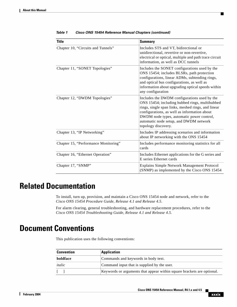


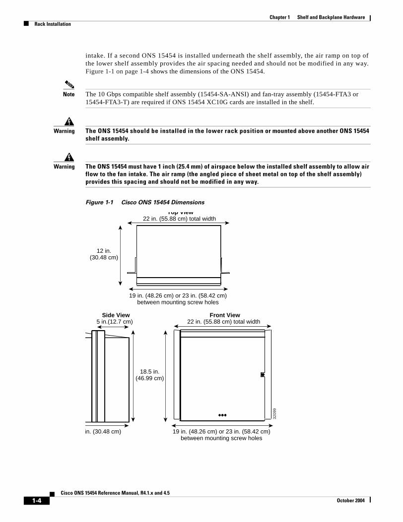


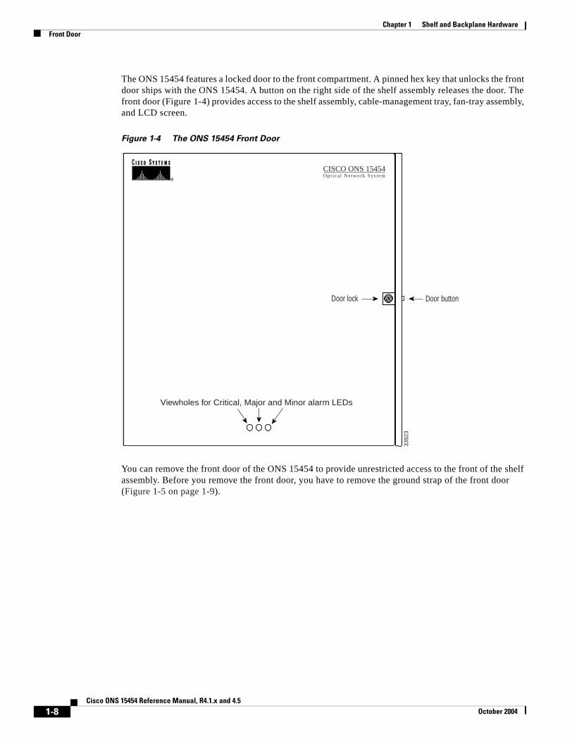
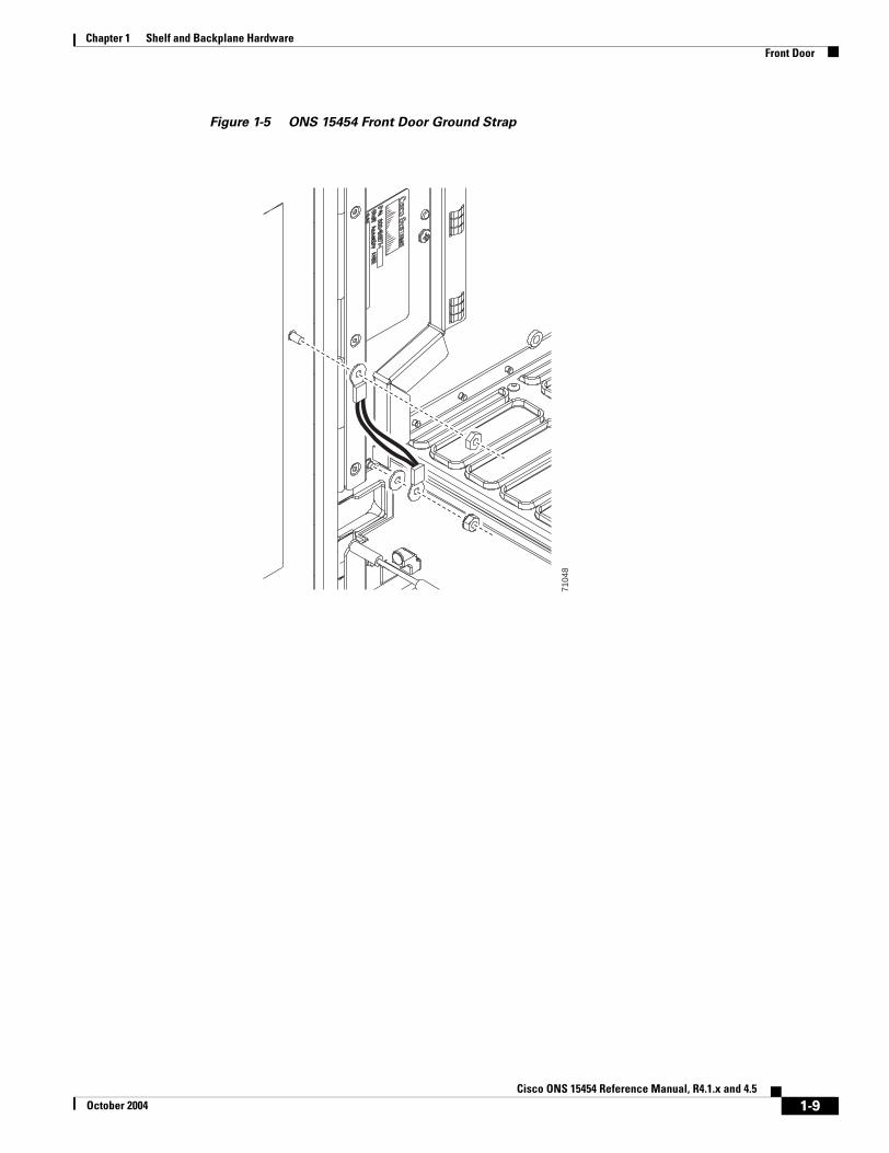


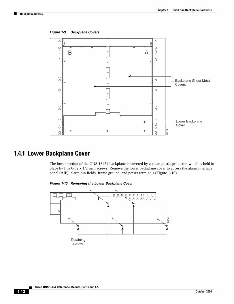
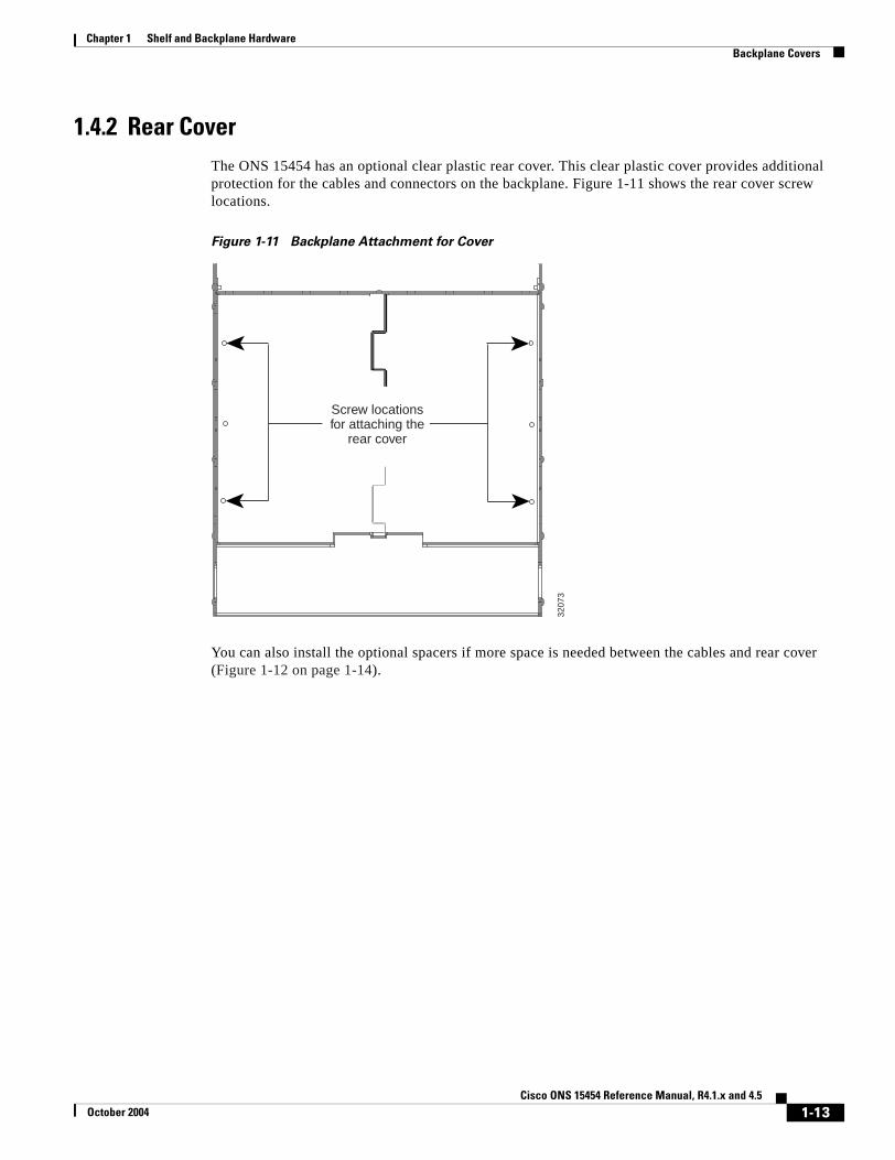


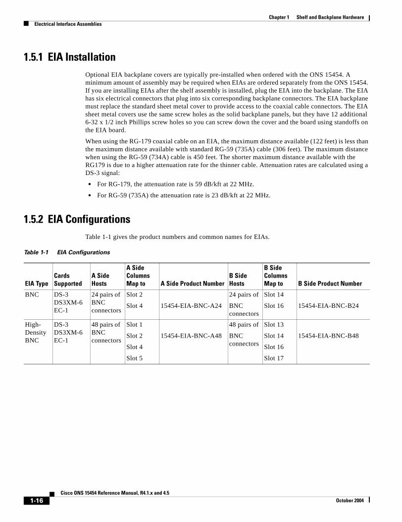

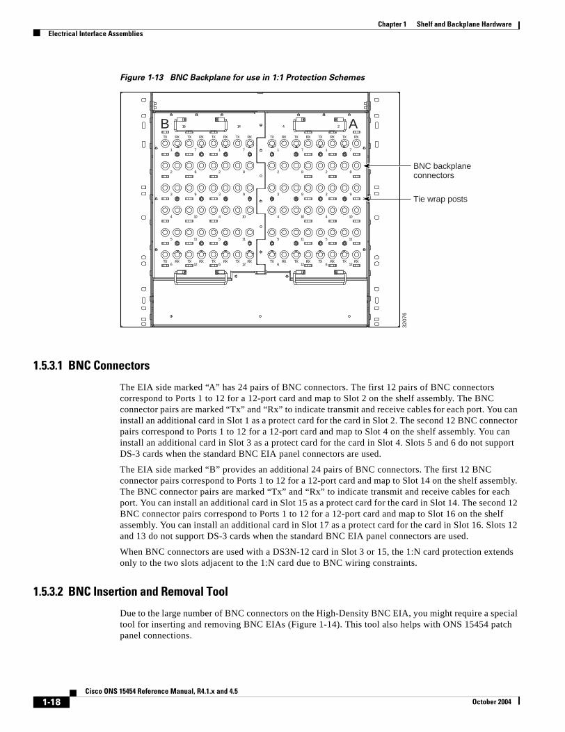
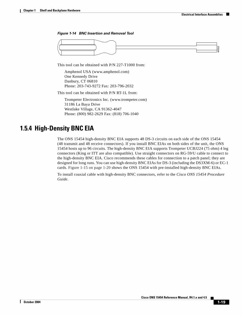
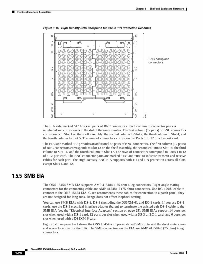
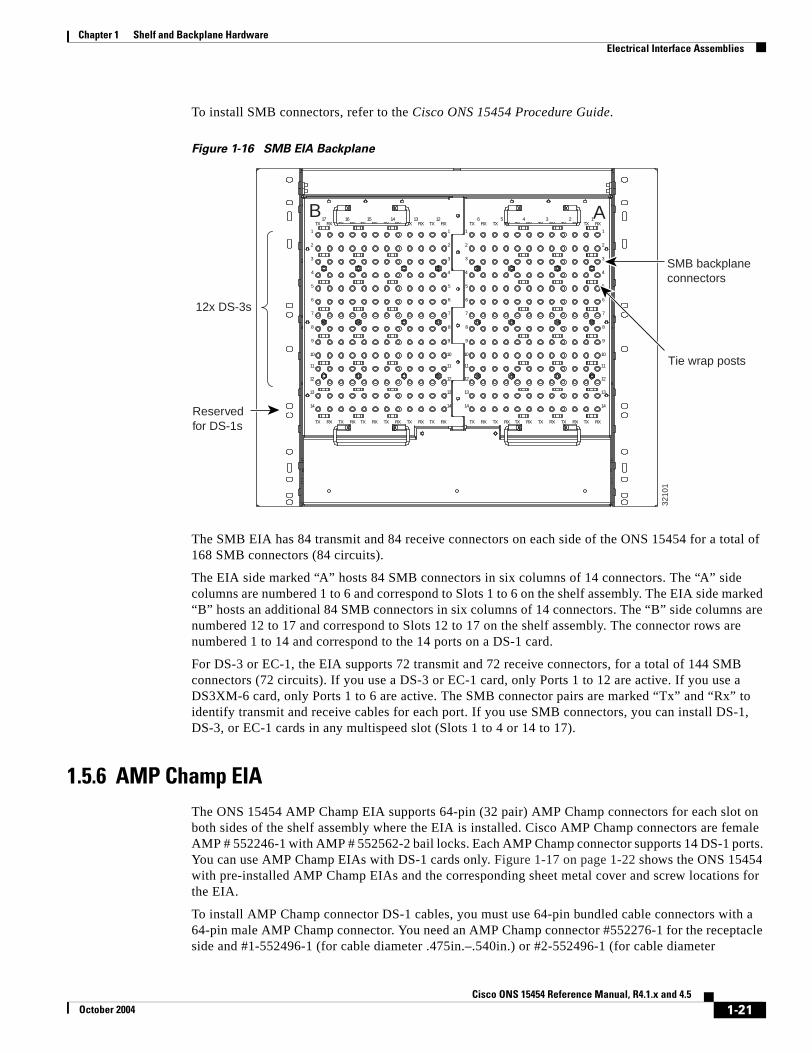


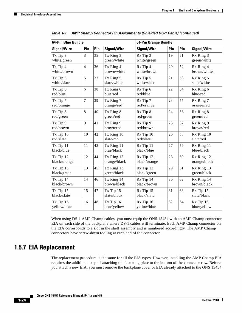


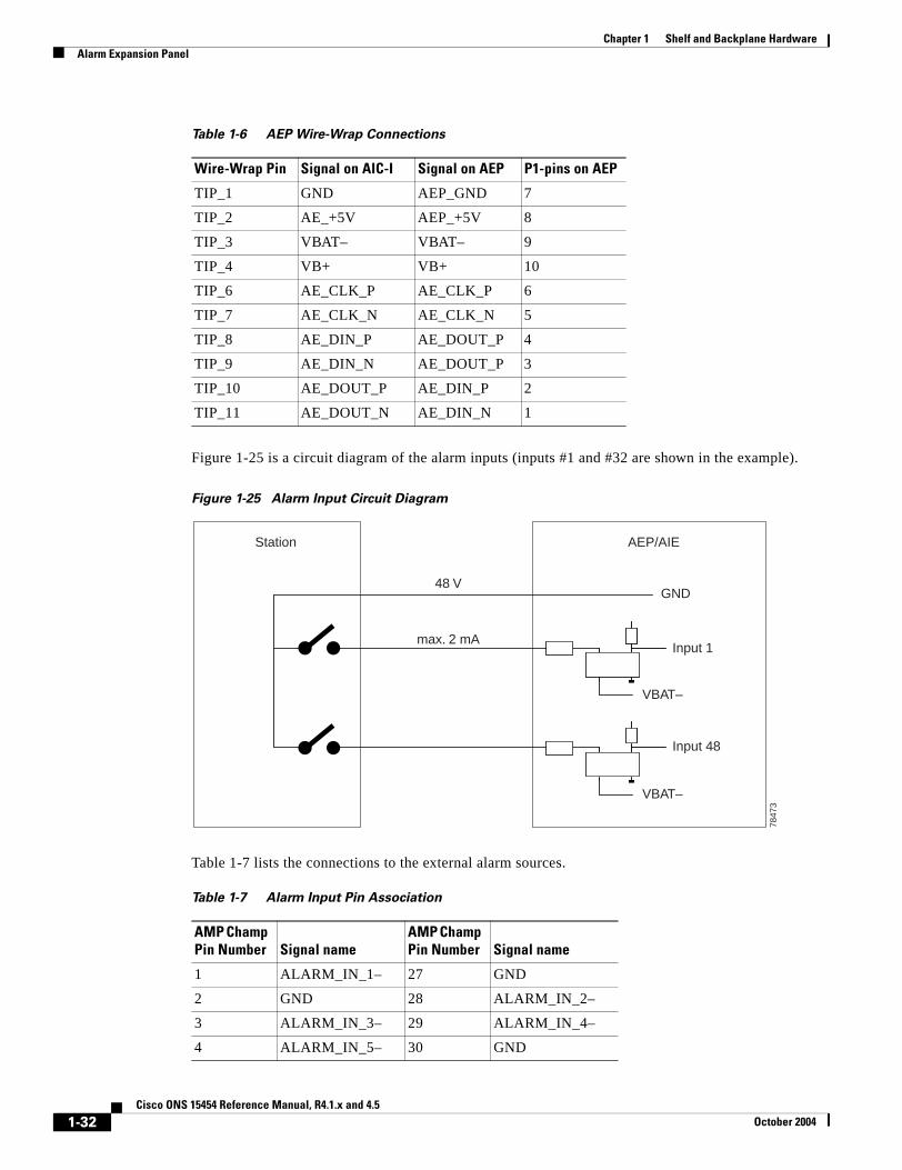
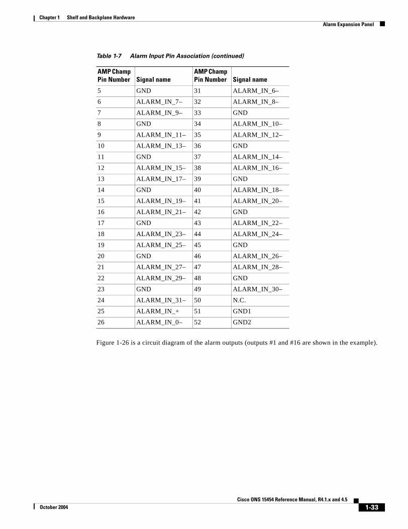
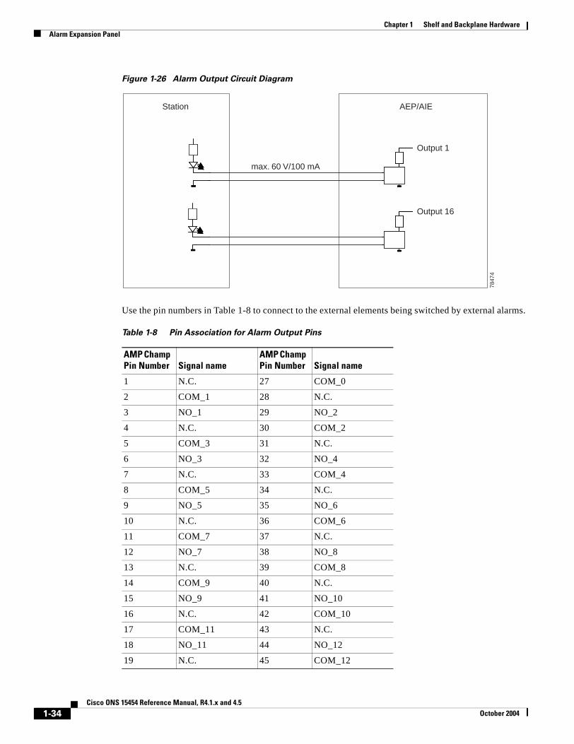
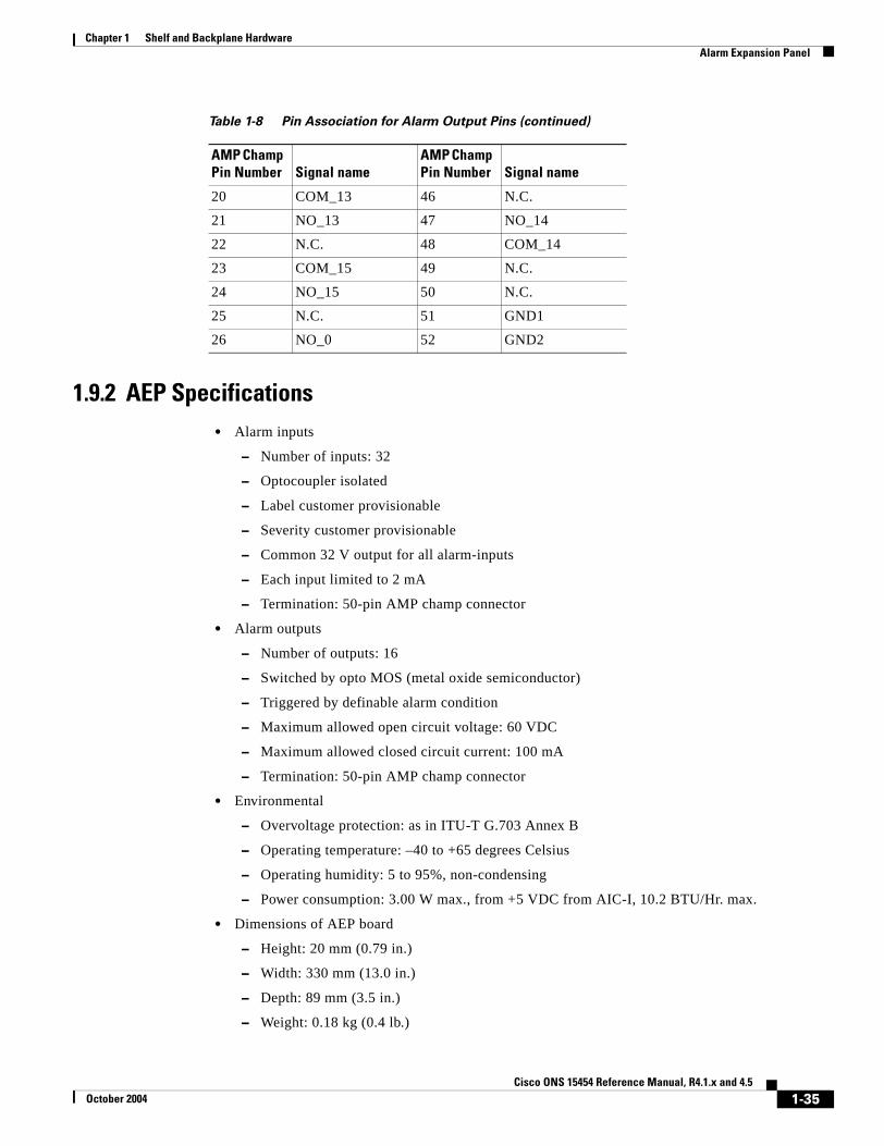


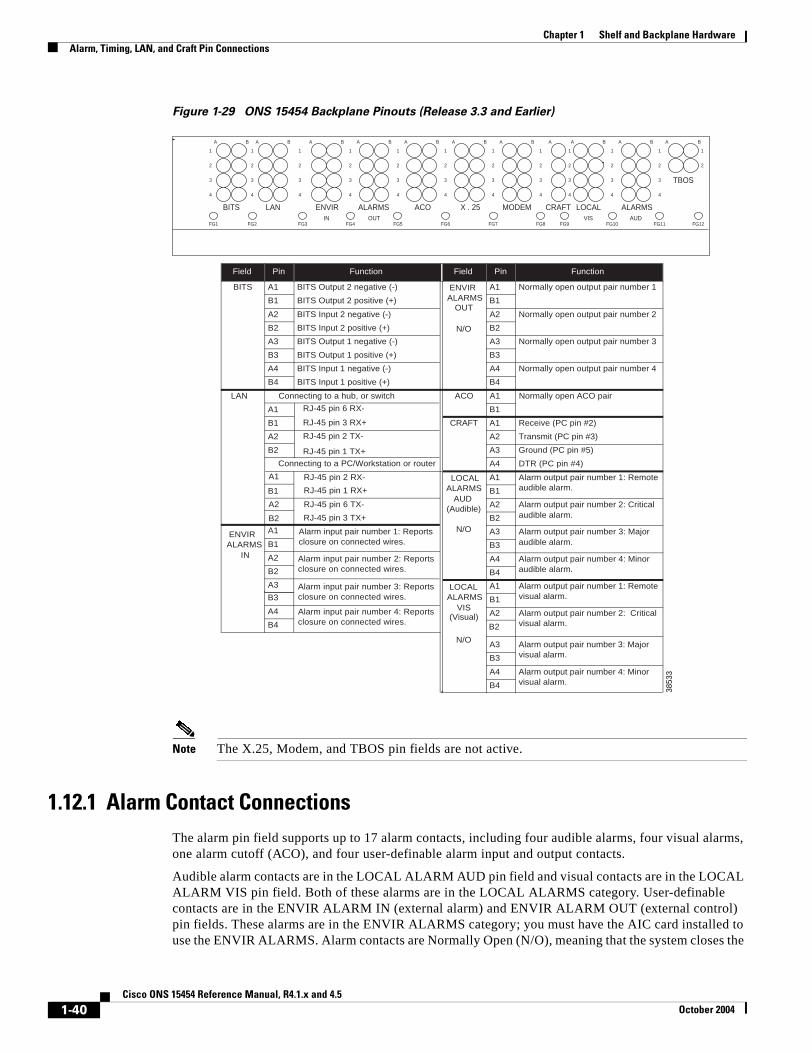

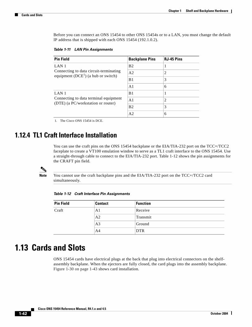

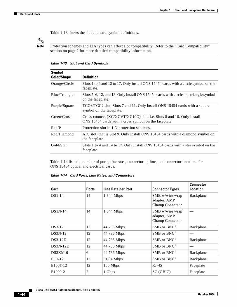
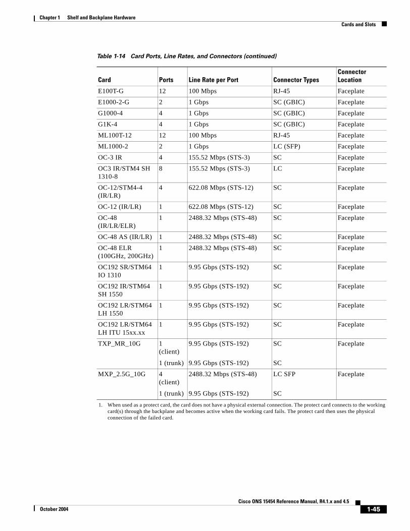


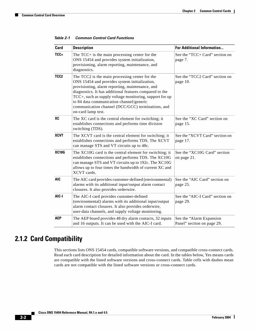
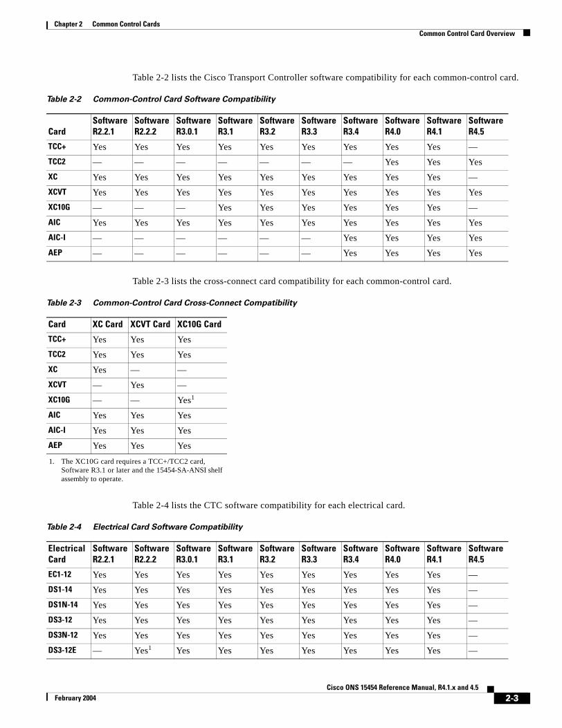


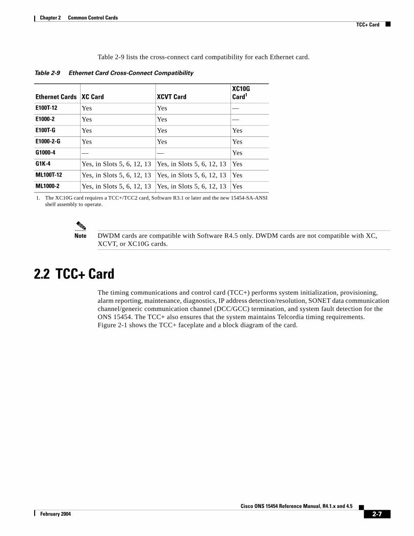
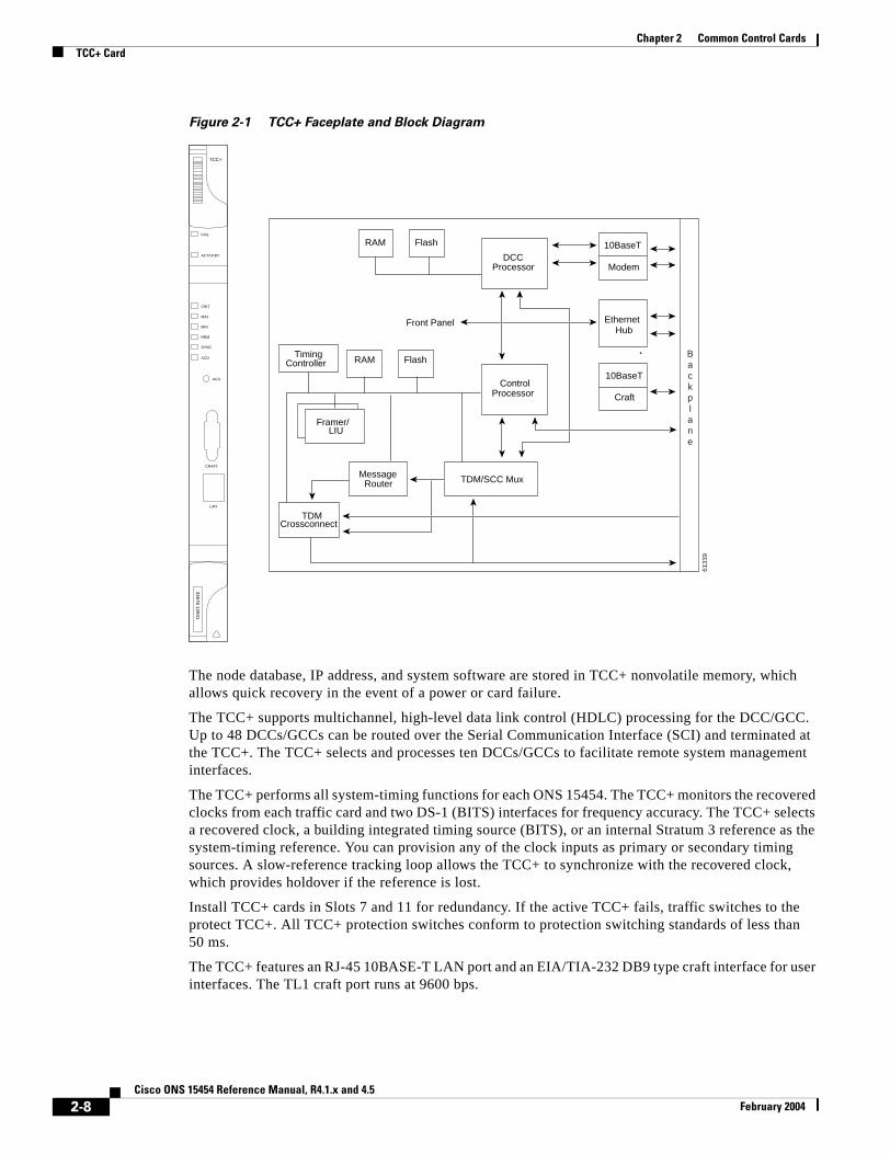
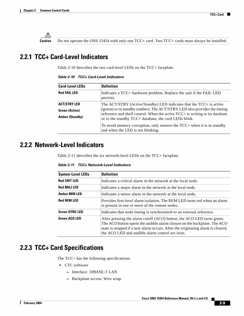

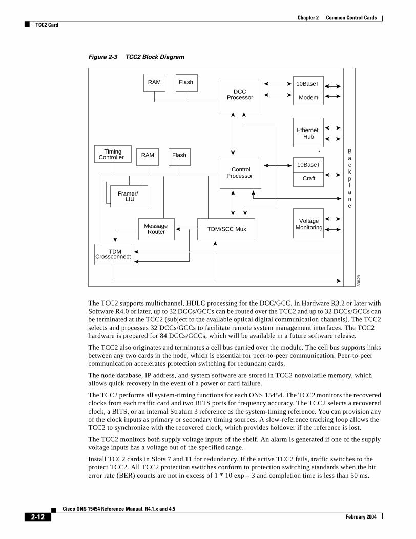
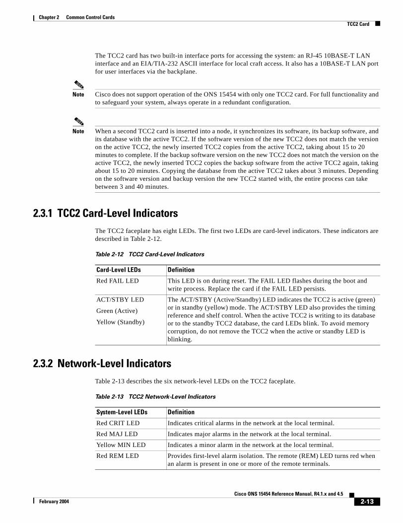
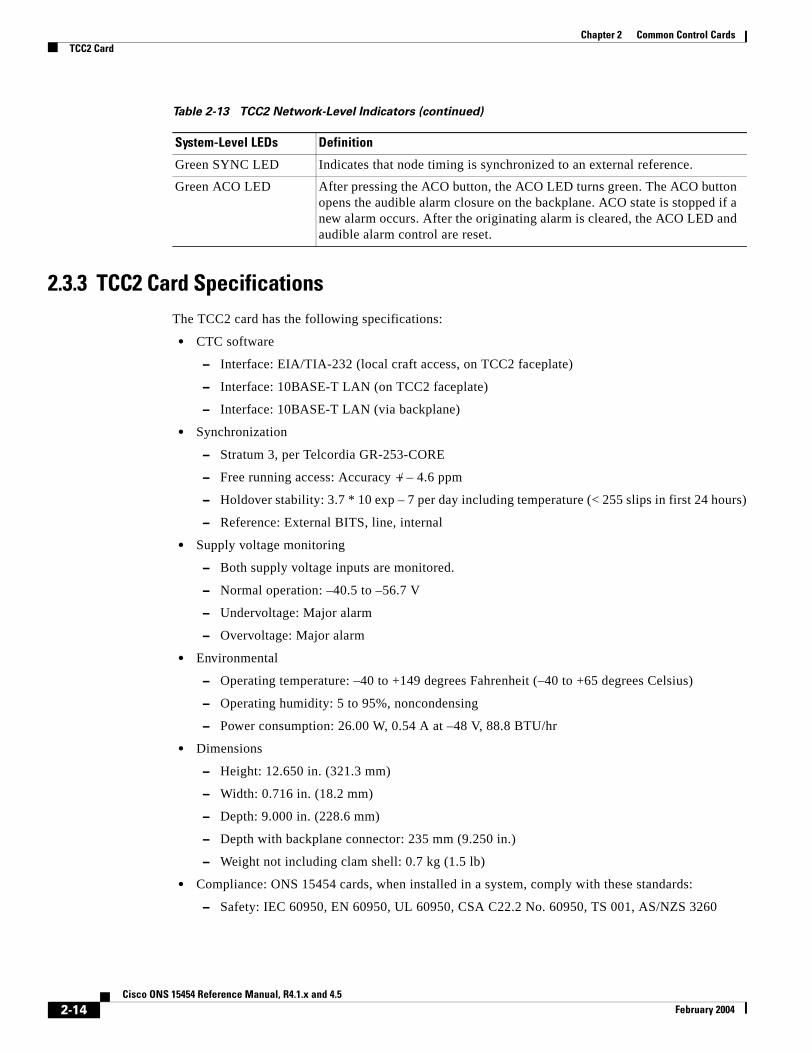


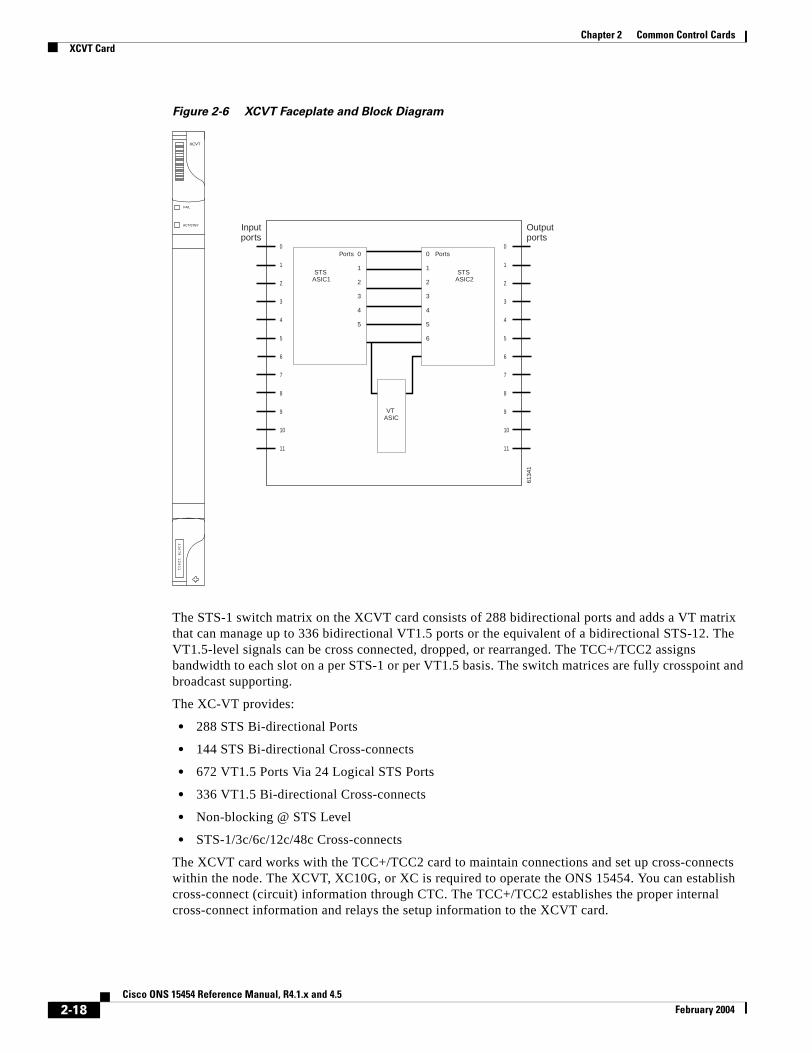


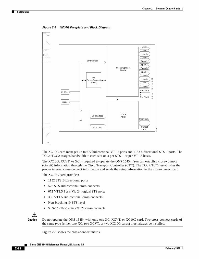
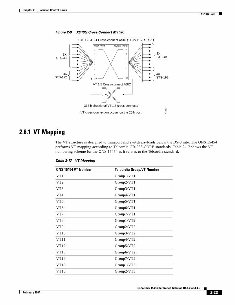


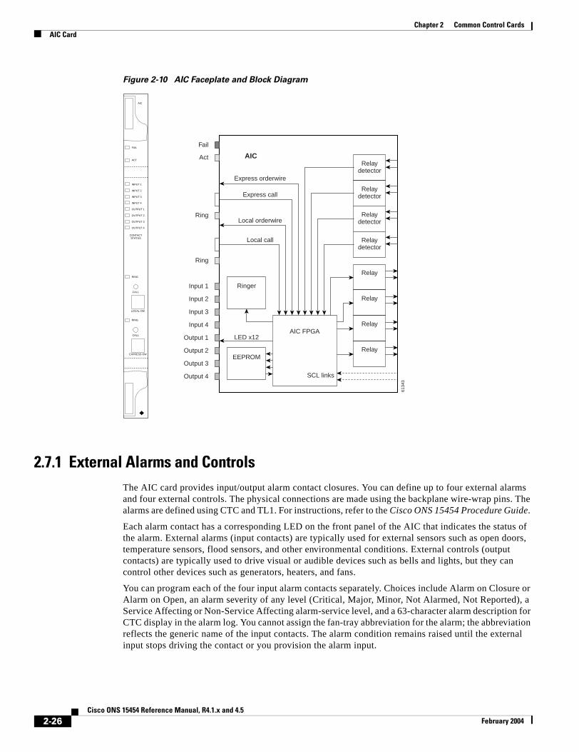


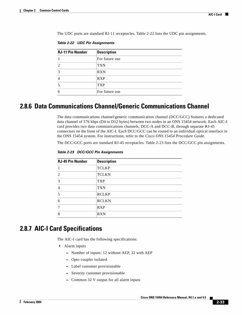


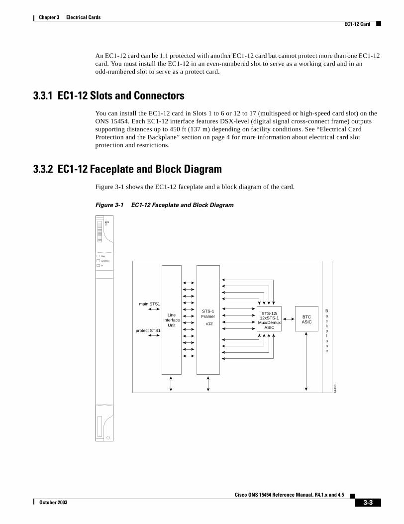

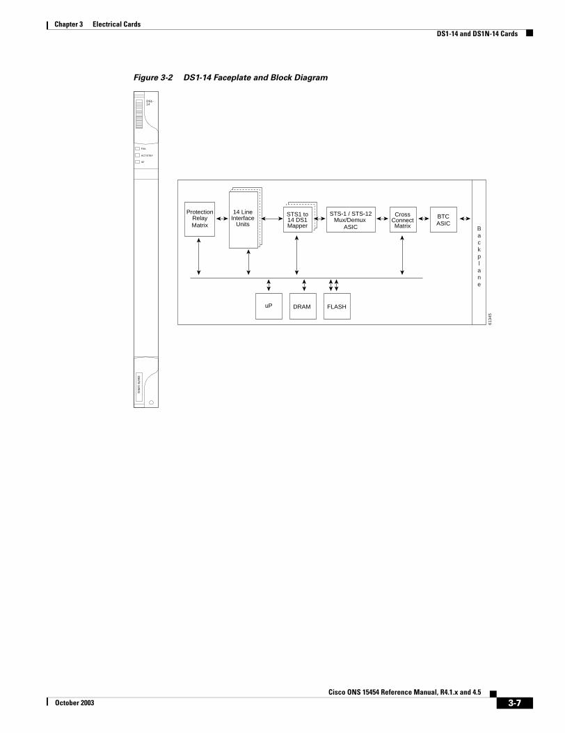

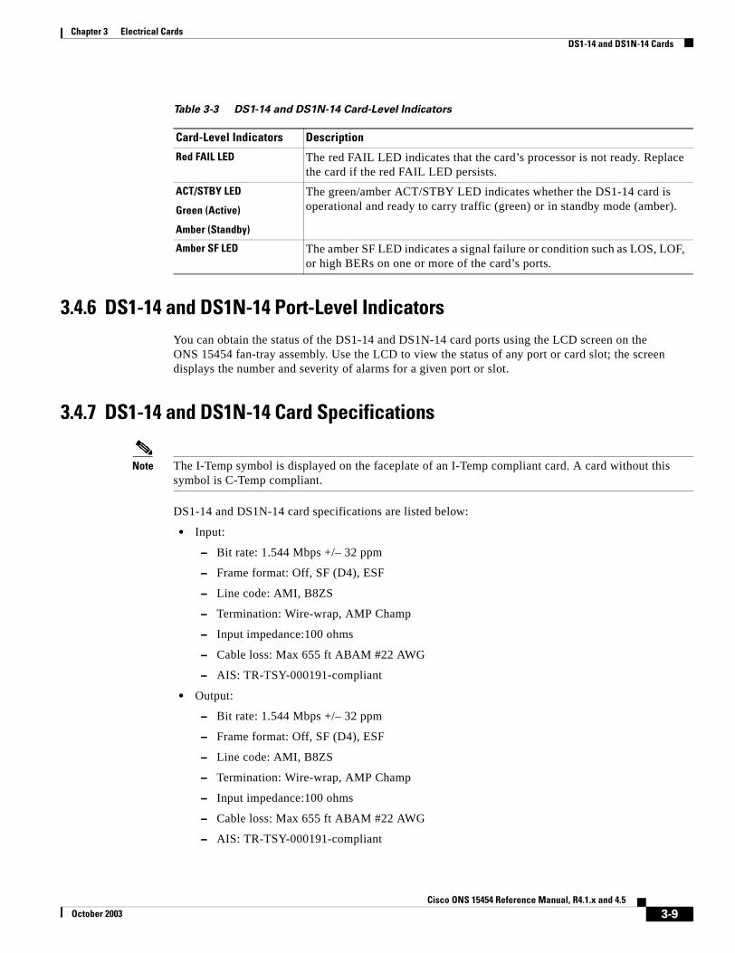
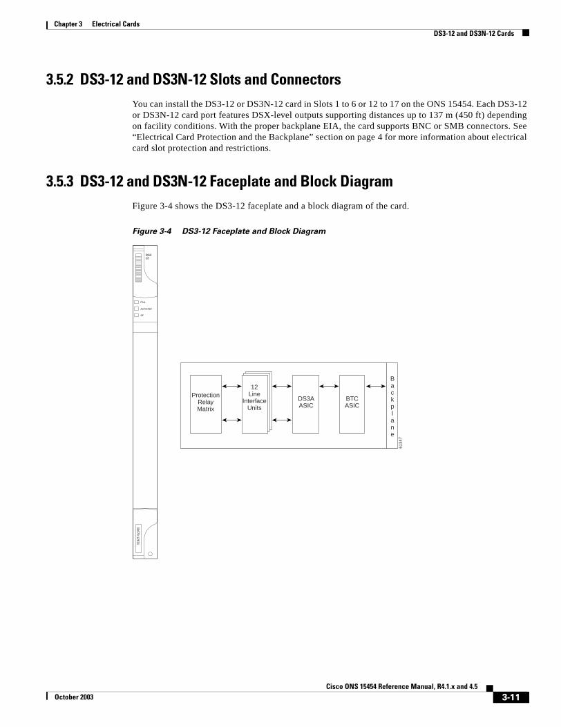
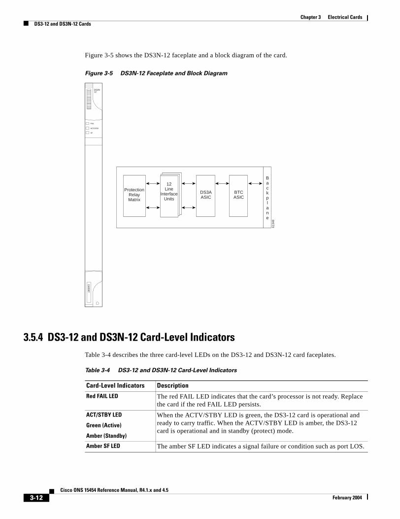

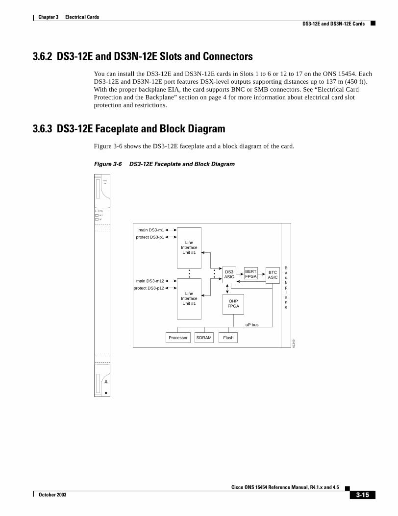
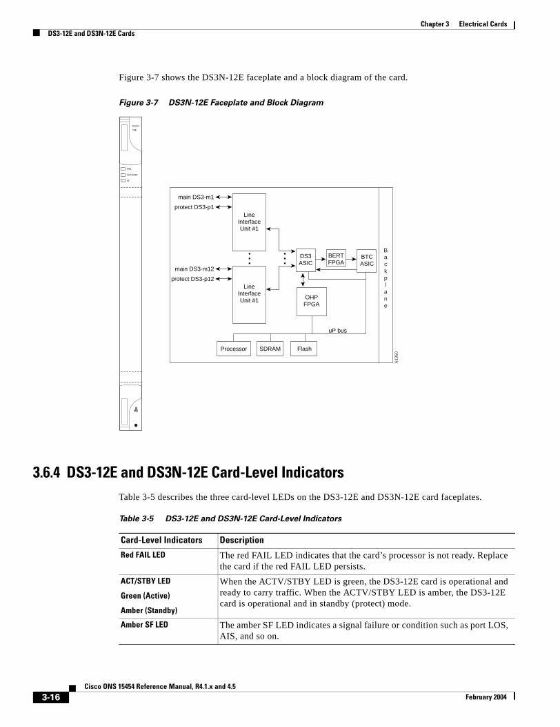

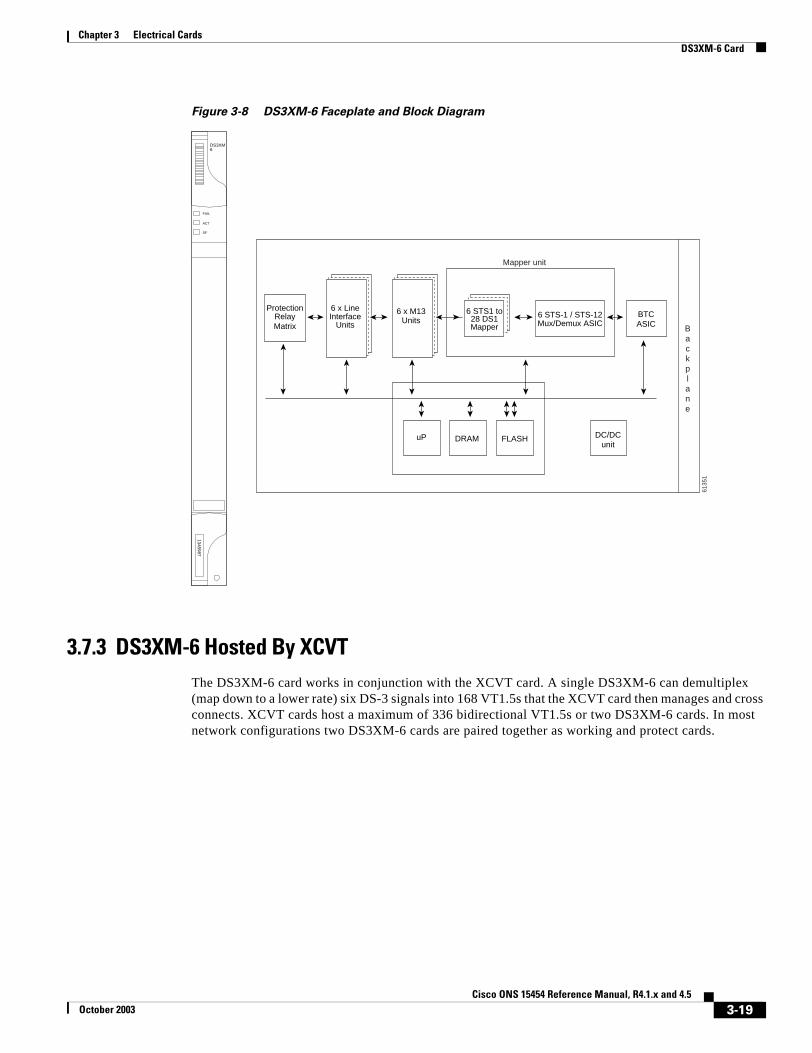


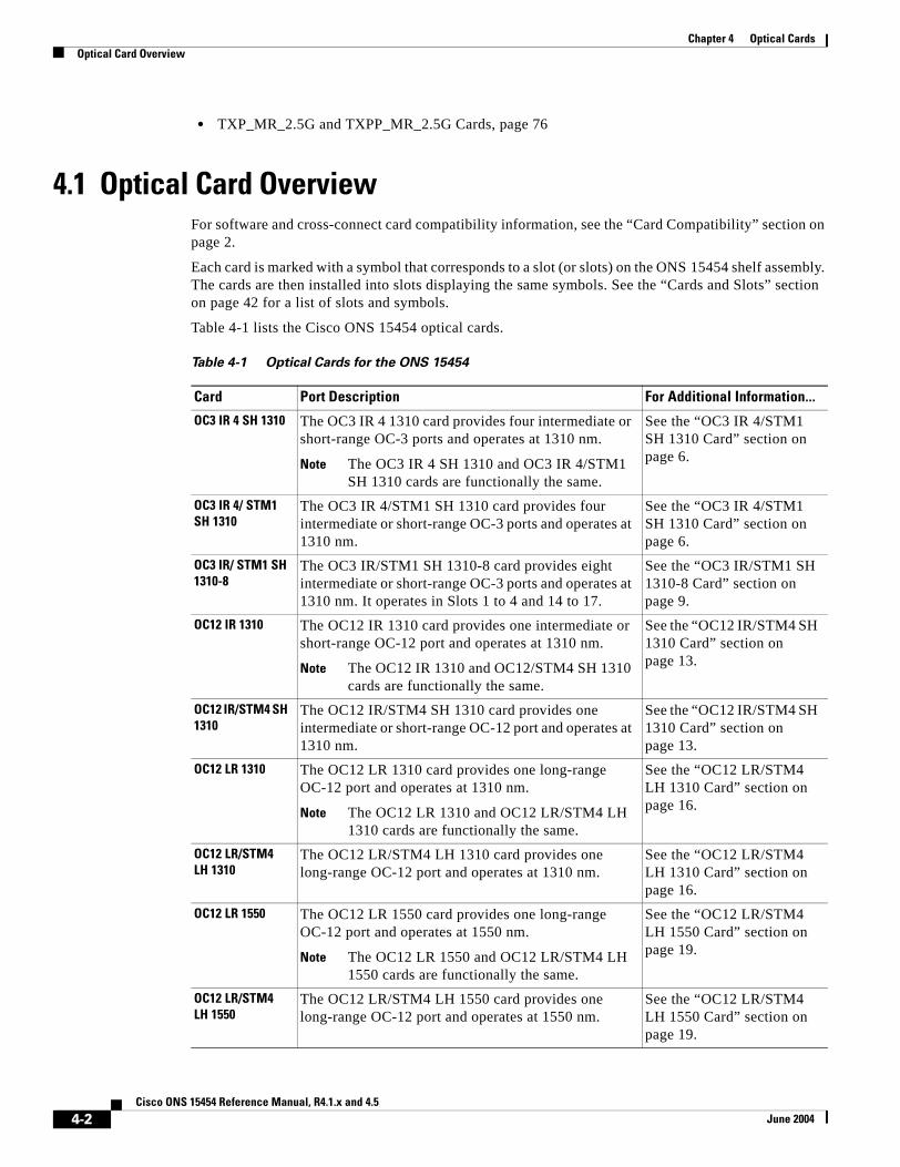


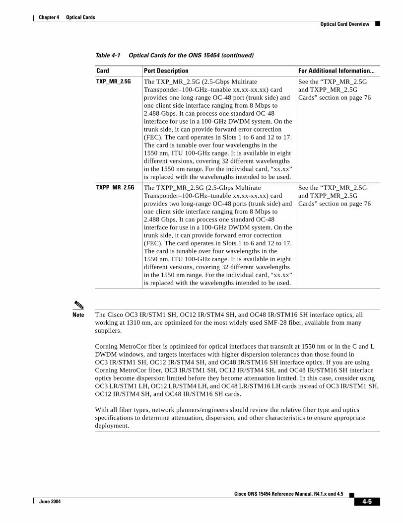


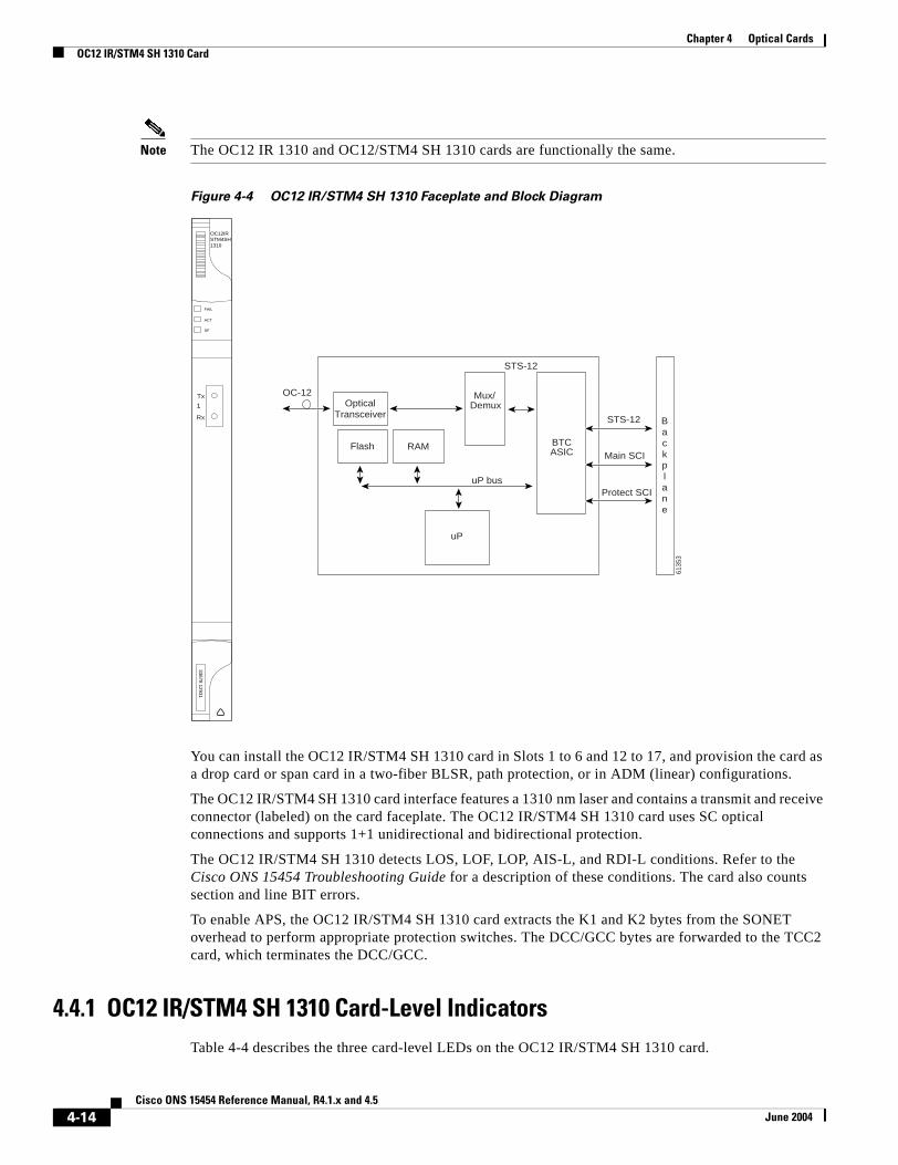
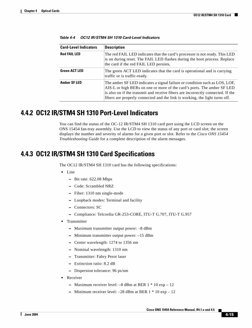


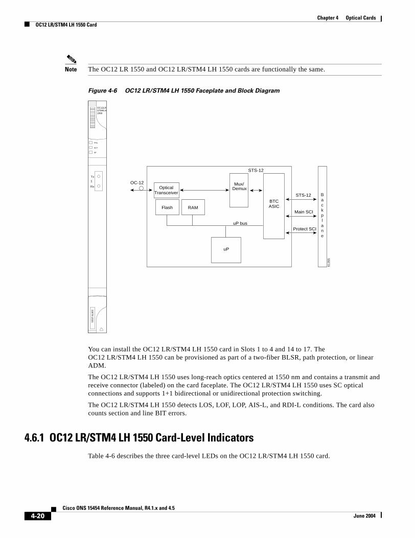

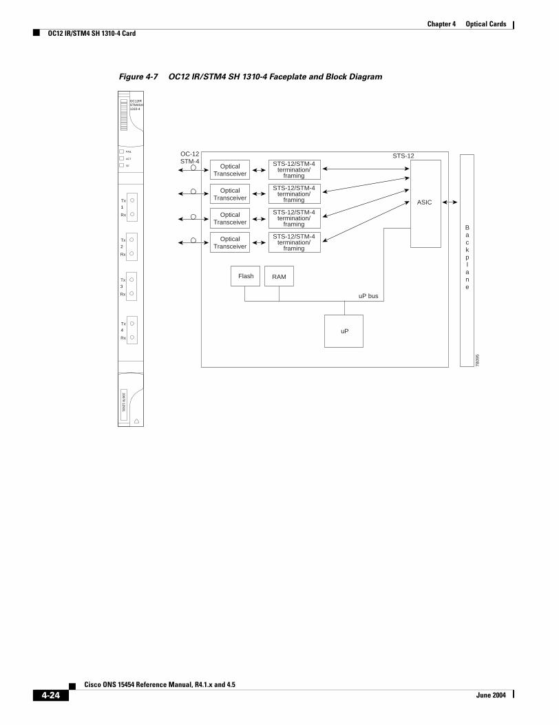


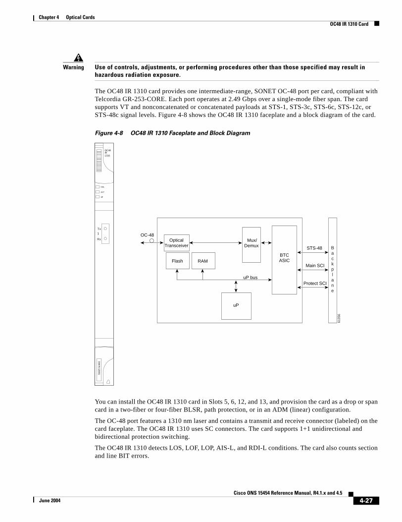


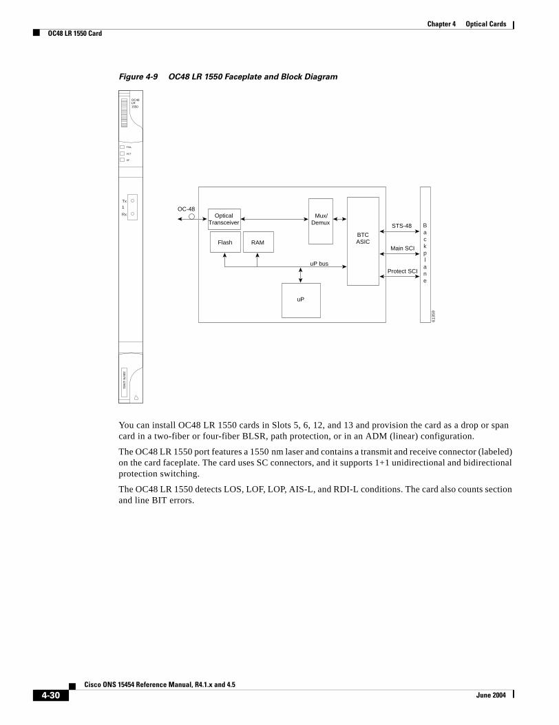


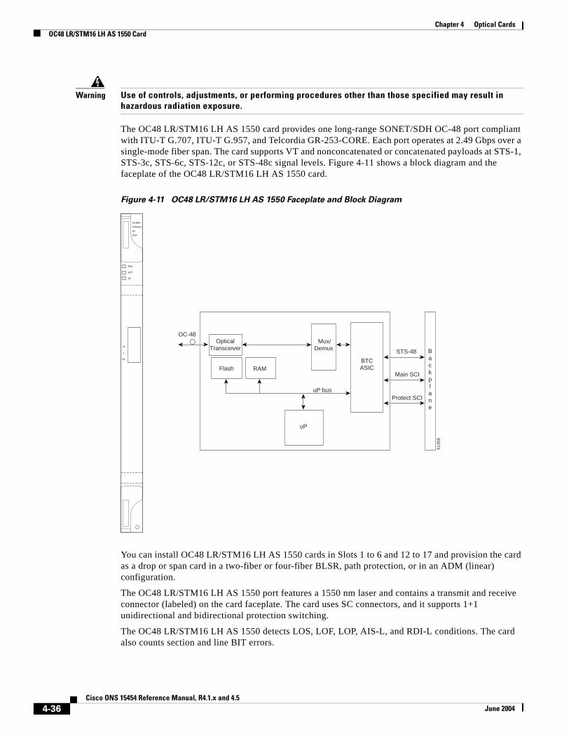


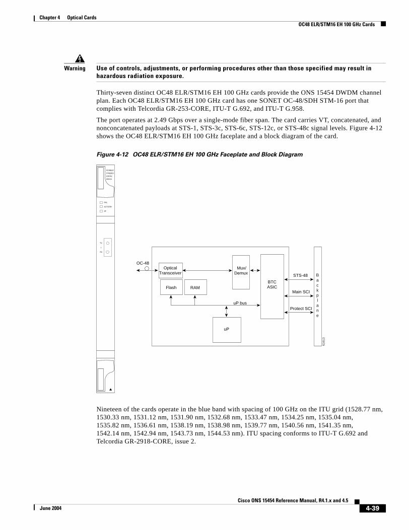

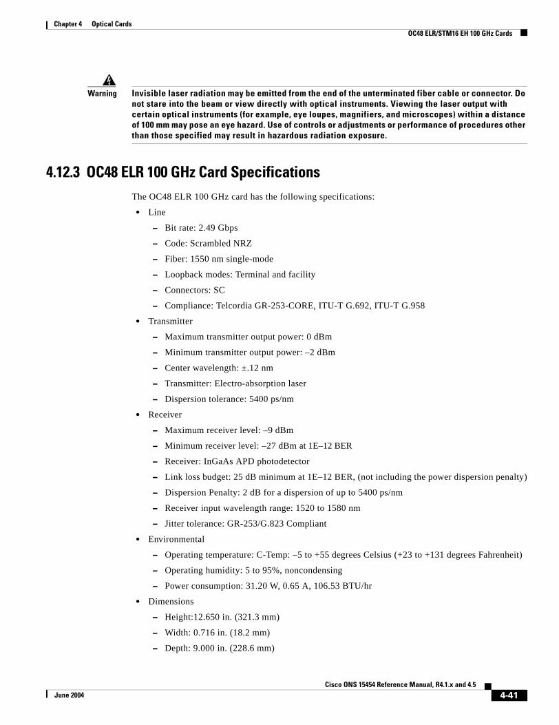

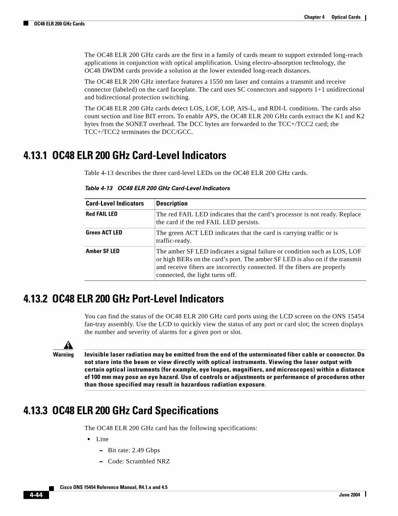


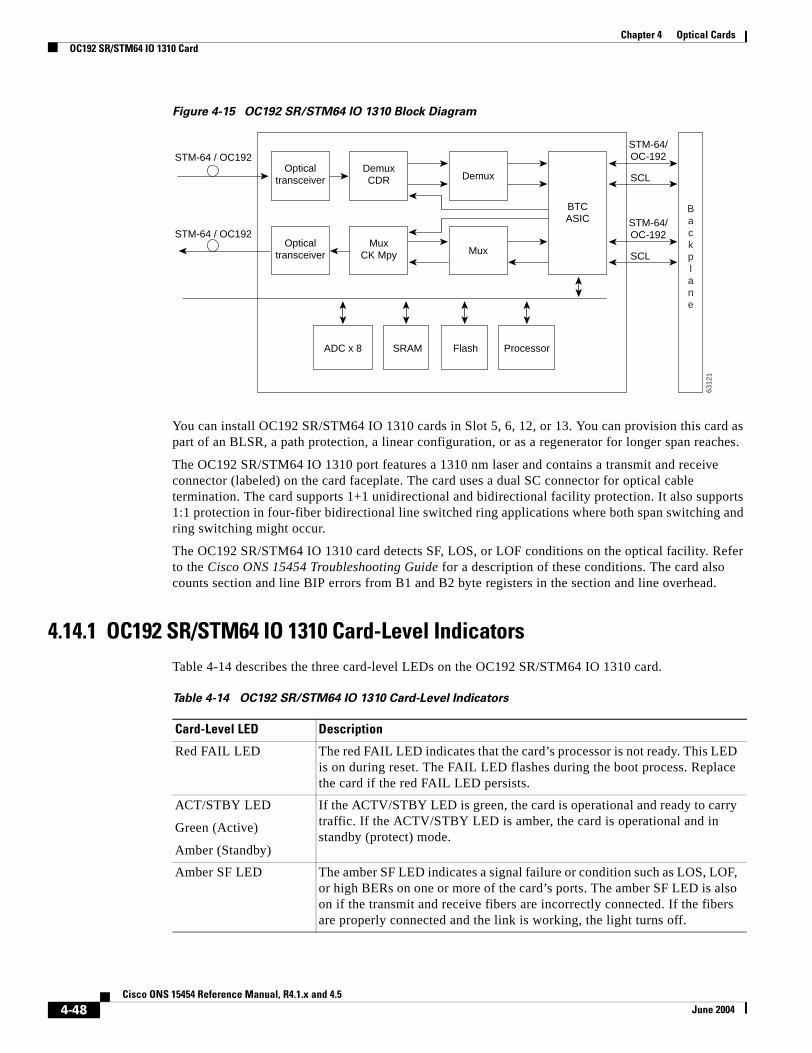

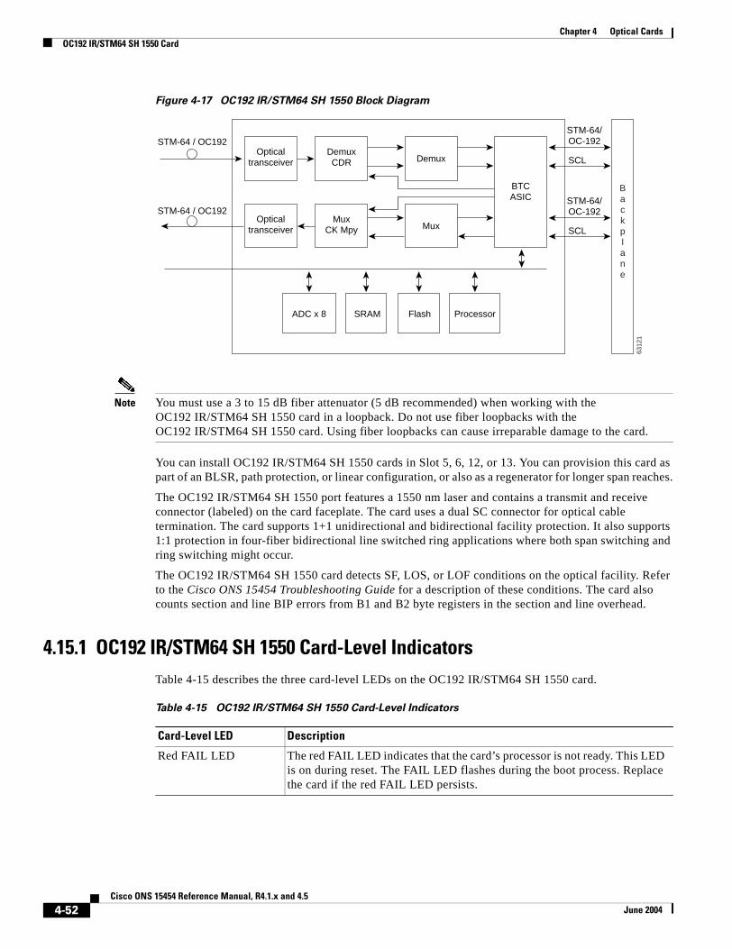


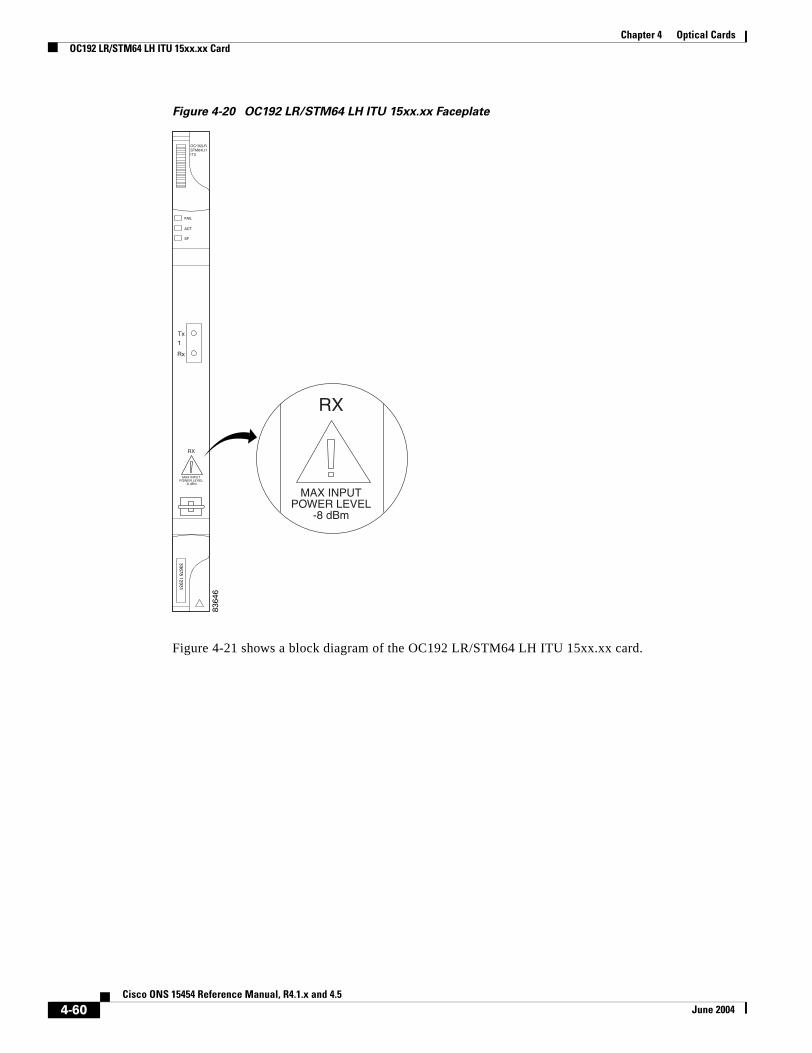
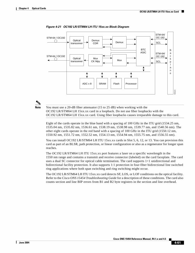


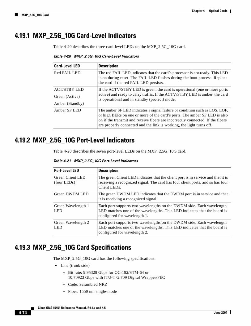


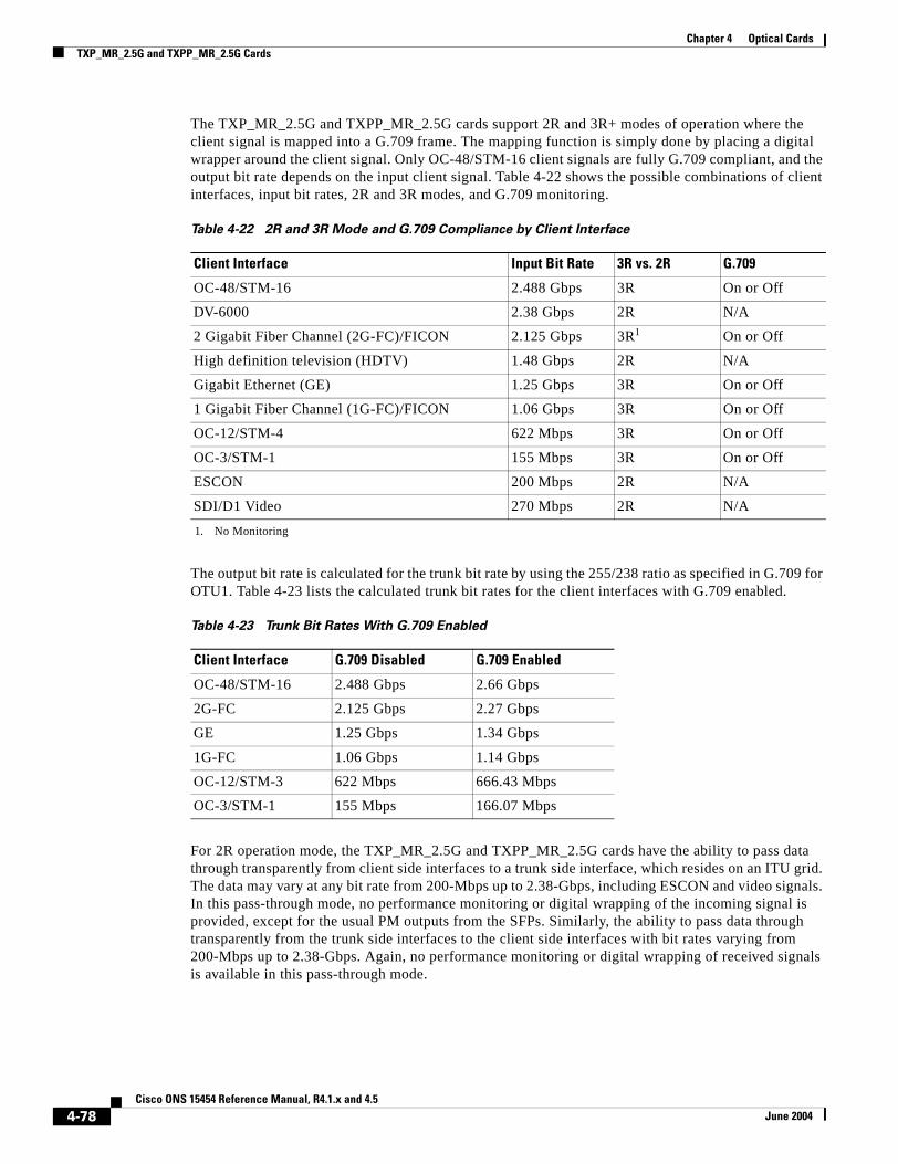
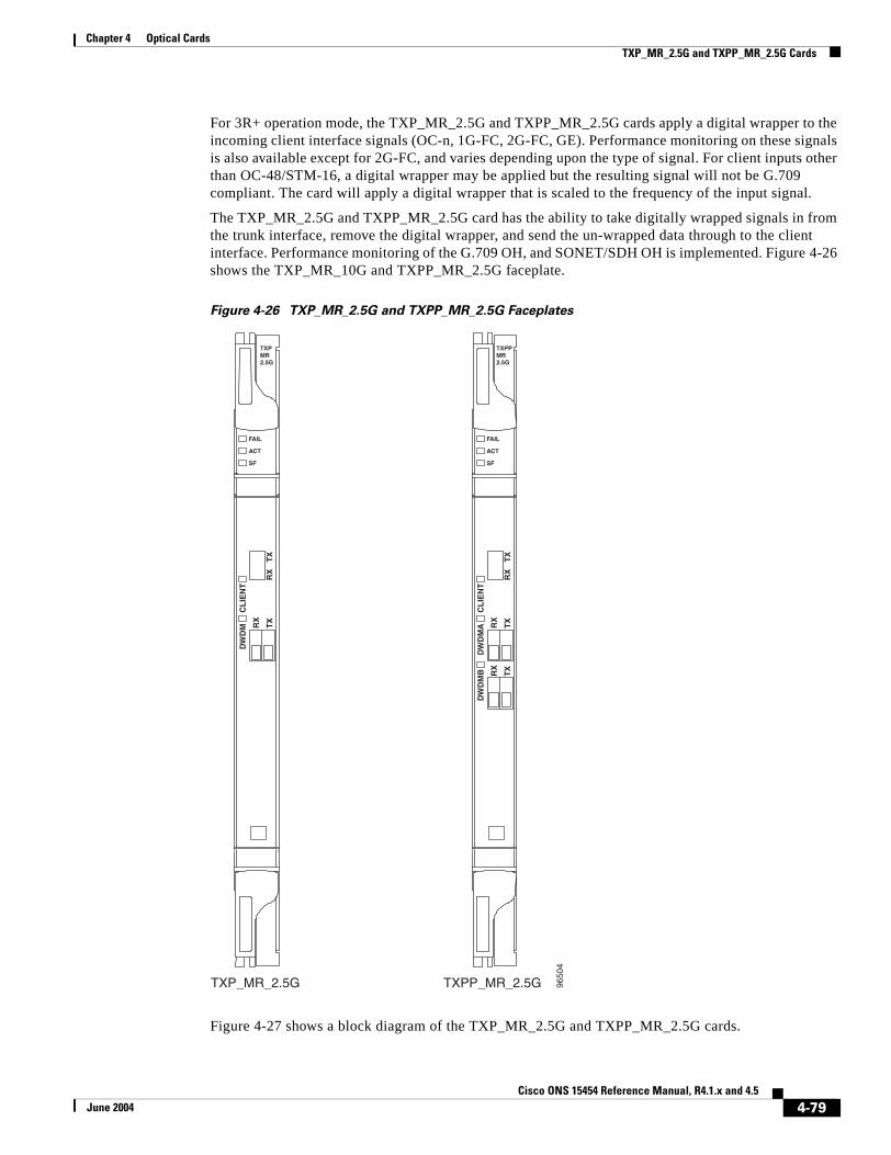


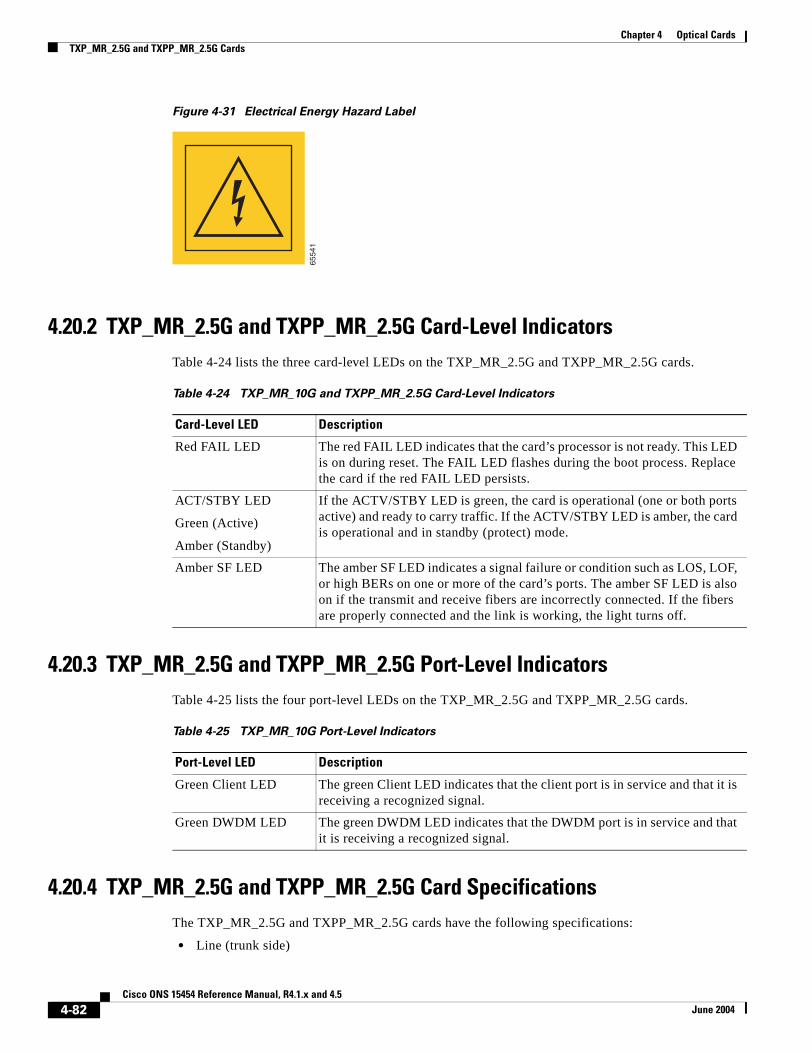


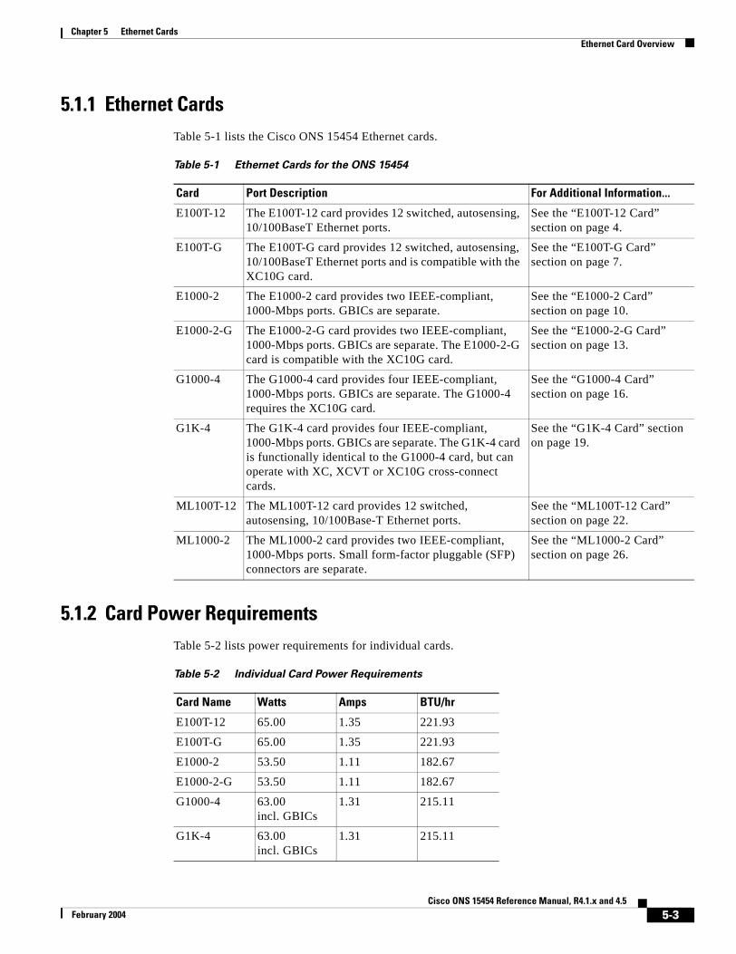

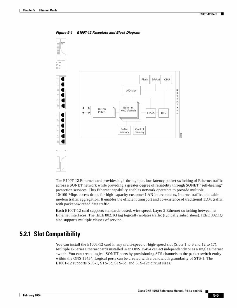


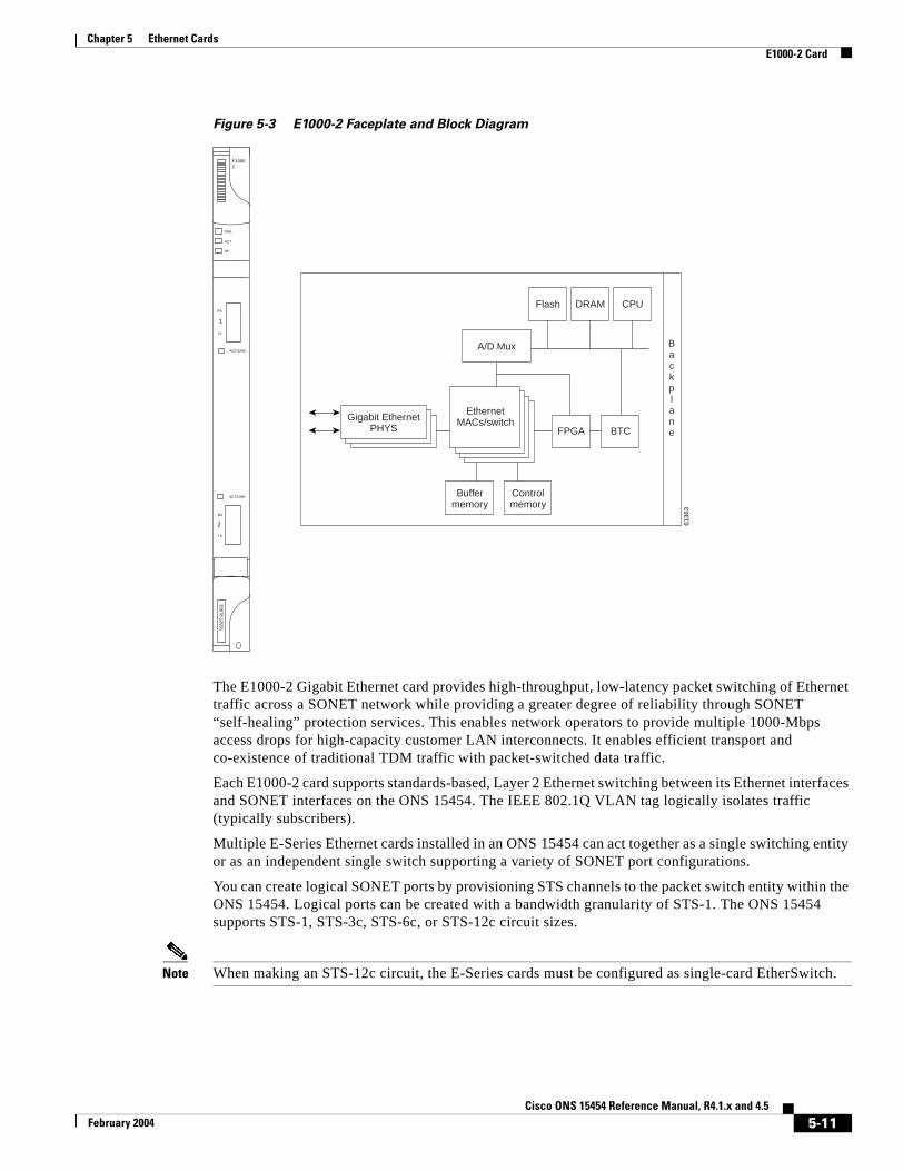


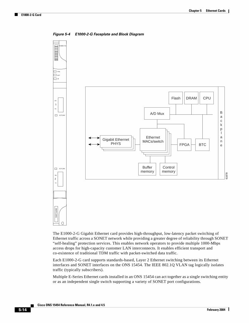

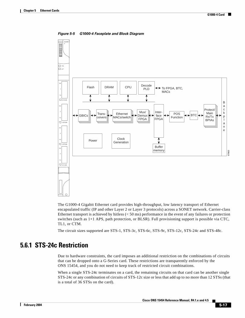

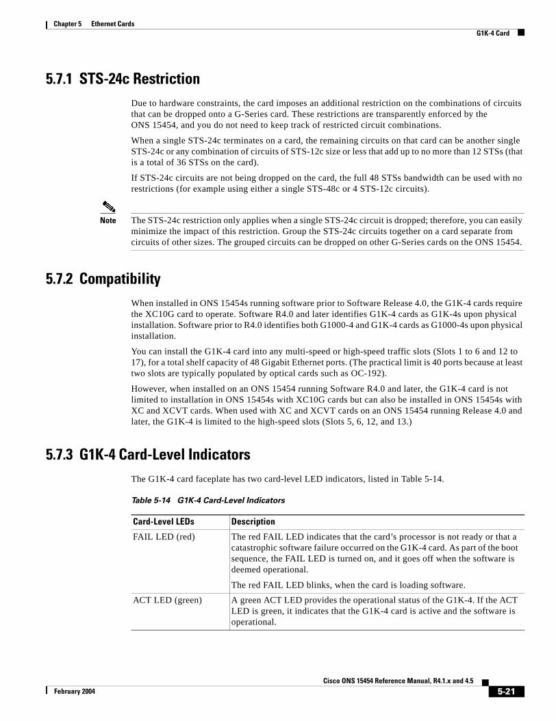
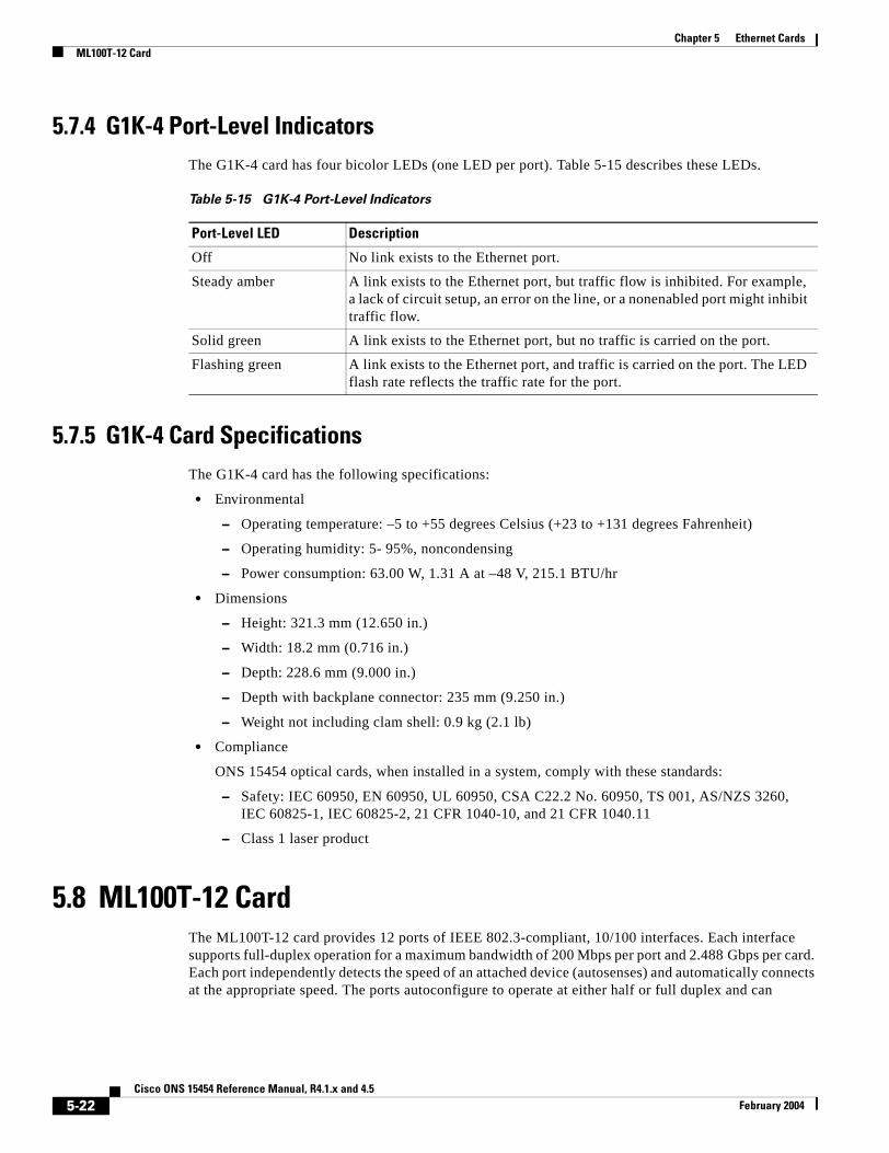

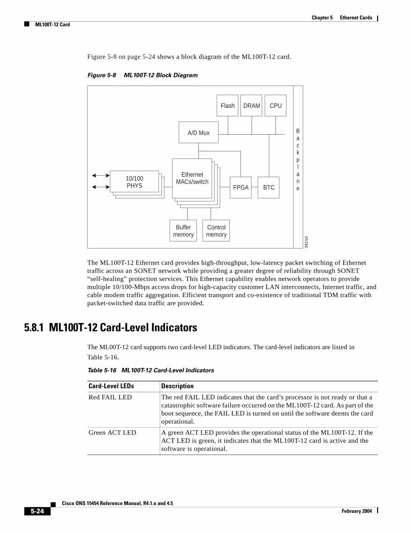
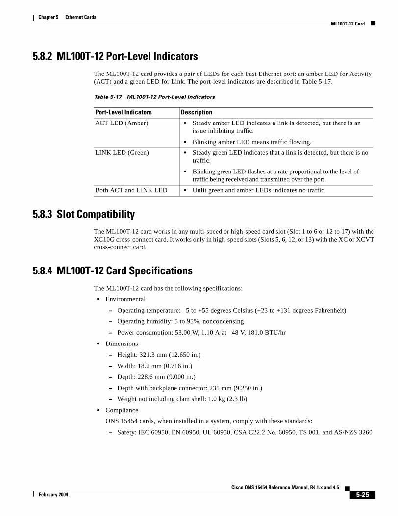
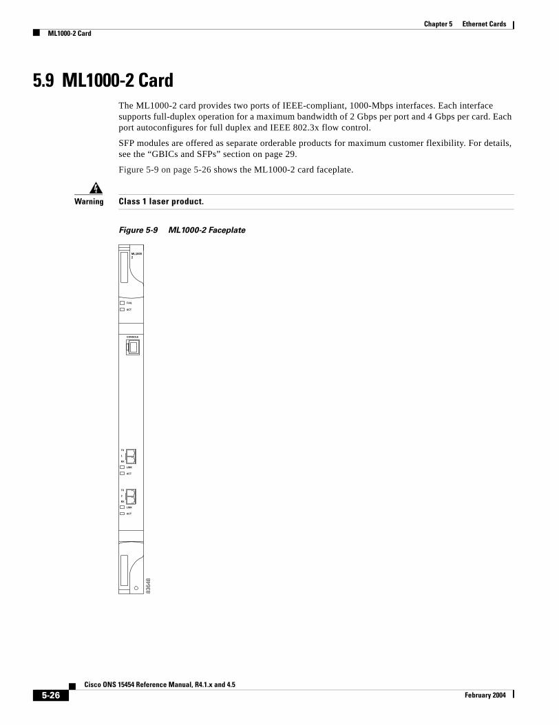

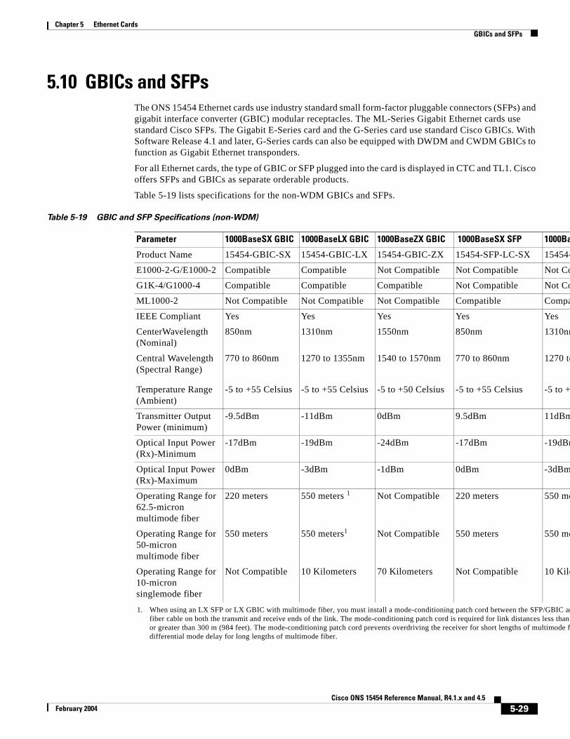


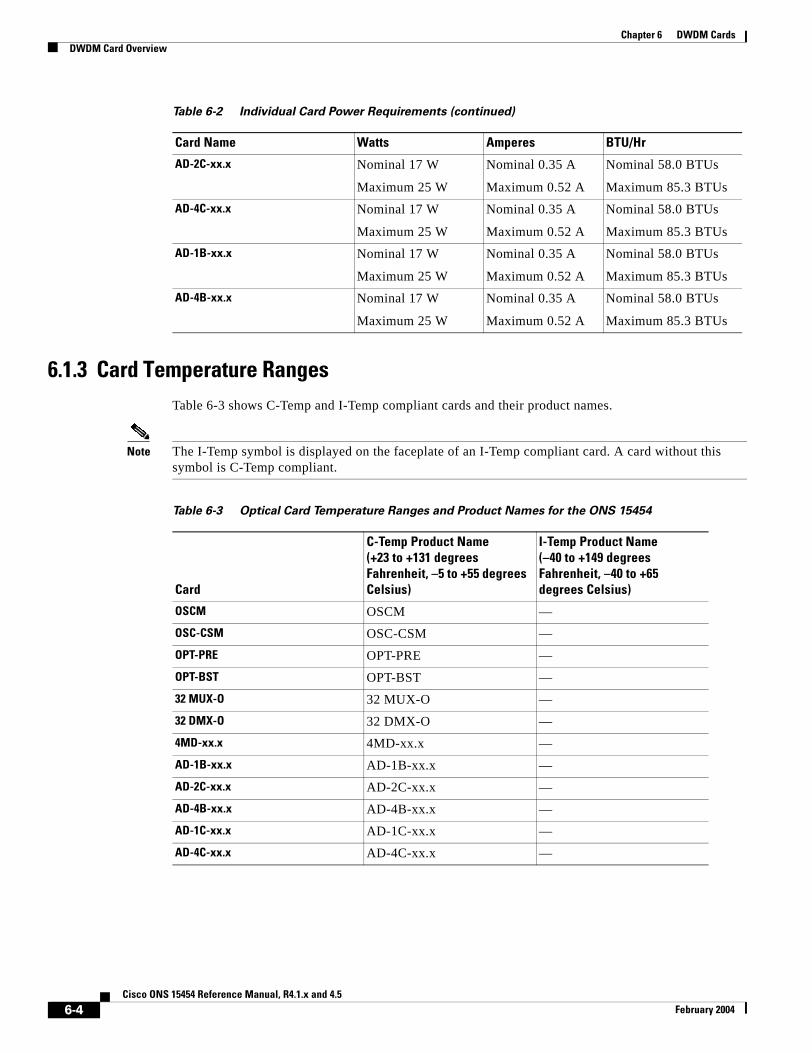
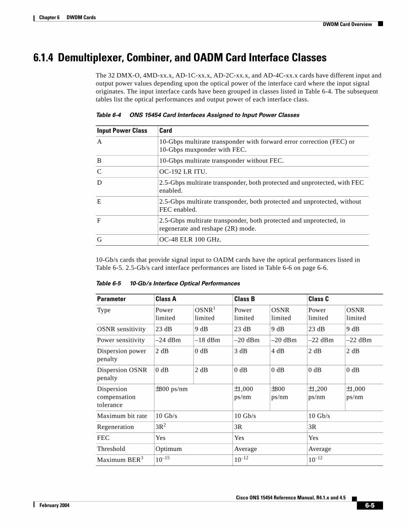
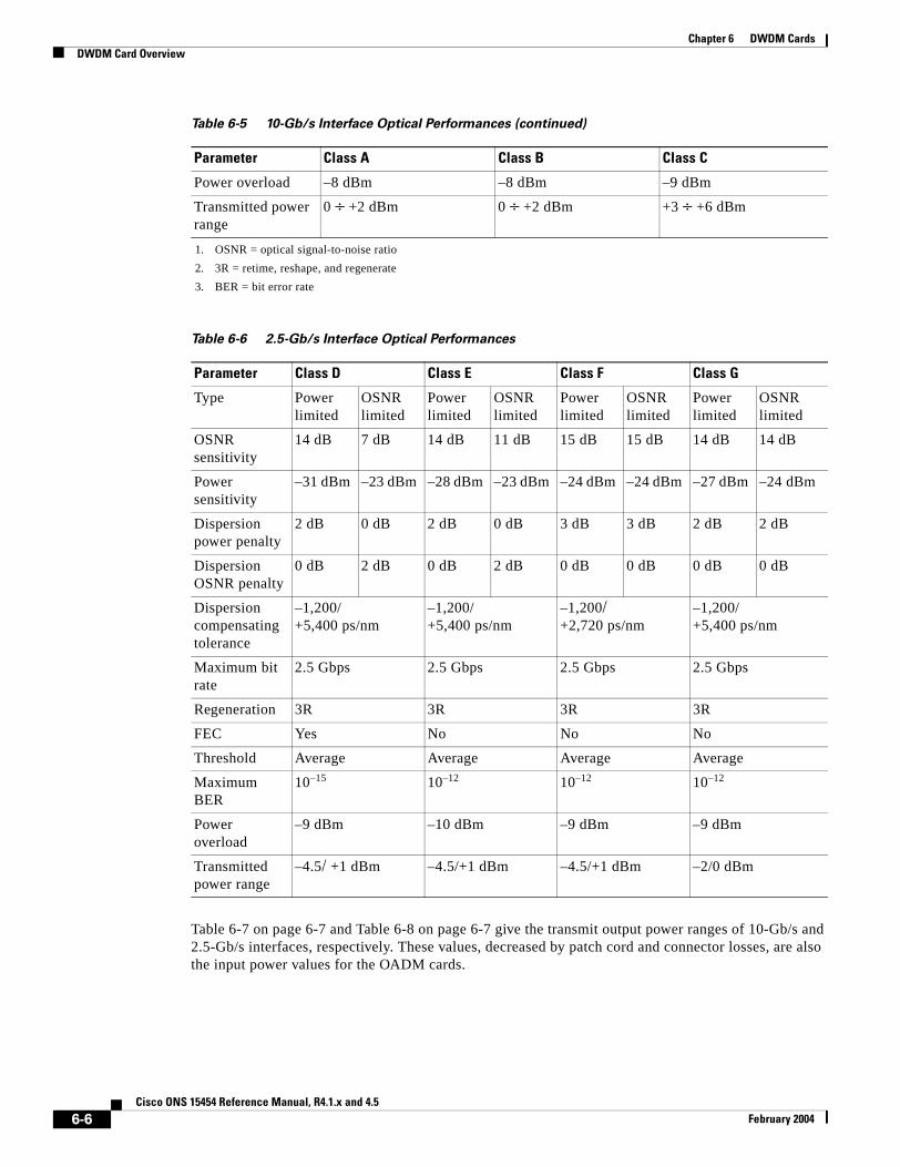
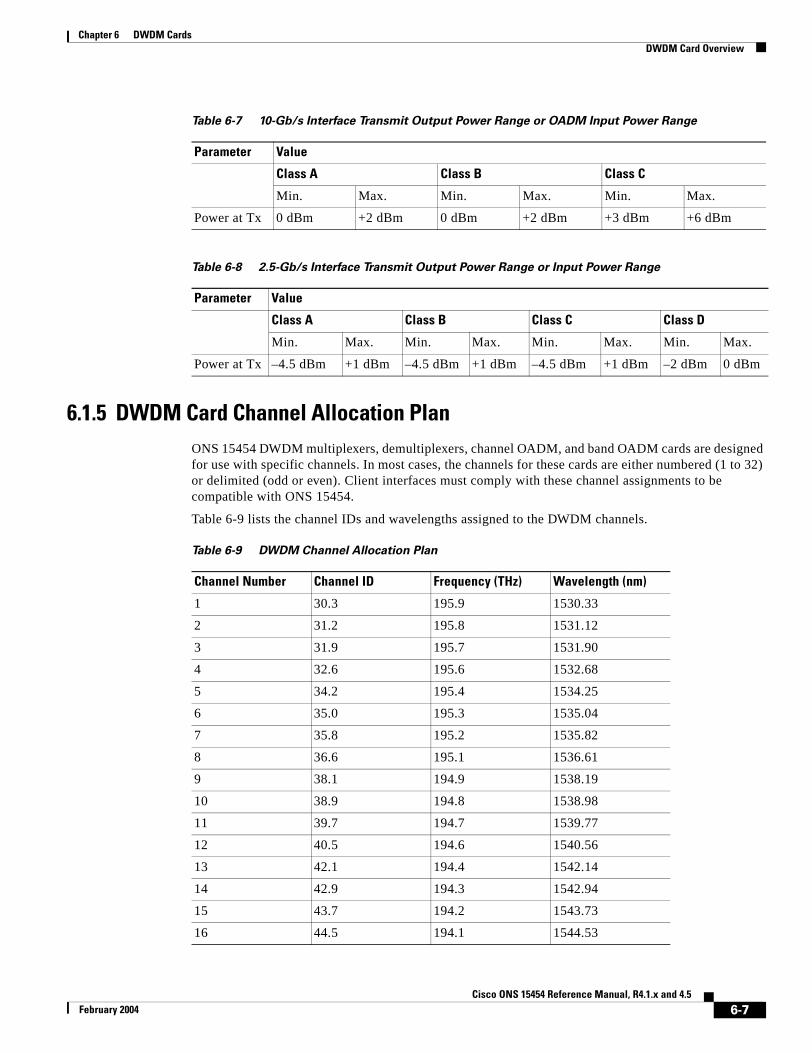
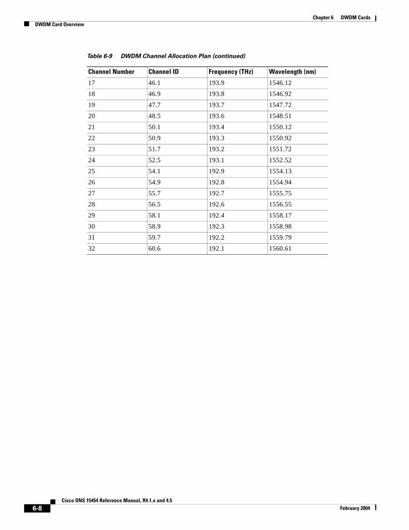
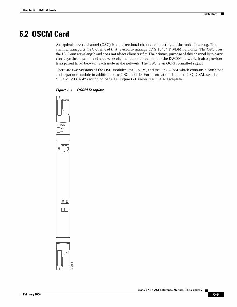
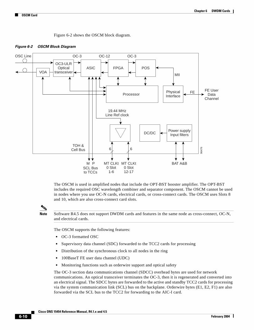


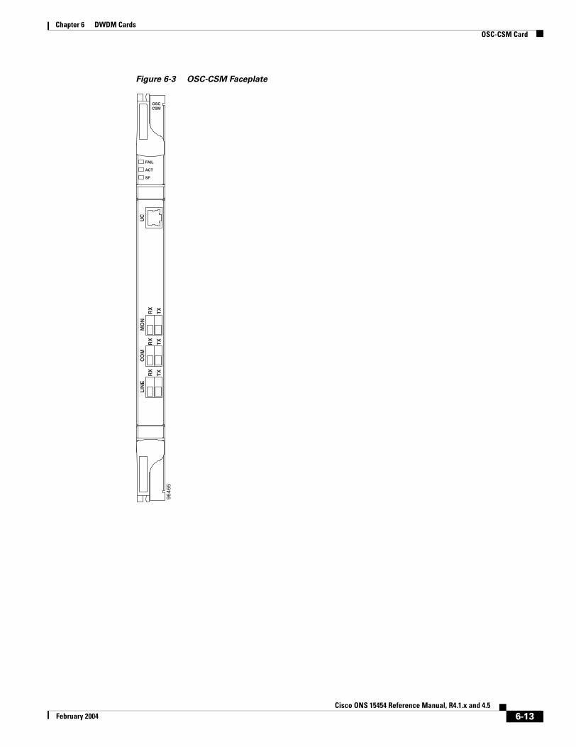

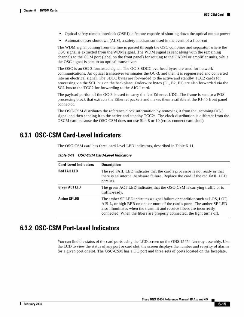

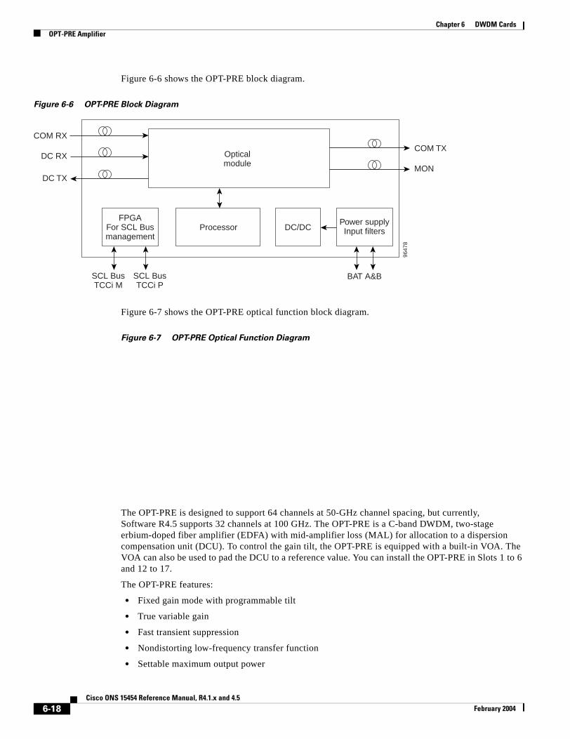
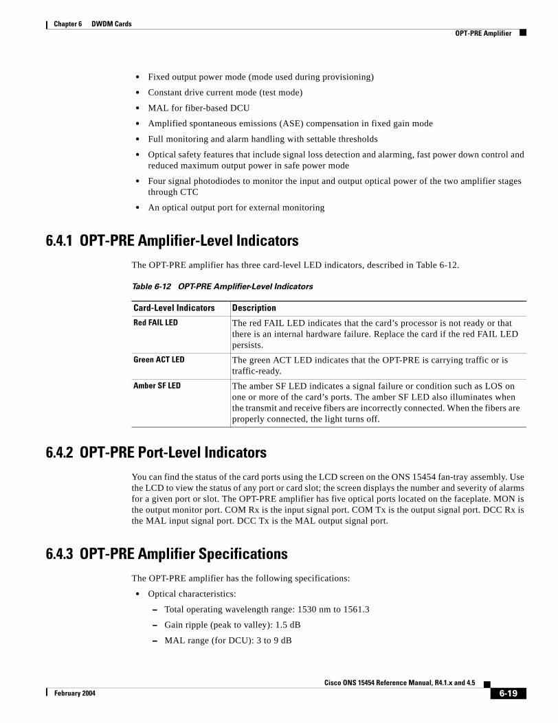
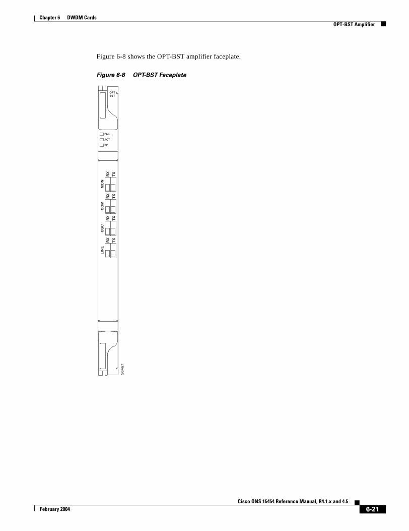
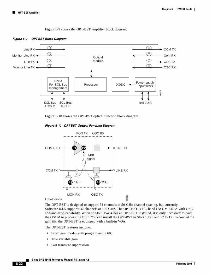


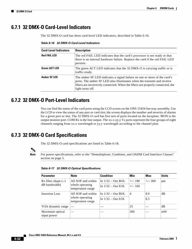
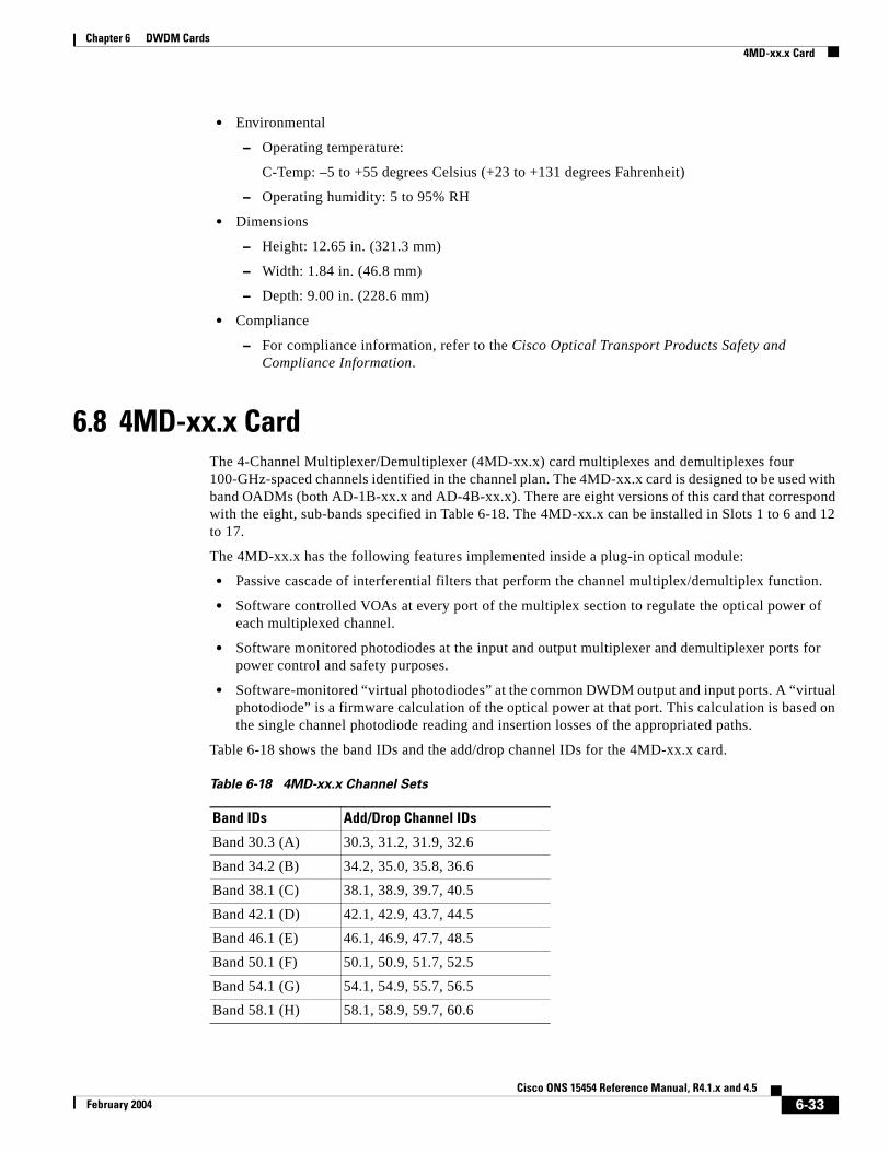


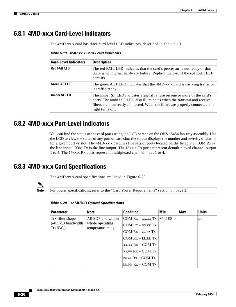
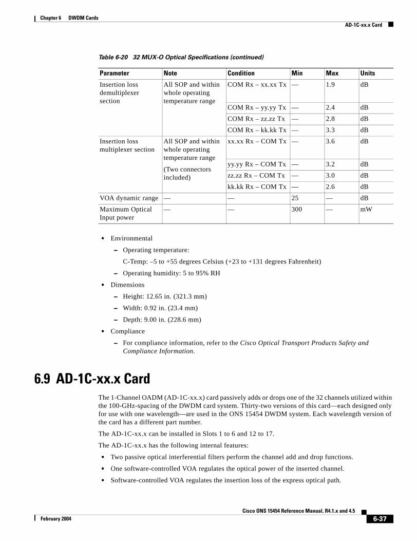

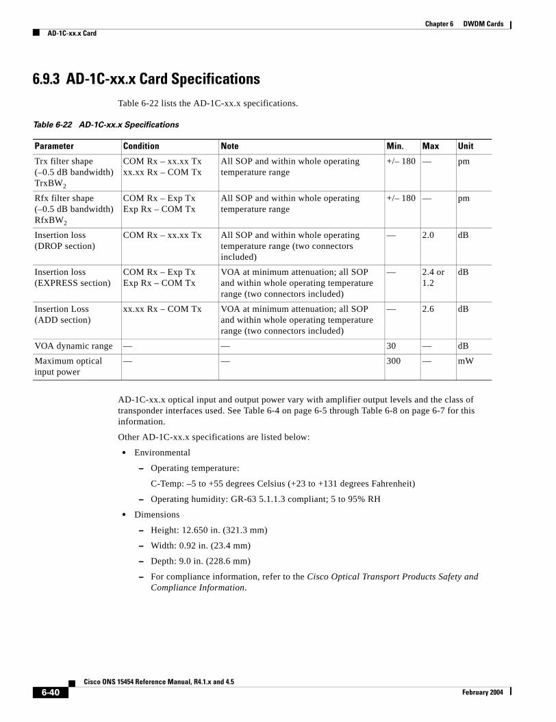
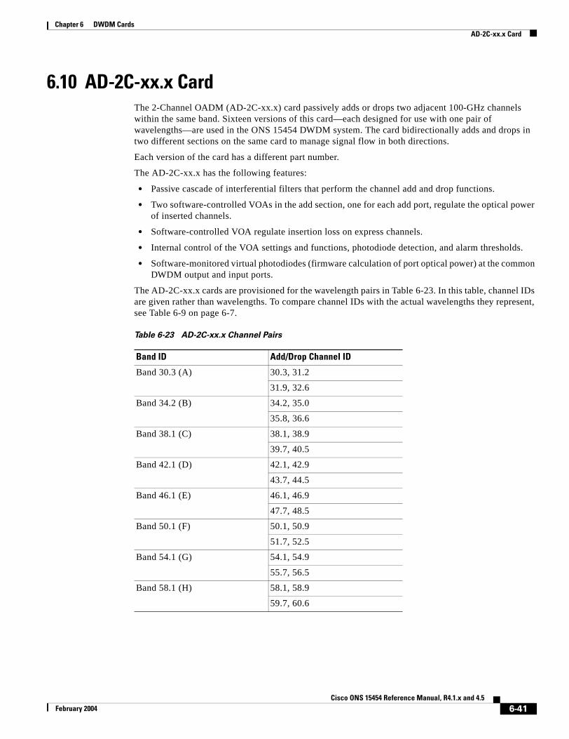


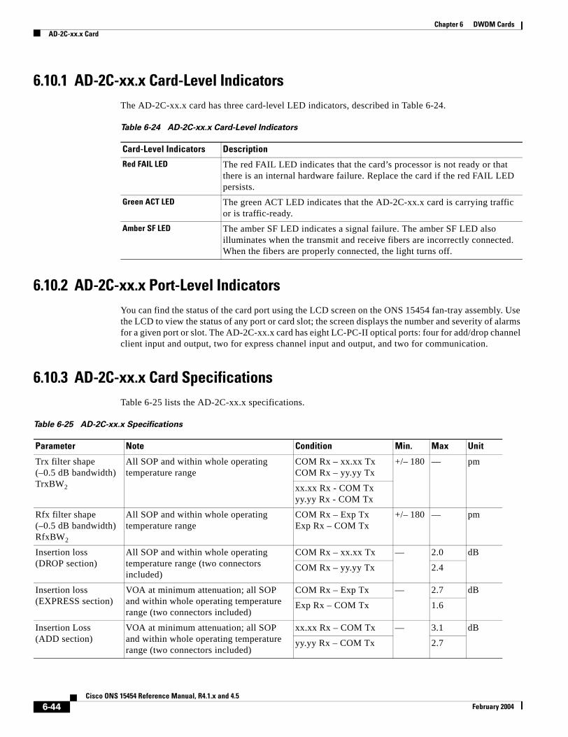


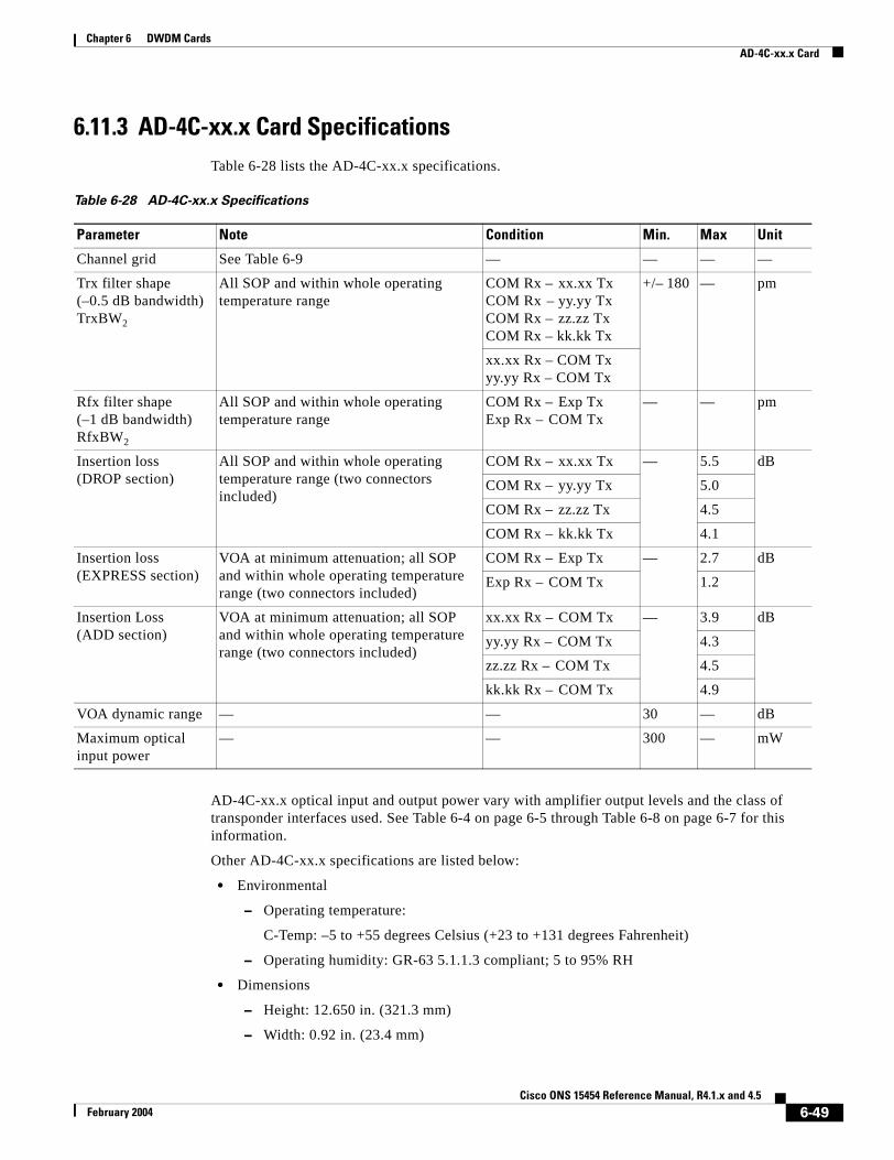


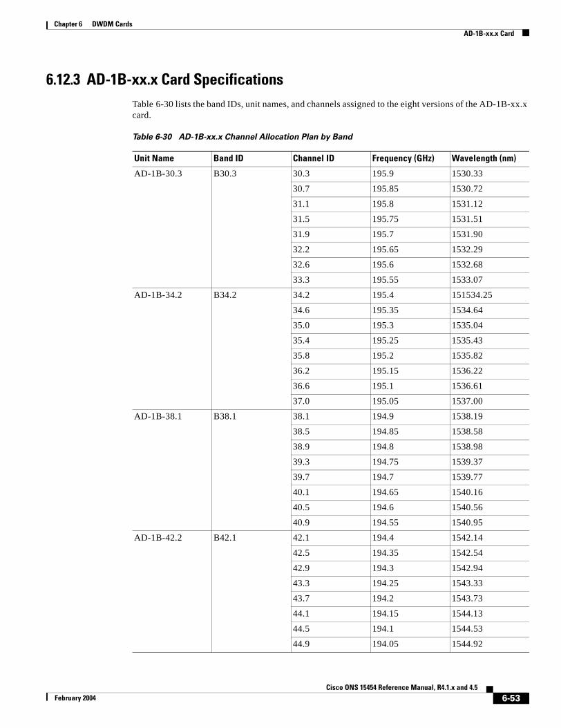
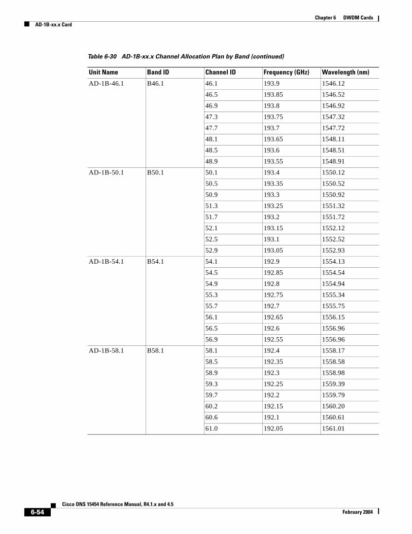
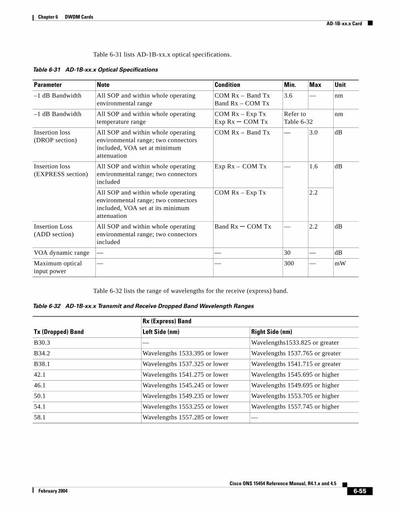


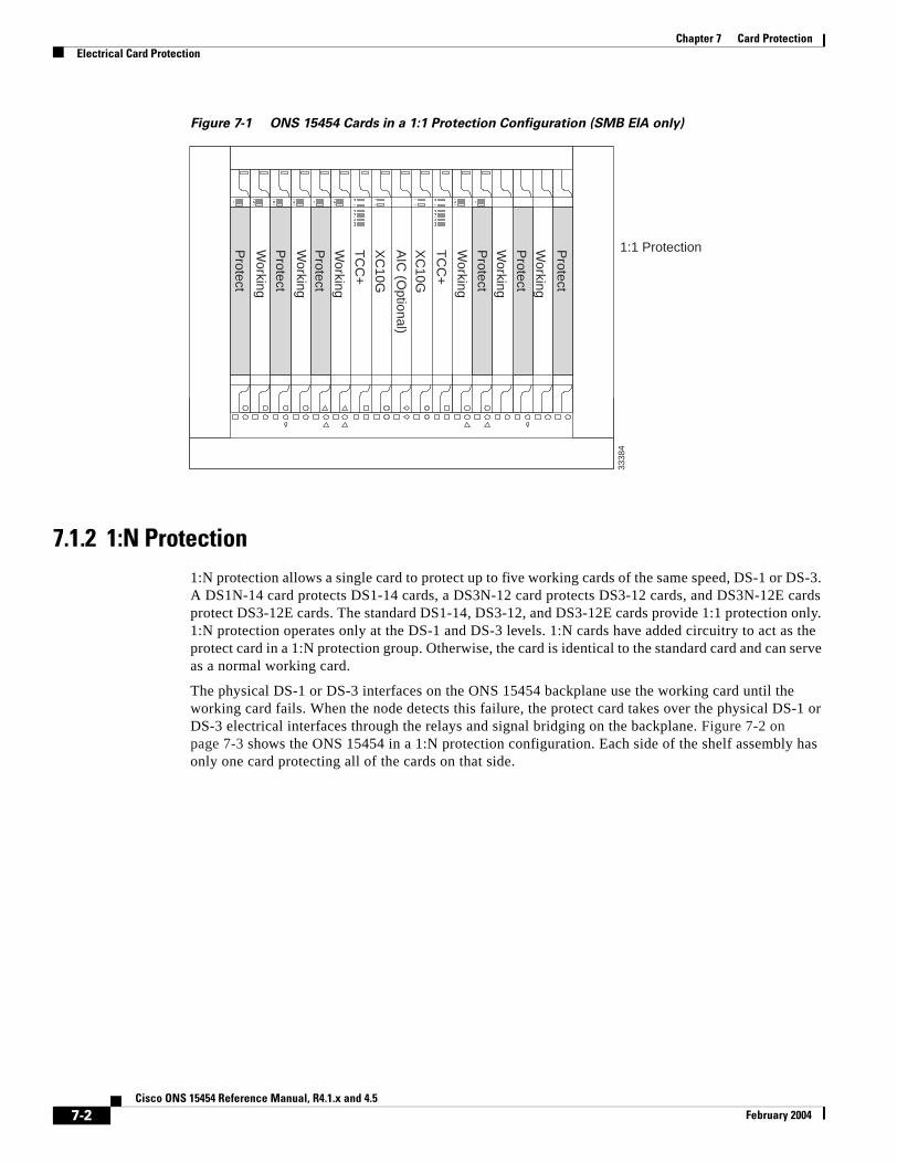
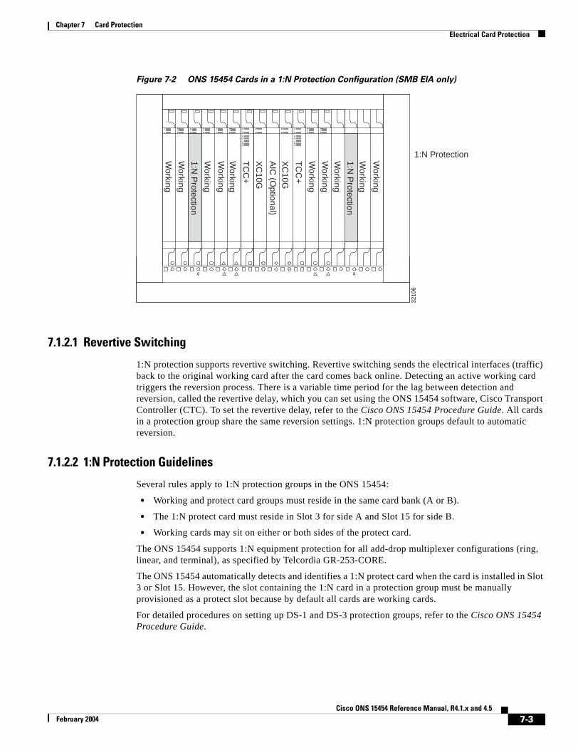


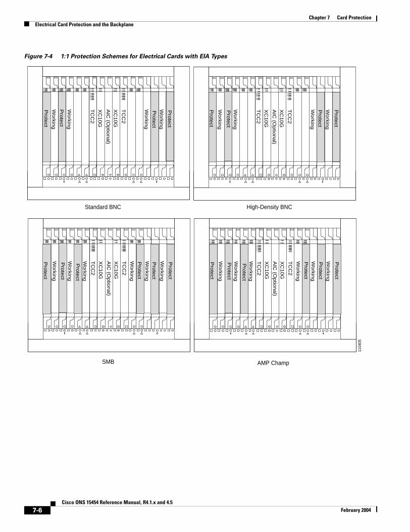
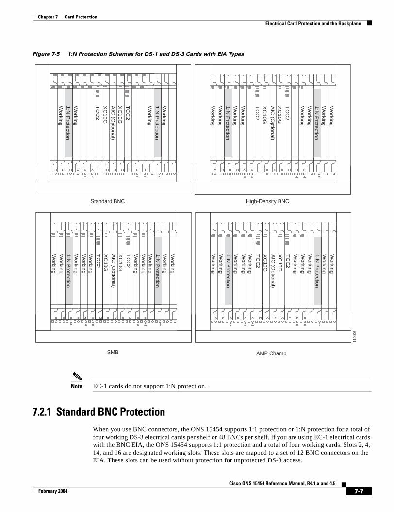


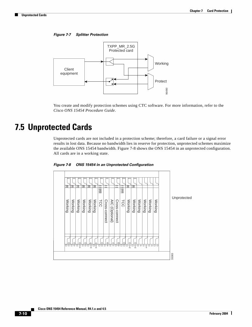


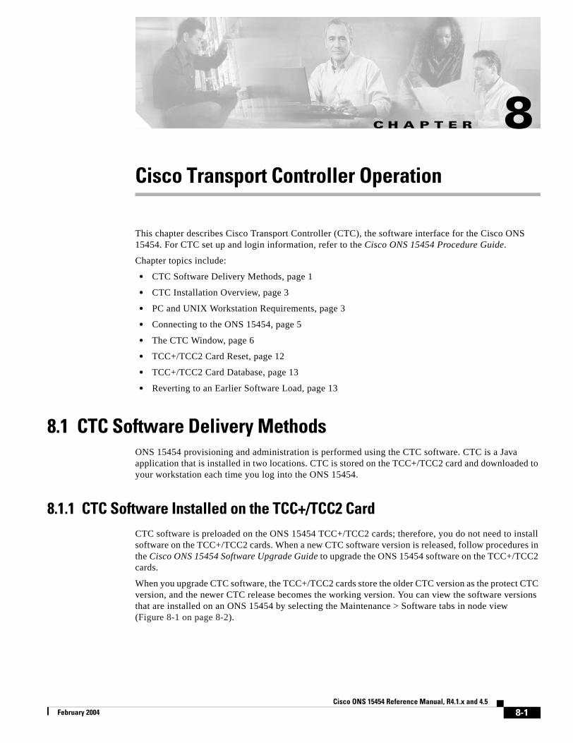
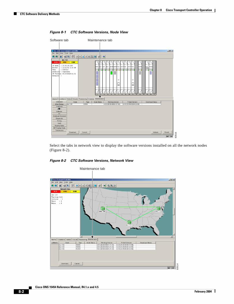


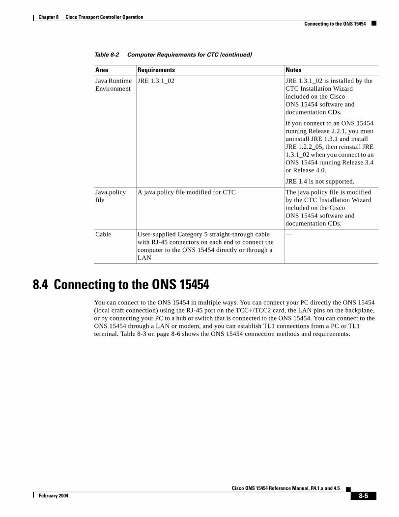
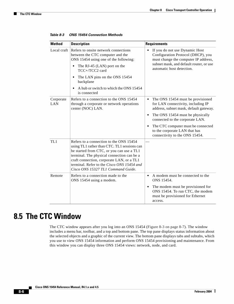
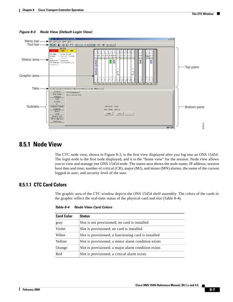

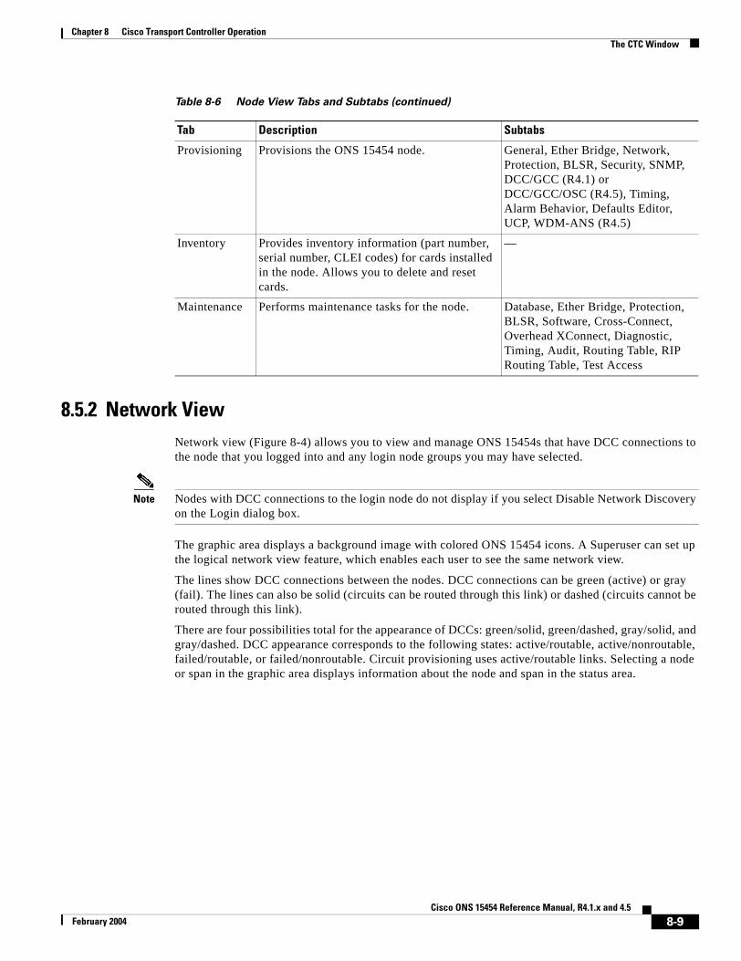
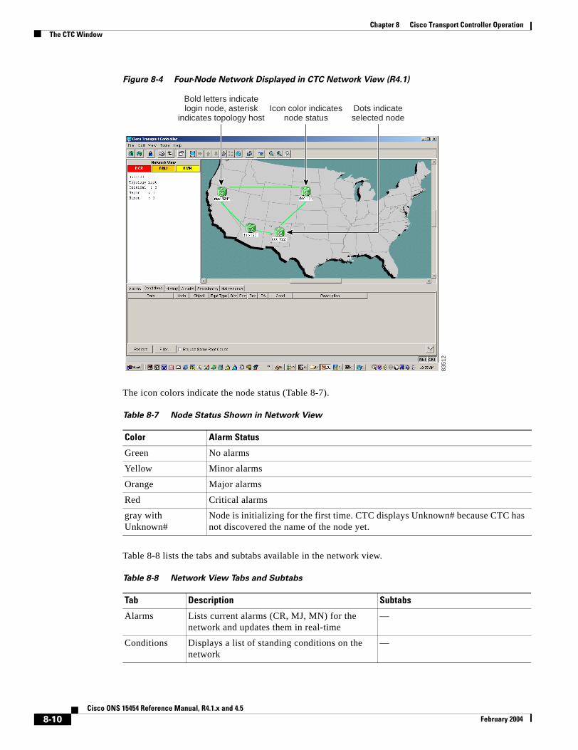

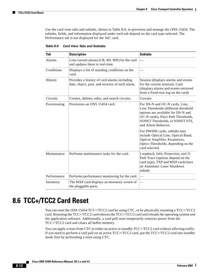


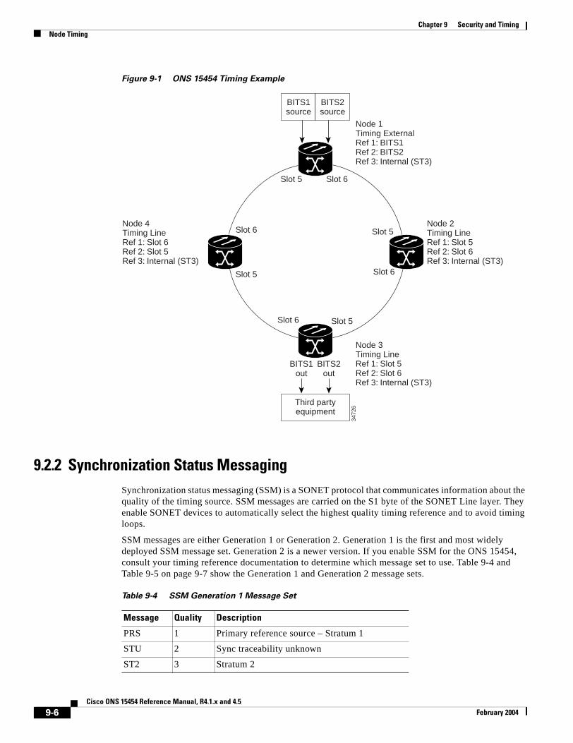


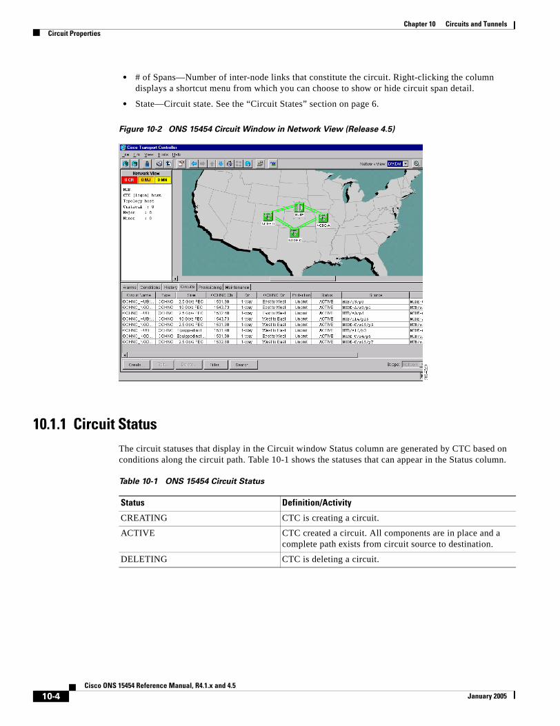
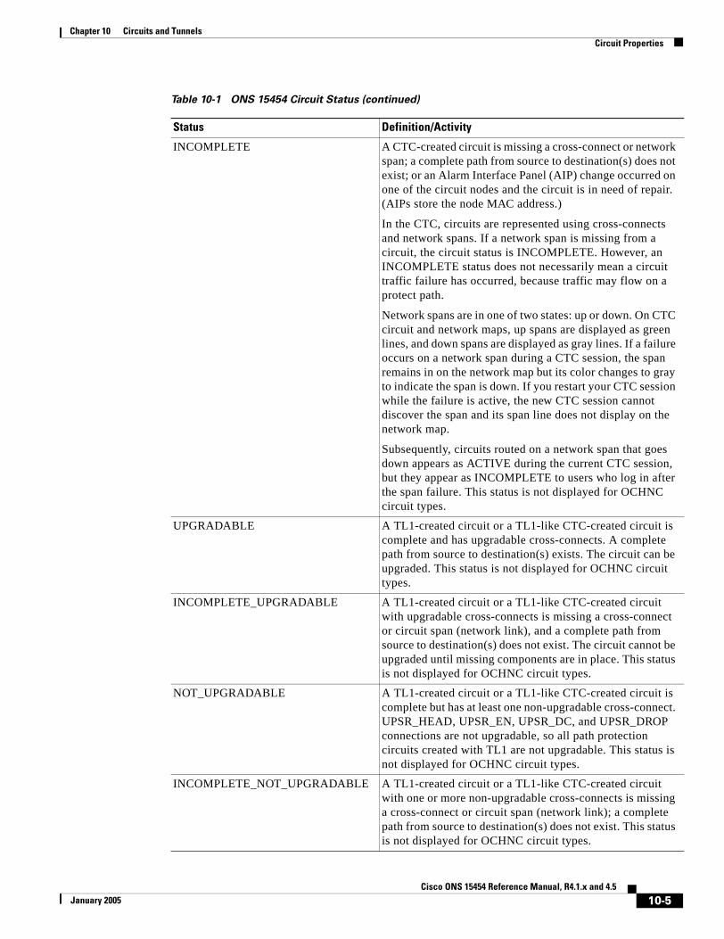

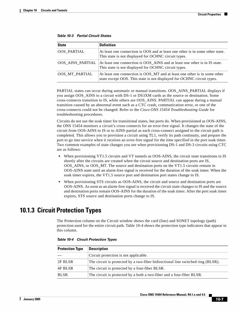

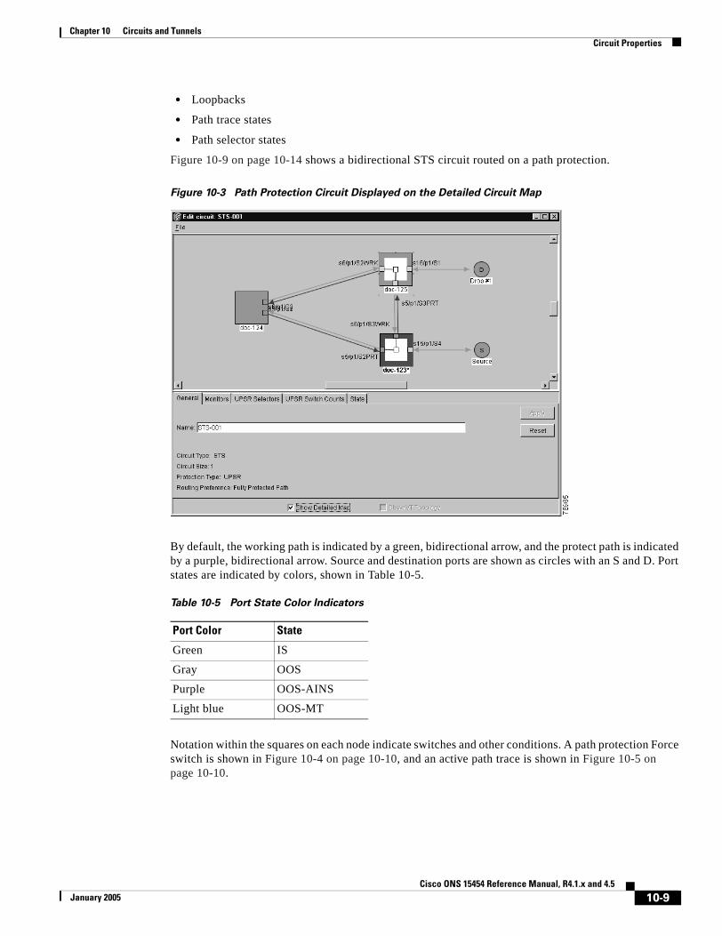

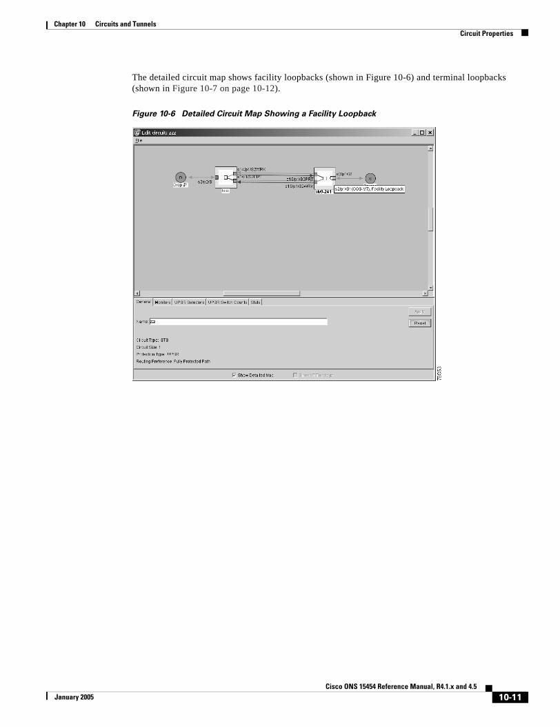

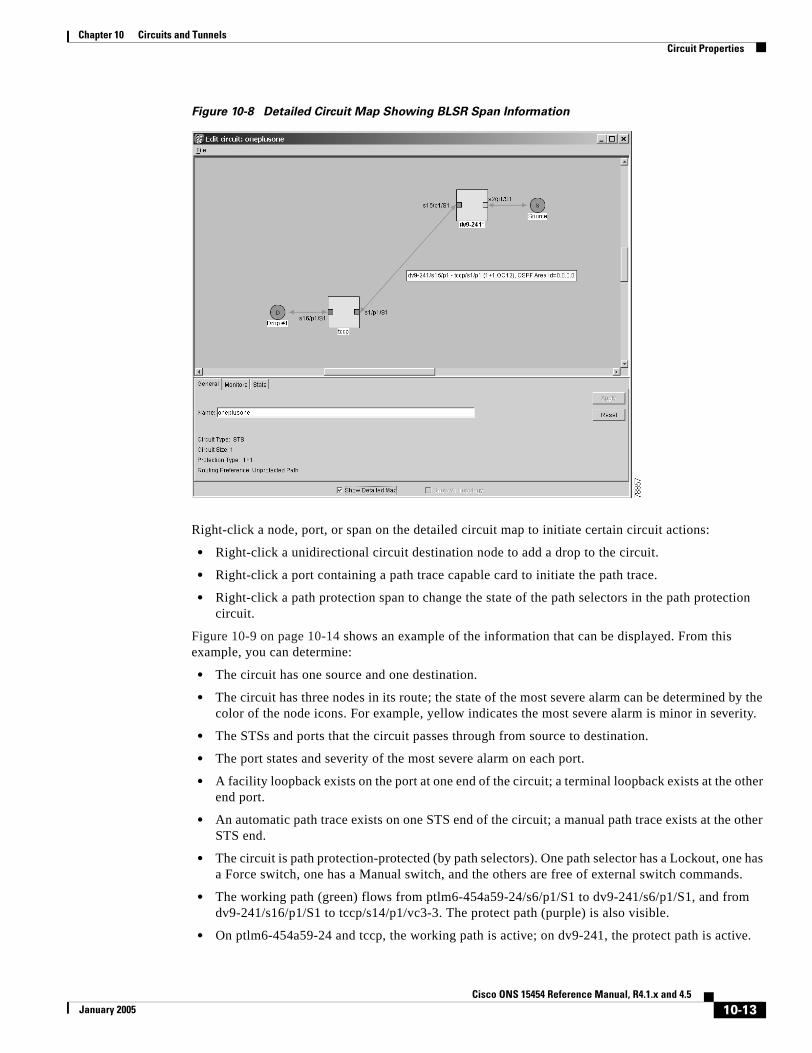

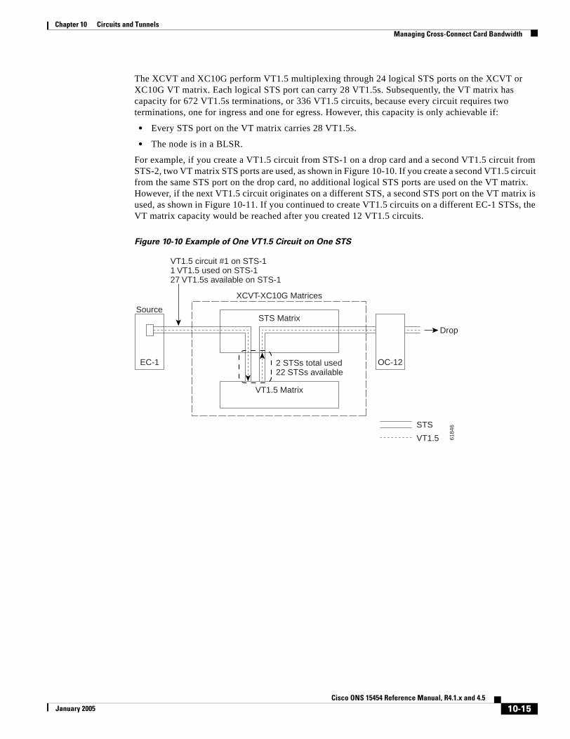

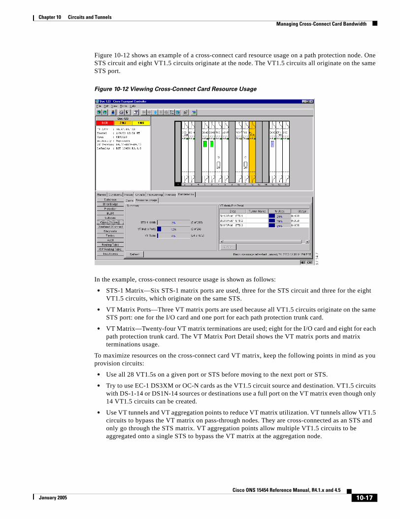
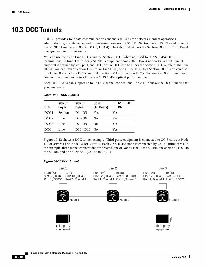


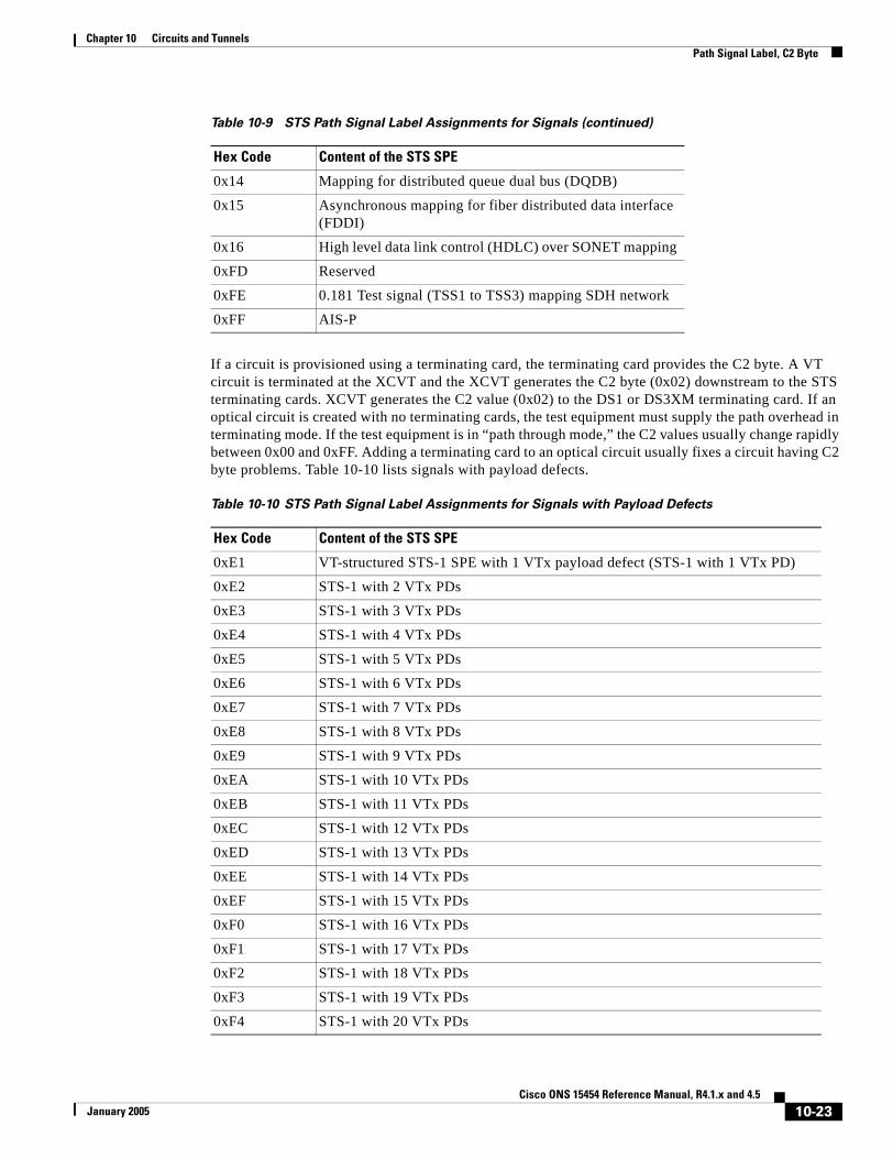
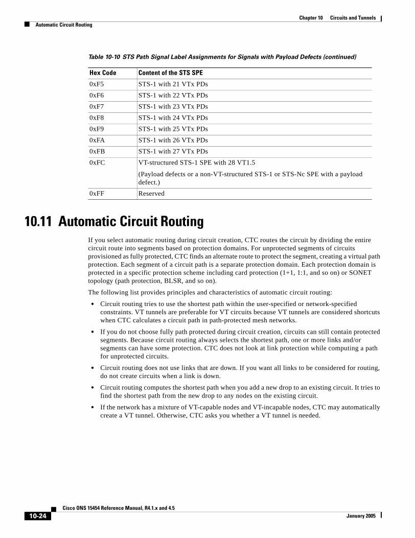
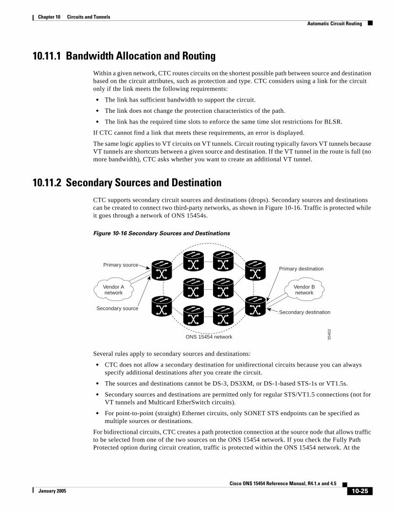


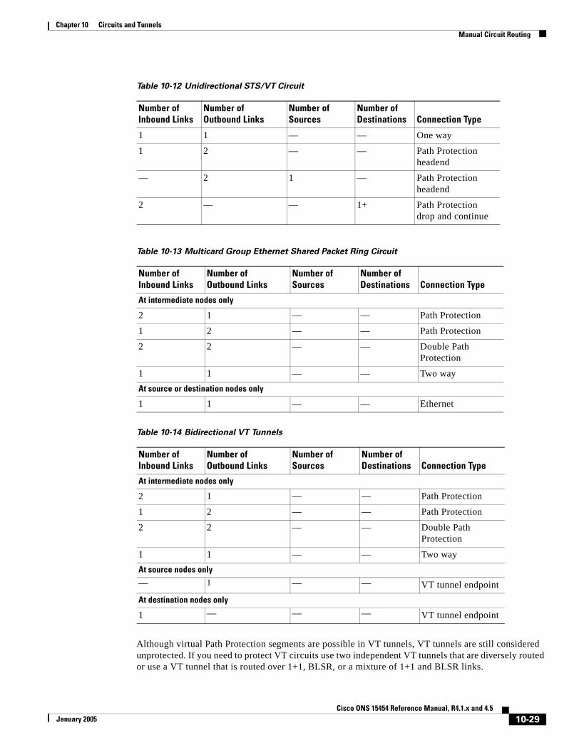


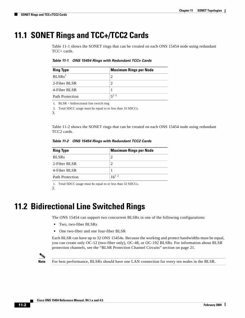
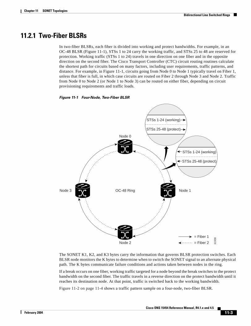
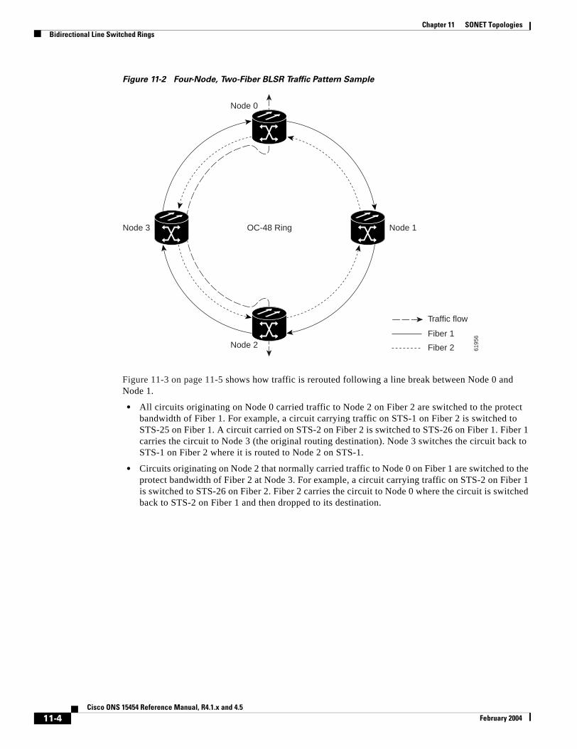
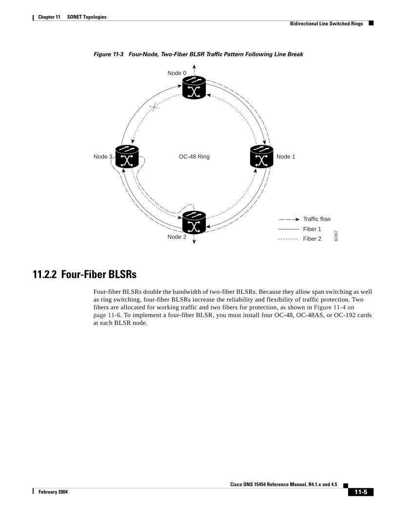


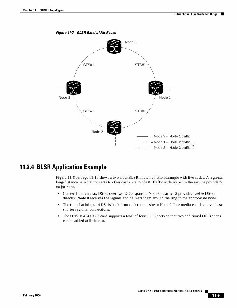
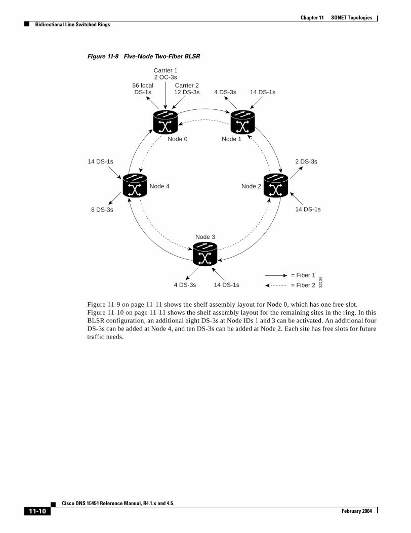


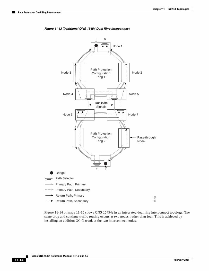
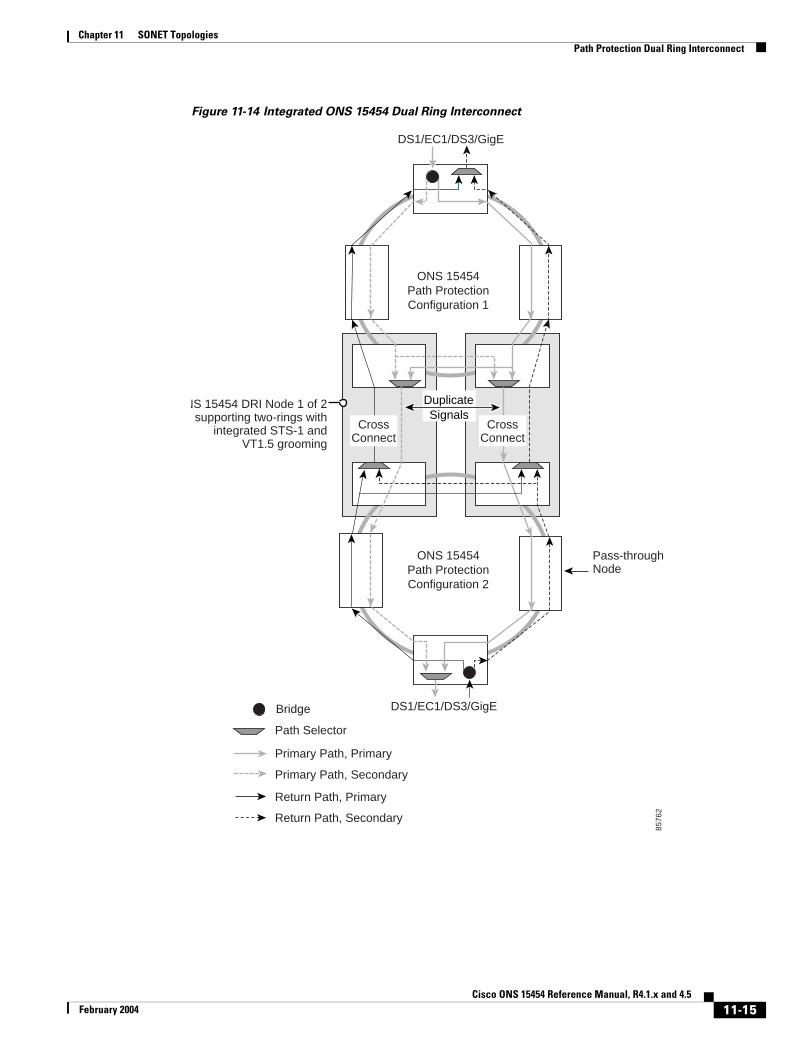
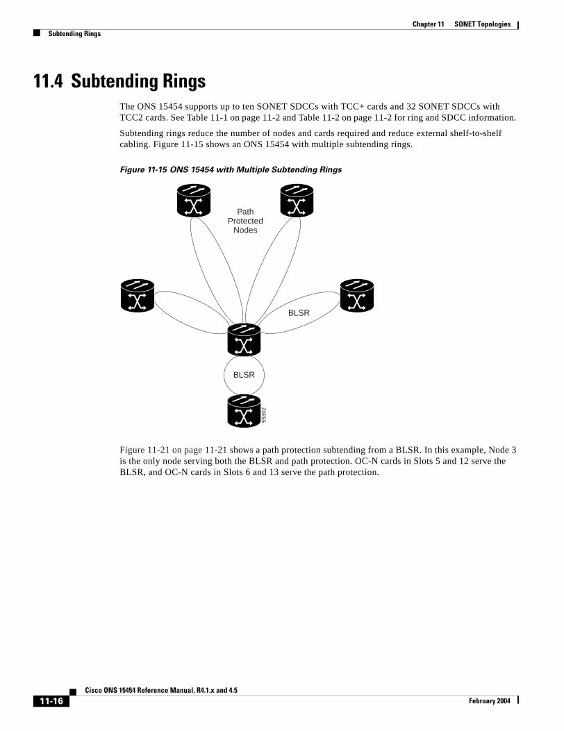
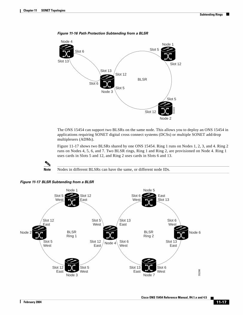

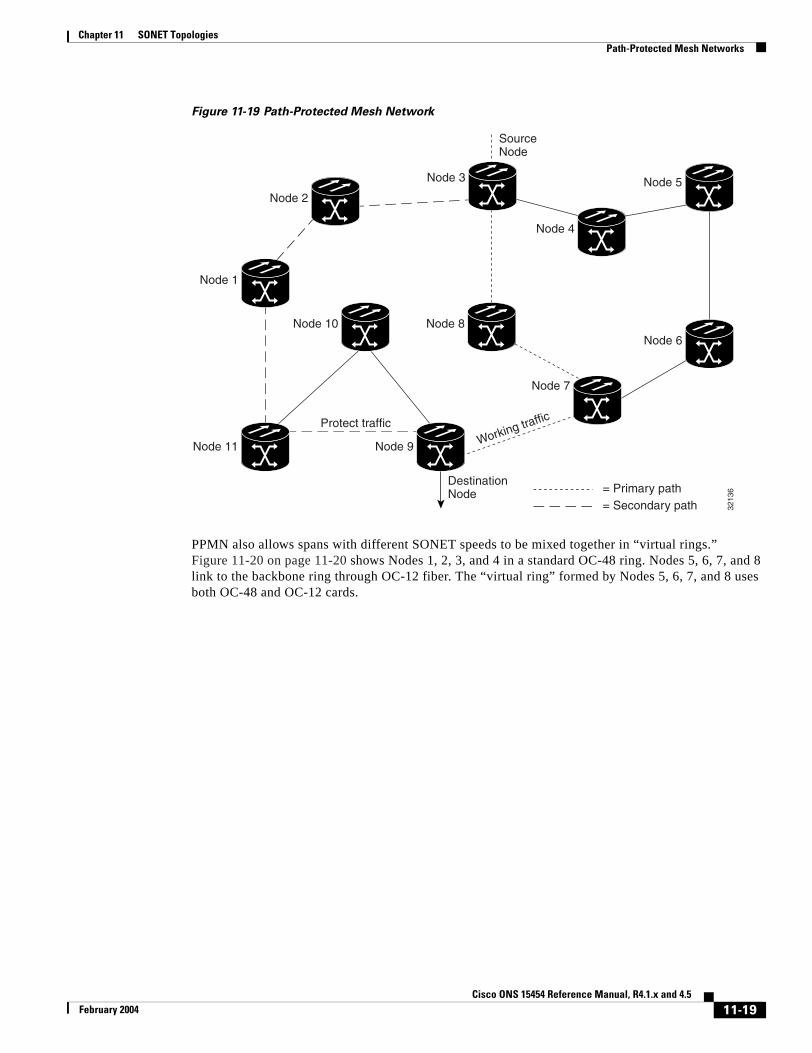


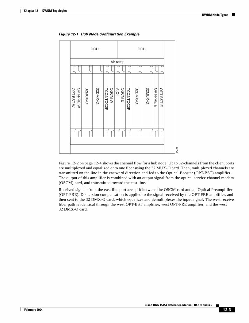
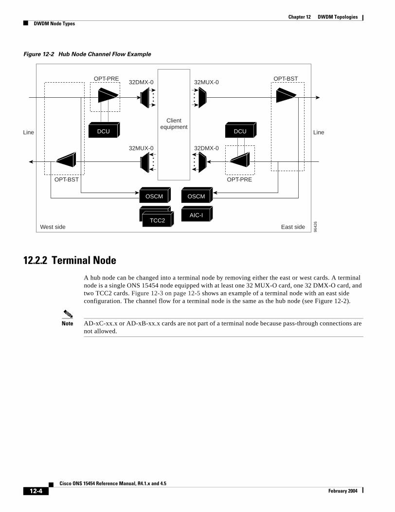


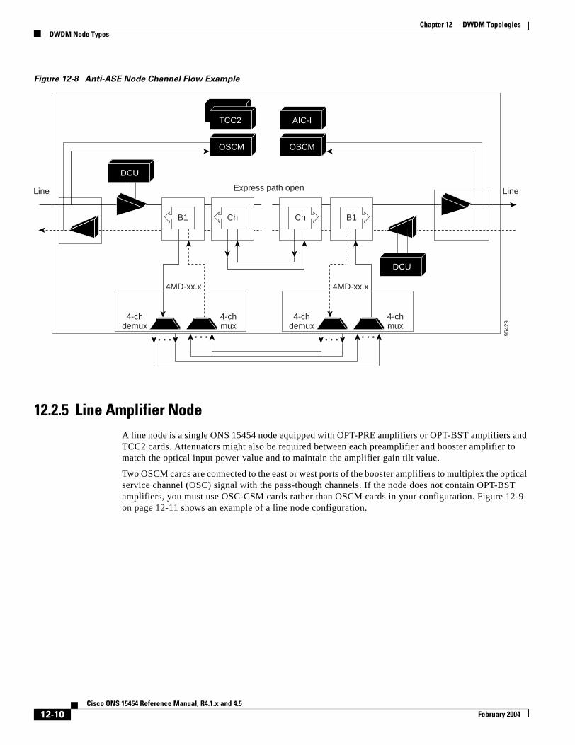
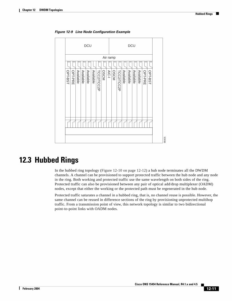

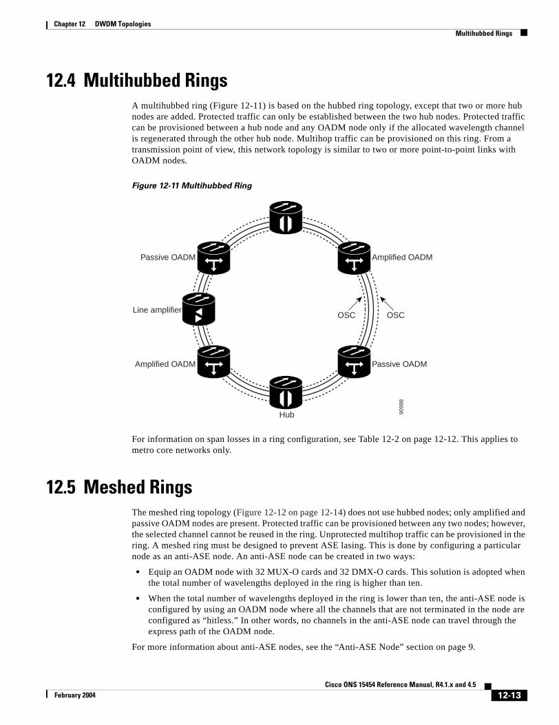
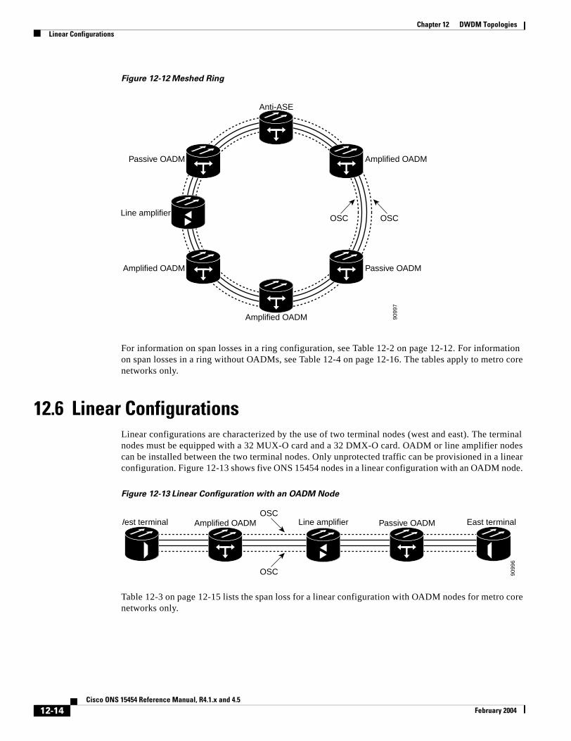


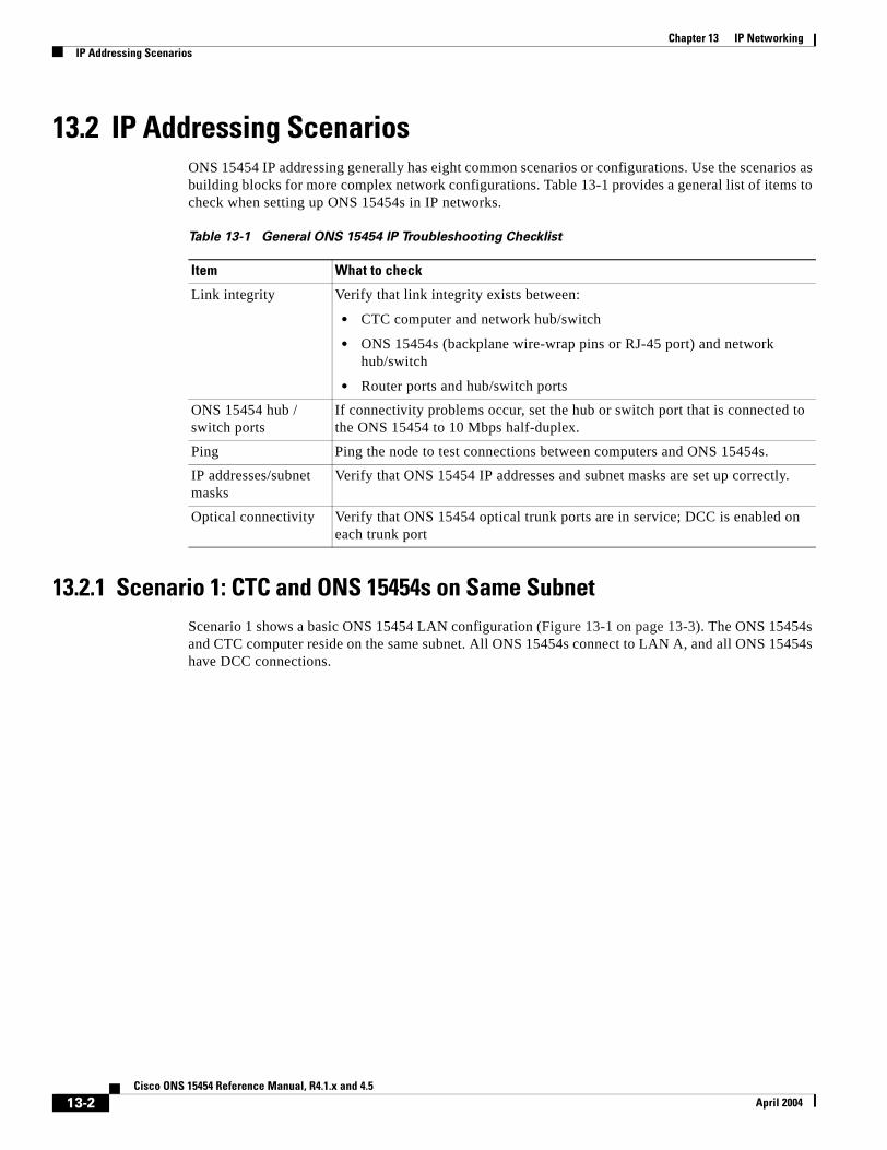


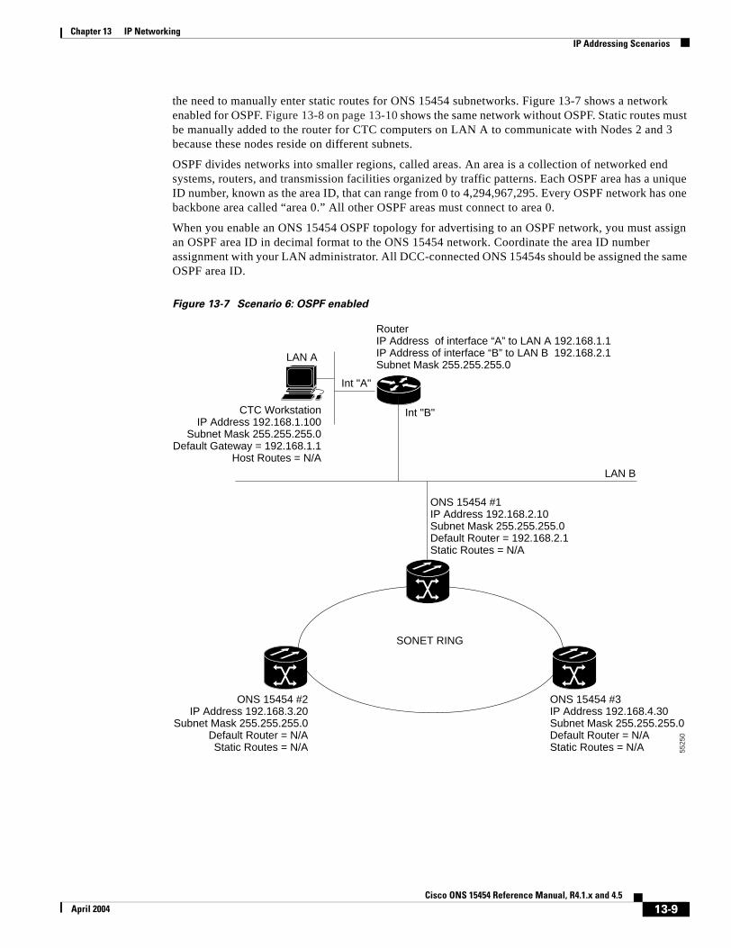


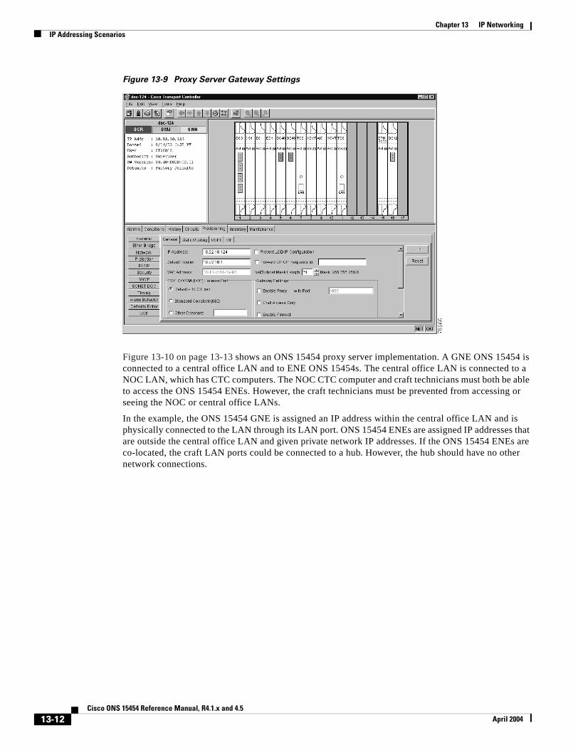
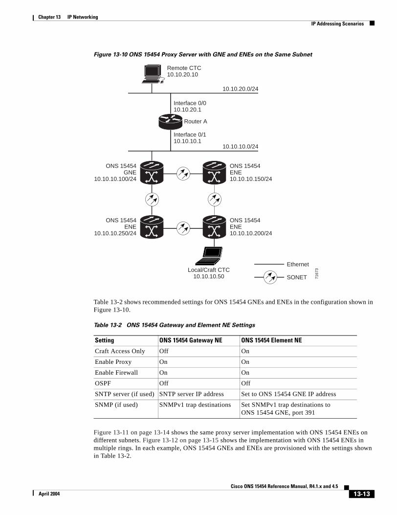

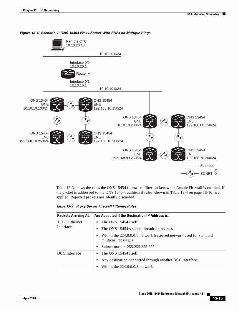
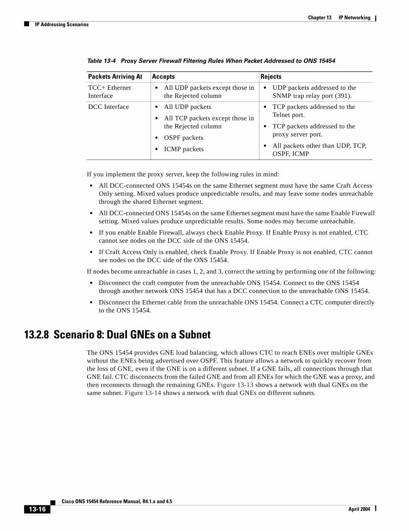


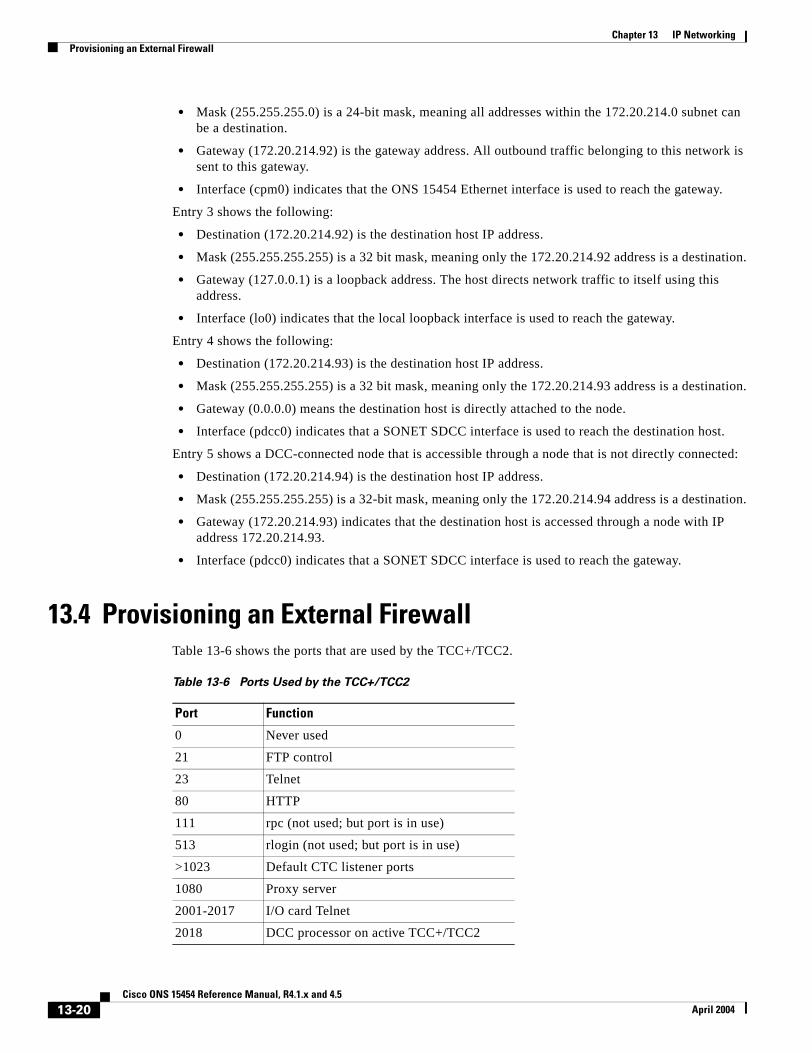

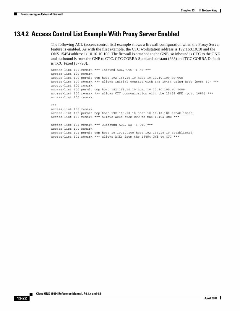

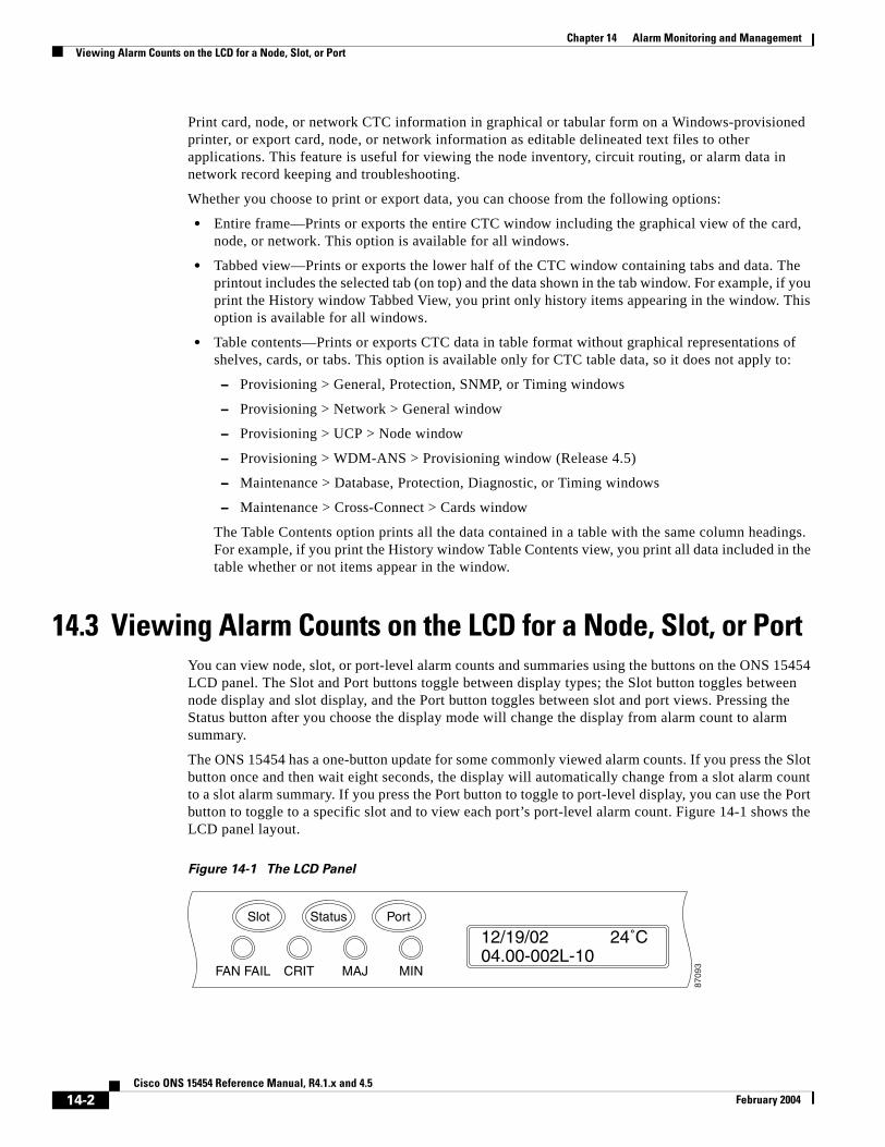


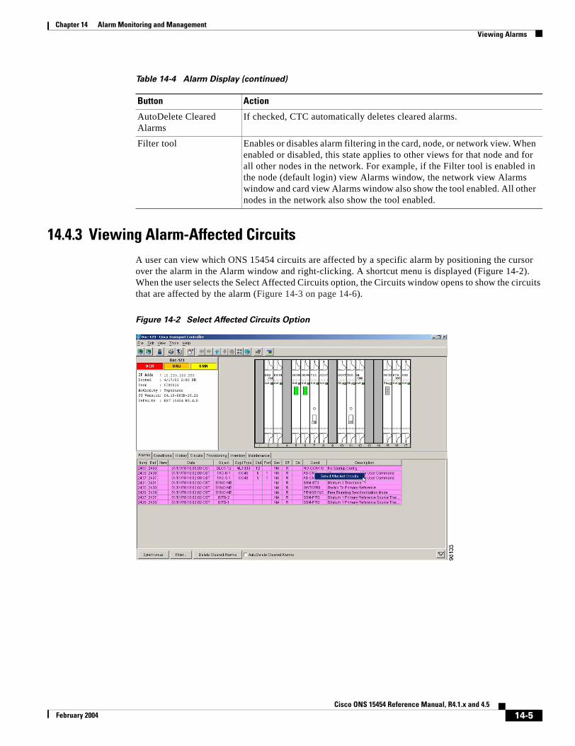
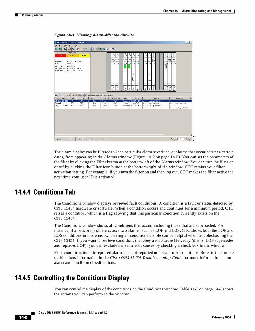
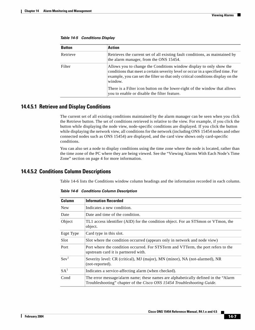


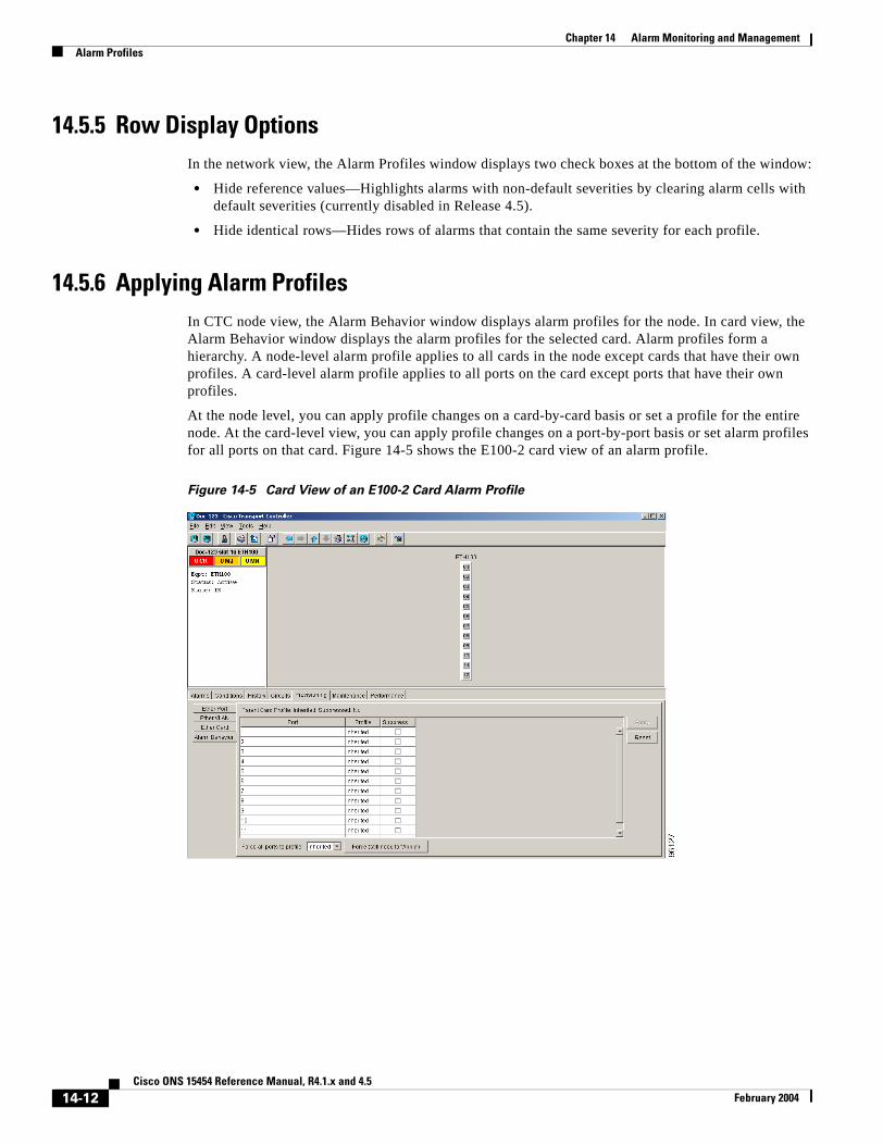


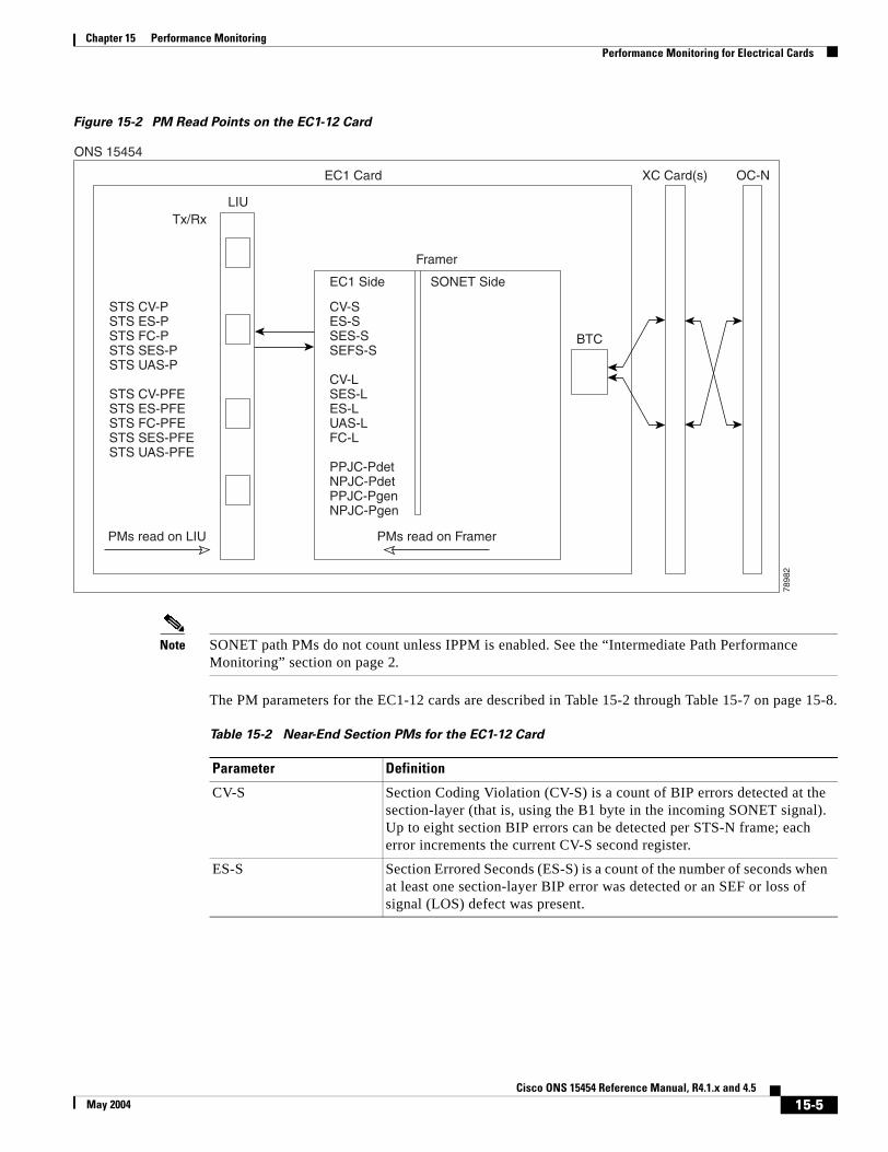


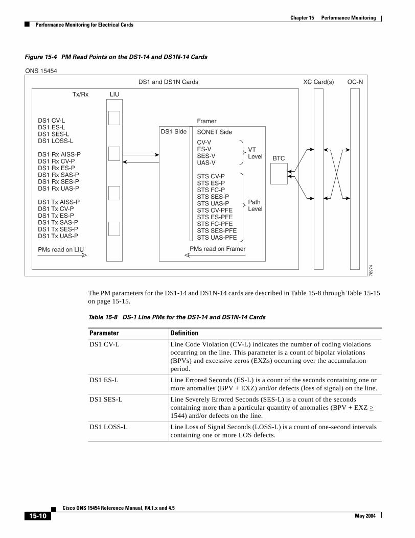


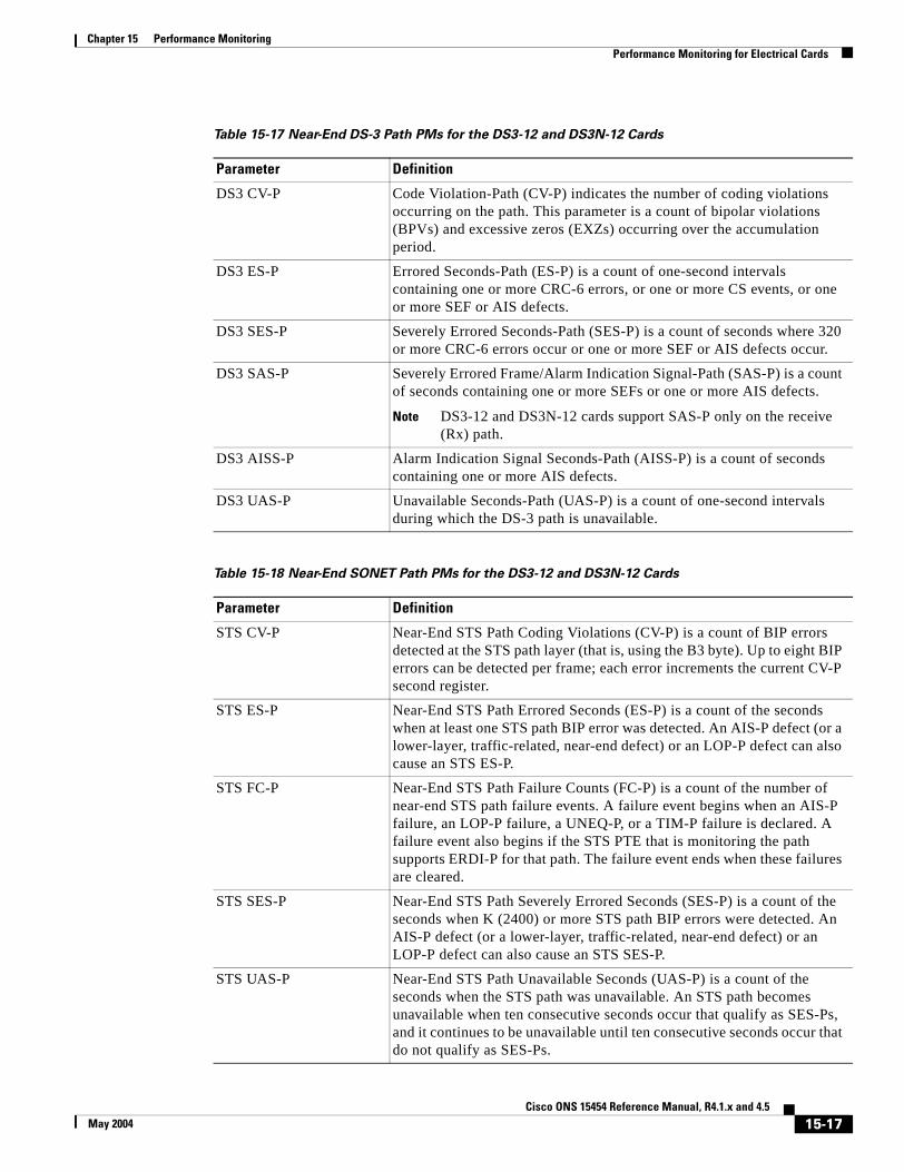
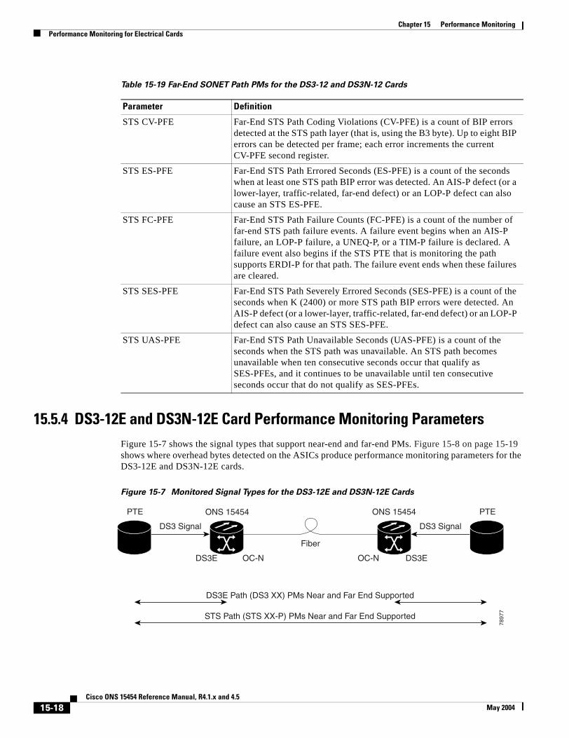
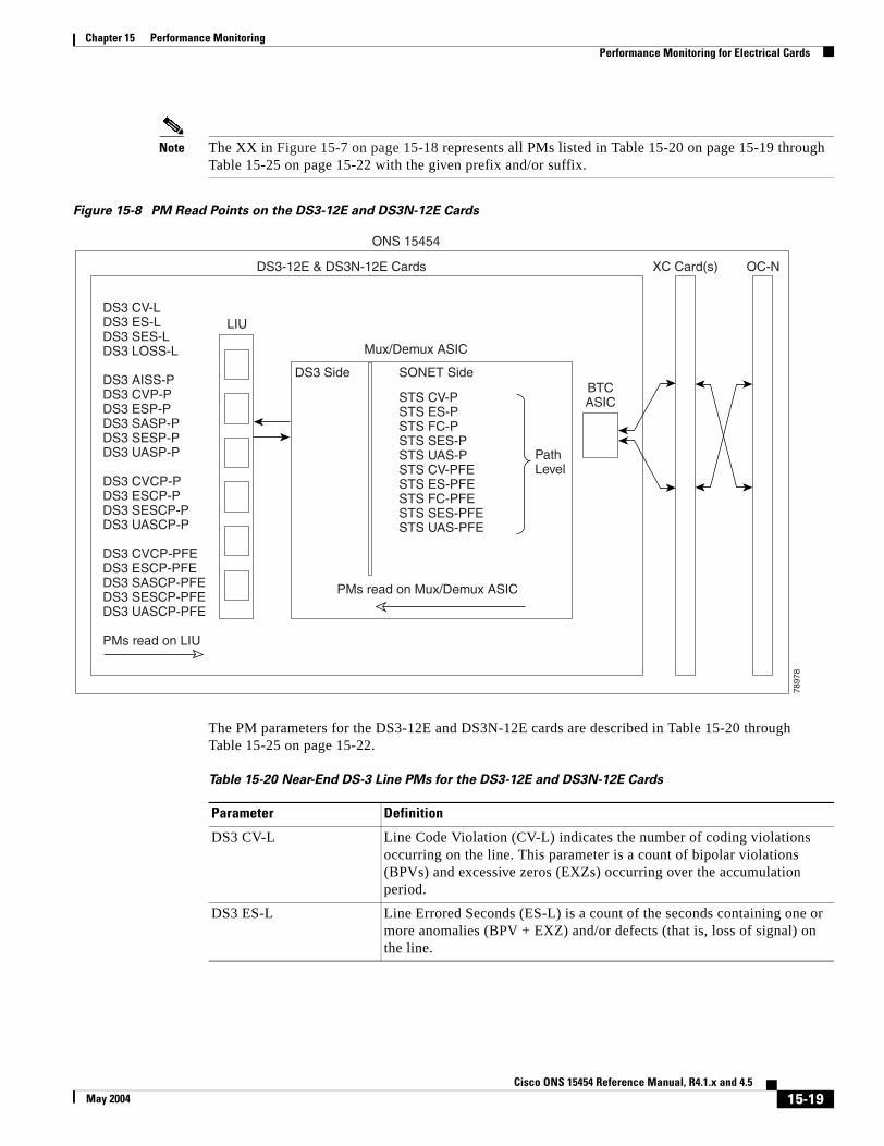
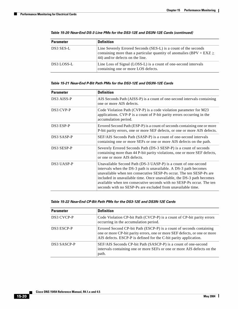
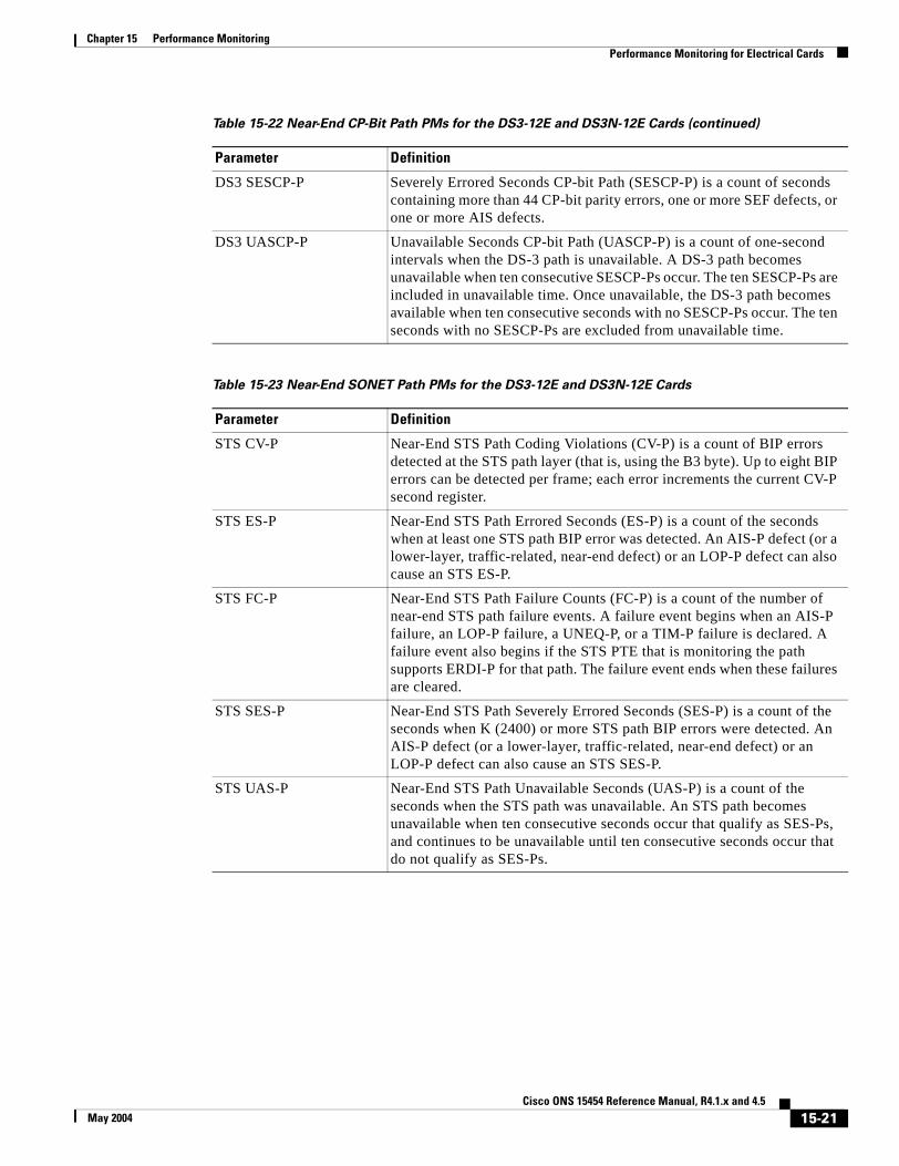
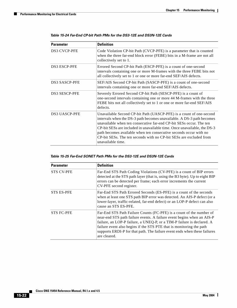
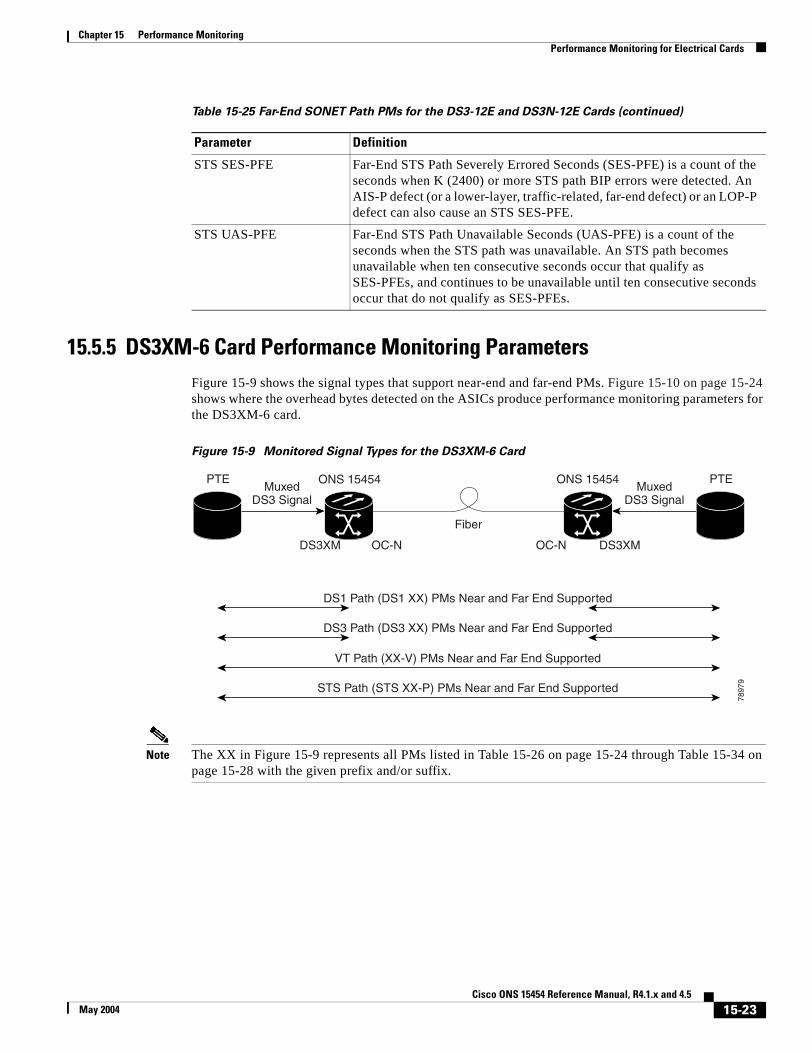


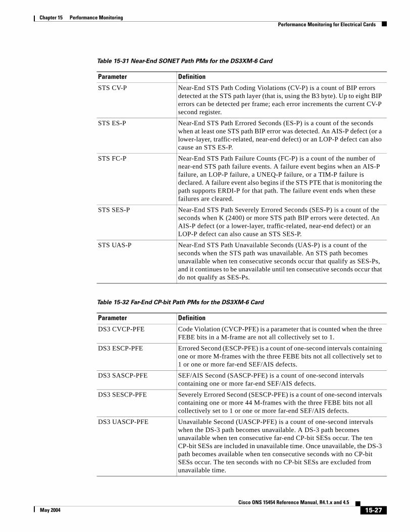
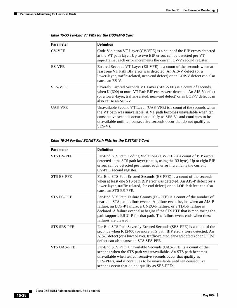
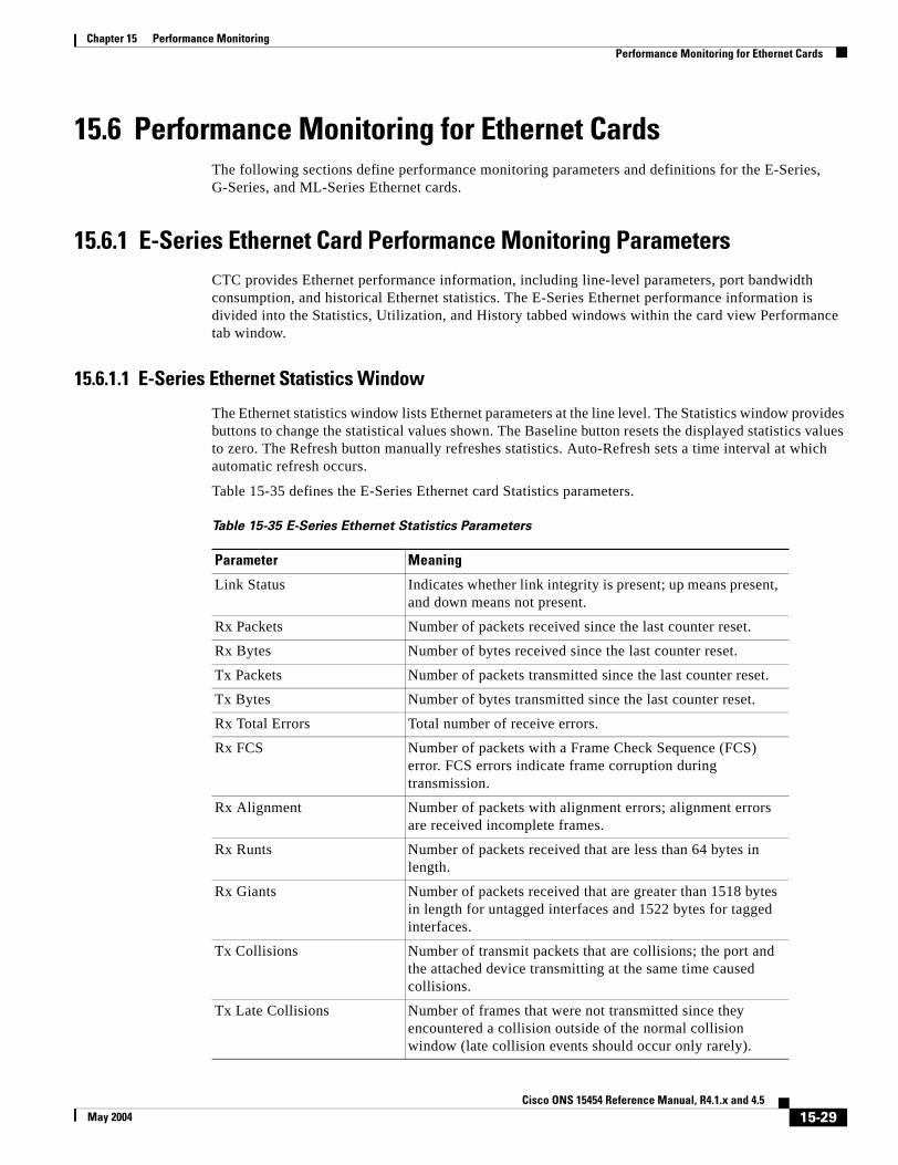


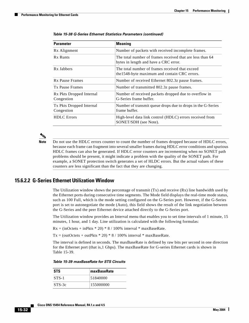
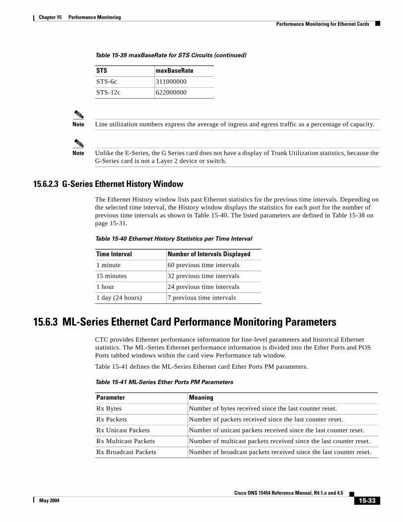


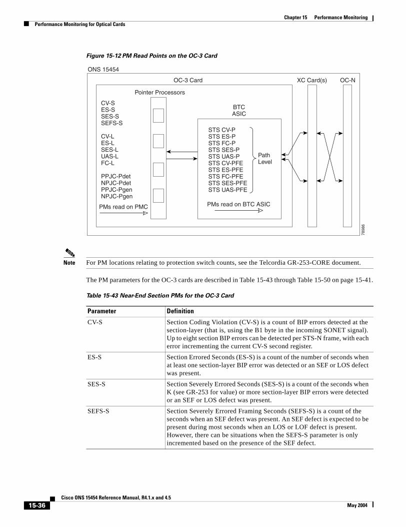
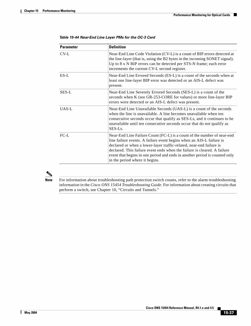
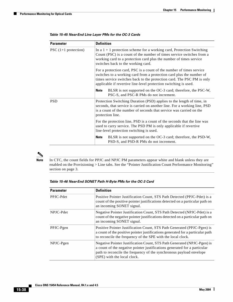


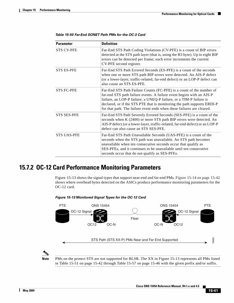


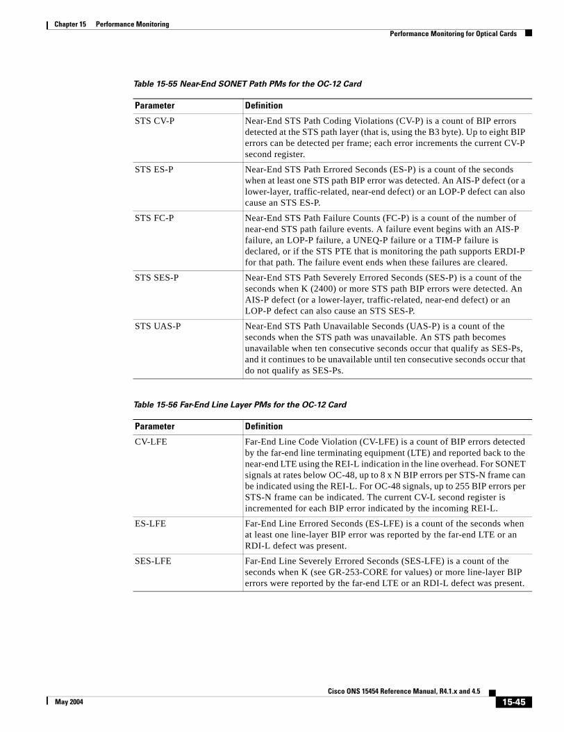
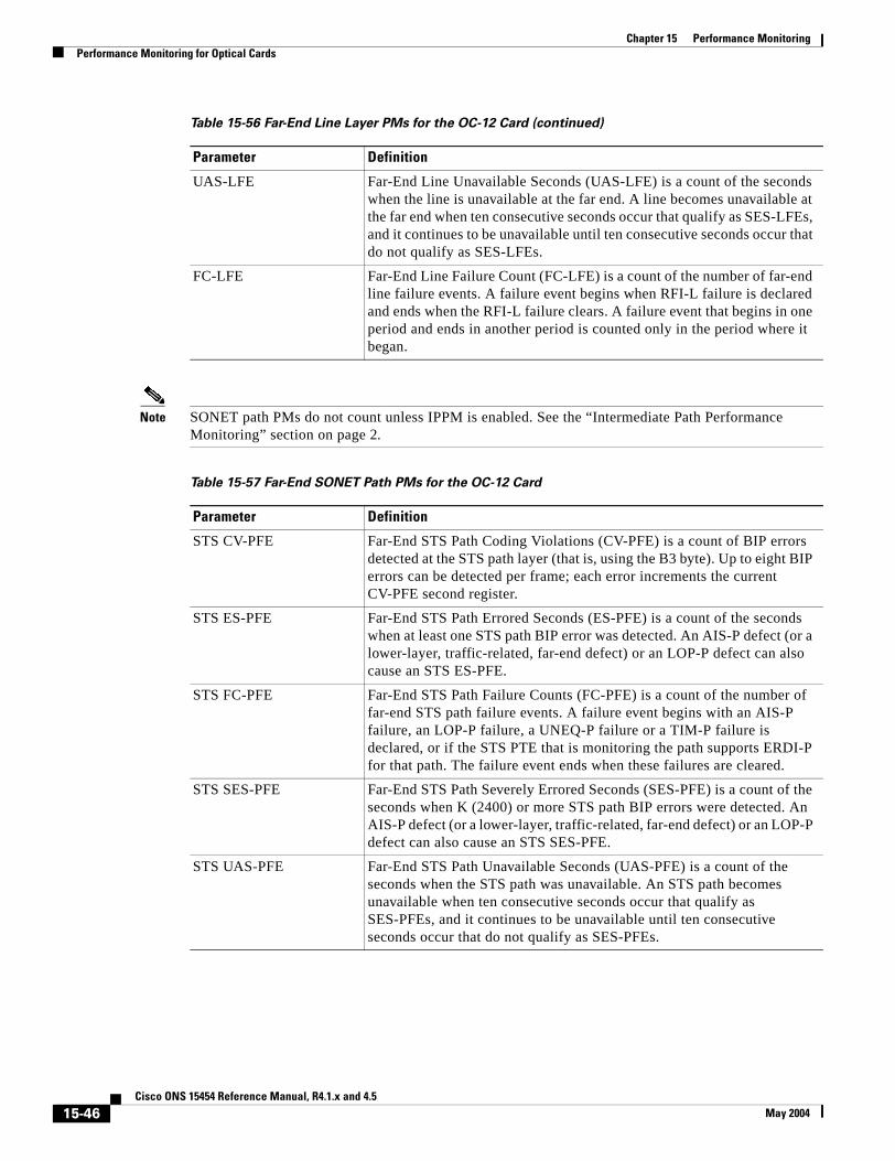

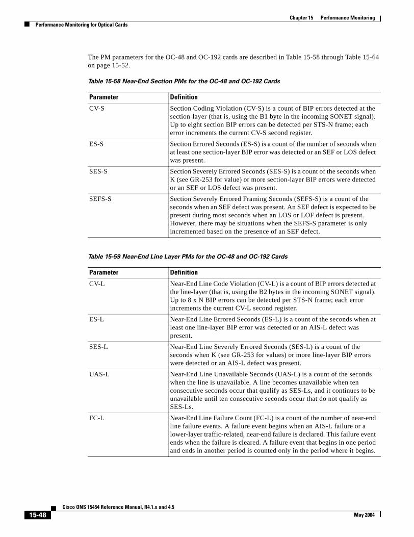


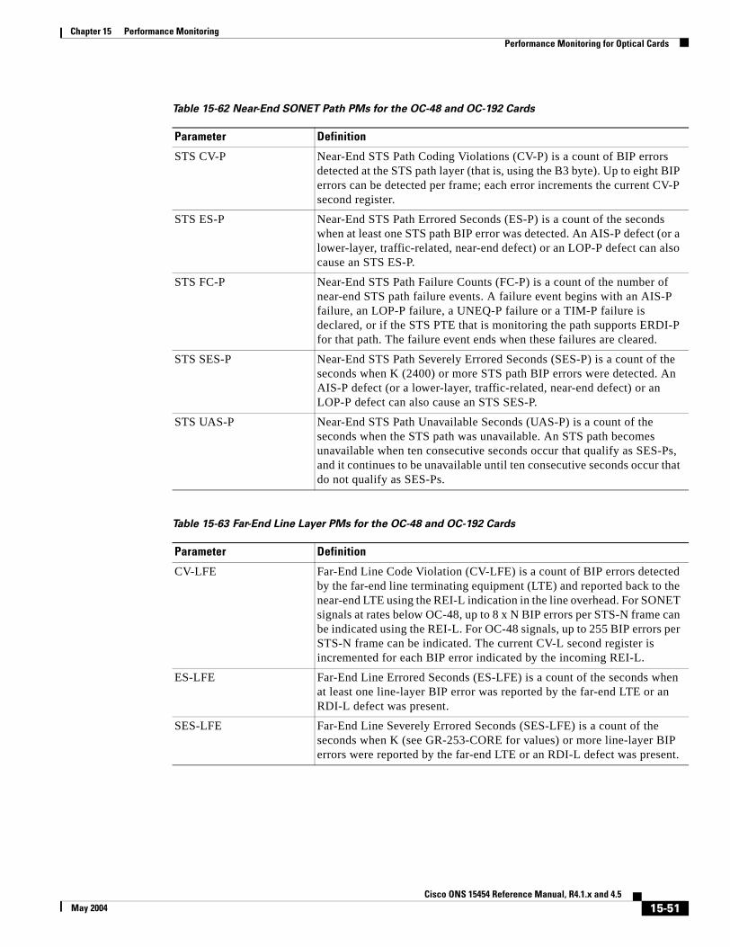


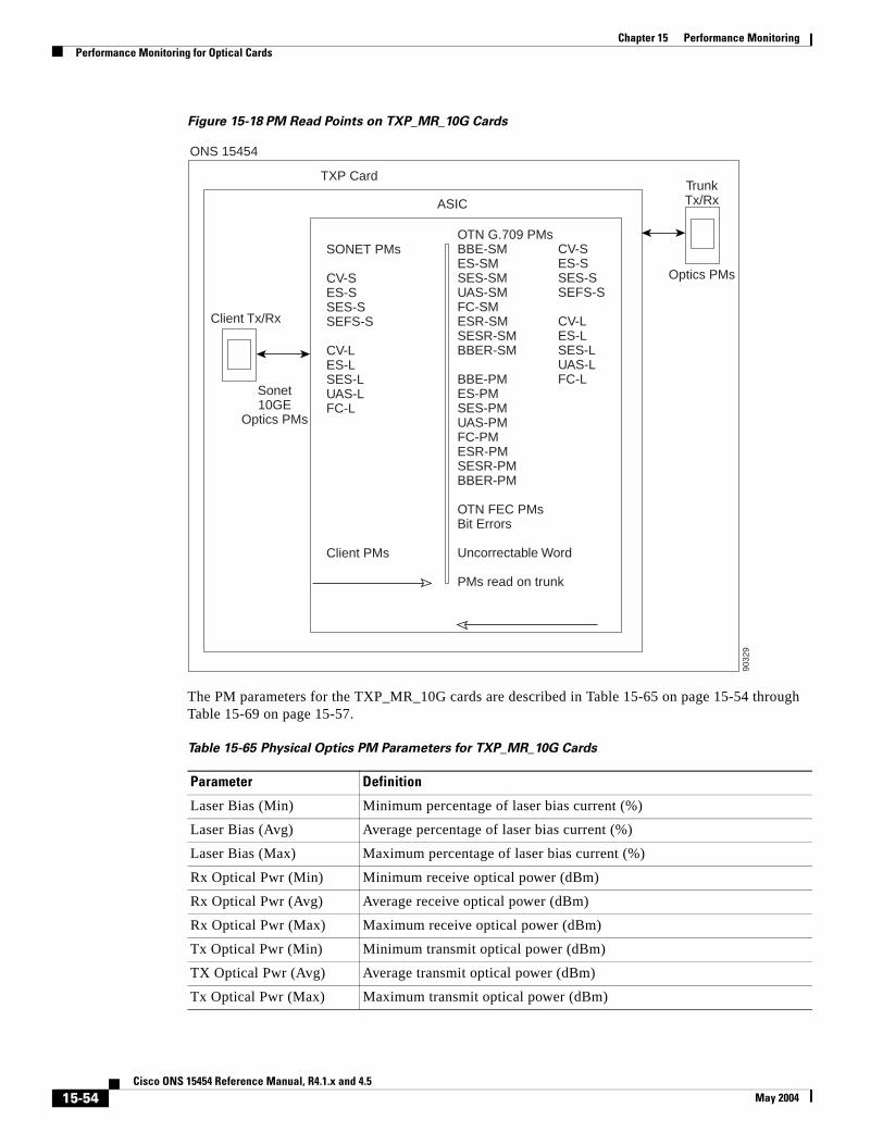


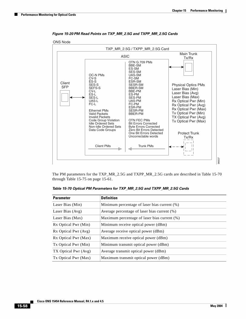
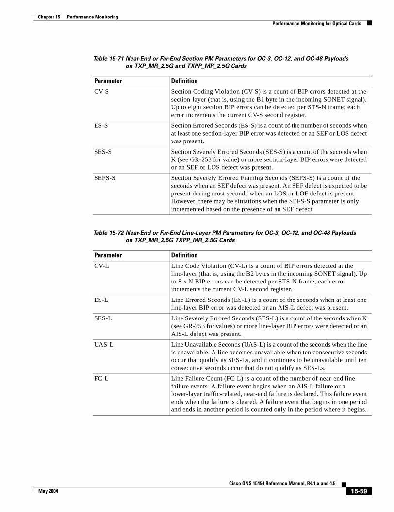
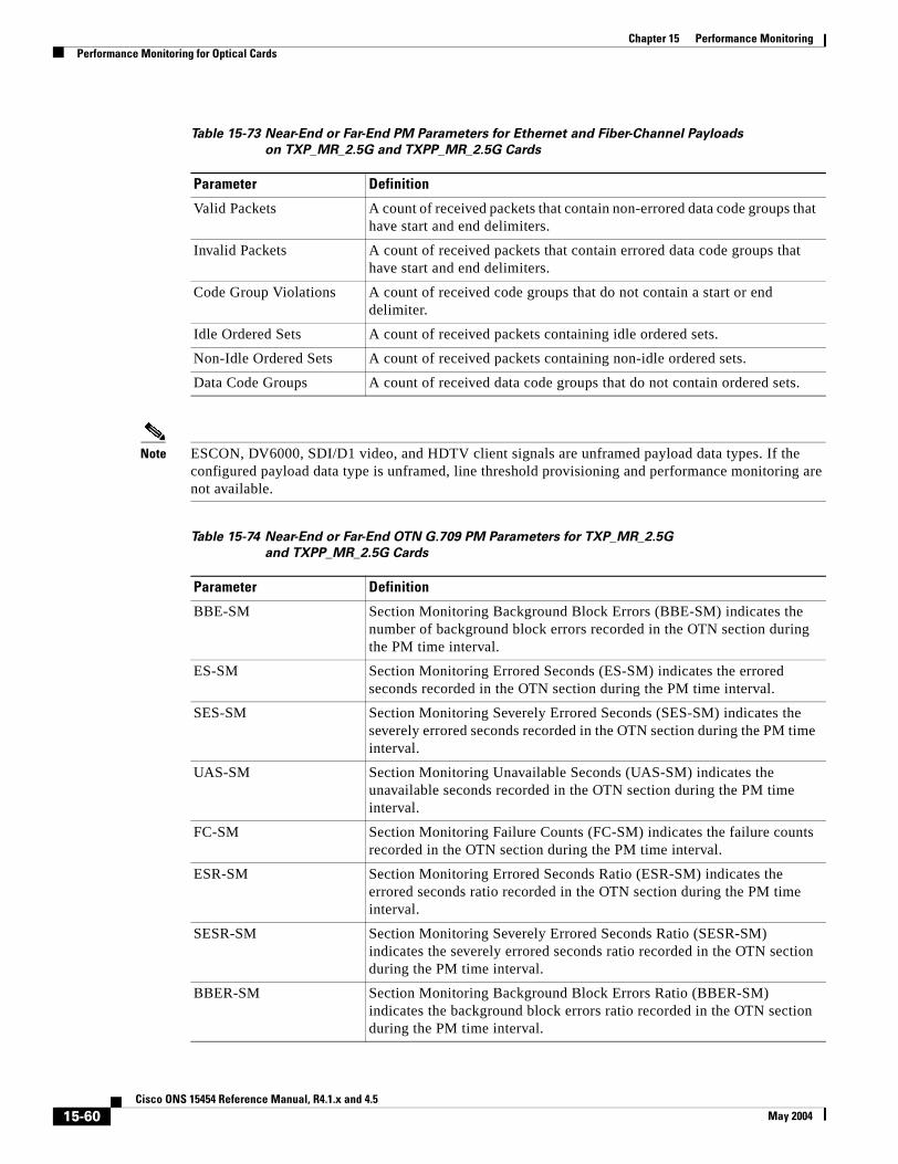
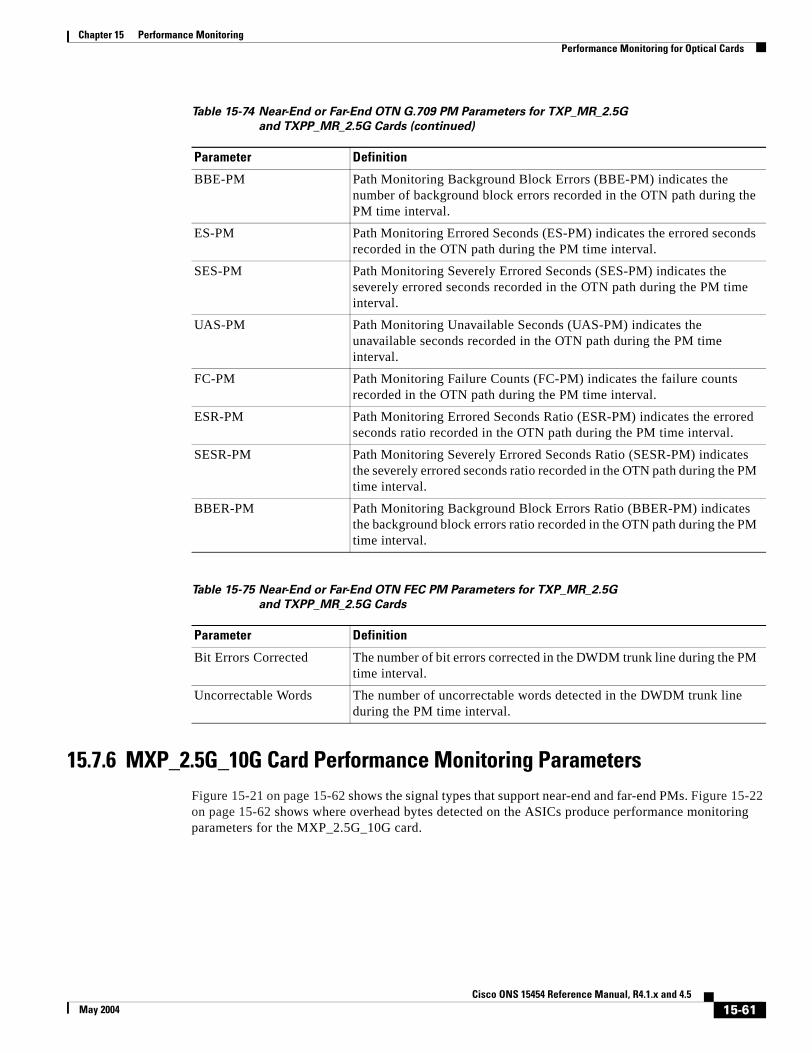

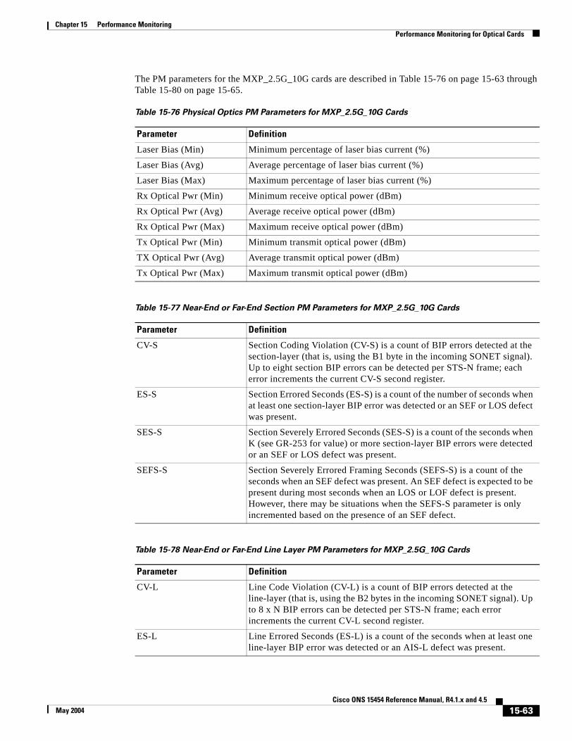

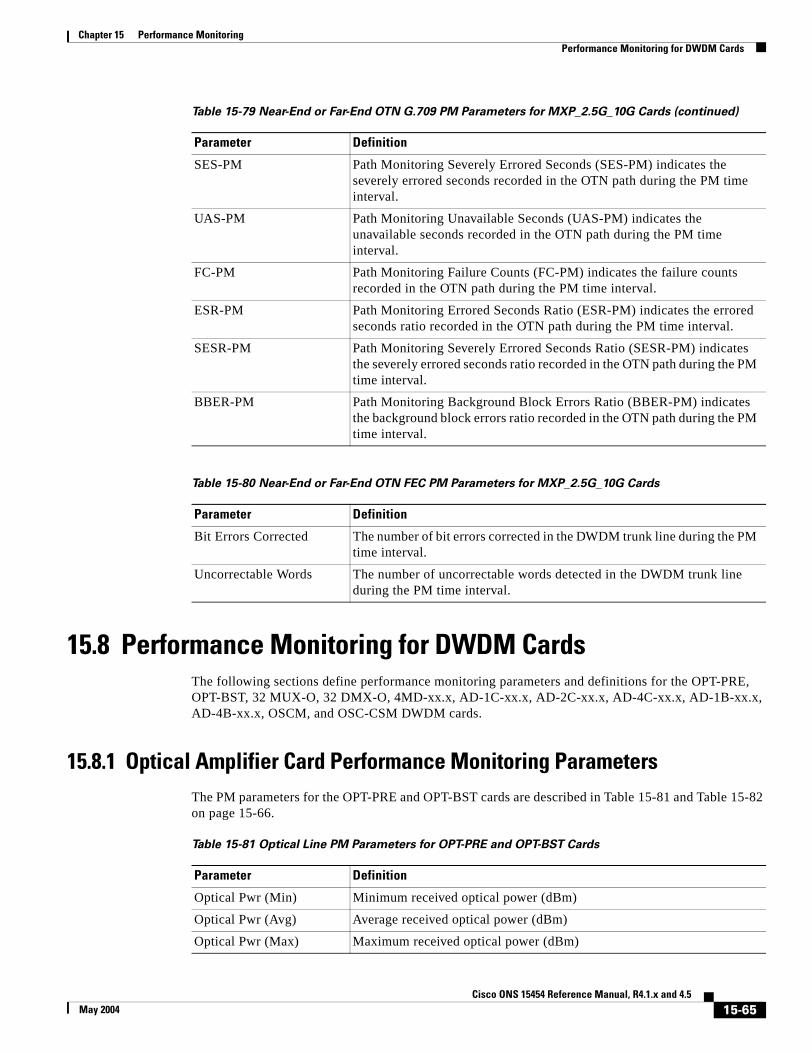
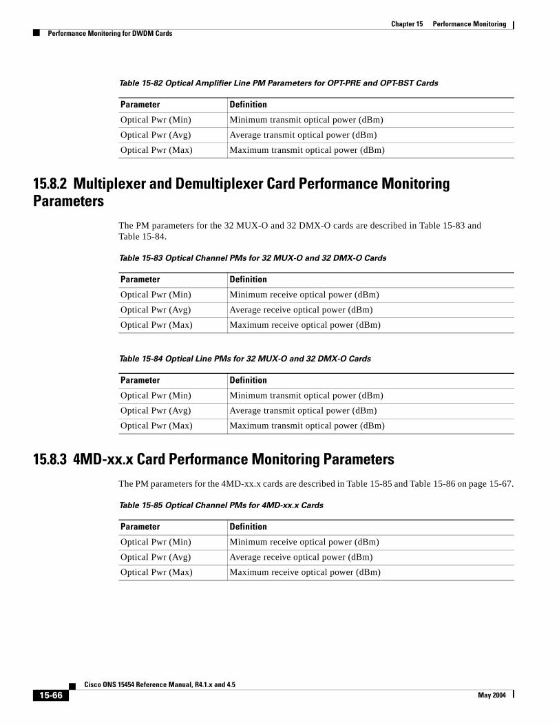


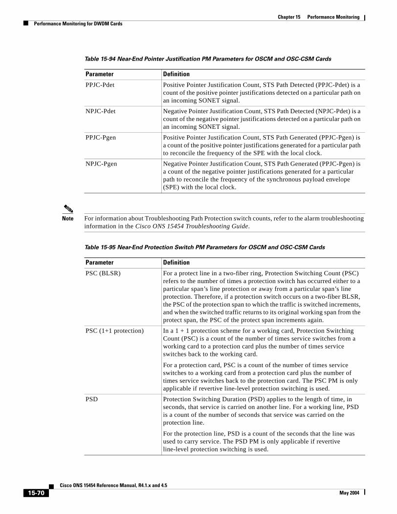
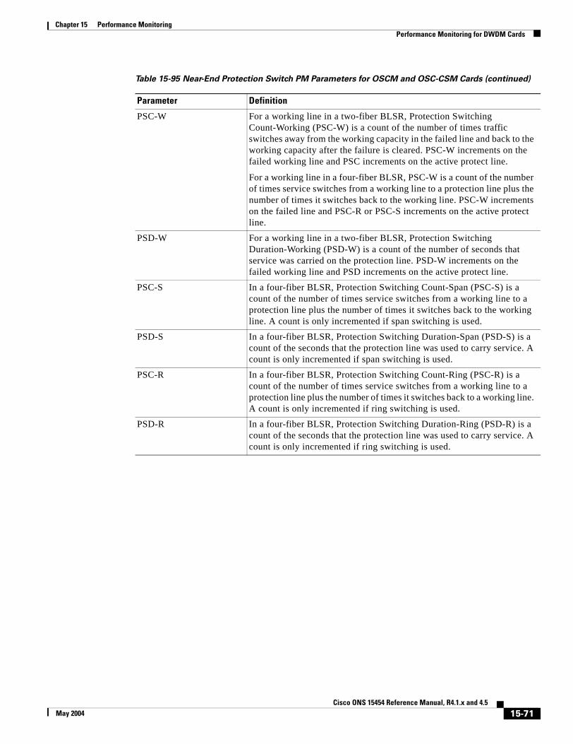


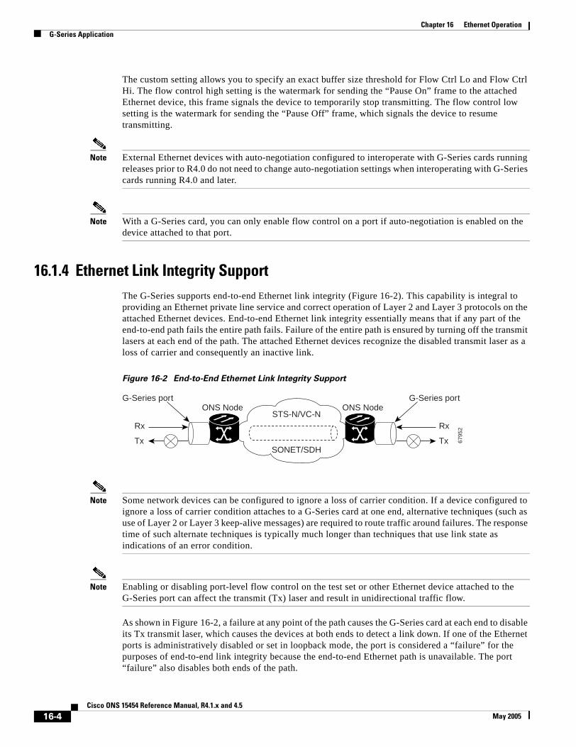

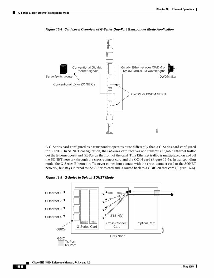
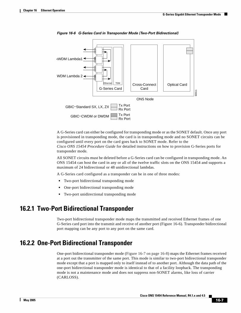

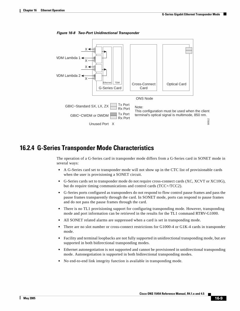

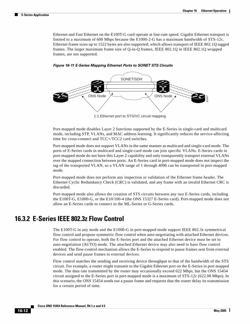
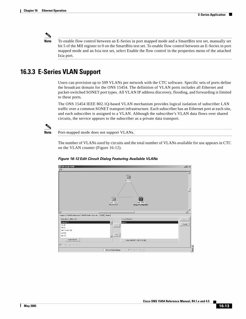


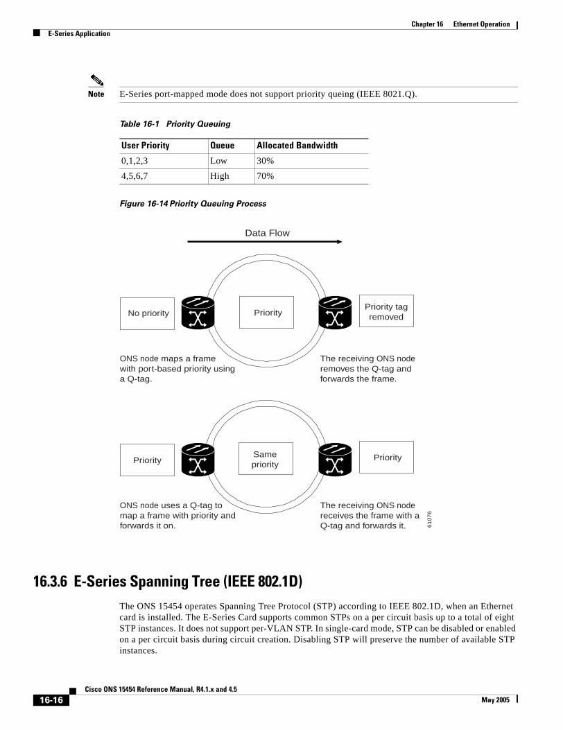
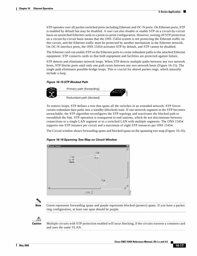
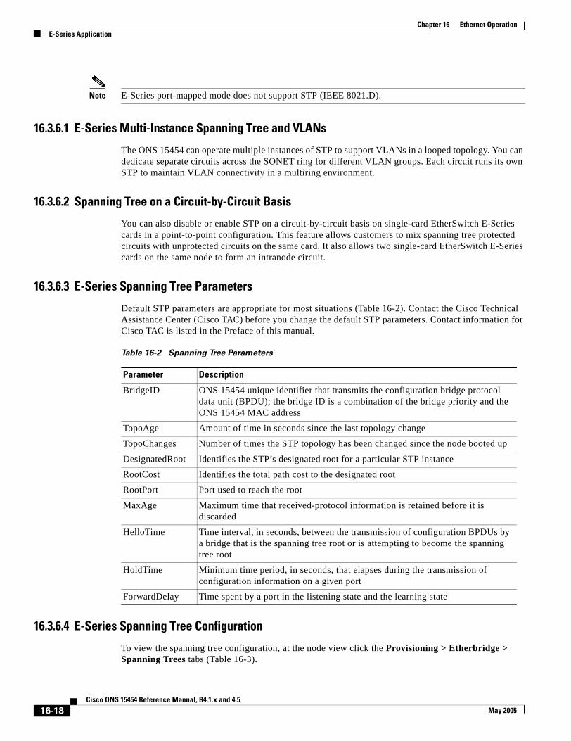

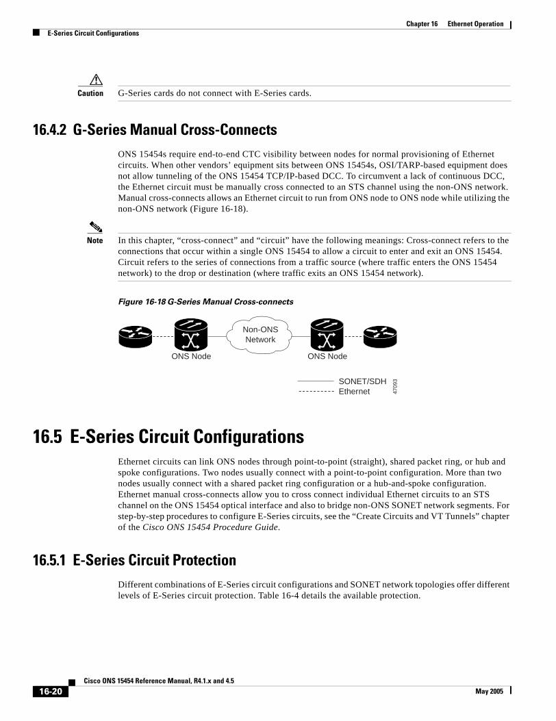


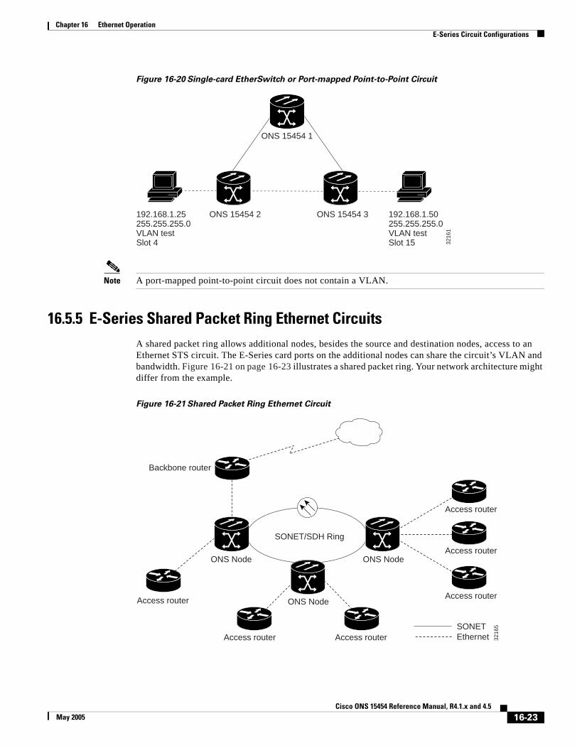


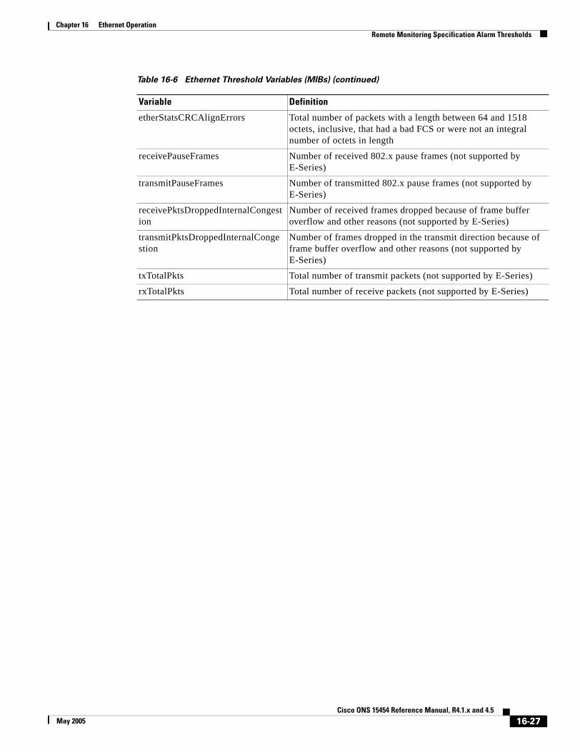


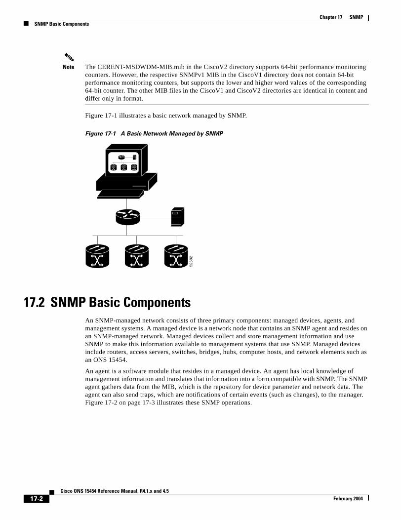


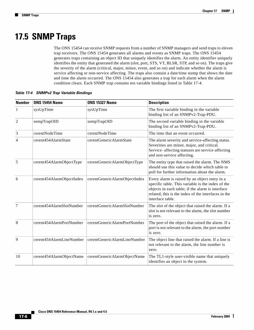


![PICMG 1.3 Backplane · PICMG 1.3 Backplane 26 PICMG 1.3 BACKPLANE PBPE-06P2 - Fit for Node chassis - Four USB ports 6-slot [PCIe x8 (1, x4 signal), PCIe x16 (2, x8 signal), PCI (2)]](https://static.documents.pub/doc/80x56/611a455fbe4d45595d007bf8/picmg-13-backplane-picmg-13-backplane-26-picmg-13-backplane-pbpe-06p2-fit-for.jpg)


