Configuring OSPF P1C-107 Configuring OSPF This chapter describes how to configure OSPF. For a complete description of the OSPF commands in this chapter, refer to the “OSPF Commands” chapter of the Network Protocols Command Reference, Part 1. To locate documentation of other commands that appear in this chapter, use the command reference master index or search online. Open shortest path first (OSPF) is an IGP developed by the OSPF working group of the Internet Engineering Task Force (IETF). Designed expressly for IP networks, OSPF supports IP subnetting and tagging of externally derived routing information. OSPF also allows packet authentication and uses IP multicast when sending/receiving packets. We support RFC 1253, Open Shortest Path First (OSPF) MIB, August 1991. The OSPF MIB defines an IP routing protocol that provides management information related to OSPF and is supported by Cisco routers. For protocol-independent features that include OSPF, see the chapter “Configuring IP Routing Protocol-Independent Features” in this document. Cisco’s OSPF Implementation Cisco’s implementation conforms to the OSPF Version 2 specifications detailed in the Internet RFC 1583. The list that follows outlines key features supported in Cisco’s OSPF implementation: • Stub areas—Definition of stub areas is supported. • Route redistribution—Routes learned via any IP routing protocol can be redistributed into any other IP routing protocol. At the intradomain level, this means that OSPF can import routes learned via IGRP, RIP, and IS-IS. OSPF routes can also be exported into IGRP, RIP, and IS-IS. At the interdomain level, OSPF can import routes learned via EGP and BGP. OSPF routes can be exported into EGP and BGP. • Authentication—Plain text and MD5 authentication among neighboring routers within an area is supported. • Routing interface parameters—Configurable parameters supported include interface output cost, retransmission interval, interface transmit delay, router priority, router “dead” and hello intervals, and authentication key. • Virtual links—Virtual links are supported. • NSSA areas—RFC 1587. • OSPF over demand circuit—RFC 1793.
Transcript
Configuring OSPF
This chapter describes how to configure OSPF. For a complete description of the OSPF commands in this chapter, refer to the “OSPF Commands” chapter of the Network Protocols Command Reference, Part 1. To locate documentation of other commands that appear in this chapter, use the command reference master index or search online.
Open shortest path first (OSPF) is an IGP developed by the OSPF working group of the Internet Engineering Task Force (IETF). Designed expressly for IP networks, OSPF supports IP subnetting and tagging of externally derived routing information. OSPF also allows packet authentication and uses IP multicast when sending/receiving packets.
We support RFC 1253, Open Shortest Path First (OSPF) MIB, August 1991. The OSPF MIB defines an IP routing protocol that provides management information related to OSPF and is supported by Cisco routers.
For protocol-independent features that include OSPF, see the chapter “Configuring IP Routing Protocol-Independent Features” in this document.
Cisco’s OSPF ImplementationCisco’s implementation conforms to the OSPF Version 2 specifications detailed in the Internet RFC 1583. The list that follows outlines key features supported in Cisco’s OSPF implementation:
• Stub areas—Definition of stub areas is supported.
• Route redistribution—Routes learned via any IP routing protocol can be redistributed into any other IP routing protocol. At the intradomain level, this means that OSPF can import routes learned via IGRP, RIP, and IS-IS. OSPF routes can also be exported into IGRP, RIP, and IS-IS. At the interdomain level, OSPF can import routes learned via EGP and BGP. OSPF routes can be exported into EGP and BGP.
• Authentication—Plain text and MD5 authentication among neighboring routers within an area is supported.
• Routing interface parameters—Configurable parameters supported include interface output cost, retransmission interval, interface transmit delay, router priority, router “dead” and hello intervals, and authentication key.
• Virtual links—Virtual links are supported.
• NSSA areas—RFC 1587.
• OSPF over demand circuit—RFC 1793.
Configuring OSPF P1C-107
OSPF Configuration Task List
OSPF Configuration Task ListOSPF typically requires coordination among many internal routers, area border routers (routers connected to multiple areas), and autonomous system boundary routers. At a minimum, OSPF-based routers or access servers can be configured with all default parameter values, no authentication, and interfaces assigned to areas. If you intend to customize your environment, you must ensure coordinated configurations of all routers.
To configure OSPF, complete the tasks in the following sections. Enabling OSPF is mandatory; the other tasks are optional, but might be required for your application.
• Enable OSPF
• Configure OSPF Interface Parameters
• Configure OSPF over Different Physical Networks
• Configure OSPF Area Parameters
• Configure OSPF Not So Stubby Area (NSSA)
• Configure Route Summarization between OSPF Areas
• Configure Route Summarization when Redistributing Routes into OSPF
• Create Virtual Links
• Generate a Default Route
• Configure Lookup of DNS Names
• Force the Router ID Choice with a Loopback Interface
• Control Default Metrics
• Change the OSPF Administrative Distances
• Configure OSPF on Simplex Ethernet Interfaces
• Configure Route Calculation Timers
• Configure OSPF over On Demand Circuits
• Log Neighbors Going Up or Down
• Change the LSA Group Pacing
• Block OSPF LSA Flooding
• Ignore MOSPF LSA Packets
• Monitor and Maintain OSPF
In addition, you can specify route redistribution; see the task “Redistribute Routing Information” in the chapter “Configuring IP Routing Protocol-Independent Features” for information on how to configure route redistribution.
P1C-108 Network Protocols Configuration Guide, Part 1
Enable OSPF
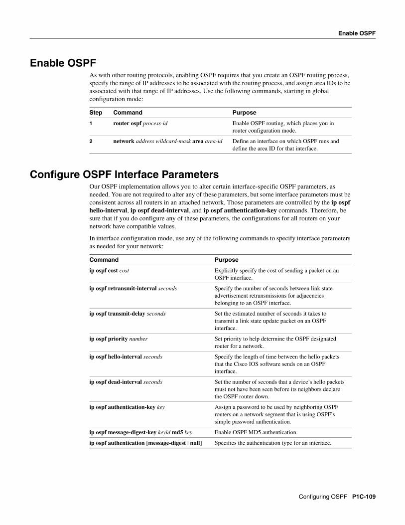
Enable OSPFAs with other routing protocols, enabling OSPF requires that you create an OSPF routing process, specify the range of IP addresses to be associated with the routing process, and assign area IDs to be associated with that range of IP addresses. Use the following commands, starting in global configuration mode:
Configure OSPF Interface ParametersOur OSPF implementation allows you to alter certain interface-specific OSPF parameters, as needed. You are not required to alter any of these parameters, but some interface parameters must be consistent across all routers in an attached network. Those parameters are controlled by the ip ospf hello-interval, ip ospf dead-interval, and ip ospf authentication-key commands. Therefore, be sure that if you do configure any of these parameters, the configurations for all routers on your network have compatible values.
In interface configuration mode, use any of the following commands to specify interface parameters as needed for your network:
Step Command Purpose
1 router ospf process-id Enable OSPF routing, which places you in router configuration mode.
2 network address wildcard-mask area area-id Define an interface on which OSPF runs and define the area ID for that interface.
Command Purpose
ip ospf cost cost Explicitly specify the cost of sending a packet on an OSPF interface.
ip ospf retransmit-interval seconds Specify the number of seconds between link state advertisement retransmissions for adjacencies belonging to an OSPF interface.
ip ospf transmit-delay seconds Set the estimated number of seconds it takes to transmit a link state update packet on an OSPF interface.
ip ospf priority number Set priority to help determine the OSPF designated router for a network.
ip ospf hello-interval seconds Specify the length of time between the hello packets that the Cisco IOS software sends on an OSPF interface.
ip ospf dead-interval seconds Set the number of seconds that a device’s hello packets must not have been seen before its neighbors declare the OSPF router down.
ip ospf authentication-key key Assign a password to be used by neighboring OSPF routers on a network segment that is using OSPF’s simple password authentication.
ip ospf message-digest-key keyid md5 key Enable OSPF MD5 authentication.
ip ospf authentication [message-digest | null] Specifies the authentication type for an interface.
Configuring OSPF P1C-109
Configure OSPF over Different Physical Networks
Configure OSPF over Different Physical NetworksOSPF classifies different media into the following three types of networks by default:
You can configure your network as either a broadcast or a nonbroadcast multiaccess network.
X.25 and Frame Relay provide an optional broadcast capability that can be configured in the map to allow OSPF to run as a broadcast network. See the x25 map and frame-relay map command descriptions in the Wide-Area Networking Command Reference for more detail.
Configure Your OSPF Network TypeYou have the choice of configuring your OSPF network type as either broadcast or nonbroadcast multiaccess, regardless of the default media type. Using this feature, you can configure broadcast networks as nonbroadcast multiaccess networks when, for example, you have routers in your network that do not support multicast addressing. You also can configure nonbroadcast multiaccess networks (such as X.25, Frame Relay, and SMDS) as broadcast networks. This feature saves you from having to configure neighbors, as described in the section “Configure OSPF for Nonbroadcast Networks.”
Configuring nonbroadcast, multiaccess networks as either broadcast or nonbroadcast assumes that there are virtual circuits from every router to every router or fully meshed network. This is not true for some cases, for example, because of cost constraints, or when you have only a partially meshed network. In these cases, you can configure the OSPF network type as a point-to-multipoint network. Routing between two routers not directly connected will go through the router that has virtual circuits to both routers. Note that it is not necessary to configure neighbors when using this feature.
An OSPF point-to-multipoint interface is defined as a numbered point-to-point interface having one or more neighbors. It creates multiple host routes. An OSPF point-to-multipoint network has the following benefits compared to nonbroadcast multiaccess and point-to-point networks:
• Point-to-multipoint is easier to configure because it requires no configuration of neighbor commands, it consumes only one IP subnet, and it requires no designated router election.
• It costs less because it does not require a fully meshed topology.
• It is more reliable because it maintains connectivity in the event of virtual circuit failure.
To configure your OSPF network type, use the following command in interface configuration mode:
See the “OSPF Point-to-Multipoint Example” section at the end of this chapter for an example of an OSPF point-to-multipoint network.
Configure Point-to-Multipoint, Broadcast NetworksOn point-to-multipoint, broadcast networks, there is no need to specify neighbors. However, you can specify neighbors with the neighbor command, in which case you should specify a cost to that neighbor.
Command Purpose
ip ospf network {broadcast | non-broadcast | {point-to-multipoint [non-broadcast] }}
Configure the OSPF network type for a specified interface.
P1C-110 Network Protocols Configuration Guide, Part 1
Configure OSPF for Nonbroadcast Networks
Before this feature, some OSPF point-to-multipoint protocol traffic was treated as multicast traffic. Therefore, the neighbor command was not needed for point-to-multipoint interfaces because multicast took care of the traffic. Hellos, updates and acknowledgments were sent using multicast. In particular, multicast hellos discovered all neighbors dynamically.
On any point-to-multipoint interface (broadcast or not), the Cisco IOS software assumed the cost to each neighbor was equal. The cost was configured with the ip ospf cost command. In reality, the bandwidth to each neighbor is different, so the cost should be different. With this feature, you can configure a separate cost to each neighbor. This feature applies to point-to-multipoint interfaces only.
To treat an interface as point-to-multipoint broadcast and assign a cost to each neighbor, use the following commands beginning in interface configuration mode:
Configure OSPF for Nonbroadcast NetworksBecause there might be many routers attached to an OSPF network, a designated router is selected for the network. It is necessary to use special configuration parameters in the designated router selection if broadcast capability is not configured.
These parameters need only be configured in those devices that are themselves eligible to become the designated router or backup designated router (in other words, routers with a nonzero router priority value).
To configure routers that interconnect to nonbroadcast networks, use the following command in router configuration mode:
You can specify the following neighbor parameters, as required:
• Priority for a neighboring router
• Nonbroadcast poll interval
• Interface through which the neighbor is reachable
On point-to-multipoint, nonbroadcast networks, you now use the neighbor command to identify neighbors. Assigning a cost to a neighbor is optional.
Prior to Release 12.0, some customers were using point-to-multipoint on nonbroadcast media (such as classic IP over ATM), so their routers could not dynamically discover their neighbors. This feature allows the neighbor command to be used on point-to-multipoint interfaces.
Step Command Purpose
1 ip ospf network point-to-multipoint Configure an interface as point-to-multipoint for broadcast media.
2 exit Enter global configuration mode.
3 router ospf process-id Configure an OSPF routing process and enter router configuration mode.
4 neighbor ip-address cost number Specify a neighbor and assign a cost to the neighbor.
5 Repeat Step 4 for each neighbor if you want to specify a cost. Otherwise, neighbors will assume the cost of the interface, based on the ip ospf cost command.
Configure a router interconnecting to nonbroadcast networks.
Configuring OSPF P1C-111
Configure OSPF Area Parameters
On any point-to-multipoint interface (broadcast or not), the Cisco IOS software assumed the cost to each neighbor was equal. The cost was configured with the ip ospf cost command. In reality, the bandwidth to each neighbor is different, so the cost should be different. With this feature, you can configure a separate cost to each neighbor. This feature applies to point-to-multipoint interfaces only.
To treat the interface as point-to-multipoint when the media does not support broadcast, use the following commands beginning in interface configuration mode:
Configure OSPF Area ParametersOur OSPF software allows you to configure several area parameters. These area parameters, shown in the following table, include authentication, defining stub areas, and assigning specific costs to the default summary route. Authentication allows password-based protection against unauthorized access to an area.
Stub areas are areas into which information on external routes is not sent. Instead, there is a default external route generated by the area border router, into the stub area for destinations outside the autonomous system. To take advantage of the OSPF stub area support, default routing must be used in the stub area. To further reduce the number of link state advertisements sent into a stub area, you can configure no-summary on the ABR to prevent it from sending summary link advertisement (link state advertisements Type 3) into the stub area.
In router configuration mode, specify any of the following area parameters as needed for your network:
Configure OSPF Not So Stubby Area (NSSA)NSSA area is similar to OSPF stub area. NSSA does not flood Type 5 external link state advertisements (LSAs) from the core into the area, but it has the ability of importing AS external routes in a limited fashion within the area.
NSSA allows importing of Type 7 AS external routes within NSSA area by redistribution. These Type 7 LSAs are translated into Type 5 LSAs by NSSA ABR which are flooded throughout the whole routing domain. Summarization and filtering are supported during the translation.
Step Command Purpose
1 ip ospf network point-to-multipoint non-broadcast
Configure an interface as point-to-multipoint for nonbroadcast media.
2 exit Enter global configuration mode.
3 router ospf process-id Configure an OSPF routing process and enter router configuration mode.
4 neighbor ip-address [cost number] Specify an OSPF neighbor and optionally assign a cost to the neighbor.
5 Repeat Step 4 for each neighbor.
Command Purpose
area area-id authentication Enable authentication for an OSPF area.
area area-id authentication message-digest Enable MD5 authentication for an OSPF area.
area area-id stub [no-summary] Define an area to be a stub area.
area area-id default-cost cost Assign a specific cost to the default summary route used for the stub area.
P1C-112 Network Protocols Configuration Guide, Part 1
Implementation Considerations
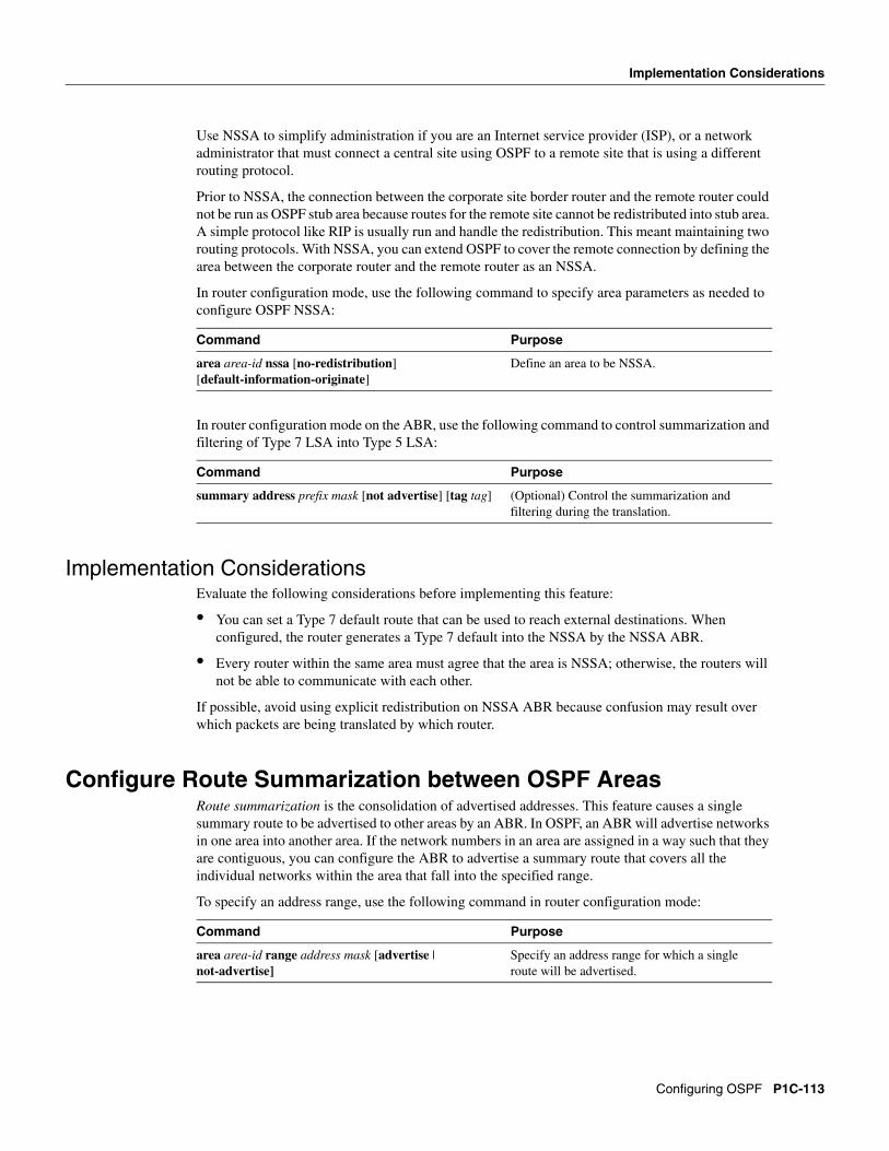
Use NSSA to simplify administration if you are an Internet service provider (ISP), or a network administrator that must connect a central site using OSPF to a remote site that is using a different routing protocol.
Prior to NSSA, the connection between the corporate site border router and the remote router could not be run as OSPF stub area because routes for the remote site cannot be redistributed into stub area. A simple protocol like RIP is usually run and handle the redistribution. This meant maintaining two routing protocols. With NSSA, you can extend OSPF to cover the remote connection by defining the area between the corporate router and the remote router as an NSSA.
In router configuration mode, use the following command to specify area parameters as needed to configure OSPF NSSA:
In router configuration mode on the ABR, use the following command to control summarization and filtering of Type 7 LSA into Type 5 LSA:
Implementation ConsiderationsEvaluate the following considerations before implementing this feature:
• You can set a Type 7 default route that can be used to reach external destinations. When configured, the router generates a Type 7 default into the NSSA by the NSSA ABR.
• Every router within the same area must agree that the area is NSSA; otherwise, the routers will not be able to communicate with each other.
If possible, avoid using explicit redistribution on NSSA ABR because confusion may result over which packets are being translated by which router.
Configure Route Summarization between OSPF AreasRoute summarization is the consolidation of advertised addresses. This feature causes a single summary route to be advertised to other areas by an ABR. In OSPF, an ABR will advertise networks in one area into another area. If the network numbers in an area are assigned in a way such that they are contiguous, you can configure the ABR to advertise a summary route that covers all the individual networks within the area that fall into the specified range.
To specify an address range, use the following command in router configuration mode:
Command Purpose
area area-id nssa [no-redistribution] [default-information-originate]
Define an area to be NSSA.
Command Purpose
summary address prefix mask [not advertise] [tag tag] (Optional) Control the summarization and filtering during the translation.
Command Purpose
area area-id range address mask [advertise | not-advertise]
Specify an address range for which a single route will be advertised.
Configuring OSPF P1C-113
Configure Route Summarization when Redistributing Routes into OSPF
Configure Route Summarization when Redistributing Routes into OSPF
When redistributing routes from other protocols into OSPF (as described in the chapter “Configuring IP Routing Protocol-Independent Features”), each route is advertised individually in an external link state advertisement (LSA). However, you can configure the Cisco IOS software to advertise a single route for all the redistributed routes that are covered by a specified network address and mask. Doing so helps decrease the size of the OSPF link state database.
To have the software advertise one summary route for all redistributed routes covered by a network address and mask, use the following command in router configuration mode:
Create Virtual LinksIn OSPF, all areas must be connected to a backbone area. If there is a break in backbone continuity, or the backbone is purposefully partitioned, you can establish a virtual link. The two end points of a virtual link are Area Border Routers. The virtual link must be configured in both routers. The configuration information in each router consists of the other virtual endpoint (the other ABR), and the nonbackbone area that the two routers have in common (called the transit area). Note that virtual links cannot be configured through stub areas.
To establish a virtual link, use the following command in router configuration mode:
To display information about virtual links, use the show ip ospf virtual-links EXEC command. To display the router ID of an OSPF router, use the show ip ospf EXEC command.
Generate a Default RouteYou can force an autonomous system boundary router to generate a default route into an OSPF routing domain. Whenever you specifically configure redistribution of routes into an OSPF routing domain, the router automatically becomes an autonomous system boundary router. However, an autonomous system boundary router does not, by default, generate a default route into the OSPF routing domain.
To force the autonomous system boundary router to generate a default route, use the following command in router configuration mode:
Command Purpose
summary-address address mask Specify an address and mask that covers redistributed routes, so only one summary route is advertised.
Force the autonomous system boundary router to generate a default route into the OSPF routing domain.
P1C-114 Network Protocols Configuration Guide, Part 1
Configure Lookup of DNS Names
See the discussion of redistribution of routes in the “Configuring IP Routing Protocol-Independent Features” chapter.
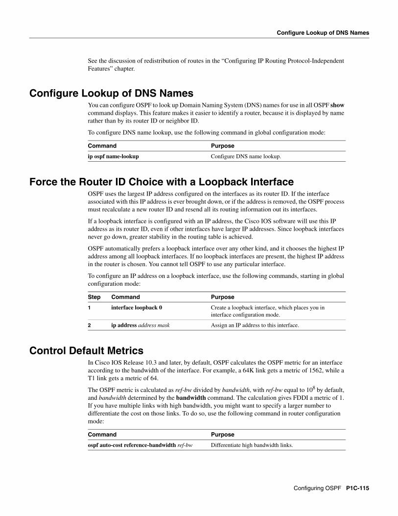
Configure Lookup of DNS NamesYou can configure OSPF to look up Domain Naming System (DNS) names for use in all OSPF show command displays. This feature makes it easier to identify a router, because it is displayed by name rather than by its router ID or neighbor ID.
To configure DNS name lookup, use the following command in global configuration mode:
Force the Router ID Choice with a Loopback InterfaceOSPF uses the largest IP address configured on the interfaces as its router ID. If the interface associated with this IP address is ever brought down, or if the address is removed, the OSPF process must recalculate a new router ID and resend all its routing information out its interfaces.
If a loopback interface is configured with an IP address, the Cisco IOS software will use this IP address as its router ID, even if other interfaces have larger IP addresses. Since loopback interfaces never go down, greater stability in the routing table is achieved.
OSPF automatically prefers a loopback interface over any other kind, and it chooses the highest IP address among all loopback interfaces. If no loopback interfaces are present, the highest IP address in the router is chosen. You cannot tell OSPF to use any particular interface.
To configure an IP address on a loopback interface, use the following commands, starting in global configuration mode:
Control Default MetricsIn Cisco IOS Release 10.3 and later, by default, OSPF calculates the OSPF metric for an interface according to the bandwidth of the interface. For example, a 64K link gets a metric of 1562, while a T1 link gets a metric of 64.
The OSPF metric is calculated as ref-bw divided by bandwidth, with ref-bw equal to 108 by default, and bandwidth determined by the bandwidth command. The calculation gives FDDI a metric of 1. If you have multiple links with high bandwidth, you might want to specify a larger number to differentiate the cost on those links. To do so, use the following command in router configuration mode:
Command Purpose
ip ospf name-lookup Configure DNS name lookup.
Step Command Purpose
1 interface loopback 0 Create a loopback interface, which places you in interface configuration mode.
2 ip address address mask Assign an IP address to this interface.
Command Purpose
ospf auto-cost reference-bandwidth ref-bw Differentiate high bandwidth links.
Configuring OSPF P1C-115
Change the OSPF Administrative Distances
Change the OSPF Administrative DistancesAn administrative distance is a rating of the trustworthiness of a routing information source, such as an individual router or a group of routers. Numerically, an administrative distance is an integer between 0 and 255. In general, the higher the value, the lower the trust rating. An administrative distance of 255 means the routing information source cannot be trusted at all and should be ignored.
OSPF uses three different administrative distances: intra-area, inter-area, and external. Routes within an area are intra-area; routes to another area are inter-area; and routes from another routing domain learned via redistribution are external. The default distance for each type of route is 110.
To change any of the OSPF distance values, use the following command in router configuration mode:
For an example of changing administrative distance, see the section “Changing OSPF Administrative Distance” at the end of this chapter.
Configure OSPF on Simplex Ethernet InterfacesBecause simplex interfaces between two devices on an Ethernet represent only one network segment, for OSPF you must configure the transmitting interface to be a passive interface. This prevents OSPF from sending hello packets for the transmitting interface. Both devices are able to see each other via the hello packet generated for the receiving interface.
To configure OSPF on simplex Ethernet interfaces, use the following command in router configuration mode:
Configure Route Calculation TimersYou can configure the delay time between when OSPF receives a topology change and when it starts a shortest path first (SPF) calculation. You can also configure the hold time between two consecutive SPF calculations. To do this, use the following command in router configuration mode:
Configure OSPF over On Demand CircuitsThe OSPF on demand circuit is an enhancement to the OSPF protocol that allows efficient operation over on demand circuits like ISDN, X.25 SVCs and dial-up lines. This feature supports RFC 1793, Extending OSPF to Support Demand Circuits.
Prior to this feature, OSPF periodic hello and link state advertisements (LSAs) updates would be exchanged between routers that connected the on demand link, even when no changes occurred in the hello or LSA information.
P1C-116 Network Protocols Configuration Guide, Part 1
Implementation Considerations
With this feature, periodic hellos are suppressed and the periodic refreshes of LSAs are not flooded over the demand circuit. These packets bring up the link only when they are exchanged for the first time, or when a change occurs in the information they contain. This operation allows the underlying datalink layer to be closed when the network topology is stable.
This feature is useful when you want to connect telecommuters or branch offices to an OSPF backbone at a central site. In this case, OSPF for on demand circuits allows the benefits of OSPF over the entire domain, without excess connection costs. Periodic refreshes of hello updates, LSA updates, and other protocol overhead are prevented from enabling the on demand circuit when there is no “real” data to transmit.
Overhead protocols such as hellos and LSAs are transferred over the on demand circuit only upon initial setup and when they reflect a change in the topology. This means that critical changes to the topology that require new SPF calculations are transmitted in order to maintain network topology integrity. Periodic refreshes that do not include changes, however, are not transmitted across the link.
To configure OSPF for on demand circuits, use the following commands, beginning in global configuration mode:
If the router is part of a point-to-point topology, then only one end of the demand circuit must be configured with this command. However, all routers must have this feature loaded.
If the router is part of a point-to-multipoint topology, only the multipoint end must be configured with this command.
For an example of OSPF over an on-demand circuit, see the section “OSPF over On-Demand Routing Example” at the end of this chapter.
Implementation ConsiderationsEvaluate the following considerations before implementing this feature:
• Because LSAs that include topology changes are flooded over an on demand circuit, it is advised to put demand circuits within OSPF stub areas, or within NSSAs to isolate the demand circuits from as many topology changes as possible.
• To take advantage of the on demand circuit functionality within a stub area or NSSA, every router in the area must have this feature loaded. If this feature is deployed within a regular area, all other regular areas must also support this feature before the demand circuit functionality can take effect. This is because type 5 external LSAs are flooded throughout all areas.
• You do not want to do on a broadcast-based network topology because the overhead protocols (such as hellos and LSAs) cannot be successfully suppressed, which means the link will remain up.
• Configuring the router for an OSPF on-demand circuit with an asynchronous interface is not a supported configuration. The supported configuration is to use dialer interfaces on both ends of the circuit. For more information, refer to the following TAC URL:
2 interface type number Enter interface configuration mode.
3 ip ospf demand-circuit Configure OSPF on an on demand circuit.
Configuring OSPF P1C-117
Log Neighbors Going Up or Down
Log Neighbors Going Up or DownTo configure the router to send a syslog message when an OSPF neighbor goes up or down, use the following command in router configuration mode:
Configure this command if you want to know about OSPF neighbors going up or down without turning on the debugging command debug ip ospf adjacency. The ospf log-adjacency-changes command provides a higher level view of such changes with less output.
Change the LSA Group PacingThe OSPF LSA group pacing feature allows the router to group together OSPF link state advertisements (LSAs) and pace the refreshing, checksumming, and aging functions. The group pacing results in more efficient use of the router.
The router groups together OSPF LSAs and paces the refreshing, checksumming, and aging functions so that sudden hits on CPU usage and network resources are avoided. This feature is most beneficial to large OSPF networks.
OSPF LSA group pacing is enabled by default. For typical customers, the default group pacing interval for refreshing, checksumming, and aging is appropriate and you need not configure this feature.
Original LSA BehaviorEach OSPF LSA has an age, which indicates whether the LSA is still valid. Once the LSA reaches the maximum age (one hour), it is discarded. During the aging process, the originating router sends a refresh packet every 30 minutes to refresh the LSA. Refresh packets are sent to keep the LSA from expiring, whether there has been a change in the network topology or not. Checksumming is performed on all LSAs every 10 minutes. The router keeps track of LSAs it generates and LSAs it receives from other routers. The router refreshes LSAs it generated; it ages the LSAs it received from other routers.
Prior to the LSA group pacing feature, the Cisco IOS software would perform refreshing on a single timer, and checksumming and aging on another timer. In the case of refreshing, for example, the software would scan the whole database every 30 minutes, refreshing every LSA the router generated, no matter how old it was. Figure 21 illustrates all the LSAs being refreshed at once. This process wasted CPU resources because only a small portion of the database needed to be refreshed. A large OSPF database (several thousand LSAs) could have thousands of LSAs with different ages. Refreshing on a single timer resulted in the age of all LSAs becoming synchronized, which resulted in much CPU processing at once. Furthermore, a huge number of LSAs could cause a sudden increase of network traffic, consuming a large amount of network resources in a short period of time.
Command Purpose
ospf log-adjacency-changes Send syslog message when an OSPF neighbor goes up or down.
P1C-118 Network Protocols Configuration Guide, Part 1
Solution
Figure 21 OSPF LSAs on a Single Timer without Group Pacing
SolutionThis problem is solved by each LSA having its own timer. Again using the example of refreshing, each LSA gets refreshed when it is 30 minutes old, independent of other LSAs. So CPU is used only when necessary. However, LSAs being refreshed at frequent, random intervals would require many packets for the few refreshed LSAs the router must send out. That would be inefficient use of bandwidth.
Therefore, the router delays the LSA refresh function for an interval of time instead of performing it when the individual timers are reached. The accumulated LSAs constitute a group, which is then refreshed and sent out in one packet or more. Thus, the refresh packets are paced, as are the checksumming and aging. The pacing interval is configurable; it defaults to 4 minutes, which is randomized to further avoid synchronization.
Figure 22 illustrates the case of refresh packets. The first timeline illustrates individual LSA timers; the second timeline illustrates individual LSA timers with group pacing.
Figure 22 OSPF LSAs on Individual Timers with Group Pacing
The group pacing interval is inversely proportional to the number of LSAs the router is refreshing, checksumming, and aging. For example, if you have approximately 10,000 LSAs, decreasing the pacing interval would benefit you. If you have a very small database (40 to 100 LSAs), increasing the pacing interval to 10 to 20 minutes might benefit you slightly.
30 minutes 30 minutes 30 minutes
Prior to pacing, all LSAs refreshed at once
All LSAs refreshed, 120 external LSAs on Ethernet need three packets
1034
1
É
4 min
Individual LSA timers with group pacing
20 LSAs, 1 packet
15 LSAs, 1 packet
1047
1
37 LSAs, 1 packet
4 min 4 min É
Individual LSA timers
Without group pacing, LSAs need to be refreshed frequentlyand at random intervals. Individual LSA timers require many
refresh packets that contain few LSAs.
Configuring OSPF P1C-119
Block OSPF LSA Flooding
The default value of pacing between LSA groups is 240 seconds (4 minutes). The range is 10 seconds to 1800 seconds (half an hour). To change the LSA group pacing interval, use the following command in router configuration mode:
For an example, see the section “LSA Group Pacing Example” at the end of this chapter.
Block OSPF LSA FloodingBy default, OSPF floods new LSAs over all interfaces in the same area, except the interface on which the LSA arrives. Some redundancy is desirable, because it ensures robust flooding. However, too much redundancy can waste bandwidth and might destabilize the network due to excessive link and CPU usage in certain topologies. An example would be a fully meshed topology.
You can block OSPF flooding of LSAs two ways, depending on the type of networks:
• On broadcast, nonbroadcast, and point-to-point networks, you can block flooding over specified OSPF interfaces.
• On point-to-multipoint networks, you can block flooding to a specified neighbor.
On broadcast, nonbroadcast, and point-to-point networks, to prevent flooding of OSPF LSAs, use the following command in interface configuration mode:
On point-to-multipoint networks, to prevent flooding of OSPF LSAs, use the following command in router configuration mode:
For an example of blocking LSA flooding, see the section “Block LSA Flooding Example” at the end of this chapter.
Ignore MOSPF LSA PacketsCisco routers do not support LSA Type 6 (MOSPF), and they generate syslog messages if they receive such packets. If the router is receiving many MOSPF packets, you might want to configure the router to ignore the packets and thus prevent a large number of syslog messages. To do so, use the following command in router configuration mode:
For an example of suppressing MOSPF LSA packets, see the section “Ignore MOSPF LSA Packets Example” at the end of this chapter.
Command Purpose
timers lsa-group-pacing seconds Change the group pacing of LSAs.
Command Purpose
ospf database-filter all out Block the flooding of OSPF LSA packets to the interface.
Command Purpose
neighbor ip-address database-filter all out Block the flooding of OSPF LSA packets to the specified neighbor.
Command Purpose
ospf ignore lsa mospf Prevent the router from generating syslog messages when it receives MOSPF LSA packets.
P1C-120 Network Protocols Configuration Guide, Part 1
Monitor and Maintain OSPF
Monitor and Maintain OSPFYou can display specific statistics such as the contents of IP routing tables, caches, and databases. Information provided can be used to determine resource utilization and solve network problems. You can also display information about node reachability and discover the routing path your device’s packets are taking through the network.
To display various routing statistics, use the following commands in EXEC mode:
OSPF Configuration ExamplesThe following sections provide OSPF configuration examples:
• OSPF Point-to-Multipoint Example
• OSPF Point-to-Multipoint, Broadcast Example
• OSPF Point-to-Multipoint, Nonbroadcast Example
• Variable-Length Subnet Masks Example
• OSPF Routing and Route Redistribution Examples
Command Purpose
show ip ospf [process-id] Display general information about OSPF routing processes.
show ip ospf [process-id area-id] database
show ip ospf [process-id area-id] database [router] [link-state-id]
show ip ospf [process-id area-id] database [router] [self-originate]
show ip ospf [process-id area-id] database [router] [adv-router [ip-address]]
show ip ospf [process-id area-id] database [network] [link-state-id]
show ip ospf [process-id area-id] database [summary] [link-state-id]
show ip ospf [process-id area-id] database [asbr-summary] [link-state-id]
show ip ospf [process-id] database [external] [link-state-id]
show ip ospf [process-id area-id] database [database-summary]
Display lists of information related to the OSPF database.
show ip ospf border-routers Display the internal OSPF routing table entries to Area Border Router (ABR) and Autonomous System Boundary Router (ASBR).
show ip ospf interface [interface-name] Display OSPF-related interface information.
show ip ospf neighbor [interface-name] [neighbor-id] detail
Display OSPF-neighbor information on a per-interface basis.
show ip ospf request-list [nbr] [intf] [intf-nbr] Display a list of all LSAs requested by a router.
show ip ospf retransmission-list [nbr] [intf] [intf-nbr]
Display a list of all LSAs waiting to be retransmitted.
show ip ospf virtual-links Display OSPF-related virtual links information.
Configuring OSPF P1C-121
OSPF Configuration Examples
• Route Map Examples
• Changing OSPF Administrative Distance
• OSPF over On-Demand Routing Example
• LSA Group Pacing Example
• Block LSA Flooding Example
• Ignore MOSPF LSA Packets Example
OSPF Point-to-Multipoint ExampleIn Figure 23, Mollie uses DLCI 201 to communicate with Neon, DLCI 202 to Jelly, and DLCI 203 to Platty. Neon uses DLCI 101 to communicate with Mollie and DLCI 102 to communicate with Platty. Platty communicates with Neon (DLCI 401) and Mollie (DLCI 402). Jelly communicates with Mollie (DLCI 301).
Figure 23 OSPF Point-to-Multipoint Example
Mollie’s Configurationhostname mollie!interface serial 1ip address 10.0.0.2 255.0.0.0ip ospf network point-to-multipointencapsulation frame-relayframe-relay map ip 10.0.0.1 201 broadcastframe-relay map ip 10.0.0.3 202 broadcastframe-relay map ip 10.0.0.4 203 broadcast
!router ospf 1network 10.0.0.0 0.0.0.255 area 0
Mollie
Neon10.0.0.1
Platty10.0.0.4
Jelly301
202
201
203
101
402
401
102
S37
75
P1C-122 Network Protocols Configuration Guide, Part 1
OSPF Point-to-Multipoint, Broadcast Example
Neon’s Configurationhostname neon!interface serial 0ip address 10.0.0.1 255.0.0.0ip ospf network point-to-multipointencapsulation frame-relayframe-relay map ip 10.0.0.2 101 broadcastframe-relay map ip 10.0.0.4 102 broadcast
!router ospf 1network 10.0.0.0 0.0.0.255 area 0
Platty’s Configurationhostname platty!interface serial 3ip address 10.0.0.4 255.0.0.0ip ospf network point-to-multipointencapsulation frame-relayclock rate 1000000frame-relay map ip 10.0.0.1 401 broadcastframe-relay map ip 10.0.0.2 402 broadcast
!router ospf 1network 10.0.0.0 0.0.0.255 area 0
Jelly’s Configurationhostname jelly!interface serial 2ip address 10.0.0.3 255.0.0.0ip ospf network point-to-multipointencapsulation frame-relayclock rate 2000000frame-relay map ip 10.0.0.2 301 broadcast
!router ospf 1network 10.0.0.0 0.0.0.255 area 0
OSPF Point-to-Multipoint, Broadcast ExampleThe following example illustrates a point-to-multipoint network with broadcast:
ip ospf network point-to-multipoint frame-relay map ip 10.0.1.3 202 broadcast frame-relay map ip 10.0.1.4 203 broadcast frame-relay map ip 10.0.1.5 204 broadcast frame-relay local-dlci 200!router ospf 1 network 10.0.1.0 0.0.0.255 area 0 neighbor 10.0.1.5 cost 5 neighbor 10.0.1.4 cost 10
Configuring OSPF P1C-123
OSPF Configuration Examples
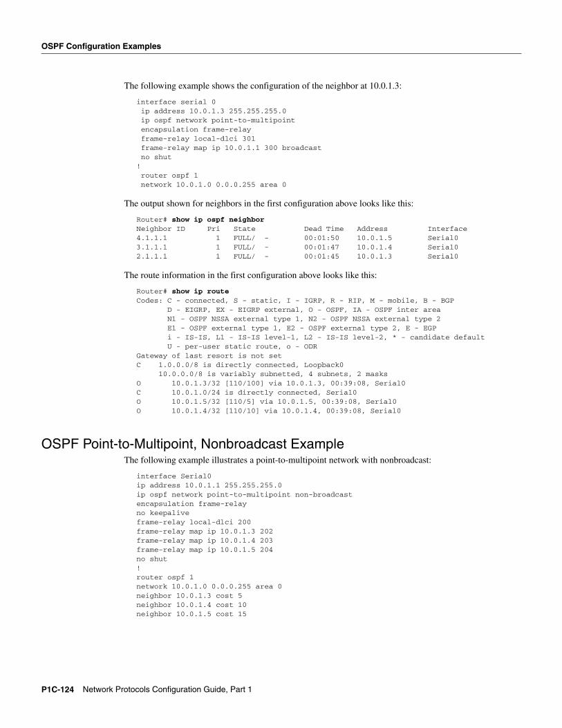
The following example shows the configuration of the neighbor at 10.0.1.3:
interface serial 0ip address 10.0.1.3 255.255.255.0ip ospf network point-to-multipointencapsulation frame-relayframe-relay local-dlci 301frame-relay map ip 10.0.1.1 300 broadcastno shut
!router ospf 1network 10.0.1.0 0.0.0.255 area 0
The output shown for neighbors in the first configuration above looks like this:
Router# show ip ospf neighborNeighbor ID Pri State Dead Time Address Interface4.1.1.1 1 FULL/ - 00:01:50 10.0.1.5 Serial03.1.1.1 1 FULL/ - 00:01:47 10.0.1.4 Serial02.1.1.1 1 FULL/ - 00:01:45 10.0.1.3 Serial0
The route information in the first configuration above looks like this:
Router# show ip routeCodes: C - connected, S - static, I - IGRP, R - RIP, M - mobile, B - BGP D - EIGRP, EX - EIGRP external, O - OSPF, IA - OSPF inter area N1 - OSPF NSSA external type 1, N2 - OSPF NSSA external type 2 E1 - OSPF external type 1, E2 - OSPF external type 2, E - EGP i - IS-IS, L1 - IS-IS level-1, L2 - IS-IS level-2, * - candidate default U - per-user static route, o - ODRGateway of last resort is not setC 1.0.0.0/8 is directly connected, Loopback0 10.0.0.0/8 is variably subnetted, 4 subnets, 2 masksO 10.0.1.3/32 [110/100] via 10.0.1.3, 00:39:08, Serial0C 10.0.1.0/24 is directly connected, Serial0O 10.0.1.5/32 [110/5] via 10.0.1.5, 00:39:08, Serial0O 10.0.1.4/32 [110/10] via 10.0.1.4, 00:39:08, Serial0
OSPF Point-to-Multipoint, Nonbroadcast ExampleThe following example illustrates a point-to-multipoint network with nonbroadcast:
P1C-124 Network Protocols Configuration Guide, Part 1
Variable-Length Subnet Masks Example
The following example is the configuration for the router on the other side:
interface Serial9/2 ip address 10.0.1.3 255.255.255.0 encapsulation frame-relay ip ospf network point-to-multipoint non-broadcast no ip mroute-cache no keepalive no fair-queue frame-relay local-dlci 301 frame-relay map ip 10.0.1.1 300 no shut ! router ospf 1 network 10.0.1.0 0.0.0.255 area 0
The output shown for neighbors in the first configuration above looks like this:
Router# show ip ospf neighborNeighbor ID Pri State Dead Time Address Interface4.1.1.1 1 FULL/ - 00:01:52 10.0.1.5 Serial03.1.1.1 1 FULL/ - 00:01:52 10.0.1.4 Serial02.1.1.1 1 FULL/ - 00:01:52 10.0.1.3 Serial0
Variable-Length Subnet Masks ExampleOSPF, static routes, and IS-IS support variable-length subnet masks (VLSMs). With VLSMs, you can use different masks for the same network number on different interfaces, which allows you to conserve IP addresses and more efficiently use available address space.
In the following example, a 30-bit subnet mask is used, leaving two bits of address space reserved for serial line host addresses. There is sufficient host address space for two host endpoints on a point-to-point serial link.
! 8 bits of host address space reserved for ethernets
interface serial 0ip address 131.107.254.1 255.255.255.252
! 2 bits of address space reserved for serial lines
! Router is configured for OSPF and assigned AS 107router ospf 107! Specifies network directly connected to the routernetwork 131.107.0.0 0.0.255.255 area 0.0.0.0
OSPF Routing and Route Redistribution ExamplesOSPF typically requires coordination among many internal routers, area border routers, and autonomous system boundary routers. At a minimum, OSPF-based routers can be configured with all default parameter values, with no authentication, and with interfaces assigned to areas.
Three examples follow:
• The first is a simple configuration illustrating basic OSPF commands.
• The second example illustrates a configuration for an internal router, ABR, and ASBRs within a single, arbitrarily assigned, OSPF autonomous system.
• The third example illustrates a more complex configuration and the application of various tools available for controlling OSPF-based routing environments.
Configuring OSPF P1C-125
OSPF Configuration Examples
Basic OSPF Configuration ExampleThe following example illustrates a simple OSPF configuration that enables OSPF routing process 9000, attaches Ethernet 0 to area 0.0.0.0, and redistributes RIP into OSPF, and OSPF into RIP:
Basic OSPF Configuration Example for Internal Router, ABR, and ASBRsThe following example illustrates the assignment of four area IDs to four IP address ranges. In the example, OSPF routing process 109 is initialized, and four OSPF areas are defined: 10.9.50.0, 2, 3, and 0. Areas 10.9.50.0, 2, and 3 mask specific address ranges, while Area 0 enables OSPF for all other networks.
router ospf 109network 131.108.20.0 0.0.0.255 area 10.9.50.0network 131.108.0.0 0.0.255.255 area 2network 131.109.10.0 0.0.0.255 area 3network 0.0.0.0 255.255.255.255 area 0
!! Interface Ethernet0 is in area 10.9.50.0:interface ethernet 0ip address 131.108.20.5 255.255.255.0
!! Interface Ethernet1 is in area 2:interface ethernet 1ip address 131.108.1.5 255.255.255.0
!! Interface Ethernet2 is in area 2:interface ethernet 2ip address 131.108.2.5 255.255.255.0
!! Interface Ethernet3 is in area 3:interface ethernet 3ip address 131.109.10.5 255.255.255.0
!! Interface Ethernet4 is in area 0:interface ethernet 4ip address 131.109.1.1 255.255.255.0
!! Interface Ethernet5 is in area 0:interface ethernet 5ip address 10.1.0.1 255.255.0.0
Each network area router configuration command is evaluated sequentially, so the order of these commands in the configuration is important. The Cisco IOS software sequentially evaluates the address/wildcard-mask pair for each interface. See the “OSPF Commands” chapter of the Network Protocols Command Reference, Part 1 for more information.
P1C-126 Network Protocols Configuration Guide, Part 1
OSPF Routing and Route Redistribution Examples
Consider the first network area command. Area ID 10.9.50.0 is configured for the interface on which subnet 131.108.20.0 is located. Assume that a match is determined for interface Ethernet 0. Interface Ethernet 0 is attached to Area 10.9.50.0 only.
The second network area command is evaluated next. For Area 2, the same process is then applied to all interfaces (except interface Ethernet 0). Assume that a match is determined for interface Ethernet 1. OSPF is then enabled for that interface and Ethernet 1 is attached to Area 2.
This process of attaching interfaces to OSPF areas continues for all network area commands. Note that the last network area command in this example is a special case. With this command, all available interfaces (not explicitly attached to another area) are attached to Area 0.
Complex Internal Router, ABR, and ASBRs ExampleThe following example outlines a configuration for several routers within a single OSPF autonomous system. Figure 24 provides a general network map that illustrates this example configuration.
Configuring OSPF P1C-127
OSPF Configuration Examples
Figure 24 Sample OSPF Autonomous System Network Map
In this configuration, five routers are configured with OSPF:
• Router A and Router B are both internal routers within Area 1.
• Router C is an OSPF area border router. Note that for Router C, Area 1 is assigned to E3 and Area 0 is assigned to S0.
• Router D is an internal router in Area 0 (backbone area). In this case, both network router configuration commands specify the same area (Area 0, or the backbone area).
• Router E is an OSPF autonomous system boundary router. Note that BGP routes are redistributed into OSPF and that these routes are advertised by OSPF.
P1C-128 Network Protocols Configuration Guide, Part 1
OSPF Routing and Route Redistribution Examples
Note It is not necessary to include definitions of all areas in an OSPF autonomous system in the configuration of all routers in the autonomous system. You must only define the directly connected areas. In the example that follows, routes in Area 0 are learned by the routers in Area 1 (Router A and Router B) when the area border router (Router C) injects summary link state advertisements (LSAs) into Area 1.
The OSPF domain in BGP autonomous system 109 is connected to the outside world via the BGP link to the external peer at IP address 11.0.0.6.
Complex OSPF Configuration for ABR ExamplesThe following example configuration accomplishes several tasks in setting up an ABR. These tasks can be split into two general categories:
• Basic OSPF configuration
• Route redistribution
The specific tasks outlined in this configuration are detailed briefly in the following descriptions. Figure 25 illustrates the network address ranges and area assignments for the interfaces.
Figure 25 Interface and Area Specifications for OSPF Example Configuration
The basic configuration tasks in this example are as follows:
• Configure address ranges for Ethernet 0 through Ethernet 3 interfaces.
• Enable OSPF on each interface.
• Set up an OSPF authentication password for each area and network.
• Assign link state metrics and other OSPF interface configuration options.
Router A
S10
31a
E3 E1
E2
E0
Network address range:192.168.110.0 through 192.168.110.255Area ID: 192.168.110.0
Network address range:10.56.0.0 through 10.56.255.255Area ID: 10.0.0.0Configured as stub area
Network address range:172.19.254.0 through 172.19.254.255Area ID: 0Configured as backbone area
Network address range:172.19.251.0 through 172.19.251.255Area ID: 0Configured as backbone area
P1C-130 Network Protocols Configuration Guide, Part 1
OSPF Routing and Route Redistribution Examples
• Create a stub area with area id 36.0.0.0. (Note that the authentication and stub options of the area router configuration command are specified with separate area command entries, but can be merged into a single area command.)
• Specify the backbone area (Area 0).
Configuration tasks associated with redistribution are as follows:
• Redistribute IGRP and RIP into OSPF with various options set (including metric-type, metric, tag, and subnet).
Route Map ExamplesThe examples in this section illustrate the use of redistribution, with and without route maps. Examples from both the IP and CLNS routing protocols are given.
The following example redistributes all OSPF routes into IGRP:
router igrp 109redistribute ospf 110
The following example redistributes RIP routes with a hop count equal to 1 into OSPF. These routes will be redistributed into OSPF as external link state advertisements with a metric of 5, metric type of Type 1, and a tag equal to 1.
The following example redistributes OSPF learned routes with tag 7 as a RIP metric of 15:
router ripredistribute ospf 109 route-map 5
!route-map 5 permitmatch tag 7set metric 15
The following example redistributes OSPF intra-area and interarea routes with next-hop routers on serial interface 0 into BGP with an INTER_AS metric of 5:
router bgp 109redistribute ospf 109 route-map 10
!route-map 10 permitmatch route-type internalmatch interface serial 0set metric 5
P1C-132 Network Protocols Configuration Guide, Part 1
Route Map Examples
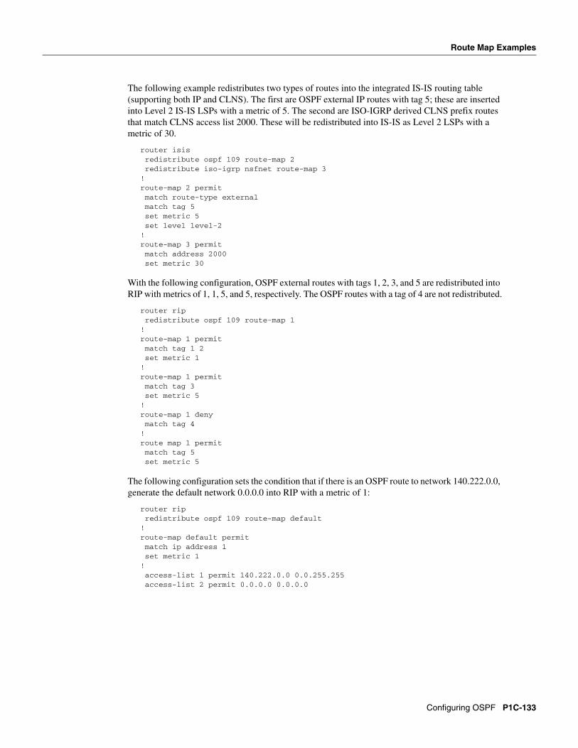
The following example redistributes two types of routes into the integrated IS-IS routing table (supporting both IP and CLNS). The first are OSPF external IP routes with tag 5; these are inserted into Level 2 IS-IS LSPs with a metric of 5. The second are ISO-IGRP derived CLNS prefix routes that match CLNS access list 2000. These will be redistributed into IS-IS as Level 2 LSPs with a metric of 30.
With the following configuration, OSPF external routes with tags 1, 2, 3, and 5 are redistributed into RIP with metrics of 1, 1, 5, and 5, respectively. The OSPF routes with a tag of 4 are not redistributed.
router ripredistribute ospf 109 route-map 1
!route-map 1 permitmatch tag 1 2set metric 1
!route-map 1 permit match tag 3set metric 5
!route-map 1 denymatch tag 4
!route map 1 permitmatch tag 5set metric 5
The following configuration sets the condition that if there is an OSPF route to network 140.222.0.0, generate the default network 0.0.0.0 into RIP with a metric of 1:
router ripredistribute ospf 109 route-map default
!route-map default permitmatch ip address 1set metric 1
In the following configuration, a RIP learned route for network 160.89.0.0 and an ISO-IGRP learned route with prefix 49.0001.0002 will be redistributed into an IS-IS Level 2 LSP with a metric of 5:
The following configuration example illustrates how a route map is referenced by the default-information router configuration command. This is called conditional default origination. OSPF will originate the default route (network 0.0.0.0) with a Type 2 metric of 5 if 140.222.0.0, with network 0.0.0.0 in the routing table. Extended access-lists cannot be used in a route map for conditional default origination.
Note Only routes external to the OSPF process can be used for tracking, such as non-OSPF routes or OSPF routes from a separate OSPF process.
route-map ospf-default permitmatch ip address 1set metric 5set metric-type type-2
Changing OSPF Administrative DistanceThe following example changes the external distance to 200, making it less trustworthy. Figure 26 illustrates the example.
P1C-134 Network Protocols Configuration Guide, Part 1
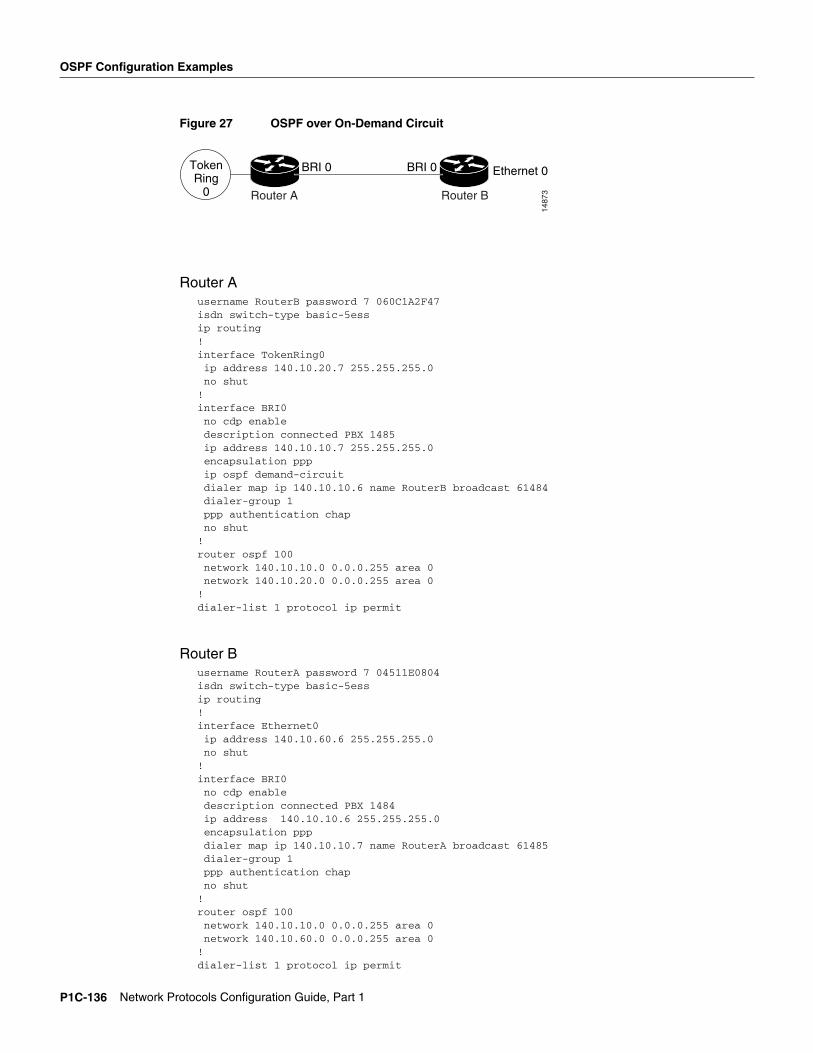
OSPF over On-Demand Routing ExampleThe following configuration allows OSPF over an on-demand circuit, as shown in Figure 27. Note that the on-demand circuit is defined on one side only (BRI 0 on RouterA). It is not required to be configured on both sides.
!router ospf 100network 140.10.10.0 0.0.0.255 area 0network 140.10.60.0 0.0.0.255 area 0
!dialer-list 1 protocol ip permit
TokenRing
0
BRI 0 BRI 0 Ethernet 0
Router A Router B
1487
3
P1C-136 Network Protocols Configuration Guide, Part 1
LSA Group Pacing Example
LSA Group Pacing ExampleThe following example changes the OSPF pacing between LSA groups to 60 seconds:
router ospftimers lsa-group-pacing 60
Block LSA Flooding ExampleThe following example prevents flooding of OSPF LSAs to broadcast, nonbroadcast, or point-to-point networks reachable through Ethernet interface 0:
interface ethernet 0ospf database-filter all out
The following example prevents flooding of OSPF LSAs to point-to-multipoint networks to the neighbor at IP address 1.2.3.4:
router ospf 109neighbor 1.2.3.4 database-filter all out
Ignore MOSPF LSA Packets ExampleThe following example configures the router to suppress the sending of syslog messages when it receives MOSPF packets:
router ospf 109ospf ignore lsa mospf
Configuring OSPF P1C-137
OSPF Configuration Examples
P1C-138 Network Protocols Configuration Guide, Part 1


![[William R. Parkhurst] Cisco OSPF Command and Conf(BookZZ.org)](https://static.documents.pub/doc/80x56/55cf8542550346484b8c0fea/william-r-parkhurst-cisco-ospf-command-and-confbookzzorg.jpg)


