Cisco Prime NCS 1.1 Deployment Guide Document ID: 113463 Contents Introduction Prerequisites Requirements Components Used Conventions Installation Physical Appliance: ISO Installation Virtual Appliance: VMware OVA Installation Use vSphere Client to install OVA Physical/Virtual Appliance Upgrade Starting NCS Migrating from WCS to NCS Data Migration from WCS Export Data from WCS Migrating WCS Data to NCS Upgrade NCS from NCS 1.0.x to 1.1 Import Maps from WCS High Availability - Basic Theory of Operation Catalyst Switch Configuration Wireless Network Planning Planning Tool Map Editor Import Maps from WCS to NCS Use NCS to Deploy a Wireless LAN Configuration Templates Configuration Groups (Config-Groups) Use NCS to Monitor/Troubleshoot a Wireless Network RRM /CleanAir Build an RF Profile with Cisco Prime NCS 1.1 Apply RF Profiles to AP Groups with NCS Use NCS to Remediate Issues Use NCS to Optimize the Operation of the Wireless Network Dashboard Customization of area charts Monitoring Clients and Users Wired/Wireless Client Troubleshooting Wireless Client Troubleshooting Wired Client Troubleshooting RF/Wireless Features Track Clients Unknown User ID Real-Time Heat Maps Monitoring Cisco Catalyst Switches Using NCS Spanning Tree Cisco StackWise
Transcript
Cisco Prime NCS 1.1 Deployment Guide
Document ID: 113463
Contents
Introduction Prerequisites Requirements Components Used Conventions Installation Physical Appliance: ISO Installation Virtual Appliance: VMware OVA Installation Use vSphere Client to install OVA Physical/Virtual Appliance Upgrade Starting NCS Migrating from WCS to NCS Data Migration from WCS Export Data from WCS Migrating WCS Data to NCS Upgrade NCS from NCS 1.0.x to 1.1 Import Maps from WCS High Availability − Basic Theory of Operation Catalyst Switch Configuration Wireless Network Planning Planning Tool Map Editor Import Maps from WCS to NCS Use NCS to Deploy a Wireless LAN Configuration Templates
Configuration Groups (Config−Groups)Use NCS to Monitor/Troubleshoot a Wireless Network RRM /CleanAir Build an RF Profile with Cisco Prime NCS 1.1 Apply RF Profiles to AP Groups with NCS Use NCS to Remediate Issues Use NCS to Optimize the Operation of the Wireless Network Dashboard Customization of area charts Monitoring Clients and Users Wired/Wireless Client Troubleshooting Wireless Client Troubleshooting Wired Client Troubleshooting RF/Wireless Features Track Clients Unknown User ID Real−Time Heat Maps Monitoring Cisco Catalyst Switches Using NCS Spanning Tree Cisco StackWise
VLAN Info Client List PagesReports (Cross−Launch and Scale) New Reports Alarms/Events Quick Filter Advanced FilterAAA User Authentication via TACACS+/RADIUS using ACS 4.2Related Information
Introduction
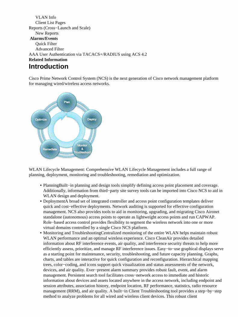
Cisco Prime Network Control System (NCS) is the next generation of Cisco network management platformfor managing wired/wireless access networks.
WLAN Lifecycle Management: Comprehensive WLAN Lifecycle Management includes a full range ofplanning, deployment, monitoring and troubleshooting, remediation and optimization.
Planning�Built−in planning and design tools simplify defining access point placement and coverage.Additionally, information from third−party site survey tools can be imported into Cisco NCS to aid inWLAN design and deployment.
•
Deployment�A broad set of integrated controller and access point configuration templates deliverquick and cost−effective deployments. Network auditing is supported for effective configurationmanagement. NCS also provides tools to aid in monitoring, upgrading, and migrating Cisco Aironetstandalone (autonomous) access points to operate as lightweight access points and run CAPWAP.Role−based access control provides flexibility to segment the wireless network into one or morevirtual domains controlled by a single Cisco NCS platform.
•
Monitoring and Troubleshooting�Centralized monitoring of the entire WLAN helps maintain robustWLAN performance and an optimal wireless experience. Cisco CleanAir provides detailedinformation about RF interference events, air quality, and interference security threats to help moreefficiently assess, prioritize, and manage RF interference issues. Easy−to−use graphical displays serveas a starting point for maintenance, security, troubleshooting, and future capacity planning. Graphs,charts, and tables are interactive for quick configuration and reconfiguration. Hierarchical mappingtrees, color−coding, and icons support quick visualization and status assessments of the network,devices, and air quality. Ever−present alarm summary provides robust fault, event, and alarmmanagement. Persistent search tool facilitates cross−network access to immediate and historicinformation about devices and assets located anywhere in the access network, including endpoint andsession attributes, association history, endpoint location, RF performance, statistics, radio resourcemanagement (RRM), and air quality. A built−in Client Troubleshooting tool provides a step−by−stepmethod to analyze problems for all wired and wireless client devices. This robust client
•
troubleshooting tool helps reduce operating costs by speeding the resolution of trouble tickets for avariety of Wi−Fi client device types.
The Role of NCS in the Network
This figure depicts Cisco wireless network architecture with Cisco Prime NCS. The interactions between thevarious network elements, which are wireless LAN controller, AP, Cisco Catalyst switch, Mobility ServicesEngine, Network Control System, client network management station, and third−party application.
Ports Used by NCS
Device Support and Software Versions
Device Type Supported SoftwareVersion*
Cisco Catalyst 2000 series switches:2960, 2975 Independent of Cisco
IOS® software releaseCisco Catalyst 3000 series switches :3560, 3750−E, 3750−X Independent of Cisco
IOS software release
Cisco Catalyst 4500 series switchesIndependent of CiscoIOS software release
Cisco Catalyst 6000 series switchesIndependent of CiscoIOS software release
* − supported controller software releases are listed in NCS Release Notes.
NCS has two deployment options:
hardware appliance1. virtual appliance2.
The virtual appliance is an OVA file that can be deployed on VMware ESX/ESXi 4.x and 5.0. This tableprovides scale numbers for devices managed by NCS.
Platform Scale
UnifiedAP�s aIOS
AP�sSwitches
WirelessLAN
ControllersSmall VirtualAppliance
3,000 1,000 1,000 240MediumVirtualAppliance
7,500 2,500 2,500 600Large VirtualAppliance
15,000 5,000 5,000 1,200
Note: Platform scale numbers for wireless LAN controllers (WLC;s) are max. scale. WLCs do not countagainst NCS license count.
This table lists the hardware requirements for the virtual appliance based on wired/wireless scale.
Virtual Appliance � Hardware Requirements
ProcessorDRAM
HardDisk
Small VirtualAppliance 2 cores @
2.93GHz8 GB 200 GB
Medium VirtualAppliance 4 cores @
2.93GHz12 GB 300 GB
Large VirtualAppliance 8 cores @
2.93GHz16 GB 400 GB
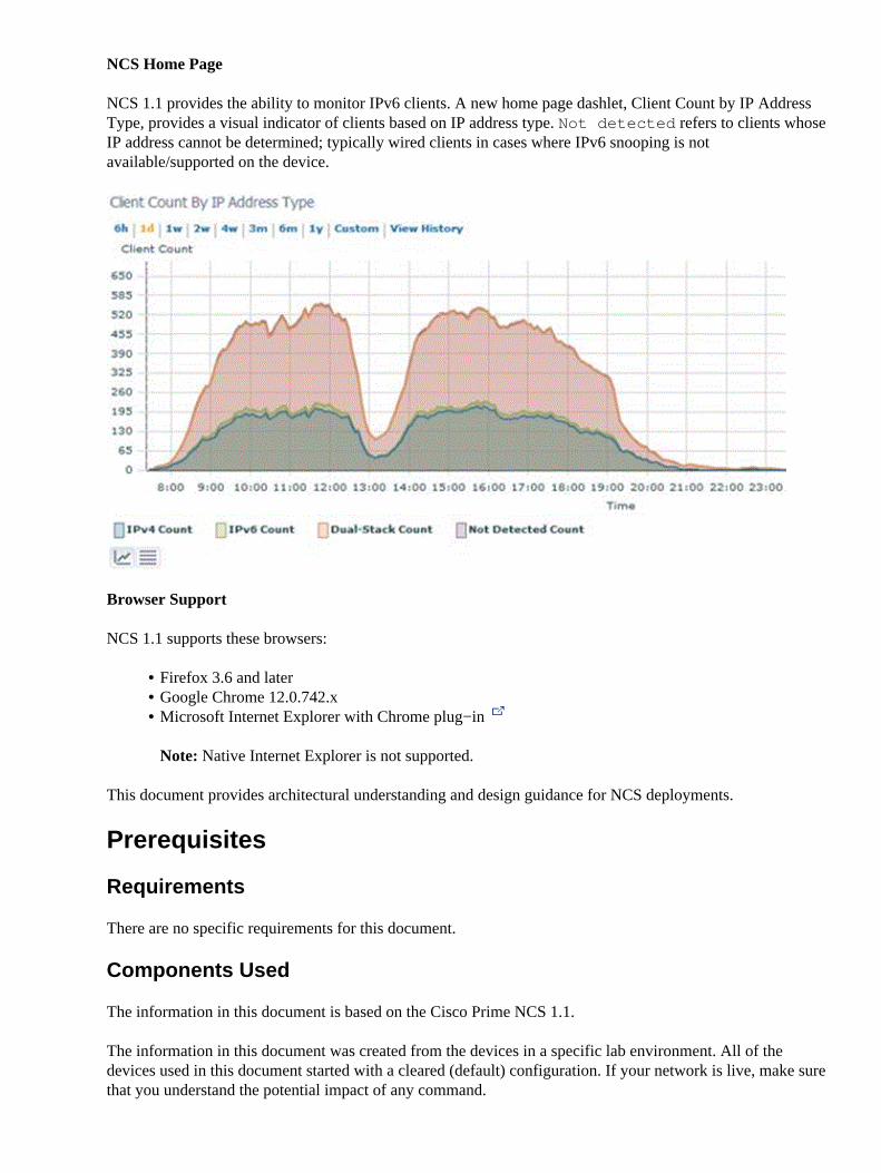
NCS Home Page
NCS 1.1 provides the ability to monitor IPv6 clients. A new home page dashlet, Client Count by IP AddressType, provides a visual indicator of clients based on IP address type. Not detected refers to clients whoseIP address cannot be determined; typically wired clients in cases where IPv6 snooping is notavailable/supported on the device.
Browser Support
NCS 1.1 supports these browsers:
Firefox 3.6 and later• Google Chrome 12.0.742.x• Microsoft Internet Explorer with Chrome plug−in
Note: Native Internet Explorer is not supported.
•
This document provides architectural understanding and design guidance for NCS deployments.
Prerequisites
Requirements
There are no specific requirements for this document.
Components Used
The information in this document is based on the Cisco Prime NCS 1.1.
The information in this document was created from the devices in a specific lab environment. All of thedevices used in this document started with a cleared (default) configuration. If your network is live, make surethat you understand the potential impact of any command.
Conventions
Refer to Cisco Technical Tips Conventions for more information on document conventions.
Installation
Physical Appliance: ISO Installation
NCS is available as both physical and virtual appliance. This section provides the steps to install ISO imageon a physical appliance.
Download and burn ISO to DVD. ISO is posted on Download Software (registered customers only) .Use your Cisco.com username and password.
1.
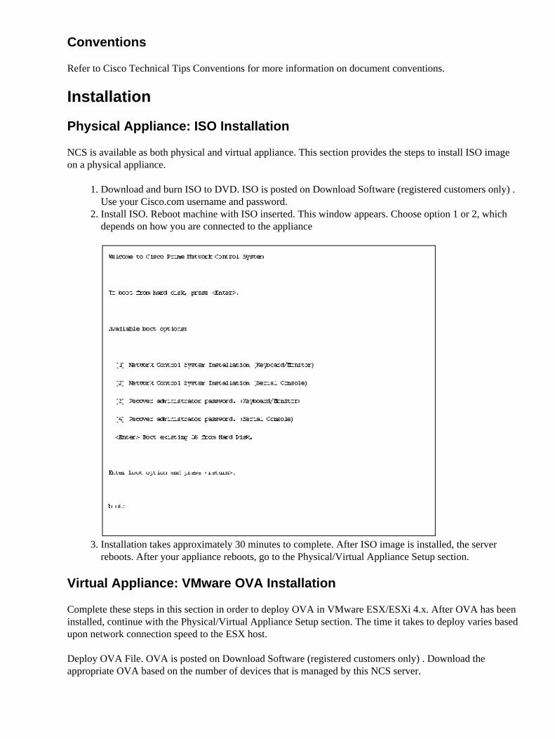
Install ISO. Reboot machine with ISO inserted. This window appears. Choose option 1 or 2, whichdepends on how you are connected to the appliance
2.
Installation takes approximately 30 minutes to complete. After ISO image is installed, the serverreboots. After your appliance reboots, go to the Physical/Virtual Appliance Setup section.
3.
Virtual Appliance: VMware OVA Installation
Complete these steps in this section in order to deploy OVA in VMware ESX/ESXi 4.x. After OVA has beeninstalled, continue with the Physical/Virtual Appliance Setup section. The time it takes to deploy varies basedupon network connection speed to the ESX host.
Deploy OVA File. OVA is posted on Download Software (registered customers only) . Download theappropriate OVA based on the number of devices that is managed by this NCS server.
NCS VMware image is packaged as an OVA (open virtualization archive) file. The menu item in theprevious screenshot is for an OVF template. An OVA is a collection of items in a single archive.These items typically consist of a virtual machine description file (*.ova), a manifest file (*.mf), andvirtual hard drive file (*.vmdk).
1.
Choose Browse and locate the NCS OVA file. Click Next.2.
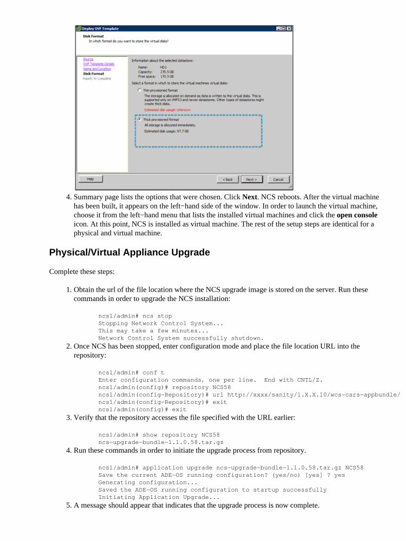
After the OVA file is selected, VMware ESX/ESXi reads the OVA file attributes. Continue throughthe steps in order to chose the OVA file that you want to install in ESX/ESXi. In the Disk Formatpage, choose the Thick provisioned format option.
3.
Summary page lists the options that were chosen. Click Next. NCS reboots. After the virtual machinehas been built, it appears on the left−hand side of the window. In order to launch the virtual machine,choose it from the left−hand menu that lists the installed virtual machines and click the open consoleicon. At this point, NCS is installed as virtual machine. The rest of the setup steps are identical for aphysical and virtual machine.
4.
Physical/Virtual Appliance Upgrade
Complete these steps:
Obtain the url of the file location where the NCS upgrade image is stored on the server. Run thesecommands in order to upgrade the NCS installation:
ncs1/admin# ncs stopStopping Network Control System...This may take a few minutes...Network Control System successfully shutdown.
1.
Once NCS has been stopped, enter configuration mode and place the file location URL into therepository:
ncs1/admin# conf tEnter configuration commands, one per line. End with CNTL/Z.ncs1/admin(config)# repository NCS58ncs1/admin(config−Repository)# url http://xxxx/sanity/1.X.X.10/wcs−cars−appbundle/ncs1/admin(config−Repository)# exitncs1/admin(config)# exit
2.
Verify that the repository accesses the file specified with the URL earlier:
ncs1/admin# show repository NCS58ncs−upgrade−bundle−1.1.0.58.tar.gz
3.
Run these commands in order to initiate the upgrade process from repository.
ncs1/admin# application upgrade ncs−upgrade−bundle−1.1.0.58.tar.gz NCS58 Save the current ADE−OS running configuration? (yes/no) [yes] ? yesGenerating configuration...Saved the ADE−OS running configuration to startup successfullyInitiating Application Upgrade...
4.
A message should appear that indicates that the upgrade process is now complete.5.
Starting NCS
After the server reboots, log into system as admin using the password that you provided as part of setup step .After you have logged into the server, start the NCS server with the admin@ncs−server opt]# ncsstart command.
Console messages indicate when NCS is running. Log into your NCS server via web browser as user rootwith the password you chose during the installation. The root password can be changed after you log intoNCS through the browser login.
Migrating from WCS to NCS
You must upgrade their Cisco WCS server to one of these releases before you attempt to perform themigration process to NCS 1.1.x.x.
7.0.164.3• 7.0.172.0• 7.0.220.0•
This section provides instructions for how to migrate the WCS on either a Windows or Linux server to NCS.The NCS release is a major release to provide for converged management of wired and wireless devices, andincreased scalability. The NCS platform is based on Linux 64 bit OS, and the backend database is OracleDBMS. The existing WCS platforms are either Windows or Linux 32 bit and the backend database is SolidDB.
Data Migration from WCS
Export Data from WCS
Export data from WCS 7.x through the CLI. The export userdata CLI command is available in WCS Release7.x and later, which creates the .zip file that contains the WCS data file. The CLI does not provide any optionto customize what can be exported; all non−global user−defined items are exported. Complete these steps inorder to export WCS data:
Stop the WCS server.1. Run the export command through the script file and provide the path and export filename whenprompted.
2.
For Linux, run the export.sh all /data/wcs.zip command. For Windows, run the export.bat all\data\wcs.zip command.
3.
Migrating WCS Data to NCS
Complete these steps in order to migrate WCS data:
Place the WCS export .zip file (for example, wcs.zip) in a repository or folder (for example,repositories).
1.
Log in as admin user and stop the NCS server by entering the ncs stop command. Configure the FTPrepository on the NCS appliance with the repository command:
ncs−appliance/admin#configurencs−appliance/admin(config)# repository ncs−ftp−reponcs−appliance/admin(config−Repository)# url ftp://209.165.200.227//ncs−appliance/admin(config−Repository)# user ftp−user password plain ftp−user
2.
Note: Make sure the archived file is available with the show repository repositoryname command.Enter the ncs migrate command in order to restore the WCS database.
By default, no WCS events are migrated. Enter the ncs start command in order to start the NCSserver after the upgrade is completed. Log in to the NCS user interface with the root login and the rootpassword.
This data is not migrated from WCS to NCS:
Subset of reports�AP Image Predownload, AP Profile Status, AP Summary, Client Count,Client Summary, Client Traffic, PCI Report, PCI Compliance Detailed and Summary reports,Preferred Call Network Summary report, Rogue APs, Adhoc Rogues, New Adhoc Roguesand Security Summary reports.
♦
Dashboard customization♦ Client Station Statistics information is not populated with old WCS data in clients charts,client details page, dashboards and reports.
♦
Client historical session information does get upgraded.♦ Events history stored in WCS database are not migrated to NCS.♦ RADIUS/TACACS server IP and credentials are not migrated and need to be added againafter the migration is complete. You need to copy the latest custom attributes from NCS andinclude them in AAA server for user authentication/authorization in TACACS+/RADIUS.
Note: Make sure RADIUS/TACACS server is enabled as AAA mode in the Administration >AAA > AAA Mode Settings page.
♦
Only alarms with Root Virtual Domain are migrated from Release 7.0 to NCS.♦ The root password is not migrated from Release 7.0.164.3 or 7.0.172.0 to NCS Release1.1.x.x. The user must change the root password during the installation of the application.Non root users and their credentials are migrated during migration.
♦
Alarm categories and subcategories are not restored after migration to NCS Alarm Summary.♦
4.
Upgrade NCS from NCS 1.0.x to 1.1
You can upgrade from NCS Releases 1.0.0.96, 1.0.1.4, 1.0.2.28, and 1.0.2.29 to NCS 1.1.x.x.
These items should be noted prior to the upgrade process:
Ensure that you perform a backup before you attempt to upgrade.• Disable High Availability before you perform the upgrade.• Shut down NCS before you perform the upgrade. Run the ncs stop command in order to stop NCS.•
Use this command in order to upgrade from NCS 1.0 to NCS 1.1.x.x:
In the previous command, NCS−upgrade−bundle−1.1.x.x.tar.gz is the upgrade bundle file, which isavailable on Download Software (registered customers only) . The repository used in the example,wcs−ftp−repo, can be any valid repository. These are examples of repository configurations:
The map export/import feature is available in WCS 7.0. This feature is described in detail in the WCS 7.0Configuration Guide.
After you export maps from your WCS server, you can import this set of maps in your NCS server. The stepsto import your maps are covered in the WCS 7.0 Configuration Guide.
Note: It is important that APs in your WCS server are first added to your NCS server prior to importing mapssince APs on your WCS maps are also included during the export process. APs that have not been added toyour NCS but are present on exported floor maps result in errors that are displayed when you import thosemaps into NCS.
High Availability − Basic Theory of Operation
The NCS HA implementation in NCS allows for up to two primary NCS systems to fail over to one secondary(backup) NCS. A second server is required that has sufficient resources (CPU, hard drive, networkconnection) in order to take over NCS operation in the event that the primary NCS fails. Each databaseinstance on the secondary NCS is a hot standby for the corresponding primary NCS.
The notation that is used to describe primary and secondary systems isN:M , where N = number of primarysystems in operation and M = number of secondary systems that are backing up the primary system(s).
In NCS, these HA configurations are supported:
1:1 � 1 Primary, 1 Secondary
The size of secondary server must be larger than or equal to primary server, for example if the primary NCSserver is medium OVA, then the secondary NCS server must be medium or large OVA.
The primary and secondary server can be a mix of a physical and virtual appliance. For example, if theprimary NCS server is a physical appliance, the secondary server can be either physical appliance or largeOVA virtual appliance, for example, the server configuration and sizing of large OVA is the same as physicalappliance.
The Health Monitor (HM) is a new process implemented in NCS, that is the primary component that manages
the HA operation of the system. HM is divided into these multiple sub−modules, each of which handle aspecific set of functions:
Core HM�responsible for these tasks:
configuration of the overall HA system♦ maintains state machine for the HA system♦ start/stop of HM and the NCS JVM♦ start/stop and monitor of other sub−modules within the HM♦ handles registration of primary/secondary pair♦ authenticates the HM specific session♦ makes all decisions about failover and failback♦
•
Heart Beat�Heart Beat submodule is responsible for maintaining communication between the primaryand secondary HMs. Communication occurs over HTTPS (default port is 8082). The timeout value is2 seconds. A retry mechanism has been implemented to retry establishing connectivity between theP−HM and S−HM. If the HM does not receive a response after sending a heartbeat request within thetimeout period, it retries establishing communication by sending another heartbeat request. The totalnumber of retries is 3. After communication has not be established after 3 retries, the HMs takeappropriate action as per the scenarios defined:
primary server goes down: this is the classic failover case. In this scenario, when the S−HMdoes not receive HeartBeat requests for 6 seconds (3 retries x 2 seconds), it initiates thefailover mechanism on the secondary NCS.
♦
secondary server goes down: in this scenario, the P−HM does not receive HeartBeat responsefrom the S−HM for 6 seconds (3 retries x 2 seconds). When this happens, the P−HM changesits state to PRIMARY_ALONE, raises alarms and changes into listening mode � waiting toreceive any messages from the secondary for re−establishing the link between P−HM andS�HM.
♦
•
Application Monitor�Application Monitor submodule is responsible for communication with NCSframework (NCS JVM) on the local server to retrieve status information. Communication is viaSOAP over HTTPS.
•
DB Monitor�DB Monitor sub−module configures the DB for replication. It is not responsible for theDB replication itself as this is accomplished via the database proprietary replication protocol.
•
File Sync�File Synchronization sub−module has 4 sub−components:
File Archiver: periodically scans directories looking for files that have been modified. Itcollects any such files and adds them to a TAR archive
1.
File Transfer Agent (FTA): responsible for transferring the compress TAR archive to thedestination (other server, i.e. primary to secondary or secondary to primary).
2.
File Upload Servlet (FUS): runs on the secondary server and is the counterpart to the FTA.When it receives a file, the FUS streams it directly to the TAR extractor rather than create thefile on the local disk (avoids unnecessary disk activity). The FTA and FUS communicate overHTTPS.
3.
Statistics Collector: keeps statistics of file transfer operations from the time that server starts.4.
•
The NCS database is the core data storage element of the system and must be replicated between primary andbackup systems in real�time without data loss. This is fundamental to the operation of NCS HA. Data isstored in 1 of 2 ways:
NCS database1. Application data2.
Application data is a set of flat files that contains this data:
database password file: replicated in real time (11 seconds)• NCS license files: replicated via batch processing (every 500 seconds)• all files under tftp root directory: replicated via batch processing (every 500 seconds)• scheduled generated reports: replicated in real time (11 seconds)•
Health Monitor: the health monitor (HM) is the primary component that manages/monitors the HAavailability of the system. There are multiple submodules that handle various functions with HM.
Core HM: responsible for these talks:
Configures the HA system• Maintains state machine for HW system• Start/stop HM• Start/stop and monitor other sub−modules within HM• Handles registration of primary−secondary pair• Makes all decisions regarding failover and failback•
Failover Operation
After initial deployment of NCS, the entire configuration of primary NCS is replicated to the host of thesecondary NCS. During normal operation (i.e. primary NCS is operational), database from primary isreplicated to secondary NCS.
In addition to the database replication, application data files are also replicated to the secondary NCS.Replication frequency is 11 seconds (real�time files) and 500 seconds (batch files).
NCS Requirements for using NCS HA Feature
Customer must be running same NCS version on both primary and secondary NCS servers. The NCS HAfeature is transparent to wireless controller, i.e. there is no software version requirement for WLC, AP�s andMSE.
Configuration of HA Feature
These parameters must be configured on the primary NCS:
name/IP address of secondary NCS• email address of network administrator for system notification• manual or automatic failover option•
Secondary NCS must always be a new installation and this option must be selected during NCS installprocess. For example, standalone or primary NCS cannot be converted to secondary NCS. Standalone NCScan be converted to HA Primary.
Note: Database replication between P−NCS and S−NCS uses port 1522, so ensure that this port is open on allnetwork devices, such as firewalls, switches, routers and so forth, along the network path between primaryand secondary NCS servers.
Example � Installation and Configuration Process
In this example, this is a 1:1 NCS HA system
Primary NCS: 172.19.27.84
Secondary NCS: 172.19.27.159
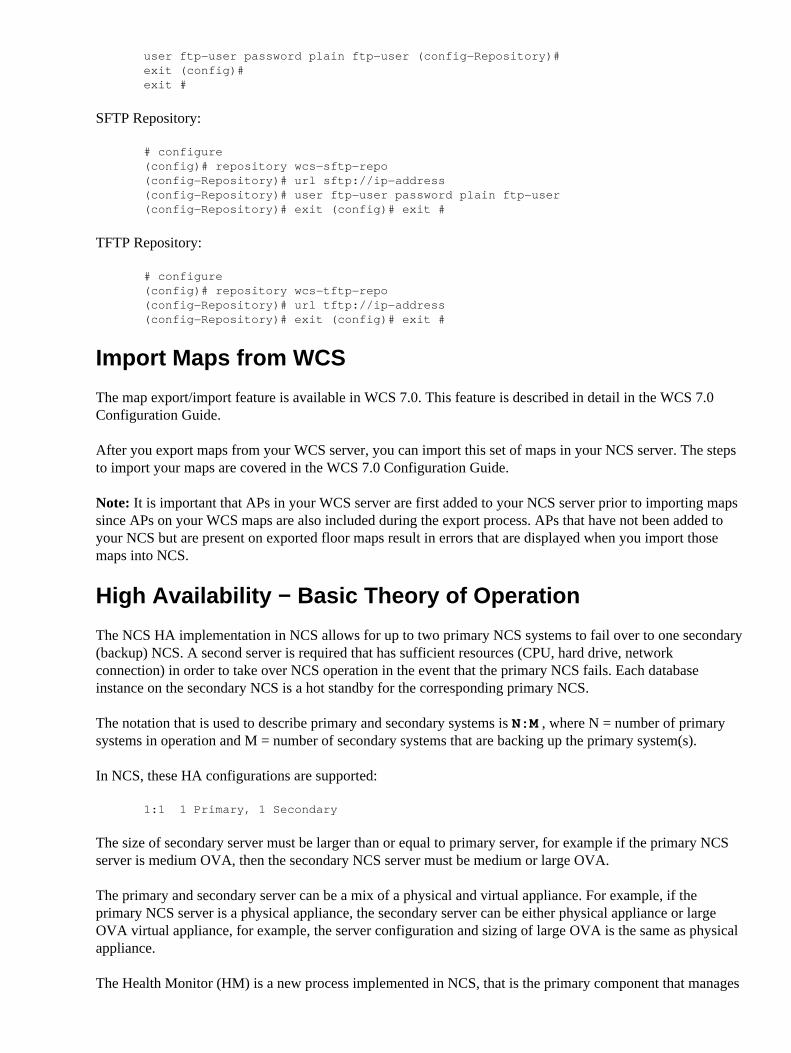
The first step is to install and configure the Secondary NCS. When configuring the Primary NCS for HA, theSecondary NCS needs to be installed and reachable by the Primary NCS.
Note: A key point to remember is that when P−NCS is running/operational, S−NCS is not running. When theSecondary server is in standby mode, these services are running on the secondary server: HM, Apache anddatabase. When P−NCS goes to a down state, HM on the Secondary server starts the NCS JVM process. Onlythen does S−NCS become accessible.
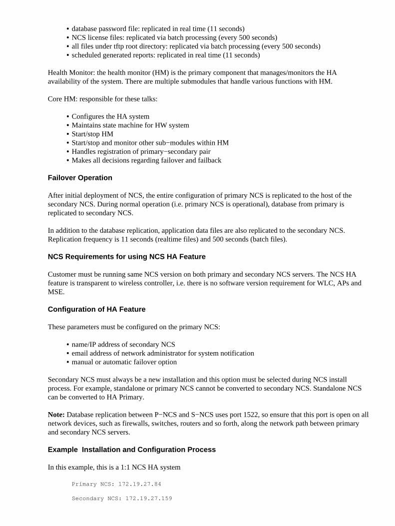
Health Monitor port needs to set up on target NCS installation machine. Default port value is port 8082. Thisport number only has local machine significance (local machine port).
Check Health Monitor Port...Please change the Health Monitor web port if needed. Health Monitor (DEFAULT: 8082): [root@NCSlinux1NCS]#
Authentication Key for Health Monitor must also be created during the installation process. This key is onlyused internally by the P�HM and S�HM for authentication. It must be the same key on both the primary andsecondary servers.
As stated earlier, only one NCS server license needs to be purchased. For example, a separate NCS licensedoes not need to be purchased for the secondary NCS. The same NCS license file resides on both the primaryand secondary NCS. Since the NCS JVM is only running on either the primary or secondary (not both), thelicense file is only active on one system at a given point in time.
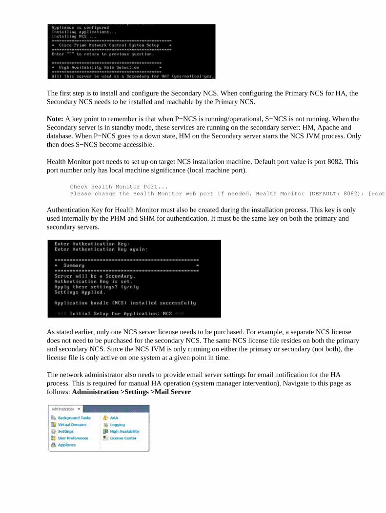
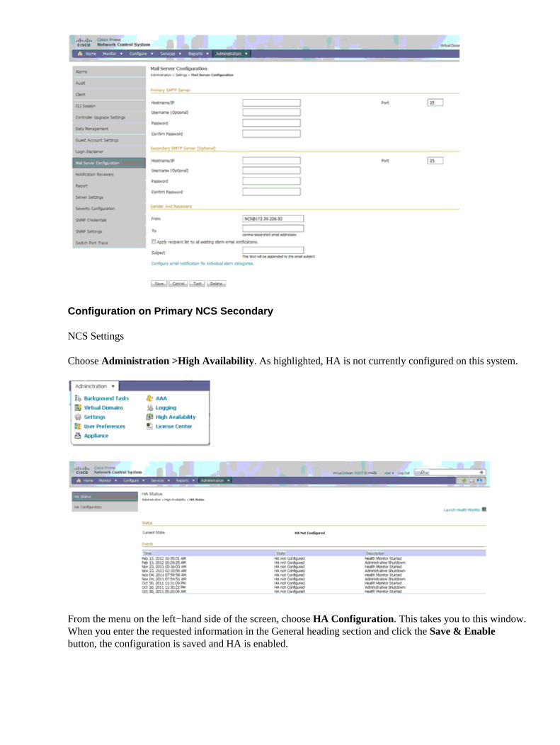
The network administrator also needs to provide email server settings for email notification for the HAprocess. This is required for manual HA operation (system manager intervention). Navigate to this page asfollows: Administration >Settings >Mail Server
Configuration on Primary NCS Secondary
NCS Settings
Choose Administration >High Availability. As highlighted, HA is not currently configured on this system.
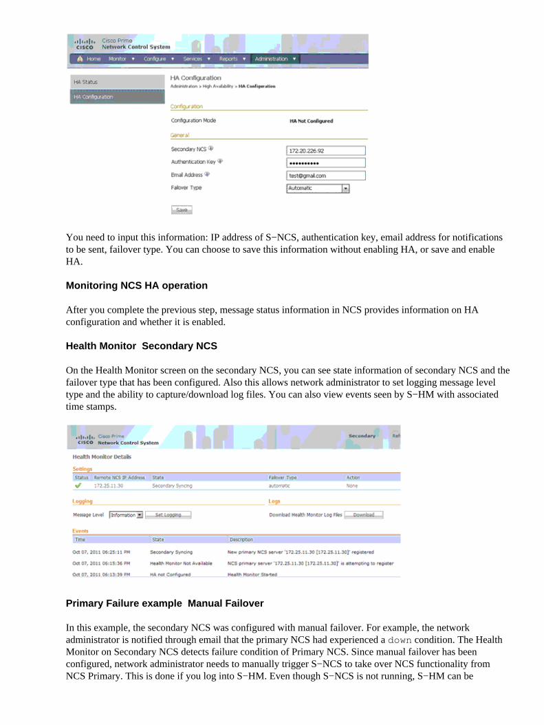
From the menu on the left−hand side of the screen, choose HA Configuration. This takes you to this window.When you enter the requested information in the General heading section and click the Save & Enablebutton, the configuration is saved and HA is enabled.
You need to input this information: IP address of S−NCS, authentication key, email address for notificationsto be sent, failover type. You can choose to save this information without enabling HA, or save and enableHA.
Monitoring NCS HA operation
After you complete the previous step, message status information in NCS provides information on HAconfiguration and whether it is enabled.
Health Monitor � Secondary NCS
On the Health Monitor screen on the secondary NCS, you can see state information of secondary NCS and thefailover type that has been configured. Also this allows network administrator to set logging message leveltype and the ability to capture/download log files. You can also view events seen by S−HM with associatedtime stamps.
Primary Failure example � Manual Failover
In this example, the secondary NCS was configured with manual failover. For example, the networkadministrator is notified through email that the primary NCS had experienced a down condition. The HealthMonitor on Secondary NCS detects failure condition of Primary NCS. Since manual failover has beenconfigured, network administrator needs to manually trigger S−NCS to take over NCS functionality fromNCS Primary. This is done if you log into S−HM. Even though S−NCS is not running, S−HM can be
connected to through this syntax:
https://<S�NCS_ip_address>:HM_port/
The S−HM displays messages in regards to events that are seen. Since Manual Failover has been configured,the S−HM waits for the system administrator to invoke the failover process. Once Manual Failover has beenchosen, this message is displayed as S−NCS starts. Once the failover process has been completed, whichmeans that the NCS database replication process is completed and S−NCS JVM process has started, thenS−NCS is the active NCS.
Health Monitor on NCS Secondary provides status information of both NCS Primary and Secondary servers.Failback can be initiated through S−HM once P−NCS has recovered from failure condition. Failback processis always initiated manually as to avoid a flapping condition that can sometimes occur when there is anetwork connectivity problem.
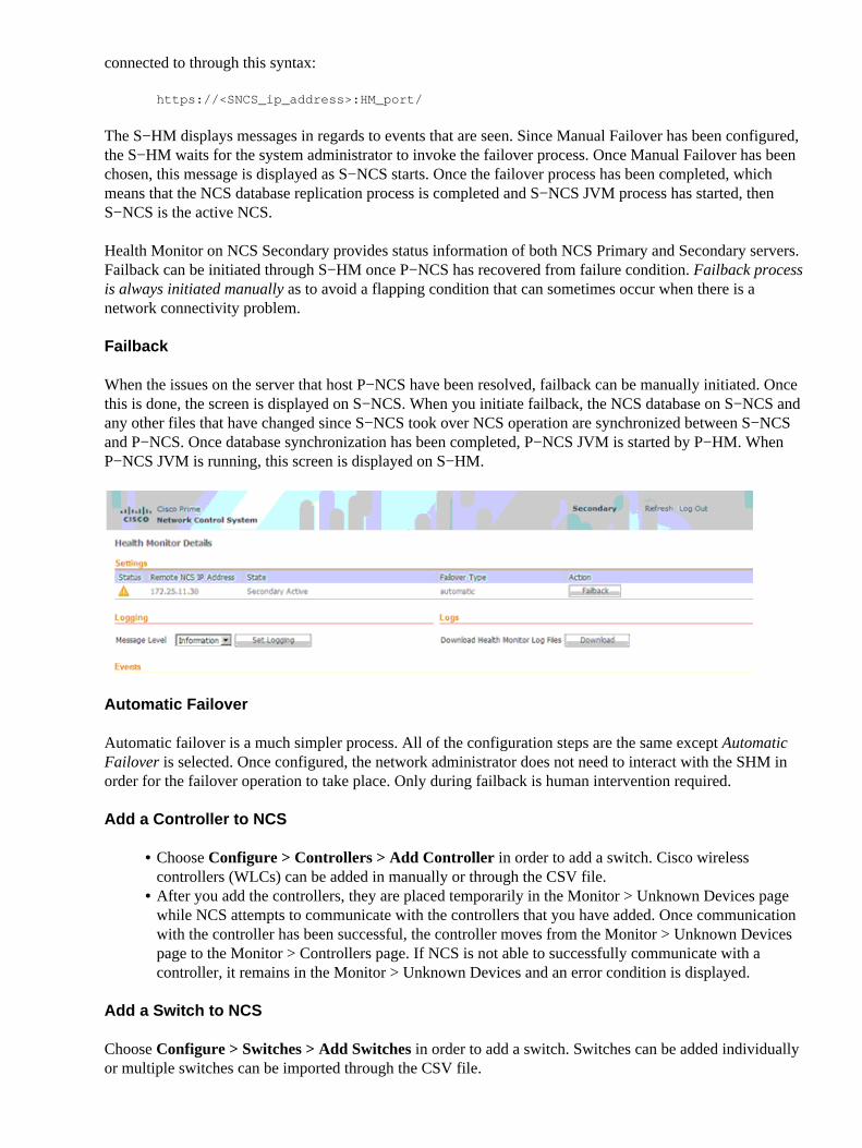
Failback
When the issues on the server that host P−NCS have been resolved, failback can be manually initiated. Oncethis is done, the screen is displayed on S−NCS. When you initiate failback, the NCS database on S−NCS andany other files that have changed since S−NCS took over NCS operation are synchronized between S−NCSand P−NCS. Once database synchronization has been completed, P−NCS JVM is started by P−HM. WhenP−NCS JVM is running, this screen is displayed on S−HM.
Automatic Failover
Automatic failover is a much simpler process. All of the configuration steps are the same except AutomaticFailover is selected. Once configured, the network administrator does not need to interact with the S�HM inorder for the failover operation to take place. Only during failback is human intervention required.
Add a Controller to NCS
Choose Configure > Controllers > Add Controller in order to add a switch. Cisco wirelesscontrollers (WLCs) can be added in manually or through the CSV file.
•
After you add the controllers, they are placed temporarily in the Monitor > Unknown Devices pagewhile NCS attempts to communicate with the controllers that you have added. Once communicationwith the controller has been successful, the controller moves from the Monitor > Unknown Devicespage to the Monitor > Controllers page. If NCS is not able to successfully communicate with acontroller, it remains in the Monitor > Unknown Devices and an error condition is displayed.
•
Add a Switch to NCS
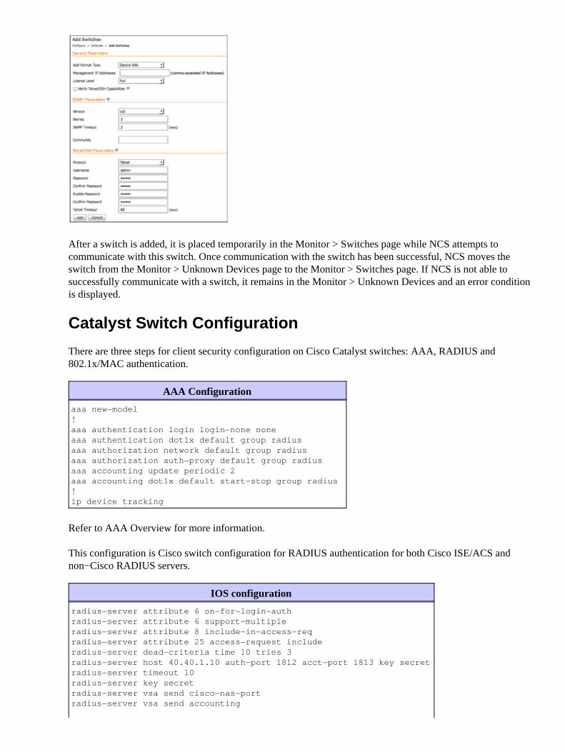
Choose Configure > Switches > Add Switches in order to add a switch. Switches can be added individuallyor multiple switches can be imported through the CSV file.
After a switch is added, it is placed temporarily in the Monitor > Switches page while NCS attempts tocommunicate with this switch. Once communication with the switch has been successful, NCS moves theswitch from the Monitor > Unknown Devices page to the Monitor > Switches page. If NCS is not able tosuccessfully communicate with a switch, it remains in the Monitor > Unknown Devices and an error conditionis displayed.
Catalyst Switch Configuration
There are three steps for client security configuration on Cisco Catalyst switches: AAA, RADIUS and802.1x/MAC authentication.
AAA Configuration
aaa new−model!aaa authentication login login−none noneaaa authentication dot1x default group radiusaaa authorization network default group radius aaa authorization auth−proxy default group radius aaa accounting update periodic 2aaa accounting dot1x default start−stop group radius!ip device tracking
Refer to AAA Overview for more information.
This configuration is Cisco switch configuration for RADIUS authentication for both Cisco ISE/ACS andnon−Cisco RADIUS servers.
RADIUS Server Reorder on Failure• RADIUS Attribute 8 (Framed−IP−Address) in Access Requests• Cisco IOS Security Command Reference•
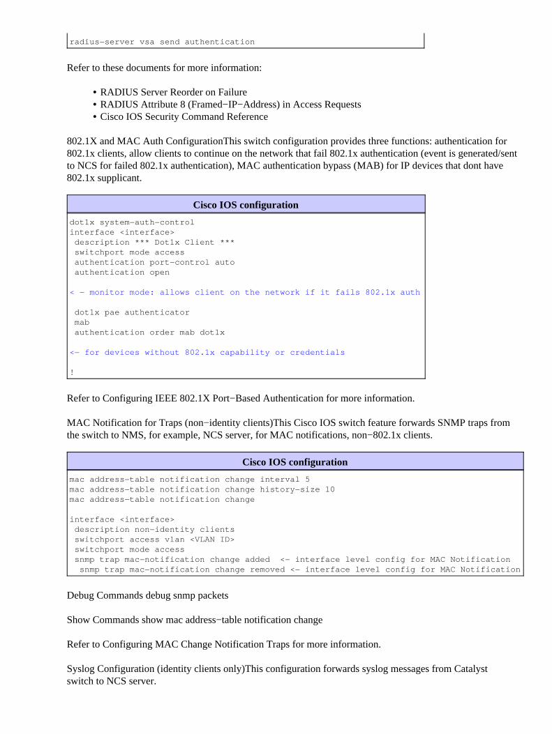
802.1X and MAC Auth Configuration�This switch configuration provides three functions: authentication for802.1x clients, allow clients to continue on the network that fail 802.1x authentication (event is generated/sentto NCS for failed 802.1x authentication), MAC authentication bypass (MAB) for IP devices that don�t have802.1x supplicant.
Cisco IOS configuration
dot1x system−auth−controlinterface <interface> description *** Dot1x Client *** switchport mode access authentication port−control auto authentication open
< − monitor mode: allows client on the network if it fails 802.1x auth
dot1x pae authenticator mab authentication order mab dot1x
<− for devices without 802.1x capability or credentials
!
Refer to Configuring IEEE 802.1X Port−Based Authentication for more information.
MAC Notification for Traps (non−identity clients)�This Cisco IOS switch feature forwards SNMP traps fromthe switch to NMS, for example, NCS server, for MAC notifications, non−802.1x clients.
The built−in planning tool provides a way for network administrators in determining what is required in thedeployment of a wireless network. As part of the planning process, various criteria are inputted into theplanning tool. Complete these steps:
Specify AP prefix and AP placement method (automatic vs. manual).1. Choose the AP type and specify the antenna for both the 2.4GHz and 5GHz band.2. Choose the protocol (band) and minimum desired throughput per band that is required for this plan3. Enable planning mode for advance options for data, voice, location. Data and Voice provide safetymargins for design help. Safety margins help design for certain RSSI thresholds, which is detailed inonline help. The location with monitor−mode factors in AP(s) that could be deployed to augmentlocation accuracy. The location typically requires a denser deployment than data and the locationcheckbox helps plan for the advertised location accuracy.
4.
Both the Demand and Override options allow for planning for any special cases where there is ahigh−density of client presence such conference rooms or lecture halls.
Generated proposal contains these:
Floor Plan Details♦ Disclaimer/Scope/Assumptions♦ Proposed AP Placement♦
5.
Coverage and Data Rate Heatmap♦ Coverage Analysis♦
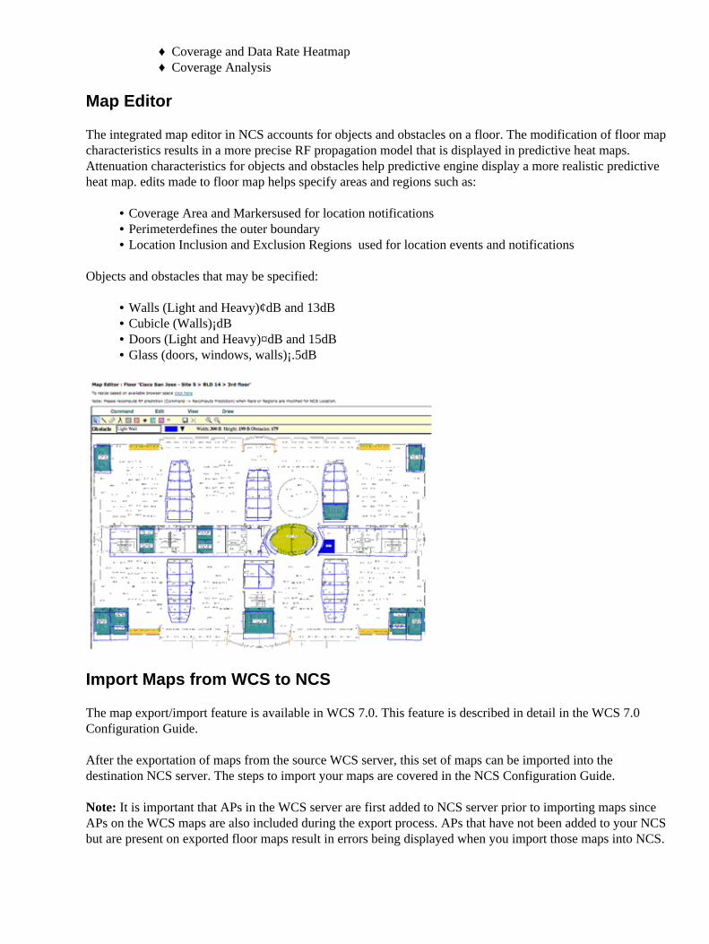
Map Editor
The integrated map editor in NCS accounts for objects and obstacles on a floor. The modification of floor mapcharacteristics results in a more precise RF propagation model that is displayed in predictive heat maps.Attenuation characteristics for objects and obstacles help predictive engine display a more realistic predictiveheat map. edits made to floor map helps specify areas and regions such as:
Coverage Area and Markers�used for location notifications• Perimeter�defines the outer boundary• Location Inclusion and Exclusion Regions � used for location events and notifications•
Objects and obstacles that may be specified:
Walls (Light and Heavy)¢dB and 13dB• Cubicle (Walls)¡dB• Doors (Light and Heavy)¤dB and 15dB• Glass (doors, windows, walls)¡.5dB•
Import Maps from WCS to NCS
The map export/import feature is available in WCS 7.0. This feature is described in detail in the WCS 7.0Configuration Guide.
After the exportation of maps from the source WCS server, this set of maps can be imported into thedestination NCS server. The steps to import your maps are covered in the NCS Configuration Guide.
Note: It is important that APs in the WCS server are first added to NCS server prior to importing maps sinceAPs on the WCS maps are also included during the export process. APs that have not been added to your NCSbut are present on exported floor maps result in errors being displayed when you import those maps into NCS.
Use NCS to Deploy a Wireless LAN
Configuration Templates
Configuration templates are sets of configurations that may be applied to devices at a system or global level.They can be re−used in order to modify existing configurations. Templates can also be used to replicateconfiguration to other devices added subsequently. Configuration templates can be used to schedule configchanges at predefined date and time. The audit capabilities in NCS can also leverage config templates todetermine config differences between NCS and existing controller configuration.
Configuration Groups (Config−Groups)
Config−groups are an easy way to group controllers logically. This feature provides a way to managecontrollers with similar configurations. Templates can be extracted from existing controller to provision newcontrollers or existing controllers with additional configuration parameters. Config groups can also be used toschedule configuration sets from being provisioned. Controller reboots can also be scheduled/cascadeddepending on operational requirements. Mobility groups, DCA, and controller configuration auditing can alsobe managed using config−groups.
Config−Groups are used when grouping sites together for easier management (mobility groups, DCA andregulatory domain settings) and for scheduling remote configuration changes. Groups sites to ensurecompliance with configuration policies .
Adding Controllers�Controllers in WCS are presented and can be moved over to the newly configgroup
•
Applying Templates�Discovered or already present template(s) can then be applied to controller• Auditing�Ensure template−based audit is selected in audit settings and then audit controllers in groupto ensure they comply with policies
•
Use NCS to Monitor/Troubleshoot a Wireless Network
RRM /CleanAir
RF Profiles and Groups is supported in NCS version 1.1 for both RF Profile creation templates, and AP Grouptemplates. If you use NCS 1.1 to create the RF Profiles through the creation of templates, this gives theadministrator a simple way to create and apply templates consistently to groups of controllers. The process
flows the same as was previously discussed in the Controller feature set with some minor but importantdifferences.
The process is the same as previously discussed in that you first create RF Profiles, then apply the profilesthrough the AP Groups. Differences are in how this is done from NCS and in the use of Templates to deployacross the network.
Build an RF Profile with Cisco Prime NCS 1.1
On The Cisco Prime NCS there are two ways that you can approach building or managing an RF Profile.Choose Configure > Controllers > (IP address of controller) > 802.11 > RF Profiles in order to accessprofiles for an individual controller.
This displays all the RF Profiles currently present on the chosen controller and allow you to make changes toProfiles or AP Group assignments. The same limitations in regards to a profile that is currently applied to anAP Group is in effect as with the Controller GUI. You have to disable the network or un−assign the RF profilefrom the AP Group.
When you create a new profile, NCS prompts you to choose an existing template. If this is the first time it isbeing accessed, you are directed to the Template Creation dialogue for an 802.11 Controller template.
Choose Configure > Controller Template Launch Pad > 802.11 > RF Profiles in order to go to theController Template Launch Pad directly.
In both cases, a new RF profile is created on NCS through the use of a template. This is a preferred method,since it allows the administrator to leverage the workflow of NCS and apply templates and configurations toall or select groups of controllers and reduce configuration errors and mismatches.
Complete these steps:
In order to create a RF Profile Template, choose new:1.
Configuration of the template/settings is almost identical with the addition of a template name. Makethis descriptive for easy recognition in the future. Change settings as needed or required and chooseSave.
Note: If you choose a threshold value for TPCv2 and it is not the chosen TPC algorithm for the RFgroup, then this value is ignored.
Note: A simple setting to change for validation is the minimum TPC power. The minimum power canbe raised if you choose a dBm value that is more than the current power level assigned by RRM. Thishelps to validate the RF Profiles operation.
2.
Once you depress Save The options at the bottom of the screen change
Choose Apply to Controllers and the controller dialogue box appears to display the list of controllersmanaged by this NCS server.
3.
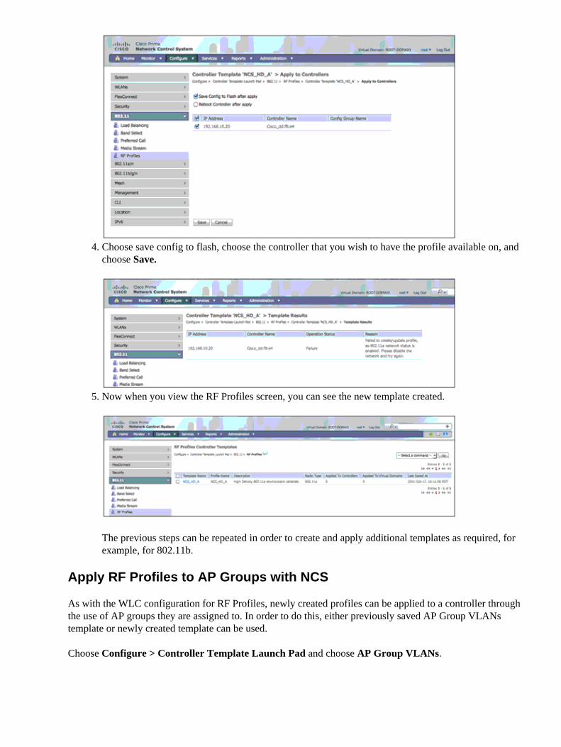
Choose save config to flash, choose the controller that you wish to have the profile available on, andchoose Save.
4.
Now when you view the RF Profiles screen, you can see the new template created.
The previous steps can be repeated in order to create and apply additional templates as required, forexample, for 802.11b.
5.
Apply RF Profiles to AP Groups with NCS
As with the WLC configuration for RF Profiles, newly created profiles can be applied to a controller throughthe use of AP groups they are assigned to. In order to do this, either previously saved AP Group VLANstemplate or newly created template can be used.
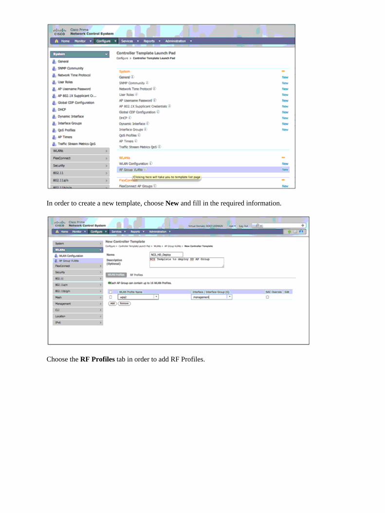
Choose Configure > Controller Template Launch Pad and choose AP Group VLANs.
In order to create a new template, choose New and fill in the required information.
Choose the RF Profiles tab in order to add RF Profiles.
If you save the template, a warning message appears.
As stated in the previous message, the change of the interface that the assigned WLAN uses disrupts theVLAN mappings for FlexConnect APs applied in this group. Ensure that the interface is the same before youproceed.
Once you choose OK, the dialogue is replaced with the option to Apply to Controllers. Choose this option.
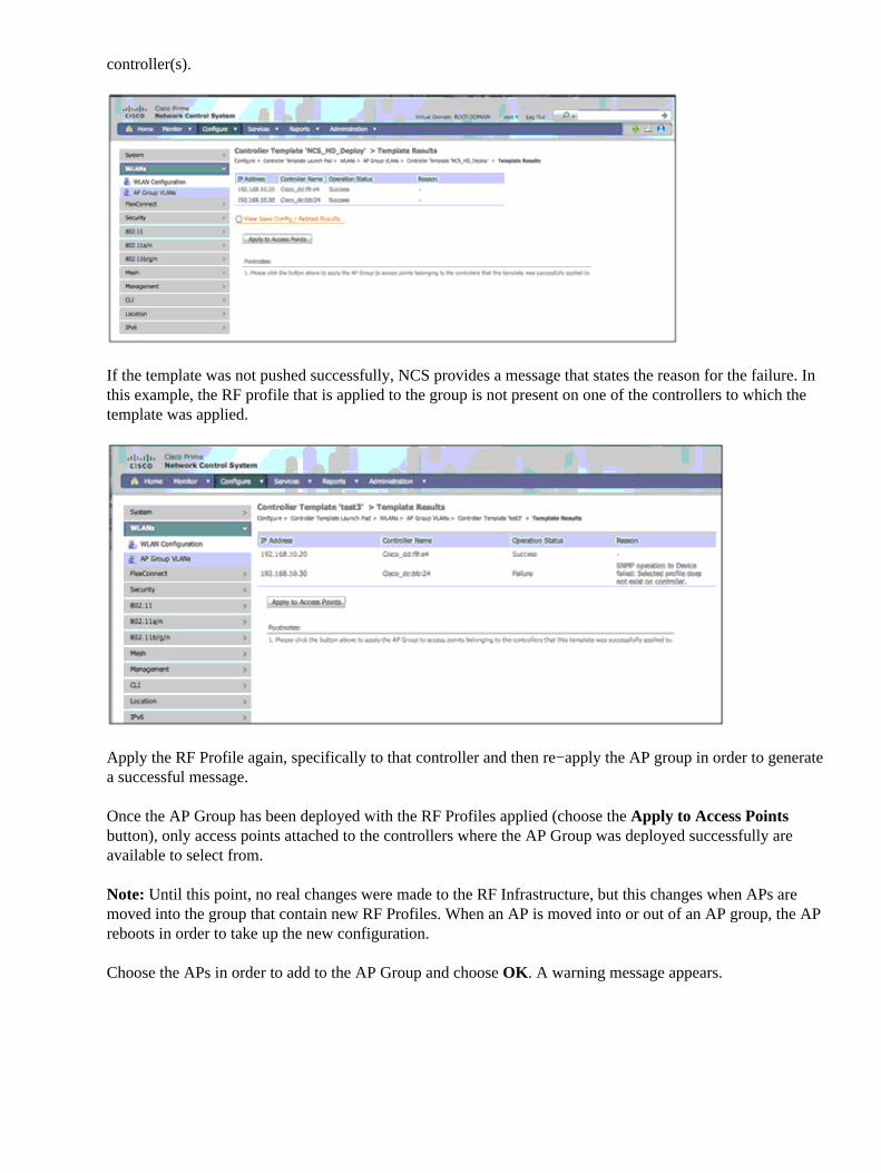
Choose the controller(s) to which the template needs to be applied.
NCS responds with operational status on whether the template was successfully applied to the selected
controller(s).
If the template was not pushed successfully, NCS provides a message that states the reason for the failure. Inthis example, the RF profile that is applied to the group is not present on one of the controllers to which thetemplate was applied.
Apply the RF Profile again, specifically to that controller and then re−apply the AP group in order to generatea successful message.
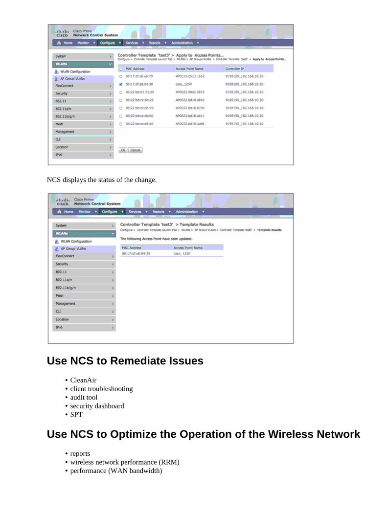
Once the AP Group has been deployed with the RF Profiles applied (choose the Apply to Access Pointsbutton), only access points attached to the controllers where the AP Group was deployed successfully areavailable to select from.
Note: Until this point, no real changes were made to the RF Infrastructure, but this changes when APs aremoved into the group that contain new RF Profiles. When an AP is moved into or out of an AP group, the APreboots in order to take up the new configuration.
Choose the APs in order to add to the AP Group and choose OK. A warning message appears.
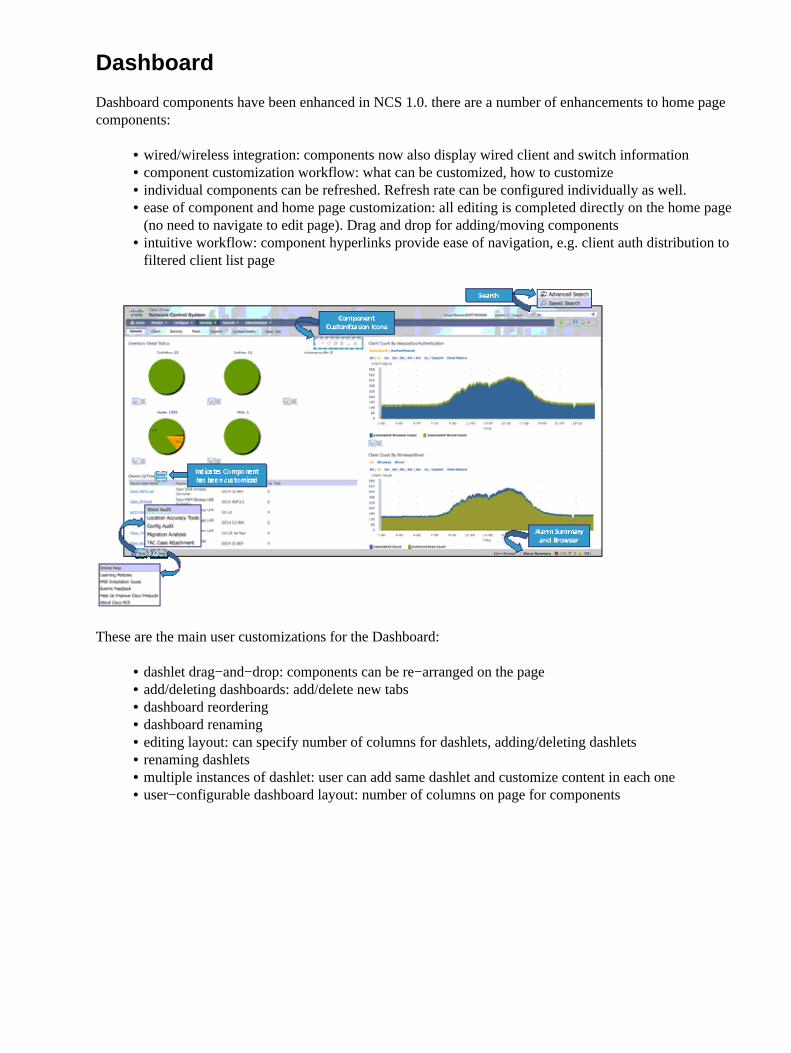
Dashboard components have been enhanced in NCS 1.0. there are a number of enhancements to home pagecomponents:
wired/wireless integration: components now also display wired client and switch information• component customization workflow: what can be customized, how to customize• individual components can be refreshed. Refresh rate can be configured individually as well.• ease of component and home page customization: all editing is completed directly on the home page(no need to navigate to edit page). Drag and drop for adding/moving components
•
intuitive workflow: component hyperlinks provide ease of navigation, e.g. client auth distribution tofiltered client list page
•
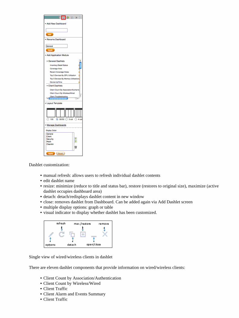
These are the main user customizations for the Dashboard:
dashlet drag−and−drop: components can be re−arranged on the page• add/deleting dashboards: add/delete new tabs• dashboard reordering• dashboard renaming• editing layout: can specify number of columns for dashlets, adding/deleting dashlets• renaming dashlets• multiple instances of dashlet: user can add same dashlet and customize content in each one• user−configurable dashboard layout: number of columns on page for components•
Dashlet customization:
manual refresh: allows users to refresh individual dashlet contents• edit dashlet name• resize: minimize (reduce to title and status bar), restore (restores to original size), maximize (activedashlet occupies dashboard area)
•
detach: detach/redisplays dashlet content in new window• close: removes dashlet from Dashboard. Can be added again via �Add Dashlet� screen• multiple display options: graph or table• visual indicator to display whether dashlet has been customized.•
Single view of wired/wireless clients in dashlet
There are eleven dashlet components that provide information on wired/wireless clients:
Client Count by Association/Authentication• Client Count by Wireless/Wired• Client Traffic• Client Alarm and Events Summary• Client Traffic•
Client Troubleshooting• Client Posture Status• Inventory Detail Status• Device Uptime• Top 5 Devices by CPU Utilization• Top 5 Devices by Memory Utilization•
Wired−only dashlets
Wired Client Speed Distribution• Top 5 Switches by Client Count•
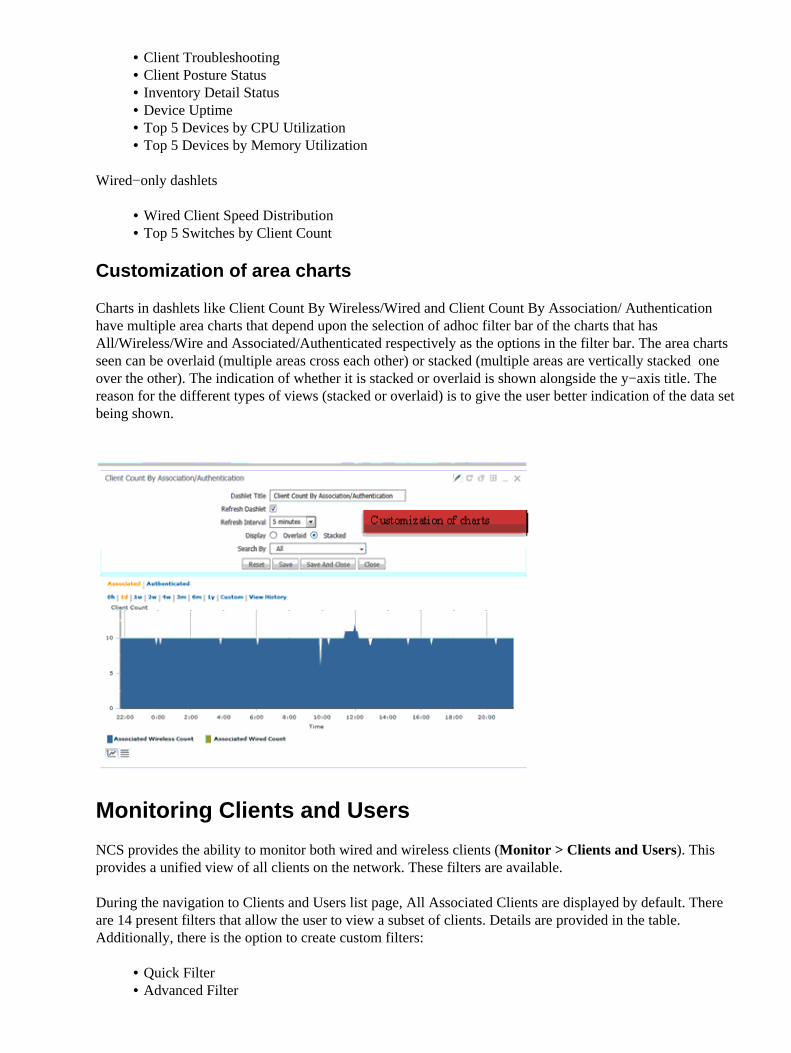
Customization of area charts
Charts in dashlets like Client Count By Wireless/Wired and Client Count By Association/ Authenticationhave multiple area charts that depend upon the selection of adhoc filter bar of the charts that hasAll/Wireless/Wire� and Associated/Authenticated respectively as the options in the filter bar. The area chartsseen can be overlaid (multiple areas cross each other) or stacked (multiple areas are vertically stacked � oneover the other). The indication of whether it is stacked or overlaid is shown alongside the y−axis title. Thereason for the different types of views (stacked or overlaid) is to give the user better indication of the data setbeing shown.
Monitoring Clients and Users
NCS provides the ability to monitor both wired and wireless clients (Monitor > Clients and Users). Thisprovides a unified view of all clients on the network. These filters are available.
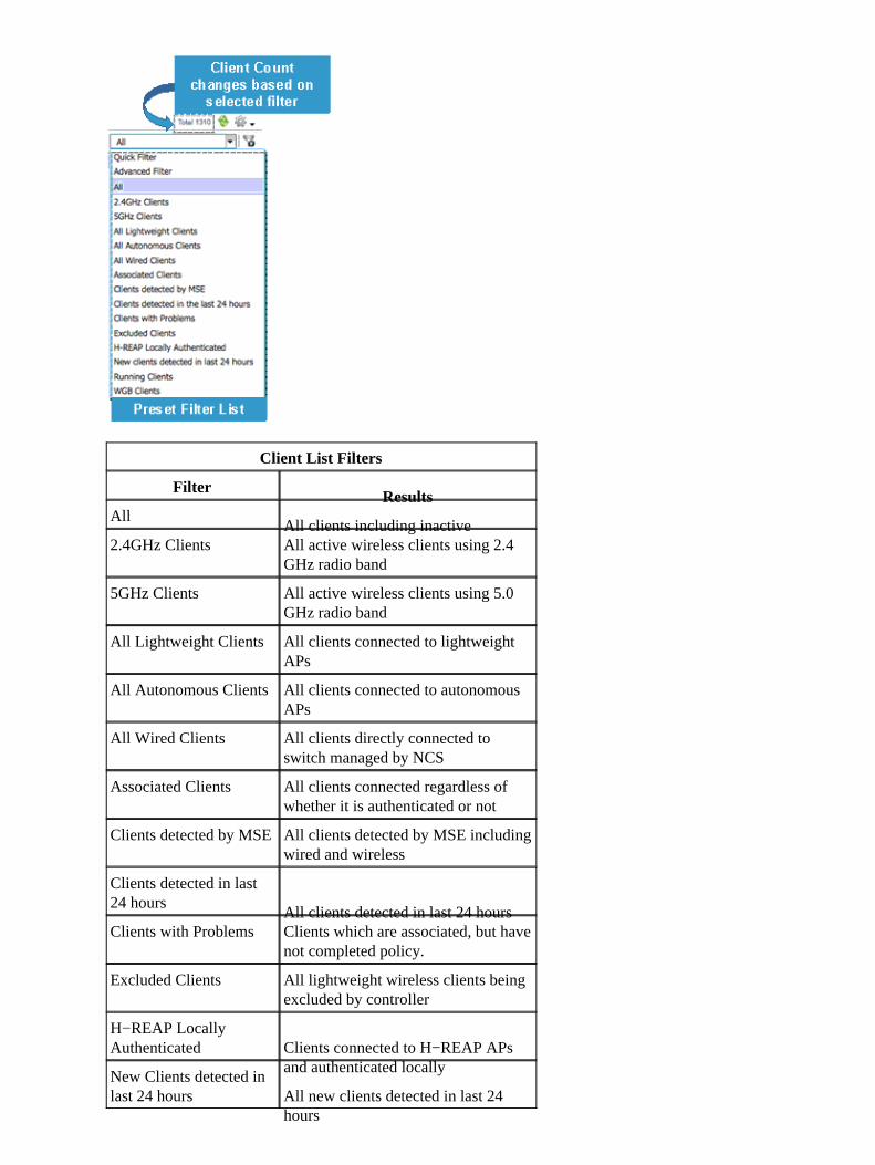
During the navigation to Clients and Users list page, All Associated Clients are displayed by default. Thereare 14 present filters that allow the user to view a subset of clients. Details are provided in the table.Additionally, there is the option to create custom filters:
Quick Filter• Advanced Filter•
Client List Filters
FilterResults
AllAll clients including inactive
2.4GHz Clients All active wireless clients using 2.4GHz radio band
5GHz Clients All active wireless clients using 5.0GHz radio band
All Lightweight Clients All clients connected to lightweightAP�s
All Autonomous Clients All clients connected to autonomousAP�s
All Wired Clients All clients directly connected toswitch managed by NCS
Associated Clients All clients connected regardless ofwhether it is authenticated or not
Clients detected by MSEAll clients detected by MSE includingwired and wireless
Clients detected in last24 hours
All clients detected in last 24 hoursClients with Problems Clients which are associated, but have
not completed policy.
Excluded Clients All lightweight wireless clients beingexcluded by controller
H−REAP LocallyAuthenticated Clients connected to H−REAP AP�s
and authenticated locallyNew Clients detected inlast 24 hours All new clients detected in last 24
hours
Running Clients Clients that have completed all setpolicies and are in running state.
WGB ClientsAll WGB clients
Columns in Client List Table can be customized directly on this page.
Columns in Client List Table can be customized directly on the Clients and Users list page. Select or unselectcolumns in order to display or hide the column immediately.
Default set of displayed columns and their order can be reset to default value through the Reset button.
In order o reorder columns, drag the column directly on the page and move it to the desired order/location.
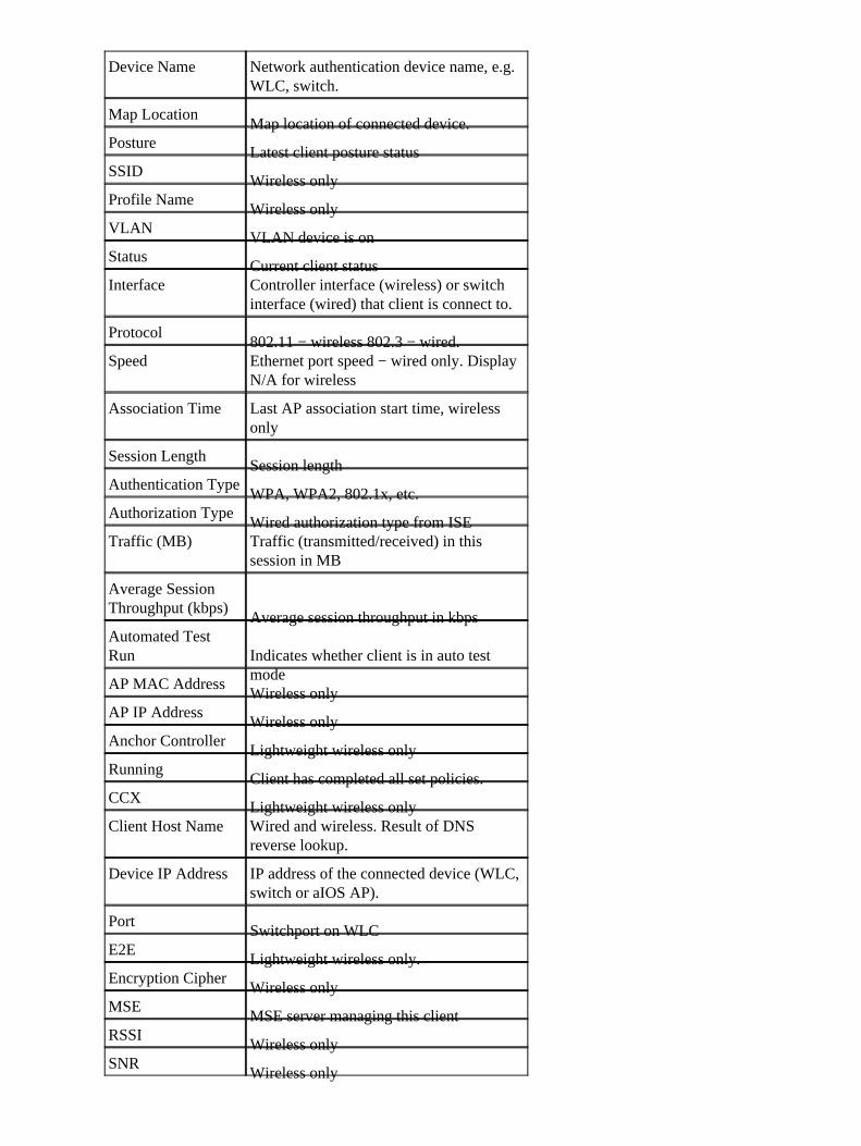
Client and User Page: Column Details
AttributeComments
IP AddressClient IP address
MAC AddressClient MAC address
UsernameUsername based on 802.1x authentication.Unknown is displayed for client connectedwithout a username
Type The icon represents a lightweight, anautonomous or a wired client.
VendorDevice vendor derived from OUI
AP NameWireless only
Device Name Network authentication device name, e.g.WLC, switch.
Map LocationMap location of connected device.
PostureLatest client posture status
SSIDWireless only
Profile NameWireless only
VLANVLAN device is on
StatusCurrent client status
Interface Controller interface (wireless) or switchinterface (wired) that client is connect to.
Protocol802.11 − wireless 802.3 − wired.
Speed Ethernet port speed − wired only. Display�N/A� for wireless
Association Time Last AP association start time, wirelessonly
Session LengthSession length
Authentication TypeWPA, WPA2, 802.1x, etc.
Authorization TypeWired authorization type from ISE
Traffic (MB) Traffic (transmitted/received) in thissession in MB
Average SessionThroughput (kbps)
Average session throughput in kbpsAutomated TestRun Indicates whether client is in auto test
modeAP MAC Address
Wireless onlyAP IP Address
Wireless onlyAnchor Controller
Lightweight wireless onlyRunning
Client has completed all set policies.CCX
Lightweight wireless onlyClient Host Name Wired and wireless. Result of DNS
reverse lookup.
Device IP Address IP address of the connected device (WLC,switch or aIOS AP).
PortSwitchport on WLC
E2ELightweight wireless only.
Encryption CipherWireless only
MSEMSE server managing this client
RSSIWireless only
SNRWireless only
Session IDAudit−session−ID used in ISE and switch
Session TimeSession start time for active sessionSession start time � session end time forinactive session
Vender NameVender name derived from OUI
The Toolbar the client/user list provides a set of tools that can be invoked on selected (one or more) clients.
Monitor > Clients and Users: Supported Commands
CommandType of Client
TroubleshootingAll
Test Menu
Link TestLightweight wireless only
Radio MeasurementsLightweight wireless only
V5 StatisticsLightweight CCX v5 wireless only
Operational ParametersLightweight CCX v5 wireless only
DisableLightweight wireless only
RemoveLightweight wireless only
More menu
ProfilesLightweight (CCXv5)
Roam ReasonLightweight wireless only
Recent MapLightweight wireless only
Present MapLightweight wireless only
SessionsAll
Detecting APsLightweight wireless only
Location HistoryLightweight wireless only
Enable Mirror ModeLightweight wireless only
Voice MetricsLightweight wireless only
Track ClientsLightweight wireless only
Identify Unknown ClientsAll
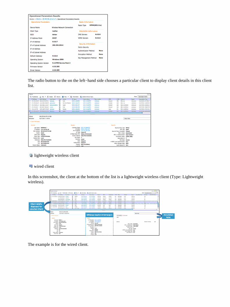
Example Action: Operational Parameters
The radio button to the on the left−hand side chooses a particular client to display client details in this clientlist.
lightweight wireless client
wired client
In this screenshot, the client at the bottom of the list is a lightweight wireless client (Type: Lightweightwireless).
The example is for the wired client.
Wired/Wireless Client Troubleshooting
In NCS 1.0, both wired and wireless monitoring and troubleshooting has been integrated with identityservices. Integration between wired/wireless network management has been achieved via three networkelements:
Cisco wireless LAN controllers (WLC)• Cisco Catalyst switch security features: AAA, RADIUS, 802.1x and MAC authentication, MACnotification traps (non−identity clients), syslog (identity clients only)
•
Cisco Identity Services Engine (ISE)•
All clients � wired and wireless � are displayed in the Clients and Users page (Monitor > Clients andUsers).
Wired clients display AP Name as N/A. Switch port information is provided in Interfaces.
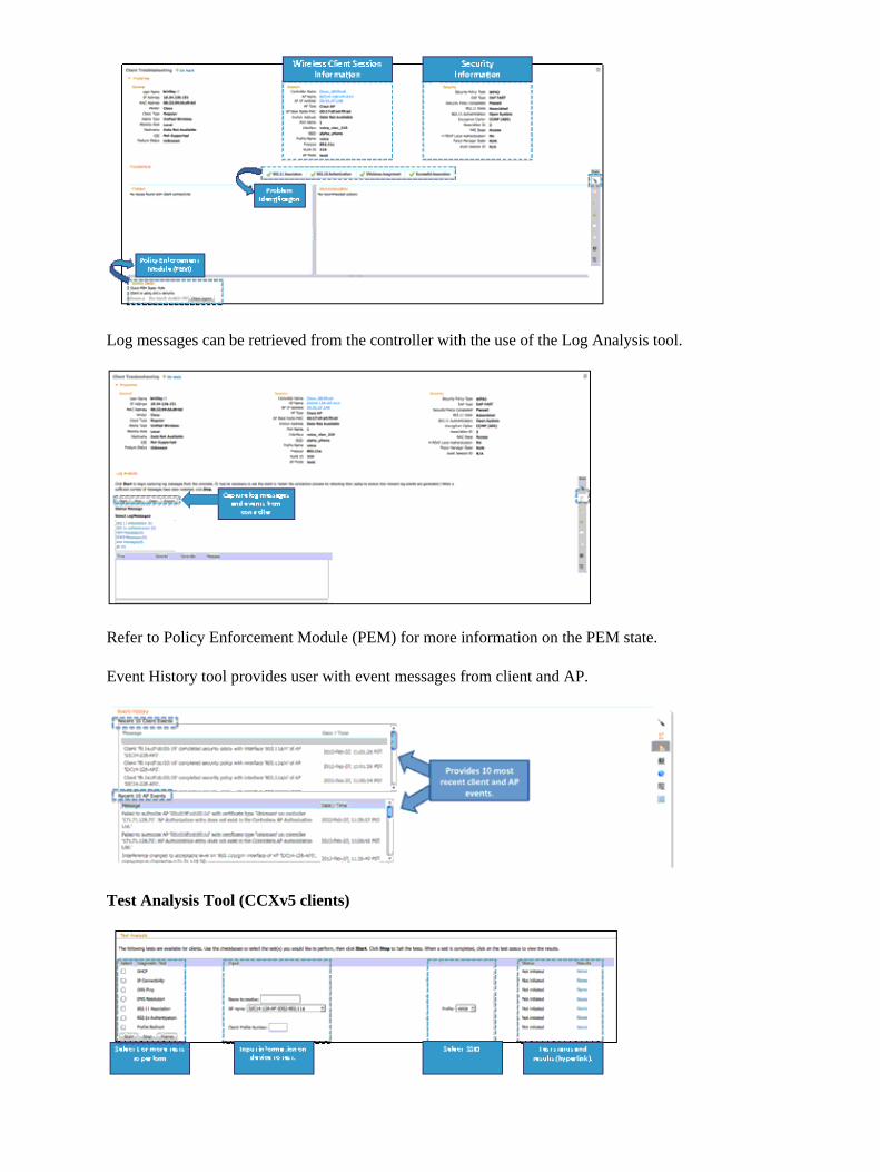
Wireless Client Troubleshooting
In order to launch Client Troubleshooting Tool, click on the radio button to the left of the client list item.Once the client is selected, click on the Troubleshooting icon in the toolbar.
The window is displayed for the client.
Log messages can be retrieved from the controller with the use of the Log Analysis tool.
Refer to Policy Enforcement Module (PEM) for more information on the PEM state.
Event History tool provides user with event messages from client and AP.
Test Analysis Tool (CCXv5 clients)
Wired Client Troubleshooting
NCS 1.0 provides integrated management of wired and wireless devices/clients. One of the major features inNCS 1.0 is monitoring and troubleshooting for wired and wireless clients. SNMP is used to discover clientsand collect client data. ISE is polled periodically to collect client statistics and other attributes to populaterelated dashboard components and reports.
If ISE is added to the systems and devices are authenticating to it, Client Details page displays an additionaldetails labeled as Security.
In order to navigate to the Client Troubleshooting page, click on the Troubleshooting icon on the tools menuat the top of the page.
This takes the user to the page shown in the screen shot. In this example, the client device has linkconnectivity, but failed MAC authentication.
On the right−hand side of the screen is a tool bar with these items all related to troubleshooting:
Event History provides messages related to connectivity events for this client. In this example, the client failedto successfully authenticate. Date/time is provided to assist the network administrator in troubleshooting thisclient.
ISE provides authentication records to NCS via REST API. Network administrator can choose time period forretrieving authentication records from ISE. In this example, the authentication record indicates that the userwas not found in ISE database.
RF/Wireless Features
Track Clients
This feature allows a network administrator to track specific clients and be notified when these clients connectto the network. This feature is enabled from the Monitor > Users and Clients page.
To track single client, click the Add button and a sub−window appears where the user can enter the MACaddress of the client along with tracking expiration (Never or specified end date).
If the user wants to track multiple clients, the client list can be imported. The resulting window allows the userto import list of client MAC addresses through the csv file.
A sample csv file can be downloaded that provides data format.
# MACAddress, Expiration: Never/Date in MM/DD/YYYY format00:40:96:b6:02:cc,10/07/201000:02:8a:a2:2e:60,Never
Notification Settings
There are three options for notifications:
Purged Expired Entries�user can set duration to keep tracked clients in NCS database. Clients can bepurged:
after 1 week♦ after 2 weeks♦ after 1 month♦ after 2 months♦ after 6 months♦ kept indefinitely♦
1.
Notification Frequency�user can specify when NCS sends notification of tracked client:
on first detection♦ on every detection♦
2.
Notification Method�user can specify for tracked client event to generate alarm or send email.3.
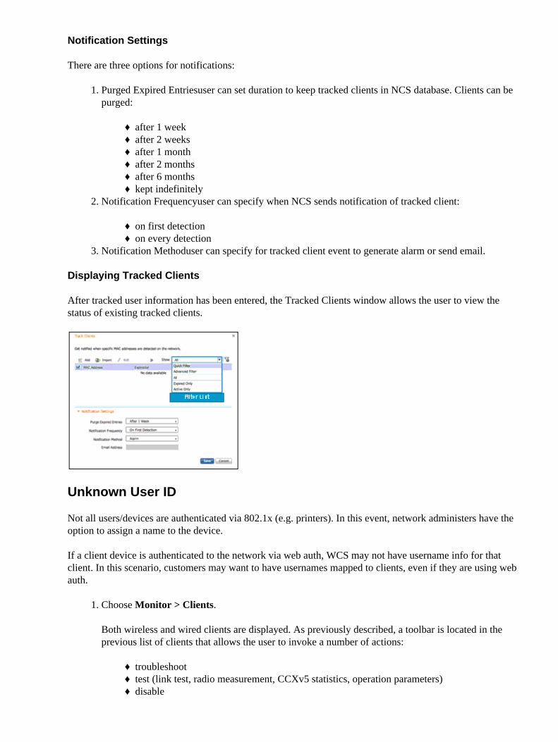
Displaying Tracked Clients
After tracked user information has been entered, the Tracked Clients window allows the user to view thestatus of existing tracked clients.
Unknown User ID
Not all users/devices are authenticated via 802.1x (e.g. printers). In this event, network administers have theoption to assign a name to the device.
If a client device is authenticated to the network via web auth, WCS may not have username info for thatclient. In this scenario, customers may want to have usernames mapped to clients, even if they are using webauth.
Choose Monitor > Clients.
Both wireless and wired clients are displayed. As previously described, a toolbar is located in theprevious list of clients that allows the user to invoke a number of actions:
troubleshoot♦ test (link test, radio measurement, CCXv5 statistics, operation parameters)♦ disable♦
1.
remove (disassociate wireless client)♦
Click the Identify Unknown Users icon in the toolbar.
This results with a pop−up window.
2.
Click Add in order to enter client details.
Individual MAC address and corresponding username can be added.
Once a client and MAC address has been added, WCS uses this table for client lookup based onmatching MAC address.
3.
Real−Time Heat Maps
One of the new features in NCS 1.0, is the option to display real−time heat maps. This is enabled by default.Choose Monitor > Maps > Properties in order to navigate to the settings.
Monitoring Cisco Catalyst Switches Using NCS
Wired inventory information is determined by these methods:
Wired client discovery via SNMP traps, SNMP polling and syslog messages from switches• ISE northbound API for additional information, such as posture, profiler, accounting, and so forth•
NCS provides feature parity with WCS 7.x for client monitoring and reporting on all clients (wired andwireless). Additionally, NCS cross−launches ISE troubleshooting for wired clients. Further level of ISEintegration is via cross−launch of ISE reports with data not contained in WCS.
This switch information is provided in NCS:
Physical Assets, for example, chassis, modules, port, and power supply from Entity MIB• Flash Device/Partition/Files• Software Installed Image• Ethernet Interface• IP interface• VLAN interface• VLAN and VTP• Etherchannel• STP• StackWise (supported only on Cisco Catalyst 3750 switches)•
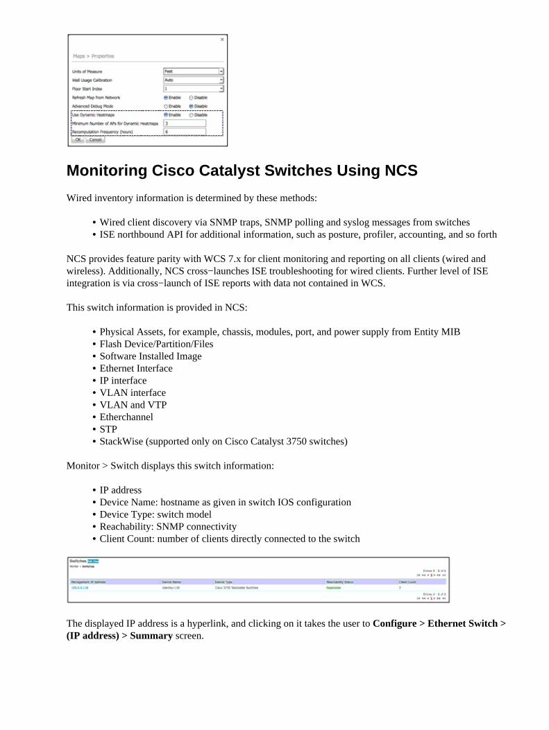
Monitor > Switch displays this switch information:
IP address• Device Name: hostname as given in switch IOS configuration• Device Type: switch model• Reachability: SNMP connectivity• Client Count: number of clients directly connected to the switch•
The displayed IP address is a hyperlink, and clicking on it takes the user to Configure > Ethernet Switch >(IP address) > Summary screen.
Wired clients are discovered via SNMP traps, SNMP polling and syslog messages from switches.
With NCS, Cisco Catalyst switches can be monitored for this information:
Chassis: UDI, model name, uptime• Memory/CPU utilization• Ports/interfaces status• Layer 2 (VLAN, VTP, spanning tree)• Environment: status of power supplies and fans• Memory and files in the system• Clients (wired)•
Spanning Tree
Spanning tree details for each spanning tree instance is provided:
STP Port• Port Role• Port Priority• Path Cost• Port State• Port Type•
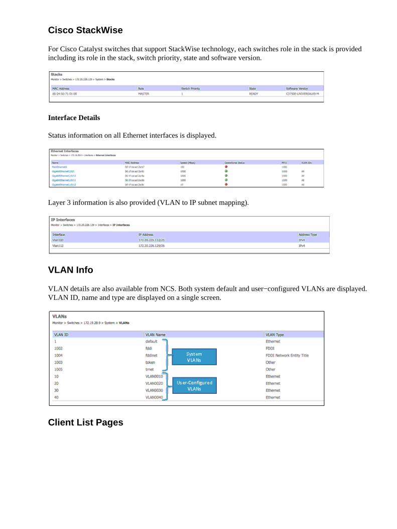
Cisco StackWise
For Cisco Catalyst switches that support StackWise technology, each switches role in the stack is providedincluding its role in the stack, switch priority, state and software version.
Interface Details
Status information on all Ethernet interfaces is displayed.
Layer 3 information is also provided (VLAN to IP subnet mapping).
VLAN Info
VLAN details are also available from NCS. Both system default and user−configured VLANs are displayed.VLAN ID, name and type are displayed on a single screen.
Client List Pages
Reports (Cross−Launch and Scale)
NCS 1.0 provides integrated management of wired and wireless devices/clients. SNMP is used to collectclient data. ISE is polled periodically to collect client statistics and other attributes to populate related reports.
Choose Reports > Reports Launch Pad. Choose report for creation/customization.
New Reports
Top N Connections
This reports shows top N users in a given period of time based on these metrics:
Username• Number of total connection attempts• Number of passed connection attempts• Number of failed connection attempts•
AP Association
This report lists all AP association details for wireless clients and is similar to Client Session reports.
Posture Status Count
This report provides a trend chart to show client posture status over time. The chart is an area chart; thebottom area is the number of clients passed the posture check and top area is the number of clients that failedthe posture check.
Alarms/Events
Alarms and events provides a single page view of alarms and events for wired and wireless. Persistent alarmsummary and browser is displayed in the bottom right of the screen regardless of what screen the user is on.NCS 1.0 provides generic alarm views including these pages:
Alarm list pages• Alarm detail pages• Event list pages• Event detail pages• Alarm search by category & sub category• Alarm summary window• Alarm dashboard• Alarm actions (acknowledge, clear, assign, unassign, delete, etc.)• Alarm notification (Email, trap)• Alarm page navigations (from and to different views)• Alarm overview panel − drilldown to filtered list• Launch existing WCS troubleshooting page from alarm page•
Columns can be customized such as displayed, hidden, and reordered. Actions can be taken on one or morealarms simultaneously.
Quick Filter
This feature allows a user to filter on one or more columns based on text string entered in the filter filed at thetop of each column. It provides an optional filtered view of alarms for wired and wireless alarms.
Alarms Page � Quick Filter
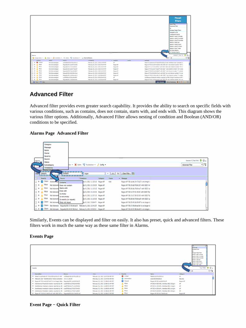
Advanced Filter
Advanced filter provides even greater search capability. It provides the ability to search on specific fields withvarious conditions, such as contains, does not contain, starts with, and ends with. This diagram shows thevarious filter options. Additionally, Advanced Filter allows nesting of condition and Boolean (AND/OR)conditions to be specified.
Alarms Page � Advanced Filter
Similarly, Events can be displayed and filter on easily. It also has preset, quick and advanced filters. Thesefilters work in much the same way as these same filter in Alarms.
Events Page
Event Page − Quick Filter
Event Page − Advanced Filter
AAA User Authentication via TACACS+/RADIUS using ACS4.2
For TACACS+ users to authenticate successfully in NCS, a few changes are required in ACS 4.2. A newService NCS HTTP needs to be added in Interface Configuration page for TACACS+ (Cisco IOS).
The entire set of NCS User Group Task list TACACS+ Custom Attributes needs to be copied in the NCSHTTP Custom attributes text area as shown in the screen shot for an AAA user. The same holds good for User
Group.
For Radius User Authentication, you need to copy the new NCS User group task list Radius custom attributesin the Cisco IOS/PIX 6.x RADIUS Attributes section for User/User Group.
From NCS, add the new TACACS+/Radius server entry in Administration > AAA > TACACS+ Servers /Radius. Set the AAA mode in Administration > AAA > AAA Mode Settings to TACACS+ / Radiusaccordingly. Re−login as AAA user.
Related Information
Technical Support & Documentation − Cisco Systems•