30
Cisco SD-Access: Enterprise Networking Made Fast and Flexible November 2017

Cisco SD-Access:Enterprise Networking
Made Fast and Flexible
November 2017

Page 2
Evaluating Cisco SD-Access for Common Networking Tasks
Executive SummaryEnterprise networking remains a lot harder than it needs to be. For far too long, enterprises have wrestled with constraints like rigid designs, arcane command-line sequences, and limited mobility.
Cisco aims to change that with SD-Access, a set of software-defined automation tools that make enterprise networking much easier and far more powerful. Based around the Cisco DNA Center management interface and supported on many Cisco hardware platforms, SD-Access abstracts away many of the tedious, repetitive func-tions required for even simple network configuration.
Cisco commissioned independent consultancy Network Test to assess SD-Access in action, with tests covering nine common customer tasks:
• Network hierarchical design
• Business segmentation
• Definition of user policy
• Greenfield deployment
• Wired automation
• New service enablement
• Network programmability
• Wireless connectivity
• Service assurance
The high-level takeaway is simple: In every test case, we deployed and managed an enterprise network in 30 minutes or less, whereas a command-line approach would have taken up to a week.
Besides its ease of use, SD-Access also makes networking much more powerful by decoupling users and physical locations. Further, all tasks can be achieved via a single web-based dashboard or programmatically, both via the same set of APIs. At long last, network professionals can tailor networks to suit business requirements, not the other way around.

Page 3
Evaluating Cisco SD-Access for Common Networking Tasks
Introducing SD-AccessSD-Access encompasses wired and wireless infrastructure in enterprise networks, and presents the entire enterprise via a single dashboard called Cisco DNA Center (DNA Center).
Many different lines of Cisco hardware already support SD-Access, including the new Catalyst 9000 switch family. All of the following products can work together to form enterprise-wide fabric domains using SD-Access:
• Catalyst 3650 and 3850 (all models)
• Catalyst 4500-E + Sup8E/9E and 4700 modules
• Catalyst 65xx + Sup2T/6T
• Catalyst 6807-XL + Sup2T/6T and 6800 10G modules
• Catalyst 6880-X or C6840-X (all models)
• Catalyst 9300, 9400 and 9500 (all models)
• Nexus 7700 + Sup2E and M3 modules
• ASR 1000-X or 1000-HX (all models)
• ISR 4430 or 4450 (all models)
• Cisco WLC 3504, 5520 or 8540
• Cisco AP 1700/2700/3700 (Wave 1, with caveats)
• Cisco AP 1800/2800/3800 (Wave 2)
On the software side, Cisco DNA Center (DNA Center) presents a web-based view of the enterprise network, with different modules for provisioning and monitoring the network. As noted, Cisco DNA Center uses a set of APIs for all tasks. These APIs make it possible to configure even very large-scale networks programmatically, handling every step of design, deployment, monitoring, and management of an enterprise network.
Simpler and More Powerful
SD-Access introduces several new concepts in enterprise network design that add ease and flexibility:
IP pools follow people, not locations. In a traditional design, a network architect allocates a pool of IP address-es, typically handed out via DHCP server, to be associated with a single physical location. With SD-Access, there’s still a DHCP server – but now, IP pools are bound to fabric domains rather than physical location. This allows much greater mobility and flexibility in associating users and policies, regardless of physical location.
IP pool size is based on the size of the entire user base across the enterprise. With SD-Access, each user gets the same IP address regardless of location (within the limits of a DHCP lease duration). This is a significant change from the old practice of allocating IP address blocks at each location, which made it much harder to grow or reallocate IP address pools in response to changing business needs.
Every edge device uses the same anycast gateway. A conventional network requires each edge device to define a gateway address, with different gateway addresses in use even at the same location, such as different buildings or floors within the same campus. In contrast, SD-Access uses IP anycast so that all edge devices within each IP pool use the same gateway address. This reduces not only configuration complexity but also the scale of IP routing within an enterprise campus.

Page 4
Evaluating Cisco SD-Access for Common Networking Tasks
Network and group segmentation can be applied at the fabric edge for both wired and wireless users. For the first time, SD-Access allows definition of VRF instances and access policies at each individual edge switch and access point (AP). This allows an unprecendented level of granularity in routing and access control for wired and wireless users and devices.
There’s a common thread across these changes: SD-Access is a much more business- and user-centric ap-proach to network design, instead of the old device- and network-centric approach. With SD-Access, business drivers define network intent and dictate the mechanics of network connectivity, not the other way around.
How We TestedCisco asked Network Test to assess SD-Access with nine use cases covering common enterprise networking tasks:
• Network hierarchical design
• Business segmentation
• Definition of user policy
• Greenfield deployment
• Wired automation
• New service enablement
• Network programmability
• Wireless connectivity
• Service assurance
In all cases we used the Cisco DNA Center dashboard, which then pushed out configurations to every network node across the enterprise.
In these tests, we set up a new site and multiple sets of users for a hypothetical organization. Each set of users had different access policies, and in some cases different virtual networks, to deliver the appropriate segmenta-tion and user access regardless of the user’s location.
Significantly, there was no need to touch every device in the network. Even in greenfield testing, only one device needed to receive an IP address; after that, Cisco DNA Center took care of all setup for all other switches and routers. In contrast, traditional network device configuration requires console login to each device. The more devices involved, the more manual configuration is required.
Where applicable, this report compares the steps and time needed for each task with the same functions using manual CLI configuration.
Page 5
Evaluating Cisco SD-Access for Common Networking Tasks
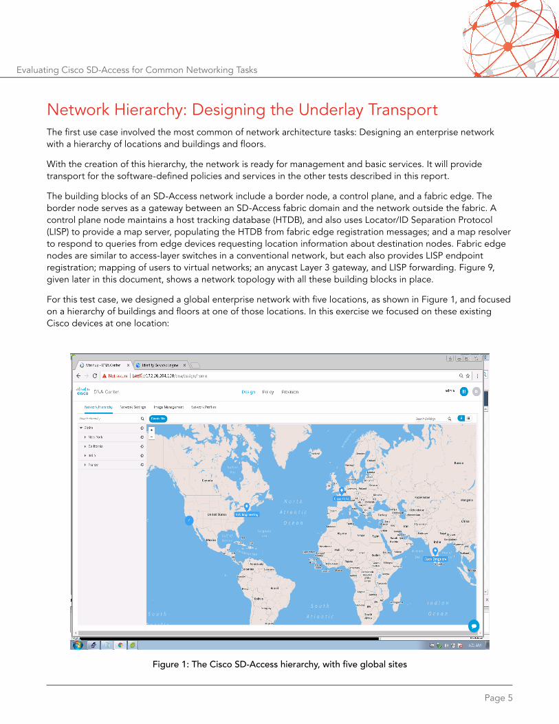
Network Hierarchy: Designing the Underlay TransportThe first use case involved the most common of network architecture tasks: Designing an enterprise network with a hierarchy of locations and buildings and floors.
With the creation of this hierarchy, the network is ready for management and basic services. It will provide transport for the software-defined policies and services in the other tests described in this report.
The building blocks of an SD-Access network include a border node, a control plane, and a fabric edge. The border node serves as a gateway between an SD-Access fabric domain and the network outside the fabric. A control plane node maintains a host tracking database (HTDB), and also uses Locator/ID Separation Protocol (LISP) to provide a map server, populating the HTDB from fabric edge registration messages; and a map resolver to respond to queries from edge devices requesting location information about destination nodes. Fabric edge nodes are similar to access-layer switches in a conventional network, but each also provides LISP endpoint registration; mapping of users to virtual networks; an anycast Layer 3 gateway, and LISP forwarding. Figure 9, given later in this document, shows a network topology with all these building blocks in place.
For this test case, we designed a global enterprise network with five locations, as shown in Figure 1, and focused on a hierarchy of buildings and floors at one of those locations. In this exercise we focused on these existing Cisco devices at one location:
Figure 1: The Cisco SD-Access hierarchy, with five global sites

Page 6
Evaluating Cisco SD-Access for Common Networking Tasks
• Cisco Catalyst 6807-XL switch (Border node)
• Cisco Catalyst 4507 switch (a passthrough device; does not require SD-Access awareness)
• 4 Cisco Catalyst 3850 switches (1 Control Plane node, and 3 edge switches)
• Cisco Identity Services Engine (ISE) server
Working with Cisco DNA Center made network design very easy. This was a five-step process, all handled through the Cisco DNA Center web interface. The entire provisioning process look less than 30 minutes from beginning to end, and that included time for experimentation with creation of different sites.
The following table shows the steps and time required with SD-Access for definition of a hierarchical network compared with configuration from a command-line interface (CLI): Note the significant time savings with SD-Access. Further, note that manual configuration times increase sharply when adding more switches and routers to the network; network design is much faster with SD-Access.
Cisco SD-Access Manual CLI configuration
Testing time: < 30 minutes
Once for the entire enterprise, using Cisco DNA Center:• Create a network hierarchy
• Define network settings for AAA, DHCP, DNS, SNMP, and CLI login credentials
• Create IP pools
• Discover devices
• (Optional) Map network topology
Estimated time: 1 day
For each building and floor of each location:• Create IP pools
For each Cisco Catalyst 68xx at each location:• Configure console access via serial and SSH
• Define network settings for AAA, DHCP, DNS, SNMP, and CLI login credentials
For each Cisco Catalyst 45xx and Cisco Catalyst 3850 at each location:• Configure console access via serial and SSH
• Define network settings for AAA, DHCP, DNS, SNMP, and CLI login credentials

Page 7
Evaluating Cisco SD-Access for Common Networking Tasks
Figures 2 and 3 respecitively illustrate site and building/floor definition within Cisco DNA Center. In both figures, note the inclusion of a parent node, creating a network hierarchy.
Figure 2: Site creation with Cisco DNA Center
Figure 3: Building and floor definition with Cisco DNA Center
Page 8
Evaluating Cisco SD-Access for Common Networking Tasks
Business Segmentation: Logical Separation via Virtual NetworksWith the network defined, our next task was to define multiple virtual networks, each encompassing different groups of users or things. The use case for this test is a university with separate virtual networks for employees, faculty, students, PCI servers, and production servers. Although our testing covered a hypothetical university network, the same concepts would apply equally well for Internet-of-Things (IOT) networks.
Users or devices within each virtual network can communicate with each other. However, there is no communica-tion between virtual networks. To enable communication between virtual networks, traffic must leave the Border node and then return, typically traversing a firewall or external router.
Again using the Cisco DNA Center web interface, this was a simple, three-step process: Create an SD-Access virtual network, add scalable groups, and define access policies between scalable groups. The web interface hides the underlying complexity from users such as creating multiple virtual routing and forwarding (VRF) in-stances and scalable group access control lists (SGACLs).
VRF configuration can be quite complex. VRFs make complete routing domains, each with its own virtual net-work, and require punching holes in firewall configurations to leak routes between them.
SD-Access policies tie into Cisco’s existing Identity Services Engine (ISE), so there’s no need to re-invent a new authentication and policy enforcement framework. Indeed, SD-Access makes use of ISE’s existing scalable group tag (SGT, formerly security group tag) mechanism to classify and manage packet flows.
It took less than 15 minutes to define virtual networks for the five groups at our hypothetical university – and that 15-minute process included time for a discussion of ISE integration. It would take less time for creation of future segments once the DNA Center/ISE integration process is well understood.
In contrast, policy and virtual network definition using CLI commands is a far more cumbersome task, spanning literally days to accomplish.
The traditional CLI-only approach requires not only definition of each VRF instance and related routing policy, but also creation of an overlay transport such as an MPLS network. This approach also requires routing configuration.
Even for experienced, highly competent network engineers, MPLS and VRF configuration can take days. For our relatively simple, single-site network, we estimate about seven days’ work to create all the necessary segments.
SD-Access abstracts away all that complexity, making it easy to see the relationships between groups of users, and to tie them together.
The following table shows the steps required with SD-Access for business segmentation compared with configu-ration from a command-line interface (CLI). Note the significant time savings with SD-Access.

Page 9
Evaluating Cisco SD-Access for Common Networking Tasks
Cisco SD-Access Manual CLI configuration
Testing time: < 15 minutes
Once for the entire enterprise, using Cisco DNA Center:• Create virtual networks
• Assign scalable groups to virtual networks
• Define access policies between scalable groups
Estimated time: 7 days
Globally, for all devices:• Create an MPLS overlay network
• Create VRFs
For each Cisco Catalyst 68xx at each location:• Configure MPLS
• Configure VRFs for each group
• Configure dynamic routing protocol(s) such as BGP, OSPF, and EIGRP
For each Cisco Catalyst 3850 at each location:• Configure MPLS
• Configure VRFs for each group
• Repeat previous 2 steps for all intermediate devices between border and edge

Page 10
Evaluating Cisco SD-Access for Common Networking Tasks
After saving, we verified that DNA Center pushed the new policies to the Cisco ISE server, as seen in Figure 5. As expected, the TrustSec section of the ISE interface showed the appropriate deny and permit rules.
User Policy Definition: Locking Down Control to ResourcesWith the underlay infrastructure in place and virtual networks defined, we next turned to user policy – defining which groups would have access to which resources.
Again using our hypothetical university, we defined two policies. The first would forbid employees from access to students or PCI servers. The second would allow faculty to reach students, production servers, and PCI servers
The Cisco DNA Center web interface made very short work of this. For each policy, all we needed to do was drag and drop icons from our previously defined virtual networks into source and destination windows, as shown in Figure 4. Then we chose the access rule (either “permit” or “deny”), enabled the policy, and saved the policy.
Figure 4: Access control policy definition in Cisco DNA Center

Page 11
Evaluating Cisco SD-Access for Common Networking Tasks
Figure 5: Access control in the ISE server, inheriting configuration from Cisco DNA Center
The entire process, both for creating and verifying access policies, took less than 5 minutes. In contrast, we estimate the conventional CLI-based approach would take approximately 2 days.
The following table compares the steps required with SD-Access for user policy definition compared with configuration from a command-line interface (CLI). Note the time savings with SD-Access.
Cisco SD-Access Manual CLI configuration
Testing time: < 5 minutes
Once for the entire enterprise, using Cisco DNA Center:• Define security policies between each source and
destination group
• Verify that policies are pushed to ISE
Estimated time: 2 days
Globally:• Enable TrustSec on all devices
• Add TrustSec user access policies on ISE
For each Cisco Catalyst 68xx at each location:• Enable TrustSec (CTS configuration)
• Configure IP-to-SGT binding using SXP
For each Cisco Catalyst 45xx and Cisco Catalyst 3850 at each location:• Enable TrustSec (CTS configuration)
• Configure static SGT binding

Page 12
Evaluating Cisco SD-Access for Common Networking Tasks
Greenfield Deployment: Software-Defined From ScratchThe test cases we’ve discussed so far deal with so-called brownfield deployments, where we use DNA Center to build a fabric from existing devices. But SD-Access works equally well in greenfield networks – and can save time by significantly reducing configuration overhead.
SD-Access relieves network managers of the tedious task of configuring every new networking device from scratch, including out-of-band management; routing; security; access policies; and other tasks. Instead, the DNA Center dashboard handles configuration automatically. All that’s needed is one addressable device in the network that supports the uPNP (universal plug-and-play) service.
In this test, we deployed four Cisco Catalyst 3850 switches from scratch using the DNA Center dashboard. We designated one of these, called “Switch100”, as the “seed switch,” meaning we manually configured the switch with an IP address to be able to manage it. From there, DNA Center automatically handled all remaining tasks.
These tasks began with reserving an IP pool and discovering Switch100 in DNA Center. After that, we selected the interfaces downstream of Switch100 we’d use to connect the remaining three switches.
Using DNA Center’s Provision module, the next step was to run LAN Automation, which would discover the remain-ing switches, and allow us to name them (in this assigning the prefix of “CA” to each new switch hostname, and choosing which ports on the seed switch will connect to the new switches). Figure 6 shows the LAN automation process; note that in the background topology map, the device inventory so far lists only Switch100.
Figure 6: LAN Automation with Cisco DNA Center

Page 13
Evaluating Cisco SD-Access for Common Networking Tasks
After LAN Automation completes, DNA Center now recognizes the new switches, which it has deployed and provisioned. Note that in Figure 7, the three new switches are now included.
Figure 7: Adding switches with LAN Automation
Figure 8 shows the final topology map. The whole process took about 20 minutes after provisioning the seed switch. We did not need to directly configure management or routing or interfaces (including loopback interfac-es) on access switches, and only needed to give the seed switch a single IP address. DNA Center automated all remaining tasks.
Figure 8: A fully functional network set up from scratch with SD-Access

Page 14
Evaluating Cisco SD-Access for Common Networking Tasks
This table compares greenfield deployment using Cisco SD-Access and traditional CLI methods. Note that networks come online much faster with SD-Access than with a manual CLI approach. Further, note that the time for manual configuration will grow exponentially, not linearly, as the network grows. This is because of the need to define not only one address on each switch but also to configure interconnections between switches, a task that increases in complexity as the network grows.
Cisco SD-Access Manual CLI configuration
Testing time: 20 minutes
Once for the entire enterprise, using Cisco DNA Center:• Select a seed device and give it an IP address
• Assign IP pools for hosts
• Select port(s) of downstream switches
• Select site
Estimated time: 5 hours
Globally for all devices:• Configure management interface
• Configure L3 interfaces
• Configure IS-IS routing
• Configure username and password
• Enable SSH for device management
• Enable transport for line vty
• Define network settings for AAA, DHCP, DNS, and SNMP
• Configure hostname
Individually on each device:• Configure routing interconnections to neighbor
devices and networks on all appropriate interfaces

Page 15
Evaluating Cisco SD-Access for Common Networking Tasks
Wired Automation: Building an Overlay NetworkIn previous test cases, we added devices in Cisco DNA Center to build an underlay transport (either manually as in the brownfield test cases, or automatically as in the greenfield test case), but we did not specify how an overlay network would work. With wired automation, SD-Access creates an overlay network and defines the fabric edge as well as control plane and border functions.
The Cisco DNA Center web interface made this possible with a simple five step process:
Provision network devices. This was simply a matter of adding all previously defined devices. Although our test involved only one site, an overlay network could encompass many devices at many locations.
Create a fabric domain. With SD-Access, the scope of a fabric domain can be arbitrarily large or small. In this case, we defined a new fabric called “University” and added all previously defined devices to it using DNA Center’s Provision/Fabric module.
Importantly, this step creates a single logical fabric of multiple physical devices, while also hiding the underlying mechanics (which can be quite complex) from network professionals.
Define a Border node. Border and Control Plane nodes require explicit definition in SD-Access. This is as simple as clicking on a previously defined Cisco Catalyst 6807-XL and designating it as a Border node.
Define a Control Plane node. Similarly, we clicked on a Catalyst 3850 switch and chose it to be the network’s Control Plane node. .
Define one or more Fabric Edge nodes. As noted in the first test case on network hierarchical design, the test bed included four Cisco Catalyst 3850 switches, one of which acts as a Control Plane node. Clicking on the remaining three switches in DNA Center allowed us to designate them as Fabric Edge nodes.
Saving the configuruation then instantiated all changes.

Page 16
Evaluating Cisco SD-Access for Common Networking Tasks
It took only 10 minutes to create a complete overlay network. The process likely would go even faster with more familiarity with Cisco DNA Center (this was our first time using the web interface), or with programmatic access to the network.
In contrast, the traditional CLI-only approach to overlay network creation can be quite laborious. Cisco devices use the Locator ID Separation Protocol (LISP) for overlay networking, and carry LISP messages through VXLAN tunnels. LISP is extremely powerful, but part of that power involves defining its attributes on every device in the overlay network.
Figure 9: Network topology showing Border, Control Plane, and Fabric Edge nodes
Figure 9 shows the final overlay network topology with border, control plane, and fabric edge nodes.
Page 17
Evaluating Cisco SD-Access for Common Networking Tasks
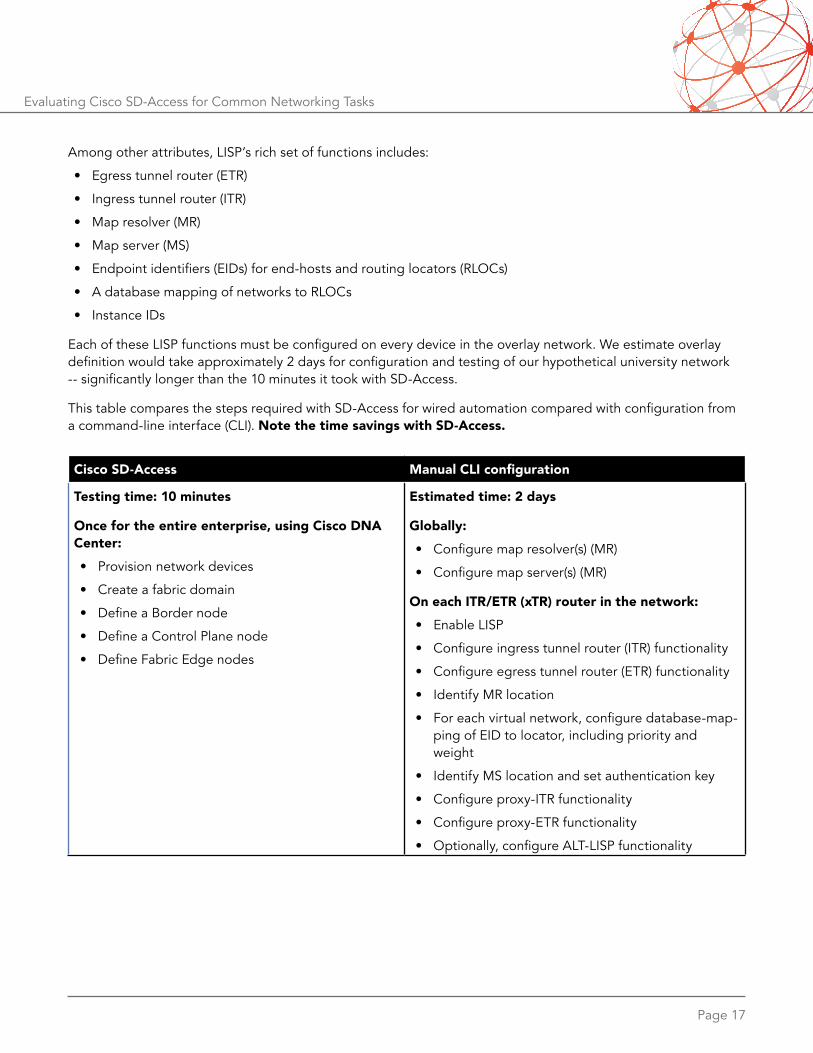
Among other attributes, LISP’s rich set of functions includes:
• Egress tunnel router (ETR)
• Ingress tunnel router (ITR)
• Map resolver (MR)
• Map server (MS)
• Endpoint identifiers (EIDs) for end-hosts and routing locators (RLOCs)
• A database mapping of networks to RLOCs
• Instance IDs
Each of these LISP functions must be configured on every device in the overlay network. We estimate overlay definition would take approximately 2 days for configuration and testing of our hypothetical university network -- significantly longer than the 10 minutes it took with SD-Access.
This table compares the steps required with SD-Access for wired automation compared with configuration from a command-line interface (CLI). Note the time savings with SD-Access.
Cisco SD-Access Manual CLI configuration
Testing time: 10 minutes
Once for the entire enterprise, using Cisco DNA Center:• Provision network devices
• Create a fabric domain
• Define a Border node
• Define a Control Plane node
• Define Fabric Edge nodes
Estimated time: 2 days
Globally:• Configure map resolver(s) (MR)
• Configure map server(s) (MR)
On each ITR/ETR (xTR) router in the network:• Enable LISP
• Configure ingress tunnel router (ITR) functionality
• Configure egress tunnel router (ETR) functionality
• Identify MR location
• For each virtual network, configure database-map-ping of EID to locator, including priority and weight
• Identify MS location and set authentication key
• Configure proxy-ITR functionality
• Configure proxy-ETR functionality
• Optionally, configure ALT-LISP functionality

Page 18
Evaluating Cisco SD-Access for Common Networking Tasks
New Service Enablement: Dynamic Authentication ProvisioningDifferent user groups need different access rights. In this test case, we created a new virtual network for guests at our hypothetical university, and gave visitors different access rights than another of the virtual networks we defined previously in the business segmentation test case.
In this test, we set up two IP pools, “Guest” and “Campus18,” with different authentication methods for each. Guests used MAC authentication bypass (MA B), while users in the Campus18 group used 802.1X access for authentication.
Working with the Cisco DNA Center web interface, this is a five-step process:
Create a “Guest” overlay virtual network. This is the same process we used in the previous test case to set up virtual networks.
Assign IP Pools for hosts. We assigned different IP pools for the “Campus18” and “Guest” networks, with 802.1X and MAB authentication respectively.
Add guest and campus hosts. Using VMware vSphere, we connected virtual machines to fabric edge ports.
Verify host authentication. As a final check, we verified that an edge switch saw each host using the correct form of authentication. Figure 10 shows two correctly authenticated host sessions, one apiece using MAB and 802.1X.
Verify host connectivity. We then verified that each guest and Campus18 host could obtain an IPv4 address, netmask, and gateway, and could ping its gateway address. This would only be possible if both MAB and 802.1X authentication worked as expected.
With the Cisco DNA Center interface, all these steps took about 20 minutes to complete.
With a traditional CLI-only approach, we estimate the same functions would take about 1 day to complete, taking into account ISE server authentication and access policy configuration; per-port authentication configura-tion on each switch; SGT host mapping, and other steps.
Figure 10: MAB and 802.1X authentication verification

Page 19
Evaluating Cisco SD-Access for Common Networking Tasks
This table compares the Cisco SD-Access and traditional CLI approaches to new service enablement. Note that SD-Access provisioning and verification is much faster than the manual CLI approach.
Cisco SD-Access Manual CLI configuration
Testing time: 20 minutes
Once for the entire enterprise, using Cisco DNA Center:• Create new virtual networks as needed
• Assign IP pools for hosts
• Add hosts to newly created virtual networks
• Verify authentication methods
• Verify host connectivity
Estimated time: 1 day
Globally:• Create a VRF instance for guest access
• Configure authentication and access policy on ISE
• Enable 802.1X dynamic host authentication
For each Cisco Catalyst 68xx at each location:• (no steps needed)
For each Cisco Catalyst 45xx and Cisco Catalyst 3850 at each location:• Enable 802.1X dynamic host authentication on
desired ports of each switch
• Configure static SGT port mapping for any ports not configured with 802.1X
• Configure 802.1X options as needed (closed, open, priority, etc.)
• Add CTS configuration per port
• Repeat previous step for all intermediate devices between access switches and the Border node

Page 20
Evaluating Cisco SD-Access for Common Networking Tasks
Network Programmability: Software-Defined Access to Any TaskAs previously noted, any task that can be accomplished via the Cisco DNA Center graphical interface also is accessible programmatically through an extensive set of APIs. These APIs cover virtually any configuration, management, and monitoring task. APIs can be called from popular scripting languages such as Python, making this software-defined method of network control especially attractive for large-scale networking.
In these tests, we performed three tasks entirely through programmatic means:
• VRF creation using NETCONF and Yang modeling
• Launch of Cisco Embedded Event Manager (EEM) via a Python script running directly on a switch
• YDK modeling to configure a fabric edge hostname; convert an interface’s configuration to XML; and enable OSPF routing
None of these tasks required direct interaction with a device’s CLI. Although our test bed involved a single switch (in this case, a Cisco Catalyst 3650), the scripts could easily be modified to perform the same tasks on hundreds or thousands of switches – all using the same zero-touch programming methods.
VRF Creation Using NETCONF and Yang Modeling
In the first automation test case, we defined a VRF instance using the YangExplorer browser. First, we navigated to the browser’s “ietf-interfaces/interfaces” node to verify the switch did not yet have interfaces or VRF instances defined, as seen in Figure 11.
Then we deliberately configured a VRF instance called “test” with an invalid route distinguisher (RD) of “abcdef”. After creating and running a remote procedure call (RPC) in YangExplorer, the browser correctly rejected the input due to the illegal use of non-integer characters in the RD name.
After correcting the error with a valid RD value, we then were able to run without error. Now, the get-config command run from the “ietf-interfaces/interfaces” node showed a valid VRF instance configured on the switch. Figure 12 compares RPC outputs after we input invalid and then valid RD values.
We also created a 20-line Python script to define and deploy VRF names and RD values from user-input values, and verified the script pushed valid VRF instance definitions to the switch. Although we tested with just one VRF instance, the same script could easily be called by another script with the names of hundreds or thousands of VRF instances and RDs – and that script, in turn, could be called by a third script running these commands on hundreds or thousands of switches.
In all, we spent about 45 minutes on these tasks, but most of that involved learning our way around YangExplorer and modifying Python scripts to see what was possible. It took less than 1 minute to programmatically create each VRF instance, including time to check and re-check input. A Python-fluent programmer could easily accomplish the entire exercise from scratch in less than 15 minutes.

Page 21
Evaluating Cisco SD-Access for Common Networking Tasks
Figure 11: The YangExplorer Browser prior to interface and VRF instance definition
Figure 12: The YangExplorer Browser’s RPC engine with invalid and valid RD values

Page 22
Evaluating Cisco SD-Access for Common Networking Tasks
Running Cisco EEM With On-Box Scripting
The next test case involved running Python scripts directly on the Cisco Catalyst 3650 switch. Cisco switches running IOS XE support a specialized Linux container (LXC) called the guest shell. Within the shell, users can install and run Python scripts and access the network, any of the SD-Access APIs, and the switch bootflash.
In this case, we ran a Python script on the switch that called Cisco Embedded Event Manager (EEM) every time the switch’s running configuration changed. The script worked by comparing a saved configuration in bootflash with the new configuration. Here again, the script took well less than 1 minute to execute, and we estimate a Python programmer could complete the whole exercise from scratch in 15 to 30 minutes.
Total Automation With the YDK
The Yang development kit (YDK) offers programmatic control over all aspects of SD-Access switch configuration, management, and monitoring.
In this exercise, we used the YDK to set a switch’s hostname; to render a switch interface’s configuration in XML; and to enable OSPF routing.
YDK stores modules in a searchable tree-like structure. By searching the tree for configuration terms such as “hostname” or “interface”, it’s possible to find the necessary command, data type, and other information need-ed to control each object programmatically.
After creating Python scripts based on the YDK, we verified that we could change the switch hostname and render an interface’s configuration in XML. Figure 13 shows the XML rendering for one interface; note that this XML markup can be handed off other programs for a modular approach to network construction.
Figure 13: Interface configuration rendered in XML via Python scripting

Page 23
Evaluating Cisco SD-Access for Common Networking Tasks
In the final automation exercise, we used application extension – a construct that allows grouping of related functions that perform similar tasks – to enable OSPF routing on the Cisco Catalyst 3650. Figure 14 shows the RPC code generated to enable OSPF, while Figure 15 compares CLI output before and after OSPF routing is enabled programmatically.
Figure 14: OSPF configuration rendered in XML via Python scripting
Figure 15: OSPF configuration checking on the command line, before and after automation
All three tasks completed in less than 1 minute. A skilled Python programmer could have scripted the necessary API calls from scratch in less than 30 minutes.
This section does not include a table comparing completion times with CLI configuration because no such comparison is possible, at least for some tasks. For example, a network manager cannot use a conventional CLI to represent an interface’s configuration in XML, much less run a script to do so on the switch, or pass the resulting XML data to another program.

Page 24
Evaluating Cisco SD-Access for Common Networking Tasks
Wireless Connectivity: Easy Onboarding Via DNA CenterIn many conventional network designs, wireless LANs are configured and managed separately from the wired network. Cisco SD-Access greatly simplifies the process of wireless client onboarding by using the same Cisco DNA Center dashboard to bring up wireless and wired clients.
We validated wireless client onboarding using Cisco DNA Center. The graphical interface made it easy to accom-plish this in just a few steps.
Figure 16 shows the discovery of several pieces of wireless infrastructure, including a wireless LAN controller (WLC) called “Fab-WLC1” and an access point called “AP3800-Edge1”. These are the devices we used in this test. Figure 17 shows the provisioning of the WLC in an existing fabric domain.
Figure 16: Discovering wireless infrastructure using DNA Center

Page 25
Evaluating Cisco SD-Access for Common Networking Tasks
Figure 17: Provisioning a wireless controller (WLC) in an existing fabric domain
Although DNA Center was the primary focus of this exercise, network managers also can continue to use existing tools to monitor connectivity. Figure 18 shows the WLC’s Web interface indicating two clients have associated with the access point called “AP3800-Edge1.” This information also is available via DNA Center.
As noted, wireless users’ access to resources can be tightly controlled in the same way, using the same rules, as for wired users. In this test case, we created a new access policy called “FTPdeny” that blocks traffic from the Employees to the Contractors user groups. This policy applies regardless of whether members in either group connect on wired or wireless networks. In fact, access policy creation works the same way for all resources.
Onboarding of wireless clients was a very rapid process. It took only 17 minutes to build a wireless network from scratch, including discovering and provisioning the WLC; creating an address pool and SSID; defining an access policy; adding the WLC to the fabric; and verifying of client connectivity.
In contrast, conventional CLI-based configuration for wireless connectivity is a more burdensome task. We estimate the same functionality achieved via the CLI and WLC GUI would take approximately 3 hours.

Page 26
Evaluating Cisco SD-Access for Common Networking Tasks
Figure 18: Verifying wireless client connectivity
This table compares the Cisco SD-Access and traditional CLI methods for wireless deployment. Note that wireless networks come online much faster with SD-Access than with a manual CLI approach.
Cisco SD-Access Manual CLI configuration
Testing time: 17 minutes
Once for the entire enterprise, using Cisco DNA Center:• Wireless controller (WLC) discovery
• Creation of separate IP address pools for wireless clients and APs
• SSID creation
• Access policy creation
• Provisioning (adding the WLC to a previously defined site)
• Integration of the WLC into a fabric domain
• Verification of wireless client connectivity
Estimated time: 3 hours
For the switch connected to the WLC:• Configure WLC-connected switchport as trunk
• Create VLANs for all wireless client subnets configured on WLC
• Configure L3 interfaces for all wireless client subnets
• Define DHCP scopes for all wireless clients (if not using a dedicated DHCP server)
For the switch(es) connected to each AP:• Configure AP-connected switchport in access
mode (for local mode AP)
• Configure AP-connected switchport in trunk mode (for FlexConnect AP)
• Create VLANs for each wireless client subnet
• Configure L3 interfaces for all wireless client subnets
• For each AP, configure AP registration method (DHCP option 43, DNS, or IP helper address pointing to WLC)

Page 27
Evaluating Cisco SD-Access for Common Networking Tasks
Service Assurance: Rapid Isolation of Network IssuesBesides configuring and deploying networks, the DNA Center dashboard also allows for continuous monitoring and management, and can rapidly correlate user problems with network issues.
We put this to the test by deliberately inducing a common problem for wireless users: Poor RF coverage.
Figure 19 shows the DNA Center Assurance module’s health check. Note the reported issues: A client on an iPhone is experiencing a coverage hole and cannot connect to the SSID “WifiCorpDot1x” on a specific AP. Note also the network topology, which gives network managers a graphic representation of client-to-network connectivity.
Figure 19: Fault isolation with Cisco DNA Center’s Assurance module
Clicking on the AP (under Assurance/Health) indicates a high utilization problem, and perhaps more importantly, makes suggestions to resolve the issue, as shown in Figure 20.
For more complex RF issues, users can drill down on each AP to see wireless-specific data over time, such as graphs of received signal strength index (RSSI), signal-to-noise ratio (SNR), and data rates. The ability to see changes to these metrics over time is far more important than any single data point, and also helps correlate user issues with problems in the network.

Page 28
Evaluating Cisco SD-Access for Common Networking Tasks
Figure 20: Root-cause identification with suggested remedies
With DNA Center’s Assurance module, it took less than 1 minute to identify client issues and correlate them to problems with a network device, in this case an AP. In contrast, manual troubleshooting can be a lengthy and error-prone process that can take hours.
This table compares the Cisco SD-Access and manual troubleshooting methods for assurance and health check-ing. Note that it’s much easier to identify and correlate wireless problems with SD-Access.
Cisco SD-Access Manual troubleshooting
Testing time: Less than 1 minute
Once for the entire enterprise, using Cisco DNA Center:• Click on Assurance module
• Click on any issues identified
Estimated time: 1-3 hours• Troubleshoot RF connectivity (manually from WLC)
• Identify client location on floor map
• Identify AP client is connected to
• Watch RSSI value over time
• Check AP layout to determine if there’s an actual RF coverage hole
• Check associated RF profile for data rates, RRM attributes (AP transmit power, channel width, channel interference, and other RF issues)

Page 29
Evaluating Cisco SD-Access for Common Networking Tasks
ConclusionCisco SD-Access represents a major change in enterprise networking, making it far easier to design, provision, monitor, and manage networks than conventional CLI-based approaches. By presenting a single view of the entire enterprise network, the Cisco DNA Center web interface made adds, moves, and changes very simple to accomplish.
More importantly, SD-Access enables new ways of thinking about network design that aren’t possible with the old CLI-based approach. Because SD-Access is user-centric, it permits access to resources based on who users are rather than where they are. This allows much greater flexibility and mobility in network design.
Also, every task in SD-Access is available programmatically through an extensive set of APIs, allowing for rapid network provisioning even at a very large scale. And DNA Center’s approach of a single dashboard for the entire network greatly simplifies monitoring and network security, for wired and wireless users alike.
These test results demonstrate that SD-Access provides a simpler yet more powerful approach to enterprise networking. The Cisco DNA Center dashboard proved capable of accomplishing complex provisioning tasks in just a few minutes in every test case, compared with multiple days – up to 7 days in one case – using convention-al CLI-based configuration. SD-Access holds great promise as a simpler, more automated, and more powerful way of deploying, managing, and monitoring enterprise networks.

Network Test Inc.31324 Via Colinas, Suite 113 • Westlake Village, CA 91362-6761 • USA+1-818-889-0011 • http://networktest.com • [email protected]
Version 2017111900. Copyright © 2017 Network Test Inc. All rights reserved.
Evaluating Cisco SD-Access for Common Networking Tasks
About Network TestNetwork Test is an independent third-party test lab and engineering services consultancy. Our core competencies are performance, security, and conformance assessment of networking equipment and live networks. Our clients include equipment manufacturers, large enterprises, service providers, industry consortia, and trade publications.
DisclaimerNetwork Test Inc. has made every attempt to ensure that all test procedures were conducted with the utmost precision and accuracy, but acknowledges that errors do occur. Network Test Inc. shall not be held liable for damages which may result for the use of information contained in this document. All trademarks mentioned in this document are property of their respective owners.


