45
Cisco TelePresence Cisco Unified Communications Manager with Cisco VCS (SIP Trunk) Deployment Guide Cisco VCS X8.1 CUCM 8.6.x, 9.x D14602.14 December 2013
| Date post: | 25-Apr-2018 |
| Category: |
Documents |
| Upload: | nguyendang |
| View: | 268 times |
| Download: | 0 times |
Cisco TelePresenceCisco Unified
Communications Manager with Cisco VCS (SIP Trunk)
Deployment Guide
Cisco VCS X8.1CUCM 8.6.x, 9.x
D14602.14
December 2013
Contents
Introduction 5Deployment scenario 5Summary of configuration process 5Prerequisites for system configuration 6
Enabling calls between endpoints registered on the VCS Control 7VCS Control configuration 7
Setting up the SIP domain of the VCS Control 7Creating transforms 7
Unified CM configuration 8Registering endpoints to the VCS Control 8
Endpoint configuration 8Confirming registrations 9Test calls 9
Enabling calls between endpoints registered on Unified CM 10VCS Control configuration 10Unified CM configuration 10
Configuring the SIP Profile for VCS 10Configuring the region with an appropriate session bit rate for video calls 13Configuring the SIP Profile for phone devices 13Adding a phone device 13Configuring the device directory number 13Configuring phone endpoint to pick up its configuration from Unified CM 14Confirming registrations 14
Test calls 14
Enabling endpoints registered on VCS to call endpoints registered on Unified CM 15Unified CM configuration 15
Configuring the SIP Trunk security profile 15Configuring the SIP Trunk device 16Configuring the Cluster Fully Qualified Domain Name 19
VCS Control configuration 20Creating a neighbor zone for Unified CM 20Creating a search rule to route calls to the Unified CM neighbor zone 21Creating a transform that converts number@<IP address of cucm> to [email protected] 23
Test calls 23
Enabling endpoints registered on Unified CM to call endpoints registered on VCS 24VCS Control configuration 24
Creating a transform to convert Unified CM supplied domain information to the VCS SIP domain 24Unified CM configuration 25
Allowing numeric dialing from Cisco phones to VCS 25Allowing dialing to VCS domain from Cisco phones 26
Test calls 26
Connecting VCS to Unified CM using TLS 27Ensuring certificate trust between Unified CM and VCS 27
Loading server and trust certificates on Unified CM 27Loading server and trust certificates on VCS 28
Unified CM with Cisco VCS (SIP Trunk) Deployment Guide (X8.1) Page 2 of 45
Configuring a SIP trunk security profile on Unified CM 28Updating the Unified CM trunk to VCS to use TLS 29Updating the VCS neighbor zone to Unified CM to use TLS 29Verifying that the TLS connection is operational 30Network of VCSs 30Encrypted calls to endpoints registered to Unified CM 30
Checking Unified CM message size limit 31
Appendix 1: Troubleshooting 32Problems connecting VCS Control local calls 32
Look at “Search history” to check the applied transforms 32Look at call history to check how the call progressed 32
Check for errors 33Tracing calls 33Call failures with Cisco TelePresence Server 33In-call problems 33
Calls clear down when a call transfer from a video phone on Unified CM transfers a call to VCS 33Failure to join a Unified CM endpoint to a conference using Multiway 33Poor video quality from Unified CM 34
Taking a trace on Unified CM using RTMT 34Configure Unified CM to enable tracing 34Installing RTMT – Real Time Monitoring Tool 34Running RTMT 34Taking a trace using RTMT 34
Call failures 35TLS calls fail when Unified CM uses SRV trunk destinations 35Encrypted call failures 35
Appendix 2: Known interworking capabilities and limitations 36Capabilities 36
SIP and H.323 endpoints making basic calls 36Limitations 36
Cisco TelePresence Conductor 36E20 encryption 36T150 running L6.0 code 36H.323 MXP and 9971 36
Appendix 3: Connecting Unified CM to a VCS cluster 37Configuring the trunk to VCS to specify the DNS SRV address for the VCS cluster 37Configuring the trunk to VCS to specify a list of VCS peers 37
Appendix 4: Connecting VCS to a cluster of Unified CM nodes 39Option 1: Using a single neighbor zone 39
Unified CM configuration 39VCS Control configuration 39
Option 2: Using a DNS zone 39Unified CM configuration 39DNS server configuration 40VCS Control configuration 40
Appendix 5: Multiway and Unified CM 42VCS configuration 42
Unified CM with Cisco VCS (SIP Trunk) Deployment Guide (X8.1) Page 3 of 45
Unified CM configuration 42
Appendix 6: Additional information 43IP address dialing 43Characters allowed in SIP URIs 43
Document revision history 44
Unified CM with Cisco VCS (SIP Trunk) Deployment Guide (X8.1) Page 4 of 45
IntroductionThis deployment guide provides guidelines on how to configure the Cisco TelePresence Video Communication Server (VCS) version X8.1 and Cisco Unified Communications Manager (Unified CM) versions 8.6.x and 9.x to interwork via a SIP trunk.
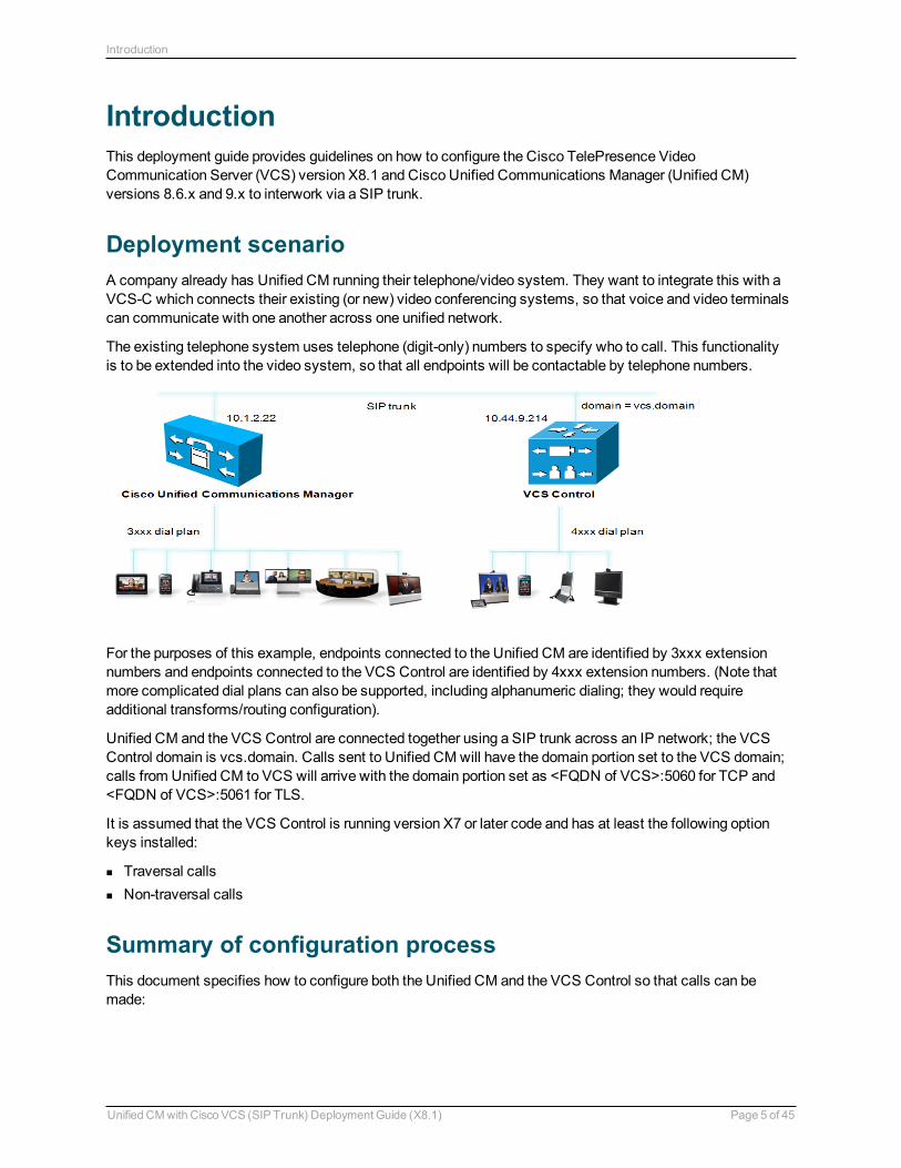
Deployment scenarioA company already has Unified CM running their telephone/video system. They want to integrate this with a VCS-C which connects their existing (or new) video conferencing systems, so that voice and video terminals can communicate with one another across one unified network.
The existing telephone system uses telephone (digit-only) numbers to specify who to call. This functionality is to be extended into the video system, so that all endpoints will be contactable by telephone numbers.
For the purposes of this example, endpoints connected to the Unified CM are identified by 3xxx extension numbers and endpoints connected to the VCS Control are identified by 4xxx extension numbers. (Note that more complicated dial plans can also be supported, including alphanumeric dialing; they would require additional transforms/routing configuration).
Unified CM and the VCS Control are connected together using a SIP trunk across an IP network; the VCS Control domain is vcs.domain. Calls sent to Unified CM will have the domain portion set to the VCS domain; calls from Unified CM to VCS will arrive with the domain portion set as <FQDN of VCS>:5060 for TCP and <FQDN of VCS>:5061 for TLS.
It is assumed that the VCS Control is running version X7 or later code and has at least the following option keys installed:
n Traversal calls n Non-traversal calls
Summary of configuration processThis document specifies how to configure both the Unified CM and the VCS Control so that calls can be made:
Unified CM with Cisco VCS (SIP Trunk) Deployment Guide (X8.1) Page 5 of 45
Introduction
n from video endpoints connected to the VCS to other video endpoints connected to that same VCS n from IP handsets or other devices connected to Unified CM to other IP handsets or devices connected to
that same Unified CM n from video endpoints connected to the VCS to IP handsets or other devices connected to Unified CM n from IP handsets or other devices connected to Unified CM to video endpoints connected to the VCS
The configuration process describes each of these stages separately, so that individual stages can be implemented and tested before moving on to the next.
Initially the configuration use non-secure TCP connections, as this allows for easier troubleshooting. It then describes how to secure the video network over TLS.
Prerequisites for system configurationBefore using this document to configure the VCS Control and Unified CM to interwork, make sure that:
n Unified CM contains a basic configuration and has already set up at least: l System > Server l System > Cisco Unified CM l System > Cisco Unified CM Group l System > Date / Time Group l System > Presence Group l System > Region Information l System > Device Pool l System > DHCP l System > Location l System > Physical location l System > Enterprise parameters l System > Licensing
n The VCS Control must be configured with IP address, DNS and NTP information, and is accessible for management via its web interface (see VCS Basic Configuration (Single VCS Control) Deployment Guide).
Unified CM with Cisco VCS (SIP Trunk) Deployment Guide (X8.1) Page 6 of 45
Introduction
Enabling calls between endpoints registered on the VCS Control
VCS Control configurationConfiguration of the VCS Control to enable calls to be made between devices that register to it can be broken down into the following steps:
n Setting up the SIP domain of the VCS Control. This is needed for SIP registration. n Creating a transform to ensure that domain information is added to dialed numbers that do not include a
domain. This forces dialed number information from SIP and H.323 endpoints into a common format: number@domain.
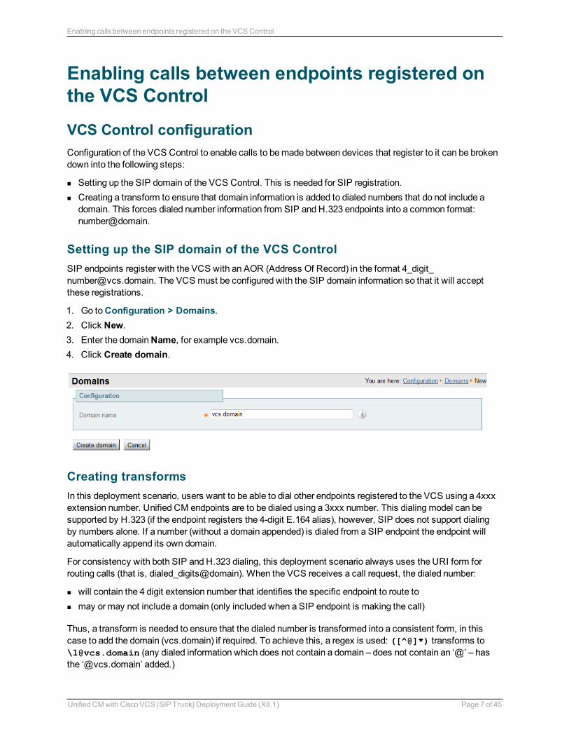
Setting up the SIP domain of the VCS ControlSIP endpoints register with the VCS with an AOR (Address Of Record) in the format [email protected]. The VCS must be configured with the SIP domain information so that it will accept these registrations.
1. Go to Configuration > Domains. 2. Click New. 3. Enter the domain Name, for example vcs.domain. 4. Click Create domain.
Creating transformsIn this deployment scenario, users want to be able to dial other endpoints registered to the VCS using a 4xxx extension number. Unified CM endpoints are to be dialed using a 3xxx number. This dialing model can be supported by H.323 (if the endpoint registers the 4-digit E.164 alias), however, SIP does not support dialing by numbers alone. If a number (without a domain appended) is dialed from a SIP endpoint the endpoint will automatically append its own domain.
For consistency with both SIP and H.323 dialing, this deployment scenario always uses the URI form for routing calls (that is, dialed_digits@domain). When the VCS receives a call request, the dialed number:
n will contain the 4 digit extension number that identifies the specific endpoint to route to n may or may not include a domain (only included when a SIP endpoint is making the call)
Thus, a transform is needed to ensure that the dialed number is transformed into a consistent form, in this case to add the domain (vcs.domain) if required. To achieve this, a regex is used: ([^@]*) transforms to \[email protected] (any dialed information which does not contain a domain – does not contain an ‘@’ – has the ‘@vcs.domain’ added.)
Unified CM with Cisco VCS (SIP Trunk) Deployment Guide (X8.1) Page 7 of 45
Enabling calls between endpoints registered on the VCS Control
See the Regular Expression Reference in the Appendices section of VCS Administrator Guide for further details, or alternatively search the internet for the term “Regular Expression”.
To create the transform:
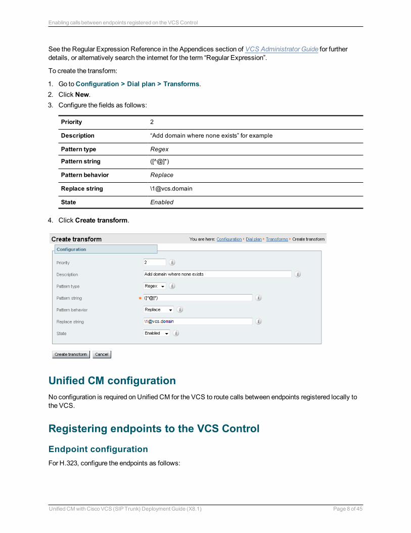
1. Go to Configuration > Dial plan > Transforms. 2. Click New. 3. Configure the fields as follows:
Priority 2
Description “Add domain where none exists” for example
Pattern type Regex
Pattern string ([^@]*)
Pattern behavior Replace
Replace string \[email protected]
State Enabled
4. Click Create transform.
Unified CM configurationNo configuration is required on Unified CM for the VCS to route calls between endpoints registered locally to the VCS.
Registering endpoints to the VCS Control
Endpoint configurationFor H.323, configure the endpoints as follows:
Unified CM with Cisco VCS (SIP Trunk) Deployment Guide (X8.1) Page 8 of 45
Enabling calls between endpoints registered on the VCS Control
n H.323 ID (for example [email protected], [email protected] and so on) n H.323 Call Setup = Gatekeeper n Gatekeeper IP address = IP address of the VCS
For SIP, configure the endpoints as follows:
n SIP Address (URI) (for example [email protected], [email protected] and so on) n Server Address (Proxy address) = IP address of the VCS
Confirming registrationsRegistration status can be confirmed by checking the VCS via Status > Registrations.
By default the VCS will accept all H.323 registrations and all SIP registrations within the specified SIP domain. You can limit registrations by explicitly allowing or denying individual registrations. See the “VCS Configuration” section of VCS Administrator Guide for further details.
Test callsMake some test calls.
Your call history can be seen on the VCS via Status > Calls > History.
Unified CM with Cisco VCS (SIP Trunk) Deployment Guide (X8.1) Page 9 of 45
Enabling calls between endpoints registered on the VCS Control
Enabling calls between endpoints registered on Unified CM
VCS Control configurationNo configuration is required on the VCS for Unified CM to route calls between endpoints registered locally to the Unified CM.
Unified CM configurationThe configuration of Unified CM and Cisco phones to enable calls to be made between the phones consists of setting up a SIP Profile, specifying the phones on Unified CM, giving the phones phone numbers and getting the phones to load their configuration. This comprises the following steps:
n Configuring the SIP Profile for VCS (already exists if using version 9.x) n Configuring the region with an appropriate session bit rate for video calls n Configuring a SIP Profile for phone devices n Adding a phone device: add the new phone device to the list of supported endpoints on Unified CM n Configuring the device directory number: specify the telephone number that will cause this phone to ring n Configure the phone endpoint to pick up its configuration from Unified CM.
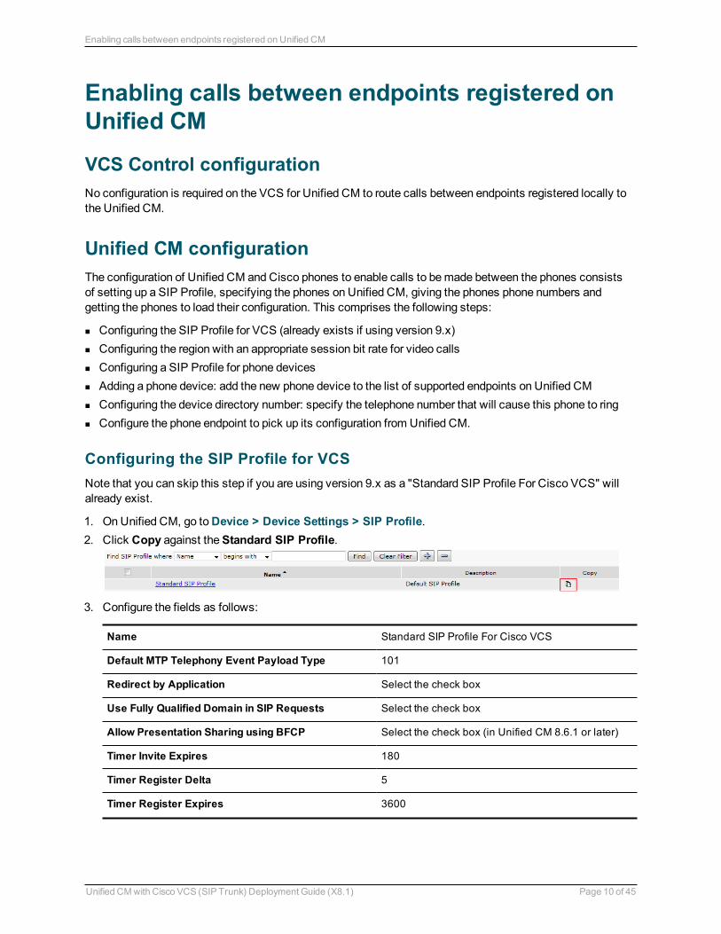
Configuring the SIP Profile for VCSNote that you can skip this step if you are using version 9.x as a "Standard SIP Profile For Cisco VCS" will already exist.
1. On Unified CM, go to Device > Device Settings > SIP Profile. 2. Click Copy against the Standard SIP Profile.
3. Configure the fields as follows:
Name Standard SIP Profile For Cisco VCS
Default MTP Telephony Event Payload Type 101
Redirect by Application Select the check box
Use Fully Qualified Domain in SIP Requests Select the check box
Allow Presentation Sharing using BFCP Select the check box (in Unified CM 8.6.1 or later)
Timer Invite Expires 180
Timer Register Delta 5
Timer Register Expires 3600
Unified CM with Cisco VCS (SIP Trunk) Deployment Guide (X8.1) Page 10 of 45
Enabling calls between endpoints registered on Unified CM
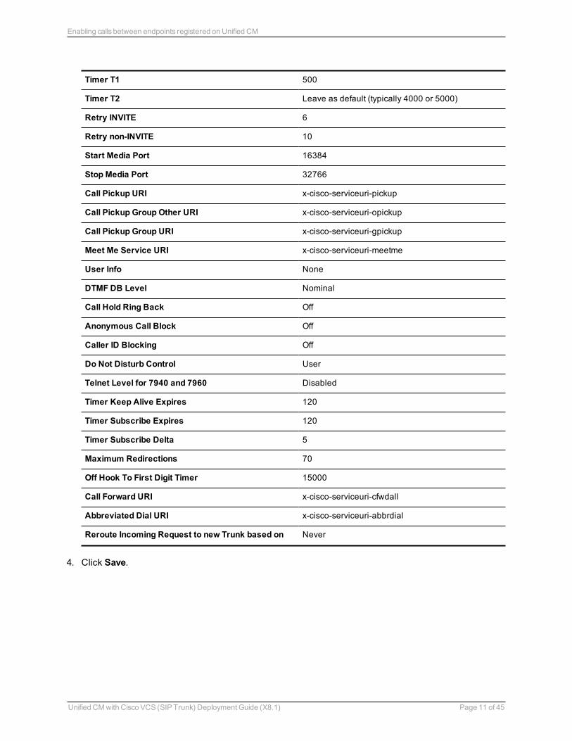
Timer T1 500
Timer T2 Leave as default (typically 4000 or 5000)
Retry INVITE 6
Retry non-INVITE 10
Start Media Port 16384
Stop Media Port 32766
Call Pickup URI x-cisco-serviceuri-pickup
Call Pickup Group Other URI x-cisco-serviceuri-opickup
Call Pickup Group URI x-cisco-serviceuri-gpickup
Meet Me Service URI x-cisco-serviceuri-meetme
User Info None
DTMF DB Level Nominal
Call Hold Ring Back Off
Anonymous Call Block Off
Caller ID Blocking Off
Do Not Disturb Control User
Telnet Level for 7940 and 7960 Disabled
Timer Keep Alive Expires 120
Timer Subscribe Expires 120
Timer Subscribe Delta 5
Maximum Redirections 70
Off Hook To First Digit Timer 15000
Call Forward URI x-cisco-serviceuri-cfwdall
Abbreviated Dial URI x-cisco-serviceuri-abbrdial
Reroute Incoming Request to new Trunk based on Never
4. Click Save.
Unified CM with Cisco VCS (SIP Trunk) Deployment Guide (X8.1) Page 11 of 45
Enabling calls between endpoints registered on Unified CM
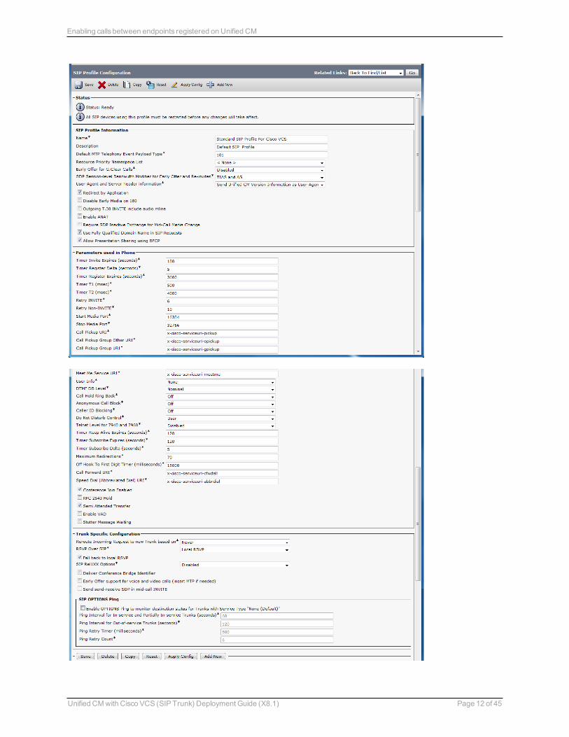
Unified CM with Cisco VCS (SIP Trunk) Deployment Guide (X8.1) Page 12 of 45
Enabling calls between endpoints registered on Unified CM
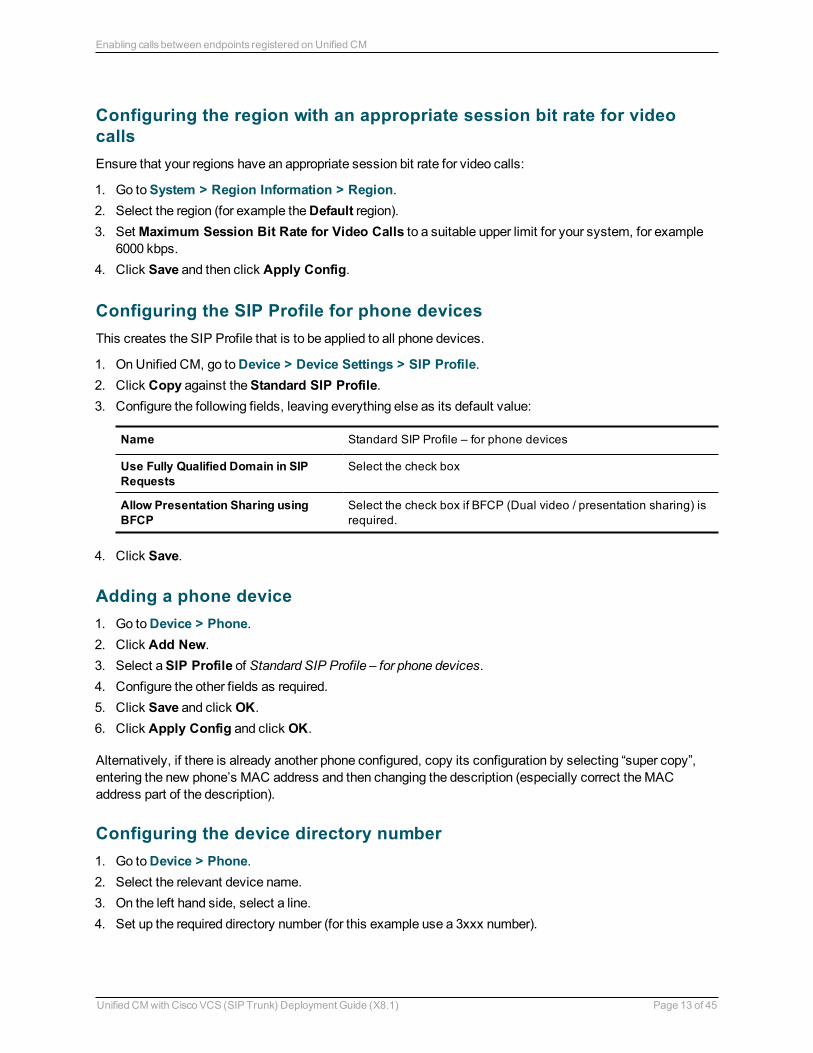
Configuring the region with an appropriate session bit rate for video callsEnsure that your regions have an appropriate session bit rate for video calls:
1. Go to System > Region Information > Region. 2. Select the region (for example the Default region). 3. Set Maximum Session Bit Rate for Video Calls to a suitable upper limit for your system, for example
6000 kbps. 4. Click Save and then click Apply Config.
Configuring the SIP Profile for phone devicesThis creates the SIP Profile that is to be applied to all phone devices.
1. On Unified CM, go to Device > Device Settings > SIP Profile. 2. Click Copy against the Standard SIP Profile. 3. Configure the following fields, leaving everything else as its default value:
Name Standard SIP Profile – for phone devices
Use Fully Qualified Domain in SIP Requests
Select the check box
Allow Presentation Sharing using BFCP
Select the check box if BFCP (Dual video / presentation sharing) is required.
4. Click Save.
Adding a phone device 1. Go to Device > Phone. 2. Click Add New. 3. Select a SIP Profile of Standard SIP Profile – for phone devices. 4. Configure the other fields as required. 5. Click Save and click OK. 6. Click Apply Config and click OK.
Alternatively, if there is already another phone configured, copy its configuration by selecting “super copy”, entering the new phone’s MAC address and then changing the description (especially correct the MAC address part of the description).
Configuring the device directory number 1. Go to Device > Phone. 2. Select the relevant device name. 3. On the left hand side, select a line. 4. Set up the required directory number (for this example use a 3xxx number).
Unified CM with Cisco VCS (SIP Trunk) Deployment Guide (X8.1) Page 13 of 45
Enabling calls between endpoints registered on Unified CM

Configuring phone endpoint to pick up its configuration from Unified CMCisco phones
1. Press the settings button. 2. Select the Network Configuration section, and check whether the TFTP Server is the IP address of
Unified CM. If not: a. Press the settings button twice – to return to SETTINGS menu. b. Select Unlock and enter the appropriate password. c. Select the Network Configuration section. d. Set Alternate TFTP = YES. e. Set TFTP Server = <IP address of Unified CM>. f. Select Accept. g. Select Save.
The phone should now indicate that Line 1 is the phone number specified on Unified CM (for example 3001).
EX60 / EX90 using TE6 software
Enter the relevant provisioning details:
n Select a Provisioning Mode of Cisco UCM. n Enter the Address of the provisioning manager.
Calls can now be made between handsets registered on Unified CM.
Confirming registrationsRegistration status of phones connected to Unified CM can be seen on the Device > Phone page.
Test callsMake some test calls by dialing the numbers of the registered phones (for example, 3001).
Unified CM with Cisco VCS (SIP Trunk) Deployment Guide (X8.1) Page 14 of 45
Enabling calls between endpoints registered on Unified CM
Enabling endpoints registered on VCS to call endpoints registered on Unified CM
Unified CM configurationConfiguration of Unified CM to enable calls to be made between devices that register to it can be broken down into 3 steps:
n Configuring the SIP Trunk security profile n Configuring the SIP Trunk device n Configuring the Cluster Fully Qualified Domain Name
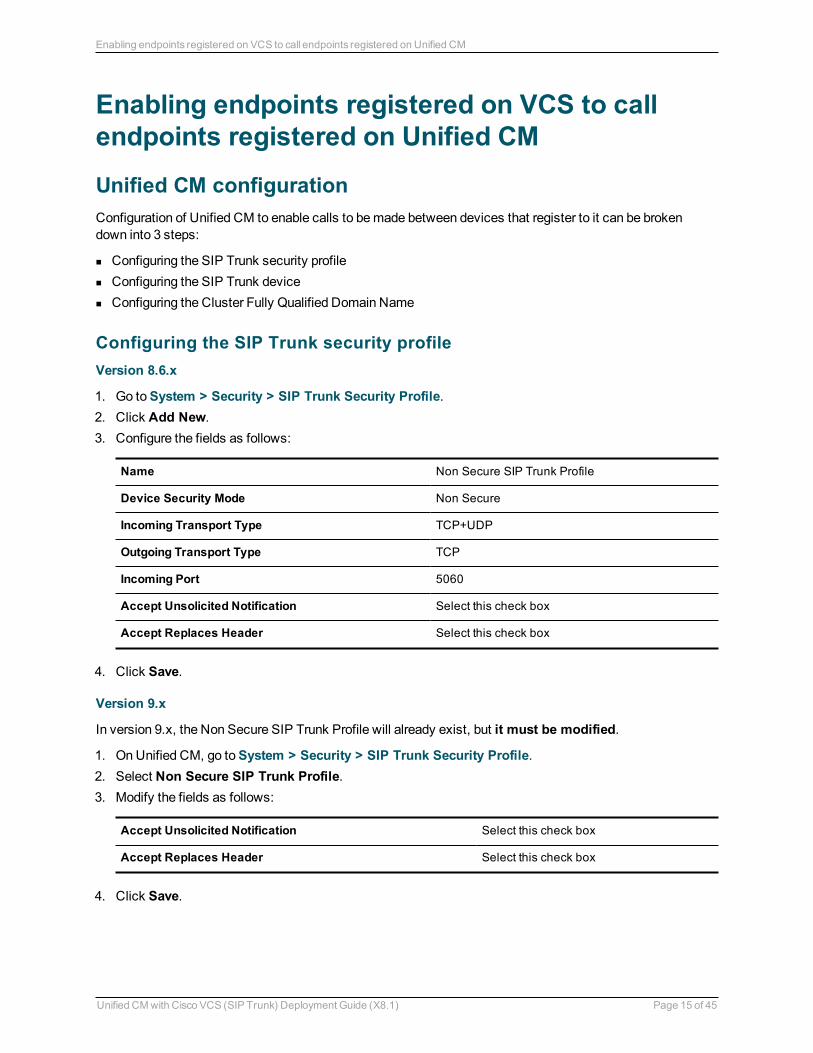
Configuring the SIP Trunk security profileVersion 8.6.x
1. Go to System > Security > SIP Trunk Security Profile. 2. Click Add New. 3. Configure the fields as follows:
Name Non Secure SIP Trunk Profile
Device Security Mode Non Secure
Incoming Transport Type TCP+UDP
Outgoing Transport Type TCP
Incoming Port 5060
Accept Unsolicited Notification Select this check box
Accept Replaces Header Select this check box
4. Click Save.
Version 9.x
In version 9.x, the Non Secure SIP Trunk Profile will already exist, but it must be modified.
1. On Unified CM, go to System > Security > SIP Trunk Security Profile. 2. Select Non Secure SIP Trunk Profile. 3. Modify the fields as follows:
Accept Unsolicited Notification Select this check box
Accept Replaces Header Select this check box
4. Click Save.
Unified CM with Cisco VCS (SIP Trunk) Deployment Guide (X8.1) Page 15 of 45
Enabling endpoints registered on VCS to call endpoints registered on Unified CM
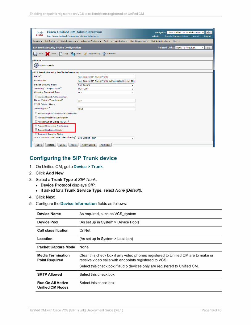
Configuring the SIP Trunk device 1. On Unified CM, go to Device > Trunk. 2. Click Add New. 3. Select a Trunk Type of SIP Trunk.
l Device Protocol displays SIP. l If asked for a Trunk Service Type, select None (Default).
4. Click Next. 5. Configure the Device Information fields as follows:
Device Name As required, such as VCS_system
Device Pool (As set up in System > Device Pool)
Call classification OnNet
Location (As set up in System > Location)
Packet Capture Mode None
Media Termination Point Required
Clear this check box if any video phones registered to Unified CM are to make or receive video calls with endpoints registered to VCS.
Select this check box if audio devices only are registered to Unified CM.
SRTP Allowed Select this check box
Run On All Active Unified CM Nodes
Select this check box
Unified CM with Cisco VCS (SIP Trunk) Deployment Guide (X8.1) Page 16 of 45
Enabling endpoints registered on VCS to call endpoints registered on Unified CM
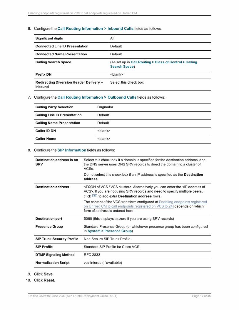
6. Configure the Call Routing Information > Inbound Calls fields as follows:
Significant digits All
Connected Line ID Presentation Default
Connected Name Presentation Default
Calling Search Space (As set up in Call Routing > Class of Control > Calling Search Space)
Prefix DN <blank>
Redirecting Diversion Header Delivery – Inbound
Select this check box
7. Configure the Call Routing Information > Outbound Calls fields as follows:
Calling Party Selection Originator
Calling Line ID Presentation Default
Calling Name Presentation Default
Caller ID DN <blank>
Caller Name <blank>
8. Configure the SIP Information fields as follows:
Destination address is an SRV
Select this check box if a domain is specified for the destination address, and the DNS server uses DNS SRV records to direct the domain to a cluster of VCSs.
Do not select this check box if an IP address is specified as the Destination address.
Destination address <FQDN of VCS / VCS cluster>. Alternatively you can enter the <IP address of VCS>. If you are not using SRV records and need to specify multiple peers, click to add extra Destination address rows.The content of the VCS transform configured at Enabling endpoints registered on Unified CM to call endpoints registered on VCS [p.24] depends on which form of address is entered here.
Destination port 5060 (this displays as zero if you are using SRV records)
Presence Group Standard Presence Group (or whichever presence group has been configured in System > Presence Group)
SIP Trunk Security Profile Non Secure SIP Trunk Profile
SIP Profile Standard SIP Profile for Cisco VCS
DTMF Signaling Method RFC 2833
Normalization Script vcs-interop (if available)
9. Click Save. 10. Click Reset.
Unified CM with Cisco VCS (SIP Trunk) Deployment Guide (X8.1) Page 17 of 45
Enabling endpoints registered on VCS to call endpoints registered on Unified CM
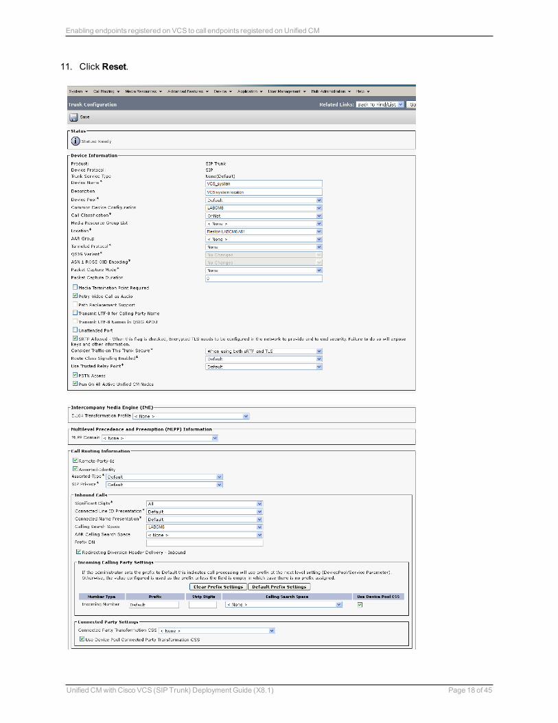
11. Click Reset.
Unified CM with Cisco VCS (SIP Trunk) Deployment Guide (X8.1) Page 18 of 45
Enabling endpoints registered on VCS to call endpoints registered on Unified CM

Configuring the Cluster Fully Qualified Domain NameUnified CM must be configured with a Cluster Fully Qualified Domain Name so that it can receive calls to addresses in the format <address>@domain. (It is also required when Unified CM is clustered so that VCS can send the call to any Unified CM node.)
1. Go to System > Enterprise parameters, and find the Clusterwide Domain Configuration section. 2. Set the Cluster Fully Qualified Domain Name to the same domain as the video network, for example
vcs.domain.This parameter defines one or more Fully Qualified Domain Names (FQDNs) for this cluster. Multiple FQDNs must be separated by a space. Requests containing URLs (for example, SIP calls) whose host portion matches any of the FQDNs in this parameter will be recognized as a request destined for this cluster and/or devices attached to it.
3. Click Save.
Unified CM with Cisco VCS (SIP Trunk) Deployment Guide (X8.1) Page 19 of 45
Enabling endpoints registered on VCS to call endpoints registered on Unified CM

VCS Control configurationThe configuration of the VCS Control has 3 steps:
n Configuring a neighbor zone that contains the Unified CM n Configuring a search rule to route calls to that zone n Configuring a transform that converts number@<IP address of cucm> to [email protected]
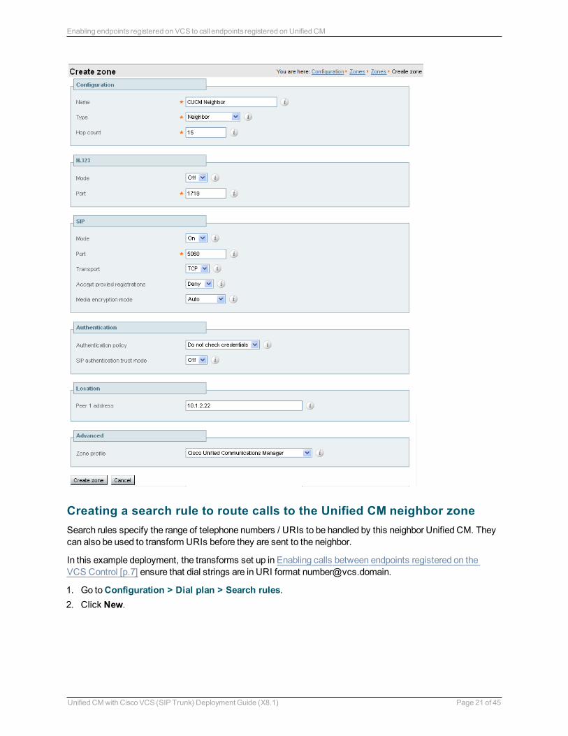
Creating a neighbor zone for Unified CM 1. Go to Configuration > Zones > Zones. 2. Click New. 3. Configure the fields as follows:
Name CUCM Neighbor
Type Neighbor
Hop count 15
H.323 mode Off (H.323 access is not required for communication with Unified CM)
SIP mode On
SIP port 5060 (if the SIP access port on Unified CM is not 5060, change the SIP Port value to be the same as used by Unified CM)
Transport TCP
Accept proxied registrations
Deny
Media encryption mode Auto
Authentication policy Configure the authentication settings according to your authentication policy.
SIP authentication trust mode
Off
Peer 1 address IP address of Unified CM, or the FQDN of Unified CM.
If you are planning to ultimately use a TLS connection, then typically you will need to specify the FQDN of Unified CM here as this is the name that will be used to authenticate the certificate presented by Unified CM.
Zone profile (Advanced section)
Select Cisco Unified Communications Manager or Cisco Unified Communications Manager (8.6.1 or later) as appropriate. Note that Unified CM 8.6.1 or later is required for BFCP (dual video / presentation sharing).
This configures the VCS to use SIP over TCP to communicate with the Unified CM. To use TLS, complete the configuration as described here for TCP and then see Connecting VCS to Unified CM using TLS [p.27].
4. Click Create zone.
Unified CM with Cisco VCS (SIP Trunk) Deployment Guide (X8.1) Page 20 of 45
Enabling endpoints registered on VCS to call endpoints registered on Unified CM
Creating a search rule to route calls to the Unified CM neighbor zoneSearch rules specify the range of telephone numbers / URIs to be handled by this neighbor Unified CM. They can also be used to transform URIs before they are sent to the neighbor.
In this example deployment, the transforms set up in Enabling calls between endpoints registered on the VCS Control [p.7] ensure that dial strings are in URI format [email protected].
1. Go to Configuration > Dial plan > Search rules. 2. Click New.
Unified CM with Cisco VCS (SIP Trunk) Deployment Guide (X8.1) Page 21 of 45
Enabling endpoints registered on VCS to call endpoints registered on Unified CM
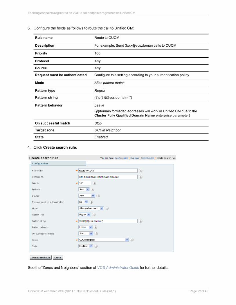
3. Configure the fields as follows to route the call to Unified CM:
Rule name Route to CUCM
Description For example: Send [email protected] calls to CUCM
Priority 100
Protocol Any
Source Any
Request must be authenticated Configure this setting according to your authentication policy
Mode Alias pattern match
Pattern type Regex
Pattern string (3\d{3})@vcs.domain(.*)
Pattern behavior Leave
(@domain formatted addresses will work in Unified CM due to the Cluster Fully Qualified Domain Name enterprise parameter)
On successful match Stop
Target zone CUCM Neighbor
State Enabled
4. Click Create search rule.
See the “Zones and Neighbors” section of VCS Administrator Guide for further details.
Unified CM with Cisco VCS (SIP Trunk) Deployment Guide (X8.1) Page 22 of 45
Enabling endpoints registered on VCS to call endpoints registered on Unified CM
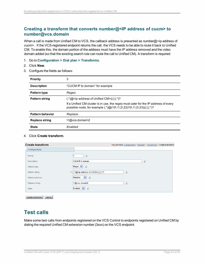
Creating a transform that converts number@<IP address of cucm> to [email protected] a call is made from Unified CM to VCS, the callback address is presented as number@<ip address of cucm>. If the VCS-registered endpoint returns the call, the VCS needs to be able to route it back to Unified CM. To enable this, the domain portion of the address must have the IP address removed and the video domain added (so that the existing search rule can route the call to Unified CM). A transform is required:
1. Go to Configuration > Dial plan > Transforms. 2. Click New. 3. Configure the fields as follows:
Priority 3
Description “CUCM IP to domain” for example
Pattern type Regex
Pattern string (.*)@<ip address of Unified CM>((:|;).*)?
If a Unified CM cluster is in use, the regex must cater for the IP address of every possible node, for example (.*)@(10\.1\.2\.22|10\.1\.2\.23)((:|;).*)?
Pattern behavior Replace
Replace string \[email protected]\2
State Enabled
4. Click Create transform.
Test callsMake some test calls from endpoints registered on the VCS Control to endpoints registered on Unified CM by dialing the required Unified CM extension number (3xxx) on the VCS endpoint.
Unified CM with Cisco VCS (SIP Trunk) Deployment Guide (X8.1) Page 23 of 45
Enabling endpoints registered on VCS to call endpoints registered on Unified CM
Enabling endpoints registered on Unified CM to call endpoints registered on VCS
VCS Control configuration
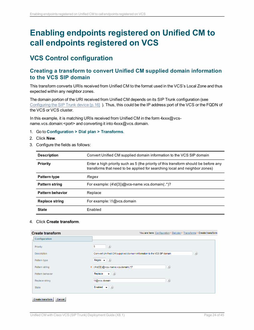
Creating a transform to convert Unified CM supplied domain information to the VCS SIP domainThis transform converts URIs received from Unified CM to the format used in the VCS’s Local Zone and thus expected within any neighbor zones.
The domain portion of the URI received from Unified CM depends on its SIP Trunk configuration (see Configuring the SIP Trunk device [p.16] ). Thus, this could be the IP address:port of the VCS or the FQDN of the VCS or VCS cluster.
In this example, it is matching URIs received from Unified CM in the form [email protected]:<port> and converting it into [email protected].
1. Go to Configuration > Dial plan > Transforms. 2. Click New. 3. Configure the fields as follows:
Description Convert Unified CM supplied domain information to the VCS SIP domain
Priority Enter a high priority such as 5 (the priority of this transform should be before any transforms that need to be applied for searching local and neighbor zones)
Pattern type Regex
Pattern string For example: (4\d{3})@vcs-name.vcs.domain(:.*)?
Pattern behavior Replace
Replace string For example: \[email protected]
State Enabled
4. Click Create transform.
Unified CM with Cisco VCS (SIP Trunk) Deployment Guide (X8.1) Page 24 of 45
Enabling endpoints registered on Unified CM to call endpoints registered on VCS
Unified CM configuration
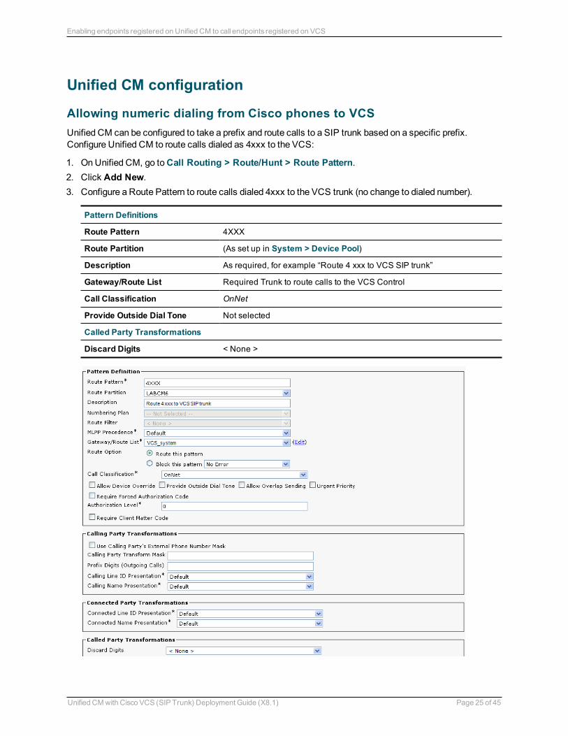
Allowing numeric dialing from Cisco phones to VCSUnified CM can be configured to take a prefix and route calls to a SIP trunk based on a specific prefix. Configure Unified CM to route calls dialed as 4xxx to the VCS:
1. On Unified CM, go to Call Routing > Route/Hunt > Route Pattern. 2. Click Add New. 3. Configure a Route Pattern to route calls dialed 4xxx to the VCS trunk (no change to dialed number).
Pattern Definitions
Route Pattern 4XXX
Route Partition (As set up in System > Device Pool)
Description As required, for example “Route 4 xxx to VCS SIP trunk”
Gateway/Route List Required Trunk to route calls to the VCS Control
Call Classification OnNet
Provide Outside Dial Tone Not selected
Called Party Transformations
Discard Digits < None >
Unified CM with Cisco VCS (SIP Trunk) Deployment Guide (X8.1) Page 25 of 45
Enabling endpoints registered on Unified CM to call endpoints registered on VCS
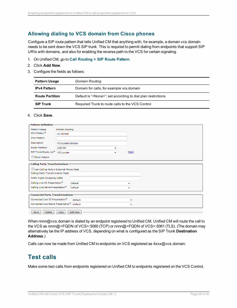
Allowing dialing to VCS domain from Cisco phonesConfigure a SIP route pattern that tells Unified CM that anything with, for example, a domain vcs.domain needs to be sent down the VCS SIP trunk. This is required to permit dialing from endpoints that support SIP URIs with domains, and also for enabling the reverse path to the VCS for certain signaling.
1. On Unified CM, go to Call Routing > SIP Route Pattern. 2. Click Add New. 3. Configure the fields as follows:
Pattern Usage Domain Routing
IPv4 Pattern Domain for calls, for example vcs.domain
Route Partition Default is “<None>”; set according to dial plan restrictions
SIP Trunk Required Trunk to route calls to the VCS Control
4. Click Save.
When [email protected] is dialed by an endpoint registered to Unified CM, Unified CM will route the call to the VCS as nnnn@<FQDN of VCS>:5060 (TCP) or nnnn@<FQDN of VCS>:5061 (TLS). (The domain may alternatively be the IP address of VCS, depending on what is configured as the SIP Trunk Destination Address.)
Calls can now be made from Unified CM to endpoints on VCS registered as [email protected].
Test callsMake some test calls from endpoints registered on Unified CM to endpoints registered on the VCS Control.
Unified CM with Cisco VCS (SIP Trunk) Deployment Guide (X8.1) Page 26 of 45
Enabling endpoints registered on Unified CM to call endpoints registered on VCS
Connecting VCS to Unified CM using TLSThese instructions explain how to take a system that is already configured and working using a TCP interconnection between VCS and Unified CM, and to convert that connection to use TLS instead. This process involves:
n Ensuring certificate trust between Unified CM and VCS n Configuring a SIP trunk security profile on Unified CM n Updating the Unified CM trunk to VCS to use TLS n Updating the VCS neighbor zone to Unified CM to use TLS
Ensuring certificate trust between Unified CM and VCSFor Unified CM and VCS to establish a TLS connection with each other:
n VCS and Unified CM must both have valid server certificates loaded n Unified CM must trust VCS’s server certificate (the root CA of the VCS server certificate must be loaded
onto Unified CM) n VCS must trust Unified CM’s server certificate (the root CA of the Unified CM server certificate must be
loaded onto VCS)
See VCS Certificate Creation and Use Deployment Guide for full details about loading certificates and how to generate CSRs on VCS to acquire certificates from a Certificate Authority (CA).
Note that in a clustered environment, you must install CA and server certificates on each peer/node individually.
We strongly recommend that you do not use self-signed certificates in a production environment.
Loading server and trust certificates on Unified CMCertificate management is performed in the Cisco Unified OS Administration application.
All existing certificates are listed under Security > Certificate Management. Server certificates are of type certs and trusted CA certificates are of type trust-certs.
Unified CM server certificate
By default, Unified CM has a self-signed server certificate CallManager.pem installed . We recommend that this is replaced with a certificate generated from a trusted certificate authority.
Unified CM trusted CA certificate
To load the root CA certificate of the authority that issued the VCS certificate (if it is not already loaded):
1. Click Upload Certificate/Certificate chain. 2. Select a Certificate Name of CallManager-trust. 3. Click Browse and select the file containing the root CA certificate of the authority that issued the VCS
certificate. 4. Click Upload File.
Repeat this process on every Unified CM server that will communicate with VCS. Typically this is every node that is running the CallManager service.
Unified CM with Cisco VCS (SIP Trunk) Deployment Guide (X8.1) Page 27 of 45
Connecting VCS to Unified CM using TLS
Loading server and trust certificates on VCSVCS server certificate
VCS has only one server certificate. By default, this is a self-signed certificate. We recommend that it is replaced by a certificate generated by a trusted certificate authority.
To upload a server certificate:
1. Go to Maintenance > Security certificates > Server certificate. 2. Use the Browse button to select and upload the server certificate PEM file. 3. If you used an external system to generate the certificate request you must also upload the server private
key PEM file that was used to encrypt the server certificate. (The private key file will have been automatically generated and stored earlier if the VCS was used to produce the signing request for this server certificate.) l The server private key must not be password protected. l You cannot upload a server private key if a certificate signing request is in progress.
4. Click Upload server certificate data.
VCS trusted CA certificate
The Trusted CA certificate page (Maintenance > Security certificates > Trusted CA certificate) allows you to manage the list of certificates for the Certificate Authorities (CAs) trusted by this VCS. Certificates presented to the VCS must be signed by a trusted CA on this list and there must be a full chain of trust (intermediate CAs) to the root CA.
The root CA of the Unified CM server certificate must be loaded into the VCS's trusted CA certificate list.
To upload a new file of CA certificates, Browse to the required PEM file and click Append CA certificate. This will append any new certificates to the existing list of CA certificates. Note that if you are replacing existing certificates for a particular issuer and subject, you have to manually delete the previous certificates.
Repeat this process on every VCS that will communicate with Unified CM.
Configuring a SIP trunk security profile on Unified CMOn Unified CM:
1. Select Cisco Unified CM Administration, click Go and log in. 2. Go to System > Security > SIP Trunk Security Profile. 3. Click Add New. 4. Configure the fields as follows:
Name A name indicating that this is an encrypted profile.
Description Enter a textual description as required.
Device Security Mode Encrypted.
Incoming Transport Type TLS.
Outgoing Transport Type TLS.
Unified CM with Cisco VCS (SIP Trunk) Deployment Guide (X8.1) Page 28 of 45
Connecting VCS to Unified CM using TLS
Enable Digest Authentication
Leave unselected.
X.509 Subject Name The subject name or an subject alternate name provided by the VCS in its certificate. For VCS clusters, ensure that this list includes all of the names contained within all of the peers' certificates. To specify multiple X.509 names, separate each name by a space, comma, semicolon or colon.
Incoming Port 5061
Accept Unsolicited Notification
Select this check box
Accept Replaces Header Select this check box
Other parameters Leave all other parameters unselected.
5. Click Save.
Updating the Unified CM trunk to VCS to use TLSOn Unified CM:
1. Go to Device > Trunk. 2. Using Find, select the Device Name previously set up for the trunk to the VCS. 3. Configure the following fields:
SIP Information section
Destination Port
5061 (unless using DNS SRV, in which case ensure the SRV records are set up correctly).
Note that some versions of Unified CM cannot perform TLS SRV lookups. See TLS calls fail when Unified CM uses SRV trunk destinations [p.35] for more information.
SIP Trunk Security Profile
Select the trunk profile set up above.
Leave other parameters as previously configured. 4. Click Save. 5. Click Reset.
Updating the VCS neighbor zone to Unified CM to use TLSNote that VCS will report that the Unified CM zone is active even while it is communicating with Unified CM over TCP. The changes below are necessary to enable communications over TLS.
On VCS:
1. Go to Configuration > Zones > Zones, then select the zone to Unified CM. 2. Configure the following fields:
Unified CM with Cisco VCS (SIP Trunk) Deployment Guide (X8.1) Page 29 of 45
Connecting VCS to Unified CM using TLS
SIP section
Port 5061
Transport TLS
TLS verify mode On
Authentication trust mode Off
Leave other parameters as previously configured. 3. Click Save.
Verifying that the TLS connection is operationalTo verify correct TLS operation, check that the VCS zone reports its status as active and then make some test calls.
1. Check the VCS zone is active: a. Go to Configuration > Zones > Zones. b. Check the SIP status of the zone.If the zone is not active, try resetting or restarting the trunk again on Unified CM.
2. Make a test call from a VCS registered endpoint to a Unified CM phone. 3. Make a test call from a Unified CM phone to a VCS registered endpoint.
Network of VCSsIf there is a network of VCSs behind this VCS neighbored to Unified CM, then, either:
n Unified CM must trust the certificates of all the VCSs in the network ('optimal' routing mode), or n The VCS neighbor zone to Unified CM must ‘always’ route the signaling. In effect this sets up this VCS as
a gateway to Unified CM, and is the preferred option. The Cisco Unified Communications Manager and Cisco Unified Communications Manager (8.6.1 or later) zone profiles are pre-configured to ‘always’ route the signaling, thus no additional configuration is required providing one of these profiles is used.
Encrypted calls to endpoints registered to Unified CMEndpoints registered to Unified CM need to be configured with a “SIP Secure profile” to provide encrypted media and call negotiation. If such a profile is not available by default, it will need to be created via System > Security > Phone Security.
See Securing Cisco TelePresence Products for further information on using the Cisco CTL Client and configuring Unified CM for secure communications.
Unified CM with Cisco VCS (SIP Trunk) Deployment Guide (X8.1) Page 30 of 45
Connecting VCS to Unified CM using TLS
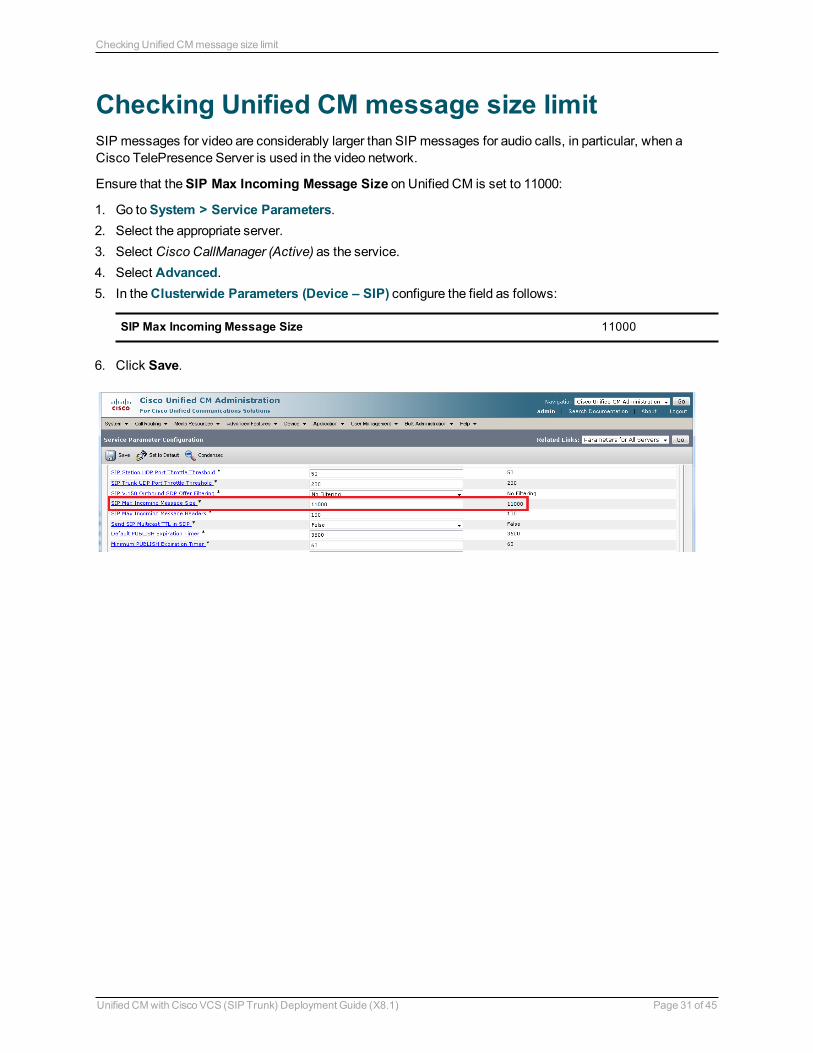
Checking Unified CM message size limitSIP messages for video are considerably larger than SIP messages for audio calls, in particular, when a Cisco TelePresence Server is used in the video network.
Ensure that the SIP Max Incoming Message Size on Unified CM is set to 11000:
1. Go to System > Service Parameters. 2. Select the appropriate server. 3. Select Cisco CallManager (Active) as the service. 4. Select Advanced. 5. In the Clusterwide Parameters (Device – SIP) configure the field as follows:
SIP Max Incoming Message Size 11000
6. Click Save.
Unified CM with Cisco VCS (SIP Trunk) Deployment Guide (X8.1) Page 31 of 45
Checking Unified CM message size limit
Appendix 1: Troubleshooting
Problems connecting VCS Control local calls
Look at “Search history” to check the applied transformsSearch history entries report on any searches initiated from a SETUP/ARQ /LRQ in H323 and from an INVITE/OPTIONS in SIP.
1. Go to Status > Search history.The summary shows the source and destination call aliases, and whether the destination alias was found.
2. Select the relevant search attempt.
The search history for that search attempt shows:
n the incoming call’s details n any transforms applied by admin or user policy or CPL n and in priority order, zones which matched the required (transformed) destination, reporting on:
l any transforms the zone may apply l found or not found status l if not found, the error code as seen in the zone’s search response l repeated until a zone is found that can accept the call, or all zone matches have been attempted
(the search may be “not found” due to lack of bandwidth or because the search from the zone resulted in an H.323 rejection reason or a non 2xx response to a SIP request)
If the search indicates:
n Found: False n Reason: 480 Temporarily Not Available
this could be because the VCS zone links are not correctly set up. From the command line execute xcommand DefaultLinksAdd to set up the required links for the VCS's default zones; also check the links for other zones that have been created.
Note that each H.323 call will have two entries in the search history:
n The first for an ARQ to see if the endpoint can be found. n The second for the Setup to actually route the call.
The ARQ search does not depend on links or link bandwidth, and so if links do not exist or link bandwidth is insufficient it may still pass, even though the Setup search will subsequently fail.
Each SIP call will usually have only a single search history entry for the SIP INVITE.
Look at call history to check how the call progressed 1. Go to Status > Calls > History.
The summary shows the source and destination call aliases, call duration and protocol (including any interworking).
2. Select the relevant call attempt and then the relevant call components.This shows the incoming and outgoing call leg details and the zone and subzone routing.
Unified CM with Cisco VCS (SIP Trunk) Deployment Guide (X8.1) Page 32 of 45
Appendix 1: Troubleshooting
Check for errorsCheck the Event Log which is accessible from the web browser: Status > Logs > Event Log.
Tracing callsTracing calls at SIP / H.323 level in VCS
1. Go to Maintenance > Diagnostics > Diagnostic logging. 2. Optionally, select Take tcpdump while logging. 3. Click Start new log. 4. (Optional) Enter some Marker text and click Add marker.
l The marker facility can be used to add comment text to the log file before certain activities are performed. This helps to subsequently identify the relevant sections in the downloaded diagnostic log file.
l You can add as many markers as required, at any time while the diagnostic logging is in progress. l Marker text is added to the log with a "DEBUG_MARKER" tag.
5. Reproduce the system issue you want to trace in the diagnostic log. 6. Click Stop logging. 7. Click Download log to save the diagnostic log to your local file system. You are prompted to save the file
(the exact wording depends on your browser). 8. If appropriate, click Download tcpdump to also download the tcpdump file to your local file system.
Call failures with Cisco TelePresence ServerSIP messages from Cisco TelePresence Server can be > 5,000 bytes (which is the default SIP Max Incoming Message Size configured in Unified CM).
Increase the SIP Max Incoming Message Size – see Checking Unified CM message size limit [p.31].
In-call problems
Calls clear down when a call transfer from a video phone on Unified CM transfers a call to VCSEven if use of a media termination point (MTP) is not requested on the SIP trunk between Unified CM and VCS, if DTMF signaling method is configured as “No preference” on the SIP trunk on Unified CM, Unified CM will try and use a Media Transfer Point and the call will fail.
To resolve this, ensure that DTMF signaling method is configured as RFC 2833 on Unified CM on the SIP trunk from Unified CM to VCS.
Failure to join a Unified CM endpoint to a conference using MultiwayEnsure that your network is set up as described in Appendix 5: Multiway and Unified CM [p.42].
Unified CM with Cisco VCS (SIP Trunk) Deployment Guide (X8.1) Page 33 of 45
Appendix 1: Troubleshooting
Poor video quality from Unified CMEnsure that your Unified CM region has an appropriate session bit rate for video calls as described in Configuring the region with an appropriate session bit rate for video calls [p.13].
Taking a trace on Unified CM using RTMTRTMT is a tool that lets you monitor system health, view graphs and collect logs from Unified CM. There are versions for both Linux and Windows. Unified CM must also be configured to specify what can be traced.
Configure Unified CM to enable tracing 1. Log in to Unified CM. 2. In the Navigation drop-down select Cisco Unified Serviceability and click Go. 3. Go to the Troubleshooting Trace Settings page (Trace > Troubleshooting Trace Settings). 4. Select the Check All Services check box. 5. Click Save.
Installing RTMT – Real Time Monitoring Tool 1. Log in to Unified CM using a Linux or Windows PC. 2. Go to Application > Plugins. 3. Select Find with ‘Name begins with <blank>’ and ‘Plugin Type equals Installation’. 4. Scroll down to the entry for ‘Cisco Unified CM Real-Time Monitoring Tool – Linux’ or ‘Cisco Unified CM
Real-Time Monitoring Tool – Windows’, as required. 5. Click on the Download link. 6. When downloaded, run the downloaded install file. 7. Follow the instructions in the install wizard. 8. When complete, click Done to exit the installer.
Running RTMT 1. Run RTMT. (For example, under windows this is in Start > All Programs > Cisco > CallManager
Serviceability > Real-Time Monitoring Tool.) 2. In the Login window enter the Host IP Address, User Name and Password. 3. Click OK.
Taking a trace using RTMT 1. Select Trace & Log Central. 2. Double-click on Real Time Trace. 3. Double-click View Real Time Data. 4. Select a Node – the Unified CM instance that is to have the trace run on it. 5. Click Next >.
Unified CM with Cisco VCS (SIP Trunk) Deployment Guide (X8.1) Page 34 of 45
Appendix 1: Troubleshooting
6. Select the following: l Products = UCM l Services = Cisco CallManager l Trace File Type = sdi
7. Click Finish.
Note that:
n Logs can take a while to download. n The sdi (System Diagnostic Interface) trace contains alarms, error information and SIP stack trace
information.
Call failures
TLS calls fail when Unified CM uses SRV trunk destinationsCalls from Unified CM may fail if they use a TLS trunk security profile and SRV trunk destinations (requiring "_sips._tcp" SRV record lookups in DNS).
See bug CSCue37440 in the Cisco Bug Search Tool for up-to-date information regarding the versions of Unified CM in which this issue has been fixed.
If you need to address one or more VCS peers you can work around this problem by not using SRV records. Instead, in the SIP trunk, specify each VCS Destination Address individually using DNS A-records or static IP addresses. However, note that these addresses affect the domain portion of the URI received by VCS from Unified CM. You may need to set up appropriate transforms on the VCS to cater for this (see Creating a transform to convert Unified CM supplied domain information to the VCS SIP domain [p.24]).
Encrypted call failuresCalls between endpoints registered to Unified CM and endpoints registered to VCS (or proxied via VCS) will fail if the Unified CM endpoint requests best effort encryption and the other endpoint does not support encryption. (Unified CM has a proprietary method for indicating fall back to no encryption - X-cisco-srtp-fallback – which VCS currently does not support.)
Unified CM with Cisco VCS (SIP Trunk) Deployment Guide (X8.1) Page 35 of 45
Appendix 1: Troubleshooting
Appendix 2: Known interworking capabilities and limitations
Capabilities
SIP and H.323 endpoints making basic calls n SIP and H.323 endpoints can make calls via the VCS to endpoints registered to Unified CM. n Endpoints registered to Unified CM can make calls to SIP and H.323 endpoints on the VCS.
Limitations
Cisco TelePresence ConductorWhen VCS is configured to work with TelePresence Conductor, calls made from Unified CM over the SIP trunk may initiate or join conferences controlled by TelePresence Conductor. When there is a Cisco TelePresence System (CTS) Series endpoint registered to the Unified CM, the VCS is connected to the TelePresence Conductor’s back-to-back user agent and the conference is hosted on a TelePresence Server, encrypted calls made from the CTS will drop when the SIP session is refreshed. In this scenario we recommend that you create a SIP trunk directly from the Unified CM to the TelePresence Conductor as detailed in Optimized Conferencing for Cisco Unified Communications Manager Solution Guide.
E20 encryptionIf E20 has Encryption Mode = Best Effort then calls from Unified CM clear when E20 answers them. Set Encryption Mode = Off.
T150 running L6.0 codeIf a SIP call is made from a T150 running L6.0 code to Unified CM 8.0 (and earlier), Unified CM does not handle the UPDATE message that the T150 sends immediately after the call is answered, and so on call answer the call is cleared down immediately.
If xConfiguration Conference H239 is set to Off then no BFCP is offered and Unified CM handles the UPDATE from the T150 and the call completes as desired.
H.323 MXP and 9971When an MXP registered to VCS is in a call with a 9971 registered to Unified CM and the MXP call is H.323, the video on the MXP will be CIF (small picture) rather than VGA (full size picture). (Seen on MXP F9.0 and 9971 version 9.0.2)
If the MXP call is SIP, a full size picture will be seen.
Unified CM with Cisco VCS (SIP Trunk) Deployment Guide (X8.1) Page 36 of 45
Appendix 2: Known interworking capabilities and limitations
Appendix 3: Connecting Unified CM to a VCS clusterFrom Unified CM version 8.5, to connect Unified CM with a cluster of VCS peers there are 2 methods of providing Unified CM with the addresses of the VCS cluster peers:
n the trunk to VCS specifies the DNS SRV address for the VCS cluster n the trunk to VCS specifies a list of VCS peers
Prior to Unified CM 8.5, the trunk to VCS had to specify the DNS SRV address for the VCS cluster.
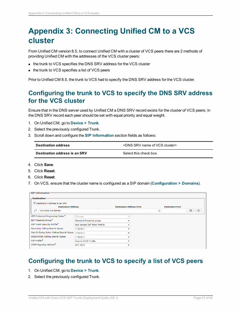
Configuring the trunk to VCS to specify the DNS SRV address for the VCS clusterEnsure that in the DNS server used by Unified CM a DNS SRV record exists for the cluster of VCS peers; in the DNS SRV record each peer should be set with equal priority and equal weight.
1. On Unified CM, go to Device > Trunk. 2. Select the previously configured Trunk. 3. Scroll down and configure the SIP Information section fields as follows:
Destination address <DNS SRV name of VCS cluster>
Destination address is an SRV Select this check box.
4. Click Save. 5. Click Reset. 6. Click Reset. 7. On VCS, ensure that the cluster name is configured as a SIP domain (Configuration > Domains).
Configuring the trunk to VCS to specify a list of VCS peers 1. On Unified CM, go to Device > Trunk. 2. Select the previously configured Trunk.
Unified CM with Cisco VCS (SIP Trunk) Deployment Guide (X8.1) Page 37 of 45
Appendix 3: Connecting Unified CM to a VCS cluster

3. Scroll down and configure the SIP Information fields as follows:(Click + to obtain additional destination address entries.)
Destination address is an SRV Ensure that this check box is not selected
Destination address 1 and
Destination port 1IP address or DNS name of VCS peer 1
5060 or 5061 depending on connectivity (TCP/TLS)
Destination address 2 and
Destination port 2IP address or DNS name of VCS peer 2
5060 or 5061 depending on connectivity (TCP/TLS)
Destination address 3 and
Destination port 3IP address or DNS name of VCS peer 3 – if it exists
5060 or 5061 depending on connectivity (TCP/TLS)
... up to Destination address 6 and
Destination port 6... repeat up to IP address or DNS name of VCS peer 6 – where they exist
4. Click Save. 5. Click Reset. 6. Click Reset.
Unified CM with Cisco VCS (SIP Trunk) Deployment Guide (X8.1) Page 38 of 45
Appendix 3: Connecting Unified CM to a VCS cluster
Appendix 4: Connecting VCS to a cluster of Unified CM nodesWhen connecting VCS to a cluster of Unified CM nodes, VCS needs to be able to route calls to each Unified CM node.
This can be done in 2 ways, in order of preference:
1. With a single neighbor zone in VCS with the Unified CM nodes listed as location peer addresses. This option is only available from VCS X7.0 or later.
2. By using DNS SRV records and a VCS DNS zone.
Note that both options ensure that the VCS to Unified CM call load is shared across Unified CM nodes.
Option 1: Using a single neighbor zone
Unified CM configurationWhen in a cluster, Unified CM needs to accept calls routed to number@domain (instead of number@<ip address of Unified CM>) so that VCS can send the call to any Unified CM node without having to make sure that the domain portion matches the IP address of the node that the call is being sent to.
Ensure that the Cluster Fully Qualified Domain Name (System > Enterprise parameters, in the Clusterwide Domain Configuration section) is set to the same domain as the video network, for example vcs.domain.
VCS Control configurationThe VCS configuration requires an update to the neighbor zone:
1. Go to Configuration > Zones. 2. Select the Unified CM neighbor zone. 3. Configure the fields as follows:
Peer 1 address IP address of Unified CM node 1, or the domain of Unified CM node 1.
Peer 2 address IP address or the domain of Unified CM node 2.
Peer 3 address IP address or the domain of Unified CM node 3, or blank if no Unified CM node 3.
.... up to Peer 6 address
... repeat up to the IP address or the domain of Unified CM node 6, or leaving it blank if there is no Unified CM node.
Option 2: Using a DNS zone
Unified CM configurationEnsure that the Cluster Fully Qualified Domain Name (System > Enterprise parameters, in the Clusterwide Domain Configuration section) is set to the same domain as the video network, for example vcs.domain.
Unified CM with Cisco VCS (SIP Trunk) Deployment Guide (X8.1) Page 39 of 45
Appendix 4: Connecting VCS to a cluster of Unified CM nodes
DNS server configurationConfigure the DNS server (that is used by the VCS) with DNS SRV records for the Unified CM cluster.
n _sips._tcp.fqdn_of_cucm_clusterrecords for TLS connectivity (one record for each Unified CM node); or n _sip._tcp.fqdn_of_cucm_clusterrecords for TCP connectivity (one record for each Unified CM node)
VCS Control configurationVCS configuration requires 3 steps:
n Create a Unified CM DNS zone n Adjust search rule to use the DNS zone n Delete the old Unified CM neighbor zone
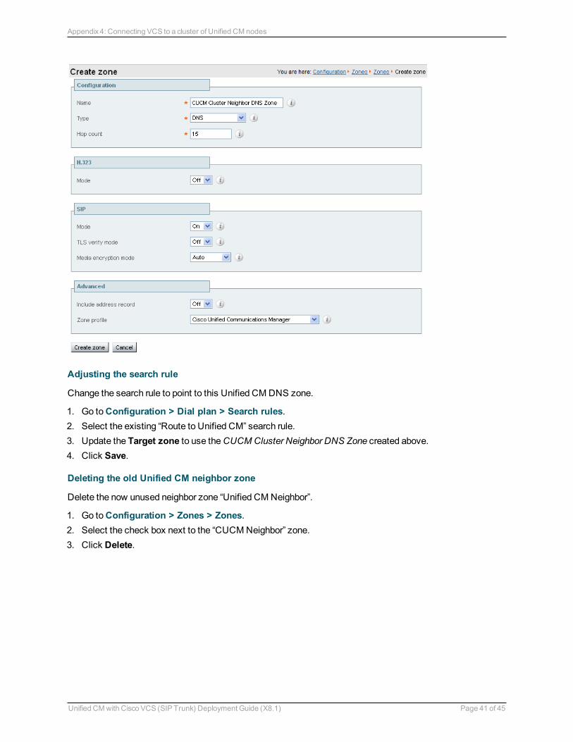
Creating a Unified CM DNS zone
1. Go to Configuration > Zones > Zones. 2. Click New. 3. Configure the fields as follows:
Name CUCM Cluster Neighbor DNS Zone
Type DNS
Hop count 15
H.323 mode OffH.323 access is not required for communication with Unified CM
SIP mode On
TLS verify mode Off
Media encryption mode Auto
Include address record Off
Zone profile Select Cisco Unified Communications Manager or Cisco Unified Communications Manager (8.6.1 or later) as appropriate.
4. Click Create zone.
Unified CM with Cisco VCS (SIP Trunk) Deployment Guide (X8.1) Page 40 of 45
Appendix 4: Connecting VCS to a cluster of Unified CM nodes
Adjusting the search rule
Change the search rule to point to this Unified CM DNS zone.
1. Go to Configuration > Dial plan > Search rules. 2. Select the existing “Route to Unified CM” search rule. 3. Update the Target zone to use the CUCM Cluster Neighbor DNS Zone created above. 4. Click Save.
Deleting the old Unified CM neighbor zone
Delete the now unused neighbor zone “Unified CM Neighbor”.
1. Go to Configuration > Zones > Zones. 2. Select the check box next to the “CUCM Neighbor” zone. 3. Click Delete.
Unified CM with Cisco VCS (SIP Trunk) Deployment Guide (X8.1) Page 41 of 45
Appendix 4: Connecting VCS to a cluster of Unified CM nodes
Appendix 5: Multiway and Unified CMTo enable Unified CM registered endpoints to be joined into a Multiway conference, ensure that:
1. The VCS zone towards Unified CM uses a zone profile with Call Signaling Routed Mode set to Always. 2. Unified CM has Route Patterns that route calls for the Multiway alias domain to VCS. 3. Unified CM has Redirect by Application selected in the SIP profile used by the SIP trunk to VCS.
VCS configurationThe VCS zone towards Unified CM must use a zone profile with Call Signaling Routed Mode set to Always. To do this, ensure that the zone profile is set to either Cisco Unified Communications Manager or Cisco Unified Communications Manager (8.6.1 or later) as appropriate.
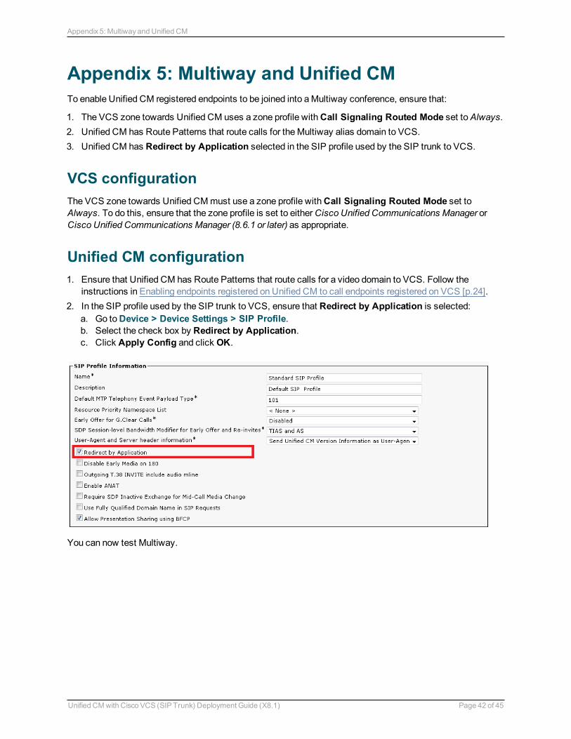
Unified CM configuration 1. Ensure that Unified CM has Route Patterns that route calls for a video domain to VCS. Follow the
instructions in Enabling endpoints registered on Unified CM to call endpoints registered on VCS [p.24]. 2. In the SIP profile used by the SIP trunk to VCS, ensure that Redirect by Application is selected:
a. Go to Device > Device Settings > SIP Profile. b. Select the check box by Redirect by Application. c. Click Apply Config and click OK.
You can now test Multiway.
Unified CM with Cisco VCS (SIP Trunk) Deployment Guide (X8.1) Page 42 of 45
Appendix 5: Multiway and Unified CM

Appendix 6: Additional information
IP address dialingUnified CM cannot dial out to IP addresses, but the VCS can. To support IP address dialing from endpoints registered to Unified CM, we recommend the following procedure:
1. Define a prefix to use for dialing the IP address, for example 8. 2. Add a Route Pattern in Unified CM to match the prefix and send it via the SIP trunk to VCS. 3. On VCS, add a search rule (or transform) with a regex to match, for example: 8(\d{3})(\d{3})(\d
{3})(\d{3}).* and then replace it with \1.\2.\3.\4This example regex matches an IP address dialed in the format of 12 digits (inserting the leading zeroes in each octet), so for example 64.102.6.247 would be dialed as prefix 8 followed by 064102006247. The replace string then inserts dots after the 3rd, 6th and 9th digits.
Characters allowed in SIP URIsThe following character set is allowed in SIP URIs (further details may be found in RFC 3261):
a-z / A-Z / 0-9 / "-" / "_" / "." / "!" / "~" / "*" / "'"/ "(" / ")" "&" / "=" / "+" / "$" / "," / ";" / "?" / "/"
If other characters are needed they must be “escaped” using "%" followed by a pair of hexadecimal digits that represents the ASCII value for the required character.
For example, "alice [email protected]" must be encoded as alice%[email protected] (where %20 represents the space character).
Unified CM with Cisco VCS (SIP Trunk) Deployment Guide (X8.1) Page 43 of 45
Appendix 6: Additional information
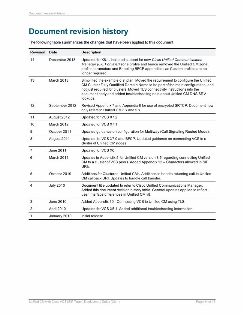
Document revision historyThe following table summarizes the changes that have been applied to this document.
Revision Date Description
14 December 2013 Updated for X8.1. Included support for new Cisco Unified Communications Manager (8.6.1 or later) zone profile and hence removed the Unified CM zone profile parameters and Enabling BFCP appendices as Custom profiles are no longer required.
13 March 2013 Simplified the example dial plan. Moved the requirement to configure the Unified CM Cluster Fully Qualified Domain Name to be part of the main configuration, and not just required for clusters. Moved TLS connectivity instructions into the document body and added troubleshooting note about Unified CM DNS SRV lookups.
12 September 2012 Revised Appendix 7 and Appendix 8 for use of encrypted SRTCP. Document now only refers to Unified CM 8.x and 9.x.
11 August 2012 Updated for VCS X7.2.
10 March 2012 Updated for VCS X7.1.
9 October 2011 Updated guidance on configuration for Multiway (Call Signaling Routed Mode).
8 August 2011 Updated for VCS X7.0 and BFCP. Updated guidance on connecting VCS to a cluster of Unified CM nodes.
7 June 2011 Updated for VCS X6.
6 March 2011 Updates to Appendix 5 for Unified CM version 8.5 regarding connecting Unified CM to a cluster of VCS peers. Added Appendix 12 – Characters allowed in SIP URIs.
5 October 2010 Additions for Clustered Unified CMs. Additions to handle returning call to Unified CM callback URI. Updates to handle call transfer.
4 July 2010 Document title updated to refer to Cisco Unified Communications Manager. Added this document revision history table. General updates applied to reflect user interface differences in Unified CM v8.
3 June 2010 Added Appendix 10 - Connecting VCS to Unified CM using TLS.
2 April 2010 Updated for VCS X5.1. Added additional troubleshooting information.
1 January 2010 Initial release.
Unified CM with Cisco VCS (SIP Trunk) Deployment Guide (X8.1) Page 44 of 45
Document revision history
THE SPECIFICATIONS AND INFORMATION REGARDING THE PRODUCTS IN THIS MANUAL ARE SUBJECT TO CHANGE WITHOUT NOTICE. ALL STATEMENTS, INFORMATION, AND RECOMMENDATIONS IN THIS MANUAL ARE BELIEVED TO BE ACCURATE BUT ARE PRESENTED WITHOUT WARRANTY OF ANY KIND, EXPRESS OR IMPLIED. USERS MUST TAKE FULL RESPONSIBILITY FOR THEIR APPLICATION OF ANY PRODUCTS.
THE SOFTWARE LICENSE AND LIMITED WARRANTY FOR THE ACCOMPANYING PRODUCT ARE SET FORTH IN THE INFORMATION PACKET THAT SHIPPED WITH THE PRODUCT AND ARE INCORPORATED HEREIN BY THIS REFERENCE. IF YOU ARE UNABLE TO LOCATE THE SOFTWARE LICENSE OR LIMITED WARRANTY, CONTACT YOUR CISCO REPRESENTATIVE FOR A COPY.
The Cisco implementation of TCP header compression is an adaptation of a program developed by the University of California, Berkeley (UCB) as part of UCB's public domain version of the UNIX operating system. All rights reserved. Copyright © 1981, Regents of the University of California.
NOTWITHSTANDING ANY OTHER WARRANTY HEREIN, ALL DOCUMENT FILES AND SOFTWARE OF THESE SUPPLIERS ARE PROVIDED "AS IS" WITH ALL FAULTS. CISCO AND THE ABOVE-NAMED SUPPLIERS DISCLAIM ALL WARRANTIES, EXPRESSED OR IMPLIED, INCLUDING, WITHOUT LIMITATION, THOSE OF MERCHANTABILITY, FITNESS FOR A PARTICULAR PURPOSE AND NONINFRINGEMENT OR ARISING FROM A COURSE OF DEALING, USAGE, OR TRADE PRACTICE.
IN NO EVENT SHALL CISCO OR ITS SUPPLIERS BE LIABLE FOR ANY INDIRECT, SPECIAL, CONSEQUENTIAL, OR INCIDENTAL DAMAGES, INCLUDING, WITHOUT LIMITATION, LOST PROFITS OR LOSS OR DAMAGE TO DATA ARISING OUT OF THE USE OR INABILITY TO USE THIS MANUAL, EVEN IF CISCO OR ITS SUPPLIERS HAVE BEEN ADVISED OF THE POSSIBILITY OF SUCH DAMAGES.
Cisco and the Cisco Logo are trademarks of Cisco Systems, Inc. and/or its affiliates in the U.S. and other countries. A listing of Cisco's trademarks can be found at www.cisco.com/go/trademarks. Third party trademarks mentioned are the property of their respective owners. The use of the word partner does not imply a partnership relationship between Cisco and any other company. (1005R)
Any Internet Protocol (IP) addresses and phone numbers used in this document are not intended to be actual addresses and phone numbers. Any examples, command display output, network topology diagrams, and other figures included in the document are shown for illustrative purposes only. Any use of actual IP addresses or phone numbers in illustrative content is unintentional and coincidental.
© 2013 Cisco Systems, Inc. All rights reserved.
Unified CM with Cisco VCS (SIP Trunk) Deployment Guide (X8.1) Page 45 of 45


